Heat Recovery 1 Heat Recovery Units

Welcome message from author
This document is posted to help you gain knowledge. Please leave a comment to let me know what you think about it! Share it to your friends and learn new things together.
Transcript

Heat Recovery 1
Heat Recovery Units

Heat Recovery Unit
Why ?
A heat recovery unit (HRU) can help make mechanicalventilation more cost effective by reclaiming energyfrom exhaust airflows. HRUs use air-to-air heatexchangers to heat or cool incoming fresh air,recapturing 40 to 85 percent of the conditionedtemperatures and/or that would otherwise be lost.
Heat Recovery Unit
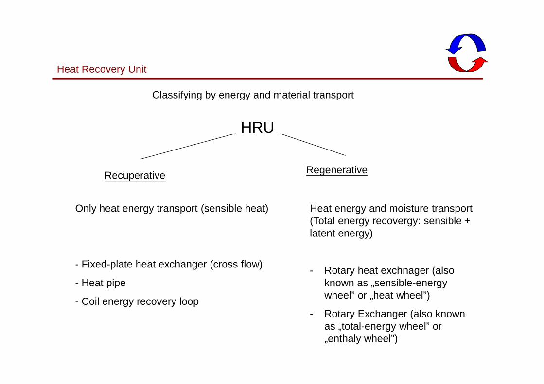
Classifying by energy and material transport
HRU
Recuperative Regenerative
Only heat energy transport (sensible heat)
- Fixed-plate heat exchanger (cross flow)
- Heat pipe
- Coil energy recovery loop
Heat energy and moisture transport(Total energy recovergy: sensible + latent energy)
- Rotary heat exchnager (alsoknown as „sensible-energywheel” or „heat wheel”)
- Rotary Exchanger (also knownas „total-energy wheel” or„enthaly wheel”)

Heat Recovery Unit
Classifying by system bulid-up
HRU
Air To Air transport Transmitting medium
- Fixed-plate heat exchanger (cross flow)
- Heatpipe
- Rotary Exchanger
- Coil Energy Recovery Loop

Heat Recovery 5

Heat Recovery 6
Heat Recovery 7
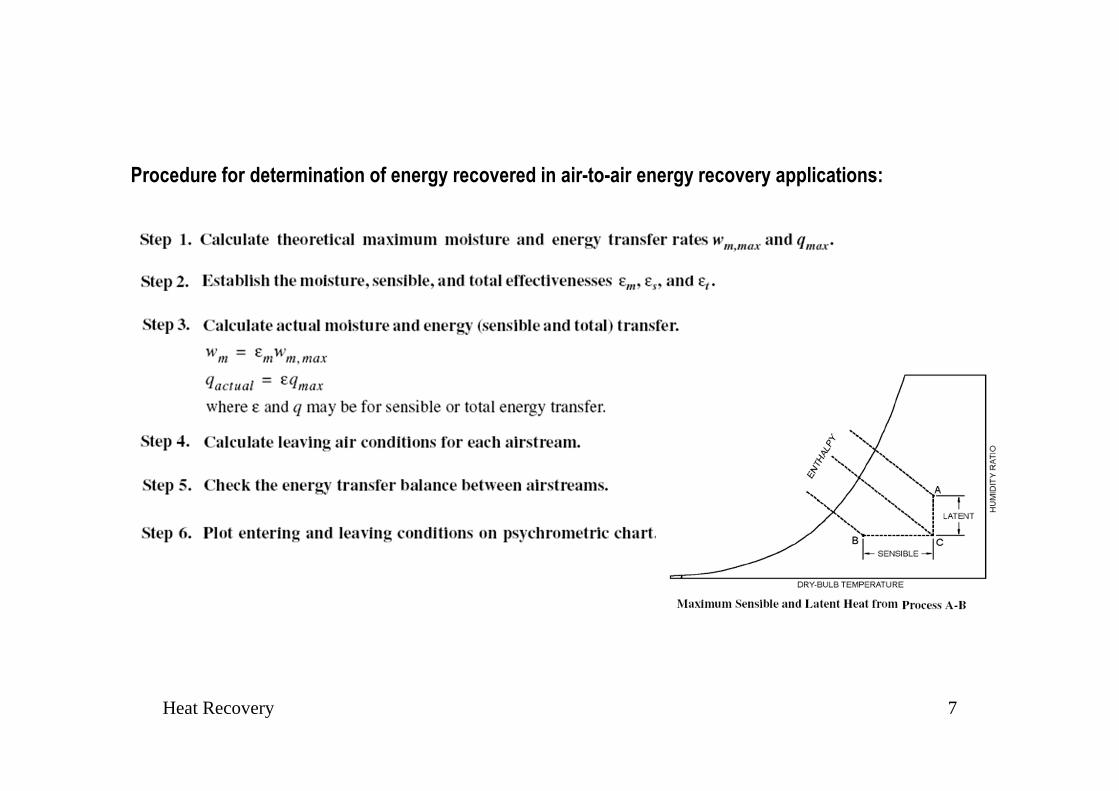
Procedure for determination of energy recovered in air-to-air energy recovery applications:

Heat Recovery 8
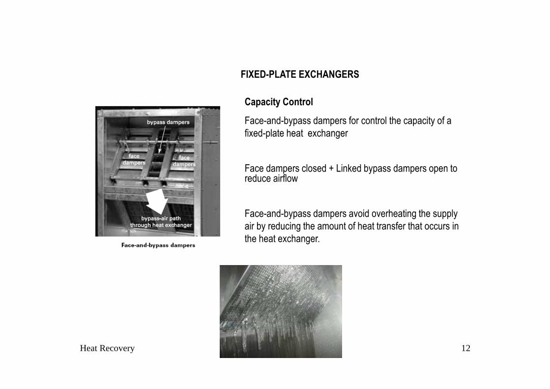
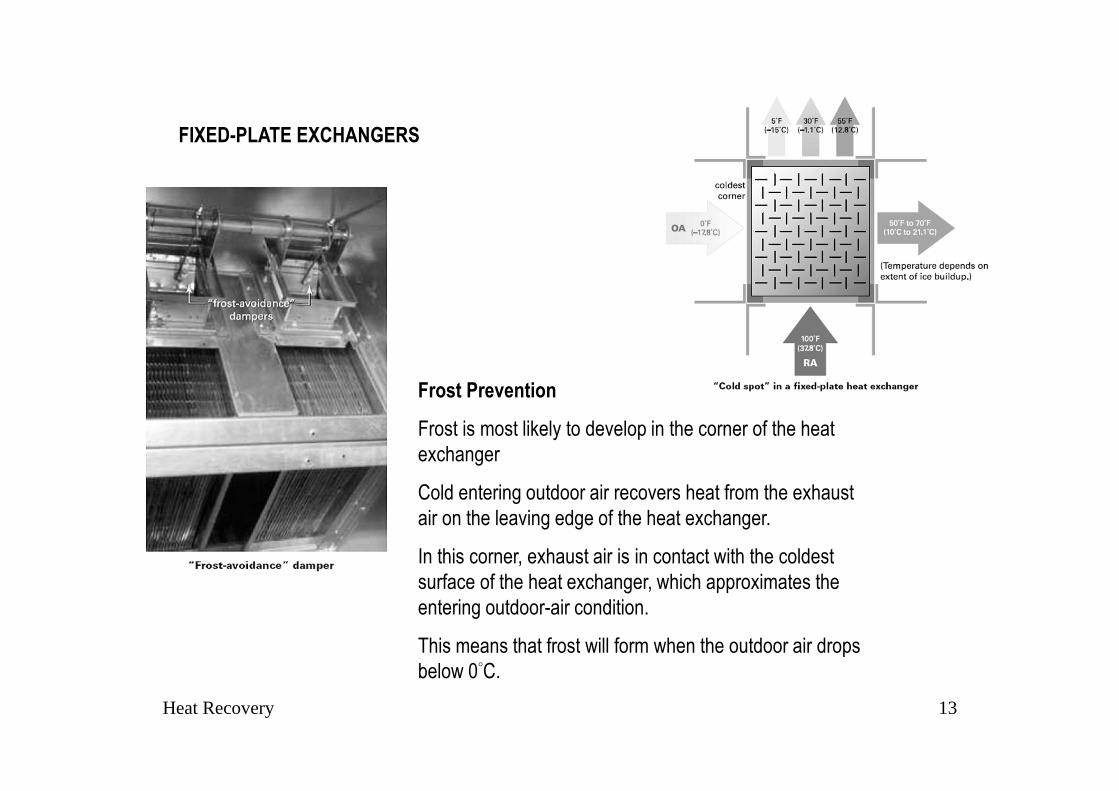
FIXED-PLATE EXCHANGERS
Heat Recovery Unit
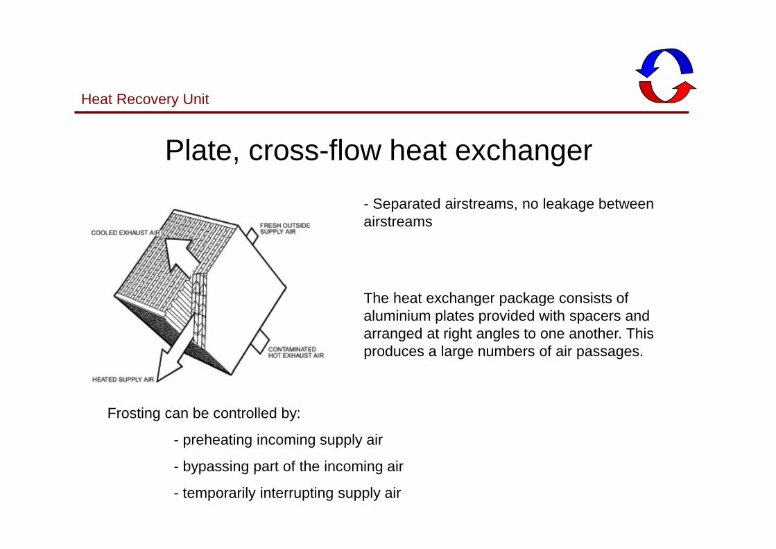
- Separated airstreams, no leakage between airstreams
The heat exchanger package consists of aluminium plates provided with spacers and arranged at right angles to one another. This produces a large numbers of air passages.
Plate, cross-flow heat exchanger
Frosting can be controlled by:
- preheating incoming supply air
- bypassing part of the incoming air
- temporarily interrupting supply air

Heat Recovery 10
FIXED-PLATE EXCHANGERS
Fixed surface plate exchangers have no moving parts.
Alternate layers of plates, separated and sealed (I.e. the
heat exchanger core), form the exhaust and supply
airstream passages.
Plate spacings range from 2.5 to 12.5 mm
Heat is transferred directly from the warm airstreams
through the separating plates into the cool airstreams.

Heat Recovery 11
FIXED-PLATE EXCHANGERS
Design and construction restrictions � cross-flow heat transfer
Additional effective heat transfer surface arranged properly into
counter flow patterns can increase heat transfer effectiveness.
Latent heat of condensation = moisture condensed as the
temperature of the warm (exhaust) air stream drops below its dew
point
Latent heat of condensation and sensible heat are conducted
through the separating plates into the cool (supply) air stream.
Moisture is not transferred.
Recovering min. 80% of available waste exhaust.
Counter flow Heat Exchanger
Outside air
Heat Recovery 12
Capacity Control
Face-and-bypass dampers for control the capacity of a
fixed-plate heat exchanger
Face dampers closed + Linked bypass dampers open to reduce airflow
Face-and-bypass dampers avoid overheating the supply
air by reducing the amount of heat transfer that occurs in
the heat exchanger.
FIXED-PLATE EXCHANGERS
Heat Recovery 13
Frost Prevention
Frost is most likely to develop in the corner of the heat
exchanger
Cold entering outdoor air recovers heat from the exhaust
air on the leaving edge of the heat exchanger.
In this corner, exhaust air is in contact with the coldest
surface of the heat exchanger, which approximates the
entering outdoor-air condition.
This means that frost will form when the outdoor air drops
below 0°C.
FIXED-PLATE EXCHANGERS

Heat Recovery 14
Heat Recovery 15
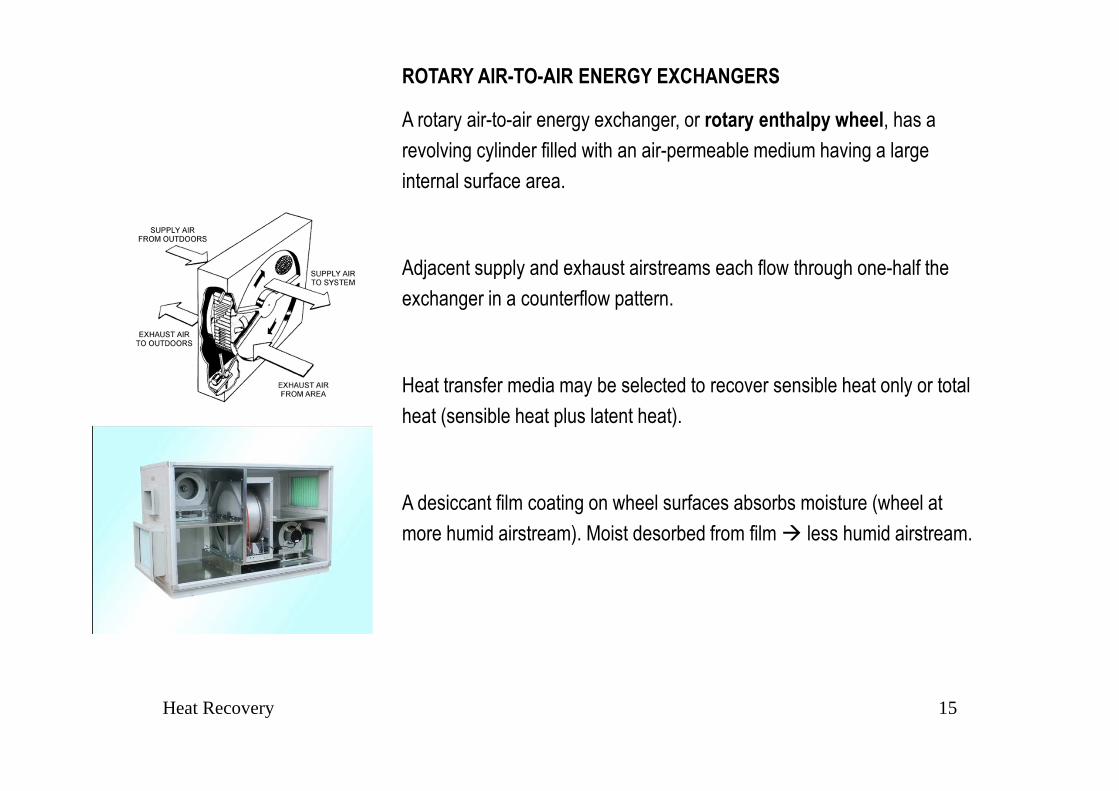
ROTARY AIR-TO-AIR ENERGY EXCHANGERS
A rotary air-to-air energy exchanger, or rotary enthalpy wheel, has a
revolving cylinder filled with an air-permeable medium having a large
internal surface area.
Adjacent supply and exhaust airstreams each flow through one-half the
exchanger in a counterflow pattern.
Heat transfer media may be selected to recover sensible heat only or total
heat (sensible heat plus latent heat).
A desiccant film coating on wheel surfaces absorbs moisture (wheel at
more humid airstream). Moist desorbed from film � less humid airstream.

Heat Recovery 16
Latent heat
1. The medium condenses moisture from the airstream
with the higher humidity ratio (medium temperature
<dew point or by desiccants )
2. Releases the moisture through evaporation (and heat
pickup) into the air stream with the lower humidity
ratio.
Sensible heat
The medium picks up and stores heat from the hot air
stream and releases it to the cold on.

Heat Recovery 17
Cross-Contamination
Carryover
Air entrained within the volume of the rotation medium is carried into the other air stream.
Leakage
Differential static pressure across two airstreams drives air from a higher to a lower static pressure region.
A purge section can be installed on the heat exchanger to
reduce cross-contamination.

Heat Recovery 18
Varying wheel rotational speed - variable- speed drives
(1) A silicon controlled rectifier (SCR) with variable-speed
dc motor,
(2) A constant speed ac motor with hysteresis coupling,
(3) An ac frequency inverter with an ac induction motor.
Regulation of wheel energy recovery:
Supply air bypass control
An air bypass damper, controlled by a wheel supply air
discharge temperature sensor, regulates the proportion of
supply air bypassing exchanger.
Comparison - Exhaust Air Bypass preferred
Exhaust-air bypass �a more linear unloading
characteristic than a VFD (stable control)
Exhaust-air bypass � wider range of capacity control.

Heat Recovery 19
Coil Loops

Heat Recovery 20
Coil Loops

Heat Recovery 21
Coil LoopConstruction and properties of a Coil Loop Heat Recovery System:
• Two or more finned-tube coils that are piped together in a closed loop
• A small pump circulates the working fluid through the two coils
• Working fluid - a solution of inhibited glycol and water through the two
coils
• An expansion tank in the system
• Modulating capacity (three-way mixing valve or a variable-speed
drive on the pump)
• The most flexible - transfer energy between air streams that are
physically separated by some distance
• Recover energy from multiple exhaust-air streams (using multiple
exhaust-side coils)
• Multiple coils - requires additional coils, more piping and glycol
(against frosting), and a larger pump.

Heat Recovery 22
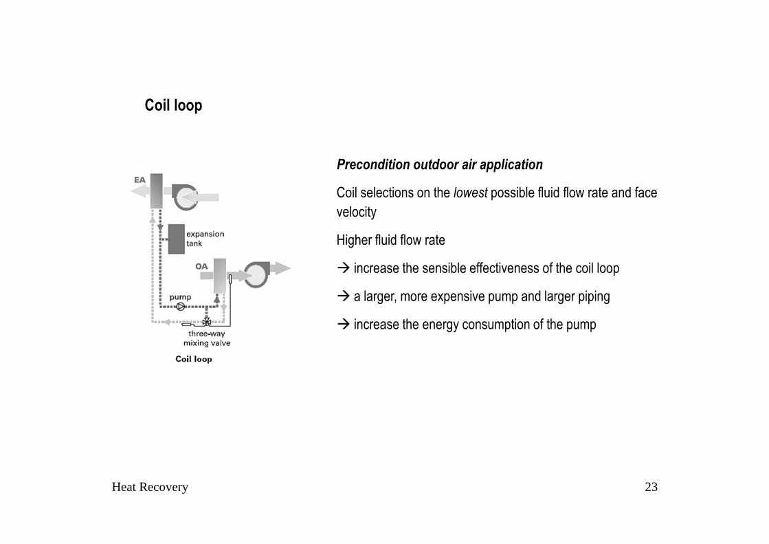
Coil Loop
Typical Performance
Coil-loop selections:
Sensible effectiveness of 45% to 65 %, balanced airflow, and airside static-pressure loss of 75-250 Pa per coil.
Varies number of rows, spacing and type of fins, face velocity, and fluid flow rate for a specific application.
Adding more rows and fins to the coils:
� increases the sensible effectiveness of the coil loop
� the fan(s) to consume more energy
Net energy saved = Energy recovered - additional fan and
pump energy.
Heat Recovery 23
Precondition outdoor air application
Coil selections on the lowest possible fluid flow rate and face
velocity
Higher fluid flow rate
� increase the sensible effectiveness of the coil loop
� a larger, more expensive pump and larger piping
� increase the energy consumption of the pump
Coil loop
Heat Recovery 24
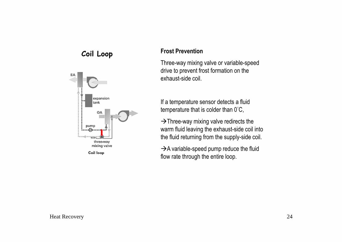
Frost Prevention
Three-way mixing valve or variable-speed
drive to prevent frost formation on the
exhaust-side coil.
If a temperature sensor detects a fluid
temperature that is colder than 0°C,
�Three-way mixing valve redirects the
warm fluid leaving the exhaust-side coil into
the fluid returning from the supply-side coil.
�A variable-speed pump reduce the fluid
flow rate through the entire loop.
Coil Loop

Heat Recovery 25


Heat Recovery 27
Heat Recovery 28
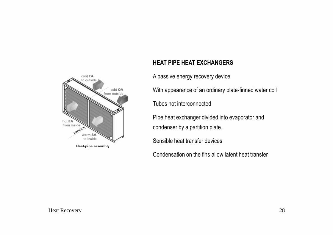
HEAT PIPE HEAT EXCHANGERS
A passive energy recovery device
With appearance of an ordinary plate-finned water coil
Tubes not interconnected
Pipe heat exchanger divided into evaporator and
condenser by a partition plate.
Sensible heat transfer devices
Condensation on the fins allow latent heat transfer

Heat Recovery 29
Heat pipe tubes are fabricated with an integral
capillary
wick structure, evacuated, filled with a suitable
working fluid and permanently sealed.
The working fluid is normally a refrigerant.
Fin designs include continuous corrugated plate
fin, continuous plain fin, and spiral fins.
Modifying fin design and tube spacing changes
pressure drop at a given face velocity.
Heat Recovery 30
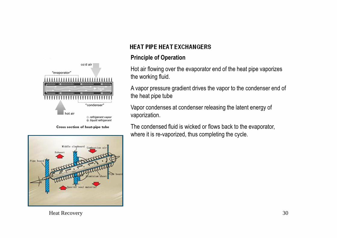
Principle of Operation
Hot air flowing over the evaporator end of the heat pipe vaporizes
the working fluid.
A vapor pressure gradient drives the vapor to the condenser end of
the heat pipe tube
Vapor condenses at condenser releasing the latent energy of
vaporization.
The condensed fluid is wicked or flows back to the evaporator,
where it is re-vaporized, thus completing the cycle.

Heat Recovery 31
Controls
Changing the slope (tilt) of a heat pipe controls the amount
of heat it transfers.
Operating the heat pipe on a slope with the hot end below
(or above) the horizontal improves (or retards) the
condensate flow back to the evaporator end of the heat
pipe.
This feature for regulating the effectiveness of the heat
pipe heat exchanger.

Heat Recovery 32
Cross-Contamination
Zero cross-contamination for pressure differentials between
airstreams of up to 12 kPa.
A vented double-wall partition between the airstreams �
additional protection against cross-contamination.
Exhaust duct attached to the partition space for exhaust of
leakage at space between two ducts.

Heat Recovery 33
In practice, tilt control is effected by pivoting the exchanger about the center of its base.
A temperature-controlled actuator
to one end of the exchanger for
control
Heat pipes
pivot

Thank you for your attention !
Related Documents