HEAT RECOVERY UNIT PRHR*3A ENGINEERING MANUAL Three-Port Heat Recovery Units Six-Port Heat Recovery Units Eight-Port Heat Recovery Units

Welcome message from author
This document is posted to help you gain knowledge. Please leave a comment to let me know what you think about it! Share it to your friends and learn new things together.
Transcript

HEAT RECOVERY UNITPRHR*3A
ENGINEERING MANUAL
Three-Port Heat Recovery Units
Six-Port Heat Recovery Units
Eight-Port Heat Recovery Units

For continual product development, LG Electronics U.S.A., Inc. reserves the right to change specifications without notice. © LG Electronics U.S.A., Inc.
PROPRIETARY DATA NOTICEThis document, as well as all reports, illustrations, data, information,
and other materials are the property of LG Electronics U.S.A., Inc., and are disclosed by LG Electronics U.S.A., Inc. only in confidence.
This document is for design purposes only.
A summary list of safety precautions is on page 3.
To access additional technical documentation such as submittals, outdoor and indoor unit engineering manuals, installation, service, product data per-formance, general best practice, and building ventilation manuals, as well as
white papers, catalogs, LATS software programs, and more, log in to www.lghvac.com.
TABLE OF CONTENTS
TABLE OF SYMBOLSThis symbol indicates an imminently hazardous situation which, if not avoided, will result in death or serious injury.This symbol indicates a potentially hazardous situation which, if not avoided, could result in death or serious injury.This symbol indicates a potentially hazardous situation which, if not avoided, may result in minor or moderate injury.This symbol indicates situations that may result in equipment or property damage accidents only.
This symbol indicates an action should not be completed.
DANGER
CAUTION
Unit Nomenclature ���������������������������������������������������������������������������������������������������������������������������������������������������������������������������������������������������������� 4
LATS Overview ������������������������������������������������������������������������������������������������������������������������������������������������������������������������������������������������������������ 5-6
Refrigerant Charge Worksheets ��������������������������������������������������������������������������������������������������������������������������������������������������������������������������������� 7-9
Product Data ������������������������������������������������������������������������������������������������������������������������������������������������������������������������������������������������������������ 10-27Mechanical Specifications ...........................................................................................................................................................................................11General Data ......................................................................................................................................................................................................... 12-13Electrical Data ............................................................................................................................................................................................................ 14Wiring Diagrams .................................................................................................................................................................................................... 15-18External Dimensions .............................................................................................................................................................................................. 19-23Refrigerant Flow Diagram ........................................................................................................................................................................................... 24Acoustic Data ............................................................................................................................................................................................................. 25Accessories ................................................................................................................................................................................................................ 26
Application Guidelines �������������������������������������������������������������������������������������������������������������������������������������������������������������������������������������������� 27-44Piping Limitations for Heat Recovery Systems ...................................................................................................................................................... 28-35Selecting the Best Location / Clearance Requirements ........................................................................................................................................ 36-37General Mounting ....................................................................................................................................................................................................... 38Wiring Guidelines .................................................................................................................................................................................................. 39-43LGRED°, HRU Compatibility, and Gen 4 DIP Switch Settings ................................................................................................................................... 44
Acronyms ���������������������������������������������������������������������������������������������������������������������������������������������������������������������������������������������������������������������� 45
INTRODUCTION | 3
Introduction
Due to our policy of continuous product innovation, some specifications may change without notification. © LG Electronics U.S.A., Inc., Englewood Cliffs, NJ. All rights reserved. “LG” is a registered trademark of LG Corp.

MUL
TI V
Hea
t Rec
over
y Un
it PR
HR*3
A En
gine
erin
g M
anua
l
UNIT NOMENCLATURE
Heat Recovery Units (HRU)PRHR 02 3A
Series Number2A = Series Number3A = Series Number
Number of Ports02 = Two Ports 03 = Three Ports 04 = Four Ports06 = Six Ports08 = Eight Ports
FamilyPRHR = Multi V Heat Recovery Unit (HRU) (Refrigerant R410A)
4 | INTRODUCTIONDue to our policy of continuous product innovation, some specifications may change without notification. © LG Electronics U.S.A., Inc., Englewood Cliffs, NJ. All rights reserved. “LG” is a registered trademark of LG Corp.

LG Air Conditioner Technical Solution (LATS) SoftwareA properly designed and installed refrigerant piping system is critical to the optimal performance of LG air-conditioning systems. To assist engineers, LG offers, free of charge, LG Air Conditioner Technical Solution (LATS) software—a total design solution for LG air conditioning systems.
To reduce the risk of designing an improper applied system or one that will not operate correctly, LG requires that LATS software be used on all projects.
FormatsLATS is available to LG customers in three user interfaces: LATS HVAC, LATS CAD2, and LATS REVIT. All three LATS formats are available through www.myLGHVAC.com, or contact an LG Sales Representative.
LATS HVAC is a Windows®-based application that aids engineers in designing LG Variable Refrigerant Flow (VRF), Multi F / Multi F MAX, Single-Zone, and Energy Recovery Ventilator (ERV) systems.*Windows® is a registered mark of Microsoft® Corporation.
LATS CAD2 combines the LG LATS program with AutoCAD® software**. It permits engineers to layout and validate LG Multi V Variable Refrigerant Flow (VRF), Multi F / Multi F MAX, Single-Zone, and Energy Recovery Ventilator (ERV) systems directly into CAD drawings.
LATS Revit integrates the LG LATS program with Revit® software**. It permits engineers to layout and validate Multi V VRF systems directly into Revit drawings.**AutoCAD® and Revit® are both registered marks of Autodesk, Inc.
FeaturesAll LG product design criteria have been loaded into the program, making LATS simple to use: double click or drag and drop the com-ponent choices. Build systems in Tree Mode where the refrigerant system can be viewed. Switch to a Schematic diagram to see the electrical and communications wiring.LATS software permits the user to input region data, indoor and outdoor design temperatures, modify humidity default values, zoning, specify type and size of outdoor units and indoor units, and input air flow and external static pressure (ESP) for ducted indoor units.
The program can also:
LG AIR CONDITIONER TECHNICAL SOLUTION (LATS)
• Import building loads from a separate Excel file.• Present options for outdoor unit auto selection.• Automatically calculate component capacity based on design
conditions for the chosen region.• Verify if the height differences between the various system
components are within system limits.• Provide the correct size of each refrigerant piping segment and LG
Y-Branches and Headers.
• Adjust overall piping system length when elbows are added.• Check for component piping limitations and flag if any parameters
are broken.• Factor operation and capacity for defrost operation.• Calculate refrigerant charge, noting any additional trim charge.• Suggest accessories for indoor units and outdoor units.• Run system simulation.
Features depend on which LATS program is being used, and the type of system being designed.
Figure 1: Example of LATS CAD2.
INTRODUCTION | 5
Introduction
Due to our policy of continuous product innovation, some specifications may change without notification. © LG Electronics U.S.A., Inc., Englewood Cliffs, NJ. All rights reserved. “LG” is a registered trademark of LG Corp.

MUL
TI V
Hea
t Rec
over
y Un
it PR
HR*3
A En
gine
erin
g M
anua
l
LATS Generates a Complete Project ReportLATS software also generates a report containing project design parameters, cooling and heating design data, system component perfor-mance, and capacity data. The report includes system combination ratio and refrigerant charge calculations; and provides detailed bill of material, including outdoor units, indoor units, control devices, accessories, refrigerant pipe sizes segregated by building, by system, by pipe size, and by pipe segments. LATS can generate an Excel GERP report that can imported into the LG SOPS pricing and ordering system.
Proper Design to Install ProcedureLG encourages a two report design-to-install-procedure. After the design engineer determines building / zone loads and other details, the engineer opens the LATS program and inputs the project’s infor-mation. When the design is complete, the “Auto Piping” and “System Check” functions must be used to verify piping sizes, limitations, and if any design errors are present. If errors are found, engineers must adjust the design, and run Auto Piping and System Check again. When the design passes the checks, then the engineer prints out a project “Shop Drawing” (LATS Tree Diagram) and provides it to the installing contractor. The contractor must follow the LATS Tree Diagram when building the piping system, but oftentimes the design changes on the building site:
• Architect has changed location and/or purpose of room(s).• Outdoor unit cannot be placed where originally intended.• Structural elements prevent routing the piping as planned.• Air conditioning system conflicts with other building systems
(plumbing, gas lines, etc.).
The contractor must mark any deviation from the design on the Shop Drawing, including as-built straight lines and elbows. This “Mark Up” drawing must be returned to the design engineer or Rep, who must input contractor changes into the LATS file. (Copy the original LATS soft-ware file, save and rename as a separate file, and modify all piping lengths by double-clicking on each length and editing information.) Like the shop drawing, the Auto Piping and System Check must also be run on this new “As Built” drawing. The design engineer or Rep must then provide the final As Built file to the contractor. The Mark Up version must be compared to the As Built version for:
• Differences in pipe diameter(s). If incorrect diameters have been installed, the piping must be changed out. If pipe diameters have changed, check to see if Y-Branches will also need to be changed.
• Changes to outdoor unit and indoor unit capacities. Capacities changes may impact line length changes. • Additional refrigerant charge quantity (“Trim Charge”). Trim charge will change if piping lengths and diameters change. The As Built version
must reflect installed piping lengths to ensure correct trim charge.
All documents submitted by the contractor, as well as the Shop Drawing and the As Built Drawing files must be provided for commissioning purposes. Model and serial numbers for all system components must also be submitted. If the steps previously detailed are not followed, and all documents are not provided to the commissioning agent, the project runs the risk of not being commissioned and voiding any limited warranty LG offers on the equipment.
LG AIR CONDITIONER TECHNICAL SOLUTION (LATS)
Figure 2: Example of a LATS Tree Diagram.
For refrigerant charge worksheets, see the respective air-source unit / water-source unit engineering and installation manuals.
6 | INTRODUCTIONDue to our policy of continuous product innovation, some specifications may change without notification. © LG Electronics U.S.A., Inc., Englewood Cliffs, NJ. All rights reserved. “LG” is a registered trademark of LG Corp.

Multi V 5 System R410A Refrigerant Charge Calculator (lbs.)REFRIGERANT CHARGE WORKSHEET
1CF (Ref.) = Correction Factor for Refrigerant Charge. 2For refrigerant charge purposes, consider only the liquid line; ignore the vapor line(s).
System Tag or ID:Job Name: __________________________________________
Project Manager: ____________________________________ Date: ______________Line # Description Chassis I.D. Size Quantity CF (Ref.)1 Total (lbs.)
1 Linear feet of 1/4" liquid line tubing2 — — 0.0152 Linear feet of 3/8" liquid line tubing2 — — 0.0413 Linear feet of 1/2" liquid line tubing2 — — 0.0794 Linear feet of 5/8" liquid line tubing2 — — 0.1165 Linear feet of 3/4" liquid line tubing2 — — 0.1796 Linear feet of 7/8" liquid line tubing2 — — 0.2387 Linear feet of 1" liquid line tubing2 — — 0.3238 Standard + Art Cool Mirror SJ, SK 5k to 15k 0.539 Standard + Art Cool Mirror SJ, SK 18k to 24k 0.62
10 Standard SV 30k to 36k 1.0111 Art Cool Gallery SF 9k to 12k 0.2212 1-Way Cassette TU 7k to 12k 0.4413 1-Way Cassette TT 18k to 24k 0.6414 2-Way Cassette TS 18k to 24k 0.7515 4-Way 2' x 2' Cassette TR 5k to 7k 0.4016 4-Way 2' x 2' Cassette TR 9k to 12k 0.5517 4-Way 2' x 2' Cassette TQ 15k to 18k 0.7118 4-Way 3' x 3' Cassette TN 7k to 24k 0.8819 4-Way 3' x 3' Cassette TM 28k to 36k 1.0820 4-Way 3’ x 3’ Cassette TM 42k to 48k 1.4121 High Static Ducted BH 7k to 24k 0.5722 High Static Ducted M2 7k to 24k 0.7723 High Static Ducted M2 28k to 42k 1.1524 High Static Ducted M3 28k to 54k 1.3525 High Static Ducted B8 36k to 96k 2.2026 Low Static Ducted, Low Static Ducted Bottom Return L1 5k to 9k 0.3127 Low Static Ducted, Low Static Ducted Bottom Return L2 12k to 18k 0.4228 Low Static Ducted, Low Static Ducted Bottom Return L3 21k to 24k 0.5529 Vertical / Horizontal Air Handling Unit NJ 12k to 30k 1.0430 Vertical / Horizontal Air Handling Unit NJ 36k 1.5731 Vertical / Horizontal Air Handling Unit NK 42k to 54k 2.0032 Floor Standing CE (U) 7k to 15k 0.3733 Floor Standing CF (U) 18k to 24k 0.8234 HRU: PRHR022A/023A, 032A/033A, 042A/043A, 063A, 083A — — 1.135 ADDITIONAL Refrigerant Charge Required (Sum of lines 1 – 34)
36 Outdoor Unit Factory Refrigerant Charge
36A ARUM072*TE5 72k 14.336B ARUM096*TE5 96k 23.236C ARUM121*TE5 121k 23.236D ARUM144*TE5 144k 26.536E ARUM168*TE5 168k 26.536F ARUM192*TE5 192k 30.936G ARUM216*TE5 216k 37.536H ARUM241*TE5 241k 37.5
37 Total ODU FACTORY Refrigerant Charge (Sum of factory refrigerant charges for all ODUs in the system, lines 36A -36H) 38 TOTAL SYSTEM CHARGE
Sum of Additional Refrigerant Charge Required (line 35) and Total ODU Factory Refrigerant Charge (line 37)
INTRODUCTION | 7
Introduction
Due to our policy of continuous product innovation, some specifications may change without notification. © LG Electronics U.S.A., Inc., Englewood Cliffs, NJ. All rights reserved. “LG” is a registered trademark of LG Corp.

MUL
TI V
Hea
t Rec
over
y Un
it PR
HR*3
A En
gine
erin
g M
anua
l
Water IV System R410A Refrigerant Charge Calculator (lbs.)REFRIGERANT CHARGE WORKSHEET
1CF (Ref.) = Correction Factor for Refrigerant Charge. 2For refrigerant charge purposes, consider only the liquid line; ignore the vapor line(s).
System Tag or ID:Job Name: __________________________________________
Project Manager: ____________________________________ Date: ______________Line # Description Chassis I.D. Size Quantity CF (Ref.)1 Total (lbs.)
1 Linear feet of 1/4" liquid line tubing2 — — 0.0152 Linear feet of 3/8" liquid line tubing2 — — 0.0413 Linear feet of 1/2" liquid line tubing2 — — 0.0794 Linear feet of 5/8" liquid line tubing2 — — 0.1165 Linear feet of 3/4" liquid line tubing2 — — 0.1796 Linear feet of 7/8" liquid line tubing2 — — 0.2387 Linear feet of 1" liquid line tubing2 — — 0.3238 Standard + Art Cool Mirror SJ, SK 5k to 15k 0.539 Standard + Art Cool Mirror SJ, SK 18k to 24k 0.62
10 Standard SV 30k to 36k 1.0111 Art Cool Gallery SF 9k to 12k 0.2212 1-Way Cassette TU 7k to 12k 0.4413 1-Way Cassette TT 18k to 24k 0.6414 2-Way Cassette TS 18k to 24k 0.7515 4-Way 2' x 2' Cassette TR 5k to 7k 0.4016 4-Way 2' x 2' Cassette TR 9k to 12k 0.5517 4-Way 2' x 2' Cassette TQ 15k to 18k 0.7118 4-Way 3' x 3' Cassette TN 7k to 24k 0.8819 4-Way 3' x 3' Cassette TM 28k to 36k 1.0820 4-Way 3’ x 3’ Cassette TM 42k to 48k 1.4121 High Static Ducted BH 7k to 24k 0.5722 High Static Ducted M2 7k to 24k 0.7723 High Static Ducted M2 28k to 42k 1.1524 High Static Ducted M3 28k to 54k 1.3525 High Static Ducted B8 36k to 96k 2.2026 Low Static Ducted, Low Static Ducted Bottom Return L1 5k to 9k 0.3127 Low Static Ducted, Low Static Ducted Bottom Return L2 12k to 18k 0.4228 Low Static Ducted, Low Static Ducted Bottom Return L3 21k to 24k 0.5529 Vertical / Horizontal Air Handling Unit NJ 12k to 30k 1.0430 Vertical / Horizontal Air Handling Unit NJ 36k 1.5731 Vertical / Horizontal Air Handling Unit NK 42k to 54k 2.0032 Floor Standing CE (U) 7k to 15k 0.3733 Floor Standing CF (U) 18k to 24k 0.8234 HRU: PRHR022A/023A, 032A/033A, 042A/043A, 063A, 083A — — 1.135 ADDITIONAL Refrigerant Charge Required (Sum of lines 1 – 34)
36 Water-Source Unit FactoryRefrigerant Charge
ARW*072BAS4, ARW*096BAS4, ARW*121BAS4, ARW*144BAS4 10.42ARW*072DAS4, ARW*096DAS4, ARW*121DAS4 10.42ARW*144DAS4, ARW*192DAS4 11.66
37 Total WSU FACTORY Refrigerant Charge (Sum of factory refrigerant charges for all WSUs in the system) 38 TOTAL SYSTEM CHARGE
Sum of Additional Refrigerant Charge Required (line 35) and Total WSU Factory Refrigerant Charge (line 37)
8 | INTRODUCTIONDue to our policy of continuous product innovation, some specifications may change without notification. © LG Electronics U.S.A., Inc., Englewood Cliffs, NJ. All rights reserved. “LG” is a registered trademark of LG Corp.
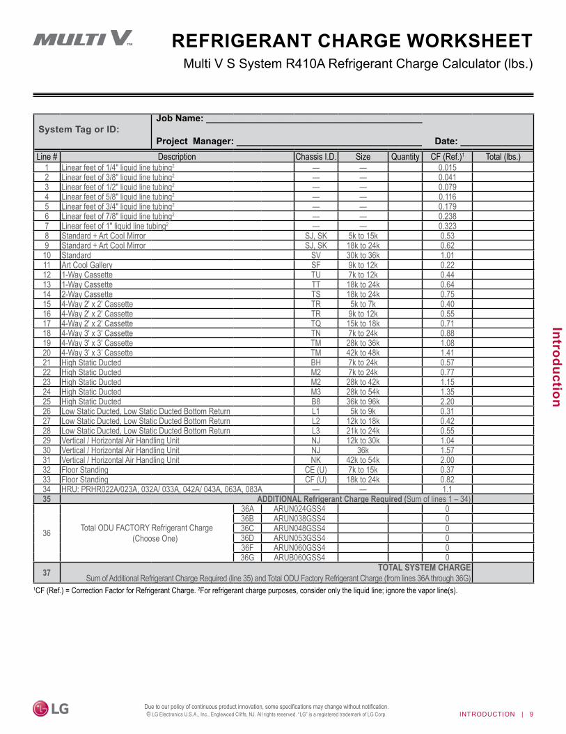
Multi V S System R410A Refrigerant Charge Calculator (lbs.)REFRIGERANT CHARGE WORKSHEET
1CF (Ref.) = Correction Factor for Refrigerant Charge. 2For refrigerant charge purposes, consider only the liquid line; ignore the vapor line(s).
System Tag or ID:Job Name: __________________________________________
Project Manager: ____________________________________ Date: ______________Line # Description Chassis I.D. Size Quantity CF (Ref.)1 Total (lbs.)
1 Linear feet of 1/4" liquid line tubing2 — — 0.0152 Linear feet of 3/8" liquid line tubing2 — — 0.0413 Linear feet of 1/2" liquid line tubing2 — — 0.0794 Linear feet of 5/8" liquid line tubing2 — — 0.1165 Linear feet of 3/4" liquid line tubing2 — — 0.1796 Linear feet of 7/8" liquid line tubing2 — — 0.2387 Linear feet of 1" liquid line tubing2 — — 0.3238 Standard + Art Cool Mirror SJ, SK 5k to 15k 0.539 Standard + Art Cool Mirror SJ, SK 18k to 24k 0.62
10 Standard SV 30k to 36k 1.0111 Art Cool Gallery SF 9k to 12k 0.2212 1-Way Cassette TU 7k to 12k 0.4413 1-Way Cassette TT 18k to 24k 0.6414 2-Way Cassette TS 18k to 24k 0.7515 4-Way 2' x 2' Cassette TR 5k to 7k 0.4016 4-Way 2' x 2' Cassette TR 9k to 12k 0.5517 4-Way 2' x 2' Cassette TQ 15k to 18k 0.7118 4-Way 3' x 3' Cassette TN 7k to 24k 0.8819 4-Way 3' x 3' Cassette TM 28k to 36k 1.0820 4-Way 3’ x 3’ Cassette TM 42k to 48k 1.4121 High Static Ducted BH 7k to 24k 0.5722 High Static Ducted M2 7k to 24k 0.7723 High Static Ducted M2 28k to 42k 1.1524 High Static Ducted M3 28k to 54k 1.3525 High Static Ducted B8 36k to 96k 2.2026 Low Static Ducted, Low Static Ducted Bottom Return L1 5k to 9k 0.3127 Low Static Ducted, Low Static Ducted Bottom Return L2 12k to 18k 0.4228 Low Static Ducted, Low Static Ducted Bottom Return L3 21k to 24k 0.5529 Vertical / Horizontal Air Handling Unit NJ 12k to 30k 1.0430 Vertical / Horizontal Air Handling Unit NJ 36k 1.5731 Vertical / Horizontal Air Handling Unit NK 42k to 54k 2.0032 Floor Standing CE (U) 7k to 15k 0.3733 Floor Standing CF (U) 18k to 24k 0.8234 HRU: PRHR022A/023A, 032A/ 033A, 042A/ 043A, 063A, 083A — — 1.135 ADDITIONAL Refrigerant Charge Required (Sum of lines 1 – 34)
36 Total ODU FACTORY Refrigerant Charge (Choose One)
36A ARUN024GSS4 036B ARUN038GSS4 036C ARUN048GSS4 036D ARUN053GSS4 036F ARUN060GSS4 036G ARUB060GSS4 0
37 TOTAL SYSTEM CHARGE Sum of Additional Refrigerant Charge Required (line 35) and Total ODU Factory Refrigerant Charge (from lines 36A through 36G)
INTRODUCTION | 9
Introduction
Due to our policy of continuous product innovation, some specifications may change without notification. © LG Electronics U.S.A., Inc., Englewood Cliffs, NJ. All rights reserved. “LG” is a registered trademark of LG Corp.

PRODUCT DATAMechanical Specifications on page 11General Data on page 12Electrical Data on page 14Wiring Diagrams on page 15External Dimensions on page 19Refrigerant Flow Diagram on page 24Acoustic Data on page 25Accessories on page 26

PRODUCT DATA | 11
Product Data
Due to our policy of continuous product innovation, some specifications may change without notification. © LG Electronics U.S.A., Inc., Englewood Cliffs, NJ. All rights reserved. “LG ” is a registered trademark of LG Corp.
Four-port Heat Recovery Unit.Multi V Heat Recovery UnitsGeneralMulti V heat recovery units are for use with Multi V 5, Water IV, and S heat recovery outdoor units to per-mit simultaneous heating and cooling operation (see page 44 for compatibility details). Heat recovery units have two (2), three (3), four (4), six (6), or eight (8) ports for connections to indoor units. Each port is capable of connecting from one (1) indoor unit up to eight (8) indoor units up to a max-imum nominal capacity of ≤60 MBh. When multiple indoor units are connected to one port, all indoor units on that port must operate in the same mode (cooling or heating). Individual indoor units ≥60 MBh nominal capacity must use two (2) neighboring heat recovery unit ports twinned together using a reverse Y-branch kit. Connect largest indoor unit to first port of the heat recovery unit. Each heat recovery unit can support a maximum capacity (sum of ports) of up to 230 MBh. Heat recovery ports can operate in heating or cooling mode independently, regardless of the mode of any other port on the unit or in the system except where heat recovery unit ports are twinned. Heat recovery units contain one double spiral subcooling heat exchanger per port, are internally insulated, and do not require a condensate drain.
Casing and ConstructionHeat recovery units are completely factory assembled, internally piped, wired, and are designed for indoor installation. Casing is con-structed of galvanized steel, and houses piping, valves and controls to divert refrigerant controlling each port to operate in either heating or cooling mode. Heat recovery units contain one double spiral subcooling heat exchanger per port, are internally insulated, and do not require a condensate drain.
Refrigerant ValvesEach heat recovery port is circuited with two two-position motorized valves to control R410A refrigerant flow path to allow indoor units to operate in heating or cooling mode.
Refrigerant PipingUnits can be piped in series and / or parallel to optimize cost between material and labor. Up to 16 heat recovery units can be piped in series, parallel, or a combination of series and parallel to optimize cost between material and labor. Any series string of heat recovery ports/units can connect up to 230 MBh of indoor unit nominal capacity (series string is defined a heat recovery units piped in series). Heat recovery unit piping limitations also depend on the allowable piping parameters of the outdoor unit installed.
• Indoor units up to 131 equivalent feet of piping length from the heat recovery unit to which it is connected. • Indoor units up to 295 equivalent feet of piping length from the first branch. • Difference between highest and lowest elevation indoor units piped to separate parallel heat recovery units (HRUs) up to 131 feet in
elevation.• Difference between highest and lowest heat recovery units piped in parallel up to 98 feet in elevation. • Difference between highest and lowest elevation heat recovery units piped in series up to 16 feet in elevation.• Elevation difference of series connected heat recovery units cannot exceed 16 feet.
All refrigerant lines from the outdoor unit to the heat recovery units, and from the heat recovery units to the indoor units must be field insulated separately.
ElectricalHeat recovery units require 208-230V, 1-phase, 60 Hz electrical power, and are capable of operation within ±10% of nominal voltage.
ControlsHeat recovery units include factory-installed control boards with integral microprocessors. Heat recovery unit control boards communi-cate with the main control board in the outdoor unit and interface with the VRF equipment controls system. The control circuit between the indoor units, heat recovery units and the outdoor unit is RS-485 daisy chain communication over two-conductor, twisted, stranded, shielded, 18 AWG cable.
Mechanical SpecificationsPRODUCT DATA

12 | PRODUCT DATA
MUL
TI V
Hea
t Rec
over
y Un
it PR
HR*3
A En
gine
erin
g M
anua
l
Due to our policy of continuous product innovation, some specifications may change without notification. © LG Electronics U.S.A., Inc., Englewood Cliffs, NJ. All rights reserved. “LG ” is a registered trademark of LG Corp.
Model PRHR023A PRHR033A PRHR043ANumber of Ports 2 3 4Max. Connectible No. of Indoor Units 16 24 32Max. Connectible No. of Indoor Units on each port 8 8 8Max. Port Capacity (each port) Btu/h 60,000 60,000 60,000Max. Unit Capacity (sum of ports) Btu/h 120,000 180,000 230,000Net Weight lbs. 33 37 40Shipping Weight lbs. 46 50 53Dimensions (W x H x D) Inches 19-1/8 x 8-5/8 x 18-15/16 Casing Galvanized Steel Plate
Connecting Pipes
To Indoor UnitsLiquid Pipe (inches) 3/8 3/8 3/8Vapor Pipe (inches) 5/8 5/8 5/8
To OutdoorUnits
Liquid (inches) 3/8 1/2 5/8Low-pressure Vapor (inches) 7/8 1-1/8 1-1/8High-pressure Vapor (inches) 3/4 7/8 7/8
Insulation Material Polyethylene Foam
Heat recovery units can only be used with LG systems piped for heat recovery operation.
Table 1: Heat Recovery Unit Specifications.
General Data
Figure 3: Two-Port Heat Recovery Unit. Figure 4: Three-Port Heat Recovery Unit. Figure 5: Four-Port Heat Recovery Unit.
PRODUCT DATA

PRODUCT DATA | 13
Product Data
Due to our policy of continuous product innovation, some specifications may change without notification. © LG Electronics U.S.A., Inc., Englewood Cliffs, NJ. All rights reserved. “LG ” is a registered trademark of LG Corp.
Table 2: Heat Recovery Unit Specifications, continued.
Figure 6: Six-Port Heat Recovery Unit. Figure 7: Eight-Port Heat Recovery Unit.
Heat recovery units can only be used with LG systems piped for heat recovery operation.
Model PRHR063A PRHR083ANumber of Ports 6 8Max. Connectible No. of Indoor Units 48 64Max. Connectible No. of Indoor Units on each port 8 8Max. Port Capacity (each port) Btu/h 60,000 60,000Max. Unit Capacity (sum of ports) Btu/h 230,000 230,000Net Weight lbs. 60 68Shipping Weight lbs. 75 82Dimensions (W x H x D) Inches 31-1/4 x 8-5/8 x 18-15/16Casing Galvanized Steel Plate
Connecting Pipes
To Indoor UnitsLiquid Pipe (inches) 3/8 3/8Vapor Pipe (inches) 5/8 5/8
To OutdoorUnits
Liquid (inches) 5/8 5/8Low-pressure Vapor (inches) 1-1/8 1-1/8High-pressure Vapor (inches) 7/8 7/8
Insulation Material Polyethylene Foam
General DataPRODUCT DATA

14 | PRODUCT DATA
MUL
TI V
Hea
t Rec
over
y Un
it PR
HR*3
A En
gine
erin
g M
anua
l
Due to our policy of continuous product innovation, some specifications may change without notification. © LG Electronics U.S.A., Inc., Englewood Cliffs, NJ. All rights reserved. “LG ” is a registered trademark of LG Corp.
Unit Model No. Voltage Range
Rated Amps MCA MFA
Power Supply Power Input (W)Hz Volts Phase Cooling Heating
PRHR023A
187-2530.06 0.17
15 60 208-230 139.8 37.2PRHR033A
PRHR043APRHR063A
0.09 0.27 75.9 72.1PRHR083A
Table 3: Heat Recovery Unit Electrical Data.
Electrical Data
MCA : Minimum Circuit Ampacity.MFA : Maximum Fuse Amps.
Units are suitable for use on an electrical system where voltage supplied to unit terminals is within the listed range limits.Select wire size based on the larger MCA value.Instead of a fuse, use the circuit breaker.
PRODUCT DATA

PRODUCT DATA | 15
Product Data
Due to our policy of continuous product innovation, some specifications may change without notification. © LG Electronics U.S.A., Inc., Englewood Cliffs, NJ. All rights reserved. “LG ” is a registered trademark of LG Corp.
Wiring DiagramPRHR023A, PRHR033A, PRHR043A
3/18
Figure 8: PRHR023A, PRHR033A, and PRHR043A Wiring Diagram.
PRODUCT DATA

16 | PRODUCT DATA
MUL
TI V
Hea
t Rec
over
y Un
it PR
HR*3
A En
gine
erin
g M
anua
l
Due to our policy of continuous product innovation, some specifications may change without notification. © LG Electronics U.S.A., Inc., Englewood Cliffs, NJ. All rights reserved. “LG ” is a registered trademark of LG Corp.
Table 4: PRHR023A, PRHR033A, and PRHR043A Wiring Diagram Legend.Description Purpose Function
TerminalsCN-INPUT (BL) Power Input Power Supply InputCN_IDU_COMM (WH) Communication Communication Connection Between Indoor Units and Heat Recovery UnitsCN_TEMP (LIQUID) (BK) Liquid Temperature Receiver Sensor Liquid Temperature SensorCN_TEMP (SC_IN) (BK) Subcooling Inlet Sensor Subcooling Inlet SensorCN_TEMP (SC_OUT) (BK) Subcooling Outlet Sensor Subcooling Outlet SensorCN_R1_MP (WH) EEV 01 EEV 01 (Bypass for Room or Zone 1)CN_R2_MP (BL) EEV 02 EEV 02 (Bypass for Room or Zone 2)CN_R3_MP (YL) EEV 03 EEV 03 (Bypass for Room or Zone 3)CN_R4_MP (VI) EEV 04 EEV 04 (Bypass for Room or Zone 4)CN_SC_EEV (RD) Subcooling EEV Subcooling EEVCN_R3_HL_EEV (WH) Low / High EEV 03 Low / High EEV 03 for Room or Zone 3CN_R4_HL_EEV (RD) Low / High EEV 04 Low / High EEV 04 for Room or Zone 4CN_R1_HL_EEV (BK) Low / High EEV 01 Low / High EEV 01 for Room or Zone 1CN_R2_HL_EEV (WH) Low / High EEV 02 Low / High EEV 02 for Room or Zone 2CN_SVC (WH) Display For Display PCBCN_SOL_VALVE (BL) Solenoid Valve Bypass 01 Solenoid Valve Bypass 01CN_CHASSIS_GND (BK) Ground Terminal Ground Terminal for Heat Recovery Unit Chassis
DIP Switch Banks
SW01E EEV or Zone Address Setting Sets EEV Number When Using Manual Addressing; Sets Time of Zoning Address When Using Automatic Addressing
SW02E (No. 1) Address Method Selects Automatic or Manual Addressing ProcedureSW02E (Nos. 2 through 4) Setting for Number of Indoor Units Setting for Total Number of Indoor Units ConnectedSW02E (No. 5) Slave PCB Setting Sets Slave PCBSW02E (No. 6) EEPROM Reset Resets EEPROM to Save SettingsSW02E (Nos. 7 and 8) Mode Setting (Zoning, etc.) Sets the Mode (Zoning, etc.)
Rotary Dials and Tact Switches
SW01B Indoor Address Setting (Increase by One)
Increases the Indoor Address by One When Using the Manual Addressing Procedure
SW01C Heat Recovery Unit Number Setting;EEV Zoning Number Setting
Sets the Heat Recovery Unit Number;Sets the EEV Zoning Number When Using the Manual Addressing Procedure
SW01D EEV Group Setting Sets the EEV Group
SW02B Indoor Address Setting(Increase by Ten)
Increases the Indoor Address by Ten When Using the Manual Addressing Procedure
PRHR023A, PRHR033A, PRHR043AWiring DiagramPRODUCT DATA

PRODUCT DATA | 17
Product Data
Due to our policy of continuous product innovation, some specifications may change without notification. © LG Electronics U.S.A., Inc., Englewood Cliffs, NJ. All rights reserved. “LG ” is a registered trademark of LG Corp.
PRHR063A, PRHR083A
3/18
Figure 9: PRHR063A and PRHR083A Wiring Diagram.
Wiring DiagramPRODUCT DATA

18 | PRODUCT DATA
MUL
TI V
Hea
t Rec
over
y Un
it PR
HR*3
A En
gine
erin
g M
anua
l
Due to our policy of continuous product innovation, some specifications may change without notification. © LG Electronics U.S.A., Inc., Englewood Cliffs, NJ. All rights reserved. “LG ” is a registered trademark of LG Corp.
Table 5: PRHR063A and PRHR083A Wiring Diagram Legend.Description Purpose Function
Main PCB TerminalsCN-INPUT (BL) Power Input Power Supply InputCN_IDU_COMM (WH) Communication Communication Connection Between Indoor Units and Heat Recovery UnitsCN_TEMP (LIQUID) (BK) Liquid Temperature Receiver Sensor Liquid Temperature SensorCN_TEMP (SC_IN) (BK) Subcooling Inlet Sensor Subcooling Inlet SensorCN_TEMP (SC_OUT) (BK) Subcooling Outlet Sensor Subcooling Outlet SensorCN_R1_MP (WH) EEV 01 EEV 01 (Bypass for Room or Zone 1)CN_R2_MP (BL) EEV 02 EEV 02 (Bypass for Room or Zone 2)CN_R3_MP (YL) EEV 03 EEV 03 (Bypass for Room or Zone 3)CN_R4_MP (VI) EEV 04 EEV 04 (Bypass for Room or Zone 4)CN_SC_EEV (RD) Subcooling EEV Subcooling EEVCN_R3_HL_EEV (WH) Low / High EEV 03 Low / High EEV 03 for Room or Zone 3CN_R4_HL_EEV (RD) Low / High EEV 04 Low / High EEV 04 for Room or Zone 4CN_R1_HL_EEV (BK) Low / High EEV 01 Low / High EEV 01 for Room or Zone 1CN_R2_HL_EEV (WH) Low / High EEV 02 Low / High EEV 02 for Room or Zone 2CN_HR_COMM (YL) Master and Slave PCB Communication Communication Connection Between Heat Recovery Unit Master and Slave PCBsCN_SVC (WH) Display For Display PCBCN_SOL_VALVE (BL) Solenoid Valve Bypass 01 Solenoid Valve Bypass 01CN_CHASSIS_GND (BK) Ground Terminal Ground Terminal for Heat Recovery Unit Chassis
Slave PCB TerminalsCN-INPUT (BL) Power Input Power Supply InputCN_R1_MP (WH) EEV 05 EEV 05 (Bypass for Room or Zone 5)CN_R2_MP (BL) EEV 06 EEV 06 (Bypass for Room or Zone 6)CN_R3_MP (YL) EEV 07 EEV 07 (Bypass for Room or Zone 7)CN_R4_MP (VI) EEV 08 EEV 08 (Bypass for Room or Zone 8)CN_R3_HL_EEV (WH) Low / High EEV 07 Low / High EEV 07 for Room or Zone 7CN_R4_HL_EEV (RD) Low / High EEV 08 Low / High EEV 04 for Room or Zone 8CN_R1_HL_EEV (BK) Low / High EEV 05 Low / High EEV 05 for Room or Zone 5CN_R2_HL_EEV (WH) Low / High EEV 06 Low / High EEV 02 for Room or Zone 6CN_HR_COMM (YL) Master and Slave PCB Communication Communication Connection Between Heat Recovery Unit Master and Slave PCBsCN_SOL_VALVE (BL) N/A N/ACN_CHASSIS_GND (BK) Ground Terminal Ground Terminal for Heat Recovery Unit Chassis
Main PCB DIP Switch Banks
SW01E EEV or Zone Address Setting Sets EEV Number When Using Manual Addressing; Sets Time of Zoning Address When Using Automatic Addressing
SW02E (No. 1) Address Method Selects Automatic or Manual Addressing ProcedureSW02E (Nos. 2 through 4) Setting for Number of Indoor Units Setting for Total Number of Indoor Units ConnectedSW02E (No. 5) Slave PCB Setting Sets Slave PCBSW02E (No. 6) EEPROM Reset Resets EEPROM to Save SettingsSW02E (Nos. 7 and 8) Mode Setting (Zoning, etc.) Sets the Mode (Zoning, etc.)
Main PCB Buttons
SW01B Indoor Address Setting (Increase by One)
Increases the Indoor Address by One When Using the Manual Addressing Procedure
SW01C Heat Recovery Unit Number Setting;EEV Zoning Number Setting
Sets the Heat Recovery Unit Number;Sets the EEV Zoning Number When Using the Manual Addressing Procedure
SW01D EEV Group Setting Sets the EEV Group
SW02B Indoor Address Setting(Increase by Ten)
Increases the Indoor Address by Ten When Using the Manual Addressing Procedure
PRHR063A, PRHR083AWiring DiagramPRODUCT DATA
PRODUCT DATA | 19
Product Data
Due to our policy of continuous product innovation, some specifications may change without notification. © LG Electronics U.S.A., Inc., Englewood Cliffs, NJ. All rights reserved. “LG ” is a registered trademark of LG Corp.
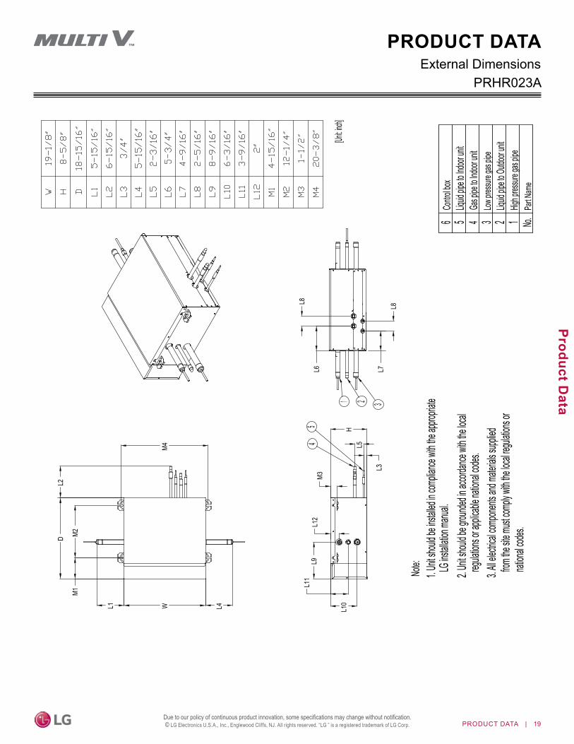
External DimensionsPRHR023A
Contro
l box
6Liq
uid pip
e to Ind
oor un
it5
Gas p
ipe to
Indoor
unit
4Low
press
ure ga
s pipe
3 2Liq
uid pip
e to Ou
tdoor u
nitHig
h pres
sure g
as pip
e
Note:
1. Unit
should
be ins
talled in
comp
liance
with the
appro
priate
LG in
stallati
on ma
nual.
2. Unit
should
be gro
unded
in acco
rdance
with th
e local
regul
ations
or appl
icable n
ational
codes
.3. A
ll elect
rical co
mpone
nts an
d mate
rials su
pplied
from
the site
must c
omply
with the
local r
egulatio
ns or
natio
nal co
des.
[Unit: in
ch]
Part N
ame
No.
54
321
L3
W
D
H
M1M2
M4
M3
L1 L4
L2
L5
L6 L7
L8 L8
L9
L10
L11
L12
1
PRODUCT DATA

20 | PRODUCT DATA
MUL
TI V
Hea
t Rec
over
y Un
it PR
HR*3
A En
gine
erin
g M
anua
l
Due to our policy of continuous product innovation, some specifications may change without notification. © LG Electronics U.S.A., Inc., Englewood Cliffs, NJ. All rights reserved. “LG ” is a registered trademark of LG Corp.
PRHR033AExternal Dimensions
Contro
l box
6
Liquid
pipe to
Indoor
unit
5
Gas p
ipe to
Indoor
unit
4
Low pr
essure
gas p
ipe3 2
Liquid
pipe to
Outdo
or unit
1Hig
h pres
sure g
as pip
e
[Unit: in
ch]
Part N
ame
No.
54
321
L3
W
H
M1M2
M3
L1 L4
L2
L5
L6 L7
L8L8
L8L8
L9
L10
L11
L12
D
M4
Note:
1. Unit
should
be ins
talled in
comp
liance
with the
appro
priate
LG in
stallati
on ma
nual.
2. Unit
should
be gro
unded
in acco
rdance
with th
e local
regul
ations
or appl
icable n
ational
codes
.3. A
ll elect
rical co
mpone
nts an
d mate
rials su
pplied
from
the site
must c
omply
with the
local r
egulatio
ns or
natio
nal co
des.
PRODUCT DATA

PRODUCT DATA | 21
Product Data
Due to our policy of continuous product innovation, some specifications may change without notification. © LG Electronics U.S.A., Inc., Englewood Cliffs, NJ. All rights reserved. “LG ” is a registered trademark of LG Corp.
PRHR043AExternal Dimensions
Contro
l box
6Liq
uid pip
e to Ind
oor un
it5
Gas p
ipe to
Indoor
unit
4Low
press
ure ga
s pipe
3 2Liq
uid pip
e to Ou
tdoor u
nitHig
h pres
sure g
as pip
e[Unit: in
ch]
Part N
ame
No.
54
321
L3
W
H
M1M2
M3
L1 L4
L2
L5
L6 L7
L8L8
L8
L8L8
L8
L9
L10
L11
L12
D
M4
Note:
1. Unit
should
be ins
talled in
comp
liance
with the
appro
priate
LG in
stallati
on ma
nual.
2. Unit
should
be gro
unded
in acco
rdance
with th
e local
regul
ations
or appl
icable n
ational
codes
.3. A
ll elect
rical co
mpone
nts an
d mate
rials su
pplied
from
the site
must c
omply
with the
local r
egulatio
ns or
natio
nal co
des.
1
PRODUCT DATA

22 | PRODUCT DATA
MUL
TI V
Hea
t Rec
over
y Un
it PR
HR*3
A En
gine
erin
g M
anua
l
Due to our policy of continuous product innovation, some specifications may change without notification. © LG Electronics U.S.A., Inc., Englewood Cliffs, NJ. All rights reserved. “LG ” is a registered trademark of LG Corp.
PRHR063AExternal Dimensions
Contro
l box
6Liq
uid pip
e to Ind
oor un
it5
Gas p
ipe to
Indoor
unit
4Low
press
ure ga
s pipe
3Liq
uid pip
e to Ou
tdoor u
nit2
High p
ressur
e gas
pipe[Unit: in
ch]
Part N
ame
No.
45
321
D
M1M2
L2
L1 L4WM4
L9L1
1
L10
M3
H
L3
L5
L6 L7L8
L8
L8L8
L8L8
L8L8
L8L8
L12
1
Note:
1. Unit
should
be ins
talled in
comp
liance
with the
appro
priate
LG in
stallati
on ma
nual.
2. Unit
should
be gro
unded
in acco
rdance
with th
e local
regul
ations
or appl
icable n
ational
codes
.3. A
ll elect
rical co
mpone
nts an
d mate
rials su
pplied
from
the site
must c
omply
with the
local r
egulatio
ns or
natio
nal co
des.
PRODUCT DATA

PRODUCT DATA | 23
Product Data
Due to our policy of continuous product innovation, some specifications may change without notification. © LG Electronics U.S.A., Inc., Englewood Cliffs, NJ. All rights reserved. “LG ” is a registered trademark of LG Corp.
PRHR083AExternal Dimensions
Contro
l box
6Liq
uid pip
e to Ind
oor un
it5
Gas p
ipe to
Indoor
unit
4Low
press
ure ga
s pipe
3Liq
uid pip
e to Ou
tdoor u
nit2
High p
ressur
e gas
pipe[Un
it: inch]
Part N
ame
No.
45
321
D
M1M2
L2
L1 L4W
L9L1
1
L10
M3
H
L3
L5
L6 L7L8
L8
L8L8
L8L8
L8L8
L8L8
L8L8
L8L8
L12
M4
Note:
1. Unit
should
be ins
talled in
comp
liance
with the
appro
priate
LG in
stallati
on ma
nual.
2. Unit
should
be gro
unded
in acco
rdance
with th
e local
regul
ations
or appl
icable n
ational
codes
.3. A
ll elect
rical co
mpone
nts an
d mate
rials su
pplied
from
the site
must c
omply
with the
local r
egulatio
ns or
natio
nal co
des.
1
PRODUCT DATA

24 | PRODUCT DATA
MUL
TI V
Hea
t Rec
over
y Un
it PR
HR*3
A En
gine
erin
g M
anua
l
Due to our policy of continuous product innovation, some specifications may change without notification. © LG Electronics U.S.A., Inc., Englewood Cliffs, NJ. All rights reserved. “LG ” is a registered trademark of LG Corp.
Refrigerant Flow Diagram
A : Switch operation between cooling and heating by two (2) valves.B : Decreases noise following subcooling operation between inlet of one indoor unit and outlet of another indoor unit during simultaneous operation. C : Prevents liquid from entering high pressure vapor valve and heat recovery unit during cooling mode.D : Controls pressure between the high and low pressure vapor piping when operation mode switches.
Low Pressure Vapor Piping
sSolenoid
EEV
Sensor
s C
A
B
D
Liquid Piping
High Pressure Vapor Piping
Vapor Piping
Vapor Piping
Vapor Piping
Vapor Piping
Vapor Piping
Vapor Piping
Vapor Piping
Liquid Piping
Liquid Piping
Liquid Piping
Liquid Piping
Liquid Piping
Liquid Piping
Liquid Piping
Liquid Piping
Vapor Piping
Refrigerant diagram above represents the PRHR083A model. Appearances may differ depending on model.
PRODUCT DATA

PRODUCT DATA | 25
Product Data
Due to our policy of continuous product innovation, some specifications may change without notification. © LG Electronics U.S.A., Inc., Englewood Cliffs, NJ. All rights reserved. “LG ” is a registered trademark of LG Corp.
Acoustic DataSound Pressure Levels
Operation Mode Sound Pressure Levels dB(A)Cooling 31Heating 31
Simultaneous 38Changeover From Cooling to Heating 33Changeover From Heating to Cooling 38
Table 6: PRHR**3A Sound Pressure Levels.
Figure 10: PRHR**3A Sound Pressure Level Diagrams.
• Measurements are taken 4.9 ft. away from the center of the unit.• Sound level will vary depending on a range of factors including the construction
(acoustic absorption coefficient) of a particular room in which the unit was installed.• Sound pressure levels are measured in dB(A) with a tolerance of ±3. • Sound pressure levels are tested in an anechoic chamber under ISO Standard 3745.
Operating Conditions:• Power source: 220V 60Hz• Reference acoustic pressure: 0dB = 20μPa.• Cooling: Indoor Temperature 80.6°F D.B., 66.2°F W.B., Outdoor Temperature 95°F
D.B., 75.2°F W.B.• Heating: Indoor Temperature 68°F D.B., 59°F W.B., Outdoor Temperature 44.6°F
D.B., 42.8°F W.B.
Figure 11: Sound Pressure Measurement Location.
4.9 feet
Microphone
PRODUCT DATAO
ctav
e Ba
nd S
ound
Pre
ssur
e Le
vel (
0dB
= 20μP
a )
Cooling Heating
Changeover from Cooling to Heating
10
20
30
40
50
60
70
80
63 125 250 500 1000 2000 4000 8000
Oct
ave
Band
Sou
nd P
ress
ure
Leve
l (0d
B =
20μP
a )
Octave Band Center Frequency (Hz)
NC-15
NC-20
NC-25
NC-30
NC-35
NC-40
NC-45
NC-50
NC-55
NC-60
NC-65
ApproximateHearing Threshold
NC-70
10
20
30
40
50
60
70
80
63 125 250 500 1000 2000 4000 8000
Oct
ave
Band
Sou
nd P
ress
ure
Leve
l (0d
B =
20μP
a )
Octave Band Center Frequency (Hz)
NC-15
NC-20
NC-25
NC-30
NC-35
NC-40
NC-45
NC-50
NC-55
NC-60
NC-65
ApproximateHearing Threshold
NC-70
10
20
30
40
50
60
70
80
63 125 250 500 1000 2000 4000 8000Octave Band Center Frequency (Hz)
NC-15
NC-20
NC-25
NC-30
NC-35
NC-40
NC-45
NC-50
NC-55
NC-60
NC-65
ApproximateHearing Threshold
10
20
30
40
50
60
70
80
63 125 250 500 1000 2000 4000 8000
Oct
ave
Band
Sou
nd P
ress
ure
Leve
l (0d
B =
20μP
a )
Octave Band Center Frequency (Hz)
NC-15
NC-20
NC-25
NC-30
NC-35
NC-40
NC-45
NC-50
NC-55
NC-60
NC-65
ApproximateHearing Threshold
Changeover from Heating to Cooling

26 | PRODUCT DATA
MUL
TI V
Hea
t Rec
over
y Un
it PR
HR*3
A En
gine
erin
g M
anua
l
Due to our policy of continuous product innovation, some specifications may change without notification. © LG Electronics U.S.A., Inc., Englewood Cliffs, NJ. All rights reserved. “LG ” is a registered trademark of LG Corp.
Accessories
Combining Heat Recovery Ports for Large Indoor Units It is necessary to combine two ports on a system designed for heat recovery operation when installing a single indoor unit with a capacity exceeding 60,000 Btu/h. Two neighboring heat recovery ports are combined using a reverse Y-branch that is then connected to the one large indoor unit (Kit sold separately).
ReducersIt may be necessary to install a reducer if the indoor unit piping or outdoor unit piping is too large or too small for the heat recovery unit connections.
ModelHigh Pressure
Vapor Piping
Low PressureLiquid Piping
Heat RecoveryUnitReducer
PRHR023AO.D. 7/8 (22.2) Ø3/4 (19.05) Ø5/8 (15.88)
Ø1/4 (6.35)O.D. 3/8 (9.52)O.D. 3/4 (19.05) Ø5/8 (15.88)
O.D. 1/2 (12.7) Ø3/8 (9.52)
Ø1/2 (12.7)
O.D. 7/8 (22.2) Ø3/4 (19.05) Ø5/8 (15.88)
O.D. 5/8 (15.88) Ø1/2 (12.7)O.D. 1/2 (12.7) Ø3/8 (9.52)
PRHR033APRHR043APRHR063APRHR083A
O.D. 3/4 (19.05) Ø5/8 (15.88)
O.D. 1-1/8 (28.58) Ø7/8 (22.2) Ø3/4 (19.05)O.D. 5/8 (15.88) Ø1/2 (12.7) Ø3/8 (9.52)
O.D. 5/8 (15.88) Ø1/2 (12.7)
Unit: Inches (mm)
Table 7: Y-Branch for Twinning Large Indoor Units.
Table 8: Reducers for Heat Recovery Units.
PRODUCT DATA
Kit ModelNo� Vapor Pipe Dimensions
Unit: Inch
ARBLN0332116-1/4 (413)
15-3/8 (390)
I.D. 3/4 (19.05)
I.D. 3/4 (19.05)
I.D. 3/4 (19.05) I.D. 1/2 (12.7)
I.D. 1/2 (12.7)
2-3/4 (70)
I.D. 5/8 (15.88)
I.D. 5/8 (15.88)
I.D. 1 (25.4)
I.D. 1 (25.4)
O.D. 1 (25.4)
3-1/8 (80) 4-5/16 (110)
3-1/4 (83)
1 2
3
3
O.D. 3/4 (19.05)O.D. 3/4 (19.05)
1 2
I.D. 7/8 (22.2)I.D. 7/8 (22.2)
I.D. 7/8 (22.2)
I.D. 28.58 (1-1/8)
I.D. 1/2 (12.7)
I.D. 1/2 (12.7)I.D. 1/2 (12.7) (74)
2-15/16
13-1/16 (332)12-5/8 (321)
I.D. 1/4 (6.35)
I.D. 1/4 (6.35)
I.D. 3/8 (9.52)
I.D. 3/8 (9.52)
I.D. 3/8 (9.52)
Liquid Pipe Dimensions
AJR54072930 AJR54072928

APPLICATION GUIDELINESPiping Limitations on page 28Selecting the Best Location / Clearance Requirements on page 36General Mounting on page 38Wiring Guidelines on page 39LGRED°, HRU Compatibility, and Gen 4 DIP Switch Settings on page 44Acronyms on page 45

28 | GUIDELINES
MUL
TI V
Hea
t Rec
over
y Un
it PR
HR*3
A En
gine
erin
g M
anua
l
Due to our policy of continuous product innovation, some specifications may change without notification. © LG Electronics U.S.A., Inc., Englewood Cliffs, NJ. All rights reserved. “LG ” is a registered trademark of LG Corp.
Piping Limitations For Systems Designed for Heat Recovery Operation — MV 5Following pages present Multi V 5 piping limitations and are for illustrative purposes only. Designers MUST use LATS when designing LG VRF systems.
Figure 12: Typical Heat Recovery System Building Layout with Piping Limitations.
Table 9: Piping Limitations for Heat Recovery Operation (See next page).
Length Total pipe length Longest actual pipe length Equivalent pipe length1
A + ΣB + ΣC ≤ 3,280 feet ≤492 feet (656 feet conditional application) ≤574 feet (738 feet conditional application)ℓ Longest pipe length after first branch
≤131 feet (295 feet conditional application)Elevation1 Elevation differential (Outdoor Unit ↔ Indoor Unit)
Height ≤360 feetElevation2 Elevation differential (Indoor Unit ↔ Indoor Unit)
height ≤131 feetElevation3 Elevation differential (Indoor Unit ↔ Heat Recovery Unit) [single heat recovery unit or series heat recovery units]
49 feetElevation4 Elevation differential (Indoor Unit ↔ Indoor Unit [connected to same Heat Recovery Unit])
49 feetheight1 Elevation differential (Outdoor Unit ↔ Outdoor Unit)
≤16.4 feetDistance between Outdoor Unit to Outdoor Unit ≤33 feet (Max. 43 feet for Outdoor Unit ≥12 tons)
Distance between fittings and Indoor Unit ≥20 inchesDistance between fittings and Y-branches / Headers ≥20 inches
Distance between two Y-branches / Headers ≥20 inchesHeight differential between two Heat Recovery Units if installed with a Y-branch ≤98 feet
Height differential between two series-piped Heat Recovery Units ≤16 feet1Assume equivalent pipe length of Y-branch is 1.6 feet, and equivalent pipe length of header is 3.3 feet.
Elev
ation
Diffe
rent
ial H
RU to
HRU
: 98'
Max. Total Equivalent Piping Length: 3,280'
Elevation Differential Two IDUs Connected to One HRU: 49'
Elevation Differential ODU to IDU: 360'Elevation Differential IDU to IDU: 131'Lo
nges
t pipe
leng
th: 65
6' ac
tual (7
38' e
quiv.
)
Elev
ation
Diffe
rent
ialHR
U to
IDU:
49'
APPLICATION GUIDELINES

GUIDELINES | 29
Application G
uidelines
Due to our policy of continuous product innovation, some specifications may change without notification. © LG Electronics U.S.A., Inc., Englewood Cliffs, NJ. All rights reserved. “LG ” is a registered trademark of LG Corp.
Following pages present Multi V 5 piping limitations and are for illustrative purposes only. Designers MUST use LATS when designing LG VRF systems.
Table 10: Main Pipe (A) Diameters from Outdoor Unit to First Y-branch.
Example: Triple-frame system, four (4) heat recovery units, one (1) header, and twelve (12) indoor units connected�ODU: Outdoor Units.HRU: Heat Recovery Units.IDU: Indoor units. A: Main Pipe from Outdoor Unit to First Y-branch.B: Heat Recovery Unit to Heat Recovery Unit, Y-branch to Heat Recovery Unit, Heat Recovery Unit to Header, or Y-branch to Y-branch.C: Heat Recovery Unit / Header to Indoor Unit.
• Always reference the LATS HVAC software report (latest version).
• Larger-capacity outdoor units must be the mas-ter in a multi-frame system.
• Master outdoor unit capacity must be greater than or equal to the slave1 outdoor unit capac-ity, and, where applicable, slave1 outdoor unit capacity must be greater than or equal to the slave2 outdoor unit capacity.
• Connection piping from branch to branch cannot exceed the main pipe diameter (A) used by the outdoor unit.
• Install the header branches or heat recovery units so that the pipe distances between the between the connected indoor units are minimized. Large differences in pipe distances can cause indoor unit performances to fluctuate.
• Y-branches and other header branches cannot be installed downstream of the initial header branch. • Total capacity of indoor units in series connection of heat recovery units ≤230,000 Btu/h.• If large capacity indoor units (>60,000 Btu/h with piping sizes >5/8Ø / 3/8Ø) are installed, the valve group setting must be used. (Refer to
the PCB of the heat recovery unit for the valve group control setting.)
Example of Pipe Sizing When Installing a Heat Recovery System
Case 1: Maximum height is 131 feet if installed with a Y-branch.Case 2: Maximum height is 16 feet in heat recovery control unit series connection.
*
Elev
ation
1 ≤36
0 fee
t
Elev
ation
2 ≤13
1 fee
t
Master ODU
Slave1ODU
Slave2ODU
Case 1
Case 2
A
Y-branch (first)
B
C
Closest IDU
CHRU
C
CB
B
CC
C CB
B C
C xHeader
C C
To Indoor UnitsToOutdoor Unit
Y-branchhe
ight1
≤16.4
feet
B
Y-branch (second)
HRU
HRU
HRU
IDU
IDU
IDU
IDU
IDU
IDU
IDU
IDU IDU IDU FarthestIDU
Brazedcap
98 fe
et
16 fe
etEl
evati
on3 4
9 fee
t
Elev
ation
4 49 f
eet
Piping Limitations For Systems Designed for Heat Recovery Operation — MV 5APPLICATION GUIDELINES
ODU Capacity
(ton)
Standard Pipe Diameter Pipe diameter when pipe length is ≥295 feet or when height differential (ODU ↔ IDU) is >164 feet
Liquid Pipe (inches OD)
Low Pressure Vapor Pipe (inches OD)
High Pressure Vapor Pipe (inches OD)
Liquid Pipe (inches OD)
Low Pressure Vapor Pipe (inches OD)
High Pressure Vapor Pipe (inches OD)
6 3/8Ø 3/4Ø 5/8Ø 1/2Ø No Increase No Increase8 3/8Ø 7/8Ø 3/4Ø 1/2Ø No Increase No Increase
10 1/2Ø 1-1/8Ø 3/4Ø 5/8Ø No Increase No Increase12 1/2Ø 1-1/8Ø 7/8Ø 5/8Ø No Increase No Increase14 5/8Ø 1-1/8Ø 7/8Ø 3/4Ø No Increase No Increase
16-18 5/8Ø 1-1/8Ø 1-1/8Ø 3/4Ø No Increase No Increase20 5/8Ø 1-3/8Ø 1-1/8Ø 3/4Ø No Increase No Increase
22-28 3/4Ø 1-3/8Ø 1-1/8Ø 7/8Ø No Increase No Increase30-42 3/4Ø 1-5/8Ø 1-1/8Ø 7/8Ø No Increase No Increase

30 | GUIDELINES
MUL
TI V
Hea
t Rec
over
y Un
it PR
HR*3
A En
gine
erin
g M
anua
l
Due to our policy of continuous product innovation, some specifications may change without notification. © LG Electronics U.S.A., Inc., Englewood Cliffs, NJ. All rights reserved. “LG ” is a registered trademark of LG Corp.
Table 11: Refrigerant Pipe (B) Diameters between Y-branches and Y-branches / Heat Recovery Unit / Headers.
Following pages present Multi V 5 piping limitations and are for illustrative purposes only. Designers MUST use LATS when designing LG VRF systems.
Downstream IDU total capacity (Btu/h) Liquid pipe (inches OD)
Vapor pipe (inches OD)Low pressure High pressure
≤19,100 1/4Ø 1/2Ø 3/8Ø<54,600 3/8Ø 5/8Ø 1/2Ø<76,400 3/8Ø 3/4Ø 5/8Ø<114,700 3/8Ø 7/8Ø 3/4Ø<172,000 1/2Ø 1-1/8Ø 7/8Ø<229,400 5/8Ø 1-1/8Ø 7/8Ø<248.500 5/8Ø 1-3/8Ø 1-1/8Ø<344,000 3/4Ø 1-3/8Ø 1-1/8Ø<592,500 3/4Ø 1-5/8Ø 1-3/8Ø
Table 12: Indoor Unit Connecting Pipe from Branch (C).Indoor Unit Capacity1 Liquid pipe (inches OD) Vapor pipe (inches OD)
≤19,100 1/4Ø 1/2Ø≤54,600 3/8Ø 5/8Ø≤76,400 3/8Ø 3/4Ø≤95,900 3/8Ø 7/8Ø
19,600-24,200 Btu/h 4-way 3 feet x 3 feet Cassette and 15,400-24,200 Btu/h High Static Ducted IDUs have 3/8Ø (liquid) and 5/8Ø (vapor).
Conditional Applications Conditional applications are computed in LATS� See below for an explanation of when pipes are upsized�If the equivalent length between the first Y-branch to the farthest indoor unit is >131 feet (maximum 295 feet):• Pipe segment diameters between the first branch and the last branch must be sized up by one. This applies to both liquid and low / high
vapor pipes. If the next size up is not available, or if the pipe segment diameters are the same as main pipe (A) diameters, sizing up is not possible.
• While calculating total refrigerant piping length, pipe (B) segment lengths between the first Y-branch and second Y-branch, and between the second Y-branch and the heat recovery unit must be calculated by two.
• Length of pipe (C) from each indoor unit to the closest Y-branch, header, or heat recovery unit ≤49 feet.• [Length of pipe from outdoor unit to farthest indoor unit (A+B+C)] - [Length of pipe from outdoor unit to closest indoor unit (A+B+C)] ≤131
feet.
Piping Limitations For Systems Designed for Heat Recovery Operation — MV 5APPLICATION GUIDELINES

GUIDELINES | 31
Application G
uidelines
Due to our policy of continuous product innovation, some specifications may change without notification. © LG Electronics U.S.A., Inc., Englewood Cliffs, NJ. All rights reserved. “LG ” is a registered trademark of LG Corp.
Piping Limitations For Systems Designed for Heat Recovery Operation — MV IV WaterFollowing pages present Multi V IV Water piping limitations and are for illustrative purposes only. Designers MUST use LATS when designing LG VRF systems.
APPLICATION GUIDELINES
Figure 13: Typical Heat Recovery System Building Layout with Piping Limitations.
ElevationDifferentialWSU to IDU: 164'
Maximum Total Piping Length: 1,640'
ElevationDifferentialIDU to IDU onsame HRU: 49'
Elevation Differential
IDU to IDU: 131'
Longest pipe length: 656' actual (738' equiv)
ElevationDifferential HRU to HRU: 98'
Table 13: Piping Limitations for Heat Recovery Operation.
Length Total pipe length Longest actual pipe length Equivalent pipe length1A + ΣB + ΣC ≤ 1,640 feet ≤656 feet ≤738 feet
ℓ Longest pipe length after first branch≤131 feet (295 feet conditional application)
Elevation 1 Elevation differential (Water Source Unit ↔ Indoor Unit)Height ≤164 feet
Elevation 2 Elevation differential (Indoor Unit ↔ Indoor Unit) [IDUs connected to separate HRUs which are parallel (Y-branch) connected.]Height ≤131 feet
Elevation 3 Elevation differential (Indoor Unit ↔ Connected HRU or Series Connected HRU]Height ≤49 feet
Elevation 4 Elevation differential (Indoor Unit ↔ Indoor Unit [connected to same Heat Recovery Unit])Height ≤49 feet
Elevation 5 Elevation differential (Highest WSU ↔ Lowest WSU unit)Height ≤16 feet
Distance between WSU to WSU ≤33 feetDistance between fittings and Indoor Unit ≥20 inches
Distance between fittings and Y-branches / Headers ≥20 inchesDistance between two Y-branches / Headers ≥20 inches
Height differential between two Heat Recovery Units if installed with a Y-branch ≤98 feetHeight differential between two series-piped Heat Recovery Units ≤16 feet
1Assume equivalent pipe length of Y-branch is 1.6 feet, and equivalent pipe length of header is 3.3 feet.

32 | GUIDELINES
MUL
TI V
Hea
t Rec
over
y Un
it PR
HR*3
A En
gine
erin
g M
anua
l
Due to our policy of continuous product innovation, some specifications may change without notification. © LG Electronics U.S.A., Inc., Englewood Cliffs, NJ. All rights reserved. “LG ” is a registered trademark of LG Corp.
Piping Limitations For Systems Designed for Heat Recovery Operation — MV IV WaterFollowing pages present Multi V IV Water piping limitations and are for illustrative purposes only. Designers MUST use LATS when designing LG VRF systems.
APPLICATION GUIDELINES
WSU: Water Source UnitHRU: Heat Recovery UnitIDU: Indoor UnitA: Main Pipe from Water Source Unit to First Y-branch.B: HRU to HRU, Y-branch to HRU, HRU to Header, or Y-branch to Y-branch.C: Heat Recovery Unit / Header to Indoor Unit.
Example of Pipe Sizing When Installing a Heat Recovery SystemExample: Triple-frame system, four (4) heat recovery units, one (1) header, and twelve (12) indoor units connected
• Always reference the LATS HVAC software report.
• Largest capacity WSU must be the master in a multi-frame system.
• Master WSU capacity must be greater than or equal to the slave1 WSU capacity, and, where applicable, slave1 WSU capacity must be greater than or equal to the slave2 WSU capacity.
• Connection piping from branch to branch cannot exceed the main pipe diameter (A) used by the water source unit. • Install the header branches or heat recovery units so that the pipe distances between the between the connected indoor units are mini-
mized. Large differences in pipe distances can cause indoor unit performances to fluctuate. • Y-branches and other header branches cannot be installed downstream of the initial header branch. • Total capacity of indoor units in series connection of heat recovery units ≤230,000 Btu/h.• If large capacity indoor units (>60,000 Btu/h with piping sizes >5/8Ø / 3/8Ø) are installed, the valve group setting must be used. (Refer to
the PCB of the heat recovery unit for the valve group control setting.)
Figure 14: Heat Recovery Triple-Frame Connections.
Elev
ation
1 ≤
164 f
t.
Elev
ation
2 ≤
131 f
t.
Slave 1 WSUSlave 2 WSU
A
Y-branch (first)
BC
Closest IDU
C
HRU
C
C
B
B
CC
C
C
B
B C
Cx
Header
C C
Elevation 5 ≤16 ft
BY-branch (second)
HRU
HRU
HRU
IDU
IDU
IDU
IDUIDU
IDU
IDU
IDU IDU IDU FarthestIDU
Brazedcap
98 ft.
16 fe
et
Master WSU
Elev
ation
3 ≤
49 ft.
Multi-FrameConnector
To indoor unitsTo WSU
Y-branch
Elev
ation
4 49
ft.

GUIDELINES | 33
Application G
uidelines
Due to our policy of continuous product innovation, some specifications may change without notification. © LG Electronics U.S.A., Inc., Englewood Cliffs, NJ. All rights reserved. “LG ” is a registered trademark of LG Corp.
Piping Limitations For Systems Designed for Heat Recovery Operation — MV IV WaterFollowing pages present Multi V IV Water piping limitations and are for illustrative purposes only. Designers MUST use LATS when designing LG VRF systems.
APPLICATION GUIDELINES
WSU Capacity
(ton)
Pipe diameter when equivalent pipe length from WSU to farthest IDU is <295 ft.
Pipe diameter when equivalent pipe length from WSU to farthest IDU is >295 ft.
Liquid Pipe (inches OD)
Low Pressure Vapor Pipe (inches OD)
High Pressure Vapor Pipe (inches OD)
Liquid Pipe (inches OD)
Low Pressure Vapor Pipe (inches OD)
High Pressure Vapor Pipe (inches OD)
6 3/8 7/8 3/4 1/2 7/8 3/48 3/8 7/8 3/4 1/2 1-1/8 3/4
10 1/2 1-1/8 3/4 5/8 1-1/8 3/412 1/2 1-1/8 3/4 5/8 1-1/8 3/414 1/2 1-1/8 3/4 5/8 1-1/8 3/416 1/2 1-1/8 3/4 5/8 1-1/8 3/418 3/4 1-3/8 1-1/8 7/8 1-3/8 1-1/820 3/4 1-3/8 1-1/8 7/8 1-3/8 1-1/824 3/4 1-3/8 1-1/8 7/8 1-3/8 1-1/828 3/4 1-3/8 1-1/8 7/8 1-3/8 1-1/830 3/4 1-5/8 1-3/8 7/8 1-5/8 1-3/832 3/4 1-5/8 1-3/8 7/8 1-5/8 1-3/836 3/4 1-5/8 1-3/8 7/8 1-5/8 1-3/840 3/4 1-5/8 1-3/8 7/8 1-5/8 1-3/848 3/4 1-5/8 1-3/8 7/8 1-5/8 1-3/8
Table 14: Main Pipe (A) Diameter from Water Source Unit to First Y-branch.
Downstream IDU total capacity (Btu/h) Liquid pipe (inches OD) Vapor pipe (inches OD)Low pressure High pressure
≤19,100 1/4 1/2 3/8<54,600 3/8 5/8 1/2<76,400 3/8 3/4 5/8<112,600 3/8 7/8 3/4<160,400 1/2 1-1/8 7/8<242,300 5/8 1-1/8 1-1/8<354,900 3/4 1-3/8 1-1/8≥354,900 3/4 1-5/8 1-3/8
Table 15: Refrigerant Pipe (B) Diameter between Y-branches and Y-branches / Heat Recovery Unit / Headers.
Table 16: Indoor Unit Connecting Pipe from Branch (C).Indoor Unit Capacity1 Liquid pipe (inches OD) Vapor pipe (inches OD)
≤19,100 1/4 1/2≤54,600 3/8 5/8≤76,400 3/8 3/4
19,600-24,200 Btu/h 4-way 3 feet x 3 feet Cassette and 15,400-24,200 Btu/h High Static Ducted IDUs have 3/8Ø (liquid) and 5/8Ø (vapor).
Conditional Applications Conditional applications are computed in LATS� See below for an explanation of when pipes are upsized�If the equivalent length between the first Y-branch to the farthest indoor unit is >131 feet (maximum 295 feet):• Pipe segment diameters between the first branch and the last branch must be sized up by one. This applies to both liquid and low / high
vapor pipes. If the next size up is not available, or if the pipe segment diameters are the same as main pipe (A) diameters, sizing up is not possible.
• While calculating total refrigerant piping length, pipe (B) segment lengths between the first Y-branch and second Y-branch, and between the second Y-branch and the heat recovery unit must be calculated by two.
• Length of pipe (C) from each indoor unit to the closest Y-branch, header, or heat recovery unit ≤131 feet.• [Length of pipe from water source unit to farthest indoor unit (A+B+C)] - [Length of pipe from water source unit to closest indoor unit
(A+B+C)] ≤131 feet.

34 | GUIDELINES
MUL
TI V
Hea
t Rec
over
y Un
it PR
HR*3
A En
gine
erin
g M
anua
l
Due to our policy of continuous product innovation, some specifications may change without notification. © LG Electronics U.S.A., Inc., Englewood Cliffs, NJ. All rights reserved. “LG ” is a registered trademark of LG Corp.
Piping Limitations For Systems Designed for Heat Recovery Operation — MV SFollowing pages present Multi V S piping limitations and are for illustrative purposes only. Designers MUST use LATS when designing LG VRF systems.
APPLICATION GUIDELINES
Figure 15: Typical Multi V S Heat Recovery ARUB060GSS4 System Building Layout Listing the Piping Limitations — When the Outdoor Unit is Above the Indoor Units.
Figure 16: Typical Multi V S Heat Recovery ARUB060GSS4 System Building Layout Listing the Piping Limitations — When the Outdoor Unit is Below the Indoor Units.
Elev
ation
Diffe
rent
ial H
RU to
HRU
:98'
Max. Total Equivalent Piping Length: 984'
Elevation Differential Two IDUs Connected to One HRU: 49'
Elevation Differential ODU to IDU: 164'Elevation Differential IDU to IDU: 49'Lo
nges
t pipe
leng
th: 49
2' ac
tual (5
74' e
quiv.
)
Elev
ation
Diffe
rent
ialHR
U to
IDU:
49'
Elev
ation
Diffe
rent
ial H
RU to
HRU
: 98'
Max. Total Equivalent Piping Length: 984'
Elevation Differential Two IDUs Connected to One HRU: 49'
Elevation Differential ODU to IDU: 131'
Elevation Differential IDU to IDU: 49'
Long
est p
ipe le
ngth:
492'
actua
l (574
' equ
iv.)
Elev
ation
Diffe
rent
ialHR
U to
IDU:
49'
Table 17: Piping Limitations for ARUB060GSS4 Heat Recovery Systems (See next page).
Length Total pipe length Longest actual pipe length Equivalent pipe lengthA + ΣB + ΣC ≤984 feet ≤492 feet ≤574 feet
ℓ Longest pipe length after first branch≤131 feet
Elevation1 Elevation differential (Outdoor Unit ↔ Indoor Unit)Height ≤164 feet (Outdoor Unit Above Indoor Unit); Height ≤131 feet (Outdoor Unit Below Indoor Unit)
Elevation2 Elevation differential (Indoor Unit ↔ Indoor Unit)height ≤49 feet
Elevation3 Elevation differential (Indoor Unit ↔ Heat Recovery Unit)49 feet
Elevation4 Elevation differential (Indoor Unit ↔ Indoor Unit [connected to same Heat Recovery Unit])49 feet
Distance between fittings and Indoor Unit ≥20 inchesDistance between fittings and Y-branches / Headers ≥20 inches
Distance between two Y-branches / Headers ≥20 inchesHeight differential between two Heat Recovery Units if installed with a Y-branch ≤98 feet
Height differential between two series-piped Heat Recovery Units ≤16 feet

GUIDELINES | 35
Application G
uidelines
Due to our policy of continuous product innovation, some specifications may change without notification. © LG Electronics U.S.A., Inc., Englewood Cliffs, NJ. All rights reserved. “LG ” is a registered trademark of LG Corp.
Piping Limitations For Systems Designed for Heat Recovery Operation — MV SFollowing pages present Multi V S piping limitations and are for illustrative purposes only. Designers MUST use LATS when designing LG VRF systems.
APPLICATION GUIDELINES
Case 1: Maximum height is 131 feet if installed with a Y-branch.Case 2: Maximum height is 16 feet in heat recovery control unit series connection.
*El
evati
on1 H
eight
≤164
feet
(Outd
oor U
nit A
bove
Indo
or U
nit);
Heigh
t ≤13
1 fee
t (Ou
tdoor
Unit
Belo
w Ind
oor U
nit)
Elev
ation
2 ≤49
feet
Case 1
Case 2
A
Y-branch (first)
B
C
Closest IDU
CHRU
C
CB
B
CC
C CB
B C
C xHeader
C C
B
Y-branch (second)
HRU
HRU
HRU
IDU
IDU
IDU
IDU
IDU
IDU
IDU
IDU IDU IDU FarthestIDU
Brazedcap
98 fe
et
16 fe
etEl
evati
on3 ≤
49 fe
et
Elev
ation
4 ≤49
feet
Example: Heat recovery system with four (4) heat re-covery units, one (1) header, and twelve (12) indoor units connectedODU: Outdoor Units.HRU: Heat Recovery Units.IDU: Indoor units. A: Main Pipe from Outdoor Unit to First Y-branch.B: Heat Recovery Unit to Heat Recovery Unit, Y-branch to Heat Recovery Unit, Heat Recovery Unit to Header, or Y-branch to Y-branch.C: Heat Recovery Unit / Header to Indoor Unit.
• Always reference the LATS Multi V software report. • Connection piping from branch to branch cannot exceed the
main pipe diameter (A) used by the outdoor unit. • Install the header branches or heat recovery units so that
the pipe distances between the connected indoor units are minimized. Large differences in pipe distances can cause indoor unit performances to fluctuate.
• Y-branches and other header branches cannot be installed downstream of the initial header branch.
• If large capacity indoor units (>60,000 Btu/h with piping sizes >5/8Ø / 3/8Ø) are installed, the valve group setting must be used. (Refer to the PCB of the heat recovery unit for the valve group control setting.)
Pipe Diameter when pipe length is ≤295 feet Pipe diameter when pipe length is ≥295 feetLiquid Pipe (inches OD)
Low Pressure Vapor Pipe (inches OD)
High Pressure Vapor Pipe (inches OD)
Liquid Pipe (inches OD)
Low Pressure Vapor Pipe (inches OD)
High Pressure Vapor Pipe (inches OD)
3/8Ø 3/4Ø 5/8Ø 1/2Ø 7/8Ø 3/4Ø
Table 18: Main Pipe (A) Diameters from ARUB060GSS4 Heat Recovery Outdoor Unit to First Y-branch.
Downstream IDU total capacity (Btu/h) Liquid pipe (inches OD) Vapor pipe (inches OD)≤19,100 1/4Ø 1/2Ø<54,600 3/8Ø 5/8Ø<76,400 3/8Ø 3/4Ø
Table 19: Refrigerant Pipe (B) Diameters between Y-branches and Y-branches / Heat Recovery Unit / Headers.
Indoor Unit Capacity1 Liquid pipe (inches OD) Vapor pipe (inches OD)≤19,100 1/4Ø 1/2Ø≤54,600 3/8Ø 5/8Ø≤76,400 3/8Ø 3/4Ø
19,600-24,200 Btu/h 4-way 3 feet x 3 feet Cassette and 15,400-24,200 Btu/h High Static Ducted IDUs have 3/8Ø (liquid) and 5/8Ø (vapor).
Table 20: Indoor Unit Connecting Pipe from Branch (C).
Conditional ApplicationsConditional application are computed in LATS� See below for an explanation of when pipes are upsized�When one or both conditions listed below are present, the diameter of main pipe (A) must be increased. • If equivalent length between the outdoor unit and the farthest indoor unit is ≥295 feet, the diameters of the liquid, high pressure vapor, and
low pressure vapor pipes must be sized up.• If elevation differential between the outdoor unit and the farthest indoor unit is ≥164 feet, the diameter of only the liquid pipe must be sized
up.
Example of Pipe Sizing When Installing a Heat Recovery System

36 | GUIDELINES
MUL
TI V
Hea
t Rec
over
y Un
it PR
HR*3
A En
gine
erin
g M
anua
l
Due to our policy of continuous product innovation, some specifications may change without notification. © LG Electronics U.S.A., Inc., Englewood Cliffs, NJ. All rights reserved. “LG ” is a registered trademark of LG Corp.
Selecting the Best Location / Clearance Requirements
Selecting the Best Location / Clearance Requirements
Select an installation space for the heat recovery unit that meets the following conditions:• Install the heat recovery unit indoors in a level and upright position.• Ensure there is enough space in the installation area for service access.• Install the heat recovery unit in a location where any sound it may generate will not disturb occupants in the surrounding rooms.• Install the refrigerant piping and electrical wiring system in an easily accessible location.
Dont’s• Refrigerant pipes must not exceed lengths specified by LG Electronics.• Do not install the heat recovery unit in a location where it would be subjected to strong radiation heat from heat sources.• Avoid an installation environment where oil splattering or vapor spray may occur.• Avoid an installation environment where high-frequency electric noise could occur.• Condensate drain piping is not required.
Heat recovery units are for use with systems designed for heat recovery operation only.
Figure 17: PRHR023A to 043A Clearance Requirements.
11-13/16
≥11-13/16
11-13/16Service Space Service Space
Service Space
20-3/8
7
12-1/
4
1
2
3
≥4 Service Space
4-15/16
5-13/1
6
6
54
3/42-1
3/16
15-5/163-5/8 6-15/16
Access Panel(Service Space)
19-1/8
5-15/16
6-1/28-9/16
Unit: Inch
≥4 Service Space
5-15/1619-1/8
Access Panel(≥10 Inch Service Space)
10
No. Component Name Connection Size (in.) / TypePRHR023A PRHR033A PRHR043A
1 Low Pressure Vapor Pipe Connection Port 7/8 Braze 1-1/8 Braze 1-1/8 Braze2 High Pressure Vapor Pipe Connection Port 3/4 Braze 7/8 Braze 7/8 Braze3 Liquid Pipe Connection Port 3/8 Braze 1/2 Braze 5/8 Braze4 Indoor Unit Vapor Pipe Connection Port 5/8 Braze 5/8 Braze 5/8 Braze5 Indoor Unit Liquid Pipe Connection Port 3/8 Braze 3/8 Braze 3/8 Braze6 Control Box – – –7 Metal Hanger Bracket (Field-Supplied Suspension Bolt) 5/16 or 7/16 5/16 or 7/16 5/16 or 7/16
Table 21: PRHR023A to 043A Heat Recovery Unit Components.
APPLICATION GUIDELINES

GUIDELINES | 37
Application G
uidelines
Due to our policy of continuous product innovation, some specifications may change without notification. © LG Electronics U.S.A., Inc., Englewood Cliffs, NJ. All rights reserved. “LG ” is a registered trademark of LG Corp.
Figure 18: PRHR063A and PRHR083A Clearance Requirements.
No. Component Name Connection Size (in. )/ TypePRHR063A PRHR083A
1 Low Pressure Vapor Pipe Connection Port 1-1/8 Braze 1-1/8 Braze2 High Pressure Vapor Pipe Connection Port 7/8 Braze 7/8 Braze3 Liquid Pipe Connection Port 5/8 Braze 5/8 Braze4 Indoor Unit Vapor Pipe Connection Port 5/8 Braze 5/8 Braze5 Indoor Unit Liquid Pipe Connection Port 3/8 Braze 3/8 Braze6 Control Box – –7 Metal Hanger Bracket (Field-Supplied Suspension Bolt) 5/16 or 7/16 5/16 or 7/16
≥11-13/16
≥11-13/16
≥11-13/16
Service Space Service Space
Service Space
7
12-1/
4
32-1/2
31-1/46-5/16 6-5/16
8-9/16
6-1/2
1
2
3
3/42-3
/16
15-5/163-5/8 6-15/16
5-13/1
6
4-15/1654
6
31-1/4
≥4 Service Space
≥4 Service Space
Unit: Inch
Access Panel(Service Space)
Access Panel(≥10 Inch Service Space)
10
Table 22: PRHR063A and PRHR083A Heat Recovery Unit Components.
• Include an access panel at the side of the heat recovery unit where the control box is located.• If reducers are used, service space must be increased equal to the dimensions of the reducer.
Selecting the Best Location / Clearance RequirementsAPPLICATION GUIDELINES
Selecting the Best Location / Clearance Requirements, Continued�

38 | GUIDELINES
MUL
TI V
Hea
t Rec
over
y Un
it PR
HR*3
A En
gine
erin
g M
anua
l
Due to our policy of continuous product innovation, some specifications may change without notification. © LG Electronics U.S.A., Inc., Englewood Cliffs, NJ. All rights reserved. “LG ” is a registered trademark of LG Corp.
• The threaded suspension bolts and other hardware must be securely tightened to prevent the unit from falling from its installation location. There is a risk of equipment damage.
• Do not damage power wiring during installation. There is a risk of equipment malfunction, which may result in property damage.• The heat recovery unit MUST be installed so that its top faces up. If not, the incorrect installation may cause unit failure.
Ceiling
Top of HRUTop of HRU
Top of HRU
The following parts are field supplied:• Six-Sided Nuts: 5/16" (M8) or 7/16" (M10)• Flat Washers: 7/16" (M10)• Suspension Bolts: 5/16" (M8) or 7/16" (M10)
General Mounting Procedure1. Select and mark the area where the anchors / suspension bolts
are to be placed on the ceiling.
2. Drill the holes for the anchors / suspension bolts as indicated.
3. Install the heat recovery unit horizontally on the metal hanger brackets with its top facing up. Use a level—the unit must be within ±5° from front to back and from left to right. Tighten all anchors, nuts, and bolts.
1 Anchor
2 Plate Washer
3 Spring Washer4 Nut
5 SuspensionBolt
Old Building New Building
Six-Sided Nut5/16 (M8) or 7/16 (M10)
Hanger metalMetal Hanger Bracket
Flat washerFlat Washer7/16 (M10)
Suspension Bolt5/16 (M8) or 7/16 (M10)
• The threaded suspension bolts and other hardware must be se-curely tightened to prevent the unit from falling from its installation location. There is a risk of personal injury from falling equipment.
• Do not damage power wiring during installation. There is risk of electric shock, which may result in physical injury or death.
Figure 19: Drilling the Holes for the Anchors / Suspension Bolts.
Figure 20: Suspension Bolts Installation.
Figure 21: Old Versus New Building Suspension Bolt Installation.
Figure 22: Installing the Heat Recovery Unit Top Side Up.
General MountingAPPLICATION GUIDELINES

GUIDELINES | 39
Application G
uidelines
Due to our policy of continuous product innovation, some specifications may change without notification. © LG Electronics U.S.A., Inc., Englewood Cliffs, NJ. All rights reserved. “LG ” is a registered trademark of LG Corp.
General Power Wiring / Communications Cable Guidelines• Follow manufacturer’s circuit diagrams displayed on the inside of the control box cover.• Have a separate power supply for the heat recovery units / indoor units.• Provide a circuit breaker switch between the power source and the heat recovery unit.• Confirm power source specifications.• Confirm that the electrical capacity is sufficient.• Starting current must be maintained ±10 percent of the rated current marked on the name plate.• Confirm wiring / cable thickness specifications:
• Power wiring is field supplied. Wire size is selected based on the larger MCA value, and must comply with the applicable local and national codes.
• Communication cable between Master ODU to IDUs / HRUs to be 18 AWG, 2-conductor, twisted, stranded, shielded. Ensure the com-munication cable shield is properly grounded to the Master ODU chassis only. Do not ground the ODU to IDUs / HRUs communication cable at any other point. Wiring must comply with all applicable local and national codes.
• It is recommended that a circuit breaker is installed, especially if conditions could become wet or moist.• Include a disconnect in the power wiring system, add an air gap contact separation of at least 1/8 inch in each active (phase) conductor.• Any openings where the field wiring enters the cabinet must be completely sealed.
• Terminal screws may loosen during transport. Properly tighten the terminal connections during installation or risk equipment malfunction or property damage.
• Loose wiring may cause unit malfunction, the wires to burnout or the terminal to overheat and catch fire. There is a risk of equipment mal-function or property damage.
• Confirm that the electrical capacity is sufficient. A voltage drop may cause magnetic switch vibration, fuse breaks, or disturbance to the normal function of an overload protection device.
• Terminal screws may loosen during transport. Properly tighten the terminal connections during installation or risk electric shock, physical injury or death.
• Loose wiring may cause the wires to burnout or the terminal to overheat and catch fire. There is a risk of electric shock, physical injury or death.
Wiring GuidelinesAPPLICATION GUIDELINES
Power Wiring and Communications Cable Connections1. Open (disassemble) the heat recovery unit control box cover from the bottom.2. Insert the power wiring / communications cable from the outdoor unit using the designated path in the heat recovery unit.3. Connect each wire to its appropriate terminal on the heat recovery unit control board. Verify that the color and terminal numbers from the
outdoor unit wiring match the color and terminal numbers on the heat recovery unit.4. Secure the power wiring / communications cable.
Figure 23: Opening the Heat Recovery Control Unit Control Box Cover. Figure 24: Heat Recovery Unit Control Box With the Cover Removed.

40 | GUIDELINES
MUL
TI V
Hea
t Rec
over
y Un
it PR
HR*3
A En
gine
erin
g M
anua
l
Due to our policy of continuous product innovation, some specifications may change without notification. © LG Electronics U.S.A., Inc., Englewood Cliffs, NJ. All rights reserved. “LG ” is a registered trademark of LG Corp.
Figure 25: Close Up of Heat Recovery Unit Terminal Block.
Master Outdoor Unit Terminal Block
Heat Recovery Unit Terminal BlockL(L1) N(L2) A B
Power Supply Communication Cable (Heat Recovery Unit to Outdoor Unit)
SODU. B SODU. A IDU. B IDU. A CEN. B CEN. A DRY1 DRY2 GND 12V
Wiring GuidelinesAPPLICATION GUIDELINES
Figure 26: Location / Path of Power Wiring / Communications Cable Terminals in Heat Recovery Units.
Power Wiring and Communications Cable Connections, Continued�
Lock Nut
Conduit L(L1)N(L2)
Power Supply(208/230V)
AB
Communication

GUIDELINES | 41
Application G
uidelines
Due to our policy of continuous product innovation, some specifications may change without notification. © LG Electronics U.S.A., Inc., Englewood Cliffs, NJ. All rights reserved. “LG ” is a registered trademark of LG Corp.
Figure 27: Example of a Typical Multi V 5 Heat Recovery System Power Wiring and Communications Cable Schematic.
Switch
Communication Line(2-wire Cable)
Power Line (3-wire Cable)
Communication Line (3-wire Cable)
Power Line (2-wire Cable)
Power Line (2-wire Cable)
Power Line (2-wire Cable)
Power Line (2-wire Cable)
Master
Indoor Units
Power supply3 Phase 3 Wires
60Hz 208-230V or60Hz 460V
Power supply1 Phase 60Hz
208-230V
Main Switch
Slave1 Slave2
Switch Switch
Pull box(Installeroption)
Pull box(Installeroption)
Pull box(Installeroption)
Power Line (2-wire Cable)
R(L1) S(L2) T(L3 R) (L1) S(L2) T(L3 R) (L1) S(L2) T(L3)
L1 L2
FusedDisconnect
FusedDisconnect
FusedDisconnect
Disconnect
HR unit
• Ground wiring is required to prevent accidental electrical shock during current leakage, communication problems from electrical noise, and motor current leakage. Do not connect the ground line to the pipes. There is risk of fire, electric shock, explosion, physical injury or death.
• Install a main shutoff switch that interrupts all power sources simultaneously. There is risk of fire, electric shock, explosion, physical injury or death.
• Communication cable between Master ODU to Slave ODU(s), and Master ODU to IDUs / HRUs to be 18 AWG, 2-conductor, twisted, strand-ed, shielded. Ensure the communication cable shield is properly grounded to the Master ODU chassis only. Do not ground the ODU to IDUs / HRUs communication cable at any other point. Wiring must comply with all applicable local and national codes. Inadequate connec-tions may generate heat, cause a fire, and physical injury or death.
• The GND terminal at the main PCB is a negative terminal for dry contact, not a ground. Inadequate connections may generate heat, cause a fire, and physical injury or death.
• Make sure that the terminal numbers of master outdoor unit and slave outdoor unit(s) match (A to A, B to B). The system will malfunction if not properly wired.
• Maintain polarity throughout the communication network. The system will malfunction if not properly wired.• If the system operates in reversed phase, it may break the compressors and other components. • If there is a possibility of reversed phase, phase loss, momentary blackout, or the power goes on and off while the system is operating, install
a field-supplied phase loss protection circuit. Operating the system in reverse phase may break the compressor and other unit components.
WARNING
Wiring GuidelinesAPPLICATION GUIDELINES
Heat Recovery Unit3(A) 4(B)A B 3(A) 4(B)
B
ODU IDU CENTRAL DRY1 DRY2 GND 12 V
A B A B A
B
DRY1 DRY2 GND 12 V
A B A B A
B
DRY1 DRY2 GND 12 V
A B AB A
Heat Recovery OperationCommunications Cable Between Master Outdoor Unit and Heat Recovery Units / Indoor Units
Communications Cable Between Master Outdoor Unit and Slave Outdoor Unit(s)
B
ODU IDU CENTRAL DRY1 DRY2 GND 12 V
A B A B A
Master Outdoor Unit Communication Terminal BlockMaster Outdoor Unit Communication Terminal Block
Slave 1 Outdoor Unit Communication Terminal Block
Slave 2 Outdoor Unit Communication Terminal Block
Indoor Unit Indoor Unit
ODU IDU CENTRAL
ODU IDU CENTRAL
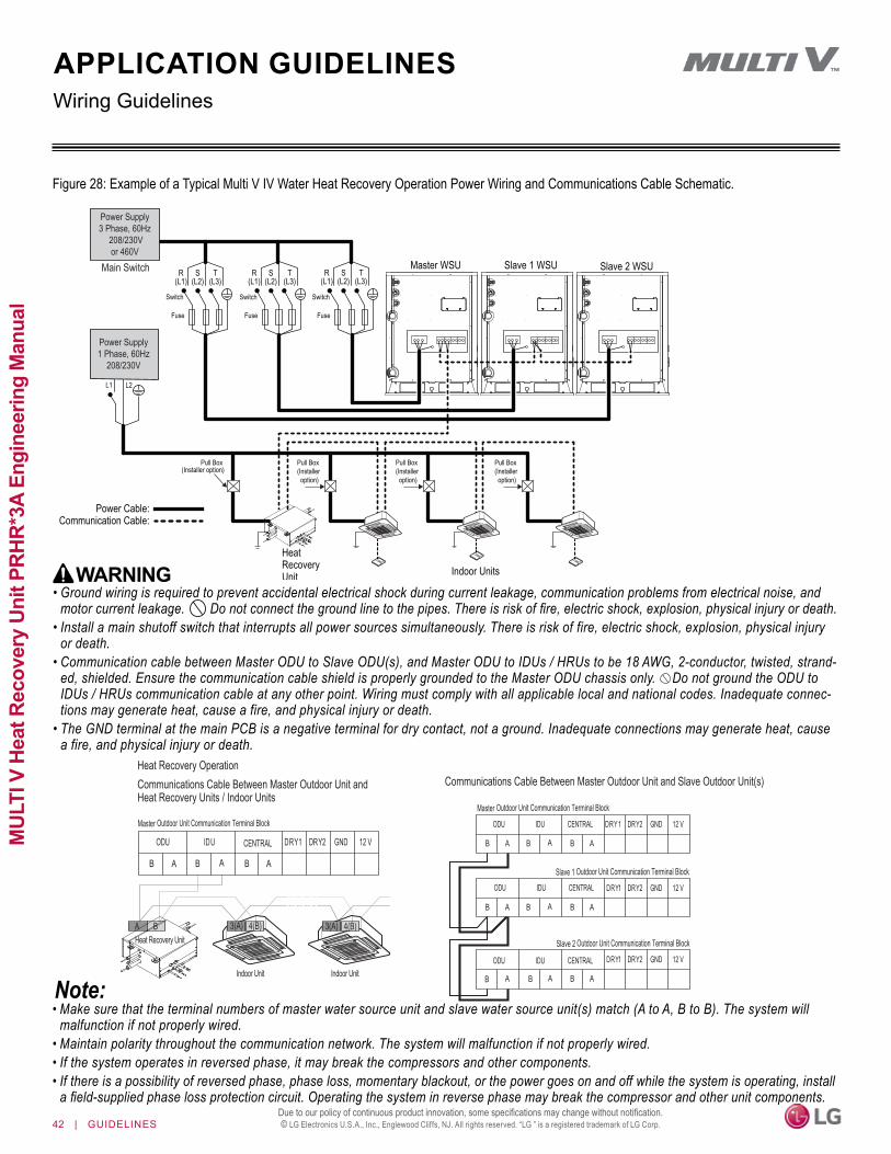
42 | GUIDELINES
MUL
TI V
Hea
t Rec
over
y Un
it PR
HR*3
A En
gine
erin
g M
anua
l
Due to our policy of continuous product innovation, some specifications may change without notification. © LG Electronics U.S.A., Inc., Englewood Cliffs, NJ. All rights reserved. “LG ” is a registered trademark of LG Corp.
Figure 28: Example of a Typical Multi V IV Water Heat Recovery Operation Power Wiring and Communications Cable Schematic.
WARNING• Ground wiring is required to prevent accidental electrical shock during current leakage, communication problems from electrical noise, and
motor current leakage. Do not connect the ground line to the pipes. There is risk of fire, electric shock, explosion, physical injury or death.• Install a main shutoff switch that interrupts all power sources simultaneously. There is risk of fire, electric shock, explosion, physical injury
or death.• Communication cable between Master ODU to Slave ODU(s), and Master ODU to IDUs / HRUs to be 18 AWG, 2-conductor, twisted, strand-
ed, shielded. Ensure the communication cable shield is properly grounded to the Master ODU chassis only. Do not ground the ODU to IDUs / HRUs communication cable at any other point. Wiring must comply with all applicable local and national codes. Inadequate connec-tions may generate heat, cause a fire, and physical injury or death.
• The GND terminal at the main PCB is a negative terminal for dry contact, not a ground. Inadequate connections may generate heat, cause a fire, and physical injury or death.
• Make sure that the terminal numbers of master water source unit and slave water source unit(s) match (A to A, B to B). The system will malfunction if not properly wired.
• Maintain polarity throughout the communication network. The system will malfunction if not properly wired.• If the system operates in reversed phase, it may break the compressors and other components. • If there is a possibility of reversed phase, phase loss, momentary blackout, or the power goes on and off while the system is operating, install
a field-supplied phase loss protection circuit. Operating the system in reverse phase may break the compressor and other unit components.
Master WSU
Indoor Units
Main Switch Slave 1 WSU Slave 2 WSU
Pull Box(Installer option)
R(L1)
L1 L2
Switch
Fuse
Switch
Fuse
Switch
Fuse
S(L2)
T(L3)
R(L1)
S(L2)
T(L3)
R(L1)
S(L2)
T(L3)
Power Supply3 Phase, 60Hz
208/230Vor 460V
Power Supply1 Phase, 60Hz
208/230V
HeatRecoveryUnit
Pull Box(Installer option)
Pull Box(Installer option)
Pull Box(Installer option)
Power Cable:Communication Cable:
Heat Recovery Unit3(A) 4(B)A B 3(A) 4(B)
B
ODU IDU CENTRAL DRY1 DRY2 GND 12 V
A B A B A
B
DRY1 DRY2 GND 12 V
A B A B A
B
DRY1 DRY2 GND 12 V
A B AB A
Heat Recovery OperationCommunications Cable Between Master Outdoor Unit and Heat Recovery Units / Indoor Units
Communications Cable Between Master Outdoor Unit and Slave Outdoor Unit(s)
B
ODU IDU CENTRAL DRY1 DRY2 GND 12 V
A B A B A
Master Outdoor Unit Communication Terminal BlockMaster Outdoor Unit Communication Terminal Block
Slave 1 Outdoor Unit Communication Terminal Block
Slave 2 Outdoor Unit Communication Terminal Block
Indoor Unit Indoor Unit
ODU IDU CENTRAL
ODU IDU CENTRAL
Wiring GuidelinesAPPLICATION GUIDELINES

GUIDELINES | 43
Application G
uidelines
Due to our policy of continuous product innovation, some specifications may change without notification. © LG Electronics U.S.A., Inc., Englewood Cliffs, NJ. All rights reserved. “LG ” is a registered trademark of LG Corp.
Wiring GuidelinesAPPLICATION GUIDELINES
Refer to electrical data table for full load ampere ratings. Properly size all circuit breakers / fuses, wiring and field provided components per local codes. There is risk of fire, electric shock, explosion, physical injury or death.
DANGER
(Switch Fuse: ELCB)
Power Supply Switch(Switch Fuse)
(Main Switch)Pull Box (Installer Option)
Communication Line (Two-Wire Cable)
Single Phase, Three Wires(L1, L2, GND)Power Supply
208-230V, 60 Hz
Heat Recovery
Unit
Power SupplySingle Phase
208-230V, 60 Hz
Power Supply Switch
Communication Line (Three-Wire Cable)
Figure 29: Multi V S ARUB060GSS4 Heat Recovery System Power Wiring / Communications Cable Connections.
• Ground wiring is required to prevent accidental electrical shock during current leakage. Do not connect the ground line to the pipes. There is risk of fire, electric shock, explosion, physical injury or death.
• Install a main shutoff switch that interrupts all power sources simultaneously. There is risk of fire, electric shock, explosion, physical injury or death.• Communication cable between ODU to IDUs/Heat Recovery Units must be 18 AWG, 2-conductor, twisted, stranded, shielded. Ensure the
communication cable shield is properly grounded to the ODU chassis only. Do not ground the ODU to IDUs/Heat Recovery Units com-munication cable at any other point. Wiring must comply with all applicable local and national codes. Inadequate connections will generate heat, cause a fire, and physical injury or death.
• The GND terminal at the main PCB is a negative terminal for dry contact, not a ground. Inadequate connections will generate heat, cause a fire, and physical injury or death.
Heat Recovery Unit
3A 4B
IDU-A IDU-B
A B 5A 6B
3A 4B 3A 4B
Figure 30: Multi V S ARUB060GSS4 Heat Recovery System Daisy-Chain Power Wiring / Communications Cable Example.
• Ground wiring is required to prevent communication problems from electrical noise and motor current leakage.• Make sure that the terminal numbers of master outdoor unit and slave outdoor unit(s) match (A to A, B to B). The system will malfunction if
not properly wired.• Maintain polarity throughout the communication network. The system will malfunction if not properly wired.• If the system operates in reversed phase, it will break the compressors and other components. • If there is a possibility of reversed phase, phase loss, momentary blackout, or the power goes on and off while the system is operating, install
a field-supplied phase loss protection circuit. Operating the system in reverse phase will break the compressor and other unit components.

44 | GUIDELINES
MUL
TI V
Hea
t Rec
over
y Un
it PR
HR*3
A En
gine
erin
g M
anua
l
Due to our policy of continuous product innovation, some specifications may change without notification. © LG Electronics U.S.A., Inc., Englewood Cliffs, NJ. All rights reserved. “LG ” is a registered trademark of LG Corp.
LGRED°, HRU COMPATIBILITY, AND GEN 4 DIP SWITCH SETTINGS
Generation 4 Indoor UnitsLG’s indoor units are designated Generation 4 (Gen 4). For Gen 4 indoor units to operate with Gen 4 indoor unit features, the air condi-tioning system must meet the following requirements:• All indoor units, heat recovery units, and air / water source units
must be Gen 4 or higher.• All air / water source units must have Gen 4 or higher software
factory or field installed.• Air / water source units DIP switch 3 must be set to ON
(factory default setting is OFF).• All controllers must support Gen 4 indoor unit features.The figure at right shows the outdoor unit DIP switch. All air and water source units, indoor units, heat recovery units, and controllers in a system must be Gen 4 compatible or the system will not operate with Gen 4 indoor unit features.
Figure 31: Location and Setting of Outdoor Unit DIP Switch 3.
1 2 765431 2 76543
ON
OFF 1 2 765431 2 76543
ON
OFF
Air/Water Source Unit DIP Switch No. 3
Table 23: PRHR*3 Heat Recovery Unit to Air / Water Source Unit Compatibility.
*Low ambient performance with LGRED° heat technology is included in Multi V 5 air source units produced after February 2019.
PRHR*3 Heat Recovery UnitsThe PRHR*3A series of heat recovery units were released in June 2018, and are not automatically backwards compatible with all LG man-ufactured VRF air / water source units. The 3A heat recovery units will be compatible with many LG manufactured air source / water source units if the its “Starting Production Date,” the “Production Starting Serial No.,” and / or the “Upgrade Software Service” dates fall after the dates shown below (see table). LG VRF systems can operate with both old 2A heat recovery units and new 3A heat recovery units if the outdoor unit software has been upgraded. If a system includes a mix of both old and new heat recovery units, system design must follow 2A heat recovery unit series piping rules. For more information, contact your local LG sales representative.
Model Starting Production Date Production Starting Serial No. Upgrade Software ServiceMulti V 5 with LGRED* ARUM****TE5 February 1, 2019 1902xxx N/AMulti V 5 ARUM****TE5 February 1, 2018 1802xxx September 28, 2018Multi V S ARUB060GSS4 October 1, 2018 1810xxx September 28, 2018Multi V Water IV ARWB****AS4 October 1, 2018 1810xxx September 28, 2018Multi V IV ARUB****TE4 N/A N/A October 31, 2018
Multi V II and III ARUB****TE2,ARUB****TE3 N/A N/A N/A
Multi V Water II ARWB****A2 N/A N/A N/A
LGRED° TechnologyLGRED technology is included in Multi V 5 air-source units produced after February 2019. The feature allows heat pump or heat recovery systems to operate in heating only mode (i.e., all indoor units in heating mode) down to -22°F outdoor ambient wet bulb by updating the main PCB software (v1.26) and replacing an air temperature sensor. Multi V 5 air-source units without these changes can only operate down to -13°F. For more information, contact your local LG sales representative.

GUIDELINES | 45
Application G
uidelines
Due to our policy of continuous product innovation, some specifications may change without notification. © LG Electronics U.S.A., Inc., Englewood Cliffs, NJ. All rights reserved. “LG ” is a registered trademark of LG Corp.
ABS Acrylonitrile Butadiene Styrene IDU Indoor UnitAC Air Conditioner/Alternate Current kW Kilowatts
ACP Advanced Control Platform in Aq inches waterAHU Air Handling Unit ISO International Standards Organization
ASHRAE American Society of Heating, Refrigeration, and Air Conditioning LATS LG Air Conditioning Technical Solution softwareASTM American Society for Testing and Materials LED Light Emitting DiodeAWG American Wire Gauge LEED Leadership in Energy and Environmental Design
AWHP Air-to-Air Water Heat Pump MBh Thousands BTUs per hourBLDC Brushless Digitally-Controlled MCA Minimum Circuit AmpacityBTL BACnet® Testing Laboratories mm MillimeterBtu/h British Thermal Unit per Hour MOP Maximum Overcurrent ProtectionCAA Clean Air Act OD Outside DiameterCFM Cubic Feet per Minute ODU Outdoor UnitCFR Code of Federal Regulations PI Power InputDB Dry Bulb PTAC Packaged Terminal Air Conditioner
dB(A) Decibels with “A” frequency weighting SHC Sensible Heat CapacityDPST Double-Pole Single Throw SMACNA Sheet Metal & Air Conditioning Contractors’ National Association
DX Direct expansion RPM Revolutions per MinuteEEV Electric Expansion valve TC Total Capacity
EPDM Ethylene Propylene Diene M-Class Rubber USD United States DollarEMF Electromagnetic Field UL Underwriters LaboratoriesESP External Static Pressure V VoltageETL Electric Testing Laboratories VAV Variable Air VolumeGND Ground VRF Variable Refrigerant FlowH/M/L High/Medium/Low W WattsHVAC Heating, Ventilating and Air Conditioning WB Wet Bulb
Hz Hertz wg Water GaugeID Inside Diameter
ACRONYMS
Table 24: Acronym Table.

To access additional technical documentation such as submittals, outdoor and indoor unit engineering manuals, installation, service, product data per-formance, general best practice, and building ventilation manuals, as well as
white papers, catalogs, LATS software programs, and more, log in to www.lghvac.com.

LG Electronics, U.S.A., Inc.Air Conditioning Technologies4300 North Point ParkwayAlpharetta, Georgia 30022www.lghvac.com
EM_MultiV_HeatRecoveryUnits_PRHR3A_04_19Supersedes: EM_MultiV_HeatRecoveryUnits_PRHR3A_03_19
EM_MultiV_HeatRecoveryUnits_PRHR3A_06_18
20001747 ISO 9001: 2008
LG ELECTRONICS INC.
Related Documents