1 CHAPTER ONE 1.0 INTRODUCTION 1.1 Preamble All variety of foods in our day to day life needs some way of preservation for several reasons. To reduce or stop spoilage, to make all varieties of food available throughout a year, to maintain desired levels of nutritional properties for the longest possible time span and to add value added products (Mjumder and Jangan, 2010). Drying of Agricultural products intended to increase shelf life, reduce packaging, transportation expenses by reducing the weight and volume, improved appearance and more important to maintain the original flavor and nutritional value (Tjukup, et al., 2012). Spoilage or deterioration of food occurs during handling or due to mechanical, physical, chemical or microbial damages. Agricultural products are perishable because of high water content of approximately 80%. Moisture above 10% encourages proliferation of spoilage of micro-organism in the agricultural product and causes short shelf life (Tjukup, et al., 2012). The food products can have wide ranges of moisture content; as low as 35 % in grains and as high as 90% or more in some fruits (e.g. water melon has moisture content as high as 93%) which needs to be reduced to an acceptable value so as to avoid microbial growth (Mjumder and Devastin, 2008). Traditionally food products were dried using open sun drying method. Although this is still in common use for non-commercial purposes. It was necessary to develop a better way of dehydration to make products of higher commercial value which resulted in use of various forms of dryers for food applications. Use of techniques such as solar cabinet dryers, tray dryers, and fluid bed dryers and so on has resulted in better product quality than that

Welcome message from author
This document is posted to help you gain knowledge. Please leave a comment to let me know what you think about it! Share it to your friends and learn new things together.
Transcript

1
CHAPTER ONE
1.0 INTRODUCTION
1.1 Preamble
All variety of foods in our day to day life needs some way of preservation for several
reasons. To reduce or stop spoilage, to make all varieties of food available throughout a year, to
maintain desired levels of nutritional properties for the longest possible time span and to add
value added products (Mjumder and Jangan, 2010). Drying of Agricultural products intended to
increase shelf life, reduce packaging, transportation expenses by reducing the weight and
volume, improved appearance and more important to maintain the original flavor and nutritional
value (Tjukup, et al., 2012). Spoilage or deterioration of food occurs during handling or due to
mechanical, physical, chemical or microbial damages. Agricultural products are perishable
because of high water content of approximately 80%. Moisture above 10% encourages
proliferation of spoilage of micro-organism in the agricultural product and causes short shelf life
(Tjukup, et al., 2012).
The food products can have wide ranges of moisture content; as low as 35 % in grains
and as high as 90% or more in some fruits (e.g. water melon has moisture content as high as
93%) which needs to be reduced to an acceptable value so as to avoid microbial growth
(Mjumder and Devastin, 2008). Traditionally food products were dried using open sun drying
method. Although this is still in common use for non-commercial purposes. It was necessary to
develop a better way of dehydration to make products of higher commercial value which resulted
in use of various forms of dryers for food applications. Use of techniques such as solar cabinet
dryers, tray dryers, and fluid bed dryers and so on has resulted in better product quality than that

2
of open sun drying (Mjumder and Chen, 2008). However the process can be made cost-effective
in terms of energy consumption as well as product quality. In order to reduce energy
consumption, it is necessary to choose an efficient heating system. Heat pump provides an
efficient technology and its environmental friendly due to low energy consumption (Fatouh, et
al., 2006).
A heat pump is machine or device that moves heat from one location (heat source) to
another location (heat sink) by using mechanical work (Jahn, 2009). It is a device that can
increase the temperature of a waste-heat source readily available to a temperature where the
waste energy becomes useful. It moves waste-heat from one medium to another (Sanchaz, 2008).
Heat pumps transfer heat by circulating a substance called refrigerant through a cycle thereby
bringing about heat transfer. There are different types of heat pump depending on the criteria of
classification. Based on waste-heat source criterion, they can be classified into: geothermal heat
pump, air-source heat pump, solar heat pump and electrical driven heat pump (www.les.com).
The efficiency of a heat pump is expressed by coefficient of performance (COP), which is the
quotient between the useful heating capacity and power input. The heat pump system is highly
economical this is because industrial heat pumps uses waste-energy. Waste-energy are heat
energy derived from industrial manufacturing processes which if not used by heat pump system
will be a waste.
Refrigerants are fluid which posses the ability to transfer heat energy from one point to
another. They are often referred to as the working fluid. There are different types of refrigerants
ranging from fluorocarbons, Halocarbons, ammonia, to the environmental friendly carbon
dioxide.1, 1, 1, 2 – tetrafluoro ethane, R- 134a is a haloalkane refrigerant with thermodynamic
property similar to R- 12 (dichlorodifluoro methane ) but with less ozone depletion potential. It

3
has the formula CH2 FCF3 and a boiling point of -26.3o C (- 15.34o F )
Over the years, the important of heat pump system had been emphasized. Numerious
researchers had performed various theoretical investigation on the ways to improve the
coefficient of performance of a heat pump system. The fabrication of a test rig heat pump system
will share more light on the effect of parameter such as degree of superheat , difference between
condenser and evaporator temperature , mass flow rate , and so on the coefficient of performance
of a heat pump system.
1.2 Problem Statement
Over 20% of the energy production in the world is consumed by preservation of
Agricultural products (Rhagavan et al., 2005). Therefore, there is need to invent a dryer system
which is less energy consuming and also energy saving. A refrigeration system use in heating
can provide a coefficient of performance five times higher than a conventional electric dryer
(Sarkar, 2005). Therefore, a heat pump dryer is the type of dryer that suits this requirement
Considering Heat pumps, the harmful effects of refrigerants to the environment and the
populace is a topic of international concern. A refrigerant such as hydro-chlorocarbons, Hydro-
Flourocarbons, among others causes depletion of the ozone layers and Global warming effects.
Therefore there is a need to design a heat pump using an environmental friendly refrigerant with
efficient performance characteristics.

4
1.3 Aims and Objectives
1.3.1 Aim
The aim of the project is to design and fabricate a R 134a heat pump system suitable for
preservation of Agricultural products.
1.3.2 Specific Objectives
1. To design an experimental test rig for R – 134a Heat pump system.
2. To fabricate the experimental test rig designed.
3. To test the performance of the test rig.
1.4 Scope of the Project
This project is limited to the design and analysis of a Heat pump dryer test rig. The test
rig is to be investigated experimentally to observe its level of performance. The refrigerant to be
used is R- 134a. The type of heat pump system adopted is the vapour compression cycle. The
power rating of the compressor is 1.5KW. The material used for the heat exchangers (condenser
and evaporator) is copper. This project is to be carried out in a Tropical Rain forest region.

5
1.5 Justification
Preservation of Agricultural products with the most effective drying mechanism is of
utmost important. This is to reduce the amount of energy consumption by the processes
involving preservation of agricultural products. Therefore there is need to investigate the
performance characteristics of the dryer, this is to measure the efficiency of the dryer. Building
into consideration how criteria such as superheat temperature, condenser temperature, evaporator
and so on, could be varied to obtain more adequate coefficient of performance.

6
CHAPTER TWO
2.0 LITERATURE REVIEW
2.1 Preservation of Agricultural Products
The astonishing fact about food preservation is that it permeated every culture at nearly
every point in time. To survive, ancient man had to harness nature. In frozen climate, he froze
seal meat on the ice. In tropical climate he dried foods in the sun. Food by its nature begins to
spoil the moment it is harvested. Food preservation enabled ancient man to make root and live in
one place and form a community. He no longer have to consume the kill or harvest immediately,
but could preserve some for later use (Nummer, 2002).
There are different methods of preserving farm produce. They includes drying, freezing,
canning, pickling, jam and jelly, hurdle technology, modified atmosphere, polling,
biopreservation and pascalization. (Eden, 1999). Of all the aforementioned methods of drying is
a method of food preservation that works by removing water from the food which inhibits the
growth of bacteria(). East and oriental cultures actively dried foods as early as12, 000 BC in the
sun. The Romans are particularly fond of any dried fruit they could make. In the middle ages
purposely built ‘still houses’ were created to dry fruits, vegetable and herbs in areas that did not
have enough strong sunlight for drying. A fire was used to create the heat needed to dry foods
and in some cases smoking them as well (Mack, 2001).
Most high value agricultural products need changing to minimize spoilage preserve
quality and reduce transportation cost (Mujumder, 2000). Drying is a complex and energy
intensive process where the water is evaporated from a product by supplying heat by convection
conduction radiation microwave and so on. About 85% of industrial driers are the convective

7
type with Hot air as drying medium and 99% of them involve removal of water (Mujumder,
2008). They consume up to 25% of the material industrial energy in the develop countries
(Raghavan, et al 2005).
In the main agricultural countries drying comprises the reduction of moisture from
about 17-30% w/w to values between 8and15% w/w depending on the grain. The final moisture
content for drying must be adequate for storage. The more oil the gain has, the lower its storage
moisture content will be (though its initial moisture for drying will also be lower). Cereals are
often dried to 14% w/w, while oil seed to 12.5% (soya beans), sunflower 8%, and peanuts 9%.
(Brooker, et al, 2012). Drying is carried out as a prerequisite for safe storage, in order to inhibit
microbial growth.
2.2 Refrigeration History
Use of ice to refrigerate and thus preserve food goes back to prehistoric times. The
seasonal harvesting of snow and ice was a regular practice of the ancient centuries: Chinese,
Hebrews, Greeks, Romans, and Persians. Ice and snow were stored in caves or other insulating
materials. The Persians stored ice in pits called straw line pit. Rationing of the ice allowed the
preservation of foods over the warm periods. This practice worked well down through the
centuries, with icehouses remaining in use into the 12th century (Bolaji, 2005).
The first known method of artificial refrigeration was demonstrated by William Cullen at
the university of Glasgow in Scotland in 1756.Cullen used a pump to create a partial vacuum
over a container of diethyl ether, which then boiled, absorbing heat from the surrounding air. The
experiment even created a small amount of ice, but had no practical application at that time. In
2005, American inventor Oliver Evans designed but never built a refrigeration system based on

8
vapor compression refrigeration cycle rather than chemical solution or volatile liquids such as
ethyl ether. An American living in Great Britain, Jacob Perkins obtained the first patent for a
vapor compression system 1834. Perkins built a prototype system and it usually worked,
although it did not succeed commercially (Bhatti, 1999).
In 1842, an American physician, John Gorier, designed the first system for refrigerating
water to produce ice. He also conceived the idea of using his refrigeration system to cool the air
for comforts in homes and hospitals. His system compressed air, then partially mixed the hot
compressed air with water before allowing it to expand while doing part of the work required
driving the air compressor. Alexander Twining began experimenting with vapor compression
refrigeration 1848 and obtained patents in 1850 and 1853. He is credited for having intiated
commercial refrigeration in the united states by 1856 (Arora, 2007).
Mechanical refrigeration has been around since the mid-ninth century. The first practical
machine was built by Jacob Perkins. (Thevenot, 1979). It was based on using ether as a
refrigerant in a vapor compression circuit. Carbon-Dioxide was first used as a refrigerant in 1866
and Ammonia in 1873. Other chemical used as vapor compression refrigerant include cymene
(petrol ether and naphtha), sulfur dioxide (R-764) and methyl ether. Their applications were
limited to industrial processes. Most food preservation was accomplished by using blocks of ice
collected during the winter and stored or manufactured through an industrial process. ( Mcquay,
2002). By the beginning of the twentieth century, refrigeration system was being used to provide
air conditioning in major building projects. The Milam Building in San Antonio, Texas was the
first high rise office building to be completely air conditioned. (Pauken, 1999). Sleeping Soundly
on Summer Nights.( ASHRAE,2002).

9
By the mid-1970s, concern began to surface about the thinning of ozone layer and whether
CFCs may be in part responsible. This led to the ratification of the Montreal Protocol in 1987
that required the phase-out of CFCs and HFCs. New solutions were developed with HFCs taking
on major role as refrigerants.
In the 1990s global warming arose as the new threat to the well-being of the planet. While
there are many contributors to the global warming, refrigerants were included because air
conditioning and refrigeration are significant energy users and many refrigerants are themselves
greenhouse gases. (Mcquay, 2002). Hence, environment friendliness of the refrigerant is a major
factor in deciding the usefulness of a particular refrigerant.
2.3 Drying Process
Drying is a highly nonlinear coupled heat and mass transfer process. It occurs by
vaporization of a liquid by supplying heat to a wet material. Drying with hot air implies
humidification and cooling of the air in a well-insulated (adiabatic) drying chamber. Heat is
transferred by convection from drying air to the product drying surface where heat is needed for
evaporation of moisture. Figure 2.1 shows a schematic representation of energy balance of a
drying system. The material enters the drying chamber at state “a” with an initial mass
Mdry+Mwet and temperature Ta. After drying, the dried material leaves the drying chamber at
state bwith the final mass Mdry and at temperature Tb. On the other hand, in the drying chamber
enters relatively dry air (at state 2) with the flow rate mair (kgdry,air/s), It absorbs water from the
material during the isenthalpic process 2-3. If the drying air is heated at constant absolute
humidity before entering the drier, the heating thermal power (kW) will be:
10
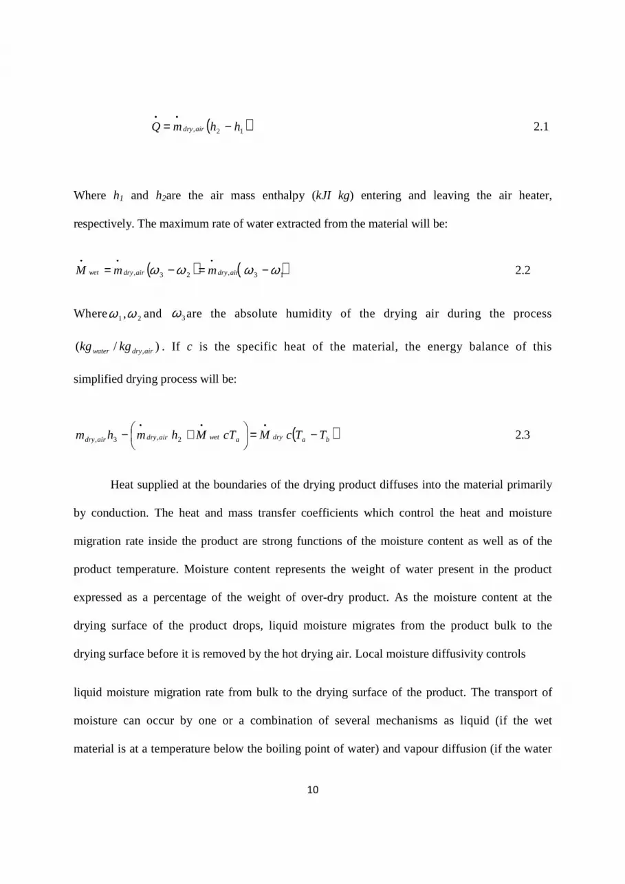
( )12, hhmQ airdry −=••
2.1
Where h1 and h2are the air mass enthalpy (kJI kg) entering and leaving the air heater,
respectively. The maximum rate of water extracted from the material will be:
( ) ( )13,23, ϖϖϖϖ −=−=•••
airdryairdrywet mmM 2.2
Where 21,ϖϖ and 3ϖ are the absolute humidity of the drying air during the process
)/( ,airdrywater kgkg . If c is the specific heat of the material, the energy balance of this
simplified drying process will be:
( )badryawetairdryairdry TTcMcTMhmhm −=
+−•••
2,3, 2.3
Heat supplied at the boundaries of the drying product diffuses into the material primarily
by conduction. The heat and mass transfer coefficients which control the heat and moisture
migration rate inside the product are strong functions of the moisture content as well as of the
product temperature. Moisture content represents the weight of water present in the product
expressed as a percentage of the weight of over-dry product. As the moisture content at the
drying surface of the product drops, liquid moisture migrates from the product bulk to the
drying surface before it is removed by the hot drying air. Local moisture diffusivity controls
liquid moisture migration rate from bulk to the drying surface of the product. The transport of
moisture can occur by one or a combination of several mechanisms as liquid (if the wet
material is at a temperature below the boiling point of water) and vapour diffusion (if the water

11
vaporizes inside the material), hydrostatic pressure differences (when internal vaporization
rates exceed the rate of vapour transport through the solid to the ambient medium) or Knudsen
diffusion (in the case of freeze drying).
For materials of high diffusivity, moisture migrates rapidly to the drying surface even at low
moisture content of the product. Therefore, the drying rate of such materials is controlled by
external transport rates while the drying rate improves with improvement of the external
conditions. Evaporation of liquid moisture takes place from exposed surface by absorbing the heat
of vaporization Hot air is used both to supply the heat for evaporation and to carry away the
evaporated moisture from the solid. At low moisture content of the product, the effect of low
relative humidity becomes less significant, at low relative humidity of air, partial vapour pressure
of drying air becomes low. This leads to a higher driving potential for mass transfer resulting in
increased moisture evaporation rate.
Liquid moisture evaporates from the drying surface of the product because of the
difference of partial vapour pressures between the air and the surface of the product. Partial
vapour pressure at the drying surface is function of the drying surface temperature and its water
activity which is a function of surface moisture content and temperature. Water activity(αw)
depends on relative pressure and is defined as the ratio of the partial pressure (Pw) ofwater at
the same temperature. Thus, αw, which is also equal to the relative humidity of the ambient
humid air, is defined as: w
w p
p=α 2.4
As the moisture content and temperature of the drying surface continuously change during
drying process, partial vapour pressure at the drying surface becomes an uncontrollable
parameter. The diffusivity at the exposed drying surface significantly drops during drying

12
process particularly when the moisture content of the product becomes low. The moisture
content of a wet material in equilibrium with the air of given relative humidity and temperature
represents the equilibrium moisture content. The evaporation rate of moisture depends on the mass
transfer coefficient of the drying air which depends mainly on the types of flow used such as
Stagnant, laminar or turbulent. Higher volume flow rate if drying air increases the mass transfer
coefficient, but the size of blower becomes large and power consumption rate increases.
Therefore, maintaining optimum flow of drying air is important for the economic operation of a
dryer. The isotherm obtained by exposing the solid to air of decreasing humidity is known as the
desorption isotherm. As the maximum allowable temperature of the drying air is limited
particularly for heat sensitive materials, partial vapour pressure of the drying air is usually
controlled by condensing moisture of the drying air by using heat pumps.
Fig 2.1 Diagram of Simplified schema of a drying system, (Source: Larsson, 2011)

13
2.4 The Heat Pump System
A heat pump is a device that can increase the temperature of a waste-heat source readily
available to a temperature where the waste-heat becomes useful. A heat pump moves waste-heat
from one medium to another. The heat pump systems are common only in few countries, for
example: Sweden, England, United States, Canada, etc. But in quite a lot of other countries they
are not that common. For that reason the heat pump systems can be unknown for some people.
The same can happen with the heat recovery systems. Not too many people know and understand
what is a heat pump system and a heat recovery system. In the other hand refrigeration systems
are very common in all the countries. We just have to take a look in our fridges.Well then, all
these three systems have the same operation principles. The difference between them is just the
objective, the medium which is necessary to control. In a refrigeration system the objective is to
maintain the refrigerated medium at a low temperature by removing heat from it. But it is not
necessary to control the warm medium; the heat is just thrown to the environment.
In a heat pump system the objective is to maintain a heated medium at a high
temperature.(carrier, 2008). In a heat recovery system the objective is double; both mediums
need to be controlled. On the one hand a heat recovery system has to maintain the refrigerated
medium at a low temperature by removing heat from it and on the other hand it has to maintain a
heated medium at a high temperature. Although normally one of the mediums is the critical and
the other medium must adapt to changes on the other.
2.4.1 Heat Pump Heat Sources
In a heat pump the heat source is the medium donating the heat. There are a lot of mediums
which can be the heat source in heat pump systems.(cdc.gov, 2008)
14
One classification of the heat sources is: Air, Water, Ground.
2.4.2 Heat Pump Sinks And Applications
The heat sink is the medium receiving the heat. Different types of liquids and gases are
both possible sinks. But the most common sinks are water and air. The possible applications of
heat pumps are very large. Some of the most common applications are:
• Space heating and water heating for washing, sanitation and cleaning.
• Steam production.
• Drying and dehumidification.
• Evaporation, distillation, concentration and desalination.
2.4.3 Heat Pump Types
I. Closed-cycle mechanical vapour compressions (MVC) heat pump
II. Open-cycle mechanical vapour compression heat pumps
III. Open-cycle thermo compression heat pumps
IV. Closed-cycle absorption heat pump
15
2.4 Closed Cycle Mechanical Vapour Compression Heat Pump System
The Basic configuration
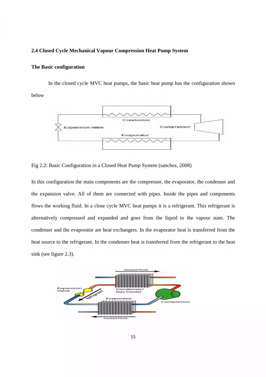
In the closed cycle MVC heat pumps, the basic heat pump has the configuration shown
below
Fig 2.2: Basic Configuration in a Closed Heat Pump System (sanchez, 2008)
In this configuration the main components are the compressor, the evaporator, the condenser and
the expansion valve. All of them are connected with pipes. Inside the pipes and components
flows the working fluid. In a close cycle MVC heat pumps it is a refrigerant. This refrigerant is
alternatively compressed and expanded and goes from the liquid to the vapour state. The
condenser and the evaporator are heat exchangers. In the evaporator heat is transferred from the
heat source to the refrigerant. In the condenser heat is transferred from the refrigerant to the heat
sink (see figure 2.3).

16
Figure 2.3: Basic Heat Pump System (Source: Goodman, 2008)
The basic thermodynamic cycle with which works this heat pump configuration is the
one stage simple cycle. This thermodynamic cycle is defined by four states (points) and four
thermodynamic processes (lines) as is shown in the figure 2.5
Figure 2.4: States and Processes in a One Stage Heat pump Simple Cycle. (Source: Sanchez,
2008)
The states refer to the refrigerant condition in a specific place:
• State 1: Saturated or slightly superheated vapour.
• State 2: Superheated vapour.
• State 3: Saturated or slightly sub-cooled liquid.
• State 4: Saturated liquid-vapour mixture.
The four thermodynamic processes are: Compression, Condensation, Expansion and
Evaporation.

17
Figure 2.5: States and Processes in a One Stage Heat Pump Simple Cycle (Source:Sanchez,
2008)
2.5 How Does The Heat Pump Work?
• Process ‘1’ to ‘2’: the compressor removes the gas produced in the evaporator (state ‘1’) and
compresses it, delivering it to the condenser at a higher pressure and temperature (state ‘2’). The
energy required for driving the compressor is called the power consumption ( Win [ kW] ).
• Process ‘2’ to ‘3’: in the condenser heat is transferred from the refrigerant to the heat sink, thus
the heat sink increases its temperature. The refrigerant changes its state from superheated vapour
(state ‘2’) to saturated liquid (state ‘3’). The total capacity of heat transfer in the condenser is
called the heating capacity ( Qc [ kW] ).
• Process ‘3’ to ‘4’: the expansion valve releases the pressure between the high-pressure
condensation side (state ‘3’) and the low-pressure evaporation side (state ‘4’).
Process ‘4’ to ‘1’: in the evaporator the refrigerant boils by absorbing energy from the heat
source, which reduces its temperature. The refrigerant changes its state from saturated liquid-
vapour mixture (state ‘4’) to saturated vapour (state ‘1’). The total capacity to absorb heat from
the heat source is called the cooling capacity ( Qe [kW] ).

18
Figure 2.6: Heat Pump System with Input and Outputs (Source: Sanchez, 2008
2.6 Components of a Heat Pump System
In Mechanical vapour compression cycle heat pumps there are four essential components,
they are: The compressor, condenser, evaporator, and the expansion valve.
2.6.1 The Compressor:
The function of a compressor is to remove the gas produced by the evaporator and to
deliver it at a required higher pressure (see figure 3-12). The compressor can be compared to a
heart pumping the blood (the refrigerant) inside the body (close cycle MVC cycle)The
compressor can be compared to a heart pumping the blood (the refrigerant) inside the body
(close cycle MVC cycle). In the basic compression cycle, the compressor is positioned between
the evaporator and the condenser. The compressor removes the gas produced in the evaporator. It
must remove continuously the gas to maintain the same pressure. After that, the compressor
pumps the gas from the evaporator and compresses it, delivering it to the condenser at a higher

19
pressure and temperature (‘1’ to ‘2’’). The energy required for the compression normally comes
from electricity.(energyblueprint.info,2008)
Fig 2.7: Close Cycle MVC Heat Pumps: Compression Process(Source : Sanchez, 2008)
The process ‘1’ to ‘2’’ symbolizes an ideal isentropic compression, in which there is not heat
exchange with the surroundings. However, in reality there are always some heat losses from
compressor and also some dissipation of energy due to mechanical friction in the equipment and
potential leakage in the compressor. The difference between isentropic and present compression
taking into account the dissipation of energy can be expressed by the isentropic compressor
efficiency: There are several types of compressors: Positive displacement compressors, Screw
compressors, Rotary compressors, Rolling piston compressors, Scroll compressors, Dynamic
compressors, and Turbo compressors.
2.6.2 The Condenser:
The function of the condenser is to transfer hot discharge gas from the compressor to a
slightly subcooled liquid flow, by transferring heat from the refrigerant to the heat sink.(
friotherm.com, 2008). The basic operation of condensers is divided into three parts:
Desuperheating, Condensation, and Sub-cooling. All three operations can be carried out
inside the condenser. Alternatively, the desuperheating or sub-cooling operation can be carried
out in a separate heat exchanger. The heat rejection can be

20
Fig 2.8 : Close Cycle MVC Heat Pumps: Condensation Process
The first part of the condenser desuperheats the gas to the saturation temperature (‘1’ to
‘2’). This cooling represents 15-25% of the total heat rejection. It is one-phase heat transfer
where the temperature of the refrigerant gas decreases typically by 20-50 K, depending on the
system and refrigerant. When the refrigerant reaches its saturation temperature, the latent heat is
rejected. Normally the condensing process represents the majority (70-80%) of the total heat
rejection (‘2’ to ‘3’). Finally, the fully condensed refrigerant (state ‘3’) is sub-cooled a few
degrees (‘3’ to ‘4’) to ensure that pure liquid enters the expansion valve (state ‘4’). This is also
one-phase heat transfer operation, representing approximately 2-5 % of the total heat rejection.
The temperature of the refrigerant decreases during the desuperheating and sub-cooling
processes, but remains constant during the condensing processes
Fig 2.9: Temperature evolution along the condensation process (Sanchez, 2008)
21
The energy rejected from the refrigerant heats the heat sink, whose temperature thus increases.
The temperature of the heat sink can be increased to approach or even exceed the condensing
temperature (‘6’). A temperature increases results in a smaller flow on heat sink side for the
same heat load. This reduces the required pump capacity. However, there is a minimum
temperature difference that must be considered and avoided for stable operation, it is called the
pinch temperature. This minimum occurs at the beginning of the condensation process (in a
counter-current condenser). Therefore, the temperatures of the two media in a heat exchanger
may converge but never be equal. An example of temperature difference between condensing
temperature and outlet heat sink maximum temperature (‘2’ to ‘6’) is 2 K.
2.6.3 The Expansion Valve:
The expansion valve is situated in the liquid line between the condenser and the inlet of
the evaporator. The expansion valve releases the pressure between the high-pressure
condensation side and the low-pressure evaporation side. (Icropetra F.P 2008)
2.6.3.1 Functions of Expansion Valve
1. Maintaining the pressure difference between the condenser (high pressure) and the evaporator
(low pressure): the pressure difference created by the work of the compressor is maintained by
the expansion device.
2. Controlling the amount of refrigerant entering the evaporator: if the capacity of the evaporator
increases, the expansion valve should allow a larger flow of refrigerant, and vice versa. An
expansion valve does control directly the evaporation temperature. Instead it regulates the
superheating by adjusting the mass flow of refrigerant into the evaporator, and maintains the
pressure difference between the high pressure and the low pressure sides. The evaporation

22
temperature depends on the capacity of the compressor and the characteristics and efficiency of
the evaporator. There are numerous types of expansion valves, depending on the demand for
control and the type of evaporator, some of them are: Thermal expansion valves, manual valves,
Capillary valves, Automatic valves, Electronic expansion valves.
2.6.4 The Evaporator:
In the evaporator, the refrigerant boils by absorbing energy from the heat source which reduce its
temperature. The heat source may be a gas o liquid, depend on the system.(GENETRON
refrigerants, 2008) The evaporation process occurs as shown in the next Log p-h diagram.
Fig 2.10 : Close Cycle MVC Heat Pumps: Evaporation Process
When the sub-cooled liquid refrigerant at high pressure (state ‘1’) is expanded through the
expansion valve, the pressure and therefore the saturation temperature decreases (state ‘2’). The
mixture of liquid and gas from the expansion valve enters the evaporator and starts to boil,
because heat is transferred from the heat source (‘2’ to ‘3’). The evaporating refrigerant absorbs
energy from the heat source, whose temperature is reduced. After full evaporation, when 100%
of the refrigerant has become saturated vapour (state ‘3’), the temperature of the vapour will start
to increase, the vapour becomes then superheated. The refrigerant flow leaving the evaporator
23
will be 100% superheated vapour (state ‘4’). The temperature change along the evaporation
process is shown in the next diagram.
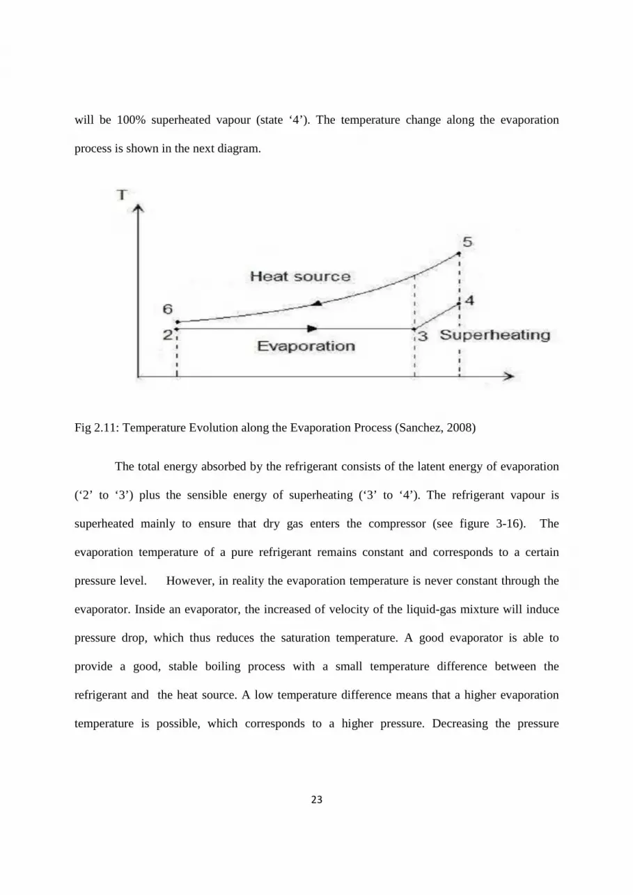
Fig 2.11: Temperature Evolution along the Evaporation Process (Sanchez, 2008)
The total energy absorbed by the refrigerant consists of the latent energy of evaporation
(‘2’ to ‘3’) plus the sensible energy of superheating (‘3’ to ‘4’). The refrigerant vapour is
superheated mainly to ensure that dry gas enters the compressor (see figure 3-16). The
evaporation temperature of a pure refrigerant remains constant and corresponds to a certain
pressure level. However, in reality the evaporation temperature is never constant through the
evaporator. Inside an evaporator, the increased of velocity of the liquid-gas mixture will induce
pressure drop, which thus reduces the saturation temperature. A good evaporator is able to
provide a good, stable boiling process with a small temperature difference between the
refrigerant and the heat source. A low temperature difference means that a higher evaporation
temperature is possible, which corresponds to a higher pressure. Decreasing the pressure

24
difference from the condensing pressure (high pressure) to the evaporation pressure (low
pressure) will decrease the energy use.
2.7 Refrigerants Requirements:
A refrigerant in a MVC heat pump system must satisfy some requirements. These requirements
can be divided into two groups:
• On the one hand the refrigerant should not cause any risk of injuries, fire or property damage in
case of leakage.
• On the other hand chemical, physical and thermodynamic properties of the refrigerant must be
the appropriate for the system and the working conditions at a reasonable cost.
(Heatpumpscenter.org, 2008)
2.7.1 The Ideal Properties of a Refrigerant
• Good heat transfer properties.
• High latent heat.
• Appropriate pressures for the operating temperature.
• Chemical stability.
• Low toxicity.
• Low fire risk.
• Environmentally friendly.
• Satisfactory oil solubility/miscibility.

25
• Easy leak detection.
• Low cost.
The most important feature is that the refrigerant must have chemical stability within the heat
pump system. Nevertheless, when the refrigerant is emitted to the atmosphere, it should not be so
stable and decompose easily without the formation of any harmful substances (Energy.kth.se).
2.7.2 Refrigerant Impact on the Environment
In addition to being toxic or explosive and therefore dangerous to people’s health, there are other
problems associated with refrigerants. Environmental aspects are increasingly being taken into
consideration. Refrigerants can thus also be ranked according to their impact on the stratospheric
ozone layer (the Ozone Depletion Potential, ODP) or as greenhouses gases (the Global Warming
Potential, GWP).
2.7.2.1 Ozone Depletion Potential (ODP):
The ODP factor is used to reflect the refrigerants impact on the ozone layer. The ODP is the ratio
of the impact on ozone of a chemical compared with the impact of a similar mass of R11. Thus,
the ODP of R11 is 1.0 by definition. Refrigerants containing chlorine or bromine contribute to
the breakdown of the ozone layer. It breaks down and reacts with the ozone molecules repeatedly
until a more stable compound is created. Some examples of ODP are: R12 has a ODP of 1.0,
R22 has a ODP of 0.6 and R134a has a ODP of 0.0.
2.7.2.2 Global Warming Potential (GWP)

26
The GWP is used to reflect the refrigerants impact on the global warming. The GWP is the ratio
of the warming caused by a substance to the warming caused by a similar mass of carbon
dioxide. Therefore, the GWP of CO2 is 1.0 by definition. Some examples of GWP are: R12 has a
GWP of 11,000, water has a GWP of 0, R22 has a GWP of 5,310 and R134a has a GWP of
3,830. (Refrigerants.com, 2008)

27
CHAPTER THREE
3.0 METHODOLOGY
A heat pump drier for the drying of agricultural produces was constructed. The test rig will
be used for high temperature applications. The heat pump dryer is the combination of heat pump
(refrigeration circuit) and dryer unit (Air circuit). The size of heat pump was determined by
moisture removal capacity of dryer and air conditions. The system consists of six main
components: compressor, evaporator, expansion device, condenser (for conventional refrigerant
based system), fan and dryer as shown in Figure 3.1 The following methods of information
acquisition lead to the design conception required for the design and fabrication of the test rig:
1. Oral Interview:This involves visitation to Refrigeration and Air-conditioning
experts to make enquire on relevant questions on the project
2. Library: Library textbooks and journal consultation
3. Physical Observation
4. Experimental Data
5. Design: Sketches and drawing using relevant mathematical analysis were also
prepared

28
3.1 Design Consideration
1. Availability of components
2. Adequate selection of materials for components
3. Ease of operation
4. Safety Considerations
5. Cost
6. Compactness of the system
7. Choice of refrigerant
8. Ozone depletion and Global warming potential of the refrigerant
9 Mechanical properties such as durability, strength, toughness, and heat conductivity.

29
Fig 3.1 Schematic Diagram of a Heat Pump Dryer
3.2 Assumptions made for the Refrigerant Cycle Analysis

30
1. Compression process is adiabatic but non-isentropic
2. Refrigerant at evaporator outlet is considered as saturated vapor
3. Refrigerant at condenser outlet is considered as saturated liquid
4. Evaporation and heat rejection (condensation/gas cooling) processes are isobaric
5. Heat transfer with the ambient is negligible
6. Air at the evaporator outlet or the gas cooler inlet is considered as saturated
7. Outlet air condition from the dryer is the same as the inlet condition to the evaporator.
3.3 Assumptions made in the air Cycle
(a) The heat pump is operated at steady state
(b) The heat transfer with ambient for the components, dryer and connecting
tubes is negligible
(c) The ambient conditions remain constant
(d) The temperature and air velocity are uniformly distributed in transverse
direction of flow.
(e) Compression process is adiabatic but non-isentropic
(f) Mixing of air is adiabatic
3.4 Component Design
31
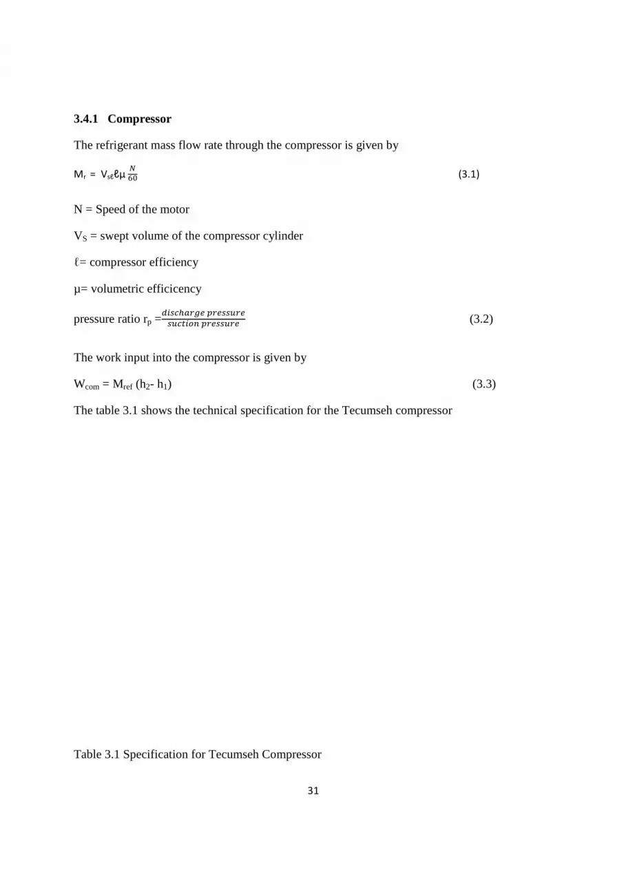
3.4.1 Compressor
The refrigerant mass flow rate through the compressor is given by
Mr = Vsℓℓµ �
�� (3.1)
N = Speed of the motor
VS = swept volume of the compressor cylinder
ℓ= compressor efficiency
µ= volumetric efficicency
pressure ratio rp =������� ������
������� ������ (3.2)
The work input into the compressor is given by
Wcom = Mref (h2- h1) (3.3)
The table 3.1 shows the technical specification for the Tecumseh compressor
Table 3.1 Specification for Tecumseh Compressor

32
Compressor Type: Operating range: Displacement volume: Swept volume: Max.operating pressure: Max. discharge temperature: Max. suction temperature:
Tecumseh 1800 to 7200 rpm ( 30 to 120Hz ) 3.33 cm3
rev (LP) and 1.88cm3 rev (HP) 1.439m3
h at 7200 rpm 2M Pa 850C at continuous operation 250C
Motor Maximum power input: 1400W Lubricant Type: Viscosity: Properties: Oil discharge:
Polyalkyene glycol (PAG) 100 cSt Non- soluble with CO2 Heavier than saturated CO2 liqiud above -150C Excellent thermal and chemical stability High viscosity index High flash point – low pour point Hygroscopic
Approximately 6 to 9 of total mass flow rate (100Hz). Oil discharge rate increases with rpm and lower suction discharge pressure ( Hubacher and Groll, 2002 s
3.4.2 Heat Exchanger
33
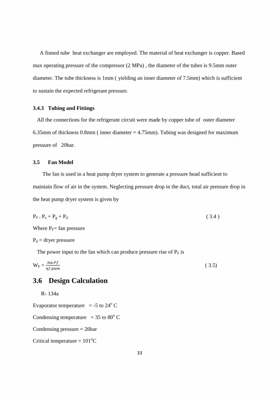
A finned tube heat exchanger are employed. The material of heat exchanger is copper. Based
max operating pressure of the compressor (2 MPa) , the diameter of the tubes is 9.5mm outer
diameter. The tube thickness is 1mm ( yielding an inner diameter of 7.5mm) which is sufficient
to sustain the expected refrigerant pressure.
3.4.3 Tubing and Fittings
All the connections for the refrigerant circuit were made by copper tube of outer diameter
6.35mm of thickness 0.8mm ( inner diameter = 4.75mm). Tubing was designed for maximum
pressure of 20bar.
3.5 Fan Model
The fan is used in a heat pump dryer system to generate a pressure head sufficient to
maintain flow of air in the system. Neglecting pressure drop in the duct, total air pressure drop in
the heat pump dryer system is given by
PF = Pe + Pg + Pd ( 3.4 )
Where PF= fan pressure
Pd = dryer pressure
The power input to the fan which can produce pressure rise of PF is
WF = ṁ.��
��.�� ( 3.5)
3.6 Design Calculation
R- 134a
Evaporator temperature = -5 to 24o C
Condensing temperature = 35 to 80o C
Condensing pressure = 26bar
Critical temperature = 101oC

34
Power input = 1400W
T4 = T1 = 10OC
h1 = 404.3
T3 = 78oC , T2 =?
S1= Sg = 1.7221 KJ KgK , h3 = h4 = constant enthalpy process, h3 = 318.63KJ KgK
To get T2, interpolation is employed
�����.�
��.�����.� =
���.���!
�.������.���!
- 0.0217 = x1 – 1.7112 X1 = 1.6895 !."
".�� =
!��.��!"
�.�"����.��!"
X2 = 1.7427KJ KgK
Similarly for y1 and y 2
Y1 = 432.77KJ KgK
Y2 = 448.58KJ KgK
#����
����� =
�.�!!���.����
�.��!���.����
T2 = 86.13oC , P2 = 30bar
Similarly , h2 = 442.46 KJ KgK
C. O. Php = �!��"
�!��� =
��!.���"��.�"
��!.������."! = 3.25
ṁ = power of compressor work net = �.�
"�.�� = 0.037 Kg s
Heat capacity =( h2 – h3) × ṁ = 123.83 × 0.037 =4.6KW
35
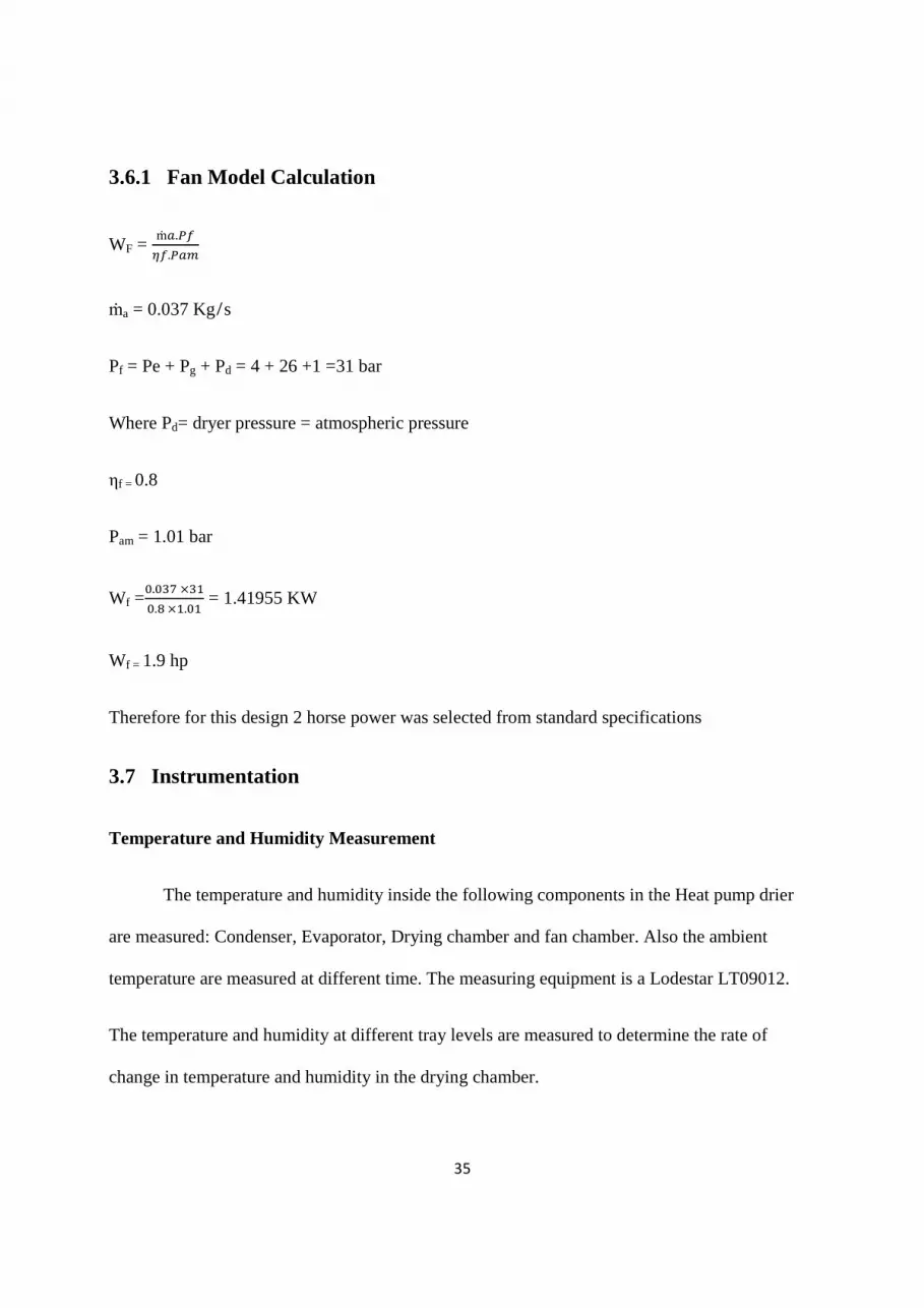
3.6.1 Fan Model Calculation
WF = ṁ.��
��.��
ṁa = 0.037 Kg s
Pf = Pe + Pg + Pd = 4 + 26 +1 =31 bar
Where Pd= dryer pressure = atmospheric pressure
ηf = 0.8
Pam = 1.01 bar
Wf =�.�"� ×"�
�.� �.�� = 1.41955 KW
Wf = 1.9 hp
Therefore for this design 2 horse power was selected from standard specifications
3.7 Instrumentation
Temperature and Humidity Measurement
The temperature and humidity inside the following components in the Heat pump drier
are measured: Condenser, Evaporator, Drying chamber and fan chamber. Also the ambient
temperature are measured at different time. The measuring equipment is a Lodestar LT09012.
The temperature and humidity at different tray levels are measured to determine the rate of
change in temperature and humidity in the drying chamber.

36
CHAPTER FOUR
4.0 RESULTS AND DISCUSSION
Table 4.4 shows the performance of heat pump when used for the drying of okra and
tomatoes. It was observed that the agricultural product maintains their original flavor after
drying. There is 75% reduction in weight of the tomato and 45% reduction in weight of the okra
.Agricultural produces placed at the top most part of the drying chamber takes more time to dry
due to an outlet present at the top most part used for defrostation of the evaporator. Therefore,
there is heat dissipation at the top most part. The heat pump drier exhibit higher performance on
a sunny day based on the fact that air injected into the system by the condenser fan contains
lesser humidity, therefore the system is weather sensitive. The lower the humidity in the drying
chamber the higher the rate of drying irrespective of the temperature in the drying chamber.
Figure 4.1 to 4.3 plotted from Table 4.2 shows the relationship among the time, humidity
and temperature which are the three criteria on which the drying capacity can be measured.
Therefore under zero loading, it can deduced that the lower the humidity the higher the
temperature at a specific time duration i.e the temperature is inversely proportional to the
humidity at constant time.
Figure 4.4 to Figure 4.6 plotted from table shows the relationship among the time,
humidity and temperature. During drying it can be deducted that there is higher temperature and
lower humidity in the first tray. Therefore, the rate of drying reduces from the first tray to the
topmost tray. The rate of drying is also dependent on distance. According to Figure 4.6, there is
stability in the percentage of humidity as the temperature increases which means that there is

37
little or no increase in humidity for five hours. This will produce the best coefficient of
performance of the drier. In the event of this, agricultural produce within higher water content
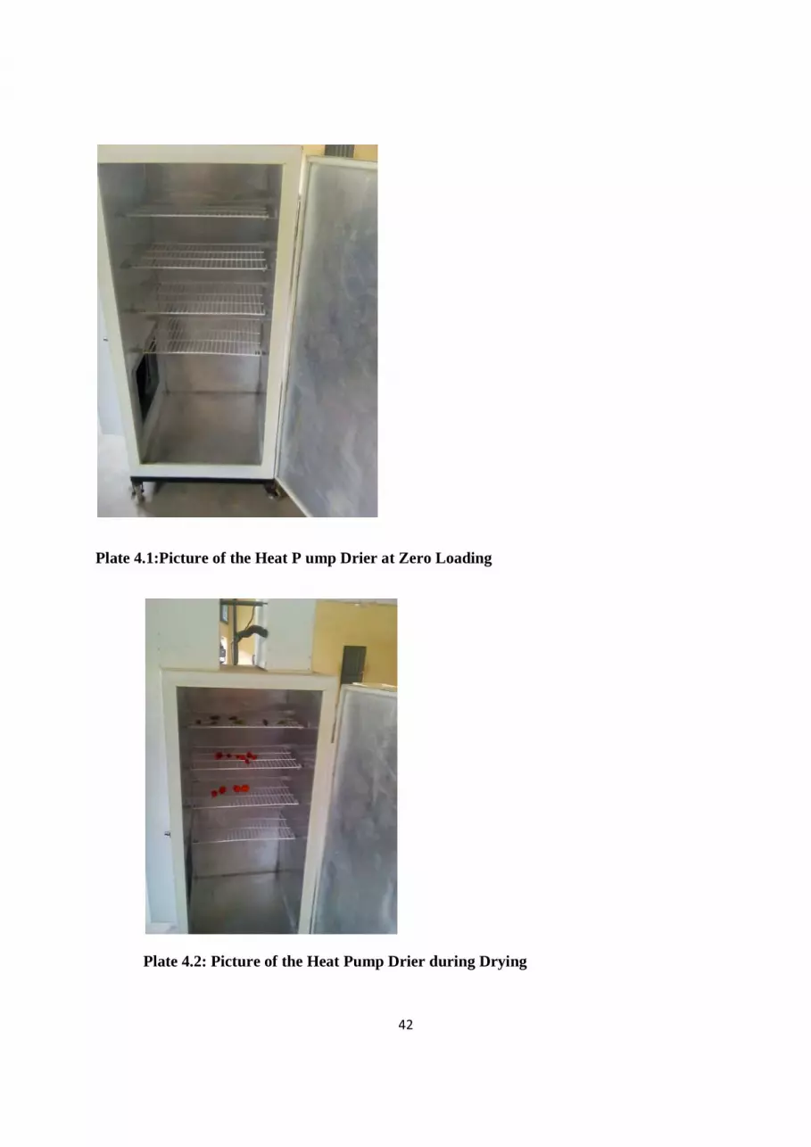
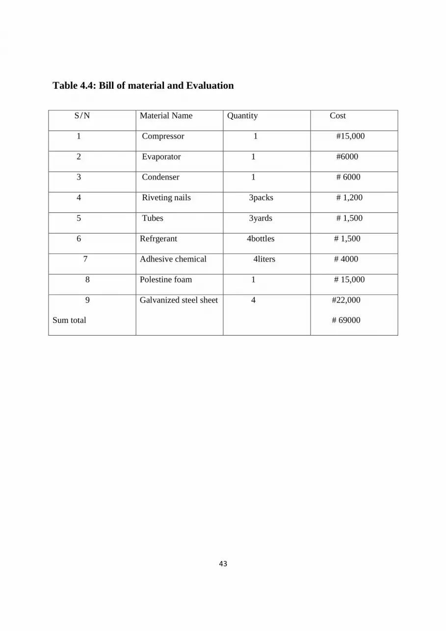
are advised to be placed on the first tray. Plate 4.1 and Plate 4.2 shows the picture of the heat p
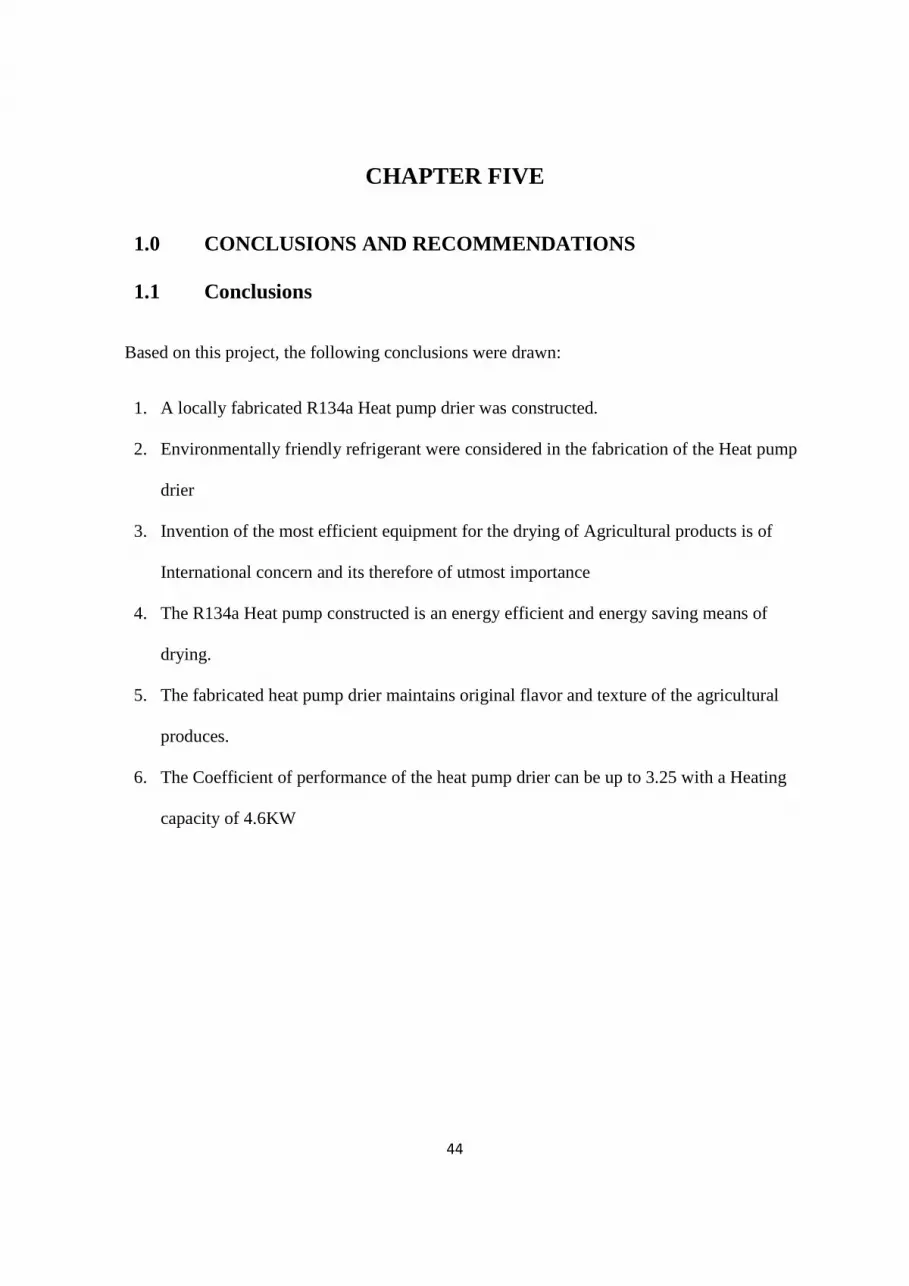
ump drier at zero loading and picture of the heat pump drier during drying respectively. Table
4.5 shows the bill of material and evaluation which determines the factors considered in the
selection of the materials, analyses of various material cost and the evaluation to discover if the
costs are economical

38
Based on reading of the lodestar meter, the following deductions were made
Table 4.1: Humidity and temperature of various component of the heat pump system
Component Temperature ( o C ) Humidity ( % ) Ambient Drying chamber Condenser Evaporation Fan chamber
28 .5 75 40 55 70 15 38
35 48 63
Table 4.2 The Temperature and Humidity during zero loading(no drying)
Drying chamber Ambient Time oC % oC % 11 am 72 50 28 84 12 pm 72 48 29 80 13 pm 75 48 32 75 14 pm 78 46 35 70 15 pm 79 45 36 67
Table 4.3 The temperature and Humidity during drying
Drying Chamber Ambient Time(hrs ) Tray one Tray two Tray three Tray four oC % o C % oC % oC % oC % 11 am 75 35 66 48 60 52 52 60 28 84 12 pm 75 35 66 46 61 52 50 60 29 80 13 pm 80 36 66 48 62 55 58 60 31 75 14 pm 80 34 70 48 60 50 55 63 35 70 15 pm 82 35 71 42 65 55 52 65 36 62
Table 4.4: The performance of the heat pump dryer
Agricultural product Temperature of
drying chamber
% reduction in
weight
Duration of drying
TOMATO 78o C 70% 15 hours
Okra 78oC 45% 10hours

39
Figure 4.1 Graph of Temperature against time for zero loading
Figure 4.2 Graph of Humidity against time for zero loading
20
30
40
50
60
70
80
90
11am 12am 01pm 02pm 03pm
Te
mp
era
ture
(C
)
Time (hours)
Graph of Temperature Against Time
drying chamber
ambient
20
30
40
50
60
70
80
90
11am 12am 01pm 02pm 03pm
Hu
mo
idit
y (
%)
Time (hours)
Graph of Humidity Against Time
drying chamber
ambient

40
Figure 4.3 Graph of Temperature against Humidity for zero loading
Figure 4.4 Graph of Temperature against time under loading
20
30
40
50
60
70
80
90
72 72 75 78 79
Hu
mid
ity
(%
)
Temperature (0C)
Graph of Humidity Against Temperature
drying chamber
ambient
20
30
40
50
60
70
80
90
11AM 12AM 1PM 2PM 3PM
Te
mp
era
ture
(O
C)
Time (hours)
Graph of Time Against Temperature
tray 1
tray 2
tray 3
tray 4
ambient

41
Figure 4.5 Graph of Humidity against Time under loading
Figure 4.6 Graph of Temperature against Humidity under loading
20
30
40
50
60
70
80
90
11AM 12AM 1PM 2PM 3PM
Hu
mid
ity
(%
)
Time (hours)
Graph of Humidity Against Time
tray 1
tray 2
tray 3
tray 4
ambient
20
30
40
50
60
70
80
90
75 75 80 80 82
Hu
mid
ity
(%
)
Temperature (0C)
Graph of Humidity Against Temperature
tray 1
tray 2
tray 3
tray 4
ambient
42
Plate 4.1:Picture of the Heat P ump Drier at Zero Loading
Plate 4.2: Picture of the Heat Pump Drier during Drying
43
Table 4.4: Bill of material and Evaluation
S N Material Name Quantity Cost
1 Compressor 1 #15,000
2 Evaporator 1 #6000
3 Condenser 1 # 6000
4 Riveting nails 3packs # 1,200
5 Tubes 3yards # 1,500
6 Refrgerant 4bottles # 1,500
7 Adhesive chemical 4liters # 4000
8 Polestine foam 1 # 15,000
9
Sum total
Galvanized steel sheet 4 #22,000
# 69000
44
CHAPTER FIVE
1.0 CONCLUSIONS AND RECOMMENDATIONS
1.1 Conclusions
Based on this project, the following conclusions were drawn:
1. A locally fabricated R134a Heat pump drier was constructed.
2. Environmentally friendly refrigerant were considered in the fabrication of the Heat pump
drier
3. Invention of the most efficient equipment for the drying of Agricultural products is of
International concern and its therefore of utmost importance
4. The R134a Heat pump constructed is an energy efficient and energy saving means of
drying.
5. The fabricated heat pump drier maintains original flavor and texture of the agricultural
produces.
6. The Coefficient of performance of the heat pump drier can be up to 3.25 with a Heating
capacity of 4.6KW

45
5.2 Recommendations
The following recommendations are made
I. The heat pump drier can be produced in large scale for commercial purpose.
II. To obtain maximum performance, the system should be operated in a low humidity
environment.
III. Also, institutions and government should create environment conducive enough for
research and development of projects work.
IV. Finally, the project is subjected to further research for improvement and development.

46
REFERENCES
ASHRAE, American Society of Heating, Refrigerating and Air-Conditioning Engineers.
Available from: http://www.ashrae.org/ [Accessed 21 May 2002]
Awra , C P (2007) Refrigeration and Air conditioning . Tata Mcgraw- Hill publishing company limited, New Delhi.
Bhatti, M. A (1999) A critical look at R – 744 and R- 134a Mobile Air conditioning system. SAE paper No 970527; 1997.
Bolaji , B.O (2008) investigating the performance of some environment friendly refrigerant as alternative to R12 in vapour compression system. PhD. This is in department of mechanical engineering, Federal university of technology, Akure, Nigeria
Brooker D Bakker- Arkema, F.W, and C.W. Hall, 1993. The Drying and Storage of Grains and Oilseeds. Van Nostrand Reinhold. Avi Book , New York. ( accessed March 2013)
Carrier: Energy Efficiency and Cost Savings. Available from: http://www.residential.carrier.com/knowledge/efficiency/index.shtml [Accessed 21 May 2008]
Chen, X.D. & Mujumdar, A.S. 2008. Drying Technologies In Food Processing. Wiley-Blackwell, West Sussex, United Kingdom.
Eden T. 1999. The Art of Preserving: How Cooks in Colonial Virginia Imitated Nature to Control It. Eighteenth Century Life 23(2):13 23. Also available from: http://muse.jhu.edu/journals/ eighteenth century_life/v023/23.2eden.html Accessed 2001 Sep 30.
EHPA, European Heat Pump Association. Available from: http://ehpa.fiz-karlsruhe.de/en/ [Accessed 21 May 2008]
Fatouh M., Metwally, M.N., Helali, A.B., Shedid, M.H., 2006. Herbs drying using a heat pump dryer, Energy Conversion and Management 4s7: 2629–2643
Friotherm AG. Available from: http://www.friotherm.com [Accessed 21 May 2008]
Global warming potential of ODS Substitution ozen layer protection US EPA , Epa.gar (2006 – 06 – 08 )
Lorentzen, G., Pettersen, J., 1993, A new, environmentally benign system for car air-conditioning, Int. Journal of Refrigeration, Vol. 16, No.1: pp. 4-12.
Mack L. 2001. Food Preservation in the Roman Empire. Chapel Hill, NC. University of North Carolina. Available from: http://www.unc.edu/courses/rometech/public /content/survival/Lindsay_ Mack/Food_Preservation.htm. Accessed 2001 Sep 30.
47
Mujumdar, A.S. & Devahastin, S. 2008. Fundamental Principles of Drying. In: Mujumdar, A.S. (Ed.). Guide to Industrial Drying − Principles, Equipments and New Developments. Three S Colors Publications, Mumbai, India
Mujumdar, A.S. 2004. Dehydration of Products of Biological Origin. Science Publishes, UK.
Mujumdar, S. A , and Jangam S, V , (2011) . Some innovative Drying Technologies for Dehydration of foods. Department of mechanical engineering, National university of Singapore
Nummer , B. A, PhD. National center for Home Food Preservation (accessed May, 2013 )
Sanchez D. V, May 2008. Heat pump system using waste energy for a district heating application. Master’s Thesis in Energy Systems.
T jukup M., Sulistyowati. E, Merah Bantul P. C, dengan Bantuan Pompa Kalor, ProsidingSNTK ‘’Kejuangan’’ , Teknik Kimia, ‘’Yogyakarta.V, Raghavan G S V , Rennie T J, Sunjka P S, Orsat V, Tedtoon P. 2005. Overview of new techniques for drying biological with emphasis one Energy aspects. Brazilian Journal of Chemical Engineering, ; 22(2); 195 – 201.s
.
Related Documents


