GSFC· 2015 Heat Flux Measurements for Supersonic Film Cooling Colin Adamson, Chandan Kittur , Salman Verma , Christopher Cadou , and Arnaud Trouve University of Maryland Joseph Ruf NASA Marshall Space Flight Center

Welcome message from author
This document is posted to help you gain knowledge. Please leave a comment to let me know what you think about it! Share it to your friends and learn new things together.
Transcript

GSFC· 2015
Heat Flux
Measurements for
Supersonic Film
Cooling
Colin Adamson, Chandan Kittur,
Salman Verma, Christopher Cadou,
and Arnaud Trouve
University of Maryland
Joseph Ruf
NASA Marshall Space Flight Center
Outline
• Background
• Previous Work
• Objectives
• Methodology
• Results
• Next Steps
2TFAWS 2015 – August 3-7, 2015 – Silver Spring, MD
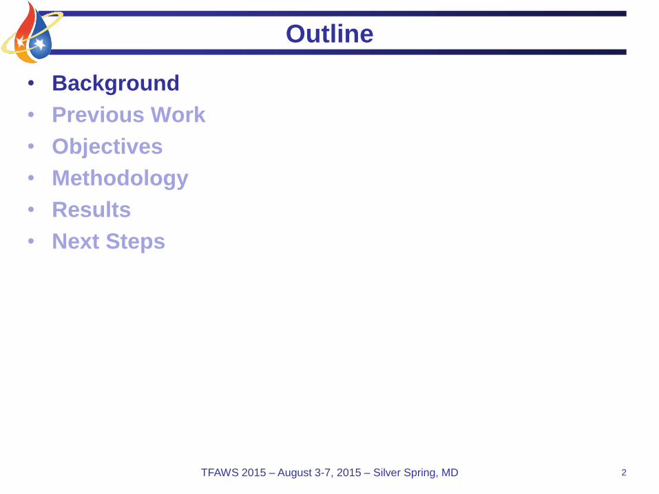
Film Cooling
• What is Film Cooling?
– Thermal protection technique
where a cooler gas injected along
a critical surface creates an
insulating layer that protects it
from hot combustion products.
• Applications
– Gas Turbines
• Combustor liner
• Turbine blades
– Rockets
• Nozzle extension
3TFAWS 2015 – August 3-7, 2015 – Silver Spring, MD
Gas turbine combustor
Rocket thrust chamber or
Nozzle Extension
Adapted from
(Sutton, 1986) J-2X Concept
Hot
Cold
Film Cooled Wall
Mainstream
Coolant
Figure Adapted from
Cruz (2008)

J-2X Comparison
4TFAWS 2015 – August 3-7, 2015 – Silver Spring, MD
• J-2X nozzle extension
• UMD tunnel
– J-2X analogue
– Various film flow cases:
• Case 0 – no film
• Case 1 – Mfilm = 0.5
• Case 2 – Mfilm = 0.7
• Case 3 – Mfilm = 1.2
M2= 1.84,
T2 = 539 K,
P02 = 2.4 atm
M1= 3.74,
T1 = 3767 K,
P01= 82 atm
x
y
𝑑𝑃
𝑑𝑥= 0
Core Inlet:
T0= 300 K
P0= 1 atm
Twall=340 K
Twall=340 KFilm Inlet:
T0= 330 K
Mcore = 2.4

UMD Supersonic Wind Tunnel
5TFAWS 2015 – August 3-7, 2015 – Silver Spring, MD
• Basic Specs
– Transient facility (6-10 sec run time)
– Working fluid: Air
– Total P, T: Ambient
– Test section Dimension: 12”x6”x26”
• The tunnel cannot directly match J-2X conditions so special care must be
taken to design analagous experiments.
– Heat walls to ensure that the heat flux vector always points into the flow
– Heat film to ensure temperature “cascade” is preserved
Outline
• Background
• Previous Work
• Objectives
• Methodology
• Results
• Next Steps
6TFAWS 2015 – August 3-7, 2015 – Silver Spring, MD

Literature Review
• Experiments, Scaling Laws, and Simulations– Wieghardt (1946) – Established much of the scaling regarding film cooling. Actually analyzed film
heating and found similarity relationship for downstream thermal profiles, as well as a model for the wall
effectiveness scaling.
– Lucas and Golladay (1963) – Studied film cooling in a rocket nozzle in the presence of accelerating
flow, measuring mass flow rates, wall temperatures and wall pressures
– Goldstein (1971) – Comprehensive review of film cooling scaling laws. Most analysis uses a fully
developed turbulent boundary layer and features scaling using the blowing ratio and slot height .
– Aupoix et al. (1998) – Performed one of the seminal supersonic film cooling studies by exploring the
mixing of a supersonic film with a supersonic mainstream for overexpanded, under-expanded and perfectly
expanded films. Total pressure, static temperature and total temperature probes were used to extract
profiles at different downstream stations. Wall pressures and adiabatic wall temperatures are also provided.
Additionally several different RANS turbulence models were tested using a boundary layer code. Boundary
layer code was noted to be incapable of capturing the initial mixing but downstream mixing trends were
captured adequately.
– Konopka et al. (2010) – Performed the first supersonic LES of film cooling and compared simulation
wall temperatures with experimental data and found excellent agreeement.
• More experimental data are needed for validating supersonic film cooling
CFD
– Most studies do not provide flow profiles or turbulence intensity info.
– No studies provide minimally-intrusive flow profiles.
• More work is required to assess suitability of RANS and LES approaches
for film cooling flows.7TFAWS 2015 – August 3-7, 2015 – Silver Spring, MD

Literature Review, Cont
• Work At UMD
– Cruz (2008) – Adiabatic and non-adiabatic film cooling experiments for multiple blowing ratios (BR=0.6,
1.2, 3.0) using microthermocouples, PIV and IR thermography. Provided mean velocity and temperature
profiles turbulent kinematic and thermal profiles, wall heat transfer, adiabatic wall effectiveness and skin
friction at several downstream locations. Had uncontrolled flow conditions affecting film cooling mixing.
Performed incompressible LES calculation of adiabatic wall jet case.
– Dellimore (2010) – Modified Simon’s incompressible model for slot film cooling to account for
compressibility effects and mainstream pressure gradients. Used RANS techniques to simulate supersonic
film cooling experiments of Maqbool (2011) in addition to the experiments of Cruz (2008).
– Maqbool (2011) – Performed supersonic film cooling experiments for both subsonic and supersonic films;
developed an efficient wall heat transfer technique that calculates the heat flux at the wall based on internal
embedded thermocouples; most of the film cooling experiments were performed with film total pressures
equal to the mainstream; used Schlieren to capture shock structures. Captured wall pressures and wall
temperatures as well
– Voegele (2011 & 2013) – Presented RANS simulations of 2D adiabatic, slot film cooling of adiabatic
experiments. Used a variety of inflow specification techniques to test RANS performance. Also explored
turbulence models and effect of turbulent Prandtl number. Found the kinematics were captured well but the
thermal fields were not captured very well. Also captured adiabatic and non-adiabatic film cooling
experiments. Used variable-density LES to accurately capture subsonic film cooling performance in terms of
both flow profiles and wall heat transfer characteristics.
8TFAWS 2015 – August 3-7, 2015 – Silver Spring, MD
Outline
• Background
• Previous Work
• Objectives
• Methodology
• Results
• Next Steps
9TFAWS 2015 – August 3-7, 2015 – Silver Spring, MD

Objective
10TFAWS 2015 – August 3-7, 2015 – Silver Spring, MD
Improve experimental apparatus and acquire more and
better data
• Correct problem with previous nozzle
• Acquire more/better heat flux data
• Acquire higher quality Schlieren images over the entire
test section
• Improve our understanding of the heat flux measurement
technique
– Reduce measurement uncertainty
Outline
• Background
• Previous Work
• Objectives
• Methodology
• Results
• Next Steps
11TFAWS 2015 – August 3-7, 2015 – Silver Spring, MD

Experiment Overview
12TFAWS 2015 – August 3-7, 2015 – Silver Spring, MD

Film Heating Methods
13TFAWS 2015 – August 3-7, 2015 – Silver Spring, MD
• Initial film heating method: Propane burner
– Difficult to tune, produced very transient results, added an order of
complexity to the system
• Heat gun development
– Simple substitution of an electric heat gun for the combuster
– The heat gun was found to produce more stable heating with much
simpler operation
Propane Burner (Case 3) Heat Gun (Case 2)
Run start Run startRun End Run End

Operational Procedure
• Heat tunnel walls from ambient to 50 K above ambient
(25-30 min)
• Pump down vacuum tanks to minimum pressure (15
min)
• Allow wall temperature to fall to ~43K above ambient
and become isothermal (5-10 min)
• Start film heater
• Open butterfly valves to begin run
– Collect pressure and temperature data
• Once flow becomes unsteady, close valves
• Begin reheating walls (10-15 min)
– Typically, walls only fall 6-7K per run, so heating is faster after
the first heat cycle
14TFAWS 2015 – August 3-7, 2015 – Silver Spring, MD

Lower Wall Infrared Measurement
15TFAWS 2015 – August 3-7, 2015 – Silver Spring, MD
Macor
Copper
Nozzle

Measurement and Shock Locations
16TFAWS 2015 – August 3-7, 2015 – Silver Spring, MD
Flow

Heat Flux Gauges
17TFAWS 2015 – August 3-7, 2015 – Silver Spring, MD
• Infer wall heat flux from sub-surface temperature-time histories
– Inverse method
• Advantage: no disturbance to flow
• Disadvantage: complex data interpretation process

Heat Flux Measurements
18TFAWS 2015 – August 3-7, 2015 – Silver Spring, MD
• Governing Equation:
• Boundary Conditions (Pr=1):
• Wall Heat Flux:
• Problem: In our expt., total T of air is
same as T wall.
– Won’t measure any heat flux w/o wall
heating or cooling.
– We will heat the wall to ensure
unidirectional heat transfer.
y
u
yy
h
c
k
yy
hv
x
hu o
p
oo )2(
Pr
11
2
0
2
2Tc
uTch ppo
pc
u
2
2
''
wq
''
wq
0'' wq ,0T
0T
T
,0
0'' TThy
Tkq w
w
w
0
00,
,00
,00
0
xTTuu
yTTuu
yTTvu w
Ref: Kays & Crawford

19TFAWS 2015 – August 3-7, 2015 – Silver Spring, MD
Wall Temperature Response
• Tbackplane must remain constant for wall T response equation to be valid
• Heat film to intermediate temperature to keep heat flux vector aligned
• Objective: extract heat flux from temperature-time histories
tk
h
t
yerfce
t
yerfc
TT
TT tk
h
k
hy
waw
w
44
2
,0
,0
Gas
T
KT 3000
0t
t
t
~26K
y
x
p
cawc
urTT
2
2
Prcr
wT ,0
awww TThq ''
~40K
Wall temperature responseHeat flux
Thermocouple
Wall
Back
Pla
ne
Flow

20TFAWS 2015 – August 3-7, 2015 – Silver Spring, MD
Data Acquisition Timing
Imaging region
Film Flow
Core
Flow
Pressure Tap
21TFAWS 2015 – August 3-7, 2015 – Silver Spring, MD
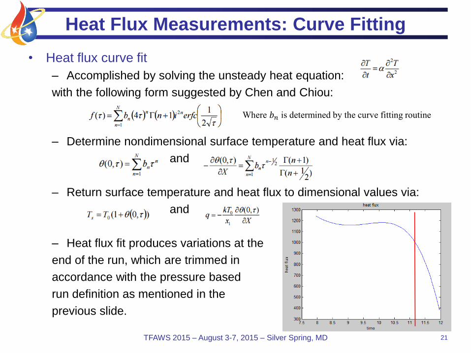
Heat Flux Measurements: Curve Fitting
• Heat flux curve fit
– Accomplished by solving the unsteady heat equation:
with the following form suggested by Chen and Chiou:
– Determine nondimensional surface temperature and heat flux via:
and
– Return surface temperature and heat flux to dimensional values via:
and
– Heat flux fit produces variations at the
end of the run, which are trimmed in
accordance with the pressure based
run definition as mentioned in the
previous slide.
Where 𝑏𝑛 is determined by the curve fitting routine

Schlieren System
22TFAWS 2015 – August 3-7, 2015 – Silver Spring, MD
• Z configuration
• Nikon D-90 with Nikon 70-300mm f/4-5.6G lens
Top down view of tunnelMain Flow
Louver
Mirror 1
Mirror 2
Horizontal Schlieren Stop
Camera
Aperture
LED
f = 59.75 in
f = 78.625 in

Outline
• Background
• Previous Work
• Objectives
• Methodology
• Results
• Next Steps
23TFAWS 2015 – August 3-7, 2015 – Silver Spring, MD
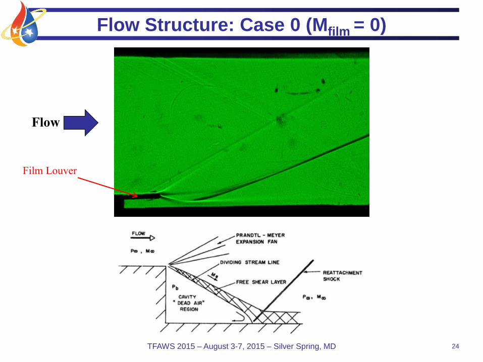
Flow Structure: Case 0 (Mfilm = 0)
24TFAWS 2015 – August 3-7, 2015 – Silver Spring, MD
Film Louver
Flow

Flow Structure: Case 1 (Mfilm = 0.5)
25TFAWS 2015 – August 3-7, 2015 – Silver Spring, MD
Mfilm< 1
Mcore> 1
Shear layer
Louver Slip line
Boundary layers
Wall
Shock
Exp
Film Louver
Flow

Flow Structure: Case 2 (Mfilm = 0.7)
26TFAWS 2015 – August 3-7, 2015 – Silver Spring, MD
Mfilm< 1
Mcore> 1
Shear layer
Louver Slip line
Boundary layers
Wall
Shock
Exp
Film Louver
Flow

Flow Structure: Case 3 (Mfilm = 1.2)
27TFAWS 2015 – August 3-7, 2015 – Silver Spring, MD
Mfilm > 1
Mcore > 1
Louver Slip line
Boundary layers
Shock
Reflected Shock
Shear layer
Shock
Wall
Exp
Film Louver
Flow

28TFAWS 2015 – August 3-7, 2015 – Silver Spring, MD
Heat Flux: Lower Wall
-9000
-8000
-7000
-6000
-5000
-4000
-3000
-2000
-1000
0
0 10 20 30 40 50 60 70
Hea
t Fl
ux
(W/m
^2
)
x/s
Case 1: Subsonic, Mfilm = 0.5
-9000
-8000
-7000
-6000
-5000
-4000
-3000
-2000
-1000
0
0 10 20 30 40 50 60 70
Hea
t Fl
ux
(W/m
^2
)
x/s
Case 2: Pressure Matched, Mfilm = 0.7
-9000
-8000
-7000
-6000
-5000
-4000
-3000
-2000
-1000
0
0 10 20 30 40 50 60 70
Hea
t Fl
ux
(W/m
^2
)
x/s
Case 3: Supersonic, Mfilm = 1.2
-9000
-8000
-7000
-6000
-5000
-4000
-3000
-2000
-1000
0
0 10 20 30 40 50 60 70
Hea
t Fl
ux
(W/m
^2
)
x/s
Case 0: Film Closed
Experiment
Loci-CHEM

29TFAWS 2015 – August 3-7, 2015 – Silver Spring, MD
Heat Flux: Upper Wall
-9000
-8000
-7000
-6000
-5000
-4000
-3000
-2000
-1000
0
0 10 20 30 40 50 60 70
Hea
t Fl
ux
(W/m
^2)
x/s
Case 0: Film Closed
Experiment
Loci-CHEM-9000
-8000
-7000
-6000
-5000
-4000
-3000
-2000
-1000
0
0 10 20 30 40 50 60 70
Hea
t Fl
ux
(W/m
^2)
x/s
Case 1: Subsonic, Mfilm = 0.5
-9000
-8000
-7000
-6000
-5000
-4000
-3000
-2000
-1000
0
0 10 20 30 40 50 60 70
Hea
t Fl
ux
(W/m
^2)
x/s
Case 2: Pressure Matched, Mfilm = 0.7
-9000
-8000
-7000
-6000
-5000
-4000
-3000
-2000
-1000
0
0 10 20 30 40 50 60 70
Hea
t Fl
ux
(W/m
^2)
x/s
Case 3: Supersonic, Mfilm = 1.2
Lip Shock
Impingement
Location

Outline
• Background
• Previous Work
• Objectives
• Methodology
• Results
• Next Steps
30TFAWS 2015 – August 3-7, 2015 – Silver Spring, MD
Next Steps
• Improve our understanding of the discrepancy between
experiments and simulations
• Improve our understanding of the heat flux instrument
– Construct unit scale test blocks to measure heat flux gauge
response to impulsive imposition of well known boundary
conditions
– Lead to better understanding of instrument error
• New measurements with favorable pressure gradient
– More direct comparison to J-2X geometry and function
– New test section is being designed now
31TFAWS 2015 – August 3-7, 2015 – Silver Spring, MD

Acknowledgements
• The authors would like to thank the National Aeronautics
and Space Administration and Melinda Nettles of the
Marshall Space Flight Center for their support under
NRA NNM13AA13G.
32TFAWS 2015 – August 3-7, 2015 – Silver Spring, MD

References
• *Carslaw, H.S. and Jaeger, J.C., “Conduction of Heat in Solids,” 2nd Edition, Oxford
University Press, 1959, pp. 70-73.
• Maqbool, Daanish. (2010). Development of an experiment for measuring film cooling
performance in supersonic flows. Master’s Thesis. Retrieved from
http://drum.lib.umd.edu/bitstream/1903/12075/1/Maqbool_umd_0117N_12356.pdf
• Maqbool, D., et. Al. (2014, January 13-17). Measurements of Film Cooling
Performance in Supersonic Environments. 52nd Aerospace Sciences Meeting. Paper
presented at AIAA SciTech: Maryland. DOI: 10.2514/6.2014-0701
• Smith, H. E., “The Flow Field and Heat Transfer Downstream of a Rearward Facing
Step in Supersonic Flow,” ARL 67-0056, Aerospace Research Laboratories, March
1967.
33TFAWS 2015 – August 3-7, 2015 – Silver Spring, MD
Related Documents