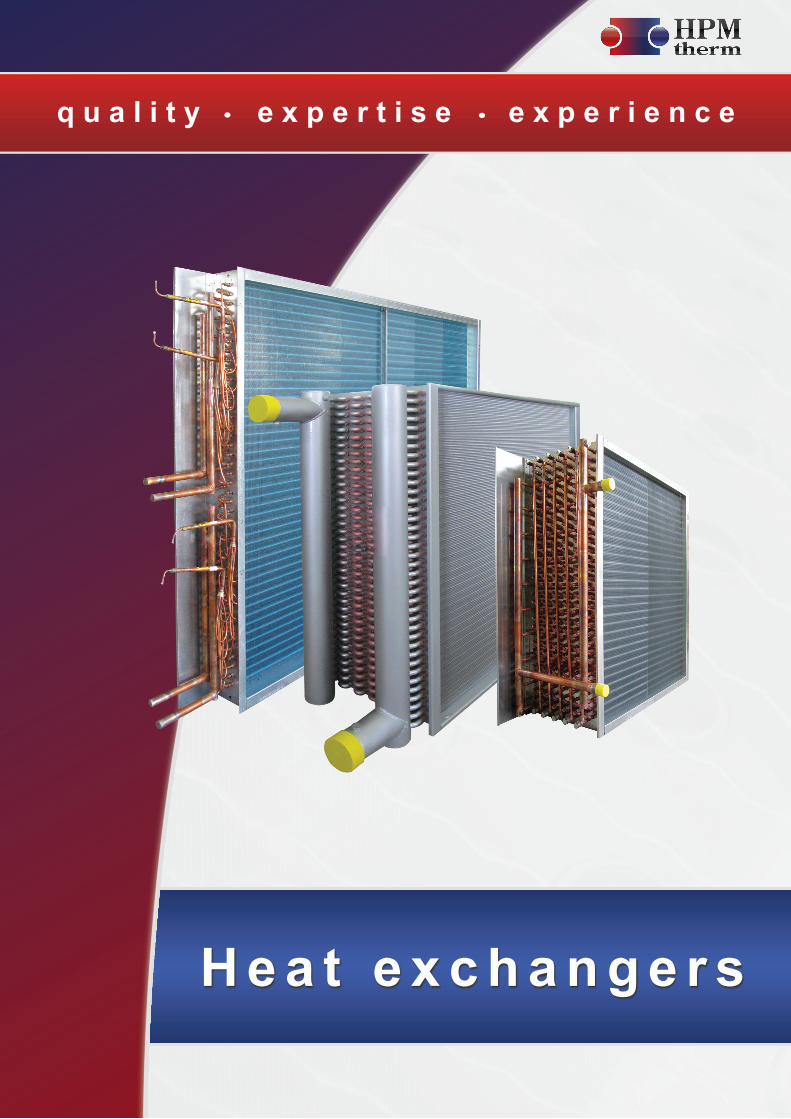
quality expertise experience Heat exchangers

Welcome message from author
This document is posted to help you gain knowledge. Please leave a comment to let me know what you think about it! Share it to your friends and learn new things together.
Transcript
q u a l i t y e x p e r t i s e e x p e r i e n c e
H e a t e x c h a n g e r s
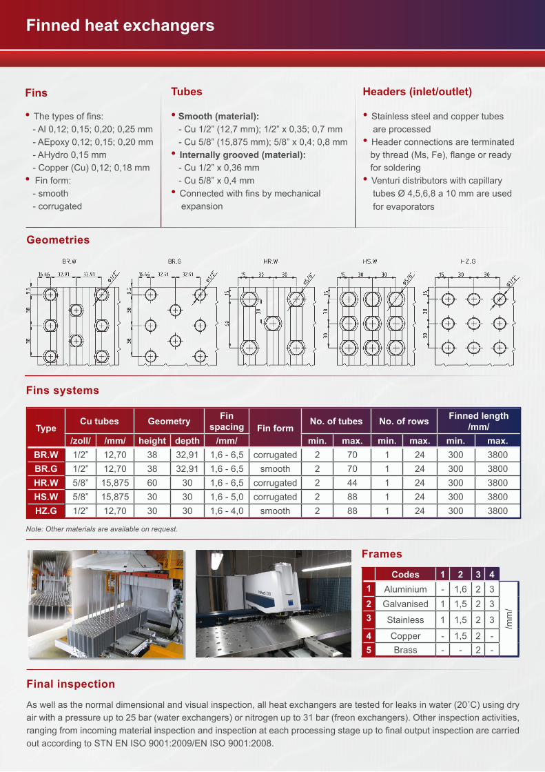
• The types of fins: - Al 0,12; 0,15; 0,20; 0,25 mm - AEpoxy 0,12; 0,15; 0,20 mm - AHydro 0,15 mm - Copper (Cu) 0,12; 0,18 mm• Fin form: - smooth - corrugated
• Smooth (material): - Cu 1/2” (12,7 mm); 1/2” x 0,35; 0,7 mm - Cu 5/8” (15,875 mm); 5/8” x 0,4; 0,8 mm• Internally grooved (material): - Cu 1/2” x 0,36 mm - Cu 5/8” x 0,4 mm• Connected with fins by mechanical expansion
• Stainless steel and copper tubes are processed • Header connections are terminated by thread (Ms, Fe), flange or ready for soldering • Venturi distributors with capillary tubes Ø 4,5,6,8 a 10 mm are used for evaporators
Geometries
TypeCu tubes Geometry Fin
spacing Fin formNo. of tubes No. of rows Finned length
/mm//zoll/ /mm/ height depth /mm/ min. max. min. max. min. max.
BR.W 1/2” 12,70 38 32,91 1,6 - 6,5 corrugated 2 70 1 24 300 3800BR.G 1/2” 12,70 38 32,91 1,6 - 6,5 smooth 2 70 1 24 300 3800HR.W 5/8” 15,875 60 30 1,6 - 6,5 corrugated 2 44 1 24 300 3800HS.W 5/8” 15,875 30 30 1,6 - 5,0 corrugated 2 88 1 24 300 3800HZ.G 1/2” 12,70 30 30 1,6 - 4,0 smooth 2 88 1 24 300 3800
Final inspection
As well as the normal dimensional and visual inspection, all heat exchangers are tested for leaks in water (20˚C) using dry air with a pressure up to 25 bar (water exchangers) or nitrogen up to 31 bar (freon exchangers). Other inspection activities, ranging from incoming material inspection and inspection at each processing stage up to final output inspection are carried out according to STN EN ISO 9001:2009/EN ISO 9001:2008.
Codes 1 2 3 41 Aluminium - 1,6 2 3
/mm
/2 Galvanised 1 1,5 2 33 Stainless 1 1,5 2 3
4 Copper - 1,5 2 -5 Brass - - 2 -
Fins systems
Frames
Fins Tubes Headers (inlet/outlet)
Finned heat exchangers
Note: Other materials are available on request.
1 2
Vert
ical
airfl
ow
HWCWSW
V
CD V
DX V
ST V
Hor
izon
tal a
irflow
HWCWSW
H
CD H
DX H
ST H
left right
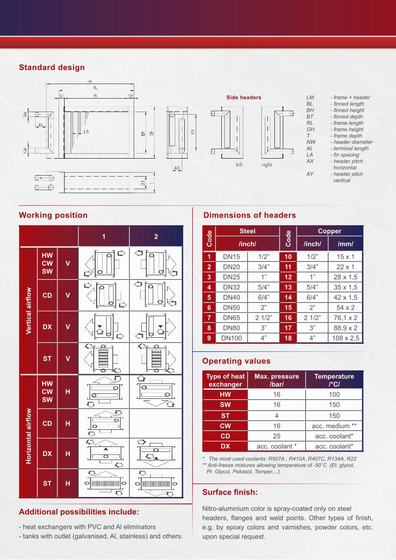
Standard design
Side headers LM - frame + headerBL -finnedlengthBH -finnedheightBT -finneddepthRL -framelengthGH -frameheightT -framedepthNW - header diameterAL -terminallengthLA -finspacingAX -headerpitch horizontal AY -headerpitch vertical
Working position Dimensions of headersC
ode Steel
Cod
e Copper
/inch/ /inch/ /mm/
1 DN15 1/2” 10 1/2” 15 x 12 DN20 3/4” 11 3/4” 22 x 13 DN25 1” 12 1” 28 x 1,54 DN32 5/4” 13 5/4” 35 x 1,55 DN40 6/4” 14 6/4” 42 x 1,56 DN50 2” 15 2” 54 x 27 DN65 2 1/2” 16 2 1/2” 76,1 x 28 DN80 3” 17 3” 88,9 x 29 DN100 4” 18 4” 108 x 2,5
Operating values
Type of heat exchanger
Max. pressure/bar/
Temperature/°C/
HW 16 100SW 16 150
ST 4 150CW 16 acc. medium **CD 25 acc. coolant*DX acc. coolant * acc. coolant*
* Themostusedcoolants:R507A,R410A,R407C,R134A,R22**Anti-freezemixturesallowingtemperatureof-50˚C(Et.glycol,Pr.Glycol,Pekasol,Temper,...)
Additional possibilities include:
- heat exchangers with PVC and Al eliminators- tanks with outlet (galvanised, Al, stainless) and others.
Surface finish:
Nitro-aluminium color is spray-coated only on steel headers, flanges and weld points. Other types of finish, e.g. by epoxy colors and varnishes, powder colors, etc. upon special request.
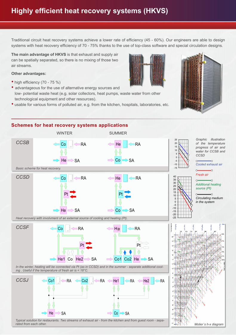
Traditional circuit heat recovery systems achieve a lower rate of efficiency (45 - 60%). Our engineers are able to design systems with heat recovery efficiency of 70 - 75% thanks to the use of top-class software and special circulation designs.
Other advantages:
• high efficiency (70 - 75 %)• advantageous for the use of alternative energy sources and low- potential waste heat (e.g. solar collectors, heat pumps, waste water from other technological equipment and other resources).• usable for various forms of polluted air, e.g. from the kitchen, hospitals, laboratories, etc.
Schemes for heat recovery systems applications WINTER SUMMER
RA
SA
Co
He
RA
SACo
He
RA
SA
Pt
Co
He
RA
SA
Pt
Co
He
He1 SA
RA
Pt
Co
Co
He2 SA
RA
Pt
Co1 Co2
Hy
He
Co2
He
Co1 RA
SA
RA RA
SACo
He1 RAHe2
e
The main advantage of HKVS is that exhaust and supply air can be spatially separated, so there is no mixing of those two air streams.
Highly efficient heat recovery systems (HKVS)
CCSB
Basicschemeforheatrecovery.
Heatrecoverywithinvolvmentofanexternalsourceofcoolingandheating(Pt).
CCSD
CCSF
Inthewinter,heatingwillbeconnectedviaPt(asinCCSD)andinthesummer-separateadditionalcool-ing.Usefulifthetemperatureoffreshairis<18°C.
CCSJ
Typicalsolutionforrestaurants.Twostreamsofexhaustair-fromthekitchenandfromguestroom-sepa-ratedfromeachother.
-15-10-505
10152025
-25-20-15-10-505
10152025303540
Molier`sh-xdiagram
Graphic illustrationof the temperatureprogress of air andwater forCCSBandCCSD
Cooledexhaustair
Freshair
Additionalheatingsource(Pt)
Circulatingmediuminthesystem
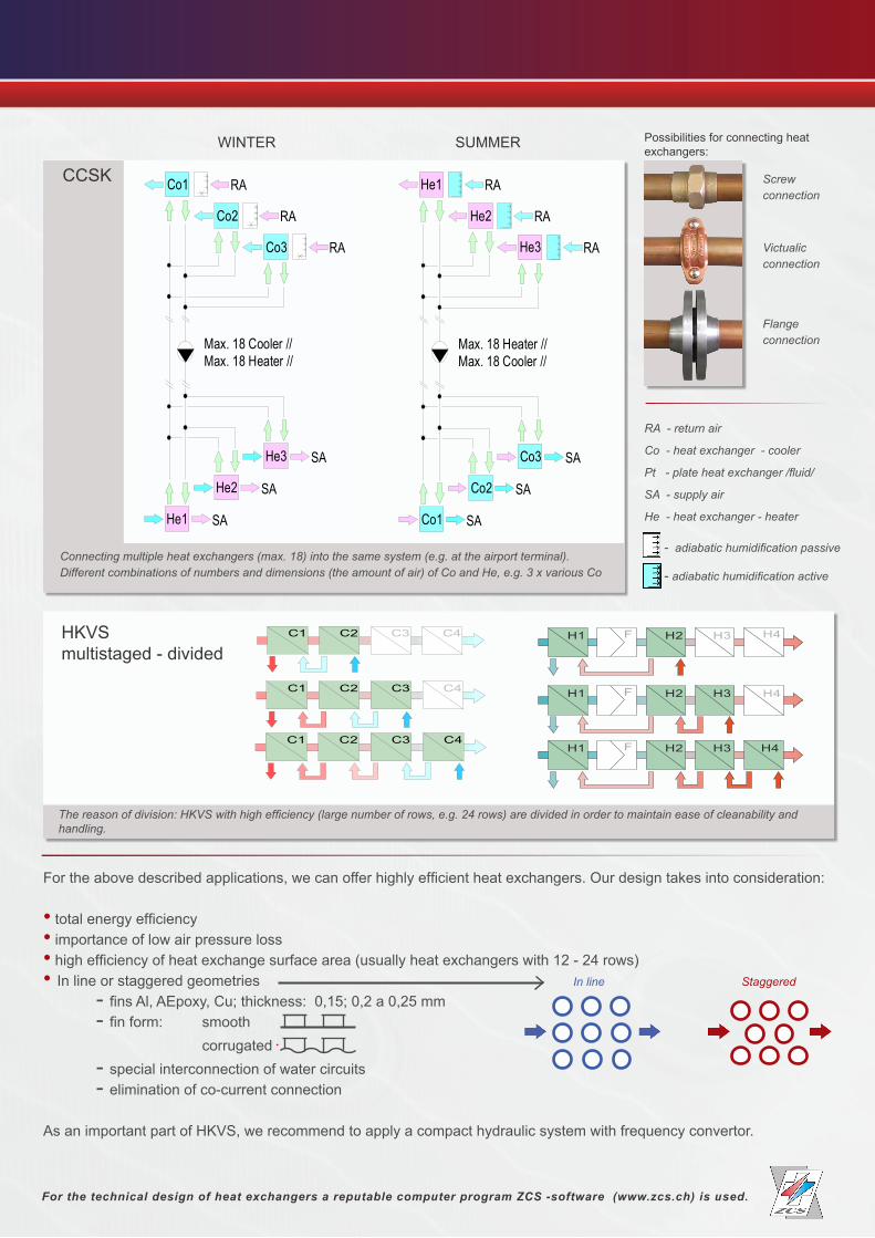
For the above described applications, we can offer highly efficient heat exchangers. Our design takes into consideration:
• total energy efficiency • importance of low air pressure loss• high efficiency of heat exchange surface area (usually heat exchangers with 12 - 24 rows)• In line or staggered geometries In line Staggered - fins Al, AEpoxy, Cu; thickness: 0,15; 0,2 a 0,25 mm - fin form: smooth corrugated - special interconnection of water circuits - elimination of co-current connection
As an important part of HKVS, we recommend to apply a compact hydraulic system with frequency convertor.
WINTER SUMMER
RA - return air
Co-heatexchanger-cooler
Pt-plateheatexchanger/fluid/
SA-supplyair
He-heatexchanger-heater
RA
SACo1
He1
RAHe2
RAHe3
SACo2
Co3 SA
Max. 18 Heater //Max. 18 Cooler //
RA
SA
Co1
He1
RA
He2
RA
He3
SA
Co2
Co3
SA
Max. 18 Cooler //Max. 18 Heater //
- adiabatichumidificationactive -adiabatichumidificationpassive
HKVSmultistaged - divided
For the technical design of heat exchangers a reputable computer program ZCS -software (www.zcs.ch) is used.
C3C1 C2 C4
C3C1 C2 C4
C3C1 C2 C4
H3H2 H4FH1
H3H2 H4FH1
H3H2 H4FH1
CCSK
Connectingmultipleheatexchangers(max.18)intothesamesystem(e.g.attheairportterminal).Differentcombinationsofnumbersanddimensions(theamountofair)ofCoandHe,e.g.3xvariousCo
Thereasonofdivision:HKVSwithhighefficiency(largenumberofrows,e.g.24rows)aredividedinordertomaintaineaseofcleanabilityandhandling.
Possibilities for connecting heat exchangers:
Screwconnection
Victualicconnection
Flangeconnection
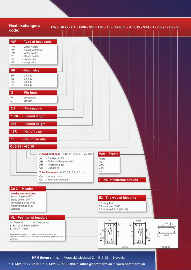
HW - BR.G - 2,1 - 1000 - 988 - 12R - 13 - Cu 0,35 - Al 0,15 - V2A - 1 - Cu 2” - E2 - VL
HW - Type of heat exch.- water heater- hot water heater- water cooler- steam heater- condenser- evaporator
HW SW CW ST CDDX
- 38 x 33- 30 x 30- 30 x 30- 60 x 30
BR HZ HSHR
- corrugated- smooth
WG
Cu - smooth tubeCx - internally grooved
- Sandard Al foil- Al-Epoxid lacquered foil- Hydrophilic foil- Copper fin
Al AE AH Cu
Finned thickness - 0,12; 0,15; 0,20; 0,25 mm
2,1 - Fin spacing
1000 - Finned length
988 - Finned height
12R - No. of rows
13 - No. of circuits
Cu 0,35 - Al 0,15
V2A - FrameFeZnAluV2AV4ACuTube thickness - 0,35; 0,7; 0,4; 0,8 mm
Cu 2” - HeaderHeader connections: Brass nipple (MPT)Brass socket (FPT)Threaded flange (Fe)Welding flange (Fe)Victaulic
G - Fin form
E2 - The way of bleedingE0 - any E+EE1 - standard E+EE2 - internal E+E (HKVS)
VL - Position of headersV - Vertical H - HorizontalL, R - direction of airflow: L - left, R - right
Note:Besidesdirectconnection(seepic.),thereisanalternativeconnectionindirection,respectivelyagainstairflowdirection.
Left Right
Vertical Horizontal
1 - No. of external circuits
BR - Geometry
Heat exchangers code:
HPM therm s. r. o. Moravské Lieskové 2 916 42 Slovakia
T +421 32 77 92 983 F +421 32 77 92 984 [email protected] www.hpmtherm.eu
Related Documents