1 1 Heat Exchangers Introduction, Classification, and Selection 1.1 INTRODUCTION A heat exchanger is a heat transfer device that is used for transfer of internal thermal energy between two or more fluids available at different temperatures. In most heat exchangers, the fluids are separated by a heat transfer surface, and ideally they do not mix. Heat exchangers are used in the process, power, petroleum, transportation, air-conditioning, refrigeration, cryogenic, heat recov- ery, alternate fuels, and other industries. Common examples of heat exchangers familiar to us in day-to-day use are automobile radiators, condensers, evaporators, air preheaters, and oil coolers. Heat exchangers can be classified into many different ways. 1.2 CONSTRUCTION OF HEAT EXCHANGERS A heat exchanger consists of heat-exchanging elements such as a core or matrix containing the heat transfer surface, and fluid distribution elements such as headers or tanks, inlet and outlet nozzles or pipes, etc. Usually, there are no moving parts in the heat exchanger; however, there are excep- tions, such as a rotary regenerator in which the matrix is driven to rotate at some design speed and a scraped surface heat exchanger in which a rotary element with scraper blades continuously rotates inside the heat transfer tube. The heat transfer surface is in direct contact with fluids through which heat is transferred by conduction. The portion of the surface that separates the fluids is referred to as the primary or direct contact surface. To increase heat transfer area, secondary surfaces known as fins may be attached to the primary surface. Figure 1.1 shows a collection of few types of heat exchangers. 1.3 CLASSIFICATION OF HEAT EXCHANGERS In general, industrial heat exchangers have been classified according to (1) construction, (2) trans- fer processes, (3) degrees of surface compactness, (4) flow arrangements, (5) pass arrangements, (6) phase of the process fluids, and (7) heat transfer mechanisms. These classifications are briefly discussed here. For more details on heat exchanger classification and construction, refer to Shah [1,2], Gupta [3], and Graham Walker [4]. For classification and systematic procedure for selection of heat exchangers, refer to Larowski et al. [5a,5b]. Table 1.1 shows some types of heat exchangers, their construction details, and performance parameters.

Heat Exchangers
Jan 18, 2016
Heat Exchanger Design Handbook, Kuppan, Chapter 1
Welcome message from author
This document is posted to help you gain knowledge. Please leave a comment to let me know what you think about it! Share it to your friends and learn new things together.
Transcript

1
1 Heat ExchangersIntroduction, Classification, and Selection
1.1 INTRODUCTION
A heat exchanger is a heat transfer device that is used for transfer of internal thermal energy between two or more fluids available at different temperatures. In most heat exchangers, the fluids are separated by a heat transfer surface, and ideally they do not mix. Heat exchangers are used in the process, power, petroleum, transportation, air-conditioning, refrigeration, cryogenic, heat recov-ery, alternate fuels, and other industries. Common examples of heat exchangers familiar to us in day-to-day use are automobile radiators, condensers, evaporators, air preheaters, and oil coolers. Heat exchangers can be classified into many different ways.
1.2 CONSTRUCTION OF HEAT EXCHANGERS
A heat exchanger consists of heat-exchanging elements such as a core or matrix containing the heat transfer surface, and fluid distribution elements such as headers or tanks, inlet and outlet nozzles or pipes, etc. Usually, there are no moving parts in the heat exchanger; however, there are excep-tions, such as a rotary regenerator in which the matrix is driven to rotate at some design speed and a scraped surface heat exchanger in which a rotary element with scraper blades continuously rotates inside the heat transfer tube. The heat transfer surface is in direct contact with fluids through which heat is transferred by conduction. The portion of the surface that separates the fluids is referred to as the primary or direct contact surface. To increase heat transfer area, secondary surfaces known as fins may be attached to the primary surface. Figure 1.1 shows a collection of few types of heat exchangers.
1.3 CLASSIFICATION OF HEAT EXCHANGERS
In general, industrial heat exchangers have been classified according to (1) construction, (2) trans-fer processes, (3) degrees of surface compactness, (4) flow arrangements, (5) pass arrangements, (6) phase of the process fluids, and (7) heat transfer mechanisms. These classifications are briefly discussed here. For more details on heat exchanger classification and construction, refer to Shah [1,2], Gupta [3], and Graham Walker [4]. For classification and systematic procedure for selection of heat exchangers, refer to Larowski et al. [5a,5b]. Table 1.1 shows some types of heat exchangers, their construction details, and performance parameters.

2 Heat Exchanger Design Handbook
1.3.1 ClassifiCation aCCording to ConstruCtion
According to constructional details, heat exchangers are classified as [1] follows:
Tubular heat exchangers—double pipe, shell and tube, coiled tubePlate heat exchangers (PHEs)—gasketed, brazed, welded, spiral, panel coil, lamellaExtended surface heat exchangers—tube-fin, plate-finRegenerators—fixed matrix, rotary matrix
1.3.1.1 Tubular Heat Exchanger1.3.1.1.1 Double-Pipe ExchangersA double-pipe heat exchanger has two concentric pipes, usually in the form of a U-bend design. Double-pipe heat changers with U-bend design are known as hairpin heat exchangers. The flow arrangement is pure countercurrent. A number of double-pipe heat exchangers can be connected in series or parallel as necessary. Their usual application is for small duties requiring, typically, less than 300 ft2 and they are suitable for high pressures and temperatures and thermally long duties [5]. This has the advantage of flexibility since units can be added or removed as required, and the design is easy to service and requires low inventory of spares because of its standardization. Either longitudinal fins or circumfer-ential fins within the annulus on the inner pipe wall are required to enhance the heat transfer from the inner pipe fluid to the annulus fluid. Design pressures and temperatures are broadly similar to shell and tube heat exchangers (STHEs). The design is straightforward and is carried out using the method of Kern [6] or proprietary programs. The Koch Heat Transfer Company LP, USA, is the pioneer in the design of hairpin heat exchangers. Figures 1.2 through 1.4 show double-pipe heat exchangers.
1.3.1.1.1.1 Application When the process calls for a temperature cross (when the hot fluid outlet temperature is below the cold fluid outlet temperature), a hairpin heat exchanger is the most efficient design and will result in fewer sections and less surface area. Also, they are com-monly used for high-fouling services such as slurries and for smaller heat duties. Multitube heat
FIGURE 1.1 Collection of few types of heat exchangers. (Courtesy of ITT STANDARD, Cheektowaga, NY.)
Dow
nloa
ded
by [
IST
AN
BU
L T
EK
NIK
UN
IVE
RSI
TE
SI]
at 0
7:56
22
Febr
uary
201
5

3Heat Exchangers
TABLE 1.1Heat Exchanger Types: Construction and Performance Features
Type of Heat Exchanger Constructional Features Performance Features
Double pipe(hair pin) heat exchanger
A double pipe heat exchanger has two concentric pipes, usually in the form of a U-bend design. U-bend design is known as hairpin heat exchangers. The flow arrangement is pure countercurrent. The surface area ranges from 300 to 6000 ft2 (finned tubes). Pressure capabilities are full vacuum to over 14,000 psi (limited by size, material, and design condition) and temperature from −100°C to 600°C (−150°F to 1100°F).
Applicable services: The process results in a temperature cross, high-pressure stream on tubeside, a low allowable pressure drop is required on one side, when the exchanger is subject to thermal shocks, when flow-induced vibration may be a problem.
Shell and tube heat exchanger (STHE)
The most commonly used heat exchanger. It is the “workhorse” of industrial process heat transfer. They are used as oil cooler, surface condenser, feed water heater, etc.
The major components of a shell and tube exchanger are tubes, baffles, shell, front head, rear head, and nozzles.
Shell diameter: 60 up to 2000 mm. Operating temperature: −20°C up to 500°C. Operating pressure max. 600 bar.
Advantages: Extremely flexible and robust design, easy to maintain and repair.
Disadvantages1. Require large site (footprint) area for
installation and often need extra space to remove the bundle.
2. Construction is heavy.3. PHE may be cheaper for pressure below 16 bar
(230 psi) and temperature below 200°C (392°F).
Coiled tube heat exchanger (CTHE)
Construction of these heat exchangers involves winding a large number of small-bore ductile tubes in helix fashion around a central core tube, with each exchanger containing many layers of tubes along both the principal and radial axes. Different fluids may be passed in counterflow to the single shellside fluid.
Advantages, especially when dealing with low-temperature applications where simultaneous heat transfer between more than two streams is desired. Because of small bore tubes on both sides, CTHEs do not permit mechanical cleaning and therefore are used to handle clean, solid-free fluids or fluids whose fouling deposits can be cleaned by chemicals. Materials are usually aluminum alloys for cryogenics, and stainless steels for high-temperature applications.
Finned-tube heat exchanger
Construction1. Normal fins on individual tubes referred to as
individually finned tubes.2. Longitudinal fins on individual tubes, which
are generally used in condensing applications and for viscous fluids in double-pipe heat exchangers.
3. Flat or continuous (plain, wavy, or interrupted) external fins on an array of tubes (either circular or flat tube).
4. The tube layout pattern is mostly staggered.
Merits: small inventory, low weight, easier transport, less foundation, better temperature control
ApplicationsCondensers and evaporators of air conditioners, radiators for internal combustion engines, charge air coolers and intercoolers for cooling supercharged engine intake air of diesel engines, etc.
(continued)
Dow
nloa
ded
by [
IST
AN
BU
L T
EK
NIK
UN
IVE
RSI
TE
SI]
at 0
7:56
22
Febr
uary
201
5

4 Heat Exchanger Design Handbook
TABLE 1.1 (continued)Heat Exchanger Types: Construction and Performance Features
Type of Heat Exchanger Constructional Features Performance Features
Air cooled heat exchanger (ACHE)
Construction1. Individually finned tube bundle. The tube
bundle consists of a series of finned tubes set between side frames, passing between header boxes at either end.
2. An air-pumping device (such as an axial flow fan or blower) across the tube bundle which may be either forced draft or induced draft.
3. A support structure high enough to allow air to enter beneath the ACHE.
Merits: Design of ACHE is simpler compared to STHE, since the airside pressure and temperature pertain to ambient conditions. Tubeside design is same as STHE. Maintenance cost is normally less than that for water-cooled systems. The fouling on the air side can be cleaned easily.
Disadvantages of ACHEsACHEs require large heat transfer surfaces because of the low heat transfer coefficient on the air side and the low specific heat of air. Noise is a factor with ACHEs.
Plate-fin heat exchanger (PFHE)
Plate fin heat exchangers (PFHEs) are a form of compact heat exchanger consisting of a stack of alternate flat plates called “parting sheets” and fin corrugations, brazed together as a block. Different fins (such as the plain triangular, louver, perforated, or wavy fin) can be used between plates for different applications.
Plate-fin surfaces are commonly used in gas-to-gas exchanger applications. They offer high area densities (up to about 6000 m2/m3 or 1800 ft2/ft3).
Designed for low-pressure applications, with operating pressures limited to about 1000 kPa g (150 psig) and operating temperature from cryogenic to 150°C (all-aluminum PFHE) and about 700°C–800°C (1300°F–1500°F) (made of heat-resistant alloys).
1. PFHE offers superior in thermal performance compared to extended surface heat exchangers.
2. PFHE can achieve temperature approaches as low as 1°C between single-phase streams and 3°C between multiphase streams.
3. With their high surface compactness, ability to handle multiple streams, and with aluminum’s highly desirable low-temperature properties, brazed aluminum plate fins are an obvious choice for cryogenic applications.
4. Very high thermal effectiveness can be achieved; for cryogenic applications, effectiveness of the order of 95% and above is common.
Limitations:1. Narrow passages in plate-fin exchangers make
them susceptible for fouling and they cannot be cleaned by mechanical means. This limits their use to clean applications like handling air, light hydrocarbons, and refrigerants.
Regenerator The heat exchanger used to preheat combustion air is called either a recuperator or a regenerator. A recuperator is a convective heat transfer type heat exchanger like tubular, plate-fin and extended surface heat exchangers. The regenerator is classified as (1) fixed matrix or fixed bed and (2) rotary regenerators. The matrix is alternatively heated by hot fluid and cooled by the cold fluid. Features:
1. A more compact size (β = 8800 m2/m3 for rotating type and 1600 m2/m3 for fixed matrix type).
2. Application to both high temperatures (800°C–1100°C) for metal matrix, and 2000°C for ceramic regenerators for services like gas turbine applications, melting furnaces or steam power plant heat recovery, and low-temperature applications like space heating (HVAC).
Usage1. Reheating process feedstock.2. Waste heat boiler and feed water heating for
generating steam (low-temperature recovery system).
3. Air preheater—preheating the combustion air (high temperature heat recovery system).
4. Space heating—rotary heat exchanger (wheel) is mainly used in building ventilation or in the air supply/discharge system of air conditioning equipment.
Dow
nloa
ded
by [
IST
AN
BU
L T
EK
NIK
UN
IVE
RSI
TE
SI]
at 0
7:56
22
Febr
uary
201
5
5Heat Exchangers
TABLE 1.1 (continued)Heat Exchanger Types: Construction and Performance Features
Type of Heat Exchanger Constructional Features Performance Features
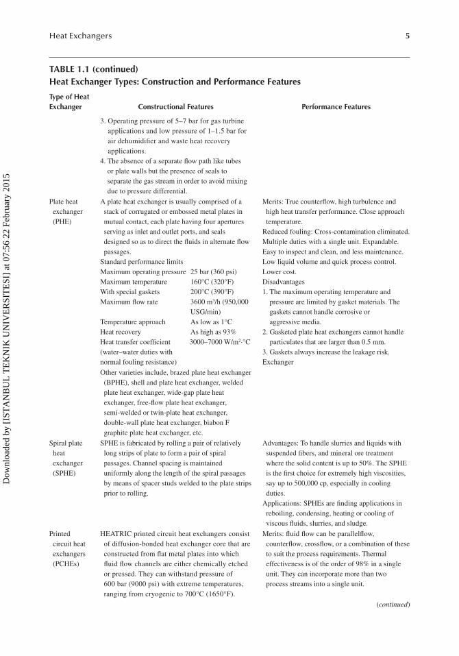
3. Operating pressure of 5–7 bar for gas turbine applications and low pressure of 1–1.5 bar for air dehumidifier and waste heat recovery applications.
4. The absence of a separate flow path like tubes or plate walls but the presence of seals to separate the gas stream in order to avoid mixing due to pressure differential.
Plate heat exchanger (PHE)
A plate heat exchanger is usually comprised of a stack of corrugated or embossed metal plates in mutual contact, each plate having four apertures serving as inlet and outlet ports, and seals designed so as to direct the fluids in alternate flow passages.
Standard performance limitsMaximum operating pressure 25 bar (360 psi)Maximum temperature 160°C (320°F)With special gaskets 200°C (390°F)Maximum flow rate 3600 m3/h (950,000
USG/min)Temperature approach As low as 1°CHeat recovery As high as 93%Heat transfer coefficient 3000–7000 W/m2·°C(water–water duties withnormal fouling resistance)
Merits: True counterflow, high turbulence and high heat transfer performance. Close approach temperature.
Reduced fouling: Cross-contamination eliminated.Multiple duties with a single unit. Expandable.Easy to inspect and clean, and less maintenance.Low liquid volume and quick process control.Lower cost.Disadvantages1. The maximum operating temperature and
pressure are limited by gasket materials. The gaskets cannot handle corrosive or aggressive media.
2. Gasketed plate heat exchangers cannot handle particulates that are larger than 0.5 mm.
3. Gaskets always increase the leakage risk.Exchanger
Other varieties include, brazed plate heat exchanger (BPHE), shell and plate heat exchanger, welded plate heat exchanger, wide-gap plate heat exchanger, free-flow plate heat exchanger, semi-welded or twin-plate heat exchanger, double-wall plate heat exchanger, biabon F graphite plate heat exchanger, etc.
Spiral plate heat exchanger (SPHE)
SPHE is fabricated by rolling a pair of relatively long strips of plate to form a pair of spiral passages. Channel spacing is maintained uniformly along the length of the spiral passages by means of spacer studs welded to the plate strips prior to rolling.
Advantages: To handle slurries and liquids with suspended fibers, and mineral ore treatment where the solid content is up to 50%. The SPHE is the first choice for extremely high viscosities, say up to 500,000 cp, especially in cooling duties.
Applications: SPHEs are finding applications in reboiling, condensing, heating or cooling of viscous fluids, slurries, and sludge.
Printed circuit heat exchangers (PCHEs)
HEATRIC printed circuit heat exchangers consist of diffusion-bonded heat exchanger core that are constructed from flat metal plates into which fluid flow channels are either chemically etched or pressed. They can withstand pressure of 600 bar (9000 psi) with extreme temperatures, ranging from cryogenic to 700°C (1650°F).
Merits: fluid flow can be parallelflow, counterflow, crossflow, or a combination of these to suit the process requirements. Thermal effectiveness is of the order of 98% in a single unit. They can incorporate more than two process streams into a single unit.
(continued)
Dow
nloa
ded
by [
IST
AN
BU
L T
EK
NIK
UN
IVE
RSI
TE
SI]
at 0
7:56
22
Febr
uary
201
5

6 Heat Exchanger Design Handbook
TABLE 1.1 (continued)Heat Exchanger Types: Construction and Performance Features
Type of Heat Exchanger Constructional Features Performance Features
Lamella heat exchanger (LHE)
A lamella heat exchanger normally consists of a cylindrical shell surrounding a number of heat transferring lamellas. The design can be compared to a tube heat exchanger but with the circular tubes replaced by thin and wide channels, lamellas. The lamella heat exchanger works with the media in full counter current flow. The absence of baffle plates minimizes the pressure drop and makes handling of most media possible.
Merits: Since the lamella bundle can be easily dismantled from the shell, inspection and cleaning is easy.
ApplicationsCooking fluid heating in pulp mills.Liquor preheaters.Coolers and condensers of flue gas.Oil coolers.
Heat pipe heat exchanger
The heat-pipe heat exchanger used for gas–gas heat recovery is essentially bundle of finned tubes assembled like a conventional air-cooled heat exchanger. The heat pipe consists of three elements: (1) a working fluid inside the tubes, (2) a wick lining inside the wall, and (3) vacuum sealed finned tube. The heat-pipe heat exchanger consists of an evaporative section through which the hot exhaust gas flows and a condensation section through which the cold air flows. These two sections are separated by a separating wall.
Application: The heat pipes are used for (i) heat recovery from process fluid to preheating of air for space heating, (ii) HVAC application-waste heat recovery from the exhaust air to heat the incoming process air
It virtually does not need mechanical maintenance, as there are no moving parts. The heat pipe heat recovery systems are capable of operating at a temperature of 300°C–315°C with 60%–80% heat recovery capability.
Plate coil heat exchanger (PCHE)
Fabricated from two metal sheets, one or both of which are embossed. When welded together, the embossings form a series of well-defined passages through which the heat transfer media flows.
A variety of standard PLATECOIL® fabrications, such as pipe coil, half pipe, jacketed tanks and vessels, clamp-on upgrades, immersion heaters and coolers, heat recovery banks, storage tank heaters, etc., are available. Easy access to panels and robust cleaning surfaces reduce maintenance burdens.
Scraped surface heat exchanger
Scraped surface heat exchangers are essentially double pipe construction with the process fluid in the inner pipe and the cooling (water) or heating medium (steam) in the annulus. A rotating element is contained within the tube and is equipped with spring-loaded blades. In operation the rotating shaft scraper blades continuously scrape product film from the heat transfer tube wall, thereby enhancing heat transfer and agitating the product to produce a homogenous mixture.
Scraped surface heat exchangers are used for processes likely to result in the substantial deposition of suspended solids on the heat transfer surface. Scraped surface heat exchangers can be employed in the continuous, closed processing of virtually any pumpable fluid or slurry involving cooking, slush freezing, cooling, crystallizing, mixing, plasticizing, gelling, polymerizing, heating, aseptic processing, etc. Use of a scraped surface exchanger prevents the accumulation of significant buildup of solid deposits.
Dow
nloa
ded
by [
IST
AN
BU
L T
EK
NIK
UN
IVE
RSI
TE
SI]
at 0
7:56
22
Febr
uary
201
5

7Heat Exchangers
Outer tube
Inner tube
(i) (ii) (iii) (iv)
(a)
(b)
FIGURE 1.2 Double pipe/twin pipe hairpin heat exchanger. (a) Schematic of the unit, (b): (i) double pipe with bare internal tube, (ii) double pipe with finned internal tube, (iii) double pipe with multibare inter-nal tubes, and (iv) double pipe with multifinned internal tubes. (Courtesy of Peerless Mfg. Co., Dallas, TX, Makers of Alco and Bos-Hatten brands of heat exchangers.)
(a)
(b)
FIGURE 1.3 Double pipe/hairpin heat exchanger. (a) 3-D view and (b) tube bundle with longitudinal fins. (Courtesy of Peerless Mfg. Co., Dallas, TX, Makers of Alco and Bos-Hatten brands of heat exchangers.)
Dow
nloa
ded
by [
IST
AN
BU
L T
EK
NIK
UN
IVE
RSI
TE
SI]
at 0
7:56
22
Febr
uary
201
5

8 Heat Exchanger Design Handbook
exchangers are used for larger heat duties. A hairpin heat exchanger should be considered when one or more of the following conditions exist:
• The process results in a temperature cross• High pressure on tubeside application• A low allowable pressure drop is required on one side• When an augmentation device to enhance the heat transfer coefficient is desired• When the exchanger is subject to thermal shocks• When flow-induced vibration may be a problem• When solid particulates or slurries are present in the process stream
1.3.1.1.2 Shell and Tube Heat ExchangerIn process industries, shell and tube heat exchangers are used in great numbers, far more than any other type of exchanger. More than 90% of heat exchangers used in industry are of the shell and tube type [7]. STHEs are the “workhorses” of industrial process heat transfer [8]. They are the first choice because of well-established procedures for design and manufacture from a wide variety of materials, many years of satisfactory service, and availability of codes and standards for design and fabrication. They are produced in the widest variety of sizes and styles. There is virtually no limit on the operating temperature and pressure. Figure 1.5 shows STHEs.
1.3.1.1.3 Coiled Tube Heat ExchangerConstruction of these heat exchangers involves winding a large number of small-bore ductile tubes in helix fashion around a central core tube, with each exchanger containing many layers of tubes
(a) (b)
(c)
FIGURE 1.4 Hairpin heat exchanger. (a) Separated head closure using separate bolting on shellside and tube-side and (b) Hairpin exchangers for high-pressure and high-temperature applications and (c) multitubes (bare) bundle. (Photo courtesy of Heat Exchanger Design, Inc., Indianapolis, IN.)
Dow
nloa
ded
by [
IST
AN
BU
L T
EK
NIK
UN
IVE
RSI
TE
SI]
at 0
7:56
22
Febr
uary
201
5

9Heat Exchangers
along both the principal and radial axes. The tubes in individual layers or groups of layers may be brought together into one or more tube plates through which different fluids may be passed in counterflow to the single shellside fluid. The construction details have been explained in Refs. [5,9]. The high-pressure stream flows through the small-diameter tubes, while the low-pressure return stream flows across outside of the small-diameter tubes in the annular space between the inner central core tube and the outer shell. Pressure drops in the coiled tubes are equalized for each high-pressure stream by using tubes of equal length and varying the spacing of these in the different layers. Because of small-bore tubes on both sides, CTHEs do not permit mechanical cleaning and therefore are used to handle clean, solid-free fluids or fluids whose fouling deposits can be cleaned by chemicals. The materials used are usually aluminum alloys for cryogenics and stainless steel for high-temperature applications.
CTHE offers unique advantages, especially when dealing with low-temperature applications for the following cases [9]:
• Simultaneous heat transfer between more than two streams is desired. One of the three classical heat exchangers used today for large-scale liquefaction systems is CTHE.
• A large number of heat transfer units are required.• High-operating pressures are involved.
CTHE is not cheap because of the material costs, high labor input in winding the tubes, and the central mandrel, which is not useful for heat transfer but increases the shell diameter [5].
1.3.1.1.3.1 Linde Coil-Wound Heat Exchangers Linde coil-wound heat exchangers are com-pact and reliable with a broad temperature and pressure range and suitable for both single- and two-phase streams. Multiple streams can be accommodated in one exchanger. They are known for their
(a)
(b)
FIGURE 1.5 Shell and tube heat exchanger. (a) Components and (b) heat exchanger. (Courtesy of Allegheny Bradford Corporation, Bradford, PA.)
Dow
nloa
ded
by [
IST
AN
BU
L T
EK
NIK
UN
IVE
RSI
TE
SI]
at 0
7:56
22
Febr
uary
201
5

10 Heat Exchanger Design Handbook
robustness in particularly during start-up and shut-down or plant-trip conditions. Both the brazed aluminum PFHEs and CTHEs find application in liquefication processes. A comparison of salient features of these two types of heat exchangers is shown in Chapter 4. Figure 1.6 shows Linde coil-wound heat exchangers.
Glass coil heat exchangers: Two basic types of glass coil heat exchangers are (i) coil type and (ii) STHE with glass or MS shells in combination with glass tube as standard material for tube. Glass coil exchangers have a coil fused to the shell to make a one-piece unit. This prohibits leak-age between the coil and shellside fluids [10]. The reduced heat transfer coefficient of boro silicate glass equipment compares favorably with many alternate tube materials. This is due to the smooth surface of the glass that improves the film coefficient and reduces the tendency for fouling. More details on glass heat exchangers are furnished in Chapter 13.
1.3.1.2 Plate Heat ExchangersPHEs are less widely used than tubular heat exchangers but offer certain important advantages. PHEs can be classified into three principal groups:
1. Plate and frame or gasketed PHEs used as an alternative to tube and shell exchangers for low- and medium-pressure liquid–liquid heat transfer applications
2. Spiral heat exchanger used as an alternative to shell and tube exchangers where low main-tenance is required, particularly with fluids tending to sludge or containing slurries or solids in suspension
3. Panel heat exchangers made from embossed plates to form a conduit or coil for liquids coupled with fins
(a) (b)
(c)
FIGURE 1.6 Coiled tube heat exchanger. (a) End section of a tube bundle, (b) tube bundle under fabrication, and (c) construction details. (From Linde AG, Engineering Division. With permission.)
Dow
nloa
ded
by [
IST
AN
BU
L T
EK
NIK
UN
IVE
RSI
TE
SI]
at 0
7:56
22
Febr
uary
201
5

11Heat Exchangers
1.3.1.2.1 Plate and Frame or Gasketed Plate Heat ExchangersA PHE essentially consists of a number of corrugated metal plates in mutual contact, each plate hav-ing four apertures serving as inlet and outlet ports, and seals designed to direct the fluids in alternate flow passages. The plates are clamped together in a frame that includes connections for the fluids. Since each plate is generally provided with peripheral gaskets to provide sealing arrangements, PHEs are called gasketed PHEs. PHEs are shown in Figure 1.7 and are covered in detail in Chapter 7.
1.3.1.2.2 Spiral Plate Heat ExchangerSPHEs have been used since the 1930s, when they were originally developed in Sweden for heat recovery in pulp mills. They are classified as a type of welded PHE. An SPHE is fabricated by roll-ing a pair of relatively long strips of plate around a split mandrel to form a pair of spiral passages. Channel spacing is maintained uniformly along the length of the spiral passages by means of spacer studs welded to the plate strips prior to rolling. Figure 1.8 shows an SPHE. For most applications, both flow channels are closed by alternate channels welded at both sides of the spiral plate. In some services, one of the channels is left open, whereas the other closed at both sides of the plate. These two types of construction prevent the fluids from mixing.
The SPHE is intended especially for the following applications [5]:
To handle slurries and liquids with suspended fibers and mineral ore treatment where the solid content is up to 50%.
SPHE is the first choice for extremely high viscosities, say up to 500,000 cp, especially in cooling duties, because of maldistribution, and hence partial blockage by local overcooling is less likely to occur in a single-channel exchanger.
SPHEs are finding applications in reboiling, condensing, heating, or cooling of viscous fluids, slurries, and sludge [11].
More details on SPHE are furnished in Chapter 7.
(a) (b)
2
1
7
8
3
5
6
4
FIGURE 1.7 Plate heat exchanger. (a) Construction details—schematic (Parts details: 1, Fixed frame plate; 2, Top carrying bar; 3, Plate pack; 4, Bottom carrying bar; 5, Movable pressure plate; 6, Support column; 7, Fluids port; and 8, Tightening bolts.) and (b) closer view of assembled plates. (Courtesy of ITT STANDARD, Cheektowaga, NY.)
Dow
nloa
ded
by [
IST
AN
BU
L T
EK
NIK
UN
IVE
RSI
TE
SI]
at 0
7:56
22
Febr
uary
201
5

12 Heat Exchanger Design Handbook
1.3.1.2.3 Plate or Panel Coil Heat ExchangerThese exchangers are called panel coils, plate coils, or embossed panel or jacketing. The panel coil serves as a heat sink or a heat source, depending upon whether the fluid within the coil is being cooled or heated. Panel coil heat exchangers are relatively inexpensive and can be made into any desired shape and thickness for heat sinks and heat sources under varied operating conditions. Hence, they have been used in many industrial applications such as cryogenics, chemicals, fibers, food, paints, pharmaceuticals, and solar absorbers.
Construction details of a panel coil: A few types of panel coil designs are shown in Figure 1.9. The panel coil is used in such industries as plating, metal finishing, chemical, textile, brewery, pharmaceutical, dairy, pulp and paper, food, nuclear, beverage, waste treatment, and many others. Construction details of panel coils are discussed next. M/s Paul Muller Company, Springfield, MO, and Tranter, Inc., TX, are the leading manufacturers of panel coil/plate coil heat exchangers.
Single embossed surface: The single embossed heat transfer surface is an economical type to utilize for interior tank walls, conveyor beds, and when a flat side is required. The single embossed design uses two sheets of material of different thickness and is available in stainless steel, other alloys, carbon steel, and in many material gages and working pressures.
Double embossed surface: Inflated on both sides using two sheets of material and the same thick-ness, the double embossed construction maximizes the heating and cooling process by utilizing both sides of the heat transfer plate. The double embossed design is commonly used in immersion applications and is available in stainless steel, other alloys, carbon steel, and in many material gages and working pressures.
FIGURE 1.8 Spiral plate heat exchanger. (Courtesy of Tranter, Inc., Wichita Falls, TX.)
Dow
nloa
ded
by [
IST
AN
BU
L T
EK
NIK
UN
IVE
RSI
TE
SI]
at 0
7:56
22
Febr
uary
201
5

13Heat Exchangers
Dimpled surface: This surface is machine punched and swaged, prior to welding, to increase the flow area in the passages. It is available in stainless steel, other alloys, carbon steel, in many material gages and working pressures, and in both MIG plug-welded and resistance spot-welded forms.
Methods of manufacture of panel coils: Basically, three different methods have been used to manufacture the panel coils: (1) they are usually welded by the resistance spot-welding or seam-welding process. An alternate method now available offers the ability to resistance spot-weld the dimpled jacket-style panel coil with a perimeter weldment made with the GMAW or resistance welding. Figure 1.10 shows a vessel jacket welded by GMAW and resistance-welding process. Other methods are (2) the die-stamping process and (3) the roll-bond process. In the die-stamping process, flow channels are die-stamped on either one or two metal sheets. When one sheet is embossed and joined to a flat (unembossed sheet), it forms a single-sided embossed panel coil. When both sheets are stamped, it forms a double-sided embossed panel coil.
Types of jackets: Jacketing of process vessels is usually accomplished by using one of the three main available types: conventional jackets, dimple jackets, and half-pipe coil jackets [12].
Advantages of panel coils: Panel coils provide the optimum method of heating and cooling pro-cess vessels in terms of control, efficiency, and product quality. Using a panel as a means of heat transfer offers the following advantages [12]:
• All liquids can be handled, as well as steam and other high-temperature vapors.• Circulation, temperature, and velocity of heat transfer media can be accurately controlled.• Panels may often be fabricated from a much less expensive metal than the vessel itself.• Contamination, cleaning, and maintenance problems are eliminated.
FIGURE 1.9 Temp-Plate® heat transfer surface. (Courtesy of Mueller, Heat Transfer Products, Springfield, MO.)
(a)
(b)
FIGURE 1.10 Welded dimpled jacket template. (a) Gas metal arc welded and (b) resistance welded.
Dow
nloa
ded
by [
IST
AN
BU
L T
EK
NIK
UN
IVE
RSI
TE
SI]
at 0
7:56
22
Febr
uary
201
5

14 Heat Exchanger Design Handbook
• Maximum efficiency, economy, and flexibility are achieved.• In designing reactors for specific process, this variety gives chemical engineers a great
deal of flexibility in the choice of heat transfer medium.
1.3.1.2.4 Lamella Heat ExchangerThe lamella heat exchanger is an efficient, and compact, heat exchanger. The principle was originally developed around 1930 by Ramens Patenter. Later Ramens Patenter was acquired by Rosenblads Patenter and the lamella heat exchanger was marketed under the Rosenblad name. In 1988, Berglunds acquired the product and continued to develop it. A lamella heat exchanger nor-mally consists of a cylindrical shell surrounding a number of heat-transferring lamellas. The design can be compared to a tube heat exchanger but with the circular tubes replaced by thin and wide channels, lamellas. Sondex Tapiro Oy Ab Pikkupurontie 11, FIN-00810 Helsinki, Finland, markets lamella heat exchangers worldwide.
The lamella is a form of welded heat exchanger that combines the construction of a PHE with that of a shell and tube exchanger without baffles. In this design, tubes are replaced by pairs of thin flat parallel metal plates, which are edge welded to provide long narrow channels, and banks of these elements of varying width are packed together to form a circular bundle and fitted within a shell. The cross section of a lamella heat exchanger is shown schematically in Figure 1.11. With this design, the flow area on the shellside is a minimum and similar in magnitude to that of the inside of the bank of elements; due to this, the velocities of the two liquid media are comparable [13]. The flow is essentially longitudinal countercurrent “tubeside” flow of both tube and shell fluids [4]. Due to this, the velocities of the two liquid media are comparable. Also, the absence of baffles minimizes the pressure drop. One end of the element pack is fixed and the other is floating to allow for thermal expansion and contraction. The connections fitted at either end of the shell, as in the normal shell and tube design, allow the bank of elements to be withdrawn, making the outside surface accessible for inspection and cleaning. Opposed from an STHE, where the whole exchanger has to be replaced in case of damage, it is possible just to replace the lamella battery and preserve the existing shell. Lamella heat exchangers can be fabricated from carbon steel, stainless steel, titanium, Incolly, and Hastelloy. They can handle most fluids, with large volume ratios between fluids. The floating nature of the bundle usually limits the working pressure to 300 psi. Lamella heat exchangers are generally used only in special cases. Design is usually done by the vendors.
Merits of lamella heat exchanger are as follows:
1. Strong turbulence in the fluid 2. High operation pressure
(a) (b)
FIGURE 1.11 Lamella heat exchanger. (a) Counterflow concept and (b) lamella tube bundle.
Dow
nloa
ded
by [
IST
AN
BU
L T
EK
NIK
UN
IVE
RSI
TE
SI]
at 0
7:56
22
Febr
uary
201
5

15Heat Exchangers
Applications
Cooking fluid heating in pulp millsLiquor preheatersCoolers and condensers of flue gasOils coolers
1.3.1.3 Extended Surface ExchangersIn a heat exchanger with gases or some liquids, if the heat transfer coefficient is quite low, a large heat transfer surface area is required to increase the heat transfer rate. This requirement is served by fins attached to the primary surface. Tube-fin heat exchangers (Figure 1.12) and plate-fin heat exchangers (Figure 1.13) are the most common examples of extended surface heat exchangers. Their design is covered in Chapter 4.
1.3.1.4 Regenerative Heat ExchangersRegeneration is an old technology dating back to the first open hearths and blast furnace stoves. Manufacturing and process industries such as glass, cement, and primary and secondary metals account for a significant fraction of all energy consumed. Much of this energy is discarded in the form of high-temperature exhaust gas. Recovery of waste heat from the exhaust gas by means of heat exchangers known as regenerators can improve the overall plant efficiency [14].
Types of regenerators: Regenerators are generally classified as fixed-matrix and rotary regenera-tors. Further classifications of fixed and rotary regenerators are shown in Figure 1.14. In the former,
FIGURE 1.12 Air-cooled condenser. (Courtesy of GEA Iberica S.A., Vizcaya, Spain.)
(a) (b)
FIGURE 1.13 Plate-fin heat exchanger. (a) Schematic of exchanger and (b) brazed aluminum plate-fin heat exchanger. (From Linde AG, Engineering Division. With permission.)
Dow
nloa
ded
by [
IST
AN
BU
L T
EK
NIK
UN
IVE
RSI
TE
SI]
at 0
7:56
22
Febr
uary
201
5

16 Heat Exchanger Design Handbook
regeneration is achieved with periodic and alternate blowing of hot and the cold stream through a fixed matrix. During the hot flow period, the matrix receives thermal energy from the hot gas and transfers it to the cold stream during the cold stream flow. In the latter, the matrix revolves slowly with respect to two fluid streams. The rotary regenerator is commonly employed in gas turbine power plants where the waste heat in the hot exhaust gases is utilized for raising the temperature of compressed air before it is supplied to the combustion chamber. A rotary regenerator (rotary wheel for HVAC application) working principle is shown in Figure 1.15, and Figure 1.16 shows the Rothemuhle regenerative air preheater of Babcock and Wilcox Company. Rotary regenerators fall in the category of compact heat exchangers since the heat transfer surface area to regenerator vol-ume ratio is very high. Regenerators are further discussed in detail in Chapter 6.
1.3.2 ClassifiCation aCCording to transfer ProCess
These classifications are as follows:
Indirect contact type—direct transfer type, storage type, fluidized bedDirect contact type—cooling towers
1.3.2.1 Indirect Contact Heat ExchangersIn an indirect contact–type heat exchanger, the fluid streams remain separate and the heat transfer takes place continuously through a dividing impervious wall. This type of heat exchanger can be further classified into direct transfer type, storage type, and fluidized bed exchangers. Direct transfer type is dealt with next, whereas the storage type and the fluidized bed type are discussed in Chapter 6.
Regenerator
Rotaryregenerator
Rotarymatrix
Fixed matrix—rotating hoods
Fixedmatrix
Dual bedvalved
Single bed
FIGURE 1.14 Classification of regenerators.
Rotating regenerator
Atmosphericcold air
Cooledexhaust air
Direction ofrotation
Warm roomexhaust air
Warm airto room
FIGURE 1.15 Rotary regenerator: working principle.
Dow
nloa
ded
by [
IST
AN
BU
L T
EK
NIK
UN
IVE
RSI
TE
SI]
at 0
7:56
22
Febr
uary
201
5

17Heat Exchangers
1.3.2.1.1 Direct Transfer–Type ExchangersIn this type, there is a continuous flow of heat from the hot fluid to the cold fluid through a separat-ing wall. There is no direct mixing of the fluids because each fluid flows in separate fluid passages. There are no moving parts. This type of exchanger is designated as a recuperator. Some examples of direct transfer–type heat exchangers are tubular exchangers, PHEs, and extended surface exchangers. Recuperators are further subclassified as prime surface exchangers, which do not employ fins or extended surfaces on the prime surface. Plain tubular exchangers, shell and tube exchangers with plain tubes, and PHEs are examples of prime surface exchangers.
1.3.2.2 Direct Contact–Type Heat ExchangersIn direct contact–type heat exchangers, the two fluids are not separated by a wall and come into direct contact, exchange heat, and are then separated.
Owing to the absence of a wall, closer temperature approaches are attained. Very often, in the direct contact type, the process of heat transfer is also accompanied by mass transfer. Various types of direct contact heat exchangers include (a) immiscible fluid exchanger, (b) gas–liquid exchanger, and (c) liquid–vapor exchanger. The cooling towers and scrubbers are examples of a direct contact–type heat exchanger.
1.3.3 ClassifiCation aCCording to surfaCe ComPaCtness
Compact heat exchangers are important when there are restrictions on the size and weight of exchangers. A compact heat exchanger incorporates a heat transfer surface having a high area den-sity, β, somewhat arbitrarily 700 m2/m3 (200 ft2/ft3) and higher [1]. The area density, β, is the ratio of heat transfer area A to its volume V. A compact heat exchanger employs a compact surface on one or more sides of a two-fluid or a multifluid heat exchanger. They can often achieve higher thermal effectiveness than shell and tube exchangers (95% vs. the 60%–80% typical for STHEs), which
2
1
2
FIGURE 1.16 Rothemuhle regenerative air preheater of Babcock and Wilcox Company—stationary matrix (part 1) and revolving hoods (part 2). (Adapted from Mondt, J.R., Regenerative heat exchangers: The elements of their design, selection and use, Research Publication GMR-3396, General Motors Research Laboratories, Warren, MI, 1980.)
Dow
nloa
ded
by [
IST
AN
BU
L T
EK
NIK
UN
IVE
RSI
TE
SI]
at 0
7:56
22
Febr
uary
201
5

18 Heat Exchanger Design Handbook
makes them particularly useful in energy-intensive industries [15]. For least capital cost, the size of the unit should be minimal. There are some additional advantages to small volume as follows:
Small inventory, making them good for handling expensive or hazardous materials [15]Low weightEasier transportLess foundationBetter temperature control
Some barriers to the use of compact heat exchangers include [15] the following:
The lack of standards similar to pressure vessel codes and standards, although this is now being redressed in the areas of plate-fin exchangers [16] and air-cooled exchangers [17].
Narrow passages in plate-fin exchangers make them susceptible for fouling and they cannot be cleaned by mechanical means. This limits their use to clean applications like handling air, light hydrocarbons, and refrigerants.
1.3.4 ClassifiCation aCCording to flow arrangement
The basic flow arrangements of the fluids in a heat exchanger are as follows:
ParallelflowCounterflowCrossflow
The choice of a particular flow arrangement is dependent upon the required exchanger effective-ness, fluid flow paths, packaging envelope, allowable thermal stresses, temperature levels, and other design criteria. These basic flow arrangements are discussed next.
1.3.4.1 Parallelflow ExchangerIn this type, both the fluid streams enter at the same end, flow parallel to each other in the same direc-tion, and leave at the other end (Figure 1.17). (For fluid temperature variations, idealized as one-dimen-sional, refer Figure 2.2 of Chapter 2.) This arrangement has the lowest exchanger effectiveness among the single-pass exchangers for the same flow rates, capacity rate (mass × specific heat) ratio, and surface area. Moreover, the existence of large temperature differences at the inlet end may induce high thermal stresses in the exchanger wall at inlet. Parallelflows are advantageous. (a) In heating very viscous fluids, parallelflow provides for rapid heating. The quick change in viscosity results in reduced pumping power requirements through the heat exchanger, (b) where the more moderate mean metal temperatures of the tube walls are required, and (c) where the improvements in heat transfer rates compensate for the lower LMTD. Although this flow arrangement is not used widely, it is preferred for the following reasons [2]:
1. When there is a possibility that the temperature of the warmer fluid may reach its freezing point. 2. It provides early initiation of nucleate boiling for boiling applications. 3. For a balanced exchanger (i.e., heat capacity rate ratio C* = 1), the desired exchanger effec-
tiveness is low and is to be maintained approximately constant over a range of NTU values. 4. The application allows piping only suited to parallelflow.
1
2
FIGURE 1.17 Parallelflow arrangement.
Dow
nloa
ded
by [
IST
AN
BU
L T
EK
NIK
UN
IVE
RSI
TE
SI]
at 0
7:56
22
Febr
uary
201
5

19Heat Exchangers
5. Temperature-sensitive fluids such as food products, pharmaceuticals, and biological prod-ucts are less likely to be “thermally damaged” in a parallelflow heat exchanger.
6. Certain types of fouling such as chemical reaction fouling, scaling, corrosion fouling, and freezing fouling are sensitive to temperature. Where control of temperature-sensitive foul-ing is a major concern, it is advantageous to use parallelflow.
1.3.4.2 Counterflow ExchangerIn this type, as shown in Figure 1.18a, the two fluids flow parallel to each other but in opposite directions, and its temperature distribution may be idealized as shown in Figure 1.18b. Ideally, this is the most efficient of all flow arrangements for single-pass arrangements under the same parameters. Since the temperature difference across the exchanger wall at a given cross section is the lowest, it produces minimum thermal stresses in the wall for equivalent performance com-pared to other flow arrangements. In certain types of heat exchangers, counterflow arrangement cannot be achieved easily, due to manufacturing difficulties associated with the separation of the fluids at each end, and the design of inlet and outlet header design is complex and difficult [2].
1.3.4.3 Crossflow ExchangerIn this type, as shown in Figure 1.19, the two fluids flow normal to each other. Important types of flow arrangement combinations for a single-pass crossflow exchanger include the following:
• Both fluids unmixed• One fluid unmixed and the other fluid mixed• Both fluids mixed
2
1
(a)
th,iCh >Cc
Hot fluid Hot fluidHot fluid
Cold fluid Cold fluid Cold fluid
Flow length Flow length Flow length
Ch <CcCh =Cc
tc,o
th,i
th,o tc,o
tc,i
th,i
th,otc,o
tc,i
th,o
tc,i
(b)
FIGURE 1.18 (a) Counterflow arrangement (schematic) and (b) temperature distribution (schematic). (Note: Ch and Cc are the heat capacity rate of hot fluid and cold fluid respectively, i refers to inlet, o refers to outlet conditions and t refers to fluid temperature.)
1
2(a)
1
2(b)
1
2
1
2 (c)
FIGURE 1.19 Crossflow arrangement: (a) unmixed–unmixed, (b) unmixed–mixed, and (c) mixed–mixed.
Dow
nloa
ded
by [
IST
AN
BU
L T
EK
NIK
UN
IVE
RSI
TE
SI]
at 0
7:56
22
Febr
uary
201
5

20 Heat Exchanger Design Handbook
A fluid stream is considered “unmixed” when it passes through individual flow passage without any fluid mixing between adjacent flow passages. Mixing implies that a thermal averaging process takes place at each cross section across the full width of the flow passage. A tube-fin exchanger with flat (continuous) fins and a plate-fin exchanger wherein the two fluids flow in separate passages (e.g., wavy fin, plain continuous rectangular or triangular flow passages) represent the unmixed–unmixed case. A crossflow tubular exchanger with bare tubes on the outside would be treated as the unmixed–mixed case, that is, unmixed on the tubeside and mixed on the outside. The both fluid mixed case is practically a less important case and represents a limiting case of some multipass shell and tube exchangers (TEMA E and J shell).
For the unmixed–unmixed case, fluid temperature variations are idealized as two-dimensional only for the inlet and outlet sections; this is shown in Figure 1.20. The thermal effectiveness for the crossflow exchanger falls in between those of the parallelflow and counterflow arrangements. This is the most common flow arrangement used for extended surface heat exchangers because it greatly simplifies the header design. If the desired heat exchanger effectiveness is generally more than 80%, the size penalty for crossflow may become excessive. In such a case, a counterflow unit is preferred [2]. In shell and tube exchangers, crossflow arrangement is used in the TEMA X shell having a single tube pass.
1.3.5 ClassifiCation aCCording to Pass arrangements
These are either single pass or multipass. A fluid is considered to have made one pass if it flows through a section of the heat exchanger through its full length once. In a multipass arrangement, a fluid is reversed and flows through the flow length two or more times.
1.3.5.1 Multipass ExchangersWhen the design of a heat exchanger results in either extreme length, significantly low veloci-ties, or low effectiveness, or due to other design criteria, a multipass heat exchanger or several single-pass exchangers in series or a combination of both is employed. Specifically, multipassing is resorted to increase the exchanger thermal effectiveness over the individual pass effectiveness. As the number of passes increases, the overall direction of the two fluids approaches that of a pure counterflow exchanger. The multipass arrangements are possible with compact, shell and tube, and plate exchangers.
tc,i
tc,o
Hot fluid outlettemperaturedistribution
th,i th,o
Cold fluid outlettemperaturedistribution
FIGURE 1.20 Temperature distribution for unmixed–unmixed crossflow arrangement.
Dow
nloa
ded
by [
IST
AN
BU
L T
EK
NIK
UN
IVE
RSI
TE
SI]
at 0
7:56
22
Febr
uary
201
5

21Heat Exchangers
1.3.6 ClassifiCation aCCording to Phase of fluids
1.3.6.1 Gas–LiquidGas–liquid heat exchangers are mostly tube-fin-type compact heat exchangers with the liquid on the tubeside. The radiator is by far the major type of liquid–gas heat exchanger, typically cooling the engine jacket water by air. Similar units are necessary for all the other water-cooled engines used in trucks, locomotives, diesel-powered equipment, and stationery diesel power plants. Other examples are air coolers, oil coolers for aircraft, intercoolers and aftercoolers in compressors, and condensers and evaporators of room air-conditioners. Normally, the liquid is pumped through the tubes, which have a very high convective heat transfer coefficient. The air flows in crossflow over the tubes. The heat transfer coefficient on the air side will be lower than that on the liquid side. Fins will be gener-ally used on the outside of the tubes to enhance the heat transfer rate.
1.3.6.2 Liquid–LiquidMost of the liquid–liquid heat exchangers are shell and tube type, and PHEs to a lesser extent. Both fluids are pumped through the exchanger, so the principal mode of heat transfer is forced convec-tion. The relatively high density of liquids results in very high heat transfer rate, so normally fins or other devices are not used to enhance the heat transfer [4]. In certain applications, low-finned tubes, microfin tubes, and heat transfer augmentation devices are used to enhance the heat transfer.
1.3.6.3 Gas–GasThis type of exchanger is found in exhaust gas–air preheating recuperators, rotary regenerators, intercoolers, and/or aftercoolers to cool supercharged engine intake air of some land-based die-sel power packs and diesel locomotives, and cryogenic gas liquefaction systems. In many cases, one gas is compressed so that the density is high while the other is at low pressure and low den-sity. Compared to liquid–liquid exchangers, the size of the gas–gas exchanger will be much larger, because the convective heat transfer coefficient on the gas side is low compared to the liquid side. Therefore, secondary surfaces are mostly employed to enhance the heat transfer rate.
1.3.7 ClassifiCation aCCording to heat transfer meChanisms
The basic heat transfer mechanisms employed for heat transfer from one fluid to the other are (1) single-phase convection, forced or free, (2) two-phase convection (condensation or evaporation) by forced or free convection, and (3) combined convection and radiation. Any of these mechanisms individually or in combination could be active on each side of the exchanger. Based on the phase change mechanisms, the heat exchangers are classified as (1) condensers and (2) evaporators.
1.3.7.1 CondensersCondensers may be liquid (water) or gas (air) cooled. The heat from condensing streams may be used for heating fluid. Normally, the condensing fluid is routed (1) outside the tubes with a water-cooled steam condenser or (2) inside the tubes with gas cooling, that is, air-cooled condensers of refrigera-tors and air-conditioners. Fins are normally provided to enhance heat transfer on the gas side.
1.3.7.2 EvaporatorsThis important group of tubular heat exchangers can be subdivided into two classes: fired systems and unfired systems.
Fired systems: These involve the products of combustion of fossil fuels at very high temperatures but at ambient pressure (and hence low density) and generate steam under pressure. Fired systems are called boilers. A system may be a fire tube boiler (for small low-pressure applications) or a water tube boiler.
Dow
nloa
ded
by [
IST
AN
BU
L T
EK
NIK
UN
IVE
RSI
TE
SI]
at 0
7:56
22
Febr
uary
201
5

22 Heat Exchanger Design Handbook
Unfired systems: These embrace a great variety of steam generators extending over a broad temperature range from high-temperature nuclear steam generators to very-low-temperature cryo-genic gasifiers for liquid natural gas evaporation. Many chemical and food processing applications involve the use of steam to evaporate solvents, concentrate solutions, distill liquors, or dehydrate compounds.
1.3.8 other ClassifiCations
1.3.8.1 Micro Heat ExchangerMicro- or microscale heat exchangers are heat exchangers in which at least one fluid flows in lateral confinements with typical dimensions below 1 mm and are fabricated via silicon micromachin-ing, deep x-ray lithography, or nonlithographic micromachining [18]. The plates are stacked forming “sandwich” structures, as in the “large” plate exchangers. All flow configurations (cocurrent, coun-tercurrent, and crossflow) are possible.
Typically, the fluid flows through a cavity called a microchannel. Microheat exchangers have been demonstrated with high convective heat transfer coefficient. Investigation of microscale thermal devices is motivated by the single-phase internal flow correlation for convective heat transfer:
h k
D= Nu
h
whereh is the heat transfer coefficientNu is the Nusselt numberk is the thermal conductivity of the fluidDh is the hydraulic diameter of the channel or duct
In internal laminar flows, the Nusselt number becomes a constant. As the Reynolds number is proportional to hydraulic diameter, fluid flow in channels of small hydraulic diameter will predomi-nantly be laminar. This correlation therefore indicates that the heat transfer coefficient increases as the channel diameter decreases. Heat transfer enhancement in laminar flow is further discussed in Chapter 8 Section 8.3.3.
1.3.8.1.1 Advantages over Macroscale Heat Exchangers• Substantially better performance• Enhanced heat transfer coefficient with a large number of smaller channels• Smaller size that allows for an increase in mobility and uses• Light weight reduces the structural and support requirements• Lower cost due to less material being used in fabrication
1.3.8.1.2 Applications of Microscale Heat ExchangersMicroscale heat exchangers are being used in the development of fuel cells. They are currently used in automotive industries, HVAC applications, aircraft, manufacturing industries, and electronics cooling.
1.3.8.1.3 Demerits of Microscale Heat ExchangersOne of the main disadvantages of microchannel heat exchangers is the high-pressure loss that is associated with a small hydraulic diameter.
Dow
nloa
ded
by [
IST
AN
BU
L T
EK
NIK
UN
IVE
RSI
TE
SI]
at 0
7:56
22
Febr
uary
201
5

23Heat Exchangers
1.3.8.2 Printed Circuit Heat ExchangerPCHE, developed by Heatric Division of Meggitt (UK) Ltd., is a promising heat exchanger because it is able to withstand pressures up to 50 MPa and temperatures from cryogenic to 700°C. It is extremely compact (the most common design feature to achieve compactness has been small chan-nel size) and has high efficiency, of the order of 98%. It can handle a wide variety of clean fluids. The flow configuration can be either crossflow or counterflow. It will maintain parent material strength and can be made from stainless steel, nickel alloys, copper alloys, and titanium. Fluid flow channels are etched chemically on metal plates. It has a typical plate thickness of 1.6 mm, width 600 mm, and length 1200 mm. The channels are semicircular with 1–2 mm diameter. Etched plates are stacked and diffusion bonded together to fabricate as a block. The blocks are then welded together to form the complete heat exchanger core, as shown in Figure 1.21a.
HEATRIC PCHEs consist of diffusion-bonded heat exchanger core that are constructed from flat metal plates into which fluid flow channels are either chemically etched or pressed. The required configuration of the channels on the plates for each fluid is governed by the operating temperature and pressure-drop constraints for the heat exchange duty and the chan-nels can be of unlimited variety and complexity. Fluid flow can be parallelflow, counterflow, crossflow, or a combination of these to suit the process requirements. Figure 1.21b through f shows HEATRIC PCHE.
The etched plates are then stacked and diffusion-bonded together to form strong, compact, all metal heat exchanger core. Diffusion bonding is a “solid-state joining” process entailing pressing metal surfaces together at temperatures below the melting point, thereby promoting grain growth between the surfaces. Under carefully controlled conditions, diffusion-bonded joints reach parent metal strength and stacks of plates are converted into solid blocks containing the fluid flow pas-sages. The blocks are then welded together to form the complete heat exchange core. Finally, head-ers and nozzles are welded to the core in order to direct the fluids to the appropriate sets of passages. Welded and diffusion-bonded PCHEs employ no gaskets or braze material, resulting in superior integrity compared to other technologies that may use gaskets or brazing as part of their construc-tion. (Gaskets or braze material can be potential sources of leakage, fluid incompatibility, and tem-perature limitations.) The mechanical design is normally of ASME VIII Division 1. Other design codes can be employed as required.
(a)
FIGURE 1.21 Printed circuit heat exchanger. (a) Heat exchanger block with flow channel.(continued)
Dow
nloa
ded
by [
IST
AN
BU
L T
EK
NIK
UN
IVE
RSI
TE
SI]
at 0
7:56
22
Febr
uary
201
5

24 Heat Exchanger Design Handbook
1.3.8.2.1 Materials of ConstructionThe majority of diffusion-bonded heat exchangers are constructed from 300 series austenitic stainless steel. Various other metals that are compatible with the diffusion-bonded process and have been qualified for use include 22 chromeduplex, copper–nickel, nickel alloys, and titanium.
(b) (c)
(d) (e)
(f )
FIGURE 1.21 (continued) Printed circuit heat exchanger. (b) Flow channel, (c) and (d) section through flow channel, (e) diffusion bonded core, (f) comparison of size of PCHE shell and tube heat exchanger (smaller size) with a conventional exchanger (bigger size) for similar duty. (Courtesy of Heatric UK, Dorset, U.K.)
Dow
nloa
ded
by [
IST
AN
BU
L T
EK
NIK
UN
IVE
RSI
TE
SI]
at 0
7:56
22
Febr
uary
201
5

25Heat Exchangers
1.3.8.2.2 Features of PCHEDiffusion-bonded heat exchangers are highly compact and robust that are well established in the upstream hydrocarbon processing, petrochemical and refining industries. Various salient construc-tional and performance features are given next:
1. Compactness: Diffusion-bonded heat exchangers are 1/4–1/6th the conventional STHEs of the equivalent heat duty. This design feature has space and weight advantages, reducing exchanger size together with piping and valve requirements. The diffusion-bonded heat exchanger in the foreground of Figure 1.21e undertakes the same thermal duty, at the same pressure drop, as the stack of three shell and tube exchangers behind. PCHE might be judged as a promising compact heat exchanger for the high efficiency recuperator [19].
2. Process capability: They can withstand pressures of 600 bar (9000 psi) or excess and can cope with extreme temperatures, ranging from cryogenic to 900°C (1650°F).
3. Thermal effectiveness: Diffusion-bonded exchangers can achieve high thermal effective-ness of the order of 98% in a single unit.
4. They can incorporate more than two process streams into a single unit. 5. The compatibility of the chemical etching and diffusion-bonding process with a wide range
of materials ensure that they are suitable for a range of corrosive and high purity streams.
1.3.8.3 Perforated Plate Heat Exchanger as CryocoolersHigh-efficiency compact heat exchangers are needed in cryocoolers to achieve very low temperatures. One approach to meet the requirements for compact and efficient cooling systems is the perforated PHE. Such heat exchangers are made up of a large number of parallel, perforated plates of high-thermal conductivity metal in a stacked array, with gaps between plates being provided by spacers. Gas flows longitudinally through the plates in one direction and other stream flows in the opposite direction through separated portions of the plates. Heat transfer takes place laterally across the plates from one stream to the other. The operating principles of this type of heat exchanger are described by Fleming [20]. The device employs plates of 0.81 mm thickness with holes of 1.14 mm in diameter and a resulting length-to-diameter ratio in the range of 0.5–1.0. The device is designed to operate from room temperature to 80 K. In order to improve operation of a compact cryocooler, much smaller holes, in the low-micron-diameter range, and thinner plates with high length-to-diameter ratio are needed. As per US Patent 5101894 [21], uniform, tubular perforations having diameters down to the low-micron-size range can be obtained. Various types of heat exchange devices including recuperative and regenera-tive heat exchangers may be constructed in accordance with the invention for use in cooling systems based on a number of refrigeration cycles such as the Linde–Hampson, Brayton, and Stirling cycles.
1.3.8.4 Scraped Surface Heat ExchangerScraped surface heat exchangers are used for processes likely to result in the substantial deposi-tion of suspended solids on the heat transfer surface. Scraped surface heat exchangers can be employed in the continuous, closed processing of virtually any pumpable fluid or slurry involv-ing cooking, slush freezing, cooling, crystallizing, mixing, plasticizing, gelling, polymerizing, heating, aseptic processing, etc. Use of a scraped surface exchanger prevents the accumulation of significant buildup of solid deposits. The construction details of scraped surface heat exchangers are explained in Ref. [4]. Scraped surface heat exchangers are essentially double pipe construc-tion with the process fluid in the inner pipe and the cooling (water) or heating medium (steam) in the annulus. A rotating element is contained within the tube and is equipped with spring-loaded blades. In operation, the rotating shaft scraper blades continuously scrape product film from the heat transfer tube wall, thereby enhancing heat transfer and agitating the product to produce a homogenous mixture. For most applications, the shaft is mounted in the center of the heat transfer tube. An off-centered shaft mount or eccentric design is recommended for viscous and sticky
Dow
nloa
ded
by [
IST
AN
BU
L T
EK
NIK
UN
IVE
RSI
TE
SI]
at 0
7:56
22
Febr
uary
201
5

26 Heat Exchanger Design Handbook
products. This shaft arrangement increases product mixing and reduces the mechanical heat load. Oval tubes are used to process extremely viscous products. All pressure elements are designed in accordance with the latest ASME code requirements. The principle of working of scraped surface heat exchangers is shown in Figure 1.22. For scraped surface exchangers, operating costs are high and applications are highly specific [5]. Design is mostly done by vendors. The leading manufac-tures include HRS Heat Exchangers, Ltd., UK, and Waukesha Cherry-Burrell, USA.
1.3.8.4.1 Unicus Scraped Surface Heat ExchangerUnicus™ is the trade name for scraped surface heat exchanger of HRS Heat Exchangers Ltd., UK, for high-fouling and viscous fluid applications. The design is based on STHE with scraping ele-ments inside each interior tube. The scrapers are moved back and forth by hydraulic action. The scraping action has two very important advantages: any fouling on the tube wall is removed and the scraping movement introduces turbulence in the fluid increasing heat transfer.
1.3.8.4.1.1 Elements of the Unicus Unicus consists of three parts: a hydraulic cylinder that moves the scraper bars, the STHE part, and a chamber that separates both the elements. The hydrau-lic cylinder is connected to a hydraulic power pack. The smaller models of the Unicus range can be supplied with a pneumatic cylinder. The scraping system consists of a stainless steel rod to which the scraping elements are fitted, as shown in Figure 1.23, and Figure 1.24 shows Unicus scraped surface heat exchangers. The pictures show the various types of scrapers that can be applied. For each application, the optimal scraper is selected and fitted.
Service fluid
Service fluid Heat transfer
ScraperTube wall
Scraper bar
Extraturbulence
Product
FIGURE 1.23 Principle of Unicus scraped surface heat exchanger working. (Courtesy of HRS Heat Exchangers Ltd, Herts, U.K.)
Heating and cooling medium
Product
Shaft
+
Heat transfer tube
Scraper blade
FIGURE 1.22 Scraped surface heat exchanger: principle.
Dow
nloa
ded
by [
IST
AN
BU
L T
EK
NIK
UN
IVE
RSI
TE
SI]
at 0
7:56
22
Febr
uary
201
5

27Heat Exchangers
1.3.8.5 Graphite Heat ExchangerImpervious graphite as a heat exchanger material is used for the construction of various types of heat exchangers such as STHE, cubic block heat exchanger, and plate and frame or gasketed heat exchangers (PHEs). Graphite tubes are used in STHE (refer to Chapter 13) and plates are used in PHEs (refer to Chapter 7) for special purpose applications. It resists a wide variety of inorganic and organic chemicals. Graphite heat exchangers are employed as boilers and condensers in the distilla-tion by evaporation of hydrochloric acid and in the concentration of weak sulfuric acid and of rare earth chloride solutions. Since cubic heat exchanger cannot be treated in categorization of extended surface heat exchanger, the same is covered next.
Cubic heat exchanger: It is similar to the compact crossflow heat exchanger, consisting of drilled holes in two perpendicular planes. They are suitable when both the process streams are corrosive. With a cubic exchanger, a multipass arrangement is possible. It is manufactured by assembling of accurately machined and drilled graphite plates bonded together by synthetic res-ins, oven cured and sintered. Gasketed headers with nozzles are assembled on both sides to the block to form a block heat exchanger and are clamped together, as shown in Figure 1.25.
Modular-block cylindrical exchanger: In this arrangement, solid impervious graphite blocks have holes drilled in them. These blocks can be multistacked in a cylindrical steel shell that has
(a) (b)
(c) (d)
FIGURE 1.24 Unicus dynamic scraped surface heat exchanger. (a) 3-D model, (b) hydraulic cylinder head, (c) a unit of Unicus, and (d) multiple Unicus units. (Courtesy of HRS Heat Exchangers Ltd, Herts, U.K.)
Dow
nloa
ded
by [
IST
AN
BU
L T
EK
NIK
UN
IVE
RSI
TE
SI]
at 0
7:56
22
Febr
uary
201
5

28 Heat Exchanger Design Handbook
gland fittings. The process holes are axial and the service holes are transverse. The units are designed as evaporators and reboilers. A modular block Graphilor® exchanger is shown in Figure 1.26.
1.4 SELECTION OF HEAT EXCHANGERS
1.4.1 introduCtion
Selection is the process in which the designer selects a particular type of heat exchanger for a given application from a variety of heat exchangers. There are a number of alternatives for selecting heat transfer equipment, but only one among them is the best for a given set of conditions. The heat exchanger selection criteria are discussed next.
(c) �ree pass Four pass
Multipass processreturn head
Graphitecore
Multipassinlet/outlet
service head
Process graphitehead liner in/out
Multipass processinlet/outlet
head(a)
Clampingplate
Returnservice head
Process graphitereturn liner
Clamping bolts
Typical flow pattern
(b)
FIGURE 1.25 NK series multipass cubic graphite heat exchanger. (a) Construction details, (b) cut section, and (c) multipass flow pattern. (Courtesy of MERSEN, Paris La Défense, France.)
Dow
nloa
ded
by [
IST
AN
BU
L T
EK
NIK
UN
IVE
RSI
TE
SI]
at 0
7:56
22
Febr
uary
201
5

29Heat Exchangers
1.4.2 seleCtion Criteria
Selection criteria are many, but primary criteria are type of fluids to be handled, operating pres-sures and temperatures, heat duty, and cost (see Table 1.1). The fluids involved in heat transfer can be characterized by temperature, pressure, phase, physical properties, toxicity, corrosivity, and fouling tendency. Operating conditions for heat exchangers vary over a very wide range, and a broad spectrum of demands is imposed for their design and performance. All of these must be
Coil springs maintainaxial force on heat
exchanger assemblyduring operational
temperature changes
Floating end compen-sates for differentialexpansion between graphite core and
steel shell
Drilled axial processholes (3 diameters
available)
Drilled transverseservice holes
Fixed end
Vertical service fluid drain(vent and drain are on shell
for horizontal operation)
Stainless steellongitudinal guide bars
and service baffle
Service fluid gaskets
Steel shell
Elastomeric servicebaffles
Graphilorheat transfer core
(4 diameters available)
Service fluid seal:TFE packing
Armored floating headassembly (1 piecegraphite and steel)
FIGURE 1.26 GRAPHILOR® cylindrical tubes (in block) heat exchanger. (Courtesy of MERSEN, Paris La Défense, France.)
Dow
nloa
ded
by [
IST
AN
BU
L T
EK
NIK
UN
IVE
RSI
TE
SI]
at 0
7:56
22
Febr
uary
201
5

30 Heat Exchanger Design Handbook
considered when assessing the type of unit to be used [22]. When selecting a heat exchanger for a given duty, the following points must be considered:
• Materials of construction• Operating pressure and temperature, temperature program, and temperature driving force• Flow rates• Flow arrangements• Performance parameters—thermal effectiveness and pressure drops• Fouling tendencies• Types and phases of fluids• Maintenance, inspection, cleaning, extension, and repair possibilities• Overall economy• Fabrication techniques• Mounting arrangements: horizontal or vertical• Intended applications
1.4.2.1 Materials of ConstructionFor reliable and continuous use, the construction materials for pressure vessels and heat exchangers should have a well-defined corrosion rate in the service environments. Furthermore, the material should exhibit strength to withstand the operating temperature and pressure. STHEs can be manufactured in vir-tually any material that may be required for corrosion resistance, for example, from nonmetals like glass, Teflon, and graphite to exotic metals like titanium, zirconium, tantalum, etc. Compact heat exchangers with extended surfaces are mostly manufactured from any metal that has drawability, formability, and malleability. Heat exchanger types like PHEs normally require a material that can be pressed or welded.
1.4.2.2 Operating Pressure and Temperature1.4.2.2.1 PressureThe design pressure is important to determine the thickness of the pressure-retaining components. The higher the pressure, the greater will be the required thickness of the pressure-retaining mem-branes and the more advantage there is to placing the high-pressure fluid on the tubeside. The pres-sure level of the fluids has a significant effect on the type of unit selected [22].
At low pressures, the vapor-phase volumetric flow rate is high and the low-allowable pressure drops may require a design that maximizes the area available for flow, such as crossflow or split flow with multiple nozzles.
At high pressures, the vapor-phase volumetric flow rates are lower and allowable pressure drops are greater. These lead to more compact units.
In general, higher heat transfer rates are obtained by placing the low-pressure gas on the out-side of tubular surfaces.
Operating pressures of the gasketed PHEs and SPHEs are limited because of the difficulty in pressing the required plate thickness, and by the gasket materials in the case of PHEs. The floating nature of floating-head shell and tube heat exchangers and lamella heat exchangers limits the operating pressure.
1.4.2.2.2 TemperatureDesign temperature: This parameter is important as it indicates whether a material at the design temperature can withstand the operating pressure and various loads imposed on the component. For low-temperature and cryogenic applications, toughness is a prime requirement, and for high-temperature applications the material has to exhibit creep resistance.
Temperature program: Temperature program in both a single-pass and multipass STHE decides (1) the mean metal temperatures of various components like shell, tube bundle, and tubesheet, and
Dow
nloa
ded
by [
IST
AN
BU
L T
EK
NIK
UN
IVE
RSI
TE
SI]
at 0
7:56
22
Febr
uary
201
5

31Heat Exchangers
(2) the possibility of temperature cross. The mean metal temperatures affect the integrity and capa-bility of heat exchangers and thermal stresses induced in various components.
Temperature driving force: The effective temperature driving force is a measure of the actual potential for heat transfer that exists at the design conditions. With a counterflow arrangement, the effective temperature difference is defined by the log mean temperature difference (LMTD). For flow arrangements other than counterflow arrangement, LMTD must be corrected by a correction factor, F. The F factor can be determined analytically for each flow arrangement but is usually presented graphically in terms of the thermal effectiveness P and the heat capacity ratio R for each flow arrangement.
Influence of operating pressure and temperature on selection of some types of heat exchangers: The influence of operating pressure and temperature on selection of STHE, compact heat exchanger, gasketed PHE, and spiral exchanger is discussed next.
Shell and tube heat exchanger: STHE units can be designed for almost any combination of pressure and temperature. In extreme cases, high pressure may impose limitations by fabrication problems associated with material thickness, and by the weight of the finished unit. Differential thermal expansion under steady conditions can induce severe thermal stresses either in the tube bundle or in the shell. Damage due to flow-induced vibration on the shellside is well known. In heat-exchanger applications where high heat transfer effectiveness (close approach temperature) is required, the standard shell and tube design may require a very large amount of heat transfer sur-face [23]. Depending on the fluids and operating conditions, other types of heat-exchanger design should be investigated.
Compact heat exchanger: Compact heat exchangers are constructed from thinner materials; they are manufactured by mechanical bonding, soldering, brazing, welding, etc. Therefore, they are lim-ited in operating pressures and temperatures.
Gasketed plate heat exchangers and spiral exchangers: Gasketed PHEs and spiral exchangers are limited by pressure and temperature, wherein the limitations are imposed by the capability of the gaskets.
1.4.2.3 Flow RateFlow rate determines the flow area: the higher the flow rate, the higher will be the crossflow area. Higher flow area is required to limit the flow velocity through the conduits and flow passages, and the higher velocity is limited by pressure drop, impingement, erosion, and, in the case of shell and tube exchanger, by shellside flow-induced vibration. Sometimes, a mini-mum flow velocity is necessary to improve heat transfer to eliminate stagnant areas and to minimize fouling.
1.4.2.4 Flow ArrangementAs defined earlier, the choice of a particular flow arrangement is dependent upon the required exchanger effectiveness, exchanger construction type, upstream and downstream ducting, packag-ing envelope, and other design criteria.
1.4.2.5 Performance Parameters: Thermal Effectiveness and Pressure DropsThermal effectiveness: For high-performance service requiring high thermal effectiveness, use brazed plate-fin exchangers (e.g., cryogenic service) and regenerators (e.g., gas turbine applica-tions), use tube-fin exchangers for slightly less thermal effectiveness in applications, and use shell and tube units for low-thermal effectiveness service.
Pressure drop: Pressure drop is an important parameter in heat exchanger design. Limitations may be imposed either by pumping cost or by process limitations or both. The heat exchanger should be designed in such a way that unproductive pressure drop is avoided to the maximum extent
Dow
nloa
ded
by [
IST
AN
BU
L T
EK
NIK
UN
IVE
RSI
TE
SI]
at 0
7:56
22
Febr
uary
201
5

32 Heat Exchanger Design Handbook
in areas like inlet and outlet bends, nozzles, and manifolds. At the same time, any pressure-drop limitation that is imposed must be utilized as nearly as possible for an economic design.
1.4.2.6 Fouling TendenciesFouling is defined as the formation on heat exchanger surfaces of undesirable deposits that impede the heat transfer and increase the resistance to fluid flow, resulting in higher pressure drop. The growth of these deposits causes the thermohydraulic performance of heat exchanger to decline with time. Fouling affects the energy consumption of industrial processes, and it also decides the amount of extra mate-rial required to provide extra heat transfer surface to compensate for the effects of fouling. Compact heat exchangers are generally preferred for nonfouling applications. In a shell and tube unit, the fluid with more fouling tendencies should be put on the tubeside for ease of cleaning. On the shellside with cross baffles, it is sometimes difficult to achieve a good flow distribution if the baffle cut is either too high or too low. Stagnation in any regions of low velocity behind the baffles is difficult to avoid if the baffles are cut more than about 20%–25%. PHEs and spiral plate exchangers are better chosen for fouling services. The flow pattern in PHE induces turbulence even at comparable low velocities; in the spiral units, the scrubbing action of the fluids on the curved surfaces minimizes fouling. Also consider Philips RODbaffle heat exchanger, TWISTED TUBE® heat exchanger, Helixchanger® heat exchanger or EMbaffle® heat exchanger to improve flow velocity on shellside, enhance heat transfer performance and reduce fouling tendencies on shellside.
1.4.2.7 Types and Phases of FluidsThe phase of the fluids within a unit is an important consideration in the selection of the heat exchanger type. Various combinations of fluid phases dealt in heat exchangers are liquid–liquid, liquid–gas, and gas–gas. Liquid-phase fluids are generally the simplest to deal with. The high den-sity and the favorable values of many transport properties allow high heat transfer coefficients to be obtained at relatively low-pressure drops [4].
1.4.2.8 Maintenance, Inspection, Cleaning, Repair, and Extension AspectsConsider the suitability of various heat exchangers as regards maintenance, inspection, cleaning, repair, and extension. For example, the pharmaceutical, dairy, and food industries require quick access to internal components for frequent cleaning. Since some of the heat exchanger types offer great variations in design, this must be kept in mind when designing for a certain application. For instance, consider inspection and manual cleaning. Spiral plate exchangers can be made with both sides open at one edge, or with one side open and one closed. They can be made with channels between 5 and 25 mm wide, with or without studs. STHE can be made with fixed tubesheets or with a removable tube bundle, with small- or large-diameter tubes, or small or wide pitch. A lamella heat exchanger bundle is removable and thus fairly easy to clean on the shellside. Inside, the lamella, however, cannot be drilled to remove the hard fouling deposits. Gasketed PHEs are easy to open, especially when all nozzles are located on the stationary end-plate side. The plate arrangement can be changed for other duties within the frame and nozzle capacity.
Repair of some of the shell and tube exchanger components is possible, but the repair of expansion joint is very difficult. Tubes can be renewed or plugged. Repair of compact heat exchangers of tube-fin type is very difficult except by plugging of the tube. Repair of the plate-fin exchanger is generally very difficult. For these two types of heat exchangers, extension of units for higher thermal duties is generally not possible. All these drawbacks are easily overcome in a PHE. It can be easily repaired, and plates and other parts can be easily replaced. Due to modular construction, PHEs possess the flexibility of enhancing or reducing the heat transfer surface area, modifying the pass arrangement, and addition of more than one duty according to the heat transfer requirements at a future date.
1.4.2.9 Overall EconomyThere are two major costs to consider in designing a heat exchanger: the manufacturing cost and the operating costs, including maintenance costs. In general, the less the heat transfer surface area and less
Dow
nloa
ded
by [
IST
AN
BU
L T
EK
NIK
UN
IVE
RSI
TE
SI]
at 0
7:56
22
Febr
uary
201
5

33Heat Exchangers
the complexity of the design, the lower is the manufacturing cost. The operating cost is the pumping cost due to pumping devices such as fans, blowers, and pumps. The maintenance costs include costs of spares that require frequent renewal due to corrosion, and costs due to corrosion/fouling prevention and control. Therefore, the heat exchanger design requires a proper balance between thermal sizing and pressure drop.
1.4.2.10 Fabrication TechniquesFabrication techniques are likely to be the determining factor in the selection of a heat transfer surface matrix or core. They are the major factors in the initial cost and to a large extent influence the integrity, service life, and ease of maintenance of the finished heat exchanger [24]. For example, shell and tube units are mostly fabricated by welding, plate-fin heat exchangers and automobile aluminum radiators by brazing, copper–brass radiators by soldering, most of the circular tube-fin exchangers by mechanical assembling, etc.
1.4.2.11 Choice of Unit Type for Intended ApplicationsAccording to the intended applications, the selection of heat exchangers will follow the guidelines given in Table 1.2.
TABLE 1.2Choice of Heat Exchanger Type for Intended Applications
Application Remarks
Low-viscosity fluids For high temperature/pressures, use STHE or double-pipe heat exchanger. Use PHE or LHE for low temperature/pressure applications.
Low-viscosity liquid to steam Use STHE in carbon steel.
Medium-viscosity fluids Use PHE or with high solids content, use SPHE.
High-viscosity fluids PHE offers the advantages of good flow distribution. For extreme viscosities, the SPHE is preferred.
Fouling liquids Use STHE with removable tube bundle. SPHE or PHE is preferred due to good flow distribution. Use PHE if easy access is of importance. Also consider Philips RODbaffle heat exchanger, TWISTED TUBE® heat exchanger and Helixchanger® heat exchanger, and EMbaffle® heat exchanger to improve flow velocity on the shellside, enhance heat transfer performance, and reduce fouling tendencies on shellside.
Slurries, suspensions, and pulps SPHE offers the best characteristics. Also consider free flow PHE or wide gap PHE, or scraped surface heat exchanger.
Heat-sensitive liquids PHE fulfills the requirements best. Also consider SPHE.
Cooling with air Extended surface types like tube-fin heat exchanger or PFHE.
Gas or air under pressure Use STHE with extended surface on the gas side or brazed plate-fin exchanger made of stainless steel or nickel alloys.
Cryogenic applications Brazed aluminum plate-fin exchanger, coiled tube heat exchangers, or PCHE.
Vapor condensation Surface condensers of STHE in carbon steel are preferred. Also consider SPHE or brazed plate heat exchanger.
Vapor/gas partial condensation Choose SPHE.
Refrigeration and air conditioning applications
Finned tube heat exchangers, special types of PHEs, brazed PHE up to 200°C.
Air–air or gas–gas applications Regenerators and plate-fin heat exchangers. Also consider STHE.
Viscous products, aseptic products, jam, food and meat processing, heat sensitive products and particulate laden products
Scraped surface heat exchanger.
Note: STHE, shell and tube heat exchanger; PHE, gasketed plate heat exchanger; SPHE, spiral plate heat exchanger; LHE, lamella heat exchanger; PCHE, printed circuit heat exchangers; CTHE, coiled tube heat exchanger; PFHE, plate-fin heat exchanger.
Dow
nloa
ded
by [
IST
AN
BU
L T
EK
NIK
UN
IVE
RSI
TE
SI]
at 0
7:56
22
Febr
uary
201
5

34 Heat Exchanger Design Handbook
1.5 REQUIREMENTS OF HEAT EXCHANGERS
Heat exchangers have to fulfill the following requirements:
• High thermal effectiveness• Pressure drop as low as possible• Reliability and life expectancy• High-quality product and safe operation• Material compatibility with process fluids• Convenient size, easy for installation, reliable in use• Easy for maintenance and servicing• Light in weight but strong in construction to withstand the operational pressures and vibra-
tions especially heat exchangers for military applications• Simplicity of manufacture• Low cost• Possibility of effecting repair to maintenance problems
The heat exchanger must meet normal process requirements specified through problem specification and service conditions for combinations of the clean and fouled conditions, and uncorroded and cor-roded conditions. The exchanger must be maintainable, which usually means choosing a configura-tion that permits cleaning as required and replacement of tubes, gaskets, and any other components that are damaged by corrosion, erosion, vibration, or aging. This requirement may also place limita-tions on space for tube bundle pulling, to carry out maintenance around it, lifting requirements for heat exchanger components, and adaptability for in-service inspection and monitoring.
REFERENCES
1. Shah, R. K., Classification of heat exchangers, in Heat Exchangers: Thermal-Hydraulic Fundamentals and Design (S. Kakac, A. E. Bergles, and F. Mayinger, eds.), Hemisphere, Washington, DC, 1981, pp. 9–46.
2. Shah, R. K. and Sekulic, D. P., Fundamentals of Heat Exchanger Design, John & Wiley, New York, 2003.
3. Gupta, J. P., Fundamentals of Heat Exchanger and Pressure Vessel Technology, Hemisphere, Washington, DC, 1986.
4. Walker, G., Cryocoolers, Part 2: Applications, Plenum Press, New York, 1983. 5a. Larowski, A. and Taylor, M. A., Systematic Procedures for Selection of Heat Exchangers, C58/82,
Institution of Mechanical Engineers, London, U.K., 1982, pp. 32–56. 5b. Larowski, A. and Taylor, M. A., Systematic Procedure for Selection of Heat Exchangers, Proc. Inst.
Mech. Eng., 197A, 51–69 (1983). 6. Kern, D. Q., Process Heat Transfer, McGraw-Hill, New York, 1950. 7. Chisholm, D. (ed.), Developments in Heat Exchanger Technology—1, Applied Science Publishers,
London, England, 1980. 8. Minton, P., Process heat transfer, Proceedings of the 9th International Heat Transfer Conference, Heat
Transfer 1990–Jerusalem, Israel, Paper No. KN–2, 1, 355–362 (1990). 9. Timmerhaus, K. D. and Flynn, T. M., Cryogenic Progress Engineering, Plenum Press, New York, 1989. 10. Muoio, J. M., Glass as a material of construction for heat transfer equipment, Industrial Heat Exchangers
Conference Proceedings (A. J. Hayes, W. W. Liang, S. L. Richlen, and E. S. Tabb, eds.), American Society for Metals, Metals Park, OH, 1985, pp. 385–390.
11. Yilmaz, S. and Samuelson, B., Vertical thermosyphon boiling in spiral plate heat exchangers, in Heat Transfer—1983, Seattle, Chem. Eng. Prog. Symp. Ser., 79(225), 47–53 (1983).
12. Markovitz, R. E., Picking the best vessel jacket, Chem. Eng., 78(26), 156–162 (1971). 13. Usher, J. D. and Cattell, G. S., Compact heat exchangers, in Developments in Heat Exchanger
Technology—1 (D. Chisholm, ed.), Applied Science Publishers Ltd., London, U.K., 1980, pp. 127–152.
Dow
nloa
ded
by [
IST
AN
BU
L T
EK
NIK
UN
IVE
RSI
TE
SI]
at 0
7:56
22
Febr
uary
201
5

35Heat Exchangers
14. Reay, D. A., Heat exchangers for waste heat recovery, International Research and Development Co., Ltd., New Castle upon Tync, U.K., in Developments in Heat Exchanger Technology—1 (D. Chisholm, ed.), Applied Science Publishers Ltd., London, U.K., 1980, pp. 233–256.
15. Butterworth, D. and Mascone, C. F., Heat transfer heads into the 21 century, Chem. Eng. Prog., September, 30–37 (1991).
16a. Taylor, M. A. (ed), Plate-Fin Heat Exchangers, Guide to Their Specification and Use, HTFS (Harwell Laboratory), Oxon, U.K., 1980.
16b. ALPEMA, The standards of the Brazed Aluminium Plate-Fin Heat Exchanger Manufacturer’s Association, 3rd ed., Didcot, Oxon, U.K., 2010. (www.alpema.org).
17. API Standard 660, Shell and Tube Exchangers for General Refinery Services, 7th edn., American Petroleum Institute, Washington, DC, 2002.
18a. Steinke, M. E. and Kandlikar, G., Single-phase heat transfer enhancement techniques in microchannel and minichannel flows, in Microchannels and Minichannels—2004, ASME, Rochester, NY, June 17–19, 2004.
18b. Tuckerman, D. B. and Pease, R. F. W., High-performance heat sinking for VLSI, IEEE Electron Device Letters, Vol. 2 (5), May 1981, pp. 126–129.
19. Nikitin, K., Kato, Y. and Ngo, L., Thermal-Hydraulic Performance of Printed Circuit Heat Exchanger in Supercritical CO2 Cycle, Research Laboratory for Nuclear Reactors, Tokyo Institute of Technology, Okayama, Tokyo, Japan, 2005.
20. Fleming, R. B., A Compact Perforated Plate Heat Exchanger, in Advances in Cryogenic Engineering, Vol. 14, Plenum Press, New York, 1969, pp. 196–204.
21. Hendricks, J. B., Perforated plate heat exchanger and method of fabrication, Patent number: 5101894, Apr 7, 1992.
22. Gollin, M., Heat exchanger design and rating, in Handbook of Applied Thermal Design (E. C. Guyer, ed.), Chapter 2, Part 7, McGraw-Hill, New York, 1984, pp. 7-24–7-36.
23. Caciula, L. and Rudy, T. M., Prediction of plate heat exchanger performance, D Symp. Ser., Heat Transfer—1983, Seattle, WA, pp. 76–89.
24. Fraas, A. P. and Ozisik, M. N., Heat Exchanger Design, John Wiley & Sons, New York, 1965.
SUGGESTED READINGS
Bell, K. J. and Mueller, A. C., Wolverine Heat Transfer Data Book II, Wolverine Division of UOP Inc., Decatur, AL, 1984.
Scaccia, C. and Theoclitus, G., Types, performance and applications, in The Chemical Engineering Guide to Heat Transfer, Volume I: Plant Principles (K. J. McNaughton and the Staff of Chemical Engineering, eds.), Hemisphere/McGraw-Hill, New York, 1986, pp. 3–14.
Shah, R. K., Classification of heat exchangers, in Low Reynolds Number Flow Heat Exchangers (S. Kakac, R. K. Shah, and A. E. Bergles, eds.), Hemisphere, Washington, DC, 1983, pp. 9–19.
Shah, R. K., What’s new in heat exchanger design, ASME, Mech. Eng., 106, 50–59 (1984).Sukhatme, S. P. and Devotta, S., Classification of heat transfer equipment, in Heat Transfer Equipment
Design (R. K. Shah, E. C. Subbarao, and R. A. Mashelikar, eds.), Hemisphere, Washington, DC, 1988, pp. 7–16.
Thome, R. T., Wolverine Heat Transfer Engineering Data Book III, Wolverine Division of UOP Inc., Decatur, AL, 2004.
BIBLIOGRAPHY
Afgan, N. H. and Schlunder, E. U. (eds.), Heat Exchangers: Design and Theory Sourcebook, McGraw-Hill, New York, 1974.
Apblett, W. R. (ed.), Shell and Tube Heat Exchangers, American Society for Metals, Metals Park, OH, 1982.Bhatia, M. V. and Cheremisinoff, N. P., Heat Transfer Equipment, Process equipment series, Vol. 2, Technomic,
Westport, CT, 1980.Bryers, R. W. (ed.), Fouling of Heat Exchanger Surfaces, Engineering Foundation, New York, 1983.Chen, S. S., Flow Induced Vibration of Circular Cylindrical Structures, Hemisphere, Washington, DC,
1987.Cheremisinoff, N. (ed.), Handbook of Heat and Mass Transfer, Vol. 1—Heat Transfer Operation & Vol. 2—
Mass Transfer and Reactor Design, Gulf Publishing Company, Houston, TX, pp. 767–805, 1986.
Dow
nloa
ded
by [
IST
AN
BU
L T
EK
NIK
UN
IVE
RSI
TE
SI]
at 0
7:56
22
Febr
uary
201
5

36 Heat Exchanger Design Handbook
Cheremisinoff, N. P., Heat Transfer Pocket Handbook, Gulf Publishing Company, Books Division, Houston, TX, 1984.
Chisholm, D. (ed.), Heat Exchanger Technology, Elsevier Applied Science, New York, 1988.Effectiveness Ntu Relationships for Design and Performance Evaluation of Multi-pass Crossflow Heat
Exchangers, Engineering Sciences Data Unit Item 87020, ESDU International, McLean, VA, October 1987.
Effectiveness Ntu Relationships for Design and Performance Evaluation of Two-Stream Heat Exchangers, Engineering Sciences Data Unit Item 86018, ESDU International, McLean, VA, July 1986.
Foster, B. D. and Patton, J. B. (eds.), Ceramic Heat Exchangers, American Ceramic Society, Columbus, OH, 1985.
Fraas, A. P., Heat Exchanger Design, 2nd edn., John Wiley & Sons, New York, 1989.Ganapathy, V., Applied Heat Transfer, PennWell Publishing Co., Tulsa, OK, 1982.Garrett-Price, B. A., Smith, S. A., Watts, R. L., Knudsen, J. C., Marner, W. J., and Suitor, J. W., Fouling of Heat
Exchangers, Noyes, Park Ridge, NJ, 1985.Hayes, A. J., Liang, W. W., Richlen, S. L., and Tabb, E. S. (eds.), Industrial Heat Exchangers Conference
Proceedings, American Society for Metals, Metals Park, OH, 1985.Hewitt, G. F. (coordinating editor), Hemisphere Handbook of Heat Exchanger Design, Hemisphere, New York,
1990.Hewitt, G. F., Shires, G. L., and Bott, T. R., Process Heat Transfer, CRC Press, Boca Raton, FL, 1994.Hewitt, G. F. and Whalley, P. B., Handbook of Heat Exchanger Calculations, Hemisphere, Washington, DC,
1989.Hryniszak, W., Heat Exchangers: Application to Gas Turbines, Butterworth Scientific Publications, London,
U.K., 1958.Hussain, H., Heat Transfer in Counterflow, Parallel Flow and Cross Flow, McGraw-Hill, New York, 1982.Jakob, M., Heat Transfer, John Wiley & Sons, New York, 1957.Kakac, S., Bergles, A. E., and Fernandes, E. O. (eds.), Two-Phase Flow Heat Exchangers: Thermal Hydraulic
Fundamentals and Design, Kluwer Academic Publishers, Dordrecht, the Netherlands, 1988.Kakac, S., Bergles, A. E., and Mayinger, F. (eds.), Heat Exchangers: Thermal-Hydraulic Fundamentals and
Design, Hemisphere/McGraw-Hill, Washington, DC, 1981.Kakac, S., Shah, R. K., and Aung, W. (eds.), Handbook of Single Phase Convective Heat Transfer, John Wiley &
Sons, New York, 1987.Kakac, S., Shah, R. K., and Bergles, A. E. (eds.), Low Reynolds Number Flow Heat Exchangers, Hemisphere,
Washington, DC, 1983.Kays, W. M. and London, A. L., Compact Heat Exchangers, 3rd edn., McGraw-Hill, New York, 1984.Kern, D. Q. and Kraus, A. D., Extended Surface Heat Transfer, McGraw-Hill, New York, 1972, pp. 439–641.Kraus, A. D., Analysis and Evaluation of Extended Surface Thermal Systems, Hemisphere, Washington, DC,
1982.Levenspiel, O., Engineering Flow and Heat Exchange, Plenum Press, New York, 1984.Mahajan, K. K., Design of Process Equipments, Pressure Vessel Handbook Publishing Company, Tulsa, OK,
1985.Manzoor, M., Heat Flow through Extended Surface Heat Exchangers, Springer-Verlag, Berlin, Germany, 1984.Martin, H., Heat Exchangers, Hemisphere, Washington, DC, 1992.McNaughton, K. J. and the Staff of Chemical Engineering (eds.), The Chemical Engineering Guide to Heat
Transfer: Vol. I: Plant Principles, Vol. II: Equipment, Hemisphere/McGraw-Hill, New York, 1986.Melo, L. F., Bott, T. R., and Bernardo, C. A. (eds.), Advances in Fouling Science and Technology, Kluwer
Academic Publishers, Dordrecht, the Netherlands, 1988.Mondt, J. R., Regenerative Heat Exchangers: The Elements of Their Design, Selection and Use, Research
Publication GMR-3396, General Motors Research Laboratories, Warren, MI, 1980.Mori, Y., Sheindlin, A. E., and Afgan, N. H. (eds.), High Temperature Heat Exchangers, Hemisphere,
Washington, DC, 1986.Palen, J. W. (ed.), Heat Exchanger Sourcebook, Hemisphere, Washington, DC, 1987.Perry, R. H. and Chilton, C. H. (eds.), Chemical Engineers’ Handbook, 5th edn., McGraw-Hill, New York,
1973.Reay, D. A., Heat Recovery Systems, E. and F. N. Spon Ltd., London, U.K., 1979.Rohsenow, W. M., Hartnett, J. P., and Ganic, E. N. (eds.), Handbook of Heat Transfer Applications, McGraw-Hill,
New York, 1985.Saunders, E. A. D., Heat Exchangers: Selection, Design and Construction, Addison Wesley Longman, Reading,
MA, 1989.
Dow
nloa
ded
by [
IST
AN
BU
L T
EK
NIK
UN
IVE
RSI
TE
SI]
at 0
7:56
22
Febr
uary
201
5

37Heat Exchangers
Schlunder, E. U. (editor-in-chief), Heat Exchanger Design Handbook, in five volumes (Vol. 1—Heal Exchanger Theory, Vol. 2—Fluid Mechanics and Heat Transfer, Vol. 3—Thermal and Hydraulic Design of Heat Exchangers, Vol. 4—Mechanical Design of Heat Exchangers, and Vol. 5—Physical Properties), Hemisphere, Washington, DC, 1983.
Schmidt, F. W. and Willmott, A. J., Thermal Energy Storage and Regeneration, Hemisphere/McGraw-Hill, Washington, DC, 1981.
Shah, R. K., Kraus, A. D., and Metzger, D. (eds.), Compact Heat Exchangers—A Festschrift for A. L. London, Hemisphere, Washington, DC, 1990, pp. 31–90.
Shah, R. K. and London, A. L., Laminar Flow Forced Convection in Ducts, Supplement 1 to advances in heat transfer series, Academic Press, New York, 1978.
Shah, R. K. and Mueller, A. C., Heat exchanger, in Ullmann’s Encyclopedia of Industrial Chemistry, Unit Operations II, Vol. B3, Chapter 2, VCH Publishers, Weinheim, Germany, 1989.
Shah, R. K., Subbarao, E. C., and Mashelkar, R. A. (eds.), Heat Transfer Equipment Design, Hemisphere, Washington, DC, 1988.
Sheindlin, A. E. (ed.), High Temperature Equipment, Hemisphere, Washington, DC, 1986.Singh, K. P. and Soler, A. I., Mechanical Design of Heat Exchangers and Pressure Vessel Components, Arcturus
Publishers, Cherry Hill, NJ, 1984.Somerscales, E. F. C. and Knudsen, J. G. (eds.), Fouling of Heat Transfer Equipment, Hemisphere/McGraw-
Hill, Washington, DC, 1981.Stasiulevicius, J. and Skrinska, A., Heat Transfer of Finned Tube Bundles in Crossflow, Hemisphere,
Washington, DC, 1987.Taborek, J., Hewitt, G. F., and Afgan, N. (eds.), Heat Exchangers: Theory and Practice, Hemisphere/McGraw-
Hill, Washington, DC, 1983.Walker, G., Industrial Heat Exchangers—A Basic Guide, Hemisphere/McGraw-Hill, New York, 1982.Yokell, S., A Working Guide to Shell and Tube Heat Exchangers, McGraw-Hill, New York, 1990.Zukauskas, A. A., High Performance Single-Phase Heat Exchangers (J. Karni, English edition editor),
Hemisphere, Washington, DC, 1989.Zukauskas, A. and Ulinskas, R., Heat Transfer in Tube Banks in Crossflow, Hemisphere, Washington, DC, 1988.
Dow
nloa
ded
by [
IST
AN
BU
L T
EK
NIK
UN
IVE
RSI
TE
SI]
at 0
7:56
22
Febr
uary
201
5

Dow
nloa
ded
by [
IST
AN
BU
L T
EK
NIK
UN
IVE
RSI
TE
SI]
at 0
7:56
22
Febr
uary
201
5
Related Documents