Heat Exchanger Equipment Thermal Design Practice

Welcome message from author
This document is posted to help you gain knowledge. Please leave a comment to let me know what you think about it! Share it to your friends and learn new things together.
Transcript

Heat Exchanger Equipment
Thermal Design Practice
Objective
• Capable to review the thermal calculation sheet from vendor and or process dept with comprehensive factor consideration.– Thermal & Mechanical performance– Cost point of view– Maintenance point of view

Shell & Tube Heat Exchanger
Heat Transfer Fundamental
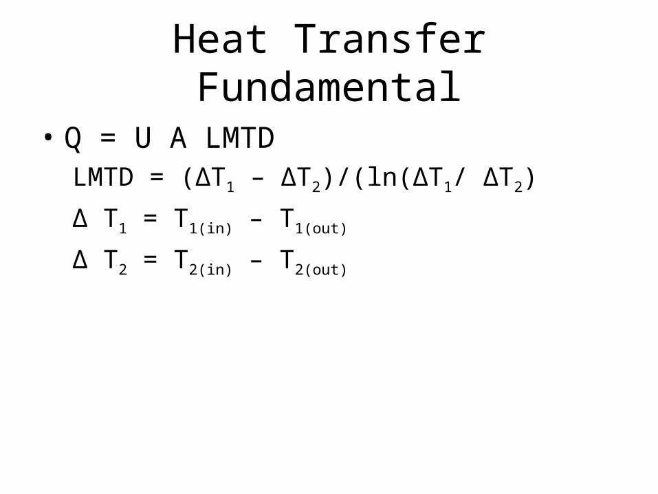
• Q = U A LMTDLMTD = (∆T1 – ∆T2)/(ln(∆T1/ ∆T2)
∆ T1 = T1(in) – T1(out)
∆ T2 = T2(in) – T2(out)
Heat Transfer Fundamental
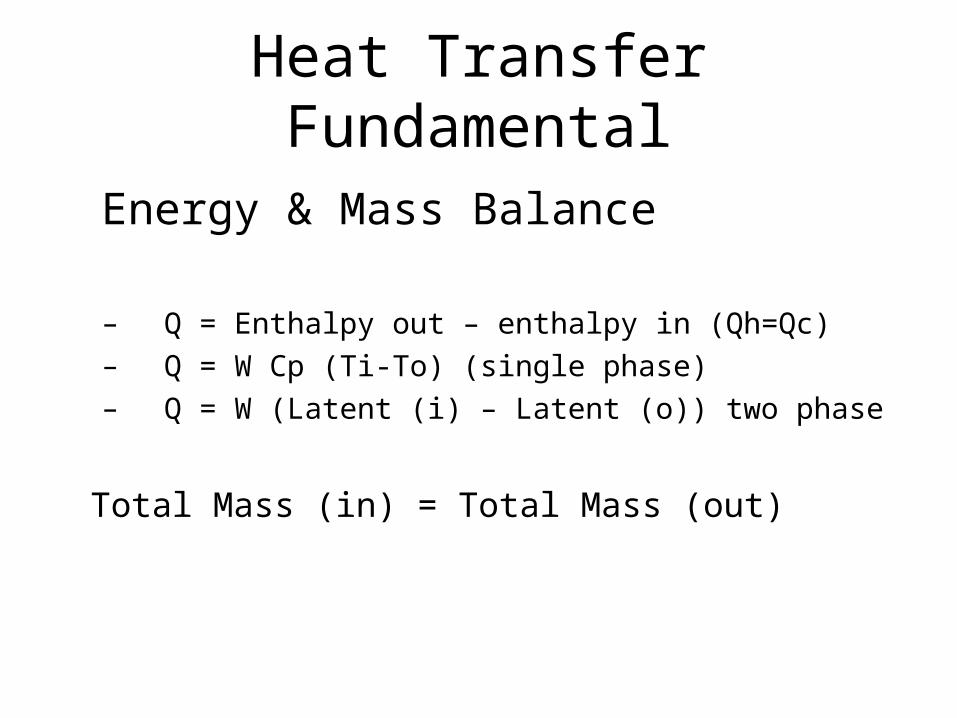
Energy & Mass Balance
– Q = Enthalpy out – enthalpy in (Qh=Qc)– Q = W Cp (Ti-To) (single phase)– Q = W (Latent (i) – Latent (o)) two phase
Total Mass (in) = Total Mass (out)
Heat Transfer Fundamental
Flow Category– Laminar – Transition– Turbulence

Heat Transfer Fundamental
• Heat Transfer Category– Conduction– Convection– Radiation ??
Heat Transfer Fundamental
• Conductivity– Thickness– Surface Shape
• Heat transfer coefficient– Flow type– Velocity of flow
• Material specification

Heat Transfer Fundamental
• Resident Time– Represented by heat transfer area provided.– Resident time most applicable for heat
transfer for solid particle
Basic Knowledge
• International Code– API 660– ASME– TEMA
• Engineering Practice
• Design Manual
• Journal

Summarize Client Spec
• ITB/ITT, Project Spec
• MOM
• Technical Clarification

Specific Client Requirement
• Maintenance point of view• Fouling Factor • Plot plan/ Space Limitation
– Stack vessel allowed?– Transportation limitation? Etc.
• Preference Tube Size (tube diameter, tube pitch)• Preference cleaning Method
– Mechanical Cleaning– Chemical cleaning
Specific Client Requirement (cont’d)
• Design Margin• Corrosion Allowance• Material Spec requirement (HIC, SOHIC,
resist, etc)• ASME code stamp requirement• FEA analysis for process nozzle and or
cyclic and excessive load.• Minimum tube thickness (range 10 – 18
BWG)

Specific Process Reqm’t/Data
• P&ID– Thermosiphon– Elevation refer to the vessel for reboiler
• Process data sheet
• Heat & Mass balance

Process Data Completeness
• Fluid properties
• Heat curve – phase change
• Boiling point temperature
Mechanical Design Reqm’t
• Setting Plan (nozzle and saddle location, tubesheet thickness)
• Design pressure/temp., – To decide shellside or tubeside location of
fluid
• Determine TEMA type of HE
• Maintenance planning
Fluid Allocation – Shellside/Tubeside
• Fluid pressure/temperature – Tubeside for higher pressure (in general, if there is no specific requirement) – for economic reason
• Corrosion – Corrosive fluid at tubeside
Fluid Allocation – Shellside/Tubeside (cont’d)
• Fouling factor/cleaning method – High fouling fluid – preferably placed on tubeside for
easy mechanical cleaning. If chemical cleaning will be applied – no preferable (either tubeside or shellside).
– If mechanical cleaning will be applied – straight tube in horizontal orientation are preferred.
– If hydraulic cleaning to be applied on shellside, a large pitch of tube must be used – increase shellside
– Removable tube bundle to be chose – take care for loosening of tube joint
– Finned tube should not be used for fouling fluid at shellside

Fluid Allocation – Shellside/Tubeside (cont’d)
• Fluid Viscosity – high viscous fluid at shellside when turbulence flow could be induced. For laminar flow more viscous should be on shellside.
• Pressure drop – to utilize maximum allowable pressure drop (both shellside/tubeside) for more increase heat transfer coefficient

Some other constraint to allocate the fluid (shellside/tubeside)
• Low max pressure drop – the fluid at tubeside (velocity could be optimize at tube side rather than shellside)
• High maximum pressure drop – the fluid at tubeside. Maximize the tube passes.
• For maximum heat transfer with no pressure drop constraint – the fluid at shellside (increase the fluid velocity w/ smaller shell diameter)

Geometry Parameter
• Shell type – TEMA– E no temperature cross– F temp cross is unavoidable and space is
limited (available with removable/fixed longitudinal baffle
• Common problem for removable long baffle: fluid leakage
– G, H, J, & X if low pressure drop is desired
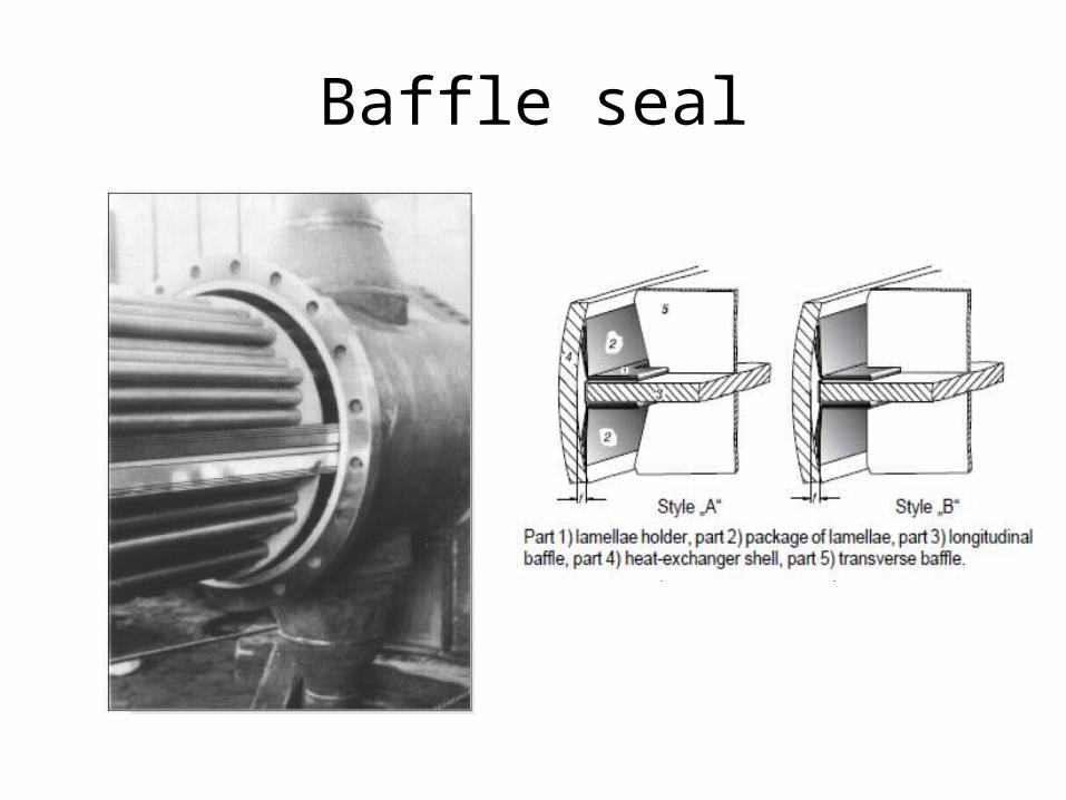
Baffle seal

Geometry Parameter (cont’d)
• Tube geometry– Plain– Finned– Longitudinal finned tube– Tube diameter
Geometry Parameter (cont’d)
• Tube field lay out– 30o , 60o , – 45o , 90o mostly for fluid with high fouling
factor fluid (for easy cleaning)– Tube pitch ratio– 1.25 to 1.5 of outside tube diameter

Tube lay out
Geometry Parameter (cont’d)
• Tube bundle type– Fixed– U tube– Floating head
Geometry Parameter (cont’d)
• Baffle type– Single Segmental– Double segmental– Disc and Doughnut– Multisegmental– NTIW– Support plate for tube vibration problemBaffle cut : 20% - 30%Horizontal baffle cut: for sensible heat transfer
(cooler/heater)Vertical baffle cut: for latent heat transfer (some phase
change)
Geometry Parameter (cont’d)
• Tube diameter, – for practical limit is the requirement for
chemical cleaning of tubes – min. ¾ in for straight tubes and 1 in for U-tubes
– 5/8, ½, 3/8, ¼ inch - for clean stream or chemical cleaning applied - improvement in heat transfer performance.

Geometry Parameter (cont’d)
• Tube length– Preferred tube length – 8ft, 12 ft, 16ft, 20ft.
Other length could be considered if delivery and handling are not a major issue
TEMA Limitation
• TEMA limitation:– Maximum shell ID: 60 in– Max. Design Pressure: 3000 psi– Or nominal tube diameter (in) multiplied by the
design pressure (psi): max. 60,000

Other components (shellside)
• Some part below are significantly affect to thermal and mechanical design:– Tie rod and spacer – are used to retain all baffles and
tube support plates securely in position.– Sealing strip and dummy tubes – to prevent excessive
bypassing flow around or trough tube bundle– Sealing strip usually used for removable bundle with
bundle-to-shell clearance more than 1 in– Impingement plate – to prevent suspended solid or
two phase mixtures from impinging on the tubes to cause damage by erosion.

Baffle Application
• Single segmental (horizontal cut)– for no phase change. Heating and cooling.
• Single segmental (vertical cut) – for vaporization and condensing (allows vapor-liquid disengagement)
• Double segmental (horizontal cut) – same as single segmental but for lower pressure drop requirement
• Double segmental (vertical cut) – same as single segmental but for lower pressure drop requirement

Design Limitation Factor
• Heat transfer coefficient
• Pressure drop– Most common remedial action for this
limitation by combination of:• Use double or multisegmental baffle• Apply shell type J or X• Decrease tube length• Increase tube pitch• Change tube layout pattern

Design Limitation Factor (cont’d)
• Temperature driving force
• Temperature cross?
Fouling Factor
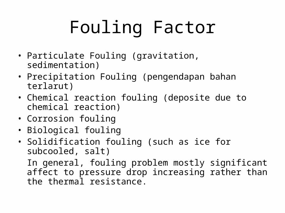
• Particulate Fouling (gravitation, sedimentation)• Precipitation Fouling (pengendapan bahan terlarut)• Chemical reaction fouling (deposite due to chemical
reaction)• Corrosion fouling• Biological fouling• Solidification fouling (such as ice for subcooled, salt)
In general, fouling problem mostly significant affect to pressure drop increasing rather than the thermal resistance.

Operating Variable affect to Fouling
• Flow velocity• Surface temperature – affect to most fouling process
such crystallization and chemical reaction• Bulk-fluid temperature – affect to rate of reaction and
crystallization• MoC – possible catalytic action and corrosion (the
greatest effect to initiating of fouling) • Surface – Roughness, size and density of cavities will
affect crystalline nucleation, sedimentation, and adherence tendency of deposit (the greatest effect to initiating of fouling)

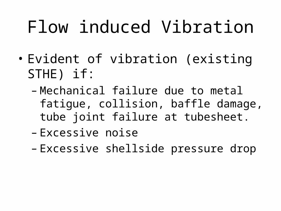
Flow induced Vibration
• Evident of vibration (existing STHE) if:– Mechanical failure due to metal fatigue,
collision, baffle damage, tube joint failure at tubesheet.
– Excessive noise– Excessive shellside pressure drop

Factor of Flow induced vibration
• Flow rate.
• Tube and baffle material
• Unsuppoarted tube span
• Tube field lay out, shell-diameter
• Inlet/outlet configuration
Flow induced Vibration
• Evident of vibration (existing STHE) if:– Mechanical failure due to metal fatigue,
collision, baffle damage, tube joint failure at tubesheet.
– Excessive noise– Excessive shellside pressure drop
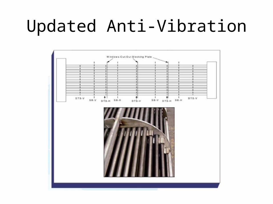
Updated Anti-Vibration

How to reduce vibration (during design)
• Reduce velocity at shellside and tubeside entering. Impingement plate will be req’d if ρV2 exceed: – For non-abrasive, single phase fluid: 1500 (2232 SI unit)– Other liquid including a liquid at its boiling point: 500 (744)– For all gases and vapors impingement protection is required
• Change tube layout (30o , 60o , 45o , 90o)• Change baffle spacing• Change baffle type and or add detuning baffles• Use special design of baffle such as rod-baffle

Thermosiphon
• Vapor-to-liquid ratio is critical to the operation of reboiler (usually 5 to 35% vapor)
• Vertical Thermosiphon– Tube length will be depend on amount of recirculation
and available static head. Shorter tubes for available static head too small
– ¾ inch tube diameter are preferred for medium pressure service and clean service for economic reason (exchanger cost low)
– Larger tube diameter usually for vacuum services and or high viscosity fluid.

Logic Diagram Thermal Design

Thermal Design Calc
Check List

Review Process Data Sheet
• Make sure latest data is referred (to check if there any data has been amended
• Is data sensible?• To check if correct TEMA type specified• Any process special requirement?
– Phase fluid changing (condensation, evaporation, boiling)– If fluid phase is changing, ensure required fluid properties is
available for the multiphase/phase changing is available.• Heat and Mass balance?• Is there any Overcapacity/oversurface required?• Is there any alternative condition to be considered?
– Case A, Case B, …• Is there any unusual design feature/problems
Check Properties/Heat Curve
• Review clients properties if given

Check Final Computer Run (Vendor Thermal Rating Result)
• Has correct program/option been used?• Ensure process data (flows, temps, fouling properties,
density, viscosity, specific heat, thermal conductivity,• Check geometry data (tube gauge, tube material, nozzle
diameter, tube pitch, tube layout angle, etc.• If high tube design pressure with S type, check if T type
required.• Does design conform to client limit• Is alternative tube type allowed such as low finned tube,
or longitudinal type tube allowed)• Is output satisfactory? Pressure drop, duty, velocities,
stream analysis, etc

Vibration Check
• Vibration Check– Is vibration analysis satisfactory?– Bundle entry/exit conditions checked– To check calculation vibration analysis at first
row of tube for more detail– Check entrance/exit calculation spread sheet– Consider impingement rods for large nozzles
(18’’ or above)– Check acoustic vibration prediction

Check Tube Count
• Tube welding required?
• Has correct U-bend min dia been allowed for Duplex, Hastelloy, Titanium, Nickel alloys, etc.
• Has allowance been made in tube count for acoustic of longitudinal baffle?

F - Shell
• Permitted by clients?• Longitudinal baffle type
– welded?– Seal (lamiflex or Kempchen) required?– Is shroud used?
• Allowance made for physical and/or thermal leakage (if F/G factor < 0.9 consider insulated longitudinal baffle)
• Be alert if ∆p > 5 psi or shell temp diff > 500oF

Hydrate / Fouling Formation
• Is there a maximum or minimum surface temp?

Low Operating Pressure
• Check vapor properties (density) have taken account of the calculated press drop. Request 2 isobaric curve if possible

Fixed Tuebsheet Design
• Calculate metal wall temperature• Any alternate condition for metal wall temp such
as winter, turndown, failure of fluid, start-up, shutdown Process to identify) if these apply). Consider also Mech Design Temp.
• If different tube/shell mat’l: give min and max temp differential.
• Alert if differential pressure hydrotest between tubeside and shellside to be applied
Kettle Design/Thermosyphon
• Space for recirculation
• Are nozzle position clearly defined?
• Ensure the low operating pressure has affect to static head
• Alert if piping is assumed or known (clearly defined) in datasheet

Check Thermal Datasheet
• Check process and geometry data (ensure all necessary data is given such as seal strips, impingement plate, seal passlane, etc if required
• Do notes and drawing adequately reflect design?
• Check flow direction (hot-down, cold-up)• Ensure if any requirement of technical
specification be included (such as tube to tubesheet welding, hydrogen or H2S service, etc)

Check Thermal Datasheet (cont’d)
• Check design pressure (DP) and design temp (DT) are correct and ensure if Full Vacuum, diff pressure required, etc)
• Ensure unusual aspect feature (if req’d) are define correctly such as connection of shell in series, special support plates, essential vents, annular distribution baffles, etc.
• Mechanical design code were specified – ASME, PD5500, TEMA, PED (European Pressure Equipment Directive).
• Code stamped requirement?

Good exercise
• How to do tube-to-tubesheet leak test at floating tubesheet (T-type)?
Related Documents