Page 1 Heat and fuel coupled operation of a high temperature polymer electrolyte fuel cell with a heat exchanger methanol steam reformer G. Schuller a,* , F. Vidal Vázquez b , W. Waiblinger a , S. Auvinen b , P. Ribeirinha c a German Aerospace Center (DLR), Institute of Engineering Thermodynamics, Pfaffenwaldring 38-40, 70569 Stuttgart, Germany b VTT Technical Research Centre of Finland, Biologinkuja 5, 02150 Espoo, Finland c Laboratório de Engenharia de Processos, Ambiente, Biotecnologia e Energia (LEPABE), Faculdade de Engenharia do Porto, Rua Roberto Frias, 4200-465 Porto, Portugal (*) Corresponding author: Gerhard Schuller, Tel.: +49 711 6862-510, Fax: +49 711 6862-747, e-mail address: [email protected]

Welcome message from author
This document is posted to help you gain knowledge. Please leave a comment to let me know what you think about it! Share it to your friends and learn new things together.
Transcript

Page 1
Heat and fuel coupled operation of a high temperature polymer electrolyte fuel cell with a heat exchanger methanol steam reformer
G. Schullera,*, F. Vidal Vázquezb, W. Waiblingera, S. Auvinenb, P. Ribeirinhac
a German Aerospace Center (DLR), Institute of Engineering Thermodynamics, Pfaffenwaldring 38-40, 70569 Stuttgart, Germany
b VTT Technical Research Centre of Finland, Biologinkuja 5, 02150 Espoo, Finland
c Laboratório de Engenharia de Processos, Ambiente, Biotecnologia e Energia (LEPABE), Faculdade de Engenharia do Porto, Rua Roberto Frias, 4200-465 Porto, Portugal
(*) Corresponding author: Gerhard Schuller, Tel.: +49 711 6862-510, Fax: +49 711 6862-747, e-mail address: [email protected]

Page 2
Abstract
In this work a methanol steam reforming (MSR) reactor has been operated thermally coupled to a high temperature polymer electrolyte fuel cell stack (HT-PEMFC) utilizing its waste heat. The operating temperature of the coupled system was 180 °C which is significantly lower than the conventional operating temperature of the MSR process which is around 250 °C. A newly designed heat exchanger reformer has been developed by VTT (Technical Research Center of Finland LTD) and was equipped with commercially available CuO/ZnO/Al2O3 (BASF RP-60) catalyst. The liquid cooled, 165 cm², 12-cell stack used for the measurements was supplied by Serenergy A/S. The off-heat from the electrochemical fuel cell reaction was transferred to the reforming reactor using triethylene glycol (TEG) as heat transfer fluid. The system was operated up to 0.4 A cm-2 generating an electrical power output of 427 Wel. A total stack waste heat utilization of 86.4 % was achieved. It has been shown that it is possible to transfer sufficient heat from the fuel cell stack to the liquid circuit in order to provide the needed amount for vaporizing and reforming of the methanol-water-mixture. Furthermore a set of recommendations is given for future system design considerations.

Page 3
Keywords
HT-PEM, Methanol Steam Reforming, Coupling, Heat utilization, PBI-Membrane, Heat Exchanger Reactor
Page 4
1 Introduction
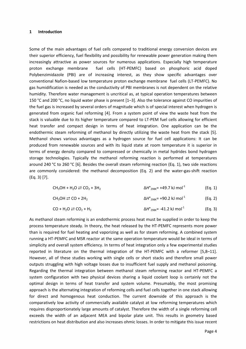
Some of the main advantages of fuel cells compared to traditional energy conversion devices are their superior efficiency, fuel flexibility and possibility for renewable power generation making them increasingly attractive as power sources for numerous applications. Especially high temperature proton exchange membrane fuel cells (HT-PEMFC) based on phosphoric acid doped Polybenzimidazole (PBI) are of increasing interest, as they show specific advantages over conventional Nafion-based low temperature proton exchange membrane fuel cells (LT-PEMFC). No gas humidification is needed as the conductivity of PBI membranes is not dependent on the relative humidity. Therefore water management is uncritical as, at typical operation temperatures between 150 °C and 200 °C, no liquid water phase is present [1–3]. Also the tolerance against CO impurities of the fuel gas is increased by several orders of magnitude which is of special interest when hydrogen is generated from organic fuel reforming [4]. From a system point of view the waste heat from the stack is valuable due to its higher temperature compared to LT-PEM fuel cells allowing for efficient heat transfer and compact design in terms of heat integration. One application can be the endothermic steam reforming of methanol by directly utilizing the waste heat from the stack [5]. Methanol shows various advantages as a hydrogen source for fuel cell applications: It can be produced from renewable sources and with its liquid state at room temperature it is superior in terms of energy density compared to compressed or chemically in metal hydrides bond hydrogen storage technologies. Typically the methanol reforming reaction is performed at temperatures around 240 °C to 260 °C [6]. Besides the overall steam reforming reaction (Eq. 1), two side reactions are commonly considered: the methanol decomposition (Eq. 2) and the water-gas-shift reaction (Eq. 3) [7].
CH3OH + H2O ⇄ CO2 + 3H2 ΔH°298K= +49.7 kJ mol-1 (Eq. 1)
CH3OH ⇄ CO + 2H2 ΔH°298K= +90.2 kJ mol-1 (Eq. 2)
CO + H2O ⇄ CO2 + H2 ΔH°298K= -41.2 kJ mol-1 (Eq. 3)
As methanol steam reforming is an endothermic process heat must be supplied in order to keep the process temperature steady. In theory, the heat released by the HT-PEMFC represents more power than is required for fuel heating and vaporizing as well as for steam reforming. A combined system running a HT-PEMFC and MSR reactor at the same operation temperature would be ideal in terms of simplicity and overall system efficiency. In terms of heat integration only a few experimental studies reported in literature on the thermal integration of the HT-PEMFC with a reformer [5,8–11]. However, all of these studies working with single cells or short stacks and therefore small power outputs struggling with high voltage losses due to insufficient fuel supply and methanol poisoning. Regarding the thermal integration between methanol steam reforming reactor and HT-PEMFC a system configuration with two physical devices sharing a liquid coolant loop is certainly not the optimal design in terms of heat transfer and system volume. Presumably, the most promising approach is the alternating integration of reforming cells and fuel cells together in one stack allowing for direct and homogenous heat conduction. The current downside of this approach is the comparatively low activity of commercially available catalyst at low reforming temperatures which requires disproportionately large amounts of catalyst. Therefore the width of a single reforming cell exceeds the width of an adjacent MEA and bipolar plate unit. This results in geometry based restrictions on heat distribution and also increases ohmic losses. In order to mitigate this issue recent

Page 5
efforts have been made to develop a low temperature MSR catalyst bringing the temperature down to fuel cell level and still achieving full conversion at temperatures as low as 180 °C and high space time velocities [12–14]. Regarding the electrical performance Avgouropoulos et al. [15] reported on a 15 cell stack (Active Area: 49 cm²) combined with 15 reformer cells achieving 70 W of electrical power output at 0.18 A cm-2 at an operation temperature of 200 °C.
In the present study a 12-cell HT-PEM fuel cell stack with direct liquid cooling has been thermally coupled with a novel aluminum heat exchanger MSR reactor (HER) which has been developed by VTT (Technical Research Center of Finland LTD) (Fig. 1/A). The design of the HER focused on optimizing the heat exchange fluid flow inside the reforming reactor to ensure homogeneous heat supply to the catalyst packed channels. The reformer has been manufactured using a novel method based on multi-port extruded (MPE) aluminum tubes which have been connected by laser welding. Besides the thermal coupling also a direct supply of the hydrogen rich reformate to the fuel cell stack was performed. The heat transfer fluid which was used for the heat transfer between fuel cell and reforming reactor was routed through each bipolar plate (BPP) of the stack in parallel / Z-flow. It allowed for a uniform heat distribution over the stack minimizing hot spot areas. This was necessary as the stack operating temperature has been defined at 180 °C as a trade-off between fuel cell degradation and methanol conversion. In a first step stack and methanol steam reformer have been characterized separately elaborating the performance of both devices. Furthermore the fuel cell stack and the reforming reactor were successfully coupled and operated in steady state mode. During operation mass flow rates, temperatures and pressures were measured in order to provide a detailed heat balance database.
Fig. 1: (A) Packed bed methanol steam reformer. (B) Reforming channels of the packed bed MSR reactor.
The steady state energy balance of the stack can be written as:
stack,lossstack,HTFth,StackCA QQQQQ +=++ (Eq. 4)
The indices ‘a’ and ‘c’ refer to the heat due to the enthalpy change of the anode and respectively cathode gas flow through the stack. The index ‘Stack,th’ describes the reaction zone and represents the heat, that is actually available in the stack. The major part of this heat is drained by the heat transfer fluid ‘HTF,stack’. The last term describes the loss due to free convection, radiation and conduction through the support and piping of the stack. The goal is to minimize this term in order to

Page 6
transfer the maximum amount of heat to the coolant media from where it can be further utilized by the MSR.
As the loss to the surroundings cannot be measured directly, the individual fractions of heat flows crossing the stack boundaries have to be calculated using measured data. The thermal heat produced by the stack can be calculated with equation 5 assuming gaseous product water. The reaction enthalpy is given in Table 1 for different temperatures.
( ) elTRcellth,Stack PH
F2InQ −−⋅
⋅= ∆ (Eq. 5)
Temperature [°C] TRH∆ [J mol-1]
160 -243177
180 -243374
200 -243569 Table 1: Reaction enthalpy for gaseous water production from hydrogen and oxygen
Each flow at the inlet of anode and cathode is measured and regulated by individual mass flow controllers. The outgoing mass flows are calculated using the actual gas composition as the stoichiometric fuel and oxygen consumption of the stack is well known and only dependent on the current load and the number of cells [3]. For the calculation of the cathode inlet gas enthalpy the humidity is neglected as the test bench is operated with dried compressed air. The sensible heat lost through anode and cathode of the stack is unavailable for the MSR process and can be calculated for anode and cathode separately using equations 6 and 7.
( ) ( )( )( ) ( )( ) ( )out,COin,COref,COr,Hout,Hout,Hin,HAs,HdryReformate,A
r,Hout,Hout,Hin,HAs,HHydrogenA
22222222
22222
hhmhhhhmQ
hhhhmQ
−⋅+−+−⋅⋅=
−+−⋅⋅=
λ
λ
(Eq. 6)
( )( )
( ) ( )out,OHr,OHr,OHout,Nin,Nin,N
r,Oout,Oout,Oin,OCs,OC
222222
22222
hhmhhm
hhhhmQ
−⋅+−⋅+
−+−⋅⋅=
λ
(Eq. 7)
The index ‘r’ refers to the reaction zone temperature of the fuel cell stack which is assumed to be equal to the temperature set point at the fuel cell coolant outlet. Index ‘s’ indicates the stoichiometric quantity of a substance. The enthalpies are calculated using empirical equations by McBride et al. [16].
The heat which is discharged by the heat exchange fluid can be calculated by making use of the measured temperatures, mass flow rate and specific heat capacity.
( )in,stack,HEFout,stack,HEFHEFHEFstack,HEF TTcmQ −⋅⋅= (Eq. 8)

Page 7
2 Experimental
The stack used as heat and power source was a 12-cell short stack with a membrane area of 165 cm² manufactured by Serenergy A/S. The bipolar plates were manufactured from BBP 4 material which is a graphite composite (Eisenhuth). Each bipolar plate was made of two halves with a milled structure in between which represents the cooling channels as the stack is liquid cooled. The cavities for the anode and cathode reactant gases are formed at the outside of each half-plate. The membrane electrode assemblies (MEAs) applied in the stack are Celtec-P 1100 W produced by BASF which are assembled around a phosphoric acid doped polybenzimidazole (PBI) based membrane. The test bench for the system was designed with the purpose to flexibly run the stack with pure hydrogen or hydrogen rich reformate from the MSR. Anode and cathode could also be purged with nitrogen for inerting. Fuel and air supply of the stack were realized in counter flow design using mass flow controllers (MFC) in case of pure hydrogen operation. Both, anode and cathode gas outlet were open to the environment with no gas recirculation. The cooling of the stack was realized using triethylene glycol (TEG) as a heat transfer fluid which was circulated by a combined heating/cooling unit model Tango by Peter Huber Kältemaschinenbau AG. In order to monitor the TEG flow a positive displacement flowmeter (Omega FDP2022-A) was installed in the coolant loop prior to the stack.
After the heat transfer fluid passed the stack it was routed to the HER where the heat, which has been absorbed from the stack, was utilized in the MSR process. The HER was build using 10 parallel multi-port extruded (MPE) aluminum tubes for the packed bed with a total volume of app. 1.4 dm³ (Fig. 1/B). The weight of this novel reformer design is app. 6.5 kg at 4.7 dm³ of total volume. Due to their internal structure with multiple thin walls MPE tubes provide excellent heat transfer into the catalyst bed. The heat transfer fluid is routed around and between each of the tubes to ensure a homogenous heat transfer over the whole reactor length. Furthermore the manufacturing is simplified by reducing the total length which has to be welded while simultaneously reducing the risk of internal leakage all at one. However, the manufacturing of the HER was still a challenging task due to the thin walls of the MPE tubes in combination with aluminum as constructing material which hindered the laser welding. The reactor was equipped with 1.9 kg of RP-60 catalyst by BASF which has been crushed to particle sizes between 250 µm and 400 µm. The dimensioning of the catalyst amount required in the reformer was based on the results of a previous study reported by Vidal et al. [16] where the same catalyst was studied for kinetic model development and reactor dimensioning. Furthermore, a study on the catalyst performance in relation to the particle size identified the particle size used in the reformer as the most suitable (Fig. 2). Reducing the particle size by one order of magnitude improves the conversion rate by 15 %. By decreasing the particle size internal and external mass transfer limitations are reduced whereat smaller catalyst particles also originate a higher pressure loss [17].

Page 8
Fig. 2: RP-60 catalyst particle size effect on methanol conversion at 180 °C tested with 1.5 g catalyst and S/C 1.5. Dotted lines were added for better readability.
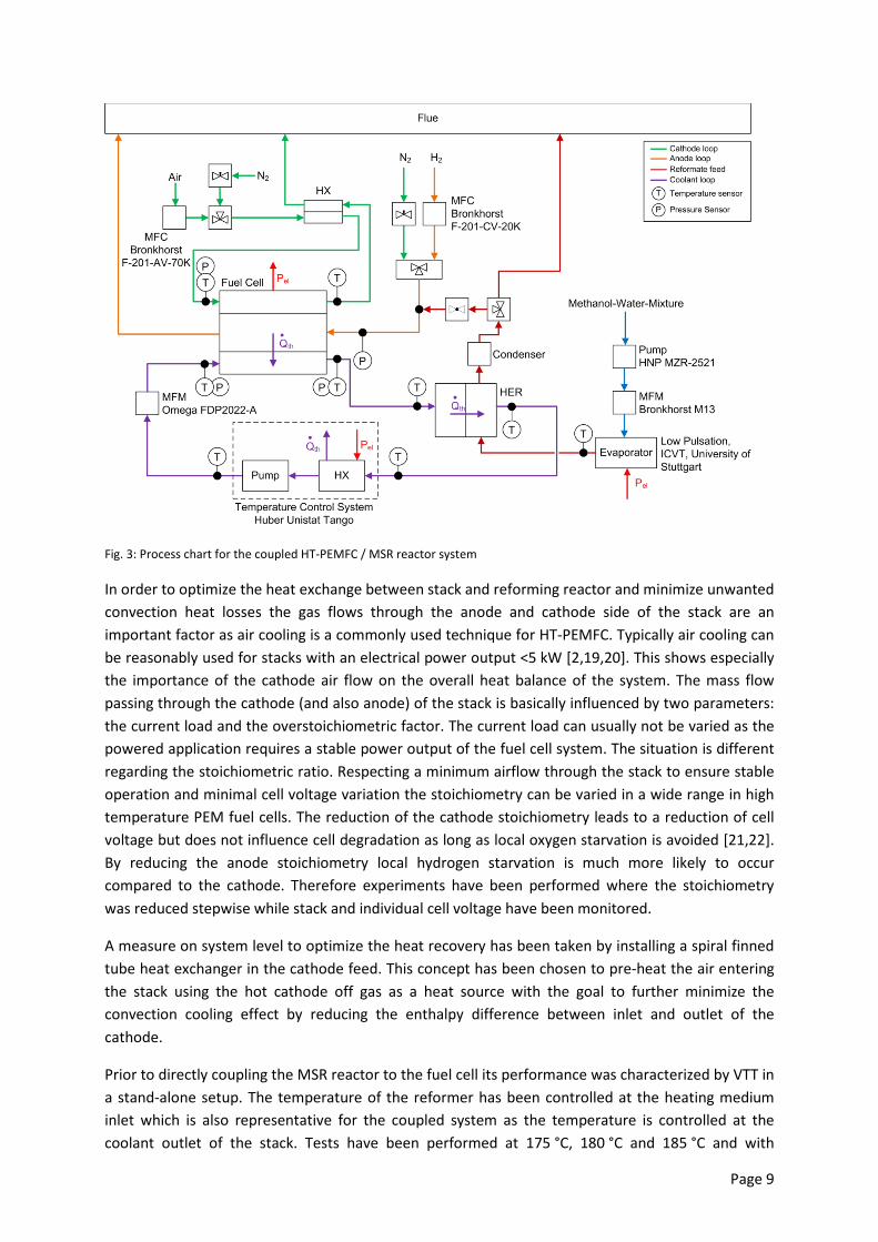
The pre-mixed methanol-water-mixture was pumped by a compact micro annular gear pump type MZR-2521 by HNP Mikrosysteme which is designed for flows up to 9 mL min-1. The flow was controlled using a Coriolis mass flow meter M13 manufactured by Bronkhorst (Fig. 3). For the evaporation of the methanol-water-mixture an electrically heated, low pulsation evaporator developed at the Institute for Chemical Process Engineering of the University of Stuttgart was used. The electrically heated device was chosen over a liquid/liquid heat exchanger due to its remarkable smooth and controlled evaporation even at transient load conditions [18]. After the conversion in the MSR the wet, hydrogen rich gas mixture is routed to a condenser where the reformate is cooled down and the excess water or unconverted methanol is collected. After passing through the stack the unused excess fuel is vented. On the cathode side the air is supplied by a mass flow controller type F-201AV manufactured by Bronkhorst. Temperatures of any media are measured using type K thermocouples which have been calibrated at 180 °C. The pressure of the reactants is monitored by Cerabar T PMC131 pressure transducers from Endress+Hauser at the inlet of the stack while the pressure of the heat transfer fluid is measured at the inlet and outlet. System monitoring and control was realized using Delphin TopMessage modules. All measured Data are logged and stored in a data base. All hot components and piping have been properly insulated with glass wool (λ=0.040 W m-1 K-1) and rubber based foam by Armacell type HT/Armaflex (λ=0.042 W m-1 K-1).
Page 9
Fig. 3: Process chart for the coupled HT-PEMFC / MSR reactor system
In order to optimize the heat exchange between stack and reforming reactor and minimize unwanted convection heat losses the gas flows through the anode and cathode side of the stack are an important factor as air cooling is a commonly used technique for HT-PEMFC. Typically air cooling can be reasonably used for stacks with an electrical power output <5 kW [2,19,20]. This shows especially the importance of the cathode air flow on the overall heat balance of the system. The mass flow passing through the cathode (and also anode) of the stack is basically influenced by two parameters: the current load and the overstoichiometric factor. The current load can usually not be varied as the powered application requires a stable power output of the fuel cell system. The situation is different regarding the stoichiometric ratio. Respecting a minimum airflow through the stack to ensure stable operation and minimal cell voltage variation the stoichiometry can be varied in a wide range in high temperature PEM fuel cells. The reduction of the cathode stoichiometry leads to a reduction of cell voltage but does not influence cell degradation as long as local oxygen starvation is avoided [21,22]. By reducing the anode stoichiometry local hydrogen starvation is much more likely to occur compared to the cathode. Therefore experiments have been performed where the stoichiometry was reduced stepwise while stack and individual cell voltage have been monitored.
A measure on system level to optimize the heat recovery has been taken by installing a spiral finned tube heat exchanger in the cathode feed. This concept has been chosen to pre-heat the air entering the stack using the hot cathode off gas as a heat source with the goal to further minimize the convection cooling effect by reducing the enthalpy difference between inlet and outlet of the cathode.
Prior to directly coupling the MSR reactor to the fuel cell its performance was characterized by VTT in a stand-alone setup. The temperature of the reformer has been controlled at the heating medium inlet which is also representative for the coupled system as the temperature is controlled at the coolant outlet of the stack. Tests have been performed at 175 °C, 180 °C and 185 °C and with

Page 10
different mass of catalyst to methanol feed (W/F) ratios. The reduction of the catalysts was performed in situ starting at 0.7 % hydrogen diluted in nitrogen at 160 °C and slowly increasing temperature and hydrogen percentage in 10 minutes intervals stepwise to 205 °C and respectively 5 %. After the reduction the reformer was flushed with nitrogen.
The general procedure for testing the coupled HT-PEMFC with the MSR was the following: During the start-up phase the system was heated externally using the Huber Unistat Tango which circulated hot TEG through stack and MSR reactor. Coolant inlet and outlet temperature as well as the inlet pressure of the stack were permanently monitored during this process to ensure homogeneous heating within temperature gradient and pressure limitations of the stack. Especially the pressure of the heat transfer fluid at the inlet of the stack was kept below 20 kPa at any time to avoid internal coolant leakage. The flow of the heat transfer fluid was controlled by adjusting the pump speed of the Huber unit. Nitrogen was purged through anode and cathode during heat-up.
Only as the temperature of the coolant outlet of the stack was above 120 °C the nitrogen purge was stopped and hydrogen and air were supplied through MFCs to anode and respectively cathode. For further heating to the preconfigured temperature of the system a current density of 0.2 A cm-2 was set using a DC load EL9080-200HP from Elektro-Automatik GmbH which speeded up the process through internal heat production. Heat and fuel coupled system experiments were only performed after the whole system reached a steady-state. Switching from hydrogen to reformate was done at a stack load of 0.1 A cm-2 by slowly decreasing the external hydrogen supply while simultaneously feeding the MSR with a methanol-water-mixture and subsequently hydrogen rich reformate to the stack.
3 Results and discussion
3.1 High temperature fuel cell stack
Experiments on the cathode and anode stoichiometric ratio sensitivity on the stack voltage were performed without the reforming reactor, running the stack on pure hydrogen at a stack current density of 0.3 A cm-2 and with moderate stoichiometry variations. As expected the results show that especially the anode side of the stack is prone to starvation as the measured cell voltage range increased dramatically when going to low stoichiometries. Reducing the cathode stoichiometry leads also to a reduction of the cell voltage whereas the cell voltage range between the best and the worst performing cell only slightly increases towards low stoichiometric ratios (Fig. 4/A/B). For further experiments in combination with the reformer the cathode stoichiometric ratio was set to 2.5 whereas the anode stoichiometry was controlled at 1.18 both values as a trade-off between cell voltage homogeneity and potential stack waste heat utilization. Reducing the cathode stoichiometry from 4.0 to 2.5 resulted in a stack heat gain of 11.4 % while decreasing the stoichiometric ratio at the anode from 1.3 to 1.18 resulted in only a heat gain of 5.1 %.
Experiments assessing the benefit of the cathode heat exchanger were also performed without the reformer coupled to the stack which was supplied with hydrogen externally. During these tests a significant increase of the cathode inlet temperature was achieved (Fig. 4/C). It was observed that the cathode inlet temperature with installed heat exchanger rose with increasing air flow. This can be associated to the increasing pressure drop at higher flow rates in the heat exchanger which enhances the heat transfer. At a current density of 0.4 A cm-2 and a cathode stoichiometry of 2.5, which equals

Page 11
33 sL min-1 of air supplied to the cathode, the temperature was raised by about 38 K through the heat exchanger. This temperature gain at the cathode inlet in turn results in a theoretical heat gain of around 27 W (equation 7) as the heat which is dissipated by the cathode air flow is reduced by this amount.
The electrical performance of the 12-cell stack is given in Fig. 4/D with stack voltage and power versus current density at 180 °C. The measurements were performed with pure hydrogen as well as with hydrogen rich reformate. In both cases the anode stoichiometric ratio was set to 1.18. Cathode air was supplied with a stoichiometry of 2.5 with the cathode heat exchanger in use. In case the stack was operated with reformate a pre-mixed methanol-water-mixture with a steam to carbon ratio of 1.5 was used. Running on reformate a maximum current density of 0.4 A cm-2 at a stack voltage of 6.5 V and an average cell voltage of 539 mV was achieved limited by the performance of the methanol-water-pump. The amount of heat which was transferred to the heat transfer fluid is plotted in (Fig. 4/E). Utilizing all measures like cathode air preheating and stoichiometry cutting up to 86.4 % (494 W) of the stack waste heat were successfully transferred to the TEG. The remaining 13.6 % of the heat were lost due to convection in the gas channels of the BPP and general environmental losses. For this experiment the flow of the heat transfer fluid was set to 2.2 L min-1.

Page 12
Fig. 4: (A) Average cell voltage versus anode stoichiometry variation. Cathode stoichiometry set to 3.0. Current density set to 0.3 A cm-2 with reformate feed at the anode and 180 °C coolant outlet temperature. (B) Average cell voltage versus cathode stoichiometry variation. Anode stoichiometry set at 1.3. Current density set to 0.3 A cm-2 with reformate feed at the anode and 180 °C coolant outlet temperature. (C) Cathode inlet temperature versus cathode inlet flow. (D) Stack polarization curve with hydrogen and reformate feed at 180 °C coolant outlet temperature. (E) Total heat produced in the HT-PEMFC and amount transferred to the cooling liquid versus current density. Anode feed: reformate, cathode stoichiometry: 2.5, anode stoichiometry: 1.18, TEG flow: 2.2 L min-1. Dotted lines added for better readability.
3.2 Packed bed heat exchanger methanol steam reformer (HER)
3.2.1 Optimization of heat exchange fluid flow distribution by CFD
During the design process of the HER, COMSOL Multiphysics was used to optimize the fluid distribution in a single cell and at the inlet and outlet manifolds to ensure homogeneous heating of all MPE tubes. Fig. 5/A shows the geometry of the empty volume of the HER for the TEG part where

Page 13
the grey area is the empty volume created between the MPE tubes and walls of the reformer. Blue areas represent the empty volume created by the piping. The channels are connected to the piping by four pipe manifolds which distribute the flow at the inlet and outlet. For the further fluid routing half pipes were attached to the reformer wall in order to reduce its dimensions. However, in the final design of the HER the pipes were detached from the body due to limitations in the manufacturing process. In the CFD simulation nine TEG channels have been considered with the following assumptions:
- Laminar flow through the entire geometry - Isothermal conditions - Isotropic fluid (properties from TEG data sheet at reformer operating temperature)
The main issue for a uniform flow distribution in one single channel was the distance between two MPE tubes (which is the height of the channel) and the geometry of the channel inlets and outlets. The height was optimized to 4 mm to create enough pressure drop along the channel but enabling machining and welding. Simulation of a single channel showed uniform flow distribution in the middle part of the channel. The inlet and outlet pipe manifolds were machined in a way that one quarter of the wall of the pipe was introduced inside each channel (Fig. 5/C). This was done to reduce the dead volume at the top and bottom of the channels.
Several different geometries where simulated with varying numbers of pipe splits and positions of the inlet and outlet manifolds. Finally, the best performing geometry was selected (Fig. 5/B). Thermal oil inlet and outlet pipe were split twice. Consequently, the manifolds at the side of the channels had two inlets or outlets (depending on the direction of the flow). These two inlets respectively outlets help to equalize the pressure at the inlets and outlets of the different channels. As a result, the maximum relative difference of volumetric flow rate between the channels is app. 4 %.

Page 14
Fig. 5: (A) Simulated geometry. (B) CFD simulation results of the full geometry with a total oil flow rate of 2 L min-1. Colored legend is the fluid velocity (m s-1). (C) CFD simulation of a single channel showing the streamlines. Colored legend is fluid velocity (m s-1). Grid unit is meter.

Page 15
3.2.2 HER performance assessment test
In analogy to the fuel cell tests the MSR reactor has been characterized separately prior to the heat and fuel coupling of stack and reformer to assess its performance. Experiments were executed at different mass of catalyst to methanol flow ratios (W/F) and operation temperatures (Fig. 6/A). The temperature of the MSR was controlled at the heating fluid inlet of the device to ensure almost identical conditions to the coupled system setup where the temperature is controlled at the coolant outlet of the stack prior to entering the reformer. At 175 °C, 90 % methanol conversion was reached at a catalyst weight to flow ratio of app. 730 kg s mol-1, at 1500 kg s mol-1, equaling a methanol flow of 3.1 mL min-1, no unconverted methanol was traceable in the reformate stream. At 180 °C complete conversion was measured at a W/F ratio of 962 kg s mol-1 which equals a hydrogen yield of around 250 L h-1 kgcat
-1. This is a good result for such a low reforming temperature also confirmed by the work of Pan et al. [5] who reported a hydrogen yield of 200 L h-1 kgcat
-1 at 180 °C also using a CuO/ZnO/Al2O3 catalyst. At the highest tested temperature of 185 °C full conversion was reached at a methanol flow of 6.2 mL min-1 achieving a hydrogen yield of 323 L h-1 kgcat
-1.
The CO content in the reformate gas was measured to be relatively constant in the area of around 0.3 %Vol at 175 °C. At higher temperatures the CO content increased slightly but generally stayed below 0.5 %Vol (Fig. 6/B).
Fig. 6: Packed bed HER characterization results. (A) Methanol conversion versus weight of catalyst to methanol flow ratio (W/F). (B) CO concentration in reformate versus weight of catalyst to methanol flow ratio (W/F). Measured at 175 °C, 180 °C and 185 °C. Dotted lines added for better readability.
3.3 Thermally and fuel coupled HT-PEMFC with MSR reactor
The switch from hydrogen to reformate feed was performed after the system was heated up and reached a steady state (Fig. 7/A). During the transition phase where reformate and hydrogen were supplied simultaneously to the stack a small voltage drop of about 4 mV per cell was observed which is assumed to be related to presence of app. 0.4 % of CO in the reformate stream and the partial pressure reduction of H2. After the complete shutdown of the external hydrogen supply the voltage dropped app. by another 11.6 mV per cell which is also likely due to CO poisoning and partially from the reduced hydrogen partial pressure due to dilution by CO2 in the reformate. The peak in the methanol feed is related to the abrupt shut down of the pure hydrogen supply by the MFC whereby

Page 16
the pressure conditions in the supply line changed abruptly. As the back pressure after the reforming reactor dropped the methanol-water-mixture pump overshot the required value by factor 2 until the controller readjusted the setting.
The average cell voltage over time is depicted in Fig. 7/B. The two voltage drops at Roman numeral one and two were due to gas bubbles coming from the methanol-water-intake of one of the fittings of the dosing pump. These gas bubbles led to a temporary fuel starvation with voltage drop upon reaching the stack. Refastening of the fittings fixed the problem. Another issue regarding the system control was found when increasing the fuel cell load. It was observed that the whole reformate supply chain (pump, reformer, condenser and pipes) of the HT-PEMFC reacted slowly when changing load levels. The control system changed sequentially the methanol flow followed by the electric load adjustment, however, the quick response of the stack to the load change was not matched by the reformer and the temporary starvation induced a voltage drop. The hydrogen rich reformate flow reached the membrane electrode assembly (MEA) of the stack only after a time delay. This is related to the high component and pipe volume of the fuel supply line which acts like a buffer. This temporary mismatch between electric load and fuel supply is responsible for the voltage drops as seen in Fig. 7/B when stepwise increasing the current density.
Changing the electric load also affects the heat generated by the fuel cell which again has an influence on the coolant liquid temperature entering the stack (Fig. 7/C). As the outlet temperature of the fuel cell was controlled at 180 °C the inlet temperature dropped with every load step. The peaks in the coolant temperature at stack and reformer outlet result from the rapid heat generation after each electric increasing load step. As the heat capacity of the complete coolant line with its components is quite large the control loop reacts slowly to changed operating conditions. The settling time to bring the stack outlet temperature back to the pre-set value was around one hour.

Page 17
Fig. 7: Coupled system performance. (A) Switch between hydrogen and reformate feed. (B) Average cell voltage, current density and methanol flow versus time. (C) Heat exchange fluid temperature at stack inlet, outlet and reformer outlet versus time. For all figures: Anode stoichiometry: 1.18; Cathode stoichiometry: 2.5; Operation Temperature: 180 °C.
The heat and energy balance of the coupled system has been calculated for a current density of 0.4 A cm-2 at steady state and a Sankey diagram has been deduced (Fig. 8). The diagram summarizes all heat and energy flows going in and out of the system. From the plot it is clear that sufficient heat is transferred to the liquid circuit (494 W) in order to provide enough energy for vaporizing and reforming the methanol-water-mixture (194 W and 129 W respectively). As the vaporizer was electrically heated within this experiment the theoretically calculated energy amount needed for total evaporation and superheating to 180 °C from room temperature (22 °C) was used in this calculation (η=1). With a total of 4.6 % (9 W) only a minor amount of heat is lost to the environment due to convection, radiation and the anode flow while cathode flow losses account for 52 W (9 %).
Fig. 8: Sankey plot of system heat and energy balance at maximum power output. Anode stoichiometry: 1.18; Cathode stoichiometry: 2.5; Current Density: 0.4 A cm-2; Coolant outlet temperature: 180 °C; Coolant flow: 2.2 L min-1.
The most substantial energy loss is due to the overstoichiometric operation ratio of the anode feed. With 186 W (15.7 %) the amount of unused chemical energy is not negligible. To overcome this loss the anode waste gas has to be reused within the system. As the anode off gas contains a high amount of CO2 (around 70 %Voldry) direct recirculation back to the stack inlet is not possible without high purge rates which implies high losses again in a comparable scale. One option can be the removal of CO2 and other impurities from the anode off gas before recycling the stream back to the stack inlet. For this approach inorganic microporous membranes [23,24] or supported ionic liquid polymer membranes might be used [25–27]. If gas purification is considered, the better idea from a system point of view would be the integration of the purification system between stack and reformer in order to increase the hydrogen partial pressure. This would be beneficial for the cell potential according to the Nernst equation [28] and due to kinetic effects. Another approach is the steam reforming of methanol inside a palladium based membrane reactor [6,24,29–31] which directly separates hydrogen from the reformate stream after reformation.

Page 18
4 Conclusion
In the present work a heat and fuel coupled system composed of a liquid-cooled high temperature fuel cell stack and a methanol steam reformer was characterized. The amount of heat which is rejected from the stack by the heat exchange fluid and which is available for further utilization was quantified with respect to the load level of the HT-PEM stack. At a load level of 0.2 A cm-2, 33 % of the energy supplied by the hydrogen rich reformate feed were available as sensible heat in the coolant. At a load level of 0.4 A cm-2 this value was increased to 42 %. The methanol steam reforming reactor equipped with crushed commercial BASF RP-60 catalyst achieved full conversion at 180 °C at a weight of catalyst to methanol flow ratio of 962 kg s mol-1. This equals a methanol flow of 4.8 mL per minute. At 180 °C the CO fraction in the reformate stream was below 0.5 %Vol in all tested cases. Finally it can be stated that the experimental outcome shows that direct heat coupling of a reformer and a high temperature PEM fuel cell as heat source using a liquid heat transfer fluid is possible at 180 °C.
5 Acknowledgments
Research leading to these results has received funding from the European Union's Seventh Framework Programme (FP7/2007-2013) for the Fuel Cells and Hydrogen Joint Technology Initiative under grant agreement nº 303476 (www.beingenergy.eu) which is highly acknowledged.

Page 19
References
[1] A. Chandan, M. Hattenberger, A. El-kharouf, S. Du, A. Dhir, V. Self, B.G. Pollet, A. Ingram, W. Bujalski, High temperature (HT) polymer electrolyte membrane fuel cells (PEMFC) – A review, J. Power Sources. 231 (2013) 264–278. doi:10.1016/j.jpowsour.2012.11.126.
[2] S.S. Araya, F. Zhou, V. Liso, S.L. Sahlin, J.R. Vang, S. Thomas, X. Gao, A Comprehensive Review of PBI-based High Temperature PEM Fuel Cells, Int. J. Hydrogen Energy. (2016) 1–35. doi:10.1016/j.ijhydene.2016.09.024.
[3] J. Weiss-Ungethüm, I. Bürger, N. Schmidt, M. Linder, J. Kallo, Experimental investigation of a liquid cooled high temperature proton exchange membrane (HT-PEM) fuel cell coupled to a sodium alanate tank, Int. J. Hydrogen Energy. 39 (2014) 5931–5941. doi:10.1016/j.ijhydene.2014.01.127.
[4] Q. Li, R. He, J.-A. Gao, J.O. Jensen, N.J. Bjerrum, The CO Poisoning Effect in PEMFCs Operational at Temperatures up to 200°C, J. Electrochem. Soc. 150 (2003) A1599–A1605. doi:10.1149/1.1619984.
[5] C. Pan, R. He, Q. Li, J.O. Jensen, N.J. Bjerrum, H.A. Hjulmand, A.B. Jensen, Integration of high temperature PEM fuel cells with a methanol reformer, J. Power Sources. 145 (2005) 392–398. doi:10.1016/j.jpowsour.2005.02.056.
[6] A. Iulianelli, P. Ribeirinha, A. Mendes, A. Basile, Methanol steam reforming for hydrogen generation via conventional and membrane reactors: A review, Renew. Sustain. Energy Rev. 29 (2014) 355–368. doi:10.1016/j.rser.2013.08.032.
[7] S. Sá, H. Silva, L. Brandão, J.M. Sousa, A. Mendes, Catalysts for methanol steam reforming-A review, Appl. Catal. B Environ. 99 (2010) 43–57. doi:10.1016/j.apcatb.2010.06.015.
[8] G. Avgouropoulos, S.G. Neophytides, Performance of internal reforming methanol fuel cell under various methanol/water concentrations, J. Appl. Electrochem. 42 (2012) 719–726. doi:10.1007/s10800-012-0453-x.
[9] G. Avgouropoulos, A. Paxinou, S. Neophytides, In situ hydrogen utilization in an internal reforming methanol fuel cell, Int. J. Hydrogen Energy. 39 (2014) 18103–18108. doi:10.1016/j.ijhydene.2014.03.101.
[10] F. Weng, C.K. Cheng, K.C. Chen, Hydrogen production of two-stage temperature steam reformer integrated with PBI membrane fuel cells to optimize thermal management, Int. J. Hydrogen Energy. 38 (2013) 6059–6064. doi:10.1016/j.ijhydene.2013.01.090.
[11] P. Ribeirinha, I. Alves, F.V. Vázquez, G. Schuller, M. Boaventura, A. Mendes, Heat integration of methanol steam reformer with a high-temperature polymeric electrolyte membrane fuel cell, Energy. (2016) 1–10. doi:10.1016/j.energy.2016.11.101.
[12] C.S.R. Azenha, C. Mateos-Pedrero, S. Queirós, P. Concepción, A. Mendes, Innovative ZrO2-supported CuPd catalysts for the selective production of hydrogen from methanol steam reforming, Appl. Catal. B Environ. 203 (2017) 400–407. doi:10.1016/j.apcatb.2016.10.041.
[13] O. Ilinich, Y. Liu, C. Castellano, G. Koermer, A. Moini, R. Farrauto, A new palladium-based catalyst for methanol steam reforming in a miniature fuel cell power source, Platin. Met. Rev. 52 (2008) 134–143. doi:10.1595/147106708X324403.
[14] B. Lindström, Hydrogen generation by steam reforming of methanol over copper-based catalysts for fuel cell applications, Int. J. Hydrogen Energy. 26 (2001) 923–933.

Page 20
doi:10.1016/S0360-3199(01)00034-9.
[15] G. Avgouropoulos, S. Schlicker, K.P. Schelhaas, J. Papavasiliou, K.D. Papadimitriou, E. Theodorakopoulou, N. Gourdoupi, A. MacHocki, T. Ioannides, J.K. Kallitsis, G. Kolb, S. Neophytides, Performance evaluation of a proof-of-concept 70 W internal reforming methanol fuel cell system, J. Power Sources. 307 (2016) 875–882. doi:10.1016/j.jpowsour.2016.01.029.
[16] B.J. McBride, M.J. Zehe, S. Gordon, NASA Glenn Coefficients for Calculating Thermodynamic Properties of Individual Species, Tech. Rep. NASA. 211556 (2002) 291. doi:NASA/TP—2002-211556.
[17] K. Pope, G.F. Naterer, Z. Wang, Pressure drop of packed bed vertical flow for multiphase hydrogen production, Int. J. Hydrogen Energy. 36 (2011) 11338–11344. doi:10.1016/j.ijhydene.2010.10.102.
[18] A. Freund, G. Friedrich, C. Merten, G. Eigenberger, Pulsationsarmer laborverdampfer für kleine Flüssigkeitsströme, Chemie-Ingenieur-Technik. 78 (2006) 577–580. doi:10.1002/cite.200500174.
[19] H. Janßen, J. Supra, L. Lüke, W. Lehnert, D. Stolten, Development of HT-PEFC stacks in the kW range, Int. J. Hydrogen Energy. 38 (2013) 4705–4713. doi:10.1016/j.ijhydene.2013.01.127.
[20] S. Juhl, S. Knudsen, S. Lennart, K. Kjær, S.J. Andreasen, S. Sahlin, Design and Control of High Temperature PEM Fuel Cell Systems using Methanol Reformers with Air or Liquid Heat Integration Introduction, 5th Int. Conf. FDFC 2013 Proc. (2013) 1–11.
[21] Z. Liu, L. Yang, Z. Mao, W. Zhuge, Y. Zhang, L. Wang, Behavior of PEMFC in starvation, J. Power Sources. 157 (2006) 166–176. doi:10.1016/j.jpowsour.2005.08.006.
[22] M. Dou, M. Hou, D. Liang, Q. Shen, H. Zhang, W. Lu, Z. Shao, B. Yi, Behaviors of proton exchange membrane fuel cells under oxidant starvation, J. Power Sources. 196 (2011) 2759–2762. doi:10.1016/j.jpowsour.2010.11.005.
[23] H. Li, K. Haas-Santo, U. Schygulla, R. Dittmeyer, Inorganic microporous membranes for H2 and C02 separation-Review of experimental and modeling progress, Chem. Eng. Sci. 127 (2015) 401–417. doi:10.1016/j.ces.2008.03.015.
[24] K. Briceño, A. Iulianelli, D. Montané, R. Garcia-Valls, A. Basile, Carbon molecular sieve membranes supported on non-modified ceramic tubes for hydrogen separation in membrane reactors, Int. J. Hydrogen Energy. 37 (2012) 13536–13544. doi:10.1016/j.ijhydene.2012.06.069.
[25] Z. Liu, C. Liu, L. Li, W. Qin, A. Xu, CO2 separation by supported ionic liquid membranes and prediction of separation performance, Int. J. Greenh. Gas Control. 53 (2016) 79–84. doi:10.1016/j.ijggc.2016.07.041.
[26] J. Wang, J. Luo, S. Feng, H. Li, Y. Wan, X. Zhang, Recent development of ionic liquid membranes, Green Energy Environ. 1 (2016) 43–61. doi:10.1016/j.gee.2016.05.002.
[27] M.K. Barillas, R.M. Enick, M. O’Brien, R. Perry, D.R. Luebke, B.D. Morreale, The CO2 permeability and mixed gas CO2/H2 selectivity of membranes composed of CO2-philic polymers, J. Memb. Sci. 372 (2011) 29–39. doi:10.1016/j.memsci.2011.01.028.
[28] M.G. Waller, M.R. Walluk, T.A. Trabold, Performance of high temperature PEM fuel cell materials. Part 1: Effects of temperature, pressure and anode dilution, Int. J. Hydrogen

Page 21
Energy. 41 (2016) 2944–2954. doi:10.1016/j.ijhydene.2015.12.069.
[29] A. Iulianelli, T. Longo, A. Basile, Methanol steam reforming reaction in a Pd-Ag membrane reactor for CO-free hydrogen production, Int. J. Hydrogen Energy. 33 (2008) 5583–5588. doi:10.1016/j.ijhydene.2008.07.044.
[30] K. Ghasemzadeh, S. Liguori, P. Morrone, A. Iulianelli, V. Piemonte, A.A. Babaluo, A. Basile, H2 production by low pressure methanol steam reforming in a dense Pd-Ag membrane reactor in co-current flow configuration: Experimental and modeling analysis, Int. J. Hydrogen Energy. 38 (2013) 16685–16697. doi:10.1016/j.ijhydene.2013.06.001.
[31] S. Liguori, a. Iulianelli, F. Dalena, V. Piemonte, Y. Huang, a. Basile, Methanol steam reforming in an Al2O3 supported thin Pd-layer membrane reactor over Cu/ZnO/Al2O3 catalyst, Int. J. Hydrogen Energy. 39 (2014) 18702–18710. doi:10.1016/j.ijhydene.2013.11.113.
Related Documents