Heart ablation using a planar rectangular high intensity ultrasound transducer and MRI guidance Andreas Couppis a,⇑ , Christakis Damianou b,c , Panayiotis Kyriacou a , Cyril Lafon d , Francoise Chavrier d , Jean-Yves Chapelon d , Alain Birer d a City University, London, UK b Frederick University Cyprus, Limassol, Cyprus c MEDSONIC, LTD, Limassol, Cyprus d INSERM, U556, Université de Lyon, Lyon F-69003, France article info Article history: Received 8 July 2011 Received in revised form 31 January 2012 Accepted 26 March 2012 Available online xxxx Keywords: Therapeutics Hyperthermia Ultrasound in surgery Medical ultrasonics abstract The aim of this study was to evaluate a flat rectangular (3 Â 10 mm 2 ) MRI compatible transducer oper- ating at 5 MHz. The main task was to explore the feasibility of creating deep lesions in heart at a depth of at least 15 mm. The size of thermal necrosis in heart tissue was estimated as a function of power and time using a simulation model. The system was then tested in an excised lamb heart. In this study, we were able to create lesions of 15 mm deep with acoustic power of 6 W for an exposure of approximately 1 min. The contrast to noise ratio (CNR) between lesion and heart tissue was evaluated using fast spin echo (FSE). The CNR value was approximately 22 using T1 W FSE. Maximum CNR was achieved with rep- etition time (TR) between 300 and 800 ms. Using T2W FSE, the corresponding CNR was approximately 13 for the 14 in vivo experiments. The average lesion depth was 11.93 mm with a standard deviation of 0.62 mm. In vivo irradiation conditions were 6 W for 60 s. The size of the lesion in the other two dimen- sions was close to 3 Â 10 mm 2 (size of the transducer element). Ó 2012 Elsevier B.V. All rights reserved. Contents 1. Introduction .......................................................................................................... 00 2. Materials and methods ................................................................................................. 00 2.1. HIFU/MRI system................................................................................................. 00 2.2. Simulation model ................................................................................................ 00 2.3. Temperature measurement......................................................................................... 00 2.4. In vitro experiments .............................................................................................. 00 2.5. In vivo experiments .............................................................................................. 00 2.6. MRI processing .................................................................................................. 00 3. Results............................................................................................................... 00 4. Discussion ............................................................................................................ 00 4.1. Future work ..................................................................................................... 00 References ........................................................................................................... 00 1. Introduction Arrhythmia is a problem with the speed or rhythm of the heart- beat. In this condition, the heart can beat too fast, too slow, or with an irregular rhythm. Most arrhythmias are harmless, but some can be serious or life threatening. With arrhythmia, the heart may not be able to pump enough blood to the body [1] Lack of blood flow can damage the brain, heart, and other organs. Atrial fibrillation (AF) and Ventricular Fibrillation (VF) are the most common types of serious arrhythmias. AF is a very fast and irregular contraction of the atria. AF occurs when the heart’s electrical signal begins in a different part of the atrium than the sinoatrial (SA) node or when the signal is con- ducted abnormally [1–3]. 0041-624X/$ - see front matter Ó 2012 Elsevier B.V. All rights reserved. http://dx.doi.org/10.1016/j.ultras.2012.03.010 ⇑ Corresponding author. Address: 105 Evagora Laniti, 3111 Limassol, Cyprus. Tel.: +357 99460087. E-mail address: [email protected] (A. Couppis). Ultrasonics xxx (2012) xxx–xxx Contents lists available at SciVerse ScienceDirect Ultrasonics journal homepage: www.elsevier.com/locate/ultras Please cite this article in press as: A. Couppis et al., Heart ablation using a planar rectangular high intensity ultrasound transducer and MRI guidance, Ultra- sonics (2012), http://dx.doi.org/10.1016/j.ultras.2012.03.010

Welcome message from author
This document is posted to help you gain knowledge. Please leave a comment to let me know what you think about it! Share it to your friends and learn new things together.
Transcript
Ultrasonics xxx (2012) xxx–xxx
Contents lists available at SciVerse ScienceDirect
Ultrasonics
journal homepage: www.elsevier .com/locate /ul t ras
Heart ablation using a planar rectangular high intensity ultrasound transducerand MRI guidance
Andreas Couppis a,⇑, Christakis Damianou b,c, Panayiotis Kyriacou a, Cyril Lafon d, Francoise Chavrier d,Jean-Yves Chapelon d, Alain Birer d
a City University, London, UKb Frederick University Cyprus, Limassol, Cyprusc MEDSONIC, LTD, Limassol, Cyprusd INSERM, U556, Université de Lyon, Lyon F-69003, France
a r t i c l e i n f o a b s t r a c t
Article history:Received 8 July 2011Received in revised form 31 January 2012Accepted 26 March 2012Available online xxxx
Keywords:TherapeuticsHyperthermiaUltrasound in surgeryMedical ultrasonics
0041-624X/$ - see front matter � 2012 Elsevier B.V.http://dx.doi.org/10.1016/j.ultras.2012.03.010
⇑ Corresponding author. Address: 105 Evagora Lanit+357 99460087.
E-mail address: [email protected] (A. Coup
Please cite this article in press as: A. Couppis et asonics (2012), http://dx.doi.org/10.1016/j.ultras
The aim of this study was to evaluate a flat rectangular (3 � 10 mm2) MRI compatible transducer oper-ating at 5 MHz. The main task was to explore the feasibility of creating deep lesions in heart at a depthof at least 15 mm. The size of thermal necrosis in heart tissue was estimated as a function of power andtime using a simulation model. The system was then tested in an excised lamb heart. In this study, wewere able to create lesions of 15 mm deep with acoustic power of 6 W for an exposure of approximately1 min. The contrast to noise ratio (CNR) between lesion and heart tissue was evaluated using fast spinecho (FSE). The CNR value was approximately 22 using T1 W FSE. Maximum CNR was achieved with rep-etition time (TR) between 300 and 800 ms. Using T2W FSE, the corresponding CNR was approximately 13for the 14 in vivo experiments. The average lesion depth was 11.93 mm with a standard deviation of0.62 mm. In vivo irradiation conditions were 6 W for 60 s. The size of the lesion in the other two dimen-sions was close to 3 � 10 mm2 (size of the transducer element).
� 2012 Elsevier B.V. All rights reserved.
Contents
1. Introduction . . . . . . . . . . . . . . . . . . . . . . . . . . . . . . . . . . . . . . . . . . . . . . . . . . . . . . . . . . . . . . . . . . . . . . . . . . . . . . . . . . . . . . . . . . . . . . . . . . . . . . . . . . 002. Materials and methods . . . . . . . . . . . . . . . . . . . . . . . . . . . . . . . . . . . . . . . . . . . . . . . . . . . . . . . . . . . . . . . . . . . . . . . . . . . . . . . . . . . . . . . . . . . . . . . . . 00
2.1. HIFU/MRI system. . . . . . . . . . . . . . . . . . . . . . . . . . . . . . . . . . . . . . . . . . . . . . . . . . . . . . . . . . . . . . . . . . . . . . . . . . . . . . . . . . . . . . . . . . . . . . . . . 002.2. Simulation model . . . . . . . . . . . . . . . . . . . . . . . . . . . . . . . . . . . . . . . . . . . . . . . . . . . . . . . . . . . . . . . . . . . . . . . . . . . . . . . . . . . . . . . . . . . . . . . . 002.3. Temperature measurement. . . . . . . . . . . . . . . . . . . . . . . . . . . . . . . . . . . . . . . . . . . . . . . . . . . . . . . . . . . . . . . . . . . . . . . . . . . . . . . . . . . . . . . . . 002.4. In vitro experiments . . . . . . . . . . . . . . . . . . . . . . . . . . . . . . . . . . . . . . . . . . . . . . . . . . . . . . . . . . . . . . . . . . . . . . . . . . . . . . . . . . . . . . . . . . . . . . 002.5. In vivo experiments . . . . . . . . . . . . . . . . . . . . . . . . . . . . . . . . . . . . . . . . . . . . . . . . . . . . . . . . . . . . . . . . . . . . . . . . . . . . . . . . . . . . . . . . . . . . . . 002.6. MRI processing . . . . . . . . . . . . . . . . . . . . . . . . . . . . . . . . . . . . . . . . . . . . . . . . . . . . . . . . . . . . . . . . . . . . . . . . . . . . . . . . . . . . . . . . . . . . . . . . . . 00
3. Results. . . . . . . . . . . . . . . . . . . . . . . . . . . . . . . . . . . . . . . . . . . . . . . . . . . . . . . . . . . . . . . . . . . . . . . . . . . . . . . . . . . . . . . . . . . . . . . . . . . . . . . . . . . . . . . 004. Discussion. . . . . . . . . . . . . . . . . . . . . . . . . . . . . . . . . . . . . . . . . . . . . . . . . . . . . . . . . . . . . . . . . . . . . . . . . . . . . . . . . . . . . . . . . . . . . . . . . . . . . . . . . . . . 00
4.1. Future work . . . . . . . . . . . . . . . . . . . . . . . . . . . . . . . . . . . . . . . . . . . . . . . . . . . . . . . . . . . . . . . . . . . . . . . . . . . . . . . . . . . . . . . . . . . . . . . . . . . . . 00
References . . . . . . . . . . . . . . . . . . . . . . . . . . . . . . . . . . . . . . . . . . . . . . . . . . . . . . . . . . . . . . . . . . . . . . . . . . . . . . . . . . . . . . . . . . . . . . . . . . . . . . . . . . . 001. Introduction
Arrhythmia is a problem with the speed or rhythm of the heart-beat. In this condition, the heart can beat too fast, too slow, or withan irregular rhythm. Most arrhythmias are harmless, but some can
All rights reserved.
i, 3111 Limassol, Cyprus. Tel.:
pis).
l., Heart ablation using a planar.2012.03.010
be serious or life threatening. With arrhythmia, the heart may notbe able to pump enough blood to the body [1] Lack of blood flowcan damage the brain, heart, and other organs. Atrial fibrillation(AF) and Ventricular Fibrillation (VF) are the most common typesof serious arrhythmias.
AF is a very fast and irregular contraction of the atria. AF occurswhen the heart’s electrical signal begins in a different part of theatrium than the sinoatrial (SA) node or when the signal is con-ducted abnormally [1–3].
rectangular high intensity ultrasound transducer and MRI guidance, Ultra-
2 A. Couppis et al. / Ultrasonics xxx (2012) xxx–xxx
VF occurs when disorganized electrical signals make the ventri-cles quiver instead of pump normally. Without the ventriclespumping blood out to the body, a person will lose consciousnesswithin seconds and will die within minutes if not treated [1] Toprevent death, the condition must be treated immediately withdefibrillation, an electric shock to the heart.
The Cox–Maze procedure is the gold standard for the surgicaltreatment of atrial fibrillation (AF) [4–7] Despite its efficacy, thisprocedure is not widely performed because of its complexity andtechnical difficulty. Recently, the introduction of ablation technol-ogies has significantly changed this attitude. To simplify the oper-ation, the incisions of the traditional cut and sew Maze procedurehave been replaced with linear lines of ablation.
Ablation technologies have greatly simplified surgical ap-proaches and have significantly increased the number of proce-dures being performed [8]. Various energy sources have beenused clinically, including cryoablation, radiofrequency, microwave,laser, and high-frequency ultrasound. The goal of these devices isto create lesions to block activation wavefronts [8].
Cryoablation is unique among presently available technologiesin that it destroys tissue by freezing instead of heating. The biggestadvantage of this technology is its ability to preserve tissue archi-tecture and collagen structure [9]. The potential disadvantage ofthis technology is the relatively long time necessary to create anablation lesion (2–3 min). Also, the circulating blood volume actsas a heat sink which makes creating lesions in the beating heartdifficult [9].
In electrophysiology laboratories, RF energy has been used forcardiac ablation for many years [10]. It is one of the first energysources to be used in the operating room for AF ablation. The firstteam to use RF energy in humans was that of Borggrefe et al. [11]who disconnected a right-sided accessory pathway. Their pioneer-ing work, which was subsequently been followed by many otherteams, opened the door to transvenous ablation at a significantlylower risk compared with direct current (DC) ablation. This ren-dered RF ablation a widely applicable therapy for patients withsupraventricular and ventricular arrhythmias. The efficacy of RFablation is limited in cases which require the ablation of largerareas in thicker tissues, and when ablation is performed on the leftside of the heart the risk of charring and thrombus formation be-comes an issue, especially when high power settings and high tar-get temperatures are used. A major advance in this area came after along series of animal experiments mainly performed by Wittkampf[12] using irrigated tip RF ablation with closed or open irrigation.
Microwave ablation is an interesting technology that has sev-eral advantages over RF [13]. It is less likely to create char forma-tion and is less sensitive to electrode positioning. It can reliablycreate transmural endocardial lesions, but it is not capable of cre-ating epicardial lesions on the beating heart. Microwave ablation isan unfocused energy source that can cause collateral injury. Thishas been documented in case reports [13].
Laser ablation is a promising technology that may have someadvantages over other energy sources [14–16]. The energy is fo-cused, unaffected by overlying fat, and uses flexible fiber opticsto deliver the energy to tissue. A disadvantage of this technologyis that the energy delivery is unconfined and thus could cause col-lateral damage.
Therapeutic ultrasound, is a non-invasive extracorporeal tech-nique capable of thermally ablating subsurface structures withoutinjuring intervening tissues. Ultrasonic energy can be applied in atarget volume to induce molecular agitation, absorptive heating,and ultimately thermal coagulative tissue necrosis. Therapeuticultrasound offers several potential advantages over other therapymodalities. Unlike microwaves, it can be readily focused withinsmall volumes. It does not have the cumulative risks associatedwith ionizing radiation, and it is unaffected by the optical opacities
Please cite this article in press as: A. Couppis et al., Heart ablation using a planarsonics (2012), http://dx.doi.org/10.1016/j.ultras.2012.03.010
that block laser penetration. Furthermore, in contrast to radiofre-quency (RF) waves, therapeutic ultrasound does not require directcontact with target tissue. The use of therapeutic ultrasound to cre-ate focal, ablative lesions in the heart has been reported in exper-imental models [17–19].
Therapeutic ultrasound was explored as a therapeutic modalityin almost every accessible tissue. Several studies have examinedthe histological changes related to therapeutic ultrasound ablationin various tissues [20,19,21,22,18,23–27].
Within the last decade, therapeutic ultrasound has been used invarious in vitro models [28–32]. Okumura et al. in 2008 [31], per-formed a study to examine tissue temperatures around pulmonaryveins (PVs) during therapeutic ultrasound balloon ablation for at-rial fibrillation. In 2009, Yokoyama and colleagues [30] developeda canine model of esophageal injury and left atrial-esophageal fis-tula after applications of forward-firing therapeutic ultrasound andside-firing unfocused ultrasound. Neven et al. in 2010 [29], evalu-ated an esophageal temperature (ET)-guided safety algorithm toapply therapeutic ultrasound in order to avoid severe complica-tions with standard ablation of pulmonary vein isolation (PVI).
Therapeutic ultrasound has been used in various in vivo modelsfor heart applications: Strickberger et al. in 1999 [18], carried out astudy to determine whether therapeutic ultrasound can be used toablate the atrioventricular (AV) junction within the beating heart.Their study suggested that therapeutic ultrasound producedwell-demarcated lesions and appears to be a feasible energy sourceto create complete AV block within the beating heart without dam-aging the overlying or underlying cardiac tissue. Otsuka et al. [33]investigated the possibility of myocardial ablation in the left ven-tricle of beating dog hearts by monitoring treatment with 2-dimensional echocardiography. Recently a transesophageal ultra-sound applicator was designed and evaluated with in vivo experi-ments [34,35] for the treatment of atrial fibrillation. The resultsindicated a potential application of the transesophageal ultrasoundapplicator for atrial fibrillation treatment.
Over the last decade, clinical studies have been conducted usingcommercially therapeutic ultrasound systems. Early study [36], re-vealed that, therapeutic ultrasound can create precise defects indifferent cardiac tissue without damage to the surrounding tissue.A multicenter clinical trial in 2005 [37], showed that after 6-monthfollow-up, epicardial, off-pump, beating-heart ablation with acous-tic energy is safe and cures 80% of patients with permanent atrialfibrillation associated with long-standing structural heart disease.
A therapeutic ultrasound balloon catheter to isolate pulmonaryveins (PVs) outside the ostia (PV antrum) was designed by Nakag-awa et al. in 2007 [38]. Results of this study showed that forward-focused therapeutic ultrasound application isolated PVs outsidethe PV ostium with elimination of AF in 16 (59%) of the 27 patientsat 12 months following the single ablation procedure. Anotherstudy by Schmidt et al. in 2009 [39] showed that, the novel defo-cused 12F Therapeutic Ultrasound-Ballon Catheter used in con-junction with a steerable sheath allows for very rapid pulmonaryvein isolation (PVI) in patients with paroxysmal atrial fibrillation(PAF). Epicor cardiac ablation system [40,41] has been proven tobe a concomitant procedure during open heart surgery that is safeand acceptably effective for the treatment of AF. Metzner et al. in2010 [42], performed a clinical study for pulmonary vein isolationusing first and second generation therapeutic ultrasound ballooncatheters (ProRhythm, Ronkonkoma, NY, USA). Patients treatedwith symptomatic PAF showed long-term success rates similarradiofrequency current (RFC) ablation-based PVI procedures.
The combination of ultrasound and MRI was first cited by Jolezand Jakab [43] who demonstrated that an ultrasonic transducercan be used inside an MRI scanner. The concept of using MRI tomonitor the necrosis produced by therapeutic ultrasound wasdemonstrated in the early 90’s by Hynynen et al. [44] in canine
rectangular high intensity ultrasound transducer and MRI guidance, Ultra-
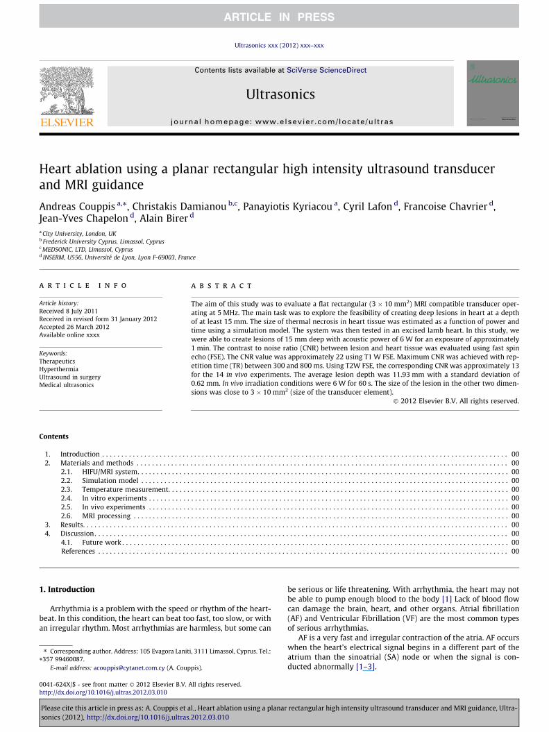
Fig. 2. Schematic of the flat rectangular MR compatible transducer.
A. Couppis et al. / Ultrasonics xxx (2012) xxx–xxx 3
muscle. In the following years many studies have been conducted[45–50] showing that the contrast between necrotic tissue andnormal tissue was excellent.
In this paper a flat rectangular MRI compatible transducer,3 � 10 mm2, operating at a frequency of 5.3 MHz was used [51].The aim was to create lesions in lamb heart in vitro and in rabbitin vivo using the cardiac transducer in order to measure the sizeof thermal necrosis in relation to the power and time. The experi-mental results are compared with the results of a simulation model.
Another task was to investigate the effectiveness of MRI inmonitoring therapeutic protocols of therapeutic ultrasound in theheart. This was achieved with the optimization of MRI pulse se-quences in order to maximize contrast between thermal necrosisand healthy cardiac tissue. Screening with MRI makes therapeuticultrasound a more credible way of treatment in comparison toother ablation methods which are guided by X-rays. MRI offers abetter contrast between thermal necrosis and healthy cardiac tis-sues, and offers the additional advantage that the patient will notbe exposed to radiation. Therefore we have used the basic MRI se-quences T1-W and T2-W fast spin echo (FSE). With T1-W FSE, theeffect of repetition time (TR) on contrast was explored, whereaswith T2-W FSE, the effect of echo time (TE) was explored.
The main innovation of this study is the evaluation of a planarMR compatible transducer in both in vitro and in vivo exploringthe following 2 main issues:
(a) Acquire knowledge regarding the size of the lesion as a func-tion of power and time (using simulation and experimentalmodels) which could be used as a preliminary data for futureclinical trials and
(b) Optimize the FSE MRI techniques for detecting the lesionscreated in heart tissue.
The advantage of using MRI is that the lesions can be monitorednearly in real time and therefore unwanted complications similarto what was reported by Metzner et al. in 2010 [42] can be avoided.
2. Materials and methods
2.1. HIFU/MRI system
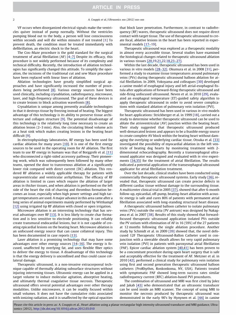
Fig. 1 shows the block diagram of the therapeutic ultrasound/MRI system. The therapeutic ultrasound system consists of a signal
Signal generator
RF amplifier
Interface cables
Heart
Interconnecting cables
Fig. 1. Block diagram of the HIFU/MRI system u
Please cite this article in press as: A. Couppis et al., Heart ablation using a planarsonics (2012), http://dx.doi.org/10.1016/j.ultras.2012.03.010
generator (HP 33120A, Agilent technologies, Englewood, CO, USA),a RF amplifier (250 W, AR, Souderton, PA, USA), and a flat rectangu-lar MR compatible transducer (Fig. 2).
The transducer consisted of a 3.8-mm outer diameter coppertube with a 0.1-mm thick wall ending in a cone-shaped MR com-patible plastic tip. The plane active surface embedded in the plasticsection is a 3 � 10 mm2 P762-type PZT piezoceramic air-backedtransducer (Quartz & Silice, Nemours, France) operating at5.3 MHz. In order to heat the myocardium for the purpose of treat-ing arrhythmias, the transducer must be placed in a catheter. Be-cause the catheter is guided to the myocardium through thearteries which are only 3–4 mm wide, the transducer elementmust be as compact as possible. If a spherically focused technologyis used, then the size of the transducer will increase and thereforewill not fit in the catheter. Also, because the catheter is insertedinto the body, the catheter is destroyed after treatment (i.e. it isconsidered as consumable). Thus, a spherically focused technologyhas the additional disadvantage that will increase the cost substan-tially. Additionally, as it will be seen from the results, a flat trans-ducer produces lesions of desired size.
The central lumen of the tube provided electrical radiofre-quency (RF) connections and a path for the cooling water. RF con-nections were made via a miniaturized 50-cm long, 50 X coaxialcable with a 0.9-mm outer diameter. The outer ground conductorwas connected to the external face of the transducer. The innerconductor reached the internal face of the transducer throughthe lumen of the tube. The transducer was glued with an MR com-patible epoxy resin (Emerson & Cuming Europe nv, Westerlo-Oe-vel, Belgium) to ensure that it was watertight and to hold it inplace. To limit energy loss during transmission of the electric sig-nal, a connection with a capacitor-inductor network was includedto match the transducer. Using the acoustic balance technique by
Thermocouple
PC
Temperature reader
MRI
Transducer
sed to drive the flat rectangular transducer.
rectangular high intensity ultrasound transducer and MRI guidance, Ultra-
4 A. Couppis et al. / Ultrasonics xxx (2012) xxx–xxx
Davidson 1991 [52], the electroacoustic efficiency of the applicatorwas measured to 65% at 5.3 MHz. The external face of the trans-ducer was cooled by a continuous flow of degassed water circulat-ing the length of the transducer. The cooling water serves ascoupling medium between the transducer and the heated tissues.The water cooling circuit was maintained at 15 �C and was drivenby a Masterflex peristaltic pump (Cole Parmer Instrument Co., Chi-cago, IL) at a flow of 0.15 L/min.
2.2. Simulation model
Numerical simulations were performed to predict the shape ofthe thermally ablated zone for different strategies, varying the fol-lowing input parameters: thickness of the cooling water, the ele-mentary sonication duration and the acoustical power. Themodel was proposed by Chavrier et al. 2000 [53] improved laterby Curiel et al. 2004 [54]. It is based on the Bio Heat Transfer Equa-tion proposed by Pennes [55]. Simulations neglected cavitation asthe evaluated transducer is not focused and operates in the highfrequency range.
The initial temperature of the heart was assumed to be 37 �Cand the initial temperature of the water was assumed to be15 �C. The spatial step used during the simulation was 0.5 mmand the temporal step used during the simulation was 0.1 s. Thethermal dose threshold of necrosis was considered to be 240 minreferenced at 43 �C.
The numerical model was implemented in C++ supported by agraphic user interface developed in MATLAB (MathWorks, Natick,United States). The simulation environment provided the followingoutput: a 3D view plus two central sections of the predicted ab-lated zone, total volume of the coagulation necrosis and 3D mapof estimated thermal dose.
Numerical simulations were performed for some exposuresin vivo conditions (the tissue parameters used are shown inTable 1).
2.3. Temperature measurement
Temperature was measured using a Digital to analog dataacquisition card (USB 6250, National Instruments, Austin Texas,USA) and a voltage to temperature converter (Omega Engineering,Stamford, Connecticut, USA). Temperature is sensed using a 50-lmdiameter T-type copper-constantan thermocouple (PhysitempInstruments, Inc. New Jersey, USA) which is MRI compatible. Thethermocouple was placed between the tissue and the transducersurface, thus measuring the temperature at the surface of the tis-sue. The temperature error of the thermocouple was on the orderof 0.1 �C. In all the experiments, the goal was to keep the temper-ature below 100 �C in order to avoid boiling.
Table 1Physical parameters used for simulations.
Parameter In vivo values
Heart Water
Thermal �conductivity (W m�1 �C�1)* 0.537* 0.627Specific heat (J kg�1 �C�1)* 3720* 4188Initial temperature (�C)* 37 10Perfusion (kg m�3 s�1)* 14.2* –Density (kg m�3)* 1060 1000Attenuation (Np m�1 MHz�1)* 4.1* 0
* Values taken from Duck FA. Physical properties of tissue. A comprehensive ref-erence book. New York: Academic Press, 1990.
Please cite this article in press as: A. Couppis et al., Heart ablation using a planarsonics (2012), http://dx.doi.org/10.1016/j.ultras.2012.03.010
2.4. In vitro experiments
Various in vitro experiments were carried out to image the le-sions using MRI created in cardiac tissue using therapeutic ultra-sound. The tissue was placed inside the water container whichwas filled with degassed water at room temperature. The trans-ducer was coupled to the holder and was immersed in the watertank, thus providing good acoustical coupling between tissue andtransducer (see Fig. 1 for the experimental arrangement). In allexperiments, the tissues used were extracted from freshly excisedlamb, and the experiment was conducted in the same day. In total,18 samples were used.
2.5. In vivo experiments
For the in vivo experiments, adult rabbits from Cyprus wereused weighting approximately 3–4 kg. 14 rabbits in total wereused in the experiments. The rabbits were anaesthetized using amixture of 500 mg of Ketamine (100 mg/mL, Aveco, Ford Dodge,IA), 160 mg of Xylazine (20 mg/mL, Loyd Laboratories, Shenan-doah, IA), and 20 mg of Acepromazine (10 mg/mL, Aveco, FordDodge, IA) at a dose of 1 mL/kg. The protocol for the animal exper-iments was approved by the national body in Cyprus responsiblefor animal studies (Ministry of Agriculture, Animal Services).
2.6. MRI processing
An MRI scanner (Signa 1.5 T, by General Electric, Fairfield, CT,USA) was used. The ultrasound transducer is coupled to the holder.The spinal coil (USA instruments, Cleveland, OH, USA) was used toacquire the MR.
The following parameters were used for T1-W FSE: TR was var-iable from 100 to 1000 ms, TE = 9 ms, slice thickness = 3 mm (gap0.3 mm), matrix = 256 � 256, FOV = 16 cm, NEX = 1, and ETL = 8.For T2-W FSE: TR = 2500 ms, TE was variable from 10 ms to160 ms, slice thickness = 3 mm (gap 0.3 mm), matrix = 256 � 256,FOV = 16 cm, NEX = 1, and ETL = 8.
The CNR was obtained by dividing the signal intensity differ-ence between the Region of Interest (ROI) in the lesion and inthe ROI of normal tissue by the standard deviation of the noise inthe ROI of normal tissue. The ROI was circular with diameter of3 mm.
3. Results
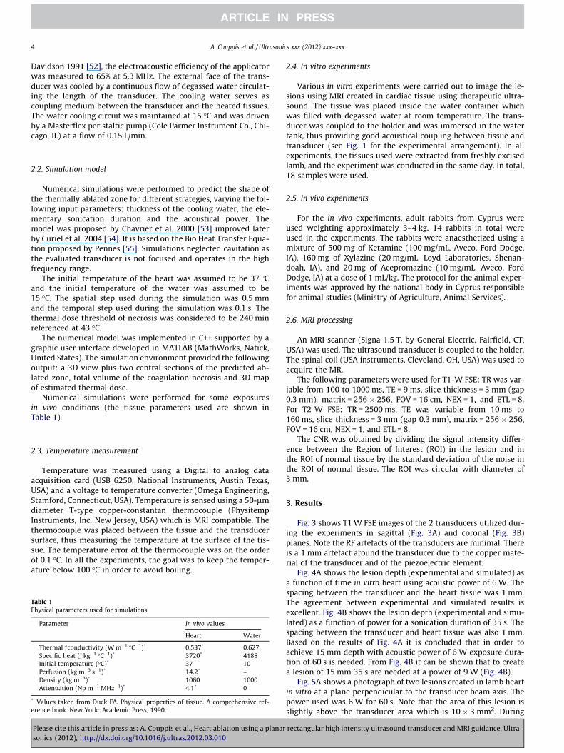
Fig. 3 shows T1 W FSE images of the 2 transducers utilized dur-ing the experiments in sagittal (Fig. 3A) and coronal (Fig. 3B)planes. Note the RF artefacts of the transducers are minimal. Thereis a 1 mm artefact around the transducer due to the copper mate-rial of the transducer and of the piezoelectric element.
Fig. 4A shows the lesion depth (experimental and simulated) asa function of time in vitro heart using acoustic power of 6 W. Thespacing between the transducer and the heart tissue was 1 mm.The agreement between experimental and simulated results isexcellent. Fig. 4B shows the lesion depth (experimental and simu-lated) as a function of power for a sonication duration of 35 s. Thespacing between the transducer and heart tissue was also 1 mm.Based on the results of Fig. 4A it is concluded that in order toachieve 15 mm depth with acoustic power of 6 W exposure dura-tion of 60 s is needed. From Fig. 4B it can be shown that to createa lesion of 15 mm 35 s are needed at a power of 9 W (Fig. 4B).
Fig. 5A shows a photograph of two lesions created in lamb heartin vitro at a plane perpendicular to the transducer beam axis. Thepower used was 6 W for 60 s. Note that the area of this lesion isslightly above the transducer area which is 10 � 3 mm2. During
rectangular high intensity ultrasound transducer and MRI guidance, Ultra-
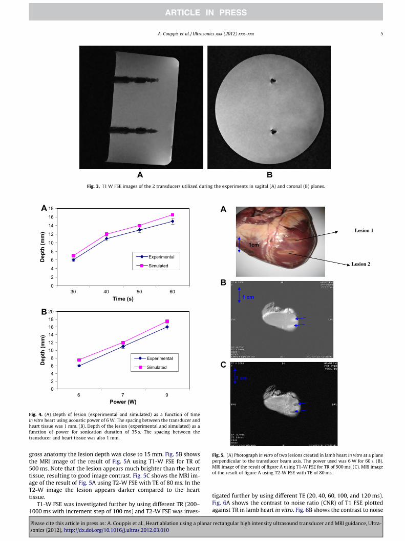
Fig. 3. T1 W FSE images of the 2 transducers utilized during the experiments in sagital (A) and coronal (B) planes.
0
2
4
6
8
10
12
14
16
18
30 40 50 60Time (s)
Dep
th (m
m)
Experimental
Simulated
02468
101214161820
6 7 9Power (W)
Dep
th (m
m)
Experimental
Simulated
A
B
Fig. 4. (A) Depth of lesion (experimental and simulated) as a function of timein vitro heart using acoustic power of 6 W. The spacing between the transducer andheart tissue was 1 mm. (B), Depth of the lesion (experimental and simulated) as afunction of power for sonication duration of 35 s. The spacing between thetransducer and heart tissue was also 1 mm.
Lesion 1
1cm
Lesion 2
1 cm
1 cm
A
B
C
Fig. 5. (A) Photograph in vitro of two lesions created in lamb heart in vitro at a planeperpendicular to the transducer beam axis. The power used was 6 W for 60 s. (B).MRI image of the result of figure A using T1-W FSE for TR of 500 ms. (C). MRI imageof the result of figure A using T2-W FSE with TE of 80 ms.
A. Couppis et al. / Ultrasonics xxx (2012) xxx–xxx 5
gross anatomy the lesion depth was close to 15 mm. Fig. 5B showsthe MRI image of the result of Fig. 5A using T1-W FSE for TR of500 ms. Note that the lesion appears much brighter than the hearttissue, resulting to good image contrast. Fig. 5C shows the MRI im-age of the result of Fig. 5A using T2-W FSE with TE of 80 ms. In theT2-W image the lesion appears darker compared to the hearttissue.
T1-W FSE was investigated further by using different TR (200–1000 ms with increment step of 100 ms) and T2-W FSE was inves-
Please cite this article in press as: A. Couppis et al., Heart ablation using a planarsonics (2012), http://dx.doi.org/10.1016/j.ultras.2012.03.010
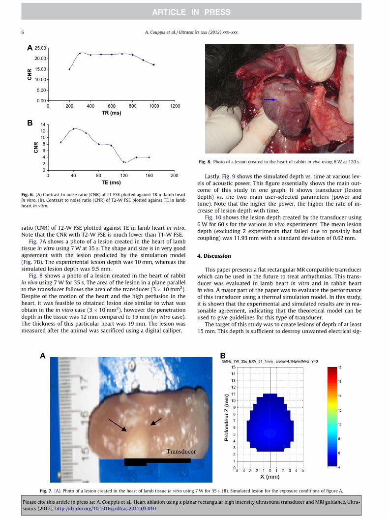
tigated further by using different TE (20, 40, 60, 100, and 120 ms).Fig. 6A shows the contrast to noise ratio (CNR) of T1 FSE plottedagainst TR in lamb heart in vitro. Fig. 6B shows the contrast to noise
rectangular high intensity ultrasound transducer and MRI guidance, Ultra-
0.00
5.00
10.00
15.00
20.00
25.00
0 200 400 600 800 1000 1200TR (ms)
CN
R
02468
101214
0 40 80 120 160 200TE (ms)
CN
R
A
B
Fig. 6. (A) Contrast to noise ratio (CNR) of T1 FSE plotted against TR in lamb heartin vitro. (B). Contrast to noise ratio (CNR) of T2-W FSE plotted against TE in lambheart in vitro.
Fig. 8. Photo of a lesion created in the heart of rabbit in vivo using 6 W at 120 s.
6 A. Couppis et al. / Ultrasonics xxx (2012) xxx–xxx
ratio (CNR) of T2-W FSE plotted against TE in lamb heart in vitro.Note that the CNR with T2-W FSE is much lower than T1-W FSE.
Fig. 7A shows a photo of a lesion created in the heart of lambtissue in vitro using 7 W at 35 s. The shape and size is in very goodagreement with the lesion predicted by the simulation model(Fig. 7B). The experimental lesion depth was 10 mm, whereas thesimulated lesion depth was 9.5 mm.
Fig. 8 shows a photo of a lesion created in the heart of rabbitin vivo using 7 W for 35 s. The area of the lesion in a plane parallelto the transducer follows the area of the transducer (3 � 10 mm2).Despite of the motion of the heart and the high perfusion in theheart, it was feasible to obtained lesion size similar to what wasobtain in the in vitro case (3 � 10 mm2), however the penetrationdepth in the tissue was 12 mm compared to 15 mm (in vitro case).The thickness of this particular heart was 19 mm. The lesion wasmeasured after the animal was sacrificed using a digital calliper.
Transducer
A
Fig. 7. (A). Photo of a lesion created in the heart of lamb tissue in vitro using 7
Please cite this article in press as: A. Couppis et al., Heart ablation using a planarsonics (2012), http://dx.doi.org/10.1016/j.ultras.2012.03.010
Lastly, Fig. 9 shows the simulated depth vs. time at various lev-els of acoustic power. This figure essentially shows the main out-come of this study in one graph. It shows transducer (lesiondepth) vs. the two main user-selected parameters (power andtime). Note that the higher the power, the higher the rate of in-crease of lesion depth with time.
Fig. 10 shows the lesion depth created by the transducer using6 W for 60 s for the various in vivo experiments. The mean lesiondepth (excluding 2 experiments that failed due to possibly badcoupling) was 11.93 mm with a standard deviation of 0.62 mm.
4. Discussion
This paper presents a flat rectangular MR compatible transducerwhich can be used in the future to treat arrhythmias. This trans-ducer was evaluated in lamb heart in vitro and in rabbit heartin vivo. A major part of the paper was to evaluate the performanceof this transducer using a thermal simulation model. In this study,it is shown that the experimental and simulated results are in rea-sonable agreement, indicating that the theoretical model can beused to give guidelines for this type of transducer.
The target of this study was to create lesions of depth of at least15 mm. This depth is sufficient to destroy unwanted electrical sig-
B
W for 35 s. (B). Simulated lesion for the exposure conditions of figure A.
rectangular high intensity ultrasound transducer and MRI guidance, Ultra-
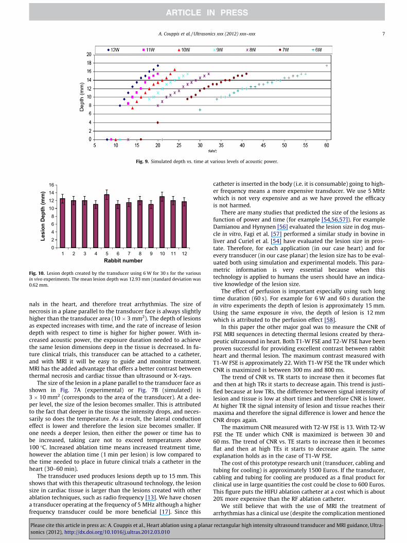
Fig. 9. Simulated depth vs. time at various levels of acoustic power.
02468
10121416
1 2 3 4 5 6 7 8 9 10 11 12
Lesi
on D
epth
(mm
)
Rabbit number
Fig. 10. Lesion depth created by the transducer using 6 W for 30 s for the variousin vivo experiments. The mean lesion depth was 12.93 mm (standard deviation was0.62 mm.
A. Couppis et al. / Ultrasonics xxx (2012) xxx–xxx 7
nals in the heart, and therefore treat arrhythmias. The size ofnecrosis in a plane parallel to the transducer face is always slightlyhigher than the transducer area (10 � 3 mm2). The depth of lesionsas expected increases with time, and the rate of increase of lesiondepth with respect to time is higher for higher power. With in-creased acoustic power, the exposure duration needed to achievethe same lesion dimensions deep in the tissue is decreased. In fu-ture clinical trials, this transducer can be attached to a catheter,and with MRI it will be easy to guide and monitor treatment.MRI has the added advantage that offers a better contrast betweenthermal necrosis and cardiac tissue than ultrasound or X-rays.
The size of the lesion in a plane parallel to the transducer face asshown in Fig. 7A (experimental) or Fig. 7B (simulated) is3 � 10 mm2 (corresponds to the area of the transducer). At a dee-per level, the size of the lesion becomes smaller. This is attributedto the fact that deeper in the tissue the intensity drops, and neces-sarily so does the temperature. As a result, the lateral conductioneffect is lower and therefore the lesion size becomes smaller. Ifone needs a deeper lesion, then either the power or time has tobe increased, taking care not to exceed temperatures above100 �C. Increased ablation time means increased treatment time,however the ablation time (1 min per lesion) is low compared tothe time needed to place in future clinical trials a catheter in theheart (30–60 min).
The transducer used produces lesions depth up to 15 mm. Thisshows that with this therapeutic ultrasound technology, the lesionsize in cardiac tissue is larger than the lesions created with otherablation techniques, such as radio frequency [13]. We have chosena transducer operating at the frequency of 5 MHz although a higherfrequency transducer could be more beneficial [17]. Since this
Please cite this article in press as: A. Couppis et al., Heart ablation using a planarsonics (2012), http://dx.doi.org/10.1016/j.ultras.2012.03.010
catheter is inserted in the body (i.e. it is consumable) going to high-er frequency means a more expensive transducer. We use 5 MHzwhich is not very expensive and as we have proved the efficacyis not harmed.
There are many studies that predicted the size of the lesions asfunction of power and time (for example [54,56,57]). For exampleDamianou and Hynynen [56] evaluated the lesion size in dog mus-cle in vitro, Fagi et al. [57] performed a similar study in bovine inliver and Curiel et al. [54] have evaluated the lesion size in pros-tate. Therefore, for each application (in our case heart) and forevery transducer (in our case planar) the lesion size has to be eval-uated both using simulation and experimental models. This para-metric information is very essential because when thistechnology is applied to humans the users should have an indica-tive knowledge of the lesion size.
The effect of perfusion is important especially using such longtime duration (60 s). For example for 6 W and 60 s duration thein vitro experiments the depth of lesion is approximately 15 mm.Using the same exposure in vivo, the depth of lesion is 12 mmwhich is attributed to the perfusion effect [58].
In this paper the other major goal was to measure the CNR ofFSE MRI sequences in detecting thermal lesions created by thera-peutic ultrasound in heart. Both T1-W FSE and T2-W FSE have beenproven successful for providing excellent contrast between rabbitheart and thermal lesion. The maximum contrast measured withT1-W FSE is approximately 22. With T1-W FSE the TR under whichCNR is maximized is between 300 ms and 800 ms.
The trend of CNR vs. TR starts to increase then it becomes flatand then at high TRs it starts to decrease again. This trend is justi-fied because at low TRs, the difference between signal intensity oflesion and tissue is low at short times and therefore CNR is lower.At higher TR the signal intensity of lesion and tissue reaches theirmaxima and therefore the signal difference is lower and hence theCNR drops again.
The maximum CNR measured with T2-W FSE is 13. With T2-WFSE the TE under which CNR is maximized is between 30 and60 ms. The trend of CNR vs. TE starts to increase then it becomesflat and then at high TEs it starts to decrease again. The sameexplanation holds as in the case of T1-W FSE.
The cost of this prototype research unit (transducer, cabling andtubing for cooling) is approximately 1500 Euros. If the transducer,cabling and tubing for cooling are produced as a final product forclinical use in large quantities the cost could be close to 600 Euros.This figure puts the HIFU ablation catheter at a cost which is about20% more expensive than the RF ablation catheter.
We still believe that with the use of MRI the treatment ofarrhythmias has a clinical use (despite the complication mentioned
rectangular high intensity ultrasound transducer and MRI guidance, Ultra-
8 A. Couppis et al. / Ultrasonics xxx (2012) xxx–xxx
by Metzner et al. 2010 [42]), because with the near real time imag-ing, the result of the therapy can be monitored. Therefore it is tooearly to abandon this technology for treating arrhythmias. Maybein the future we may come to the conclusion that MRI cannot mon-itor the heating effects in the beating heart precisely, however thismust be determined in future MRI studies.
4.1. Future work
In vitro MRI experiments do not provide much value due to thefact that the MRI response of a living tissue is different from ex vivotissue responses. Thus, more in vivo work has to be done, especiallyregarding the MRI evaluation of thermal lesions. Additional MRIroutines have to be explored because the FSE sequences used arelong and sensitive to motion and could not be the optimum rou-tines in a beating heart.
The key advantage of MRI is its ability to map temperature.However, this is difficult in a beating heart. In this paper therewas no attempt to map the temperature in the heart tissue usingMRI, and therefore this a key future task.
References
[1] M.A. Brodsky et al., The history of heart failure predicts arrhythmia treatmentefficacy: data from the antiarrythmics versus implantable defibrillators (AVID)study, Am. Heart J. 152 (2006) 724–730.
[2] S. Maltais, J. Forcillo, D. Bouchard, M. Carrier, R. Cartier, P. Demers, L.P. Perrault,N. Poirier, M. Ladouceur, P. Pagé, M. Pellerin, Long-term results followingconcomitant radiofrequency modified maze ablation for atrial fibrillation, J.Cardiac Surg. 25 (2010) 608–613.
[3] Pierre Jais, Michel Haissaguerre, Dipen C. Shah, Salah Chouairi, Laurent Gencel,Meleze Hocini, Jacques Clementy, A focal source of atrial fibrillation treated bydiscrete radiofrequency ablation, Am. Heart Assoc. 95 (1997) 572–576.
[4] S.M. Prasad, H.S. Maniar, C.J. Camillo, et al., The cox maze III procedure foratrial fibrillation: long-term efficacy inpatients undergoing lone versusconcomitant procedures, J. Thorac. Cardiovasc. Surg. 126 (2003) 1822–1828.
[5] E. Raanani, A. Albage, T.E. David, et al., The efficacy of the cox/maze procedurecombined with mitral valve surgery: a matched control study, Eur. J. Cardio.-Thorac. Surg. 19 (2001) 438–442.
[6] D.B. Doty, K.A. Dilip, R.C. Millar, Mitral valve replacement with homograft andmaze III procedure, Ann. Thorac. Surg. 69 (2000) 739–742.
[7] H.V. Schaff, J.A. Dearani, R.C. Daly, et al., Cox–maze procedure for atrialfibrillation: mayo clinic experience, Semin. Thorac. Cardiovasc. Surg. 12 (2000)30–37.
[8] H. Calkins, J. Brugada, D.L. Packer, R. Cappato, S.A. Chen, H.J. Crijns, et al., HRS/EHRA/ECAS expert consensus statement on catheter and surgical ablation ofatrial fibrillation: recommendations for personnel, policy, procedures andfollow-up. A report of the heart rhythm society (HRS) task force on catheterand surgical ablation of atrial fibrillation, Heart Rhythm 4 (2007) 816–861.
[9] F. Milla, N. Skubas, W.M. Briggs, et al., Epicardial beating heart cryoablationusing a novel argon-based cryoclamp and linear probe, J. Thorac. Cardiovasc.131 (2006) 403–411.
[10] N. Viola, M.R. Williams, M.C. Oz, N. Ad, The technology in use for the surgicalablation of atrial fibrillation, Semin. Thorac. Cardiovasc. Surg. 14 (2002) 198–205.
[11] M. Borggrefe, T. Budde, A. Podczeck, G. Breithardt, High frequency alternatingcurrent ablation of an accessory pathway in humans, J. Am. Coll. Cardiol. 10(1987) 576–582.
[12] F.H. Wittkampf, Temperature response in radiofrequency ablation, Eur. Heart J.86 (1992) 1648–1650.
[13] S. Geidel, M. Lass, J. Ostermeyer, A 5-year clinical experience with bipolarradiofrequency ablation for permanent atrial fibrillation concomitant tocoronary artery bypass grafting and aortic valve surgery, Interact.Cardiovasc. Thorac. Surg. 7 (2008) 777–780.
[14] S.P. Thomas, D.J. Guy, A. Rees, et al., Production of narrow but deep lesionssuitable for ablation of atrial fibrillation using a saline cooled narrow beamNd:YAG laser catheter, Laser. Surg. Med. 28 (2001) 375–380.
[15] V.Y. Reddy, C. Houghtaling, J. Fallon, et al., Use of a diode laser balloon ablationcatheter to generate circumferential pulmonary venous lesions in an open-thoracotomy caprine model, Pac. Clin. Electrophysiol. 27 (2004) 52–57.
[16] R.J. Darwood, N. Theivacumar, D. Dellagrammaticas, A.I. Mavor, M.J. Gough,Randomized clinical trial comparing endovenous laser ablation with surgeryfor the treatment of primary great saphenous varicose veins, Brit. J. Surg. 95(2008) 294–301.
[17] D.S. He, J.E. Zimmer, F.I. Marcus, et al., Application of ultrasound energy forintracardiac ablation of arrhythmias, Eur. Heart J. 16 (1995) 961–966.
[18] S.A. Strickberger, T. Tokano, J.A. Kluiwstra, et al., Extracardiac ablation of thecanine atrioventricular junction by use of high intensity focused ultrasound,Am. Heart Assoc. 100 (1999) 203–208.
Please cite this article in press as: A. Couppis et al., Heart ablation using a planarsonics (2012), http://dx.doi.org/10.1016/j.ultras.2012.03.010
[19] L.A. Lee, C. Simon, E.L. Bove, et al., High intensity focused ultrasound effect oncardiac tissues: potential for clinical application, Echocardiography 17 (2000)563–566.
[20] C. Damianou, In vitro and in vivo ablation of porcine renal tissues usinghigh-intensity focused ultrasound, Ultrasound Med. Biol. 29 (2003) 1321–1330.
[21] A.L. Malcolm, G.R. ter Haar, Ablation of tissue volumes using high intensityfocused ultrasound, Ultrasound Med. Biol. 22 (1996) 659–669.
[22] A. Sibille, F. Prat, J.Y. Chapelon, et al., Characterization of extracorporealablation of normal and tumor-bearing liver tissue by high intensity focusedultrasound, Ultrasound Med. Biol. 19 (1993) 803–813.
[23] M. Susani, S. Madersbacher, C. Kratzik, L. Vingers, M. Marberger, Morphologyof tissue destruction induced by focused ultrasound, Eur. Urol. 23 (1993) 34–38.
[24] N.I. Vykhodtseva, K. Hynynen, C. Damianou, Pulse duration and peak intensityduring focused ultrasound surgery: theoretical and experimental effects inrabbit brain in vivo, Ultrasound Med. Biol. 20 (1994) 987–1000.
[25] F. Wu, W.Z. Chen, J. Bai, et al., Pathological changes in human malignantcarcinoma treated with high-intensity focused ultrasound, Ultrasound Med.Biol. 27 (2001) 1099–1106.
[26] L. Chen, G. ter Haar, D. Robertson, J.P. Bensted, C.R. Hill, Histological study ofnormal and tumor-bearing liver treated with focused ultrasound, UltrasoundMed. Biol. 25 (1999) 847–856.
[27] R. Yang, N.T. Sanghvi, F.J. Rescorla, K.K. Kopecky, J.L. Grosfeld, Liver cancerablation with extracorporeal high-intensity focused ultrasound, Eur. Urol. 23(1993) 17–22.
[28] Ryo Otsuka, Kana Fujikura, Kumiko Hirata, Todd Pulerwitz, Yukiko Abe, Takeki.Suzuki, In vitro ablation of cardiac valves using high-intensity focusedultrasound, Ultrasound Med. Biol. 31 (2004) 109–114.
[29] K. Neven, B. Schmidt, A. Metzner, K. Otomo, D. Nuyens, T. De Potter, K.R. Chun,F. Ouyang, K.H. Kuck, Fatal end of a safety algorithm for pulmonary veinisolation with use of high-intensity focused ultrasound, Circ. ArrhythmiaElectrophysiol. 3 (2010) 260–265.
[30] K. Yokoyama, H. Nakagawa, K.A. Seres, E. Jung, J. Merino, Y. Zou, A. Ikeda, J.V.Pitha, R. Lazzara, W.M. Jackman, Canine model of esophageal injury and atrial-esophageal fistula after applications of forward-firing therapeutic ultrasoundand side-firing unfocused ultrasound in the left atrium and inside thepulmonary vein, Circ. Arrhythmia Electrophysiol. 2 (2009) 41–49.
[31] Y. Okumura, M.W. Kolasa, S.B. Johnson, T.J. Bunch, B.D. Henz, C.J. O’Brien, D.V.Miller, D.L. Packer, Mechanism of tissue heating during high intensity focusedultrasound pulmonary vein isolation: implications for atrial fibrillationablation efficacy and phrenic nerve protection, J. Cardiovasc. Electrophysiol.19 (2008) 945–951.
[32] D.J. Engel, R. Muratore, K. Hirata, R. Otsuka, K. Fujikura, K. Sugioka, C. Marboe,F.L. Lizzi, S. Homma, Myocardial lesion formation using high-intensity focusedultrasound, J. Am. Soc. Echocardiogr. 19 (2006) 932–937.
[33] Ryo Otsuka, Kana Fujikura, Yukio Abe, Kazue Okajima, Todd Pulerwitz, David J.Engel, Robert Muratore, Jeffrey A. Ketterling, Andrew Kalisz, Robert Sciacca,Charles Marboe, Genghua Yi, Jie Wang, Shunichi Homma, Extracardiac ablationof the left ventricular septum in beating canine hearts using therapeuticultrasound, J. Am. Soc. Echocardiogr. 20 (2007) 1400–1406.
[34] J. Werner, E.J. Park, H. Lee, D. Francischelli, N.B. Smith, Feasibility of in vivotransesophageal cardiac ablation using a phased ultrasound array, UltrasoundMed. Biol. 36 (2010) 752–760.
[35] N.R. Villamizar, J.H. Crow, V. Piacentino, L.R. Dibernardo, M.A. Daneshmand,D.E. Bowles, M.A. Groh, C.A. Milano, Reproducibility of left atrial ablation withtherapeutic ultrasound energy in a calf model, J. Thorac. Cardiovasc. Surg. 140(2010) 1381–1387.
[36] L.A. Lee, C. Simon, E.L. Bove, R.S. Mosca, E.S. Ebbini, G.D. Abrams, A.Ludomirsky, High intensity focused ultrasound effect on cardiac tissues:potential for clinical application, Echocardiography 17 (2000) 563–566.
[37] J. Ninet, X. Roques, R. Seitelberger, C. Deville, J.L. Pomar, J. Robin, O. Jegaden, F.Wellens, E. Wolner, C. Vedrinne, R. Gottardi, J. Orrit, M.A. Billes, D.A. Hoffmann,J.L. Cox, G.L. Champsaur, Surgical ablation of atrial fibrillation with off-pump,epicardial, high-intensity focused ultrasound: results of a multicenter trial, J.Thorac. Cardiovasc. Surg. 130 (2005) 803–809.
[38] H. Nakagawa, M. Antz, T. Wong, B. Schmidt, S. Ernst, F. Ouyang, T. Vogtmann, R.Wu, K. Yokoyama, D. Lockwood, S.S. Po, K.J. Beckman, D.W. Davies, K.H. Kuck,W.M. Jackman, Initial experience using a forward directed, therapeuticultrasound balloon catheter for pulmonary vein antrum isolation in patientswith atrial fibrillation, J. Cardiovasc. Electrophysiol. 18 (2007) 136–144.
[39] B. Schmidt, K.R. Chun, A. Metzner, A. Fuernkranz, F. Ouyang, K.H. Kuck,Pulmonary vein isolation with high-intensity focused ultrasound: results fromthe therapeutic ultrasound 12F study, Europace 11 (2009) 1281–1288.
[40] S. Mitnovetski, A.A. Almeida, J. Goldstein, A.W. Pick, J.A. Smith, Epicardialtherapeutic ultrasound cardiac ablation for surgical treatment of atrialfibrillation, Heart Lung. Circ. 18 (2009) 28–31.
[41] S. Schopka, C. Schmid, A. Keyser, A. Kortner, J. Tafelmeier, C. Diez, L. Rupprecht,M. Hilker, Ablation of atrial fibrillation with the epicor system: a prospectiveobservational trial to evaluate safety and efficacy and predictors of success, J.Cardiothorac. Surg. 5 (2010) 5–34.
[42] A. Metzner, K.R. Chun, K. Neven, A. Fuernkranz, F. Ouyang, M. Antz, R. Tilz, T.Zerm, B. Koektuerk, E. Wissner, I. Koester, S. Ernst, S. Boczor, K.H. Kuck, B.Schmidt, Long-term clinical outcome following pulmonary vein isolation withtherapeutic ultrasound balloon catheters in patients with paroxysmal atrialfibrillation, Europace 12 (2010) 188–193.
rectangular high intensity ultrasound transducer and MRI guidance, Ultra-
A. Couppis et al. / Ultrasonics xxx (2012) xxx–xxx 9
[43] F.A. Jolez, P.D. Jakab, Acoustic pressure wave generation within an MRI system:potential medical applications, J. Magn. Reson. Imag. 1 (1991) 609–613.
[44] K. Hynynen, C. Damianou, A. Darkazanli, E. Unger, J.F. Schenck, The feasibilityof using MRI to monitor and guide noninvasive ultrasound surgery, UltrasoundMed. Biol. 19 (1993) 91–92.
[45] H.E. Cline, J.F. Schenck, K. Hynynen, R.D. Watkins, S.P. Souza, F.A. Jolesz, MRI-guided focused ultrasound surgery, J. Comput. Assist. Tomogr. 16 (1992) 956–965.
[46] E. Lecornet, H.U. Ahmed, C.M. Moore, M. Emberton, Conceptual basis for focaltherapy in prostate cancer, J. Endourol. 24 (2010) 811–818.
[47] J. Rabinovici, Y. Inbar, A. Revel, Y. Zalel, J.M. Gomori, Y. Itzchak, E. Schiff, S.Yagel, Clinical improvement and shrinkage of uterine fibroids after thermalablation by magnetic resonance-guided focused ultrasound surgery,Ultrasound Obstet. Gynecol. 30 (2007) 771–777.
[48] K.B. Pauly, C.J. Diederich, V. Rieke, D. Bouley, J. Chen, W.H. Nau, A.B. Ross, A.M.Kinsey, G. Sommer, Magnetic resonance-guided high-intensity ultrasoundablation of the prostate, Magn. Reson. Imaging 17 (2006) 195–207.
[49] I.P. Wharton, I.H. Rivens, G.R. Ter Haar, D.J. Gilderdale, D.J. Collins, J.W. Hand,P.D. Abel, N.M. de Souza, Design and development of a prototype endocavitaryprobe for therapeutic ultrasound delivery with integrated magnetic resonanceimaging, J. Magn. Reson. Imaging 25 (2007) 548–556.
[50] X.D. Zhou, X.L. Ren, J. Zhang, G.B. He, M.J. Zheng, X. Tian, L. Li, T. Zhu, M. Zhang,L. Wang, W. Luo, Therapeutic response assessment of high intensity focusedultrasound therapy for uterine fibroid: utility of contrast-enhancedultrasonography, Eur. J. Radiol. 62 (2007) 289–294.
Please cite this article in press as: A. Couppis et al., Heart ablation using a planarsonics (2012), http://dx.doi.org/10.1016/j.ultras.2012.03.010
[51] C.X. Deng, F. Qu, V.P. Nikolski, Y. Zhou, I.R. Efimov, Fluorescence imaging forreal-time monitoring of therapeutic ultrasound cardiac ablation, Ann. Biomed.Eng. 33 (2005) 1352–1359.
[52] F. Davidson, Ultrasonic power balances, in: R.C. Preston (Ed.), OutputMeasurements for Medical Ultrasound, Springer, 1991, pp. 75–90.
[53] F. Chavrier, J.Y. Chapelon, A. Gelet, D. Cathignol, Modeling of high-intensityfocused ultrasound-induced lesions in the presence of cavitation bubbles, J.Acoust. Soc. Am. 108 (2000) 432–440.
[54] L. Curiel, F. Chavrier, B. Gignoux, S. Pichardo, S. Chesnais, J.Y. Chapelon,Experimental evaluation of lesion prediction modelling in the presence ofcavitation bubbles: intended for high-intensity focused ultrasound prostatetreatment, Med. Biol. Eng. Comput. 42 (2004) 44–54.
[55] H.H. Pennes, Analysis of tissue and arterial blood temperatures in restingforearm, J. Appl. Physiol. 1 (1948) 93–122.
[56] C. Damianou, K. Hynynen, The effects of various physical parameters on thesize and shape of necrosed tissue volume during ultrasound surgery, J. Acoust.Soc. Am. 95 (3) (1993) 1641–1649.
[57] F. Li, R. Feng, Q. Zhang, J. Bai, Z. Wang, Estimation of HIFU induced lesionsin vitro: numerical simulation and experiment, Ultrasonics 44 (2006) 337–340.
[58] L. Chen, G. Ter Haar, C. Hill, M. Dworkin, P. Carnochan, H. Young, J. Bensted,Effect of blood perfusion on the ablation of liver parenchyma with high-intensity focused ultrasound, Phys. Med. Biol. 38 (11) (1993) 1661–1667.
rectangular high intensity ultrasound transducer and MRI guidance, Ultra-
Related Documents