HEALTH MONITORING USING WIRELESS SENSORS AND GSM || 2014-2015 1 CHAPTER 1 INTRODUCTION In a hospital health care monitoring system it is necessary to constantly monitor the patient’s physiological parameters. Although present systems allow continuous monitoring of patient vital signs, these systems require the sensors to be placed bedside monitors or PCs, and limit the patient to his bed. A real-time monitoring system of some critical vital signs will be implemented. Such a system may help the doctor or people in the family to monitor the emergency alarm from patients. In this project, we consider three parameters of the vital signs which are Pulse rate, Human body temperature and ECG. The data helps to prevent and protect the patient’s. Wireless technology is used in many applications that have become a part of human activities such as agriculture, military, medical care, smart home system etc. Distinctly, wireless sensor networks (WSN) play a crucial role in such monitoring systems, for the reason that WSN can offer some advantages over other types of wireless systems, especially its scalability and flexibility of architecture. In this Project, a group of sensors have been implemented for measuring Pulse rate, body temperature and ECG with real-time monitoring system based on ZigBee wireless network. This project incorporates sensors to measure parameters like body temperature, heart beat rate and IR pulse rate sensors. A micro-controller board is used for analyzing the inputs from the patient and any abnormality felt by the patient causes the monitoring system to give an alarm and the SMS to the doctor and concerned authorities. Also all the process parameters within an interval selectable by the user are recorded to the common computer. This is very useful for future analysis and review of patient’s health condition. For more versatile medical applications, this project can be improvised, by incorporating dental sensors and annunciation systems, thereby making it useful in hospitals as a very efficient and dedicated patient care system.

Welcome message from author
This document is posted to help you gain knowledge. Please leave a comment to let me know what you think about it! Share it to your friends and learn new things together.
Transcript

HEALTH MONITORING USING WIRELESS SENSORS AND GSM || 2014-2015
1
CHAPTER 1
INTRODUCTION
In a hospital health care monitoring system it is necessary to constantly monitor the
patient’s physiological parameters. Although present systems allow continuous
monitoring of patient vital signs, these systems require the sensors to be placed bedside
monitors or PCs, and limit the patient to his bed. A real-time monitoring system of
some critical vital signs will be implemented. Such a system may help the doctor or
people in the family to monitor the emergency alarm from patients. In this project, we
consider three parameters of the vital signs which are Pulse rate, Human body
temperature and ECG. The data helps to prevent and protect the patient’s.
Wireless technology is used in many applications that have become a part of
human activities such as agriculture, military, medical care, smart home system etc.
Distinctly, wireless sensor networks (WSN) play a crucial role in such monitoring
systems, for the reason that WSN can offer some advantages over other types of
wireless systems, especially its scalability and flexibility of architecture. In this Project,
a group of sensors have been implemented for measuring Pulse rate, body temperature
and ECG with real-time monitoring system based on ZigBee wireless network.
This project incorporates sensors to measure parameters like body temperature,
heart beat rate and IR pulse rate sensors. A micro-controller board is used for analyzing
the inputs from the patient and any abnormality felt by the patient causes the monitoring
system to give an alarm and the SMS to the doctor and concerned authorities. Also all
the process parameters within an interval selectable by the user are recorded to the
common computer.
This is very useful for future analysis and review of patient’s health condition.
For more versatile medical applications, this project can be improvised, by
incorporating dental sensors and annunciation systems, thereby making it useful in
hospitals as a very efficient and dedicated patient care system.

HEALTH MONITORING USING WIRELESS SENSORS AND GSM || 2014-2015
2
CHAPTER 2
LITERATURE SURVEY
The health monitoring task is achieved by telemedicine (enabling medical infor-
mation exchange as the support to distant decision making) and telemonitoring (ena-
bling simultaneous distant monitoring of patient and his vital function) that monitors
the changes in ECG signals and provide feedback to help maintain an optimal heart
status. Wireless ECG sensor module is realized by using an eZ430-RF2500 which is a
complete MSP430 wireless development tool providing all the hardware and software
for the MSP430F2274 microcontroller and CC2500 2.4GHz wireless transceiver. On
the personal server module, visualization and analysis software are implemented. This
software has the following facilities: GUI (Graphic Interface) for ECG waveforms; dis-
plays the patient’s parameters received from the sensors; sends the commands and med-
ical decisions. [1]
There are many advantages of using this type of sensor. It can be used for broader
range of patients and medical professionals and those people living in rural or isolated
regions. It reduces cost and time. It provides the best health care and flexible capable
of measuring, pre-processing and transmission ECG info to personal server. This type
of sensor can be used for those patients’ that has a longer time span than normal span
and the proposed system could also be used as a warning system for monitoring during
normal activity or physical exercise.
The system architecture for smart healthcare based on an advanced Wireless Sen-
sor Network (WSN). It specifically targets assisted-living residents and others who may
benefit from continuous, remote health monitoring. It presents best practices in wireless
sensor network design for health care applications. Based on the most important aspects
like power efficiency and security which guide the development of a wireless sensor
network based applications. The sensor boards handle acquisition of physiological sig-
nals and pre-processing. For example, the ISPM samples three independent accelerom-
eter axes each at a rate of 200 Hz. The raw accelerometer data is filtered and pre-pro-
cessed. The filtering includes moving an average filter to eliminate high frequency
movement artifacts, and separation of low and high frequency components of the ac-

HEALTH MONITORING USING WIRELESS SENSORS AND GSM || 2014-2015
3
celeration signal. Sensor orientation can be calculated as the angle between low fre-
quency accelerometer components. User activity is estimated with a function based on
the Sum of the integrals of the AC components in each channel. [2]
Thus, also the ongoing miniaturization allows building tiny computers that are
able to observe all kinds of physical phenomena. Structural Health Monitoring (SHM)
has the potential to dramatically reduce lifecycle costs, safe useful life of a structure,
shrink insurance costs, decrease the need for expensive repairs, and circumvent com-
plete failure of the monitored structure.
A portable real-time wireless health monitoring system also provides an accurate
result which is used for remote monitoring of patients’ pulse rate and oxygen saturation
in blood. The system was designed and implemented using ZigBee wireless technolo-
gies. All pulse oximetry data are transferred within a group of wireless personal area
network (WPAN) to database computer server. The developed real-time pulse oximetry
monitoring system has a pair of light-emitting diodes (LEDs), One of LED has a wave-
length in red and other one is in infrared region. The light was detected by a photodiode.
The LEDs and photodiode was packed in Velcro strip that facing through a patient’s
fingertip. The pulse oximetry data was kept and calculated by microcontroller unit. [3]
The basic wireless technologies which currently healthcare systems are RFID,
Bluetooth, ZigBee and wireless sensor network which gives innovative medium for
data transmission in the field of medicine. WBAN usually uses Zigbee. One of many
applications of WBAN in medical domain is computer assisted physical rehabilitation.
Intelligent sensors used by patients transmit vital signs to personal server sequentially;
the data is transmitted from personal server to servers of the healthcare system, such as
weather forecast, medical database or emergency server over Internet. Algorithms may
be executed on the healthcare system servers to give instant and patient-specific rec-
ommendations. [4]

HEALTH MONITORING USING WIRELESS SENSORS AND GSM || 2014-2015
4
CHAPTER 3
Problem Statement
Health monitoring system is mandatory to constantly monitor the patient’s phys-
iological parameters. Although present systems allow constant monitoring, these sys-
tems require the sensors to be placed in such a way that it limits the patient to his bed.
This Project focuses on creating a Health monitoring System using Wireless
Body sensor networks (WBAN) and can help people by providing healthcare services
such as medical monitoring, medical data access, and communication with the
healthcare provider.
The Project contains three sensors to monitor the human body temperature,
Pulse Rate and ECG. The sensed information is sent to a Microcontroller through signal
conditioning circuit in the patient unit. A desired amount of sensor value is set and
if it is exceeded the sensor information will be transmitted from the patient unit to the
main controller unit with the help of a ZigBee communication system which is con-
nected with the Microcontroller in both the units. The main controller unit will send the
sensed data of the patient by the help of a GSM Module to the physician. The physician
can receive the SMS sent by GSM module and check the vitals of the patient. The
message is sent to a mobile phone using Global system mobile (GSM) Modem.
MAX232 will act as a driver between the microcontroller and the modem.
The Project would benefit the patient as the patient will no longer be confined
to the hospital bed as the sensors are wearable nor any assistant doctor or nurse will be
required to log the health vitals of the patient manually thus reducing any possible hu-
man error.

HEALTH MONITORING USING WIRELESS SENSORS AND GSM || 2014-2015
5
CHAPTER 4
Methodology
4.1 Need of components:
4.1.1 AT89S51: 89S51 over 8051 due to the following reasons: For 8051
we have to install its corresponding software for writing program on PC. For
8051 we will write program. In Keil which is freely available on internet for
downloading.
4.1.2 MPC3208: The MPC3208 12-bit Analog-to-Digital Converter (ADC)
combines high performance and low power consumption in a small package.
The chip we are using has eight separate ADC channels we can use. The
MCP3208 works at 3-5 volts, and can take 50,000 samples per second (50 kHz)
with 12 bits of resolution.
4.1.3 Level Converter: To convert the bipolar voltage signal into unipolar
format. We can use any level converter IC satisfying the electrical specifications
of microcontroller. We chose to use MAX 232 IC.
4.1.4 Voltage Regulator: It is a standard practice to provide voltage reg-
ulation by using IC’s. We choose to use a fixed output voltage providing regu-
lator IC 7805.
4.1.5 DB107: It is a bridge rectifier. A bridge rectifier is an arrangement of
four or more diodes in a bridge circuit configuration which provides the same
output polarity for either input polarity. It is used for converting an alternating
current (AC) input into a direct current (DC) output.

HEALTH MONITORING USING WIRELESS SENSORS AND GSM || 2014-2015
6
4.1.6 Serial Interfacing: For serial transfer of code we need a serial in-
terfacing cable .Depending on the distance between the door and the PC we
choose serial interface required. We choose to use RS 232 which provides sep-
aration of 300 m. & data transfer rate of 330 kb/s.

HEALTH MONITORING USING WIRELESS SENSORS AND GSM || 2014-2015
7
4.2 Methodology
The project begins with the study of different types of sensors such as pulse rate, heart-
beat, blood pressure, temperature and ECG.
The most important part of our project was to write the program in keil for the micro-
processor whose algorithm is given below:
➢ Define input and output ports
-Input ports: ADC and switch
-Output ports: LCD and Buzzer
➢ Set the required timer 0 and serial port.
➢ Initializing the UART , LCD, message and GSM modem
➢ Set a_flag=0 so that command is not sent from GSM which will be a false
command in the beginning as the system is switched on.
➢ Set mode_set=1 for Normal Mode which includes pulse rate and temperature
sensor.

HEALTH MONITORING USING WIRELESS SENSORS AND GSM || 2014-2015
8
➢ Set mode_set=0 for ECG mode
➢ If old value of parameters equals the new value message will not be sent again.
➢ If new value is less than or greater than threshold value a message will be sent
to physician.
➢ Stop
Based upon the above algorithm the program was written and debugged. The errors
occurred were rectified and run successfully.
4.3 Circuit Board Assemblance:
It basically consists of PCB (printed circuit board) design , PCB making and
soldering. These processes are explained below, in brief.
4.3.1 PCB Layout :
Printed circuit board is a piece of art. The performance of an electronic circuit
depends upon layout and design of PCB. Printed circuit boards are used to route elec-
trical current through copper tracks, which are firmly bonded to an insulating base. The
PCB layout was designed in EAGLE Version 4.11. . Depending upon the number of
component and the area of the board the layout will be single layered or multi layered.
The details of this are given in chapter 4.
4.3.2 Soldering:
In single sided PCB, the conductor tracks runs only on one side of copper clad
board. Thus crossing of conductor is not allowed .While soldering care must be taken
that the pads are not burned while soldering and no short circuit occurs while soldering.
4.4 Graphical User Interface:
To make the information of employee entrance/exit and to make the circuit user
friendly we have designed a user interface in VISUAL BASICS 6.0. In VB, we have
designed a form which contains of textbox, captions, labels, hardware triggering icon
and other required components, usually used in VB programming.

HEALTH MONITORING USING WIRELESS SENSORS AND GSM || 2014-2015
9
CHAPTER 5
Project Description
5.1 PROJECT HARDWARE
5.1.1 BLOCK DIAGRAM-
Figure 5.1: Block diagram of system

HEALTH MONITORING USING WIRELESS SENSORS AND GSM || 2014-2015
10
5.1.2 EXPLANATION OF THE BLOCK DIAGRAM
Information is gathered using wearable sensors such as temperature, pulse and ECG
and transmitted to the micro controller AT89S51. The microcontroller AT89S51 is used
for the purpose of transmitting and receiving data. The vital parameter measured by the
IR Pulse rate sensor is connected to pin 2 of port 3 of the microcontroller which acts as
a timer while the information from the Temperature sensor is sent to the analog to dig-
ital convertor, MCP3208 which is 12 bit converter and has 8 input channels. This con-
vertor in turn is connected to port 1 of microcontroller which is an I/O port. The data is
continuously streamed through ZigBee to a personal Computer. This way the medical
history of the patient is maintained which can be referred to anytime. ZigBee module
NRF24L01 is used for the above purposes. GSM modem sim900 has also been used in
the above system so as to send an automated message to the physician in case the vital
parameters fall or increase from the threshold value .The modem receives information
from RS232 which acts as a protocol converter. A buzzer is also attached to the system
and it will act as an alarm system in case of emergency situations. This system works
on a 5V power supply.
The system consists of three major units:
1) Patient unit: The patient unit consists of three different types of sensors to measure
the temperature, Pulse rate and ECG of the human body in its working environment.
The sensors are connected on the basis of Wireless Body Sensor Network (WBAN).
The microcontroller of the patient unit acquires the sensor information by the help of
the signal conditioning circuit and in the meantime microcontroller passes that acquired
information the Main Controller Unit by the help of the ZigBee transmitter module.
2) Main Controller unit: The main controller unit consists of ZigBee module and
GSM modem. The information of the patient unit is received by the microcontroller
and displayed on the LCD of the controller unit. Buzzer is for providing warning in any
critical condition. By the use of the GSM modem all the information of the patient’s
vital parameters will be transmitted to the Physician’s mobile as a SMS.
3) Observer unit: This unit consists of Physician’s mobile phone and the personal
computer which will be storing the physiological parameters of the patient.

HEALTH MONITORING USING WIRELESS SENSORS AND GSM || 2014-2015
11
5.1.3. List of Components:
1] IC’s used:
Sr No. NAME OF COMPONENT No. used. IC No.
1 Microcontroller 1 89S51
2 Level converter 1 MAX 232
3 ADC 1 MPC3208
4 Voltage regulator 1 LM 7805
2] Other components:
Sr No. NAME OF COMPONENT No. Used Value
1 Resistor pull up package 1 --------
2 LM358 3 --------
3 Crystal 1 11.0592MHz
4 LED’s 2 2 v
5 Bridge Rectifier DB107 1 --------
6 Capacitors 18
1
1
6
0.01mF/16 v
0.1mF/25 v
1mF/25 v
33pF/10 v
7 Resistors 3 330 ohms/ 0.25 w
8 Switches 1 SPST
9 RS 232C(serial connector) 1 --------
10 Zigbee Module- NRF24L01 2 --------
11 GSM Module-SIM 900 1 --------
12 LCD 16x2 Display 1 --------

HEALTH MONITORING USING WIRELESS SENSORS AND GSM || 2014-2015
12
5.1.4 COMPONENT SPECIFICATIONS-
Microcontroller AT89S51:
The AT89S51 is a low-power, high-performance CMOS 8-bit microcomputer with 4K
bytes of Flash programmable and erasable read only memory (PEROM). The device is
manufactured using Atmel’s high-density nonvolatile memory technology and is
compatible with the industry-standard MCS-51 instruction set and pinout. The on-chip
Flash allows the program memory to be reprogrammed in-system or by a conventional
nonvolatile memory programmer. By combining a versatile 8-bit CPU with Flash on a
monolithic chip, the Atmel AT89S51 is a powerful microcomputer which provides a
highly-flexible and cost-effective solution to many embedded control applications.
The AT89S51 provides the following standard features: 4K bytes of Flash, 128 bytes
of RAM, 32 I/O lines, two 16-bit timer/counters, a five vector two-level interrupt
architecture, a full duplex serial port, on-chip oscillator and clock circuitry. In addition,
the AT89S51 is designed with static logic for operation down to zero frequency and
supports two software selectable power saving modes. The Idle Mode stops the CPU
while allowing the RAM, timer/counters, serial port and interrupt system to continue
functioning. The Power-down Mode saves the RAM contents but freezes the oscillator
disabling all other chip functions until the next hardware reset.
Figure 5.2: Pin diagram of AT89S51

HEALTH MONITORING USING WIRELESS SENSORS AND GSM || 2014-2015
13
LCD 16x2: LCD is a liquid crystal display9 and there are 14-pin and 16-pin displays.
Among them 16-pin display is used which has additional features than 14-pin like
background color transition and more than 80 characters are displayed. RS pin resets
the display after some delay, 4 data lines are connected to MCU.
Figure 5.3: LCD display
LM358 Operational amplifier-
• Large Dc Voltage Gain: 100dB
• Wide Bandwidth (Unity Gain): 1.1mHz (Temperature Compensated)
• Very Low Supply Current/Op (500μA) Essentially Independent Of Supply
Voltage
• Low Input Bias Current: 20nA (Temperature Compensated)
• Low Input Offset Voltage: 2mv
• Low Input Offset Current: 2nA
• Input Common-Mode Voltage Range Includes Ground
• Differential Input Voltage Range Equal To The Power Supply Voltage
• Large Output Voltage Swing 0v To Vcc - 1.5V
Figure 5.4:LM358 operational amplifier

HEALTH MONITORING USING WIRELESS SENSORS AND GSM || 2014-2015
14
Resistors- A resistor is a passive two-terminal electrical component that implements
electrical resistance as a circuit element. Resistors act to reduce current flow, and, at
the same time, act to lower voltage levels within circuits. In electronic circuits resistors
are used to limit current flow, to adjust signal levels, bias active elements, terminate
transmission lines among other uses.
Light Dependent Resistor (LDR) - A photo resistor or light-dependent resistor (LDR)
or photocell is a light-controlled variable resistor. A photo resistor can be applied in
light-sensitive detector circuits, and light- and dark-activated switching circuits.
Figure 5.5: Resistors
Figure 5.6: LDR

HEALTH MONITORING USING WIRELESS SENSORS AND GSM || 2014-2015
15
A photo resistor is made of a high resistance semiconductor If incident light on a photo
resistor exceeds a certain frequency, photons absorbed by the semiconductor give
bound electrons enough energy to jump into the conduction band..The resulting free
electron and the whole partners conduct electricity, thereby lowering resistance.
The resistance of the photo resistor decreases with increasing light intensity ,in other
words , it exhibits photo conductivity.
LM35 Temperature Sensor -It is also known as analog temperature sensor. It pro-
vides a voltage output that is linearly proportional to Celsius (temperature. It uses a
solid state technology to determine the temperature. If the temperature increases
means voltage also increases. By amplifying the voltage change it is easy to generate
an analog signal which is directly proportional to temperature. They are precise, never
wear out, don’t need calibration work for any environmental conditions. It can be con-
sistent between sensor and readings. In our project we are converting celsius into Far-
enheit by using the formula:- F = C x 1.8 + 32
Bridge Rectifier DB107-
• Surge overload rating to 30 Amperes peak
• Ideal for printed circuit board
• Reliable low cost construction utilizing molded
Figure 5.7:LM35 Temperature

HEALTH MONITORING USING WIRELESS SENSORS AND GSM || 2014-2015
16
• Plastic material has UL flammability classification94V-O
• Polarity symbols molded on body.
Capacitors-
A capacitor is an electrical/electronic device that can store energy in the electric field
between a pair of conductors (called "plates"). The process of storing energy in the
capacitor is known as "charging", and involves electric charges of equal magnitude, but
opposite polarity, building up on each plate.
Capacitors are often used in electric and electronic circuits as energy-storage devices.
They can also be used to differentiate between high-frequency and low-frequency sig-
nals. This property makes them useful in electronic filters.
Figure 5.8: Bridge Rectifier DB107
Figure 5.9:Capacitors

HEALTH MONITORING USING WIRELESS SENSORS AND GSM || 2014-2015
17
Crystal Oscillator- A crystal oscillator is an electronic circuit that uses the mechanical
resonance of a vibrating crystal of piezoelectric material to create an electrical signal
with a very precise frequency. This frequency is commonly used to keep track of time
(as in quartz wristwatches), to provide a stable clock signal for digital integrated cir-
cuits, and to stabilize frequencies for radio transmitters/receivers. We use a 11.0592
MHz crystal oscillator.
RS 232 C- It is a serial interface between the sensors and the micro controller .It is
connected to sensors through 16 pin socket.
MAX 232- It is a level converter which will convert the bipolar code received through
RS232C to unipolar format that is 0 to +5V.
NRF24L01 Zigbee module-
NRF24L01 RF Module is a trans receiver module which provides easy to use RF com-
munication at 2.4 Ghz. It can be used to transmit and receive data at 9600 baud rates
from any standard CMOS/TTL source. It works in half duplex mode.
Features:
• Supports Baud rate 9600
• Works on ISM band (2.4 GHz)
• 1 to 30 bytes dynamic payload length
• Automatic packet handling
• Authentication based packet communication
• No complex wireless connection software of RF is required to connect our serial
devices.
• No external Antenna required.

HEALTH MONITORING USING WIRELESS SENSORS AND GSM || 2014-2015
18
SIM900A Module-
SIM Com has created an ultra-compact wireless module-SIM900. It is a complete
Quad-band
GSM module and designed with a very powerful single-chip processor integrating
ARM926EJ-S core.
Featuring an industry-standard interface, the SIM900 delivers GSM
850/900/1800/1900MHz performance for voice, SMS, Data, and Fax in a small form
factor and with low power consumption. With a tiny configuration of 24mm x 24mm
x3 mm, SIM900 can fit almost all the space requirements in your M2M applications,
especially for slim and compact demands of design.
General features
•Quad-Band 850/ 900/ 1800/ 1900 MHz
•Compliant to GSM phase 2/2+
– Class 4 (2 W @850/ 900 MHz)
– Class 1 (1 W @ 1800/1900MHz)
•SAIC (Single Antenna Interference Cancellation)
•Control via AT commands (GSM 07.07 , 07.05 and SIMCOM enhanced AT Com-
mands)
•SIM application toolkit
•Supply voltage range: 3.2V to 4.8V
•Low power consumption: 1.0mA
Figure 5.10: GSM Sim900 module

HEALTH MONITORING USING WIRELESS SENSORS AND GSM || 2014-2015
19
CHAPTER 6
IMPLEMENTATION
The schematic of Health monitoring system including IR Pulse Rate Sensor, ECG has
been made using EAGLE which is a powerful graphics editor for designing PC-board
layouts and schematics. The Graphic User Interface has been created using Visual
Basics version 6 to display Temperature and pulse rate parameters. The parameters are
streamed to the Pc using Zigbee Module.
6.1 SOFTWARE IMPLEMENTATION
EAGLE stands for Easily Applicable Graphical Layout-Editor developed by CadSoft
Computer . It is a flexible, expandable and scriptable EDA(Electronic design
automation) application with schematic capture editor, PCB layout editor.
EAGLE contains a schematic editor, for designing circuit diagrams. Parts can be placed
on many sheets and connected together through ports. We use the ADD command to
add the components and the symbols for +5V, V+, and GND from supply1.
6.1.1 SCHEMATIC CAPTURE-
Figure 6.1: IR Pulse Rate Sensor Schematic

HEALTH MONITORING USING WIRELESS SENSORS AND GSM || 2014-2015
20
6.1.2 PCB Layout:
The PCB layout editor allows back annotation to the schematic and auto-routing to
automatically connect traces based on the connections defined in the schematic.
Figure 6.2: PCB Layout Component Placement
Figure 6.3: PCB Layout

HEALTH MONITORING USING WIRELESS SENSORS AND GSM || 2014-2015
21
6.1.3 SCHEMATIC CAPTURE OF THE WHOLE CIRCUIT –
Figure 6.4: Schematic of the whole circuit

HEALTH MONITORING USING WIRELESS SENSORS AND GSM || 2014-2015
22
6.1.4 Graphic User Interface Using Visual Basic
Visual Basic is a third-generation event-driven programming language and integrated
development environment (IDE) from Microsoft for its COM programming model first
released in 1991.
Forms are created using drag-and-drop techniques. A tool is used to place controls (e.g.,
text boxes, buttons, etc.) on the form (window). Controls have attributes and event
handlers associated with them. Default values are provided when the control is created,
but may be changed by the programmer. Many attribute values can be modified during
run time based on user actions or changes in the environment, providing a dynamic
application. For example, code can be inserted into the form resize event handler to
reposition a control so that it remains centered on the form, expands to fill up the form,
etc. Visual Basic can create executables (EXE files), ActiveX controls, or DLL files,
but is primarily used to develop Windows applications and to interface database
systems. In this project we have used three boxes displaying Comm Port No. , Input
Length which is the length of string it will receive and the RThreshold. Temperature
and Pulse rate parameters will be displayed using this application and will be sent to
the PC using Zigbee module.
Figure 6.5: GUI

HEALTH MONITORING USING WIRELESS SENSORS AND GSM || 2014-2015
23
6.1.5 Microcontroller coding using Keil:
The coding of Microcontroller is done using embedded C and the software used
for coding is Keil µVision 3.The ANSI standard Keil µVision 3 compiler is specifically
designed for the 8051 and 8951 microcontroller families. Extensions incorporated into
the compiler support all resources of your embedded hardware and allow efficient ac-
cess to interrupts, register banks, SFRs, and memory spaces. The µVision 3 configura-
tion wizard simplifies editing the startup code (and many other configuration files). A
graphical interface helps you quickly select the options that match your target system
and easily spot potential startup problems. Since the microcontrollers came into picture
in the early sixties, the need for simulation of various program codes was felt. Initially
the technique of downloading the code on the circuit board was used but it was time
consuming and uneconomical. Hence was the need to develop software to debug the
microcontroller related code programs directly. This need resulted in the development
of Keil.

HEALTH MONITORING USING WIRELESS SENSORS AND GSM || 2014-2015
24
6.2 HARDWARE IMPMENTATION
IMPLEMENTATION OF SENSORS
6.2.1 IR PULSE RATE SENSOR
Block Diagram-
WORKING -
Heart beat sensor is designed to give digital output of heart beat when a finger
is placed on it. When the heart beat detector is working, the red LED with 660nm wave-
length flashes in unison with each pulse. Because the flow of blood is pulsatile in na-
ture, the transmitted light changes with time. A normal finger has light absorbed from
bloodless tissue, venous blood, and arterial blood. The volume of arterial blood changes
with pulse, so the absorption of light also changes. The light detector will therefore see
a large DC signal representing the residual arterial blood, venous blood, and bloodless
tissue. When the photodiode detects light, a current is created proportional to the inten-
sity of the light detected. This current is converted into voltage using a differential cur-
rent-to-voltage amplifier, followed by signal conditioning circuit consisting of low pass
and high pass filters. The Filtered output is passed on to a ZigBee module through
which Pulse Rate will be stored in the Microcontroller.
Figure 6.6: Block Diagram of IR Pulse Rate
HEALTH MONITORING USING WIRELESS SENSORS AND GSM || 2014-2015
25
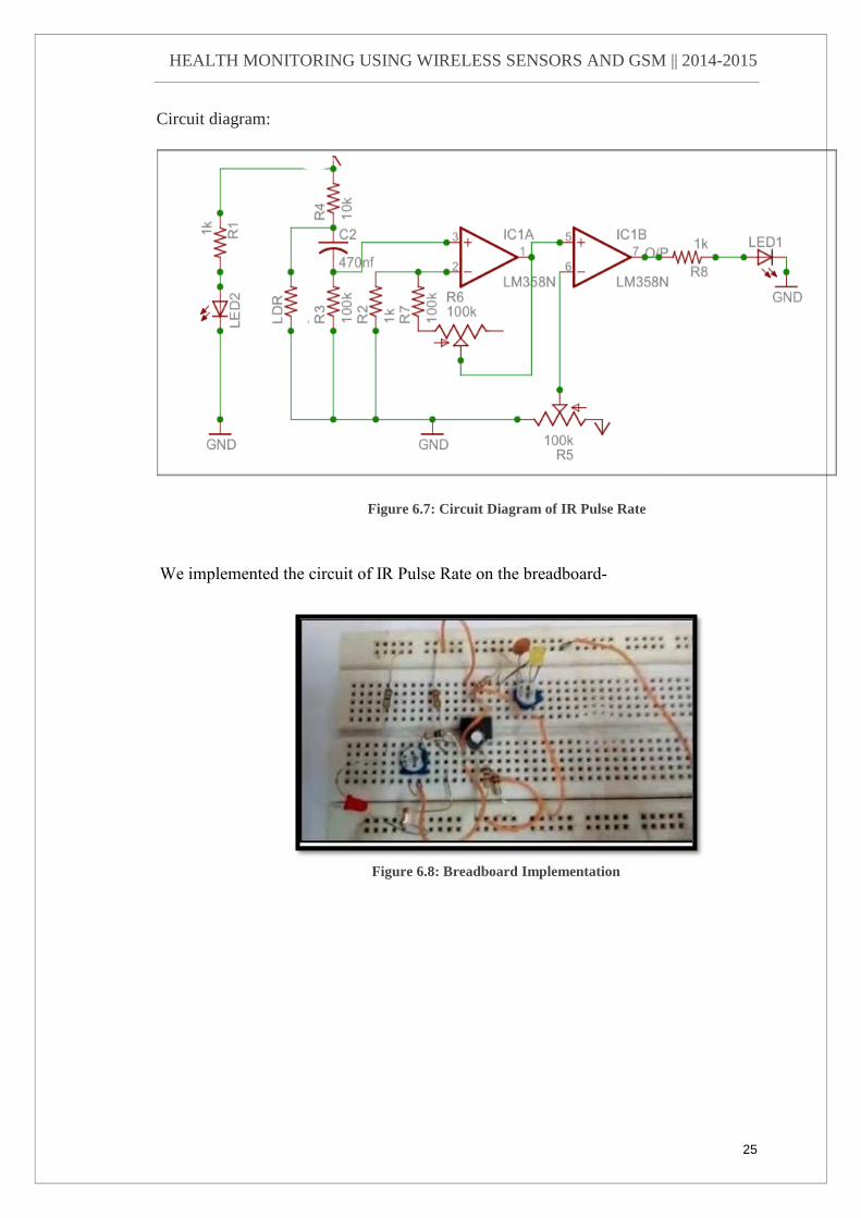
Circuit diagram:
We implemented the circuit of IR Pulse Rate on the breadboard-
Figure 6.7: Circuit Diagram of IR Pulse Rate
Figure 6.8: Breadboard Implementation

HEALTH MONITORING USING WIRELESS SENSORS AND GSM || 2014-2015
26
PCB Track of Pulse Rate Sensor-
Figure 6.10: Assembled pulse rate sensor with Ring
Figure 6.9: PCB Layout of Pulse Rate sensor

HEALTH MONITORING USING WIRELESS SENSORS AND GSM || 2014-2015
27
6.2.2 ECG Sensor
Working-
The sensor requires three connections to the right arm (RA), left arm (LA) and right leg
(RL) of the patient. We make use of Instrumentation Amplifiers (INAs) to condition
small signals in the presence of large common-mode voltages and DC potentials so we
choose Analog instrumentation amplifier to amplify the ECG voltage from electrodes,
Figure 6.11: Circuit Diagram of ECG Sensor
Figure 6.12: Connections for ECG Sensor

HEALTH MONITORING USING WIRELESS SENSORS AND GSM || 2014-2015
28
which is in the range of 1mV to 5mV.we have designed the instrumentation amplifier
using op-amp LM358, with a gain of 1000 and power supply is +12V to -12V. It
contains following signal conditioning unit:-
Low pass filter:
This block is used to remove the unwanted signals like noise, the frequency range of
ECG is 0.04HZ to 150 Hz, and so the low pass filter is designed with the cut off
frequency of 150HZ.
Amplifier:
It consists of a simple non inverting amplifier which is designed to saturate the ECG
signals, and the output of amplifier is fed to the microcontroller to count the heart rate.
Microcontroller AT89S51 is being used in our project for counting of the pulses. It
takes the conditioned square pulses from hardware system as an input and counts it for
one minute, which is the required heart rate count.
Figure 6.13: ECG Sensor

HEALTH MONITORING USING WIRELESS SENSORS AND GSM || 2014-2015
29
6.2.3 INTERFACING UNIT
The Interfacing unit consists of micro controller, MAX232,ADC,Buzzer,RS232
connection port.This unit is responsible for conditioning of the signal,converting the
values of the parameters received and sending it to the GUI and Access Port Software
to display the results.
PCB Track of the Interfacing Unit-
Figure 6.14: PCB Layout of Interfacing Unit

HEALTH MONITORING USING WIRELESS SENSORS AND GSM || 2014-2015
30
Figure 6.15: Front of the Interfacing Unit
Figure 6.16: Assembled Interfacing Unit

HEALTH MONITORING USING WIRELESS SENSORS AND GSM || 2014-2015
31
CHAPTER 7
RESULTS
Temperature and Pulse Rate is displayed on the LCD and the parameters are also
displayed on the GUI through Zigbee so as to maintain a History of the patients
continuous monitoring.
Figure 7.1: Result displayed on LCD
Figure 7.2: Result displayed on GUI

HEALTH MONITORING USING WIRELESS SENSORS AND GSM || 2014-2015
32
This is the Access port software which displays the magnitude of the ECG wave. The
computer is connected via RS232 to comm port1 at 9600 baud rate and data is streamed
to the software.
Figure 7.3: Magnitude of ECG displayed on Access Port

HEALTH MONITORING USING WIRELESS SENSORS AND GSM || 2014-2015
33
An Automated message is sent to the local physician’s mobile whose number is al-
ready inserted in the program.
The threshold values set for temperature and pulse rate are as follows:-
-Temperature rises above 102 F.
-Pulse rate falls below 30 ppm or rises above 150 ppm.
Figure 7.4: Text message sent to doctor

HEALTH MONITORING USING WIRELESS SENSORS AND GSM || 2014-2015
34
CHAPTER 8
ADVANTAGES AND APPLICATIONS
ADVANTAGES
This system has the following advantages:
Easy and reliable for Doctors: In a hospital, either the nurse or the doctor has
to move physically from one person to another for health checkup, due to which
continuous monitoring becomes difficult.
Increased Efficiency: The number of nurses required for keeping a check on
patients in ICU can be reduced to a large extent.
More Accurate: Chances of human error in checking health parameters is also
reduced, also the database is formed and updated regularly.
APPLICATIONS
This system can be used for the following purposes:
Continuous monitoring: It can be used in hospitals on operated patients for
monitoring their vital parameters.
Record Keeping: This system consists of a GUI and an access terminal
software which can maintain the history of the patients.

HEALTH MONITORING USING WIRELESS SENSORS AND GSM || 2014-2015
35
CHAPTER 9
CONCLUSION
The project provides low-cost solution to enhance the remote monitoring
capability of existing health care system by using ZigBee wireless standard and GSM
modem. It uses three sensors such as IR Pulse rate, Body temperature and ECG data
monitoring. The sensors are operated and vital information is transmitted to the
microcontroller. By using this prototype circuit containing AT89S52 MCU, GSM
Modem, and other hardware circuit the messages can be transmitted in case the value
of any parameter falls below a predetermined value to the corresponding medical expert
so that necessary medication can be given to the patient. The system can be installed
for testing the health parameters of patient’s in their home for health care monitoring
and the wireless sensor network can operate on an area of 6-10 square meters.

HEALTH MONITORING USING WIRELESS SENSORS AND GSM || 2014-2015
36
CHAPTER 10
FUTURE SCOPE
The future scope of this system would be a wireless sensor network architecture for
smart homecare that possesses the essential elements of each of the future medical
applications,namely:
-integration with existing medical practices and technology,
-Real time, long-term, remote-monitoring,
-Miniature,wearablesensors,and
- Assistance to the elderly and chronic patients.
It extends healthcare from the traditional clinic or hospital setting to the patient's home,
enabling telecare without the prohibitive costs of retrofitting existing dwellings. Patient
tracking module can be included in the system using GPS. Further efforts are necessary
to improve quality of service of wireless communication, reliability of sensor nodes,
security, and standardization of interfaces and interoperability

HEALTH MONITORING USING WIRELESS SENSORS AND GSM || 2014-2015
37
References
[1] Cristian Rotariu, Hariton Costin,Dragos Arotaritel, Bogdan Dionisie, “A
WIRELESS ECG MODULE FOR PATIENT MONITORING NETWORK”,
2008 .
[2] P. Binkley, “An Advanced Wireless Sensor Network for Health Monitor-
ing”, IEEE Engineering in Medicine and Biology Magazine 22 (3) (2003) 23–
24.
[3] Philippe Bonnet, Johannes Gaehrke and Praveen Sephardic, “Real-Time
Multi-Patient Monitoring System on Wireless Sensor Network”,IEEE Personal
Communications (2005), Vol. 9.
[4] TamVuNgoc , “Medical Applications of Wireless Networks”,2013.
[5] Media Aminian, “A Hospital Healthcare Monitoring System Using Wireless
Sensor Networks ”, J Health Med Inform 2013.
[6] J. A. Stankovic, Q. Cao, T. Doan, L. Fang, Z. He, R. Kiran, S. Lin, S. Son,
R. Stoleru, A. Wood , “Wireless Sensor Networks for In-Home Healthcare: Po-
tential and Challenges ”,Department of Computer Science, University of Vir-
ginia,2012.

HEALTH MONITORING USING WIRELESS SENSORS AND GSM || 2014-2015
38
APPENDIX

HEALTH MONITORING USING WIRELESS SENSORS AND GSM || 2014-2015
39

HEALTH MONITORING USING WIRELESS SENSORS AND GSM || 2014-2015
40

HEALTH MONITORING USING WIRELESS SENSORS AND GSM || 2014-2015
41

HEALTH MONITORING USING WIRELESS SENSORS AND GSM || 2014-2015
42

HEALTH MONITORING USING WIRELESS SENSORS AND GSM || 2014-2015
43
-

HEALTH MONITORING USING WIRELESS SENSORS AND GSM || 2014-2015
44

HEALTH MONITORING USING WIRELESS SENSORS AND GSM || 2014-2015
45

HEALTH MONITORING USING WIRELESS SENSORS AND GSM || 2014-2015
46
Related Documents


![ME Health Monitoring System PPT[1]](https://static.cupdf.com/doc/110x72/544d8bfaaf7959f7178b4be1/me-health-monitoring-system-ppt1.jpg)


