HCCB TBM Mechanical HCCB TBM Mechanical Design Design R. Hunt, A. Ying, M. Abdou R. Hunt, A. Ying, M. Abdou Fusion Science & Technology Center Fusion Science & Technology Center University of California Los Angeles University of California Los Angeles May 11, 2006 May 11, 2006 Presented by Ryan Presented by Ryan Hunt Hunt

HCCB TBM Mechanical Design
Jan 01, 2016
HCCB TBM Mechanical Design. Presented by Ryan Hunt. R. Hunt, A. Ying, M. Abdou Fusion Science & Technology Center University of California Los Angeles May 11, 2006. Overview. Allocated ½ Port Design Requirements Description of HCCB Subcomponents Overall He Flow Routing Scheme - PowerPoint PPT Presentation
Welcome message from author
This document is posted to help you gain knowledge. Please leave a comment to let me know what you think about it! Share it to your friends and learn new things together.
Transcript

HCCB TBM Mechanical DesignHCCB TBM Mechanical Design
R. Hunt, A. Ying, M. AbdouR. Hunt, A. Ying, M. AbdouFusion Science & Technology CenterFusion Science & Technology CenterUniversity of California Los AngelesUniversity of California Los Angeles
May 11, 2006May 11, 2006
Presented by Ryan HuntPresented by Ryan Hunt

May 11, 2006May 11, 2006 UCLA Fusion Science & Technology CenterUCLA Fusion Science & Technology Center 22
OverviewOverview
Allocated ½ PortAllocated ½ PortDesign RequirementsDesign RequirementsDescription of HCCB Description of HCCB
SubcomponentsSubcomponentsOverall He Flow Overall He Flow
Routing SchemeRouting SchemeAssembly ProcessAssembly ProcessManufacturing Manufacturing
RequirementsRequirementsFigure 1
May 11, 2006May 11, 2006 UCLA Fusion Science & Technology CenterUCLA Fusion Science & Technology Center 33
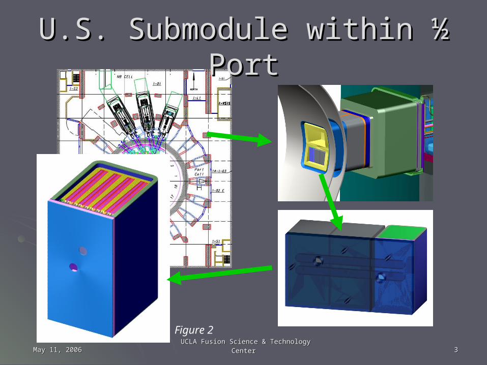
U.S. Submodule within ½ PortU.S. Submodule within ½ Port
Figure 2

May 11, 2006May 11, 2006 UCLA Fusion Science & Technology CenterUCLA Fusion Science & Technology Center 44
TBM Design RequirementsTBM Design Requirements Overall size must fit within available space (51cm x Overall size must fit within available space (51cm x
38.9cm x 71cm)38.9cm x 71cm) He must cool first wall to acceptable temperaturesHe must cool first wall to acceptable temperatures He must cool breeding zonesHe must cool breeding zones All cooling plates & manifolds must satisfy stress criteriaAll cooling plates & manifolds must satisfy stress criteria Helium channels (for both FW and cooling channels) Helium channels (for both FW and cooling channels)
must be economically fabricablemust be economically fabricable Must house appropriate amounts of breeder and Must house appropriate amounts of breeder and
beryllium multiplierberyllium multiplier Back wall must align with JA Submodules into common Back wall must align with JA Submodules into common
½ port back wall manifold½ port back wall manifold Must ensure survival of structural box under accidental Must ensure survival of structural box under accidental
conditions (TBD)conditions (TBD)
May 11, 2006May 11, 2006 UCLA Fusion Science & Technology CenterUCLA Fusion Science & Technology Center 55
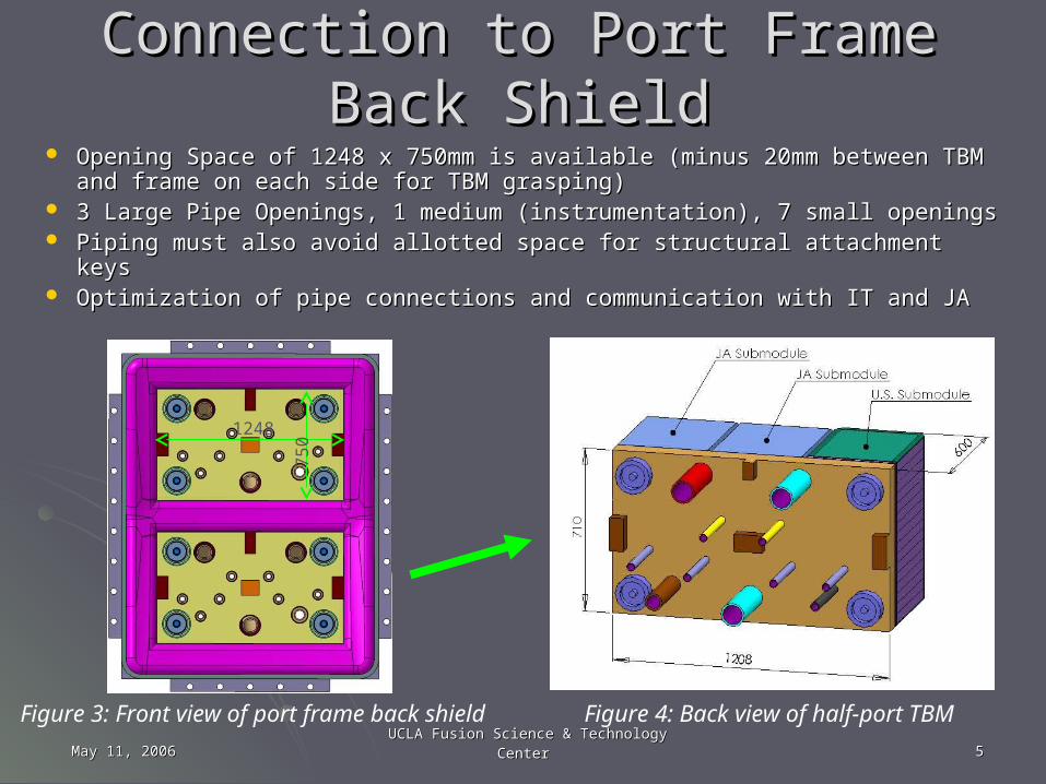
Connection to Port Frame Back ShieldConnection to Port Frame Back Shield Opening Space of 1248 x 750mm is available (minus 20mm between Opening Space of 1248 x 750mm is available (minus 20mm between
TBM and frame on each side for TBM grasping) TBM and frame on each side for TBM grasping) 3 Large Pipe Openings, 1 medium (instrumentation), 7 small openings3 Large Pipe Openings, 1 medium (instrumentation), 7 small openings Piping must also avoid allotted space for structural attachment keysPiping must also avoid allotted space for structural attachment keys Optimization of pipe connections and communication with IT and JAOptimization of pipe connections and communication with IT and JA
75
0
1248
Figure 3: Front view of port frame back shield Figure 4: Back view of half-port TBM
May 11, 2006May 11, 2006 UCLA Fusion Science & Technology CenterUCLA Fusion Science & Technology Center 66
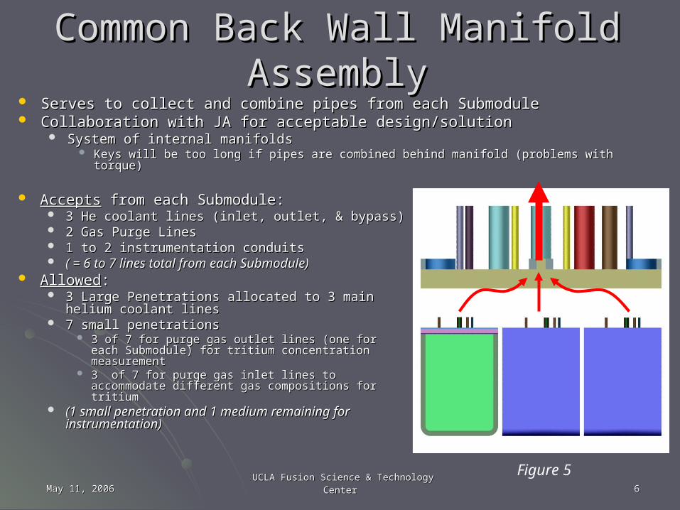
Common Back Wall Manifold AssemblyCommon Back Wall Manifold Assembly Serves to collect and combine pipes from each SubmoduleServes to collect and combine pipes from each Submodule Collaboration with JA for acceptable design/solutionCollaboration with JA for acceptable design/solution
System of internal manifoldsSystem of internal manifolds Keys will be too long if pipes are combined behind manifold (problems with torque)Keys will be too long if pipes are combined behind manifold (problems with torque)
AcceptsAccepts from each Submodule: from each Submodule: 3 He coolant lines (inlet, outlet, & bypass)3 He coolant lines (inlet, outlet, & bypass) 2 Gas Purge Lines2 Gas Purge Lines 1 to 2 instrumentation conduits1 to 2 instrumentation conduits ( = 6 to 7 lines total from each Submodule)( = 6 to 7 lines total from each Submodule)
AllowedAllowed: : 3 Large Penetrations allocated to 3 main helium 3 Large Penetrations allocated to 3 main helium
coolant linescoolant lines 7 small penetrations7 small penetrations
3 of 7 for purge gas outlet lines (one for each 3 of 7 for purge gas outlet lines (one for each Submodule) for tritium concentration measurementSubmodule) for tritium concentration measurement
3 of 7 for purge gas inlet lines to accommodate 3 of 7 for purge gas inlet lines to accommodate different gas compositions for tritiumdifferent gas compositions for tritium
(1 small penetration and 1 medium remaining for (1 small penetration and 1 medium remaining for instrumentation)instrumentation)
Figure 5
May 11, 2006May 11, 2006 UCLA Fusion Science & Technology CenterUCLA Fusion Science & Technology Center 77
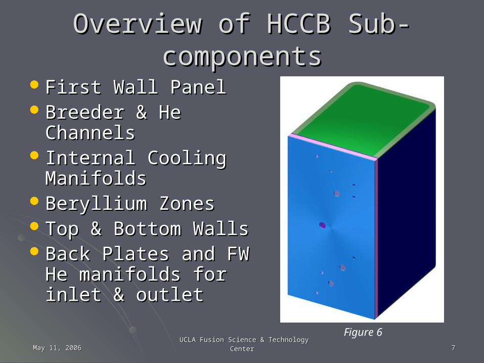
Overview of HCCB Sub-componentsOverview of HCCB Sub-components
First Wall PanelFirst Wall PanelBreeder & He Breeder & He
ChannelsChannels Internal Cooling Internal Cooling
ManifoldsManifoldsBeryllium ZonesBeryllium ZonesTop & Bottom WallsTop & Bottom WallsBack Plates and FW Back Plates and FW
He manifolds for inlet He manifolds for inlet & outlet& outlet Figure 6
May 11, 2006May 11, 2006 UCLA Fusion Science & Technology CenterUCLA Fusion Science & Technology Center 88
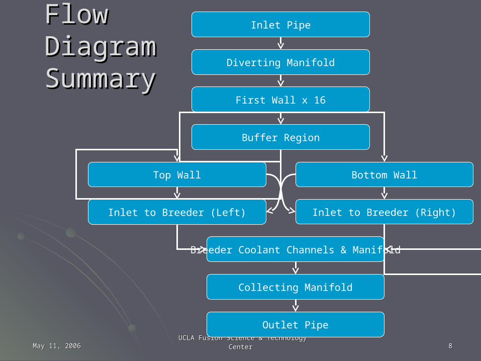
Flow DiagramFlow DiagramSummarySummary
Inlet Pipe
Diverting Manifold
First Wall x 16
Buffer Region
Top Wall Bottom Wall
Inlet to Breeder (Right)Inlet to Breeder (Left)
Breeder Coolant Channels & Manifold
Collecting Manifold
Outlet Pipe
May 11, 2006May 11, 2006 UCLA Fusion Science & Technology CenterUCLA Fusion Science & Technology Center 99
U.S. Planning for RAFM Steel Fabrication U.S. Planning for RAFM Steel Fabrication Technology Development for ITER TBMTechnology Development for ITER TBM
Four Parallel lines of technological development planned:Four Parallel lines of technological development planned:1.1. Square tube manufacturing and bending to produce first-Square tube manufacturing and bending to produce first-
wall.wall.2.2. HHot ot IIsostatic sostatic PPressing (HIP) technology to join square ressing (HIP) technology to join square
tubes to form the first wall, and the fabrication of other tubes to form the first wall, and the fabrication of other elements such as internal cooling plates and manifolds.elements such as internal cooling plates and manifolds.
3.3. Investment casting as an alternative to HIP.Investment casting as an alternative to HIP. Reduces the need for extensive joining operations.Reduces the need for extensive joining operations. Reduces the amount of NDE needed (fewer joints).Reduces the amount of NDE needed (fewer joints). Potentially less expensive than other fabrication methods.Potentially less expensive than other fabrication methods. Complex castings of 9-10 Cr steels have been produced with Complex castings of 9-10 Cr steels have been produced with
mechanical properties similar to those of wrought products.mechanical properties similar to those of wrought products.
4.4. Electron-beam, laser welding, and possibly other Electron-beam, laser welding, and possibly other techniques to join internal cooling plates and manifolds techniques to join internal cooling plates and manifolds to the first-wall structure.to the first-wall structure.
May 11, 2006May 11, 2006 UCLA Fusion Science & Technology CenterUCLA Fusion Science & Technology Center 1010
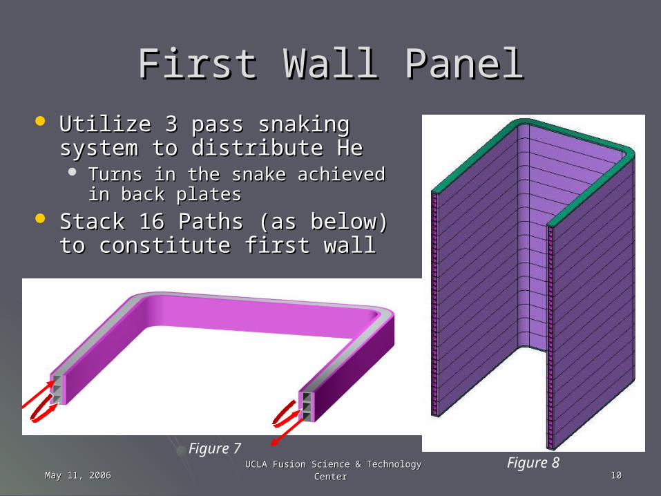
First Wall PanelFirst Wall Panel Utilize 3 pass snaking system to Utilize 3 pass snaking system to
distribute Hedistribute He Turns in the snake achieved in back Turns in the snake achieved in back
platesplates Stack 16 Paths (as below) to Stack 16 Paths (as below) to
constitute first wallconstitute first wall
Figure 7Figure 8
May 11, 2006May 11, 2006 UCLA Fusion Science & Technology CenterUCLA Fusion Science & Technology Center 1111
First Wall FabricationFirst Wall Fabrication Two MethodsTwo Methods
1.1. Components of first wall are bent into U-shape before Components of first wall are bent into U-shape before assembly, and are then pressed between two metal assembly, and are then pressed between two metal plates and joined with HIPPING processplates and joined with HIPPING process
Sealing welds must be made at ends and along pipe path Sealing welds must be made at ends and along pipe path (likely must be done prior to giving to a manufacturing co.)(likely must be done prior to giving to a manufacturing co.)
2.2. Two thicker plates each with desired half-channels Two thicker plates each with desired half-channels milled out. Pressed and joined with HIPPING milled out. Pressed and joined with HIPPING process, and finally bent into U-shape of first wallprocess, and finally bent into U-shape of first wall
Much more machiningMuch more machining Have had inaccurate channel dimensions (at corners) when Have had inaccurate channel dimensions (at corners) when
bending occurs after weldingbending occurs after welding
May 11, 2006May 11, 2006 UCLA Fusion Science & Technology CenterUCLA Fusion Science & Technology Center 1212
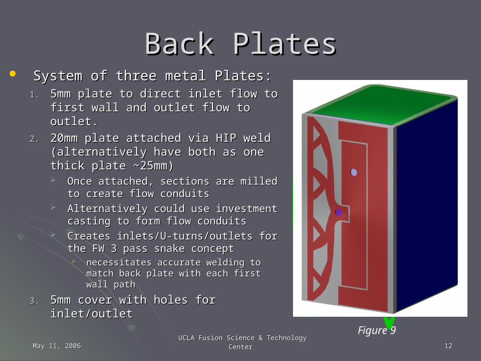
Back PlatesBack Plates System of three metal Plates:System of three metal Plates:
1.1. 5mm plate to direct inlet flow to first 5mm plate to direct inlet flow to first wall and outlet flow to outlet. wall and outlet flow to outlet.
2.2. 20mm plate attached via HIP weld 20mm plate attached via HIP weld (alternatively have both as one thick (alternatively have both as one thick plate ~25mm)plate ~25mm) Once attached, sections are milled to Once attached, sections are milled to
create flow conduitscreate flow conduits Alternatively could use investment Alternatively could use investment
casting to form flow conduits casting to form flow conduits Creates inlets/U-turns/outlets for the Creates inlets/U-turns/outlets for the
FW 3 pass snake conceptFW 3 pass snake concept necessitates accurate welding to necessitates accurate welding to
match back plate with each first wall match back plate with each first wall pathpath
3.3. 5mm cover with holes for inlet/outlet5mm cover with holes for inlet/outletFigure 9
May 11, 2006May 11, 2006 UCLA Fusion Science & Technology CenterUCLA Fusion Science & Technology Center 1313
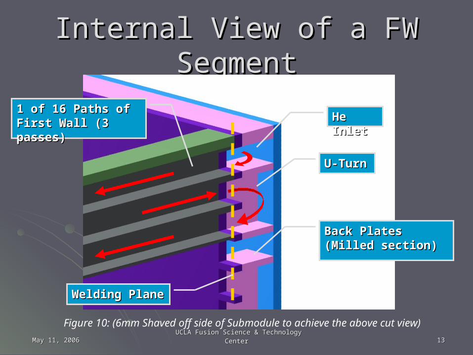
Internal View of a FW SegmentInternal View of a FW Segment
1 of 16 Paths of First 1 of 16 Paths of First Wall (3 passes)Wall (3 passes)
Back Plates (Milled Back Plates (Milled section)section)
Figure 10: (6mm Shaved off side of Submodule to achieve the above cut view)
U-TurnU-Turn
He InletHe Inlet
Welding PlaneWelding Plane
May 11, 2006May 11, 2006 UCLA Fusion Science & Technology CenterUCLA Fusion Science & Technology Center 1414
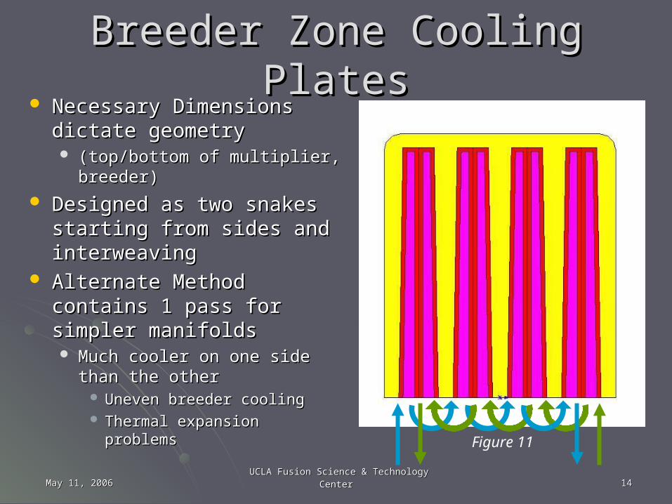
Breeder Zone Cooling PlatesBreeder Zone Cooling Plates Necessary Dimensions Necessary Dimensions
dictate geometrydictate geometry (top/bottom of multiplier, (top/bottom of multiplier,
breeder)breeder)
Designed as two snakes Designed as two snakes starting from sides and starting from sides and interweavinginterweaving
Alternate Method contains 1 Alternate Method contains 1 pass for simpler manifoldspass for simpler manifolds Much cooler on one side than Much cooler on one side than
the otherthe other Uneven breeder coolingUneven breeder cooling Thermal expansion problemsThermal expansion problems
Figure 11

May 11, 2006May 11, 2006 UCLA Fusion Science & Technology CenterUCLA Fusion Science & Technology Center 1515
Breeder Coolant Channel Breeder Coolant Channel FabricationFabrication
• Difficult as geometry is Difficult as geometry is much more complex.much more complex.
• Options available:Options available:1.1. Half Plates joined by Half Plates joined by
Hipping. Manufactured Hipping. Manufactured either through:either through:
1.1. milling and bending, ormilling and bending, or2.2. Investment castingInvestment casting
2.2. 1mm square tubes stacked 1mm square tubes stacked and HIPPED between and HIPPED between 0.5mm plates0.5mm plates
3.3. Entire model is cast, no Entire model is cast, no HIPPING is involved.HIPPING is involved.
Figure 12: Example of Outer Half of Coolant Channels

May 11, 2006May 11, 2006 UCLA Fusion Science & Technology CenterUCLA Fusion Science & Technology Center 1616
Internal ManifoldsInternal Manifolds Allows double snake Allows double snake
design to occurdesign to occur Green diverts flow from Green diverts flow from
top & bottom wallstop & bottom walls Orange transfers flow Orange transfers flow
from one pass to the from one pass to the nextnext
4 vertically & 4 vertically & horizontally horizontally compartmented compartmented sections (TBD)sections (TBD)
Blue is outlet collectorBlue is outlet collector Tan tubes distribute Tan tubes distribute
flow poloidally to all flow poloidally to all parallel channelsparallel channels
Uneven coolant flow Uneven coolant flow will make manifold will make manifold design challengingdesign challenging
Figure 13
May 11, 2006May 11, 2006 UCLA Fusion Science & Technology CenterUCLA Fusion Science & Technology Center 1717
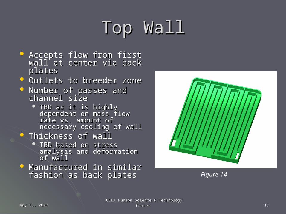
Top WallTop Wall Accepts flow from first wall Accepts flow from first wall
at center via back platesat center via back plates Outlets to breeder zoneOutlets to breeder zone Number of passes and Number of passes and
channel size channel size TBD as it is highly TBD as it is highly
dependent on mass flow dependent on mass flow rate vs. amount of rate vs. amount of necessary cooling of wallnecessary cooling of wall
Thickness of wall Thickness of wall TBD based on stress TBD based on stress
analysis and deformation of analysis and deformation of wallwall
Manufactured in similar Manufactured in similar fashion as back platesfashion as back plates
Figure 14
May 11, 2006May 11, 2006 UCLA Fusion Science & Technology CenterUCLA Fusion Science & Technology Center 1818
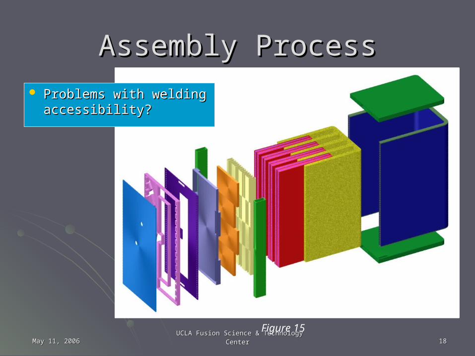
Assembly ProcessAssembly Process
Problems with welding Problems with welding accessibility?accessibility?
Figure 15
May 11, 2006May 11, 2006 UCLA Fusion Science & Technology CenterUCLA Fusion Science & Technology Center 1919
Obstacles to OvercomeObstacles to Overcome Thin walled members could have high deformation under Thin walled members could have high deformation under
thermal expansion (tolerance)thermal expansion (tolerance) Future stress analyses will tell what thicknesses and supports will be Future stress analyses will tell what thicknesses and supports will be
necessary.necessary. Very small He channels (with thin walls) are hard to Very small He channels (with thin walls) are hard to
manufacturemanufacture Need to decide manufacturing strategy of coolant channels and first Need to decide manufacturing strategy of coolant channels and first
wall channels so more detailed design can begin.wall channels so more detailed design can begin. Parallel flowParallel flow
Need system of baffles, buffers, and diverters to assure equal flow to Need system of baffles, buffers, and diverters to assure equal flow to all channels in Poloidal direction.all channels in Poloidal direction.
Attachments to Port Frame Back ShieldAttachments to Port Frame Back Shield Limitation on number of pipes from Submodule means coordinated Limitation on number of pipes from Submodule means coordinated
effort with JA to combine each pipe system from 3 in to 1effort with JA to combine each pipe system from 3 in to 1 i.e. each Submodule has 1 He outlet pipe = 3 total for ½ Port. Needs to i.e. each Submodule has 1 He outlet pipe = 3 total for ½ Port. Needs to
be combined into a single common pipe.be combined into a single common pipe.

Questions or Comments?Questions or Comments?
Related Documents


![Summary of FIP, FNF, SEE and MPT - Indico [Home] · Summary of FIP, FNF, SEE and MPT ... • Fusion Engineering, Integration and Power Plant ... HCCB TBM by CN HCCR TBM by KO LLCB](https://static.cupdf.com/doc/110x72/5b7824fb7f8b9a4c438ea154/summary-of-fip-fnf-see-and-mpt-indico-home-summary-of-fip-fnf-see-and.jpg)


