OM 479823011-1215-A HC-8 NEXSTAR III OWNERS MANUAL Serial No. __________________ Mailing Address: P.O. Box 580697 Tulsa, OK 74158-0697 Physical Address: 4707 N. Mingo Rd. Tulsa, OK 74117-5904 Phone 1-800-777-2760 Fax (918) 269-6688 http://www.autocrane.com

Welcome message from author
This document is posted to help you gain knowledge. Please leave a comment to let me know what you think about it! Share it to your friends and learn new things together.
Transcript

OM 479823011-1215-A
HC-8NEXSTAR III
OWNERS MANUAL
Serial No. __________________
Mailing Address:P.O. Box 580697Tulsa, OK 74158-0697Physical Address:4707 N. Mingo Rd.Tulsa, OK 74117-5904
Phone 1-800-777-2760Fax (918) 269-6688http://www.autocrane.com


Product Registration Rev 05152014
Auto Crane RegistrationFrom: Date:
End User Information:
Company: Phone:
Address:
City: State: Zip:
Contact: E-mail:
Distributor Information:
Company: Phone:
Address:
City: State: Zip:
Contact: E-mail:
Product Information:
Model No: Serial No: Date Delivered:
VIN #:
ONE REGISTRATION FORM PER UNIT (CRANE, BODY, OR COMPRESSOR)Please submit form within 15 days after installation
Online: www.autocrane.com | Resources | Warranties
Fax: 918-234-2177
Mail: Product Registration, Auto Crane Company, PO Box 580697, Tulsa, OK 74158-0697


WARNINGSWARNING! Federal law (49 cfr part 571) requires that the Final Stage Manufacturer of a vehiclecertify that the vehicle complies with all applicable federal regulations. Any modifications performed on the vehicle prior to the final state are also considered intermediate stage manufacturing and must be certified as to compliance. The installer of this crane and body is considered one of the manufacturers of the vehicle. As such a manufacturer, the installer is responsible for compliance with all applicable federal and state regulations, and is required to certify that the vehicle is in compliance.
WARNING! It is the further responsibility of the installer to comply with the OSHA Truck Crane Stability Requirements as specified by 29 CFR part 1910.180 (C) (1).
WARNING! NEVER OPERATE THE CRANE NEAR ELECTRICAL POWER LINES!Death or serious injury will result from boom, line, or load contacting electric lines. Do not use crane within 10 feet (3.05m) of electric power lines carrying up to 50,000 volts. One-foot additional clearance is required for every additional 30,000 volts or less. SEE DANGER DECAL (P/N 040529) in this Owner’s Manual.
WARNING! NEVER......................................... • EXCEED load chart capacities (centerline of rotation to hoist hook). • Un-reel last 5 wraps of cable from drum! • Wrap cable around load! • Attempt to lift or drag a load from the side! The boom can fail far below its rated capacity. • Weld, modify, or use unauthorized components on any Auto Crane unit! This will void any • warranty or liability. Also failure of the crane may result. • Place a chain link on the tip of the hook and try to lift a load! • Use a sling bar or anything larger than the hook throat that could prevent the hook latch from clos-
ing, thus negating the safety feature! • Hold on any pendant Select Switch that will cause unsafe operating conditions!
WARNING! In using a hook with latch, ALWAYS make sure that the hook latch throat is closed before lift-ing a load! Proper attention and common sense applied to the use of the hoist hook and various slings will prevent possible damage to material being hoisted and may prevent injury to personnel.
WARNING! Failure to correctly plumb and wire crane can cause inadvertent operation and damage to crane and/or personnel!
WARNING! Auto Crane Company remote controlled cranes are not designed or intended for use for any applications involving the lifting or moving of personnel.
WARNING! ALWAYS operate the crane in compliance with the load capacity chart. DO NOT USE the overload shutdown device to determine maximum rated loads, if the crane is equipped with this type of device.
READ THIS PAGE


HC-8TABLE OF CONTENTS
INTRODUCTION ………………………………………….. 1
GENERAL SPECIFICATIONS ………………………………………….. 3
SAFETY TIPS AND PRECAUTIONS ………………………………………….. 4
OPERATING PRACTICES & WARNINGS ………………………………………….. 6
QUALIFICATIONS FOR OPERATORS ………………………………………….. 7
OPERATION OF UNIT / OUTRIGGERS ………………………………………….. 10
CRANE OPERATION ………………………………………….. 11
TRANSMITTER SYNCHRONIZATION ………………………………………….. 16
INSPECTION REQUIREMENTS ………………………………………….. 17
GENERAL REPAIRS AND MTCE ………………………………………….. 20
BATTERY MAINTENANCE ………………………………………….. 22
LUBRICATION & MTCE SCHEDULE ………………………………………….. 24
SAFETY DECAL SECTION ………………………………………….. 26
GENERAL DIMENSIONS ………………………………………….. 33
MOUNTING AND INSTALLATION ………………………………………….. 34
GENERAL ASSEMBLY ………………………………………….. 36
PEDESTAL ASSEMBLY ………………………………………….. 38
BOOM ASSEMBLY ………………………………………….. 44
ROTATION GEARBOX ………………………………………….. 46
HOIST ASSEMBLY ………………………………………….. 48
TRAVELING BLOCK ASSEMBLY ………………………………………….. 51
MAIN HARNESS DIAGRAM ………………………………………….. 52
HYDRAULIC CONTROL VALVE ………………………………………….. 54
COUNTERBALANCE VALVE ADJ. ………………………………………….. 56
VALVE OVERRIDE ………………………………………….. 57
TROUBLESHOOTING CHART ………………………………………….. 58
ERROR CODE TROUBLESHOOTING ………………………………………….. 59
ELECTRICAL TROUBLESHOOTING ………………………………………….. 60
HYDRAULIC TROULBESHOOTING ………………………………………….. 62
CARTRIDGE MAINTENANCE ………………………………………….. 63
HC-8 LOAD CHART ………………………………………….. 64
STABILITY CHART ………………………………………….. 65
PREVENTATIVE MAINTENANCE ………………………………………….. 66
WARRANTY …………………………………………..LAST 2 PAGES
1
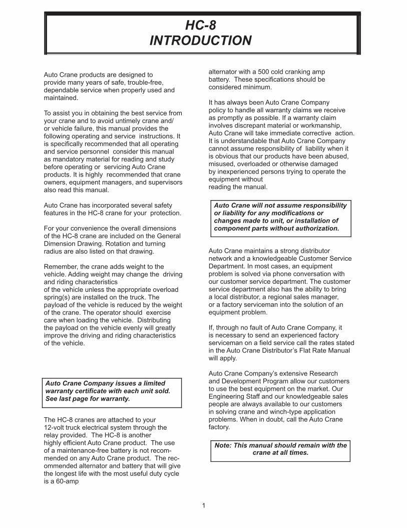
alternator with a 500 cold cranking amp battery. These specifications should be considered minimum. It has always been Auto Crane Company policy to handle all warranty claims we receive as promptly as possible. If a warranty claim involves discrepant material or workmanship, Auto Crane will take immediate corrective action. It is understandable that Auto Crane Company cannot assume responsibility of liability when it is obvious that our products have been abused, misused, overloaded or otherwise damaged by inexperienced persons trying to operate the equipment without reading the manual.
Auto Crane maintains a strong distributor network and a knowledgeable Customer Service Department. In most cases, an equipment problem is solved via phone conversation with our customer service department. The customer service department also has the ability to bring a local distributor, a regional sales manager, or a factory serviceman into the solution of an equipment problem.
If, through no fault of Auto Crane Company, it is necessary to send an experienced factory serviceman on a field service call the rates stated in the Auto Crane Distributor’s Flat Rate Manual will apply.
Auto Crane Company’s extensive Research and Development Program allow our customers to use the best equipment on the market. Our Engineering Staff and our knowledgeable sales people are always available to our customers in solving crane and winch-type application problems. When in doubt, call the Auto Crane factory.
Auto Crane will not assume responsibility or liability for any modifications or changes made to unit, or installation of component parts without authorization.
Note: This manual should remain with the crane at all times.
Auto Crane products are designed to provide many years of safe, trouble-free, dependable service when properly used and maintained. To assist you in obtaining the best service from your crane and to avoid untimely crane and/or vehicle failure, this manual provides the following operating and service instructions. It is specifically recommended that all operating and service personnel consider this manual as mandatory material for reading and study before operating or servicing Auto Crane products. It is highly recommended that crane owners, equipment managers, and supervisors also read this manual. Auto Crane has incorporated several safety features in the HC-8 crane for your protection. For your convenience the overall dimensions of the HC-8 crane are included on the General Dimension Drawing. Rotation and turning radius are also listed on that drawing. Remember, the crane adds weight to the vehicle. Adding weight may change the driving and riding characteristics of the vehicle unless the appropriate overload spring(s) are installed on the truck. The payload of the vehicle is reduced by the weight of the crane. The operator should exercise care when loading the vehicle. Distributing the payload on the vehicle evenly will greatly improve the driving and riding characteristics of the vehicle.
The HC-8 cranes are attached to your 12-volt truck electrical system through the relay provided. The HC-8 is another highly efficient Auto Crane product. The use of a maintenance-free battery is not recom-mended on any Auto Crane product. The rec-ommended alternator and battery that will give the longest life with the most useful duty cycle is a 60-amp
Auto Crane Company issues a limited warranty certificate with each unit sold. See last page for warranty.
HC-8 INTRODUCTION

2
HC-8INTRODUCTION
DISTRIBUTOR ASSISTANCE:
Should you require any assistance not given in this manual, we recommend that you consult your nearest Auto Crane Distributor. Our distributors sell authorized parts and have service departments that can solve almost any needed repair. This manual does not cover all maintenance, operating, or repair instructions pertinent to all possible situations. If you require additional information, please contact the Auto Crane Company at the following telephone num-ber: 1-800-777-2760. The information contained in the manual is in effect at the time of this printing. Auto Crane Company reserves the right to update this material without notice or obligation.
3
HC-8GENERAL SPECIFICATIONS
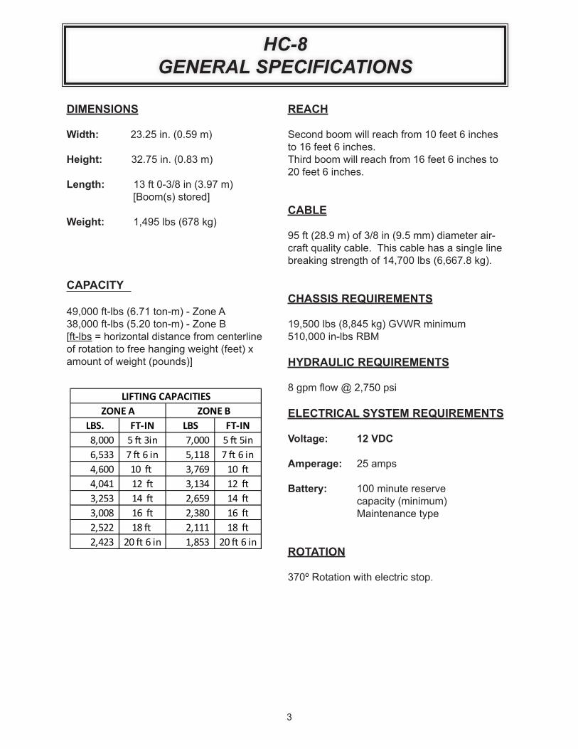
REACH
Second boom will reach from 10 feet 6 inches to 16 feet 6 inches.Third boom will reach from 16 feet 6 inches to 20 feet 6 inches.
CABLE
95 ft (28.9 m) of 3/8 in (9.5 mm) diameter air-craft quality cable. This cable has a single line breaking strength of 14,700 lbs (6,667.8 kg).
CHASSIS REQUIREMENTS
19,500 lbs (8,845 kg) GVWR minimum510,000 in-lbs RBM
HYDRAULIC REQUIREMENTS
8 gpm flow @ 2,750 psi
ELECTRICAL SYSTEM REQUIREMENTS
Voltage: 12 VDC
Amperage: 25 amps
Battery: 100 minute reserve capacity (minimum) Maintenance type
ROTATION
370º Rotation with electric stop.
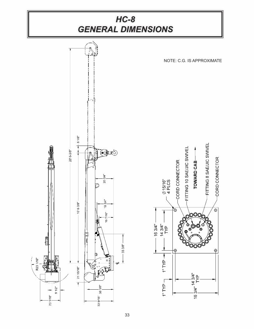
DIMENSIONS
Width: 23.25 in. (0.59 m) Height: 32.75 in. (0.83 m)
Length: 13 ft 0-3/8 in (3.97 m) [Boom(s) stored]
Weight: 1,495 lbs (678 kg)
CAPACITY
49,000 ft-lbs (6.71 ton-m) - Zone A38,000 ft-lbs (5.20 ton-m) - Zone B[ft-lbs = horizontal distance from centerline of rotation to free hanging weight (feet) x amount of weight (pounds)]
LIFTING CAPACITIESZONE A ZONE B
LBS. FT-IN LBS FT-IN8,000 5 ft 3in 7,000 5 ft 5in6,533 7 ft 6 in 5,118 7 ft 6 in4,600 10 ft 3,769 10 ft4,041 12 ft 3,134 12 ft3,253 14 ft 2,659 14 ft3,008 16 ft 2,380 16 ft2,522 18 ft 2,111 18 ft2,423 20 ft 6 in 1,853 20 ft 6 in
4
—-IMPORTANT—-SAFETY TIPS AND PRECAUTIONS
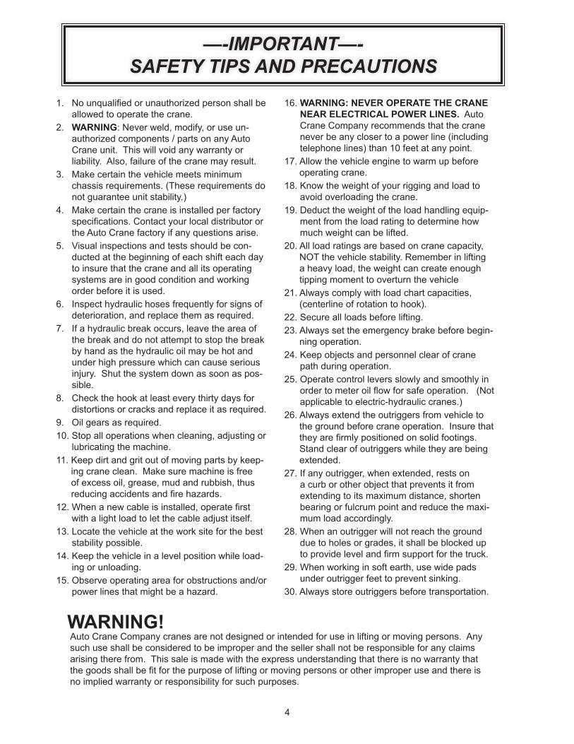
1. No unqualified or unauthorized person shall be allowed to operate the crane.
2. WARNING: Never weld, modify, or use un-authorized components / parts on any Auto Crane unit. This will void any warranty or liability. Also, failure of the crane may result.
3. Make certain the vehicle meets minimum chassis requirements. (These requirements do not guarantee unit stability.)
4. Make certain the crane is installed per factory specifications. Contact your local distributor or the Auto Crane factory if any questions arise.
5. Visual inspections and tests should be con-ducted at the beginning of each shift each day to insure that the crane and all its operating systems are in good condition and working order before it is used.
6. Inspect hydraulic hoses frequently for signs of deterioration, and replace them as required.
7. If a hydraulic break occurs, leave the area of the break and do not attempt to stop the break by hand as the hydraulic oil may be hot and under high pressure which can cause serious injury. Shut the system down as soon as pos-sible.
8. Check the hook at least every thirty days for distortions or cracks and replace it as required.
9. Oil gears as required.10. Stop all operations when cleaning, adjusting or
lubricating the machine.11. Keep dirt and grit out of moving parts by keep-
ing crane clean. Make sure machine is free of excess oil, grease, mud and rubbish, thus reducing accidents and fire hazards.
12. When a new cable is installed, operate first with a light load to let the cable adjust itself.
13. Locate the vehicle at the work site for the best stability possible.
14. Keep the vehicle in a level position while load-ing or unloading.
15. Observe operating area for obstructions and/or power lines that might be a hazard.
16. WARNING: NEVER OPERATE THE CRANE NEAR ELECTRICAL POWER LINES. Auto Crane Company recommends that the crane never be any closer to a power line (including telephone lines) than 10 feet at any point.
17. Allow the vehicle engine to warm up before operating crane.
18. Know the weight of your rigging and load to avoid overloading the crane.
19. Deduct the weight of the load handling equip-ment from the load rating to determine how much weight can be lifted.
20. All load ratings are based on crane capacity, NOT the vehicle stability. Remember in lifting a heavy load, the weight can create enough tipping moment to overturn the vehicle
21. Always comply with load chart capacities, (centerline of rotation to hook).
22. Secure all loads before lifting.23. Always set the emergency brake before begin-
ning operation.24. Keep objects and personnel clear of crane
path during operation.25. Operate control levers slowly and smoothly in
order to meter oil flow for safe operation. (Not applicable to electric-hydraulic cranes.)
26. Always extend the outriggers from vehicle to the ground before crane operation. Insure that they are firmly positioned on solid footings. Stand clear of outriggers while they are being extended.
27. If any outrigger, when extended, rests on a curb or other object that prevents it from extending to its maximum distance, shorten bearing or fulcrum point and reduce the maxi-mum load accordingly.
28. When an outrigger will not reach the ground due to holes or grades, it shall be blocked up to provide level and firm support for the truck.
29. When working in soft earth, use wide pads under outrigger feet to prevent sinking.
30. Always store outriggers before transportation.
WARNING!Auto Crane Company cranes are not designed or intended for use in lifting or moving persons. Any such use shall be considered to be improper and the seller shall not be responsible for any claims arising there from. This sale is made with the express understanding that there is no warranty that the goods shall be fit for the purpose of lifting or moving persons or other improper use and there is no implied warranty or responsibility for such purposes.
5
—-IMPORTANT—-SAFETY TIPS AND PRECAUTIONS
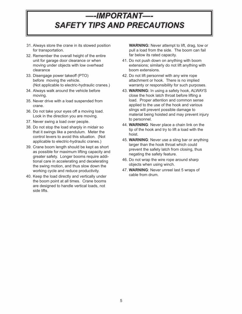
31. Always store the crane in its stowed position for transportation.
32. Remember the overall height of the entire unit for garage door clearance or when moving under objects with low overhead clearance
33. Disengage power takeoff (PTO) before moving the vehicle. (Not applicable to electric-hydraulic cranes.)
34. Always walk around the vehicle before moving.
35. Never drive with a load suspended from crane.
36. Do not take your eyes off a moving load. Look in the direction you are moving.
37. Never swing a load over people.38. Do not stop the load sharply in midair so
that it swings like a pendulum. Meter the control levers to avoid this situation. (Not applicable to electric-hydraulic cranes.)
39. Crane boom length should be kept as short as possible for maximum lifting capacity and greater safety. Longer booms require addi-tional care in accelerating and decelerating the swing motion, and thus slow down the working cycle and reduce productivity.
40. Keep the load directly and vertically under the boom point at all times. Crane booms are designed to handle vertical loads, not side lifts.
WARNING: Never attempt to lift, drag, tow or pull a load from the side. The boom can fail far below its rated capacity.
41. Do not push down on anything with boom extensions; similarly do not lift anything with boom extensions.
42. Do not lift personnel with any wire rope attachment or hook. There is no implied warranty or responsibility for such purposes.
43. WARNING: In using a safety hook, ALWAYS close the hook latch throat before lifting a load. Proper attention and common sense applied to the use of the hook and various slings will prevent possible damage to material being hoisted and may prevent injury to personnel.
44. WARNING: Never place a chain link on the tip of the hook and try to lift a load with the hoist.
45. WARNING: Never use a sling bar or anything larger than the hook throat which could prevent the safety latch from closing, thus negating the safety feature.
46. Do not wrap the wire rope around sharp objects when using winch.
47. WARNING: Never unreel last 5 wraps of cable from drum.

6
—-IMPORTANT—-OPERATING PRACTICES AND WARNINGS
1. Make certain the vehicle meets minimum chassis requirements. (These requirements do not guarantee unit stability)
2. Make certain the crane is installed per factory specifications. Contact your local Distributor or the Auto Crane factory if any questions arise.
3. Keep the vehicle in as level a position as possible while loading or unloading.
4. ALWAYS set the vehicle emergency brake before beginning crane operations.
5. ALWAYS use outriggers from vehicle to the ground during crane operation. Make sure they are firmly positioned on solid footings.
6. All load ratings are based on crane capacity, NOT truck/crane stability.
7. Keep objects and personnel clear of crane path during operation.
8. Keep hoist cable pulled tight at all times.9. REMEMBER, in lifting a heavy load, the weight can
create enough tipping momentum to overturn the vehicle.
10. ALWAYS keep load as close to ground as possible.11. Hydraulic hoses need to be inspected frequently for
signs of deterioration, and be replaced as required.12. The hoist hook is an important item that an operator
should consider and use properly. It should be checked on a daily basis for distortion or cracks.
13. ALWAYS store outriggers before road travel.14. In applications, where the rotation of the load is
hazardous a tag or restraint line should be used (ref OSHA 1910.180(h)(3)(xvi)). To reduce the potential for the load to rotate or rope twist, operate at minimal boom angles and extension. If restraining the load and/or changing operation location is not an option,
15. WARNING! NEVER OPERATE THE CRANE NEAR ELECTRICAL POWER LINES! Death or serious injury will result from boom, line, or load contacting electric lines. Do not use crane within 10 feet (3.05m) of electric power lines carrying up to 50,000 volts. One foot additional clearance is required for every additional 30,000 volts or less.
16. WARNING! NEVER EXCEED load chart capacities (centerline of rotation to hoist hook).
17. WARNING! NEVER un-reel last 5 wraps of cable from drum!
18. WARNING! NEVER wrap cable around load!19. WARNING! NEVER attempt to lift or drag a load
from the side! The boom can fail far below its rated capacity.
20. WARNING! NEVER weld, modify, or use unauthorized components on any Auto Crane unit! This will void any warranty or liability. Also failure of the crane may result.
21. WARNING! NEVER place a chain link on the tip of the hook and try to lift a load!
22. WARNING! NEVER use a sling bar or anything larger than the hook throat that could prevent the hook latch from closing, thus negating the safety feature!
23. WARNING! In using a hook with latch, ALWAYS insure that the hook latch throat is closed before lifting a load! Proper attention and common sense applied to the use of the hoist hook and various slings will prevent possible damage to material being hoisted and may prevent injury to personnel.
24. WARNING! NEVER hold any Control Select Switch on that will cause unsafe operating conditions!
WARNING!Auto Crane Company remote controlled, stiff boom cranes are not designed or intended for use on any applications involving the lifting or moving of personnel.

7
QUALIFICATIONS FOR AND CONDUCT OFOPERATORS AND OPERATING PRACTICES
REFERENCE ASME B30.5a AND OSHA 1910.180 FOR COMPLETE QUALIFICATION REQUIREMENTS
OPERATORS 1. Crane operation shall be limited to personnel
with the following minimum qualifications:A. Designated persons.B. Trainees under the direct supervision of a
designated person.C. Maintenance and test personnel (when it
is necessary in the performance of their duties).
D. Inspectors (crane). 2. No one other than the personnel specified
above shall enter the operating area of a crane with the exception of persons such as oilers, supervisors, and those specified persons authorized by supervisors whose duties require them to do so and then only in the performance of their duties and with the knowledge of the operator or other persons.
QUALIFICATIONS FOR OPERATORS1. Operators shall be required by the employer
to pass a practical operating examination. Qualifications shall be limited to the specific type of equipment for which examined.
2. Operators and operator trainees shall meet the following physical qualifications:
A. Vision of at least 20/30 Snellen in one eye and 20/50 in the other, with or without corrective lenses.
B. Ability to distinguish colors, regardless of position, if color differentiation is required for operation.
C. Adequate hearing with or without hearing aid for the specific operation.
3. Evidence of physical defects or emotional instability, which render a hazard to operator or others, which in the opinion of the examiner could interfere with the operator’s performance, may be sufficient cause for disqualification. In such cases, specialized clinical or medical judgment and tests may be required.
4. Evidence that operator is subject to seizures or loss of physical control shall be sufficient reason for disqualification. Specialized medical
tests may be required to determine these conditions.
5. Operators and operator trainees should have normal depth perception, coordination, and no tendencies to dizziness or similar undesirable characteristics.
6. In addition to the above listed requirements, the operator shall:A. Demonstrate the ability to comprehend and
interpret all labels, operator’s manuals, safety codes, and other information pertinent to correct crane operations.
B. Posses the knowledge of emergency procedures and implement it.
C. Demonstrate to the employer the ability to operate the specific type of equipment.
D. Be familiar with the applicable safety regulations.
E. Understand the operating procedures as outlined by the manufacturer.
F. Be thoroughly familiar with the crane and its control functions.
G. Understand the operating procedures as outlined by the manufacturer.
CONDUCT OF OPERATORS1. The operator shall not engage in any practice,
which will divert his attention while actually operating the crane.
2. Each operator shall be responsible for those operations under the operator’s direct control. Whenever there is any doubt as to safety, the operator shall consult with the supervisor before handling the loads.
3. The operator should not leave a suspended load unattended unless specific precautions have been instituted and are in place.
4. If there is a warning sign on the switch or engine starting controls, the operator shall not close the switch or start the engine until the warning sign has been removed by the appointed person.
5. Before closing the switch or starting the engine, the operator shall see that all controls are in the “OFF”

8
QUALIFICATIONS FOR AND CONDUCT OFOPERATORS AND OPERATING PRACTICES
or neutral position and all personnel are in the clear.
6. If power fails during operation, the operator shall:A. Move power controls to the “OFF” or
neutral position.B. Land the suspended load and boom, if
practical.7. The operator shall be familiar with the equip-
ment and its proper care. If adjustments or repairs are necessary, the operator shall report the same promptly to the appointed person, and shall also notify the next opera-tor.
8. The operator at the start of each shift shall test all controls. If any controls do not operate properly, they shall be adjusted or repaired before operations are begun.
9. Stabilizers shall be visible to the operator while extending or setting unless a signal person assists operator.
OPERATING PRACTICES/HANDLING THE LOAD1. Size of load.
A. No crane shall be loaded beyond the rated load except for test purposes
B. The load to be lifted is to be within the rated load of the crane and its existing configuration.
C. When loads that are not accurately known are to be lifted, the person responsible for the job shall ascertain that the weight of the load does not exceed the crane rated load at the radius at which the load is to be lifted.
2. Attaching the load.A. The load shall be attached to the hook by
means of slings or other devices of suf-ficient capacity.
B. Hoist rope shall not be wrapped around the load.
3. Moving the load.The operator shall determine that:A. The crane is level and, where necessary,
the vehicle/carrier is blocked properly.B. The load is well secured and balanced in
the sling or lifting device before it is lifted more than a few inches.
C. Means are provided to hold the vehicle stationary while operating the crane.
D. Before starting to lift, the hook shall be positioned over the load in such a manner as to minimize swinging.
E. During lifting care shall be taken that:1. There is no sudden acceleration or
deceleration of the moving load.2. Load, boom or other parts of the crane
do not contact any obstruction.F. Cranes shall not be used for dragging
loads sideways.G. This standard recognizes that telescopic
boom cranes are designed and intended for handling materials. They do not meet personnel lift or elevator requirements. Therefore, no lifting, lowering, swinging or traveling shall be done while a person is on the hook or load. Hook attached suspended work platforms (baskets) shall not be used with cranes covered by this standard. Crane manufacturer must ap-prove work platforms attached to the boom.
H. The operator should avoid carrying loads over people.
I. When the crane is so equipped, the stabilizers shall be fully extended and set. Blocking under stabilizers shall meet the requirements as follows:1. Strong enough to prevent crushing.2. Of such thickness, width and length
as to completely support the stabilizer pad.
J. Firm footing under all tires, or individual stabilizer pads should be level. Where such a footing is not otherwise supplied, timbers, cribbing, or other structural members to distribute the load so as to not exceed allowable bearing capacity or the underlying material should provide it.
K. In transit, the boom shall be carried in stowed position.
L. When rotating the crane, sudden starts and stops shall be avoided. Rotational speed shall be such that the load does not swing out beyond the radius at which it can be controlled.
M. The crane shall not be transported with a load on the hook unless recommended by the manufacturer.
9
QUALIFICATIONS FOR AND CONDUCT OFOPERATORS AND OPERATING PRACTICES
N. No person should be permitted to stand or pass under a suspended load.
4. Stowing procedure. Follow the manufacturer’s procedure and sequence when stowing and un-stowing the crane.
MISCELLANEOUS
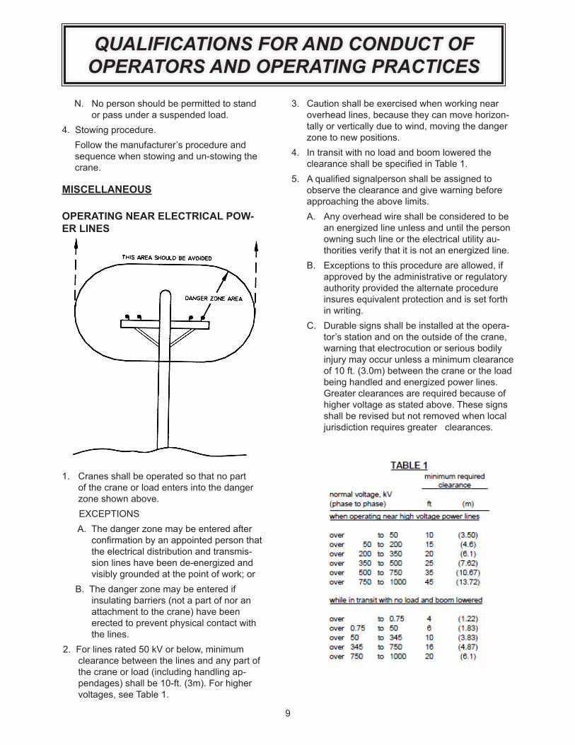
OPERATING NEAR ELECTRICAL POW-ER LINES
1. Cranes shall be operated so that no part of the crane or load enters into the danger zone shown above.EXCEPTIONS
A. The danger zone may be entered after confirmation by an appointed person that the electrical distribution and transmis-sion lines have been de-energized and visibly grounded at the point of work; or
B. The danger zone may be entered if insulating barriers (not a part of nor an attachment to the crane) have been erected to prevent physical contact with the lines.
2. For lines rated 50 kV or below, minimum clearance between the lines and any part of the crane or load (including handling ap-pendages) shall be 10-ft. (3m). For higher voltages, see Table 1.
3. Caution shall be exercised when working near overhead lines, because they can move horizon-tally or vertically due to wind, moving the danger zone to new positions.
4. In transit with no load and boom lowered the clearance shall be specified in Table 1.
5. A qualified signalperson shall be assigned to observe the clearance and give warning before approaching the above limits.A. Any overhead wire shall be considered to be
an energized line unless and until the person owning such line or the electrical utility au-thorities verify that it is not an energized line.
B. Exceptions to this procedure are allowed, if approved by the administrative or regulatory authority provided the alternate procedure insures equivalent protection and is set forth in writing.
C. Durable signs shall be installed at the opera-tor’s station and on the outside of the crane, warning that electrocution or serious bodily injury may occur unless a minimum clearance of 10 ft. (3.0m) between the crane or the load being handled and energized power lines. Greater clearances are required because of higher voltage as stated above. These signs shall be revised but not removed when local jurisdiction requires greater clearances.
10
—-IMPORTANT—-BEFORE OPERATING CRANE
1. Make sure this manual has been thoroughly read by all crane operating personnel and supervisors.
2. A routine inspection of the crane should be mandatory before each operating day. Any defects should be corrected immediately.
3. At a job site the vehicle should be positioned so that the crane can adequately reach the load within the rated capacity (centerline of rotation to hoist hook).
4. Keep the vehicle as level as possible during operation. CANNOT EXCEED 10° SLOPE.
5. For electric cranes, engage emergency brake and leave ignition on with transmission in neutral (or in park for automatic transmissions). Activate any crane power switches. For Auto Crane units requiring battery and hydraulic operation, engage emergency brake, place gear selector in neutral, press clutch, activate PTO, release clutch and after hydraulic fluid is warm, set throttle control to proper engine speed.
6. Always use outriggers from the truck to the ground. Be sure these are firm and adequately positioned. When rotating, keep load as low to the ground as possible.
7. Remove the transmitter from cab or storage area. Power transmitter on. Detach hook from dead man. Crane is now ready for operation.
8. Always boom up before rotating so the boom will clear the required boom support.
9. When extending the boom, always maintain clearance between the boom crown and the traveling block or hoist hook.
10. Always observe safe and practical operation to avoid possible accidents. Refer to Safety Tips and Precautions.
11. After completing lifting operations, return the boom to stowed position on the boom support. Avoid unneeded pressure on the boom support.
12. Store transmitter in proper location (in cab or storage area).
13. Return outriggers to stowed position. Make sure they are pinned in place or jacklegs are returned to compartment.
14. Check work area for any tools or equipment not stored.
15. Release throttle control, depress clutch and disengage PTO. Deactivate any crane power switches.
16. Report any unusual occurrence during crane operation that may indicate required maintenance or repair.
17. NEVER use two cranes to support a load too large for either crane.
OPERATION OF OUTRIGGERS
HYDRAULIC OUTRIGGERS1. Shift crane/outrigger control valve to
“outrigger” position.2. Operate the outrigger control valves to
position the outriggers.4. After outriggers are positioned, return crane/
outrigger selector to “crane” position.5. Crane is now ready to operate.
MANUAL OUTRIGGERS1. Pull lock pins to release jackleg or drop down
outrigger and move to outermost lock position.2. Make sure lock pins are reinstalled properly.3. Lower outrigger pad to firm ground and adjust foot
to take out slack.4. Crane is now ready to operate.

11
NEXSTAR III CRANE OPERATION
TRANSMITTER LAYOUT
TURNING OFF TRANSMITTER— Move <SW5> to the “off” position TURNING ON TRANSMITTER— Move <SW5> to the “on position” , Press and release <SW5> into the link posi-tion. Once the transmitter comes to the main screen move <SW5> to the “Link” position again.
12/3/15
ACTIVATING E-STOP Press the E-stop Switch. Note: 1. When E-stop is active, the transmitter will remain on but will not operate any functions. This includes truck
and crane functions. 2. Activating E-stop will not turn the truck off. 3. There will be an Error Code on the receiver stating “E-stop active”.
DEACTIVATING E-STOP 1. Pull to release E-stop. 2. Turn transmitter to the “OFF” position. 3. Once the screen goes out. Turn transmitter back on. Reference “Turning transmitter on” procedures

12
NEXSTAR III CRANE OPERATION
TRANSMITTER LAYOUT
12/3/15
LABEL DIRECTION FUNCTION GRAPHIC DESCRIPTION
SW1 Up Engine Start Sends a 12VDC signal from crane to start vehicle
Down Engine Stop Sends a 12VDC signal from crane to stop vehicle
SW2
Up Boom Up Moving the joystick up activates boom up func-tion
Down Boom Down Moving the joystick down activates boom down function
Left Rotate CCW Moving the joystick to the left activates counter-clockwise rotation function
Right Rotate CW Moving the joystick to the right activates clock-wise rotation function
SW3
Up Hoist Up Moving the joystick up activates hoist up function
Down Hoist Down Moving the joystick down activates hoist down function
Left Boom Retract Moving the joystick to the left activates the boom retract function
Right Boom Extend Moving the joystick to the right activates the boom extend function
SW4 Up Auxiliary AUX
Sends a Latching signal that activates an auxiliary output to operate an external component (i.e. compressor, worklights)
Down High Idle HIGH IDLE Sends a latching signal that activates High Idle on Vehicle
SW5
Up Link, Speed & Mode Ad-justment Link
Links transmitter to crane (Press & Release) Access to the Speed & Mode Selection Screen (Press & Hold)
Center On Transmitter is on*
Down Off Off Turns off Transmitter
PB1 In E-stop Activated Activates E-stop
Out E-stop Deactivated Deactivates E-stop PB2 In Horn Momentarily activates an audible signal device
* Although switch maybe in the “On” position doesn’t necessarily mean there is communication betweenthe transmitter and the crane. The transmitter goes to sleep after a certain amount of time. If the unit goes to sleep, the transmitter will need to be turned back on. Reference the steps under “Turning On Transmitter” if this occurs.
13
NEXSTAR III CRANE OPERATION
TRANSMITTER LAYOUT
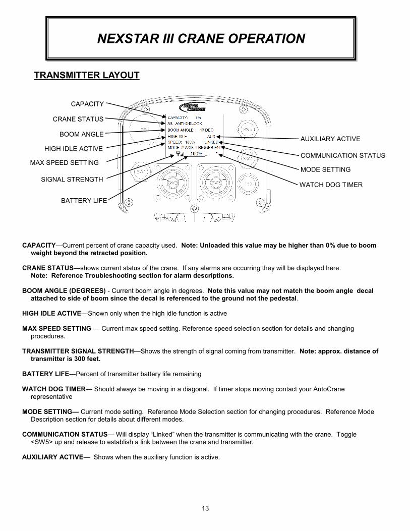
CAPACITY—Current percent of crane capacity used. Note: Unloaded this value may be higher than 0% due to boom weight beyond the retracted position.
CRANE STATUS—shows current status of the crane. If any alarms are occurring they will be displayed here. Note: Reference Troubleshooting section for alarm descriptions. BOOM ANGLE (DEGREES) - Current boom angle in degrees. Note this value may not match the boom angle decal
attached to side of boom since the decal is referenced to the ground not the pedestal. HIGH IDLE ACTIVE—Shown only when the high idle function is active MAX SPEED SETTING — Current max speed setting. Reference speed selection section for details and changing procedures. TRANSMITTER SIGNAL STRENGTH—Shows the strength of signal coming from transmitter. Note: approx. distance of
transmitter is 300 feet. BATTERY LIFE—Percent of transmitter battery life remaining WATCH DOG TIMER— Should always be moving in a diagonal. If timer stops moving contact your AutoCrane representative MODE SETTING— Current mode setting. Reference Mode Selection section for changing procedures. Reference Mode
Description section for details about different modes. COMMUNICATION STATUS— Will display “Linked” when the transmitter is communicating with the crane. Toggle
<SW5> up and release to establish a link between the crane and transmitter. AUXILIARY ACTIVE— Shows when the auxiliary function is active.
12/3/15
CAPACITY
CRANE STATUS
BOOM ANGLE
HIGH IDLE ACTIVE
MAX SPEED SETTING MODE SETTING
WATCH DOG TIMER SIGNAL STRENGTH
BATTERY LIFE
COMMUNICATION STATUS
AUXILIARY ACTIVE

14
NEXSTAR III CRANE OPERATION
12/3/15
SPEED/MODE SELECTION
SPEED SELECTION 1. Press and hold <SW5> in the up position. (Screen above will be visible when <SW5> is held in up position) 2. While holding the <SW5> switch, move the <SW2> joystick in the up position to increase max speed or
move the <SW2> joystick in the down position to decrease max speed. 3. Release <SW5> switch once the desired speed is selected. Note: 1. Slower speed decreases the max speed and gives more finite control of the proportional joystick/trigger. 2. Faster speed increases the max speed but gives less finite control over the load. 3. The speed percentage on the screen will show the current speed setting of the transmitter.
SPEED PERCENTAGE
MODE SELECTED
MODE SELECTION 1. Press and hold <SW5> in the up position. (Screen above will be visible when <SW5> is held in up position) 2. While holding the <SW5> switch, move the <SW3> joystick in the up or down position to change modes. 3. Release <SW5> switch once the desired mode is selected.
MODE DESCRIPTIONS 1-AXIS, TRIGGER PROP
Allows only one function to operate on each joystick. The joysticks are on-off and just need to be moved in the direction of the function to operate. The speed control is located in the trigger. The more you de-press the trigger, the faster the function and/or functions will go.
2-AXIS, TRIGGER PROP Allows two functions to operate on each joystick. The joysticks are on-off and just need to be moved in the direction of the function to operate. The speed control is located in the trigger. The more you de-press the trigger, the faster the function and/or functions will go.
1-AXIS, TRIGGER EN Allows only one function to operate on each joystick. The speed control is located on the joystick. The more you move the joystick in the direction of the function, the faster the function will go. The trigger must be depressed for the functions to operate.
2-AXIS, TRIGGER EN Allows two functions to operate on each joystick. The speed control is located on the joystick. The more you move the joystick in the direction of the function, the faster the function will go. The trigger must be depressed for the functions to operate.
NOTE: In 1-Axis operation - Once the joystick is moved in a direction, it locks out all remaining directions. For example: If you are booming up, you cannot rotate at the same time. You can, however, hoist up at the same time.
In 2-Axis operation - Allows the joystick to be up/down and left/right at the same time. For example: You can boom up slow and rotate CCW quickly but pushing up a little bit and moving to the far left at the same time.
15
CRANE OPERATION
RECEIVER LAYOUT
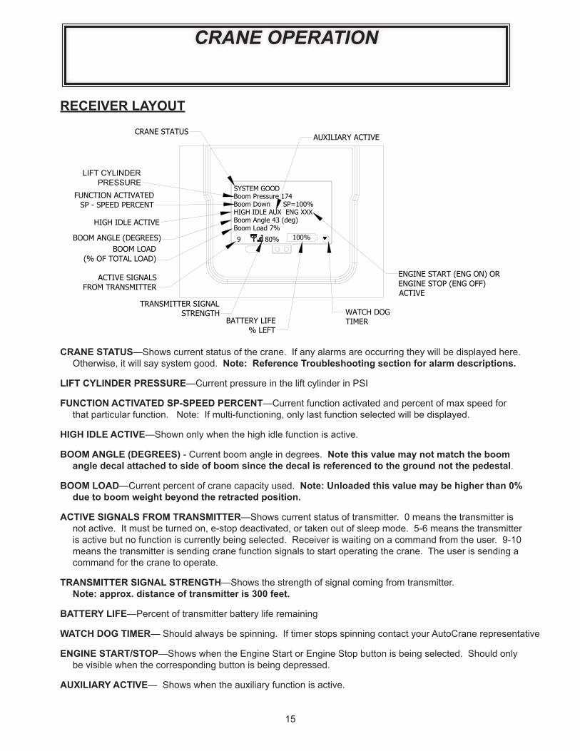
CRANE STATUS—Shows current status of the crane. If any alarms are occurring they will be displayed here. Otherwise, it will say system good. Note: Reference Troubleshooting section for alarm descriptions.
LIFT CYLINDER PRESSURE—Current pressure in the lift cylinder in PSI
FUNCTION ACTIVATED SP-SPEED PERCENT—Current function activated and percent of max speed for that particular function. Note: If multi-functioning, only last function selected will be displayed.
HIGH IDLE ACTIVE—Shown only when the high idle function is active.
BOOM ANGLE (DEGREES) - Current boom angle in degrees. Note this value may not match the boom angle decal attached to side of boom since the decal is referenced to the ground not the pedestal.
BOOM LOAD—Current percent of crane capacity used. Note: Unloaded this value may be higher than 0% due to boom weight beyond the retracted position.
ACTIVE SIGNALS FROM TRANSMITTER—Shows current status of transmitter. 0 means the transmitter is not active. It must be turned on, e-stop deactivated, or taken out of sleep mode. 5-6 means the transmitter is active but no function is currently being selected. Receiver is waiting on a command from the user. 9-10 means the transmitter is sending crane function signals to start operating the crane. The user is sending a command for the crane to operate.
TRANSMITTER SIGNAL STRENGTH—Shows the strength of signal coming from transmitter. Note: approx. distance of transmitter is 300 feet.
BATTERY LIFE—Percent of transmitter battery life remaining
WATCH DOG TIMER— Should always be spinning. If timer stops spinning contact your AutoCrane representative
ENGINE START/STOP—Shows when the Engine Start or Engine Stop button is being selected. Should only be visible when the corresponding button is being depressed.
AUXILIARY ACTIVE— Shows when the auxiliary function is active.
80%9
CRANE STATUS
HIGH IDLE ACTIVE
BOOM ANGLE (DEGREES)BOOM LOAD
(% OF TOTAL LOAD)
TRANSMITTER SIGNALSTRENGTH
BATTERY LIFE% LEFT
100%
WATCH DOGTIMER
FUNCTION ACTIVATEDSP - SPEED PERCENT
ENGINE START (ENG ON) ORENGINE STOP (ENG OFF)ACTIVE
SYSTEM GOODBoom Pressure 174Boom Down SP=100%HIGH IDLE AUX ENG XXXBoom Angle 43 (deg)Boom Load 7%
AUXILIARY ACTIVE
ACTIVE SIGNALSFROM TRANSMITTER
LIFT CYLINDERPRESSURE
16
TRANSMITTER SYNCHRONIZATION INSTRUCTIONS
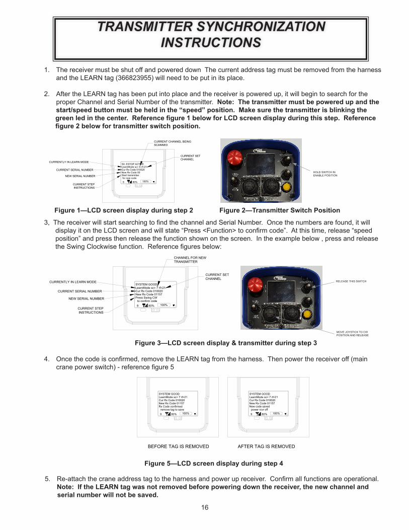
1. The receiver must be shut off and powered down The current address tag must be removed from the harness and the LEARN tag (366823955) will need to be put in its place.
2. After the LEARN tag has been put into place and the receiver is powered up, it will begin to search for the proper Channel and Serial Number of the transmitter. Note: The transmitter must be powered up and the start/speed button must be held in the “speed” position. Make sure the transmitter is blinking the
greenledinthecenter.Referencefigure1belowforLCDscreendisplayduringthisstep.Reference figure2belowfortransmitterswitchposition.
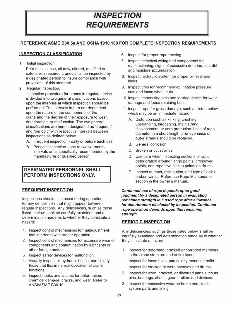
3, The receiver will start searching to find the channel and Serial Number. Once the numbers are found, it will display it on the LCD screen and will state “Press <Function> to confirm code”. At this time, release “speed position” and press then release the function shown on the screen. In the example below , press and release the Swing Clockwise function. Reference figures below:
Figure 3—LCD screen display & transmitter during step 3
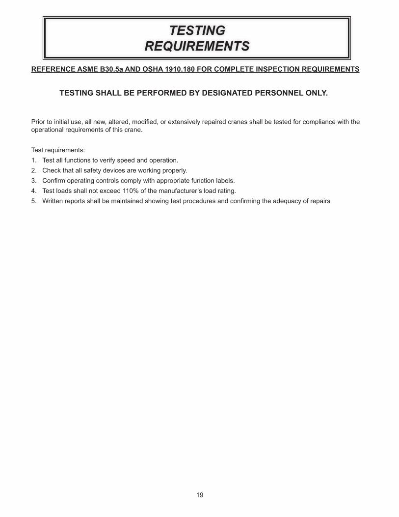
4. Once the code is confirmed, remove the LEARN tag from the harness. Then power the receiver off (main crane power switch) - reference figure 5
Figure 5—LCD screen display during step 4
5. Re-attach the crane address tag to the harness and power up receiver. Confirm all functions are operational. Note: If the LEARN tag was not removed before powering down the receiver, the new channel and
serial number will not be saved.
S0. ESTOP ACTIVELearnMode sc= 6 rf=21Cur Rx Code 010020New Rx Code 00Start transmitter for new code
100%80%9
CURRENTLY IN LEARN MODE
CURRENT SERIAL NUMBER
NEW SERIAL NUMBER
CURRENT STEPINSTRUCTIONS
CURRENT CHANNEL BEINGSCANNED
CURRENT SETCHANNEL
100%80%9
CURRENTLY IN LEARN MODE
CURRENT SERIAL NUMBER
NEW SERIAL NUMBER
CURRENT STEPINSTRUCTIONS
CURRENT SETCHANNEL
CHANNEL FOR NEWTRANSMITTER
SYSTEM GOODLearnMode sc= 7 rf=21Cur Rx Code 010020New Rx Code 01157Press Swing CW to confirm code
100%80%9
SYSTEM GOODLearnMode sc= 7 rf=21Cur Rx Code 010020New Rx Code 01157Rx Code confirmed remove tag to save
SYSTEM GOODLearnMode sc= 7 rf=21Cur Rx Code 010020New Rx Code 01157New code saved power rcvr off
100%80%9
BEFORE TAG IS REMOVED AFTER TAG IS REMOVED
HOLD SWITCH IN ENABLE POSITION
RELEASE THIS SWITCH
MOVE JOYSTICK TO CW POSITION AND RELEASE
Figure 1—LCD screen display during step 2 Figure 2—Transmitter Switch PositionGS HYDRAULICS P/N: GS14294602 REV A
ECN# REV. DESCRIPTION DATE BY
REVISIONS
31936 A PRODUCTION RELEASE 10/15/15 IRP
4707 NORTH MINGO ROADP.O. BOX 580697TULSA, OKLAHOMA 74158-0697918-836-0463
TRANSMITTER, NEXSTAR III
11 OFSHEET
A36682396410/15/15DATEDRAWN BY
B
TITLE
WEIGHT
REVDRAWING NO.SIZE
SCALE:
UNLESS OTHERWISE NOTEDALL DIMENSIONS ARE IN INCHES.
TOLERANCES UNLESS OTHERWISESPECIFIED. ANGLES 1/2 FRACTIONAL 1/16
REMOVE ALL BURRS AND SHARPEDGES. DO NOT SCALE THISDRAWING.TOLERANCES NOT SHOWN ABOVEARE PER ANSI Y14.5-1973
THIS PRINT IS THE PROPERTY OF AUTO CRANE CO.AND MUST NOT BE USED IN ANY MANNER DETRIMENTALTO THEIR INTERESTS.
IRP
PRIN
TED
ON
: Tue
sday
, Nov
embe
r 10,
201
5
.X .060.XX .030
.XXX .010
DO NOT SCALEDRAWING
GS HYDRAULICS P/N: GS14294602 REV A
ECN# REV. DESCRIPTION DATE BY
REVISIONS
31936 A PRODUCTION RELEASE 10/15/15 IRP
4707 NORTH MINGO ROADP.O. BOX 580697TULSA, OKLAHOMA 74158-0697918-836-0463
TRANSMITTER, NEXSTAR III
11 OFSHEET
A36682396410/15/15DATEDRAWN BY
B
TITLE
WEIGHT
REVDRAWING NO.SIZE
SCALE:
UNLESS OTHERWISE NOTEDALL DIMENSIONS ARE IN INCHES.
TOLERANCES UNLESS OTHERWISESPECIFIED. ANGLES 1/2 FRACTIONAL 1/16
REMOVE ALL BURRS AND SHARPEDGES. DO NOT SCALE THISDRAWING.TOLERANCES NOT SHOWN ABOVEARE PER ANSI Y14.5-1973
THIS PRINT IS THE PROPERTY OF AUTO CRANE CO.AND MUST NOT BE USED IN ANY MANNER DETRIMENTALTO THEIR INTERESTS.
IRP
PRIN
TED
ON
: Tue
sday
, Nov
embe
r 10,
201
5
.X .060.XX .030
.XXX .010
DO NOT SCALEDRAWING
17
INSPECTION REQUIREMENTS
REFERENCE ASME B30.5a AND OSHA 1910.180 FOR COMPLETE INSPECTION REQUIREMENTS
INSPECTION CLASSIFICATION
1. Initial inspection.Prior to initial use, all new, altered, modified or extensively repaired cranes shall be inspected by a designated person to insure compliance with provisions of this standard
2. Regular inspection.Inspection procedure for cranes in regular service is divided into two general classifications based upon the intervals at which inspection should be performed. The intervals in turn are dependent upon the nature of the components of the crane and the degree of their exposure to wear, deterioration, or malfunction. The two general classifications are herein designated as “frequent” and “periodic” with respective intervals between inspections as defined below.A. Frequent inspection - daily or before each useB. Periodic inspection - one to twelve-month
intervals or as specifically recommended by the manufacturer or qualified person.
DESIGNATED PERSONNEL SHALL PERFORM INSPECTIONS ONLY.
FREQUENT INSPECTION
Inspections should also occur during operation for any deficiencies that might appear between regular inspections. Any deficiencies, such as those listed below, shall be carefully examined and a determination made as to whether they constitute a hazard:
1. Inspect control mechanisms for maladjustment that interferes with proper operation.
2. Inspect control mechanisms for excessive wear of components and contamination by lubricants or other foreign matter.
3. Inspect safety devices for malfunction.4. Visually inspect all hydraulic hoses, particularly
those that flex in normal operation of crane functions.
5. Inspect hooks and latches for deformation, chemical damage, cracks, and wear. Refer to ANSI/ASME B30.10.
6. Inspect for proper rope reeving.7. Inspect electrical wiring and components for
malfunctioning, signs of excessive deterioration, dirt and moisture accumulation.
8. Inspect hydraulic system for proper oil level and leaks.
9. Inspect tires for recommended inflation pressure, cuts and loose wheel nuts.
10. Inspect connecting pins and locking device for wear damage and loose retaining bolts.
11. Inspect rope for gross damage, such as listed below, which may be an immediate hazard.A. Distortion such as kinking, crushing,
unstranding, birdcaging, main strand displacement, or core protrusion. Loss of rope diameter in a short length or unevenness of outer strands should be replaced.
B. General corrosion.C. Broken or cut strands.D. Use care when inspecting sections of rapid
deterioration around flange points, crossover points, and repetitive pickup points on drums.
E. Inspect number, distribution, and type of visible broken wires. Reference Rope Maintenance section in the owner’s manual.
Continued use of rope depends upon good judgment by a designated person in evaluating remaining strength in a used rope after allowance for deterioration disclosed by inspection. Continued rope operation depends upon this remaining strength.
PERIODIC INSPECTION
Any deficiencies, such as those listed below, shall be carefully examined and determination made as to whether they constitute a hazard:
1. Inspect for deformed, cracked or corroded members in the crane structure and entire boom.
Inspect for loose bolts, particularly mounting bolts. Inspect for cracked or worn sheaves and drums.2. Inspect for worn, cracked, or distorted parts such as
pins, bearings, shafts, gears, rollers and devices.3. Inspect for excessive wear on brake and clutch
system parts and lining.

18
INSPECTION REQUIREMENTS
6. Inspect crane hooks for cracks.7. Inspect travel steering, braking, and locking de-
vices for malfunction.8. Inspect for excessively worn or damaged tires.9. Inspect hydraulic hose, fittings, and tubing for the
following problems:A. Evidence of leakage at the surface of the
flexible hose or its junction with metal and coupling.
B. Blistering, or abnormal deformation to the outer covering of the hydraulic or pneumatic hose.
C. Leakage at threaded or clamped joints that cannot be eliminated by normal tightening or recommended procedures.
D. Evidence of excessive abrasion or scrubbing on the outer surface of a hose, rigid tube, or fitting. Means shall be taken to eliminate the interference of elements in contact or other-wise protect the components.
10. Inspect hydraulic pumps and motors for the follow-ing problems:A. Loose bolts and fasteners.B. Leaks at joints between sections.C. Shaft seal leaks.D. Unusual noises or vibrations.E. Loss of operating speed.F. Excessive heating of the fluid.G. Loss of pressure.
11. Inspect hydraulic valves for the following prob-lems:A. Cracks in valve housing.B. Improper return of spool to neutral position.C. Leaks at spools or joints.D. Sticking spools.E. Failure of relief valves to attain or maintain
correct pressure setting.F. Relief valve pressure shall be checked as
specified by the manufacturers.12. Inspect hydraulic cylinders for the following prob-
lems:A. Drifting caused by fluid leaking across piston.B. Rod seals leaking.C. Leaks at welded joints.D. Scored, nicked, or dented cylinder rods.E. Damaged case (barrel).F. Loose or deformed rod eyes or connecting
joints.
13. Inspect hydraulic filters for evidence of rubber particles on the filter elements indicating possible hose, “O” ring, or other rubber component dete-rioration. Metal chips or pieces on the filter may denote failure in pumps, motors, or cylinders. Further inspection will be necessary to determine the origin of the problem before corrective action can be taken.
14. Inspect labels to confirm correct location and leg-ibility. Reference decal layout in this manual for proper location of decals.
15. Rope Inspections need not be at equal calen-dar intervals and should be more frequent as the rope approaches the end of useful life. A qualified person shall inspect the wire rope based on such factors as:A. Expected rope life as determined by experi-
ence on the particular installation or similar installations.
B. Severity of environment.C. Percentage of capacity lifts.D. Frequency rates of operation.E. Exposure to shock loads.This inspection shall cover the entire length of the rope. Only the surface wires need to be inspected and no attempt should be made to open the rope. Any deterioration resulting in ap-preciable loss of original strength shall be noted and determination made as to whether use of the rope would constitute a hazard. A few notable deterioration points are listed below:A. Reduction of rope diameter below nominal
diameter due to loss of core support.B. Internal or external corrosion.C. Wear of outside wires.D. Severly corroded, cracked, bent, worn, or
improperly applied connections.
CRANES NOT IN REGULAR USE
A crane, which has been idle for a period of over one month or more, shall be given an inspection conform-ing to the “initial” and “regular” inspection require-ments of this section.
INSPECTION RECORDS
Dated records of periodic inspection should be made on critical items such as brakes, crane hooks, rope, cylinders, and relief pressure valves.
19
TESTINGREQUIREMENTS
REFERENCE ASME B30.5a AND OSHA 1910.180 FOR COMPLETE INSPECTION REQUIREMENTS
TESTING SHALL BE PERFORMED BY DESIGNATED PERSONNEL ONLY.
Prior to initial use, all new, altered, modified, or extensively repaired cranes shall be tested for compliance with the operational requirements of this crane.
Test requirements:1. Test all functions to verify speed and operation.2. Check that all safety devices are working properly.3. Confirm operating controls comply with appropriate function labels.4. Test loads shall not exceed 110% of the manufacturer’s load rating.5. Written reports shall be maintained showing test procedures and confirming the adequacy of repairs
20
GENERALREPAIRS AND MAINTENANCE
REFERENCE ASME B30.5a AND OSHA 1910.180 FOR COMPLETE MAINTENANCE AND REPAIR REQUIREMENTS
A preventative maintenance program should be established based on this section and all replacement parts should be obtained from AutoCrane Company. For replacement parts contact your local authorized distributor.
MAINTENANCE PRECAUTIONS1. Place crane where it will cause the least
interference with other equipment or operations.2. Verify all controls are in the “off” position and all
operating features secured from inadvertent motion by brakes, pawls, or other means.
3. The means for starting the crane shall be rendered inoperative.
4. The boom should be secured in place before maintenance.
5. Relieve hydraulic oil pressure from all hydraulic circuits before loosening or removing hydraulic components.
6. Warning or “OUT OF ORDER” signs shall be placed on all crane controls.
7. After adjustments and repairs have been made, the crane shall not be returned to service until all guards have been reinstalled, trapped air removed from hydraulic system (if required), safety devices reactivated, and maintenance equipment removed.
ADJUSTMENTS AND REPAIRS
1. Any hazardous conditions disclosed by the inspection requirements shall be corrected before operation of crane is resumed. Only designated personnel shall do adjustments and repairs.
2. Adjustments shall be maintained to assure correct functioning of components, the following are examples:A. Functional operating mechanism.B. Safety devices.C. Control systems.
3. Repairs or replacements shall be provided as needed for operation, the following are examples:A. Critical parts of functional operating
mechanisms which are cracked, broken, corroded, bent, or excessively worn.
B. Critical parts of the crane structure which are cracked, bent, broken, or excessively corroded.
C. Crane hooks showing cracks, damage, or corrosion shall be taken out of service. Repairs by welding are not recommended.
4. If bleeding the hydraulic system is required, run each crane function until smooth operation of that particular function is noticeable.
LUBRICATIONAll moving parts of the crane, for which lubrication is specified, should be regularly lubricated per the manufacturer’s recommendations and procedures. Reference Lubrication and Maintenance Schedule in this manual.
ROPE REPLACEMENTNo precise rules can be given for determination of the exact time for replacement of rope, since many variable factors are involved.
1. Conditions such as the following shall be reason for questioning continued use of the rope or increasing the frequency of inspection:A. In running ropes, six randomly distributed
broken wires in one lay or three broken wires in one strand in one lay.
B. One outer wire broken at the contact point with the core of the rope structure and protrudes or loops out of the rope structure. Additional inspection of this section is required.
C. Wear of one third of the original diameter of the outside individual wire.
D. Kinking, crushing, bird caging, or any other damage resulting in distortion of the rope structure.
E. Evidence of any heat damage from any cause.F. Reduction from nominal diameter of more
than 1/64 in. (0.4mm) for diameters up to and including 5/16 in. (8 mm), 1/32 in. (0.8 mm) for diameter 3/8 in. (9.5 mm) to and including 1/2 in. (13 mm), 3/64 in. (1.2 mm) for diameter 9/16 in. (14.5 mm) to and including 3/4 in. (19 mm). 1/16 in. (1.6 mm) for diameter 7/8 in. (22 mm) to and including 1-1/8 in. (29 mm), 3/32 in. (2.4 mm) for diameters 1-1/4 in. (32 mm) to and including 1-1/2 in. (38 mm).
G. In standing ropes, more than two broken wires in one lay in sections beyond end connections or more than one broken wire at an end connection.

21
GENERALREPAIRS AND MAINTENANCE
2. Replacement rope shall have a strength rating at least as great as the original rope furnished or recommended by AutoCrane. A rope manufactur-er, AutoCrane, or a qualified person shall specify any deviation from the original size, grade, or construction.
ROPE MAINTENANCE1. Rope should be stored to prevent damage or
deterioration.2. Unreeling or uncoiling of rope shall be done as
recommended by the rope manufacturer and with care to avoid kinking or inducing twist.
3. Before cutting a rope, seizing shall be placed on each side of the place where the rope is to be cut to prevent unlaying of the strands. On pre-formed rope, one seizing on each side of the cut is required. On non-preformed ropes of 7/8 in. (22 mm) diameter or smaller, two seiz-ings on each side of the cut are required, and for non-preformed rope 1 in. (25 mm) diameter or larger, three seizings on each side of the cut are required.
4. During installation care should be exercised to avoid dragging of the rope in the dirt or around objects that will scrape, nick crush or induce sharp bends in it.
5. Rope should be maintained in a well-lubricated condition. It is important that lubricant applied as a part of a maintenance program shall be compatible with the original lubricant and to this end the rope manufacturer should be consulted. Lubricant applied shall be the type that does not hinder visual inspection. Those sections of rope that are located over sheaves or otherwise hid-den during inspection and maintenance proce-dures require special attention when lubricating rope. The object of rope lubrication is to reduce internal friction and to prevent corrosion.
6. When an operating rope shows greater wear or well-defined localized areas than on the re-mainder of the rope, rope life can be extended in some cases by shifting the wear to different areas of the rope.

22
MAINTENANCEOF BATTERIES
Maintenance of Auto Crane unit batteries differs very little from the generally prescribed maintenance of any lead acid battery. All batteries must be kept properly charged, properly filled with water, and relatively clean.
Keep Properly Charged
Many things affect the proper charge to a battery, such as:1. Regulator settings.2. Proper tightness of belts on the alternator or
generator.3. Good, clean connections of all cables and wires
at the following places:a. Battery.b. Regulator.c. Starting motor.d. Alternator or generator.e. Ground connections (most
important).It is of extreme importance to keep the battery as fully charged as possible without overcharging, especially when vehicles are left outside for extended periods in extremely cold climates. A battery can freeze. Freezing points for various specific gravities of acid are as follows:
Specific Gravity Freezing Temp. (Corrected to 80ºF) Degrees F.
1.280 -90ºF 1.250 -62ºF 1.200 -16ºF 1.150 5ºF 1.100 19ºF
As shown, a half-charged battery (about 1.100 specific gravity) cannot stand for any length of time at 20ºF or it will freeze. The main reason for keeping the battery as fully charged as possible without over-charging is to insure that power is available even though the vehicle has been standing for some time.
Keep Properly Filled with WaterThe battery should always be properly filled with water. If the electrolyte level is allowed to fall below the top of the plates, the results become threefold:
1. The exposed portion of the plate will become sulfated.
2. The portion of the plate exposed is not usable.3. That portion of the acid remaining becomes
more concentrated and may cause more rapid deterioration of the remaining parts of the battery.
Keep A Relatively Clean BatteryThe battery should be kept clean. Batteries filled with acid and which are not in use self-discharge to a limited degree because of the nature of the materials within the battery. If dirt is allowed to collect on the top of the battery (and this dirt absorbs moisture) and electrical path can be set up between the various terminals of the battery and the ground. Once such a path has been established, the self-discharge of the battery is accelerated. This also accelerates corrosion of the battery cables at the terminals.
Periodic Maintenance is NeededA definite program of periodic maintenance of all batteries should be conducted on a regular basis. Periodic maintenance includes:
1. Checking belts for tightness on the charging equipment.
2. Checking battery electrolyte levels.3. Checking cables for good connections.4. Cleaning where corrosion is apparent.
When corrosion is cleaned off, the cable terminals and battery terminals should be coated with a light coating of petroleum jelly before they are replaced. When terminals are cleaned, the top of the battery should be cleaned with a mild solution of soda water.
Low Maintenance Batteries(Maintenance Free)Low maintenance batteries should not be used on AutoCrane Cranes or trucks equipped with AutoCrane Cranes. The batteries are not designed for “deep” discharge.
Testing Your BatteryIf the condition of the battery is in question, it should be removed from the vehicle, taken to the shop, and allowed to reach room temperature. It should then be recharged until specific gravity readings taken at one-half hour intervals. If the specific gravity readings are fairly uniform, the battery should be checked with a high rate tester. Use the tester in accordance with the manufacturer’s instructions. The high rate tester is the best method to test a questionable battery.

23
MAINTENANCEOF BATTERIES
If, after charging, it is noted that the specific gravity reading of one cell is 30 points less than any of the other cells, it may be assumed that the cell is bad and that the battery should be replaced. If all cells are uniform but not up to full charge, a low rate of charge should be attempted for an extended time. This usually will recover a badly sulfated battery.
Replacing a BatteryIf it is necessary to replace a battery, and a dry charge battery is used, the following procedure applies:
1. Fill the battery with electrolyte of the proper specific gravity.
2. Place the battery on charge according to the manufacturer’s instructions.
It is essential that the second step above be followed to ensure that the battery going on the vehicle is fully charged.
It is also very important that the battery hold-downs be checked periodically to insure that the batteries are properly positioned to avoid vibration problems, breakage of cables or terminals. Care must be taken to avoid cracking or breaking containers or covers by tightening hold-down fixtures excessively. They also must not be so loose that breakage results from a hold-down that is too loose.
24
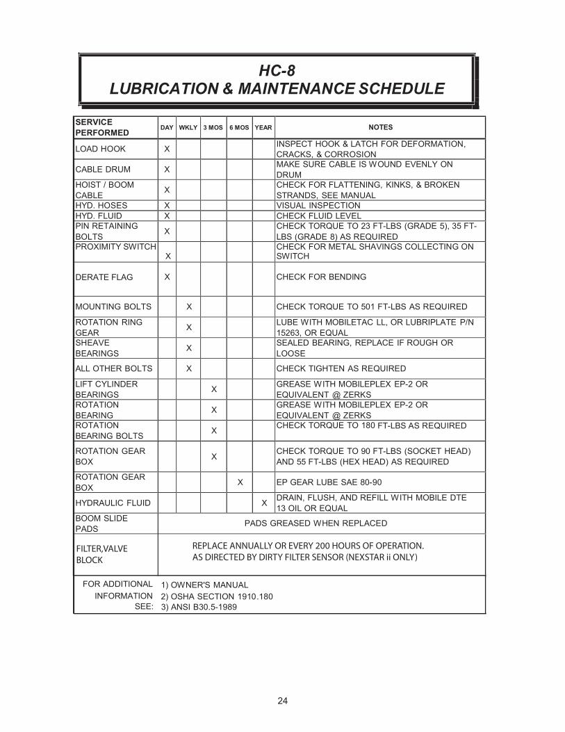
HC-8LUBRICATION & MAINTENANCE SCHEDULE
SERVICE PERFORMED
DAY WKLY 3 MOS 6 MOS YEAR NOTES
LOAD HOOK X INSPECT HOOK & LATCH FOR DEFORMATION,CRACKS, & CORROSION
CABLE DRUM X MAKE SURE CABLE IS WOUND EVENLY ONDRUM
HOIST / BOOMCABLE X CHECK FOR FLATTENING, KINKS, & BROKEN
STRANDS, SEE MANUALHYD. HOSES X VISUAL INSPECTIONHYD. FLUID X CHECK FLUID LEVELPIN RETAININGBOLTS X CHECK TORQUE TO 23 FT-LBS (GRADE 5), 35 FT-
LBS (GRADE 8) AS REQUIREDPROXIMITY SWITCH
XCHECK FOR METAL SHAVINGS COLLECTING ON SWITCH
DERATE FLAG X CHECK FOR BENDING
MOUNTING BOLTS X CHECK TORQUE TO 501 FT-LBS AS REQUIRED
ROTATION RINGGEAR X LUBE WITH MOBILETAC LL, OR LUBRIPLATE P/N
15263, OR EQUALSHEAVEBEARINGS X SEALED BEARING, REPLACE IF ROUGH OR
LOOSE
ALL OTHER BOLTS X CHECK TIGHTEN AS REQUIRED
LIFT CYLINDERBEARINGS X GREASE WITH MOBILEPLEX EP-2 OR
EQUIVALENT @ ZERKSROTATIONBEARING X GREASE WITH MOBILEPLEX EP-2 OR
EQUIVALENT @ ZERKSROTATIONBEARING BOLTS X CHECK TORQUE TO 180 FT-LBS AS REQUIRED
ROTATION GEAR BOX X CHECK TORQUE TO 90 FT-LBS (SOCKET HEAD)
AND 55 FT-LBS (HEX HEAD) AS REQUIRED
ROTATION GEARBOX X EP GEAR LUBE SAE 80-90
HYDRAULIC FLUID X DRAIN, FLUSH, AND REFILL WITH MOBILE DTE13 OIL OR EQUAL
BOOM SLIDEPADS
PADS GREASED WHEN REPLACED
FOR ADDITIONAL 1) OWNER'S MANUAL INFORMATION 2) OSHA SECTION 1910.180
SEE: 3) ANSI B30.5-1989
FILTER,VALVEBLOCK
REPLACE ANNUALLY OR EVERY 200 HOURS OF OPERATION.AS DIRECTED BY DIRTY FILTER SENSOR (NEXSTAR ii ONLY)
25
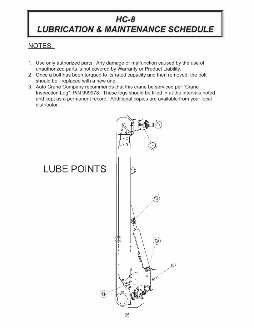
HC-8LUBRICATION & MAINTENANCE SCHEDULE
1. Use only authorized parts. Any damage or malfunction caused by the use of unauthorized parts is not covered by Warranty or Product Liability.
2. Once a bolt has been torqued to its rated capacity and then removed; the bolt should be replaced with a new one.
3. Auto Crane Company recommends that this crane be serviced per “Crane Inspection Log” P/N 999978. These logs should be filled in at the intervals noted and kept as a permanent record. Additional copies are available from your local distributor.
NOTES:
26
HC-8SAFETY DECAL SECTION
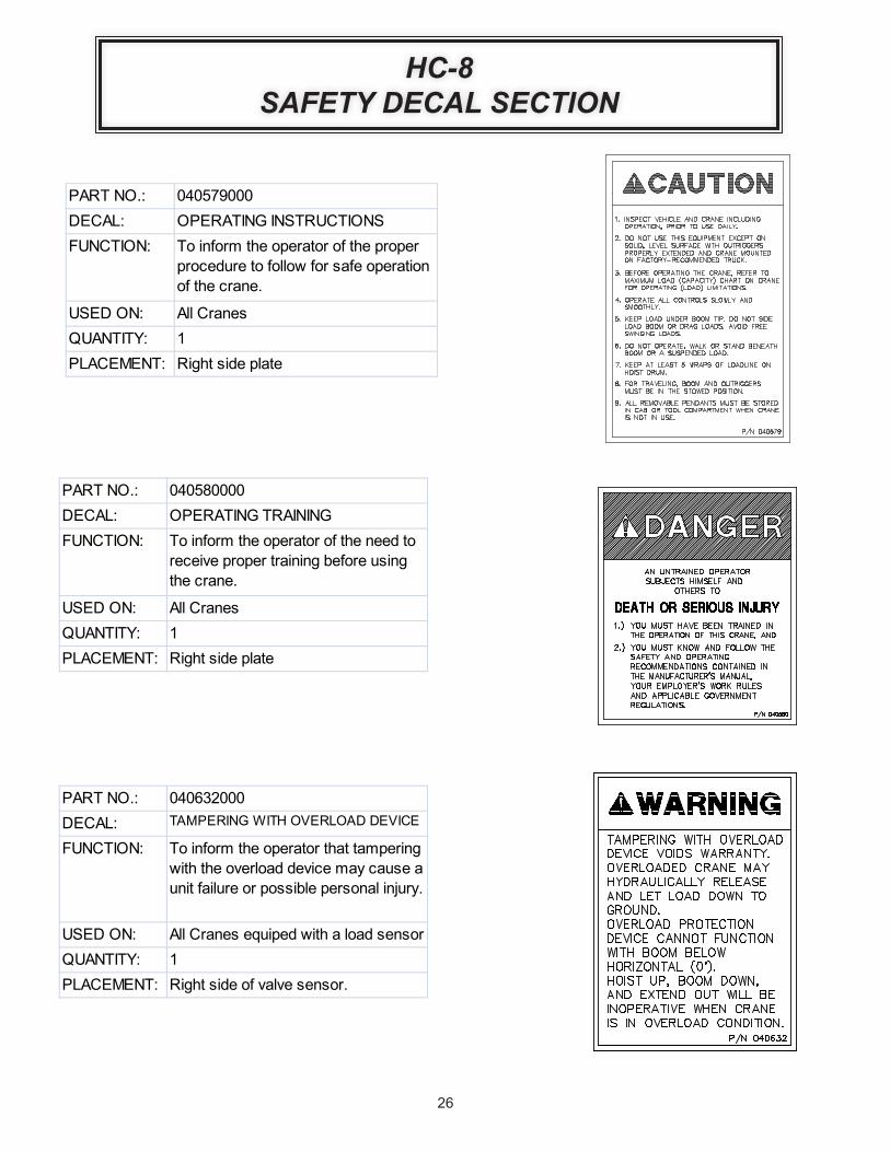
PART NO.: 040579000DECAL: OPERATING INSTRUCTIONSFUNCTION: To inform the operator of the proper
procedure to follow for safe operation of the crane.
USED ON: All CranesQUANTITY: 1PLACEMENT: Right side plate
PART NO.: 040580000DECAL: OPERATING TRAININGFUNCTION: To inform the operator of the need to
receive proper training before using the crane.
USED ON: All CranesQUANTITY: 1PLACEMENT: Right side plate
PART NO.: 040632000DECAL: TAMPERING WITH OVERLOAD DEVICE
FUNCTION: To inform the operator that tampering with the overload device may cause a unit failure or possible personal injury.
USED ON: All Cranes equiped with a load sensorQUANTITY: 1PLACEMENT: Right side of valve sensor.

27
HC-8SAFETY DECAL SECTION
PART NO.: 040529000DECAL: ELECTROCUTION HAZARDFUNCTION: To inform the operator of the
hazard involved with contacting electrical power lines with crane boom.
USED ON: All CranesQUANTITY: 2PLACEMENT: Both sides of end of lower boom
PART NO.: 040517000DECAL: STAY CLEAR OF BOOMFUNCTION: To inform the operator of the
hazard of proximity or contact with the crane boom during operation.
USED ON: All CranesQUANTITY: 2PLACEMENT: Both sides of crown
PART NO.: 040518000DECAL: STAY CLEAR OF LOADFUNCTION: To inform the operator of the
hazard of proximity or contact with the crane load during operation.
USED ON: All CranesQUANTITY: 2PLACEMENT: Both sides of traveling block
28
HC-8SAFETY DECAL SECTION
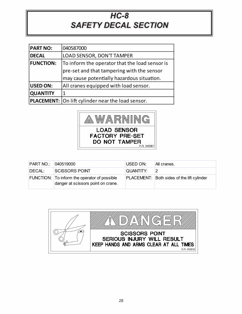
PART NO.: 040519000 USED ON: All cranes.DECAL: SCISSORS POINT QUANTITY: 2FUNCTION: To inform the operator of possible
danger at scissors point on crane.PLACEMENT: Both sides of the lift cylinder
PART NO: 040587000DECAL LOAD SENSOR, DON'T TAMPERFUNCTION: To inform the operator that the load sensor is
pre-set and that tampering with the sensor may cause potentially hazardous situation.
USED ON: All cranes equipped with load sensor.QUANTITY 1PLACEMENT: On lift cylinder near the load sensor.
29
HC-8SAFETY DECAL SECTION
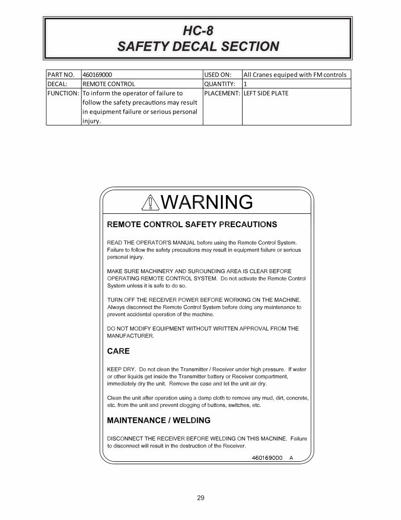
PART NO. 460169000 USED ON: All Cranes equiped with FM controlsDECAL: REMOTE CONTROL QUANTITY: 1FUNCTION: To inform the operator of failure to
follow the safety precautions may result in equipment failure or serious personal injury.
PLACEMENT: LEFT SIDE PLATE

30
NOTES

31
HC-8 DECAL LAYOUTP/N: 479989300
108931
4
17
18
2 5 6 7
13 11 8 15 3 4 1
17
21418
12
11
SECTION A-A
16
ITEM NO. QTY PART
NUMBER DESCRIPTION
1 2 040517 DECAL STAY CLEAR OF BOOM2 2 040519 DECAL DANGER SCISSOR POINT3 2 479624000 DECAL, BOOM, HC-8 LOGO4 2 040529 DECAL DANGER "ELECTROCUTION HAZARD" POWER LINE5 1 040587 DECAL WARNING LOAD SENSOR6 1 460169000 DECAL WARNING, REMOTE CONTROL7 1 040579 DECAL OPERATION INSTRUCTIONS8 2 479823000 DECAL, LOAD CHART, HC-8, FM, NEXSTAR II9 1 320318001 DECAL ANGLE INDICATOR SS
10 1 330622 DECAL SERIAL NO11 2 360034 DECAL AUTO CRANE LOGO12 1 040824000 DECAL, AMERICAN FLAG, MADE IN THE U.S.A.13 1 040632 DECAL WARNING - OVERLOAD14 1 040580 DECAL TRAINED OPERATOR15 1 320318 DECAL ANGLE INDICATOR CS16 1 366823302 DECAL, MAN OR PROCEDURES, GS HYD, LRG H-MODS,
PUSH BUTTON 17 2 479853000 DECAL MAX BLOCK LOAD, HC-8
18 2 040518 DECAL STAY CLEAR OF LOAD

32
HC-8 DECAL LAYOUTP/N: 479989300
108931
4
17
18
2 5 6 7
13 11 8 15 3 4 1
17
21418
12
11
SECTION A-A
16
ITEM NO. QTY PART
NUMBER DESCRIPTION
1 2 040517 DECAL STAY CLEAR OF BOOM2 2 040519 DECAL DANGER SCISSOR POINT3 2 479624000 DECAL, BOOM, HC-8 LOGO4 2 040529 DECAL DANGER "ELECTROCUTION HAZARD" POWER LINE5 1 040587 DECAL WARNING LOAD SENSOR6 1 460169000 DECAL WARNING, REMOTE CONTROL7 1 040579 DECAL OPERATION INSTRUCTIONS8 2 479823000 DECAL, LOAD CHART, HC-8, FM, NEXSTAR II9 1 320318001 DECAL ANGLE INDICATOR SS
10 1 330622 DECAL SERIAL NO11 2 360034 DECAL AUTO CRANE LOGO12 1 040824000 DECAL, AMERICAN FLAG, MADE IN THE U.S.A.13 1 040632 DECAL WARNING - OVERLOAD14 1 040580 DECAL TRAINED OPERATOR15 1 320318 DECAL ANGLE INDICATOR CS16 1 366823302 DECAL, MAN OR PROCEDURES, GS HYD, LRG H-MODS,
PUSH BUTTON 17 2 479853000 DECAL MAX BLOCK LOAD, HC-8
18 2 040518 DECAL STAY CLEAR OF LOAD
108931
4
17
18
2 5 6 7
13 11 8 15 3 4 1
17
21418
12
11
SECTION A-A
16
ITEM NO. QTY PART
NUMBER DESCRIPTION
1 2 040517 DECAL STAY CLEAR OF BOOM2 2 040519 DECAL DANGER SCISSOR POINT3 2 479624000 DECAL, BOOM, HC-8 LOGO4 2 040529 DECAL DANGER "ELECTROCUTION HAZARD" POWER LINE5 1 040587 DECAL WARNING LOAD SENSOR6 1 460169000 DECAL WARNING, REMOTE CONTROL7 1 040579 DECAL OPERATION INSTRUCTIONS8 2 479823000 DECAL, LOAD CHART, HC-8, FM, NEXSTAR II9 1 320318001 DECAL ANGLE INDICATOR SS
10 1 330622 DECAL SERIAL NO11 2 360034 DECAL AUTO CRANE LOGO12 1 040824000 DECAL, AMERICAN FLAG, MADE IN THE U.S.A.13 1 040632 DECAL WARNING - OVERLOAD14 1 040580 DECAL TRAINED OPERATOR15 1 320318 DECAL ANGLE INDICATOR CS16 1 366823302 DECAL, MAN OR PROCEDURES, GS HYD, LRG H-MODS,
PUSH BUTTON 17 2 479853000 DECAL MAX BLOCK LOAD, HC-8
18 2 040518 DECAL STAY CLEAR OF LOAD
33
HC-8 GENERAL DIMENSIONS
NOTE: C.G. IS APPROXIMATE

34
HC-8 MOUNTING AND INSTALLATION
1. Check to make sure the following items are with your crane. Please note the different, model specific, quantities.
2. Pressure and return hoses are not furnished with this crane. The hoses must be provided by the installer and the lengths determined at installation.REQUIREMENTS FOR INSTALLATION USING 23 GALLON RESERVOIR(*)A. RETURN LINE FROM CRANE TO RESERVOIR (IN COMPARTMENT): -10 SAE 100R2 (OR EQUIVA-
LENT ). HOSE LENGTH IS DETERMINED BY INSTALLER. RETURN LINES LONGER THAN 6 FEET SHOULD BE SIZE –12. HOSE END FITTINGS ARE –10 JIC FEMALE SWIVEL (CRANE END) AND –10 JIC FEMALE SWIVEL (RESERVOIR END).
B. PRESSURE LINE FROM PUMP TO CRANE: -8 SAE 100R12 (OR EQUIVALENT) WITH A 3,000 PSI MINIMUM WORKING PRESSURE. HOSE LENGTHS IS DETERMINED BY INSTALLER. HOSE END FIT-TINGS ARE BOTH –8 JIC FEMALE SWIVEL.IMPORTANT: The recommended hydraulic reservoir size for the average industry application CRANE ONLYinstallationistwotimesthecranehydraulicflowrate.Forcraneapplicationsrequiringmorethan 25% crane operation time while the PTO is engaged and/or additional equipment is operated by the same hydraulic system, it is recommended that an appropriate sized larger hydraulic reser-voir and/or forced air, hydraulic oil cooler be installed. The addition of other auxiliary equipment will require additional capacity.CAUTION–FAILURE TO USE CLEAN HYDRAULIC HOSES AND COMPONENTS MAY CONTAMINATE THE CRANE AND HYDRAULIC SYSTEM AND VOID WARRANTY.
3. Crane must be provided with a flow of 8 to 12 gallons per minute and a pressure of 2750 PSI. Excess flow will cause erratic operation, and too little flow will cause poor crane operation.
CAUTION— HYDRAULIC RESERVOIR OIL TEMPERATURE MUST NOT EXCEED 180°F OR CRANE PERFORMANCE MAY BE ADVERSELY AFFECTED.
4. Vehicle should meet minimum GVW rating of 19,500 pounds.5. The vehicle MUST be equipped with an engine speed control and tachometer.6. Make sure mounting surface is properly reinforced to withstand 49,000 ft-lb capacity loading of crane
and that outriggers are used to provide total stability for the truck.
*Note: 23 GALLON RESEVOIR IS MINIMUM REQUIREMENT FOR CRANE ONLY.
ITEM NO. QTY. PART NO. DESCRIPTION
1 4 015100000 7/8-14 X 4 HH GR 82 4 022200000 WASHER SP LK 7/83 4 018900000 NUT HX 7/8 NFCP GR84 1 480689000 FUSE 15 AMP TIME-DELAY5 1 480688000 FUSE HOLDER IN-LINE WATERPROOF6 120 in 800596000 WIRE 16G 600V 1C YEL7 6 634401000 WIRE TIE 7 INCHES LONG8 6 750738000 WIRE TIE STICK ON RETAINER9 5 320357000 CONNECTOR FEM POWER10 1 340638000 CONDUCTOR POWER11 1 320355000 POWER PLAY12 1 320363000 PLUG RELAY14 1 479823011 MANUAL, HC-8, FM, NEXSTAR III13 479200100 DERATE FLAG, HC-815 1 479823000 DECAL, LOAD CHART, HC-8, FM, NEXSTAR II16* 480854000 TRAVELING BLOCK ASSEMBLY17* 366823964 TRANSMITTER, NEXSTAR III
18
*ITEMS NOT SHOWN
1 479824000 DECAL, STABILITY CHART, HC-8, FM, NEXSTAR II
*

35
HC-8 MOUNTING AND INSTALLATION
7. A 13 1/2” diameter hole should be cut out of mounting location (centered with mounting bolts) for access to hydraulic connections.
8. Make sure the mounting bolts are 7/8” dia, grade 8-UNF. Torque bolts to 501 ft-lbs.
9. When crane is not in operation, a boom support should always be used. Traveling block should be connected to hook loop.
10. Electrical hookup:
Wiring (FM – cable from base of crane:A. CONNECT THE BLACK WIRE TO THE BATTERY NEGATIVE (GROUND).B. CONNECT THE RED WIRE TO FUSED 12VDC POWER. 12VDC POWER SHOULD BE SUPPLIED
THROUGH A DEDICATED SWITCH THAT IS POWERED ONLY WHEN THE IGNITION SWITCH IS ON.C. OPTIONALLY, USE THE WHITE ( OR BROWN) WIRE FOR ENGINE FAST/SLOW (12VDC
MAINTAINED-FM ONLY).D. OPTIONALLY, USE THE BLUE ( OR YELLOW) WIRE FOR ENGINE START.E. OPTIONALLY, USE THE ORANGE (OR GREEN) WIRE FOR ENGINE STOP.F. OPTIONALLY, USE THE GREEN OR BLUE) WIRE FOR AUXILIARY (12VDC MAINTAINED-FM ONLY).
NOTE: IF YOU HAVE A BROWN, USE THE COLORS IN PARENTHESES.
NOTE: ALL ELECTRICAL CONNECTIONS BETWEEN THE CRANE AND THE VEHICLE SHOULD BE MADE USING RELAYS TO ISOLATE THE ELECTRICAL SYSTEMS OF EACH AS MUCH AS POSSIBLE.
WARNING! FAILURE TO CORRECTLY PLUMB AND WIRE CRANE CAN CAUSE INADVERTENT OPERATION AND DAMAGE TO CRANE AND/OR PERSONNEL!
11. Once crane and plumbing are installed on the truck, fill the reservoir to top of sight glass (mobile DTE 13 or equal). Before operating crane, connect together the pressure and return hoses going to base of crane using 10-12 JIC union and engage PTO with engine running. Allow oil to circulate for 15 to 20 minutes. This will flush any contaminants from the system back to the return line filter. Operate all cylinders to full extension and retraction a minimum of six times, to bleed air from system. Return all cylinders to the stored position and disengage PTO. Refill reservoir to top sight glass. To ensure 8 gallons per
minute (GPM), install an in-line flow meter between the crane and the reservoir in the return hose.12. Load test the crane to ensure proper functioning and truck stability.13. Make certain the owner’s manual is delivered to the customer.14. For additional help: call the service department at the Auto Crane Company (800) 777-2760 (Tulsa, Oklahoma).
FEDERAL LAW (49 CFR PART 571) REQUIRES THAT THE FINAL STAGE MANUFACTURER OF A VEHICLE CERTIFY THAT HE VEHICLE COMPLIES WITH ALL APPLICABLE FEDERAL REGULATIONS. ANY MODIFICATIONS PERFORMED ON THE VEHICLE PRIOR TO THE FINAL STAGE ARE ALSO CONSIDERED INTERMEDIATE STAGE MANUFACTURING AND MUST BE CERTIFIED AS TO COMPLIANCE. THE INSTALLER OF THIS CRANE AND BODY IS CONSIDERED ONE OF THE MANUFACTURERS OF THE VEHICLE. AS SUCH A MANUFACTURER, THE INSTALLER IS RESPONSIBLE FOR COMPLIANCE WITH ALL APPLICABLE FEDERAL AND STATE REGULATIONS, AND IS REQUIRED TO CERTIFY THAT THE VEHICLE IS IN COMPLIANCE.
IT IS THE FURTHER RESPONSIBILITY OF THE INSTALLER OF THE CRANE TO COMPLY WITH THE OSHA TRUCK CRANE STABILITY REQUIREMENTS AS SPECIFIED BY 29 CFR PART 1910.180 (C) (1).
WARNING
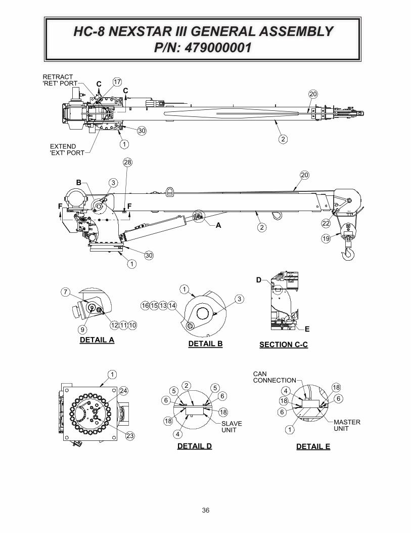
36
HC-8 NEXSTAR III GENERAL ASSEMBLYP/N: 479000001
A
B
FF
CC
DETAIL A DETAIL B
D
E
SECTION C-C
DETAIL D DETAIL E
SECTION F-F
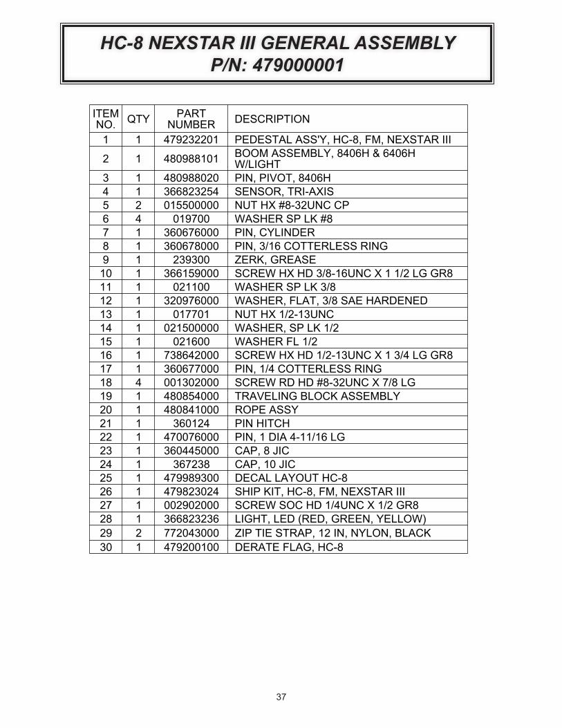
37
HC-8 NEXSTAR III GENERAL ASSEMBLYP/N: 479000001
A
B
FF
CC
DETAIL A DETAIL B
D
E
SECTION C-C
DETAIL D DETAIL E
SECTION F-F
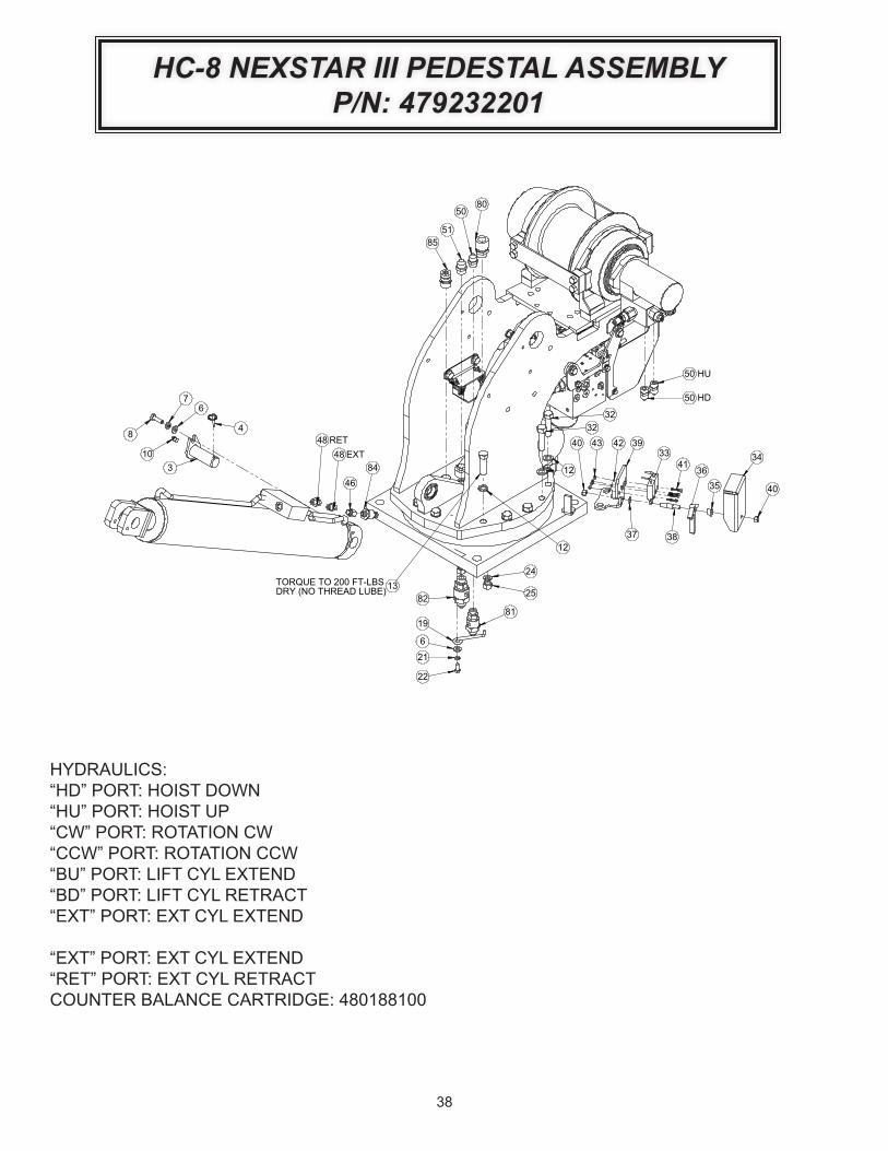
38
HC-8 NEXSTAR III PEDESTAL ASSEMBLYP/N: 479232201
HYDRAULICS: “HD” PORT: HOIST DOWN “HU” PORT: HOIST UP“CW” PORT: ROTATION CW“CCW” PORT: ROTATION CCW“BU” PORT: LIFT CYL EXTEND“BD” PORT: LIFT CYL RETRACT“EXT” PORT: EXT CYL EXTEND
“EXT” PORT: EXT CYL EXTEND“RET” PORT: EXT CYL RETRACTCOUNTER BALANCE CARTRIDGE: 480188100
40
34
3536
38
4133
37
39424340
50
8050
5185
22
21
6
1981
82 25
24
12
13
HU
50 HD
TORQUE TO 200 FT-LBSDRY (NO THREAD LUBE)
8446
4848
EXTRET
4
3
6
10
7
8
3232
12
53
53
EXT
RET
55
55 BU
BD54
54 CW
CCW
52
52
HD
HU
VALVE BANK HOSING DETAIL
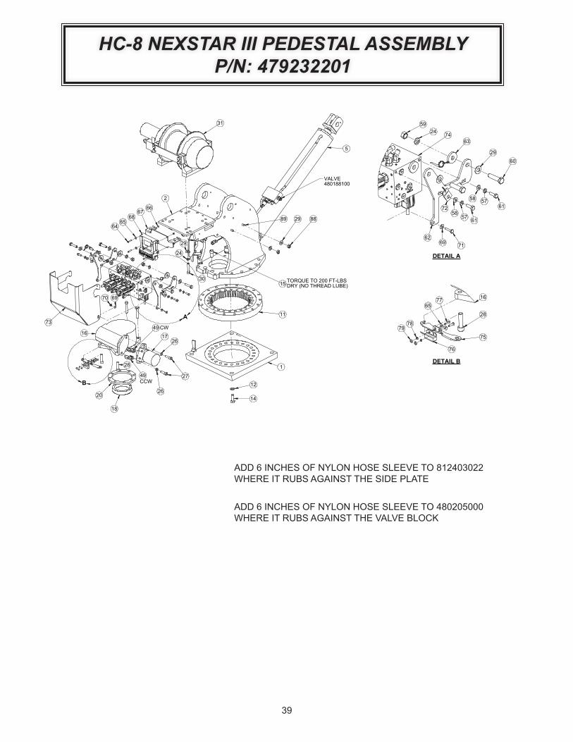
39
HC-8 NEXSTAR III PEDESTAL ASSEMBLYP/N: 479232201
ADD 6 INCHES OF NYLON HOSE SLEEVE TO 812403022WHERE IT RUBS AGAINST THE SIDE PLATE
ADD 6 INCHES OF NYLON HOSE SLEEVE TO 480205000 WHERE IT RUBS AGAINST THE VALVE BLOCK
A
B
VALVE480188100
15 TORQUE TO 200 FT-LBSDRY (NO THREAD LUBE)
1
11
12
14
5
31
2
6667
6865
64
29
24
30
73
27
26
18
2026
17
49
49CCW
CW
28
16
6970
29 8889
DETAIL A
716962
60
29
63
24
615758
615758
72
59
74
DETAIL B
28
75
7978
76
6577 16

40
HC-8 NEXSTAR III PEDESTAL ASSEMBLYPN: 479232201
C
DETAIL C
90
8789292988
9169699293
C
DETAIL C
90
8789292988
9169699293

41
HC-8 NEXSTAR III PEDESTAL ASSEMBLYPN: 479232201
ITEM NO. QTY PART
NUMBER DESCRIPTION1 1 480988220 BASE PLATE WELDMENT2 1 480988210 PEDESTAL WELD, LARGE CRANE3 1 360676000 PIN, CYLINDER4 1 360678000 PIN, 3/16 COTTERLESS RING5 1 366822250 CYLINDER, LIFT, 6406H, STROKE - 27.816 2 320976000 WASHER, FLAT, 3/8 SAE HARDENED7 1 021100 WASHER SP LK 3/88 1 366159000 SCREW HX HD 3/8-16UNC X 1 1/2 LG GR89 1 366333 BEARING, SPHERICAL 1.25 ID
10 1 239300 ZERK, GREASE11 1 480023002 BEARING ROTATION 5005-800512 36 023902 WASHER FL 5/8 HARDENED13 10 490171 SCREW HX HD 5/8-11UNC X 2 1/4 LG GR814 24 012198 SCREW HX HD 5/8-11UNC X 1 3/4 LG GR815 4 006205 SCREW SOC HD 5/8-11UNC X 1 1/4 LG16 1 160407 GEAR BOX, ROTATION17 1 366440 ROTATION MOTOR18 1 360162 RING, ECCENTRIC19 1 360207 RETAINER ECCENTRIC RING20 1 480011 SEAL ROTATION BOX21 1 020601 WASHER SP LK 5/1622 1 007807 SCREW HX HD 5/16-18UNC X 3/4 LG GR523 2 011202 SCREW HX HD 1/2-20UNF X 2 3/4 LG GR524 14 021500000 WASHER, SP LK 1/225 2 017704 NUT HX HVY 1/2-20UNF26 2 021502 WASHER SP LK 1/2 HI COLLAR27 2 012197 SCREW SOC HD 1/2-13UNC X 1/2 LG28 2 009118 SCREW SOC HD 1/2-13UNC X 2 LG29 16 320588000 WASHER, FL 1/2, HARDENED30 8 011609 SCREW 1/2 X 2 1/2NC GR531 1 123341 WINCH- RPH 4200 W/ RELIEF VALVE32 2 366393 SCREW HX HD 5/8-11UNC X 2 1/2 LG GR833 1 460110100 ROTATION STOP SWITCH ASSEMBLY, 24"34 1 366676000 COVER, ROTATION STOP35 1 460079000 BEARING, ROTATION STOP36 1 366671000 ARM, ROTATION STOP37 1 366675000 WASHER, NYLON38 1 366673000 PIN, ROTATION STOP39 1 480988255 BRACKET, ROT STOP40 2 017301 NUT HX NYLK 3/8-16UNC CP41 4 006210000 CAPSCREW-#8-32 X 7/8 LG SOC HD Z/P42 4 019700 WASHER SP LK #843 4 725321 NUT HX NYLK #8-32UNC44 1 813013000 KIT, HOSE 5005H-6406H FULLY PROP45 1 480201000 HOSE ASSY 8 STR X 21.546 1 369611000 ADAPTER, STR -6 ORM/ -4 ORF
ITEM NO. QTY PART
NUMBER DESCRIPTION47 1 812403022 HOSE ASSY 10 JIC STR48 2 200876 FITTING 6 SAE/6 JIC STRAIGHT49 2 490198 FITTING 10SAE(M)/6JIC ELBOW 9050 3 770055000 FITTING 8 SAE/8 JIC STRAIGHT51 1 490199 FITTING STR 10-SAE/10-JIC52 2 812303023 HOSE ASSY 8 JIC STR53 2 812203022 HOSE ASSY, -6 JIC FEM, STR54 2 812203037 HOSE ASSY 6 JIC STR55 2 480205 HOSE ASSY 6 STR X 19.2556 47 374086 NYLON HOSE SLEEVE, 1.81" ID57 4 020600 WASHER 5/16 LOCK SS58 4 020901 WASHER FL 5/1659 4 017701 NUT HX 1/2-13UNC60 4 011608000 SCREW HX HD 1/2UNC X 2 GR561 4 007811000 SCREW HX HD 5/16-18UNC X 1 LG GR562 2 366823210 BRACKET, VALVE MTG63 4 366823211 SPACER, VALVE BANK64 4 460094000 SCREW, SOC HD, #10-24 X 1"L, ZPL65 6 020000 WASHER FL #10 ZP66 4 015801 NUT HX NYLK #10-24UNC ZP67 1 366823212 BRACKET, RECEIVER MTG68 1 366823963 TRANSCEIVER, NEXSTAR III69 8 020400 WASHER FL SAE 1/470 2 016300 NUT HX NYLK 1/4-20UNC71 2 005604 SCREW HX HD 1/4-20UNC X 1 LG72 2 366823240 PIN, 3/16 W/LANYARD73 1 366823025 COVER, VALVE, REAR MTD FM74 1 366823251 VALVE BANK, 8 GPM W/FILTER SENSOR75 1 479200110 PROXIMITY SWITCH BRACKET, HC-876 1 772020212 SENSOR, FERROUS PROXIMITY77 2 002607 SCREW RD HD #10-24UNC X 3/4 LG CP78 2 019800 WASHER SP LK #1079 2 750074 NUT #10 NC STAINLESS80 1 366508000 CORD GRIP HUBBLE F-3 SHC 103681 1 366359 FITTING, -8 SAE / -8 JIC, SWIVEL, STR82 1 366358 FITTING, -10 SAE / -10 JIC, SWIVEL, STR83 1 479210200 TAG, ID HC-884 1 366823255 TRANSDUCER, PRESSURE 0-3000 PSI85 1 366698000 CORD GRIP .375-.500 3/4" HUB86 1 366823220 HARNESS, NEXSTAR III, HYD. CRANES87 1 366823224 BRACKET, ALARM, HC-6 TO HC-988 2 738058008 NUT HX 1/2-13UNC89 2 010201 SCREW HX HD 1/2-13UNC x 1 1/2 LG
90 1 366823223 KIT, ALARM, CONSTANT TONE, W/ DEUTSCH PLUG
91 2 005500 SCREW HX HD 1/4-20UNC X 3/4 LG92 2 020200 WASHER SP LK 1/493 2 015900 NUT HX 1/4-20UNC SS94 1 366823271 KIT, ELEC/HYD NEXSTAR III, 8 GPM AND BELOW
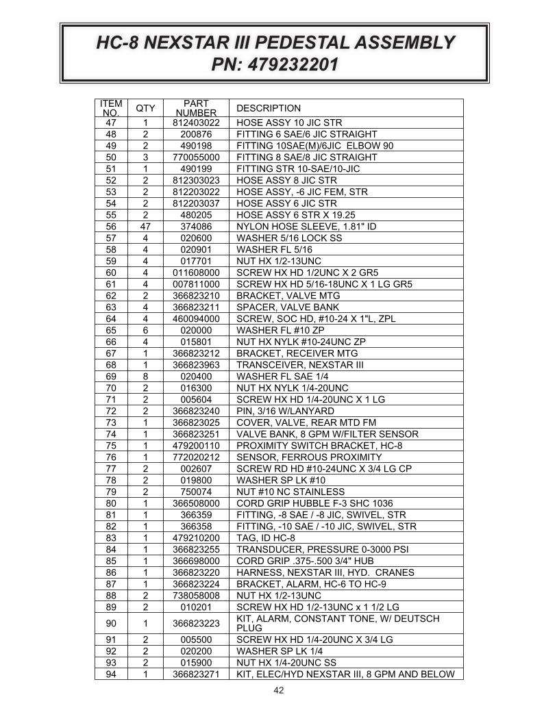
42
HC-8 NEXSTAR III PEDESTAL ASSEMBLYPN: 479232201
ITEM NO. QTY PART
NUMBER DESCRIPTION1 1 480988220 BASE PLATE WELDMENT2 1 480988210 PEDESTAL WELD, LARGE CRANE3 1 360676000 PIN, CYLINDER4 1 360678000 PIN, 3/16 COTTERLESS RING5 1 366822250 CYLINDER, LIFT, 6406H, STROKE - 27.816 2 320976000 WASHER, FLAT, 3/8 SAE HARDENED7 1 021100 WASHER SP LK 3/88 1 366159000 SCREW HX HD 3/8-16UNC X 1 1/2 LG GR89 1 366333 BEARING, SPHERICAL 1.25 ID
10 1 239300 ZERK, GREASE11 1 480023002 BEARING ROTATION 5005-800512 36 023902 WASHER FL 5/8 HARDENED13 10 490171 SCREW HX HD 5/8-11UNC X 2 1/4 LG GR814 24 012198 SCREW HX HD 5/8-11UNC X 1 3/4 LG GR815 4 006205 SCREW SOC HD 5/8-11UNC X 1 1/4 LG16 1 160407 GEAR BOX, ROTATION17 1 366440 ROTATION MOTOR18 1 360162 RING, ECCENTRIC19 1 360207 RETAINER ECCENTRIC RING20 1 480011 SEAL ROTATION BOX21 1 020601 WASHER SP LK 5/1622 1 007807 SCREW HX HD 5/16-18UNC X 3/4 LG GR523 2 011202 SCREW HX HD 1/2-20UNF X 2 3/4 LG GR524 14 021500000 WASHER, SP LK 1/225 2 017704 NUT HX HVY 1/2-20UNF26 2 021502 WASHER SP LK 1/2 HI COLLAR27 2 012197 SCREW SOC HD 1/2-13UNC X 1/2 LG28 2 009118 SCREW SOC HD 1/2-13UNC X 2 LG29 16 320588000 WASHER, FL 1/2, HARDENED30 8 011609 SCREW 1/2 X 2 1/2NC GR531 1 123341 WINCH- RPH 4200 W/ RELIEF VALVE32 2 366393 SCREW HX HD 5/8-11UNC X 2 1/2 LG GR833 1 460110100 ROTATION STOP SWITCH ASSEMBLY, 24"34 1 366676000 COVER, ROTATION STOP35 1 460079000 BEARING, ROTATION STOP36 1 366671000 ARM, ROTATION STOP37 1 366675000 WASHER, NYLON38 1 366673000 PIN, ROTATION STOP39 1 480988255 BRACKET, ROT STOP40 2 017301 NUT HX NYLK 3/8-16UNC CP41 4 006210000 CAPSCREW-#8-32 X 7/8 LG SOC HD Z/P42 4 019700 WASHER SP LK #843 4 725321 NUT HX NYLK #8-32UNC44 1 813013000 KIT, HOSE 5005H-6406H FULLY PROP45 1 480201000 HOSE ASSY 8 STR X 21.546 1 369611000 ADAPTER, STR -6 ORM/ -4 ORF
ITEM NO. QTY PART
NUMBER DESCRIPTION47 1 812403022 HOSE ASSY 10 JIC STR48 2 200876 FITTING 6 SAE/6 JIC STRAIGHT49 2 490198 FITTING 10SAE(M)/6JIC ELBOW 9050 3 770055000 FITTING 8 SAE/8 JIC STRAIGHT51 1 490199 FITTING STR 10-SAE/10-JIC52 2 812303023 HOSE ASSY 8 JIC STR53 2 812203022 HOSE ASSY, -6 JIC FEM, STR54 2 812203037 HOSE ASSY 6 JIC STR55 2 480205 HOSE ASSY 6 STR X 19.2556 47 374086 NYLON HOSE SLEEVE, 1.81" ID57 4 020600 WASHER 5/16 LOCK SS58 4 020901 WASHER FL 5/1659 4 017701 NUT HX 1/2-13UNC60 4 011608000 SCREW HX HD 1/2UNC X 2 GR561 4 007811000 SCREW HX HD 5/16-18UNC X 1 LG GR562 2 366823210 BRACKET, VALVE MTG63 4 366823211 SPACER, VALVE BANK64 4 460094000 SCREW, SOC HD, #10-24 X 1"L, ZPL65 6 020000 WASHER FL #10 ZP66 4 015801 NUT HX NYLK #10-24UNC ZP67 1 366823212 BRACKET, RECEIVER MTG68 1 366823963 TRANSCEIVER, NEXSTAR III69 8 020400 WASHER FL SAE 1/470 2 016300 NUT HX NYLK 1/4-20UNC71 2 005604 SCREW HX HD 1/4-20UNC X 1 LG72 2 366823240 PIN, 3/16 W/LANYARD73 1 366823025 COVER, VALVE, REAR MTD FM74 1 366823251 VALVE BANK, 8 GPM W/FILTER SENSOR75 1 479200110 PROXIMITY SWITCH BRACKET, HC-876 1 772020212 SENSOR, FERROUS PROXIMITY77 2 002607 SCREW RD HD #10-24UNC X 3/4 LG CP78 2 019800 WASHER SP LK #1079 2 750074 NUT #10 NC STAINLESS80 1 366508000 CORD GRIP HUBBLE F-3 SHC 103681 1 366359 FITTING, -8 SAE / -8 JIC, SWIVEL, STR82 1 366358 FITTING, -10 SAE / -10 JIC, SWIVEL, STR83 1 479210200 TAG, ID HC-884 1 366823255 TRANSDUCER, PRESSURE 0-3000 PSI85 1 366698000 CORD GRIP .375-.500 3/4" HUB86 1 366823220 HARNESS, NEXSTAR III, HYD. CRANES87 1 366823224 BRACKET, ALARM, HC-6 TO HC-988 2 738058008 NUT HX 1/2-13UNC89 2 010201 SCREW HX HD 1/2-13UNC x 1 1/2 LG
90 1 366823223 KIT, ALARM, CONSTANT TONE, W/ DEUTSCH PLUG
91 2 005500 SCREW HX HD 1/4-20UNC X 3/4 LG92 2 020200 WASHER SP LK 1/493 2 015900 NUT HX 1/4-20UNC SS94 1 366823271 KIT, ELEC/HYD NEXSTAR III, 8 GPM AND BELOW

43
NOTES
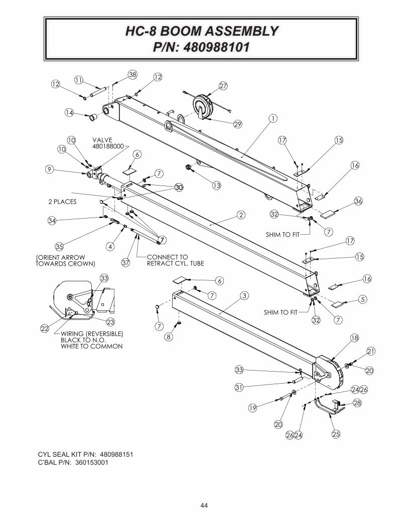
44
HC-8 BOOM ASSEMBLYP/N: 480988101
CYL SEAL KIT P/N: 480988151C’BAL P/N: 360153001
2223
33
WIRING (REVERSIBLE)BLACK TO N.O. WHITE TO COMMON
11
13
29
27
17 15
1
16
36
32
53
21
20
18
28
25
33
31
19
6
30
79
10
14
12
6
2
30
17
15
34
47
7
16
12
7
8
7
10
777
32
SHIM TO FIT
VALVE480188000
35
(ORIENT ARROWTOWARDS CROWN) 37
CONNECT TORETRACT CYL. TUBE
SHIM TO FIT
2 PLACES
20
24 26
2426
38
ITEM NO. QTY PART
NUMBER DESCRIPTION
1 1 480988115 LOWER BOOM WELD, 8406H W/LIGHT2 1 480988120 MID BOOM WELD, 8406H
3 1 480988130 UPPER BOOM WELD, 8406H
4 1 770055000 FITTING 8 SAE/8 JIC STRAIGHT5 1 460053000 WEAR PAD, BOTTOM UPPER6 2 460177160 WEAR PAD, 5.13X3X.25, BOSS 1X37 10 360767000 PAD BOOM 1.5 O.D.8 1 407277000 PAD BOOM 1.5 O.D.9 1 480988150 CYLINDER, EXTENSION, STROKE - 48/7210 2 200876 FITTING 6 SAE/6 JIC STRAIGHT11 1 460177161 PIN, 1.25OD, 7.81 GRIP12 2 480029 RING RETAINING13 1 366333 BEARING, SPHERICAL 1.25 ID14 2 366394 BEARING, PIVOT15 2 460081000 WEAR PAD, CABLE16 2 460082000 PLATE, WEAR PAD RETAINER17 4 460177163 SCREW SOC HD CTRSNK 5/16-24UNF X 5/8 LG18 1 366198 SHEAVE ASSY 3/819 1 014400 SCREW HX HD 3/4-16UNF X 5 LG GR520 2 022102 WASHER FL 3/421 1 018600 NUT HX NYLK 3/4-16UNF22 1 646900 SWITCH, LIMIT ANTI-TWO BLOCK23 1 642918 CORD CONNECTOR24 2 016801 NUT HX NYLK 5/16-18UNC CP25 1 470110160 BAIL WELDMENT W/ 2 IN TRIP BAR26 2 007807 SCREW HX HD 5/16-18UNC X 3/4 LG GR527 1 360759001 CORD REEL ASSY28 1 366678000 SPRING, EXTENSION29 1 360882000 NUT, PUSH-ON TYPE (.161-.164DIA)30 2 460177162 SCREW SOC HD 5/8-11UNC X 3/4 LG31 1 470076000 PIN, 1 DIA 4-11/16 LG32 4 460177164 SHIM, 1.31 OD X 0.9 ID X 0.04 TH, NYLON33 1 360124 PIN HITCH34 1 374400000 FITTING, -8 ORB, -8 ORB, STRAIGHT35 1 460177180 VALVE, IN-LINE RELIEF, 400PSI36 1 366669000 WEAR PAD, BOTTOM MID37 1 812234017 HOSE ASSY, -8 JICF/-8 JICF, -6 HOSE, 17LG38 1 239000 ZERK DRIVE GR
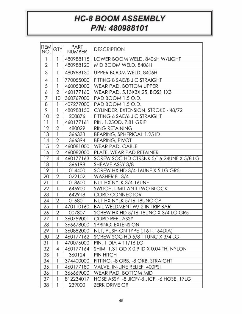
45
HC-8 BOOM ASSEMBLYP/N: 480988101
2223
33
WIRING (REVERSIBLE)BLACK TO N.O. WHITE TO COMMON
11
13
29
27
17 15
1
16
36
32
53
21
20
18
28
25
33
31
19
6
30
79
10
14
12
6
2
30
17
15
34
47
7
16
12
7
8
7
10
777
32
SHIM TO FIT
VALVE480188000
35
(ORIENT ARROWTOWARDS CROWN) 37
CONNECT TORETRACT CYL. TUBE
SHIM TO FIT
2 PLACES
20
24 26
2426
38
ITEM NO. QTY PART
NUMBER DESCRIPTION
1 1 480988115 LOWER BOOM WELD, 8406H W/LIGHT2 1 480988120 MID BOOM WELD, 8406H
3 1 480988130 UPPER BOOM WELD, 8406H
4 1 770055000 FITTING 8 SAE/8 JIC STRAIGHT5 1 460053000 WEAR PAD, BOTTOM UPPER6 2 460177160 WEAR PAD, 5.13X3X.25, BOSS 1X37 10 360767000 PAD BOOM 1.5 O.D.8 1 407277000 PAD BOOM 1.5 O.D.9 1 480988150 CYLINDER, EXTENSION, STROKE - 48/7210 2 200876 FITTING 6 SAE/6 JIC STRAIGHT11 1 460177161 PIN, 1.25OD, 7.81 GRIP12 2 480029 RING RETAINING13 1 366333 BEARING, SPHERICAL 1.25 ID14 2 366394 BEARING, PIVOT15 2 460081000 WEAR PAD, CABLE16 2 460082000 PLATE, WEAR PAD RETAINER17 4 460177163 SCREW SOC HD CTRSNK 5/16-24UNF X 5/8 LG18 1 366198 SHEAVE ASSY 3/819 1 014400 SCREW HX HD 3/4-16UNF X 5 LG GR520 2 022102 WASHER FL 3/421 1 018600 NUT HX NYLK 3/4-16UNF22 1 646900 SWITCH, LIMIT ANTI-TWO BLOCK23 1 642918 CORD CONNECTOR24 2 016801 NUT HX NYLK 5/16-18UNC CP25 1 470110160 BAIL WELDMENT W/ 2 IN TRIP BAR26 2 007807 SCREW HX HD 5/16-18UNC X 3/4 LG GR527 1 360759001 CORD REEL ASSY28 1 366678000 SPRING, EXTENSION29 1 360882000 NUT, PUSH-ON TYPE (.161-.164DIA)30 2 460177162 SCREW SOC HD 5/8-11UNC X 3/4 LG31 1 470076000 PIN, 1 DIA 4-11/16 LG32 4 460177164 SHIM, 1.31 OD X 0.9 ID X 0.04 TH, NYLON33 1 360124 PIN HITCH34 1 374400000 FITTING, -8 ORB, -8 ORB, STRAIGHT35 1 460177180 VALVE, IN-LINE RELIEF, 400PSI36 1 366669000 WEAR PAD, BOTTOM MID37 1 812234017 HOSE ASSY, -8 JICF/-8 JICF, -6 HOSE, 17LG38 1 239000 ZERK DRIVE GR

46
HC-8 ROTATION GEARBOXP/N: 160407

47
HC-8 ROTATION GEARBOXP/N: 160407
ITEM NO. QTY. PART NO.
DESCRIPTION
1 1 300058 ADAPTER2 1 308085 BUSHING3 1 316092 CAP BEARING4 1 328126 COVER5 1 334016 GEAR R.H.6 1 338261 HOUSING GEAR7 2 342120 KEY8 1 357139 SHAFT OUTPUT9 1 366019 WASHER THRUST10 1 368183 WORM R.H.11 1 402044 BEARING BALL12 1 402105 BEARING NEEDLE13 1 402106 BEARING NEEDLE14 1 402107 BEARING NEEDLE15 1 413013 COVER16 14 414146 SCREW HX HD 5/16 NC X 1-1/4 GR5
(NYLON HEAVY PATCH)17 2 414581 SCREW HX HD 1/2 NC X 3/4 GR518 6 414869 SCREW SOC HD 5/16 NC X 119 6 418163 WASHER LK 5/16 MED SECT21 2 442182 GASKET22 1 442187 GASKET23 1 456008 FITTING RELIEF24 1 462029 O-RING26 2 468018 PLUG PIPE27 4 470062 PIN DOWEL28 1 486071 SEAL OIL29 2 518026 WASHER THRUST30 1 472088 PLUG - EXPANSION

48
HC-8 HOIST ASSEMBLYP/N: 123341
SEAL KIT #246048

49
HC-8 HOIST ASSEMBLYP/N: 123341
ITEM NO. QTY. PART NO. DESCRIPTION1 1 234189 DRUM ASSEMBLY2 1 306042 PISTON-BRAKE3 1 315004 ANCHOR-CABLE4 1 338300 END BRG-MOTOR END5 1 338301 END BRG-GEAR HSG.6 1 338302 HSG-BRAKE7 4 346045 PIN-BRAKE8 1 357513 SHAFT-INPUT9 2 362291 SPACER-FOOT MOUNTING
10 4 362284 SPACER-TIE PLATE11 1 402120 BEARING12 1 402121 BEARING13 1 412084 BUSHING-DRUM, MOTOR END
14 1 412085 BUSHING-DRUM,GEAR END
15 4 414159 CS-5/16-18UNCX2.50,HXHD,GR5,ZP,N/P
16 6 414303 BOLT-3/8-16NC X2 1/2,HXHD,GR-5, Z/P
17 8 414548 CAPSCREW-1/2-13NCX1 1/2,HXHD,Z/P,G5
18 2 414854 SCREW-1/4-20NCX1/2LG,RDHD,SLOT,Z/PL
19 1 414926 SETSCREW-3/8-16NC X1,SOCKET,NYLON
20 2 414948 CAPSCREW-1/2-13NCX1 1/4LG,SOCKET HD
21 1 416016 SETSCREW1/4-20NCX1/4 HX SOCK HD CUP
22 1 416080 SETSCREW-5/8-18NF X1 LG,HXSOCHD,CUP
23 1 418036 NUT-3/8-16 NC,HEX JAM,Z/P
24 1 418088 NUT-JAM 5/8-18NF HEX HD,ZINC PLT
25 2 418218 LOCKWASHER-1/2 ID MED SECT,ZINC PLT
26 1 426048 PLUNGER-CLUTCH,BLOCKED
27 1 431015 COUPLING-MOTOR
28 2 432018 FITTING
29 4 438022 DISC-BRAKE
30 1 442220 GASKET-BRAKE HSG.
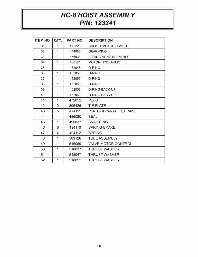
50
HC-8 HOIST ASSEMBLYP/N: 123341
ITEM NO. QTY. PART NO. DESCRIPTION31 1 442223 GASKET-MOTOR FLANGE
32 1 444085 GEAR-RING
33 1 456038 FITTING-VENT, BREATHER
34 1 458121 MOTOR-HYDRAULIC
35 1 462046 O-RING
36 1 462056 O-RING
37 1 462057 O-RING
38 1 462058 O-RING
39 1 462059 O-RING-BACK-UP
40 1 462060 O-RING-BACK-UP
41 1 472052 PLUG42 2 395426 TIE PLATE43 5 474111 PLATE-SEPARATOR, BRAKE44 1 486080 SEAL45 1 490037 SNAP RING 46 6 494110 SPRING-BRAKE47 4 494112 SPRING48 1 509126 TUBE ASSEMBLY49 1 516069 VALVE-MOTOR CONTROL50 1 518037 THRUST WASHER51 1 518047 THRUST WASHER52 1 518052 THRUST WASHER
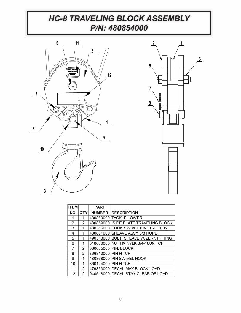
51
HC-8 TRAVELING BLOCK ASSEMBLYP/N: 480854000
ITEM NO. QTY
PART NUMBER DESCRIPTION
1 1 480860000 TACKLE LOWER2 2 480859000 SIDE PLATE TRAVELING BLOCK3 1 480366000 HOOK SWIVEL 6 METRIC TON4 1 480861000 SHEAVE ASSY 3/8 ROPE5 1 490313000 BOLT, SHEAVE W/ZERK FITTING6 1 018600000 NUT HX NYLK 3/4-16UNF CP7 2 360605000 PIN, BLOCK8 2 366813000 PIN HITCH9 1 480368000 PIN SWIVEL HOOK
10 1 360124000 PIN HITCH11 2 479853000 DECAL MAX BLOCK LOAD12 2 040518000 DECAL STAY CLEAR OF LOAD
11
2
12
1
9
3
10
8
7
5
6
42
5
7
9

52
HC-8 NEXSTAR III MAIN HARNESSP/N: 366823220
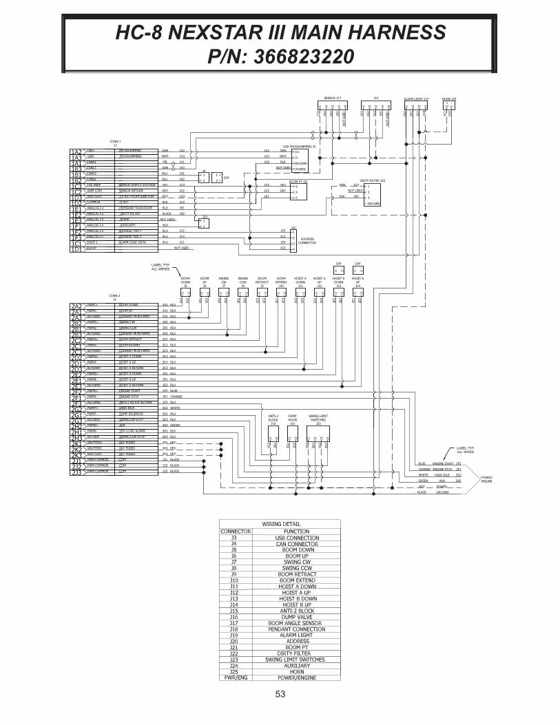
53
HC-8 NEXSTAR III MAIN HARNESS P/N: 366823220
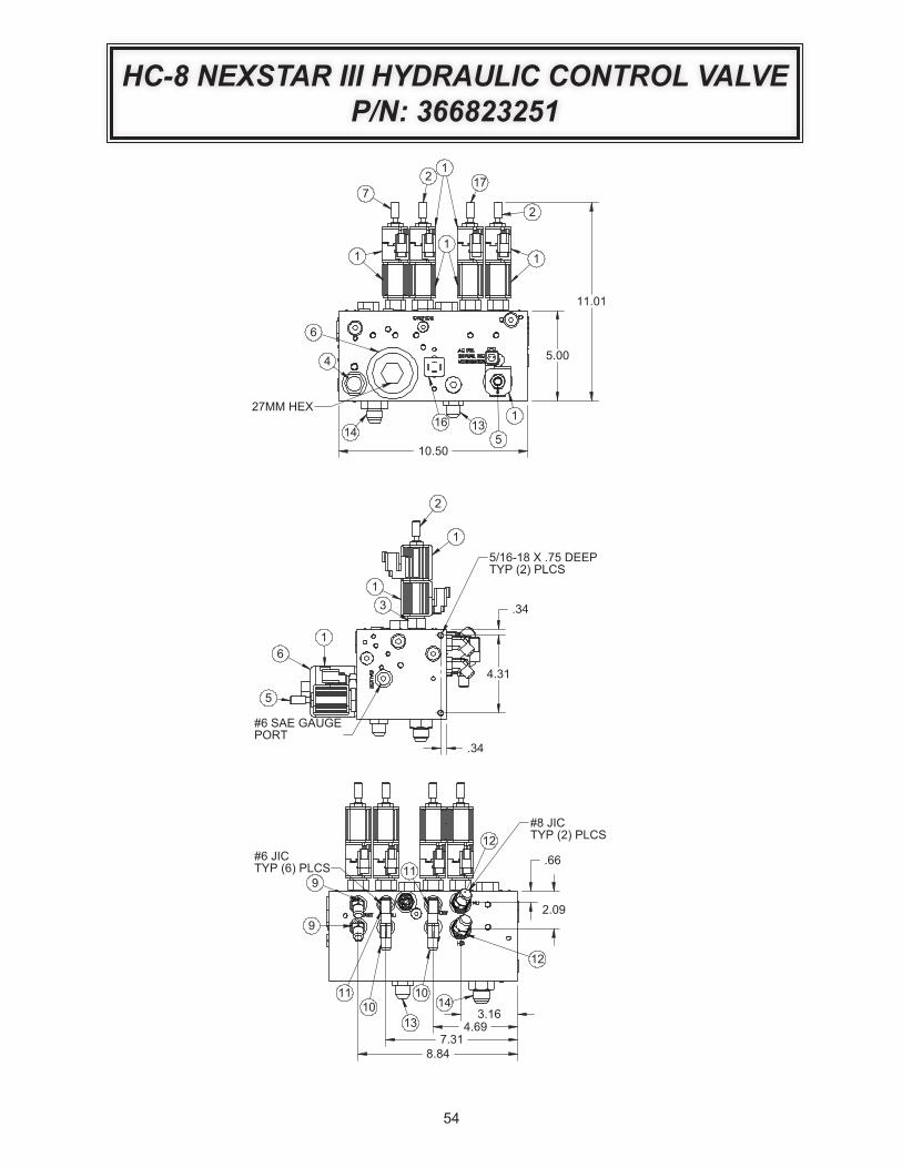
54
HC-8 NEXSTAR III HYDRAULIC CONTROL VALVEP/N: 366823251
.34
.34
4.31
5/16-18 X .75 DEEP TYP (2) PLCS
#6 SAE GAUGEPORT
6
5
1
2
1
13
.66
2.09
3.164.69
7.318.84
#8 JICTYP (2) PLCS
#6 JICTYP (6) PLCS
1011
12
12
13
1410
119
9
10.50
11.01
5.00
27MM HEX
1
72
1
1
17
2
1
6
14 131
516
4
BOM REVS
ITEM NO. QTY PART
NUMBER DESCRIPTION
1 9 366823901 COIL, 5/8" DIA 12VDC DEUTSCHB 2 2 366823902 CARTRIDGE, SIZE 4W 3P CLSD CTR
3 2 366823906 VALVE, LOGIC SPOOL TYPE 290 PSIC 4 1 366823914 VALVE, CHECK 100 PSI
E 5 1 366823960 CARTRIDGE, 2-WAY UNLOADER, EXTENDED MANUAL OVERRIDE
6 1 366823909 BOWL, FILTER B, D 7 1 366823903 CARTRIDGE, SIZE 4W 3P FLOAT CTR
8 1 366823905 VALVE, RELIEF DIRECT-ACTING (2750PSI)9 2 480195 FITTING 45 6-SAE/6-JIC
10 2 241175 FITTING 90 6-SAE/6-JIC11 2 330645 FITTING 90 6-SAE/6-JIC LONG12 2 374017 FITTING 45 8-SAE/8-JIC13 1 372041 FITTING 8JIC/10SAE STRAIGHT 8-10 F5OX14 1 372260 FITTING, 10-12 JIC/SAE STR15 1 366823910 FILTER, 20 MICRON
C 16 1 366823913 INDICATOR, CLOGGING FILTER 101.5 PSID 17 1 366823911 CARTRIDGE, SIZE 4W 3P FLOAT CTR - 6GPM
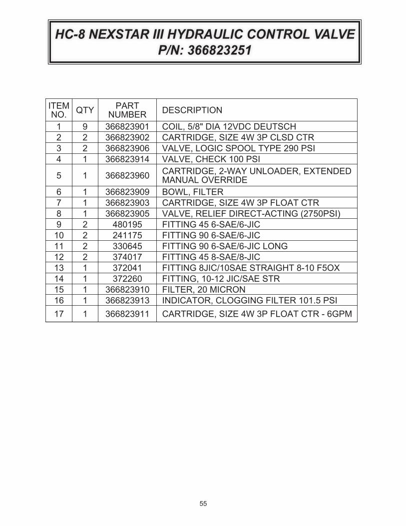
55
HC-8 NEXSTAR III HYDRAULIC CONTROL VALVEP/N: 366823251
.34
.34
4.31
5/16-18 X .75 DEEP TYP (2) PLCS
#6 SAE GAUGEPORT
6
5
1
2
1
13
.66
2.09
3.164.69
7.318.84
#8 JICTYP (2) PLCS
#6 JICTYP (6) PLCS
1011
12
12
13
1410
119
9
10.50
11.01
5.00
27MM HEX
1
72
1
1
17
2
1
6
14 131
516
4
BOM REVS
ITEM NO. QTY PART
NUMBER DESCRIPTION
1 9 366823901 COIL, 5/8" DIA 12VDC DEUTSCHB 2 2 366823902 CARTRIDGE, SIZE 4W 3P CLSD CTR
3 2 366823906 VALVE, LOGIC SPOOL TYPE 290 PSIC 4 1 366823914 VALVE, CHECK 100 PSI
E 5 1 366823960 CARTRIDGE, 2-WAY UNLOADER, EXTENDED MANUAL OVERRIDE
6 1 366823909 BOWL, FILTER B, D 7 1 366823903 CARTRIDGE, SIZE 4W 3P FLOAT CTR
8 1 366823905 VALVE, RELIEF DIRECT-ACTING (2750PSI)9 2 480195 FITTING 45 6-SAE/6-JIC
10 2 241175 FITTING 90 6-SAE/6-JIC11 2 330645 FITTING 90 6-SAE/6-JIC LONG12 2 374017 FITTING 45 8-SAE/8-JIC13 1 372041 FITTING 8JIC/10SAE STRAIGHT 8-10 F5OX14 1 372260 FITTING, 10-12 JIC/SAE STR15 1 366823910 FILTER, 20 MICRON
C 16 1 366823913 INDICATOR, CLOGGING FILTER 101.5 PSID 17 1 366823911 CARTRIDGE, SIZE 4W 3P FLOAT CTR - 6GPM
56
HC-8 COUNTERBALANCE VALVE ADJUSTMENT
Counterbalance Valve Adjustment
1. With PTO disengaged and boom properly supported, remove the plug on the counterbalance valve. Install a pressure gauge (0-3000 PSI) into the port.
2. Engage PTO and insure pump flow is 8 to 9 GPM. With no load on boom, boom up to an angle of 70 degrees. Boom down and note pressure. If pressure reading is not approximately 1300 PSI, the counterbalance valve requires adjustment.
A. To increase the CB valve setting, loosen nut and turn Allen head screw counter clockwise.
B. To reduce the CB valve setting, loosen nut and turn Allen head screw clockwise.
3. Tighten nut on adjustment screw and repeat procedure if needed to obtain the proper pressure setting.
4. Disengage PTO, remove the pressure gauge and install plug. Crane is now ready for operation.
Notice:1. In an EMERGENCY situation when it becomes
necessary to lower the boom without flow present, the CB valve adjustment can be turned in until the boom begins to descend. Make sure the boom will lower onto a proper support. Loosen the lock nut and carefully turn adjustment screw clockwise! Count the number of turns. Turn slowly until the boom just begins to lower, and remove hand/arm/fingers from cranes while boom is lowering.
2. Turning adjustment screw too far will cause valve to come apart on the inside. This condition is not repairable
3. After boom is lowered, turn adjustment screw counter clockwise the approximate number of turns made during lowering procedure. After the problem is corrected, readjust the counterbalance valve using the procedure in this manual.
WARNING:DO NOT TRY TO ADJUST VALVES WHILE BOOM IS MOVING. Doing so may result in personal injury!

57
HC-8VALVE OVERRIDE OPERATION
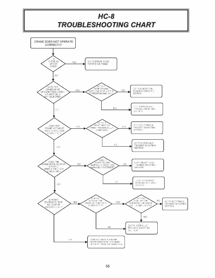
58
HC-8 TROUBLESHOOTING CHART
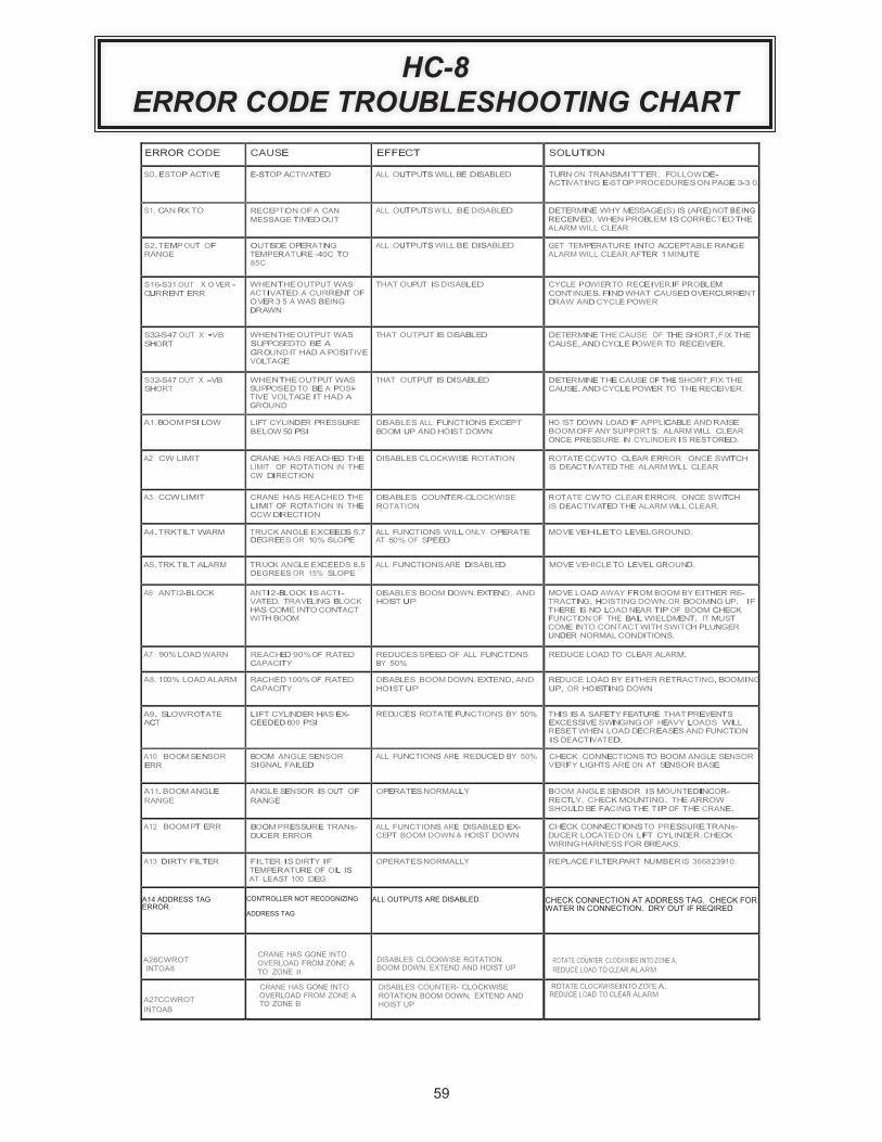
59
ERROR CODE CAUSE EFFECT SOLUTION
SO.ESTOP ACTIVE E-STOP ACTIVATED ALL OUTPUTS WILL BE DISABLED TURN ON TRANSMITTER. FOLLOWDE-ACTIVATING E-STOP PROCEDURESON PAGE 3-3 0.
S1. CAN RX TO RECEPTION OFA CAN MESSAGE TIMEDOUT
ALL OUTPUTSWILL BE DISABLED DETERMINE WHY MESSAGE(S) IS (ARE) NOT BEINGRECEIVED. WHEN PROBLEM IS CORRECTEDTHE ALARM WILL CLEAR
S2.TEMP OUT OFRANGE
OUTISDE OPERATINGTEMPERATURE -40C TO85C
ALL OUTPUTS WILL BE DISABLED GET TEMPERATURE INTO ACCEPTABLE RANGEALARM WILL CLEAR AFTER 1MINUTE
S16-S31 OUT X O VER -CURRENT ERR
WHENTHE OUTPUT WAS ACTIVATED.A CURRENT OFOVER 3 5 A WAS BEING DRAWN
THAT OUPUT ISDISABLED CYCLE POWIER TO RECEIVER. IF PROBLEMCONTINUES.FIND WHAT CAUSED OVERCURRENT DRAW AND CYCLE POWER
S32-S47 OUT X •VBSHORT
WHENTHEOUTPUT WAS SUPPOSEDTO BE AGROUND IT HAD A POSITIVEVOLTAGE
THAT OUTPUT IS DISABLED DETERMINE THE CAUSE OF THE SHORT,F IX THECAUSE,ANDCYCLE POWER TO RECEIVER.
S32-S47 OUT X -VBSHORT
WHENTHE OUTPUT WASSUPPOSED TO BE A POSI-TIVE VOLTAGE IT HAD AGROUND
THAT OUTPUT IS DISABLED DETERMINE THECAUSE OF THE SHORT,FIX THE CAUSE.ANDCYCLE POWER TO THE RECEIVER.
A1.BOOM PSI LOW LIFT CYLINDER PRESSUREBELOW 50 PSI
DISABLES ALL FUNCTIONS EXCEPTBOOM UP AND HOIST DOWN
HO 1ST DOWN LOAD IF APPLICABLE ANDRAISEBOOM OFF ANY SUPPORTS. ALARM WILL CLEAR ONCE PRESSURE IN CYLINDER IS RESTORED.
A2 CW LIMIT CRANE HAS REACHED THELIMIT OF ROTATION IN THECW DIRECTION
DISABLES CLOCKWISE ROTATION ROTATE CCWTO CLEAR ERROR ONCE SWITCHIS DEACTIVATED THE ALARM WILL CLEAR
A3 CCWLIMIT CRANE HAS REACHED THE LIMIT OF ROTATION IN THECCWDIRECTION
DISABLES COUNTER-CLOCKWISE ROTATION
ROTATE CWTO CLEAR ERROR. ONCE SWITCHIS DEACTIVATED THE ALARM WILL CLEAR.
A4.TRKTILT WARM TRUCK ANGLE EXCEEDS 5.7DEGREES OR 10% SLOPE
ALL FUNCTIONS WILL ONLY OPERATEAT 50% OF SPEED
MOVE VEHLETO LEVELGROUND.
A5.TRK TILT ALARM TRUCK ANGLE EXCEEDS 8.5DEGREES OR 15% SLOPE
ALL FUNCTIONS ARE DISABLED MOVE VEHICLE TO LEVEL GROUND.
A6 ANTI2-BLOCK ANTI2-BLOCK IS ACTI-VATED. TRAVELING BLOCK HAS COME INTO CONTACT WITH BOOM
DISABLES BOOM DOWN.EXTEND, AND HOIST UP
MOVE LOAD AWAY FROM BOOM BY EITHER RE-TRACTING, HOISTING DOWN.OR BOOMING UP. IFTHERE IS NO LOAD NEAR TIP OF BOOM CHECKFUNCTION OF THE BAIL WIELDMENT. IT MUSTCOME INTO CONTACT WITH SWITCH PLUNGERUNDER NORMAL CONDITIONS.
A7 90% LOAD WARN REACHED 90%OF RATEDCAPACITY
REDUCES SPEED OF ALL FUNCTIONS BY 50%
REDUCE LOAD TO CLEAR ALARM.
A8.100% LOAD ALARM RACHED 100% OF RATEDCAPACITY
DISABLES BOOM DOWN.EXTEND,AND HOIST UP
REDUCE LOAD BY EITHER RETRACTING, BOOMING UP, OR HOISTING DOWN
A9. SLOWROTATE ACT
LIFT CYLINDER HAS EX-CEEDED 600 PSI
REDUCES ROTATE FUNCTIONS BY 50% THIS IS A SAFETY FEATURE THAT PREVENTSEXCESSIVE SWINGING OF HEAVY LOADS WILLRESET WHEN LOAD DECREASES AND FUNCTIONIS DEACTIVATED.
A10 BOOM SENSOR ERR
BOOM ANGLE SENSOR SIGNAL FAILED
ALL FUNCTIONS ARE REDUCED BY 50% CHECK CONNECTIONS TO BOOM ANGLE SENSOR VERIFY LIGHTS ARE ON AT SENSOR BASE
A11.BOOM ANGLERANGE
ANGLE SENSOR IS OUT OFRANGE
OPERATES NORMALLY BOOM ANGLE SENSOR IS MOUNTEDINCOR-RECTLY. CHECK MOUNTING. THE ARROW SHOULD BE FACING THE TIP OF THE CRANE.
A12 BOOMPT ERR BOOMPRESSURE TRANs-DUCER ERROR
ALL FUNCTIONS ARE DISABLED EX-CEPT BOOM DOWN & HOIST DOWN
CHECK CONNECTIONSTO PRESSURETRANs-DUCER LOCATED ON LIFT CYLINDER. CHECKWIRING HARNESS FOR BREAKS.
A13 DIRTY FILTER FILTER IS DIRTY IFTEMPERATURE OF OIL IS AT LEAST 100 DEG
OPERATES NORMALLY REPLACE FILTER.PART NUMBER IS 366823910.
A14 ADDRESS TAGERROR
CONTROLLER NOT RECOGNIZING
ADDRESS TAG
ALL OUTPUTS ARE DISABLED CHECK CONNECTION AT ADDRESS TAG. CHECK FORWATER IN CONNECTION. DRY OUT IF REQIRED
A26CWROT INTOA8
CRANE HAS GONE INTO OVERLOAD FROM ZONE A TO ZONE B.
DISABLES CLOCKWISE ROTATION. BOOM DOWN, EXTEND AND HOIST UP
ROTATE COUNTER CLOCKWISE INTO ZONE A, REDUCE LOAD TO CLEAR ALARM
A27CCWROT INTOAB
CRANE HAS GONE INTO OVERLOAD FROM ZONE A TO ZONE B
DISABLES COUNTER- CLOCKWISE ROTATION.BOOM DOWN, EXTEND AND HOIST UP
ROTATE CLOCKWISEINTO ZOI'E A. REDUCE LOAD TO CLEAR ALARM
HC-8 ERROR CODE TROUBLESHOOTING CHART
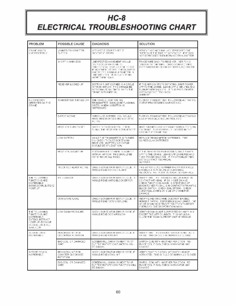
609-5.0
5005HELECTRICAL TROUBLESHOOTING CHART
HC-8 ELECTRICAL TROUBLESHOOTING CHART
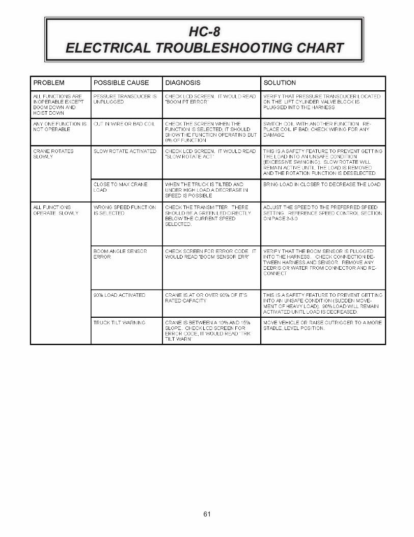
61
HC-8 ELECTRICAL TROUBLESHOOTING CHART
9-6.0
5005HELECTRICAL TROUBLESHOOTING CHART
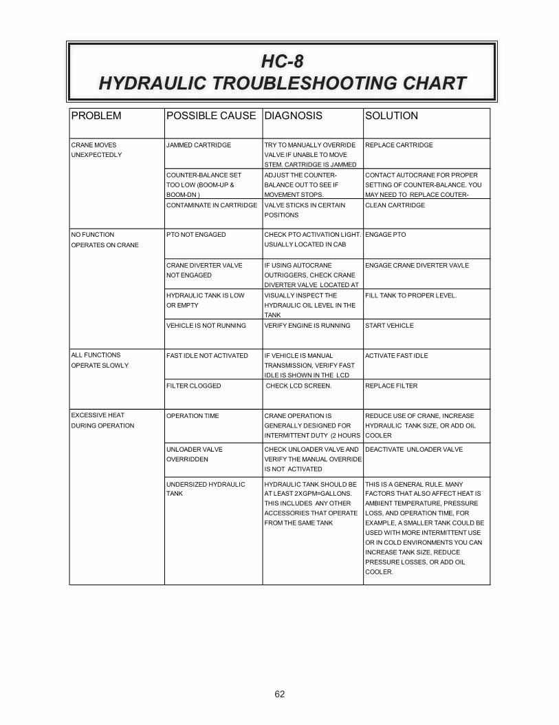
62
PROBLEM POSSIBLE CAUSE DIAGNOSIS SOLUTION
JAMMED CARTRIDGE TRY TO MANUALLY OVERRIDE VALVE IF UNABLE TO MOVE STEM. CARTRIDGE IS JAMMED
REPLACE CARTRIDGE
COUNTER-BALANCE SETTOO LOW (BOOM-UP &BOOM-DN )
ADJUST THE COUNTER-BALANCE OUT TO SEE IF MOVEMENT STOPS.
CONTACT AUTOCRANE FOR PROPER SETTING OF COUNTER-BALANCE. YOU MAY NEED TO REPLACE COUTER-
CONTAMINATE IN CARTRIDGE VALVE STICKS IN CERTAIN POSITIONS
CLEAN CARTRIDGE
PTO NOT ENGAGED CHECK PTO ACTIVATION LIGHT. USUALLY LOCATED IN CAB
ENGAGE PTO
CRANE DIVERTER VALVENOT ENGAGED
IF USING AUTOCRANE OUTRIGGERS, CHECK CRANE DIVERTER VALVE LOCATED AT
ENGAGE CRANE DIVERTER VAVLE
HYDRAULIC TANK IS LOW OR EMPTY
VISUALLY INSPECT THE HYDRAULIC OIL LEVEL IN THE TANK
FILL TANK TO PROPER LEVEL.
VEHICLE IS NOT RUNNING VERIFY ENGINE IS RUNNING START VEHICLE
FAST IDLE NOT ACTIVATED IF VEHICLE IS MANUAL TRANSMISSION, VERIFY FAST IDLE IS SHOWN IN THE LCD
ACTIVATE FAST IDLE
FILTER CLOGGED CHECK LCD SCREEN. REPLACE FILTER
OPERATION TIME CRANE OPERATION IS GENERALLY DESIGNED FOR INTERMITTENT DUTY (2 HOURS
REDUCE USE OF CRANE, INCREASE HYDRAULIC TANK SIZE, OR ADD OIL COOLER
UNLOADER VALVEOVERRIDDEN
CHECK UNLOADER VALVE AND VERIFY THE MANUAL OVERRIDE IS NOT ACTIVATED
DEACTIVATE UNLOADER VALVE
UNDERSIZED HYDRAULIC TANK
HYDRAULIC TANK SHOULD BE AT LEAST 2XGPM=GALLONS. THIS INCLUDES ANY OTHER ACCESSORIES THAT OPERATE FROM THE SAME TANK
THIS IS A GENERAL RULE. MANY FACTORS THAT ALSO AFFECT HEAT IS AMBIENT TEMPERATURE, PRESSURE LOSS, AND OPERATION TIME, FOR EXAMPLE, A SMALLER TANK COULD BE USED WITH MORE INTERMITTENT USE OR IN COLD ENVIRONMENTS YOU CAN INCREASE TANK SIZE, REDUCE PRESSURE LOSSES, OR ADD OIL COOLER.
CRANE MOVESUNEXPECTEDLY
NO FUNCTION
OPERATES ON CRANE
ALL FUNCTIONS
OPERATE SLOWLY
EXCESSIVE HEAT
DURING OPERATION
HC-8 HYDRAULIC TROUBLESHOOTING CHART

63
HC-8 CARTRIDGE MAINTENANCE
• Clean the area around the valve spool to be removed from the valve bank• Remove the valve spool from the valve bank being careful not to touch or hit surrounding objects• Carefully remove any visible debris from the valve spool• The recommended cleaning fluid is off-the-shelf automotive brake cleaning fluid.• It is recommended the skin and eye protection be worn when spraying the valve spool clean.• Inspect o-rings for damage and replace if needed• Dip the valve spool into fresh hydraulic oil to lubricate and fill cavities• Reinstall the valve spool in the reverse order in which it was removed• Validate function operation of the crane
9-8.0 3/15/11
• Clean the area around the valve spool to be removed from the valve bank• Remove the valve spool from the valve bank being careful not to touch or hit surrounding objects• Carefully remove any visible debris from the valve spool• The recommended cleaning fluid is off-the-shelf automotive brake cleaning fluid.• It is recommended the skin and eye protection be worn when spraying the valve spool clean.• Inspect o-rings for damage and replace if needed• Dip the valve spool into fresh hydraulic oil to lubricate and fill cavities• Reinstall the valve spool in the reverse order in which it was removed• Validate function operation of the crane
5005HCARTRIDGE MAINTENANCE
VERIFY MOVEMENT IN PORTS WHILE MANUALLY OVER-RIDING CARTRIDGE. VERIFY MOVEMENT IN PORTS WHILE MANUALLY OVER-RIDING CARTRIDGE.
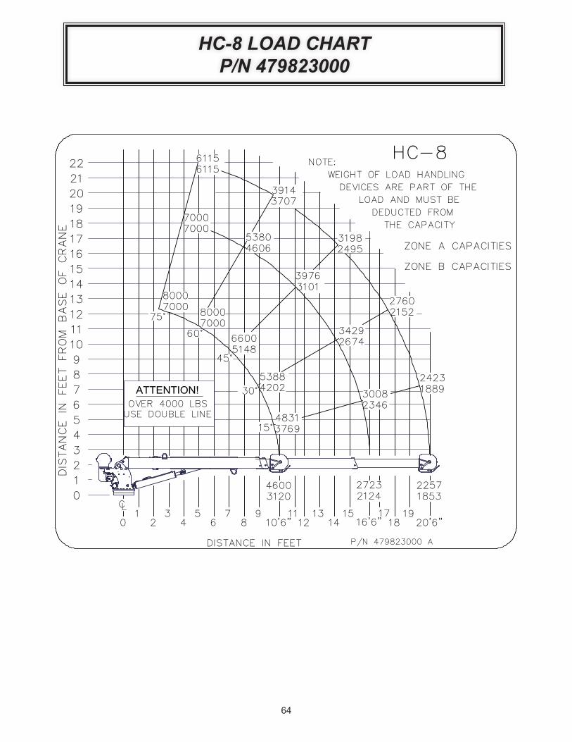
64
HC-8 LOAD CHARTP/N 479823000
ATTENTION!

65
HC-8 STABILITY CHARTP/N 479824000
669-10.0
CRANEPREVENTATIVE MAINTENANCE
PAINT FINISH PREVENTIVE MAINTENANCE INSTRUCTIONS
The paint finish on Auto Crane products can become damaged during normal use when chipped, scratched, exposed to harsh chemicals, cleaned with high pressure washers, etc. During periods when the truck is exposed to salt or other corrosive chemicals, Auto Crane products should be washed weekly.The paint finish should be inspected when washed or at least monthly. Any exposed bare metal or visible rust should be repaired immediately. Damaged paint on cranes should be repaired by:
1. Sanding the damaged areas to bare metal. 2. Solvent cleaning the sanded areas to remove sanding residue. Wipe
dry with a clean cloth to remove any remaining residue. 3. Priming the sanded areas to a minimum of a 2 mil dry film thickness
per the primer manufacturer’s instructions. The primer must be com-patible with Sherwin Williams’ E2W932 epoxy primer.
4. Applying a 2 mil dry film thickness top coat paint per the manufac-turer’s instructions within 24 hours of applying the primer. The top coat paint must be compatible with Sherwin Williams’ E2W932 epoxy primer and Sherwin Williams’ Genesis polyurethane top coat paint. The final primer and top coat should have approximately a 4 mil dry film thickness.
10/18/10

P.O.Box 580697 • Tulsa, OK 74158-06974707 N. Mingo Rd. • Phone (918) 438-2760
LIMITED WARRANTY1 YEAR PURCHASED REPLACEMENT PARTS
Auto Crane will warranty to the consumer for a period of (1) year from the date that a new Auto Crane replacement part was purchased from an authorized Auto Crane distributor. Each new Auto Crane part they sell will be free under normal use and service from defects in material andworkmanship. Date of purchase will be honored as the date indicated on the Bill of Sale to the consumer.
The obligation of Auto Crane under this warranty does not apply to parts replaced under thelimited warranty for a new Auto Crane product. The warranty for parts replaced under the limited warranty of a new Auto Crane product expires when the warranty for that product expires.
The obligation of Auto Crane under this warranty is limited to the replacement or repair ofpurchased replacement parts that appear to the manufacturer to be defective after review ofdocumentation (Auto Crane Warranty Claim Form. photos. data etc.) provided by the Auto Cranedistributor and/or inspection of parts returned to Auto Crane. This warranty does not obligate AutoCrane to bear labor costs to replace the defective parts or travel time charges in connection with thereplacement or repair of defective parts. Responsibility for customer's claims arising frommisapplication. abuse. misuse or alteration of equipment or parts lies with the distributor or user andno warranty obligation is assumed in these circumstances by Auto Crane.
Auto Crane will in no event be liable for any consequential damages or contingent liabilitiesarising out of the failure of any Auto Crane product or parts to operate properly
Auto Crane makes no warranty in respect to parts for component accessories. it being subjectto the warranties of their respective manufacturers.
If field service, at the request of the distributor, is rendered and fault is found not to be with AutoCrane's product, the distributor shall pay the time and expense of the field representative.
Claims for service labor or other expenses that have incurred by the buyer without approvalor authorization or Auto Crane will not be accepted
When applying for warranty claims may be handled by contacting your nearest authorized Auto Crane Distributor. All claims are to be filed in writing on an Auto Crane Warranty Claim Form.
Limited Parts Warranty 1 Year Effective June 15. 2010


Auto Crane Company issues a limited warranty certif-icate with each unit sold. See last page for warranty.
Auto Crane will not assume responsibility or liability for any modifications or changes made to unit, or installation of component parts without authorization.
Note: This manual should remain with the crane at all times.

Related Documents


