measure and predict with confidence Strain Gages and Accessories www.hbm.com

HBM Strain Gage Catalog
Oct 09, 2014
Welcome message from author
This document is posted to help you gain knowledge. Please leave a comment to let me know what you think about it! Share it to your friends and learn new things together.
Transcript

mea
sure
and
pre
dict
wit
h co
nfide
nce
Strain Gages and Accessories
www.hbm.com
Serbia, Bosnia-Herzegovina and Montenegro: TRCpro Tel. (+381) 21 -6433774Email: [email protected]
Singapore: Hottinger Baldwin Measurement Spectris Pte LtdTel: (+65) 6744 5963 Email: [email protected]: see Czech Republic
Slovenia and Croatia: TRC Tel. (+386) 4235 83 10Email: [email protected]
South Africa: **Esteq Engineering (Pty.) Ltd.Email:[email protected] Africa: *Elexsys (Pty) Ltd. Tel: +27 21 930-0214, Fax: +27 21 930-8685Sales Email: [email protected], Support Email: [email protected]
Spain: HBM Ibérica, S. L.Tel. (+34) 91,806 2610Email: [email protected]
Sweden: HBM Sverige Tel. (+46) 87 56 23 33Email: [email protected]
Taiwan: Tolsolution weighing & measurement Ent.Tel. (+886) 2 2649 7330Email: [email protected]
Thailand: **Dynistec Co Ltd. Tel. (+66) 2 9461735 7Email: [email protected]
Tunisia: SCOPIA Tel. (+216) 71 25 66 96Email: [email protected]
Turkey: Sensor Teknolojileri San. Ve Tic. Ltd. Sti., Tel. (+90) 312 284 9723Email: [email protected]
UK: HBM United Kingdom Ltd. Tel. +44 (0) 208 515 6100Email: [email protected]
Ukraine: ANWIT Tel. + Fax (+380) 44 451 4699 Email: [email protected]
Uruguay: CONATEL MATERIALES ELÉTRICOSTel. (+598) 2 902-0314 Ext. 2434Email: [email protected]
Venezuela: I.C.C. Ingeniería de Control de Calidad Tel. (+58) 212 2729756Email: [email protected]
Vietnam: refer to Singapore
Yugoslavia: see Serbia
* = Weighing technology ** = Process measurement technology
Up to date addresses of repre-sentatives can also be found on the Internet under: www.hbm.com/representatives
measure and predict with confidence S 12
65-3
.0 e
n
Israel: **Elina Technologies Ltd. Tel. (+972) 3 559 0277Email: [email protected]
Italy: HBM Italia s.r.l. Tel. (+39) 02 45 47 16 16Email: [email protected]
Japan: Spectris Co., Ltd. HBM Division Tel. (+81) 3 3255 8156,Email: sales: [email protected]: support: [email protected]/jp
Korea: Spectris Korea Co. Ltd. / HBM TeamTel. (+82) 31-786-0860Email: [email protected] www.hbmkorea.co.kr
Liechtenstein: see Switzerland
Luxembourg: see Netherlands
Macedonia and Albania: E3pro 1000 SkopjeTel. (+389)-2 3099 014Email: [email protected]
Malaysia: refer to Singapore
Mexico: ByASA – Básculas y automatizaciones S.A.Tel. (+52) 5 553419999Email: [email protected]
Montenegro: see Serbia
Morocco: AUTEREP, Tel: (+212) 22 24 73 44 Email: [email protected]: [email protected] www.auterep.com
Netherlands: HBM Benelux Tel. (+31) 344 67 3434Email: [email protected]
Norway: HBM Norge AS Tel. (+47) 48 300 700Email: [email protected]
Pakistan: Premier InternationalTel. +92-42-611 41 23-24Email: [email protected]
Peru: IRE, Jr. Tel. (+51) 1 423-5099 / 3326147Email: [email protected]
Poland: Biuro Inzynierskie M. Zajaczkowski Tel. + Fax (+48) 61 66 25 666, Email: [email protected]
Portugal: see Spain
Romania: Spectromas SrlOffice Bucharest: Metav Business Tel. (+40) 21 310 1095 Email: [email protected] Cluj-Napoca: Tel. (+40) 264 440 378Email: [email protected]
Russia (West): KWT Ltd. Tel. (+7) 495 22 66 431 + 432Email: [email protected]
Russia (Siberia): *Cestus Ltd. Tel. + Fax (+7) 3842 36 28 12Email: [email protected]
HBM companies and representatives world-wideBaltic States (Estonia, Latvia, Lithuania): ISOmetrija SIA Tel. (+371) 7 614 427Email: [email protected]
Belarus: MultimeraTel. /Fax: (+375) 17 2577567, Email: [email protected]
Belgium: see Netherlands
Brazil: Spectris do Brasil Instrumentos Eletrônicos Ltda. Tel. (+55) 11 5188 8193Email: [email protected]
Bosnia-Herzegovina: see Serbia
Bulgaria: Sigmametro EOOD Tel. (+359) 2 9515172Email: [email protected]
Canada: see HBM, Inc., USA
Chile: CELESTRON Tel. (+56) 2 2640404Email: [email protected]
Croatia: see Slovenia
Columbia: B.C.I. Básculas comerciales e Industriales Ltda. Tel. (+57) 1 3157572Email: [email protected]
Czech Republic and Slovakia: HBPTel. (+42) 02 24 92 18 61, 02 24 91 24 37Email: [email protected]
Denmark: HBM Danmark ApS Tel. (+45) 87 68 05 00Email: [email protected]
Egypt; **SOI Scientific Office for InstrumentTel. / Fax (+20) 2 24305717Email: [email protected]
Finland: HBM FinlandTel. (+358) 9 229 30150Email: [email protected]
France: HBM France SAS Tel. (+33) 1 69 90 63 70 Email: [email protected]
Greece: NETSCOPE Solutions S.A.Tel. (+30) 210 27 24 107 Email: [email protected]
Hong Kong: see HBM (Suzhou) Co., Ltd. PR China
Hungary: HB Mérnöki IrodaTel. (+36) 28,430,209Email: [email protected]
Iceland: see Norway
India: IPS, Integrated Process Systems Tel. (+91) 44 2498 17 86, 44 2498 00 91 + 92Email: [email protected]
Indonesia: PT. Sarana Dinamika PratamaTel: (+62) 21 4219 585 , 4210 446 Email: [email protected]
Ireland: see UK
HBM GmbH
www.hbm.com Tel. +49 6151 8030Email: [email protected] Fax +49 6151 803 9100
© Hottinger Baldwin Messtechnik GmbH. All rights reserved. All details describe our products in general form only. They are not to be understood as express warranty and do not constitute any liability whatsoever.
Headquarters world-wide
EuropeHottinger Baldwin Messtechnik GmbHIm Tiefen See 45 64293 Darmstadt, Germany Tel. +49 6151 8030Email: [email protected]
North and South AmericaHBM, Inc., 19 Bartlett Street, Marlborough MA 01752, USA Tel. +1-800-578-4260 / +1-508-624-4500 Email: [email protected]
AsiaHottinger Baldwin Measurement (Suzhou) Co., Ltd., 106 Hengshan Road, Suzhou 215011 Jiangsu, PR China Tel. (+86) 512 6824777Free hotline: 4006217621 (only in China)Email: [email protected]
Sales offices in Germany, Austria and Switzerland
Hottinger Baldwin Messtechnik GmbH:Office Berlin: Magirusstraße 5, 12103 BerlinTel. (030) 75 48 95 50
Office Dresden: Chemnitzer Straße 48b 01187 DresdenTel. (0351) 4 70 06 21
Office Düsseldorf: Hauptstraße 1340699 ErkrathTel. (02104) 93 56 01
Office Frankfurt: Im Tiefen See 45 64293 DarmstadtTel. (06151) 803-161
Office Hannover: Gutenbergstraße 3 30966 Hemmingen / HannoverTel. (0511) 94 26 48 0
Office München: Carl-Zeiss-Ring 11-13,85737 IsmaningTel. (089) 96 05 37 20
Office Stuttgart: Böblinger Str. 13,71229 LeonbergTel. (07152) 35 413 -10
Austria: Hottinger Baldwin Messtechnik GmbHLemböckgasse 63/2/2, A-1230 ViennaTel. (+43) 18 65 84 41Email: [email protected]
Switzerland: Hottinger Baldwin Messtechnik AGChriesbaumstrasse 6, CH-8604 Volketswil Tel. (+41) 44 943 60 80Email: [email protected] Yverdon:Hottinger Baldwin Messtechnik SARoute de Bellevue 11, 1400 Yverdon-les-bainsTel. (+41) 24,426 72 80
Sales world-wide
Albania: see Macedonia
Argentina: I.S.P.I.S.A., I.S. Proveedores de Industrias S.A. Tel. (+54) 1147571839Email: [email protected]
Australia: Spectris Australia Pty LtdTel: (+61) 2 9889 8070Email: [email protected]


Strain gages and accessories 3

IntroductionExplanations on specifications 6-11
From measured strain to mechanical stress 12-13
How to easily find the right strain gage 14-15
Type coding 16-17
SG / Y, C, G, K and V seriesSG / Y series 18
Specifications 19
with 1 measuring grid / linear SG 20-23
with 2 measuring grids / double SG 24
with 2 measuring grids / T-rosette 25-26
with 2 measuring grids / torsion-shear SG / T-rosette 27-28
with 3 measuring grids / rosettes 29-32
with 4 measuring grids / full bridges 33
with 4 measuring grids / membrane rosettes 34
Strain gage chains 35-38
Strain gages with connection cable K-LY... / K-XY... / K-RY... 39
Specifications 40
with 1 measuring grid 41
with 2 measuring grids 42
with 3 measuring grids 43
Strain gages with connection cable and RJ connector 44
SG / C series 45
Specifications 46
with 1 measuring grid 47
with 2 measuring grids / 3 measuring grids 48
SG / G series 49
Specifications 50
with 1 measuring grid / 2 measuring grids 51-52
SG / K series 53
Specifications 54
with 1 measuring grid / linear SG 55-56
with 2 measuring grids / double-SG 57
with 2 measuring grids / torsion-shear SG 58
with 2 measuring grids / T-rosette 59
with 2 measuring grids / membrane rosette 60
Balancing and compensating elements 61-62
4 Strain gages and accessories
Table of contents

Strain gages and accessories 5
SG / V series 63
Encapsulated strain gages with 3m (9.842 ft) stranded connection
wire / Specifications 64
Special strain gagesEncapsulated strain gages with stranded wire 65
Weldable strain gages 66
Strain gages for high strains 67
Strain gages for integration in composites 68
Temperature sensor 69
Crack propagation gage 70-71
Strain gages for determination of internal stresses 72-75
MTS3000, integral hole drilling method 76
Customized strain gages 77
Optical strain gages Based on fiber Bragg grating 78-79
Strain gage accessoriesStrain gage fastening materials 80-81
Strain gage covering materials 82-84
Cleaning agents, gluing and soldering materials 85
Soldering terminals 86
Cables and stranded wires 87-89
Bridge completions, resin-cored solder, lead-free solder 90
Strain gage installation case 91
HBM software 92-93
Universal measuring amplifier systems 94-95
Literature, learning sets, seminars, CD-ROM 96-97
MTS3000 98
Strain gage seriesThe HBM strain gage range consists of the Y, C, G, K, V series and special strain gages. There are different type series within each strain gage series. Many specifications are identical for one strain gage series; therefore, in this catalog, the specifications of a series are given on the pages preceding the list of individual strain gages. Where the specifications of individual strain gages differ from those stated for the other strain gages of a series, these strain gages are provided with a relevant note. The specifica-tions and their tolerances are stated in compliance with OIML directive IR62, which is essentially identical to the VDI/VDE directive 2635.
The specifications have been determined according to OIML directive IR62. The tolerances are stated per OIML with double standard deviation. If the specified tolerance values of the gage factor, transverse sensitivity, temperature coefficient, and temperature response are halved, the data complies with VDI/VDE directive 2635.Below you will find further explanations regarding the terms used in the specifications tables.
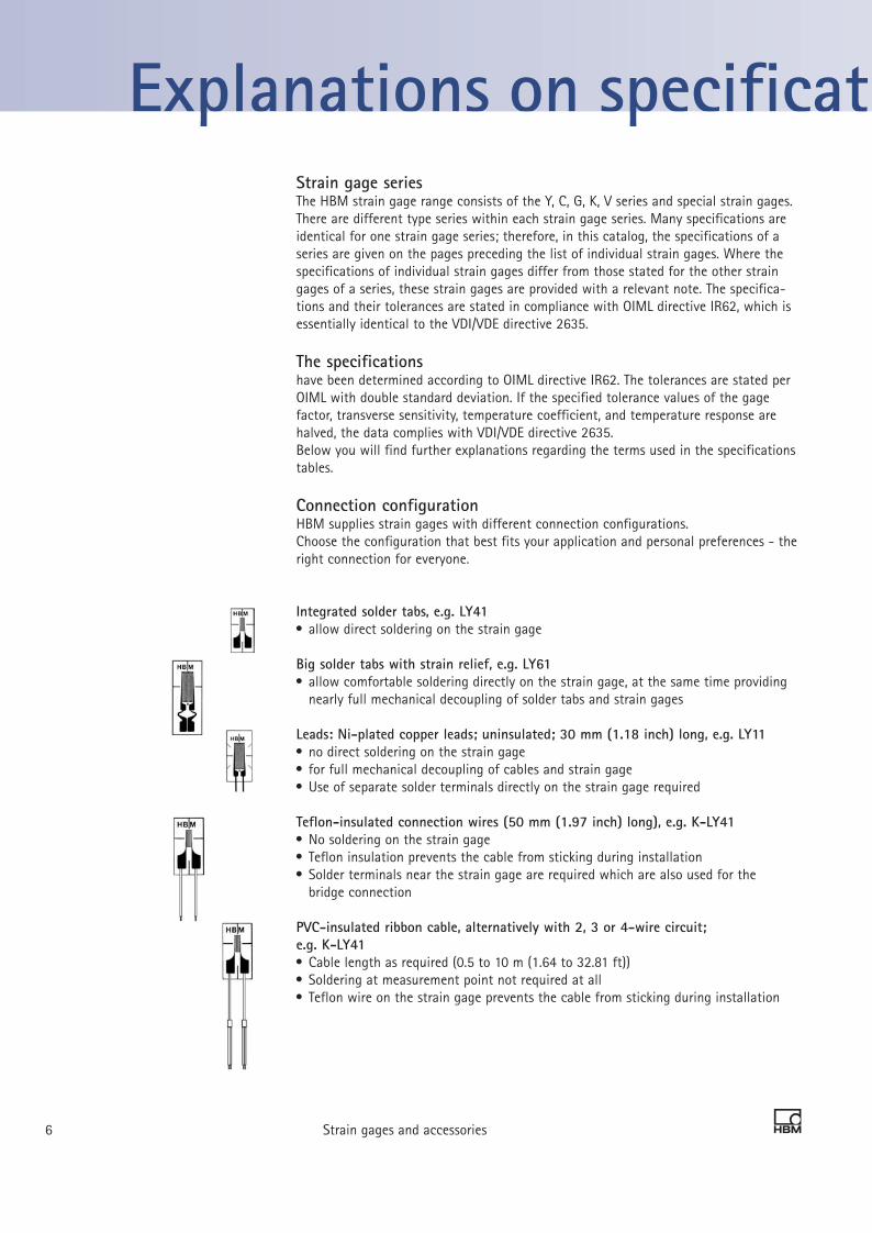
Connection configurationHBM supplies strain gages with different connection configurations.Choose the configuration that best fits your application and personal preferences - the right connection for everyone.
Integrated solder tabs, e.g. LY41 allow direct soldering on the strain gage
Big solder tabs with strain relief, e.g. LY61 allow comfortable soldering directly on the strain gage, at the same time providing nearly full mechanical decoupling of solder tabs and strain gages
Leads: Ni-plated copper leads; uninsulated; 30 mm (1.18 inch) long, e.g. LY11 no direct soldering on the strain gage for full mechanical decoupling of cables and strain gage Use of separate solder terminals directly on the strain gage required
Teflon-insulated connection wires (50 mm (1.97 inch) long), e.g. K-LY41 No soldering on the strain gage Teflon insulation prevents the cable from sticking during installation Solder terminals near the strain gage are required which are also used for the bridge connection
PVC-insulated ribbon cable, alternatively with 2, 3 or 4-wire circuit;e.g. K-LY41 Cable length as required (0.5 to 10 m (1.64 to 32.81 ft)) Soldering at measurement point not required at all Teflon wire on the strain gage prevents the cable from sticking during installation
Strain gages and accessories 76 Strain gages and accessories
Explanations on specifications

Strain gage dimensions
The specified active measuring grid length “a” is the net length of the grid without the end loops (transverse bridges). If the following facts are taken into account, it is possible to cut the carrier foil: Cutting the foil in parallel to the measuring grid has only minor effects. Shortening the carrier foil perpendicular to the measuring grid influences the way the strain is introduced, thereby also changing essential characteristics of the strain gage. A minimum distance of 1mm (0.04 inch) between the measuring grid end and the end of the carrier foil should therefore be maintained.
Strain gage resistance
The electric resistance between the two metal leads, solder tabs or cable ends for con-necting the measuring cable is called the resistance of a strain gage.1 Please note that the nominal resistance for strain gages with connection cables* is specified without the cable.
HBM strain gages are available with 120 Ohm, 350 Ohm, 700 Ohm or 1000 Ohm resist-ance. The nominal resistance is stated on each strain gage package including the resist-ance tolerance per package. HBM strain gages are 100% resistance checked.
Gage factor (strain sensitivity)
The strain sensitivity k of a strain gage is the proportionality factor between the relative change in resistance ∆R/R0 and the strain to be measured ε: ∆R/R0 = k · εThe strain sensitivity yields a dimensionless number and is designated as gage factor. This gage factor is determined for each production batch by measuring and is specified on each strain gage package as a nominal value complete with tolerance. The gage factors vary between the production batches by just a few thousandths.
Temperature coefficient of the gage factor
The specified gage factor applies at room temperature. It changes as the temperature changes; however, with an excellent approximation, this correlation is linear. In the case of constantan measuring grids (V, G, K, Y series) the gage factor is proportional to temperature; in the case of chromium-nickel measuring grids (C series) the gage factor is inversely proportional to temperature. The temperature coefficient of the gage factor and its tolerance are stated on each strain gage package.
(1) SG / V series, LE11
* see page 39
a
Active measuring grid length Schematic diagram of a strain gage
Strain gages and accessories 76 Strain gages and accessories
Explanations on specifications

Maximum permissible effective bridge excitation voltage
A strain gage is a resistor, converting electrical energy into heat. To prevent heating of the strain gage it is essential to choose a supply voltage that is not excessively high. The maximum permissible bridge excitation voltage is calculated for each strain gage and is listed in a table in this catalog.
The specified excitation voltage always applies for the Wheatstone bridge as a whole. Only half the voltage may be applied to the individual strain gage. The maximum values specified are permissible only for application on materials featuring excellent heat conduction characteristics (e.g. steel of sufficient thickness). Strain gage measurements on plastic materials, and similar materials with poor heat conduction characteristics, require a reduction of the excitation voltage or switch-on period (impulse operation). Also, with very low temperatures, the decreasing heat capacity of the materials may require a smaller excitation voltage.
Reference temperature
The reference temperature is the ambient temperature to which the specifications of the strain gage refer, unless no specific temperature ranges have been stated. The specifications for the strain gages are based on the reference temperature of 23°C (73.4°F).
Transverse sensitivity
The transverse sensitivity is the ratio of the sensitivity of a strain gage transverse to the measuring grid direction to its sensitivity in the measuring grid direction. The transverse sensitivity is stated on each strain gage package.
Schematic diagram of the transverse sensitivity of a measuring grid
Strain gages and accessories 98 Strain gages and accessories
Explanations on specifications

Strain gages and accessories 98 Strain gages and accessories
Operating temperature range
The operating temperature range is the range of ambient temperatures in which the strain gage can be used without lasting changes in measurement properties occurring. There are different operating temperature ranges for absolute (with zero point reference) or relative (without zero point reference) measurements.
Temperature response in a 1/4-bridge circuit
Strain gages that are connected individually show an output signal, if the temperature changes. This signal is called “apparent strain” or “thermal output” and is independent of the mechanical load on the test object.
However, it is possible to adjust a strain gage to the thermal expansion coefficient of a specific material such that the output signal is very small in the case of a temperature change. Such strain gages are called strain gages with “matched temperature response” or “self-compensated” strain gages. All HBM strain gages, with the exception of the LD20 high-strain gage, are self-compensated.
To benefit from their matching to the temperature response, strain gages must be select-ed according to the thermal expansion coefficient α of the test material. Therefore HBM offers strain gages for different materials. The code number for the temperature response matching is included in the strain gage type name.
Thus, for example, the types LY21 or RY31 (code number 1) have been matched to fer-ritic steel with α =10.8 .10-6/K. The material to which the respective strain gage has been matched is specified on the package with the applicable α.Despite this measure, a residual error remains, which is printed on the package in the form of a mathematical function and a graphical representation. The effects of strain gages using connection leads are also taken into account. This enables the apparent strain to be compensated by wiring and also mathematically.
1 for ferritic steel with α = 10.8 · 10-6/K ( 6.0 · 10-6/°F)
3 for aluminum with α = 23 · 10-6/K ( 12.8 · 10-6/°F)
5 for austenitic steel with α = 16 · 10-6/K ( 8.9 · 10-6/°F)
6 for quartz with α = 0.5 · 10-6/K ( 0.3 · 10-6/°F)
7 for titanium/gray cast iron with α = 9 · 10-6/K ( 5.0 · 10-6/°F)
8 for plastic material with α = 65 · 10-6/K ( 36.1 · 10-6/°F)
9 for molybdenum with α = 5.4 · 10-6/K ( 3.0 · 10-6/°F)
Explanations on specifications

The temperature response involves a tolerance and only applies in the temperature range of the temperature response matching. This temperature range is specified in the specifi-cations of the individual series in this catalog.Another possibility of compensating the apparent strain is to use appropriate wiring (e.g. circuit with compensating strain gage, half bridge circuit, etc.).
Creep adjustment
Spring element materials react with a spontaneous positive or negative strain when subjected to a sudden load. In the event of a constant load being applied, the material will continue to strain slowly in load direction, i.e. the material will creep. As transducers are loaded within the strictly elastic range only, the process described here is reversible. It is called elastic after-effect. The elastic after-effect causes a time-dependent fault with a positive sign (in the direction of the deformation by the measur-ing quantity).
If a strain gage is subjected to a static load, it will show a slow change in resistance over time - in spite of the component strain being constant. This change in the measuring signal of an extended (or shortened) strain gage occurs in the direction of strain relief. This creep can be explained as follows: the extended measuring grid acts similar to a tensioned spring which generates shear stresses between measuring grid and carrier (mainly in the area of the measuring grid end loops).
Due to the influence of these stresses, the plastic materials of the strain gage and the adhesive relax. It is possible to influence such strain gage creep directly by modifying the end loops. The elastic after-effect of the spring element material will therefore lead to a positive fault while the strain gage creep generates a negative fault. In an ideal case, both faults will compensate each other. In order to approximate this ideal case as closely as possible, it is necessary to determine the most suitable strain gage by experiment. It is for this reason, that the K strain gage series provides three different creep adjustments for each strain gage type.
Mechanical hysteresis
The mechanical hysteresis of a strain gage is defined as the difference of the measured value displayed for increasing and decreasing strain loadings with the same strain value on the specimen. Hysteresis is not only dependent on the strain gage but to a major ex-tent it is also dependent on application parameters such as type and layer thickness of the adhesive, etc. For this reason, the specifications include hysteresis values for differ-ent installation parameters.
Maximum elongation
The maximum elongation of a strain gage is the strain where the characteristic curve (resistance change-strain characteristic) deviates by more than ± 5% from the mean characteristic curve of the type. This is often the case if the installation or the strain gage has been damaged.
Strain gages and accessories 1110 Strain gages and accessories
Explanations on specifications

Minimum radius of curvature
The flexibility of a strain gage is characterized by the minimum radius of curvature which it will withstand, without any auxiliary measures, in each direction respectively. The polyimide carriers of Y and C series strain gages are flexible to an extent that they can be bonded around edges. Although the carrier materials of the other strain gage series are more brittle, they can also be easily prepared for application to smaller radii by thermal pre-forming Exception: V series strain gages have a bigger radius of curvature because of their specific potting.
Fatigue life
If a strain gage is subjected to an alternating strain which can be superimposed over a static mean strain, an increase in the number of load cycles may create changes with regard to the zero point. The fatigue life is dependent upon the number of strain cycles and their amplitude and is independent of applied strain duration.The achievable load cycle values are also dependent on the various installation param-eters and are therefore only given for representative examples.
Applicable bonding materials
For each strain gage series, the relevant bonding materials are specified. With regard to bonding technique, the HBM range of accessories distinguishes among cold and hot curing adhesives as well as spot welding methods. One of the most important selection criteria is the application temperature range of the individual bonding materials.
Example diagram of the fatigue life of strain gages
Strain gages and accessories 1110 Strain gages and accessories
remaining zero point error in µm/m (microstrain)
10 30 100 300 failure
number of load cycles n
ε w (i
n m
m/m
) (in
ch/1
000
inch
)
Explanations on specifications

Strain gages and accessories 1312 Strain gages and accessories
0°/45°/90° rosettee.g. RY3x
0°/60°/120° rosettee.g. RY7x
Analysis of the biaxial stress state with unknownprincipal directions
The principle of experimental stress analysis using strain gages (SG) consists in using strain gages to measure strains on the component surface. From these measured strains and the known material properties (modulus of elasticity and Poisson’s ratio), the absolute value and the direction of these mechanical stresses are determined. These calculations are based on Hooke’s Law which applies to the elastic deformation range of linear-elastic materials.
In experimental stress analysis, so-called 3-grid rosettes are used for strain measure-ment. These are available in 0°/45°/90° and 0°/60°/120° versions. Both forms have a historical background. It is up to the user to choose which version to use.
The 3 measuring grids of the rosettes are designated with the letters a, b and c. There-fore, a 3-grid rosette measures the three strains εa, εb and εc.
The principal normal stresses σ1 and σ2 are calculated for the 0°/45°/90° rosette using the formula:
and for the 0°/60°/120° rosette:
From measured strain to mechanical stress ...

Strain gages and accessories 1312 Strain gages and accessories
The principal directions are determined below. First the tangent of an auxiliary angle ψ is calculated.For the 0°/45°/90° rosette using the formula:
and for the 0°/60°/120° rosette according to the formula:
Note: The tangent of an angle in the right-angled triangle is the ratio of the opposite side (numerator N) to the adjacent side (denominator D):
This ambiguity of the tangent makes it necessary to determine the signs of the numera-tor (N) and the denominator (D) before carrying out the final calculation of the two above mentioned quotients. Determining the signs is important because they alone indicate the quadrant of the circular arc in which the angle ψ is located.From the value of the tan, the value of the intermediate angle ψ must first be determined:
Then the angle ϕ should be determined using the following scheme:
The angle ϕ found in this manner should be applied from the axis of the reference meas-uring grid a in the mathematically positive direction (counterclockwise). The axis of the measuring grid a forms one arm of the angle ϕ. The other arm represents the first prin-cipal direction. This is the direction of the principal normal stress σ1 (identical with the principal strain direction ε1). The point of the angle is located at the intersection of the axes of the measuring grids. The second principal direction (direction of the principal normal stress σ2) has the angle ϕ +90°.
Opposite side
Adjacent side
From measured strain to mechanical stress ...

SG resistanceHBM strain gages are available in 120, 350, 700 and 1000 Ohm versions. The selection of the resistance depends on the constraints of the measurement task. Other resistances on request.
120 ohm strain gages: + Relative insensitivity to variations in insulation resistance, e.g. caused by ef-fects of humidity.
High ohm strain gages: + Less specific heat because of their lower measurement current + Less sensitive to ohmic resistances in the connection linesto the measurement amplifier. - Better “antennae” for reception of noise pulses.
Geometry of the strain gage (dependent on the measurement task to be solved)
Linear strain gages (e.g. LY11), one measuring gridTypical application: - Strain measurement in one direction
Double SG with two measuring grids (e.g. DY11), arranged in parallelTypical application: - Measurement on bending beams For more detailed information see 1) and 2)
T-rosettes with two measuring grids (e.g. XY11), offset by 90° Typical applications: - Analysis of the biaxial stress state with known principal directions- Measurements on tension/compression bars For more detailed information see 1) and 2)
Rosettes with three measuring grids (e.g. RY81), 0°/45°/90° or 0°/60°/120° arrangement Typical application: - Analysis of the biaxial stress state with known principal stress directionsThe three measuring grids are arranged in a so-called quarter bridge circuit. The absolute value and the direction of the first and second principal stress are computed as described on page 12.For more detailed information see 2)
V-shaped strain gages (e.g. XY21), 2 measuring grids, arranged at ±45° relative to the SG axis
Typical applications: - Measurements on torsion bars - Determination of shear stresses occurring in shear beams around the neutral fiber For more detailed information see 1) and 2)
Full bridge strain gages (e.g. VY41), 4 measuring grids, offset by 90° relative to each other Typical applications: - Measurements on tension/compression bars - Measurements on torsion bars - Determination of shear stresses occurring in shear beams around the neutral fiber For more detailed information see 1) and 2)
Diaphragm rosettes (e.g. MY11), 4 measuring grids Typical applications:- Manufacture of diaphragm pressure transducers
Strain gage chains (e.g. KY11), 10 or 15 very small measuring grids, arranged equidistantly on a common carrier, plus one compensating SGTypical application: - Determination of strain gradients. HBM also supplies strain gage chains complete with several rosettes and alternating measuring grid directions so that it is even possible to determine the gradient of a biaxial stress state. For more detailed information see 2)
1) Brochure “Using the Wheatstone bridge circuit” (free)2) Book: “An Introduction to Measurements Using Strain Gages”
SG measuring grid length dependent on aim of measurement, as the result of a measurement using strain gages will be the mean strain underneath the measur-ing grid. In general, measuring grid lengths of 3 or 6 mm (0.118 or 0.236 inch) represent a good solution.Long measuring grids are recommended where there is an inhomogeneous material such as e.g. concrete or wood.
A long strain gage will bridge the inhomogeneities of the work piece and, as a measurement result, will supply the strain underneath the measuring grid.
Short measuring grids are suitable for detecting a local strain state. They are therefore suitable for determining strain gradients (see strain gage chains), the maximum point of notch stresses and similar stresses.
14 Strain gages and accessories
The easy way to find the right strain gage
SG seriesThe HBM strain gage range comprises various type series for the following typi-cal applications:
Y SG: The universal strain gage for stress analysis and “simple” transducers. Easy to handle, robust, flexible, many geometries and nominal (rated) resistances available. Measuring grid: Constantan; Measuring grid carrier: Polyimide
C SG: For measurements at extreme temperatures; operating temperature range from -269... up to +250°C (-452°F... up to +482°F); temperature response with matching in the range of -200... +250°C (-328°F... +482°F).Measuring grid: Cr-Ni alloy; Measuring grid carrier: Polyimide
G SG: For the manufacture of transducers, nominal (rated) resistances of 120 O and 350 O availableMeasuring grid: Constantan; Measuring grid carrier: phenolic resin, glass fiber reinforced.
K SG: For the manufacture of transducers, different creep adjustments available; also as a “stick on” version complete with touch-dry adhesive coating for opti-mum measurement results.Measuring grid: Constantan; Measuring grid carrier: phenolic resin, glass fiber reinforced.
V SG: Encapsulated strain gages for experimental stress analysis.Measuring grid: Constantan; Measuring grid carrier: polyimide with potting made of special plastic material and 3 m (9.84 ft) stranded wire.

Select measuring grid length 5 times larger than the inhomogeneity of testobject (e.g. gravel in concrete)
Transducer construction?
Principal stress directionknown?
Space requirementscritical?
Temperatures outside-70...+200°C (-94°F... +392°F) (static)-200...+250°C (-328°F... +482°F) (dynamic)
?
Measure straingradient?
Measurement aim:Local strain state?
According tomeasurement task:Linear SG
SG with 2 measuring grids connected as half bridge Full bridge SG
SG rosette with 3 measuring grids
SG rosette with 2 measuring grids
Size of SG deter-mined by test object
SG chains
Yes
Yes
Yes
Yes
Yes
Yes
Yes
Yes
Yes
No
No
No
No
No
No
No
No
No
C SG Y SG
G SG K SG
Short measuring grids
3 (0.118) or 6 (0.236) mm (inch) measuring grid length recommended
Biaxialstress state?
Strain fieldhomogenous?
High-quality transducers, creep adjustment required?
V SG
Restricted temperature range -30°C...+105°C (-22°F... +221°F)
Strain gages and accessories 15
A SG 1
U SG1
1) SG for transducer construction, see catalog “Strain gages for manufac-turers of transducers”. Note: Page 77

Strain gages and accessories 1716 Strain gages and accessories
1) available for selected strain gage types only
Type coding
with α = 10.8· 10-6/K (6.0 · 10-6/°F) with α = 23· 10-6/K (12.8 · 10-6/°F) with α = 16· 10-6/K (8.9 · 10-6/°F) with α = 0.5· 10-6/K (0.3 · 10-6/°F) with α = 9 · 10-6/K (5.0 · 10-6/°F) with α = 65 · 10-6/K (36.1 · 10-6/°F) with α = 5.4 · 10-6/K (3.0 · 10-6/°F)
1- L Y 1 1 - 3 / 120 A
Options1): A = Application aid V = Four wire connection Z = Two wire connection
Measuring grid resistance in ohms
Measuring grid length in mm/inch - For RY1x, RY3x, RY4x, RY7x: Diameter of circle which surrounds the measuring grid - For SG chains: Distance of measuring grid centers relative to each other (pitch)
Material to which the SG 1 ferritic steel temperature response is matched: 3 Aluminum If, at this position, you find the 5 austenitic steel placeholder “x”, replace it 6 Quartz with the code number 7 titanium / gray cast iron for the temperature response 8 plastic material matching of your choice. 9 molybdenum
Layout of grids, type and position of the connections
SG series C series = Carrier and cover: Polyimide-/-Measuring grid foil Chromium/nickel alloy Y series = Carrier and cover: Polyimide-/-Measuring grid foil Constantan G series = Carrier and cover: Glass-fiber reinforced phenolic resin-/- Measuring grid foil: Constantan K series = Carrier and cover: Glass-fiber reinforced phenolic resin-/- Measuring grid foil: Constantan, additionally, different creep adjustments available ex stock V series = Carrier: Polyimide/Measuring grid foil: Constantan, Molded with special plastic material, 3 m (9.84 ft) stranded wire as standard
Number of measuring grids and their relative positions to each other L = one measuring grid, linear SG D = two measuring grids, measuring grid direction: parallel X = two measuring grids, measuring grid direction: T or X-shaped, offset by 90° R = three measuring grids, rosettes V = 4 measuring grids, full bridge SG M = full bridge SG as diaphragm rosette K = SG chains for determining strain gradients
Standard or configurable 1 = Standard
K = with freely configurable connection cables
Type coding

An even greater range of types - Easy to order
The current catalog offers a great selection of strain gages (SG). In addition to our wide range of preferential strain gages (available ex stock), we hold a comprehensive choice of variants available for you.
This is how easily you can order our strain gages
Types available ex stock are printed on a shaded background in our price list. Strain gage variants do not have a shaded background and are not always available ex stock. We will be pleased to provide information on current availability if requested. The minimum order quantity for these strain gages is 3 packages.
What does the “x” in the type designation of the strain gages in the “Variants” column stand for?
Instead of the “x” in the strain gage type designation in the “Others” column, please enter the code number for the appropriate temperature responsematching.
Example:You wish matching of the type 1-LY1x-10/120 to plastic material. Then enter an “8” instead of the placeholder “x” when ordering; the exact order designa-tion will then be 1-LY18-10/120.
The preferential strain gages are matched to steel or aluminum.
Please note the exceptions in the case of types marked by #!
To simplify your order procedures, please also use our CD-ROM “SGdirect”.Order your example free of charge right now. For more information, go to: www.hbm.com
You can now also order via the new HBM online shop!http://www.hbm.com/shop
Types available ex stock Variants No- Dimensions (mm/inch) Max. perm. Solder minal effective terminals resis- bridge tance ex. voltage
Measuring grid Measuring grid carrier
Steel Aluminum Other Ω a b c d V
1-LY11-0.6/120 1-LY13-0.6/120 120 0.6 1 5 3.2 1.5 LS 7
1-LY11-1.5/120 1-LY13-1.5/120 1-LY1x-1.5/120 120 1.5 1.2 6.5 4.7 2.5 LS 7
1-LY11-3/120 1-LY13-3/120 1-LY1x-3/120 120 3 1.4 8.5 4.5 4 LS 7
1-LY11-3/120A 1-LY1x-3/120A 120 3 1.4 8.5 4.5 4 LS 7
1-LY11-6/120 1-LY13-6/120 1-LY1x-6/120 120 6 2.8 13 6 8 LS 5
1-LY11-6/120A 1-LY1x-6/120A 120 6 2.8 13 6 8 LS 5
1-LY11-10/120 1-LY13-10/120 1-LY1x-10/120 120 10 4.9 18.5 9.5 13 LS 5
1-LY11-10/120A 1-LY1x-10/120A 120 10 4.9 18.5 9.5 13 LS 5
1-LY11-1.5/350 1-LY13-1.5/350 350 1.5 1.2 5.7 4.7 4.5 LS 212
1-LY11-3/350 1-LY13-3/350 1-LY1x-3/350 350 3 1.5 8.5 4.5 7 LS 7
1-LY1x-3/350A 350 3 1.5 8.5 4.5 7 LS 7
1-LY11-6/350 1-LY13-6/350 1-LY1x-6/350 350 6 2.9 13 6 14 LS 5
1-LY11-6/350A 1-LY1x-6/350A 350 6 2.9 13 6 14 LS 5
1-LY11-10/350 1-LY1x-10/350 350 10 5 18.5 9.5 23 LS 5
1-LY11-10/350A 1-LY1x-10/350A 350 10 5 18.5 9.5 23 LS 5
Strain gages and accessories 1716 Strain gages and accessories
0.024 0.039 0.197 0.126
0.059 0.047 0.256 0.185
0.118 0.055 0.335 0.177
0.118 0.055 0.335 0.177
0.236 0.11 0.512 0.236
0.236 0.11 0.512 0.236
0.394 0.193 0.728 0.374
0.394 0.193 0.728 0.374
0.059 0.047 0.224 0.185
0.118 0.059 0.335 0.177
0.118 0.059 0.335 0.177
0.236 0.114 0.512 0.236
0.236 0.114 0.512 0.236
0.394 0.197 0.728 0.374
0.394 0.197 0.728 0.374

SG / Y seriesSG / Y series
Strain gages and accessories 1918 Strain gages and accessories
SG in series Y
The universal SG
Excellent measuring characteristics
Different connection configurations
Strain gage with connection cable (Page 39)
Flexible, therefore easy to handle
Wide range of geometries available ex stock
Numerous geometries are available with different nominal (120, 350, 700, 1000 Ω) resistance values
Pipe specimen made of carbon-fiber reinforcedplastic in torsion fracture test

1) The data depend on the various parameters of the specific application and are therefore stated for representative examples only.2) With measuring grid lengths of 0.3 mm (0.012 inch) and 0.6 mm (0.024 inch), the nominal resistance may deviate by ± 1%. For the types LY 51/ LY5x the deviation is ± 0.75%. For XY9x, RY9x and the KY types (per chain) it is ± 0.5%.3) Matching to plastic (code number 8) is only possible in the temperature range of -10°C…+50°C (14°F...+122°F).
Strain gages and accessories 1918 Strain gages and accessories
Specifications
SG construction Foil SG with embedded measuring gridMeasuring grid
Material Constantan foil Thickness µm (microinch) 3.8 or 5 (150 or 197), depending on SG type
Carrier Material µm (microinch) Polyimide
Thickness 45 ± 10 (1.772 ± 394)Covering agent Material µm (microinch) Polyimide Thickness 25 ± 12 (984 ± 472)Connections Nickel plated Cu leads, approx. 30 mm in
length without connection leads Integrated solder tabs, approx. 1.5 mm long, approx. 1.6 … 2.2 mm (0.063 ± 0.087 inch) wide
Nominal resistance Ω 120, 350, 700 or 1000, depending on SG typeResistance tolerance2) % ± 0.3 without; ± 0.35 with connection leads Gage factor approx. 2Nominal value of gage factor Specified on each packageGage factor tolerance with 1.5 mm (0.059 inch) measuring grid length % ± 1.5
with 3 mm (0.118 inch) measuring grid length % ± 1 Temperature coefficient of the gage factor 1/K (1/°F) approx. (115 ± 10) · 10-6 (64 ± 5.5) · 10-6
Nominal value of gage factor temperature coefficient Specified on each package
Reference temperature ºC (ºF) 23 (73.4)Operating temperature range
for static, i.e. zero point-related measurements ºC (ºF) - 70 … + 200 (-94...+392) for dynamic, i.e. non-zero point-related measurements ºC (ºF) - 200 … + 200 (-328...+392)
Transverse sensitivity Specified on each package at reference temperature when using Z70 adhesive % - 0.1 on SG type LY11-6/120
Temperature response Specified on each packageTemperature response as required, adapted to coefficients of thermal expansion α for ferritic steel 1/K (1/ºF) 10.8 · 10-6 (6.0 · 10-6)α for aluminum 1/K (1/ºF) 23 · 10-6 (12.8 · 10-6)α for plastic material 1/K (1/ºF) 65 · 10-6 (36.1 · 10-6)α for austenitic steel 1/K (1/ºF) 16 · 10-6 (8.9 · 10-6)α for titanium 1/K (1/ºF) 9 · 10-6 (5.0 · 10-6)α for molybdenum 1/K (1/ºF) 5.4 · 10-6 (3.0 · 10-6)α for quartz 1/K (1/ºF) 0.5 · 10-6 (0.3 · 10-6)Tolerance of temperature response 1/K (1/ºF) ± 0.3 · 10-6 ± (0.17 · 10-6)Temperature response with matching in the range of 3) ºC (ºF) -10 … + 20 (14 ..248)
Mechanical hysteresis1) at reference temperature and strain ε = ± 1000 µm/m (microstrain) on SG type LY11-6/120
at 1st load cycle and adhesive Z 70 µm/m (microstrain) 1at 3rd load cycle and adhesive Z 70 µm/m (microstrain) 0.5at 1st load cycle and adhesive X 60 µm/m (microstrain) 2.5at 3rd load cycle and adhesive X 60 µm/m (microstrain) 1at 1st load cycle and adhesive EP 250 µm/m (microstrain) 1at 3rd load cycle and adhesive EP 250 µm/m (microstrain) 1
Maximum elongation1)
at reference temperature using adhesive Z 70 on SG type LY11-6/120
Absolute strain value ε for positive direction µm/m (microstrain) 50-000 ( 5 %)Absolute strain valueε for negative direction µm/m (microstrain) 50-000 ( 5 %)
Fatigue life1) at reference temperature using adhesive X 60 on SG type LY61-6/120
Achievable number of load cycles Lw at alternating strain εw = ± 1000 µm/m and zero point drift εm ∆ 300 µm/m (microstrain) >> 107 (test was interrupted at 107) εm ∆ 30 µm/m (microstrain) > 107 (test was interrupted at 107)
Minimum radius of curvature, longitudinal and transverse, at reference temperature for strain gages with leads mm (inch) 0.3 (0.012) for SG with integrated solder tabs within measuring grid area mm (inch) 0.3 (0.012) within solder tabs area mm (inch) 2 (0.079)Bonding material than can be used Cold-curing adhesives Z 70; X 60; X 280 Hot-curing adhesives EP 150; EP 250; EP 310S
>>

LY21Linear SGTemperature response matched to steelwith α = 10.8 · 10-6/K (6.0 · 10-6/°F)
LY2xTemperature response matched to customer’s choicesee page 16
Illustrations show actual size(Data: grid length in mm/inch)
Contents per package: 10 pcs.
0.6(0.024)
1.5(0.059)
3(0.118)
6(0.236)
0.3 0.6 1.5 3 6 10(0.012) (0.024) (0.059) (0.118) (0.236) (0.394)
SG / Series Y with 1 measuring grid / linear SG
Types marked # are only available with matching to aluminum, ferritic or austenitic steel
Types available ex stock Variants No- Dimensions (mm/inch) Max. perm. Solder minal effective terminals resis- bridge tance ex. voltage
Measuring grid Measuring grid carrier
Steel Aluminum Other Ω a b c d V
1-LY21-0.6/120 1-LY2x-0.6/120# 120 0.6 0.6 3.5 6.4 1 LS 7
1-LY21-1.5/120 1-LY2x-1.5/120 120 1.5 1.5 4.7 8.3 2 LS 5
1-LY21-3/120 1-LY2x-3/120 120 3 2.8 7.5 10 6 LS 5
1-LY2x-6/120 120 6 6 11 16 12 LS 4
Strain gages and accessories 2120 Strain gages and accessories
LY11Linear SGTemperature response matched to steelwith α = 10.8 · 10-6/K (6.0 · 10-6/°F)
LY13Temperature response matched to aluminumwith α = 23 · 10-6/K (12.8 · 10-6/°F)
LY1xTemperature response matched to customer’s choicesee page 16
Illustrations show actual size(Data: grid length in mm/inch)
Contents per package: 10 pcs.
Types available ex stock Variants No- Dimensions (mm/inch) Max. perm. Solder minal effective terminals resis- bridge tance ex. voltage
Measuring grid Measuring grid carrier
Steel Aluminum Other Ω a b c d V
1-LY11-0.3/120 1-LY1x-0.3/120# 120 0.3 0.9 2 1.2 0.6 LS 7
1-LY11-0.6/120 1-LY13-0.6/120 1-LY1x-0.6/120# 120 0.6 1 5 3.2 1.5 LS 7
1-LY11-1.5/120 1-LY13-1.5/120 1-LY1x-1.5/120 120 1.5 1.2 6.5 4.7 2.5 LS 7
1-LY11-3/120 1-LY13-3/120 1-LY1x-3/120 120 3 1.6 8.5 4.5 4 LS 7
1-LY11-3/120A 1-LY1x-3/120A 120 3 1.6 8.5 4.5 4 LS 7
1-LY11-6/120 1-LY13-6/120 1-LY1x-6/120 120 6 2.7 13 6 8 LS 5
1-LY11-6/120A 1-LY1x-6/120A 120 6 2.7 13 6 8 LS 5
1-LY11-10/120 1-LY13-10/120 1-LY1x-10/120 120 10 4.6 18.5 9.5 13 LS 5
1-LY11-10/120A 1-LY1x-10/120A 120 10 4.6 18.5 9.5 13 LS 5
1-LY11-1.5/350 1-LY13-1.5/350 1-LY1x-1.5/350# 350 1.5 1.2 5.7 4.7 4.5 LS 7
1-LY11-3/350 1-LY13-3/350 1-LY1x-3/350 350 3 1.6 8.5 4.5 7 LS 7
1-LY1x-3/350A 350 3 1.6 8.5 4.5 7 LS 7
1-LY11-6/350 1-LY13-6/350 1-LY1x-6/350 350 6 2.8 13 6 13 LS 5
1-LY11-6/350A 1-LY1x-6/350A 350 6 2.8 13 6 13 LS 5
1-LY11-10/350 1-LY1x-10/350 350 10 5.0 18.5 9.5 23 LS 5
1-LY11-10/350A 1-LY1x-10/350A 350 10 5.0 18.5 9.5 23 LS 5
0.012 0.035 0.079 0.047
0.024 0.039 0.197 0.126
0.059 0.047 0.256 0.185
0.118 0.063 0.335 0.177
0.118 0.063 0.335 0.177
0.236 0.106 0.512 0.236
0.236 0.106 0.512 0.236
0.394 0.181 0.728 0.374
0.394 0.181 0.728 0.374
0.059 0.047 0.224 0.185
0.118 0.063 0.335 0.177
0.118 0.063 0.335 0.177
0.236 0.11 0.512 0.236
0.236 0.11 0.512 0.236
0.394 0.197 0.728 0.374
0.394 0.197 0.728 0.374
0.024 0.024 0.138 0.252
0.059 0.059 0.185 0.327
0.118 0.11 0.295 0.394
0.236 0.236 0.433 0.63
(0.012) (0.059) (0.236) (0.394)
(0.012) (0.024) (0.059) (0.118) (0.236) (0.394)
(0.012) (0.024) (0.059) (0.118) (0.236) (0.394)

SG / Series Y with 1 measuring grid / linear SG
(1) Solder terminals are not compulsoryTypes marked # are only available with matching to aluminum, ferritic or austenitic steel
LY41Linear SGTemperature response matched to steelwith α = 10.8 · 10-6/K (6.0 · 10-6/°F)
LY43Temperature response matched to aluminum with α = 23 · 10-6/K (12.8 · 10-6/°F)
LY4xTemperature response matched to customer’s choicesee page 16
Illustrations show actual size(Data: grid length in mm/inch)
Contents per package: 10 pcs.
Strain gages and accessories 2120 Strain gages and accessories
Types available ex stock Variants No- Dimensions (mm/inch) Max. perm. Solder minal effective terminals resis- bridge (1) tance ex. voltage
Measuring grid Measuring grid carrier
Steel Aluminum Other Ω a b c d V
1-LY41-0.6/120 1-LY4x-0.6/120# 120 0.6 1.1 6 4 1.5 LS 5
1-LY41-1.5/120 1-LY4x-1.5/120 120 1.5 1.2 7 5 2.5 LS 5
1-LY41-3/120 1-LY43-3/120 1-LY4x-3/120 120 3 1.2 8 5 3.5 LS 5
1-LY4x-3/120A 120 3 1.2 8 5 3.5 LS 5
1-LY41-6/120 1-LY43-6/120 1-LY4x-6/120 120 6 2.7 13.9 5.9 8 LS 5
1-LY41-6/120A 1-LY4x-6/120A 120 6 2.7 13.9 5.9 8 LS 5
1-LY41-10/120 1-LY4x-10/120 120 10 4.9 18 8 14 LS 5
1-LY4x-10/120A 120 10 4.9 18 8 14 LS 5
1-LY41-20/120 1-LY4x-20/120 120 20 0.5 31.8 8.2 6.5 LS 5
1-LY41-50/120 1-LY4x-50/120 120 50 0.8 63.6 8.2 12 LS 5
1-LY41-100/120 1-LY4x-100/120 120 100 1 114.8 8.2 19 LS 5
1-LY41-150/120 1-LY4x-150/120 120 150 1.2 165.6 8.2 25 LS 5
1-LY41-1.5/350 1-LY4x-1.5/350# 350 1.5 2.3 9.2 5.9 6.5 LS 5
1-LY41-3/350 1-LY43-3/350 1-LY4x-3/350 350 3 2.5 10.9 5.9 9 LS 5
1-LY41-3/350A 1-LY4x-3/350A 350 3 2.5 10.9 5.9 9 LS 5
1-LY41-6/350 1-LY43-6/350 1-LY4x-6/350 350 6 2.8 13.9 5.9 15 LS 5
1-LY41-6/350A 1-LY4x-6/350A 350 6 2.8 13.9 5.9 15 LS 5
1-LY41-10/350 1-LY4x-10/350 350 10 5 18 8 24 LS 5
1-LY4x-10/350A 350 10 5 18 8 24 LS 5
1-LY41-3/700 1-LY43-3/700 1-LY4x-3/700 700 3 2.7 10.9 5.9 13 LS 5
1-LY41-6/700 1-LY4x-6/700 700 6 4.1 13.9 5.9 23 LS 5
1-LY41-10/700 1-LY4x-10/700 700 10 5 18 8 33 LS 5
1-LY4x-3/1000# 1000 3 2.7 10.9 5.9 16 LS 5
1-LY41-6/1000 1-LY4x-6/1000# 1000 6 4.2 13.9 5.9 27 LS 5
1-LY4x-10/1000# 1000 10 5 18 8 40 LS 5
0.024 0.043 0.236 0.157
0.059 0.047 0.276 0.197
0.118 0.047 0.315 0.197
0.118 0.047 0.315 0.197
0.236 0.106 0.547 0.232
0.236 0.106 0.547 0.232
0.394 0.193 0.709 0.315
0.394 0.193 0.709 0.315
0.787 0.020 1.252 0.323
1.969 0.031 2.504 0.323
3.937 0.039 4.520 0.323
5.906 0.047 6.520 0.323
0.059 0.091 0.362 0.232
0.118 0.098 0.429 0.232
0.118 0.098 0.429 0.232
0.236 0.110 0.547 0.232
0.236 0.110 0.547 0.232
0.394 0.197 0.709 0.315
0.394 0.197 0.709 0.315
0.118 0.106 0.429 0.232
0.236 0.161 0.547 0.232
0.394 0.197 0.709 0.315
0.118 0.106 0.429 0.232
0.236 0.165 0.547 0.232
0.394 0.197 0.709 0.315
0,6 1,5 3 6(0.024) (0.059) (0.118) (0.236)
10 20 50 100 150(0.394) (0.787) (2.968) (3.937) (5.905)

LY61Linear SGTemperature response matched to steelwith α = 10.8 · 10-6/K (6.0 · 10-6/°F)
LY63Temperature response matched to aluminumwith α = 23 · 10-6/K (12.8 · 10-6/°F)
LY6xTemperature response matched to customer’s choicesee page 16
Illustrations show actual size(Data: grid length in mm/inch)
Contents per package: 10 pcs.
SG / Series Y with 1 measuring grid / linear SG
LY51Linear SGTemperature response matched to steelwith α = 10.8 · 10-6/K (6.0 · 10-6/°F)
LY5xTemperature response matched to customer’s choicesee page 16
Illustrations show actual size(Data: grid length in mm/inch)
Contents per package: 10 pcs.
Strain gages and accessories 2322 Strain gages and accessories
3 6(0.118) (0.236)
1.5 3 6 10(0.059) (0.118) (0.236) (0.394)
(1) Solder terminals are not compulsoryTypes marked # are only available with matching to aluminum, ferritic or austenitic steel
Types available ex stock Variants No- Dimensions (mm/inch) Max. perm. Solder minal effective terminals resis- bridge tance ex. voltage
Measuring grid Measuring grid carrier
Steel Aluminum Other Ω a b c d V
1-LY61-1.5/120 1-LY6x-1.5/120 120 1.5 1.0 7.8 4.7 2.5 -
1-LY61-3/120 1-LY6x-3/120 120 3 1.5 9.8 4.7 4 -
1-LY6x-3/120A 120 3 1.5 9.8 4.7 4 -
1-LY61-6/120 1-LY63-6/120 1-LY6x-6/120 120 6 2.7 16 6.3 8 -
1-LY6x-6/120A 120 6 2.7 16 6.3 8 -
1-LY61-10/120 1-LY6x-10/120 120 10 4.6 23.5 9.3 13 -
1-LY61-3/350 1-LY6x-3/350 350 3 1.6 9.8 4.7 7 -
1-LY6x-3/350A 350 3 1.6 9.8 4.7 7 -
1-LY61-6/350 1-LY63-6/350 1-LY6x-6/350 350 6 2.7 16 6.3 13 -
1-LY61-6/350A 1-LY6x-6/350A 350 6 2.7 16 6.3 13 -
1-LY61-10/350 1-LY6x-10/350 350 10 5 23.5 9.3 21 -
Types available ex stock Variants No- Dimensions (mm/inch) Max. perm. Solder minal effective terminals resis- bridge tance ex. voltage
Measuring grid Measuring grid carrier
Steel Aluminum Other Ω a b c d V
1-LY51-3/120 1-LY5x-3/120 120 3 0.4 9 4.7 2 LS 7
1-LY5x-6/120 120 6 0.4 13 4.7 3 LS 7
0.059 0.039 0.307 0.185
0.118 0.059 0.386 0.185
0.118 0.059 0.386 0.185
0.236 0.106 0.63 0.248
0.236 0.106 0.63 0.248
0.394 0.181 0.925 0.366
0.118 0.063 0.386 0.185
0.118 0.063 0.386 0.185
0.236 0.106 0.63 0.248
0.236 0.106 0.63 0.248
0.394 0.197 0.925 0.366
0.118 0.016 0.354 0.185
0.236 0.016 0.512 0.185

LY71Linear SGTemperature response matched to steelwith α = 10.8 · 10-6/K (6.0 · 10-6/°F)
LY73Temperature response matched to aluminumwith α = 23 · 10-6/K (12.8 · 10-6/°F)
LY7xTemperature response matched to customer’s choicesee page 16
Illustrations show actual size(Data: grid length in mm/inch)
Contents per package: 10 pcs.
Strain gages and accessories 2322 Strain gages and accessories
1.5 3 6 (0.059) (0.118) (0.236)
SG / Series Y with 1 measuring grid / linear SG
Types available ex stock Variants No- Dimensions (mm/inch) Max. perm. Solder minal effective terminals resis- bridge (1) tance ex. voltage
Measuring grid Measuring grid carrier
Steel Aluminum Other Ω a b c d V
1-LY71-0.6/120 1-LY7x-0.6/120# 120 0.6 1 2.3 5.6 1 LS7
1-LY71-1.5/120 1-LY7x-1.5/120 120 1.5 1.5 3.4 7.5 2.5 LS5
1-LY71-3/120 1-LY7x-3/120 120 3 2.8 5.5 10.5 5 LS4
1-LY7x-6/120 120 6 6 9 15.5 10 LS4
1-LY71-1.5/350 1-LY73-1.5/350 1-LY7x-1.5/350# 350 1.5 1.6 3.4 7.5 5 LS5
1-LY71- 3/350 1-LY7x-3/350 350 3 2.7 5.5 10.5 8.5 LS4
1-LY7x-6/350 350 6 5.6 9 15.5 18 LS4
LY81Linear SGTemperature response matched to steelwith α = 10.8 · 10-6/K (6.0 · 10-6/°F)
LY83Temperature response matched to aluminumwith α = 23 · 10-6/K (12.8 · 10-6/°F)
LY8xTemperature response matched to customer’s choicesee page 16
Illustrations show actual size(Data: grid length in mm/inch)
Contents per package: 10 pcs.
Types available ex stock Variants No- Dimensions (mm/inch) Max. perm. Solder minal effective terminals resis- bridge (1) tance ex. voltage
Measuring grid Measuring grid carrier
Steel Aluminum Other Ω a b c d V
1-LY8x-0.6/120# 120 0.6 1 5.6 2.3 1 LS7
1-LY81-1.5/120 1-LY8x-1.5/120 120 1.5 1.5 7.5 3.4 2.5 LS5
1-LY81-3/120 1-LY8x-3/120 120 3 3 10.5 5.5 5 LS4
1-LY8x-6/120 120 6 6 15.5 9 10 LS4
1-LY81-1.5/350 1-LY83-1.5/350 1-LY8x-1.5/350# 350 1.5 1.5 7.5 3.4 5 LS5
1-LY8x-3/350 350 3 3 10.5 5.5 8.5 LS4
1-LY8x-6/350 350 6 5.6 15.5 9 18 LS4
0.6 1.5 3 6 (0.24) (0.059) (0.118) (0.236)
a
d
c
b
0.6(0.024)
(1) Solder terminals are not compulsoryTypes marked # are only available with matching to aluminum, ferritic or austenitic steel
0.024 0.039 0.091 0.22
0.059 0.059 0.134 0.295
0.118 0.11 0.217 0.413
0.236 0.236 0.354 0.61
0.059 0.063 0.134 0.295
0.118 0.106 0.217 0.413
0.236 0.22 0.354 0.61
0.024 0.039 0.22 0.091
0.059 0.059 0.295 0.134
0.118 0.118 0.413 0.217
0.236 0.236 0.61 0.354
0.059 0.059 0.295 0.134
0.118 0.118 0.413 0.217
0.236 0.22 0.61 0.354

Strain gages and accessories 2524 Strain gages and accessories
DY41Double SGTemperature response matched to steelwith α = 10.8 · 10-6/K (6.0 · 10-6/°F)
DY43Temperature response matched to aluminumwith α = 23 · 10-6/K (12.8 · 10-6/°F)
DY4xTemperature response matched to customer’s choicesee page 16
Illustrations show actual size(Data: grid length in mm/inch)
Contents per package: 5 pcs.
SG / Series Y with 2 measuring grids / double SG
DY11Double SGTemperature response matched to steelwith α = 10.8 · 10-6/K (6.0 · 10-6/°F)
DY13Temperature response matched to aluminumwith α = 23 · 10-6/K (12.8 · 10-6/°F)
DY1xTemperature response matched to customer’s choicesee page 16
Illustrations show actual size(Data: grid length in mm/inch)
Contents per package: 5 pcs.
3 6 (0.118) (0.236)
1.5 3 6 (0.059) (0.118) (0.236)
Types available ex stock Variants No- Dimensions (mm/inch) Max. perm. Solder minal effective terminals resis- bridge tance ex. voltage
Measuring grid Measuring grid carrier
Steel Aluminum Other Ω a b c d V
1-DY11-3/350 1-DY13-3/350 1-DY1x-3/350 350 3 2.7 9 8 9 LS 7
1-DY11-6/350 1-DY13-6/350 1-DY1x-6/350 350 6 3.2 12.5 9.4 14 LS 7
a
b
c
d
Types available ex stock Variants No- Dimensions (mm/inch) Max. perm. Solder minal effective terminals resis- bridge (1) tance ex. voltage
Measuring grid Measuring grid carrier
Steel Aluminum Other Ω a b c d V
1-DY41-1.5/350 1-DY4x-1.5/350# 350 1.5 1.8 5.5 6 5 LS 7
1-DY41-3/350 1-DY43-3/350 1-DY4x-3/350 350 3 2.7 8.2 8 8.5 LS 7
1-DY41-6/350 1-DY4x-6/350 350 6 3.2 10.7 9 13 LS 7
(1) Solder terminals are not compulsoryTypes marked # are only available with matching to aluminum, ferritic or austenitic steel
0.118 0.106 0.354 0.315
0.236 0.126 0.492 0.370
0.059 0.071 0.217 0.236
0.118 0.106 0.323 0.315
0.236 0.126 0.421 0.354

SG / Series Y with 2 measuring grids / T rosette
XY110°/90° T rosetteTemperature response matched to steelwith α = 10.8 · 10-6/K (6.0 · 10-6/°F)
XY13Temperature response matched to aluminumwith α = 23 · 10-6/K (12.8 · 10-6/°F)
XY1xTemperature response matched to customer’s choicesee page 16
Illustrations show actual size(Data: grid length in mm/inch)
Contents per package: 5 pcs.
XY310°/90° T rosetteTemperature response matched to steelwith α = 10.8 · 10-6/K (6.0 · 10-6/°F)
XY33Temperature response matched to aluminumwith α = 23 · 10-6/K (12.8 · 10-6/°F)
XY3xTemperature response matched to customer’s choicesee page 16
Illustrations show actual size(Data: grid length in mm/inch
Contents per package: 5 pcs.
Strain gages and accessories 2524 Strain gages and accessories
Types available ex stock Variants No- Dimensions (mm/inch) Max. perm. Solder minal effective terminals resis- bridge tance ex. voltage
Measuring grid Measuring grid carrier
Steel Aluminum Other Ω a b c d V
1-XY11-0.6/120 1-XY1x-0.6/120# 120 0.6 1.1 6 4 1.5 LS 7
1-XY11-1.5/120 1-XY13-1.5/120 1-XY1x-1.5/120 120 1.5 1.5 9 5 3 LS 5
1-XY11-3/120 1-XY13-3/120 1-XY1x-3/120 120 3 3.2 14.5 7.5 6 LS 4
1-XY11-6/120 1-XY1x-6/120 120 6 6.5 23.5 11 12 LS 5
1-XY11-1.5/350 1-XY13-1.5/350 1-XY1x-1.5/350# 350 1.5 1.5 9 5 5 LS 5
1-XY11-3/350 1-XY13-3/350 1-XY1x-3/350 350 3 3.1 14.4 7.3 10 LS 4
1-XY11-6/350 1-XY13-6/350 1-XY1x-6/350 350 6 6.3 23.3 10.5 20 LS 40.6(0.024)
(1) Solder terminals are not compulsoryTypes marked # are only available with matching to aluminum, ferritic or austenitic steel
Types available ex stock Variants No- Dimensions (mm/inch) Max. perm. Solder minal effective terminals resis- bridge (1) tance ex. voltage
Measuring grid Measuring grid carrier
Steel Aluminum Other Ω a b c d V
1-XY31-0.6/120 1-XY3x-0.6/120# 120 0.6 1 7 6 1.5 LS7
1-XY31-1.5/120 1-XY33-1.5/120 1-XY3x-1.5/120 120 1.5 1.6 8 6.3 3 LS7
1-XY31-3/120 1-XY3x-3/120 120 3 3.2 10.5 8 5.5 LS7
1-XY31-6/120 1-XY3x-6/120 120 6 6.3 17.5 12 11 LS4
1-XY31-1.5/350 1-XY33-1.5/350 1-XY3x-1.5/350# 350 1.5 1.7 7.7 6.3 5 LS7
1-XY31-3/350 1-XY33-3/350 1-XY3x-3/350 350 3 3.3 10.9 7.6 10 LS5
1-XY31-6/350 1-XY33-6/350 1-XY3x-6/350 350 6 6.5 18 12 20 LS4
0.024 0.039 0.276 0.236
0.059 0.063 0.315 0.248
0.118 0.126 0.413 0.315
0.236 0.248 0.689 0.472
0.059 0.067 0.303 0.248
0.118 0.13 0.429 0.299
0.236 0.256 0.709 0.472
0.024 0.043 0.236 0.157
0.059 0.059 0.354 0.197
0.118 0.126 0.571 0.295
0.236 0.256 0.925 0.433
0.059 0.059 0.354 0.197
0.118 0.122 0.567 0.287
0.236 0.248 0.917 0.413
0.6(0.024)
1.5 3 6 (0.059) (0.118) (0.236)
1.5 3 6(0.059) (0.118) (0.236)

Strain gages and accessories 2726 Strain gages and accessories
(1) Solder terminals are not compulsoryTypes marked # are only available with matching to aluminum, ferritic or austenitic steel
XY710°/90° T rosetteTemperature response matched to steelwith α = 10.8 · 10-6/K (6.0 · 10-6/°F)
XY73Temperature response matched to aluminumwith α = 23 · 10-6/K (12.8 · 10-6/°F)
XY7xTemperature response matched to customer’s choicesee page 16
Illustrations show actual size(Data: grid length in mm/inch)
Contents per package: 5 pcs.
XY910°/90° stacked T rosetteTemperature response matched to steelwith α = 10.8 · 10-6/K (6.0 · 10-6/°F)
XY93Temperature response matched to aluminumwith α = 23 · 10-6/K (12.8 · 10-6/°F)
XY9xTemperature response matched to customer’s choicesee page 16
Illustrations show actual size(Data: grid length in mm/inch)
Contents per package: 5 pcs.
Types available ex stock Variants No- Dimensions (mm/inch) Max. perm. Solder minal effective terminals resis- bridge (1) tance ex. voltage
Measuring grid Measuring grid carrier
Steel Aluminum Other Ω a b c d V
1-XY7x-0.6/120# 120 0.6 0.8 5.9 4.3 1 LS7
1-XY7x-1.5/120 120 1.5 1.4 6.5 5 2.5 LS7
1-XY7x-3/120 120 3 3 11.5 7.3 5.5 LS7
1-XY7x-6/120 120 6 5.7 18.5 12.5 10 LS4
1-XY71-1.5/350 1-XY73-1.5/350 1-XY7x-1.5/350# 350 1.5 1.5 6.5 5 4.5 LS7
1-XY71-3/350 1-XY73-3/350 1-XY7x-3/350 350 3 3 11.5 7.3 9 LS5
1-XY7x-6/350 350 6 5.8 18.5 12.5 18.5 LS4
SG / Series Y with 2 measuring grids / T rosette
Types available ex stock Variants No- Dimensions (mm/inch) Max. perm. Solder minal effective terminals resis- bridge tance ex. voltage
Measuring grid Measuring grid carrier
Steel Aluminum Other Ω a b1 b2 c d V
1-XY91-1.5/120 1-XY9x-1.5/120 120 1.5 1.2 1.2 4.7 6.7 1 LS 5
1-XY91-3/120 1-XY93-3/120 1-XY9x-3/120 120 3 1.4 1.3 6.2 7.9 2 LS 5
1-XY91-6/120 1-XY93-6/120 1-XY9x-6/120 120 6 1.9 2.2 10 9.6 3.5 LS 4
1-XY91-10/120 1-XY9x-10/120 120 10 3.2 3.8 15.2 14.0 6.5 LS 212
1-XY91-1.5/350 1-XY93-1.5/350 1-XY9x-1.5/350# 350 1.5 1.5 1.5 4.7 6.7 2.5 LS 5
1-XY91-3/350 1-XY93-3/350 1-XY9x-3/350 350 3 1.5 1.4 6.2 7.9 3.5 LS 5
1-XY91-6/350 1-XY93-6/350 1-XY9x-6/350 350 6 2 2.2 10 9.6 6 LS 4
1-XY9x-10/350 350 10 3.3 3.7 15.2 14 11.5 LS 212
0.024 0.031 0.232 0.169
0.059 0.055 0.256 0.197
0.118 0.118 0.453 0.287
0.236 0.224 0.728 0.492
0.059 0.059 0.256 0.197
0.118 0.118 0.453 0.287
0.236 0.228 0.728 0.492
0.059 0.047 0.047 0.185 0.264
0.118 0.055 0.051 0.244 0.311
0.236 0.075 0.087 0.394 0.378
0.394 0.126 0.15 0.598 0.551
0.059 0.059 0.059 0.185 0.264
0.118 0.059 0.055 0.244 0.311
0.236 0.079 0.087 0.394 0.378
0.394 0.13 0.146 0.551 0.551
0.6(0.024)
1.5(0.059)
3(0.118)
6(0.236)
1.5(0.059)
3(0.118)
10(0.394)
6(0.236)

Strain gages and accessories 2726 Strain gages and accessories
SG / Series Y with 2 measuring grids / Shear/torsion SG / T rosette
XY1010°/90° T rosetteTemperature response matched to steelwith α = 10.8 · 10-6/K (6.0 · 10-6/°F)
XY103Temperature response matched to aluminumwith α = 23 · 10-6/K (12.8 · 10-6/°F)
XY10xTemperature response matched to customer’s choicesee page 16
Illustrations show actual size(Data: grid length in mm/inch)
Contents per package: 5 pcs.
Types available ex stock Variants No- Dimensions (mm/inch) Max. perm. Solder minal effective terminals resis- bridge (1) tance ex. voltage
Measuring grid Measuring grid carrier
Steel Aluminum Other Ω a b c d V
1-XY101-1.5/120 1-XY10x-1.5/120 120 1.5 1.6 8 8.3 1.5 LS7
1-XY101-3/120 1-XY103-3/120 1-XY10x-3/120 120 3 3.2 10.6 9.8 3 LS5
1-XY10x-6/120 120 6 6.5 18 16.5 5.5 LS4
1-XY101-3/350 1-XY103-3/350 1-XY10x-3/350 350 3 3.3 10.6 9.8 11 LS5
1-XY10x-6/350 350 6 6 18 16.5 10 LS4
XY21Shear/torsion half bridgeTemperature response matched to steelwith α = 10.8 · 10-6/K (6.0 · 10-6/°F)
XY23Temperature response matched to aluminumwith α = 23 · 10-6/K (12.8 · 10-6/°F)
XY2xTemperature response matched to customer’s choicesee page 16
Illustrations show actual size(Data: grid length in mm/inch)
Contents per package: 5 pcs.
a
bd
c
(1) Solder terminals are not compulsoryTypes marked # are only available with matching to aluminum, ferritic or austenitic steel
Types available ex stock Variants No- Dimensions (mm/inch) Max. perm. Solder minal effective terminals resis- bridge tance ex. voltage
Measuring grid Measuring grid carrier
Steel Aluminum Other Ω a b1 b2 c d V
1-XY21-0.6/120 1-XY2x-0.6/120# 120 0.6 2.2 1.1 7.5 4 2.5 LS 7
1-XY21-1.5/120 1-XY2x-1.5/120 120 1.5 1.7 2.5 6.8 4.5 4.5 LS 7
1-XY21-3/120 1-XY2x-3/120 120 3 3.7 5.3 11.2 9.5 6 LS 5
1-XY21-6/120 1-XY2x-6/120 120 6 8 10 17.5 12.7 11 LS 4
1-XY21-1.5/350 1-XY2x-1.5/350# 350 1.5 2.2 2.5 7.4 4.5 5 LS 7
1-XY21-3/350 1-XY23-3/350 1-XY2x-3/350 350 3 4.2 5.3 11.2 9.5 10 LS 4
1-XY21-6/350 1-XY23-6/350 1-XY2x-6/350 350 6 8 10 17.5 12.7 19 LS 4
1-XY2x-3/700# 700 3 4.0 4.7 11.2 9.5 14 LS 5
1-XY2x-6/700 700 6 7.8 9.2 17.5 12.7 27 LS 4
0.059 0.063 0.315 0.327
0.118 0.126 0.417 0.386
0.236 0.256 0.709 0.65
0.118 0.13 0.417 0.386
0.236 0.236 0.709 0.65
0.024 0.087 0.043 0.295 0.157
0.059 0.067 0.098 0.268 0.177
0.118 0.146 0.209 0.441 0.374
0.236 0.315 0.394 0.689 0.5
0.059 0.087 0.098 0.291 0.177
0.118 0.165 0.209 0.441 0.374
0.236 0.315 0.394 0.689 0.5
0.118 0.157 0.185 0.441 0.374
0.236 0.307 0.362 0.689 0.5
1.5(0.059)
3(0.118)
6(0.236)
0.6(0.024)
1.5(0.059)
3(0.118)
6(0.236)

Strain gages and accessories 2928 Strain gages and accessories
SG / Series Y with 2 measuring grids / Torsion/shear SG
XY41Shear/torsion half bridgeTemperature response matched to steelwith α = 10.8 · 10-6/K (6.0 · 10-6/°F)
XY43Temperature response matched to aluminumwith α = 23 · 10-6/K (12.8 · 10-6/°F)
XY4xTemperature response matched to customer’s choicesee page 16
Illustrations show actual size(Data: grid length in mm/inch)
Contents per package: 5 pcs.
(1) Solder terminals are not compulsoryTypes marked # are only available with matching to aluminum, ferritic or austenitic steel
Types available ex stock Variants No- Dimensions (mm/inch) Max. perm. Solder minal effective terminals resis- bridge (1) tance ex. voltage
Measuring grid Measuring grid carrier
Steel Aluminum Other Ω a b1 b2 c d V
1-XY41-0.6/120 1-XY4x-0.6/120# 120 0.6 2.2 1.6 6.5 4.6 1.5 LS 7
1-XY41-1.5/120 1-XY43-1.5/120 1-XY4x-1.5/120 120 1.5 1.8 3.1 7.5 4.6 2.5 LS 7
1-XY41-3/120 1-XY4x-3/120 120 3 3 5.4 11 8 5 LS 7
1-XY41-6/120 1-XY4x-6/120 120 6 6 10.2 16 12.2 9.5 LS 4
1-XY41-1.5/350 1-XY4x-1.5/350# 350 1.5 2.1 3.1 7.5 4.5 4 LS7
1-XY41-3/350 1-XY43-3/350 1-XY4x-3/350 350 3 4.2 5.6 11 8 9.5 LS 7
1-XY41-6/350 1-XY4x-6/350 350 6 6 10 16 12.2 16 LS 4
1-XY41-3/700 1-XY4x-3/700# 700 3 4.2 5.6 11 8 13.5 LS 7
1-XY4x-6/700 700 6 6.1 9.9 16 12.2 23 LS 4
0.024 0.087 0.063 0.256 0.181
0.059 0.071 0.122 0.295 0.181
0.118 0.118 0.213 0.433 0.315
0.236 0.236 0.402 0.63 0.48
0.059 0.083 0.122 0.295 0.177
0.118 0.165 0.22 0.433 0.315
0.236 0.236 0.394 0.63 0.48
0.118 0.165 0.22 0.433 0.315
0.236 0.24 0.39 0.63 0.48
0.6(0.024)
1.5(0.059)
3(0.118)
6(0.236)

SG / Series Y with 3 measuring grids / rosettes
RY110°/45°/90° rosetteTemperature response matched to steelwith α = 10.8 · 10-6/K (6.0 · 10-6/°F)
RY13Temperature response matched to aluminumwith α = 23 · 10-6/K (12.8 · 10-6/°F)
RY1xTemperature response matched to customer’s choicesee page 16
Illustrations show actual size(Data: Dimension a2 in mm/inch)
Contents per package: 5 pcs.
RY310°/45°/90° rosetteTemperature response matched to steelwith α = 10.8 · 10-6/K (6.0 · 10-6/°F)
RY33Temperature response matched to aluminumwith α = 23 · 10-6/K (12.8 · 10-6/°F)
RY3xTemperature response matched to customer’s choicesee page 16
Illustrations show actual size(Data: Dimension a2 in mm/inch)
Contents per package: 5 pcs.
a1
db
a2
c
a1
d
a2
Types available ex stock Variants No- Dimensions (mm/inch) Max. perm. Solder minal effective terminals resis- bridge tance ex. voltage
Measuring grid Measuring grid carrier
Steel Aluminum Other Ω a1 a2 b c d V
1-RY11-3/120 1-RY13-3/120 1-RY1x-3/120# 120 0.8 3 0.8 7 7 1.5 LS 7
1-RY11-6/120 1-RY13-6/120 1-RY1x-6/120 120 2 6 1.4 11 11 3 LS 5
1-RY11-10/120 1-RY1x-10/120 120 2.9 10 2.7 15.4 15.4 5 LS 4
Strain gages and accessories 2928 Strain gages and accessories
(1) Solder terminals are not compulsoryTypes marked # are only available with matching to aluminum, ferritic or austenitic steel
Types available ex stock Variants No- Dimensions (mm/inch) Max. perm. Solder minal effective terminals resis- bridge (1) tance ex. voltage
Measuring grid Measuring grid carrier
Steel Aluminum Other Ω a1 a2 b d V
1-RY31-3/120 1-RY3x-3/120# 120 0.8 3 0.8 6.9 1.5 LS 7
1-RY31-6/120 1-RY33-6/120 1-RY3x-6/120 120 2 6 1.4 11 3 LS 5
1-RY31-10/120 1-RY3x-10/120 120 2.9 10 2.7 15.4 5 LS 4
0.031 0.118 0.031 0.276 0.276
0.079 0.236 0.055 0.433 0.433
0.114 0.394 0.106 0.606 0.606
0.0310.118 0.031 0.272
0.079 0.236 0.055 0.433
0.1140.3940.106 0.606
3(0.118)
10(0.394)
6(0.236)
3(0.118)
10(0.394)
6(0.236)

Strain gages and accessories 3130 Strain gages and accessories
SG / Series Y with 3 measuring grids / rosettes
RY410°/60°/120° rosetteTemperature response matched to steelwith α = 10.8 · 10-6/K (12.8 · 10-6/°F)
RY4xTemperature response matched to customer’s choicesee page 16
Illustrations show actual size(Data: Dimension a2 in mm/inch)
Contents per package: 5 pcs.
a2
c
d
b
a1
RY7x0°/60°/120° rosetteTemperature response matched to customer’s choicesee page 16
Illustrations show actual size(Data: Dimension a2 in mm/inch)
Contents per package: 5 pcs.
a2
b
a1
d
Types available ex stock Variants No- Dimensions (mm/inch) Max. perm. Solder minal effective terminals resis- bridge tance ex. voltage
Measuring grid Measuring grid carrier
Steel Aluminum Other Ω a1 a2 b c d V
1-RY4x-3/120# 120 0.8 3 0.8 7 7 1.5 LS 7
1-RY41-6/120 1-RY4x-6/120 120 2 6 1.4 11 11 3 LS 5
1-RY41-10/120 1-RY4x-10/120 120 2.9 10 2.7 15.4 15.4 5 LS 4
(1) Solder terminals are not compulsoryTypes marked # are only available with matching to aluminum, ferritic or austenitic steel
Types available ex stock Variants No- Dimensions (mm/inch) Max. perm. Solder minal effective terminals resis- bridge (1) tance ex. voltage
Measuring grid Measuring grid carrier
Steel Aluminum Other Ω a1 a2 b d V
1-RY7x-3/120# 120 0.8 3 0.8 6.9 1.5 LS 7
1-RY7x-6/120 120 2 6 1.4 11 3 LS 5
1-RY7x-10/120 120 2.9 10 2.7 15.4 5 LS 4
0.0310.118 0.031 0.276 0.276
0.0790.236 0.055 0.433 0.433
0.114 0.394 0.106 0.606 0.606
0.0310.118 0.031 0.272
0.0790.236 0.055 0.433
0.114 0.394 0.106 0.606
3(0.118)
10(0.394)
6(0.236)
3(0.118)
10(0.394)
6(0.236)

SG / Series Y with 3 measuring grids / rosettes
Types available ex stock Variants No- Dimensions (mm/inch) Max. perm. Solder minal effective terminals resis- bridge (1) tance ex. voltage
Measuring grid Measuring grid carrier
Steel Aluminum Other Ω a b c d V
1-RY8x-0.6/120# 120 0.6 1.2 4.8 8.7 1.6 LS 7
1-RY81-1.5/120 1-RY8x-1.5/120 120 1.5 1.4 8.2 14.6 2.5 LS 7
1-RY81-3/120 1-RY83-3/120 1-RY8x-3/120 120 3 1.1 9.7 14.6 3 LS 7
1-RY81-6/120 1-RY8x-6/120 120 6 3 13 22.9 7.5 LS 7
1-RY8x-1.5/350# 350 1.5 1.6 8.2 14.6 5 LS 7
1-RY8x-3/350 350 3 1.2 9.7 14.6 5.5 LS 7
1-RY81-6/350 1-RY8x-6/350 350 6 2.8 13.1 22.9 13 LS 5
Strain gages and accessories 3130 Strain gages and accessories
RY910°/45°/90° - rosette, stacked measuring gridsTemperature response matched to steelwith α = 10.8 · 10-6/K (6.0 · 10-6/°F)
RY93Temperature response matched to aluminumwith α = 23 · 10-6/K (12.8 · 10-6/°F)
RY9xTemperature response matched to customer’s choicesee page 16
Illustrations show actual size(Data: grid length in mm/inch)
Contents per package: 5 pcs.
RY810°/45°/90° rectangular rosetteTemperature response matched to steelwith α = 10.8 · 10-6/K (6.0 · 10-6/°F)
RY83Temperature response matched to aluminumwith α = 23 · 10-6/K (12.8 · 10-6/°F)
RY8xTemperature response matched to customer’s choicesee page 16
Illustrations show actual size(Data: grid length in mm/inch)
Contents per package: 5 pcs.
(1) Solder terminals are not compulsoryTypes marked # are only available with matching to aluminum, ferritic or austenitic steel
Types available ex stock Variants No- Dimensions (mm/inch) Max. perm. Solder minal effective terminals resis- bridge tance ex. voltage
Measuring grid Measuring grid carrier
Steel Aluminum Other Ω a b c d V
1-RY91-1.5/120 1-RY9x-1.5/120 120 1.5 1.3 9 8 1.5 LS 7
1-RY91-3/120 1-RY93-3/120 1-RY9x-3/120 120 3 1.3 9 9 2 LS 7
1-RY91-6/120 1-RY93-6/120 1-RY9x-6/120 120 6 2.6 12.5 11.4 4.5 LS 7
1-RY91-10/120 1-RY9x-10/120 120 10 4 17.5 16 7 LS 7
1-RY91-1.5/350 1-RY9x-1.5/350# 350 1.5 1.5 8 9 2.5 LS 7
1-RY91-3/350 1-RY93-3/350 1-RY9x-3/350 350 3 1.5 9 9 3.5 LS 7
1-RY91-6/350 1-RY93-6/350 1-RY9x-6/350 350 6 2.6 12.5 11.4 6 LS 7
1-RY9x-10/350 350 10 4 17.6 16 11.5 LS 7
0.024 0.047 0.189 0.343
0.059 0.055 0.323 0.575
0.118 0.043 0.382 0.575
0.236 0.118 0.512 0.902
0.059 0.063 0.323 0.575
0.118 0.047 0.382 0.575
0.236 0.11 0.516 0.902
0.059 0.051 0.354 0.315
0.118 0.051 0.354 0.354
0.236 0.102 0.492 0.449
0.394 0.157 0.689 0.63
0.059 0.059 0.315 0.354
0.118 0.059 0.354 0.354
0.236 0.102 0.492 0.449
0.394 0.157 0.693 0.63
0.6(0.024)
1.5(0.059)
3(0.118)
6(0.236)
1.5(0.059)
3(0.118)
10(0.394)
6(0.236)

Strain gages and accessories 3332 Strain gages and accessories
SG / Series Y with 3 measuring grids / rosettes
RY1010°/45°/90° rectangular rosetteTemperature response matched to steelwith α = 10.8 · 10-6/K (6.0 · 10-6/°F)
RY103Temperature response matched to aluminumwith α = 23 · 10-6/K (12.8 · 10-6/°F)
RY10xTemperature response matched to customer’s choicesee page 16
Illustrations show actual size(Data: grid length in mm/inch)
Contents per package: 5 pcs.
b
a
d
c
(1) Solder terminals are not compulsory
Types available ex stock Variants No- Dimensions (mm/inch) Max. perm. Solder minal effective terminals resis- bridge tance ex. voltage
Measuring grid Measuring grid carrier
Steel Aluminum Other Ω a b c d V
1-RY101-1.5/120 1-RY10x-1.5/120 120 1.5 1.4 8.2 13.5 2.5 LS 7
1-RY101-3/120 1-RY103-3/120 1-RY10x-3/120 120 3 1.1 9.7 13.5 3 LS 7
1-RY101-6/120 1-RY103-6/120 1-RY10x-6/120 120 6 3 16.4 22.9 7.5 LS 4
1-RY101-3/350 1-RY103-3/350 1-RY10x-3/350 350 3 1.2 9.7 13.5 5.5 LS 7
1-RY101-6/350 1-RY103-6/350 1-RY10x-6/350 350 6 2.8 16.4 22.9 12 LS4
0.059 0.055 0.323 0.531
0.118 0.043 0.382 0.531
0.236 0.118 0.646 0.902
0.118 0.047 0.382 0.531
0.236 0.11 0.646 0.902
1.5(0.059)
3(0.118)
6(0.236)

SG / Series Y with 4 measuring grids / full bridges
Strain gages and accessories 3332 Strain gages and accessories
Types available ex stock Variants No- Dimensions (mm/inch) Max. perm. Solder minal effective terminals resis- bridge tance ex. voltage
Measuring grid Measuring grid carrier
Steel Aluminum Other Ω a b c d V
1-VY11-3/120 1-VY1x-3/120 120 3 7 13.5 13.5 6 LS 5/7
1-VY11-6/120 1-VY1x-6/120 120 6 14 23 23 12 LS 5/7
VY110°/90° - T full bridgeTemperature response matched to steelwith α = 10.8 · 10-6/K (6.0 · 10-6/°F)
VY1xTemperature response matched to customer’s choicesee page 16
Illustrations show actual size(Data: grid length in mm/inch)
Contents per package: 5 pcs.
VY41Shear/torsion full bridgeTemperature response matched to steelwith α = 10.8 · 10-6/K (6.0 · 10-6/°F)
VY43Temperature response matched to aluminumwith α = 23 · 10-6/K (12.8 · 10-6/°F)
VY4xTemperature response matched to customer’s choicesee page 16
Illustrations show actual size(Data: grid length in mm/inch)
Contents per package: 5 pcs.
a b
c
d
(1) Solder terminals are not compulsory
Types available ex stock Variants No- Dimensions (mm/inch) Max. perm. Solder minal effective terminals resis- bridge (1) tance ex. voltage
Measuring grid Measuring grid carrier
Steel Aluminum Other Ω a b c d V
1-VY41-3/120 1-VY41x-3/120 120 3 1.3 9.8 10 3.5 LS7
1-VY41x-6/120 120 6 2.7 18 17 7.5 LS4
1-VY41-3/350 1-VY43-3/350 1-VY41x-3/350 350 3 1.2 9.8 10 6 LS7
1-VY41x-6/350 350 6 2.7 18 17 13 LS4
0.118 0.051 0.386 0.394
0.236 0.106 0.709 0.669
0.118 0.047 0.386 0.394
0.236 0.106 0.709 0.669
0.118 0.276 0.531 0.531
0.236 0.551 0.906 0.906
3(0.118)
6(0.236)
3(0.118)
6(0.236)

Strain gages and accessories 3534 Strain gages and accessories
MY21Diaphragm rosetteTemperature response matched to steelwith α = 10.8 · 10-6/K (6.0 · 10-6/°F)
MY2xTemperature response matched to customer’s choicesee page 16
Illustrations show actual size(Data: Dimension a in mm/inch)
Contents per package: 5 pcs.
SG / Series Y with 4 measuring grids / diaphragm rosettes
Types available ex stock Variants No- Dimensions (mm/inch) Max. perm. Solder minal effective terminals resis- bridge (1) tance ex. voltage
Measuring grid Measuring grid carrier
Steel Aluminum Other Ω a b c d V
1-MY2x-6/120 120 6 – 7.3 – 3.5 LS 7
1-MY21-15/350 1-MY2x-15/350 350 15 – 17 – 13 LS 5
0.236 0.287
0.591 0.669
6(0.236)
15(0.???)

KY11SG chainComprising 10 measuring grids in parallel to the chain axis and 1 compensating SG. Temperature response matched to steelwith α = 10.8 · 10-6/K (6.0 · 10-6/°F)
KY13Temperature response matched to aluminumwith α = 23 · 10-6/K (12.8 · 10-6/°F)
KY1xTemperature response matched to customer’s choicesee page 16
Illustrations show actual size(Data: Pitch t in mm/inch)
Contents per package: 1 piece
SG / Series Y SG chains
KY21SG chainComprising 10 measuring grids vertical to the chain axis and 1 compensating SG. Temperature response matched to steel with α = 10.8 · 10-6/K (6.0 · 10-6/°F)
KY23Temperature response matched to aluminumwith α = 23 · 10-6/K (12.8 · 10-6/°F)
KY2xTemperature response matched to customer’s choicesee page 16
Illustrations show actual size(Data: Pitch t in mm/inch)
Contents per package: 1 piece
Types marked # are only available with matching to aluminum, ferritic or austenitic steel
Strain gages and accessories 3534 Strain gages and accessories
Types available ex stock Variants No- Dimensions (mm/inch) Max. perm. Solder minal effective terminals resis- bridge tance ex. voltage
Measuring Measuring Pitch grid grid carrier
Steel Aluminum Other Ω a b c d t V
1-KY21-1/120 1-KY23-1/120 1-KY2x-1/120# 120 0.8 0.8 6.9 15 1 1.5 LS 7
1-KY21-2/120 1-KY2x-2/120 120 1.7 1.7 9.5 27 2 3.5 LS 7
Types available ex stock Variants No- Dimensions (mm/inch) Max. perm. Solder minal effective terminals resis- bridge tance ex. voltage
Measuring Measuring Pitch grid grid carrier
Steel Aluminum Other Ω a b c d t V
1-KY11-1/120 1-KY13-1/120 1-KY1x-1/120# 120 0.6 1 7.2 14.5 1 2 LS 7
1-KY11-2/120 1-KY13-2/120 1-KY1x-2/120 120 1.5 1.3 6.7 24.5 2 2.5 LS 7
1-KY11-4/120 1-KY1x-4/120 120 3 2.1 9.7 44.5 4 5 LS 7
0.024 0.039 0.283 0.571 0.039
0.059 0.051 0.264 0.965 0.079
0.118 0.083 0.382 1.752 0.157
0.031 0.031 0.272 0.591 0.039
0.067 0.067 0.374 1.063 0.079
4(0.157)
2(0.079)
1(0.039)
1(0.039)
2(0.079)

KY3xSG rosette chainComprising 5 rosettes each with 3 0°-/-60°-/-120° measuring grids and 1 compensating SG.
Temperature response matched to customer’s choicesee page 16
Illustrations show actual size(Data: Pitch t in mm/inch)
Contents per package: 1 pcs.
Strain gages and accessories 3736 Strain gages and accessories
SG / Series Y SG chains
KY41SG chainComprising 10 measuring grids (5 parallel, 5 vertical to chain axis, alternating) and 1 compensating SG. Temperature response matched to steel with α = 10.8 · 10-6/K (6.0 · 10-6/°F)
KY4xTemperature response matched to customer’s choicesee page 16
Illustrations show actual size(Data: Pitch t in mm/inch)
Contents per package: 1 piece
Types available ex stock Variants No- Dimensions (mm/inch) Max. perm. Solder minal effective terminals resis- bridge tance ex. voltage
Measuring Measuring Pitch grid grid carrier
Steel Aluminum Other Ω a b c d t V
1-KY4x-2/120 120 1.2 1.3 9.2 24.5 2 2.5 LS 7
1-KY41-4/120 1-KY4x-4/120 120 3 3 11.5 44.5 4 6 LS 5
Types available ex stock Variants No- Dimensions (mm/inch) Max. perm. Solder minal effective terminals resis- bridge tance ex. voltage
Measuring Measuring Pitch grid grid carrier
Steel Aluminum Other Ω a b c d t V
1-KY3x-4/120 120 1.2 1.3 8.3 24 4 2.5 LS 7
0.047 0.051 0.362 0.965 0.079
0.118 0.118 0.453 1.752 0.157
0.047 0.051 0.327 0.945 0.157
2(0.079)
4(0.157)
4(0.157)

KY6xSG chainComprising 10 measuring grids with common connection in vertical to chain axis and 1 compensating SG.
Temperature response matched to customer’s choicesee page 16
Illustrations show actual size(Data: Pitch t in mm/inch)
Contents per package: 5 pcs.
KY5xSG chainComprising 10 measuring grids with common connection in parallel to chain axis and 1 compensating SG.
Temperature response matched to customer’s choicesee page 16
Illustrations show actual size(Data: Pitch t in mm/inch)
Contents per package: 5 pcs.
Strain gages and accessories 3736 Strain gages and accessories
SG / Series Y SG chains
Types marked # are only available with matching to aluminum, ferritic or austenitic steel
Types available ex stock Variants No- Dimensions (mm/inch) Max. perm. Solder minal effective terminals resis- bridge tance ex. voltage
Measuring Measuring Pitch grid grid carrier
Steel Aluminum Other Ω a b c d t V
1-KY6x-1/120# 120 0.8 0.7 5.6 12.8 1 1.2 -
1-KY6x-2/120 120 1.3 1.6 6 22.8 2 2.5 -
Types available ex stock Variants No- Dimensions (mm/inch) Max. perm. Solder minal effective terminals resis- bridge tance ex. voltage
Measuring Measuring Pitch grid grid carrier
Steel Aluminum Other Ω a b c d t V
1-KY5x-1/120# 120 0.6 1.2 5.6 12.8 1 1.5 -
1-KY5x-2/120 120 1.5 1.4 6 22.8 2 2.5 -
0.024 0.047 0.22 0.504 0.039
0.059 0.055 0.236 0.898 0.079
0.031 0.028 0.22 0.504 0.039
0.051 0.063 0.236 0.898 0.079
1(0.039)
2(0.079)
1(0.039)
2(0.079)

KY7xSG chainComprising 10 measuring grids with common connection in (5 parallel, 5 vertical to chain axis, alternating) and 1 compensation SG.
Temperature response matched to customer’s choicesee page 16
Illustrations show actual size(Data: Pitch t in mm/inch)
Contents per package: 5 pcs.
Strain gages and accessories 3938 Strain gages and accessories
KY9xSG chainComprising 10 measuring grids vertical to the chain axis and 1 compensating SG.
Temperature response matched to customer’s choicesee page 16
Illustrations show actual size(Data: Pitch t in mm/inch)
Contents per package: 5 pcs.
KY8xSG chainComprising 10 measuring grids parallel to the chain axis and 1 compensating SG.
Temperature response matched to customer’s choicesee page 16
Illustrations show actual size(Data: Pitch t in mm/inch)
Contents per package: 5 pcs.
SG / Series Y SG chains
d
b
t
ac
Types available ex stock Variants No- Dimensions (mm/inch) Max. perm. Solder minal effective terminals resis- bridge tance ex. voltage
Measuring Measuring Pitch grid grid carrier
Steel Aluminum Other Ω a b c d t V
1-KY8x-2/120 120 1 1 5 21.7 2 2 -
Types available ex stock Variants No- Dimensions (mm/inch) Max. perm. Solder minal effective terminals resis- bridge tance ex. voltage
Measuring Measuring Pitch grid grid carrier
Steel Aluminum Other Ω a b c d t V
1-KY9x-2/120 120 1.2 1.2 5 21.7 2 2 -
Types available ex stock Variants No- Dimensions (mm/inch) Max. perm. Solder minal effective terminals resis- bridge tance ex. voltage
Measuring Measuring Pitch grid grid carrier
Steel Aluminum Other Ω a b c d t V
1-KY7x-2/120 120 1.3 1.5 6 22.8 2 2.5 -0.051 0.059 0.236 0.898 0.079
0.039 0.039 0.197 0.854 0.079
0.047 0.047 0.197 0.854 0.079
2(0.079)
2(0.079)

Strain gages and accessories 3938 Strain gages and accessories
SG with connection cable K-LY... / K-XY.../ K-RY...
Characteristic features
Soldering at measurement point not required
Proven quality of Y series SG, now also available with prewired PVC ribbon cable
50 mm (1.968 inch) Teflon wire, optional cable lengths from 0.5 m (1.64 ft) up to 10 m (32.81 ft)
2, 3 and 4 wire versions
Linear strain gages, T rosettes, shear/torsion strain gages and 3-measuring grid rosettes
Teflon wire on the SG prevents the cable from sticking during installation
and RJ11 connector (optional)

Specifications
SG construction Foil SG with embedded measuring gridMeasuring grid
Material Constantan Thickness µm (microinch) 3.8 or 5 (150 or 197), depending on SG type
Carrier Material µm (microinch) Polyimide
Thickness 45 ± 10 (1.772 ± 394)Covering agent Material µm (microinch) Polyimide Thickness 25 ± 12 (984± 472)
Connections Teflon wires, Ø = 0.051 mm2, approx. 50 mm long, connected to AWG28 ribbon cables (PVC insulated) through soldering
sleeves in 2, 3 or 4-wire circuit, in different lengths
Nominal resistance 1) Ω 120, 350, 700 or 1000, depending on SG typeResistance tolerance1) % ± 0.35
with 0.6 mm and 1.5 mm measuring grid length % ± 1 Gage factor approx. 2 (stated on the packaging)Gage factor tolerance1) % ± 1 with 0.6 mm and 1.5 mm measuring grid length % ± 1.5Temperature coefficient of gage factor1) 1/K (1/ºF) (115 ± 10) · 10-6 ((64 ± 5.5) · 10-6)Nominal value of gage factor temperature coefficient Specified on each package
Reference temperature ºC (ºF) 23Operating temperature range with PVC cable without PVC cable
For static measurements (zero point related) ºC (ºF) - 10 … + 90 (-14 … + 32) - 10 ... +155 (-14 … + 32) for dynamic measurements (not zero point related measurements) ºC (ºF) - 10 … + 90 (-14 … + 32) - 10 ... +155 (-14 … + 32)
Transverse sensitivity Specified on each package; for LY41-3/120 % +0.2
Temperature response Specified on each packageTemperature response as required, adapted to coefficients of thermal expansion 10.8 · 10-6 (6.0 ·10-6)α for aluminum 1/K (1/ºF) 23 · 10-6 (12.8 · 10-6)α for plastic material 1/K (1/ºF) 65 · 10-6 (36.1 · 10-6)α for austenitic steel 1/K (1/ºF) 16 · 10-6 (8.9 · 10-6)α for titanium 1/K (1/ºF) 9 · 10-6 (5.0 · 10-6)α for molybdenum 1/K (1/ºF) 5.4 · 10-6 (3.0 · 10-6)α for quartz 1/K (1/ºF) 0.5 · 10-6 (0.3 · 10-6)Tolerance of temperature response 1/K (1/ºF) ± 0.3 · 10-6 (± 0.17 · 10-6)Temperature response with matching in the range of 2) ºC (ºF) -10 … +120 (-14…+248)
Mechanical hysteresis 1)at reference temperature and strain ε = ± 1000 µm/m (microstrain) on SG type LY41-3/120
at 1st load cycle and adhesive Z 70 µm/m (microstrain) 1at 3rd load cycle and adhesive Z 70 µm/m (microstrain) 0.5at 1st load cycle and adhesive X 60 µm/m (microstrain) 2.5at 3rd load cycle and adhesive X 60 µm/m (microstrain) 1
Maximum elongation
at reference temperature using adhesive Z 70 on SG type LY41-3/120
Absolute strain value for positive direction µm/m (microstrain) 20-000 (2 %)Absolute strain value for negative direction µm/m (microstrain) 25-000 (2.5%)
Fatigue life at reference temperature using adhesive Z 70 on SG type LY41-3/120
Achievable number of load cycles Lw at alternating strain εw = ± 1000 µm/m and
Zero point variation εm ∆ 300 µm/m (microstrain) > 1 . 107 (test was interrupted at 1 . 107) Zero point variation εm ∆ 30 µm/m (microstrain) 5 . 106
Minimum radius of curvature, longitudinal and transverse, at reference temperature within measuring grid area mm (inch) 0.3 (0.012) within solder tabs area mm (inch) 10 (0.394)
Applicable bonding materials Cold curing adhesives Z70; X60; X280
Strain gages and accessories 4140 Strain gages and accessories
1) = Properties of strain gages without flat ribbon cables (incl. Teflon wire)2) Matching to plastic (code number 8) is only possible in the temperature range of -10°C…+50°C (14...122°F).

Strain gages and accessories 4140 Strain gages and accessories
SG with connection cable (incl. Teflon wire) with 1 measuring grid
not
requ
ired
Available cable lengths see page 44
K-LY41Linear SGTemperature response matched to steelwith α = 10.8 · 10-6/K (6.0 · 10-6/°F)
K-LY43Temperature response matched to aluminumwith α = 23 · 10-6/K (12.8 · 10-6/°F)
K-LY4xTemperature response matched to customer’s choicesee page 16
Illustrations show actual size(Data: grid length in mm/inch)
Contents per package: 10 pcs.
*Variants: Minimum order quantity: 3 packagesTypes marked # are only available with matching to aluminum, ferritic or austenitic steel
Types available at short notice Variants* No- Dimensions (mm/inch) Max. perm. Solder minal effective terminals resis- bridge tance ex. voltage
Measuring Measuring grid grid carrier
Steel Aluminum Other Ω a b c d V
K-LY4x-0.6/120# 120 0.6 1.1 6 4 1.5
K-LY4x-1.5/120 120 1.5 1.2 7 4 2.5
K-LY41-3/120 K-LY4x-3/120 120 3 1.2 8 5 4
K-LY41-6/120 K-LY43-6/120 K-LY4x-6/120 120 6 2.7 13.9 5.9 8
K-LY41-10/120 K-LY4x-10/120 120 10 4.9 18 8 14
K-LY41-20/120 K-LY4x-20/120 120 20 0.5 31.8 8.2 7
K-LY41-50/120 K-LY4x-50/120 120 50 0.8 63.6 8.2 12
K-LY4x-100/120 120 100 1 114.8 8.2 19
K-LY4x-150/120 120 150 1.2 165.6 8.2 25
K-LY4x-1.5/350# 350 1.5 2.3 9.2 5.9 6.5
K-LY4x-3/350 350 3 2.5 10.9 5.9 9
K-LY41-6/350 K-LY4x-6/350 350 6 2.8 13.9 5.9 15
K-LY4x-10/350 350 10 5 18 8 24
K-LY4x-3/700 700 3 2.7 10.9 5.9 13
K-LY4x-6/700 700 6 4.1 13.9 5.9 23
K-LY4x-10/700 700 10 5 18 8 33
K-LY4x-3/1000# 1000 3 2.7 10.9 5.9 16
K-LY4x-6/1000# 1000 6 4.2 13.9 5.9 27
K-LY4x-10/1000# 1000 10 5 18 8 40
0.024 0.043 0.236 0.157
0.059 0.047 0.276 0.157
0.118 0.047 0.315 0.197
0.236 0.106 0.547 0.232
0.394 0.193 0.709 0.315
0.787 0.02 1.252 0.323
1.969 0.031 2.504 0.323
3.937 0.039 4.52 0.323
5.906 0.047 6.52 0.323
0.059 0.091 0.362 0.232
0.118 0.098 0.429 0.232
0.236 0.11 0.547 0.232
0.394 0.197 0.709 0.315
0.118 0.106 0.429 0.232
0.236 0.161 0.547 0.232
0.394 0.197 0.709 0.315
0.118 0.106 0.429 0.232
0.236 0.165 0.547 0.232
0.394 0.197 0.709 0.315
100(3.937)
20(0.787)
50(2.968)
0.6(0.024)
1.5(0.059)
3(0.118)
10(0.394)
6(0.236)
150(5.905)

Strain gages and accessories 4342 Strain gages and accessories
K-XY4xShear/torsion half bridge
Temperature response matched to customer’s choicesee page 16
Illustrations show actual size
Contents per package: 5 pcs.
K-XY310°/90° T rosetteTemperature response matched to steelwith α = 10.8 · 10-6/K (6.0 · 10-6/°F)
K-XY33Temperature response matched to aluminumwith α = 23 · 10-6/K (12.8 · 10-6/°F)
K-XY3xTemperature response matched to customer’s choicesee page 16
Illustrations show actual size
Contents per package: 5 pcs.
SG with connection cable (incl. Teflon wire) with 2 measuring grids
not
requ
ired
not
requ
ired
*Variants: Minimum order quantity: 3 packages
Types marked # are only available with matching to aluminum, ferritic or austenitic steel
Types available at short notice Variants* No- Dimensions (mm/inch) Max. perm. Solder minal effective terminals resis- bridge tance ex. voltage
Measuring Measuring grid grid carrier
Steel Aluminum Other Ω a b c d V
K-XY3x-0.6/120# 120 0.6 1 7 6 1.5
K-XY3x-1.5/120 120 1.5 1.6 8 6.3 3
K-XY3x-3/120 120 3 3.2 10.5 8 5.5
K-XY31-6/120 K-XY3x-6/120 120 6 6.3 17.5 12 11
K-XY3x-1.5/350# 350 1.5 1.7 7.7 6.3 5
K-XY31-3/350 K-XY3x-3/350 350 3 3.3 10.9 7.6 10
K-XY33-6/350 K-XY3x-6/350 350 6 6.5 18 12 20
Types available at short notice Variants* No- Dimensions (mm/inch) Max. perm. Solder minal effective terminals resis- bridge tance ex. voltage
Measuring Measuring grid grid carrier
Steel Aluminum Other Ω a b1 b2 c d V
K-XY4x-3/120 120 3 3 5.4 11 8 5
K-XY4x-6/120 120 6 6 10.2 16 12.2 9.5
K-XY4x-3/350 350 3 4.2 5.6 11 8 9.5
K-XY4x-6/350 350 6 6 10 16 12.2 16
K-XY4x-3/700# 700 3 4.2 5.6 11 8 13.5
K-XY4x-6/700 700 6 6.1 9.9 16 12.2 23
0.024 0.039 0.276 0.236
0.059 0.063 0.315 0.248
0.118 0.126 0.413 0.315
0.236 0.248 0.689 0.472
0.059 0.067 0.303 0.248
0.118 0.13 0.429 0.299
0.236 0.256 0.709 0.472
0.118 0.12 0.210.433 0.315
0.236 0.24 0.40 0.630 0.480
0.118 0.17 0.22 0.433 0.315
0.236 0.24 0.39 0.630 0.480
0.118 0.17 0.22 0.433 0.315
0.236 0.24 0.39 0.630 0.480
0.6(0.024)
1.5(0.059)
3(0.118)
6(0.236)
3(0.118)
6(0.236)

K-RY810°/45°/90° rectangular rosetteTemperature response matched to steelwith α = 10.8 · 10-6/K (6.0 · 10-6/°F)
K-RY83Temperature response matched to aluminumwith α = 23 · 10-6/K (12.8 · 10-6/°F)
K-RY8xTemperature response matched to customer’s choicesee page 16
Illustrations show actual size
Contents per package: 5 pcs.
K-RY61R0°/45°/90° rectangular hole drilling rosetteTemperature response matched to customer’s choicesee page 16
Illustrations show actual size
Contents per package: 5 pcs.
Strain gages and accessories 4342 Strain gages and accessories
SG with connection cable (incl. Teflon wire) with 3 measuring grids
*Variants: Minimum order quantity: 3 packages
**= only available with temperature response matched to ferritic steel
a
b
c
d
not
requ
ired
not
requ
ired
K-RY61K0°/45°/90° rectangular hole drilling rosetteTemperature response matched to customer’s choicesee page 16
Illustrations show actual size
Contents per package: 5 pcs.
not
requ
ired
a
b
d
c
Types available at short notice Variants* No- Dimensions (mm/inch) Max. perm. Solder minal effective terminals resis- bridge tance ex. voltage
Measuring Measuring grid grid carrier
Steel Aluminum Other Ω a b c d V
K-RY8x-0.6/120# 120 0.6 1.2 4.8 8.7 1.6
K-RY8x-1.5/120 120 1.5 1.3 8.2 14.6 2.5
K-RY81-3/120 K-RY8x-3/120 120 3 1.1 9.7 14.6 3
K-RY81-6/120 K-RY83-6/120 K-RY8x-6/120 120 6 3 13 22.9 7.5
K-RY8x-1.5/350# 350 1.5 1.6 8.2 14.6 5
K-RY8x-3/350 350 3 1.2 9.7 14.6 5.5
K-RY8x-6/350 350 6 2.8 13.1 22.9 13
Types available at short notice Variants* No- Dimensions (mm/inch) Max. perm. Solder minal effective terminals resis- bridge tance ex. voltage
Measuring Measuring grid grid carrier
Steel Aluminum Other Ω a b c d V
K-RY6x-1.5/120R** 120 1.5 0.8 8 13.5 2
Types available at short notice Variants* No- Dimensions (mm/inch) Max. perm. Solder minal effective terminals resis- bridge tance ex. voltage
Measuring Measuring grid grid carrier
Steel Aluminum Other Ω a b c d V
K-RY6x-1.5/120K** 120 1.5 0.8 7.2 10.2 20.059 0.031 0.283 0.402
0.059 0.031 0.315 0.531
0.024 0.047 0.189 0.343
0.059 0.051 0.323 0.575
0.118 0.043 0.382 0.575
0.236 0.118 0.512 0.902
0.059 0.063 0.323 0.575
0.118 0.047 0.382 0.575
0.236 0.11 0.516 0.902
1.5(0.059)
1.5(0.059)
0.6(0.024)
1.5(0.059)
3(0.118)
6(0.236)

Strain gages and accessories 4544 Strain gages and accessories
Available cable lengths (fitted PVC flat ribbon cable)
SG with connection cable and RJ11 connector
0.5 m
1 m -
2 m -
3 m -
5 m -
7.5 m -
10 m -
Wire design +RJ11 1) Wire design +RJ11 1)Wire design +RJ11 1)
K-LY4...1) / K-XY3...1) 2- 3- 4- 4-
Advantages:- No soldering on measuring point or cable end required
- No faulty measurements due to resistance changes in connector through 4-wire design
- Measurements without loss of time - after installation, measurements can start
Connection of SG to CANHEAD basic module CB1016(SG with RJ11 connectors are not compatible with distributor boards VT810 and VT814)
1) The option “connection cable in 4-wire design with RJ11 connector is available for the following SG:K-LY4..., K-XY3... and K-RY8...
0.5 m - - - 1 m - - - 2 m - - -
3 m - - - 5 m - - - 7.5 m - - -
10 m - - -
0.5 m
1 m -
2 m -
3 m -
5 m -
7.5 m -
10 m -
K-RY6... / K-RY8...1) 2- 3- 4- 4-
K-XY4... 2- 3- 4- 4-

Strain gages and accessories 4544 Strain gages and accessories
SG / C seriesSG / C series
The specialist for extreme temperatures (-269... +250°C) (-452... +482°F)
Temperature response with matching in the range of -200 ... +250°C (-328... +482°F)
Flexible, therefore easy to handle
Tensile force measurement using C series strain gages at low temperatures (permafrost)
SG with connection cable and RJ11 connector

Specifications
SG construction Foil SG with embedded measuring gridMeasuring grid
Material CrNi special alloy Thickness µm (microinch) 5 (197)
Carrier Material Polyimide
Thickness µm (microinch) 45 ± 10 (1772 ± 394)Covering agent Material Polyimide Thickness µm (microinch) 25 ± 12 (984 ± 472)Connections Nickel-plated Cu leads, approx. 30 mm long Nickel-plated in SGs without connection leads Strain relief solder tabs, 4-wire, copper-beryllium
Nominal resistance Ω 120 or 350, depending on SG typeResistance tolerance % ± 0.35Gage factor approx. 2.2Nominal value of gage factor Specified on each packageGage factor tolerance % ± 1Temperature coefficient of the gage factor Specified on each package
Reference temperature ºC (ºF) 23 (73.4)Operating temperature range
for static, i.e. zero point-related measurements ºC (ºF) - 200 … + 200 (-328 … 392) for dynamic, i.e. non-zero point-related measurements ºC (ºF) - 269 … + 250 (-452.2 … 482)
Transverse sensitivity Specified on each package at reference temperature when using Z70 adhesive % - 0.15 on SG type LC11-6/120
Temperature response Specified on each packageTemperature response matched to thermal expansion coefficient
α for ferritic steel 1/K 10.8 · 10–6 α for aluminum 1/K 23 ·10–6
Tolerance of temperature response 1/K ± 0.6 · 10–6
Adaptation of temperature response in range ºC (ºF) -200 … + 250 (-328 …482)
Mechanical hysteresis1) at reference temperature and strain ε = ± 1000 µm/m (microstrain) on SG type LC11-6/120
at 1st load cycle and adhesive Z 70 µm/m (microstrain) 1.25at 3rd load cycle and adhesive Z 70 µm/m (microstrain) 0.75
Maximum elongation1)
at reference temperature using adhesive Z 70 on SG type LC11-6/120
Absolute strain value ε for positive direction µm/m (microstrain) 20-000 (2 %)Absolute strain valueε for negative direction µm/m (microstrain) 100-000 ( 10 %)
Fatigue life1) at reference temperature using adhesive Z 70 on SG type LC61-6/120
Achievable number of load cycles Lw at alternating strain εw = ± 1000 µm/m and zero point drift εm ∆ 300 µm/m (microstrain) >> 107 (test was interrupted at 107) εm ∆ 30 µm/m (microstrain) > 107 (test was interrupted at 107)
Minimum radius of curvature, longitudinal and transverse, at reference temperature within measuring grid area mm (inch) 0.3 (0.012) within solder tabs area mm (inch) 2 (0.079)
Bonding material than can be used Cold-curing adhesives Z 70; X 60; X 280 Hot-curing adhesives EP 150; EP 250; EP 310S
47 Strain gages and accessories 4746 Strain gages and accessories
1) The data depend on the various parameters of the specific application and are therefore stated for representative examples only.

47 Strain gages and accessories 4746 Strain gages and accessories
SG / Series C with 1 measuring grid
LC11Linear SGTemperature response matched to steelwith α = 10.8 · 10-6/K (6.0 · 10-6/°F)
LC1xTemperature response matched to customer’s choicesee page 16
Illustrations show actual size(Data: grid length in mm/inch)
Contents per package: 10 pcs.
ca
bd
Types available ex stock Variants No- Dimensions (mm/inch) Max. perm. Solder minal effective terminals resis- bridge tance ex. voltage
Measuring grid Measuring grid carrier
Steel Aluminum Other Ω a b c d V
1-LC11-3/120 120 3 3.3 8.5 5.5 6 LS 5
1-LC11-6/120 120 6 3.2 12 5.5 9 LS 5
1-LC11-10/120 120 10 3.2 16 5.5 11 LS 5
1-LC11-1.5/350 1-LC1x-1.5/350* 350 1.5 3.3 6.4 5.5 6 LS5
1-LC11-3/350 1-LC1x-3/350* 350 3 3.4 8.5 5.5 10 LS 5
1-LC11-6/350 1-LC1x-6/350* 350 6 3.3 12 5.5 14 LS 5
1-LC11-10/350 1-LC1x -10/350* 350 10 3.3 16 5.5 18 LS 5
Types marked * are only available with matching to aluminum or ferritic steel
Types available ex stock
Maximum elongation1)
at reference temperature using adhesive Z 70 on SG type LC11-6/120Absolute strain value ε for positive direction µm/m (microstrain) 25-000 ( 2.5 %)Absolute strain valueε for negative direction µm/m (microstrain) 50-000 ( 5 %)
Minimum radius of curvature, longitudinal and transverse, at reference temperature within measuring grid area mm (inch) 0.5 (0.02) within solder tabs area mm (inch) 10 (0.39)
LC61Linear SGTemperature response matched to steelwith α = 10.8 · 10-6/K (6.0 · 10-6/°F)
LC6xTemperature response matched to customer’s choicesee page 16
Illustrations show actual size(Data: grid length in mm/inch)
Contents per package: 10 pcs.
...Other specifications as on Page 46
Variants No- Dimensions (mm/inch) Max. perm. Solder minal effective terminals resis- bridge tance ex. voltage
Measuring grid Measuring grid carrier
Steel Aluminum Other Ω a b c d V
1-LC61-3/350 1-LC6x-3/350* 350 3 3.4 11 8 9.5 -
1-LC6x-6/350* 350 6 3.4 14 8 16 -
0.118 0.13 0.335 0.217
0.236 0.126 0.472 0.217
0.394 0.126 0.63 0.217
0.059 0.13 0.252 0.217
0.118 0.134 0.335 0.217
0.236 0.13 0.472 0.217
0.394 0.13 0.63 0.217
0.118 0.134 0.433 0.315
0.236 0.134 0.551 0.315
3(0.118)
6(0.236)
10(0.394)
3(0.118)
6(0.236)

XC110°/90° T rosetteTemperature response matched to steelwith α = 10.8 · 10-6/K (6.0 · 10-6/°F)
XC1xTemperature response matched to customer’s choicesee page 16
Illustrations show actual size(Data: grid length in mm/inch)
Contents per package: 5 pcs.
Strain gages and accessories 4948 Strain gages and accessories
d
ac
b
Types marked * are only available with matching to aluminum or ferritic steel
SG / Series C with 2 measuring grids, with 3 measuring grids
RC110°/45°/90° rosetteTemperature response matched to steelwith α = 10.8 · 10-6/K (6.0 · 10-6/°F)
RC1xTemperature response matched to customer’s choicesee page 16
Illustrations show actual size(Data: Dimension a2 in mm/inch)
Contents per package: 5 pcs.
c b
d
a1
a2
Types available ex stock Variants No- Dimensions (mm/inch) Max. perm. Solder minal effective terminals resis- bridge tance ex. voltage
Measuring grid Measuring grid carrier
Steel Aluminum Other Ω a b c d V
1-XC11-3/350 1-XC1x-3/350* 350 3 3.3 10 10 10 LS 7
1-XC1x-6/350* 350 6 6.4 16 18 20 LS 4
Types available ex stock Variants No- Dimensions (mm/inch) Max. perm. Solder minal effective terminals resis- bridge tance ex. voltage
Measuring grid Measuring grid carrier
Steel Aluminum Other Ω a1 a2 b c d V
1-RC11-4/350 1-RC1x-4/350* 350 1.2 4 1.1 8 8 3.5 LS 7
1-RC1x-6/350* 350 2 6 1.3 11 11 5 LS 5
0.118 0.13 0.394 0.394
0.236 0.252 0.63 0.709
0.047 0.157 0.043 0.315 0.315
0.079 0.236 0.051 0.433 0.433
3(0.118)
6(0.236)
6(0.236)
4(0.157)

Strain gages and accessories 4948 Strain gages and accessories
SG / G seriesSG / G seriesSG for manufacture of transducers
Nominal resistances of 120 ohms and 350 ohms available
Carrier material: Glass-fiber reinforced phenolic resin Measuring grid material: Constantan
Leads: fitted as standard
G series strain gages for manufacture of transducers on different base bodies
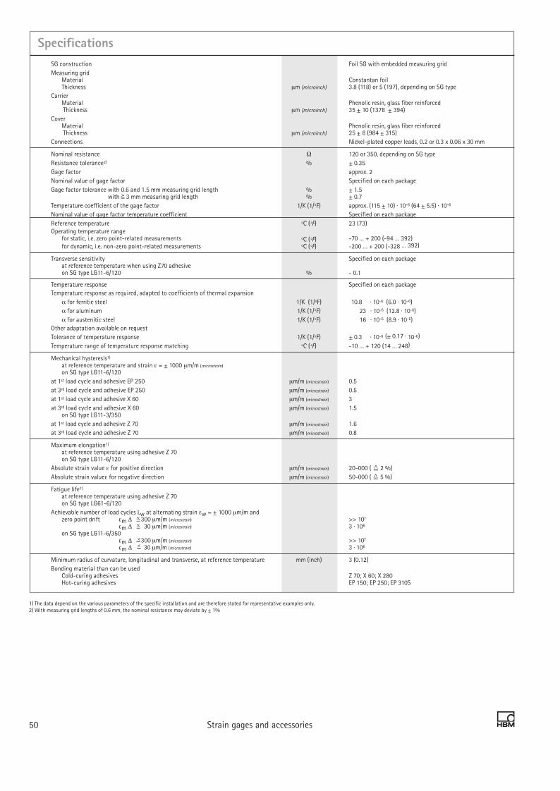
SpecificationsSG construction Foil SG with embedded measuring gridMeasuring grid
Material Constantan foil Thickness µm (microinch) 3.8 (118) or 5 (197), depending on SG type
Carrier Material Phenolic resin, glass fiber reinforced Thickness µm (microinch) 35 ± 10 (1378 ± 394)
Cover Material Phenolic resin, glass fiber reinforced Thickness µm (microinch) 25 ± 8 (984 ± 315)
Connections Nickel-plated copper leads, 0.2 or 0.3 x 0.06 x 30 mm
Nominal resistance Ω 120 or 350, depending on SG typeResistance tolerance2) % ± 0.35Gage factor approx. 2Nominal value of gage factor Specified on each packageGage factor tolerance with 0.6 and 1.5 mm measuring grid length % ± 1.5
with 3 mm measuring grid length % ± 0.7Temperature coefficient of the gage factor 1/K (1/ºF) approx. (115 ± 10) · 10-6 (64 ± 5.5) · 10-6
Nominal value of gage factor temperature coefficient Specified on each packageReference temperature ºC (ºF) 23 (73)Operating temperature range
for static, i.e. zero point-related measurements ºC (ºF) - 70 … + 200 (-94 … 392) for dynamic, i.e. non-zero point-related measurements ºC (ºF) - 200 … + 200 (-328 … 392)
Transverse sensitivity Specified on each package at reference temperature when using Z70 adhesive on SG type LG11-6/120 % - 0.1
Temperature response Specified on each packageTemperature response as required, adapted to coefficients of thermal expansion α for ferritic steel 1/K (1/ºF) 10.8 · 10-6 (6.0 · 10-6) α for aluminum 1/K (1/ºF) 23 · 10-6 (12.8 · 10-6) α for austenitic steel 1/K (1/ºF) 16 · 10-6 (8.9 · 10-6)Other adaptation available on requestTolerance of temperature response 1/K (1/ºF) ± 0.3 · 10-6 (± 0.17 · 10-6)
Temperature range of temperature response matching ºC (ºF) -10 … + 120 (14 … 248)
Mechanical hysteresis1) at reference temperature and strain ε = ± 1000 µm/m (microstrain) on SG type LG11-6/120
at 1st load cycle and adhesive EP 250 µm/m (microstrain) 0.5at 3rd load cycle and adhesive EP 250 µm/m (microstrain) 0.5at 1st load cycle and adhesive X 60 µm/m (microstrain) 3at 3rd load cycle and adhesive X 60 µm/m (microstrain) 1.5
on SG type LG11-3/350at 1st load cycle and adhesive Z 70 µm/m (microstrain) 1.6at 3rd load cycle and adhesive Z 70 µm/m (microstrain) 0.8
Maximum elongation1)
at reference temperature using adhesive Z 70 on SG type LG11-6/120
Absolute strain value ε for positive direction µm/m (microstrain) 20-000 ( 2 %)Absolute strain valueε for negative direction µm/m (microstrain) 50-000 ( 5 %)
Fatigue life1) at reference temperature using adhesive Z 70 on SG type LG61-6/120
Achievable number of load cycles Lw at alternating strain εw = ± 1000 µm/m and zero point drift εm ∆ 300 µm/m (microstrain) >> 107 εm ∆ 30 µm/m (microstrain) 3 · 106
on SG type LG11-6/350 εm ∆ 300 µm/m (microstrain) >> 107 εm ∆ 30 µm/m (microstrain) 3 · 106
Minimum radius of curvature, longitudinal and transverse, at reference temperature mm (inch) 3 (0.12)Bonding material than can be used
Cold-curing adhesives Z 70; X 60; X 280 Hot-curing adhesives EP 150; EP 250; EP 310S
Strain gages and accessories 5150 Strain gages and accessories
1) The data depend on the various parameters of the specific installation and are therefore stated for representative examples only.2) With measuring grid lengths of 0.6 mm, the nominal resistance may deviate by ± 1%
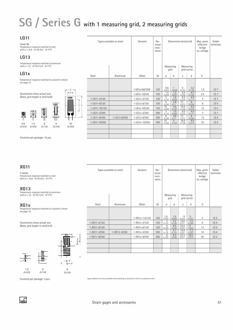
Strain gages and accessories 5150 Strain gages and accessories
XG11T rosetteTemperature response matched to steelwith α = 10.8 · 10-6/K (6.0 · 10-6/°F)
XG13Temperature response matched to aluminumwith α = 23 · 10-6/K (12.8 · 10-6/°F)
XG1xTemperature response matched to customer’s choicesee page 16
Illustrations show actual size(Data: grid length in mm/inch)
Contents per package: 5 pcs.
SG / Series G with 1 measuring grid, 2 measuring grids
LG11Linear SGTemperature response matched to steelwith a = 10.8 · 10-6/K (6.0 · 10-6/°F)
LG13Temperature response matched to aluminumwith a = 23 · 10-6/K (12.8 · 10-6/°F)
LG1xTemperature response matched to customer’s choicesee page 16
Illustrations show actual size(Data: grid length in mm/inch)
Contents per package: 10 pcs.
Types available ex stock Variants No- Dimensions (mm/inch) Max. perm. Solder minal effective terminals resis- bridge tance ex. voltage
Measuring Measuring grid grid carrier
Steel Aluminum Other Ω a b c d V
1-LG1x-0.6/120# 120 0.6 1 5 3.2 1.5 LS 7
1-LG1x-1.5/120 120 1.5 1.2 6.5 4.7 2.5 LS 7
1-LG11-3/120 1-LG1x-3/120 120 3 1.6 8.5 4.5 4 LS 7
1-LG11-6/120 1-LG1x-6/120 120 6 2.8 13 6 8 LS 5
1-LG11-10/120 1-LG1x-10/120 120 10 4.6 18.5 9.5 13 LS 5
1-LG11-3/350 1-LG1x-3/350 350 3 1.6 8.5 4.5 7 LS 7
1-LG11-6/350 1-LG13-6/350 1-LG1x-6/350 350 6 2.8 13 6 13 LS 5
1-LG11-10/350 1-LG1x-10/350 350 10 5 18.5 9.5 23 LS 5
Types available ex stock Variants No- Dimensions (mm/inch) Max. perm. Solder minal effective terminals resis- bridge tance ex. voltage
Measuring Measuring grid grid carrier
Steel Aluminum Other Ω a b c d V
1-XG1x-1.5/120 120 1.5 1.5 9 5 3 LS 5
1-XG11-3/120 1-XG1x-3/120 120 3 3.2 14.5 7.5 6 LS 4
1-XG11-6/120 1-XG1x-6/120 120 6 6.5 23.5 11 12 LS 5
1-XG11-3/350 1-XG13-3/350 1-XG 1x-3/350 350 3 3.1 14.4 7.3 10 LS 4
1-XG11-6/350 1-XG1x-6/350 350 6 6.3 23.3 10.5 20 LS 5
Types marked # are only available with matching to aluminum, ferritic or austenitic steel
0.024 0.039 0.197 0.126
0.059 0.047 0.256 0.185
0.118 0.063 0.335 0.177
0.236 0.11 0.512 0.236
0.394 0.181 0.728 0.374
0.118 0.063 0.335 0.177
0.236 0.11 0.512 0.236
0.394 0.197 0.728 0.374
0.059 0.059 0.354 0.197
0.118 0.126 0.571 0.295
0.236 0.256 0.925 0.433
0.118 0.122 0.567 0.287
0.236 0.248 0.917 0.413
0.6(0.024)
1.5(0.059)
3(0.118)
10(0.394)
6(0.236)
1.5(0.059)
3(0.118)
6(0.236)

Strain gages and accessories 5352 Strain gages and accessories
SG / Series G with 2 measuring grids
XG21Shear/torsion half bridgeTemperature response matched to steelwith α = 10.8 · 10-6/K (6.0 · 10-6/°F)
XG2xTemperature response matched to customer’s choicesee page 16
Illustrations show actual size(Data: grid length in mm/inch)
Contents per package: 5 pcs.
Types marked # are only available with matching to aluminum, ferritic or austenitic steel
0.06 0.07 0.10 0.268
0.18 0.12 0.15 0.209
0.44 0.37 0.24 0.311
0.39 0.69 0.5 0.118
0.18 0.21 0.44 0.374
1.5(0.059)
3(0.118)
6(0.236)
Types available ex stock Variants No- Dimensions (mm/inch) Max. perm. Solder minal effective terminals resis- bridge terminals tance ex. voltage
Measuring Measuring grid grid carrier
Steel Aluminum Other Ω a b c d V
1-XG2x-1.5/120 120 1.5 1.7 2.5 6.8 4.5 2.5 LS 7
1-XG2x-3/120 120 3 3.7 5.3 11.2 9.5 6 LS 5
1-XG2x-6/120 120 6 7.9 10 17.5 12.7 11 LS4
1-XG21-3/350 1-XG2x-3/350 350 3 4.5 5.3 11.2 9.5 10 LS4
1-XG21-6/350 1-XG2x-6/350 350 6 7.9 10 17.5 12.7 19 LS 5

Strain gages and accessories 5352 Strain gages and accessories
SG / K seriesSG / K seriesOptimum SG for manufacture of transducers
Carrier material: Glass-fiber reinforced phenolic resin Measuring grid material: Constantan
Various SG available with different creep adjustments
Specially matched compensating elements for zero point, TCO and TCS balancing
On request, every K series strain gage without leads can be supplied as stick-on strain gages (with touch-dry adhesive coating, hot curing) – for maximum precision and easy use in the manufacture of transducers.
SG installation on customized machine element
K series strain gages for manufacture of transducers

Specifications
Type LK1x, DK1x, LK2x, LK4x, XK5x, XK1x, DK2x, XK2x, MK1x XK6x, MK2x
SG construction Foil SG with embedded Foil SG without cover measuring grid, with integrated with integrated solder tabs connection leads
Measuring grid Material Constantan foil Thickness µm (microinch) 5 (197)
Carrier Material Phenolic resin, glass fiber reinforced Thickness µm (microinch) 35 ± 10 (1,378 ± 394)
Covering agent Material Phenolic resin, glass fiber reinforced
Thickness µm (microinch) 25 ± 8 (984 ± 315) –Connections Nickel-plated copper leads integrated
approx. 30 mm (1.18 inch) long contact surfaces
Nominal resistance Ω 350Resistance tolerance % ± 0.35 ± 0.3Gage factor approx. 2Nominal value of gage factor 3 Specified on each packageGage factor tolerance3) % ± 0.7Temperature coefficient of the gage factor 1/K (1/ºF) approx. (115 ± 10) · 10-6 (64 ± 5.5) · 10-6
Nominal value of gage factor temperature coefficient Specified on each package
Reference temperature ºC (ºF) 23 (73.4)Operating temperature range
for static, i.e. zero point-related measurements ºC (ºF) - 70 … + 200 (-94... +392) for dynamic, i.e. non-zero point-related measurements ºC (ºF) -200 … + 200 (-328... +392)
Transverse sensitivity Specified on each package at reference temperature when using Z70 adhesive on SG type LK11E-3/350 % - 0.09
Temperature response Specified on each packageTemperature response as required, adapted to coefficients of thermal expansion α for ferritic steel 1/K (1/ºF) 10.8 · 10-6 (6.0 · 10-6)α for aluminum 1/K (1/ºF) 23 · 10-6 (12.8 · 10-6)α for austenitic steel 1/K (1/ºF) 16 · 10-6 (8.9 · 10-6)Other adaptation available on requestTolerance of temperature response 1/K (1/ºF) ± 0.3 …· 10-6 (± 0.17 · 10-6)
Adaptation of temperature response in range ºC (ºF) -10 … + 120 (14... 248)
Creep adjustment2)
The end loop length u corresponds to a multiple of the grid line width s Code letter A: u = 1-s M: u = 7-s C: u = 2-s O: u = 8-s Umkehrstelle E: u = 3-s Q: u = 9-s G: u = 4-s S: u = 10-s I: u = 5-s U: u = 11-s K: u = 6-s W: u = 12-s
Mechanical hysteresis1) at reference temperature and strain ε = ± 1000 µm/m (microstrain) on SG type LK11E-3/350
at 1st load cycle and adhesive Z 70 µm/m (microstrain) 1.1at 3rd load cycle and adhesive Z 70 µm/m (microstrain) 0.8
Maximum elongation1)
at reference temperature using adhesive Z 70 on SG type LK11E-3/350
Absolute strain value ε for positive direction µm/m (microstrain) 20-000 ( 2 %)Absolute strain valueε for negative direction µm/m (microstrain) 50-000 ( 5 %)
Fatigue life 1) at reference temperature when using Z70 adhesive and alternating strain εw = ± 1000 µm/m on SG type K11E- 3/350 Achievable number of stress cycles with zero point variation εm ∆ 300 µm/m (microstrain) >> 107 εm ∆ 30 µm/m (microstrain) 3 · 106
Minimum radius of curvature, longitudinal and transverse, at reference temperature mm (inch) 3 (0.118) Applicable bonding materials Cold curing adhesives Z 70; X 60; X 280 Hot-curing adhesives EP 150; EP 250; EP 310S
Strain gages and accessories 5554 Strain gages and accessories
1) The data depend on the various parameters of the specific application and are therefore stated for representative examples only. 2) Different creep adjustments are available per type. 3) Does not apply for MK1x, MK2x.

Strain gages and accessories 5554 Strain gages and accessories
SG / Series K with 1 measuring grid / linear SG
LK11Linear SG with coverTemperature response matched to steelwith α = 10.8 · 10-6/K (6.0 · 10-6/°F)
LK13Temperature response matched to aluminumwith α = 23 · 10-6/K (12.8 · 10-6/°F)
LK1xTemperature response matched to customer’s choicesee page 16
Illustrations show actual size(Data: grid length in mm/inch)
Contents per package: 10 pcs.
LK21Linear SG without coverTemperature response matched to steelwith α = 10.8 · 10-6/K (6.0 · 10-6/°F)
LK23Temperature response matched to aluminumwith α = 23 · 10-6/K (12.8 · 10-6/°F)
LK2xTemperature response matched to customer’s choicesee page 16
Illustrations show actual size(Data: grid length in mm/inch)
Contents per package: 10 pcs.
Types available ex stock Variants No- Dimensions (mm/inch) Max. perm. Solder minal effective terminals resis- bridge tance ex. voltage
Measuring Measuring grid grid carrier
Steel Aluminum Other Ω a b c d V
1-LK1xE-3/350# E 3 3 9.5 5 10 LS 212
1-LK1xG-3/350# G 3 3 9.5 5 10 LS 212
1-LK11K-3/350 1-LK13K-3/350 1-LK1xK-3/350# K 3 3 9.5 5 10 LS 212
1-LK11O-3/350 1-LK1xO-3/350# O 3 3 9.5 5 10 LS 212
1-LK1xA-6/350# A 6 3 12.5 5 14 LS 212
1-LK1xC-6/350# C 6 3 12.5 5 14 LS 212
1-LK11E-6/350 1-LK13E-6/350 1-LK1xE-6/350# E 6 3 12.5 5 14 LS212
1-LK1xG-6/350# G 6 3 12.5 5 14 LS212
1-LK1xI-6/350# I 6 3 12.5 5 14 LS212
Types available ex stock Variants No- Dimensions (mm/inch) Max. perm. Solder minal effective terminals resis- bridge tance ex. voltage
Measuring Measuring grid grid carrier
Steel Aluminum Other Ω a b c d V
1-LK21K-3/350 1-LK2xK-3/350# K 3 3 9.5 5 9 LS 212
1-LK21O-3/350 1-LK23O-3/350 1-LK2xO-3/350# O 3 3 9.5 5 9 LS 212
1-LK21S-3/350 1-LK23S-3/350 1-LK2xS-3/350# S 3 3 9.5 5 9 LS 212
1-LK23W-3/350 1-LK2xW-3/350# W 3 3 9.5 5 9 LS 212
1-LK2xG-6/350# G 6 3 12.5 5 13 LS 212
1-LK21K-6/350 1-LK2xK-6/350# K 6 3 12.5 5 13 LS 212
1-LK2xO-6/350# O 6 3 12.5 5 13 LS212
(1) Solder terminals are not compulsoryTypes marked # are only available with matching to aluminum, ferritic or austenitic steel
0.118 0.118 0.374 0.197
0.118 0.118 0.374 0.197
0.118 0.118 0.374 0.197
0.118 0.118 0.374 0.197
0.236 0.118 0.492 0.197
0.236 0.118 0.492 0.197
0.236 0.118 0.492 0.197
0.236 0.118 0.492 0.197
0.236 0.118 0.492 0.197
0.118 0.118 0.374 0.197
0.118 0.118 0.374 0.197
0.118 0.118 0.374 0.197
0.118 0.118 0.374 0.197
0.236 0.118 0.492 0.197
0.236 0.118 0.492 0.197
0.236 0.118 0.492 0.197
3(0.118)
6(0.236)
3(0.118)
6(0.236)

LK4xLinear SG without coverTemperature response matched to customer’s choicesee page 16
Illustrations show actual size(Data: grid length in mm/inch)
Contents per package: 10 pcs.
Strain gages and accessories 5756 Strain gages and accessories
SG / Series K with 1 measuring grid / linear SG
Types available ex stock Variants No- Dimensions (mm/inch) Max. perm. Solder minal effective terminals resis- bridge tance ex. voltage
Measuring Measuring grid grid carrier
Steel Aluminum Other Ω a b c d V
1-LK4xK-3/350# K 3 3 10.5 5 9 LS 212
1-LK4xO-3/350# O 3 3 10.5 5 9 LS 212
1-LK4xS-3/350# S 3 3 10.5 5 9 LS 212
(1) Solder terminals are not compulsoryTypes marked # are only available with matching to aluminum, ferritic or austenitic steel
0.118 0.118 0.413 0.197
0.118 0.118 0.413 0.197
0.118 0.118 0.413 0.197
3(0.118)

Strain gages and accessories 5756 Strain gages and accessories
SG / Series K with 2 measuring grids / double SG
(1) Solder terminals are not compulsoryTypes marked # are only available with matching to aluminum, ferritic or austenitic steel
DK11Double SG with coverTemperature response matched to steelwith α = 10.8 · 10-6/K (6.0 · 10-6/°F)
DK13Temperature response matched to aluminumwith α = 23 · 10-6/K (12.8 · 10-6/°F)
DK1xTemperature response matched to customer’s choicesee page 16
Illustrations show actual size(Data: grid length in mm/inch)
Contents per package: 5 pcs.
DK21Double SG without coverTemperature response matched to steelwith α = 10.8 · 10-6/K (6.0 · 10-6/°F)
DK23Temperature response matched to aluminumwith α = 23 · 10-6/K (12.8 · 10-6/°F)
DK2xTemperature response matched to customer’s choicesee page 16
Illustrations show actual size(Data: grid length in mm/inch)
Contents per package: 5 pcs.
Types available ex stock Variants No- Dimensions (mm/inch) Max. perm. Solder minal effective terminals resis- bridge tance ex. voltage
Measuring Measuring grid grid carrier
Steel Aluminum Other Ω a b c d V
1-DK1xE-3/350# E 3 3 9.5 8.5 10 LS 224
1-DK11G-3/350 1-DK13G-3/350 1-DK1xG-3/350# G 3 3 9.5 8.5 10 LS 224
1-DK11K-3/350 1-DK1xK-3/350# K 3 3 9.5 8.5 10 LS 224
1-DK1xO-3/350# O 3 3 9.5 8.5 10 LS 224
1-DK1xA-6/350# A 6 3 12.5 8.5 14 LS 224
1-DK1xC-6/350# C 6 3 12.5 8.5 14 LS 224
1-DK11E-6/350 1-DK1xE-6/350# E 6 3 12.5 8.5 14 LS224
1-DK11G-6/350 1-DK1xG-6/350# G 6 3 12.5 8.5 14 LS224
1-DK1xI-6/350# I 6 3 12.5 8.5 14 LS224
Types available ex stock Variants No- Dimensions (mm/inch) Max. perm. Solder minal effective terminals resis- bridge tance ex. voltage
Measuring Measuring grid grid carrier
Steel Aluminum Other Ω a b c d V
1-DK21K-3/350 1-DK2xK-3/350# K 3 3 9.5 8.5 9 LS 224
1-DK21O-3/350 1-DK2xO-3/350# O 3 3 9.5 8.5 9 LS 224
1-DK2xS-3/350# S 3 3 9.5 8.5 9 LS 224
1-DK2xW-3/350# W 3 3 9.5 8.5 9 LS 224
1-DK2xG-6/350# G 6 3 12.5 8.5 13 LS 224
1-DK21K-6/350 1-DK23K-6/350 1-DK2xK-6/350# K 6 3 12.5 8.5 13 LS 224
1-DK2xO-6/350# O 6 3 12.5 8.5 13 LS224
0.118 0.118 0.374 0.335
0.118 0.118 0.374 0.335
0.118 0.118 0.374 0.335
0.118 0.118 0.374 0.335
0.236 0.118 0.492 0.335
0.236 0.118 0.492 0.335
0.236 0.118 0.492 0.335
0.236 0.118 0.492 0.335
0.236 0.118 0.492 0.335
0.118 0.118 0.374 0.335
0.118 0.118 0.374 0.335
0.118 0.118 0.374 0.335
0.118 0.118 0.374 0.335
0.236 0.118 0.492 0.335
0.236 0.118 0.492 0.335
0.236 0.118 0.492 0.335
3(0.118)
6(0.236)
3(0.118)
6(0.236)

XK21Shear/torsion SG without coverTemperature response matched to steelwith α = 10.8 · 10-6/K (6.0 · 10-6/°F)
XK2xTemperature response matched to customer’s choicesee page 16
Illustrations show actual size(Data: grid length in mm/inch)
Contents per package: 5 pcs.
XK11Shear/torsion SG with coverTemperature response matched to steelwith α = 10.8 · 10-6/K (6.0 · 10-6/°F)
XK13Temperature response matched to aluminumwith α = 23 · 10-6/K (12.8 · 10-6/°F)
XK1xTemperature response matched to customer’s choicesee page 16
Illustrations show actual size(Data: grid length in mm/inch)
Contents per package: 5 pcs.
3 Strain gages and accessories 5958 Strain gages and accessories
SG / Series K with 2 measuring grids / Torsion/shear SG
Types available ex stock Variants No- Dimensions (mm/inch) Max. perm. Solder minal effective terminals resis- bridge tance ex. voltage
Measuring Measuring grid grid carrier
Steel Aluminum Other a b1 b2 c d V
1-XK21K-3/350 1-XK2xK-3/350# K 3 4.5 5.8 15 8 9 LS224
1-XK21O-3/350 1-XK2xO-3/350# O 3 4.5 5.8 15 8 9 LS224
1-XK21S-3/350 1-XK2xS-3/350# S 3 4.5 5.8 15 8 9 LS224
Types available ex stock Variants No- Dimensions (mm/inch) Max. perm. Solder minal effective terminals resis- bridge tance ex. voltage
Measuring Measuring grid grid carrier
Steel Aluminum Other a b1 b2 c d V
1-XK11E-3/350 1-XK1xE-3/350# E 3 4.5 5.8 15 8 10 LS224
1-XK1xG-3/350# G 3 4.5 5.8 15 8 10 LS224
1-XK11K-3/350 1-XK1xK-3/350# K 3 4.5 5.8 15 8 10 LS224
1-XK11O-3/350 1-XK1xO-3/350# O 3 4.5 5.8 15 13 10 LS224
1-XK1xA-6/350# A 6 5.7 10.4 20 13 15 LS212
1-XK1xC-6/350# C 6 5.7 10.4 20 13 15 LS212
1-XK11E-6/350 1-XK1xE-6/350# E 6 5.7 10.4 20 13 15 LS212
1-XK1xG-6/350# G 6 5.7 10.4 20 13 15 LS212
1-XK1xI-6/350# I 6 5.7 10.4 20 13 15 LS212
(1) Solder terminals are not compulsoryTypes marked # are only available with matching to aluminum, ferritic or austenitic steel
0.118 0.18 0.23 0.591 0.315
0.118 0.18 0.23 0.591 0.315
0.118 0.18 0.23 0.591 0.315
0.118 0.18 0.23 0.591 0.512
0.236 0.22 0.41 0.787 0.512
0.236 0.22 0.41 0.787 0.512
0.236 0.22 0.41 0.787 0.512
0.236 0.22 0.41 0.787 0.512
0.236 0.22 0.41 0.787 0.512
0.118 0.1770.217 0.591 0.315
0.118 0.1770.217 0.591 0.315
0.118 0.1770.217 0.591 0.315
3(0.118)
6(0.236)
3(0.118)

3 Strain gages and accessories 5958 Strain gages and accessories
XK510°/90° T rosette with coverTemperature response matched to steelwith α = 10.8 · 10-6/K (6.0 · 10-6/°F)
XK5xTemperature response matched to customer’s choicesee page 16
Illustrations show actual size(Data: grid length in mm/inch)
Contents per package: 5 pcs.
XK6x0°/90° T rosette without coverTemperature response matched to customer’s choicesee page 16
Illustrations show actual size(Data: grid length in mm/inch)
Contents per package: 5 pcs.
Types available ex stock Variants No- Dimensions (mm/inch) Max. perm. Solder minal effective terminals resis- bridge tance ex. voltage
Measuring Measuring grid grid carrier
Steel Aluminum Other a b c d V
1-XK5xA-3/350# A 3 3 10 10 10 LS 224
1-XK51E-3/350 1-XK5xE-3/350# E 3 3 10 10 10 LS 224
1-XK51M-3/350 1-XK5xM-3/350# M 3 3 10 10 10 LS 224
1-XK51A-6/350 1-XK5xA-6/350# A 6 6 16 18 20 LS 224
1-XK5xC-6/350# C 6 6 16 18 20 LS 224
1-XK51E-6/350 1-XK5xE-6/350# E 6 6 16 18 20 LS 224
SG / Series K with 2 measuring grids / T rosette
Types available ex stock Variants No- Dimensions (mm/inch) Max. perm. Solder minal effective terminals resis- bridge tance ex. voltage
Measuring Measuring grid grid carrier
Steel Aluminum Other a b c d V
1-XK6xA-3/350# A 3 3 10 10 9 LS 224
1-XK6xE-3/350# E 3 3 10 10 9 LS 224
1-XK6xM-3/350# M 3 3 10 10 9 LS 224
1-XK6xA-6/350# A 6 6 16 18 18 LS 224
1-XK6xE-6/350# E 6 6 16 18 18 LS 224
1-XK6xI-6/350# I 6 6 16 18 18 LS 224
(1) Solder terminals are not compulsoryTypes marked # are only available with matching to aluminum, ferritic or austenitic steel
0.118 0.118 0.394 0.394
0.118 0.118 0.394 0.394
0.118 0.118 0.394 0.394
0.236 0.236 0.63 0.709
0.236 0.236 0.63 0.709
0.236 0.236 0.63 0.709
0.118 0.118 0.394 0.394
0.118 0.118 0.394 0.394
0.118 0.118 0.394 0.394
0.236 0.236 0.63 0.709
0.236 0.236 0.63 0.709
0.236 0.236 0.63 0.709
3(0.118)
6(0.236)
3(0.118)
6(0.236)

3 Strain gages and accessories 6160 Strain gages and accessories
SG / Series K with 4 measuring grids / diaphragm SG
Types available ex stock Variants Creep Dimensions (mm/inch) Max. perm. Solder adap- effective terminals tation bridge (1) ex. voltage
Measuring Measuring grid grid carrier
Steel Aluminum Other a b c d V
1-MK2xM-10/350# M 10 - 12 - 7 LS 224
Types available ex stock Variants No- Dimensions (mm/inch) Max. perm. Solder minal effective terminals resis- bridge tance ex. voltage
Measuring Measuring grid grid carrier
Steel Aluminum Other a b c d V
1-MK11M-10/350 1-MK1xM-10/350# M 10 - 13 - 8 LS 224
1-MK11M-15/350 1-MK1xM-15/350 # M 15 - 18 - 13 LS 224
MK11Diaphragm full bridge with coverTemperature response matched to steel with α = 10.8 · 10-6/K (6.0 · 10-6/°F)
MK1xTemperature response matched to customer’s choicesee page 16
Illustrations show actual size(Data: Dimension a in mm/inch)
Contents per package: 5 pcs.
MK2xDiaphragm full bridge without coverTemperature response matched to customer’s choicesee page 16
Illustrations show actual size(Data: grid length in mm/inch)
Contents per package: 5 pcs.
(1) Solder terminals are not compulsoryTypes marked # are only available with matching to aluminum, ferritic or austenitic steel
0.394 0.512
0.591 0.709
0.394 – 0.512 –
10(0.394)
15(0.591)
10(0.394)

3 Strain gages and accessories 6160 Strain gages and accessories
SG / Series K Balancing and compensating elements
NA1 6/4.73Adjustable foil resistor for zero point balancing on a polyimide carrier with a raw resistance of two times approx. 9 Ω. Per bridge branch, maximum 4.73 Ω can be connected, with the following stages:2.4 Ω – 1.2 Ω – 0.6 Ω – 0.3 Ω – 0.15 Ω – 0.08 Ω ± 20% a)
Zero point balancing resistor
Contents per package: 10 pcs.
TN1 3/1.05Adaptable foil resistor for temperature compensation of the zero point. Nickel foil on polyimide carrier with raw resistance of two times approx. 0.7 Ω. Each bridge branch can be connected with maximum 1.05 Ω, with the following stages: 0.6 Ω – 0.3 Ω – 0.15 Ω ± 20% a) Temperature coefficient of resistance: (+ 20°C…+ 70°C) (+68...+128°F): 4.9 · 10-3/K
TCO compensating resistor
Contents per package: 10 pcs.
TC1 4/60Adaptable foil resistor for temperature compensation of the sensitivity. Nickel foil on polyimide carrier with a raw resistance of approx. 1 Ω. Maximum 60 Ωcan be con-nected, with the following stages: 32 Ω – 16 Ω – 8 Ω – 4 Ω ± 20% a) Temperature coefficient of resistance: (+ 20°C…+ 70°C) (+68...+128°F): 4.9 · 10-3/K
TCS compensating resistor(Data: grid length in mm/inch)
Contents per package: 10 pcs.
Dimensions (mm/inch)
Grid Carrier
Type a b c d
1-NA1-6/4.73 6 14.5 8
Dimensions (mm/inch)
Grid Carrier
Type a b c d
1-TN1-3/1.05 6 11 8
Dimensions (mm/inch)
Grid Carrier
Type a b c d
1-TC1-4/60 4.2 7 11.5 9
a) Reference temperature for resistance data: T=23°C (73.4°F)
0.236 0.571 0.315
0.236 0.433 0.315
0.165 0.276 0.453 0.354

3 Strain gages and accessories 6362 Strain gages and accessories
SG / Series K Balancing and compensating elements
Example circuit of balancing and compensating elements in a straingage full bridge
It´s so easy, ... ...using stick-on strain gages:Preparation: - Roughly clean and degrease the installation area (e.g. with RMS1) - Grind (grain size 220-300), sandblast (e.g. corundum, grain size 80-100) - Clean with ultra-pure solvent (e.g. RMS1)
SG: No preparation required
Fixing the SG: With heat-resistant adhesive tape (e.g. 1-adhesive tape)
SG press-fitting: e.g. with a clamping device - protect the SG with separating foil (e.g. 1-Teflon) and pressure compensation pads (e.g. silicone) against damage
Curing theadhesives: Optimum curing occurs under the following conditions: - Contact pressure: 20-35 N/cm2 (36 – 51 lbf/sq. in.) - Heating rate (under pressure): 2.5 K (4.5 °F)/min from room temperature to 160°C (320°F) - Curing time: 3.5h at 160 °C (320°F) - Cooling (under pressure): down to room temperature - Subsequent curing (without pressure): 1h at 160 °C (320°F)
Series K strain gages without leads are also available with the stick-on option
Note: For more details, please refer to the HBM book “The route to measurement transducers”

3 Strain gages and accessories 6362 Strain gages and accessories
SG / V seriesSG / V series
Experimental investigations on a railway rail
Encapsulated SG
3m (9.84 ft) stranded connection wire, PVC insulated
High mechanical protection

Specifications
SG construction Foil SG with embedded measuring grid and cable in plastic potting Measuring grid
Material Constantan foil Thickness µm (microinch) 5 (197)
Carrier Material Polyimide Thickness µm (microinch) 45 ± 10 (1772 ± 394)
Covering agent Material Polyimide Thickness µm (microinch) 25 ± 5 ( 984 ± 197)
Potting Material Plastic Thickness mm (inch) approx. 1.5 (0.04)
Connections PVC-coated stranded connection wires, 3m long in two-wire circuit
Nominal resistance Ω 120; including stranded connection wireResistance tolerance % ± 0.5
Gage factor approx. 2Nominal value of gage factor Specified on each packageGage factor tolerance % ± 1
Temperature coefficient of the gage factor 1/K (1/ºF) approx. (115 ± 10) · 10-6 (( 64 ± 5.5) · 10-6)
Nominal value of gage factor temperature coefficient Specified on each package (Reference temperature ºC (ºF) 23 (73.4)
Operating temperature range for static, i.e. zero point-related measurements ºC (ºF) –30 … + 105 (-22 … + 221) for dynamic, i.e. non-zero point-related measurements ºC (ºF) –30 … + 105 (-22 … +221)
Temperature response Specified on each packageAdaptation of temperature response in range ºC (ºF) –10 … + 105 (-22 … + 221)
Maximum elongation1)
at reference temperature using adhesive Z 70 on SG type LV41-3/120
Absolute strain value ε for positive direction µm/m (microstrain) 20-000 ( 2 %)Absolute strain valueε for negative direction µm/m (microstrain) 50-000 ( 5 %)
Minimum radius of curvature, longitudinal and transverse, at reference temperature mm (inch) 100 (3.94)
Bonding material than can be used Cold-curing adhesives Z 70; X 60; X280
3 Strain gages and accessories 6564 Strain gages and accessories
SG / Series V Encapsulated SG with 3m (9.842 ft) stranded connection wire
1) The data depend on the various parameters of the specific application and are therefore stated for representative examples only.
LV41Linear SG Contents per package: 10 pcs.
XV910°/90° T rosetteContents per package: 5 pcs.
RV910°/45°/90° rosetteContents per package: 5 pcs.Temperature response matched to steelwith α = 10.8 · 10-6/K (6.0 · 10-6/°F)
LV41 XV91 RV91
Types available ex stock Nominal Dimensions (mm/inch) Max. perm. resistance effective bridge ex. voltage
Measuring Measuring grid grid carrier
Steel Ω a b c d V
1-LV41-3/120 120 3 1.1 19 12 2
1-XV91-3/120 120 3 1.4 24.5 20.5 2
1-RV91-3/120 120 3 1.25 24.5 20.5 1
0.118 0.043 0.748 0.472
0.118 0.055 0.965 0.807
0.118 0.049 0.965 0.807

3 Strain gages and accessories 6564 Strain gages and accessories
Special SG Encapsulated SG with stranded wire
IP 671) protection
With 1m Teflon-insulated stranded connection wire
Moisture proof and resistant against chemicals2) due to full encapsulation in special
plastic material
Excellent zero signal stability with changing moisture
Optionally 2-wire or 4-wire circuit
LE11Encapsulated linear SG Temperature response matched to steel α = 10.8 · 10-6/K (6.0 · 10-6/°F)
Illustrations show actual size
Contents per package: 5 pcs.
Specifications
Type LE11-3/350
SG construction Foil SG, IP 67, resistant against chemicals 2)
Measuring grid material Constantan foilMeasuring grid length mm (inch) 3 (0.12)Carrier
Material Special plastic material Thickness µm (microinch) 25 (984)
Covering material Special plastic material, 25 µm (microinch) thickThickness of complete SG mm (inch) 0.65 (0.026)
Nominal resistance Ω 350Resistance tolerance per package % ± 0.5Gage factor approx. 2Nominal value of gage factor Specified on each packageGage factor tolerance % ± 1
Reference temperature ºC (ºF) + 23 (73.4)Operating temperature range
for installation with Z 70 ºC (ºF) - 70 … + 120 (-94 … + 248) for installation with EP 250/EP 310S/X 280 ºC (ºF) -200 … + 180 (-328... +356)
Temperature response matched to thermal expansion coefficientα for ferritic steel 1/K (1/ºF) 10.8 · 10-6 (6.0 · 10-6 )
Temperature range of temperature response matching ºC (ºF) - 10…+ 120 (14... +248) Transverse sensitivity at reference temperature when using Z70 adhesive % 0.25
Minimum radius of curvature, longitudinal and transverse, at reference temperature mm (inch) 3 (0.118)
Maximum elongation at reference temperature µm/m (microstrain) ± 50 000 ( ± 5 %)Fatigue life at reference temperature
when using Z70 adhesive Achievable number of load cycles Lw at alternating strain εw = ± 1000 µm/m and zero point drift εm ∆ 300 µm/m (microstrain) >> 107 (test was interrupted at 107) εm ∆ 30 µm/m (microstrain) > 107 (test was interrupted at 107)
Connection cable, 1 m long 2 or 4 Teflon-insulated stranded wiresApplicable bonding materials Z 70, EP 150, EP 310S, EP 250, X 280
Types available ex stock Nominal Dimensions (mm/inch) Max. perm. resistance effective bridge ex. voltage
Measuring Measuring grid grid carrier
Steel Ω a b c d V
1-LE11-3/350Z (2-wire circuit) 350 3 2 15 9 6
1-LE11-3/350V (4-wire circuit) 350 3 2 15 9 6
1) Please note the resistance of the adhesives used. 2) Only concentrated acids (sulphuric acid, nitric acid) will destroy this special plastic material. High resistance against fuels and engine oils.
0.118 0.079 0.591 0.354
0.118 0.079 0.591 0.354

Specifications
Type LS 31-6/350
SG construction Foil SG (quarter bridge) with polyimide carrier and constantan measuring grid, hot-bonded to carrier plate
Measuring grid length mm/inch 6Carrier plate
I x w mm (inch) 40 x 10 Thickness mm (inch) 0.1 Material X 8 Cr 17 (1.4016)
Nominal resistance Ω 350Resistance tolerance per package % ± 1 ; measured at end of cableGage factor approx. 2Nominal value of gage factor Specified on each packageMaximum permissible bridge excitation voltage V 15
Reference temperature ºC (ºF) + 23 (73.4)Operating temperature range ºC (ºF) - 200 … + 150 (-328... +302)
Temperature response matched to thermal expansion coefficientα for ferritic steel 1/K (1/ºF) 10.8 · 10-6 (6.0 · 10-6)
Adaptation of temperature response in range °C - 10…+ 120 (14... 248)Minimum radius of curvature, longitudinal and transverse,
at reference temperature mm (inch) 75 (2.95)Maximum elongation at reference temperature µm/m (microstrain) ±3000 ( ± 0.3 %)
Strain-related restoring force N (lbf) < 250 (< 56) 1,000 μm/m(microstrain)
Bonding method Spot welding method
3 Strain gages and accessories 6766 Strain gages and accessories
LS31
Contents per package: 5 pcs. 1)
Cover agent Stranded wire 0.5 m (1.64 ft) long
1) Each package is supplied with two plates for welding exercises
Special SG / Weldable SG
Field of application: Strain measurements at increased temperatures on weldable components on which – due to their size – strain gage installation using hot curing adhesive is not possible. Use of strain gages "on site" where the cleanliness required for bonding cannot be guaranteed (construction sites, production plants, etc.).
Bonding: Spot welding is a simple bonding method for strain gages as hardly any preparations are necessary and very little practical experience is required of users.
Layout design: Y series foil strain gage on carrier plate, covered with transparent silicone rubber; fitted with 0.5 m (1.64 ft) stranded connection wires

3 Strain gages and accessories 6766 Strain gages and accessories
SG for high strains
LD20Linear strain gages for high strainsNo matching of temperature response
Illustrations show actual size(Data: grid length in mm/inch)
Contents per package: 10 pcs.
SG for high strains These strain gages are used in all applications where they are extended or shortened by > 5%.
Specifications: Maximum elongation ± 100-000 µm/m ( ±10%). Fatigue life: less resistance to alternating loads than with Y series strain gages.
More specifications: see page 19
Types available ex stock No- Dimensions (mm/inch) Max. perm. Solder minal effective terminals resis- bridge tance ex. voltage
Measuring Measuring grid grid carrier
Ω a b c d V
1-LD20-6/120 120 6 2.8 13 6 8 LS 7
1-LD20-10/120 120 10 4.6 18.5 9.5 13 LS 5
1-LD20-6/350 350 6 2.8 13 6 13 LS 7
1-LD20-10/350 350 10 5 18.5 9.5 23 LS 5
0.236 0.11 0.512 0.236
0.394 0.181 0.728 0.374
0.236 0.11 0.512 0.236
0.394 0.197 0.728 0.374
10(0.394)
6(0.236)

Specifications1)
Configuration Foil strain gage with embedded measuring grid Application of strain via the carrier foil
Connections Integrated solder tabs with strain relief, connected to vertically positioned, insulated connection pins
Measuring grid Material Ω Constantan Thickness µm (microinch) 5 (197)
Carrier material Material Polyimide Thickness µm (microinch) 45 ±10 (1.772 ± 394)
Basis foil Material Polyimide Thickness µm (microinch) 45 ±10 (1.772 ± 394)
Nominal resistance Ω 350
Resistance tolerance % ±0.35
Gage factor approx. 2 (specified on each package)
Gage factor tolerance % ±1
Temperature coefficient of the gage factor, approx. 1/K (1/ºF) (115±10) . 10-6 ((64 ± 5.5) . 10-6)
Nominal value of gage factor temperature coefficient Specified on each package
Transverse sensitivity Specified on each package
Reference temperature °C 23 (73.4)
Operating temperature range for static measurements (zero point related measurements) °C -40 ...+180 (-40 ...+356) for dynamic measurements (not zero point related measurements) °C -40 ...+180 (-40 ...+356)
Temperature response Specified on each package
Temperature response adapted to coefficients of thermal expansion α for quartz 1/K (1/ºF) 0.5 .10-6 (0.3 · 10-6 )
Temperature response tolerance 1/K (1/ºF) ±0.3.10-6 (±0.17 · 10-6)
Adaptation of temperature response in range °C -10 ... +120 (14... 248)
Max. elongation Absolute strain value for positive direction µm/m (microstrain) ±50.000 (5%) Absolute strain value for negative direction µm/m (microstrain) ±50.000 (5%)
Fatigue life at reference temperature using a multi-directional CFP sample
Ach. number of load cycles Lw at alternating strain εw = ± 1000 mm/m u. Zero point variation εm∆ < 100 µm/m (microstrain) 5 000 000 Zero point variation εm∆ < 300 µm/m (microstrain) 10 000 000
Minimum radius of curvature (longitudinal and transverse) at reference temperature within measuring grid area mm (inch) 0.3 (0.012) within solder tabs area mm (inch) ∞
Applicable bonding materials Matrix resin
3 Strain gages and accessories 6968 Strain gages and accessories
1) All data according to OIML guideline IR62
LI66-10/350 Strain gages for integration in composites
Types available ex stock Nominal Dimensions (mm/inch) Max. perm. Solder Temperature response restistance effective terminals adapted to: bridge (1) ex. voltage
Measuring Measuring grid grid carrier
Quartz Ω a b c d V 1-LI66-10/350 350 10 3.8 22 10 2.5 -0.394 0.15 0.866 0.394
4.72(0.186)

3 Strain gages and accessories 6968 Strain gages and accessories
TT-3/100 Temperature sensor
1) All data according to OIML guideline IR62
Typical characteristic curve of the TT-3/100 temperature sensor
-50
0
50
100
150
200
60 80 100 120 140 160 180 200
Registance [Ohm]
Tem
pera
ture
[°C]
Original size
Types available ex stock: Nominal Dimensions (mm/inch) resistance (at 0°C) (32°F)
Measuring Measuring grid grid carrier
Ω a b c d 1-TT-3/100 100 3 3.3 6.6 4.7
Special features
Rapid response time, through good thermal contact with component and very low heat capacity
Can be installed like metallic strain gages
Can also be installed on curved surfaces
Any resistance meter suitable for measured value acquisition
Specifications1)
SG construction Nickel temperature sensor (embedded)
Measuring grid Material Nickel Thickness µm (microinch) 5 ±0.3 (197±11.8),
Carrier material Material Polyimide Thickness µm (microinch) 40 ±5 (1575±197)
Cover
Material Polyimide Thickness µm (microinch) 25 ±5 (9841±197)
Connections Integrated solder tabs
Nominal resistance (at 0°C) Ω 100
Resistance tolerance of nominal resistance % ±1
Specification of nominal resistance Ω stated on packaging
Specification of resistance tolerance % ±0.3
Characteristic curve of the sensor stated on the packaging
Sensitivity error % 0.5 (at reference temperature)
Temperature range °C -50 ... +180 (-58... +356)
Minimum radius of curvature (longitudinal and transverse) at reference temperature mm (inch) 2, within solder tabs area 5
Applicable bonding materials Cold curing adhesives Z70, X60, X280 Hot curing adhesives EP150, EP250, EP310S
0.118 0.13 0.26 0.185
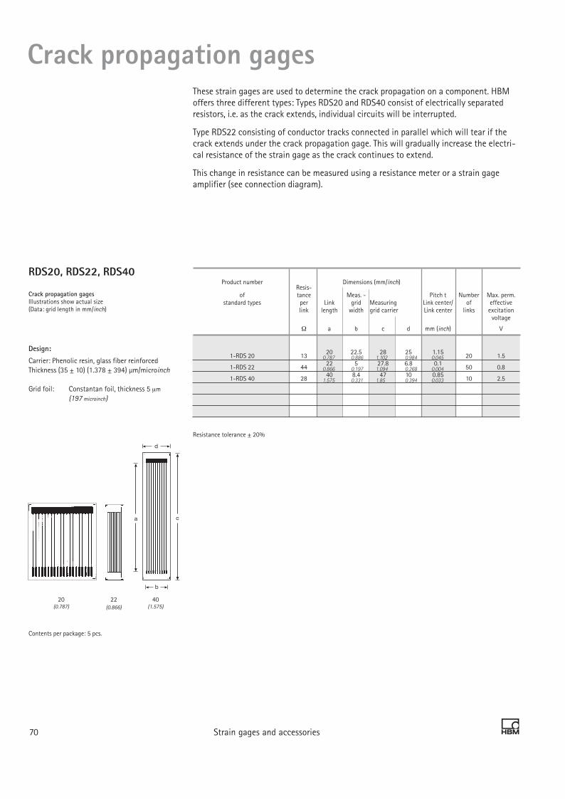
RDS20, RDS22, RDS40
Crack propagation gagesIllustrations show actual size(Data: grid length in mm/inch)
Design:
Carrier: Phenolic resin, glass fiber reinforced Thickness (35 ± 10) (1.378 ± 394) μm/microinch
Grid foil: Constantan foil, thickness 5 µm (197 microinch)
Contents per package: 5 pcs.
3 Strain gages and accessories 7170 Strain gages and accessories
Crack propagation gagesThese strain gages are used to determine the crack propagation on a component. HBM offers three different types: Types RDS20 and RDS40 consist of electrically separated resistors, i.e. as the crack extends, individual circuits will be interrupted.
Type RDS22 consisting of conductor tracks connected in parallel which will tear if the crack extends under the crack propagation gage. This will gradually increase the electri-cal resistance of the strain gage as the crack continues to extend.
This change in resistance can be measured using a resistance meter or a strain gage amplifier (see connection diagram).
a
b
c
d
Product number Resis-
Dimensions (mm/inch)
of tance Meas. - Pitch t Number Max. perm. standard types per Link grid Measuring Link center/ of effective link length width grid carrier Link center links excitation voltage
Ω a b c d mm (inch) V
1-RDS 20 13 20 22.5 28 25 1.15 20 1.5
1-RDS 22 44 22 5 27.8 6.8 0.1 50 0.8
1-RDS 40 28 40 8.4 47 10 0.85 10 2.5
Resistance tolerance ± 20%
0.787 0.886 1.102 0.984 0.045
0.866 0.197 1.094 0.268 0.004
1.575 0.331 1.85 0.394 0.033
40(1.575)
22(0.866)
20(0.787)

3 Strain gages and accessories 7170 Strain gages and accessories
Connecting a crack propagation gage There are two different types of crack propagation gages: RDS22 consisting of conductor tracks connected in parallel which will tear if the crack extends under the crack propaga-tion gage. This will gradually increase the electrical resistance of the strain gage as the crack continues to extend. Types RDS20 and RDS40 consist of electrically separated resis-tor lines, i.e. as the crack extends, individual circuits will be interrupted.If these are contacted individually, the direction in which the gap extends can be detected. The easiest way to detect the signals of crack propagation gages (RDS) is to measure the resistance. Many amplifiers from HBM enable such direct resistance measurements to be taken (e.g. MGCplus or Spider8 with the appropriate modules).
The resulting resistance (R) of the RDS is dependent on the number of torn links and can easily be calculated. n identical resistors (Ri) are connected in parallel:
Rn= If a grid line is interrupted, this is described by
R(n-1) =
The measurement can also be taken using an amplifier for strain gage measurements. The connection diagram shows how the RDS has to be comple-mented to obtain a resistance change that is inside the meas-uring range of an amplifier for strain gage quarter bridges.
Temperature effects can be minimized using temperature stable fixed resistors or strain gages as completion resistors. A higher sensitivity can be obtained by selecting a parallel resistor with a higher resistance value.
Crack propagation gages
0 Number of intact links
Typical signal curve for RDS20 with links connected in parallel Output signal
UA
UB
3-wire circuit between completionresistors and amplifier
Amplifier for strain gages in quarter bridge circuit, 350 Ω
Short, low-ohmleads
RDS22Crack propa-gation gages
R=349.5 OhmR=1Ohm
Connecting an RDS crack propagation gage to an SG amplifier
Ri
n
Ri
(n-1)
UA (bridge output voltage)UB (bridge excitation voltage)

3 Strain gages and accessories 7372 Strain gages and accessories
XY510°/90° ring core rosetteTemperature response matched to steelwith α = 10.8 · 10-6/K (6.0 · 10-6/°F)Operating temperature range: + 10°… + 60°C (+50°... +140°F)
Illustrations show actual size
Contents per package: 5 pcs.
RY510°/45°/90° ring core rosetteTemperature response matched to steelwith α = 10.8 · 10-6/K (6.0 · 10-6/°F) Operating temperature range: + 10°… + 60°C (+50°... +140°F)
Illustrations show actual size
Contents per package: 5 pcs.
SG for determination of residual stressFor determining residual stresses, the two following proven strain gage based technolo-gies are frequently used: the ring core method and the hole-drilling method. A common feature of both methods is that, after installation of the strain gage rosettes onto the work piece, the residual stress condition is disturbed by a suitable action. In case of the ring core method, this is done by cutting a circular groove around the strain gage rosette. In case of the hole-drilling method, a hole is drilled into the center of the rosette.
Following this action, residual stresses cause strains on the surface of the work piece, which are detected by the strain gage and then used for calculating the residual stress state.
Ring core method The XY51 rosettes (for residual stresses with known principal direction) and RY51 (for residual stresses with unknown principal direction) are specifically designed for the ring core method. This process enables high precision measurements to be taken and the residual stresses to be represented in relation to the drilling depth.
Specifications:
Resistance tolerance ± 1-%More specifications: see page 23
As these strain gages are covered by a print plate, they can be used on level or weakly curved surfaces only.
Types available ex stock Variants No- Dimensions (mm/inch) Max. perm. Solder minal effective terminals resis- bridge tance ex. voltage
Measuring grid Measuring grid carrier
Steel Aluminum Other Ω a b c d V
1-RY51-5/350 350 5 2.5 12 – 4.5 –
Specifications:
Resistance tolerance ± 1-%More specifications: see page 23
As these strain gages are covered by a print plate, they can be used on level or weakly curved surfaces only.
Types available ex stock Variants No- Dimensions (mm/inch) Max. perm. Solder minal effective terminals resis- bridge tance ex. voltage
Measuring grid Measuring grid carrier
Steel Aluminum Other Ω a b c d V
1-XY51-5/350 350 5 2.5 12 – 6.5 –0.197 0.098 0.472 –
0.197 0.098 0.472 –

3 Strain gages and accessories 7372 Strain gages and accessories
RY610°/45°/90°hole-drilling rosettefor use with HBM drilling device RY 61Temperature response matched to steel with α = 10.8 · 10-6/K + 10°… + 60°C (+50°... +140°F)
Illustrations show actual size
Contents per package: 5 pcs.
RY210°/45°/90° hole-drilling rosetteTemperature response matched to steelwith α = 10.8 · 10-6/K (6.0 · 10-6/°F)
Illustrations show actual size
Contents per package: 5 pcs.
SG for determination of residual stressHole-drilling method according to the integral method
Using RY21 or, particularly easy to handle, RY61 and the associated drilling device, (page 76), it is possible to determine the residual stresses according to the integral method.
The result is the integral mean value of the residual stresses over the entire drilling depth.
Types available ex stock Variants No- Dimensions (mm/inch) Max. perm. Solder minal effective terminals resis- bridge tance ex. voltage
Measuring grid Measuring grid carrier
Steel Aluminum Other Ω a b c d V
1-RY21-3/120 120 3 2.5 22.1 22.1 4.5 LS 5
Specifications:Resistance tolerance ± 1-%More specifications: see page 23
Types available ex stock Variants No- Dimensions (mm/inch) Max. perm. Solder minal effective terminals resis- bridge tance ex. voltage (1)
Measuring grid Measuring grid carrier
Steel Aluminum Other Ω a b c d V
1-RY61-1.5/120 120 1.5 0.8 – 12 2 LS 5
(1) Solder terminals are not compulsory
0.118 0.098 –0.866
0.059 0.031 0.472
(0.394)(0.079)
As these strain gages are covered by a print plate, they can be used on level or weakly curved surfaces only.

3 Strain gages and accessories 7574 Strain gages and accessories
RY61K0°/45°/90° rectangular hole drilling rosetteStrain gages with integrated contact surfaces Temperature response matched to steel with α = 10.8 · 10-6/K (6.0 · 10-6/°F)
Illustrations show actual size
Contents per package: 5 pcs.
RY61S0°/45°/90°hole-drilling rosetteTemperature response matched to steelwith α = 10.8 · 10-6/K (6.0 · 10-6/°F) (see page 47).
Illustrations show actual size
Contents per package: 5 pcs.
SG for determination of residual stress
Types available ex stock Variants No- Dimensions (mm/inch) Max. perm. Solder minal effective terminals resis- bridge (1) tance ex. voltage
Measuring grid Measuring grid carrier
Steel Aluminum Other Ω a b c d V
1-RY61-1.5/120S 120 1.5 0.8 – 10.2 2 LS 5
a
b
c
d
RY61R0°/45°/90°hole-drilling rosetteTemperature response matched to steelwith α = 10.8 · 10-6/K (6.0 · 10-6/°F)
Illustrations show actual size
Contents per package: 5 pcs.
Types available ex stock Variants No- Dimensions (mm/inch) Max. perm. Solder minal effective terminals resis- bridge (1) tance ex. voltage
Measuring grid Measuring grid carrier
Steel Aluminum Other Ω a b c d V
1-RY6x-1.5/120R** 120 1.5 0.8 8 13.5 2 LS 7
Types available ex stock Variants Nominal Dimensions (mm/inch) Max. perm. Solder resis- effective terminals tance bridge (1) ex. voltage
Measuring grid Measuring grid carrier
Steel Aluminum Other Ω a b c d V
1-RY61-1.5/120K 120 1.5 0.8 7.2 10.2 2 LS 7
Types available ex stock Variants No Dimensions (mm/inch) Max. perm. Solder minal effective terminals resis- bridge (1) tance ex. voltage
Measuring grid Measuring grid carrier
Steel Aluminum Other Ω a b c d V
1-RY61-3.2/120S 120 3.2 3.2 20.9 22 10 LS 5
RY61-3.2/120S0°/45°/90°hole-drilling rosetteTemperature response matched to steelwith α = 10.8 · 10-6/K (6.0 · 10-6/°F) (see page 47).
Illustrations show actual size
Contents per package: 5 pcs.
(1) Solder terminals are not compulsory**= only available with temperature response matched to ferritic steel
0.059 0.031 0.283 0.402
0.059 0.031 0.315 0.531
0.059 0.031 – 0.402
0.126 0.126 0.823 0.866

3 Strain gages and accessories 7574 Strain gages and accessories
VY61S0°/45°/90°/135° hole-drilling rosetteTemperature response matched to steelwith α = 10.8 · 10-6/K (6.0 · 10-6/°F)
Illustrations show actual size
Contents per package: 5 pcs.
a
b
d
Types available ex stock Variants No- Dimensions (mm/inch) Max. perm. Solder minal effective terminals resis- bridge (1) tance ex. voltage
Measuring grid Measuring grid carrier
Steel Aluminum Other Ω a b c d V
1-VY6x-1.5/120S** 120 1.5 0.8 - 10.2 2 LS 5
(1) Solder terminals are not compulsory**= only available with temperature response matched to ferritic steel
SG for determination of residual stress
Types available ex stock Variants No- Dimensions (mm/inch) Max. perm. Solder minal effective terminals resis- bridge tance ex. voltage
Measuring grid Measuring grid carrier*
Steel Aluminum Other Ω a b c d V
1-RY61-1.5/120M 120 1.5 0.77 11.7 22.5 2.5 -
1-RY61-1.5/350M 350 1.5 0.77 11.7 22.5 4.5 -
*= Dimensions of SG without circuit board
RY61M0°/45°/90°hole-drilling rosette, symmetricalTemperature response matched to steelwith α = 10.8 · 10-6/K (6.0 · 10-6/°F)
Illustrations show actual size
Contents per package: 5 pcs.In residual stress analysis based on the hole drilling method, even small eccentricities can cause relatively large measurement errors.The symmetrical hole drilling rosette RY61M, with 6 measuring grids, has the advantage, due to the opposing radially arranged measurement grids, that any measurement errors in a common measurement direction can be almost completely compensated for.
0.059 0.031 0.402
0.059 0.03 0.461 0.886
0.059 0.03 0.461 0.886

Integral hole drilling method
3 Strain gages and accessories 7776 Strain gages and accessories
MTS 3000 System for automatically determining residual stress based on the hole drilling method
For more information refer topage 98.
Drilling device for hole drilling rosette 1-RY61-1.5/120 The drilling device is used to apply the hole in the center of the installed hole drilling rosette. It comprises a magnetic holder, a centering pin, a shaft drill, and a universal coupling: Order No.: 1-RY61Spare drill for material hardness up to 30 HRC: Order No..: 1-8410.0019Carbide drill for material hardness up to 45 HRC: Order No.: 2-9219.9133
SINT Technology, a HBM partner, offers the measurement chain MTS3000 with which it is easy to implement the hole drilling method. To create the hole, a cutter with a speed of 400,000 rpm is used, driven by a stepper motor. The strain changes arising due to the step by step drilling of the hole into the work piece will be detected by a strain gage rosette (see page 74) specifically designed for this process.

Customized strain gages
Customized strain gages
Contact us, we will produce customized strain gages according to your requirements! From quantities of 20 packages onwards. Please use the request form included in our strain gage price list or send your request or layout direct via fax or e-mail to: [email protected]
Please also refer to our catalog“Strain gages for manufacturersof transducers”
You have special requirements which cannot be met by a strain gage from our standard product range?
You are looking for a strain gage equivalent to the one you currently use?
You have designed your own strain gage?
T strain gages
Diaphragm rosette strain gages
Half bridge strain gages
Full bridge strain gages
3 Strain gages and accessories 7776 Strain gages and accessories

3 Strain gages and accessories 7978 Strain gages and accessories
Optical strain gagesOptical strain gages Based on fiber Bragg grating
K-OPCharacteristic features- Optical strain gages - based on fiber Bragg grating
- Up to 13 optical strain gages per glass fiber
- Installation like electrical strain gages
- All relevant data determined and displayed, e.g. gage factor
- Insensitive to electromagnetic interferences
- Application in Ex-areas possible
- Lower wiring outlay compared to electrical strain gages
- Lower mass of glass fiber compared to standard connecting cables

3 Strain gages and accessories 7978 Strain gages and accessories
Optical strain gages
1) Spliced fiber optic cable with plug and buffer is available as an option (length as requested by customer).
2) Contact pressure when using X280 with optical strain gage: 1 N/cm2
Achievable number of load cycles dependent on quality of installation and fatigue life of component under investigation.
Specifications
SG construction Glass fibers with Bragg grating symmetrically embedded in modified modified acrylic resin, potted in plastic material
Outside diameter of glass fiber µm (microinch) 185 (7283)
Core diameter of glass fiber, approx. µm (microinch) 5 (197)
Diameter with buffer, approx. mm (inch) 1.5 (0.06)
Dimensions SG with potting SG without potting
(Standard) (Customer requirem.) Length mm (inch) 40±1 (1.575±0.039) 30±1 (1.181±0.039) Width mm (inch) 12±0.5 (0.472±0.02) 5±1 (0.197±0.039) Thickness mm (inch) 2.0±0.5 (0.079±0.02) 0.5±0.01 (0.02±0.0004)
Connector (plug)1) FC/ACP
Available Bragg wavelengths nm 1520, 1525, 1530, 1535, 1540, 1545, 1550, 1555, 1560, 1565, 1570, 1575, 1580
Bragg wavelength tolerance nm ±1
Gage factor approx. 0.79 (stated on the packaging)
Gage factor tolerance % 2
Reference temperature °C (ºF) 23 (73.4)
Operating temperature range °C (ºF) -10 ... +80 (-14 ... +176)
Storage temperature range °C (ºF) -20 ... +100 (--4 ... +212)
Temperature response (thermal expansion coefficient of measurement object 0 μm/m/K) μm/m/K 7.8
Tolerance of temperature response μm/m/K 1
Maximum elongation at reference temperature when using Z70 adhesive Absolute strain value for positive direction µm/m (microstrain) 10.000 (1%) Absolute strain value for negative direction µm/m (microstrain) 10.000 (1%)
Fatigue life at reference temperature when using Z70 adhesive
Achieved no. of load cycles Lw at alternating strain εw = ± 1000 µm/m (microstrain) and Zero point variation εm∆ 30 µm/m (microstrain) >>107 (interrupted after 107 load cycles)
Alternating strain εw = ± 3000 µm/m (microstrain) and Zero point variation εm∆ 60 µm/m (microstrain) >>107 (interrupted after 107 load cycles)
Fatigue life at reference temperature when using adhesive X2802)
Achieved no. of load cycles Lw at alternating strain εw = ± 5000 µm/m (microstrain) and zero point variation εm∆ 100 µm/m (microstrain) >>107 (interrupted after 107 load cycles)
Minimum radius of curvature, longitudinal and transverse, at ref. temperature mm (inch) 25 (0.98
Applicable bonding materials Cold curing adhesives Z70, X60, X280

3 Strain gages and accessories 8180 Strain gages and accessories
The most usual way to connect strain gages to the test object is by bonding. It is essential that adhesives are used that are application-specific and that meet the follow-ing requirements:• Loss-free transfer of deformation of the test object to the strain gage• Stable behavior across a temperature and strain range which is as wide as possible• The strain gage and test object must not be chemically attacked
All adhesive packages from HBM include the adhesive and the accessories (such as Teflon foil) required for bonding and, in addition, a safety data sheet. Your criteria for adhesive selection should be:• Application temperature• Material of the measuring body and recommendations for the relevant strain gage• Requirements for long-term stability and reproducibility• Surface roughness
Hot curing adhesivesHot curing adhesives can be used where the test object can be brought up to the curing temperature. This is generally possible in the manufacture of transducers, but also where installations can be made before machine assembly or where the machine can be disas-sembled. Hot curing adhesives meet higher quality demands and can be used within a greater temperature range than cold curing adhesives.
SG accessories ... SG fastening materials
Adhesive Description Suitable SG Pot life Storage life Curing Curing Contact pressure Temperature limits Delivery quantity at room temperature (RT) Dry temperature time3) (N/mm2 ) lower upper upper static1) dynamic2)
Cold curing Z 70 Cyanacrylate adhesive, optimum: Y, C, LD, LE, V – 6 months 5°C (41°F) 3) 10 minutes Thumb pressure – 55°C -67°F) + 100°C (212°F) +120°C (248°F) 10 ml Order No.: low viscosity, SG residual stress at – 15°C (5°F): 20°C (68°F) 1 minute (briefly 1 Z 70 good: K, G minimum 2 years 30°C (86°F) 0.5 minutes - 70°C (-94°F)) for optional use with Z 70 1-BCY 01 Accelerator for Z 70
X 60 Methyl metacrylate optimum: Y, C, LD, V 5 minutes > 1 year 0°C (32°F) 60 minutes Thumb pressure – 200°C + 60°C (140°F) + 80°C (176°F) Components Order No.: Two-component adhesive SG residual stress 20°C (68°F) 10 minutes (-328°F) A= 0.1 kg 1-X 60 pasty, also suitable for good: K, G, LS 35°C (95°F) 2 minutes B = 80 ml absorbent or uneven surfaces Other container sizes, see price list
X 280 Two-component optimum: Y, C, LD, LE, V 30 minutes 1 year at + 4°C (39°F) RT . . . 95°C 8 h . . . 1 h 0.05 . . . 2.0 – 70°C + 200°C (392°F) + 280°C (536°F) 6 double Epoxy resin adhesive good: G, K (203°F) (-94°F) bags à Order No.: for smooth and absorbent 10 g = 60 g 1-X 280 surfaces Hot curing EP 150, Single-component optimum: Y, C, K, G, LD, LE - 12 months at 160 . . . (320...) 6 h . . . 1 h 0.3 . . . 0.5 – 70 °C + 150 °C (302°F) + 150 °C (302°F) 2 x 30 ml bottles EP 150 GP Epoxy resin adhesive good: SG residual stress Storage in 190 °C (374°F) (-94°F) (EP 150) Order No.: Low viscosity refrigerator (7 °C 10 x 20 ml bottles 1-EP150 (44.6°F)) (EP 150-GP) Order No.: 1-EP150-GP EP 310 S Two-component optimum: Y, C, K, G, LD, LE 1 month (at RT) 6 months 95... (203°F. . . ) 5 h . . . 0.5 h 0.1 . . . 0.5 -270°C + 260°C (500°F) + 310°C (590°F) Components Order No.: Epoxy resin adhesive good: SG residual stress 6 months (at + 2°C (+36°F)) 205°C (401°F) (-454°F) A = 60 ml 1-EP 310 S low viscosity, 12 months (at – 32°C (-26°F)) B = 30 ml
EP 250 Two-component optimum: Y, C, K, G, LD, LE 24 h 1 year 95 . . . (203°F... ) 16 h . . . 0.5 h 0.1 . . . (0.15...) – 240°C + 250°C (428°F) + 315°C (599°F) 5 double bags à Order No.: Epoxy resin adhesive good: SG residual stress 200°C (392°F) 1.5 (2.18) (-400°F) 10.5 g (0.37 oz) = 1-EP 250 pasty, also suitable for 52.5 g (1.85 oz) absorbent surfaces
EP 310 S
EP 250
EP 150
X 280
X 60
BCY 01
Z 70

3 Strain gages and accessories 8180 Strain gages and accessories
Cold curing adhesivesCold curing adhesives are easy to use and can be processed at minimum cost and effort as they harden under normal ambient conditions. If they have short curing times they are also called “superglues”. The preferred field of application is in experimental stress analysis. However, if the temperature around the measuring point is higher than about 80° C (176°F), we recommend using a hot curing adhesive or a heat resistant cold curing epoxy resin adhesive (X280).
Spot weld jointsSpot weld joints are only possible with the special strain gage type LS 31, and if the test object is of a weldable material. This method is particularly suitable for applications where cleanliness required for bonding cannot be guaranteed. Hardly any preparations or experience are necessary. However, it is essential to follow the process instructions sup-plied with the strain gages.
SG accessories ... SG fastening materials
1) Zero-point based measurement 2) Non-zero-point based measurement 3) Curing condition: Relative humidity of 30 - 80%
Adhesive Description Suitable SG Pot life Storage life Curing Curing Contact pressure Temperature limits Delivery quantity at room temperature (RT) Dry temperature time3) (N/mm2 ) lower upper upper static1) dynamic2)
Cold curing Z 70 Cyanacrylate adhesive, optimum: Y, C, LD, LE, V – 6 months 5°C (41°F) 3) 10 minutes Thumb pressure – 55°C -67°F) + 100°C (212°F) +120°C (248°F) 10 ml Order No.: low viscosity, SG residual stress at – 15°C (5°F): 20°C (68°F) 1 minute (briefly 1 Z 70 good: K, G minimum 2 years 30°C (86°F) 0.5 minutes - 70°C (-94°F)) for optional use with Z 70 1-BCY 01 Accelerator for Z 70
X 60 Methyl metacrylate optimum: Y, C, LD, V 5 minutes > 1 year 0°C (32°F) 60 minutes Thumb pressure – 200°C + 60°C (140°F) + 80°C (176°F) Components Order No.: Two-component adhesive SG residual stress 20°C (68°F) 10 minutes (-328°F) A= 0.1 kg 1-X 60 pasty, also suitable for good: K, G, LS 35°C (95°F) 2 minutes B = 80 ml absorbent or uneven surfaces Other container sizes, see price list
X 280 Two-component optimum: Y, C, LD, LE, V 30 minutes 1 year at + 4°C (39°F) RT . . . 95°C 8 h . . . 1 h 0.05 . . . 2.0 – 70°C + 200°C (392°F) + 280°C (536°F) 6 double Epoxy resin adhesive good: G, K (203°F) (-94°F) bags à Order No.: for smooth and absorbent 10 g = 60 g 1-X 280 surfaces Hot curing EP 150, Single-component optimum: Y, C, K, G, LD, LE - 12 months at 160 . . . (320...) 6 h . . . 1 h 0.3 . . . 0.5 – 70 °C + 150 °C (302°F) + 150 °C (302°F) 2 x 30 ml bottles EP 150 GP Epoxy resin adhesive good: SG residual stress Storage in 190 °C (374°F) (-94°F) (EP 150) Order No.: Low viscosity refrigerator (7 °C 10 x 20 ml bottles 1-EP150 (44.6°F)) (EP 150-GP) Order No.: 1-EP150-GP EP 310 S Two-component optimum: Y, C, K, G, LD, LE 1 month (at RT) 6 months 95... (203°F. . . ) 5 h . . . 0.5 h 0.1 . . . 0.5 -270°C + 260°C (500°F) + 310°C (590°F) Components Order No.: Epoxy resin adhesive good: SG residual stress 6 months (at + 2°C (+36°F)) 205°C (401°F) (-454°F) A = 60 ml 1-EP 310 S low viscosity, 12 months (at – 32°C (-26°F)) B = 30 ml
EP 250 Two-component optimum: Y, C, K, G, LD, LE 24 h 1 year 95 . . . (203°F... ) 16 h . . . 0.5 h 0.1 . . . (0.15...) – 240°C + 250°C (428°F) + 315°C (599°F) 5 double bags à Order No.: Epoxy resin adhesive good: SG residual stress 200°C (392°F) 1.5 (2.18) (-400°F) 10.5 g (0.37 oz) = 1-EP 250 pasty, also suitable for 52.5 g (1.85 oz) absorbent surfaces

3 Strain gages and accessories 8382 Strain gages and accessories
The quality of a measuring point with strain gages is not only dependent on the strain gage itself but mainly on the type of installation and its implementation. A properly functioning measuring point requires thorough preparation of the installation surface, careful bonding, correct connections and also a protective covering. It is therefore important to provide the user with all necessary aids. The HBM strain gage accessory product range offers everything necessary for good strain gage installation.
SG covering agentsIn general, it is recommended that strain gages be protected against external effects such as humidity or mechanical damage since even small fluctuations in the atmospheric humidity affect the measured signal of a strain gage.Suitable covering agents should have only minimum effects on the measuring point.The strain gage and test object must not be attacked. Criteria for selecting the appropri-ate covering agent should be: Application temperature Media surrounding the measuring point
The following table will help in the selection of a suitable means of measuring point protection, which for special requirements can also be carried out in several layers. For instance, it would make sense to apply AK22, with - in extremely humid environments - additional sealing by ABM 75. Caution: NG 150 cannot be combined with PU 140.Please ensure, in the case of multi-layer covering, that the second layer may only be applied after full curing of the first layer and that it should overlap on all sides. All HBM covering agents are supplied with a safety data sheet.
SG accessories ... SG covering materials
AK 22
ABM 75

3 Strain gages and accessories 8382 Strain gages and accessories
SG accessories ... SG covering agents
PU 140
1) Caution: PU 140 and NG 150 cannot be combined
NG 150
SL 450
SG 200
SG covering materials Temperature range Package One package Application Curing Storage life Components of resistance contents sufficient for method conditions at room in air in °C approx. temperature
AK 22 – 50 °C . . . + 170 °C 1 kg 30 SGs kneading on – unlimited viscous, kneadable, Viscous putty (-58°F. . . +338°F) (2.2 lb) by hand sticky putty Order No.: 1-AK 22
ABM 75 – 196 °C . . . + 75 °C 11 pcs. 200 SGs pressing on – unlimited 0.05 mm thick Aluminum foil (-321°F. . . +167°F) 205 mm x by hand aluminum foil, coated with kneading compound 100 mm with 3 mm thick Order No.: 1-ABM 75 (8.07 x 3.94 in.) kneading compound
NG 150 1) – 269 °C . . . + 150 °C 3 bottles 35 SGs brush on air-drying max. 1 year solvent-containing Nitrile rubber (-452°F. . . +302°F) each with with brush at room single-component Order No.: 1-NG 150 approx. 25 cm3 temperature nitrile rubber
(0.85 liquid ounce, US)
SG 200 -55 °C . . . +200 °C Tube with 20 SGs application room 6 months white white -67°F . . . + 392°F) approx. 85 g from tube temperature single-component Silicone rubber (3.0 oz) silicone rubber Order No.: 1-SG 200
SG 250 – 70 °C . . . + 250 °C Tube with 20 SGs application Air-drying 6 months transparent, Transparent (-94°F . . . +482°F) approx. 85 g from tube at room solvent free Silicone rubber (3.0 oz) temperature single-component Order No.: 1-SG 250 silicone rubber
PU 140 1) – 40 °C . . . + 140 °C 3 bottles 250 SGs brush on room temperature 9 months solvent containing Polyurethane paint -40°F . . . + 284°F) each with 30 ml with brush . . . + 80°C single-component Order No.: 1-PU 120 (1.0 liquid ounce, US) (. . . + 176°F) polyurethane paint
SL 450 – 50 °C . . . + 450 °C 3 bottles 90 SGs brush on in temperature 6 months transparent, Transparent (-58°F . . . +842°F) each with 25 g with brush stages from solvent containing Silicone resin (0.9 oz) 95°C to 315°C silicone resin Order No.: 1-SL 450 (203°F... 599°F)
SG 250
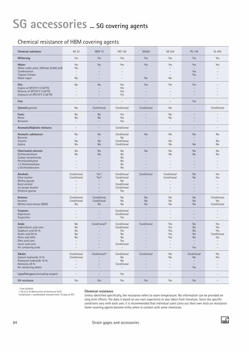
3 Strain gages and accessories 8584 Strain gages and accessories
Chemical resistanceUnless identified specifically, the resistance refers to room temperature. No information can be provided on long term effects. The data is based on our own experience or was taken from literature. Since the specific conditions vary with each user, it is recommended that individual users carry out their own tests on resistance Some covering agents become milky when in contact with some chemicals.
1) Low alcohols2) Up to 5-% (destruction of aluminum foil!)Conditional = conditionally resistant (min. 10 days at RT)
SG accessories ... SG covering agents
Chemical resistance of HBM covering agents
Chemical substance AK 22 ABM 75 NG 150 SG200 SG 250 PU 140 SL 450
Witterung Yes Yes Yes Yes Yes Yes Yes
Water: Yes Yes Yes Yes Yes Yes Yes Water under press. (400 bar (5,800 psi)) Yes – – - – – – Condensation – – – - – Yes – Tropical climate – – – - – Yes – Water vapor No – – No No – –
Oils: No No Yes Yes Yes Yes – Engine oil (RT/70°C (158°F)) – – Yes - – – – Mineral oil (RT/70°C (158°F)) – – Yes - – – – Hydraulic oil (RT/70°C (158°F)) – – Yes - – – –
Fats - – – - – Yes –
Solvents general No Conditional Conditional Conditional No - Conditional
Fuels: No No Yes - No – – Petrol No No Yes - No – – Kerosene – – Yes - – – –
Aromatic/Aliphatic mixtures – – Conditional - – – –
Aromatic substances: No No Conditional No No No No Benzene – – No - – – – Toluene No No Conditional - No - No Xylene No No Conditional - No No No
Chlorinated solvents: No No No No No No No Dichloromethane No No No - No No No Carbon tetrachloride – – No - – – – Perchloroethylene – – No - – – – 1.2-Dichloroethane – – No - – – – o-Dichlorobenzene – – No - – – –
Alcohols: Conditional Yes1) Conditional Conditional Conditional No Yes Ethyl alcohol Conditional Yes1) Conditional - Conditional No Yes Methyl glycole – – No - – - – Butyl alcohol – – Conditional - – - – iso-propyl alcohol – – Conditional - – - – Ethylene glycole – – Yes - – – –
Ketones: Conditional Conditional No No No No Conditional Acetone Conditional Conditional No No No No Yes Methyl ethyl ketone (MEK) No No No No No No Conditional
Terpenes: – – Conditional - – – – Dipentenes – – Conditional - – – – Turpentine – – Yes - – – –
Acids: No Conditional2) Conditional Conditional Yes No Yes Hydrochloric acid conc. No – Conditional - Yes No Yes Sulphuric acid 50 % No – Yes - Yes No Yes Acetic acid 50 % No – No - Yes No Conditional Nitric acid 50% No – No - Yes No Yes Oleic acid conc. – – Yes - – – – Lactic acid conc. – – Conditional - – – – Air containing acids – – – - – Yes –
Alkalis: Conditional Conditional2) Conditional Conditional No Conditional Yes Sodium hydroxide 10 % Conditional – No - No No Yes Potassium hydroxide 10 % – – No - – – – Ammonia 28 % – – Conditional - – – – Air containing alkalis – – – - – Yes –
Liquefied gases (excluding oxygen) – – Yes - – – –
UV resistance Yes Yes Yes Yes Yes Yes –

3 Strain gages and accessories 8584 Strain gages and accessories
SG accessories ... Cleaning agents, gluing and soldering materials
Cleaning agent RMS1Environmentally-friendly solvent mixture that dissolves all normal contamination. One packing unit contains 1 l cleaning agent and 450 cleaning pads.Order No.: 1-RMS1
Cleaning agent RMS1 SPRAYEnvironmentally-friendly solvent mixture. Contains 5 spray cans with 200 ml cleaning agent each and 450 cleaning pads.Order No.: 1-RMS1-SPRAY
Teflon foil33 m (108.27 ft)Teflon foil on reel, suitable for cold and hot curing strain gage bonding. The Teflon foil prevents other material except the strain gage from bonding to the com-ponent. Thickness: 0.05 mm (0.000164 inch), width: 60 mm (0.197 inch)Order No.: 1-Teflon
Flux penSoldering aid in felt pen format for production of smaller soldering connections. Suitable for solders with melting points up to 350 °C (662°F). The flux pen contains non-corrosive flux without chloride. Package contents: 5 pcs.Order No.: 1-FS01
Polyimide tape33 m (108.27 ft)heat resistant tape, 19 mm (0.748 inch) wide, ca. 70 μm (microinch) total thickness. Temperature application range: -70°C to +260 °C (-94°F to 500°F).Order No.: 1-Klebeband
Cleaning padsCellulose pads for cleaning test objects before strain gage installation. Format 5 cm x 5 cm (1.967 x 1.967 inch). Package contents: 450 pcsOrder No.: 1-8402.0026
Cleaning agent dispenser
In order to avoid contamination of the solvent over time, we recommend using the RSP 120 cleaning agent dispenser. Order No.: 1-RSP120
Cleaning agent dispenser
Flux pen
Cleaning agent RMS1 SPRAY

3 Strain gages and accessories 8786 Strain gages and accessories
SG accessories ... Soldering terminals
LS2Bronze soldering tag on Teflon carrier suitable for dynamic loadsAttachment to test object: Bonding Can be used up to 180°C, briefly up to 260°C
LS7/5/4Copper, nickel-plated, on polyimide Attachment to test object: Bonding Can be used up to 180°C (356°F), briefly up to 260°C (500°F)
LS212Copper, nickel-plated, on polyimide Attachment to test object: Bonding Can be used up to 180°C (356°F), briefly up to 260°C (500°F)
LS224Copper, nickel-plated, on polyimide Attachment to test object: Bonding Can be used up to 180°C (356°F), briefly up to 260°C (500°F)
For strain gages with leads or wires, solder terminals should be installed between the connecting cables and the strain gage itself. This will facilitate the execution of a perfect solder joint and provide strain relief for the SG connec-tions. The solder terminals are installed in the same way on the test object as on the SG. HBM offers solder terminals in various designs and dimensions.
LS 2
LS4
LS 212
LS 224
LS 5
LS 7
Product number Dimensions (mm/inch)
Solder tag Carrier Distance Contents per package:
a b c d t
1-LS 2 2.6 14 72 20 4 36 pairs (6 strips)
Product number Dimensions (mm/inch)
Solder tag Carrier Distance Contents per package:
a b c d t
1-LS 7 1 3 21 6 2 125 pairs
1-LS 5 1.5 4.5 35 10 2.5 125 pairs
1-LS 4 2.5 6.5 50.1 13 4 125 pairs (25 strips each)
Product number Dimensions (mm/inch)
Solder tag Carrier Distance Contents per package:
a b c d t
1-LS 212 3.7 6 47.5 8 1 125 pairs (25 strips)
Product number Dimensions (mm/inch)
Solder tag Carrier Distance Contents per package:
a b c d t
1-LS 224 6.5 6 45 8 1 150 pairs (25 strips)
0.102 0.551 2.835 0.787 0.157
0.039 0.118 0.827 0.236 0.079
0.059 0.177 1.378 0.394 0.098
0.098 0.256 1.972 0.512 0.157
0.146 0.236 1.870 0.315 0.039
0.256 0.236 1.772 0.315 0.039

Designation Insulation Thermal resistance Chemical resistance Typ. application
Flexible stranded wire Teflon – 200 . . . + 260 °C Not resistant against: for internal connection of 1-3301.0088-S (-328°F... +500°F) elementary fluoride, chorine SG bridges or for connection 1-3301.0089-R trifluoride, molten from SG to solder terminal point 1-3301.0091-GR Alkali metals. 1-3301.0092-B Otherwise resistant against 1-3301.0094-W all chemicals
Jumper wire Teflon – 200 . . . + 260 °C See flexible stranded wire See flexible stranded wire 1-3130.0239-G (-328°F... +500°F) Very flexible PVC Briefly 105° C (221°F) Not resistant against: for internal connection of SG stranded wire Continuous ...70 °C (... 158°F) Esters, chlorinated hydrocarbons in transducer 1-SLI 01 ketones, aromatics, benzene, liquid halogens, conc. nitric acid, aqueous solutions depending on the plasticizer
PVC flat ribbon cable PVC Briefly 105° C (221°F) See very flexible stranded wire See flexible stranded wire 1-3133.0034 Continuous ...90 °C (194°F)
Paint-insulated Polyurethane Briefly 120 ° C (248°F) Not resistant against: for internal connection of SG copper wire Continuous -40...80 °C strong acids, strong alkalis in transducer 1-CULD 01 (-40°F... +176°F) Alcohols, aromatics, saturated vapor, hot water
3 Strain gages and accessories 8786 Strain gages and accessories
SG accessories ... Cables and stranded wires
PVC flat ribbon cablePVC insulated flat ribbon cable, consisting of 6 wires with a cross-section of 0.14 mm2 (0.0002 sq. in.) each, 50 m (164 ft) per roll, resistance 0.131 Ω/m (0.04 Ω/ft).Order No.: 1-3133.0034
Paint-insulated copper wirePolyurethane-insulated copper wire with a cross-section of 0.04 mm2 (6.2 · 10-5 sq. in.), 25 m (82 ft) long.Order No.: 1-CULD01
Jumper wireTeflon insulated jumper wire with a cross section of 0.05 mm2,(7.75 · 10-5 sq. in.), yellow, 100 m (328 ft) per reel, resistance 0.34 Ω/m (ft) (0.104 Ω/ft).Order No.: 1-3130.0239-G
Very flexible stranded wirefor internal, exposed wiring of transducers; cross-section 0.04 mm2 (6.2 · 10-5 sq. in.) (multi-wire), 0.6 mm (0.024 inch) external diameter, resistance 0.417 Ω/m (0.127 Ω/ft), permissible temperature + 70°C (158°F), 25 m (82 ft) per reel, PVC insulation. Order No.: 1-SLI 01
Flexible stranded wireTeflon-insulated flexible stranded wire with a cross-section of 0.24 mm2 (0.0004 sq. in.) (multi-wire), external diameter of 0.9 mm (0.035 inch), 100 m (328.08 ft) per roll, resistance 0.0741 Ω/m (0.023 Ω/ft). blue Order No.: 1-3301.0092-B black Order No.: 1-3301.0088-S green Order No.: 1-3301.0091-GR red Order No.: 1-3301.0089-R white Order No.: 1-3301.0094-W

3 Strain gages and accessories 8988 Strain gages and accessories
SG accessories ... Cables and stranded wires
Shielded measurement cableType
Notes
Sheath color
No. of cores
Outside diameter [mm (inch)]
Core cross-section [mm (inch)]
Insulation material (core)
Sheath material
Resistance [Ω/m (Ω/ft)]
Insulation resistance (core-core) [Ω/m (Ω/ft)]
Capacitance (core-core) [pF/m]
Capacitance (core-shield) [pF/m]
Temperature range [°C (°F)]
1/4 bridges in 3-wire circuit,full bridges without sensinglead connected
1/4 bridges in 4-wire circuit,full bridges without sensinglead connected
Half bridges; full bridges with sensing lead connected
Order number
Kab7/00-4
Wide temperature range and good chemical resistance. When using CF amplifiers, the applicable cable length is restricted(CF 600Hz <50m (164 ft); CF 4.8kHz <20m (65 ft))
gray
4
6.5 (0.256)
0.5 (0.020)
Teflon
Silicone
0.040 (0.0122)
1012 (0.305 · 1012)
140 (42.7 pF/ft)
140 (42.7 pF/ft)
-50...180 (-58... +356)
x
x
4-3131.0048
Kab5/00-4
Reduced capacitance, therefore also suitable for CF amplifiers and longer distances. Very thin, there-fore predestined for geomet-rically critical conditions
gray
4
5 (0.197)
0.17 (0.007)
PE
PVC
0.106 (0.305)
1012 (0.305 · 1012)
80 (24.4 pF/ft)
80 (24.4 pF/ft)
-35....80 (-31... +176)
x
x
4-3133.0002
Kab5.4/00-6
Inexpensive 6-wire cable for uncritical applications(CF 600Hz <50m (164 ft); CF 4.8kHz <20m (65 ft))
gray
6
5.4 (0.213)
0.14 (0.006)
PE
PVC
0.130 (0.04)
1012(0.305 · 1012)
82 (25 pF/ft)
82 (25 pF/ft)
30... 85 (-22... +185)
x
4-3131.0071
Kab6.5/00-6-SIL
Chemically resistant cable with extended temperature range. Also suitable for lon-ger distances due to reduced capacitance and resistance
gray
6
6.5 (0.256)
0.25 (0.010)
Teflon
Silicone
0.080 (0.0244)
1012(0.305 · 1012)
100 (30.5 pF/ft)
100 (30.5 pF/ft)
-50... 180 (-58... +356)
x
4-3301.0108
Kab8/00-2/2/2
Quad-shielded cable twisted in pairs, also suitable for longer distances and higher-frequency CF amplifiers
gray
6
7.5 (0.295)
0.14 (0.006)
PE
PVC
0.138 (0.0421)
1012(0.305 · 1012)
75 (22.9 pF/ft)
130 (39.6 pF/ft)
-30... 70 (-22... +158)
x
4-3301.0071
Kab4.1/00-3
Inexpensive cable for connecting 1/4 bridges in 3-wire circuits (CF 600Hz <50m (164 ft); CF 4.8kHz <20m (65 ft))
gray
3
4.1 (0.161)
0.14 (0.006)
PVC
PVC
0.130 (0.04)
1012 (0.305 · 1012)
110 (33.5 pF/ft)
110 (33.5 pF/ft)
-20....80 (-4... +176)
x
x
4-3131.0017
Kab8/00-4
Very reduced capacitance cable with low resistance, therefore suitable for longer distances
gray
4
8 (0.215)
0.26 (0.010)
PE
PVC
0.075 (0.0229)
1012 (0.305 · 1012)
67 (20.4 pF/ft)
67 (20.4 pF/ft)
-35....80 (-31... +176)
x
x
4-3133.0023
Kab9/00-4
Like KAB7/00-4, but with smaller resistance, therefore greater range for lower- frequency CF or DCamplifiers
gray
4
8.8 (0.346)
1.25 (0.049)
Teflon
Silicone
0.014 (0.00427)
1012 (0.305 · 1012)
140 (42.7 pF/ft)
140 (42.7 pF/ft)
-50...180 (-58... +356)
x
x
4-3131.0012
Kab6.5/00-6-TPE
Like Kab5.4/00-6, but with extended temperature range
gray
6
6.5 (0.256)
0.25 (0.010)
TPE
TPE
0.077 (0.0235)
1012(0.305 · 1012)
100 (30.5 pF/ft)
100 (30.5 pF/ft)
50... 120 (-58... +248)
x
4-3301.0115
Kab4.2/00-6-PUR
Special cable for usein the soil(CF 600Hz <50m (164 ft); CF 4.8kHz <20m (65 ft))
black
6
4.2 (0.165)
0.15 (0.006)
TPE
PUR
0.120 (0.0366)
1012 (0.305 · 1012)
95 (42.7 pF/ft)
140 (42.7 pF/ft)
-50... 125 (-58... +257)
x
4-3301.0151
Kab8/00-2/2/2 SIC
Like Kab8/00-2/2/2, but better chemical resistance
gray
6
7.5 (0.295)
0.14 (0.006)
PE
Silicone
0.138 (0.0421)
1012(0.305 · 1012)
75 (22.9 pF/ft)
130 (39.6 pF/ft)
-30... 70 (-22... +158)
x
4-3301.0169
Minimum order quantity: 10 m (32.8 ft) Further information can be found in the price list (load cells, transducers, amplifiers, data acquisition and software)

3 Strain gages and accessories 8988 Strain gages and accessories
SG accessories ... Cables and stranded wires
Shielded measurement cableKab7/00-4
Wide temperature range and good chemical resistance. When using CF amplifiers, the applicable cable length is restricted(CF 600Hz <50m (164 ft); CF 4.8kHz <20m (65 ft))
gray
4
6.5 (0.256)
0.5 (0.020)
Teflon
Silicone
0.040 (0.0122)
1012 (0.305 · 1012)
140 (42.7 pF/ft)
140 (42.7 pF/ft)
-50...180 (-58... +356)
x
x
4-3131.0048
Kab5/00-4
Reduced capacitance, therefore also suitable for CF amplifiers and longer distances. Very thin, there-fore predestined for geomet-rically critical conditions
gray
4
5 (0.197)
0.17 (0.007)
PE
PVC
0.106 (0.305)
1012 (0.305 · 1012)
80 (24.4 pF/ft)
80 (24.4 pF/ft)
-35....80 (-31... +176)
x
x
4-3133.0002
Kab5.4/00-6
Inexpensive 6-wire cable for uncritical applications(CF 600Hz <50m (164 ft); CF 4.8kHz <20m (65 ft))
gray
6
5.4 (0.213)
0.14 (0.006)
PE
PVC
0.130 (0.04)
1012(0.305 · 1012)
82 (25 pF/ft)
82 (25 pF/ft)
30... 85 (-22... +185)
x
4-3131.0071
Kab6.5/00-6-SIL
Chemically resistant cable with extended temperature range. Also suitable for lon-ger distances due to reduced capacitance and resistance
gray
6
6.5 (0.256)
0.25 (0.010)
Teflon
Silicone
0.080 (0.0244)
1012(0.305 · 1012)
100 (30.5 pF/ft)
100 (30.5 pF/ft)
-50... 180 (-58... +356)
x
4-3301.0108
Kab8/00-2/2/2
Quad-shielded cable twisted in pairs, also suitable for longer distances and higher-frequency CF amplifiers
gray
6
7.5 (0.295)
0.14 (0.006)
PE
PVC
0.138 (0.0421)
1012(0.305 · 1012)
75 (22.9 pF/ft)
130 (39.6 pF/ft)
-30... 70 (-22... +158)
x
4-3301.0071
Kab4.1/00-3
Inexpensive cable for connecting 1/4 bridges in 3-wire circuits (CF 600Hz <50m (164 ft); CF 4.8kHz <20m (65 ft))
gray
3
4.1 (0.161)
0.14 (0.006)
PVC
PVC
0.130 (0.04)
1012 (0.305 · 1012)
110 (33.5 pF/ft)
110 (33.5 pF/ft)
-20....80 (-4... +176)
x
x
4-3131.0017
Kab8/00-4
Very reduced capacitance cable with low resistance, therefore suitable for longer distances
gray
4
8 (0.215)
0.26 (0.010)
PE
PVC
0.075 (0.0229)
1012 (0.305 · 1012)
67 (20.4 pF/ft)
67 (20.4 pF/ft)
-35....80 (-31... +176)
x
x
4-3133.0023
Kab9/00-4
Like KAB7/00-4, but with smaller resistance, therefore greater range for lower- frequency CF or DCamplifiers
gray
4
8.8 (0.346)
1.25 (0.049)
Teflon
Silicone
0.014 (0.00427)
1012 (0.305 · 1012)
140 (42.7 pF/ft)
140 (42.7 pF/ft)
-50...180 (-58... +356)
x
x
4-3131.0012
Kab6.5/00-6-TPE
Like Kab5.4/00-6, but with extended temperature range
gray
6
6.5 (0.256)
0.25 (0.010)
TPE
TPE
0.077 (0.0235)
1012(0.305 · 1012)
100 (30.5 pF/ft)
100 (30.5 pF/ft)
50... 120 (-58... +248)
x
4-3301.0115
Kab4.2/00-6-PUR
Special cable for usein the soil(CF 600Hz <50m (164 ft); CF 4.8kHz <20m (65 ft))
black
6
4.2 (0.165)
0.15 (0.006)
TPE
PUR
0.120 (0.0366)
1012 (0.305 · 1012)
95 (42.7 pF/ft)
140 (42.7 pF/ft)
-50... 125 (-58... +257)
x
4-3301.0151
Kab8/00-2/2/2 SIC
Like Kab8/00-2/2/2, but better chemical resistance
gray
6
7.5 (0.295)
0.14 (0.006)
PE
Silicone
0.138 (0.0421)
1012(0.305 · 1012)
75 (22.9 pF/ft)
130 (39.6 pF/ft)
-30... 70 (-22... +158)
x
4-3301.0169

Strain gages and accessories 9190 Strain gages and accessories
Bridge completionsBridge completion resistors are connected to the strain gages of a measuring point to form the Wheatstone bridge circuit. In accordance with the nominal strain gage resistances, HBM offers various resistance values.2 x 120 O Order No.: 3-3054.0334 2 x 350 O Order No.: 3-3054.0282
Resin-cored solderResin cored solder for SG applications. Soldering wire Ø 0.5 mm (0.019 inch), consisting of cored solder S-SN60Pb38Cu2 with resin core type F-SW32. The flux is non-corrosive. Melting range: 183 ... 190° C (361.4°F ... 374°F). Delivery form: 1 kg (2.2 lb) on reelOrder No.: 1-Lot
Lead-free solderLead-free resin cored solder for SG applications. Diameter: 0.5 mm (0.02 inch); Sn95, 5Ag3, 8Cu0,7 (“no clean”). Melting range: 217 °C to 219 °C (422.6°F to 426.2°F). Delivery form: 500 g on reelOrder No.: 1-Lot-LF
SG accessories ... Bridge completions / resin-cored solder / lead-free solder

Strain gages and accessories 9190 Strain gages and accessories
SG accessories ... SG installation case
SG installation case DAK 2The DAK 2 strain gage installation case contains all tools and aids required for strain-gage installations. It is portable and lockable. In the bottom part of the DAK 2 there is space for various adhesives and other uses, below the removable insert.Dimensions: 470 x 170 x 360 mm (18.50 x 6.69 x 14.17 inch) Weight: Approx. 6 kg (13.23 lb) (incl. standard scope of delivery) Order No.: 1-DAK 2
SG Starter Kit DAK 1This handy case contains all the equipment needed for installing strain gages for the first time. It provides an easy introduction to strain gage technology.Comprehensive know-how around installation and wiring of strain gages, and evaluation of measured values is provided by the specialized book written by Karl Hoffmann, an experienced specialist in strain gage technology.For the first practical steps, containing:Strain gagesSolder terminalsCleaning agents and cleaning padsEmery clothCold-curing adhesives X60 and Z70Stranded connection wires2 agents for measuring point protection: AK22 and ABM75
Because DAK1 has been used for many years in company- internal SG and instrumentation seminars, the contents have been continuously optimized.Order No.: 1-DAK1
DAK 2 contents
1 Ersa soldering iron (16 W) 1 Scalpel holder plus 6 blades
1 Flat brush 10 m (32.8 ft) Flat ribbon cable 6 x 0.14 mm2, various colors
1 Folding magnifying glass (6x) 25 g (0.88 oz) Soldering wire Ø 1 mm
1 Graduated ruler, 150 mm (5.91 inch) 1 Flux pen
1 Glass fiber erasing brush, plus 1 spare brush 1 Roll of Scotch tape
1 Scissors, toothed 1 Rubber
1 Pointed scissors 1 HBM ballpoint pen
1 Tweezers, wide 1 each corundum cloth sheets, grain size 180/220/360
1 Tweezers, pointed 100 cm3 (3.38 liquid ounce, US) Cleaning agent RMS 1
1 Flexible ruler, 300 mm (11.81 inch) 200 Cleaning pads, 50 x 50 mm (1.97 x 1.97 inch)
1 Dental probe with bent tip
1 Cement spatula
1 Cutting and stripping pliers
1 Petri dish 60/15
DAK 1 contents
10 SG LY11-6/120A
1 Z 70
1 X 60
1 AK 22
1 ABM 75
Soldering terminals
Stranded connection wires
Emery cloth
RMS 1
Cleaning pads
Solder
1 Petri dish1 Specialist book: “Eine Einführung in die Technik Messens mit Dehnungsmessstreifen” (An introduction to strain gage measurement technology)

HBM software ...for configuring, displaying and analyzing your measurement results
3 Strain gages and accessories 9392 Strain gages and accessories
catman®Easy - Acquisition and visualization of measured dataThe quick and simple way to handle your many and varied measurement tasks - without wasting time and energy on programming - catman®Easy. Thanks to the optimum interplay between hardware and software, you can rapidly configure your amplifier, define your measurement parameters such as measuring rate or triggers and select your preferred visualization. Data can be graphically displayed, analyzed and exported using various formats (e.g. Excel or ASCII).
catman®AP - Complete measurement technology packet - simple and professionalProfit from the latest generation measurement data acquisition software. catman®AP bundles together highly efficient modules for a wide variety of different measurement tasks. Each one a champion in its own application area. Together, the modules form a flexible, powerful and networked high-performance package.Measurement data can be acquired, visualized, evaluated and output as reports with catman®AP. In addition, complete measurement sequences can be automated.

HBM software ...for configuring, displaying and analyzing your measurement results
3 Strain gages and accessories 9392 Strain gages and accessories
catman® Enterprise – Software solution for multi-channel systemsThe software package catman®Enterprise was specially developedfor tasks with numerous channels. The actual measurement is implemented by a Server PC; in addition, several Client PCs can access the data of this server in real time and so track the measurement.
GlyphXE™ – Analysis software for a clear view of the measurement resultsGlyphXE™ is a modern and powerful analysis software that simply, rapidly and securely produces meaningful test reports, even from large data volumes.With GlyphXE™, you can develop individual analysis calculations yourself with the help of a graphical user interface and execute them reproducibly for all measurements. You obtain your report at the click of a mouse.

3 Strain gages and accessories 9594 Strain gages and accessories
HBM offers a wide selection of flexible data acquisition systems: From simple mobile desktop devices via PC measurement electronics to power-ful and expandable universal measurement sys-tems.
MGCplus – universal and scalable systemMeasure static or dynamic force, mass, displacement, pressure, temperature, torque, acceleration, elongation, electr. voltage, current, frequency, resistance. MGCplus always has the appropriate module.
eDAQ - Rugged and mobile data acquisition systemData can be recorded with the self-contained eDAQ system even under hard environmental conditions. The data volume can be drastically reduced thanks to the intelligent data modes. A Peak-to-Peak-Valley or Rainflow matrix for example can be calculated online. The system is therefore also optionally suitable for the sector of mobile fatigue testing.
Universal measuring amplifier systemsUniversal measuring amplifier systems ...for data acquisition

3 Strain gages and accessories 9594 Strain gages and accessories
QuantumX - XXL performance in mini formatThe universal amplifier system for demanding inspection and test projects. An all-round system with all current transducer technologies for all current transducers and sensors. Data acquisition at the highest level, small, fast and universal.
CANHEAD - for experimental structural and stress analysisWhether for static structural testing, material fatigue testing or long-termmonitoring - CANHEAD saves cabling time. Because CANHEAD® is installed right next to the measuring point.
Universal measuring amplifier systemsUniversal measuring amplifier systems ...for data acquisition

3 Strain gages and accessories 9796 Strain gages and accessories
SG specialized book“Eine Einführung in die Technik des Messens mit Dehnungsmessstreifen” (An introduction to measurement using strain gages) A practical introduction into this specialist area of measurement technology with a focus on how to avoid or correct measuring errors.Order No.: 1-Hoffm. Buch-D (deutsch) 1-Hoffm. Buch-E (English)
SG teaching packThe strain gage teaching pack provides a multimedia introduction to the installation of strain gages. The film explains the competent installation of strain gages using cold curing and hot curing adhesives. In addition, the tips and tricks shown can be read in the manuscript and in the specialized book “An Introduction to Measurements Using Strain Gages”.Order No.: 1-DMS-Lernpaket
Literature . Teaching pack . Seminars . CD-ROMLiterature . Teaching pack . Seminars . CD-ROM
An Introduction to Measurements using Strain Gages

3 Strain gages and accessories 9796 Strain gages and accessories
Literature . Teaching pack . Seminars . CD-ROMSeminarsLearning by rote is not our style. HBM offers you practical basic and advanced train-ing in the field of the electrical measurement of mechanical quantities. The basics in this field will first be explained and demonstrated by means of hands-on lectures. Subsequent practical training will follow. Theory and practice sessions alternate several times during the course of the seminar, in order to discuss and clarify questions - which usually first occur in practical application sessions - in the next theory block.
Our seminar concept offers the right seminar for everybody – ranging from the free one-day lecture through workshops up to 1-week seminars.
DKBasics of strain gage bonding and measuring technology Target group: Specialist personnel, master tradesmen or engineers who want to imple-ment SG installations independently.
DMStrain gage measuring technology in transducer construction and experimental stress analysisTarget group: Users from all specialist disciplines who want to carry out measurements with strain gages.
For more detailed information on our seminars on HBM device technology and soft-ware and all seminar dates, please visit our homepage at www.hbm.com. Or request our seminar program from [email protected]. It is of course possible to implement all seminars that are offered in our seminar center at Darmstadt directly on your own premises. On request, we can modify our seminars in order to enable us to offer you target- oriented basic and advanced training.
Literature . Teaching pack . Seminars . CD-ROM

98 Strain gages and accessories
Complete measurement chain with amplifier, control and evaluation PC
MTS 3000 System for automatically determining residual stress based on the hole drilling method
The strength behavior of components is influenced by residual stresses existing in these components without showing any visible signs. It is therefore sensible to determine the mechanical stresses present in the components in order to take them into account when dimensioning a component.
With the hole-drilling method for determining residual stresses, a small hole approx. Ø 1.8 mm (0.071 inch) is drilled into the work piece surface and strain gages are used to measure the resulting strain changes.
SINT Technology, a HBM partner, offers the measurement chain MTS3000 with which it is easy to implement this method. To create the hole, a cutter with a speed of 400,000 rpm is used, driven by a stepper motor. The strain changes created by the incremental creation of the bore in the measurement object are recorded by a strain gage rosette developed specially for this procedure.
Signal processing is performed digitally. In addition to system control functions, the software package comprises four different evaluation algorithms.
The entire measurement process is PC-controlled. This ensures a high degree of measurement reliability as well as optimum reproducibility.


mea
sure
and
pre
dict
wit
h co
nfide
nce
Strain Gages and Accessories
www.hbm.com
Serbia, Bosnia-Herzegovina and Montenegro: TRCpro Tel. (+381) 21 -6433774Email: [email protected]
Singapore: Hottinger Baldwin Measurement Spectris Pte LtdTel: (+65) 6744 5963 Email: [email protected]: see Czech Republic
Slovenia and Croatia: TRC Tel. (+386) 4235 83 10Email: [email protected]
South Africa: **Esteq Engineering (Pty.) Ltd.Email:[email protected] Africa: *Elexsys (Pty) Ltd. Tel: +27 21 930-0214, Fax: +27 21 930-8685Sales Email: [email protected], Support Email: [email protected]
Spain: HBM Ibérica, S. L.Tel. (+34) 91,806 2610Email: [email protected]
Sweden: HBM Sverige Tel. (+46) 87 56 23 33Email: [email protected]
Taiwan: Tolsolution weighing & measurement Ent.Tel. (+886) 2 2649 7330Email: [email protected]
Thailand: **Dynistec Co Ltd. Tel. (+66) 2 9461735 7Email: [email protected]
Tunisia: SCOPIA Tel. (+216) 71 25 66 96Email: [email protected]
Turkey: Sensor Teknolojileri San. Ve Tic. Ltd. Sti., Tel. (+90) 312 284 9723Email: [email protected]
UK: HBM United Kingdom Ltd. Tel. +44 (0) 208 515 6100Email: [email protected]
Ukraine: ANWIT Tel. + Fax (+380) 44 451 4699 Email: [email protected]
Uruguay: CONATEL MATERIALES ELÉTRICOSTel. (+598) 2 902-0314 Ext. 2434Email: [email protected]
Venezuela: I.C.C. Ingeniería de Control de Calidad Tel. (+58) 212 2729756Email: [email protected]
Vietnam: refer to Singapore
Yugoslavia: see Serbia
* = Weighing technology ** = Process measurement technology
Up to date addresses of repre-sentatives can also be found on the Internet under: www.hbm.com/representatives
measure and predict with confidence S 12
65-3
.0 e
n
Israel: **Elina Technologies Ltd. Tel. (+972) 3 559 0277Email: [email protected]
Italy: HBM Italia s.r.l. Tel. (+39) 02 45 47 16 16Email: [email protected]
Japan: Spectris Co., Ltd. HBM Division Tel. (+81) 3 3255 8156,Email: sales: [email protected]: support: [email protected]/jp
Korea: Spectris Korea Co. Ltd. / HBM TeamTel. (+82) 31-786-0860Email: [email protected] www.hbmkorea.co.kr
Liechtenstein: see Switzerland
Luxembourg: see Netherlands
Macedonia and Albania: E3pro 1000 SkopjeTel. (+389)-2 3099 014Email: [email protected]
Malaysia: refer to Singapore
Mexico: ByASA – Básculas y automatizaciones S.A.Tel. (+52) 5 553419999Email: [email protected]
Montenegro: see Serbia
Morocco: AUTEREP, Tel: (+212) 22 24 73 44 Email: [email protected]: [email protected] www.auterep.com
Netherlands: HBM Benelux Tel. (+31) 344 67 3434Email: [email protected]
Norway: HBM Norge AS Tel. (+47) 48 300 700Email: [email protected]
Pakistan: Premier InternationalTel. +92-42-611 41 23-24Email: [email protected]
Peru: IRE, Jr. Tel. (+51) 1 423-5099 / 3326147Email: [email protected]
Poland: Biuro Inzynierskie M. Zajaczkowski Tel. + Fax (+48) 61 66 25 666, Email: [email protected]
Portugal: see Spain
Romania: Spectromas SrlOffice Bucharest: Metav Business Tel. (+40) 21 310 1095 Email: [email protected] Cluj-Napoca: Tel. (+40) 264 440 378Email: [email protected]
Russia (West): KWT Ltd. Tel. (+7) 495 22 66 431 + 432Email: [email protected]
Russia (Siberia): *Cestus Ltd. Tel. + Fax (+7) 3842 36 28 12Email: [email protected]
HBM companies and representatives world-wideBaltic States (Estonia, Latvia, Lithuania): ISOmetrija SIA Tel. (+371) 7 614 427Email: [email protected]
Belarus: MultimeraTel. /Fax: (+375) 17 2577567, Email: [email protected]
Belgium: see Netherlands
Brazil: Spectris do Brasil Instrumentos Eletrônicos Ltda. Tel. (+55) 11 5188 8193Email: [email protected]
Bosnia-Herzegovina: see Serbia
Bulgaria: Sigmametro EOOD Tel. (+359) 2 9515172Email: [email protected]
Canada: see HBM, Inc., USA
Chile: CELESTRON Tel. (+56) 2 2640404Email: [email protected]
Croatia: see Slovenia
Columbia: B.C.I. Básculas comerciales e Industriales Ltda. Tel. (+57) 1 3157572Email: [email protected]
Czech Republic and Slovakia: HBPTel. (+42) 02 24 92 18 61, 02 24 91 24 37Email: [email protected]
Denmark: HBM Danmark ApS Tel. (+45) 87 68 05 00Email: [email protected]
Egypt; **SOI Scientific Office for InstrumentTel. / Fax (+20) 2 24305717Email: [email protected]
Finland: HBM FinlandTel. (+358) 9 229 30150Email: [email protected]
France: HBM France SAS Tel. (+33) 1 69 90 63 70 Email: [email protected]
Greece: NETSCOPE Solutions S.A.Tel. (+30) 210 27 24 107 Email: [email protected]
Hong Kong: see HBM (Suzhou) Co., Ltd. PR China
Hungary: HB Mérnöki IrodaTel. (+36) 28,430,209Email: [email protected]
Iceland: see Norway
India: IPS, Integrated Process Systems Tel. (+91) 44 2498 17 86, 44 2498 00 91 + 92Email: [email protected]
Indonesia: PT. Sarana Dinamika PratamaTel: (+62) 21 4219 585 , 4210 446 Email: [email protected]
Ireland: see UK
HBM GmbH
www.hbm.com Tel. +49 6151 8030Email: [email protected] Fax +49 6151 803 9100
© Hottinger Baldwin Messtechnik GmbH. All rights reserved. All details describe our products in general form only. They are not to be understood as express warranty and do not constitute any liability whatsoever.
Headquarters world-wide
EuropeHottinger Baldwin Messtechnik GmbHIm Tiefen See 45 64293 Darmstadt, Germany Tel. +49 6151 8030Email: [email protected]
North and South AmericaHBM, Inc., 19 Bartlett Street, Marlborough MA 01752, USA Tel. +1-800-578-4260 / +1-508-624-4500 Email: [email protected]
AsiaHottinger Baldwin Measurement (Suzhou) Co., Ltd., 106 Hengshan Road, Suzhou 215011 Jiangsu, PR China Tel. (+86) 512 6824777Free hotline: 4006217621 (only in China)Email: [email protected]
Sales offices in Germany, Austria and Switzerland
Hottinger Baldwin Messtechnik GmbH:Office Berlin: Magirusstraße 5, 12103 BerlinTel. (030) 75 48 95 50
Office Dresden: Chemnitzer Straße 48b 01187 DresdenTel. (0351) 4 70 06 21
Office Düsseldorf: Hauptstraße 1340699 ErkrathTel. (02104) 93 56 01
Office Frankfurt: Im Tiefen See 45 64293 DarmstadtTel. (06151) 803-161
Office Hannover: Gutenbergstraße 3 30966 Hemmingen / HannoverTel. (0511) 94 26 48 0
Office München: Carl-Zeiss-Ring 11-13,85737 IsmaningTel. (089) 96 05 37 20
Office Stuttgart: Böblinger Str. 13,71229 LeonbergTel. (07152) 35 413 -10
Austria: Hottinger Baldwin Messtechnik GmbHLemböckgasse 63/2/2, A-1230 ViennaTel. (+43) 18 65 84 41Email: [email protected]
Switzerland: Hottinger Baldwin Messtechnik AGChriesbaumstrasse 6, CH-8604 Volketswil Tel. (+41) 44 943 60 80Email: [email protected] Yverdon:Hottinger Baldwin Messtechnik SARoute de Bellevue 11, 1400 Yverdon-les-bainsTel. (+41) 24,426 72 80
Sales world-wide
Albania: see Macedonia
Argentina: I.S.P.I.S.A., I.S. Proveedores de Industrias S.A. Tel. (+54) 1147571839Email: [email protected]
Australia: Spectris Australia Pty LtdTel: (+61) 2 9889 8070Email: [email protected]
Related Documents