Hazards Induced by Breach of Liquid Rocket Fuel Tanks: Conditions and Risks of Cryogenic Liquid Hydrogen- Oxygen Mixture Explosions Viatcheslav (Slava) Osipov 1 , Cyrill Muratov 2 , Halyna Hafiychuk 3 , Ekaterina Ponizovskaya-Devine 4 , Vadim Smelyanskiy 5 Applied Physics Group, Intelligent Systems Division, NASA Ames Research Center, Moffett Field, CA, 94035 Donovan Mathias 6 , Scott Lawrence 7 , and Mary Werkheiser 8 Supercomputing Division, NASA Ames Research Center, MS 258-1, Moffett Field, CA, 94035, USA We analyze the data of purposeful rupture experiments with LOx and LH2 tanks, the Hydrogen-Oxygen Vertical Impact (HOVI) tests that were performed to clarify the ignition mechanisms, the explosive power of cryogenic H2/Ox mixtures under different conditions, and to elucidate the puzzling source of the initial formation of flames near the intertank section during the Challenger disaster. We carry out a physics-based analysis of general explosions scenarios for cryogenic gaseous H2/Ox mixtures and determine their realizability conditions, using the well-established simplified models from the detonation and deflagration theory. We study the features of aerosol H2/Ox mixture combustion and show, in particular, that aerosols intensify the deflagration flames and can induce detonation for any ignition mechanism. We propose a cavitation-induced mechanism of self-ignition of cryogenic H2/Ox mixtures that may be realized when gaseous H2 and Ox flows are mixed with a liquid Ox turbulent stream, as occurred in all HOVI tests. We present an overview of the HOVI tests to make conclusion on the risk of strong explosions in possible liquid rocket incidents and 1 Senior Research Scientist, MCT Inc, NASA Ames Research Center, Moffett Field, CA, 94035. 2 Associate Professor, Department of Mathematical Sciences, New Jersey Institute of Technology, Newark, NJ 07102. 3 Research Scientist, SGT, Inc., NASA Ames Research Center, Moffett Field, CA, 94035, USA. 4 Research Scientist, SGT, Inc., NASA Ames Research Center, Moffett Field, CA, 94035, USA. 5 Senior Research Scientist, Applied Physics Group Lead, NASA Ames Research Center, MS 269-1, Moffett Field, CA, 94035. 6 Aerospace Engineer, Supercomputing Division, AIAA Member, NASA Marshall Space Flight Center, Huntsville, Alabama. 7 Aerospace Engineer, AUS, AIAA Member, NASA Marshall Space Flight Center, Huntsville, Alabama 35812. 8 Aerospace Engineer, Supercomputing Division, AIAA Member, NASA Marshall Space Flight Center, Huntsville, Alabama 35812.

Welcome message from author
This document is posted to help you gain knowledge. Please leave a comment to let me know what you think about it! Share it to your friends and learn new things together.
Transcript
Hazards Induced by Breach of Liquid Rocket Fuel Tanks:
Conditions and Risks of Cryogenic Liquid Hydrogen-
Oxygen Mixture Explosions
Viatcheslav (Slava) Osipov1, Cyrill Muratov
2, Halyna Hafiychuk
3,
Ekaterina Ponizovskaya-Devine4, Vadim Smelyanskiy
5
Applied Physics Group, Intelligent Systems Division, NASA Ames Research Center, Moffett Field, CA, 94035
Donovan Mathias6, Scott Lawrence
7, and Mary Werkheiser
8
Supercomputing Division, NASA Ames Research Center, MS 258-1, Moffett Field, CA, 94035, USA
We analyze the data of purposeful rupture experiments with LOx and LH2 tanks, the
Hydrogen-Oxygen Vertical Impact (HOVI) tests that were performed to clarify the ignition
mechanisms, the explosive power of cryogenic H2/Ox mixtures under different conditions,
and to elucidate the puzzling source of the initial formation of flames near the intertank
section during the Challenger disaster. We carry out a physics-based analysis of general
explosions scenarios for cryogenic gaseous H2/Ox mixtures and determine their realizability
conditions, using the well-established simplified models from the detonation and deflagration
theory. We study the features of aerosol H2/Ox mixture combustion and show, in particular,
that aerosols intensify the deflagration flames and can induce detonation for any ignition
mechanism. We propose a cavitation-induced mechanism of self-ignition of cryogenic H2/Ox
mixtures that may be realized when gaseous H2 and Ox flows are mixed with a liquid Ox
turbulent stream, as occurred in all HOVI tests. We present an overview of the HOVI tests
to make conclusion on the risk of strong explosions in possible liquid rocket incidents and
1 Senior Research Scientist, MCT Inc, NASA Ames Research Center, Moffett Field, CA, 94035. 2 Associate Professor, Department of Mathematical Sciences, New Jersey Institute of Technology, Newark, NJ 07102. 3 Research Scientist, SGT, Inc., NASA Ames Research Center, Moffett Field, CA, 94035, USA. 4 Research Scientist, SGT, Inc., NASA Ames Research Center, Moffett Field, CA, 94035, USA. 5 Senior Research Scientist, Applied Physics Group Lead, NASA Ames Research Center, MS 269-1, Moffett Field, CA, 94035. 6 Aerospace Engineer, Supercomputing Division, AIAA Member, NASA Marshall Space Flight Center, Huntsville, Alabama. 7 Aerospace Engineer, AUS, AIAA Member, NASA Marshall Space Flight Center, Huntsville, Alabama 35812. 8 Aerospace Engineer, Supercomputing Division, AIAA Member, NASA Marshall Space Flight Center, Huntsville, Alabama
35812.
provide a semi-quantitative interpretation of the HOVI data based on aerosol combustion.
We uncover the most dangerous situations and discuss the foreseeable risks which can arise
in space missions and lead to tragic outcomes. Our analysis relates to only unconfined
mixtures that are likely to arise as a result of liquid propellant space vehicle incidents.
Nomenclature
= gas mass density
P = gas pressure
T = gas temperature
u = gas velocity
E = internal energy
C = sound velocity
CV = specific heat at constant volume
CP = specific heat at constant pressure
= ratio of specific heats; = Cp/CV
Ci = molar concentration of the i-th component
Mi = molar mass of the i-th component
L = size of the mixed H2/Ox clouds
LD = thermodiffusion length
R0 = universal gas constant
Rb = bubble radius
R = reaction rate
j = mass flux
Qh = heat of combustion
S = cross-section area
GH2 = gaseous hydrogen
LH2 = liquid hydrogen
GOx = gaseous oxygen
Lox = liquid oxygen
= thermal conductivity
= dynamic viscosity
Subscripts
g = gas
L = liquid
V = vapor
H = hole
t = tank
H2 = hydrogen
Ox = oxygen
N2 = nitrogen
0 = initial state
mix = mixture
max = maximum
ign = ignition
evap = evaporation
cj = Chapman-Jouguet point
3
I. Introduction
The Challenger disaster of 1986 provoked studies of different risks that can lead to similar catastrophic events
related to the use of H2/Ox cryogenic fuels. As was established by the Challenger investigation, the original source
of the disaster was freezing of the O-ring in the lower section of the left solid booster and formation of a gas leak
through the O-ring [1-3]. This leak developed into a strong jet of hot gases from the booster and caused the
separation of the lower dome from the rest of the LH2 tank. As a result, the tank began to accelerate upwards under
the action of the gas pressure inside the tank. The accelerating LH2 tank broke the LOx feed line in the intertank
space and then the LOx tank’s bottom dome. The resulting LOx stream from the broken LOx feed line was injected
into the intertank space, mixing with the GH2 jet from the rupture of the LH2 tank top dome. The mixture of fuels in
the intertank space then self-ignited, causing disintegration of the Orbiter and the tragic loss of life (Fig. 1).
Fig. 1 Initiation of the first flash near the Challenger’s Orbiter/External tank forward attachment.
The Challenger disaster represents only one possible scenario of a sequence of catastrophic events involving
potentially explosive cryogenic fuels such as LH2 and LOx. Another such scenario has to do with an uncontained
failure of the first stage of an LH2/LOx-liquid rocket shortly after launch. As a consequence of such an event, the
fully loaded tanks of the second and third stages would come crashing down to the ground, violently releasing their
entire content into the air. To predict the power of the ensuing explosion, a number of factors determined by the
physical processes leading to the explosion have to be taken into consideration. In a situation in which the LH2 tank
hits the ground first, the following sequence of events will take place. First, as the LH2 storage tank disintegrates
upon impact, LH2 is ejected from the rocket onto the ground. Second, the resulting splash of rapidly evaporating
LH2 produces GH2 and a spray of LH2 droplets in the air that are expanding from the impact location. Third, after
some delay the rapture of the LOx tank leads to ejection of LOx and the formation of a LOx spray into the GH2-rich
4
area. Direct contact between LH2 and LOx is known to lead to self-ignition of the hydrogen/oxygen gas mixture [4].
The energy released by the LH2/LOx combustion then vaporizes the liquid propellants, increasing their mass in the
gas form and makes them available for further reaction, ultimately leading to an explosion.
We note that the analysis of the underlying physical processes and catastrophic risks associated with the use of
cryogenic fuels in rocket engines presents a number of puzzles. Up until now, the most enigmatic event in the
sequence leading to the Orbiter’s disintegration in the Challenger disaster has been the initial formation of flames
near the intertank section, not near the engine nozzles [1-3]. In other words, the mixture of cryogenic GH2 and
LOx/GOx self-ignited near the intertank region. This is quite surprising, considering the fact that in the tanks LOx is
stored at a very low temperature of about 90K and LH2 is stored at an even lower temperature of only about 20K,
while the minimum temperature of GH2/GOx mixture self-ignition at atmospheric pressure is about 850K [5].
Similarly, the power of the explosion following an uncontained first stage failure should depend on the degree of H2
and Ox mixing before the ignition occurs. Clearly, only a (possibly small) part of the propellants in which they are
well-mixed can participate in the chemical reaction. At the same time, the mixed fraction of the propellants
sensitively depends on the time delay between the propellant release and the moment of self-ignition. On the other
hand, the character of the explosion (a strong blast or a weak deflagration flame) should strongly depend on the
initial density and temperature of the mixed propellants.
To clarify the important questions about the mechanisms governing the outcome of explosions involving
cryogens, a set of experiments with LOx and LH2 tanks, the Hydrogen-Oxygen Vertical Impact (HOVI) tests were
carried out in NASA Johnston Space Center White Sands Test Facility. We appreciate Dr. Frank Benz for providing
us the HOVI test data. The configuration of the tanks in the tests was similar to the one in a launch vehicle, as well
as in the External Tank of the Space Shuttle (Fig.2).
In all HOVI tests, the LOx tank was placed above the LH2 tank. The tanks were made from an aluminum alloy
and were insulated with 1÷2 inch-thick polyurethane foam. Either the LOx tank alone or both the LH2 and the LOx
tank were fixed on a 76 m (250 ft)-high drop tower. Then the tanks were dropped to the ground. The results of these
tests showed some surprising characteristics of the explosions involving these cryogenic substances (see Section II
for details).
The purpose of this paper is to reconstruct the general picture of different types of cryogenic H2/Ox mixture
5
Fig. 2 Two main types of LH2 and LOx tanks used in the HOVI tests. The first type: two rupture devices are
located under the bottoms of both tanks (a) and (b); the second type: one rupture device is between the LH2
and the LOx tank (c).
explosions based on well-know results of combustion theory [5-8] and to present an overview of the HOVI tests to
make conclusions about the risk of a strong explosion in possible liquid rocket incidents. We provide a semi-
quantitative interpretation of the HOVI data and analyze the ignition conditions and the parameters of different types
of cryogenic H2/O2/N2 mixture explosions including the ones involved in the HOVI tests. We carry out a physics-
based analysis of the general explosion scenarios and determine their realizability conditions, using the well-
established simplified models from the detonation and deflagration theory. We uncover the most dangerous
situations and discuss the foreseeable risks which can arise in space missions and lead to tragic outcomes.
The purpose of this paper is to reconstruct the general picture of different types of cryogenic H2/Ox mixture
explosions based on well-know results of combustion theory [5-8] and to present an overview of the HOVI tests to
make conclusions about the risk of a strong explosion in possible liquid rocket incidents. We provide a semi-
quantitative interpretation of the HOVI data and analyze the ignition conditions and the parameters of different types
of cryogenic H2/O2/N2 mixture explosions including the ones involved in the HOVI tests. We carry out a physics-
based analysis of the general explosion scenarios and determine their realizability conditions, using the well-
established simplified models from the detonation and deflagration theory. We uncover the most dangerous
situations and discuss the foreseeable risks which can arise in space missions and lead to tragic outcomes.
6
We note that our analysis is limited to unconfined mixtures that are likely to arise as a result of liquid propellant
space vehicle incidents. An independent problem is the H2/O2 mixture explosion in confined spaces, e.g. in the
propellant feed lines. In such cases, detonation may arise as a result of the interaction of a deflagration flame with an
external shock wave or localized obstacles [6, 9]. These effects are not analyzed in the present paper.
Our paper is organized as follows. The main data for the HOVI tests are analyzed in Section II. The theoretic
basis, the conditions and the parameters of detonation, deflagration, and aerosol combustion in cryogenic H2/Ox/N2
mixtures, and also the interpretation of the HOVI test data are presented in Section III. The mechanism of
cavitation-induced ignition of these mixtures is considered in Section IV. The conditions, parameters, and risk of the
strong blast onset in cryogenic H2/Ox/N2 mixtures are discussed in Section V.
II. HOVI Test Data: Conditions and Typical Scenarios of Explosions
Most HOVI tests used two tanks, one LH2 tank and one LOx tank (Fig.2a and 2b), except for HOVI 9 and 10
tests, in which the side-by-side double tank configuration consisting of four tanks were used (Fig.2c). The LOx and
LH2 tanks in most tests, including HOVI 9, 13, and 14, were fixed on a 76 m (250 ft)-high drop tower. Then both
tanks were dropped to the ground. In HOVI 2 and 5 only the LOx tank was dropped on the LH2 tank situated on the
ground. The impact velocity was within 30÷35m/sec. All HOVI tests can be divided into two groups based on the
location of the rupture devices. The group 1 consists of the HOVI tests in which two rupture devices located under
the bottoms of the LOx and the LH2 tank were used (see HOVI 13 and 9 in Fig.2a and b). Group 2 consists of the
tests in which only one rupture device located between the LOx and the LH2 tank was used. HOVI 2 and 5 (Fig.2c)
belong to this group.
The tanks used had three typical sizes. The LH2 (LOx) tanks in HOVI 13 and 14 have diameter Dt=0.94 m,
height Ht = 3.84 (1.42) m, the initial fuel mass of about mH2=129 (840) kg, the total volume Vt=2.396 (0.817) m3 and
the gas (ullage) volume Vg0 =0.553 (0.081) m3. The pressures in the tanks are pH2= 1.43 atm and pOx=3.15 atm,
respectively. HOVI 9 and 10 have double tanks, with each of the LH2 (LOx) tanks having Dt=0.46 m, Ht = 1.78
(0.71) m, mH2=33 (176) kg, Vt = 0.273 (0.095) m3, Vg0= 0.037 (0.018) m
3, pH2=1.43 atm (pOx=3.42 atm), respectively.
The LOx and LH2 tanks in HOVI 2 and 5 have Dt=0.58 m, Ht = 2.24 (0.86) m, mH2 =37 (189) kg, Vt = 0.545 (0.185)
m3, Vg0 = 0.016 (0.019) m
3, pH2=1.43 atm (pOx=3.38 atm in HOVI 2 and pOx=5 atm in HOVI 5), respectively.
7
Many pressure sensors and also three film and video cameras were used to detect the explosion parameters. The
main pressure sensors were located along three legs at ground level, 10 sensors in each (Fig.3). The main purpose of
these tests was to obtain explosion data that would be more typical or more representative of a launch vehicle failure
than the distributive mixture tests.
Fig. 3 The HOVI test site and the location of the main pressure sensors.
Both the HOVI and the LH2/LO2 pan (dewar) tests demonstrated that the ignition always occurred and was not
due to external sources. The HOVI test data also showed that a liquid hydrogen spill alone is not likely to self-ignite,
because in every HOVI test with a ground cloud of hydrogen, caused by a rupture in the bottom of the hydrogen
tank, the ground cloud did not ignite until liquid oxygen was released. The HOVI data verified the tendency for self-
ignition of H2/Ox mixtures, because each HOVI test ignited without external assistance. HOVI test data showed that
self-ignition occurs when GH2, GOx, and LOx mixture is available.
In each of the test in the first group (HOVI 9, 13, 14) the LOx and the LH2 tanks were raised together. After the
impact with the ground, first the lower rupture device (Fig. 2) broke the bottom dome of the LH2 tank, then the
upper rupture device broke the LOx tank’s bottom dome with some delay. As a result, H2 and Ox liquid streams
were ejected from the tanks. These streams were fragmented and the liquid droplets were partially evaporated. The
hydrogen aerosol cloud arose near the LH2 tank bottom area (Fig.4).
8
Fig. 4 Dynamics of the formation of H2 and Ox aerosol clouds and the explosion for HOVI tests of the first
(left) and second (right) types.
The oxygen aerosol cloud appeared in the region between the tanks with the delay time tdelay~20-30msec. Then
these aerosol clouds mixed partly and the explosion was observed with the total delay tdelay~100msec that coincides
with the time of the fall of LOx pieces onto the ground. The size of the observed clouds was about 2x1.4x3 m3 when
the explosions arose. These explosions are characterized by the sensor data presented in Fig. 5. These data are
discussed later on.
Fig. 5 Typical data of pressure sensors located near the explosion center for the HOVI tests of the first type.
Data are provided by NASA Johnston Space Center White Sand Test Facility.
In the tests of the second group (HOVI 2 and 5) the LOx tank was dropped onto the LH2 tank that was
positioned at ground level. After the impact of the LOx tank with rupture device located between the tanks (Fig. 2c)
9
the rupture device broke the top dome of the LH2 tank and, with some delay, the bottom dome of the LOx tank. As a
result, GH2 and LOx streams escaped from the tanks into the region between the tanks (Fig. 6).
The LOx stream was fragmented and the liquid droplets were evaporated partly. The oxygen aerosol cloud
appeared with the delay time tdelay~20-30msec. The gaseous hydrogen cloud mixed partly with the LOx aerosol
cloud and the explosion was observed with the total delay tdelay~60ms. These explosions are characterized by the
sensor data presented in Fig. 7.
Fig. 6 Typical data from the pressure sensors located near the explosion center for the HOVI tests of the
second type. Data are provided by NASA Johnston Space Center White Sand Test Facility.
III. Explosions of Cryogenic H2/O2/N2 Mixtures
To analyze the experimental data and to estimate the risks of a strong explosion, we first consider detonation and
deflagration characteristics of cryogenic GH2/GOx/GN2 mixture explosions in unconfined areas as functions of
their temperature and composition, including the conditions for initiation of these explosions. Then, we compare
these detonation and deflagration characteristics with the HOVI test data.
A. Stationary Detonation Wave in GH2/GO2/GN2 Mixtures
Detonation is supersonic combustion induced by a strong shock wave propagating directly ahead of the
combustion front. The stationary detonation wave in unconfined reactive gas mixtures is described by the Chapman–
Jouguet theory extended by Zeldovich, Von Neumann and Doering (ZND) [6-9]. The ZND theory is based on the
equations of mass, momentum and energy conservation, the ideal gas equation of state, and the equations describing
the kinetics of chemical chain reactions. The ZND model with full chemical kinetics including 21 chemical reactions
(CANTERA [6]) was used to calculate the characteristics of the detonation waves in different GH2/GO2/GN2
mixtures.
10
The structure of the detonation wave in the GH2/GO2
stoichiometric mixture and the ZND method of its
construction are shown in Fig. 8, where the Hugoniot curve is given by
1
p
p0
0
p p0
2
1
1
0
Q, (1)
and the Rayleigh line, which is tangent to the Hugoniot curve at the Chapman-Jouguet point. Here T, p, ρ are the
temperature, pressure and mass density of the combustion products after the detonation wave front, and the subscript
Fig. 7 A stationary detonation wave in the H2/O2
stoichiometric mixture (2:1) (ZND theory).
“mix” denotes an initial state of the mixture before the wave front; ( ) ( )mix mix
i i j j mixQ Y h T Y h T is the
reaction enthalpy, hi and Yi are the enthalpy and the mole fraction of the i-th component of the mixture.
Fig. 8 A stationary detonation wave in the H2/O2
stoichiometric mixture (2:1) (ZND theory).
The characteristics of the detonation waves for several GH2/GO2/GN2 mixtures are shown in Fig. 9. Our
simulations showed that, as expected, the maximum temperature Tmax and velocity vdw of the detonation wave
11
strongly depend on the composition and weakly on the initial mixture temperature Tmix. Conversely, the maximum
detonation pressure pmax
depends strongly on Tmix
and relatively weakly on the mixture composition (Fig. 9). The
Fig. 9 The parameters of stationary detonation waves in typical H2/O2
/N2 mixtures.
maximum pressure behaves approximately as pmax(1/Tmix)n, where n 1.7 . The closer the mixture composition to
the stoichiometric H2/O2 composition (2:1), the higher the pressure and temperature of the detonation wave. The
highest pressure (≈110atm) and temperature (≈3900K) in the detonation wave, i.e. the strongest blast, are achieved
in cryogenic stoichiometric H2/O2 mixtures (2:1) at temperatures Tmix ≤100K. The blast power is determined by the
explosion impulse pmaxτimp, where τimp=L/vdw is the blast impulse duration, L is the size of the mixed clouds, i.e. the
radius of a hemispherical area where the mixed clouds are localized. For example, pmaxτimp≈104
Pa∙sec for the
explosion of the stoichiometric H2/O2 mixture localized in a hemisphere of radius 2.8m. We note that the detonation
wave front is unstable with respect to the formation of an irregular cellular structure [6, 7]. However, the main
parameters of real detonation waves are close to those given by the ZND theory [13, 14].
12
B. Conditions and Dynamics of Detonation Formation in Cryogenic Unconfined Mixtures
One of the possible detonation initiation mechanisms was pointed out by Zeldovich [6-9]. It can be realized only
in sufficiently hot explosive mixtures in the presence of a small temperature gradient when the ignition phase
velocity in the adjacent parts of the burning mixture is higher than the detonation wave velocity vdw
. This mechanism
and its realization in experiments are analyzed in detail in [10, 11]. At cryogenic temperatures, however, the
Zeldovich mechanism is not realized, since the gas mixture is too cold.
Obviously, the detonation of cryogenic GH2/GO2/GN2 mixtures can be induced by a strong external shock
wave with the pressure p > pmax. Such a shock wave can be generated by a local blast. Recent experiments show that
detonation in the stoichiometric hydrogen/air mixture enclosed in a large hemispherical envelope can be initiated by
a blast of 10 g of C-4 high explosive located in the center of the hemisphere [12]. The detonation velocity was found
to be 1980 m/s, which is in good agreement with the results of the ZND theory for the stoichiometric mixture.
To analyze the possible scenarios and conditions of detonation initiation, we will use a simplified combustion
model taking into account that the GH2/GOx burning rate is mainly limited by the initiation reactions
H2+Ox→OH+OH and H2+Ox→HOx+H, which have the lowest rate. The rate of these reactions can be written as
2 2 2( ) /burn H Ox H HR A T C C C where 7 2.4319680 26926( ) 5.5 10 exp( ) 0.74 exp( )A T T
T T
3[ / ec]m mol s [14]
and 2H is the time scale of CH2 variation. Note that this approximation is close to the one-step mechanism of
Mitani and Williams [15]. In this case the dynamics of the GH2/GO2/GN2 mixture combustion are described by the
continuity equations for the molar concentration of the mixture components Ci:
22 2 22 ( ), ( ),OxH
H H Ox Ox H Ox
CCuC C C A T uC C C A T
t t
(2)
2 22 2 20, 2 ( )N H O
N H O H Ox
C CuC uC C C A T
t t
(3)
as well as conservation of momentum and energy
u
tu u p, M
iC
ii
, p RoCT (4)
2 2
2
0
/ 2[ ( )] 2 ( ), .
5 / 2h H O
E E uu E p T Q C C A T T
t CR
(5)
13
Here ,i
i
C C Mi
and i are the molar mass and the thermal conductivity of the i-th component. For the analysis
we use the following values:
R0 8.31
J
mol K, Q
h 2.86 105 J
mol,
T
Tref
1/2
iC
i
Ci
, where Tref is a reference
temperature. We assume that a radially symmetric explosive mixture with temperature Tmix=100K at pressure p=patm
occupies a hemisphere of radius Lmix and a source of ignition is in its center. Our simulations show that the
detonation arises when the ignition source generates a shock wave with p0=80atm >pc j=55atm inside a small area of
radius r < r0=1cm (Fig. 10).
Fig. 10 Formation of a detonation wave in the stoichiometric GH2/GOx mixture. Initial conditions: p0=1atm
and T0=100K for r> r0=1cm and p0=80atm and T0=100K for r < r0=1cm. The detonation wave parameters:
pmax=100atm, pcj=60atm, Tmax=3800K, vdw=3000m/s.
Parameters of detonation wave obtained: pmax=100atm, Tmax=3800K and velocity vdw
=3000m/s are close to those
of a stationary detonation wave estimated by the ZND model (Fig. 8). If the initial pressure p0=40atm < pcj=55atm
inside a small area of radius r < r0=1cm, the shock wave dissipates and no combustion is initiated (Fig. 11).
Fig. 11 The distributions of pressure and temperature in the stoichiometric GH2/GOx mixture. Initial
conditions: p0=1atm and T0=100K for r> r0=1cm and p0=40atm and T0=100K for r < r0=1cm: no detonation.
14
When the initiating shock wave has high enough temperature, T>Tign, then detonation arises even at p0=40atm < pcj
(Fig. 12). In this case the parameters of the detonation wave are the same as those for the case presented in Fig. 5.
Fig. 12 Formation of a detonation wave in the stoichiometric GH2/GOx mixture. Initial conditions: p0=1atm
and T0=100K for r> r0=1cm and p0=40atm and T0=3000K for r < r0=1cm. The detonation wave parameters:
pmax=100atm, pcj=60atm, Tmax=3800K, vdw=3000m/s.
We note that the detonation of the GH2/GO2/GN2 mixture at room temperature is initiated easier than in the
cryogenic mixture, since the pressure of the initiation shock wave can be less (Fig. 13). At the same time, the
pressure and temperature of the detonation wave in GH2/GO2/GN2 mixtures are smaller than those for the
stoichiometric mixture. More general conditions for detonation of the GH2/GO2/GN2 mixtures are discussed in next
sections.
Fig. 13 Formation of a detonation wave in the GH2/GOx/GN2 mixture (2:1:4). Initial conditions: p0=1atm
and T0=100K for r> r0=1cm and p0=35atm and T0=3000K for r < r0=1cm. The detonation wave parameters:
pmax=80atm, pcj=45atm, Tmax=2800K, vdw=2000m/s.
15
C. Deflagration in unconfined GH2/GO2/GN2 mixtures
Deflagration is slow subsonic combustion mediated by heat conduction: the hot burning gas heats the adjacent
layer of the cold gas and ignites it. There are three main processes determining the deflagration flame dynamics at
pressures close to patm: (i) conductive heat transfer from the flame front to the cold mixture, (ii) burning rate
enhancement due to turbulence, and (iii) thermal expansion of hot combustion products. The burning rate due to the
conductive heat transfer in a quiescent gas can be estimated as
2
(1.5 2) / secair bDD
H air air
RLv m
C
(6)
where 6
23 10 sec
H
is the typical reaction time of the GH2/GO2/GN2 mixtures. Turbulence accelerates the
flame front by increasing the effective flame area. According to experimental and numerical studies, the burning rate
increases approximately as [16]:
3.6 (3 5) / secTurb Dv v m (7)
Moreover, the flame front velocity increases due to expansion of the hot combustion products as
2 2
,
(20 150) / sec,
(2000 3900)
flam
front Turb
mix
H Hflame atm
products p products
Tv v m
T
QT T K
C
(8)
for Tmix =100K÷300K.
Deflagration can be initiated by a small spark or any hot object with temperature T >Tign (Fig. 14).
Fig. 14 Formation of a deflagration wave in the stoichiometric GH2/GOx mixture: the pressure and
temperature distributions at different times as a function of distance from the center of the hemisphere
combustion wave. Initial conditions: p0=1atm and T0=300K for r> r0=1cm and p0=1atm and T0=1800K for r <
r0=1cm (in red). The deflagration wave parameters: pmax1atm, Tmax=2500K, v=28m/s.
16
Recent studies of stoichiometric H2/Ox mixture explosions show that in atmosphere the flame front velocity is vf
=20m/sec-33m/sec and the pressure is close to 1atm [17].
The simulation results of the simplified model given by Eqs. (2)-(5) agree with the results obtained from the
analytical estimates above and experiments [17]. The pressure in the deflagration wave is very close to the
atmospheric pressure patm. The pressure length scale is much greater than that of temperature, i.e. the “temperature
wave” is more localized than the “pressure wave”. This is in contrast to the detonation wave, where the temperature
and pressure waves have the same length-scale (see Section A). The pressure in the deflagration wave falls to the
atmospheric independently of the initial pressure of the initiating shock wave, if p < pcj (Fig. 15 and Fig. 16).
Fig. 15 Formation of a deflagration wave in the stoichiometric GH2/GOx mixture. Initial conditions:
p0=1atm and T0=300K for r> r0=1cm and p0=35atm and T0=1700K for r < r0=1cm (in red). The deflagration
wave parameters: pmax=1atm, Tmax=3000K, v=30m/s.
Fig. 16 Formation of a deflagration wave in the GH2/GOx/N2 mixture (2:1:4). Initial conditions: p0=1atm and
T0=300K for r> r0=1cm and p0=35atm and T0=2500K for r < r0=1cm. The deflagration wave parameters:
pmax1atm, Tmax=2200K, v=25m/s.
17
D. Differences between the HOVI test data and the parameters of the detonation and deflagration waves
in cryogenic GH2/GO2/GN2 mixtures
The analysis above shows that the deflagration waves propagating in cryogenic GH2/GO2/GN2 mixtures have
pressure p ≈ patm =1atm and flame velocity vdefl ≈ (25÷100) m/sec, while the detonation waves have p > 40atm and
vdw >2000m/sec. At the same time, the sensor data showed that the maximum pressure in all HOVI tests, except for
HOVI 9, were about (3÷5) atm and the front velocities were about (660÷780) m/sec (Fig. 5 and Fig. 7). Thus, these
data conflict with the predictions for the detonation and deflagration waves propagating in cryogenic
GH2/GO2/GN2 mixtures. We point out that in reality aerosol H2/O2/N2 mixtures, not pure gaseous GH2/GO2/GN2
mixtures, appear in the HOVI tests. The HOVI data may be explained by aerosol combustion of these mixtures, as
we discuss below.
E. Formation of aerosol H2/O2/N2 mixtures in HOVI tests
Let us first discuss the first HOVI group (Fig. 2 a), in which the impact of the tanks with the rupture devices
results in the rupture of the bottom domes in both the LH2 and the LOx tank. The turbulent LH2 jet from the breach
impinges on the hot ground and breaks into droplets. The rupture of the bottom dome of the LO2 tank occurs with a
delay time tdelay ~ 20-40msec for HOVI 13 and 14. The escaping LO2 stream brakes into droplets after the impact
with the LH2 tank top (Fig. 4). The droplets scatter from the tank surface during ~60 msec.
Fragmentation of a liquid stream into droplets is a complex and poorly understood phenomenon. Droplet sizes may
vary significantly. The typical droplet radius depends on the parameters of both the liquid and gas [18]. Recent
experimental studies of liquid jets impinging on a flat smooth surface established the following empirical correlation
for the mean droplet radius [19]:
2
1.165 1.28 0.4
2
2 2
, We=2.53 10 Re / , Re ,h L h Ld h LH air
LH LH
d v d vr d We
(9)
Here is the dynamic viscosity, which equals to5
1.63 10 secair
Pa
for air, 5
21.32 10 sec
LHPa
for LH2,
and 4
21.96 10 sec
LOPa
for LO2, v is liquid velocity, ρL is the liquid density, dh is the stream (hole) diameter,
and σ is the surface tension. Assuming v=v0=30m/sec (see Section II), we find that the typical radius of the droplets
18
in the H2 cloud is about rdr,H2
= 8mm and in the O2 cloud is about r
dr,O2= 0.5 mm. We emphasize that these values are
almost independent of the hole diameter dh.
The typical droplets of radius rdr and mass m 4Lrdr
3 / 3 bouncing off the ground move with initial velocity of
order v0 and fly through the air with temperature Tair
≈ 300K and pressure pair
= 1atm. The droplet velocity v is
slowed by the air drag and is governed by:
2
2 2
0 0 0
81 1,
2 3
d L drair dr v
v air d
C rdv dv vm v r or
dt v dt v C v
. (10)
Therefore, the velocity and the travel distance as functions of time t are equal to:
00( ) , ( ) ln 1
1 /v v
v v
v tv t L t v
t
.
(11)
Assuming the drag coefficient for a droplet to be Cd≈0.4, we find from Eq. (11) that the travel distance for HOVI 13
and 14 is equal to Lv≈ 2.7m for the typical LH2 droplets and the explosion delay time t ≈90msec, and Lv ≈ 2.8m for
the typical LOx droplets for the explosion delay time t ≈60msec. These values agree with the observed sizes of the
H2 and Ox aerosol clouds (Fig. 4 and Fig. 6).
Let us now discuss the second HOVI group, in which the rupture device is between the bottom of the LOx tank
and top of the LH2 tank (Fig. 2c and Fig.6). In this case the breach of the LH2 tank top dome results in the escape of
gaseous H2, while the breach of the LOx tank bottom results in the escape of liquid Ox. The released LO2 flow is
broken into droplets after the impact with the LH2 tank top. Our estimates show that the typical radius of the
droplets in the LOx cloud is about rdr,Ox=0.5 mm and the scattering distance during the explosion delay time t
≈90msec for HOVI 2 and 5 is equal to Lv≈ 2.7m for typical droplets.
F. Aerosol explosion and the interpretation of the HOVI data
The LH2 and LOx droplets are evaporated partly by the contact with the hot combustion products and air.
Therefore, aerosol clouds containing liquid droplets and gaseous H2, Ox, and N2 are formed. During time τd
≈100msec, H2 and Ox clouds partly mix and the gaseous H2 and Ox mixture ignites (see Sections A and D). As we
noted in Section C, the temperature of such a burning mixture can be about Tflame=3000K÷3900K. To understand the
effect of the increased GH2 and GOx masses due to droplet evaporation within the aerosols, we need to pinpoint the
19
primary heat transfer mechanism from the hot combustion products to the LH2 and LOx droplets. We note that this
mechanism should be very efficient in order to add a significant amount of extra fuel to the mixture during the short
explosion duration of a few milliseconds in order to have a significant amplifying effect.
A natural candidate for the primary heat transfer mechanism is heat conduction from the hot combustion
products through the gas phase [6]. Let us estimate the fraction of the droplet mass that would evaporate by heat
conduction during time 3 secd m corresponding to the typical observed duration of the pressure spike in the
aerosol cloud. If / 0.5 mmD g g gL c is the thermodiffusion length in the gas phase, where we took
1/2
, ( / ) 0.1 / ( )g g ref flame refT T W m K as the gas thermal conductivity relative to some reference value (for air at
room temperature), 31 /g kg m as the gas mass density, and 310 / ( )gc J kg K as the specific heat at constant
pressure, then the heat balance 24 / ,evap L dr d g flame Dm q r T L yields 34 10evapm g for an LH2 droplet of radius
rdr,H 2 8 mm,which weighs mdr 4rdr3L / 3 0.15 g. This estimate shows that only a small fraction (a few per
cent) of the droplet mass may evaporate during the short explosion time. A similar situation takes place for LOx
droplets of radius rdr ,Ox 0.5 mm . This is due to the fact that in an aerosol formed as a result of a splash the
droplets have rather large radii, which prevents them from being evaporated efficiently by the conductive heat
transfer mechanism. Other situation occurs for very small spray droplets [6].
Another possible mechanism for heat transfer from the hot combustion products to the droplets is via radiation.
We note that in HOVI tests the explosion was accompanied by a strong flash of bright white light similar to the one
observed in the detonation experiments on unconfined H2/air mixtures [12]. As we will show below, this
mechanism proves to be substantially more efficient in the case of the considered cryogenic aerosols. Heated
combustion products, mainly water, will radiate in the infrared with the maximum intensity at wavelength
(1 3) .rad m According to the infrared absorption data in [20], the peak in the absorption coefficient for LH2
occurs at wavelength, 2 2.2absorp LH m , which lies within this spectral range of radiation. At that wavelength the
absorption length (the inverse of the absorption coefficient) in LH2 is , 2 3 .absorp LHl mm Therefore, in this spectral
range of the infrared the droplets are opaque and are able to absorb a significant portion of the incoming radiation.
Furthermore, since labsorp,LH 2 is comparable to the droplet radius, the heat from radiation will be absorbed in the
20
droplet bulk, raising the temperature of the liquid phase inside without significant evaporation at the droplet
interface. Thus, the radiation heat may quickly raise the LH2 and LOx droplet temperature to the critical temperature
Tc, resulting in an explosive vaporization of the entire droplet. This will greatly enhance the aerosol combustion.
The evaporation time for a droplet subject to radiative heat transfer can be estimated via the following heat balance,
3 * 4 24( ) 4 ,
3L L c L dr flame dr evapC T T r T r t
(12)
where σ=5.67x10⁻⁸
W/m2/K
4 is the Stephan-Boltzmann constant and
* is the absorption efficiency. We will
estimate * 0.1 0.5, assuming that a significant portion of the radiation is absorbed by the droplet. We note that
a more precise estimation of the absorption efficiency requires a detailed analysis of a very complex problem of
light emission by the combustion products (water) and propagation through a highly heterogeneous aerosol mixture,
which is beyond the scope of this paper. Here we limit ourselves to semi-quantitative estimates aimed at capturing
the orders of magnitude of the quantities of interest and allowing us to fit the experimental data. As follows from
Eq. (12)
4
1
* 4
0
( ),
3
L L c L drevap evap evap
flame
C T T rTt
T T
(13)
where T1=3500K is the characteristic flame temperature. The evaporation time strongly depends on the flame
temperature Tflame. Taking * 0.25 and the droplet radii from Section E, we have tevap ≤ 10msec both for the LH2
and the LOx droplets at T =3500K. Of course, tevap depends on a number of factors and may vary in the range from a
few milliseconds to tens of milliseconds.
Importantly, the vaporization of the LH2 and LOx droplets results in an abrupt increase of the combustible gas
density and leads to a strong buildup of pressure in the combustion products. The total mass of the burned GH2,
2 2 2,
burned
H GH H dropm m m , is controlled by the available mass of GOx, , 28burned burned
Ox GOx Ox drop Hm m m m
formed by the initial gaseous Ox and the evaporated LOx droplets, mixed with GH2. The product mass (water) is
2 2 29burned burned burned
H O Ox H Hm m m m and the pressure of the aerosol combustion wave can be estimated as
2 2 29 ,droplet
acw H O GH H i i flame
i
p R R T
(14)
21
where ,i iR are the mass density and the gas constants for the i-th unburned gas component, 2 2 /droplet droplet
H H Lm V ,
where 32 / 3LV L is the volume of the hemisphere in which the aerosol cloud is mixed, acwp is the pressure in the
aerosol combustion wave. Assuming acwp is equal to the maximum pressure pmax that is determined by the sensor
data (Fig. 5 and Fig. 7) we can estimate the density of the droplets from Eq. (14) as
2 2 2
max max2 2 2 max
88 8 1
9 9 9
i idroplet droplet iO H GH atm
H O flame H O H O flame
Rp p
for p p atmR T R R T
(15)
To simulate the aerosol combustion we use Eqs. (2)-(5) in which we replace Eqs. (2) with Eqs. (16):
4
2 22 2
1
4
2
1
4 4
2 2
1 1
2 ( ) ,
( ) ,
,
droplet
H HH H Ox
evap
droplet
Ox OxOx H Ox
evap
droplet dropletdroplet droplet
Ox OxH H
evap evap
C C TuC C C A T
t T
C C TuC C C A T
t T
dC CdC C T T
dt T dt T
(16)
where Ci is the molar concentration of the i-th component in the mixture.
As we noted above, the first HOVI group (HOVI 13 and 14) is characterized by the formation of both Ox and H2
aerosol clouds forming due to the rupture of the bottom domes in both tanks. These clouds first mix and then the
explosion occurs. To simulate this aerosol explosion, we take into account that C
H2
droplet 0 and
C
Ox
droplet 0 and have the
initial values giving the pressure in the aerosol combustion wave which coincides with pmax in the explosion wave
measured by the sensors (Fig. 5 and Fig. 7). For example, according to Eq. (15) the sensor reading of pmax≈4atm in
HOVI 13 corresponds to an aerosol combustion wave with 3
2 20 /droplet
HC mol m3
2( 0.04 / )droplet
H kg m and
310 /droplet
OxC mol m 3( 0.32 / )droplet
ox kg m (see Fig. 17).
22
Fig. 17 The distributions of pressure and temperature during aerosol combustion in the mixture (2:1:4) with
the evaporation time and the droplet densities ρH2=0.04 kg/m3 and ρOx=0.32kg/m
3. Initial
conditions: p0=1atm and T0=100K for r> r0=1cm and p0=1atm and T0=2500K for r < r0=1cm (in red). The
wave parameters: pmax4.2atm, Tmax=3300K, v=600m/s.
The second HOVI group (HOVI 2 and 5) is characterized by the formation of an Ox aerosol cloud and
a gaseous GH2 cloud arising from the rupture of the LOx tank bottom dome and of the LH2 tank top
dome. In this case 20d ro p let
HC and the initial concentration
2HC in the mixture greatly exceedsOxC . Figure
18 shows the formation of the aerosol combustion wave with the parameters close to those of the HOVI 5
explosion (Fig. 7).
Fig. 18 The distributions of pressure and temperature during aerosol combustion in the H2/O2/N2 (3/1/2)
mixture with , ρH2 = 0 and ρOx = 0.02kg/m3. Initial conditions: p0=1atm and T0=100K for r> r0=1cm
and a hot object with T=2500K (in red). The wave parameters: pmax 5.4atm, Tmax= 3200K, v= 720m/s.
Comparison of the parameters of the simulated aerosol combustion waves with the sensor data are given in Table 1.
This table summarizes our findings regarding the cryogen masses involved in different representative HOVI tests, as
1 sevap m
1 sevap m
23
well as the main characteristics of the blast. Specifically, column 1 lists the numbers of the typical HOVI tests for
which the analysis was presented, column 2 shows the masses of mixed LH2 and LOx aerosols found from the
numerical simulations of Section F to produce a blast wave with the peak pressure observed experimentally, column
3 lists the masses of LH2/GH2 and LOx that escaped from the tanks prior to explosion computed in Section G,
column 4 lists the peak pressures recorder by the sensors, column 5 lists the blast wave velocity measured
experimentally, column 6 lists the values of the calculated blast wave velocity based on the shock wave speed at
pressure shown in column 4, column 7 lists the duration of the dynamic pressure impulse measured by the sensors,
and column 8 lists the calculated values of the blast duration computed as the ratio of the aerosol cloud radius to the
shock wave velocity.
Table 1 Main parameters of aerosol combustion and the sensor data
#
HOVI
test
Aerosol
mass of
mixed
H2 and
Ox (kg),
1evapor ms
Escaped
H2 and Ox
mass (kg)
at
Rhole
≥10cm
Maximum
pressure
from
sensor
data (atm)
Experimental
blast wave
velocity
(m/sec) /v L t
Calculated blast
wave velocity
(m/sec)
0
1/2( 1)
0 21
p
pv c
Measured
duration
of the
blast
wave
(msec)
Calculated
duration of
the blast
wave
/L v
13
≈ 0.52
H2
≈ 4.1 Ox
≥ 66 LH2
≥13 LOx 3.3÷4.2 ≈ 740÷825 ≈ 760 ≈3.5 ≈3.5
2 ≈ 0 H2
3.8 Ox
≥ 0.5 GH2
≥ 7.2 LOx 3.2÷5.4 ≈ 780 ≈ 785 ≈3.4 ≈3.4
5 ≈ 0 H2
2.7 Ox
≥ 0.9 GH2
≥ 7.1 LOx 2.5÷3 ≈ 660 ≈ 660 ≈4.0 ≈4.0
9
8.3÷15.2
H2
66-121
Ox
≥6.2 LH2
≥ 23 LOx 80÷110 2625÷2966 2500÷2928 ≈0.7 ≈0.7
One can see from these data that only a small fraction of the escaped cryogens mass participates in the explosion
in the form of aerosol. Also, the blast wave velocity and duration agree very well with the numbers based on the
peak pressure and the size of the aerosol cloud. We note that deflagration wave acceleration in aerosol H2/O2/N2
mixtures also occurs for lower droplet evaporation rates, i.e., for . However, for larger values of
one obtains very similar combustion waves, provided that initial droplet mass is higher. For example, for the 2:1:4
mixture and 5 secevap m one finds ρH2=0.07kg/m3 and ρOx=0.56kg/m
3. Let us point out that an aerosol
1 sevap m evap
24
deflagration wave can accelerate and transform into a strong detonation wave for large enough aerosol densities and
sizes of the mixed H2 and O2 aerosol clouds. This effect is considered in Section G.
G. Estimates of the escaped H2 and Ox masses before the explosion
The aerosol combustion is determined by the H2 and Ox masses inside the overlapping area of the H2 and Ox
aerosol clouds. These masses are 3
2 2 2 / 3aerosol aerosol
H H overm L , 32 / 3aerosol aerosol
Ox Ox overm L . The typical
size of the overlap area is Lover ≈2m. Obviously the H2 and Ox masses escaped from the ruptured tanks during the
short delay time tdelay<100msec before the explosion have to be greater than the aerosol masses obtained in Section
F. Our estimates below show that this condition is fulfilled for all HOVI tests. Indeed, the escaped LH2 mass in the
first group of the HOVI tests can be estimated from the equations of momentum, energy and mass conservation for
the LH2 flow:
2 200
0
0
0
1.4, ,2 2
,
p
v
gL Lat
g
hg L g g h L
C
C
Vv v pp p
p V
Sdh dh vdt dV S dh S vdt dV
S
(17)
where 2
h hS R is the cross-section area of the hole in the tank bottom. It follows form Eq. (17) that
1/21/2
20 0 0
0 0
2,
2
g g atm Lh
g L
dV V p v pa a S
dt V p p
(18)
For LH2 we have
L70kg/m3, C
p/C
v1.4,p
01.45atm,p
atm1atmand the condition
Lv
0
2
2 p0
p
atm
p0
is valid
for the impact velocity v0 < 45m/sec. Therefore, according to Eq. (18)
1/2
0,max 0
0 02
atm LL g
p vV V
p p
. (19)
It then follows that 2 2 ,max 66escaped
LH LH gm V kg for HOVI 13 (Vg0=0.553m3) and 2 21escaped
LHm kg for HOVI 14
(Vg0=0.176m3). The volume of the escaped LH2 equals to its maximum value VL, max for time t≈20ms < tdelay. VL, max
does not depend on the ignition delay time tdelay and the cross-section Sh =rh
2 of the hole in the LH2 tank top. We
25
see that the values of 2
escaped
LHm for HOVI 13 and 14 are much more than the necessary mass of the H2 aerosol in the
overlapping H2 and Ox clouds: 2 2 2 0.67 ,droplet droplet droplet
H H Hm V kg 3
2 (2 / 3)droplet
H overlapV L for
3
2 0.04 / 2 .droplet
H overlapkg m and L m For Ox, we have 31141 / , / 1.4,L p vkg m C C 0 2.1 ,p atm
1atmp atm and the opposite condition2
0
0 02
L atmv p
p p
is valid for the impact velocity v0>14m/s. Analysis of Eq. (18)
shows that m
LOx
escaped 15kg for the ignition delay time tdelay > 50msec and Rh > 10cm. At the same time the droplet
mass 2 5.4 .droplet droplet droplet escaped
Ox Ox H Oxm V kg m Moreover, there is additional oxygen in the atmosphere.
The second group of the HOVI tests is characterized by the rupture device located between the tanks. In this case
the impact results in the rupture of the bottom of the LOx tank and the top of the LH2 tank. As a consequence, liquid
Ox and gaseous H2 escape from the tanks. The escaped LOx masses are determined by Eq. (18) and their values are
presented in Table 1. The escape dynamics of GH2 is given by [21]
e
0
1/ 1 /
0 0
max 02 2 0
00
, ,
2( ) 1
1
(0)( ) ,
sc
vg h v v
v
t
H h H v g
dV jS p R T
dt
p pj t p
p p
p pm S j t dt m V
p
(20)
The values of the escaped GH2 mass for the delay time tdelay ≈ 100 msec are presented in Table 1. These parameters
were taken into account in other calculations.
H. Deflagration-to-detonation transition in aerosol mixtures
As we noted above, deflagration in the explosive H2/Ox mixtures may be initiated by a small spark or any hot
object with temperature T > Tign (Fig. 14). Due to the presence of aerosols the deflagration wave accelerates and its
pressure increases (Section F). When the pressure exceeds the value ~pcj, a strong detonation wave arises. The
characteristics of this wave are determined only by the parameters of the H2/Ox mixture and do not depend on the
initial condition triggering this explosion. Thus, the greatest explosion risk is posed by the aerosol H2/Ox mixtures.
These mixtures are easily ignited and can produce an especially strong explosion when the mixtures are close to the
stoichiometric composition. This effect is realized at relatively high droplet densities of both H2 and Ox
components (Fig. 19), or even LOx alone (Fig. 20).
26
ig. 19 Deflagration-to-detonation transition in the aerosol H2/O2 mixture (~2:1) with the evaporation time
and the droplet densities ρH2=0.08 and ρOx=0.64kg/m3. Initial conditions: p0=1atm and T0=100K
for r> r0=1cm and T=2500K (in red). The wave parameters: pmax 102atm, Tmax= 3800K, v =3000m/s. Inserts
show early stages of the processes.
This leads us to an important conclusion: a strong detonation explosion can be initiated by a spark or a hot object
in an aerosol mixture, not just by a strong shock wave, as is the case for cryogenic gaseous mixtures (Section B). We
note that the maximum pressure of the aerosol detonation wave can exceed that of the detonation wave in gas
mixtures (compare Fig. 11 with Fig. 19). The aerosol detonation scenario is apparently realized in the HOVI 9 test,
which resulted in an unusually strong blast (see detail in Section E).
Fig. 20 Deflagration-to-detonation transition (3:1:0) in the aerosol H2/O2/N2 mixture with ,
ρH2=0 and ρOx=0.48kg/m3. Initial conditions: p0=1atm and T0=100K for r> r0=1cm and T=2500K (in red).
The wave parameters: pmax 100atm, Tmax =3800K, v =3000m/s. Inserts show the beginning stage of the
processes.
Let us point out that the effect of deflagration-to-detonation transition in aerosol H2/O2/N2 mixtures discussed
above also occurs at lower rates of droplet evaporation, e.g., when the evaporation time 1 sevap m . However, for
1 sevap m
1 sevap m
27
larger values of evap higher droplet mass is necessary. For example, for stoichiometric aerosol H2/O2 mixtures one
needs ρH2=0.32kg/m3 at 5 sevap m .
IV. Cavitation-induced ignition of H2/O2/N2 mixtures
One of the puzzling questions in the studies of cryogenic explosions is the mechanism of ignition in the
cryogenic H2/O2/N2 mixtures [22]. Multiple tests, including the HOVI tests, give clear evidence that the ignition in
these mixtures is not due to external sources. GH2 released alone does not explode, despite of the large amount of
oxygen present in the air. Ignition occurs when gaseous or aerosol cryogenic hydrogen and oxygen, as well as liquid
oxygen (LOx) are available. The tests showed that self-ignition of the cryogenic mixtures is realized always for the
short time less than 0.1s after GH2 and GOx flows are mixed with a turbulent LOx stream. This condition is
fulfilled in all HOVI tests. Below we discuss a possible mechanism of self-ignition of cryogenic H2/Ox mixtures
that can be realized when GH2, GOx, and LOx flows mix.
I. Cavitation-induced Detonation of H2/O2/N2 Mixtures
We propose a cavitation-induced mechanism which may explain self-ignition in cryogenic H2/Ox mixtures.
Cavitation refers to the formation and compression of vapor bubbles in a liquid under the action of the applied
pressure difference. Due to the inertial motion of the liquid, this process results in a rapidly collapsing bubble and an
increase in the gas temperature and pressure inside the bubble, producing a strong shock wave [23, 24]. In the
simplest case, the dynamics of the bubble radius is described by the Rayleigh-Plesset equation [22]
22
2
( )43 2
2
b b b b b LLb
L b L L
d R dR dR p R pR
dt dt R dt R
(21)
where ( )b bp R and Lp are the pressures inside the bubble and in the liquid far from it, respectively. A pressure
jump ( )b b sp R p between the LOx and the bubble can arise from the turbulent mix of gaseous H2 and Ox and Ox
liquid stream or due to relatively weak initiating shock wave arising from in the LOx piece containing the bubble as
a result of impact of this piece on a solid object. Cavitation-induced ignition of H2/Ox mixtures may be caused by
the second strong shock wave generated by a collapsing bubble near the LOx surface which propagates across the
GH2/GOx-LOx interface and ignites the gas mixture (Fig. 21).
28
Fig. 21 Cavitation-induced ignition: collapse of a vapor Ox bubble in liquid Ox under the action of a pressure
differential pL-pb (a); the bubble can contain only Ox vapor or a GOx/GH2/GN2 mixture (b); generation of
the shock wave and injection of hot gas from a bubble collapsing near the LOx - GOx/GH2 interface (c).
To estimate the gas parameters in the collapsing bubble, we will assume that the bubble contains Ox vapor and
maybe a small portion of GH2. The analysis carried out in [23, 24] show that we can assume that the Ox vapor
pressure due to active condensation is closed to the pressure of saturated Ox vapor, and the compression of GH2 in
the collapsing bubble is an adiabatic process. In other words, we can write the pressure in the bubble as [23]
3
0 0( ) ( ) /b S S g bp t p T p R R
(22)
Here 0bR and 0gp are the initial bubble radius and the initial partial pressure of the H2 gas in the bubble, ( )S Sp T is
the saturation pressure of the Ox vapor at temperature T equal to the temperature Ts at the liquid-vapor interface. The
time of the bubble collapse can be estimated by [22]
1/22
00.915 L bTC
L s
Rt
p p
(23)
The results of the numerical analysis of Eqs. (21)-(22) are presented in Fig. 22. These results show that the collapse
time is close to that given by Eq. (23). We also see that under the action of the pressure difference exceeding 0.2 atm
the initial bubble radius R0=2mm goes to its minimum value Rmin≈0.1mm, and the temperature and pressure in the
collapsing bubble can exceed 500 atm and 2500K, respectively. Our simulations based on Eqs. (2)-(5) show that a
localized shock wave of lower intensity is sufficient to induce detonation both in stoichiometric H2/Ox (Fig. 23) and
29
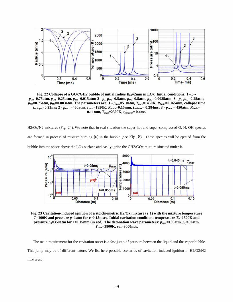
Fig. 22 Collapse of a GOx/GH2 bubble of initial radius Rb0=2mm in LOx. Initial conditions: 1 - pL-
pO2=0.75atm, pO2=0.25atm, pH2=0.015atm; 2 - pL-pO2=0.5atm, pO2=0.5atm, pH2=0.0085atm; 3 - pL-pO2=0.25atm,
pO2=0.75atm, pH2=0.003atm. The parameters are: 1 - pmax=510atm, Tmax=1450K, Rbmin=0.165mm, collapse time
tcollapse=0.23ms: 2 - pmax =460atm, Tmax=1850K, Rbmin=0.15mm, tcollapse= 0.284ms; 3 - pmax = 450atm, Rbmin=
0.11mm, Tmax=2500K, tcollapse= 0.4ms.
H2/Ox/N2 mixtures (Fig. 24). We note that in real situation the super-hot and super-compressed O, H, OH species
are formed in process of mixture burning [6] in the bubble (see Fig. 8). These species will be ejected from the
bubble into the space above the LOx surface and easily ignite the GH2/GOx mixture situated under it.
Fig. 23 Cavitation-induced ignition of a stoichiometric H2/Ox mixture (2:1) with the mixture temperature
T=100K and pressure p=1atm for r>0.15msec. Initial cavitation condition: temperature T0=1500K and
pressure p0=350atm for r<0.15mm (in red). The detonation wave parameters: pmax=100atm, pcj=60atm,
Tmax=3800K, vdw=3000m/s.
The main requirement for the cavitation onset is a fast jump of pressure between the liquid and the vapor bubble.
This jump may be of different nature. We list here possible scenarios of cavitation-induced ignition in H2/O2/N2
mixtures:
30
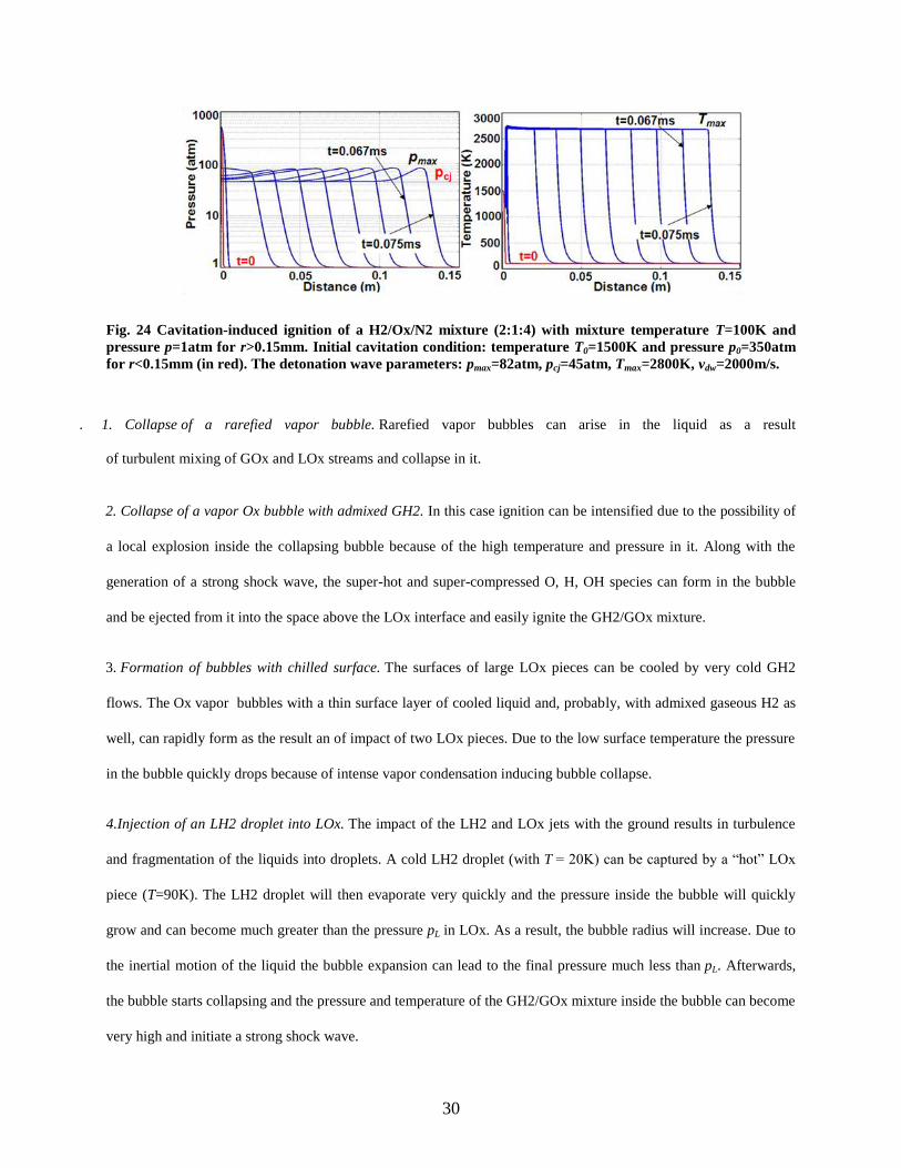
Fig. 24 Cavitation-induced ignition of a H2/Ox/N2 mixture (2:1:4) with mixture temperature T=100K and
pressure p=1atm for r>0.15mm. Initial cavitation condition: temperature T0=1500K and pressure p0=350atm
for r<0.15mm (in red). The detonation wave parameters: pmax=82atm, pcj=45atm, Tmax=2800K, vdw=2000m/s.
. 1. Collapse of a rarefied vapor bubble. Rarefied vapor bubbles can arise in the liquid as a result
of turbulent mixing of GOx and LOx streams and collapse in it.
2. Collapse of a vapor Ox bubble with admixed GH2. In this case ignition can be intensified due to the possibility of
a local explosion inside the collapsing bubble because of the high temperature and pressure in it. Along with the
generation of a strong shock wave, the super-hot and super-compressed O, H, OH species can form in the bubble
and be ejected from it into the space above the LOx interface and easily ignite the GH2/GOx mixture.
3. Formation of bubbles with chilled surface. The surfaces of large LOx pieces can be cooled by very cold GH2
flows. The Ox vapor bubbles with a thin surface layer of cooled liquid and, probably, with admixed gaseous H2 as
well, can rapidly form as the result an of impact of two LOx pieces. Due to the low surface temperature the pressure
in the bubble quickly drops because of intense vapor condensation inducing bubble collapse.
4.Injection of an LH2 droplet into LOx. The impact of the LH2 and LOx jets with the ground results in turbulence
and fragmentation of the liquids into droplets. A cold LH2 droplet (with T = 20K) can be captured by a “hot” LOx
piece (T=90K). The LH2 droplet will then evaporate very quickly and the pressure inside the bubble will quickly
grow and can become much greater than the pressure pL in LOx. As a result, the bubble radius will increase. Due to
the inertial motion of the liquid the bubble expansion can lead to the final pressure much less than pL. Afterwards,
the bubble starts collapsing and the pressure and temperature of the GH2/GOx mixture inside the bubble can become
very high and initiate a strong shock wave.
31
These scenarios were confirmed by our preliminary numerical simulations. A detailed analysis of these results is
beyond the scope of this paper [25].
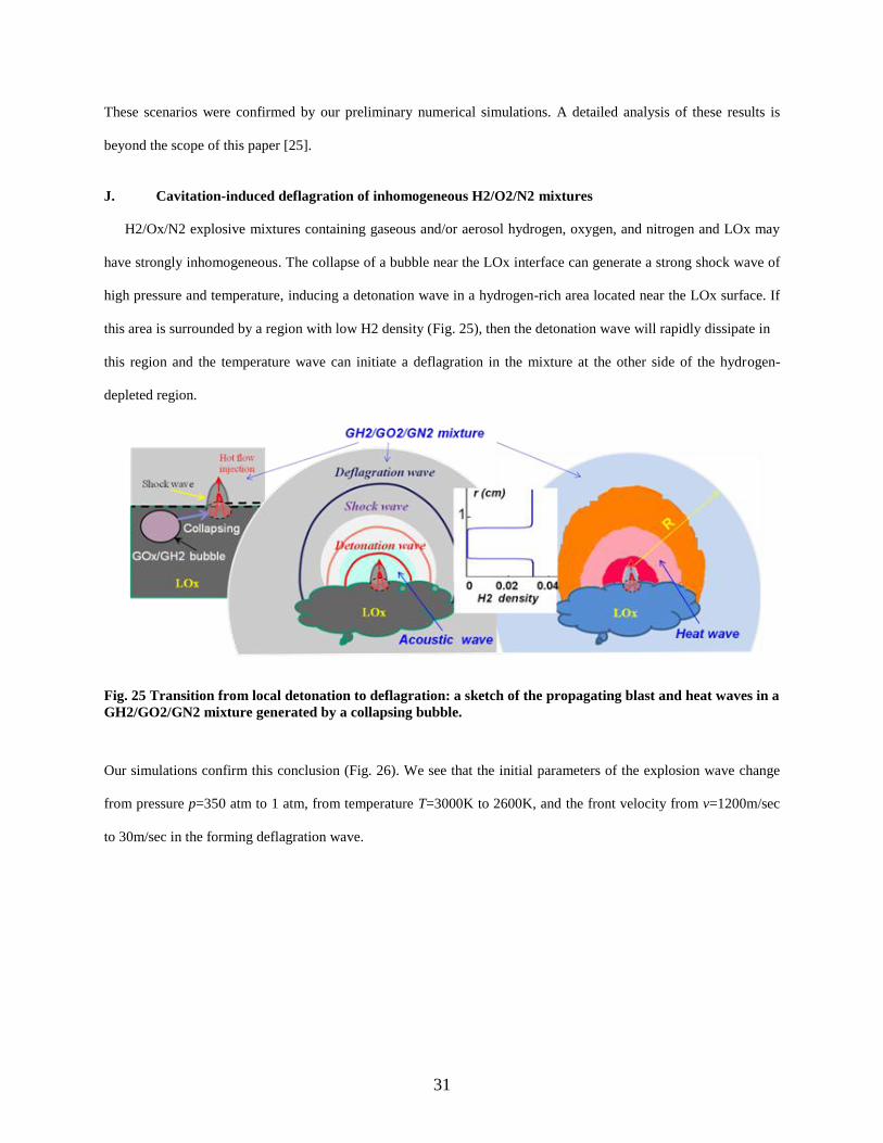
J. Cavitation-induced deflagration of inhomogeneous H2/O2/N2 mixtures
H2/Ox/N2 explosive mixtures containing gaseous and/or aerosol hydrogen, oxygen, and nitrogen and LOx may
have strongly inhomogeneous. The collapse of a bubble near the LOx interface can generate a strong shock wave of
high pressure and temperature, inducing a detonation wave in a hydrogen-rich area located near the LOx surface. If
this area is surrounded by a region with low H2 density (Fig. 25), then the detonation wave will rapidly dissipate in
this region and the temperature wave can initiate a deflagration in the mixture at the other side of the hydrogen-
depleted region.
Fig. 25 Transition from local detonation to deflagration: a sketch of the propagating blast and heat waves in a
GH2/GO2/GN2 mixture generated by a collapsing bubble.
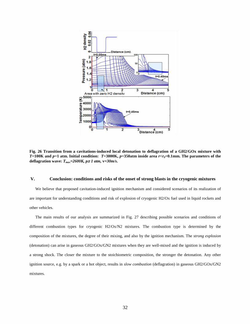
Our simulations confirm this conclusion (Fig. 26). We see that the initial parameters of the explosion wave change
from pressure p=350 atm to 1 atm, from temperature T=3000K to 2600K, and the front velocity from v=1200m/sec
to 30m/sec in the forming deflagration wave.
32
Fig. 26 Transition from a cavitations-induced local detonation to deflagration of a GH2/GOx mixture with
T=100K and p=1 atm. Initial condition: T=3000K, p=350atm inside area r<r0=0.1mm. The parameters of the
deflagration wave: Tmax=2600K, p 1 atm, v=30m/s.
V. Conclusion: conditions and risks of the onset of strong blasts in the cryogenic mixtures
We believe that proposed cavitation-induced ignition mechanism and considered scenarios of its realization of
are important for understanding conditions and risk of explosion of cryogenic H2/Ox fuel used in liquid rockets and
other vehicles.
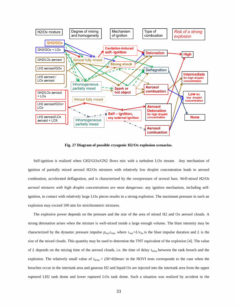
The main results of our analysis are summarized in Fig. 27 describing possible scenarios and conditions of
different combustion types for cryogenic H2/Ox/N2 mixtures. The combustion type is determined by the
composition of the mixtures, the degree of their mixing, and also by the ignition mechanism. The strong explosion
(detonation) can arise in gaseous GH2/GOx/GN2 mixtures when they are well-mixed and the ignition is induced by
a strong shock. The closer the mixture to the stoichiometric composition, the stronger the detonation. Any other
ignition source, e.g. by a spark or a hot object, results in slow combustion (deflagration) in gaseous GH2/GOx/GN2
mixtures.
33
Fig. 27 Diagram of possible cryogenic H2/Ox explosion scenarios.
Self-ignition is realized when GH2/GOx/GN2 flows mix with a turbulent LOx stream. Any mechanism of
ignition of partially mixed aerosol H2/Ox mixtures with relatively low droplet concentration leads to aerosol
combustion, accelerated deflagration, and is characterized by the overpressure of several bars. Well-mixed H2/Ox
aerosol mixtures with high droplet concentrations are most dangerous: any ignition mechanism, including self-
ignition, in contact with relatively large LOx pieces results in a strong explosion. The maximum pressure in such an
explosion may exceed 100 atm for stoichiometric mixtures.
The explosive power depends on the pressure and the size of the area of mixed H2 and Ox aerosol clouds. A
strong detonation arises when the mixture is well-mixed inside a large enough volume. The blast intensity may be
characterized by the dynamic pressure impulse pmaxτimp, where τimp=L/vdw is the blast impulse duration and L is the
size of the mixed clouds. This quantity may be used to determine the TNT equivalent of the explosion [4]. The value
of L depends on the mixing time of the aerosol clouds, i.e. the time of delay tdelay between the tank breach and the
explosion. The relatively small value of tdelay ≈ (30÷60)msec in the HOVI tests corresponds to the case when the
breaches occur in the intertank area and gaseous H2 and liquid Ox are injected into the intertank area from the upper
ruptured LH2 tank dome and lower ruptured LOx tank dome. Such a situation was realized by accident in the
34
Challenger disaster [1-3] and purposely in the second group of the HOVI tests (Fig. 2c). The escaped GH2 and LOx
flows very quickly (but poorly) mixed together and self-ignited. Similar events can occur in the case of the bulkhead
failure [26].
The aerosol combustion, accelerating the deflagration combustion, is likely to arise in the cases with the
maximum blast pressure from one to several bars. Here the risk of a strong explosion is intermediate. Different
situation may occur when the bottom domes of both tanks are ruptured, as can be seen from the first group of the
HOVI tests (Fig. 2a and 2b). Here the delay can be longer due to a much larger area separating the H2 and Ox
aerosol clouds and the large LOx pieces. Such an event was probably realized in the HOVI 9 test. This test used
doubled tanks (Fig. 2b) with the rupture devices placed underneath each tank. Following the rupture of the LH2
tank, its thermal insulation detached and shielded the H2 aerosol cloud from direct contact with the turbulent LOx
stream. This resulted in a long delay time tdelay ≈ 200 msec between the rupture and the cavitation-induced ignition.
During this time, the expanding H2 and Ox aerosol clouds had a chance to form and mix together. As a
consequence, a nearly stoichiometric H2/Ox mixture confined to a hemi-sphere of radius of about 2m was formed.
The self-ignition of this mixture induced the strongest explosion (aerosol detonation), characterized by the
maximum pressure exceeding 100 atm and the duration of about 1msec (Fig. 24). We attribute this strong explosion
to a chance occurrence of the complex breaking dynamics of the insulating foam detaching from the double LH2
tank. Such a strong explosion was not observed in all other 13 HOVI tests, including the HOVI 10 test, which had
the same double tanks as HOVI 9. In the case of HOVI 10 the value of tdelay was very small and pmax=1.36 atm.
An event in which the contents of the LH2 and LOx tanks is scattered over a relatively large area is probably the
most dangerous from the point of view of the risk of the strongest explosion. Indeed, in this case the escaped H2 and
Ox liquids will have large enough time to evaporate and to generate GH2 and GOx aerosol clouds that will have
time to mix together into a large enough area before self-igniting upon contact with the ejected turbulent LOx
stream. We emphasize once more that self-ignition of cryogenic H2/O2 mixtures is always realized when GH2 and
GOx flows are mixed with a turbulent LOx stream.
We acknowledge Dr. Frank Benz from NASA Johnston Space Center White Sands Test Facility for providing us
the test data for Hydrogen Oxygen vertical impact tests performed at the facility. We also acknowledge Dr. Benz for
interesting discussions.
35
References
[1] Cole, M.D., “Challenger: America's space tragedy”, Springfield, N.J., Enslow Publishers, 1995.
[2] Diane, V., “The Challenger Launch Decision: Risky Culture, Technology, and Deviance at NASA”, Chicago:
University Of Chicago Press, 1996.
[3] Report of the Presidential Commission on the Space Shuttle Challenger Accident, DIANE Publishing, 1986, 256 pages
(/ http://history.nasa.gov/rogersrep/genindex.htm).
[4] Gayle J. B., Blakewood C. H., Bransford, J. W., Swindell, W. H., High, R. W., “Preliminary investigation of blast
hazards of RP-I/LOX and LH2/LOX propellant combinations.” NASA Technical Memorandum X-53240, 1965.
[5] Glassman, I. and Yetter, R. A., “Combustion”, 4th edition, Elsevier, New York, 2008.
[6] Kao S, Shepherd J. E, “Numerical solution methods for control volume explosions and ZND detonation structure”,
GALCIT Report FM2006.007 (CANTERA- http://www.galcit.caltech.edu/EDL/).
[7] Williams, F. A., “Combustion Theory”, Addison-Wesley Publishing Company, Inc., Princeton University, 1985.
[8] Zeldovich, Ya. B., Barenblatt, G.I., Librovich, V.B., Makhviladze, G.M., “The Mathematical Theory of Combustion
and Explosion”, Consultants Bureau, New York, 1985.
[9] Oran, E. S., Gamezo, V. N., “Origins of the deflagration-to-detonation transition in gas-phase combustion”,
Combustion and Flame 148, 4-47, (2007).
[10] Short, M., “The initiation of detonation from general non-uniformly distributed initial conditions”, Philosophical
transactions, V.353, 173-203 (1995);
[11] Kapila, A. K., Schwendeman, D. W., Quirk, J. J., Hawa, T., "Mechanisms of detonation formation due to a
temperature gradient“, Combustion Theory and Modeling, 6, 553-594 (2002).
[12] Groethe, M., Merilo, E., Colton, J., Chiba, S., Sato, Y., Iwabuchi, H., “Large-scale hydrogen deflagration and
detonation”, International Journal of Hydrogen Energy 32, 2125 – 2133 (2007).
[13] Plaster, M., McClenagan, R.D., Benz, F.J., Shepherd, J.E., Lee, J.H.S., “Detonation of Cryogenic Gaseous Hydrogen-
Oxygen Mixtures”, American Institute of Aeronautics and Astronautics, Inc., 1990.
[14] We use the parameters of the initiation reactions specific for high temperatures that are given in works: Ripley D.L,
Gardiner W.C. Jr., “Shock tube study of the hydrogen-oxygen reaction. II. Role of exchange initiation”, J. Chem. Phys.,
44, 2285 (1966); Michael, J.V., Sutherland, J.W., Harding, L.B., Wagner, A.F., “Initiation in H2/O2: rate constants for
H2+O2 →H+HO2 at high temperature”, Proceedings of the Combustion Institute, 28, 1471-1478 (2000). Note that these
parameters are closed to those used in CANTERA 1.5: Goodwin, D., Defining Phases and Interfaces: Div. of
Engineering and Applied Science, California Inst. of Technology, Pasadena, CA, 2003.
36
[15] Mitani, T. and Williams, F. A. Studies of Cellular Flames in Hydrogen–Oxygen–Nitrogen Mixtures, Combustion and
Flame, Vol. 39, pp. 169–190 (1980).
[16] Molkov, V., Makarov D. and Schneider, H., “LES modeling of an unconfined large-scale hydrogen–air deflagration”,
J. Phys. D: Appl. Phys., 39, 4366-4376 (2006); “Hydrogen-air deflagration in open atmosphere: Large eddy simulation
analysis of experimental data”, International Journal of Hydrogen Energy, 32, 2198-2205 (2007).
[17] Merilo, E.G., Groethe, M.A., “Deflagration Safety Study of Mixtures of Hydrogen and Natural Gas in a Semi-open
Space”, In Proceedings of the international conference on hydrogen safety, S. Sebastian, Spain, 2007
[18] Lei Xu, Wendy W. Zhang, and Sidney R. Nagel, “Drop Splashing on a Dry Smooth Surface”, Phys. Rev. Lett. 94,
184505 (2005).
[19] Ahmed, M., Ashgriz, N. and Tran, H. N., “Influence of Breakup Regimes on the Droplet Size Produced by Splash-
Plate Nozzles”, AIAA Journal Vol. 47, No. 3, 516-522 (2009).
[20] E.J. Allin, W.F.J. Hare and R. E. MacDonald, “Infrared absorption of liquid and solid hydrogen”, Phys. Rev., Vol. 98,
pp. 554-555 (1955); E.J. Allin, H.P. Gush, W.F.J. Hare and H.L. Welsh, “The infrared spectrum of liquid and solid
hydrogen”, Il Nuovo Cimento, V.9, Supplement 1, 77-83 (1958).
[21] Landau, L. D., Lifshitz, E. M., “Course of Theoretical Physics”, Vol. 6, Butterworth-Heinemann. Oxford, 1987.
[22] Even though in the 1970's Farber hypothesized that the source of self-ignition in cryogenic Ox/H2 mixtures can be
some sort of piezoelectric effect between the "ice" crystals (SOx) and the colder H2 gas (GH2), or that there may be a
static charge buildup due to the transport of hydrogen bubbles [see Farber E.A., “Explosive Yield Limiting Self-
Ignition Phenomena in LO2/LH2 and LO2/RP-1 Mixtures”, 15 Explosives Safety Seminar, San Francisco, CA,
pp.1287-1303 (September 18-20, 1973); “Prediction of Explosive Yields and other Characteristic of Liquid Rocket
Propellants”, NASA 10-1255, University of Florida, Department of Mechanical Engineering (June 30, 1975)], his
arguments meet serious objections. Indeed, both hydrogen and oxygen, in either gas, liquid or solid phase are formed
by covalently bonded dumbbell-shaped molecules H-H and O=O, respectively. SOx, like any other molecular crystal, is
built from the O=O dumbbells held together by weak van-der-Waals intermolecular forces. At pressures of about 1 atm
and temperatures below 54K SOx forms a molecular crystal in the γ-phase with a cubic structure, and below 24K SOx
has monoclinic crystal structure [Yu.A. Freiman, H.J. Jodl, “Solid Oxygen”, Physics Reports, 401, 1–228, (2004)].
Therefore, SOx is not piezoelectric: the O=O dumbbells cannot produce piezoelectricity upon deformation because the
O=O molecules do not possess any dipole moment. The surface of SOx is non-polar, either. The binding energy of the
dumbbell O=O molecule is equal to 5.12 eV, while the kinetic energy of the H-H molecule moving with the velocity of
about 100m/sec is less than 10-4 eV. Therefore, moving H-H molecules cannot charge the oxygen surface.
37
[23] Brennen, C. E., “Fundamentals of Multiphase Flow”, Cambridge University Press, 2005; Brennen, C. E., “Cavitation
and Bubble Dynamics”, Oxford University Press, 1995.
[24] Fujikawa S. and Akamatsu, T., “Effects of the non-equilibrium condensation of vapor on the pressure wave produced
by the collapse of the bubble in a liquid”, J.Fluid Mech., v.97, part 3, pp.481-512 (1980).
[25] Osipov, V. V., Muratov, C. B. Ponizovskaya-Devine, E, Foygel, M, Smelyanskiy, V. N., “Cavitation-induced ignition
mechanisms in cryogenic hydrogen/oxygen mixtures” (in preparation).
[26] Sachdev, J. S., Hosangadi, A., Madavan, N. K. and Lawrence, S. L., “Simulations for Assessing Potential Impact of
Ares I Propellant Tank Common Bulkhead Failure”, 45th AIAA/ASME/SAE/ASEE Joint Propulsion Conference &
Exhibit, Denver, Colorado, 2 - 5 August (2009).
Related Documents