Hazard Resilient Housing Construction Manual Hazard Resilient Construction Series No. 1 Prepared under the Research & Development Programme of National Building Research Organisation No. 99/1 Jawatta Road, Colombo 05, Sri Lanka. 2015

Welcome message from author
This document is posted to help you gain knowledge. Please leave a comment to let me know what you think about it! Share it to your friends and learn new things together.
Transcript

I
Hazard Resilient Housing Construction Manual
Hazard Resilient Construction Series No. 1
Prepared under the
Research & Development Programmeof
National Building Research OrganisationNo. 99/1 Jawatta Road,
Colombo 05,Sri Lanka.
2015
II
Hazard Resilient Housing Construction ManualResilient Construction Series No. 1
Published by National Building Research Organisation (NBRO), Sri Lanka
Supported by Government Research Grant -2013
First Edition August 2015
Contributed by : Prof. Priyan Dias, University of Moratuwa Prof. Athula Kulathilake, University of Moratuwa Prof. S. Hettiarachchi, University of Moratuwa Prof. S. Thilakasiri, University of Moratuwa Prof. M. T. R. Jayasinghe, University of Moratuwa Prof. Kapila Dahanayake, University of Peradeniya Prof. S. B. S. Abayakoon, University of Peradeniya Eng. Shiromal Fernando, Consultant Eng. Keerthi Sri Senanayake, Consultant Dr. Sudhira de Silva, University of Ruhuna Dr. Udeni Nawagamuwa, University of Moratuwa
Edited by - Dr. Udeni Nawagamuwa Mr. Clarence Perera
Illustrations by - Nadeeka Priyadarshani, Savani de Zoysa
Technical Layout by - Chaya Samarakkodi
Cover Design by - Eshi Wijegunarathna
Copies are available at;
National Building Research OrganisationNo. 99/1 Jawatta Road, Colombo 05, Sri Lanka.Web: www.nbro.gov.lk
ISBN: 978-955-0283-05-7
Printed by Printec Establishment (Pvt) Ltd 0112 815 816 www.printec.lk

III
FOREWORD
Natural hazards such as Landslides, Floods, High Winds, Cyclones, and Droughts have become a part of the lives of people in Sri Lanka due to increased frequency of occurrence of such extreme incidents. In addition, greater concern has been raised recently on earthquakes and tsunamis due to the December 2004 tsunami. The National Building Research Organisation (NBRO) under the Ministry of Disaster Management is to provide engineering solutions through research to reduce the impact of potential disasters by creating a resilient and safer built environment. Today, we have every reason to believe that it is within our grasp to reduce the impact of potential hazardous events. However, we will not meet this goal without tackling the causative factors of natural hazards and the impacts of climate change. It is of prime importance to focus on reducing the damages to lives, residential houses and vulnerable communities by ensuring enhanced planning, siting, design and construction of houses by building housing unit that are more resilient to the impacts of natural hazards. At NBRO, we are concerned that unless a bold action is taken now, a disastrously non engineered housing stock threatens to put prosperity out of reach of thousands of people and roll back decades of hard earned development. In response we are stepping up our mitigation, adaptation, and disaster risk management work, and will increasingly look at all our development initiatives through a “Resilient Lens.” But we know that our work alone is not enough. We need to support actions by others to deliver bold ideas that will make the biggest difference. Over the years, several stakeholders have taken initiatives in producing hazard specific construction guidelines and technical documents that assist in the construction of safe and cost efficient houses. NBRO as an entity dedicated to research, building resilience and landslide disaster mitigation, has considered it as a timely requirement to produce a “Hazard Resilient Housing Construction Manual” that would provide ample guidance and advice by sharing the experiences and expertise available in Sri Lanka and in the world. This is the first of a series of Resilient Construction Manuals that is intended to serve the professionals, practitioners and the laymen who may want to safeguard their house by adding simple, but engineered solutions. Consequently, this manual presents practical recommendations and advice on best practices for people who are building new houses for greater resilience to disasters. It is recommended that the principles outlined and the issues raised in this manual will be given due consideration by planners, architects, engineers, designers and contractors involved as well as the owners in order to build houses with greater resilience.
Eng. (Dr.) Asiri Karunawardena Director General
National Building Research Organisation (NBRO)
iii

IV
Aggregate mix: A mixture of mineral materials, such as sand or stone, used in making concrete
Asymmetric profile: An irregular shape
Backfill: Material used to refill an excavated area
Beam: A horizontal member of the structure supporting the vertical loads
Coarse aggregate: Large particles
Coastal erosion: The wearing away of land or the removal of beach or dune sediments by wave action, tidal currents, wave currents, or drainage. A combination of episodic inundation events and relative sea level rise will serve to accelerate coastal erosion (NOAA,2013).
Column shaft: The component extending from top of the footing (foundation base) to the underside of the column
Confined masonry: Consisting of masonry walls and horizontal and vertical reinforced concrete confining members built on all four sides of a wall panel
Contour line: A line on a map joining points of equal elevation above a given level, usually mean sea level
Cyclones: This term encompasses tropical depressions, tropical storms, hurricanes, and typhoons. At maturity, the tropical cyclone is one of the most intense and feared storms of the world; winds exceeding 90 m s-1(175 knots/324.1 kmph) have been measured, and its rains are torrential. Tropical cyclones are initiated by a large variety of disturbances, including easterly waves and monsoon troughs. Once formed, they are maintained by the extraction of latent heat from the ocean at high temperature and heat export at the low temperatures of the tropical upper troposphere. Fully mature tropical cyclones range in diameter from 100 to well over 1000 km (American Meteorological Society, 2013).
d.p.c.: damp proof course
Disaster: A serious disruption of the functioning of a community or a society involving widespread human, material, economic or environmental losses and impacts, which exceeds the ability of the affected community or society to cope using its own resources (UNISDR, 2009)
Diversion drains: A channel made to divert the flow of water from one course to another or to direct the flow of water draining from a piece of ground.
Drainage: The removal of surface or sub-surface water through natural or artificial methods
Drought: Is a condition of moisture deficit sufficient to have an adverse effect on vegetation, animals, and man over a sizeable area. There are four types of drought namely; Meteorological drought, Agricultural Drought, Hydrologic Drought and Socio-Economic Drought (DMC, 2012).
Earthquake: Earthquake is a term used to describe both sudden slip on a fault, and the resulting ground shaking and radiated seismic energy caused by the slip, or by volcanic or magmatic activity, or other sudden stress changes in the earth (USGS, 2013).
Exterior walls: Walls on the outside of a structure
Flash-flood: Rapid accumulation of runoff waters from rain storms (CHPB, 2003).
Flood: High-water stages in which water over flows its natural or artificial banks onto normally dry land, such as a river inundating its floodplain (SAARC-SDMC, 2013).
Footing/base: The lowest supporting layer of the foundation. face of the foundation
Foundation depth: The distance between the ground level and bottom face of the foundation
GLOSSARY AND UNITS
iv
V
GLOSSARY, CONT’D
Hazard: A dangerous phenomenon, substance, human activity or condition that may cause loss of life, injury or other health impacts, property damage, loss of livelihoods and services, social and economic disruption, or environmental damage (UNISDR, 2009)
Hipped roof: A type of roof where all sides slope downwards to the exterior walls
Landslide: All mass movements other than surface erosion of a hillside. This event includes terms such as precipitation of earth, settling, horizontal land thrust, mass movement, displacement, subsidence, collapse of caves or mines, rock falls (slow or quick), detachment of soil masses or rocks on watersheds or hillsides.
Lap length: Required length of overlap of two reinforcing steel bars
Lightning (Thunderstorm) / Electrical Storm: Lightning is a transient, high-current electric discharge with path lengths measured in kilometres. The most common source of lightning is the electric charge separated in ordinary thunderstorm clouds (cumulonimbus). (American Meteorological Society, 2013).
Lintel beam: A horizontal member spanning over an opening in a wall between two vertical supports
Load-bearing walls: Walls supporting loads from a roof or floor
Masonry ties: Metal anchors used to support masonry components of a structure to its main structural members
Mortar joint: A joint between masonry or other structural units created out of a mixture of cementitious material or materials, aggregate, and water
Overhang: A projection or an extension of a structural or non-structural component
Plinth: The rectangular slab or block that forms the lowest part of the base of a column, wall, or pier
Post-disaster structures: Physical structures which are required to remain in operational condition following a disaster; power stations, meteorological stations, telecommunications buildings, police stations, air traffic control buildings, fire stations, hospitals, telephone exchanges, buildings designated as community evacuation centers.
Rafter: Means the inclined roof framing member making up the main framework of the roof connected between the ridge and the wall plate and nailed to the wall plate
Rain: Precipitation in the form of liquid water droplets greater than 0.5 mm. If widely scattered, the drop size may be smaller (American Meteorological Society, 2013).
Reeper: A horizontal member that provides intermediate support above the common rafters of a roof construction
Resilience: The ability of a system, community or society exposed to hazards to resist, absorb, accommodate to and recover from the effects of a hazard in a timely and efficient manner, including through the preservation and restoration of its essential basic structures and functions (UNISDR, 2009).
Retaining wall: A wall constructed to hold back earth, loose rock etc.
Ridge: The horizontal member spanning from one end to the other end of the structure provided to connect the rafters
Running bond: The placement of masonry units such that the vertical joints in successive courses are horizontally offset at least 25% of the unit length.
v
VI
GLOSSARY, CONT’D
Safe Bearing capacity: The ultimate load which a foundation can support
Sedimentation: Deposits of solid material on hillsides and river beds produced by mass movements or surface erosion with damages on crops, utilities or other infrastructure.
Seepage flows: Movement of water in soils
Shotcreting cement: A process in which concrete or mortar is projected onto a surface at a high velocity through a hose
Soil Erosion: Washing away of soil down the surface of hill slopes or mass movements due to storm water flow during intense rains. This can cause sedimentation in streams / rivers and areas at the toe of the hills.
Soil nailing: A technique that can be used as a remedial measure to treat unstable natural soil slopes or as a technique that allows the safe over-steepening of new or existing soil slopes.
Storm Surge: An abnormal rise in sea level accompanying a tropical cyclone or other intense storm and whose height is the difference between the observed level of the sea surface and the level that would have occurred in the absence of the storm. Storm surge is usually estimated by subtracting the normal or astronomical tide from the observed storm tide (NWS, NOAA, 2013).
Superstructure: The main structural frame engineered to bear all the loads
Trench: A type of excavation or depression in the ground
Tsunami: A tsunami is a sea wave of local or distant origin that results from large-scale seafloor displacements associated with large earthquakes, major submarine slides, or exploding volcanic islands (USGS, 2013).
uPVC: Unplasticized Poly Vinyl Chloride
Urban Flood: As land is converted from fields or woodlands to roads and parking lots, it loses its ability to absorb rainfall. Urbanization decreases the ability to absorb water 2 to 6 times over what would occur on natural terrain. During periods of urban flooding, streets can become swift moving rivers, while basements can become death traps as they fill with water (SAARC-SDMC,2013).
Wall plate: Horizontal member connected to the walls or the columns of the structure to connect the roof structure
Weep holes: A small opening left in a Earth retaining structure or an the outer wall of masonry construction as an outlet for water to move from retained side to outside
vi

VII
1. General 01 - 05
1.1 About the Manual 01
1.2 Need for this Manual 02
1.3 Structure of the Manual 03
1.4 Using the Manual 04
1.5 Sources of Information 05
2 Natural Hazards and Other Hazardous Conditions 06 - 19
2.1 Hazards 07
2.2 Hazard Resilience 08
2.3 Natural Hazards in Sri Lanka 09
2.3.1 Landslides 09
2.3.2 Floods 12
2.3.3 High Winds 14
2.3.4 Earthquakes 16
2.3.5 Tsunami 18
2.4 Other Hazardous Conditions 20-27
2.4.1 Ground Conditions 20
2.4.2 Expansive Soils 21
2.4.3 Ground Subsidence 24
TABLE OF CONTENTSForeword iii
Glossary, Abbreviations and Units iv
Table of Contents vii
SECTION A - INTRODUCTION 01 - 25
VIII
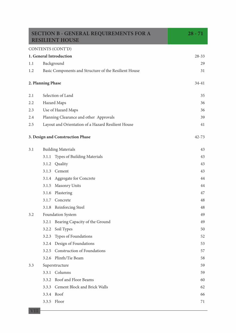
CONTENTS (CONT’D)
1. General Introduction 28-33
1.1 Background 29
1.2 Basic Components and Structure of the Resilient House 31
2. Planning Phase 34-41
2.1 Selection of Land 35
2.2 Hazard Maps 36
2.3 Use of Hazard Maps 36
2.4 Planning Clearance and other Approvals 39
2.5 Layout and Orientation of a Hazard Resilient House 41
3. Design and Construction Phase 42-73
3.1 Building Materials 43
3.1.1 Types of Building Materials 43
3.1.2 Quality 43
3.1.3 Cement 43
3.1.4 Aggregate for Concrete 44
3.1.5 Masonry Units 44
3.1.6 Plastering 47
3.1.7 Concrete 48
3.1.8 Reinforcing Steel 48
3.2 Foundation System 49
3.2.1 Bearing Capacity of the Ground 49
3.2.2 Soil Types 50
3.2.3 Types of Foundations 52
3.2.4 Design of Foundations 53
3.2.5 Construction of Foundations 57
3.2.6 Plinth/Tie Beam 58
3.3 Superstructure 59
3.3.1 Columns 59
3.3.2 Roof and Floor Beams 60
3.3.3 Cement Block and Brick Walls 62
3.3.4 Roof 66
3.3.5 Floor 71
SECTION B - GENERAL REQUIREMENTS FOR A 28 - 71 RESILIENT HOUSE

IX
CONTENTS (CONT’D)1. Landslides 74-961.1 General Information 751.2 Planning Considerations 75 1.2.1. Landslide Clearance for Construction 76 1.2.2 Basic Requirements for a Safe Structure 76 1.2.3 Land Selection 77 1.2.4 Areas Not Suitable for Building 81 1.2.5 Layout Arrangement and Orientation of the House 851.3 Land preparation 861.4 Earthworks 87 1.4.1 Cut Slopes 87 1.4.2 Space between House and Cut Slopes 891.5 Foundations 901.6 Stabilization and Protection of Slopes 901.7 Earth Retaining Structures 91 1.7.1 Gravity Retaining Walls 91 1.7.2 Reinforced Concrete Walls 92 1.7.3 Embedded Walla 93 1.7.4 Drainage Behind Retaining Walls 941.8 Soil Erosion Control and Drainage 95 1.8.1 Soil Erosion Control 95 1.8.2 Surface Drainage 95 1.8.3 Sub-surface Drainage 96
2. Floods 97-99
2.1 Planning Phase 97 2.1.1 House Plan and Orientation 972.2 Foundations 982.3 Raised Floor Elevation 982.4 Superstructure 99
3. High Winds 100-113
3.1 Planning Phase 100 3.1.1 How Wind acts on Structures 100 3.1.2 Factors generating Wind Forces 101 3.1.3 Basic Requirements for a Safe Structure 101 3.1.4 Assessment of the Severity of Wind Effects 102 3.1.5 Planning Considerations 104 3.1.6 House Plan and Orientation 1053.2 Walls 1063.3 Roof Structure 1073.4 Roof Covering 1113.5 Concrete Flat Roofs 1123.6 Doors 113
SECTION C - HAZARD SPECIFIC DESIGN AND CONSTRUCTION REQUIREMENTS FOR A RESILIENT 74 - 130HOUSE

X
CONTENTS (CONT’D)4. Earthquakes 114-1204.1 Planning Phase 114
4.1.1 How Buildings behave during Earthquakes 114
4.1.2 Planning Considerations 115
4.1.3 Land Selection 115
4.1.4 House Plan and Orientation 115
a. Layout Arrangement 115
b. Orientation of the House 115
c. Shape of the Structure 115
d. Type of Structure 116
4.2 Foundations 116
4.3 Confined Masonry Structure 117
5. Problematic Soils 121-124
5.1 Expansive Soils 121 5.1.1 Planning Phase 121 5.1.2 Ground Preparation 121 5.1.3 Ground Improvement 121 5.1.4 Foundations 122 5.1.5 Superstructure 122 5.1.6 Drainage 1225.2 Soft Soils 123 5.2.1 Planning Phase 123 5.2.2 Method of Reclamation (Ground Improvement Method) 123 5.2.3 Preloading; 123 5.2.4 Foundations 124
6. Tsunami 125 - 130
6.1 General 125 6.1.1 Avoid Tsunami prone Areas 125 6.1.2 Reduce Tsunami Risks 125 6.1.3 Mitigate the Damages 1256.2 Basic Requirements for a Safe Structure 126 6.2.1 Site Selection 126 6.2.2 Shape and Orientation 1276.3 Design and Construction 1276.4 Structure 1286.5 Exterior structures 129

XI
APPENDICES 131 - 144
Soils 132
Classification of Residual Soil Profile 133
Drainage Methods 134
Root systems 135
Suitable Plants for Soil erosion Control 136
Sample Drawings 138
Drawing 1. Landslides 140
Drawing 2. Floods - Raised Plinth 141
Drawing 3. Floods - On Stilts 142
Drawing 4. High Winds 143
Checklist for Construction in Hilly Areas 144
XII

XIII
INTRODUCTION
SECTION A
XIV
1GENERAL
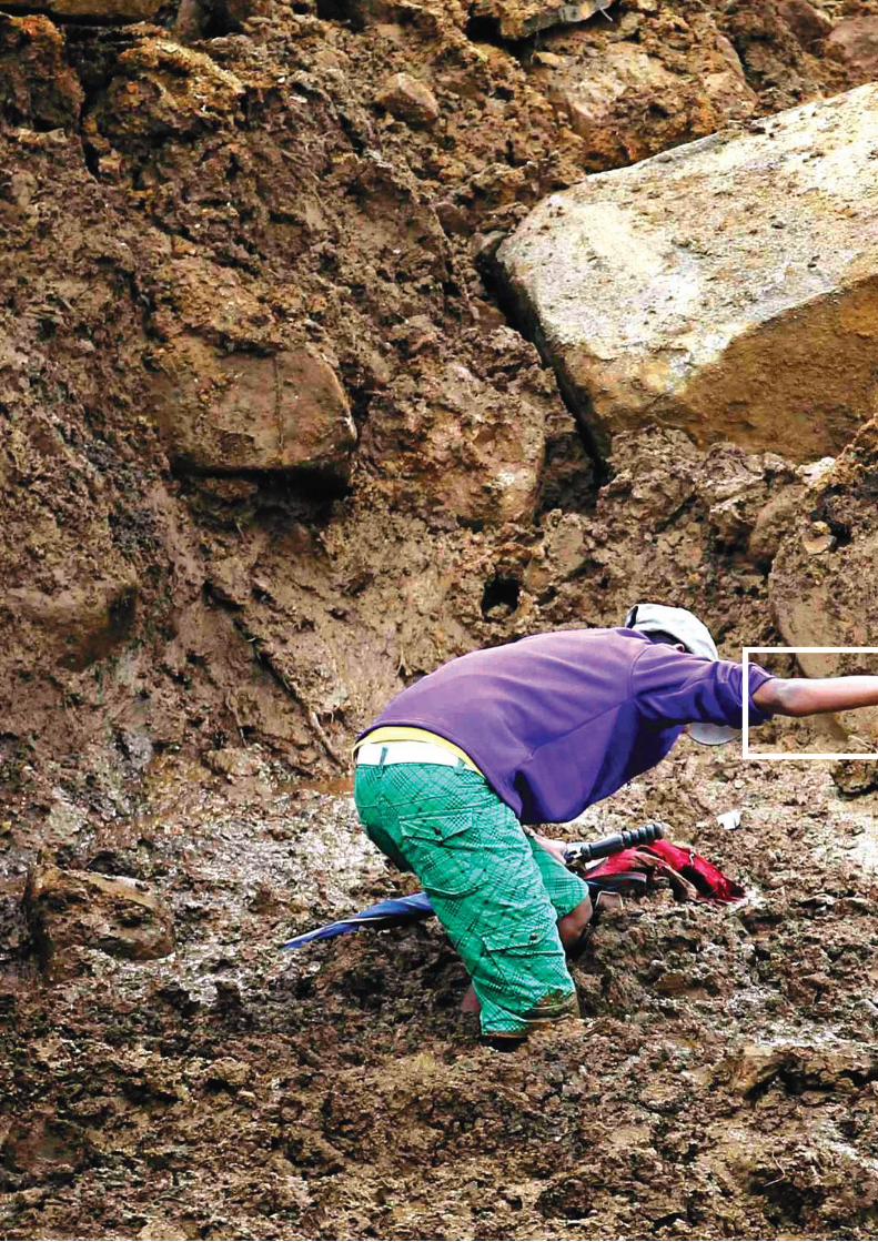
The primary aim of this Manual is to minimize the risk associated with individual houses built in natural hazard prone localities as far as possible. Also, it aims to minimize the damage to at least some structural elements, if not all elements of the house during an extreme event, so that people can resume their day-to-day activities without much interruption.

1
SECTION A
1.1 About the Manual This Manual has been developed to promote the use of hazard resilient engineering design and construction practices when building houses in Sri Lanka. The goal of the manual is to develop a culture of hazard resilience among house builders through basic engineering practices. Furthermore, it attempts to inculcate among the communities to adopt additional safer building construction practices when constructing in areas identified as disaster prone. The Manual focuses on ensuring that housing environment is better prepared for potential disaster events through proper planning, siting, design and construction practices. The primary aim of this Manual is to minimize the risk associated with individual houses built in natural hazard prone localities as far as possible. Also, it aims to minimize the damage to at least some structural elements, if not all elements of the house during an extreme event, so that people can resume their day-to-day activities without much interruption. The Manual mainly focuses on construction of a single or two storey house having a floor area of not more than 80 m2. It attempts to address specific issues associated in the construction of housing in areas prone to specific natural hazards, namely, landslides, high winds, floods, tsunamis and earthquakes or in areas exposed to inherent problematic ground conditions that could be hazardous to be built therein. This Manual also aims at providing as much technical information as possible in a single reference material that brings together the relevant previously published disaster specific construction guidelines and additional engineering measures that have been adopted recently through research and practice.
1. GENERAL
Important!
There may be other alternative design and construction methods apart from what is presented in this manual which the user may wish to adopt at his/her own risk. This Manual strongly recommends the user to seek professional advice when uncertain. Although every effort has been made to make this Manual as comprehensive and simple as possible, no single manual can anticipate every situation or need that may arise in areas prone to hazards.
This Manual is not intended for direct field application by builders without input from a qualified person, particularly a professional Engineer or Architect.
7
SECTION A

2
1.2 Need of this Manual
The catastrophic results of natural hazards such as landslides, floods, cyclones, storm surges, and tsunamis have adequately shown that certain building types could not withstand the forces generated by the extreme events. The buildings that totally collapsed or partially damaged were mostly the low-rise ordinary houses located in marginalized lands. These include houses made of earthen wattle and daub, and masonry construction using kabook (laterite bricks) or random rubble or clay brick with cement or clay mud mortar. Often, such houses have been feebly constructed or built without the necessary technical guidance or engineering design and practices. This may be due to a number of socio-economic issues such as; • lack of affordability of low income households for proper housing. • lack of awareness on particular hazards, locations and their destructive forces. • lack of concerns about safety as people tend to soon forget any infrequent occurrence of a disaster. • safety becoming insignificant among priorities of the people. • lack of knowledge that level of safety in the houses could be enhanced at a small additional cost only with
very simple modifications. • relaxation or inadequacies in implementation or enforcement of building and safety regulations. • house builders’ reluctance to go through cumbersome and time consuming procedures for building
permits and approvals. • lack of concerns or ignorance regarding the essential professional inputs from architects and engineers
not obtained in the planning and design of buildings in hazardous locations. • lack of qualified persons for proper technical advice or house builder’s reluctance to consult them. • high cost of building materials, which prevents use of the required amount of cement and steel.
Such issues, while needing due attention and solutions, would compel the people to continue using construction practices and dwellings that are unsuitable for hazardous areas. This manual is a timely initiative and requirement while it is intended to provide advice, guidance and necessary information on key issues associated with building in disaster prone areas and for the planning, siting, design, and construction of housing with improved resilience to common and recurrent hazardous events.
8
SECTION A
SECTION A

3
1.3 Structure of the Manual The Manual consist of three (3) main Sections and Appendices;
Section A General Section B General Requirements for Resilient House Section C Hazard Specific Design and Construction Requirements for Resilient House Appendices
Section A has been formed to introduce the Manual, its background and how to use it. This section also introduces the common hazards that affect housing in Sri Lanka and typical damages that can occur due to each hazard. Upon being knowledgeable about each hazard and its consequences, it is expected that the user will have a basic understanding of the necessity to implement measures to minimize damages to the house built. Section B has been designed to furnish the user with the general recommended practices to follow when building a single or two storey house having a floor area of not more than 80 square meters in hazard prone areas irrespective of the type of the hazard within the scope of this Manual. If one wishes to be proactive, it is possible that minimum requirements presented in this section are followed in areas that are not designated as hazard prone as well. However, it is prudent for the user to avoid risks and seek professional advice in getting the safety of the location ascertained. If the house construction is carried out in a disaster prone area or a hazardous location, use of this manual is strongly recommended to ensure that potential damages from disasters are minimized. Section C specifies design and construction requirements that shall be followed with respect to the type of hazard in addition to the general requirements for hazard resilience given in Section B. Appendices provide additional material related to soil types, landslides etc. that are supplementary to the 3 main sections, while it also includes sample drawings of Flood, Landslide and High Wind resilient houses.
9
SECTION A
SECTION A
4
Flood
Earthquake
Landslide
High wind/Cyclone
Tsunami
Ground Subsidence
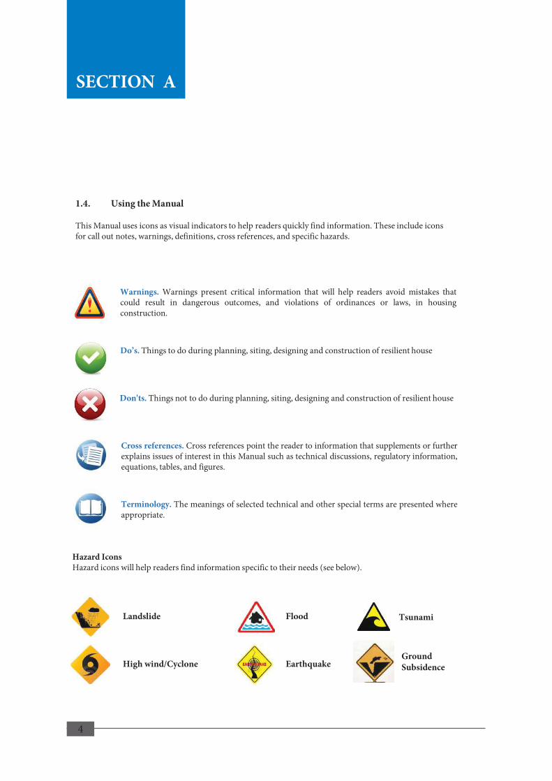
Hazard Icons Hazard icons will help readers find information specific to their needs (see below).
Warnings. Warnings present critical information that will help readers avoid mistakes that could result in dangerous outcomes, and violations of ordinances or laws, in housing construction.
Terminology. The meanings of selected technical and other special terms are presented where appropriate.
Cross references. Cross references point the reader to information that supplements or further explains issues of interest in this Manual such as technical discussions, regulatory information, equations, tables, and figures.
Do’s. Things to do during planning, siting, designing and construction of resilient house
Don'ts. Things not to do during planning, siting, designing and construction of resilient house
1.4. Using the Manual This Manual uses icons as visual indicators to help readers quickly find information. These include icons for call out notes, warnings, definitions, cross references, and specific hazards.
10
SECTION A
SECTION A
5
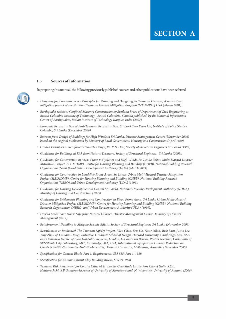
1.5 Sources of Information In preparing this manual, the following previously published sources and other publications have been referred.
• Designing for Tsunamis: Seven Principles for Planning and Designing for Tsunami Hazards, A multi-state mitigation project of the National Tsunami Hazard Mitigation Program (NTHMP) of USA (March 2001).
• Earthquake-resistant Confined Masonry Construction by Svetlana Brzev of Department of Civil Engineering at British Columbia Institute of Technology , British Columbia, Canada published by the National Information Center of Earthquakes, Indian Institute of Technology Kanpur, India (2007).
• Economic Reconstruction of Post-Tsunami Reconstruction: Sri Lank Two Years On, Institute of Policy Studies, Colombo, Sri Lanka (December 2006).
• Extracts from Design of Buildings for High Winds in Sri Lanka, Disaster Management Centre (November 2006) based on the original publication by Ministry of Local Government, Housing and Construction (April 1980).
• Graded Examples in Reinforced Concrete Design, W. P. S. Dias, Society of Structural Engineers Sri Lanka (1995)
• Guidelines for Buildings at Risk from Natural Disasters, Society of Structural Engineers, Sri Lanka (2005).
• Guidelines for Construction in Areas Prone to Cyclones and High Winds, Sri Lanka Urban Multi-Hazard Disaster Mitigation Project (SLUMDMP), Centre for Housing Planning and Building (CHPB), National Building Research Organisation (NBRO) and Urban Development Authority (UDA) (March 2003)
• Guidelines for Construction in Landslide Prone Areas, Sri Lanka Urban Multi-Hazard Disaster Mitigation Project (SLUMDMP), Centre for Housing Planning and Building (CHPB), National Building Research Organisation (NBRO) and Urban Development Authority (UDA) (1999).
• Guidelines for Housing Development in Coastal Sri Lanka, National Housing Development Authority (NHDA), Ministry of Housing and Construction (2005)
• Guidelines for Settlements Planning and Construction in Flood Prone Areas, Sri Lanka Urban Multi-Hazard Disaster Mitigation Project (SLUMDMP), Centre for Housing Planning and Building (CHPB), National Building Research Organisation (NBRO) and Urban Development Authority (UDA) (1999).
• How to Make Your House Safe from Natural Disaster, Disaster Management Centre, Ministry of Disaster Management (2012).
• Reinforcement Detailing to Mitigate Seismic Effects, Society of Structural Engineers Sri Lanka (November 2006)
• Resettlement or Resilience? The Tsunami Safe(r) Project, Ellen Chen, Eric Ho, Nour Jallad, Rick Lam, Justin Lee, Ying Zhou of Tsunami Design Initiative, Graduate School of Design, Harvard University, Cambridge, MA, USA and Domenico Del Re of Buro Happold Engineers, London, UK and Luis Berrios, Walter Nicolino, Carlo Ratti of SENSEable City Laboratory, MIT, Cambridge, MA, USA, International Symposium Disaster Reduction on Coasts Scientific-Sustainable-Holistic-Accessible, Monash University, Melbourne, Australia (November 2005)
• Specification for Cement Blocks Part 1; Requirements, SLS 855: Part 1: 1989.
• Specification for Common Burnt Clay Building Bricks, SLS 39: 1978.
• Tsunami Risk Assessment for Coastal Cities of Sri Lanka: Case Study for the Port City of Galle. S.S.L. Hettiarachchi, S.P. Samarawickrama of University of Moratuwa and, N. Wijeratne, University of Ruhuna (2006).
11
SECTION A
SECTION A

6
2NATURAL HAZARDS AND OTHER HAZARDOUS CONDITIONS
A hazard resilient house aimed to be achieved through this manual is a residential structure engineered in such a way that it should not suffer total or partial collapse or any irreparable damage which would require demolishing and rebuilding, but which may sustain only such damage that could be repaired quickly and restore its usual functioning.

7
2.1 Hazards Certain types of natural or man-made hazards and hazardous conditions could severely affect the stability and functioning of a house and the safety of its occupants. Therefore, anyone who is preparing for construction of a house needs to consider and properly understand issues related to natural hazards and other hazardous conditions. Vulnerability to a hazard and the degree of damage it can cause to a house would depend not only on the nature and severity of the disaster but also on the location and type of building, the quality of materials used and how well the house is constructed. It is sometimes possible that two or more natural hazards may occur simultaneously, or in some cases, one hazard may trigger another. For example, cyclonic wind may accompany heavy rainfall causing flooding, and heavy rainfall or earthquake may trigger a landslide. Such interactive events bring cumulative effects that can be much severe than the damage expected from a single event. Impacts of climate change also cannot be ignored as studies suggest that the frequency, the intensity or the severity of some natural hazards may gradually increase in the future while the frequency of some other events may be expected to decrease. Besides the natural hazards, there are hazardous conditions inherent to the ground which can cause structural distress or damage to a house built on it unless necessary precautions are taken in the structural design. These are referred to as difficult ground conditions associated with sub soils which; • exhibit general weaknesses in strength and stability or,
• possess high degree of variability in its properties or,
• when loaded, behave in a significantly complex manner that could be detrimental to the structure supported on them and difficult to rectify with conventional techniques.
Two such difficult ground conditions commonly encountered in Sri Lanka are; • Poor Ground Conditions due the weak and highly compressible soil deposits prevailing mostly in the low lying
areas.
• Expansive Soils which behave differently when wet or dry and prevailing in some dry zone areas.
2. NATURAL HAZARDS AND OTHER HAZARDOUS CONDITIONS
12
SECTION A
SECTION A

8
2.2 Hazard Resilience Most natural hazards cannot be averted and disaster-proof housing is not practically possible. Design of a house that can resist all possible extreme weather events or disasters would be tremendously difficult, if not impossible. Moreover, it will be an uneconomic effort of wasting valuable resources. However, it is still possible to achieve hazard resilient housing. It is possible to avert or mitigate impacts of disaster on housing and vulnerable communities if so prepared through proper planning, siting, design, construction along with essential human interventions for proper management and maintenance of the land and conservation of environment. A hazard resilient house aimed to be achieved through this manual is a residential structure engineered in such a way that it should not suffer total or partial collapse or any irreparable damage which would require demolishing and rebuilding, but which may sustain only such damage that could be repaired quickly and restore its usual functioning. From the safety view point, the safety of human lives is given the primary concern in a disaster resilient house and the functioning of the house in the event of a disaster has lower priority. The necessity for disaster preparedness measures such as routine vigilance and being alert to disaster warnings, timely evacuation in the event of a disaster etc., that should be taken by the occupants cannot be ruled out. A hazard resilient house is not a “Post-Disaster” structure. Post disaster structures are mostly important public buildings or critical infrastructure facilities, which are required to remain in operational condition following a disastrous event. They are beyond the scope of this manual and their design should be entrusted to a chartered civil/structural engineer with relevant experience. In such a background it is of primarily importance to know about; • Major types of disasters experienced in Sri Lanka in the past and likely to occur in the future ,
• Problematic geo-environmental conditions that can have a damaging impact on housing,
• How, when and where the disasters or hazardous conditions are likely to occur or prevail,
• How the disasters or hazardous conditions affect the structural stability and functionality of a house,
13
SECTION A
SECTION A
9
2.3 Natural Hazards in Sri Lanka 2.3.1 Landslides a) Background A landslide is a downward or outward movement under the influence of gravity of a part of earth material on a natural slope. Such movement of rock and/or soil can occur in many ways for example as falls, topples, slides, flows, slips, creeps or spreads and also as complex landslides where two or more of above types of movements occurring together. The speed of movement may range from very slow as in ground creeping to rapid as in a rock fall. Landslides usually occur on hilly terrain with steep slopes, but not uncommon in areas with low relief. Slope failures can occur in earth cuts and in embankments. b) Causes Numerous factors, natural or man-made, can contribute to the instability of slopes; • Natural conditions of the slope, such as topography and steepness of slope, type of soil/rock and
stratification, general weaknesses in geological formation due to weathering, lineaments, faults, joints, discontinuities, etc.
• Natural phenomena, for example, intense and / prolonged rainfall resulting in heavy infiltration and raising the ground water table, decreasing the soil strength and saturation of the soil making it heavier; ground vibrations due to earth tremors; continuous runoff over a slope causing erosion; water flow in streams, rivers or wave action causing toe erosion of bank slopes and loss of lateral support of a soil mass; rapid lowering of the water levels in rivers and reservoirs; fluctuation of water levels due to the tidal action causing erosion and instability of coastal slopes; can trigger instability of slope.
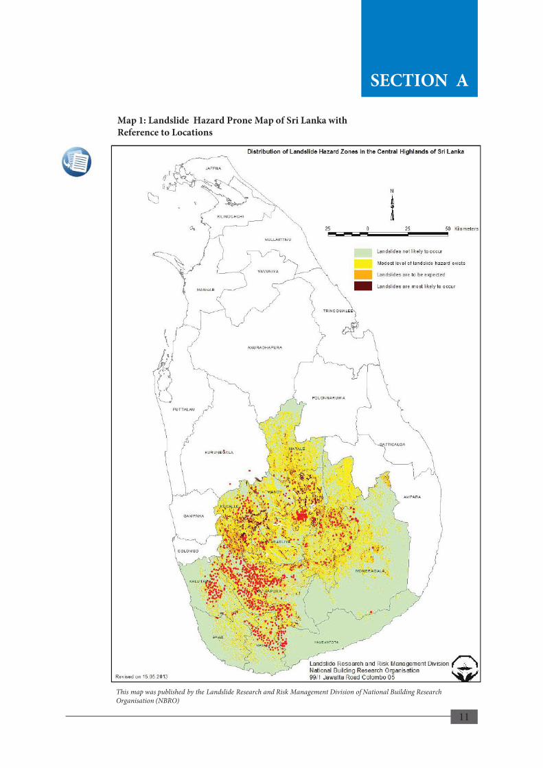
Human interventions through improper land use, unplanned development and construction activities without proper engineering inputs can contribute to instability of slopes. These include for example; improper excavations and fillings, mining and quarrying etc., changing of the natural slope; blasting of rock causing ground vibrations; denudation of slopes and watersheds by deforestation; removal or burning down of vegetation increasing the susceptibility to soil erosion; improper farming practices; surface or subsurface ponding of water and irrigation on slopes that change surface and ground water regimes; reclamation of land by filling on unstable slopes. c) Typical Damages The momentum of the mass of material moving from a landslide can destroy property along its path of movement and cause death to people and livestock. During the period from 1869 to 2003, there were about 178 reported landslides all over Sri Lanka, causing over 455 deaths. Most of the impacts of landslides have increased during the last 25 years and 85 % of the deaths occurred during this period. The worst landslide in the history of country was reported in May 2003 causing loss of 188 lives. For the past 25 years from 1982 to 2007 landslides have affected almost 150,000 families and around 2,800 million rupees had to be spent on relief measures. It is mostly the Central Highlands of Sri Lanka and the surrounding slopes that are frequently affected by landslides (Refer Map1).
14
SECTION A
SECTION A

10
d) Impact on Housing Landslides, except for most minor slope failures, generally involve large mass of material and momentum which can destabilize, damage, destroy or bury buildings. The nature and extent of damage to a house vary on many factors including the type and severity of the landslide and location of the house relative to the path of landslide. For example, ground movement caused by a creep may cause the house to settle, tilt or develop cracks in the foundation and walls, or even to collapse under excessive deformation. Falling rocks or debris can hit the roof and walls damaging them or burying the house fully or partially depending on the volume of debris.
15
Source: NBRO
This photograph was taken at the landslide affected area at Miriyabedda, Haldummulla. 2014
SECTION A
d) Impact on Housing Landslides, except for most minor slope failures, generally involve large mass of material and momentum which can destabilize, damage, destroy or bury buildings. The nature and extent of damage to a house vary on many factors including the type and severity of the landslide and location of the house relative to the path of landslide. For example, ground movement caused by a creep may cause the house to settle, tilt or develop cracks in the foundation and walls, or even to collapse under excessive deformation. Falling rocks or debris can hit the roof and walls damaging them or burying the house fully or partially depending on the volume of debris.
15
Source: NBRO
This photograph was taken at the landslide affected area at Miriyabedda, Haldummulla. 2014
SECTION A d) Impact on Housing Landslides, except for most minor slope failures, generally involve large mass of material and momentum which can destabilize, damage, destroy or bury buildings. The nature and extent of damage to a house vary on many factors including the type and severity of the landslide and location of the house relative to the path of landslide. For example, ground movement caused by a creep may cause the house to settle, tilt or develop cracks in the foundation and walls, or even to collapse under excessive deformation. Falling rocks or debris can hit the roof and walls damaging them or burying the house fully or partially depending on the volume of debris.
15
Source: NBRO
This photograph was taken at the landslide affected area at Miriyabedda, Haldummulla. 2014
SECTION A
SECTION A
11
Map 1: Landslide Hazard Prone Map of Sri Lanka with Reference to Locations
This map was published by the Landslide Research and Risk Management Division of National Building Research Organisation (NBRO)
16
SECTION A
d) Impact on Housing Landslides, except for most minor slope failures, generally involve large mass of material and momentum which can destabilize, damage, destroy or bury buildings. The nature and extent of damage to a house vary on many factors including the type and severity of the landslide and location of the house relative to the path of landslide. For example, ground movement caused by a creep may cause the house to settle, tilt or develop cracks in the foundation and walls, or even to collapse under excessive deformation. Falling rocks or debris can hit the roof and walls damaging them or burying the house fully or partially depending on the volume of debris.
15
Source: NBRO
This photograph was taken at the landslide affected area at Miriyabedda, Haldummulla. 2014
SECTION A
SECTION A
12
2.3.2 Floods a) Background A flood is a rising of a body of water overflowing on to lands which are not normally under water. Flooding occurs in well-defined areas when the rivers or canals cannot contain run off from the catchments. Types of floods differ according to the location and cause of flooding. Low-lying areas and valleys of waterways are susceptible to natural or seasonal flooding by riverine floods due to overflow of rivers. Riverine flooding is caused by continuous rainfall over long durations or intense rains. Rapid accumulation of runoff from intense rainfall in upper catchments can cause a flash flood in a downstream location. In Sri Lanka, hazard maps of floods surrounding the areas of Attanagalu Oya, Kelani River Basin, Kalu River Baisn, and Gin River Basin have currently been published (DMC, 2012). Flooding in coastal areas can be due to high tidal waves and storm surges caused by high winds or cyclones. Tsunamis can cause instantaneous flooding by very high waves. Local floods and water stagnation can occur anywhere in depressions due to inadequate drainage or retention area. b) Causes of floods Flooding is a natural phenomenon. But it becomes a hazard when land use allocation is done without considering the flood risk levels or when people occupy flood plains demarcated as reservations. Improper land use and management practices and human interventions without proper engineering input can change the scale and extent of flooding and aggravate the consequences of flooding. Denudation by removing forests in the catchment, reclamation of wetlands for agricultural or development purposes, construction of roads blocking or constricting the natural waterways and drainage paths, encroachments and development activities along the banks of rivers and canals and around water bodies, can have detrimental effects in increasing the runoff or reducing the carrying capacities of waterways and detention areas. As a result floods can spread over larger areas and rise to much higher levels than the natural flood level. c) Typical damages from various types of floods
i) Riverine floods
Floods can critically interfere with the normal functioning of communities by disrupting communication and services. They can damage housing and other buildings and the infrastructure, particularly transportation and communication networks and public utility systems and services of a region, which may take a long time to repair or restore. Communities in flood affected areas may get isolated when the roadways are blocked or damaged. Floods cause death of people and animals by drowning. In addition, flood forces can cause structural damage to dwellings and other and buildings. Filthy matter carried by floods cause contamination of drinking water from wells or damaged pipelines adding to health problems.
ii) Coastal floods Type of damage from coastal flooding can be similar to those experienced from a riverine flood. However, coastal flooding from storm surges and tsunamis (Refer to Section C for more details) can cause much severe damage because of large dynamic forces exerted by the fast moving water mass. The effects of the waves depend on the height and speed of the tides.
17
SECTION A
SECTION A

13
Source: http://digitaljournal.com House inundated due to heavy rain.
d) Impact on housing Floods, riverine or coastal, can cause structural damage to dwellings and other buildings. Flood flow and the water filled up around a house can exert lateral forces strong enough to cause damage or collapse of walls. Houses with lighter structures can even be carried away in a flood when the forces of flowing water are significantly large. Water filled up around the building can exert uplift forces on the floor large enough to cause damage to floor slab. Erosion underneath the foundations and floor slabs can cause floor slab failures. Moreover, foundations can undergo settlement or total collapse due to loss of strength caused by saturation or liquefaction of subsoil. Unsuitable or poor quality materials such as unburnt clay bricks and poorly bonded masonry used in houses and poorly designed foundations can easily give away during a flood.
Houses built within the storm tide inundation zone can generally suffer damage caused by; • Seawater inundation which can affect quality and deterioration of building material • Water currents that break through walls and move whole buildings off their foundations • Water currents and high winds that drive debris into the building • Impact of large items such as sheds, fences, water tanks and logs that may be swept away by the
currents.
18
SECTION A
SECTION A

14
2.3.3 High Winds a) Background The wind is normally a continuous sequence of gusts and lulls with rapid changes of direction. Wind becomes a hazard when it is experienced as high speed winds, cyclones, tornados or gales. Cyclones are huge revolving storms caused by winds blowing around a low atmospheric pressure area at the centre. Tornado is a form of high speed wind which is localized and short lived. Strong winds and gales occur more often than cyclones. b) Causes
Cyclonic storms and gale force winds experienced in Sri Lanka are associated with monsoon activity or severe weather changes in the Bay of Bengal. Cyclones occur due to high temperatures over tropical sea surface and high speed winds move anticlockwise around a low pressure area. Tracks of some past cyclones and storms are shown in Map 2. Strong winds in the order of 50m/s can be expected c) Typical damages Located near the confluence of the Arabian sea, Indian ocean and the bay of Bengal and the tropical cyclone path, Sri Lanka is vulnerable to high speed winds, cyclones and tornados. Mostly the east and northeast coastal areas of the island suffer from highly destructive winds during the cyclone season and the monsoon seasons annually. Strong winds in the order of 50m/s can be expected in that coastal zone. Extreme wind conditions can cause fatalities and injuries due to falling, flying or collapsing objects and direct damage to property and the economy by disrupting transportation and communication systems and services due to falling trees or damage to power transmission lines etc. High winds can have other indirect effects as areas along the cyclone path may receive very heavy and widespread rainfall that leads to flash floods and landslides. d) Impact on housing Blowing off of roofs of buildings along the cyclone path is a typical damage caused by extreme high winds. The roofs are vulnerable to significant wind forces because of their higher elevation from the ground, lighter weight, having sharp corners and protruding eaves and when they lack in proper bearing and anchoring to the superstructure. In intense wind conditions, structural walls may be damaged from lateral forces and vibrations. Damage to roofs and sometimes to other parts of house can be caused by falling trees.
19
SECTION A
SECTION A

15
Source: www.hazards.lk
Map 2: Tracks of Past Cyclones and Storms
This map was produced by the Department of Meteorology (DoM) under the Hazard Profiles development process initiated by the Disaster Management Center (DMC) with the assistance of UNDP.
20
SECTION A
Important!
This map is intended to be used as a guide in national or regional level planning and for public information only.
SECTION A
16
2.3.4 Earthquakes a) Background An earthquake is a natural phenomenon which occurs due to the sudden relative movement of the earth’s crust. They can occur as “inter-plate type earthquakes closer to the tectonic plate boundaries or as intra-plate type earthquakes away from the tectonic plate boundaries”. Sri Lanka being located within a plate known as Indian-Australian plate (refer to Map 3) and far away from the plate boundaries, earthquakes in the Island will be of the intra-plate type. This type of earthquakes can occur without much warning or historical records. In contrast, inter-plate type earthquakes are more frequent and violent and can be highly destructive. Earthquakes that have occurred in and around Indian-Australian Plate is shown in Map 4. Sri Lanka has historical records of several moderate to severe earthquakes with magnitudes ranging from 3.0 to 6.0 on the Richter Scale. Minor tremors also have been reported in several locations without their causes fully established. The possibilities of increased seismic activities in the region also have drawn much attention. While it is generally difficult to predict when and where an earthquake could occur in Sri Lanka, it would be prudent to be prepared for any possible event in the future. It would therefore be desirable to construct buildings resilient to certain criteria such as expected ground motions, which are to be established thorough scientific studies. b) Causes Earthquakes or tremors of significance may also be created by volcanic activities, meteorite impacts, undersea landslides, explosions of nuclear bombs, etc.
c) Typical damages Sudden tectonic movements will generate seismic waves that could cause ground vibrations or ground shaking. Buildings and structures on the ground surface respond to that shaking in varying degrees. Earthquakes can also induce secondary disasters; ground failures, landslides, tsunamis and fire. Ground cracking, settlement and soil liquefaction can seriously affect the buildings, infrastructure and utilities. d) Impact on housing Ground shaking from earthquakes and secondary effects can damage or destroy a house unless it has been designed and constructed or strengthened to be earthquake resistant. Houses of traditional construction with brick or stone masonry are the most vulnerable. Most of the loss of lives in past earthquakes worldwide had been due to collapse of such buildings.
21
SECTION A SECTION A
SECTION A

17
Map 3: Major Tectonic Plates
Source: U.S. Geological Survey, 1997
Source: www.jaeger.earthsci.unimelb.edu.au
Map 4: Earthquakes in and around Indo-Australian Plate
22
SECTION A SECTION A
SECTION A

18
23
SECTION A
19
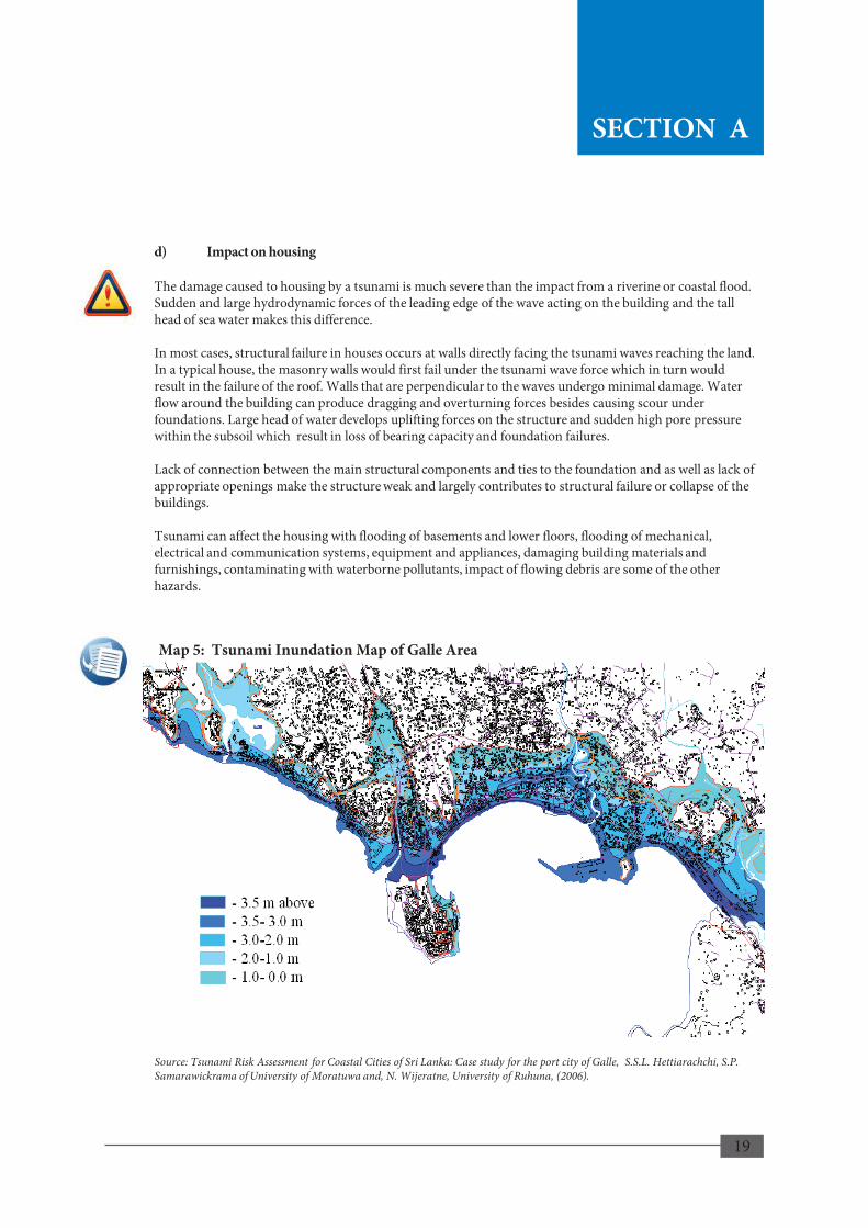
d) Impact on housing The damage caused to housing by a tsunami is much severe than the impact from a riverine or coastal flood. Sudden and large hydrodynamic forces of the leading edge of the wave acting on the building and the tall head of sea water makes this difference. In most cases, structural failure in houses occurs at walls directly facing the tsunami waves reaching the land. In a typical house, the masonry walls would first fail under the tsunami wave force which in turn would result in the failure of the roof. Walls that are perpendicular to the waves undergo minimal damage. Water flow around the building can produce dragging and overturning forces besides causing scour under foundations. Large head of water develops uplifting forces on the structure and sudden high pore pressure within the subsoil which result in loss of bearing capacity and foundation failures. Lack of connection between the main structural components and ties to the foundation and as well as lack of appropriate openings make the structure weak and largely contributes to structural failure or collapse of the buildings. Tsunami can affect the housing with flooding of basements and lower floors, flooding of mechanical, electrical and communication systems, equipment and appliances, damaging building materials and furnishings, contaminating with waterborne pollutants, impact of flowing debris are some of the other hazards.
Map 5: Tsunami Inundation Map of Galle Area
Source: Tsunami Risk Assessment for Coastal Cities of Sri Lanka: Case study for the port city of Galle, S.S.L. Hettiarachchi, S.P. Samarawickrama of University of Moratuwa and, N. Wijeratne, University of Ruhuna, (2006).
24
SECTION A
SECTION A

20
2.4 Other Hazardous Conditions 2.4.1 (Soft / Loose) Ground Conditions a) Background This is a ground condition with sub soils not having adequate strength to support the structures placed on them or necessary stiffness to prevent the structures from undergoing significant settlement and deformation. Poor (soft/loose) subsoil conditions are generally associated with loose deposits of silt and fine sand and highly compressible peats and soft clays which are often found in low-lying areas, paddy fields and marshy land. These soils generally have high amount of voids ( high void ratio or porosity ). In soft clays voids are filled with water and soils have a high water content. Like a sponge soaked in water soils have voids filled with water. As the soil is loaded with a structure above it, the soil particles may rearrange themselves and the entrapped water begins to gradually escape with a proportionate reduction in volume, which reflects as ground settlement. Settlement in some soils can be very high and in soft clays may continue over a few months or even a few years. This necessitates special attention on the stability and serviceability aspects of foundation of buildings and infrastructure e.g. road and railway embankments and structures such as the bridges and culverts. b) Occurrence Poor (soft/ loose) subsoil conditions can exist in almost any part of the country within and around low-lying areas, natural valleys or buried valleys. More commonly they are found adjacent to lower reaches of rivers and their tributaries, and particularly along the coastal belt surrounding the lagoons. Weak soils may exist as shallow deposits or extending deeper than even 10~20 meters. Marshy conditions are generally indicative of the prevalence of poor soils at shallow depths, but poor soils may often be not evident when they are hidden by other deposits or due to reclamation. In general, low lying areas are also prone to riverine floods and if located near the coastline, also to coastal flooding. c) Typical damages Structures constructed on poor ground without adequate treatment for improving soil properties can settle, deform, break away or even fail causing accidents. Buried ducts, water pipelines etc., will be subjected to bending, dislocation and can become non-functional. Buildings can settle, tilt, overturn or even collapse due to foundation failures. d) Impact on housing Houses built over soils that are weak and highly compressible can undergo significant settlement. Sometimes, settlement may take place over a long time period, which means that substantial settlement would still remain even many years after construction. Due to local differences in the soil properties or how differently the loads are distributed over the soil, the structure may settle unevenly. Such differential settlement if exceeds the tolerable limits can cause damages such as; cracks on walls (cracks due to differential settlements can be quite large and grow with time), floor and foundation, difficulties in closing and opening of doors and windows due to tilting or deformation of the building. Buildings may tilt or even collapse due to failure of the foundation. These can also create psychological discomfort and health problems besides the house is becoming aesthetically unpleasant.
25
SECTION A
SECTION A

21
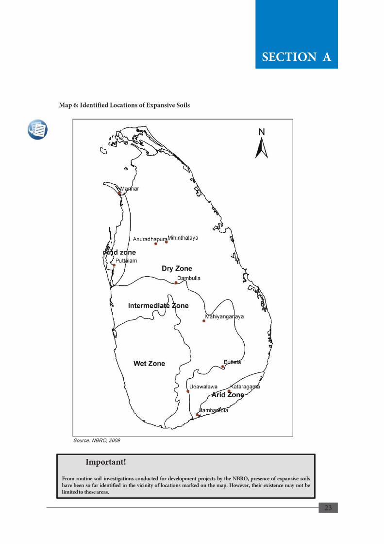
2.4.2. Expansive Soils a) Background Soils that undergo significant volume changes due to variation of their moisture content are known as expansive soils or swelling soils. These typically contain clay minerals such as montmorrilonite that attract and absorb water and cause the plates in clay particles to push apart each other and increase in volume. Soils containing expansive clays shrink and become very hard when dry. But when wet, they may become very sticky and looses strength significantly. The presence of surface cracks due to shrinkage can be an indication of an expansive soil. b) Occurrence In Sri Lanka, expansive soils are found in the dry zone where the clay mineral montmorrilonite is prevalent. Their presence has been identified in the regions of Anuradhapura, Buttala, Dambulla, Kataragama, Mahiyangana, Mihintale, Murunkan in Mannar, Puttalam, Hambantota and Uda-Walawe (refer Map 6).
c) Typical damages Expansive soil on swelling can develop pressures large enough to force a structure supported on it to move upwards (heaving). This uplift pressure could cause cracking in the lightly loaded areas of the building such as under window sills and pavement/floors. As the soil dries, shrinkage causes the structure to move downward (settlement). If the soil dries and shrinks only on one side of the structure while the soil on the other side remains expanded, the structure would experience differential movement. Uneven shrinkage and swelling of the soil can, therefore, create high distress in the foundation and cause serious damage to the structure in the form of cracks, deformation or failure of structural members. d) Impact on housing The differential movements, i.e. due to differential ground settlement or heaving, of a house constructed on expansive soil can cause deformation and cracking of its foundation, walls and the floors mainly at ground level (Refer image 1a &1b). Distress or damage may be evident as; • Sagging of brick lines or diagonal /stair-stepping cracks in brick masonry walls. • Tilting of walls. • Cracks or separation at wall corners and floor. • Cracks above doors and windows. • Crack under window sills. • Warped door/window frames sticking doors/windows. • Cracked floor surface. • Crack in pavement around the house. • Separation of apron from foundation. Moreover, deep cracks of varying depth developed on ground or floor and the tilting of boundary walls and retaining walls can pose a danger.
26
SECTION A
SECTION A

22
SECTION A
Image: 1a. Vertical Crack along the Wall
Image: 1b. Cracks on the Floor and Window Sills
27
SECTION A
Image: 1a. Vertical Crack along the Wall
Image: 1b. Cracks on the Floor and Window Sills
27
SECTION A
23
Map 6: Identified Locations of Expansive Soils
Mihinthalaya Anuradhapura
Mannar
Hambantota
28
SECTION A
Source: NBRO, 2009
Important!
From routine soil investigations conducted for development projects by the NBRO, presence of expansive soils have been so far identified in the vicinity of locations marked on the map. However, their existence may not be limited to these areas.
SECTION A
Image: 1a. Vertical Crack along the Wall
Image: 1b. Cracks on the Floor and Window Sills
27
SECTION A

24
2.4.3. Ground Subsidence a) Background Ground subsidence is known as the settling or sudden sinking of the Earth's surface due to subsurface movement of earth materials. One of the most common causes of this is the removal of large volume of soil which can be caused by events such as mining. In addition, dissolution of soluble rock or soils materials also results in ground subsidence. Subsidence can also be caused by prolonged dewatering for construction or by pumping out water in water supply schemes. b) Occurrence Subsidence may occur gradually over many years or can occur abruptly although it is more infrequent, leaving ground openings where it is possible, to swallow any part of a structure lying at that location or leaving significant holes. Mining, vibration, removal of support around foundations, changes in the water table and in-filled sites can be considered as man-made factors that cause subsidence. Ground movement due to mining is caused by collapse of the mine workings. Where pits and quarries have been filled after excavation or mining with different materials, the fill can degrade over time causing subsidence. Land subsidence occurrences of considerable magnitude were reported in Sri Lanka in Matale area in the recent past (refer to Map 7).
c) Typical damages As subsidence is a downward movement of the ground, buildings constructed on such ground experience damages due to the uneven movement of the ground. This often results in cracking of the structure, which leads to long term damages. d) Impact on housing Houses that are affected by ground subsidence experience vertical and diagonal cracking concentrated in specific areas and tapering in width between the top and bottom of the crack, cracks extending through the damp proof course (d.p.c) down into the foundations, external cracking reflected internally in the same area of wall, distortions of openings (which are weak points in the structure), causing doors and windows to stick, and cracks appearing after a prolonged period of dry weather,
29
SECTION A SECTION A

25
Map 7: Risk Map of Ground Subsidence in Matale
30
Source: NBRO, 2015
SECTION A
SECTION A

26

27
GENERAL REQUIREMENTS FOR A
SAFER HOUSE
28
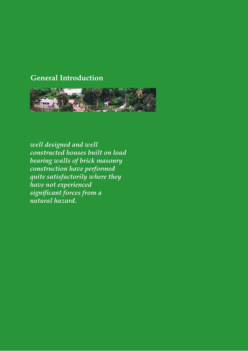
General Introduction
well designed and well constructed houses built on load bearing walls of brick masonry construction have performed quite satisfactorily where they have not experienced significant forces from a natural hazard.
29
1.1 Background The traditional buildings that have incorporated the accumulated traditional wisdom, technology, experience, skill and craft evolved through the ages generally have demonstrated good performance against most natural hazards. However, some modern-day structures, especially the small residential houses, are non-engineered structures without receiving the benefit of such time-tested technology or the input from engineering or architectural professionals. Non-engineered houses can suffer in hazards, but engineered houses can be resilient against hazards (refer to Fig. B-1 and Fig. B-2). For example, well designed and well constructed houses built on load bearing walls of brick masonry construction have performed quite satisfactorily where they have not experienced significant forces from a natural hazard. Even two-storey residential structures of similar construction have shown good performance under normal conditions. However, these may not sustain required performance under more severe hazards and/or hazardous conditions. Irrespective of whether the house is to be built at a location within an area identified as prone to a specific hazard or in an area unlikely to be affected by any kind of natural hazard or hazardous condition, the house should have greater resilience. This requires the house to be structurally strengthened to meet required level of performance. The simplest form of strengthened structure recommended in this manual is a reinforced concrete framed structure with masonry walls enclosed between reinforced concrete columns. This type of structure is considered appropriate for a house that should have minimum resilience in general that is applicable to areas with any type of hazard discussed in this and it is believed that these requirements can be easily adopted by the local builder who is familiar with the construction of houses with brick masonry walls having concrete columns. If the house is to be built within an area prone to a specific hazard or hazardous condition, there are additional requirements and precautions. Therefore, upon meeting the minimum requirements in this Section, the reader is required to refer to guidance given in Section C under the relevant specific hazard or hazardous condition.
1. General Introduction
32
Important!
Section B of the manual has been designed to furnish the user with minimum recommended practices to follow when building a single story house having a floor area not more than 80 square meters in hazard prone areas irrespective of the type of the hazard within the scope of this Manual.
If one wishes to be proactive, it is possible that minimum requirements presented in this Section are followed in areas that are not designated as hazard prone as well. However, it is prudent for the user to avoid risks and seek professional advice in getting the safety of the location ascertained.
If the house construction is in a disaster prone area or a hazardous location, use of this manual is strongly recommended to ensure that potential damages from disasters are minimized.
SECTION B
SECTION B

30
Weaknesses of a Non engineered House
5. Inadequate connection of roof framing to structure.
6. Inadequate anchoring of door and window frames to structure.
7. Inadequate connection of gable to structure and roofing to gable.
8. Inadequate anchoring of roof sheets and/or tiles to roof framing.
9. Disturbances to existing ground conditions. 10. Possible damages to neighboring structures.
1. Inadequate depth of foundation and floor located below flood level.
2. Inadequate connection between walls or lack of a frame structure to increase the stiffness.
3. Unsupported gable wall and perimeter walls. 4. Diagonal cracking at corners of openings
due to not providing sill and lintel beams. 5. Poor quality building material lacking
required strength and performance.
1 2
3
4
5
6
7
8 9
10
Fig. B-1: Weaknesses of a Non-engineered House
33
Important!
Non-engineered houses may increase the vulnerability to hazards (Fig. B-1). Structures lacking proper connectivity and strength in its components to withstand different types of forces should be avoided when building in areas prone to disasters.
SECTION B
SECTION B

31
1.2 Basic Components and Structure of a Hazard Resilient House
Residential buildings are composed of structural and non-structural components in which numerous types of material are used. Foundations, columns, beams, walls, floor slabs and roof frame are the basic structural components that make the skeleton of the structure, which carries the loads and connected to other members. In a Hazard Resilient House, these components are designed to contribute as much as possible to the integrity of the structure refer Fig. B-2.
This manual recommends that the basic structure of a house is planned and designed to be constructed as a reinforced concrete framed structure with masonry walls filling in between columns.
The reinforced concrete frame shall consist of;
• A foundation system suitable for the ground conditions and structural loads.
• Reinforced concrete columns provided at each corner of the house and elsewhere as required.
• Reinforced plinth beams provided at the base of the structure; over the wall foundations structurally connecting with the columns, unless the wall foundation itself is of concrete.
• Reinforced concrete ties at required levels structurally tied to the reinforced concrete frames.
• A roof frame for a pitched roof with tiles or sheets or a flat concrete roof slab properly anchored to the superstructure
• Concrete slab floor where required for the upper floor.
34
SECTION B
SECTION B

32
Features of a Hazard Resilient House
6. Door and window frames properly anchored to structure.
7. Roof structure properly built and connected to the main structure.
8. Properly connected gable wall to structure and roofing to gable wall.
9. Roof covering properly connected to roof structure.
10. Minimal disturbance to ground and supported cuts to retain slopes.
1. Increased depth of foundation and raised floor level.
2. Framed structure with reinforced concrete columns.
3. Walls provided with proper framing. 4. Walls stiffened at openings using lintel/sill
beams. 5. Good quality building materials used in all
components to meet required strength and other properties.
Fig. B-2: Features of a Hazard Resilient House
1
2
3
4 5
7
6
8
9
10
35
Important!
Engineered regular structures with symmetric frames incorporating disaster resilient features are highly encouraged as per Fig. B-2. • It is recommended that the house is planned to be constructed as a reinforced concrete
framed structure with masonry walls between columns. • The reinforced concrete frame shall be of reinforced concrete columns provided at each
corner of the house at minimum ties with reinforced concrete beams at required levels. • Length of the structure is recommended not to exceed three (3) times the width of the
structure (length to width ratio to be maximum 3:1).
SECTION B
SECTION B

33
34
Planning Phase
Before considering to build a house on one’s own land or purchasing a plot of land to build one, it is necessary to ascertain the suitability of the location and its environment. It will be required to get as much factual information as possible to make the decision.

35
2. Planning Phase
2.1 Selection of Land
Before considering to build a house on one’s own land or purchasing a plot of land to build one, it is necessary to ascertain the suitability of the location and its environment. It will be required to get as much factual information as possible to make the decision. In this, consultation of respective Local Authority and other relevant authorities regarding approvals permits etc., may be required. Some important factors that should be taken into consideration are given below.
a) Land and location – In addition to legal rights the owner should have, it must be ascertained whether residential buildings are permitted in the land. Land may be suitable physically, but may not be in an area demarcated for residential use. Special attention shall be given to land selection when building in areas or locations that may be subject to natural hazards or other hazardous conditions. Hazard maps depicting the hazardous areas and hazard zonation maps showing different risk levels in hazardous areas are useful in broadly identifying whether the land is located in a specific hazardous area.
b) Topography – Elevation, slope, undulations, drainage, ground condition etc., of the land are important factors that affect cost of construction and safety of the house.
• Elevation – General elevation and elevation of the land above nearby water bodies can indicate whether the land is vulnerable to floods or inundation.
• Slope - Construction on sloping land can be difficult and costlier than building on flat land, besides being unsafe. Risks can become higher as the slope becomes steeper. Building on slopes that may create any risky situations of slope instability must be avoided. Therefore, the builder is strongly advised to take extra care when building on slopes, particularly if the selected land has a ground slope greater than 20% or a slope angle more than 11 degrees. Professional advice should be sought when building on steeper ground slopes for which restrictions are imposed (refer Section C 1).
c) Subsoil conditions - A good knowledge of the ground conditions, including sub-soils, would be useful to decide the proposed location of the house and demarcating it on the drawing sent for approval of the authorities. Once the building plans are approved, change of location due to subsequent identification of unfavorable subsoil conditions can lead to time delays or use of costly foundations.
d) Water bodies - Proximity to drainage paths, waterways, water bodies, wetlands, marsh-lands, coastline would suggest potential of flooding. It is also necessary to know the extent of land allocated for reservations.
e) Vulnerability to hazards – Knowledge and history of any natural or other hazards that occurred in and around the land would be helpful. If there is any risk prevailing, reference should be made to the relevant hazard in Section C.
f) Performance of neighboring buildings etc., - Performance of any existing buildings or other structures in the vicinity, for example, structural damage, appearance of cracks, settlement or tilting of structures that have taken place over the time can be useful in understanding the risks and how to manage them.
g) Accessibility - Need for construction of access roads and related ground stability issues, particularly in hilly terrain, need special attention. Convenience of communication and routes for evacuation during an event also must be considered. To collect above information, it is recommended to; • Explore the land and its surroundings. • Inquire from local residents, particularly the elders of the area, who can give information on the
environment and past incidents. • Study relevant plans and maps including hazard zonation maps, air photos and satellite images.
36
SECTION B
SECTION B

36
2.2 Hazard Maps
Impacts of disasters arising from natural hazards due to unplanned land use and development activities are increasing in Sri Lanka, compromising a great number of lives and properties each year. With this situation development of hazard profiles for the country became an urgent requirement to minimize the unfavorable impacts of overall development by ensuring the sustainability of investments.
In order to fulfill this growing requirement, the Disaster Management Centre (DMC) and the United Nations Development Programme (UNDP) initiated a hazard profile development process in collaboration with the relevant technical agencies such as the National Building Research Organisation (NBRO), Department of Meteorology (DoM), Coast Conservation and Coastal Resource Management Department (CC&CRMD), Irrigation Department (ID) as well as the Faculty of Agriculture of the University of Peradeniya in 2009.
These institutions are responsible for research, early warning and forecasting, preparedness and mitigation activities of the country. At present nine natural hazards namely; coastal erosion, drought, floods, landslides, lightning, sea level rise, storm surge, tropical cyclones and tsunami have been identified in the country. These hazard profiles including hazard maps have been developed and published by the above technical agencies and they could be used for regional level planning for disaster risk reduction in Sri Lanka.
2.3 Use of Hazard Maps
When building in areas or locations that may be subject to natural hazards or other hazardous conditions, special attention shall be given to land selection. The following maps may be used for broadly identifying whether the land is located in a specific hazardous area.
• Landslide Hazard Zonation Maps prepared by the Landslide Research and Risk Management Division of NBRO at scale 1:50,000 for 10 districts; Nuwara Eliya, Badullla, Kegalle, Ratnapura, Matale, Kandy, Kalutara, Hambantoata, Galle and Matara are available (refer Map 8.1 and Sample Map 8.2). In addition, maps at scale 1:10,000 are being prepared for specific local areas. The relevant local government authority is required to obtain NBRO’s Landslide Risk Assessment Report or recommendations report on landslide vulnerability prior to giving approvals for development and construction plans in a landslide prone area.
• Flood Hazard Maps of the River Basins published by Irrigation Department with the assistance from Disaster Management Centre Sri Lanka are available at scale 1:50,000 for Attanagalu Oya, Kelani River Basin, Kalu River Basin, and Gin River Basin (refer Map 9: Sample Map Attanagalu Oya). These maps are useful to broadly identify the inundation areas. However, the inundation areas shown in these maps based on past flood events shall not be considered as the only areas subject to flood hazard as floods of higher magnitude can be expected.
• The Map of Wind Loading Zones Sri Lanka given in Map 11 in Section C, depicts three zones according to the severity of wind and the suggested wind velocities for design on buildings (refer to Section C 3).
37
Important!
Limitations in the Use of Hazard Maps
Hazard maps may not be available for all the hazardous areas. Some hazard maps may be under preparation or revision or some areas may be excluded from hazard mapping. User is requested to inquire from the local authority or the relevant technical authority.
SECTION B
SECTION B

37
Sample Map 8.1: Landslide Hazard Zonation Map for District Level – Kandy District
Map 8: Landslide Hazard Zonation Maps
Sample Map 8.2: Landslide Hazard Zonation Map for Local Authority Area – Gampola UC
38
SECTION B
Maps shown above are reduced scale reproduction of a Hazard Maps that was produced and published by the Landslide Research & Risk Management Division of NBRO
SECTION B
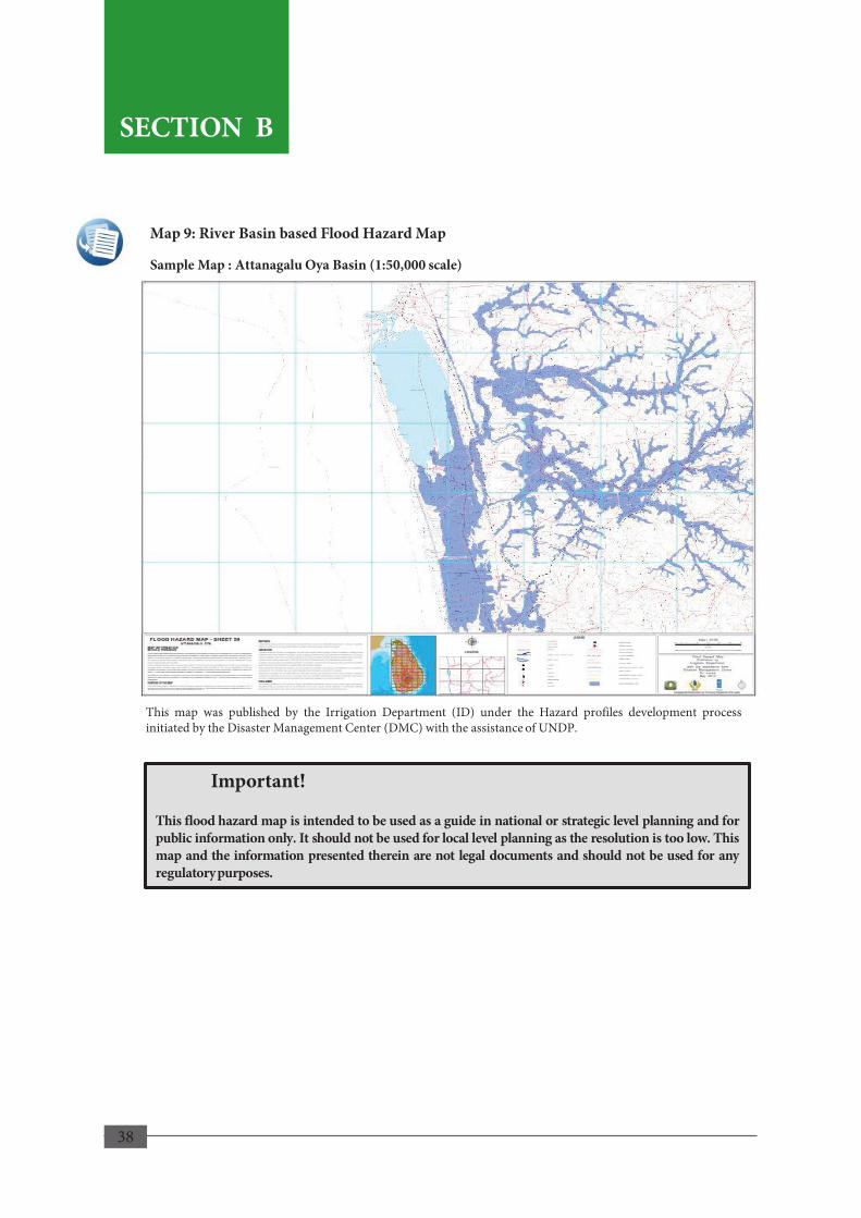
38
Map 9: River Basin based Flood Hazard Map
This map was published by the Irrigation Department (ID) under the Hazard profiles development process initiated by the Disaster Management Center (DMC) with the assistance of UNDP.
Sample Map : Attanagalu Oya Basin (1:50,000 scale)
39
Important!
This flood hazard map is intended to be used as a guide in national or strategic level planning and for public information only. It should not be used for local level planning as the resolution is too low. This map and the information presented therein are not legal documents and should not be used for any regulatory purposes.
SECTION B
SECTION B

39
2.4 Planning Clearance and other Approvals
If the house construction involves a Housing scheme, a schematic development plan fulfilling the criteria specified under the relevant acts must be submitted for preliminary planning clearance from the relevant local authority and/or the Urban Development Authority (UDA) before proceeding with detailed design, so as to accommodate the statutory requirement of such authorities.
Prior to commencing any construction activity, approval shall be obtained from the relevant authorities in accordance with the relevant acts, laws and bylaws. Approvals required for the purpose of development of residential houses are summarized in Table B-1 only as a guide. Should further information is required by the reader; the reader is responsible for contacting the relevant authority.
SECTION B
40
Important!
It is essential that the house plan (Building Plan) submitted to the local authority for approval shall conform to building regulations of the Urban Development Authority (UDA) and relevant guidelines pertaining to mandatory items such as; plot size, access from road, floor area, number of floors, height of house, room sizes, interior partitions and all other requirements specified therein.
SECTION B

40
Purpose for which Approval/Permit/ Clearance
Certificate should be obtained
Stage to Obtain Approving
Authority/issuing institute Relevant Legal Documents
for Reference
Landslide Risk Assessment Report for any land development/or building constructions in ten districts declared as prone to landslides
During land selection/planning construction activities
National Building Research Organisation (NBRO)
Circular No 11/1 of Ministry of Disaster Management
Approval for any type of construction in areas which are declared as developed areas under the UDA Act.
During land selection
Urban Development Authority (UDA)
UDA Act 41 of 1978 as amended by Act No. 4 of 1982 and Act No. 44 of 1984
Preliminary Planning Clearance Certificate for any land/real estate development project.
During land selection
Urban Development Authority (UDA)
UDA Regulations in Gazette No. 392/9 of 10.03.1986
Approval for filling of paddy lands
During land selection
Urban Development Authority (UDA) Department of Agrarian Services
Permission for development within the coastal zone
During land selection
Coast Conservation & Coastal Resources Management Department (CCRMD)
Coast Conservation Act, CZMP (2004), 1997 setback limits.
Permission for development in areas declared as low-lying (or marshland/wetland)
During land selection
Sri Lanka Land Reclamation and Development Corporation (SLLRDC)
SLLRDC Act No. 15 of 1969 and amendments
Building permit for any building activity
During planning of construction activities
Urban Council UDA Act 41 of 1978 as amended by Act No. 4 of 1982 and Act No. 44 of 1984
Municipal Council
Municipal Council Ordinance; UDA Regulations in Gazette No. 392/9 of 10.03.1986
Pradeshiya Sabha House and Town Improvement Act of 1915
Certificate of Conformity After construction is completed and prior to occupying
Urban Council UDA Act 41 of 1978 as amended by Act No. 4 of 1982 and Act No. 44 of 1984
Municipal Council UDA Regulations in Gazette No. 392/9 of 10.03.1986
Pradeshiya Sabha Municipal Council Ordinance
Table B-1: Approving Authorities for Residential Building Planning and Construction Activities
41
Important!
Table B-1 outlines the basic types of approvals and/or certificates that one should obtain at different stages of building a house. Authorities responsible for granting the approvals are listed based on the type of approval required.
SECTION B
SECTION B
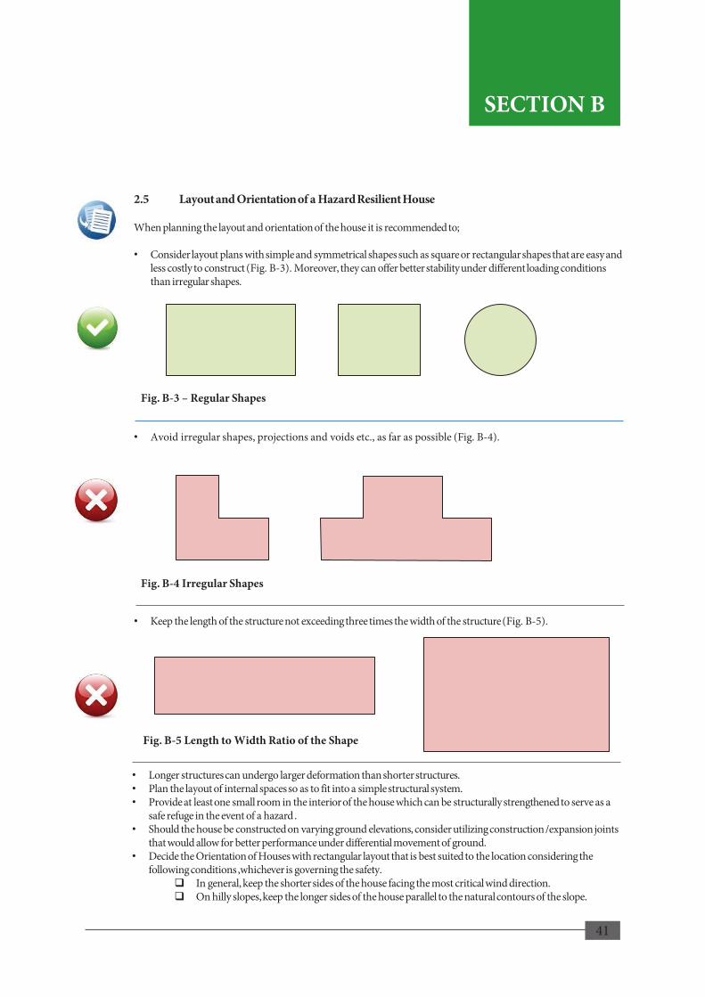
41
SECTION B
2.5 Layout and Orientation of a Hazard Resilient House When planning the layout and orientation of the house it is recommended to; • Consider layout plans with simple and symmetrical shapes such as square or rectangular shapes that are easy and
less costly to construct (Fig. B-3). Moreover, they can offer better stability under different loading conditions than irregular shapes.
• Avoid irregular shapes, projections and voids etc., as far as possible (Fig. B-4).
• Keep the length of the structure not exceeding three times the width of the structure (Fig. B-5).
• Longer structures can undergo larger deformation than shorter structures. • Plan the layout of internal spaces so as to fit into a simple structural system. • Provide at least one small room in the interior of the house which can be structurally strengthened to serve as a
safe refuge in the event of a hazard . • Should the house be constructed on varying ground elevations, consider utilizing construction /expansion joints
that would allow for better performance under differential movement of ground. • Decide the Orientation of Houses with rectangular layout that is best suited to the location considering the
following conditions ,whichever is governing the safety. In general, keep the shorter sides of the house facing the most critical wind direction. On hilly slopes, keep the longer sides of the house parallel to the natural contours of the slope.
Fig. B-5 Length to Width Ratio of the Shape
Fig. B-4 Irregular Shapes
Fig. B-3 – Regular Shapes
42
SECTION B
42
Design and Construction Phase
Residential buildings are composed of structural and non-structural components in which numerous types of material are utilized. Foundations, columns, beams, walls, floor slabs and roof frame are the basic structural components that makes the skeleton of the structure that carries the load. Walls, floor slabs and roof may or may not play an important part depending on how they are structurally designed and connected to other members.
43
3.1 Building Materials 3.1.1 Types of Building Materials Residential buildings are composed of structural and non-structural components in which numerous types of material are utilized. Foundations, columns, beams, walls, floor slabs and roof frame are the basic structural components that makes the skeleton of the structure that carries the load. Walls, floor slabs and roof may or may not play an important part depending on how they are structurally designed and connected to other members. Non-structural components include wall and roof claddings, ceilings, flooring and lighting and ventilation openings such as doors and windows. There are several types of building materials used in different structural components of a house. The commonly used building materials are;
• Bricks, cement blocks, and metal in masonry-walls and sometimes in columns/pillars
• Concrete in foundations, walls, beams, columns and slabs
• Steel, cement, sand and gravel in concrete members
• Mortar (cement, sand and lime) in masonry works and plastering
• Timber in roof structure
In addition there is a wide variety of materials that can be used in non-structural components. 3.1.2 Quality The different types of building material used in a house are selected based on their individual properties and more precisely on the properties of building components made up of them. It is important how the material is used to yield the required performance of building components such as the capacity to resist damage from loads, shocks and vibrations, impacts or variations in moisture and temperature, durability and strength. It is a primary requirement that all building materials and the components used in the house should be of specified quality satisfying the standards of the Sri Lanka Standards Institute or equivalent, particularly when building in a disaster prone area. The role and required performance of each material or component, and the minimum requirements in standards of quality, sizes, etc., they should meet are presented below. It would be prudent not to sacrifice the quality of the house by using substandard materials or any substituent materials and methods that are not approved by the engineer or the concerned authority. 3.1.3 Cement Cement normally used for construction are Ordinary Portland Cement (OPC) complying to requirements of SLS 107, Blended Hydraulic Cement (HPC) complying to requirements of SLS 1247 and Portland Limestone Cement (PLC) complying to requirements of SLS 1253 of 2008.
3. Design and Construction Phase
43
SECTION B
SECTION B

44
3.1.4 Aggregate for Concrete Aggregate for concrete shall consist of coarse aggregate (gravel) substantially retained on the 5mm sieve and fine aggregate (sand) substantially passing the 5mm sieve. Crushed rock for coarse aggregate and river sand for fine aggregate are recommended. Crusher fines may be used on engineer’s approval. Sand extracted directly from the marine sources are not recommended for structural use. But off shore sand shall be procured from a responsible vendor who would ensure quality where Chloride ion content is less than 0.02%. Aggregates, both coarse and fine, shall be hard, durable and clean and free from weathered, soft, fakes, laminated or elongated pieces, salt, deleterious or organic matter, dust and clay. 3.1.5 Masonry Units There are several types of masonry units such as burnt or un-burnt clay bricks, soil-cement blocks, hollow or solid cement/concrete bricks/blocks, lime based blocks, shaped or broken stones. Generally, the choice is governed by local availability; compressive strength; durability; resistance to fire, moisture permeation and erosion; cost; ease of construction; etc. Brick has the advantage over metal as it requires less labour for laying and easy to construct. Thus, the first choice often would be brick if it is available at reasonable cost and is of the specified quality having the strength and other properties. Burnt clay bricks are the most widely used material in house construction in many parts of Sri Lanka. However, studies conducted by NBRO show that the average size and strength of clay bricks manufactured using commonly known methods for moulding and burning in the local industry varies widely. The strength of masonry depends not only on strength of bricks and grade of mortar but also on surface characteristics and uniformity of size and shape of units. Machine made bricks commonly known as wire-cut bricks are engineered bricks which are true in shape and size can be laid with thinner mortar joints, thereby resulting in higher strength. Therefore, in disaster resilient housing where higher masonry strength is needed, use of engineered bricks has greater advantage. However, machine made bricks generally have polished surface and hence reduced surface absorption that may result in poor adhesion to mortar unless surface absorption is controlled. A variety of natural building stones is available in many parts of Sri Lanka. Dense stones such as gneiss, granite, soft stone such as sandstone, limestone, and weak stones such as laterite are generally used in house construction mostly depending on their local availability. Broken stones (rubble) are commonly used in masonry and cut or shaped stones are used for ornamental purposes but rarely for structures.
44
SECTION B
SECTION B

45
a) Recommended Types of Masonry Units
Of the various types of masonry units available in the market, only the types listed in sub-sections i) and ii) are recommended for use in masonry works (refer Fig. B-6). Use of a particular type of unit may not be permitted in certain works or in certain parts of the structure depending on the conditions and environment they would be exposed to.
The following types of masonry units shall not be used;
• Any product that does not meet the requirements of the relevant SLS Standards,
• Any product that is not tested by a government accredited/recognized laboratory/authority and approved as acceptable by the engineer.
• All masonry units used shall meet the requirements of the relevant SLS Standards.
i) Clay Bricks
Clay bricks shall have the following properties.
• Size of normal burnt clay bricks shall be 220 x 105 x 65 (Length x Width x Height in mm). However, bricks of this standard size may not be freely available.
• Cement Stabilized Earth Blocks can be used for construction after obtaining guidance from relevant standards.
• For single to two storey structures hand-made bricks can be used and the minimum compressive strength of bricks used in single storey structures shall be 2.8MPa and two storey structures shall be 4.8MPa.
ii) Cement Blocks
Cement Blocks shall have the following properties.
• Sizes of cement blocks shall be in accordance with Table B-2 (refer Fig. B-6 for profiles).
• Minimum face shell thickness of hollow/cellular cement blocks shall be 25mm for work size blocks with width less than 150mm, 30mm for blocks of width between 150mm and 200mm, and 35mm for blocks of width greater than 200mm.
• Cement to sand or fine aggregate mix ratio shall be 1:8 and the water-cement ratio (w/c) shall be 0.9.
• Cement, sand to chipped aggregate (6-8mm) mix ratio shall be 1:7:10.
• Minimum compressive strength of blocks used for walls in single storey houses shall be 1.2MPa. For typical walls (solid blocks) of two storey houses, the compressive strength shall be 2.5MPa.
• Cement blocks shall be allowed to properly undergo shrinkage under moist condition and used 1-2 months after casting.
Table B-2 Types and Sizes of Cement Blocks Permitted
Type Size (Length x Width x Height in mm)
Solid 400 x 100 x 200
Hollow/Cellular 400 X 100 x 200
Source: Extracted from SLS 855 : Part 1 : 1989 Table 6
45
SECTION B
SECTION B

46
iii) Stones for Masonry Work • Stones used for masonry work shall have adequate strength to carry the loads imposed.
• Dense crushed/broken stones e.g. of gneiss or granite origin are recommended for rubble masonry
works in foundations, retaining walls and parapet walls particularly where masonry work is submerged in water or in contact with soil/ moisture or generally below plinth level.
• Random rubble may be of any shape and size but should not be less than 150mm in any direction.
• Stones shall be free from defects like cavities, cracks, flaws, veins of soft or loose materials, mica, organic impurities, or any other deleterious materials, etc.
Fig. B-6: Masonry Units
46
Solid Cement Block
Hei
ght
Brick
Hei
ght
Hollow Cement Block
Hei
ght
SECTION B
SECTION B
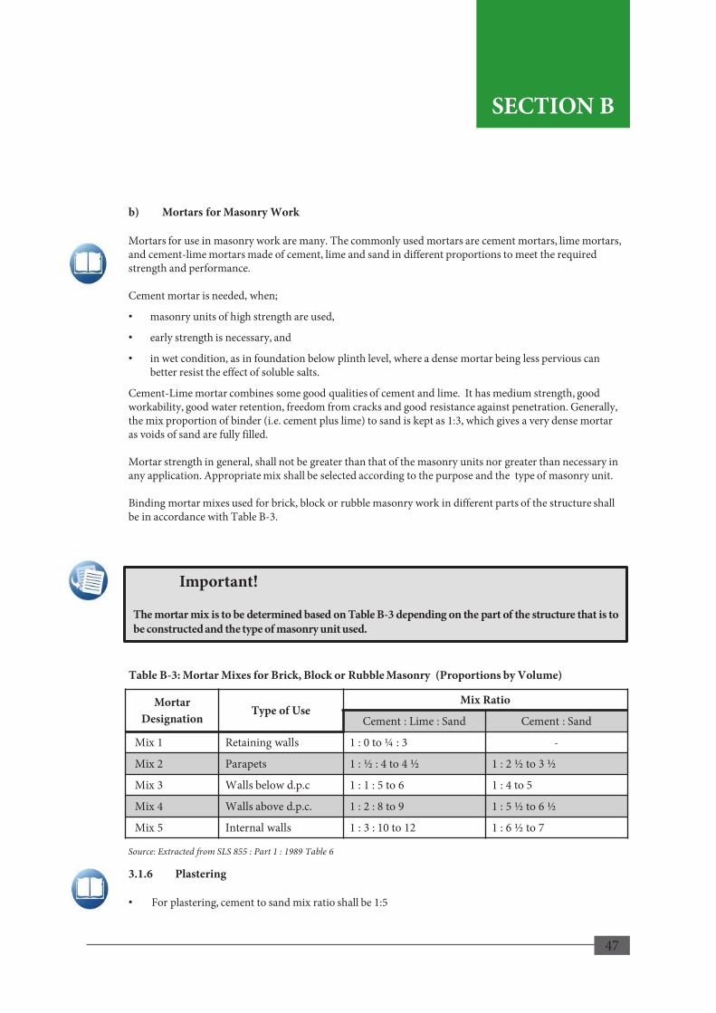
47
Mortar Designation
Type of Use Mix Ratio
Cement : Lime : Sand Cement : Sand
Mix 1 Retaining walls 1 : 0 to ¼ : 3 -
Mix 2 Parapets 1 : ½ : 4 to 4 ½ 1 : 2 ½ to 3 ½
Mix 3 Walls below d.p.c 1 : 1 : 5 to 6 1 : 4 to 5
Mix 4 Walls above d.p.c. 1 : 2 : 8 to 9 1 : 5 ½ to 6 ½
Mix 5 Internal walls 1 : 3 : 10 to 12 1 : 6 ½ to 7
b) Mortars for Masonry Work Mortars for use in masonry work are many. The commonly used mortars are cement mortars, lime mortars, and cement-lime mortars made of cement, lime and sand in different proportions to meet the required strength and performance. Cement mortar is needed, when;
• masonry units of high strength are used,
• early strength is necessary, and
• in wet condition, as in foundation below plinth level, where a dense mortar being less pervious can better resist the effect of soluble salts.
Cement-Lime mortar combines some good qualities of cement and lime. It has medium strength, good workability, good water retention, freedom from cracks and good resistance against penetration. Generally, the mix proportion of binder (i.e. cement plus lime) to sand is kept as 1:3, which gives a very dense mortar as voids of sand are fully filled. Mortar strength in general, shall not be greater than that of the masonry units nor greater than necessary in any application. Appropriate mix shall be selected according to the purpose and the type of masonry unit. Binding mortar mixes used for brick, block or rubble masonry work in different parts of the structure shall be in accordance with Table B-3.
Table B-3: Mortar Mixes for Brick, Block or Rubble Masonry (Proportions by Volume)
3.1.6 Plastering • For plastering, cement to sand mix ratio shall be 1:5
Source: Extracted from SLS 855 : Part 1 : 1989 Table 6
47
Important!
The mortar mix is to be determined based on Table B-3 depending on the part of the structure that is to be constructed and the type of masonry unit used.
SECTION B
SECTION B

48
Exposure Classification
Examples of Exposure
Nominal Cover (mm)
Mild Indoor 25 20 20 20 20 Moderate Outdoor -- 35 30 25 20 Severe Driving Rain -- -- 40 30 25 Very Severe Sea Spray -- -- 50 40 30 Extreme Abrasive -- -- -- 60 50 Maximum free water/cement ratio 0.65 0.60 0.55 0.50 0.45
Minimum cement content (kg/m3) 275 (300) 300 (325) 325 (350) 350 (400) 400 (450)
Lowest grade of concrete 25 30 35 40 45
Table B-4 provides the concrete cover and concrete strength that are to be used. The builder is to determine the type of condition where the house is going to be located in terms of location, environmental condition etc. Based this condition, the concrete cover and the required strength of concrete can be selected from the table.
3.1.7 Concrete • Concrete should have adequate strength to withstand the different conditions it is exposed to and
nominal cover to protect steel against corrosion and fire.
• The cover to a main bar should not be less than the bar size or, in the case of pairs or bundles, the size of a single bar of the same cross-sectional area.
• When using concrete for indoor applications; the minimum compressive strength of concrete shall be 25MPa. (Achievable with a cement: sand : coarse aggregate mix ratio of 1:2:4.)
• The minimum cover for all reinforcement in slabs, beams and columns shall be 25mm.
• Higher concrete strength or thicker cover will be required according to the conditions of exposure (refer to Table B-4).
Table B-4: Concrete Compressive Strength and Nominal Concrete Cover Based on Exposure
3.1.8 Reinforcing Steel Reinforcing steel shall conform to the following specifications.
• All steel reinforcement shall be tor steel or rib-bars.
• Steel reinforcement shall satisfy the 460MPa yield strength and ultimate strength should be greater than 10% of yield strength ( ICTAD 2004).
Source: Graded Examples in Reinforced Concrete Design by W.P.S. Dias, Society of Structural Engineers Sri Lanka (1995)
48
SECTION B
SECTION B

49
3.2 Foundation System
Foundation system broadly refers to the arrangement of structural members below the plinth level that transfer the loads from superstructure to the ground. The function of a building foundation is to support the building by safely distributing all the loads acting on the structure including the weight of the building and foundation, live loads and external loads to the ground. Foundation shall therefore be designed to,
• contain any settlement in the ground within tolerable limits,
• have sufficient strength and rigidity not to undergo significant deformation
• be stable and durable
• neither affect nor be affected by any adjoining structures that are existing or to be built in the future.
A basic understanding about suitability of different types of soil, how much load the soil can carry and the types of foundations suitable for different ground conditions, will be useful to the reader in the design and construction of the foundation system. 3.2.1 Bearing Capacity of the Ground Structural loads from the roof , floors etc., and the loads from external forces will be transmitted to the foundation and then to the ground through columns or walls or through a combination of both. Ground floor can be supported either as an on-ground slab that transfers the load directly to the ground or as suspended slab that transmits the load through beams and columns. The pressure distributed on the ground resulting from all such loads applied on the foundation is known as the bearing pressure. The capacity of ground to resist the foundation pressures is known as the bearing resistance or the bearing capacity of the ground. For a structure to be safely supported, the ground essentially should have adequate bearing capacity with a given safety factor to withstand the bearing pressure.
Bearing Pressure < Allowable Bearing Capacity (Allowable Bearing Capacity = Ultimate bearing capacity / Safety Factor)
Bearing capacity of the ground depends on many factors such as subsoil profile, type and structure of the soils, moisture content, the type, shape, depth and size of foundation. Therefore, when designing foundations for a structure, the allowable bearing capacity of the ground soil shall be determined by a geotechnical engineer who would study the profile and properties of subsoil based on appropriate field and laboratory investigations. However, for small and light structures such as a single or two storied houses it is possible to develop reasonable but somewhat conservative foundation design solutions if the type of soil and/or strata is known and the sub-soil structure is reasonably uniform. In using such solutions, it is important that the reader be familiar with the various types of soil likely to be encountered and the various types of foundations that would be appropriate.
49
SECTION B
SECTION B

50
SECTION B
3.2.2 Soil Types
The type, depth and size of a footing depends on the bearing capacity of the supporting material (soil or rock), which again depends on the type of soil and many other factors such as soil structure and composition, ground water etc. Common types of soil, their bearing capacity properties and the type(s) of foundation suitable for each soil type are given below;
• Rock - Rock usually offers a high bearing capacity, which depends on the type of rock, state of weathering and any fissures that exist within the rock. In certain areas, rock may exist at shallow depth. Reinforced pad footings for columns and narrow strip footings for walls would be quite adequate on rock. On a slope rock surface, the foundation may have to be doweled in to the rock. (Image B-1).
Besides rock, there are five other types of soils having particles of different sizes, which may naturally exist in different compositions. • Gravel and Gravelly Soils - Gravel, sometimes mixed with small proportions of sand/ or clay etc., exist
as gravelly soils. As they have a low compressibility and a high bearing capacity, pad footings can be used for columns and strip footings for the walls (Image B-2).
Image B-1: Rock
Image B-2: Gravel and Gravelly Soils
50
SECTION B

51
Sand and Sandy Soils
Sandy soils also have a high bearing capacity when densely compacted, but, relatively low bearing capacity when loose. Dense sandy soils have low compressibility but foundations placed on loosely compacted sandy soil can undergo significant settlement quickly as the load is applied. Pad footings for columns and strip footings for walls can be used. Settlements in sandy soils will be completed within a short time, mostly during construction. (Image B-3).
Silts and Silty Soils
Silty soils have a moderate bearing capacity when dry, compacted and confined. But, their structure can easily break down when exposed to water. Silty soils are compressible when loose. Pad footings or strip footings of appropriate size can be used in silt soils as column and wall foundations respectively (Image B-4).
Clays and Clayey Soils
Clayey soils are made up of fine particles and are described as cohesive soils for their sticky and binding properties. They generally have a lower bearing capacity than the sandy soils. Foundation load can cause significant but gradual and prolonged settlement in some clays, which may occur over weeks and months or even years. Some clays have a very high affinity for water and expand with the absorption of water (expansive soil) (Image B-5).
Organic Soils
Organic matter may exist alone as in peats that are highly compressible or mixed with clays, silts or sands. Foundations should be avoided on organic soils without appropriate ground improvement. (Image B-6).
Image B-3: Sand and Sandy Soils
Image B-4: Silts and Silty Soils
Image B-5: Clays and Clayey Soils
Image B-6: Organic Soils
51
SECTION B
Sand and Sandy Soils
Sandy soils also have a high bearing capacity when densely compacted, but, relatively low bearing capacity when loose. Dense sandy soils have low compressibility but foundations placed on loosely compacted sandy soil can undergo significant settlement quickly as the load is applied. Pad footings for columns and strip footings for walls can be used. Settlements in sandy soils will be completed within a short time, mostly during construction. (Image B-3).
Silts and Silty Soils
Silty soils have a moderate bearing capacity when dry, compacted and confined. But, their structure can easily break down when exposed to water. Silty soils are compressible when loose. Pad footings or strip footings of appropriate size can be used in silt soils as column and wall foundations respectively (Image B-4).
Clays and Clayey Soils
Clayey soils are made up of fine particles and are described as cohesive soils for their sticky and binding properties. They generally have a lower bearing capacity than the sandy soils. Foundation load can cause significant but gradual and prolonged settlement in some clays, which may occur over weeks and months or even years. Some clays have a very high affinity for water and expand with the absorption of water (expansive soil) (Image B-5).
Organic Soils
Organic matter may exist alone as in peats that are highly compressible or mixed with clays, silts or sands. Foundations should be avoided on organic soils without appropriate ground improvement. (Image B-6).
Image B-3: Sand and Sandy Soils
Image B-4: Silts and Silty Soils
Image B-5: Clays and Clayey Soils
Image B-6: Organic Soils
51
SECTION B SECTION B
SECTION B
3.2.2 Soil Types
The type, depth and size of a footing depends on the bearing capacity of the supporting material (soil or rock), which again depends on the type of soil and many other factors such as soil structure and composition, ground water etc. Common types of soil, their bearing capacity properties and the type(s) of foundation suitable for each soil type are given below;
• Rock - Rock usually offers a high bearing capacity, which depends on the type of rock, state of weathering and any fissures that exist within the rock. In certain areas, rock may exist at shallow depth. Reinforced pad footings for columns and narrow strip footings for walls would be quite adequate on rock. On a slope rock surface, the foundation may have to be doweled in to the rock. (Image B-1).
Besides rock, there are five other types of soils having particles of different sizes, which may naturally exist in different compositions. • Gravel and Gravelly Soils - Gravel, sometimes mixed with small proportions of sand/ or clay etc., exist
as gravelly soils. As they have a low compressibility and a high bearing capacity, pad footings can be used for columns and strip footings for the walls (Image B-2).
Image B-1: Rock
Image B-2: Gravel and Gravelly Soils
50
SECTION B
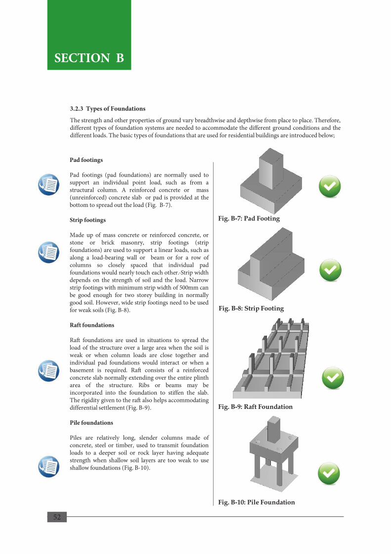
52
3.2.3 Types of Foundations
The strength and other properties of ground vary breadthwise and depthwise from place to place. Therefore, different types of foundation systems are needed to accommodate the different ground conditions and the different loads. The basic types of foundations that are used for residential buildings are introduced below;
Pad footings Pad footings (pad foundations) are normally used to support an individual point load, such as from a structural column. A reinforced concrete or mass (unreinforced) concrete slab or pad is provided at the bottom to spread out the load (Fig. B-7). Strip footings Made up of mass concrete or reinforced concrete, or stone or brick masonry, strip footings (strip foundations) are used to support a linear loads, such as along a load-bearing wall or beam or for a row of columns so closely spaced that individual pad foundations would nearly touch each other. Strip width depends on the strength of soil and the load. Narrow strip footings with minimum strip width of 500mm can be good enough for two storey building in normally good soil. However, wide strip footings need to be used for weak soils (Fig. B-8). Raft foundations Raft foundations are used in situations to spread the load of the structure over a large area when the soil is weak or when column loads are close together and individual pad foundations would interact or when a basement is required. Raft consists of a reinforced concrete slab normally extending over the entire plinth area of the structure. Ribs or beams may be incorporated into the foundation to stiffen the slab. The rigidity given to the raft also helps accommodating differential settlement (Fig. B-9). Pile foundations Piles are relatively long, slender columns made of concrete, steel or timber, used to transmit foundation loads to a deeper soil or rock layer having adequate strength when shallow soil layers are too weak to use shallow foundations (Fig. B-10).
Fig. B-7: Pad Footing
Fig. B-8: Strip Footing
Fig. B-10: Pile Foundation
52
SECTION B
Fig. B-9: Raft Foundation
SECTION B
53
3.2.4 Design of Foundations It would be prudent to have a general idea of the subsoil condition of the site before deciding on the location of the house and demarcating it on the plan sent for building approval by the authorities. Preliminary information can be gathered from a trial pit dug at the location. However for the design of foundations, more detailed investigations may be required as given below. Step 1. Ascertain the Nature of the Ground Nature of the ground, e.g. whether the ground is natural, flat or sloping or having rapid undulations, cut or reclaimed, located close to a marshy or low lying land presence of any significant features such as, old fills, wells, pits or quarries or variations within the site that may significantly affect the foundation design. If the land shows any such complexities, this manual recommends to seek professional advice of a geotechnical engineer who may conduct necessary studies to ascertain the parameters for foundation design. However, if the ground is judged to be free from any such complexities and having understood the risks of ignoring any complexities, the reader may be guided by the following procedure for the design of foundation. If there are complexities, the reader may obtain desired input as needed from a qualified person. Step 2. Ascertain the Subsoil Profile and Bearing Stratum It is essential that the foundation is placed on a soil layer having the required bearing capacity and sufficiently below the design final ground level in order to minimize the impact of any erosion and to maximize the lateral restraint from surrounding soil. For deciding the appropriate depth of foundation, it is necessary to know the type and strength of soil layers, ground water table and its possible fluctuations, etc., Dig a trial pit within the planned building area, preferably at or close to the location of columns or walls, to a minimum depth of 1.0m below the planned ground level, but deep enough to penetrate into a hard soil layer suitable as the bearing stratum. The foundation level must be decided ensuring that the subsoil underlying the foundation is equally strong or stronger than the bearing stratum to some further depth, say at least another 1.0~1.5 meters. Soil may be identified visually by digging further if practical or as a crude test, by probing the ground below with a crow bar or a metal rod and observing the resistance. Observe the ground water table if encountered within the pit after the water level has stabilized. Observe whether the soil consists mostly of gravel, sand or clay and how the soil is naturally compacted (loose, medium or dense) or how stiff (soft, firm or stiff) it is. Identify the soil type and hardness of the soil layers. A soil sample shall be obtained for testing if so required on technical advice.
53
SECTION B
SECTION B

54
Table B-5 can be used to get a rough estimate of the bearing capacity of the subsoil on which the foundation is to be placed. Once the soil type is identified as to whether the subsoil consists of mostly sand or clay, loosely or densely compacted, the user can match it with the “Type of Subsoil” column of the table to estimate of the bearing capacity.
Step 3. Determine the Bearing Capacity The Presumptive Safe bearing capacity of the soil can be estimated from Table B-5 according to the type of soil and the stiffness or compaction. As presence of ground water can reduce the bearing capacity of non-cohesive soils, value estimated from table should be reduced by half if there is a tendency of future fluctuation of ground water table above the foundation level. Presumptive Safe Bearing Capacity is the bearing capacity that can be presumed in the absence of data based on visual identification at the site.
Table B-5: Presumptive Safe Bearing Capacities of Soil Types
Group Type of Sub Soil Bearing Capacity (kN/m2)
Non-cohesive soils (Sand)
1 Dense gravel or dense sand and gravel 250 to 300
2 Medium dense gravel or medium dense gravel and sand 200 to 250
3 Loose gravel or loose sand and gravel < 150 4 Compact sand >200 5 Medium dense sand 100 to 200 6 Loose sand < 100
Cohesive soils (Clay)
7 Very stiff boulder clays and hard clays 150 to 250 8 Stiff clays 100 to 150 9 Firm clays 75 to 100 10 Soft clays 50
Step 4. Determine the Size of Foundation Based on the safe bearing capacity and the column or wall load transmitted to the ground, the required area of footing and the width of footing can be determined as per the Sections i) Design of Column Foundations and ii) Design of Wall Foundations and also refer Chart 1 and Table B-6.
54
SECTION B SECTION B
SECTION B

55
i) Column foundations • Square based pad footings may be used for
column foundations. • Minimum footing (base) size shall be
750mm x 750mm and 150mm in thickness. • Ensure that the column is positioned at the
center of the footing base as far as possible to avoid any significant eccentric loading on the footing (Fig. B -11).
• To determine the size of footing, the total load acting on the base of footing and the safe bearing capacity of the soil are required.
• The appropriate footing size based on the column load, is illustrated by the appendix B . (Example: the appropriate size of footing for a total column load of 240kN, supported on stiff clay having a safe bearing capacity of 200kNm2 can be read from Chart 1 to be between 1000mmx1000mm and 1200mmx1200mm. Select the larger size i.e.1200mmx1200mm).
Fig. B-11: Typical Column Foundation Section
55
Important!
The total load at the base of footing (Pct) is the sum of the weight of footing base (Wf), the column shaft (Wcs), the weight of soil (Ws) above the footing and the estimated column load (Pce). However, for simplicity, the weight of footing base (Wf) and of column shaft (Wcs), because of their small influence and the weight of soil above the footing (Ws) for its partial contribution to bearing capacity can be ignored.
SECTION B
SECTION B

56
Table B-6 has been provided to give an indication of the size of the footing (base of the foundation), depth below ground level, and the plinth wall thickness of a wall foundation. Once the builder determines the type of wall construction material and the size, the footing dimensions can be obtained from this table.
Table B-6: Foundation Properties of Cement Block and Clay Brick Walls
Wall Type Footing Width Footing Thickness
Footing Depth Below Ground Level
Plinth Wall Thickness
Cement Block Greater of 2.5 X wall thickness or 600mm 300mm 600mm 300mm
225mm Brick 600mm 300mm 600mm 300mm
113mm Brick 450mm 300mm 450mm 250mm
ii) Wall Foundations • Strip footings are generally used for the
wall foundations. • The size of footing or width of footing at
the base will depend on the thickness and type of the wall, the load acting along the wall and transmitted to the base of the footing, depth of footing and the safe bearing capacity of the soil.
• The linear load acting along the base of footing can be determined by adding the bearing pressures due to load from walls and weight of the footing including plinth beam if any.
• The required size (width) of the footing can be determined from Table B-6 by comparing with the presumptive safe bearing capacity of the soil type applicable given in Table B-5 and also refer to Fig. B-12.
• The depth of footing depends on the depth to suitable bearing stratum. Fig. B-12: Typical Wall Foundation Section
(Rubble Masonry)
56
SECTION B
SECTION B
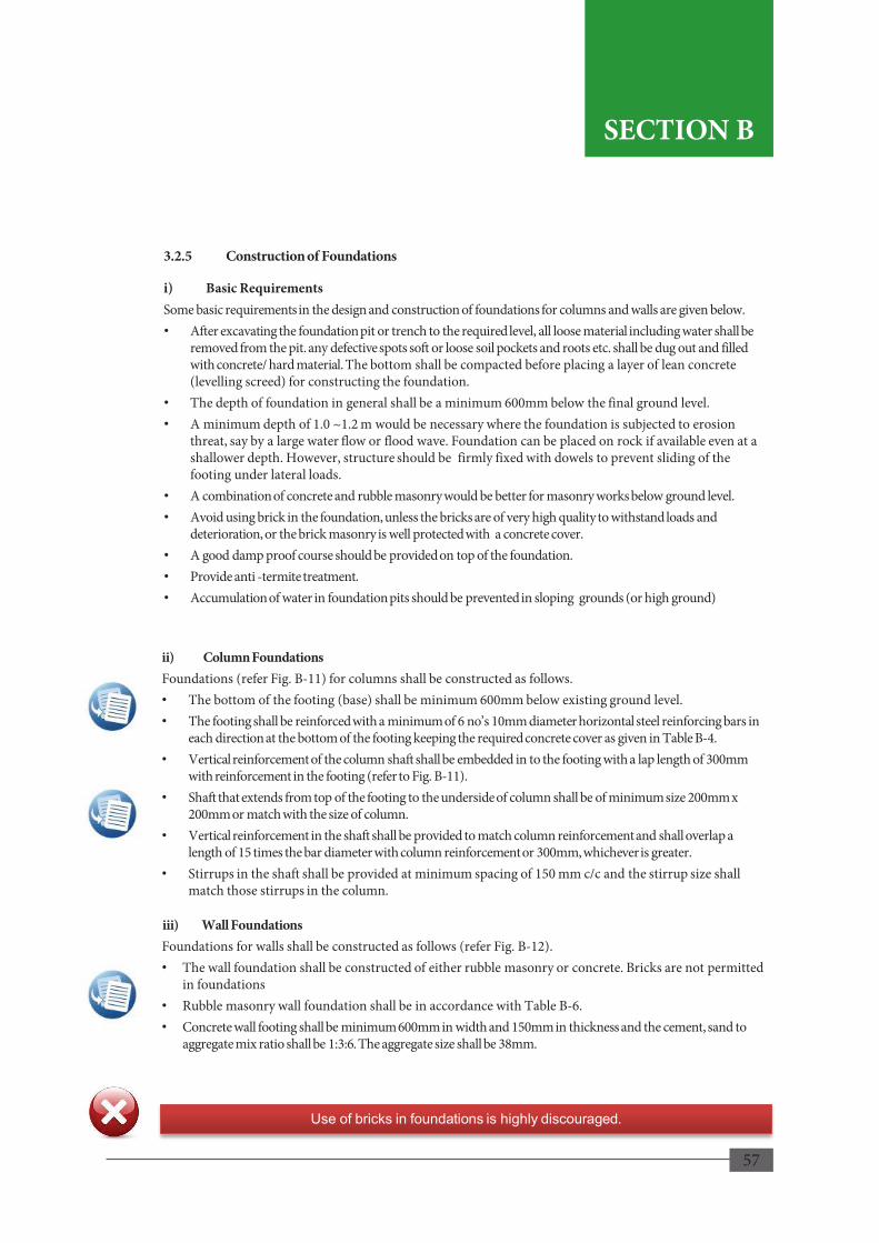
57
ii) Column Foundations Foundations (refer Fig. B-11) for columns shall be constructed as follows. • The bottom of the footing (base) shall be minimum 600mm below existing ground level. • The footing shall be reinforced with a minimum of 6 no’s 10mm diameter horizontal steel reinforcing bars in
each direction at the bottom of the footing keeping the required concrete cover as given in Table B-4. • Vertical reinforcement of the column shaft shall be embedded in to the footing with a lap length of 300mm
with reinforcement in the footing (refer to Fig. B-11). • Shaft that extends from top of the footing to the underside of column shall be of minimum size 200mm x
200mm or match with the size of column. • Vertical reinforcement in the shaft shall be provided to match column reinforcement and shall overlap a
length of 15 times the bar diameter with column reinforcement or 300mm, whichever is greater. • Stirrups in the shaft shall be provided at minimum spacing of 150 mm c/c and the stirrup size shall
match those stirrups in the column.
iii) Wall Foundations Foundations for walls shall be constructed as follows (refer Fig. B-12). • The wall foundation shall be constructed of either rubble masonry or concrete. Bricks are not permitted
in foundations • Rubble masonry wall foundation shall be in accordance with Table B-6. • Concrete wall footing shall be minimum 600mm in width and 150mm in thickness and the cement, sand to
aggregate mix ratio shall be 1:3:6. The aggregate size shall be 38mm.
Use of bricks in foundations is highly discouraged.
3.2.5 Construction of Foundations
i) Basic Requirements Some basic requirements in the design and construction of foundations for columns and walls are given below. • After excavating the foundation pit or trench to the required level, all loose material including water shall be
removed from the pit. any defective spots soft or loose soil pockets and roots etc. shall be dug out and filled with concrete/ hard material. The bottom shall be compacted before placing a layer of lean concrete (levelling screed) for constructing the foundation.
• The depth of foundation in general shall be a minimum 600mm below the final ground level. • A minimum depth of 1.0 ~1.2 m would be necessary where the foundation is subjected to erosion
threat, say by a large water flow or flood wave. Foundation can be placed on rock if available even at a shallower depth. However, structure should be firmly fixed with dowels to prevent sliding of the footing under lateral loads.
• A combination of concrete and rubble masonry would be better for masonry works below ground level. • Avoid using brick in the foundation, unless the bricks are of very high quality to withstand loads and
deterioration, or the brick masonry is well protected with a concrete cover. • A good damp proof course should be provided on top of the foundation. • Provide anti -termite treatment. • Accumulation of water in foundation pits should be prevented in sloping grounds (or high ground)
57
SECTION B
SECTION B

58
3.2.6 Plinth/Tie Beam • A plinth/tie beam shall be provided at the base of the structure connecting the column and wall
foundations (refer Fig. B-13).
• Use of plinth/tie beams however, is not required if the walls are supported on an entirely concrete foundation connected to the columns.
• The plinth/tie beam shall be at least 450mm above the adjacent finished ground level.
• The minimum width of the plinth/tie beam shall be at least equal to the width of the walls.
• The depth of the plinth/tie beam shall be equal to or more than its width.
• Plinth beam shall be of consistent depth all around and shall be reinforced with 4 Nos. of 10mm diameter bars with 6mm diameter stirrups at a spacing of 150mm c/c.
Reinforcement
Fig. B-13: Plinth/Tie Beam on typical Wall Foundation Section (Rubble Masonry)
58
SECTION B
SECTION B

59
Fig. B-14: Column Details
3. 3 Superstructure
3.3.1 Columns
Specifications for columns (refer Fig. B-14) shall be as follows; • Columns shall be placed at least at each
corner of the house and the spacing between columns shall not exceed 5m centre to centre.
• The minimum size of columns in cross section shall be 200 X 200 mm.
• Vertical reinforcement shall be minimum 4 No’s of 12 mm diameter reinforcing steel bars provided at each corner of the column.
• Concrete cover shall be a minimum of 25mm and in accordance with Table B-4 based on the exposure condition.
• 6mm in diameter mild steel stirrups spaced at 150mm centre to centre shall be provided for the full height of the column. The stirrups shall be closed with a 135o hook.
• Minimum lap length of vertical reinforcing shall be 15 times the bar diameter or 300mm, whichever is greater.
• Splicing of vertical reinforcement shall be provided at mid-height of column except for the ground floor level columns, where splicing is not permitted.
• During casting of the column provision shall be made for fixing the wall plates for the roof by embedding 2 No’s16mm GI rods into every column at the top end and by neatly levelling the top of column. The total embedment length of the GI rods shall be minimum 250mm (excluding the hook) having 50mm embedment into the column and the remainder into the beam supported on the column. It should be bent at 90˚ (refer Fig. B-28) to provide adequate anchorage.
Clear Cover
Plan View
Outer Face of Column
Column Reinforcement Bend At 1:6 Slope At Lap
Lap Length Of Reinforcing Bars
Column Reinforcement
Cage
59
SECTION B
SECTION B
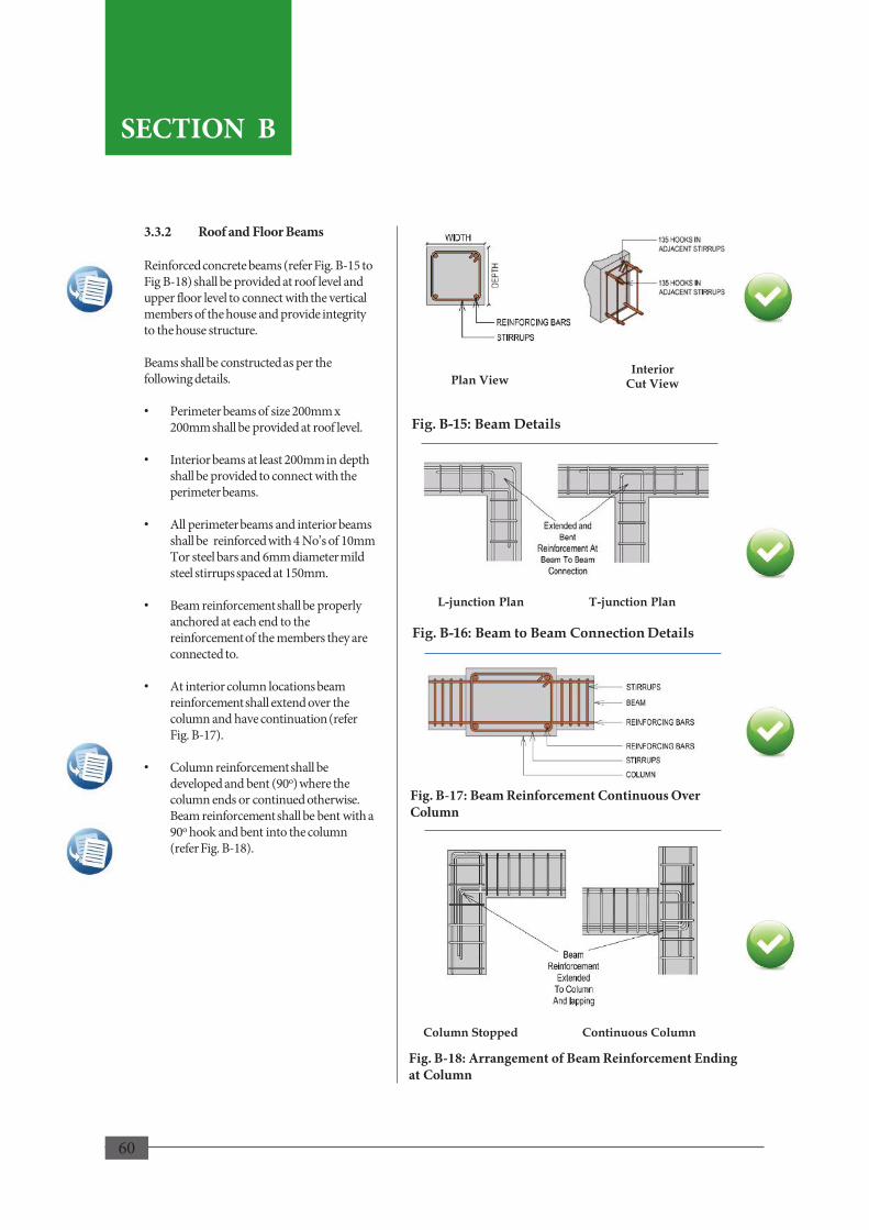
60
Fig. B-17: Beam Reinforcement Continuous Over Column
Fig. B-18: Arrangement of Beam Reinforcement Ending at Column
3.3.2 Roof and Floor Beams Reinforced concrete beams (refer Fig. B-15 to Fig B-18) shall be provided at roof level and upper floor level to connect with the vertical members of the house and provide integrity to the house structure. Beams shall be constructed as per the following details. • Perimeter beams of size 200mm x
200mm shall be provided at roof level.
• Interior beams at least 200mm in depth shall be provided to connect with the perimeter beams.
• All perimeter beams and interior beams shall be reinforced with 4 No’s of 10mm Tor steel bars and 6mm diameter mild steel stirrups spaced at 150mm.
• Beam reinforcement shall be properly anchored at each end to the reinforcement of the members they are connected to.
• At interior column locations beam reinforcement shall extend over the column and have continuation (refer Fig. B-17).
• Column reinforcement shall be developed and bent (90o) where the column ends or continued otherwise. Beam reinforcement shall be bent with a 90o hook and bent into the column (refer Fig. B-18).
Fig. B-16: Beam to Beam Connection Details
Beam
Beam
Column Stopped Continuous Column
Fig. B-15: Beam Details
60
Plan View Interior
Cut View
L-junction Plan T-junction Plan
SECTION B
SECTION B

61
• In case of gable walls, a gable band (refer Fig. B-19) shall be provided along the top of gable wall to provide strength against lateral forces. The gable band shall be connected to the roof beam with a vertical support at the gable and at the two ends properly anchored with reinforcement.
Bands Supporting Gable Wall
Vertical Support Reinforced Concrete Roof Beam
Reinforced Concrete Gable Band
Vertical Support And Roof Beam Connection
Vertical Support
Roof Beam
Gable Band Connection At Corner
Column
Gable Band
Roof Beam
61
SECTION B
Fig. B-19 Gable Wall
SECTION B

62
Solid Cement Block BRICK
Fig. B-20: Openings in Cement Block or Brick Wall
3.3.3 Cement Block and Brick Walls
i) Walls shall be constructed with the following properties;
• Sizes of blocks or bricks used shall be in accordance with the specifications of masonry units.
• Exterior walls or any load bearing walls shall be minimum 200mm in thickness and all other walls shall be minimum 100mm in thickness. However, should hollow cement blocks be used, the wall thickness shall be a minimum 200mm.
• Should the nominal wall thickness be 100mm, solid cement blocks or 115mm burnt clay brick shall be used.
• The free standing wall height shall not be more than 3m.
• Finishing mortar mix and binding mortar of clay or cement to sand ratio shall in accordance with Table B-3.
ii) Openings in walls shall be as follows (refer Fig. B-20);
• The sum of width of all openings in the wall shall be less than 50% of the length of the wall for single storey structures and 42% for two storey structures respectively.
• Edge of opening shall be 25% of opening height or 600mm away from the edge of the wall, whichever is greater.
• The horizontal distance (pier width) between two openings shall not be less than 50% of the height of the shorter opening or 600mm, whichever is greater.
• Vertical distance from an opening to an opening directly above it shall not be less that 600mm or 50% of the width of bigger opening.
• Effect of openings on the strength of wall can be reduced by having small and centrally located openings.
• The openings may be positioned with their top edges and/or bottom edges at the same level so that wall strengthening using lintel/sill be easier.
Hollow Cement Block
62
Hei
ght
Hei
ght
Hei
ght
Important!
Sizes of Openings • A+B+C (single storey) < 0.5L • A+B+C (two storey) < 0.42L • X > 0.25h1 or 600mm • Y > 0.5h2 or 600mm • L is length of wall
SECTION B
SECTION B
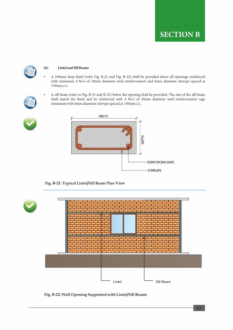
63
iii) Lintel and Sill Beams • A 100mm deep lintel (refer Fig. B-21 and Fig. B-22) shall be provided above all openings reinforced
with minimum 4 No’s of 10mm diameter steel reinforcement and 6mm diameter stirrups spaced at 150mm c/c.
• A sill beam (refer to Fig. B-21 and B-22) below the opening shall be provided. The size of the sill beam shall match the lintel and be reinforced with 4 No’s of 10mm diameter steel reinforcement cage minimum with 6mm diameter stirrups spaced at 150mm c/c.
Fig. B-21: Typical Lintel/Sill Beam Plan View
Lintel Sill Beam
Fig. B-22: Wall Opening Supported with Lintel/Sill Beams
63
SECTION B
SECTION B

64
Vertical Mortar Joint Placed At The Middle of The Unit Below
Half Unit Length
iv) The construction procedure shall be as follows;
• To ensure strong masonry, the masonry units shall be free from dirt, sand and dust. They shall contain adequate moisture to prevent sucking out water from wet cement mortar causing the mortar to quickly dry out and crumble before attaining strength.
• Clay bricks shall be thoroughly soaked in water long enough, generally about 6 hours, for the water to just penetrate the whole depth of bricks. However, they shall be removed from water sufficiently early so that they are skin dry at the time of laying
• The cement blocks need not be wetted before or during the laying of the blocks. Any blocks, soaked or washed, shall be allowed for the water to drain out before using. In dry climate the top and sides of the blocks may be slightly moistened to so as to prevent absorption of water from the mortar.
• All walls shall be built at the same time along with the corners to ensure strong connection between them.
• Walls shall be constructed in running bonds (refer Fig. B-23), with each vertical mortar joint positioned at the middle of the unit below (staggered vertical joints).
Fig. B-23: Masonry Wall Profile (Running Bonds)
64
SECTION B
SECTION B
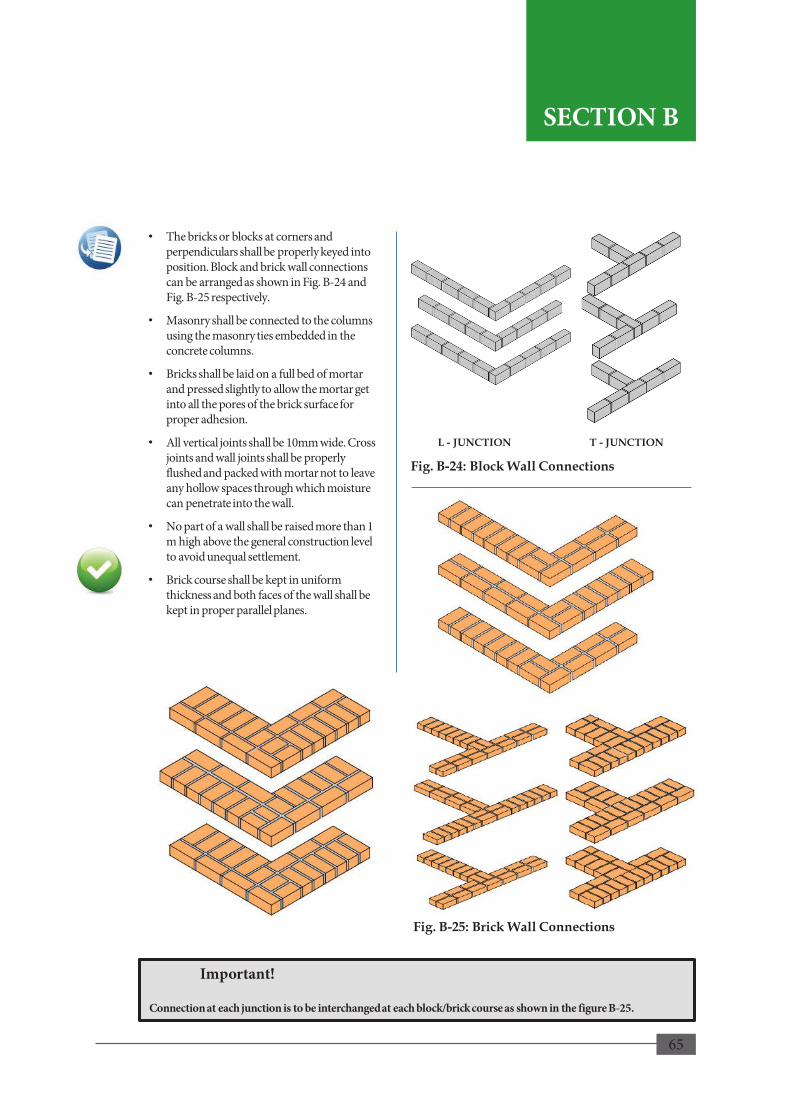
65
• The bricks or blocks at corners and perpendiculars shall be properly keyed into position. Block and brick wall connections can be arranged as shown in Fig. B-24 and Fig. B-25 respectively.
• Masonry shall be connected to the columns using the masonry ties embedded in the concrete columns.
• Bricks shall be laid on a full bed of mortar and pressed slightly to allow the mortar get into all the pores of the brick surface for proper adhesion.
• All vertical joints shall be 10mm wide. Cross joints and wall joints shall be properly flushed and packed with mortar not to leave any hollow spaces through which moisture can penetrate into the wall.
• No part of a wall shall be raised more than 1 m high above the general construction level to avoid unequal settlement.
• Brick course shall be kept in uniform thickness and both faces of the wall shall be kept in proper parallel planes.
L - JUNCTION T - JUNCTION
Fig. B-24: Block Wall Connections
Fig. B-25: Brick Wall Connections
65
Important!
Connection at each junction is to be interchanged at each block/brick course as shown in the figure B-25.
SECTION B
SECTION B
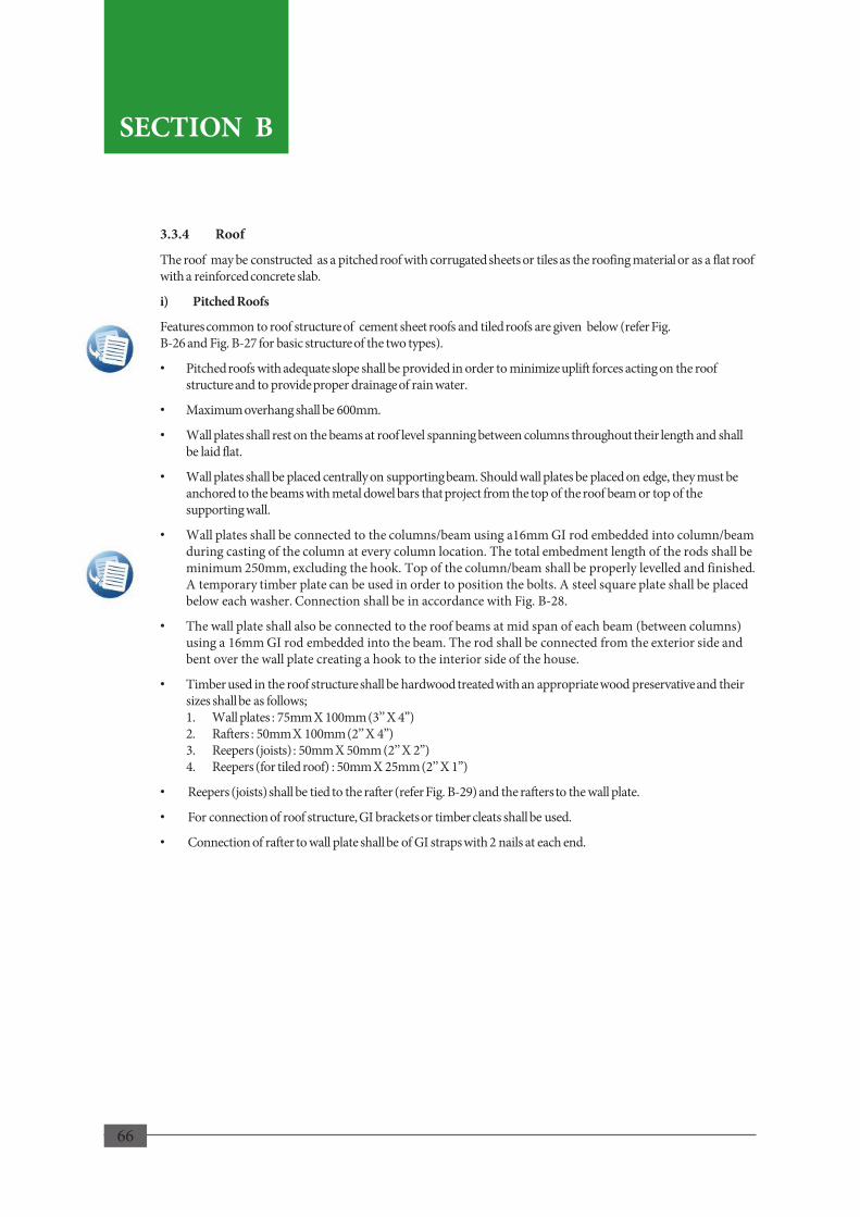
66
3.3.4 Roof
The roof may be constructed as a pitched roof with corrugated sheets or tiles as the roofing material or as a flat roof with a reinforced concrete slab.
i) Pitched Roofs
Features common to roof structure of cement sheet roofs and tiled roofs are given below (refer Fig. B-26 and Fig. B-27 for basic structure of the two types).
• Pitched roofs with adequate slope shall be provided in order to minimize uplift forces acting on the roof structure and to provide proper drainage of rain water.
• Maximum overhang shall be 600mm.
• Wall plates shall rest on the beams at roof level spanning between columns throughout their length and shall be laid flat.
• Wall plates shall be placed centrally on supporting beam. Should wall plates be placed on edge, they must be anchored to the beams with metal dowel bars that project from the top of the roof beam or top of the supporting wall.
• Wall plates shall be connected to the columns/beam using a16mm GI rod embedded into column/beam during casting of the column at every column location. The total embedment length of the rods shall be minimum 250mm, excluding the hook. Top of the column/beam shall be properly levelled and finished. A temporary timber plate can be used in order to position the bolts. A steel square plate shall be placed below each washer. Connection shall be in accordance with Fig. B-28.
• The wall plate shall also be connected to the roof beams at mid span of each beam (between columns) using a 16mm GI rod embedded into the beam. The rod shall be connected from the exterior side and bent over the wall plate creating a hook to the interior side of the house.
• Timber used in the roof structure shall be hardwood treated with an appropriate wood preservative and their sizes shall be as follows; 1. Wall plates : 75mm X 100mm (3’’ X 4”) 2. Rafters : 50mm X 100mm (2’’ X 4”) 3. Reepers (joists) : 50mm X 50mm (2’’ X 2”) 4. Reepers (for tiled roof) : 50mm X 25mm (2’’ X 1”)
• Reepers (joists) shall be tied to the rafter (refer Fig. B-29) and the rafters to the wall plate.
• For connection of roof structure, GI brackets or timber cleats shall be used.
• Connection of rafter to wall plate shall be of GI straps with 2 nails at each end.
66
SECTION B
SECTION B
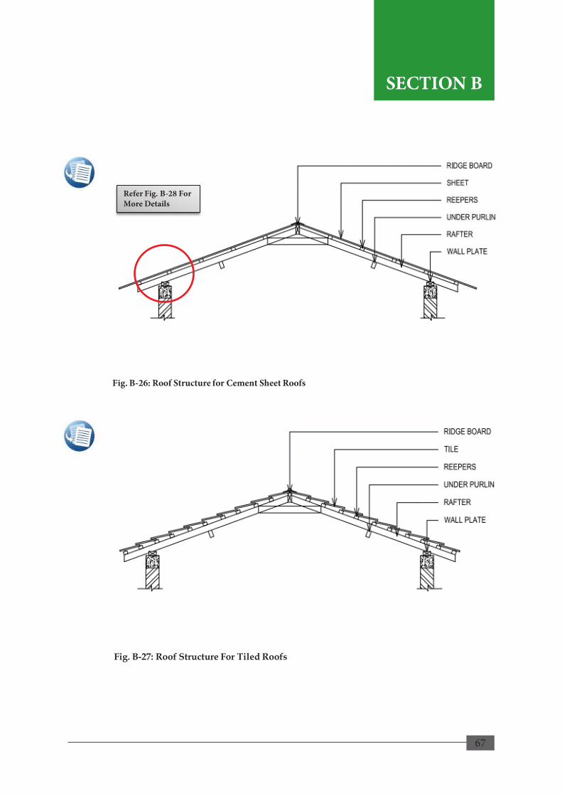
67
Fig. B-26: Roof Structure for Cement Sheet Roofs
Fig. B-27: Roof Structure For Tiled Roofs
Refer Fig. B-28 For More Details
67
SECTION B
SECTION B

68
Reinforced Concrete Beam Supported On Column
Elevation and Plan
RAFTER
REEPER
LOCATION NAIL
Fig. B-28: Wall Plate on Structure
Fig. B-29: Reeper to Rafter Connection At Splice
Reeper
Rafter
Minimum Gap Between Ends
Flat Head Nails
Straps
Plan View
COLUMN/BEAM FINISHED TOP FACE
68
Important!
Straps are to be provided over the reepers with the twists fixed to the sides of the rafter with two nails on each side.
SECTION B
SECTION B
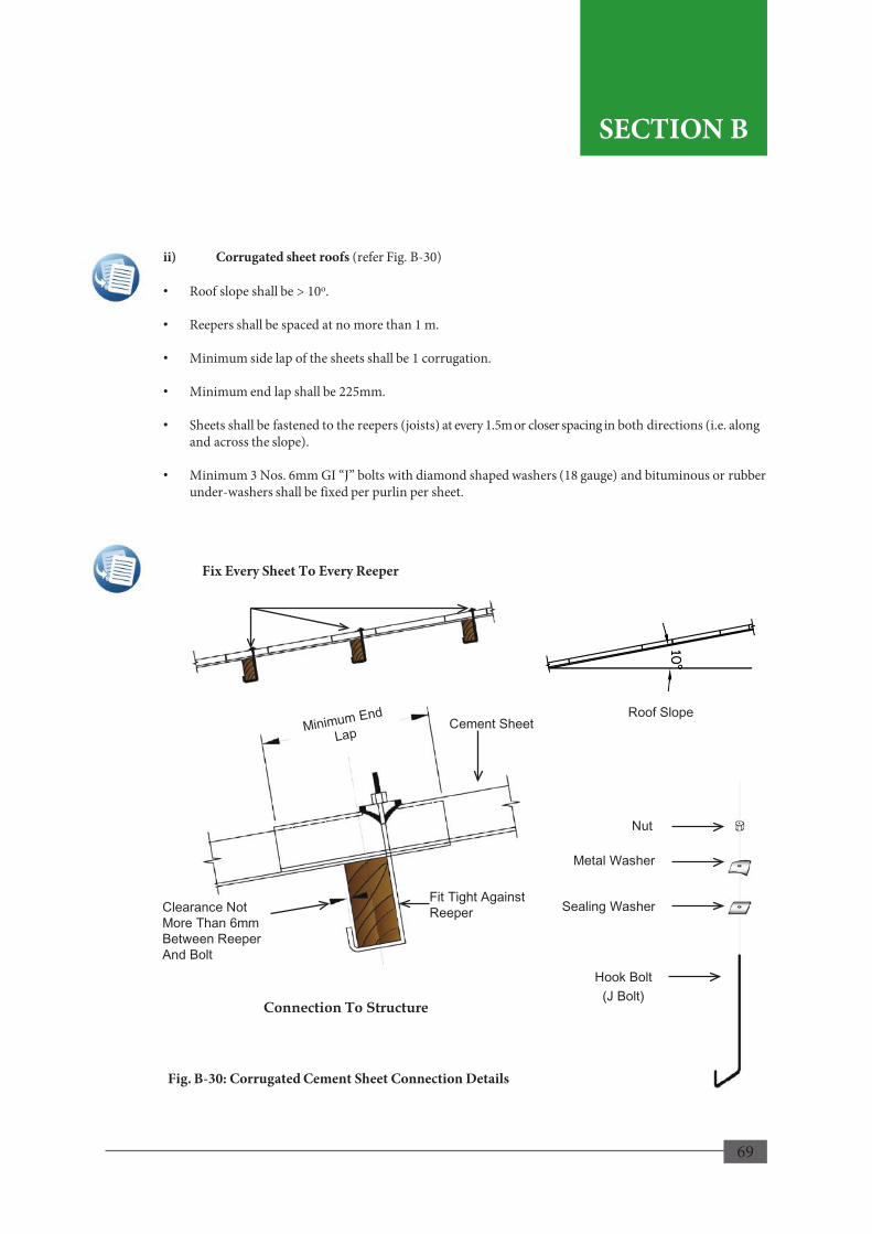
69
Nut
Metal Washer
Sealing Washer
Hook Bolt (J Bolt)
ii) Corrugated sheet roofs (refer Fig. B-30)
• Roof slope shall be > 10o.
• Reepers shall be spaced at no more than 1 m.
• Minimum side lap of the sheets shall be 1 corrugation.
• Minimum end lap shall be 225mm.
• Sheets shall be fastened to the reepers (joists) at every 1.5m or closer spacing in both directions (i.e. along and across the slope).
• Minimum 3 Nos. 6mm GI “J” bolts with diamond shaped washers (18 gauge) and bituminous or rubber under-washers shall be fixed per purlin per sheet.
Fig. B-30: Corrugated Cement Sheet Connection Details
Roof Slope
Fix Every Sheet To Every Reeper
Cement Sheet
Clearance Not More Than 6mm Between Reeper And Bolt
Fit Tight Against Reeper
Connection To Structure
69
SECTION B
SECTION B

70
Roof Slope
Tiled Roof
Mortar Restraining Bands
iii. Tiled Roofs
Specifications for tiled roofs shall be as follows (refer Fig. B-31);
• Roof slope shall be > 20o.
• Mortar restraining bands shall be provided at 1.2m intervals at gable ends and 1.5m intervals elsewhere.
• To develop adequate connection a 10mm diameter deformed bar can be placed in the band. A metal strap should be used to tie the band to the rafter (refer Fig. B-32).
Note: Unless otherwise designed, the size of reepers shall be 50 mm x 25 mm for tiled roofs. Reepers may be spaced as specified by the tile manufacturer.
Fig. B-31: Tiled Roof Details
Fig. B-32: Connection with Deformed Bar
Break Off Lip Of Tile At Strap
Concrete Strip
Nails
G.I. Strap Rafter
Tiled Roof
70
SECTION B
SECTION B
71
iv) Roof Drainage
Adequate roof drainage shall be provided and shall be as follows;
• uPVC gutters shall be provided to collect water from the roof. every length of the gutter shall be firmly fitted with brackets at intervals not greater than 1’ – 2’’ (350 mm).
• Down pipes shall be provided at suitable spacing, but not more than 6m apart, depending on locations of window or other openings. Pipes shall be firmly fitted to walls or columns using brackets.
• The down pipe for corrugated sheet roofing shall be 4’’ x 3’’ and 3 ½’’ in diameter for tiled roofing. Diameter of down pipe shall be minimum 75 mm for 10 m2 and 100 mm for 20 m2 horizontal projection area of the roof, or a maximum average rainstorm of 200 mm/hr. Rectangular pipes of equivalent area may be used.
• The bottom end of the down pipe shall direct water away from the base of the plinth to a safe distance to avoid erosion of earth around the plinth perimeter. Rainwater shall be discharged directly by means of a channel into or over an inlet to a surface drain or shall discharge freely into a compound at a safe distance.
v) Reinforced Concrete Flat Roofs
Specifications for reinforced concrete flat roofs shall be as follows.
• Roof slope shall be > 1:80
• Maximum overhang shall be 600 mm.
• Reinforced concrete slab shall be minimum 100 mm in thickness and be constructed with 25 MPa concrete and shall include a reinforcing bar mesh.
• Roof slabs shall be provided with proper water proofing.
• Construction procedure shall be as follows for reinforced concrete flat roof.
• All vertical reinforcing bars in the vertical components of the structure shall be bent and extended into the slab at least 450mm overlap and tied to the slab reinforcement with binding wire.
3.3.5 Floor
Floor on ground can be constructed in accordance with the below mentioned practices.
• Shall be constructed of concrete reinforced with steel mesh.
• Brick laid on ground with cement rendering may also be used as an alternative.
• Minimum thickness of slab/floor shall be 75 mm.
• The grade shall be properly compacted and the soil shall be provided with termite treatment.
• Slab/floor joints shall be allowed for proper thermal and shrinkage movements.
• When floor drains are required, floors shall be sloped such that the water flow is directed towards the drain.
71
Important!
This Manual strongly recommends the reader to seek professional services of a Chartered Civil Engineer for the detailed structural design of roof slabs.
SECTION B
SECTION B

72
73
HAZARD SPECIFIC DESIGN AND CONSTRUCTION
REQUIREMENTS FOR A HAZARD RESILIENT HOUSE
74
LANDSLIDES
Land formation is the result of a continuing natural process of ground movements due to gradual weakening of rock and soil strata and the destabilized material moving down the slopes. For this fact, hilly areas are generally susceptible to landslides.

75
1.1 General Information Landslides include a wide range of ground movement down a slope involving massive volumes of rock, soil, or debris. They can occur in a matter of seconds without any warning or over a prolonged period with or without some indications. The impact of a landslide may be limited to a small area or may spread over a large area. Ground instability can also occur suddenly or over a long period of time in the form of sinkholes, ground subsidence and ground movements e.g. due to formation of underground cavities and collapse or movement of material above. Land formation is the result of a continuing natural process of ground movements due to gradual weakening of rock and soil strata and the destabilized material moving down the slopes. For this fact, hilly areas are generally susceptible to landslides. The potential of landslides at a given location depends on many causative and contributive factors including geomorphological and physical features of the location. Ten districts, viz., Badulla, Galle, Hambantota, Kalutara, Kandy, Kegalle, Matale, Matara, Nuwara Eliya and Ratnapura in Sri Lanka are identified as some of the districts having terrain prone to landslides (refer Map 1: Landslide Hazard Prone Map of Sri Lanka with Reference to Locations) in Section A. Certain hilly parts of these districts may have a very high potential whereas some parts with gentle slopes or flat terrain can have a very low potential of landslides. Declaration of only the above ten districts does not rule out potential of landslides in any location outside these districts. Knowing about the potential of landslides occurring in your area would help significantly in deciding a suitable location for building your house and what additional precautions that would be necessary to make it resilient to landslides
1. LANDSLIDES
1.2 Planning Considerations When planning to build a house in a hilly area or on or nearby slopes, due attention must be given to the following requirements and conditions in addition to the minimum requirements given in Section B.
73
Important!
Section C of the manual specifies design and construction requirements that shall be followed with respect to the type of hazard in addition to the minimum requirements for Hazard Resilience given in Section B.
Important!
No construction is permitted on lands with ground slope > 31º unless clearance is obtained from NBRO and construction is done based on the recommendations and conditions given in the Risk Assessment Report.
For ground slopes between 11º – 31º recommendations provided in this Section shall be followed (refer Table C-1).
SECTION C
SECTION C

76
1.2.1. Landslide Clearance for Construction For ground slopes between 11º – 31º recommendations provided in this section shall be followed (refer Table C-1). Therefore, obtaining the necessary landslide risk assessment report for construction from the NBRO is a primary requirement (refer Sections from Section C 1.2 onward for more information and conditions applicable to lands with ground slope <31º). In order to minimize the risk from landslide disasters and to increase the safety of life and property from future slope instabilities, certain restrictions are imposed on construction activities on slopes. Accordingly, it is made mandatory to obtain concurrence of NBRO for implementation of construction activities on slopes, particularly in the ten districts of Badulla, Galle, Hambantota, Kalutara, Kandy, Kegalle, Matale, Matara, Nuwara Eliya and Ratnapura having large extents of identified landslide prone areas. Therefore, depending on the steepness of the slope of terrain and certain other conditions, the local authority may ask the builder to obtain the landslide clearance for construction when necessary, even if the land is situated outside the known hazard prone areas in above districts. On issuing the landslide clearance for construction NBRO will also advise the builder on additional conditions, if any, the builder should satisfy. 1.2.2 Basic Requirements for a Safe Structure Houses built on slopes or in hilly areas if not properly located are vulnerable to not only landslides but also to high winds, flash floods, mudflow etc. depending on the environment Therefore, Hazard Resilient houses shall be located essentially outside any land susceptible to landslides and sufficiently away from any unstable or vulnerable areas, so that they will not be collapsed or buried or severely damaged. Even then, unexpected ground movements or vibrations may possibly affect the house due to any instability in a neighboring area. The hazard resilient house should be able to resist; • minor ground movements without damage to the structure, • moderate ground movements without structural damage but with some non-structural damage. • larger movements without collapse, but with some structural damage and some nonstructural damage. Although a certain degree of damage is acceptable in the house due to an unexpected event, loss of life is unacceptable. Accordingly, the structure of the house must be designed to ensure that it has adequate strength, appropriate rigidity, and will remain as one integral unit, even while subjected to very large ground movements. Flexible structures are most appropriate for hilly areas as these can accommodate movements without apparent significant distress. Steel or timber structures are generally used as the main material in them. The type of structure recommended in this manual for the landslide prone areas is a reinforced concrete framed structure in-filled with brick walls and stiffened foundations as specified in Section B with additional recommendations presented herein.
74
SECTION C
No construction is permitted on lands with ground slope > 31º unless risk assessment is obtained from NBRO and construction is done based on the recommendations and conditions given in the Risk assessment report.
SECTION C

77
1.2.3 Land Selection The type of terrain and the landslide potential are two important factors governing the suitability of land for house building. a) Type of terrain The type of terrain, for convenience, is expressed here in measurable terms of ground slope. In general, the steeper the slope becomes, higher the tendency for instability. Slope instability problems often occur on terrain with slopes that are steeper than 10o-15o. However, slope angle is only one of the factors contributing to ground instability and it is practically not possible to suggest general threshold values up to which a slope is definitely stable and beyond which the slope is unstable. In this manual, for the purpose of assessment of landslide potential the type of terrain is identified under five broad categories of ground slope based on the observations of past landslides in Sri Lanka, as given below.
Type I: Flat Land - slope angle less than 5o or ground slope less than 8% approximately
Type II: Gentle Slopes - slope angle between 5o ~11o or ground slope between 8%~20% approximately
Type III: Moderate Slopes - slope angle between 11o~17o ( or ground slope between 20%~30% approximately
Type IV: Moderate Slopes - slope angle between 17o~31o (or ground slope between
30%~60% approximately
Type V: Steep Slopes - slope angle more than 31o or ground slope more than 60% approximately
Fig. C-1 gives an idea of the steepness of slopes in terms of slope angle, gradient and as %.
75
Important!
The following areas are not suitable for locating a house and therefore shall be avoided;
• Areas prohibited or restricted by law
• Areas designated as unsafe
• Areas with a history of landslides
• Areas where landslides are imminent
• Areas prone to landslide hazards
SECTION C SECTION C
SECTION C
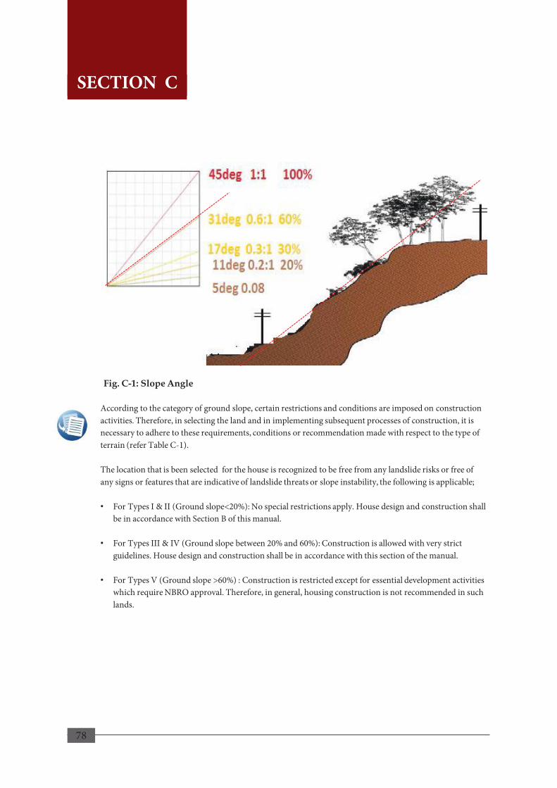
78
According to the category of ground slope, certain restrictions and conditions are imposed on construction activities. Therefore, in selecting the land and in implementing subsequent processes of construction, it is necessary to adhere to these requirements, conditions or recommendation made with respect to the type of terrain (refer Table C-1). The location that is been selected for the house is recognized to be free from any landslide risks or free of any signs or features that are indicative of landslide threats or slope instability, the following is applicable; • For Types I & II (Ground slope<20%): No special restrictions apply. House design and construction shall
be in accordance with Section B of this manual.
• For Types III & IV (Ground slope between 20% and 60%): Construction is allowed with very strict guidelines. House design and construction shall be in accordance with this section of the manual.
• For Types V (Ground slope >60%) : Construction is restricted except for essential development activities which require NBRO approval. Therefore, in general, housing construction is not recommended in such lands.
Fig. C-1: Slope Angle
76
SECTION C
SECTION C
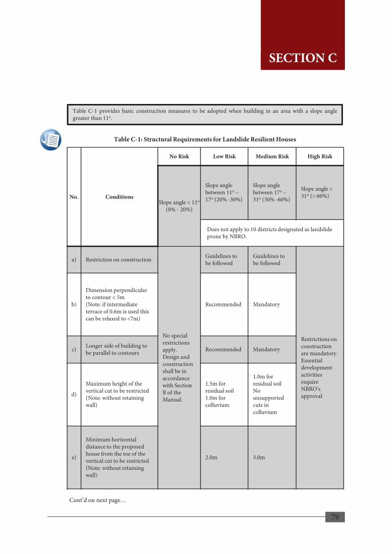
79
Table C-1: Structural Requirements for Landslide Resilient Houses
No. Conditions
No Risk Low Risk Medium Risk High Risk
Slope angle < 11o (0% - 20%)
Slope angle between 11o – 17o (20% -30%)
Slope angle between 17o – 31o (30% -60%)
Slope angle > 31o (> 60%)
Does not apply to 10 districts designated as landslide prone by NBRO.
a) Restriction on construction
No special restrictions apply. Design and construction shall be in accordance with Section B of the Manual.
Guidelines to be followed
Guidelines to be followed
Restrictions on construction are mandatory. Essential development activities require NBRO’s approval
b)
Dimension perpendicular to contour < 5m (Note: if intermediate terrace of 0.6m is used this can be relaxed to <7m)
Recommended Mandatory
c) Longer side of building to be parallel to contours Recommended Mandatory
d)
Maximum height of the vertical cut to be restricted (Note: without retaining wall)
1.5m for residual soil 1.0m for colluvium
1.0m for residual soil No unsupported cuts in colluvium
e)
Minimum horizontal distance to the proposed house from the toe of the vertical cut to be restricted (Note: without retaining wall)
2.0m 3.0m
Table C-1 provides basic construction measures to be adopted when building in an area with a slope angle greater than 11o.
Cont’d on next page…
77
SECTION C
SECTION C

80
No. Conditions
No Risk Low Risk Medium Risk High Risk
Slope angle < 11o (0% -20%)
Slope angle between 11o – 17o (20% -30%)
Slope angle between 17o – 31o (30% -60%)
Slope angle > 31o (> 60%)
Does not apply to 10 districts designated as landslide prone by NBRO.
f)
Minimum horizontal distance to the nearest building from the top of vertical cut to be > height of the cut (Note: without retaining wall)
No special restrictions apply. Design and construction shall be in accordance with Section B of the manual.
Mandatory Mandatory
Restrictions on construction are mandatory. Essential development activities require NBRO’s approval
g)
Retaining wall (if height of vertical cut is higher than the maximum limit as indicated in condition (d) above)
Mandatory (See Section C 1.7 for retaining wall construction techniques)
Mandatory and designed by a technically qualified person
h)
Restriction on slope (if cut is NOT vertical and restrictions (d) to (g) are not imposed
Mandatory (gradient should not exceed 60o)
Mandatory (gradient should not exceed 45o)
i) Development of surface drainage of land
Mandatory (if development obstructs the natural surface drains)
Mandatory
j) Turn or other erosion control measures Recommended Mandatory
Source: NBRO Web ww.nbro.gov.lk/web/images/stories/publications/landslidechecklist.pdf
78
SECTION C
Table C-1: Structural Requirements for Landslide Resilient Houses
Cont’d from previous page…
SECTION C
81
b) Landslide potential Suitability of a site in respect of landslide potential shall not be judged merely from the characteristics of the site itself in isolation, but of a broader area which encloses and influences the site. Select the site only after proper assessment of the land and its surrounding area to identify the level of risk from landslide hazards, if any. A site selected for a house shall be free of any features that are indicative of landslide threats or slope instability. Therefore, the land should be located sufficiently away from such potential risk areas and features such as steep slopes, cliffs, escarpments, rivers, perennial or ephemeral streams and mountain channels. 1.2.4 Areas Not Suitable for Construction of Building a) Areas prohibited or restricted by law
The land chosen for building a house may fall within a safe zone permitted for human settlement and construction of residential buildings or it may fall within a zone that is demarcated as prohibited or restricted zone for such activities. Reader should, therefore, seek further advice of the local authority to ascertain whether the land use is restricted or not. b) Areas designated unsafe
Avoid building in any areas designated or declared as unsafe. Such areas are shown in the Landslide Hazard Zonation Maps as zones where;
• Landslides are most likely to occur,
• Landslides are to be expected,
• Modest level of landslide hazard exists In the areas where a modest level of landslide hazard exists, building construction may be permitted after the landslide clearance for construction obtained from NBRO and only when necessary engineering precautions are taken and the construction plans are technically vetted and certified by specialists. Even if a site falls within an area demarcated on the hazard map as safe zone for construction, it is still necessary to physically ascertain that the site is hazard free now and also in the future. This is important because the hazard zones have been mapped at a smaller scale and the conditions of ground stability can change considerably due to subsequent changes in land use and topography, new developments etc., that may have taken place after the mapping was done. The level of the risk involved viz., No Risk, Low Risk, Medium Risk or High Risk can be broadly identified by referring to landslide hazard zonation map of the area where available. Map. 10 shows the areas for which the landslide hazard zonation maps have been published for different scales (refer to www.nbro.gov.lk/web/index).
79
SECTION C
SECTION C
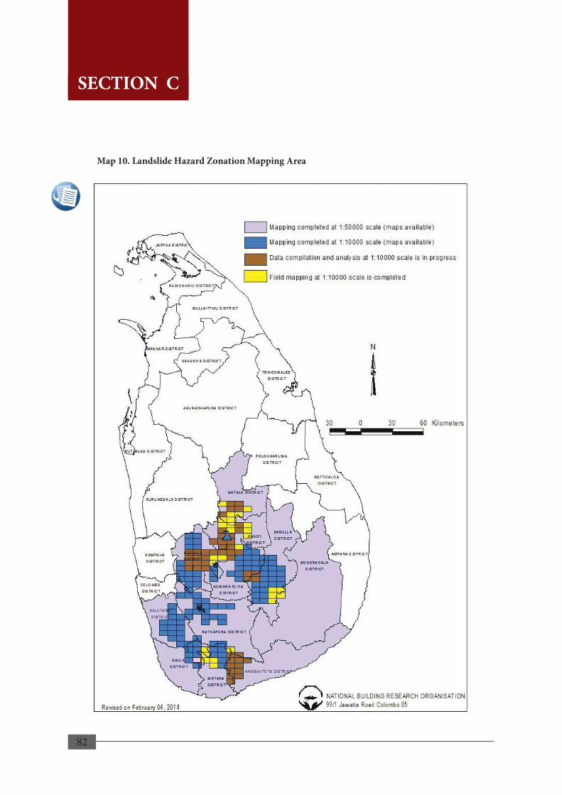
82
Map 10. Landslide Hazard Zonation Mapping Area
80
SECTION C
SECTION C

83
c) Areas with a history of landslides
Avoid building on existing landslides, old or recent. The chances of reactivation or future occurrence of another landslide or slope instability in an area with a history of landslides are generally high. Therefore, it is important to know whether the land has a history of landslides which pose any future risks by studying ;
• Information on reported past or potential landslide hazards obtained from the local authorities or from the NBRO.
• Information that could be gathered from local residents who may be knowledgeable on any past events or any existing hazards in the vicinity.
When any such information is lacking or not available, it is still possible and desirable to identify whether the land has a landslide history by studying the existence of abnormal landforms, unusual behavior of trees and structures etc., which may indicate past ground movement due to landslides. If there are any doubts about the safety of the site, professional advice and services shall be sought. An area with a history of landslides may have one or more of the following features which are indicative and helpful in identifying a past landslide; Landforms such as;
• Old scarps existing on the slope; steep, curved scarps that are common at the top of landslides
• Uneven hummocky ground with subsidence or heaves which often indicates a former landslide
• Bulging ground appearing at the base of a slope
• Cracks on the ground surface Abnormalities in existing structures, vegetation etc.;
• Trees that lean in different directions or having bent tree trunks (knees)
• Tilted or leaning fences, walls or utility poles/posts;
• Moved structures such as houses, retaining walls
• Cracked, bulged, tilted or off-set retaining walls, stone hedges
• Tilted and/or moved ancillary structures such as concrete steps, sidewalls, pavements, floors and patios gaping away from the main structure/ house
• Patched or un-patched cracks in the walls or foundations.
81
SECTION C
SECTION C
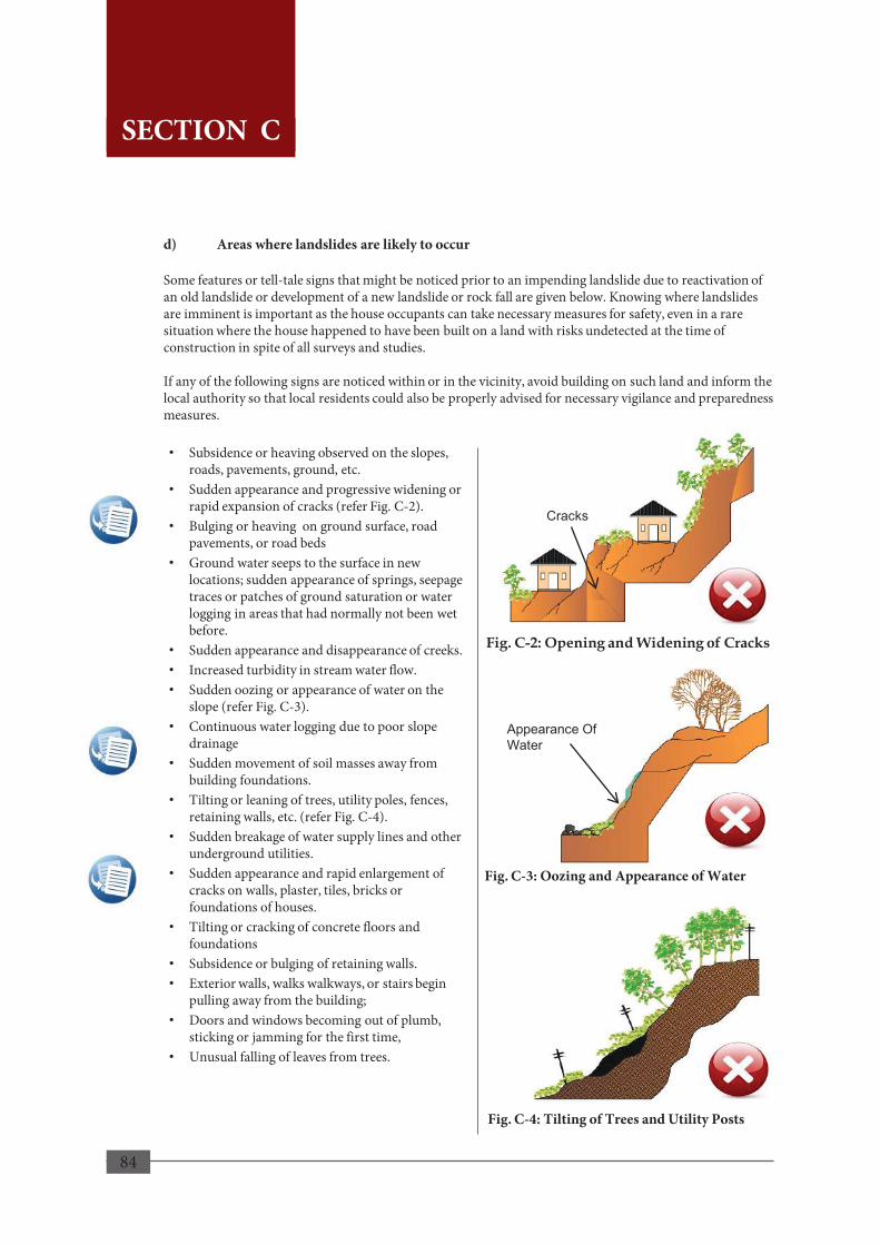
84
d) Areas where landslides are likely to occur Some features or tell-tale signs that might be noticed prior to an impending landslide due to reactivation of an old landslide or development of a new landslide or rock fall are given below. Knowing where landslides are imminent is important as the house occupants can take necessary measures for safety, even in a rare situation where the house happened to have been built on a land with risks undetected at the time of construction in spite of all surveys and studies. If any of the following signs are noticed within or in the vicinity, avoid building on such land and inform the local authority so that local residents could also be properly advised for necessary vigilance and preparedness measures.
• Subsidence or heaving observed on the slopes, roads, pavements, ground, etc.
• Sudden appearance and progressive widening or rapid expansion of cracks (refer Fig. C-2).
• Bulging or heaving on ground surface, road pavements, or road beds
• Ground water seeps to the surface in new locations; sudden appearance of springs, seepage traces or patches of ground saturation or water logging in areas that had normally not been wet before.
• Sudden appearance and disappearance of creeks. • Increased turbidity in stream water flow. • Sudden oozing or appearance of water on the
slope (refer Fig. C-3). • Continuous water logging due to poor slope
drainage • Sudden movement of soil masses away from
building foundations. • Tilting or leaning of trees, utility poles, fences,
retaining walls, etc. (refer Fig. C-4). • Sudden breakage of water supply lines and other
underground utilities. • Sudden appearance and rapid enlargement of
cracks on walls, plaster, tiles, bricks or foundations of houses.
• Tilting or cracking of concrete floors and foundations
• Subsidence or bulging of retaining walls. • Exterior walls, walks walkways, or stairs begin
pulling away from the building; • Doors and windows becoming out of plumb,
sticking or jamming for the first time, • Unusual falling of leaves from trees.
Appearance Of Water
Fig. C-2: Opening and Widening of Cracks
Fig. C-3: Oozing and Appearance of Water
Fig. C-4: Tilting of Trees and Utility Posts
82
Cracks
SECTION C
SECTION C

85
e) Areas prone to landslide hazards Areas that seemingly appear to be stable and safe from landslides may sometimes have a potential risk. Avoid selecting a land at vulnerable locations such as; • Close to the base or top of a cliff or a cut or fill slope particularly where the slope is a steep • On or near steep natural slopes in weak geologic material with outcrops of fractured rocks • At or close to the top or along the nose of ridges adjacent to steep slope; • Close to the base of rock mass showing joints, outcrops of fractured rocks • On steep slope areas with thick soil masses free from vegetation; • On developed /cultivated hill slopes where irrigation or drainage systems are located. • On slopes close to where springs, seeping or ponding of water prevails • In relatively flat areas with thick soil mass and frequent seepage. • In areas where slope angle changes abruptly and variations occur in the thickness of soil overburden
as a result of construction activities. • At the base of a steep slope with a lot of detached or buried boulders on unstable upper slopes • On Irrigated hillsides and steep slopes where surface runoff is directed onto the slope • On or near the path of mountain drainage • On denudated slopes where wildfires or human intervention have removed vegetation
1.2.5 Layout Arrangement and Orientation of the House In planning the layout, orientation and shape of the house due consideration shall be given; • to minimize disturbances to existing slopes due to excavation and cutting required for land
preparation and foundations, • to minimize the volume of earthworks and hence the cost of construction. Plan the layout and internal spaces as far as possible to fit into a simple structural system. On gentle slopes, the house may be planned to be built on a single, levelled formation in natural ground. If the ground slope is moderate, • The house may be planned as terraced house i.e. with stepped floor levels and built on two or more
platforms at different levels cut into natural ground to match with the ground slope profile (refer Fig. C-5). By utilizing terraced housing or foundations to suit the ground slope, ground disturbances and earthworks can be significantly reduced.
• As an alternative the house can be planned, with necessary professional advice taken, as an elevated structure on columns or raised footings supported on natural ground causing least disturbance to the slope (refer Fig. C-6).
• A group of houses as in a housing scheme should be planned professionally considering the general guidelines that will be provided by the local authority.
83
Important!
Areas prone to landslide hazards may also have some indicative signs similar to those where landslides have occurred or are imminent.
SECTION C
SECTION C

86
Fig. C-5: Terraced Housing Fig. C-6: Foundations to Suit Slope
Foundation Elevation To Suit Slope
a) Orientation of the House
Houses founded on a single platform should preferably be planned to have their longer sides running parallel to the natural contour lines. This can avoid encountering large differences in sub soil conditions and reduce cutting and filling work (refer Section C 1.5 on Foundations). b) Shape of the Structure
Simple and symmetrical shapes such as square or rectangular shapes are preferable to minimize adverse effects from possible ground movements or ground disturbances. c) Land Space requirements
The house shall be located at a sufficiently safe distance away from the toe of steep slopes, protected or unprotected natural or manmade slopes. The distance so required shall be decided on the advice of the engineer. For safe space to be kept between the house and toe of cut slopes refer Section C 1.4.2. Additional land space needed for the provision of access roads, garage and other facilities, such as for sewage disposal and the space required for cut and fill slopes, berms, retaining structures etc., shall be taken into due consideration at the planning stage. 1.3 Land Preparation Prepare the ground, in a single or multiple terraced formation on berms so that, it cascades parallel to the natural contours of the slope. Avoid deep cuts and/or high fills and the need for their protection with costly structures (refer Section C 1.4 Earthworks and 1.7 Earth Retaining Structures). Unless essential, do not remove vegetation and large trees which can provide stability and protection to the slopes. Limit clearing and stripping to the minimal area required for construction. However, where filling is required, all vegetative and other unsuitable matter such as loose/soft top soil, debris, shall be removed before placing any fill material.
84
Stepped Ground With Minimal Change To Slope
SECTION C
SECTION C

87
Inward Dip
1.4 Earthworks All earthworks involved with cut and fills for site preparation, access roads, excavation for foundations and trenches shall be designed and executed to ensure safety and stability during and after construction. 1.4.1 Cut Slopes
The permitted slope angle of cut surfaces of temporary or permanent excavations depends on the soil type and several factors such as the height of cut and how the slope will be protected. Steeper slopes are permitted for cuts in competent bedrock. But in weathered rock slope depends on the weathering condition and the dipping of bedding planes (refer Fig. C-7), foliation planes or principal joint sets in rock formation. The cut slopes in different soil or rock formations up to a maximum height of cut of 3m, with or without a retaining wall can be utilized in accordance with Table C-2.
Earth
Rock
85
Fig. C-7: Dip Types
Outward Dip
SECTION C
SECTION C

88
Average slope values for bedrock excavation for planes of weakness dipping less than 30 degrees shall be in conformance with Table C-3.
Type of Soil/Rock Stable Cut Slope (Vertical: Horizontal)
without Wall with Wall
Soil or soil mixed with boulders and
a) Dense vegetation b) Less vegetation
2:1 1:1
5:1 3:1
Hard rock, shale or harder rock with
a) Inward dip b) Outward dip
4:1 to vertical 2:1 or dip angle
Vertical 5:1
The cut slopes in different soil or rock formations up to a maximum height of cut of 3m, with or without a retaining wall can be utilized in accordance with Table C-2.
Table C-2: Cut Slopes
Source: Guidelines for Construction in Landslide Prone Areas (SLUMDMP)
Table C-3: Average Slope Values for Bedrock Excavation
Type of Soil/Rock Maximum Slope Range (Vertical: Horizontal)
Igneous granite, basalt, volcanic tuff 4:1 to 2:1
Sedimentary
1. Massive sandstone, lime stone 2. Inter-bedded sandstone, shale 3. Massive clay stone, silt stone
4:1 to 2:1 2:1 to 4:3 4:3 to 1:1
Metamorphic
a) Gneiss, schist, marble b) Slate c) Serpentine
4:1 to 2:1 2:1 to 1:1 Special investigation
Source: Guidelines for Construction in Landslide Prone Areas (SLUMDMP)
86
SECTION C
SECTION C

89
1.4.2 Space between House and Cut Slopes
Adequate safe space shall be provided between the house and the toe of the cut slope. The safe distance (d) between the house and the toe of cut slope depends on the height of cut and whether the cut slope is supported with a retaining wall (refer to Fig. C-8).
• For free standing cut slopes, the distance (d) should be equal to the height (H) of the cut slope.
• If the slope is stabilized with a retaining wall, the distance (d) should be equal to the height of the retaining wall or house (refer Fig. C-9).
Fig. C-8: Space between House and Cut Slope
Fig. C-9: Distance from a Retaining Wall
H
H
d
87
SECTION C
SECTION C

90
1.5 Foundations • The house, and hence its foundations, shall be located sufficiently away from unprotected slopes natural
or manmade slopes (refer Fig. C-10 and Table C-1).
• Where the building footprint crosses both cut and fill areas, footings shall be taken below fill and supported on a suitable bearing stratum in natural undisturbed ground.
• The bottom of the footing shall be at least 1.0m below the existing ground level or the finished ground level whichever is lower, including on the cut/filled part.
• The size and depth of foundation shall be decided depending on the type of subsoil and its bearing capacity (refer Table B-5 in Section B).
• Footing on sloping ground should be constructed with sufficient edge distance, minimum 60cm to 90cm, for protection against erosion.
• The difference in elevation between footings should not be so great which may cause undesirable overlapping of stress in soil.
Fig. C-10: Space between Foundation and Slopes
Minimum 60cm (rock) Minimum 90cm (soil)
1.6 Stabilization and Protection of Slopes All cut or fill slopes constructed shall be appropriately protected and stabilized against erosion, degradation and failure. Slopes that are cut or filled to a safe slope angle may be protected and stabilized e.g. with vegetation or a blanket of natural grass which is economical and aesthetic for landscaping. Unstable cut, fill or natural slopes shall be stabilized either with an externally or internally stabilized system. Externally stabilized system consists of a structural wall to take up the pressures exerted by the soil and water that is retained behind the wall. Internally stabilized system involves strengthening or reinforcing the earth mass of the slope. There are numerous methods and materials used for slope stabilization and protection (refer Table C-4).
88
SECTION C
SECTION C
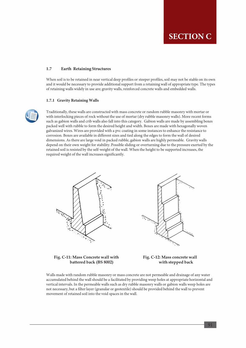
91
1.7 Earth Retaining Structures When soil is to be retained in near vertical deep profiles or steeper profiles, soil may not be stable on its own and it would be necessary to provide additional support from a retaining wall of appropriate type. The types of retaining walls widely in use are; gravity walls, reinforced concrete walls and embedded walls. 1.7.1 Gravity Retaining Walls Traditionally, these walls are constructed with mass concrete or random rubble masonry with mortar or with interlocking pieces of rock without the use of mortar (dry rubble masonry walls). More recent forms such as gabion walls and crib walls also fall into this category. Gabion walls are made by assembling boxes packed well with rubble to form the desired height and width. Boxes are made with hexagonally woven galvanized wires. Wires are provided with a pvc coating in some instances to enhance the resistance to corrosion. Boxes are available in different sizes and tied along the edges to form the wall of desired dimensions. As there are large void in packed rubble, gabion walls are highly permeable. Gravity walls depend on their own weight for stability. Possible sliding or overturning due to the pressure exerted by the retained soil is resisted by the self-weight of the wall. When the height to be supported increases, the required weight of the wall increases significantly. Walls made with random rubble masonry or mass concrete are not permeable and drainage of any water accumulated behind the wall should be a facilitated by providing weep holes at appropriate horizontal and vertical intervals. In the permeable walls such as dry rubble masonry walls or gabion walls weep holes are not necessary, but a filter layer (granular or geotextile) should be provided behind the wall to prevent movement of retained soil into the void spaces in the wall.
89
SECTION C
Fig. C-11: Mass Concrete wall with battered back (BS 8002)
Fig. C-12: Mass concrete wall with stepped back
SECTION C

92
90
1.7.2 Reinforced Concrete Walls Walls made of reinforced concrete in the shapes of “L” or “Inverted T” can also be used to retain soils. The weight of the soil lying above the base is added to the weight of the wall to maintain stability. Therefore the wall should be of sufficient base width. The wall stem should be adequately reinforced to withstand the bending moment exerted by the retained soil. Walls can be in the cantilevered form or laterally stiffened by counterforts or buttresses. This lateral stiffening will reduce the bending moments on the wall stem. The resistance to sliding can be enhanced by providing a shear key.
(a) L – Shaped Cantilever Retaining Wall
(b) Inverted T - Shaped Cantilever Retaining Wall
(c) Reversed L - Shaped Cantilever Retaining Wall with Key
SECTION C
Fig. C-13: Hexagonally Woven mesh gabion cage (BS 8002)
Fig. C-14: Example of a Gabion Wall
Fig. C-15: Types of Reinforced Concrete Retaining Walls
SECTION C

93
91
1.7.3 Embedded Walls Walls embedded to an adequate depth can be used to retain soil. This type is particularly useful for supporting excavations. Embedded wall sections can be of preformed from; timber, steel or masonry and driven to the ground to an adequate depth before excavation commences. However, walls made of steel (steel sheet piles) are the most widely used type. Alternatively, a wall of necessary depth can be constructed with insitu concrete in the form a diaphragm wall or by a continuation of a line of bored piles. Diaphragm walls are constructed in the form of interlocking panels. Bored pile walls can be constructed; with an overlap (secant pile wall), touching each other (contiguous wall) or with a gap between piles (intermittent walls). If an excavation is extended below the ground water table, use of a secant pile wall is recommended. Embedded walls can be done in the form of cantilevered walls or laterally supported at one or more levels by anchors or props. With the usage of lateral supports, the required depth of embedment is reduced. Lateral supports will reduce the deformations as well. The stability of an embedded retaining wall is derived from its depth of embedding and lateral support. The wall section should be of adequate structural stiffness to withstand the bending moments developed.
(d) Inverted T – Shaped Cantilever Retaining Wall with Key
(e) Retaining Wall with Counterforts
(f) Retaining Wall with Buttresses
SECTION C
Fig. C-15: Types of Reinforced Concrete Retaining Walls
SECTION C
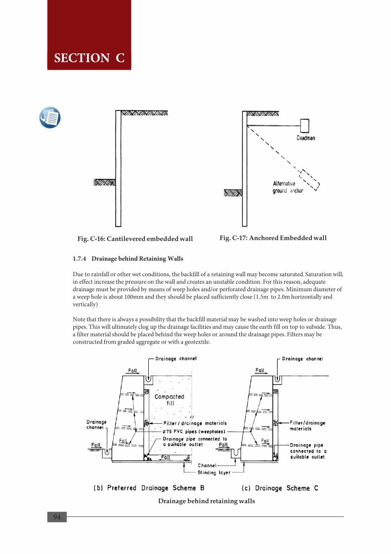
94
92
1.7.4 Drainage behind Retaining Walls Due to rainfall or other wet conditions, the backfill of a retaining wall may become saturated. Saturation will, in effect increase the pressure on the wall and creates an unstable condition. For this reason, adequate drainage must be provided by means of weep holes and/or perforated drainage pipes. Minimum diameter of a weep hole is about 100mm and they should be placed sufficiently close (1.5m to 2.0m horizontally and vertically) Note that there is always a possibility that the backfill material may be washed into weep holes or drainage pipes. This will ultimately clog up the drainage facilities and may cause the earth fill on top to subside. Thus, a filter material should be placed behind the weep holes or around the drainage pipes. Filters may be constructed from graded aggregate or with a geotextile.
Drainage behind retaining walls
SECTION C
Fig. C-16: Cantilevered embedded wall Fig. C-17: Anchored Embedded wall
SECTION C

95
1.8 Soil Erosion Control and Drainage Most of the landslides in Sri Lanka have occurred when heavy storms and prolonged rainfall have been experienced. Rains, while contributing to surface erosion of the soil on a slope, also percolate into the soil filling the voids. This reduces the matric sadiron of the soil and saturates it, making it more heavy in turn. The groundwater level can also rise. There will be a reduction in the strength of soil. Even a slope that appears to be stable under dry conditions may become unstable due to poor drainage of the slope. Therefore, it is extremely important to manage both surface and subsurface drainage of a slope. The areas that should be avoided when building on slopes and the areas that may be considered as suitable for housing construction are recommended in Section C 1.2.3 of this manual. Even if the land is carefully selected, all precautions shall be taken to ensure that soil erosion is controlled and the surface and subsurface drainage is properly managed in order to sustain the stability not only of the premises of the house but also of the surrounding lands. 1.8.1 Soil Erosion Control Soil erosion can happen as a result of rain splashing against the soil surface, flow of surface runoff and formation of gullies. Erosion of banks and bottom of gullies and streams occur due to rapid water flow. These conditions can eventually contribute to slope instability. This manual recommends the builder to ensure minimizing soil erosion by adopting the following methods; • Minimize disturbance to existing terrain as far as possible by matching development to the terrain and
limiting adjustments to existing ground contours. • Minimize exposure to soil erosion by planning the construction and scheduling so that the extent of
exposed areas and the duration of the exposure are minimized and the grading works can be done during relatively dry seasons.
• Minimize clearing of site by retaining existing vegetation as vegetation helps reduce run off velocities and volumes. Use plants like Vetiver grass (savandara variety) for re-vegetating (refer Appendix A).
• Optimize slope angle and length. • Divert runoff away from cleared areas and minimize runoff velocities by grass lining of diversion
trenches, use of broad and shallow flow areas, network of surface drains and rock fragments on slopes. 1.8.2 Surface Drainage It must be ensured that natural drainage, stability and environment of the land and surrounding area is not adversely affected during and after construction. All water from rain, springs and waste water shall not be released on or in to the slope and shall be properly directed away from the slope appropriately into natural water courses or the local storm water drainage system or the wastewater drainage systems as applicable.
93
SECTION C
SECTION C

96
Following measures are recommended; • Provide interceptor drains to collect and divert runoff and springs to prevent surface flow within any
unstable or cleared area. • Provide diversion drains to prevent water flowing into any unstable or cleared area across its periphery. • Provide silt traps / silt fence to prevent blockage of drains due to siltation. • Line the trenches and channels to minimize erosion. • Utilize flexible material or flexible joints if pipes are used to drain water. • Provide structures to dissipate energy and reduce the flow velocities in channels. • Provide adequate reservation for existing natural streams or drains. • Provide culverts, concrete pipes etc., as required for access or internal road crossings. • Provide adequate flow capacity and slope and drops in all drains, channels, pipes etc., to prevent
blockage. 1.8.3 Sub-surface Drainage Rise in ground water table within the land due to rains or any other reasons can result in instability particularly of any cut slopes or generally unpleasant environment with sodden ground around the house. It is, therefore, necessary to control groundwater table and/or seepage flows. Following measures are recommended; • Intercept the groundwater and properly divert it away from the land using a French drain or sub-
surface drains. French drain consists of a perforated hollow pipe wrapped around with a filter of geotextile fibre and surrounded by permeable material such as sand and gravel packed within a lateral trench. The pipe should have a proper gradient and an outlet to a suitable surface drain for the intercepted water to flow away swiftly. These drains are more suited when the groundwater rises to within about1.5m from ground surface as deeper excavation could be costly.
• Provide sub-surface drains in to help lower the ground water table and prevent build-up of hydrostatic pressure against the walls.
Ensure that; • Adequate number and area of weep holes are provided. • pipelines used for construction of all subsurface and diversion drains are of flexible materials and
with flexible joints provided to accommodate ground movements and to prevent breakage and leakage
• manholes are provided at appropriate locations for maintenance. • Surface runoff is diverted separately preventing inflow of surface water in to sub-surface drains.
94
SECTION C
SECTION C

97
SECTION CSECTION C
2. FLOODS
2.1 Planning Phase • Identify the flood zone and the maximum flood level recorded in the location selected, using available
sources or by contacting relevant authorities. i.e. Irrigation Department • Identify the direction of flooding.
2.1.2 House Plan and Orientation • Shorter side of the house shall be oriented to face the direction of the flooding (refer Fig. C-18). • Place openings in line with each other on opposite walls creating a flow path for water (refer Fig. C-19).
Fig. C-18: House Orientation
Fig. C-19: Placement of Openings
95
SECTION C

98
2.2 Foundations Depth of foundation shall be increased as follows;
• The column footings shall be lowered minimum 1.0m below finished grade. • Wall footings shall be lowered minimum 0.6m below grade.
2.3 Raised Floor Elevation • The floor elevation shall be raised by increasing the plinth (refer Fig. C-20 and C-21). The plinth height
shall be minimum 150mm above the highest recorded flood level in the region.
Raised Plinth
Fig. C-21: Plinth Level Raised By Creating An Elevated Ground
Fig. C-20: Plinth Level Raised By Building On Higher Ground
Raised Plinth
96
SECTION C
SECTION C

99
2.4 Superstructure • Cross walls can be utilized to strengthen walls against flow of flood water as per Fig. C-23.
Fig. C-22: Plinth Level Raised by Building on Silts
Fig. C-23: Cross Walls
Construct the house on silts as per the below specifications (refer Fig. C-22). • The silts shall be raised up to minimum 150 mm above highest recorded flood level in the region. • The maximum unsupported height of silts shall not exceed 3m. Otherwise an intermediate tie
beam shall be provided.
97
RAISED FLOOR BUILDING ON STILTS
PARTLY EXPOSED
CONTINUOUS LINTEL
CROSS WALLS
SECTION C
SECTION C

100
3.1 Planning Phase 3.1.1 How Wind acts on Structures Knowing how high winds work will help the user understand the subsequent technical sections. As the wind passes an obstruction, its direction is changed and/or its speed is slowed down. As a result, pressures are developed which will act on the surfaces of the object. These may exert as positive pressures or negative pressures (suction) (Fig. C-24). High speed winds cause greater concern because the wind load increases proportionately with the square of its speed. Lateral winds acting on structures create pushing forces on the windward side of upright or inclined surfaces, suction forces on the leeward side and suction or uplift forces on horizontal surfaces. Broadly, there are four ways the wind forces can affect a house; • Uplift - wind flowing over the roof of the
house can create a lifting effect (Fig. C-25).
• Sliding - horizontal wind pressure can cause the house to slide off its foundation (Fig. C-26).
• Racking - horizontal wind pressure can cause tilting of the house (Fig. C-27).
• Overturning- wind can cause the walls to rotate off the foundation
A structure that is not properly designed to withstand high winds may suffer different levels of damage to its structural components. Typical damage patterns include separation of structural components or breakage of members.
3. HIGH WINDS
Fig. C-24: Pressure or Suction
Fig. C-25: Uplift
Fig. C-26: Sliding
Fig. C-27: Racking(Tilting)
98
SECTION C
SECTION C

101
3.1.2 Factors generating Wind Forces The wind loads acting on a house may depend on many factors; for example, location and topography around the house, level of site exposure to winds, structures and vegetation around the building, proximity and the height of neighboring buildings or structures, density of vegetation and the type of trees planted, shape, elevation and height of the house above ground. Wind speeds and hence atmospheric pressure varies for different geographical locations. Wind speed will ; • increase as it passes over or between hills, but will slow down as it passes over rougher terrain and
accelerate over open and flat large expanses of land or water. • be slowed by trees and vegetation around the building. Certain species of trees act as barriers to
blowing and hence reduce the effect on the structure. • decrease when a site is surrounded by taller buildings, but increase where it funnels around or
between buildings. The higher the building, the more exposed it will be to higher winds particularly where the building is taller than adjacent buildings or vegetation.
99
Important!
3.1.3 Basic Requirements for a Safe Structure For a building to be safe in high winds or cyclones, its structural integrity is extremely important. Structural integrity depends on the provision of Anchorage, Bracing and Continuity (A, B and C) right throughout the structure. Anchorage - Every part of the structure must be tied back to some secure point which is capable of
resisting all the applied forces. Bracing - Every part of the structure must be held rigid so it cannot tilt, slide or rotate. Continuity - Every part of the structure must be property connected to every other member in the
‘‘strength chain” from the cladding to the ground. Strength chain is a continuous load path carrying the wind loads acting on the roof and walls down through the structure to the foundation.
Therefore, it must be ensured that all these essential requirements are met throughout design, construction and supervision. To manage this easier, the following steps should be taken: • Make the structural systems as simple as possible • Keep the strength chains as short and as direct as possible • Minimize the number of joints forming the strength chains • Where possible, use connections, which remain visible and can be checked and maintained. • Provide the necessary bracing against horizontal forces by providing frequent cross walls, return walls,
columns or alcoves in external walls wherever possible, • During use, the anchorages and connections should be regularly inspected and maintained or replaced as
relevant If large spans or cantilevers are unavoidable, these must be properly designed and constructed by a qualified person.
SECTION C
SECTION C

102
Wind
3.1.4 Assessment of the Severity of Wind Effects Severity of wind effects on the structure should be assessed before commencing of building a house in a High Wind prone area. The effect of wind on a house is greatly influenced by the site topography, surrounding structures, besides the arrangement, orientation and shape of the house. Therefore, to minimize the wind effects, these factors need due attention at the planning stage. The following requirements and conditions must be met in addition to the minimum requirements given in Section B. Select a location where the wind does not blow direct on to the structure from any direction. Avoid exposed locations as much as possible. When unavoidable, the house should be properly sheltered. Select a sheltered location with permanent shelter. Though other existing structures or trees near by may act as wind barriers, their effectiveness and any possibilities of their future removal must be taken into account. In hilly terrains, whenever possible, locate the house in a valley, but away from any strong wind paths. The force created by wind is proportional to the square of its speed. Therefore, the speed of the wind is the determining factor of the extent of damage to buildings and other structures. Wind loading zones and that has been established in the manual for “Design of Buildings For High Winds in Sri Lanka”; Sri Lanka has been divided into three (3) Wind Loading Zones for the purpose of design of buildings and structures. The basic wind speed considered for the design of residential houses in each zone are Zone 1 – 49.0m/s, Zone 2 – 42.5m/s and Zone 3 – 33.5m/s. Severity of wind effects is highest in Zone 1, an approximately 50km wide belt along the North East Coastline and reduces in the order, Zone 2 and Zone 3 (Refer to Map 11). Effect of the wind on the house is greatly influenced by whether the house is exposed or sheltered. Exposure condition depends on the location, topography and surrounding features. A house may be considered to be;
Fig. C-28: Exposed Condition
Fig. C-29: Sheltered Condition
100
• An Exposed house (Fig. 28) - when located in an open area where wind is not obstructed by other structures, vegetation or topographical features.
• A Sheltered house (Fig. 29) - when surrounded by other structures of about the same or greater height or permanently covered by vegetation or topographical features obstructing the wind.
• Locations facing large open area for example, the sea, lagoons, lakes and reservoirs or large areas of paddy or farmland clear from any obstacles such as trees, shrubs or buildings etc., are considered as exposed locations.
• An exposed house located in Zone 1 has the most severe wind effect and a Sheltered house in Zone 3 has the least severe effect.
Wind
SECTION C SECTION C

103
This map has been extracted from the document Extracts from Design of Buildings for High Winds in Sri Lanka, Disaster Management Centre (November 2006) based on the original publication by Ministry of Local Government, Housing and Construction (April 1980).
Map 11: Wind Loading Zones of Sri Lanka
101
Important!
This map is intended to be used as a guide in national or regional level planning and for public information only. It should not be used for local level planning and decision making processes as the scale is very high whilst resolution is too low. This map is not a legitimate document and should not be used for regulatory processes.
SECTION C SECTION C
SECTION C
104
3.1.5 Planning Considerations The effect of wind on a house is greatly influenced by the site topography, surrounding structures, besides the arrangement, orientation and shape of the house. Therefore, to minimize the wind effects, these factors need due attention in the planning stage . The following requirements and conditions must be met in addition to the minimum requirements given in Section B. a) Land selection
• Select a location where the wind does not blow direct on to the structure from any direction. • Avoid exposed locations as practicable as possible. In unavoidable situations, the house should be
properly sheltered. • Select a sheltered location with permanent shelter. Though other existing structures or trees near by
may act as wind barriers, their effectiveness and any possibilities of their future removal must be taken into account.
• In hilly terrains, whenever possible, locate the house in a valley, but away from any strong wind paths. b) Layout arrangement
• Plan the layout and internal spaces so as to fit into a simple structural system. • Plan for at least one small room in the interior of the house which can be structurally strengthened to
serve as a safe refuge from cyclone or high wind situations. c) Orientation of the house
• Orientation of the house should be such that the wind force is minimum. • Rectangular structures should be planned to have their shorter sides facing the most critical wind
direction in a wind tunnel situation. d) Shape of the structure
• The shape or the design profile of a building has a major effect on wind separation and hence the
magnitude, nature and distribution of wind forces acting upon them. • Avoid irregular shapes as far as possible. • Select simple symmetrical shapes which offer better stability under wind loads. • Square or rectangular shapes are preferable. a circular or even an octagonal floor plan may ideally
streamline the wind flow from any direction, but they pose functional difficulties.
102
Important!
How to Improve Resistance to Wind Forces
The type of damage that can be caused to different structural components and the specific ways to achieve improved resistance to wind forces are given in the following pages.
SECTION C
SECTION C

105
Fig. C-30: Shorter Side of House Facing Wind Direction
Fig. C-31: Openings on Opposite Walls Creating Flow Path
3.1.6 House Plan and Orientation Following techniques can be utilized during planning phase for high wind resilience. • Plan the layout and internal spaces so as to fit into a simple structural system. Plan for at least one small
room in the interior of the house which can be structurally strengthened to serve as a safe refuge from cyclone or high wind situation.
• Orientation of the house should be such that the wind force on them is minimum. Rectangular structures should be planned to have their shorter sides facing the most critical wind direction in a wind tunnel situation (Fig. C-30). The shape or the design profile of a building has a major effect on wind separation and hence the magnitude, nature and distribution of wind forces acting upon them. Avoid irregular shapes as far as possible.
• Select simple symmetrical shapes which offer better stability under wind loads. square or rectangular shapes are preferable. a circular or even an octagonal floor plan may ideally streamline the wind flow from any direction, but they pose functional difficulties.
• Plan to have openings on opposite walls creating a flow path allowing the wind to pass through (Fig. C-31).
103
SECTION C
SECTION C

106
3.2 Walls • It is recommended that the following are practiced in order to provide strengthened walls against
lateral wind forces. • Walls shall be supported on all four sides with columns and beams to provide a stiffer wall. • Height of double brick panel block walls shall not be more than 3m and single panel brick walls
shall not be more than 2.4m. • Vertical support of brick walls shall be spaced in accordance with Table C-4.
Table C-4: Recommended Spacing of Vertical Supports for Brick Walls
Panel Description 2.7m double brick
panel with no openings
3m double brick panel with opening
2.4m single brick panel with no openings1
Plastered both sides Not plastered
Zone and Exposure Spacing (m)
Zone 1 Exposed 3 2.4 2 2 Zone 2 Exposed 3.6 3 1.5 1.2 Zone 1 Sheltered 4.2 3.6 1.8 1.5
Zone 2 Sheltered
Zone 3 Exposed
Zone 3 Sheltered
Follow roof specifications given in
Section B 4.2
2.4
3.6
1.8
2.7
1 In single brick walls with openings a vertical support must be provided on either side of any opening in Zones 1 and 2, within 1 foot of the opening. 2 Use of single brickwork is not recommended.
Source: Extracts from Design of Buildings for High Winds in Sri Lanka
Table C-4 provides the spacing of recommended vertical supports for brick walls. Once the builder determines the wind zone and the type of exposure, the spacing at which vertical supports are to provided can be determined from the table based on the type of the wall.
104
SECTION C
SECTION C

107
Table C-5: Specifications of Timber Roof Structure for Sheet and Tiled Roofs
Roof Type Sheet Roof Tiled Roof
Reeper size (width x depth) mm 1 50 X 50 50 X 50
Rafter size (width x depth) mm 1 50 X 100 50 X 100
Ridge board size (width x depth) mm 1 50 X 200 50 X 200
Reeper spacing in m (ft) 1 0.75
(2’ 6’’)
0.90
(3’ 0’’)
1.0
(3’ 6’’)
1.2
(4’ 0’’) To suit tiles
Rafter spacing in m (ft) 1 0.90
(3’ 0’’)
0.90
(3’ 0’’)
0.75
(2’ 6’’)
0.60
(2’ 0’’)
Maximum rafter span in m (ft) 2.1 (7’) 2 2.4 (8’) 2 2.7 (9’) 2
2.1 (7’) 1 2.4 (8’) 3 2.7 (9’) 3 3.0 (10’) 3
1 applies to all Zones 2 applies to Zone 1 only 3 applies to Zone 2 only
3.3 Roof Structure a) Roof Local wind flow separation at the building causes high negative pressures near roof edges, i.e. at the eaves, gables, ridges and hips. These suction forces can cause following type of damages; • lifting of roof cladding at eaves or gable end, • breakage of cantilever rafter at eaves overhang, • lifting of reepers from rafter • Collapsing of roof truss b) Type & slope Suction forces on low-pitched roofs cause lifting off of the roof cover. Suction can be substantially reduced by having a pitch of 45°. If this is not practical, slopes less than 30° should be avoided as far as possible. Experiments have shown that hipped roofs are better than gable roofs in withstanding wind forces. Any overhangs should be kept as small as possible. c) Construction of roof structure
• Spacing and sizes of members of timber roof structure are as follows are given in Table C-5.
Source: Extracts from Design of Buildings for High Winds in Sri Lanka
Table C-5 provides the size and spacing of members of the timber roof structure. Once the builder decides the type of roof covering; sheet or tiled, the sizes of the structural members can be determined. According to the table, the structural members can be spaced.
105
SECTION C
SECTION C
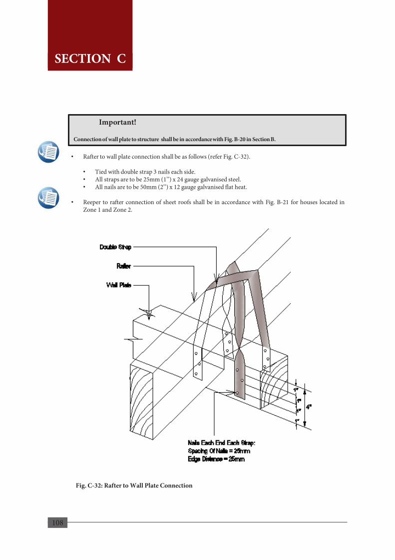
108
• Rafter to wall plate connection shall be as follows (refer Fig. C-32).
• Tied with double strap 3 nails each side. • All straps are to be 25mm (1’’) x 24 gauge galvanised steel. • All nails are to be 50mm (2’’) x 12 gauge galvanised flat heat.
• Reeper to rafter connection of sheet roofs shall be in accordance with Fig. B-21 for houses located in
Zone 1 and Zone 2.
Fig. C-32: Rafter to Wall Plate Connection
106
Important!
Connection of wall plate to structure shall be in accordance with Fig. B-20 in Section B.
SECTION C
SECTION C
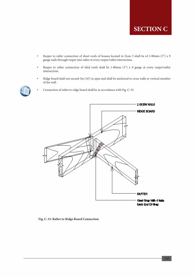
109
• Reeper to rafter connection of sheet roofs of houses located in Zone 3 shall be of 2-80mm (3’’) x 9 gauge nails through reeper into rafter at every reeper/rafter intersection.
• Reeper to rafter connection of tiled roofs shall be 1-80mm (3’’) x 9 gauge at every reeper/rafter intersection.
• Ridge board shall not exceed 3m (10’) in span and shall be anchored to cross walls or vertical member of the wall.
• Connection of rafter to ridge board shall be in accordance with Fig. C-33.
Fig. C-33: Rafter to Ridge Board Connection
107
SECTION C
SECTION C
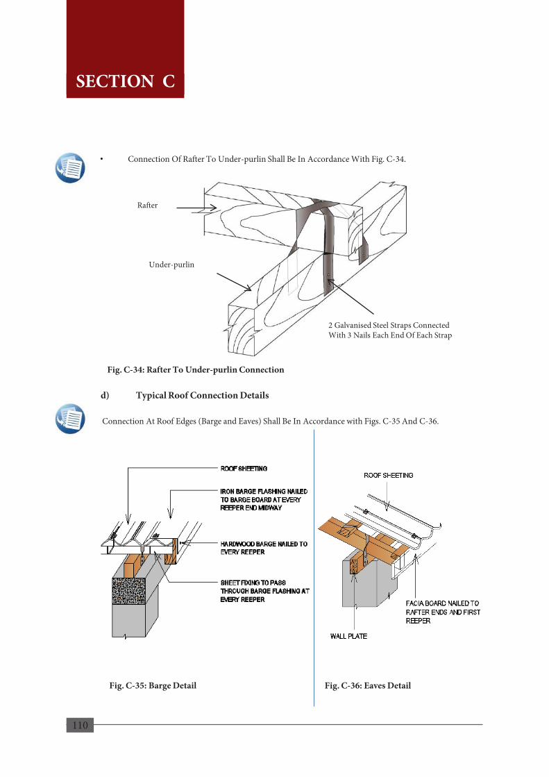
110
• Connection Of Rafter To Under-purlin Shall Be In Accordance With Fig. C-34.
Fig. C-34: Rafter To Under-purlin Connection
d) Typical Roof Connection Details
Connection At Roof Edges (Barge and Eaves) Shall Be In Accordance with Figs. C-35 And C-36.
Fig. C-35: Barge Detail Fig. C-36: Eaves Detail
Under-purlin
2 Galvanised Steel Straps Connected With 3 Nails Each End Of Each Strap
Rafter
108
SECTION C
SECTION C
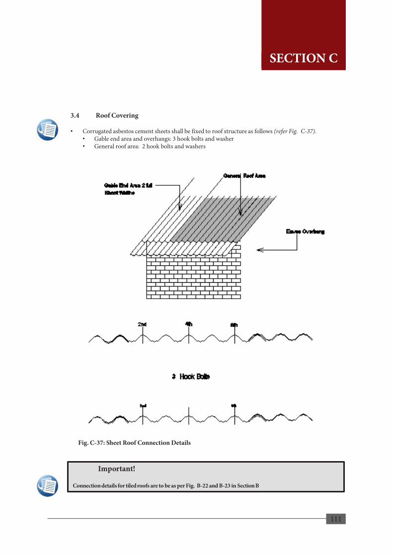
111
3.4 Roof Covering
• Corrugated asbestos cement sheets shall be fixed to roof structure as follows (refer Fig. C-37). • Gable end area and overhangs: 3 hook bolts and washer • General roof area: 2 hook bolts and washers
Fig. C-37: Sheet Roof Connection Details
109
Important!
Connection details for tiled roofs are to be as per Fig. B-22 and B-23 in Section B
SECTION C
SECTION C

112
3.5 Concrete Flat Roofs Reinforced concrete flat roofs can be utilized to provide greater resilience to high winds and specifications are as follows (refer to Fig. C-38). • Roof slope shall be > 1:100. • Maximum overhang shall be in accordance with the minimum requirements. • Reinforced concrete slab shall be minimum 100mm in thickness and be constructed with 25MPa
concrete and shall include a reinforcing wire mesh. • Roof slabs shall be provided with proper water proofing. • All vertical reinforcing bars in the vertical components of the structure shall be bent and extended into
the slab at least 450mm overlap and tied to the slab reinforcement with binding wire.
Fig. C-38: At Least One Room to have a Flat Roof
110
SECTION C
SECTION C
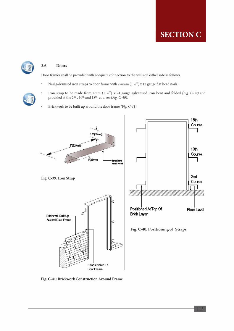
113
3.6 Doors Door frames shall be provided with adequate connection to the walls on either side as follows.
• Nail galvanised iron straps to door frame with 2-4mm (1 ½’’) x 12 gauge flat head nails.
• Iron strap to be made from 4mm (1 ½’’) x 24 gauge galvanised iron bent and folded (Fig. C-39) and
provided at the 2nd , 10th and 18th courses (Fig. C-40).
• Brickwork to be built up around the door frame (Fig. C-41).
Fig. C-39: Iron Strap
Fig. C-40: Positioning of Straps
Fig. C-41: Brickwork Construction Around Frame
111
SECTION C
SECTION C

114
4. EARTHQUAKES
4.1 Planning Phase 4.1.1 How Do Buildings behave during Earthquakes Buildings subject to ground shaking behave differently depending on how they have been designed and constructed. Knowing how a building behaves during earthquakes will help the user understand the subsequent technical sections. Earthquakes generate ground vibrations simultaneously in both vertical and horizontal directions. These vibrations develop inertia forces at different locations of mass in the building which travel through the roof and walls to the foundation. It means that all the components of the building have to carry some additional dynamic load on top of the load they normally carry. A wall unsupported on top and two ends may topple down easily when it is pushed horizontally at its top and perpendicular to its plane. But the same wall would offer greater resistance when pushed with the same force along its length. Wall has its weak direction perpendicular to its plane and strong direction along its length. The Horizontal inertia force transferred from the roof acts on the walls either perpendicular to the wall i.e. in the weak direction or along its length i.e. in the strong direction. Masonry walls generally are slender as their thickness is small compared to their height and length. Moreover, they are brittle and more vulnerable to vibration from earthquakes. When the walls are not tied along its edges to the roof structure, end walls, cross walls and the foundation, they will not have adequate resistance and tend to topple under these inertia forces acting back and forth in their weak direction. The earthquake resilient house should be able to resist; • Minor – earthquakes without damage. • Moderate – earthquakes without structural damage but with some non-structural damage. • Major – earthquakes without collapse, but with some structural damage and some non-structural
damage In other words, a certain degree of damage is acceptable in the house during an earthquake but no loss of life is acceptable from any damage to the structure. To achieve earthquake resilience, the building must be designed to ensure that it has adequate strength, high ductility, and will remain as one integral unit, even while subjected to very large ground motions. Houses in Sri Lanka are generally built with brick or cement block masonry walls with or without concrete columns and the roof structure simply rests on them sometimes without being adequately tied down to the walls. The end of walls are not always properly bonded to the columns if any. This type of construction is vulnerable to earthquake damage as each component would behave independently. Therefore, it is necessary to design and construct such structures to have adequate strength and improved integrity. To ensure good seismic performance of a building the overall integrity of its three components viz. roof, wall and foundation, must be ensured. This can be achieved without any additional cost, with the same type of common building materials but utilized properly and effectively.
112
SECTION C
SECTION C
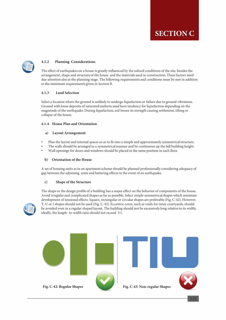
115
4.1.2 Planning Considerations The effect of earthquakes on a house is greatly influenced by the subsoil conditions of the site, besides the arrangement, shape and structure of the house and the materials used in construction. These factors need due attention also at the planning stage. The following requirements and conditions must be met in addition to the minimum requirements given in Section B. 4.1.3 Land Selection Select a location where the ground is unlikely to undergo liquefaction or failure due to ground vibrations. Ground with loose deposits of saturated uniform sand have tendency for liquefaction depending on the magnitude of the earthquake. During liquefaction, soil looses its strength causing settlement, tilting or collapse of the house. 4.1.4 House Plan and Orientation a) Layout Arrangement • Plan the layout and internal spaces so as to fit into a simple and approximately symmetrical structure. • The walls should be arranged in a symmetrical manner and be continuous up the full building height. • Wall openings for doors and windows should be placed in the same position in each floor. b) Orientation of the House A set of housing units as in an apartment scheme should be planned professionally considering adequacy of gap between the adjoining units and battering effects in the event of an earthquake. c) Shape of the Structure The shape or the design profile of a building has a major effect on the behavior of components of the house. Avoid irregular and complicated shapes as far as possible. Select simple symmetrical shapes which minimize development of tensional effects. Square, rectangular or circular shapes are preferable (Fig. C-42). However, T, U or I shapes should not be used (Fig. C-43). Eccentric cores, such as voids for inner courtyards, should be avoided even in a regular shaped layout. The building should not be excessively long relative to its width; ideally, the length- to-width ratio should not exceed 3:1.
Fig. C-42: Regular Shapes Fig. C-43: Non-regular Shapes
113
SECTION C
SECTION C
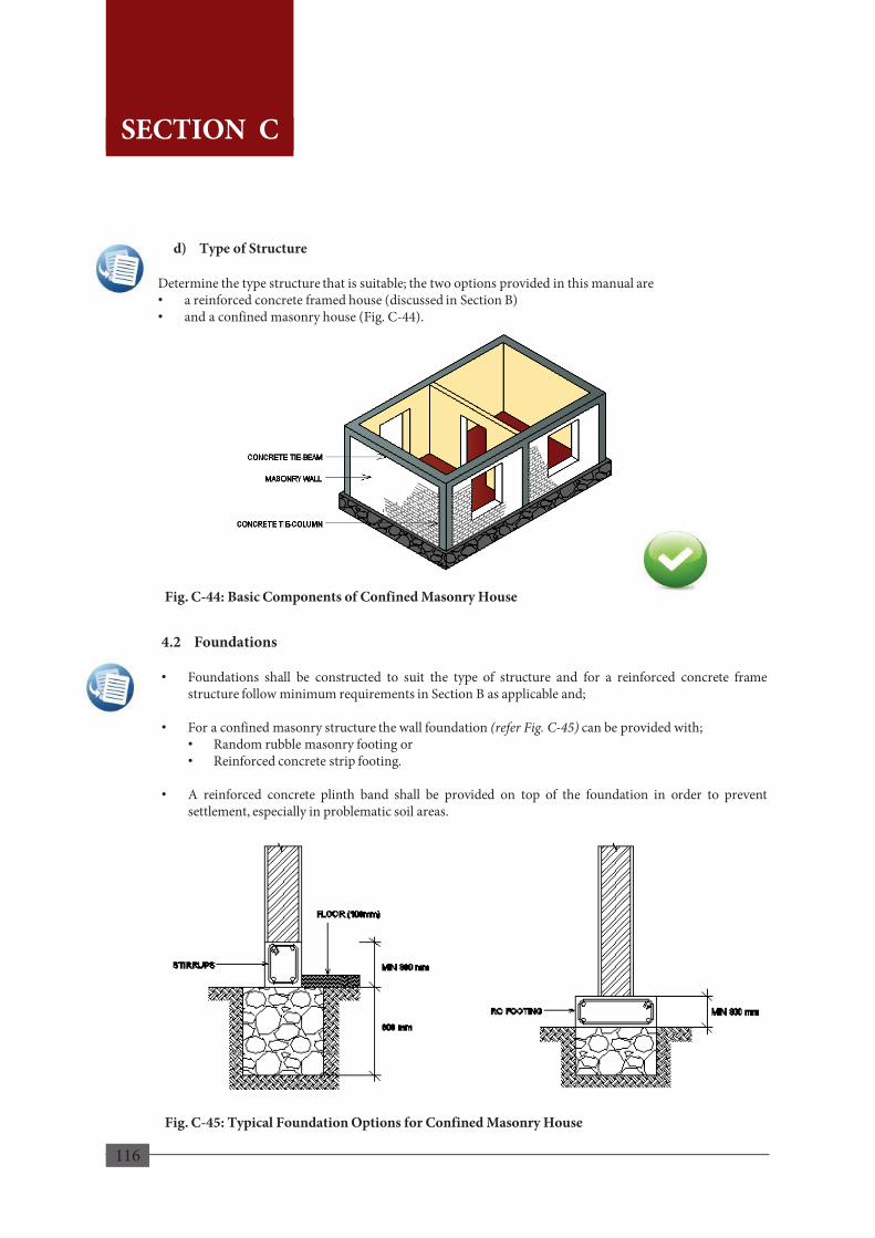
116
4.2 Foundations • Foundations shall be constructed to suit the type of structure and for a reinforced concrete frame
structure follow minimum requirements in Section B as applicable and; • For a confined masonry structure the wall foundation (refer Fig. C-45) can be provided with;
• Random rubble masonry footing or • Reinforced concrete strip footing.
• A reinforced concrete plinth band shall be provided on top of the foundation in order to prevent
settlement, especially in problematic soil areas.
Fig. C-45: Typical Foundation Options for Confined Masonry House
d) Type of Structure Determine the type structure that is suitable; the two options provided in this manual are • a reinforced concrete framed house (discussed in Section B) • and a confined masonry house (Fig. C-44).
Fig. C-44: Basic Components of Confined Masonry House
114
SECTION C
SECTION C

117
4.3 Confined Masonry Structure The house can be constructed as a confined masonry structure in accordance with the following steps with a foundation system as an alternative to reinforced concrete framed structure. a) Masonry walls (Fig. C-46) shall be constructed first and in accordance with the following
specifications.
• At least two fully confined walls shall be provided in each direction. • 100mm or greater in thickness. • The wall height to thickness ratio shall not exceed 30. • The wall shall rest on the plinth band. • In order to ensure adequate wall confinement, toothed edges shall be left one each side of the wall. • It is recommended that steel dowels are placed in mortar bed joints of tie-columns and the walls
to ensure interaction between the concrete and the masonry. • Tie-columns shall be placed at both sides of any opening having an area of more than 1.5m2.
Fig. C-46: Basic Framed Structure
115
SECTION C
SECTION C

118
b) Tie-columns (Fig. C-47) shall be cast in place after masonry walls are constructed to the required height and in conformity with the following;
• Tie-columns shall be placed at every 4m and at the following locations.
i. At wall to wall intersections. ii. Within the wall if necessary to ensure that 4m spacing between the adjacent confining
elements is not exceeded, and iii. At the free end of a wall.
• Tie-columns size shall be minimum 100mm x 100mm or equal to the wall thickness.
• Tie-columns shall be provided with following reinforcement. i. Minimum 4 No’s of 10mm diameter steel reinforcing bars. ii. Minimum 6mm diameter stirrups placed at 100mm spacing in the column end-zones and at
200mm spacing in between. Stirrups shall be closed with a 135o hook. iii. Lap length of vertical reinforcing bars and splicing shall be in accordance with Section B.
• Formwork shall be provided in the two sides other than the sides with the walls.
Fig. C-47: Arrangement of Tie-columns
116
SECTION C
SECTION C
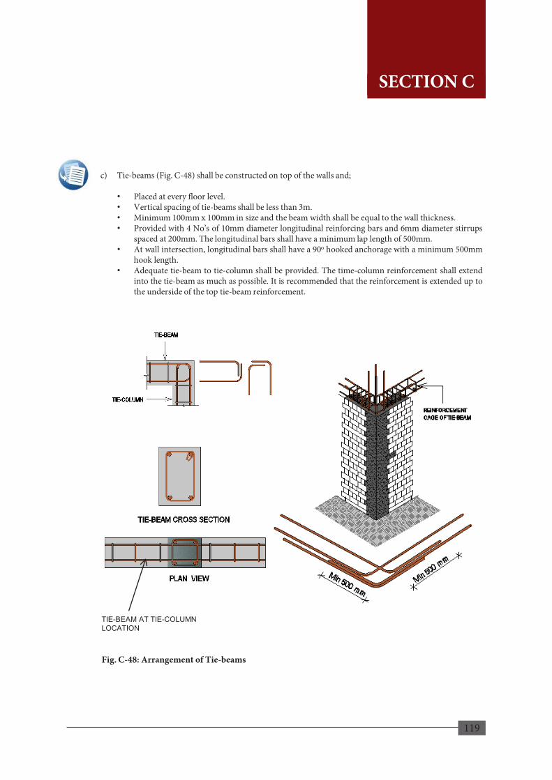
119
TIE-BEAM AT TIE-COLUMN LOCATION
Fig. C-48: Arrangement of Tie-beams
c) Tie-beams (Fig. C-48) shall be constructed on top of the walls and;
• Placed at every floor level. • Vertical spacing of tie-beams shall be less than 3m. • Minimum 100mm x 100mm in size and the beam width shall be equal to the wall thickness. • Provided with 4 No’s of 10mm diameter longitudinal reinforcing bars and 6mm diameter stirrups
spaced at 200mm. The longitudinal bars shall have a minimum lap length of 500mm. • At wall intersection, longitudinal bars shall have a 90o hooked anchorage with a minimum 500mm
hook length. • Adequate tie-beam to tie-column shall be provided. The time-column reinforcement shall extend
into the tie-beam as much as possible. It is recommended that the reinforcement is extended up to the underside of the top tie-beam reinforcement.
117
SECTION C
SECTION C
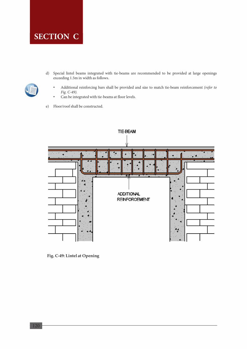
120
d) Special lintel beams integrated with tie-beams are recommended to be provided at large openings exceeding 1.5m in width as follows. • Additional reinforcing bars shall be provided and size to match tie-beam reinforcement (refer to
Fig. C-49). • Can be integrated with tie-beams at floor levels.
e) Floor/roof shall be constructed.
Fig. C-49: Lintel at Opening
118
SECTION C
SECTION C
121
5.1 Expansive Soil 5.1.1 Planning Phase • Identify whether the site concerned is located in a region with the potential of expansive soil conditions
using the Map 6 given in Section A. • Follow minimum planning requirements given in Section B as applicable. • Identify whether the land you have selected consist of an expansive soil condition by visual inspection
using the following guidelines.
• Whether the soil has cracks or fractures when it dries. • Whether the soil becomes very sticky when wet and hard and brittle when dry. • If the selected land was once covered by seas or lakes, it is possible that expansive soil conditions
exist considering that it is common in river bottoms or valleys formed by sediment. Also, expansive soils are common in desert areas.
• If one is uncertain of the type of soil, it is advised that he/she consults a soil expert to perform an
expansion test. • Check whether the existing buildings in the vicinity are subjected to structural distress typical on
expansive soil.
• Check to see whether the soil in the selected land had previously been treated with some means to control soil expansion.
• Plan to have the house constructed in reinforced concrete and it is advised that a qualified engineer is
consulted.
5.1.2 Ground Preparation • Soil should be sloped away from the house minimum 1.5m further from the walls. • Trees should not be grown within a minimum distance of 3m from the house considering that roots
may cause the moisture in the soil surrounding the house to be removed and cause shrinkage. • Provide moisture barrier or aprons.
5.1.3 Ground Improvement • Lime or other anti-expansion products can be mixed into the soil with the direction of an Engineer.
• Existing soil can also be removed and replaced with a non-expansive soil prior to construction.
• Burnt paddy husk can be mixed with the soil to reduce the expansion with advise from an Engineer.
5. PROBLEMATIC SOILS
119
SECTION C
SECTION C
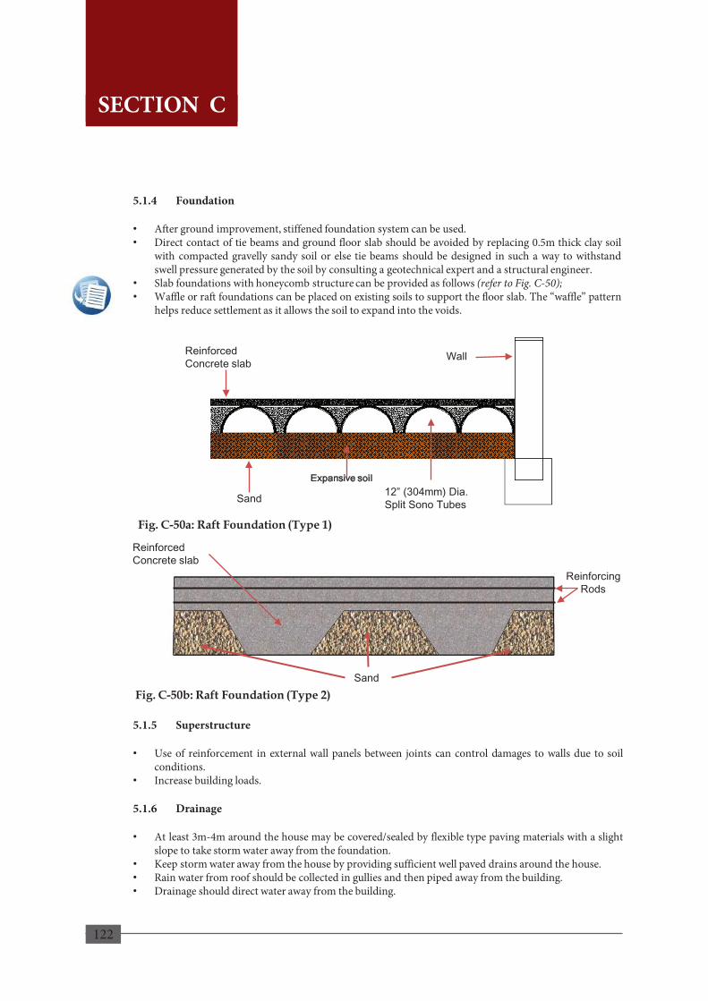
122
5.1.4 Foundation
• After ground improvement, stiffened foundation system can be used. • Direct contact of tie beams and ground floor slab should be avoided by replacing 0.5m thick clay soil
with compacted gravelly sandy soil or else tie beams should be designed in such a way to withstand swell pressure generated by the soil by consulting a geotechnical expert and a structural engineer.
• Slab foundations with honeycomb structure can be provided as follows (refer to Fig. C-50); • Waffle or raft foundations can be placed on existing soils to support the floor slab. The “waffle” pattern
helps reduce settlement as it allows the soil to expand into the voids.
5.1.5 Superstructure • Use of reinforcement in external wall panels between joints can control damages to walls due to soil
conditions. • Increase building loads.
5.1.6 Drainage • At least 3m-4m around the house may be covered/sealed by flexible type paving materials with a slight
slope to take storm water away from the foundation. • Keep storm water away from the house by providing sufficient well paved drains around the house. • Rain water from roof should be collected in gullies and then piped away from the building. • Drainage should direct water away from the building.
Fig. C-50a: Raft Foundation (Type 1)
Reinforcing Rods
Reinforced Concrete slab
Sand Fig. C-50b: Raft Foundation (Type 2)
120
SECTION C
Wall
12” (304mm) Dia. Split Sono Tubes
Reinforced Concrete slab
Sand
Expansive soil
SECTION C

123
5.2. Soft Soil 5.2.1 Planning Phase • Identify whether there is a potential for soft soil conditions to exist. For areas in and around Colombo,
it can be determined whether the site is water logged or marshy. • Necessary investigations should be conducted to obtain the subsoil profile and necessary guidance
should be obtained from a geotechnical expert.
• Provide a placement and compaction of a fill material to an appropriate thickness for executing construction activities.
• If the soft soil layer (peat/organic clay) is thick, the land should be reclaimed to raise the ground well above the water table and flood level on account of the low lying nature.
5.2.2 Method of Reclamation (Ground Improvement Method)
• Fill placed should be well compacted. • Sand/quarry dust layer should be provided in between existing ground and the fill layer to improve
drainage of pore water.
• Granular materials are suitable for under water compaction (sand/quarry dust). • Adequate thickness of fill should be provided to overcome (ensure that a appropriate ground elevation
is reached) problems due to ground water and flood.
• Ensure that there is an adequate depth of well compacted fill below foundation level so that the underlying soft layers are least affected by foundation loads.
• Adequate time should be left for major part of settlement to take place under the fill load leaving tolerable residual settlement before commencing construction.
• Settlement of the fill should be monitored to ensure that a great percentage of settlement is completed prior to the commencement of the construction by prior application of a load.
5.2.3 Preloading • Involves the loading of the ground prior to construction (normally 1.5 times the intended building
load)
• Available materials that are economical can be used as the surcharge material is bulk and moved across using machinery.
• Surcharge load can be removed before commencing the construction achieving required construction settlement.
• The time for removal should be decided based on the results of settlement monitoring
121
SECTION C
SECTION C

124
Top & Bottom plug mass concrete
> 4.0m
Plinth Beam Existing ground
Compacted Sand or Quarry Dust
Dense Silty Sand
5.2.4 Foundations
Following types of foundations with enhanced stiffeners are suitable for sites underlain by soft soils.
Fig. C-51: Stiffened Strip Footing: Inverted “T” type Foundation
Fig. C-52: Vierendeel Girder type Foundation
Fig. C-53: Sinking Cylinders (If soft soil layer is 3-4m and firm stratum found in shallow depth)
122
Important!
It is highly advised that a geotechnical expert and a structural engineer is consulted to obtain guidance for the design of foundations in soft soil conditions.
SECTION C
SECTION C

125
6.1 General Though tsunami occurrences are rare in Sri Lanka, the Indian Ocean Tsunami of 2004 has shown the severity of the hazard and that the settlements near the coast and coastal low-lying areas are highly vulnerable to the risk of tsunami. Therefore, anyone undertaking any housing development activity in the coastal belt must have an understanding about the severity of proneness of the proposed locations and the possible effects of tsunami in the area. During the stage of planning a housing settlement or a house, every effort must be taken to reduce tsunami risks and mitigate the damages by adopting measures including, the following; 6.1.1 Avoid Tsunami prone Areas Considering the magnitude of tsunami forces and the scale of devastation, it is best to avoid areas with risk of tsunami hazard. However, this is always not possible due to various socio-economic and technological issues. Authorities such as the Coast Conservation & Coastal Resources Department (CCCRMD) have identified the tsunami prone areas according to severity of hazard and accordingly, where settlement development should be avoided or where such activities are prohibited or restricted in the coastal belt. Where development is unavoidable within a tsunami prone area and permitted by the concerned authorities, the structures should be designed in such a way to minimize the damages from tsunami waves. House construction must be strictly adhered to the Coast Conservation Regulations and other guidelines imposed by the Coast Conservation Act. In addition, other relevant regulations and guidelines on land use, building and construction etc., mentioned in Section B 2.4 . This manual strongly recommends that the design of the structures of houses shall be undertaken by professional engineers who are well versed with relevant Standards and Codes of Practice. 6.1.2 Reduce Tsunami Risks When development is unavoidable within tsunami prone areas, tsunami risks can be reduced through a combination of different techniques to; • Diminish the power of tsunami waves and slow down the currents reaching land by creating barriers
such as specially designed forests, green belts, ditches and slopes,
• Steer away the tsunami forces e.g. by strategically placing the structure, and by using angled walls, ditches and paved surfaces.
• Block the water forces by providing rigid structures such as walls and dykes, terraced berms.
However, most of these techniques are generally adopted by the concerned authorities to mitigate tsunami risks in selected areas or communities. These options are usually beyond economical reach of an average house builder and may not be practical for isolated small individual plots. 6.1.3 Mitigate the Damages Damage to a house built within a tsunami prone area can be reduced by placing the house on the high side of the land and / or by raising the structure above tsunami inundation level by using stilts/ piers or hardened podiums.
6. TSUNAMI
123
SECTION C
SECTION C

126
SECTION C
6.2 Basic Requirements for a Safe Structure For a building to be safe during a tsunami, its structural integrity is extremely important as in the case of a building performing under high winds (refer to Section C 3). Tsunami resilient houses shall be located, designed, and constructed to; • Withstand water forces, debris and wave-break impacts, earthquake shaking if any, foundation and
ground failure due to erosion, scouring or liquefaction, or other effects without significant structural damage.
• Enable the occupants swiftly evacuate to a designated safe location above the level of wave action resulting from a tsunami within short notice by the competent authority or by the tsunami warning system provided.
• Enable the occupants reoccupy the house within a few days to weeks after clean-up, minor repairs, and the restoration of utilities.
• Ensure required level of performance as before the event by utilizing flood-resistant materials and appropriate construction.
6.2.1 Site selection Houses located at different parts of the area affected by tsunami run-up depending of several factors such as the distance from the shoreline, elevation, obstacles on the tsunami path will experience different damaging forces. Those located at lower elevations near the shoreline are likely to be affected by tall waves in a tsunami, whereas, those in less hazardous areas affected by shallow run-up water depths may survive with repairable damage. Therefore, in selecting sites for housing construction in the coastal belt, it must be kept in mind that; • Buildings should be located to avoid the coastal reservation area and restricted zones
• Locations near rivers and waterways, lagoons and bays etc., connected to the sea and along which the
tsunami waves could reach the land shall be avoided
• The site should be such that the houses could be located on a high ground desirably well above the possible tsunami inundation level (Fig. C-56). If the ground is sloping towards the sea, locate the house on the higher side of the land. When siting on sufficiently high ground is not possible, the house may be constructed on stilts or on created high ground made up of thoroughly compacted earthen embankment.
• Ground should have suitable bearing stratum to construct stable foundations and the sub-soils must not be prone to failure in bearing capacity that may be caused by sudden rise in pore water pressure in the soil.
124
Important!
Loss and damage to life and property cannot be eliminated with tsunami resilient housing alone. These can be mitigated to a great extent only if the occupants;
• are aware of the severity of tsunami hazard and how it could affect them. • are ready with Tsunami preparedness being vigilant of warnings, alarms issued by the authorities • Disaster Management Centre or its district office through relevant local agencies. Swiftly evacuate to the
nearest designated locations for refuge.
SECTION C 6.2 Basic Requirements for a Safe Structure
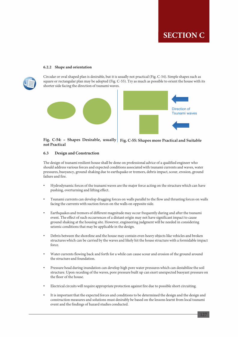
127
6.2.2 Shape and orientation Circular or oval shaped plan is desirable, but it is usually not practical (Fig. C-54). Simple shapes such as square or rectangular plan may be adopted (Fig. C-55). Try as much as possible to orient the house with its shorter side facing the direction of tsunami waves. 6.3 Design and Construction The design of tsunami resilient house shall be done on professional advice of a qualified engineer who should address various forces and expected conditions associated with tsunami currents and waves, water pressures, buoyancy, ground shaking due to earthquake or tremors, debris impact, scour, erosion, ground failure and fire. • Hydrodynamic forces of the tsunami waves are the major force acting on the structure which can have
pushing, overturning and lifting effect.
• Tsunami currents can develop dragging forces on walls parallel to the flow and thrusting forces on walls facing the currents with suction forces on the walls on opposite side.
• Earthquakes and tremors of different magnitude may occur frequently during and after the tsunami event. The effect of such occurrences of a distant origin may not have significant impact to cause ground shaking at the housing site. However, engineering judgment will be needed in considering seismic conditions that may be applicable in the design.
• Debris between the shoreline and the house may contain even heavy objects like vehicles and broken structures which can be carried by the waves and likely hit the house structure with a formidable impact force.
• Water currents flowing back and forth for a while can cause scour and erosion of the ground around the structure and foundation.
• Pressure head during inundation can develop high pore water pressures which can destabilize the soil structure. Upon receding of the waves, pore pressure built up can exert unexpected buoyant pressure on the floor of the house.
• Electrical circuits will require appropriate protection against fire due to possible short circuiting.
• It is important that the expected forces and conditions to be determined the design and the design and construction measures and solutions must desirably be based on the lessons learnt from local tsunami event and the findings of hazard studies conducted.
Fig. C-54: – Shapes Desirable, usually not Practical
Fig. C-55: Shapes more Practical and Suitable
Direction of Tsunami waves
125
SECTION C
SECTION C

128
6.4 Structure A heavy steel framed structure though may perform well in a tsunami, may not be acceptable for houses due to high cost and rapid deterioration due to corrosion by sea winds. Confined concrete masonry structures (refer to Section C4) are considered suitable for tsunami resilient housing and therefore, recommended in this Manual for adoption with some special considerations or modifications as given below. • If constructed on raised ground, embankments
must be designed to streamline the flow of tsunami currents and all its sides shall be well protected against possible scour, erosion and being carried away by wave forces.
• House on stilts/columns have the advantage that the underside can be used for non-occupancy purposes such as a garage or space where human activities are minimal.
• If constructed on stilts/columns, (Fig. C-56), they shall be robust and adequately braced against overturning and properly anchored into the ground through a stable foundation or piles to prevent lifting. The columns shall be designed and constructed to withstand the seismic forces too.
• If the house to be constructed on ground within reach of tsunami waves, provision shall be made to divert the water currents away from the house using barriers (Fig. C-57 and Fig. C-58). Lower floor may be so designed to allow the water to flow freely across the house through wall openings placed in line with each other to minimize forces acting on the walls.
• Use internal cross walls perpendicular to the walls facing the sea or the tsunami waves.
• Floor slab shall be designed to withstand warping and lifting under buoyant pressures
• Shallow foundations shall be founded on suitable bearing stratum but well below possible scour level. Possibilities of liquefaction shall also be taken into consideration in the design of foundation.
• It is desirable to provide an apron around the house to minimize erosion and undermining of foundations.
Fig. C-58: Block Water Forces
Fig. C-57: Slow down water currents using Barriers
Fig. C-56: Locate above the Inundation Level
126
SECTION C
SECTION C
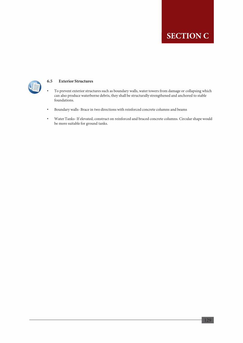
129
6.5 Exterior Structures • To prevent exterior structures such as boundary walls, water towers from damage or collapsing which
can also produce waterborne debris, they shall be structurally strengthened and anchored to stable foundations.
• Boundary walls- Brace in two directions with reinforced concrete columns and beams
• Water Tanks- If elevated, construct on reinforced and braced concrete columns. Circular shape would be more suitable for ground tanks.
127
SECTION C
SECTION C

130
References 1. DMC, 2012, Hazard Profile of Sri Lanka, Nanila Publication (Pvt.) Ltd. 2. CHPB, 2003, Guidelines for Settlements Planning and Construction in Flood Prone Areas,
128
SECTION C
SECTION C

131
APPENDIX
APPENDICES
129
APPENDICES

132
2. Rock Types available in Sri Lanka
Massive Consolidated types • Igneous rocks; Granite Loose unconsolidated types • Sedimentary rocks; Sand stone, Metamorphic Rocks • Gneisses; Khondalite; Charnockitic; Garnet Biotite; Quartzo fledspathic
• Metamorphic Rocks
They are quite stable and hence stand well (provided the geological structures( joint pattern and density, Lineaments, Shear Zones, Fault axis's) are favorable. Such rocks generally require extensive and expensive blasting.
3. The Structural features (Geological structures) of the rocks
• Although a given rock may be quite hard and otherwise suitable for a cut or a road foundation, yet, if some planes of weakness (such as joints, bedding planes etc.) dipping towards the open side are present, the road may slip along these planes at any times during or after its construction.
• The determination and intelligent reading of various structural features of the adjoining rocks such as their dip and strike position of joints, fault planes and shear zones is, therefore, very important.
1. More Specific Soil Types • Residual Soils Products of weathering of igneous, sedimentary and
metamorphic rocks. Residual soils are not generally bad soils in an engineering sense. Products of weathering of rocks, the degree of weathering and the extent to which the original structure of the rock mass is destroyed varying with depth from the ground surface.
• Crystalline Rocks In Sri Lanka over 90% of the land is made up of
highly crystalline rocks belonging to the South Indian Shield.
• Laterite - “Cabook” which is locally known as “Cabook” is found in the
South western part of the Island. • Colluvial soils Formed by movement of soil from its original place
by gravity such as during landslides. Colluvial soils are considered weak soils in the sense of earth related activities.
Soils
Residual soils
Colluvium soil
130
APPENDIX A
APPENDICES A
APPENDICES
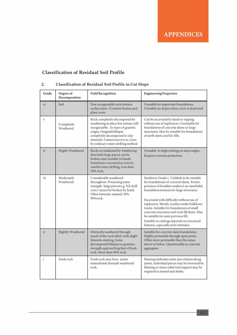
133
Grade Degree of Decomposition
Field Recognition Engineering Properties
vi Soil Non recognizable rock texture; surface layer. Contains humus and plant roots
Unstable for important foundations. Unstable on slopes when cover is destroyed
v Completely Weathered
Rock completely decomposed by weathering in place but texture still recognizable . In types of granitic origin, Original feldspar completely decomposed to clay minerals. Cannot recover ac cores by ordinary rotary drilling method
Can be excavated by hand or ripping without use of explosives. Unsuitable for foundations of concrete dams or large structures. May be suitable for foundations of earth dams and for fills.
iv
Highly Weathered
Rocks so weakened by weathering that fairly large pieces can be broken and crumble in hands. Sometimes recovered as core by careful rotary drilling. Less than 50% rock.
Unstable. In high cuttings at steep angles. Requires erosion protection.
iii
Moderately Weathered
Considerable weathered throughout. Possessing some strength- large pieces(e.g. NX drill core) cannot be broken by hand. Often limonite-stained. 50%-90%rock.
Similar to Grade v. Unlikely to be suitable for foundations of concrete dams. Erratic presence of boulders makes it an unreliable foundation stratum for large structures Excavated with difficulty without use of explosives. Mostly crushes under bulldozer tracks. Suitable for foundations of small concrete structures and rock fill dams. May be suitable for semi pervious fill. Suitable in cuttings depends on structural features, especially joint attitudes.
ii
Slightly Weathered
Distinctly weathered through much of the rock fabric with slight limonite staining. Some decomposed feldspar in granites. strength approaching that of fresh rock. More than 90% rock.
Suitable for concrete dam foundations. Highly permeable through open joints. Often more permeable than the zones above or below. Questionable as concrete aggregates.
i
Fresh rock
Fresh rock may have joints immediately beneath weathered rock.
Staining indicates water percolation along joints. Individual pieces may be loosened by blasting or stress relief and support may be required in tunnel and shafts.
2. Classification of Residual Soil Profile in Cut Slope
Classification of Residual Soil Profile
131
APPENDIX A
APPENDICES A
APPENDICES

134
3. Drainage Behind Retaining Walls • Rainfall or other wet conditions, the backfill material for a retaining wall may become saturated.
• Saturation will, in effect, increase the pressure on the wall and create an unstable condition.
• For this reason , adequate drainage must be provided by means of weep holes and/or perforated
drainage pipes
• Weep holes should be provided in moss concrete, Gabion walls and reinforced concrete walls. Random rubble masonry walls and dry-stone masonry retaining walls are normally self-draining.
• Note that there is always a possibility that the backfill material may be washed in to weep holes or
drainage pipes. This will ultimately clog up the drainage facilities. Thus, filter material need to be placed behind the weep holes or around the drainage pipe.
• Nowadays, geotextiles are used to serve the same purpose.
Drainage Methods
132
APPENDIX A
APPENDICES A
APPENDICES
3. Drainage Behind Retaining Walls • Rainfall or other wet conditions, the backfill material for a retaining wall may become saturated.
• Saturation will, in effect, increase the pressure on the wall and create an unstable condition.
• For this reason , adequate drainage must be provided by means of weep holes and/or perforated
drainage pipes
• Weep holes should be provided in moss concrete, Gabion walls and reinforced concrete walls. Random rubble masonry walls and dry-stone masonry retaining walls are normally self-draining.
• Note that there is always a possibility that the backfill material may be washed in to weep holes or
drainage pipes. This will ultimately clog up the drainage facilities. Thus, filter material need to be placed behind the weep holes or around the drainage pipe.
• Nowadays, geotextiles are used to serve the same purpose.
Drainage Methods
132
APPENDIX A

135
3. Drainage Behind Retaining Walls • Rainfall or other wet conditions, the backfill material for a retaining wall may become saturated.
• Saturation will, in effect, increase the pressure on the wall and create an unstable condition.
• For this reason , adequate drainage must be provided by means of weep holes and/or perforated
drainage pipes
• Weep holes should be provided in moss concrete, Gabion walls and reinforced concrete walls. Random rubble masonry walls and dry-stone masonry retaining walls are normally self-draining.
• Note that there is always a possibility that the backfill material may be washed in to weep holes or
drainage pipes. This will ultimately clog up the drainage facilities. Thus, filter material need to be placed behind the weep holes or around the drainage pipe.
• Nowadays, geotextiles are used to serve the same purpose.
Drainage Methods
132
APPENDIX A
Effects of Root System for Erosion Control
Slope surface protection using vegetation as a bio engineering approach is recommended to be applied in local slopes. Vegetation will minimize erosion/binds the soil at a shallow depth. In unprotected slope erosion at surface level can gradually propagate causing much severe erosion and further slope instability.
Stem Ground surface
Surface roots
Fiber roots
Tap roots
Ground surface
Surface roots
Root systems
133
APPENDIX A
APPENDICES A
APPENDICES

136
Guatemala Grass (Euchluena luxurians) Used in tea plantations prior to new planting. Root System: Fiber
Belathana (Elesina indica) More suitable for loose soil areas. Difficult to uproot easily. Root System: Fiber
Arunadevi/Tharaka (Wedelia trilobite) Act as good surface mat, easily removable and quickly regrown. Root System: Fiber
Kakilla (Nephrolepis) Most suitable for lateritic soil(kabook in Sinhala) Root System: Surface
Suitable Plants for Soil erosion Control
134
APPENDIX A
APPENDICES

137
Undupiyaliya (Desmodium trifolium) Good cover for erosion control Root System: Surface
Savandara (Vertivaria ziznaidus) Control erosion well Root System: Surface
Cow root Grass/ Australian Blue Grass (Dactyloetriem) Well Protection from erosion of surface Root System: Fiber
Una (Bambuseae) Good protection for surface erosion. Root System: Fiber
135
Suitable Plants for Soil erosion Control APPENDIX A
APPENDICES
138
SAMPLE DRAWINGS
136
Important!
The sample drawings included in Appendix B have been provided for information only and these plans and details by no means shall be taken as construction drawings. The given plans provide the user with an idea about the layout and the look of a possible landslide/flood/high wind resilient house. These can only be used as sample plans in order to help the user create his/her own set of drawings with architectural and structural plans/details that are specific to the chosen land and area. Also, note that the four drawings included herein may not consist of all the design/construction details needed. About the given drawings; Drawing 1. Landslide Resilient House: Plans and details have been extracted from the drawings prepared by NBRO for the landslide resilient model house constructed in Agalawatta. The slope angle of this land was measured to be 28o. The elevations shown in this drawing are particular to this site and shall not be taken as a general condition as the slope angle will vary depending on the site. This illustrates how a house can be constructed in a sloping site without increasing the risk of a landslide (slope failure). Drawing 2. Flood Resilient House – Raised Plinth: These plans and details are a sample of a flood resilient model house with a raised plinth design. This model house has been constructed in Yatawara Junction and highest known flood level was 4ft. Therefore, the plinth has been raised above this level. The height of the plinth is specific to the flood level in this area and shall not be taken as a general condition. Drawing 3. Floods – On Stilts: These plans and details are a sample of a flood resilient model house designed to be constructed on stilts. This model house has been constructed in Gatulawa with the highest known flood level of 4ft and the floor has been raised above this level. The height of the stilts is specific to the flood level in this area and shall not be taken as a general condition. Drawing 4. High Winds: This drawing consists of design plans and details of a high wind resilient model house constructed in Mundalama. The details such as orientation and layout of this house has been designed in accordance with the site specific conditions and shall not be taken as general conditions.
APPENDIX B
APPENDICES

139
Relationship between Column Load, Footing Size, Safe Bearing Capacity and Bearing Pressure
137
-
100
200
300
400
500
600
700
150 175 200 225 250 275 300 325 350 375
750x750
900x900
1000x1000
1200x1200
1300x1300
1400x1400
1500x1500
1600x1600
1700x1700
1800x1800
2000x2000
Footing Size (mm x mm)
Safe
Bea
ring
Cap
acity
or B
earin
g Pr
essu
re (k
N/m
2 )
Total Column Load (kN)
APPENDIX B
APPENDICES

140
Drawing 1. Landslides
138
APPENDIX B
APPENDICES

141
Drawing 2. Floods - Raised Plinth
139
APPENDIX B
APPENDICES

142
Drawing 3. Floods - On Stilts
140
APPENDIX B
APPENDICES
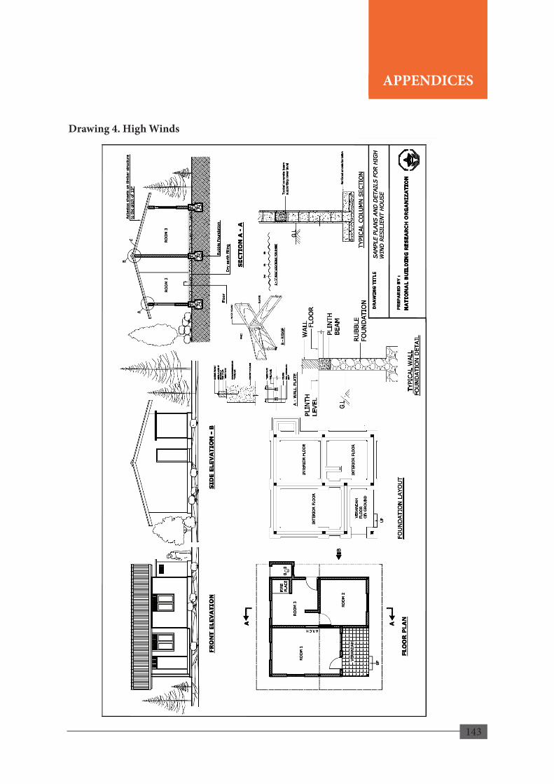
143
Drawing 4. High Winds
141
APPENDIX B
APPENDICES
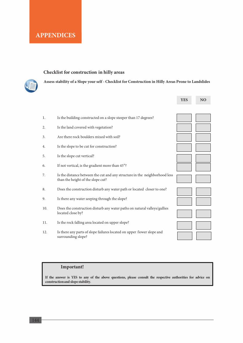
144
Assess stability of a Slope your self - Checklist for Construction in Hilly Areas Prone to Landslides
1. Is the building constructed on a slope steeper than 17 degrees?
2. Is the land covered with vegetation?
3. Are there rock boulders mixed with soil?
4. Is the slope to be cut for construction?
5. Is the slope cut vertical?
6. If not vertical, is the gradient more than 45°?
7. Is the distance between the cut and any structure in the neighborhood less than the height of the slope cut?
8. Does the construction disturb any water path or located closer to one?
9. Is there any water seeping through the slope?
10. Does the construction disturb any water paths on natural valleys/gullies located close by?
11. Is the rock falling area located on upper slope?
12. Is there any parts of slope failures located on upper /lower slope and surrounding slope?
YES
Checklist for construction in hilly areas
NO
142
Important!
If the answer is YES to any of the above questions, please consult the respective authorities for advice on construction and slope stability.
APPENDIX C
APPENDICES
Related Documents