HAZARD AND OPERABILITY (HAZOP) STUDY OF THE BOILER TRIP SYSTEM AT SEJINGKAT POWER CORPORATION (SPC) MOHAMAD ARIFFIN BIN ZULKIPLY ``ýý1 ýºSýý ,. Iý) ; ýU 5"'r AIMN UNIVERSITI MALAYSIA SARAWAK 2002 is 176 1697 2002

Welcome message from author
This document is posted to help you gain knowledge. Please leave a comment to let me know what you think about it! Share it to your friends and learn new things together.
Transcript

HAZARD AND OPERABILITY (HAZOP) STUDY OF THE BOILER TRIP SYSTEM AT SEJINGKAT POWER CORPORATION (SPC)
MOHAMAD ARIFFIN BIN ZULKIPLY
``ýý1 ýºSýý
,. Iý)
; ýU 5"'r AIMN
UNIVERSITI MALAYSIA SARAWAK
2002 is 176 1697 2002
HAZARD AND OPERABILITY (HAZOP) STUDY OF THE BOILER
TRIP SYSTEM AT SEJINGKAT POWER CORPORATION (SPC)
P. KMIDMAT MAKLUMAT AKADEMIK UNIMAS
0000118384
MOHAMAD ARIFFIN B. ZULKIPLY
Tesis Ini Dikemukakan Kepada Fakulti Kejuruteraan, Universiti Malaysia
Sarawak Sebagai Memenuhi Sebahagian Daripada Syarat Penganugerahan
Sarjana Muda Kejuruteraan Dengan Kepujian (Kejuruteraan Mekanikal dan
Sistem Pembuatan)
Universiti Malaysia Sarawak
2002
BORANG PENYERAHAN TESIS
Judul: HAZARD AND OPERABILITY (HAZOP) STUDY OF THE BOILER TRIP SYSTEM AT SEJINGKAT POWER CORPORATION SDN. BHD.
SESI PENGAJIAN: 1999/2002
Saya MOHAMAD ARIFFIN BIN ZULKIPLY mengaku membenarkan tesis ini disimpan di Pusat Khidmat Maklumat Akademik, Universiti Malaysia Sarawak dengan syarat-syarat kegunaan seperti berikut:
I. Hakmilik kertas projek adalah di bawah nama pewlis meJainkan penuflsan sebaga< pro)ek bersama dan dibiayai oleh UNIMAS, hakmiliknya adalah kepxuryaan UNIMAS.
2. Naskhah salinan di dalam bentuk kertas atau mikro hanya bolch dibuat dengan kebermran bertulis daripada penulis.
I Pusat Khidmat Maklumat Akademik, UNIMAS dibenarkan mernbuat salinaa untuk pengajian mereka
4. Kertas projek harrya boleh diterbitJcan dengan kebenaran penulis. Bayaran royalti adalah mengikut kadar yang dipersetujui kelak.
5. * Saya membenarkan/tidak membenarkan Perpustakaan membuat salinsn kertss proik ini sebagai bahan pertukaran di antara instiriisi pengajian tinggi.
6. ** Sila tandakan (3)
F-I SULIT
F7 (Menem maklumat yang berdarjah kesdamatan stau kepentingan Malaysia seperti yang termaktub di dalam AKTA RAHSIA RASMI 1972).
TERHAD (MengandunM maklumat TERHAD yang tdah ditertuican ddt organisasi/ badan di man peiryetidikan dijalanlcan). El
TIDAK TERHAD
(TANDATAII
Disatkan oleh
gja 'I
A
PENULIS) (TANDATANGAN EN4EIA)
Alamat tetap: 232 JAI. AN HAJI MATAIM. CIK RUBIYAH BTE. HAR BAINI
94300 KUCIIING. SARAWAK
Tarikh: 23 APRIL 2002
Nama Perryeiia:
Tarikh: 23 APRIL 2002
CATATAN . Potong yang tidak berkenaan. "" Jika Kertm Projek iai SULIT ataa TERHAD, sila laar'irkae surat daripada pihak berkuasal organisasi berkenaan dengan menyertakau sekali tempoh kertas projek. Ini periu dikdaskan sdagai SULIT atao TERHA D.

Approval Sheet
This project report attached here to, entitled "HAZARD AND OPERABILITY
(HAZOP) STUDY OF THE BOILER TRIP SYSTEM AT SEJINGKAT POWER
CORPORATION SDN. BHD. " prepared and submitted by Mohamad Ariffin
Bin Zulkiply as a partial fulfilment of the requirement for the degree of Bachelor
of Engineering with Honours in Mechanical and Manufacturing System is hereby
read and approved by:
Date: 23 APRIL 2002 MISS RUBIYAH BTE. HJ. BAINI (SUPERVISOR)

. BISMILL. AHIRR. 4HMANIRRAh/IM.
BY THE NAME OF ALLAH, MOST GRACIOUS AND MOST MERCIFUL
"THIS PROJECT IS DEDICATED TO MY
MOTHER, BONDA ROKAYAH MOHIDI, MY
AUNTIE, MARY MOHIDI, AND TO ALL MY
FAMILY MEMBERS
ESPECIALLY TO SH. KHANIZAH"
"1 LOVE You ALL"
ACKNOWLEDGMENT
BISMILLAHIRRAHMANIRRAHIM
"IN THE NAME OF ALLAH MOST GRACIOUS AND MOST MERCIFUL"
Firstly, the author wants to express gratitude to his supervisor, Miss
Rubiyah Bte. Haji Baini for the support, guidance and supervision towards the
completion this project.
Secondly, the author also wishes to thank the Head of Mechanical
Engineering and Manufacturing System Programme, Mr. Nazeri Abdul Rahman
for the valuable advises.
Thanks also due to the Sejingkat Power Corporation (SPC) Management
people especially to Mr. Luke Wong (SPC General Manager) for giving the
permission to the author to carry out his Final Project at the company. Special
thanks to Mr. Mohamad Abdullah (The Performance Engineer), Mr. Daniel
Sahari (The Shift Charge Engineer), Mr. Stanley Wong, Mr. Lensus, Mr.
Sulaiman Abdullah, Mr. Abang Azman and to all employees at SPC for the
information and support.
Appreciation also goes to Mr. Mohamad Aminurashid and Mr. Mohamad
Afif for their valuable information and support toward the end of this project.
Thanks are also extended to author's friends especially to all the final
year students of Mechanical Engineering and Manufacturing System Program
and those who stayed at Bungalow 65, Sri Muara College, for their friendship
and support toward the completion this project.

Gratitude is also expressed to all Engineering staffs and lecturers and the
author classmate for their help and friendship during his stay in UNIMAS.
Last but not least, the author is extremely in debt to his family especially
to his mother and his auntie, whom has gave enormous encouragement and
support forever.
ti

ABSTRACT
The objective of this study is to carry out hazard and operability (HAZOP)
analysis, to determine the potential hazardous that can be activated by the
Master Fuel Trip (MFT) and also to determine the hazard rating thus to verify
the necessity of each trip signal of the Boiler Trip System. The study has been
done at Sejingkat Power Corporation (SPC), at Bako area in Kuching. From the
result, a HAZOP analysis system has been done in order to avoid potential
hazards during the operation, and the required safeguard and action, have been
developed to assure the safety of the boiler and also to the environment. The
necessity of the each boiler tripping signals has also been analyzed using graphs
based on the hazard rating. From the result, it has been determine that the loss
of coding air fan trip signal can be neglected from the MFT. The most highest
hazard rating consist of three signals which are the Induce Draft Fan (IDF) trip
signal, Furnace Pressure High trip signal and less flow of air in furnace trip
signals. Recommendations are included in form to enhance the efficiency of the
system and can be used as future reference for similar system in other section or
industries.
111

ABSTRAK
Tujuan projek nu dijalankan adalah untuk menganalisis kesan kemudaratan
yang boleh berlaku semasa sesuatu operasi sedang dijalankan (Hazard and
Operability) khasnya di dalam sistem pembakaran dan pendidihan (Boiler) yang
terdapat di Sejingkat Power Corporation, iaitu sebuah loji penjana kuasa elektrik yang
terletak di Bahagian Bako, Kuching. Kajian ini jugs memfokuskan mengenai Chap
keperluan sesuatu sistem petanda untuk memberhentikan sesuatu proses itu dengan
serta merta (Trip System) yang terdapat pada sistem pembakaran dan pendidihan
(Boiler) di kawasan yang lama. Daripada keputusan yang telah diperolehi, satu sistem
untuk mengenal pasti kesan kemudaratan yang berpotensi untuk berlaku semasa
proses dijalankan, langkah keselamatan dan tindakan susulan telah direka bagi
memastikan tahap keselamatan ketika operasi dapat ditingkatkan. Tahap keperluan
sesuatu sistem petanda untuk memberhentikan sesuatu proses itu dengan serta merta
(Trip System) yang terdapat pads sistein pembakaran dan pendidihan (Boiler) jugs
dapat di kenal pasti dengan menggunakan graf berdasarkan tahap kesan kemudaratan
yang mungkin berlaku ketika operasi dijalankan. Daripada keputusan yang diperolehi,
didapati bahawa isyarat Loss of Cooling Air Fan Trip Signal boleh diabaikan daripada
Messer Fuel Trip (MFT) kerana kesan kemudaratan yang rendah. Selain itu jugs
didapati terdapat 3 Trip Signal yang mempunyai kesan kemudaratan yang tinggi iaitu
Induced Draft Fan (IDF), Furnace Pressure High dan Total Air Flow < 25%.
Beberapa cadangan bagi meningkatkan operasi sistem pembakaran dan pendidihan
(Boiler) juga telah disertakan untuk kemajuan sistem yang sama dan berkaitan pads
masa depan.
IV
CONTENTS
ACKNOWLEDGEMENT .................................................................... i
ABSTRACT ................................................................................. ...
ABSTRAK ..................................................................................... . iv
CONTENTS .................................................................................... v
LIST OF FIGURES '
LIST OF TABLES .......
NOTATIONS ................................................................................... z
CHAPTER 1: INTRODUCTION ....................................................... 1
1.0 Introduction to the Study ..........................................................
1
1.1 Background of the Study Location .............................................. 2
1.2 General Process At Sejingkat Power Corporation (SPC) ................. 4
1.2.1 Coal Supply ................................................................... 6
1.2.2 Combustion and Furnace .................................................. 7
1.2.3 Steam-Condensate-Feedwater Cycles ................................. 8
1.2.4 Electrical System .......................................................... 10
1.2.5 Seawater Cooling System ............................................... 10
1.2.6 Auxiliary Boiler .............................................................
11
1.2.7 Ash Handling System ..................................................... 11
1.2.8 Balance of Plant ............................................................ 12
1.3 Boiler ................................................................................... 13
V

1.3.1 Major Parts of Boiler ...................................................... 15
1. Drum ................................................................. 15
2. Furnace Chamber ................................................ 16
3. Downcomer ......................................................... 17
4. Waterwalls ......................................................... 17
5. Superheater ........................................................ 18
6. Economiser ......................................................... 18
7. Attemerator ........................................................
19
8. Force Draft Fan (FDF) ........................................ 19
9. Induced Draft Fan (IDF) ....................................... 20
10. Primary Air Fan (PAF) ......................................... 20
11. Cooling Air Fan (CAF) ......................................... 20
1.3.2 Steam Water System .......................................................
20
1.3.3 Process Description of the Boiler Trip System ..................... 24
1.3.4 Master Fuel Trip (MFI') .................................................. 24
1.3.5 Manual Emergency Shutdown ..........................................
25
1.4 Scope of the Study .................................................................... 26
1.4.1 Objective of the Study ..................................................... 27
CHAPTER 2: LITERATURE REVIEW ............................................. 28
2.0 Plant Safety ............................................................................
28
2.1 Trip Mechanism ....................................................................... 28
2.2 Design Aspect for Trip System .................................................... 29
2.3 Heat Exchanger ....................................................................... 33
vi

2.3.2 Boiler Problems ............................................................... 35
2.4 Deviation from Design Intent ..................................................... 38
CAHPTER 3: METHODOLOGY ...................................................... 40
3.0 Introduction ...........................................................................
40
3.1 Visiting the Study Location ....................................................... 41
3.1.1 The Component Involved .................................................
41
3.1.2 MFT Operation .............................................................. 42
3.1.3 Upper Process and Down Process ......................................
42
3.2 Data to be collected for Hazard Identification ..............................
44
3.3 Hazard Analysis .....................................................................
44
3.3.2 The Reason Using HAZOP ...............................................
45
3.3.3 The Basic Concept of HAZOP Study ..................................
46
3.3.4 HAZOP Study Methodology ..............................................
50
3.3.5 Considering All Keywords - HAZOP Procedure ....................
51
3.4 Hazards Rating .......................................................................
53
CHAPTER 4: RESULT ................................................................... 54
4.0 Introduction ...........................................................................
54
4.1 HAZOP Analysis .....................................................................
54
4.2 Hazards Rating of the Consequences of the 12 Boiler Trip
Signals ...................................................................................
61
vii
CHAPTER 5: DISCUSSION AND CONCLUSION ............................ 67
5.0 Introduction .........................................................................
67
5.1 The HAZOP Analysis and Hazards Rating of the Trip System........ 67
5.2 Conclusion .............................................................................
69
CHAPTER 6: RECOMMENDATION .............................................. 71
6.1 Introduction ........................................................................... 71
6.2 Recommendation for the Future Study .......................................
71
6.3 Recommendation for SPC .........................................................
72
BIBLIOGRAPHY ............................................................................. 73
viii

LIST OF FIGURES
FIGURE 1.1
FIGURE 1.2
FIGURE 1.3
FIGURE 1.4
FIGURE 1.5
FIGURE 2.1
FIGURE 2.2
FIGURE 3.1
FIGURE 5.1
Sejingkat Power Corporation Sdn. Bhd ............................................ 3
Overall Process Diagram of the Power Plant ..................................... 5
Centralized Control Room ............................................................. 13
Two Boiler units at SPC ............................................................... 14
Steam Water Circuit in the Boiler ..................................................
23
Heat Transfer Principle ................................................................
33
Large Scale Tube Bundle Heat Exchanger ....................................... 38
HAZOP Procedure Flow Diagram ................................................... 52
The Hazards Rating of the 12 Trip Signals ...................................... 68
LIST OF TABLES
TABLE 3.1
TABLE 3.2
TABLE 3.3
TABLE 4.1
TABLE 5.1
Words Depend upon the Plant Being Studied .................................... 47
Operational Word for HAZOP ......................................................... 48
Secondary Word for HAZOP Potential Deviation ................................ 49
Hazards Rating and Descriptions ..................................................... 61
Hazards Rating Summarization ...................................................... 67
ix

NOTATIONS
ASME American Society of Mechanical Engineer
CAF Cooling Air Fan
CCR Centralized Control Room
ESD Emergency Shutdown System
ESP Electrostatic Precipitator
FDF Force Draft Fan
GWh Giga Watt per Hour
HAZOP Hazard and Operability
HHH High high high
HSH High Temperature Superheater
IDF Induced Draft Fan
IPP Independent Power Producer
KJ/Kg Kilo Joule per Kilogram
KWB Kuching Water Board
LLL Low low low
LSH Low Temperature Superheater
MFT Master Fuel Trip
PAF Primary Air Fan
SECB Sarawak Enterprise Corporation Berhad
SESCO Sarawak Electricity Supply Corporation
SPC Sejingkat Power Corporation
X

CHAPTER 1
INTRODUCTION
1.0 Introduction to the study
Nowadays, in Malaysia, there are a number of high-risk industries such as
power plants, petrochemical plants, and etc., which operate successfully. Normally
in these plants, there are several integrated equipment or components functioning
to achieve one purpose of process. These components include boiler, steam turbine,
gas turbine, generator, compressor, heat exchanger etc. In order to obtain smooth
and efficient operation, a trip system is required as the supporting section. This
trip system detects and analyzes the abnormal activities that may cause the
malfunction of certain equipment. In the event of dangerous conditions the process
will be tripped or shutdown to avoid damaged of other equipment that involved in
the process as well as to avoid any hazardous conditions to the workers and
environment.
The common parts in a trip system includes:
1. Sensor. An element that responds to a parameter to be measured
and converts the response into a more usable form. Measured
parameters such as temperature, pressure, water level and etc.
1
CHAPTER 1 Introduction
2. Controller. The components that computes the error signal and uses
it to produce the control action.
3. Actuator. A control system component that provides the power
needed to carry out the control action produced by the controller.
These three types of mechanism are important to avoid the unexpected
hazard occurrence that may cause harm to the living things in the process area. It
can be worst if the hazard occurs in a nuclear power plant. Imagine there is a high
possibility of radioactive and poisonous material escape to the atmosphere and
maybe explosion. These eventually will give bad impact to the environment and the
living things.
Therefore, a study of a trip system becomes essential in order to maintain
the efficiency and the integrity of the plant and provide safe working environment.
1.1 Background of the Study Location
Sejingkat Power Corporation Sdn. Bhd. (hereinafter know as SPC) was
incorporated on 281h of September 1993 under the Companies Act 1965 primarily
for the implementation of a 100 MW coal-fired power station in Kuching on the
privatization concept of an Independent Power Producer (IPP). (F7igure 1.1)
2

CI-_E -1
ý SEJINGKAT POWER CORPORATION SDN BND
Introduction
.
.
Figure 1.1 Sejingkat Power Corporation Sdn. Bhd (SPC).
[Sejingkat Power Corporation Brochures (2000)]
The Sarawak Enterprise Corporation Berhad (SECB) and Sarawak
Electricity Supply Corporation (SESCO) presently jointly own the corporation.
SECB is also the holding company of SESCO.
Known as the Kuching Coal-fired Power Station, it is located on a 130-
hectare land area situated by the side of the Sarawak River dose to Kampung
Goebilt in Muara Tebas. The traveling distance from Kuching City to the power
station is 27 kilometers by road. The power station is designed to accommodate 4
units of 50 MW coal-fired steam turbine generators and to be developed in 2
phases. Phases 1, which has been completed, consist of 2 generating units and the
common facilities such as pond, coal unloading wharf, coal storage yard, coal
handling system and raw water cooling system, all of which are adequately sized to
serve Phase 2 development in future.
The Kuching Coal-Fired Power Station is being operated as a base load
station and the electricity is sold to SESCO.
3

CHAPTER 1 Introduction
In 1993, a feasibility study conducted by SESCO confirmed the technical
and financial viability of setting up the thermal power station in Kuching using
local indigenous coal as fuel. Beside energy generation, it plays a strategic role of
assuring security of electricity supply to the Kuching area.
In May 1994, the contract for the implementation of the project was design
for the commissioning in middle 1997. Sejingkat Power Corporation was granted
an electricity generation license by the Than Yang Terutama for a period of 25
years, commencing on lot of July 1997.
The 2x 50 MW coal-fired generating plants were fully commissioned and
entered initial trail operation from mid 1998. The dependable capacity of the
station is 90 MW (2 x 45 MW) and the planned annual generation output 670 GWh
at 0.85 plant capacity factor
1.2 General Process At Sejingkat Power Corporation
(SPC)
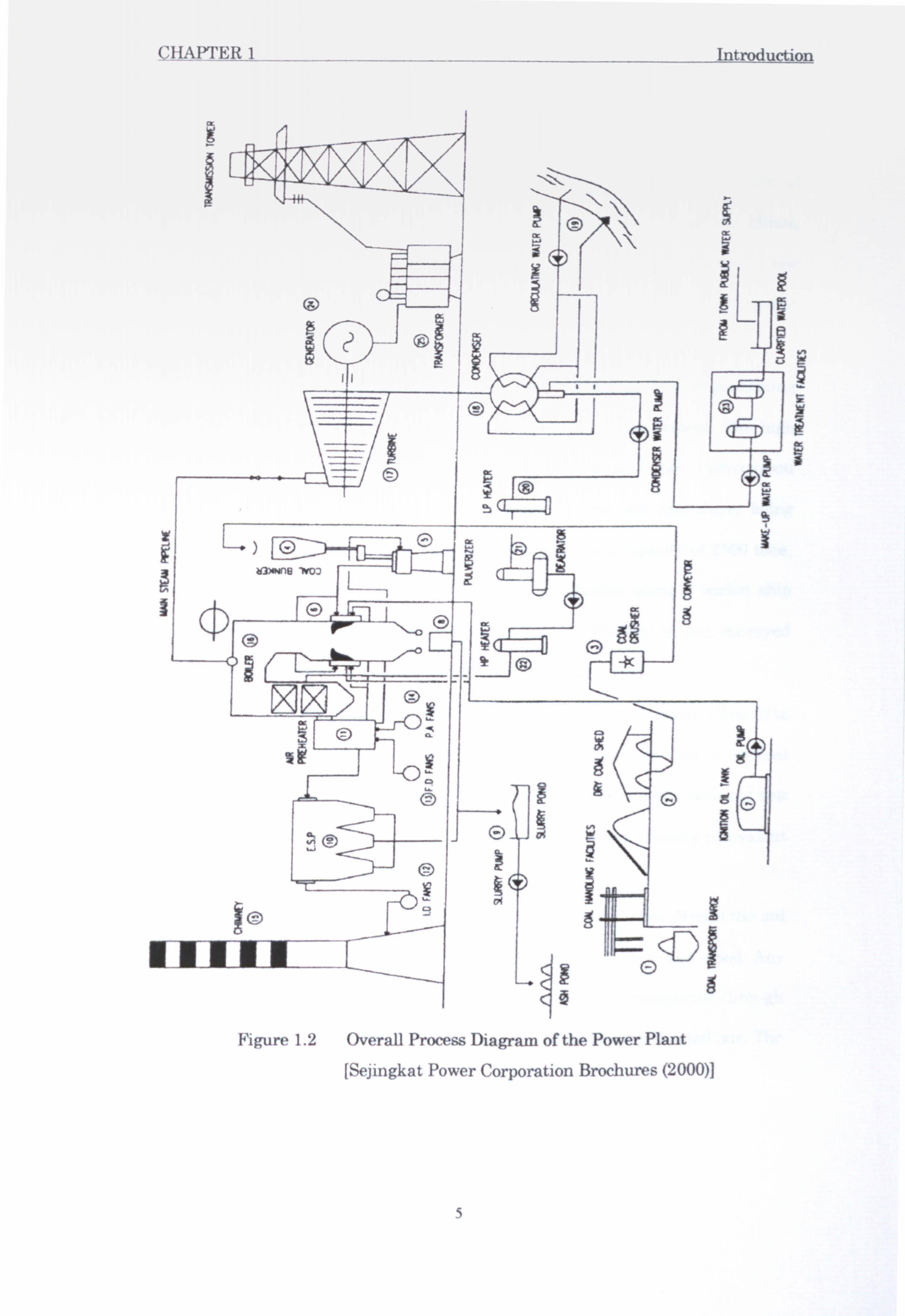
The explanation of the general process in the following text is based on
Figure 1.2. The systems have been classified into six major categories:
1. Boiler
2. Steam Turbine
3. Electrical System
4. Coal Handling
5. Chemical Treatment
6. Utilities
4
CIIAP'I'ER 1 Introduction
I
ý ý ý
Figure 1.2 Overall Process Diagram of the Power Plant
[Sejingkat Power Corporation Brochures (2000)]
5
CHAPTER 1 Introduction
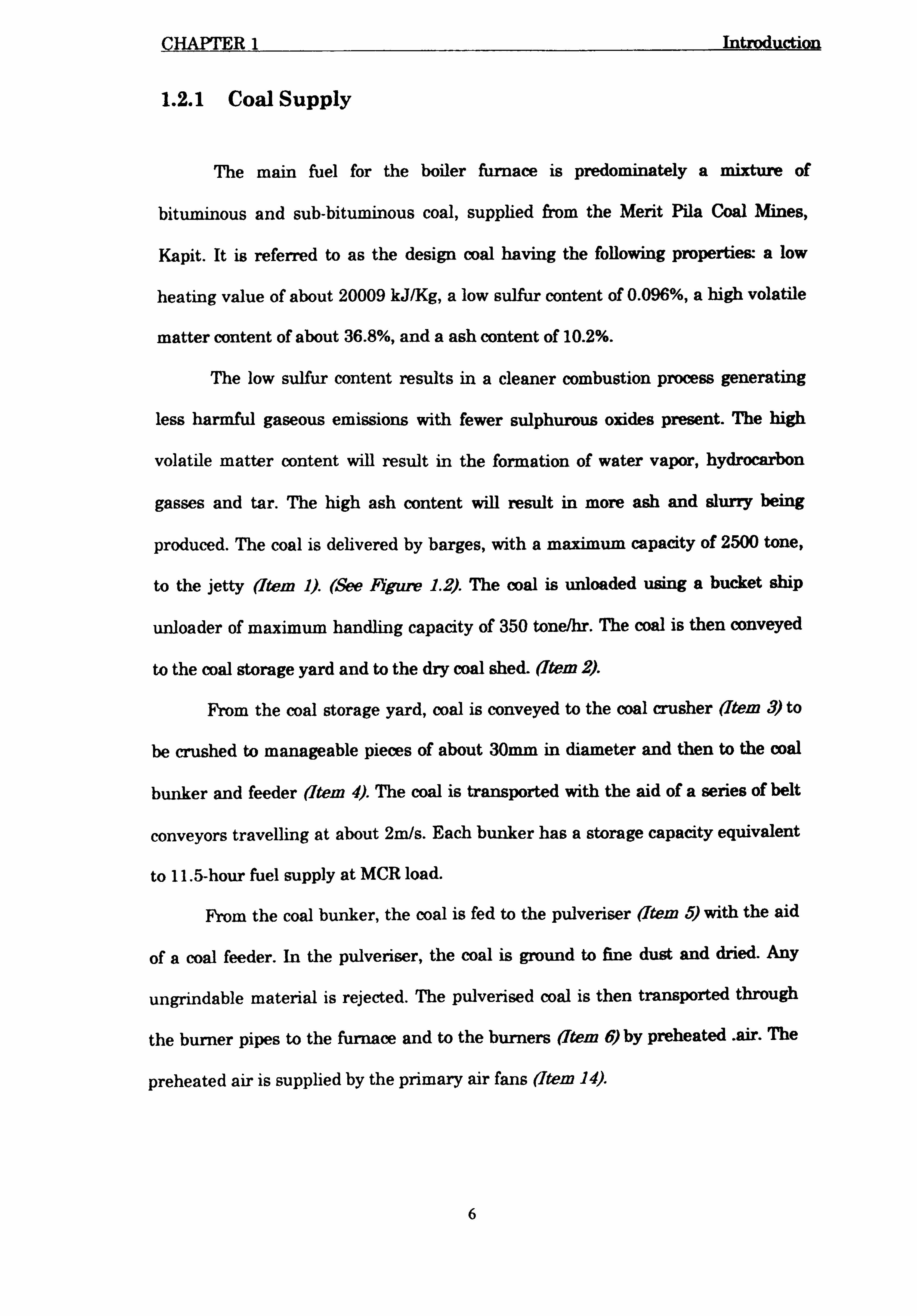
1.2.1 Coal Supply
The main fuel for the boiler furnace is predominately a mixture of
bituminous and sub-bituminous coal, supplied from the Merit Pila Coal Mines,
Kapit. It is referred to as the design coal having the following properties: a low
heating value of about 20009 kJ/Kg, a low sulfur content of 0.096%, a high volatile
matter content of about 36.8%, and a ash content of 10.2%.
The low sulfur content results in a cleaner combustion process generating
less harmful gaseous emissions with fewer sulphurous oxides present. The high
volatile matter content will result in the formation of water vapor, hydrocarbon
gasses and tar. The high ash content will result in more ash and slurry being
produced. The coal is delivered by barges, with a maximum capacity of 2500 tone,
to the jetty (Item 1). (See Figure 1.2). The coal is unloaded using a bucket ship
unloader of maximum handling capacity of 350 tone/hr. The coal is then conveyed
to the coal storage yard and to the dry coal shed. (Item 2).
From the coal storage yard, coal is conveyed to the coal crusher (Item 3) to
be crushed to manageable pieces of about 30mm in diameter and then to the coal
bunker and feeder (Item 4). The coal is transported with the aid of a series of belt
conveyors travelling at about 2m/s. Each bunker has a storage capacity equivalent
to 11.5-hour fuel supply at MCR load.
From the coal bunker, the coal is fed to the pulverizer (Item 5) with the aid
of a coal feeder. In the pulveriser, the coal is ground to fine dust and dried. Any
ungrindable material is rejected. The pulverised coal is then transported through
the burner pipes to the furnace and to the burners (Item 6) by preheated air. The
preheated air is supplied by the primary air fans (Item 14).
6

CHAPTER 1 Introduction
1.2.2 Combustion and Furnace
During start-up, diesel is used as fuel for the furnace since coal can only be
used at comparatively higher loads. Once the load reaches 10 MW, coal firing is
started and the oil guns are retracted. Diesel is also used as a standby fuel. The
fuel is stored in two 265m tanks (Item 7) (See Figure 1.2) and is pumped to the
furnace's oil guns. The fuel storage levels are monitored and alarms will activate if
the oil level reaches the 2m low level.
The combustion process takes place in the furnace at an average maximum
temperature of up to 980°C to 990°C. Combustion air is provided using forced draft
fans (Item 13). The air is then preheated in the air preheater (Item 11) to up to
326°C. using heat from the hot flue gas (at about 368°C at MCR). The heat released
from the combustion of coal is transferred to the boiler tubes through a
combination of conduction, radiation and convection processes in the boiler (Item
16). The boiler consists of a boiler drum, firewalls, superheaters and economiser. It
is capable of generating up to 220 tone/hr of superheated steam at 540°C. Boiler
water is supplied via the feedwater system.
Inside the furnace, soot can accumulate on the boiler tubes. Soot build up
can reduce the heat transfer efficiency from the fire to the water inside the boiler
tubes. It can also create an obstruction to the gas flow inside the furnace. As such,
sootblowing must be carried out to remove the soot built up on the heat-absorbing
surfaces.
Low-pressure main boiler steam is injected into sootblowing lances as the
cleaning medium. Auxiliary steam from the auxiliary boiler is used only when the
main boiler is not in operation.
7

CHAPTER 1 Introduction
1.2.3 Steam-Condensate-Feedwater Cycles
The superheated steam is conveyed via the main steam pipeline to the
turbine (Item 17) (See Figure 1.2) where it expands and produces useful work to
turn the turbine. The low-pressure steam exhausted from the turbine is collected in
the condenser waterbox (Item 18), Here the steam is condensed to water and
recirculated back to the boiler. The rapid cooling effect creates a vacuum effect in
the condenser section, which reduces the backpressure on the turbine and
increases its output and efficiency.
The condensed steam, or the condensate, is pumped through a series of
regeneration heaters. The first stage is a series of three low pressure heat
exchanger heaters (Item 20) that heats the condensate to about 135°C. Low
pressure steam tapped from the turbine low pressure extraction points provides the
heat for the purpose.
The heated condensate is piped to the deaerator (Item 21) where dissolved
oxygen and gasses are removed. The deaerated water (or feedwater) is stored in the
adjacent 70m3 storage tank. From the tank the water is pumped by the boiler feed
pump to two high pressure heaters arranged in series (Item 22) which raise the
water temperature further to about 235°C. High pressure steam tapped from the
turbine high pressure extraction points provides the heat for this purpose. The
heated feedwater is then supplied to the boiler economiser and finally back to the
boiler drum.
A good quality of the boiler feedwater must be maintained where it must
has a very low concentration of minerals. Thus, a water treatment plant (Item 23)
is used to treat the water before it is supplied to the boiler. The source of raw water
supply for the water treatment plant is from the existing water mains of Kuching
Water Board (KWB). The demineralisation system is used to remove dissolved
8

CHAPTER 1 Introduction
minerals such as silica from the town water supply before enter the boiler and the
hydrogen generation facility.
The system is capable of treating up to 26m3/hour of water through a series
of activated carbon filters, cation exchangers, anion exchangers and mixed ion
exchangers. Feedwater dosing is carried out to ensure that the water has the
required quality. A number of chemicals such as phosphate, hydrazine and
ammonia are used. Phosphate is injected into the boiler drum to prevent scaling.
Hydrazine and ammonia are injected in the deaerator to remove residual oxygen in
the feed water and to maintain the pH value of the water respectively. Both are
used to protect the feed water piping and equipment from corrosion.
Daily periodic water analyses to determine the amount of dissolved oxygen,
conductivity, pH, phosphate and sodium concentrations are carried out to ensure
that they are within the prescribed safe working limits. The boiler water after
demineralisation will still have a small concentration of minerals. With
recirculation, the concentration of minerals in the boiler will build up due to
evaporation losses. As such physical removal of part of the boiler water must be
carried out. This process is called blowdown.
Continuous blowdown and periodic blowdown are carried out to remove part
of the boiler water in circulation in the event of high mineral content in the
feedwater. This is replenished by makeup water from the water treatment plant.
Continuous blowdown removes a smaller quantity of the water continually whereas
periodic blowdown removes a larger quantity of the water periodically. Both are
carried out to maintain the boiler water quality. The makeup water also
replenishes losses due to evaporation.
9
Related Documents