KnoahSoft, Inc. 701 N. Green Valley Parkway, Suite 200 Henderson, NV 89074 USA http://www.knoahsoft.com Tel: 702 990-3022 Fax: 650 779-9899 Harmony Installation and Configuration Guide Version 3.1 Doc version 3.1.1c

Harmony Installation Guide 3.1
Nov 18, 2014
Uploaded from Google Docs
Welcome message from author
This document is posted to help you gain knowledge. Please leave a comment to let me know what you think about it! Share it to your friends and learn new things together.
Transcript

KnoahSoft, Inc.701 N. Green Valley Parkway, Suite 200
Henderson, NV 89074 USAhttp://www.knoahsoft.com
Tel: 702 990-3022Fax: 650 779-9899
Harmony Installation and Configuration GuideVersion 3.1
Doc version 3.1.1c

© 2010 KnoahSoft, Inc. All rights reserved. All trademarks, service marks, registered trademarks, or registeredservice marks in this document are the property of their respective owners. KnoahSoft assumes no responsibilityfor any inaccuracies in this document or for any obligation to update information in this document. KnoahSoftreserves the right to change, modify, transfer, or otherwise revise this document without notice. No part of thisdocument may be reproduced or distributed in any form or by any means without the prior permission ofKnoahSoft, Inc.

C O N T E N T S
C H A P T E R 1 Welcome to Harmony 1-1
About This Guide 1-1
Technical Support 1-2
System Overview 1-2
Deployment Scenarios 1-3
Single Site Deployment 1-3
Multi-Site Deployment 1-3
Call Flow Overview 1-4
Failover and Redundancy 1-5
Recording Server, Multi-Server Support 1-5
Recording Server, Multi-Interface Support 1-5
Database Server 1-6
Storage Server 1-6
Multiple SPAN Ports 1-6
KnoahSniffer 1-6
C H A P T E R 2 System Requirements 2-1
Hardware Requirements 2-1
Storage Calculator 2-2
Network Configuration 2-4
Network Ports 2-5
Best Practices 2-5
Software Requirements 2-6
Pre-Installation Checklists 2-8
iKnoahSoft Harmony User Guide

Contents
C H A P T E R 3 Component Installation 3-1
Core Components 3-1
Debugging Components 3-2
Installing the KnoahSoft Components 3-3
C H A P T E R 4 Component Configuration 4-1
Common Configuration Settings 4-3
Database Settings 4-4
Mail Settings 4-5
Storage Settings 4-6
Security Settings 4-7
AlertMgr Settings 4-8
Component Configuration Settings 4-9
Web 4-9
Recorder 4-11
KnoahSniffer 4-15
Converter 4-16
G729 Generator 4-17
UCM Recorder 4-18
Upload Server 4-21
Process Check List 4-22
ED Service 4-23
Starting Components 4-26
Cisco Adapter Configuration 4-27
Screen Configuration 4-29
Non-ADS Deployment 4-29
Deployment from ADS 4-31
Recording Middleware Service Configuration 4-33
iiKnoahSoft Harmony User Guide
Contents
Upload Client Configuration 4-35
Call Download Utility 4-36
C H A P T E R 5 Post-Installation Tasks 5-1
IIS Web Server Configuration 5-2
Starting and Stopping Services 5-3
Setting Passwords for services.msc Components 5-3
System Start 5-4
Changing Installation Configuration via Installer 5-4
Report Templates 5-5
XML File Extension 5-6
Post-Installation Checklist 5-6
Troubleshooting 5-7
userlogin.exe and Log File 5-7
Recording Server and Screen.exe 5-8
Screen Capture Issues 5-9
C H A P T E R 6 TAPI Integration 6-1
System Overview 6-1
Creating CTI user in Call Manager 6-2
TSP Installations and Configurations 6-5
TSP Installation 6-5
TSP Configuration 6-6
TSP Configuration Settings 6-6
Managing the Cisco TSP 6-14
Reinstalling the Cisco TSP 6-14
Upgrading the Cisco TSP 6-15
Uninstalling the Cisco TSP 6-15
TAPI Installation 6-16
iiiKnoahSoft Harmony User Guide

Contents
C H A P T E R 7 Debugging Configuration 7-1
Log Manager Configuration 7-2
Log Manager Web Interface 7-3
Alert Manager Configuration 7-6
Alert Manager Architecture 7-6
Alert Manager Configuration 7-8
Web Alerts 7-9
SNMP Traps 7-11
Event Viewer Log 7-12
Email Alerts 7-14
GetDumpFilesForCall 7-14
GetDumpFilesForCall Configuration Settings 7-14
C H A P T E R 8 Archiving 8-1
Scheduled Archiver 8-2
Configuration 8-2
Database Information 8-2
Mail Notification Information 8-2
Source Storage Settings 8-3
Destination Storage Settings 8-3
Transaction Settings 8-3
Lean Period Configuration Settings 8-5
Other Settings 8-6
Starting and Stopping Scheduled Archiver 8-6
C H A P T E R 9 Other Features 9-1
On-demand Recording 9-2
ANI-based Recording 9-3
Recording Rules 9-3
ivKnoahSoft Harmony User Guide

Contents
Shift-based Recording 9-4
Recording Rules 9-5
Dual Monitor Modes 9-5
Hardware Recommendations 9-6
Dual Monitor Setup 9-7
vKnoahSoft Harmony User Guide

Contents
viKnoahSoft Harmony User Guide

Knoa
C H A P T E R 1
Welcome to HarmonyKnoahSoft Harmony is a web-based suite of tightly integrated tools, designed to improve and enhance all aspects of your business operations and employee performance.
Harmony is easy to implement, maintain, and manage in a wide variety of diverse contact center deployment models—from centralized contact centers, to distributed branches, to work-at-home agents.
The following product suites are offered by KnoahSoft:
• Harmony Standard Edition—Features include recording, monitoring, messaging, and reports;
• Harmony Contact Center Edition—Includes all Harmony Standard features, plus the Evaluate and Analyze modules;
• Harmony Enterprise Edition—Includes all Harmony Contact Center features, plus the Coach and Learn modules and the Survey module.
About This GuideThis guide walks you through the installation of all the necessary components of the Harmony product. This document is intended to be read and used by those who possess basic to intermediate system administration capabilities.
Tip It is strongly recommended that you review this guide in its entirety before you run the Harmony installer, to note the information you will be prompted for during the installation process.
1-1hSoft Harmony Installation Guide
Chapter 1 Welcome to HarmonySystem Overview
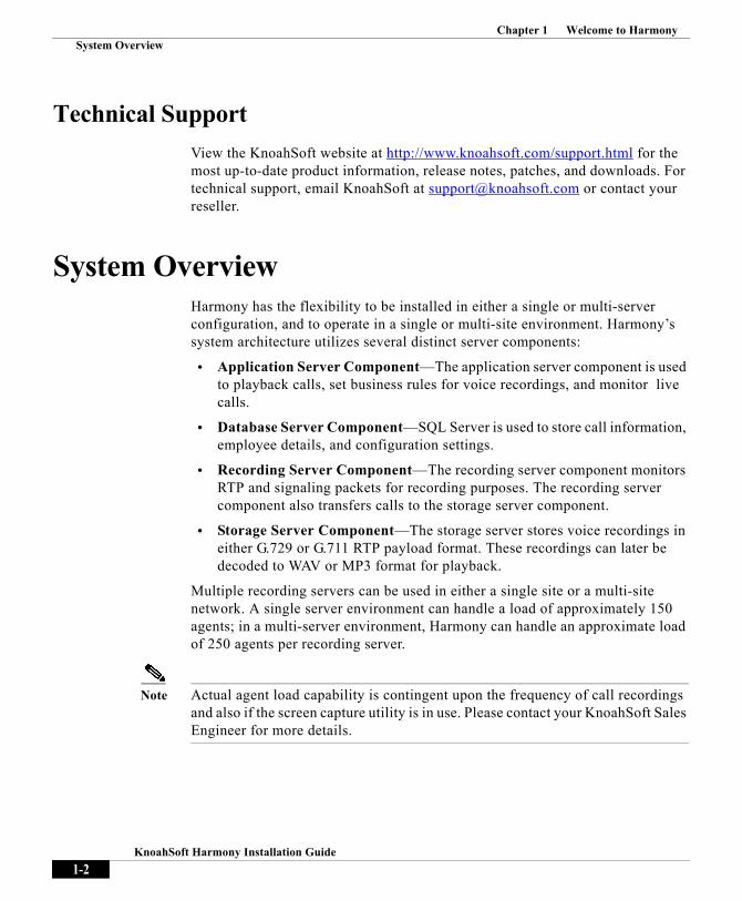
Technical SupportView the KnoahSoft website at http://www.knoahsoft.com/support.html for the most up-to-date product information, release notes, patches, and downloads. For technical support, email KnoahSoft at [email protected] or contact your reseller.
System OverviewHarmony has the flexibility to be installed in either a single or multi-server configuration, and to operate in a single or multi-site environment. Harmony’s system architecture utilizes several distinct server components:
• Application Server Component—The application server component is used to playback calls, set business rules for voice recordings, and monitor live calls.
• Database Server Component—SQL Server is used to store call information, employee details, and configuration settings.
• Recording Server Component—The recording server component monitors RTP and signaling packets for recording purposes. The recording server component also transfers calls to the storage server component.
• Storage Server Component—The storage server stores voice recordings in either G.729 or G.711 RTP payload format. These recordings can later be decoded to WAV or MP3 format for playback.
Multiple recording servers can be used in either a single site or a multi-site network. A single server environment can handle a load of approximately 150 agents; in a multi-server environment, Harmony can handle an approximate load of 250 agents per recording server.
Note Actual agent load capability is contingent upon the frequency of call recordings and also if the screen capture utility is in use. Please contact your KnoahSoft Sales Engineer for more details.
1-2KnoahSoft Harmony Installation Guide

Chapter 1 Welcome to HarmonySystem Overview
Deployment Scenarios Harmony seamlessly scales from single site environments to distributed, multi-site enterprises. A multiple accounts across multiple sites configuration model is supported, and recordings can be stored at each individual site or at a central repository, if required.
Single Site Deployment
A single site deployment model is one where all Harmony users are located within the same physical location. This model can be either a single or multi-server configuration, depending on how many users must be accommodated.
A typical single site, single server deployment, with up to 50 users and implementing all the necessary components—storage, database, application, and recording servers—can usually be accomplished using one Harmony server. This is a cost-effective deployment for organizations with limited hardware budgets.
A single site, multi-server deployment can accommodate as many users as required by distributing the Harmony server components across multiple physical servers. Typically, separate physical servers would exist for the application, database, and recording server components.
In this deployment model, the Harmony server is linked to the network's data switch via the server’s Voice NIC. The switch is configured to copy all voice traffic to the Harmony server through the use of port spanning (SPAN/RSPAN).
Multi-Site DeploymentHarmony components can be separated and deployed across multiple physical servers to better accommodate multi-site environments with large numbers of agents, thus reducing total cost of ownership. With one instance of the database and application components installed on one server, multiple instances of the recording and storage services can be deployed at individual sites, to better handle larger numbers of agents.
Note The number of agents that Harmony can handle in a multi-site environment will depend on your underlying network infrastructure—routers used, available bandwidth, etc.
1-3KnoahSoft Harmony Installation Guide

Chapter 1 Welcome to HarmonySystem Overview
Harmony also supports branch recording, a light-weight deployment model well-suited to record calls in all remote branch locations where it is not practical to deploy a recording server to capture and process calls.
Tip If the same voice gateway is serving multiple sites, recording servers can be installed at a single location and handle calls flowing through multiple sites. If each site has its own independent voice gateway, recording servers are best installed and configured at each site.
Call Flow OverviewHarmony uses two network interface cards (NICs)—a Data NIC and a Voice NIC. The Data NIC is used for general network data access, and the Voice NIC is used as a packet sniffing interface to capture voice traffic via VLAN SPAN/RSPAN switching.
All voice packets of all logged in Harmony users in the network are captured and their calls are processed through the Cisco Call Manager.
RTP packets are copied and sent through the SPAN to the Voice NIC on the Harmony server. The packets are evaluated by the Harmony recording server component to determine if the call transaction should be saved as a recording and also which agent is associated with the transaction.
Agents are identified by the extensions present in the signaling packets from the SPAN data stream. Harmony's screen captures are identified by the agent's network ID and associated with their respective extension.
Once the call is recorded, call details are stored in the database and the audio files are stored on the storage server. The application server component communicates with the database and storage server components to coordinate the retrieval and playback of recordings.
All HTTP web requests are received and processed by the Windows Internet Information Services (IIS) snap-in running on the Harmony application server.
1-4KnoahSoft Harmony Installation Guide

Chapter 1 Welcome to HarmonySystem Overview
Failover and Redundancy
Recording Server, Multi-Server Support
The following recommendations will help ensure that the recording server is always running and maintaining a high degree of recording integrity.
Note In a single server deployment, the recommendations apply to that single server; in a multi-server model, they apply to the physical recording servers.
Recommendation #1– A secondary or backup recording server is recommended for failover. Two separate SPAN sessions are provided to both the primary and secondary recording servers. If the primary server fails, the secondary server continues to record calls from its SPAN session.
Recommendation #2—Configure the KnoahSniffer application on every recording server (including the Harmony server, if you are using a single server deployment). KnoahSniffer collects voice traffic from the recording server’s Voice NIC, writing to files in rotation. If the recording server fails, recordings can be retrieved from the KnoahSniffer file dumps.(Refer to the “KnoahSniffer” topic, below.)
Recording Server, Multi-Interface SupportIf a multiple redundant server model is not desired, installing multiple NIC cards in a single server can help provide redundancy at the NIC level.
Normally, if a NIC fails, all traffic will stop. By grouping together several physical NICs into one logical NIC (a.k.a., teaming), availability is maximized. With teaming, if one NIC fails, the network connection does not cease and continues to operate on the other NICs.
A multi-interface NIC configuration (i.e., a configuration using multiple NICs in a team) can also be used to connect multiple SPANs to the recording server, and each SPAN’s traffic can be forwarded to a separate interface. A multi-interface NIC configuration also supports failover at the switch level. If two switches are configured in failover mode, you can configure two SPANs on the switches and direct that traffic to the two interfaces. Now, if the primary switch fails and the backup switch becomes primary, Harmony will still continue to record calls.
1-5KnoahSoft Harmony Installation Guide

Chapter 1 Welcome to HarmonySystem Overview
Note Harmony supports a maximum of five NICs in a multi-interface NIC configuration.
Database ServerIn addition to a redundant hardware configuration, SQL Server offers multiple ways of providing failover support, including database mirroring, failover clustering, and backup log shipping. It is strongly recommended that at least one of these methods be adopted.
Storage ServerIn the instance of storage server failure, the Harmony Recorder component has the capability to write files locally so there is no loss of data. This is one good reason for separating the recorder server component from the primary application server in a single-server deployment. The recorder server component will not write files locally in a single-server deployment if the single server fails.
Multiple SPAN Ports
It is critical to ensure that the point of failure which can occur at the data switch level is mitigated in the best manner possible. Since Harmony relies on a properly functioning SPAN, it is highly recommended that multiple SPAN ports be configured to avoid loss of recording due to port failure.
KnoahSnifferThe KnoahSniffer application sniffs network packets from the recording server NIC and dumps them to files. It can be used to analyze problems related to improper processing of received packets. It can also be used to recover calls when a recording server fails by running the server offline in tethereal mode.
KnoahSniffer is useful in branch recording scenarios where it can be used to collect packet dumps from remote locations. It can also be used in delayed recording scenarios, where generated packet dumps are simultaneously read by
1-6KnoahSoft Harmony Installation Guide

Chapter 1 Welcome to HarmonySystem Overview
the recorder, on the same machine, and calls are extracted from the packet dumps. Delayed recording is useful if you need to process more than 500 agents with one machine, and KnoahSniffer helps to ensure there is no packet loss.
During normal contact center operations, KnoahSniffer runs faster than the recording server and accumulates packet dumps. During lean periods, the recording server continues to process pending dumps so that all calls are available in the database and storage server by the next working day.
Tip It is recommended that KnoahSniffer be installed on each recording server in your system. It requires 30GB of hard disk space.
1-7KnoahSoft Harmony Installation Guide

Chapter 1 Welcome to HarmonySystem Overview
1-8KnoahSoft Harmony Installation Guide

Knoa
C H A P T E R 2
System RequirementsThis sections lists the system hardware, software, and network requirements for Harmony. Be sure to install and configure all of these items as described before you launch the Harmony installation CD.
Hardware RequirementsHard disk space is based on storage requirements before archiving and will vary based on your specific client requirements. Refer to the “Storage Calculator” topic, below, for information on how to calculate your storage needs based on anticipated call length, screenshot configuration, etc.
Table 2-1 Single Server Environment
Database, Storage, Application, Recording Server
Hard Disk Drive (HDD) 500GB (RAID 5 recommended)
Processor Intel or AMD 64-bit quad-core, with dual processors
RAM 4GB (SDRAM/RDRAM preferred)
2-1hSoft Harmony Installation Guide

Chapter 2 System Requirements
Table 2-2 Multi-Server Environment
Note Each recording server must have two network interface cards (NICs) installed. Refer to the “Network Configuration” topic, below.
Storage CalculatorThe Storage Calculator utility is designed to help determine your storage requirements for your Harmony deployment.
To calculate your storage requirements:
Step 1 Navigate to the StorageCalculator.exe file on the Harmony installation CD then double-click the file.
Step 2 The Storage Calculator application launches.
Database, Storage, and Application Server
RAM 4GB (SDRAM/RDRAM preferred)
Hard Disk Drive (HDD) 500GB (RAID 5 recommended)
Recording Servers
RAM 4GB per server (SDRAM/RDRAM preferred)
Hard Disk Drive (HDD) 80GB (SCSI) per server (RAID 5 recommended)
2-2KnoahSoft Harmony Installation Guide

Chapter 2 System Requirements
Figure 2-1 Storage Calculator, Sample Data
Step 3 Enter the following:
• Number of Seats—Number of users that will be recorded at any given time.
• Average Call Duration (mins)—Average call duration of recorded calls. This duration includes calls that are transferred to other agents.
• Average Calls Per Seat—Average number of calls per seat, per day.
• Storage Days—Number of days to save calls on the storage device.
• Audio Codec—Audio compression format for incoming calls prior to conversion, either G.711 or G.729. During installation, select to compress G.711 calls using G.729 format. Calls will not be compressed if not selected.
• Storage Format—Audio format for call storage, either G.711 or G.729. (These are the only two options currently in use.)
2-3KnoahSoft Harmony Installation Guide

Chapter 2 System Requirements
• % of Calls with Screen Capture—Users utilizing some form of the screen capture utility, as a percentage. For example, if 50% of agents use screen capture for 50% of their calls, this number would be 25%.
• Screen Capture Interval (sec)—Interval, in seconds, between screen captures (range: 5 to 50 seconds, in increments of 5). This setting is configured on a per agent or group basis in the Administration module. Refer to the KnoahSoft System Administration Guide for more information.
• Screen Capture Image Quality—Select a quality level for screen captures —N/A, Very Low, Low, Medium, Very Medium, High, Very High. Note that the image in the Preview pane changes with your selection so you can preview the quality of the setting. Also note that this selection significantly effects the size of the stored image and, subsequently, the overall storage requirement.
Step 4 Click Click this Button to Calculate Storage. Your storage requirement appears in the Your Storage Requirement text area. Modify the parameters in step 3 and recalculate, if necessary.
Step 5 Click Exit to close the utility.
Network ConfigurationAll deployment models should use minimum 100BASE-T, Fast Ethernet LAN connections; 1000BASE-T is preferred. Multi-site deployments should utilize as much bandwidth between site locations as possible; a minimum T1 connection is strongly recommended.
Each recording server must have two 100/1000Mbps network interface cards (NICs) installed, each with a distinct static IP address. One card is used for standard network access, while the other is used as a packet sniffing interface
When you run the Harmony installer, the packet sniffing NIC is referred to as the Voice NIC. You must direct the SPAN traffic in your SPAN configuration to this NIC’s IP address.
Ensure that your SIP/SCCP and RTP traffic is configured to route to the Voice NIC of the recording server in the SPAN configuration.
2-4KnoahSoft Harmony Installation Guide

Chapter 2 System Requirements
Network PortsIf your Harmony deployment is limited to your local intranet, there is no need to open any ports on the firewall. However, if you want to provide external access to Harmony, or you have firewalls on both ends of a private WAN, you must open up the following ports on your firewall:
Note In a multi-site deployment, be sure to implement secure links between all sites in your configuration.
Best PracticesTo ensure that Harmony runs efficiently in your environment, and to allow KnoahSoft personnel to best support the product, ensure the following:
Implement a server name resolution plan for all Harmony servers
Do not use underscores in a server name string
Do not configure any Harmony server as a domain controller
Set up a swap file across multiple physical disks, if possible, allocating 1.5 times the size of the physical RAM for the server
Install Symantec’s pcAnywhere Access Server, or a similar remote administration tool, to allow KnoahSoft support personnel access to install and configure Harmony
Create an account for KnoahSoft support with local administrative privileges on each Harmony server, so that the KnoahSoft Technical Support team can help troubleshoot installation or other issues, if required.
Set up a mail server or SMTP service for email alert notifications
Port Protocol Description
8080 TCP Harmony application server
8081 TCP IIS web server
4444 UDP Silent Monitoring
25500 TCP Screen Capture Upload Server (optional)
2-5KnoahSoft Harmony Installation Guide

Chapter 2 System Requirements
Set proper time and time zone, and synchronize all Harmony servers appropriately
Schedule anti-virus software to run during lean periods—i.e., not during peak contact center business hours
Software RequirementsThe following software must be installed prior to Harmony installation.
Operating System
Windows 2003 Server SP2 or higher (64-bit OS)
– Be sure to create an administrative user to use for KnoahSoft installation and maintenance purposes (e.g., KnoahSoftAdmin)
IIS 6.0 or higher (with ASP.NET server extensions enabled).
– To install IIS:
1. Navigate to Start > Control Panel > Add or Remove Programs. (Your Windows 2003 Server CD may be required.)
2. From Add/Remove Programs, select Add/Remove Windows Components. The Windows Components window appears.
3. Select Application Server then click Details. A new window appears.
4. Select both the ASP.NET and IIS options, then click OK. (Note that a system reboot may be required.)
Note Refer to the “IIS Web Server Configuration” topic in Chapter 5, Post-Installation Tasks, for more information.
Database
SQL Server 2005 SP3
– Be sure to install SQL Server with Mixed Mode Authentication selected
– Harmony requires its own separate SQL Server instance, so do not use an existing SQL Server configuration
2-6KnoahSoft Harmony Installation Guide

Chapter 2 System Requirements
– Ensure that the SQL Server Agent service is enabled
– Please note during install Harmony will attempt to create a user called "metric" with a password of "metric". If Password Policy is enabled on the machine where SQL Server is installed, Harmony will still create the "metric" user, however it will not create the "metric" password. In this instance, a password will need to be manually added.
Reporting Services
In order to accommodate the exporting of reports to other formats, you must have Microsoft Excel and Adobe Reader installed on those user’s computers where these reports will be viewed in these formats.
Microsoft Excel 2003
Adobe Reader 8.0 or higher
– Ensure automatic updates for Adobe Reader is disabled as follows:
1. From Adobe Reader, select Edit > Preferences. The Preferences window appears.
2. Select Updates from the Categories list.
3. Select Do not automatically check for critical updates.
Third-party Applications
Installers for the third-party applications listed below can be found on the Harmony installation CD.
In a single server environment, all software must be installed on that one physical machine. In a multi-server environment, all software must also be installed on the application server and Wireshark must be installed on the recording servers.
J2SE 1.5.0 Update 16
– Use all installation defaults, when prompted, during installation.
Wireshark 1.0.5
– Use all installation defaults, when prompted, during installation. Be sure to select the WinPCap program installation, when prompted.
TextPad
– (optional) This tool is useful for Technical Support purposes.
2-7KnoahSoft Harmony Installation Guide

Chapter 2 System Requirements
Pre-Installation ChecklistsThe following tables list the third-party software, hardware, and configurations that must be considered before you run the installer.
Note For a single site installation, the application, recorder and database server will be same physical machine.
Table 2-3 Third-party Software Pre-Installation Considerations
Name Version Installed Location Status
JBOSS jboss-4.2.3GA Application server, any drive (e.g., C:\Jboss-4.2.3GA)
MS SQL Server SQL 2005 Standard Edition SP3 Mixed Mode
Database server
JDK 1.5.0_16 Application server, any drive (e.g., C:\Program Files(86)\Java)
IIS 6.0 and above Application server
WireShark 1.0.5 Recorder server (e.g., C:\Program Files\WireShark)
WinPCap (available with WireShark)
4.0 Recorder server (e.g., C:\Program Files\WinPCap)
TextPad (optional) 5.2 All servers (C:\Program Files\ Textpad 4.0)
2-8KnoahSoft Harmony Installation Guide

Chapter 2 System Requirements
Table 2-4 Hardware and Configuration Pre-Installation Considerations
Item Status
Servers with required OS, as per System Requirements, are available
Zero (0) script has been run to creates KS database user
Data NIC and Voice NIC on recording servers are enabled
Local Administrator account or Domain User Account with local administrator privileges is available
Valid Mail Server details are ready
Sound Card is available on any machine, to listen to live and recorded calls
Create Voice directory in the non-OS drive; share the Voice directory; give permissions to KnoahSoft account to create the directories
After logging as KnoahSoft account, ensure loop back address [\\127.0.0.1\c$\Voice] is working
Harmony Setup and License Keys are available on all the servers
It is recommended to stop the anti-virus software at the time of KnoahSoft installation
SQL 2008/SQL 2005 is installed, with mixed mode AUTH with SP2/SP3
Install IIS and ensure a sample image 'pageerror.gif' can be browsed
Edit run.bat (:\jboss-4.2.3GA \bin) file to assign perm size parameter '-Xms128m -Xmx1024m -XX:MaxPermSize=256m'
Spanning [VLAN / Gateway/ Port level] should be configured where the Recording Servers are resided
RTP/RTCP/UDP traffic must flow into the recorder server, and can be confirmed with the help of WireShark
Windows Automatic updates on all the servers must be disabled, but can be applied after scheduling in the lean period [KnoahSoft to be updated on the patch that would be applied]
Symantec Anti Virus is suggested to be installed or run after the Harmony installation is complete, and scanning should be done in the lean period (excluding the KnoahSoft components)
2-9KnoahSoft Harmony Installation Guide

Chapter 2 System Requirements
2-10KnoahSoft Harmony Installation Guide

Knoa
C H A P T E R 3
Component InstallationDuring the installation process, you will be prompted to install the following components to the C:\ drive of your server, as listed below.
Note You must create a shared directory on your storage server named Voice before you run the installer. You will be prompted for this directory during the installation process.
Core Components
• Recorder • KnoahSniffer • Converter • G729 Generator • Cisco Adapter• UCM Recorder• Upload Server • Process Check List• Web• Scheduled Archiver• Screen• EDService• TAPI Adapter
3-1hSoft Harmony Installation Guide

Chapter 3 Component Installation
• Recording Middleware Service• Upload Client• Call Download Utility
Debugging Components
• Log Manager• Alert Manager• Get Dump Files For Calls
3-2KnoahSoft Harmony Installation Guide
Chapter 3 Component Installation
Installing the KnoahSoft Components
To install the KnoahSoft components:
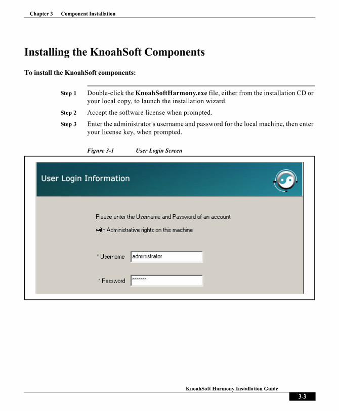
Step 1 Double-click the KnoahSoftHarmony.exe file, either from the installation CD or your local copy, to launch the installation wizard.
Step 2 Accept the software license when prompted.
Step 3 Enter the administrator's username and password for the local machine, then enter your license key, when prompted.
Figure 3-1 User Login Screen
3-3KnoahSoft Harmony Installation Guide
Chapter 3 Component Installation
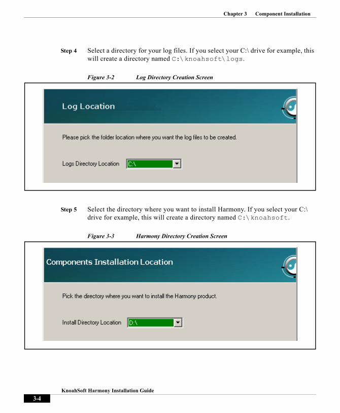
Step 4 Select a directory for your log files. If you select your C:\ drive for example, this will create a directory named C:\knoahsoft\logs.
Figure 3-2 Log Directory Creation Screen
Step 5 Select the directory where you want to install Harmony. If you select your C:\ drive for example, this will create a directory named C:\knoahsoft.
Figure 3-3 Harmony Directory Creation Screen
3-4KnoahSoft Harmony Installation Guide

Chapter 3 Component Installation
Step 6 Enter Password@123 in the Password text field for database username knoahsoftsa.
Step 7 Enter the passwords you want to assign to metric and metricsec users. These users are created in your database by the installer.
Note Username metricsec is used for Harmony’s ED Service security feature only.
Step 8 Click Test DB to ensure that the username and password are working properly.
Figure 3-4 Database Configuration Screen
3-5KnoahSoft Harmony Installation Guide

Chapter 3 Component Installation
Step 9 Select the components you want to install (Recorder, Converter, etc.) then click Next.
Step 10 Install the components, when prompted. A confirmation screen appears upon successful installation of all components.
Step 11 Proceed to Chapter 4, Component Configuration.
Figure 3-5 Component Installation Screen
3-6KnoahSoft Harmony Installation Guide

Knoa
C H A P T E R 4
Component ConfigurationOnce the Harmony components have been installed, as described in Chapter 3, launch Harmony’s Component Configuration to configure the installed components with the appropriate data. Configuration of MSI files is also described.
Note Refer to Chapter 6, TAPI Integration, for information on the Cisco Computer Telephony Integration (CTI) application and how to enable basic call recording with TAPI integration.
4-1hSoft Harmony Installation Guide

Chapter 4 Component Configuration
To launch Harmony’s Component Configuration:
Step 1 From your local machine, click Start > All Programs > Knoahsoft > Knoahsoft Config. The Component Configuration screen is launched.
Step 2 Enter your administrator username and password.
Figure 4-1 User Login Screen
4-2KnoahSoft Harmony Installation Guide

Chapter 4 Component Configuration
Common Configuration SettingsClick on the components you wish to configure from the Main Configuration screen. Once complete, be sure to click Next from the Main Configuration screen and then click Finish to complete the configuration process.
Figure 4-2 Main Configuration Selection Screen
Note During configuration, you will be prompted for various IP addresses. In a single-server deployment, the same IP address is to be used throughout; in a multi-server deployment, be sure to use the appropriate server IP address for the component you are configuring.
4-3KnoahSoft Harmony Installation Guide

Chapter 4 Component Configuration
Database Settings
• Database IP Address—IP address of machine where SQL Server is installed.
• Backup Database IP Address—IP address of machine where backup instance of SQL Server is installed.
• Database Name—Name of database. Enter Metrics_Commercial.
• Database Username—Database user ID. Enter metric.
• Database Password—Password for database username metric, as previously created during component installation.
• Database Port—Enter 1433, Harmony’s default port number assignment.
Figure 4-3 Database Settings Screen
4-4KnoahSoft Harmony Installation Guide

Chapter 4 Component Configuration
Mail Settings
Figure 4-4 Mail Settings Screen
• Send Email Alerts—Select to enable the sending of email alerts.
• Mail Server IP Address—IP address of the local SMTP mail server.
• Sender Email Address—Email address associated with Harmony system alerts. Harmony generates email alerts automatically when component services encounter errors or communication is otherwise interrupted (e.g., network connection lost, storage disk full, etc.).
Note This address need not be a functioning email address but can be a non-reply alias used to identify either Harmony (e.g., [email protected]) or specific servers in a multi-server environment (i.e., [email protected]).
• Mail Server Port—Enter 25, Harmony’s default port number assignment.
• Send alerts to these Email addresses—Email addresses where alerts will be sent, one per field (minimum one, maximum four).
4-5KnoahSoft Harmony Installation Guide

Chapter 4 Component Configuration
Storage Settings
Figure 4-5 Storage Server Settings Screen
• Network Folder Path—Mapped drive path to storage server directory where recording server stores calls (e.g., \\server_IP\Voice, C:/Voice directory for local storage). You must have created this shared directory on your storage server, as previously described, named Voice.
• Username—Network user ID used to connect to the storage server. In a single server deployment, this is the administrative username you created for Harmony (e.g., KnoahSoftAdmin). You can also log in as a domain user (i.e., domain\username)
• Password—Network password for specified user ID.
4-6KnoahSoft Harmony Installation Guide

Chapter 4 Component Configuration
Security Settings
Figure 4-6 Security Settings Screen
• Security Enabled—Select to enable Harmony’s ED Security service feature.
• ED Service IP—IP address of server where ED Security service will be installed.
• ED Service Port—Enter 33047, Harmony’s default port number assignment for ED Security service.
4-7KnoahSoft Harmony Installation Guide

Chapter 4 Component Configuration
AlertMgr Settings
Alert Manager is a debugging component that receives HTTP alerts from all Harmony components. It sends those alerts to the Alert Manager server, where they are processed for viewing in various web, log, and email formats.
Figure 4-7 Alert Manager Configuration & Settings Screen
• HTTP Alerts Enabled—Select to install the Alert Manager debugging component.
• Alert Manager IP Address—IP address of server where Alert Manager will be installed.
• Alert Manager Port—Enter 33035, Harmony’s default port number assignment for Alert Manager.
Note Refer to the “Alert Manager Configuration” topic in Chapter 7, Debugging Configuration,” for information on how to configure Alert Manager’s web alerts, SNMP traps, event viewer, and email server.
4-8KnoahSoft Harmony Installation Guide

Chapter 4 Component Configuration
Component Configuration Settings
Web
Figure 4-8 Web (AppServer) Configuration Screen
App Server Settings
• J2SE path—Click Browse to navigate to the directory where J2SE is installed (C:\Program Files\Java\jdk1.5.0_16)
• JBoss path—Directory where the JBoss application server is installed (informational only).
• Host IP—IP address where web server will be installed.
Web Server Settings
• Working Directory—Directory to create for the Harmony web application, to host configuration settings and static content
• SSL Enabled—Select if Harmony’s ED Security service will be used.
4-9KnoahSoft Harmony Installation Guide
Chapter 4 Component Configuration
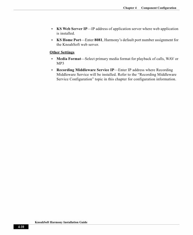
• KS Web Server IP—IP address of application server where web application is installed.
• KS Home Port—Enter 8081, Harmony’s default port number assignment for the KnoahSoft web server.
Other Settings
• Media Format—Select primary media format for playback of calls, WAV or MP3
• Recording Middleware Service IP—Enter IP address where Recording Middleware Service will be installed. Refer to the “Recording Middleware Service Configuration” topic in this chapter for configuration information.
4-10KnoahSoft Harmony Installation Guide

Chapter 4 Component Configuration
Recorder
Figure 4-9 Recorder Configuration Screen, Part One
Recorder Server IP Settings
• Data NIC IP Address—IP address of NIC card used by the recording server to connect to the network. This must be an actual IP address (i.e., a loop back address is not allowed).
• Voice NIC IP Address—IP address of NIC card used to sniff voice traffic from the SPAN/RSPAN port. This must be an actual IP address (i.e., a loop back address is not allowed).
• Storage IP Address—IP Address of Harmony storage server. In a single server deployment, this is the server’s Data NIC.
Folder settings
• Working Directory in—Logical drive under which the VoiceData and VoiceTransferFailed directories will be created by Harmony for the recording server component.
4-11KnoahSoft Harmony Installation Guide

Chapter 4 Component Configuration
Figure 4-10 Recorder Configuration Screen, Part Two
Advanced Storage Space Threshold Alerts
• Local (Space in MB)—(optional) Storage threshold limit for local server (i.e., recording server working directories), after which an email alert is sent
• Remote (Space in MB)—(optional) Storage threshold limit for storage server, after which an email alert is sent
Server IP settings
• Monitor Server Public IP Address— IP address or fully qualified hostname of server hosting Harmony recording server components. In a single server deployment, this is the server’s Data NIC. This must be an actual IP address (i.e., a loop back address is not allowed).
• Application Server IP Address— IP Address of Harmony server. In a single server deployment, this is the server’s Data NIC. This must be an actual IP address (i.e., a loop back address is not allowed).
4-12KnoahSoft Harmony Installation Guide

Chapter 4 Component Configuration
On demand recorder settings
• Pattern to start recording—(optional) Pattern of digits or characters used to initiate recording (maximum five), issued from a phone when on-demand recording is implemented. (Note that the entire call will be recorded.)
• Pattern to stop recording—(optional) Pattern of digit or characters used to end recording (maximum five), issued from a phone when on-demand recording is implemented. (Note that this sequence does not stop a recording and cancels the storage of the recording completely. No recording will be maintained if this sequence is issued.)
Note Refer to the “On-demand Recording” topic in Chapter 9, Other Features, for information on post-installation tasks to enable on-demand recording.
4-13KnoahSoft Harmony Installation Guide

Chapter 4 Component Configuration
Figure 4-11 Recorder Configuration Screen, Part Three
Recorder Settings
• Enable Screen Capture—Select to enable screenshots of agent desktops during call recordings.
• Extension Mobility—Select if you have free-agent seating. Do not select for an Avaya environment or if Cisco CTI OS integration is used.
• Compress G.711 calls—Select to compress calls using G.729 compression. Calls will not be compressed if not selected.
Video Generator Settings
• Currently not used.
Sip Proxy Server List
• SIP Servers List—Comma-separated list of IP addresses of SIP servers used to record calls, if SIP proxy servers and Cisco Call Managers are used. This enables Harmony to record calls made to and from SIP phones. Note that the SIPProcessingEnabled parameter in the recorder.ini file must also be set to TRUE to enable SIP phone recording.
4-14KnoahSoft Harmony Installation Guide

Chapter 4 Component Configuration
KnoahSniffer
Figure 4-12 Knoah Sniffer Configuration Screen
• Host Data IP—IP address of NIC card where the KnoahSniffer component is running and monitoring. In a single server deployment, this is the server’s Data NIC. This must be an actual IP address (i.e., a loop back address is not allowed).
• Voice IP—IP address of Voice NIC card where the recording server component is running, and that KnoahSniffer will monitor. In a single server deployment, this is the server’s Data NIC. This must be an actual IP address (i.e., a loop back address is not allowed).
• Working Directory—Logical drive where KnoahSniffer temporary files are to be stored.
• Tethereal File Location—Directory where captured packet dumps are to be stored.
• Packet Sniffer File Size (MB)—Maximum size of individual packet dump file before next file is created.
4-15KnoahSoft Harmony Installation Guide

Chapter 4 Component Configuration
• Recorder IP Address—Data NIC IP address of central branch recording server component. In a single server deployment, this is the server’s Data NIC. This must be an actual IP address (i.e., a loop back address is not allowed).
• UploadServer IP Address—IP address of central branch recording upload server.
Converter
The Harmony Converter converts calls on the storage server to WAV or MP3 format for playback.
Figure 4-13 Converter Folder Screen
• Provide KS_HOME Path—Logical drive where converted voice files will be stored. (e.g., D:\Knoahsoft). A directory named VoiceConvertedFiles is created in that location.
4-16KnoahSoft Harmony Installation Guide

Chapter 4 Component Configuration
G729 Generator
The G729 Generator converts G.711 audio calls to G.729. The generator is a CPU-intensive application and should be run on a machine with no other significant services running and configured to run during off-peak system processing periods.
Figure 4-14 G729 Generator Configuration Screen
Host Settings
• Host Ip Address—Data NIC IP address of machine running G729 generator. In a single server deployment, this is the server’s Data NIC. This must be an actual IP address (i.e., a loop back address is not allowed).
Lean Period
• Convert During Lean Period—Select to convert calls during specified start and stop times. If not selected, calls are converted when the recording server pushes the completed calls to the storage server.
• Start Time—Time at which to begin converting recorded calls into G.729 format, in HH:MM format (e.g., 17:30 for 5:30PM).
• Stop Time—Time at which to stop converting recorded calls into G.729 format, in HH:MM format (e.g., 23:30 for 11:30PM).
4-17KnoahSoft Harmony Installation Guide

Chapter 4 Component Configuration
UCM Recorder
These settings are used to configure the connection between Cisco Call Manager and Harmony, specifically for trunk-based recording.
Figure 4-15 UCM Trunkrecorder Configuration Screen, Part One
• Host Data IP—Data NIC IP address of machine where trunk recorder is running. In a single server deployment, the server’s Data NIC. This must be an actual IP address (i.e., a loop back address is not allowed).
• Server Port—Port number of UCM trunk recorder
• Max Number Trunks—Maximum number of trunks configured in all clusters. Must not be less than total number of trunks configured in all clusters.
4-18KnoahSoft Harmony Installation Guide
Chapter 4 Component Configuration
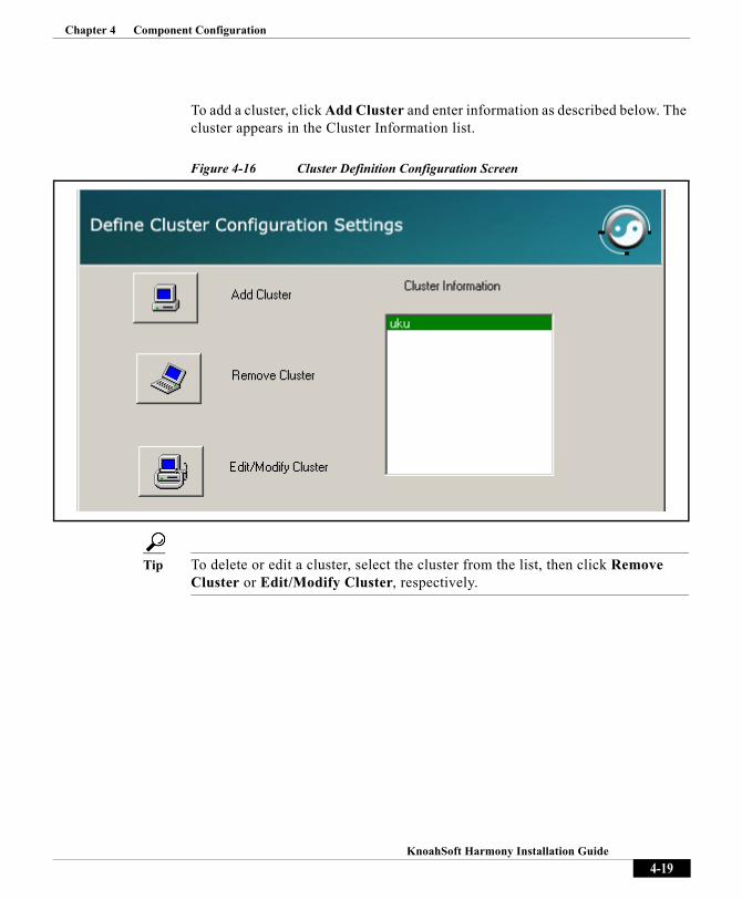
To add a cluster, click Add Cluster and enter information as described below. The cluster appears in the Cluster Information list.
Figure 4-16 Cluster Definition Configuration Screen
Tip To delete or edit a cluster, select the cluster from the list, then click Remove Cluster or Edit/Modify Cluster, respectively.
4-19KnoahSoft Harmony Installation Guide

Chapter 4 Component Configuration
Figure 4-17 UCM Trunkrecorder Configuration Screen, Part Two
• Cluster Name—Name of cluster (e.g., Cluster01)
• Max Num Of Trunks—Maximum number of trunks configured in the cluster
• SIP Transport—Select TCP
• First Trunk DN—DN of first SIP trunk
• Backup SIP Trunk DN—DN of second SIP trunk
• CM IP Address List—IP address list of all Call Managers in the cluster, separated by commas (maximum five)
4-20KnoahSoft Harmony Installation Guide

Chapter 4 Component Configuration
Upload Server
The upload server is installed on the storage server. The Screen utility (asinstalled on the agent desktop) captures screenshots during support calls, convertsthem to JPEG format, then the upload server uploads them to the storage server.
Figure 4-18 Upload Server Configuration Screen
• Delete Calls recordings older than (Days)—Number of days to save recordings. All recordings and their associated screens older than number of days specified will be deleted. This makes room for new calls to be stored.
4-21KnoahSoft Harmony Installation Guide

Chapter 4 Component Configuration
Process Check List
The Process Check List monitors the status of various Harmony and other components. The Process Check List service will send out an alert message to the administrator whenever a component has stopped running.
• Long Running Processes Name—Name of application or Harmony service to monitor (converter.exe, recorder.exe, UploadServer.exe, etc.)
– In a single server configuration, you must specify all installed services— Recorder.exe, Converter.exe, UploadServer.exe, Java.exe, G729Generator.exe.
– In a multi-server configuration, you must specify Java.exe, Converter.exe, and UploadServer.exe on the application server. For the recording servers, specify Recorder.exe, Converter.exe and UploadServer.exe, if these components are installed.
• Time Interval—Enter status checking interval (i.e., frequency of delay between alerts) to check process running state, in minutes
Figure 4-19 Process Checklist Configuration Screen
4-22KnoahSoft Harmony Installation Guide

Chapter 4 Component Configuration
ED Service
The ED Service creates two ZIP files: one contains the recorded call audio file and the .inf file, if present; the other contains all the screen files. These ZIP files are then stored at the central storage server, in encrypted form. The ED Service also receives request from the converter for the decryption and playback of calls.
Figure 4-20 Encryption Service Screen, Part One
KnoahSoftsa user credentials
• Username—Database username knoahsoftsa (informational field only).
• Password—Password for database user knoahsoftsa, as previously created.
Metricsec user credentials
• Username—Database username metricsec (informational field only).
• Password—Password for database user knoahsoftsa, as previously created.
4-23KnoahSoft Harmony Installation Guide

Chapter 4 Component Configuration
Figure 4-21 Encryption Service Screen, Part Two
• Password—Password to create RSA keys for encryption. (This password is different from the metricsec user password.)
• No Of Keys—Enter how many 256-bit encryption keys you want to generate, in numerical form (1 minimum, 10 maximum). These are saved to the database in encrypted form using an RSA 1024-bit key.
4-24KnoahSoft Harmony Installation Guide

Chapter 4 Component Configuration
Figure 4-22 Encryption Service Screen, Part Three
• Central Storage Path—Secure storage location where calls are stored after encryption.
• Central Storage Server Login ID—Network user ID used to connect to storage server, above. In a single server deployment, this is the administrative username you created for Harmony (e.g., KnoahSoftAdmin). You can also login as a domain user.
• Central Storage Server Password—Network password for specified user ID, above.
• Drive Select—Drive location where ED Service will create temporary files during encryption and decryption of calls and screens.
4-25KnoahSoft Harmony Installation Guide

Chapter 4 Component Configuration
Starting ComponentsOnce you’ve configured your components, you will arrive at the component start selection screen. Here, you select the components you want to start, then click Finish.
Figure 4-23 Component Start Selection Screen
4-26KnoahSoft Harmony Installation Guide

Chapter 4 Component ConfigurationCisco Adapter Configuration
Cisco Adapter ConfigurationThe Cisco Adapter collects events from one or more CTI/OS servers to compose and cache a dynamic global agent list. This allows the system to validate agent availability before attempting to stream a call from the agent. The adapter connects to CCM via JTAPI, allowing for initiation of agent monitoring requests.
If you selected to install the Cisco Adapter component, you must configure the component as follows:
Step 1 Ensure that the Cisco Adapter is started via Start > Run > services.msc.
Step 2 Open the CiscoAdapter.properties file, located in the KnoahSoft\CiscoAdapter\Conf directory, and add the following lines with the appropriate parameters:
Version: Harmony version number (default = 3.1) Application_Description: Harmony Cisco AdapterNumClusterConfigs: Number of configured clusters (e.g., 3)Cluster1_Name: Cluster name (default = UCCCE75_CLUSTER)Cluster1_NumCTIOSServerPairs: Number of configured CTIOS server pairsCluster1_PeripheralID: Peripheral ID of CTIOS server, based on version of Call Manager used, 5002 for 6.0 and 5003 for 7.0 (default = 5002)Cluster1_CTIOS_1A_HostName: Primary CTIOS server IP addressCluster1_CTIOS_1A_Port: Primary CTIOS server port (default value = 42028)Cluster1_CTIOS_1B_HostName: Secondary CTIOS server IP addressCluster1_CTIOS_1B_Port: Secondary CTIOS server port (default = 42028)
Step 3 Open the DBConfig.properties file, located in the KnoahSoft\CiscoAdapter\Conf directory and add the following lines:
jdbc.dataBaseServerIP:jdbc:jtds:sqlserver://database server IP addressjdbc.portNumber: Database port numberjdbc.dataBaseName: Database namejdbc.username: Database usernamejdbc.password: Database password
Step 4 Open the Recorder.ini file, located in the C:\Program Files\KnoahSoft\Recorder directory, then add the following lines and enter the appropriate parameters:
CTIOSAdapterServer1Address=<Server IP address>CTIOSAdapterServer1Port=34201
4-27KnoahSoft Harmony Installation Guide
Chapter 4 Component ConfigurationCisco Adapter Configuration
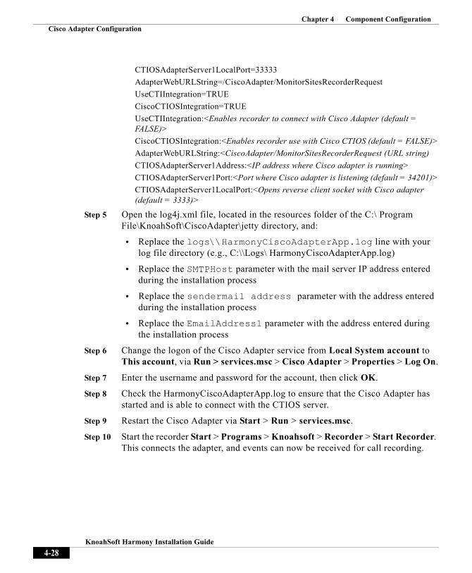
CTIOSAdapterServer1LocalPort=33333AdapterWebURLString=/CiscoAdapter/MonitorSitesRecorderRequestUseCTIIntegration=TRUECiscoCTIOSIntegration=TRUEUseCTIIntegration:<Enables recorder to connect with Cisco Adapter (default = FALSE)>CiscoCTIOSIntegration:<Enables recorder use with Cisco CTIOS (default = FALSE)>AdapterWebURLString:<CiscoAdapter/MonitorSitesRecorderRequest (URL string)CTIOSAdapterServer1Address:<IP address where Cisco adapter is running>CTIOSAdapterServer1Port:<Port where Cisco adapter is listening (default = 34201)>CTIOSAdapterServer1LocalPort:<Opens reverse client socket with Cisco adapter (default = 3333)>
Step 5 Open the log4j.xml file, located in the resources folder of the C:\ Program File\KnoahSoft\CiscoAdapter\jetty directory, and:
• Replace the logs\\HarmonyCiscoAdapterApp.log line with your log file directory (e.g., C:\\Logs\ HarmonyCiscoAdapterApp.log)
• Replace the SMTPHost parameter with the mail server IP address entered during the installation process
• Replace the sendermail address parameter with the address entered during the installation process
• Replace the EmailAddress1 parameter with the address entered during the installation process
Step 6 Change the logon of the Cisco Adapter service from Local System account to This account, via Run > services.msc > Cisco Adapter > Properties > Log On.
Step 7 Enter the username and password for the account, then click OK.
Step 8 Check the HarmonyCiscoAdapterApp.log to ensure that the Cisco Adapter has started and is able to connect with the CTIOS server.
Step 9 Restart the Cisco Adapter via Start > Run > services.msc.
Step 10 Start the recorder Start > Programs > Knoahsoft > Recorder > Start Recorder. This connects the adapter, and events can now be received for call recording.
4-28KnoahSoft Harmony Installation Guide

Chapter 4 Component ConfigurationScreen Configuration
Screen ConfigurationThe following procedures describe how to initiate screencapture for users in your Harmony environment when they log on and off their machines.
You can configure screencapture initiation in one of two ways, based on whether or not you are using Windows Active Directory.
Non-ADS Deployment
The following procedures must be performed on each user’s machine in your Harmony environment.
First, add the userlogin.exe script to the group policy logon and logoff scripts:
Step 1 Navigate to Start > Run > gpedit.msc. The Group Policy window appears.
Step 2 Navigate to User Configuration > Windows Settings > Scripts (Logon/Logoff).
Step 3 Click Logon. The Logon Properties window appears.
Step 4 Click Add, then enter the following:
• Script Name—C:\Program Files\KnoahSoft\Screen\userlogin.exe
• Script Parameters—1
Step 5 Click OK.
Step 6 Click Logoff. The Logoff Properties window appears. (Note that although the script is named userlogin, it functions for both logon and logoff events.)
Step 7 Click Add, then enter the following:
• Script Name—C:\Program Files\KnoahSoft\Screen\userlogin.exe
• Script Parameters—2
Step 8 Click OK.
Step 9 Log off then log back in as an agent.
Step 10 Ensure that appropriate entries are found in userlogin.log log file, located in the C:\Program Files\KnoahSoft\Logs\ directory.
4-29KnoahSoft Harmony Installation Guide

Chapter 4 Component ConfigurationScreen Configuration
Note If you do not enter the script parameters 1 and 2 as per steps 4 and 6, no message is sent to the Screen.exe program that the user logged in and out.
Next, deploy the group policy for the screencapture application:
Step 1 Navigate to Start > Control Panel > Administrative Tools > Computer Management.
Step 2 Select Local Users and Groups.
Step 3 Select the group you want to deploy the package to (e.g., KnoahSoft). If you have a pre-existing group that contains all the users you want to configure for group policy log on and off screen capture, select that group. Otherwise, create a group with the appropriate users.
Step 4 Create a user with administrative privileges in the selected group.
Step 5 Create a new Group Policy for the user (Properties > Group Policy > New).
Step 6 Edit the new Group Policy Object logon script (Window settings > Scripts > Log On) as follows:
• Open inisettings.exe file for the MSI Installer
• Edit the file to create a db.ini file in the C:\Program Files\KnoahSoft\Screen directory
• Create a shared directory for the C:\ and copy the db.ini and MSI packager into the directory
• Edit the batch file provided with the installer, specifying the shared directory path in the second and third lines of the batch file
Step 7 Click Show files. Copy the MSI Installer and batch file into the new window.
Step 8 Click Add in the Log On properties window. The Add Script window appears.
Step 9 Click Browse, select the batch file, then click OK and Apply.
Step 10 Specify the path of the MSI packager.
Step 11 Click Browse, then copy the batch file to this location.
Step 12 Click Add, then select the batch file.
Step 13 Save and close all open windows.
Step 14 Repeat steps for each user’s machine.
4-30KnoahSoft Harmony Installation Guide

Chapter 4 Component ConfigurationScreen Configuration
Finally, configure the UserLogin application so that it runs whenever every user logs in or out:
Step 1 Navigate to Start > Programs > Administrative Tools > Active Directory Users and Computers.
Step 2 Open the scripts window for the group you want to run the UserLogin program for (Properties > Window Settings > Scripts).
Step 3 Select Log On and apply the logon script.
Step 4 Click Show files, then copy the userlogin.exe and log4cplus.dll files from the KnoahSoft directory.
Step 5 Click Browse, then select the userlogin.exe file.
Step 6 Set the Script Parameter to 1.
Step 7 Save and close all open windows. The script will now run whenever a user logs into their machine, and the screencapture application will run for the user account.
Step 8 Repeat steps 1 through 5 for the logoff script, setting the Script Parameter to 2.
Step 9 Save and close all open windows.
To confirm that the screencapture group policy is working:
Step 1 Log into a user machine in the MSI deployed group as the admin user.
Step 2 Wait two minutes, then check the Task Manager to ensure that the Screen.exe process is running on the machine.
Step 3 Log off the machine, then perform the above procedure for all machines.
Note Note that all users in your system are in the group.
Deployment from ADS
This procedure describes how to deploy a Microsoft Installer (MSI) packager from a central ADS server to all the machines configured in the group, if you use Active Directory you dont need to manually on each machine as per the first procedure.
4-31KnoahSoft Harmony Installation Guide

Chapter 4 Component ConfigurationScreen Configuration
First, configure all clients as follows:
Step 1 Create a Knoahsoft\Screen directory in the C:\Program Files directory on the ADS server.
Step 2 Run the IniSettings application, which will create a db.ini file in the directory created in step 1.
Step 3 Copy the ini file and MSI packager into one shared folder.
Step 4 Open the batch file with a text editor. Modify the second and third lines of the batch file with the IP address of the ADS server and the directory name with the shared directory name for the ADS server.
Step 5 Save the batch file.
Note The installation CD contains the following files in the Screen_MSI directory: inisettings.exe, MSI_Installer_CentralPush_Script.bat, and ScreenMSIPackager.msi.
Then, log in to the active directory server with a user with administrator privileges as follows:
Step 1 Navigate to Start > Programs > Administrative Tools > Active Directory Users and Computers.
Step 2 Select a group to deploy that package to.
Step 3 Create a user in the selected group with administrator privileges, then right-click on that user to open the Properties window.
Step 4 Click the Group Policy tab. Click New. The Group Policy Object and Group Policy Object Links page appears.
Step 5 Click Edit. Select Window Settings then click the Scripts option.
Step 6 Click the log on script. Specify the path of the batch file, as edited in the previous procedure.
Step 7 Click Show Files. Copy the batch file to the location shown.
Step 8 Click Add, then click Browse and locate and open the batch file previously created.
Step 9 The batch file is added to the log on script. Click OK.
4-32KnoahSoft Harmony Installation Guide

Chapter 4 Component ConfigurationRecording Middleware Service Configuration
Now, configure the userlogin application as follows:
Step 1 Navigate to Start >Run >gpedit.msc.
Step 2 Click New from the Group Policy menu to create a new group policy for the user group.
Step 3 Click Edit. The UserConfiguration >Windows Settings >Scripts (Logon/Logoff) window appears.
Step 4 Click the log on script, then click Show Files.
Step 5 Click Add, then click Browse and select and open the userlogin.exe file.
Step 6 Enter 1 for the parameter then click OK. Now, whenever the user logs into their machine, the user login account will run the application.
Step 7 Repeat steps 4 through 6 for the log off script, entering a 2 for the parameter.
Finally, test the script log off script running:
Step 1 Close all ADS windows, go to individual machines of the MSI deployed group and log in with an admin user (i.e., whatever user you have created in this MSI deployment).
Step 2 Wait for two minutes and check in the task manager whether the screen.exe is running on that machine or not.
Step 3 If it is running, log off that machine and repeat this procedure for all machines.
Recording Middleware Service ConfigurationHarmony’s Recording Middleware Service (RMS) can be easily integrated with CRM applications.
RMS receives different types of HTTP events from CRM applications and, after processing those messages into CTIOS messages, passes them to the recorder for further processing.
4-33KnoahSoft Harmony Installation Guide

Chapter 4 Component ConfigurationRecording Middleware Service Configuration
During installation, the following RMS registry key is created: • 32-bit machine
HKEY_LOCAL_MACHINE\SOFTWARE\Knoahsoft\HarmonyRMS
• 64-bit machine HKEY_LOCAL_MACHINE\SOFTWARE\vow6432node\Knoahsoft\HarmonyRMS
The key contains the following values: HarmonyRMSServerPort=33022
HarmonyRMSIntegrationPort=33023
Where: • HarmonyRMSServerPort is used to connect RMS with the recorder.
Recorder will open the connection on this port (default = 33022).
• HarmonyRMSIntegrationPort is used to connect the CRM application with Harmony RMS. The CRM application will open the connection on this port (default = 33023).
To configure RMS:
Step 1 Start the service via Start > Program Files >Knoahsoft > HarmonyRMS > Start HarmonyRMS.
Step 2 Open the Recorder.ini file, located in the C:\Program Files\KnoahSoft\Recorder directory, and modify the following parameters:
CTIOSAdapterServer1Address=IP addressCTIOSAdapterServer1Port=33022UseCTIIntegration=TRUE
Where: CTIOSAdapterServer1Address = IP address where RMS is runningCTIOSAdapterServer1Port = port where RMS is listening (default = 33022)UseCTIIntegration enables recorder to connect with RMS (default = FALSE)
Step 3 Start the recorder via Start > Programs > Knoahsoft > Recorder > Start Recorder.
4-34KnoahSoft Harmony Installation Guide

Chapter 4 Component ConfigurationUpload Client Configuration
Upload Client Configuration The Upload Client is used for uploading calls from the recorder server to the storage server. The Upload Client must be installed and configured to run on the same machine where the recorder is running, and the SCUpload Server must be configured to run on the storage server.
Note If the recorder and storage server are both installed are on the same machine, then there is no need to install the Upload Client.
To configure the Upload Client:
Step 1 Stop the Upload Client services on the recorder server via Start > Program Files > KnoahSoft > UploadClient > Stop UploadClient.
Step 2 Stop the recorder services on the recorder server via Start > Program Files > KnoahSoft > Recorder > Stop Recorder.
Step 3 Stop the Upload Server service via Start > Program Files > KnoahSoft > SCUploadServer > StopSCUploadServer.
Step 4 To change default value of any of the below parameters, add that parameter in C:\Program Files\KnoahSoft\UploadClient\UploadClient.ini file and start the application
Step 5 Open the recorder.ini file and add the following parameters:
• UploadCallRecordings=TRUE
• UploadClientIpAddress=IP address
• UploadClientPort=33026
Where:
• UploadCallRecordings—Enables uploading of calls with the help of the Upload Client (default = FALSE)
• UploadClientIpAddress—Upload Client host IP address
• UploadClientPort—Upload Client and recorder communication port (default = 33026).
Step 6 Open the UploadServer.ini file, located in the C:\Program Files\KnoahSoft\SCUploadServer directory, and add the following parameters:
4-35KnoahSoft Harmony Installation Guide

Chapter 4 Component ConfigurationCall Download Utility
• StorageServerAddress=IP address
• UploadServerHTTPServerPort=33028
• FileUploadServerPort=33027
Step 7 Restart the recorder, Upload Client, and Upload Server via Start > Run > services.msc.
Call Download UtilityThe Call download utility provides a comprehensive view of all calls stored in the database. It provides the flexibility to select which calls are to be download, and in what format (wav, mp3). The Call Download Tool can be used to calculate the storage space available in the destination directory, as well as the space required to download the calls in the desired format.
Upon installation, directories are to be created on the basis of client name, site name, extension, and date under Voice folder, for audio only calls and audio with screenshots, respectively. Calls are stored in raw format (G.711 or G.729) by date, and are archived in two files (fwd and bwd) which correspond to the forward and backward playback of the call.
Note It is recommended that the Archival Tool be installed on the Storage server.
To setup the Call Download Utility:
Step 1 Navigate to the Archiver MSI Packager directory on your local server.
Step 2 Click the MSI Packager. A prompt will display upon successful installation.
To access the Call Download Utility:
Step 1 Navigate to Start > Programs > KnoahSoft > Call Download > Run CallDownloadUtility.
Step 2 Enter the following database login credentials:
• Login User ID—Database login user ID (metric)
• Login Password—Database login user password (metric)
4-36KnoahSoft Harmony Installation Guide
Chapter 4 Component ConfigurationCall Download Utility
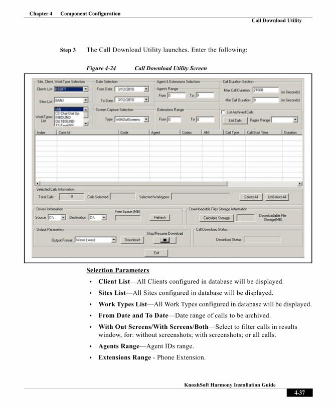
Step 3 The Call Download Utility launches. Enter the following:
Figure 4-24 Call Download Utility Screen
Selection Parameters
• Client List—All Clients configured in database will be displayed.
• Sites List—All Sites configured in database will be displayed.
• Work Types List—All Work Types configured in database will be displayed.
• From Date and To Date—Date range of calls to be archived.
• With Out Screens/With Screens/Both—Select to filter calls in results window, for: without screenshots; with screenshots; or all calls.
• Agents Range—Agent IDs range.
• Extensions Range - Phone Extension.
4-37KnoahSoft Harmony Installation Guide

Chapter 4 Component ConfigurationCall Download Utility
• Min call duration and Max call duration (in seconds)—Select calls that match this range of call duration criteria. Default for Min and Max are 0 and 21600 seconds respectively.
• List Archived Calls—Select the checkbox, if you want to download Archived calls Pages Range - Number of pages to appear in the results window before a new page appears.
• Click List Calls to filter results window after selection.
Selected Calls Information
• Total Calls—Number of calls currently displayed in the results window.
• Calls Selected—Number of calls currently selected in the results window. Click Select All and Unselect All to filter.
• Selected Worktypes —Above selected worktypes will be displayed
Drive Information
• Source—Database where calls are recorded. Map the drive until Voice folder.
• Destination—Database to download recorded calls. Space available on the drive is shown in the Free Space MB text box. Click Refresh to recalculate if a new drive is selected.
Downloadable Files Storage Information
• Calculate Storage—Click to view storage requirements for the selected audio format, as selected in the Output Parameters section (below).
Output Parameters
• Output Format—Format used to archive calls (wav, mp3).
Call Download Status
• Downloading Status—Status of all selected calls being download, shown as a progress bar.
4-38KnoahSoft Harmony Installation Guide

Knoa
C H A P T E R 5
Post-Installation TasksThis section describes the post-installation tasks you need to perform for IIS web server configuration, once you have run the installer as previously described.
Information is also provided on how to start your system, change the settings you made during the installation process, and start and stop Harmony services.
Detailed troubleshooting help for user login, recording server, and screencapture issues is also provided.
5-1hSoft Harmony Installation Guide

Chapter 5 Post-Installation TasksIIS Web Server Configuration
IIS Web Server ConfigurationYour Microsoft IIS web server must be configured to host static KnoahSoft web content on the machine where the JBoss application server is running.
Thus, you must create a new website in IIS, provide access to screenshot images stored on the storage server, and configure Silent Monitoring images as follows:
First, create a new website in IIS for KnoahSoft:
• Create a new website named KnoahSoft, enabling TCP port 8081.
• Point the home directory of the website to the KnoahSoft directory, KS_HOME.
• Enable Read and Run Scripts for the KnoahSoft working directory.
• Ensure anonymous access for the KnoahSoft working directory, as per IIS’s directory security.
• Ensure Integrated Windows authentication is disabled for the KnoahSoft working directory.
Next, provide access to screenshot images stored on the storage server:
• Create a new virtual directory labeled Voice pointing to the storage folder Voice with appropriate login credentials for the KnoahSoft website, as previously created in IIS.
• Ensure the proper user ID and password are set for access to the storage server.
• Ensure anonymous access for the Screens directory, as per IIS’s directory security.
• Ensure Integrated Windows authentication is disabled for the Screens directory.
• Enable Read and Run Scripts for the Voice sub-directory of the StorageServerWorkingDirectory directory.
5-2KnoahSoft Harmony Installation Guide

Chapter 5 Post-Installation TasksIIS Web Server Configuration
Finally, configure the following settings for Silent Monitoring images:
• Ensure Expire Immediately is selected for HTTP Headers/Enable Content Expiration for the SilentMonitorImage sub-directory of the KnoahSoft website, as well as the QARuntimeVoiceComments, SurveyVoicePrompts and EmpPhotos sub-directories.
• Ensure anonymous access for the SilentMonitorImage directory, as per IIS’s directory security.
Starting and Stopping Services
To start or stop a service:
Step 1 Navigate to Start > Programs > KnoahSoft.
Step 2 Select the service you want to start or stop.
Step 3 To start the service, select Start (e.g., to start the Recorder, select Start Recorder). To stop the service, select Stop (e.g., to stop the Recorder, select Stop Recorder).
Setting Passwords for services.msc Components
During the first installation process of the product, you will be required to set the passwords for the components in services.msc.
To set password in services.msc:
Step 1 Navigate to Start > Run. The Run window appears.
Step 2 Type services.msc in Run window then click OK.
Step 3 Right-click on any of the Harmony components, then click Properties.
Step 4 Click Log On Tab in the new window that appears.
Step 5 Change the password to the local System administrator's password, confirm the password, then click OK.
Step 6 A dialog box with “The account <username> has been granted the Log on as a Service right.” appears. Click OK and close the service window.
5-3KnoahSoft Harmony Installation Guide

Chapter 5 Post-Installation TasksIIS Web Server Configuration
System StartOnce all the servers have been installed and properly configured as previously described, you can then start the KnoahSoft web application and log in as the Administrator user.
To start the KnoahSoft web application:
Step 1 Log into the physical server hosting the web application component.
Step 2 Click Start > Programs > KnoahSoft > Web > Start Web.
Step 3 Once the service is started, enter the following URL in your browser:
http://server name:8080/knoahsoft/
where server name is the KnoahSoft web application host server system name or IP address (i.e., the server hosting JBoss).
Step 4 Login as the Administrator user as follows:
• UserID—admin
• Password—password
Step 5 Be sure to change the password the first time you log in.
Note The System Administrator can create accounts, employees, etc. For more information, refer to the KnoahSoft Harmony System Administration Guide.
Changing Installation Configuration via Installer
To modify settings for recording, web application, and other servers and services after installation:
Step 1 Navigate to Start > Programs > KnoahSoft > KnoahSoft Config. The installer relaunches.
Step 2 Follow the prompts to make your changes, then click OK.
Step 3 Restart the server or service to enable your changes.
5-4KnoahSoft Harmony Installation Guide

Chapter 5 Post-Installation TasksReport Templates
Note Contact KnoahSoft Technical Support in the event that you need to change any IP address.
Report TemplatesIn order to download JRXML and HRXML templates in the Reports module using the Import New Templates feature, you must associate the JRXML and HRXML file extensions to the Windows OS in IIS, as described below.
Note Refer to the “Importing New Templates” topic in Chapter 3 of the KnoahSoft Harmony User Guide for more information.
To configure jrxml and hrxml mime types for use with Harmony:
Step 1 Ensure that your KnoahSoft IIS web server is properly configured as previously described (above).
Step 2 Open IIS and navigate to the KnoahSoft website.
Step 3 Navigate to Reports > Properties. The KnoahSoft Properties window appears.
Step 4 Navigate to HTTP Headers > MIME types block, then click MIME Types. The MIME Types window appears.
Step 5 Click New.
Step 6 Specify the extension as jrxml and the MIME type as Jrxml file, then click OK.
Step 7 Click New.
Step 8 Specify the extension as hrxml and the MIME type as Hrxml file, then click OK.
Step 9 Click OK in the MIME Types window, then click Apply and OK in the KnoahSoft Properties window.
Step 10 Repeat steps 2 through 9 for all required end-user desktop machines.
5-5KnoahSoft Harmony Installation Guide

Chapter 5 Post-Installation TasksPost-Installation Checklist
XML File Extension Normally, when the hrxml and jrxml files are downloaded, they are saved as .xml files. To download files with their native hrxml and jrxml extensions:
Step 1 In Windows Explorer, navigate to Tools > Folder Options > File Types, then click New.
Step 2 Enter jrxml as the file extension, then click OK.
Step 3 Click New.
Step 4 Enter hrxml as the file extension, then click OK.
Step 5 Click Apply and OK in the Folder Options window.
Post-Installation ChecklistEnsure that the following items are properly configured and function as described in the table below.
Table 5-1 Post-Installation Checklist
Item StatusChange the password to the one that was assigned to the KnoahSoft account via the Log On tabRefresh and then restart the Harmony services
Cross-check all log files and ensure all services are up and running
Do not change the IP address of any of the KnoahSoft servers after installation. If this is required, inform KnoahSoft Support for assistance prior to changing the server IP address. Launch the web application using the following URL: http://HOSTNAME:8080/knoahsoft/faces/login.jspx Configure the web application server to launch the Harmony Login page by entering the URLLog in as user ADMIN
Update the organization name
5-6KnoahSoft Harmony Installation Guide

Chapter 5 Post-Installation TasksTroubleshooting
Troubleshooting
userlogin.exe and Log File1. User login and logout information is created by the userlogin.exe program,
and can be found in the userlogin.log file, which is located in the C:\Program Files\KnoahSoft\Logs\directory. View the messages in the file to discover if there are login issues.
– If the agent’s network ID is displayed in the log file instead of their employee ID, the userlogin.exe program was probably unable to resolve the agent’s ID to their employee ID. More than likely, the agent’s
Update the client, site, department, and designation
Upload the employees manually or using Excel Upload
Ensure employees are uploaded into the database
Ensure that supervisors are assigned to the agents
Ensure Work Types are assigned to the site and employees
Cross-check the Group [access To] in User Details screen, for supervisor and managersEnsure recording is enabled for voice agents
Ensure screen capture is enabled for agents [if available]
Ensure that user feature permissions are enabled as required for that designation
Ensure that user report permissions are enabled as required for that designation
After calls are recorded, ensure the Work Type name is changed as required for easy filtering of Work Type callsLog in as Supervisor
Search for recorded calls via the Reports module and ensure that you are able to playback the callsPlayback calls via t he Monitor module and ensure the Active X control is installed on one of the supervisor’s machineOnce an evaluation form is created, ensure you can save the evaluation (Contact Center Edition and higher)
5-7KnoahSoft Harmony Installation Guide

Chapter 5 Post-Installation TasksTroubleshooting
information is improperly entered in the KnoahSoft database. Login to the KnoahSoft Admin module and navigate to the Employee Management screen to correct this issue.
– If there are no entries in the log file, it may be that the group policies are improperly configured either for the machine or in ADS. Refer to the installation procedure for information on group policy configuration.
– If there are employee IDs listed in the userlogin.log log file, but no messages in the screencapture.log log file noting reception of AGENT_LOGGED_IN and AGENT_LOGGED_OUT messages, then the userlogin.exe program could not connect to the Screen.exe program. More than likely a firewall is configured on the machine to disallow connections. Disable the firewall, logout, then log back in as an agent. If that works, fix the connection by reconfiguring the firewall to allow connections to the ports that the Screen.exe program listens on, TCP 55000 and TCP 33000.
2. If your group policies are configured correctly, run the userlogin.exe program. If all permissions are correct, the userlogin.log log file will be generated. If the file is not generated, check file access permissions for both the userlogin.exe program and the userlogin.log file.
3. Ensure that agents log into the computer at the start of the day and log out at the end of the day, so that the system can always identify who is currently logged in.
– If this occurs on a locked desktop, the log file will contain a messages such as nCaptureSubAgent.cpp:209 ERROR - BitBlt() failed.
– If an entry such as this is not in the file, then either userlogin.exe is not running or permission has not been provided to create the log file in C:\Program Files\KnoahSoft\Logs folder.
– Group policies may also not be configured properly on that machine.
Recording Server and Screen.exe1. The recording server sends START_CAPTURE and STOP_CAPTURE
messages to the Screen.exe program. If it cannot, more than likely there is a network problem, and there is no connectivity between the recording server and the agent’s desktop. This is a rare scenario but may occur if there are VLAN issues.
5-8KnoahSoft Harmony Installation Guide

Chapter 5 Post-Installation TasksTroubleshooting
– Ensure that the agent desktop firewall is disabled and that agent desktops are separated from the recorder by the company firewall.
– Permissions should be granted in the firewall to enable the recorder to connect to the agent desktop machines.
– Ensure that the agent’s machine is configured for screen capture, and that the capture interval is configured as per the Voice Configuration setting for the agent.
Screen Capture Issues1. In order to ensure that screenshots are being captured, open either the
C:\VSCR or D:\VSCR directory. The directory will contain sub-directories with numbered names which contain JPG images.
– Open the most recent sub-directory with the largest number of images and ensure that screenshot images are being generated when calls are occurring.
– If there are no images, the call may not be qualified for due to business rules, as per the Voice Configuration setting for the agent.
– If there are images in any of the sub-directories after the call has ended, then uploading of images to the Storage server is not working. Ensure that the SCUploadServer is configured and running on the Storage server. All images are stored on the Storage server, in the voice case id directory, which also stores agent and customer voice files.
2. Ensure that the Screen.exe program is running in Windows Task Manager. Press Ctrl + Alt + Delete to launch Task Manager, then click the Processes tab to view all currently running processes.
– If Screen.exe is not running, ensure that the Screen Service is installed as a service. Click Start > Programs > Administrative Tools > Services to launch the Services window and view all installed services, or open the services.msc file from the administrator’s account.
– If the Screen Service is not installed, run the setup program to install it.
5-9KnoahSoft Harmony Installation Guide

Chapter 5 Post-Installation TasksTroubleshooting
3. If the Screen Service is installed but is not started, check the ScreenCapture.log file, located in the C:\Program Files\KnoahSoft\Logs directory, and view the messages in the file to discover why the service did not start. There may be a database connectivity problem, storage drive problem, socket binding issue, etc.
4. Run the userlogin.exe (located in the C:\Program Files\KnoahSoft\Screen directory) to check for permissions related issues. Set proper permissions, if required.
5. There may be a problem with permissions for the C:\Program Files\KnoahSoft\Logs directory. If permissions have been set properly, you can create an empty text file in that directory. If not, set proper permissions.
6. View the UserLogin log file and see if there are any connection errors—e.g., ports disabled by firewall, cannot connect or send messages to servers, etc.
– Add Power user as an authentic user list.
– Set permissions on C:\Program Files\KnoahSoft\Screen directory so that only the administrator can delete or move directory contents.
5-10KnoahSoft Harmony Installation Guide

Knoa
C H A P T E R 6
TAPI IntegrationThis chapter describes the functionality of the Computer Telephony Integration (CTI) application, and how to make basic call recording work with TAPI integration.
System OverviewThe Cisco Unified Telephony Application Programming Interface (TAPI) comprises the set of classes and principles of operation that constitute a telephony application programming interface. The Cisco Unified TAPI implementations provide the interface between computer telephony applications and telephony services.
The Cisco Unified Communications Manager (formerly Cisco Unified Call Manager) includes a TAPI Service Provider (Cisco Unified TSP), which allows developers to create customized IP telephony applications for Cisco users. Cisco Unified TSP enables the Cisco Unified Communications system to understand commands from the user-level application such as Cisco Soft Phone via the operating system.
Note The system does not support using Cisco TAPI 2.1 TSP via the TAPI 3.x compatibility layer.
6-1hSoft Harmony Installation Guide

Chapter 6 TAPI IntegrationSystem Overview
Creating CTI user in Call ManagerTo give the CTI manager ip address, user name and password in the CTI Manager Tab in Cisco TSP configuration settings, Create a CTI user in the Cisco Call manager as follows.
Step 1 Open Cisco Unified Communications Manager Administration > User Management > Application user.
Step 2 Click Add New. It displays a Application user configuration page.
Step 3 Fill in the details in Application User Information section.
Figure 6-1 Application User Information
6-2KnoahSoft Harmony Installation Guide

Chapter 6 TAPI IntegrationSystem Overview
• User ID—Enter the CTI manager user ID: Example: CTIManager1
• Password—Enter the password for the UserID.
• Confirm Password—Re- enter the password for conformation.
• Digest Credentials—Enter the digest Credentials if any.
• Confirm Digest Credentials—confirm the entered digest credentials.
• Presence Group—Select Standard presence group.
• Accept presence subscription—uncheck
• Accept Out-of-dialog REFER—uncheck
• Accept Unsolicited Notification—uncheck
• Accept Replaces Header—uncheck
Step 4 Fill in the details in Device Information section.
Figure 6-2 Device Information
6-3KnoahSoft Harmony Installation Guide

Chapter 6 TAPI IntegrationSystem Overview
• Controlled Devices—Select the devices which are configured in the Cisco call managers for TAPI call recording. If any device is not found click the Find More Phones at the right side and a window will be displayed Find for the device (with the known search criteria) which you want to add in the controlled devices column and click add selected. The device is now added to the controlled device.
• Permission Information
• Groups—Add necessary groups to the Groups column:
– Standard CCM Admin Users
– Standard CCM End Users
– Standard CTI Allow Call Monitoring
– Standard CTI Allow Call Recording
– Standard CTI Enabled
• Roles—The information in roles is displayed depending on the selection of the Group information:
– Standard CCM Admin Users
– Standard CCM End Users
– Standard CCMUSER Administration
– Standard CTI Allow Call Monitoring
– Standard CTI Allow Call Recording
– Standard CTI Enabled
– Standard CUReporting
Step 5 Click Save to save the Application user information settings.
6-4KnoahSoft Harmony Installation Guide

Chapter 6 TAPI IntegrationTSP Installations and Configurations
TSP Installations and ConfigurationsA TSP Server must be installed and configured on the machine where TAPI Adapter is running. The TSP server is connected to Cisco TSP. The TSP server extracts call data from the Cisco TSP and encapsulates the extracted data in events that are output to clients.
Typically, in order for an application running on an agent workstation to receive events receive from the TSP server, the application must register with the TSP server, and provide code for communicating directly with the TSP server. A client connects to the TSP server in Monitor mode when it wants to receive all events that TSP server publishes, or a specified subset of those events.
Generally, Monitor mode application may receive events for calls, multiple agents or statistics. To set a connection in monitor mode, create a filter that specifies which events to monitor over that connection. After establishing the monitor mode, depends on message filter value TSP server publishes the events to the client. After receiving the events from TSP Server, create CTIOS messages and send it to the UCM Trunk Recorder application for further processing.
TSP InstallationInstall the Cisco Unified TSP software either directly from the Cisco Unified Communications Manager CD-ROM or from Cisco Unified Communications Manager Administration as follows:
Step 1 Download CiscoTSP.exe from Cisco Unified Communications Manager Administration > Application > Plugins.
Step 2 Click on Download for the plugin name Cisco Telephony Service Provider.
Step 3 Double-click on the downloaded CsicoTSP.exe.
Step 4 Select the number of TSPs you want to configure (for multiple TSPs) and follow the online instructions.
Note For information on installing plug-ins from the Cisco Unified Communications Manager, see the Cisco Unified Communications Manager Administration Guide.
6-5KnoahSoft Harmony Installation Guide

Chapter 6 TAPI IntegrationTSP Installations and Configurations
TSP Configuration
Step 1 Open the Control Panel.
Step 2 Double-click Phone and Modem Options.
Step 3 Choose the Cisco TSP you want to configure.
Step 4 Click Configure. The system displays the Cisco IP PBX Service Provider dialog box, with General, User, CTI Manager, Wave, Trace, Advanced, and Language tabs.
Step 5 Select each tab and enter the configuration settings.
Step 6 Click OK to save the changes.
Note After configuring the TSP, you must restart the telephony service before an application can run and connect with its devices.
TSP Configuration Settings
The General tab displays TSP and TSPUI version information.
Figure 6-3 General Tab
6-6KnoahSoft Harmony Installation Guide

Chapter 6 TAPI IntegrationTSP Installations and Configurations
The User tab allows you to configure security information.
Figure 6-4 User Tab
• User Name—Enter the user name of the CTI User that you want to give access to devices. This TSP can access devices and lines associated with this user. Make sure this user is also configured in the Cisco Call Manager, so TSP can connect to Cisco Call Manager. The TSP configuration keys store the user name and password that you enter.
• Password—Enter the password associated with the user that you entered in the User Name field. The computer encrypts the password and stores it.
• Verify password—Re-enter the user password.
Note You can designate only one active user name and password t at a time for a TSP.
6-7KnoahSoft Harmony Installation Guide

Chapter 6 TAPI IntegrationTSP Installations and Configurations
The CTI Manager tab allows you to configure primary and secondary CTI Manager Information.
Figure 6-5 CTI Manager Tab
• Primary CTI Manager Location—Specifies the CTI Manager to which the TSP attempts to connect first. If the TSP is on the same computer as the primary CTIManager, choose the Local Host radio button. If the primary CTIManager is on a different computer, choose the IP Address radio button and enter the IP address of primary CTIManager or choose the Host Name radio button and enter the host name of primary CTI Manager.
• Backup CTI Manager Location—Specifies the CTI Manager to which the TSP attempts to connect if a connection to the primary CTI Manager fails. If the TSP is on the same computer as the backup CTIManager, choose the Local Host radio button. If the backup CTIManager is on a different computer, choose the IP Address radio button and enter the IP address of backup CTIManager or choose the Host Name radio button and enter the host name of backup CTI Manager.
6-8KnoahSoft Harmony Installation Guide

Chapter 6 TAPI IntegrationTSP Installations and Configurations
The Wave tab allows you to configure settings for your wave devices.
Figure 6-6 Wave Tab
• Automated Voice Calls—The number of Cisco wave devices that you are using determines the possible number of automated voice lines (default = 5). You can open as many CTI ports as the number of Cisco wave devices configured. For example, if you enter 5, you need to create five CTI port devices in Cisco Call Manager. If you change this number, you need to remove and then reinstall any Cisco wave devices that you installed.
• Silence Detection—If you use silence detection, this check box notifies the wave driver which method to use to detect silence on lines that support automated voice calls using the Cisco Wave Driver. If the check box is checked (default), the wave driver searches for the absence of audio-stream RTP packets. Because all devices on the network suppress silence and stop sending packets, this method provides a very efficient way for the wave driver to detect silence.
6-9KnoahSoft Harmony Installation Guide

Chapter 6 TAPI IntegrationTSP Installations and Configurations
The Trace tab allows you to configure various trace settings, as shown below Changes to trace parameters take effect immediately, even if TSP is running.
Figure 6-7 Trace Tab
• On—Allows you to enable Global CiscoTSP trace. Check the check box to enable CiscoTSP trace so you can modify other trace parameters in the dialog box. The CiscoTSP trace depends on the other values that you enter in these fields.
• Max line/file—Specifies the maximum number of lines the trace file can contain. The default is 10,000. Once the file contains the maximum number of lines, trace opens the next file and writes to that file.
• No. of files—Specifies the maximum number of trace files. The default is 10. File numbering occurs in a rotating sequence starting at 0. The counter restarts at 0 after it reaches the maximum number of files minus one.
• Directory—Specifies the location in which trace files for all Cisco TSPs are stored. Make sure that the specified directory exists. The system creates a subdirectory for each Cisco TSP. For example, the CiscoTSP001Log directory stores Cisco TSP 1 log files. The system creates trace files with filename TSP001Debug000xxx.txt for each TSP in its respective subdirectory.
6-10KnoahSoft Harmony Installation Guide

Chapter 6 TAPI IntegrationTSP Installations and Configurations
• TSP Trace—Activates internal TSP tracing. When you activate TSP tracing, Cisco TSP logs internal debug information that you can use for debugging purposes. You can choose one of the following levels:
• Error—Logs only TSP errors. (The system checks the TSP Trace check box and chooses the Error radio button by default.)
• Detailed—Logs all TSP details (i.e., log function calls in the order that they are called).
• CTI Trace—Traces all messages and function calls between TAPI and Cisco TSP. The system leaves this check box unchecked by default. If you check the check box, TSP traces all the function calls made by TAPI to Cisco TSP with parameters and messages (events) from Cisco TSP to TAPI.
• TSPI Trace—Traces messages flowing between Cisco TSP and CTI. Cisco TSP communicates with the CTI Manager. By default, the system leaves the check box unchecked.
6-11KnoahSoft Harmony Installation Guide

Chapter 6 TAPI IntegrationTSP Installations and Configurations
The Advanced tab allows you to configure timer settings.
Figure 6-8 Advanced Tab
• Synchronous Message Timeout (secs)—Designates the time that the TSP waits to receive a response to a synchronous message. The value displays in seconds, and the default is 15. Range goes from 5 to 60 seconds.
• Requested Heartbeat Interval (secs)—Designates the interval at which the heartbeat messages are sent from TSP to detect whether the CTI Manager connection is still alive. TSP sends heartbeats when no traffic exists between the TSP and CTI Manager for 30 seconds or more. The default interval is 30 seconds. Range goes from 30 to 300 seconds.
• Connect Retry Interval (secs)—Designates the interval between reconnection attempts after a CTI Manager Connection failure. The default is 30 seconds. Range goes from 15 to 300 seconds.
• Provider Open Completed Timeout (secs)—Designates the time that the TSP waits for a Provider Open Completed Event. This event indicates that the initialization of CTI Manager is done and is ready to serve TSP requests. This initialization time is directly proportional to the number of devices configured in the system. The default value is 30 seconds. Range goes from 5 to 900 seconds.
6-12KnoahSoft Harmony Installation Guide

Chapter 6 TAPI IntegrationTSP Installations and Configurations
The Language tab allows you to select one of the installed languages to view the configuration settings in that language.
Choose a language and click Change Language to reload the tabs with the text in that language.
Figure 6-9 Language Tab
6-13KnoahSoft Harmony Installation Guide

Chapter 6 TAPI IntegrationManaging the Cisco TSP
Managing the Cisco TSP You can perform the following actions on all installed TSPs:
• Reinstall the existing Cisco TSP version
• Upgrade to the newer version of the Cisco TSP
• Uninstall the Cisco TSP
Note You cannot change the number of installed Cisco TSPs when you reinstall or upgrade the Cisco TSPs.
Reinstalling the Cisco TSP
To reinstall the Cisco TSP on all supported platforms:
Step 1 Open the Control Panel and double-click Add/Remove Programs.
Step 2 Choose Cisco TSP and click Add/Remove. The Cisco TSP maintenance install dialog box displays.
Step 3 Click Reinstall TSP 3.2(0.X) radio button and click Next.
Step 4 Follow the online instructions.
Note If TSP files are already locked, the installation program prompts you to restart the computer.
6-14KnoahSoft Harmony Installation Guide

Chapter 6 TAPI IntegrationManaging the Cisco TSP
Upgrading the Cisco TSP
To upgrade the Cisco TSP on all supported platforms:
Step 1 Double-click CiscoTSP.exe.
Step 2 If CiscoTSP.exe contains different version of Cisco TSP than you have installed, the installation program displays one of the following prompts, depending upon the previous Cisco TSP version. Select the type of installation for TSP Version 3.3(0.X).
• If the previous installed version is Cisco TSP 3.1(0.X), the following prompt displays: Upgrade from TSP 3.1(0.X)
• If the previous installed version is Cisco TSP 3.2(0.X), the following prompt displays: Upgrade from TSP 3.2(0.X)
• If the previous installed version is Cisco TSP 3.3(0.X), the following prompt displays: Upgrade from 3.3(0.X)
Step 3 Click Reinstall TSP 3.3(0.X). The CiscoTSP maintenance install dialog box displays. Click Next.
Step 4 Choose Upgrade from TSP 3.1(0.X) to 3.2(0.Y) radio button or Upgrade from TSP 3.2(0.X) to 3.2(0.Y) radio button and click Next.
Step 5 Follow the online instructions.
Uninstalling the Cisco TSP
To uninstall the Cisco TSP on all supported platforms.
Step 1 Open the Control Panel and double-click Add/Remove Programs.
Step 2 Choose Cisco TSP and click Add/Remove. The Cisco TSP maintenance install dialog box displays.
Step 3 Choose Uninstall: Remove the installed TSP radio button and click Next.
Step 4 Follow the online instructions.
6-15KnoahSoft Harmony Installation Guide

Chapter 6 TAPI IntegrationManaging the Cisco TSP
TAPI Installation
Step 1 Double click the TAPIAdapterMSIPackager.msi. This Installs TAPI Adapter on your machine.
Step 2 Configure the TAPIAdapterServerPort in the TAPIAdapter file.
Step 3 Check the TAPIAdapter.log for verification.
Step 4 Add the following parameters to the recorder.ini file:
CTIOSAdapterServer1Address=<IP address where TAPIAdapter is running>CTIOSAdapterServer1Port=33022NoOfCTIOSAdapters=<number of Adapters connected to the recorder>
6-16KnoahSoft Harmony Installation Guide

Knoa
C H A P T E R 7
Debugging ConfigurationThis chapter describes how to configure the Log Manager, Alert Manager, and Get Dump Files For Calls debugging components. These components can be selected for installation during component installation of Harmony, as described in Chapter 3.
7-1hSoft Harmony Installation Guide

Chapter 7 Debugging ConfigurationLog Manager Configuration
Log Manager ConfigurationLog Manager can be used to manage the Harmony application logs, so you can easily troubleshoot and identify system issues. Log Manager is installed on all remote servers where you want to manage application logs.
Log Manager creates logs on daily basis, from the configured parameters, and then stores them in ZIP file format in the OldLogs directory, with the application name and date. You can fetch logs by agent extension, network ID, or call duration.
Harmony fetches only those logs found in the OldLogs directory.
To configure Log Manager:
Step 1 Open the LogManager.ini file, located in the C:\Program File\KnoahSoft\LogManager directory.
Step 2 Modify the following parameters:
• MonitorApplicationsList—Enter the Harmony components you want to monitor for logging from the following list. (Log file names are provided in parentheses.) Application names must be comma-separated (e.g., AES Adapter, Archiver, etc.):
– Archiver (Archiver.log)– Converter (Converter.log)– CRMAdapter (CRMAdapter.log)– KnoahSniffer (KnoahSniffer.log)– Screen (ScreenCapture.log)– UserLogin (UserLogin.log)– SCUploadServer (SCUploadServer.log)– UploadClient (UploadClient.log)– Recorder (Recorder.log)– CallDownloadUtility (CallDownloadUtility.log)
• MonitorApplicationTime—20090715000000 from this date daily basis thread will create the OldLogs directory under HarmonyLogsPath (key), then creates the applications logs and then zipped the file.(YYYYMMDDhhmmss).
7-2KnoahSoft Harmony Installation Guide

Chapter 7 Debugging ConfigurationLog Manager Configuration
• DeleteLogsOlderThan—300 Delete the old logs based on the configured value from the Logs directory.(No of days)
• DeleteOldLogsOlderThan—30 Delete the old logs based on the configured value from the OldLogs directory.(No of days)
• LogManagerHTTPServerPort—33036 Log Manager Server port value.
Log Manager Web Interface
You can fetch logs from a browser interface, based on date or voice case ID. Web interface functionality starts working when the URL comes into the picture. It will fetch logs only when the logs are present in the OldLogs directory
To fetch logs:
Step 1 Enter http://machine_IP:port/HarmonyLogsConsole in your browser window, where machine_IP:port is the machine and port number, as entered in the ini file (default = 33036).
Step 2 The Log Manager interface appears.
7-3KnoahSoft Harmony Installation Guide

Chapter 7 Debugging ConfigurationLog Manager Configuration
Figure 7-1 Log Manager Interface
Step 3 To fetch logs based on date range:
• Application name— Select Harmony application (i.e., component) you want to review the logs for (e.g., KnoahSniffer).
• From Date and Time—Enter a from date and time range parameter for the log files, in YYYYMMDDhhmmss format (e.g., 20090521040000 for 4AM, May 21, 2009).
• To Date and Time—Enter a to date range and time parameter for the log files, in YYYYMMDDhhmmss format (e.g., 20090522040000 for 4AM, May 22, 2009).
7-4KnoahSoft Harmony Installation Guide

Chapter 7 Debugging ConfigurationLog Manager Configuration
• Expression (1 though 8)—These all parameters are works as a filter for logs. Eg: Provide any string from the logs in these expression fields. Like agent, Extension xxxxx. Final log file will have only those lines that are in the expressions field.
Step 4 Click Submit. In the above examples, logs will be returned for KnoahSniffer between 4AM May 21 and 4AM May22.
Step 5 To fetch logs based on voice case ID:
• Application name— Select Harmony application (i.e., component) you want to review the logs for (e.g., KnoahSniffer).
• Voice case Id—Enter a voice case id. Based on the time that is present in the voice case id, LogManager will try to fetch the logs for the selected application. Based on the given time in the voice case id itself application will create start and end time for call. Note: Max limit 110 characters. Call Start time—start time in voice case id - time tolerance. Call End time— start time in voice case id + duration of call in voice case id + time tolerance
• Time Tolerance—Provide the integer value in two digits for getting the logs before the call start and after the call end. Note: Min value is 1 and Max value is 99. Eg: 9 Means LogManager will creates the logs 9 minute before the call start and after 9 minute the calls end for the selected application.
• Expression (1 though 8)—These all parameters are works as a filter for logs. Eg: Provide any string from the logs in these expression fields. Like agent, Extension xxxxx. Final log file will have only those lines that are in the expressions field.
Step 6 Click Submit. In the above examples, logs will be returned for KnoahSniffer between 4AM May 21 and 4AM May22.
7-5KnoahSoft Harmony Installation Guide

Chapter 7 Debugging ConfigurationAlert Manager Configuration
Alert Manager ConfigurationAlert Manager is a debugging component that receives HTTP alerts from all Harmony components. It sends those alerts to the Alert Manager server where they are processed for viewing in various web, log, and email formats.
Alert Manager provides web-based access to view all alerts using a single URL, and provides a range of filters to view alerts based on severity and component.
During installation, you select to install Alert Manager as a Debugging Component, and configure the following parameters:
• HTTP Alerts Enabled—Select to install the Alert Manager debugging component.
• Alert Manager IP Address—IP address of server where Alert Manager will be installed.
• Alert Manager Port—Port number of IP address for Alert Manager.
Note Alert Manager is backward compatibile with all previous versions of Harmony’s alert management system.
Alert Manager ArchitectureAlert Manager is configured on a central machine where Harmony components are running. Alert Manager:
• Receives HTTP alerts from Harmony components;
• Converts alerts into a single line message and saves it in the alerts.log file;
• Sends filtered alerts to the web page;
• Acts as a SNMP agent, sending alerts as SNMP traps to the NMS server;
• Connects to Window’s Event Viewer Application log, sending error and fatal alerts as logging events;
• Sends email alerts to the email addresses configured in AlertManager.ini file.
7-6KnoahSoft Harmony Installation Guide
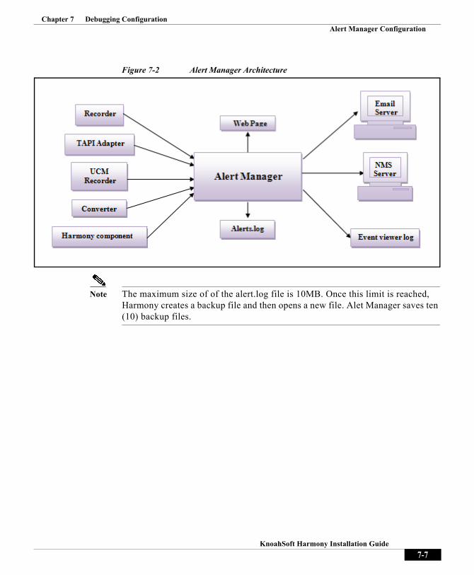
Chapter 7 Debugging ConfigurationAlert Manager Configuration
Figure 7-2 Alert Manager Architecture
Note The maximum size of of the alert.log file is 10MB. Once this limit is reached, Harmony creates a backup file and then opens a new file. Alet Manager saves ten (10) backup files.
7-7KnoahSoft Harmony Installation Guide
Chapter 7 Debugging ConfigurationAlert Manager Configuration
Alert Manager ConfigurationThe following is a list of configurable Alert Manager parameters in the AlertManager.ini file, located in the ??? directory:
• LogLevel—String which dictates verbosity level of output to the log file. Values=TRACE/DEBUG/ERROR/INFO/WARN/FATAL.
• MaxSizeOfAlertManagerMessagesQueue—Number of alert messages Alert Manager queue can hold (minimum/default = 1000, maximum 10000).
• HTMLTableWidth—Width, in pixels, of web page table for an HTML alert request (default = 100).
• HTMLTableBorderSize—Width, in pixels, of web page table border for an HTML alert request (default = 1).
• HTMLWebPageRefreshInterval—Interval, in seconds, that web page displaying HTML alert is refreshed (default = 30).
• HTMLFontSize—Size, in pixels, of font for text in web page displaying HTML alert (default = 2).
• MaxSizeOfAlertLogFile—Size limit, in MB, of alerts.log file (default = 10).
• MaxNoOfAlertLogFiles—Maximum number of alerts.log files to be created (default = 10).
• MaxSizeOfSNMPTrapAlertsQueue—Maximum size of SNMP Trap alerts queue (default = 1,000).
• NMSIPAddress—IP address of NMS server.
• NMSPort—Port number of NMS server, i.e., UDP port (default = 162).
• SendSNMPTraps—TRUE/FALSE parameter used to enable sending of alerts as SNMP traps to the NMS server (default = FALSE).
• NumberOfAlertsToDisplay—Number of alerts to be displayed in the web page (default = 1,000).
• LogAlertsToEventViewer—TRUE/FALSE parameter used to enable sending of alerts as logging events to the Event Viewer (default = FALSE).
• SenderEmailAddress—Email address to be assigned as the sender of email alerts.
• EmailAddress1—Email address of email alert recipient.
• EmailAddress2—Email address of email alert recipient.
7-8KnoahSoft Harmony Installation Guide

Chapter 7 Debugging ConfigurationAlert Manager Configuration
• EmailAddress3—Email address of email alert recipient.
• MailServerIpAddress—IP address of mail server.
• MailServerPort—Port number of mail server (default = 25).
• EmailAlertsEnabled—TRUE/FALSE parameter used to enable sending of alerts as emails to the mail server (default = FALSE).
• IPAccessControlForAlertRequestsEnabled—TRUE/FALSE parameter used to validate the network to receive and accept web connections for web alerts (default = TRUE).
• IPAccessControlListForAlertRequests—Used to specify IP addresses and range of machines that Alert Manager will accept alerts from for web alerts (e.g., 10.2.86.16/14, 10.2.84.12/32, etc.).
Web AlertsAlert Manager consists of a web server that accepts web connections and processes requests to display alerts in the web page. Filtering can be done to fetch desired by IP address of machine, alert severity, Harmony component name, and number of latest alerts.
Alert Manager can also validate the network IP address of the web request. If the network address is in the AlertManager.ini file, requests from those networks are validated and allowed to access Alert manager alerts. (See “Alert Manager Configuration” topic, above.)
To configure web alerts:
Step 1 Ensure that the IPAccessControlForAlertRequestsEnabled and IPAccessControlListForAlertRequests parameters in the AlertManager.ini file are properly configured, as previously described.
Step 2 Enter the following URL in your web browser, where machine_IP is the IP address where Alert Manager is installed and running:
http//machine_IP:33035/HarmonyAlertsConsole
7-9KnoahSoft Harmony Installation Guide

Chapter 7 Debugging ConfigurationAlert Manager Configuration
Figure 7-3 Alert Manager Selector
Step 3 The alert manager selector page is displayed. Enter and select the following:
• Number of Alerts—Number of alerts to display in the web page (default = 1000).
• Alert severity—Alert severity level (FATAL, ERROR, WARN, DEBUG and INFO) to display in web page. By default, type ALL is selected, to display all alert types.
• Machine IP Address—IP address of machine where the Harmony component you want to monitor alerts for is running. If no IP address is entered, all IP address are considered and alerts for all machine IP addresses are displayed.
• Application name—Select the Harmony component you wish to monitor alerts for. Multiple selections are allowed. If no components are selected, the alerts of all components are displayed in the web page.
7-10KnoahSoft Harmony Installation Guide

Chapter 7 Debugging ConfigurationAlert Manager Configuration
Step 4 Click Submit. The Alert Manager web page is displayed. Alerts are displayed by date, and are color-coded as follows:
FATAL = RedERROR = Dark red WARN = BlueINFO = Green DEBUG = Black
Figure 7-4 Alert Manager Web Page
SNMP TrapsAlert Manager acts as SNMP agent and sends alerts as SNMP traps to the SNMP manager (i.e., the NMS server).
SNMP traps are alerts generated by agents on a managed device. They are network packets that contain data relating to a component of the system sending the trap. The data may be statistical in nature or even status related.
Alert Manager acts as SNMP agent and provides the ability to send traps (i.e., notifications) to advise an administrator when one or more conditions have been met. Traps are defined in the Management Information Base (MIB) provided by
7-11KnoahSoft Harmony Installation Guide

Chapter 7 Debugging ConfigurationAlert Manager Configuration
the vendor, and the administrator then defines thresholds, or limits to the conditions, to generate the trap. Conditions range from preset thresholds to a restart. After the condition has been met, the SNMP agent forms the SNMP packet (i.e., trap).
Trap-based notification allows an administrator who is responsible for a large number of devices to be notified of selective events, instead of having to poll or request information from every object on every device in the network.
To configure SNMP traps:
Step 1 Ensure that the SendSNMPTraps parameter is set to TRUE in the AlertManager.ini file.
Step 2 Ensure that the NMSIPAddress and NMSPort parameters in the AlertManager.ini file are properly configured, as previously described.
Step 3 Start Alert Manager via Start > Program Files > KnoahSoft > Alert Manager > Start Alert Manager. Alert Manager will now receive alerts, and events are generated as SNMP traps and sent to the NMS server on the specified port.
Event Viewer LogAlert Manager has the ability to log ERROR and FATAL type alerts in the Windows Event Viewer log, if desired. Event logs in the Event Viewer can help predict and identify sources of system problems.
Three types of logs are recorded: Application, System, and Security. (All users can view Application and System logs; administrators are the only ones who can access Security logs.)
The Application log contains events logged by applications and programs. For example, a database program might record a file error in the Application log; the program developer decides which events to record.
The Event Viewer records five types of events:
• Error• Warning• Information,• Success Audit • Failure Audit
7-12KnoahSoft Harmony Installation Guide

Chapter 7 Debugging ConfigurationAlert Manager Configuration
The Application log in the Event Viewer will display alerts as ERROR types when they are received from the Alert Manager.
To configure and view alerts with Event Viewer:
Step 1 Ensure that the LogAlertsToEventViewer parameter is set to TRUE in the AlertManager.ini file.
Step 2 Open the Event Viewer Application Log, via Control Panel > Administrative Tools > Event Viewer > Application Log.
Step 3 Look for any Harmony components under the Source column, to see if there are any ERROR events listed in the Type column.
Figure 7-5 Event Viewer Application Log
7-13KnoahSoft Harmony Installation Guide

Chapter 7 Debugging ConfigurationGetDumpFilesForCall
Email AlertsAlert Manager can send alert message emails to the Mail server, if desired. Alert Manager acts as an email client, preparing emails with alert message details and then sending them to the pre-configured email addresses.
To configure email alerts:
Step 1 Ensure that the EmailAlertsEnabled parameter is set to TRUE in the AlertManager.ini file.
Step 2 Configure the MailServerIpAddress, MailServerPort, SenderEmailAddress, EmailAddress1, EmailAddress2, EmailAddress3, and EmailAddress4 parameters in the AlertManager.ini file are properly configured, as previously described.
GetDumpFilesForCallThe GetDumpFilesForCall utility program collects the dump file of particular configured calls from the dump location.
During installation, all the necessary folders and files are created in the default location C:\Program Files\KnoahSoft\GetDumpFilesForCall.
The KnoahSniffer application is used to capture the dump files. So KnoahSniffer must be running on the recording server in order to debug call recording issues.
Ensure that KnoahSniffer does not over write those files with new files, as it runs in a ring buffer fashion. (Refer to KnoahSniffer configuration and how to allocate enough space so you can retain the files for a call which is two or three days old.)
GetDumpFilesForCall Configuration Settings
To configure the utility:
Step 1 Select drive the dump files are located (e.g., C:\). This will be the DriveSelect parameter value configured in the KnoahSniffer.ini file.
Step 2 Select the SourceFilesLocation (i.e., the name of directory where we have the dump files; e.g., VoiceDataTest).
7-14KnoahSoft Harmony Installation Guide

Chapter 7 Debugging ConfigurationGetDumpFilesForCall
Note Note: The GetDumpCallFilesForCall utility will see the <DriveSelect>:\SourcelFilesLocation directory as the source of dump file. (It should be same as TethereaFilesLocation configured in KnoahSniffer.ini file, as KnoahSniffer creates dump files in this directory.
Step 3 Select the VoiceCaseId: for the dump file (e.g., agent1002_MUM_4063_07232009_134512_001500_0)
Step 4 Select the DestFilesLocation directory where the GetDumpFilesForCall utility will copy all dump files related to the VoiceCaseID. This folder is the same as the VoiceCaseId directory. (This is useful when you collect the dump files of more than one call at the same time).Dump files are located in the <DriveSelect >:\ DestFilesLocation directory.
Step 5 Select the TimeBeforeCallStar, in minutes. Based on the configured time, this utility will collect all dump files before the call starts (e.g., - 2).
Step 6 Select the TimeAfterCallEnd, in minutes. This is based on the configured time the utility will collect the dump files up to the configured call end time (e.g., -5).
For example:
VoiceCaseId=agent1002_MUM_4063_07232009_134512_001500_0
TimeBeforeCallStart=2
TimeAfterCallEnd=5
Call start time of call is "134512" on “07232009”.
GetDumpFilesForCall utility creates the range based on TimeBeforeCallStart, TimeBeforeCallEnd and collect the dump files as follows:
Start range = 134512 + 2 (in min) = 134312
End range = 134512 + 5 (in min) = 135012
So dump files will be 134312 to 135012 on 07232009 (July 23, 2009).
To execute the utility:
Step 1 Configure all parameter in the ini file then click GetDumpFilesForCall.exe.
Step 2 View the dump files collected at <DriveSelect>:\DestFilesLocation.
7-15KnoahSoft Harmony Installation Guide

Chapter 7 Debugging ConfigurationGetDumpFilesForCall
7-16KnoahSoft Harmony Installation Guide

Knoa
C H A P T E R 8
ArchivingArchiving is a maintenance task you must perform on a regular basis, moving calls from the storage server to an archival server in order to create space for new calls on the storage server.
To automatically archive calls, the Scheduled Archiver service is used
8-1hSoft Harmony Installation Guide

Chapter 8 ArchivingScheduled Archiver
Scheduled ArchiverThe Scheduled Archiver service is designed to automatically archives calls based on the parameters you configure in the archiver.ini file. Different transaction parameters can be configured to archive different types of calls, based on clients, sites, Work Types, call freshness, call start times, etc. This allows you to schedule a wide-variety of transaction types for archiving.
Archiving can also be scheduled to start and stop during specified times—i.e., during lean, off-peak system processing periods.
ConfigurationScheduled Archiver is configured via the archiver.ini file, located in the C:\Program Files\KnoahSoft\Archiver directory. The ini file can be modified using a text editor, to edit or add new transactions. (A transaction is defined as a set of parameters you create for archival purposes.)
Note After modifying the ini file, you must either restart your server or start the service, as described below.
Database Information• DatabaseServerIPAddress—IP address of machine where SQL Server is
installed.
• Database Name—Name of database. Enter Metrics_Commercial.
• DatabaseUserId—Database user ID. Enter metric.
• Database Password—Password for database user metric.
Mail Notification Information
• MailServerIpAddress—IP address of the local SMTP mail server.
• SenderEmailAddress—Email address to be associated with when component services encounter errors or communication is otherwise interrupted (e.g., network connection lost, storage disk full, etc.).
8-2KnoahSoft Harmony Installation Guide

Chapter 8 ArchivingScheduled Archiver
• EmailAddress1—Email addresses where alerts will be sent.
Source Storage Settings
• Storage Path—Storage server IP address and directory where calls are currently stored (e.g., \\10.2.86.26\Voice).
• StorageServerLoginId—ID used to connect to storage server. In a single server deployment, this is the administrative username you created for Harmony (e.g., KnoahSoftAdmin).
• StorageServerPassword— Password for specified user ID, as per login ID above.
Destination Storage Settings
• DestStorageServerPath—Server IP address and directory where calls are to archived, as moved from the storage server (e.g., \\10.2.86.46\Voice).
• DestStorageServerLoginId—ID used to connect to server where calls are to archived (e.g., KnoahSoftAdmin).
• DestStorageServerPassword—Password for specified user ID, as per login ID above.
Transaction Settings
• NoOfTransactions—Enter number of transactions you want to configure for archiving. Transactions are numbered sequentially, and each transaction consists of its own distinct list of the parameters, as listed below (e.g., Transaction1_SiteList, Transaction2_SiteList, Transaction1_ClientList, Transaction2_ClientList, etc.).
• Transaction<num>_SiteList—Comma separated list of sites whose calls are to be archived—e.g., Cambridge, Oakland, San Francisco. (Sites are created in the Harmony System Administration module.)
• Transaction<num>_ClientList—Comma separated list of clients whose calls are to be archived (e.g., ELNK, PALM, AWH). (Clients are created in the Harmony System Administration module.)
8-3KnoahSoft Harmony Installation Guide

Chapter 8 ArchivingScheduled Archiver
• Transaction<num>_WorkTypeList—Comma separated list of Work Types whose calls are to be archived. (Work Types are created in the Harmony System Administration module.)
Note Calls are archived based on Work Types, and the client and site parameters are ignored. If a Work Types is not entered, calls are archived based on the other transaction parameters.
• Transaction<num>_ArchiveCallsOlderThan—For this parameter, entering 10 means all calls recorded 10 days ago or later from the current date will be archived. Calls recorded 8 days ago, for example, will not be archived for another 2 days.
• Transaction<num>_ArchiveCallsNewerThan—For this parameter, entering 10 means all calls recorded 10 days ago or less from the current date will be archived. For example, calls recorded 9 days ago will be archived but calls recorded 11 days ago will not be archived.
Important Notes
– The value of the ArchiveCallsOlderThan parameter must always be less than or equal to the ArchiveCallsNewerThan parameter, to avoid a system conflict.
– If both the ArchiveCallsOlderThan and ArchiveCallsNewerThan parameters are left empty, the default value of ArchiveCallsOlderThan is 30 and ArchiveCallsNewerThan is 31.
– If the ArchiveCallsOlderThan parameter is empty, but a parameter is entered for ArchiveCallsNewerThan, then the ArchiveCallsOlderThan parameter will be the ArchiveCallsNewerThan parameter, less 1 (one).
– If the ArchiveCallsNewerThan parameter is empty, but a parameter is entered for ArchiveCallsOlderThan, then the ArchiveCallsNewerThan parameter will be the ArchiveCallsOlderThan parameter, plus 1 (one).
• Transaction<num>_CallStartTime—Call start time, in HH:MM:SS format (hours minutes seconds). Default = 00:00:00
• Transaction1_CallEndTime—Call end time, in HH:MM:SS format (hours minutes seconds). Default = 23:59:59.
8-4KnoahSoft Harmony Installation Guide

Chapter 8 ArchivingScheduled Archiver
• Transaction<num>_CallType—Enter InBound, OutBound, or Both. If set to Inbound, only inbound calls will be archived; if set to Outbound, only outbound calls will be archived. If set to Both or left empty, both inbound and outbound calls with be archived. Default = Both.
• Transaction<num>_ScreenCaptureType—Enter VoiceOnly, VoiceScreen, or Both. If set to VoiceOnly, voice calls without screencaptures are archived; if set to VoiceScreen, voice calls and associated screencaptures are archived; if set to Both, VoiceOnly and VoiceScreen calls are archived. Default = Both.
• Transaction<num>_MinCallDuration—Minimum length of calls, in seconds, to be archived. For example, if set to 60, all calls at least 60 seconds in length with be archived. Default = 0 (zero).
• Transaction<num>_MaxCallDuration—Maximum length of calls, in seconds, to be archived. For example, if set to 7200, all calls up to 7200 seconds (two hours) will be archived; calls longer than this will not. Default = 43200 (12 hours)
• Transaction<num>_DeleteSource—Enter TRUE or FALSE. Set to TRUE if you want to delete calls from the storage server after archiving. Default = FALSE.
• Transaction<num>_OutputFormat—Output format of recorded call. Must be set to RAW.
• Transaction<num>_OutputLocation—Currently not used.
• Transaction<num>_ArchiveScreens—Enter TRUE or FALSE. Set to TRUE if you want to archive screencaptures with calls. Default = FALSE.
Lean Period Configuration Settings
• ArchiveCallsDuringLeanPeriod—Enter TRUE or FALSE. Set to TRUE to archive calls during a lean period (as specified with the start and stop parameters, below). Default = FALSE.
• LeanPeriodStartTime—Enter archival start time in this field, in hours and minutes format (HH:MM). For example, if set to 01:00, the service will start at 1AM and run until the specified stop time.
• LeanPeriodStopTime—Enter archival stop time in this field, in hours and minutes format (HH:MM). For example, if set to 04:00, the service will stop archiving at 4AM.
8-5KnoahSoft Harmony Installation Guide

Chapter 8 ArchivingScheduled Archiver
Other Settings
• LogLevel=DEBUG— Set to TRUE to allow for system messages to be saved into a log file, for debugging purposes.
Starting and Stopping Scheduled ArchiverYou can start or stop the Scheduled Archiver service in one of two ways:
• Navigate to Start > Programs > KnoahSoft > Archiver > and select Start Archiver or Stop Archiver, as appropriate;
• Manually start or stop the Archiver Service by opening the Windows Services window in one of two ways:
– Navigate to Start > Run then enter services.msc
– Navigate to Start > Control Panel > Administrative Tools > Services
8-6KnoahSoft Harmony Installation Guide
Knoa
C H A P T E R 9
Other FeaturesThis chapter describes additional Harmony features that can be configured for use, specifically:
• On-demand recording
• ANI-based recording
• Shift-based recording
• Dual monitor modes
9-1hSoft Harmony Installation Guide

Chapter 9 Other FeaturesOn-demand Recording
On-demand RecordingOn-demand recording can be initiated either by a phone key event or as a Record Call Now selection during Silent Monitoring. On-demand recording can be used with Session Initiation Protocol (SIP) or Skinny Client Control Protocol (SCCP) based phones.
Note A license is required for every user that you wish to use on-demand recording for.
You enter the start and stop recording patterns while running the Harmony installer. To enable on-demand recording if you did not enter the patterns during installation, or to change those settings after installation, you must modify the recorder.ini file, located in the C:\ProgramFiles\KnoahSoft\Recorder directory, by editing the following parameters:
StartRecordingPattern=*7*7 (for example)StopRecordingPattern=*8*8 (for example)
Note You can also change these parameters by re-running the installer. Refer to the “Changing Installation Configuration” topic in this document for more information.
Normally, the call is recorded with the initiation of the start recording key sequence. If you want to start recording from the beginning of the call, you must modify the following ini file parameter:
MonitorAllCalls=TRUE
You must restart the recorder service after modifying the file.
Note Refer to the Harmony System Administration Guide for Silent Monitoring Record Call Now information for on-demand recording.
9-2KnoahSoft Harmony Installation Guide

Chapter 9 Other FeaturesANI-based Recording
ANI-based RecordingHarmony can be configured to record incoming calls based on specific area codes (a.k.a, Automatic Number Identification (ANI)-based recording). To enable this feature, you must modify the Recorder.ini file, which is located in the following directory:
C:\ProgramFiles\KnoahSoft\Recorder\Recorder.ini
Open the file, then edit and save the file by adding the following parameter: ANIPrefixesList=xxx,yyy
Where xxx and yyy are the comma-separated area codes you always want to be recorded (e.g., 212, 415).
Note Be sure to leave all other settings in the Recorder.ini file (e.g., log level, shift timings, etc.) as they are.
Recording RulesCall recording rules are configured on an agent-by-agent basis by the System Administrator. It is important to note that:
• The agent must be enabled to record calls;
• If an agent is configured to record random calls (i.e., not continuous), all calls matching the area codes in the Recorder.ini file will still be recorded;
• If an agent has exceeded the maximum number of calls they are configured to record, all calls matching the area codes in the Recorder.ini file will be still recorded;
• If an agent receives a call that does not fall within the shift timings, but the call is an ANI-based call with a matching area code, the call is recorded.
• Rules are not affected by ANI-based calls (e.g., if an agent has exceeded the maximum number of calls they are configured to record screen captures for, will not be enabled for ANI-based calls).
9-3KnoahSoft Harmony Installation Guide

Chapter 9 Other FeaturesANI-based Recording
Note For information on how to set employee recording rules, refer to the “Adding A New Employee” topic in Chapter 4 of the KnoahSoft System Administration Guide, Version 3.1.
Shift-based RecordingHarmony can be configured to record incoming calls based on specific time shifts. To enable this feature, you must modify the Recorder.ini file, which is located in the following directory:
C:\ProgramFiles\KnoahSoft\Recorder\Recorder.ini
Open the file, then edit and save the file by adding the following parameters: ShiftTimingsDefined=TRUEShift1Timing= HH:MM-HH:MMShift2Timing= HH:MM-HH:MMShift3Timing= HH:MM-HH:MM
Where ShiftTimingsDefined is defined as either TRUE or FALSE (i.e., enabled or disabled), and the Shift1Timing, Shift2Timing, and Shift3Timing parameters are the time ranges for recording.
You can enter timings values to cover a complete twenty-four hour work cycle or select time shifts.
Twenty-four hour coverage example: ShiftTimingsDefined=TRUEShift1Timing=1:00-9:00Shift2Timing=9:00-17:00Shift3Timings=17:00-1:00
Select hours coverage example: ShiftTimingsDefined=TRUEShift1Timing=1:00-8:00Shift2Timing=11:00-17:00Shift3Timings=19:00-21:00
Note Be sure to leave all other settings in the Recorder.ini file (e.g., log level, area code prefixes, etc.) as they are.
9-4KnoahSoft Harmony Installation Guide

Chapter 9 Other FeaturesDual Monitor Modes
Recording Rules
With shift based recording, calls are recorded only during the shift period, and all other recording rules apply. It is important to note that:
• If an agent is configured to record a maximum 5 calls and the recording type is continuous, the first 5 calls received during the shift will be recorded.
• If an agent is configured to record a maximum 5 calls and the recording type is random, 5 random calls during the shift will be recorded.
• If an agent receives a call that does not fall within the shift timings, the call will not be recorded, even if the agent is configured with recording type continuous.
• If an agent receives a call that does not fall within the shift timings, but the call is an ANI-based call with a matching area code, the call is recorded.
• Rules are not affected by shift-based recording (e.g., if an agent has exceeded the maximum number of calls they are configured to record screen captures for, will not be enabled for shift-based calls).
Note For information on how to set employee recording rules, refer to the “Adding A New Employee” topic in Chapter 4 of the KnoahSoft System Administration Guide, Version 3.1.
Dual Monitor ModesA dual monitor setup is a good way to efficiently manage your desktop window viewing when running Harmony.
For example, a manager may want to dedicate their primary monitor for tracking live calls and leave their secondary monitor available for other applications (word processing, spreadsheets, etc.). A quality evaluator may want to combine two monitors (i.e., span) into one, for easier viewing of detailed evaluation forms.
The Windows operating system allows you to view your desktop in one of several dual display modes. Harmony’s functionality supports all configuration parameters—resolution, scaling, color depth, refresh rate, desktop orientation, and so forth—for the following dual monitor modes:
9-5KnoahSoft Harmony Installation Guide

Chapter 9 Other FeaturesDual Monitor Modes
• Dual view—In this mode, the screen is the same for both monitors. Windows can be moved from the primary monitor to the secondary monitor, and vice versa. is performed for the primary monitor only; any activity on the secondary monitor is not captured.
• Span view—The screen is stretched across two monitors. One half of the screen is viewed on the primary monitor and the other half is viewed on the secondary monitor. The image on both monitors is captured as a single image.
• Clone View—The screen for both monitors is the same. Screen capturing of the primary monitor is performed as a single image
.
Note Not all versions of KnoahSoft Harmony 2.0 can be used for in dual view mode. Contact your reseller for more information.
Hardware RecommendationsThe following are recommendations for hardware for desktop to use dual monitor mode with Harmony. Note that these are recommendations only; you may need additional hardware:
• Microsoft Windows XP or Vista
• 1.5GHz processor (e.g., Intel Pentium 4, AMD Athlon XP 1500+, or equivalent)
• 256MB RAM
• 2GB of free hard disk space
9-6KnoahSoft Harmony Installation Guide

Chapter 9 Other FeaturesDual Monitor Modes
• SLI-ready motherboard, with PCI Express chipset support, and dual x16 connectors for two graphics cards
• Two dual monitor Express graphics cards, with identical GPU and memory, preferably both cards from the same vendor
• One SLI connector to connect graphics cards
Tip You can adjust your GPU graphics cards timings, to support a variety of different display timings, for ultimate flexibility for analog CRT and DVI connections.
Dual Monitor SetupTo setup your Windows system for dual monitor use, right-click on the desktop, then select Properties > Settings > Advanced (or alternatively, click Start > Control Panel > Display > Settings > Advanced).
For complete step-by-step procedures on how to expand your workspace for multiple monitors, refer to your Windows system documentation.
9-7KnoahSoft Harmony Installation Guide

Chapter 9 Other FeaturesDual Monitor Modes
9-8KnoahSoft Harmony Installation Guide

I N D E X
A
ADS deployment 4-31
agent load capability 1-2
ANI-based recording 9-3
anti-virus software 2-6
application serverusage 1-2
archiving 8-1
B
best practices 2-5
C
calculatorstorage 2-2
call download utility 4-36
call flow overview 1-4
Call ManagerCTI user 6-2
Cisco TSP 6-14
Cisco adapter configuration 4-27
cluster settings 4-19
common configuration settings 4-3
component configuration 4-1
settings 4-9
component installation 3-1
core components 3-1
CTI usercreating 6-2
D
databaserequirements 2-6
database configuration 3-5
database serverredundancy 1-6
usage 1-2
Data NIC 1-4
debuggingcomponents 3-2
configuration 7-1
deployment scenarios 1-3
multi-site 1-3
single site 1-3
domain controller 2-5
dual monitor modes 9-5
IN-1KnoahSoft Harmony User Guide

Index
E
ED service 4-23
event viewer log 7-12
F
failover 1-5
G
G729 generator 4-17
GetDumpFilesForCall 7-14
H
Hamonyeditions 1-1
hard disk driverequirement, multi-server 2-2
requirement, single server 2-1
hardware requirements 2-1
HTTP web requestsprocess 1-4
I
IIS web server configuration 5-2
installationcomponent 3-1
IN-2KnoahSoft Harmony User Guide
installation configurationchanging 5-4
K
KnoahSnifferoverview 1-6
space requirement 1-7
L
log manager configuration 7-2
M
multi-site deployment 1-3
N
network configuration 2-4
network interface cards 1-4
network ports 2-5
NICs 1-4
non-ADS deployment 4-29
O
on-demand recordersettings 4-13
on-demand recording 9-2

Index
P
post-installation checklist 5-6
pre-installation checklists 2-8
process check list 4-22
processorrequirement, single server 2-1
R
RAMrequirement, multi-server 2-2
requirement, single server 2-1
recording middleware service 4-33
recording serverfailover 1-5
usage 1-2
redundancy 1-5
reporting servicesrequirements 2-7
report templates 5-5
RTP packetscall flow 1-4
RTP traffic 2-4
S
screen capture issues 5-9
screen configuration 4-29
server name resolution plan 2-5
servicesstarting 5-3
stopping 5-3
shift-based recording 9-4
SIP servers 4-14
SNMP traps 7-11
software requirements 2-6
SPAN ports 1-6
starting 4-26
starting components 4-26
starting services 5-3
stopping services 5-3
storage calculator 2-2
storage serverredundancy 1-6
usage 1-2
system overview 1-2
system requirements 2-1
T
TAPI integration 6-1
technical support 1-2
third-party applications 2-7
troubleshooting 5-7
TSP installation, configuration 6-5
U
UCM recorder 4-18
upload client 4-35
IN-3KnoahSoft Harmony User Guide

Index
upload server 4-21
usage 2-5
V
Voice NIC 1-4
W
web alerts 7-9
IN-4KnoahSoft Harmony User Guide
Related Documents