ETSI EN 301 908-15 V5.2.1 (2011-07) Harmonized European Standard IMT cellular networks; Harmonized EN covering the essential requirements of article 3.2 of the R&TTE Directive; Part 15: Evolved Universal Terrestrial Radio Access (E-UTRA FDD) (Repeaters)

Welcome message from author
This document is posted to help you gain knowledge. Please leave a comment to let me know what you think about it! Share it to your friends and learn new things together.
Transcript
ETSI EN 301 908-15 V5.2.1 (2011-07)
Harmonized European Standard
IMT cellular networks;Harmonized EN covering the essential requirements
of article 3.2 of the R&TTE Directive;Part 15: Evolved Universal Terrestrial Radio Access
(E-UTRA FDD) (Repeaters)
ETSI
ETSI EN 301 908-15 V5.2.1 (2011-07)2
Reference REN/MSG-TFES-008-15
Keywords 3G, 3GPP, cellular, digital, IMT, IMT-2000, mobile, radio, regulation, repeater, UMTS,
WCDMA, E-UTRA, LTE
ETSI
650 Route des Lucioles F-06921 Sophia Antipolis Cedex - FRANCE
Tel.: +33 4 92 94 42 00 Fax: +33 4 93 65 47 16
Siret N° 348 623 562 00017 - NAF 742 C
Association à but non lucratif enregistrée à la Sous-Préfecture de Grasse (06) N° 7803/88
Important notice
Individual copies of the present document can be downloaded from: http://www.etsi.org
The present document may be made available in more than one electronic version or in print. In any case of existing or perceived difference in contents between such versions, the reference version is the Portable Document Format (PDF).
In case of dispute, the reference shall be the printing on ETSI printers of the PDF version kept on a specific network drive within ETSI Secretariat.
Users of the present document should be aware that the document may be subject to revision or change of status. Information on the current status of this and other ETSI documents is available at
http://portal.etsi.org/tb/status/status.asp
If you find errors in the present document, please send your comment to one of the following services: http://portal.etsi.org/chaircor/ETSI_support.asp
Copyright Notification
No part may be reproduced except as authorized by written permission. The copyright and the foregoing restriction extend to reproduction in all media.
© European Telecommunications Standards Institute 2011.
All rights reserved.
DECTTM, PLUGTESTSTM, UMTSTM and the ETSI logo are Trade Marks of ETSI registered for the benefit of its Members. 3GPPTM and LTE™ are Trade Marks of ETSI registered for the benefit of its Members and
of the 3GPP Organizational Partners. GSM® and the GSM logo are Trade Marks registered and owned by the GSM Association.
ETSI
ETSI EN 301 908-15 V5.2.1 (2011-07)3
Contents
Intellectual Property Rights ................................................................................................................................ 5
Foreword ............................................................................................................................................................. 5
Introduction ........................................................................................................................................................ 6
1 Scope ........................................................................................................................................................ 7
2 References ................................................................................................................................................ 7
2.1 Normative references ......................................................................................................................................... 7
2.2 Informative references ........................................................................................................................................ 8
3 Definitions, symbols and abbreviations ................................................................................................... 8
3.1 Definitions .......................................................................................................................................................... 8
3.2 Symbols .............................................................................................................................................................. 9
3.3 Abbreviations ................................................................................................................................................... 10
4 Technical requirements specifications ................................................................................................... 10
4.1 Environmental profile ....................................................................................................................................... 10
4.2 Conformance requirements .............................................................................................................................. 10
4.2.1 Introduction................................................................................................................................................. 11
4.2.2 Operating band unwanted emissions .......................................................................................................... 11
4.2.2.1 Definition .............................................................................................................................................. 11
4.2.2.2 Limit ...................................................................................................................................................... 11
4.2.2.2.1 General operating band unwanted emissions ................................................................................... 12
4.2.2.2.2 Protection of the BS receiver in the operating band ........................................................................ 16
4.2.2.2.3 Co-existence with services in adjacent frequency bands ................................................................. 16
4.2.2.2.4 Protection of DTT............................................................................................................................ 17
4.2.2.3 Conformance ......................................................................................................................................... 17
4.2.3 Spurious emissions ..................................................................................................................................... 17
4.2.3.1 Definition .............................................................................................................................................. 17
4.2.3.2 Limit ...................................................................................................................................................... 17
4.2.3.2.1 Spurious emissions .......................................................................................................................... 18
4.2.3.2.2 Co-existence with other systems in the same geographical area ..................................................... 18
4.2.3.3 Conformance ......................................................................................................................................... 19
4.2.4 Maximum output power .............................................................................................................................. 19
4.2.4.1 Definition .............................................................................................................................................. 19
4.2.4.2 Limit ...................................................................................................................................................... 19
4.2.4.3 Conformance ......................................................................................................................................... 20
4.2.5 Input intermodulation ................................................................................................................................. 20
4.2.5.1 Definition .............................................................................................................................................. 20
4.2.5.2 Limit ...................................................................................................................................................... 20
4.2.5.2.1 General input intermodulation requirement ..................................................................................... 20
4.2.5.2.2 Co-existence with other systems ..................................................................................................... 21
4.2.5.3 Conformance ......................................................................................................................................... 22
4.2.6 Out of band gain ......................................................................................................................................... 22
4.2.6.1 Definition .............................................................................................................................................. 22
4.2.6.2 Limits .................................................................................................................................................... 22
4.2.6.3 Conformance ......................................................................................................................................... 22
4.2.7 Adjacent Channel Rejection Ratio .............................................................................................................. 22
4.2.7.1 Definition .............................................................................................................................................. 22
4.2.7.2 Limit ...................................................................................................................................................... 23
4.2.7.2.1 ACRR .............................................................................................................................................. 23
4.2.7.2.2 Co-existence with UTRA ................................................................................................................ 23
4.2.7.3 Conformance ......................................................................................................................................... 23
4.2.8 Output intermodulation ............................................................................................................................... 23
4.2.8.1 Definition .............................................................................................................................................. 23
4.2.8.2 Limit ...................................................................................................................................................... 24
4.2.8.3 Conformance ......................................................................................................................................... 24

ETSI
ETSI EN 301 908-15 V5.2.1 (2011-07)4
5 Testing for compliance with technical requirements .............................................................................. 24
5.1 Environmental conditions for testing ............................................................................................................... 24
5.2 Interpretation of the measurement results ........................................................................................................ 24
5.3 Essential radio test suites .................................................................................................................................. 26
5.3.1 Operating band unwanted emissions .......................................................................................................... 26
5.3.1.1 Initial conditions ................................................................................................................................... 26
5.3.1.2 Procedures ............................................................................................................................................. 26
5.3.2 Spurious emissions ..................................................................................................................................... 27
5.3.2.1 Initial conditions ................................................................................................................................... 27
5.3.2.2 Procedures ............................................................................................................................................. 27
5.3.3 Maximum output power .............................................................................................................................. 28
5.3.3.1 Initial conditions ................................................................................................................................... 28
5.3.3.2 Procedures ............................................................................................................................................. 28
5.3.4 Input intermodulation ................................................................................................................................. 28
5.3.4.1 Initial conditions ................................................................................................................................... 28
5.3.4.2 Procedures ............................................................................................................................................. 29
5.3.5 Out of band gain ......................................................................................................................................... 29
5.3.5.1 Initial conditions ................................................................................................................................... 29
5.3.5.2 Procedures ............................................................................................................................................. 29
5.3.6 Adjacent Channel Rejection Ratio .............................................................................................................. 30
5.3.6.1 Initial conditions ................................................................................................................................... 30
5.3.6.2 Procedures ............................................................................................................................................. 30
5.3.7 Output intermodulation ............................................................................................................................... 30
5.3.7.1 Initial conditions ................................................................................................................................... 30
5.3.7.2 Procedures ............................................................................................................................................. 30
Annex A (normative): HS Requirements and conformance Test specifications Table (HS-RTT) ........................................................................................................ 32
Annex B (normative): Repeater configurations ................................................................................ 34
B.1 Power supply .......................................................................................................................................... 34
B.2 Power supply options ............................................................................................................................. 34
B.3 Combining of Repeaters ......................................................................................................................... 34
Annex C (normative): Repeater stimulus signal spectral purity requirements .............................. 35
Annex D (informative): Environmental profile specification ............................................................. 36
Annex E (informative): The EN title in the official languages ........................................................... 37
Annex F (informative): Bibliography ................................................................................................... 38
History .............................................................................................................................................................. 39
ETSI
ETSI EN 301 908-15 V5.2.1 (2011-07)5
Intellectual Property Rights IPRs essential or potentially essential to the present document may have been declared to ETSI. The information pertaining to these essential IPRs, if any, is publicly available for ETSI members and non-members, and can be found in ETSI SR 000 314: "Intellectual Property Rights (IPRs); Essential, or potentially Essential, IPRs notified to ETSI in respect of ETSI standards", which is available from the ETSI Secretariat. Latest updates are available on the ETSI Web server (http://ipr.etsi.org).
Pursuant to the ETSI IPR Policy, no investigation, including IPR searches, has been carried out by ETSI. No guarantee can be given as to the existence of other IPRs not referenced in ETSI SR 000 314 (or the updates on the ETSI Web server) which are, or may be, or may become, essential to the present document.
Foreword This Harmonized European Standard (EN) has been produced by ETSI Technical Committee Mobile Standards Group (MSG).
The present document has been produced by ETSI in response to mandate M/284 from the European Commission issued under Council Directive 98/34/EC [i.1] (as amended) laying down a procedure for the provision of information in the field of technical standards and regulations.
The title and reference to the present document are intended to included in the publication in the Official Journal of the European Union of titles and references of Harmonized Standard under the Directive 1999/5/EC [i.2].
See article 5.1 of Directive 1999/5/EC [i.2] for information on presumption of conformity and Harmonised Standards or parts thereof the references of which have been published in the Official Journal of the European Union.
The requirements relevant to Directive 1999/5/EC [i.2] are summarised in annex A.
The present document is part 15 of a multi-part deliverable covering the essential requirements under article 3.2 of Directive 1999/5/EC [i.2] (R&TTE Directive) for Base Stations (BS), Repeaters and User Equipment (UE) for IMT cellular networks, as identified below:
Part 1: "Introduction and common requirements";
Part 2: "CDMA Direct Spread (UTRA FDD) User Equipment (UE)";
Part 3: "CDMA Direct Spread (UTRA FDD) Base Stations (BS)";
Part 4: "CDMA Multi-Carrier (cdma2000) User Equipment (UE)";
Part 5: "CDMA Multi-Carrier (cdma2000) Base Stations (BS)";
Part 6: "CDMA TDD (UTRA TDD) User Equipment (UE)";
Part 7: "CDMA TDD (UTRA TDD) Base Stations (BS)";
Part 8: "Harmonized EN for IMT-2000, TDMA Single-Carrier (UWC 136) (UE) covering essential requirements of article 3.2 of the R&TTE Directive";
Part 9: "Harmonized EN for IMT-2000, TDMA Single-Carrier (UWC 136) (BS) covering essential requirements of article 3.2 of the R&TTE Directive";
Part 10: "Harmonized EN for IMT-2000, FDMA/TDMA (DECT) covering essential requirements of article 3.2 of the R&TTE Directive";
Part 11: "CDMA Direct Spread (UTRA FDD) (Repeaters)";
Part 12: "Harmonized EN for IMT-2000, CDMA Multi-Carrier (cdma2000) (Repeaters) covering the essential requirements of article 3.2 of the R&TTE Directive";
Part 13: "Evolved Universal Terrestrial Radio Access (E-UTRA) User Equipment (UE)";
ETSI
ETSI EN 301 908-15 V5.2.1 (2011-07)6
Part 14: "Evolved Universal Terrestrial Radio Access (E-UTRA) Base Stations (BS)";
Part 15: "Evolved Universal Terrestrial Radio Access (E-UTRA FDD) (Repeaters)";
Part 16: "Harmonized EN for IMT-2000, Evolved CDMA Multi-Carrier Ultra Mobile Broadband (UMB) (UE) covering the essential requirements of article 3.2 of the R&TTE Directive";
Part 17: "Harmonized EN for IMT-2000, Evolved CDMA Multi-Carrier Ultra Mobile Broadband (UMB) (BS) covering the essential requirements of article 3.2 of the R&TTE Directive";
Part 18: "E-UTRA, UTRA and GSM/EDGE Multi-Standard Radio (MSR) Base Station (BS)";
Part 19: "OFDMA TDD WMAN (Mobile WiMAX) TDD User Equipment (UE)";
Part 20: "OFDMA TDD WMAN (Mobile WiMAX) TDD Base Stations (BS)";
Part 21: "OFDMA TDD WMAN (Mobile WiMAX) FDD User Equipment (UE)";
Part 22: "OFDMA TDD WMAN (Mobile WiMAX) FDD Base Stations (BS)".
National transposition dates
Date of adoption of this EN: 4 July 2011
Date of latest announcement of this EN (doa): 31 October 2011
Date of latest publication of new National Standard or endorsement of this EN (dop/e):
30 April 2012
Date of withdrawal of any conflicting National Standard (dow): 30 April 2013
Introduction The present document is part of a set of standards developed by ETSI and is designed to fit in a modular structure to cover all radio and telecommunications terminal equipment within the scope of the R&TTE Directive [i.2]. The modular structure is shown in EG 201 399 [i.3].

ETSI
ETSI EN 301 908-15 V5.2.1 (2011-07)7
1 Scope The present document applies to the following radio equipment type:
• Repeaters for Evolved Universal Terrestrial Radio Access (E-UTRA) (FDD).
This radio equipment type is capable of operating in all or any part of the frequency bands given in table 1-1.
Table 1-1: E-UTRA Repeater operating bands
E-UTRA FDD band
Direction of transmission E-UTRA Repeater operating bands
1 Downlink 2 110 MHz to 2 170 MHz Uplink 1 920 MHz to 1 980 MHz
3 Downlink 1 805 MHz to 1 880 MHz Uplink 1 710 MHz to 1 785 MHz
7 Downlink 2 620 MHz to 2 690 MHz Uplink 2 500 MHz to 2 570 MHz
8 Downlink 925 MHz to 960 MHz Uplink 880 MHz to 915 MHz
20 Downlink 791 MHz to 821 MHz Uplink 832 MHz to 862 MHz
The present document covers requirements for E-UTRA Repeaters for Release 8 and 9.
The present document is intended to cover the provisions of Directive 1999/5/EC [i.2] (R&TTE Directive), article 3.2, which states that "….. radio equipment shall be so constructed that it effectively uses the spectrum allocated to terrestrial/space radio communications and orbital resources so as to avoid harmful interference".
In addition to the present document, other ENs that specify technical requirements in respect of essential requirements under other parts of article 3 of the R&TTE Directive [i.2] may apply to equipment within the scope of the present document.
NOTE: A list of such ENs is included on the web site http://www.newapproach.org.
2 References References are either specific (identified by date of publication and/or edition number or version number) or non-specific. For specific references, only the cited version applies. For non-specific references, the latest version of the reference document (including any amendments) applies.
Referenced documents which are not found to be publicly available in the expected location might be found at http://docbox.etsi.org/Reference.
NOTE: While any hyperlinks included in this clause were valid at the time of publication ETSI cannot guarantee their long term validity.
2.1 Normative references The following referenced documents are necessary for the application of the present document.
[1] ETSI EN 301 908-1 (V5.2.1): "IMT cellular networks; Harmonized EN covering the essential requirements of article 3.2 of the R&TTE Directive; Part 1: Introduction and common requirements".
[2] ETSI TS 136 143 (V9.2.0): "LTE; Evolved Universal Terrestrial Radio Access (E-UTRA); FDD repeater conformance testing (3GPP TS 36.143 version 9.2.0 Release 9)".
[3] Void.
ETSI
ETSI EN 301 908-15 V5.2.1 (2011-07)8
[4] ITU-R Recommendation SM.329-11 (2011): "Unwanted emissions in the spurious domain".
[5] IEC 60068-2-1 (2007): "Environmental testing - Part 2-1: Tests - Test A: Cold".
[6] IEC 60068-2-2 (2007): "Environmental testing - Part 2-2: Tests - Test B: Dry heat".
[7] ETSI EN 301 908-11 (V5.2.1): "IMT cellular networks; Harmonized EN covering the essential requirements of article 3.2 of the R&TTE Directive; Part 11: CDMA Direct Spread (UTRA FDD) (Repeaters)".
[8] ETSI TS 136 141 (V9.7.0): "LTE; Evolved Universal Terrestrial Radio Access (E-UTRA); Base Station (BS) conformance testing (3GPP TS 36.141 version 9.7.0 Release 9)".
[9] ETSI TS 125 141 (V9.7.0): "Universal Mobile Telecommunications System (UMTS); Base Station (BS) conformance testing (FDD) (3GPP TS 25.141 version 9.7.0 Release 9)".
[10] ETSI TS 136 104 (V9.7.0): "LTE; Evolved Universal Terrestrial Radio Access (E-UTRA); Base Station (BS) radio transmission and reception (3GPP TS 36.104 version 9.7.0 Release 9)".
2.2 Informative references The following referenced documents are not necessary for the application of the present document but they assist the user with regard to a particular subject area.
[i.1] Directive 98/34/EC of the European Parliament and of the Council of 22 June 1998 laying down a procedure for the provision of information in the field of technical standards and regulations.
[i.2] Directive 1999/5/EC of the European Parliament and of the Council of 9 March 1999 on radio equipment and telecommunications terminal equipment and the mutual recognition of their conformity (R&TTE Directive).
[i.3] ETSI EG 201 399 (V2.2.1): "Electromagnetic compatibility and Radio spectrum Matters (ERM); A guide to the production of Harmonized Standards for application under the R&TTE Directive".
[i.4] ETSI TR 102 215 (V1.3.1): "Electromagnetic compatibility and Radio spectrum Matters (ERM); Recommended approach, and possible limits for measurement uncertainty for the measurement of radiated electromagnetic fields above 1 GHz".
[i.5] ETSI TR 100 028 (all parts) (V1.4.1): "Electromagnetic compatibility and Radio spectrum Matters (ERM); Uncertainties in the measurement of mobile radio equipment characteristics".
3 Definitions, symbols and abbreviations
3.1 Definitions For the purposes of the present document, the following terms and definitions apply:
carrier: modulated waveform conveying the E-UTRA or UTRA (WCDMA) physical channels
channel bandwidth: RF bandwidth supporting a single E-UTRA RF carrier with the transmission bandwidth configured in the uplink or downlink of a cell
NOTE: The channel bandwidth is measured in MHz and is used as a reference for transmitter and receiver RF requirements.
channel edge: lowest and highest frequency of the E-UTRA carrier, separated by the channel bandwidth
donor coupling loss: coupling loss between the repeater and the donor Base Station
downlink: signal path where Base Station transmits and mobile receives
downlink operating band: part of the operating band designated for downlink
ETSI
ETSI EN 301 908-15 V5.2.1 (2011-07)9
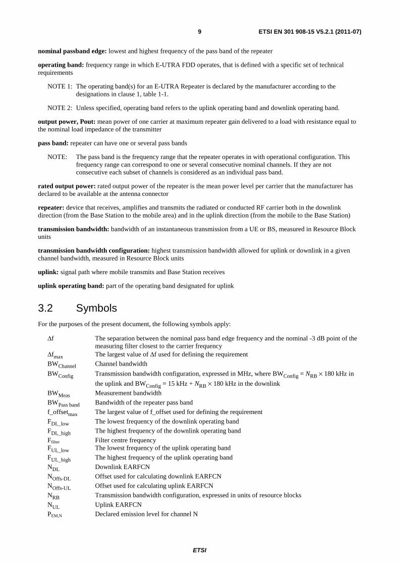
nominal passband edge: lowest and highest frequency of the pass band of the repeater
operating band: frequency range in which E-UTRA FDD operates, that is defined with a specific set of technical requirements
NOTE 1: The operating band(s) for an E-UTRA Repeater is declared by the manufacturer according to the designations in clause 1, table 1-1.
NOTE 2: Unless specified, operating band refers to the uplink operating band and downlink operating band.
output power, Pout: mean power of one carrier at maximum repeater gain delivered to a load with resistance equal to the nominal load impedance of the transmitter
pass band: repeater can have one or several pass bands
NOTE: The pass band is the frequency range that the repeater operates in with operational configuration. This frequency range can correspond to one or several consecutive nominal channels. If they are not consecutive each subset of channels is considered as an individual pass band.
rated output power: rated output power of the repeater is the mean power level per carrier that the manufacturer has declared to be available at the antenna connector
repeater: device that receives, amplifies and transmits the radiated or conducted RF carrier both in the downlink direction (from the Base Station to the mobile area) and in the uplink direction (from the mobile to the Base Station)
transmission bandwidth: bandwidth of an instantaneous transmission from a UE or BS, measured in Resource Block units
transmission bandwidth configuration: highest transmission bandwidth allowed for uplink or downlink in a given channel bandwidth, measured in Resource Block units
uplink: signal path where mobile transmits and Base Station receives
uplink operating band: part of the operating band designated for uplink
3.2 Symbols For the purposes of the present document, the following symbols apply:
Δf The separation between the nominal pass band edge frequency and the nominal -3 dB point of the measuring filter closest to the carrier frequency
Δfmax The largest value of Δf used for defining the requirement
BWChannel Channel bandwidth
BWConfig Transmission bandwidth configuration, expressed in MHz, where BWConfig = NRB × 180 kHz in
the uplink and BWConfig = 15 kHz + NRB × 180 kHz in the downlink
BWMeas Measurement bandwidth
BWPass band Bandwidth of the repeater pass band
f_offsetmax The largest value of f_offset used for defining the requirement
FDL_low The lowest frequency of the downlink operating band
FDL_high The highest frequency of the downlink operating band
Ffilter Filter centre frequency FUL_low The lowest frequency of the uplink operating band
FUL_high The highest frequency of the uplink operating band
NDL Downlink EARFCN
NOffs-DL Offset used for calculating downlink EARFCN
NOffs-UL Offset used for calculating uplink EARFCN
NRB Transmission bandwidth configuration, expressed in units of resource blocks
NUL Uplink EARFCN
PEM,N Declared emission level for channel N

ETSI
ETSI EN 301 908-15 V5.2.1 (2011-07)10
Pmax Maximum output power Pout Output power
3.3 Abbreviations For the purposes of the present document, the following abbreviations apply:
ACLR Adjacent Channel Leakage Ratio ACRR Adjacent Channel Rejection Ratio BS Base Station BW Bandwidth CW Continuous Wave DTT Digital Terrestrial Television DUT Device Under Test EARFCN E-UTRA Absolute Radio Frequency Channel Number E-TM E-UTRA Test Model E-UTRA Evolved Universal Terrestrial Radio Access ERM Electromagnetic compatibility and Radio spectrum Matters EUT Equipment Under Test FDD Frequency Division Duplex ITU-R International Telecommunication Union - Radiocommunication GSM Global System for Mobile Communications IMT International Mobile Telecommunications LTE Long Term Evolution, also known as E-UTRA MS Mobile Station
NOTE: For GSM.
MSG Mobile Standards Group PCCPCH Primary Common Control Physical Channel R&TTE Radio and Telecommunications Terminal Equipment RF Radio Frequency RMS Root Mean Square (value) RRC Root Raised Cosine RSS Root Sum Square SCCPCH Secondary Common Control Physical Channel TDD Time Division Duplex TFES Task Force for European Standards for IMT UARFCN UTRA Absolute Radio Frequency Channel Number UMB Ultra Mobile Broadband UTRA Universal Terrestrial Radio Access WCDMA Wideband Code Division Multiple Access
4 Technical requirements specifications
4.1 Environmental profile The technical requirements of the present document apply under the environmental profile for operation of the equipment, which shall be declared by the supplier. The equipment shall comply with all the technical requirements of the present document at all times when operating within the boundary limits of the declared operational environmental profile.
For guidance on how a supplier can declare the environmental profile, see annex C.
4.2 Conformance requirements The requirements in the present document are based on the assumption that the operating band (see table 1-1) is shared between systems of the IMT family (for bands 3 and 8 also GSM) or systems having compatible characteristics.

ETSI
ETSI EN 301 908-15 V5.2.1 (2011-07)11
4.2.1 Introduction
To meet the essential requirement under article 3.2 of Directive 1999/5/EC [i.2] (R&TTE Directive) for IMT Repeaters five essential parameters in addition to those in EN 301 908-1 [1] have been identified. Table 4.2.1-1 provides a cross reference between these five essential parameters and the corresponding seven technical requirements for equipment within the scope of the present document.
Table 4.2.1-1: Cross references
Essential parameter Corresponding technical requirements Spectrum emissions mask 4.2.2 Operating band unwanted emissions Conducted spurious emissions from the antenna connector 4.2.3 Spurious emissions Accuracy of maximum output power 4.2.4 Maximum output power
Receiver immunity 4.2.5 Input intermodulation 4.2.6 Out of band gain 4.2.7 Adjacent Channel Rejection Ratio
Intermodulation attenuation of the output 4.2.8 Output intermodulation
4.2.2 Operating band unwanted emissions
4.2.2.1 Definition
Unwanted emissions consist of out of band emissions and spurious emissions (ITU-R Recommendation SM.329-11 [4]). Out of band emissions are emissions immediately outside the pass band bandwidth resulting from the modulation process and non-linearity in the transmitter, but excluding spurious emissions. Spurious emissions are emissions which are caused by unwanted transmitter effects such as harmonics emission, parasitic emission, intermodulation products and frequency conversion products, but exclude out of band emissions.
The out of band emissions requirement for repeater is specified both in terms operating band unwanted emissions and protection of the BS receiver in the uplink operating band. The operating band unwanted emissions define all unwanted emissions in the repeater operating band plus the frequency ranges 10 MHz above and 10 MHz below that band. Unwanted emissions outside of this frequency range are limited by a spurious emissions requirement.
4.2.2.2 Limit
Emissions shall not exceed the maximum levels specified in the tables below, where:
• Δf is the separation between the nominal pass band edge frequency and the nominal -3 dB point of the measuring filter closest to the carrier frequency.
• Nominal passband edge is the lowest and highest frequency of the pass band of the repeater.
• BWMeas is the measurement bandwidth.
• BWPass band is the bandwidth of the repeaters pass band.
• f_offset is the separation between the nominal pass band edge frequency and the centre of the measuring filter.
• f_offsetmax is the offset to the frequency 10 MHz outside the repeater operating band.
• Δfmax is equal to f_offsetmax minus half of the bandwidth of the measuring filter.
Unless otherwise stated, all requirements are measured as mean power (RMS).
This requirement applies to the uplink and downlink of the repeater, at maximum gain, and with the following input signals:
• without E-UTRA input signal;
• with E-UTRA input signals in the pass band of the repeater, at levels that produce the maximum rated power output per channel;

ETSI
ETSI EN 301 908-15 V5.2.1 (2011-07)12
• with 10 dB increased E-UTRA input signals in all channels in the pass band, compared to the input level producing the maximum rated output power.
4.2.2.2.1 General operating band unwanted emissions
For E-UTRA FDD repeater operating in bands 3 or 8 emissions shall not exceed the maximum levels specified in tables 4.2.2.2.1-1 and 4.2.2.2.1-2. The measurements shall apply to both paths uplink and downlink of the Repeater.
Table 4.2.2.2.1-1: General operating band unwanted emission limits for repeater pass band lower than 5 MHz for (E-UTRA bands 3 and 8)
Frequency offset of measurement filter -3 dB point, Δf
Frequency offset of measurement filter centre frequency,
f_offset
Test requirement Measurement bandwidth
0 MHz ≤ Δf < 0,2 MHz 0,015 MHz ≤ f_offset < 0,215 MHz
-12,5 dBm 30 kHz
0,2 MHz ≤ Δf < 1 MHz 0,215 MHz ≤ f_offset < 1,015 MHz dB
MHz
offsetfdBm ⎟
⎠
⎞⎜⎝
⎛ −−− 215,0_
*155,12 30 kHz
1,015 MHz ≤ f_offset < 1,5 MHz
-24,5 dBm 30 kHz
1 MHz ≤ Δf < 2 × BWPass band 1,5 MHz ≤ f_offset < 2 × BWPass band +
0,5 MHz
-11,5 dBm 1 MHz
2 × BWPass band ≤ Δf ≤ Δfmax 2 × BWPass band +
0,5 MHz ≤ f_offset < f_offsetmax
-15 dBm 1 MHz
NOTE 1: Frequencies and bandwidth are given in MHz. NOTE 2: If the repeater input signal consists of E-UTRA signals with a channel bandwidth of 1,4 MHz or 3 MHz placed so
that the channel edge is less than 200 kHz from the pass band edge, the requirements in table 4.2.2.2.1-3 supersede table 4.2.2.2.1-1 for applicable frequency offsets.
Table 4.2.2.2.1-2: General operating band unwanted emission limits for repeater pass band 5 MHz and above for (E-UTRA band 3 and 8)
Frequency offset of measurement filter -3 dB point, Δf
Frequency offset of measurement filter centre frequency,
f_offset
Test requirement Measurement bandwidth
0 MHz ≤ Δf < 0,2 MHz 0,015 MHz ≤ f_offset < 0,215 MHz
-12,5 dBm 30 kHz
0,2 MHz ≤ Δf < 1 MHz 0,215 MHz ≤ f_offset < 1,015 MHz dB
MHz
offsetfdBm ⎟
⎠
⎞⎜⎝
⎛ −−− 215,0_
*155,12 30 kHz
1,015 MHz ≤ f_offset < 1,5 MHz
-24,5 dBm 30 kHz
1 MHz ≤ Δf < 10 MHz 1,5 MHz ≤ f_offset < 10,5 MHz
-11,5 dBm 1 MHz
10 MHz ≤ Δf ≤ Δfmax 10,5 MHz ≤ f_offset < f_offsetmax
-15 dBm 1 MHz
NOTE 1: Frequencies and bandwidth are given in MHz. NOTE 2: If the repeater input signal consists of E-UTRA signals with a channel bandwidth of 1,4 MHz or 3 MHz placed so
that the channel edge is less than 200 kHz from the pass band edge, the requirements in table 4.2.2.2.1-3 supersede table 4.2.2.2.1-2 for applicable frequency offsets.
ETSI
ETSI EN 301 908-15 V5.2.1 (2011-07)13
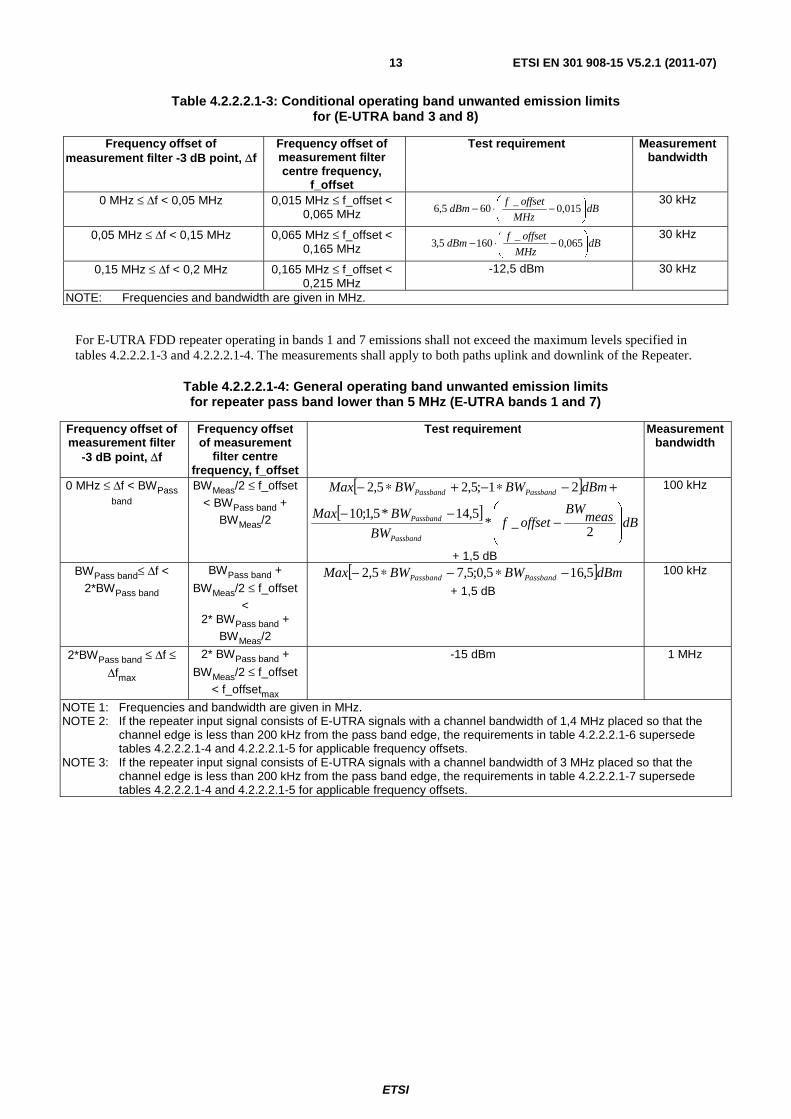
Table 4.2.2.2.1-3: Conditional operating band unwanted emission limits for (E-UTRA band 3 and 8)
Frequency offset of measurement filter -3 dB point, Δf
Frequency offset of measurement filter centre frequency,
f_offset
Test requirement Measurement bandwidth
0 MHz ≤ Δf < 0,05 MHz 0,015 MHz ≤ f_offset < 0,065 MHz dB
MHz
offsetfdBm ⎟
⎠
⎞⎜⎝
⎛ −⋅− 015,0_
605,6 30 kHz
0,05 MHz ≤ Δf < 0,15 MHz 0,065 MHz ≤ f_offset < 0,165 MHz dB
MHz
offsetfdBm ⎟
⎠
⎞⎜⎝
⎛ −⋅− 065,0_
1605,3 30 kHz
0,15 MHz ≤ Δf < 0,2 MHz 0,165 MHz ≤ f_offset < 0,215 MHz
-12,5 dBm 30 kHz
NOTE: Frequencies and bandwidth are given in MHz.
For E-UTRA FDD repeater operating in bands 1 and 7 emissions shall not exceed the maximum levels specified in tables 4.2.2.2.1-3 and 4.2.2.2.1-4. The measurements shall apply to both paths uplink and downlink of the Repeater.
Table 4.2.2.2.1-4: General operating band unwanted emission limits for repeater pass band lower than 5 MHz (E-UTRA bands 1 and 7)
Frequency offset of measurement filter
-3 dB point, Δf
Frequency offset of measurement
filter centre frequency, f_offset
Test requirement Measurement bandwidth
0 MHz ≤ Δf < BWPass band
BWMeas/2 ≤ f_offset < BWPass band +
BWMeas/2
[ ] +−∗−+∗− dBmBWBWMax PassbandPassband 21;5,25,2
[ ]dBmeas
BWoffsetf
BW
BWMax
Passband
Passband
⎟⎟
⎠
⎞
⎜⎜
⎝
⎛−
−−2
_*5,14*5,1;10
+ 1,5 dB
100 kHz
BWPass band≤ Δf < 2*BWPass band
BWPass band +
BWMeas/2 ≤ f_offset <
2* BWPass band + BWMeas/2
[ ]dBmBWBWMax PassbandPassband 5,165,0;5,75,2 −∗−∗−
+ 1,5 dB
100 kHz
2*BWPass band ≤ Δf ≤
Δfmax
2* BWPass band +
BWMeas/2 ≤ f_offset < f_offsetmax
-15 dBm 1 MHz
NOTE 1: Frequencies and bandwidth are given in MHz. NOTE 2: If the repeater input signal consists of E-UTRA signals with a channel bandwidth of 1,4 MHz placed so that the
channel edge is less than 200 kHz from the pass band edge, the requirements in table 4.2.2.2.1-6 supersede tables 4.2.2.2.1-4 and 4.2.2.2.1-5 for applicable frequency offsets.
NOTE 3: If the repeater input signal consists of E-UTRA signals with a channel bandwidth of 3 MHz placed so that the channel edge is less than 200 kHz from the pass band edge, the requirements in table 4.2.2.2.1-7 supersede tables 4.2.2.2.1-4 and 4.2.2.2.1-5 for applicable frequency offsets.
ETSI
ETSI EN 301 908-15 V5.2.1 (2011-07)14
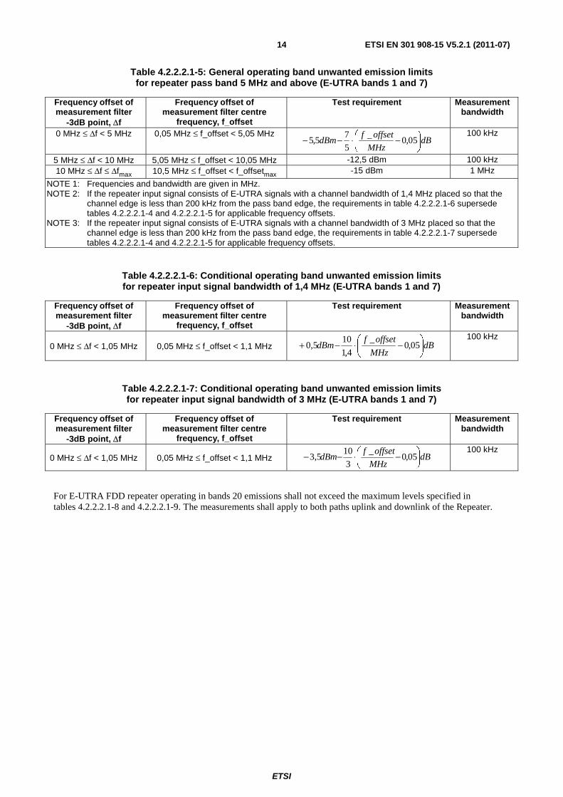
Table 4.2.2.2.1-5: General operating band unwanted emission limits for repeater pass band 5 MHz and above (E-UTRA bands 1 and 7)
Frequency offset of measurement filter
-3dB point, Δf
Frequency offset of measurement filter centre
frequency, f_offset
Test requirement Measurement bandwidth
0 MHz ≤ Δf < 5 MHz 0,05 MHz ≤ f_offset < 5,05 MHz dB
MHz
offsetfdBm ⎟
⎠
⎞⎜⎝
⎛ −⋅−− 05,0_
5
75,5 100 kHz
5 MHz ≤ Δf < 10 MHz 5,05 MHz ≤ f_offset < 10,05 MHz -12,5 dBm 100 kHz 10 MHz ≤ Δf ≤ Δfmax 10,5 MHz ≤ f_offset < f_offsetmax -15 dBm 1 MHz
NOTE 1: Frequencies and bandwidth are given in MHz. NOTE 2: If the repeater input signal consists of E-UTRA signals with a channel bandwidth of 1,4 MHz placed so that the
channel edge is less than 200 kHz from the pass band edge, the requirements in table 4.2.2.2.1-6 supersede tables 4.2.2.2.1-4 and 4.2.2.2.1-5 for applicable frequency offsets.
NOTE 3: If the repeater input signal consists of E-UTRA signals with a channel bandwidth of 3 MHz placed so that the channel edge is less than 200 kHz from the pass band edge, the requirements in table 4.2.2.2.1-7 supersede tables 4.2.2.2.1-4 and 4.2.2.2.1-5 for applicable frequency offsets.
Table 4.2.2.2.1-6: Conditional operating band unwanted emission limits for repeater input signal bandwidth of 1,4 MHz (E-UTRA bands 1 and 7)
Frequency offset of measurement filter
-3dB point, Δf
Frequency offset of measurement filter centre
frequency, f_offset
Test requirement Measurement bandwidth
0 MHz ≤ Δf < 1,05 MHz 0,05 MHz ≤ f_offset < 1,1 MHz dBMHz
offsetfdBm ⎟
⎠
⎞⎜⎝
⎛ −⋅−+ 05,0_
4,1
100,5
100 kHz
Table 4.2.2.2.1-7: Conditional operating band unwanted emission limits for repeater input signal bandwidth of 3 MHz (E-UTRA bands 1 and 7)
Frequency offset of measurement filter
-3dB point, Δf
Frequency offset of measurement filter centre
frequency, f_offset
Test requirement Measurement bandwidth
0 MHz ≤ Δf < 1,05 MHz 0,05 MHz ≤ f_offset < 1,1 MHz dBMHz
offsetfdBm ⎟
⎠
⎞⎜⎝
⎛ −⋅−− 05,0_
3
103,5 100 kHz
For E-UTRA FDD repeater operating in bands 20 emissions shall not exceed the maximum levels specified in tables 4.2.2.2.1-8 and 4.2.2.2.1-9. The measurements shall apply to both paths uplink and downlink of the Repeater.

ETSI
ETSI EN 301 908-15 V5.2.1 (2011-07)15
Table 4.2.2.2.1-8: General operating band unwanted emission limits for repeater pass band bandwidth lower than 5 MHz (E-UTRA bands 20)
Frequency offset of measurement filter
-3dB point, Δf
Frequency offset of measurement
filter centre frequency, f_offset
Test requirement Measurement bandwidth
0 MHz ≤ Δf < BWPass
band
BWMeas/2 ≤ f_offset < BWPass band +
BWMeas/2
[ ] +−∗−+∗− dBmBWBWMax PassbandPassband 21;5,25,2
[ ]dBmeas
BWoffsetf
BW
BWMax
Passband
Passband
⎟⎟
⎠
⎞
⎜⎜
⎝
⎛−−−
2_*
5,14*5,1;10
+ 1,5 dB
100 kHz
BWPass band≤ Δf < 2*BWPass band
BWPass band + BWMeas/2 ≤ f_offset
< 2* BWPass band +
BWMeas/2
[ ]dBmBWBWMax PassbandPassband 5,165,0;5,75,2 −∗−∗−
+ 1,5 dB
100 kHz
2*BWPass band ≤ Δf ≤ Δfmax
2* BWPass band + BWMeas/2 ≤ f_offset
< f_offsetmax
-16 dBm 100 kHz
NOTE 1: Frequencies and bandwidth are given in MHz. NOTE 2: If the repeater input signal consists of E-UTRA signals with a channel bandwidth of 1,4 MHz placed so that the
channel edge is less than 200 kHz from the pass band edge, the requirements in table 4.2.2.2.1.10 supersedes tables 4.2.2.2.1.8 and 4.2.2.2.1.9 for applicable frequency offsets.
NOTE 3: If the repeater input signal consists of E-UTRA signals with a channel bandwidth of 3 MHz placed so that the channel edge is less than 200 kHz from the pass band edge, the requirements in table 4.2.2.2.1.11 supersedes tables 4.2.2.2.1.8 and 4.2.2.2.1.9 for applicable frequency offsets.
Table 4.2.2.2.1-9: General operating band unwanted emission limits for repeater pass band bandwidth 5 MHz and above (E-UTRA bands 20)
Frequency offset of measurement filter
-3dB point, Δf
Frequency offset of measurement filter centre
frequency, f_offset
Test requirement Measurement bandwidth
0 MHz ≤ Δf < 5 MHz 0,05 MHz ≤ f_offset < 5,05 MHz dB
MHz
offsetfdBm ⎟
⎠
⎞⎜⎝
⎛ −⋅−− 05,0_
5
75,5 100 kHz
5 MHz ≤ Δf < 10 MHz 5,05 MHz ≤ f_offset < 10,05 MHz -12,5 dBm 100 kHz 10 MHz ≤ Δf ≤ Δfmax 10,05 MHz ≤ f_offset < f_offsetmax -16 dBm 100 kHz
NOTE 1: Frequencies and bandwidth are given in MHz. NOTE 2: If the repeater input signal consists of E-UTRA signals with a channel bandwidth of 1,4 MHz placed so that the
channel edge is less than 200 kHz from the pass band edge, the requirements in table 4.2.2.2.1.10 supersedes tables 4.2.2.2.1.8 and 4.2.2.2.1.9 for applicable frequency offsets.
NOTE 3: If the repeater input signal consists of E-UTRA signals with a channel bandwidth of 3 MHz placed so that the channel edge is less than 200 kHz from the pass band edge, the requirements in table 4.2.2.2.1.11 supersedes tables 4.2.2.2.1.8 and 4.2.2.2.1.9 for applicable frequency offsets.
Table 4.2.2.2.1-10: Conditional operating band unwanted emission limits for repeater input signal bandwidth of 1,4 MHz (E-UTRA bands 20)
Frequency offset of measurement filter
-3dB point, Δf
Frequency offset of measurement filter centre
frequency, f_offset
Test requirement Measurement bandwidth
0 MHz ≤ Δf < 1,05 MHz 0,05 MHz ≤ f_offset < 1,1 MHz dBMHz
offsetfdBm ⎟
⎠
⎞⎜⎝
⎛ −⋅−+ 05,0_
4,110
0,5 100 kHz
NOTE: Frequencies and bandwidth are given in MHz.
ETSI
ETSI EN 301 908-15 V5.2.1 (2011-07)16
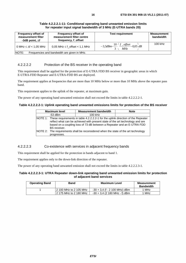
Table 4.2.2.2.1-11: Conditional operating band unwanted emission limits for repeater input signal bandwidth of 3 MHz (E-UTRA bands 20)
Frequency offset of measurement filter
-3dB point, Δf
Frequency offset of measurement filter centre
frequency, f_offset
Test requirement Measurement bandwidth
0 MHz ≤ Δf < 1,05 MHz 0,05 MHz ≤ f_offset < 1,1 MHz dBMHz
offsetfdBm ⎟
⎠
⎞⎜⎝
⎛ −⋅−− 05,0_
3
103,5 100 kHz
NOTE: Frequencies and bandwidth are given in MHz.
4.2.2.2.2 Protection of the BS receiver in the operating band
This requirement shall be applied for the protection of E-UTRA FDD BS receiver in geographic areas in which E-UTRA-FDD Repeater and E-UTRA-FDD BS are deployed.
The requirement applies at frequencies that are more than 10 MHz below or more than 10 MHz above the repeater pass band.
This requirement applies to the uplink of the repeater, at maximum gain.
The power of any operating band unwanted emission shall not exceed the limits in table 4.2.2.2.2-1.
Table 4.2.2.2.2-1: Uplink operating band unwanted emissions limits for protection of the BS receiver
Maximum level Measurement bandwidth Note -53 dBm 100 kHz
NOTE 1: These requirements in table 4.2.2.2.2-1 for the uplink direction of the Repeater reflect what can be achieved with present state of the art technology and are based on a coupling loss of 73 dB between a Repeater and an E-UTRA FDD BS receiver.
NOTE 2: The requirements shall be reconsidered when the state of the art technology progresses.
4.2.2.2.3 Co-existence with services in adjacent frequency bands
This requirement shall be applied for the protection in bands adjacent to band 1.
The requirement applies only to the down-link direction of the repeater.
The power of any operating band unwanted emission shall not exceed the limits in table 4.2.2.2.3-1.
Table 4.2.2.2.3-1: UTRA Repeater down-link operating band unwanted emission limits for protection of adjacent band services
Operating Band Band Maximum Level Measurement Bandwidth
1 2 100 MHz to 2 105 MHz -30 + 3,4 (f - 2 100 MHz) dBm 1 MHz 2 175 MHz to 2 180 MHz -30 + 3,4 (2 180 MHz - f) dBm 1 MHz
ETSI
ETSI EN 301 908-15 V5.2.1 (2011-07)17
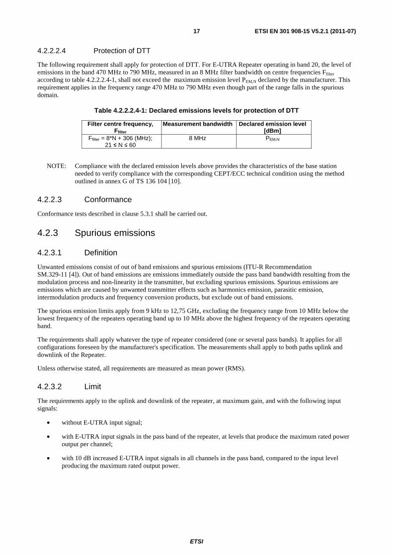
4.2.2.2.4 Protection of DTT
The following requirement shall apply for protection of DTT. For E-UTRA Repeater operating in band 20, the level of emissions in the band 470 MHz to 790 MHz, measured in an 8 MHz filter bandwidth on centre frequencies Ffilter according to table 4.2.2.2.4-1, shall not exceed the maximum emission level PEM,N declared by the manufacturer. This requirement applies in the frequency range 470 MHz to 790 MHz even though part of the range falls in the spurious domain.
Table 4.2.2.2.4-1: Declared emissions levels for protection of DTT
Filter centre frequency, Ffilter
Measurement bandwidth Declared emission level [dBm]
Ffilter = 8*N + 306 (MHz); 21 ≤ N ≤ 60
8 MHz PEM,N
NOTE: Compliance with the declared emission levels above provides the characteristics of the base station needed to verify compliance with the corresponding CEPT/ECC technical condition using the method outlined in annex G of TS 136 104 [10].
4.2.2.3 Conformance
Conformance tests described in clause 5.3.1 shall be carried out.
4.2.3 Spurious emissions
4.2.3.1 Definition
Unwanted emissions consist of out of band emissions and spurious emissions (ITU-R Recommendation SM.329-11 [4]). Out of band emissions are emissions immediately outside the pass band bandwidth resulting from the modulation process and non-linearity in the transmitter, but excluding spurious emissions. Spurious emissions are emissions which are caused by unwanted transmitter effects such as harmonics emission, parasitic emission, intermodulation products and frequency conversion products, but exclude out of band emissions.
The spurious emission limits apply from 9 kHz to 12,75 GHz, excluding the frequency range from 10 MHz below the lowest frequency of the repeaters operating band up to 10 MHz above the highest frequency of the repeaters operating band.
The requirements shall apply whatever the type of repeater considered (one or several pass bands). It applies for all configurations foreseen by the manufacturer's specification. The measurements shall apply to both paths uplink and downlink of the Repeater.
Unless otherwise stated, all requirements are measured as mean power (RMS).
4.2.3.2 Limit
The requirements apply to the uplink and downlink of the repeater, at maximum gain, and with the following input signals:
• without E-UTRA input signal;
• with E-UTRA input signals in the pass band of the repeater, at levels that produce the maximum rated power output per channel;
• with 10 dB increased E-UTRA input signals in all channels in the pass band, compared to the input level producing the maximum rated output power.

ETSI
ETSI EN 301 908-15 V5.2.1 (2011-07)18
4.2.3.2.1 Spurious emissions
The power of any spurious emission shall not exceed the limits in table 4.2.3.2.1-1.
Table 4.2.3.2.1-1: Uplink and downlink: General spurious emissions limits, Category B
Frequency range Maximum level
Measurement bandwidth
Note
9 kHz ↔ 150 kHz -36 dBm 1 kHz Note 1 150 kHz ↔ 30 MHz -36 dBm 10 kHz Note 1 30 MHz ↔ 1 GHz -36 dBm 100 kHz Note 1
1 GHz ↔ 12,75 GHz -30 dBm 1 MHz Note 2 NOTE 1: Bandwidth as in ITU-R Recommendation SM.329-11 [4], section 4.1. NOTE 2: Bandwidth as in ITU-R Recommendation SM.329-11 [4], section 4.1. Upper frequency as
in ITU-R Recommendation SM.329-11 [4], section 2.5, table 1.
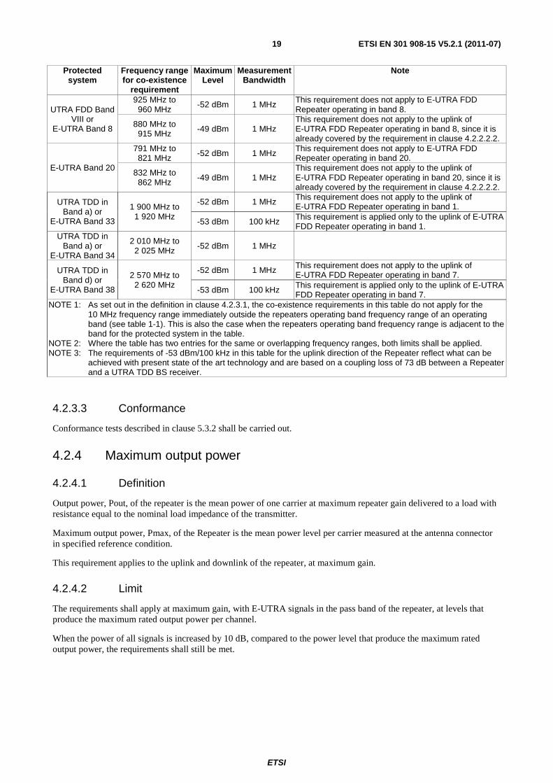
4.2.3.2.2 Co-existence with other systems in the same geographical area
These requirements may be applied for the protection of UE, MS and/or BS operating in other frequency bands in the same geographical area. The requirements may apply in geographic areas in which both E-UTRA-FDD Repeater and a system operating in another frequency band than the E-UTRA operating band are deployed. The system operating in the other frequency band may be GSM900, DCS1800, UTRA FDD/TDD and/or E-UTRA.
The power of any spurious emission shall not exceed the limits of table 4.2.3.2.2-1 for an E-UTRA Repeater where requirements for co-existence with the system listed in the first column apply.
Table 4.2.3.2.2-1: Spurious emissions limits for E-UTRA-FDD repeater in geographic coverage area of systems operating in other frequency bands
Protected system
Frequency range for co-existence
requirement
Maximum Level
Measurement Bandwidth
Note
GSM900
921 MHz to 960 MHz -57 dBm 100 kHz This requirement does not apply to E-UTRA FDD
Repeater operating in band 8.
876 MHz to 915 MHz -61 dBm 100 kHz
This requirement does not apply to the uplink of E-UTRA FDD Repeater operating in band 8, since it is already covered by the requirement in clause 4.2.2.2.2.
DCS1800
1 805 MHz to 1 880 MHz -47 dBm 100 kHz This requirement does not apply to E-UTRA FDD
Repeater operating in band 3.
1 710 MHz to 1 785 MHz -61 dBm 100 kHz
This requirement does not apply to the uplink of E-UTRA FDD Repeater operating in band 3, since it is already covered by the requirement in clause 4.2.2.2.2.
UTRA FDD Band I or
E-UTRA Band 1
2 110 MHz to 2 170 MHz -52 dBm 1 MHz
This requirement does not apply to E-UTRA FDD Repeater operating in band 1.
1 920 MHz to 1 980 MHz -49 dBm 1 MHz
This requirement does not apply to the uplink of E-UTRA FDD Repeater operating in band 1, since it is already covered by the requirement in clause 4.2.2.2.2.
UTRA FDD Band III or
E-UTRA Band 3
1 805 MHz to 1 880 MHz -52 dBm 1 MHz This requirement does not apply to E-UTRA FDD
Repeater operating in band 3.
1 710 MHz to 1 785 MHz -49 dBm 1 MHz
This requirement does not apply to the uplink of E-UTRA FDD Repeater operating in band 3, since it is already covered by the requirement in clause 4.2.2.2.2.
UTRA FDD Band VII or
E-UTRA Band 7
2 620 MHz to 2 690 MHz -52 dBm 1 MHz This requirement does not apply to E-UTRA FDD
Repeater operating in band 7.
2 500 MHz to 2 570 MHz -49 dBm 1 MHz
This requirement does not apply to the uplink of E-UTRA FDD Repeater operating in band 7, since it is already covered by the requirement in clause 4.2.2.2.2.
ETSI
ETSI EN 301 908-15 V5.2.1 (2011-07)19
Protected system
Frequency range for co-existence
requirement
Maximum Level
Measurement Bandwidth
Note
UTRA FDD Band VIII or
E-UTRA Band 8
925 MHz to 960 MHz
-52 dBm 1 MHz This requirement does not apply to E-UTRA FDD Repeater operating in band 8.
880 MHz to 915 MHz -49 dBm 1 MHz
This requirement does not apply to the uplink of E-UTRA FDD Repeater operating in band 8, since it is already covered by the requirement in clause 4.2.2.2.2.
E-UTRA Band 20
791 MHz to 821 MHz -52 dBm 1 MHz This requirement does not apply to E-UTRA FDD
Repeater operating in band 20.
832 MHz to 862 MHz -49 dBm 1 MHz
This requirement does not apply to the uplink of E-UTRA FDD Repeater operating in band 20, since it is already covered by the requirement in clause 4.2.2.2.2.
UTRA TDD in Band a) or
E-UTRA Band 33
1 900 MHz to 1 920 MHz
-52 dBm 1 MHz This requirement does not apply to the uplink of E-UTRA FDD Repeater operating in band 1.
-53 dBm 100 kHz This requirement is applied only to the uplink of E-UTRA FDD Repeater operating in band 1.
UTRA TDD in Band a) or
E-UTRA Band 34
2 010 MHz to 2 025 MHz -52 dBm 1 MHz
UTRA TDD in Band d) or
E-UTRA Band 38
2 570 MHz to 2 620 MHz
-52 dBm 1 MHz This requirement does not apply to the uplink of E-UTRA FDD Repeater operating in band 7.
-53 dBm 100 kHz This requirement is applied only to the uplink of E-UTRA FDD Repeater operating in band 7.
NOTE 1: As set out in the definition in clause 4.2.3.1, the co-existence requirements in this table do not apply for the 10 MHz frequency range immediately outside the repeaters operating band frequency range of an operating band (see table 1-1). This is also the case when the repeaters operating band frequency range is adjacent to the band for the protected system in the table.
NOTE 2: Where the table has two entries for the same or overlapping frequency ranges, both limits shall be applied. NOTE 3: The requirements of -53 dBm/100 kHz in this table for the uplink direction of the Repeater reflect what can be
achieved with present state of the art technology and are based on a coupling loss of 73 dB between a Repeater and a UTRA TDD BS receiver.
4.2.3.3 Conformance
Conformance tests described in clause 5.3.2 shall be carried out.
4.2.4 Maximum output power
4.2.4.1 Definition
Output power, Pout, of the repeater is the mean power of one carrier at maximum repeater gain delivered to a load with resistance equal to the nominal load impedance of the transmitter.
Maximum output power, Pmax, of the Repeater is the mean power level per carrier measured at the antenna connector in specified reference condition.
This requirement applies to the uplink and downlink of the repeater, at maximum gain.
4.2.4.2 Limit
The requirements shall apply at maximum gain, with E-UTRA signals in the pass band of the repeater, at levels that produce the maximum rated output power per channel.
When the power of all signals is increased by 10 dB, compared to the power level that produce the maximum rated output power, the requirements shall still be met.
ETSI
ETSI EN 301 908-15 V5.2.1 (2011-07)20
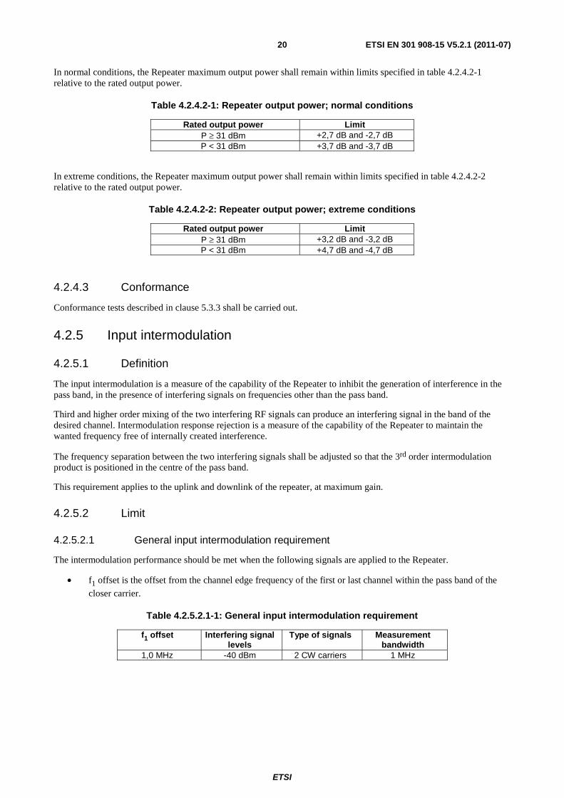
In normal conditions, the Repeater maximum output power shall remain within limits specified in table 4.2.4.2-1 relative to the rated output power.
Table 4.2.4.2-1: Repeater output power; normal conditions
Rated output power Limit P ≥ 31 dBm +2,7 dB and -2,7 dB P < 31 dBm +3,7 dB and -3,7 dB
In extreme conditions, the Repeater maximum output power shall remain within limits specified in table 4.2.4.2-2 relative to the rated output power.
Table 4.2.4.2-2: Repeater output power; extreme conditions
Rated output power Limit P ≥ 31 dBm +3,2 dB and -3,2 dB P < 31 dBm +4,7 dB and -4,7 dB
4.2.4.3 Conformance
Conformance tests described in clause 5.3.3 shall be carried out.
4.2.5 Input intermodulation
4.2.5.1 Definition
The input intermodulation is a measure of the capability of the Repeater to inhibit the generation of interference in the pass band, in the presence of interfering signals on frequencies other than the pass band.
Third and higher order mixing of the two interfering RF signals can produce an interfering signal in the band of the desired channel. Intermodulation response rejection is a measure of the capability of the Repeater to maintain the wanted frequency free of internally created interference.
The frequency separation between the two interfering signals shall be adjusted so that the 3rd order intermodulation product is positioned in the centre of the pass band.
This requirement applies to the uplink and downlink of the repeater, at maximum gain.
4.2.5.2 Limit
4.2.5.2.1 General input intermodulation requirement
The intermodulation performance should be met when the following signals are applied to the Repeater.
• f1 offset is the offset from the channel edge frequency of the first or last channel within the pass band of the
closer carrier.
Table 4.2.5.2.1-1: General input intermodulation requirement
f1 offset Interfering signal levels
Type of signals Measurement bandwidth
1,0 MHz -40 dBm 2 CW carriers 1 MHz

ETSI
ETSI EN 301 908-15 V5.2.1 (2011-07)21
For the parameters specified in table 4.2.5.2.1-1, the power in the pass band shall not increase with more than the limit in table 4.2.5.2.1-2 at the output of the Repeater as measured in the centre of the pass band, compared to the level obtained without interfering signals applied.
Table 4.2.5.2.1-2: General input intermodulations limit
Limit for the increase of power in the pass band +11,2 dB
4.2.5.2.2 Co-existence with other systems
The intermodulation performance should be met when the following signals are applied to the Repeater.
Table 4.2.5.2.2-1: Input intermodulation requirements for interfering signals in co-existing other systems
Co-existence with other systems
Frequency of interfering
signals
Interfering signal levels
Type of signals
Measurement bandwidth
Note
GSM900 876 MHz to 915 MHz -15 dBm 2 CW
carriers 1 MHz
This requirement does not apply to E-UTRA FDD Repeater operating in band 8, since it is already covered by the requirement in clause 4.2.5.2.1.
DCS1800 1 710 MHz to
1 785 MHz -15 dBm 2 CW
carriers 1 MHz
This requirement does not apply to E-UTRA FDD Repeater operating in band 3, since it is already covered by the requirement in clause 4.2.5.2.1.
UTRA FDD band I or
E-UTRA band 1
1 920 MHz to 1 980 MHz
-15 dBm 2 CW carriers 1 MHz
This requirement does not apply to E-UTRA FDD Repeater operating in band 1, since it is already covered by the requirement in clause 4.2.5.2.1.
UTRA FDD band III or
E-UTRA band 3
1 710 MHz to 1 785 MHz
-15 dBm 2 CW carriers 1 MHz
This requirement does not apply to E-UTRA FDD Repeater operating in band 3, since it is already covered by the requirement in clause 4.2.5.2.1.
UTRA FDD band VII or
E-UTRA band 7
2 500 MHz to 2 570 MHz
-15 dBm 2 CW carriers
1 MHz
This requirement does not apply to E-UTRA FDD Repeater operating in band 7, since it is already covered by the requirement in clause 4.2.5.2.1.
UTRA FDD band VIII or
E-UTRA band 8
880 MHz to 915 MHz -15 dBm
2 CW carriers 1 MHz
This requirement does not apply to E-UTRA FDD Repeater operating in band 8, since it is already covered by the requirement in clause 4.2.5.2.1.
UTRA FDD band XX or
E-UTRA band 20
832 MHz to 862 MHz -15 dBm 2 CW
carriers 1 MHz
This requirement does not apply to E-UTRA FDD Repeater operating in band 20, since it is already covered by the requirement in clause 4.2.5.2.1.
NOTE: The co-existence requirements in this table do not apply when the repeaters pass band frequency range is adjacent to the frequency range of the co-existence requirement in this table. The current state-of-the-art technology does not allow a single generic solution for co-existence.
For the parameters specified in table 4.2.5.2.2-1, the power in the pass band shall not increase with more than the limit in table 4.2.5.2.2-2 at the output of the Repeater as measured in the centre of the pass band, compared to the level obtained without interfering signals applied.
Table 4.2.5.2.2-2: General input intermodulations limit
Limit for the increase of power in the pass band +11,2 dB

ETSI
ETSI EN 301 908-15 V5.2.1 (2011-07)22
4.2.5.3 Conformance
Conformance tests described in clause 5.3.4 shall be carried out.
4.2.6 Out of band gain
4.2.6.1 Definition
Out of band gain refers to the gain of the Repeater immediately outside the pass band.
This requirement applies to the uplink and downlink of the Repeater, at maximum gain.
4.2.6.2 Limits
The intended use of a Repeater in a system is to amplify the in band signals and not to amplify the out of band emission of the donor Base Station.
In the intended application of the Repeater, the out of band gain is less than the donor coupling loss.
The Repeater minimum donor coupling loss shall be declared by the manufacturer. This is the minimum required attenuation between the donor BS and the Repeater for proper Repeater operation.
The gain outside the pass band shall not exceed the maximum level specified in table 4.2.6.2-1, where:
• f_offset_CW is the offset between the outer channel edge frequency of the outer channel in the pass band and a CW signal.
Table 4.2.6.2-1: Out of band gain limits 1
Frequency offset, f_offset_CW Maximum gain 0,2 ≤ f_offset_CW < 1,0 MHz 60,5 dB 1,0 ≤ f_offset_CW < 5,0 MHz 45,5 dB
5,0 ≤ f_offset_CW < 10,0 MHz 45,5 dB 10,0 MHz ≤ f_offset_CW 35,5 dB
For 10 MHz ≤ f_offset_CW the out of band gain shall not exceed the maximum gain of table 4.2.6.2-2 or the maximum gain stated in table 4.2.6.2-2 whichever is lower.
Table 4.2.6.2-2: Out of band gain limits 2
Frequency offset, f_offset_CW Maximum gain 10 MHz ≤ f_offset_CW Out of band gain ≤ minimum donor coupling loss
4.2.6.3 Conformance
Conformance tests described in clause 5.3.5 shall be carried out.
4.2.7 Adjacent Channel Rejection Ratio
4.2.7.1 Definition
Adjacent Channel Rejection Ratio (ACRR) is the ratio of the RRC weighted gain per carrier of the repeater in the pass band to the RRC weighted gain of the repeater on an adjacent channel outside the repeater pass band. The carrier in the pass band and in the adjacent channel shall be of the same type (reference carrier).
The requirement shall apply to the uplink and downlink of the Repeater, at maximum gain, where the donor link is maintained via antennas (over the air Repeater).
ETSI
ETSI EN 301 908-15 V5.2.1 (2011-07)23
4.2.7.2 Limit
4.2.7.2.1 ACRR
There is no minimum requirement for E-UTRA signals.
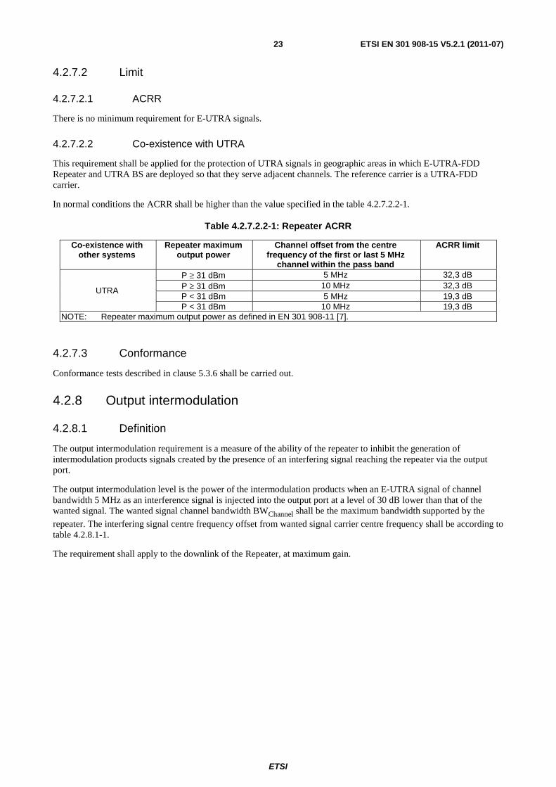
4.2.7.2.2 Co-existence with UTRA
This requirement shall be applied for the protection of UTRA signals in geographic areas in which E-UTRA-FDD Repeater and UTRA BS are deployed so that they serve adjacent channels. The reference carrier is a UTRA-FDD carrier.
In normal conditions the ACRR shall be higher than the value specified in the table 4.2.7.2.2-1.
Table 4.2.7.2.2-1: Repeater ACRR
Co-existence with other systems
Repeater maximum output power
Channel offset from the centre frequency of the first or last 5 MHz
channel within the pass band
ACRR limit
UTRA
P ≥ 31 dBm 5 MHz 32,3 dB P ≥ 31 dBm 10 MHz 32,3 dB P < 31 dBm 5 MHz 19,3 dB P < 31 dBm 10 MHz 19,3 dB
NOTE: Repeater maximum output power as defined in EN 301 908-11 [7].
4.2.7.3 Conformance
Conformance tests described in clause 5.3.6 shall be carried out.
4.2.8 Output intermodulation
4.2.8.1 Definition
The output intermodulation requirement is a measure of the ability of the repeater to inhibit the generation of intermodulation products signals created by the presence of an interfering signal reaching the repeater via the output port.
The output intermodulation level is the power of the intermodulation products when an E-UTRA signal of channel bandwidth 5 MHz as an interference signal is injected into the output port at a level of 30 dB lower than that of the wanted signal. The wanted signal channel bandwidth BWChannel shall be the maximum bandwidth supported by the
repeater. The interfering signal centre frequency offset from wanted signal carrier centre frequency shall be according to table 4.2.8.1-1.
The requirement shall apply to the downlink of the Repeater, at maximum gain.
ETSI
ETSI EN 301 908-15 V5.2.1 (2011-07)24
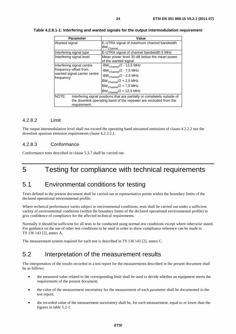
Table 4.2.8.1-1: Interfering and wanted signals for the output intermodulation requirement
Parameter Value Wanted signal E-UTRA signal of maximum channel bandwidth
BWChannel
Interfering signal type E-UTRA signal of channel bandwidth 5 MHz Interfering signal level Mean power level 30 dB below the mean power
of the wanted signal Interfering signal centre frequency offset from wanted signal carrier centre frequency
-BWChannel/2 - 12,5 MHz -BWChannel/2 - 7,5 MHz -BWChannel/2 - 2,5 MHz BWChannel/2 + 2,5 MHz BWChannel/2 + 7,5 MHz BWChannel/2 + 12,5 MHz
NOTE: Interfering signal positions that are partially or completely outside of the downlink operating band of the repeater are excluded from the requirement.
4.2.8.2 Limit
The output intermodulation level shall not exceed the operating band unwanted emissions of clause 4.2.2.2 nor the downlink spurious emission requirements clause 4.2.3.2.1.
4.2.8.3 Conformance
Conformance tests described in clause 5.3.7 shall be carried out.
5 Testing for compliance with technical requirements
5.1 Environmental conditions for testing Tests defined in the present document shall be carried out at representative points within the boundary limits of the declared operational environmental profile.
Where technical performance varies subject to environmental conditions, tests shall be carried out under a sufficient variety of environmental conditions (within the boundary limits of the declared operational environmental profile) to give confidence of compliance for the affected technical requirements.
Normally it should be sufficient for all tests to be conducted using normal test conditions except where otherwise stated. For guidance on the use of other test conditions to be used in order to show compliance reference can be made to TS 136 143 [2], annex A.
The measurement system required for each test is described in TS 136 143 [2], annex C.
5.2 Interpretation of the measurement results The interpretation of the results recorded in a test report for the measurements described in the present document shall be as follows:
• the measured value related to the corresponding limit shall be used to decide whether an equipment meets the requirements of the present document;
• the value of the measurement uncertainty for the measurement of each parameter shall be documented in the test report;
• the recorded value of the measurement uncertainty shall be, for each measurement, equal to or lower than the figures in table 5.2-1.

ETSI
ETSI EN 301 908-15 V5.2.1 (2011-07)25
For the test methods, according to the present document, the measurement uncertainty figures shall be calculated and shall correspond to an expansion factor (coverage factor) k = 1,96 (which provide confidence levels of respectively 95 % in the case where the distributions characterizing the actual measurement uncertainties are normal (Gaussian)). Principles for the calculation of measurement uncertainty are contained in TR 100 028 [i.5] or TR 102 215 [i.4].
Table 5.2-1 is based on such expansion factors.
Table 5.2-1: Maximum measurement uncertainty
Parameter Condition Uncertainty Operating band unwanted emission (except Protection of the BS receiver in the operating band)
The interference from the signal generator ACLR shall be minimum 10 dB below that of a Base Station according to TS 136 141 [8]
±1,5 dB
Protection of the BS receiver in the operating band
for results > -60 dBm for results < -60 dBm
±2,0 dB ±3,0 dB
Spurious emissions In E-UTRA and coexistence receive bands: for results > -60 dBm for results < -60 dBm Outside above range: emission power 9 kHz < f ≤ 4 GHz f > 4 GHz The interference from the signal generator ACLR shall be minimum 10 dB below that of a Base Station according to TS 136 141 [8]
±2,0 dB ±3,0 dB
±2,0 dB ±4,0 dB
Output power ±0,7 dB Input intermodulation characteristics Formula:
( ) ( ) ( )222 ___22__1 errortmeasuremenerrorlevelCWerrorlevelCW +⋅+
RSS: CW1 level error, 2 x CW2 level error, and measurement error (using all errors = ±0,5 dB)
±1,2 dB
Out of band gain Calibration of test set-up shall be made without DUT in order to achieve the accuracy
±0,5 dB
Output intermodulation Operating band unwanted emission: The interference from the signal generator ACLR shall be minimum 10 dB below that of a Base Station according to TS 136 141 [8] For spurious emission: In UTRA and coexistence receive bands: for results > -60 dBm for results < -60 dBm Outside above range: emission power; 9 kHz < f ≤ 4 GHz f > 4 GHz The interference signal must have a spurious emission level at least 10 dB below the spurious levels required in clause 4.2.3.2
±2,1 dB
±2,0 dB ±3,0 dB
±2,0 dB ±4,0 dB
Adjacent Channel Rejection Ratio ±0,7 dB NOTE 1: For RF tests it should be noted that the uncertainties in table 5.2-1 apply to the Test System operating into a
nominal 50 Ω load and do not include system effects due to mismatch between the EUT and the Test System. NOTE 2: If the Test System for a test is known to have a measurement uncertainty greater than that specified in
table 5.2-1, this equipment can still be used, provided that an adjustment is made as follows: Any additional uncertainty in the Test System over and above that specified in table 5.2-1 is used to tighten the Test Requirements - making the test harder to pass (for some tests, e.g. receiver tests, this may require modification of stimulus signals). This procedure will ensure that a Test System not compliant with table 5.2-1 does not increase the probability of passing an EUT that would otherwise have failed a test if a Test System compliant with table 5.2-1 had been used.

ETSI
ETSI EN 301 908-15 V5.2.1 (2011-07)26
5.3 Essential radio test suites This clause describes the test suites for E-UTRA (FDD).
5.3.1 Operating band unwanted emissions
5.3.1.1 Initial conditions
Test environment: normal, see TS 136 143 [2], clause A.2.
A measurement set-up is shown in TS 136 143 [2], annex C.
1) Connect a signal generator to the input port of the Repeater.
2) Detection mode: True RMS.
5.3.1.2 Procedures
1) Set the Repeater to maximum gain.
2) Set the signal generator to generate signal(s) in accordance to table 5.3.1.2-1.
Table 5.3.1.2-1: Stimulus signal for operating band unwanted emissions testing
Repeater under test link and passband bandwidth
Stimulus reference Note
Downlink pass band BW < 2,8 MHz
Repeater stimulus signal 4 The signal is defined in TS 136 143 [2], clause D.4
Uplink pass band BW < 2,8 MHz
Repeater stimulus signal 3 The signal is defined in TS 136 143 [2], clause D.3
Downlink pass band BW ≥ 2,8 MHz
Repeater stimulus signal 2 The signal is defined in TS 136 143 [2], clause D.2
Uplink pass band BW ≥ 2,8 MHz
Repeater stimulus signal 1 The signal is defined in TS 136 143 [2], clause D.1
At centre frequencies such that the whole signal can be fitted inside the repeater pass band and at level(s) which produce the manufacturer specified maximum output power at maximum gain.
3) The detecting device shall be configured with a measurement bandwidth as stated in the test requirement tables.
4) Measure the emission at the specified frequencies with specified measurement bandwidth and note that the measured value does not exceed the specified value. To select the table and the maximum level, use the repeater pass band and stimulus signal if necessary.
5) Increase the input power with 10 dB compared to the level obtained in step 2).
6) Measure the emission at the specified frequencies with specified measurement bandwidth and note that the measured value does not exceed the specified value. To select the table and the maximum level, use the repeater pass band and stimulus signal if necessary.
7) If the pass band is wider than 2,8 MHz, repeat steps 1) to 6) with a new stimulus signal of the same kind, but using different centre frequencies such that the whole signal fitted in the repeater pass band.
8) Switch off the input signal to the repeater.
ETSI
ETSI EN 301 908-15 V5.2.1 (2011-07)27
9) Measure the emission at the specified frequencies with specified measurement bandwidth and note that the measured value does not exceed the specified value. To select the table and the maximum level, use the repeater pass band.
NOTE: As a general rule the resolution bandwidth of the measuring equipment should be equal to the measurement bandwidth. However, to improve measurement accuracy, sensitivity and efficiency, the resolution bandwidth may be smaller than the measurement bandwidth. When the resolution bandwidth is smaller than the measurement bandwidth, the result should be integrated over the measurement bandwidth in order to obtain the equivalent noise bandwidth of the measurement bandwidth.
The results obtained shall be compared to the limits in clause 4.2.2.2 in order to prove compliance.
5.3.2 Spurious emissions
5.3.2.1 Initial conditions
Test environment: normal, see TS 136 143 [2], clause A.2.
A measurement set-up is shown in TS 136 143 [2], annex C.
1) Connect a signal generator to the input port of the repeater.
2) Detection mode: True RMS.
5.3.2.2 Procedures
1) Set the Repeater to maximum gain.
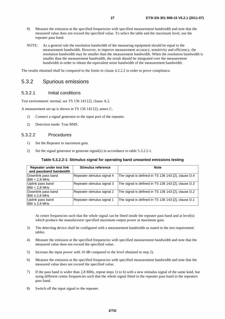
2) Set the signal generator to generate signal(s) in accordance to table 5.3.2.2-1.
Table 5.3.2.2-1: Stimulus signal for operating band unwanted emissions testing
Repeater under test link and passband bandwidth
Stimulus reference Note
Downlink pass band BW < 2,8 MHz
Repeater stimulus signal 4 The signal is defined in TS 136 143 [2], clause D.4
Uplink pass band BW < 2,8 MHz
Repeater stimulus signal 3 The signal is defined in TS 136 143 [2], clause D.3
Downlink pass band BW ≥ 2,8 MHz
Repeater stimulus signal 2 The signal is defined in TS 136 143 [2], clause D.2
Uplink pass band BW ≥ 2,8 MHz
Repeater stimulus signal 1 The signal is defined in TS 136 143 [2], clause D.1
At centre frequencies such that the whole signal can be fitted inside the repeater pass band and at level(s) which produce the manufacturer specified maximum output power at maximum gain.
3) The detecting device shall be configured with a measurement bandwidth as stated in the test requirement tables.
4) Measure the emission at the specified frequencies with specified measurement bandwidth and note that the measured value does not exceed the specified value.
5) Increase the input power with 10 dB compared to the level obtained in step 2).
6) Measure the emission at the specified frequencies with specified measurement bandwidth and note that the measured value does not exceed the specified value.
7) If the pass band is wider than 2,8 MHz, repeat steps 1) to 6) with a new stimulus signal of the same kind, but using different centre frequencies such that the whole signal fitted in the repeater pass band in the repeaters pass band.
8) Switch off the input signal to the repeater.
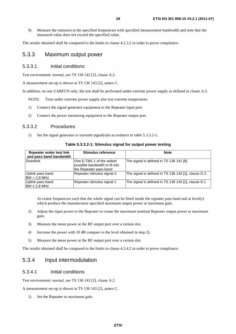
ETSI
ETSI EN 301 908-15 V5.2.1 (2011-07)28
9) Measure the emission at the specified frequencies with specified measurement bandwidth and note that the measured value does not exceed the specified value.
The results obtained shall be compared to the limits in clause 4.2.3.2 in order to prove compliance.
5.3.3 Maximum output power
5.3.3.1 Initial conditions
Test environment: normal, see TS 136 143 [2], clause A.2.
A measurement set-up is shown in TS 136 143 [2], annex C.
In addition, on one UARFCN only, the test shall be performed under extreme power supply as defined in clause A.5.
NOTE: Tests under extreme power supply also test extreme temperature.
1) Connect the signal generator equipment to the Repeater input port.
2) Connect the power measuring equipment to the Repeater output port.
5.3.3.2 Procedures
1) Set the signal generator to transmit signal(s)in accordance to table 5.3.3.2-1.
Table 5.3.3.2-1: Stimulus signal for output power testing
Repeater under test link and pass band bandwidth
Stimulus reference Note
Downlink One E-TM1.1 of the widest possible bandwidth to fit into the Repeater pass band
The signal is defined in TS 136 141 [8]
Uplink pass band BW < 2,8 MHz
Repeater stimulus signal 3 The signal is defined in TS 136 143 [2], clause D.3
Uplink pass band BW ≥ 2,8 MHz
Repeater stimulus signal 1 The signal is defined in TS 136 143 [2], clause D.1
At centre frequencies such that the whole signal can be fitted inside the repeater pass band and at level(s) which produce the manufacturer specified maximum output power at maximum gain.
2) Adjust the input power to the Repeater to create the maximum nominal Repeater output power at maximum gain.
3) Measure the mean power at the RF output port over a certain slot.
4) Increase the power with 10 dB compare to the level obtained in step 2).
5) Measure the mean power at the RF output port over a certain slot.
The results obtained shall be compared to the limits in clause 4.2.4.2 in order to prove compliance.
5.3.4 Input intermodulation
5.3.4.1 Initial conditions
Test environment: normal, see TS 136 143 [2], clause A.2.
A measurement set-up is shown in TS 136 143 [2], annex C.
1) Set the Repeater to maximum gain.
ETSI
ETSI EN 301 908-15 V5.2.1 (2011-07)29
2) Connect two signal generators with a combining circuit or one signal generator with the ability to generate several CW carriers to the input.
3) Connect a spectrum analyser to the output of the Repeater. Set the resolution bandwidth to 1 MHz in the centre of the pass band. Set averaging to 1 second or more.
5.3.4.2 Procedures
1) Adjust the frequency of the input signals, either below or above the pass band, so that one carrier, f1, is 1 MHz
outside the channel edge frequency of the first or last channel in the pass band, and the lowest order intermodulation product from the two carriers is positioned in the centre of the pass band, according to clause 4.2.5.2.
2) Take the measurement of the rise of the output signal.
3) Repeat the measurement for the opposite path of the Repeater.
The results obtained shall be compared to the limits in clause 4.2.5.2 in order to prove compliance.
5.3.5 Out of band gain
5.3.5.1 Initial conditions
Test environment: normal, see TS 136 143 [2], clause A.2.
A measurement set-up is shown in TS 136 143 [2], annex C.
1) f_offset_CW is the offset between the outer channel edge frequency of the outer channel in the pass band and a CW-signal.
2) The test shall be performed with an f_offset_CW of 0,2 MHz, 0,5 MHz, 1 MHz, 5 MHz, 7,5 MHz, 10 MHz, 12,5 MHz, 15 MHz and 20 MHz, excluding other pass bands. In addition the test shall also be performed for all harmonic frequencies of the repeaters pass band up to 12,75 GHz.
5.3.5.2 Procedures
1) Set the Repeater to maximum gain.
2) Set the signal generator to generate a CW-signal, applied to the input port of the Repeater. The power level of the RF input signal shall be at least 5 dB below the power level which, when applied within the pass band, would produce the maximum rated output power, as declared by the manufacturer. This is to ensure that the equipment is operating in the linear output range.
3) The average output power in each case shall be measured using a spectrum analyser connected to the output port of the Repeater and the net gain shall be recorded and compared to tables 4.2.6.2-1 or 4.2.6.2-2 whichever is lower.
4) With the same input power as in step 1) set the repeater gain to the minimum specified by the manufacturer.
5) The average output power in each case shall be measured using a spectrum analyser connected to the output port of the repeater and the net gain shall be recorded and compared to tables 4.2.6.2-1 or 4.2.6.2-2 whichever is lower.
The results obtained shall be compared to the limits in clause 4.2.6.2 in order to prove compliance.
ETSI
ETSI EN 301 908-15 V5.2.1 (2011-07)30
5.3.6 Adjacent Channel Rejection Ratio
5.3.6.1 Initial conditions
Test environment: normal, see TS 136 143 [2], clause A.2.
A measurement set-up is shown in TS 136 143 [2], annex C.
1) Connect a signal generator to the input port of the Repeater.
2) Connect a power measuring equipment to the output port of the Repeater.
3) The measurement device characteristics shall be:
- measurement filter bandwidth: defined in clause 4.2.7.1;
- detection mode: true RMS voltage or true average power.
5.3.6.2 Procedures
1) Set the signal generator to transmit a signal modulated with a combination of PCCPCH, SCCPCH and Dedicated Physical Channels specified as test model 1 in TS 125 141 [9] at the first or last 5 MHz channel within the pass band.
2) Adjust the input power to the Repeater to create the maximum nominal Repeater output power at maximum gain.
3) Measure the RRC filtered mean power at the RF output port over a certain slot.
4) Set the signal generator to transmit the same signal and the same input power at one of the channel offsets outside the repeater pass band according to table 4.2.7.2.2-1.
5) Measure the RRC filtered mean power at the RF output port over a certain slot.
6) Calculate the ratio of the measured power in the pass band to the measured power at the channel offset.
7) Repeat step 4) to 6) until all channel offsets in table 4.2.7.2.2-1 are measured.
The results obtained shall be compared to the limits in clause 4.2.7.2 in order to prove compliance.
5.3.7 Output intermodulation
5.3.7.1 Initial conditions
Test environment: normal, see TS 136 143 [2], clause A.2.
A measurement set-up is shown in TS 136 143 [2], annex C.
1) Connect a signal generator to the input port of the Repeater (wanted signal). Connect a signal generator to the circulator on the output port (interfering signal) and make sure the signal generator power is directed to the repeater output port.
2) Detection mode: True RMS.
5.3.7.2 Procedures
1) Set the Repeater to maximum gain.
2) Set the signal generator at the repeater input port (wanted signal) to generate a signal in accordance to test model E-TM 1.1, TS 136 141 [8], clause 6.1.1.1, with a bandwidth as defined in table 4.2.8.1-1, at the level which produce the manufacturer specified maximum output power at maximum gain.
ETSI
ETSI EN 301 908-15 V5.2.1 (2011-07)31
3) Set the signal generator at the repeater output port (interference signal) to generate a signal in accordance to test model E-TM 1.1, TS 136 141 [8], clause 6.1.1.1, with a bandwidth, level and frequency offset as defined in table 4.2.8.1-1.
4) Measure the emission at the specified frequencies with specified measurement bandwidth as described in the test requirements and note that the measured value does not exceed the specified value. Measurements in the band of the interfering signal shall be excluded. The measurements can be limited to the power of all third and fifth order intermodulation products.
5) Repeat the test from step 3) on until all interfering signal centre frequency offsets in table 4.2.8.1-1 has been tested, but exclude interfering signal frequencies that are outside of the allocated frequency band for E-UTRA downlink specified in clause 1.
NOTE: As a general rule the resolution bandwidth of the measuring equipment should be equal to the measurement bandwidth. However, to improve measurement accuracy, sensitivity and efficiency, the resolution bandwidth can be smaller than the measurement bandwidth. When the resolution bandwidth is smaller than the measurement bandwidth, the result should be integrated over the measurement bandwidth in order to obtain the equivalent noise bandwidth of the measurement bandwidth.
The results obtained shall be compared to the limits in clause 4.2.8.2 in order to prove compliance.

ETSI
ETSI EN 301 908-15 V5.2.1 (2011-07)32
Annex A (normative): HS Requirements and conformance Test specifications Table (HS-RTT) The HS Requirements and conformance Test specifications Table (HS-RTT) in table A-1 serves a number of purposes, as follows:
• it provides a statement of all the requirements in words and by cross reference to (a) specific clause(s) in the present document or to (a) specific clause(s) in (a) specific referenced document(s);
• it provides a statement of all the test procedures corresponding to those requirements by cross reference to (a) specific clause(s) in the present document or to (a) specific clause(s) in (a) specific referenced document(s);
• it qualifies each requirement to be either:
- Unconditional: meaning that the requirement applies in all circumstances; or
- Conditional: meaning that the requirement is dependent on the manufacturer having chosen to support optional functionality defined within the schedule.
• in the case of Conditional requirements, it associates the requirement with the particular optional service or functionality;
• it qualifies each test procedure to be either:
- Essential: meaning that it is included with the Essential Radio Test Suite and therefore the requirement shall be demonstrated to be met in accordance with the referenced procedures;
- Other: meaning that the test procedure is illustrative but other means of demonstrating compliance with the requirement are permitted.
Table A-1: HS Requirements and conformance Test specifications Table (HS-RTT)
Harmonized Standard EN 301 908-15 The following requirements and test specifications are relevant to the presumption of conformity
under the article article 3.2 of the R&TTE Directive [i.2] Requirement Requirement Conditionality Test Specification
No Description Reference: Clause No
U/C Condition E/O Reference: Clause No
1 Operating band unwanted emissions
4.2.2 U E 5.3.1
2 Spurious emissions 4.2.3 U E 5.3.2 3 Maximum output
power 4.2.4 U E 5.3.3
4 Input intermodulation 4.2.5 U E 5.3.4 5 Out of band gain 4.2.6 U E 5.3.5 6 Adjacent Channel
Rejection Ratio 4.2.7 U E 5.3.6
7 Output intermodulation
4.2.8 U
E
5.3.7
Key to columns:
Requirement:
No A unique identifier for one row of the table which may be used to identify a requirement or its test specification.
Description A textual reference to the requirement.
ETSI
ETSI EN 301 908-15 V5.2.1 (2011-07)33
Clause Number Identification of clause(s) defining the requirement in the present document unless another document is referenced explicitly.
Requirement Conditionality:
U/C Indicates whether the requirement is to be unconditionally applicable (U) or is conditional upon the manufacturers claimed functionality of the equipment (C).
Condition Explains the conditions when the requirement shall or shall not be applicable for a technical requirement which is classified "conditional".
Test Specification:
E/O Indicates whether the test specification forms part of the Essential Radio Test Suite (E) or whether it is one of the Other Test Suite (O).
NOTE: All tests whether "E" or "O" are relevant to the requirements. Rows designated "E" collectively make up the Essential Radio Test Suite; those designated "O" make up the Other Test Suite; for those designated "X" there is no test specified corresponding to the requirement. The completion of all tests classified "E" as specified with satisfactory outcomes is a necessary condition for a presumption of conformity. Compliance with requirements associated with tests classified "O" or "X" is a necessary condition for presumption of conformity, although conformance with the requirement may be claimed by an equivalent test or by manufacturer's assertion supported by appropriate entries in the technical construction file.
Clause Number Identification of clause(s) defining the test specification in the present document unless another document is referenced explicitly. Where no test is specified (that is, where the previous field is "X") this field remains blank.
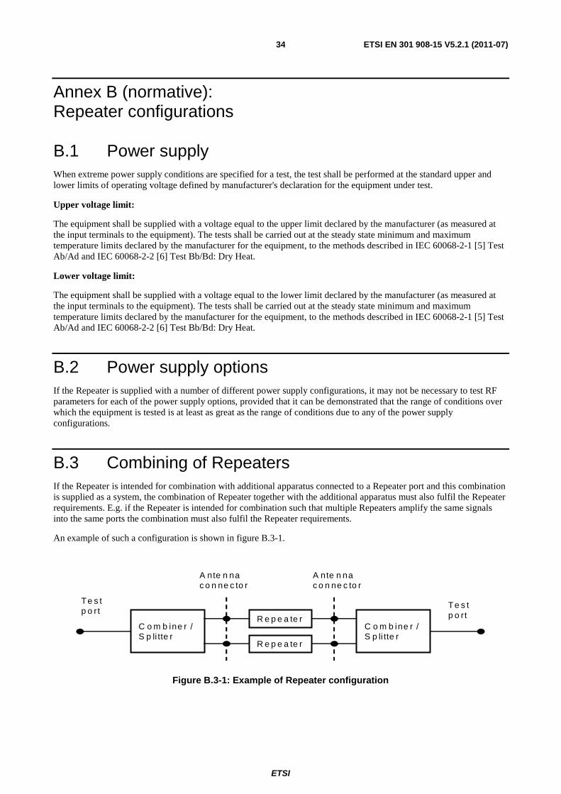
ETSI
ETSI EN 301 908-15 V5.2.1 (2011-07)34
Annex B (normative): Repeater configurations
B.1 Power supply When extreme power supply conditions are specified for a test, the test shall be performed at the standard upper and lower limits of operating voltage defined by manufacturer's declaration for the equipment under test.
Upper voltage limit:
The equipment shall be supplied with a voltage equal to the upper limit declared by the manufacturer (as measured at the input terminals to the equipment). The tests shall be carried out at the steady state minimum and maximum temperature limits declared by the manufacturer for the equipment, to the methods described in IEC 60068-2-1 [5] Test Ab/Ad and IEC 60068-2-2 [6] Test Bb/Bd: Dry Heat.
Lower voltage limit:
The equipment shall be supplied with a voltage equal to the lower limit declared by the manufacturer (as measured at the input terminals to the equipment). The tests shall be carried out at the steady state minimum and maximum temperature limits declared by the manufacturer for the equipment, to the methods described in IEC 60068-2-1 [5] Test Ab/Ad and IEC 60068-2-2 [6] Test Bb/Bd: Dry Heat.
B.2 Power supply options If the Repeater is supplied with a number of different power supply configurations, it may not be necessary to test RF parameters for each of the power supply options, provided that it can be demonstrated that the range of conditions over which the equipment is tested is at least as great as the range of conditions due to any of the power supply configurations.
B.3 Combining of Repeaters If the Repeater is intended for combination with additional apparatus connected to a Repeater port and this combination is supplied as a system, the combination of Repeater together with the additional apparatus must also fulfil the Repeater requirements. E.g. if the Repeater is intended for combination such that multiple Repeaters amplify the same signals into the same ports the combination must also fulfil the Repeater requirements.
An example of such a configuration is shown in figure B.3-1.
R e p e a te r C o m b ine r / S p li tte r
R e p e a te r
C o m b ine r / S p li tte r
A nte n na c o n ne c to r
A nte n na c o n ne c to r
Te s t p o rt
Te s t p o rt
Figure B.3-1: Example of Repeater configuration
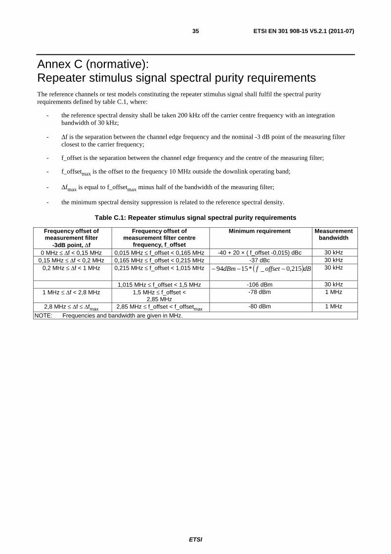
ETSI
ETSI EN 301 908-15 V5.2.1 (2011-07)35
Annex C (normative): Repeater stimulus signal spectral purity requirements The reference channels or test models constituting the repeater stimulus signal shall fulfil the spectral purity requirements defined by table C.1, where:
- the reference spectral density shall be taken 200 kHz off the carrier centre frequency with an integration bandwidth of 30 kHz;
- Δf is the separation between the channel edge frequency and the nominal -3 dB point of the measuring filter closest to the carrier frequency;
- f_offset is the separation between the channel edge frequency and the centre of the measuring filter;
- f_offsetmax is the offset to the frequency 10 MHz outside the downlink operating band;
- Δfmax is equal to f_offsetmax minus half of the bandwidth of the measuring filter;
- the minimum spectral density suppression is related to the reference spectral density.
Table C.1: Repeater stimulus signal spectral purity requirements
Frequency offset of measurement filter
-3dB point, Δf
Frequency offset of measurement filter centre
frequency, f_offset
Minimum requirement Measurement bandwidth
0 MHz ≤ Δf < 0,15 MHz 0,015 MHz ≤ f_offset < 0,165 MHz -40 + 20 × ( f_offset -0,015) dBc 30 kHz 0,15 MHz ≤ Δf < 0,2 MHz 0,165 MHz ≤ f_offset < 0,215 MHz -37 dBc 30 kHz
0,2 MHz ≤ Δf < 1 MHz 0,215 MHz ≤ f_offset < 1,015 MHz ( )dBoffsetfdBm 215,0_*1594 −−−
30 kHz
1,015 MHz ≤ f_offset < 1,5 MHz -106 dBm 30 kHz 1 MHz ≤ Δf < 2,8 MHz 1,5 MHz ≤ f_offset <
2,85 MHz -78 dBm 1 MHz
2,8 MHz ≤ Δf ≤ Δfmax 2,85 MHz ≤ f_offset < f_offsetmax -80 dBm 1 MHz
NOTE: Frequencies and bandwidth are given in MHz.
ETSI
ETSI EN 301 908-15 V5.2.1 (2011-07)36
Annex D (informative): Environmental profile specification The following environmental conditions may be declared by the supplier:
• barometric pressure: minimum and maximum;
• temperature: minimum and maximum;
• relative humidity: minimum and maximum;
• power supply: lower and upper voltage limit.
When operating outside the boundary limits of the declared operational environmental profile the equipment should not make ineffective use of the radio frequency spectrum so as to cause harmful interference.
ETSI
ETSI EN 301 908-15 V5.2.1 (2011-07)37
Annex E (informative): The EN title in the official languages The enlargement of the European Union (EU) resulted in a requirement from the EU for a larger number of languages for the translation of the titles of Harmonized Standards and mandated ENs that are to be listed in the Official Journal to support the implementation of this legislation.
For this reason the title translation concerning the present document can be consulted via the e-approval application.

ETSI
ETSI EN 301 908-15 V5.2.1 (2011-07)38
Annex F (informative): Bibliography
• Directive 2004/108/EC of the European Parliament and of the Council of 15 December 2004 on the approximation of the laws of the Member States relating to electromagnetic compatibility and repealing Directive 89/336/EEC (text with EEA relevance (EMC Directive).
• Directive 2006/95/EC of the European Parliament and of the Council of 12 December 2006 on the harmonisation of the laws of Member States relating to electrical equipment designed for use within certain voltage limits (LV Directive).
• CEPT/ERC/REC 74-01 (Siófok 1998, Nice 1999, Sesimbra 2002, Hradec Kralove 2005, Cardiff 2011): "Unwanted Emissions in the Spurious Domain".
• ETSI TS 136 521-1 (V9.3.0): "LTE; Evolved Universal Terrestrial Radio Access (E-UTRA); User Equipment (UE) conformance specification; Radio transmission and reception; Part 1: conformance testing (3GPP TS 36.521-1 version 9.3.0 Release 9)".
• Commission Decision 2008/477/EC of 13 June 2008 on the harmonisation of the 2 500-2 690 MHz frequency band for terrestrial systems capable of providing electronic communications services in the Community.
• Commission Decision 2010/267/EU of 6 May 2010 on harmonised technical conditions of use in the 790-862 MHz frequency band for terrestrial systems capable of providing electronic communications services in the European Union.
ETSI
ETSI EN 301 908-15 V5.2.1 (2011-07)39
History
Document history
V4.2.1 March 2010 Publication
V5.1.1 October 2010 Public Enquiry PE 20110224: 2010-10-27 to 2011-02-24
V5.2.1 May 2011 Vote V 20110702: 2011-05-03 to 2011-07-04
V5.2.1 July 2011 Publication
Related Documents