HARMONISED TECHNICAL STANDARDS: DESIGNS AND MINIMUM SPECIFICATIONS Publication Date: May 2021 Version: 1.0 Published by: Rural Electrification Agency Contact: Corporate Headquarters No 22, Freetown Street, Wuse 2, Abuja, FCT, Nigeria. Email: [email protected] Phone: +2348112494040, +2348107829134 This publication presents the Rural Electrification Agency’s (REA) harmonised technical standard (including designs and minimum specifications) that is required to implement the agency’s rural electrification schemes through grid extension, injection substations and solar mini-grids, solar home systems and solar street lights. The publication was conceived and produced by REA. All reasonable precaution has been taken by the agency to verify the reliability of the material in this publication.

Welcome message from author
This document is posted to help you gain knowledge. Please leave a comment to let me know what you think about it! Share it to your friends and learn new things together.
Transcript

HARMONISED TECHNICAL STANDARDS: DESIGNS AND
MINIMUM SPECIFICATIONS
Publication Date: May 2021 Version: 1.0
Published by: Rural Electrification Agency Contact: Corporate Headquarters No 22, Freetown Street, Wuse 2, Abuja, FCT, Nigeria. Email: [email protected] Phone: +2348112494040, +2348107829134
This publication presents the Rural Electrification Agency’s (REA) harmonised technical standard (including designs and minimum specifications) that is required to implement the agency’s rural electrification schemes through grid extension, injection substations and solar mini-grids, solar home systems and solar street lights. The publication was conceived and produced by REA. All reasonable precaution has been taken by the agency to verify the reliability of the material in this publication.
Acknowledgements The Rural Electrification Agency (REA) would like to acknowledge the cooperation and contributions of all the key internal and external stakeholders that took part in the design, concept and production of this publication, specifically the representatives from the office of the Managing Director (MD), Technical Services (TS) directorate, Rural Electrification Fund (REF), Nigerian Electrification Project (NEP), Performance department and Procurement department.
Glossary of Terms
AAC All Aluminium Conductor AC Alternating Current ACSR Aluminium Conductor Steel Reinforced BEME Bill of Engineering Measurement and Evaluation BoS Balance of System CT Current Transformer CVT Capacitor Voltage Transformer dB Decibel DC Direct Current DOD Depth of Discharge EVA Ethylene Vinyl Acetate Hz Hertz IEC International Electrotechnical Commission IP Ingress Protection kV Kilovolt (1,000 Volts) KW KWH Kilowatts kWh Kilowatt-hour kVA Kilovolt-Ampere MD Minor Deviation MPPT Maximum Power Point Tracking MT Metric Tonnes MC Multi-Contact MW Megawatts NEMSA Nigerian Electricity Management Services Agency NERC Nigerian Electricity Regulatory Commission NESI Nigeria Electricity Supply Industry NESIS Nigeria Electricity Supply and Installation Standards NESP Nigerian Energy Support Programme PRS Pre-stressed Rectangular Solid p.u. Per unit PV Photovoltaic SAIDI System Average Interruption Duration Index SAIFI System Average Interruption Frequency Index SON Standards Organisation of Nigeria SR Safety Relevant STC Standard Test Conditions TUV Technischer Überwachungsverein V Volt VD Voltage Drop XLPE Cross-linked polyethene

Definition of Terms
Applicant Mini-grid Owner, also referred to as Owner, who may authorise a third-party that is fully familiar with the Mini-Grid, to apply and procure the Inspection Certificate on its behalf, provided that he is a NEMSA certified Renewable Energy contractor for Electricity Generation.
Back-up Generation
Any firm Generation such as diesel-powered or biomass-powered generator that can operate within seconds of the non-availability of Solar Photovoltaic (PV) Generation.
Balance of System (BoS)
All components of a PV system other than the PV panels; including wiring, switches, a mounting system, one or many solar inverters, a battery bank or many battery banks, related electronic battery converters and battery chargers.
Customer A client of the Owner buying electricity from the Mini-Grid under a domestic, commercial, productive and/or administrative service contract, and maybe a natural person or any other legal entity.
Commissioning The period when all installations of electrical works been completed and technically inspected, tested and certified by NEMSA before the start of operations.
Distribution Network
Electric power lines with connections for low voltage (230/400V) and optionally medium voltage (up to 33kV), transformers and other switchgear to distribute electric power (produced by a Generation source) to the Customers.
Electrical Installation
The construction or installation of electrical wiring and the permanent attachment or installation of electrical products in or on any structure.
Electrical Safety Any safety precautions (organisational measures and technical) taken against electricity (electric current, electric arc, electromagnetic field and static electricity) to prevent harmful and dangerous effects on anyone.
Generation Solar PV Generation in combination with any Other Generation and Back-up Generation, as well as the land (including the Powerhouse and the Fencing) housing the Generation source
Inspection The physical inspection and testing of electrical installations by NEMSA inspectors as per the procedure described in their extant guidelines
Inspection Certificate
shall mean the Certificate issued by NEMSA to any Owner of a Solar Hybrid Mini-grid having successfully undergone the process of Inspection by NEMSA Inspectors, as defined in these Guidelines, and is valid for 5 years, unless the Electrical Installation requires Significant Modifications before this period, in which case the Owner shall apply for Re-inspection.
Inspection Fee The fee stipulated for inspection of electrical works/installations as published by NEMSA on www.nemsa.gov.ng.
Meter As defined under the Nigerian Electricity Regulatory Commission (NERC), Metering Code, V02 and NEMSA Act, 2015.
Mini-grid Any electricity supply system with its power Generation capacity of up to 1 MW, supplying electricity to more than one customer and which can operate in isolation from or be connected to a Distribution Licensee’s network”, under NERC’s, Mini-grid Regulations, 2016.
Mini-grid Documentation and Inspection Forms
The standardised document to be filled by the Applicant to apply for inspection and shall be subject to changes by NEMSA and for which the latest version can be downloaded from www.nemsa.gov.ng or picked up in any of the NEMSA Inspectorate Field Offices (https://nemsa.gov.ng/field-inspectorate-offices/).
NEMSA Certified Contractor
Any Contractor duly certified by NEMSA to carry out electrification projects through grid extension, injection substations and solar mini-grids, home systems and street lights.
Inspector An inspecting Engineer under NEMSA to carry out the functions of inspection, testing and certification of all electrical installations/works
Regulation Any applicable piece of Regulation, as approved by the NERC or any other statutory regulatory body in Nigeria.
Re-inspection Inspection after correcting the defects observed during Inspection or upon expiry of the Inspection Certificate for reasons of renewal of the Inspection Certificate or upon significant modifications carried out by the contractor, and shall follow the same procedure as Inspections.
Solar Hybrid Mini-grid
Any Mini-grid that combines Solar PV Generation, other Generation sources (wind, biomass, etc.), Back-up Generation and a Distribution Network, as specified in NERC’s Mini-grid Regulations, 2016
Solar PV Generation
The main Generation source of the Solar Hybrid Mini-grid and comprising the solar modules, the ground-mounted/roof-mounted or building-integrated support structure, the charge controller or grid-tie inverter and the required Balance of Systems (BoS), if not part of the System Controller.
Standard Any Standard as recommended by NERC, NEMSA and/or approved by SON or the International Electro-technical Commission (IEC).
Storage Secondary (rechargeable) batteries, including, but not necessarily limited to lead-acid batteries and lithium to store excess electricity produced by the Generation for later use, including power electronic converters or charge controllers and monitoring, if not part of the overall System Controller.
System Controller
The central element of the Generation to manage all types of Generation and Storage of the Mini-grid and ensure a reliable supply of electricity to the Distribution Network of the Mini-Grid. The System Controller shall comprise of a simple charge controller for small systems (i.e., up to 10kW) and dedicated off-grid inverters, or a supervisory controller in combination with dedicated controllers and electronic power inverters for large systems (i.e., from 10kW), including all required BoS.
System Stress Testing
Loading the concurrent users over and beyond the level that the system can handle, so it breaks at the weakest link within the entire system.
Technical Documentation
Datasheets, Single Line Diagrams (SLDs), detailed schematics, construction plans, internal test and Commissioning reports/protocols, as well as Operating Procedures.

Table of Contents 1 SCOPE ................................................................................................................................................................ 1 2 GRID EXTENSION .............................................................................................................................................. 2
2.1 STANDARDS AND SPECIFICATIONS: ELECTRICAL WORKS ................................................................. 2 2.1.1. General Guidelines .............................................................................................................................. 2 2.1.2 Allowable Voltages ............................................................................................................................. 2 2.1.3 Insulation Requirements .................................................................................................................... 3 2.1.4 Equipment and Installation Devices ................................................................................................... 4 2.1.5 Overhead Distribution Lines ................................................................................................................ 4 2.1.6 Concrete Poles .................................................................................................................................... 4 2.1.7 Steel Towers/Steel Poles ..................................................................................................................... 5 2.1.8 Steelworks ........................................................................................................................................... 6 2.1.9 Overhead Line Insulators ..................................................................................................................... 7 2.1.10 Cross Arms .......................................................................................................................................... 7 2.1.11 Line Conductors ................................................................................................................................... 8 2.1.12 Installation of Transformers ................................................................................................................. 8 2.1.13 Feeder Pillars ....................................................................................................................................... 8 2.1.14 Transformer Incomer Cables ............................................................................................................... 9 2.1.15 Transformer Incomer Cables ............................................................................................................... 9 2.1.16 Substation Upriser ............................................................................................................................... 9 2.1.17 Ganged Isolators and Anti-climb Guards ............................................................................................. 9 2.1.18 Tree Cutting ......................................................................................................................................... 9 2.1.19 Danger Plates ...................................................................................................................................... 9 2.1.20 Tension Sets ........................................................................................................................................ 9 2.1.21 Bolts, Nuts and Threads .................................................................................................................... 10 2.1.22 Washers ............................................................................................................................................. 10 2.1.23 Surge Arresters .................................................................................................................................. 10
3 INJECTION SUBSTATIONS ............................................................................................................................. 10 3.1 STANDARDS AND SPECIFICATIONS: ELECTRICAL WORKS ............................................................... 10
3.1.1 Switchgear and Fuse Gear Assemblies ................................................................................................. 10 3.1.2 Voltage Transformers (VTs) ................................................................................................................. 11 3.1.3 Current Transformers (CTs) .................................................................................................................. 11 3.1.4 Station Service Transformers ............................................................................................................... 11 3.1.5 Lightning Arresters ................................................................................................................................ 11 3.1.6 Control Panels ....................................................................................................................................... 12 3.1.7 Protection Panel .................................................................................................................................... 12 3.1.8 Cables for Underground Transmission Lines ....................................................................................... 12 3.1.9 Battery Banks ........................................................................................................................................ 12
3.2 STANDARDS AND SPECIFICATIONS: CIVIL WORKS ............................................................................ 13 3.2.1 Civil Works: Design, Site Preparation and Installation .......................................................................... 13 3.2.2 Access Roads ........................................................................................................................................ 13 3.2.3 Property Fencing ................................................................................................................................... 14 3.2.4 Galvanised Steel Chain Link .................................................................................................................. 14 3.2.5 Vibrated Block Wall ................................................................................................................................ 14 3.2.6 Control Room Building ........................................................................................................................... 15 3.2.7 Equipment Plinth and Oil Sump ............................................................................................................. 15 3.2.8 Drainage ................................................................................................................................................ 16 3.2.9 Cable Trenches ..................................................................................................................................... 16 3.2.10 Gravelling and Landscaping .............................................................................................................. 16
4 SOLAR MINI-GRIDS ......................................................................................................................................... 16 4.1 STANDARDS AND SPECIFICATIONS: SOLAR MINI-GRIDS .................................................................. 16
4.1.1 General Guidelines ................................................................................................................................ 16 4.1.2 System Design and Requirements ........................................................................................................ 17 4.1.3 Compliance with the Manufacturers’ Requirements .............................................................................. 19 4.1.4 Compliance with Service Standards (Reliability and Availability) .......................................................... 19 4.1.5 Capacity Shortage and PV Modules ...................................................................................................... 20
4.1.6 PV Mounting .......................................................................................................................................... 20 4.1.7 Batteries/Energy Storage Devices ......................................................................................................... 21 4.1.8 Electronics and Balance of the System ................................................................................................. 22 4.1.9 Generators: Diesel, Gas and Biomass .................................................................................................. 25 4.1.10 Accessories and Spare Parts ............................................................................................................ 26 4.1.11 Metering and Distribution ................................................................................................................... 27 4.1.12 Installation .......................................................................................................................................... 27
5 SOLAR HOME SYSTEMS (SHS) ..................................................................................................................... 27 5.1 STANDARDS AND SPECIFICATIONS: SHS ....................................................................................................... 27
6 SOLAR STREET LIGHTS ................................................................................................................................. 28 6.1 STANDARDS AND SPECIFICATIONS: SOLAR STREET LIGHTS ............................................................................ 28
ANNEXES ................................................................................................................................................................. 30 ANNEXE A: INTERNATIONAL ELECTROTECHNICAL COMMISSION (IEC) CODES .............................................................. 30 ANNEXE B: GRID EXTENSION .................................................................................................................................... 33
1 Environmental Requirements and Conditions: Electrical Works ............................................................... 33 2 Guide to Conduct Electrical Load Surveys ................................................................................................ 34 3 Route Surveys ........................................................................................................................................... 34 4 Engineering Design ................................................................................................................................... 34 5 Pole Markings ............................................................................................................................................ 35 6 High Tension Dressed Poles ..................................................................................................................... 36
ANNEXE C: INJECTION SUBSTATIONS ........................................................................................................................ 37 1 Substation Designs .................................................................................................................................... 37 2 Safety Requirements: Control Panels ....................................................................................................... 45 3 Cables ....................................................................................................................................................... 45
ANNEXE D: SOLAR MINI-GRIDS ................................................................................................................................ 47 1 Technical Schedule Guarantees ............................................................................................................... 47 2 Diesel Generators: Operating Concept ..................................................................................................... 47 3 PV Module Designs: Grounding and Equipotential Bonding ..................................................................... 49
ANNEXE E: SOLAR STREET LIGHTS ........................................................................................................................... 50 1 Solar Street Lights Design ......................................................................................................................... 50
1
1 SCOPE 1. This publication presents the Rural Electrification Agency’s (REA) harmonised technical
standard (including designs and minimum specifications) that is required to implement the agency’s rural electrification schemes through grid extension, injection substations and solar mini-grids, solar home systems and solar street lights.
2. It incorporates previously developed technical standards for the Technical Services (TS) Directorate, Rural Electrification Fund (REF) and Nigerian Electrification Project (NEP). Extant Procurement rules, as well as the Nigerian Electricity Regulatory Commission (NERC), Nigerian Electricity Management Services Agency (NEMSA), Nigerian Electricity Supply and Installation Standards (NESIS) and International Electrotechnical Commission (IEC) standards, were also considered.
3. A committee was set-up to develop and present this publication to the Executive Management and Board for ratification. The committee consisted of representatives from the following directorates/departments: office of the Managing Director (MD), TS, REF, NEP, Performance and Procurement.
4. The publication provides usefulness to project developers, contractors, power sector Ministries, Departments and Agencies (MDAs), utility companies, investors, equipment manufacturers/suppliers, development partners, local authorities/communities, as well as other stakeholders interested in implementing sustainable rural electrification schemes through grid extension, injection substations and solar mini-grids, solar home systems and solar street lights.
5. Internally, the publication also provides usefulness to REA in carrying out several organisational functions, including procurement, survey, internal control, performance management, project implementation, project inspection/monitoring and project assessment.
6. The standards and specifications in this publication are in line with extant laws and regulations, and as such, shall be implemented together with other laws, regulations and standards, including: a. Laws of the Federal Republic of Nigeria, including (but not limited to) the Electric Power
Sector Reform Act, 2005 and NEMSA Act, 2015. b. Regulations from NERC, but not limited to:
i. The Nigerian Electricity Health and Safety Code, 2014. ii. The Nigerian Electricity Supply and Installation Standards Regulation, 2015. iii. The Grid Code, 2018 iv. The Distribution Code, 2014 v. The Metering Code (V02), 2014 vi. Nigerian Electricity Smart Metering Regulations, 2015 vii. The Mini-Grid Regulations, 2016 viii. Electrical Installations Regulations S.I.5 and Electricity Supply Regulations S.I.6 of
1996; and ix. The Nigerian Electrical Installations and Construction Guidelines Manual, Distribution
Subsector, Volume 1, 2020. x. Other technical regulations, guidelines and codes issued occasionally by NERC,
NESIS, NEMSA, IEC, etc. c. IEC Standards, specifically for materials and equipment that are not covered under any
Nigerian Law, Regulation or Standard. These IEC standards include (but not limited to) the following:
i. IEC 62446-1:2016+A1:2018: PV systems - Requirements for testing, documentation and maintenance - Part 1: Grid-connected systems - Documentation, commissioning tests and inspection.

2
ii. IEC 60896-21:2004: Stationary lead-acid batteries - Part 21: Valve regulated types - Methods of test.
iii. IEC 62485-1:2015: Safety requirements for secondary batteries and battery installations - Part 1: General safety information.
iv. IEC 62619:2017: Secondary cells and batteries containing alkaline or other non-acid electrolytes - Safety requirements for secondary lithium cells and batteries, for use in industrial applications.
v. IEC 62620:2014: Secondary cells and batteries containing alkaline or other non-acid electrolytes - Secondary lithium cells and batteries for use in industrial applications.
7. Upon ratification by the Executive Management and Board, the document will supersede the above-mentioned technical standards that were previously developed. The document will also take precedence over other technical standards, provided it is in line with extant laws and regulations.
8. The document will be periodically revised and updated (as required) to meet international best practices.
2 GRID EXTENSION 2.1 STANDARDS AND SPECIFICATIONS: ELECTRICAL WORKS
This sub-section outlines standards and specifications for electrical works. The distribution network, in this context, includes the following: 33kV networks; 11kV networks; 400V networks and below.
2.1.1. General Guidelines 1. Material Requirements: All materials used for electrical works, their components,
accessories and support structures are required to ensure safe operational performance within the anticipated life span of the installation.
2. Thermal Ratings: The thermal capacity of electrical works shall be sufficient to pass the electrical load for which they are designed, without reduction of electrical and mechanical properties to a level below safe operational performance.
3. Short Circuit Ratings: The electrical works shall be of sufficient capacity to pass short circuit currents, which will enable the correct operation of protective devices so that a fault is cleared without reduction of electrical and mechanical properties to a level below safe operational performance.
4. Mechanical Loading Conditions: The electrical works shall have sufficient mechanical and structural strength to withstand anticipated stresses and strains due to environmental and electrical service conditions.
5. Electrical Service Conditions and Physical Environment: In determining the electrical service conditions and the physical environment under which the electrical works will operate, due and reasonable care shall be given to the consideration of extremes that may occur, the likelihood of their occurrence and the associated risks.
6. Prevention of Unauthorised Access: All electrical works with exposed live parts shall be designed and constructed in a manner that prevents unauthorised access to any person, as far as is reasonably practicable.
2.1.2 Allowable Voltages The distribution network shall be operated on voltages as defined below:
1. System of Supply: The following system standards shall apply; a. The frequency shall operate within a narrow operating band of 50 Herz ± 0.5%) or
(49.75 – 50.25 Hz). However, under System Stress Testing, the Frequency on the Power System can experience variations within the limits of 50 Hz ± 2.5% (48.75 – 51.25 Hz).
b. Standard A.C. voltages shall be 230 V ± 6% between the phase conductor and neutral
3
conductor and 400 Volts ± 6% between phases conductors. Primary distribution high voltage shall be 33,000 Volts ± 6% and secondary distribution high voltage shall be 11,000 Volts ± 6%.
2. Standard Types of Supply
a. Two-wire system (single-phase alternating current) at a nominal voltage not exceeding 230 volts at the user’s main switchboard.
b. Three-phase four-wire alternating current system at a nominal voltage not exceeding 400 volts between phases
c. The voltage shall be maintained within ±6% of the nominal voltage at the consumer’s main switchboard. In the case of a complaint by any consumer that the variation in voltage exceeds the limits specified, or on the instructions of the Inspecting Engineer, the Distribution licensee shall provide, connect and maintain a portable recording device to record the voltage profile between the service line. If the variation thus recorded are caused within and by the licensee’s system and exceed the above limits, the licensee shall take immediate steps to resolve the complaint.
3. Supply Voltage
a. The Supply Voltage shall not exceed 230 volts at the user’s main switchboard. For supply to services exceeding 10 kilowatts connected load, the nominal voltage shall not exceed 400 volts at such switchboard.
b. The Supply Voltage for industrial purposes may be given at high voltages either for transformation or for direct supply to motors or any other agreed voltage between the Distribution Licensee and the user. This shall be subject to the standard voltage in these regulations provided that the transforming apparatus and control gear are so enclosed as to be inaccessible except to authorised persons.
2.1.3 Insulation Requirements Distribution Network shall be appropriately insulated to guarantee the safety of equipment and personnel. Insulation materials used shall be capable of withstanding high insulation value(s) throughout the service life of the equipment or installation. Provisions of IEC 62068 on the insulation of equipment, materials and installation shall be adhered to.
1. Earthing: All electrical installations and network shall be adequately earthed to guarantee operational safety as specified in the Code of Practice for Earthing (NCP1 09).
2. Earthing of Metal Structures
a. Where lines are operated at high voltages, all metal structures, other than conductors shall be permanently and effectively connected to earth electrode(s). For this purpose, a continuous earth wire shall be provided and connected to the earth.
b. Where any special equipment on a pole includes a metal structure accessible from ground level which normally has to be handled by an operator when the line is alive (e.g., a switch-operating handle), such metal structure shall be connected to an earthing mat, so situated as to include within its area the whole of the ground on which the operator would normally stand.
c. Earthing at Pole-Mounted Substations for Pole-mounted transformer: The electrode used for earthing the steelwork shall be situated outside the resistance area of the earthed electrode connected to the low voltage neutral.
1 National Security Inspectorate (NSI) Code of Practice -NCP
4
d. Earthing at Plinth-Mounted Substations for Plinth-mounted transformer: The Lightning Arrester, D-fuse and general earthing (Transformer body, Feeder pillar body, channel iron, Transformer neutral etc.) shall have different earth pit respectively. All section poles shall be earthed including angle poles with steel cross arm.
2.1.4 Equipment and Installation Devices
1. All materials, equipment, devices and accessories used directly in construction, installation and maintenance of distribution network shall constitute electrical network equipment and installation devices. They shall include (but not limited to) the following:
a. Support structures; metal or reinforced concrete poles, gantry guy, stay assembly b. Overhead materials; conductors, insulators, line hardware, accessories c. Underground materials; cables, termination kits, lugs d. Substation equipment; transformers, shunt capacitors, arresters, feeder pillars.
2.1.5 Overhead Distribution Lines
1. Overhead Distribution Lines shall be constructed with non-insulated and insulated conductors on supports designed and constructed to:
a. Have insulation appropriate for the nominal voltage; b. Carry the electrical load currents for which they are designed; c. Allow the passage of electrical short circuit currents which will enable the correct
operation of protective devices; d. Ensure they are structurally secure for the environment and service conditions for which
they are designed; e. Maintain safe clearances; f. Ensure that safe operational performance will occur, and g. Prevent unauthorised access to electrical works.
2. Overhead Lines with Bare Conductors: Where overhead lines with bare conductors
are routed across sites used for public recreation and work activities other than farming, they shall be protected with cradle guards.
3. Routing Overhead Lines across Farmlands: A risk assessment shall be carried out and any unacceptable location shall be avoided. Examples include the following: a. Locations where regular loading /unloading activities take place b. Fields where potable irrigation pipes are regularly used. c. Any location identified as being a potential hazard to farmworkers
4. Space Between Conductors: The space between conductors in the 33kV line shall be 1.2m while that of the 11kV line shall be 0.9m. The transverse distance between the phase conductor of the 400V line shall be 0.25m.
5. Supporting Structures: The supporting structures to be used require any of the following: concrete poles, steel poles, steel lattice towers, gantry guy and stay assembly.
2.1.6 Concrete Poles
1. The accepted types of concrete poles include the following: Pre-stressed steel-reinforced H section; Pre-stressed steel-reinforced spun square section, and Pre-stressed steel-reinforced spun circular section.
5
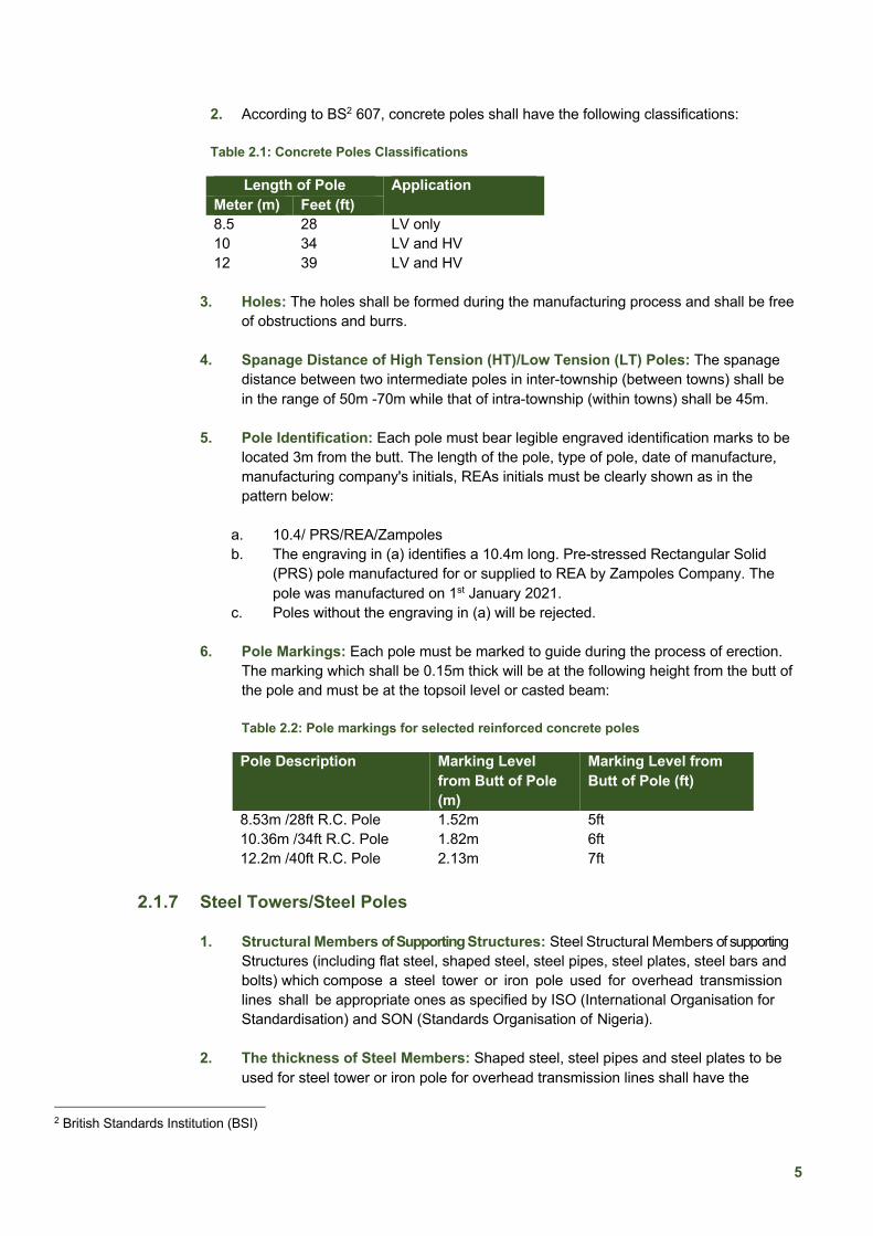
2. According to BS2 607, concrete poles shall have the following classifications:
Table 2.1: Concrete Poles Classifications
Length of Pole Application Meter (m) Feet (ft) 8.5 28 LV only 10 34 LV and HV 12 39 LV and HV
3. Holes: The holes shall be formed during the manufacturing process and shall be free
of obstructions and burrs. 4. Spanage Distance of High Tension (HT)/Low Tension (LT) Poles: The spanage
distance between two intermediate poles in inter-township (between towns) shall be in the range of 50m -70m while that of intra-township (within towns) shall be 45m.
5. Pole Identification: Each pole must bear legible engraved identification marks to be
located 3m from the butt. The length of the pole, type of pole, date of manufacture, manufacturing company's initials, REAs initials must be clearly shown as in the pattern below:
a. 10.4/ PRS/REA/Zampoles b. The engraving in (a) identifies a 10.4m long. Pre-stressed Rectangular Solid
(PRS) pole manufactured for or supplied to REA by Zampoles Company. The pole was manufactured on 1st January 2021.
c. Poles without the engraving in (a) will be rejected. 6. Pole Markings: Each pole must be marked to guide during the process of erection.
The marking which shall be 0.15m thick will be at the following height from the butt of the pole and must be at the topsoil level or casted beam: Table 2.2: Pole markings for selected reinforced concrete poles
Pole Description Marking Level from Butt of Pole (m)
Marking Level from Butt of Pole (ft)
8.53m /28ft R.C. Pole 1.52m 5ft 10.36m /34ft R.C. Pole 1.82m 6ft 12.2m /40ft R.C. Pole 2.13m 7ft
2.1.7 Steel Towers/Steel Poles
1. Structural Members of Supporting Structures: Steel Structural Members of supporting Structures (including flat steel, shaped steel, steel pipes, steel plates, steel bars and bolts) which compose a steel tower or iron pole used for overhead transmission lines shall be appropriate ones as specified by ISO (International Organisation for Standardisation) and SON (Standards Organisation of Nigeria).
2. The thickness of Steel Members: Shaped steel, steel pipes and steel plates to be used for steel tower or iron pole for overhead transmission lines shall have the
2 British Standards Institution (BSI)

6
thickness and other dimensions as specified below:
a. Minimum thickness of shaped steel to be used as:
i. The main post member of an iron pole shall have a thickness of 4mm. The same shall apply where the main member of a cross arm is included.
ii. The main post member of a steel tower shall have a thickness of 5mm.
iii. Other structural members shall have a thickness of 3mm.
b. Minimum thickness of steel pipes to be used as:
i. The main post member of an iron pole shall have a thickness of 2mm.
ii. The main post member of a steel tower shall have a thickness of 2.4mm.
iii. Other structural members shall have a thickness of 1.6mm.
c. Slenderness ratio of steel members: The slenderness ratio of a compression member shall be no more than 200 for those to be used as the main post member and no more than 220 for compression members other than main post members (excluding those used as auxiliary members) and no more than 250 for those used as auxiliary members.
d. Minimum thickness of steel plates: The thickness shall be no less than 1mm.
2.1.8 Steelworks Steelworks entail the channel iron, angle iron, stay rod, stay thimble, stay wire, terminating strap, j-hook, clevis adapter, socket tongue, cross arm (tie) strap, bracket mount, line taps, shackle insulator complete (D-iron, D-iron pin) and bolts, nuts & washers. The steel material for steelworks used in the construction of overhead lines must be galvanised. 1. General Guidelines
a. The steel used in the manufacture of the items listed is to be Grade 43A, 28/33-ton quality, to BS. 4360 or an equivalent specification approved by NEMSA and the sections must conform with BS. 4848 Part 4, or to an equivalent Standard.
b. Where a tube is used in the manufacture of some of the items, solid drawn seamless to B.S. 980 CDS-2 or equivalent shall be used
c. All drillings, filing and welding must be carried out before galvanising and such galvanising must be in accordance with BS 729, i.e., a minimum deposition of 610 grammes/m².
d. Where nuts, bolts or studs are required, they must comply with Equipment & Materials Standard 1-250 for fasteners and must be galvanised.
2. Stay Rods
a. Rods used in the construction of the stay rod shall be Grade 43A steel complying with BS 4360.
b. Stay Rod could be the tubular type rods for use with High Voltage services and or the Auger type rods for use with Low Voltage service lines
3. Stay Wires a. All Stay wires shall be galvanised steel and stranded; stay wires shall be galvanised to
BS 443 or equivalent
7
b. Stay wires shall be manufactured from mild steel stay wire of 700N/mm2 quality in accordance with BS 183 or an equivalent specification approved by NEMSA
c. The finished strand shall be right-hand lay, except for the 19-wire strand, which shall have an inner layer left hand and outer 12-wire right-hand lay.
d. The lay of the strand of each size of stay wire shall be in accordance with BS 183 or an equivalent specification.
e. Where a stay wire crosses over a road or street, a flying stay should be adopted.
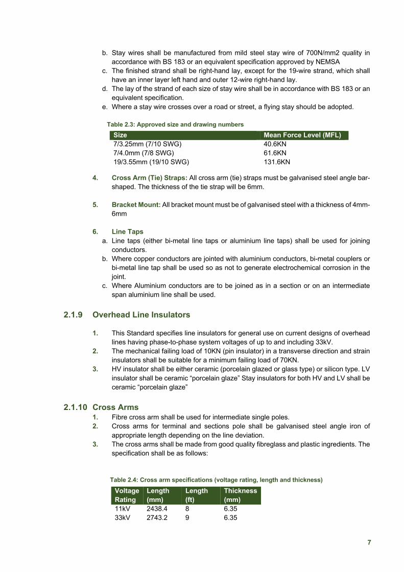
Table 2.3: Approved size and drawing numbers
4. Cross Arm (Tie) Straps: All cross arm (tie) straps must be galvanised steel angle bar-shaped. The thickness of the tie strap will be 6mm.
5. Bracket Mount: All bracket mount must be of galvanised steel with a thickness of 4mm-6mm
6. Line Taps
a. Line taps (either bi-metal line taps or aluminium line taps) shall be used for joining conductors.
b. Where copper conductors are jointed with aluminium conductors, bi-metal couplers or bi-metal line tap shall be used so as not to generate electrochemical corrosion in the joint.
c. Where Aluminium conductors are to be joined as in a section or on an intermediate span aluminium line shall be used.
2.1.9 Overhead Line Insulators
1. This Standard specifies line insulators for general use on current designs of overhead lines having phase-to-phase system voltages of up to and including 33kV.
2. The mechanical failing load of 10KN (pin insulator) in a transverse direction and strain insulators shall be suitable for a minimum failing load of 70KN.
3. HV insulator shall be either ceramic (porcelain glazed or glass type) or silicon type. LV insulator shall be ceramic “porcelain glaze” Stay insulators for both HV and LV shall be ceramic “porcelain glaze”
2.1.10 Cross Arms 1. Fibre cross arm shall be used for intermediate single poles. 2. Cross arms for terminal and sections pole shall be galvanised steel angle iron of
appropriate length depending on the line deviation. 3. The cross arms shall be made from good quality fibreglass and plastic ingredients. The
specification shall be as follows:
Table 2.4: Cross arm specifications (voltage rating, length and thickness)
Size Mean Force Level (MFL) 7/3.25mm (7/10 SWG) 40.6KN 7/4.0mm (7/8 SWG) 61.6KN 19/3.55mm (19/10 SWG) 131.6KN
Voltage Rating
Length (mm)
Length (ft)
Thickness (mm)
11kV 2438.4 8 6.35 33kV 2743.2 9 6.35
8
2.1.11 Line Conductors
1. The conductors used on overhead lines shall be limited to aluminium and alloys of aluminium material, essentially All Aluminium Conductor (AAC) and Aluminium Conductor Steel Reinforced (ACSR).
2. Classes and qualities of aluminium conductors applicable in distribution overhead network shall comply with the provisions of IEC 61089.
3. For 33kV and 11kV lines, 150mm2 /100mm2 ACSR shall be used for inter-township connection in the far north. 150mm2 /100mm2 AAC shall be used in the south except where strong wind exists.
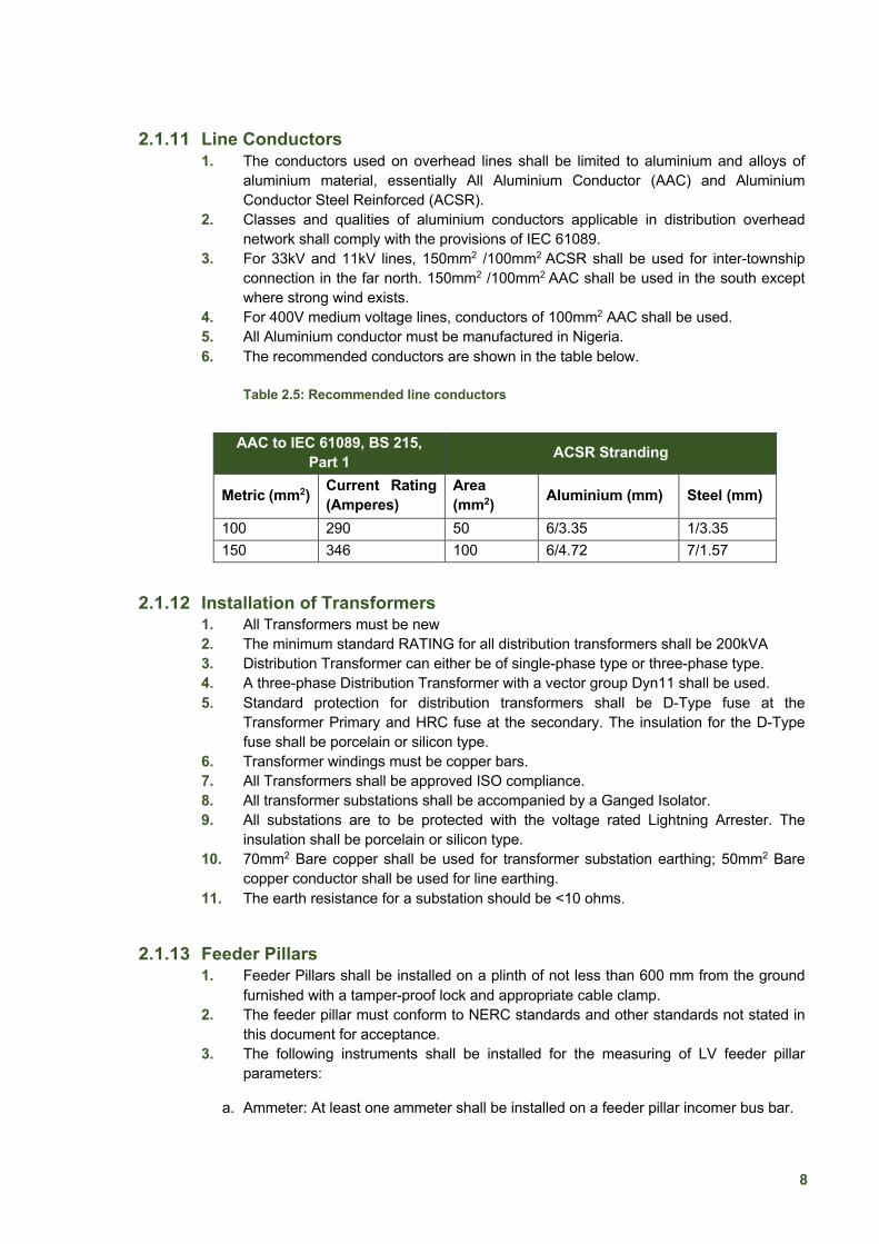
4. For 400V medium voltage lines, conductors of 100mm2 AAC shall be used. 5. All Aluminium conductor must be manufactured in Nigeria. 6. The recommended conductors are shown in the table below.
Table 2.5: Recommended line conductors
2.1.12 Installation of Transformers
1. All Transformers must be new 2. The minimum standard RATING for all distribution transformers shall be 200kVA 3. Distribution Transformer can either be of single-phase type or three-phase type. 4. A three-phase Distribution Transformer with a vector group Dyn11 shall be used. 5. Standard protection for distribution transformers shall be D-Type fuse at the
Transformer Primary and HRC fuse at the secondary. The insulation for the D-Type fuse shall be porcelain or silicon type.
6. Transformer windings must be copper bars. 7. All Transformers shall be approved ISO compliance. 8. All transformer substations shall be accompanied by a Ganged Isolator. 9. All substations are to be protected with the voltage rated Lightning Arrester. The
insulation shall be porcelain or silicon type. 10. 70mm2 Bare copper shall be used for transformer substation earthing; 50mm2 Bare
copper conductor shall be used for line earthing. 11. The earth resistance for a substation should be <10 ohms.
2.1.13 Feeder Pillars 1. Feeder Pillars shall be installed on a plinth of not less than 600 mm from the ground
furnished with a tamper-proof lock and appropriate cable clamp. 2. The feeder pillar must conform to NERC standards and other standards not stated in
this document for acceptance. 3. The following instruments shall be installed for the measuring of LV feeder pillar
parameters:
a. Ammeter: At least one ammeter shall be installed on a feeder pillar incomer bus bar.
AAC to IEC 61089, BS 215, Part 1 ACSR Stranding
Metric (mm2) Current Rating (Amperes)
Area (mm2) Aluminium (mm) Steel (mm)
100 290 50 6/3.35 1/3.35 150 346 100 6/4.72 7/1.57
9
b. Voltmeter: Voltmeter shall be installed on a feeder pillar to show line-to-line and line-to-neutral voltages.
c. Energy Meter: Energy Meter for low voltage distribution feeder pillar panels shall be installed according to the requirements of the Nigerian Metering Code.
4. The approved feeder pillars shall be 800A, 4ways, copper Bars for all transformer substations.
2.1.14 Transformer Incomer Cables 1. 11kV/400V Transformer Substations: Transformer Incomer cables shall be
30m(10mx3) of 35mm2 Cross-linked polyethylene (XLPE) Nigerian Cable 2. 33kv/400V Transformer Substations: Transformer Incomers cable shall be 30m
(10mx3) of 95mm2 single core (copper) Nigerian Cable.
2.1.15 Transformer Incomer Cables 1. 200KVA transformers: The feeder pillar Incomer cable shall be 6m of 150mm2 x4
Core Nigerian Cable. 2. 300KVA transformers: The Feeder Pillar Incomer cable shall be 24m (4x6m) of
300mm2 x1 Core Nigerian Cable. 3. 500KVA transformers: The Feeder Pillar Incomer cable shall be 24m (4x6m) of
500mm2 x1 Core Nigerian Cable
2.1.16 Substation Upriser 1. 200KVA transformers Up riser cable shall be 15m of 70mm2 x4Core Nigerian Cable. 2. 300KVA transformers Up riser cable shall be 15m of 120mm2 x4Core Nigerian Cable. 3. 500KVA transformers Up riser cable shall be 15m of 150mm2 x4Core Nigerian Cable 4. To avoid vandalization, uprisers should be incorporated into PVC pipes and concreted.
2.1.17 Ganged Isolators and Anti-climb Guards 1. Ganged Isolator shall be either Silicon type or Porcelain depending on the requirements
of the Distribution Company (DisCo). 2. Anti-climbing guards must be fitted in suitable positions where climbing is facilitated
2.1.18 Tree Cutting 1. All trees within the line right of way (ROW) which does not exceed 3 meters and are
within the location of the poles must be cut down. 2. Also, all other trees on the ROW that are considered to interfere with the stringing of
the line must be cut down. 3. Other trees outside the line ROW considered as a threat to the power line during
operations shall be cut or trimmed.
2.1.19 Danger Plates 1. Conspicuous “DANGER” plates shall be provided and fixed on all poles at
approximately 2m above ground. 2. The danger plate shall be fixed at substations and positioned at the base of the
transformer.
2.1.20 Tension Sets 1. Conforming to IEC-60120, the fittings shall consist of a cross arm strap and forged steel
ball eye to attach the socket end of the strain insulator to the cross arm strap.
10
2. Fittings for strain insulators with conventional dead-end clamps are to be used with tongue & clevis or ball & socket type insulators.
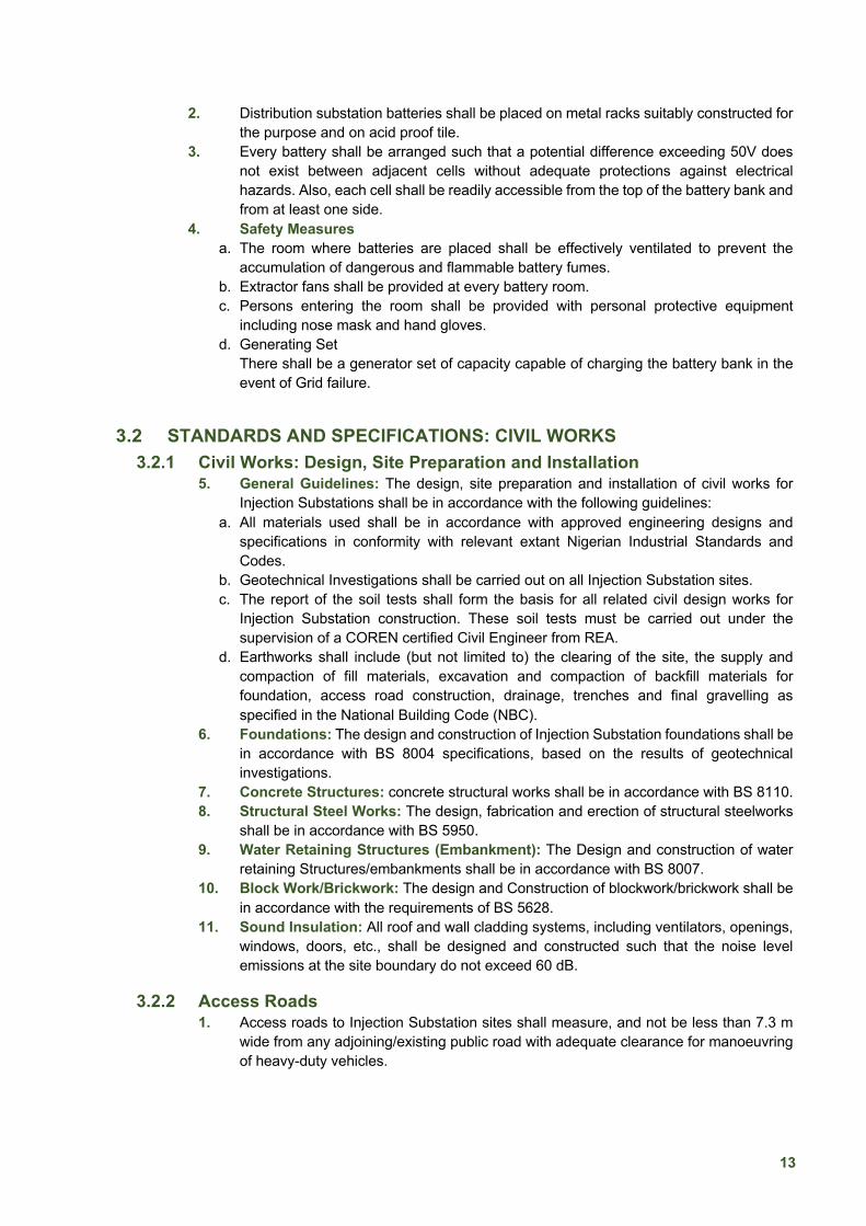
2.1.21 Bolts, Nuts and Threads 1. Bolts shall comply with BS 4190, grade 4.6; Nuts shall comply with BS 4190, grade 4. 2. Each bolt shall be supplied with one nut. 3. Threads shall be in accordance with BS 3643. 4. the thread shall be related to the bolt or stud lengths as follows:
Table 2.6: Thread lengths and respective bolt lengths
2.1.22 Washers 1. Washer – Round (Flat): Round mild steel washers (flat) shall be in accordance with
BS 4320. 2. The washers shall accommodate either M12, M16 or M20 bolts. 3. Square Curved and Flat washers shall be of mild steel and shall be in accordance with
BS 3410.
2.1.23 Surge Arresters 1. Surge arresters shall be gapless Metal-Oxide type made of Zinc-Oxide polycrystalline
element, housed in polymer insulating materials and suitable for the pole-top mounting arrangement
2. Surge arresters shall comply with the IEC 60099-4 standards. 3. The surge arresters shall protect power equipment (like transformers) from system
overvoltage and lightning surges. 4. The surge arrester shall be suitable for satisfactory and continuous operation under a
moderately hot and humid tropical climate, including maximum wind loading of 570N/m2
and minimum ambient air temperatures of 50ºC (degree Celsius) and 5ºC respectively.
3 INJECTION SUBSTATIONS
3.1 STANDARDS AND SPECIFICATIONS: ELECTRICAL WORKS
3.1.1 Switchgear and Fuse Gear Assemblies
1. The Scope includes low-voltage switchgear and control gear assemblies (Type-Tested Assemblies – TTA) or Partially Type-Tested Assemblies – PTTA) whose rated voltages are £ 1,000 VAC or 1,500 VDC.
2. The new IEC 61439 standard applies to enclosures where the rated voltage is under 1,000V AC (at frequencies not exceeding 1,000 Hz) or 1,500 V DC.
3. Switch Gears a. The design, manufacture, assemblage, installation, testing and commissioning of all
33kV and 11kV switch gears in an Injection Substation shall conform to the requirements of IEC 62271.
Length of Bolt Length of Thread Up to 180mm Standard BS 4190 Over 180mm 150mm

11
b. Also, they shall be capable of continuous operation under a daily average ambient temperature range from 25°C to 50°C.
4. Indoor Switchgears a. Indoor switchgears shall be housed in well laid-out buildings. b. Materials, equipment and methods used in the manufacture of indoor switchgears
shall conform to the requirements of the following standards: i. Switchgear and control gear – IEC 60694, IEC 60298, IEC 62271-200, IEC
60529. ii. Circuit Breaker – IEC 62271 – 100 iii. Isolating and earthing switches – IEC 62271-102 iv. Current Transformer – IEC 60185 v. Voltage Transformer – IEC 60186 vi. Relays – IEC 60215
c. The LV and HV switchgear should be located near the door. d. A clear passageway of at least 1m wide shall be allowed from each item of
switchgear to the access door.
3.1.2 Voltage Transformers (VTs) 1. Voltage Transformers (VTs) shall conform to the following Standards: NIS/IEC
60186, 60694 and 60947-1. 2. The number of secondary cores (protection or metering), accuracy class and
burden shall be accordi n g t o the requirements of the protection system. 3. The accuracy class for metering core shall be equal to or better than the accuracy
class of the meter specified in the Metering Code
3.1.3 Current Transformers (CTs) 1. Current Transformers used for instrumentation and protection of power system
equipment shall conform to the following Standards: NIS/IEC60186, 60694 and 60947.
2. The rated currents and ratios, the number of secondary cores (protection or metering), accuracy class, burden, secondary winding resistance, knee point voltage and excitation current shall be in accordance with the requirements of the protection system.
3. The accuracy class for the metering core shall be equal to or better than the accuracy class of the meter specified in the Metering Code.
3.1.4 Station Service Transformers 1. The 33 kV substation service transformers will be supplying the substation auxiliary
services loads from the main substation through a 33 kV bus bar (where available). 2. In substations without a 33kV busbar, other means of supplying the auxiliary station
loads shall be used. This includes (but not restricted to) earthing transformers. 3. Combined CTs and Voltage Transformers (VTs) shall be deployed where there is a
constraint of space and shall conform to the applicable standards for Current and Voltage Transformers.
3.1.5 Lightning Arresters 1. Every electric equipment or any support exposed to liability or injury from lightning
shall be effectively protected against such liability by lightning or surge arresters. 2. These shall be fitted with pressure relief devices and diverting ports suitable for
preventing shattering of porcelain housing providing a path for the flow of rated currents in the event of failure of the surge arrester.
3. A leakage current monitor with a surge counter shall be provided with each lightning arrester.

12
4. All such Surge Arresters to be deployed shall comply with the provisions of IEC 60099-4 on Surge Arresters.
5. The design and dimensioning of the surge arresters shall take cognisance of the energisation of the different lines as well as the lightning protection of the substation equipment.
3.1.6 Control Panels 1. Control panels, including the frames to which they are attached, shall be made of
fireproof material. 2. All types of boxes, cabinets, etc., shall generally conform to and be tested in
accordance with IEC-60439, as applicable. 3. All Control cabinets, junction boxes, marshalling boxes & terminal boxes shall be dust,
water & vermin proof. 4. Other safety requirements can be seen in annexe C2.
3.1.7 Protection Panel 1. The fabricated protection panel shall be of adequate dimensions (height, width, and
depth), with sufficient working space to conveniently house all protective relays and auxiliary protective devices.
2. Suitable provision shall be made, either by connecting (with earth) a point of the system at the lower voltage or otherwise, to guard the system against danger.
3.1.8 Cables for Underground Transmission Lines 1. The cables shall have the electric resistance specified in IEC 60228 2. The cables shall be stranded wires composed of solid wires, such as annealed
copper wire, annealed aluminium wire, hard-drawn aluminium wire and semi hard-drawn aluminium wire that satisfy the mechanical characteristics specified in annexe C3.
3. Insulators a. A cable shall have an insulator that is a butyl rubber compound, an ethylene-propylene
rubber compound or a polyethene compound b. Also, have an electric shielding layer made of metal provided on the insulated
conductor, or shall be a lead-covered cable, aluminium-covered cable or a cable with some other metal cover.
c. Deviation from the above shall be subject to written approval from NERC. 4. Joint Boxes: Cables shall be jointed using a joint box that conforms to the following
requirements: a. The joint box shall not increase the electric resistance of cables. b. The joint box shall have the dielectric strength equal to or higher than that of cables. c. The joint box shall have sufficient mechanical strength. d. The joint box shall have a corrosion-free structure.
5. Earthing of Underground Cables and Joint Boxes: Class D earthing work shall be provided on metallic members used for covering cables for underground transmission lines
6. Where cables enter or leave the ground, they shall be protected from a point at least half a meter below the ground level to a height above ground as may be considered necessary.
3.1.9 Battery Banks 1. Distribution substation batteries shall be installed in a separate room provided to house
the Battery Banks and a charger.to provide DC supply and protection for the system.
13
2. Distribution substation batteries shall be placed on metal racks suitably constructed for the purpose and on acid proof tile.
3. Every battery shall be arranged such that a potential difference exceeding 50V does not exist between adjacent cells without adequate protections against electrical hazards. Also, each cell shall be readily accessible from the top of the battery bank and from at least one side.
4. Safety Measures a. The room where batteries are placed shall be effectively ventilated to prevent the
accumulation of dangerous and flammable battery fumes. b. Extractor fans shall be provided at every battery room. c. Persons entering the room shall be provided with personal protective equipment
including nose mask and hand gloves. d. Generating Set
There shall be a generator set of capacity capable of charging the battery bank in the event of Grid failure.
3.2 STANDARDS AND SPECIFICATIONS: CIVIL WORKS
3.2.1 Civil Works: Design, Site Preparation and Installation 5. General Guidelines: The design, site preparation and installation of civil works for
Injection Substations shall be in accordance with the following guidelines: a. All materials used shall be in accordance with approved engineering designs and
specifications in conformity with relevant extant Nigerian Industrial Standards and Codes.
b. Geotechnical Investigations shall be carried out on all Injection Substation sites. c. The report of the soil tests shall form the basis for all related civil design works for
Injection Substation construction. These soil tests must be carried out under the supervision of a COREN certified Civil Engineer from REA.
d. Earthworks shall include (but not limited to) the clearing of the site, the supply and compaction of fill materials, excavation and compaction of backfill materials for foundation, access road construction, drainage, trenches and final gravelling as specified in the National Building Code (NBC).
6. Foundations: The design and construction of Injection Substation foundations shall be in accordance with BS 8004 specifications, based on the results of geotechnical investigations.
7. Concrete Structures: concrete structural works shall be in accordance with BS 8110. 8. Structural Steel Works: The design, fabrication and erection of structural steelworks
shall be in accordance with BS 5950. 9. Water Retaining Structures (Embankment): The Design and construction of water
retaining Structures/embankments shall be in accordance with BS 8007. 10. Block Work/Brickwork: The design and Construction of blockwork/brickwork shall be
in accordance with the requirements of BS 5628. 11. Sound Insulation: All roof and wall cladding systems, including ventilators, openings,
windows, doors, etc., shall be designed and constructed such that the noise level emissions at the site boundary do not exceed 60 dB.
3.2.2 Access Roads 1. Access roads to Injection Substation sites shall measure, and not be less than 7.3 m
wide from any adjoining/existing public road with adequate clearance for manoeuvring of heavy-duty vehicles.

14
2. Within substation fencing, roads to be provided for access along with car parking lot shall have the capacity to accommodate a minimum of five cars with adequate clearance from installed equipment and building.
3. The layout of the roads shall be based on layout drawings for the substation. 4. Parking areas shall be provided for site personnel and visitors as per layout drawing. 5. Adequate turning space for vehicles shall be provided and bend radius shall be set
accordingly. 6. All access roads, up to the control room building, shall be constructed to have a
minimum load-bearing capacity that will support the transportation of heavy-duty equipment up to 100 Metric Tonnes (MT).
7. All access roads shall be provided with paving stones and demarcated with side kerbs. 8. The roadside kerbs used for the construction of all access roads shall be of a minimum
thickness of 80 mm with compressive strength of not less than 450 kg/cm2.
3.2.3 Property Fencing 1. All Injection Substations shall be fenced to prevent unauthorised access. 2. The fence shall be constructed using either galvanised steel chain link or vibrated
blockwork. 3. To withstand the prevailing wind speed within the environment, all perimeter fencing
shall be designed to meet critical loading conditions that are peculiar to the site under consideration.
4. Where Electric Fencing is installed as part of security measures to prevent unauthorised entry and access into substation premises, it shall be mandatory that marked Warning Signs be displayed within visible range of not more than six meters apart on all sides of the perimeter fencing.
5. The installation of electric fencing shall be in accordance with guidelines on electric fencing issued by NERC Guidelines on Electric Fences (Version 1).
3.2.4 Galvanised Steel Chain Link 1. Where the perimeter fence and the entrance gates are made of galvanised steel chain-
link fencing and galvanised steel pipes (as may be specified in the General Specification for materials and workmanship), they shall comply with the provisions of this regulation.
2. The height of the fence and the gates shall not be less than 2.5m vertical with a further 0.5m extended outwards from the site at 45º on which 3 numbered rows of barbed wire shall be fixed.
3. The mid-sections of the fence shall be kept taut by the introduction of steel stiffeners. 4. Fence posts shall be of galvanised tubular steel of 50 mm diameter for intermediate
posts and 75mm for angle and tensioned posts, 3.0 m apart on the average centre. 5. The fence posts shall have a concrete foundation projecting 100 mm above the finished
laterite level, but flushing with the top level of the crushed rock. 6. The top of the concrete foundation of the steel pipes shall be cambered to prevent
water stagnations that might lead to rusting. 7. The vehicular and pedestrian gates shall be plastic coated chain link with galvanised
steel frames/posts. 8. The widths of the vehicular and pedestrian gates in a fully opened position shall be 5.0
m and 1.0 m respectively.
3.2.5 Vibrated Block Wall 1. Where the perimeter fence and the entrance gates are made of vibrated blocks, 228.6
mm vibrated blocks shall be used for fenced work.

15
2. The height of the fence and the gates shall not be less than 1.90 m vertical with a capping and fence wire finishing.
3. The mid-sections of the fence shall be maintained with concrete reinforcement 3.0 m apart on the average centres.
4. The vehicular and pedestrian gates shall be of plastic-coated, galvanised or enamelled-steel sheet with galvanised steel frames/posts.
5. The widths of the vehicular and pedestrian gates in a fully opened position shall be 5.0 m and 1.0 m respectively.
3.2.6 Control Room Building
1. The control room building design shall consider the following specifications: a. The suitability of the structure to withstand possible major hazard events as defined in
the NERC Health & Safety Code. b. The layout and the arrangement of switchgears, tripping units, etc., to ensure effective
ergonomic operation of the indoors and outdoors equipment for normal operations and emergencies, including the provision of emergency exits.
c. More than one emergency exit shall be provided for a control room exceeding 10m in length.
2. The construction of the control room building shall conform to the requirements of the National Building Code. The structural design and details of the control room building shall be able to guarantee the following stability conditions:
a. All possible combination of dead and service loads b. Wind loads c. Natural hazards due to seismic activities and flooding d. Fire and thermal loading
3. The minimum floor area for the control room building shall not be less than 200m2, which may be increased at the time of detailed engineering design to meet project requirements.
4. An open workspace of a minimum of 1.2 m shall be provided between the wall and the switchgears to allow for movement and access as well as maintenance.
5. The building design shall also meet the following requirements: a. Provide for easy access and maintenance of the equipment with, wherever required,
fire-resisting and/or retarding materials for walls, ceilings and doors. b. Adopt the use of materials that shall prevent dust accumulation. c. Individual structural members of the building frames shall be designed for the worst
combination of forces, such as bending moments, axial force, shear force and torsion. d. Permissible building loading stress shall be in accordance with the National Building
Code. e. The Control Room building lighting shall be designed in accordance with IEC 60364. f. The Control Room building auxiliary services such as Heating, Ventilation and Air
Conditioning Systems, fire prevention, detection and control systems and all other miscellaneous services shall be designed in accordance with the NBC.
3.2.7 Equipment Plinth and Oil Sump 1. The construction of the equipment plinths shall take into consideration the site
geotechnical investigation report and shall be designed to meet the load-bearing capacity that adequately supports the weight of the intended equipment to be installed in the substation.
2. Also, the reinforced concrete design and construction of the equipment plinth shall accommodate the equipment manufacturer’s specifications.
3. The power transformer plinth shall be of a minimum horizontal distance of 11.2 m from the control room.

16
4. The oil sump provided shall be of a minimum depth of 1 m and a width of 0.6m.
3.2.8 Drainage 1. The entire substation area shall be provided with adequate drainage facilities to prevent
flooding and accumulation of water. 2. Building drains shall be provided for the collection and evacuation of stormwater from
the roof and the adjoining facilities. 3. The design of drain collectors shall be adequate to effectively evacuate stormwater
from the substation.
3.2.9 Cable Trenches 1. Cable trenches shall be constructed for use in Injection Substations. 2. The separation between cables and their depths shall depend on the following factors:
Operating Voltages; Ambient temperature; Cable design temperature; Soil Resistivity; Heat sources in the vicinity of cables; Cable type; Method of earthing, and Load cycle
3. Cable trenches shall be of a minimum depth of 1m, except under the switchgear where the trench shall be of a depth of 1.2m and a minimum width of 800mm, for cable trench and switchgear panels.
4. Manhole capable of permitting bending radius of 3m shall be provided along the trench route before cable entry into the control room.
5. Trenches must be watertight and must not be connected to the outside drainage system.
6. Trench covers must be suitably constructed to support pedestrian traffic. 7. The covers must be divided into sections of a maximum of 1m lengths, each weighing
no more than 20 kg. 8. The trench cover when laid across the trench shall be flush with the surrounding floor
level.
3.2.10 Gravelling and Landscaping 1. The Injection Substation active switchyard area shall be demarcated using roadside
Kerbs and gravelled with 25mm aggregate chippings to a minimum depth of 150mm. 2. Landscaping shall be carried out in non-active areas of the Injection Substation. Non-
active areas within the Injection Substation shall be landscaped for proper levelling; paving, sloping, consolidation and grassing.
4 SOLAR MINI-GRIDS 4.1 STANDARDS AND SPECIFICATIONS: SOLAR MINI-GRIDS
4.1.1 General Guidelines
1. The service standards and technical specifications listed below are complementary to the NERC Mini-Grid Regulations 3 and the NEMSA regulations but do not replace them.
2. Applicants applying for Mini-grid projects in REA shall comply with the technical specifications set out below, as well as the Mini-Grid Regulations and the NEMSA regulations (Section 5 and Section 10).
3. Also, applicants applying for REA Mini-grids projects should meet the service standards listed in Table 4.2.
4. These service standards are differentiated based on the size of the mini-grid, based on the same categorisation found in the NERC Mini-Grid Regulations
5. Mini-grids rated above 100kW (of distributed electricity) are subject to different standards compared to mini-grids rated below 100kW
6. Service standards are measured at the point of customer connection.
17
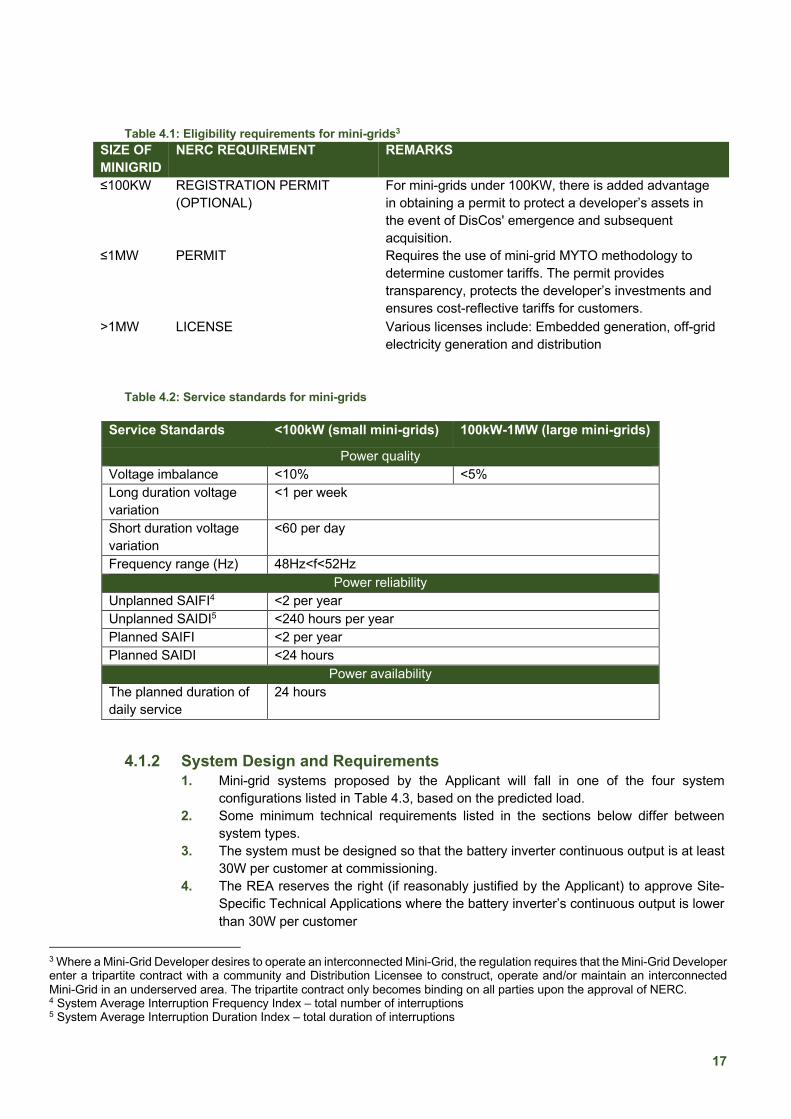
Table 4.1: Eligibility requirements for mini-grids3 SIZE OF MINIGRID
NERC REQUIREMENT REMARKS
≤100KW REGISTRATION PERMIT (OPTIONAL)
For mini-grids under 100KW, there is added advantage in obtaining a permit to protect a developer’s assets in the event of DisCos' emergence and subsequent acquisition.
≤1MW PERMIT Requires the use of mini-grid MYTO methodology to determine customer tariffs. The permit provides transparency, protects the developer’s investments and ensures cost-reflective tariffs for customers.
>1MW LICENSE Various licenses include: Embedded generation, off-grid electricity generation and distribution
Table 4.2: Service standards for mini-grids
4.1.2 System Design and Requirements
1. Mini-grid systems proposed by the Applicant will fall in one of the four system configurations listed in Table 4.3, based on the predicted load.
2. Some minimum technical requirements listed in the sections below differ between system types.
3. The system must be designed so that the battery inverter continuous output is at least 30W per customer at commissioning.
4. The REA reserves the right (if reasonably justified by the Applicant) to approve Site-Specific Technical Applications where the battery inverter’s continuous output is lower than 30W per customer
3 Where a Mini-Grid Developer desires to operate an interconnected Mini-Grid, the regulation requires that the Mini-Grid Developer
enter a tripartite contract with a community and Distribution Licensee to construct, operate and/or maintain an interconnected
Mini-Grid in an underserved area. The tripartite contract only becomes binding on all parties upon the approval of NERC.
4 System Average Interruption Frequency Index – total number of interruptions
5 System Average Interruption Duration Index – total duration of interruptions
Service Standards <100kW (small mini-grids) 100kW-1MW (large mini-grids)
Power quality Voltage imbalance <10% <5% Long duration voltage variation
<1 per week
Short duration voltage variation
<60 per day
Frequency range (Hz) 48Hz<f<52Hz Power reliability
Unplanned SAIFI4 <2 per year Unplanned SAIDI5 <240 hours per year Planned SAIFI <2 per year Planned SAIDI <24 hours
Power availability The planned duration of daily service
24 hours

18
5. Renewable Energy Fraction: The system must be designed to meet a minimum of 60% renewable energy fraction, as calculated by any reputable renewable energy simulation software.
6. Table 4.4 presents the design margins that Applicants shall comply with. The REA reserves the right to approve Site-Specific Technical Applications where these design margins are not met if this is reasonably justified by the Applicant.
Table 4.3: Overview of system configurations Type 1 Type 2-A Type 2-B Type 3
Summary
Small systems, using direct current (DC) coupling of Photovoltaic (PV) generation to a battery via a Maximum Power Point Tracking (MPPT) charge controller and employing a single grid-forming inverter that produces single phase electricity.
• Multiple bi-directional single-phase inverters connected in parallel create a single-phase (Type 2-A) or three-phase (Type 2-B) power output.
• The battery inverter capacity can be extended modularly.
• Solar PV is coupled to the AC bus using PV inverters and/or to the DC bus using MPPT charge controllers.
Large AC coupled systems using central three-phase battery inverters of typically 100 kVA and above per module.
Battery inverter continuous output
Single small inverter <10kW
Parallel inverters totalling 10kW to 300kw, single-phase/three-phase
Parallel inverters totalling 150kW to 1000kW, three-phase
Central inverters >1MW, three-phase
Table 4.4: Design requirements for mini-grids
System component/aspect
Formula
Nomenclature Grid-Tie Inverter !!"# =
!$##$% × Ƞ
• !!"#, Grid-Tie inverter capacity • !$# , PV nominal capacity connected to the
inverter • #$%, Inverter loading ratio also known as DC/AC
ratio. ILR can be a maximum of two. The recommended value is 1.25
• Ƞ, Efficiency of the inverter at rated power Battery Inverter !& = )* × !'()* • !&, Battery inverter capacity under continuous
load at 25°C ambient temperature • !'()* , Peak-load from demand assessment • )* is a design factor, the allowable range is 1.2
– 1.6
19
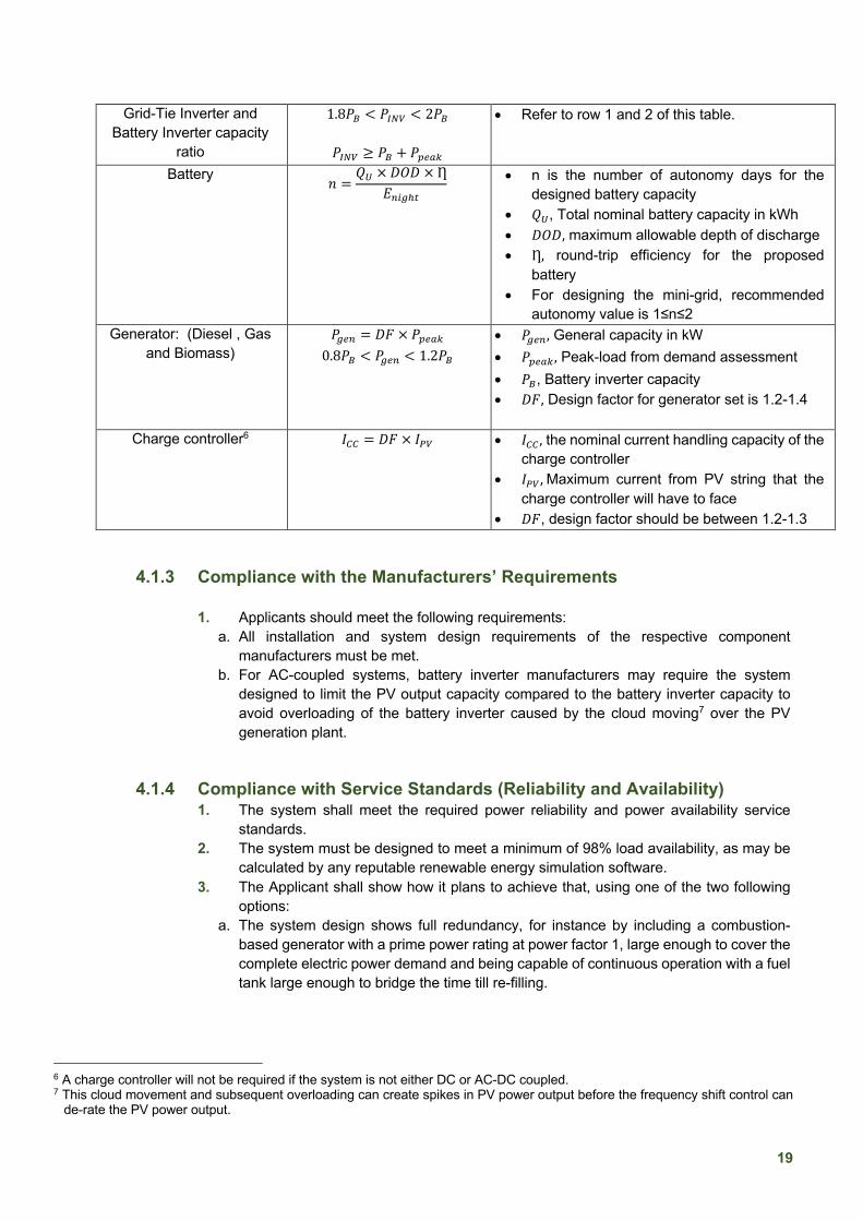
Grid-Tie Inverter and Battery Inverter capacity
ratio
1.8!& < !!"# < 2!&
!!"# ≥ !& + !'()*
• Refer to row 1 and 2 of this table.
Battery 2 = 3+ × )4) × Ƞ5,-./0
• n is the number of autonomy days for the designed battery capacity
• 3+, Total nominal battery capacity in kWh • )4), maximum allowable depth of discharge • Ƞ, round-trip efficiency for the proposed
battery • For designing the mini-grid, recommended
autonomy value is 1≤n≤2 Generator: (Diesel , Gas
and Biomass) !.(, = )* × !'()* 0.8!& < !.(, < 1.2!&
• !.(,, General capacity in kW • !'()* , Peak-load from demand assessment • !&, Battery inverter capacity • )*, Design factor for generator set is 1.2-1.4
Charge controller6 #11 = )* × #$# • #11 , the nominal current handling capacity of the
charge controller • #$# ,Maximum current from PV string that the
charge controller will have to face • )*, design factor should be between 1.2-1.3
4.1.3 Compliance with the Manufacturers’ Requirements
1. Applicants should meet the following requirements: a. All installation and system design requirements of the respective component
manufacturers must be met. b. For AC-coupled systems, battery inverter manufacturers may require the system
designed to limit the PV output capacity compared to the battery inverter capacity to avoid overloading of the battery inverter caused by the cloud moving7 over the PV generation plant.
4.1.4 Compliance with Service Standards (Reliability and Availability) 1. The system shall meet the required power reliability and power availability service
standards. 2. The system must be designed to meet a minimum of 98% load availability, as may be
calculated by any reputable renewable energy simulation software. 3. The Applicant shall show how it plans to achieve that, using one of the two following
options: a. The system design shows full redundancy, for instance by including a combustion-
based generator with a prime power rating at power factor 1, large enough to cover the complete electric power demand and being capable of continuous operation with a fuel tank large enough to bridge the time till re-filling.
6 A charge controller will not be required if the system is not either DC or AC-DC coupled.
7 This cloud movement and subsequent overloading can create spikes in PV power output before the frequency shift control can
de-rate the PV power output.

20
b. A stock of critical spare parts comprising inverters, charge controllers, battery cells, fuses, breakers, etc., is available on site or within a distance from the site that enables shipment to the site within less than two calendar days.
4.1.5 Capacity Shortage and PV Modules
1. Any reputable renewable energy simulation software must show a capacity shortage of less than 3% of the total annual electricity demand (kWh).
2. The Applicant shall declare and present evidence that all the solar PV modules comply with the minimum specifications in table 4.5:
Table 4.5: Standards and specifications for PV modules Property Description Required Standard Type of solar cells Polycrystalline/Monocrystalline8
Solar cells embedded in EVA-layer (ethylene vinyl acetate) Number of modules Provide the number of rows mounted on the support structure
An equal number of modules per row The requirement of voltage, power, and current per input of the charge controller or grid-tie inverter specified below for the climatic conditions in Nigeria
Type of Frame Anodised aluminium frame Nominal power per module of solar cells
>300W at Standard Test Conditions (STC).
Power tolerance of individual module
±3% from nominal power capacity
Junction box Weatherproof, IP 65 with bypass diodes and pre-configured cables Output cables According to TUV or equivalent of 4.0 mm², symmetrical lengths and suitable for
installation on the support structure, MC4-compatible connectors. Product Warranty >10 years Performance Warranty Minimum of 10 years for 90%
Maximum of 25 years for 80% Temperature coefficient -0.46%/0C ±0.05 The efficiency of PV modules ≥16% Equipotential bonding 16mm2 copper conductor to be used. Grounding <10Ω earth resistance of support structure
4.1.6 PV Mounting Table 4.6: Standards and specifications for PV mounting
Description Required Standard Slope Between 10° to 15° Height clearance 0.5m minimum clearance Support structure Open area support for all photovoltaic solar modules supplied
Depth of planting the PV structure
Not <1.5m
Materials for bolts and nuts Recommendation galvanised iron shear nuts Protection against corrosion Metal parts of the structure in-ground and near the ground
must be protected against corrosion for 20 years.
8 Polycrystalline PV modules are recommended in temperate regions of Nigeria

21
Surface Photovoltaic solar modules must be fixed on an even surface, with no more than 20mm difference from the ideal plane
Gravelling 150mm thick Material for bolts and nuts For structures in aluminium: all bolts and nuts made of
stainless steel For steel structures: all bolts and nuts made of hot-dip galvanised steel
Static calculation In accordance with ground conditions in considering wind speed and other risks
4.1.7 Batteries/Energy Storage Devices
1. The REA reserves the right to accept Site-Specific Technical Applications with
stationary Lithium-Ion batteries for Type 1 systems if this is reasonably justified by the Applicant.
Table 4.7: Standards and specifications for batteries/energy storage devices Property Description Required Standard Lithium-ion batteries Secondary cells and batteries containing alkaline or other non-acid
electrolytes – Safety requirements for large format secondary lithium cells and batteries for use in industrial applications (IEC 62619)
Battery charge controllers for photovoltaic systems
Performance and functioning (IEC 62509)
Safety requirements for secondary batteries and battery installations
Part 1: General safety information and Part 2: stationary batteries (IEC 62485-1 and 62485-2).
Battery Rack Battery support structure/cabinet made of steel and insulated to ground Floor bearing capacity must allow carrying the weight of the battery
Battery cabling Battery cables to be made of copper (16mm2 and 25mm2), preconfigured with terminals according to the requirement of the battery quoted Cable length and cross-section should limit DC voltage drop to less than 1% Appropriate cable termination with lugs.
Reference battery life cycle For lithium-ion or other technologies: 4,000 cycles at 80% depth of discharge and end of life 80% of nominal capacity
Paralleling of cells to get the requested capacity
For lithium batteries and others: paralleling of cells only allowed if explicitly specified by the manufacturer and if an adequate battery management system is installed
Operating temperature range in the battery room
10°C to 30°C, air conditioning is required for systems with more than 30 kW rated battery inverter power
Battery management The algorithm calculating the switch-off point needs to consider the measured battery temperature to prevent deep-discharge and overcharging (low voltage disconnect)

22
Table 4.8: Minimum Technical Requirements for batteries/energy storage devices based on mini-grid system configurations
4.1.8 Electronics and Balance of the System
1. Electronics and balance of the system should comply with the following IEC norms and standards: Safety of power converters for use in photovoltaic power systems (IEC 62109).
2. The electronics and balance of the system should comply with the following specifications according to the type of the system in table 4.9.
3. Table 4.9 shows the requirements for the electronics and balance of the following components: Solar Inverter/Grid-Tie Inverter; Battery Inverters; DC& AC Combiner Boxes for PV Strings, Power Station Monitoring Systems.
Table 4.9: Technical requirements for the electronics and balance of the system (solar charge controller)
Type of Requirement
Type 1 Type 2-A Type 2-B Type 3
Solar charge controller (if part of the system) Minimum rated power per charge controller
> 4.5kW >100kW
Maximum Power Point Tracking (MPPT) type
Yes Yes
PV array operating voltage range
100-600VDC 600-1200VDC
Maximum efficiency >95% >95% DC disconnect device
Yes Yes
DC surge arrester Type I + II for each DC string Type I + II for each DC string; and PV modules; and
PV inverters must each have surge arrestors installed if more than 20m cable length in between PV modules and the inverter
The minimum degree of protection
IP20 or better if not installed outside or
IP54 or better for outside installation
Type of requirement Type 1 Type 2-A Type 2-B Type 3 The nominal voltage of battery strings
40-100 VDC 300-1,200 VDC
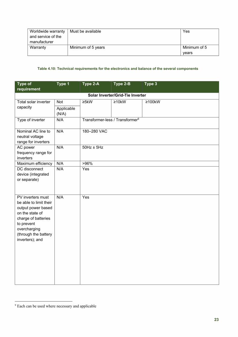
23
Worldwide warranty and service of the manufacturer
Must be available Yes
Warranty Minimum of 5 years Minimum of 5 years
Table 4.10: Technical requirements for the electronics and balance of the several components
Type of requirement
Type 1 Type 2-A Type 2-B Type 3
Solar Inverter/Grid-Tie Inverter Total solar inverter capacity
Not ≥5kW ≥10kW ≥100kW Applicable (N/A)
Type of inverter N/A Transformer-less / Transformer9
Nominal AC line to neutral voltage range for inverters
N/A 180–280 VAC
AC power frequency range for inverters
N/A 50Hz ± 5Hz
Maximum efficiency N/A >96% DC disconnect device (integrated or separate)
N/A Yes
PV inverters must be able to limit their output power based on the state of charge of batteries to prevent overcharging (through the battery inverters); and
N/A Yes
9 Each can be used where necessary and applicable
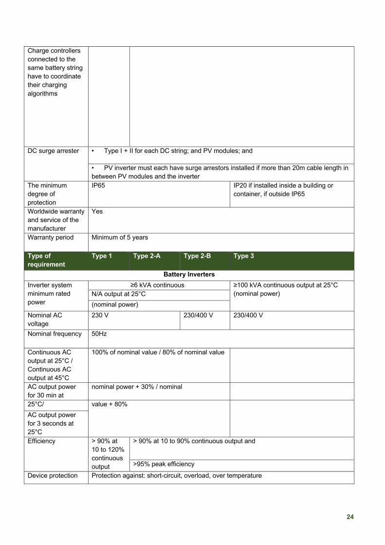
24
Charge controllers connected to the same battery string have to coordinate their charging algorithms
DC surge arrester • Type I + II for each DC string; and PV modules; and
• PV inverter must each have surge arrestors installed if more than 20m cable length in between PV modules and the inverter
The minimum degree of protection
IP65 IP20 if installed inside a building or container, if outside IP65
Worldwide warranty and service of the manufacturer
Yes
Warranty period Minimum of 5 years
Type of requirement
Type 1 Type 2-A Type 2-B Type 3
Battery Inverters Inverter system minimum rated power
≥6 kVA continuous ≥100 kVA continuous output at 25°C (nominal power) N/A output at 25°C
(nominal power) Nominal AC voltage
230 V 230/400 V 230/400 V
Nominal frequency 50Hz
Continuous AC output at 25°C / Continuous AC output at 45°C
100% of nominal value / 80% of nominal value
AC output power for 30 min at
nominal power + 30% / nominal
25°C/ value + 80%
AC output power for 3 seconds at 25°C Efficiency > 90% at
10 to 120% continuous output
> 90% at 10 to 90% continuous output and
>95% peak efficiency
Device protection Protection against: short-circuit, overload, over temperature

25
Ambient temperature:
0°C to 50°C
Display Yes, or other ways of displaying inverter parameters Multi-function relays
Not required
Required
Warranty Minimum of 5 years DC Combiner Box for PV Strings
Box cabinet material
Powder-coated steel
DC fuse or DC-rated breaker
Required if string configuration of more than 2 strings in parallel
Internal powerhouse cables pre-configured for plug and play installation and testing
Yes
AC Combiner Box Box cabinet material
Powder-coated steel
Overvoltage arrestors
Integrated combined Type I and II
Circuit breakers Sized according to battery inverter, self-consumption of the power plant and the peak current
Internal powerhouse cables and cables to all components inside of the power station pre-configured for plug and play installation, and tested
Yes
Power Station Monitoring Systems Data storage N/A The monitoring system must have a local data storage option (if possible,
with remote data retrieval via GSM network)
Minimum recorded data Storage on SD cards or internal storage.
N/A Time series of state of charge of each battery, and
Power in and power out of each battery, and Solar power produced per inverter/charger and total generation
Minimum data resolution
N/A Every 15 minutes
4.1.9 Generators: Diesel, Gas and Biomass 1. The Applicant shall declare and present evidence that all the diesel generators comply
with the following specifications: Rotating electrical machines – Part 1- Rating and performance (IEC 60034-1)

26
2. The standards for diesel generators apply only to the relevant system type as indicated in Table 4.10 for diesel generators.
3. The diesel generators may be installed inside the powerhouse, or under a suitable massive shelter, or outside with a canopy.
4. Each Generator shall be supplied complete with all installation drawings and documentation, warranty, operation and maintenance manuals.
5. The diesel generators shall be prime rated with an electrical output from each diesel generator as given below:
a. 5kVA (single phase) b. 10kVA (Single phase) c. 16kVA (single-phase and three-phase options) d. 25kVA, 40kVA, 60Kva, 80kVA, 100kVA, 150kVA, 200kVA, 500KVA, 1MVA.
6. The diesel generator set shall achieve the rated values and performance under the following specified conditions and shall deliver power within the following requirements:
a. Nominal Voltage: 415/240 V at alternator terminals. b. Nominal Frequency: 50 Hz. c. Power Factor: Maximum 0.8 lagging. d. Overload greater than 2.0 p.u. for 10 seconds, with less than 30% voltage dip.
Table 4.11: Minimum Technical Requirements for batteries/energy storage devices based on mini-grid system configurations
Type of Requirement Type 1 Type 2-A Type 2-B Type 3 Nominal capacity No diesel
generator kVA prime power rating
Nominal AC voltage range N/A 220V- 240 V 220V-240V and 380V-415V
Nominal frequency N/A 50Hz Cable to connect the diesel generator to the AC combiner box
N/A Armoured AC cable, unless the cable is installed inside a building
Cable length and cross-section N/A Must limit AC voltage drop to less than 1%
Bypass switch (to switch between diesel generator only and battery inverter to supply power to the network)
N/A Yes
The generator should include a canopy N/A Yes
Day tank fuel capacity N/A 80 litres 200 litres or 200 litres or or above above above
4.1.10 Accessories and Spare Parts
1. The Applicant shall declare and present evidence that all the accessories and spare parts comply with the following specifications:
a. All tools for installation and maintenance of the components specified in a toolbox, including 2 pieces of 1,000 V isolated screwdrivers and spanners for the terminals of the distribution, power lines
b. For the building installations, 2 pieces of large side cutters with 1,000 V isolated handles, 2 pieces of electrician's knife, 2 sets of basic spanners, hammer, small handsaw, set of terminal strips, electrical tape, cable ties, 10 pcs of MC4 connectors, spare DC fuses, two hard hats, and electrical gloves.
c. Cleaning equipment, including 2 quality soft brooms for cleaning of solar modules, 2 squeegees with extra-long handle, 2 buckets for wet cleaning of the PV modules, soft

27
cloth for wiping of inverters and other cloth for wiping of batteries, one aluminium ladder with 2m length.
d. One complete first aid box, including bandages, antiseptic, sterile pads, burn treatment and an adhesive bandage.
4.1.11 Metering and Distribution The standards for metering and distribution apply only to the relevant system type as indicated in the table below.
Table 4.12: Technical requirements for metering and distribution based on system type/configuration
Type of requirement Type 1 Type 2-A Type 2-B Type 3
Energy meters Prepaid meters and in accordance with the Nigeria metering code (version 2)
Distribution system 230 V (±6%), single-phase as per the distribution code of Nigeria
230/400 V (±6%), three phases as per the distribution code of Nigeria
Voltage Drop (VD) ±10% drop from nominal voltage level at the end of the feeders
Applicable distribution code
The company installing the distribution code must follow the guidelines of the Distribution Code and Grid Code of NERC, Nigeria
Distribution line design, planning and installation guideline
The distribution network can either be overhead or underground and according to ''Nigerian Electricity Supply and Installation Standards Regulations 2015''
4.1.12 Installation
1. The minimum requirements for electric installation inside customer premises are as follows:
a. Protection against overcurrent (IEC 60364-4-43) must be installed with a miniature circuit breaker (MCB). Rating of the breakers must ensure instantaneous release considering the loop impedance of the network and the rated and short-term overcurrent of the appliances.
b. Earthing Requirement: a protective conductor (PE) is required for all British standard sockets, other 3 and 5 pole sockets and directly connected appliances of protection class 1, in accordance with IEC 61140.
c. Residual Current Device (RCD) protection is required for customers with loads exceeding 10kW. It is accepted if all customers have it installed at the service drop.
5 SOLAR HOME SYSTEMS (SHS)
5.1 Standards and Specifications: SHS
Table 5.1: Standards and specifications10 for solar home systems
10
Due to the capacity limitations for tier 1 products/services, it does not satisfy productive use of activities. Tier 2 and above
products/services have been recommended for SHS’ standards and specifications. However, a derogation/exemption can be
applied to previous and ongoing REA contracts that requires the supply of tier 1 products/services. Subsequently, future contracts
shall be aligned with the agency’s agreed, approved and updated standards of the use of tier 2 and above products/services.
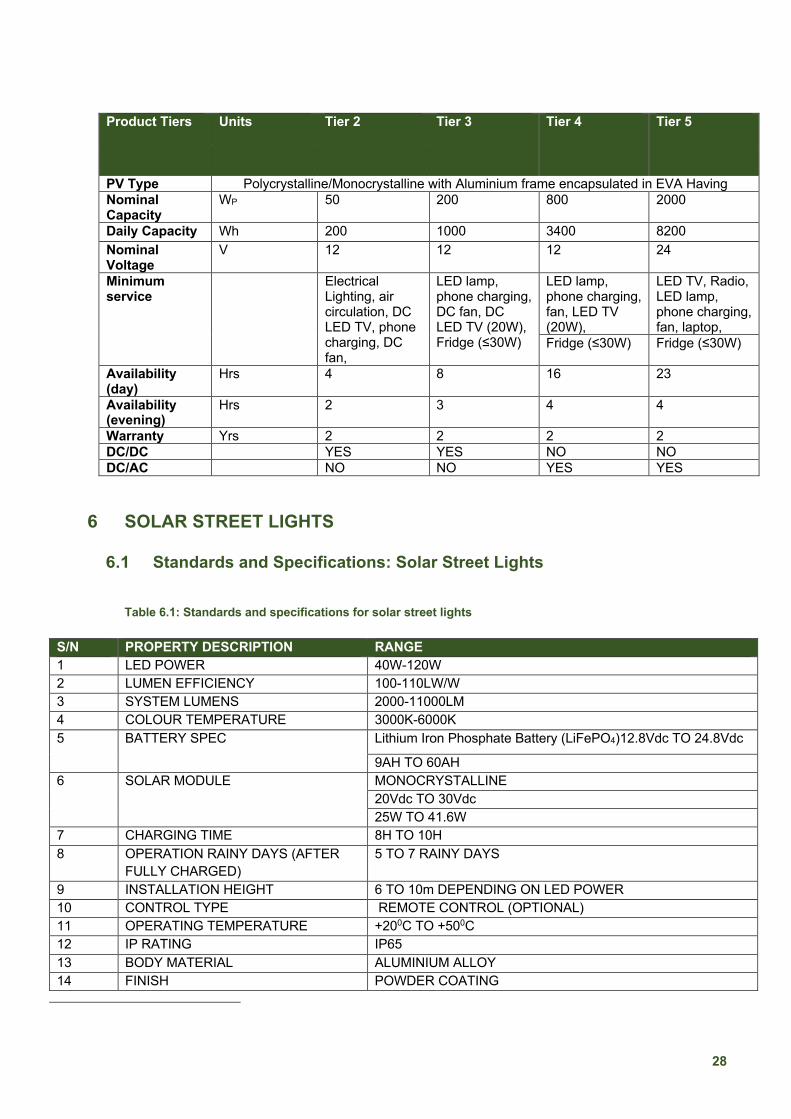
28
Product Tiers Units Tier 2 Tier 3 Tier 4 Tier 5
PV Type Polycrystalline/Monocrystalline with Aluminium frame encapsulated in EVA Having Nominal Capacity
WP 50 200 800 2000
Daily Capacity Wh 200 1000 3400 8200 Nominal Voltage
V 12 12 12 24
Minimum service
Electrical Lighting, air circulation, DC LED TV, phone charging, DC fan,
LED lamp, phone charging, DC fan, DC LED TV (20W), Fridge (≤30W)
LED lamp, phone charging, fan, LED TV (20W),
LED TV, Radio, LED lamp, phone charging, fan, laptop,
Fridge (≤30W) Fridge (≤30W)
Availability (day)
Hrs 4 8 16 23
Availability (evening)
Hrs 2 3 4 4
Warranty Yrs 2 2 2 2 DC/DC
YES YES NO NO
DC/AC
NO NO YES YES
6 SOLAR STREET LIGHTS
6.1 Standards and Specifications: Solar Street Lights
Table 6.1: Standards and specifications for solar street lights
S/N PROPERTY DESCRIPTION RANGE 1 LED POWER 40W-120W 2 LUMEN EFFICIENCY 100-110LW/W 3 SYSTEM LUMENS 2000-11000LM 4 COLOUR TEMPERATURE 3000K-6000K 5 BATTERY SPEC Lithium Iron Phosphate Battery (LiFePO4)12.8Vdc TO 24.8Vdc
9AH TO 60AH 6 SOLAR MODULE MONOCRYSTALLINE
20Vdc TO 30Vdc 25W TO 41.6W
7 CHARGING TIME 8H TO 10H 8 OPERATION RAINY DAYS (AFTER
FULLY CHARGED) 5 TO 7 RAINY DAYS
9 INSTALLATION HEIGHT 6 TO 10m DEPENDING ON LED POWER 10 CONTROL TYPE REMOTE CONTROL (OPTIONAL) 11 OPERATING TEMPERATURE +200C TO +500C 12 IP RATING IP65 13 BODY MATERIAL ALUMINIUM ALLOY 14 FINISH POWDER COATING
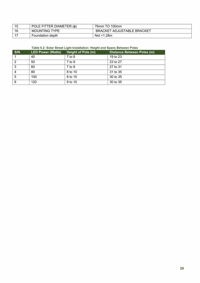
29
15 POLE FITTER DIAMETER (ɸ) 76mm TO 100mm 16 MOUNTING TYPE BRACKET ADJUSTABLE BRACKET 17 Foundation depth Not <1.28m
Table 6.2: Solar Street Light Installation: Height and Spans Between Poles S/N LED Power (Watts) Height of Pole (m) Distance Between Poles (m) 1 40 7 to 8 19 to 23 2 50 7 to 9 23 to 27 3 60 7 to 9 27 to 31 4 80 8 to 10 31 to 35 5 100 8 to 10 30 to 35 6 120 9 to 10 30 to 35

30
ANNEXES
Annexe A: International Electrotechnical Commission (IEC) Codes
Table A1: IEC Codes for electrical works CODE DESCRIPTION IEC 60364-7-711 Electrical installations of buildings - Part 7-711: Requirements for special
installations or locations - Exhibitions, shows and stands IEC 60364-7-701 Low-voltage electrical installations - Part 7-701: Requirements for special
installations or locations - Locations containing a bath or shower IEC 60364-7-705 Low-voltage electrical installations - Part 7-705: Requirements for special
installations or locations - Agricultural and horticultural premises IEC 60364-7-704 Low-voltage electrical installations - Part 7-704: Requirements for special
installations or locations - Construction and demolition site installations IEC 60092-306 Electrical installations in ships - Part 306: Equipment - Luminaires and lighting
accessories IEC 60598-2-3 Luminaires - Part 2-3: Particular requirements - Luminaires for road and street
lighting NIS IEC 61000-3-11 Electromagnetic compatibility (EMC) - Part 3-11: Limits - Limitation of voltage
changes, voltage fluctuations and flicker in public low-voltage supply systems - Equipment with rated current ≤ 75 A and subject to conditional connection
NIS IEC 60081 Double-capped fluorescent lamps - Performance specifications NIS IEC 60974-9 Arc welding equipment - Part 9: Installation and use NIS IEC 60335 Household and similar electrical appliances IEC 60335-2-75 Households and similar electrical appliances, with a particular requirement for
commercial dispensing appliances and bending machines IEC 60099-8 Surge arresters - Part 8: Metal-oxide surge arresters with an external series gap
(EGLA) for overhead transmission and distribution lines of a.c. systems above 1 kV IEC 61850 Communication networks and systems in substations - ALL PARTS IEC 608-70-104 Communication between Substation Automation System (SAS) and power plant
devices NIS IEC 60557 Dissolved gas analysis carried out on all transformers periodically IEC 60726 Dry-type power transformers IEC 60044 Instrument transformers IEC60044-2 (2000-1) Instrument transformers - Part 2: Inductive voltage transformers
IEC 60502-2 Power cables with extruded insulation and their accessories for rated voltages from 1 kV (Um =1,2 kV) up to 30 kV (Um = 36 kV) – Part 2: Cables for rated voltages from 6 kV (Um = 7,2 kV) up to 30 kV (Um = 36 kV)
IEC 60060 High-voltage test techniques - ALL PARTS IEC 60947-1 Low-voltage switchgear and control gear - Part 1: General rules IEC 60947-2 Low-voltage switchgear and control gear - Part 2: Circuit-breakers IEC 60898 Electrical accessories - Circuit-breakers for overcurrent protection for household
and similar installations IEC 62271-100 High-voltage switchgear and control gear - Part 100: Alternating current circuit-
breakers IEC 62271-200 High-voltage switchgear and control gear - Part 200: AC metal-enclosed switchgear
and control gear for rated voltages above 1 kV and up to and including 52 kV
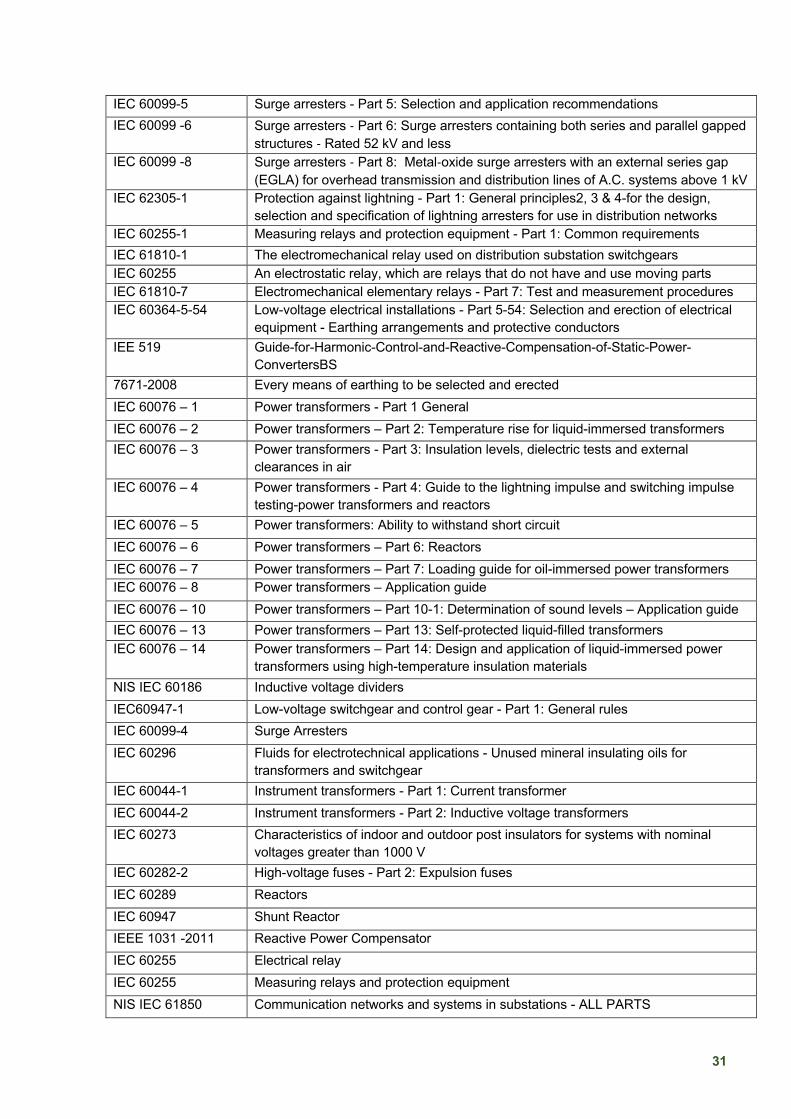
31
IEC 60099-5 Surge arresters - Part 5: Selection and application recommendations IEC 60099 -6 Surge arresters - Part 6: Surge arresters containing both series and parallel gapped
structures - Rated 52 kV and less IEC 60099 -8 Surge arresters - Part 8: Metal-oxide surge arresters with an external series gap
(EGLA) for overhead transmission and distribution lines of A.C. systems above 1 kV IEC 62305-1 Protection against lightning - Part 1: General principles2, 3 & 4-for the design,
selection and specification of lightning arresters for use in distribution networks IEC 60255-1 Measuring relays and protection equipment - Part 1: Common requirements IEC 61810-1 The electromechanical relay used on distribution substation switchgears IEC 60255 An electrostatic relay, which are relays that do not have and use moving parts IEC 61810-7 Electromechanical elementary relays - Part 7: Test and measurement procedures IEC 60364-5-54 Low-voltage electrical installations - Part 5-54: Selection and erection of electrical
equipment - Earthing arrangements and protective conductors IEE 519 Guide-for-Harmonic-Control-and-Reactive-Compensation-of-Static-Power-
ConvertersBS 7671-2008 Every means of earthing to be selected and erected IEC 60076 – 1 Power transformers - Part 1 General IEC 60076 – 2 Power transformers – Part 2: Temperature rise for liquid-immersed transformers IEC 60076 – 3 Power transformers - Part 3: Insulation levels, dielectric tests and external
clearances in air IEC 60076 – 4 Power transformers - Part 4: Guide to the lightning impulse and switching impulse
testing-power transformers and reactors IEC 60076 – 5 Power transformers: Ability to withstand short circuit IEC 60076 – 6 Power transformers – Part 6: Reactors IEC 60076 – 7 Power transformers – Part 7: Loading guide for oil-immersed power transformers IEC 60076 – 8 Power transformers – Application guide IEC 60076 – 10 Power transformers – Part 10-1: Determination of sound levels – Application guide IEC 60076 – 13 Power transformers – Part 13: Self-protected liquid-filled transformers IEC 60076 – 14 Power transformers – Part 14: Design and application of liquid-immersed power
transformers using high-temperature insulation materials NIS IEC 60186 Inductive voltage dividers IEC60947-1 Low-voltage switchgear and control gear - Part 1: General rules IEC 60099-4 Surge Arresters IEC 60296 Fluids for electrotechnical applications - Unused mineral insulating oils for
transformers and switchgear IEC 60044-1 Instrument transformers - Part 1: Current transformer IEC 60044-2 Instrument transformers - Part 2: Inductive voltage transformers IEC 60273 Characteristics of indoor and outdoor post insulators for systems with nominal
voltages greater than 1000 V IEC 60282-2 High-voltage fuses - Part 2: Expulsion fuses IEC 60289 Reactors IEC 60947 Shunt Reactor IEEE 1031 -2011 Reactive Power Compensator IEC 60255 Electrical relay IEC 60255 Measuring relays and protection equipment NIS IEC 61850 Communication networks and systems in substations - ALL PARTS
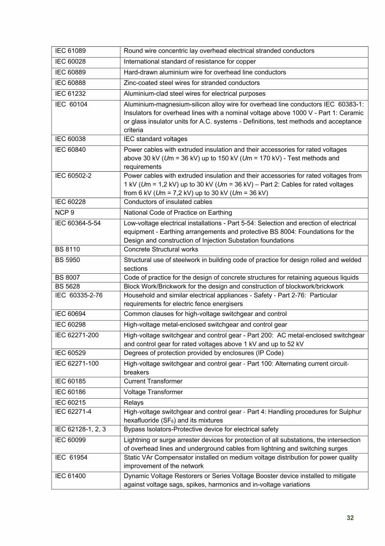
32
IEC 61089 Round wire concentric lay overhead electrical stranded conductors IEC 60028 International standard of resistance for copper IEC 60889 Hard-drawn aluminium wire for overhead line conductors IEC 60888 Zinc-coated steel wires for stranded conductors IEC 61232 Aluminium-clad steel wires for electrical purposes IEC 60104 Aluminium-magnesium-silicon alloy wire for overhead line conductors IEC 60383-1:
Insulators for overhead lines with a nominal voltage above 1000 V - Part 1: Ceramic or glass insulator units for A.C. systems - Definitions, test methods and acceptance criteria
IEC 60038 IEC standard voltages IEC 60840 Power cables with extruded insulation and their accessories for rated voltages
above 30 kV (Um = 36 kV) up to 150 kV (Um = 170 kV) - Test methods and requirements
IEC 60502-2 Power cables with extruded insulation and their accessories for rated voltages from 1 kV (Um = 1,2 kV) up to 30 kV (Um = 36 kV) – Part 2: Cables for rated voltages from 6 kV (Um = 7,2 kV) up to 30 kV (Um = 36 kV)
IEC 60228 Conductors of insulated cables NCP 9 National Code of Practice on Earthing IEC 60364-5-54 Low-voltage electrical installations - Part 5-54: Selection and erection of electrical
equipment - Earthing arrangements and protective BS 8004: Foundations for the Design and construction of Injection Substation foundations
BS 8110 Concrete Structural works BS 5950 Structural use of steelwork in building code of practice for design rolled and welded
sections BS 8007 Code of practice for the design of concrete structures for retaining aqueous liquids BS 5628 Block Work/Brickwork for the design and construction of blockwork/brickwork IEC 60335-2-76 Household and similar electrical appliances - Safety - Part 2-76: Particular
requirements for electric fence energisers IEC 60694 Common clauses for high-voltage switchgear and control IEC 60298 High-voltage metal-enclosed switchgear and control gear IEC 62271-200 High-voltage switchgear and control gear - Part 200: AC metal-enclosed switchgear
and control gear for rated voltages above 1 kV and up to 52 kV IEC 60529 Degrees of protection provided by enclosures (IP Code) IEC 62271-100 High-voltage switchgear and control gear - Part 100: Alternating current circuit-
breakers IEC 60185 Current Transformer IEC 60186 Voltage Transformer IEC 60215 Relays IEC 62271-4 High-voltage switchgear and control gear - Part 4: Handling procedures for Sulphur
hexafluoride (SF6) and its mixtures IEC 62128-1, 2, 3 Bypass Isolators-Protective device for electrical safety IEC 60099 Lightning or surge arrester devices for protection of all substations, the intersection
of overhead lines and underground cables from lightning and switching surges IEC 61954 Static VAr Compensator installed on medium voltage distribution for power quality
improvement of the network IEC 61400 Dynamic Voltage Restorers or Series Voltage Booster device installed to mitigate
against voltage sags, spikes, harmonics and in-voltage variations

33
IEC 60871 Shunt capacitors installed in the Injection Substations-Each capacitor unit is designed, rated, manufactured, and tested
IEC 60143-1 Series capacitors for power systems - Part 1: General IEC 62068 Electrical insulating materials and systems - General method of evaluation of
electrical endurance under repetitive voltage impulses IEC 61089 Classes and qualities of aluminium conductors applicable in distribution overhead
network B.S. 125, 1970 For Copper or Copper Equivalent B.S. 215 Part 1 197 for Aluminium IEC 60173 Colours of the cores of flexible cables and cords: High-voltage switchgear and
control gear - Part 202: High-voltage/ low-voltage prefabricated substation NIS IEC 60228 Conductors of insulated cables IEC 60079-0 Explosive atmospheres - Part 0: Equipment - General requirements IEC 60227 Polyvinyl chloride insulated cables of rated voltages up to and including 450/750 V -
Part 1: General requirements IEC 60502 Power cables with extruded insulation and their accessories for rated voltages from
1 kV (Um = 1,2 kV) up to 30 kV (Um = 36 kV) - ALL PARTS NIS IEC 60204 Safety of machinery - Electrical equipment of machines - ALL PARTS NIS IEC 60884 Plugs and socket-outlets for household and similar purposes - Part 1: General
requirements BS5266-1 Where indoor lighting is designated for emergency purposes in such places as
hospitals, entertainment venues, schools, industrial premises, hotels amongst others
Annexe B: Grid Extension
1 Environmental Requirements and Conditions: Electrical Works
The design, construction and installation of electrical works shall take into consideration environmental issues and concerns, which include (but not limited to) the following:
1. Promotion of energy efficiency 2. Social impact of new projects and community concerns 3. Minimisation of environmental damage, including visual impacts, tree and forestry
management programs 4. Considerations for electromagnetic radiation 5. Erosion prone environment 6. Equipment and materials that are exposed due to outdoor installations must be able to
withstand the environmental conditions shown below in table B1:
Table B1: Environmental conditions: Electrical works
Humidity Extended periods of relative humidity, ranging from 10% to 90%
Solar Radiation Level 1,100 W/m2 with high ultraviolet content Ambient Temperature Range
45°C summer daytime (maximum) and - 5°C winter night time (minimum)
Precipitation Annual rainfall above 1500mm (Bureau of Meteorology)

34
Wind Speed Tropical summer storms with gust wind speeds above 160 km/h
Isokeraunic Level 35-40 (Bureau of Meteorology) Pollution Level IV – Very heavy (for installation in polluted ambient air
with areas of coastal salt spray and industrial pollution
2 Guide to Conduct Electrical Load Surveys
1. Identify a contact person for the survey exercise. 2. Identify any obstacles at the T-off, including buildings, shrines, markets, etc. 3. Set up measuring instrument and record all possible landmarks (big lines, convert, rivers
bridges, etc.) along survey route and the angles of the route. 4. Identify the feeder which is the source of electricity supply. 5. Identify the bulk source of electricity supply. For 33kv feeders, identify the transmission
station. for the 11kV feeder, identify the primary injection substation. 6. Record the capacity of the transformer (including the loading percentage) and its approximate
distance from the T-off point to the proposed network. 7. Mark out the boundaries within inter-town distribution networks. These indicated boundaries
must be shown in the Legend of your drawings. 8. Sketch out all existing electrical networks along the survey route 9. Enumerate all physical structures (schools, churches, mosques, and other household
categories) in the community for Energy Audit. 10. Produce a design based on collected information, taking into consideration the load diversity
and growth plan at an optimum cost. 11. Develop the BEME using computer software or other spreadsheet applications.
3 Route Surveys
1. Pole line surveys shall produce a plan and profile of the surveyed route. The plan shall show the route the line will follow and the significant topography adjacent to the route.
2. Poles for distribution lines shall be placed on the side of the streets that is freest of other lines and trees.
3. Poles shall be erected 10m away from the road edge where practicable, else the poles should be erected at a safe distance such that its collapse will not result in traffic jam or destruction of properties.
4 Engineering Design 1. All engineering designs shall be carried out, certified and approved by qualified COREN
Registered Engineer(s).
2. Engineering designs of overhead distribution lines shall also take into consideration the following:
a. Compliance with Statutory Regulations b. Safety of equipment, employees and the general public c. Economic utilisation of materials d. Conformity with international best practices that meet the need of users with minimum
environmental impact e. To conform to acceptable standards, both from an engineering point of view and
aesthetics

35
5 Pole Markings
Figure B1: Pole markings for low-tension poles and high-tension poles
0.15m
0.15m
8.54m 10.06m
12.2m
2.13m
(7ft)
1.82m
(6ft)
1.52m
(5ft)
0.15m
(A) L.T POLE 28ft = 18.54m
(B) H.T POLE 33ft = 10.06m
(C) H.T POLE 40ft = 12.2m
POLE MARKINGS

36
6 High Tension Dressed Poles
Figure B2: Dimensions for a typical high tension dressed pole

37
Annexe C: Injection Substations
1 Substation Designs

38
Figure C1: Typical substation layout
Figure C2: Detailed top-down layout of a substation site (all dimensions are in mm)
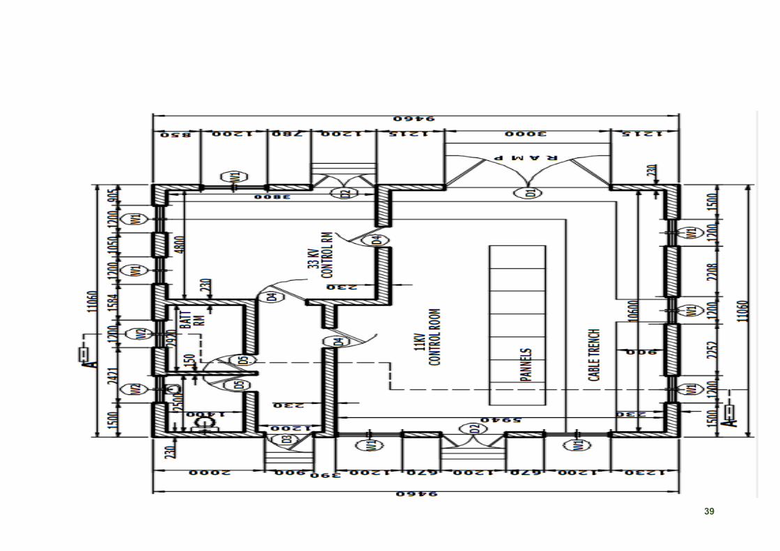
39
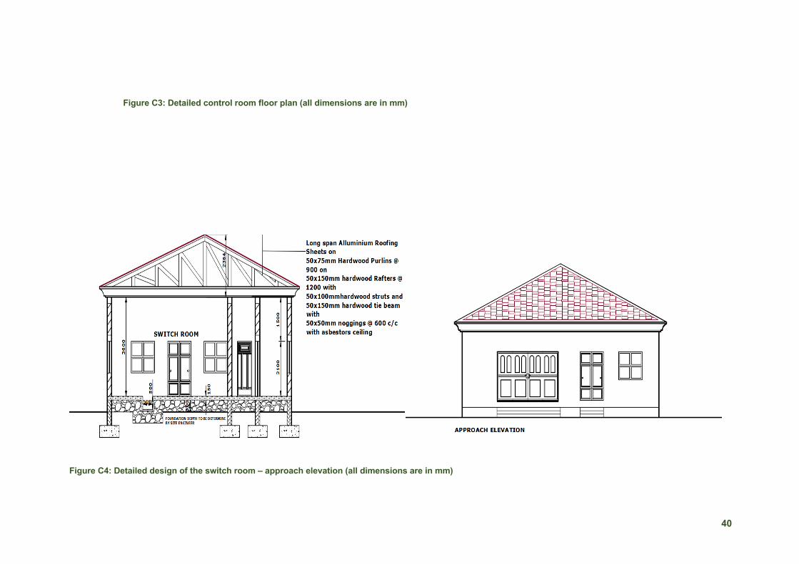
40
Figure C3: Detailed control room floor plan (all dimensions are in mm)
Figure C4: Detailed design of the switch room – approach elevation (all dimensions are in mm)
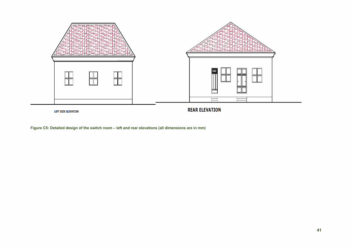
41
Figure C5: Detailed design of the switch room – left and rear elevations (all dimensions are in mm)

42
Figure C6: Detailed design of the switch room – right and top elevations (all dimensions are in mm)
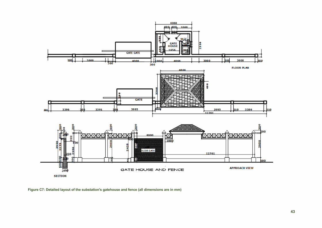
43
Figure C7: Detailed layout of the substation's gatehouse and fence (all dimensions are in mm)
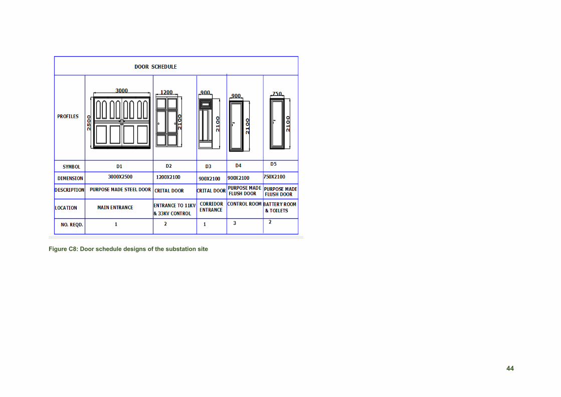
44
Figure C8: Door schedule designs of the substation site

45
2 Safety Requirements: Control Panels
1. Safety requirements of Control Panels include the following:
a. No live conductor shall be exposed on the front of any control panel and the back of any control panel of which bare live metal is mounted shall be made inaccessible (except to authorised persons) using earthed screens or otherwise.
b. Every door leading to the back of a control panel shall be provided with a spring or other approved device which shall ensure that the door remains open when not properly shut or locked.
c. An appropriately rated insulating mat or insulating stand shall be provided for the protection of operators in front of control panels of every control room and substation. A similar arrangement shall also be provided in the screened-in space at the rear of every control room and substation control panel (not being of the enclosed iron-clad cubicle type).
d. All panels shall have marked thereon, near each switch, the name of the feeder controlled by such switch.
e. All control room and substation control panels shall be provided with at least two different and independent earth connections, connected in parallel, to which all metal frames, all metal instrument cases (unless otherwise protected) and other metal parts thereof shall be connected. Means shall be provided to test the earth electrode resistance of these earth connections individually.
f. The terminal blocks shall be of extendable design, 650 V category, rated to carry the maximum expected current on the terminals continuously, provided with test links and isolating facilities wherever required and suitable for connecting the designed size of conductors on each side.
g. Control and instrument lead from the switchboards or other equipment will be brought to terminal boxes or control cabinets in conduits. All interphase and external connections to equipment or to control cubicles will be made through terminal blocks having a locking characteristic to prevent the cable from escaping from the terminal clamp.
3 Cables Table C2: Mechanical properties of selected cables
Wire Type The diameter of Solid Wire (mm) Tensile Stress (N/mm2)
Elongation (%)
Annealed copper wire
No less than 0.10, no more than 0.28
No less than 196, below (462 -10.8d)
No less than 15.0
More than 0.28, no more than 0.29
No less than 20.0
More than 0.29, no more than 0.45
No less than 20.0
More than 0.45, no more than 0.70
No less than 20.0
More than 0.70, no more than 1.6
No less than 25.0
More than 1.6, no more than 7.0
No less than 30.0
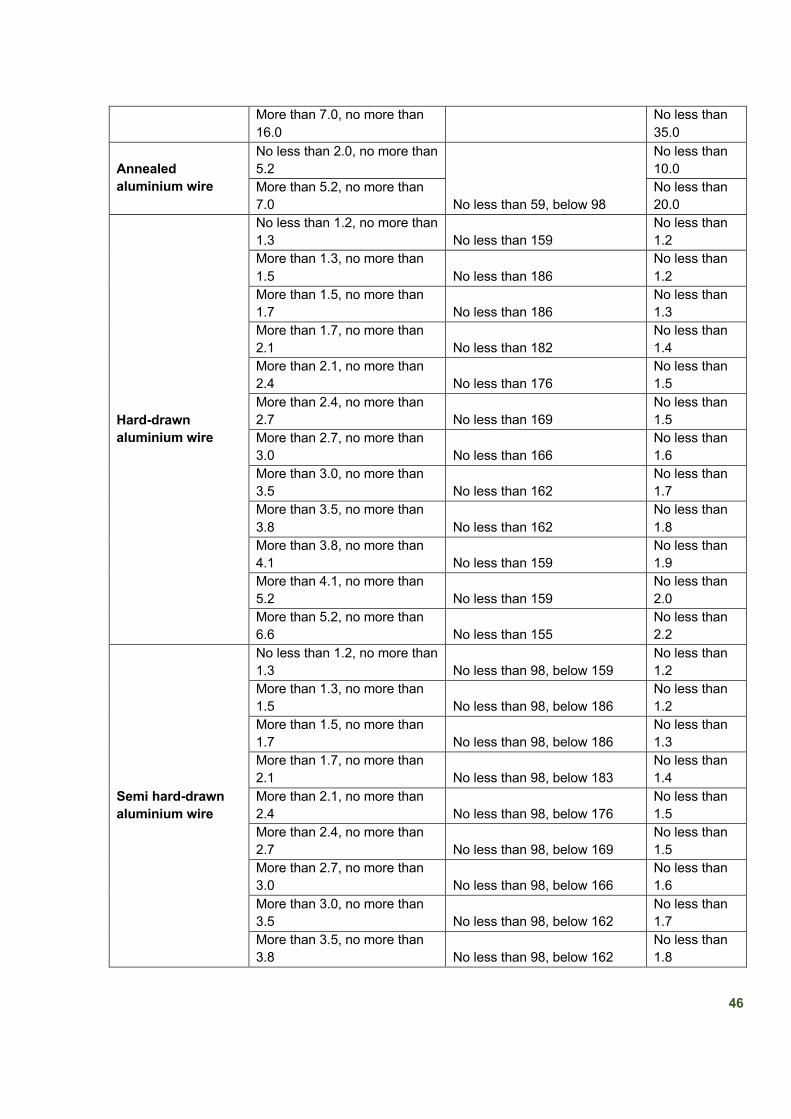
46
More than 7.0, no more than 16.0
No less than 35.0
Annealed aluminium wire
No less than 2.0, no more than 5.2
No less than 59, below 98
No less than 10.0
More than 5.2, no more than 7.0
No less than 20.0
Hard-drawn aluminium wire
No less than 1.2, no more than 1.3 No less than 159
No less than 1.2
More than 1.3, no more than 1.5 No less than 186
No less than 1.2
More than 1.5, no more than 1.7 No less than 186
No less than 1.3
More than 1.7, no more than 2.1 No less than 182
No less than 1.4
More than 2.1, no more than 2.4 No less than 176
No less than 1.5
More than 2.4, no more than 2.7 No less than 169
No less than 1.5
More than 2.7, no more than 3.0 No less than 166
No less than 1.6
More than 3.0, no more than 3.5 No less than 162
No less than 1.7
More than 3.5, no more than 3.8 No less than 162
No less than 1.8
More than 3.8, no more than 4.1 No less than 159
No less than 1.9
More than 4.1, no more than 5.2 No less than 159
No less than 2.0
More than 5.2, no more than 6.6 No less than 155
No less than 2.2
Semi hard-drawn aluminium wire
No less than 1.2, no more than 1.3 No less than 98, below 159
No less than 1.2
More than 1.3, no more than 1.5 No less than 98, below 186
No less than 1.2
More than 1.5, no more than 1.7 No less than 98, below 186
No less than 1.3
More than 1.7, no more than 2.1 No less than 98, below 183
No less than 1.4
More than 2.1, no more than 2.4 No less than 98, below 176
No less than 1.5
More than 2.4, no more than 2.7 No less than 98, below 169
No less than 1.5
More than 2.7, no more than 3.0 No less than 98, below 166
No less than 1.6
More than 3.0, no more than 3.5 No less than 98, below 162
No less than 1.7
More than 3.5, no more than 3.8 No less than 98, below 162
No less than 1.8

47
More than 3.8, no more than 4.1 No less than 98, below 159
No less than 1.9
More than 4.1, no more than 5.2 No less than 98, below 159
No less than 2.0
More than 5.2, no more than 6.6 No less than 98, below 155
No less than 2.2
Annexe D: Solar Mini-Grids
1 Technical Schedule Guarantees 1. Specific fuel consumption (g/kWe) and power output (kWe) must be quoted at standard (ISO)
ambient conditions and 45°C. Although, it’s not the highest possible ambient this temperature will be used for assessment of the equipment performance in hot conditions.
2. There shall be adherence to the de-rating curves or correction curves or formulae or calculations applicable to the particular diesel generator for the power de-ration or fuel consumption for the ambient conditions.
2 Diesel Generators: Operating Concept 1. General Guidelines
a. The diesel engine, alternator, generator control panel, fuel delivery system and fuel storage system shall comply with the current versions of the following applicable standards or equivalent standards.
b. To provide optimal fuel efficiency and maximum machine life, several generators in series to match the load profile provided in each order shall be provided, instead of one large generator which would run at high inefficiency.
c. Additionally, should load grow beyond the capacity of the installed diesel generator(s), it shall be possible to increase load capacity following a modular concept, adding multiple units to form a single combined source of electricity or mini-grid.
d. The operation concept also considers the future connection of PV modules or other RE sources (supplied by others; either with or without batteries) to the generation units.
e. Each diesel generator unit shall be able to operate as stand-alone within the mini-grid. f. Manual switchover control panel, automatic switchover control panel for single machine
control, and also, panels for full synchronisation control shall be provided separately. The synchronisation control in each case shall be designed for the following modes of operation:
2. Diesel Only a. The first diesel unit takes over all loads. In the event of a load approaching a certain
threshold (preset on-site, e.g., 70% of nominal capacity), the second unit will be automatically switched on and synchronised.
b. Switching off and disconnecting the second unit from the grid will take place when the load is below a certain threshold (e.g., 60% of unit capacity).
c. The diesel gen-sets are running in isochronous or baseload control mode and are adjusted to an internal speed drop.
3. PV-diesel Hybrid a. For PV-diesel hybrid generation, the diesel units operate as stand-by systems on the
main AC bus together with the PV modules.

48
b. Diesel gen-sets are operated if the load exceeds a certain threshold (e.g., 70% of module or battery capacity) or the Depth of Discharge (DOD) of the battery is below a preset threshold (e.g., 50%).
4. Base Load / Isochronous Load Control
a. In all operation modes (automatic, semi-automatic and manual), it shall be possible to select between Base Load / Isochronous Load Control.
b. Baseload control is by operator set point for fixed kW and power factor output. c. Isochronous Load Control is by automatic load sharing control.
5. Local Test
In Local Test mode only (initiated only at the diesel generator control panel), the diesel generator and ancillaries will run to speed for mechanical and electrical excitation checking. They will not synchronise to the load.

49
3 PV Module Designs: Grounding and Equipotential Bonding
Figure D1: Grounding and Equipotential Bonding for PV modules
PV MODULE GROUNDING AND EQUIPOTENTIAL BONDING DIAGRAMS

50
Annexe E: Solar Street Lights
1 Solar Street Lights Design
Figure E1: Detailed design for solar street lights
Related Documents


