1 Rao S. Thallam Fellow, IEEE Salt River Project Phoenix, AZ, USA Presented at: National Workshop on Electric Power Quality Nov 10, 2004 Indian Institute of Technology, Kanpur Kanpur, UP, India Harmonics - Application of Standards • Introduction • THD and TDD • Displacement and True Power Factor • K-Factor and Transformer Derating • When should you be concerned? • Application of IEEE 519 Standard • Harmonics Measurements • Industrial Customers • Commercial Customers • IEC Standards • Conclusions

Welcome message from author
This document is posted to help you gain knowledge. Please leave a comment to let me know what you think about it! Share it to your friends and learn new things together.
Transcript

1
Rao S. ThallamFellow, IEEE
Salt River ProjectPhoenix, AZ, USA
Presented at:National Workshop on Electric Power Quality
Nov 10, 2004Indian Institute of Technology, Kanpur
Kanpur, UP, India
Harmonics -Application of Standards
�������• Introduction• THD and TDD• Displacement and True Power Factor• K-Factor and Transformer Derating• When should you be concerned?• Application of IEEE 519 Standard• Harmonics Measurements• Industrial Customers• Commercial Customers• IEC Standards• Conclusions
2
"This alternating current thing is just a fad. It is much too dangerous for general use"
Thomas Alva Edison
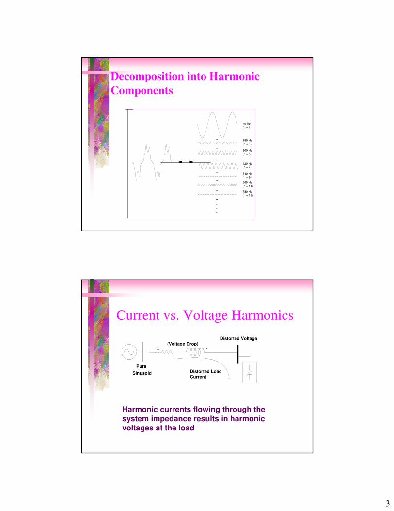
What Are Harmonics ?�Harmonics are due to distortion of the voltage or
current waveform�The distortion comes from nonlinear devices,
principally loads
V(t)
I(t)
V
I
Nonlinear Resistor
3
Decomposition into Harmonic Components
·
+
+
+
+
+
+
··
+
60 Hz(h = 1)
300 Hz(h = 5)
420 Hz(h = 7)
540 Hz(h = 9)
660 Hz(h = 11)
780 Hz(h = 13)
180 Hz(h = 3)
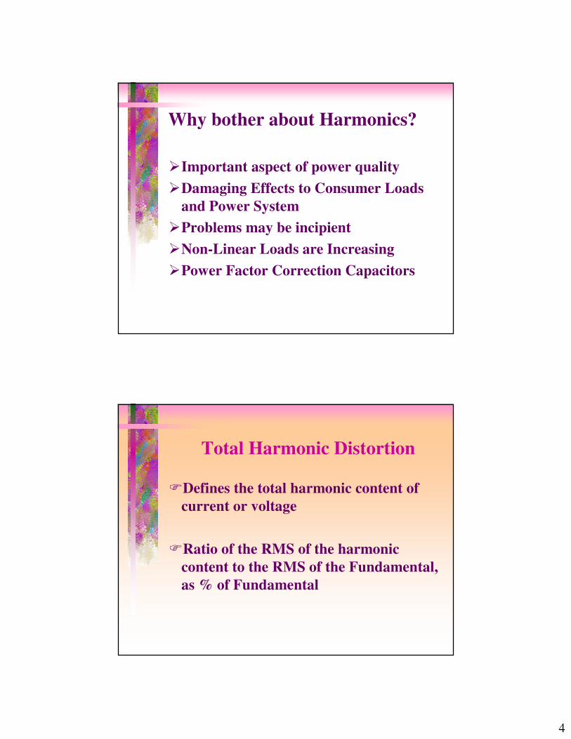
Current vs. Voltage Harmonics
PureSinusoid Distorted Load
Current
Distorted Voltage
+ -(Voltage Drop)
Harmonic currents flowing through the system impedance results in harmonic voltages at the load
4
Why bother about Harmonics?
�Important aspect of power quality�Damaging Effects to Consumer Loads
and Power System�Problems may be incipient�Non-Linear Loads are Increasing�Power Factor Correction Capacitors
Total Harmonic Distortion
�Defines the total harmonic content of current or voltage
�Ratio of the RMS of the harmonic content to the RMS of the Fundamental, as % of Fundamental

5
THD = sum of squares of amplitudes of all harmonics
square of amplitude of fundamental x 100 .
Mathematically, THD of a voltage wave form can be defined as,
THD = V
V
100 .x h
h
h 2
122=
= ∞�
Total Harmonic Distortion
THD for Current Waveform
THD = I
I
100 x h
h
h 2
1
22=
=∞�

6
Total Demand Distortion Factor (TDD)
�Applies for current distortion only.�The total rms harmonic current
distortion, in % of the maximum demand load current (15 or 30 min demand)
Displacement Power Factor
�When V and I are not distorted, PF is:�“Ratio of the active power of the
fundamental, in watts, to the apparent power of the fundamental wave, in volt-amperes”
�P = V1rms I1rms Cos ��PF = Cos �

7
Power and Power Factor�When significant distortion is present
PF = Cos θθθθ
“Displacement Power Factor”
True Power Factor
�Ratio of the total power, in watts, to the total volt-amperes. This includes fundamental and all harmonic components.
�This is also called “Distortion Power Factor”

8
True Power Factor
PFPS
=
S Vrms Irms=
PT
v t i t dtT
= �1
0( ) ( )
Where:
Engineering Speak
“We are looking at a number of approaches”
Translation:We are guessing.

9
Engineering Speak
“We are making modifications to address minor difficulties”
Translation:We are starting over.
Engineering Speak
“Test results are gratifying”
Translation:It worked and boy are we surprised!

10
Engineering Speak
“We are trying some new approaches”
Translation:We threw some new guys on it.
K-Factor�K-Factor is ratio of eddy current losses
due to distorted current compared to the losses for the same rms fundamental frequency current
�Example: �Eddy Current Losses with 100 A rms with harmonics =
270 Watts�Eddy Current Losses with 100 A rms 60 Hz sine wave =
27 Watts
�K - Factor = 270/27 = 10
11
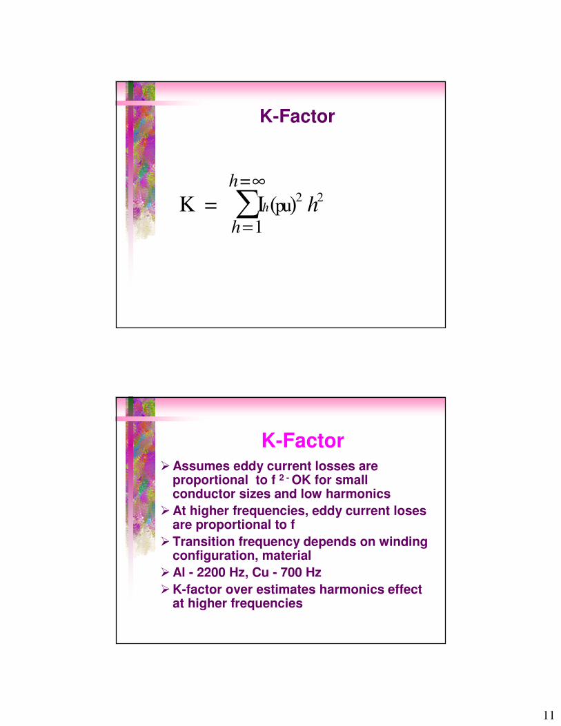
K-Factor
K = I ( ) 2pu
= h
h
hh
=
∞�
1
2
K-Factor�Assumes eddy current losses are
proportional to f 2 - OK for small conductor sizes and low harmonics
�At higher frequencies, eddy current loses are proportional to f
�Transition frequency depends on winding configuration, material
�Al - 2200 Hz, Cu - 700 Hz �K-factor over estimates harmonics effect
at higher frequencies

12
THD and K-Factor(Example Calculation)
�Harmonics for 3-ph PWM type ASD�Fund. = 100 A rms�5th : 60 A rms = 0.6 pu�7th : 40 A rms = 0.4 pu�11th : 30 A rms = 0.3 pu�13th : 20 A rms = 0.2 pu�THD = Sqrt (0.62 + 0.42 + 0.32 +0.22)* 100 = 81 %�K = 12 + 0.62 * 52 + 0.42 * 72 + 0.32 *112+0.22*132
� = 1 + 9 + 7.84 + 10.89 + 6.76 = 35.49
Transformer Derating
�Non K-rated transformers have to be derated when load current has harmonics
�IEEE C57.110 “Recommended Practice for Establishing Transformer Capability When Supplying Nonsinusoidal Load Currents”
13
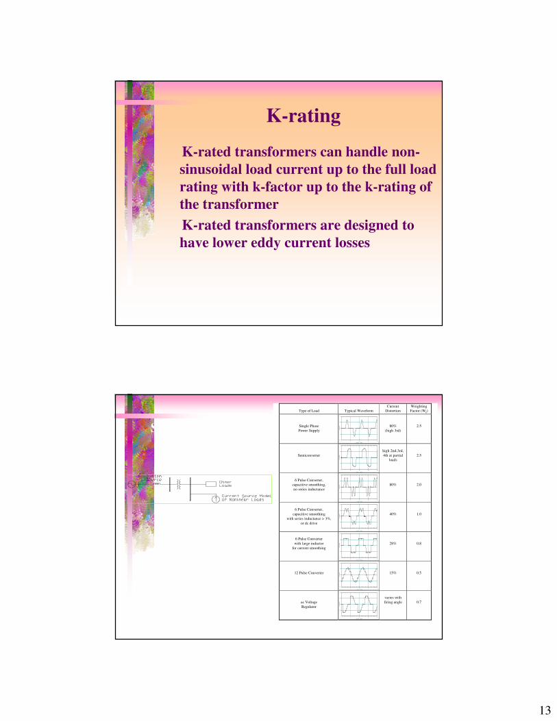
K-rating
�K-rated transformers can handle non-sinusoidal load current up to the full load rating with k-factor up to the k-rating of the transformer
�K-rated transformers are designed to have lower eddy current losses
Type of Load Typical WaveformCurrent
DistortionWeightingFactor (Wi)
Single PhasePower Supply
0 10 20 30 40
-1.0
-0.5
0.0
0.5
1.0
Time (mS)
Current 80%
(high 3rd)2.5
Semiconverter
0 10 20 30 40
-1.0
-0.5
0.0
0.5
1.0
Time (mS)
Current
high 2nd,3rd,4th at partial
loads2.5
6 Pulse Converter,capacitive smoothing,no series inductance
0 10 20 30 40
-1.0
-0.5
0.0
0.5
1.0
Time (mS)
Current 80% 2.0
6 Pulse Converter,capacitive smoothing
with series inductance > 3%,or dc drive
0 10 20 30 40
-1.0
-0.5
0.0
0.5
1.0
Time (mS)
Current 40% 1.0
6 Pulse Converterwith large inductor
for current smoothing
0 10 20 30 40
-1.0
-0.5
0.0
0.5
1.0
Time (mS)
Current 28% 0.8
12 Pulse Converter
0 10 20 30 40
-1.0
-0.5
0.0
0.5
1.0
Time (mS)
Current 15% 0.5
ac VoltageRegulator
0 10 20 30 40
-1.0
-0.5
0.0
0.5
1.0
Time (mS)
Current
varies withfiring angle 0.7
Sources of Harmonics
14
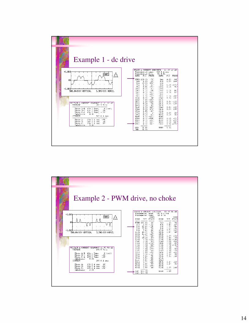
Example 1 - dc drive
Example 2 - PWM drive, no choke
15
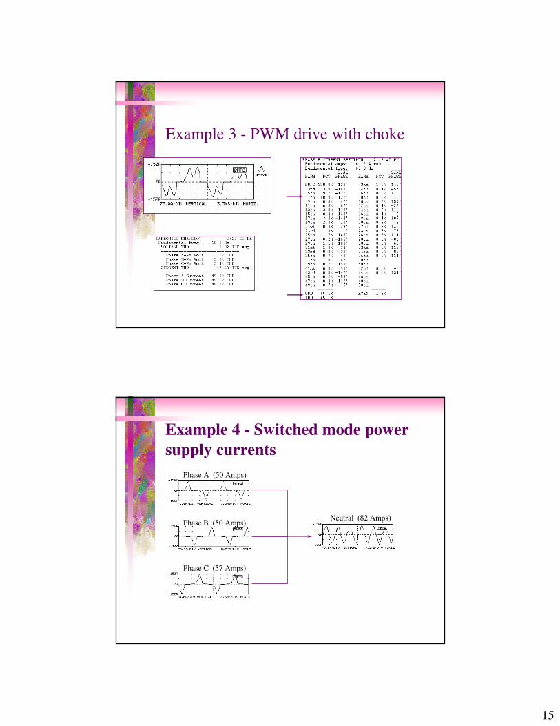
Example 3 - PWM drive with choke
Example 4 - Switched mode power supply currents
Phase A (50 Amps)
Phase B (50 Amps)
Phase C (57 Amps)
Neutral (82 Amps)

16
Example 5 - electronic ballast
Line to Neutral Voltage for Electronic Ballast
0 10 20 30 40 50-200
-150
-100
-50
0
50
100
150
200
Time (mS)
Voltage (V)
Max:Min:Avg:Abs:RMS:CF :FF :
170 -170 109.055 170 120.727 1.40814 1.10703
Line Current for Electronic Ballast
0 10 20 30 40 50-1.00
-0.75
-0.50
-0.25
0.00
0.25
0.50
0.75
1.00
Time (mS)
Current (Amps)
Max:Min:Avg:Abs:RMS:CF :FF :
0.784 -0.792 0.305828 0.792 0.334094 2.37059 1.09242
When Should You be Concerned About Harmonics
� 20 % of total load is power electronic load
� If service transformer is loaded near rating
� When PF correction capacitors are planned
�Neutral to ground voltage in 120 V supply exceeds 1 to 2 volts
�
17
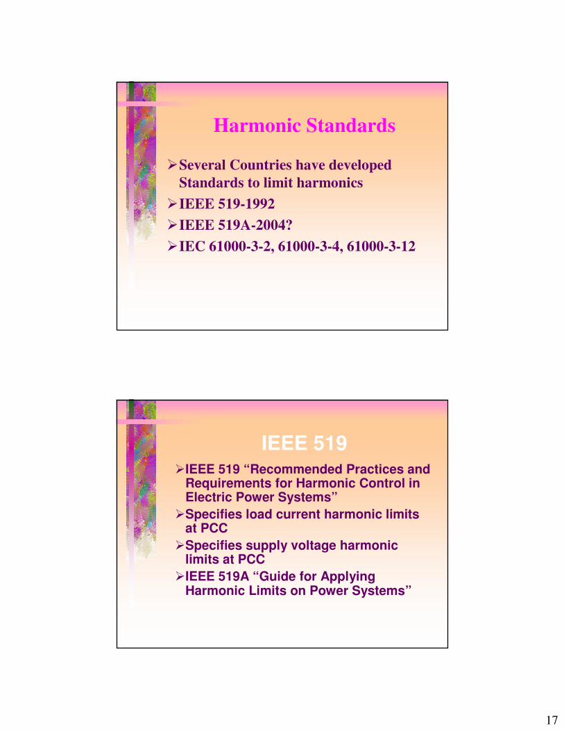
Harmonic Standards
�Several Countries have developed Standards to limit harmonics
�IEEE 519-1992�IEEE 519A-2004?�IEC 61000-3-2, 61000-3-4, 61000-3-12
IEEE 519�IEEE 519 “Recommended Practices and
Requirements for Harmonic Control in Electric Power Systems”
�Specifies load current harmonic limits at PCC
�Specifies supply voltage harmonic limits at PCC
�IEEE 519A “Guide for Applying Harmonic Limits on Power Systems”
18
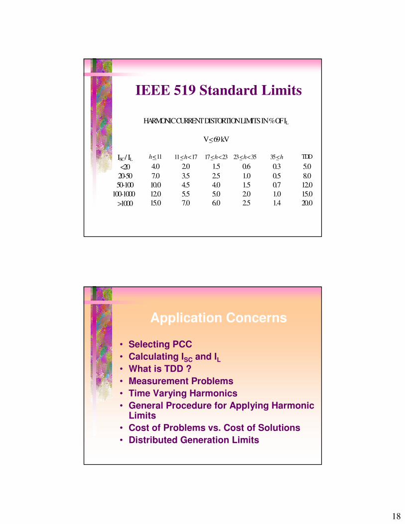
HARMONIC CURRENT DISTORTION LIMITS IN % OF IL
V < 69 kV
ISC / IL h < 11 11 < h < 17 17 < h < 23 23 < h < 35 35 < h TDD
<20 4.0 2.0 1.5 0.6 0.3 5.020-50 7.0 3.5 2.5 1.0 0.5 8.050-100 10.0 4.5 4.0 1.5 0.7 12.0
100-1000 12.0 5.5 5.0 2.0 1.0 15.0>1000 15.0 7.0 6.0 2.5 1.4 20.0
IEEE 519 Standard Limits
Application Concerns
• Selecting PCC• Calculating ISC and IL• What is TDD ? • Measurement Problems• Time Varying Harmonics• General Procedure for Applying Harmonic
Limits• Cost of Problems vs. Cost of Solutions• Distributed Generation Limits

19
What is PCC ?
�“Point in the public network which is closest to the consumer concerned and to which other customers are or may be connected” IEC 61000-3-4:1998

20
HARMONIC VOLTAGE DISTORTION LIMITS (in % of Nominal Fundamental Frequency Voltage)
Bus Voltage at PCC Individual Harmonic Voltage
Distortion Total Voltage Harmonic
Distortion (THDV) V <<<< 69 kV
3.0 5.0
69 kV <<<< V <<<< 161 kV
1.5 2.5
V >>>> 161 kV 1.0 1.5
IEEE 519 Standard Limits(Utility)

21
IEEE 519 Standard
�Limits apply for the “worst case” for normal operation (lasting longer than one hour)
�For shorter periods, during start-ups limits may be exceeded by 50%
�Even harmonics are limited to 25% of odd harmonic limits
�Co-gen - use Isc / IL < 20, irrespective of actual value
Harmonic Current Measurements
• Calculate harmonics as % of a fixed (average max. demand) current, not as % of fundamental
• Limits in the Table Apply only to Odd harmonics – Even Harmonics are limited to 25% of those limits
• CT Characteristics are important – usually good (should be less than 3 dB)
• How long to monitor?– Very stable, One day may be adequate– one week – for most cases– Permanent monitoring in some cases

22
Presentation of Results –snap shots
Presentation of Results –Time Trends

23
Harmonic Voltage Measurements
• Measure at PCC• Low Voltage – measure with direct
connection• Higher Voltages – Connect with PT –
frequency response is good to 3 k Hz (50th
harmonic)• Avoid CCVTs – frequency response is not
good
Evaluation Procedure
• Non-linear load is less than 10 - 20% of total plant load – No harmonic evaluation necessary
• Weighted Disturbing Power
S S WDw Di ii
= � ( )
24
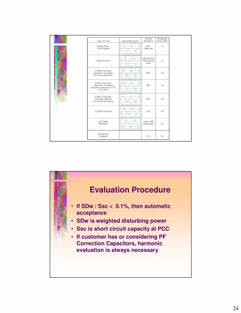
Type of Load
Typical W aveform
Current Distortion
W eighting Factor (W i)
Single Phase
Power Supply
0 10 20 30 40
-1.0
-0.5
0.0
0.5
1.0
Time (mS)
Current
80%
(high 3rd)
2.5
Semiconverter
0 10 20 30 40
-1.0
-0.5
0.0
0.5
1.0
Time (mS)
Current
high 2nd,3rd, 4th at partial
loads
2.5
6 Pulse Converter,
capacitive smoothing, no series inductance
0 10 20 30 40
-1.0
-0.5
0.0
0.5
1.0
Time (mS)
Current
80%
2.0
6 Pulse Converter,
capacitive smoothing with series inductance > 3% ,
or dc drive
0 10 20 30 40-1.0
-0.5
0.0
0.5
1.0
Time (mS)
Current
40%
1.0
6 Pulse Converter with large inductor
for current smoothing
0 10 20 30 40
-1.0
-0.5
0.0
0.5
1.0
Time (mS)
Current
28%
0.8
12 Pulse Converter
0 10 20 30 40
-1.0
-0.5
0.0
0.5
1.0
Time (mS)
Current
15%
0.5
ac Voltage Regulator
0 10 20 30 40
-1.0
-0.5
0.0
0.5
1.0
Time (mS)
Current
varies with firing angle
0.7
Fluorescent
Lighting
17%
0.5
Evaluation Procedure
• If SDw / Ssc < 0.1%, then automatic acceptance
• SDw is weighted disturbing power• Ssc is short circuit capacity at PCC• If customer has or considering PF
Correction Capacitors, harmonic evaluation is always necessary
25
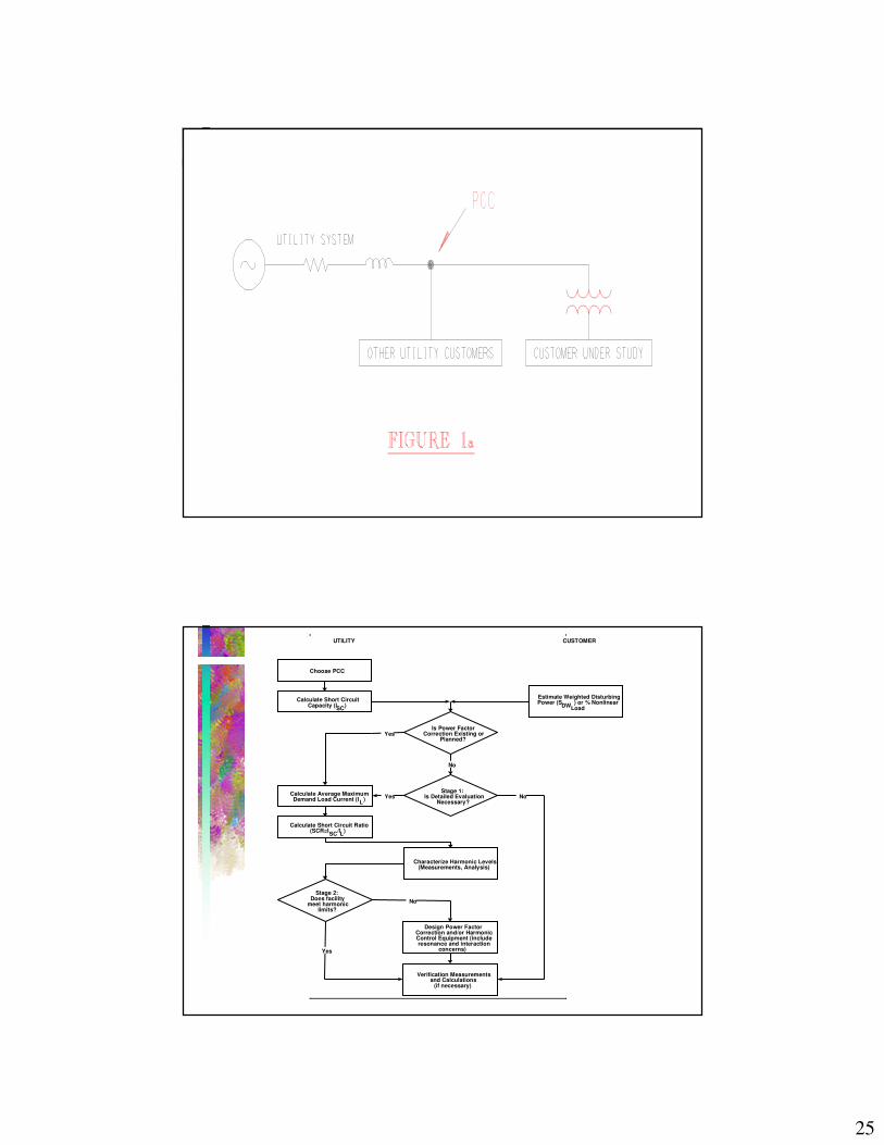
Choose PCC
Calculate Short CircuitCapacity (ISC)
Stage 1:Is Detailed Evaluation
Necessary?
Estimate Weighted DisturbingPower (SDW ) or % Nonlinear
Load
Is Power FactorCorrection Existing or
Planned?
No
Calculate Short Circuit Ratio(SCR=ISC/IL)
Yes
Characterize Harmonic Levels(Measurements, Analysis)
Stage 2:Does facility
meet harmoniclimits?
Calculate Average MaximumDemand Load Current (IL)
Yes
No
Design Power FactorCorrection and/or HarmonicControl Equipment (includeresonance and interaction
concerns)
Verification Measurementsand Calculations
(if necessary)
Yes
No
UTILITY CUSTOMER
26
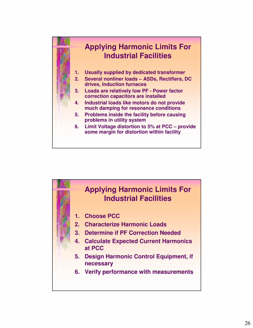
Applying Harmonic Limits For Industrial Facilities
1. Usually supplied by dedicated transformer2. Several nonliner loads – ASDs, Rectifiers, DC
drives, Induction furnaces 3. Loads are relatively low PF - Power factor
correction capacitors are installed4. Industrial loads like motors do not provide
much damping for resonance conditions5. Problems inside the facility before causing
problems in utility system6. Limit Voltage distortion to 5% at PCC – provide
some margin for distortion within facility
Applying Harmonic Limits For Industrial Facilities
1. Choose PCC2. Characterize Harmonic Loads3. Determine if PF Correction Needed4. Calculate Expected Current Harmonics
at PCC5. Design Harmonic Control Equipment, if
necessary6. Verify performance with measurements
27
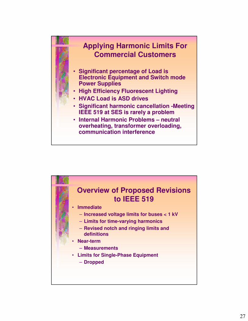
Applying Harmonic Limits For Commercial Customers
• Significant percentage of Load is Electronic Equipment and Switch mode Power Supplies
• High Efficiency Fluorescent Lighting• HVAC Load is ASD drives• Significant harmonic cancellation -Meeting
IEEE 519 at SES is rarely a problem• Internal Harmonic Problems – neutral
overheating, transformer overloading, communication interference
Overview of Proposed Revisions to IEEE 519
• Immediate– Increased voltage limits for buses < 1 kV– Limits for time-varying harmonics– Revised notch and ringing limits and
definitions• Near-term
– Measurements• Limits for Single-Phase Equipment
– Dropped
28
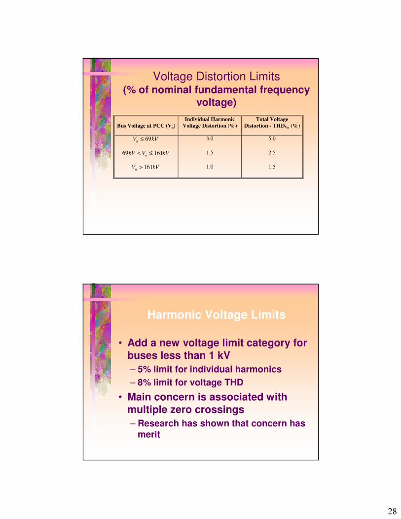
Voltage Distortion Limits(% of nominal fundamental frequency
voltage)
Bus Voltage at PCC (Vn) Individual Harmonic
Voltage Distortion (%) Total Voltage
Distortion - THDVn (%)
V kVn ≤ 69 3.0 5.0
69 161kV V kVn< ≤ 1.5 2.5
V kVn > 161 1.0 1.5
Harmonic Voltage Limits
• Add a new voltage limit category for buses less than 1 kV– 5% limit for individual harmonics– 8% limit for voltage THD
• Main concern is associated with multiple zero crossings– Research has shown that concern has
merit

29
Time-Varying Harmonics
• Limits must be based on factual cause/effect– Thermal effects occur over time– Burst distortion effects can be instantaneous– Startup/abnormal conditions should be tolerated
• The facts suggest providing– Significant limit increases for short periods– Some limit increases for intermediate periods– No increases for the majority of the time
• Some statistical techniques may be needed
Time Varying Harmonics
30
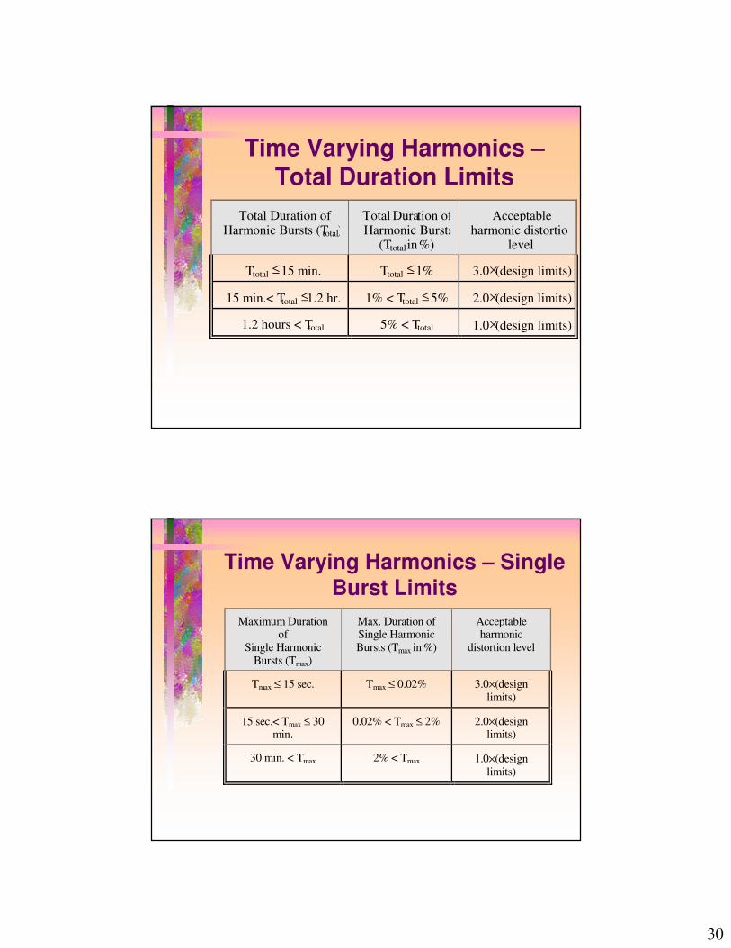
Time Varying Harmonics –Total Duration Limits
Total Duration of Harmonic Bursts (Ttotal)
Total Duration of Harmonic Bursts
(Ttotal in%)
Acceptable harmonic distortion
level
Ttotal ≤15 min. Ttotal ≤ 1% 3.0×(design limits)
15 min.< Ttotal ≤1.2 hr. 1% < Ttotal ≤ 5% 2.0×(design limits)
1.2 hours < Ttotal 5% < Ttotal 1.0×(design limits)
Time Varying Harmonics – Single Burst Limits
Maximum Duration of
Single Harmonic Bursts (Tmax)
Max. Duration of Single Harmonic Bursts (Tmax in %)
Acceptable harmonic
distortion level
Tmax ≤ 15 sec. Tmax ≤ 0.02% 3.0×(design limits)
15 sec.< Tmax ≤ 30 min.
0.02% < Tmax ≤ 2% 2.0×(design limits)
30 min. < Tmax 2% < Tmax 1.0×(design limits)
31
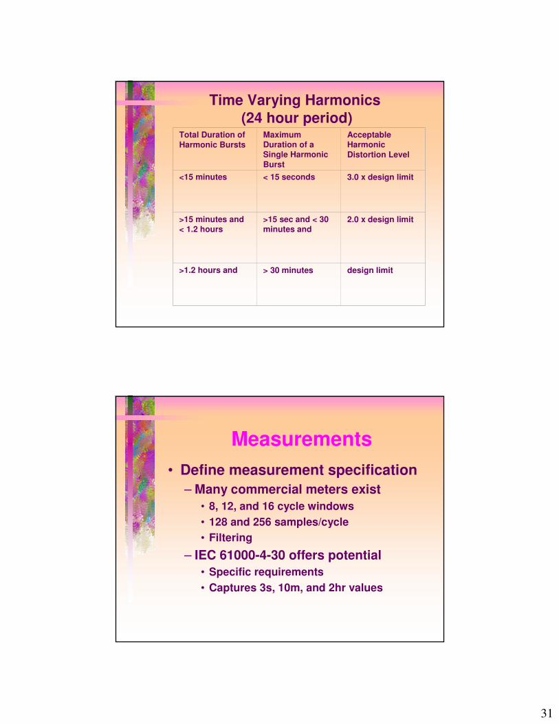
Time Varying Harmonics(24 hour period)
Total Duration of Harmonic Bursts
Maximum Duration of a Single Harmonic Burst
Acceptable Harmonic Distortion Level
<15 minutes < 15 seconds 3.0 x design limit
>15 minutes and < 1.2 hours
>15 sec and < 30 minutes and
2.0 x design limit
>1.2 hours and > 30 minutes design limit
Measurements• Define measurement specification
– Many commercial meters exist• 8, 12, and 16 cycle windows• 128 and 256 samples/cycle• Filtering
– IEC 61000-4-30 offers potential• Specific requirements• Captures 3s, 10m, and 2hr values
32
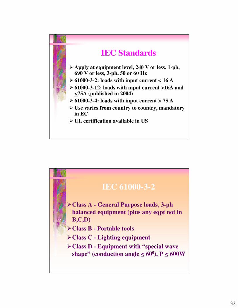
IEC Standards�Apply at equipment level, 240 V or less, 1-ph,
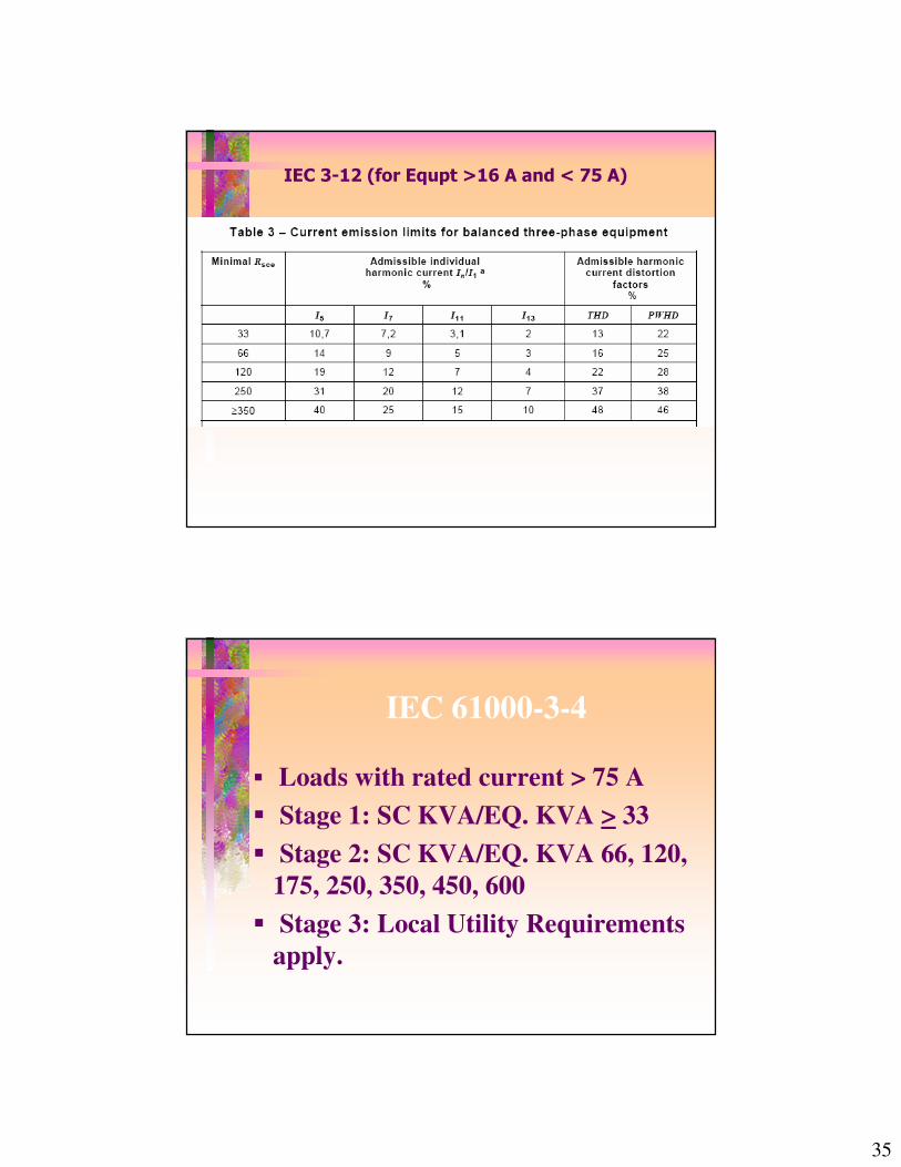
690 V or less, 3-ph, 50 or 60 Hz� 61000-3-2: loads with input current < 16 A� 61000-3-12: loads with input current >16A and
<75A (published in 2004)� 61000-3-4: loads with input current > 75 A�Use varies from country to country, mandatory
in EC�UL certification available in US
IEC 61000-3-2
�Class A - General Purpose loads, 3-ph balanced equipment (plus any eqpt not in B,C,D)
�Class B - Portable tools�Class C - Lighting equipment�Class D - Equipment with “special wave
shape” (conduction angle < 600), P < 600W

33
Class A (Balanced 3-ph Equipment)Harmonic Max. Permissible HarmonicOrder Current (Amps)
3 2.35 1.147 0.779 0.411 0.3313 0.2115-39 0.15 x 15/n
2 1.084 0.436 0.30
8-40 0.23 x 8/n
����� ������������������ ������������������ ������������������ �������������
�������������� �������� ��� ����������
34
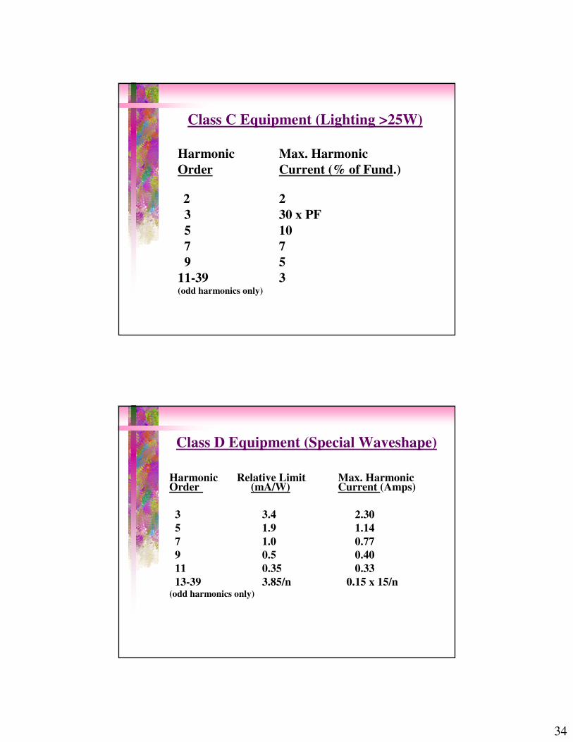
Class C Equipment (Lighting >25W)
Harmonic Max. HarmonicOrder Current (% of Fund.)
2 2 3 30 x PF5 107 79 5
11-39 3(odd harmonics only)
Class D Equipment (Special Waveshape)
Harmonic Relative Limit Max. Harmonic Order (mA/W) Current (Amps)
3 3.4 2.305 1.9 1.147 1.0 0.779 0.5 0.4011 0.35 0.3313-39 3.85/n 0.15 x 15/n
(odd harmonics only)
35
�������������������� ����!��"�#���$
IEC 61000-3-4
� Loads with rated current > 75 A� Stage 1: SC KVA/EQ. KVA > 33� Stage 2: SC KVA/EQ. KVA 66, 120,
175, 250, 350, 450, 600� Stage 3: Local Utility Requirements
apply.

36
IEC Standards� IEC Standards are based on European
distribution system� 3 ph, 3-wire feeder, and 3-ph, 3-wire
branches, 11 or 12 kV� 3-ph (delta-star), large (500 kVA - 1000
kVA) distribution transformers� 400/230V, 3-ph long secondary� USNC - IEC standards in US
US distribution systems are different
�3-ph, 4-wire Feeder, 1-ph, 2-wire branches, most 15 kV class
�Small (50 - 100 kVA) transformers serving 6 to 8 residents
�120/240 V, 1-ph, short secondaries�No consensus between manufacturers,
utilities and users

37
Comparison of European and North American Systems
European North AmericanFeeder 3-ph, 3-wire 3-ph, 4-wireBranch 3-ph, 3-wire 1-ph, 2-wireTransformer 500 kVA-1MVA 50 kVA-100kVA
Connection Y / ∇∇∇∇ Gr Y / Gr YSecondary 400/230V, 3-ph 120/240V, 1-ph
Length Long short
���������
• Harmonics are important aspect of power quality
• Application of power electronics is causing increased level of harmonics
• Survey the loads and make preliminary evaluation
• IEEE and IEC Standards reviewed
Related Documents