IEEE TRANSACTIONS ONPOWER DELIVERY, VOL. 35, NO. 3, JUNE 2020 1209 Harmonic Analysis of Modular Multilevel Matrix Converter for Fractional Frequency Transmission System Jiajie Luo, Xiao-Ping Zhang , Senior Member, IEEE, Ying Xue , Member, IEEE, Kanghui Gu , and Feng Wu Abstract—Fractional Frequency Transmission is a competitive technology for offshore wind power transmission. Modular Mul- tilevel Matrix Converter (M 3 C) plays a key role in a Fractional Frequency Transmission System (FFTS) as the frequency changer. M 3 C is broadly considered as the AC–AC converter for the future with its attractive advantages in high voltage and high power applications. Due to the lack of a DC link, electrical quantities at different frequencies from two AC systems couple in M 3 C, resulting in a complex harmonic condition. Harmonics can lead to stability issues and its analysis is of great importance. This paper focuses on the harmonic analysis of M 3 C. The arm capacitor voltage ripples and the harmonic currents are analyzed at various frequencies. Major factors influencing the harmonics magnitude are discussed. Analysis is conducted on sub-module capacitance and arm induc- tance selection. A zero-sequence current mitigation controller for M 3 C is implemented and tested. It is found that for a FFTS, some current harmonics flow into AC systems even though the system is balanced, while the others circulate within the converter. The theoretical harmonic analysis is verified by simulations in Real Time Digital Simulator (RTDS) of a M 3 C system where each arm consists of forty sub-modules. Index Terms—Fractional frequency transmission system, harmonic analysis, modular multilevel matrix converter (M 3 C), offshore wind power, energy storage. I. INTRODUCTION U NDER the pressure of fossil energy depletion and envi- ronmental pollution, renewable energy development has drawn worldwide attention. Offshore wind power is favored with merits of not taking up land in cities, rich and stable resource and suitability for large-scale development. Three main offshore Manuscript received November 13, 2018; revised March 28, 2019 and July 2, 2019; accepted August 16, 2019. Date of publication October 21, 2019; date of current version May 21, 2020. This work was supported in part by EPSRC Grants EP/N032888/1, EP/L017725/1, and EP/K006312/1 and in part by 111 Project “Renewable Energy Generation and smart grid” at Hohai University. This work was also sponsored by 111 Project “Renewable Energy Generation and smart grid” at Hohai University. Paper no. TPWRD-01403-2018. (Corresponding author: Xiao-Ping Zhang.) J. Luo, X.-P. Zhang, and Y. Xue are with the Department of Electronic, Electrical and Systems Engineering, University of Birmingham, Birmingham B15 2TT, U.K. (e-mail: [email protected]; [email protected]; [email protected]). K. Gu and F. Wu are with the Department of Electronic, Electrical and Systems Engineering, University of Birmingham, Birmingham B15 2TT, U.K., and also with the College of Energy and Electrical Engineering, Hohai University, Nanjing 210098, China (e-mail: [email protected]). Color versions of one or more of the figures in this article are available online at http://ieeexplore.ieee.org. Digital Object Identifier 10.1109/TPWRD.2019.2939312 wind transmission methods are traditional HVAC, HVDC and Fractional Frequency Transmission (FFT) [1]. FFT was first proposed in [2], the principle is to use a proportion of the system frequency, mostly 1/3, for the generator side. FFT re- quires less charging reactive current for cables than traditional HVAC, and therefore can support much longer transmission distance. Compared with HVDC, one main advantage is that no offshore converter station is needed. That means, not only for investment, but also for operation and maintenance, FFT is more economical within certain distance range, usually between 80 km and 180 km [3]. Most of the wind power plant projects that were built or planned lie in this range [4], [5] studied the feasibility of FFT and it showed a lower annual cost of FFT than HVDC. In addition, DC circuit breaker technology is still immature, and therefore the connection between the offshore wind farm and the onshore AC system is limited to point-to-point HVDC connections. Reliability suffers due to this reason and the situation would get worse when the level of offshore wind power penetration becomes high. On the contrary, FFT is not limited to point-to-point, and offshore grids are easy to form [6]. There is no doubt that frequency changer is the core com- ponent of FFT. Early-stage research has been focused on the use of cycloconverter [7], [8]. However, it was later proven that cycloconverter might not be suitable for offshore wind integration with defects of poor controllability, severe harmonics and unsatisfactory fault ride through ability [3]. Instead, M 3 C presents its strength in this application. Low voltage harmonic level, low switching loss, flexible scalability and controllable power factor make M 3 C outstanding as the next-generation AC-AC converter, particularly in high voltage applications like offshore wind power transmission [9]. M 3 C was introduced in 2001 in [10]. The topology is similar with the traditional matrix converter but there are significant dif- ferences with the inclusion of multilevel H-bridge sub-modules. Two main applications of M 3 C are motor driving [11]–[13] and wind energy transmission [9], [14], [15]. In [11], a control strategy for M 3 C based on dq transformation was proposed for motor driving and it was validated by experiment using a 400 V, 15 kW prototype. [12] optimized the inductors in M 3 C so that significant reductions in size and weight could be brought. The effectiveness was verified by a downscaled motor drive system. For wind energy transmission, different from that of motor drives, voltage rating is high and the sub-module number is large for M 3 C. Also the frequencies on both sides of M 3 C This work is licensed under a Creative Commons Attribution 4.0 License. For more information, see http://creativecommons.org/licenses/by/4.0/

Welcome message from author
This document is posted to help you gain knowledge. Please leave a comment to let me know what you think about it! Share it to your friends and learn new things together.
Transcript

IEEE TRANSACTIONS ON POWER DELIVERY, VOL. 35, NO. 3, JUNE 2020 1209
Harmonic Analysis of Modular Multilevel MatrixConverter for Fractional Frequency
Transmission SystemJiajie Luo, Xiao-Ping Zhang , Senior Member, IEEE, Ying Xue , Member, IEEE, Kanghui Gu , and Feng Wu
Abstract—Fractional Frequency Transmission is a competitivetechnology for offshore wind power transmission. Modular Mul-tilevel Matrix Converter (M3C) plays a key role in a FractionalFrequency Transmission System (FFTS) as the frequency changer.M3C is broadly considered as the AC–AC converter for the futurewith its attractive advantages in high voltage and high powerapplications. Due to the lack of a DC link, electrical quantities atdifferent frequencies from two AC systems couple in M3C, resultingin a complex harmonic condition. Harmonics can lead to stabilityissues and its analysis is of great importance. This paper focuses onthe harmonic analysis of M3C. The arm capacitor voltage ripplesand the harmonic currents are analyzed at various frequencies.Major factors influencing the harmonics magnitude are discussed.Analysis is conducted on sub-module capacitance and arm induc-tance selection. A zero-sequence current mitigation controller forM3C is implemented and tested. It is found that for a FFTS, somecurrent harmonics flow into AC systems even though the systemis balanced, while the others circulate within the converter. Thetheoretical harmonic analysis is verified by simulations in RealTime Digital Simulator (RTDS) of a M3C system where each armconsists of forty sub-modules.
Index Terms—Fractional frequency transmission system,harmonic analysis, modular multilevel matrix converter (M3C),offshore wind power, energy storage.
I. INTRODUCTION
UNDER the pressure of fossil energy depletion and envi-ronmental pollution, renewable energy development has
drawn worldwide attention. Offshore wind power is favored withmerits of not taking up land in cities, rich and stable resourceand suitability for large-scale development. Three main offshore
Manuscript received November 13, 2018; revised March 28, 2019 and July 2,2019; accepted August 16, 2019. Date of publication October 21, 2019; date ofcurrent version May 21, 2020. This work was supported in part by EPSRC GrantsEP/N032888/1, EP/L017725/1, and EP/K006312/1 and in part by 111 Project“Renewable Energy Generation and smart grid” at Hohai University. This workwas also sponsored by 111 Project “Renewable Energy Generation and smartgrid” at Hohai University. Paper no. TPWRD-01403-2018. (Correspondingauthor: Xiao-Ping Zhang.)
J. Luo, X.-P. Zhang, and Y. Xue are with the Department of Electronic,Electrical and Systems Engineering, University of Birmingham, BirminghamB15 2TT, U.K. (e-mail: [email protected]; [email protected];[email protected]).
K. Gu and F. Wu are with the Department of Electronic, Electrical and SystemsEngineering, University of Birmingham, Birmingham B15 2TT, U.K., and alsowith the College of Energy and Electrical Engineering, Hohai University,Nanjing 210098, China (e-mail: [email protected]).
Color versions of one or more of the figures in this article are available onlineat http://ieeexplore.ieee.org.
Digital Object Identifier 10.1109/TPWRD.2019.2939312
wind transmission methods are traditional HVAC, HVDC andFractional Frequency Transmission (FFT) [1]. FFT was firstproposed in [2], the principle is to use a proportion of thesystem frequency, mostly 1/3, for the generator side. FFT re-quires less charging reactive current for cables than traditionalHVAC, and therefore can support much longer transmissiondistance. Compared with HVDC, one main advantage is thatno offshore converter station is needed. That means, not onlyfor investment, but also for operation and maintenance, FFT ismore economical within certain distance range, usually between80 km and 180 km [3]. Most of the wind power plant projectsthat were built or planned lie in this range [4], [5] studied thefeasibility of FFT and it showed a lower annual cost of FFTthan HVDC. In addition, DC circuit breaker technology is stillimmature, and therefore the connection between the offshorewind farm and the onshore AC system is limited to point-to-pointHVDC connections. Reliability suffers due to this reason and thesituation would get worse when the level of offshore wind powerpenetration becomes high. On the contrary, FFT is not limitedto point-to-point, and offshore grids are easy to form [6].
There is no doubt that frequency changer is the core com-ponent of FFT. Early-stage research has been focused on theuse of cycloconverter [7], [8]. However, it was later proventhat cycloconverter might not be suitable for offshore windintegration with defects of poor controllability, severe harmonicsand unsatisfactory fault ride through ability [3]. Instead, M3Cpresents its strength in this application. Low voltage harmoniclevel, low switching loss, flexible scalability and controllablepower factor make M3C outstanding as the next-generationAC-AC converter, particularly in high voltage applications likeoffshore wind power transmission [9].
M3C was introduced in 2001 in [10]. The topology is similarwith the traditional matrix converter but there are significant dif-ferences with the inclusion of multilevel H-bridge sub-modules.Two main applications of M3C are motor driving [11]–[13]and wind energy transmission [9], [14], [15]. In [11], a controlstrategy for M3C based on dq transformation was proposedfor motor driving and it was validated by experiment using a400 V, 15 kW prototype. [12] optimized the inductors in M3Cso that significant reductions in size and weight could be brought.The effectiveness was verified by a downscaled motor drivesystem. For wind energy transmission, different from that ofmotor drives, voltage rating is high and the sub-module numberis large for M3C. Also the frequencies on both sides of M3C
This work is licensed under a Creative Commons Attribution 4.0 License. For more information, see http://creativecommons.org/licenses/by/4.0/
1210 IEEE TRANSACTIONS ON POWER DELIVERY, VOL. 35, NO. 3, JUNE 2020
are controlled to be constant. This paper focuses on this kind ofapplication. In [15], M3C was used in FFTS and its performancebased on a new space vector modulation (SVM) control schemewas evaluated. As M3C is further developed, it has been foundthat the number of space vectors grew exponentially with theincreasing number of sub-modules. Consequently, SVM is un-likely to be implemented in wind power transmission applicationwhich requires a large number of sub-modules. A novel currentcontrol method of M3C was developed in [16], featuring inthe decoupling of input and output. In [9], this method wasfurther improved for FFTS by introducing the cross synchronousrotating frames, so that DC values are dealt with at most timein current loops. In [14], a feedforward compensation strategywas proposed. Simulation results show that with the proposedcontrol method, M3C can cope with unbalanced grid conditions.Although plenty of work on M3C control has been carried out,limited attention has been paid on the harmonic analysis ofM3C. Based on ideal assumptions, paper [17] derived the currentexpression of one arm of M3C. The focus was on parametersselection of the capacitor and harmonic was not fully analyzedfor all nine arms in M3C. Authors of [18] provided an analysisof M3C in FFTS. A mathematical model of a sub-converterwas presented and verified, but no attention was paid to theharmonics.
For offshore wind power transmission system, harmonic anal-ysis is vital from the stability point of view, as the generatorside is a weak AC system and is prone to stability issues. Itis shown that resonance and harmonic instability phenomenacan occur when fast-switching devices interact with each other[19], [20]. Harmonic interaction was reported in [21] in theBorWin1 offshore wind farm system. The incident resulted in anoutage of the HVDC system and wind power was not able to betransmitted. Harmonic analysis is also crucial to prevent devicedamage and economic loss. [22] reveals that for MMC, with thesub-module capacitor voltage ripple and harmonic currents, eventhe harmonic currents only circulate within the converter and donot flow into the grid, there exist poorly damped resonant modesthat can lead to harmonic instability. In a MMC-HVDC system,[23] shows that circulating currents are in even orders, mainly insecond order and they are confined within the converter. Besides,both the second order capacitor voltage and arm voltage are innegative sequence. However, the harmonic situation for a M3Cbased FFTS is still not clear, which is the main focus of thispaper. Undoubtedly, MMC and M3C have similarities and theyare often compared as counterparts. Nevertheless, without a DClink in M3C, two frequencies intertwine in the converter, andhence the harmonic situation is fundamentally different fromthat in MMC.
The contributions of the paper are summarized as follows.� A harmonic analysis method for M3C is proposed. This
method analyzes how the harmonic components are gen-erated and it is compatible with different applications.
� Current harmonics at multiple frequencies are quantified.Based on the analysis, they are classified into three types. Itis indicated that some current harmonics circulate in arms,some behave as positive-sequence fundamental current andthe others are zero-sequence and flow into AC systems.
Fig. 1. The configuration of an offshore wind FFTS.
� Factors that have large impacts on harmonic magnitude arestudied. Also, the influences of the harmonic componentson M3C itself and AC systems are discussed in a detailedmanner. The analysis provides insights to M3C modellingand can serve for the development of new control method.
� Guidelines are provided on sub-module capacitanceand arm inductance selection to limit capacitor volt-age ripple and harmonic current distortion. An effectivezero-sequence current mitigation controller for M3C isdesigned.
The rest of the paper is organized as follows. Section II intro-duces the M3C for offshore wind FFTS. The current and voltagerelations for one sub-module are derived first, and then thewhole arm consisting all sub-modules is considered. Section IIIconducts a harmonic analysis of the M3C for FFTS. Differentcomponents are quantified and classified. The influences ofdifferent harmonic components are discussed. In Section IV,time-domain simulation results are presented to confirm thecorrectness of the analysis. Finally, conclusions are providedin Section V.
II. M3C FOR OFFSHORE WIND FFTS
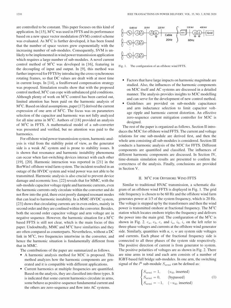
Similar to traditional HVAC transmission, a schematic dia-gram of an offshore wind FFTS is displayed in Fig. 1. The gridside frequency is chosen to be 60 Hz and the offshore wind farmgenerates power at 1/3 of the system frequency, which is 20 Hz.The voltage is stepped up by the transformers and then the windpower is transmitted onshore at fractional frequency. The M3Cstation which locates onshore triples the frequency and deliversthe power into the main grid. The configuration of the M3C isshown in Fig. 2. ea, eb, ec and ia, ib, ic on the left refer tothree-phase voltages and currents at the offshore wind generatorside. Similarly, quantities with u, v, w are system side voltagesand currents. Each phase of the fractional frequency side isconnected to all three phases of the system side respectively.The positive direction of current is from generator to system.The positive polarities of voltages are as shown in Fig. 2. Thereare nine arms in total and each arm consists of a number ofIGBT-based full bridge sub-modules. In one arm, the switchingsignal of the ith sub-module Sarmi can be defined as:
⎧⎪⎨
⎪⎩
Sarmi = 1, (udc inserted)
Sarmi = 0, (bypassed)
Sarmi = −1, (−udc inserted)
(1)
LUO et al.: HARMONIC ANALYSIS OF MODULAR MULTILEVEL MATRIX CONVERTER FOR FFTS 1211
Fig. 2. Schematic diagram of a M3C.
Assuming that the sub-module voltages are balanced at steadystate, the capacitor voltage udc for every sub-module in an armis the same. The current relation for one sub-module can beexpressed as:
Sarmi iarm = Cdudc
dt(2)
where iarm is the arm current, C is the capacitance of one sub-module. Refer N to the total sub-module number in an arm.Summing up (2) for all sub-modules in the arm, the currentrelation becomes:
N∑
i=1
Sarmi iarm = NCdudc
dt
n iarm = NCdudc
dt(3)
where n is the difference between the number ofudc inserted sub-modules and that of −udc inserted ones. Considering that sub-modules are inserted in only one direction at normal operation,n can be referred to the number of the inserted sub-modules(negative value means sub-modules are inserted with −udc).Define Sarm as the average switching function of an arm, whichis the ratio between inserted sub-module number and total sub-module number (n/N). This yields the current relation of a M3Carm:
Sarm iarm = Cdudc
dt(4)
The voltage relation of a M3C arm can be written as (5), whereuarm is the arm voltage.
uarm = NSarm udc (5)
Equation (4) and (5) describe both the voltage and currentrelations for a M3C arm. The same equations are applied to allnine arms of M3C.
III. HARMONIC ANALYSIS OF M3C FOR
OFFSHORE WIND FFTS
Frequencies from the generator side ω1 and the system sideω3 couple in M3C. At balanced steady state, the phase current
is equally spread in three arms [17], [18]. For example, the armcurrent iau contains one third of the phase current ia, one thirdof the phase current iu, and also harmonics. The arm currentscan be expressed as:
iarm =1
3i20 +
1
3i60 + iharmonics
arm (6)
where i20 and i60 are the phase currents from the generator sideand the grid side respectively. iharmonics
arm is the arm harmonicswhich will be discussed later in this section. When the harmoniccurrent is insignificant, arm currents for all nine arms can begiven as:
iau ≈ 1
3Iasin (ω1t+ β1) +
1
3Iusin (ω3t+ β3)
iav ≈ 1
3Iasin (ω1t+ β1) +
1
3Iusin (ω3t+ β3 − 120) .
.
.
.
icw ≈ 1
3Iasin (ω1t+ β1 + 120) +
1
3Iusin (ω3t+ β3 + 120)
(7)where Ia, Iu, β1 and β3 are the magnitudes and phase anglesof the generator side and system side current respectively. Also,the arm switching functions can be given by:
Sau = masin (ω1t+ α1)−musin (ω3t+ α3)
Sav = masin (ω1t+ α1)−musin (ω3t+ α3 − 120)
.
.
.
Scw = masin (ω1t+ α1 + 120)−musin (ω3t+ α3 + 120)(8)
wherema,mu,α1 andα3 are the generator side and system sidevoltage modulation ratios and angles.
A. Capacitor Voltage Ripples
Apply (4) to arm au, the capacitor voltage can be expressedas:
udc_au =
∫1
CSauiau (9)
Substitute iau in (7) and Sau in (8) into (9), the expression ofthe capacitor voltage in arm au can be derived. The expressionsof the rest eight arms can be acquired in the same manner. Thearm current and the switching function both contain harmoniccomponents at frequencies ω1 and ω3. According to trigono-metric product-to-sum identity, the capacitor voltage frequencyspectrum contains 2ω1, 2ω3, (ω3 ± ω1) and 0 Hz components.In this section and later analysis, the system frequency is con-sidered to be 60 Hz. In this case, beside the DC component,the capacitor voltage has ripples of 40 Hz (also 80 Hz and120 Hz). These frequencies are different from frequencies ateither side of the ac systems. The 40 Hz voltage ripple has thelargest magnitude compared to components at other frequencies.This will be further discussed and verified by the time domain

1212 IEEE TRANSACTIONS ON POWER DELIVERY, VOL. 35, NO. 3, JUNE 2020
TABLE IARM FREQUENCY COMPONENTS
simulation in Section IV. The constituent terms at 40 Hz areanalyzed and the full expressions are calculated and shown as:
udcau40= k1[−maIasin (θ1) +maIusin (θ2)
−muIasin (θ3)]
udcav40= k1[−maIasin (θ1) +maIusin (θ2 − 120)
−muIasin (θ3 − 120)]
udcaw40= k1[−maIasin (θ1) +maIusin (θ2 + 120)
−muIasin (θ3 + 120)]...
udcbw40= k1[−maIasin (θ1 + 120) +maIusin (θ2 − 120)
−muIasin (θ3 − 120)]...
udccw40= k1[−maIasin (θ1 − 120) +maIusin (θ2)
−muIasin (θ3)]
(10)
where: k1 = 112Cω1
; θ1 = 2ω1t+ α1 + β1; θ2 = 2ω1t+ β3 −α1; θ3 = 2ω1t+ α3 − β1
As can be seen from (10), the 40 Hz component of thecapacitor voltage consists of three terms. For each term, themagnitude is the same for all nine arms while there can be aphase shift between nine arms. When the high order componentsare neglected, the capacitor voltage can be expressed as the sumof the dc component and the 40 Hz component:
udc ≈ udc_0 + udc_40 (11)
B. Arm Current Harmonics
The purpose of this part is to analyze the arm currents of theM3C at various frequencies. In order to derive the expression ofthe arm currents, arm voltages are derived first. Then togetherwith KVL equations, the arm currents are acquired so that theharmonics can be analyzed.
In (8), switching function is of 20 Hz and 60 Hz. And in(11), capacitor voltage is of DC and 40 Hz. Substitute (8) and(11) into (5), components at different frequencies appear in armvoltage, which are shown in Table I. As can be seen, arm voltagecontains components at 20 Hz, 60 Hz and 100 Hz. How eachcomponent is generated is shown in the second column in Table I.For instance, switching function at 60 Hz and capacitor voltageat 40 Hz gives arm voltage at 100 Hz and 20 Hz. The terms(20 + DC) and (60 + DC) are in positive sequence and theyrelate to the positive-sequence fundamental currents. These two
terms do not belong to the scope of harmonics and will not beanalyzed.
According to KVL, equations at 20 Hz, 60 Hz and 100 Hzcan be written as:
ea = uarm_au_20 + Ldiau_20
dt
0 = uarm_au_60 + Ldiau_60
dt+ eu
0 = uarm_au_100 + Ldiau_100
dt(12)
As KVL does not alter frequency, the frequency componentsof the arm current remain the same as the ones of the armvoltage as Table I shows. Combine (5), (8) and (10–12), currentharmonics at 20 Hz, 60 Hz and 100 Hz can be calculated.
1) 100 Hz: The expression of the arm currents at 100 Hz isshown in (13). ω5 is referred to the frequency at 100 Hz. Thearm currents at 100 Hz are formed of three terms. For each term,the magnitude is the same for all nine arms. Adding up iau100,iav100 and iaw100, all three terms cancel out, which means thatthe arm currents at 100 Hz will not flow into phase a and existonly in the arm. Same rule applies to phase b and c, and thereforethe arm currents at 100 Hz are isolated from the generator sideAC system. In terms of the system side, the same procedure iscarried out. Likewise, iaw100, ibw100 and icw100 add up to zero(same for phase u and v) so no current at 100 Hz will flow intothe system side. In conclusion, the natures of these currents arecirculating currents which only circulate within the converter.They take up the current rating of the semiconductor devicesand should be suppressed during operation.
iau100 = k2[mumaIasin (θ4)−mumaIusin (θ5)
+m2uIasin (θ6)]
iav100 = k2[mumaIasin (θ4 − 120)−mumaIusin (θ5 + 120)
+m2uIasin (θ6 + 120) ]
iaw100 = k2[mumaIasin (θ4 + 120)−mumaIusin (θ5 − 120)
+m2uIasin (θ6 − 120)]
...
ibw100 = k2[mumaIasin (θ4 − 120)−mumaIusin (θ5)
+m2uIasin (θ6)]...
icw100 = k2[mumaIasin (θ4)−mumaIusin (θ5 + 120)
+m2uIasin (θ6 + 120)]
(13)
where: k2 = N24LCω1ω5
; θ4 = ω5t+ α3 + α1 + β1; θ5 = ω5t+ α3 + β3 − α1; θ6 = ω5t+ 2α3 − β1
2) 60 Hz: According to Table I, there are two sources of the60 Hz arm currents. The first one is fundamental current and doesnot need to be analyzed. The expression of the second componentis calculated and shown in (14). As it shows, the first of the threeterms of the arm currents at 60 Hz has the same magnitude andphase angle for all nine arms of M3C. As a result, it behaves aszero-sequence current for AC systems at both sides and it flows

LUO et al.: HARMONIC ANALYSIS OF MODULAR MULTILEVEL MATRIX CONVERTER FOR FFTS 1213
TABLE II20 Hz ARM CURRENT
into both systems with equal magnitude if no countermeasurewas implemented. This current is undesirable since it causescurrent distortion and can bring further instability issues likeharmonic interaction and resonance. For the rest two terms, theycancel out at the fractional frequency side and are of positivesequence at the system side. They behave like the fundamentalcurrent and can be regulated by the current controller in vectorcontrol. The positive-sequence components are not problematicand strictly speaking, they do not belong to the harmonic scope.
iau60_2 = k3[−m2aIasin (θ7) +m2
aIusin (θ8)
−mamuIasin (θ9)]
iav60_2 = k3[−m2aIasin (θ7) +m2
aIusin (θ8 − 120)
−mamuIasin (θ9 − 120)]
iaw60_2 = k3[−m2aIasin (θ7) +m2
aIusin (θ8 + 120)
−mamuIasin (θ9 + 120)]...
ibw60_2 = k3[−m2aIasin (θ7) +m2
aIusin (θ8 + 120)
−mamuIasin (θ9 + 120)]...
icw60_2 = k3[−m2aIasin (θ7) +m2
aIusin (θ8 + 120)
−mamuIasin (θ9 + 120)]
(14)
where: k3 = N24LCω1ω3
; θ7 = ω3t+ 2α1 + β1; θ8 = ω3t+ β3;θ9 = ω3t+ α1 + α3 − β1
3) 20 Hz: The harmonic currents at 20 Hz are analyzed bycarrying out the same calculations to the second and the thirdterms of 20 Hz in Table I. Results are concluded in Table II.Detailed equations are available in the appendix. The first termof the component (40–20) Hz and the second and third termsof the component (60–40) Hz behave like the positive-sequencefundamental current. The second and third terms of the compo-nent (40–20) Hz and the first term of the component (60–40) Hzonly exist in the arms and will not flow into AC systems.
To sum up, the components of the arm currents analyzed abovecan be classified into three types. The first type only circulateswithin the converter but does not flow into AC systems. The sec-ond type does not cancel out at terminals and therefore goes intoAC systems as zero-sequence current. The third type acts likepositive-sequence fundamental current. The affecting factors of
harmonic magnitude and influences of these harmonics on M3Citself and also AC systems connected to it are discussed in thefollowing section.
C. Affecting Factors and Influences of M3C HarmonicComponents
As (13), (14), (A1) and (A2) show, the magnitude of theseharmonic components depends on the sub-module capacitance,the inductance, the frequency of the AC system etc. The smallerthe capacitance or the inductance, the larger the harmonicsmagnitude would be. If the AC system frequency is very small, intheory the harmonic components become infinity and the systemcould not function normally. Thus, the working frequency ofthe FFTS cannot be too low. In addition, current harmonics arerelated to capacitor voltage ripples. Effective ripple control isbeneficial to harmonic suppression. Some of the current compo-nents coincide with the system frequency and are easy to omit.
Based on the analysis in Section B, it is indicated that therewill be zero-sequence current flowing into the AC systems atboth sides if no countermeasure was conducted. This can beproblematic as wind farm is prone to stability problems [24].Attention should also be paid to the system side, because off-shore wind farms are often located in remote areas, where thestrength of the AC network is weak [25]. Among three typesof currents discussed in the last session, the components inpositive sequence are not harmful since they can be regulatedby the close-loop current controller. Circulating current andzero-sequence current can adversely influence the converter andAC systems in the following aspects:� Both circulating and zero-sequence currents take up current
rating of the power electronic devices. They raise thermalissues and degrade the semiconductors. For multilevelconverters, high voltage can be achieved by stacking upsub-modules but current ability limits the power rating.In terms of an offshore wind power transmission project,converter capital cost is therefore increased.
� The zero-sequence currents can flow into the AC network,which bring additional losses in devices including trans-formers and AC motors and raise the operating tempera-ture. The aging of devices is accelerated and power lossalso leads to low efficiency.
� The harmonic currents flowing in the AC system canfurther cause instability problems. Large magnitude ofzero-sequence current may trip the zero-sequence protec-tion. When wind energy has high penetration, unexpecteddisconnection of a large wind power source would have sig-nificant effect on power system stability. Besides, harmonicinteraction or resonance may happen. Torsional oscillationcan be triggered in generators with the existence of injectedharmonic currents. It results in shaft fatigue or even shaftfailure [26], [27].
The transformer connection in an offshore wind power systembased on real projects is shown in Fig. 1, with more detailsavailable in [28], [29]. The step-up transformer at the wind gen-erator side usually includes delta connection, as a result of which,the zero-sequence currents could not reach the wind generator.

1214 IEEE TRANSACTIONS ON POWER DELIVERY, VOL. 35, NO. 3, JUNE 2020
Fig. 3. Topology to connect a high power wind turbine via M3C.
TABLE IIISIMULATION PARAMETERS
However, for the system side, due to protection considerationsat high voltage level (several hundred kV), transformers arenormally in Wye/Wye connection with grounding. Wye/Wyetransformer enjoys the advantages of fewer turns for winding,lower insulation level, no phase displacement and therefore ischeaper and suitable for high voltage applications. [30] Furtheraction should be taken when the harmonic magnitude is large.Besides FFT, another topology (as shown in Fig. 3) that connectsmedium voltage high power wind turbine with M3C is prosed in[13], [31]. In this application, maximum power point trackingcan be achieved and good dynamic performance was validated.However, in terms of harmonics, zero-sequence currents canimpede the wind generator and also the electrical network, sofurther measures should be taken. Undoubtedly, sub-modulecapacitance and arm inductance should be carefully selectedto limit the harmonics. Besides, one option could be adoptingdelta winding for the grid-connecting transformer to cut off thepath of the zero-sequence currents. However, in that case thebenefits of the Wye/Wye transformer would no longer exist.Another solution is to leave the transformer unchanged, butadopt a closed-loop controller to suppress the zero-sequencecurrents using the controllability of M3C. The control algo-rithm will be discussed and the effectiveness will be verified inSection V.
IV. SIMULATION RESULTS AND ANALYSIS VALIDATION
To validate the theoretical analysis, a M3C connecting two ACsystems at 20 Hz and 60 Hz is simulated in RTDS (See Fig. 2).Each arm has forty sub-modules. System at 20 Hz transmitspower to 60 Hz side. Simulation parameters are provided inTable III. The M3C simulated in RTDS is a detailed model andthe simulation time step is set to 3 μs to guarantee the accuracyof the simulation results where the MMC valves are modeled inthe small time step.
In the ‘small time step’ modelling framework of RTDS, thereare two different modelling methods developed, referred to asMethod A and Method B, thereafter.� Method A: In this method, modeling switching devices with
the use of L and C was discussed in [33]. This methodcould lead to certain discrepancy if parameters were notset properly. Results between PSCAD and RTDS (smalltime step) were presented and compared in [33], whichmatched very well.
� Method B: In Method B, the MMC valve model in RTDSsimulation also employs a resistive switching. Details ofMMC valve model in RTDS using a resistive switching(Method B) can be found in [32]. In our simulations, ‘smalltime step’ Method B is used to model the MMC switchingdevices.
Method B models the MMC switching devices with theresistive switching approach, which is similar to that used inPSCAD. It may be useful to point out that due to calculationconstraint, an artificial short interface line around 400 meters isinserted between the MMC arm component and the rest of thesmall time step circuit in RTDS. But since the application in thispaper is offshore wind power transmission, whose distance isnormally from tens of km to several hundred km, the impact ofsuch a very short interface line on the accuracy of the overallsystem simulations is negligible. [32] conducted a thoroughcomparison on CIGRE DC grid test systems between RTDSMMC model using Method B and PSCAD MMC model tovalidate the correctness of the RTDS MMC valve model. Allthe cases showed very close results. In terms of actual values ofthe interface line parameters, C is in the magnitude of nF andthis is so tiny that it can be ignored, and L is in the magnitude ofmH, which can be taken out of the real arm inductance so that thetotal inductance remains the same. In addition, there are wiresbetween arms in physical circuit, which justifies the rationalityof the interface.
The assumptions can be verified and the theoretical analysiscan be compared to simulation results. The control methodadopted is the vector control with inner current loops and outerloops for active/reactive power control or capacitor voltagebalancing control. More details of the control system can befound in [34]. Note that the capacitor voltage for the controlinput should be the filtered version to avoid influence of thecontroller on quantified analysis. Otherwise the controller wouldtry to control the capacitor voltage ripple as well and would notmatch the theoretical calculation. A low pass filter is applied tothe active power signal for the same consideration.
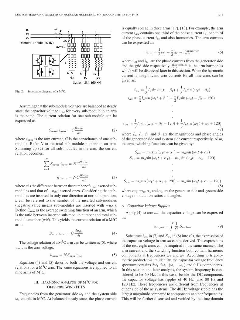
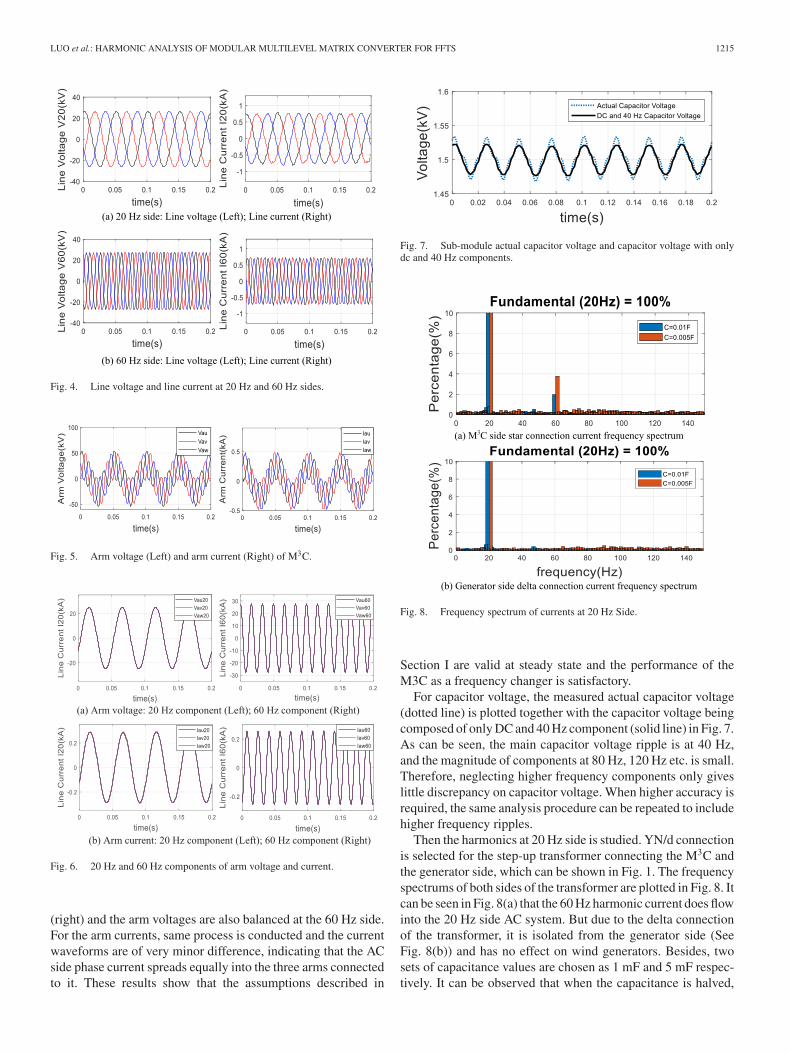
Line voltages and line currents at both generator side (20 Hz)and system side (60 Hz) are plotted in Fig. 4. It can be seenthat line voltages are perfect sinusoidal waveforms while linecurrents have small amount of harmonics. Fig. 5 shows thearm voltages and arm currents of the M3C. Both are mainlycomposed of 20 Hz and 60 Hz quantities, which can be reflectedby (7) and (8). Furthermore, the 20 Hz arm voltage componentsof au, av and aw are extracted and plotted in Fig. 6a (left). Ascan be seen, three curves are overlapped, indicating that the armvoltages are balanced at the 20 Hz side. Similarly, the 60 Hzarm voltage components of au, bu and cu are plotted in Fig. 6a
LUO et al.: HARMONIC ANALYSIS OF MODULAR MULTILEVEL MATRIX CONVERTER FOR FFTS 1215
Fig. 4. Line voltage and line current at 20 Hz and 60 Hz sides.
Fig. 5. Arm voltage (Left) and arm current (Right) of M3C.
Fig. 6. 20 Hz and 60 Hz components of arm voltage and current.
(right) and the arm voltages are also balanced at the 60 Hz side.For the arm currents, same process is conducted and the currentwaveforms are of very minor difference, indicating that the ACside phase current spreads equally into the three arms connectedto it. These results show that the assumptions described in
Fig. 7. Sub-module actual capacitor voltage and capacitor voltage with onlydc and 40 Hz components.
Fig. 8. Frequency spectrum of currents at 20 Hz Side.
Section I are valid at steady state and the performance of theM3C as a frequency changer is satisfactory.
For capacitor voltage, the measured actual capacitor voltage(dotted line) is plotted together with the capacitor voltage beingcomposed of only DC and 40 Hz component (solid line) in Fig. 7.As can be seen, the main capacitor voltage ripple is at 40 Hz,and the magnitude of components at 80 Hz, 120 Hz etc. is small.Therefore, neglecting higher frequency components only giveslittle discrepancy on capacitor voltage. When higher accuracy isrequired, the same analysis procedure can be repeated to includehigher frequency ripples.
Then the harmonics at 20 Hz side is studied. YN/d connectionis selected for the step-up transformer connecting the M3C andthe generator side, which can be shown in Fig. 1. The frequencyspectrums of both sides of the transformer are plotted in Fig. 8. Itcan be seen in Fig. 8(a) that the 60 Hz harmonic current does flowinto the 20 Hz side AC system. But due to the delta connectionof the transformer, it is isolated from the generator side (SeeFig. 8(b)) and has no effect on wind generators. Besides, twosets of capacitance values are chosen as 1 mF and 5 mF respec-tively. It can be observed that when the capacitance is halved,

1216 IEEE TRANSACTIONS ON POWER DELIVERY, VOL. 35, NO. 3, JUNE 2020
Fig. 9. Currents at 60 Hz Side.
Fig. 10. Frequency spectrum of arm current harmonics.
the harmonic current magnitude doubles. Results validate theanalysis in Section III.
On the system side, the line currents are measured and de-composed into positive-sequence currents and zero-sequencecurrent. Fig. 9 shows that the positive-sequence currents peakat 0.68 kA while the zero-sequence current peaks at 0.013 kA.The magnitude of the zero-sequence current is 2% of the basecurrents. And it agrees with the current frequency spectrum (leftbar at 60 Hz, Fig. 8(a)).
Arm harmonic current can be calculated as (iau− 13 ia− 1
3 iu).As an example, the frequency spectrum of harmonic current inarm au is plotted in Fig. 10. As is expected, the arm harmoniccurrent contains 20 Hz (circulating), 60 Hz (zero-sequence) and100 Hz (circulating) components. There is also a small amount of140 Hz component. It can be studied using the same method andincluding the higher order voltage ripples. When the capacitanceis halved, similarly, harmonic magnitudes double. Again, thesimulation result validates the theoretical analysis.
To compare the analytical formula with the simulation model,the calculated value (red) of the 40 Hz capacitor voltage rippleis plotted together with the measured ripple at 40 Hz in timedomain simulation (black) in Fig 11. As can be seen, there is agood match between the two curves and therefore the calculated
Fig. 11. Capacitor voltage 40 Hz – simulation result (black) and calculationvalue (red).
TABLE IVQUANTIZATION COMPARISON WITH SIMULATION RESULTS
value has high accuracy. In addition, the calculated values ofharmonic currents are compared with the measured values insimulation and the results are shown in Table IV. It can be seenthat the difference is only 0.001–0.002 kA. However, the valuesof harmonic currents are small so the discrepancy in percentageis around 20%. Hence, the current magnitude calculation isless accurate than the ripple voltage. Specifically, the calculated60 Hz zero-sequence current is larger since theoretical analysisneglects resistance, with the presence of which, the actual currenthas a smaller value. For the 100 Hz and 20 Hz harmonic currents,the calculated values are smaller as expected, as theoreticalanalysis does not include the higher orders of the capacitorvoltage ripple that can also lead to harmonic currents at 100 Hzand 20 Hz. For example, the 80 Hz voltage ripple interacts withthe 20 Hz component in switching function and produces 100 Hzharmonics (80 + 20), or interacts with the 60 Hz component andproduces 20 Hz harmonics (80–60).
V. SUPPRESSION OF M3C HARMONICS
M3C harmonics can be controlled using hardware or softwaresolutions. Based on the discussion in Section III, it is knownthat sub-module capacitance and arm inductance are affectingfactors of the harmonics. So, proper values of the elements canbe selected to limit the harmonics within a certain range. Adetailed analysis is conducted in this section in order to provideinstructions for capacitor and inductor values selection for theconsideration of limiting harmonics. Also, delta connectioncould be an option for the grid-connecting transformer on theoffshore side to deal with zero-sequence harmonic currents. Theabove measures are regarded as hardware methods to suppressM3C harmonics. On the other hand, an effective zero-sequencecurrent mitigation control algorithm is proposed and tested forM3C in subsection B, which is indicated as a software methodfor harmonic suppression.
LUO et al.: HARMONIC ANALYSIS OF MODULAR MULTILEVEL MATRIX CONVERTER FOR FFTS 1217
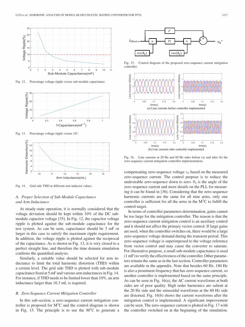
Fig. 12. Percentage voltage ripple versus sub-module capacitance.
Fig. 13. Percentage voltage ripple versus 1/C.
Fig. 14. Grid side THD at different arm inductor values.
A. Proper Selection of Sub-Module Capacitanceand Arm Inductance
At steady-state operation, it is normally considered that thevoltage deviation should be kept within 10% of the DC sub-module capacitor voltage [35]. In Fig. 12, the capacitor voltageripple is plotted against the sub-module capacitance for thetest system. As can be seen, capacitance should be 3 mF orlarger in this case to satisfy the maximum ripple requirement.In addition, the voltage ripple is plotted against the reciprocalof the capacitance. As is shown in Fig. 13, it is very closed to aperfect straight line, and therefore the time domain simulationconfirms the quantified analysis.
Similarly, a suitable value should be selected for arm in-ductance to limit the total harmonic distortion (THD) withina certain level. The grid side THD is plotted with sub-modulecapacitance fixed at 5 mF and various arm inductances in Fig. 14.For instance, if THD needs to be limited lower than 10%, an arminductance larger than 10.3 mL is required.
B. Zero-Sequence Current Mitigation Controller
In this sub-section, a zero-sequence current mitigation con-troller is proposed for M3C and the control diagram is shownin Fig. 15. The principle is to use the M3C to generate a
Fig. 15. Control diagram of the proposed zero-sequence current mitigationcontroller.
Fig. 16. Line currents at 20 Hz and 60 Hz sides before (a) and after (b) thezero-sequence current mitigation controller implementation.
compensating zero-sequence voltage v0 based on the measuredzero-sequence current. The control purpose is to reduce theundesirable zero-sequence down to zero. θ3 is the angle of thezero-sequence current and more details on the PLL for measur-ing it can be found in [36]. Considering that the zero-sequenceharmonic currents are the same for all nine arms, only onecontroller is sufficient for all the arms in the M3C to fulfill thecontrol target.
In terms of controller parameters determination, gains cannotbe too large for the mitigation controller. The reason is that thezero-sequence current mitigation control is an auxiliary controland it should not affect the primary vector control. If large gainsare used, when the controller switches on, there would be a largezero-sequence voltage demand during the transient period. Thiszero-sequence voltage is superimposed to the voltage referencefrom vector control and may cause the converter to saturate.For illustrative purpose, a small sub-module capacitance is used(1 mF) to verify the effectiveness of the controller. Other parame-ters remain the same as in the last section. Controller parametersare available in the appendix. Note that besides 60 Hz, 180 Hzis also a prominent frequency that has zero-sequence current, soanother controller is implemented based on the same principle.As can be seen in Fig. 16(a), the AC current waveforms at bothsides are of poor quality. High order harmonics are salient atthe 20 Hz side and the sinusoidal waveforms at the 60 Hz sideare distorted. Fig. 16(b) shows the current waveforms after themitigation control is implemented. A significant improvementcan be seen. The zero-sequence current is plotted in Fig. 17 withthe controller switched on at the beginning of the simulation.

1218 IEEE TRANSACTIONS ON POWER DELIVERY, VOL. 35, NO. 3, JUNE 2020
Fig. 17. Mitigation of zero-sequence current with controller switched on atthe start of simulation.
It can be seen that with small gains, it may take seconds tofully suppress the zero-sequence current. But at steady state, thezero-sequence current can be mitigated to a negligible level andthe effectiveness of the controller is verified.
VI. CONCLUSION
As M3C is the core device in a FFTS, its harmonics havea considerable influence on the overall system performance.This paper has conducted a detailed harmonic analysis for M3C.Owing to the interaction between the switching function and thearm current at multiple frequencies, capacitor voltage ripplesare induced on top of the DC voltage. It has been indicatedthat these ripples affect the arm voltages and further the armcurrents. Also, it has been found that the arm currents containharmonic components at 20 Hz, 60 Hz and 100 Hz and theyhave been analyzed respectively. The expressions of currentsfor all nine arms have been derived so that each componentcan be quantified. It has been found that several factors havelarge impact on the current harmonic magnitude, includingcapacitance, inductance and system operating frequency. Theanalysis has also revealed the nature of all the terms of theharmonic components. Some terms flow into AC systems atboth sides, some terms are cancelled out and only exist in thearms, and the others have characteristics as fundamental currentsand can be regulated by vector control. Zero-sequence compo-nents can cause instability problems, bringing risks of trippingzero-sequence protection, harmonics interaction and torsionaloscillation. Both zero-sequence and circulating components takeup current rating of the converter and have negative economicimpact. They also bring extra losses, raise thermal issues andadversely affect the operation of other devices. Delta connectionprovides isolation on zero-sequence currents. In other cases, theharmonic currents can flow into the system or the generator andcan cause a series of problems. The quantified calculation resultshave been compared with simulation results in RTDS and goodmatches have validated the theoretical analysis. Guidelines onsub-module capacitance and arm inductance have been providedto limit the capacitor voltage ripple and harmonic currents withina certain range. A zero-sequence current mitigation controller forM3C has been implemented and tested. Although the analysishas been carried out for FFTS in this paper, the procedure isgeneral and can be beneficial to M3C modelling and controlmethod development.
TABLE VMITIGATION CONTROLLER PARAMETERS
APPENDIX
A. 20 Hz Arm Current Expressions
iau20_2 = k4[m2aIasin (θ10)−m2
aIusin (θ11)
+mamuIasin (θ12)]
iav20_2 = k4[m2aIasin (θ10)−m2
aIusin (θ11 − 120)
+mamuIasin (θ12 − 120)]
iaw20_2 = k4[m2aIasin (θ10)−m2
aIusin (θ11 + 120)
+mamuIasin (θ12 + 120)]...
ibw20_2 = k4[m2aIasin (θ10 − 120)−m2
aIusin (θ11)
+mamuIasin (θ12)]...
icw20_2 = k4[m2aIasin (θ10 + 120)−m2
aIusin (θ11 − 120)
+mamuIasin (θ12 − 120)]
(A1)
where: k4 = N24LCω2
1; θ10 = ω1t+ β1; θ11 = ω1t+ β3 − 2α1;
θ12 = ω1t+ α3 − β1 − α1
iau20_3 = k4[−mumaIasin (θ13) +mumaIusin (θ14)
−m2uIasin (θ15)]
iav20_3 = k4[−mumaIasin (θ13 − 120) +mumaIusin (θ14)
−m2uIasin (θ15)]
iaw20_3 = k4[−mumaIasin (θ13 + 120) +mumaIusin (θ14)
−m2uIasin (θ15)]
...ibw20_3 = k4[−mumaIasin (θ13) +mumaIusin (θ14 − 120)
−m2uIasin (θ15 − 120)]
...icw20_3 = k4[−mumaIasin (θ13 − 120) +mumaIu
sin (θ14 + 120)−m2uIasin (θ15 + 120)]
(A2)
where: θ13 = ω1t+ α3 − α1 − β1; θ14 = ω1t+ α3 − β3 +α1; θ15 = ω1t+ β1
REFERENCES
[1] X. Xiang, M. Merlin, and T. Green, “Cost analysis and comparison ofHVac, LFac and HVdc for offshore wind power connection,” in Proc. 12thIET Int. Conf. AC DC Power Transmiss., 2016, pp. 1–6.
[2] X. Wang, “The fractional frequency transmission system,” Proc. IEEE 5thAnnu. Conf. Jpn. Power Energy, pp. 53–58, 1994.
[3] J. Ruddy, R. Meere, and T. O’Donnell, “Low frequency ac transmission foroffshore wind power: A review,” Renewable Sustain. Energy Rev., vol. 56,pp. 75–86, 2016.

LUO et al.: HARMONIC ANALYSIS OF MODULAR MULTILEVEL MATRIX CONVERTER FOR FFTS 1219
[4] CIGRE Working Group B4.55 Technical Brochure 619, “HVdc connectionof offshore wind power plants,” pp. 76–85, 2015.
[5] S. Liu et al., “Integrating offshore wind power via fractional frequencytransmission system,” IEEE Trans. Power Del., vol. 32, no. 3, pp. 1253–1261, Jun. 2017.
[6] X. Wang, X. Wei, and Y. Meng, “Experiment on grid-connection processof wind turbines in fractional frequency wind power system,” IEEE Trans.Energy Convers., vol. 30, no. 1, pp. 22–31, Mar. 2015.
[7] J. Li and X.-P. Zhang, “Small signal stability of fractional frequencytransmission system with offshore wind farms,” IEEE Trans. Sustain.Energy, vol. 7, no. 4, pp. 1538–1546, Oct. 2016.
[8] X. Wang, C. Cao, and Z. Zhou, “Experiment on fractional frequencytransmission system,” IEEE Trans. Power Syst., vol. 21, no. 1, pp. 372–377,Feb. 2006.
[9] S. Liu et al., “A decoupled control strategy of modular multilevel matrixconverter for fractional frequency transmission system,” IEEE Trans.Power Del., vol. 32, no. 4, pp. 2111–2121, Aug. 2017.
[10] R. W. Erickson and O. A. Al-Naseem, “A new family of matrix convert-ers,” in Proc. 27th Annu. Conf. IEEE Ind. Electron. Soc., vol. 2, 2001,pp. 1515–1520.
[11] W. Kawamura, M. Hagiwara, and H. Akagi, “Control and experiment ofa modular multilevel cascade converter based on triple-star bridge cells,”IEEE Trans. Ind. Appl., vol. 50, no. 5, pp. 3536–3548, Oct. 2014.
[12] W. Kawamura et al., “AC-inductors design for a modular multilevel TSBCconverter, and performance of a low-speed high-torque motor drive usingthe converter,” IEEE Trans. Ind. Appl., vol. 53, no. 5, pp. 4718–4729, Oct.2017.
[13] M. Diaz et al., “Modelling and control of the modular multilevel matrixconverter and its application to wind energy conversion systems,” in Proc.42nd Annu. Conf. IEEE Ind. Electron. Soc., 2016, pp. 5052–5057.
[14] S. Liu, M. Saeedifard, and X. Wang, “Analysis and control of the modularmultilevel matrix converter under unbalanced grid conditions,” IEEE J.Emerg. Sel. Topics Power Electron., vol. 6, no. 4, pp. 1979–1989, Dec.2018.
[15] Y. Miura et al., “Modular multilevel matrix converter for low frequency actransmission,” in Proc. IEEE 10th Int. Conf. Power Electron. Drive Syst.,2013, pp. 1079–1084.
[16] F. Kammerer, J. Kolb, and M. Braun, “Fully decoupled current control andenergy balancing of the modular multilevel matrix converter,” in Proc. 15thInt. Power Electron. Motion Control Conf., 2012, pp. LS2a. 3-1 - 3-8.
[17] P. Sun et al., “The harmonic analysis and the arm capacitor parametersselection of module multilevel matrix converter,” in Proc. IEEE PES Asia-Pacific Power Energy Eng. Conf., 2016, pp. 1617–1621.
[18] J. Ma et al., “Modular multilevel matrix converter for offshore lowfrequency ac transmission system,” in Proc. IEEE 26th Int. Symp. Ind.Electron., 2017, pp. 768–774.
[19] L. Sainz et al., “Effect of wind turbine converter control on wind powerplant harmonic response and resonances,” IET Electric Power Appl.,vol. 11, no. 2, pp. 157–168, 2017.
[20] H. Saad et al., “On resonances and harmonics in HVdc-MMC stationconnected to ac grid,” IEEE Trans. Power Del., vol. 32, no. 3, pp. 1565–1573, Jun. 2017.
[21] C. Buchhagen et al., “BorWin1 - First experiences with harmonic inter-actions in converter dominated grids,” in Proc. Int. ETG Congr., 2015,pp. 1–7.
[22] T. Li, A. M. Gole, and C. Zhao, “Harmonic instability in MMC-HVdcconverters resulting from internal dynamics,” IEEE Trans. Power Del.,vol. 31, no. 4, pp. 1738–1747, Aug. 2016.
[23] Q. Tu, Z. Xu, and L. Xu, “Reduced switching-frequency modulation andcirculating current suppression for modular multilevel converters,” IEEETrans. Power Del., vol. 26, no. 3, pp. 2009–2017, Jul. 2011.
[24] E. Ebrahimzadeh et al., “Harmonic instability source identification inlarge wind farms,” in Proc. IEEE Power Energy Soc. Gen. Meeting, 2017,pp. 1–5.
[25] N. P. Strachan and D. Jovcic, “Stability of a variable-speed permanentmagnet wind generator with weak ac grids,” IEEE Trans. Power Del.,vol. 25, no. 4, pp. 2779–2788, Oct. 2010.
[26] X. Wang, F. Blaabjerg, and W. Wu, “Modeling and analysis of harmonicstability in an ac power-electronics-based power system,” IEEE Trans.Power Electron., vol. 29, no. 12, pp. 6421–6432, Dec. 2014.
[27] W. Hu et al., “Modeling and control of zero-sequence current in multiplegrid connected converter,” in Proc. IEEE Power Electron. Spec. Conf.,2008, pp. 2064–2069.
[28] B. Gao et al., “Differential protection for an outgoing transformer of large-scale doubly fed induction generator-based wind farms,” Energies, vol. 7,no. 9, pp. 5566–5585, 2014.
[29] B. Zhang et al., “Impact of wind farm integration on relay protection (6):Analysis of distance protection for wind farm outgoing transmission line,”Electric Power Automat. Equip., vol. 6, pp. 1–6, 2013.
[30] M. Heathcote, J & P Transformer Book. New York, NY, USA: Elsevier,2011.
[31] M. Diaz et al., “Control of wind energy conversion systems based on themodular multilevel matrix converter,” IEEE Trans. Ind. Electron., vol. 64,no. 11, pp. 8799–8810, Nov. 2017.
[32] S. Elimban, Y. Zhang, and J. C. G. Alonso, “Real time simulation for HVdcgrids with modular multi-level converters,” in Proc. 11th IET Int. Conf.AC DC Power Transmiss., 2015, pp. 1–8.
[33] T. Maguire and J. Giesbrecht, “Small time-step VSC model for the real timedigital simulator,” in Proc. Int. Conf. Power System Transients, Montreal,QC, Canada, 2005, Paper IPST05-168.
[34] S. Shang et al., “Research on modeling and control strategy of modularmultilevel matrix converter supplying passive networks,” in Proc. IEEEPES Asia-Pacific Power Energy Eng. Conf., 2016, pp. 1974–1978.
[35] M. Zygmanowski, B. Grzesik, and R. Nalepa, “Capacitance and inductanceselection of the modular multilevel converter,” in Proc. 15th Eur. Conf.Power Electron. Appl., 2013, pp. 1–10.
[36] Y. Wang et al., “Open-winding power conversion systems fed by half-controlled converters,” IEEE Trans. Power Electron., vol. 28, no. 5,pp. 2427–2436, May 2013.
Jiajie Luo received the B.Eng. degrees from theHuazhong University of Science and Technology,Wuhan, China and the University of Birmingham,Birmingham, U.K., in 2015. He is currently work-ing toward the Ph.D. degree with the University ofBirmingham. He is currently working with SiemensGamesa at its Power Converter Competence Center,U.K. His research interests include renewable energyintegration, modeling, and control.
Xiao-Ping Zhang (M’95–SM’06) received theB.Eng., M.Sc., and Ph.D. degrees from SoutheastUniversity, in 1988, 1990 and 1993, respectively. Heis currently a Professor of electrical power systemswith the University of Birmingham, U.K. He is alsothe Director of Smart Grid, Birmingham Energy In-stitute and the Codirector of the Birmingham EnergyStorage Center. He has coauthored the first and secondedition of the monograph Flexible AC TransmissionSystems: Modeling and Control, (Springer in 2006and 2012). He has coauthored the book Restructured
Electric Power Systems: Analysis of Electricity Markets with Equilibrium Mod-els, (IEEE Press/Wiley in 2010). His research interests include modeling andcontrol of HVdc/FACTS, renewable energy (wind/wave) control, distributedgeneration, energy storage and power economics, etc. Mr. Zhang is advisor tothe IEEE PES U.K. and Ireland Chapter.
Ying Xue received the B.Eng. degree in electricalengineering from the Huazhong University of Scienceand Technology, Wuhan, China, and the Universityof Birmingham, Birmingham, U.K., in 2012, and thePh.D. degree in electrical engineering from the Uni-versity of Birmingham, in 2016. He is a Lecturer withthe University of Birmingham. His main research areais HVdc modeling and control.
Kanghui Gu received the B.Eng. degree in electricalengineering from the Jiangsu University of Scienceand Technology, China, in 2014. He is currently work-ing toward the Ph.D. degree in electrical engineeringwith Hohai University, Nanjing, China. He was aVisiting Student at the University of Birmingham be-tween 2017 and 2018. His research interests includemodeling and stability analysis of renewable energygeneration.
Feng Wu photographs and biographies not available at the time of publication.
Related Documents