Hardware/Software FPGA Architecture for Robotics Applications Juan Carlos Moctezuma Eugenio and Miguel Arias Estrada National Institute for Astrophysics Optics and Electronics, INAOE Street Luis Enrique Erro no.1, Puebla-Mexico [email protected] http://ccc.inaoep.mx Abstract. This work presents a Hardware/Software FPGA Robotics Architecture for applications on Mobile Robotics. A test mobile robot was built and it is based in a commercial programmable robot called Create from iRobot, also the test platform has additional components like sonars, infrared sensors and a robotic arm, these components are used to increase robot’s functionality and to show that it is feasible to build any kind of hybrid robot. The Hardware/Software Architecture is a complete Embedded System (ES). Hardware side includes processor, buses, memory and peripherals like co-processors, sensors, robotic arm, controllers, UARTs, etc., Software side includes a Linux OS with a set of libraries that performs different functionalities and to control all com- ponents in FPGA, these functions are easy-understanding for robotic programmers. The main purpose of this work is to show the advantages of using FPGAs to implement Robotics Platforms. Some of these advan- tages are parallelism, flexibility and scalability. Finally some experiments was performed to show these advantages 1 Introduction Mobile Robotics works with robots that are ables to navigate in their environ- ment with certain grade of intelligence. A mobile robot is a set of subsystems for locomotion, sensing, decision making and communication between components [1]. Since movement and behavior of these kind of robots are based on what they are sensing, a systems development that can manipulate many hardware components, communicate between them, support real-time responses and have software support for user programs are very important. On the other hand, an ES is a computer for specific purpose, these systems can be optimized since they are focus to perform special functions, reducing cost and size of the final product. The four major components of an ES are: Processor, Buses, Memory and Peripherals [2, 4]. Embedded Systems have some special features like: performance specific task, real-time requirements, interact- ing with its environment (re-actives), dedicated hardware, which be optimized, among others. These features make an ES a suitable option to implement Robotic Platforms. J. Becker et al. (Eds.): ARC 2009, LNCS 5453, pp. 27–38, 2009. c Springer-Verlag Berlin Heidelberg 2009

Welcome message from author
This document is posted to help you gain knowledge. Please leave a comment to let me know what you think about it! Share it to your friends and learn new things together.
Transcript
Hardware/Software FPGA Architecture for
Robotics Applications
Juan Carlos Moctezuma Eugenio and Miguel Arias Estrada
National Institute for Astrophysics Optics and Electronics, INAOEStreet Luis Enrique Erro no.1, Puebla-Mexico
http://ccc.inaoep.mx
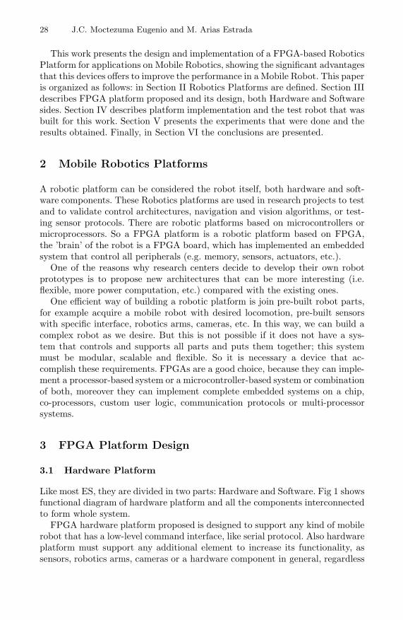
Abstract. This work presents a Hardware/Software FPGA RoboticsArchitecture for applications on Mobile Robotics. A test mobile robotwas built and it is based in a commercial programmable robot calledCreate from iRobot, also the test platform has additional componentslike sonars, infrared sensors and a robotic arm, these components areused to increase robot’s functionality and to show that it is feasible tobuild any kind of hybrid robot. The Hardware/Software Architecture isa complete Embedded System (ES). Hardware side includes processor,buses, memory and peripherals like co-processors, sensors, robotic arm,controllers, UARTs, etc., Software side includes a Linux OS with a setof libraries that performs different functionalities and to control all com-ponents in FPGA, these functions are easy-understanding for roboticprogrammers. The main purpose of this work is to show the advantagesof using FPGAs to implement Robotics Platforms. Some of these advan-tages are parallelism, flexibility and scalability. Finally some experimentswas performed to show these advantages
1 Introduction
Mobile Robotics works with robots that are ables to navigate in their environ-ment with certain grade of intelligence. A mobile robot is a set of subsystems forlocomotion, sensing, decision making and communication between components[1]. Since movement and behavior of these kind of robots are based on whatthey are sensing, a systems development that can manipulate many hardwarecomponents, communicate between them, support real-time responses and havesoftware support for user programs are very important.
On the other hand, an ES is a computer for specific purpose, these systemscan be optimized since they are focus to perform special functions, reducingcost and size of the final product. The four major components of an ES are:Processor, Buses, Memory and Peripherals [2, 4]. Embedded Systems have somespecial features like: performance specific task, real-time requirements, interact-ing with its environment (re-actives), dedicated hardware, which be optimized,among others. These features make an ES a suitable option to implement RoboticPlatforms.
J. Becker et al. (Eds.): ARC 2009, LNCS 5453, pp. 27–38, 2009.c© Springer-Verlag Berlin Heidelberg 2009
28 J.C. Moctezuma Eugenio and M. Arias Estrada
This work presents the design and implementation of a FPGA-based RoboticsPlatform for applications on Mobile Robotics, showing the significant advantagesthat this devices offers to improve the performance in a Mobile Robot. This paperis organized as follows: in Section II Robotics Platforms are defined. Section IIIdescribes FPGA platform proposed and its design, both Hardware and Softwaresides. Section IV describes platform implementation and the test robot that wasbuilt for this work. Section V presents the experiments that were done and theresults obtained. Finally, in Section VI the conclusions are presented.
2 Mobile Robotics Platforms
A robotic platform can be considered the robot itself, both hardware and soft-ware components. These Robotics platforms are used in research projects to testand to validate control architectures, navigation and vision algorithms, or test-ing sensor protocols. There are robotic platforms based on microcontrollers ormicroprocessors. So a FPGA platform is a robotic platform based on FPGA,the ’brain’ of the robot is a FPGA board, which has implemented an embeddedsystem that control all peripherals (e.g. memory, sensors, actuators, etc.).
One of the reasons why research centers decide to develop their own robotprototypes is to propose new architectures that can be more interesting (i.e.flexible, more power computation, etc.) compared with the existing ones.
One efficient way of building a robotic platform is join pre-built robot parts,for example acquire a mobile robot with desired locomotion, pre-built sensorswith specific interface, robotics arms, cameras, etc. In this way, we can build acomplex robot as we desire. But this is not possible if it does not have a sys-tem that controls and supports all parts and puts them together; this systemmust be modular, scalable and flexible. So it is necessary a device that ac-complish these requirements. FPGAs are a good choice, because they can imple-ment a processor-based system or a microcontroller-based system or combinationof both, moreover they can implement complete embedded systems on a chip,co-processors, custom user logic, communication protocols or multi-processorsystems.
3 FPGA Platform Design
3.1 Hardware Platform
Like most ES, they are divided in two parts: Hardware and Software. Fig 1 showsfunctional diagram of hardware platform and all the components interconnectedto form whole system.
FPGA hardware platform proposed is designed to support any kind of mobilerobot that has a low-level command interface, like serial protocol. Also hardwareplatform must support any additional element to increase its functionality, assensors, robotics arms, cameras or a hardware component in general, regardless
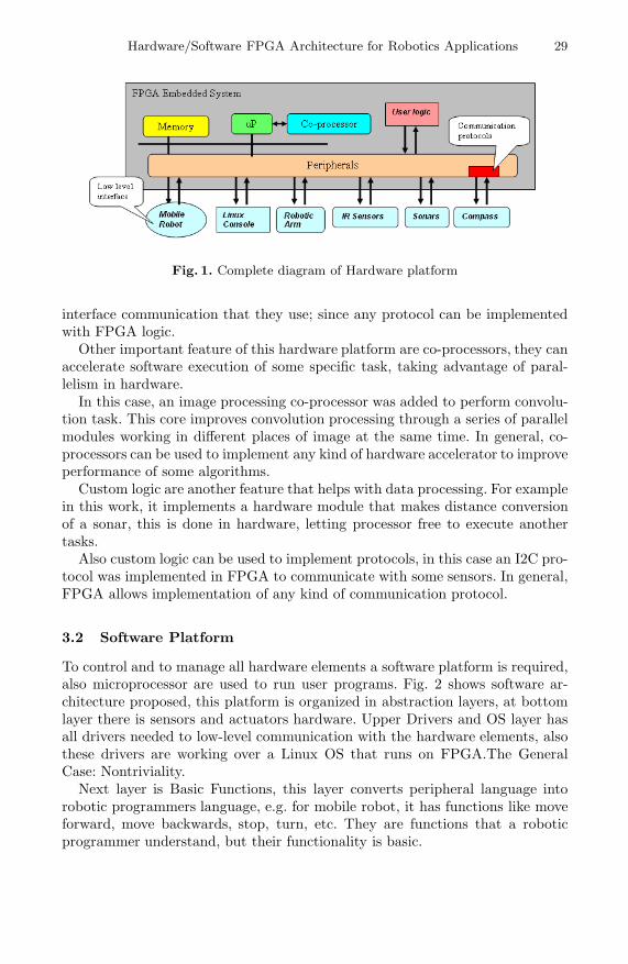
Hardware/Software FPGA Architecture for Robotics Applications 29
Fig. 1. Complete diagram of Hardware platform
interface communication that they use; since any protocol can be implementedwith FPGA logic.
Other important feature of this hardware platform are co-processors, they canaccelerate software execution of some specific task, taking advantage of paral-lelism in hardware.
In this case, an image processing co-processor was added to perform convolu-tion task. This core improves convolution processing through a series of parallelmodules working in different places of image at the same time. In general, co-processors can be used to implement any kind of hardware accelerator to improveperformance of some algorithms.
Custom logic are another feature that helps with data processing. For examplein this work, it implements a hardware module that makes distance conversionof a sonar, this is done in hardware, letting processor free to execute anothertasks.
Also custom logic can be used to implement protocols, in this case an I2C pro-tocol was implemented in FPGA to communicate with some sensors. In general,FPGA allows implementation of any kind of communication protocol.
3.2 Software Platform
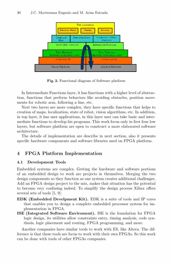
To control and to manage all hardware elements a software platform is required,also microprocessor are used to run user programs. Fig. 2 shows software ar-chitecture proposed, this platform is organized in abstraction layers, at bottomlayer there is sensors and actuators hardware. Upper Drivers and OS layer hasall drivers needed to low-level communication with the hardware elements, alsothese drivers are working over a Linux OS that runs on FPGA.The GeneralCase: Nontriviality.
Next layer is Basic Functions, this layer converts peripheral language intorobotic programmers language, e.g. for mobile robot, it has functions like moveforward, move backwards, stop, turn, etc. They are functions that a roboticprogrammer understand, but their functionality is basic.
30 J.C. Moctezuma Eugenio and M. Arias Estrada
Fig. 2. Functional diagram of Software platform
In Intermediate Functions layer, it has functions with a higher level of abstrac-tion, functions that perform behaviors like avoiding obstacles, position move-ments for robotic arm, following a line, etc.
Next two layers are more complex, they have specific functions that helps tocreation of maps, localization, state of robot, vision algorithms, etc. In addition,in top layer, it has user applications, in this layer user can take basic and inter-mediate functions to develop his programs. This work focus only in first four lowlayers, but software platform are open to construct a more elaborated softwarearchitecture.
The details of implementation are describe in next section, also it presentsspecific hardware components and software libraries used on FPGA platform.
4 FPGA Platform Implementation
4.1 Development Tools
Embedded systems are complex. Getting the hardware and software portionsof an embedded design to work are projects in themselves. Merging the twodesign components so they function as one system creates additional challenges.Add an FPGA design project to the mix, makes that situation has the potentialto become very confusing indeed. To simplify the design process Xilinx offersseveral sets of tools [5, 9]:EDK (Embedded Develpment Kit). EDK is a suite of tools and IP cores
that enables you to design a complete embedded processor system for im-plementation in FPGA.
ISE (Integrated Software Enviroment). ISE is the foundation for FPGAlogic design, its utilities allow constraints entry, timing analysis, code syn-thesis, logic placement and routing, FPGA programming, and more.
Another companies have similar tools to work with ES, like Altera. The dif-ference is that these tools are focus to work with their own FPGAs. So this workcan be done with tools of other FPGAs companies.
Hardware/Software FPGA Architecture for Robotics Applications 31
4.2 Test Robot Platform
Our Test Robot Platform consist of the following components:
Create Mobile robot. Create [10] is a programmable robot that makes trans-parent low-level mechanism for actuators and sensors, this robot has adifferential-pair locomotion with a caster wheel.
Sonars. This FPGA platform supports three different types of sonars: two chan-nels for burst and entry echo (SRF05), one channel for both burst and entryecho (PING Ultrasonic), and a sonar that works with I2C protocol (SRF02).
Compass. The CMPS03 compass operates with I2C protocol and has beenspecifically designed for use in robots as an aid to navigation.
Infrared sensors. A proximity sensor and a line tracking sensor were used forthis work. They have digital outputs.
Robotic Arm. AX-12 Smart Robotic Arm was used [12]. This arm has sevenservo motors called dynamixels, they are connected in daisy chain and workwith half-duplex serial protocol.
Image Processing Co-processor. This is an internal component of FPGAplatform. This module performs the convolution process of an image.
All these elements conform whole robotic test platform used in this work.Although it is possible to construct another different robot with any kind ofextra elements. FPGA platform has enough hardware/software resources to dothat.
4.3 Implementation Process
The implementation process consists in four principal steps: a) Hardware plat-form development, b) Software Libraries development, c) Mounting Linux OSon FPGA and d) Co-processor development.
a) Hardware Platform Development. The Hardware Platform developmentis done in EDK and it is a Microblaze-based system. Microblaze is a RISCsoft processor optimized and implemented with FPGA resources. This processoris highly configurable, it allows having a flexible architecture, and it balancesexecution performance against implementation size. By integrating one or moreMicroBlaze processors along with the right mix or peripherals on an FPGA, youcan reduce component count as well as board design complexity, reducing overallproduct cost [8]. The general process of construction in EDK is as follows:
1. Putting all hardware components (IP cores) needed for system (e.g. Proces-sor, Memory, Controllers, UARTs, Timers, General Purpose IO, etc.).
2. Connect Buses to hardware components in general level.3. Connect every signal of each component as design required and assigns I/O
signals for the system.4. Assign memory space for each peripheral, so that processor can communicate
with them.
32 J.C. Moctezuma Eugenio and M. Arias Estrada
b) Software Libraries Development. Once systems hardware has been cre-ated, next step is to create systems software (i.e. drivers, libraries, users applica-tions, etc.). Before creating any user program it is necessary generate a softwareinfrastructure to communicate with hardware. This bridge between software andhardware is called Board Support Package (BSP). BSP is a collection of files thatcontain drivers for each peripheral, libraries, I/O standard devices and othersoftware elements. Also BSP allows Linux OS mounting in hardware platform.
With respect to user applications, they can be done using BSP, i.e. usingdrivers to communicate with peripherals. In this way, it is possible to make Li-braries to control each element of test robot, building Basic and Intermediate lay-ers of fig. 2. For example, for Create robot, functions as drive forward/backward,to turn certain degrees, to stop robot, sensing bumpers, etc. For robotic arm,functions as tracking object to take it, move to an initial position, move to pickup an object, etc. And so on for remainder elements of the robot.
In total, software platform has more than 80 functions in Drivers layer andmore than 50 functions in Basic and Intermediate layers. These last 50 functionsare available to programmers to develop robotic applications.
c) Mounting Linux OS on FPGA. Linux Distribution used for this work isPetalinux [11]. PetaLinux is an uClinux port, source-based hardware and soft-ware distribution which has been developed specifically for using EmbeddedLinux on reconfigurable logic devices. The PetaLinux distribution includes ev-erything needed to easily create Linux systems running on Xilinx FPGAs. Ingeneral, to mount a Linux OS on FPGA, it needs four things:
1. Hardware platform running on FPGA.2. The BSP for hardware platform.3. The Linux Distribution (Petalinux).4. GCC Microblaze tool-chain, that includes all necessary to build uClinux
kernel on a Linux host.
d) Co-processor Development. This core was implemented on Xilinx SystemGenerator (XSG) tool [13] and the core is configurable by user through a usergraphical interface (GUI), i.e. user can choice size of image entry, size of maskconvolution and mask coefficients with an arbitrary fixed point representation.So it is possible represents any kind of mask convolution.
Two important Simulink techniques were used to implement this core: Dy-namic Blocks Generation and Masking Subsystems. So with aid of these tech-niques it is possible that the model was automatically generated when GUIparameters changes.
5 Experiments and Results
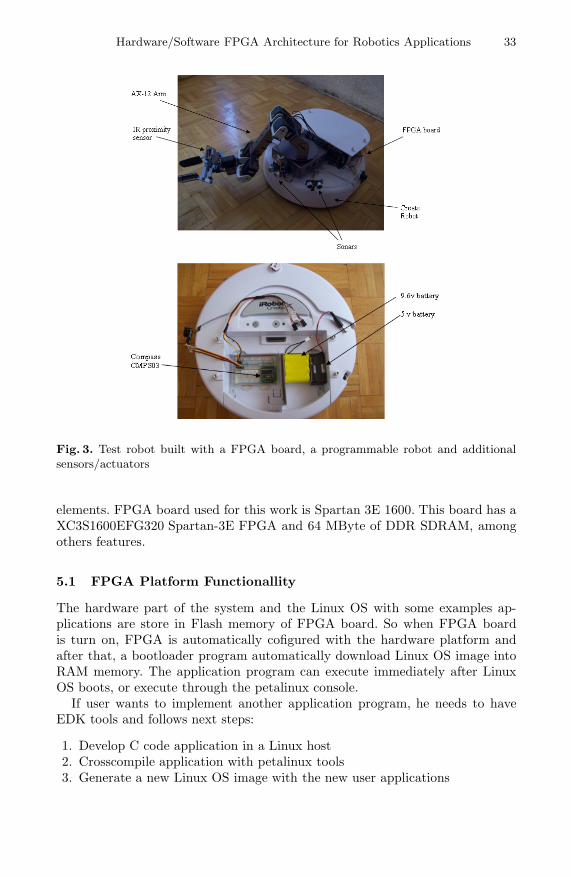
Four main experiments was development in a test environment of 3x3 me-ters. Fig. 3 shows test robot platform built for this work and its additional
Hardware/Software FPGA Architecture for Robotics Applications 33
Fig. 3. Test robot built with a FPGA board, a programmable robot and additionalsensors/actuators
elements. FPGA board used for this work is Spartan 3E 1600. This board has aXC3S1600EFG320 Spartan-3E FPGA and 64 MByte of DDR SDRAM, amongothers features.
5.1 FPGA Platform Functionallity
The hardware part of the system and the Linux OS with some examples ap-plications are store in Flash memory of FPGA board. So when FPGA boardis turn on, FPGA is automatically cofigured with the hardware platform andafter that, a bootloader program automatically download Linux OS image intoRAM memory. The application program can execute immediately after LinuxOS boots, or execute through the petalinux console.
If user wants to implement another application program, he needs to haveEDK tools and follows next steps:
1. Develop C code application in a Linux host2. Crosscompile application with petalinux tools3. Generate a new Linux OS image with the new user applications
34 J.C. Moctezuma Eugenio and M. Arias Estrada
4. Download the new Linux OS image to FPGA using EDK tools5. Now user can execute its new applications on the petalinux console
To change or add some hardware module, it needs a qualified person thatcan work with EDK tools. FPGA platform is still in development phase, so in afuture this platform will be totally functional and easy-use for the user.
5.2 Experiment 1: Protocol Implementation
CMPS03 works with I2C protocol. In this experiment, we implement an I2Cprotocol and glue it to Microblaze system. With this, it shows that it is possibleto implement communication protocols to communicate with sensors or actua-tors. EDK tools have a great variety of communication protocols, but the useralso has the option of implement a custom protocol, this gives flexibility to thesystem.
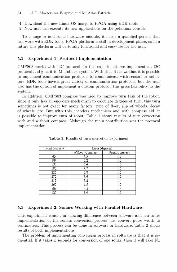
In addition, CMPS03 compass was used to improve turn task of the robot,since it only has an encoders mechanism to calculate degrees of turn, this turnsometimes is not exact for many factors: type of floor, slip of wheels, decayof wheels, etc. But with this encoders mechanism and with compass aid, itis possible to improve turn of robot. Table 1 shows results of turn correctionwith and without compass. Although the main contribution was the protocolimplementation.
Table 1. Results of turn correction experiment
5.3 Experiment 2: Sonars Working with Parallel Hardware
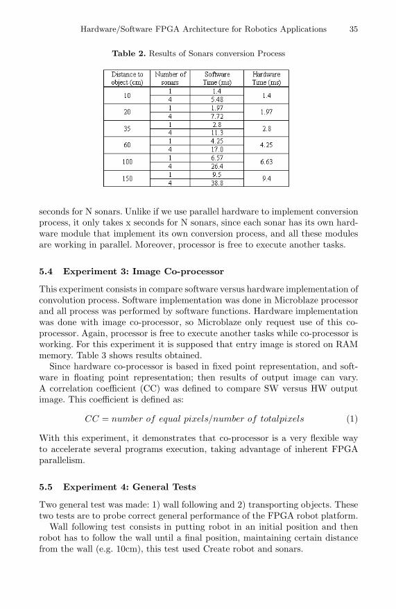
This experiment consist in showing difference between software and hardwareimplementation of the sonars conversion process, i.e. convert pulse width tocentimeters. This process can be done in software or hardware. Table 2 showsresults of both implementations.
The problem of implementing conversion process in software is that it is se-quential. If it takes x seconds for conversion of one sonar, then it will take Nx
Hardware/Software FPGA Architecture for Robotics Applications 35
Table 2. Results of Sonars conversion Process
seconds for N sonars. Unlike if we use parallel hardware to implement conversionprocess, it only takes x seconds for N sonars, since each sonar has its own hard-ware module that implement its own conversion process, and all these modulesare working in parallel. Moreover, processor is free to execute another tasks.
5.4 Experiment 3: Image Co-processor
This experiment consists in compare software versus hardware implementation ofconvolution process. Software implementation was done in Microblaze processorand all process was performed by software functions. Hardware implementationwas done with image co-processor, so Microblaze only request use of this co-processor. Again, processor is free to execute another tasks while co-processor isworking. For this experiment it is supposed that entry image is stored on RAMmemory. Table 3 shows results obtained.
Since hardware co-processor is based in fixed point representation, and soft-ware in floating point representation; then results of output image can vary.A correlation coefficient (CC) was defined to compare SW versus HW outputimage. This coefficient is defined as:
CC = number of equal pixels/number of totalpixels (1)
With this experiment, it demonstrates that co-processor is a very flexible wayto accelerate several programs execution, taking advantage of inherent FPGAparallelism.
5.5 Experiment 4: General Tests
Two general test was made: 1) wall following and 2) transporting objects. Thesetwo tests are to probe correct general performance of the FPGA robot platform.
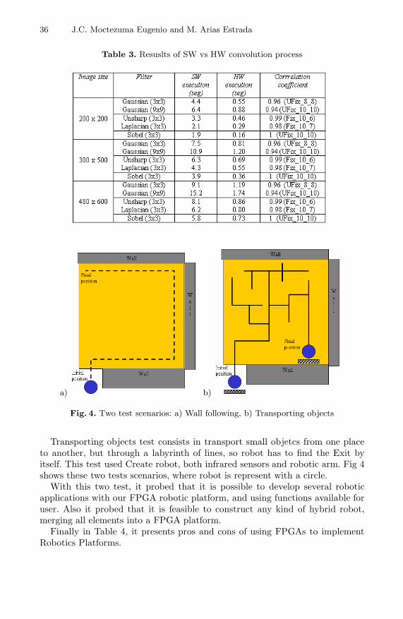
Wall following test consists in putting robot in an initial position and thenrobot has to follow the wall until a final position, maintaining certain distancefrom the wall (e.g. 10cm), this test used Create robot and sonars.
36 J.C. Moctezuma Eugenio and M. Arias Estrada
Table 3. Resuslts of SW vs HW convolution process
a) b)
Fig. 4. Two test scenarios: a) Wall following, b) Transporting objects
Transporting objects test consists in transport small objetcs from one placeto another, but through a labyrinth of lines, so robot has to find the Exit byitself. This test used Create robot, both infrared sensors and robotic arm. Fig 4shows these two tests scenarios, where robot is represent with a circle.
With this two test, it probed that it is possible to develop several roboticapplications with our FPGA robotic platform, and using functions available foruser. Also it probed that it is feasible to construct any kind of hybrid robot,merging all elements into a FPGA platform.
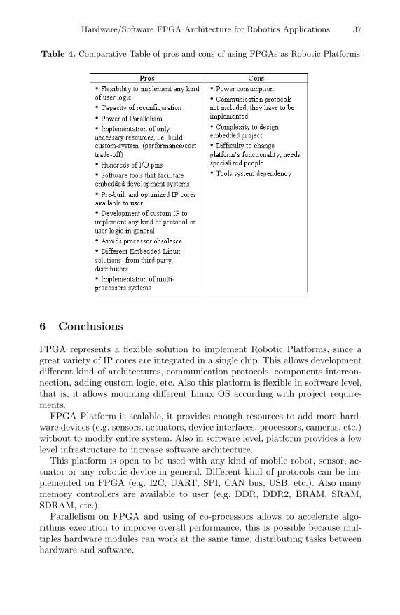
Finally in Table 4, it presents pros and cons of using FPGAs to implementRobotics Platforms.
Hardware/Software FPGA Architecture for Robotics Applications 37
Table 4. Comparative Table of pros and cons of using FPGAs as Robotic Platforms
6 Conclusions
FPGA represents a flexible solution to implement Robotic Platforms, since agreat variety of IP cores are integrated in a single chip. This allows developmentdifferent kind of architectures, communication protocols, components intercon-nection, adding custom logic, etc. Also this platform is flexible in software level,that is, it allows mounting different Linux OS according with project require-ments.
FPGA Platform is scalable, it provides enough resources to add more hard-ware devices (e.g. sensors, actuators, device interfaces, processors, cameras, etc.)without to modify entire system. Also in software level, platform provides a lowlevel infrastructure to increase software architecture.
This platform is open to be used with any kind of mobile robot, sensor, ac-tuator or any robotic device in general. Different kind of protocols can be im-plemented on FPGA (e.g. I2C, UART, SPI, CAN bus, USB, etc.). Also manymemory controllers are available to user (e.g. DDR, DDR2, BRAM, SRAM,SDRAM, etc.).
Parallelism on FPGA and using of co-processors allows to accelerate algo-rithms execution to improve overall performance, this is possible because mul-tiples hardware modules can work at the same time, distributing tasks betweenhardware and software.
38 J.C. Moctezuma Eugenio and M. Arias Estrada
Using embedded Linux OS is a good choice, since this kind of OS provideswell-known features like reliable, efficiency and stability. Moreover, it is a familiarenvironment for Linux programmers.
Reconfiguration on FPGA is a good feature because it allow to implementdifferent kind of hardware/software architectures on the same chip for a widevariety of mobile robots, sensors and actuators. Also dynamic reconfigurationallows re-programming FPGA in execution time. So we can implement differenthardware depending of what robot is sensing, all this when robot is running.
Programmability of FPGA platform with software tools reduce developmenttime of the system and facilities modification of platform if user has a goodknowledge of the tools.
References
1. Gregory, D., Michael, J.: Computacional Principles of Mobile Robotics, 1st edn.Cambridge University Press, Cambridge (2000)
2. Thomas, B.: Embedded Robotics: Mobile Robot Design and Applications withEmbedded Systems, 2nd edn. Springer, Heidelberg (2006)
3. Qing, L., Carolyn, L.: Real Time Concepts for Embedded Systems. CMP Books(2003)
4. Caas Jose, M., Vicente, M., Rodrigo, M.: Programacion de Robots Moviles, Uni-versidad Rey Juan Carlos, Espana, Instituto Nacional de Astrofisica Optica y Elec-tronica, Mexico (2004)
5. Xilinx Company: EDK Concepts, Tools and Techniques: A Hands-on Guide toEffective Embedded System Design, Version 9.1i (2007)
6. Davis, D., Beeravolu, S., Jaganathan, R.: Hardware/Software Codesign for plat-forms FPGA, Xilinx Inc. (2005)
7. Xilinx Company, XAPP529: Connecting Customized IP to the Microblaze SoftProcessor Using the Fast Simplex Link (FSL) Channel (2004)
8. Xilinx Company: MicroBlaze Processor Reference Guide, UG081 ver 7.0 (2007)9. Xilinx website (July 2008), http://www.xilinx.com
10. Creates from iRobot website (March 2008), http://www.irobot.com/create11. Petalinux from Petalogix website (March 2008), http://www.petalogix.com12. AX-12 Smart Robotic Arm from CrustCrawler website (March 2008),
http://www.crustcrawler.com
13. Xilinx System Generator Design Tool website (May 2008),http://www.xilinx.com/ise/optionalprod/systemgenerator.htm
Related Documents