HARDWARE MANUAL FX1N SERIES PROGRAMMABLE CONTROLLERS

Welcome message from author
This document is posted to help you gain knowledge. Please leave a comment to let me know what you think about it! Share it to your friends and learn new things together.
Transcript

HARDWARE MANUAL
FX1N SERIES PROGRAMMABLE CONTROLLERS
FX1N Series Programmable Controllers
Foreword
• This manual contains text, diagrams and explanations which will guide the reader in the correct installationand operation of the FX1N Series Programmable Controllers. It should be read and understood beforeattempting to install or use the unit.
• Further information can be found in the FX Series Programming Manual II.
• If in doubt at any stage of the installation of an FX1N Series Programmable Controller always consult aprofessional electrical engineer who is qualified and trained to the local and national standards which apply tothe installation site.
• If in doubt about the operation or use of FX1N Series Programmable Controller please consult the nearestMitsubisi Electric distributor.
• This manual is subject to change without notice.
i
FX1N Series Programmable Controllers
Hardware Manual
FX1N Series Programmable Controllers
Manual number : JY992D89301
Manual revision :D
Date : December 2000

FX1N Series Programmable Controllers
ii
f the FX1N.
e of the FX1N. The manual hasThe definition of such a person
n and construction of automaticnual should be of a competentstandards required to fulfill thatpects of safety with regards to
competent nature, trained andfulfill that job. These engineersf the completed product. Thisd documentation for the saidrdance with established safety
d to use that product in a safesafety practices. The operatorsnected with the actual operation
arty constructed device whichal.
Guidelines for the safety of the user and protection o
This manual provides information for the installation and usbeen written to be used by trained and competent personnel.or persons is as follows;
a) Any engineer who is responsible for the planning, desigequipment using the product associated with this manature, (trained and qualified to the local and nationalrole). These engineers should be fully aware of all asautomated equipment.
b) Any commissioning or service engineer must be of aqualified to the local and national standards required toshould also be trained in the use and maintenance oincludes being completely familiar with all associateproduct. All maintenance should be carried out in accopractices.
c) All operators of the completed product should be traineand co-ordinated manner in compliance to establishedshould also be familiar with documentation which is conof the completed equipment.
Note : The term ‘completed equipment’ refers to a third pcontains or uses the product associated with this manu
FX1N Series Programmable Controllers
iii
ill be used to highlight points ofafety and protect the integrity ofncountered, its associated notewill now be listed with a brief
d property damage.
physical and property damage.
nt of software.
ftware element should be aware
Note’s on the symbols used in this manual
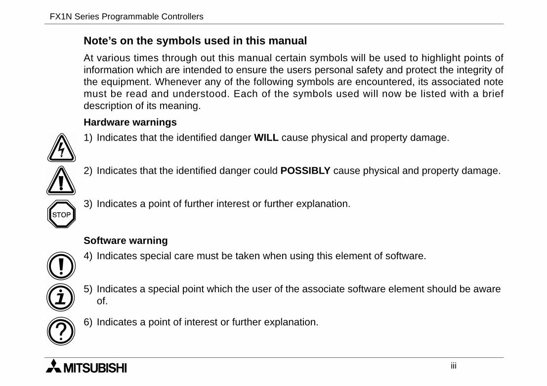
At various times through out this manual certain symbols winformation which are intended to ensure the users personal sthe equipment. Whenever any of the following symbols are emust be read and understood. Each of the symbols useddescription of its meaning.
Hardware warnings
Software warning
1) Indicates that the identified danger WILL cause physical an
2) Indicates that the identified danger could POSSIBLY cause
3) Indicates a point of further interest or further explanation.
4) Indicates special care must be taken when using this eleme
5) Indicates a special point which the user of the associate soof.
6) Indicates a point of interest or further explanation.

FX1N Series Programmable Controllers
iv
liable or responsible for anyallation or use of this equipment.
intended only as an aid tosubishi Electric will accept nollustrative examples.
his equipment, you must satisfy
material for the correct operation
Description
nual for FX1S, FX1N, FX2N andrammable Logic Controllers
g the RS422 interface board
g the RS485 interface board
g the RS232 interface board
g the variable potentiometer input
g the special adapter board
g the display module 5DM
• Under no circumstances will Mitsubishi Electric beconsequential damage that may arise as a result of the inst
• All examples and diagrams shown in this manual areunderstanding the text, not to guarantee operation. Mitresponsibility for actual use of the product based on these i
• Owing to the very great variety in possible application of tyourself as to its suitability for your specific application.
Associated Manuals
The following manuals are recomended as esential referenceof a FX1N series Programmable Logic controller.
Manual Name Manual Number
FX Programming Manual II JY992D88101 Programming maFX2NC series Prog
FX1N-422-BD Users JY992D84101 Instruction regardin
FX1N-485-BD Users JY992D84201 Instruction regardin
FX1N-232-BD Users JY992D84401 Instruction regardin
FX1N-8AV-BD JY992D84601 Instruction regardinboard
FX1N-CNV-BD JY992D84701 Instruction regardin
FX1N-5DM Users JY992D84901 Instruction regardin

v
................................ii
................................1-1...................................... 1-6...................................... 1-7...................................... 1-8...................................... 1-9........................................ 1-11........................................ 1-13.................................... 1-14
................................2-1...................................... 2-1...................................... 2-3...................................... 2-6
FX1N Series Programmable Controllers
Table of Contents
Guideline ..............................................................
1. Introduction............................................................1.1 World Specification. .......................................................1.2 Model Name ..................................................................1.3 Serial Numbers .............................................................1.4 Configuration .................................................................
1.4.1 Input/Output Points and Current Consumption ...............1.4.2 Rules of Expansion .........................................................
1.5 EEPROM Back up Data ................................................
2. Terminal layouts ....................................................2.1 AC Powered Main Units ................................................2.2 DC Powered Main Units ................................................2.3 FX2N and FX0N Extension blocks .................................
FX1N Series Programmable Controllers
vi
................................3-1...................................... 3-2...................................... 3-4...................................... 3-5...................................... 3-6...................................... 3-7...................................... 3-8.................................... 3-10.................................... 3-11.................................... 3-12........................................ 3-12........................................ 3-13
................................4-1...................................... 4-1...................................... 4-1...................................... 4-1...................................... 4-2...................................... 4-3.......................................... 4-3.......................................... 4-4...................................... 4-6...................................... 4-6
3. Installation Notes...................................................3.1 Product Outline..............................................................3.2 FX1N RUN/STOP Control ..............................................3.3 General Specifications...................................................3.4 PLC Mounting Arrangements ........................................3.5 DIN Rail Mounting .........................................................3.6 Direct Mounting ............................................................3.7 Termination at Screw Terminals ....................................3.8 Wiring Techniques.........................................................3.9 Installing Optional Units .................................................
3.9.1 Special Function Boards .................................................3.9.2 FX1N-5DM Display Module .............................................
4. Power Supply ........................................................4.1 Wiring Techniques.........................................................4.2 Wiring Cautions .............................................................4.3 Power Supply ................................................................4.4 Power Requirements ....................................................4.5 Example Wiring .............................................................
4.5.1 AC Power supply.............................................................4.5.2 DC Power supply.............................................................
4.6 Service Power supply ....................................................4.7 Earthing / Grounding .....................................................
FX1N Series Programmable Controllers
vii
................................5-1...................................... 5-1.......................................... 5-2.......................................... 5-3.......................................... 5-4.......................................... 5-5...................................... 5-6.......................................... 5-6.......................................... 5-7
................................6-1...................................... 6-1.......................................... 6-2.......................................... 6-3.......................................... 6-3........................................... 6-4.......................................... 6-4...................................... 6-5
5. Inputs.....................................................................5.1 24V DC input Specifications ..........................................
5.1.1 Typical Wiring..................................................................5.1.2 Input Circuit Connection ..................................................5.1.3 Diodes and Inputs Connected in Series ..........................5.1.4 Resistors and Inputs Connected in Parallel ....................
5.2 AC110V Input Extension Block......................................5.2.1 Input Circuit Connection ..................................................5.2.2 Programming Caution .....................................................
6. Outputs..................................................................6.1 Output Specifications.....................................................
6.1.1 Relay Output Example ....................................................6.1.2 Reliability Tests ...............................................................6.1.3 Response Times .............................................................6.1.4 Transistor Output Example.............................................6.1.5 Japanese Model Transistor Output .................................
6.2 Applying Safe Loads......................................................
FX1N Series Programmable Controllers
viii
................................7-1...................................... 7-1...................................... 7-2...................................... 7-3...................................... 7-3...................................... 7-4...................................... 7-5...................................... 7-6...................................... 7-7...................................... 7-8.................................... 7-11
7. Diagnostics............................................................7.1 Preliminary Checks........................................................7.2 ERROR LED ON (CPU ERROR) ..................................7.3 Common Errors .............................................................7.4 Maintenance ..................................................................7.5 Operation and Error Flags .............................................7.6 PLC Status Registers ...................................................7.7 Error Registers ..............................................................7.8 Error Codes ...................................................................7.9 Instruction List ...............................................................7.10 Device List ....................................................................
FX1N Series Programmable Controllers Introduction 1.
1 INTRODUCTION
2 TERMINAL LAYOUTS
3 INSTALLATION NOTES
4 POWER SUPPLY
5 INPUTS
6 OUTPUTS
7 DIAGNOSTICS

FX1N Series Programmable Controllers Introduction 1.
Introduction 1.
1-1
the FX1N Series Programmable
RY
DIMENSIONSmm (inches)
WEIGHTkg (lbs)
0
z
90(3.6)
90(3.5)
75(3.0)
0.45(0.99)
90(3.6)
0.45(0.99)
130(5.2)
0.65(1.44)
175(7.0)
0.80(1.77)
C
C
90(3.6)
90(3.5)
75(3.0)
0.45(0.99)
90(3.6)
0.45(0.99)
130(5.2)
0.65(1.44)
175(7.0)
0.80(1.77)
FX1N Series Programmable Controllers
1. Introduction
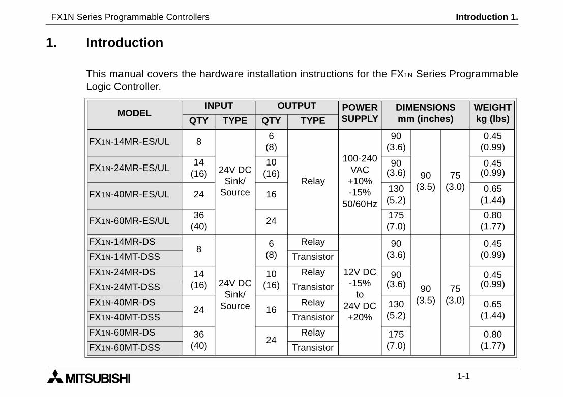
This manual covers the hardware installation instructions forLogic Controller.
MODELINPUT OUTPUT POWE
SUPPLQTY TYPE QTY TYPE
FX1N-14MR-ES/UL 8
24V DCSink/
Source
6(8)
Relay
100-24VAC
+10%-15%
50/60H
FX1N-24MR-ES/UL14
(16)10
(16)
FX1N-40MR-ES/UL 24 16
FX1N-60MR-ES/UL36
(40)24
FX1N-14MR-DS8
24V DCSink/
Source
6(8)
Relay
12V D-15%
to24V D+20%
FX1N-14MT-DSS Transistor
FX1N-24MR-DS 14(16)
10(16)
Relay
FX1N-24MT-DSS Transistor
FX1N-40MR-DS24 16
Relay
FX1N-40MT-DSS Transistor
FX1N-60MR-DS 36(40)
24Relay
FX1N-60MT-DSS Transistor

FX1N Series Programmable Controllers Introduction 1.
1-2
nt.
.95’’)8 (0.31’’)
DIN railmountingslot
UNITS: mm (inches)
Main unit outlinePlease see the previous page for each units width measureme
N X14
24V Y7
Y6Y0
FX1N 24M R
X0 X2
X1 X3 X5
X4
X7
X6
X11
X10
S/S X13
X12
X15
L
0V
Y11COM 2 COM 4
Y10Y5
Y4
Y2Y1
COM 0 COM 1 COM 3
Y3
POW ER
ERROR
IN
OUT
0 1 2 3
0 1 2 3
RUN
4 5 6 7
4 5 6 7
1110
131110 12
14 15
W
W - 8 (0.31’’)
82 (
3.20
’’)
90 (
3.54
’’)
75 (2
2 - 4.5 (0.18’’)

FX1N Series Programmable Controllers Introduction 1.
1-3
YDIMENSIONSmm (inches)
WEIGHTkg (lbs)
z 150(5.9)
90(3.5)
87(3.4)
0.75(1.65)
z
150(5.9)
0.65(1.4)
182(7.2)
0.85(1.9)
z220(8.7)
1.00(2.2)
Powered Extension units
MODELINPUT OUTPUT POWER
SUPPLQTY TYPE QTY DEVICE
FX0N-40ER-ES/UL 24
24V DCSink /Source
16 Relay
100-240VAC+10%,-15%
50/60H
FX0N-40ET-DSS 24 16 Transistor(Source)
24VDC+20%-15%FX0N-40ER-DS 24 16 Relay
FX2N-32ER-ES/UL 16 16 Relay 100-240VAC+10%,-15%
50/60H
FX2N-32ET-ESS/UL 16 16 Transistor(Source)
FX2N-48ER-ES/UL 24 24 Relay
FX2N-48ET-ESS/UL 24 24 Transistor(Source)
100-240VAC+10%,-15%
50/60HFX2N-48ER-UA1/UL 24 110VAC 24 Relay

FX1N Series Programmable Controllers Introduction 1.
1-4
DIMENSIONSmm (inches)
MASS(WEIGHT)kg (lbs)
43(1.7)
90(3.5)
87(3.4)
0.2(0.44)
70(2.8)
0.3(0.66)
40(1.6)
90(3.5)
87(3.4)
0.3(0.66)
Extension blocks
MODELINPUT OUTPUT
QTY TYPE QTY DEVICE TYPE
FX0N-8EX-UA1/UL 8110V AC
inputs- - -
FX0N-8EX-ES/UL 8 24V DCSink/
Source
- - -
FX0N-8ER-ES/UL 4 4Relay
-
FX0N-8EYR-ES/UL - - 8 -
FX0N-8EYT-ESS/UL - - 8 Transistor Source
FX0N-16EX-ES/UL 1624V DC
Sink/Source
- - -
FX0N-16EYR-ES/UL - - 16 Relay -
FX0N-16EYT-ESS/UL - - 16 Transistor Source
FX2N-16EX-ES/UL 1624V DC
Sink/Source
- - -
FX2N-16EYR-ES/UL - - 16 Relay -
FX2N-16EYT-ESS/UL - - 16 Transistor Source
FX1N Series Programmable Controllers Introduction 1.
1-5
PLYDIMENSIONSmm (inches)
MASS(WEIGHT)kg (lbs)ernal
V DC
mA*1 43(1.7)
90(3.5)
87(3.4)
0.2(0.44)mA*1
0mA
55(2.1) 0.3(0.66)
5mA
mA
0mA
0mA43
(1.7)
0.2(0.44)
mA 0.5(1.1)
mA*1 43(1.7)
87(3.4) 0.2(0.44)
mA 75(3.0)
75(3.0) 0.3(0.66)
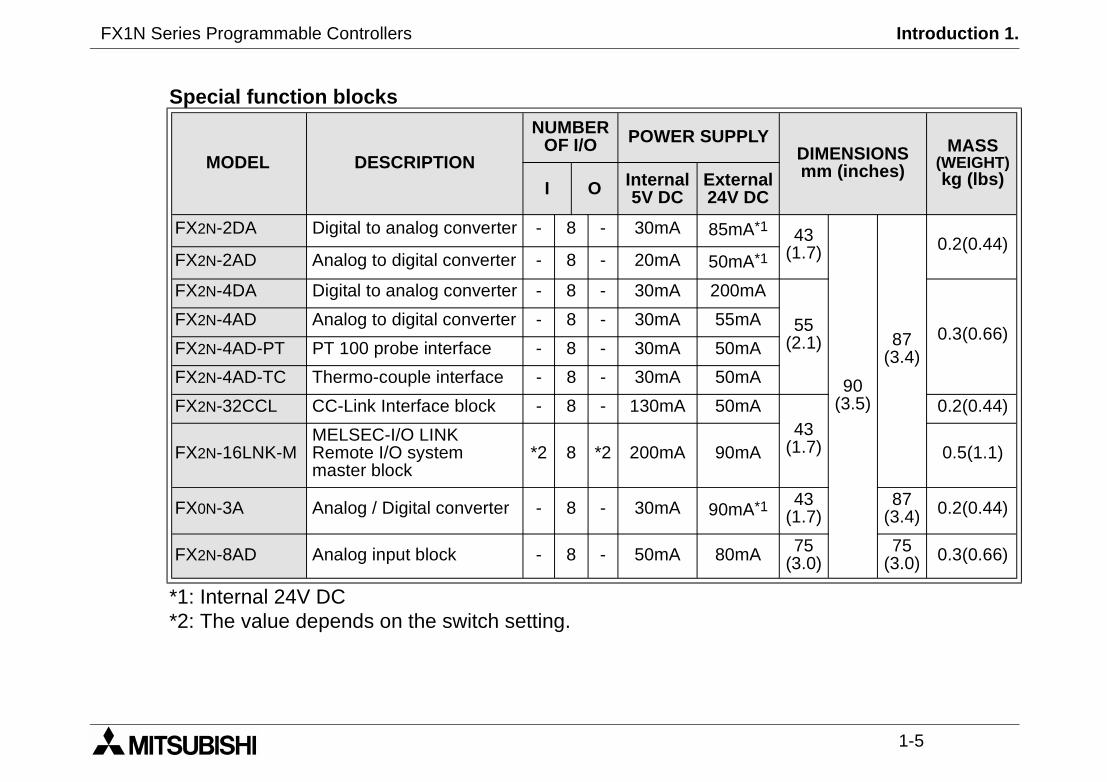
*1: Internal 24V DC*2: The value depends on the switch setting.
Special function blocks
MODEL DESCRIPTION
NUMBEROF I/O POWER SUP
I O Internal5V DC
Ext24
FX2N-2DA Digital to analog converter - 8 - 30mA 85
FX2N-2AD Analog to digital converter - 8 - 20mA 50
FX2N-4DA Digital to analog converter - 8 - 30mA 20
FX2N-4AD Analog to digital converter - 8 - 30mA 5
FX2N-4AD-PT PT 100 probe interface - 8 - 30mA 50
FX2N-4AD-TC Thermo-couple interface - 8 - 30mA 5
FX2N-32CCL CC-Link Interface block - 8 - 130mA 5
FX2N-16LNK-MMELSEC-I/O LINKRemote I/O systemmaster block
*2 8 *2 200mA 90
FX0N-3A Analog / Digital converter - 8 - 30mA 90
FX2N-8AD Analog input block - 8 - 50mA 80

FX1N Series Programmable Controllers Introduction 1.
1-6
1.1 World Specification.
InputSink / Source
World spec models : SINK / SOURCE.Japanese models : ALWAYS SINK.
OutputsTransistor
World spec models : ALWAYS SOURCE.Japanese models : ALWAYS SINK.
FX1N Series Programmable Controllers Introduction 1.
1-7
ed official UL certification.
.
e spec.
e spec.
ec, CE & UL registered *1.
pec. DC source transistor, CE & UL.
e spec.
pec, CE registered.
spec. DC source transistor, CE
upply, AC inputs, CE registered. *2
d
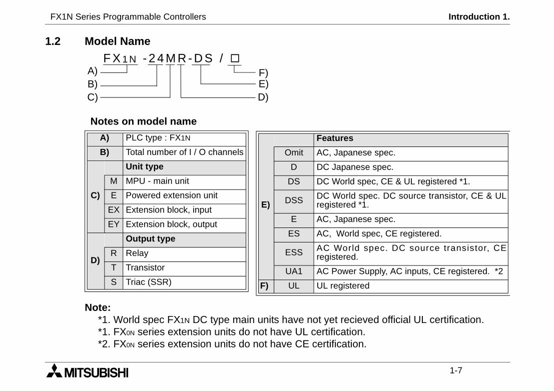
1.2 Model Name
Notes on model name
Note:*1. World spec FX1N DC type main units have not yet reciev*1. FX0N series extension units do not have UL certification.*2. FX0N series extension units do not have CE certification
F X 1 N - 2 4 M R - D S /
C)
A)B) E)
D)
F)
A) PLC type : FX1N
B) Total number of I / O channels
C)
Unit type
M MPU - main unit
E Powered extension unit
EX Extension block, input
EY Extension block, output
D)
Output type
R Relay
T Transistor
S Triac (SSR)
E)
Features
Omit AC, Japanes
D DC Japanes
DS DC World sp
DSS DC World sregistered *1
E AC, Japanes
ES AC, World s
ESS AC Worldregistered.
UA1 AC Power S
F) UL UL registere
FX1N Series Programmable Controllers Introduction 1.
1-8
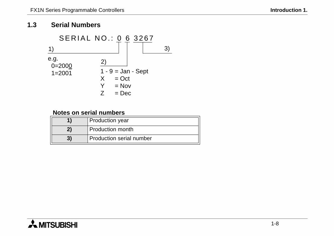
1.3 Serial Numbers
Notes on serial numbers1) Production year
2) Production month
3) Production serial number
S E R I A L N O . : 0 6 3 2 6 73)1)
2)e.g.0=20001=2001 1 - 9 = Jan - Sept
X = OctY = NovZ = Dec

FX1N Series Programmable Controllers Introduction 1.
1-9
G
J
FX2N-16EX-ES/ULFX2N-16EYR-ES/ULFX2N-16EYT-ESS/UL
FX0N-8EX-ES/ULFX0N-8EX-UA1/ULFX0N-8ER-ES/ULFX0N-8EYR-ES/ULFX0N-8EYT-ESS/ULFX0N-16EX-ES/ULFX0N-16EYR-ES/ULFX0N-16EYT-ESS/UL
K
FX2N-2DAFX2N-4DAFX2N-2ADFX2N-4ADFX2N-4AD-PTFX2N-4AD-TCFX2N-32CCLFX2N-16LNK-MFX0N-3A
I
L
LULL
/ULUL
FX2N-8AD
1.4 Configuration
Schematic system
B
FX1N-5DMFX1N-EEPROM-8L
FX1N-14MR-ES/ULFX1N-24MR-ES/ULFX1N-40MR-ES/ULFX1N-60MR-ES/ULFX1N-14MT-DSSFX1N-24MT-DSSFX1N-40MT-DSSFX1N-60MT-DSS
FX1N-232-BDFX1N-422-BDFX1N-485-BDFX1N-CNV-BDFX1N-8AV-BD
A
C
1
2
3
D
RS 422/RS 232 CONVERTERFX-232AW(C)
FX-10DU-E FX-40DU-ESFX-20DU-E FX-40DU-TK -ESFX-25DU-E FX-50DU-TKS-EFX-30DU-E
F930GOT F940GOTFX-10DM-E
F
FX-10P-E FX-20P-EH
MELSEC MEDOCFX-PCS/AT-EEMELSEC MEDOC PLUSFX-PCS/WIN-E
E
FXON-232ADP*FXON-485ADP**used withFX1N-CNV-BD
1
FX0N-40ER-ES/UFX0N-40ET-DSSFX0N-40ER-DSFX2N-32ER-ES/UFX2N-32ET-ESS/FX2N-48ER-ES/U
4
FX2N-48ER-UA1FX2N-48ET-ESS/
FX1N-14MR-DSFX1N-24MR-DSFX1N-40MR-DSFX1N-60MR-DS
GX Developer
FX1N Series Programmable Controllers Introduction 1.
1-10
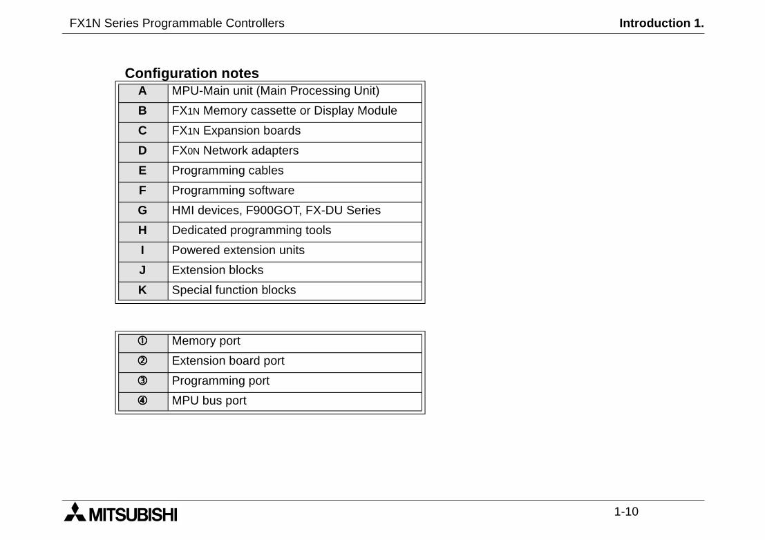
Configuration notesA MPU-Main unit (Main Processing Unit)
B FX1N Memory cassette or Display Module
C FX1N Expansion boards
D FX0N Network adapters
E Programming cables
F Programming software
G HMI devices, F900GOT, FX-DU Series
H Dedicated programming tools
I Powered extension units
J Extension blocks
K Special function blocks
Memory port
Extension board port
Programming port
MPU bus port
FX1N Series Programmable Controllers Introduction 1.
1-11
s types of FX series extensiontion block current consumption.
k should occupy 16 input/output
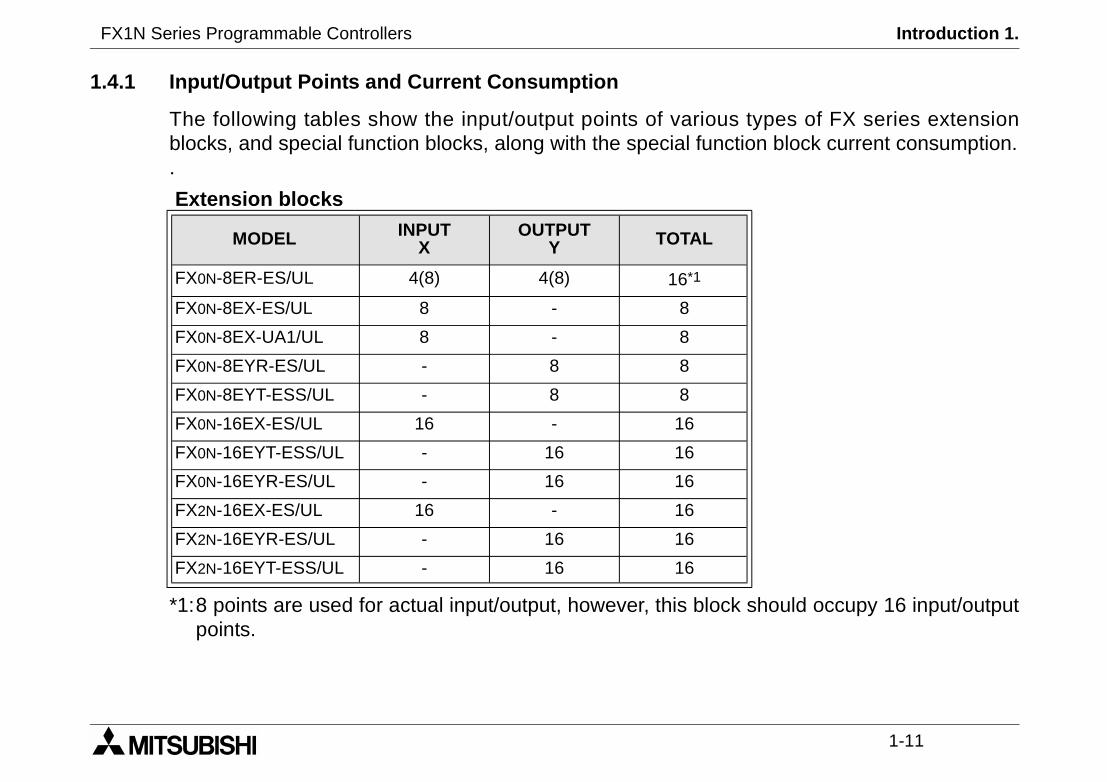
1.4.1 Input/Output Points and Current Consumption
The following tables show the input/output points of varioublocks, and special function blocks, along with the special func.
*1:8 points are used for actual input/output, however, this blocpoints.
Extension blocks
MODEL INPUTX
OUTPUTY TOTAL
FX0N-8ER-ES/UL 4(8) 4(8) 16*1
FX0N-8EX-ES/UL 8 - 8
FX0N-8EX-UA1/UL 8 - 8
FX0N-8EYR-ES/UL - 8 8
FX0N-8EYT-ESS/UL - 8 8
FX0N-16EX-ES/UL 16 - 16
FX0N-16EYT-ESS/UL - 16 16
FX0N-16EYR-ES/UL - 16 16
FX2N-16EX-ES/UL 16 - 16
FX2N-16EYR-ES/UL - 16 16
FX2N-16EYT-ESS/UL - 16 16
FX1N Series Programmable Controllers Introduction 1.
1-12
OUTPUTY TOTAL
- 8
8 16
- 8
- 8
- 8
- 8
- 8
- 8
- 8
- 8
*2 *2
- -
- -
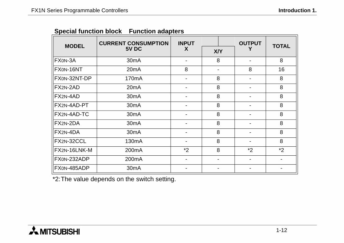
*2:The value depends on the switch setting.
Special function block Function adapters
MODEL CURRENT CONSUMPTION5V DC
INPUTX X/Y
FX0N-3A 30mA - 8
FX0N-16NT 20mA 8 -
FX0N-32NT-DP 170mA - 8
FX2N-2AD 20mA - 8
FX2N-4AD 30mA - 8
FX2N-4AD-PT 30mA - 8
FX2N-4AD-TC 30mA - 8
FX2N-2DA 30mA - 8
FX2N-4DA 30mA - 8
FX2N-32CCL 130mA - 8
FX2N-16LNK-M 200mA *2 8
FX0N-232ADP 200mA - -
FX0N-485ADP 30mA - -

FX1N Series Programmable Controllers Introduction 1.
1-13
s or upto 32 points of I/O whenfunction blocks when used ined FX1N can be expanded by 8extension unit (2+6).
pecial function blocks.
f less than 24VDC -15% (20.4Vlocks or extension units.f I/O.
1.4.2 Rules of Expansion
The FX1N Series can be expanded by 2 special function blockused on its own. It can also be expanded by 4 specialconjunction with an FX0N extension unit (2+2). An AC powerspecial function blocks when used in conjunction with an FX2N
The maximum for an FX1N system is 128 points of I/O and 8 s
If a DC powered main unit is being used with a power supply oDC or less) it cannot be expanded by using special function bIt can however accomodate a maximum additional 32 points o

FX1N Series Programmable Controllers Introduction 1.
1-14
wn, before the data is lost.
um of 10 days, and requires 30
quires backup of more than 10
1.5 EEPROM Back up Data
FX1N existing data will be kept for 5 minutes during power do
The capacitor backed memory will retain programs for a maximminutes to recharge upon power up.
Note: The FX1N does not have battery backup, if a system redays, a peripheral backup power source must be provided.

FX1N Series Programmable Controllers Terminal layouts 2.
1 INTRODUCTION
2 TERMINAL LAYOUTS
3 INSTALLATION NOTES
4 POWER SUPPLY
5 INPUTS
6 OUTPUTS
7 DIAGNOSTICS
FX1N Series Programmable Controllers Terminal layouts 2.
Terminal layouts 2.
2-1
X1N product range.d to aid the creation of wiring
X4
24MR-ES/UL
X5
Y2 Y3
X32
COM3M2
X7X6
Y5COM4
X12X13X11
X10X15
X14
Y6Y4
Y10Y7 Y11
FX1N Series Programmable Controllers
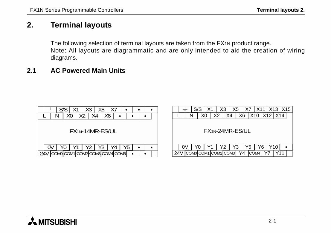
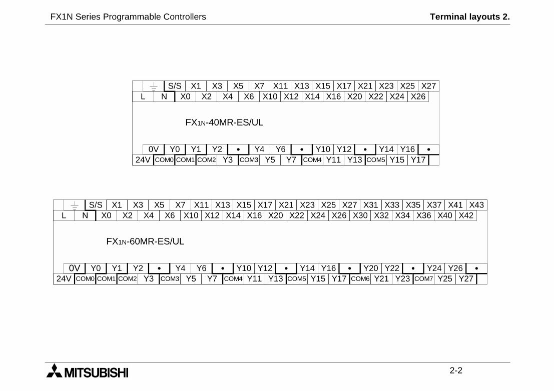
2. Terminal layouts
The following selection of terminal layouts are taken from the FNote: All layouts are diagrammatic and are only intendediagrams.
2.1 AC Powered Main Units
S/S X1N X0 X4
FX1N-14MR-ES/UL
X5
0V Y0 Y1 Y2 Y3
X3X2
24V COM0 COM1 COM3COM2
LX7
X6
Y4COM4 COM5
Y5
S/S X1N X0
FX1N-
0V Y0 Y1
X
24V COM0 COM1 CO
L
FX1N Series Programmable Controllers Terminal layouts 2.
2-2
Y14
21 X23X22 X24
X25X26
X27
COM5
Y16Y15 Y17
X310 X32
X33X34
X35X40
X41X42
X43
Y20 Y22Y21 Y236
Y24 Y26Y25 Y27COM7
X36X37
S/S X1N X0 X4
FX1N-40MR-ES/UL
X5
0V Y0 Y1 Y2Y3
X3X2
24V COM0 COM1 COM3COM2
LX7
X6
Y5 COM4
X12X13X11
X10X15
X14
Y6Y4Y7 Y11
X20XX17
X16
Y10 Y12Y13
S/S X1N X0 X4
FX1N-60MR-ES/UL
X5
0V Y0 Y1 Y2Y3
X3X2
24V COM0 COM1 COM3COM2
LX7
X6
Y5 COM4
X12X13X11
X10X15
X14
Y6Y4 Y14Y7 Y11
X20X21X17
X16X23
X22 X24X25
X26X27
Y10 Y12Y13 COM5
Y16Y15 Y17
X3
COM
FX1N Series Programmable Controllers Terminal layouts 2.
2-3
X4
-24MR-DS
X5
Y2 Y3
X32
COM3M2
X7X6
Y5COM4
X12X13X11
X10X15
X14
Y6Y4
Y10Y7 Y11
X4X5
Y2 Y3
X32
X7X6
Y5
X12X13X11
X10X15
X14
Y6 Y10Y7 Y11V2 +V3 Y4 +V4
-24MT-DSS
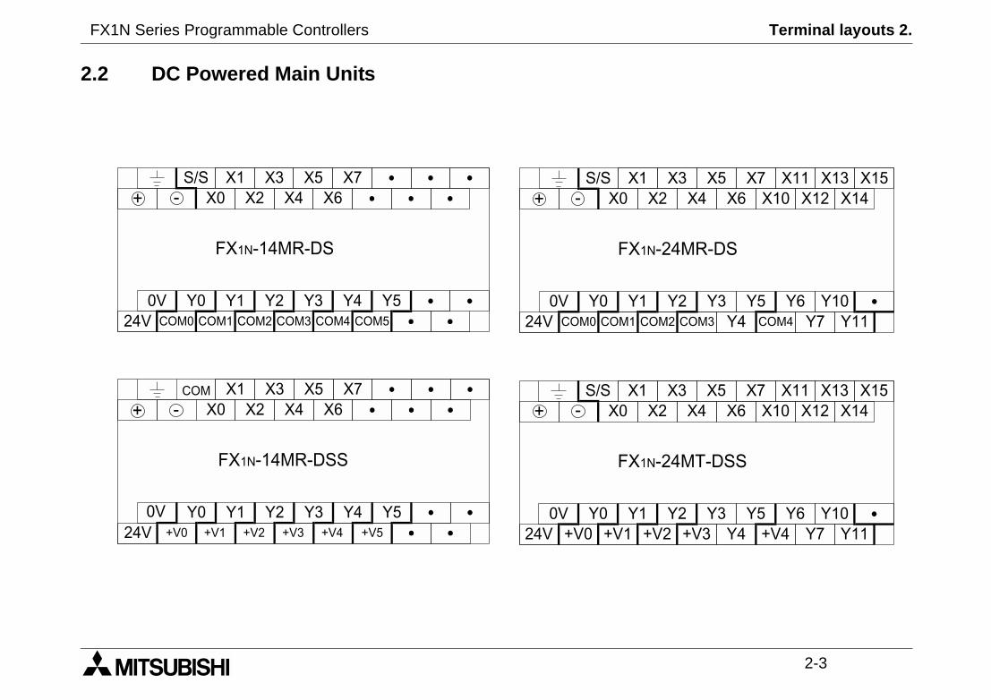
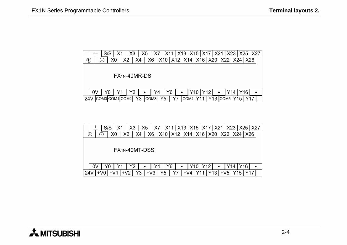
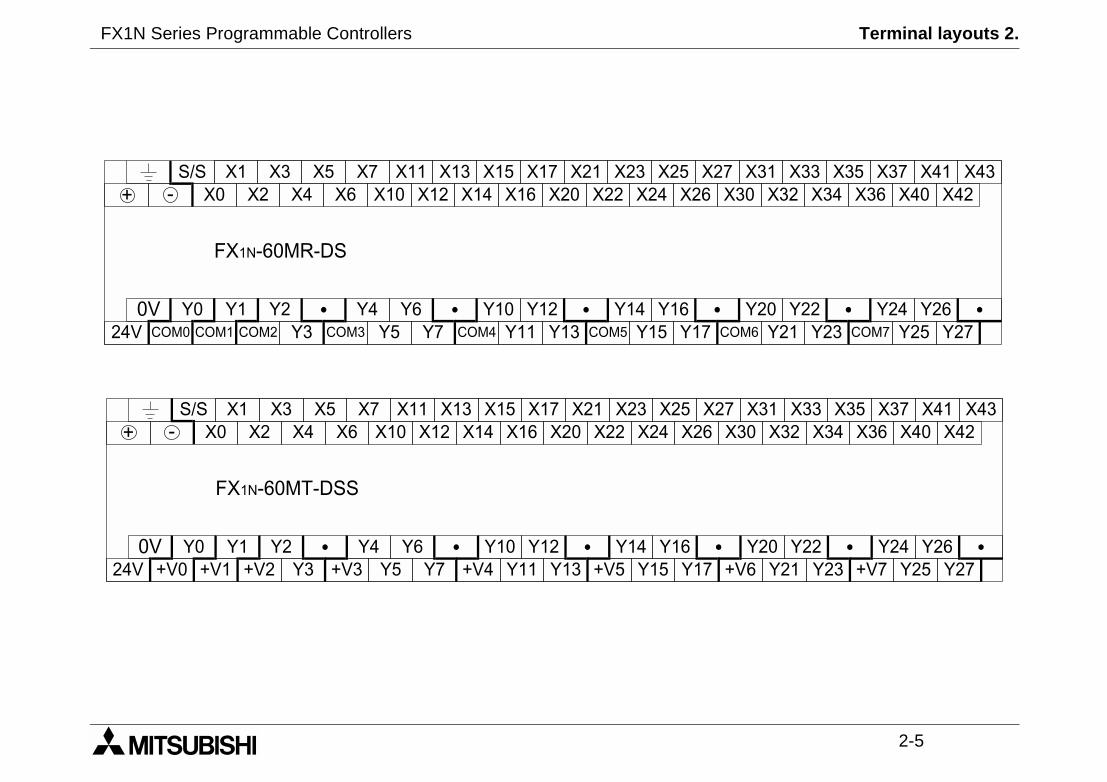
2.2 DC Powered Main Units
S/S X1X0 X4
FX1N-14MR-DS
X5
0V Y0 Y1 Y2 Y3
X3X2
24V COM0 COM1 COM3COM2
X7X6
Y4COM4 COM5
Y5
-+
COM X1X0 X4
X5
0V Y0 Y1 Y2 Y3
X3X2
24V +V0 +V1 +V3+V2
X7X6
Y4+V4 +V5
Y5
FX1N-14MR-DSS
-+
S/S X1X0
FX1N
0V Y0 Y1
X
24V COM0 COM1 CO
-+
S/S X1X0
0V Y0 Y1
X
24V +V0 +V1 +
FX1N
-+
FX1N Series Programmable Controllers Terminal layouts 2.
2-4
14
23X24
X25X26
X27
5
Y16Y15 Y17
14
23X24
X25X26
X27
Y16Y15 Y17
S/S X1X0 X4
FX1N-40MR-DS
X5
0V Y0 Y1 Y2Y3
X3X2
24V COM0 COM1 COM3COM2
X7X6
Y5 COM4
X12X13X11
X10X15
X14
Y6Y4 YY7 Y11
X20X21X17
X16X
X22
Y10 Y12Y13 COM
-+
S/S X1X0 X4
FX1N-40MT-DSS
X5
0V Y0 Y1 Y2
X3X2
24V
X7X6
Y5
X12X13X11
X10X15
X14
Y6Y4 YY7 Y11
X20X21X17
X16X
X22
Y10 Y12Y13+V0 +V1 +V2 +V3 +V4 +V5Y3
-+
FX1N Series Programmable Controllers Terminal layouts 2.
2-5
X3130 X32
X33X34
X35X40
X41X42
X43
Y20 Y22Y21 Y23OM6
Y24 Y26Y25 Y27COM7
X36X37
X31X30 X32
X33X34
X35X40
X41X42
X43
Y20 Y22Y21 Y23
Y24 Y26Y25 Y27
X36X37
V6 +V7
S/S X1X0 X4
FX1N-60MR-DS
X5
0V Y0 Y1 Y2Y3
X3X2
24V COM0 COM1 COM3COM2
X7X6
Y5 COM4
X12X13X11
X10X15
X14
Y6Y4 Y14Y7 Y11
X20X21X17
X16X23
X22 X24X25
X26X27
Y10 Y12Y13 COM5
Y16Y15 Y17
X
C
-+
S/S X1X0 X4
FX1N-60MT-DSS
X5
0V Y0 Y1 Y2Y3
X3X2
24V
X7X6
Y5
X12X13X11
X10X15
X14
Y6Y4 Y14Y7 Y11
X20X21X17
X16X23
X22 X24X25
X26X27
Y10 Y12Y13
Y16Y15 Y17+V0 +V1 +V2 +V3 +V4 +V5 +
-+
FX1N Series Programmable Controllers Terminal layouts 2.
2-6
X5
X7
FX
2N-16EY
R-E
S/U
L
FX
2N-16EY
T-E
SS
/UL
X3
X1
X0
X5
X6
X3
X1
S/S
X7
X4
X2
X0
X6
X4
X2
Y5
Y7
Y3
Y1
Y0
Y5
Y6
Y3
Y1
CO
M1
Y7
Y4
Y2
Y0
Y6
Y4
Y2
CO
M2
Y5
Y7
Y3
Y1
Y0
Y5
Y6
Y3
Y1
+V
0Y
7Y
4Y
2Y
0Y
6Y
4Y
2+
V1
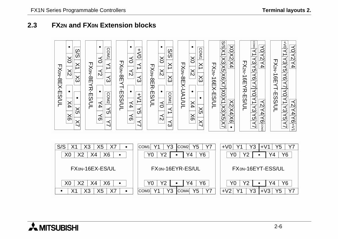
+V0 Y1 Y3Y0 Y2 Y4 Y6
FX0N-16EYT-ESS/UL
Y5 Y7
Y0 Y2 Y4 Y6
+V1
+V2 Y1 Y3 Y5 Y7+V3
2.3 FX2N and FX0N Extension blocks
S/S
X1
X3
X0
X2
CO
M1
X5
X7
X4
X6
FX
0N-8EX
-ES
/UL
Y1
Y3
Y0
Y2
Y5
Y7
Y4
Y6
FX
0N-8EY
R-E
S/U
L
CO
M2
Y1
Y3
Y0
Y2
Y5
Y7
Y4
Y6
FX
0N-8EY
T-E
SS
/UL
+V
0+
V1
X1
X3
X0
X2
Y1
Y3
Y0
Y2
FX
0N-8ER
-ES
/UL
S/S
CO
M1
X1
X3
X0
X2
X5
X7
X4
X6
FX
0N-8EX
-UA
1/UL
CO
M1
FX
2N-16EX
-ES
/UL
S/S X1 X3X0 X2 X4 X6
FX0N-16EX-ES/UL
X5 X7
X1 X3 X5 X7X0 X2 X4 X6
COM1 Y1 Y3Y0 Y2 Y4 Y6
FX0N-16EYR-ES/UL
Y5 Y7
Y0 Y2 Y4 Y6
COM2
COM3 Y1 Y3 Y5 Y7COM4
FX1N Series Programmable Controllers Installation notes 3.
1 INTRODUCTION
2 TERMINAL LAYOUTS
3 INSTALLATION NOTES
4 POWER SUPPLY
5 INPUTS
6 OUTPUTS
7 DIAGNOSTICS
FX1N Series Programmable Controllers Installation notes 3.
Installation Notes 3.
3-1
fe and easy. When the productsally, they must be installed in atalled in accordance to the local
FX1N Series Programmable Controllers
3. Installation Notes
The installation of FX1N products has been designed to be saassociated with this manual are used as a system or individusuitable enclosure. The enclosure should be selected and insand national standards.

FX1N Series Programmable Controllers Installation Notes 3.
3-2
"# $%&"&%' $%("
3.1 Product Outline
Features of the FX1N PLC
➁ ➂
➀
➉ ➈
➇
➄
➆
!
➁
))
➂
➂
➂
➅
➃
))

FX1N Series Programmable Controllers Installation Notes 3.
3-3
d from VR1. Lower pot D8031
Features table1 Top cover
2 Direct mounting holes (4.5 mm diameter)
3 I/O terminal block securing screws
4 Input terminals (24V DC) and power supply terminals
5 Input LED status indicators
6 Expansion port cover
7 PLC status indicators (POWER, RUN, ERROR)
8 Output LED status indicators
9 DIN rail mounting clip
10 Output terminals and power supply source terminals
11 Optional equipment connector
12 Expansion port
13 Run/Stop switch
14 Programming port
15Variable analog potentiometers. Upper pot, D8030 rearead from VR2

FX1N Series Programmable Controllers Installation Notes 3.
3-4
ort.
ers.
eripheral.
e RUN-input terminal. Please
is determined by the most
STOP is made from a personalSTOP then back to RUN to
ectionRUN INPUT
TERMINALFX1N MPU
STATUS
RUN
RUN
STOP
RUN
3.2 FX1N RUN/STOP Control
RUN or STOP of the FX1N can be controlled by:
The RUN/STOP switch mounted next to the programming p
A standard input (X0 to X17) defined by the system paramet
Remotely from a personal computer or other programming p
Note:The FX1N RUN/STOP switch works in parallel with threfer to the table below.During remote operation the FX1N RUN/STOP statusrecently operated control.E.g. If the RUN/STOP switch is in RUN and a remotecomputer the RUN/STOP switch must be switched toswitch the MPU back to RUN mode.
S/S
RUN
0V 24V X0
RUN/STOP selRUN/STOP
SWITCH
Run input terminal
FX1N Series Programmable Controllers Installation Notes 3.
3-5
tion
ation
ation
mm Half Amplitude
/s2 Accelerationes (80 min in each direction)
mm Half Amplitude
/s2 Accelerationes (80 min in each direction)
ration, Action Time: 11 msction X, Y, and Z
sted by noise simulator
een all points, terminals and grounden all points, terminals and ground.
oints, terminals and ground
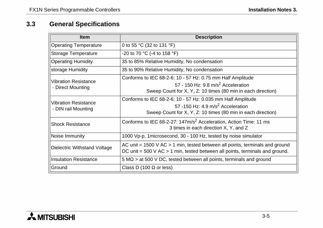
3.3 General Specifications
Item Descrip
Operating Temperature 0 to 55 °C (32 to 131 °F)
Storage Temperature -20 to 70 °C (-4 to 158 °F)
Operating Humidity 35 to 85% Relative Humidity, No condens
storage Humidity 35 to 90% Relative Humidity, No condens
Vibration Resistance- Direct Mounting
Conforms to IEC 68-2-6; 10 - 57 Hz: 0.75
57 - 150 Hz: 9.8 mSweep Count for X, Y, Z: 10 tim
Vibration Resistance- DIN rail Mounting
Conforms to IEC 68-2-6; 10 - 57 Hz: 0.035
57 -150 Hz: 4.9 mSweep Count for X, Y, Z: 10 tim
Shock Resistance Conforms to IEC 68-2-27: 147m/s2 Accele3 times in each dire
Noise Immunity 1000 Vp-p, 1microsecond, 30 - 100 Hz, te
Dielectric Withstand Voltage AC unit = 1500 V AC > 1 min, tested betwDC unit = 500 V AC > 1 min, tested betwe
Insulation Resistance 5 MΩ > at 500 V DC, tested between all p
Ground Class D (100 Ω or less)
FX1N Series Programmable Controllers Installation Notes 3.
3-6
ever mount them to the floor or
X0N-65EC
1N
PU
Fun
ctio
nbl
ock
Fun
ctio
nbl
ock
A
A
,FX2N
sions A
0mm(1.97 inches)
A
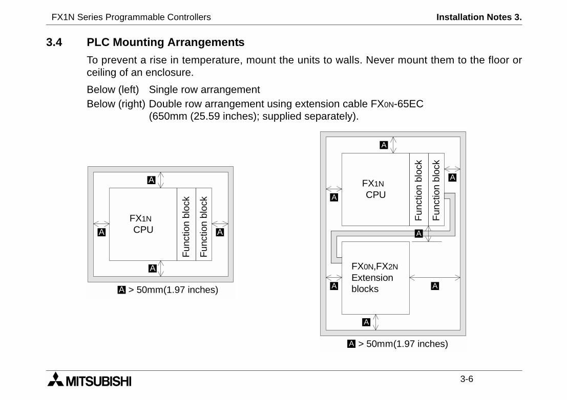
3.4 PLC Mounting Arrangements
To prevent a rise in temperature, mount the units to walls. Nceiling of an enclosure.
Below (left) Single row arrangementBelow (right) Double row arrangement using extension cable F
(650mm (25.59 inches); supplied separately).
FXCA
FX0N
ExtenblockA
A
> 5A
FX1N
CPU
Fun
ctio
nbl
ock
Fun
ctio
nbl
ock
A
A
AA
> 50mm(1.97 inches)A

FX1N Series Programmable Controllers Installation Notes 3.
3-7
wing conditions: excessive orr rain, excessive heat, regular
it during installation e.g. cute the protective paper band, to
22). To release, pull the spring
Caution
• Units should not be installed in areas subject to the folloconductive dust, corrosive or flammable gas, moisture oimpact shocks or excessive vibration.
• Take special care not to allow debris to fall inside the unwires, shavings etc. Once installation is complete removprevent overheating.
3.5 DIN Rail Mounting
Units can be snap mounted to 35mm DIN rail (DIN EN 500loaded clips away from the rail and slide the unit up and off.
FX1N Series Programmable Controllers Installation Notes 3.
3-8+,-
.+,-
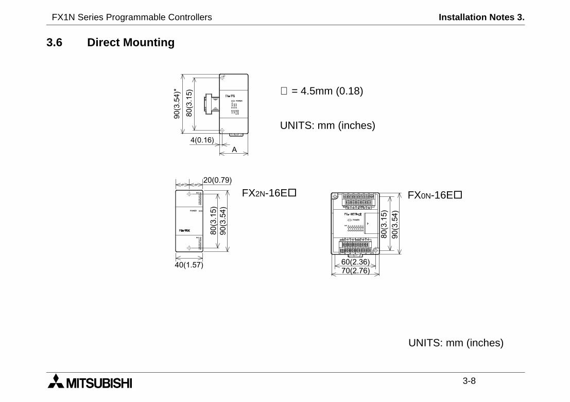
FX0N-16E
UNITS: mm (inches)
3.6 Direct Mounting
* *
+,-
.+,-/
+, -
∅ = 4.5mm (0.18)
UNITS: mm (inches)
"
"
+,.-
+,-
.+,-
+,-
+, - +, -
FX2N-16E

FX1N Series Programmable Controllers Installation Notes 3.
3-9
EL A
NT-DP
43(1.69)
2ADP
5ADP
Side view
MODEL A MODEL A MOD
FX2N-4DA
55(2.16)
FX2N-2DA
43(1.69)
FX0N-32
FX2N-4AD FX2N-2AD FX0N-23
FX2N-4AD-PT FX2N-32CCL FX0N-48
FX2N-4AD-TC FX2N-16LNK-M FX0N-8E
FX0N-3A FX0N-8E
+,-/
.+,-
FX0N-232ADP is 68(2.68)
UNITS: mm (inches)
FX1N Series Programmable Controllers Installation Notes 3.
3-10
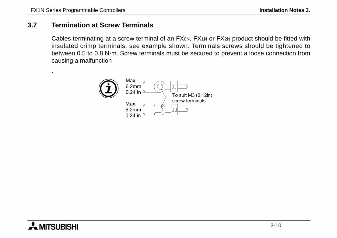
2N product should be fitted withscrews should be tightened toprevent a loose connection from
3.7 Termination at Screw Terminals
Cables terminating at a screw terminal of an FX0N, FX1N or FXinsulated crimp terminals, see example shown. Terminalsbetween 0.5 to 0.8 Nm. Screw terminals must be secured tocausing a malfunction
.
""
""
"0123""+,24-0#&%5"3%&'24670
68, ,'',"24
68, ,'',"24
FX1N Series Programmable Controllers Installation Notes 3.
3-11
easy. If during the installation ofontact a professional electricianthe installation site.
output signals or allow them to
w them to share the samearated or insulated with regard
nce consideration for voltage
s far as possible fromequipment.
3.8 Wiring Techniques
The wiring of FX1N products has been designed to be safe andthese products or associated products concern is felt, please cwho is trained to the local and national standards applicable to
Wiring cautions
• Do not run input signals in the same multicore cable asshare the same wire.
• Do not lay I/O signal cables next to power cables or allotrunking duct. Low voltage cables should be reliably septo high voltage cabling.
• Where I/O signal lines are used over an extended distadrop and noise interference should be made.
• Always ensure that mounted units and blocks are kept ahigh-voltage cables, high-voltage equipment and power

FX1N Series Programmable Controllers Installation Notes 3.
3-12
cial function board to the FX1N
l unit, please see the relevant
special function board. Only onerds.
quipment board.r port.
r.
B).
crews C).
removing section D)’ to expose
w E).
3.9 Installing Optional Units
3.9.1 Special Function Boards
The following is a generic explanation of how to install a spePLC. For greater detail and specifications of each optionaproducts manual.
Always make sure the power is turned off, before installing aboard can be used at one time, do not try to stack multiple boa
A) Special function or optional eB) Optional equipment connectoC) M3 screw to secure board.D) Top cover for board.E) M3 screw to secure top coveNote: Do not remove this screw.
• Remove base unit top cover.
• Plug board A) into connector
• Fix board to base unit using s
• Attach top cover for board D)connector etc. (if applicable)
• Secure top cover with M3 scre
-
9-
-
-
-:-
3%
-
FX1N Series Programmable Controllers Installation Notes 3.
3-13
5DM.
nual.
-
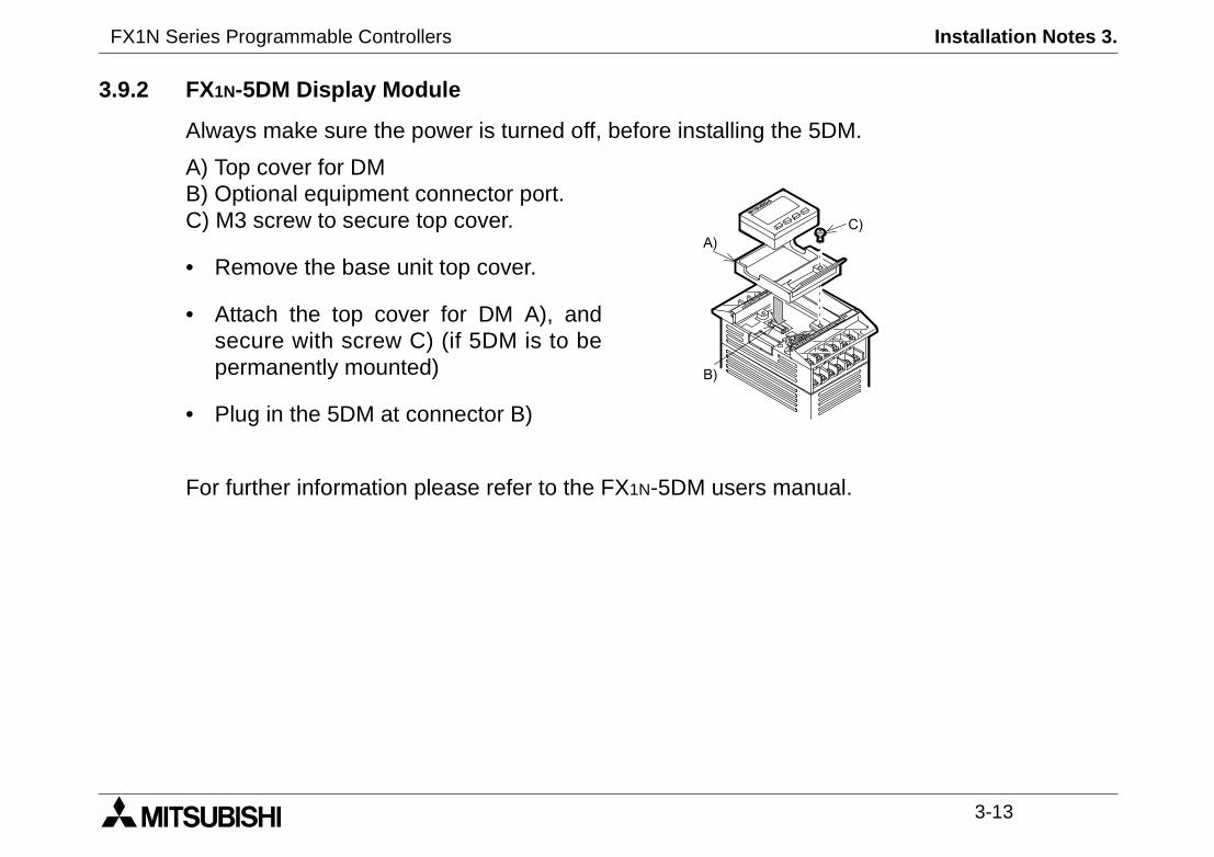
3.9.2 FX1N-5DM Display Module
Always make sure the power is turned off, before installing the
A) Top cover for DMB) Optional equipment connector port.C) M3 screw to secure top cover.
• Remove the base unit top cover.
• Attach the top cover for DM A), andsecure with screw C) (if 5DM is to bepermanently mounted)
• Plug in the 5DM at connector B)
For further information please refer to the FX1N-5DM users ma
9-
-
FX1N Series Programmable Controllers Installation Notes 3.
3-14
MEMO

FX1N Series Programmable Controllers Power supply 4.
1 INTRODUCTION
2 TERMINAL LAYOUTS
3 INSTALLATION NOTES
4 POWER SUPPLY
5 INPUTS
6 OUTPUTS
7 DIAGNOSTICS

FX1N Series Programmable Controllers Power supply 4.
Power Supply 4.
4-1
easy. If during the installation ofontact a professional electricianthe installation site.
signals or allow them to share the
share the same trunking duct. Lowrd to high voltage cabling.
ideration for voltage drop and noise
“L” terminal and the “Neutral” cableire to the “N” terminal, the user might
“+” terminal and the “Neutral” cableire to the “-” terminal, the user might
FX1N Series Programmable Controllers
4. Power Supply
4.1 Wiring Techniques
The wiring of FX1N products has been designed to be safe andthese product or associated products concern is felt, please cwho is trained to the local and national standards applicable to
4.2 Wiring Cautions
• Do not run input signals in the same multicore cable as outputsame wire.
• Do not lay I/O signal cables next to power cables or allow them tovoltage cables should be reliably separated or insulated with rega
• Where I/O signal lines are used over an extended distance consinterference should be made.
4.3 Power Supply
When wiring AC supplies the “Live” cable should be connected to theshould be connected to the “N” terminal. Do NOT connect the “Live” wreceive a dangerous shock on powerup.
When wiring DC supplies the “Live” cable should be connected to theshould be connected to the “-” terminal. Do NOT connect the “Live” wreceive a dangerous shock on powerup.
FX1N Series Programmable Controllers Power Supply 4.
4-2
FX1N-40M FX1N-60M+10%, -15%, 50-60Hz
the PLC will continue operation.
250V 3.15A (3A)Max. 15A for 5msMax. 25A for 5ms
32W 35W
FX1N-40M FX1N-60MDC -15% (28.8 ~ 10.2V DC)
e PLC will continue operation.
V 3.15Aax. 25A for 1ms
ax. 22A for 0.3ms18W 20W
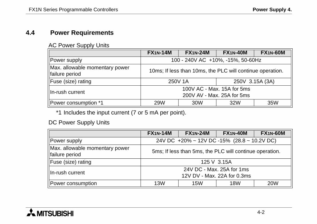
*1 Includes the input current (7 or 5 mA per point).
DC Power Supply Units
4.4 Power Requirements
AC Power Supply UnitsFX1N-14M FX1N-24M
Power supply 100 - 240V ACMax. allowable momentary powerfailure period
10ms; If less than 10ms,
Fuse (size) rating 250V 1A
In-rush current100V AC -200V AV -
Power consumption *1 29W 30W
FX1N-14M FX1N-24MPower supply 24V DC +20% ~ 12VMax. allowable momentary powerfailure period
5ms; If less than 5ms, th
Fuse (size) rating 125
In-rush current24V DC - M
12V DV - MPower consumption 13W 15W

FX1N Series Programmable Controllers Power Supply 4.
4-3
ly 100 - 240V AC +10% -15%
ctor or Fuse
stop
ly switch
pilot indicator
ly for loads
4.5 Example Wiring
4.5.1 AC Power supply
AC/DCConverter
Extension block
Extension block
MC
PL
MC
MC MC
L
N
24V0V
Power supp50 - 60 Hz
Circuit prote
Emergency
Power supp
Power ON
Power supp
Ground
Fuse
Main unit
Breaker
FX1N Series Programmable Controllers Power Supply 4.
4-4
r supply
it protector or fuse
nd
circuit power supply
switch
sensor (PNP open collector)
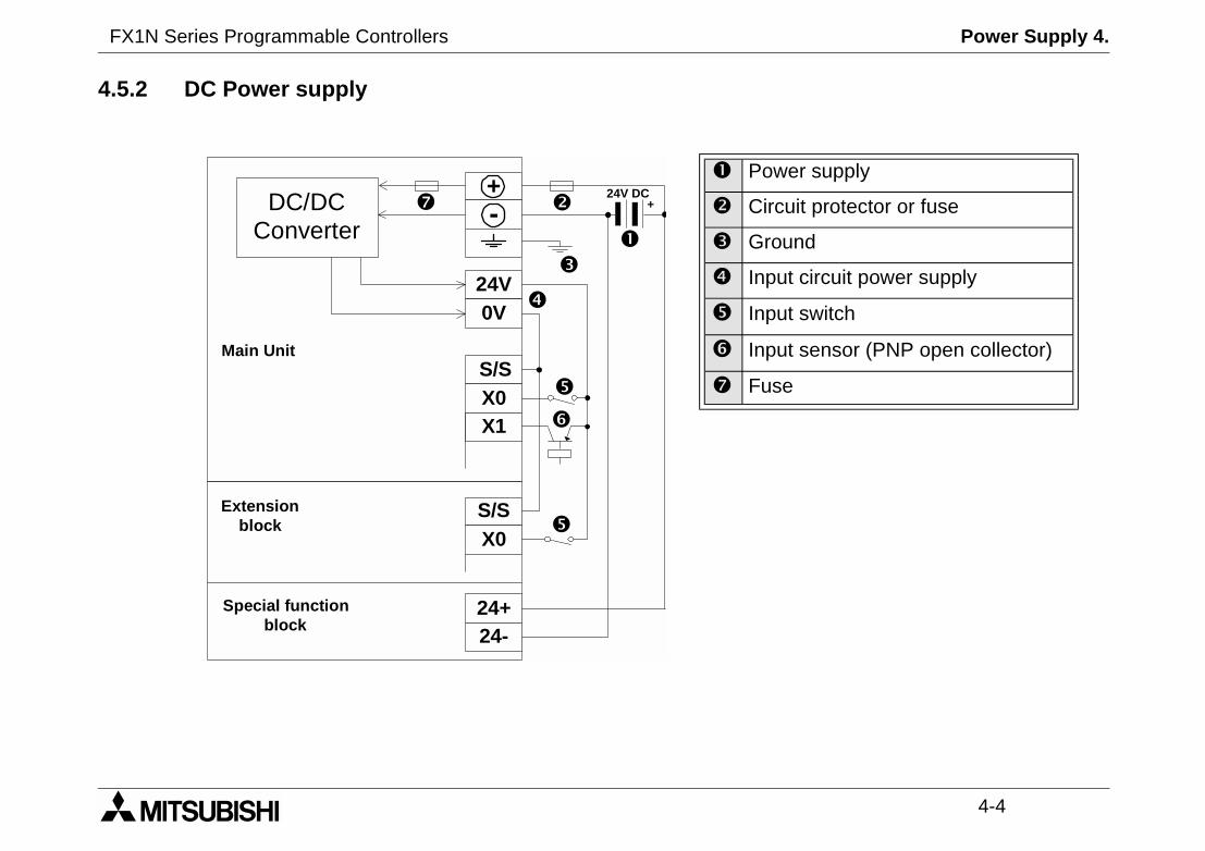
4.5.2 DC Power supply
Powe
Circu
Grou
Input
Input
Input
Fuse
DC/DCConverter
+-
24V0V
S/SX0X1
S/SX0
24+24-
24V DC
Main Unit
Extensionblock
Special functionblock
+
FX1N Series Programmable Controllers Power Supply 4.
4-5
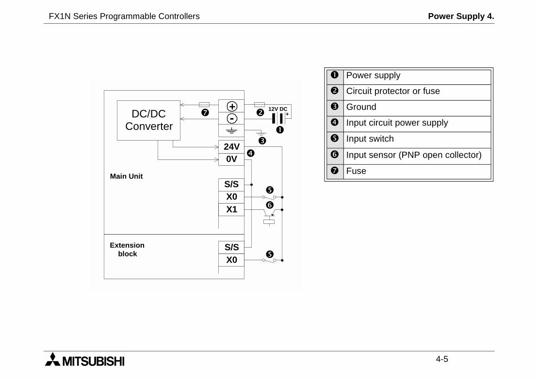
ower supply
ircuit protector or fuse
round
put circuit power supply
put switch
put sensor (PNP open collector)
use
P
C
G
In
In
In
F
DC/DCConverter
+-
24V0V
S/SX0X1
S/SX0
12V DC
Main Unit
Extensionblock
+
FX1N Series Programmable Controllers Power Supply 4.
4-6
at 400mA when used on its own
ly a service current. Howeverit power supply
t. Ground resistance must benot be connected to the sameut if a proper ground cannot berounded.
4.6 Service Power supply
An AC powered FX1N can supply a service current of 24V DCand, when used with extension or special function blocks.
A DC powered FX1N does not have the capacity to suppAdditional extension blocks can be powered from the main un
4.7 Earthing / Grounding
Use a cable at least 0.2mm2 (AWG24) to ground equipmenless than 100Ω (class D). Note that the ground cable mustground as the power circuits. Grounding is recommended bprovided, the PLC will still operate correctly without being g
FX1N Series Programmable Controllers Inputs 5.
1 INTRODUCTION
2 TERMINAL LAYOUTS
3 INSTALLATION NOTES
4 POWER SUPPLY
5 INPUTS
6 OUTPUTS
7 DIAGNOSTICS

FX1N Series Programmable Controllers Inputs 5.
Inputs 5.
5-1
0N, FX2N Extension block
0%
24V DC, 5mA
>3.5mA
---
ler
t
FX1N Series Programmable Controllers
5. Inputs
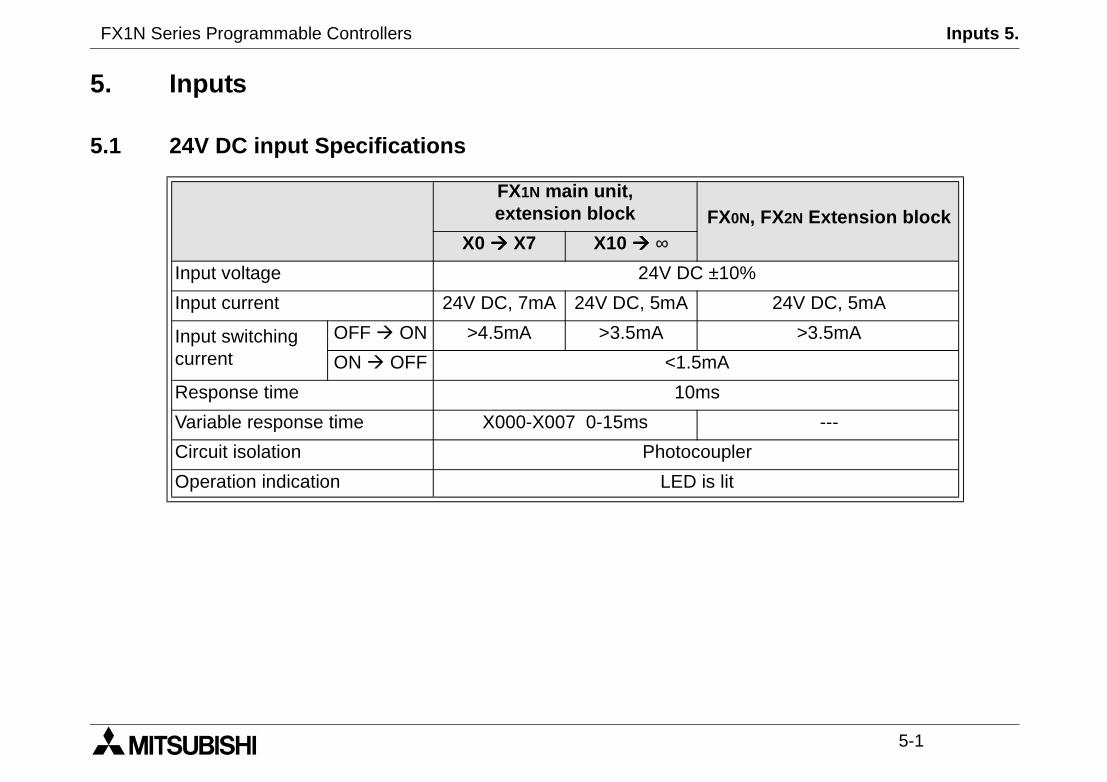
5.1 24V DC input Specifications
FX1N main unit,extension block FX
X0 X7 X10 ∞Input voltage 24V DC ±1
Input current 24V DC, 7mA 24V DC, 5mA
Input switchingcurrent
OFF ON >4.5mA >3.5mA
ON OFF <1.5mA
Response time 10ms
Variable response time X000-X007 0-15ms
Circuit isolation Photocoup
Operation indication LED is li
FX1N Series Programmable Controllers Inputs 5.
5-2
a DC powered unit, the inputshould be used. If an externalsed the FX1N will not operate
owered unit, an external 24V DC
odel - Service supplyodel - Input circuit power supply
Sensor
Sensor
t Device Contact
unit
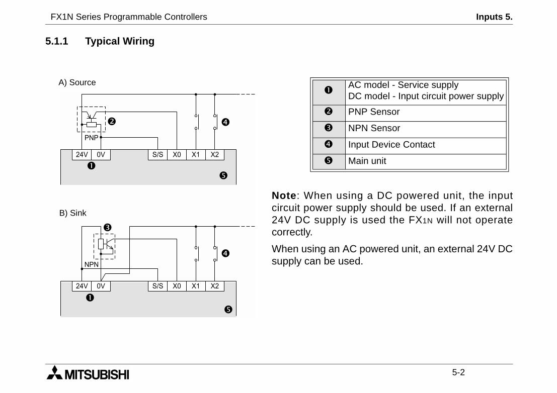
5.1.1 Typical Wiring
Note: When usingcircuit power supply24V DC supply is ucorrectly.
When using an AC psupply can be used.
AC mDC m
PNP
NPN
Inpu
Main24V 0V S/S X0 X1 X2
PNP
24V 0V S/S X0 X1 X2
NPN
A) Source
B) Sink
FX1N Series Programmable Controllers Inputs 5.
5-3
24V
X24VDC
0VS/S
/S)
S/S
X
Sink
4.3 kΩ
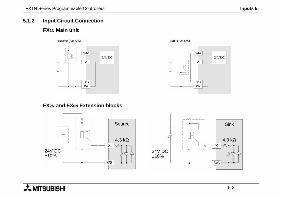
5.1.2 Input Circuit Connection
FX1N Main unit
FX2N and FX0N Extension blocks
24V
X24VDC
0VS/S
Source(-veS/S) Sink (+veS
S/S
X
Source
24V DC±10%
4.3 kΩ
24V DC±10%
FX1N Series Programmable Controllers Inputs 5.
5-4
FX0N, FX2NExtention block
X
S/S
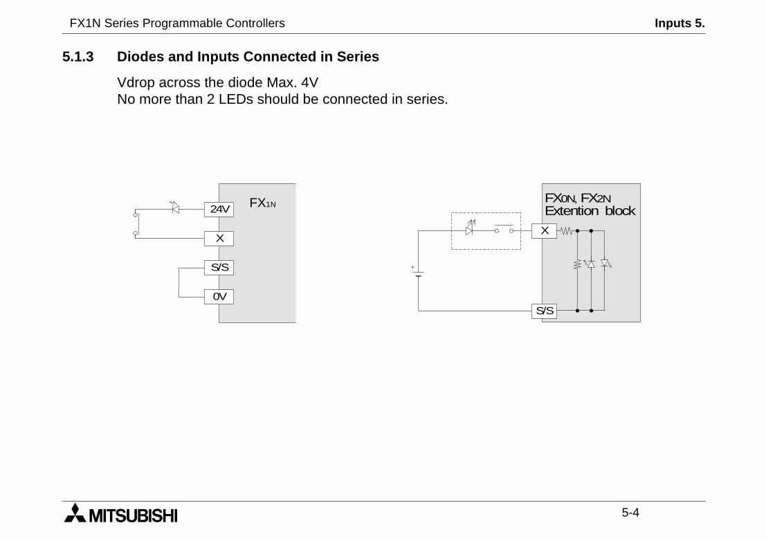
5.1.3 Diodes and Inputs Connected in Series
Vdrop across the diode Max. 4VNo more than 2 LEDs should be connected in series.
24V
X
0V
S/S
FX1N
FX1N Series Programmable Controllers Inputs 5.
5-5
than the stated value, then add
akage is greater than the stated
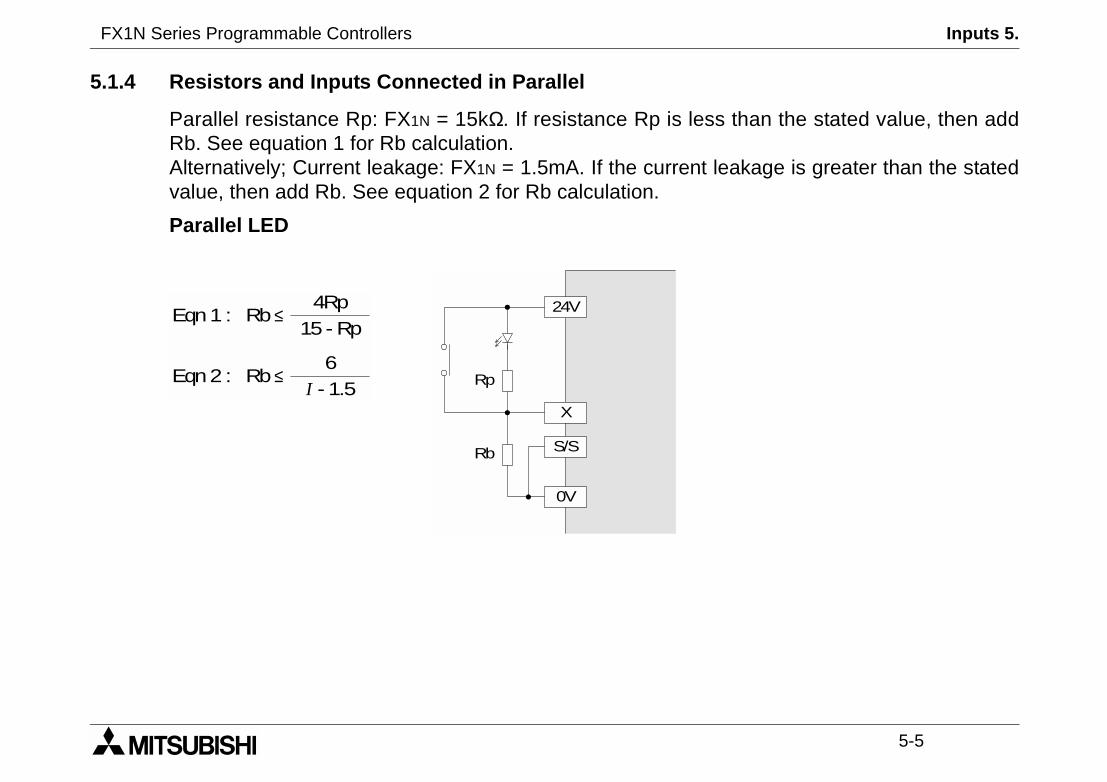
5.1.4 Resistors and Inputs Connected in Parallel
Parallel resistance Rp: FX1N = 15kΩ. If resistance Rp is lessRb. See equation 1 for Rb calculation.Alternatively; Current leakage: FX1N = 1.5mA. If the current levalue, then add Rb. See equation 2 for Rb calculation.
Parallel LED
Rb ≤4Rp
15 - RpEqn1 :
Rb ≤6
I - 1.5Eqn2 :
24V
X
0V
S/S
Rp
Rb
FX1N Series Programmable Controllers Inputs 5.
5-6
-60Hz
kΩ/60Hz
/50Hz 6.2mA 110V AC/60Hz
V 1.7mA
D is lit
5.2 AC110V Input Extension Block
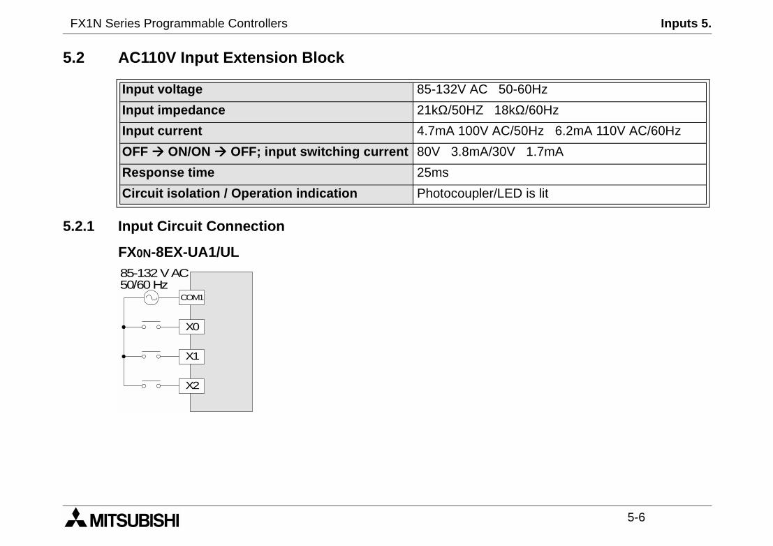
5.2.1 Input Circuit Connection
FX0N-8EX-UA1/UL
Input voltage 85-132V AC 50
Input impedance 21kΩ/50HZ 18
Input current 4.7mA 100V AC
OFF ON/ON OFF; input switching current 80V 3.8mA/30
Response time 25ms
Circuit isolation / Operation indication Photocoupler/LE
X0
COM1
85-132VAC50/60Hz
X1
X2
FX1N Series Programmable Controllers Inputs 5.
5-7
routines are not suitable for usealso not suitable.
5.2.2 Programming Caution
When using 110V AC units, high speed counter and interruptdue to the long 'ON/OFF' times. The following instructions are
FNC 52 MTR
FNC 56 SPD
FNC 72 DSW
FX1N Series Programmable Controllers Inputs 5.
5-8
MEMO
FX1N Series Programmable Controllers Outputs 6.
1 INTRODUCTION
2 TERMINAL LAYOUTS
3 INSTALLATION NOTES
4 POWER SUPPLY
5 INPUTS
6 OUTPUTS
7 DIAGNOSTICS

FX1N Series Programmable Controllers Outputs 6.
Outputs 6.
6-1
ransistor Output
5-30V DC
A/1 point, 0.8A/COM
12W/24V DC
1.5W/24V DC
------------------
ms; < 5µs (Y0,Y1 only)
I > 0.2A); <5µs (Y0,Y1 only)
PhotoCoupler
0.1mA/30V DC
energized
FX1N Series Programmable Controllers
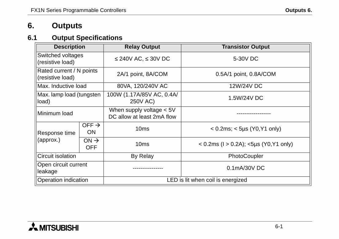
6. Outputs6.1 Output Specifications
Description Relay Output T
Switched voltages(resistive load)
≤ 240V AC, ≤ 30V DC
Rated current / N points(resistive load)
2A/1 point, 8A/COM 0.5
Max. Inductive load 80VA, 120/240V AC
Max. lamp load (tungstenload)
100W (1.17A/85V AC, 0.4A/250V AC)
Minimum loadWhen supply voltage < 5VDC allow at least 2mA flow
Response time(approx.)
OFF
ON10ms < 0.2
ON
OFF10ms < 0.2ms (
Circuit isolation By Relay
Open circuit currentleakage
----------------
Operation indication LED is lit when coil is

FX1N Series Programmable Controllers Outputs 6.
6-2
Do not use this terminal
Fuse
Surge absorbing Diode.
External MechanicalInterlock
Emergency Stop
Noise suppressor 0.1µFcapacitor + 100-120ΩresistorContactor
Valve
Incandescent Lamp
DC Power Supply
AC Power Supply
6.1.1 Relay Output Example
Typical Relay
COM0 Y0 Y1 Y2 Y3COM1 COM2 Y4 Y5
MC1 MC2
MC2 MC1+
FX1N Series Programmable Controllers Outputs 6.
6-3
ON/OFF test cycle. Please noterelay contacts service life. Theoid valve is 500,000 operations
figure below. If a response time'dummy' resistor and ensure the
01 are high speed responsee following characteristics:
5 - 24V DC, 100kHz maximum
response is required, a currentmust be used.
80VA0.8A/100V AC0.4A/240V AC
200,000
S-K180,S-K400
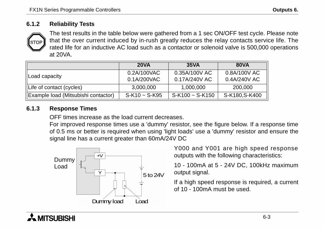
6.1.2 Reliability Tests
The test results in the table below were gathered from a 1 secthat the over current induced by in-rush greatly reduces therated life for an inductive AC load such as a contactor or solenat 20VA.
6.1.3 Response TimesOFF times increase as the load current decreases.For improved response times use a 'dummy' resistor, see theof 0.5 ms or better is required when using 'light loads' use asignal line has a current greater than 60mA/24V DC
Y000 and Y0outputs with th
10 - 100mA atoutput signal.
If a high speedof 10 - 100mA
20VA 35VA
Load capacity0.2A/100VAC0.1A/200VAC
0.35A/100V AC0.17A/240V AC
Life of contact (cycles) 3,000,000 1,000,000
Example load (Mitsubishi contactor) S-K10 ~ S-K95 S-K100 ~ S-K150
5 to24VY
+V
Dummy load Load
10 to100mA
DummyLoad

FX1N Series Programmable Controllers Outputs 6.
6-4
Do not use this terminal
Emergency Stop
Fuse
External MechanicalInterlock
DC Power Supply
6.1.4 Transistor Output Example
6.1.5 Japanese Model Transistor Output
+V0 Y0 Y1 Y2 Y3+V1 +V2 Y4 Y5
MC1 MC2
MC2 MC1
+
COM0 Y0 Y1 Y2 Y3COM1 COM2 Y4 Y5
MC1 MC2
MC2 MC1+

FX1N Series Programmable Controllers Outputs 6.
6-5
output, see previous figures.irection control of a motor),PLC's sequencing alone.rcuits. (See preceding figure.)
6.2 Applying Safe Loads
Ensure all loads are applied to the same side of each PLCLoads which should NEVER simultaneously operate (e.g. dbecause of a safety critical situation, should not rely on theMechanical interlocks MUST be fitted to all safety critical ci

FX1N Series Programmable Controllers Outputs 6.
6-6
MEMO
FX1N Series Programmable Controllers Diagnostics 7.
1 INTRODUCTION
2 TERMINAL LAYOUTS
3 INSTALLATION NOTES
4 POWER SUPPLY
5 INPUTS
6 OUTPUTS
7 DIAGNOSTICS

FX1N Series Programmable Controllers Diagnostics 7.

Diagnostics 7.
7-1
orrectly.
own load a smallit has been written
rcibly turn ON/OFF
k the previouslyare complete take
any live or
FX1N Series Programmable Controllers
7. Diagnostics
7.1 Preliminary Checks
Check power supply, ground and I/O cables are wired c
Turn the power supply on. Check the power LED is lit. Dtest program into the PLC. Verify the program to ensureto the PLC correctly. Using the programming device, foeach output. Check the output LEDs for operation.
Put the PLC into RUN. Check the RUN LED is lit. Checdown loaded program works correctly. Once all checksthe PLC out of run and turn OFF the power supply.
During this testing stage take extreme care not to touchhazardous parts.
POWERRUN
ERROR
POWERRUN
ERROR
POWERRUN
ERROR
FX1N Series Programmable Controllers Diagnostics 7.
7-2
s the memory cassette beentalled or removed while the unitss still been powered?
amming error. Ensure the earth/correctly rewired.
A
PC M/C PC M/C
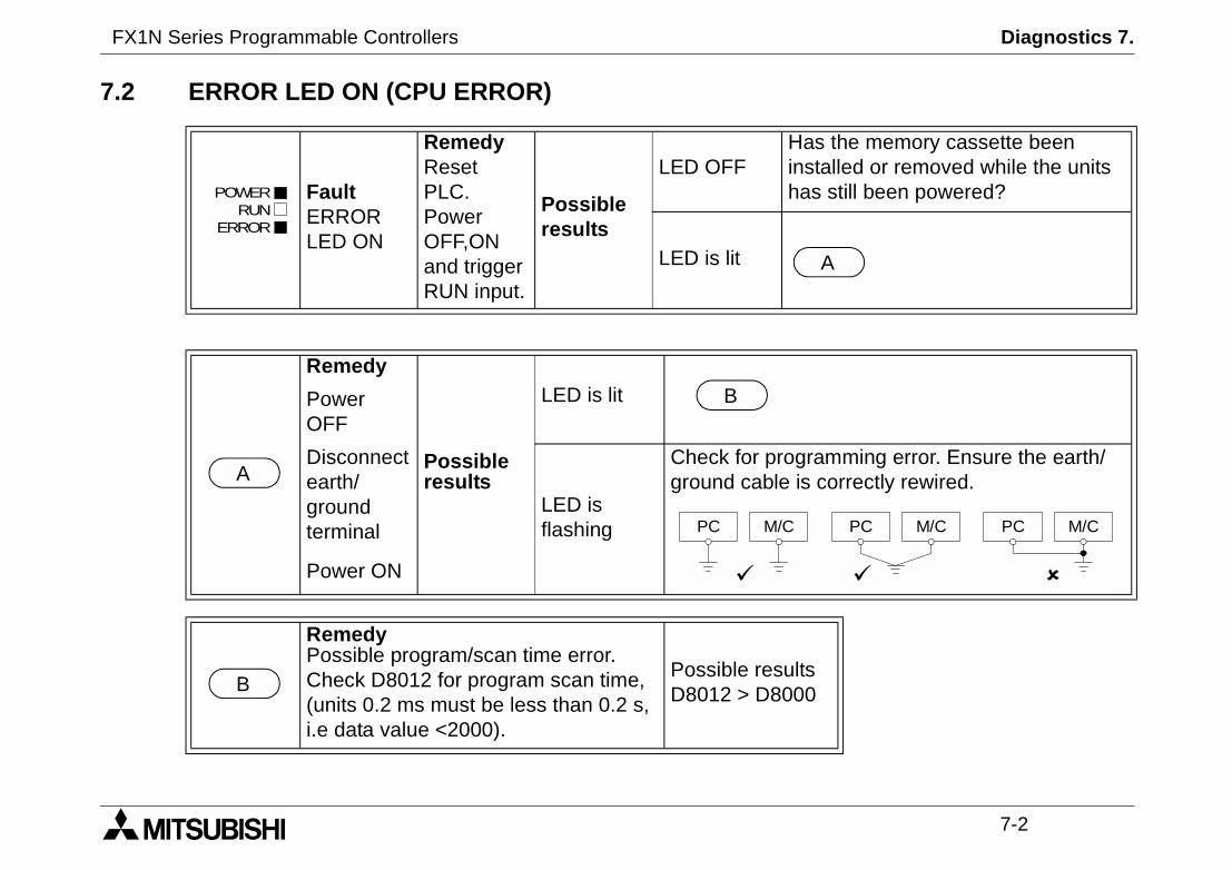
7.2 ERROR LED ON (CPU ERROR)
FaultERRORLED ON
RemedyResetPLC.PowerOFF,ONand triggerRUN input.
Possibleresults
LED OFFHainsha
LED is lit
Remedy
Possibleresults
LED is litPowerOFF
Disconnectearth/groundterminal
LED isflashing
Check for progrground cable is
Power ON
RemedyPossible program/scan time error.Check D8012 for program scan time,(units 0.2 ms must be less than 0.2 s,i.e data value <2000).
Possible resultsD8012 > D8000
POWERRUN
ERROR
A
B
PC M/C
B

FX1N Series Programmable Controllers Diagnostics 7.
7-3
ting range.
by one program scan.
ue to vibration).
7.3 Common Errors
- Corroded contact points at some point in an I/O line.
- An I/O device has been used outside its specified opera
- An input signal occurs in a shorter time period that taken
7.4 Maintenance
- Check interior temperature of the panel.
- Check panel air filters if fitted.
- Check for loosening of terminals or mounting facilities (d
FX1N Series Programmable Controllers Diagnostics 7.
7-4
Parallel linkerror
Parameter error
Syntaxerror
Program(circuit) error
Programexecutionerror
Executionerror latch
9)
9)
9)
PChardwareerror
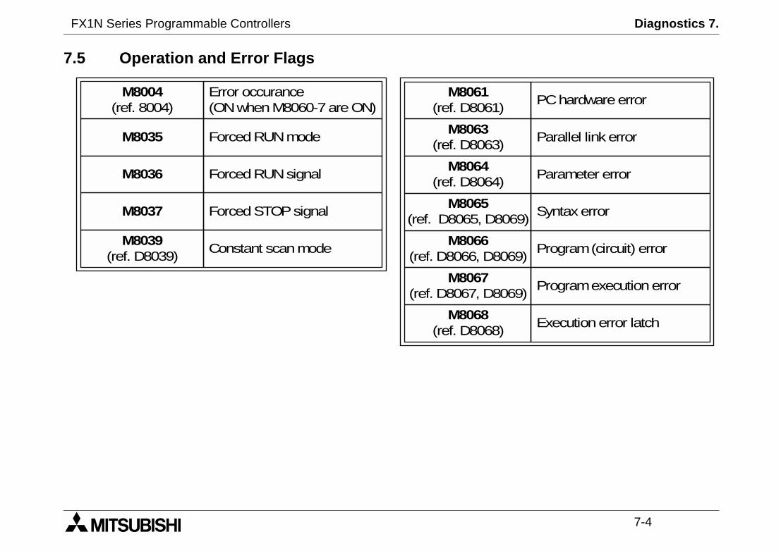
7.5 Operation and Error Flags
M8063(ref. D8063)
M8064(ref. D8064)
M8065(ref. D8065, D806
M8066(ref. D8066, D806
M8067(ref. D8067, D806
M8068(ref. D8068)
M8061(ref. D8061)
M8004(ref. 8004)
M8035
M8036
M8037
M8039(ref. D8039)
Error occurance(ONwhenM8060-7areON)
ForcedRUNmode
ForcedRUNsignal
ForcedSTOPsignal
Constant scanmode
FX1N Series Programmable Controllers Diagnostics 7.
7-5
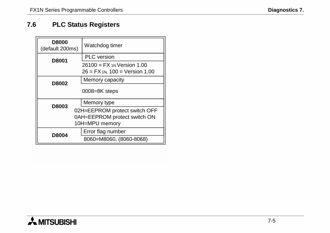
7.6 PLC Status Registers
02H=EEPROM protect switch OFF0AH=EEPROM protect switch ON10H=MPU memory
D8000(default 200ms)
D8001
D8002
D8003
D8004
Watchdog timer
PLC version
26100 = FX 1N Version 1.0026 = FX 1N, 100 = Version 1.00
Memory capacity
0008=8K steps
Memory type
Error flag number8060=M8060, (8060-8068)

FX1N Series Programmable Controllers Diagnostics 7.
7-6
7.7 Error Registers
D8061
D8063
D8064
D8065
D8066
D8067
D8068
D8069
Error code for PLChardwareerror
Error code for parallel link fault
Parameter error code
Syntax error code
Program(circuit) error code
Programexecutionerror code
Latchedstepnumber of executionerror
Stepnumber of errorsassociatedwitherror flagsM8065-M8067
FX1N Series Programmable Controllers Diagnostics 7.
7-7
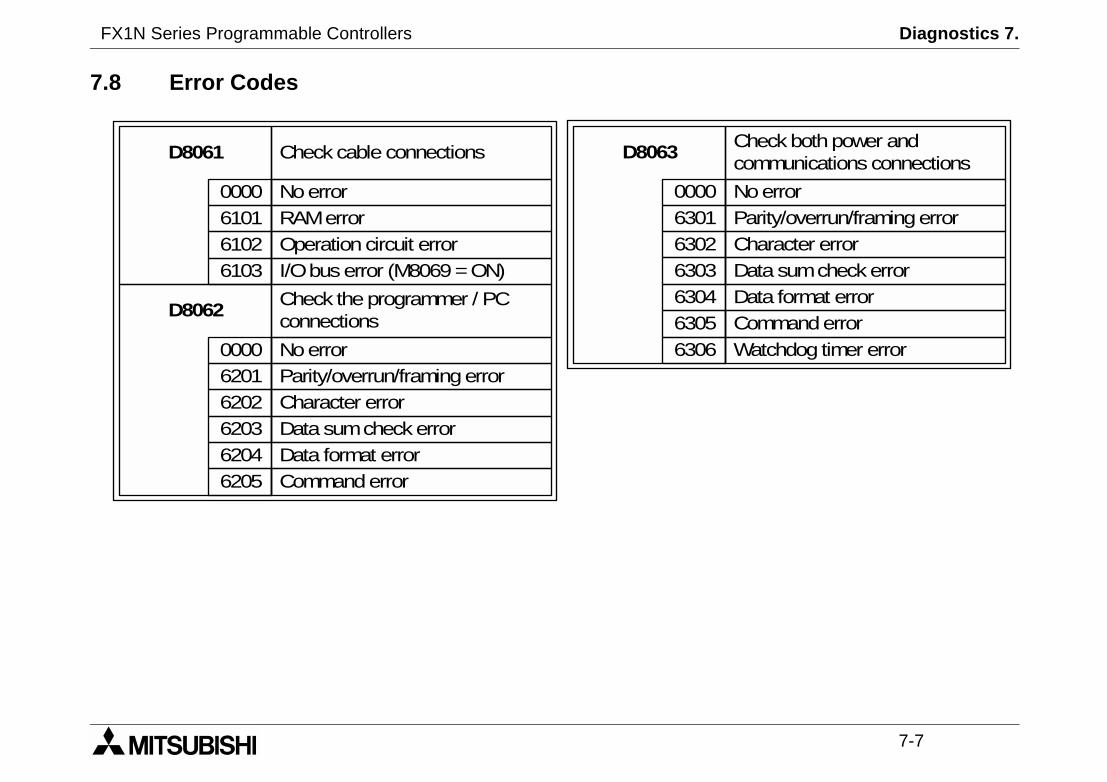
Checkbothpower andcommunications connections
NoerrorParity/overrun/framingerrorCharacter errorData sumcheckerrorData format errorCommanderrorWatchdog timer error
7.8 Error Codes
D8061 Checkcable connections
Noerror0000RAMerror6101Operation circuit error6102I/Obuserror (M8069=ON)6103
D8062Check theprogrammer / PCconnections
Noerror0000Parity/overrun/framingerror6201Character error6202Data sumcheckerror6203Data format error6204Commanderror6205
D8063
0000630163026303630463056306
FX1N Series Programmable Controllers Diagnostics 7.
7-8
6 7 8 9
FEND WDT FOR NEXT
V BCD BIN
WAND WOR WXOR
L SFWR SFRD
SPD PLSY PWM PLSR
ALT RAMP
FROM TO
D VRSC PID
ZRN PLSV DRVI DRVA
TRD TWR HOUR
RD3A WR3A
LD< LD≠ LD≤AND≠ AND≤ AND≥
≤ OR≥
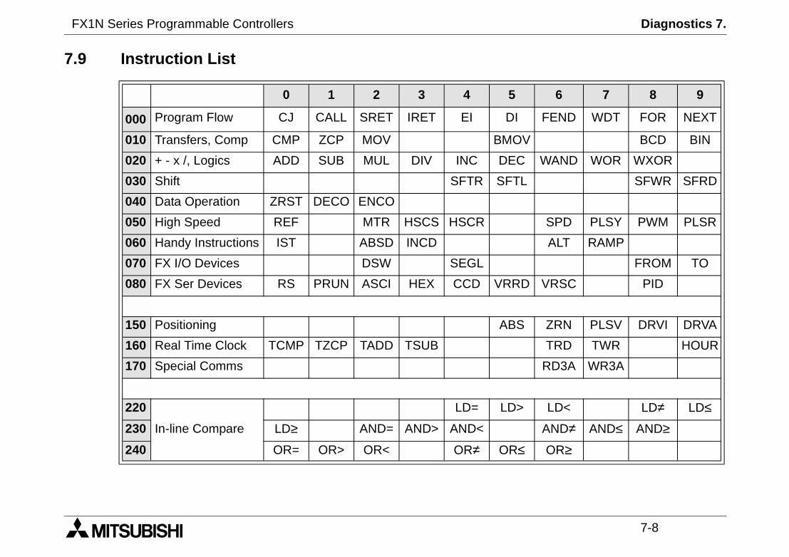
7.9 Instruction List
0 1 2 3 4 5
000 Program Flow CJ CALL SRET IRET EI DI
010 Transfers, Comp CMP ZCP MOV BMO
020 + - x /, Logics ADD SUB MUL DIV INC DEC
030 Shift SFTR SFT
040 Data Operation ZRST DECO ENCO
050 High Speed REF MTR HSCS HSCR
060 Handy Instructions IST ABSD INCD
070 FX I/O Devices DSW SEGL
080 FX Ser Devices RS PRUN ASCI HEX CCD VRR
150 Positioning ABS
160 Real Time Clock TCMP TZCP TADD TSUB
170 Special Comms
220
In-line Compare
LD= LD>
230 LD≥ AND= AND> AND<
240 OR= OR> OR< OR≠ OR
FX1N Series Programmable Controllers Diagnostics 7.
7-9
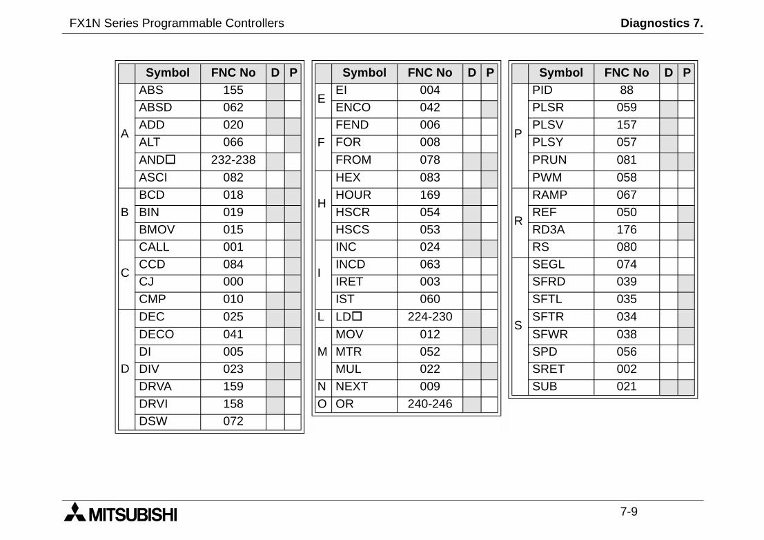
Symbol FNC No D P
P
PID 88PLSR 059PLSV 157PLSY 057
PRUN 081
PWM 058
R
RAMP 067REF 050RD3A 176RS 080
S
SEGL 074SFRD 039SFTL 035
SFTR 034
SFWR 038SPD 056SRET 002SUB 021
Symbol FNC No D P Symbol FNC No D P
A
ABS 155E
EI 004ABSD 062 ENCO 042ADD 020
F
FEND 006ALT 066 FOR 008
AND 232-238 FROM 078
ASCI 082
H
HEX 083
BBCD 018 HOUR 169BIN 019 HSCR 054BMOV 015 HSCS 053
C
CALL 001
I
INC 024CCD 084 INCD 063CJ 000 IRET 003CMP 010 IST 060
D
DEC 025 L LD 224-230
DECO 041M
MOV 012DI 005 MTR 052DIV 023 MUL 022DRVA 159 N NEXT 009DRVI 158 O OR 240-246DSW 072

FX1N Series Programmable Controllers Diagnostics 7.
7-10
ZZCP 011ZRN 156ZRST 040
Symbol FNC No D P
T
TADD 162V
VRRD 085TCMP 160 VRSC 086TO 079
W
WAND 026TRD 166 WDT 007TSUB 163 WOR 027TWR 167 WR3A 177TZCP 161 WXOR 028
Symbol FNC No D P Symbol FNC No D P

FX1N Series Programmable Controllers Diagnostics 7.
7-11
Remarksrovided by built in EEPROM memory
128, dependent on user selectionInputs 128, Outputs 128)
M0 to M383
M384 to M1535
From the range M8000 to M8255
S0 to S999
S0 to S9
T0 to T199
T200 to T245
T246 to T249
T250 to T255
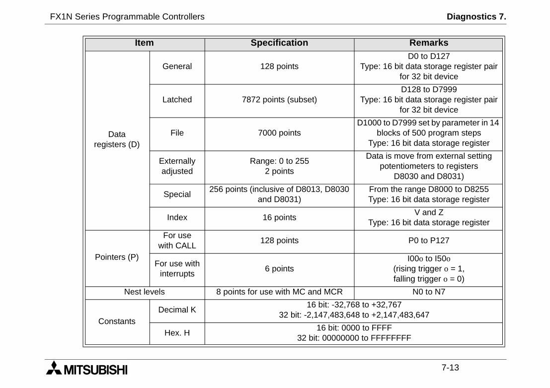
7.10 Device List
Item SpecificationProgram capacity 8K steps P
I/O configurationMax hardware I/O configuration points
(Max. software addressable
Auxiliaryrelay
(M coils)
General 384 points
Latched 1152 points (subset)
Special 256 points
State relays(S coils)
Latched 1000 points
Initial 10 points (subset)
Timers (T)
100 msRange: 0.1 to 3,276.7 s
200 points
10 msRange: 0.01 to 327.67 s
46 points
1 msretentive
Range: 0.001 to 32.767 s4 point
100 msretentive
Range: 0.1 to 3,276.7 s6 points
FX1N Series Programmable Controllers Diagnostics 7.
7-12
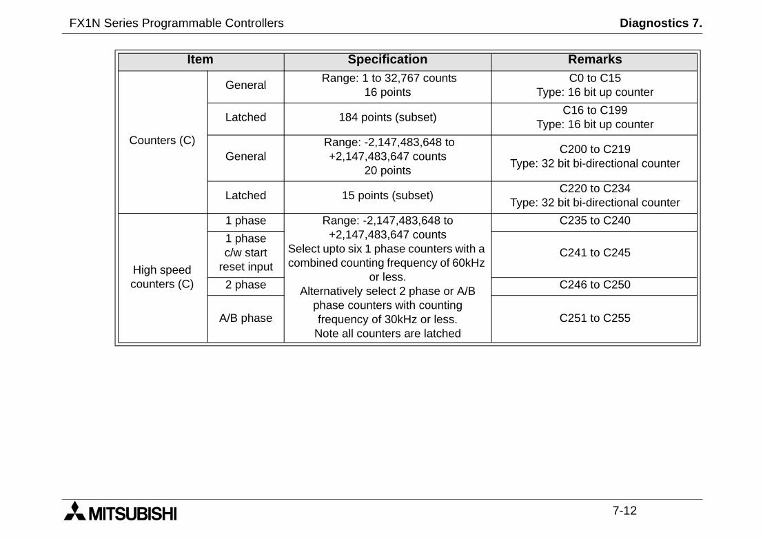
C0 to C15Type: 16 bit up counter
C16 to C199Type: 16 bit up counter
C200 to C219Type: 32 bit bi-directional counter
C220 to C234Type: 32 bit bi-directional counter
C235 to C240
C241 to C245
C246 to C250
C251 to C255
Remarks
Counters (C)
GeneralRange: 1 to 32,767 counts
16 points
Latched 184 points (subset)
GeneralRange: -2,147,483,648 to+2,147,483,647 counts
20 points
Latched 15 points (subset)
High speedcounters (C)
1 phase Range: -2,147,483,648 to+2,147,483,647 counts
Select upto six 1 phase counters with acombined counting frequency of 60kHz
or less.Alternatively select 2 phase or A/B
phase counters with countingfrequency of 30kHz or less.
Note all counters are latched
1 phasec/w start
reset input
2 phase
A/B phase
Item Specification
FX1N Series Programmable Controllers Diagnostics 7.
7-13
D0 to D127Type: 16 bit data storage register pair
for 32 bit device
D128 to D7999Type: 16 bit data storage register pair
for 32 bit device
1000 to D7999 set by parameter in 14blocks of 500 program steps
Type: 16 bit data storage register
Data is move from external settingpotentiometers to registers
D8030 and D8031)
From the range D8000 to D8255Type: 16 bit data storage register
V and ZType: 16 bit data storage register
P0 to P127
I00o to I50o(rising trigger o = 1,falling trigger o = 0)
N0 to N7
to +32,767to +2,147,483,647
to FFFFto FFFFFFFF
Remarks
Dataregisters (D)
General 128 points
Latched 7872 points (subset)
File 7000 pointsD
Externallyadjusted
Range: 0 to 2552 points
Special256 points (inclusive of D8013, D8030
and D8031)
Index 16 points
Pointers (P)
For usewith CALL
128 points
For use withinterrupts
6 points
Nest levels 8 points for use with MC and MCR
ConstantsDecimal K
16 bit: -32,76832 bit: -2,147,483,648
Hex. H16 bit: 0000
32 bit: 00000000
Item Specification

FX1N Series Programmable Controllers Diagnostics 7.
7-14

Under no circumstances will MITSUBISHI ELECTRIC be liable or responsible for any consequential damage thatmay arise as a result of the installation or use of this equipment.All examples and diagrams shown in this manual are intended only as an aid to understanding the text, not to guar-antee operation. MITSUBISHI ELECTRIC will accept no responsibility for actual use of the product based on theseillustrative examples.Owing to the very great variety in possible application of this equipment, you must satisfy yourself as to its suitabilityfor your specific application.
FX1N Series Programmable Controllers

HEAD OFFICE: MITSUBISHI DENKI BLDG MARUNOUCHI TOKYO 100-8310 TELEX: J24532 CABLE MELCO TOKYOHIMEJI WORKS: 840, CHIYODA CHO, HIMEJI, JAPAN
JY992D89301D(MEE0012)
Effective December. 2000Specification are subject tochange without notice.
HARDWARE MANUALFX1N SERIES PROGRAMMABLE CONTROLLERS
Related Documents