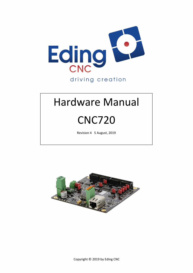
Copyright © 2019 by Eding CNC Hardware Manual CNC720 Revision 4 5 August, 2019

Welcome message from author
This document is posted to help you gain knowledge. Please leave a comment to let me know what you think about it! Share it to your friends and learn new things together.
Transcript
Copyright © 2019 by Eding CNC
Hardware Manual
CNC720 Revision 4 5 August, 2019
Hardware Manual – CNC720
Page | 2
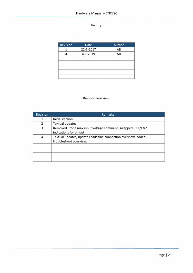
History:
Revision overview:
Revision Date Author
1 22-5-2017 AB
4 4-7-2019 AB
Revision Remarks
1 Initial version.
2 Textual updates
3 Removed Probe max input voltage comment, swapped CN1/CN2 indications for pinout
4 Textual updates, update Leadshine connection overview, added troubleshoot overview.
Hardware Manual – CNC720
Page | 3
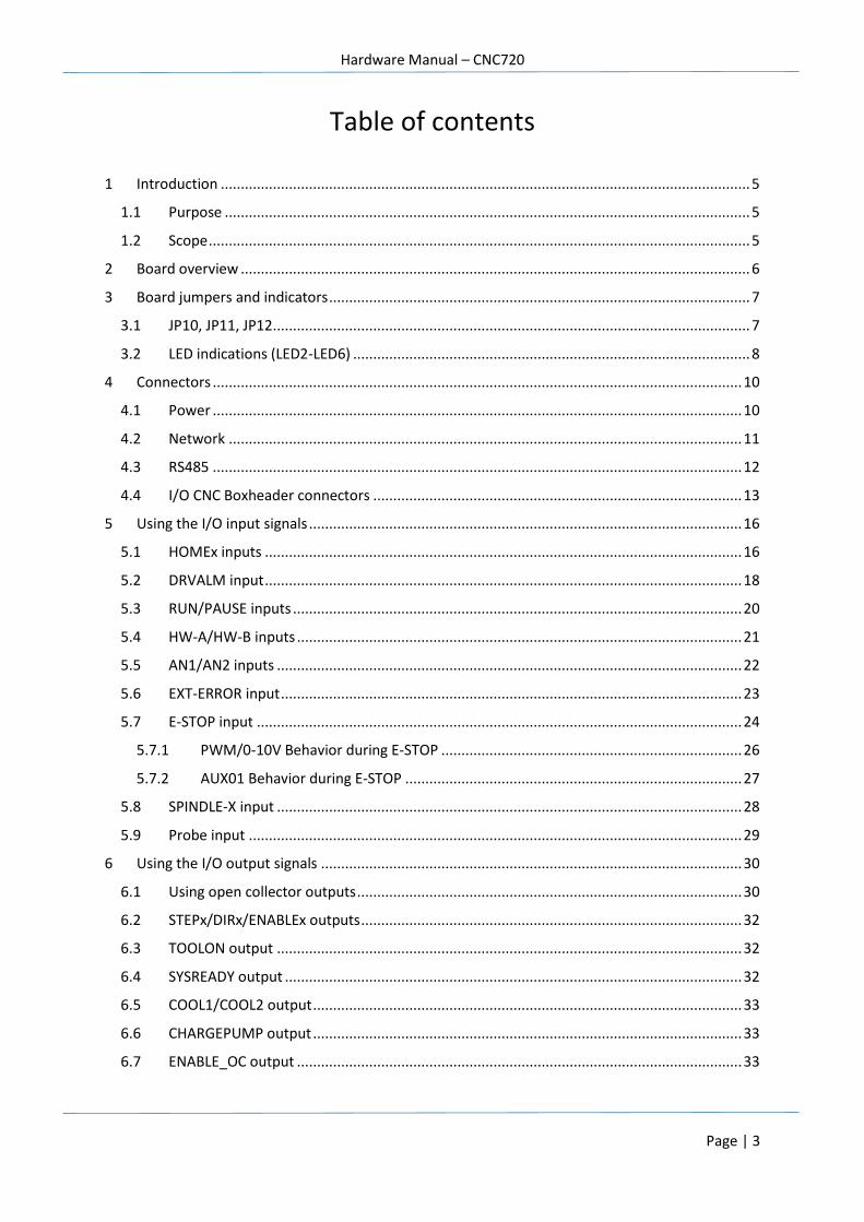
Table of contents
1 Introduction .................................................................................................................................... 5
1.1 Purpose ................................................................................................................................... 5
1.2 Scope ....................................................................................................................................... 5
2 Board overview ............................................................................................................................... 6
3 Board jumpers and indicators ......................................................................................................... 7
3.1 JP10, JP11, JP12 ....................................................................................................................... 7
3.2 LED indications (LED2-LED6) ................................................................................................... 8
4 Connectors .................................................................................................................................... 10
4.1 Power .................................................................................................................................... 10
4.2 Network ................................................................................................................................ 11
4.3 RS485 .................................................................................................................................... 12
4.4 I/O CNC Boxheader connectors ............................................................................................ 13
5 Using the I/O input signals ............................................................................................................ 16
5.1 HOMEx inputs ....................................................................................................................... 16
5.2 DRVALM input ....................................................................................................................... 18
5.3 RUN/PAUSE inputs ................................................................................................................ 20
5.4 HW-A/HW-B inputs ............................................................................................................... 21
5.5 AN1/AN2 inputs .................................................................................................................... 22
5.6 EXT-ERROR input ................................................................................................................... 23
5.7 E-STOP input ......................................................................................................................... 24
5.7.1 PWM/0-10V Behavior during E-STOP ........................................................................... 26
5.7.2 AUX01 Behavior during E-STOP .................................................................................... 27
5.8 SPINDLE-X input .................................................................................................................... 28
5.9 Probe input ........................................................................................................................... 29
6 Using the I/O output signals ......................................................................................................... 30
6.1 Using open collector outputs ................................................................................................ 30
6.2 STEPx/DIRx/ENABLEx outputs ............................................................................................... 32
6.3 TOOLON output .................................................................................................................... 32
6.4 SYSREADY output .................................................................................................................. 32
6.5 COOL1/COOL2 output ........................................................................................................... 33
6.6 CHARGEPUMP output ........................................................................................................... 33
6.7 ENABLE_OC output ............................................................................................................... 33

Hardware Manual – CNC720
Page | 4
6.8 PWM_VOLT output ............................................................................................................... 34
6.9 AUXOUT1 output .................................................................................................................. 35
6.10 NO_ESTOP output ................................................................................................................. 35
7 Getting started .............................................................................................................................. 36
8 38
9 Connecting a wired pendant ......................................................................................................... 39
10 Troubleshooting the CNC720 ........................................................................................................ 41
Hardware Manual – CNC720
Page | 5
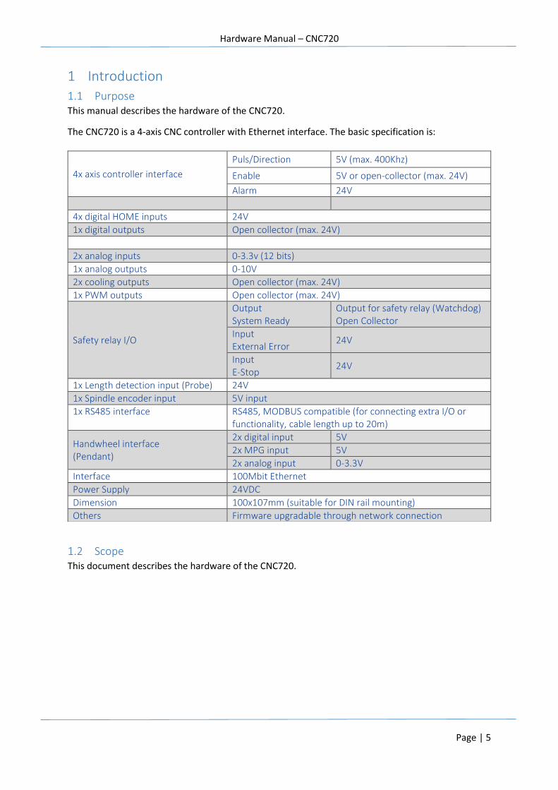
1 Introduction
1.1 Purpose This manual describes the hardware of the CNC720.
The CNC720 is a 4-axis CNC controller with Ethernet interface. The basic specification is:
1.2 Scope This document describes the hardware of the CNC720.
4x axis controller interface
Puls/Direction 5V (max. 400Khz)
Enable 5V or open-collector (max. 24V)
Alarm 24V
4x digital HOME inputs 24V
1x digital outputs Open collector (max. 24V)
2x analog inputs 0-3.3v (12 bits)
1x analog outputs 0-10V
2x cooling outputs Open collector (max. 24V)
1x PWM outputs Open collector (max. 24V)
Safety relay I/O
Output System Ready
Output for safety relay (Watchdog) Open Collector
Input External Error
24V
Input E-Stop
24V
1x Length detection input (Probe) 24V
1x Spindle encoder input 5V input
1x RS485 interface RS485, MODBUS compatible (for connecting extra I/O or functionality, cable length up to 20m)
Handwheel interface (Pendant)
2x digital input 5V
2x MPG input 5V
2x analog input 0-3.3V
Interface 100Mbit Ethernet
Power Supply 24VDC
Dimension 100x107mm (suitable for DIN rail mounting)
Others Firmware upgradable through network connection
Hardware Manual – CNC720
Page | 6
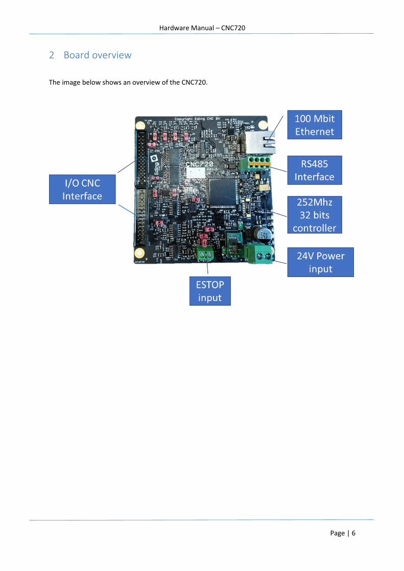
2 Board overview
The image below shows an overview of the CNC720.
Hardware Manual – CNC720
Page | 7
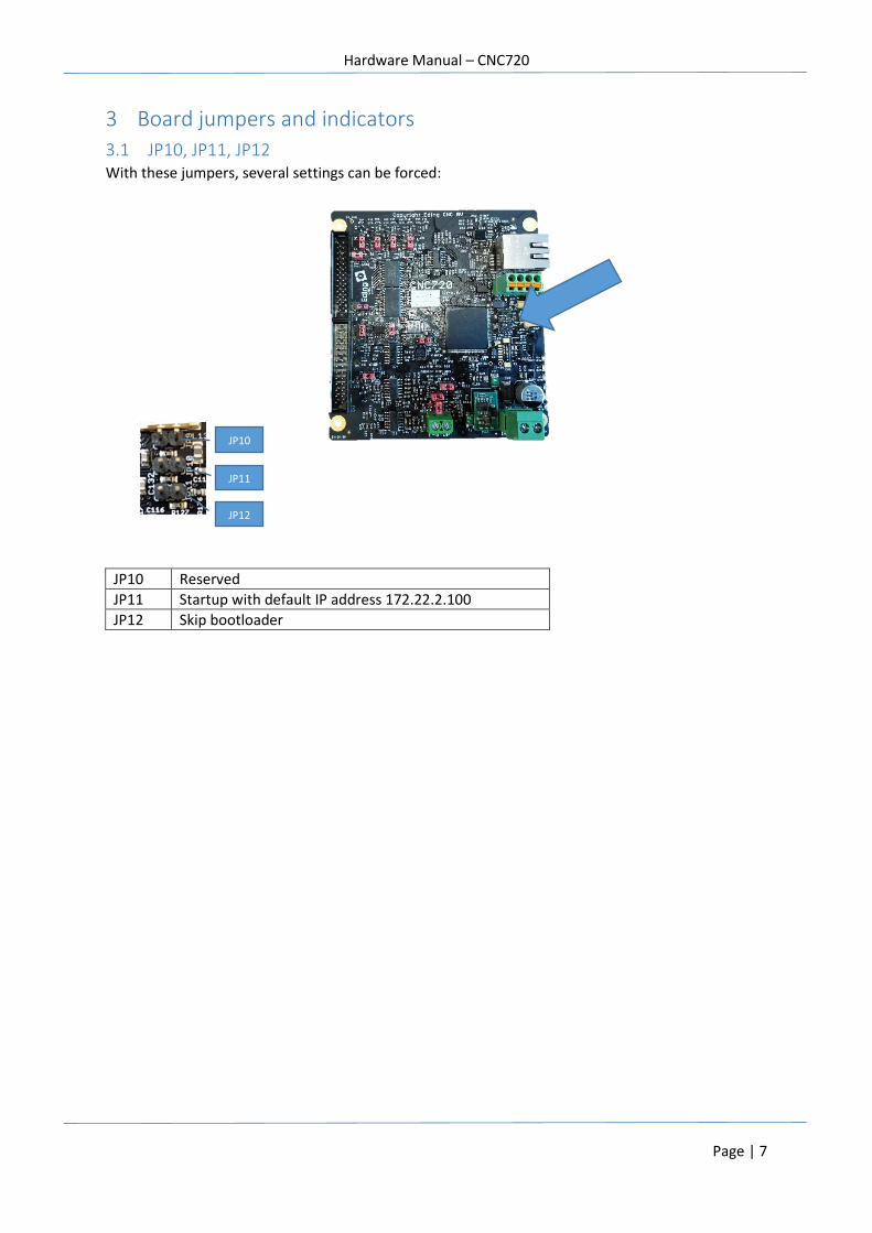
3 Board jumpers and indicators
3.1 JP10, JP11, JP12 With these jumpers, several settings can be forced:
JP10 Reserved
JP11 Startup with default IP address 172.22.2.100
JP12 Skip bootloader
JP12
JP10
JP11
Hardware Manual – CNC720
Page | 8
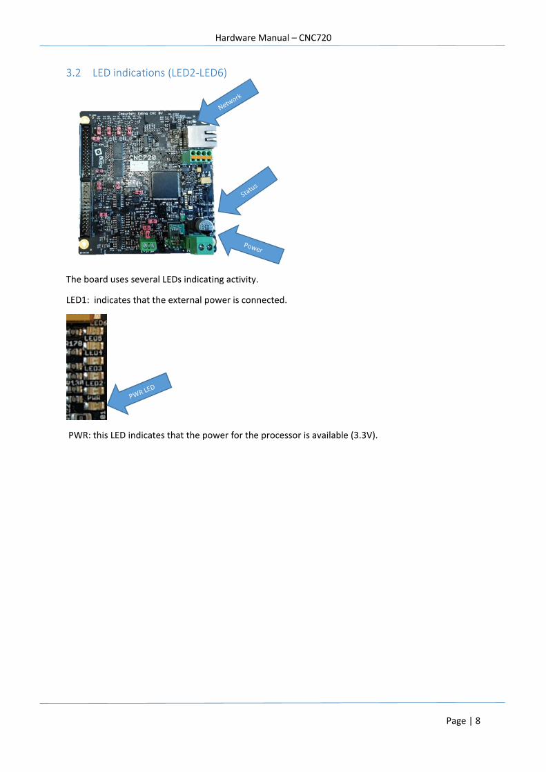
3.2 LED indications (LED2-LED6)
The board uses several LEDs indicating activity.
LED1: indicates that the external power is connected.
PWR: this LED indicates that the power for the processor is available (3.3V).
Hardware Manual – CNC720
Page | 9
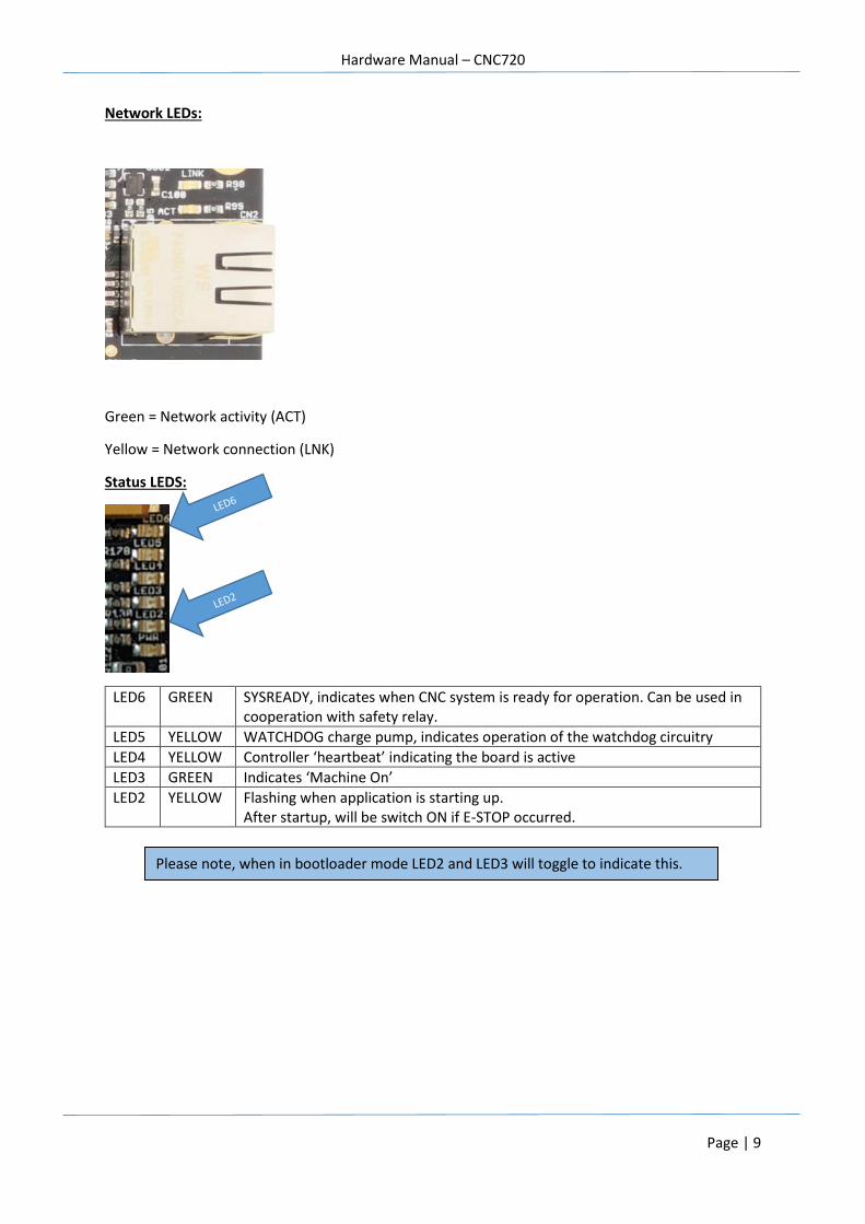
Network LEDs:
Green = Network activity (ACT)
Yellow = Network connection (LNK)
Status LEDS:
LED6 GREEN SYSREADY, indicates when CNC system is ready for operation. Can be used in cooperation with safety relay.
LED5 YELLOW WATCHDOG charge pump, indicates operation of the watchdog circuitry
LED4 YELLOW Controller ‘heartbeat’ indicating the board is active
LED3 GREEN Indicates ‘Machine On’
LED2 YELLOW Flashing when application is starting up. After startup, will be switch ON if E-STOP occurred.
Please note, when in bootloader mode LED2 and LED3 will toggle to indicate this.
Hardware Manual – CNC720
Page | 10
4 Connectors
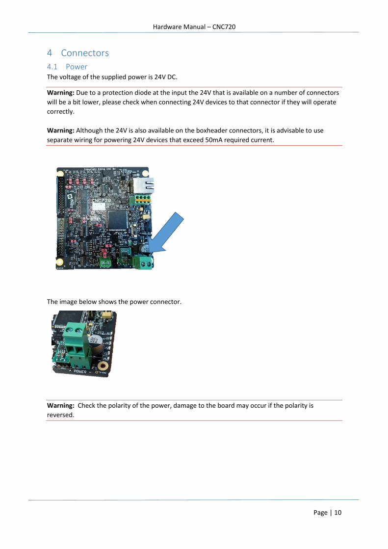
4.1 Power The voltage of the supplied power is 24V DC.
Warning: Due to a protection diode at the input the 24V that is available on a number of connectors
will be a bit lower, please check when connecting 24V devices to that connector if they will operate
correctly.
Warning: Although the 24V is also available on the boxheader connectors, it is advisable to use
separate wiring for powering 24V devices that exceed 50mA required current.
The image below shows the power connector.
Warning: Check the polarity of the power, damage to the board may occur if the polarity is
reversed.
Hardware Manual – CNC720
Page | 11
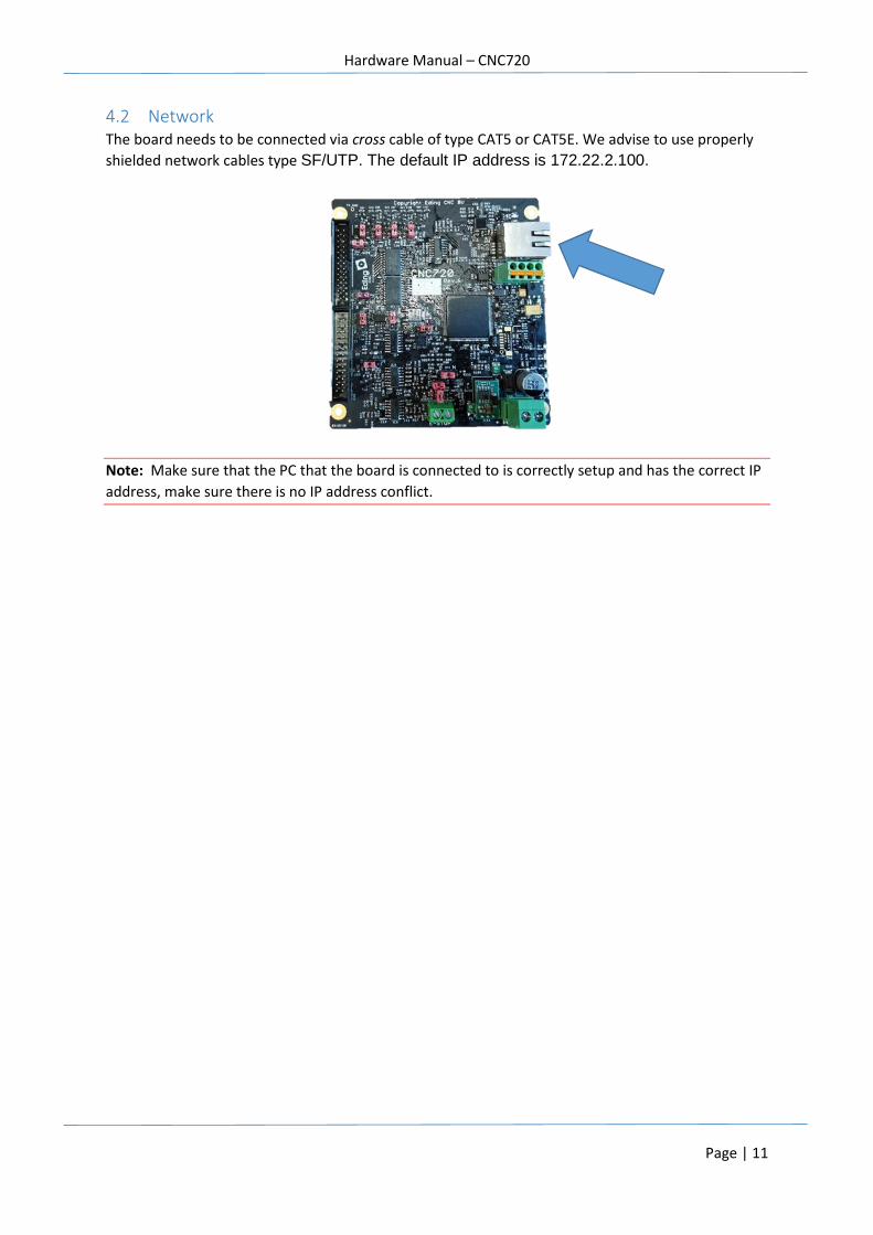
4.2 Network The board needs to be connected via cross cable of type CAT5 or CAT5E. We advise to use properly
shielded network cables type SF/UTP. The default IP address is 172.22.2.100.
Note: Make sure that the PC that the board is connected to is correctly setup and has the correct IP
address, make sure there is no IP address conflict.
Hardware Manual – CNC720
Page | 12
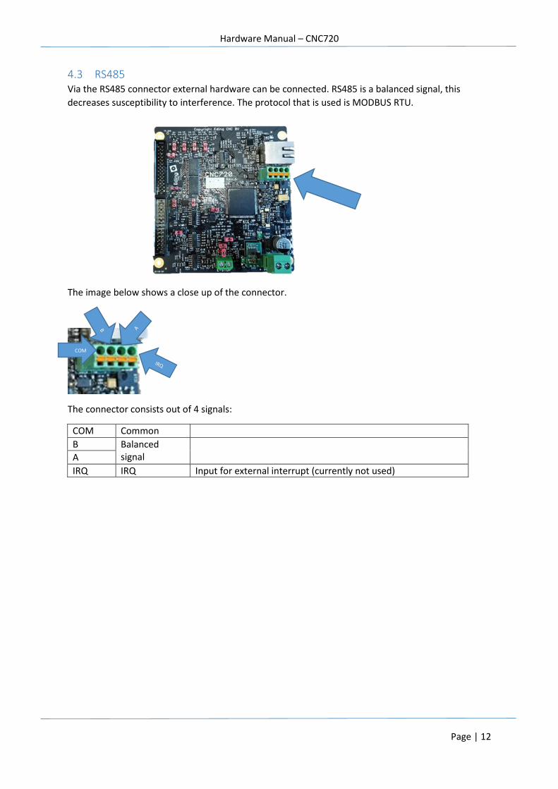
4.3 RS485 Via the RS485 connector external hardware can be connected. RS485 is a balanced signal, this
decreases susceptibility to interference. The protocol that is used is MODBUS RTU.
The image below shows a close up of the connector.
The connector consists out of 4 signals:
COM Common
B Balanced signal
A
IRQ IRQ Input for external interrupt (currently not used)
COM
Hardware Manual – CNC720
Page | 13
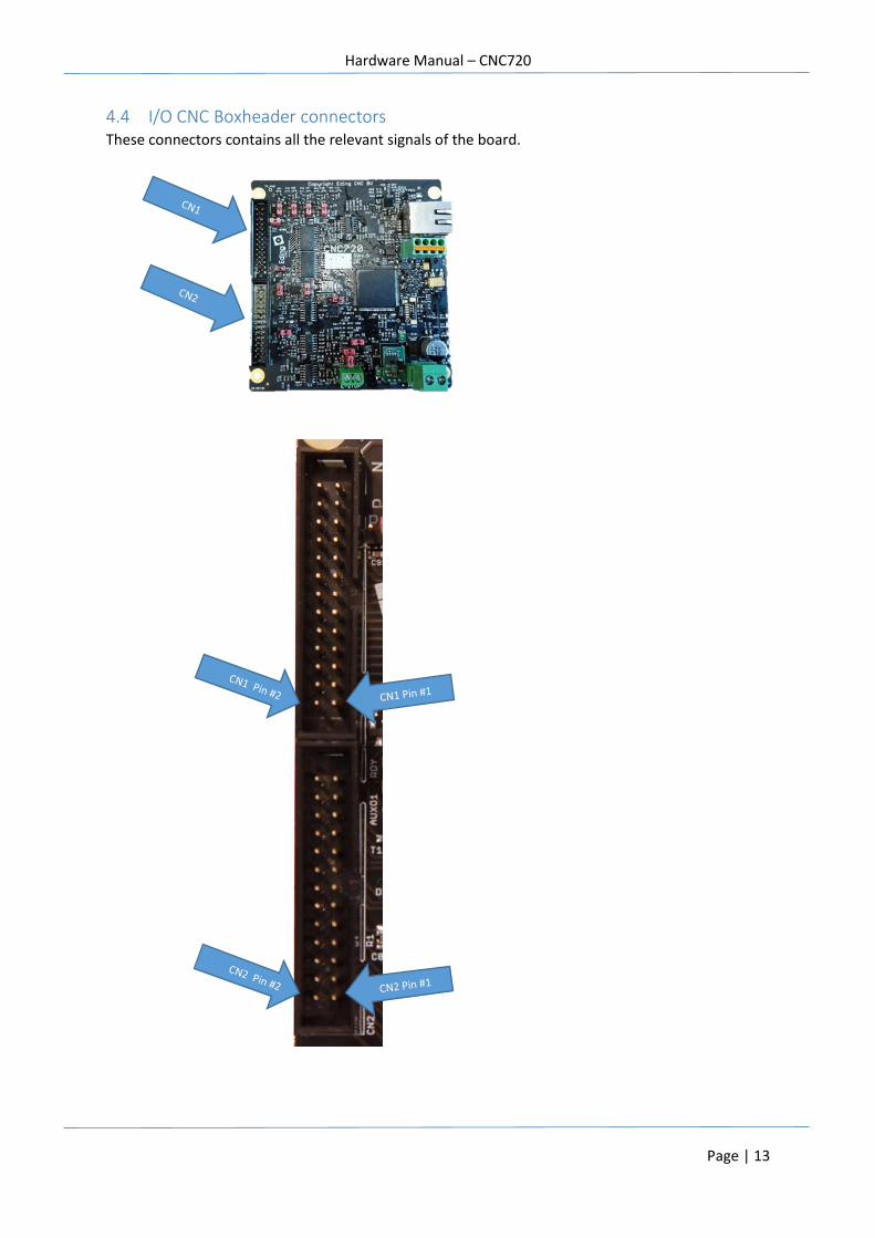
4.4 I/O CNC Boxheader connectors These connectors contains all the relevant signals of the board.
Hardware Manual – CNC720
Page | 14
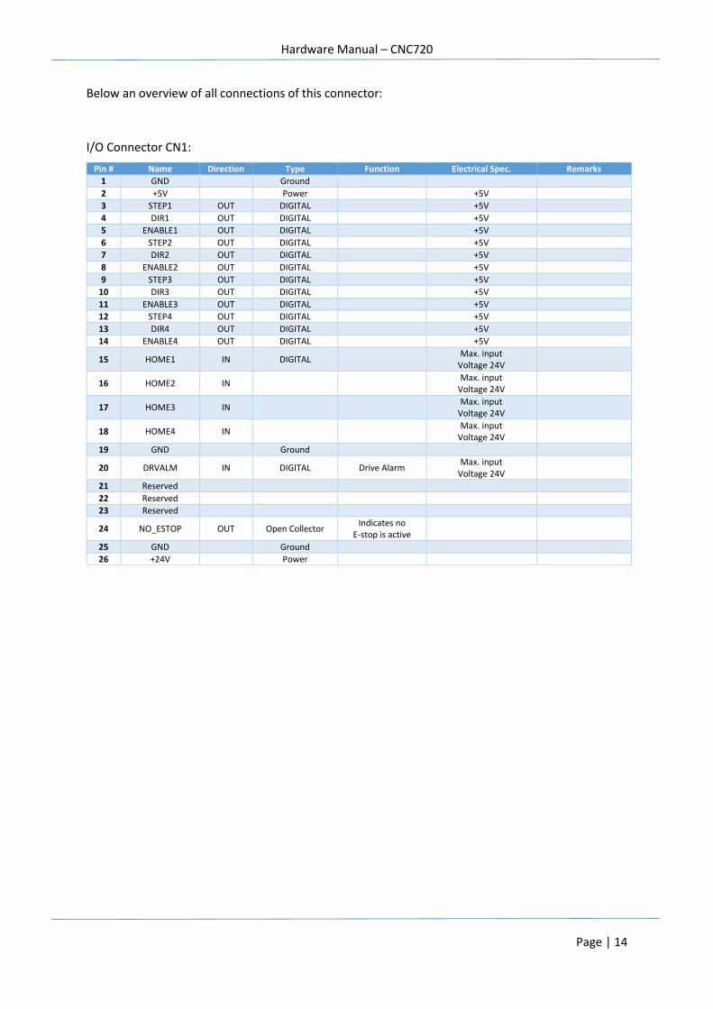
Below an overview of all connections of this connector:
I/O Connector CN1:
Pin # Name Direction Type Function Electrical Spec. Remarks
1 GND Ground
2 +5V Power +5V
3 STEP1 OUT DIGITAL +5V
4 DIR1 OUT DIGITAL +5V
5 ENABLE1 OUT DIGITAL +5V
6 STEP2 OUT DIGITAL +5V
7 DIR2 OUT DIGITAL +5V
8 ENABLE2 OUT DIGITAL +5V
9 STEP3 OUT DIGITAL +5V
10 DIR3 OUT DIGITAL +5V
11 ENABLE3 OUT DIGITAL +5V
12 STEP4 OUT DIGITAL +5V
13 DIR4 OUT DIGITAL +5V
14 ENABLE4 OUT DIGITAL +5V
15 HOME1 IN DIGITAL Max. input
Voltage 24V
16 HOME2 IN Max. input
Voltage 24V
17 HOME3 IN Max. input
Voltage 24V
18 HOME4 IN Max. input
Voltage 24V
19 GND Ground
20 DRVALM IN DIGITAL Drive Alarm Max. input
Voltage 24V
21 Reserved
22 Reserved
23 Reserved
24 NO_ESTOP OUT Open Collector Indicates no
E-stop is active
25 GND Ground
26 +24V Power

Hardware Manual – CNC720
Page | 15
I/O Connector CN2:
Pin # Name Direction Type Function Electrical Spec. Remarks
1 GND
2 +5V 5V
3 RUN IN Digital RUN switch Max. Input Voltage 5V
Active low
4 HW-A IN Digital Handwheel A input Max. Input voltage 5V
5 PAUSE IN Digital PAUSE switch Max. Input voltage 5V
Active low
6 HW-B IN Digital Handwheel B input Max. Input
voltage 5V
7 AN1 IN Analogue Analogue input 1 Max. Input
voltage 3.3V 12 bits
8 AN2 IN Analogue Analogue input 2
Max. Input
voltage 3.3V 12 bits
9 GND Ground
10 AVDD Power 3.3V
11 EXT-ERROR IN Digital Extern Error Max. input voltage 24V
12 ESTOP IN Digital Emergency Stop
13 SPINDLE-X IN Digital Spindle position
14 Reserved
15 PROBE IN Digital Probe/toolsetter
16 Reserved
17 TOOLON OUT Open Collector Switch tool ON
(eg. Spindle) Max. rating 50V/500mA
18 SYSREADY OUT Open Collector System Ready Max. rating 50V/500mA
System Ready, indicates that
system is ready for operation.
19 COOL1 OUT Open Collector Coolant1 signal Max. rating 50V/500mA
20 COOL2 OUT Open Collector Coolant2 signal Max. rating 50V/500mA
21 CHARGEPUMP OUT Open Collector Watchdog signal Max. rating 50V/500mA Pulsed signal 10Hz
22 ENABLE_OC OUT Open Collector Drive enable Max. rating 50V/500mA
23 PWM_VOLT OUT Open Collector or
Analogue PWM or 0-10V
PWM mode: Max. rating 50V/500mA 0-10V mode: Max.
100mA
24 AUXOUT1 OUT Open Collector Generic output Max. rating 50V/500mA
25 GND Ground
26 +24V Power 24V
Hardware Manual – CNC720
Page | 16
5 Using the I/O input signals
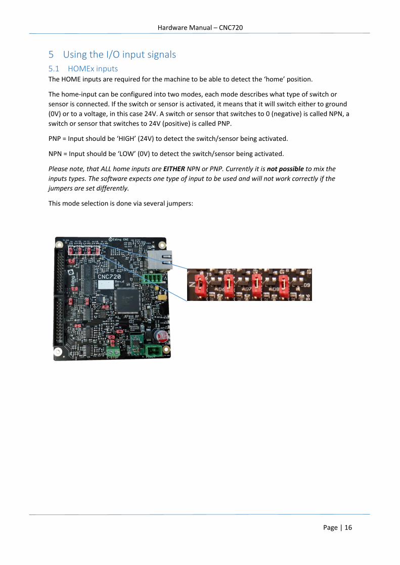
5.1 HOMEx inputs The HOME inputs are required for the machine to be able to detect the ‘home’ position.
The home-input can be configured into two modes, each mode describes what type of switch or
sensor is connected. If the switch or sensor is activated, it means that it will switch either to ground
(0V) or to a voltage, in this case 24V. A switch or sensor that switches to 0 (negative) is called NPN, a
switch or sensor that switches to 24V (positive) is called PNP.
PNP = Input should be ‘HIGH’ (24V) to detect the switch/sensor being activated.
NPN = Input should be ‘LOW’ (0V) to detect the switch/sensor being activated.
Please note, that ALL home inputs are EITHER NPN or PNP. Currently it is not possible to mix the
inputs types. The software expects one type of input to be used and will not work correctly if the
jumpers are set differently.
This mode selection is done via several jumpers:
Hardware Manual – CNC720
Page | 17
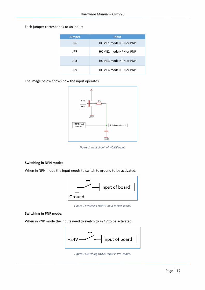
Each jumper corresponds to an input:
The image below shows how the input operates.
Figure 1 Input circuit of HOME input.
Switching in NPN mode:
When in NPN mode the input needs to switch to ground to be activated.
Figure 2 Switching HOME input in NPN mode.
Switching in PNP mode:
When in PNP mode the inputs need to switch to +24V to be activated.
Figure 3 Switching HOME input in PNP mode.
Jumper Input
JP6 HOME1 mode NPN or PNP
JP7 HOME2 mode NPN or PNP
JP8 HOME3 mode NPN or PNP
JP9 HOME4 mode NPN or PNP
Hardware Manual – CNC720
Page | 18
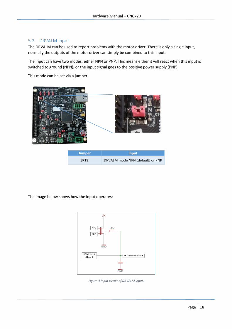
5.2 DRVALM input The DRVALM can be used to report problems with the motor driver. There is only a single input,
normally the outputs of the motor driver can simply be combined to this input.
The input can have two modes, either NPN or PNP. This means either it will react when this input is
switched to ground (NPN), or the input signal goes to the positive power supply (PNP).
This mode can be set via a jumper:
The image below shows how the input operates:
Figure 4 Input circuit of DRVALM input.
Jumper Input
JP15 DRVALM mode NPN (default) or PNP
Hardware Manual – CNC720
Page | 19
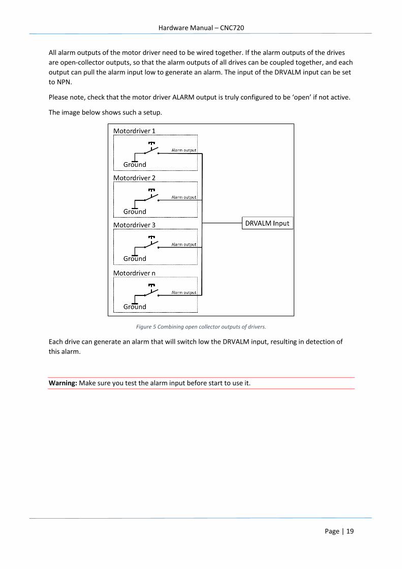
All alarm outputs of the motor driver need to be wired together. If the alarm outputs of the drives
are open-collector outputs, so that the alarm outputs of all drives can be coupled together, and each
output can pull the alarm input low to generate an alarm. The input of the DRVALM input can be set
to NPN.
Please note, check that the motor driver ALARM output is truly configured to be ‘open’ if not active.
The image below shows such a setup.
Figure 5 Combining open collector outputs of drivers.
Each drive can generate an alarm that will switch low the DRVALM input, resulting in detection of
this alarm.
Warning: Make sure you test the alarm input before start to use it.
Hardware Manual – CNC720
Page | 20
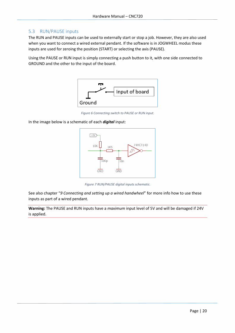
5.3 RUN/PAUSE inputs The RUN and PAUSE inputs can be used to externally start or stop a job. However, they are also used
when you want to connect a wired external pendant. If the software is in JOGWHEEL modus these
inputs are used for zeroing the position (START) or selecting the axis (PAUSE).
Using the PAUSE or RUN input is simply connecting a push button to it, with one side connected to
GROUND and the other to the input of the board.
Figure 6 Connecting switch to PAUSE or RUN input.
In the image below is a schematic of each digital input:
Figure 7 RUN/PAUSE digital inputs schematic.
See also chapter “9 Connecting and setting up a wired handwheel” for more info how to use these
inputs as part of a wired pendant.
Warning: The PAUSE and RUN inputs have a maximum input level of 5V and will be damaged if 24V
is applied.
Hardware Manual – CNC720
Page | 21
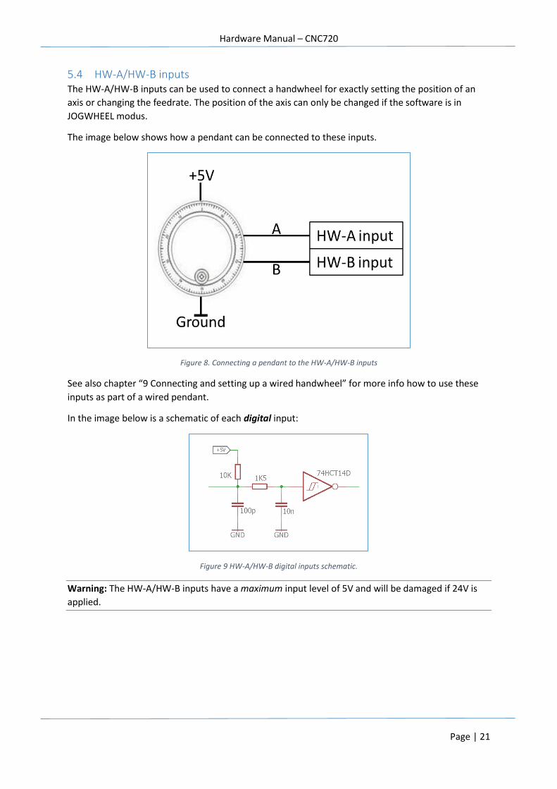
5.4 HW-A/HW-B inputs The HW-A/HW-B inputs can be used to connect a handwheel for exactly setting the position of an
axis or changing the feedrate. The position of the axis can only be changed if the software is in
JOGWHEEL modus.
The image below shows how a pendant can be connected to these inputs.
Figure 8. Connecting a pendant to the HW-A/HW-B inputs
See also chapter “9 Connecting and setting up a wired handwheel” for more info how to use these
inputs as part of a wired pendant.
In the image below is a schematic of each digital input:
Figure 9 HW-A/HW-B digital inputs schematic.
Warning: The HW-A/HW-B inputs have a maximum input level of 5V and will be damaged if 24V is
applied.
Hardware Manual – CNC720
Page | 22
5.5 AN1/AN2 inputs The analogue inputs can have several functions:
- Reading external values for control
- Controlling the feedrate
- Selecting an axis or multiplier in a wired pendant application
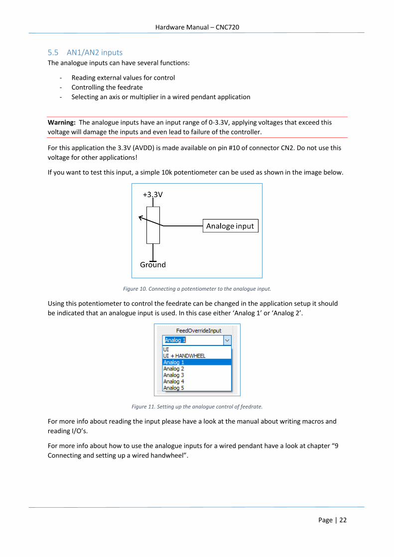
Warning: The analogue inputs have an input range of 0-3.3V, applying voltages that exceed this
voltage will damage the inputs and even lead to failure of the controller.
For this application the 3.3V (AVDD) is made available on pin #10 of connector CN2. Do not use this
voltage for other applications!
If you want to test this input, a simple 10k potentiometer can be used as shown in the image below.
Figure 10. Connecting a potentiometer to the analogue input.
Using this potentiometer to control the feedrate can be changed in the application setup it should
be indicated that an analogue input is used. In this case either ‘Analog 1’ or ‘Analog 2’.
Figure 11. Setting up the analogue control of feedrate.
For more info about reading the input please have a look at the manual about writing macros and
reading I/O’s.
For more info about how to use the analogue inputs for a wired pendant have a look at chapter “9
Connecting and setting up a wired handwheel”.
Hardware Manual – CNC720
Page | 23
5.6 EXT-ERROR input The EXT-ERROR input can be used for indicating any external ERROR has occurred. The behavior of
this input can be indicated in the setup of the application.
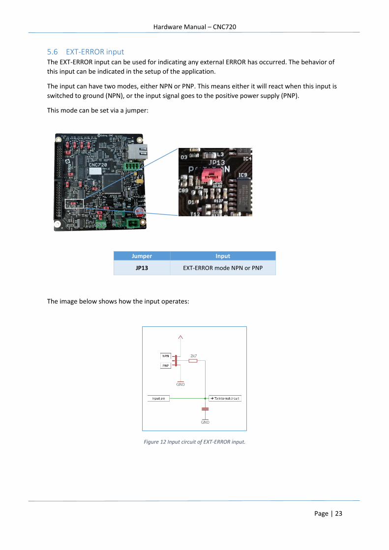
The input can have two modes, either NPN or PNP. This means either it will react when this input is
switched to ground (NPN), or the input signal goes to the positive power supply (PNP).
This mode can be set via a jumper:
The image below shows how the input operates:
Figure 12 Input circuit of EXT-ERROR input.
Jumper Input
JP13 EXT-ERROR mode NPN or PNP
Hardware Manual – CNC720
Page | 24
5.7 E-STOP input The E-STOP input is used for indicating an EMERGENCY. The CNC720 is equipped with a hardware
features that can shut down the outputs if an E-STOP occurs, this is in addition to the software
behavior in case of an E-STOP condition.
The hardware E-STOP functionality shuts down the following outputs:
- DIRx/STEPx/ENABLEx
- TOOLON
- COOL1
- COOL2
- PWM/0-10V (configurable)
- AUX01 (configurable)
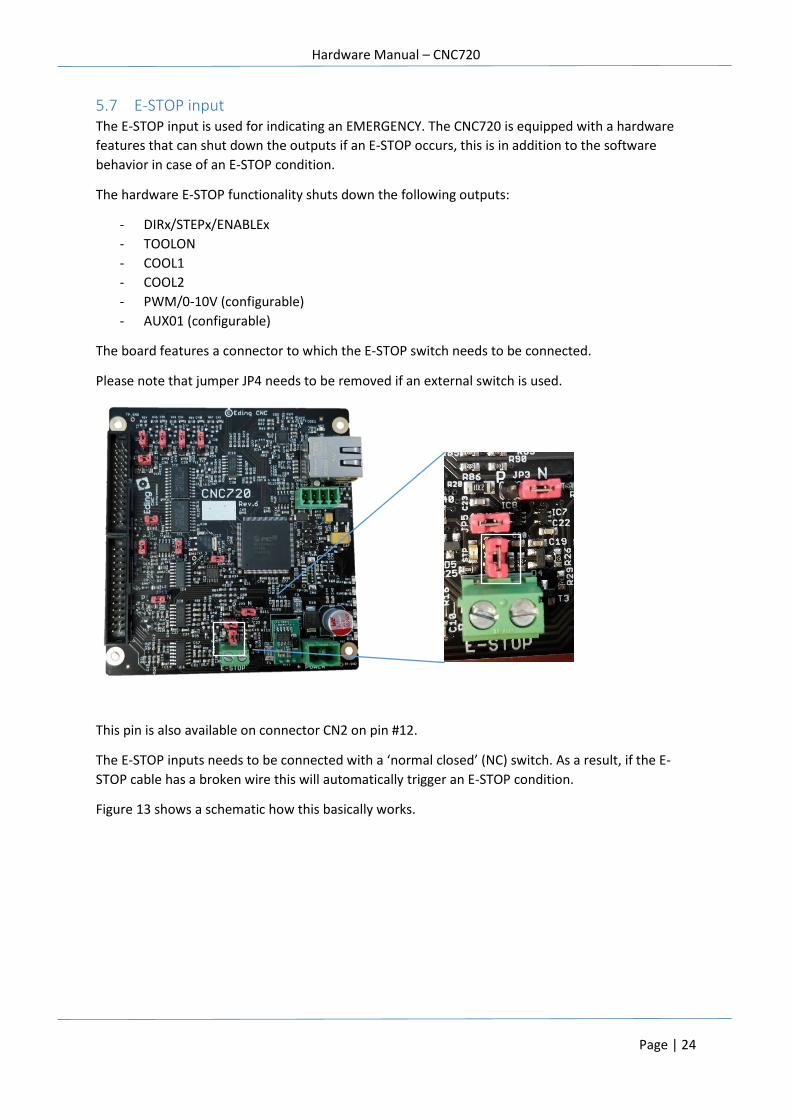
The board features a connector to which the E-STOP switch needs to be connected.
Please note that jumper JP4 needs to be removed if an external switch is used.
This pin is also available on connector CN2 on pin #12.
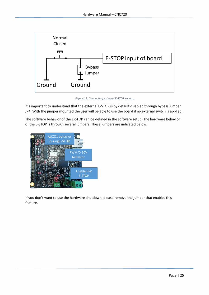
The E-STOP inputs needs to be connected with a ‘normal closed’ (NC) switch. As a result, if the E-
STOP cable has a broken wire this will automatically trigger an E-STOP condition.
Figure 13 shows a schematic how this basically works.
Hardware Manual – CNC720
Page | 25
Figure 13. Connecting external E-STOP switch.
It’s important to understand that the external E-STOP is by default disabled through bypass jumper
JP4. With the jumper mounted the user will be able to use the board if no external switch is applied.
The software behavior of the E-STOP can be defined in the software setup. The hardware behavior
of the E-STOP is through several jumpers. These jumpers are indicated below:
If you don’t want to use the hardware shutdown, please remove the jumper that enables this
feature.
PWM/0-10V
behavior
during E-STOP
Enable HW
E-STOP
AUXO1 behavior
during E-STOP
Hardware Manual – CNC720
Page | 26
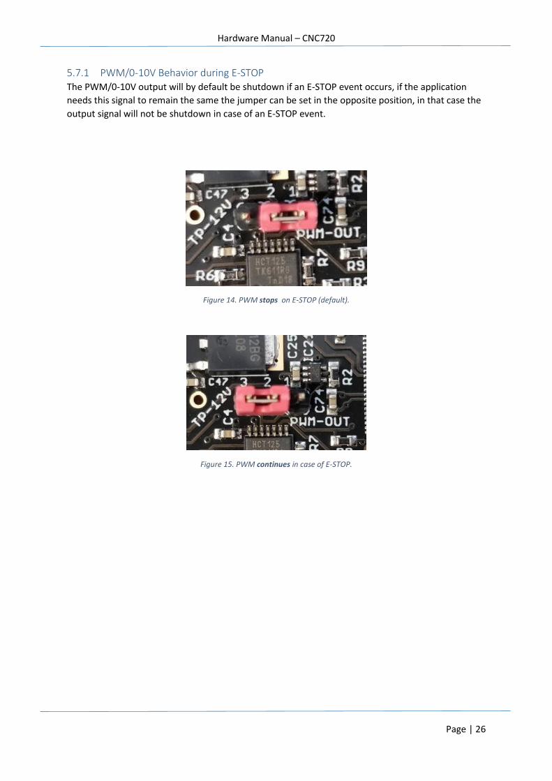
5.7.1 PWM/0-10V Behavior during E-STOP The PWM/0-10V output will by default be shutdown if an E-STOP event occurs, if the application
needs this signal to remain the same the jumper can be set in the opposite position, in that case the
output signal will not be shutdown in case of an E-STOP event.
Figure 14. PWM stops on E-STOP (default).
Figure 15. PWM continues in case of E-STOP.
Hardware Manual – CNC720
Page | 27
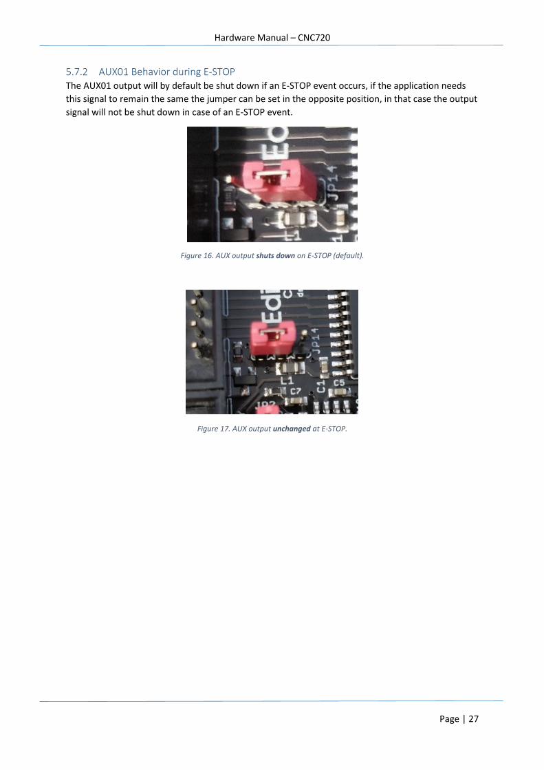
5.7.2 AUX01 Behavior during E-STOP The AUX01 output will by default be shut down if an E-STOP event occurs, if the application needs
this signal to remain the same the jumper can be set in the opposite position, in that case the output
signal will not be shut down in case of an E-STOP event.
Figure 16. AUX output shuts down on E-STOP (default).
Figure 17. AUX output unchanged at E-STOP.
Hardware Manual – CNC720
Page | 28
5.8 SPINDLE-X input The SPINDLE-X input can be used to connect an external sensor that indicates the rotation of the
spindle or used in case of tapping when used in a lathe application.
The SPINDLE-X has a maximum input level of 5V and will be damaged if 24V is applied.
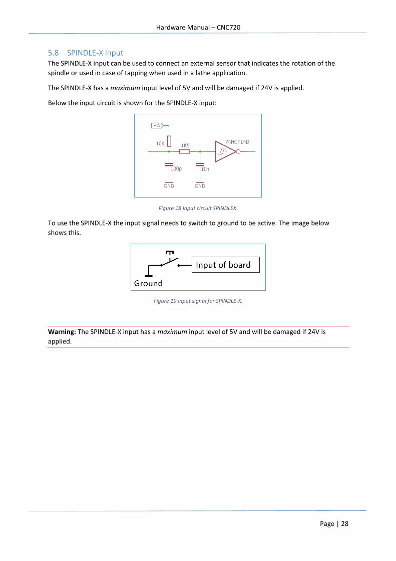
Below the input circuit is shown for the SPINDLE-X input:
Figure 18 Input circuit SPINDLEX.
To use the SPINDLE-X the input signal needs to switch to ground to be active. The image below
shows this.
Figure 19 Input signal for SPINDLE-X.
Warning: The SPINDLE-X input has a maximum input level of 5V and will be damaged if 24V is
applied.
Hardware Manual – CNC720
Page | 29
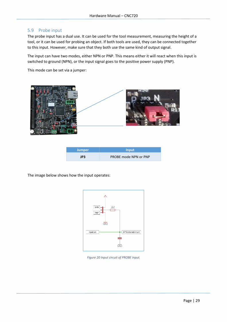
5.9 Probe input The probe input has a dual use. It can be used for the tool measurement, measuring the height of a
tool, or it can be used for probing an object. If both tools are used, they can be connected together
to this input. However, make sure that they both use the same kind of output signal.
The input can have two modes, either NPN or PNP. This means either it will react when this input is
switched to ground (NPN), or the input signal goes to the positive power supply (PNP).
This mode can be set via a jumper:
The image below shows how the input operates:
Figure 20 Input circuit of PROBE input.
Jumper Input
JP3 PROBE mode NPN or PNP
Hardware Manual – CNC720
Page | 30
6 Using the I/O output signals
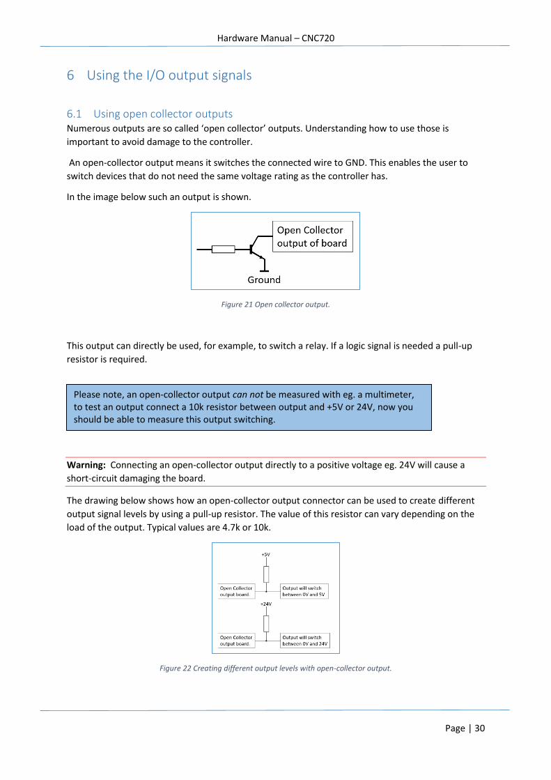
6.1 Using open collector outputs Numerous outputs are so called ‘open collector’ outputs. Understanding how to use those is
important to avoid damage to the controller.
An open-collector output means it switches the connected wire to GND. This enables the user to
switch devices that do not need the same voltage rating as the controller has.
In the image below such an output is shown.
Figure 21 Open collector output.
This output can directly be used, for example, to switch a relay. If a logic signal is needed a pull-up
resistor is required.
Warning: Connecting an open-collector output directly to a positive voltage eg. 24V will cause a
short-circuit damaging the board.
The drawing below shows how an open-collector output connector can be used to create different
output signal levels by using a pull-up resistor. The value of this resistor can vary depending on the
load of the output. Typical values are 4.7k or 10k.
Figure 22 Creating different output levels with open-collector output.
Please note, an open-collector output can not be measured with eg. a multimeter, to test an output connect a 10k resistor between output and +5V or 24V, now you should be able to measure this output switching.
Hardware Manual – CNC720
Page | 31
With open-collector output it is very simple to use a relay in order to switch bigger loads. Connecting
a relay is shown in the drawing below.
Figure 23 Connecting a relay to an open collector output.
In the above example a 5V relay and 24V relay is used, both will switch. However please consider
that a 5V relay will need more current to switch. This can limit the total number of used relays
because of the maximum total current that can be switched.
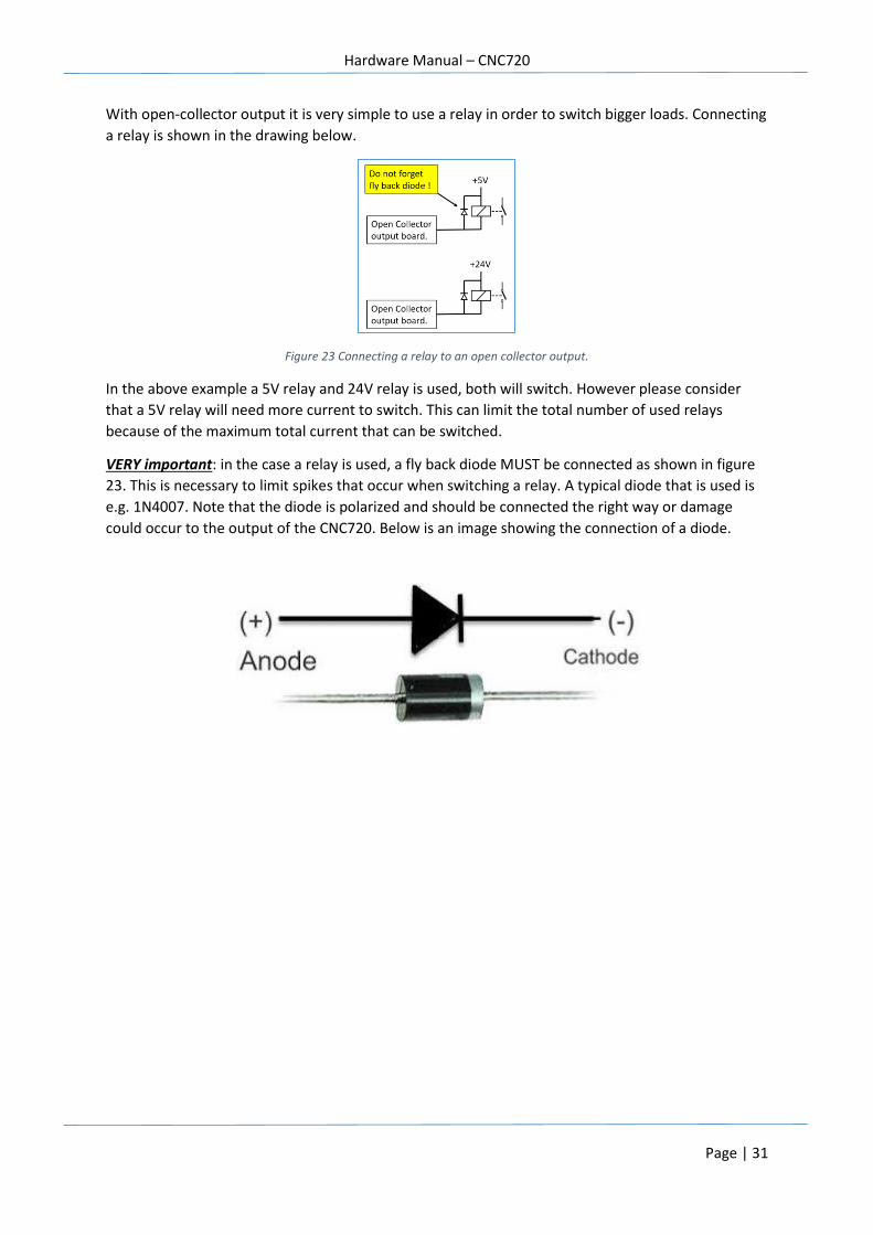
VERY important: in the case a relay is used, a fly back diode MUST be connected as shown in figure
23. This is necessary to limit spikes that occur when switching a relay. A typical diode that is used is
e.g. 1N4007. Note that the diode is polarized and should be connected the right way or damage
could occur to the output of the CNC720. Below is an image showing the connection of a diode.
Hardware Manual – CNC720
Page | 32
6.2 STEPx/DIRx/ENABLEx outputs These outputs can control up to 4 axes simultaneously. Each output has an output level of 5V and
can sink or source around 20mA per output. The maximum step frequency is 400Khz.
Please note, the ENABLEx output is simultaneously switched for all axis at the same time. Depending
on how the E-STOP hardware behavior is configured these outputs can be switched off in case of an
E-STOP condition.
For your information, in the software the ENABLE behavior can be inverted depending on the drivers
that are used.
Not all motor drivers are capable of support step frequencies up to 400Khz. If you notice that the
motors are not moving at all or show erratic movement, try to lower this frequency. Also consult
your motordriver datasheet for the supported frequency.
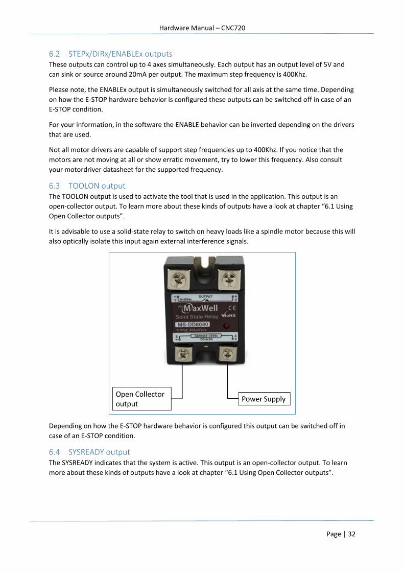
6.3 TOOLON output The TOOLON output is used to activate the tool that is used in the application. This output is an
open-collector output. To learn more about these kinds of outputs have a look at chapter “6.1 Using
Open Collector outputs”.
It is advisable to use a solid-state relay to switch on heavy loads like a spindle motor because this will
also optically isolate this input again external interference signals.
Depending on how the E-STOP hardware behavior is configured this output can be switched off in
case of an E-STOP condition.
6.4 SYSREADY output The SYSREADY indicates that the system is active. This output is an open-collector output. To learn
more about these kinds of outputs have a look at chapter “6.1 Using Open Collector outputs”.
Hardware Manual – CNC720
Page | 33
6.5 COOL1/COOL2 output The COOLx output is an output to control the flow of any coolants that might be used.
These outputs are open-collector output. To learn more about these kinds of outputs have a look at
chapter “6.1 Using Open Collector outputs”.
Depending on how the E-STOP hardware behavior is configured this output can be switched off in
case of an E-STOP condition.
If a large load is switched it is also here advisable to use a (solid-state) relay as described in chapter
“6.3 TOOLON output”
6.6 CHARGEPUMP output The CHARGEPUMP signal is a signal that is toggled around 10Hz. It is internally used for resetting a
watchdog systems that checks that the board is still alive. Absence of this signals shows that the
controller is no longer responsive. Also the SYSTEMREADY output will deactivate.
This output is an open-collector output. To learn more about these kinds of outputs have a look at
chapter “6.1 Using Open Collector outputs”.
6.7 ENABLE_OC output This output can be optionally used if the standard axis enable signal can not be used. It is the same
signal, except it features an open-collector output. To learn more about these kinds of outputs have
a look at chapter “6.1 Using Open Collector outputs”.
Hardware Manual – CNC720
Page | 34
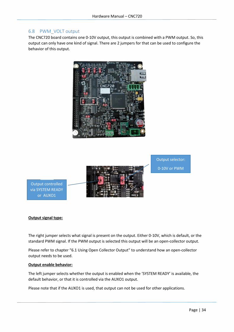
6.8 PWM_VOLT output The CNC720 board contains one 0-10V output, this output is combined with a PWM output. So, this
output can only have one kind of signal. There are 2 jumpers for that can be used to configure the
behavior of this output.
Output signal type:
The right jumper selects what signal is present on the output. Either 0-10V, which is default, or the
standard PWM signal. If the PWM output is selected this output will be an open-collector output.
Please refer to chapter “6.1 Using Open Collector Output" to understand how an open-collector
output needs to be used.
Output enable behavior:
The left jumper selects whether the output is enabled when the ‘SYSTEM READY’ is available, the
default behavior, or that it is controlled via the AUXO1 output.
Please note that if the AUXO1 is used, that output can not be used for other applications.
Output selector:
0-10V or PWM
Output controlled
via SYSTEM READY
or AUXO1
Hardware Manual – CNC720
Page | 35
Depending on how the E-STOP hardware behavior is configured this output can be switched off in
case of an E-STOP condition.
6.9 AUXOUT1 output This output is a generic output that can be used for any application. This output is an open-collector
output. Please refer to chapter “6.1 Using Open Collector Output" to understand how an open-
collector output needs to be used.
Depending on how the E-STOP hardware behavior is configured this output can be switched off in
case of an E-STOP condition.
6.10 NO_ESTOP output This output indicates when there is NO E-STOP condition. If operates hardware based and is not
SYTEMREADY related.
An application example might be is using it is to switch the power of parts of the machine
automatically off when a E-STOP condition occurs.
Hardware Manual – CNC720
Page | 36
7 Getting started Before installing the board it’s a good idea to validate that the board is operational.
Validate the board
Step 1. The first step is to validate the board is operational. Connect the network cross cable to the
board and the PC. Make sure you have set the correct IP address on the PC. For a
description on how to setup the PC please refer to the software manual.
Step 2. Connect the power, as a result the blue power LED should turn on. And observe that the
status LEDs indicates that the board is active, indicated by the ‘heartbeat’.
Step 3. Try to connect to the board.
The board should now able to communicate with the application software.
Check for motion
Now the board is operational the next step is to check whether the machine and home switches
work correctly. We start with the homing switches. Make sure that the power is off.
Step 1. The first step is to determine how to configure the jumpers. For now, the most important
ones are the jumpers for the home inputs. Set these jumpers to the correct position based
on the type of the home switches used.
Step 2. Power up the board and connect.
Step 3. By using the I/O screen of the application validate that the switches are correctly detected; if
you need to invert the signal do this in the setup of the software. If this is done, power down
the board.
Step 4. Connect the drivers to the board, you can choose to connect all motors at once or just one
at a time. Please check the manual of the driver on how to connect it to the controller, also
check that the enable signal is connected correctly; direct or via the open-collector output.
Some drivers will automatically be enabled when this input is not connected, and than
power up.
Step 5. DOUBLE check all connections.
Step 6. Power up the board and driver(s) and connect to the board.
Step 7. Normally with the default settings of the software you should be able to get some motion. If
not please check the following:
- Are all signals correctly connected?
- Do some signals need to be inverted (eg. ENABLE) ?
- Is the step frequency ok, some drivers only accept lower frequencies, so start with a low
step frequency.
TIP: By using the software I/O screen you can manually check the enabling of the drivers. When the
drive is not enabled you will be able to move it by hand, if it is enabled this should not be possible.

Hardware Manual – CNC720
Page | 37
If all went ok, your machine has now a basic setup. From here you can continue to connect more I/O
to the board, please check all I/O via the software; also check whether inversion is required.
Please note that the system will need to be tuned to each specific machine. This means that machine
parameters as speed/acceleration etc. will need to be changed to get optimum performance. Please
make sure you know who to do this, and f not request support.
And finally perform each part of the setup step by step, so you know where to look in case
something does not work immediately.
Hardware Manual – CNC720
Page | 38
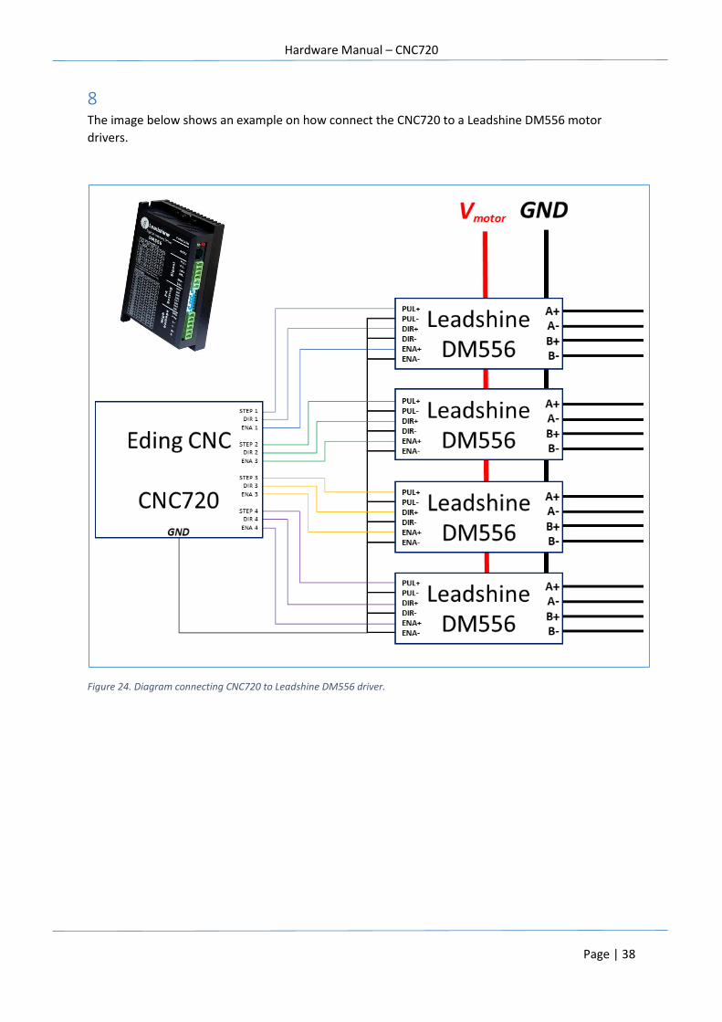
8 The image below shows an example on how connect the CNC720 to a Leadshine DM556 motor
drivers.
Figure 24. Diagram connecting CNC720 to Leadshine DM556 driver.
Hardware Manual – CNC720
Page | 39
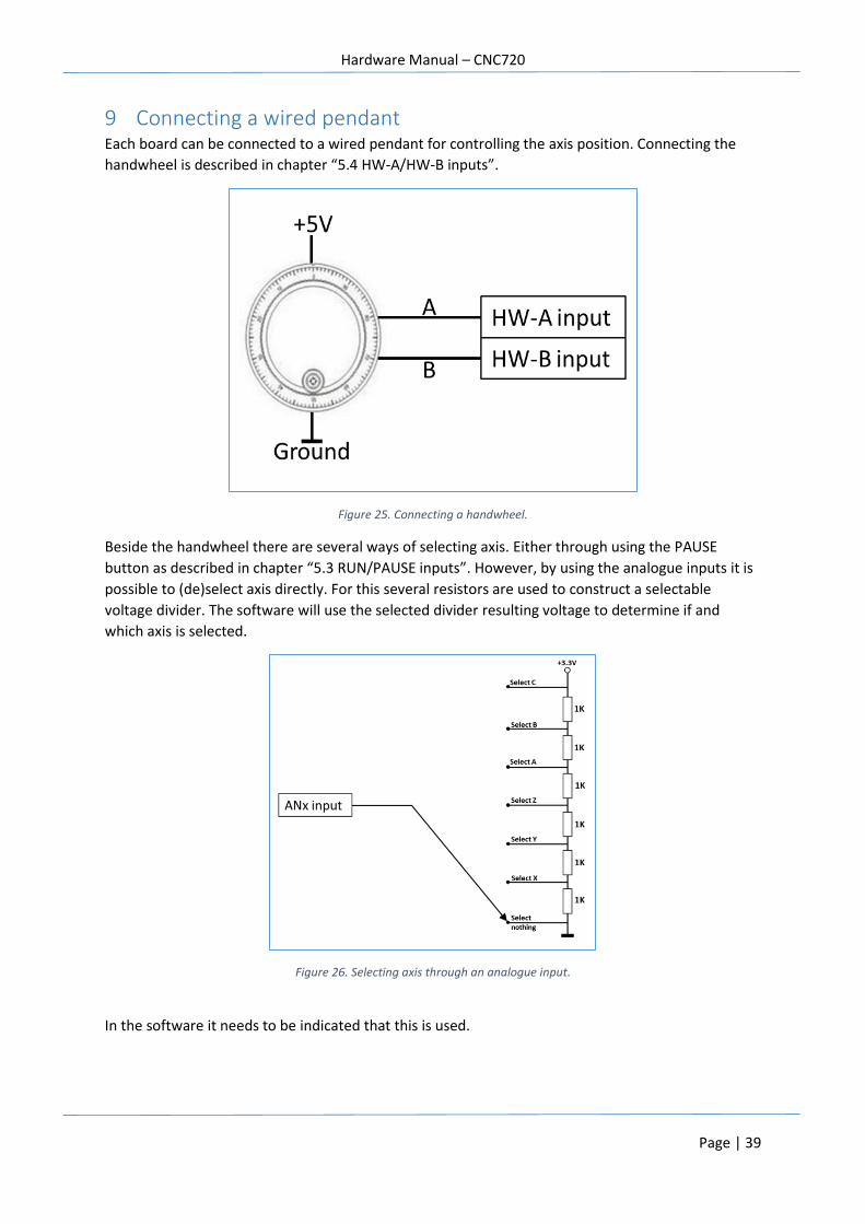
9 Connecting a wired pendant Each board can be connected to a wired pendant for controlling the axis position. Connecting the
handwheel is described in chapter “5.4 HW-A/HW-B inputs”.
Figure 25. Connecting a handwheel.
Beside the handwheel there are several ways of selecting axis. Either through using the PAUSE
button as described in chapter “5.3 RUN/PAUSE inputs”. However, by using the analogue inputs it is
possible to (de)select axis directly. For this several resistors are used to construct a selectable
voltage divider. The software will use the selected divider resulting voltage to determine if and
which axis is selected.
Figure 26. Selecting axis through an analogue input.
In the software it needs to be indicated that this is used.
Hardware Manual – CNC720
Page | 40
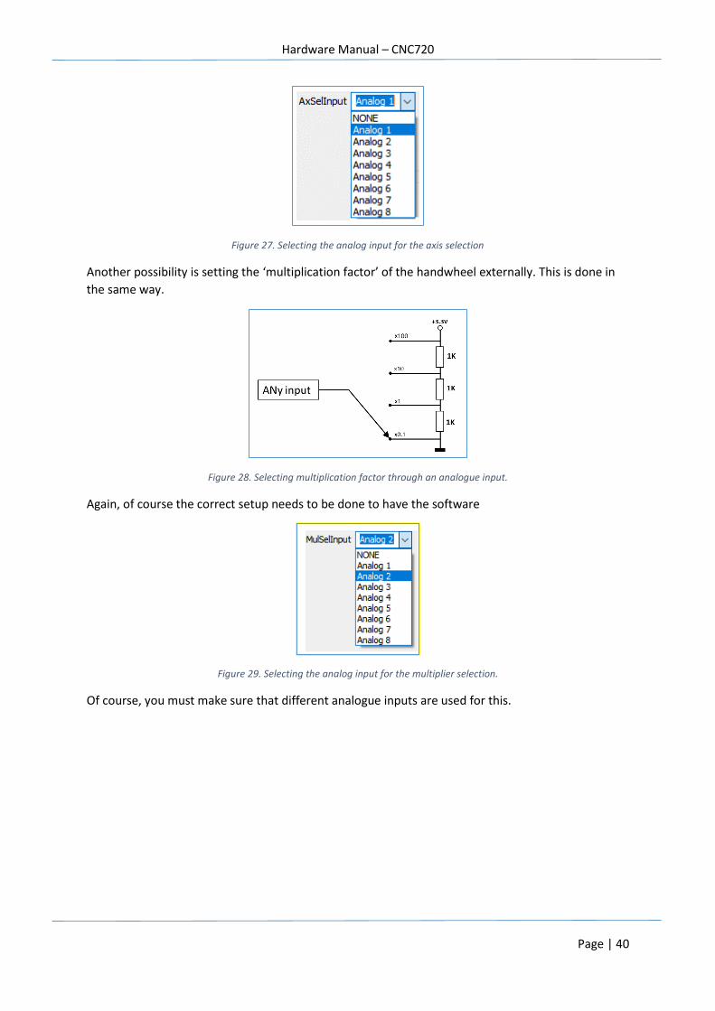
Figure 27. Selecting the analog input for the axis selection
Another possibility is setting the ‘multiplication factor’ of the handwheel externally. This is done in
the same way.
Figure 28. Selecting multiplication factor through an analogue input.
Again, of course the correct setup needs to be done to have the software
Figure 29. Selecting the analog input for the multiplier selection.
Of course, you must make sure that different analogue inputs are used for this.
Hardware Manual – CNC720
Page | 41
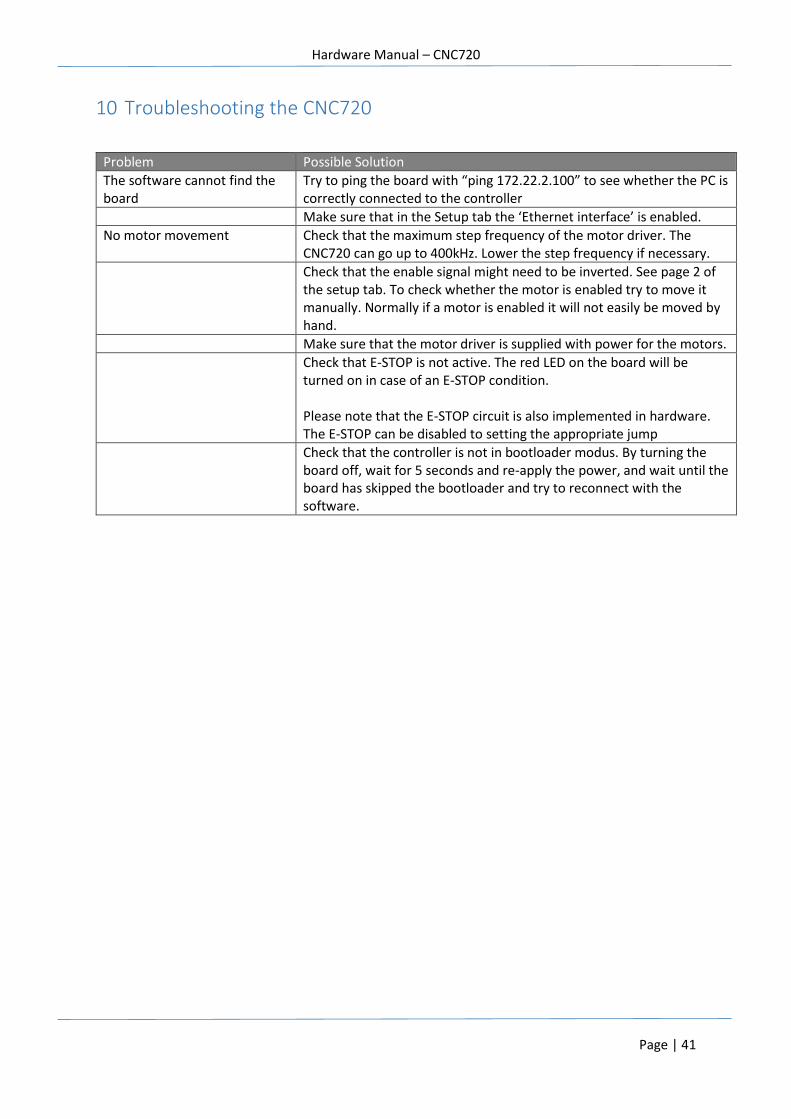
10 Troubleshooting the CNC720
Problem Possible Solution
The software cannot find the board
Try to ping the board with “ping 172.22.2.100” to see whether the PC is correctly connected to the controller
Make sure that in the Setup tab the ‘Ethernet interface’ is enabled.
No motor movement Check that the maximum step frequency of the motor driver. The CNC720 can go up to 400kHz. Lower the step frequency if necessary.
Check that the enable signal might need to be inverted. See page 2 of the setup tab. To check whether the motor is enabled try to move it manually. Normally if a motor is enabled it will not easily be moved by hand.
Make sure that the motor driver is supplied with power for the motors.
Check that E-STOP is not active. The red LED on the board will be turned on in case of an E-STOP condition. Please note that the E-STOP circuit is also implemented in hardware. The E-STOP can be disabled to setting the appropriate jump
Check that the controller is not in bootloader modus. By turning the board off, wait for 5 seconds and re-apply the power, and wait until the board has skipped the bootloader and try to reconnect with the software.

Hardware Manual – CNC720
Page | 42
DISCLAIMER
The information contained herein is believed to be reliable. Eding CNC makes no warranties regarding the information contain herein. Eding CNC assumes no responsibility or liability whatsoever for the use of the information contained herein. The information contained herein is provided "AS IS, WHERE IS" and with all faults, and the entire risk associated with such information is entirely with the user. All information contained herein is subject to change without notice. Customers should obtain and verify the latest relevant information before placing orders for Eding CNC products. The information contained herein or any use of such information does not grant, explicitly or implicitly, to any party any patent rights, licenses, or any other intellectual property rights, whether with regard to such information itself or anything described by such information. Eding CNC products are not warranted or authorized for use as critical components in medical, life-saving, or life-sustaining applications, or other applications where a failure would reasonably be expected to cause severe personal injury or death.
Related Documents