Hardware Maintenance Manual ThinkPad SL410, L410, SL510, and L510

Welcome message from author
This document is posted to help you gain knowledge. Please leave a comment to let me know what you think about it! Share it to your friends and learn new things together.
Transcript
Hardware Maintenance Manual
ThinkPad SL410, L410, SL510, and L510
Note: Before using this information and the product it supports, be sure to read the general informationunder Appendix A “Notices” on page 167.
Sixth Edition (April 2012)
© Copyright Lenovo 2009, 2012.
LIMITED AND RESTRICTED RIGHTS NOTICE: If data or software is delivered pursuant a General Services Administration“GSA” contract, use, reproduction, or disclosure is subject to restrictions set forth in Contract No. GS-35F-05925.

Contents
About this manual. . . . . . . . . . . iii
Chapter 1. Safety information. . . . . . 1General safety . . . . . . . . . . . . . . . . 1Electrical safety . . . . . . . . . . . . . . . 2Safety inspection guide . . . . . . . . . . . . 3Handling devices that are sensitive to electrostaticdischarge. . . . . . . . . . . . . . . . . . 3Grounding requirements . . . . . . . . . . . . 4Safety notices (multilingual translations) . . . . . . 4Laser compliance statement (multilingualtranslations) . . . . . . . . . . . . . . . . 17
Chapter 2. Important serviceinformation . . . . . . . . . . . . . . 23Strategy for replacing FRUs . . . . . . . . . 23
Strategy for replacing a hard disk drive . . . 24Important notice for replacing a systemboard . . . . . . . . . . . . . . . . 24How to use error message . . . . . . . . 24
Strategy for replacing FRUs for CTO, CMV, andGAV . . . . . . . . . . . . . . . . . . . 24
Product definition. . . . . . . . . . . . 24FRU identification for CTO, CMV, and GAVproducts . . . . . . . . . . . . . . . 25
Chapter 3. General checkout . . . . . 27What to do first . . . . . . . . . . . . . . 27Checkout guide . . . . . . . . . . . . . . 28
System supporting the Lenovo ThinkVantageToolbox program and the PC-Doctor for DOSdiagnostics program . . . . . . . . . . 28System supporting the Lenovo diagnosticsprograms . . . . . . . . . . . . . . . 33
Power system checkout . . . . . . . . . . . 35Checking the ac power adapter . . . . . . 35Checking operational charging . . . . . . 36Checking the battery pack . . . . . . . . 36Checking the backup battery . . . . . . . 37
Chapter 4. Related serviceinformation . . . . . . . . . . . . . . 39Restoring the factory contents by using ProductRecovery discs . . . . . . . . . . . . . . 39Restoring the factory contents by using RecoveryDisc Set . . . . . . . . . . . . . . . . . 39Passwords . . . . . . . . . . . . . . . . 41
Power-on password . . . . . . . . . . . 41Hard-disk password. . . . . . . . . . . 41
Supervisor password . . . . . . . . . . 41How to remove the power-on password . . . 41How to remove the hard-disk password . . . 42
Power management . . . . . . . . . . . . 43Screen blank mode . . . . . . . . . . . 43Sleep (standby) mode . . . . . . . . . . 43Hibernation mode . . . . . . . . . . . 44
Symptom-to-FRU index . . . . . . . . . . . 44Numeric error codes . . . . . . . . . . 45Error messages . . . . . . . . . . . . 46No-beep symptoms . . . . . . . . . . . 47LCD-related symptoms . . . . . . . . . 47Intermittent problems . . . . . . . . . . 48Undetermined problems . . . . . . . . . 48
Chapter 5. Status indicators . . . . . 51
Chapter 6. Fn key combinations . . . 53
Chapter 7. FRU replacementnotices . . . . . . . . . . . . . . . . 57Screw notices . . . . . . . . . . . . . . . 57Retaining serial numbers. . . . . . . . . . . 58
Restoring the serial number of the systemunit . . . . . . . . . . . . . . . . . 58Retaining the UUID . . . . . . . . . . . 59Reading or writing the ECA information . . . 59
Chapter 8. Removing and replacing aFRU . . . . . . . . . . . . . . . . . . 611010 Battery pack . . . . . . . . . . . . . 611020 ExpressCard blank bezel and Media Cardblank bezel . . . . . . . . . . . . . . . . 631030 Optical drive or travel cover . . . . . . . 641040 Thermal cover. . . . . . . . . . . . . 651050 Hard disk drive (HDD) assembly . . . . . 661060 DIMM . . . . . . . . . . . . . . . . 671070 Fan assembly . . . . . . . . . . . . . 681080 CPU . . . . . . . . . . . . . . . . 711090 SIM slot cover . . . . . . . . . . . . 721100 Wireless WAN slot cover and PCI ExpressMini Card for wireless WAN. . . . . . . . . . 741110 Palm rest assembly with cables . . . . . . 761120 PCI Express Mini Card for wireless LAN . . 781130 Backup battery . . . . . . . . . . . . 801140 Bluetooth daughter card (BDC-2) . . . . . 801150 Media Card Reader slot board and MediaCard Reader cable assembly . . . . . . . . . 81
© Copyright Lenovo 2009, 2012 i

1160 Keyboard . . . . . . . . . . . . . . 831170 Keyboard bezel . . . . . . . . . . . . 851180 LCD unit . . . . . . . . . . . . . . . 871190 Top shielding assembly . . . . . . . . . 911200 System board assembly. . . . . . . . . 931210 USB connector board and USB cableassembly . . . . . . . . . . . . . . . . . 971220 DC-in cable and base cover . . . . . . . 992010 LCD front bezel . . . . . . . . . . . . 1032020 Speaker assembly . . . . . . . . . . . 1042030 Integrated camera . . . . . . . . . . . 1052040 Antenna assembly . . . . . . . . . . . 1052050 Hinges, LCD panel, LCD cable, and LCD rearcover assembly . . . . . . . . . . . . . . 107
Chapter 9. Locations . . . . . . . . 111Front view . . . . . . . . . . . . . . . . 111Rear view. . . . . . . . . . . . . . . . . 112Bottom view . . . . . . . . . . . . . . . 113
Chapter 10. Parts list . . . . . . . . 115Overall . . . . . . . . . . . . . . . . . . 116LCD FRUs . . . . . . . . . . . . . . . . 142Keyboard . . . . . . . . . . . . . . . . . 151
Miscellaneous parts . . . . . . . . . . . . 152ac power adapters . . . . . . . . . . . . . 154Power cords . . . . . . . . . . . . . . . 155Recovery discs . . . . . . . . . . . . . . 156
Windows XP Professional (32 bit) DVDs . . . 156Windows XP Professional (shipping group)DVDs . . . . . . . . . . . . . . . . 157Windows Vista Home Basic (32 bit) DVDs . . 157Windows Vista Home Premium (32 bit)DVDs . . . . . . . . . . . . . . . . 158Windows Vista Home Premium (64 bit)DVDs . . . . . . . . . . . . . . . . 158Windows Vista Business (32 bit) DVDs . . . 159Windows 7 Starter (32 bit) DVDs . . . . . . 159Windows 7 Home Basic (32 bit) DVDs. . . . 160Windows 7 Home Premium (32 bit) DVDs . . 160Windows 7 Home Premium (64 bit) DVDs . . 161Windows 7 Professional (32 bit) DVDs. . . . 162Windows 7 Professional (64 bit) DVDs. . . . 163
Common service tools . . . . . . . . . . . 164
Appendix A. Notices. . . . . . . . . 167Electronic emission notices. . . . . . . . . . 168Trademarks . . . . . . . . . . . . . . . . 168
ii Hardware Maintenance Manual
About this manual
This manual contains service and reference information for the following ThinkPad® notebook products.
ThinkPad SL410 Machine Type (MT) 2842 and 2874
ThinkPad L410 MT 2931 and 0616
ThinkPad SL510 MT 2847 and 2875
ThinkPad L510 MT 2873 and 5072
Use this manual along with the advanced diagnostic tests to troubleshoot problems.
Important: This manual is intended only for trained service technicians who are familiar with ThinkPadNotebook products. Use this manual along with the advanced diagnostic tests to troubleshoot problemseffectively.
Before servicing a ThinkPad notebook product, be sure to read all the information under Chapter 1 “Safetyinformation” on page 1 and Chapter 2 “Important service information” on page 23.
© Copyright Lenovo 2009, 2012 iii

iv Hardware Maintenance Manual

Chapter 1. Safety information
This chapter presents following safety information that you need to be familiar with before you servicea ThinkPad Notebook.• “General safety” on page 1• “Electrical safety” on page 2• “Safety inspection guide” on page 3• “Handling devices that are sensitive to electrostatic discharge” on page 3• “Grounding requirements” on page 4• “Safety notices (multilingual translations)” on page 4• “Laser compliance statement (multilingual translations)” on page 17
General safetyFollow these rules to ensure general safety:
• Observe good housekeeping in the area of the machines during and after maintenance.
• When lifting any heavy object:
1. Make sure that you can stand safely without slipping.
2. Distribute the weight of the object equally between your feet.
3. Use a slow lifting force. Never move suddenly or twist when you attempt to lift.
4. Lift by standing or by pushing up with your leg muscles; this action removes the strain from themuscles in your back. Do not attempt to lift any object that weighs more than 16 kg (35 lb) or thatyou think is too heavy for you.
• Do not perform any action that causes hazards to the customer, or that makes the equipment unsafe.
• Before you start the machine, make sure that other service technicians and the customer's personnel arenot in a hazardous position.
• Place removed covers and other parts in a safe place, away from all personnel, while you are servicingthe machine.
• Keep your toolcase away from walk areas so that other people will not trip over it.
• Do not wear loose clothing that can be trapped in the moving parts of a machine. Make sure that yoursleeves are fastened or rolled up above your elbows. If your hair is long, fasten it.
• Insert the ends of your necktie or scarf inside clothing or fasten it with a nonconductive clip, about 8centimeters (3 inches) from the end.
• Do not wear jewelry, chains, metal-frame eyeglasses, or metal fasteners for your clothing.
Attention: Metal objects are good electrical conductors.
• Wear safety glasses when you are hammering, drilling, soldering, cutting wire, attaching springs, usingsolvents, or working in any other conditions that might be hazardous to your eyes.
• After service, reinstall all safety shields, guards, labels, and ground wires. Replace any safety devicethat is worn or defective.
• Reinstall all covers correctly before returning the machine to the customer.
• Fan louvers on the machine help to prevent overheating of internal components. Do not obstruct fanlouvers or cover them with labels or stickers.
© Copyright Lenovo 2009, 2012 1

Electrical safetyObserve the following rules when working on electrical equipment.
Important:
• Use only approved tools and test equipment. Some hand tools have handles covered with a soft materialthat does not insulate you when working with live electrical currents.
• Many customers have, near their equipment, rubber floor mats that contain small conductive fibers todecrease electrostatic discharges. Do not use this type of mat to protect yourself from electrical shock.
• Find the room emergency power-off (EPO) switch, disconnecting switch, or electrical outlet. If an electricalaccident occurs, you can then operate the switch or unplug the power cord quickly.
• Do not work alone under hazardous conditions or near equipment that has hazardous voltages.
• Disconnect all power before:– Performing a mechanical inspection– Working near power supplies– Removing or installing main units
• Before you start to work on the machine, unplug the power cord. If you cannot unplug it, ask the customerto power-off the wall box that supplies power to the machine, and to lock the wall box in the off position.
• If you need to work on a machine that has exposed electrical circuits, observe the following precautions:– Ensure that another person, familiar with the power-off controls, is near you.
Attention: Another person must be there to switch off the power, if necessary.– Use only one hand when working with powered-on electrical equipment; keep the other hand in your
pocket or behind your back.
Attention: An electrical shock can occur only when there is a complete circuit. By observing the aboverule, you may prevent a current from passing through your body.
– When using testers, set the controls correctly and use the approved probe leads and accessories forthat tester.
– Stand on suitable rubber mats (obtained locally, if necessary) to insulate you from grounds such asmetal floor strips and machine frames.
Observe the special safety precautions when you work with very high voltages; Instructions for theseprecautions are in the safety sections of maintenance information. Use extreme care when measuringhigh voltages.
• Regularly inspect and maintain your electrical hand tools for safe operational condition.
• Do not use worn or broken tools and testers.
• Never assume that power has been disconnected from a circuit. First, check that it has been powered off.
• Always look carefully for possible hazards in your work area. Examples of these hazards are moist floors,nongrounded power extension cables, power surges, and missing safety grounds.
• Do not touch live electrical circuits with the reflective surface of a plastic dental mirror. The surface isconductive; such touching can cause personal injury and machine damage.
• Do not service the following parts with the power on when they are removed from their normal operatingplaces in a machine:– Power supply units– Pumps– Blowers and fans– Motor generators– Similar units to listed aboveThis practice ensures correct grounding of the units.
2 Hardware Maintenance Manual

• If an electrical accident occurs:– Use caution; do not become a victim yourself.– Switch off power.– Send another person to get medical aid.
Safety inspection guideThe purpose of this inspection guide is to assist you in identifying potentially unsafe conditions. As eachmachine was designed and built, required safety items were installed to protect users and service techniciansfrom injury. This guide addresses only those items. You should use good judgment to identify potentialsafety hazards due to attachment of non-ThinkPad features or options not covered by this inspection guide.
If any unsafe conditions are present, you must determine how serious the apparent hazard could be andwhether you can continue without first correcting the problem.
Consider these conditions and the safety hazards they present:
• Electrical hazards, especially primary power (primary voltage on the frame can cause serious or fatalelectrical shock)
• Explosive hazards, such as a damaged CRT face or a bulging capacitor
• Mechanical hazards, such as loose or missing hardware
To determine whether there are any potentially unsafe conditions, use the following checklist at the beginningof every service task. Begin the checks with the power off, and the power cord disconnected.
Checklist:
1. Check exterior covers for damage (loose, broken, or sharp edges).
2. Power off the computer. Disconnect the power cord.
3. Check the power cord for:
a. A third-wire ground connector in good condition. Use a meter to measure third-wire groundcontinuity for 0.1 ohm or less between the external ground pin and the frame ground.
b. The power cord should be the type specified in the parts list.
c. Insulation must not be frayed or worn.
4. Check for cracked or bulging batteries.
5. Remove the cover.
6. Check for any obvious non-ThinkPad alterations. Use good judgment as to the safety of anynon-ThinkPad alterations.
7. Check inside the unit for any obvious unsafe conditions, such as metal filings, contamination, water orother liquids, or signs of fire or smoke damage.
8. Check for worn, frayed, or pinched cables.
9. Check that the power-supply cover fasteners (screws or rivets) have not been removed or tampered with.
Handling devices that are sensitive to electrostatic dischargeAny computer part containing transistors or integrated circuits (ICs) should be considered sensitive toelectrostatic discharge (ESD.) ESD damage can occur when there is a difference in charge between objects.Protect against ESD damage by equalizing the charge so that the machine, the part, the work mat, and theperson handling the part are all at the same charge.
Notes:
Chapter 1. Safety information 3
1. Use product-specific ESD procedures when they exceed the requirements noted here.
2. Make sure that the ESD protective devices you use have been certified (ISO 9000) as fully effective.
When handling ESD-sensitive parts:
• Keep the parts in protective packages until they are inserted into the product.
• Avoid contact with other people.
• Wear a grounded wrist strap against your skin to eliminate static on your body.
• Prevent the part from touching your clothing. Most clothing is insulative and retains a charge even whenyou are wearing a wrist strap.
• Use a grounded work mat to provide a static-free work surface. The mat is especially useful whenhandling ESD-sensitive devices.
• Select a grounding system, such as those listed below, to provide protection that meets the specificservice requirement.
Note: The use of a grounding system to guard against ESD damage is desirable but not necessary.
– Attach the ESD ground clip to any frame ground, ground braid, or green-wire ground.
– When working on a double-insulated or battery-operated system, use an ESD common ground orreference point. You can use coax or connector-outside shells on these systems.
– Use the round ground prong of the ac plug on ac-operated computers.
Grounding requirementsElectrical grounding of the computer is required for operator safety and correct system function. Propergrounding of the electrical outlet can be verified by a certified electrician.
Safety notices (multilingual translations)The safety notices in this section are provided in the following languages:• English• Arabic• Brazilian Portuguese• French• German• Hebrew• Japanese• Korean• Spanish• Traditional Chinese
DANGER
4 Hardware Maintenance Manual

DANGER
DANGER
DANGER
DANGER
DANGER
DANGER
Chapter 1. Safety information 5

DANGER
6 Hardware Maintenance Manual
PERIGO
PERIGO
PERIGO
Chapter 1. Safety information 7
PERIGO
PERIGO
PERIGO
PERIGO
PERIGO
8 Hardware Maintenance Manual

DANGER
DANGER
DANGER
DANGER
DANGER
Chapter 1. Safety information 9
DANGER
DANGER
DANGER
VORSICHT
VORSICHT
10 Hardware Maintenance Manual
VORSICHT
VORSICHT
VORSICHT
VORSICHT
VORSICHT
VORSICHT
Chapter 1. Safety information 11
12 Hardware Maintenance Manual
Chapter 1. Safety information 13

14 Hardware Maintenance Manual
Chapter 1. Safety information 15

16 Hardware Maintenance Manual
Laser compliance statement (multilingual translations)The laser compliance statements in this section are provided in the following languages:• English• Arabic• Brazilian Portuguese• French• German• Hebrew• Japanese• Korean• Spanish• Traditional Chinese
Chapter 1. Safety information 17

18 Hardware Maintenance Manual

Chapter 1. Safety information 19

20 Hardware Maintenance Manual
Chapter 1. Safety information 21

22 Hardware Maintenance Manual
Chapter 2. Important service information
This chapter presents following important service information that applies to all machine types supported bythis manual:• “Strategy for replacing FRUs” on page 23
– “Strategy for replacing a hard disk drive” on page 24– “Important notice for replacing a system board” on page 24– “How to use error message” on page 24
• “Strategy for replacing FRUs for CTO, CMV, and GAV” on page 24– “Product definition” on page 24– “FRU identification for CTO, CMV, and GAV products” on page 25
Important:• Advise customers to contact the Lenovo Customer Support Center if they need any assistance in
obtaining or installing any software fixes, drivers, and BIOS downloads. Telephone numbers for LenovoSupport are available at:http://www.lenovo.com/support/phone
• System Disassembly/Reassembly videos that show the FRU removals or replacements for the Lenovo®authorized service technicians are available in the following support site:http://www.lenovoservicetraining.com/ion/
Strategy for replacing FRUsBefore replacing parts:Make sure that all software fixes, drivers, and BIOS downloads are installed before replacing any FRUslisted in this manual.
After a system board is replaced, ensure that the latest BIOS is loaded to the system board beforecompleting the service action.
To download software fixes, drivers, and BIOS, do as follows:
1. Go to http://support.lenovo.com.
2. Enter the product number of the computer or press Auto-detect button on the screen.
3. Select Downloads and drivers.
4. Follow the directions on the screen and install the necessary software.
Use the following strategy to prevent unnecessary expense for replacing and servicing FRUs:
• If you are instructed to replace a FRU but the replacement does not correct the problem, reinstallthe original FRU before you continue.
• Some computers have both a processor board and a system board. If you are instructed to replace eitherthe processor board or the system board, and replacing one of them does not correct the problem,reinstall that board, and then replace the other one.
• If an adapter or a device consists of more than one FRU, any of the FRUs may be the cause of the error.Before replacing the adapter or device, remove the FRUs, one by one, to see if the symptoms change.Replace only the FRU that changed the symptoms.
Attention: The setup configuration on the computer you are servicing may have been customized. RunningAutomatic Configuration may alter the settings. Note the current configuration settings (using the ViewConfiguration option); then, when service has been completed, verify that those settings remain in effect.
© Copyright Lenovo 2009, 2012 23
Strategy for replacing a hard disk driveAlways try to run a low-level format before replacing a hard disk drive. This will cause all customer data onthe hard disk to be lost. Be sure that the customer has a current backup of the data before doing this task.
Attention: The drive startup sequence in the computer you are servicing may have been changed. Beextremely careful during write operations such as copying, saving, or formatting. If you select an incorrectdrive, data or programs can be overwritten.
Important notice for replacing a system boardSome components mounted on a system board are very sensitive. Improper handling of a system board cancause damage to those components, and may cause a system malfunction.
Attention: When handling a system board:
• Do not drop a system board or apply any excessive force to it.
• Avoid rough handling of any kind.
• Avoid bending a system board and hard pushing to prevent cracking at each BGA (Ball Grid Array) chipset.
How to use error messageUse the error codes displayed on the screen to diagnose failures. If more than one error code is displayed,begin the diagnosis with the first error code. Whatever causes the first error code may also cause false errorcodes. If no error code is displayed, see whether the error symptom is listed in the Symptom-to-FRUIndex for the computer you are servicing.
Strategy for replacing FRUs for CTO, CMV, and GAV
Product definition
Dynamic Configure To Order (CTO)
This provides the ability for a customer to configure a Lenovo solution from an eSite, and have thisconfiguration sent to fulfillment, where it is built and shipped directly to the customer. The machine label,Product Entitlement Warehouse (PEW), eSupport, and the HMM will load these products as the 4-digit MTand 3-digit model, where model = “CTO” (Example: 1829-CTO).
Custom Model Variant (CMV)
This is a unique configuration that has been negotiated between Lenovo and the customer. A unique 4-digitMT and 3-digit model is provided to the customer to place orders (Example: 1829-W15). A CMV is a specialbid offering. Therefore, it is NOT generally announced.
• The MTM portion of the machine label is the 4-digit MT and 3-digit model, where model = “CTO”(Example: 1829-CTO). The PRODUCT ID portion of the machine label is the 4-digit MT and 3-digit CMVmodel (Example: 1829-W15).
• The PEW record is the 4-digit MT and 3-digit model, where model = “CTO” (Example: 1829-CTO).
• eSupport will show both the CTO and CMV machine type models (Example: 1829-CTO and 1829-W15will be found on the eSupport site.)
• The HMM will have the 4-digit MT and 3-digit CTO model only (Example: 1829-CTO). Again, CMVs arecustom models and are not found in the HMM.
24 Hardware Maintenance Manual
General Announce Variant (GAV)
This is a standard model (fixed configuration). GAVs are announced and offered to all customers. The MTMportion of the machine label is a 4-digit MT and 3-digit model, where model = a “fixed part number”, not“CTO” (Example: 1829-F1U). Also, PEW, eSupport, and the HMM will list these products under the samefixed model number.
FRU identification for CTO, CMV, and GAV productsThere are three information resources to identify which FRUs are used to support CTO, CMV, and GAVproducts. These sources are PEW, eSupport, and the HMM.
Using PEW
• PEW is the primary source for identifying FRU part numbers and FRU descriptions for the key commoditiesfor CTO, CMV and GAV products at a MT - serial number level. An example of key commodities are harddisk drives, system boards, microprocessors, Liquid Crystal Displays (LCDs), and memory.
• Remember, all CTO and CMV products are loaded in PEW under the 4-digit MT and 3-digit model, wheremodel = “CTO” (Example: 1829-CTO). GAVs are loaded in PEW under the 4-digit MT and 3-digit model,where model = a “fixed part number”, not “CTO” (Example: 1829-F1U).
• PEW can be accessed at the following Web site:http://www.lenovo.com/support/site.wss/document.do?lndocid=LOOK-WARNTYSelect Warranty lookup. Input the MT and the Serial number and the list of key commodities will bereturned in the PEW record under COMPONENT INFORMATION.
Using eSupport
For key commodities (examples - hard disk drive, system board, microprocessor, LCD, and memory)
• eSupport can be used to view the list of key commodities built in a particular machine serial (this is thesame record found in PEW).
• eSupport can be accessed at the following Web site:http://support.lenovo.com
• To view the key commodities, do the following:
1. Click Products & Service Warranty.
2. Click Check Warranty Status.
3. On the Warranty Status Lookup page, click Parts Lookup.
4. Type your machine type and serial number, and then click Submit. The key commodities will bedisplayed.
For the remaining FRUs (the complete list of FRUs at the MT model level)
• eSupport can be used to view the complete list of FRUs for a machine type and model.
• To view the complete list of FRUs, do the following:
1. Click Product & Parts Detail and then follow the instructions on the screen to reach the Productand Parts Details page.
2. Click the Parts Detail tab to view the list of service parts.
Using the HMM
For key commodities (examples - hard disk drive, system board, microprocessor, LCD, and memory)
Use the HMM as a backup to PEW and eSupport to view the complete list of FRUs at the MT model level.
Chapter 2. Important service information 25

26 Hardware Maintenance Manual
Chapter 3. General checkout
This chapter presents following information:• “What to do first” on page 27• “Checkout guide” on page 28
– “System supporting the Lenovo ThinkVantage Toolbox program and the PC-Doctor for DOSdiagnostics program” on page 28
– “System supporting the Lenovo diagnostics programs” on page 33• “Power system checkout” on page 35
Before you go to the checkout guide, be sure to read the following important notes.
Important:
• Only certified trained personnel should service the computer.
• Before replacing any FRU, read the entire page on removing and replacing FRUs.
• When you replace FRUs, it is recommended use new nylon-coated screws.
• Be extremely careful during such write operations as copying, saving, or formatting. Drives in thecomputer that you are servicing sequence might have been altered. If you select an incorrect drive,data or programs might be overwritten.
• Replace a FRU only with another FRU of the correct model. When you replace a FRU, make sure thatthe model of the machine and the FRU part number are correct by referring to the FRU parts list.
• A FRU should not be replaced because of a single, unreproducible failure. Single failures can occurfor a variety of reasons that have nothing to do with a hardware defect, such as cosmic radiation,electrostatic discharge, or software errors. Consider replacing a FRU only when a problem recurs. If yoususpect that a FRU is defective, clear the error log and run the test again. If the error does not recur, donot replace the FRU.
• Be careful not to replace a nondefective FRU.
What to do firstWhen you do return a FRU, you must include the following information in the parts exchange form orparts return form that you attach to it:1. Name and phone number of service technician2. Date of service3. Date on which the machine failed4. Date of purchase5. Failure symptoms, error codes appearing on the display, and beep symptoms6. Procedure index and page number in which the failing FRU was detected7. Failing FRU name and part number8. Machine type, model number, and serial number9. Customer's name and address
Note: During the warranty period, the customer may be responsible for repair costs if the computer damagewas caused by misuse, accident, modification, unsuitable physical or operating environment, or impropermaintenance by the customer. Following is a list of some common items that are not covered under warrantyand some symptoms that might indicate that the system was subjected to stress beyond normal use.
Before checking problems with the computer, determine whether the damage is covered under the warrantyby referring to the following list:
The following are not covered under warranty:
© Copyright Lenovo 2009, 2012 27

• LCD panel cracked from the application of excessive force or from being dropped• Scratched (cosmetic) parts• Distortion, deformation, or discoloration of the cosmetic parts• Plastic parts, latches, pins, or connectors that have been cracked or broken by excessive force• Damage caused by liquid spilled into the system• Damage caused by the improper insertion of a PC Card or the installation of an incompatible card• Improper disc insertion or use of an optical drive• Diskette drive damage caused by pressure on the diskette drive cover, foreign material in the drive,
or the insertion of a diskette with multiple labels• Damaged or bent diskette eject button• Fuses blown by attachment of a nonsupported device• Forgotten computer password (making the computer unusable)• Sticky keys caused by spilling a liquid onto the keyboard• Use of an incorrect ac adapter on laptop products
The following symptoms might indicate damage caused by nonwarranted activities:• Missing parts might be a symptom of unauthorized service or modification.• If the spindle of a hard disk drive becomes noisy, it may have been subjected to excessive force,
or dropped.
Checkout guideUse the following procedures as a guide in identifying and correcting problems with the ThinkPad notebookcomputers.
Note: The diagnostic tests are intended to test only ThinkPad products. The use of non-ThinkPad products,prototype cards, or modified options can lead to false indications of errors and invalid system responses.
1. Identify the failing symptoms in as much detail as possible.
2. Verify the symptoms. Try to re-create the failure by running the diagnostic test or by repeating theoperation.
System supporting the Lenovo ThinkVantage Toolbox program and thePC-Doctor for DOS diagnostics programThe section provides information about ThinkPad computers that support the Lenovo ThinkVantage®Toolbox program and the PC-Doctor® for DOS diagnostics program. Some descriptions might not applyto your particular computer.
Diagnostics using PC-Doctor for DOSThe ThinkPad Notebook has a test program called PC-Doctor for DOS (hereafter called PC-Doctor.) You candetect errors by running the diagnostics test included in PC-Doctor.
Note: PC-Doctor for DOS is available at the following Web site:http://support.lenovo.com
To create the PC-Doctor diagnostic CD, follow the instructions on the Web site.
For some possible configurations of the computer, PC-Doctor might not run correctly. To avoid this problem,you need to initialize the computer setup by use of the BIOS Setup Utility before you run PC-Doctor.
To enter BIOS Setup Utility, do as follows:
1. Turn on the computer.
2. When the ThinkPad logo comes up, immediately press F1 to enter the BIOS Setup Utility.
28 Hardware Maintenance Manual

Note: If a supervisor password has been set by the customer, BIOS Setup Utility menu appears after thepassword is entered. You can start the BIOS Setup Utility by pressing Enter instead of entering the supervisorpassword; however, you cannot change the parameters that are protected by the supervisor password.
On the BIOS Setup Utility screen, press F9, Enter, F10, and then Enter.
Note: When you initialize the computer configuration, some devices are disabled, such as the serial port. Ifyou test one of these devices, you will need to enable it by using Configuration utility for DOS. The utility isavailable on the following Web site: http://support.lenovo.com
PC-Doctor cannot be used to test a device that is in the docking station, even if the computer supports thedocking station. To test a USB device, connect it to the USB connector of the computer.
Testing the computerNote: The PC-Doctor for DOS CD-R/CD-RW disc supports only test of internal optical disc drives (CD-RW,CD-RW/DVD Combo, and DVD Multi drives) on ThinkPad computers. It does not support test of any opticaldisc drives connected through USB devices, PC cards, CardBus cards, or similar. The USB limitation onlyapplies to testing of the device. Using a bootable PC-Doctor for DOS CD/DVD, the computer can bestarted from a USB attached optical drive.
To run the test, do as follows:
1. Turn off the computer.
2. Make sure that the optical drive that is supported as a startup device is installed to the computeryou are servicing.
3. Turn on the computer. If the computer cannot be powered on, go to “Power system checkout” onpage 35, and check the power sources.
If an error code appears, go to “Symptom-to-FRU index” on page 44.
4. When the ThinkPad logo comes up, immediately press F12 to enter the Boot Menu.
5. Insert the PC-Doctor CD into the optical drive.
6. Press cursor keys to select ATAPI CDx (x: 0, 1, ...) and then press Enter.
7. Follow the instructions on the screen.
8. The main panel of PC-Doctor appears.
9. Select Diagnostics with the arrow keys, and press Enter.
Note: You can select an item not only with the arrow keys, but also with the TrackPoint® pointer.Instead of pressing Enter, click the left button.
A pull-down menu appears. (Its exact form depends on the model.)
Note: PC-Doctor menu does not mean the formal support device list. Some unsupported device namesmay appear in the PC-Doctor menu.
Chapter 3. General checkout 29
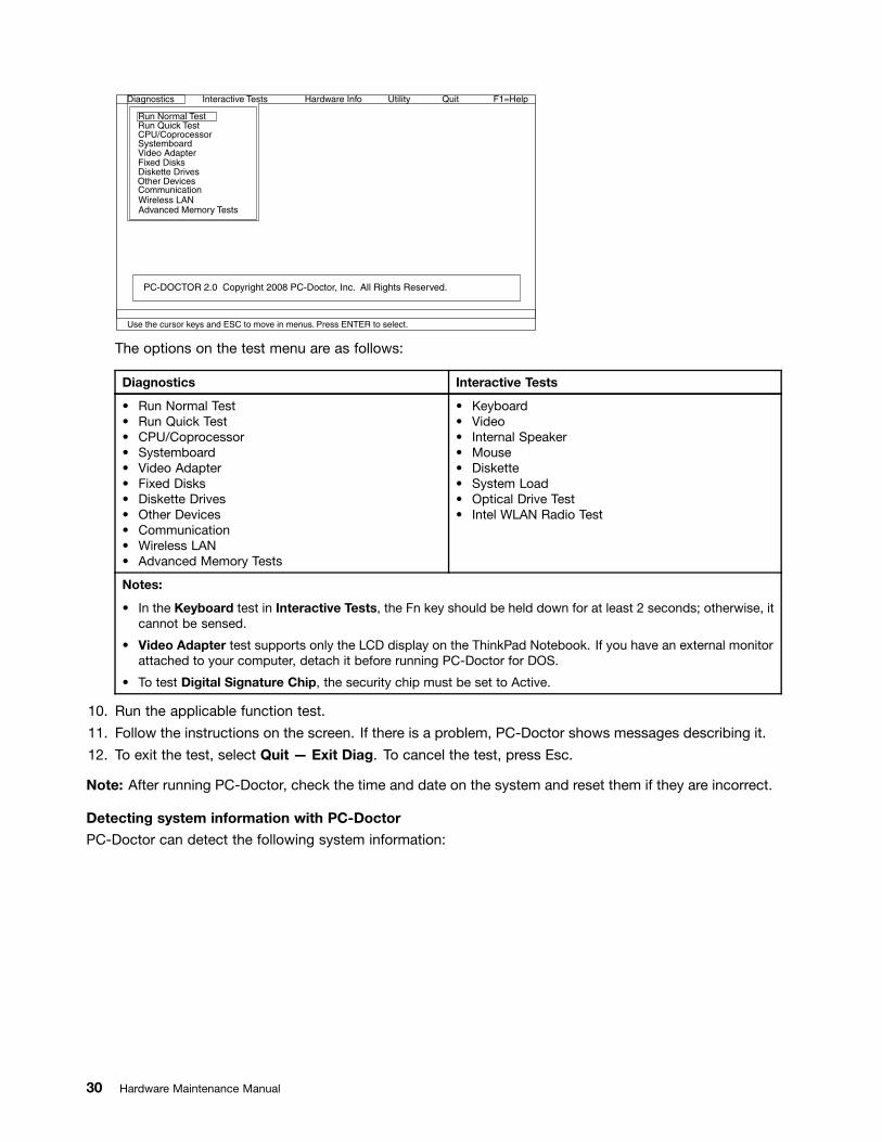
Diagnostics
Run Normal TestRun Quick TestCPU/CoprocessorSystemboardVideo AdapterFixed DisksDiskette DrivesOther DevicesCommunication
Advanced Memory Tests
Interactive Tests Hardware Info Utility Quit F1=Help
PC-DOCTOR 2.0 Copyright 2008 PC-Doctor, Inc. All Rights Reserved.
Use the cursor keys and ESC to move in menus. Press ENTER to select.
Wireless LAN
The options on the test menu are as follows:
Diagnostics Interactive Tests
• Run Normal Test• Run Quick Test• CPU/Coprocessor• Systemboard• Video Adapter• Fixed Disks• Diskette Drives• Other Devices• Communication• Wireless LAN• Advanced Memory Tests
• Keyboard• Video• Internal Speaker• Mouse• Diskette• System Load• Optical Drive Test• Intel WLAN Radio Test
Notes:
• In the Keyboard test in Interactive Tests, the Fn key should be held down for at least 2 seconds; otherwise, itcannot be sensed.
• Video Adapter test supports only the LCD display on the ThinkPad Notebook. If you have an external monitorattached to your computer, detach it before running PC-Doctor for DOS.
• To test Digital Signature Chip, the security chip must be set to Active.
10. Run the applicable function test.
11. Follow the instructions on the screen. If there is a problem, PC-Doctor shows messages describing it.
12. To exit the test, select Quit — Exit Diag. To cancel the test, press Esc.
Note: After running PC-Doctor, check the time and date on the system and reset them if they are incorrect.
Detecting system information with PC-DoctorPC-Doctor can detect the following system information:
30 Hardware Maintenance Manual
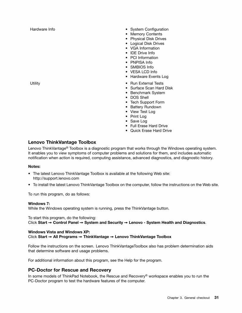
Hardware Info • System Configuration• Memory Contents• Physical Disk Drives• Logical Disk Drives• VGA Information• IDE Drive Info• PCI Information• PNPISA Info• SMBIOS Info• VESA LCD Info• Hardware Events Log
Utility • Run External Tests• Surface Scan Hard Disk• Benchmark System• DOS Shell• Tech Support Form• Battery Rundown• View Test Log• Print Log• Save Log• Full Erase Hard Drive• Quick Erase Hard Drive
Lenovo ThinkVantage ToolboxLenovo ThinkVantage® Toolbox is a diagnostic program that works through the Windows operating system.It enables you to view symptoms of computer problems and solutions for them, and includes automaticnotification when action is required, computing assistance, advanced diagnostics, and diagnostic history.
Notes:
• The latest Lenovo ThinkVantage Toolbox is available at the following Web site:http://support.lenovo.com
• To install the latest Lenovo ThinkVantage Toolbox on the computer, follow the instructions on the Web site.
To run this program, do as follows:
Windows 7:While the Windows operating system is running, press the ThinkVantage button.
To start this program, do the following:Click Start ➙ Control Panel ➙ System and Security ➙ Lenovo - System Health and Diagnostics.
Windows Vista and Windows XP:Click Start ➙ All Programs ➙ ThinkVantage ➙ Lenovo ThinkVantage Toolbox
Follow the instructions on the screen. Lenovo ThinkVantageToolbox also has problem determination aidsthat determine software and usage problems.
For additional information about this program, see the Help for the program.
PC-Doctor for Rescue and RecoveryIn some models of ThinkPad Notebook, the Rescue and Recovery® workspace enables you to run thePC-Doctor program to test the hardware features of the computer.
Chapter 3. General checkout 31
To run the test, click “Run Diagnostics” on the Rescue and Recovery main screen.
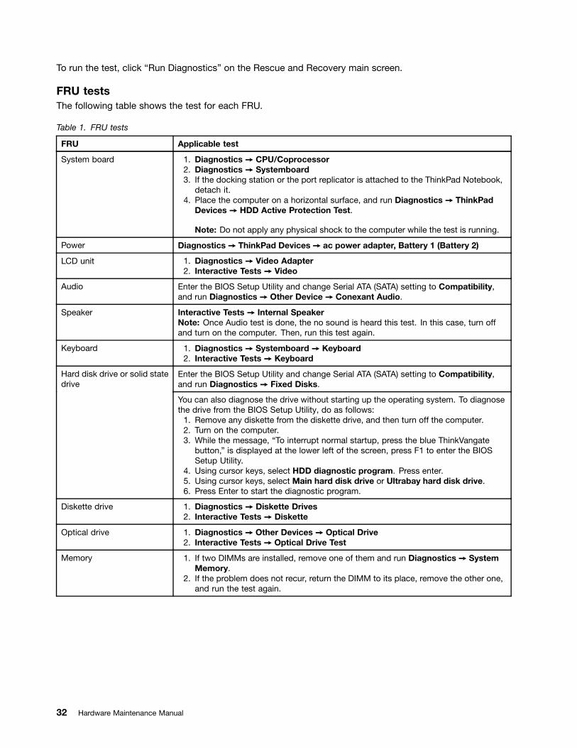
FRU testsThe following table shows the test for each FRU.
Table 1. FRU tests
FRU Applicable test
System board 1. Diagnostics ➙ CPU/Coprocessor2. Diagnostics ➙ Systemboard3. If the docking station or the port replicator is attached to the ThinkPad Notebook,
detach it.4. Place the computer on a horizontal surface, and run Diagnostics ➙ ThinkPad
Devices ➙ HDD Active Protection Test.
Note: Do not apply any physical shock to the computer while the test is running.
Power Diagnostics ➙ ThinkPad Devices ➙ ac power adapter, Battery 1 (Battery 2)
LCD unit 1. Diagnostics ➙ Video Adapter2. Interactive Tests ➙ Video
Audio Enter the BIOS Setup Utility and change Serial ATA (SATA) setting to Compatibility,and run Diagnostics ➙ Other Device ➙ Conexant Audio.
Speaker Interactive Tests ➙ Internal SpeakerNote: Once Audio test is done, the no sound is heard this test. In this case, turn offand turn on the computer. Then, run this test again.
Keyboard 1. Diagnostics ➙ Systemboard ➙ Keyboard2. Interactive Tests ➙ Keyboard
Enter the BIOS Setup Utility and change Serial ATA (SATA) setting to Compatibility,and run Diagnostics ➙ Fixed Disks.
Hard disk drive or solid statedrive
You can also diagnose the drive without starting up the operating system. To diagnosethe drive from the BIOS Setup Utility, do as follows:1. Remove any diskette from the diskette drive, and then turn off the computer.2. Turn on the computer.3. While the message, “To interrupt normal startup, press the blue ThinkVangate
button,” is displayed at the lower left of the screen, press F1 to enter the BIOSSetup Utility.
4. Using cursor keys, select HDD diagnostic program. Press enter.5. Using cursor keys, select Main hard disk drive or Ultrabay hard disk drive.6. Press Enter to start the diagnostic program.
Diskette drive 1. Diagnostics ➙ Diskette Drives2. Interactive Tests ➙ Diskette
Optical drive 1. Diagnostics ➙ Other Devices ➙ Optical Drive2. Interactive Tests ➙ Optical Drive Test
Memory 1. If two DIMMs are installed, remove one of them and run Diagnostics ➙ SystemMemory.
2. If the problem does not recur, return the DIMM to its place, remove the other one,and run the test again.
32 Hardware Maintenance Manual
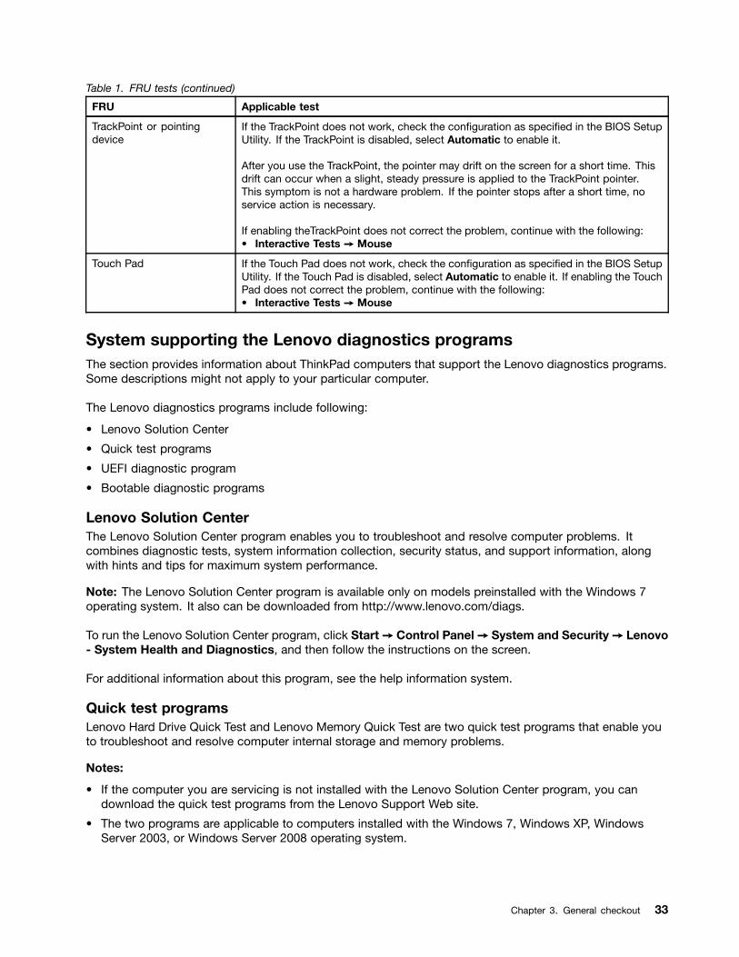
Table 1. FRU tests (continued)
FRU Applicable test
TrackPoint or pointingdevice
If the TrackPoint does not work, check the configuration as specified in the BIOS SetupUtility. If the TrackPoint is disabled, select Automatic to enable it.
After you use the TrackPoint, the pointer may drift on the screen for a short time. Thisdrift can occur when a slight, steady pressure is applied to the TrackPoint pointer.This symptom is not a hardware problem. If the pointer stops after a short time, noservice action is necessary.
If enabling theTrackPoint does not correct the problem, continue with the following:• Interactive Tests ➙ Mouse
Touch Pad If the Touch Pad does not work, check the configuration as specified in the BIOS SetupUtility. If the Touch Pad is disabled, select Automatic to enable it. If enabling the TouchPad does not correct the problem, continue with the following:• Interactive Tests ➙ Mouse
System supporting the Lenovo diagnostics programsThe section provides information about ThinkPad computers that support the Lenovo diagnostics programs.Some descriptions might not apply to your particular computer.
The Lenovo diagnostics programs include following:
• Lenovo Solution Center
• Quick test programs
• UEFI diagnostic program
• Bootable diagnostic programs
Lenovo Solution CenterThe Lenovo Solution Center program enables you to troubleshoot and resolve computer problems. Itcombines diagnostic tests, system information collection, security status, and support information, alongwith hints and tips for maximum system performance.
Note: The Lenovo Solution Center program is available only on models preinstalled with the Windows 7operating system. It also can be downloaded from http://www.lenovo.com/diags.
To run the Lenovo Solution Center program, click Start➙ Control Panel➙ System and Security➙ Lenovo- System Health and Diagnostics, and then follow the instructions on the screen.
For additional information about this program, see the help information system.
Quick test programsLenovo Hard Drive Quick Test and Lenovo Memory Quick Test are two quick test programs that enable youto troubleshoot and resolve computer internal storage and memory problems.
Notes:
• If the computer you are servicing is not installed with the Lenovo Solution Center program, you candownload the quick test programs from the Lenovo Support Web site.
• The two programs are applicable to computers installed with the Windows 7, Windows XP, WindowsServer 2003, or Windows Server 2008 operating system.
Chapter 3. General checkout 33

To download and install a quick test program, go to http://www.lenovo.com/diags, and follow the instructionson the Web site.
To run a quick test using the downloaded program, do the following:
1. Go to the C:\SWTOOLS\ldiag folder.
2. Double-click the gui_lsc_lite.exe file.
3. When the User Account Control window opens, click Yes.
4. Select the device class to be tested.
5. Select the devices to be tested.
6. Select the tests to be performed.
7. Follow the instructions on the screen to start the test. When a problem is detected, informationmessages will be displayed. Refer to the messages to troubleshoot the problem.
UEFI diagnostic programA UEFI diagnostic program is preinstalled on the computer. It enables you to test memory and internalstorage problems, view system information, and check and recover bad sectors on internal storage devices.
To run the UEFI diagnostic program, do the following:
1. Turn on the computer. If the computer cannot be turned on, go to “Power system checkout” on page 35,and check the power sources. If an error code is displayed, go to “Symptom-to-FRU index” on page 44for error code descriptions and troubleshooting hints.
2. When the ThinkPad logo is displayed, repeatedly press and release the F12 key. When the Boot Menuwindow opens, release the F12 key.
3. Press the Tab key to switch to the Application Menu window.
4. Use the arrow keys to select Lenovo Diagnostics and then press Enter. The main screen of the UEFIdiagnostic program is displayed.
5. Follow the instructions on the screen to use the diagnostic program.
The options on the main screen are as follows:
Tests Tools
• Quick Memory Test• Quick Storage Device Test• Exit Application
• System Information• Recover Bad Sectors Tool
Bootable diagnostic programsIf the computer you are servicing is not installed with the UEFI diagnostic program, you can download abootable diagnostic program from the Lenovo Support Web site. The bootable diagnostic programs enableyou to test computer memory and internal storage devices, view system information, and check and recoverthe internal storage devices. To use the bootable diagnostic programs, you can create a bootable diagnosticmedium on a USB device or CD.
To create a bootable diagnostic medium, do the following:
1. Go to http://www.lenovo.com/diags.
2. Click Lenovo Bootable Diagnostics.
3. Follow the instructions on the Web site to create a bootable diagnostic medium on a USB device or CD.
To use the diagnostic medium you have created, do one of the following:
34 Hardware Maintenance Manual
• If you have created the bootable diagnostic medium on a USB device, do the following:
1. Attach the USB device to the computer.
2. Turn on the computer. If the computer cannot be turned on, go to “Power system checkout” on page35, and check the power sources. If an error code is displayed, go to “Symptom-to-FRU index” onpage 44 for error code descriptions and troubleshooting hints.
3. When the ThinkPad logo is displayed, repeatedly press and release the F12 key. When the BootMenu window opens, release the F12 key.
4. Use the arrow keys to select USB HDD and then press Enter. The diagnostic program will belaunched automatically.
5. Follow the instructions on the screen to use the diagnostic program.
• If you have created the bootable diagnostic medium on a CD, do the following:
1. Turn on the computer. If the computer cannot be turned on, go to “Power system checkout” on page35, and check the power sources. If an error code is displayed, go to “Symptom-to-FRU index” onpage 44 for error code descriptions and troubleshooting hints.
2. Insert the CD into the optical drive.
3. Restart the computer.
4. When the ThinkPad logo is displayed, repeatedly press and release the F12 key. When the BootMenu window opens, release the F12 key.
5. Use the arrow keys to select ATAPI CDx (x: 0, 1, ...) and then press Enter. The diagnostic programwill be launched automatically.
6. Follow the instructions on the screen to use the diagnostic program.
Power system checkoutTo verify a symptom, do the following:1. Turn off the computer.2. Remove the battery pack.3. Connect the ac adapter.4. Check that power is supplied when you turn on the computer.5. Turn off the computer.6. Disconnect the ac adapter and install the charged battery pack.7. Check that the battery pack supplies power when you turn on the computer.
If you suspect a power problem, see the appropriate one of the following power supply checkouts:• “Checking the ac power adapter” on page 35• “Checking operational charging” on page 36• “Checking the battery pack” on page 36• “Checking the backup battery” on page 37
Checking the ac power adapterYou are here because the computer fails only when the ac adapter is used.
• If the power problem occurs only when the docking station or the port replicator is used, replace thedocking station or the port replicator.
• If the power-on indicator does not turn on, check the power cord of the ac adapter for correct continuityand installation.
• If the computer does not charge during operation, go to “Checking operational charging” on page 36.
To check the ac adapter, do the following:1. Unplug the ac adapter cable from the computer.
Chapter 3. General checkout 35

2. Measure the output voltage at the plug of the ac adapter cable. See the following figure:
Pin Voltage (V dc)
1 +20
2 0
3 Ground1
2
3
(20V)
Note: Output voltage of pin 2 of the ac adapter may differ from the one you are servicing.3. If the voltage is not correct, replace the ac adapter.4. If the voltage is acceptable, do the following:
• Replace the system board.
Note: Noise from the ac adapter does not always indicate a defect.
Checking operational chargingTo check whether the battery charges properly during operation, use a discharged battery pack or a batterypack that has less than 50% of the total power remaining when installed in the computer.
Perform operational charging. If the battery status indicator or icon does not turn on, remove the batterypack and let it return to room temperature. Reinstall the battery pack. If the charge indicator or icon still doesnot turn on, replace the battery pack.
If the charge indicator still does not turn on, replace the system board. Then reinstall the battery pack. If it isstill not charged, go to the next section.
Checking the battery packBattery charging does not start until the Power Manager Battery Gauge shows that less than 96% of thetotal power remains; under this condition the battery pack can charge to 100% of its capacity. This protectsthe battery pack from being overcharged or from having a shortened life.
To check your battery, move your cursor to the Power Manager Battery Gauge icon in the icon tray of theWindows taskbar and wait for a moment (but do not click), and the percentage of battery power remainingis displayed. To get detailed information about the battery, double-click the Power Manager BatteryGauge icon.
Note: If the battery pack becomes hot, it may not be able to charge. Remove it from the computer and leaveit at room temperature for a while. After it cools down, reinstall and recharge it.
To check the battery pack, do the following:1. Power off the computer.2. Remove the battery pack and measure the voltage between battery terminals 1 (+) and 7 (-). See the
following figure:
36 Hardware Maintenance Manual

Terminal Voltage (V dc)
1 + 0 to + 16.8
7 Ground (-)
1(+)2(+)
3 4 5 6(-)7(-)
3. If the voltage is less than +11.0 V dc, the battery pack has been discharged.
Note: Recharging will take at least 3 hours, even if the indicator does not turn on.
If the voltage is still less than +11.0 V dc after recharging, replace the battery.4. If the voltage is more than +11.0 V dc, measure the resistance between battery terminals 5 and 7.
The resistance must be 4 to 30 K Ω. If the resistance is not correct, replace the battery pack. If theresistance is correct, replace the system board.
Checking the backup batteryDo the following:
1. Power off the computer, and unplug the ac adapter from it.
2. Turn the computer upside down.
3. Remove the battery pack (see “1010 Battery pack” on page 61).
4. Remove the backup battery (see “1130 Backup battery” on page 80).
5. Measure the voltage of the backup battery. See the following figure.
Wire Voltage (V dc)
Red +2.5 to +3.2
Black Ground
• If the voltage is correct, replace the system board.
• If the voltage is not correct, replace the backup battery.
• If the backup battery discharges quickly after replacement, replace the system board.
Chapter 3. General checkout 37

38 Hardware Maintenance Manual

Chapter 4. Related service information
This chapter presents following information:• “Restoring the factory contents by using Recovery Disc Set” on page 39• “Passwords” on page 41• “Power management” on page 43• “Symptom-to-FRU index” on page 44
Service Web site:When the latest maintenance diskette and the system program service diskette become available, they willbe posted onhttp://support.lenovo.com.
Restoring the factory contents by using Product Recovery discsWhen the hard disk drive (HDD) or solid state drive (SSD) is replaced because of a failure, noProduct Recovery program is on the new drive. In this case, you must use the recovery discs for thecomputer. Order the recovery discs and the drive at the same time so that you can recover the newdrive with the pre-installed software when they arrive. For information on which discs to order, seehttp://www.lenovo.com/serviceparts-lookup.
To install the factory contents by using Product Recovery discs, do the following:
Note: Recovery takes several hours. The length of time depends on the method you use. If you use recoverydiscs, recovery takes at least five hours.
1. Insert the bootable Start Recovery Disc into the DVD drive.
2. Select your language and click Next.
3. Read the license. If you agree with the terms, select I accept these terms and conditions and thenclick Next.
4. Insert the Operating System Recovery Disc, when prompted and click Yes to begin the operatingsystem recovery process.
5. Insert the Product Recovery Disc, when prompted and click OK.
6. If you have a Supplemental Recovery Disc, insert it when prompted and click Yes. If you do not have aSupplemental Recovery Disc, click No.
Note: Not all recovery disc sets come with a Supplemental Recovery Disc. If there is a SupplementalRecovery Disc, it will be clearly marked as such.
7. When all of the data has been copied from the last disc in the set, a message is displayed promptingyou to restart the computer. Remove the disc and then click Yes.
Note: The remainder of the recovery process is fully automated and no action is required by you. Thecomputer will restart into the Windows desktop several times and you might experience periods whenno activity is apparent on the screen for several minutes at a time. This is normal.
8. When the recovery process is complete, the Welcome to Microsoft Windows screen is displayed. Followthe instructions on the screen to complete the Windows setup.
Restoring the factory contents by using Recovery Disc SetWhen the hard disk drive is replaced because of a failure, no product recovery program is on thenew hard disk. In this case, you must use the Recovery Disc Set for the computer. Order theRecovery Disc Set and the hard disk drive at the same time so that you can recover the new hard disk
© Copyright Lenovo 2009, 2012 39

drive with the pre-installed software when they arrive. For information on which discs to order, seehttp://www.lenovo.com/serviceparts-lookup..
The recovery disc set consists of the user instructions and the following set of DVDs to restore the computerto the original factory configuration.
Operating System Recovery Disc (one disc) This disc restores the Microsoft®Windows operatingsystem. Use this disc to start the recovery process.
Applications and Drivers Recovery Disc (one ormore discs)
This disc restores the preinstalled applications anddrivers on the computer.
Supplemental Recovery Disc This disc contains additional content, such asupdates to the software that was preinstalled on thecomputer. Not all recovery disc sets come with aSupplemental Recovery Disc.
Notes:
• You must have a DVD drive to use the recovery discs. If you do not have an internal DVD drive, youcan use an external USB DVD drive.
• During the recovery process, all data on the hard disk drive will be deleted. If possible, copy anyimportant data or personal files that you want to keep onto removable media or a network drive beforeyou start the recovery process.
To restore the computer to the original factory configuration using the recovery disc set, do the following:
Note: Recovery can take one to two hours to complete. The length of time depends on the method you use.If you use recovery discs, the recovery process will take about two hours.
1. Make the CD/DVD drive the first startup device in the startup sequence using the following procedure:
a. Press and hold down the F1 key, and then turn on the computer. When the logo screen is displayedor if you hear repeating beeps, release the F1 key. The Setup Utility program opens.
b. Use the arrow keys to select Startup ➙ Boot.
c. Select the CD/DVD drive as the 1st Boot Device.
2. Insert the Operating System Recovery Disc into the DVD drive.
3. Press F10 to save the Setup Utility configuration changes. Follow the instructions on the screen tobegin the recovery process.
4. Select your language and click Next.
5. Read the license. If you agree with the terms and conditions, select I accept these terms andconditions and then click Next. If you do not agree with the terms and conditions, follow theinstructions on the screen.
6. Click Yes in the displayed window to begin the operating system recovery process.
7. Insert the Applications and Drivers Recovery Disc when prompted and then click OK to begin theapplications and drivers recovery process.
8. If you have a Supplemental Recovery Disc, insert it when prompted and click Yes. If you do not have aSupplemental Recovery Disc, click No.
9. When all of the data has been copied from the last disc in the set and has been processed, remove thedisc and restart the computer.
Note: The rest of the recovery process is fully automated and no action is required by you. Thecomputer will restart into the Microsoft Windows desktop several times and you might experienceperiods when no activity is apparent on the screen for several minutes at a time. This is normal.
10. When the recovery process is complete, the Set Up Windows screen is displayed. Follow theinstructions on the screen to complete the Windows setup.
40 Hardware Maintenance Manual
11. After you have completed the Windows setup, you might want to restore the original startup sequence.Start the Setup Utility program and then press F9 to restore the default settings. Press F10 to save andexit the Setup Utility.
Note: After restoring a hard disk drive to the factory default settings, you might need to reinstall somedevice drivers.
PasswordsAs many as three passwords may be needed for any ThinkPad Notebook: the power-on password (POP),the hard-disk password (HDP), and the supervisor password (SVP).
If any of these passwords has been set, a prompt for it appears on the screen whenever the computer isturned on. The computer does not start until the password is entered.
Exception: If only an SVP is installed, the password prompt does not appear when the operating systemis booted.
Power-on passwordA power-on password (POP) protects the system from being powered on by an unauthorized person. Thepassword must be entered before an operating system can be booted. For how to remove the POP, see“How to remove the power-on password” on page 41.
Hard-disk passwordThere are two hard-disk passwords (HDPs):
• User HDP—for the user
• Master HDP—for the system administrator, who can use it to get access to the hard disk even if the userhas changed the user HDP
Note: There are two modes for the HDP: User only and Master + User. The Master + User mode requirestwo HDPs; the system administrator enters both in the same operation. The system administrator thenprovides the user HDP to the system user.
Attention: If the user HDP has been forgotten, check whether a master HDP has been set. If it has, it can beused for access to the hard disk drive. If no master HDP is available, neither Lenovo nor Lenovo authorizedservice technicians provide any services to reset either the user or the master HDP, or to recover data fromthe hard disk drive. The hard disk drive can be replaced for a scheduled fee.
For how to remove the POP, see “How to remove the hard-disk password” on page 42.
Supervisor passwordA supervisor password (SVP) protects the system information stored in the BIOS Setup Utility. The user mustenter the SVP in order to get access to the BIOS Setup Utility and change the system configuration.
Attention: If the SVP has been forgotten and cannot be made available to the service technician, there is noservice procedure to reset the password. The system board must be replaced for a scheduled fee.
How to remove the power-on passwordTo remove a POP that you have forgotten, do the following:
(A) If no SVP has been set:
Chapter 4. Related service information 41

1. Turn off the computer.
2. Remove the battery pack. For how to remove the battery pack, see “1010 Battery pack” on page 61.
3. Remove the backup battery. For how to remove the backup battery, see “1130 Backup battery” onpage 80.
4. Turn on the computer and wait until the POST ends. After the POST ends, the password prompt doesnot appear. The POP has been removed.
5. Reinstall the backup battery and the battery pack.
(B) If an SVP has been set and is known by the service technician:
1. Turn on the computer.
2. When the ThinkPad logo comes up, immediately press F1 to enter BIOS Setup Utility. For modelssupporting the Passphrase function, press F1 while the POP icon is appearing on the screen; then enterthe POP. For the other models, enter the POP.
Note: To check whether the ThinkPad Notebook you are servicing supports the Passphrase function,enter the BIOS Setup Utility and go to Security➙ Password. If the Using Passphrase item is displayedin the menu, this function is available on the ThinkPad Notebook.
3. Select Security, using the cursor directional keys to move the menu.
4. Select Password.
5. Select Power-On Password.
6. Type the current SVP in the Enter Current Password field, then leave the Enter New Password fieldblank, and press Enter twice.
7. In the Changes have been saved window, press Enter.
8. Press F10; then, in the Setup confirmation window, select Yes.
How to remove the hard-disk passwordAttention: If User only mode is selected and the user HDP has been forgotten and cannot be madeavailable to the service technician, neither Lenovo nor Lenovo authorized service technicians provide anyservices to reset the user HDPs or to recover data from the hard disk drive. The hard disk drive can bereplaced for a scheduled fee.
To remove a user HDP that has been forgotten, when the SVP and the master HDP are known, do thefollowing:
1. Turn on the computer.
2. When the ThinkPad logo comes up, immediately press F1 to enter BIOS Setup Utility. For modelssupporting the Passphrase function, press F1 while HDP icon is appearing on the screen; then enter themaster HDP. For the other models, enter the master HDP.
Note: To check whether the ThinkPad Notebook you are servicing supports the Passphrase function,enter the BIOS Setup Utility and go to Security➙ Password. If the Using Passphrase item is displayedin the menu, this function is available on the ThinkPad Notebook.
3. Select Security, using the cursor directional keys to move the menu.
4. Select Password.
5. Select Hard-disk x password, where x is the letter of the hard disk drive. A pop-up window opens.
6. Select Master HDP.
7. Type the current master HDP in the Enter Current Password field. then leave the Enter New Passwordfield blank, and press Enter twice.
8. Press F10.
9. Select Yes in the Setup Configuration window. Both user HDP and master HDP will have been removed.
42 Hardware Maintenance Manual
Power managementTo reduce power consumption, the computer has three power management modes: screen blank, sleep(standby in Windows XP), and hibernation.
Screen blank modeIf the time set on the “Turn off monitor” timer in the operating system expires, the LCD backlight turns off.
To put the computer into screen blank mode, do as follows:
1. Press Fn+F3. A panel for selecting a power plan (in Windows XP, power scheme) appears.
2. Select Power off display (keep current power plan) (in Windows XP, keep current power scheme).
You can also put the computer into screen blank mode, press ThinkVantage button and use the ThinkVantageProductivity Center.
Note: If the computer is a Windows 7 model, it does not support ThinkVantage Productivity Center.
To end screen blank mode and resume normal operation, press any key.
Sleep (standby) modeWhen the computer enters sleep (standby) mode, the following events occur in addition to what occursin screen blank mode:• The LCD is powered off.• The hard disk drive or the solid state drive is powered off.• The CPU stops.
To enter sleep (standby) mode, press Fn+F4.
Note: You can change the action of the Fn+F4 key combination by changing the settings in Power Manager.
In certain circumstances, the computer goes into sleep (standby) mode automatically:
• If a “suspend time” has been set on the timer, and the user does not do any operation with the keyboard,the TrackPoint, the hard disk, the parallel connector, or the diskette drive within that time.
• If the battery indicator blinks orange, indicating that the battery power is low.
Note: Even if you do not set the low-battery alarm, the charge indicator notifies you when the battery is low,and then the computer enters the power-saving mode automatically.
To cause the computer to return from sleep (standby) mode and resume operation, do one of the following:• Press the Fn key.• Open the LCD cover.• Turn on the power switch.
Also, in either of the following events, the computer automatically returns from sleep (standby) mode andresumes operation:
• The ring indicator (RI) is signaled by a serial device or a PC Card device. (does not support the ringindicator (RI) resume by PC Card device.)
• The time set on the resume timer elapses.
Note: The computer does not accept any input immediately after it enters sleep (standby) mode. Wait afew seconds before taking any action to reenter operation mode.
Chapter 4. Related service information 43

Hibernation modeIn hibernation mode, the following occurs:
• The system status, RAM, VRAM, and setup data are stored on the hard disk.
• The system is powered off.
Note: If the computer enters the hibernation mode while it is docked to the docking station, do not undock itbefore resuming normal operation. If you do undock it and then try to resume normal operation, you will getan error message, and you will have to restart the system.
To cause the computer to enter hibernation mode, do any of the following:
• Press the Fn+F12 keys.
• If you have defined one of the following actions as the event that causes the system to go into hibernationmode, perform that action.– Closing the lid.– Pressing the power button.– Pressing Fn+F4 keys.
Also, the computer goes into hibernation mode automatically in either of the following conditions:
• If a “hibernation time” has been set on the timer, and if the user does not do any operation with thekeyboard, the TrackPoint, the hard disk drive, the parallel connector, or the diskette drive within that time.
• If the timer conditions are satisfied in suspend mode.
When the power is turned on, the computer returns from hibernation mode and resumes operation. Thehibernation file in the boot record on the hard disk drive is read, and system status is restored from thehard disk drive.
Symptom-to-FRU indexThis section contains following information:• “Numeric error codes” on page 45• “Error messages” on page 46• “No-beep symptoms” on page 47• “LCD-related symptoms” on page 47• “Intermittent problems” on page 48• “Undetermined problems” on page 48
The symptom-to-FRU index in this section lists symptoms and errors and their possible causes. The mostlikely cause is listed first, in boldface type.
Note: Do the FRU replacement or other actions in the sequence shown in the column headed “FRU oraction, in sequence.” If replacing a FRU does not solve the problem, put the original part back in thecomputer. Do not replace a nondefective FRU.
This index can also help you determine, during regular servicing, what FRUs are likely to need to bereplaced next.
A numeric error is displayed for each error detected in POST or system operation. In the displays, n canbe any number.
If no numeric code is displayed, check the narrative descriptions of symptoms. If the symptom is notdescribed there, go to “Intermittent problems” on page 48.
44 Hardware Maintenance Manual
Note: For a device not supported by diagnostic codes in the ThinkPad Notebooks, see the manual forthat device.
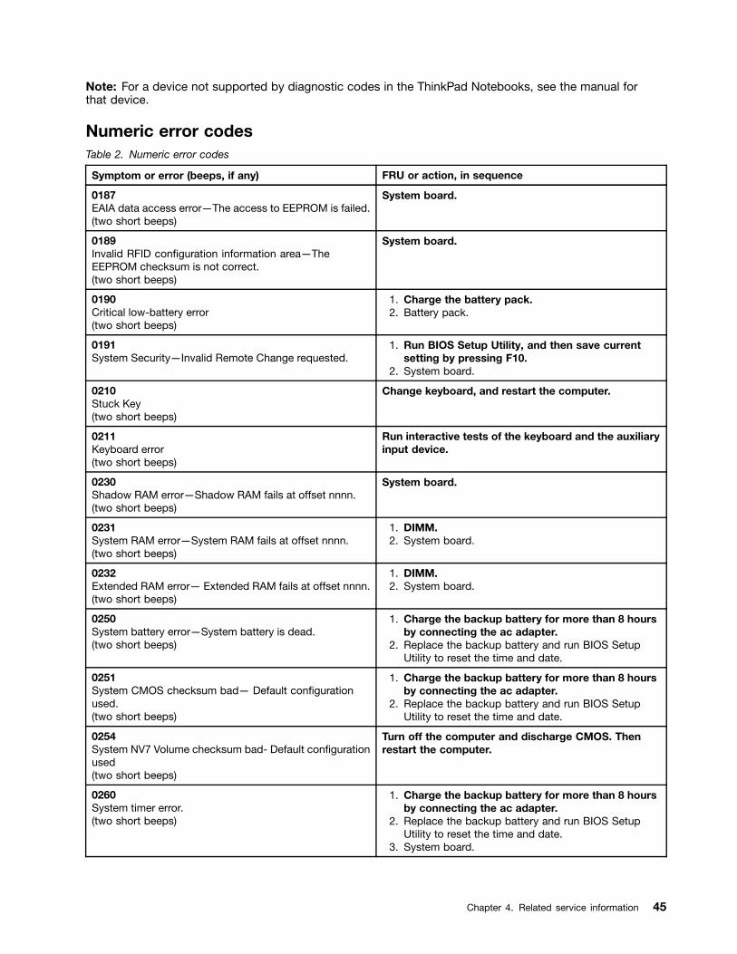
Numeric error codesTable 2. Numeric error codes
Symptom or error (beeps, if any) FRU or action, in sequence
0187EAIA data access error—The access to EEPROM is failed.(two short beeps)
System board.
0189Invalid RFID configuration information area—TheEEPROM checksum is not correct.(two short beeps)
System board.
0190Critical low-battery error(two short beeps)
1. Charge the battery pack.2. Battery pack.
0191System Security—Invalid Remote Change requested.
1. Run BIOS Setup Utility, and then save currentsetting by pressing F10.
2. System board.
0210Stuck Key(two short beeps)
Change keyboard, and restart the computer.
0211Keyboard error(two short beeps)
Run interactive tests of the keyboard and the auxiliaryinput device.
0230Shadow RAM error—Shadow RAM fails at offset nnnn.(two short beeps)
System board.
0231System RAM error—System RAM fails at offset nnnn.(two short beeps)
1. DIMM.2. System board.
0232Extended RAM error— Extended RAM fails at offset nnnn.(two short beeps)
1. DIMM.2. System board.
0250System battery error—System battery is dead.(two short beeps)
1. Charge the backup battery for more than 8 hoursby connecting the ac adapter.
2. Replace the backup battery and run BIOS SetupUtility to reset the time and date.
0251System CMOS checksum bad— Default configurationused.(two short beeps)
1. Charge the backup battery for more than 8 hoursby connecting the ac adapter.
2. Replace the backup battery and run BIOS SetupUtility to reset the time and date.
0254System NV7 Volume checksum bad- Default configurationused(two short beeps)
Turn off the computer and discharge CMOS. Thenrestart the computer.
0260System timer error.(two short beeps)
1. Charge the backup battery for more than 8 hoursby connecting the ac adapter.
2. Replace the backup battery and run BIOS SetupUtility to reset the time and date.
3. System board.
Chapter 4. Related service information 45
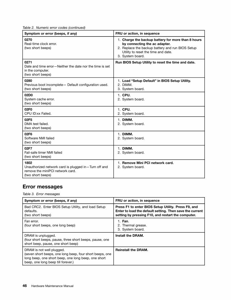
Table 2. Numeric error codes (continued)
Symptom or error (beeps, if any) FRU or action, in sequence
0270Real-time clock error.(two short beeps)
1. Charge the backup battery for more than 8 hoursby connecting the ac adapter.
2. Replace the backup battery and run BIOS SetupUtility to reset the time and date.
3. System board.
0271Date and time error—Neither the date nor the time is setin the computer.(two short beeps)
Run BIOS Setup Utility to reset the time and date.
0280Previous boot incomplete— Default configuration used.(two short beeps)
1. Load “Setup Default” in BIOS Setup Utility.2. DIMM.3. System board.
02D0System cache error.(two short beeps)
1. CPU.2. System board.
02F0CPU ID:xx Failed.
1. CPU.2. System board.
02F5DMA test failed.(two short beeps)
1. DIMM.2. System board.
02F6Software NMI failed(two short beeps)
1. DIMM.2. System board.
02F7Fail-safe timer NMI failed(two short beeps)
1. DIMM.2. System board.
1802Unauthorized network card is plugged in—Turn off andremove the miniPCI network card.(two short beeps)
1. Remove Mini PCI network card.2. System board.
Error messagesTable 3. Error messages
Symptom or error (beeps, if any) FRU or action, in sequence
Bad CRC2. Enter BIOS Setup Utility, and load Setupdefaults.(two short beeps)
Press F1 to enter BIOS Setup Utility. Press F9, andEnter to load the default setting. Then save the currentsetting by pressing F10, and restart the computer.
Fan error.(four short beeps, one long beep)
1. Fan.2. Thermal grease.3. System board.
DRAM is unplugged.(four short beeps, pause, three short beeps, pause, oneshort beep, pause, one short beep)
Install the DRAM.
DRAM is not well plugged.(seven short beeps, one long beep, four short beeps, onelong beep, one short beep, one long beep, one shortbeep, one long beep till forever.)
Reinstall the DRAM.
46 Hardware Maintenance Manual

Table 3. Error messages (continued)
Symptom or error (beeps, if any) FRU or action, in sequence
Operating system not found. 1. Check that the operating system has no failureand is installed correctly.
2. Enter BIOS Setup Utility and see whether the harddisk drive is properly identified. If you still see thesame error message, check the boot sequence.
3. Reinstall the hard disk drive.4. Reinstall the operating system.
Unauthorized WAN card is plugged inPower off and remove the WAN card.
Turn off the computer and remove the WAN card.
System Configuration Data Read Error(two short beeps)
Press F1 to enter BIOS Setup Utility. Press F9, andEnter to load the default setting. Then save the currentsetting by pressing F10, and restart the computer.
No-beep symptomsTable 4. No-beep symptoms
Symptom or error FRU or action, in sequence
No beep, power-on indicator on, LCD blank, and noPOST.
1. Make sure that every connector is connectedtightly and correctly.
2. DIMM.3. System board.
No beep, power-on indicator on, and LCD blank duringPOST.
1. Reseat DIMM.
2. System board.
The power-on password prompt appears. A power-on password or a supervisor password is set.Type the password and press Enter.
The hard-disk password prompt appears. A hard-disk password is set. Type the password andpress Enter.
LCD-related symptomsImportant:
• The TFT LCD for the notebook computer contains many thin-film transistors (TFTs). The presenceof a small number of dots that are missing, discolored, or always lighted is characteristic of TFT LCDtechnology, but excessive pixel problems can cause viewing concerns.
• If the LCD you are servicing has two or less visible defective pixels, it should not be considered faulty.However, if the LCD has three or more visible defective pixels, it will be deemed as defective by Lenovoand it should be replaced.
Notes:
• This policy applies to all ThinkPad Notebooks purchased on 1 January, 2008 or later.
• Lenovo will not provide replacement if the LCD is within specification as we cannot guarantee that anyreplacement LCD will have zero pixel defects.
• One pixel consists of R, G, B sub-pixels.
Chapter 4. Related service information 47

Table 5. LCD-related symptoms
Symptom or error FRU or action, in sequence
No beep, power-on indicator on, and a blank LCD duringPOST.
System board.
• LCD backlight not working.• LCD too dark.• LCD brightness cannot be adjusted.• LCD contrast cannot be adjusted.
1. Reseat the LCD connectors.2. LCD assembly.3. System board.
• LCD screen unreadable.• Characters missing pixels.• Screen abnormal.• Wrong color displayed.
1. See important note for “LCD-related symptoms.”2. Reseat all LCD connectors.3. LCD assembly.4. System board.
Horizontal or vertical lines displayed on LCD. LCD assembly.
Intermittent problemsIntermittent system hang problems can be due to a variety of causes that have nothing to do with a hardwaredefect, such as cosmic radiation, electrostatic discharge, or software errors. FRU replacement should beconsidered only when a problem recurs.
When analyzing an intermittent problem, do the following:1. Run the diagnostic test for the system board in loop mode at least 10 times.2. If no error is detected, do not replace any FRUs.3. If any error is detected, replace the FRU shown by the FRU code. Rerun the test to verify that no
more errors exist.
Undetermined problemsIf the diagnostic tests did not identify the adapter or device that has failed, if wrong devices are installed,or if the system simply is not operating, follow these procedures to isolate the failing FRU (do not isolateFRUs that have no defects).
Verify that all attached devices are supported by the computer.
Verify that the power supply being used at the time of the failure is operating correctly. (See “Power systemcheckout” on page 35.)
1. Turn off the computer.2. Visually check each FRU for damage. Replace any damaged FRU.3. Remove or disconnect all of the following devices:
a. Non-ThinkPad devicesb. Devices attached to the docking station or the port replicatorc. Printer, mouse, and other external devicesd. Battery packe. Hard disk drivef. External diskette drive or optical driveg. DIMMh. Optical disk or diskette in the internal drivei. PC Cards
4. Turn on the computer.5. Determine whether the problem has been solved.6. If the problem does not recur, reconnect the removed devices one at a time until you find the failing FRU.7. If the problem remains, replace the following FRUs one at a time (do not replace a nondefective FRU):
a. System board
48 Hardware Maintenance Manual

b. LCD assembly
Chapter 4. Related service information 49

50 Hardware Maintenance Manual

Chapter 5. Status indicators
This chapter presents the system status indicators that show the status of the computer.
2
1
3
45
6
7
8
Table 6. Status indicators
Indicator Meaning
1 Numeric lock By default, when the numeric lock is on, the indicator is displayed on the screen.
2 Power on Green: The computer is on and ready to use.The power switch stays lit whenever thecomputer is on and is not lit when thecomputer is in sleep (standby) mode.
3 WirelessLAN/WAN/WiMAXstatus
Green: The wireless feature (802.11 standard or802.11n) is on, and the radio link is readyfor use.
Blinking green: Data is being transmitted.
4 Bluetooth wirelessstatus
Green: Bluetooth wireless is on, and the radiolink is ready for use.
Blinking green: Data is being transmitted.
© Copyright Lenovo 2009, 2012 51

Table 6. Status indicators (continued)
Indicator Meaning
5 Device access Data is being read from or written to the hard disk drive. When this indicator is on, donot put the computer into sleep (standby) mode or turn off the computer.
Note: Do not move the computer while this indicator is on. Sudden physical shockcould cause drive errors.
6 Caps lock Caps Lock mode is enabled.
7 Sleep (Standby)status
Green: The computer is in sleep (standby) mode.
Blinking green: The computer is entering sleep (standby)mode or hibernation mode, or isresuming normal operation.
8 Battery status Green: The battery is charged between 80%to 100% of the capacity, and beingdischarged between 0% to 80% of thecapacity.
Blinking green: The battery is charged between 20%to 80% of the capacity, and beingcharged. When the battery reaches 80%charge, blinking stops, but the chargingmight continue until the battery is 100%charged.
Orange: The battery is charged between 5%and 20% of the capacity, and beingdischarged.
Blinking orange (slow): The battery is charged between 5% to20% of the capacity, and being charged.When it reaches 20%, the blinking colorchanges to green.
Blinking orange: The battery is charged between 0% to5% of the capacity.
Blinking orange (rapid): An error has occurred in the battery.
Off: The battery of the computer is detached.
52 Hardware Maintenance Manual
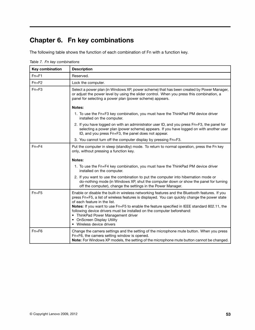
Chapter 6. Fn key combinations
The following table shows the function of each combination of Fn with a function key.
Table 7. Fn key combinations
Key combination Description
Fn+F1 Reserved.
Fn+F2 Lock the computer.
Fn+F3 Select a power plan (in Windows XP, power scheme) that has been created by Power Manager,or adjust the power level by using the slider control. When you press this combination, apanel for selecting a power plan (power scheme) appears.
Notes:
1. To use the Fn+F3 key combination, you must have the ThinkPad PM device driverinstalled on the computer.
2. If you have logged on with an administrator user ID, and you press Fn+F3, the panel forselecting a power plan (power scheme) appears. If you have logged on with another userID, and you press Fn+F3, the panel does not appear.
3. You cannot turn off the computer display by pressing Fn+F3.
Fn+F4 Put the computer in sleep (standby) mode. To return to normal operation, press the Fn keyonly, without pressing a function key.
Notes:
1. To use the Fn+F4 key combination, you must have the ThinkPad PM device driverinstalled on the computer.
2. If you want to use the combination to put the computer into hibernation mode ordo-nothing mode (in Windows XP, shut the computer down or show the panel for turningoff the computer), change the settings in the Power Manager.
Fn+F5 Enable or disable the built-in wireless networking features and the Bluetooth features. If youpress Fn+F5, a list of wireless features is displayed. You can quickly change the power stateof each feature in the list.Notes: If you want to use Fn+F5 to enable the feature specified in IEEE standard 802.11, thefollowing device drivers must be installed on the computer beforehand:• ThinkPad Power Management driver• OnScreen Display Utility• Wireless device drivers
Fn+F6 Change the camera settings and the setting of the microphone mute button. When you pressFn+F6, the camera setting window is opened.Note: For Windows XP models, the setting of the microphone mute button cannot be changed.
© Copyright Lenovo 2009, 2012 53

Table 7. Fn key combinations (continued)
Key combination Description
Apply a presentation scheme directly, with no need to start Presentation Director.
To disable this function and use the Fn+F7 key combination for switching a display outputlocation, start Presentation Director, and change the settings.
Note: If the computer is a windows 7 model, it does not support presentation schemes, butthe Fn+F7 combination is available for switching a display output location.
Fn+F7
For Windows 7:Switch a display output location• Computer display only (LCD)• Computer display and external monitor (same image)• Computer display and external monitor (extended desktop)• External monitor onlyNote: To switch between the computer display and an external monitor, the Win+P keycombination is also available.
For Windows Vista and Windows XP:Switch a display output location• External monitor• Computer display (LCD) and external monitor• Computer display (LCD)
Notes:1. This function is not supported if different desktop images are displayed on the computer
display and the external monitor (the Extend desktop function).2. This function does not work while a DVD movie or a video clip is playing.
To enable this function, start Presentation Director, and change the Fn+F7 settings.
Note: Multiple users can log on to a single operating system by using different user IDs. Eachuser needs to change the settings.
Fn+F8 Change the settings of the UltraNav® pointing device.
Fn+F9 Reserved.
Fn+F10 Reserved.
Fn+F11 Reserved.
Fn+F12 Put the computer into hibernation mode. To return to normal operation, press the powerbutton for less than four seconds.Note: To use Fn+F12 for hibernation, you must have the ThinkPad PM device driver installedon the computer.
Fn+PgUp Turn the ThinkLight® on or off.Note: This function is supported only on the ThinkPad Notebooks that have the ThinkLight.The on or off status of the ThinkLight is shown on the screen for a few seconds when youpress Fn+PgUp.
Fn+Home The computer display becomes brighter.
Fn+End The computer display becomes dimmer.
Fn+Spacebar Enable the FullScreen Magnifier function.
Fn+PrtSc Has the same function as the SysRq key.
Fn+ScrLk Enable or disable the numeric keypad. The indicator of numeric lock will be displayed onthe screen.
54 Hardware Maintenance Manual

Table 7. Fn key combinations (continued)
Key combination Description
Fn+Pause Has the same function as the Break key.
Fn+cursor keys These key combinations work with Windows Media Player. Fn+down arrow key works for thePlay or Pause button, Fn+up arrow key for the Stop button, Fn+right arrow key for the NextTrack button, and Fn+left arrow key for the Previous Track button.
Chapter 6. Fn key combinations 55

56 Hardware Maintenance Manual
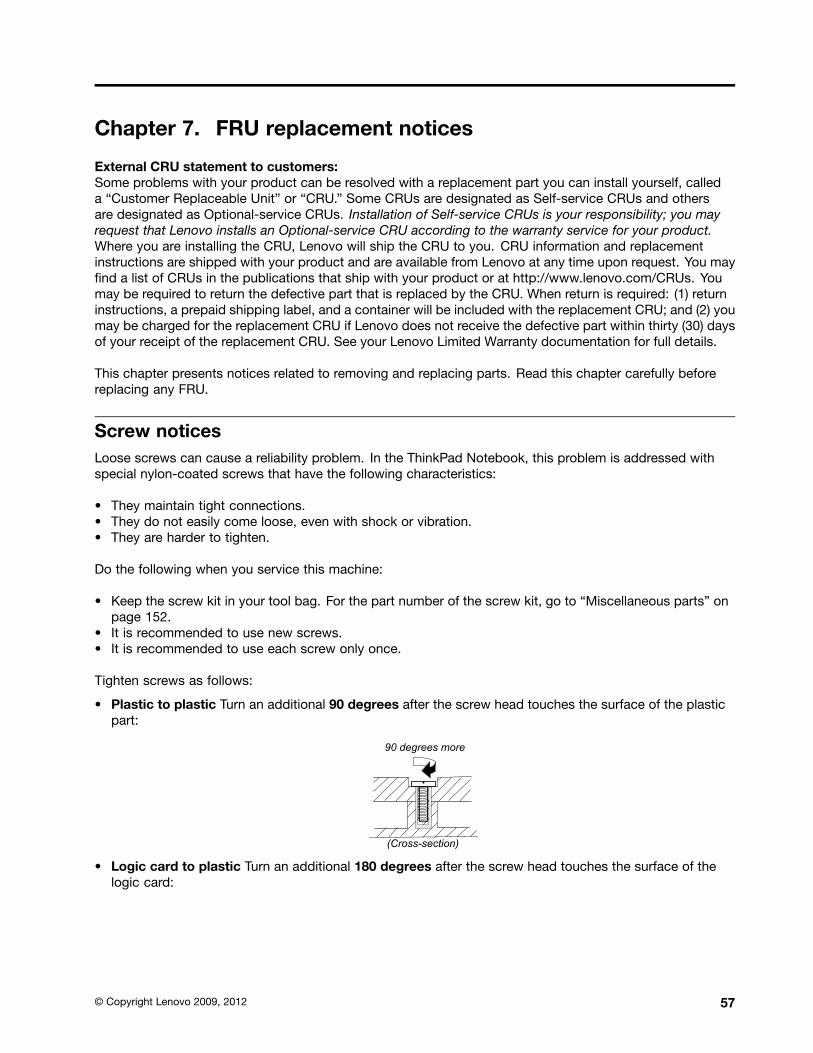
Chapter 7. FRU replacement notices
External CRU statement to customers:Some problems with your product can be resolved with a replacement part you can install yourself, calleda “Customer Replaceable Unit” or “CRU.” Some CRUs are designated as Self-service CRUs and othersare designated as Optional-service CRUs. Installation of Self-service CRUs is your responsibility; you mayrequest that Lenovo installs an Optional-service CRU according to the warranty service for your product.Where you are installing the CRU, Lenovo will ship the CRU to you. CRU information and replacementinstructions are shipped with your product and are available from Lenovo at any time upon request. You mayfind a list of CRUs in the publications that ship with your product or at http://www.lenovo.com/CRUs. Youmay be required to return the defective part that is replaced by the CRU. When return is required: (1) returninstructions, a prepaid shipping label, and a container will be included with the replacement CRU; and (2) youmay be charged for the replacement CRU if Lenovo does not receive the defective part within thirty (30) daysof your receipt of the replacement CRU. See your Lenovo Limited Warranty documentation for full details.
This chapter presents notices related to removing and replacing parts. Read this chapter carefully beforereplacing any FRU.
Screw noticesLoose screws can cause a reliability problem. In the ThinkPad Notebook, this problem is addressed withspecial nylon-coated screws that have the following characteristics:
• They maintain tight connections.• They do not easily come loose, even with shock or vibration.• They are harder to tighten.
Do the following when you service this machine:
• Keep the screw kit in your tool bag. For the part number of the screw kit, go to “Miscellaneous parts” onpage 152.
• It is recommended to use new screws.• It is recommended to use each screw only once.
Tighten screws as follows:
• Plastic to plastic Turn an additional 90 degrees after the screw head touches the surface of the plasticpart:
• Logic card to plastic Turn an additional 180 degrees after the screw head touches the surface of thelogic card:
© Copyright Lenovo 2009, 2012 57

• Torque driver If you have a torque driver, refer to the Torque column in the screw information table foreach step.
• Make sure that you use the correct screw. It is recommended to use new screws for replacements. Ifyou have a torque screwdriver, tighten all screws firmly to the torque specified in the screw informationtable for each step.
• Ensure torque screw drivers are calibrated correctly following country specifications.
Retaining serial numbersThis section includes the following descriptions:
• “Restoring the serial number of the system unit” on page 58• “Retaining the UUID” on page 59• “Reading or writing the ECA information” on page 59
Restoring the serial number of the system unitWhen the computer was manufactured, the EEPROM on the system board was loaded with the serialnumbers of the system and all major components. These numbers need to remain the same throughoutthe life of the computer.
If you replace the system board, you must restore the serial number of the system unit to its original value.
Before replacing the system board, save the original serial number by doing the following:
1. Install the LENOVO ThinkPad Hardware Maintenance Diskette Version 1.76 or later, and restart thecomputer.
2. From the main menu, select 1. Set System Identification.
3. Select 2. Read S/N data from EEPROM.
The serial number of each device in your computer is displayed; the serial number of the system unit islisted as follows:• 20: Serial number
Write down that number.
Note: The serial number of the system unit is also written on the label attached to the bottom of the computer.
After you have replaced the system board, restore the serial number by doing the following:
1. Install the LENOVO ThinkPad Hardware Maintenance Diskette Version 1.76 or later and restart thecomputer.
2. From the main menu, select 1. Set System Identification.
3. Select 1. Add S/N data from EEPROM. Follow the instructions on the screen.
58 Hardware Maintenance Manual
If the MTM and Product ID numbers differ from each other on the rear label, use what is shown for theProduct ID field. See example below:
MTM on rear label: TTTT-CTO S/N SSSSSSS
Product ID on rear label: TTTT-MMM (Use this number when setting SerialNumber)
In the example, the Serial Number to be input is “1STTTTMMMSSSSSSS”.
Retaining the UUIDThe Universally Unique Identifier (UUID) is a 128-bit number uniquely assigned to your computer atproduction and stored in the EEPROM of your system board. The algorithm that generates the number isdesigned to provide unique IDs until the year A.D. 3400. No two computers in the world have the samenumber.
When you replace the system board, you must set the UUID on the new system board as follows:
1. Install the LENOVO ThinkPad Hardware Maintenance Diskette Version 1.76 or later, and restart thecomputer.
2. From the main menu, select 4. Assign UUID. A new UUID is created and written. If a valid UUID alreadyexists, it is not overwritten.
Reading or writing the ECA informationInformation on Engineering Change Announcements (ECA) are stored in the EEPROM of the system board.The electronic storage of this information simplifies the procedure to check if the ECA has been previouslyapplied to a machine. The machine does not need to be disassembled to check for the ECA application.
To check what ECAs have been previously applied to the machine, use the ECA Information Read/Writefunction on the LENOVO ThinkPad Hardware Maintenance Diskette Version 1.76 or later.
1. Insert the LENOVO ThinkPad Hardware Maintenance Diskette Version 1.76 or later, and restart thecomputer.
2. From the main menu, select 6. Set ECA Information.
3. To read ECA information, select 2. Read ECA/rework number from EEPROM and follow theinstruction.
4. To read box build date, select 5. Read box build date from EEPROM, and follow the instruction onthe screen.
After an ECA has been applied to the machine, the EEPROM must be updated to reflect the ECA'sapplication. Use the LENOVO ThinkPad Hardware Maintenance Diskette Version 1.76 or later to update theEEPROM.
Note: Only the ECA number is stored in the EEPROM. The machine type of the ECA is assumed be the sameas the machine type of the machine that had the ECA applied to it.
1. Insert the LENOVO ThinkPad Hardware Maintenance Diskette Version 1.76 or later, and restart thecomputer.
2. From the main menu, select 6. Set ECA Information.
3. To write ECA information, select 1. Write ECA/rework number from EEPROM, and follow theinstruction.
4. To write box build date, select 4. Write box build date from EEPROM, and follow the instruction onthe screen.
Chapter 7. FRU replacement notices 59
If the system board is being replaced, try to read the ECA information from the old system board and transferthe information to the new system. If the system board is inoperable, this will not be possible.
60 Hardware Maintenance Manual
Chapter 8. Removing and replacing a FRU
External CRU statement to customers:Some problems with your product can be resolved with a replacement part you can install yourself, calleda “Customer Replaceable Unit” or “CRU.” Some CRUs are designated as Self-service CRUs and othersare designated as Optional-service CRUs. Installation of Self-service CRUs is your responsibility; you mayrequest that Lenovo installs an Optional-service CRU according to the warranty service for your product.Where you are installing the CRU, Lenovo will ship the CRU to you. CRU information and replacementinstructions are shipped with your product and are available from Lenovo at any time upon request. You mayfind a list of CRUs in the publications that ship with your product or at http://www.lenovo.com/CRUs. Youmay be required to return the defective part that is replaced by the CRU. When return is required: (1) returninstructions, a prepaid shipping label, and a container will be included with the replacement CRU; and (2) youmay be charged for the replacement CRU if Lenovo does not receive the defective part within thirty (30) daysof your receipt of the replacement CRU. See your Lenovo Limited Warranty documentation for full details.
This chapter presents directions and drawings for use in removing and replacing a FRU. Be sure to observethe following general rules:
1. Do not try to service any computer unless you have been trained and certified. An untrained person runsthe risk of damaging parts.
2. Before replacing any FRU, review Chapter 7 “FRU replacement notices” on page 57.
3. Begin by removing any FRUs that have to be removed before replacing the failing FRU. Any such FRUsare listed at the top of each FRU replacement page. Remove them in the order in which they are listed.
4. Follow the correct sequence in the steps for removing a FRU, as given in the drawings by the numbersin square callouts.
5. When turning a screw to replace a FRU, turn it in the direction as given by the arrow in the drawing.
6. When removing a FRU, move it in the direction as given by the arrow in the drawing.
7. To put the new FRU in place, reverse the removal procedure and follow any notes that pertain toreplacement. For information about connecting and arranging internal cables, see Chapter 9 “Locations”on page 111.
8. When replacing a FRU, use the correct screw(s) as shown in the procedures.
DANGER
Before removing any FRU, turn off the computer, unplug all power cords from electrical outlets,remove the battery pack, and then disconnect any interconnecting cables.
Attention: After replacing a FRU, do not turn on the computer until you have made sure that all screws,springs, and other small parts are in place and none are loose inside the computer. Verify this by shakingthe computer gently and listening for rattling sounds. Metallic parts or metal flakes can cause electricalshort circuits.
Attention: The system board is sensitive to, and can be damaged by, electrostatic discharge. Beforetouching it, establish personal grounding by touching a ground point with one hand or by using anelectrostatic discharge (ESD) strap (P/N 6405959).
1010 Battery packImportant notice for replacing a battery pack:Lenovo ThinkVantage Toolbox (in Windows 7) and Lenovo System Toolbox (in Windows Vista and Windows
© Copyright Lenovo 2009, 2012 61

XP) have an automatic battery diagnostic that determines if the battery pack is defective. A battery packFRU should not be replaced unless this diagnostic shows that the battery is defective.
The only exception to this is if the battery pack is physically damaged or a customer is reporting a possiblesafety issue.
If Lenovo ThinkVantage Toolbox or Lenovo System Toolbox is not installed in the computer, the customershould download this program before a non-physically damaged battery pack is replaced. Note that thereplacement of a physically damaged battery pack is not covered by the warranty.
Removal steps of battery pack
DANGER
Use only the battery specified in the parts list for your computer. Any other battery could igniteor explode.
Unlock the battery latch 1 . Holding the battery lock lever in the unlocked position 2 , remove the batterypack in the direction shown by arrow 3 .
3
21
When installing:
Install the battery pack along the slide rails of the slot. Make sure that the battery release lever is in thelocked position.
62 Hardware Maintenance Manual

1020 ExpressCard blank bezel and Media Card blank bezel
Removal steps of ExpressCard blank bezel
When you press the ExpressCard blank bezel 1 , it pops out 2 .
1
2
When installing:
Make sure that the bezel is correctly oriented as shown in this figure.
Chapter 8. Removing and replacing a FRU 63

Removal steps of Media Card blank bezel
When you press the Media Card blank bezel 1 , it pops out 2 .
1
2
When installing:
Make sure that the bezel is correctly oriented as shown in the following figure.
1030 Optical drive or travel coverFor access, remove this FRU:• “1010 Battery pack” on page 61
64 Hardware Maintenance Manual

Removal steps of optical drive or travel cover
1
Step Screw (quantity) Color Torque
1 M2 × 8 mm, wafer-head, nylon-coated (1) Black 0.181 Nm(1.85 kgfcm)
3
2
1040 Thermal coverFor access, remove this FRU:• “1010 Battery pack” on page 61
Chapter 8. Removing and replacing a FRU 65

Removal steps of thermal cover
Note: Loosen the screws 1 .
1
11
1
1
1
2
Attention: Do not touch or apply any excessive force to the fan motor located in the slot. It might causedamage to the fan assembly or the computer to mulfunction.
1050 Hard disk drive (HDD) assemblyFor access, remove these FRUs in order:• “1010 Battery pack” on page 61• “1040 Thermal cover” on page 65
Attention:
• Do not drop the drive or apply any physical shock to it. The drive is sensitive to physical shock. Improperhandling can cause damage and permanent loss of data.
• Before removing the drive, have the user make a backup copy of all the information on it if possible.
• Never remove the drive while the computer is operating or is in suspend mode.
66 Hardware Maintenance Manual

Removal steps of HDD assembly
1
When installing:
Make sure that the HDD is attached firmly.
2
a
When installing:
Do not apply excessive force to the HDD bracket a . To do so, you might bend or break it.
1060 DIMMFor access, remove these FRUs in order:
Chapter 8. Removing and replacing a FRU 67
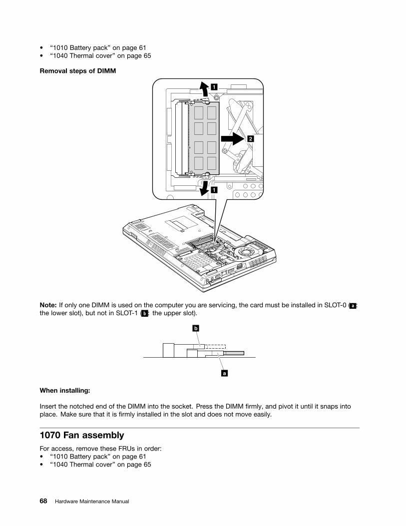
• “1010 Battery pack” on page 61• “1040 Thermal cover” on page 65
Removal steps of DIMM
1
1
2
Note: If only one DIMM is used on the computer you are servicing, the card must be installed in SLOT-0 ( a :the lower slot), but not in SLOT-1 ( b : the upper slot).
b
a
When installing:
Insert the notched end of the DIMM into the socket. Press the DIMM firmly, and pivot it until it snaps intoplace. Make sure that it is firmly installed in the slot and does not move easily.
1070 Fan assemblyFor access, remove these FRUs in order:• “1010 Battery pack” on page 61• “1040 Thermal cover” on page 65
68 Hardware Maintenance Manual
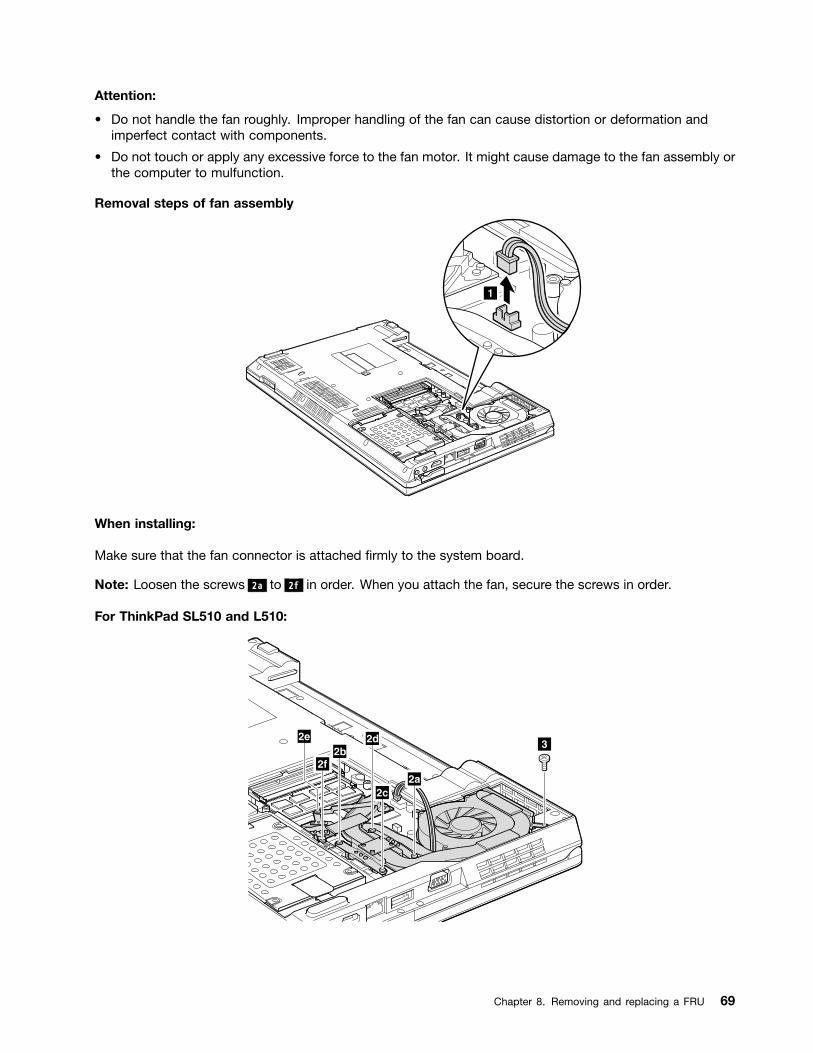
Attention:
• Do not handle the fan roughly. Improper handling of the fan can cause distortion or deformation andimperfect contact with components.
• Do not touch or apply any excessive force to the fan motor. It might cause damage to the fan assembly orthe computer to mulfunction.
Removal steps of fan assembly
1
When installing:
Make sure that the fan connector is attached firmly to the system board.
Note: Loosen the screws 2a to 2f in order. When you attach the fan, secure the screws in order.
For ThinkPad SL510 and L510:
2a
32d
2c
2b2f
2e
Chapter 8. Removing and replacing a FRU 69
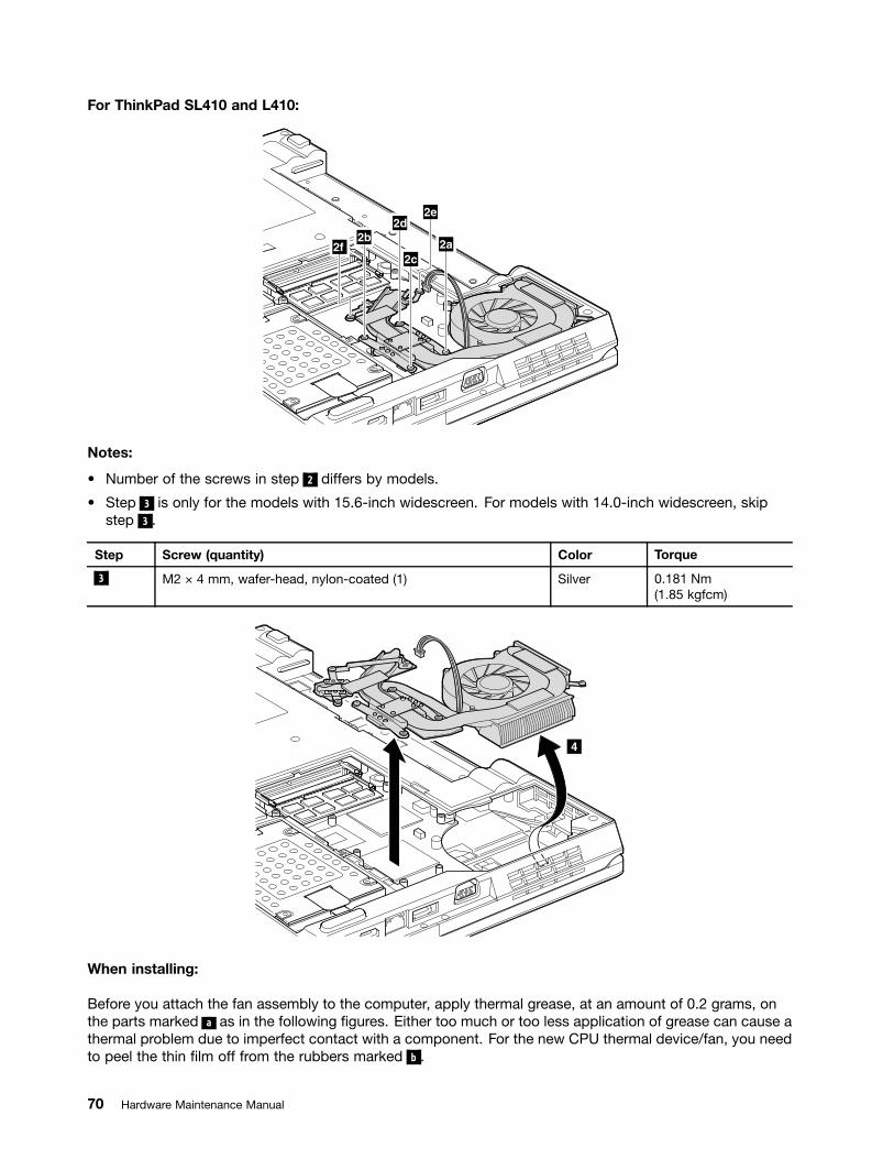
For ThinkPad SL410 and L410:
2a
2d
2c
2b
2e
2f
Notes:
• Number of the screws in step 2 differs by models.
• Step 3 is only for the models with 15.6-inch widescreen. For models with 14.0-inch widescreen, skipstep 3 .
Step Screw (quantity) Color Torque
3 M2 × 4 mm, wafer-head, nylon-coated (1) Silver 0.181 Nm(1.85 kgfcm)
4
When installing:
Before you attach the fan assembly to the computer, apply thermal grease, at an amount of 0.2 grams, onthe parts marked a as in the following figures. Either too much or too less application of grease can cause athermal problem due to imperfect contact with a component. For the new CPU thermal device/fan, you needto peel the thin film off from the rubbers marked b .
70 Hardware Maintenance Manual

For discrete fan assembly:
a
b
b
b
a
For integrated fan assembly:
b
a
b
b
1080 CPUFor access, remove these FRUs in order:• “1010 Battery pack” on page 61• “1040 Thermal cover” on page 65• “1070 Fan assembly” on page 68
Attention: The CPU is extremely sensitive. When you service the CPU, avoid any kind of rough handling.
Chapter 8. Removing and replacing a FRU 71
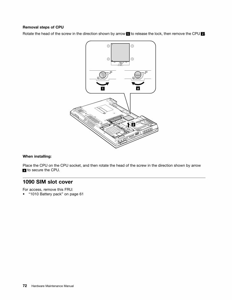
Removal steps of CPU
Rotate the head of the screw in the direction shown by arrow 1 to release the lock, then remove the CPU 2 .
a1
2
When installing:
Place the CPU on the CPU socket, and then rotate the head of the screw in the direction shown by arrowa to secure the CPU.
1090 SIM slot coverFor access, remove this FRU:• “1010 Battery pack” on page 61
72 Hardware Maintenance Manual
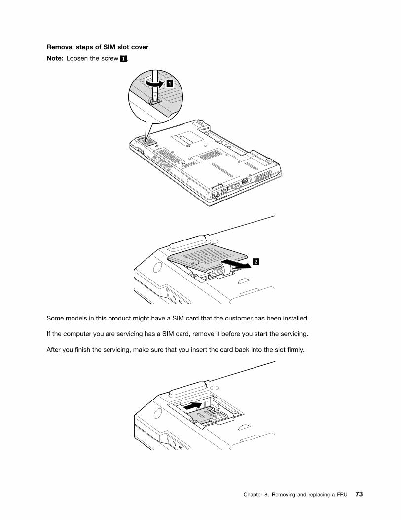
Removal steps of SIM slot cover
Note: Loosen the screw 1 .
1
2
Some models in this product might have a SIM card that the customer has been installed.
If the computer you are servicing has a SIM card, remove it before you start the servicing.
After you finish the servicing, make sure that you insert the card back into the slot firmly.
Chapter 8. Removing and replacing a FRU 73

1
2
1100 Wireless WAN slot cover and PCI Express Mini Card for wirelessWANFor access, remove this FRU:• “1010 Battery pack” on page 61
Removal steps of wireless WAN slot cover and PCI Express Mini Card for wireless WAN
Note: Loosen the screw 1 .
1
74 Hardware Maintenance Manual

2
In step 3a and 3b , unplug the jacks by using the removal tool antenna RF connector (P/N: 08K7159) or pickthe connectors with your fingers and gently unplug them in the direction of the arrow.
4
43a3b
When installing:
Plug the red cable 3a into the jack labeled MAIN , and the blue cable 3b into the jack labeled AUX on thecard.
Step Screw (quantity) Color Torque
4 M2 × 3 mm, wafer-head, nylon-coated (2) Black 0.181 Nm(1.85 kgfcm)
5
Chapter 8. Removing and replacing a FRU 75

1110 Palm rest assembly with cablesFor access, remove these FRUs in order:• “1010 Battery pack” on page 61• “1030 Optical drive or travel cover” on page 64
Note: In models with the fingerprint reader, the sensor is attached to the palm rest FRU. If the fingerprintreader has any defects, you can replace it by the procedures given in this section, which are the samefor a palm rest with or without a fingerprint reader.
Removal steps of palm rest assembly with cables
2
2
2
2
21
1
2
2
Step Screw (quantity) Color Torque
1 M2 × 8 mm, wafer-head, nylon-coated (1) Black 0.181 Nm(1.85 kgfcm)
2 M2 × 5 mm, wafer-head, nylon-coated (6) Black 0.181 Nm(1.85 kgfcm)
76 Hardware Maintenance Manual

3
34
5
67
6
8
7
Installation of palm rest assembly with cables
When installing:
1. Attach the cables to the system board firmly.
2. Attach the palm rest so that the two small projections of the palm rest a firmly fit into the guide holesof the keyboard bezel as shown in this figure.
Chapter 8. Removing and replacing a FRU 77
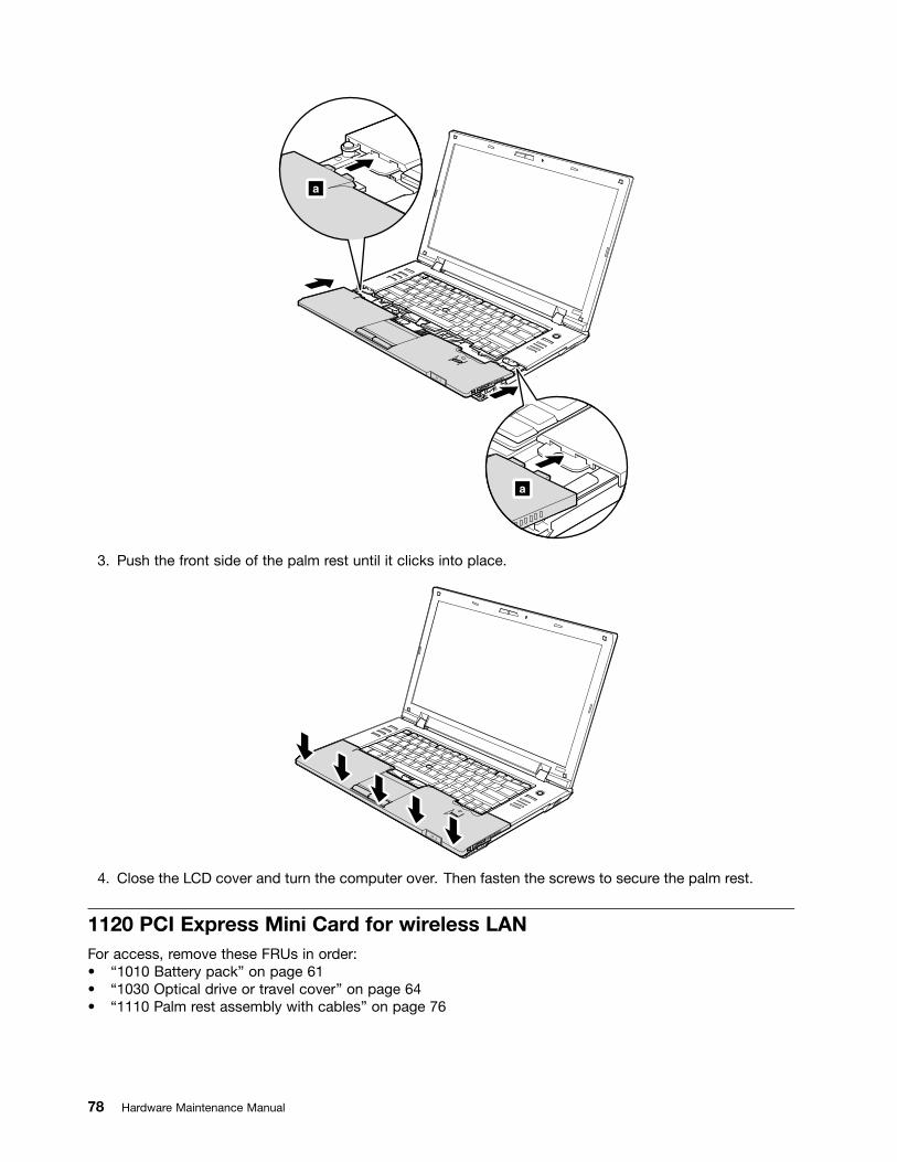
a
a
3. Push the front side of the palm rest until it clicks into place.
4. Close the LCD cover and turn the computer over. Then fasten the screws to secure the palm rest.
1120 PCI Express Mini Card for wireless LANFor access, remove these FRUs in order:• “1010 Battery pack” on page 61• “1030 Optical drive or travel cover” on page 64• “1110 Palm rest assembly with cables” on page 76
78 Hardware Maintenance Manual

Removal steps of PCI Express Mini Card for wireless LAN
In step 1a and 1b , unplug the jacks by using the removal tool antenna RF connector (P/N: 08K7159) or pickthe connectors with your fingers and gently unplug them in the direction of the arrow.
1a
1b
2
2
Step Screw (quantity) Color Torque
2 M2 × 3 mm, wafer-head, nylon-coated (2) Black 0.181 Nm(1.85 kgfcm)
3
When installing:
Plug the gray cable into the jack labeled MAIN, and the black cable into the jack labeled AUX on the card.
Chapter 8. Removing and replacing a FRU 79

1130 Backup batteryFor access, remove these FRUs in order:• “1010 Battery pack” on page 61• “1030 Optical drive or travel cover” on page 64• “1110 Palm rest assembly with cables” on page 76
DANGER
Use only the battery specified in the parts list for your computer. Any other battery could igniteor explode.
Removal steps of backup battery
21
When installing:
Make sure that the battery connector is attached firmly to the system board.
1140 Bluetooth daughter card (BDC-2)For access, remove these FRUs in order:• “1010 Battery pack” on page 61• “1030 Optical drive or travel cover” on page 64• “1110 Palm rest assembly with cables” on page 76
80 Hardware Maintenance Manual
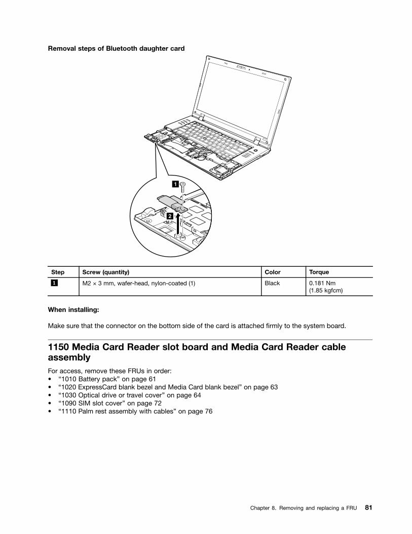
Removal steps of Bluetooth daughter card
1
2
Step Screw (quantity) Color Torque
1 M2 × 3 mm, wafer-head, nylon-coated (1) Black 0.181 Nm(1.85 kgfcm)
When installing:
Make sure that the connector on the bottom side of the card is attached firmly to the system board.
1150 Media Card Reader slot board and Media Card Reader cableassemblyFor access, remove these FRUs in order:• “1010 Battery pack” on page 61• “1020 ExpressCard blank bezel and Media Card blank bezel” on page 63• “1030 Optical drive or travel cover” on page 64• “1090 SIM slot cover” on page 72• “1110 Palm rest assembly with cables” on page 76
Chapter 8. Removing and replacing a FRU 81
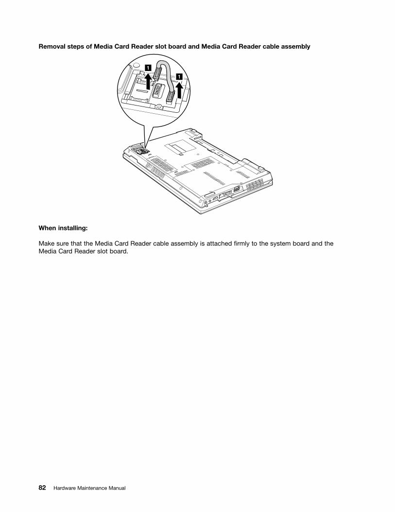
Removal steps of Media Card Reader slot board and Media Card Reader cable assembly
1
1
When installing:
Make sure that the Media Card Reader cable assembly is attached firmly to the system board and theMedia Card Reader slot board.
82 Hardware Maintenance Manual
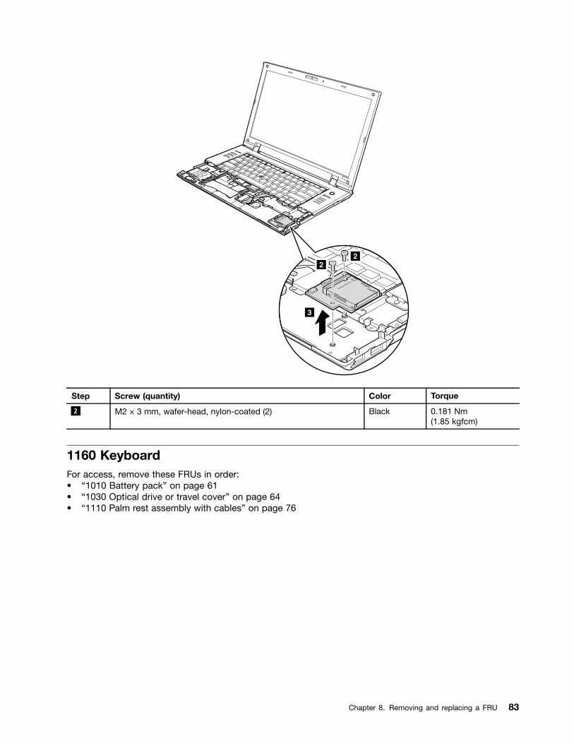
22
3
Step Screw (quantity) Color Torque
2 M2 × 3 mm, wafer-head, nylon-coated (2) Black 0.181 Nm(1.85 kgfcm)
1160 KeyboardFor access, remove these FRUs in order:• “1010 Battery pack” on page 61• “1030 Optical drive or travel cover” on page 64• “1110 Palm rest assembly with cables” on page 76
Chapter 8. Removing and replacing a FRU 83
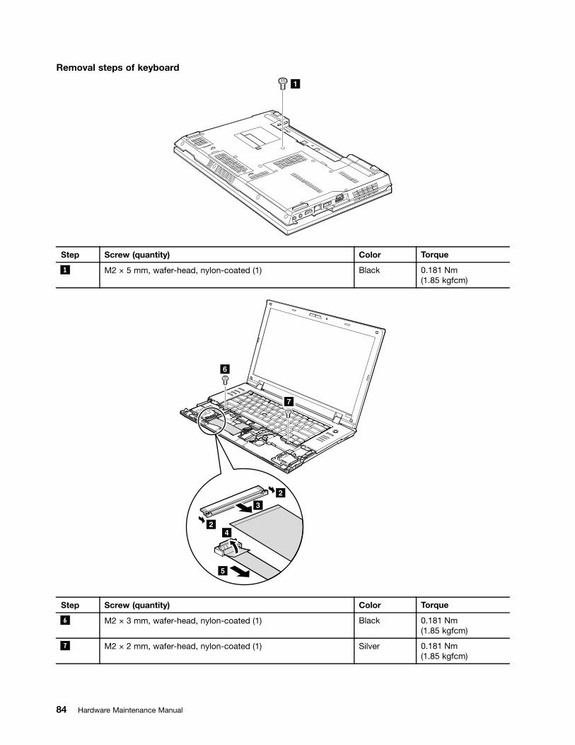
Removal steps of keyboard
1
Step Screw (quantity) Color Torque
1 M2 × 5 mm, wafer-head, nylon-coated (1) Black 0.181 Nm(1.85 kgfcm)
24
2
3
5
6
7
Step Screw (quantity) Color Torque
6 M2 × 3 mm, wafer-head, nylon-coated (1) Black 0.181 Nm(1.85 kgfcm)
7 M2 × 2 mm, wafer-head, nylon-coated (1) Silver 0.181 Nm(1.85 kgfcm)
84 Hardware Maintenance Manual
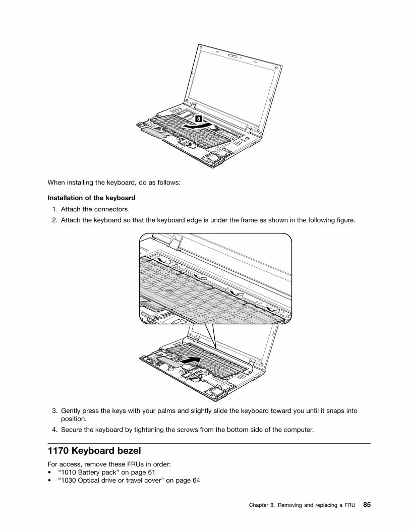
8
When installing the keyboard, do as follows:
Installation of the keyboard
1. Attach the connectors.
2. Attach the keyboard so that the keyboard edge is under the frame as shown in the following figure.
3. Gently press the keys with your palms and slightly slide the keyboard toward you until it snaps intoposition.
4. Secure the keyboard by tightening the screws from the bottom side of the computer.
1170 Keyboard bezelFor access, remove these FRUs in order:• “1010 Battery pack” on page 61• “1030 Optical drive or travel cover” on page 64
Chapter 8. Removing and replacing a FRU 85

• “1070 Fan assembly” on page 68• “1100 Wireless WAN slot cover and PCI Express Mini Card for wireless WAN” on page 74• “1110 Palm rest assembly with cables” on page 76• “1120 PCI Express Mini Card for wireless LAN” on page 78• “1160 Keyboard” on page 83
Removal steps of keyboard bezel
Note: Steps 2a and 3a are only for ThinkPad SL510 and L510. For ThinkPad SL410 and L410, skip steps2a to 3a .
3
33
13a
1
2
2
22a
2a
Step Screw (quantity) Color Torque
1 M2.5 × 6.5 mm, wafer-head, nylon-coated (2) Black 0.392 Nm(4 kgfcm)
2 M2 × 3 mm, wafer-head, nylon-coated (3) Black 0.181 Nm(1.85 kgfcm)
2a M2 × 3 mm, wafer-head, nylon-coated (2) Black 0.181 Nm(1.85 kgfcm)
3 M2 × 5 mm, wafer-head, nylon-coated (3) Black 0.181 Nm(1.85 kgfcm)
3a M2 × 5 mm, wafer-head, nylon-coated (1) Black 0.181 Nm(1.85 kgfcm)
86 Hardware Maintenance Manual
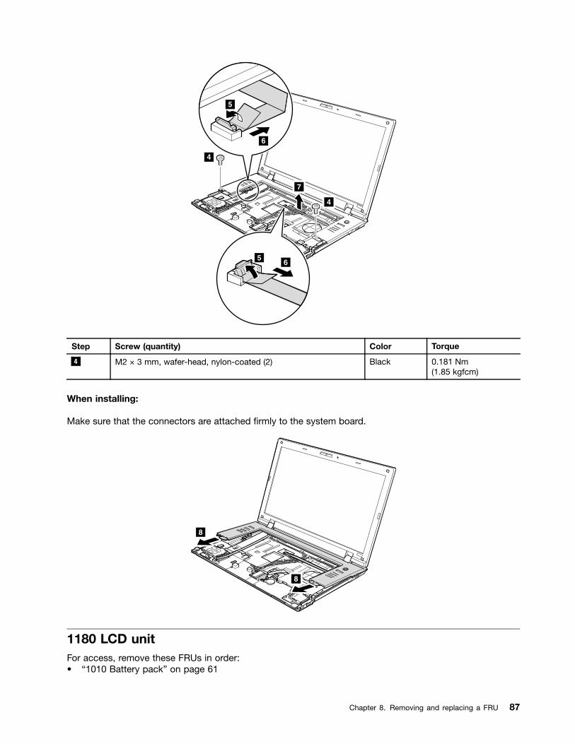
4
4
7
5
6
56
Step Screw (quantity) Color Torque
4 M2 × 3 mm, wafer-head, nylon-coated (2) Black 0.181 Nm(1.85 kgfcm)
When installing:
Make sure that the connectors are attached firmly to the system board.
8
8
1180 LCD unitFor access, remove these FRUs in order:• “1010 Battery pack” on page 61
Chapter 8. Removing and replacing a FRU 87

• “1030 Optical drive or travel cover” on page 64• “1100 Wireless WAN slot cover and PCI Express Mini Card for wireless WAN” on page 74• “1110 Palm rest assembly with cables” on page 76• “1120 PCI Express Mini Card for wireless LAN” on page 78• “1160 Keyboard” on page 83• “1170 Keyboard bezel” on page 85
Removal steps of LCD unit
1
1
Step Screw (quantity) Color Torque
1 M2.5 × 6.5 mm, wafter-head, nylon-coated (2) Black 0.392 Nm(4 kgfcm)
2
2
3
When installing:
Make sure that the connectors are attached firmly to the system board.
In step 4 , release wireless antenna cables from the cable guides.
88 Hardware Maintenance Manual

For ThinkPad SL510 and L510:
4 4 4
4 4
4
4
4
4
4
4
For ThinkPad SL410 and L410:
44
4
4
4
4
4
4
44 4
4
4
4
4
4
4
When installing:
Make sure that the cables are attached to the cable guides firmly.
Attention: When you route the cables, make sure that they are not subjected to any tension. Tension couldcause the cables to be damaged by the cable guides, or a wire to be broken.
Chapter 8. Removing and replacing a FRU 89

For ThinkPad SL510 and L510:
5
5
5 5
For ThinkPad SL410 and L410:
5
5
5
5
Step Screw (quantity) Color Torque
5 M2.5 × 6.5 mm, wafter-head, nylon-coated (4) Black 0.392 Nm(4 kgfcm)
90 Hardware Maintenance Manual
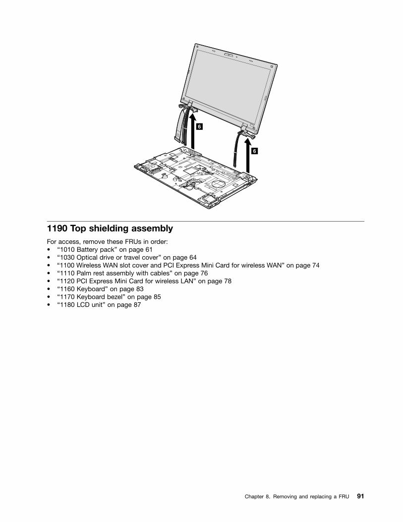
6
6
1190 Top shielding assemblyFor access, remove these FRUs in order:• “1010 Battery pack” on page 61• “1030 Optical drive or travel cover” on page 64• “1100 Wireless WAN slot cover and PCI Express Mini Card for wireless WAN” on page 74• “1110 Palm rest assembly with cables” on page 76• “1120 PCI Express Mini Card for wireless LAN” on page 78• “1160 Keyboard” on page 83• “1170 Keyboard bezel” on page 85• “1180 LCD unit” on page 87
Chapter 8. Removing and replacing a FRU 91

Removal steps of top shielding assembly
For ThinkPad SL510 and L510:
3
11
1
2
2
22
Step Screw (quantity) Color Torque
1 M2 × 3 mm, wafer-head, nylon-coated (3) Black 0.181 Nm(1.85 kgfcm)
2 M2 × 5 mm, wafer-head, nylon-coated (4) Black 0.181 Nm(1.85 kgfcm)
For ThinkPad SL410 and L410:
2
1 12
2
2
3
92 Hardware Maintenance Manual
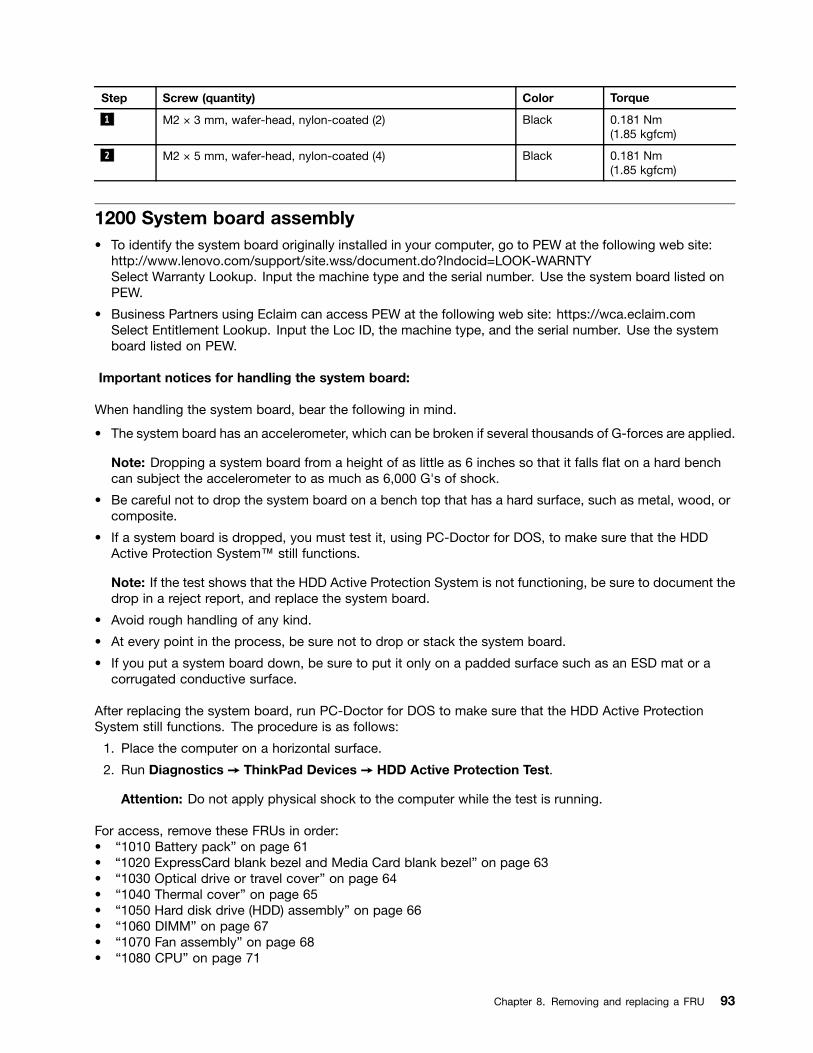
Step Screw (quantity) Color Torque
1 M2 × 3 mm, wafer-head, nylon-coated (2) Black 0.181 Nm(1.85 kgfcm)
2 M2 × 5 mm, wafer-head, nylon-coated (4) Black 0.181 Nm(1.85 kgfcm)
1200 System board assembly• To identify the system board originally installed in your computer, go to PEW at the following web site:
http://www.lenovo.com/support/site.wss/document.do?lndocid=LOOK-WARNTYSelect Warranty Lookup. Input the machine type and the serial number. Use the system board listed onPEW.
• Business Partners using Eclaim can access PEW at the following web site: https://wca.eclaim.comSelect Entitlement Lookup. Input the Loc ID, the machine type, and the serial number. Use the systemboard listed on PEW.
Important notices for handling the system board:
When handling the system board, bear the following in mind.
• The system board has an accelerometer, which can be broken if several thousands of G-forces are applied.
Note: Dropping a system board from a height of as little as 6 inches so that it falls flat on a hard benchcan subject the accelerometer to as much as 6,000 G's of shock.
• Be careful not to drop the system board on a bench top that has a hard surface, such as metal, wood, orcomposite.
• If a system board is dropped, you must test it, using PC-Doctor for DOS, to make sure that the HDDActive Protection System™ still functions.
Note: If the test shows that the HDD Active Protection System is not functioning, be sure to document thedrop in a reject report, and replace the system board.
• Avoid rough handling of any kind.
• At every point in the process, be sure not to drop or stack the system board.
• If you put a system board down, be sure to put it only on a padded surface such as an ESD mat or acorrugated conductive surface.
After replacing the system board, run PC-Doctor for DOS to make sure that the HDD Active ProtectionSystem still functions. The procedure is as follows:
1. Place the computer on a horizontal surface.
2. Run Diagnostics ➙ ThinkPad Devices ➙ HDD Active Protection Test.
Attention: Do not apply physical shock to the computer while the test is running.
For access, remove these FRUs in order:• “1010 Battery pack” on page 61• “1020 ExpressCard blank bezel and Media Card blank bezel” on page 63• “1030 Optical drive or travel cover” on page 64• “1040 Thermal cover” on page 65• “1050 Hard disk drive (HDD) assembly” on page 66• “1060 DIMM” on page 67• “1070 Fan assembly” on page 68• “1080 CPU” on page 71
Chapter 8. Removing and replacing a FRU 93

• “1090 SIM slot cover” on page 72• “1100 Wireless WAN slot cover and PCI Express Mini Card for wireless WAN” on page 74• “1110 Palm rest assembly with cables” on page 76• “1120 PCI Express Mini Card for wireless LAN” on page 78• “1130 Backup battery” on page 80• “1140 Bluetooth daughter card (BDC-2)” on page 80• “1150 Media Card Reader slot board and Media Card Reader cable assembly” on page 81• “1160 Keyboard” on page 83• “1170 Keyboard bezel” on page 85• “1180 LCD unit” on page 87• “1190 Top shielding assembly” on page 91
Location of major sensitive components on the system board
The following components soldered on the top side of the system board are extremely sensitive. When youservice the system board, avoid any kind of rough handling.
a Integrated video chip (GMCH)
b CPU
c I/O Controller Hub (ICH)
d Video chip (only for discrete models)
For ThinkPad SL410 and L410 integrated models:
a
b
c
94 Hardware Maintenance Manual

For ThinkPad SL410 and L410 discrete models:
c
d
a
b
For ThinkPad SL510 and L510 integrated models:
a
b
c
For ThinkPad SL510 and L510 discrete models:
c
d
a
b
Chapter 8. Removing and replacing a FRU 95
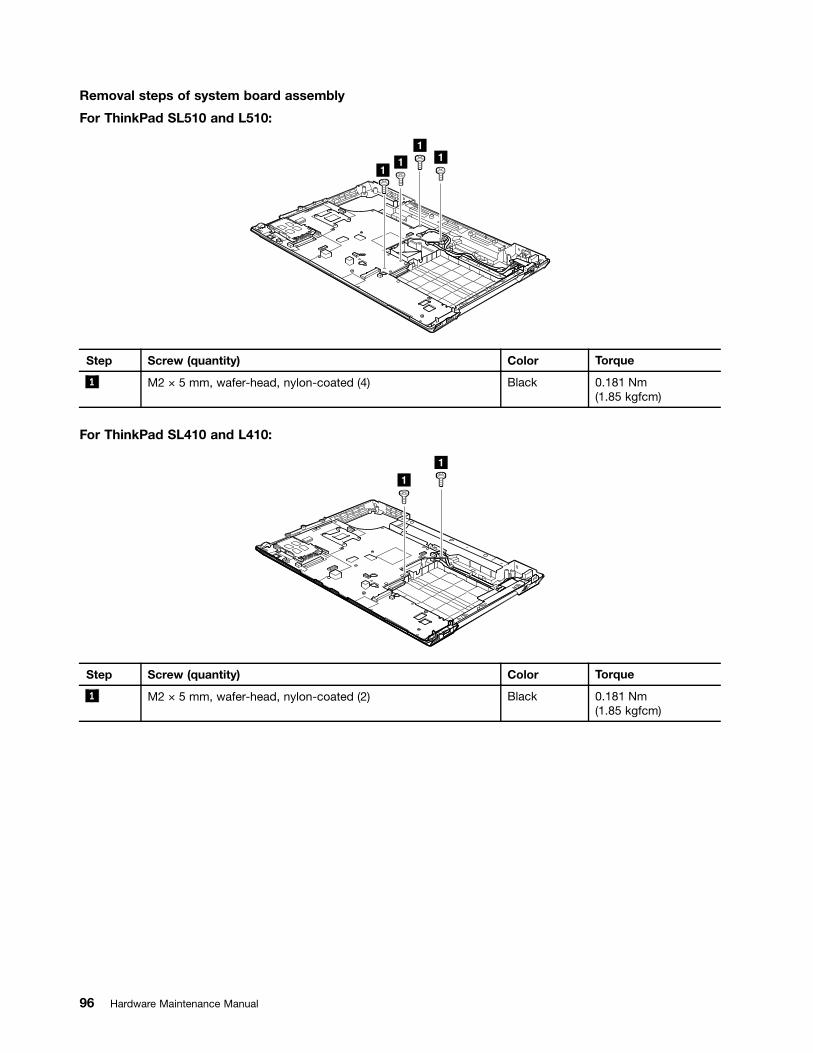
Removal steps of system board assembly
For ThinkPad SL510 and L510:
111
1
Step Screw (quantity) Color Torque
1 M2 × 5 mm, wafer-head, nylon-coated (4) Black 0.181 Nm(1.85 kgfcm)
For ThinkPad SL410 and L410:
1
1
Step Screw (quantity) Color Torque
1 M2 × 5 mm, wafer-head, nylon-coated (2) Black 0.181 Nm(1.85 kgfcm)
96 Hardware Maintenance Manual
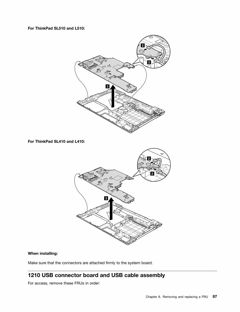
For ThinkPad SL510 and L510:
2
2
3
For ThinkPad SL410 and L410:
2
2
3
When installing:
Make sure that the connectors are attached firmly to the system board.
1210 USB connector board and USB cable assemblyFor access, remove these FRUs in order:
Chapter 8. Removing and replacing a FRU 97
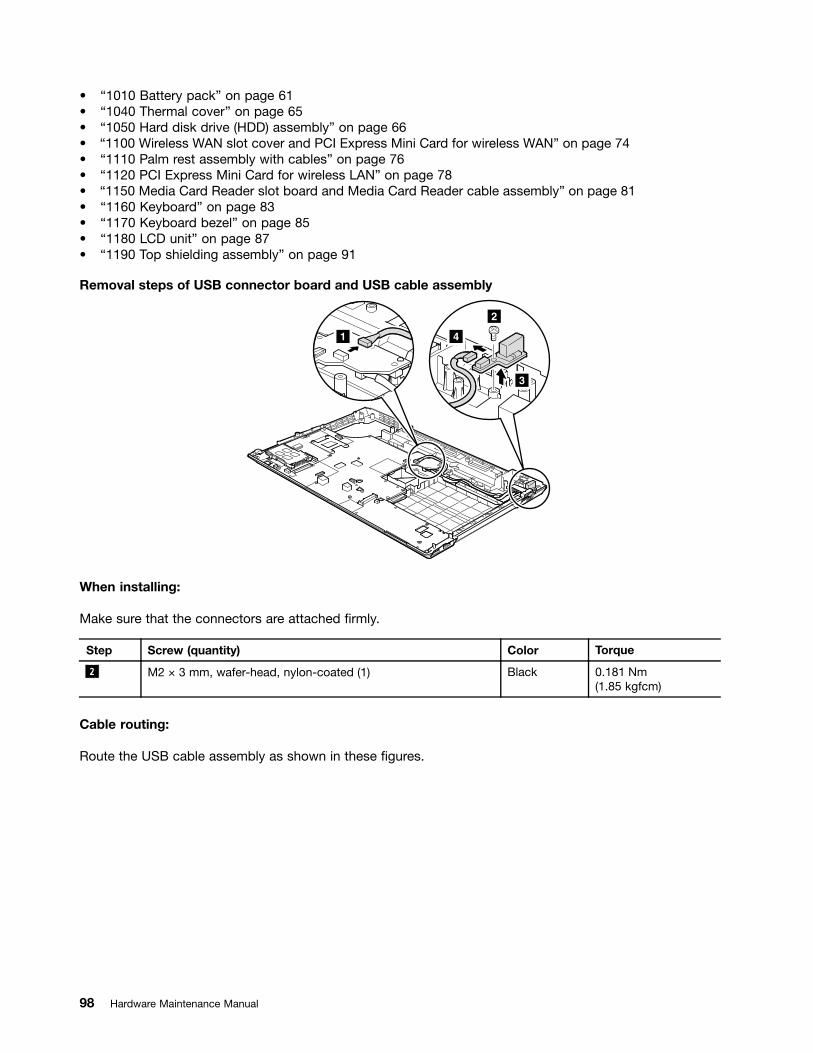
• “1010 Battery pack” on page 61• “1040 Thermal cover” on page 65• “1050 Hard disk drive (HDD) assembly” on page 66• “1100 Wireless WAN slot cover and PCI Express Mini Card for wireless WAN” on page 74• “1110 Palm rest assembly with cables” on page 76• “1120 PCI Express Mini Card for wireless LAN” on page 78• “1150 Media Card Reader slot board and Media Card Reader cable assembly” on page 81• “1160 Keyboard” on page 83• “1170 Keyboard bezel” on page 85• “1180 LCD unit” on page 87• “1190 Top shielding assembly” on page 91
Removal steps of USB connector board and USB cable assembly
3
2
41
When installing:
Make sure that the connectors are attached firmly.
Step Screw (quantity) Color Torque
2 M2 × 3 mm, wafer-head, nylon-coated (1) Black 0.181 Nm(1.85 kgfcm)
Cable routing:
Route the USB cable assembly as shown in these figures.
98 Hardware Maintenance Manual
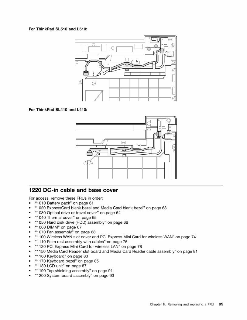
For ThinkPad SL510 and L510:
For ThinkPad SL410 and L410:
1220 DC-in cable and base coverFor access, remove these FRUs in order:• “1010 Battery pack” on page 61• “1020 ExpressCard blank bezel and Media Card blank bezel” on page 63• “1030 Optical drive or travel cover” on page 64• “1040 Thermal cover” on page 65• “1050 Hard disk drive (HDD) assembly” on page 66• “1060 DIMM” on page 67• “1070 Fan assembly” on page 68• “1100 Wireless WAN slot cover and PCI Express Mini Card for wireless WAN” on page 74• “1110 Palm rest assembly with cables” on page 76• “1120 PCI Express Mini Card for wireless LAN” on page 78• “1150 Media Card Reader slot board and Media Card Reader cable assembly” on page 81• “1160 Keyboard” on page 83• “1170 Keyboard bezel” on page 85• “1180 LCD unit” on page 87• “1190 Top shielding assembly” on page 91• “1200 System board assembly” on page 93
Chapter 8. Removing and replacing a FRU 99

Removal steps of DC-in cable and base cover
For ThinkPad SL510 and L510:
2
1
1
3
Step Screw (quantity) Color Torque
1 M2 × 3 mm, wafer-head, nylon-coated (2) Black 0.181 Nm(1.85 kgfcm)
For ThinkPad SL410 and L410:
3
1
2
Step Screw (quantity) Color Torque
1 M2 × 5 mm, wafer-head, nylon-coated (1) Black 0.181 Nm(1.85 kgfcm)
Cable routing:
Route the cable as shown in these figures.
100 Hardware Maintenance Manual
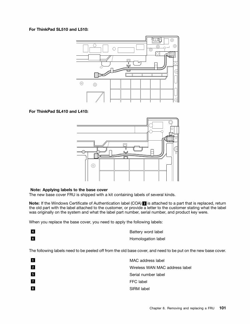
For ThinkPad SL510 and L510:
For ThinkPad SL410 and L410:
Note: Applying labels to the base coverThe new base cover FRU is shipped with a kit containing labels of several kinds.
Note: If the Windows Certificate of Authentication label (COA) 3 is attached to a part that is replaced, returnthe old part with the label attached to the customer, or provide a letter to the customer stating what the labelwas originally on the system and what the label part number, serial number, and product key were.
When you replace the base cover, you need to apply the following labels:
4 Battery word label
6 Homologation label
The following labels need to be peeled off from the old base cover, and need to be put on the new base cover.
1 MAC address label
2 Wireless WAN MAC address label
5 Serial number label
7 FFC label
8 SIRM label
Chapter 8. Removing and replacing a FRU 101
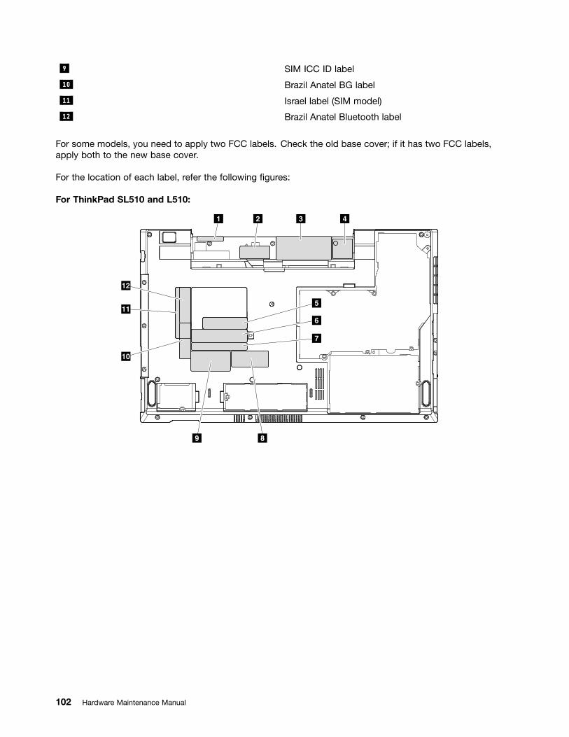
9 SIM ICC ID label
10 Brazil Anatel BG label
11 Israel label (SIM model)
12 Brazil Anatel Bluetooth label
For some models, you need to apply two FCC labels. Check the old base cover; if it has two FCC labels,apply both to the new base cover.
For the location of each label, refer the following figures:
For ThinkPad SL510 and L510:
2 3
89
41
5
6
7
10
12
11
102 Hardware Maintenance Manual

For ThinkPad SL410 and L410:
2 3
5
6
7
89
10
12
11
41
2010 LCD front bezelFor access, remove these FRUs in order:• “1010 Battery pack” on page 61• “1100 Wireless WAN slot cover and PCI Express Mini Card for wireless WAN” on page 74• “1110 Palm rest assembly with cables” on page 76• “1120 PCI Express Mini Card for wireless LAN” on page 78• “1160 Keyboard” on page 83• “1170 Keyboard bezel” on page 85• “1180 LCD unit” on page 87
Removal steps of LCD front bezel
1
1
1
1
Step Screw cap Screw (quantity) Color Torque
1 M2 × 5 mm, wafer-head, nylon-coated (4) Black 0.181 Nm(1.85 kgfcm)
Chapter 8. Removing and replacing a FRU 103

2
2 2
2
2
2
2
2
22
2
When installing:
Make sure that all the latches are attached firmly. Then secure the bezel with the screws.
2020 Speaker assemblyFor access, remove these FRUs in order:• “1010 Battery pack” on page 61• “1100 Wireless WAN slot cover and PCI Express Mini Card for wireless WAN” on page 74• “1110 Palm rest assembly with cables” on page 76• “1120 PCI Express Mini Card for wireless LAN” on page 78• “1160 Keyboard” on page 83• “1170 Keyboard bezel” on page 85• “1180 LCD unit” on page 87• “2010 LCD front bezel” on page 103
Removal steps of speaker assembly1
2
1
3
104 Hardware Maintenance Manual
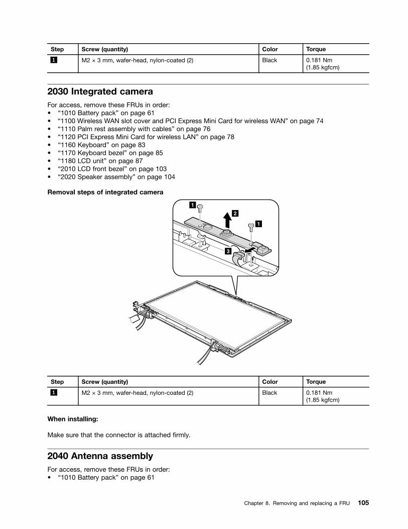
Step Screw (quantity) Color Torque
1 M2 × 3 mm, wafer-head, nylon-coated (2) Black 0.181 Nm(1.85 kgfcm)
2030 Integrated cameraFor access, remove these FRUs in order:• “1010 Battery pack” on page 61• “1100 Wireless WAN slot cover and PCI Express Mini Card for wireless WAN” on page 74• “1110 Palm rest assembly with cables” on page 76• “1120 PCI Express Mini Card for wireless LAN” on page 78• “1160 Keyboard” on page 83• “1170 Keyboard bezel” on page 85• “1180 LCD unit” on page 87• “2010 LCD front bezel” on page 103• “2020 Speaker assembly” on page 104
Removal steps of integrated camera
1
1
2
3
Step Screw (quantity) Color Torque
1 M2 × 3 mm, wafer-head, nylon-coated (2) Black 0.181 Nm(1.85 kgfcm)
When installing:
Make sure that the connector is attached firmly.
2040 Antenna assemblyFor access, remove these FRUs in order:• “1010 Battery pack” on page 61
Chapter 8. Removing and replacing a FRU 105
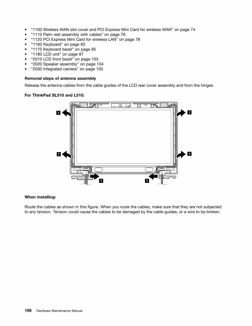
• “1100 Wireless WAN slot cover and PCI Express Mini Card for wireless WAN” on page 74• “1110 Palm rest assembly with cables” on page 76• “1120 PCI Express Mini Card for wireless LAN” on page 78• “1160 Keyboard” on page 83• “1170 Keyboard bezel” on page 85• “1180 LCD unit” on page 87• “2010 LCD front bezel” on page 103• “2020 Speaker assembly” on page 104• “2030 Integrated camera” on page 105
Removal steps of antenna assembly
Release the antenna cables from the cable guides of the LCD rear cover assembly and from the hinges.
For ThinkPad SL510 and L510:
1
1
11
1
1
When installing:
Route the cables as shown in this figure. When you route the cables, make sure that they are not subjectedto any tension. Tension could cause the cables to be damaged by the cable guides, or a wire to be broken.
106 Hardware Maintenance Manual

For ThinkPad SL410 and L410 :
1
1
1
1
11
When installing:
Route the cables as shown in this figure. When you route the cables, make sure that they are not subjectedto any tension. Tension could cause the cables to be damaged by the cable guides, or a wire to be broken.
2
2
22
2
2050 Hinges, LCD panel, LCD cable, and LCD rear cover assemblyFor access, remove these FRUs in order:• “1010 Battery pack” on page 61• “1100 Wireless WAN slot cover and PCI Express Mini Card for wireless WAN” on page 74• “1110 Palm rest assembly with cables” on page 76• “1120 PCI Express Mini Card for wireless LAN” on page 78
Chapter 8. Removing and replacing a FRU 107

• “1160 Keyboard” on page 83• “1170 Keyboard bezel” on page 85• “1180 LCD unit” on page 87• “2010 LCD front bezel” on page 103• “2020 Speaker assembly” on page 104• “2030 Integrated camera” on page 105• “2040 Antenna assembly” on page 105
Removal steps of hinges, LCD panel, LCD cable, and LCD rear cover assembly
For ThinkPad SL510 and L510:
11
11
Step Screw (quantity) Color Torque
1 M2 × 5 mm, wafer-head, nylon-coated (4) Black 0.181 Nm(1.85 kgfcm)
For ThinkPad SL410 and L410:
1
1
Step Screw (quantity) Color Torque
1 M2 × 5 mm, wafer-head, nylon-coated (2) Black 0.181 Nm(1.85 kgfcm)
108 Hardware Maintenance Manual

2
3
3
4
3
34
Step Screw (quantity) Color Torque
3 M2 × 3 mm, small-head, nylon-coated (4) Black 0.181 Nm(1.85 kgfcm)
Chapter 8. Removing and replacing a FRU 109

7
5
6
When installing:
Make sure that the LCD connector is attached firmly.
110 Hardware Maintenance Manual

Chapter 9. Locations
This chapter presents the location of ThinkPad SL410, L410, SL510, and L510 features and hardwarecomponents.
Front view1 Integrated camera
2 Built-in microphone
3 Built-in stereo speakers
4 Power switch
5 ac power connector
6 ThinkVantage button
7 System status indicators
Note: For the description of each indicator, see Chapter 5 “Status indicators” on page 51.
8 Optical drive or second battery or travel cover
9 Media Card reader
10 USB connector
11 Wireless radio switch
12 Power status indicators
Note: For the description of each indicator, see Chapter 5 “Status indicators” on page 51.
13 Fingerprint reader (for some models)
14 Touch pad buttons
15 Touch pad
16 TrackPoint buttons
17 TrackPoint pointing stick
18 UltraNav
19 Volume control buttons
© Copyright Lenovo 2009, 2012 111

12
3
3
4
65
78
911
1210
13
14
15
16
17
18
19
Rear view
1 Stereo headphone jack or Combo audio jack
2 Microphone jack
3 HDMI port or DisplayPort connector
4 RJ-45 (Ethernet) connector
5 eSATA/USB combo connector
6 External monitor connector
7 Security keyhole
Note: In some models, the security keyhole is located on the right side of the computer.
8 USB connector
23
4
178
56
112 Hardware Maintenance Manual

Bottom view
1 Battery pack
2 Battery pack latch
3 Docking connector (for some models)
4 Thermal slot (DIMM, hard disk drive, fan assembly)
5 ExpressCard slot
6 Wireless WAN card slot
7 SIM slot
1
2
4
5
6
67
3
Chapter 9. Locations 113

114 Hardware Maintenance Manual

Chapter 10. Parts list
This chapter contains following lists of the service parts.• “Overall” on page 116• “LCD FRUs” on page 142• “Keyboard” on page 151• “Miscellaneous parts” on page 152• “ac power adapters” on page 154• “Power cords” on page 155• “Recovery discs” on page 156• “Common service tools” on page 164
Notes:• Each FRU is available for all types or models, unless specific types or models are specified.• FRU with specific models listed and described as xxU (where U is an example of a country designator) should be
used for all models ending in U.• FRU with specific models listed and described as 3Dx (where 3D is an example of a unique configuration) should be
used for all of these models, unless specific country or region designator is specified.• A CRU (customer replaceable unit) is identified by a single asterisk (*) or two asterisks (**) in the CRU ID column. An
N in the CRU ID column means that the part is not a CRU. A single asterisk (*) means that the part is a Self-serviceCRU; two asterisks (**) means that the part is an Optional-service CRU.
External CRU statement to customers:Some problems with your product can be resolved with a replacement part you can install yourself, calleda “Customer Replaceable Unit” or “CRU.” Some CRUs are designated as Self-service CRUs and others aredesignated as Optional-service CRUs. Installation of Self-service CRUs is your responsibility; you may requestthat Lenovo installs an Optional-service CRU according to the warranty service for your product. Where you areinstalling the CRU, Lenovo will ship the CRU to you. CRU information and replacement instructions are shippedwith your product and are available from Lenovo at any time upon request. You may find a list of CRUs in thepublications that ship with your product or at http://www.lenovo.com/CRUs. You may be required to return thedefective part that is replaced by the CRU. When return is required: (1) return instructions, a prepaid shipping label,and a container will be included with the replacement CRU; and (2) you may be charged for the replacement CRU ifLenovo does not receive the defective part within thirty (30) days of your receipt of the replacement CRU. See yourLenovo Limited Warranty documentation for full details.
ThinkPad computers contain the following types of CRUs:– Self-service CRUs: These CRUs unplug or are held by no more than two screws. Examples of these types
of CRUs include the ac power adapter, power cord, battery, and hard disk drive. Other Self-service CRUsdepending on product design may include the memory module, wireless card, keyboard, and palm rest withfinger print reader and touchpad.
– Optional-service CRUs: These CRUs are isolated parts within the computer that are concealed by an accesspanel that is typically secured by more than two screws. Once the access panel is removed, the specificCRU is visible.
© Copyright Lenovo 2009, 2012 115
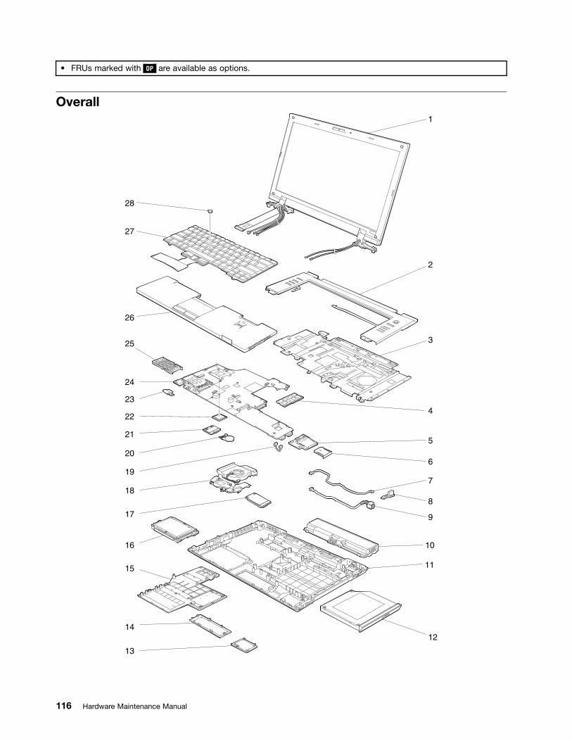
• FRUs marked with OP are available as options.
Overall1
2
3
4
5
8
7
6
10
9
11
12
28
27
26
23
24
25
22
21
20
19
18
17
16
15
13
14
116 Hardware Maintenance Manual
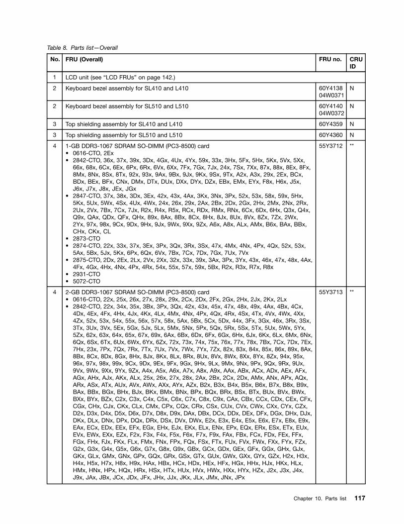
Table 8. Parts list—Overall
No. FRU (Overall) FRU no. CRUID
1 LCD unit (see “LCD FRUs” on page 142.)
2 Keyboard bezel assembly for SL410 and L410 60Y413804W0371
N
2 Keyboard bezel assembly for SL510 and L510 60Y414004W0372
N
3 Top shielding assembly for SL410 and L410 60Y4359 N
3 Top shielding assembly for SL510 and L510 60Y4360 N
4 1-GB DDR3-1067 SDRAM SO-DIMM (PC3-8500) card• 0616-CTO, 2Ex• 2842-CTO, 36x, 37x, 39x, 3Dx, 4Gx, 4Ux, 4Yx, 59x, 33x, 3Hx, 5Fx, 5Hx, 5Kx, 5Vx, 5Xx,
66x, 68x, 6Cx, 6Ex, 6Px, 6Rx, 6Vx, 6Xx, 7Fx, 7Gx, 7Jx, 24x, 7Sx, 7Xx, 87x, 88x, 8Ex, 8Fx,8Mx, 8Nx, 8Sx, 8Tx, 92x, 93x, 9Ax, 9Bx, 9Jx, 9Kx, 9Sx, 9Tx, A2x, A3x, 29x, 2Ex, BCx,BDx, BEx, BFx, CNx, DMx, DTx, DUx, DXx, DYx, DZx, EBx, EMx, EYx, F8x, H6x, J5x,J6x, J7x, J8x, JEx, JGx
• 2847-CTO, 37x, 38x, 3Dx, 3Ex, 42x, 43x, 4Ax, 3Kx, 3Nx, 3Px, 52x, 53x, 58x, 59x, 5Hx,5Kx, 5Ux, 5Wx, 4Sx, 4Ux, 4Wx, 24x, 26x, 29x, 2Ax, 2Bx, 2Dx, 2Gx, 2Hx, 2Mx, 2Nx, 2Rx,2Ux, 2Vx, 7Bx, 7Cx, 7Jx, R2x, R4x, R5x, RCx, RDx, RMx, RNx, 6Cx, 6Dx, 6Hx, Q3x, Q4x,Q9x, QAx, QDx, QFx, QHx, 89x, 8Ax, 8Bx, 8Cx, 8Hx, 8Jx, 8Ux, 8Vx, 8Zx, 7Zx, 2Wx,2Yx, 97x, 98x, 9Cx, 9Dx, 9Hx, 9Jx, 9Wx, 9Xx, 9Zx, A6x, A8x, ALx, AMx, B6x, BAx, BBx,CHx, CKx, CL
• 2873-CTO• 2874-CTO, 22x, 33x, 37x, 3Ex, 3Px, 3Qx, 3Rx, 3Sx, 47x, 4Mx, 4Nx, 4Px, 4Qx, 52x, 53x,
5Ax, 5Bx, 5Jx, 5Kx, 6Px, 6Qx, 6Vx, 7Bx, 7Cx, 7Dx, 7Gx, 7Ux, 7Vx• 2875-CTO, 2Dx, 2Ex, 2Lx, 2Vx, 2Xx, 32x, 33x, 39x, 3Ax, 3Px, 3Yx, 43x, 46x, 47x, 48x, 4Ax,
4Fx, 4Gx, 4Hx, 4Nx, 4Px, 4Rx, 54x, 55x, 57x, 59x, 5Bx, R2x, R3x, R7x, R8x• 2931-CTO• 5072-CTO
55Y3712 **
4 2-GB DDR3-1067 SDRAM SO-DIMM (PC3-8500) card• 0616-CTO, 22x, 25x, 26x, 27x, 28x, 29x, 2Cx, 2Dx, 2Fx, 2Gx, 2Hx, 2Jx, 2Kx, 2Lx• 2842-CTO, 22x, 34x, 35x, 3Bx, 3Px, 3Qx, 42x, 43x, 45x, 47x, 48x, 49x, 4Ax, 4Bx, 4Cx,
4Dx, 4Ex, 4Fx, 4Hx, 4Jx, 4Kx, 4Lx, 4Mx, 4Nx, 4Px, 4Qx, 4Rx, 4Sx, 4Tx, 4Vx, 4Wx, 4Xx,4Zx, 52x, 53x, 54x, 55x, 56x, 57x, 58x, 5Ax, 5Bx, 5Cx, 5Dx, 44x, 3Fx, 3Gx, 46x, 3Rx, 3Sx,3Tx, 3Ux, 3Vx, 5Ex, 5Gx, 5Jx, 5Lx, 5Mx, 5Nx, 5Px, 5Qx, 5Rx, 5Sx, 5Tx, 5Ux, 5Wx, 5Yx,5Zx, 62x, 63x, 64x, 65x, 67x, 69x, 6Ax, 6Bx, 6Dx, 6Fx, 6Gx, 6Hx, 6Jx, 6Kx, 6Lx, 6Mx, 6Nx,6Qx, 6Sx, 6Tx, 6Ux, 6Wx, 6Yx, 6Zx, 72x, 73x, 74x, 75x, 76x, 77x, 78x, 7Bx, 7Cx, 7Dx, 7Ex,7Hx, 23x, 7Px, 7Qx, 7Rx, 7Tx, 7Ux, 7Vx, 7Wx, 7Yx, 7Zx, 82x, 83x, 84x, 85x, 86x, 89x, 8Ax,8Bx, 8Cx, 8Dx, 8Gx, 8Hx, 8Jx, 8Kx, 8Lx, 8Rx, 8Ux, 8Vx, 8Wx, 8Xx, 8Yx, 8Zx, 94x, 95x,96x, 97x, 98x, 99x, 9Cx, 9Dx, 9Ex, 9Fx, 9Gx, 9Hx, 9Lx, 9Mx, 9Nx, 9Px, 9Qx, 9Rx, 9Ux,9Vx, 9Wx, 9Xx, 9Yx, 9Zx, A4x, A5x, A6x, A7x, A8x, A9x, AAx, ABx, ACx, ADx, AEx, AFx,AGx, AHx, AJx, AKx, ALx, 25x, 26x, 27x, 28x, 2Ax, 2Bx, 2Cx, 2Dx, AMx, ANx, APx, AQx,ARx, ASx, ATx, AUx, AVx, AWx, AXx, AYx, AZx, B2x, B3x, B4x, B5x, B6x, B7x, B8x, B9x,BAx, BBx, BGx, BHx, BJx, BKx, BMx, BNx, BPx, BQx, BRx, BSx, BTx, BUx, BVx, BWx,BXx, BYx, BZx, C2x, C3x, C4x, C5x, C6x, C7x, C8x, C9x, CAx, CBx, CCx, CDx, CEx, CFx,CGx, CHx, CJx, CKx, CLx, CMx, CPx, CQx, CRx, CSx, CUx, CVx, CWx, CXx, CYx, CZx,D2x, D3x, D4x, D5x, D6x, D7x, D8x, D9x, DAx, DBx, DCx, DDx, DEx, DFx, DGx, DHx, DJx,DKx, DLx, DNx, DPx, DQx, DRx, DSx, DVx, DWx, E2x, E3x, E4x, E5x, E6x, E7x, E8x, E9x,EAx, ECx, EDx, EEx, EFx, EGx, EHx, EJx, EKx, ELx, ENx, EPx, EQx, ERx, ESx, ETx, EUx,EVx, EWx, EXx, EZx, F2x, F3x, F4x, F5x, F6x, F7x, F9x, FAx, FBx, FCx, FDx, FEx, FFx,FGx, FHx, FJx, FKx, FLx, FMx, FNx, FPx, FQx, FSx, FTx, FUx, FVx, FWx, FXx, FYx, FZx,G2x, G3x, G4x, G5x, G6x, G7x, G8x, G9x, GBx, GCx, GDx, GEx, GFx, GGx, GHx, GJx,GKx, GLx, GMx, GNx, GPx, GQx, GRx, GSx, GTx, GUx, GWx, GXx, GYx, GZx, H2x, H3x,H4x, H5x, H7x, H8x, H9x, HAx, HBx, HCx, HDx, HEx, HFx, HGx, HHx, HJx, HKx, HLx,HMx, HNx, HPx, HQx, HRx, HSx, HTx, HUx, HVx, HWx, HXx, HYx, HZx, J2x, J3x, J4x,J9x, JAx, JBx, JCx, JDx, JFx, JHx, JJx, JKx, JLx, JMx, JNx, JPx
55Y3713 **
Chapter 10. Parts list 117

Table 8. Parts list—Overall (continued)
No. FRU (Overall) FRU no. CRUID
• 2847-CTO, 22x, 33x, 34x, 35x, 39x, 44x, 45x, 46x, 47x, 48x, 49x, 4Bx, 4Cx, 4Dx, 4Ex, 4Fx,4Gx, 4Hx, 3Lx, 4Jx, 3Mx, 3Qx, 4Xx, 4Yx, 4Zx, 54x, 55x, 56x, 57x, 5Cx, 5Dx, 5Ex, 5Fx,5Gx, 5Jx, 5Lx, 5Mx, 5Nx, 5Px, 5Qx, 5Rx, 5Sx, 5Tx, 5Vx, 5Xx, 5Yx, 5Zx, 62x, 63x, 64x, 65x,66x, 67x, 4Nx, 4Px, 4Qx, 4Rx, 4Tx, 4Vx, 25x, 27x, 28x, 2Cx, 2Ex, 2Fx, 2Jx, 2Kx, 2Lx, 2Px,2Qx, 2Sx, 2Tx, 72x, 73x, 74x, 75x, 76x, 77x, 78x, 79x, 7Ax, 7Dx, 7Ex, 7Fx, R3x, R6x, R7x,R8x, R9x, RAx, RBx, RFx, RGx, RHx, RJx, RKx, RLx, RPx, RQx, RRx, RSx, RTx, RUx, RVx,RWx, RXx, 68x, 69x, 6Ax, 6Bx, 6Gx, Q2x, Q5x, Q6x, Q7x, Q8x, QEx, QGx, QJx, 82x, 83x,84x, 85x, 86x, 87x, 88x, 8Dx, 8Ex, 8Fx, 8Gx, 8Kx, 8Lx, 8Mx, 8Nx, 8Px, 8Qx, 8Rx, 8Sx, 8Tx,8Yx, 7Wx, 7Xx, 7Yx, 6Jx, 6Kx, 6Lx, 6Mx, 2Xx, 2Zx, 7Kx, 7Lx, 7Mx, 7Nx, 6Nx, 6Px, 6Qx,6Rx, 6Sx, 6Tx, 6Ux, 6Vx, 6Wx, 6Xx, 6Yx, 6Zx, 92x, 93x, 94x, 95x, 96x, 99x, 9Ax, 9Bx, 9Ex,9Fx, 9Gx, 9Kx, 9Lx, 9Mx, 9Nx, 9Px, 9Qx, 9Rx, 9Sx, 9Tx, 9Ux, 9Vx, 9Yx, 3Vx, 3Wx, 3Xx,3Yx, 3Zx, A2x, A3x, A4x, A5x, A7x, A9x, AAx, ABx, ACx, ADx, AEx, AFx, 7Px, 7Qx, 7Rx,7Sx, AGx, AHx, AJx, AKx, ANx, APx, AQx, ARx, ASx, 7Tx, 7Ux, 7Vx, ATx, AUx, AVx, AWx,AXx, AYx, AZx, B2x, B3x, B4x, B5x, B7x, B8x, B9x, BCx, BDx, BEx, BFx, BGx, BHx, BJx,BKx, BMx, BNx, BPx, BQx, BRx, BSx, BTx, BUx, BVx, BWx, BXx, BYx, BZx, C2x, C3x,C4x, C5x, C6x, C7x, C8x, C9x, CAx, CBx, CCx, CDx, CEx, CFx, CGx, CJx, CMx, CNx, CQx
• 2873-CTO, 22x, 33x, 32x• 2874-CTO, 22x, 32x, 34x, 35x, 36x, 39x, 3Bx, 3Gx, 3Kx, 3Lx, 3Mx, 3Nx, 46x, 48x, 49x, 4Ax,
4Bx, 4Cx, 4Dx, 4Fx, 4Gx, 4Hx, 4Jx, 4Kx, 4Lx, 54x, 55x, 56x, 57x, 58x, 59x, 5Cx, 5Dx, 5Ex,5Fx, 5Gx, 5Hx, 5Lx, 5Mx, 5Nx, 5Px, 5Qx, 5Rx, 62x, 63x, 64x, 65x, 66x, 67x, 68x, 69x, 6Ax,6Bx, 6Cx, 6Dx, 6Ex, 6Fx, 6Gx, 6Hx, 6Jx, 6Kx, 6Lx, 6Mx, 6Nx, 6Rx, 6Sx, 6Tx, 6Ux, 6Wx,6Xx, 6Yx, 6Zx, 72x, 73x, 74x, 75x, 76x, 77x, 78x, 79x, 7Ax, 7Bx, 7Cx, 7Dx, 7Ex, 7Fx, 7Gx,7Hx, 7Jx, 7Kx, 7Lx, 7Mx, 7Nx, 7Px, 7Qx, 7Rx, 7Sx, 7Tx, 7Vx, 7Wx, 7Xx, 7Yx, 7Zx, 82x
• 2875-CTO, 23x, 24x, 25x, 26x, 27x, 28x, 29x, 2Ax, 2Bx, 2Cx, 2Dx, 2Fx, 2Gx, 2Hx, 2Jx,2Kx, 2Mx, 2Nx, 2Px, 2Qx, 2Rx, 2Sx, 2Tx, 2Ux, 2Wx, 2Yx, 2Zx, 35x, 36x, 3Mx, 3Nx, 3Wx,3Xx, 3Zx, 42x, 44x, 45x, 49x, 4Bx, 4Cx, 4Dx, 4Ex, 4Jx, 4Kx, 4Lx, 4Qx, 4Sx, 4Tx, 4Ux, 4Vx,4Wx, 4Xx, 4Yx, 52x, 53x, 56x, 57x, 58x, 59x, 5Ax, 5Bx, 5Cx, R4x, R5x, R6x, R8x, R9x,RAx, RBx, RCx, RDx, RFx, RGx, RHx, RJx
• 2931-CTO, 25x, 26x, 27x, 22x• 5072-CTO
4 4-GB DDR3-1067 SDRAM SO-DIMM (PC3-8500) card• 0616-CTO• 2842-CTO, GVx• 2847-CTO, 23x, 36x, 5Ax, 5Bx, 6Ex, 6Fx, QBx, QCx, 8Wx, 8Xx, CPx• 2873-CTO• 2874-CTO• 2875-CTO• 2931-CTO• 5072-CTO
55Y3714 **
4 1-GB DDR3-1333 SDRAM SO-DIMM (PC3-10600) card• 0616-CTO, 2Ex• 2842-CTO, 36x, 37x, 39x, 3Dx, 4Gx, 4Ux, 4Yx, 59x, 33x, 3Hx, 5Fx, 5Hx, 5Kx, 5Vx, 5Xx,
66x, 68x, 6Cx, 6Ex, 6Px, 6Rx, 6Vx, 6Xx, 7Fx, 7Gx, 7Jx, 24x, 7Sx, 7Xx, 87x, 88x, 8Ex, 8Fx,8Mx, 8Nx, 8Sx, 8Tx, 92x, 93x, 9Ax, 9Bx, 9Jx, 9Kx, 9Sx, 9Tx, A2x, A3x, 29x, 2Ex, BCx,BDx, BEx, BFx, CNx, DMx, DTx, DUx, DXx, DYx, DZx, EBx, EMx, EYx, F8x, H6x, J5x,J6x, J7x, J8x, JEx, JGx
• 2847-CTO, 37x, 38x, 3Dx, 3Ex, 42x, 43x, 4Ax, 3Kx, 3Nx, 3Px, 52x, 53x, 58x, 59x, 5Hx,5Kx, 5Ux, 5Wx, 4Sx, 4Ux, 4Wx, 24x, 26x, 29x, 2Ax, 2Bx, 2Dx, 2Gx, 2Hx, 2Mx, 2Nx, 2Rx,2Ux, 2Vx, 7Bx, 7Cx, 7Jx, R2x, R4x, R5x, RCx, RDx, RMx, RNx, 6Cx, 6Dx, 6Hx, Q3x, Q4x,Q9x, QAx, QDx, QFx, QHx, 89x, 8Ax, 8Bx, 8Cx, 8Hx, 8Jx, 8Ux, 8Vx, 8Zx, 7Zx, 2Wx,2Yx, 97x, 98x, 9Cx, 9Dx, 9Hx, 9Jx, 9Wx, 9Xx, 9Zx, A6x, A8x, ALx, AMx, B6x, BAx, BBx,CHx, CKx, CL
• 2873-CTO• 2874-CTO, 22x, 33x, 37x, 3Ex, 3Px, 3Qx, 3Rx, 3Sx, 47x, 4Mx, 4Nx, 4Px, 4Qx, 52x, 53x,
5Ax, 5Bx, 5Jx, 5Kx, 6Px, 6Qx, 6Vx, 7Bx, 7Cx, 7Dx, 7Gx, 7Ux, 7Vx
55Y3715 **
118 Hardware Maintenance Manual

Table 8. Parts list—Overall (continued)
No. FRU (Overall) FRU no. CRUID
• 2875-CTO, 2Dx, 2Ex, 2Lx, 2Vx, 2Xx, 32x, 33x, 39x, 3Ax, 3Px, 3Yx, 43x, 46x, 47x, 48x, 4Ax,4Fx, 4Gx, 4Hx, 4Nx, 4Px, 4Rx, 54x, 55x, 57x, 59x, 5Bx, R2x, R3x, R7x, R8x
• 2931-CTO• 5072-CTO
4 2-GB DDR3-1333 SDRAM SO-DIMM (PC3-10600) card• 0616-CTO, 22x, 25x, 26x, 27x, 28x, 29x, 2Cx, 2Dx, 2Fx, 2Gx, 2Hx, 2Jx, 2Kx, 2Lx• 2842-CTO, 22x, 34x, 35x, 3Bx, 3Px, 3Qx, 42x, 43x, 45x, 47x, 48x, 49x, 4Ax, 4Bx, 4Cx,
4Dx, 4Ex, 4Fx, 4Hx, 4Jx, 4Kx, 4Lx, 4Mx, 4Nx, 4Px, 4Qx, 4Rx, 4Sx, 4Tx, 4Vx, 4Wx, 4Xx,4Zx, 52x, 53x, 54x, 55x, 56x, 57x, 58x, 5Ax, 5Bx, 5Cx, 5Dx, 44x, 3Fx, 3Gx, 46x, 3Rx, 3Sx,3Tx, 3Ux, 3Vx, 5Ex, 5Gx, 5Jx, 5Lx, 5Mx, 5Nx, 5Px, 5Qx, 5Rx, 5Sx, 5Tx, 5Ux, 5Wx, 5Yx,5Zx, 62x, 63x, 64x, 65x, 67x, 69x, 6Ax, 6Bx, 6Dx, 6Fx, 6Gx, 6Hx, 6Jx, 6Kx, 6Lx, 6Mx, 6Nx,6Qx, 6Sx, 6Tx, 6Ux, 6Wx, 6Yx, 6Zx, 72x, 73x, 74x, 75x, 76x, 77x, 78x, 7Bx, 7Cx, 7Dx, 7Ex,7Hx, 23x, 7Px, 7Qx, 7Rx, 7Tx, 7Ux, 7Vx, 7Wx, 7Yx, 7Zx, 82x, 83x, 84x, 85x, 86x, 89x, 8Ax,8Bx, 8Cx, 8Dx, 8Gx, 8Hx, 8Jx, 8Kx, 8Lx, 8Rx, 8Ux, 8Vx, 8Wx, 8Xx, 8Yx, 8Zx, 94x, 95x,96x, 97x, 98x, 99x, 9Cx, 9Dx, 9Ex, 9Fx, 9Gx, 9Hx, 9Lx, 9Mx, 9Nx, 9Px, 9Qx, 9Rx, 9Ux,9Vx, 9Wx, 9Xx, 9Yx, 9Zx, A4x, A5x, A6x, A7x, A8x, A9x, AAx, ABx, ACx, ADx, AEx, AFx,AGx, AHx, AJx, AKx, ALx, 25x, 26x, 27x, 28x, 2Ax, 2Bx, 2Cx, 2Dx, AMx, ANx, APx, AQx,ARx, ASx, ATx, AUx, AVx, AWx, AXx, AYx, AZx, B2x, B3x, B4x, B5x, B6x, B7x, B8x, B9x,BAx, BBx, BGx, BHx, BJx, BKx, BMx, BNx, BPx, BQx, BRx, BSx, BTx, BUx, BVx, BWx,BXx, BYx, BZx, C2x, C3x, C4x, C5x, C6x, C7x, C8x, C9x, CAx, CBx, CCx, CDx, CEx, CFx,CGx, CHx, CJx, CKx, CLx, CMx, CPx, CQx, CRx, CSx, CUx, CVx, CWx, CXx, CYx, CZx,D2x, D3x, D4x, D5x, D6x, D7x, D8x, D9x, DAx, DBx, DCx, DDx, DEx, DFx, DGx, DHx, DJx,DKx, DLx, DNx, DPx, DQx, DRx, DSx, DVx, DWx, E2x, E3x, E4x, E5x, E6x, E7x, E8x, E9x,EAx, ECx, EDx, EEx, EFx, EGx, EHx, EJx, EKx, ELx, ENx, EPx, EQx, ERx, ESx, ETx, EUx,EVx, EWx, EXx, EZx, F2x, F3x, F4x, F5x, F6x, F7x, F9x, FAx, FBx, FCx, FDx, FEx, FFx,FGx, FHx, FJx, FKx, FLx, FMx, FNx, FPx, FQx, FSx, FTx, FUx, FVx, FWx, FXx, FYx, FZx,G2x, G3x, G4x, G5x, G6x, G7x, G8x, G9x, GBx, GCx, GDx, GEx, GFx, GGx, GHx, GJx,GKx, GLx, GMx, GNx, GPx, GQx, GRx, GSx, GTx, GUx, GWx, GXx, GYx, GZx, H2x, H3x,H4x, H5x, H7x, H8x, H9x, HAx, HBx, HCx, HDx, HEx, HFx, HGx, HHx, HJx, HKx, HLx,HMx, HNx, HPx, HQx, HRx, HSx, HTx, HUx, HVx, HWx, HXx, HYx, HZx, J2x, J3x, J4x,J9x, JAx, JBx, JCx, JDx, JFx, JHx, JJx, JKx, JLx, JMx, JNx, JPx
• 2847-CTO, 22x, 33x, 34x, 35x, 39x, 44x, 45x, 46x, 47x, 48x, 49x, 4Bx, 4Cx, 4Dx, 4Ex, 4Fx,4Gx, 4Hx, 3Lx, 4Jx, 3Mx, 3Qx, 4Xx, 4Yx, 4Zx, 54x, 55x, 56x, 57x, 5Cx, 5Dx, 5Ex, 5Fx,5Gx, 5Jx, 5Lx, 5Mx, 5Nx, 5Px, 5Qx, 5Rx, 5Sx, 5Tx, 5Vx, 5Xx, 5Yx, 5Zx, 62x, 63x, 64x, 65x,66x, 67x, 4Nx, 4Px, 4Qx, 4Rx, 4Tx, 4Vx, 25x, 27x, 28x, 2Cx, 2Ex, 2Fx, 2Jx, 2Kx, 2Lx, 2Px,2Qx, 2Sx, 2Tx, 72x, 73x, 74x, 75x, 76x, 77x, 78x, 79x, 7Ax, 7Dx, 7Ex, 7Fx, R3x, R6x, R7x,R8x, R9x, RAx, RBx, RFx, RGx, RHx, RJx, RKx, RLx, RPx, RQx, RRx, RSx, RTx, RUx, RVx,RWx, RXx, 68x, 69x, 6Ax, 6Bx, 6Gx, Q2x, Q5x, Q6x, Q7x, Q8x, QEx, QGx, QJx, 82x, 83x,84x, 85x, 86x, 87x, 88x, 8Dx, 8Ex, 8Fx, 8Gx, 8Kx, 8Lx, 8Mx, 8Nx, 8Px, 8Qx, 8Rx, 8Sx, 8Tx,8Yx, 7Wx, 7Xx, 7Yx, 6Jx, 6Kx, 6Lx, 6Mx, 2Xx, 2Zx, 7Kx, 7Lx, 7Mx, 7Nx, 6Nx, 6Px, 6Qx,6Rx, 6Sx, 6Tx, 6Ux, 6Vx, 6Wx, 6Xx, 6Yx, 6Zx, 92x, 93x, 94x, 95x, 96x, 99x, 9Ax, 9Bx, 9Ex,9Fx, 9Gx, 9Kx, 9Lx, 9Mx, 9Nx, 9Px, 9Qx, 9Rx, 9Sx, 9Tx, 9Ux, 9Vx, 9Yx, 3Vx, 3Wx, 3Xx,3Yx, 3Zx, A2x, A3x, A4x, A5x, A7x, A9x, AAx, ABx, ACx, ADx, AEx, AFx, 7Px, 7Qx, 7Rx,7Sx, AGx, AHx, AJx, AKx, ANx, APx, AQx, ARx, ASx, 7Tx, 7Ux, 7Vx, ATx, AUx, AVx, AWx,AXx, AYx, AZx, B2x, B3x, B4x, B5x, B7x, B8x, B9x, BCx, BDx, BEx, BFx, BGx, BHx, BJx,BKx, BMx, BNx, BPx, BQx, BRx, BSx, BTx, BUx, BVx, BWx, BXx, BYx, BZx, C2x, C3x,C4x, C5x, C6x, C7x, C8x, C9x, CAx, CBx, CCx, CDx, CEx, CFx, CGx, CJx, CMx, CNx, CQx
• 2873-CTO, 22x, 33x, 32x• 2874-CTO, 22x, 32x, 34x, 35x, 36x, 39x, 3Bx, 3Gx, 3Kx, 3Lx, 3Mx, 3Nx, 46x, 48x, 49x, 4Ax,
4Bx, 4Cx, 4Dx, 4Fx, 4Gx, 4Hx, 4Jx, 4Kx, 4Lx, 54x, 55x, 56x, 57x, 58x, 59x, 5Cx, 5Dx, 5Ex,5Fx, 5Gx, 5Hx, 5Lx, 5Mx, 5Nx, 5Px, 5Qx, 5Rx, 62x, 63x, 64x, 65x, 66x, 67x, 68x, 69x, 6Ax,6Bx, 6Cx, 6Dx, 6Ex, 6Fx, 6Gx, 6Hx, 6Jx, 6Kx, 6Lx, 6Mx, 6Nx, 6Rx, 6Sx, 6Tx, 6Ux, 6Wx,6Xx, 6Yx, 6Zx, 72x, 73x, 74x, 75x, 76x, 77x, 78x, 79x, 7Ax, 7Bx, 7Cx, 7Dx, 7Ex, 7Fx, 7Gx,7Hx, 7Jx, 7Kx, 7Lx, 7Mx, 7Nx, 7Px, 7Qx, 7Rx, 7Sx, 7Tx, 7Vx, 7Wx, 7Xx, 7Yx, 7Zx, 82x
• 2875-CTO, 23x, 24x, 25x, 26x, 27x, 28x, 29x, 2Ax, 2Bx, 2Cx, 2Dx, 2Fx, 2Gx, 2Hx, 2Jx,2Kx, 2Mx, 2Nx, 2Px, 2Qx, 2Rx, 2Sx, 2Tx, 2Ux, 2Wx, 2Yx, 2Zx, 35x, 36x, 3Mx, 3Nx, 3Wx,3Xx, 3Zx, 42x, 44x, 45x, 49x, 4Bx, 4Cx, 4Dx, 4Ex, 4Jx, 4Kx, 4Lx, 4Qx, 4Sx, 4Tx, 4Ux, 4Vx,
55Y3716 **
Chapter 10. Parts list 119
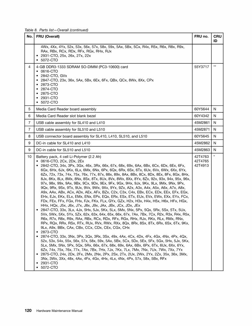
Table 8. Parts list—Overall (continued)
No. FRU (Overall) FRU no. CRUID
4Wx, 4Xx, 4Yx, 52x, 53x, 56x, 57x, 58x, 59x, 5Ax, 5Bx, 5Cx, R4x, R5x, R6x, R8x, R9x,RAx, RBx, RCx, RDx, RFx, RGx, RHx, RJx
• 2931-CTO, 25x, 26x, 27x, 22x• 5072-CTO
4 4-GB DDR3-1333 SDRAM SO-DIMM (PC3-10600) card• 0616-CTO• 2842-CTO, GVx• 2847-CTO, 23x, 36x, 5Ax, 5Bx, 6Ex, 6Fx, QBx, QCx, 8Wx, 8Xx, CPx• 2873-CTO• 2874-CTO• 2875-CTO• 2931-CTO• 5072-CTO
55Y3717 **
5 Media Card Reader board assembly 60Y5644 N
6 Media Card Reader slot blank bezel 60Y4342 N
7 USB cable assembly for SL410 and L410 45M2861 N
7 USB cable assembly for SL510 and L510 45M2871 N
8 USB connector board assembly for SL410, L410, SL510, and L510 60Y5645 N
9 DC-in cable for SL410 and L410 45M2862 N
9 DC-in cable for SL510 and L510 45M2863 N
10 Battery pack, 4 cell Li-Polymer (2.2 Ah)• 0616-CTO, 2Cx, 2Dx, 2Ex• 2842-CTO, 34x, 3Px, 3Gx, 46x, 3Rx, 66x, 67x, 68x, 69x, 6Ax, 6Bx, 6Cx, 6Dx, 6Ex, 6Fx,
6Gx, 6Hx, 6Jx, 6Kx, 6Lx, 6Mx, 6Nx, 6Px, 6Qx, 6Rx, 6Sx, 6Tx, 6Ux, 6Vx, 6Wx, 6Xx, 6Yx,6Zx, 72x, 73x, 74x, 75x, 76x, 77x, 87x, 88x, 89x, 8Ax, 8Bx, 8Cx, 8Dx, 8Ex, 8Fx, 8Gx, 8Hx,8Jx, 8Kx, 8Lx, 8Mx, 8Nx, 8Sx, 8Tx, 8Ux, 8Vx, 8Wx, 8Xx, 8Yx, 8Zx, 92x, 93x, 94x, 95x, 96x,97x, 98x, 99x, 9Ax, 9Bx, 9Cx, 9Dx, 9Ex, 9Fx, 9Gx, 9Hx, 9Jx, 9Kx, 9Lx, 9Mx, 9Nx, 9Px,9Qx, 9Rx, 9Sx, 9Tx, 9Ux, 9Vx, 9Wx, 9Xx, 9Yx, 9Zx, A2x, A3x, A4x, A5x, A6x, A7x, A8x,A9x, AAx, ABx, ACx, ADx, AEx, AFx, BZx, C2x, C3x, C4x, EBx, ECx, EDx, EEx, EFx, EGx,EHx, EJx, EKx, ELx, EMx, ENx, EPx, EQx, ERx, ESx, ETx, EUx, EVx, EWx, EXx, EYx, FCx,FDx, FEx, FFx, FGx, FHx, FJx, FKx, FLx, GYx, GZx, H2x, H3x, H4x, H5x, H6x, HFx, HGx,HHx, HQx, J5x, J6x, J7x, J8x, J9x, JAx, JBx, JCx, JDx, JEx
• 2847-CTO, 33x, 3Lx, 4Jx, 5Hx, 5Jx, 5Kx, 5Lx, 5Mx, 5Nx, 5Px, 5Qx, 5Rx, 5Sx, 5Tx, 5Ux,5Vx, 5Wx, 5Xx, 5Yx, 5Zx, 62x, 63x, 64x, 65x, 66x, 67x, 7Ax, 7Bx, 7Cx, R2x, R3x, R4x, R5x,R6x, R7x, R8x, R9x, RAx, RBx, RCx, RDx, RFx, RGx, RHx, RJx, RKx, RLx, RMx, RNx,RPx, RQx, RRx, RSx, RTx, RUx, RVx, RWx, RXx, 8Qx, 8Rx, 8Sx, 8Tx, 6Rx, 6Sx, 6Tx, 9Kx,9Lx, A9x, BBx, CAx, CBx, CCx, CDx, CEx, CGx, CHx
• 2873-CTO• 2874-CTO, 33x, 3Nx, 3Px, 3Qx, 3Rx, 3Sx, 49x, 4Ax, 4Cx, 4Dx, 4Fx, 4Gx, 4Nx, 4Px, 4Qx,
52x, 53x, 54x, 55x, 56x, 57x, 58x, 59x, 5Ax, 5Bx, 5Cx, 5Dx, 5Ex, 5Fx, 5Gx, 5Hx, 5Jx, 5Kx,5Lx, 5Mx, 5Nx, 5Px, 5Qx, 5Rx, 66x, 67x, 68x, 69x, 6Ax, 6Bx, 6Px, 6Tx, 6Ux, 6Xx, 6Yx,6Zx, 74x, 75x, 76x, 77x, 7Ax, 7Bx, 7Hx, 7Jx, 7Kx, 7Lx, 7Mx, 7Nx, 7Ux, 7Wx, 7Xx, 7Yx
• 2875-CTO, 24x, 2Dx, 2Fx, 2Mx, 2Nx, 2Px, 2Sx, 2Tx, 2Ux, 2Wx, 2Yx, 2Zx, 35x, 36x, 3Mx,3Nx, 3Wx, 3Xx, 48x, 4Ax, 4Fx, 4Gx, 4Hx, 4Lx, 4Nx, 4Px, 57x, 58x, 5Bx, RFx
• 2931-CTO• 5072-CTO
42T476342T476542T4913
*
120 Hardware Maintenance Manual

Table 8. Parts list—Overall (continued)
No. FRU (Overall) FRU no. CRUID
10 Battery pack, 6 cell Li-ion (2.2 Ah)• 0616-CTO, 22x, 25x, 26x, 27x, 28x, 29x, 2Fx, 2Gx, 2Hx, 2Jx, 2Kx, 2Lx• 2842-CTO, 22x, 35x, 36x, 37x, 39x, 3Bx, 3Dx, 3Qx, 42x, 43x, 45x, 47x, 48x, 49x, 4Ax, 4Bx,
4Cx, 4Dx, 4Ex, 4Fx, 4Gx, 4Hx, 4Jx, 4Kx, 4Lx, 4Mx, 4Nx, 4Px, 4Qx, 4Rx, 4Sx, 4Tx, 4Ux,4Vx, 4Wx, 4Xx, 4Yx, 4Zx, 52x, 53x, 54x, 55x, 56x, 57x, 58x, 59x, 5Ax, 5Bx, 5Cx, 5Dx, 44x,33x, 3Fx, 3Hx, 3Sx, 3Tx, 3Ux, 3Vx, 5Ex, 5Fx, 5Gx, 5Hx, 5Jx, 5Kx, 5Lx, 5Mx, 5Nx, 5Px,5Qx, 5Rx, 5Sx, 5Tx, 5Ux, 5Vx, 5Wx, 5Xx, 5Yx, 5Zx, 62x, 63x, 64x, 65x, 78x, 7Bx, 7Cx,7Dx, 7Ex, 7Fx, 7Gx, 7Hx, 7Jx, 23x, 24x, 7Px, 7Qx, 7Rx, 7Sx, 7Tx, 7Ux, 7Vx, 7Wx, 7Xx,7Yx, 7Zx, 82x, 83x, 84x, 85x, 86x, 8Rx, AGx, AHx, AJx, AKx, ALx, 25x, 26x, 27x, 28x, 29x,2Ax, 2Bx, 2Cx, 2Dx, 2Ex, AMx, ANx, APx, AQx, ARx, ASx, ATx, AUx, AVx, AWx, AXx, AYx,AZx, B2x, B3x, B4x, B5x, B6x, B7x, B8x, B9x, BAx, BBx, BCx, BDx, BEx, BFx, BGx, BHx,BJx, BKx, BMx, BNx, BPx, BQx, BRx, BSx, BTx, BUx, BVx, BWx, BXx, BYx, C5x, C6x,C7x, C8x, C9x, CAx, CBx, CCx, CDx, CEx, CFx, CGx, CHx, CJx, CKx, CLx, CMx, CNx,CPx, CQx, CRx, CSx, CUx, CVx, CWx, CXx, CYx, CZx, D2x, D3x, D4x, D5x, D6x, D7x,D8x, D9x, DAx, DBx, DCx, DDx, DEx, DFx, DGx, DHx, DJx, DKx, DLx, DMx, DNx, DPx,DQx, DRx, DSx, DTx, DUx, DVx, DWx, DXx, DYx, DZx, E2x, E3x, E4x, E5x, E6x, E7x, E8x,E9x, EAx, EZx, F2x, F3x, F4x, F5x, F6x, F7x, F8x, F9x, FAx, FBx, FMx, FNx, FPx, FQx,FSx, FTx, FUx, FVx, FWx, FXx, FYx, FZx, G2x, G3x, G4x, G5x, G6x, G7x, G8x, G9x, GBx,GCx, GDx, GEx, GFx, GGx, GHx, GJx, GKx, GLx, GMx, GNx, GPx, GQx, GRx, GSx,GTx, GUx, GVx, GWx, GXx, H7x, H8x, H9x, HAx, HBx, HCx, HDx, HEx, HJx, HKx, HLx,HMx, HNx, HPx, HRx, HSx, HTx, HUx, HVx, HWx, HXx, HYx, HZx, J2x, J3x, J4x, JFx,JGx, JHx, JJx, JKx, JLx, JMx, JNx, JPx
• 2847-CTO, 22x, 34x, 35x, 36x, 37x, 38x, 39x, 3Dx, 3Ex, 42x, 43x, 44x, 45x, 46x, 47x, 48x,49x, 4Ax, 4Bx, 4Cx, 4Dx, 4Ex, 4Fx, 4Gx, 4Hx, 3Kx, 3Mx, 3Nx, 3Px, 3Qx, 4Xx, 4Yx, 4Zx,52x, 53x, 54x, 55x, 56x, 57x, 58x, 59x, 5Ax, 5Bx, 5Cx, 5Dx, 5Ex, 5Fx, 5Gx, 4Nx, 4Px, 4Qx,4Rx, 4Sx, 4Tx, 4Ux, 4Vx, 4Wx, 24x, 25x, 26x, 27x, 28x, 29x, 2Ax, 2Bx, 2Cx, 2Dx, 2Ex,2Fx, 2Gx, 2Hx, 2Jx, 2Kx, 2Lx, 2Mx, 2Nx, 2Px, 2Qx, 2Rx, 2Sx, 2Tx, 2Ux, 2Vx, 72x, 73x,74x, 75x, 76x, 77x, 78x, 79x, 7Dx, 7Ex, 7Fx, 7Jx, 68x, 69x, 6Ax, 6Bx, 6Cx, 6Dx, 6Ex, 6Fx,6Gx, 6Hx, Q2x, Q3x, Q4x, Q5x, Q6x, Q7x, Q8x, Q9x, QAx, QBx, QCx, QDx, QEx, QFx,QGx, QHx, QJx, 82x, 83x, 84x, 85x, 86x, 87x, 88x, 89x, 8Ax, 8Bx, 8Cx, 8Dx, 8Ex, 8Fx,8Gx, 8Hx, 8Jx, 8Kx, 8Lx, 8Mx, 8Nx, 8Px, 8Ux, 8Vx, 8Wx, 8Xx, 8Yx, 8Zx, 7Zx, 7Wx, 7Xx,7Yx, 6Jx, 6Kx, 6Lx, 6Mx, 2Wx, 2Xx, 2Yx, 2Zx, 7Kx, 7Lx, 7Mx, 7Nx, 6Nx, 6Px, 6Qx, 6Ux,6Vx, 6Wx, 6Xx, 6Yx, 6Zx, 92x, 93x, 94x, 95x, 96x, 97x, 98x, 99x, 9Ax, 9Bx, 9Cx, 9Dx, 9Ex,9Fx, 9Gx, 9Hx, 9Jx, 9Mx, 9Nx, 9Px, 9Qx, 9Rx, 9Sx, 9Tx, 9Ux, 9Vx, 9Wx, 9Xx, 9Yx, 9Zx,3Vx, 3Wx, 3Xx, 3Yx, 3Zx, A2x, A3x, A4x, A5x, A6x, A8x, AAx, ABx, ACx, ADx, AEx, AFx,7Px, 7Qx, 7Rx, 7Sx, AGx, AHx, AJx, AKx, ALx, AMx, ANx, APx, AQx, ARx, ASx, 7Tx,7Ux, 7Vx, ATx, AUx, AVx, AWx, AXx, AYx, AZx, B2x, B3x, B4x, B5x, B6x, B7x, B8x, B9x,BAx, BCx, BDx, BEx, BFx, BGx, BHx, BJx, BKx, BMx, BNx, BPx, BQx, BRx, BSx, BTx,BUx, BVx, BWx, BXx, BYx, BZx, C2x, C3x, C4x, C5x, C6x, C7x, C8x, C9x, CFx, CJx,CKx, CLx, CMx, CNx, CPx, CQx
• 2873-CTO, 32x, 33x, 22x• 2874-CTO, 32x, 34x, 35x, 36x, 37x, 39x, 3Bx, 3Ex, 3Gx, 3Kx, 3Lx, 3Mx, 46x, 47x, 48x,
4Bx, 4Hx, 4Jx, 4Kx, 4Lx, 4Mx, 62x, 63x, 64x, 65x, 6Cx, 6Dx, 6Ex, 6Fx, 6Gx, 6Hx, 6Jx, 6Kx,6Lx, 6Mx, 6Nx, 6Qx, 6Rx, 6Sx, 6Vx, 6Wx, 72x, 73x, 78x, 79x, 7Cx, 7Dx, 7Ex, 7Fx, 7Gx,7Px, 7Qx, 7Rx, 7Sx, 7Tx, 7Vx, 7Zx, 82x
• 2875-CTO, 25x, 26x, 27x, 28x, 29x, 2Ax, 2Bx, 2Cx, 2Ex, 2Gx, 2Hx, 2Jx, 2Kx, 2Lx, 2Qx,2Rx, 2Vx, 2Xx, 32x, 33x, 39x, 3Ax, 3Px, 3Yx, 3Zx, 42x, 43x, 44x, 45x, 46x, 47x, 49x,4Bx, 4Cx, 4Dx, 4Ex, 4Jx, 4Kx, 4Qx, 4Rx, 4Sx, 4Tx, 4Ux, 4Vx, 4Wx, 4Xx, 4Yx, 52x, 53x,54x, 55x, 56x, 59x, 5Ax, 5Cx, R2x, R3x, R4x, R5x, R6x, R7x, R8x, R9x, RAx, RBx, RCx,RDx, RGx, RHx, RJx
• 2931-CTO, 25x, 26x, 27x, 23x, 24x• 5072-CTO
42T475142T475342T475542T4848
*
Chapter 10. Parts list 121
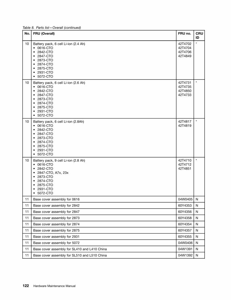
Table 8. Parts list—Overall (continued)
No. FRU (Overall) FRU no. CRUID
10 Battery pack, 6 cell Li-ion (2.4 Ah)• 0616-CTO• 2842-CTO• 2847-CTO• 2873-CTO• 2874-CTO• 2875-CTO• 2931-CTO• 5072-CTO
42T470242T470442T470642T4849
*
10 Battery pack, 6 cell Li-ion (2.6 Ah)• 0616-CTO• 2842-CTO• 2847-CTO• 2873-CTO• 2874-CTO• 2875-CTO• 2931-CTO• 5072-CTO
42T473142T473542T485042T4733
*
10 Battery pack, 6 cell Li-ion (2.8Ah)• 0616-CTO• 2842-CTO• 2847-CTO• 2873-CTO• 2874-CTO• 2875-CTO• 2931-CTO• 5072-CTO
42T481742T4819
*
10 Battery pack, 9 cell Li-ion (2.8 Ah)• 0616-CTO• 2842-CTO• 2847-CTO, A7x, 23x• 2873-CTO• 2874-CTO• 2875-CTO• 2931-CTO• 5072-CTO
42T471042T471242T4851
*
11 Base cover assembly for 0616 04W0405 N
11 Base cover assembly for 2842 60Y4353 N
11 Base cover assembly for 2847 60Y4356 N
11 Base cover assembly for 2873 60Y4358 N
11 Base cover assembly for 2874 60Y4354 N
11 Base cover assembly for 2875 60Y4357 N
11 Base cover assembly for 2931 60Y4355 N
11 Base cover assembly for 5072 04W0406 N
11 Base cover assembly for SL410 and L410 China 04W1391 N
11 Base cover assembly for SL510 and L510 China 04W1392 N
122 Hardware Maintenance Manual
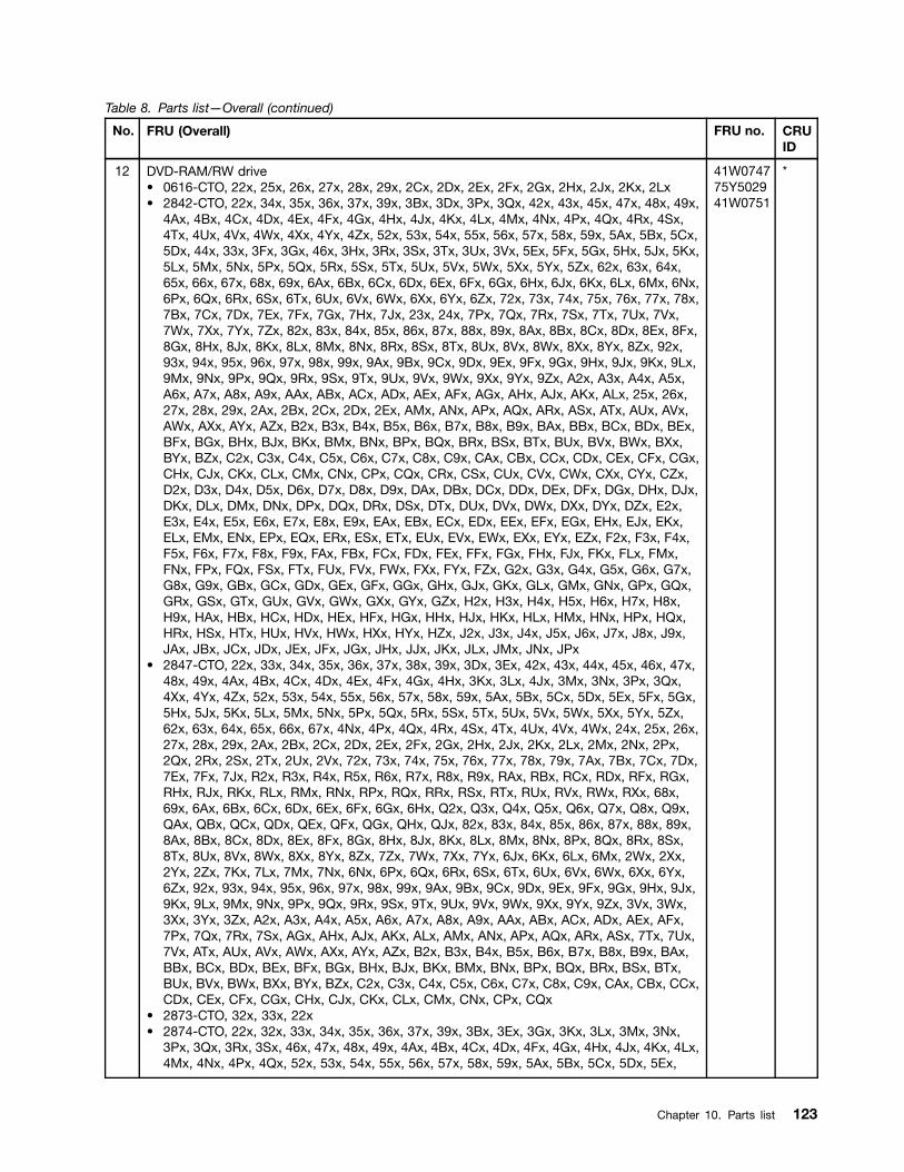
Table 8. Parts list—Overall (continued)
No. FRU (Overall) FRU no. CRUID
12 DVD-RAM/RW drive• 0616-CTO, 22x, 25x, 26x, 27x, 28x, 29x, 2Cx, 2Dx, 2Ex, 2Fx, 2Gx, 2Hx, 2Jx, 2Kx, 2Lx• 2842-CTO, 22x, 34x, 35x, 36x, 37x, 39x, 3Bx, 3Dx, 3Px, 3Qx, 42x, 43x, 45x, 47x, 48x, 49x,
4Ax, 4Bx, 4Cx, 4Dx, 4Ex, 4Fx, 4Gx, 4Hx, 4Jx, 4Kx, 4Lx, 4Mx, 4Nx, 4Px, 4Qx, 4Rx, 4Sx,4Tx, 4Ux, 4Vx, 4Wx, 4Xx, 4Yx, 4Zx, 52x, 53x, 54x, 55x, 56x, 57x, 58x, 59x, 5Ax, 5Bx, 5Cx,5Dx, 44x, 33x, 3Fx, 3Gx, 46x, 3Hx, 3Rx, 3Sx, 3Tx, 3Ux, 3Vx, 5Ex, 5Fx, 5Gx, 5Hx, 5Jx, 5Kx,5Lx, 5Mx, 5Nx, 5Px, 5Qx, 5Rx, 5Sx, 5Tx, 5Ux, 5Vx, 5Wx, 5Xx, 5Yx, 5Zx, 62x, 63x, 64x,65x, 66x, 67x, 68x, 69x, 6Ax, 6Bx, 6Cx, 6Dx, 6Ex, 6Fx, 6Gx, 6Hx, 6Jx, 6Kx, 6Lx, 6Mx, 6Nx,6Px, 6Qx, 6Rx, 6Sx, 6Tx, 6Ux, 6Vx, 6Wx, 6Xx, 6Yx, 6Zx, 72x, 73x, 74x, 75x, 76x, 77x, 78x,7Bx, 7Cx, 7Dx, 7Ex, 7Fx, 7Gx, 7Hx, 7Jx, 23x, 24x, 7Px, 7Qx, 7Rx, 7Sx, 7Tx, 7Ux, 7Vx,7Wx, 7Xx, 7Yx, 7Zx, 82x, 83x, 84x, 85x, 86x, 87x, 88x, 89x, 8Ax, 8Bx, 8Cx, 8Dx, 8Ex, 8Fx,8Gx, 8Hx, 8Jx, 8Kx, 8Lx, 8Mx, 8Nx, 8Rx, 8Sx, 8Tx, 8Ux, 8Vx, 8Wx, 8Xx, 8Yx, 8Zx, 92x,93x, 94x, 95x, 96x, 97x, 98x, 99x, 9Ax, 9Bx, 9Cx, 9Dx, 9Ex, 9Fx, 9Gx, 9Hx, 9Jx, 9Kx, 9Lx,9Mx, 9Nx, 9Px, 9Qx, 9Rx, 9Sx, 9Tx, 9Ux, 9Vx, 9Wx, 9Xx, 9Yx, 9Zx, A2x, A3x, A4x, A5x,A6x, A7x, A8x, A9x, AAx, ABx, ACx, ADx, AEx, AFx, AGx, AHx, AJx, AKx, ALx, 25x, 26x,27x, 28x, 29x, 2Ax, 2Bx, 2Cx, 2Dx, 2Ex, AMx, ANx, APx, AQx, ARx, ASx, ATx, AUx, AVx,AWx, AXx, AYx, AZx, B2x, B3x, B4x, B5x, B6x, B7x, B8x, B9x, BAx, BBx, BCx, BDx, BEx,BFx, BGx, BHx, BJx, BKx, BMx, BNx, BPx, BQx, BRx, BSx, BTx, BUx, BVx, BWx, BXx,BYx, BZx, C2x, C3x, C4x, C5x, C6x, C7x, C8x, C9x, CAx, CBx, CCx, CDx, CEx, CFx, CGx,CHx, CJx, CKx, CLx, CMx, CNx, CPx, CQx, CRx, CSx, CUx, CVx, CWx, CXx, CYx, CZx,D2x, D3x, D4x, D5x, D6x, D7x, D8x, D9x, DAx, DBx, DCx, DDx, DEx, DFx, DGx, DHx, DJx,DKx, DLx, DMx, DNx, DPx, DQx, DRx, DSx, DTx, DUx, DVx, DWx, DXx, DYx, DZx, E2x,E3x, E4x, E5x, E6x, E7x, E8x, E9x, EAx, EBx, ECx, EDx, EEx, EFx, EGx, EHx, EJx, EKx,ELx, EMx, ENx, EPx, EQx, ERx, ESx, ETx, EUx, EVx, EWx, EXx, EYx, EZx, F2x, F3x, F4x,F5x, F6x, F7x, F8x, F9x, FAx, FBx, FCx, FDx, FEx, FFx, FGx, FHx, FJx, FKx, FLx, FMx,FNx, FPx, FQx, FSx, FTx, FUx, FVx, FWx, FXx, FYx, FZx, G2x, G3x, G4x, G5x, G6x, G7x,G8x, G9x, GBx, GCx, GDx, GEx, GFx, GGx, GHx, GJx, GKx, GLx, GMx, GNx, GPx, GQx,GRx, GSx, GTx, GUx, GVx, GWx, GXx, GYx, GZx, H2x, H3x, H4x, H5x, H6x, H7x, H8x,H9x, HAx, HBx, HCx, HDx, HEx, HFx, HGx, HHx, HJx, HKx, HLx, HMx, HNx, HPx, HQx,HRx, HSx, HTx, HUx, HVx, HWx, HXx, HYx, HZx, J2x, J3x, J4x, J5x, J6x, J7x, J8x, J9x,JAx, JBx, JCx, JDx, JEx, JFx, JGx, JHx, JJx, JKx, JLx, JMx, JNx, JPx
• 2847-CTO, 22x, 33x, 34x, 35x, 36x, 37x, 38x, 39x, 3Dx, 3Ex, 42x, 43x, 44x, 45x, 46x, 47x,48x, 49x, 4Ax, 4Bx, 4Cx, 4Dx, 4Ex, 4Fx, 4Gx, 4Hx, 3Kx, 3Lx, 4Jx, 3Mx, 3Nx, 3Px, 3Qx,4Xx, 4Yx, 4Zx, 52x, 53x, 54x, 55x, 56x, 57x, 58x, 59x, 5Ax, 5Bx, 5Cx, 5Dx, 5Ex, 5Fx, 5Gx,5Hx, 5Jx, 5Kx, 5Lx, 5Mx, 5Nx, 5Px, 5Qx, 5Rx, 5Sx, 5Tx, 5Ux, 5Vx, 5Wx, 5Xx, 5Yx, 5Zx,62x, 63x, 64x, 65x, 66x, 67x, 4Nx, 4Px, 4Qx, 4Rx, 4Sx, 4Tx, 4Ux, 4Vx, 4Wx, 24x, 25x, 26x,27x, 28x, 29x, 2Ax, 2Bx, 2Cx, 2Dx, 2Ex, 2Fx, 2Gx, 2Hx, 2Jx, 2Kx, 2Lx, 2Mx, 2Nx, 2Px,2Qx, 2Rx, 2Sx, 2Tx, 2Ux, 2Vx, 72x, 73x, 74x, 75x, 76x, 77x, 78x, 79x, 7Ax, 7Bx, 7Cx, 7Dx,7Ex, 7Fx, 7Jx, R2x, R3x, R4x, R5x, R6x, R7x, R8x, R9x, RAx, RBx, RCx, RDx, RFx, RGx,RHx, RJx, RKx, RLx, RMx, RNx, RPx, RQx, RRx, RSx, RTx, RUx, RVx, RWx, RXx, 68x,69x, 6Ax, 6Bx, 6Cx, 6Dx, 6Ex, 6Fx, 6Gx, 6Hx, Q2x, Q3x, Q4x, Q5x, Q6x, Q7x, Q8x, Q9x,QAx, QBx, QCx, QDx, QEx, QFx, QGx, QHx, QJx, 82x, 83x, 84x, 85x, 86x, 87x, 88x, 89x,8Ax, 8Bx, 8Cx, 8Dx, 8Ex, 8Fx, 8Gx, 8Hx, 8Jx, 8Kx, 8Lx, 8Mx, 8Nx, 8Px, 8Qx, 8Rx, 8Sx,8Tx, 8Ux, 8Vx, 8Wx, 8Xx, 8Yx, 8Zx, 7Zx, 7Wx, 7Xx, 7Yx, 6Jx, 6Kx, 6Lx, 6Mx, 2Wx, 2Xx,2Yx, 2Zx, 7Kx, 7Lx, 7Mx, 7Nx, 6Nx, 6Px, 6Qx, 6Rx, 6Sx, 6Tx, 6Ux, 6Vx, 6Wx, 6Xx, 6Yx,6Zx, 92x, 93x, 94x, 95x, 96x, 97x, 98x, 99x, 9Ax, 9Bx, 9Cx, 9Dx, 9Ex, 9Fx, 9Gx, 9Hx, 9Jx,9Kx, 9Lx, 9Mx, 9Nx, 9Px, 9Qx, 9Rx, 9Sx, 9Tx, 9Ux, 9Vx, 9Wx, 9Xx, 9Yx, 9Zx, 3Vx, 3Wx,3Xx, 3Yx, 3Zx, A2x, A3x, A4x, A5x, A6x, A7x, A8x, A9x, AAx, ABx, ACx, ADx, AEx, AFx,7Px, 7Qx, 7Rx, 7Sx, AGx, AHx, AJx, AKx, ALx, AMx, ANx, APx, AQx, ARx, ASx, 7Tx, 7Ux,7Vx, ATx, AUx, AVx, AWx, AXx, AYx, AZx, B2x, B3x, B4x, B5x, B6x, B7x, B8x, B9x, BAx,BBx, BCx, BDx, BEx, BFx, BGx, BHx, BJx, BKx, BMx, BNx, BPx, BQx, BRx, BSx, BTx,BUx, BVx, BWx, BXx, BYx, BZx, C2x, C3x, C4x, C5x, C6x, C7x, C8x, C9x, CAx, CBx, CCx,CDx, CEx, CFx, CGx, CHx, CJx, CKx, CLx, CMx, CNx, CPx, CQx
• 2873-CTO, 32x, 33x, 22x• 2874-CTO, 22x, 32x, 33x, 34x, 35x, 36x, 37x, 39x, 3Bx, 3Ex, 3Gx, 3Kx, 3Lx, 3Mx, 3Nx,
3Px, 3Qx, 3Rx, 3Sx, 46x, 47x, 48x, 49x, 4Ax, 4Bx, 4Cx, 4Dx, 4Fx, 4Gx, 4Hx, 4Jx, 4Kx, 4Lx,4Mx, 4Nx, 4Px, 4Qx, 52x, 53x, 54x, 55x, 56x, 57x, 58x, 59x, 5Ax, 5Bx, 5Cx, 5Dx, 5Ex,
41W074775Y502941W0751
*
Chapter 10. Parts list 123

Table 8. Parts list—Overall (continued)
No. FRU (Overall) FRU no. CRUID
5Fx, 5Gx, 5Hx, 5Jx, 5Kx, 5Lx, 5Mx, 5Nx, 5Px, 5Qx, 5Rx, 62x, 63x, 64x, 65x, 66x, 67x,68x, 69x, 6Ax, 6Bx, 6Cx, 6Dx, 6Ex, 6Fx, 6Gx, 6Hx, 6Jx, 6Kx, 6Lx, 6Mx, 6Nx, 6Px, 6Qx,6Rx, 6Sx, 6Tx, 6Ux, 6Vx, 6Wx, 6Xx, 6Yx, 6Zx, 72x, 73x, 74x, 75x, 76x, 77x, 78x, 79x,7Ax, 7Bx, 7Cx, 7Dx, 7Ex, 7Fx, 7Gx, 7Hx, 7Jx, 7Kx, 7Lx, 7Mx, 7Nx, 7Px, 7Qx, 7Rx, 7Sx,7Tx, 7Ux, 7Vx, 7Wx, 7Xx, 7Yx, 7Zx, 82x
• 2875-CTO, 23x, 24x, 25x, 26x, 27x, 28x, 29x, 2Ax, 2Bx, 2Cx, 2Dx, 2Ex, 2Fx, 2Gx, 2Hx,2Jx, 2Kx, 2Lx, 2Mx, 2Nx, 2Px, 2Qx, 2Rx, 2Sx, 2Tx, 2Ux, 2Vx, 2Wx, 2Xx, 2Yx, 2Zx, 32x,33x, 35x, 36x, 39x, 3Ax, 3Mx, 3Nx, 3Px, 3Wx, 3Xx, 3Yx, 3Zx, 42x, 43x, 44x, 45x, 46x, 47x,48x, 49x, 4Ax, 4Bx, 4Cx, 4Dx, 4Ex, 4Fx, 4Gx, 4Hx, 4Jx, 4Kx, 4Lx, 4Nx, 4Px, 4Qx, 4Rx,4Sx, 4Tx, 4Ux, 4Vx, 4Wx, 4Xx, 4Yx, 52x, 53x, 54x, 55x, 56x, 57x, 58x, 59x, 5Ax, 5Bx, 5Cx,R2x, R3x, R4x, R5x, R6x, R7x, R8x, R9x, RAx, RBx, RCx, RDx, RFx, RGx, RHx, RJx
• 2931-CTO, 25x, 26x, 27x, 22x, 24x• 5072-CTO
12 DVD-RAM/RW drive• 0616-CTO, 22x, 25x, 26x, 27x, 28x, 29x, 2Cx, 2Dx, 2Ex, 2Fx, 2Gx, 2Hx, 2Jx, 2Kx, 2Lx• 2842-CTO, 22x, 34x, 35x, 36x, 37x, 39x, 3Bx, 3Dx, 3Px, 3Qx, 42x, 43x, 45x, 47x, 48x, 49x,
4Ax, 4Bx, 4Cx, 4Dx, 4Ex, 4Fx, 4Gx, 4Hx, 4Jx, 4Kx, 4Lx, 4Mx, 4Nx, 4Px, 4Qx, 4Rx, 4Sx,4Tx, 4Ux, 4Vx, 4Wx, 4Xx, 4Yx, 4Zx, 52x, 53x, 54x, 55x, 56x, 57x, 58x, 59x, 5Ax, 5Bx, 5Cx,5Dx, 44x, 33x, 3Fx, 3Gx, 46x, 3Hx, 3Rx, 3Sx, 3Tx, 3Ux, 3Vx, 5Ex, 5Fx, 5Gx, 5Hx, 5Jx, 5Kx,5Lx, 5Mx, 5Nx, 5Px, 5Qx, 5Rx, 5Sx, 5Tx, 5Ux, 5Vx, 5Wx, 5Xx, 5Yx, 5Zx, 62x, 63x, 64x,65x, 66x, 67x, 68x, 69x, 6Ax, 6Bx, 6Cx, 6Dx, 6Ex, 6Fx, 6Gx, 6Hx, 6Jx, 6Kx, 6Lx, 6Mx, 6Nx,6Px, 6Qx, 6Rx, 6Sx, 6Tx, 6Ux, 6Vx, 6Wx, 6Xx, 6Yx, 6Zx, 72x, 73x, 74x, 75x, 76x, 77x, 78x,7Bx, 7Cx, 7Dx, 7Ex, 7Fx, 7Gx, 7Hx, 7Jx, 23x, 24x, 7Px, 7Qx, 7Rx, 7Sx, 7Tx, 7Ux, 7Vx,7Wx, 7Xx, 7Yx, 7Zx, 82x, 83x, 84x, 85x, 86x, 87x, 88x, 89x, 8Ax, 8Bx, 8Cx, 8Dx, 8Ex, 8Fx,8Gx, 8Hx, 8Jx, 8Kx, 8Lx, 8Mx, 8Nx, 8Rx, 8Sx, 8Tx, 8Ux, 8Vx, 8Wx, 8Xx, 8Yx, 8Zx, 92x,93x, 94x, 95x, 96x, 97x, 98x, 99x, 9Ax, 9Bx, 9Cx, 9Dx, 9Ex, 9Fx, 9Gx, 9Hx, 9Jx, 9Kx, 9Lx,9Mx, 9Nx, 9Px, 9Qx, 9Rx, 9Sx, 9Tx, 9Ux, 9Vx, 9Wx, 9Xx, 9Yx, 9Zx, A2x, A3x, A4x, A5x,A6x, A7x, A8x, A9x, AAx, ABx, ACx, ADx, AEx, AFx, AGx, AHx, AJx, AKx, ALx, 25x, 26x,27x, 28x, 29x, 2Ax, 2Bx, 2Cx, 2Dx, 2Ex, AMx, ANx, APx, AQx, ARx, ASx, ATx, AUx, AVx,AWx, AXx, AYx, AZx, B2x, B3x, B4x, B5x, B6x, B7x, B8x, B9x, BAx, BBx, BCx, BDx, BEx,BFx, BGx, BHx, BJx, BKx, BMx, BNx, BPx, BQx, BRx, BSx, BTx, BUx, BVx, BWx, BXx,BYx, BZx, C2x, C3x, C4x, C5x, C6x, C7x, C8x, C9x, CAx, CBx, CCx, CDx, CEx, CFx, CGx,CHx, CJx, CKx, CLx, CMx, CNx, CPx, CQx, CRx, CSx, CUx, CVx, CWx, CXx, CYx, CZx,D2x, D3x, D4x, D5x, D6x, D7x, D8x, D9x, DAx, DBx, DCx, DDx, DEx, DFx, DGx, DHx, DJx,DKx, DLx, DMx, DNx, DPx, DQx, DRx, DSx, DTx, DUx, DVx, DWx, DXx, DYx, DZx, E2x,E3x, E4x, E5x, E6x, E7x, E8x, E9x, EAx, EBx, ECx, EDx, EEx, EFx, EGx, EHx, EJx, EKx,ELx, EMx, ENx, EPx, EQx, ERx, ESx, ETx, EUx, EVx, EWx, EXx, EYx, EZx, F2x, F3x, F4x,F5x, F6x, F7x, F8x, F9x, FAx, FBx, FCx, FDx, FEx, FFx, FGx, FHx, FJx, FKx, FLx, FMx,FNx, FPx, FQx, FSx, FTx, FUx, FVx, FWx, FXx, FYx, FZx, G2x, G3x, G4x, G5x, G6x, G7x,G8x, G9x, GBx, GCx, GDx, GEx, GFx, GGx, GHx, GJx, GKx, GLx, GMx, GNx, GPx, GQx,GRx, GSx, GTx, GUx, GVx, GWx, GXx, GYx, GZx, H2x, H3x, H4x, H5x, H6x, H7x, H8x,H9x, HAx, HBx, HCx, HDx, HEx, HFx, HGx, HHx, HJx, HKx, HLx, HMx, HNx, HPx, HQx,HRx, HSx, HTx, HUx, HVx, HWx, HXx, HYx, HZx, J2x, J3x, J4x, J5x, J6x, J7x, J8x, J9x,JAx, JBx, JCx, JDx, JEx, JFx, JGx, JHx, JJx, JKx, JLx, JMx, JNx, JPx
• 2847-CTO, 22x, 33x, 34x, 35x, 36x, 37x, 38x, 39x, 3Dx, 3Ex, 42x, 43x, 44x, 45x, 46x, 47x,48x, 49x, 4Ax, 4Bx, 4Cx, 4Dx, 4Ex, 4Fx, 4Gx, 4Hx, 3Kx, 3Lx, 4Jx, 3Mx, 3Nx, 3Px, 3Qx,4Xx, 4Yx, 4Zx, 52x, 53x, 54x, 55x, 56x, 57x, 58x, 59x, 5Ax, 5Bx, 5Cx, 5Dx, 5Ex, 5Fx, 5Gx,5Hx, 5Jx, 5Kx, 5Lx, 5Mx, 5Nx, 5Px, 5Qx, 5Rx, 5Sx, 5Tx, 5Ux, 5Vx, 5Wx, 5Xx, 5Yx, 5Zx,62x, 63x, 64x, 65x, 66x, 67x, 4Nx, 4Px, 4Qx, 4Rx, 4Sx, 4Tx, 4Ux, 4Vx, 4Wx, 24x, 25x, 26x,27x, 28x, 29x, 2Ax, 2Bx, 2Cx, 2Dx, 2Ex, 2Fx, 2Gx, 2Hx, 2Jx, 2Kx, 2Lx, 2Mx, 2Nx, 2Px,2Qx, 2Rx, 2Sx, 2Tx, 2Ux, 2Vx, 72x, 73x, 74x, 75x, 76x, 77x, 78x, 79x, 7Ax, 7Bx, 7Cx, 7Dx,7Ex, 7Fx, 7Jx, R2x, R3x, R4x, R5x, R6x, R7x, R8x, R9x, RAx, RBx, RCx, RDx, RFx, RGx,RHx, RJx, RKx, RLx, RMx, RNx, RPx, RQx, RRx, RSx, RTx, RUx, RVx, RWx, RXx, 68x,69x, 6Ax, 6Bx, 6Cx, 6Dx, 6Ex, 6Fx, 6Gx, 6Hx, Q2x, Q3x, Q4x, Q5x, Q6x, Q7x, Q8x, Q9x,QAx, QBx, QCx, QDx, QEx, QFx, QGx, QHx, QJx, 82x, 83x, 84x, 85x, 86x, 87x, 88x, 89x,8Ax, 8Bx, 8Cx, 8Dx, 8Ex, 8Fx, 8Gx, 8Hx, 8Jx, 8Kx, 8Lx, 8Mx, 8Nx, 8Px, 8Qx, 8Rx, 8Sx,8Tx, 8Ux, 8Vx, 8Wx, 8Xx, 8Yx, 8Zx, 7Zx, 7Wx, 7Xx, 7Yx, 6Jx, 6Kx, 6Lx, 6Mx, 2Wx, 2Xx,
04W126804W127004W1269
*
124 Hardware Maintenance Manual
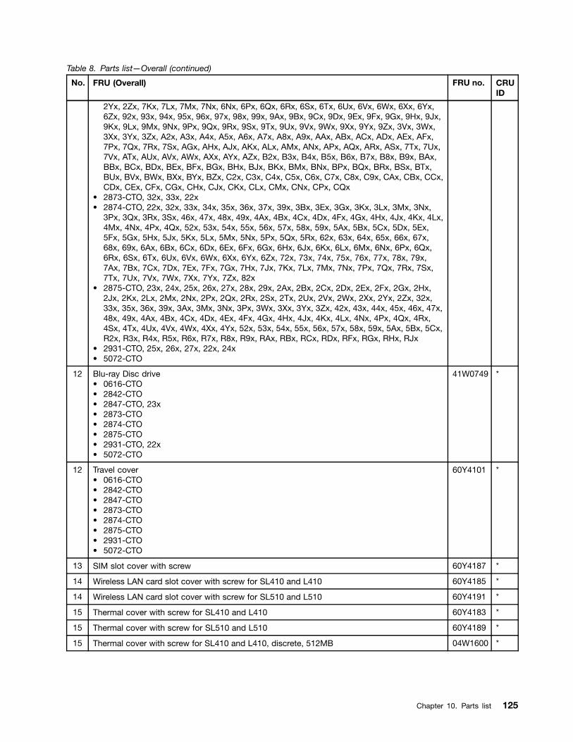
Table 8. Parts list—Overall (continued)
No. FRU (Overall) FRU no. CRUID
2Yx, 2Zx, 7Kx, 7Lx, 7Mx, 7Nx, 6Nx, 6Px, 6Qx, 6Rx, 6Sx, 6Tx, 6Ux, 6Vx, 6Wx, 6Xx, 6Yx,6Zx, 92x, 93x, 94x, 95x, 96x, 97x, 98x, 99x, 9Ax, 9Bx, 9Cx, 9Dx, 9Ex, 9Fx, 9Gx, 9Hx, 9Jx,9Kx, 9Lx, 9Mx, 9Nx, 9Px, 9Qx, 9Rx, 9Sx, 9Tx, 9Ux, 9Vx, 9Wx, 9Xx, 9Yx, 9Zx, 3Vx, 3Wx,3Xx, 3Yx, 3Zx, A2x, A3x, A4x, A5x, A6x, A7x, A8x, A9x, AAx, ABx, ACx, ADx, AEx, AFx,7Px, 7Qx, 7Rx, 7Sx, AGx, AHx, AJx, AKx, ALx, AMx, ANx, APx, AQx, ARx, ASx, 7Tx, 7Ux,7Vx, ATx, AUx, AVx, AWx, AXx, AYx, AZx, B2x, B3x, B4x, B5x, B6x, B7x, B8x, B9x, BAx,BBx, BCx, BDx, BEx, BFx, BGx, BHx, BJx, BKx, BMx, BNx, BPx, BQx, BRx, BSx, BTx,BUx, BVx, BWx, BXx, BYx, BZx, C2x, C3x, C4x, C5x, C6x, C7x, C8x, C9x, CAx, CBx, CCx,CDx, CEx, CFx, CGx, CHx, CJx, CKx, CLx, CMx, CNx, CPx, CQx
• 2873-CTO, 32x, 33x, 22x• 2874-CTO, 22x, 32x, 33x, 34x, 35x, 36x, 37x, 39x, 3Bx, 3Ex, 3Gx, 3Kx, 3Lx, 3Mx, 3Nx,
3Px, 3Qx, 3Rx, 3Sx, 46x, 47x, 48x, 49x, 4Ax, 4Bx, 4Cx, 4Dx, 4Fx, 4Gx, 4Hx, 4Jx, 4Kx, 4Lx,4Mx, 4Nx, 4Px, 4Qx, 52x, 53x, 54x, 55x, 56x, 57x, 58x, 59x, 5Ax, 5Bx, 5Cx, 5Dx, 5Ex,5Fx, 5Gx, 5Hx, 5Jx, 5Kx, 5Lx, 5Mx, 5Nx, 5Px, 5Qx, 5Rx, 62x, 63x, 64x, 65x, 66x, 67x,68x, 69x, 6Ax, 6Bx, 6Cx, 6Dx, 6Ex, 6Fx, 6Gx, 6Hx, 6Jx, 6Kx, 6Lx, 6Mx, 6Nx, 6Px, 6Qx,6Rx, 6Sx, 6Tx, 6Ux, 6Vx, 6Wx, 6Xx, 6Yx, 6Zx, 72x, 73x, 74x, 75x, 76x, 77x, 78x, 79x,7Ax, 7Bx, 7Cx, 7Dx, 7Ex, 7Fx, 7Gx, 7Hx, 7Jx, 7Kx, 7Lx, 7Mx, 7Nx, 7Px, 7Qx, 7Rx, 7Sx,7Tx, 7Ux, 7Vx, 7Wx, 7Xx, 7Yx, 7Zx, 82x
• 2875-CTO, 23x, 24x, 25x, 26x, 27x, 28x, 29x, 2Ax, 2Bx, 2Cx, 2Dx, 2Ex, 2Fx, 2Gx, 2Hx,2Jx, 2Kx, 2Lx, 2Mx, 2Nx, 2Px, 2Qx, 2Rx, 2Sx, 2Tx, 2Ux, 2Vx, 2Wx, 2Xx, 2Yx, 2Zx, 32x,33x, 35x, 36x, 39x, 3Ax, 3Mx, 3Nx, 3Px, 3Wx, 3Xx, 3Yx, 3Zx, 42x, 43x, 44x, 45x, 46x, 47x,48x, 49x, 4Ax, 4Bx, 4Cx, 4Dx, 4Ex, 4Fx, 4Gx, 4Hx, 4Jx, 4Kx, 4Lx, 4Nx, 4Px, 4Qx, 4Rx,4Sx, 4Tx, 4Ux, 4Vx, 4Wx, 4Xx, 4Yx, 52x, 53x, 54x, 55x, 56x, 57x, 58x, 59x, 5Ax, 5Bx, 5Cx,R2x, R3x, R4x, R5x, R6x, R7x, R8x, R9x, RAx, RBx, RCx, RDx, RFx, RGx, RHx, RJx
• 2931-CTO, 25x, 26x, 27x, 22x, 24x• 5072-CTO
12 Blu-ray Disc drive• 0616-CTO• 2842-CTO• 2847-CTO, 23x• 2873-CTO• 2874-CTO• 2875-CTO• 2931-CTO, 22x• 5072-CTO
41W0749 *
12 Travel cover• 0616-CTO• 2842-CTO• 2847-CTO• 2873-CTO• 2874-CTO• 2875-CTO• 2931-CTO• 5072-CTO
60Y4101 *
13 SIM slot cover with screw 60Y4187 *
14 Wireless LAN card slot cover with screw for SL410 and L410 60Y4185 *
14 Wireless LAN card slot cover with screw for SL510 and L510 60Y4191 *
15 Thermal cover with screw for SL410 and L410 60Y4183 *
15 Thermal cover with screw for SL510 and L510 60Y4189 *
15 Thermal cover with screw for SL410 and L410, discrete, 512MB 04W1600 *
Chapter 10. Parts list 125

Table 8. Parts list—Overall (continued)
No. FRU (Overall) FRU no. CRUID
16 SATA hard disk drive, 160 GB, 5,400 rpm• 0616-CTO• 2842-CTO, 34x, 3Px, 3Fx, 3Gx, 46x, 3Rx, 5Gx, ALx, GRx, H6x• 2847-CTO, 33x, 37x, 38x, 39x, 3Lx, 4Jx, 52x, 53x, 24x, 25x, 26x, 27x, 2Bx, 2Cx, 2Dx, 2Ex,
2Jx, 2Kx, 7Fx, QDx, QGx, 8Qx, 8Tx, 2Wx, 9Kx, 9Mx, APx, BBx• 2873-CTO• 2874-CTO, 32x, 3Bx, 3Mx, 46x, 49x, 4Ax, 4Dx, 6Ux, 6Yx, 7Ax• 2875-CTO, 24x, 26x, 27x, 2Ax, 2Cx, 2Kx, 2Lx, 2Mx, 2Nx, 2Px, 2Qx, 2Tx, 2Ux, 2Vx, 4Dx,
4Sx, 5Bx, R9x, RAx, RCx• 2931-CTO• 5072-CTO
41W077541W076741W078375Y502175Y503175Y5041
**
16 SATA hard disk drive, 250 GB, 5,400 rpm• 0616-CTO, 2Ex• 2842-CTO, 3Bx, 48x, 4Cx, 4Ex, 4Px, 4Ux, 4Yx, 4Zx, 52x, 53x, 57x, 5Cx, 5Dx, 44x, 33x,
5Ex, 5Hx, 5Kx, 66x, 67x, 6Cx, 6Dx, 6Jx, 6Px, 6Qx, 6Vx, 6Wx, 73x, 7Cx, 7Ex, 7Fx, 7Hx,23x, 7Qx, 7Rx, 7Sx, 7Tx, 7Ux, 7Vx, 7Wx, 7Xx, 7Yx, 87x, 88x, 89x, 8Ex, 8Fx, 8Gx, 8Mx,8Nx, 8Rx, 8Sx, 8Ux, 8Xx, 92x, 94x, 97x, 9Ax, 9Cx, 9Fx, 9Jx, 9Lx, 9Px, 9Sx, 9Ux, 9Xx, A2x,A4x, A7x, AMx, ANx, ARx, ASx, AVx, AWx, AZx, BCx, BDx, BEx, BFx, BRx, BSx, BUx,BVx, BWx, BYx, CDx, CEx, CFx, CMx, CNx, CPx, DNx, EAx, EBx, ECx, EFx, EJx, EMx,ENx, ERx, EUx, F7x, GFx, GKx, GWx, GXx, H7x, H8x, HEx, HSx, HUx, HXx, J5x, J6x, J7x,J8x, J9x, JAx, JLx, JMx
• 2847-CTO, 42x, 43x, 44x, 45x, 4Ax, 4Bx, 4Ex, 4Hx, 3Kx, 3Qx, 4Xx, 4Yx, 4Zx, 54x, 55x,56x, 57x, 58x, 59x, 5Hx, 5Jx, 5Nx, 5Rx, 5Ux, 5Vx, 5Zx, 64x, 4Nx, 4Qx, 4Sx, 4Tx, 4Vx, 28x,2Fx, 2Lx, 2Mx, 2Nx, 2Sx, 2Tx, 72x, 73x, 7Bx, 7Cx, 7Dx, 7Ex, 7Jx, R2x, R3x, R4x, R6x,R9x, RCx, RFx, RJx, RMx, RPx, RSx, 68x, 69x, 6Ax, 6Bx, 6Gx, 6Hx, Q5x, Q6x, Q7x, Q8x,Q9x, QAx, QEx, QHx, 89x, 8Ax, 8Bx, 8Cx, 8Dx, 8Kx, 8Mx, 8Nx, 8Px, 8Rx, 8Sx, 8Ux, 8Wx,8Yx, 6Lx, 6Mx, 2Xx, 2Zx, 7Kx, 7Lx, 7Mx, 7Nx, 9Hx, 9Jx, 9Lx, 9Nx, 9Ux, 3Xx, 3Yx, 3Zx,7Px, 7Qx, 7Tx, 7Ux, 7Vx, ATx, AUx, AVx, AWx, AZx, B4x, B5x, B6x, B7x, B9x, BQx, BUx,BVx, C3x, C5x, CAx, CCx, CQx
• 2873-CTO, 32x, 22x• 2874-CTO, 34x, 35x, 36x, 39x, 3Ex, 3Gx, 3Lx, 3Px, 3Rx, 47x, 48x, 4Bx, 4Cx, 4Kx, 4Lx,
4Mx, 4Px, 52x, 53x, 55x, 58x, 5Bx, 5Dx, 5Gx, 5Kx, 5Mx, 5Qx, 63x, 64x, 6Dx, 6Ex, 6Fx,6Jx, 6Kx, 6Qx, 6Rx, 6Sx, 6Vx, 6Xx, 6Zx, 72x, 74x, 78x, 79x, 7Bx, 7Hx, 7Jx, 7Mx, 7Sx, 7Tx,7Ux, 7Vx, 7Wx, 7Xx, 82x
• 2875-CTO, 28x, 29x, 2Bx, 2Dx, 2Fx, 2Jx, 2Rx, 2Sx, 2Wx, 2Xx, 2Zx, 33x, 39x, 3Ax, 3Mx,3Px, 3Yx, 42x, 45x, 48x, 4Bx, 4Cx, 4Ex, 4Fx, 4Jx, 4Kx, 4Px, 4Qx, 4Rx, 4Tx, 4Ux, 4Vx, 4Xx,4Yx, 52x, 53x, 54x, 55x, 56x, 58x, 59x, 5Cx, R2x, R6x, R7x, R8x, RBx, RDx, RJx
• 2931-CTO, 23x, 24x, 25x• 5072-CTO
41W077741W076941W078575Y502375Y503375Y5043
**
16 SATA hard disk drive, 250 GB, 5,400 rpm, 7mmH• 0616-CTO• 2842-CTO, L8x, LFx• 2847-CTO• 2873-CTO• 2931-CTO• 5072-CTO
75Y513375Y5145
**
126 Hardware Maintenance Manual
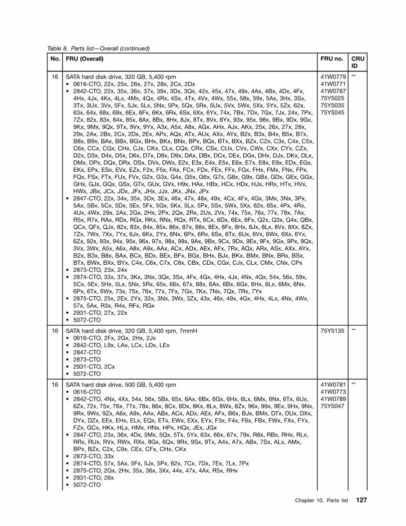
Table 8. Parts list—Overall (continued)
No. FRU (Overall) FRU no. CRUID
16 SATA hard disk drive, 320 GB, 5,400 rpm• 0616-CTO, 22x, 25x, 26x, 27x, 28x, 2Cx, 2Dx• 2842-CTO, 22x, 35x, 36x, 37x, 39x, 3Dx, 3Qx, 42x, 45x, 47x, 49x, 4Ax, 4Bx, 4Dx, 4Fx,
4Hx, 4Jx, 4Kx, 4Lx, 4Mx, 4Qx, 4Rx, 4Sx, 4Tx, 4Vx, 4Wx, 55x, 58x, 59x, 5Ax, 3Hx, 3Sx,3Tx, 3Ux, 3Vx, 5Fx, 5Jx, 5Lx, 5Nx, 5Px, 5Qx, 5Rx, 5Ux, 5Vx, 5Wx, 5Xx, 5Yx, 5Zx, 62x,63x, 64x, 68x, 69x, 6Ex, 6Fx, 6Kx, 6Rx, 6Sx, 6Xx, 6Yx, 74x, 7Bx, 7Dx, 7Gx, 7Jx, 24x, 7Px,7Zx, 82x, 83x, 84x, 85x, 8Ax, 8Bx, 8Hx, 8Jx, 8Tx, 8Vx, 8Yx, 93x, 95x, 98x, 9Bx, 9Dx, 9Gx,9Kx, 9Mx, 9Qx, 9Tx, 9Vx, 9Yx, A3x, A5x, A8x, AGx, AHx, AJx, AKx, 25x, 26x, 27x, 28x,29x, 2Ax, 2Bx, 2Cx, 2Dx, 2Ex, APx, AQx, ATx, AUx, AXx, AYx, B2x, B3x, B4x, B5x, B7x,B8x, B9x, BAx, BBx, BGx, BHx, BKx, BNx, BPx, BQx, BTx, BXx, BZx, C2x, C3x, C4x, C5x,C6x, CCx, CGx, CHx, CJx, CKx, CLx, CQx, CRx, CSx, CUx, CVx, CWx, CXx, CYx, CZx,D2x, D3x, D4x, D5x, D6x, D7x, D8x, D9x, DAx, DBx, DCx, DEx, DGx, DHx, DJx, DKx, DLx,DMx, DPx, DQx, DRx, DSx, DVx, DWx, E2x, E3x, E4x, E5x, E6x, E7x, E8x, E9x, EDx, EGx,EKx, EPx, ESx, EVx, EZx, F2x, F5x, FAx, FCx, FDx, FEx, FFx, FGx, FHx, FMx, FNx, FPx,FQx, FSx, FTx, FUx, FVx, G2x, G3x, G4x, G5x, G6x, G7x, G8x, G9x, GBx, GDx, GEx, GGx,GHx, GJx, GQx, GSx, GTx, GUx, GVx, H9x, HAx, HBx, HCx, HDx, HJx, HRx, HTx, HVx,HWx, JBx, JCx, JDx, JFx, JHx, JJx, JKx, JNx, JPx
• 2847-CTO, 22x, 34x, 35x, 3Dx, 3Ex, 46x, 47x, 48x, 49x, 4Cx, 4Fx, 4Gx, 3Mx, 3Nx, 3Px,5Ax, 5Bx, 5Cx, 5Dx, 5Ex, 5Fx, 5Gx, 5Kx, 5Lx, 5Px, 5Sx, 5Wx, 5Xx, 62x, 65x, 4Px, 4Rx,4Ux, 4Wx, 29x, 2Ax, 2Gx, 2Hx, 2Px, 2Qx, 2Rx, 2Ux, 2Vx, 74x, 75x, 76x, 77x, 78x, 7Ax,R5x, R7x, RAx, RDx, RGx, RKx, RNx, RQx, RTx, 6Cx, 6Dx, 6Ex, 6Fx, Q2x, Q3x, Q4x, QBx,QCx, QFx, QJx, 82x, 83x, 84x, 85x, 86x, 87x, 88x, 8Ex, 8Fx, 8Hx, 8Jx, 8Lx, 8Vx, 8Xx, 8Zx,7Zx, 7Wx, 7Xx, 7Yx, 6Jx, 6Kx, 2Yx, 6Nx, 6Px, 6Rx, 6Sx, 6Tx, 6Ux, 6Vx, 6Wx, 6Xx, 6Yx,6Zx, 92x, 93x, 94x, 95x, 96x, 97x, 98x, 99x, 9Ax, 9Bx, 9Cx, 9Dx, 9Ex, 9Fx, 9Gx, 9Px, 9Qx,3Vx, 3Wx, A5x, A6x, A8x, A9x, AAx, ACx, ADx, AEx, AFx, 7Rx, AQx, ARx, ASx, AXx, AYx,B2x, B3x, B8x, BAx, BCx, BDx, BEx, BFx, BGx, BHx, BJx, BKx, BMx, BNx, BRx, BSx,BTx, BWx, BXx, BYx, C4x, C6x, C7x, C8x, CBx, CDx, CGx, CJx, CLx, CMx, CNx, CPx
• 2873-CTO, 23x, 24x• 2874-CTO, 33x, 37x, 3Kx, 3Nx, 3Qx, 3Sx, 4Fx, 4Gx, 4Hx, 4Jx, 4Nx, 4Qx, 54x, 56x, 59x,
5Cx, 5Ex, 5Hx, 5Lx, 5Nx, 5Rx, 65x, 66x, 67x, 68x, 6Ax, 6Bx, 6Gx, 6Hx, 6Lx, 6Mx, 6Nx,6Px, 6Tx, 6Wx, 73x, 75x, 76x, 77x, 7Fx, 7Gx, 7Kx, 7Nx, 7Qx, 7Rx, 7Yx
• 2875-CTO, 25x, 2Ex, 2Yx, 32x, 3Nx, 3Wx, 3Zx, 43x, 46x, 49x, 4Gx, 4Hx, 4Lx, 4Nx, 4Wx,57x, 5Ax, R3x, R4x, RFx, RGx
• 2931-CTO, 27x, 22x• 5072-CTO
41W077941W077141W078775Y502575Y503575Y5045
**
16 SATA hard disk drive, 320 GB, 5,400 rpm, 7mmH• 0616-CTO, 2Fx, 2Gx, 2Hx, 2Jx• 2842-CTO, L9x, LAx, LCx, LDx, LEx• 2847-CTO• 2873-CTO• 2931-CTO, 2Cx• 5072-CTO
75Y5135 **
16 SATA hard disk drive, 500 GB, 5,400 rpm• 0616-CTO• 2842-CTO, 4Nx, 4Xx, 54x, 56x, 5Bx, 65x, 6Ax, 6Bx, 6Gx, 6Hx, 6Lx, 6Mx, 6Nx, 6Tx, 6Ux,
6Zx, 72x, 75x, 76x, 77x, 78x, 86x, 8Cx, 8Dx, 8Kx, 8Lx, 8Wx, 8Zx, 96x, 99x, 9Ex, 9Hx, 9Nx,9Rx, 9Wx, 9Zx, A6x, A9x, AAx, ABx, ACx, ADx, AEx, AFx, B6x, BJx, BMx, DTx, DUx, DXx,DYx, DZx, EEx, EHx, ELx, EQx, ETx, EWx, EXx, EYx, F3x, F4x, F6x, FBx, FWx, FXx, FYx,FZx, GCx, HKx, HLx, HMx, HNx, HPx, HQx, JEx, JGx
• 2847-CTO, 23x, 36x, 4Dx, 5Mx, 5Qx, 5Tx, 5Yx, 63x, 66x, 67x, 79x, R8x, RBx, RHx, RLx,RRx, RUx, RVx, RWx, RXx, 8Gx, 6Qx, 9Rx, 9Sx, 9Tx, A4x, A7x, ABx, 7Sx, ALx, AMx,BPx, BZx, C2x, C9x, CEx, CFx, CHx, CKx
• 2873-CTO, 33x• 2874-CTO, 57x, 5Ax, 5Fx, 5Jx, 5Px, 62x, 7Cx, 7Dx, 7Ex, 7Lx, 7Px• 2875-CTO, 2Gx, 2Hx, 35x, 36x, 3Xx, 44x, 47x, 4Ax, R5x, RHx• 2931-CTO, 26x• 5072-CTO
41W078141W077341W078975Y5047
**
Chapter 10. Parts list 127

Table 8. Parts list—Overall (continued)
No. FRU (Overall) FRU no. CRUID
16 SATA hard disk drive, 320 GB, 7,200 rpm• 0616-CTO• 2842-CTO, 43x, 4Gx, 5Mx, 5Sx, 5Tx, C7x, C8x, C9x, CAx, CBx, DDx, DFx, F8x, F9x, FJx,
FKx, FLx, GLx, GMx, GNx, GPx, GYx, GZx, H2x, H3x, H4x, H5x, HFx, HGx, HHx, HYx,HZx, J2x, J3x, J4x
• 2847-CTO, 9Vx, 9Wx, 9Xx, 9Yx, 9Zx, A2x, A3x, AGx, AHx, AJx, AKx, ANx• 2873-CTO• 2874-CTO, 69x, 6Cx, 7Zx• 2875-CTO• 2931-CTO• 5072-CTO
60Y473960Y473760Y480960Y4819
**
16 SATA hard disk drive, 500 GB, 7,200 rpm• 0616-CTO• 2842-CTO• 2847-CTO• 2873-CTO• 2931-CTO• 5072-CTO
60Y481160Y482175Y5125
**
16 SATA solid state drive, 2.5”, 4 GB, 7mmH• 0616-CTO• 2842-CTO• 2847-CTO• 2873-CTO• 2931-CTO• 5072-CTO
04W1283 **
— mSATA spacer 04W2145 *
17 Qualcomm® UNDP1-Wireless WAN card• 0616-CTO• 2842-CTO, 22x, 3Tx, 3Vx, 8Rx, AHx, AKx, 26x, 28x, 2Bx, 2Dx, B8x, BBx, DHx, DKx, FMx,
FNx, FPx, FQx, FSx, FTx, FUx, FVx, G6x• 2847-CTO, 6Hx• 2873-CTO• 2874-CTO• 2875-CTO• 2931-CTO• 5072-CTO
42T0961 **
17 Ericsson F3507g USA-Wireless WAN card• 0616-CTO• 2842-CTO, 22x• 2847-CTO, 9Zx• 2873-CTO• 2874-CTO• 2875-CTO• 2931-CTO• 5072-CTO
43Y6537 **
128 Hardware Maintenance Manual
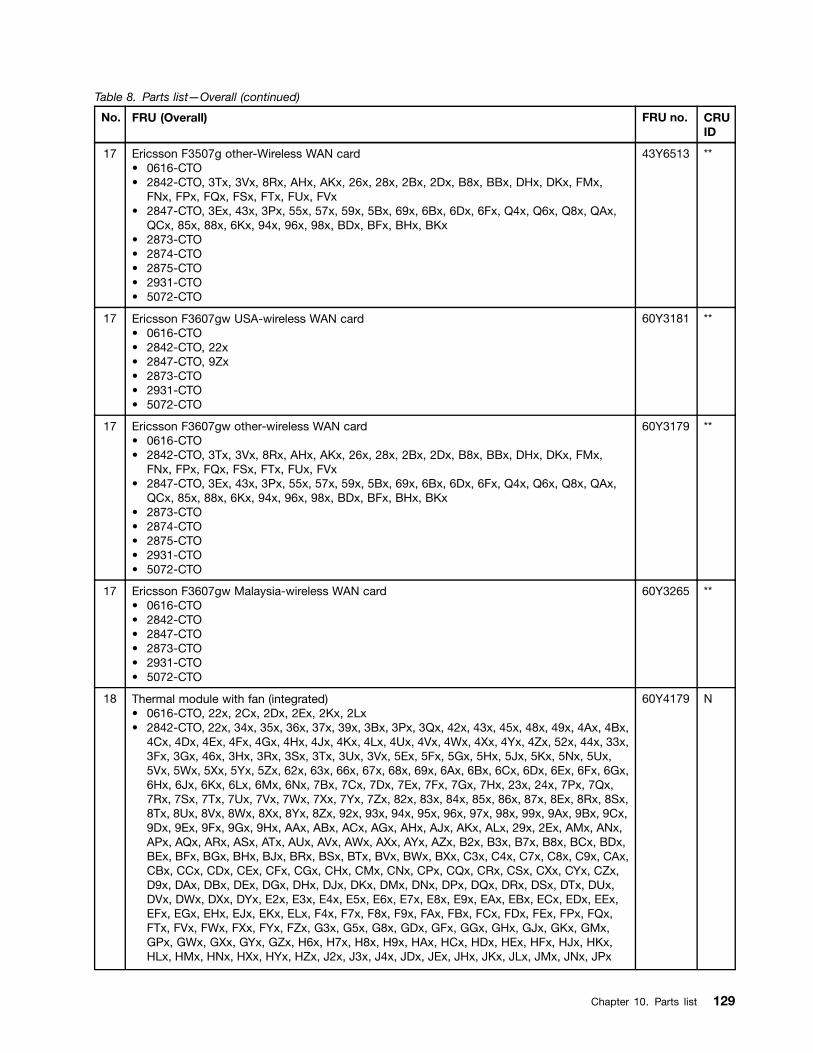
Table 8. Parts list—Overall (continued)
No. FRU (Overall) FRU no. CRUID
17 Ericsson F3507g other-Wireless WAN card• 0616-CTO• 2842-CTO, 3Tx, 3Vx, 8Rx, AHx, AKx, 26x, 28x, 2Bx, 2Dx, B8x, BBx, DHx, DKx, FMx,
FNx, FPx, FQx, FSx, FTx, FUx, FVx• 2847-CTO, 3Ex, 43x, 3Px, 55x, 57x, 59x, 5Bx, 69x, 6Bx, 6Dx, 6Fx, Q4x, Q6x, Q8x, QAx,
QCx, 85x, 88x, 6Kx, 94x, 96x, 98x, BDx, BFx, BHx, BKx• 2873-CTO• 2874-CTO• 2875-CTO• 2931-CTO• 5072-CTO
43Y6513 **
17 Ericsson F3607gw USA-wireless WAN card• 0616-CTO• 2842-CTO, 22x• 2847-CTO, 9Zx• 2873-CTO• 2931-CTO• 5072-CTO
60Y3181 **
17 Ericsson F3607gw other-wireless WAN card• 0616-CTO• 2842-CTO, 3Tx, 3Vx, 8Rx, AHx, AKx, 26x, 28x, 2Bx, 2Dx, B8x, BBx, DHx, DKx, FMx,
FNx, FPx, FQx, FSx, FTx, FUx, FVx• 2847-CTO, 3Ex, 43x, 3Px, 55x, 57x, 59x, 5Bx, 69x, 6Bx, 6Dx, 6Fx, Q4x, Q6x, Q8x, QAx,
QCx, 85x, 88x, 6Kx, 94x, 96x, 98x, BDx, BFx, BHx, BKx• 2873-CTO• 2874-CTO• 2875-CTO• 2931-CTO• 5072-CTO
60Y3179 **
17 Ericsson F3607gw Malaysia-wireless WAN card• 0616-CTO• 2842-CTO• 2847-CTO• 2873-CTO• 2931-CTO• 5072-CTO
60Y3265 **
18 Thermal module with fan (integrated)• 0616-CTO, 22x, 2Cx, 2Dx, 2Ex, 2Kx, 2Lx• 2842-CTO, 22x, 34x, 35x, 36x, 37x, 39x, 3Bx, 3Px, 3Qx, 42x, 43x, 45x, 48x, 49x, 4Ax, 4Bx,
4Cx, 4Dx, 4Ex, 4Fx, 4Gx, 4Hx, 4Jx, 4Kx, 4Lx, 4Ux, 4Vx, 4Wx, 4Xx, 4Yx, 4Zx, 52x, 44x, 33x,3Fx, 3Gx, 46x, 3Hx, 3Rx, 3Sx, 3Tx, 3Ux, 3Vx, 5Ex, 5Fx, 5Gx, 5Hx, 5Jx, 5Kx, 5Nx, 5Ux,5Vx, 5Wx, 5Xx, 5Yx, 5Zx, 62x, 63x, 66x, 67x, 68x, 69x, 6Ax, 6Bx, 6Cx, 6Dx, 6Ex, 6Fx, 6Gx,6Hx, 6Jx, 6Kx, 6Lx, 6Mx, 6Nx, 7Bx, 7Cx, 7Dx, 7Ex, 7Fx, 7Gx, 7Hx, 23x, 24x, 7Px, 7Qx,7Rx, 7Sx, 7Tx, 7Ux, 7Vx, 7Wx, 7Xx, 7Yx, 7Zx, 82x, 83x, 84x, 85x, 86x, 87x, 8Ex, 8Rx, 8Sx,8Tx, 8Ux, 8Vx, 8Wx, 8Xx, 8Yx, 8Zx, 92x, 93x, 94x, 95x, 96x, 97x, 98x, 99x, 9Ax, 9Bx, 9Cx,9Dx, 9Ex, 9Fx, 9Gx, 9Hx, AAx, ABx, ACx, AGx, AHx, AJx, AKx, ALx, 29x, 2Ex, AMx, ANx,APx, AQx, ARx, ASx, ATx, AUx, AVx, AWx, AXx, AYx, AZx, B2x, B3x, B7x, B8x, BCx, BDx,BEx, BFx, BGx, BHx, BJx, BRx, BSx, BTx, BVx, BWx, BXx, C3x, C4x, C7x, C8x, C9x, CAx,CBx, CCx, CDx, CEx, CFx, CGx, CHx, CMx, CNx, CPx, CQx, CRx, CSx, CXx, CYx, CZx,D9x, DAx, DBx, DEx, DGx, DHx, DJx, DKx, DMx, DNx, DPx, DQx, DRx, DSx, DTx, DUx,DVx, DWx, DXx, DYx, E2x, E3x, E4x, E5x, E6x, E7x, E8x, E9x, EAx, EBx, ECx, EDx, EEx,EFx, EGx, EHx, EJx, EKx, ELx, F4x, F7x, F8x, F9x, FAx, FBx, FCx, FDx, FEx, FPx, FQx,FTx, FVx, FWx, FXx, FYx, FZx, G3x, G5x, G8x, GDx, GFx, GGx, GHx, GJx, GKx, GMx,GPx, GWx, GXx, GYx, GZx, H6x, H7x, H8x, H9x, HAx, HCx, HDx, HEx, HFx, HJx, HKx,HLx, HMx, HNx, HXx, HYx, HZx, J2x, J3x, J4x, JDx, JEx, JHx, JKx, JLx, JMx, JNx, JPx
60Y4179 N
Chapter 10. Parts list 129
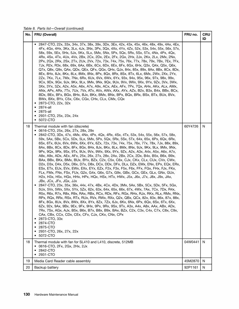
Table 8. Parts list—Overall (continued)
No. FRU (Overall) FRU no. CRUID
• 2847-CTO, 22x, 33x, 34x, 37x, 38x, 39x, 3Dx, 3Ex, 42x, 43x, 45x, 46x, 48x, 49x, 4Ax, 4Ex,4Fx, 4Gx, 4Hx, 3Kx, 3Lx, 4Jx, 3Nx, 3Px, 3Qx, 4Xx, 4Yx, 4Zx, 52x, 53x, 54x, 55x, 56x, 57x,58x, 59x, 5Ex, 5Hx, 5Jx, 5Kx, 5Lx, 5Mx, 5Nx, 5Px, 5Qx, 5Rx, 5Sx, 5Tx, 4Nx, 4Px, 4Qx,4Rx, 4Sx, 4Tx, 4Ux, 4Vx, 2Bx, 2Cx, 2Dx, 2Ex, 2Fx, 2Gx, 2Hx, 2Jx, 2Kx, 2Lx, 2Mx, 2Nx,2Px, 2Qx, 2Rx, 2Sx, 2Tx, 2Ux, 2Vx, 72x, 73x, 74x, 75x, 76x, 77x, 78x, 79x, 7Bx, 7Ex, 7Fx,7Jx, R2x, R3x, 68x, 69x, 6Ax, 6Bx, 6Cx, 6Dx, 6Ex, 6Fx, 6Gx, 6Hx, Q3x, Q4x, Q5x, Q6x,Q7x, Q8x, Q9x, QAx, QDx, QEx, QFx, QGx, QHx, QJx, 84x, 85x, 89x, 8Ax, 8Bx, 8Cx, 8Dx,8Ex, 8Hx, 8Jx, 8Kx, 8Lx, 8Mx, 8Nx, 8Px, 8Qx, 8Rx, 8Sx, 8Tx, 6Lx, 6Mx, 2Wx, 2Xx, 2Yx,2Zx, 7Kx, 7Lx, 7Mx, 7Nx, 6Rx, 6Ux, 6Vx, 6Wx, 6Yx, 93x, 94x, 95x, 96x, 97x, 98x, 99x,9Cx, 9Dx, 9Gx, 9Jx, 9Kx, 9Lx, 9Mx, 9Nx, 9Qx, 9Ux, 9Vx, 9Wx, 9Xx, 9Yx, 9Zx, 3Vx, 3Wx,3Xx, 3Yx, 3Zx, A2x, A5x, A6x, A7x, A9x, ACx, AEx, AFx, 7Px, 7Qx, AHx, AKx, ALx, AMx,ANx, APx, ARx, 7Tx, 7Ux, 7Vx, ATx, AVx, AWx, AXx, AYx, AZx, B2x, B3x, B4x, BBx, BCx,BDx, BEx, BFx, BGx, BHx, BJx, BKx, BMx, BNx, BPx, BQx, BRx, BSx, BTx, BUx, BVx,BWx, BXx, BYx, C5x, C6x, CGx, CHx, CLx, CMx, CQx
• 2873-CTO, 22x, 32x• 2874-all• 2875-all• 2931-CTO, 25x, 23x, 24x• 5072-CTO
18 Thermal module with fan (discrete)• 0616-CTO, 25x, 26x, 27x, 28x, 29x• 2842-CTO, 3Dx, 47x, 4Mx, 4Nx, 4Px, 4Qx, 4Rx, 4Sx, 4Tx, 53x, 54x, 55x, 56x, 57x, 58x,
59x, 5Ax, 5Bx, 5Cx, 5Dx, 5Lx, 5Mx, 5Px, 5Qx, 5Rx, 5Sx, 5Tx, 64x, 65x, 6Px, 6Qx, 6Rx,6Sx, 6Tx, 6Ux, 6Vx, 6Wx, 6Xx, 6Yx, 6Zx, 72x, 73x, 74x, 75x, 76x, 77x, 78x, 7Jx, 88x, 89x,8Ax, 8Bx, 8Cx, 8Dx, 8Fx, 8Gx, 8Hx, 8Jx, 8Kx, 8Lx, 8Mx, 8Nx, 9Jx, 9Kx, 9Lx, 9Mx, 9Nx,9Px, 9Qx, 9Rx, 9Sx, 9Tx, 9Ux, 9Vx, 9Wx, 9Xx, 9Yx, 9Zx, A2x, A3x, A4x, A5x, A6x, A7x,A8x, A9x, ADx, AEx, AFx, 25x, 26x, 27x, 28x, 2Ax, 2Bx, 2Cx, 2Dx, B4x, B5x, B6x, B9x,BAx, BBx, BKx, BMx, BUx, BYx, BZx, C2x, C5x, C6x, CJx, CKx, CLx, CUx, CVx, CWx,D2x, D3x, D4x, D5x, D6x, D7x, D8x, DCx, DDx, DFx, DLx, DZx, EMx, ENx, EPx, EQx, ERx,ESx, ETx, EUx, EVx, EWx, EXx, EYx, EZx, F2x, F3x, F5x, F6x, FFx, FGx, FHx, FJx, FKx,FLx, FMx, FNx, FSx, FUx, G2x, G4x, G6x, G7x, G9x, GBx, GCx, GEx, GLx, GNx, GUx,H2x, H3x, H5x, HGx, HHx, HPx, HQx, HSx, HTx, HWx, J5x, J6x, J7x, J8x, J9x, JAx,JBx, JCx, JFx, JGx, JJx
• 2847-CTO, 23x, 35x, 36x, 44x, 47x, 4Bx, 4Cx, 4Dx, 3Mx, 5Ax, 5Bx, 5Cx, 5Dx, 5Fx, 5Gx,5Ux, 5Vx, 5Wx, 5Xx, 5Yx, 5Zx, 62x, 63x, 64x, 65x, 66x, 67x, 4Wx, 7Ax, 7Cx, 7Dx, R4x,R5x, R6x, R7x, R8x, R9x, RAx, RBx, RCx, RDx, RFx, RGx, RHx, RJx, RKx, RLx, RMx, RNx,RPx, RQx, RRx, RSx, RTx, RUx, RVx, RWx, RXx, Q2x, QBx, QCx, 82x, 83x, 86x, 87x, 88x,8Fx, 8Gx, 8Ux, 8Vx, 8Wx, 8Xx, 8Yx, 8Zx, 7Zx, 6Jx, 6Kx, 6Nx, 6Px, 6Qx, 6Sx, 6Tx, 6Xx,6Zx, 92x, 9Ax, 9Bx, 9Ex, 9Fx, 9Hx, 9Px, 9Rx, 9Sx, 9Tx, A3x, A4x, A8x, AAx, ABx, ADx,7Rx, 7Sx, AGx, AJx, B5x, B6x, B7x, B8x, B9x, BAx, BZx, C2x, C3x, C4x, C7x, C8x, C9x,CAx, CBx, CCx, CDx, CEx, CFx, CJx, CKx, CNx, CPx
• 2873-CTO, 33x• 2874-CTO• 2875-CTO• 2931-CTO, 26x, 27x, 22x• 5072-CTO
60Y4726 N
18 Thermal module with fan for SL410 and L410, discrete, 512MB• 0616-CTO, 2Fx, 2Gx, 2Hx, 2Jx• 2842-CTO• 2931-CTO
04W0441 N
19 Media Card Reader cable assembly 45M2870 N
20 Backup battery 92P1161 N
130 Hardware Maintenance Manual

Table 8. Parts list—Overall (continued)
No. FRU (Overall) FRU no. CRUID
21 ThinkPad 11 b/g/n Wireless LAN Mini-PCI Express Adapter II (1x2 BGN)• 0616-CTO, 22x, 25x• 2842-CTO, 22x, 34x, 3Px, 4Ux, 4Vx, 4Wx, 4Xx, 4Yx, 4Zx, 52x, 53x, 54x, 55x, 56x, 57x,
58x, 59x, 5Ax, 5Bx, 5Cx, 5Dx, 44x, 3Gx, 46x, 3Rx, 66x, 67x, 68x, 69x, 6Ax, 6Bx, 6Cx, 6Dx,6Ex, 6Fx, 6Gx, 6Hx, 6Jx, 6Kx, 6Lx, 6Mx, 6Nx, 6Px, 6Qx, 6Rx, 6Sx, 6Tx, 6Ux, 6Vx, 6Wx,6Xx, 6Yx, 6Zx, 72x, 73x, 74x, 75x, 76x, 77x, 78x, 7Ex, 87x, 88x, 89x, 8Ax, 8Bx, 8Cx, 8Dx,8Ex, 8Fx, 8Gx, 8Hx, 8Jx, 8Kx, 8Lx, 8Mx, 8Nx, 8Sx, 8Tx, 8Ux, 8Vx, 8Wx, 8Xx, 8Yx, 8Zx,92x, 93x, 94x, 95x, 96x, 97x, 98x, 99x, 9Ax, 9Bx, 9Cx, 9Dx, 9Ex, 9Fx, 9Gx, 9Hx, 9Jx, 9Kx,9Lx, 9Mx, 9Nx, 9Px, 9Qx, 9Rx, 9Sx, 9Tx, 9Ux, 9Vx, 9Wx, 9Xx, 9Yx, 9Zx, A2x, A3x, A4x,A5x, A6x, A7x, A8x, A9x, AAx, ABx, ACx, ADx, AEx, AFx, AMx, ANx, APx, AQx, ARx, ASx,ATx, AUx, AVx, AWx, AXx, AYx, AZx, B2x, B3x, B4x, B5x, B6x, BCx, BDx, BEx, BFx, BGx,BHx, BJx, BKx, BMx, BUx, BYx, BZx, C2x, C3x, C4x, D5x, D6x, D7x, D8x, D9x, DAx, DBx,DCx, GEx, GFx, GKx, GWx, GXx, H6x, H7x, H8x, H9x, HAx, HBx, HSx, HTx, HUx, HVx,HWx, J5x, J6x, J7x, J8x, J9x, JAx, JBx, JCx, JDx, JEx
• 2847-CTO, 33x, 4Ax, 4Bx, 4Cx, 4Dx, 4Hx, 3Kx, 3Lx, 4Jx, 52x, 53x, 5Hx, 5Jx, 5Kx, 5Lx,5Mx, 5Nx, 5Px, 5Qx, 5Rx, 5Sx, 5Tx, 5Ux, 5Vx, 5Wx, 5Xx, 5Yx, 5Zx, 62x, 63x, 64x, 65x,66x, 67x, 7Ax, 7Bx, 7Cx, R2x, R3x, R4x, R5x, R6x, R7x, R8x, R9x, RAx, RBx, RCx, RDx,RFx, RGx, RHx, RJx, RKx, RLx, RMx, RNx, RPx, RQx, RRx, RSx, RTx, RUx, RVx, RWx,RXx, 82x, 83x, 89x, 8Ax, 8Bx, 8Cx, 8Dx, 8Ex, 8Fx, 8Gx, 8Qx, 8Tx, 8Yx, 8Zx, 7Zx, 6Ux,6Vx, 6Wx, 6Xx, 9Fx, 9Kx, A5x, A6x, A8x, A9x, AAx, ABx, ADx, AGx, AHx, AMx, 7Tx, 7Vx,ATx, AUx, AVx, AWx, AXx, AYx, B5x, B6x, B7x, B8x, BAx, BBx, BVx, C3x, C4x, C5x, C6x,C7x, C8x, CAx, CBx, CCx, CDx, CEx, CFx, CGx, CHx, CQx
• 2873-CTO• 2874-CTO, 39x, 3Bx, 3Ex, 3Nx, 3Px, 3Qx, 3Rx, 3Sx, 46x, 47x, 48x, 49x, 4Ax, 4Dx, 4Fx,
4Gx, 4Hx, 4Kx, 4Lx, 4Mx, 4Nx, 4Px, 4Qx, 52x, 53x, 54x, 55x, 56x, 57x, 58x, 59x, 5Ax, 5Bx,5Cx, 5Dx, 5Ex, 5Fx, 5Gx, 5Hx, 5Jx, 5Kx, 5Lx, 5Mx, 5Nx, 5Px, 5Qx, 5Rx, 62x, 63x, 64x,65x, 66x, 67x, 68x, 69x, 6Ax, 6Bx, 6Cx, 6Ex, 6Fx, 6Gx, 6Hx, 6Jx, 6Kx, 6Lx, 6Mx, 6Qx, 6Rx,6Sx, 6Tx, 6Ux, 6Yx, 75x, 76x, 77x, 7Ax, 7Cx, 7Dx, 7Ex, 7Fx, 7Gx, 82x
• 2875-CTO, 24x, 26x, 27x, 2Bx, 2Cx, 2Dx, 2Ex, 2Fx, 2Gx, 2Hx, 2Jx, 2Kx, 2Lx, 2Mx, 2Nx,2Px, 2Qx, 2Rx, 2Sx, 2Tx, 2Ux, 2Vx, 2Yx, 2Zx, 32x, 33x, 35x, 36x, 3Ax, 3Mx, 3Nx, 3Px,3Wx, 3Xx, 3Yx, 3Zx, 42x, 43x, 44x, 45x, 46x, 47x, 48x, 49x, 4Ax, 4Dx, 4Ex, 4Fx, 4Gx, 4Hx,4Px, 4Qx, 4Rx, 4Sx, 4Xx, 57x, 58x, 59x, 5Ax, 5Bx, R2x, R3x, R4x, R7x, R8x, R9x, RAx,RBx, RCx, RFx, RGx, RHx, RJx
• 2931-CTO, 27x, 23x• 5072-CTO
43Y655360Y3177
**
21 ThinkPad b/g/n Wireless LAN Mini-PCI Express Adapter II (1x1 BGN)• 0616-CTO, 2Cx, 2Dx, 2Ex, 2Fx, 2Gx, 2Hx, 2Jx, 2Kx, 2Lx• 2842-CTO, L2x, L3x, L4x, L5x, L6x, L7x, LGx• 2847-CTO, DJx, DLx, DNx, DRx, DSx, DTx• 2873-CTO, 23x, 24x• 2931-CTO, 2Cx, 2Dx, 2Ex• 5072-CTO
60Y324760Y3249
**
21 Intel® Centrino® Wireless-N 1000• 0616-CTO, 26x, 27x, 28x, 29x• 2842-CTO, AGx, AHx, AJx, AKx, ALx, 25x, 26x, 27x, 28x, 29x, CMx, CNx, CPx, CQx, CRx,
CSx, CUx, CVx, CWx, CXx, CYx, CZx, D2x, D3x, D4x, DDx, DEx, DFx, DGx, DHx, DJx,DKx, DLx, DMx, DNx, DPx, DQx, DRx, DSx, DTx, DUx, DVx, DWx, DXx, DYx, DZx, E2x,E3x, E4x, E5x, E6x, E7x, E8x, E9x, EAx, EBx, ECx, EDx, EEx, EFx, EGx, EHx, EJx, EKx,ELx, EMx, ENx, EPx, EQx, ERx, ESx, ETx, EUx, EVx, EWx, EXx, EYx, EZx, F2x, F3x, F4x,F5x, F6x, F7x, F8x, F9x, FAx, FBx, FCx, FDx, FEx, FFx, FGx, FHx, FJx, FKx, FLx, FMx,FNx, FPx, FQx, FSx, FTx, FUx, FVx, FWx, FXx, FYx, FZx, G2x, G3x, G4x, G5x, G6x, G7x,G8x, G9x, GBx, GCx, GDx, GGx, GHx, GJx, GLx, GMx, GNx, GPx, GQx, GRx, GSx, GTx,GUx, GVx, GYx, GZx, H2x, H3x, H4x, H5x, HDx, HEx, HFx, HGx, HHx, HJx, HKx, HLx,HMx, HNx, HPx, HQx, HRx, HXx, J4x, JFx, JGx, JHx, JJx, JKx, JLx, JMx, JNx, JPx
• 2847-CTO, Q2x, Q3x, Q4x, Q5x, Q6x, Q7x, Q8x, Q9x, QAx, QBx, QCx, QDx, QEx, QFx,QGx, QHx, QJx, 8Kx, 8Mx, 8Px, 8Sx, 8Vx, 7Wx, 7Xx, 7Yx, 6Jx, 6Kx, 2Wx, 2Xx, 2Yx, 7Kx,
60Y3241 **
Chapter 10. Parts list 131

Table 8. Parts list—Overall (continued)
No. FRU (Overall) FRU no. CRUID
7Lx, 7Mx, 7Nx, 6Nx, 6Px, 6Qx, 6Rx, 6Sx, 6Tx, 6Yx, 6Zx, 92x, 93x, 94x, 95x, 96x, 97x, 98x,99x, 9Ax, 9Bx, 9Cx, 9Dx, 9Ex, 9Gx, 9Hx, 9Jx, 9Lx, 9Mx, 9Nx, 9Px, 9Qx, 9Rx, 9Sx, 9Tx,9Ux, 9Vx, 9Wx, 9Xx, 9Yx, 9Zx, 3Zx, A2x, A3x, A4x, ACx, AEx, AFx, 7Qx, 7Rx, 7Sx, AJx,AKx, ALx, ANx, APx, AQx, ARx, ASx, 7Ux, AZx, B3x, B4x, BGx, BHx, BJx, BKx, BMx, BNx,BPx, BSx, BTx, BUx, BWx, BXx, BYx, BZx, C2x, C9x, CJx, CKx, CLx, CMx, CNx, CPx
• 2873-CTO• 2874-CTO, 78x, 79x, 7Bx, 7Hx, 7Jx, 7Kx, 7Lx, 7Mx, 7Nx, 7Px, 7Qx, 7Rx, 7Sx, 7Vx, 7Wx,
7Xx, 7Yx, 7Zx• 2875-CTO, 4Bx, 4Cx, 4Tx, 4Yx, 52x, 53x, 54x, 55x, 56x, 5Cx, R5x, R6x, RDx• 2931-CTO• 5072-CTO
21 Intel WiFi Link 1000• 0616-CTO, 26x, 27x, 28x, 29x• 2842-CTO, AGx, AHx, AJx, AKx, ALx, 25x, 26x, 27x, 28x, 29x, CMx, CNx, CPx, CQx, CRx,
CSx, CUx, CVx, CWx, CXx, CYx, CZx, D2x, D3x, D4x, DDx, DEx, DFx, DGx, DHx, DJx,DKx, DLx, DMx, DNx, DPx, DQx, DRx, DSx, DTx, DUx, DVx, DWx, DXx, DYx, DZx, E2x,E3x, E4x, E5x, E6x, E7x, E8x, E9x, EAx, EBx, ECx, EDx, EEx, EFx, EGx, EHx, EJx, EKx,ELx, EMx, ENx, EPx, EQx, ERx, ESx, ETx, EUx, EVx, EWx, EXx, EYx, EZx, F2x, F3x, F4x,F5x, F6x, F7x, F8x, F9x, FAx, FBx, FCx, FDx, FEx, FFx, FGx, FHx, FJx, FKx, FLx, FMx,FNx, FPx, FQx, FSx, FTx, FUx, FVx, FWx, FXx, FYx, FZx, G2x, G3x, G4x, G5x, G6x, G7x,G8x, G9x, GBx, GCx, GDx, GGx, GHx, GJx, GLx, GMx, GNx, GPx, GQx, GRx, GSx, GTx,GUx, GVx, GYx, GZx, H2x, H3x, H4x, H5x, HDx, HEx, HFx, HGx, HHx, HJx, HKx, HLx,HMx, HNx, HPx, HQx, HRx, HXx, J4x, JFx, JGx, JHx, JJx, JKx, JLx, JMx, JNx, JPx
• 2847-CTO, Q2x, Q3x, Q4x, Q5x, Q6x, Q7x, Q8x, Q9x, QAx, QBx, QCx, QDx, QEx, QFx,QGx, QHx, QJx, 8Kx, 8Mx, 8Px, 8Sx, 8Vx, 7Wx, 7Xx, 7Yx, 6Jx, 6Kx, 2Wx, 2Xx, 2Yx, 7Kx,7Lx, 7Mx, 7Nx, 6Nx, 6Px, 6Qx, 6Rx, 6Sx, 6Tx, 6Yx, 6Zx, 92x, 93x, 94x, 95x, 96x, 97x, 98x,99x, 9Ax, 9Bx, 9Cx, 9Dx, 9Ex, 9Gx, 9Hx, 9Jx, 9Lx, 9Mx, 9Nx, 9Px, 9Qx, 9Rx, 9Sx, 9Tx,9Ux, 9Vx, 9Wx, 9Xx, 9Yx, 9Zx, 3Zx, A2x, A3x, A4x, ACx, AEx, AFx, 7Qx, 7Rx, 7Sx, AJx,AKx, ALx, ANx, APx, AQx, ARx, ASx, 7Ux, AZx, B3x, B4x, BGx, BHx, BJx, BKx, BMx, BNx,BPx, BSx, BTx, BUx, BWx, BXx, BYx, BZx, C2x, C9x, CJx, CKx, CLx, CMx, CNx, CPx
• 2873-CTO• 2874-CTO, 78x, 79x, 7Bx, 7Hx, 7Jx, 7Kx, 7Lx, 7Mx, 7Nx, 7Px, 7Qx, 7Rx, 7Sx, 7Vx, 7Wx,
7Xx, 7Yx, 7Zx• 2875-CTO, 4Bx, 4Cx, 4Tx, 4Yx, 52x, 53x, 54x, 55x, 56x, 5Cx, R5x, R6x, RDx• 2931-CTO• 5072-CTO
60Y3203 **
21 Intel WiFi Link 5100• 0616-CTO• 2842-CTO, 35x, 36x, 37x, 39x, 3Bx, 3Dx, 3Qx, 42x, 43x, 45x, 47x, 48x, 49x, 4Ax, 4Bx,
4Cx, 4Dx, 4Ex, 4Fx, 4Gx, 4Hx, 4Jx, 4Kx, 4Lx, 4Mx, 4Nx, 4Px, 4Qx, 4Rx, 4Sx, 4Tx, 33x,3Fx, 3Hx, 3Sx, 3Tx, 3Ux, 3Vx, 5Ex, 5Fx, 5Gx, 5Hx, 5Jx, 5Kx, 5Lx, 5Mx, 5Nx, 5Px, 5Qx,5Rx, 5Sx, 5Tx, 5Ux, 5Vx, 5Wx, 5Xx, 5Yx, 5Zx, 62x, 63x, 64x, 65x, 7Bx, 7Cx, 7Dx, 7Fx,7Gx, 7Hx, 7Jx, 23x, 24x, 7Px, 7Qx, 7Rx, 7Sx, 7Tx, 7Ux, 7Vx, 7Wx, 7Xx, 7Yx, 7Zx, 82x,83x, 84x, 85x, 86x, 8Rx, 2Ax, 2Bx, 2Cx, 2Dx, 2Ex, B7x, B8x, B9x, BAx, BBx, BNx, BPx,BQx, BRx, BSx, BTx, BVx, BWx, BXx, C5x, C6x, C7x, C8x, C9x, CAx, CBx, CCx, CDx,CEx, CFx, CGx, CHx, CJx, CKx, CLx, HCx, HYx, HZx, J2x, J3x
• 2847-CTO, 22x, 34x, 35x, 36x, 37x, 38x, 39x, 3Dx, 3Ex, 42x, 43x, 44x, 45x, 46x, 47x, 48x,49x, 4Ex, 4Fx, 4Gx, 3Mx, 3Nx, 3Px, 3Qx, 4Xx, 4Yx, 4Zx, 54x, 55x, 56x, 57x, 58x, 59x,5Ax, 5Bx, 5Cx, 5Dx, 5Ex, 5Fx, 5Gx, 4Nx, 4Px, 4Qx, 4Rx, 4Sx, 4Tx, 4Ux, 4Vx, 4Wx, 24x,25x, 26x, 27x, 28x, 29x, 2Ax, 2Bx, 2Cx, 2Dx, 2Ex, 2Fx, 2Gx, 2Hx, 2Jx, 2Kx, 2Lx, 2Mx,2Nx, 2Px, 2Qx, 2Rx, 2Sx, 2Tx, 2Ux, 2Vx, 72x, 73x, 74x, 75x, 76x, 77x, 78x, 79x, 7Ex,7Fx, 7Jx, 68x, 69x, 6Ax, 6Bx, 6Cx, 6Dx, 6Ex, 6Fx, 6Hx, 84x, 85x, 86x, 87x, 88x, 8Hx,8Jx, 8Lx, 8Nx, 8Rx, 8Ux, 8Wx, 8Xx, 6Lx, 6Mx, 2Zx, 3Vx, 3Wx, 3Xx, 3Yx, A7x, 7Px, B2x,BCx, BDx, BEx, BFx, BQx, BRx
• 2873-CTO, 32x, 33x, 22x
43Y6517 **
132 Hardware Maintenance Manual
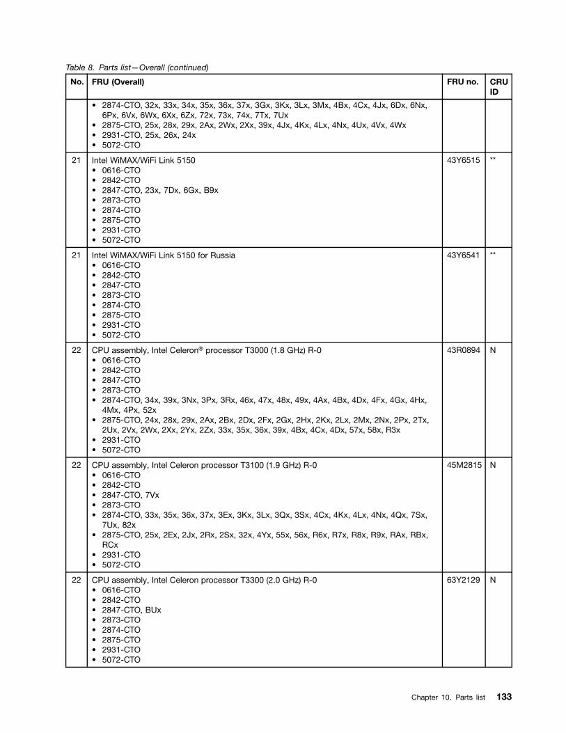
Table 8. Parts list—Overall (continued)
No. FRU (Overall) FRU no. CRUID
• 2874-CTO, 32x, 33x, 34x, 35x, 36x, 37x, 3Gx, 3Kx, 3Lx, 3Mx, 4Bx, 4Cx, 4Jx, 6Dx, 6Nx,6Px, 6Vx, 6Wx, 6Xx, 6Zx, 72x, 73x, 74x, 7Tx, 7Ux
• 2875-CTO, 25x, 28x, 29x, 2Ax, 2Wx, 2Xx, 39x, 4Jx, 4Kx, 4Lx, 4Nx, 4Ux, 4Vx, 4Wx• 2931-CTO, 25x, 26x, 24x• 5072-CTO
21 Intel WiMAX/WiFi Link 5150• 0616-CTO• 2842-CTO• 2847-CTO, 23x, 7Dx, 6Gx, B9x• 2873-CTO• 2874-CTO• 2875-CTO• 2931-CTO• 5072-CTO
43Y6515 **
21 Intel WiMAX/WiFi Link 5150 for Russia• 0616-CTO• 2842-CTO• 2847-CTO• 2873-CTO• 2874-CTO• 2875-CTO• 2931-CTO• 5072-CTO
43Y6541 **
22 CPU assembly, Intel Celeron® processor T3000 (1.8 GHz) R-0• 0616-CTO• 2842-CTO• 2847-CTO• 2873-CTO• 2874-CTO, 34x, 39x, 3Nx, 3Px, 3Rx, 46x, 47x, 48x, 49x, 4Ax, 4Bx, 4Dx, 4Fx, 4Gx, 4Hx,
4Mx, 4Px, 52x• 2875-CTO, 24x, 28x, 29x, 2Ax, 2Bx, 2Dx, 2Fx, 2Gx, 2Hx, 2Kx, 2Lx, 2Mx, 2Nx, 2Px, 2Tx,
2Ux, 2Vx, 2Wx, 2Xx, 2Yx, 2Zx, 33x, 35x, 36x, 39x, 4Bx, 4Cx, 4Dx, 57x, 58x, R3x• 2931-CTO• 5072-CTO
43R0894 N
22 CPU assembly, Intel Celeron processor T3100 (1.9 GHz) R-0• 0616-CTO• 2842-CTO• 2847-CTO, 7Vx• 2873-CTO• 2874-CTO, 33x, 35x, 36x, 37x, 3Ex, 3Kx, 3Lx, 3Qx, 3Sx, 4Cx, 4Kx, 4Lx, 4Nx, 4Qx, 7Sx,
7Ux, 82x• 2875-CTO, 25x, 2Ex, 2Jx, 2Rx, 2Sx, 32x, 4Yx, 55x, 56x, R6x, R7x, R8x, R9x, RAx, RBx,
RCx• 2931-CTO• 5072-CTO
45M2815 N
22 CPU assembly, Intel Celeron processor T3300 (2.0 GHz) R-0• 0616-CTO• 2842-CTO• 2847-CTO, BUx• 2873-CTO• 2874-CTO• 2875-CTO• 2931-CTO• 5072-CTO
63Y2129 N
Chapter 10. Parts list 133
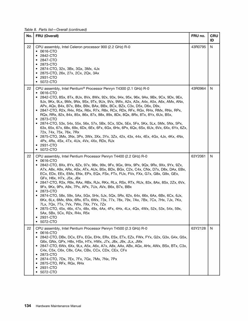
Table 8. Parts list—Overall (continued)
No. FRU (Overall) FRU no. CRUID
22 CPU assembly, Intel Celeron processor 900 (2.2 GHz) R-0• 0616-CTO• 2842-CTO• 2847-CTO• 2873-CTO• 2874-CTO, 32x, 3Bx, 3Gx, 3Mx, 4Jx• 2875-CTO, 26x, 27x, 2Cx, 2Qx, 3Ax• 2931-CTO• 5072-CTO
43R0795 N
22 CPU assembly, Intel Pentium® Processor Penryn T4300 (2.1 GHz) R-0• 0616-CTO• 2842-CTO, 8Sx, 8Tx, 8Ux, 8Vx, 8Wx, 92x, 93x, 94x, 95x, 96x, 9Ax, 9Bx, 9Cx, 9Dx, 9Ex,
9Jx, 9Kx, 9Lx, 9Mx, 9Nx, 9Sx, 9Tx, 9Ux, 9Vx, 9Wx, A2x, A3x, A4x, A5x, A6x, AMx, ANx,APx, AQx, B4x, B7x, B8x, B9x, BAx, BBx, BCx, BZx, C3x, D5x, D6x, D9x,
• 2847-CTO, R2x, R4x, R5x, R6x, R7x, R8x, RCx, RDx, RFx, RGx, RHx, RMx, RNx, RPx,RQx, RRx, 82x, 84x, 85x, 86x, 87x, 88x, 89x, 8Dx, 8Qx, 8Rx, 8Tx, 8Yx, 6Ux, B5x,
• 2873-CTO• 2874-CTO, 53x, 54x, 55x, 56x, 57x, 5Bx, 5Cx, 5Dx, 5Ex, 5Fx, 5Kx, 5Lx, 5Mx, 5Nx, 5Px,
63x, 65x, 67x, 68x, 69x, 6Dx, 6Ex, 6Fx, 6Gx, 6Hx, 6Px, 6Qx, 6Sx, 6Ux, 6Vx, 6Xx, 6Yx, 6Zx,72x, 74x, 75x, 76x, 7Rx
• 2875-CTO, 3Mx, 3Nx, 3Px, 3Wx, 3Xx, 3Yx, 3Zx, 42x, 43x, 44x, 4Ex, 4Gx, 4Jx, 4Kx, 4Nx,4Px, 4Rx, 4Sx, 4Tx, 4Ux, 4Vx, 4Xx, RDx, RJx
• 2931-CTO• 5072-CTO
43R0964 N
22 CPU assembly, Intel Pentium Processor Penryn T4400 (2.2 GHz) R-0• 0616-CTO• 2842-CTO, 8Xx, 8Yx, 8Zx, 97x, 98x, 99x, 9Fx, 9Gx, 9Hx, 9Px, 9Qx, 9Rx, 9Xx, 9Yx, 9Zx,
A7x, A8x, A9x, ARx, ASx, ATx, AUx, B5x, BDx, BGx, C2x, C4x, CNx, D7x, D8x, DAx, EBx,ECx, EDx, EEx, EMx, ENx, EPx, EQx, FSx, FTx, FUx, FVx, FXx, G7x, G8x, G9x, GEx,GFx, H6x, H7x, J5x, J6x
• 2847-CTO, R3x, R9x, RAx, RBx, RJx, RKx, RLx, RSx, RTx, RUx, 83x, 8Ax, 8Sx, 2Zx, 6Vx,9Fx, 9Kx, 9Px, A9x, 7Px, APx, 7Ux, AVx, B6x, B7x, BBx
• 2873-CTO• 2874-CTO, 58x, 59x, 5Ax, 5Gx, 5Hx, 5Jx, 5Qx, 5Rx, 62x, 64x, 66x, 6Ax, 6Bx, 6Cx, 6Jx,
6Kx, 6Lx, 6Mx, 6Nx, 6Rx, 6Tx, 6Wx, 73x, 77x, 78x, 79x, 7Ax, 7Bx, 7Cx, 7Hx, 7Jx, 7Kx,7Lx, 7Qx, 7Tx, 7Vx, 7Wx, 7Xx, 7Yx, 7Zx
• 2875-CTO, 45x, 46x, 47x, 48x, 49x, 4Ax, 4Fx, 4Hx, 4Lx, 4Qx, 4Wx, 52x, 53x, 54x, 59x,5Ax, 5Bx, 5Cx, R2x, R4x, R5x
• 2931-CTO• 5072-CTO
63Y2061 N
22 CPU assembly, Intel Pentium Processor Penryn T4500 (2.3 GHz) R-0• 0616-CTO• 2842-CTO, DBx, DCx, EFx, EGx, EHx, ERx, ESx, ETx, EZx, FWx, FYx, G2x, G3x, G4x, G5x,
G6x, GNx, GPx, H8x, HSx, HTx, HWx, J7x, J8x, J9x, JLx, JMx• 2847-CTO, 6Wx, 6Xx, 9Lx, A5x, A6x, A7x, A8x, AAx, ABx, AGx, AHx, AWx, BSx, BTx, C3x,
C4x, C5x, C6x, C8x, CAx, CBx, CCx, CDx, CEx, CFx• 2873-CTO• 2874-CTO, 7Dx, 7Ex, 7Fx, 7Gx, 7Mx, 7Nx, 7Px• 2875-CTO, RFx, RGx, RHx• 2931-CTO• 5072-CTO
63Y2128 N
134 Hardware Maintenance Manual
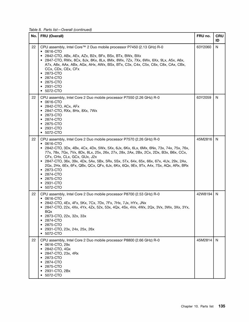
Table 8. Parts list—Overall (continued)
No. FRU (Overall) FRU no. CRUID
22 CPU assembly, Intel Core™ 2 Duo mobile processor P7450 (2.13 GHz) R-0• 0616-CTO• 2842-CTO, ABx, AEx, AZx, B2x, BFx, BSx, BTx, BWx, BXx• 2847-CTO, RWx, 8Cx, 8Jx, 8Kx, 8Lx, 8Mx, 8Wx, 7Zx, 7Xx, 6Wx, 6Xx, 9Lx, A5x, A6x,
A7x, A8x, AAx, ABx, AGx, AHx, AWx, BSx, BTx, C3x, C4x, C5x, C6x, C8x, CAx, CBx,CCx, CDx, CEx, CFx
• 2873-CTO• 2874-CTO• 2875-CTO• 2931-CTO• 5072-CTO
63Y2060 N
22 CPU assembly, Intel Core 2 Duo mobile processor P7550 (2.26 GHz) R-0• 0616-CTO• 2842-CTO, ACx, AFx• 2847-CTO, RXx, 8Hx, 8Xx, 7Wx• 2873-CTO• 2874-CTO• 2875-CTO• 2931-CTO• 5072-CTO
63Y2059 N
22 CPU assembly, Intel Core 2 Duo mobile processor P7570 (2.26 GHz) R-0• 0616-CTO• 2842-CTO, 3Dx, 4Bx, 4Cx, 4Dx, 5Wx, 5Xx, 6Jx, 6Kx, 6Lx, 6Mx, 6Nx, 73x, 74x, 75x, 76x,
77x, 78x, 7Gx, 7Vx, 8Dx, 8Lx, 25x, 26x, 27x, 28x, 2Ax, 2Bx, 2Cx, 2Dx, B3x, B6x, CCx,CFx, CHx, CLx, GCx, GUx, J2x
• 2847-CTO, 36x, 39x, 4Dx, 5Ax, 5Bx, 5Rx, 5Sx, 5Tx, 64x, 65x, 66x, 67x, 4Ux, 29x, 2Ax,2Gx, 2Hx, 6Ex, 6Fx, QBx, QCx, QFx, 6Jx, 6Kx, 6Qx, 9Ex, 9Tx, A4x, 7Sx, AQx, ARx, BRx
• 2873-CTO• 2874-CTO• 2875-CTO• 2931-CTO• 5072-CTO
45M2816 N
22 CPU assembly, Intel Core 2 Duo mobile processor P8700 (2.53 GHz) R-0• 0616-CTO• 2842-CTO, 4Ex, 4Fx, 5Kx, 7Cx, 7Dx, 7Fx, 7Hx, 7Jx, HYx, JNx• 2847-CTO, 22x, 4Xx, 4Yx, 4Zx, 52x, 53x, 4Qx, 4Sx, 4Vx, 4Wx, 2Qx, 3Vx, 3Wx, 3Xx, 3Yx,
BQx• 2873-CTO, 22x, 32x, 33x• 2874-CTO• 2875-CTO• 2931-CTO, 23x, 24x, 25x, 26x• 5072-CTO
42W8194 N
22 CPU assembly, Intel Core 2 Duo mobile processor P8800 (2.66 GHz) R-0• 0616-CTO, 29x• 2842-CTO, 4Gx• 2847-CTO, 23x, 4Rx• 2873-CTO• 2874-CTO• 2875-CTO• 2931-CTO, 2Bx• 5072-CTO
45M2814 N
Chapter 10. Parts list 135

Table 8. Parts list—Overall (continued)
No. FRU (Overall) FRU no. CRUID
22 CPU assembly, Intel Core 2 Duo mobile processor T5870 (2.0 GHz) M-0• 0616-CTO• 2842-CTO, 34x, 3Bx, 3Px, 42x, 43x, 45x, 4Hx, 4Jx, 4Mx, 4Px, 4Qx, 4Tx, 4Ux, 4Vx, 4Yx,
4Zx, 52x, 53x, 54x, 57x, 59x, 5Ax, 5Bx, 5Cx, 33x, 3Fx, 3Gx, 46x, 3Rx, 3Sx, 3Tx, 3Ux, 3Vx,5Gx, 5Hx, 5Lx, 5Mx, 5Nx, 5Px, 5Yx, 5Zx, 64x, 66x, 67x, 68x, 69x, 6Ax, 6Bx, 6Px, 6Qx,6Rx, 6Sx, 6Tx, 6Ux, 7Ex, 23x, 24x, 7Px, 7Qx, 7Rx, 7Sx, 7Yx, 7Zx, 84x, 87x, 88x, 89x, 8Ax,8Ex, 8Fx, 8Gx, 8Hx, 8Mx, 8Nx, AGx, AHx, AJx, AKx, ALx, C5x, C7x, C8x, CDx, CJx,DPx, DQx, E2x, E8x, F5x
• 2847-CTO, 33x, 37x, 42x, 43x, 44x, 45x, 46x, 47x, 48x, 4Ax, 4Bx, 4Ex, 4Fx, 3Kx, 3Lx, 4Jx,3Qx, 54x, 55x, 56x, 57x, 58x, 59x, 5Cx, 5Ex, 5Fx, 5Hx, 5Jx, 5Kx, 5Lx, 5Mx, 5Ux, 5Vx,5Wx, 5Xx, 5Yx, 24x, 25x, 2Bx, 2Cx, 2Jx, 2Kx, 2Lx, 2Mx, 2Nx, 2Rx, 2Sx, 2Tx, 2Ux, 2Vx,72x, 73x, 74x, 75x, 7Ax, 7Dx, 7Ex, 7Fx, 7Jx, 68x, 69x, 6Ax, 6Bx, Q5x, Q6x, Q7x, Q8x,Q9x, QAx, QDx, QGx, QHx, 6Lx, 6Mx, 9Jx
• 2873-CTO• 2874-CTO• 2875-CTO• 2931-CTO• 5072-CTO
43N7739 N
22 CPU assembly, Intel Core 2 Duo mobile processor T6570 (2.1 GHz) R-0• 0616-CTO• 2842-CTO, CMx, CPx, CQx, CRx, CSx, CUx, CVx, CWx, DDx, DEx, DFx, DGx, DHx,
DJx, DKx, DLx, DMx, DNx, DVx, DWx, DXx, DYx, DZx, E4x, E7x, EAx, EJx, EKx, ELx,EUx, EVx, EWx, EXx, EYx, F2x, F3x, F7x, F8x, FAx, FBx, FCx, FDx, FEx, FFx, FGx, FHx,FJx, FKx, FLx, FMx, FNx, FPx, FQx, FZx, GBx, GDx, GGx, GHx, GJx, GKx, GLx, GMx,GWx, GXx, GYx, GZx, H2x, H3x, H9x, HAx, HCx, HDx, HEx, HFx, HGx, HJx, HMx, HNx,HPx, HQx, HXx, J4x, JAx
• 2847-CTO, 2Wx, 2Xx, 2Yx, 7Kx, 7Lx, 7Mx, 7Nx, 6Nx, 6Px, 6Rx, 6Sx, 6Tx, 6Yx, 6Zx, 92x,93x, 94x, 95x, 96x, 97x, 98x, 99x, 9Ax, 9Bx, 9Cx, 9Dx, 9Mx, 9Nx, 9Qx, 9Rx, 9Sx, 9Ux, 9Vx,9Wx, 9Xx, 3Zx, A2x, A3x, ACx, ADx, AEx, AFx, 7Qx, 7Rx, AJx, AKx, ALx, AMx, ANx, 7Tx,ATx, AUx, AXx, AYx, AZx, B2x, B3x, B4x, B8x, B9x, BAx, BJx, BKx, BMx, BNx, BPx, C9x
• 2873-CTO• 2874-CTO• 2875-CTO• 2931-CTO• 5072-CTO
42W8193 N
22 CPU assembly, Intel Core 2 Duo mobile processor T6600 (2.2 GHz) R-0• 0616-CTO• 2842-CTO, AAx, ADx, AVx, AWx, AXx, AYx, BEx, BHx, BJx, BKx, BMx, BRx, BUx, BVx,
BYx, E5x, E6x• 2847-CTO, RVx, 8Bx, 8Ex, 8Fx, 8Gx, 8Nx, 8Px, 8Ux, 8Vx, 8Zx, 7Yx• 2873-CTO• 2874-CTO• 2875-CTO• 2931-CTO• 5072-CTO
43N8584 N
136 Hardware Maintenance Manual

Table 8. Parts list—Overall (continued)
No. FRU (Overall) FRU no. CRUID
22 CPU assembly, Intel Core 2 Duo mobile processor T6670 (2.2 GHz) R-0• 0616-CTO, 22x, 25x, 26x, 2Cx, 2Fx, 2Gx, 2Kx• 2842-CTO, 22x, 35x, 36x, 37x, 39x, 3Qx, 47x, 48x, 49x, 4Ax, 4Kx, 4Lx, 4Nx, 4Rx, 4Sx,
4Wx, 4Xx, 55x, 56x, 58x, 5Dx, 44x, 3Hx, 5Ex, 5Fx, 5Jx, 5Qx, 5Rx, 5Sx, 5Tx, 5Ux, 5Vx, 62x,63x, 65x, 6Cx, 6Dx, 6Ex, 6Fx, 6Gx, 6Hx, 6Vx, 6Wx, 6Xx, 6Yx, 6Zx, 72x, 7Bx, 7Tx, 7Ux,7Wx, 7Xx, 82x, 83x, 85x, 86x, 8Bx, 8Cx, 8Jx, 8Kx, 8Rx, 29x, 2Ex, C6x, C9x, CAx, CBx,CEx, CGx, CKx, CXx, CYx, CZx, D2x, D3x, D4x, DRx, DSx, DTx, DUx, E3x, E9x, F4x, F6x,F9x, H5x, HHx, HKx, HLx, J3x, JBx, JCx, JDx, JEx, JFx, JGx, JHx, JJx, JKx, JPx
• 2847-CTO, 34x, 35x, 38x, 3Dx, 3Ex, 49x, 4Cx, 4Gx, 4Hx, 3Mx, 3Nx, 3Px, 5Dx, 5Gx, 5Nx,5Px, 5Qx, 5Zx, 62x, 63x, 4Nx, 4Px, 4Tx, 26x, 27x, 28x, 2Dx, 2Ex, 2Fx, 2Px, 76x, 77x, 78x,79x, 7Bx, 7Cx, 6Cx, 6Dx, 6Gx, 6Hx, Q2x, Q3x, Q4x, QEx, QJx, 9Gx, 9Hx, 9Yx, 9Zx, ASx,BCx, BDx, BEx, BFx, BGx, BHx, BVx, BWx, BXx, BYx, BZx, C2x, C7x, CGx, CHx, CJx,CKx, CLx, CMx, CNx, CPx, CQx
• 2873-CTO• 2874-CTO• 2875-CTO• 2931-CTO, 27x• 5072-CTO
45M2817 N
22 CPU assembly, Intel Core 2 Duo mobile processor T9600 (2.80 GHz) E-0• 0616-CTO• 2842-CTO, HZx• 2847-CTO• 2873-CTO• 2874-CTO• 2875-CTO• 2931-CTO, 22x• 5072-CTO
42W8290 N
22 CPU assembly, Intel Core 2 Duo mobile processor P8400 (2.26 GHz) R-0• 0616-CTO, 2Hx, 2Jx, 2Lx• 2842-CTO• 2847-CTO• 2873-CTO• 2874-CTO• 2875-CTO• 2931-CTO• 5072-CTO
42W8286 N
22 CPU assembly, Intel Core 2 Duo mobile processor P8600 (2.4 GHz) R-0• 0616-CTO, 27x, 28x• 2842-CTO• 2847-CTO• 2873-CTO• 2874-CTO• 2875-CTO• 2931-CTO• 5072-CTO
42W8287 N
22 CPU assembly, Intel Celeron mobile processor T3500 (2.1 GHz) R-0• 0616-CTO, 2Dx, 2Ex• 2842-CTO• 2847-CTO• 2873-CTO• 2874-CTO• 2875-CTO• 2931-CTO• 5072-CTO
04W0375 N
Chapter 10. Parts list 137

Table 8. Parts list—Overall (continued)
No. FRU (Overall) FRU no. CRUID
23 Bluetooth daughter card (BDC-2.1)• 0616-CTO, 22x, 25x, 26x, 27x, 28x, 29x, 2Cx, 2Dx, 2Ex, 2Fx, 2Gx, 2Hx, 2Jx, 2Kx, 2Lx• 2842-CTO, 34x, 35x, 36x, 37x, 39x, 3Bx, 3Dx, 3Px, 3Qx, 42x, 43x, 45x, 47x, 48x, 49x, 4Ax,
4Bx, 4Cx, 4Dx, 4Ex, 4Fx, 4Gx, 4Hx, 4Jx, 4Kx, 4Lx, 4Mx, 4Nx, 4Px, 4Qx, 4Rx, 4Sx, 4Tx,33x, 3Gx, 46x, 3Hx, 3Rx, 3Sx, 3Tx, 3Ux, 3Vx, 5Ex, 5Fx, 5Jx, 5Kx, 5Lx, 5Mx, 5Nx, 5Px,5Qx, 5Rx, 5Sx, 5Tx, 5Ux, 5Vx, 5Wx, 5Xx, 5Yx, 5Zx, 62x, 63x, 64x, 65x, 7Bx, 7Cx, 7Dx,7Ex, 7Fx, 7Gx, 7Hx, 7Jx, 7Qx, 7Rx, 7Sx, 7Tx, 7Ux, 7Vx, 7Wx, 7Xx, 7Yx, 7Zx, 82x, 83x,84x, 85x, 86x, 8Rx, 9Ax, 9Bx, 9Cx, 9Dx, 9Ex, 9Fx, 9Gx, 9Hx, A2x, A3x, A4x, A5x, A6x,A7x, A8x, A9x, AGx, AHx, AJx, AKx, 25x, 26x, 27x, 28x, 29x, 2Ax, 2Bx, 2Cx, 2Dx, 2Ex,AMx, ANx, APx, AQx, ARx, ASx, ATx, AUx, AVx, AWx, AXx, AYx, AZx, B2x, B3x, B4x, B5x,B6x, B7x, B8x, B9x, BAx, BBx, BCx, BDx, BEx, BFx, BGx, BHx, BJx, BKx, BMx, BNx,BPx, BQx, BRx, BSx, BTx, BUx, BVx, BWx, BXx, BYx, BZx, C2x, C3x, C4x, C5x, C6x, C7x,C8x, C9x, CAx, CBx, CCx, CDx, CEx, CFx, CGx, CHx, CJx, CKx, CLx, CMx, CNx, CPx,CQx, CRx, CSx, CUx, CVx, CWx, CXx, CYx, CZx, D2x, D3x, D4x, D5x, D6x, D7x, D8x,D9x, DAx, DBx, DCx, DDx, DEx, DFx, DGx, DHx, DJx, DKx, DLx, DMx, DNx, DPx, DQx,DRx, DSx, DTx, DUx, DVx, DWx, DXx, DYx, DZx, E2x, E3x, E4x, E5x, E6x, E7x, E8x, E9x,EAx, EFx, EGx, EHx, EJx, EKx, ELx, ERx, ESx, ETx, EUx, EVx, EWx, EXx, EYx, EZx, F2x,F3x, F4x, F5x, F6x, F9x, FCx, FDx, FEx, FFx, FGx, FHx, FJx, FKx, FLx, FMx, FNx, FPx,FQx, FSx, FTx, FUx, FVx, FWx, FXx, FYx, FZx, G2x, G3x, G4x, G5x, G6x, G7x, G8x, G9x,GBx, GCx, GDx, GEx, GFx, GGx, GHx, GJx, GKx, GLx, GMx, GNx, GPx, GQx, GRx, GSx,GTx, GUx, GVx, GWx, GXx, GYx, GZx, H2x, H3x, H4x, H5x, H6x, H7x, H8x, H9x, HAx,HBx, HCx, HDx, HFx, HGx, HHx, HJx, HKx, HLx, HMx, HNx, HPx, HQx, HRx, HWx, HXx,HYx, HZx, J2x, J3x, J4x, JDx, JEx, JFx, JGx, JHx, JJx, JKx, JLx, JNx, JPx
• 2847-CTO, 22x, 23x, 33x, 34x, 35x, 36x, 37x, 38x, 3Dx, 3Ex, 42x, 43x, 44x, 45x, 46x, 47x,48x, 49x, 4Ex, 4Fx, 4Gx, 3Kx, 3Lx, 4Jx, 3Mx, 3Nx, 3Px, 3Qx, 54x, 55x, 56x, 57x, 58x, 59x,5Ax, 5Bx, 5Cx, 5Dx, 5Ex, 5Fx, 5Gx, 4Nx, 4Px, 4Qx, 4Rx, 4Sx, 4Tx, 4Ux, 4Vx, 4Wx, 24x,25x, 26x, 27x, 28x, 29x, 2Ax, 2Bx, 2Cx, 2Dx, 2Ex, 2Fx, 2Gx, 2Hx, 2Lx, 2Px, 2Qx, 73x, 74x,75x, 76x, 77x, 78x, 79x, 7Jx, RMx, RNx, RPx, RQx, RRx, RSx, RTx, RUx, 68x, 69x, 6Ax,6Bx, 6Cx, 6Dx, 6Ex, 6Fx, Q2x, Q3x, Q4x, Q5x, Q6x, Q7x, Q8x, Q9x, QAx, QBx, QCx, QDx,QEx, QFx, QJx, 82x, 83x, 84x, 85x, 86x, 87x, 88x, 89x, 8Ax, 8Bx, 8Cx, 8Dx, 8Ex, 8Fx, 8Gx,8Hx, 8Jx, 8Kx, 8Lx, 8Mx, 8Nx, 8Px, 8Qx, 8Rx, 8Sx, 8Tx, 8Ux, 8Vx, 8Wx, 8Xx, 8Yx, 8Zx,7Zx, 7Wx, 7Xx, 7Yx, 6Jx, 6Kx, 6Lx, 6Mx, 2Wx, 2Xx, 2Yx, 2Zx, 7Kx, 7Lx, 7Mx, 7Nx, 6Nx,6Px, 6Qx, 6Rx, 6Sx, 6Tx, 6Ux, 6Vx, 6Wx, 6Xx, 6Yx, 6Zx, 92x, 93x, 94x, 95x, 96x, 97x, 98x,99x, 9Ax, 9Bx, 9Cx, 9Dx, 9Ex, 9Fx, 9Gx, 9Hx, 9Jx, 9Kx, 9Lx, 9Nx, 9Px, 9Qx, 9Rx, 9Sx,9Tx, 9Vx, 9Yx, A2x, A3x, A4x, A5x, A6x, A7x, A8x, A9x, AAx, ABx, ACx, ADx, AEx, AFx,7Px, 7Qx, 7Rx, 7Sx, AGx, AHx, AJx, AKx, ALx, AMx, ANx, APx, AQx, ARx, ASx, 7Ux, ATx,AUx, AVx, AWx, AXx, AYx, B2x, B3x, B5x, B6x, B7x, B8x, B9x, BAx, BBx, BCx, BDx, BEx,BFx, BGx, BHx, BJx, BKx, BMx, BNx, BPx, BQx, BRx, BSx, BTx, BUx, BVx, BWx, BXx,BYx, BZx, C2x, C8x, C9x, CGx, CHx, CJx, CKx, CLx, CMx, CNx, CPx, CQx
• 2873-CTO, 22x, 32x, 33x• 2874-CTO, 33x, 34x, 35x, 36x, 37x, 39x, 3Bx, 3Ex, 3Gx, 3Kx, 3Lx, 3Nx, 48x, 49x, 4Ax,
4Bx, 4Cx, 4Dx, 4Fx, 4Gx, 4Hx, 4Jx, 4Kx, 4Lx, 52x, 5Kx, 5Lx, 5Mx, 5Nx, 5Px, 5Qx, 5Rx,62x, 63x, 64x, 65x, 66x, 67x, 68x, 69x, 6Ax, 6Bx, 6Cx, 6Dx, 6Ex, 6Fx, 6Gx, 6Hx, 6Jx, 6Kx,6Lx, 6Mx, 6Nx, 6Px, 6Qx, 6Rx, 6Sx, 6Tx, 6Ux, 6Vx, 6Wx, 6Xx, 6Yx, 6Zx, 72x, 73x, 74x,75x, 76x, 77x, 78x, 79x, 7Ax, 7Bx, 7Cx, 7Dx, 7Ex, 7Fx, 7Gx, 7Qx, 7Rx, 7Tx, 7Ux, 7Vx, 82x
• 2875-CTO, 24x, 25x, 28x, 29x, 2Bx, 2Cx, 2Jx, 2Mx, 2Nx, 2Px, 2Wx, 2Xx, 39x, 3Ax, 4Bx,4Cx, 4Ex, 4Fx, 4Gx, 4Hx, 4Jx, 4Kx, 4Lx, 4Nx, 4Px, 4Qx, 4Rx, 4Sx, 4Tx, 4Ux, 4Vx, 4Wx,4Xx, 4Yx, 52x, 53x, 54x, 55x, 56x, 59x, 5Ax, 5Bx, 5Cx, R2x, R3x, R4x, R5x, RDx, RFx,RGx, RHx, RJx
• 2931-CTO, 22x, 23x, 24x, 25x, 26x, 27x,• 5072-CTO
60Y319960Y3213
N
24 System board assembly, GL40 (A1/FastEthernet) Integrated 14W• 0616-CTO, 2Dx, 2Ex• 2842-CTO, K5x, K6x, K7x, K8x, K9x, KAx, KBx, KCx, KNx, KPx, KQx, KWx, L2x, L3x, L6x• 2874-all• 2931-CTO, 2Ex
63Y2092 N
138 Hardware Maintenance Manual
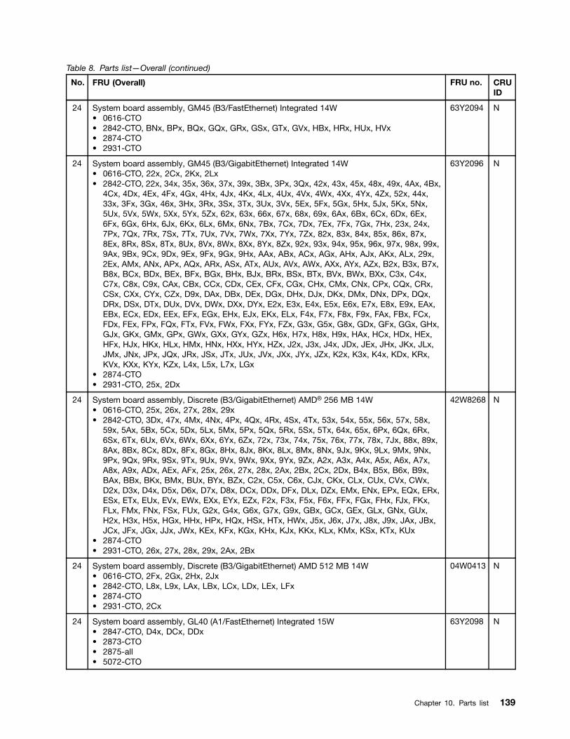
Table 8. Parts list—Overall (continued)
No. FRU (Overall) FRU no. CRUID
24 System board assembly, GM45 (B3/FastEthernet) Integrated 14W• 0616-CTO• 2842-CTO, BNx, BPx, BQx, GQx, GRx, GSx, GTx, GVx, HBx, HRx, HUx, HVx• 2874-CTO• 2931-CTO
63Y2094 N
24 System board assembly, GM45 (B3/GigabitEthernet) Integrated 14W• 0616-CTO, 22x, 2Cx, 2Kx, 2Lx• 2842-CTO, 22x, 34x, 35x, 36x, 37x, 39x, 3Bx, 3Px, 3Qx, 42x, 43x, 45x, 48x, 49x, 4Ax, 4Bx,
4Cx, 4Dx, 4Ex, 4Fx, 4Gx, 4Hx, 4Jx, 4Kx, 4Lx, 4Ux, 4Vx, 4Wx, 4Xx, 4Yx, 4Zx, 52x, 44x,33x, 3Fx, 3Gx, 46x, 3Hx, 3Rx, 3Sx, 3Tx, 3Ux, 3Vx, 5Ex, 5Fx, 5Gx, 5Hx, 5Jx, 5Kx, 5Nx,5Ux, 5Vx, 5Wx, 5Xx, 5Yx, 5Zx, 62x, 63x, 66x, 67x, 68x, 69x, 6Ax, 6Bx, 6Cx, 6Dx, 6Ex,6Fx, 6Gx, 6Hx, 6Jx, 6Kx, 6Lx, 6Mx, 6Nx, 7Bx, 7Cx, 7Dx, 7Ex, 7Fx, 7Gx, 7Hx, 23x, 24x,7Px, 7Qx, 7Rx, 7Sx, 7Tx, 7Ux, 7Vx, 7Wx, 7Xx, 7Yx, 7Zx, 82x, 83x, 84x, 85x, 86x, 87x,8Ex, 8Rx, 8Sx, 8Tx, 8Ux, 8Vx, 8Wx, 8Xx, 8Yx, 8Zx, 92x, 93x, 94x, 95x, 96x, 97x, 98x, 99x,9Ax, 9Bx, 9Cx, 9Dx, 9Ex, 9Fx, 9Gx, 9Hx, AAx, ABx, ACx, AGx, AHx, AJx, AKx, ALx, 29x,2Ex, AMx, ANx, APx, AQx, ARx, ASx, ATx, AUx, AVx, AWx, AXx, AYx, AZx, B2x, B3x, B7x,B8x, BCx, BDx, BEx, BFx, BGx, BHx, BJx, BRx, BSx, BTx, BVx, BWx, BXx, C3x, C4x,C7x, C8x, C9x, CAx, CBx, CCx, CDx, CEx, CFx, CGx, CHx, CMx, CNx, CPx, CQx, CRx,CSx, CXx, CYx, CZx, D9x, DAx, DBx, DEx, DGx, DHx, DJx, DKx, DMx, DNx, DPx, DQx,DRx, DSx, DTx, DUx, DVx, DWx, DXx, DYx, E2x, E3x, E4x, E5x, E6x, E7x, E8x, E9x, EAx,EBx, ECx, EDx, EEx, EFx, EGx, EHx, EJx, EKx, ELx, F4x, F7x, F8x, F9x, FAx, FBx, FCx,FDx, FEx, FPx, FQx, FTx, FVx, FWx, FXx, FYx, FZx, G3x, G5x, G8x, GDx, GFx, GGx, GHx,GJx, GKx, GMx, GPx, GWx, GXx, GYx, GZx, H6x, H7x, H8x, H9x, HAx, HCx, HDx, HEx,HFx, HJx, HKx, HLx, HMx, HNx, HXx, HYx, HZx, J2x, J3x, J4x, JDx, JEx, JHx, JKx, JLx,JMx, JNx, JPx, JQx, JRx, JSx, JTx, JUx, JVx, JXx, JYx, JZx, K2x, K3x, K4x, KDx, KRx,KVx, KXx, KYx, KZx, L4x, L5x, L7x, LGx
• 2874-CTO• 2931-CTO, 25x, 2Dx
63Y2096 N
24 System board assembly, Discrete (B3/GigabitEthernet) AMD® 256 MB 14W• 0616-CTO, 25x, 26x, 27x, 28x, 29x• 2842-CTO, 3Dx, 47x, 4Mx, 4Nx, 4Px, 4Qx, 4Rx, 4Sx, 4Tx, 53x, 54x, 55x, 56x, 57x, 58x,
59x, 5Ax, 5Bx, 5Cx, 5Dx, 5Lx, 5Mx, 5Px, 5Qx, 5Rx, 5Sx, 5Tx, 64x, 65x, 6Px, 6Qx, 6Rx,6Sx, 6Tx, 6Ux, 6Vx, 6Wx, 6Xx, 6Yx, 6Zx, 72x, 73x, 74x, 75x, 76x, 77x, 78x, 7Jx, 88x, 89x,8Ax, 8Bx, 8Cx, 8Dx, 8Fx, 8Gx, 8Hx, 8Jx, 8Kx, 8Lx, 8Mx, 8Nx, 9Jx, 9Kx, 9Lx, 9Mx, 9Nx,9Px, 9Qx, 9Rx, 9Sx, 9Tx, 9Ux, 9Vx, 9Wx, 9Xx, 9Yx, 9Zx, A2x, A3x, A4x, A5x, A6x, A7x,A8x, A9x, ADx, AEx, AFx, 25x, 26x, 27x, 28x, 2Ax, 2Bx, 2Cx, 2Dx, B4x, B5x, B6x, B9x,BAx, BBx, BKx, BMx, BUx, BYx, BZx, C2x, C5x, C6x, CJx, CKx, CLx, CUx, CVx, CWx,D2x, D3x, D4x, D5x, D6x, D7x, D8x, DCx, DDx, DFx, DLx, DZx, EMx, ENx, EPx, EQx, ERx,ESx, ETx, EUx, EVx, EWx, EXx, EYx, EZx, F2x, F3x, F5x, F6x, FFx, FGx, FHx, FJx, FKx,FLx, FMx, FNx, FSx, FUx, G2x, G4x, G6x, G7x, G9x, GBx, GCx, GEx, GLx, GNx, GUx,H2x, H3x, H5x, HGx, HHx, HPx, HQx, HSx, HTx, HWx, J5x, J6x, J7x, J8x, J9x, JAx, JBx,JCx, JFx, JGx, JJx, JWx, KEx, KFx, KGx, KHx, KJx, KKx, KLx, KMx, KSx, KTx, KUx
• 2874-CTO• 2931-CTO, 26x, 27x, 28x, 29x, 2Ax, 2Bx
42W8268 N
24 System board assembly, Discrete (B3/GigabitEthernet) AMD 512 MB 14W• 0616-CTO, 2Fx, 2Gx, 2Hx, 2Jx• 2842-CTO, L8x, L9x, LAx, LBx, LCx, LDx, LEx, LFx• 2874-CTO• 2931-CTO, 2Cx
04W0413 N
24 System board assembly, GL40 (A1/FastEthernet) Integrated 15W• 2847-CTO, D4x, DCx, DDx• 2873-CTO• 2875-all• 5072-CTO
63Y2098 N
Chapter 10. Parts list 139
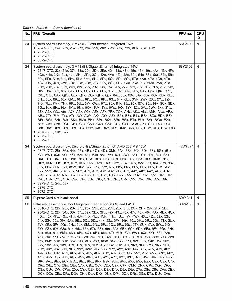
Table 8. Parts list—Overall (continued)
No. FRU (Overall) FRU no. CRUID
24 System board assembly, GM45 (B3/FastEthernet) Integrated 15W• 2847-CTO, 24x, 25x, 26x, 27x, 28x, 29x, 2Ax, 7Wx, 7Xx, 7Yx, AQx, ASx, AUx• 2873-CTO• 2875-CTO• 5072-CTO
63Y2100 N
24 System board assembly, GM45 (B3/GigabitEthernet) Integrated 15W• 2847-CTO, 33x, 34x, 37x, 38x, 39x, 3Dx, 3Ex, 42x, 43x, 45x, 46x, 48x, 49x, 4Ax, 4Ex, 4Fx,
4Gx, 4Hx, 3Kx, 3Lx, 4Jx, 3Nx, 3Px, 3Qx, 4Xx, 4Yx, 4Zx, 52x, 53x, 54x, 55x, 56x, 57x, 58x,59x, 5Ex, 5Hx, 5Jx, 5Kx, 5Lx, 5Mx, 5Nx, 5Px, 5Qx, 5Rx, 5Sx, 5Tx, 4Nx, 4Px, 4Qx, 4Rx,4Sx, 4Tx, 4Ux, 4Vx, 2Bx, 2Cx, 2Dx, 2Ex, 2Fx, 2Gx, 2Hx, 2Jx, 2Kx, 2Lx, 2Mx, 2Nx, 2Px,2Qx, 2Rx, 2Sx, 2Tx, 2Ux, 2Vx, 72x, 73x, 74x, 75x, 76x, 77x, 78x, 79x, 7Bx, 7Ex, 7Fx, 7Jx,R2x, R3x, 68x, 69x, 6Ax, 6Bx, 6Cx, 6Dx, 6Ex, 6Fx, 6Gx, 6Hx, Q3x, Q4x, Q5x, Q6x, Q7x,Q8x, Q9x, QAx, QDx, QEx, QFx, QGx, QHx, QJx, 84x, 85x, 89x, 8Ax, 8Bx, 8Cx, 8Dx, 8Ex,8Hx, 8Jx, 8Kx, 8Lx, 8Mx, 8Nx, 8Px, 8Qx, 8Rx, 8Sx, 8Tx, 6Lx, 6Mx, 2Wx, 2Xx, 2Yx, 2Zx,7Kx, 7Lx, 7Mx, 7Nx, 6Rx, 6Ux, 6Vx, 6Wx, 6Yx, 93x, 94x, 95x, 96x, 97x, 98x, 99x, 9Cx, 9Dx,9Gx, 9Jx, 9Kx, 9Lx, 9Mx, 9Nx, 9Qx, 9Ux, 9Vx, 9Wx, 9Xx, 9Yx, 9Zx, 3Vx, 3Wx, 3Xx, 3Yx,3Zx, A2x, A5x, A6x, A7x, A9x, ACx, AEx, AFx, 7Px, 7Qx, AHx, AKx, ALx, AMx, ANx, APx,ARx, 7Tx, 7Ux, 7Vx, ATx, AVx, AWx, AXx, AYx, AZx, B2x, B3x, B4x, BBx, BCx, BDx, BEx,BFx, BGx, BHx, BJx, BKx, BMx, BNx, BPx, BQx, BRx, BSx, BTx, BUx, BVx, BWx, BXx,BYx, C5x, C6x, CGx, CHx, CLx, CMx, CQx, CSx, CUx, CVx, CWx, CXx, CZx, D2x, D3x,D9x, DAx, DBx, DEx, DFx, DGx, DHx, DJx, DKx, DLx, DMx, DNx, DPx, DQx, DRx, DSx, DTx
• 2873-CTO, 23x, 32x• 2875-CTO• 5072-CTO
63Y2102 N
24 System board assembly, Discrete (B3/GigabitEthernet) AMD 256 MB 15W• 2847-CTO, 35x, 36x, 44x, 47x, 4Bx, 4Cx, 4Dx, 3Mx, 5Ax, 5Bx, 5Cx, 5Dx, 5Fx, 5Gx, 5Ux,
5Vx, 5Wx, 5Xx, 5Yx, 5Zx, 62x, 63x, 64x, 65x, 66x, 67x, 4Wx, 7Ax, 7Cx, 7Dx, R4x, R5x,R6x, R7x, R8x, R9x, RAx, RBx, RCx, RDx, RFx, RGx, RHx, RJx, RKx, RLx, RMx, RNx,RPx, RQx, RRx, RSx, RTx, RUx, RVx, RWx, RXx, Q2x, QBx, QCx, 82x, 83x, 86x, 87x, 88x,8Fx, 8Gx, 8Ux, 8Vx, 8Wx, 8Xx, 8Yx, 8Zx, 7Zx, 6Jx, 6Kx, 6Nx, 6Px, 6Qx, 6Sx, 6Tx, 6Xx,6Zx, 92x, 9Ax, 9Bx, 9Ex, 9Fx, 9Hx, 9Px, 9Rx, 9Sx, 9Tx, A3x, A4x, A8x, AAx, ABx, ADx,7Rx, 7Sx, AGx, AJx, B5x, B6x, B7x, B8x, B9x, BAx, BZx, C2x, C3x, C4x, C7x, C8x, C9x,CAx, CBx, CCx, CDx, CEx, CFx, CJx, CKx, CNx, CPx, CRx, CYx, D5x, D6x, D7x, D8x
• 2873-CTO, 24x, 33x• 2875-CTO• 5072-CTO
42W8274 N
25 ExpressCard slot blank bezel 60Y4341 N
26 Palm rest assembly without fingerprint reader for SL410 and L410• 0616-CTO, 22x, 25x, 26x, 27x, 28x, 29x, 2Cx, 2Dx, 2Ex, 2Fx, 2Gx, 2Hx, 2Jx, 2Kx, 2Lx• 2842-CTO, 22x, 34x, 36x, 37x, 39x, 3Bx, 3Px, 42x, 43x, 45x, 47x, 48x, 49x, 4Ax, 4Bx, 4Cx,
4Dx, 4Ex, 4Fx, 4Gx, 4Hx, 4Jx, 4Kx, 4Lx, 4Mx, 4Nx, 4Ux, 4Vx, 4Wx, 4Xx, 4Zx, 52x, 53x,54x, 55x, 56x, 59x, 5Ax, 5Bx, 5Cx, 5Dx, 44x, 33x, 3Fx, 3Gx, 46x, 3Hx, 3Rx, 3Sx, 3Tx, 3Ux,3Vx, 5Ex, 5Fx, 5Gx, 5Hx, 5Lx, 5Mx, 5Nx, 5Px, 5Qx, 5Rx, 5Sx, 5Tx, 5Ux, 5Vx, 5Wx, 5Xx,5Yx, 5Zx, 62x, 63x, 64x, 65x, 66x, 67x, 68x, 69x, 6Ax, 6Bx, 6Cx, 6Dx, 6Ex, 6Fx, 6Gx, 6Hx,6Jx, 6Kx, 6Lx, 6Mx, 6Nx, 6Px, 6Qx, 6Rx, 6Sx, 6Tx, 6Ux, 6Vx, 6Wx, 6Xx, 6Yx, 6Zx, 72x,73x, 74x, 75x, 76x, 77x, 7Ex, 23x, 24x, 7Px, 7Qx, 7Rx, 7Sx, 7Tx, 7Ux, 7Vx, 7Wx, 7Xx, 85x,86x, 8Mx, 8Nx, 8Rx, 8Sx, 8Tx, 8Ux, 8Vx, 8Wx, 8Xx, 8Yx, 8Zx, 92x, 93x, 94x, 95x, 96x,97x, 98x, 99x, 9Ax, 9Bx, 9Cx, 9Dx, 9Ex, 9Fx, 9Gx, 9Hx, 9Jx, 9Kx, 9Lx, 9Mx, 9Nx, 9Px,9Qx, 9Rx, 9Sx, 9Tx, 9Ux, 9Vx, 9Wx, 9Xx, 9Yx, 9Zx, A2x, A3x, A4x, A5x, A6x, A7x, A8x,A9x, AAx, ABx, ACx, ADx, AEx, AFx, AGx, AHx, AJx, AKx, ALx, 29x, 2Ex, AMx, ANx, APx,AQx, ARx, ASx, ATx, AUx, AVx, AWx, AXx, AYx, AZx, B2x, B3x, B4x, B5x, B6x, B7x, B8x,B9x, BAx, BBx, BCx, BDx, BEx, BFx, BRx, BSx, BUx, BVx, BXx, BYx, BZx, C2x, C3x, C4x,C5x, C6x, C7x, C8x, C9x, CAx, CBx, CCx, CDx, CEx, CFx, CMx, CNx, CPx, CQx, CRx,CSx, CUx, CVx, CWx, CXx, CYx, CZx, D2x, D3x, D4x, D5x, D6x, D7x, D8x, D9x, DAx, DBx,DCx, DDx, DEx, DFx, DGx, DHx, DJx, DKx, DNx, DPx, DQx, DRx, DSx, DTx, DUx, DVx,
60Y4130 N
140 Hardware Maintenance Manual

Table 8. Parts list—Overall (continued)
No. FRU (Overall) FRU no. CRUID
DWx, DXx, DYx, DZx, E5x, EAx, EBx, ECx, EDx, EEx, EFx, EGx, EHx, EJx, EKx, ELx,EMx, ENx, EPx, EQx, ERx, ESx, ETx, EUx, EVx, EWx, EZx, F5x, F6x, F7x, F8x, FAx, FBx,FCx, FDx, FEx, FFx, FGx, FHx, FJx, FKx, FLx, FMx, FNx, FPx, FQx, FSx, FTx, FUx, FVx,FWx, FXx, FYx, FZx, G2x, G3x, G4x, G5x, G6x, G7x, G8x, G9x, GBx, GCx, GDx, GEx,GFx, GKx, GLx, GMx, GNx, GPx, GQx, GRx, GSx, GTx, GUx, GVx, GWx, GXx, GYx,GZx, H2x, H3x, H4x, H5x, H6x, H7x, H8x, H9x, HAx, HDx, HEx, HFx, HGx, HHx, HKx,HLx, HMx, HNx, HPx, HRx, HSx, HTx, HUx, HVx, HWx, J5x, J6x, J7x, J8x, J9x, JAx, JBx,JCx, JDx, JEx, JFx, JGx, JKx, JLx, JMx
• 2874-CTO, 32x, 34x, 35x, 36x, 39x, 3Bx, 3Ex, 3Gx, 3Kx, 3Lx, 3Mx, 3Nx, 3Px, 3Qx, 3Rx,3Sx, 46x, 47x, 48x, 49x, 4Ax, 4Bx, 4Cx, 4Dx, 4Fx, 4Gx, 4Hx, 4Jx, 4Kx, 4Lx, 4Mx, 4Nx,4Px, 4Qx, 53x, 54x, 55x, 56x, 57x, 58x, 59x, 5Ax, 5Bx, 5Cx, 5Dx, 5Ex, 5Fx, 5Gx, 5Hx, 5Jx,5Kx, 5Lx, 5Mx, 5Nx, 5Px, 5Qx, 5Rx, 62x, 63x, 64x, 65x, 66x, 67x, 68x, 69x, 6Ax, 6Bx, 6Cx,6Dx, 6Ex, 6Fx, 6Gx, 6Hx, 6Jx, 6Kx, 6Lx, 6Mx, 6Qx, 6Rx, 6Sx, 6Ux, 6Vx, 6Yx, 6Zx, 75x,76x, 77x, 78x, 79x, 7Ax, 7Cx, 7Dx, 7Ex, 7Fx, 7Gx, 7Hx, 7Jx, 7Kx, 7Lx, 7Mx, 7Nx, 7Px,7Sx, 7Tx, 7Ux, 7Vx, 7Wx, 7Xx, 7Yx, 7Zx, 82x
• 2931-CTO, 25x
26 Palm rest assembly with fingerprint reader for SL410 and L410• 0616-CTO• 2842-CTO, 35x, 3Dx, 3Qx, 4Px, 4Qx, 4Rx, 4Sx, 4Tx, 4Yx, 57x, 58x, 5Jx, 5Kx, 78x, 7Bx,
7Cx, 7Dx, 7Fx, 7Gx, 7Hx, 7Jx, 7Yx, 7Zx, 82x, 83x, 84x, 87x, 88x, 89x, 8Ax, 8Bx, 8Cx, 8Dx,8Ex, 8Fx, 8Gx, 8Hx, 8Jx, 8Kx, 8Lx, 25x, 26x, 27x, 28x, 2Ax, 2Bx, 2Cx, 2Dx, BGx, BHx,BJx, BKx, BMx, BNx, BPx, BQx, BTx, BWx, CGx, CHx, CJx, CKx, CLx, DLx, DMx, E2x,E3x, E4x, E6x, E7x, E8x, E9x, EXx, EYx, F2x, F3x, F4x, F9x, GGx, GHx, GJx, HBx, HCx,HJx, HQx, HXx, HYx, HZx, J2x, J3x, J4x, JHx, JJx, JNx, JPx
• 2874-CTO, 33x, 37x, 52x, 6Nx, 6Px, 6Tx, 6Wx, 6Xx, 72x, 73x, 74x, 7Bx, 7Qx, 7Rx• 2931-CTO, 22x, 23x, 24x, 26x, 27x
60Y4132 N
26 Palm rest assembly without fingerprint reader for SL410 and L410, Texture• 0616-CTO, 22x, 25x, 26x, 27x, 28x, 29x, 2Cx, 2Dx, 2Ex, 2Fx, 2Gx, 2Hx, 2Jx, 2Kx, 2Lx• 2842-CTO, JQx, JRx, JSx, JTx, JUx, JVx, JWx, JXx, JYx, JZx, K2x, K3x, K4x, K5x, K6x,
K7x, K8x, K9x, KAx, KBx, KCx, KDx, KEx, KFx, KGx, KHx, KJx, KKx, KLx, KMx, KNx, KPx,KQx, KRx, KSx, KTx, KUx, KVx, KWx, KXx, KYx, KZx, L2x, L3x, L4x, L5x, L6x, L7x, L8x,L9x, LAx, LBx, LCx, LDx, LEx, LFx, LGx
• 2874-CTO• 2931-CTO, 28x, 29x, 2Ax, 2Bx, 2Cx, 2Dx, 2Ex
04W0369 N
26 Palm rest assembly without fingerprint reader for SL510 and L510• 2847-CTO, 22x, 23x, 33x, 37x, 38x, 39x, 42x, 43x, 44x, 45x, 46x, 47x, 4Ax, 4Bx, 4Cx, 4Dx,
4Hx, 3Kx, 3Lx, 4Jx, 3Qx, 4Xx, 4Yx, 4Zx, 52x, 53x, 54x, 55x, 56x, 57x, 58x, 59x, 5Cx, 5Dx,5Ex, 5Fx, 5Gx, 5Hx, 5Jx, 5Kx, 5Lx, 5Mx, 5Nx, 5Px, 5Qx, 5Rx, 5Sx, 5Tx, 5Ux, 5Vx, 5Wx,5Xx, 5Yx, 5Zx, 62x, 63x, 64x, 65x, 66x, 67x, 4Wx, 24x, 25x, 26x, 27x, 28x, 29x, 2Ax, 2Bx,2Cx, 2Dx, 2Ex, 2Fx, 2Gx, 2Hx, 2Jx, 2Kx, 2Lx, 2Mx, 2Nx, 2Rx, 2Sx, 2Tx, 2Ux, 2Vx, 78x,79x, 7Ax, 7Bx, 7Cx, 7Dx, 7Ex, 7Fx, 7Jx, R2x, R3x, R4x, R5x, R6x, R7x, R8x, R9x, RAx,RBx, RCx, RDx, RFx, RGx, RHx, RJx, RKx, RLx, RMx, RNx, RPx, RQx, RRx, RSx, RTx,RUx, RVx, RWx, RXx, 68x, 69x, 6Ax, 6Bx, 6Gx, 6Hx, Q5x, Q6x, Q7x, Q8x, Q9x, QAx, QDx,QEx, QFx, QGx, QHx, 82x, 83x, 84x, 85x, 86x, 87x, 88x, 89x, 8Ax, 8Bx, 8Cx, 8Dx, 8Ex,8Nx, 8Px, 8Qx, 8Sx, 8Tx, 8Yx, 8Zx, 7Zx, 6Lx, 6Mx, 2Wx, 2Xx, 2Yx, 2Zx, 7Kx, 7Lx, 7Mx,7Nx, 6Nx, 6Px, 6Qx, 6Rx, 6Sx, 6Tx, 6Ux, 6Vx, 6Wx, 6Xx, 6Yx, 6Zx, 92x, 93x, 94x, 95x,96x, 97x, 98x, 99x, 9Fx, 9Jx, 9Kx, 9Lx, 9Mx, 9Nx, 9Px, 9Rx, 9Ux, 9Vx, 9Wx, 9Xx, 9Zx,3Vx, 3Wx, 3Xx, 3Yx, 3Zx, A2x, A3x, A4x, A9x, ACx, ADx, 7Px, 7Qx, 7Rx, 7Sx, AGx, AHx,AJx, AKx, ANx, APx, AQx, ARx, ASx, 7Tx, 7Ux, 7Vx, ATx, AUx, AVx, AWx, AXx, AYx, AZx,B3x, B4x, B5x, B6x, B7x, B8x, B9x, BAx, BBx, BJx, BKx, BSx, BTx, BUx, BVx, BWx, BXx,BYx, BZx, C2x, C3x, C4x, C5x, C6x, C7x, C8x, C9x, CAx, CBx, CCx, CDx, CEx, CFx,CGx, CHx, CJx, CKx, CLx, CMx, CPx, CQx
• 2873-CTO, 32x• 2875-CTO, 24x, 26x, 27x, 28x, 29x, 2Ax, 2Bx, 2Cx, 2Dx, 2Ex, 2Fx, 2Gx, 2Hx, 2Jx, 2Kx,
2Lx, 2Mx, 2Nx, 2Px, 2Qx, 2Rx, 2Sx, 2Tx, 2Ux, 2Vx, 2Wx, 2Xx, 2Yx, 2Zx, 32x, 33x, 35x,36x, 3Ax, 3Mx, 3Nx, 3Px, 3Wx, 3Xx, 3Yx, 3Zx, 42x, 43x, 44x, 45x, 46x, 47x, 48x, 49x, 4Ax,
60Y4134 N
Chapter 10. Parts list 141

Table 8. Parts list—Overall (continued)
No. FRU (Overall) FRU no. CRUID
4Bx, 4Cx, 4Dx, 4Ex, 4Fx, 4Gx, 4Hx, 4Jx, 4Kx, 4Px, 4Qx, 4Rx, 4Sx, 4Tx, 4Xx, 4Yx, 52x,53x, 54x, 55x, 56x, 57x, 58x, 59x, 5Ax, 5Bx, R2x, R3x, R4x, R6x, R7x, R8x, R9x, RAx,RBx, RCx, RDx, RJx
• 5072-CTO
26 Palm rest assembly with fingerprint reader for SL510 and L510• 2847-CTO, 34x, 35x, 36x, 3Dx, 3Ex, 48x, 49x, 4Ex, 4Fx, 4Gx, 3Mx, 3Nx, 3Px, 5Ax, 5Bx,
4Nx, 4Px, 4Qx, 4Rx, 4Sx, 4Tx, 4Ux, 4Vx, 2Px, 2Qx, 72x, 73x, 74x, 75x, 76x, 77x, 6Cx, 6Dx,6Ex, 6Fx, Q2x, Q3x, Q4x, QBx, QCx, QJx, 8Fx, 8Gx, 8Hx, 8Jx, 8Kx, 8Lx, 8Mx, 8Rx, 8Ux,8Vx, 8Wx, 8Xx, 7Wx, 7Xx, 7Yx, 6Jx, 6Kx, 9Ax, 9Bx, 9Cx, 9Dx, 9Ex, 9Gx, 9Hx, 9Qx, 9Sx,9Tx, 9Yx, A5x, A6x, A7x, A8x, AAx, ABx, AEx, AFx, ALx, AMx, B2x, BCx, BDx, BEx, BFx,BGx, BHx, BMx, BNx, BPx, BQx, BRx, CNx
• 2873-CTO, 33x• 2875-CTO, 25x, 39x, 4Lx, 4Nx, 4Ux, 4Vx, 4Wx, 5Cx, R5x, RFx, RGx, RHx• 5072-CTO
60Y4136 N
26 Palm rest assembly without fingerprint reader for SL510 and L510, Texture• 2847-CTO, 34x, 35x, 36x, 3Dx, 3Ex, 48x, 49x, 4Ex, 4Fx, 4Gx, 3Mx, 3Nx, 3Px, 5Ax, 5Bx,
4Nx, 4Px, 4Qx, 4Rx, 4Sx, 4Tx, 4Ux, 4Vx, 2Px, 2Qx, 72x, 73x, 74x, 75x, 76x, 77x, 6Cx, 6Dx,6Ex, 6Fx, Q2x, Q3x, Q4x, QBx, QCx, QJx, 8Fx, 8Gx, 8Hx, 8Jx, 8Kx, 8Lx, 8Mx, 8Rx, 8Ux,8Vx, 8Wx, 8Xx, 7Wx, 7Xx, 7Yx, 6Jx, 6Kx, 9Ax, 9Bx, 9Cx, 9Dx, 9Ex, 9Gx, 9Hx, 9Qx, 9Sx,9Tx, 9Yx, A5x, A6x, A7x, A8x, AAx, ABx, AEx, AFx, ALx, AMx, B2x, BCx, BDx, BEx, BFx,BGx, BHx, BMx, BNx, BPx, BQx, BRx, CNx
• 2873-CTO, 22x, 33x• 2875-CTO• 5072-CTO
04W0370 N
27 Keyboard (see “Keyboard” on page 151.)
28 TrackPoint stick caps 91P9642 *
— ac power adapter (see “ac power adapters” on page 154.)
LCD FRUsIn ThinkPad SL410, L410, SL510, and L510, there are following types of LCDs.• 14.0-inch HD LED-backlight LCD (Table 9 “14-inch HD LED-backlight LCD” on page 144)• 15.6-inch HD LED-backlight LCD (Table 10 “15.6-inch HD LED-backlight LCD” on page 147)• 15.6-inch HDx,, LED-backlight LCD (Table 11 “15.6-inch HDx,, LED-backlight LCD” on page 150)
142 Hardware Maintenance Manual
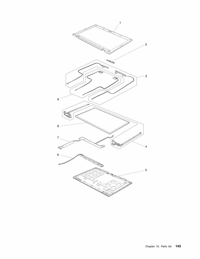
1
3
4
5
6
7
8
9
2
Chapter 10. Parts list 143
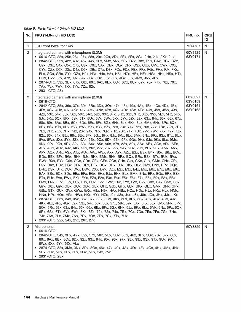
Table 9. Parts list—14.0-inch HD LCD
No. FRU (14.0-inch HD LCD) FRU no. CRUID
1 LCD front bezel for 14W 75Y4787 N
2 Integrated camera with microphone (0.3M)• 0616-CTO, 22x, 25x, 26x, 27x, 28x, 29x, 2Cx, 2Dx, 2Ex, 2Fx, 2Gx, 2Hx, 2Jx, 2Kx, 2Lx• 2842-CTO, 22x, 42x, 43x, 45x, 44x, 5Lx, 5Mx, 5Nx, 5Px, B7x, B8x, B9x, BAx, BBx, BZx,
C2x, C3x, C4x, C5x, C7x, C8x, C9x, CAx, CBx, CQx, CRx, CSx, CUx, CVx, CWx, CXx,CYx, CZx, D2x, D3x, D4x, D5x, D6x, D7x, D8x, FCx, FDx, FEx, FFx, FGx, FHx, FJx, FKx,FLx, GQx, GRx, GYx, GZx, H2x, H3x, H4x, H5x, H6x, H7x, HEx, HFx, HGx, HHx, HSx, HTx,HUx, HVx, J5x, J7x, J9x, JAx, JBx, JDx, JEx, JFx, JGx, JLx, JMx, JNx, JPx
• 2874-CTO, 39x, 3Bx, 67x, 68x, 69x, 6Ax, 6Bx, 6Cx, 6Dx, 6Ux, 6Yx, 76x, 77x, 78x, 79x,7Ax, 7Vx, 7Wx, 7Xx, 7Yx, 7Zx, 82x
• 2931-CTO, 23x
60Y332563Y0171
N
2 Integrated camera with microphone (2.0M)• 0616-CTO• 2842-CTO, 35x, 36x, 37x, 39x, 3Bx, 3Dx, 3Qx, 47x, 48x, 49x, 4Ax, 4Bx, 4Cx, 4Dx, 4Ex,
4Fx, 4Gx, 4Hx, 4Jx, 4Kx, 4Lx, 4Mx, 4Nx, 4Px, 4Qx, 4Rx, 4Sx, 4Tx, 4Ux, 4Vx, 4Wx, 4Xx,4Zx, 53x, 54x, 55x, 56x, 59x, 5Ax, 5Bx, 33x, 3Fx, 3Hx, 3Sx, 3Tx, 3Ux, 3Vx, 5Ex, 5Fx, 5Hx,5Jx, 5Kx, 5Qx, 5Rx, 5Sx, 5Tx, 5Ux, 5Vx, 5Wx, 5Xx, 5Yx, 5Zx, 62x, 63x, 64x, 65x, 66x, 67x,68x, 69x, 6Ax, 6Bx, 6Cx, 6Dx, 6Ex, 6Fx, 6Gx, 6Hx, 6Jx, 6Kx, 6Lx, 6Mx, 6Nx, 6Px, 6Qx,6Rx, 6Sx, 6Tx, 6Ux, 6Vx, 6Wx, 6Xx, 6Yx, 6Zx, 72x, 73x, 74x, 75x, 76x, 77x, 7Bx, 7Cx, 7Dx,7Ex, 7Fx, 7Gx, 7Hx, 7Jx, 23x, 24x, 7Px, 7Qx, 7Rx, 7Sx, 7Tx, 7Ux, 7Vx, 7Wx, 7Xx, 7Yx, 7Zx,82x, 83x, 84x, 85x, 86x, 8Ex, 8Fx, 8Gx, 8Hx, 8Jx, 8Kx, 8Lx, 8Mx, 8Nx, 8Rx, 8Sx, 8Tx, 8Ux,8Vx, 8Wx, 8Xx, 8Yx, 8Zx, 9Ax, 9Bx, 9Cx, 9Dx, 9Ex, 9Fx, 9Gx, 9Hx, 9Jx, 9Kx, 9Lx, 9Mx,9Nx, 9Px, 9Qx, 9Rx, A2x, A3x, A4x, A5x, A6x, A7x, A8x, A9x, AAx, ABx, ACx, ADx, AEx,AFx, AGx, AHx, AJx, AKx, 25x, 26x, 27x, 28x, 29x, 2Ax, 2Bx, 2Cx, 2Dx, 2Ex, AMx, ANx,APx, AQx, ARx, ASx, ATx, AUx, AVx, AWx, AXx, AYx, AZx, B2x, B3x, B4x, B5x, B6x, BCx,BDx, BEx, BFx, BGx, BHx, BJx, BKx, BMx, BNx, BPx, BQx, BRx, BSx, BTx, BUx, BVx,BWx, BXx, BYx, C6x, CCx, CDx, CEx, CFx, CGx, CHx, CJx, CKx, CLx, CMx, CNx, CPx,D9x, DAx, DBx, DCx, DDx, DEx, DFx, DGx, DHx, DJx, DKx, DLx, DMx, DNx, DPx, DQx,DRx, DSx, DTx, DUx, DVx, DWx, DXx, DYx, DZx, E2x, E3x, E4x, E5x, E6x, E7x, E8x, E9x,EAx, EBx, ECx, EDx, EEx, EFx, EGx, EHx, EJx, EKx, ELx, EMx, ENx, EPx, EQx, ERx, ESx,ETx, EUx, EVx, EWx, EXx, EYx, EZx, F2x, F3x, F4x, F5x, F6x, F7x, F8x, F9x, FAx, FBx,FMx, FNx, FPx, FQx, FSx, FTx, FUx, FVx, FWx, FXx, FYx, FZx, G2x, G3x, G4x, G5x, G6x,G7x, G8x, G9x, GBx, GCx, GDx, GEx, GFx, GGx, GHx, GJx, GKx, GLx, GMx, GNx, GPx,GSx, GTx, GUx, GVx, GWx, GXx, H8x, H9x, HAx, HBx, HCx, HDx, HJx, HKx, HLx, HMx,HNx, HPx, HQx, HRx, HWx, HXx, HYx, HZx, J2x, J3x, J4x, J6x, J8x, JCx, JHx, JJx, JKx
• 2874-CTO, 33x, 34x, 35x, 36x, 37x, 3Ex, 3Gx, 3Kx, 3Lx, 3Rx, 3Sx, 48x, 4Bx, 4Cx, 4Jx,4Kx, 4Lx, 4Px, 4Qx, 52x, 53x, 54x, 55x, 56x, 57x, 58x, 59x, 5Ax, 5Kx, 5Lx, 5Mx, 5Nx, 5Px,5Qx, 5Rx, 62x, 63x, 64x, 65x, 66x, 6Ex, 6Fx, 6Gx, 6Hx, 6Jx, 6Kx, 6Lx, 6Mx, 6Nx, 6Px, 6Qx,6Rx, 6Sx, 6Tx, 6Vx, 6Wx, 6Xx, 6Zx, 72x, 73x, 74x, 7Bx, 7Cx, 7Dx, 7Ex, 7Fx, 7Gx, 7Hx,7Jx, 7Kx, 7Lx, 7Mx, 7Nx, 7Px, 7Qx, 7Rx, 7Sx, 7Tx, 7Ux
• 2931-CTO, 22x, 24x, 25x, 26x, 27x
60Y332763Y015963Y016163Y0163
N
2 Microphone• 0616-CTO• 2842-CTO, 34x, 3Px, 4Yx, 52x, 57x, 58x, 5Cx, 5Dx, 3Gx, 46x, 3Rx, 5Gx, 78x, 87x, 88x,
89x, 8Ax, 8Bx, 8Cx, 8Dx, 92x, 93x, 94x, 95x, 96x, 97x, 98x, 99x, 9Sx, 9Tx, 9Ux, 9Vx,9Wx, 9Xx, 9Yx, 9Zx, ALx
• 2874-CTO, 32x, 3Mx, 3Nx, 3Px, 3Qx, 46x, 47x, 49x, 4Ax, 4Dx, 4Fx, 4Gx, 4Hx, 4Mx, 4Nx,5Bx, 5Cx, 5Dx, 5Ex, 5Fx, 5Gx, 5Hx, 5Jx, 75x
• 2931-CTO, 2Ex
60Y3329 N
144 Hardware Maintenance Manual
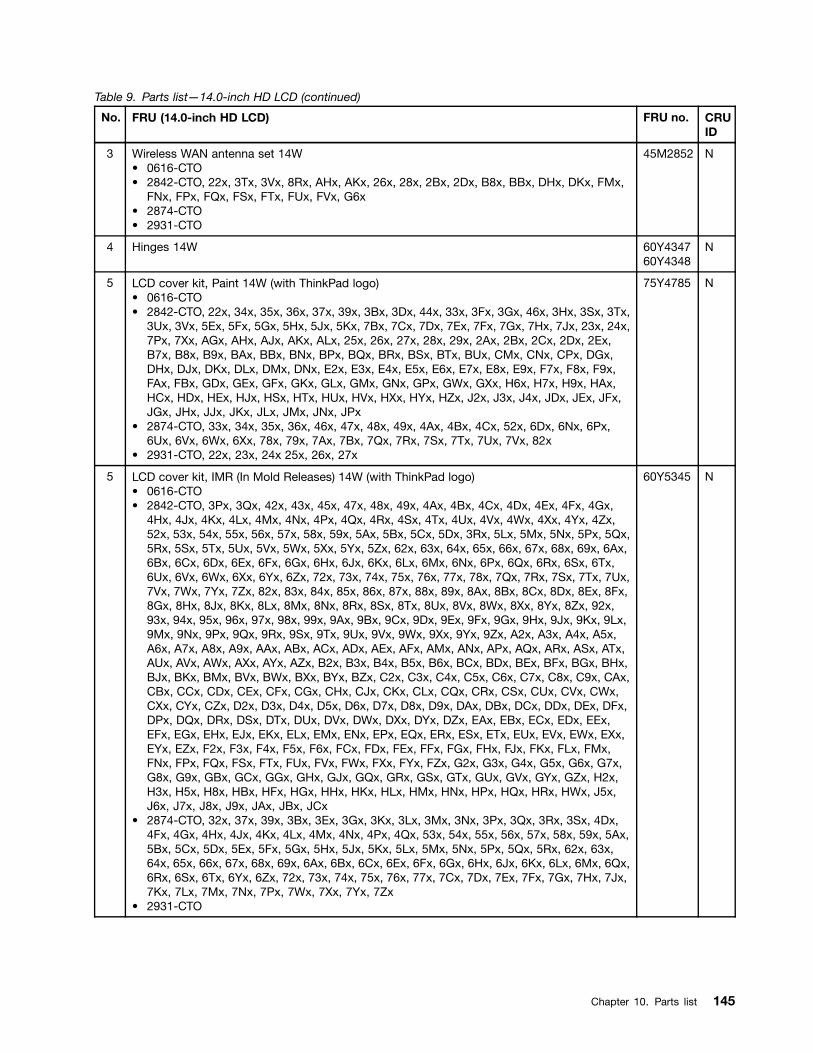
Table 9. Parts list—14.0-inch HD LCD (continued)
No. FRU (14.0-inch HD LCD) FRU no. CRUID
3 Wireless WAN antenna set 14W• 0616-CTO• 2842-CTO, 22x, 3Tx, 3Vx, 8Rx, AHx, AKx, 26x, 28x, 2Bx, 2Dx, B8x, BBx, DHx, DKx, FMx,
FNx, FPx, FQx, FSx, FTx, FUx, FVx, G6x• 2874-CTO• 2931-CTO
45M2852 N
4 Hinges 14W 60Y434760Y4348
N
5 LCD cover kit, Paint 14W (with ThinkPad logo)• 0616-CTO• 2842-CTO, 22x, 34x, 35x, 36x, 37x, 39x, 3Bx, 3Dx, 44x, 33x, 3Fx, 3Gx, 46x, 3Hx, 3Sx, 3Tx,
3Ux, 3Vx, 5Ex, 5Fx, 5Gx, 5Hx, 5Jx, 5Kx, 7Bx, 7Cx, 7Dx, 7Ex, 7Fx, 7Gx, 7Hx, 7Jx, 23x, 24x,7Px, 7Xx, AGx, AHx, AJx, AKx, ALx, 25x, 26x, 27x, 28x, 29x, 2Ax, 2Bx, 2Cx, 2Dx, 2Ex,B7x, B8x, B9x, BAx, BBx, BNx, BPx, BQx, BRx, BSx, BTx, BUx, CMx, CNx, CPx, DGx,DHx, DJx, DKx, DLx, DMx, DNx, E2x, E3x, E4x, E5x, E6x, E7x, E8x, E9x, F7x, F8x, F9x,FAx, FBx, GDx, GEx, GFx, GKx, GLx, GMx, GNx, GPx, GWx, GXx, H6x, H7x, H9x, HAx,HCx, HDx, HEx, HJx, HSx, HTx, HUx, HVx, HXx, HYx, HZx, J2x, J3x, J4x, JDx, JEx, JFx,JGx, JHx, JJx, JKx, JLx, JMx, JNx, JPx
• 2874-CTO, 33x, 34x, 35x, 36x, 46x, 47x, 48x, 49x, 4Ax, 4Bx, 4Cx, 52x, 6Dx, 6Nx, 6Px,6Ux, 6Vx, 6Wx, 6Xx, 78x, 79x, 7Ax, 7Bx, 7Qx, 7Rx, 7Sx, 7Tx, 7Ux, 7Vx, 82x
• 2931-CTO, 22x, 23x, 24x 25x, 26x, 27x
75Y4785 N
5 LCD cover kit, IMR (In Mold Releases) 14W (with ThinkPad logo)• 0616-CTO• 2842-CTO, 3Px, 3Qx, 42x, 43x, 45x, 47x, 48x, 49x, 4Ax, 4Bx, 4Cx, 4Dx, 4Ex, 4Fx, 4Gx,
4Hx, 4Jx, 4Kx, 4Lx, 4Mx, 4Nx, 4Px, 4Qx, 4Rx, 4Sx, 4Tx, 4Ux, 4Vx, 4Wx, 4Xx, 4Yx, 4Zx,52x, 53x, 54x, 55x, 56x, 57x, 58x, 59x, 5Ax, 5Bx, 5Cx, 5Dx, 3Rx, 5Lx, 5Mx, 5Nx, 5Px, 5Qx,5Rx, 5Sx, 5Tx, 5Ux, 5Vx, 5Wx, 5Xx, 5Yx, 5Zx, 62x, 63x, 64x, 65x, 66x, 67x, 68x, 69x, 6Ax,6Bx, 6Cx, 6Dx, 6Ex, 6Fx, 6Gx, 6Hx, 6Jx, 6Kx, 6Lx, 6Mx, 6Nx, 6Px, 6Qx, 6Rx, 6Sx, 6Tx,6Ux, 6Vx, 6Wx, 6Xx, 6Yx, 6Zx, 72x, 73x, 74x, 75x, 76x, 77x, 78x, 7Qx, 7Rx, 7Sx, 7Tx, 7Ux,7Vx, 7Wx, 7Yx, 7Zx, 82x, 83x, 84x, 85x, 86x, 87x, 88x, 89x, 8Ax, 8Bx, 8Cx, 8Dx, 8Ex, 8Fx,8Gx, 8Hx, 8Jx, 8Kx, 8Lx, 8Mx, 8Nx, 8Rx, 8Sx, 8Tx, 8Ux, 8Vx, 8Wx, 8Xx, 8Yx, 8Zx, 92x,93x, 94x, 95x, 96x, 97x, 98x, 99x, 9Ax, 9Bx, 9Cx, 9Dx, 9Ex, 9Fx, 9Gx, 9Hx, 9Jx, 9Kx, 9Lx,9Mx, 9Nx, 9Px, 9Qx, 9Rx, 9Sx, 9Tx, 9Ux, 9Vx, 9Wx, 9Xx, 9Yx, 9Zx, A2x, A3x, A4x, A5x,A6x, A7x, A8x, A9x, AAx, ABx, ACx, ADx, AEx, AFx, AMx, ANx, APx, AQx, ARx, ASx, ATx,AUx, AVx, AWx, AXx, AYx, AZx, B2x, B3x, B4x, B5x, B6x, BCx, BDx, BEx, BFx, BGx, BHx,BJx, BKx, BMx, BVx, BWx, BXx, BYx, BZx, C2x, C3x, C4x, C5x, C6x, C7x, C8x, C9x, CAx,CBx, CCx, CDx, CEx, CFx, CGx, CHx, CJx, CKx, CLx, CQx, CRx, CSx, CUx, CVx, CWx,CXx, CYx, CZx, D2x, D3x, D4x, D5x, D6x, D7x, D8x, D9x, DAx, DBx, DCx, DDx, DEx, DFx,DPx, DQx, DRx, DSx, DTx, DUx, DVx, DWx, DXx, DYx, DZx, EAx, EBx, ECx, EDx, EEx,EFx, EGx, EHx, EJx, EKx, ELx, EMx, ENx, EPx, EQx, ERx, ESx, ETx, EUx, EVx, EWx, EXx,EYx, EZx, F2x, F3x, F4x, F5x, F6x, FCx, FDx, FEx, FFx, FGx, FHx, FJx, FKx, FLx, FMx,FNx, FPx, FQx, FSx, FTx, FUx, FVx, FWx, FXx, FYx, FZx, G2x, G3x, G4x, G5x, G6x, G7x,G8x, G9x, GBx, GCx, GGx, GHx, GJx, GQx, GRx, GSx, GTx, GUx, GVx, GYx, GZx, H2x,H3x, H5x, H8x, HBx, HFx, HGx, HHx, HKx, HLx, HMx, HNx, HPx, HQx, HRx, HWx, J5x,J6x, J7x, J8x, J9x, JAx, JBx, JCx
• 2874-CTO, 32x, 37x, 39x, 3Bx, 3Ex, 3Gx, 3Kx, 3Lx, 3Mx, 3Nx, 3Px, 3Qx, 3Rx, 3Sx, 4Dx,4Fx, 4Gx, 4Hx, 4Jx, 4Kx, 4Lx, 4Mx, 4Nx, 4Px, 4Qx, 53x, 54x, 55x, 56x, 57x, 58x, 59x, 5Ax,5Bx, 5Cx, 5Dx, 5Ex, 5Fx, 5Gx, 5Hx, 5Jx, 5Kx, 5Lx, 5Mx, 5Nx, 5Px, 5Qx, 5Rx, 62x, 63x,64x, 65x, 66x, 67x, 68x, 69x, 6Ax, 6Bx, 6Cx, 6Ex, 6Fx, 6Gx, 6Hx, 6Jx, 6Kx, 6Lx, 6Mx, 6Qx,6Rx, 6Sx, 6Tx, 6Yx, 6Zx, 72x, 73x, 74x, 75x, 76x, 77x, 7Cx, 7Dx, 7Ex, 7Fx, 7Gx, 7Hx, 7Jx,7Kx, 7Lx, 7Mx, 7Nx, 7Px, 7Wx, 7Xx, 7Yx, 7Zx
• 2931-CTO
60Y5345 N
Chapter 10. Parts list 145
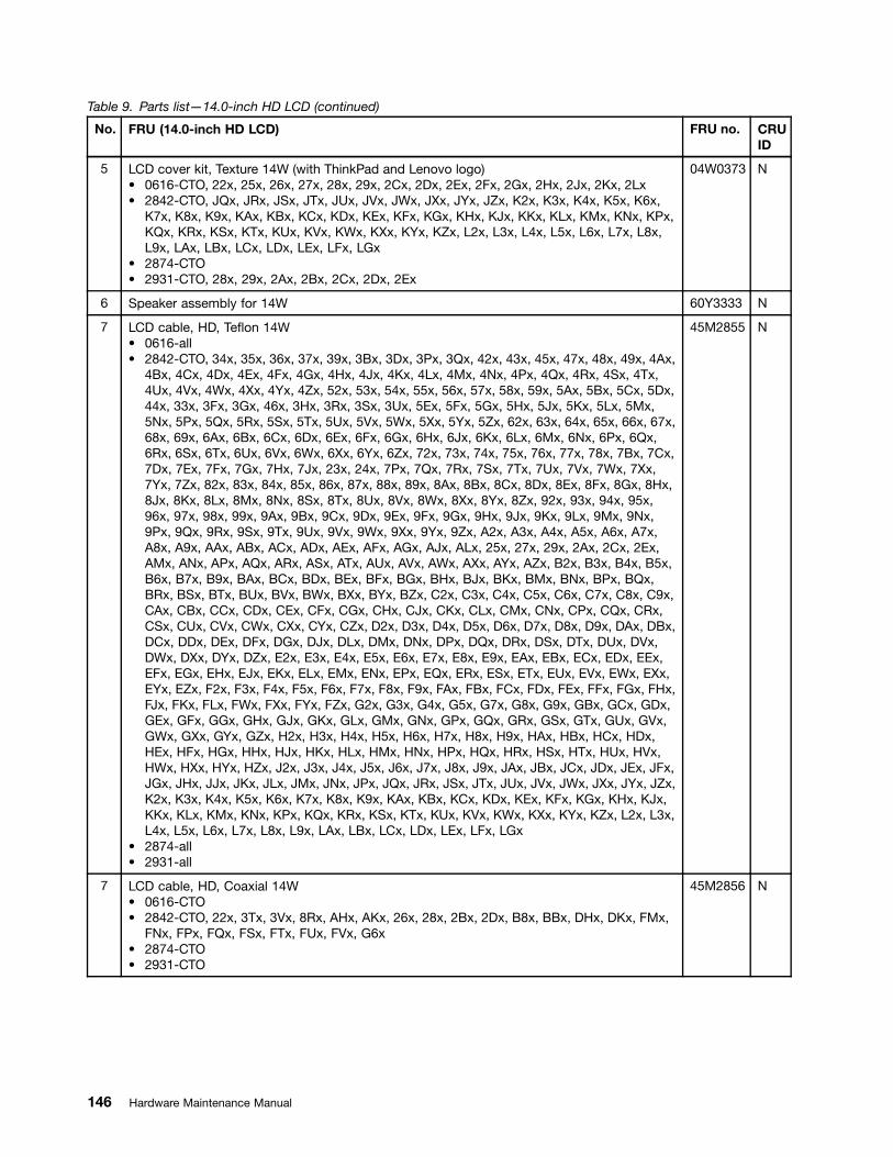
Table 9. Parts list—14.0-inch HD LCD (continued)
No. FRU (14.0-inch HD LCD) FRU no. CRUID
5 LCD cover kit, Texture 14W (with ThinkPad and Lenovo logo)• 0616-CTO, 22x, 25x, 26x, 27x, 28x, 29x, 2Cx, 2Dx, 2Ex, 2Fx, 2Gx, 2Hx, 2Jx, 2Kx, 2Lx• 2842-CTO, JQx, JRx, JSx, JTx, JUx, JVx, JWx, JXx, JYx, JZx, K2x, K3x, K4x, K5x, K6x,
K7x, K8x, K9x, KAx, KBx, KCx, KDx, KEx, KFx, KGx, KHx, KJx, KKx, KLx, KMx, KNx, KPx,KQx, KRx, KSx, KTx, KUx, KVx, KWx, KXx, KYx, KZx, L2x, L3x, L4x, L5x, L6x, L7x, L8x,L9x, LAx, LBx, LCx, LDx, LEx, LFx, LGx
• 2874-CTO• 2931-CTO, 28x, 29x, 2Ax, 2Bx, 2Cx, 2Dx, 2Ex
04W0373 N
6 Speaker assembly for 14W 60Y3333 N
7 LCD cable, HD, Teflon 14W• 0616-all• 2842-CTO, 34x, 35x, 36x, 37x, 39x, 3Bx, 3Dx, 3Px, 3Qx, 42x, 43x, 45x, 47x, 48x, 49x, 4Ax,
4Bx, 4Cx, 4Dx, 4Ex, 4Fx, 4Gx, 4Hx, 4Jx, 4Kx, 4Lx, 4Mx, 4Nx, 4Px, 4Qx, 4Rx, 4Sx, 4Tx,4Ux, 4Vx, 4Wx, 4Xx, 4Yx, 4Zx, 52x, 53x, 54x, 55x, 56x, 57x, 58x, 59x, 5Ax, 5Bx, 5Cx, 5Dx,44x, 33x, 3Fx, 3Gx, 46x, 3Hx, 3Rx, 3Sx, 3Ux, 5Ex, 5Fx, 5Gx, 5Hx, 5Jx, 5Kx, 5Lx, 5Mx,5Nx, 5Px, 5Qx, 5Rx, 5Sx, 5Tx, 5Ux, 5Vx, 5Wx, 5Xx, 5Yx, 5Zx, 62x, 63x, 64x, 65x, 66x, 67x,68x, 69x, 6Ax, 6Bx, 6Cx, 6Dx, 6Ex, 6Fx, 6Gx, 6Hx, 6Jx, 6Kx, 6Lx, 6Mx, 6Nx, 6Px, 6Qx,6Rx, 6Sx, 6Tx, 6Ux, 6Vx, 6Wx, 6Xx, 6Yx, 6Zx, 72x, 73x, 74x, 75x, 76x, 77x, 78x, 7Bx, 7Cx,7Dx, 7Ex, 7Fx, 7Gx, 7Hx, 7Jx, 23x, 24x, 7Px, 7Qx, 7Rx, 7Sx, 7Tx, 7Ux, 7Vx, 7Wx, 7Xx,7Yx, 7Zx, 82x, 83x, 84x, 85x, 86x, 87x, 88x, 89x, 8Ax, 8Bx, 8Cx, 8Dx, 8Ex, 8Fx, 8Gx, 8Hx,8Jx, 8Kx, 8Lx, 8Mx, 8Nx, 8Sx, 8Tx, 8Ux, 8Vx, 8Wx, 8Xx, 8Yx, 8Zx, 92x, 93x, 94x, 95x,96x, 97x, 98x, 99x, 9Ax, 9Bx, 9Cx, 9Dx, 9Ex, 9Fx, 9Gx, 9Hx, 9Jx, 9Kx, 9Lx, 9Mx, 9Nx,9Px, 9Qx, 9Rx, 9Sx, 9Tx, 9Ux, 9Vx, 9Wx, 9Xx, 9Yx, 9Zx, A2x, A3x, A4x, A5x, A6x, A7x,A8x, A9x, AAx, ABx, ACx, ADx, AEx, AFx, AGx, AJx, ALx, 25x, 27x, 29x, 2Ax, 2Cx, 2Ex,AMx, ANx, APx, AQx, ARx, ASx, ATx, AUx, AVx, AWx, AXx, AYx, AZx, B2x, B3x, B4x, B5x,B6x, B7x, B9x, BAx, BCx, BDx, BEx, BFx, BGx, BHx, BJx, BKx, BMx, BNx, BPx, BQx,BRx, BSx, BTx, BUx, BVx, BWx, BXx, BYx, BZx, C2x, C3x, C4x, C5x, C6x, C7x, C8x, C9x,CAx, CBx, CCx, CDx, CEx, CFx, CGx, CHx, CJx, CKx, CLx, CMx, CNx, CPx, CQx, CRx,CSx, CUx, CVx, CWx, CXx, CYx, CZx, D2x, D3x, D4x, D5x, D6x, D7x, D8x, D9x, DAx, DBx,DCx, DDx, DEx, DFx, DGx, DJx, DLx, DMx, DNx, DPx, DQx, DRx, DSx, DTx, DUx, DVx,DWx, DXx, DYx, DZx, E2x, E3x, E4x, E5x, E6x, E7x, E8x, E9x, EAx, EBx, ECx, EDx, EEx,EFx, EGx, EHx, EJx, EKx, ELx, EMx, ENx, EPx, EQx, ERx, ESx, ETx, EUx, EVx, EWx, EXx,EYx, EZx, F2x, F3x, F4x, F5x, F6x, F7x, F8x, F9x, FAx, FBx, FCx, FDx, FEx, FFx, FGx, FHx,FJx, FKx, FLx, FWx, FXx, FYx, FZx, G2x, G3x, G4x, G5x, G7x, G8x, G9x, GBx, GCx, GDx,GEx, GFx, GGx, GHx, GJx, GKx, GLx, GMx, GNx, GPx, GQx, GRx, GSx, GTx, GUx, GVx,GWx, GXx, GYx, GZx, H2x, H3x, H4x, H5x, H6x, H7x, H8x, H9x, HAx, HBx, HCx, HDx,HEx, HFx, HGx, HHx, HJx, HKx, HLx, HMx, HNx, HPx, HQx, HRx, HSx, HTx, HUx, HVx,HWx, HXx, HYx, HZx, J2x, J3x, J4x, J5x, J6x, J7x, J8x, J9x, JAx, JBx, JCx, JDx, JEx, JFx,JGx, JHx, JJx, JKx, JLx, JMx, JNx, JPx, JQx, JRx, JSx, JTx, JUx, JVx, JWx, JXx, JYx, JZx,K2x, K3x, K4x, K5x, K6x, K7x, K8x, K9x, KAx, KBx, KCx, KDx, KEx, KFx, KGx, KHx, KJx,KKx, KLx, KMx, KNx, KPx, KQx, KRx, KSx, KTx, KUx, KVx, KWx, KXx, KYx, KZx, L2x, L3x,L4x, L5x, L6x, L7x, L8x, L9x, LAx, LBx, LCx, LDx, LEx, LFx, LGx
• 2874-all• 2931-all
45M2855 N
7 LCD cable, HD, Coaxial 14W• 0616-CTO• 2842-CTO, 22x, 3Tx, 3Vx, 8Rx, AHx, AKx, 26x, 28x, 2Bx, 2Dx, B8x, BBx, DHx, DKx, FMx,
FNx, FPx, FQx, FSx, FTx, FUx, FVx, G6x• 2874-CTO• 2931-CTO
45M2856 N
146 Hardware Maintenance Manual

Table 9. Parts list—14.0-inch HD LCD (continued)
No. FRU (14.0-inch HD LCD) FRU no. CRUID
8 LCD module, 14.0-inch HD glare• 0616-CTO• 2842-all• 2874-all• 2931-CTO
42T067042T065842T068442T064827R243327R246393P549927R249793P570793P572793P573593P572304W0412
N
8 LCD module, 14.0-inch HD anti-glare• 0616-all• 2842-CTO• 2874-CTO• 2931-all
42T066842T065642T068242T064627R243193P549727R246593P570593P572593P573393P572104W0411
N
9 Wireless LAN antenna set 14W 45M2851 N
Table 10. Parts list—15.6-inch HD LCD
No. FRU (15.6-inch HD LCD) FRU no. CRUID
1 LCD front bezel for 15W 75Y4788 N
2 Integrated camera with microphone (0.3M)• 2847-CTO, 22x, 44x, 4Hx, 5Cx, 5Dx, 84x, 85x, 86x, 87x, 88x, 2Zx, 7Kx, 7Lx, 7Mx, 7Nx,
6Nx, 6Px, 6Qx, 6Rx, 6Sx, 6Tx, A9x, 7Px, 7Qx, 7Rx, 7Sx, ANx, APx, 7Ux, AVx, B4x, B5x,B6x, B7x, BBx, C3x, C4x, C5x, C6x, C7x, CAx, CBx, CGx, CHx, CJx, CKx
• 2873-CTO• 2875-CTO, 28x, 2Ax, 2Bx, 2Cx, 2Wx, 2Xx, 4Bx, 4Cx, 4Jx, 4Kx, 4Sx, 4Tx, 4Ux, 4Yx, 52x,
53x, 54x, 55x, 56x, 5Bx, R3x, R4x, R5x, RDx, RFx, RGx, RHx, RJx• 5072-CTO
60Y332563Y0171
N
2 Integrated camera with microphone (2.0M)• 2847-CTO, 23x, 34x, 35x, 36x, 37x, 38x, 39x, 3Dx, 3Ex, 42x, 43x, 45x, 46x, 47x, 48x, 49x,
4Ax, 4Bx, 4Cx, 4Dx, 4Ex, 4Fx, 4Gx, 3Kx, 3Mx, 3Nx, 3Px, 3Qx, 54x, 55x, 56x, 57x, 58x,59x, 5Ax, 5Bx, 5Ex, 5Fx, 5Gx, 5Hx, 5Jx, 5Kx, 5Lx, 5Mx, 5Nx, 5Px, 5Qx, 5Rx, 5Sx, 5Tx,5Ux, 5Vx, 5Wx, 5Xx, 5Yx, 5Zx, 62x, 63x, 64x, 65x, 66x, 67x, 4Nx, 4Px, 4Qx, 4Rx, 4Tx,4Ux, 4Vx, 4Wx, 24x, 25x, 26x, 27x, 28x, 29x, 2Ax, 2Bx, 2Cx, 2Dx, 2Ex, 2Fx, 2Gx, 2Hx,2Lx, 2Mx, 2Nx, 2Px, 2Qx, 2Rx, 2Sx, 2Tx, 2Ux, 2Vx, 72x, 73x, 74x, 75x, 76x, 77x, 78x, 79x,7Ax, 7Bx, 7Cx, 7Dx, 7Ex, 7Jx, R2x, R3x, R4x, R5x, R6x, R7x, R8x, R9x, RAx, RBx, RMx,RNx, RPx, RQx, RRx, RSx, RTx, RUx, RVx, RWx, RXx, 68x, 69x, 6Ax, 6Bx, 6Cx, 6Dx, 6Ex,6Fx, 6Gx, 6Hx, Q2x, Q3x, Q4x, Q5x, Q6x, Q7x, Q8x, Q9x, QAx, QBx, QCx, QDx, QEx,QFx, QHx, QJx, 82x, 83x, 89x, 8Ax, 8Bx, 8Cx, 8Dx, 8Ex, 8Fx, 8Gx, 8Hx, 8Jx, 8Kx, 8Lx,8Mx, 8Nx, 8Px, 8Qx, 8Rx, 8Sx, 8Tx, 8Ux, 8Vx, 8Wx, 8Xx, 8Yx, 8Zx, 7Zx, 7Wx, 7Xx, 7Yx,6Jx, 6Kx, 6Lx, 6Mx, 2Wx, 2Xx, 2Yx, 6Ux, 6Vx, 6Wx, 6Xx, 6Yx, 6Zx, 92x, 93x, 94x, 95x,96x, 97x, 98x, 99x, 9Ax, 9Bx, 9Cx, 9Dx, 9Ex, 9Gx, 9Hx, 9Jx, 9Kx, 9Lx, 9Nx, 9Px, 9Qx,
60Y332763Y015963Y016163Y0163
N
Chapter 10. Parts list 147
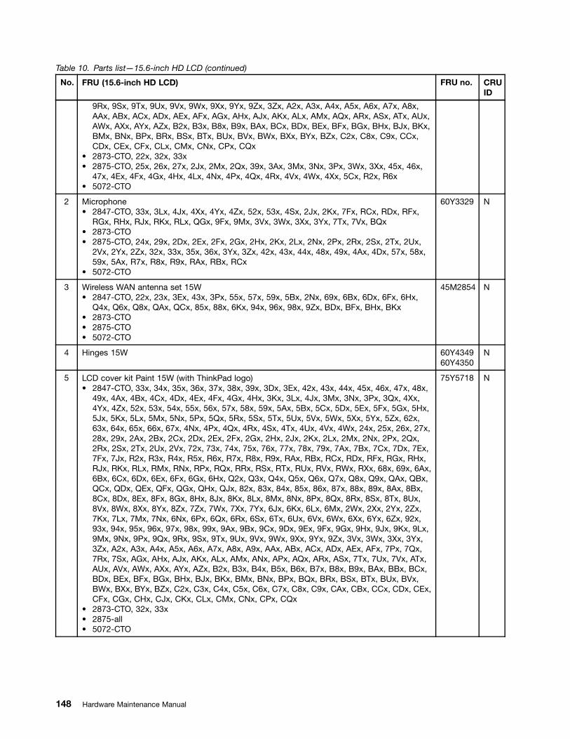
Table 10. Parts list—15.6-inch HD LCD (continued)
No. FRU (15.6-inch HD LCD) FRU no. CRUID
9Rx, 9Sx, 9Tx, 9Ux, 9Vx, 9Wx, 9Xx, 9Yx, 9Zx, 3Zx, A2x, A3x, A4x, A5x, A6x, A7x, A8x,AAx, ABx, ACx, ADx, AEx, AFx, AGx, AHx, AJx, AKx, ALx, AMx, AQx, ARx, ASx, ATx, AUx,AWx, AXx, AYx, AZx, B2x, B3x, B8x, B9x, BAx, BCx, BDx, BEx, BFx, BGx, BHx, BJx, BKx,BMx, BNx, BPx, BRx, BSx, BTx, BUx, BVx, BWx, BXx, BYx, BZx, C2x, C8x, C9x, CCx,CDx, CEx, CFx, CLx, CMx, CNx, CPx, CQx
• 2873-CTO, 22x, 32x, 33x• 2875-CTO, 25x, 26x, 27x, 2Jx, 2Mx, 2Qx, 39x, 3Ax, 3Mx, 3Nx, 3Px, 3Wx, 3Xx, 45x, 46x,
47x, 4Ex, 4Fx, 4Gx, 4Hx, 4Lx, 4Nx, 4Px, 4Qx, 4Rx, 4Vx, 4Wx, 4Xx, 5Cx, R2x, R6x• 5072-CTO
2 Microphone• 2847-CTO, 33x, 3Lx, 4Jx, 4Xx, 4Yx, 4Zx, 52x, 53x, 4Sx, 2Jx, 2Kx, 7Fx, RCx, RDx, RFx,
RGx, RHx, RJx, RKx, RLx, QGx, 9Fx, 9Mx, 3Vx, 3Wx, 3Xx, 3Yx, 7Tx, 7Vx, BQx• 2873-CTO• 2875-CTO, 24x, 29x, 2Dx, 2Ex, 2Fx, 2Gx, 2Hx, 2Kx, 2Lx, 2Nx, 2Px, 2Rx, 2Sx, 2Tx, 2Ux,
2Vx, 2Yx, 2Zx, 32x, 33x, 35x, 36x, 3Yx, 3Zx, 42x, 43x, 44x, 48x, 49x, 4Ax, 4Dx, 57x, 58x,59x, 5Ax, R7x, R8x, R9x, RAx, RBx, RCx
• 5072-CTO
60Y3329 N
3 Wireless WAN antenna set 15W• 2847-CTO, 22x, 23x, 3Ex, 43x, 3Px, 55x, 57x, 59x, 5Bx, 2Nx, 69x, 6Bx, 6Dx, 6Fx, 6Hx,
Q4x, Q6x, Q8x, QAx, QCx, 85x, 88x, 6Kx, 94x, 96x, 98x, 9Zx, BDx, BFx, BHx, BKx• 2873-CTO• 2875-CTO• 5072-CTO
45M2854 N
4 Hinges 15W 60Y434960Y4350
N
5 LCD cover kit Paint 15W (with ThinkPad logo)• 2847-CTO, 33x, 34x, 35x, 36x, 37x, 38x, 39x, 3Dx, 3Ex, 42x, 43x, 44x, 45x, 46x, 47x, 48x,
49x, 4Ax, 4Bx, 4Cx, 4Dx, 4Ex, 4Fx, 4Gx, 4Hx, 3Kx, 3Lx, 4Jx, 3Mx, 3Nx, 3Px, 3Qx, 4Xx,4Yx, 4Zx, 52x, 53x, 54x, 55x, 56x, 57x, 58x, 59x, 5Ax, 5Bx, 5Cx, 5Dx, 5Ex, 5Fx, 5Gx, 5Hx,5Jx, 5Kx, 5Lx, 5Mx, 5Nx, 5Px, 5Qx, 5Rx, 5Sx, 5Tx, 5Ux, 5Vx, 5Wx, 5Xx, 5Yx, 5Zx, 62x,63x, 64x, 65x, 66x, 67x, 4Nx, 4Px, 4Qx, 4Rx, 4Sx, 4Tx, 4Ux, 4Vx, 4Wx, 24x, 25x, 26x, 27x,28x, 29x, 2Ax, 2Bx, 2Cx, 2Dx, 2Ex, 2Fx, 2Gx, 2Hx, 2Jx, 2Kx, 2Lx, 2Mx, 2Nx, 2Px, 2Qx,2Rx, 2Sx, 2Tx, 2Ux, 2Vx, 72x, 73x, 74x, 75x, 76x, 77x, 78x, 79x, 7Ax, 7Bx, 7Cx, 7Dx, 7Ex,7Fx, 7Jx, R2x, R3x, R4x, R5x, R6x, R7x, R8x, R9x, RAx, RBx, RCx, RDx, RFx, RGx, RHx,RJx, RKx, RLx, RMx, RNx, RPx, RQx, RRx, RSx, RTx, RUx, RVx, RWx, RXx, 68x, 69x, 6Ax,6Bx, 6Cx, 6Dx, 6Ex, 6Fx, 6Gx, 6Hx, Q2x, Q3x, Q4x, Q5x, Q6x, Q7x, Q8x, Q9x, QAx, QBx,QCx, QDx, QEx, QFx, QGx, QHx, QJx, 82x, 83x, 84x, 85x, 86x, 87x, 88x, 89x, 8Ax, 8Bx,8Cx, 8Dx, 8Ex, 8Fx, 8Gx, 8Hx, 8Jx, 8Kx, 8Lx, 8Mx, 8Nx, 8Px, 8Qx, 8Rx, 8Sx, 8Tx, 8Ux,8Vx, 8Wx, 8Xx, 8Yx, 8Zx, 7Zx, 7Wx, 7Xx, 7Yx, 6Jx, 6Kx, 6Lx, 6Mx, 2Wx, 2Xx, 2Yx, 2Zx,7Kx, 7Lx, 7Mx, 7Nx, 6Nx, 6Px, 6Qx, 6Rx, 6Sx, 6Tx, 6Ux, 6Vx, 6Wx, 6Xx, 6Yx, 6Zx, 92x,93x, 94x, 95x, 96x, 97x, 98x, 99x, 9Ax, 9Bx, 9Cx, 9Dx, 9Ex, 9Fx, 9Gx, 9Hx, 9Jx, 9Kx, 9Lx,9Mx, 9Nx, 9Px, 9Qx, 9Rx, 9Sx, 9Tx, 9Ux, 9Vx, 9Wx, 9Xx, 9Yx, 9Zx, 3Vx, 3Wx, 3Xx, 3Yx,3Zx, A2x, A3x, A4x, A5x, A6x, A7x, A8x, A9x, AAx, ABx, ACx, ADx, AEx, AFx, 7Px, 7Qx,7Rx, 7Sx, AGx, AHx, AJx, AKx, ALx, AMx, ANx, APx, AQx, ARx, ASx, 7Tx, 7Ux, 7Vx, ATx,AUx, AVx, AWx, AXx, AYx, AZx, B2x, B3x, B4x, B5x, B6x, B7x, B8x, B9x, BAx, BBx, BCx,BDx, BEx, BFx, BGx, BHx, BJx, BKx, BMx, BNx, BPx, BQx, BRx, BSx, BTx, BUx, BVx,BWx, BXx, BYx, BZx, C2x, C3x, C4x, C5x, C6x, C7x, C8x, C9x, CAx, CBx, CCx, CDx, CEx,CFx, CGx, CHx, CJx, CKx, CLx, CMx, CNx, CPx, CQx
• 2873-CTO, 32x, 33x• 2875-all• 5072-CTO
75Y5718 N
148 Hardware Maintenance Manual

Table 10. Parts list—15.6-inch HD LCD (continued)
No. FRU (15.6-inch HD LCD) FRU no. CRUID
5 LCD cover kit, Texture 15W (with ThinkPad and Lenovo logo)• 2847-CTO, CRx, CSx, CUx, CVx, CWx, CXx, CYx, CZx, D2x, D3x, D4x, D5x, D6x, D7x,
D8x, D9x, DAx, DBx, DCx, DDx, DEx, DFx, DGx, DHx, DJx, DKx, DLx, DMx, DNx, DPx,DQx, DRx, DSx, DTx
• 2873-CTO, 23x, 24x• 2875-CTO• 5072-CTO
04W0374 N
6 Speaker assembly for 15W 60Y3334 N
7 LCD cable, HD, Teflon 15W• 2847-CTO, 33x, 34x, 35x, 36x, 37x, 38x, 39x, 3Dx, 42x, 44x, 45x, 46x, 47x, 48x, 49x, 4Ax,
4Bx, 4Cx, 4Dx, 4Ex, 4Fx, 4Gx, 4Hx, 3Kx, 3Lx, 4Jx, 3Mx, 3Nx, 3Qx, 4Xx, 4Yx, 4Zx, 52x,53x, 54x, 56x, 58x, 5Ax, 5Cx, 5Dx, 5Ex, 5Fx, 5Gx, 5Hx, 5Jx, 5Kx, 5Lx, 5Mx, 5Nx, 5Px,5Qx, 5Rx, 5Sx, 5Tx, 5Ux, 5Vx, 5Wx, 5Xx, 5Yx, 5Zx, 62x, 63x, 64x, 65x, 66x, 67x, 4Nx, 4Px,4Qx, 4Rx, 4Sx, 4Tx, 4Ux, 4Vx, 4Wx, 24x, 25x, 26x, 27x, 28x, 29x, 2Ax, 2Bx, 2Cx, 2Dx, 2Ex,2Fx, 2Gx, 2Hx, 2Jx, 2Kx, 2Lx, 2Mx, 2Px, 2Qx, 2Rx, 2Sx, 2Tx, 2Ux, 2Vx, 72x, 73x, 74x, 75x,76x, 77x, 78x, 79x, 7Ax, 7Bx, 7Cx, 7Dx, 7Ex, 7Fx, 7Jx, R2x, R3x, R4x, R5x, R6x, R7x, R8x,R9x, RAx, RBx, RCx, RDx, RFx, RGx, RHx, RJx, RKx, RLx, RMx, RNx, RPx, RQx, RRx,RSx, RTx, RUx, RVx, RWx, RXx, 68x, 6Ax, 6Cx, 6Ex, 6Gx, Q2x, Q3x, Q5x, Q7x, Q9x, QBx,QDx, QEx, QFx, QGx, QHx, QJx, 82x, 83x, 84x, 86x, 87x, 89x, 8Ax, 8Bx, 8Cx, 8Dx, 8Ex,8Fx, 8Gx, 8Hx, 8Jx, 8Kx, 8Lx, 8Mx, 8Nx, 8Px, 8Qx, 8Rx, 8Sx, 8Tx, 8Ux, 8Vx, 8Wx, 8Xx,8Yx, 8Zx, 7Zx, 7Wx, 7Xx, 7Yx, 6Jx, 6Lx, 6Mx, 2Wx, 2Xx, 2Yx, 2Zx, 7Kx, 7Lx, 7Mx, 7Nx,6Nx, 6Px, 6Qx, 6Rx, 6Sx, 6Tx, 6Ux, 6Vx, 6Wx, 6Xx, 6Yx, 6Zx, 92x, 93x, 95x, 97x, 99x, 9Ax,9Bx, 9Cx, 9Dx, 9Ex, 9Fx, 9Gx, 9Hx, 9Jx, 9Kx, 9Lx, 9Mx, 9Nx, 9Px, 9Qx, 9Rx, 9Sx, 9Tx,9Ux, 9Vx, 9Wx, 9Xx, 9Yx, 3Vx, 3Wx, 3Xx, 3Yx, 3Zx, A2x, A3x, A4x, A5x, A6x, A7x, A8x,A9x, AAx, ABx, ACx, ADx, AEx, AFx, 7Px, 7Qx, 7Rx, 7Sx, AGx, AHx, AJx, AKx, ALx, AMx,ANx, APx, AQx, ARx, ASx, 7Tx, 7Ux, 7Vx, ATx, AUx, AVx, AWx, AXx, AYx, AZx, B2x, B3x,B4x, B5x, B6x, B7x, B8x, B9x, BAx, BBx, BCx, BEx, BGx, BJx, BMx, BNx, BPx, BQx, BRx,BSx, BTx, BUx, BVx, BWx, BXx, BYx, BZx, C2x, C3x, C4x, C5x, C6x, C7x, C8x, C9x, CAx,CBx, CCx, CDx, CEx, CFx, CGx, CHx, CJx, CKx, CLx, CMx, CNx, CPx, CQx, CRx, CSx,CUx, CVx, CWx, CXx, CYx, CZx, D2x, D3x, D4x, D5x, D6x, D7x, D8x, D9x, DAx, DBx, DCx,DDx, DEx, DFx, DGx, DHx, DJx, DKx, DLx, DMx, DNx, DPx, DQx, DRx, DSx, DTx
• 2873-CTO, 23x, 24x, 32x, 33x• 2875-CTO, 24x, 25x, 26x, 27x, 28x, 29x, 2Ax, 2Bx, 2Cx, 2Dx, 2Ex, 2Fx, 2Gx, 2Hx, 2Jx,
2Kx, 2Lx, 2Mx, 2Nx, 2Px, 2Qx, 2Rx, 2Sx, 2Tx, 2Ux, 2Vx, 2Wx, 2Xx, 2Yx, 2Zx, 32x, 33x,35x, 36x, 39x, 3Ax, 3Mx, 3Nx, 3Px, 3Wx, 3Xx, 3Yx, 3Zx, 42x, 43x, 44x, 45x, 46x, 47x, 48x,49x, 4Ax, 4Bx, 4Cx, 4Dx, 4Ex, 4Fx, 4Gx, 4Hx, 4Jx, 4Kx, 4Lx, 4Nx, 4Px, 4Qx, 4Rx, 4Sx,4Tx, 4Ux, 4Vx, 4Wx, 4Xx, 4Yx, 52x, 53x, 54x, 55x, 56x, 57x, 58x, 59x, 5Ax, 5Bx, 5Cx, R2x,R3x, R4x, R5x, R6x, R7x, R8x, R9x, RAx, RBx, RCx, RDx, RFx, RGx, RHx, RJx
• 5072-CTO
75Y5628 N
7 LCD cable, HD, Coaxial 15W• 2847-CTO, 3Ex, 43x, 3Px, 55x, 57x, 59x, 5Bx, 2Nx, 69x, 6Bx, 6Dx, 6Fx, 6Hx, Q4x, Q6x,
Q8x, QAx, QCx, 85x, 88x, 6Kx, 94x, 96x, 98x, 9Zx, BDx, BFx, BHx, BKx• 2873-CTO• 2875-CTO• 5072-CTO
75Y5629 N
Chapter 10. Parts list 149
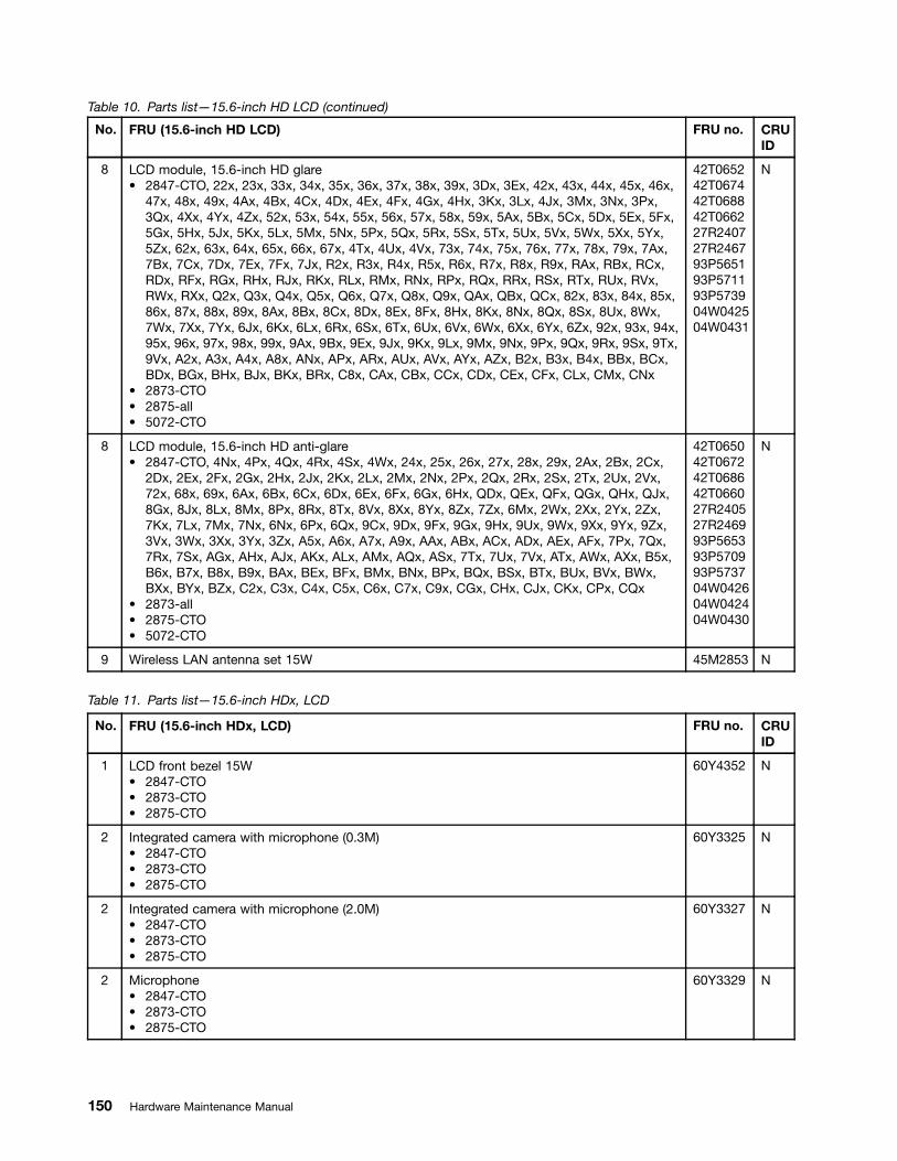
Table 10. Parts list—15.6-inch HD LCD (continued)
No. FRU (15.6-inch HD LCD) FRU no. CRUID
8 LCD module, 15.6-inch HD glare• 2847-CTO, 22x, 23x, 33x, 34x, 35x, 36x, 37x, 38x, 39x, 3Dx, 3Ex, 42x, 43x, 44x, 45x, 46x,
47x, 48x, 49x, 4Ax, 4Bx, 4Cx, 4Dx, 4Ex, 4Fx, 4Gx, 4Hx, 3Kx, 3Lx, 4Jx, 3Mx, 3Nx, 3Px,3Qx, 4Xx, 4Yx, 4Zx, 52x, 53x, 54x, 55x, 56x, 57x, 58x, 59x, 5Ax, 5Bx, 5Cx, 5Dx, 5Ex, 5Fx,5Gx, 5Hx, 5Jx, 5Kx, 5Lx, 5Mx, 5Nx, 5Px, 5Qx, 5Rx, 5Sx, 5Tx, 5Ux, 5Vx, 5Wx, 5Xx, 5Yx,5Zx, 62x, 63x, 64x, 65x, 66x, 67x, 4Tx, 4Ux, 4Vx, 73x, 74x, 75x, 76x, 77x, 78x, 79x, 7Ax,7Bx, 7Cx, 7Dx, 7Ex, 7Fx, 7Jx, R2x, R3x, R4x, R5x, R6x, R7x, R8x, R9x, RAx, RBx, RCx,RDx, RFx, RGx, RHx, RJx, RKx, RLx, RMx, RNx, RPx, RQx, RRx, RSx, RTx, RUx, RVx,RWx, RXx, Q2x, Q3x, Q4x, Q5x, Q6x, Q7x, Q8x, Q9x, QAx, QBx, QCx, 82x, 83x, 84x, 85x,86x, 87x, 88x, 89x, 8Ax, 8Bx, 8Cx, 8Dx, 8Ex, 8Fx, 8Hx, 8Kx, 8Nx, 8Qx, 8Sx, 8Ux, 8Wx,7Wx, 7Xx, 7Yx, 6Jx, 6Kx, 6Lx, 6Rx, 6Sx, 6Tx, 6Ux, 6Vx, 6Wx, 6Xx, 6Yx, 6Zx, 92x, 93x, 94x,95x, 96x, 97x, 98x, 99x, 9Ax, 9Bx, 9Ex, 9Jx, 9Kx, 9Lx, 9Mx, 9Nx, 9Px, 9Qx, 9Rx, 9Sx, 9Tx,9Vx, A2x, A3x, A4x, A8x, ANx, APx, ARx, AUx, AVx, AYx, AZx, B2x, B3x, B4x, BBx, BCx,BDx, BGx, BHx, BJx, BKx, BRx, C8x, CAx, CBx, CCx, CDx, CEx, CFx, CLx, CMx, CNx
• 2873-CTO• 2875-all• 5072-CTO
42T065242T067442T068842T066227R240727R246793P565193P571193P573904W042504W0431
N
8 LCD module, 15.6-inch HD anti-glare• 2847-CTO, 4Nx, 4Px, 4Qx, 4Rx, 4Sx, 4Wx, 24x, 25x, 26x, 27x, 28x, 29x, 2Ax, 2Bx, 2Cx,
2Dx, 2Ex, 2Fx, 2Gx, 2Hx, 2Jx, 2Kx, 2Lx, 2Mx, 2Nx, 2Px, 2Qx, 2Rx, 2Sx, 2Tx, 2Ux, 2Vx,72x, 68x, 69x, 6Ax, 6Bx, 6Cx, 6Dx, 6Ex, 6Fx, 6Gx, 6Hx, QDx, QEx, QFx, QGx, QHx, QJx,8Gx, 8Jx, 8Lx, 8Mx, 8Px, 8Rx, 8Tx, 8Vx, 8Xx, 8Yx, 8Zx, 7Zx, 6Mx, 2Wx, 2Xx, 2Yx, 2Zx,7Kx, 7Lx, 7Mx, 7Nx, 6Nx, 6Px, 6Qx, 9Cx, 9Dx, 9Fx, 9Gx, 9Hx, 9Ux, 9Wx, 9Xx, 9Yx, 9Zx,3Vx, 3Wx, 3Xx, 3Yx, 3Zx, A5x, A6x, A7x, A9x, AAx, ABx, ACx, ADx, AEx, AFx, 7Px, 7Qx,7Rx, 7Sx, AGx, AHx, AJx, AKx, ALx, AMx, AQx, ASx, 7Tx, 7Ux, 7Vx, ATx, AWx, AXx, B5x,B6x, B7x, B8x, B9x, BAx, BEx, BFx, BMx, BNx, BPx, BQx, BSx, BTx, BUx, BVx, BWx,BXx, BYx, BZx, C2x, C3x, C4x, C5x, C6x, C7x, C9x, CGx, CHx, CJx, CKx, CPx, CQx
• 2873-all• 2875-CTO• 5072-CTO
42T065042T067242T068642T066027R240527R246993P565393P570993P573704W042604W042404W0430
N
9 Wireless LAN antenna set 15W 45M2853 N
Table 11. Parts list—15.6-inch HDx, LCD
No. FRU (15.6-inch HDx, LCD) FRU no. CRUID
1 LCD front bezel 15W• 2847-CTO• 2873-CTO• 2875-CTO
60Y4352 N
2 Integrated camera with microphone (0.3M)• 2847-CTO• 2873-CTO• 2875-CTO
60Y3325 N
2 Integrated camera with microphone (2.0M)• 2847-CTO• 2873-CTO• 2875-CTO
60Y3327 N
2 Microphone• 2847-CTO• 2873-CTO• 2875-CTO
60Y3329 N
150 Hardware Maintenance Manual
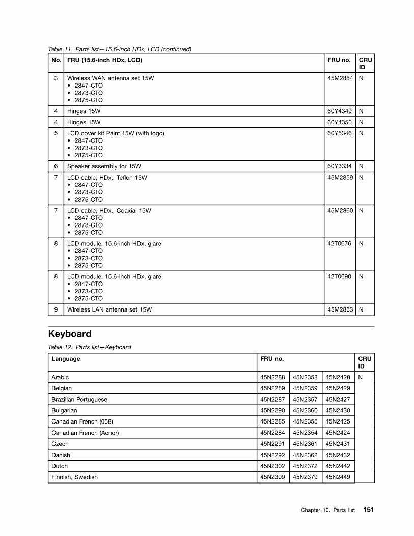
Table 11. Parts list—15.6-inch HDx, LCD (continued)
No. FRU (15.6-inch HDx, LCD) FRU no. CRUID
3 Wireless WAN antenna set 15W• 2847-CTO• 2873-CTO• 2875-CTO
45M2854 N
4 Hinges 15W 60Y4349 N
4 Hinges 15W 60Y4350 N
5 LCD cover kit Paint 15W (with logo)• 2847-CTO• 2873-CTO• 2875-CTO
60Y5346 N
6 Speaker assembly for 15W 60Y3334 N
7 LCD cable, HDx,, Teflon 15W• 2847-CTO• 2873-CTO• 2875-CTO
45M2859 N
7 LCD cable, HDx,, Coaxial 15W• 2847-CTO• 2873-CTO• 2875-CTO
45M2860 N
8 LCD module, 15.6-inch HDx, glare• 2847-CTO• 2873-CTO• 2875-CTO
42T0676 N
8 LCD module, 15.6-inch HDx, glare• 2847-CTO• 2873-CTO• 2875-CTO
42T0690 N
9 Wireless LAN antenna set 15W 45M2853 N
KeyboardTable 12. Parts list—Keyboard
Language FRU no. CRUID
Arabic 45N2288 45N2358 45N2428
Belgian 45N2289 45N2359 45N2429
Brazilian Portuguese 45N2287 45N2357 45N2427
Bulgarian 45N2290 45N2360 45N2430
Canadian French (058) 45N2285 45N2355 45N2425
Canadian French (Acnor) 45N2284 45N2354 45N2424
Czech 45N2291 45N2361 45N2431
Danish 45N2292 45N2362 45N2432
Dutch 45N2302 45N2372 45N2442
Finnish, Swedish 45N2309 45N2379 45N2449
N
Chapter 10. Parts list 151
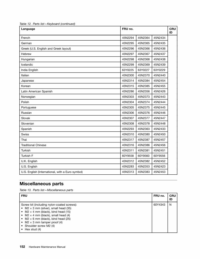
Table 12. Parts list—Keyboard (continued)
Language FRU no. CRUID
French 45N2294 45N2364 45N2434
German 45N2295 45N2365 45N2435
Greek (U.S. English and Greek layout) 45N2296 45N2366 45N2436
Hebrew 45N2297 45N2367 45N2437
Hungarian 45N2298 45N2368 45N2438
Icelandic 45N2299 45N2369 45N2439
India English 63Y0225 63Y0227 63Y0229
Italian 45N2300 45N2370 45N2440
Japanese 45N2314 45N2384 45N2454
Korean 45N2315 45N2385 45N2455
Latin American Spanish 45N2286 45N2356 45N2426
Norwegian 45N2303 45N2373 45N2443
Polish 45N2304 45N2374 45N2444
Portuguese 45N2305 45N2375 45N2445
Russian 45N2306 45N2376 45N2446
Slovak 45N2307 45N2377 45N2447
Slovenian 45N2308 45N2378 45N2448
Spanish 45N2293 45N2363 45N2433
Swiss 45N2310 45N2380 45N2450
Thai 45N2317 45N2387 45N2457
Traditional Chinese 45N2316 45N2386 45N2456
Turkish 45N2311 45N2381 45N2451
Turkish F 60Y9558 60Y9560 60Y9556
U.K. English 45N2312 45N2382 45N2452
U.S. English 45N2283 45N2353 45N2423
U.S. English (International, with a Euro symbol) 45N2313 45N2383 45N2453
Miscellaneous partsTable 13. Parts list—Miscellaneous parts
FRU FRU no. CRUID
Screw kit (including nylon-coated screws):• M2 × 3 mm (silver), small head (35)• M2 × 4 mm (black), bind head (15)• M2 × 4 mm (black), small head (4)• M2 × 6 mm (black), bind head (25)• M2 × 3 mm tamper proof (4)• Shoulder screw M2 (4)• Hex stud (4)
60Y4343 N
152 Hardware Maintenance Manual

Table 13. Parts list—Miscellaneous parts (continued)
FRU FRU no. CRUID
• Security screw M2 × 4 mm (2)
Seal kit:• Tape for LCD cable (large)• Tape S (cable fix)• Tape L (cable fix)• Screw cap, thin• Screw cap square
60Y4344 N
System board miscellaneous parts 14W 60Y4414 N
System board miscellaneous parts 15W 60Y4415 N
Table 14. Parts list—Miscellaneous parts
FRU FRU no. CRUID
• Rubber foot (front)• Rubber foot (rear)• LCD latch knob• LCD latch• Latch link wire• LCD latch spring• Wireless radio switch knob• Wireless radio switch latch• Security keyhole bracket• EMI spring (optical drive)• EMI spring (HDD front)• EMI spring (HDD rear)• Gasket (long)• Gasket (short)• HDD guide (front)• HDD rubber rail (front)• HDD guide (rear)• HDD rubber rail (rear)• LCD latch rubber• Pad, battery• Sponge (large)• Sponge (small)• Cap for Mg• Screw M2 × 3
System miscellaneous parts:• Expansion slot cover• HDD cover• I/O sub bracket• Connector cap• Optical drive bracket
N
Chapter 10. Parts list 153

Table 14. Parts list—Miscellaneous parts (continued)
FRU FRU no. CRUID
System board miscellaneous parts:• Mini Card stud, system board• Stud, system board• Insulation (top)• Insulation, black (battery)• Insulation, black (coil)• Insulation, black (SIM)• SIM card bracket• Eject sheet• USB gascket
N
LCD miscellaneous parts:• Heat spreader for camera• ThinkPad logo• Lenovo logo• Label (camera)• Label (no camera)• Label (LED)• Tape cable fix (10 × 38)• LCD latch R• LCD latch L• Rubber 0.5• Rubber 0.8• Rubber 0.8 long• Rubber 1.0• Rubber 1.5• Alpet sheet for LCD• Gasket for LCD• Screw cap, thin• Screw cap, square
N
ac power adaptersTable 15. Parts list—2-pin ac adapters
FRU FRU no. CRUID
2-pin (65 W, 20 V) adapter (models CTO, xxU, xxF, xxL, xxP, xxS, xxY, xxE, xxJ) 42T5282
2-pin (65 W, 20 V) adapter (models CTO, xxU, xxF, xxL, xxP, xxS, xxY, xxE, xxJ) 42T4423
2-pin (65 W, 20 V) adapter (models CTO, xxU, xxF, xxL, xxP, xxS, xxY, xxE, xxJ) 42T4419
2-pin (90 W, 20 V) adapter (models CTO, xxU, xxF, xxL, xxP, xxS, xxY, xxE, xxJ) 42T4427
2-pin (90 W, 20 V) adapter (models CTO, xxU, xxF, xxL, xxP, xxS, xxY, xxE, xxJ) 42T4431
2-pin (90 W, 20 V) adapter (models CTO, xxU, xxF, xxL, xxP, xxS, xxY, xxE, xxJ) 42T4435
2-pin (90 W, 20 V) adapter (models CTO, xxU, xxF, xxL, xxP, xxS, xxY, xxE, xxJ) 42T4439
*
154 Hardware Maintenance Manual

Table 16. Parts list—3-pin ac adapters
FRU FRU no. CRUID
3-pin (65 W, 20 V) adapter (models CTO, xxG, xxM, xxQ, xxA, xxT, xxK, xxC, xxB, xxH, xxV) 42T5283
3-pin (65 W, 20 V) adapter (models CTO, xxG, xxM, xxQ, xxA, xxT, xxK, xxC, xxB, xxH, xxV) 42T4421
3-pin (65 W, 20 V) adapter (models CTO, xxG, xxM, xxQ, xxA, xxT, xxK, xxC, xxB, xxH, xxV) 42T4417
3-pin (90 W, 20 V) adapter (models CTO, xxG, xxM, xxQ, xxA, xxT, xxK, xxC, xxB, xxH, xxV) 42T4425
3-pin (90 W, 20 V) adapter (models CTO, xxG, xxM, xxQ, xxA, xxT, xxK, xxC, xxB, xxH, xxV) 42T4429
3-pin (90 W, 20 V) adapter (models CTO, xxG, xxM, xxQ, xxA, xxT, xxK, xxC, xxB, xxH, xxV) 42T4433
3-pin (90 W, 20 V) adapter (models CTO, xxG, xxM, xxQ, xxA, xxT, xxK, xxC, xxB, xxH, xxV) 45N0068
*
Power cordsA ThinkPad power cord for a specific country or region is usually available only in that country or region:
Table 17. Parts list—2-pin power cords
Country or region FRU no. CRUID
Argentina• models -CTO, xxY
42T502042T5105
Brazil• models -CTO, xxP
42T518042T5183
Canada, U.S.• models -CTO, xxF, xxL, xxS, xxU
42T500842T5093
Japan• models -CTO, xxE, xxJ
42T501442T5099
*
Table 18. Parts list—3-pin power cords
Country or region FRU no. CRUID
Australia, New Zealand• models -CTO, xxM
42T505042T5135
Bangladesh, Sri Lanka, South Africa• models -CTO, xxG
42T505642T5141
Canada, U.S.• models -CTO, xxG, xxT
42T500442T5089
China (P.R.C.) (other than Hong Kong S.A.R.)• models -CTO, xxC
42T506542T5150
Denmark• models -CTO, xxG
42T504142T5126
European countries• models -CTO, xxG
42T502942T5114
India• models -CTO, xxQ
42T508342T5168
Israel• models -CTO, xxG
42T506242T5147
Italy• models -CTO, xxG
42T504742T5132
*
Chapter 10. Parts list 155
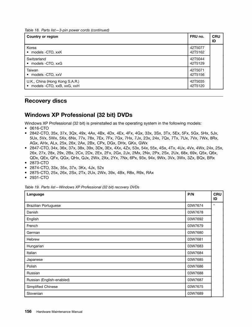
Table 18. Parts list—3-pin power cords (continued)
Country or region FRU no. CRUID
Korea• models -CTO, xxK
42T507742T5162
Switzerland• models -CTO, xxG
42T504442T5129
Taiwan• models -CTO, xxV
42T507142T5156
U.K., China (Hong Kong S.A.R.)• models -CTO, xxB, xxG, xxH
42T503542T5120
Recovery discs
Windows XP Professional (32 bit) DVDsWindows XP Professional (32 bit) is preinstalled as the operating system in the following models:• 0616-CTO• 2842-CTO, 35x, 37x, 3Qx, 49x, 4Ax, 4Bx, 4Dx, 4Ex, 4Fx, 4Gx, 33x, 3Sx, 3Tx, 5Ex, 5Fx, 5Gx, 5Hx, 5Jx,
5Ux, 5Vx, 5Wx, 5Xx, 6Nx, 77x, 78x, 7Ex, 7Fx, 7Gx, 7Hx, 7Jx, 23x, 24x, 7Qx, 7Tx, 7Ux, 7Vx, 7Wx, 8Rx,AGx, AHx, ALx, 25x, 26x, 2Ax, 2Bx, CPx, DGx, DHx, GKx, GWx
• 2847-CTO, 34x, 36x, 37x, 38x, 39x, 3Dx, 3Ex, 4Xx, 4Zx, 53x, 54x, 55x, 4Sx, 4Tx, 4Ux, 4Vx, 4Wx, 24x, 25x,26x, 27x, 28x, 29x, 2Bx, 2Cx, 2Dx, 2Ex, 2Fx, 2Gx, 2Jx, 2Mx, 2Nx, 2Px, 2Sx, 2Ux, 68x, 69x, Q5x, Q6x,QDx, QEx, QFx, QGx, QHx, QJx, 2Wx, 2Xx, 2Yx, 7Nx, 6Px, 93x, 94x, 9Wx, 3Vx, 3Wx, 3Zx, BQx, BRx
• 2873-CTO• 2874-CTO, 33x, 35x, 37x, 3Kx, 4Jx, 52x• 2875-CTO, 25x, 26x, 2Sx, 2Tx, 2Ux, 2Wx, 39x, 4Bx, R8x, R9x, RAx• 2931-CTO
Table 19. Parts list—Windows XP Professional (32 bit) recovery DVDs
Language P/N CRUID
Brazilian Portuguese 03W7674
Danish 03W7678
English 03W7692
French 03W7679
German 03W7680
Hebrew 03W7681
Hungarian 03W7683
Italian 03W7684
Japanese 03W7685
Polish 03W7686
Russian 03W7688
Russian (English-enabled) 03W7687
Simplified Chinese 03W7675
Slovenian 03W7689
*
156 Hardware Maintenance Manual

Table 19. Parts list—Windows XP Professional (32 bit) recovery DVDs (continued)
Language P/N CRUID
Spanish 03W7690
Traditional Chinese 03W7676
Traditional Chinese (Hong Kong S.A.R.) 03W7682
Turkish 03W7691
Windows XP Professional (shipping group) DVDsWindows XP Professional (shipping group) is preinstalled as the operating system in the following models:• 0616-CTO• 2842-CTO• 2847-CTO• 2873-CTO• 2874-CTO• 2875-CTO• 2931-CTO• 5072-CTO
Table 20. Parts list—Windows XP Professional (shipping group) recovery DVDs
Language P/N CRUID
English 58Y2547
Russian 58Y2542
Russian (English-enabled) 58Y2541
Simplified Chinese 58Y2529
Spanish 58Y2544
Traditional Chinese 58Y2530
Traditional Chinese (Hong Kong S.A.R.) 58Y2536
*
Windows Vista Home Basic (32 bit) DVDsWindows Vista Home Basic (32 bit) is preinstalled as the operating system in the following models:• 0616-CTO• 2842-CTO, 34x, 3Bx, 3Px, 4Ux, 4Vx, 4Wx, 4Xx, 4Yx, 4Zx, 52x, 53x, 54x, 55x, 56x, 57x, 58x, 59x, 5Ax,
5Bx, 5Cx, 5Dx, 8Mx, BSx, BUx, BWx• 2847-CTO, 33x, 42x, 43x, 44x, 4Ax, 4Bx, 4Cx, 4Dx, 7Ax, 8Jx, 8Kx, 8Mx, 8Nx• 2873-CTO• 2874-CTO, 34x, 3Mx, 3Px, 3Qx, 3Rx, 3Sx, 6Xx, 72x, 73x, 74x• 2875-CTO, 24x, 29x, 2Ax, 2Dx, 2Ex, 2Fx, 2Gx, 2Hx, 4Ux, 4Wx• 2931-CTO• 5072-CTO
Chapter 10. Parts list 157

Table 21. Parts list—Windows Vista Home Basic (32 bit) recovery DVDs
Language P/N CRUID
English 58Y2606
English for India 58Y2604
Russian 58Y2605
Russian (English-enabled) 58Y3198
Simplified Chinese 58Y2603
Spanish 58Y3199
Traditional Chinese (Hong Kong S.A.R.) 58Y3197
*
Windows Vista Home Premium (32 bit) DVDsWindows Vista Home Premium (32 bit) is preinstalled as the operating system in the following models:• 0616-CTO• 2842-CTO, 3Dx, 4Hx, 4Kx, B4x, B5x, B6x, C5x, C6x, CRx, CVx, CYx, D3x, D6x, H4x• 2847-CTO, 35x, 45x• 2873-CTO• 2874-CTO, 3Ex, 6Nx, 6Px, 7Qx, 7Rx• 2875-CTO, 2Jx• 2931-CTO• 5072-CTO
Table 22. Parts list—Windows Vista Home Premium (32 bit) recovery DVDs
Language P/N CRUID
English 58Y2602
English for India 58Y2599
Korean 58Y2601
Russian 58Y3193
Russian (English-enabled) 58Y3192
Simplified Chinese 58Y3191
Spanish 58Y3194
Traditional Chinese 58Y2598
Traditional Chinese (Hong Kong S.A.R.) 58Y2600
*
Windows Vista Home Premium (64 bit) DVDsWindows Vista Home Premium (64 bit) is preinstalled as the operating system in the following models:• 0616-CTO• 2842-CTO• 2847-CTO• 2873-CTO• 2874-CTO• 2875-CTO• 2931-CTO• 5072-CTO
158 Hardware Maintenance Manual

Table 23. Parts list—Windows Vista Home Premium (64 bit) recovery DVDs
Language P/N CRUID
English 58Y3196
Spanish 58Y3195
*
Windows Vista Business (32 bit) DVDsWindows Vista Business (32 bit) is preinstalled as the operating system in the following models:• 0616-CTO• 2842-CTO, 22x, 39x, 45x, 47x, 4Jx, 4Lx, 4Mx, 4Nx, 4Sx, 4Tx, 83x, 84x• 2847-CTO, 46x, 47x, 48x, 49x, 75x, 77x• 2873-CTO, 32x• 2874-CTO, 32x, 36x, 3Nx• 2875-CTO, 27x• 2931-CTO, 25x• 5072-CTO
Table 24. Parts list—Windows Vista Business (32 bit) recovery DVDs
Language P/N CRUID
English 58Y2597
English for India 58Y2595
Korean 58Y2596
Russian 58Y3189
Russian (English-enabled) 58Y3188
Simplified Chinese 58Y2592
Spanish 58Y3190
Traditional Chinese 58Y2593
Traditional Chinese (Hong Kong S.A.R.) 58Y2594
*
Windows 7 Starter (32 bit) DVDsWindows 7 Starter (32 bit) is preinstalled as the operating system in the following models:• 0616-CTO• 2847-CTO• 2873-CTO• 2874-CTO• 2875-CTO• 2931-CTO• 5072-CTO
Table 25. Parts list—Windows 7 Starter (32 bit) recovery DVDs
Language P/N CRUID
English 04T2028 *
Chapter 10. Parts list 159

Windows 7 Home Basic (32 bit) DVDsWindows 7 Home Basic (32 bit) is preinstalled as the operating system in the following models:• 0616-CTO, 22x, 25x, 27x, 2Gx, 2Hx, 2Kx, 2Lx• 2842-CTO, 3Fx, 3Gx, 3Rx, 66x, 67x, 68x, 69x, 6Ax, 6Bx, 6Cx, 6Dx, 6Ex, 6Fx, 6Gx, 6Hx, 6Jx, 6Kx, 6Lx,
6Mx, 6Px, 6Qx, 6Rx, 6Sx, 6Tx, 6Ux, 6Vx, 6Wx, 6Xx, 6Yx, 6Zx, 72x, 73x, 74x, 75x, 76x, 87x, 88x, 89x,8Ax, 8Bx, 8Cx, 8Ex, 8Fx, 8Gx, 8Hx, 8Jx, 8Kx, 8Nx, 8Sx, 8Tx, 8Ux, 8Vx, 8Wx, 8Xx, 8Yx, 8Zx, 92x, 93x,94x, 95x, 96x, 97x, 98x, 99x, 9Ax, 9Bx, 9Cx, 9Dx, 9Ex, 9Fx, 9Gx, 9Hx, 9Jx, 9Kx, 9Lx, 9Mx, 9Nx, 9Px,9Qx, 9Rx, 9Sx, 9Tx, 9Ux, 9Vx, 9Wx, 9Xx, 9Yx, 9Zx, A2x, A3x, A4x, A5x, A6x, A7x, A8x, A9x, AAx, ABx,ACx, ADx, AEx, AFx, ANx, AQx, ASx, AUx, AWx, AYx, B2x, B3x, BGx, BHx, BJx, BKx, BMx, BTx, BXx,CGx, CHx, DNx, EBx, ECx, EDx, EEx, EFx, EGx, EHx, EJx, EKx, ELx, EMx, ENx, EPx, EQx, ERx, ESx,ETx, EUx, EVx, EWx, EXx, EYx, FSx, FTx, G2x, G3x, G7x, G8x, GEx, GFx, GJx, GNx, GPx, HQx, HSx,HTx, HUx, HVx, JLx, JQx, K6x, K8x, K9x, KAx, KBx, KCx, KDx, KFx, KHx, KJx, KKx, KLx, KMx, KNx, KPx,KQx, KRx, KSx, KTx, KUx, LAx, LBx, LDx, LEx
• 2847-CTO, 3Kx, 3Lx, 5Hx, 5Jx, 5Kx, 5Lx, 5Mx, 5Nx, 5Px, 5Qx, 5Rx, 5Sx, 5Tx, 5Ux, 5Vx, 5Wx, 5Xx, 5Yx,5Zx, 62x, 63x, 64x, 65x, 66x, 67x, 7Bx, 7Cx, 7Fx, R2x, R3x, R4x, R5x, R6x, R7x, R8x, R9x, RAx, RBx,RCx, RDx, RFx, RGx, RHx, RJx, RKx, RLx, RMx, RNx, RPx, RQx, RRx, RSx, RTx, RUx, RVx, RWx, RXx,8Dx, 8Ex, 8Fx, 8Gx, 8Hx, 8Lx, 8Ux, 8Vx, 8Yx, 9Mx, AGx, AHx, B5x, B6x, B7x, BAx, C3x, C4x, C5x, C6x,C7x, CAx, CBx, CCx, D6x, D7x, DCx
• 2873-CTO• 2874-CTO, 48x, 49x, 4Dx, 4Mx, 4Nx, 4Px, 4Qx, 53x, 54x, 55x, 56x, 57x, 58x, 59x, 5Ax, 5Bx, 5Cx, 5Dx,
5Ex, 5Fx, 5Gx, 5Hx, 5Jx, 5Kx, 5Lx, 5Mx, 5Nx, 5Px, 5Qx, 5Rx, 62x, 6Fx, 6Hx, 6Kx, 6Mx, 6Sx, 6Tx, 7Bx,7Ex, 7Gx, 7Hx, 7Jx, 7Kx, 7Lx, 7Mx, 7Nx, 7Px, 7Tx, 7Ux, 7Wx, 7Xx, 7Yx, 7Zx, 82x
• 2875-CTO, 2Mx, 2Nx, 2Zx, 32x, 33x, 35x, 36x, 3Ax, 3Mx, 3Nx, 3Px, 3Wx, 3Xx, 3Yx, 3Zx, 42x, 43x, 44x,45x, 46x, 47x, 48x, 49x, 4Ax, 4Rx, 4Vx, 4Xx, 53x, 5Cx, R2x, RDx, RJx
• 2931-CTO, 27x, 28x, 2Ax, 2Bx• 5072-CTO
Table 26. Parts list—Windows 7 Home Basic (32 bit) recovery DVDs
Language P/N (SP0) P/N (SP1) CRUID
Brazilian Portuguese 03W7008 04T2029
English 03W7016 04T2037
Russian 03W7012 04T2033
Russian (English-enabled) 03W7011 04T2032
Serbian-Latin 03W7014 04T2035
Simplified Chinese 03W7009 04T2030
Spanish 03W7013 04T2034
Traditional Chinese (Hong Kong S.A.R.) 03W7010 04T2031
Turkish 03W7015 04T2036
*
Windows 7 Home Premium (32 bit) DVDsWindows 7 Home Premium (32 bit) is preinstalled as the operating system in the following models:• 0616-CTO• 2842-CTO, 46x, 5Lx, 5Mx, 5Qx, 5Sx, 5Yx, 62x, 29x, 2Ex, BNx, BPx, BQx, BZx, C2x, C3x, C4x, C7x, CAx,
CNx, D8x, D9x, DAx, DBx, DCx, DEx, DFx, EZx, FDx, FGx, FKx, GDx, GLx, GMx, GSx, GTx, GUx, GVx,H7x, H8x, H9x, HDx, HFx, HGx, HRx, HWx, JZx
• 2847-CTO, 4Jx, 3Mx, 3Qx, 7Dx, 7Ex, Q2x, 82x, 83x, 8Wx, 8Xx, 8Zx, 7Zx, 7Wx, 7Xx, 7Yx, 2Zx, 7Kx, 6Sx,6Ux, 6Vx, 6Wx, 6Xx, 6Yx, 6Zx, 9Jx, 9Nx, 9Px, 9Rx, A7x, ABx, ACx, ADx, AJx, AKx, ALx, AQx, ARx, ASx,AVx, AWx, AXx, B3x, B8x, B9x, BPx, C8x, CDx, CEx, CFx, DRx
160 Hardware Maintenance Manual
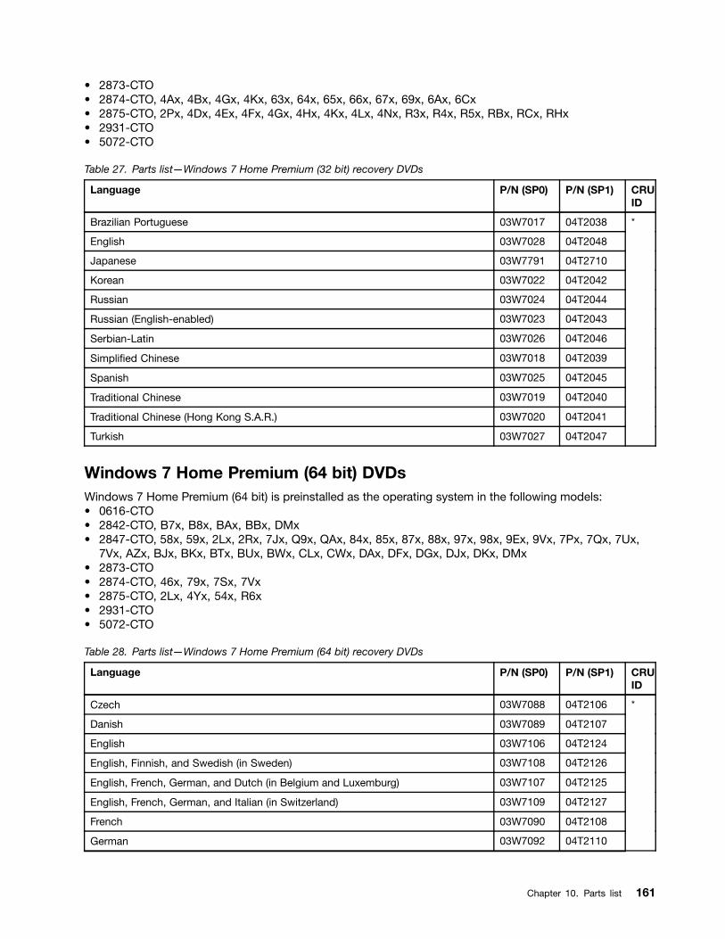
• 2873-CTO• 2874-CTO, 4Ax, 4Bx, 4Gx, 4Kx, 63x, 64x, 65x, 66x, 67x, 69x, 6Ax, 6Cx• 2875-CTO, 2Px, 4Dx, 4Ex, 4Fx, 4Gx, 4Hx, 4Kx, 4Lx, 4Nx, R3x, R4x, R5x, RBx, RCx, RHx• 2931-CTO• 5072-CTO
Table 27. Parts list—Windows 7 Home Premium (32 bit) recovery DVDs
Language P/N (SP0) P/N (SP1) CRUID
Brazilian Portuguese 03W7017 04T2038
English 03W7028 04T2048
Japanese 03W7791 04T2710
Korean 03W7022 04T2042
Russian 03W7024 04T2044
Russian (English-enabled) 03W7023 04T2043
Serbian-Latin 03W7026 04T2046
Simplified Chinese 03W7018 04T2039
Spanish 03W7025 04T2045
Traditional Chinese 03W7019 04T2040
Traditional Chinese (Hong Kong S.A.R.) 03W7020 04T2041
Turkish 03W7027 04T2047
*
Windows 7 Home Premium (64 bit) DVDsWindows 7 Home Premium (64 bit) is preinstalled as the operating system in the following models:• 0616-CTO• 2842-CTO, B7x, B8x, BAx, BBx, DMx• 2847-CTO, 58x, 59x, 2Lx, 2Rx, 7Jx, Q9x, QAx, 84x, 85x, 87x, 88x, 97x, 98x, 9Ex, 9Vx, 7Px, 7Qx, 7Ux,
7Vx, AZx, BJx, BKx, BTx, BUx, BWx, CLx, CWx, DAx, DFx, DGx, DJx, DKx, DMx• 2873-CTO• 2874-CTO, 46x, 79x, 7Sx, 7Vx• 2875-CTO, 2Lx, 4Yx, 54x, R6x• 2931-CTO• 5072-CTO
Table 28. Parts list—Windows 7 Home Premium (64 bit) recovery DVDs
Language P/N (SP0) P/N (SP1) CRUID
Czech 03W7088 04T2106
Danish 03W7089 04T2107
English 03W7106 04T2124
English, Finnish, and Swedish (in Sweden) 03W7108 04T2126
English, French, German, and Dutch (in Belgium and Luxemburg) 03W7107 04T2125
English, French, German, and Italian (in Switzerland) 03W7109 04T2127
French 03W7090 04T2108
German 03W7092 04T2110
*
Chapter 10. Parts list 161
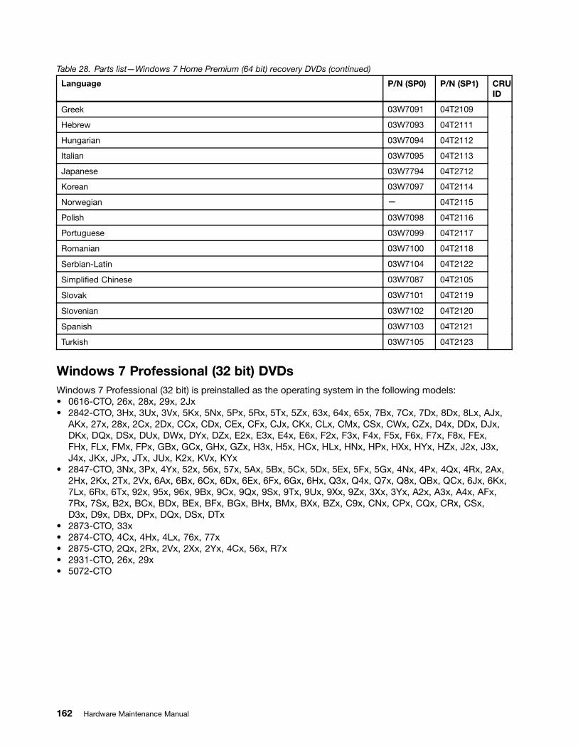
Table 28. Parts list—Windows 7 Home Premium (64 bit) recovery DVDs (continued)
Language P/N (SP0) P/N (SP1) CRUID
Greek 03W7091 04T2109
Hebrew 03W7093 04T2111
Hungarian 03W7094 04T2112
Italian 03W7095 04T2113
Japanese 03W7794 04T2712
Korean 03W7097 04T2114
Norwegian — 04T2115
Polish 03W7098 04T2116
Portuguese 03W7099 04T2117
Romanian 03W7100 04T2118
Serbian-Latin 03W7104 04T2122
Simplified Chinese 03W7087 04T2105
Slovak 03W7101 04T2119
Slovenian 03W7102 04T2120
Spanish 03W7103 04T2121
Turkish 03W7105 04T2123
Windows 7 Professional (32 bit) DVDsWindows 7 Professional (32 bit) is preinstalled as the operating system in the following models:• 0616-CTO, 26x, 28x, 29x, 2Jx• 2842-CTO, 3Hx, 3Ux, 3Vx, 5Kx, 5Nx, 5Px, 5Rx, 5Tx, 5Zx, 63x, 64x, 65x, 7Bx, 7Cx, 7Dx, 8Dx, 8Lx, AJx,
AKx, 27x, 28x, 2Cx, 2Dx, CCx, CDx, CEx, CFx, CJx, CKx, CLx, CMx, CSx, CWx, CZx, D4x, DDx, DJx,DKx, DQx, DSx, DUx, DWx, DYx, DZx, E2x, E3x, E4x, E6x, F2x, F3x, F4x, F5x, F6x, F7x, F8x, FEx,FHx, FLx, FMx, FPx, GBx, GCx, GHx, GZx, H3x, H5x, HCx, HLx, HNx, HPx, HXx, HYx, HZx, J2x, J3x,J4x, JKx, JPx, JTx, JUx, K2x, KVx, KYx
• 2847-CTO, 3Nx, 3Px, 4Yx, 52x, 56x, 57x, 5Ax, 5Bx, 5Cx, 5Dx, 5Ex, 5Fx, 5Gx, 4Nx, 4Px, 4Qx, 4Rx, 2Ax,2Hx, 2Kx, 2Tx, 2Vx, 6Ax, 6Bx, 6Cx, 6Dx, 6Ex, 6Fx, 6Gx, 6Hx, Q3x, Q4x, Q7x, Q8x, QBx, QCx, 6Jx, 6Kx,7Lx, 6Rx, 6Tx, 92x, 95x, 96x, 9Bx, 9Cx, 9Qx, 9Sx, 9Tx, 9Ux, 9Xx, 9Zx, 3Xx, 3Yx, A2x, A3x, A4x, AFx,7Rx, 7Sx, B2x, BCx, BDx, BEx, BFx, BGx, BHx, BMx, BXx, BZx, C9x, CNx, CPx, CQx, CRx, CSx,D3x, D9x, DBx, DPx, DQx, DSx, DTx
• 2873-CTO, 33x• 2874-CTO, 4Cx, 4Hx, 4Lx, 76x, 77x• 2875-CTO, 2Qx, 2Rx, 2Vx, 2Xx, 2Yx, 4Cx, 56x, R7x• 2931-CTO, 26x, 29x• 5072-CTO
162 Hardware Maintenance Manual
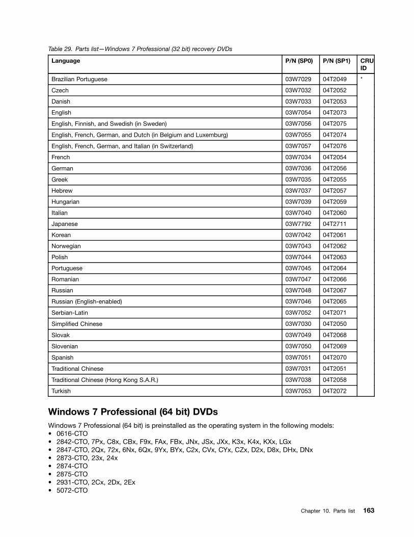
Table 29. Parts list—Windows 7 Professional (32 bit) recovery DVDs
Language P/N (SP0) P/N (SP1) CRUID
Brazilian Portuguese 03W7029 04T2049
Czech 03W7032 04T2052
Danish 03W7033 04T2053
English 03W7054 04T2073
English, Finnish, and Swedish (in Sweden) 03W7056 04T2075
English, French, German, and Dutch (in Belgium and Luxemburg) 03W7055 04T2074
English, French, German, and Italian (in Switzerland) 03W7057 04T2076
French 03W7034 04T2054
German 03W7036 04T2056
Greek 03W7035 04T2055
Hebrew 03W7037 04T2057
Hungarian 03W7039 04T2059
Italian 03W7040 04T2060
Japanese 03W7792 04T2711
Korean 03W7042 04T2061
Norwegian 03W7043 04T2062
Polish 03W7044 04T2063
Portuguese 03W7045 04T2064
Romanian 03W7047 04T2066
Russian 03W7048 04T2067
Russian (English-enabled) 03W7046 04T2065
Serbian-Latin 03W7052 04T2071
Simplified Chinese 03W7030 04T2050
Slovak 03W7049 04T2068
Slovenian 03W7050 04T2069
Spanish 03W7051 04T2070
Traditional Chinese 03W7031 04T2051
Traditional Chinese (Hong Kong S.A.R.) 03W7038 04T2058
Turkish 03W7053 04T2072
*
Windows 7 Professional (64 bit) DVDsWindows 7 Professional (64 bit) is preinstalled as the operating system in the following models:• 0616-CTO• 2842-CTO, 7Px, C8x, CBx, F9x, FAx, FBx, JNx, JSx, JXx, K3x, K4x, KXx, LGx• 2847-CTO, 2Qx, 72x, 6Nx, 6Qx, 9Yx, BYx, C2x, CVx, CYx, CZx, D2x, D8x, DHx, DNx• 2873-CTO, 23x, 24x• 2874-CTO• 2875-CTO• 2931-CTO, 2Cx, 2Dx, 2Ex• 5072-CTO
Chapter 10. Parts list 163

Table 30. Parts list—Windows 7 Professional (64 bit) recovery DVDs
Language P/N(SP0) P/N(SP1) CRUID
Brazilian Portuguese 03W7058 04T2077
Czech 03W7061 04T2080
Danish 03W7062 04T2081
English 03W7083 04T2101
English, Finnish, and Swedish (in Sweden) 03W7085 04T2103
English, French, German, and Dutch (in Belgium and Luxemburg) 03W7084 04T2102
English, French, German, and Italian (in Switzerland) 03W7086 04T2104
French 03W7063 04T2082
German 03W7065 04T2084
Greek 03W7064 04T2083
Hebrew 03W7066 04T2085
Hungarian 03W7068 04T2087
Italian 03W7069 04T2088
Japanese 03W7793 —
Korean 03W7071 04T2089
Norwegian 03W7072 04T2090
Polish 03W7073 04T2091
Portuguese 03W7074 04T2092
Romanian 03W7076 04T2094
Russian 03W7077 04T2095
Russian (English-enabled) 03W7075 04T2093
Serbian-Latin 03W7081 04T2099
Simplified Chinese 03W7059 04T2078
Slovak 03W7078 04T2096
Slovenian 03W7079 04T2097
Spanish 03W7080 04T2098
Traditional Chinese 03W7060 04T2079
Traditional Chinese (Hong Kong S.A.R.) 03W7067 04T2086
Turkish 03W7082 04T2100
*
Common service toolsTable 31. Parts list—Common service tools
Tool P/N
Screwdriver kit 95F3598
1/4" drive spinner handle 1650840
1/4" Sq. to 1/4" hex torx adapter 93F2838
TR7-TR-10 tamper resistant torx bits 00P6967
164 Hardware Maintenance Manual
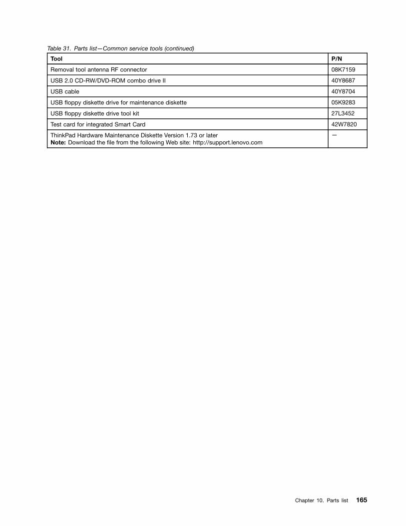
Table 31. Parts list—Common service tools (continued)
Tool P/N
Removal tool antenna RF connector 08K7159
USB 2.0 CD-RW/DVD-ROM combo drive II 40Y8687
USB cable 40Y8704
USB floppy diskette drive for maintenance diskette 05K9283
USB floppy diskette drive tool kit 27L3452
Test card for integrated Smart Card 42W7820
ThinkPad Hardware Maintenance Diskette Version 1.73 or laterNote: Download the file from the following Web site: http://support.lenovo.com
—
Chapter 10. Parts list 165

166 Hardware Maintenance Manual

Appendix A. Notices
Lenovo may not offer the products, services, or features discussed in this document in all countries. Consultyour local Lenovo representative for information on the products and services currently available in yourarea. Any reference to a Lenovo product, program, or service is not intended to state or imply that only thatLenovo product, program, or service may be used. Any functionally equivalent product, program, or servicethat does not infringe any Lenovo intellectual property right may be used instead. However, it is the user’sresponsibility to evaluate and verify the operation of any other product, program, or service.
Lenovo may have patents or pending patent applications covering subject matter described in thisdocument. The furnishing of this document does not give you any license to these patents. You can sendlicense inquiries, in writing, to:
Lenovo (United States), Inc.1009 Think Place - Building OneMorrisville, NC 27560U.S.A.Attention: Lenovo Director of Licensing
LENOVO PROVIDES THIS PUBLICATION “AS IS” WITHOUT WARRANTY OF ANY KIND, EITHER EXPRESSOR IMPLIED, INCLUDING, BUT NOT LIMITED TO, THE IMPLIED WARRANTIES OF NON-INFRINGEMENT,MERCHANTABILITY OR FITNESS FOR A PARTICULAR PURPOSE. Some jurisdictions do not allowdisclaimer of express or implied warranties in certain transactions, therefore, this statement may not applyto you.
This information could include technical inaccuracies or typographical errors. Changes are periodicallymade to the information herein; these changes will be incorporated in new editions of the publication.Lenovo may make improvements and/or changes in the product(s) and/or the program(s) described in thispublication at any time without notice.
The products described in this document are not intended for use in implantation or other life supportapplications where malfunction may result in injury or death to persons. The information contained in thisdocument does not affect or change Lenovo product specifications or warranties. Nothing in this documentshall operate as an express or implied license or indemnity under the intellectual property rights of Lenovoor third parties. All information contained in this document was obtained in specific environments and ispresented as an illustration. The result obtained in other operating environments may vary.
Lenovo may use or distribute any of the information you supply in any way it believes appropriate withoutincurring any obligation to you.
Any references in this publication to non-Lenovo Web sites are provided for convenience only and do not inany manner serve as an endorsement of those Web sites. The materials at those Web sites are not part ofthe materials for this Lenovo product, and use of those Web sites is at your own risk.
Any performance data contained herein was determined in a controlled environment. Therefore, the resultobtained in other operating environments may vary significantly. Some measurements may have beenmade on development-level systems and there is no guarantee that these measurements will be the sameon generally available systems. Furthermore, some measurements may have been estimated throughextrapolation. Actual results may vary. Users of this document should verify the applicable data for theirspecific environment.
© Copyright Lenovo 2009, 2012 167

Electronic emission noticesFor electronic emission information on Class B digital devices, refer to the corresponding information inthe User Guide.
TrademarksThe following terms are trademarks of Lenovo in the United States, other countries or both:
LenovoRescue and RecoveryThinkPadThinkVantageTrackPointUltrabayUltraNav
The following terms are trademarks of the Microsoft group of companies:
MicrosoftWindowsWindows Vista
AMD is a trademark or registered trademark of Advanced Micro Devices, Inc.
The following are trademarks of Intel Corporation or its subsidiaries in the United States, other countries, orboth:
IntelIntel CeleronIntel CentrinoIntel CoreIntel Pentium
Other company, product, or service names may be the trademarks or service marks of others.
168 Hardware Maintenance Manual


Part Number: 60Y3635_05
Printed in China
(1P) P/N: 60Y3635_05

*60Y3635_05*
Related Documents