Hardware Interrupts (HWI) Introduction In this chapter, we'll see what the EDMA can do when it finishes a transfer. We will discuss how the CPU’s interrupts work, how to configure the EDMA to interrupt the CPU at the end of a transfer, and how to configure the EDMA to auto-initialize. Learning Objectives EDMA Channel gBuf1 2. EDMA copies values from one buffer to another 2 Lab 5… CPU gBuf0 1. CPU writes buffer with sine values 1 Frame Transfer Complete 3 3. When the EDMA transfer is complete EDMA signals CPU to refill the buffer EDMA re-initializes itself Technical Training Organization T TO Outline Hardware Interrupts (HWI) Generating Interrupt with the EDMA Enabling & Responding to HWI’s EDMA Auto-Initialization Exercise Lab Optional Topics Technical Training Organization T TO C6000 Integration Workshop - Hardware Interrupts (HWI) 5 - 1

Welcome message from author
This document is posted to help you gain knowledge. Please leave a comment to let me know what you think about it! Share it to your friends and learn new things together.
Transcript

Hardware Interrupts (HWI)
Introduction In this chapter, we'll see what the EDMA can do when it finishes a transfer. We will discuss how the CPU’s interrupts work, how to configure the EDMA to interrupt the CPU at the end of a transfer, and how to configure the EDMA to auto-initialize.
Learning Objectives
EDMA
ChannelgBuf1
2. EDMA copies values from one buffer to another
2
Lab 5…
CPU
gBuf0
1. CPU writes buffer with sine values
1
Frame Transfer Complete3
3. When the EDMA transfer is completeEDMA signals CPU to refill the bufferEDMA re-initializes itself
Technical TrainingOrganization
T TO
Outline
Hardware Interrupts (HWI)Generating Interrupt with the EDMAEnabling & Responding to HWI’s
EDMA Auto-Initialization
Exercise
Lab
Optional Topics
Technical TrainingOrganization
T TO
C6000 Integration Workshop - Hardware Interrupts (HWI) 5 - 1

EDMA Interrupt Generation
Chapter Topics Hardware Interrupts (HWI) .................................................................................................................... 5-1
EDMA Interrupt Generation................................................................................................................... 5-3 Hardware Interrupts (HWIs) .................................................................................................................. 5-6
How do they work?............................................................................................................................. 5-7 Interrupt Service Routines (ISRs)....................................................................................................... 5-9 Configuring HWI Objects .................................................................................................................5-11 Interrupt Initialization........................................................................................................................5-13
EDMA Interrupt Dispatcher ..................................................................................................................5-14 EDMA Auto-Initialization ......................................................................................................................5-17
6 Steps to Auto-Initialization.............................................................................................................5-19 Summary ................................................................................................................................................5-21
Configuring EDMA Interrupts in 6 Easy Steps .................................................................................5-22 The EDMA ISR.................................................................................................................................5-24 The EDMA's CSL Functions.............................................................................................................5-25
Exercise..................................................................................................................................................5-26 Lab 5 ......................................................................................................................................................5-29
Overview ...........................................................................................................................................5-29 Lab Overview ....................................................................................................................................5-30
Optional Topics......................................................................................................................................5-36 Saving Context in HWIs....................................................................................................................5-36 Interrupts and the DMA.....................................................................................................................5-38 EDMA Channel Chaining .................................................................................................................5-41 Additional HWI Topics .....................................................................................................................5-42 Exercise 1 ..........................................................................................................................................5-50 Exercise 2 ..........................................................................................................................................5-51
5 - 2 C6000 Integration Workshop - Hardware Interrupts (HWI)

EDMA Interrupt Generation
EDMA Interrupt Generation EDMA channels can be configured to send interrupt signals to the CPU when they finish a transfer.
Generate EDMA Interrupt
You can prevent (or enable) the channel from sending an interrupt…
What causes an EDMA channel to send an interrupt?The channel’s “Transfer Count” going to zero
EDMA ChannelsChannel #
15
...
1
0
The TCINT bit of each channel turns EDMA interrupt generation on and off.
EDMA ChannelsGenerate EDMA Interrupt (TCINT)
OptionsOptions TCINT20 Channel’s Options register allows you to enable/disable
interrupt generation
Similar to the CPU's interrupt recognition, the EDMA has flag/enable bits ...
Channel #
TCINT=0
15
...
1
0
Options
C6000 Integration Workshop - Hardware Interrupts (HWI) 5 - 3

EDMA Interrupt Generation
The CIPR register records which enabled (TCINT set) channels have finished. The CIER register controls which CIPR bits send an interrupt to the CPU.
Generate EDMA Interrupt (TCINT)EDMA Channels
Channel #
TCINT=0
15
...
1
0
Options
OptionsOptions TCINT20 The Channel Interrupt Pending Register (CIPR) records
that an EDMA transfer complete has occurred
How do you pick which CIPR bit gets set?
EDMA Interrupt Generation
0
1
1
0
CIPR
CIER0 = 0
CIER1 = 0
CIER8 = 1
CIER15 = 0
CIER
EDMAINT
The TCC field in the Options Register allows each channel to set any CIPR bit.
Generate EDMA Interrupt (TCC)EDMA Channels
Channel #
TCINT=1
TCINT=0
TCINT=1
TCINT=0
TCC=8
TCC=0
TCC=1
TCC=1515
...
1
0
Options
OptionsOptions TCCTCINT20 19 16 Any channel can set any CIPR bit
Value in TCC bit field selects CIPR bit that will get setSetting any CIPR bit is allows for EDMA channel chaining(described later in Optional Topics)
To read/write CIPR or enable/disable CIER …
EDMA Interrupt Generation
0
1
1
0
CIPR
CIER0 = 0
CIER1 = 0
CIER8 = 1
CIER15 = 0
CIER
EDMAINT
5 - 4 C6000 Integration Workshop - Hardware Interrupts (HWI)

EDMA Interrupt Generation
The Chip Support Library (CSL) has functions for manipulating the various bits used by the EDMA to control interrupt generation.
Generate EDMA Interrupt (TCC)EDMA Channels
Channel #
TCINT=1
TCINT=0
TCINT=1
TCINT=0
TCC=8
TCC=0
TCC=1
TCC=1515
...
1
0
Options
OptionsOptions TCCTCINT20 19 16
Where does EDMAINT go?
EDMA Interrupt Generation
0
1
1
0
CIPR
CIER0 = 0
CIER1 = 0
CIER8 = 1
CIER15 = 0
CIER
EDMAINT
Enabling/disabling CIER bits using:EDMA_intEnable(#)EDMA_intDisable(#)
Access CIPR bits using:EDMA_intTest(#)EDMA_intClear(#)EDMA_intAlloc(-1 or #)EDMA_intFree(#)
Technical TrainingOrganization
T TO
Passing a “-1” to EDMA_intAlloc( ) allocates any available CIPR bit, as opposed to allocating a specific bit.
For now, allocating any CIPR bit is OK. When using EDMA Channel Chaining, though, a specific CIPR bit must be used. In these cases, it is either a good idea to allocate the specific CIPR bits first, or plan out which channels will use which bits. Then use the EDMA_intAlloc() function to officially allocate (i.e. reserve) each CIPR bit. (Note, Channel Chaining is briefly discussed at the end of this chapter as an optional topic.)
C6000 Integration Workshop - Hardware Interrupts (HWI) 5 - 5

Hardware Interrupts (HWIs)
Hardware Interrupts (HWIs) If the EDMA can generate an interrupt, what has to be done in order for the CPU to recognize and respond to this interrupt? What is an interrupt anyway?
EDMA Interrupts the CPU
CPU Interrupt Logic
HWI15
…HWI5HWI4
C6000CPU
EDMA Channels EDMA Interrupt
GenerationChannel #
…
2
1
0
EDMAINT
1. First, we examined how the EDMA generates interrupts to the CPU
2. Next, we explore how CPU interrupts (HWI’s) work
Technical TrainingOrganization
T TO
5 - 6 C6000 Integration Workshop - Hardware Interrupts (HWI)

Hardware Interrupts (HWIs)
How do they work? Interrupts are very important in DSP systems. They allow the CPU to interact with the outside world.
How do Interrupts Work?
• EDMA• HPI• Timers• Ext pins• Etc.
1. An interrupt occurs
2. Sets flag in IFR register
. . .
C6000 Integration Workshop - Hardware Interrupts (HWI) 5 - 7

Hardware Interrupts (HWIs)
The IER register and the GIE bit in the Control Status Register allow users to enable and disable interrupts.
Interrupting the CPU
IER“Individual
Enable”
GIE“MasterEnable”
‘C6000CPU
IFRInterrupt
Flag0
1
0
EDMAINT
Interrupt Flag Reg (IFR)bit set when int occurs
Interrupt Enable Reg (IER)enables individual int's
IRQ_enable(IRQ_EVT_XINT2)IRQ_enable(IRQ_EVT_EDMAINT)
Global Interrupt Enable (GIE) bit in Control Status Reg
enables all IER-enabled interruptsIRQ_globalEnable() IRQ_globalDisable()
Technical TrainingOrganization
T TO
Here is a nice summary of how CPU interrupts work on the C6000.
How do Interrupts Work?
• DMA• HPI• Timers• Ext pins• Etc.
1. An interrupt occurs
3. CPU acknowledges interrupt and …• Stops what it is doing• Turn off interrupts globally• Clears flag in register• Saves return-to location• Determines which interrupt• Calls ISR
2. Sets flag in IFR register
. . .
4. ISR (Interrupt Service Routine)• Saves context of system*• Runs your interrupt code (ISR)• Restores context of system*• Continues where left off*
* Must be done in user code, unless you choose to use the DSP/BIOS HWI dispatcherTechnical Training
Organization
T TO
Note, the DSP/BIOS HWI Dispatcher is discussed later (on page 5-12).
5 - 8 C6000 Integration Workshop - Hardware Interrupts (HWI)

Hardware Interrupts (HWIs)
Interrupt Service Routines (ISRs) The Interrupt Service Routine is the function that gets called when an interrupt occurs. The ISR contains the instructions for what needs to be done when a given interrupt occurs.
Please fill-in the code that needs to be run in our system, when the EDMA finishes transferring a block of sine wave values:
Interrupt Service Routine
What do we want to happen when the EDMA interrupts the CPU?
void edmaHWI()
{
}
Hint: Just fill in the functions that need to run. Don’t worry about the arguments, for now. Though, you’ll need to come up with the function arguments when coding the ISR in the upcoming lab.
C6000 Integration Workshop - Hardware Interrupts (HWI) 5 - 9

Hardware Interrupts (HWIs)
The ISR should perform two actions: • Refill the buffer with new sine values. • Trigger the EDMA to run again, thus moving the new sine values.
Interrupt Service Routine
What do we want to happen when the EDMA interrupts the CPU?
void edmaHWI()
{
SINE_blockFill();
EDMA_setChannel();
}
Technical TrainingOrganization
T TO
5 - 10 C6000 Integration Workshop - Hardware Interrupts (HWI)
Hardware Interrupts (HWIs)
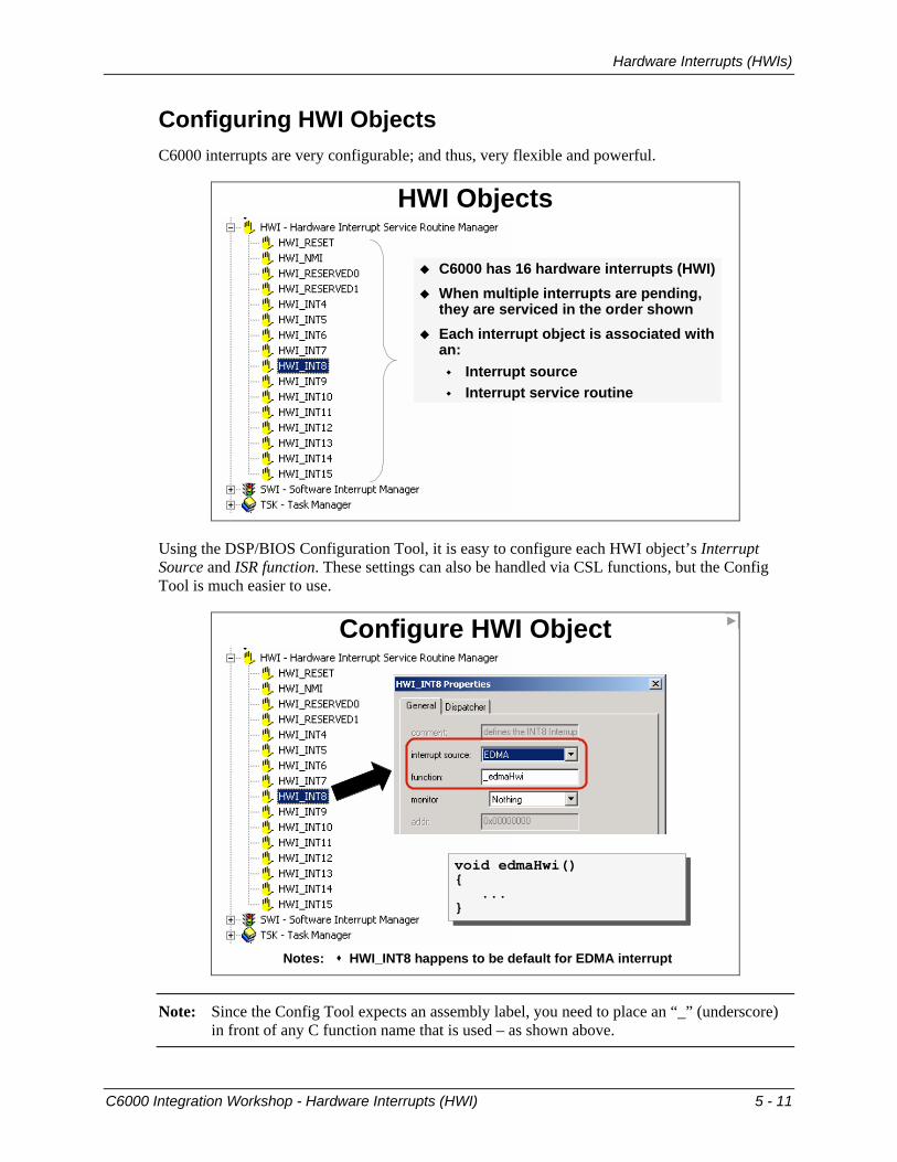
Configuring HWI Objects C6000 interrupts are very configurable; and thus, very flexible and powerful.
HWI Objects
C6000 has 16 hardware interrupts (HWI)When multiple interrupts are pending, they are serviced in the order shownEach interrupt object is associated with an:
Interrupt sourceInterrupt service routine
Using the DSP/BIOS Configuration Tool, it is easy to configure each HWI object’s Interrupt Source and ISR function. These settings can also be handled via CSL functions, but the Config Tool is much easier to use.
Configure HWI Object
Notes: HWI_INT8 happens to be default for EDMA interrupt
void edmaHwi() {
... }
void edmaHwi() {
... }
Note: Since the Config Tool expects an assembly label, you need to place an “_” (underscore) in front of any C function name that is used – as shown above.
C6000 Integration Workshop - Hardware Interrupts (HWI) 5 - 11

Hardware Interrupts (HWIs)
The HWI object allows you to select the HWI dispatcher. This is found on the 2nd tab:
Configure HWI Object
Notes: HWI_INT8 happens to be default for EDMA interruptDispatcher saves/restores context for the ISR
?T TO
The HWI Interrupt Dispatcher takes care of saving and restoring the context of the ISR.
HWI Interrupt Dispatcher
Count = 0 C6000CPU
EDMAINT
EDMA Channel
HWI_nothing……
HWI_nothing
_edmaHWI
HWI_nothing
HWI_nothing
_c_int00
XINT215
EDMAINT5
EXTINT44
……
Reset0
HWI Dispatcher
void edmaHWI(){…
}
Context Save
Context Restore
T TO
The HWI dispatcher is plugged into the interrupt vector table. It saves the necessary CPU context, and calls the function specified by the associated HWI object. Additionally, it allows the use of DSP/BIOS scheduling functions by preventing the scheduler from running while an HWI ISR is active.
5 - 12 C6000 Integration Workshop - Hardware Interrupts (HWI)

Hardware Interrupts (HWIs)
Interrupt Initialization Several concepts have been introduced up to this point. Let's take a moment to make sure that you understand how to setup the CPU to receive a given interrupt.
Enable CPU Interrupts
void initHWI(void)
{
}
Exercise: Fill in the lines of code required to enable the EDMAINT hardware interrupt:
C6000 Integration Workshop - Hardware Interrupts (HWI) 5 - 13

EDMA Interrupt Dispatcher
EDMA Interrupt Dispatcher The EDMA Interrupt Dispatcher, which is completely different from the HWI Dispatcher that we talked about earlier, helps us solve a very basic problem.
EDMA ISR ProblemHow many EDMA channels?
How many EDMA interrupt service routines could exist?
How many EDMA interrupts?
16 (or 64)
16 (or 64)
1
Since there is only one EDMA ISR, the CIPR bits can be used to tell which EDMA channels have actually completed transfers and need to be serviced.
Which Channel?EDMA Channels EDMA Interrupt Generation
Channel #
TCINT=1
TCINT=0
TCINT=1
TCINT=0
TCC=8
TCC=0
TCC=1
TCC=1515
...
1
0 CIER0 = 0
CIER1 = 0
CIER8 = 1
CIER15 = 0
0
1
1
0
CIERCIPROptions
EDMAINT
Since there is only one EDMA interrupt to the CPU, how does the CPU know which channel caused it?Two methods:1. Test each CIPR bit using: EDMA_intTest(bit #)2. Automate testing each CIPR bit using
EDMA Interrupt DispatcherTechnical Training
Organization
T TO
5 - 14 C6000 Integration Workshop - Hardware Interrupts (HWI)

EDMA Interrupt Dispatcher
To use the EDMA Interrupt Dispatcher, the EDMA interrupt vector needs to be setup to call the dispatcher.
EDMA Interrupt Problem?
Count = 0 C6000CPU
EDMAINT
EDMA Channel
HWI_nothing
_edmaHWI
_c_int00
XINT215
EDMAINT5
Reset0
HWI Dispatcher
Context Save
Context Restore
EDMA_intDispatcher
Previously, our EDMAINT vectored directly to our Interrupt Service RoutineCan you think of a problem this might create?
What if two different EDMA channels cause an interrupt?Do you want all channels to use the same ISR? (Not very convenient)
To solve this problem, CSL provides a simple EDMA Interrupt Dispatcher
The EDMA Interrupt Dispatcher figures out what channels have finished and calls the function that has been associated with each CIPR bit that’s been set.
EDMA Interrupt Dispatcher
Count = 0 C6000CPU
EDMAINT
EDMA Channel
HWI_nothing
_EDMA_intDispatcher
_c_int00
XINT215
EDMAINT5
Reset0
HWI Dispatcher
Context Save
Context Restore
EDMA Int Dispatcher1. Read CIPR & CIER2. For each enabled CIPR bit,
(starting with CIPR0), call the associated (“hooked”) function
_edmaHWI8
Function to Call (“hooked” function)
…
0 ….
CIPR bit void edmaHWI(CIPR bit)
{…
}
void edmaHWI(CIPR bit){…
}
T TO The source code for the EDMA dispatcher is provided (as is the source code for all of CSL). Upon examination you’ll find that the EDMA dispatcher reads both the CIPR and CIER registers. It then calls a function for any CIPR bit = 1, whose respective CIER bit is also = 1.
How do we know which function is associated with which channel (i.e. CIPR bit)?
C6000 Integration Workshop - Hardware Interrupts (HWI) 5 - 15

EDMA Interrupt Dispatcher
The EDMA Interrupt Dispatcher needs to be told what function to call for each of the CIPR bits that we want to cause an interrupt to the CPU. This is referred to as "hooking" a function into the EDMA Interrupt Dispatcher. And thus, the CSL function is called EDMA_intHook().
EDMA_intHook
_edmaHWI8
Function to Call (“hooked” function)
…
0 ….
CIPR bit
void initEDMA(){...
EDMA_intHook(8, edmaHWI);
...}
void initEDMA(){
...
EDMA_intHook(8, edmaHWI);
...}
Plugs entry in EDMA Interrupt Dispatch table
Technical TrainingOrganization
T TO
The EDMA_intHook function has two arguments, the CIPR bit number and the function to be called when it’s set by a completed EDMA channel.
For simplicity, the example shown above specifies a CIPR bit with just the number “8”. Most likely, though, you will use a variable to represent the CIPR bit number. A variable is a better choice as it can be set when using the EDMA_intAlloc() function to reserve a CIPR bit for an EDMA channel.
5 - 16 C6000 Integration Workshop - Hardware Interrupts (HWI)
EDMA Auto-Initialization
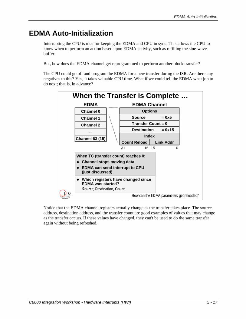
EDMA Auto-Initialization Interrupting the CPU is nice for keeping the EDMA and CPU in sync. This allows the CPU to know when to perform an action based upon EDMA activity, such as refilling the sine-wave buffer.
But, how does the EDMA channel get reprogrammed to perform another block transfer?
The CPU could go off and program the EDMA for a new transfer during the ISR. Are there any negatives to this? Yes, it takes valuable CPU time. What if we could tell the EDMA what job to do next; that is, in advance?
When the Transfer is Complete …
Options
IndexLink AddrCount Reload
31 16 15 0
Channel 63 (15)
Channel 1Channel 2
...
Channel 0EDMA EDMA Channel
When TC (transfer count) reaches 0:Channel stops moving dataEDMA can send interrupt to CPU (just discussed)
Which registers have changed since EDMA was started?Source, Destination, Count
How can the EDMA parameters get reloaded?
Source = 0x5
Destination = 0x15Transfer Count = 0
Technical TrainingOrganization
T TO
Notice that the EDMA channel registers actually change as the transfer takes place. The source address, destination address, and the transfer count are good examples of values that may change as the transfer occurs. If these values have changed, they can't be used to do the same transfer again without being refreshed.
C6000 Integration Workshop - Hardware Interrupts (HWI) 5 - 17

EDMA Auto-Initialization
The EDMA has a set of "reload" registers that can be configured like an EDMA channel. Each channel can be linked to a reload set of registers. In this way, the values in the reload registers can be used to "reload" the “used” EDMA channel.
When the Transfer is Completes …
31 16 15 0
Channel 63 (15)
Channel 1Channel 2
...
Channel 0EDMA EDMA Channel
LINK=1
Essentially, the EDMA has its own 2KB parameter RAM split between channels & reloads
Source = 0x5
Destination = 0x15Transfer Count = 0
Options
IndexLink AddrCount Reload
Reload 21 (69)
Reload 1Reload 2
...
Reload 0
When TC (transfer count) reaches 0:EDMA can reload the channel’s parameters from one of the many Reload setsEach Reload set consists of six 32-bit valuesLink Address points to the next Reload setupAuto-Init, Reload, and Linking all refer to the same EDMA feature
Technical TrainingOrganization
T TO
The reload register sets can also be linked to other reload sets; thus a linked-list can be created.
Creating a “Linked-List” of Transfers
Offloads CPU ... can reinitialize all six registers of an EDMA channelNext transfer specified by Link Address Perform simple re-initialization or create linked-list of eventsUseful for ping-pong buffers, data sorting, circular buffers, etc.
Source
DestinationTransfer Count
Options (Link=1)
IndexLink AddrCount Reload
31 16 15 0
Channel 0 Source
DestinationTransfer Count
Options (Link=1)
IndexLink AddrCount Reload
Reload 1
Source
DestinationTransfer Count
Options (Link=1)
IndexLink AddrCount Reload
Reload 2
Technical TrainingOrganization
T TO
5 - 18 C6000 Integration Workshop - Hardware Interrupts (HWI)

EDMA Auto-Initialization
6 Steps to Auto-Initialization Here is a nice 6-step procedure for setting up EDMA Auto-Initialization.
Reloading an EDMA channel in 6 Steps
Channel 0
…
Channel 15
hMyHandle Options (Link = 1)Source
DestinationIndex
Link AddrCnt Reload
Transfer Count
1
Reload 1
…
Reload 21 (69)
OptionsSource
DestinationIndex
Link AddrCnt Reload
Transfer Count
hMyReload2 3 4
And the 5th step is ...
Procedure1. Choose LINK option2. Allocate handle for
reload values3. Allocate a reload set4. Configure reload set
(with same values asoriginal channel)
Steps 5 & 6: Set the Link Address fields
Channel 0
…
Channel 15
hMyHandle OptionsSource
DestinationIndex
Link AddrCnt Reload
Transfer Count
Reload 1
…
Reload 21 (69)
OptionsSource
DestinationIndex
Link AddrCnt Reload
Transfer Count
hMyReload
EDMA_link(hMyReload, hMyReload)
EDMA_link(hMyHandle, hMyReload)
EDMA_link() pokeshMyReload addressinto Link Address field
5
6
Technical TrainingOrganization
T TO
C6000 Integration Workshop - Hardware Interrupts (HWI) 5 - 19

EDMA Auto-Initialization
Here’s a code summary of the six steps required for setting up a channel for linking:
Reloading an EDMA channel in 6 Steps
3 Allocate a Reload location (reserve a reload set; -1 for “any”)
hMyReload = EDMA_allocTable(-1);
1 Modify your config to enable linking:EDMA_OPT_RMK(
…EDMA_OPT_LINK_YES, … ),
2 Create a handle to reference a Reload location: EDMA_Handle hMyReload;
4 Configure reload set (writes config structure to reload set)EDMA_config(hMyReload, &myConfig);
5Update Link Address fields (modifies field in chan, not myConfig struct)EDMA_link(hMyHandle, hMyReload);EDMA_link(hMyReload, hMyReload);6
Technical TrainingOrganization
T TO
5 - 20 C6000 Integration Workshop - Hardware Interrupts (HWI)
Summary
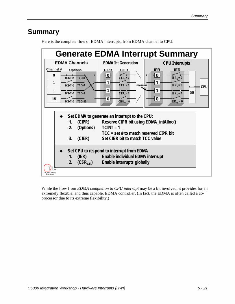
Summary Here is the complete flow of EDMA interrupts, from EDMA channel to CPU:
Generate EDMA Interrupt Summary
Set EDMA to generate an interrupt to the CPU:1. (CIPR) Reserve CIPR bit using EDMA_intAlloc()2. (Options) TCINT = 1
TCC = set # to match reserved CIPR bit3. (CIER) Set CIER bit to match TCC value
Set CPU to respond to interrupt from EDMA1. (IER) Enable individual EDMA interrupt2. (CSRGIE) Enable interrupts globally
EDMA Channels EDMA Int GenerationChannel #
TCINT=1
TCINT=0
TCINT=1
TCINT=0
TCC=8
TCC=0
TCC=1
TCC=1515
...
1
0CIER0 = 0
CIER1 = 0
CIER8 = 1
CIER15 = 0
0
1
1
0
CIERCIPROptions
CPU Interrupts
IER4 = 0
IER5 = 0
IERx = 1
IER15 = 0
011
0
IERIFR
GIECPUEDMAINT
Technical TrainingOrganization
T TO
While the flow from EDMA completion to CPU interrupt may be a bit involved, it provides for an extremely flexible, and thus capable, EDMA controller. (In fact, the EDMA is often called a co-processor due to its extreme flexibility.)
C6000 Integration Workshop - Hardware Interrupts (HWI) 5 - 21
Summary
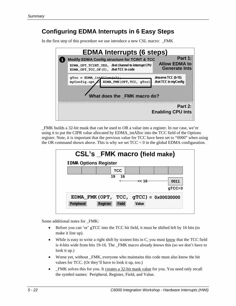
Configuring EDMA Interrupts in 6 Easy Steps In the first step of this procedure we use introduce a new CSL macro: _FMK
Part 1:Allow EDMA to
Generate Ints
Part 2:Enabling CPU Ints
1 Modify EDMA Config structure for TCINT & TCC EDMA_OPT_TCINT_YES, //set channel to interrupt CPUEDMA_OPT_TCC_OF(0), //set TCC in code
gTcc = EDMA_intAlloc(-1); //reserve TCC (0-15)myConfig.opt |= EDMA_FMK(OPT,TCC, gTcc); //set TCC in myConfig
EDMA Interrupts (6 steps)
What does the _FMK macro do?
_FMK builds a 32-bit mask that can be used to OR a value into a register. In our case, we’re using it to put the CIPR value allocated by EDMA_intAlloc into the TCC field of the Options register. Note, it is important that the previous value for TCC have been set to “0000” when using the OR command shown above. This is why we set TCC = 0 in the global EDMA configuration.
CSL’s _FMK macro (field make)
TCC19 16
0011
gTCC=3
<< 16
EDMA Options Register
Peripheral Register Field ValueEDMA_FMK(OPT, TCC, gTCC) = 0x00030000
Some additional notes for _FMK: • Before you can ‘or’ gTCC into the TCC bit field, it must be shifted left by 16 bits (to
make it line up). • While is easy to write a right shift by sixteen bits in C, you must know that the TCC field
is 4-bits wide from bits 19-16. The _FMK macro already knows this (so we don’t have to look it up.)
• Worse yet, without _FMK, everyone who maintains this code must also know the bit values for TCC. (Or they’ll have to look it up, too.)
• _FMK solves this for you. It creates a 32-bit mask value for you. You need only recall the symbol names: Peripheral, Register, Field, and Value.
5 - 22 C6000 Integration Workshop - Hardware Interrupts (HWI)

Summary
Here is the complete summary of the 6-step procedure for setting up an EDMA channel to interrupt the CPU.
Part 1:Allow EDMA to
Generate Ints
EDMA Interrupts (Part 1)1 Modify EDMA Config structure for TCINT & TCC
EDMA_OPT_TCINT_YES, //set channel to interrupt CPUEDMA_OPT_TCC_OF(0), //set TCC in code
gTcc = EDMA_intAlloc(-1); //reserve TCC (0-15)myConfig.opt |= EDMA_FMK(OPT,TCC, gTcc); //set TCC in myConfig
What about setting up hardware interrupts?
3 Set the appropriate bit in the CIER registerEDMA_intEnable(gTcc); // must match chosen TCC value
2 Hook the ISR to the appropriate TCC value:EDMA_intHook(gTcc, myISR);
Technical TrainingOrganization
T TO
Part 2:Enabling CPU Ints
EDMA Interrupts (Part 2)
5 Set the appropriate bit in the IER registerIRQ_enable(IRQ_EVT_EDMAINT);
6 Turn on global interruptsIRQ_globalEnable( ); // turn on interrupts globally
4 Include the header file#include <csl_irq.h>
When the transfer completes…what happens?Technical TrainingOrganization
T TO
C6000 Integration Workshop - Hardware Interrupts (HWI) 5 - 23

Summary
The EDMA ISR Here is the summary for how a function is run, which is associated with the completion of an EDMA channel.
EDMA ISR
Count = 0C6000CPU
EDMAINT
void edmaHwi(CIPR bit) {
SINE_blockFill(…);
EDMA_setChannel(hMyChannel);
}
When the transfer count reaches zero:EDMA interrupt is sent to the CPUChannel reg’s are re-initialized (autoinit)
EDMA Dispatcher will:Read CIPR and CIERClear CIPR bitsCall ISR functions for set (and enabled) CIPR bits
Your ISR needs to:Perform whatever your system requiresInitiate the next block transfer with EDMA_setChannel(unless your system uses EDMA synchronization – discussed in Ch 6)
HWI Dispatcher
EDMA Dispatcher
Technical TrainingOrganization
T TO
The flow described above is specific to the upcoming lab exercise. Though much of it is generic, two of the steps are specific:
• The lab asks you to setup autoinitialization for the channel we’re using. This may, or may not, be what you need in another system.
• The final step triggers the EDMA to run using the EDMA_setChannel() function. Often this is done automatically by interrupt events. In Lab 5, we will use the _setChannel function, but the next lab uses the McBSP to trigger the EDMA to run.
5 - 24 C6000 Integration Workshop - Hardware Interrupts (HWI)

Summary
The EDMA's CSL Functions With so many EDMA control registers, and so many CSL functions, we thought a summary which correlated the functions to the EDMA registers they act upon might be helpful.
EDMA_intEnableEDMA_intDisable CIER
EDMA_getChannel ER
EDMA_setChannel ESR
EDMA_clearChannel ECR
EDMA_enableChannelEDMA_disableChannel EER
EDMA_intAllocEDMA_intFreeEDMA_intTest
EDMA_intClearCIPR
EDMA_enableChainingEDMA_disableChaining CCER
EDMA Functions (Which Registers they Affect)
Technical TrainingOrganization
T TO
Here’s the same summary, but we’ve added the function’s arguments and return values.
EDMA_intEnable(tcc)EDMA_intDisable(tcc)
CIER(Chan Interrupt Enable Reg)
1 or 0 = EDMA_getChannel(h) ER(Event Register)
EDMA_setChannel(h)(sets ESR bit which sets corresponding ER bit)
ESR(Event Set Register)
EDMA_clearChannel(h)(sets ECR bit which clears corresponding ER bit)
ECR(Event Clear Register)
EDMA_enableChannel(h)EDMA_disableChannel(h)
EER(Event Enable Register)
tcc or -1 = EDMA_intAlloc(tcc or -1)EDMA_intFree(tcc)
1 or 0 = EDMA_intTest(tcc)EDMA_intClear(tcc)
CIPR(Chan Interrupt Pending Reg)
EDMA_enableChaining(h)EDMA_disableChaining(h)
CCER(Chan Chaining Enable Reg)
Technical TrainingOrganization
T TO
C6000 Integration Workshop - Hardware Interrupts (HWI) 5 - 25

Exercise
Exercise Exercise 1 (Review)
void edmaHwi(void){
SINE_blockFill(gBuf0, BUFFSIZE); // Fill buffer with sine data
EDMA_setChannel(hEdma); // start EDMA running
};
• Complete the following Interrupt Service Routine.Here’s a few hints:
Follow the code outlined on the “EDMA ISR” slide.Don’t forget, though, that our exercise (and the upcoming lab) uses different variable names than those used in the slide’s example code.To “fill the buffer”, what function did we use in Labs 2 and 4 to create a buffer of sine wave data?
Technical TrainingOrganization
T TO
Exercise 2: Step 1
EDMA_Config gEdmaConfig = { EDMA_OPT_RMK(
EDMA_OPT_PRI_LOW, // Priority?EDMA_OPT_ESIZE_16BIT, // Element size?EDMA_OPT_2DS_NO, // 2 dimensional source?EDMA_OPT_SUM_INC, // Src update mode?EDMA_OPT_2DD_NO, // 2 dimensional dest?EDMA_OPT_DUM_INC, // Dest update mode?EDMA_OPT_TCINT_NO, // Cause EDMA interrupt?EDMA_OPT_TCC_OF(0), // Transfer complete code?EDMA_OPT_LINK_NO, // Enable link parameters?EDMA_OPT_FS_YES ), // Use frame sync?
... };
1. Change gEdmaConfig so that it will: (Just cross-out the old and jot in the new value)
Interrupt the CPU when transfer count reaches 0Auto-initialize and keep running
5 - 26 C6000 Integration Workshop - Hardware Interrupts (HWI)

Exercise
Exercise 2: Steps 2-42. Reserve “any” CIPR bit (save it to gXmtTCC). Then set this value in the
gEdmaConfig structure.
3. Allow the EDMA’s interrupt to pass through to the CPU.That is, set the appropriate CIER bit. (Hint: the TCC value indicates which bit in CIPR and CIER are used)
4. Hook the ISR function so it is called whenever the appropriate CIPR bit is set and the CPU is interrupted.
Exercise 2: Steps 55. Enable the CPU to accept the EDMA interrupt. (Hint: Add 3 lines of code.)
void initHwi(void){
};
Please continue on to the next page.
C6000 Integration Workshop - Hardware Interrupts (HWI) 5 - 27

Exercise
Exercise 2: Steps 6-9 (EDMA Reload)6. Declare a handle for an EDMA reload location and name it
hEdmaReload:
7. Allocate one of the Reload sets: (Hint: hEdmaReload gets this value)
8. Configure the EDMA reload set:
9. Modify both the EDMA channel and the reload set to link to the reload set of parameters:
5 - 28 C6000 Integration Workshop - Hardware Interrupts (HWI)

Lab 5
Lab 5
Overview In lab 5, you'll have an opportunity to test everything that you have learned about interrupts and auto-initialization.
EDMA
Lab 5 – Programming the EDMA
CPUgBuf0
EDMA
Frame Transfer Complete
gBuf1
Pseudo Code1. CPU generates 32 sine values into buf02. EDMA transfers 32 elements from buf0 to buf13. EDMA sends “transfer complete” interrupt to CPU4. Go to step 1
Technical TrainingOrganization
T TO
Goals of the lab:
• To use CSL to configure the EDMA interrupt to the CPU in order to generate another buffer full of sine wave values.
• To change the configuration of the EDMA so that it uses auto-initialization to setup the next transfer.
C6000 Integration Workshop - Hardware Interrupts (HWI) 5 - 29

Lab 5
Lab Overview This lab will follow the basic outline of the discussion material. Here's how we are going to go about this:
• First, we're going to configure the CPU to respond to interrupts and set up the interrupt vector using the .cdb file. We're going to configure the CPU to call the EDMA dispatcher that will call our function to process the EDMA interrupt.
• Next, we'll write the function that we want the EDMA dispatcher to call. • Then, we'll change some setting in the EDMA configuration and the initEdma( ) code.
One thing that we'll definitely need to do is to tell the EDMA dispatcher to call the function that we wrote in the previous step.
• Finally, we'll configure the EDMA channel to use auto-initialization.
Configure the CPU to Respond to Interrupts How does the CPU know what to do when the interrupt occurs? Where does code execution go? We need to tell the CPU that when the EDMA interrupt occurs, we want it to call the EDMA interrupt dispatcher. The EDMA dispatcher will then see what interrupts have occurred and call the configured functions.
During this part of the lab, we will be somewhat following the "6-step procedure to program the EDMA to interrupt the CPU" outlined on pages 5-21 to 5-23. Feel free to flip back and review that material before trying to write the code.
5 - 30 C6000 Integration Workshop - Hardware Interrupts (HWI)
Lab 5
1. Reset the DSK, start CCS and open audioapp.pjt.
2. Open the CDB file and click the + sign next to Scheduling
3. Click the + sign next to HWI – Hardware Interrupt Manager
A list of hardware interrupts will appear. Hardware interrupt #8 (HWI_INT8) is the EDMA interrupt to the CPU (by default).
4. Right-click HWI_INT8 and select Properties
5. Change the function name to _EDMA_intDispatcher
The hardware interrupt vector table is written in assembly, so the underscore is required to access the C function, EDMA_intDispatcher ( ), which is provided by CSL.
6. Use the HWI Dispatcher
Click on the Dispatcher tab and check the Use Dispatcher checkbox. Click OK. Close and Save.
We are actually using two dispatchers here as we discussed in the material. The HWI dispatcher that we configured with the check box takes care of context save/restores for the ISR routine. The EDMA dispatcher figures out which EDMA interrupts to the CPU need to run and calls the functions to handle them.
Initializing Interrupts We need to set up two things: (1) enable the CPU to respond to the EDMA interrupt (IER) and (2) turn on global interrupts (GIE). Refer to the discussion material which outlines the 5-step CSL procedure for initializing an HWI.
7. Add a new function called initHwi( ) at the end of your code in main.c
We will use this function to initialize hardware interrupts. We will add a call to it in main( ) in few steps.
8. Add a call to IRQ_enable( ) in initHwi( )to enable the EDMA interrupt to the CPU
This connects the EDMA interrupt to the CPU via the IER register.
9. Enable CPU interrupts globally and terminate the initHwi() function
Add the CSL function call that enables global interrupts (GIE). Add a closing brace to the function to finish it off.
10. Add the proper include file for interrupts to the top of main.c in the "include" area
11. Add a call to initHwi( ) in main( ) after the call to initEdma( )
C6000 Integration Workshop - Hardware Interrupts (HWI) 5 - 31

Lab 5
Writing the ISR Funcion We need to set up the EDMA to cause a CPU interrupt when it finishes transferring a buffer
(i.e. when the transfer count reaches zero – this is the transfer complete interrupt). We then will set up a CPU Interrupt Service Routine (ISR for short) to fill the source buffer with new sine values and kick-off the EDMA to transfer them to the other buffer.
12. Review the Pseudo Code for Our System
Here is a summary of the code that you will need to write in the ISR function. The steps to write this code will follow.
So, the new code will look something like this:
• Init the EDMA to fire an interrupt when it completes
• Init the CPU to recognize the EDMA’s interrupt
• Enter the infinite while loop • While running in the infinite while loop
o When our EDMA interrupt (HWI) occurs, code execution goes to the ISR
o In the ISR, the buffer is filled with new sine values and the EDMA copy is triggered
o We re-enter the while loop. When the copy is done, the EDMA causes another CPU interrupt … and so on …
Hint: Whenever the instructions ask you to “add a new function”…don’t forget to prototype it! We've already added it to the header file for you for inclusion in other files.
13. Add a new function called edmaHwi( ) at the end of your edma.c code
This function will serve as our Interrupt Service Routine (ISR) that will get called by the EDMA interrupt dispatcher. The EDMA interrupt dispatcher passes the CIPR bit of the EDMA channel that caused the interrupt to the edmaHwi( ) routine. We will not be using this argument for now, but we will need it later. So, go ahead and write the function with the argument in the definition like this:
void edmaHwi(int tcc)
5 - 32 C6000 Integration Workshop - Hardware Interrupts (HWI)

Lab 5
14. Copy SINE_blockFill( ) and EDMA_setChannel( ) Every time the ISR occurs, we want to fill a buffer and trigger the EDMA to copy the buffer.
So, copy the code that calls SINE_blockFill ( ) and EDMA_setChannel( ) routines from main() to the ISR function edmaHwi() you just created.
Make sure that you copy these function calls. Do not delete them from main( ). The calls are needed in main( ) to “prime the pump” (i.e. get the whole process started). If we don't do this, the ISR will never run because the first buffer never gets transferred. So, leave the calls in main( ).
Use a closing brace to complete the edmaHwi() ISR.
15. Create an external reference to SINE_Obj
The SINE_blockFill( ) function refers to the SINE_Obj created in main.c. So, we need to create an external reference to it much like we did to the buffers in the previous lab.
16. Add sine.h to edma.c
Add a #include statement for sine.h to edma.c to take care of the prototype for SINE_blockFill() and the SINE_Obj data type.
Configuring the EDMA to Send Interrupts While you have just setup the CPU to respond to interrupts properly … currently, the EDMA is not setup to send interrupts. We need to modify the EDMA config structure to tell the EDMA to send an interrupt when it completes a transfer. We also need to modify the initEDMA( ) code to make some other changes in order to initialize interrupts properly.
17. Turn on the EDMA interrupt in the EDMA config structure
Change TCINT field to YES. This will cause the EDMA to trigger an interrupt to the CPU.
18. Create a Global Variable to store to TCC Value
We don’t really care which TCC value gets used – it’s arbitrary.
Create a global variable (of type short) named gXmtTCC.
Modify initEdma( ) 19. Configure the EDMA Channel to use a TCC Value
Configure the channel using your new variable. (It’s a two step process.) • Inside the initEdma function (after the _open) set gXmtTCC equal to “any” TCC value
as shown in the discussion material. • Then set the actual TCC field (in the configuration) to this value.
This reserves a specific TCC value so that no other channel can use it.
After referring to the material, you hopefully came up with these two steps to be added to initEdma( ):
gXmtTCC = EDMA_intAlloc(-1); gEdmaConfig.opt |= EDMA_FMK(OPT, TCC, gXmtTCC);
C6000 Integration Workshop - Hardware Interrupts (HWI) 5 - 33
Lab 5
20. Hook the edmaHwi( ) function into the EDMA Interrupt Dispatcher
The EDMA Interrupt Dispatcher automatically calls a function for each of the CIPR bits that get set by an EDMA interrupt and that are enabled.
We need to tell it what function to call when the transmit interrupt fires. The transmit interrupt is going to assert a given CIPR bit when it occurs. So, we need to tell the EDMA Interrupt Dispatcher which function is tied to that CIPR bit. Refer back to the lecture material if you can't figure out which API call to use here, or how to use it. Don't forget about online help inside CCS as well. Add this code anywhere in the initEdma( ) function that makes sense to you.
21. Clear any spurious interrupts and enable the EDMA interrupt
At the end of the initEdma( ) function in edma.c, add the following calls to clear the EDMA’s channel interrupt pending bit associated with the channel we’re using (i.e. clear the appropriate CIPR bit). Also, enable the EDMA interrupt (i.e. set the required CIER bit). Note, the same TCC value used earlier is required for both these operations.
EDMA_intClear(gXmtTCC); EDMA_intEnable(gXmtTCC);
Initialize the Channel’s Link Address Now that we've got interrupts all set up, let's configure the channel to auto-initialize each time it completes. In addition to interrupting the CPU, this will be done each time the EDMA channel completes a transfer.
We will be following the "6 Steps to Auto-Initialization" procedure outlined earlier. Please feel free to refer back to this material to help you understand this part of the lab.
22. Enable the link parameters
Change the LINK field to YES in the EDMA Configuration Structure. This will cause the channel to link to a reload entry and refresh the channel with its original contents – this is called autoinitialization. The next few steps will set up the channel’s link address to the reload entry.
23. Add another global EDMA handle named hEdmaReload to edma.c
24. Initialize the new reload entry handle
In initEdma( ), add the following API call to initialize the reload handle (hEdmaReload) to ANY reload entry location:
hEdmaReload = EDMA_allocTable(-1);
You can see an example of this in the discussion material. This handle points to the reload entry that we will initialize with the original channel's EDMA config structure.
5 - 34 C6000 Integration Workshop - Hardware Interrupts (HWI)

Lab 5
25. Configure the Reload Entry
We have already configured the channel registers using EDMA_config. You now need to configure the reload entry using the same configuration and API (different handle):
EDMA_config(hEdmaReload, &gEdmaConfig);
26. Link the channel and reload entry to the reload handle
After the channel finishes the first transfer, we need to tell it where to link to for the next transfer. We need to link the channel to the new reload entry handle (acquired in the previous step) AND we need to link the reload entry to itself for all succeeding transfers. This is the basis of autoinitialization. Use the proper API to link the channel to the reload entry and use that same API to link the reload entry to itself. Go ahead and add this code to initEdma( ).
Build and Run 27. Build/load the project and fix any errors
28. Run the code, then halt and verify that both buffers contain sine values.
Graph gBuf0 and gBuf1 – do they look like sine waves? They might look a bit funny based on when you hit “Halt”. At this point, we have verified that the buffers are being written to at least once. However, we have not verified that they are being written repeatedly. So, let’s try a CCS technique to verify this. Unfortunately, this will have an affect on real-time operation…but we’ll discover a workaround for this later in the BIOS discussion.
29. Set a breakpoint in the edmaHwi( ) function.
Open edma.c and look in the edmaHwi( ) function. Set a breakpoint anywhere inside the edmaHwi() function. Make sure you can see a graph of gBuf0 or gBuf1.
30. Animate your code
Click the Animate button:
on the vertical tool bar. You should see your buffers and your graph update continuously. If so, halt your code.
31. Copy project to preserve your solution.
Using Windows Explorer, copy the contents of:
c:\iw6000\labs\audioapp\*.* TO c:\iw6000\labs\lab5
You’re Done
C6000 Integration Workshop - Hardware Interrupts (HWI) 5 - 35

Optional Topics
Optional Topics
Saving Context in HWIs
Interrupt Keywordmain(){...
...
interrupt occursnext instruction
Vector Table
interrupt myISR(void);context save …- - - -- - - -- - - -context restore …B IRP;
Interrupt KeywordWhen using the interrupt keyword:
Compiler handles register preservationReturns to original location
No arguments (void)No return values (void data type) The HWI dispatcher…
DispatcherUses standard (unmodified) C function, which allows the use of algorithms from an object file (library)Required when interrupt uses DSP/BIOS scheduler functionsEasy to use -- simple checkboxSimple way to nest interruptsSaves code space -- since all share one context save/restore routine
HWI Dispatcher
Vector Table
HWI Dispatcher:
context restore
context save
void myISR(arg1);- - - -- - - -- - - -return;
main(){...
interrupt occursnext instruction...
Comparing the two…
5 - 36 C6000 Integration Workshop - Hardware Interrupts (HWI)

Optional Topics
1. HWI Dispatcher Allows nesting of interrupts Saves code spaceRequired when ISR uses BIOS scheduler functionsAllows an argument passed to ISR
2. Interrupt KeywordProvides highest code optimization (by a little bit)
Notes:Choose HWI dispatcher and Interrupt keyword on an interrupt-by-interrupt basis
HWI Dispatcher vs. Interrupt Keyword
Caution:For each interrupt, use only one of these two interrupt context methods
Alternatively ...Technical TrainingOrganization
T TO
3. Write ISR’s using Assembly Code
If using Assembly, you can either handle interrupt context/restore & return with the HWI dispatcher, or in your own codeIf you don’t use the HWI Dispatcher, the HWI _enter/_exit macros can handle:
Context save (save/restore registers)Return from interruptRe-enable interrupts (to allow nesting interrupts)
HWI_enter: Modify IER and re-enable GIEHWI_exit: Disable GIE then restore IER
.include “hwi.s62”
myASM_ISR:HWI_enter C62_ABTEMPS, 0, 0xffff, 0
Your ISR code …
HWI_exit C62_ABTEMPS, 0, 0xffff, 0
Technical TrainingOrganization
T TO
C6000 Integration Workshop - Hardware Interrupts (HWI) 5 - 37

Optional Topics
Interrupts and the DMA
DMA Interrupt Generation
DMA: Interrupt Generation
Primary CtrlSecondary Ctrl
SourceDestinationXfr Count
DMAPrimary Ctrl
TCINT25
4 3SX CNDSX IEFRM CNDFRM IELAST CNDLAST IE
0125
10 9BLK CNDBLK IERDROP CRDROP IEWDROP CWDROP IE
11 678
Generate Interrupt to CPU When:Split XMT Overrun (SX)
Frame complete (FRAME)Start xfr last frame (LAST)
Block xfr completes (BLOCK)WSYNC drop (WDROP)RSYNC drop (RDROP)
Generate Interrupt to CPU When:Split XMT Overrun (SX)
Frame complete (FRAME)Start xfr last frame (LAST)
Block xfr completes (BLOCK)WSYNC drop (WDROP)RSYNC drop (RDROP)
SXCND
IE
RDROPCND
IE
...To DMACx pin
or DMA_INTxto CPU
CND = true (1)IE = int enable
TCINT
Technical TrainingOrganization
T TO
DMA: Interrupt GenerationDMA_INT signal generates CPU interrupt if enabled in IERDuring ISR, CPU may need to check DMA’s Secondary Control register to determine cause of DMA interruptCPU must clear CND bit in Secondary Control register
CND = true (1)IE = int enable
DMA_INTx
TCINT
Primary CtrlSecondary Ctrl
SourceDestinationXfr Count
DMAPrimary Ctrl
TCINT25
4 3SX CNDSX IEFRM CNDFRM IELAST CNDLAST IE
0125
10 9BLK CNDBLK IERDROP CRDROP IEWDROP CWDROP IE
11 678
Technical TrainingOrganization
T TO
5 - 38 C6000 Integration Workshop - Hardware Interrupts (HWI)

Optional Topics
DMA Reload Process
Three steps are required to use this feature:
Primary CtrlSecondary Ctrl
SourceDestinationXfr Count
DMAPrimary Ctrl
DMA: Auto ReloadUse auto-reload to automatically reload the DMA channel for next block of transfers Unlike EDMA only 3 registers can be reloaded:
Source AddressDestination AddressTransfer Counter
0
START1
1. START: 11b (start w/auto-init enabled)DMA Start bits:
00: Stop01: Start w/o auto-init10: Pause11: Start w/auto-init
DMA Start bits:00: Stop01: Start w/o auto-init10: Pause11: Start w/auto-init
Three steps are required to use this feature:
Primary CtrlSecondary Ctrl
SourceDestinationXfr Count
DMAPrimary Ctrl
DMA: Auto ReloadUse auto-reload to automatically reload the DMA channel for next block of transfers Unlike EDMA only 3 registers can be reloaded:
Source AddressDestination AddressTransfer Counter
0
START1
1. START: 11b (start w/auto-init enabled)2. SRC/DST RELOAD: specifies which global
address register (B, C, D or none)3. CNT RELOAD: specifies which global count
reload register (A, B)
DST RELOAD3031 2829
SRC RELOAD12
CNT RELOAD
DMA Global RegistersDMA Global RegistersCount Reload ACount Reload B
Index AIndex B
Address AAddress BAddress CAddress D
Technical TrainingOrganization
T TO
C6000 Integration Workshop - Hardware Interrupts (HWI) 5 - 39

Optional Topics
DMA/EDMA Comparison
DMA / EDMA Comparison
4 prog levels2 prog levels4 fixed levelsPriority
Count = 0six: 3 for Count3 for errors
Interrupt Conditions
elementframe2D (block)
elementframeSync
14CPU Interrupts
2169~2Reload (Auto-Init)
64 channels4 channels (8-11)NoneChain Channels
64 channels+ 1 for HPI+ Q-DMA
16 channels+ 1 for HPI+ Q-DMA
4 channels+ 1 for HPIChannels
C64x EDMAC67x EDMADMAFeatures:
Technical TrainingOrganization
T TO
5 - 40 C6000 Integration Workshop - Hardware Interrupts (HWI)

Optional Topics
EDMA Channel Chaining
Chaining EDMA Channels
When one channel completes, it can trigger another to runC67x: only channels 8-11 can be used for chaining C64x: all channels can be chainedTo chain channels:
1. CIPRbit # must match Channel #2. CIER can be 0 or 13. CCERbit must be 14. EERbit must be 1
What’s the difference between EDMA Auto-Initialization and EDMA Channel Chaining?
EDMA Event InputCCER
EDMA Interrupt GenerationEDMA ChannelsChannel #
TCINT = 0
TCINT = 1
TCINT = 0
TCINT = 1
TCC = 8
TCC = 1
TCC = 14
TCC = 4
.
.
.
… 8(EDMA_TCC8)
… 4 …(EXT_INT4)
1(TINT0)
0(DSPINT) CIER0 = 0
CIER1 = 1
CIER4 = 0
CIER8 = 0
0
1
1
0
CIERCIPROptions
… 15(REVT1) TCINT TCC
20 19 16 0
0
1
0
1
EER0 = 0
EER1 = 1
EER4 = 0
EER8 = 0
EERER
CCR8 = 0
EDMAINT
CIPR8 – CIPR11Connect to CCR8-11
Technical TrainingOrganization
T TO
Alternate Transfer Chaining (C64x only)EDMA_Config gEdmaConfig = {
EDMA_OPT_RMK(... EDMA_OPT_TCCM_DEFAULT, // Transfer Complete Code Upper Bits (64x only)EDMA_OPT_ATCINT_DEFAULT, // Alternate TCC Interrupt (c64x only) EDMA_OPT_ATCC_DEFAULT, // Alternate Transfer Complete Code (c64x only) …
Similar to EDMA channel chaining, but an event/interrupt is generated after each intermediate transfer (i.e. each request sent to the Transfer Controller).This allows you to send an event sync signal to a chained EDMA channel (or CPU interrupt) at the end of each transfer.By having both ATCC and TCC, it allows two different sync signals to be generated. One at the end of each transfer, another at the end of all transfers.Useful for very large transfers. Rather than triggering a big transfer request that would tie up a bus resource for too long, a transfer can be broken into many, smaller intermediate requests. (See the EDMA documentation for examples of this.)
Technical TrainingOrganization
T TO
C6000 Integration Workshop - Hardware Interrupts (HWI) 5 - 41
Optional Topics
Additional HWI Topics
NMIE
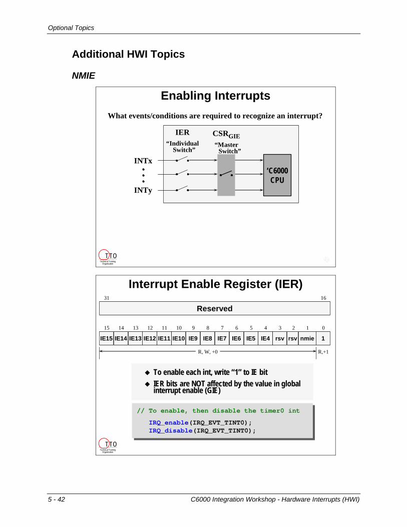
Enabling Interrupts
INTx
INTy
IER“Individual
Switch”
CSRGIE“Master
Switch”
‘C6000CPU
What events/conditions are required to recognize an interrupt?
Technical TrainingOrganization
T TO
Interrupt Enable Register (IER)
To enable each int, write “1” to IE bit IER bits are NOT affected by the value in global interrupt enable (GIE)
nmie 1rsvrsvIE4IE5IE6IE7IE8IE9IE10IE11IE12IE13IE14IE15
15 14 13 12 11 10 9 8 7 6 5 4 3 2 1 0
31 16
Reserved
R, W, +0 R,+1
// To enable, then disable the timer0 int
IRQ_enable(IRQ_EVT_TINT0);IRQ_disable(IRQ_EVT_TINT0);
// To enable, then disable the timer0 int
IRQ_enable(IRQ_EVT_TINT0);IRQ_disable(IRQ_EVT_TINT0);
Technical TrainingOrganization
T TO
5 - 42 C6000 Integration Workshop - Hardware Interrupts (HWI)

Optional Topics
NMIE - NMI Enable?
1rsv NMIENMIErsvIE4IE5IE6IE7IE8IE9IE10IE11IE12IE13IE14IE15
15 14 13 12 11 10 9 8 7 6 5 4 3 2 1 0
31 16
Reserved
R, W, +0 R,+1
NMIE enables the non-maskable interrupt (NMI)Exists to avoid unwanted NMIs occurring after RESET and before system is initializedNMIE must be enabled for any interrupts to occurOnce enabled, NMI is non-maskable Enable NMIE just before exiting your boot routine
NMIE is automatically set before main() when CDB file is included in the project
Technical TrainingOrganization
T TO
External Interrupt Pins
Valid Interrupt Signal
INTx
CLKOUT1
Interruptlatched
Interruptrecognized
by CPU
To generate a valid interrupt signal, hold INTx low for 2+ cycles, then high for 2+ cyclesInterrupt is latched on rising edge of CLKOUT1 following a rising edge of INTx (if above timing is met)Interrupt is recognized by the CPU one cycle later
To generate a valid interrupt signal, hold INTx low for 2+ cycles, then high for 2+ cyclesInterrupt is latched on rising edge of CLKOUT1 following a rising edge of INTx (if above timing is met)Interrupt is recognized by the CPU one cycle later
Interruptlow
Technical TrainingOrganization
T TO
C6000 Integration Workshop - Hardware Interrupts (HWI) 5 - 43

Optional Topics
Mapped Interrupt Registers Address (hex)Interrupt Multiplexor (High) 019C_0000Interrupt Multiplexor (Low) 019C _0004External Interrupt Polarity 019C_0008
Allows change of polarity for the external interrupts EXT_INT4-7
XIP7 XIP6 XIP5 XIP40123
0 = low to high (default)1 = high to low (inverted)
External Interrupt Polarity
Technical TrainingOrganization
T TO
Allows change of polarity for the external interrupts EXT_INT4-7
XIP7 XIP6 XIP5 XIP40123
0 = low to high (default)1 = high to low (inverted)
External Interrupt Polarity
Technical TrainingOrganization
T TO
5 - 44 C6000 Integration Workshop - Hardware Interrupts (HWI)

Optional Topics
Interrupt Vectors
Interrupt VectorsRESET:
mvkl _c_int00,b0mvkh _c_int00,b0b b0nopnopnopnopnop
nmi_vector:mvkl _nmi_isr,b0mvkh _nmi_isr,b0b b0nopnopnopnopnop
...
0h20h
80hA0hC0h
200h
_c_int00
RESET ISFPNMI ISFP
rsvdrsvd
INT4 ISFPINT5 ISFPINT6 ISFPINT7 ISFPINT8 ISFPINT9 ISFP
INT10 ISFPINT11 ISFPINT12 ISFPINT13 ISFPINT14 ISFPINT15 ISFP
boot.c
RESET
_c_int00
HWI_RESET Properties
Vector table can be relocated ...Technical TrainingOrganization
T TO
Vector Table Pointer (ISTP)
C6000CPU
B0 - BxxA0 - Axx
Data Regs
Control RegsISTP...
ISTB fieldR,W,+0 R,+0
31 10 9 0
Locates vector table on any 1K boundary
ISTP is located in CPUISTB field points to vector tableAllows you to locate Interrupt Vector Table on any 1K boundaryConfigure with in CDB fileor use IRQ_setVecs()
Use CDB file to set ISTP ...Technical Training
Organization
T TO
C6000 Integration Workshop - Hardware Interrupts (HWI) 5 - 45

Optional Topics
Let CDB setup ISTP
What does the Vector Table look like?Technical Training
Organization
T TO
Interrupt ISFP AddressReset 0x000NMI ISTB + 0x020reservedreservedINT4 ISTB + 0x080INT5 ISTB + 0x0A0INT6 ISTB + 0x0C0INT7 ISTB + 0x0E0
INT8 ISTB + 0x100INT9 ISTB + 0x120INT10 ISTB + 0x140INT11 ISTB + 0x160INT12 ISTB + 0x180INT13 ISTB + 0x1A0INT14 ISTB + 0x1C0INT15 ISTB + 0x1E0
New Interrupt Vector Table
Technical TrainingOrganization
T TO
5 - 46 C6000 Integration Workshop - Hardware Interrupts (HWI)

Optional Topics
HWI Interrupt Selector
IER CSRGIE
‘C6000CPU
HWI4
HWI15
IFR
1
0
1
HWI5
TINT0
XMIT1
EDMAINT
InterruptMux
Hardware Interrupt Selector
There are 12 configurable interruptsMost C6000 devices have more than 12 interrupt sourcesThe interrupt selector allows you to map any interrupt source to any HWI objectSide benefit is that you can change the hardware interrupt priority
Technical TrainingOrganization
T TO
C6000 Integration Workshop - Hardware Interrupts (HWI) 5 - 47

Optional Topics
Interrupt SelectionInterrupt Multiplexer High (INT10 - INT15)
Interrupt Multiplexer Low (INT4 - INT9)
2629INTSEL15
2124INTSEL14
1619INTSEL13
1013INTSEL12
58INTSEL11
03INTSEL10
2629INTSEL9
2124INTSEL8
1619INTSEL7
1013INTSEL6
58INTSEL5
03INTSEL4
C6701 Sources(HPI) DSPINT
TINT0TINT1
SD_INTEXT_INT4EXT_INT5EXT_INT6EXT_INT7
DMA_INT0DMA_INT1DMA_INT2DMA_INT3
XINT0RINT0XINT1RINT1
Sel #0000b0001b0010b0011b0100b0101b0110b0111b1000b1001b1010b1011b1100b1101b1110b1111b
Interrupt Selector registers are memory-mappedConfigured by HWI objects in Config ToolOr, set dynamically using IRQ_map()
Technical TrainingOrganization
T TO
5 - 48 C6000 Integration Workshop - Hardware Interrupts (HWI)

Optional Topics
CPU Interrupt Registers
Return Pointers (IRP/NRP)
NRP (NMI)NRP (NMI)31 0
R,W,+x
B.S2 NRP ;return, NMIE = 1NOP 5
31
IRP (interrupt)IRP (interrupt)0
R,W,+x
B.S2 IRP ;return, PGIE GIENOP 5
When interrupt serviced, address of next executepacket placed in IRP or NRP registerAt the end of interrupt service routine, branch to IRP/NRP:
Technical TrainingOrganization
T TO
IRP(Non-maskable Int. Return Ptr.)
IRQ_mapIRQ_config
IRQ_test
IFR(Interrupt Flag Register)
IRQ_set(sets ISR bit which sets corresponding IFR bit)
ISR(Interrupt Set Register)
IRQ_clear(sets ICR bit which clears corresponding IFR bit)
ICR(Interrupt Clear Register)
IRQ_enableIRQ_disableIRQ_restore
IER(Interrupt Enable Register)
IRP(Interrupt Return Pointer)
IRQ_setVecsor Use Config Tool
ISTP(Interrupt Service Table Ptr.)
Technical TrainingOrganization
T TO
C6000 Integration Workshop - Hardware Interrupts (HWI) 5 - 49

Optional Topics
Solutions to Paper Exercises
Exercise 1
Enable CPU Interrupts
void initHWI(void)
{
IRQ_enable(IRQ_EVT_EDMAINT);
IRQ_globalEnable();
}
Exercise 1: Fill in the lines of code required to enable the EDMAINT hardware interrupt:
Technical TrainingOrganization
T TO
5 - 50 C6000 Integration Workshop - Hardware Interrupts (HWI)

Optional Topics
Exercise 2
Exercise 2: Step 1
EDMA_Config gEdmaConfig = { EDMA_OPT_RMK(
EDMA_OPT_PRI_LOW, // Priority?EDMA_OPT_ESIZE_16BIT, // Element size?EDMA_OPT_2DS_NO, // 2 dimensional source?EDMA_OPT_SUM_INC, // Src update mode?EDMA_OPT_2DD_NO, // 2 dimensional dest?EDMA_OPT_DUM_INC, // Dest update mode?EDMA_OPT_TCINT_NO, // Cause EDMA interrupt?EDMA_OPT_TCC_OF(0), // Transfer complete code?EDMA_OPT_LINK_NO, // Enable link parameters?EDMA_OPT_FS_YES ), // Use frame sync?
... };
1. Change gEdmaConfig so that it will: (Just cross-out the old and jot in the new value)
Interrupt the CPU when transfer count reaches 0Auto-initialize and keep running
YES
YES
Technical TrainingOrganization
T TO
Exercise 2: Steps 2-42. Reserve “any” CIPR bit (save it to gXmtTCC). Then set this value in the
gEdmaConfig structure.
3. Allow the EDMA’s interrupt to pass through to the CPU.That is, set the appropriate CIER bit. (Hint: the TCC value indicates which bit in CIPR and CIER are used)
4. Hook the ISR function so it is called whenever the appropriate CIPR bit is set and the CPU is interrupted.
gXmtTCC = EDMA_intAlloc(-1);gEdmaConfig.opt |= EDMA_FMK (OPT, TCC, gXmtTCC);
EDMA_intEnable(gXmtTCC);
EDMA_intHook(gXmtTCC, edmaHWI);
Technical TrainingOrganization
T TO
C6000 Integration Workshop - Hardware Interrupts (HWI) 5 - 51

Optional Topics
Exercise 2: Steps 55. Enable the CPU to accept the EDMA interrupt. (Hint: Add 3 lines of code.)
#include <csl_irq.h>
void initHwi(void){
IRQ_enable(IRQ_EVT_EDMAINT);IRQ_globalEnable(void);
};
Technical TrainingOrganization
T TO
Exercise 2: Steps 6-9 (EDMA Reload)6. Declare a handle for an EDMA reload location and name it
hEdmaReload:
7. Allocate one of the Reload sets: (Hint: hEdmaReload gets this value)
8. Configure the EDMA reload set:
9. Modify both the EDMA channel and the reload set to link to the reload set of parameters:
EDMA_Handle hEdmaReload;
hEdmaReload = EDMA_allocTable( -1 );
EDMA_config (hEdmaReload,&gEdmaConfig);
EDMA_link(hEdma, hEdmaReload);EDMA_link(hEdmaReload, hEdmaReload);
Technical TrainingOrganization
T TO
5 - 52 C6000 Integration Workshop - Hardware Interrupts (HWI)
Related Documents