IOSR Journal of Electronics and Communication Engineering (IOSRJECE) ISSN : 2278-2834 Volume 1, Issue 2 (May-June 2012), PP 93-102 www.iosrjournals.org www.iosrjournals.org 93 | Page Hardware Implementation of Face Detection Using ADABOOST Algorithm Ms.Vijayalami 1 , Mr.B.Obulesu 2 1, 2 (ECE, Vignan Institute of Technology & Science, India) ABSTRACT: One of the main challenges of computer vision is efficiently detecting and classifying objects in an image or video sequence. Several machine learning approaches have been applied to this problem, demonstrating significant improvements in detection accuracy and speed. However, most approaches have limited object detection to a single class of objects, such as faces or pedestrians. A common benchmark for computer vision researchers is face detection. Given a set of images, a face detection algorithm determines which images have sub-windows containing faces. This task is trivial for humans, but is computationally expensive for machines. Most face detection systems simplify the face detection problem by constraining the problem to frontal views of non-rotated faces. Approaches have been demonstrated capable of relaxing these constraints, at the cost of additional computation. They utilize AdaBoost to select a set of features and train a classifier. The detector uses a cascade structure to reduce the number of features considered for each sub- window. This approach is significantly faster than previous techniques and is applicable for real-time systems. There is a need for hardware architectures capable of detecting several objects in large image frames, and which can be used under several object detection scenarios. In this work, we present a generic, flexible parallel architecture, which is suitable for all ranges of object detection applications and image sizes. The architecture implements the AdaBoost-based detection algorithm, which is considered one of the most efficient object detection algorithms. Keywords: AdaBoost, Correlator, Face Detection, FPGA,Template. I. INTRODUCTION Real-time object detection is becoming necessary for a wide number of applications related to computer vision and image processing, security, bioinformatics, and several other areas. Existing software implementations of object detection algorithms are constrained in small-sized images and rely on favorable conditions in the image frame to achieve real-time detection frame rates. Efforts to design hardware architectures have yielded encouraging results, yet are mostly directed towards a single application, targeting specific operating environments. Face detection is used in biometrics, often as a part of (or together with) a facial recognition system. It is also used in video surveillance, human computer interface and image database management. Some recent digital cameras use face detection for autofocus. Face detection is also useful for selecting regions of interest in photo slideshows that use a pan-and-scale Ken Burns effect. Face detection is gaining the interest of marketers. A webcam can be integrated into a television and detect any face that walks by. The system then calculates the race, gender, and age range of the face. Once the information is collected, a series of advertisements can be played that is specific toward the detected race/gender/age.Face detection is also being researched in the area of energy conservation. Televisions and computers can save energy by reducing the brightness. People tend to watch TV while doing other tasks and not focused 100% on the screen. The TV brightness stays the same level unless the user lowers it manually. The system can recognize the face direction of the TV user. When the user is not looking at the screen, the TV brightness is lowered. When the face returns to the screen, the brightness is increased. There are several algorithms used to perform detection each of which has its own advantages and disadvantages. A facial recognition system is a computer application for automatically identifying or verifying a person from a digital image or a video frame from a video source. One of the ways to do this is by comparing selected facial features from the image and a facial database. It is typically used in security systems and can be compared to other biometrics such as fingerprint or eye iris recognition systems. Automatic face detection is a complex problem in image processing. Many methods exist to solve this problem such as template matching, Fisher Linear Discriminant, Neural Networks, SVM, and MRC. Success has been achieved with each method to varying degrees and complexities. This paper presents a generic architecture based on the object detection framework presented by Viola and Jones [6] where they utilize the AdaBoost learning algorithm introduced by Freund and Schapire [7], [13].The object detection system uses a strong classifier to determine if sub-windows in an image contain a

Welcome message from author
This document is posted to help you gain knowledge. Please leave a comment to let me know what you think about it! Share it to your friends and learn new things together.
Transcript
IOSR Journal of Electronics and Communication Engineering (IOSRJECE)
ISSN : 2278-2834 Volume 1, Issue 2 (May-June 2012), PP 93-102 www.iosrjournals.org
www.iosrjournals.org 93 | Page
Hardware Implementation of Face Detection Using ADABOOST
Algorithm
Ms.Vijayalami1, Mr.B.Obulesu
2
1, 2 (ECE, Vignan Institute of Technology & Science, India)
ABSTRACT: One of the main challenges of computer vision is efficiently detecting and classifying objects in
an image or video sequence. Several machine learning approaches have been applied to this problem,
demonstrating significant improvements in detection accuracy and speed. However, most approaches have limited object detection to a single class of objects, such as faces or pedestrians. A common benchmark for
computer vision researchers is face detection. Given a set of images, a face detection algorithm determines
which images have sub-windows containing faces. This task is trivial for humans, but is computationally
expensive for machines. Most face detection systems simplify the face detection problem by constraining the
problem to frontal views of non-rotated faces. Approaches have been demonstrated capable of relaxing these
constraints, at the cost of additional computation. They utilize AdaBoost to select a set of features and train a
classifier. The detector uses a cascade structure to reduce the number of features considered for each sub-
window. This approach is significantly faster than previous techniques and is applicable for real-time systems.
There is a need for hardware architectures capable of detecting several objects in large image frames, and
which can be used under several object detection scenarios. In this work, we present a generic, flexible parallel
architecture, which is suitable for all ranges of object detection applications and image sizes. The architecture
implements the AdaBoost-based detection algorithm, which is considered one of the most efficient object detection algorithms.
Keywords: AdaBoost, Correlator, Face Detection, FPGA,Template.
I. INTRODUCTION
Real-time object detection is becoming necessary for a wide number of applications related to
computer vision and image processing, security, bioinformatics, and several other areas. Existing software
implementations of object detection algorithms are constrained in small-sized images and rely on favorable
conditions in the image frame to achieve real-time detection frame rates. Efforts to design hardware architectures have yielded encouraging results, yet are mostly directed towards a single application, targeting
specific operating environments. Face detection is used in biometrics, often as a part of (or together with)
a facial recognition system. It is also used in video surveillance, human computer interface and image database
management. Some recent digital cameras use face detection for autofocus. Face detection is also useful for
selecting regions of interest in photo slideshows that use a pan-and-scale Ken Burns effect. Face detection is
gaining the interest of marketers. A webcam can be integrated into a television and detect any face that walks
by. The system then calculates the race, gender, and age range of the face. Once the information is collected, a
series of advertisements can be played that is specific toward the detected race/gender/age.Face detection is also
being researched in the area of energy conservation. Televisions and computers can save energy by reducing the
brightness. People tend to watch TV while doing other tasks and not focused 100% on the screen. The TV
brightness stays the same level unless the user lowers it manually. The system can recognize the face direction of the TV user. When the user is not looking at the screen, the TV brightness is lowered. When the face returns
to the screen, the brightness is increased.
There are several algorithms used to perform detection each of which has its own advantages and
disadvantages. A facial recognition system is a computer application for automatically identifying or verifying a
person from a digital image or a video frame from a video source. One of the ways to do this is by comparing
selected facial features from the image and a facial database. It is typically used in security systems and can be
compared to other biometrics such as fingerprint or eye iris recognition systems. Automatic face detection is a
complex problem in image processing. Many methods exist to solve this problem such as template matching,
Fisher Linear Discriminant, Neural Networks, SVM, and MRC. Success has been achieved with each method to
varying degrees and complexities.
This paper presents a generic architecture based on the object detection framework presented by Viola
and Jones [6] where they utilize the AdaBoost learning algorithm introduced by Freund and Schapire [7], [13].The object detection system uses a strong classifier to determine if sub-windows in an image contain a
Hardware Implementation of Face Detection Using ADABOOST Algorithm
www.iosrjournals.org 94 | Page
specified object. The strong classifier is composed of a set of weak learners with associated weights. Each weak
learner uses a single image feature to produce a hypothesis. Viola and Jones show that AdaBoost can be used to
both select a small subset of features and train the classifiers. There are four steps to building an object detection
system with AdaBoost: select a dataset with positive and negative training examples, train the threshold values
for each feature, select and train a subset of the classifiers and train the attentional cascade. Once the detector is
built, images are exhaustively scanned at all locations and scales to identify objects. The architecture is evaluated by verifying its operation on a FPGA Spartan 3E kit, and by synthesizing and
implementing the architecture using Synopsys Design Compiler. The rest of this paper is organized as follows.
First, a detailed description of the algorithm is given in Section II, deals with object detection ,Section II also
gives a review of related work. Section III presents the Implementation, and Section IV presents the results,
explaining dataflow and computational semantics. Section VI concludes this paper, giving future directives.
II. FACE DETECTION& RELATED WORK
The object detection system uses a strong classifier to determine if sub-windows in an image contain a specified
object. The strong classifier is composed of a set of weak learners with associated weights. Each weak learner
uses a single image feature to produce a hypothesis. Viola and Jones show that AdaBoost can be used to both
select a small subset of features and train the classifiers. There are four steps to building an object detection
system with AdaBoost: select a dataset with positive and negative training examples, train the threshold values
for each feature, select and train a subset of the classifiers and train the attentional cascade. Once the detector is
built, images are exhaustively scanned at all locations and scales to identify objects.
The process is divided into two general phases. In the first phase, the candidate region undergoes
aggressive erosion to break up the region into smaller pieces. At this point, we evaluate the size of each piece; if
it is greater than a certain threshold, the piece is removed and is given to the template matcher as a possible face.
It is tempting to reject the smaller pieces as non-faces. However, experiments show that erosion often causes the smaller face to break in half. To compensate, we dilate the smaller pieces with the intention of recovering faces
that are unintentionally broken down. In most cases, this process of selective dilation is effective in
reconstructing faces. There are, however, false alarms, when regions such as the neck are falsely reconstructed.
We ultimately decide that given our edge correlator (described in the following) that this aggressive separation
of the blobs is unnecessary. In fact, repeated application of erosion, dilation, and thickening give unnaturally
jagged edges that are not beneficial to our edge correlator. Face Correlator- Implementation Details Once the
color segmentation and morphological operations have occurred, we are left with shapeless containing both the
image of interest as well as clutter and noise. One common method to distinguish desired image (i.e., faces in
our case), and clutter, is through correlating the unknown images with a template, and then matching the image
based on the correlation level. Methods for generating a template include averaging sample faces from training
sets or constructing a template from eigen facial deconstructions. Template matching is a simple, yet robust In our project, we first approach toward constructing the face template is first by constructing an average face from
all the training sets, using ground truth masks for extraction. All faces are equally weighted as follows:
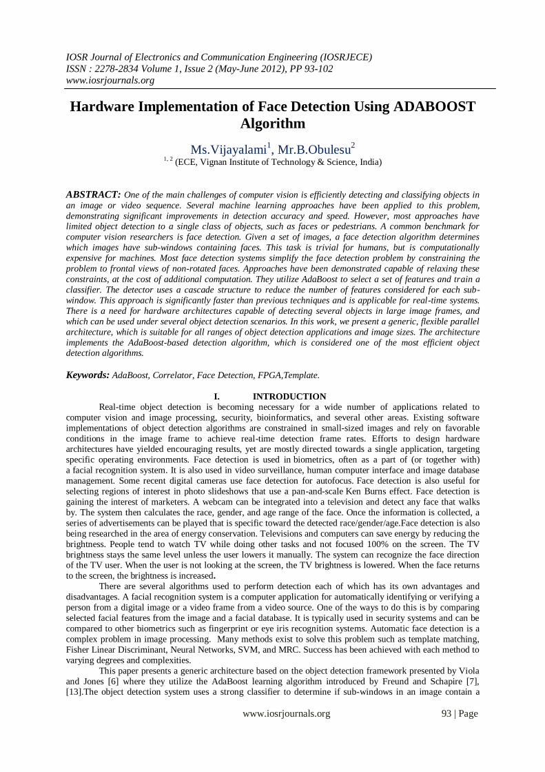
Where xi represents each facial image, scaled to the median width and height of the training image sets
using bi cubic interpolation. We chose the median width and height to maximize the correlation with images of
different sizes. Our first template looks like this:
Fig. 2.1 First template face
We then used calculated the 2-D cross-correlation to determine the goodness of match. We were
expecting to see good separation between faces and clutter. Instead we discovered that the average template
does not perform very well as image identifier.
Hardware Implementation of Face Detection Using ADABOOST Algorithm
www.iosrjournals.org 95 | Page
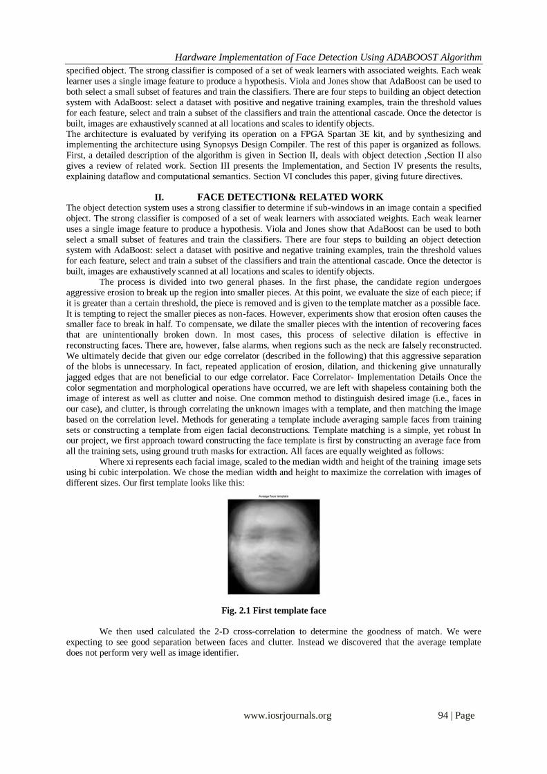
Fig.2.2 a) 2-face region. b) Cross-correlation with first template face
As one can see, this average face does not generate high levels of separation (thus one cannot identify
the two pictures from one single peak), which would be necessary for distinguishing faces. Worse, this face
template was prone to identify not only faces, but skin-color regions in general, whether it be body parts, khakis,
or the natural environment. This does not serve our detection purposes well. One possible explanation for this
fact could be that human skin color all happen to have similar hue, saturation, and intensity. Furthermore, the
averaging operation blends and reduces the unique and distinguishing features of all images, thus the separation
between faces is quite poor.
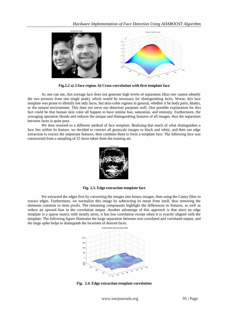
We then resorted to a different method of face template. Realizing that much of what distinguishes a
face lies within its feature, we decided to convert all grayscale images to black and white, and then use edge
extraction to extract the important features, then combine them to form a template face. The following face was constructed from a sampling of 25 faces taken from the training set.
Fig. 2.3. Edge extraction template face
We extracted the edges first by converting the images into binary images, then using the Canny filter to extract edges. Furthermore, we normalize this image by subtracting its mean from itself, thus removing the
elements common to most pixels. The remaining components highlight the differences in features, as well as
reduce an upward bias in the correlation output. Another advantage of this approach is that since an edge
template is a sparse matrix with mostly zeros, it has low correlation except when it is exactly aligned with the
template. The following figure illustrates the large separation between non-correlated and correlated output, and
the large spike helps to distinguish the locations of desired faces.
Fig. 2.4. Edge extraction template correlation
Hardware Implementation of Face Detection Using ADABOOST Algorithm
www.iosrjournals.org 96 | Page
Another advantage of using edges for detection is that they form clearly identiable regions, which can
then be counted and used to help distinguish unknown images extracted from the segmentation mask. Using
label, we can label and count the regions, and it shows that the face has 43 connected regions, while the hand
only has 14. Since faces are in general more complex than hands, clothing, or other clutter, by using the region
statistics of these edges images, it can further supplement our algorithm. Detection Algorithm Three main
criteria were used in our detection algorithm. We used: • Correlation: Using the edge template as a measure of how closely it matches our average facial features
• Dimensions: Using width, height and area, whether the image is large enough to contain a face, observing
aspect ratios, etc.
• Region counting: Using the region number statistics to help differentiate faces from clutter.
The precise algorithm is described in our Matlab implementation, but we basically used the correlation
level on the first pass, eliminating objects that are clearly unlikely to be faces. Then we used heuristics such as
dimensions and region counting to help determine whether zero, one, or multiple faces reside in a given region.
If an image does not qualify as a face, we move on to the next object. If a single face exists, we return the
location of the highest correlation peak as the faces estimated location. If, however, we suspected an image
formed by one or more partially or wholly joined faces, we have to then use a multiple facial detection routine.
Detecting Multiple Faces within a Single Face Region For the case of multiple faces within a single region, we
cannot rely solely on the single correlation peak detection used for single faces. Once an estimate of the expected number of faces within a region has been made, we attempt to find that number of peaks (and
corresponding face locations) in the correlation output for the given region.
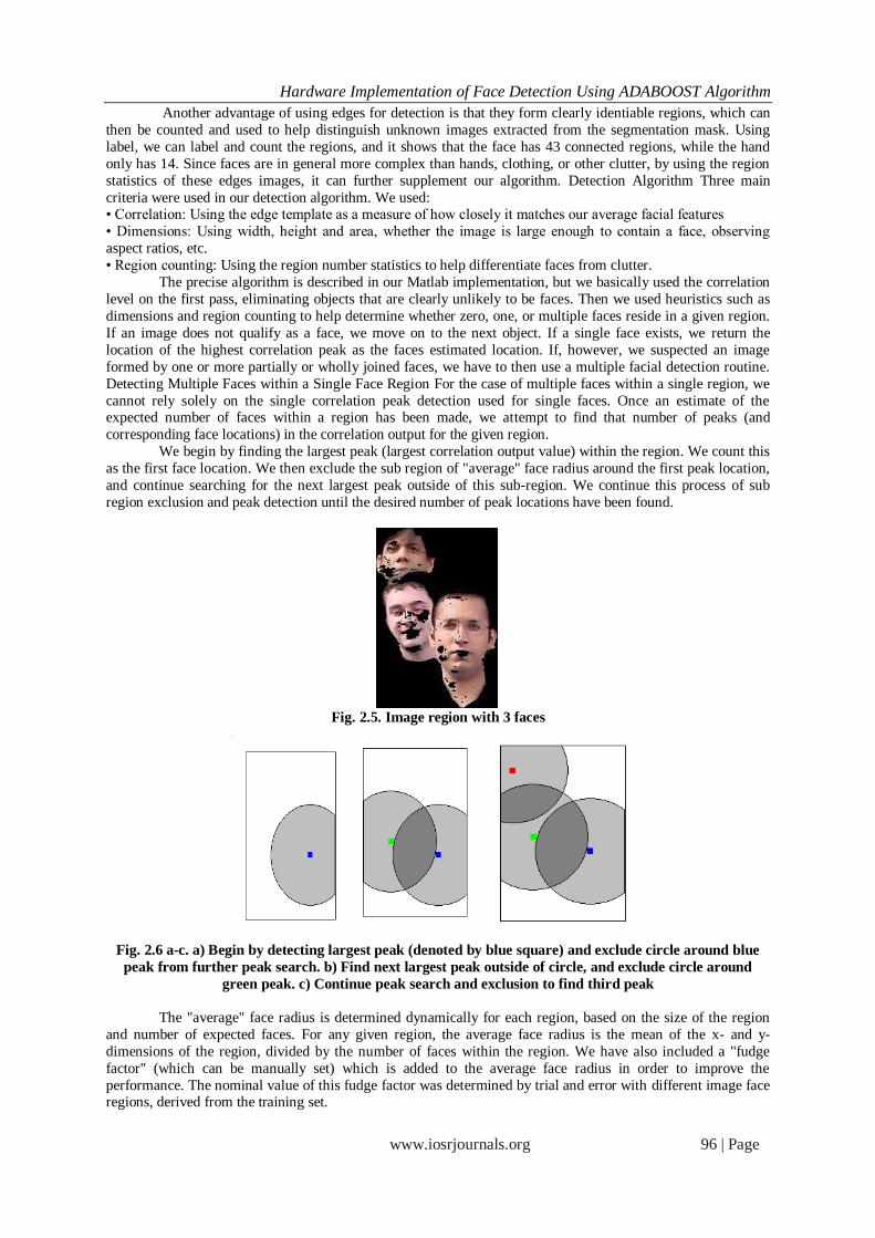
We begin by finding the largest peak (largest correlation output value) within the region. We count this
as the first face location. We then exclude the sub region of "average" face radius around the first peak location,
and continue searching for the next largest peak outside of this sub-region. We continue this process of sub
region exclusion and peak detection until the desired number of peak locations have been found.
Fig. 2.5. Image region with 3 faces
Fig. 2.6 a-c. a) Begin by detecting largest peak (denoted by blue square) and exclude circle around blue
peak from further peak search. b) Find next largest peak outside of circle, and exclude circle around
green peak. c) Continue peak search and exclusion to find third peak
The "average" face radius is determined dynamically for each region, based on the size of the region
and number of expected faces. For any given region, the average face radius is the mean of the x- and y-
dimensions of the region, divided by the number of faces within the region. We have also included a "fudge
factor" (which can be manually set) which is added to the average face radius in order to improve the
performance. The nominal value of this fudge factor was determined by trial and error with different image face regions, derived from the training set.
Hardware Implementation of Face Detection Using ADABOOST Algorithm
www.iosrjournals.org 97 | Page
The object detection system uses simple features to build weak learners. Viola and Jones suggest the
use of features rather than pixel values directly, because it enables encoding of ad-hoc domain knowledge that is
difficult to learn from a finite set of training data. Also, a feature-based system is much faster than a pixel-based
system. The features utilized are rectangular features similar to Haar basis functions, which have been used by
Papageorgious et al.
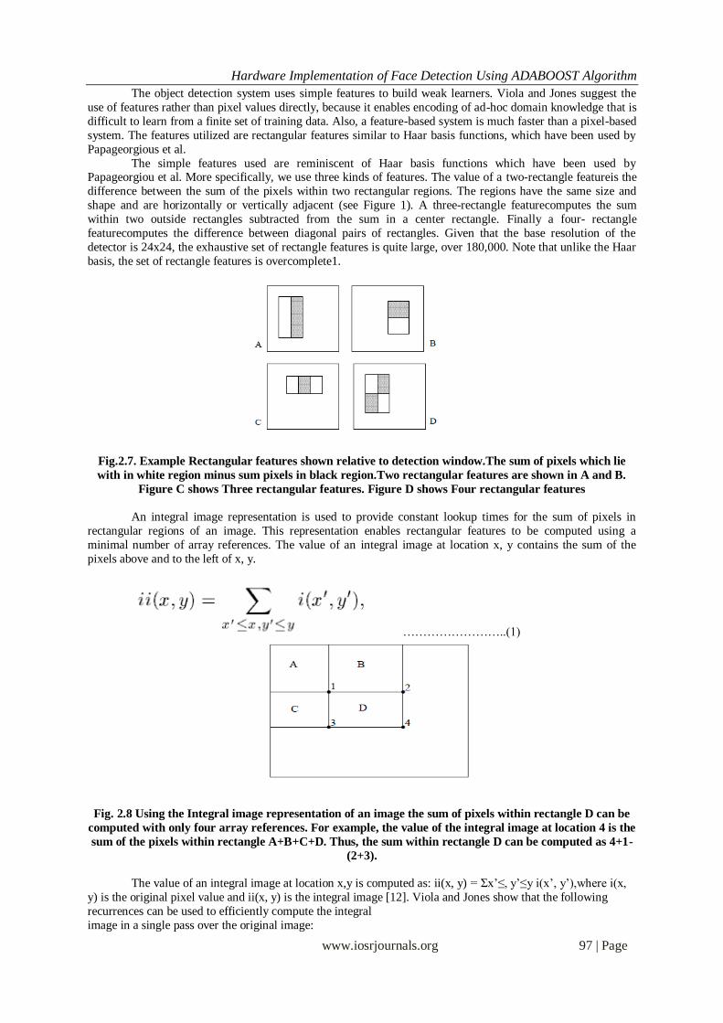
The simple features used are reminiscent of Haar basis functions which have been used by Papageorgiou et al. More specifically, we use three kinds of features. The value of a two-rectangle featureis the
difference between the sum of the pixels within two rectangular regions. The regions have the same size and
shape and are horizontally or vertically adjacent (see Figure 1). A three-rectangle featurecomputes the sum
within two outside rectangles subtracted from the sum in a center rectangle. Finally a four- rectangle
featurecomputes the difference between diagonal pairs of rectangles. Given that the base resolution of the
detector is 24x24, the exhaustive set of rectangle features is quite large, over 180,000. Note that unlike the Haar
basis, the set of rectangle features is overcomplete1.
Fig.2.7. Example Rectangular features shown relative to detection window.The sum of pixels which lie
with in white region minus sum pixels in black region.Two rectangular features are shown in A and B.
Figure C shows Three rectangular features. Figure D shows Four rectangular features
An integral image representation is used to provide constant lookup times for the sum of pixels in
rectangular regions of an image. This representation enables rectangular features to be computed using a
minimal number of array references. The value of an integral image at location x, y contains the sum of the
pixels above and to the left of x, y.
……………………..(1)
Fig. 2.8 Using the Integral image representation of an image the sum of pixels within rectangle D can be
computed with only four array references. For example, the value of the integral image at location 4 is the
sum of the pixels within rectangle A+B+C+D. Thus, the sum within rectangle D can be computed as 4+1-
(2+3).
The value of an integral image at location x,y is computed as: ii(x, y) = Σx’≤, y’≤y i(x’, y’),where i(x,
y) is the original pixel value and ii(x, y) is the integral image [12]. Viola and Jones show that the following
recurrences can be used to efficiently compute the integral
image in a single pass over the original image:
Hardware Implementation of Face Detection Using ADABOOST Algorithm
www.iosrjournals.org 98 | Page
s(x, y) = s(x, y - 1) + i(x, y) …………………………(2)
ii(x, y) = ii(x - 1, y) + s(x, y)’ ………………………(3)
where s(x, y) is the cumulative row sum and s(x, 0) = 0 and ii(0, y) = 0. The top left corner of an integral image
is shown in Figure 2. The variable Px,y refers to the pixel value of an image at location x, y. Viola and Jones
show that the sum of pixels in a rectangular region can be found in four array references. The value of D in
Figure 3 can be computed as 4 + 1 – (2 + 3). Therefore, the time required to compute a feature is not dependent on its size.
2.1 Learning the Classifier Function
The system of Viola and Jones makes a successful application of the discrete version of AdaBoost to
learn the classification function. Specifically, AdaBoost is adapted to solve the following three fundamental
problems in one boosting procedure:
Learning effective featuresfrom a large feature set. The conventional AdaBoost procedure can be easily
interpreted as a greedy feature selection process. Consider the general problem of boosting, in which a large set
of classification functions are combined using a weighted majority vote. The challenge is to associate a large weight with each good classification function and a smaller with poor functions. Drawing an analogy between
weak classifiers and features, AdaBoost is an effective procedure for searching out a small number of good
features.
Constructing weak classifierseach of which is based on one of the selected features. One practical
method for completing this analogy is to restrict the weak learner to the set of classification functions each of
which depend on a single feature. In support of this goal, the weak learning algorithm is designed to select the
single rectangle feature which best separates the positive and negative examples. From the theory this implies
choosing the feature which minimizes the error ²t or Zt, for the discrete or real version of AdaBoost,
respectively.
Boosting the weak classifiersinto a stronger classifier.AdaBoost combines the Selected features as a
linear combination and provides a strong theoretical Backbone for the bound of the training error. The way Real AdaBoost is adopted to solve these problems is described in Algorithm4.
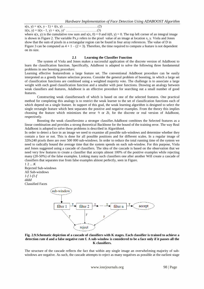
In order to detect a face in an image we need to examine all possible sub-windows and determine whether they
contain a face or not. This is done for all possible positions and for different scales. In a regular image of
320x240 pixels there are over 500 000 sub-windows. In order to reduce the total running time of the system we
need to radically bound the average time that the system spends on each sub-window. For this purpose, Viola
and Jones suggested using a cascade of classifiers. The idea of the cascade is based on the observation that we
need very few features to create a classifier that accepts almost 100% of the positive examples while rejecting
many (20-50%) of the false examples. Linking many such classifiers one after another Will create a cascade of
classifiers that separates true from false examples almost perfectly, seen in Figure.
1 2 ... K
Rejected Sub-windows
All Sub-windows 1-f 1-f1-f
dddd
Classified Faces
Fig. 2.9.Schematic depiction of a cascade of classifiers with K stages. Each classifier is trained to achieve a
detection rate d and a false negative rate f. A sub-window is considered to be a face only if it passes all the
K classifiers.
The structure of the cascade reflects the fact that within any single image an overwhelming majority of sub-
windows are negative. As such, the cascade attempts to reject as many negatives as possible at the earliest stage

Hardware Implementation of Face Detection Using ADABOOST Algorithm
www.iosrjournals.org 99 | Page
possible. While a positive instance will trigger the evaluation of every classifier in the cascade, this is an
exceedingly rare event.
The building process of the cascade is described in Algorithm 5. Inputs to the algorithm are the desired
false positive rate, f, the detection rate, d, of the cascade stages and the final positive rate, f¯nal, of the cascade.
Each stage of the cascade is trained by AdaBoost with the number of features used being increased until the
target detection and false positive rates can be met for this level. Because AdaBoost attempts only to minimize errors and is not specifically designed to achieve high detection rates at the expense of larger false positive rates,
a threshold, µ, for the strong classifier is introduced. That is, let the new strong classifier be
H(x) ¸ µ ) x is a face
<µ ) x is a non-face
Algorithm 4 TheAdaBoost Algorithm for Learning a Classifier Function
Given example images (x1; y1); : : : ; (xm; ym) where yi= ¡1; +1 for negative and
positive examples, respectively.
Initialize weights wi = 1/2M, 1/2L for yi = 0, 1 respectively, where M and L are the
number of negatives and positives.
For t = 1 to T 1. Normalize the weights, so that i=1:nwi = 1
2. Choose the classifier, hj, with the lowest error εj:
εj = i wi |hj(xi) – yi|.
3. Update the weights for each example:
wi βt example xi is classified correctly
wi =wi βt example xi is classified correctly
wi otherwise
where βt = εt/(1 - εt) and t = - log βt
The final strong classifier is:
h(x) =1 t=1:T αtht(x) ≥ λ Σt=1:T αt, where λ = ½
0 otherwise
Algorithm 5 Training algorithm for building a cascade detector
Input: Allowed false positive rates f, detection rate d and final false positive rate
f¯nal.
Initialize: F0 = 1, D0 = 1
Do until Fi <f¯nal
1. Train a classifier with AdaBoostuntil freached < f and d reached > d on the
validation set.
2. Fi+1 = Fi £ f reached
3. Di+1 = Di £ d reached
4. Discard misclassified faces and generate new data from non-face images.
III. IMPLEMENTATIONAND SYNTHESIS RESULTS The work is implemented using following steps:
1. The first module is conversion of image into text file by using Matlab.
2. AdaBoost algorithm was implemented by using System C language. The code has been developed in System
C language. This code was saved as .C file and added as source file in Xilinx Platform Studio (XPS)
Platform.
Fig. 3.1. Block diagram
Input Im
age
Object Detection
Net list
file
Bitmap
file
Spartan-3E FPGA
kit

Hardware Implementation of Face Detection Using ADABOOST Algorithm
www.iosrjournals.org 100 | Page
3. The hardware was realized on a Xilinx FPGA. The Micro Blaze Processor IP core was used to design the
architecture for real time object detection. The processor was coded using VHDL and simulated using
XILINX ISE.
4. VHDLcan not handle the standard image formats, the images were converted to ASCII text files using
MATLAB. The ASCII text file was applied as vector to the hardware interface. The output files were
similarly converted and viewed in MATLAB.
Fig. 3.2. The output file viewed in MATLAB
5. The netlist file was generated and bit stream file was generated. Then .elf file was created. This file was
dumped into Spartan-3E FPGA kit. The led will glows if code was dumped successfully. Then the resultant
image will be displayed in Visual Basic.
Fig.3.3. Face detected image window
6. A part of the synthesis report showing the hardware required is presented in Table. The clock frequency:
65.432MHz. Total memory usage is 187092 kilobytes
Fig. 3.4. Synthesis report
Hardware Implementation of Face Detection Using ADABOOST Algorithm
www.iosrjournals.org 101 | Page
Synthesis Results: Device Selected: 3s200tq144-4
Number of Slices 1880 out of 1920 (97%)
Number of Slice flip Flops 2118 out of 3840 (55%)
Number of 4 input LUT’s 2971 out of 3840 (77%)
Number of IOs 62
Number of bonded IOBs 62 out of 97 (63%)
Number of RAMs 4 out of 12(33%)
Number of Multipliers 3 out of 12 (25%)
Number of GCLKS 4 out of 8(50%)
Number of DCMs 1 out of 4 (25%)
Table. 3.1: Synthesis report showing hardware requirements
7. The execution time for the entire program for an image of size 128*128 is a matter of few seconds.
Fig. 3.5. Timing report
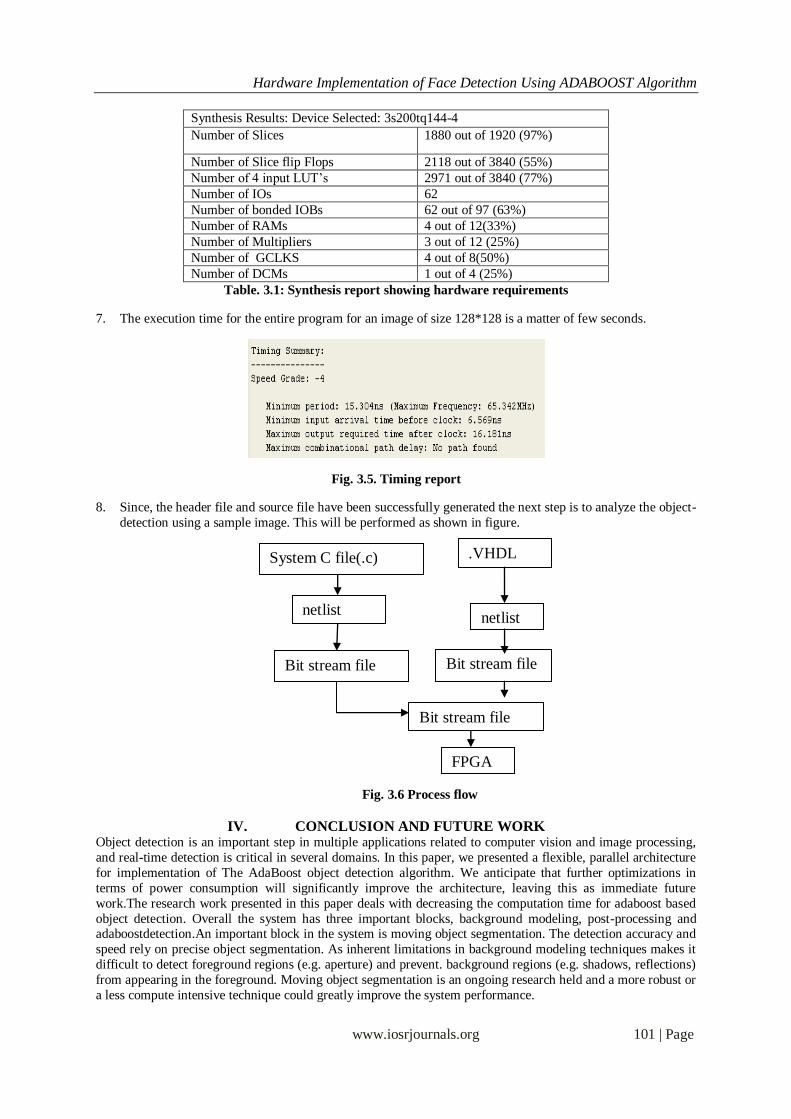
8. Since, the header file and source file have been successfully generated the next step is to analyze the object-
detection using a sample image. This will be performed as shown in figure.
Fig. 3.6 Process flow
IV. CONCLUSION AND FUTURE WORK Object detection is an important step in multiple applications related to computer vision and image processing,
and real-time detection is critical in several domains. In this paper, we presented a flexible, parallel architecture
for implementation of The AdaBoost object detection algorithm. We anticipate that further optimizations in
terms of power consumption will significantly improve the architecture, leaving this as immediate future
work.The research work presented in this paper deals with decreasing the computation time for adaboost based
object detection. Overall the system has three important blocks, background modeling, post-processing and adaboostdetection.An important block in the system is moving object segmentation. The detection accuracy and
speed rely on precise object segmentation. As inherent limitations in background modeling techniques makes it
difficult to detect foreground regions (e.g. aperture) and prevent. background regions (e.g. shadows, reflections)
from appearing in the foreground. Moving object segmentation is an ongoing research held and a more robust or
a less compute intensive technique could greatly improve the system performance.
System C file(.c)
Bit stream file
.VHDL
netlist netlist
Bit stream file
FPGA
Bit stream file

Hardware Implementation of Face Detection Using ADABOOST Algorithm
www.iosrjournals.org 102 | Page
Another important aspect is the adaboost cascade detector; where by significant reduction in false positives can
be achieved by training the Haar cascade with a more robust data set from the target object class. Moreover, the
adaboost training process is highly complex, time consuming and requires few hundred training samples. Efforts
to reduce training complexity could greatly benefit surveillance applications. The proposed system is tested for
faces and upper-body using pre trained Haar feature databases from Open CV. However the system could be
used to detect other objects for example automobiles and this should be investigated.Finally, the optimal number of features per stage and the optimal number of stages in hardware to achieve real-time detection performance
and the tradeoffs thereof requires significant research attention in the future. Also low complexity hardware for
other compute intensive blocks such as morphology, connected component labeling, integral image computation
and image scaling could be a good research direction.
REFERENCES [1] J. MacQueen, “Some methods for classification and analysis of multivariate observations,” in Proc. 5th Berkeley Symp. Math. Stat.
Probab.,1967, pp. 281–297.
[2] K. Krishna, K. R. Ramakrishnan, and M. A. L. Thathachar, “Vector quantization using genetic K-means algorithm for image
compression,” in Proc. Int. Conf. Inf., Commun. Signal Process., Sep. 1997, pp. 1585–1587.
[3] Y.-C. Hu and M.-G.Lee, “K-means-based color palette design scheme with the use of stable flags,” J. Electron.Imag., vol. 16, no. 3,
pp. 033003 1–11, 2007.
[4] S. Ray and R. H. Turi, “Determination of number of clusters in K-means clustering and application in colour image segmentation,”
in Proc. 4th Int. Conf. Adv. Pattern Recog. Digit.Techn., 1999, pp. 137–143.
[5] M. Leeser, J. Theiler,M. Estlick, and J. J. Szymanski, “Design tradeoffs in a hardware implementation of the K-means clustering
algorithm,” in Proc. IEEE Sensor Array Multichannel Signal Process. Workshop, 2000, pp. 520–524.
[6] M. Estlick, M. Leeser, J. Theiler, and J. J. Szymanski, “Algorithmic transformations in the implementation of K-means clustering
on reconfigurable hardware,” in Proc. ACM/SIGDA Int. Symp. Field Program.Gate Arrays, 2001, pp. 103–110.
[7] A. G. d. S. Filho, A. C. Frery, C. C. de Araújo, H. Alice, J. Cerqueira, J. A. Loureiro, M. E. de Lima, M. d. G. S. Ol iveira, and M.
M. Horta, “Hyperspectral images clustering on reconfigurable hardware using the K-means algorithm,” in Proc. Symp.
Integr.Circuits Syst. Des., Sep. 2003, pp. 99–104.
[8] B. Maliatski and O. Yadid-Pecht, “Hardware-driven adaptive K-meansclustering for real-time video imaging,” IEEE Trans. Circuits
Syst. Video Technol., vol. 15, no. 1, pp. 164–166, Jan. 2005.
[9] T. Maruyama, “Real-time K-means clustering for color images on reconfigurable hardware,” in Proc. Int. Conf. Pattern Recog.,
2006, pp. 816–819.
[10] T.-W. Chen, C.-H.Sun, J.-Y.Bai, H.-R.Chen, and S.-Y. Chien, “Architectural analyses of K-means silicon intellectual property for
image segmentation,” in Proc. IEEE Int. Symp.Circuits Syst., May 2008, pp.2578–2581.
[11] T.-W. Chen and S.-Y.Chien, “Bandwidth adaptive hardware architecture of K-means clustering for video analysis,” IEEE Trans.
Very Large Scale Integr. (VLSI) Syst., vol. 18, no. 6, pp. 957–966, Jun. 2010.
[12] T.-W. Chen, Y.-L.Chen, and S.-Y. Chien, “Photo retrieval based on spatial layout with hardware acceleration,” in Proc. IEEE Int.
Symp. Intell. Signal Process. Commun. Syst., Dec. 2009, pp. 196–199.
[13] ARM Limited, Cambridge, U.K., “AMBA Specification (Rev 2.0),” 1999. [Online].
[14] J. Yang, Y.-G.Jiang, A. G. Hauptmann, and C.-W.Ngo, “Evaluating bag-of-visual-words representations in scene classification,” in
Proc. Int. Workshop Multimedia Inf. Retrieval, 2007, pp. 197–206.
[15] A. K. Jain, M. N. Murty, and P. J. Flynn, “Data clustering: A review,” ACM Comput. Surveys, vol. 31, no. 3, pp. 264–323, 1999.
[16] R. O. Duda, P. E. Hard, and D. G. Stork, Pattern Classification, 2nd
ed. Singapore: Wiley Interscience, 2000.
[17] T.-S Chen, T.-H Tsai, Y.-T Chen, C.-C Lin, R.-C Chen, S.-Y Li, and H.-Y Chen, “A combined K-means and hierarchical clustering
method for improving the clustering efficiency of microarray,” in Proc.IEEE Int. Symp. Intell. Signal Process. Commun.Syst., Dec.
2005, pp.405–408.
[18] N. Chehata and F. Bretar, “Terrain modeling from LIDAR data: Hierarchical K-means filtering and markovian regularization,” in
Proc. IEEE Int. Conf. Image Process., 2008, pp. 1900–1903.
[19] Y.-C. F. Wang and D. Casasent, “Hierarchical K-means clustering using new support vector machines for multi-class
classification,” in Proc. Int. Joint Conf. Neural Netw., 2006, pp. 3457–3464.
[20] Y. Liu and Z. Liu, “An improved hierarchical K-means algorithm for web document clustering,” in Proc. Int. Conf. Comput. Sci.
Inf. Technol., 2008, pp. 606–610.
[21] D. Nistér and H. Stewénius, “Scalable recognition with a vocabulary tree,” in Proc. IEEE Comput. Soc. Conf. Comput. Vision
Pattern Recog., 2006, pp. 2161–2168.
[22] J. Philbin, O. Chum, M. Isard, J. Sivic, and A. Zisserman, “Object retrieval with large vocabularies and fast spatial matching,” in
Proc. IEEE Comput. Soc. Conf. Comput. Vision Pattern Recog., 2007, pp. 1–8.
[23] J. M. Peña, J. A. Lozano, and P. Larrañaga, “An empirical comparison of four initialization methods for the K-means algorithm,”
Pattern Recog. Lett., vol. 20, no. 10, pp. 1027–1040, 1999.
Related Documents


![Theory and Applications of Boostingschapire/talks/nips-tutorial.pdf · AdaBoost •[Freund & Schapire ’95]: • introduced “AdaBoost” algorithm • strong practical advantages](https://static.cupdf.com/doc/110x72/5ae63d3c7f8b9acc268d1dfa/theory-and-applications-of-schapiretalksnips-tutorialpdfadaboost-freund-schapire.jpg)
![An FPGA-based Parallel Hardware Architecture for Real-time ... · presented an eye detection method using AdaBoost training with MCT-based eye features [17]. The MCT-based AdaBoost](https://static.cupdf.com/doc/110x72/5eb711373352f8751405d84d/an-fpga-based-parallel-hardware-architecture-for-real-time-presented-an-eye.jpg)