SRX5800 Services Gateway Hardware Guide Published: 2010-12-21 Copyright © 2010, Juniper Networks, Inc.

Welcome message from author
This document is posted to help you gain knowledge. Please leave a comment to let me know what you think about it! Share it to your friends and learn new things together.
Transcript
SRX5800 ServicesGateway
Hardware Guide
Published: 2010-12-21
Copyright © 2010, Juniper Networks, Inc.

Juniper Networks, Inc.1194 North Mathilda AvenueSunnyvale, California 94089USA408-745-2000www.juniper.net
This product includes the Envoy SNMP Engine, developed by Epilogue Technology, an Integrated Systems Company. Copyright © 1986-1997,Epilogue Technology Corporation. All rights reserved. This program and its documentation were developed at private expense, and no partof them is in the public domain.
This product includes memory allocation software developed by Mark Moraes, copyright © 1988, 1989, 1993, University of Toronto.
This product includes FreeBSD software developed by the University of California, Berkeley, and its contributors. All of the documentationand software included in the 4.4BSD and 4.4BSD-Lite Releases is copyrighted by the Regents of the University of California. Copyright ©1979, 1980, 1983, 1986, 1988, 1989, 1991, 1992, 1993, 1994. The Regents of the University of California. All rights reserved.
GateD software copyright © 1995, the Regents of the University. All rights reserved. Gate Daemon was originated and developed throughrelease 3.0 by Cornell University and its collaborators. Gated is based on Kirton’s EGP, UC Berkeley’s routing daemon (routed), and DCN’sHELLO routing protocol. Development of Gated has been supported in part by the National Science Foundation. Portions of the GateDsoftware copyright © 1988, Regents of the University of California. All rights reserved. Portions of the GateD software copyright © 1991, D.L. S. Associates.
This product includes software developed by Maker Communications, Inc., copyright © 1996, 1997, Maker Communications, Inc.
Juniper Networks, Junos, Steel-Belted Radius, NetScreen, and ScreenOS are registered trademarks of Juniper Networks, Inc. in the UnitedStates and other countries. The Juniper Networks Logo, the Junos logo, and JunosE are trademarks of Juniper Networks, Inc. All othertrademarks, service marks, registered trademarks, or registered service marks are the property of their respective owners.
Juniper Networks assumes no responsibility for any inaccuracies in this document. Juniper Networks reserves the right to change, modify,transfer, or otherwise revise this publication without notice.
Products made or sold by Juniper Networks or components thereof might be covered by one or more of the following patents that areowned by or licensed to Juniper Networks: U.S. Patent Nos. 5,473,599, 5,905,725, 5,909,440, 6,192,051, 6,333,650, 6,359,479, 6,406,312,6,429,706, 6,459,579, 6,493,347, 6,538,518, 6,538,899, 6,552,918, 6,567,902, 6,578,186, and 6,590,785.
SRX5800 Services Gateway Hardware GuideCopyright © 2010, Juniper Networks, Inc.All rights reserved. Printed in USA.
Revision HistoryAugust 2008—530-025322-01 Revision 01 Initial releaseOctober 2008—530-025322-01 Revision 02 Correct system description sectionOctober 2008—530-025322-01 Revision 03 Minor change routing engine section.April 2009—530-029952-01 Revision 01 Add Flex IOC and port modules.July 2009—530-029952-01 Revision 02November 2010—530-029952-01 Revision 03 Add high-capacity power supplies.
The information in this document is current as of the date listed in the revision history.
SOFTWARE LICENSE
The terms and conditions for using this software are described in the software license contained in the acknowledgment to your purchaseorder or, to the extent applicable, to any reseller agreement or end-user purchase agreement executed between you and Juniper Networks.By using this software, you indicate that you understand and agree to be bound by those terms and conditions.
Generally speaking, the software license restricts the manner in which you are permitted to use the software and may contain prohibitionsagainst certain uses. The software license may state conditions under which the license is automatically terminated. You should consultthe license for further details.
For complete product documentation, please see the Juniper Networks Web site at www.juniper.net/techpubs.
Copyright © 2010, Juniper Networks, Inc.ii

ENDUSER LICENSE AGREEMENT
READ THIS ENDUSER LICENSE AGREEMENT (“AGREEMENT”) BEFORE DOWNLOADING, INSTALLING, ORUSING THE SOFTWARE.BY DOWNLOADING, INSTALLING, OR USING THE SOFTWARE OR OTHERWISE EXPRESSING YOUR AGREEMENT TO THE TERMSCONTAINED HEREIN, YOU (AS CUSTOMER OR IF YOU ARE NOT THE CUSTOMER, AS A REPRESENTATIVE/AGENT AUTHORIZED TOBIND THE CUSTOMER) CONSENT TO BE BOUND BY THIS AGREEMENT. IF YOU DO NOT OR CANNOT AGREE TO THE TERMS CONTAINEDHEREIN, THEN (A) DO NOT DOWNLOAD, INSTALL, OR USE THE SOFTWARE, AND (B) YOU MAY CONTACT JUNIPER NETWORKSREGARDING LICENSE TERMS.
1. The Parties. The parties to this Agreement are (i) Juniper Networks, Inc. (if the Customer’s principal office is located in the Americas) orJuniper Networks (Cayman) Limited (if the Customer’s principal office is located outside the Americas) (such applicable entity being referredto herein as “Juniper”), and (ii) the person or organization that originally purchased from Juniper or an authorized Juniper reseller the applicablelicense(s) for use of the Software (“Customer”) (collectively, the “Parties”).
2. The Software. In this Agreement, “Software” means the program modules and features of the Juniper or Juniper-supplied software, forwhich Customer has paid the applicable license or support fees to Juniper or an authorized Juniper reseller, or which was embedded byJuniper in equipment which Customer purchased from Juniper or an authorized Juniper reseller. “Software” also includes updates, upgradesand new releases of such software. “Embedded Software” means Software which Juniper has embedded in or loaded onto the Juniperequipment and any updates, upgrades, additions or replacements which are subsequently embedded in or loaded onto the equipment.
3. LicenseGrant.Subject to payment of the applicable fees and the limitations and restrictions set forth herein, Juniper grants to Customera non-exclusive and non-transferable license, without right to sublicense, to use the Software, in executable form only, subject to thefollowing use restrictions:
a. Customer shall use Embedded Software solely as embedded in, and for execution on, Juniper equipment originally purchased byCustomer from Juniper or an authorized Juniper reseller.
b. Customer shall use the Software on a single hardware chassis having a single processing unit, or as many chassis or processing unitsfor which Customer has paid the applicable license fees; provided, however, with respect to the Steel-Belted Radius or Odyssey AccessClient software only, Customer shall use such Software on a single computer containing a single physical random access memory spaceand containing any number of processors. Use of the Steel-Belted Radius or IMS AAA software on multiple computers or virtual machines(e.g., Solaris zones) requires multiple licenses, regardless of whether such computers or virtualizations are physically contained on a singlechassis.
c. Product purchase documents, paper or electronic user documentation, and/or the particular licenses purchased by Customer mayspecify limits to Customer’s use of the Software. Such limits may restrict use to a maximum number of seats, registered endpoints, concurrentusers, sessions, calls, connections, subscribers, clusters, nodes, realms, devices, links, ports or transactions, or require the purchase ofseparate licenses to use particular features, functionalities, services, applications, operations, or capabilities, or provide throughput,performance, configuration, bandwidth, interface, processing, temporal, or geographical limits. In addition, such limits may restrict the useof the Software to managing certain kinds of networks or require the Software to be used only in conjunction with other specific Software.Customer’s use of the Software shall be subject to all such limitations and purchase of all applicable licenses.
d. For any trial copy of the Software, Customer’s right to use the Software expires 30 days after download, installation or use of theSoftware. Customer may operate the Software after the 30-day trial period only if Customer pays for a license to do so. Customer may notextend or create an additional trial period by re-installing the Software after the 30-day trial period.
e. The Global Enterprise Edition of the Steel-Belted Radius software may be used by Customer only to manage access to Customer’senterprise network. Specifically, service provider customers are expressly prohibited from using the Global Enterprise Edition of theSteel-Belted Radius software to support any commercial network access services.
The foregoing license is not transferable or assignable by Customer. No license is granted herein to any user who did not originally purchasethe applicable license(s) for the Software from Juniper or an authorized Juniper reseller.
4. Use Prohibitions. Notwithstanding the foregoing, the license provided herein does not permit the Customer to, and Customer agreesnot to and shall not: (a) modify, unbundle, reverse engineer, or create derivative works based on the Software; (b) make unauthorizedcopies of the Software (except as necessary for backup purposes); (c) rent, sell, transfer, or grant any rights in and to any copy of theSoftware, in any form, to any third party; (d) remove any proprietary notices, labels, or marks on or in any copy of the Software or any productin which the Software is embedded; (e) distribute any copy of the Software to any third party, including as may be embedded in Juniperequipment sold in the secondhand market; (f) use any ‘locked’ or key-restricted feature, function, service, application, operation, or capabilitywithout first purchasing the applicable license(s) and obtaining a valid key from Juniper, even if such feature, function, service, application,operation, or capability is enabled without a key; (g) distribute any key for the Software provided by Juniper to any third party; (h) use the
iiiCopyright © 2010, Juniper Networks, Inc.
Software in any manner that extends or is broader than the uses purchased by Customer from Juniper or an authorized Juniper reseller; (i)use Embedded Software on non-Juniper equipment; (j) use Embedded Software (or make it available for use) on Juniper equipment thatthe Customer did not originally purchase from Juniper or an authorized Juniper reseller; (k) disclose the results of testing or benchmarkingof the Software to any third party without the prior written consent of Juniper; or (l) use the Software in any manner other than as expresslyprovided herein.
5. Audit. Customer shall maintain accurate records as necessary to verify compliance with this Agreement. Upon request by Juniper,Customer shall furnish such records to Juniper and certify its compliance with this Agreement.
6. Confidentiality. The Parties agree that aspects of the Software and associated documentation are the confidential property of Juniper.As such, Customer shall exercise all reasonable commercial efforts to maintain the Software and associated documentation in confidence,which at a minimum includes restricting access to the Software to Customer employees and contractors having a need to use the Softwarefor Customer’s internal business purposes.
7. Ownership. Juniper and Juniper’s licensors, respectively, retain ownership of all right, title, and interest (including copyright) in and tothe Software, associated documentation, and all copies of the Software. Nothing in this Agreement constitutes a transfer or conveyanceof any right, title, or interest in the Software or associated documentation, or a sale of the Software, associated documentation, or copiesof the Software.
8. Warranty, Limitation of Liability, Disclaimer ofWarranty. The warranty applicable to the Software shall be as set forth in the warrantystatement that accompanies the Software (the “Warranty Statement”). Nothing in this Agreement shall give rise to any obligation to supportthe Software. Support services may be purchased separately. Any such support shall be governed by a separate, written support servicesagreement. TO THE MAXIMUM EXTENT PERMITTED BY LAW, JUNIPER SHALL NOT BE LIABLE FOR ANY LOST PROFITS, LOSS OF DATA,OR COSTS OR PROCUREMENT OF SUBSTITUTE GOODS OR SERVICES, OR FOR ANY SPECIAL, INDIRECT, OR CONSEQUENTIAL DAMAGESARISING OUT OF THIS AGREEMENT, THE SOFTWARE, OR ANY JUNIPER OR JUNIPER-SUPPLIED SOFTWARE. IN NO EVENT SHALL JUNIPERBE LIABLE FOR DAMAGES ARISING FROM UNAUTHORIZED OR IMPROPER USE OF ANY JUNIPER OR JUNIPER-SUPPLIED SOFTWARE.EXCEPT AS EXPRESSLY PROVIDED IN THE WARRANTY STATEMENT TO THE EXTENT PERMITTED BY LAW, JUNIPER DISCLAIMS ANYAND ALL WARRANTIES IN AND TO THE SOFTWARE (WHETHER EXPRESS, IMPLIED, STATUTORY, OR OTHERWISE), INCLUDING ANYIMPLIED WARRANTY OF MERCHANTABILITY, FITNESS FOR A PARTICULAR PURPOSE, OR NONINFRINGEMENT. IN NO EVENT DOESJUNIPER WARRANT THAT THE SOFTWARE, OR ANY EQUIPMENT OR NETWORK RUNNING THE SOFTWARE, WILL OPERATE WITHOUTERROR OR INTERRUPTION, OR WILL BE FREE OF VULNERABILITY TO INTRUSION OR ATTACK. In no event shall Juniper’s or its suppliers’or licensors’ liability to Customer, whether in contract, tort (including negligence), breach of warranty, or otherwise, exceed the price paidby Customer for the Software that gave rise to the claim, or if the Software is embedded in another Juniper product, the price paid byCustomer for such other product. Customer acknowledges and agrees that Juniper has set its prices and entered into this Agreement inreliance upon the disclaimers of warranty and the limitations of liability set forth herein, that the same reflect an allocation of risk betweenthe Parties (including the risk that a contract remedy may fail of its essential purpose and cause consequential loss), and that the sameform an essential basis of the bargain between the Parties.
9. Termination. Any breach of this Agreement or failure by Customer to pay any applicable fees due shall result in automatic terminationof the license granted herein. Upon such termination, Customer shall destroy or return to Juniper all copies of the Software and relateddocumentation in Customer’s possession or control.
10. Taxes. All license fees payable under this agreement are exclusive of tax. Customer shall be responsible for paying Taxes arising fromthe purchase of the license, or importation or use of the Software. If applicable, valid exemption documentation for each taxing jurisdictionshall be provided to Juniper prior to invoicing, and Customer shall promptly notify Juniper if their exemption is revoked or modified. Allpayments made by Customer shall be net of any applicable withholding tax. Customer will provide reasonable assistance to Juniper inconnection with such withholding taxes by promptly: providing Juniper with valid tax receipts and other required documentation showingCustomer’s payment of any withholding taxes; completing appropriate applications that would reduce the amount of withholding tax tobe paid; and notifying and assisting Juniper in any audit or tax proceeding related to transactions hereunder. Customer shall comply withall applicable tax laws and regulations, and Customer will promptly pay or reimburse Juniper for all costs and damages related to anyliability incurred by Juniper as a result of Customer’s non-compliance or delay with its responsibilities herein. Customer’s obligations underthis Section shall survive termination or expiration of this Agreement.
11. Export. Customer agrees to comply with all applicable export laws and restrictions and regulations of any United States and anyapplicable foreign agency or authority, and not to export or re-export the Software or any direct product thereof in violation of any suchrestrictions, laws or regulations, or without all necessary approvals. Customer shall be liable for any such violations. The version of theSoftware supplied to Customer may contain encryption or other capabilities restricting Customer’s ability to export the Software withoutan export license.
Copyright © 2010, Juniper Networks, Inc.iv
12. Commercial Computer Software. The Software is “commercial computer software” and is provided with restricted rights. Use,duplication, or disclosure by the United States government is subject to restrictions set forth in this Agreement and as provided in DFARS227.7201 through 227.7202-4, FAR 12.212, FAR 27.405(b)(2), FAR 52.227-19, or FAR 52.227-14(ALT III) as applicable.
13. Interface Information. To the extent required by applicable law, and at Customer's written request, Juniper shall provide Customerwith the interface information needed to achieve interoperability between the Software and another independently created program, onpayment of applicable fee, if any. Customer shall observe strict obligations of confidentiality with respect to such information and shall usesuch information in compliance with any applicable terms and conditions upon which Juniper makes such information available.
14. Third Party Software.Any licensor of Juniper whose software is embedded in the Software and any supplier of Juniper whose productsor technology are embedded in (or services are accessed by) the Software shall be a third party beneficiary with respect to this Agreement,and such licensor or vendor shall have the right to enforce this Agreement in its own name as if it were Juniper. In addition, certain third partysoftware may be provided with the Software and is subject to the accompanying license(s), if any, of its respective owner(s). To the extentportions of the Software are distributed under and subject to open source licenses obligating Juniper to make the source code for suchportions publicly available (such as the GNU General Public License (“GPL”) or the GNU Library General Public License (“LGPL”)), Juniperwill make such source code portions (including Juniper modifications, as appropriate) available upon request for a period of up to threeyears from the date of distribution. Such request can be made in writing to Juniper Networks, Inc., 1194 N. Mathilda Ave., Sunnyvale, CA
94089, ATTN: General Counsel. You may obtain a copy of the GPL at http://www.gnu.org/licenses/gpl.html, and a copy of the LGPL
at http://www.gnu.org/licenses/lgpl.html .
15. Miscellaneous. This Agreement shall be governed by the laws of the State of California without reference to its conflicts of lawsprinciples. The provisions of the U.N. Convention for the International Sale of Goods shall not apply to this Agreement. For any disputesarising under this Agreement, the Parties hereby consent to the personal and exclusive jurisdiction of, and venue in, the state and federalcourts within Santa Clara County, California. This Agreement constitutes the entire and sole agreement between Juniper and the Customerwith respect to the Software, and supersedes all prior and contemporaneous agreements relating to the Software, whether oral or written(including any inconsistent terms contained in a purchase order), except that the terms of a separate written agreement executed by anauthorized Juniper representative and Customer shall govern to the extent such terms are inconsistent or conflict with terms containedherein. No modification to this Agreement nor any waiver of any rights hereunder shall be effective unless expressly assented to in writingby the party to be charged. If any portion of this Agreement is held invalid, the Parties agree that such invalidity shall not affect the validityof the remainder of this Agreement. This Agreement and associated documentation has been written in the English language, and theParties agree that the English version will govern. (For Canada: Les parties aux présentés confirment leur volonté que cette convention demême que tous les documents y compris tout avis qui s'y rattaché, soient redigés en langue anglaise. (Translation: The parties confirm thatthis Agreement and all related documentation is and will be in the English language)).
vCopyright © 2010, Juniper Networks, Inc.

Copyright © 2010, Juniper Networks, Inc.vi
Table of Contents
About This Guide . . . . . . . . . . . . . . . . . . . . . . . . . . . . . . . . . . . . . . . . . . . . . . . . . xvii
Objectives . . . . . . . . . . . . . . . . . . . . . . . . . . . . . . . . . . . . . . . . . . . . . . . . . . . . . . . . xvii
Audience . . . . . . . . . . . . . . . . . . . . . . . . . . . . . . . . . . . . . . . . . . . . . . . . . . . . . . . . . xvii
Documentation Conventions . . . . . . . . . . . . . . . . . . . . . . . . . . . . . . . . . . . . . . . . . xvii
SRX Series Documentation and Release Notes . . . . . . . . . . . . . . . . . . . . . . . . . . . xix
Obtaining Documentation . . . . . . . . . . . . . . . . . . . . . . . . . . . . . . . . . . . . . . . . . . . . xix
Documentation Feedback . . . . . . . . . . . . . . . . . . . . . . . . . . . . . . . . . . . . . . . . . . . . xx
Requesting Technical Support . . . . . . . . . . . . . . . . . . . . . . . . . . . . . . . . . . . . . . . . . xx
Part 1 SRX5800 Services Gateway Overview
Chapter 1 Introduction to the SRX5800 Services Gateway . . . . . . . . . . . . . . . . . . . . . . . 3
SRX5800 Services Gateway Description . . . . . . . . . . . . . . . . . . . . . . . . . . . . . . . . . 3
SRX5800 Services Gateway Physical Specifications . . . . . . . . . . . . . . . . . . . . . . . . 3
SRX5800 Services Gateway Component Redundancy . . . . . . . . . . . . . . . . . . . . . . 5
Chapter 2 SRX5800 Services Gateway Hardware Components . . . . . . . . . . . . . . . . . . . 7
SRX5800 Services Gateway Chassis . . . . . . . . . . . . . . . . . . . . . . . . . . . . . . . . . . . . 7
SRX5800 Services Gateway Rack-Mounting Hardware . . . . . . . . . . . . . . . . . . . . 10
SRX5800 Services Gateway Card Cage and Slots . . . . . . . . . . . . . . . . . . . . . . . . . . 11
SRX5800 Services Gateway Midplane Description . . . . . . . . . . . . . . . . . . . . . . . . 12
SRX5800 Services Gateway I/O Cards . . . . . . . . . . . . . . . . . . . . . . . . . . . . . . . . . . 13
SRX5800 Services Gateway I/O Card Description . . . . . . . . . . . . . . . . . . . . . . 13
SRX5800 Services Gateway I/O Card Components . . . . . . . . . . . . . . . . . . . . 14
SRX5800 Services Gateway I/O Card LEDs . . . . . . . . . . . . . . . . . . . . . . . . . . . 15
SRX5800 Services Gateway Flex I/O Cards and Port Modules . . . . . . . . . . . . . . . 16
SRX5800 Services Gateway Flex IOC and Port Module Description . . . . . . . 16
SRX5800 Services Gateway Flex IOC Components . . . . . . . . . . . . . . . . . . . . 18
SRX5800 Services Gateway Port Module Components . . . . . . . . . . . . . . . . . 19
SRX5800 Services Gateway Port Module LEDs . . . . . . . . . . . . . . . . . . . . . . . 19
SRX5800 Services Gateway Services Processing Cards . . . . . . . . . . . . . . . . . . . . . 21
SRX5800 Services Gateway Services Processing Card Description . . . . . . . . 21
SRX5800 Services Gateway Services Processing Card Components . . . . . . 22
SRX5800 Services Gateway Services Processing Card LEDs . . . . . . . . . . . . . 22
SRX5800 Services Gateway Host Subsystem Description . . . . . . . . . . . . . . . . . . 24
SRX5800 Services Gateway Switch Control Board . . . . . . . . . . . . . . . . . . . . . . . . 24
SRX5800 Services Gateway Switch Control Board Description . . . . . . . . . . 24
SRX5800 Services Gateway Switch Control Board Slots . . . . . . . . . . . . . . . . 25
SRX5800 Services Gateway Switch Control Board Redundancy . . . . . . . . . 26
SRX5800 Services Gateway Switch Control Board Components . . . . . . . . . 26
SRX5800 Services Gateway Switch Control Board LEDs . . . . . . . . . . . . . . . . 27
viiCopyright © 2010, Juniper Networks, Inc.
SRX5800 Services Gateway Routing Engine . . . . . . . . . . . . . . . . . . . . . . . . . . . . . 27
SRX5800 Services Gateway Routing Engine Description . . . . . . . . . . . . . . . . 27
SRX5800 Services Gateway Routing Engine Components . . . . . . . . . . . . . . 28
SRX5800 Services Gateway Routing Engine LEDs . . . . . . . . . . . . . . . . . . . . . 29
SRX5800 Services Gateway Routing Engine Interface Ports . . . . . . . . . . . . . 30
SRX5800 Services Gateway Routing Engine Boot Sequence . . . . . . . . . . . . 30
SRX5800 Services Gateway Craft Interface . . . . . . . . . . . . . . . . . . . . . . . . . . . . . . 31
SRX5800 Services Gateway Craft Interface Overview . . . . . . . . . . . . . . . . . . 31
SRX5800 Services Gateway Craft Interface Alarm LEDs and Alarm
Cutoff/Lamp Test Button . . . . . . . . . . . . . . . . . . . . . . . . . . . . . . . . . . . . . 32
SRX5800 Services Gateway Craft Interface Host Subsystem LEDs . . . . . . . 32
SRX5800 Services Gateway Craft Interface Power Supply LEDs . . . . . . . . . . 33
SRX5800 Services Gateway Craft Interface IOC and SPC LEDs . . . . . . . . . . 33
SRX5800 Services Gateway Craft Interface Fan LEDs . . . . . . . . . . . . . . . . . . 34
SRX5800 Services Gateway Craft Interface Online Buttons . . . . . . . . . . . . . 34
SRX5800 Services Gateway Craft Interface Alarm Relay Contacts . . . . . . . . 35
SRX5800 Services Gateway Power System Description . . . . . . . . . . . . . . . . . . . . 35
SRX5800 Services Gateway Power System Overview . . . . . . . . . . . . . . . . . . 35
SRX5800 Services Gateway Power Distribution . . . . . . . . . . . . . . . . . . . . . . . 36
Power Distribution for Standard-Capacity AC Power Supplies . . . . . . . . 37
Power Distribution for DC and High-Capacity AC Power Supplies . . . . . 37
SRX5800 Services Gateway High-Capacity AC Power Supply . . . . . . . . . . . 39
SRX5800 Services Gateway High-Capacity AC Power Supply LEDs . . . . . . . 41
SRX5800 Services Gateway Standard-capacity AC Power Supply . . . . . . . . 42
SRX5800 Services Gateway Standard-Capacity AC Power Supply LEDs . . . 43
SRX5800 Services Gateway DC Power Supply . . . . . . . . . . . . . . . . . . . . . . . 44
SRX5800 Services Gateway DC Power Supply LEDs . . . . . . . . . . . . . . . . . . . 45
SRX5800 Services Gateway Cooling System Description . . . . . . . . . . . . . . . . . . . 46
SRX5800 Services Gateway Cable Manager Description . . . . . . . . . . . . . . . . . . . 48
Part 2 Setting Up the SRX5800 Services Gateway
Chapter 3 SRX5800 Services Gateway Installation . . . . . . . . . . . . . . . . . . . . . . . . . . . . . 53
Overview of Installing the SRX5800 Services Gateway . . . . . . . . . . . . . . . . . . . . . 53
Chapter 4 Preparing the Site for the SRX5800 Services Gateway Installation . . . . . . 55
Site Preparation Checklist for the SRX5800 Services Gateway . . . . . . . . . . . . . . 55
SRX5800 Services Gateway Rack Requirements . . . . . . . . . . . . . . . . . . . . . . . . . 56
SRX5800 Services Gateway Rack Size and Strength Requirements . . . . . . . 57
Spacing of Rack-Mounting Bracket Holes for the SRX5800 Services
Gateway . . . . . . . . . . . . . . . . . . . . . . . . . . . . . . . . . . . . . . . . . . . . . . . . . . . 58
Connection to Building Structure for the SRX5800 Services Gateway
Rack . . . . . . . . . . . . . . . . . . . . . . . . . . . . . . . . . . . . . . . . . . . . . . . . . . . . . . 59
Clearance Requirements for SRX5800 Services Gateway Airflow and
Hardware Maintenance . . . . . . . . . . . . . . . . . . . . . . . . . . . . . . . . . . . . . . . 59
SRX5800 Services Gateway Cabinet Requirements . . . . . . . . . . . . . . . . . . . . . . . 61
SRX5800 Services Gateway Cabinet Size and Clearance Requirements . . . . 61
SRX5800 Services Gateway Cabinet Airflow Requirements . . . . . . . . . . . . . 61
Copyright © 2010, Juniper Networks, Inc.viii
SRX5800 Services Gateway Hardware Guide
Chapter 5 Unpacking the SRX5800 Services Gateway . . . . . . . . . . . . . . . . . . . . . . . . . . 63
Tools and Parts Required to Unpack the SRX5800 Services Gateway . . . . . . . . . 63
Unpacking the SRX5800 Services Gateway . . . . . . . . . . . . . . . . . . . . . . . . . . . . . 63
Verifying the SRX5800 Services Gateway Parts Received . . . . . . . . . . . . . . . . . . 65
Chapter 6 Installing the SRX5800 Services GatewayMounting Hardware . . . . . . . . . 69
Installing the SRX5800 Services Gateway Mounting Hardware for a Four-Post
Rack or Cabinet . . . . . . . . . . . . . . . . . . . . . . . . . . . . . . . . . . . . . . . . . . . . . . . . 69
Installing the SRX5800 Services Gateway Mounting Hardware in an Open-Frame
Rack . . . . . . . . . . . . . . . . . . . . . . . . . . . . . . . . . . . . . . . . . . . . . . . . . . . . . . . . . . 71
Chapter 7 Installing the SRX5800 Services Gateway . . . . . . . . . . . . . . . . . . . . . . . . . . . 75
Tools Required to Install the SRX5800 Services Gateway with a Mechanical
Lift . . . . . . . . . . . . . . . . . . . . . . . . . . . . . . . . . . . . . . . . . . . . . . . . . . . . . . . . . . . 75
Installing the SRX5800 Services Gateway Using a Mechanical Lift . . . . . . . . . . . 75
Chapter 8 Connecting the SRX5800 Services Gateway . . . . . . . . . . . . . . . . . . . . . . . . . 79
Tools and Parts Required for SRX5800 Services Gateway Connections . . . . . . . 79
Connecting the SRX5800 Services Gateway to Management and Alarm
Devices . . . . . . . . . . . . . . . . . . . . . . . . . . . . . . . . . . . . . . . . . . . . . . . . . . . . . . . 80
Connecting the SRX5800 Services Gateway to a Network for Out-of-Band
Management . . . . . . . . . . . . . . . . . . . . . . . . . . . . . . . . . . . . . . . . . . . . . . . 80
Connecting the SRX5800 Services Gateway to a Management Console or
an Auxiliary Device . . . . . . . . . . . . . . . . . . . . . . . . . . . . . . . . . . . . . . . . . . . 81
Connecting an SRX5800 Services Gateway to an External Alarm-Reporting
Device . . . . . . . . . . . . . . . . . . . . . . . . . . . . . . . . . . . . . . . . . . . . . . . . . . . . . 82
Connecting Network Cables to SRX5800 Services Gateway IOCs and Port
Modules . . . . . . . . . . . . . . . . . . . . . . . . . . . . . . . . . . . . . . . . . . . . . . . . . . . . . . . 83
Chapter 9 Grounding and Providing Power to the SRX5800 Services Gateway . . . . . 85
Tools and Parts Required for SRX5800 Services Gateway Grounding and Power
Connections . . . . . . . . . . . . . . . . . . . . . . . . . . . . . . . . . . . . . . . . . . . . . . . . . . . 85
Grounding the SRX5800 Services Gateway . . . . . . . . . . . . . . . . . . . . . . . . . . . . . . 86
Connecting Power to an AC-Powered SRX5800 Services Gateway . . . . . . . . . . . 86
Powering On an AC-Powered SRX5800 Services Gateway . . . . . . . . . . . . . . . . . 90
Connecting Power to a DC-Powered SRX5800 Services Gateway . . . . . . . . . . . . 91
Powering On a DC-Powered SRX5800 Services Gateway . . . . . . . . . . . . . . . . . . 93
Powering Off the SRX5800 Services Gateway . . . . . . . . . . . . . . . . . . . . . . . . . . . 95
Chapter 10 Configuring Junos OS for the SRX5800 Services Gateway . . . . . . . . . . . . . 97
SRX5800 Services Gateway Software Configuration Overview . . . . . . . . . . . . . . 97
Initially Configuring the SRX5800 Services Gateway . . . . . . . . . . . . . . . . . . . . . . 98
ixCopyright © 2010, Juniper Networks, Inc.
Table of Contents
Part 3 SRX5800 Services Gateway Hardware Maintenance,Replacement, and Troubleshooting Procedures
Chapter 11 Maintaining the SRX5800 Services Gateway Hardware Components . . . 105
Tools and Parts Required to Maintain the SRX5800 Services Gateway . . . . . . . 105
Routine Maintenance Procedures for the SRX5800 Services Gateway . . . . . . . 105
Maintaining the SRX5800 Cooling System Components . . . . . . . . . . . . . . . . . . 106
Maintaining the Air Filter on the SRX5800 Services Gateway . . . . . . . . . . . 106
Maintaining the Fan Trays on the SRX5800 Services Gateway . . . . . . . . . . . 107
Maintaining the SRX5800 Services Gateway Host Subsystem and SCBs . . . . . 108
Maintaining the SRX5800 Packet Forwarding Engine Components . . . . . . . . . . . 111
Maintaining SPCs, IOCs, and Flex IOCs on the SRX5800 Services
Gateway . . . . . . . . . . . . . . . . . . . . . . . . . . . . . . . . . . . . . . . . . . . . . . . . . . . 111
Maintaining Port Modules on the SRX5800 Services Gateway . . . . . . . . . . . 113
Maintaining SRX5800 Services Gateway Network Cables . . . . . . . . . . . . . . 114
Handling and Storing SRX5800 Services Gateway Cards . . . . . . . . . . . . . . . . . . . 115
SRX5800 Services Gateway Card Terminology . . . . . . . . . . . . . . . . . . . . . . . 115
Holding an SRX5800 Services Gateway Card . . . . . . . . . . . . . . . . . . . . . . . . 116
Storing an SRX5800 Services Gateway Card . . . . . . . . . . . . . . . . . . . . . . . . . 118
Maintaining SRX5800 Services Gateway Power Supplies . . . . . . . . . . . . . . . . . . 119
Chapter 12 Troubleshooting the SRX5800 Services Gateway HardwareComponents . . . . . . . . . . . . . . . . . . . . . . . . . . . . . . . . . . . . . . . . . . . . . . . . . . . . . 121
Troubleshooting Resources for the SRX5800 Services Gateway . . . . . . . . . . . . . 121
Troubleshooting the SRX5800 Services Gateway with the Command-Line
Interface . . . . . . . . . . . . . . . . . . . . . . . . . . . . . . . . . . . . . . . . . . . . . . . . . . . 121
Troubleshooting the SRX5800 Services Gateway with Chassis and Interface
Alarm Messages . . . . . . . . . . . . . . . . . . . . . . . . . . . . . . . . . . . . . . . . . . . . 122
Troubleshooting the SRX5800 Services Gateway with Alarm Relay
Contacts . . . . . . . . . . . . . . . . . . . . . . . . . . . . . . . . . . . . . . . . . . . . . . . . . . 122
Troubleshooting the SRX5800 Services Gateway with the Craft Interface
LEDs . . . . . . . . . . . . . . . . . . . . . . . . . . . . . . . . . . . . . . . . . . . . . . . . . . . . . 123
Troubleshooting the SRX5800 Services Gateway with the Component
LEDs . . . . . . . . . . . . . . . . . . . . . . . . . . . . . . . . . . . . . . . . . . . . . . . . . . . . . 124
Juniper Networks Technical Assistance Center . . . . . . . . . . . . . . . . . . . . . . . 124
Troubleshooting the SRX5800 Services Gateway Cooling System . . . . . . . . . . . 124
Troubleshooting SRX5800 Services Gateway IOCs and Flex IOCs . . . . . . . . . . . 125
Troubleshooting SRX5800 Services Gateway Port Modules . . . . . . . . . . . . . . . . 127
Troubleshooting SRX5800 Services Gateway SPCs . . . . . . . . . . . . . . . . . . . . . . . 127
Troubleshooting the SRX5800 Services Gateway Power System . . . . . . . . . . . . 129
Chapter 13 Replacing SRX5800 Services Gateway Hardware Components . . . . . . . . 131
SRX5800 Services Gateway Field-Replaceable Units . . . . . . . . . . . . . . . . . . . . . 132
Tools and Parts Required to Replace SRX5800 Services Gateway Hardware
Components . . . . . . . . . . . . . . . . . . . . . . . . . . . . . . . . . . . . . . . . . . . . . . . . . . 132
Replacing the SRX5800 Services Gateway Craft Interface . . . . . . . . . . . . . . . . . 134
Disconnecting the Alarm Relay Wires from the SRX5800 Services Gateway
Craft Interface . . . . . . . . . . . . . . . . . . . . . . . . . . . . . . . . . . . . . . . . . . . . . . 134
Removing the SRX5800 Services Gateway Craft Interface . . . . . . . . . . . . . . 134
Installing the SRX5800 Services Gateway Craft Interface . . . . . . . . . . . . . . 135
Copyright © 2010, Juniper Networks, Inc.x
SRX5800 Services Gateway Hardware Guide
Connecting the Alarm Relay Wires to the SRX5800 Services Gateway Craft
Interface . . . . . . . . . . . . . . . . . . . . . . . . . . . . . . . . . . . . . . . . . . . . . . . . . . 136
Replacing an SRX5800 Services Gateway Fan Tray . . . . . . . . . . . . . . . . . . . . . . . 136
Removing an SRX5800 Services Gateway Fan Tray . . . . . . . . . . . . . . . . . . . 136
Installing an SRX5800 Services Gateway Fan Tray . . . . . . . . . . . . . . . . . . . . 138
Replacing the SRX5800 Services Gateway Air Filter . . . . . . . . . . . . . . . . . . . . . . 140
Removing the SRX5800 Services Gateway Air Filter . . . . . . . . . . . . . . . . . . 140
Installing the SRX5800 Services Gateway Air Filter . . . . . . . . . . . . . . . . . . . . 141
Replacing SRX5800 Services Gateway Host Subsystem Components . . . . . . . 142
Taking the SRX5800 Services Gateway Host Subsystem Offline . . . . . . . . . 142
Operating and Positioning the SRX5800 Services Gateway SCB
Ejectors . . . . . . . . . . . . . . . . . . . . . . . . . . . . . . . . . . . . . . . . . . . . . . . . . . . 143
Replacing an SRX5800 Services Gateway SCB . . . . . . . . . . . . . . . . . . . . . . . 143
Removing an SRX5800 Services Gateway SCB . . . . . . . . . . . . . . . . . . . 144
Installing an SRX5800 Services Gateway SCB . . . . . . . . . . . . . . . . . . . . 145
Replacing the SRX5800 Services Gateway Routing Engine . . . . . . . . . . . . . 147
Removing the SRX5800 Services Gateway Routing Engine . . . . . . . . . 147
Installing the SRX5800 Services Gateway Routing Engine . . . . . . . . . . 148
Replacing Connections to SRX5800 Services Gateway Routing Engine Interface
Ports . . . . . . . . . . . . . . . . . . . . . . . . . . . . . . . . . . . . . . . . . . . . . . . . . . . . . . . . . 150
Replacing the Management Ethernet Cable on an SRX5800 Services
Gateway . . . . . . . . . . . . . . . . . . . . . . . . . . . . . . . . . . . . . . . . . . . . . . . . . . 150
Replacing the SRX5800 Services Gateway Console or Auxiliary Cable . . . . . 151
Replacing SRX5800 Services Gateway IOCs . . . . . . . . . . . . . . . . . . . . . . . . . . . . 152
Removing an SRX5800 Services Gateway IOC . . . . . . . . . . . . . . . . . . . . . . . 152
Installing an SRX5800 Services Gateway IOC . . . . . . . . . . . . . . . . . . . . . . . . 154
Replacing SRX5800 Services Gateway Flex IOCs . . . . . . . . . . . . . . . . . . . . . . . . . 157
Removing an SRX5800 Services Gateway Flex IOC . . . . . . . . . . . . . . . . . . . 157
Installing an SRX5800 Services Gateway Flex IOC . . . . . . . . . . . . . . . . . . . . 159
Replacing SRX5800 Services Gateway Port Modules . . . . . . . . . . . . . . . . . . . . . . 161
Removing an SRX5800 Services Gateway Port Module . . . . . . . . . . . . . . . . 161
Installing an SRX5800 Services Gateway Port Module . . . . . . . . . . . . . . . . . 163
Replacing an SRX5800 IOC or Port Module Cable . . . . . . . . . . . . . . . . . . . . . . . . 164
Removing an SRX5800 IOC or Port Module Cable . . . . . . . . . . . . . . . . . . . . 165
Installing an SRX5800 IOC or Port Module Cable . . . . . . . . . . . . . . . . . . . . . 166
Replacing SRX5800 Services Gateway SPCs . . . . . . . . . . . . . . . . . . . . . . . . . . . . 167
Removing an SRX5800 Services Gateway SPC . . . . . . . . . . . . . . . . . . . . . . . 167
Installing an SRX5800 Services Gateway SPC . . . . . . . . . . . . . . . . . . . . . . . 169
Replacing SRX5800 Services Gateway XFP and SFP Transceivers . . . . . . . . . . . 172
Removing an SRX5800 Services Gateway SFP or XFP Transceiver . . . . . . . 172
Installing an SRX5800 Services Gateway SFP or XFP Transceiver . . . . . . . . 174
Replacing an SRX5800 Services Gateway AC Power Supply . . . . . . . . . . . . . . . . 174
Removing an SRX5800 Services Gateway AC Power Supply . . . . . . . . . . . . 174
Installing an SRX5800 Services Gateway AC Power Supply . . . . . . . . . . . . . 177
Upgrading an SRX5800 Services Gateway from Standard-Capacity to
High-Capacity AC Power Supplies . . . . . . . . . . . . . . . . . . . . . . . . . . . . . . . . . 179
Replacing an SRX5800 Services Gateway DC Power Supply . . . . . . . . . . . . . . . 180
Removing an SRX5800 Services Gateway DC Power Supply . . . . . . . . . . . 180
Installing an SRX5800 Services Gateway DC Power Supply . . . . . . . . . . . . 183
xiCopyright © 2010, Juniper Networks, Inc.
Table of Contents
Replacing an SRX5800 Services Gateway AC Power Supply Cord . . . . . . . . . . . 186
Disconnecting an SRX5800 Services Gateway AC Power Supply Cord . . . . 186
Connecting an SRX5800 Services Gateway AC Power Supply Cord . . . . . . 186
Replacing an SRX5800 Services Gateway DC Power Supply Cable . . . . . . . . . . 188
Disconnecting an SRX5800 Services Gateway DC Power Supply Cable . . . 188
Connecting an SRX5800 Services Gateway DC Power Supply Cable . . . . . 189
Replacing the SRX5800 Services Gateway Cable Manager . . . . . . . . . . . . . . . . 190
Removing the SRX5800 Services Gateway Cable Manager . . . . . . . . . . . . . 190
Installing the SRX5800 Services Gateway Cable Manager . . . . . . . . . . . . . . 191
Part 4 Appendixes
Appendix A Safety and Regulatory Compliance Information . . . . . . . . . . . . . . . . . . . . . . 195
SRX5800 Services Gateway Definition of Safety Warning Levels . . . . . . . . . . . . 195
SRX5800 Services Gateway General Safety Guidelines and Warnings . . . . . . . . 197
Additional SRX5800 Services Gateway Warnings . . . . . . . . . . . . . . . . . . . . . . . . 198
Qualified Personnel Warning . . . . . . . . . . . . . . . . . . . . . . . . . . . . . . . . . . . . . 198
Restricted Access Area Warning . . . . . . . . . . . . . . . . . . . . . . . . . . . . . . . . . . . 199
Preventing Electrostatic Discharge Damage to the SRX5800 Services
Gateway . . . . . . . . . . . . . . . . . . . . . . . . . . . . . . . . . . . . . . . . . . . . . . . . . . . . . . 201
SRX5800 Services Gateway Fire Safety Requirements and Fire Suppression
Equipment . . . . . . . . . . . . . . . . . . . . . . . . . . . . . . . . . . . . . . . . . . . . . . . . . . . 203
SRX5800 Services Gateway Installation Safety Guidelines and Warnings . . . . 204
Chassis Lifting Guidelines . . . . . . . . . . . . . . . . . . . . . . . . . . . . . . . . . . . . . . . 204
Installation Instructions Warning . . . . . . . . . . . . . . . . . . . . . . . . . . . . . . . . . . 205
Rack-Mounting Requirements and Warnings . . . . . . . . . . . . . . . . . . . . . . . . 206
Ramp Warning . . . . . . . . . . . . . . . . . . . . . . . . . . . . . . . . . . . . . . . . . . . . . . . . 209
SRX5800 Services Gateway Laser and LED Safety Guidelines and Warnings . . 210
General Laser Safety Guidelines . . . . . . . . . . . . . . . . . . . . . . . . . . . . . . . . . . . 210
Class 1 Laser Warning . . . . . . . . . . . . . . . . . . . . . . . . . . . . . . . . . . . . . . . . . . . . 211
Class 1 LED Product Warning . . . . . . . . . . . . . . . . . . . . . . . . . . . . . . . . . . . . . . 211
Laser Beam Warning . . . . . . . . . . . . . . . . . . . . . . . . . . . . . . . . . . . . . . . . . . . . 212
Radiation from Open Port Apertures Warning . . . . . . . . . . . . . . . . . . . . . . . . 213
SRX5800 Services Gateway Maintenance and Operational Safety Guidelines
and Warnings . . . . . . . . . . . . . . . . . . . . . . . . . . . . . . . . . . . . . . . . . . . . . . . . . . 214
Battery Handling Warning . . . . . . . . . . . . . . . . . . . . . . . . . . . . . . . . . . . . . . . . 214
Jewelry Removal Warning . . . . . . . . . . . . . . . . . . . . . . . . . . . . . . . . . . . . . . . . 215
Lightning Activity Warning . . . . . . . . . . . . . . . . . . . . . . . . . . . . . . . . . . . . . . . . 216
Operating Temperature Warning . . . . . . . . . . . . . . . . . . . . . . . . . . . . . . . . . . . 217
Product Disposal Warning . . . . . . . . . . . . . . . . . . . . . . . . . . . . . . . . . . . . . . . . 219
SRX5800 Services Gateway Electrical Safety Guidelines and Warnings . . . . . . . 219
In Case of Electrical Accident . . . . . . . . . . . . . . . . . . . . . . . . . . . . . . . . . . . . . 220
General Electrical Safety Guidelines and Warnings . . . . . . . . . . . . . . . . . . . 220
DC Power Electrical Safety Guidelines and Warnings . . . . . . . . . . . . . . . . . . 224
SRX5800 Services Gateway Agency Approvals . . . . . . . . . . . . . . . . . . . . . . . . . . 230
SRX5800 Services Gateway Compliance Statements for EMC
Requirements . . . . . . . . . . . . . . . . . . . . . . . . . . . . . . . . . . . . . . . . . . . . . . . . . . 231
Canada . . . . . . . . . . . . . . . . . . . . . . . . . . . . . . . . . . . . . . . . . . . . . . . . . . . . . . . 231
European Community . . . . . . . . . . . . . . . . . . . . . . . . . . . . . . . . . . . . . . . . . . . 231
Copyright © 2010, Juniper Networks, Inc.xii
SRX5800 Services Gateway Hardware Guide
Japan . . . . . . . . . . . . . . . . . . . . . . . . . . . . . . . . . . . . . . . . . . . . . . . . . . . . . . . . 232
United States . . . . . . . . . . . . . . . . . . . . . . . . . . . . . . . . . . . . . . . . . . . . . . . . . . 232
Appendix B SRX5800 Services Gateway Environmental Specifications . . . . . . . . . . . 233
SRX5800 Services Gateway Environmental Specifications . . . . . . . . . . . . . . . . 233
Appendix C SRX5800 Services Gateway Power Guidelines, Requirements, andSpecifications . . . . . . . . . . . . . . . . . . . . . . . . . . . . . . . . . . . . . . . . . . . . . . . . . . . 235
SRX5800 Services Gateway Chassis Grounding Specifications . . . . . . . . . . . . . 235
SRX5800 Services Gateway Grounding-Cable Lug Specification . . . . . . . . . . . . 238
SRX5800 Services Gateway AC Power Specifications and Requirements . . . . . 238
SRX5800 Services Gateway AC Power System Specifications . . . . . . . . . . 238
SRX5800 Services Gateway AC Power Supply Specifications . . . . . . . . . . . 239
Power Consumption for an AC-Powered SRX5800 Services Gateway . . . . 239
AC Power Circuit Breaker Requirements for the SRX5800 Services
Gateway . . . . . . . . . . . . . . . . . . . . . . . . . . . . . . . . . . . . . . . . . . . . . . . . . . 241
AC Power Cord Specifications for the SRX5800 Services Gateway . . . . . . . 241
SRX5800 Services Gateway DC Power Specifications and Requirements . . . . . 243
SRX5800 Services Gateway DC Power System Specifications . . . . . . . . . . 243
SRX5800 Services Gateway DC Power Supply Specifications . . . . . . . . . . 244
Power Consumption for a DC-Powered SRX5800 Services Gateway . . . . . 245
DC Power Circuit Breaker Requirements for the SRX5800 Services
Gateway . . . . . . . . . . . . . . . . . . . . . . . . . . . . . . . . . . . . . . . . . . . . . . . . . . 247
DC Power Source Cabling for the SRX5800 Services Gateway . . . . . . . . . . 247
DC Power Cable Specifications for the SRX5800 Services Gateway . . . . . 248
DC Power Cable Lug Specifications for the SRX5800 Services Gateway . . 249
SRX5800 Services Gateway Electrical Wiring Guidelines . . . . . . . . . . . . . . . . . . 250
Appendix D Cable andWire Guidelines and Specifications for the SRX5800ServicesGateway . . . . . . . . . . . . . . . . . . . . . . . . . . . . . . . . . . . . . . . . . . . . . . . . . . . . . . . . 251
Network Cable Specifications and Guidelines for the SRX5800 Services
Gateway . . . . . . . . . . . . . . . . . . . . . . . . . . . . . . . . . . . . . . . . . . . . . . . . . . . . . . 251
Signal Loss in Multimode and Single-Mode Fiber-Optic Cable for the
SRX5800 Services Gateway . . . . . . . . . . . . . . . . . . . . . . . . . . . . . . . . . . 251
Attenuation and Dispersion in Fiber-Optic Cable for the SRX5800 Services
Gateway . . . . . . . . . . . . . . . . . . . . . . . . . . . . . . . . . . . . . . . . . . . . . . . . . . 252
Calculating Power Budget for Fiber-Optic Cable for the SRX5800 Services
Gateway . . . . . . . . . . . . . . . . . . . . . . . . . . . . . . . . . . . . . . . . . . . . . . . . . . 253
Calculating Power Margin for Fiber-Optic Cable for the SRX5800 Services
Gateway . . . . . . . . . . . . . . . . . . . . . . . . . . . . . . . . . . . . . . . . . . . . . . . . . . 253
Routing Engine Interface Cable and Wire Specifications for the SRX5800
Services Gateway . . . . . . . . . . . . . . . . . . . . . . . . . . . . . . . . . . . . . . . . . . 255
Alarm Relay Contact Wire Specifications for the SRX5800 Services
Gateway . . . . . . . . . . . . . . . . . . . . . . . . . . . . . . . . . . . . . . . . . . . . . . . . . . 256
Console Port Cable and Wire Specifications for the SRX5800 Services
Gateway . . . . . . . . . . . . . . . . . . . . . . . . . . . . . . . . . . . . . . . . . . . . . . . . . . 256
xiiiCopyright © 2010, Juniper Networks, Inc.
Table of Contents
Appendix E Cable Connector Pinouts . . . . . . . . . . . . . . . . . . . . . . . . . . . . . . . . . . . . . . . . . . 257
RJ-45 Connector Pinouts for the SRX5800 Services Gateway Routing Engine
Ethernet Port . . . . . . . . . . . . . . . . . . . . . . . . . . . . . . . . . . . . . . . . . . . . . . . . . . 257
RJ-45 Connector Pinouts for the SRX5800 Services Gateway Routing Engine
Auxiliary and Console Ports . . . . . . . . . . . . . . . . . . . . . . . . . . . . . . . . . . . . . . 258
Appendix F Installing the SRX5800 Services Gateway Without a Mechanical Lift . . 259
Overview of Installing the SRX5800 Services Gateway Without a Mechanical
Lift . . . . . . . . . . . . . . . . . . . . . . . . . . . . . . . . . . . . . . . . . . . . . . . . . . . . . . . . . . 259
Tools Required to Install the SRX5800 Services Gateway Without a Mechanical
Lift . . . . . . . . . . . . . . . . . . . . . . . . . . . . . . . . . . . . . . . . . . . . . . . . . . . . . . . . . . 260
Removing Components from the SRX5800 Chassis Before Installing It Without
a Lift . . . . . . . . . . . . . . . . . . . . . . . . . . . . . . . . . . . . . . . . . . . . . . . . . . . . . . . . 260
Removing the Power Supplies Before Installing the SRX5800 Services
Gateway Without a Lift . . . . . . . . . . . . . . . . . . . . . . . . . . . . . . . . . . . . . . 261
Removing the Cable Manager Before Installing the SRX5800 Services
Gateway Without a Lift . . . . . . . . . . . . . . . . . . . . . . . . . . . . . . . . . . . . . . 262
Removing Fan Trays Before Installing the SRX5800 Services Gateway
Without a Lift . . . . . . . . . . . . . . . . . . . . . . . . . . . . . . . . . . . . . . . . . . . . . . 263
Removing SCBs Before Installing the SRX5800 Services Gateway Without
a Lift . . . . . . . . . . . . . . . . . . . . . . . . . . . . . . . . . . . . . . . . . . . . . . . . . . . . . 265
Removing IOCs, Flex IOCs, and SPCs Before Installing the SRX5800 Services
Gateway Without a Lift . . . . . . . . . . . . . . . . . . . . . . . . . . . . . . . . . . . . . . 266
Installing the SRX5800 Services Gateway Chassis in the Rack Manually . . . . . 269
Reinstalling Components in the SRX5800 Services Gateway Chassis After
Installing It Without a Lift . . . . . . . . . . . . . . . . . . . . . . . . . . . . . . . . . . . . . . . . 271
Reinstalling Power Supplies After Installing the SRX5800 Services Gateway
Without a Lift . . . . . . . . . . . . . . . . . . . . . . . . . . . . . . . . . . . . . . . . . . . . . . 271
Reinstalling Fan Trays After Installing the SRX5800 Services Gateway
Without a Lift . . . . . . . . . . . . . . . . . . . . . . . . . . . . . . . . . . . . . . . . . . . . . . 273
Reinstalling SCBs After Installing the SRX5800 Services Gateway Without
a Lift . . . . . . . . . . . . . . . . . . . . . . . . . . . . . . . . . . . . . . . . . . . . . . . . . . . . . 274
Reinstalling IOCs, Flex IOCs, and SPCs After Installing the SRX5800 Services
Gateway Without a Lift . . . . . . . . . . . . . . . . . . . . . . . . . . . . . . . . . . . . . . 275
Reinstalling the Cable Manager After Installing an SRX5800 Services
Gateway Without a Lift . . . . . . . . . . . . . . . . . . . . . . . . . . . . . . . . . . . . . . 277
Appendix G Contacting Customer Support and Returning the SRX5800 ServicesGateway Hardware . . . . . . . . . . . . . . . . . . . . . . . . . . . . . . . . . . . . . . . . . . . . . . . 279
Return Procedure for the SRX5800 Services Gateway . . . . . . . . . . . . . . . . . . . . 279
Locating SRX5800 Services Gateway Component Serial Numbers . . . . . . . . . . 280
Listing the SRX5800 Services Gateway Component Serial Numbers with
the Command-Line Interface . . . . . . . . . . . . . . . . . . . . . . . . . . . . . . . . . 281
Locating the SRX5800 Services Gateway Chassis Serial Number Label . . . 282
Locating the SRX5800 Services Gateway SCB Serial Number Label . . . . . 283
Locating the SRX5800 Services Gateway IOC, Flex IOC, and SPC Serial
Number Labels . . . . . . . . . . . . . . . . . . . . . . . . . . . . . . . . . . . . . . . . . . . . 284
Locating the SRX5800 Services Gateway Port Module Serial Number
Labels . . . . . . . . . . . . . . . . . . . . . . . . . . . . . . . . . . . . . . . . . . . . . . . . . . . . 285
Copyright © 2010, Juniper Networks, Inc.xiv
SRX5800 Services Gateway Hardware Guide
Locating the SRX5800 Services Gateway Power Supply Serial Number
Label . . . . . . . . . . . . . . . . . . . . . . . . . . . . . . . . . . . . . . . . . . . . . . . . . . . . 286
Locating the SRX5800 Services Gateway Routing Engine Serial Number
Label . . . . . . . . . . . . . . . . . . . . . . . . . . . . . . . . . . . . . . . . . . . . . . . . . . . . 288
Locating the SRX5800 Services Gateway Craft Interface Serial Number
Label . . . . . . . . . . . . . . . . . . . . . . . . . . . . . . . . . . . . . . . . . . . . . . . . . . . . 288
Contacting Customer Support to Obtain Return Materials Authorization for the
SRX5800 Services Gateway . . . . . . . . . . . . . . . . . . . . . . . . . . . . . . . . . . . . . 289
Information You Might Need to Supply to JTAC . . . . . . . . . . . . . . . . . . . . . . 289
Contacting Customer Support . . . . . . . . . . . . . . . . . . . . . . . . . . . . . . . . . . . . 290
Packing the SRX5800 Services Gateway or a Component for Shipment . . . . . 290
Required Tools and Parts for Packing the SRX5800 Services Gateway . . . 290
Packing the SRX5800 Services Gateway for Shipment . . . . . . . . . . . . . . . . 291
Packing SRX5800 Services Gateway Components for Shipment . . . . . . . . 292
Part 5 Index
Index . . . . . . . . . . . . . . . . . . . . . . . . . . . . . . . . . . . . . . . . . . . . . . . . . . . . . . . . . . . . 295
xvCopyright © 2010, Juniper Networks, Inc.
Table of Contents

Copyright © 2010, Juniper Networks, Inc.xvi
SRX5800 Services Gateway Hardware Guide
About This Guide
• Objectives on page xvii
• Audience on page xvii
• Documentation Conventions on page xvii
• SRX Series Documentation and Release Notes on page xix
• Obtaining Documentation on page xix
• Documentation Feedback on page xx
• Requesting Technical Support on page xx
Objectives
This guide describes hardware components and installation, basic configuration, and
basic troubleshooting procedures for the Juniper Networks SRX5800 Services Gateway.
It explains how to prepare your site for services gateway installation, unpack and install
the hardware, power on the services gateway, perform initial software configuration, and
perform routine maintenance. After completing the installation and basic configuration
procedures covered in this guide, see the Junos OS configuration guides for information
about further Junos OS configuration.
Audience
This guide is designed for network administrators who are installing and maintaining a
Juniper Networks SRX5800 Services Gateway or preparing a site for services gateway
installation. To use this guide, you need a broad understanding of networks in general
and the Internet in particular, networking principles, and network configuration. Any
detailed discussion of these concepts is beyond the scope of this guide.
Documentation Conventions
Table 1 on page xviii defines the notice icons used in this guide.
xviiCopyright © 2010, Juniper Networks, Inc.
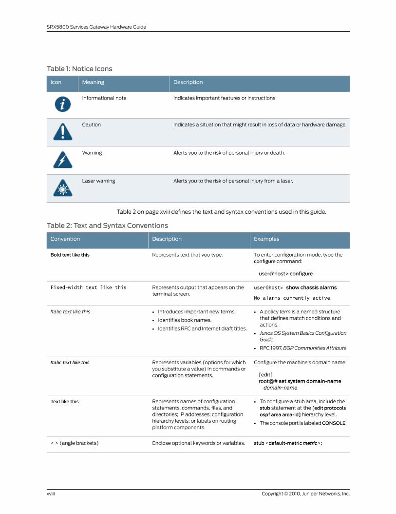
Table 1: Notice Icons
DescriptionMeaningIcon
Indicates important features or instructions.Informational note
Indicates a situation that might result in loss of data or hardware damage.Caution
Alerts you to the risk of personal injury or death.Warning
Alerts you to the risk of personal injury from a laser.Laser warning
Table 2 on page xviii defines the text and syntax conventions used in this guide.
Table 2: Text and Syntax Conventions
ExamplesDescriptionConvention
To enter configuration mode, type theconfigure command:
user@host> configure
Represents text that you type.Bold text like this
user@host> show chassis alarms
No alarms currently active
Represents output that appears on theterminal screen.
Fixed-width text like this
• A policy term is a named structurethat defines match conditions andactions.
• JunosOSSystemBasicsConfigurationGuide
• RFC 1997,BGPCommunities Attribute
• Introduces important new terms.
• Identifies book names.
• Identifies RFC and Internet draft titles.
Italic text like this
Configure the machine’s domain name:
[edit]root@# set system domain-namedomain-name
Represents variables (options for whichyou substitute a value) in commands orconfiguration statements.
Italic text like this
• To configure a stub area, include thestub statement at the [edit protocolsospf area area-id] hierarchy level.
• The console port is labeledCONSOLE.
Represents names of configurationstatements, commands, files, anddirectories; IP addresses; configurationhierarchy levels; or labels on routingplatform components.
Text like this
stub <default-metricmetric>;Enclose optional keywords or variables.< > (angle brackets)
Copyright © 2010, Juniper Networks, Inc.xviii
SRX5800 Services Gateway Hardware Guide
Table 2: Text and Syntax Conventions (continued)
ExamplesDescriptionConvention
broadcast | multicast
(string1 | string2 | string3)
Indicates a choice between the mutuallyexclusive keywords or variables on eitherside of the symbol. The set of choices isoften enclosed in parentheses for clarity.
| (pipe symbol)
rsvp { # Required for dynamicMPLS onlyIndicates a comment specified on thesame line as the configuration statementto which it applies.
# (pound sign)
community namemembers [community-ids ]
Enclose a variable for which you cansubstitute one or more values.
[ ] (square brackets)
[edit]routing-options {static {route default {nexthop address;retain;
}}
}
Identify a level in the configurationhierarchy.
Indention and braces ( { } )
Identifies a leaf statement at aconfiguration hierarchy level.
; (semicolon)
J-Web GUI Conventions
• In the Logical Interfaces box, selectAll Interfaces.
• To cancel the configuration, clickCancel.
Represents J-Web graphical userinterface (GUI) items you click or select.
Bold text like this
In the configuration editor hierarchy,select Protocols>Ospf.
Separates levels in a hierarchy of J-Webselections.
> (bold right angle bracket)
SRX Series Documentation and Release Notes
For a list of related SRX Series documentation, see
http://www.juniper.net/techpubs/hardware/srx-series-main.html. If the information in the
latest SRX Series Release Notes differs from the information in the documentation,
follow the SRX Series Release Notes.
Obtaining Documentation
To obtain the most current version of all Juniper Networks technical documentation, see
the products documentation page on the Juniper Networks Web site at
http://www.juniper.net/.
To order printed copies of this guide and other Juniper Networks technical documents,
or to order a documentation CD, which contains this guide, contact your sales
representative.
xixCopyright © 2010, Juniper Networks, Inc.
About This Guide
Copies of the Management Information Bases (MIBs) available in a software release are
included on the documentation CDs and at http://www.juniper.net/techpubs.
Documentation Feedback
We encourage you to provide feedback, comments, and suggestions so that we can
improve the documentation. You can send your comments to
[email protected], or fill out the documentation feedback form at
http://www.juniper.net/techpubs/docbug/docbugreport.html. If you are using e-mail, be
sure to include the following information with your comments:
• Document Name
• Document part number
• Page number
• Software release version (not required for Network Operations Guides [NOGs])
Requesting Technical Support
Technical product support is available through the Juniper Networks Technical Assistance
Center (JTAC). If you are a customer with an active J-Care or JNASC support contract,
or are covered under warranty, and need postsales technical support, you can access
our tools and resources online or open a case with JTAC.
• JTAC policies—For a complete understanding of our JTAC procedures and policies,
review the JTAC User Guide located at
http://www.juniper.net/customers/support/downloads/710059.pdf.
• Product warranties—For product warranty information, visit
http://www.juniper.net/support/warranty/.
• JTAC Hours of Operation—The JTAC centers have resources available 24 hours a day,
7 days a week, 365 days a year.
Self-Help Online Tools and Resources
For quick and easy problem resolution, Juniper Networks has designed an online
self-service portal called the Customer Support Center (CSC) that provides you with the
following features:
• Find CSC offerings: http://www.juniper.net/customers/support/
• Search for known bugs: http://www2.juniper.net/kb/
• Find product documentation: http://www.juniper.net/techpubs/
• Find solutions and answer questions using our Knowledge Base: http://kb.juniper.net/
• Download the latest versions of software and review release notes:
http://www.juniper.net/customers/csc/software/
• Search technical bulletins for relevant hardware and software notifications:
https://www.juniper.net/alerts/
Copyright © 2010, Juniper Networks, Inc.xx
SRX5800 Services Gateway Hardware Guide
• Join and participate in the Juniper Networks Community Forum:
http://www.juniper.net/company/communities/
• Open a case online in the CSC Case Manager: http://www.juniper.net/cm/
To verify service entitlement by product serial number, use our Serial Number Entitlement
(SNE) Tool located at https://tools.juniper.net/SerialNumberEntitlementSearch/.
Opening a Casewith JTAC
You can open a case with JTAC on the Web or by telephone.
• Use the Case Manager tool in the CSC at http://www.juniper.net/cm/ .
• Call 1-888-314-JTAC (1-888-314-5822 toll-free in the USA, Canada, and Mexico).
For international or direct-dial options in countries without toll-free numbers, visit us at
http://www.juniper.net/support/requesting-support.html.
xxiCopyright © 2010, Juniper Networks, Inc.
About This Guide

Copyright © 2010, Juniper Networks, Inc.xxii
SRX5800 Services Gateway Hardware Guide
PART 1
SRX5800 Services Gateway Overview
• Introduction to the SRX5800 Services Gateway on page 3
• SRX5800 Services Gateway Hardware Components on page 7
1Copyright © 2010, Juniper Networks, Inc.

Copyright © 2010, Juniper Networks, Inc.2
SRX5800 Services Gateway Hardware Guide
CHAPTER 1
Introduction to the SRX5800 ServicesGateway
This section includes the following topics:
• SRX5800 Services Gateway Description on page 3
• SRX5800 Services Gateway Physical Specifications on page 3
• SRX5800 Services Gateway Component Redundancy on page 5
SRX5800 Services Gateway Description
The SRX5800 Services Gateway is a high-performance, highly-scalable, carrier-class
security device with multi-processor architecture.
The services gateway provides 12 slots that youn can populate with two or three Switch
Control Boards (SCBs) and up to 12 additional cards of the following types:
• Services Processing Cards (SPCs) provide the procesing capacity to run integrated
services such as firewall, IPsec, and IDP.
• I/O Cards (IOCs) provide Ethernet interfaces that connect the services gateway to
your network.
• Flex I/O Cards (Flex IOCs) are similar to IOCs, but have slots for port modules that
allow you greater flexibility in adding different types of Ethernet ports to your services
gateway.
RelatedDocumentation
SRX5800 Services Gateway Physical Specifications on page 3•
• SRX5800 Services Gateway Chassis on page 7
• SRX5800 Services Gateway Card Cage and Slots on page 11
• SRX5800 Services Gateway Component Redundancy on page 5
SRX5800 Services Gateway Physical Specifications
Table 3 on page 4 summarizes the physical specifications for the services gateway
chassis.
3Copyright © 2010, Juniper Networks, Inc.
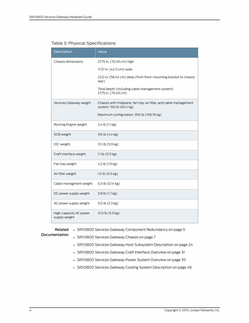
Table 3: Physical Specifications
ValueDescription
27.75 in. (70.49 cm) high
17.37 in. (44.11 cm) wide
23.0 in. (58.42 cm) deep (from front-mounting bracket to chassisrear)
Total depth (including cable management system)27.75 in. (70.49 cm)
Chassis dimensions
Chassis with midplane, fan tray, air filter, and cable managementsystem: 150 lb (60.4 kg)
Maximum configuration: 350 lb (158.76 kg)
Services Gateway weight
2.4 lb (1.1 kg)Routing Engine weight
9.6 lb (4.4 kg)SCB weight
13.1 lb (5.9 kg)IOC weight
1.1 lb (0.5 kg)Craft interface weight
4.2 lb (1.9 kg)Fan tray weight
1.0 lb (0.5 kg)Air filter weight
0.3 lb (0.14 kg)Cable managment weight
3.8 lb (1.7 kg)DC power supply weight
5.0 lb (2.3 kg)AC power supply weight
12.0 lb (5.5 kg)High-capacity AC powersupply weight
RelatedDocumentation
SRX5800 Services Gateway Component Redundancy on page 5•
• SRX5800 Services Gateway Chassis on page 7
• SRX5800 Services Gateway Host Subsystem Description on page 24
• SRX5800 Services Gateway Craft Interface Overview on page 31
• SRX5800 Services Gateway Power System Overview on page 35
• SRX5800 Services Gateway Cooling System Description on page 46
Copyright © 2010, Juniper Networks, Inc.4
SRX5800 Services Gateway Hardware Guide
SRX5800 Services Gateway Component Redundancy
The following major hardware components are redundant:
• Switch Control Boards (SCBs)—The host subsystem consists of a Routing Engine
installed in an SCB. The device must have one host subsystem installed. You can install
a second SCB for increased throughput, and a third SCB for redundancy. If a second
or third SCB is installed, the host subsystem SCB functions as the master and the
others function as the backup. If the SCB of the host subsystem fails, one of the other
SCBs takes over as the master.
• Power supplies—In the AC configuration, a minimum of three power supplies are
required to supply power to a fully configured services gateway. All AC power supplies
share the load evenly. The addition of a fourth power supply provides full power
redundancy. If one power supply fails in a redundant configuration, the three remaining
power supplies provide full power.
In the DC configuration, two power supplies are required to supply power to a fully
configured services gateway. One power supply supports approximately half of the
components in the services gateway, and the other power supply supports the remaining
components. The addition of two power supplies provides full power redundancy. If
one or two power supplies fail, the remaining power supplies can provide full power
to the services gateway.
• Cooling system—The cooling system has redundant components, which are controlled
by the host subsystem. If one of the fans fails, the host subsystem increases the speed
of the remaining fans to provide sufficient cooling for the services gateway indefinitely.
RelatedDocumentation
• SRX5800 Services Gateway Chassis on page 7
• SRX5800 Services Gateway Switch Control Board Description on page 24
• SRX5800 Services Gateway Power System Overview on page 35
• SRX5800 Services Gateway Cooling System Description on page 46
5Copyright © 2010, Juniper Networks, Inc.
Chapter 1: Introduction to the SRX5800 Services Gateway

Copyright © 2010, Juniper Networks, Inc.6
SRX5800 Services Gateway Hardware Guide
CHAPTER 2
SRX5800 Services Gateway HardwareComponents
Nearly all components of the SRX5800 Services Gateway are field-replaceable units
(FRUs), including the Switch Control Board (SCB), Routing Engine, Service Processing
Cards (SPC), and I/O Cards (IOC), the power supply, fan tray, and filter.
This section includes the following topics:
• SRX5800 Services Gateway Chassis on page 7
• SRX5800 Services Gateway Rack-Mounting Hardware on page 10
• SRX5800 Services Gateway Card Cage and Slots on page 11
• SRX5800 Services Gateway Midplane Description on page 12
• SRX5800 Services Gateway I/O Cards on page 13
• SRX5800 Services Gateway Flex I/O Cards and Port Modules on page 16
• SRX5800 Services Gateway Services Processing Cards on page 21
• SRX5800 Services Gateway Host Subsystem Description on page 24
• SRX5800 Services Gateway Switch Control Board on page 24
• SRX5800 Services Gateway Routing Engine on page 27
• SRX5800 Services Gateway Craft Interface on page 31
• SRX5800 Services Gateway Power System Description on page 35
• SRX5800 Services Gateway Cooling System Description on page 46
• SRX5800 Services Gateway Cable Manager Description on page 48
SRX5800 Services Gateway Chassis
The services gateway chassis is a rigid sheet metal structure that houses all the other
services gateway components (see Figure 1 on page 8, Figure 2 on page 9, and Figure
3 on page 10). The chassis measures 27.75 in. (70.49 cm) high, 17.37 in. (44.11 cm) wide,
and 23.0 in. (58.42 cm) deep (from the front-mounting flanges to the rear of the chassis).
The chassis installs in standard 800-mm (or larger) enclosed cabinets, 19-in. equipment
racks, or telco open-frame racks. Up to three services gateways can be installed in one
standard (48-U) rack if the rack can handle their combined weight, which can be greater
7Copyright © 2010, Juniper Networks, Inc.
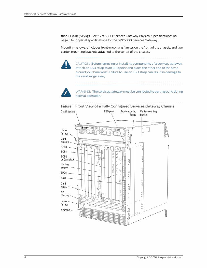
than 1,134 lb (515 kg). See “SRX5800 Services Gateway Physical Specifications” on
page 3 for physical specifications for the SRX5800 Services Gateway.
Mounting hardware includes front-mounting flanges on the front of the chassis, and two
center-mounting brackets attached to the center of the chassis.
CAUTION: Before removing or installing components of a services gateway,attach an ESD strap to an ESD point and place the other end of the straparound your bare wrist. Failure to use an ESD strap can result in damage tothe services gateway.
WARNING: The services gatewaymust be connected to earth ground duringnormal operation.
Figure 1: Front View of a Fully Configured Services Gateway Chassis
Copyright © 2010, Juniper Networks, Inc.8
SRX5800 Services Gateway Hardware Guide
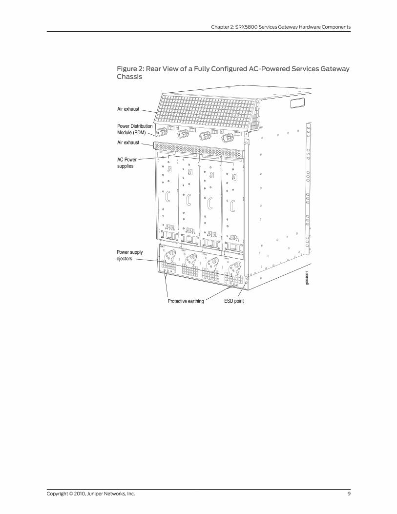
Figure 2: Rear View of a Fully Configured AC-Powered Services GatewayChassis
9Copyright © 2010, Juniper Networks, Inc.
Chapter 2: SRX5800 Services Gateway Hardware Components
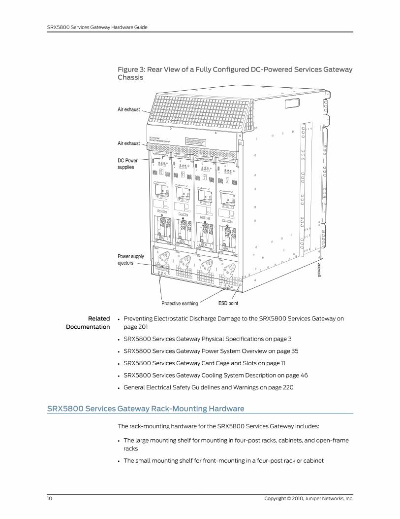
Figure 3: Rear View of a Fully Configured DC-Powered Services GatewayChassis
RelatedDocumentation
Preventing Electrostatic Discharge Damage to the SRX5800 Services Gateway on
page 201
•
• SRX5800 Services Gateway Physical Specifications on page 3
• SRX5800 Services Gateway Power System Overview on page 35
• SRX5800 Services Gateway Card Cage and Slots on page 11
• SRX5800 Services Gateway Cooling System Description on page 46
• General Electrical Safety Guidelines and Warnings on page 220
SRX5800 Services Gateway Rack-Mounting Hardware
The rack-mounting hardware for the SRX5800 Services Gateway includes:
• The large mounting shelf for mounting in four-post racks, cabinets, and open-frame
racks
• The small mounting shelf for front-mounting in a four-post rack or cabinet
Copyright © 2010, Juniper Networks, Inc.10
SRX5800 Services Gateway Hardware Guide
• Front-mounting flanges on the front of the chassis for front-mounting in a four-post
rack or cabinet
• Two center-mounting brackets attached to the center of the chassis for
center-mounting in an open-frame rack. For an open-frame rack, center-mounting is
preferable because of the more even distribution of weight.
RelatedDocumentation
Installing the SRX5800 Services Gateway Mounting Hardware for a Four-Post Rack
or Cabinet on page 69
•
• Installing the SRX5800 Services Gateway Mounting Hardware in an Open-Frame Rack
on page 71
• SRX5800 Services Gateway Chassis on page 7
• Chassis Lifting Guidelines on page 204
SRX5800 Services Gateway Card Cage and Slots
The card cage is the set of 14 vertical slots in the front of the chassis where you install
cards. The slots are numbered from left to right. Table 4 on page 11 describes the types
of cards that you can install into each slot.
Table 4: SRX5800 Services Gateway Card Cage Slots
Eligible Cards
Card Cage Slot SCBFlex IOCIOCSPC
XXX0 (leftmost)
XXX1
XXX2
XXX3
XXX4
XXX5
X0
X1
XXXX2/6
XXX7
XXX8
11Copyright © 2010, Juniper Networks, Inc.
Chapter 2: SRX5800 Services Gateway Hardware Components
Table 4: SRX5800 Services Gateway Card Cage Slots (continued)
Eligible Cards
Card Cage Slot SCBFlex IOCIOCSPC
XXX9
XXX10
XXX11 (rightmost)
RelatedDocumentation
SRX5800 Services Gateway Midplane Description on page 12•
SRX5800 Services GatewayMidplane Description
The midplane is located toward the rear of the chassis and forms the rear of the card
cage (see Figure 4 on page 13). IOCs, SPCs, and SCBs install into the midplane from the
front of the chassis, and the power supplies install into the midplane from the rear of the
chassis. The cooling system components also connect to the midplane.
The midplane performs the following major functions:
• Data path—Data packets are transferred across the midplane between the IOCs and
SPCs through the fabric ASICs on the SCBs.
• Power distribution—The power supplies are connected to the midplane, which
distributes power to all the services gateway components.
• Signal path—The midplane provides the signal path to the IOCs, SCBs, SPCs, Routing
Engine, and other system components for monitoring and control of the system.
Copyright © 2010, Juniper Networks, Inc.12
SRX5800 Services Gateway Hardware Guide
Figure 4: Midplane
RelatedDocumentation
SRX5800 Services Gateway Chassis on page 7•
• SRX5800 Services Gateway Card Cage and Slots on page 11
• SRX5800 Services Gateway Flex IOC and Port Module Description on page 16
• SRX5800 Services Gateway I/O Card Description on page 13
• SRX5800 Services Gateway Switch Control Board Description on page 24
• SRX5800 Services Gateway Power System Overview on page 35
SRX5800 Services Gateway I/O Cards
This section includes the following topics:
• SRX5800 Services Gateway I/O Card Description on page 13
• SRX5800 Services Gateway I/O Card Components on page 14
• SRX5800 Services Gateway I/O Card LEDs on page 15
SRX5800 Services Gateway I/O Card Description
The I/O Cards (IOCs) are optimized for Ethernet density and are capable of supporting
up to 40 Gigabit Ethernet or four 10-Gigabit Ethernet ports (see Figure 5 on page 14).
13Copyright © 2010, Juniper Networks, Inc.
Chapter 2: SRX5800 Services Gateway Hardware Components
The IOC assembly combines packet forwarding and Ethernet interfaces on a single board,
with four 10-Gbps Packet Forwarding Engines. Each Packet Forwarding Engine consists
of one I-chip for Layer 3 processing and one Layer 2 network processor. The IOCs interface
with the power supplies and Switch Control Boards (SCBs).
You can install IOCs in any of the slots not reserved for SCBs. If a slot is not occupied by
a card, you must install a blank panel to shield the empty slot and to allow cooling air to
circulate properly through the services gateway.
Figure 5 on page 14 shows the IOCs supported on the services gateway.
Figure 5: IOCs Supported on the Services Gateway
RelatedDocumentation
Installing an SRX5800 Services Gateway IOC on page 154•
• Removing an SRX5800 Services Gateway IOC on page 152
• SRX5800 Services Gateway Card Cage and Slots on page 11
• SRX5800 Services Gateway Field-Replaceable Units on page 132
• SRX5800 Services Gateway I/O Card Components on page 14
• SRX5800 Services Gateway I/O Card LEDs on page 15
SRX5800 Services Gateway I/O Card Components
Each IOC consists of the following components:
• IOC cover, which functions as a ground plane and a stiffener
• Fabric interfaces
Copyright © 2010, Juniper Networks, Inc.14
SRX5800 Services Gateway Hardware Guide
• Two Gigabit Ethernet interfaces that allow control information, route information, and
statistics to be sent between the Routing Engine and the CPU on the IOCs
• Two interfaces from the SCBs that enable the boards to be powered on and controlled
• Physical IOC connectors
• Packet Forwarding Engines
• Midplane connectors and power circuitry
• Processor subsystem, which includes a 1.2-GHz CPU, system controller, and 1 GB of
SDRAM
RelatedDocumentation
SRX5800 Services Gateway I/O Card Description on page 13•
• Installing an SRX5800 Services Gateway IOC on page 154
• Removing an SRX5800 Services Gateway IOC on page 152
• SRX5800 Services Gateway Field-Replaceable Units on page 132
• SRX5800 Services Gateway I/O Card LEDs on page 15
SRX5800 Services Gateway I/O Card LEDs
LEDs on the 4-port 10-Gigabit Ethernet faceplate indicate the port status. LEDs are
labeled top to bottom 0/0 through 0/3 (see Table 5 on page 15).
Table 5: 4-Port 10-Gigabit Ethernet IOC LEDs
DescriptionStateColorLabel
IOC is functioning normally.On steadilyGreenOK/FAIL
IOC has failed.On steadilyRed
Normal operating mode.OffGreenTUNNEL
Port configured in tunnel mode.On steadily
Link is active.On steadilyGreenLINK
No link.Off
LEDs on the 40–port Gigabit Ethernet faceplate indicate the port status. LEDs are labeled
horizontally and top to bottom 0/0 through 0/5, 1/0 through 1/5, 2/0 through 2/5, and
3/0 through 3/5 (see Table 6 on page 16).
15Copyright © 2010, Juniper Networks, Inc.
Chapter 2: SRX5800 Services Gateway Hardware Components
Table 6: 40-Port Gigabit Ethernet IOC LEDs
DescriptionStateColorLabel
IOC is functioning normally.On steadilyGreenOK/FAIL
IOC has failed.On steadilyRed
Link is active.On steadilyGreenLINK
No link.Off
RelatedDocumentation
SRX5800 Services Gateway I/O Card Description on page 13•
• Installing an SRX5800 Services Gateway IOC on page 154
• Removing an SRX5800 Services Gateway IOC on page 152
• SRX5800 Services Gateway Field-Replaceable Units on page 132
• SRX5800 Services Gateway I/O Card Components on page 14
SRX5800 Services Gateway Flex I/O Cards and Port Modules
This section includes the following topics:
• SRX5800 Services Gateway Flex IOC and Port Module Description on page 16
• SRX5800 Services Gateway Flex IOC Components on page 18
• SRX5800 Services Gateway Port Module Components on page 19
• SRX5800 Services Gateway Port Module LEDs on page 19
SRX5800 Services Gateway Flex IOC and Port Module Description
Flex I/O Cards (Flex IOCs) are IOCs with two slots, which accept port modules that add
Ethernet ports to your services gateway. A Flex IOC with installed port modules functions
in the same way as a regular IOC, but allows greater flexibility in adding different types
of Ethernet ports to your services gateway. Figure 6 on page 17 shows a Flex IOC with
two typical port modules installed.
Copyright © 2010, Juniper Networks, Inc.16
SRX5800 Services Gateway Hardware Guide
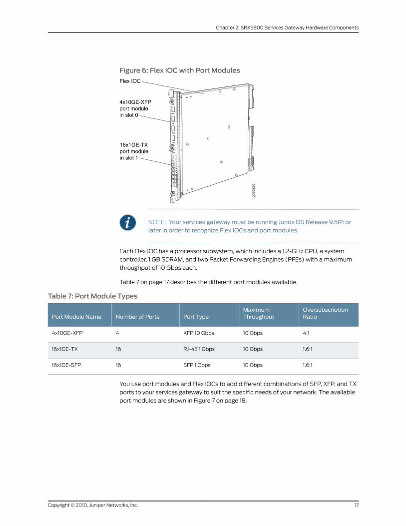
Figure 6: Flex IOCwith Port Modules
g030
286
Flex IOC
4x10GE-XFPport modulein slot 0
16x1GE-TXport modulein slot 1
NOTE: Your services gatewaymust be running Junos OS Release 9.5R1 orlater in order to recognize Flex IOCs and port modules.
Each Flex IOC has a processor subsystem, which includes a 1.2-GHz CPU, a system
controller, 1 GB SDRAM, and two Packet Forwarding Engines (PFEs) with a maximum
throughput of 10 Gbps each.
Table 7 on page 17 describes the different port modules available.
Table 7: Port Module Types
OversubscriptionRatio
MaximumThroughputPort TypeNumber of PortsPort Module Name
4:110 GbpsXFP 10 Gbps44x10GE-XFP
1.6:110 GbpsRJ-45 1 Gbps1616x1GE-TX
1.6:110 GbpsSFP 1 Gbps1616x1GE-SFP
You use port modules and Flex IOCs to add different combinations of SFP, XFP, and TX
ports to your services gateway to suit the specific needs of your network. The available
port modules are shown in Figure 7 on page 18.
17Copyright © 2010, Juniper Networks, Inc.
Chapter 2: SRX5800 Services Gateway Hardware Components
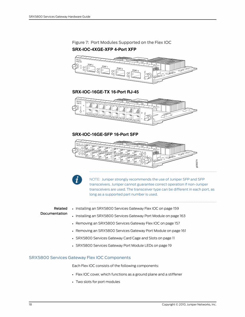
Figure 7: Port Modules Supported on the Flex IOC
g030
274
SRX-IOC-16GE-TX 16-Port RJ-45
SRX-IOC-16GE-SFP 16-Port SFP
SRX-IOC-4XGE-XFP 4-Port XFP
NOTE: Juniper strongly recommends the use of Juniper SFP and SFPtransceivers. Juniper cannot guarantee correct operation if non-Junipertransceivers are used. The transceiver type can be different in each port, aslong as a supported part number is used.
RelatedDocumentation
Installing an SRX5800 Services Gateway Flex IOC on page 159•
• Installing an SRX5800 Services Gateway Port Module on page 163
• Removing an SRX5800 Services Gateway Flex IOC on page 157
• Removing an SRX5800 Services Gateway Port Module on page 161
• SRX5800 Services Gateway Card Cage and Slots on page 11
• SRX5800 Services Gateway Port Module LEDs on page 19
SRX5800 Services Gateway Flex IOC Components
Each Flex IOC consists of the following components:
• Flex IOC cover, which functions as a ground plane and a stiffener
• Two slots for port modules
Copyright © 2010, Juniper Networks, Inc.18
SRX5800 Services Gateway Hardware Guide
• Fabric interfaces
• Two Gigabit Ethernet interfaces that allow control information, route information, and
statistics to be sent between the Routing Engine and the CPU on the Flex IOC
• Two interfaces from the SCBs that enable the Flex IOC to be powered on and controlled
• Two 10 Gbps PFEs
• Midplane connectors and power circuitry
• Processor subsystem, including a 1.2-GHz CPU, a system controller, and 1 GB of SDRAM
RelatedDocumentation
Installing an SRX5800 Services Gateway Flex IOC on page 159•
• Removing an SRX5800 Services Gateway Flex IOC on page 157
• Maintaining SPCs, IOCs, and Flex IOCs on the SRX5800 Services Gateway on page 111
• Troubleshooting SRX5800 Services Gateway IOCs and Flex IOCs on page 125
• SRX5800 Services Gateway Field-Replaceable Units on page 132
SRX5800 Services Gateway Port Module Components
Each services gateway port module consists of the following components:
• Port module cover, which functions as a ground plane and a stiffener
• Physical I/O port connectors
• Ethernet switch
• Online button (behind pinhole) for bringing the port module online and offline
• Port module slot connectors and power circuitry
RelatedDocumentation
Installing an SRX5800 Services Gateway Port Module on page 163•
• Removing an SRX5800 Services Gateway Port Module on page 161
• Maintaining Port Modules on the SRX5800 Services Gateway on page 113
• Troubleshooting SRX5800 Services Gateway Port Modules on page 127
• SRX5800 Services Gateway Field-Replaceable Units on page 132
• SRX5800 Services Gateway Port Module LEDs on page 19
SRX5800 Services Gateway Port Module LEDs
LEDs on the faceplate of each port module indicate the status of the module and of each
port. Table 8 on page 20, Table 9 on page 20, and Table 10 on page 20 describe the LEDs
on each port module type.
19Copyright © 2010, Juniper Networks, Inc.
Chapter 2: SRX5800 Services Gateway Hardware Components
Table 8: 4-Port 10-Gigabit XFP Ethernet Port Module LEDs
DescriptionStateColorLabel
Port module is functioning normally.On steadilyGreenOK/FAIL
Port module has failed.On steadilyRed
Link is active.On steadilyGreenLINK
No link.Off
Port is receiving or transmitting data.BlinkingGreenTX/RX
No activity.Off
Table 9: 16-Port SFP Ethernet Port Module LEDs
DescriptionStateColorLabel
Port module is functioning normally.On steadilyGreenOK/FAIL
Port module has failed.On steadilyRed
Link is active.On steadilyGreenLink 0through 15
No link.Off
Table 10: 16-Port TX Ethernet Port Module LEDs
DescriptionStateColorLabel
Port module is functioning normally.On steadilyGreenOK/FAIL
Port module has failed.On steadilyRed
Link is active.On steadilyGreenLink (top orleft of eachport) No link.Off
Port is receiving or transmitting data.BlinkingGreenTX/RX(bottom orright ofeach port)
No activity.Off
RelatedDocumentation
Installing an SRX5800 Services Gateway Port Module on page 163•
• Removing an SRX5800 Services Gateway Port Module on page 161
• Maintaining Port Modules on the SRX5800 Services Gateway on page 113
• Troubleshooting SRX5800 Services Gateway Port Modules on page 127
Copyright © 2010, Juniper Networks, Inc.20
SRX5800 Services Gateway Hardware Guide
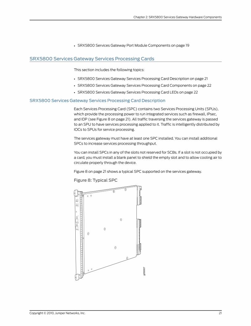
• SRX5800 Services Gateway Port Module Components on page 19
SRX5800 Services Gateway Services Processing Cards
This section includes the following topics:
• SRX5800 Services Gateway Services Processing Card Description on page 21
• SRX5800 Services Gateway Services Processing Card Components on page 22
• SRX5800 Services Gateway Services Processing Card LEDs on page 22
SRX5800 Services Gateway Services Processing Card Description
Each Services Processing Card (SPC) contains two Services Processing Units (SPUs),
which provide the processing power to run integrated services such as firewall, IPsec,
and IDP (see Figure 8 on page 21). All traffic traversing the services gateway is passed
to an SPU to have services processing applied to it. Traffic is intelligently distributed by
IOCs to SPUs for service processing.
The services gateway must have at least one SPC installed. You can install additional
SPCs to increase services processing throughput.
You can install SPCs in any of the slots not reserved for SCBs. If a slot is not occupied by
a card, you must install a blank panel to shield the empty slot and to allow cooling air to
circulate properly through the device.
Figure 8 on page 21 shows a typical SPC supported on the services gateway.
Figure 8: Typical SPC
21Copyright © 2010, Juniper Networks, Inc.
Chapter 2: SRX5800 Services Gateway Hardware Components
RelatedDocumentation
SRX5800 Services Gateway Services Processing Card Components on page 22•
• SRX5800 Services Gateway Services Processing Card LEDs on page 22
• SRX5800 Services Gateway Card Cage and Slots on page 11
• SRX5800 Services Gateway Field-Replaceable Units on page 132
• Maintaining SPCs, IOCs, and Flex IOCs on the SRX5800 Services Gateway on page 111
• Troubleshooting SRX5800 Services Gateway SPCs on page 127
• Replacing SRX5800 Services Gateway SPCs on page 167
SRX5800 Services Gateway Services Processing Card Components
Each SPC consists of the following components:
• SPC cover, which functions as a ground plane and a stiffener.
• Two Small Form-factor Pluggable (SFP) Chassis Cluster Control ports for connecting
multiple devices into a redundant chassis cluster. Refer to the Junos OS Security
ConfigurationGuide for more information about connecting and configuring redundant
chassis clusters.
NOTE: Juniper strongly recommends the use of Juniper SFP transceivers.Juniper cannot guarantee correct operation if non-Juniper transceivers areused. The transceiver type can be different in each port, as long as asupported part number is used.
• Fabric interfaces.
• Two Gigabit Ethernet interfaces that allow control information, route information, and
statistics to be sent between the Routing Engine and the CPU on the SPCs.
• Two interfaces from the SCBs that enable the boards to be powered on and controlled.
• Physical SPC connectors.
• Midplane connectors and power circuitry.
• Processor subsystem, which includes a 1.2-GHz CPU, system controller, and 1 GB of
SDRAM.
• LEDs on the faceplate that indicate the SPC status.
RelatedDocumentation
SRX5800 Services Gateway Services Processing Card Description on page 21•
• SRX5800 Services Gateway Port Module LEDs on page 19
SRX5800 Services Gateway Services Processing Card LEDs
LEDs on the faceplate indicate the SPC status (see Table 11 on page 23).
Copyright © 2010, Juniper Networks, Inc.22
SRX5800 Services Gateway Hardware Guide

Table 11: SPC LEDs
DescriptionStateColorLabel
SPC is functioning normally.On steadilyGreenOK/FAIL
SPC has failed.On steadilyRed
SPU is offline. If both SPUs are offline it is safe to removethe SPC from the chassis.
OffOffSTATUS
SPU is operating normally.On steadilyGreen
SPU is initializing.On steadilyAmber
SPU has an error or failure.On steadilyRed
Service is not running on the SPU.OffOffSERVICE
Service is running on the SPU under acceptable load.On steadilyGreen
Service on the SPU is overloaded.On steadilyAmber
All cluster members and monitored links are available.On steadilyGreenHA
A cluster member is missing or unreachable, or the othernode is no longer part of a cluster because it has beendisabled by the dual membership and detection recoveryprocess in reaction to a control link or fabric link failure.
On steadilyRed
All cluster members are present, but one or moremonitored links are down.
On steadilyAmber
The node is not configured for clustering or it has beendisabled by the dual membership and detection recoveryprocess in reaction to a control link or fabric link failure.
OffUnlit
Chassis Cluster Control port link is active.On steadilyGreenLINK/ACT
No link.Off
The Chassis Cluster Control port is enabled.On steadilyGreenENABLE
The Chassis Cluster Control port is disabled.Off
Two LEDs, located on the craft interface above the SPC, display the status of the SPC
and are labeled OK and FAIL.
RelatedDocumentation
SRX5800 Services Gateway Craft Interface IOC and SPC LEDs on page 33•
• SRX5800 Services Gateway Services Processing Card Description on page 21
• SRX5800 Services Gateway Services Processing Card Components on page 22
23Copyright © 2010, Juniper Networks, Inc.
Chapter 2: SRX5800 Services Gateway Hardware Components
SRX5800 Services Gateway Host SubsystemDescription
The host subsystem consists of a routing engine installed in a switch control board (SCB).
The host subsystem provides the routing and system management functions of the
services gateway. You must install one host subsystem on the device.
The host subsystem has three LEDs that display its status. The host subsystem LEDs are
located in the middle of the craft interface.
RelatedDocumentation
SRX5800 Services Gateway Craft Interface Host Subsystem LEDs on page 32•
• SRX5800 Services Gateway Switch Control Board Description on page 24
• SRX5800 Services Gateway Routing Engine Description on page 27
• SRX5800 Services Gateway Card Cage and Slots on page 11
SRX5800 Services Gateway Switch Control Board
This section includes the following topics:
• SRX5800 Services Gateway Switch Control Board Description on page 24
• SRX5800 Services Gateway Switch Control Board Slots on page 25
• SRX5800 Services Gateway Switch Control Board Redundancy on page 26
• SRX5800 Services Gateway Switch Control Board Components on page 26
• SRX5800 Services Gateway Switch Control Board LEDs on page 27
SRX5800 Services Gateway Switch Control Board Description
The Switch Control Board (SCB) provides the following functions:
• Powers on and powers off IOCs and SPCs
• Controls clocking, system resets, and booting
• Monitors and controls system functions, including fan speed, board power status, PDM
status and control, and the system front panel
• Provides interconnections to all the IOCs within the chassis through the switch fabrics
integrated into the SCB
When the SCB is part of a host subsystem, the Routing Engine installs directly into a slot
on the SCB (see Figure 9 on page 25).
Copyright © 2010, Juniper Networks, Inc.24
SRX5800 Services Gateway Hardware Guide
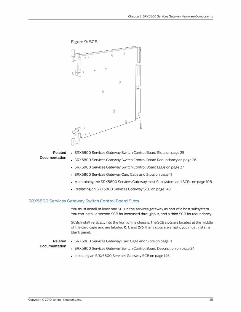
Figure 9: SCB
RelatedDocumentation
SRX5800 Services Gateway Switch Control Board Slots on page 25•
• SRX5800 Services Gateway Switch Control Board Redundancy on page 26
• SRX5800 Services Gateway Switch Control Board LEDs on page 27
• SRX5800 Services Gateway Card Cage and Slots on page 11
• Maintaining the SRX5800 Services Gateway Host Subsystem and SCBs on page 108
• Replacing an SRX5800 Services Gateway SCB on page 143
SRX5800 Services Gateway Switch Control Board Slots
You must install at least one SCB in the services gateway as part of a host subsystem.
You can install a second SCB for increased throughput, and a third SCB for redundancy.
SCBs install vertically into the front of the chassis. The SCB slots are located at the middle
of the card cage and are labeled 0, 1, and 2/6. If any slots are empty, you must install a
blank panel.
RelatedDocumentation
SRX5800 Services Gateway Card Cage and Slots on page 11•
• SRX5800 Services Gateway Switch Control Board Description on page 24
• Installing an SRX5800 Services Gateway SCB on page 145
25Copyright © 2010, Juniper Networks, Inc.
Chapter 2: SRX5800 Services Gateway Hardware Components
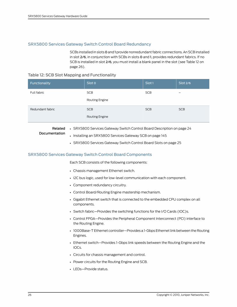
SRX5800 Services Gateway Switch Control Board Redundancy
SCBs installed in slots0and 1provide nonredundant fabric connections. An SCB installed
in slot 2/6, in conjunction with SCBs in slots 0 and 1, provides redundant fabrics. If no
SCB is installed in slot 2/6, you must install a blank panel in the slot (see Table 12 on
page 26).
Table 12: SCB Slot Mapping and Functionality
Slot 2/6Slot 1Slot 0Functionality
–SCBSCB
Routing Engine
Full fabric
SCBSCBSCB
Routing Engine
Redundant fabric
RelatedDocumentation
SRX5800 Services Gateway Switch Control Board Description on page 24•
• Installing an SRX5800 Services Gateway SCB on page 145
• SRX5800 Services Gateway Switch Control Board Slots on page 25
SRX5800 Services Gateway Switch Control Board Components
Each SCB consists of the following components:
• Chassis management Ethernet switch.
• I2C bus logic, used for low-level communication with each component.
• Component redundancy circuitry.
• Control Board/Routing Engine mastership mechanism.
• Gigabit Ethernet switch that is connected to the embedded CPU complex on all
components.
• Switch fabric—Provides the switching functions for the I/O Cards (IOC)s.
• Control FPGA—Provides the Peripheral Component Interconnect (PCI) interface to
the Routing Engine.
• 1000Base-T Ethernet controller—Provides a 1-Gbps Ethernet link between the Routing
Engines.
• Ethernet switch—Provides 1-Gbps link speeds between the Routing Engine and the
IOCs.
• Circuits for chassis management and control.
• Power circuits for the Routing Engine and SCB.
• LEDs—Provide status.
Copyright © 2010, Juniper Networks, Inc.26
SRX5800 Services Gateway Hardware Guide
RelatedDocumentation
SRX5800 Services Gateway Switch Control Board Redundancy on page 26•
• SRX5800 Services Gateway Switch Control Board LEDs on page 27
• SRX5800 Services Gateway Switch Control Board Description on page 24
SRX5800 Services Gateway Switch Control Board LEDs
Three LEDs on the SCB indicate the status of the SCB. The LEDs, labeled FABRICACTIVE,
FABRICONLY, andOK/FAIL, are located directly on the SCB. Table 13 on page 27 describes
the functions of the SCB LEDs.
Table 13: Switch Control Board LEDs
DescriptionStateColorLabel
Fabric is in active mode.On steadilyGreenFABRICACTIVE
SCB operates in fabric-only mode.On steadilyGreenFABRICONLY
SCB operates in fabric/control board mode.Off
SCB is online.On steadilyGreenOK/FAIL
SCB is offline.Off
SCB has failed.On steadilyRed
RelatedDocumentation
SRX5800 Services Gateway Switch Control Board Description on page 24•
• SRX5800 Services Gateway Craft Interface Host Subsystem LEDs on page 32
SRX5800 Services Gateway Routing Engine
This section includes the following topics:
• SRX5800 Services Gateway Routing Engine Description on page 27
• SRX5800 Services Gateway Routing Engine Components on page 28
• SRX5800 Services Gateway Routing Engine LEDs on page 29
• SRX5800 Services Gateway Routing Engine Interface Ports on page 30
• SRX5800 Services Gateway Routing Engine Boot Sequence on page 30
SRX5800 Services Gateway Routing Engine Description
The Routing Engine is an Intel-based PC platform that runs Junos OS. Software processes
that run on the Routing Engine maintain the routing tables, manage the routing protocols
used on the device, control the device interfaces, control some chassis components, and
provide the interface for system management and user access to the device.
27Copyright © 2010, Juniper Networks, Inc.
Chapter 2: SRX5800 Services Gateway Hardware Components
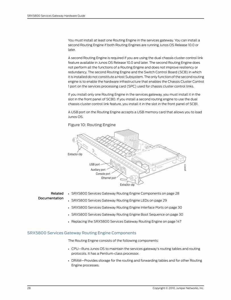
You must install at least one Routing Engine in the services gateway. You can install a
second Routing Engine if both Routing Engines are running Junos OS Release 10.0 or
later.
A second Routing Engine is required if you are using the dual chassis cluster control link
feature available in Junos OS Release 10.0 and later. The second Routing Engine does
not perform all the functions of a Routing Engine and does not improve resiliency or
redundancy. The second Routing Engine and the Switch Control Board (SCB) in which
it is installed do not constitute a Host Subsystem. The only function of the second routing
engine is to enable the hardware infrastructure that enables the Chassis Cluster Control
1 port on the services processing card (SPC) used for chassis cluster control links.
If you install only one Routing Engine in the services gateway, you must install it in the
slot in the front panel of SCB0. If you install a second routing engine to use the dual
chassis cluster control link feature, you install it in the slot in the front panel of SCB1.
A USB port on the Routing Engine accepts a USB memory card that allows you to load
Junos OS.
Figure 10: Routing Engine
RelatedDocumentation
SRX5800 Services Gateway Routing Engine Components on page 28•
• SRX5800 Services Gateway Routing Engine LEDs on page 29
• SRX5800 Services Gateway Routing Engine Interface Ports on page 30
• SRX5800 Services Gateway Routing Engine Boot Sequence on page 30
• Replacing the SRX5800 Services Gateway Routing Engine on page 147
SRX5800 Services Gateway Routing Engine Components
The Routing Engine consists of the following components:
• CPU—Runs Junos OS to maintain the services gateway's routing tables and routing
protocols. It has a Pentium-class processor.
• DRAM—Provides storage for the routing and forwarding tables and for other Routing
Engine processes.
Copyright © 2010, Juniper Networks, Inc.28
SRX5800 Services Gateway Hardware Guide
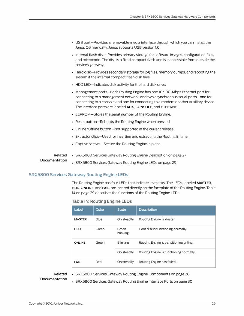
• USB port—Provides a removable media interface through which you can install the
Junos OS manually. Junos supports USB version 1.0.
• Internal flash disk—Provides primary storage for software images, configuration files,
and microcode. The disk is a fixed compact flash and is inaccessible from outside the
services gateway.
• Hard disk—Provides secondary storage for log files, memory dumps, and rebooting the
system if the internal compact flash disk fails.
• HDD LED—Indicates disk activity for the hard disk drive.
• Management ports—Each Routing Engine has one 10/100-Mbps Ethernet port for
connecting to a management network, and two asynchronous serial ports—one for
connecting to a console and one for connecting to a modem or other auxiliary device.
The interface ports are labeled AUX, CONSOLE, and ETHERNET.
• EEPROM—Stores the serial number of the Routing Engine.
• Reset button—Reboots the Routing Engine when pressed.
• Online/Offline button—Not supported in the current release.
• Extractor clips—Used for inserting and extracting the Routing Engine.
• Captive screws—Secure the Routing Engine in place.
RelatedDocumentation
SRX5800 Services Gateway Routing Engine Description on page 27•
• SRX5800 Services Gateway Routing Engine LEDs on page 29
SRX5800 Services Gateway Routing Engine LEDs
The Routing Engine has four LEDs that indicate its status. The LEDs, labeled MASTER,
HDD,ONLINE, and FAIL, are located directly on the faceplate of the Routing Engine. Table
14 on page 29 describes the functions of the Routing Engine LEDs.
Table 14: Routing Engine LEDs
DescriptionStateColorLabel
Routing Engine is Master.On steadilyBlueMASTER
Hard disk is functioning normally.Greenblinking
GreenHDD
Routing Engine is transitioning online.BlinkingGreenONLINE
Routing Engine is functioning normally.On steadily
Routing Engine has failed.On steadilyRedFAIL
RelatedDocumentation
SRX5800 Services Gateway Routing Engine Components on page 28•
• SRX5800 Services Gateway Routing Engine Interface Ports on page 30
29Copyright © 2010, Juniper Networks, Inc.
Chapter 2: SRX5800 Services Gateway Hardware Components
SRX5800 Services Gateway Routing Engine Interface Ports
In the center of the Routing Engine are three ports that connect the Routing Engine to
one or more external devices on which system administrators can issue Junos OS
command-line interface (CLI) commands to manage the device.
The ports with the indicated labels function as follows:
• AUX—Connects the Routing Engine to a laptop, modem, or other auxiliary device
through a cable with an RJ-45 connector.
• CONSOLE—Connects the Routing Engine to a system console through a cable with an
RJ-45 connector.
• ETHERNET—Connects the Routing Engine through an Ethernet connection to a
management LAN (or any other device that plugs into an Ethernet connection) for
out-of-band management. The port uses an autosensing RJ-45 connector to
support10-Mbps or 100-Mbps connections. Two small LEDs on the bottom of the port
indicate the connection in use: the LED lights yellow or green for a 10-Mbps connection,
and the LED lights green when traffic is passing through the port.
RelatedDocumentation
SRX5800 Services Gateway Routing Engine Description on page 27•
• SRX5800 Services Gateway Routing Engine LEDs on page 29
• SRX5800 Services Gateway Routing Engine Boot Sequence on page 30
• RJ-45 Connector Pinouts for the SRX5800 Services Gateway Routing Engine Auxiliary
and Console Ports on page 258
• RJ-45 Connector Pinouts for the SRX5800 Services Gateway Routing Engine Ethernet
Port on page 257
SRX5800 Services Gateway Routing Engine Boot Sequence
The Routing Engine boots from the storage media in this order: the USB device (if present),
then the internal flash disk, then the hard disk, then the LAN.
NOTE: For specific information about Routing Engine components (forexample, the amount of DRAM), issue the show chassis routing-engine
command.
RelatedDocumentation
SRX5800 Services Gateway Routing Engine Description on page 27•
• SRX5800 Services Gateway Routing Engine Interface Ports on page 30
Copyright © 2010, Juniper Networks, Inc.30
SRX5800 Services Gateway Hardware Guide
SRX5800 Services Gateway Craft Interface
This section includes the following topics:
• SRX5800 Services Gateway Craft Interface Overview on page 31
• SRX5800 Services Gateway Craft Interface Alarm LEDs and Alarm Cutoff/Lamp Test
Button on page 32
• SRX5800 Services Gateway Craft Interface Host Subsystem LEDs on page 32
• SRX5800 Services Gateway Craft Interface Power Supply LEDs on page 33
• SRX5800 Services Gateway Craft Interface IOC and SPC LEDs on page 33
• SRX5800 Services Gateway Craft Interface Fan LEDs on page 34
• SRX5800 Services Gateway Craft Interface Online Buttons on page 34
• SRX5800 Services Gateway Craft Interface Alarm Relay Contacts on page 35
SRX5800 Services Gateway Craft Interface Overview
The craft interface shows you status and troubleshooting information at a glance and
lets you perform many system control functions. It is hot-insertable and hot-removable.
The craft interface is located on the front of the services gateway above the upper fan
tray.
Figure 11: Front Panel of the Craft Interface
NOTE: At least one SCBmust be installed in the services gateway for thecraft interface to obtain power.
RelatedDocumentation
SRX5800 Services Gateway Craft Interface Alarm LEDs and Alarm Cutoff/Lamp Test
Button on page 32
•
• SRX5800 Services Gateway Craft Interface Host Subsystem LEDs on page 32
• SRX5800 Services Gateway Craft Interface Power Supply LEDs on page 33
• SRX5800 Services Gateway Craft Interface IOC and SPC LEDs on page 33
• SRX5800 Services Gateway Craft Interface Fan LEDs on page 34
• SRX5800 Services Gateway Craft Interface Online Buttons on page 34
• SRX5800 Services Gateway Craft Interface Alarm Relay Contacts on page 35
31Copyright © 2010, Juniper Networks, Inc.
Chapter 2: SRX5800 Services Gateway Hardware Components
• Replacing the SRX5800 Services Gateway Craft Interface on page 134
SRX5800 Services Gateway Craft Interface Alarm LEDs and Alarm Cutoff/Lamp Test Button
Two large alarm LEDs are located at the upper right of the craft interface. The circular
red LED lights to indicate a critical condition that can result in a system shutdown. The
triangular yellow LED lights to indicate a less severe condition that requires monitoring
or maintenance. Both LEDs can be lit simultaneously. A condition that causes an LED to
light also activates the corresponding alarm relay contact on the craft interface.
To deactivate the red and yellow alarms, press the button labeled ACO/LT (for “alarm
cutoff/lamp test”), which is located to the right of the alarm LEDs. Deactivating an alarm
turns off both LEDs and deactivates the device attached to the corresponding alarm
relay contact on the craft interface.
Table 15 on page 32 describes the alarm LEDs and alarm cutoff button in more detail.
Table 15: Alarm LEDs and Alarm Cutoff/Lamp Test Button
DescriptionStateColorShape
Critical alarm LED—Indicates a critical condition thatcan cause the device to stop functioning. Possiblecauses include component removal, failure, oroverheating.
On steadilyRed
Warning alarm LED—Indicates a serious but nonfatalerror condition, such as a maintenance alert or asignificant increase in component temperature.
On steadilyYellow
Alarm cutoff/lamp test button—Deactivates red andyellow alarms. Causes all LEDs on the craft interfaceto light (for testing) when pressed and held.
––
RelatedDocumentation
SRX5800 Services Gateway Craft Interface Alarm Relay Contacts on page 35•
• SRX5800 Services Gateway Craft Interface Overview on page 31
• SRX5800 Services Gateway Craft Interface Host Subsystem LEDs on page 32
SRX5800 Services Gateway Craft Interface Host Subsystem LEDs
The host subsystem has three LEDs, located in the middle of the craft interface, that
indicate its status. The LEDs labeledRE0 show the status of the Routing Engine and SCB
in slot 0 .
The LEDs labeled RE1 show the status of the Routing Engine and SCB in slot 1. Table 16
on page 33 describes the functions of the host subsystem LEDs.
Copyright © 2010, Juniper Networks, Inc.32
SRX5800 Services Gateway Hardware Guide
Table 16: Host Subsystem LEDs
DescriptionStateColorLabel
Host is functioning as the master.On steadilyGreenMASTER
Host is online and is functioning normally.On steadilyGreenONLINE
Host is installed but the Routing Engine is offline.On steadilyRedOFFLINE
Host is not installed.Off
RelatedDocumentation
SRX5800 Services Gateway Craft Interface Overview on page 31•
• SRX5800 Services Gateway Craft Interface Alarm LEDs and Alarm Cutoff/Lamp Test
Button on page 32
• SRX5800 Services Gateway Craft Interface Power Supply LEDs on page 33
SRX5800 Services Gateway Craft Interface Power Supply LEDs
Each power supply has two LEDs on the craft interface that indicate its status. The LEDs,
labeled 0 through 3, are located on the upper left of the craft interface next to the PEM
label. Table 17 on page 33 describes the functions of the power supply LEDs on the craft
interface.
Table 17: Power Supply LEDs on the Craft Interface
DescriptionStateColorLabel
Power supply is functioning normally.On steadilyGreenPEM
Power supply has failed or power input has failed.On steadilyRed
RelatedDocumentation
SRX5800 Services Gateway Craft Interface Overview on page 31•
• SRX5800 Services Gateway Craft Interface Host Subsystem LEDs on page 32
• SRX5800 Services Gateway Craft Interface IOC and SPC LEDs on page 33
SRX5800 Services Gateway Craft Interface IOC and SPC LEDs
Each IOC and SPC has LEDs on the craft interface that indicate its status. The IOC and
SPC LEDs—labeled 0 through 5, 2/6, and 7 through 11—are located along the bottom of
the craft interface. Table 18 on page 34 describes the functions of the IOC and SPC LEDs.
33Copyright © 2010, Juniper Networks, Inc.
Chapter 2: SRX5800 Services Gateway Hardware Components
Table 18: IOC and SPC LEDs
DescriptionStateColorLabel
Card is functioning normally.On steadilyGreenOK
Card is transitioning online or offline.Blinking
The card is not online.Off
Card has failed.On steadilyRedFAIL
RelatedDocumentation
SRX5800 Services Gateway Craft Interface Overview on page 31•
• SRX5800 Services Gateway Craft Interface Power Supply LEDs on page 33
• SRX5800 Services Gateway Craft Interface Fan LEDs on page 34
SRX5800 Services Gateway Craft Interface Fan LEDs
Each fan LED is located on the top left of the craft interface. Table 19 on page 34 describes
the functions of the fan LEDs.
Table 19: Fan LEDs
DescriptionStateColorLabel
Fan is functioning normally.On steadilyGreenFAN
Fan has failed.On steadilyRed
RelatedDocumentation
SRX5800 Services Gateway Craft Interface Overview on page 31•
• SRX5800 Services Gateway Craft Interface IOC and SPC LEDs on page 33
• SRX5800 Services Gateway Craft Interface Online Buttons on page 34
SRX5800 Services Gateway Craft Interface Online Buttons
The craft interface has a row of Online buttons along its lower edge. Each button
corresponds to one slot in the card cage.
In the current release, the Online buttons are only supported for slots containing I/O
Cards (IOCs) and Flex I/O Cards (Flex IOCs).
RelatedDocumentation
SRX5800 Services Gateway Craft Interface Overview on page 31•
• SRX5800 Services Gateway Craft Interface Fan LEDs on page 34
• SRX5800 Services Gateway Craft Interface Alarm Relay Contacts on page 35
Copyright © 2010, Juniper Networks, Inc.34
SRX5800 Services Gateway Hardware Guide
SRX5800 Services Gateway Craft Interface Alarm Relay Contacts
The craft interface has two alarm relay contacts for connecting the device to external
alarm devices (see Figure 12 on page 35). Whenever a system condition triggers either
the red or yellow alarm on the craft interface, the alarm relay contacts are also activated.
The alarm relay contacts are located on the upper right of the craft interface.
Figure 12: Alarm Relay Contacts
RelatedDocumentation
SRX5800 Services Gateway Craft Interface Overview on page 31•
• SRX5800 Services Gateway Craft Interface Online Buttons on page 34
• Connecting an SRX5800 Services Gateway to an External Alarm-Reporting Device on
page 82
• Alarm Relay Contact Wire Specifications for the SRX5800 Services Gateway on page 256
SRX5800 Services Gateway Power SystemDescription
This section includes the following topics:
• SRX5800 Services Gateway Power System Overview on page 35
• SRX5800 Services Gateway Power Distribution on page 36
• SRX5800 Services Gateway High-Capacity AC Power Supply on page 39
• SRX5800 Services Gateway High-Capacity AC Power Supply LEDs on page 41
• SRX5800 Services Gateway Standard-capacity AC Power Supply on page 42
• SRX5800 Services Gateway Standard-Capacity AC Power Supply LEDs on page 43
• SRX5800 Services Gateway DC Power Supply on page 44
• SRX5800 Services Gateway DC Power Supply LEDs on page 45
SRX5800 Services Gateway Power SystemOverview
The SRX5800 Services Gateway uses either AC or DC power supplies. The services
gateway is configurable with two to four AC power supplies or two or four DC power
supplies. The power supplies connect to the midplane, which distributes the different
output voltages produced by the power supplies to the services gateway components,
depending on their voltage requirements.
35Copyright © 2010, Juniper Networks, Inc.
Chapter 2: SRX5800 Services Gateway Hardware Components
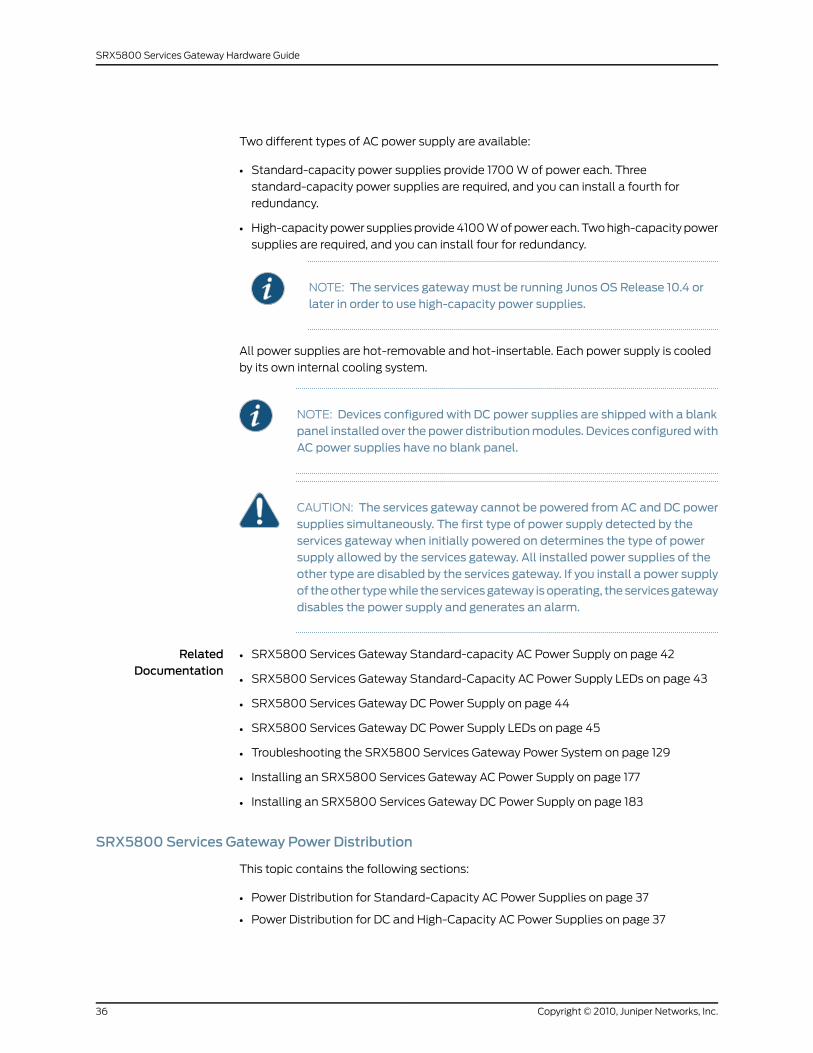
Two different types of AC power supply are available:
• Standard-capacity power supplies provide 1700 W of power each. Three
standard-capacity power supplies are required, and you can install a fourth for
redundancy.
• High-capacity power supplies provide 4100 W of power each. Two high-capacity power
supplies are required, and you can install four for redundancy.
NOTE: The services gatewaymust be running Junos OS Release 10.4 orlater in order to use high-capacity power supplies.
All power supplies are hot-removable and hot-insertable. Each power supply is cooled
by its own internal cooling system.
NOTE: Devices configured with DC power supplies are shipped with a blankpanel installed over thepower distributionmodules. Devices configuredwithAC power supplies have no blank panel.
CAUTION: The services gateway cannot be powered fromAC and DC powersupplies simultaneously. The first type of power supply detected by theservices gateway when initially powered on determines the type of powersupply allowed by the services gateway. All installed power supplies of theother type are disabled by the services gateway. If you install a power supplyof theother typewhile theservicesgateway isoperating, theservicesgatewaydisables the power supply and generates an alarm.
RelatedDocumentation
SRX5800 Services Gateway Standard-capacity AC Power Supply on page 42•
• SRX5800 Services Gateway Standard-Capacity AC Power Supply LEDs on page 43
• SRX5800 Services Gateway DC Power Supply on page 44
• SRX5800 Services Gateway DC Power Supply LEDs on page 45
• Troubleshooting the SRX5800 Services Gateway Power System on page 129
• Installing an SRX5800 Services Gateway AC Power Supply on page 177
• Installing an SRX5800 Services Gateway DC Power Supply on page 183
SRX5800 Services Gateway Power Distribution
This topic contains the following sections:
• Power Distribution for Standard-Capacity AC Power Supplies on page 37
• Power Distribution for DC and High-Capacity AC Power Supplies on page 37
Copyright © 2010, Juniper Networks, Inc.36
SRX5800 Services Gateway Hardware Guide
Power Distribution for Standard-Capacity AC Power Supplies
When the services gateway is powered by standard-capacity AC power supplies, the
services gateway contains either three or four AC power supplies, located at the rear of
the chassis in slotsPEM0 throughPEM3 (left to right). Each power supply provides power
to all components in the services gateway. When three power supplies are present, they
share power almost equally within a fully populated system. Four power supplies provide
full power redundancy. If one power supply fails or is removed, the remaining power
supplies instantly assume the entire electrical load without interruption. Three power
supplies provide the maximum configuration with full power for as long as the services
gateway is operational.
Power Distribution for DC and High-Capacity AC Power Supplies
When the services gateway is powered by DC power supplies or by high-capacity AC
power supplies, power distribution within the chassis is divided into zones, as described
in Table 20 on page 37.
Table 20: SRX5800 Services Gateway Power Distribution (DC or High-Capacity AC PowerSupplies)
Provide Power To:Power SuppliesZone
• IOC or SPC slots 0 through 5
• SCB slot 0
• Upper fan tray
• PEM0
• PEM2
Zone 1
• IOC or SPC Slots 6 through 11
• SCB Slots 1 and 2
• Lower fan tray
• PEM1
• PEM3
Zone 0
Figure 13 on page 38 shows the distribution of power from the power supplies to the
chassis components in an SRX5800 services gateway chassis powered by DC power
supplies or high-capacity AC power supplies.
37Copyright © 2010, Juniper Networks, Inc.
Chapter 2: SRX5800 Services Gateway Hardware Components
Figure 13: Power Distribution fromDC and High-Capacity AC PowerSupplies in the SRX5800 Services Gateway Chassis
Zone 0Zone 1
PEM0 PEM1 PEM2 PEM3
g030
291
You can install either two or four DC power supplies or high-capacity AC power supplies.
Two power supplies are required to power the two zones, while four power supplies
provide full redundancy for both zones. The power supplies in slots PEM0 and PEM2 form
a redundant pair, as do the power supplies in slots PEM1 and PEM3. When two power
supplies are installed for a zone, they share the load equally. If a power supply fails, its
redundant power supply assumes the full load of that zone without interruption.
If you do install only two power supplies, they must be installed so that one is in an
odd-numbered slot and the other is in an even-numbered slot. For example, you can
install one high-capacity AC power supply in each of the slots PEM0 and PEM1.
CAUTION: The services gateway cannot be powered fromAC and DC powersupplies simultaneously. The first type of power supply detected by theservices gateway when initially powered on determines the type of powersupply allowed by the services gateway. All installed power supplies of theother type are disabled by the services gateway. If you install a power supplyof theother typewhile theservicesgateway isoperating, theservicesgatewaydisables the power supply and generates an alarm.
NOTE: The services gateway cannot be powered from standard-capacityand high-capacity AC power supplies simultaneously. The one exception isduring the process of replacing standard-capacity AC power supplies withhigh-capacity AC power supplies, when it is permissible to have both typesinstalled briefly.
Copyright © 2010, Juniper Networks, Inc.38
SRX5800 Services Gateway Hardware Guide
SRX5800 Services Gateway High-Capacity AC Power Supply
High-capacity AC power supplies provide a maximum of 4100 W of power each. Two
high-capacity power supplies are required, and you can install four high-capacity power
supplies for redundancy. Each high-capacity AC power supply has two corresponding
AC appliance inlets: one located in the chassis directly above the power supply and one
located near the top edge of the power supply itself. For each power supply, you connect
one power cord to the inlet on the chassis above the power supply and one power cord
to the inlet on the power supply itself. Each inlet you connect requires a dedicated AC
power feed and a dedicated 15 A (250 VAC) circuit breaker.
NOTE: The services gateway cannot be powered from standard-capacityand high-capacity AC power supplies simultaneously. The one exception isduring the process of replacing standard-capacity AC power supplies withhigh-capacity AC power supplies, when it is permissible to have both typesinstalled briefly.
NOTE: The high-capacity power supply will operate with only one of its twoAC inlets connected to an AC power feed. However, its DC output will belimited to amaximum of 1700W.We recommend that you connect two ACpower feeds to each high-capacity AC power supply.
NOTE: The services gatewaymust be running Junos OS Release 10.4 or laterin order to use high-capacity power supplies.
Each high-capacity AC power supply has an input mode switch, covered by a small metal
plate. The input mode switch tells the system the number of AC power feeds it should
expect. The input mode switch settings are described in Table 21 on page 39. The default
setting is 1.
Table 21: High-Capacity AC Power Supply Input Mode Switch Settings
ResultAC InputsMode SwitchSetting
DC output of 4100 W
DCOK LED lights
Both AC inlets powered1
DC output of 1700 W
DCOK LED lights
Only one AC inlet powered
39Copyright © 2010, Juniper Networks, Inc.
Chapter 2: SRX5800 Services Gateway Hardware Components
Table 21: High-Capacity AC Power Supply Input Mode Switch Settings (continued)
ResultAC InputsMode SwitchSetting
DC output of 4100 W
DCOK LED lights
Both AC inlets powered0
DC output disabled
DCOK LED unlit
Only one AC inlet powered
NOTE: We recommend that you set the input mode switch to 1 and connect
two AC input feeds to each high-capacity AC power supply.
WARNING: The services gateway is pluggable type A equipment installed ina restricted-access location. It has a separate protective earthing terminal(the left pair is sized for M6 bolts, and the right pair is sized for UNC 1/4-20ground lugs) provided on the chassis in addition to the grounding pin of thepower supply cord. This separate protective earth terminal must bepermanently connected to earth.
Copyright © 2010, Juniper Networks, Inc.40
SRX5800 Services Gateway Hardware Guide
Figure 14: High-Capacity AC Power Supply
g004
710
AC-1 OKAC-2 OKDC OKPS FAIL
RelatedDocumentation
SRX5800 Services Gateway High-Capacity AC Power Supply LEDs on page 41•
• SRX5800 Services Gateway Power Distribution on page 36
SRX5800 Services Gateway High-Capacity AC Power Supply LEDs
Each high-capacity AC power supply faceplate contains four LEDs that indicate the status
of the power supply (see Table 22 on page 42). The power supply status is also reflected
in two LEDs on the craft interface. In addition, a power supply failure triggers the red
alarm LED on the craft interface.
41Copyright © 2010, Juniper Networks, Inc.
Chapter 2: SRX5800 Services Gateway Hardware Components
Table 22: High-Capacity AC Power Supply LEDs
DescriptionStateColorLabel
AC power applied to power supply at the upper appliance inlet is not within thenormal operating range.
OffGreenAC-1 OK
AC power applied to power supply at the upper appliance inlet is within the normaloperating range.
On
AC power applied to power supply at the lower appliance inlet is not within thenormal operating range.
OffGreenAC-2 OK
AC power applied to power supply at the lower appliance inlet is within the normaloperating range.
On
DC power outputs generated by the power supply are not within the normaloperating ranges.
OffGreenDCOK
DC power outputs generated by the power supply are within the normal operatingranges.
On
Power supply is functioning normally.OffRedPS FAIL
Power supply is not functioning normally. Check the AC-1 OK, AC-2 OK, and DCOKLEDs for more information.
On
RelatedDocumentation
SRX5800 Services Gateway Craft Interface Power Supply LEDs on page 33•
• SRX5800 Services Gateway High-Capacity AC Power Supply on page 39
• SRX5800 Services Gateway Power System Overview on page 35
SRX5800 Services Gateway Standard-capacity AC Power Supply
Each standard-capacity AC power supply has a corresponding AC appliance inlet located
in the chassis directly above the power supply. Each inlet requires a dedicated AC power
feed and a dedicated 15 A (250 VAC) circuit breaker.
WARNING: The services gateway is pluggable type A equipment installed ina restricted-access location. It has a separate protective earthing terminal(the left pair is sized for M6 bolts, and the right pair is sized for UNC 1/4-20ground lugs) provided on the chassis in addition to the grounding pin of thepower supply cord. This separate protective earth terminal must bepermanently connected to earth.
Copyright © 2010, Juniper Networks, Inc.42
SRX5800 Services Gateway Hardware Guide
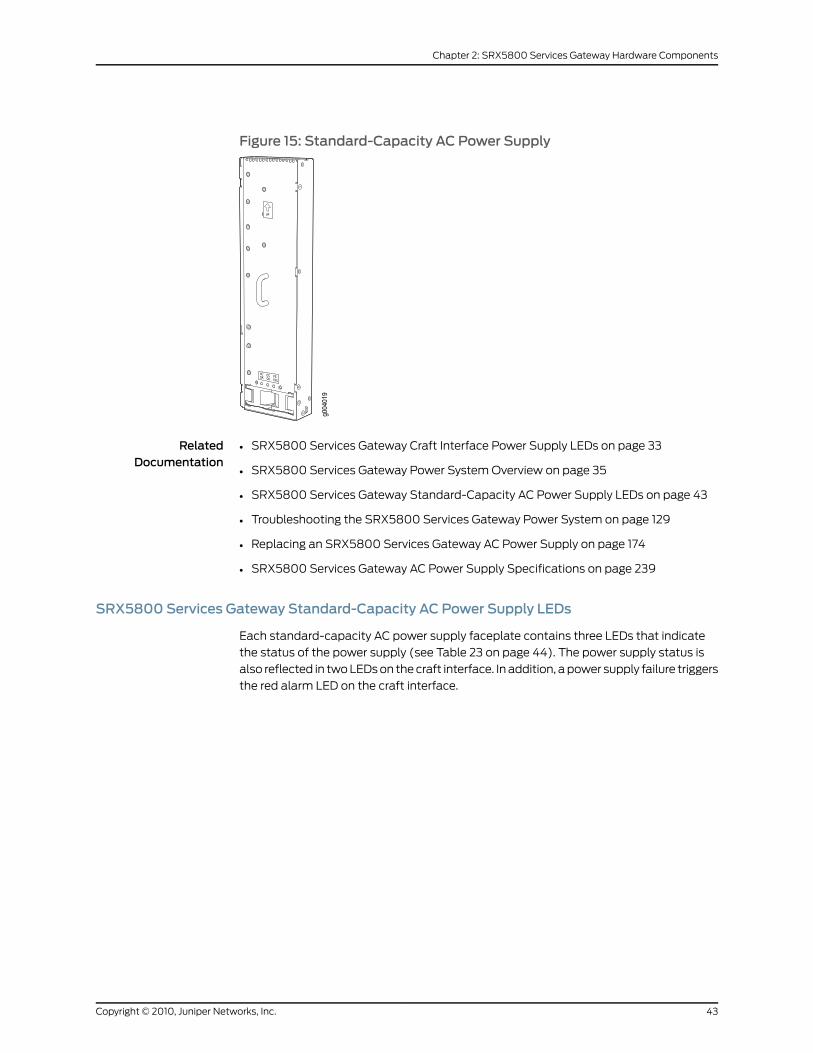
Figure 15: Standard-Capacity AC Power Supply
RelatedDocumentation
SRX5800 Services Gateway Craft Interface Power Supply LEDs on page 33•
• SRX5800 Services Gateway Power System Overview on page 35
• SRX5800 Services Gateway Standard-Capacity AC Power Supply LEDs on page 43
• Troubleshooting the SRX5800 Services Gateway Power System on page 129
• Replacing an SRX5800 Services Gateway AC Power Supply on page 174
• SRX5800 Services Gateway AC Power Supply Specifications on page 239
SRX5800 Services Gateway Standard-Capacity AC Power Supply LEDs
Each standard-capacity AC power supply faceplate contains three LEDs that indicate
the status of the power supply (see Table 23 on page 44). The power supply status is
also reflected in two LEDs on the craft interface. In addition, a power supply failure triggers
the red alarm LED on the craft interface.
43Copyright © 2010, Juniper Networks, Inc.
Chapter 2: SRX5800 Services Gateway Hardware Components
Table 23: Standard Capacity AC Power Supply LEDs
DescriptionStateColorLabel
AC power applied to power supply is not within the normal operating range.OffGreenACOK
AC power applied to power supply is within the normal operating range.On
DC power outputs generated by the power supply are not within the normaloperating ranges.
OffGreenDCOK
DC power outputs generated by the power supply are within the normal operatingranges.
On
Power supply is functioning normally.OffRedPS FAIL
Power supply is not functioning normally. Check ACOK and DCOK LEDs for moreinformation.
On
RelatedDocumentation
SRX5800 Services Gateway Craft Interface Power Supply LEDs on page 33•
• SRX5800 Services Gateway Power System Overview on page 35
• SRX5800 Services Gateway Standard-capacity AC Power Supply on page 42
• SRX5800 Services Gateway DC Power Supply on page 44
SRX5800 Services Gateway DC Power Supply
In the DC power configuration, the services gateway contains either two or four DC power
supplies (see Figure 16 on page 45), located at the lower rear of the chassis in slotsPEM0
through PEM3 (left to right). You can upgrade your DC power system from two to four
power supplies.
Four power supplies provide full redundancy. If a DC power supply fails, its redundant
power supply takes over without interruption.
Each DC power supply has a single DC input (–48 VDC and return) that requires a
dedicated 80 A (–48 VDC) circuit breaker for the maximum hardware configuration.
Copyright © 2010, Juniper Networks, Inc.44
SRX5800 Services Gateway Hardware Guide
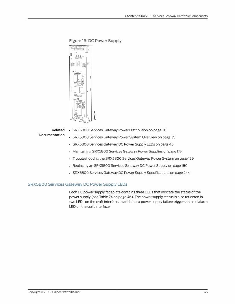
Figure 16: DC Power Supply
RelatedDocumentation
SRX5800 Services Gateway Power Distribution on page 36•
• SRX5800 Services Gateway Power System Overview on page 35
• SRX5800 Services Gateway DC Power Supply LEDs on page 45
• Maintaining SRX5800 Services Gateway Power Supplies on page 119
• Troubleshooting the SRX5800 Services Gateway Power System on page 129
• Replacing an SRX5800 Services Gateway DC Power Supply on page 180
• SRX5800 Services Gateway DC Power Supply Specifications on page 244
SRX5800 Services Gateway DC Power Supply LEDs
Each DC power supply faceplate contains three LEDs that indicate the status of the
power supply (see Table 24 on page 46). The power supply status is also reflected in
two LEDs on the craft interface. In addition, a power supply failure triggers the red alarm
LED on the craft interface.
45Copyright © 2010, Juniper Networks, Inc.
Chapter 2: SRX5800 Services Gateway Hardware Components
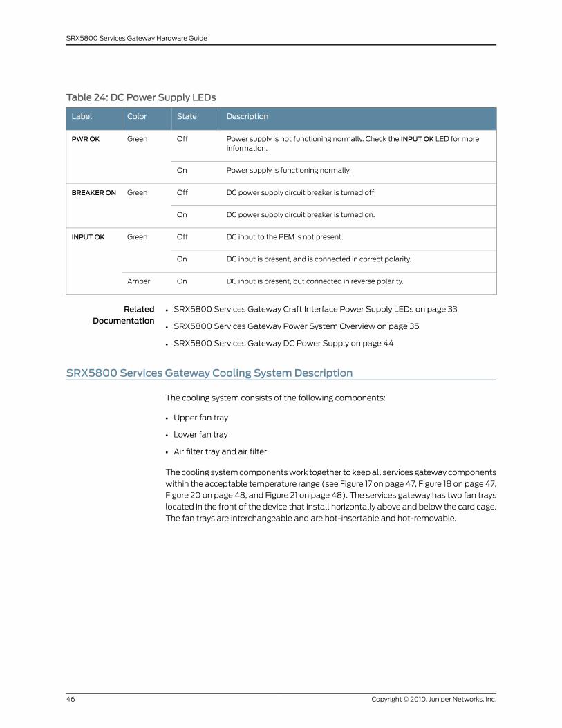
Table 24: DC Power Supply LEDs
DescriptionStateColorLabel
Power supply is not functioning normally. Check the INPUTOK LED for moreinformation.
OffGreenPWROK
Power supply is functioning normally.On
DC power supply circuit breaker is turned off.OffGreenBREAKERON
DC power supply circuit breaker is turned on.On
DC input to the PEM is not present.OffGreenINPUTOK
DC input is present, and is connected in correct polarity.On
DC input is present, but connected in reverse polarity.OnAmber
RelatedDocumentation
SRX5800 Services Gateway Craft Interface Power Supply LEDs on page 33•
• SRX5800 Services Gateway Power System Overview on page 35
• SRX5800 Services Gateway DC Power Supply on page 44
SRX5800 Services Gateway Cooling SystemDescription
The cooling system consists of the following components:
• Upper fan tray
• Lower fan tray
• Air filter tray and air filter
The cooling system components work together to keep all services gateway components
within the acceptable temperature range (see Figure 17 on page 47, Figure 18 on page 47,
Figure 20 on page 48, and Figure 21 on page 48). The services gateway has two fan trays
located in the front of the device that install horizontally above and below the card cage.
The fan trays are interchangeable and are hot-insertable and hot-removable.
Copyright © 2010, Juniper Networks, Inc.46
SRX5800 Services Gateway Hardware Guide
Figure 17: Airflow Through the Chassis
The host subsystem monitors the temperature of the device components. When the
device is operating normally, the fans function at lower than full speed. If a fan fails or
the ambient temperature rises above a threshold, the speed of the remaining fans is
automatically adjusted to keep the temperature within the acceptable range. If the
ambient maximum temperature specification is exceeded and the system cannot be
adequately cooled, the Routing Engine shuts down the system by disabling output power
from each PEM.
There is a single air intake in the front of the services gateway. Air is pushed up through
an air filter, through the card cage, and then through the upper fan tray where it combines
in a common exhaust plenum and is exhausted out the upper rear of the system.
Two different types of fan tray are available:
• The standard capacity fan tray has six fans and is adequate for services gateways in
which standard-capacity power supplies are installed.
• The high-capacity fan tray has 12 fans and is required when high-capacity power
supplies are installed. When high-capacity fan trays are installed, you must also install
the high-capacity air filter tray.
Figure 18: Standard-Capacity Fan Tray (SameUpper and Lower)
Figure 19: High-Capacity Fan Tray (SameUpper and Lower)
g030
294
47Copyright © 2010, Juniper Networks, Inc.
Chapter 2: SRX5800 Services Gateway Hardware Components
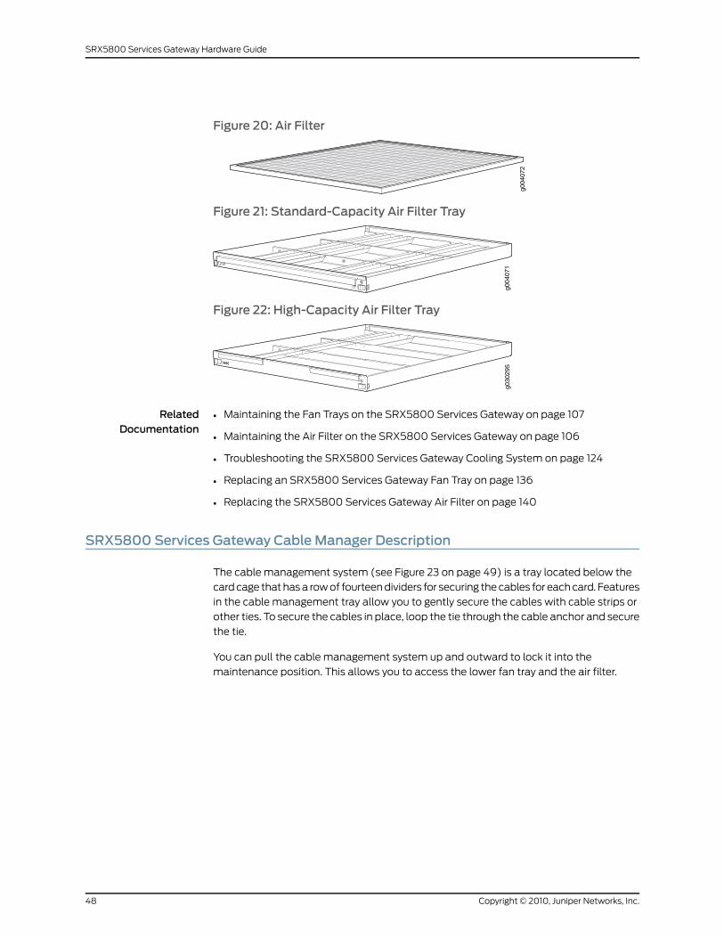
Figure 20: Air Filter
Figure 21: Standard-Capacity Air Filter Tray
Figure 22: High-Capacity Air Filter Tray
g030
295
RelatedDocumentation
Maintaining the Fan Trays on the SRX5800 Services Gateway on page 107•
• Maintaining the Air Filter on the SRX5800 Services Gateway on page 106
• Troubleshooting the SRX5800 Services Gateway Cooling System on page 124
• Replacing an SRX5800 Services Gateway Fan Tray on page 136
• Replacing the SRX5800 Services Gateway Air Filter on page 140
SRX5800 Services Gateway Cable Manager Description
The cable management system (see Figure 23 on page 49) is a tray located below the
card cage that has a row of fourteen dividers for securing the cables for each card. Features
in the cable management tray allow you to gently secure the cables with cable strips or
other ties. To secure the cables in place, loop the tie through the cable anchor and secure
the tie.
You can pull the cable management system up and outward to lock it into the
maintenance position. This allows you to access the lower fan tray and the air filter.
Copyright © 2010, Juniper Networks, Inc.48
SRX5800 Services Gateway Hardware Guide
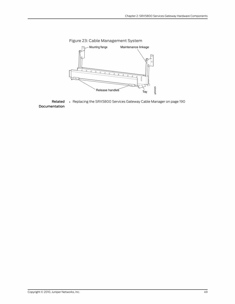
Figure 23: Cable Management System
Release handles
Maintenance linkage
RelatedDocumentation
• Replacing the SRX5800 Services Gateway Cable Manager on page 190
49Copyright © 2010, Juniper Networks, Inc.
Chapter 2: SRX5800 Services Gateway Hardware Components

Copyright © 2010, Juniper Networks, Inc.50
SRX5800 Services Gateway Hardware Guide
PART 2
Setting Up the SRX5800 ServicesGateway
• SRX5800 Services Gateway Installation on page 53
• Preparing the Site for the SRX5800 Services Gateway Installation on page 55
• Unpacking the SRX5800 Services Gateway on page 63
• Installing the SRX5800 Services Gateway Mounting Hardware on page 69
• Installing the SRX5800 Services Gateway on page 75
• Connecting the SRX5800 Services Gateway on page 79
• Grounding and Providing Power to the SRX5800 Services Gateway on page 85
• Configuring Junos OS for the SRX5800 Services Gateway on page 97
51Copyright © 2010, Juniper Networks, Inc.

Copyright © 2010, Juniper Networks, Inc.52
SRX5800 Services Gateway Hardware Guide
CHAPTER 3
SRX5800 Services Gateway Installation
This section includes the following topic:
• Overview of Installing the SRX5800 Services Gateway on page 53
Overview of Installing the SRX5800 Services Gateway
To install the SRX5800 Services Gateway:
1. Prepare your installation site as described in “Site Preparation Checklist for the
SRX5800 Services Gateway” on page 55.
2. Review the safety guidelines explained in “SRX5800 Services Gateway General Safety
Guidelines and Warnings” on page 197.
3. Unpack the services gateway and verify the parts.
a. “Unpacking the SRX5800 Services Gateway” on page 63
b. “Verifying the SRX5800 Services Gateway Parts Received” on page 65
4. Install the mounting hardware.
• Installing the SRX5800 Services Gateway Mounting Hardware for a Four-Post Rack
or Cabinet on page 69
• Installing the SRX5800 Services Gateway Mounting Hardware in an Open-Frame
Rack on page 71
5. Lift the services gateway on to the rack. Because of the weight of the services gateway,
we recommend that you use a mechanical lift.
• Installing the SRX5800 Services Gateway Using a Mechanical Lift on page 75
• Installing the SRX5800 Services Gateway Chassis in the Rack Manually on page 269
6. Connect cables to the network and external devices.
• Connecting the SRX5800 Services Gateway to a Management Console or an
Auxiliary Device on page 81
• Connecting the SRX5800 Services Gateway to a Network for Out-of-Band
Management on page 80
53Copyright © 2010, Juniper Networks, Inc.
• Connecting the Alarm Relay Wires to the SRX5800 Services Gateway Craft Interface
on page 136
7. Connect the grounding cable as described in “Grounding the SRX5800 Services
Gateway” on page 86.
8. Connect the AC power cord or DC power cables:
• Connecting Power to an AC-Powered SRX5800 Services Gateway on page 86
• Connecting Power to a DC-Powered SRX5800 Services Gateway on page 91
9. Power on the services gateway:
• Powering On an AC-Powered SRX5800 Services Gateway on page 90
• Powering On a DC-Powered SRX5800 Services Gateway on page 93
10. Perform the initial system configuration as described in “Initially Configuring the
SRX5800 Services Gateway” on page 98.
RelatedDocumentation
• SRX5800 Services Gateway Chassis on page 7
• Routine Maintenance Procedures for the SRX5800 Services Gateway on page 105
Copyright © 2010, Juniper Networks, Inc.54
SRX5800 Services Gateway Hardware Guide
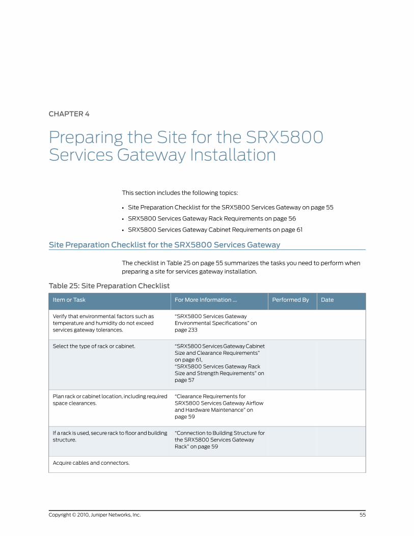
CHAPTER 4
Preparing the Site for the SRX5800Services Gateway Installation
This section includes the following topics:
• Site Preparation Checklist for the SRX5800 Services Gateway on page 55
• SRX5800 Services Gateway Rack Requirements on page 56
• SRX5800 Services Gateway Cabinet Requirements on page 61
Site Preparation Checklist for the SRX5800 Services Gateway
The checklist in Table 25 on page 55 summarizes the tasks you need to perform when
preparing a site for services gateway installation.
Table 25: Site Preparation Checklist
DatePerformed ByFor More Information ...Item or Task
“SRX5800 Services GatewayEnvironmental Specifications” onpage 233
Verify that environmental factors such astemperature and humidity do not exceedservices gateway tolerances.
“SRX5800 Services Gateway CabinetSize and Clearance Requirements”on page 61,“SRX5800 Services Gateway RackSize and Strength Requirements” onpage 57
Select the type of rack or cabinet.
“Clearance Requirements forSRX5800 Services Gateway Airflowand Hardware Maintenance” onpage 59
Plan rack or cabinet location, including requiredspace clearances.
“Connection to Building Structure forthe SRX5800 Services GatewayRack” on page 59
If a rack is used, secure rack to floor and buildingstructure.
Acquire cables and connectors.
55Copyright © 2010, Juniper Networks, Inc.
Table 25: Site Preparation Checklist (continued)
DatePerformed ByFor More Information ...Item or Task
“DC Power Electrical SafetyGuidelines and Warnings” on page 224
Locate sites for connection of systemgrounding.
Measure distance between external powersources and services gateway installation site.
“Calculating Power Budget forFiber-Optic Cable for the SRX5800Services Gateway” onpage 253,“Calculating Power Marginfor Fiber-Optic Cable for theSRX5800 Services Gateway” onpage 253
Calculate the optical power budget and opticalpower margin.
RelatedDocumentation
Overview of Installing the SRX5800 Services Gateway on page 53•
• Unpacking the SRX5800 Services Gateway on page 63
SRX5800 Services Gateway Rack Requirements
The services gateway can be installed in a rack. Many types of racks are acceptable,
including four-post (telco) racks and open-frame racks. An example of an open-frame
rack is shown in Figure 24 on page 57.
Copyright © 2010, Juniper Networks, Inc.56
SRX5800 Services Gateway Hardware Guide
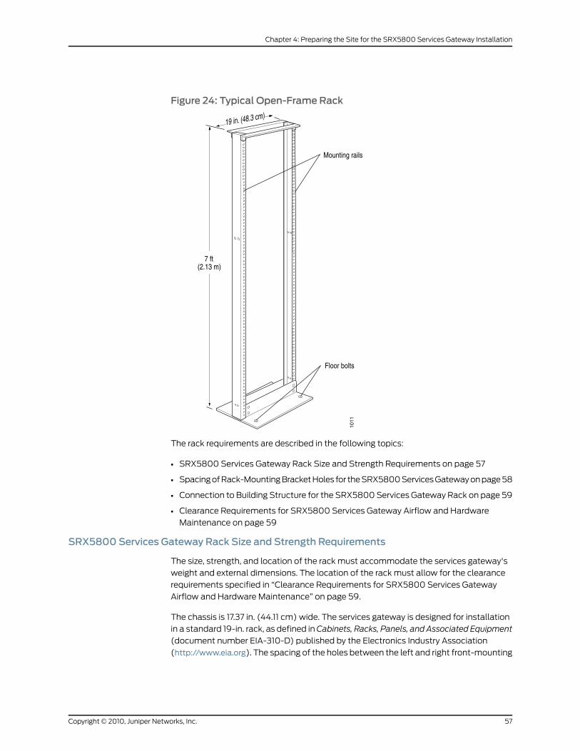
Figure 24: Typical Open-Frame Rack
The rack requirements are described in the following topics:
• SRX5800 Services Gateway Rack Size and Strength Requirements on page 57
• Spacing of Rack-Mounting Bracket Holes for the SRX5800 Services Gateway on page 58
• Connection to Building Structure for the SRX5800 Services Gateway Rack on page 59
• Clearance Requirements for SRX5800 Services Gateway Airflow and Hardware
Maintenance on page 59
SRX5800 Services Gateway Rack Size and Strength Requirements
The size, strength, and location of the rack must accommodate the services gateway's
weight and external dimensions. The location of the rack must allow for the clearance
requirements specified in “Clearance Requirements for SRX5800 Services Gateway
Airflow and Hardware Maintenance” on page 59.
The chassis is 17.37 in. (44.11 cm) wide. The services gateway is designed for installation
in a standard 19-in. rack, as defined in Cabinets, Racks, Panels, and Associated Equipment
(document number EIA-310-D) published by the Electronics Industry Association
(http://www.eia.org). The spacing of the holes between the left and right front-mounting
57Copyright © 2010, Juniper Networks, Inc.
Chapter 4: Preparing the Site for the SRX5800 Services Gateway Installation
flanges and center-mounting brackets is 18.31 in (465 mm) apart. However, the inner
edge of the rack rails must allow sufficient space for the width of the chassis.
With the use of adapters or approved wing devices to narrow the opening between the
rails, the services gateway can fit into a 600-mm-wide rack, as defined in the four-part
EquipmentEngineering(EE);European telecommunicationsstandard forequipmentpractice
(document numbers ETS 300 119-1 through 119-4) published by the European
Telecommunications Standards Institute (http://www.etsi.org).
Observe these guidelines:
• The rack must have sufficient vertical usable space to accomodate the height of the
services gateway: 27.75 in. (70.49 cm) high (approximately 16 U). You can stack three
services gateways in a rack that is at least 48 U (89.3 in. or 2.24 m) in height.
NOTE: AU is the standard rack unit defined inCabinets, Racks, Panels, and
Associated Equipment.
• The location of the rack must provide sufficient space to accomodate the depth of the
services gateway. The chassis is 23.0 in. (58.42 cm) deep.
• The rack must be strong enough to support the weight of the fully configured services
gateway, up to 378 lb (172 kg). If you stack three fully configured services gateways, it
must be capable of supporting up to 1,050 lb (515 kg).
RelatedDocumentation
Overview of Installing the SRX5800 Services Gateway on page 53•
• Site Preparation Checklist for the SRX5800 Services Gateway on page 55
• Spacing of Rack-Mounting Bracket Holes for the SRX5800 Services Gateway on
page 58
• Connection to Building Structure for the SRX5800 Services Gateway Rack on page 59
• Clearance Requirements for SRX5800 Services Gateway Airflow and Hardware
Maintenance on page 59
Spacing of Rack-Mounting Bracket Holes for the SRX5800 Services Gateway
The services gateway can be mounted in any rack that provides holes or hole patterns
spaced at 1 U (1.75 in.) increments. The mounting brackets used to attach the chassis to
a rack are designed to fasten to holes spaced at those distances.
RelatedDocumentation
Overview of Installing the SRX5800 Services Gateway on page 53•
• SRX5800 Services Gateway Rack Size and Strength Requirements on page 57
• Connection to Building Structure for the SRX5800 Services Gateway Rack on page 59
• Clearance Requirements for SRX5800 Services Gateway Airflow and Hardware
Maintenance on page 59
Copyright © 2010, Juniper Networks, Inc.58
SRX5800 Services Gateway Hardware Guide
Connection to Building Structure for the SRX5800 Services Gateway Rack
Always secure the rack to the structure of the building. If your geographical area is subject
to earthquakes, bolt the rack to the floor. For maximum stability, also secure the rack to
ceiling brackets.
RelatedDocumentation
Overview of Installing the SRX5800 Services Gateway on page 53•
• SRX5800 Services Gateway Rack Size and Strength Requirements on page 57
• Spacing of Rack-Mounting Bracket Holes for the SRX5800 Services Gateway on
page 58
• Clearance Requirements for SRX5800 Services Gateway Airflow and Hardware
Maintenance on page 59
Clearance Requirements for SRX5800 Services Gateway Airflow and HardwareMaintenance
When planning the installation site, you need to allow sufficient clearance around the
rack (see Figure 25 on page 60):
• For the cooling system to function properly, the airflow around the chassis must be
unrestricted.
• For service personnel to remove and install hardware components, there must be
adequate space at the front and back of the services gateway. At least 24 in. (61 cm)
is required both in front of and behind the services gateway. NEBS GR-63 recommends
that you allow at least 30 in. (76.2 cm) behind the services gateway.
• Airflow must always be from front to back with respect to the rack. If the device has
side to rear airflow, then provisions must be made to ensure that fresh air from the
front of the rack is supplied to the inlets, and exhaust exits the rear of the rack. The
device must not interfere with the cooling of other systems in the rack. Fillers must be
used as appropriate in the rack to ensure there is no recirculation of heated exhaust
air back to the front of the rack. Care must also be taken around cables to ensure that
no leakage of air in situations where recirculation may result.
• Additional clearance is also required to accommodate the depth of the high-capacity
AC power supplies; they extend beyond the chassis 2.85 in. (7.2 cm).
59Copyright © 2010, Juniper Networks, Inc.
Chapter 4: Preparing the Site for the SRX5800 Services Gateway Installation
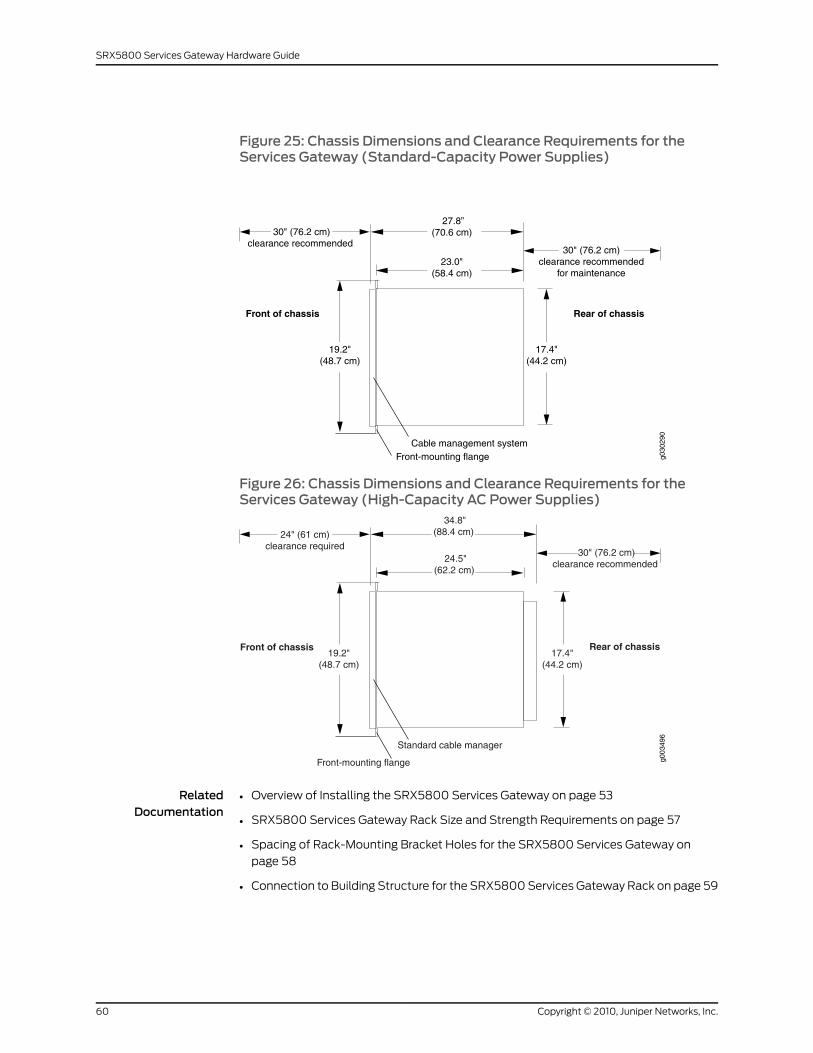
Figure 25: Chassis Dimensions and Clearance Requirements for theServices Gateway (Standard-Capacity Power Supplies)
g030
290
17.4"(44.2 cm)
23.0"(58.4 cm)
Front-mounting flange
19.2"(48.7 cm)
30" (76.2 cm)clearance recommended
30" (76.2 cm)clearance recommended
for maintenance
Cable management system
27.8”(70.6 cm)
Rear of chassisFront of chassis
Figure 26: Chassis Dimensions and Clearance Requirements for theServices Gateway (High-Capacity AC Power Supplies)
Rear of chassisFront of chassis17.4"
(44.2 cm)
24.5"(62.2 cm)
g003
496
Front-mounting flange
19.2"(48.7 cm)
24" (61 cm)clearance required
30" (76.2 cm)clearance recommended
Standard cable manager
34.8"(88.4 cm)
RelatedDocumentation
Overview of Installing the SRX5800 Services Gateway on page 53•
• SRX5800 Services Gateway Rack Size and Strength Requirements on page 57
• Spacing of Rack-Mounting Bracket Holes for the SRX5800 Services Gateway on
page 58
• Connection to Building Structure for the SRX5800 Services Gateway Rack on page 59
Copyright © 2010, Juniper Networks, Inc.60
SRX5800 Services Gateway Hardware Guide
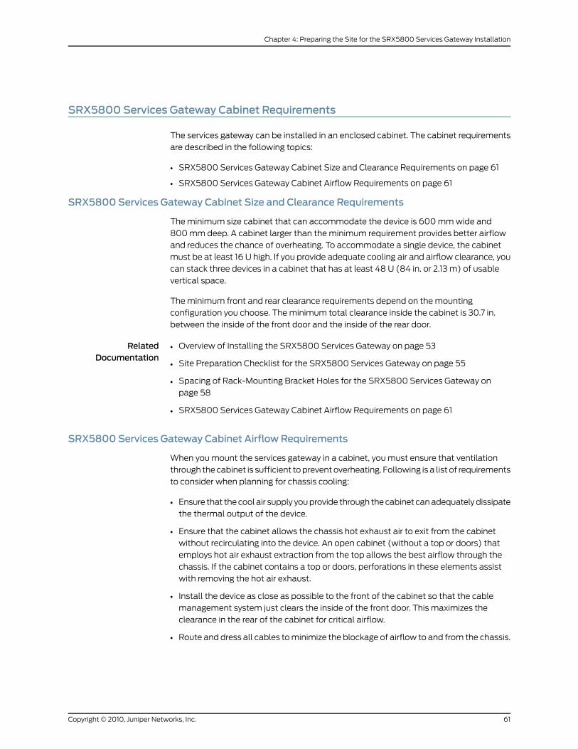
SRX5800 Services Gateway Cabinet Requirements
The services gateway can be installed in an enclosed cabinet. The cabinet requirements
are described in the following topics:
• SRX5800 Services Gateway Cabinet Size and Clearance Requirements on page 61
• SRX5800 Services Gateway Cabinet Airflow Requirements on page 61
SRX5800 Services Gateway Cabinet Size and Clearance Requirements
The minimum size cabinet that can accommodate the device is 600 mm wide and
800 mm deep. A cabinet larger than the minimum requirement provides better airflow
and reduces the chance of overheating. To accommodate a single device, the cabinet
must be at least 16 U high. If you provide adequate cooling air and airflow clearance, you
can stack three devices in a cabinet that has at least 48 U (84 in. or 2.13 m) of usable
vertical space.
The minimum front and rear clearance requirements depend on the mounting
configuration you choose. The minimum total clearance inside the cabinet is 30.7 in.
between the inside of the front door and the inside of the rear door.
RelatedDocumentation
Overview of Installing the SRX5800 Services Gateway on page 53•
• Site Preparation Checklist for the SRX5800 Services Gateway on page 55
• Spacing of Rack-Mounting Bracket Holes for the SRX5800 Services Gateway on
page 58
• SRX5800 Services Gateway Cabinet Airflow Requirements on page 61
SRX5800 Services Gateway Cabinet Airflow Requirements
When you mount the services gateway in a cabinet, you must ensure that ventilation
through the cabinet is sufficient to prevent overheating. Following is a list of requirements
to consider when planning for chassis cooling:
• Ensure that the cool air supply you provide through the cabinet can adequately dissipate
the thermal output of the device.
• Ensure that the cabinet allows the chassis hot exhaust air to exit from the cabinet
without recirculating into the device. An open cabinet (without a top or doors) that
employs hot air exhaust extraction from the top allows the best airflow through the
chassis. If the cabinet contains a top or doors, perforations in these elements assist
with removing the hot air exhaust.
• Install the device as close as possible to the front of the cabinet so that the cable
management system just clears the inside of the front door. This maximizes the
clearance in the rear of the cabinet for critical airflow.
• Route and dress all cables to minimize the blockage of airflow to and from the chassis.
61Copyright © 2010, Juniper Networks, Inc.
Chapter 4: Preparing the Site for the SRX5800 Services Gateway Installation
RelatedDocumentation
• SRX5800 Services Gateway Cooling System Description on page 46
• Overview of Installing the SRX5800 Services Gateway on page 53
• Site Preparation Checklist for the SRX5800 Services Gateway on page 55
• Spacing of Rack-Mounting Bracket Holes for the SRX5800 Services Gateway on
page 58
• SRX5800 Services Gateway Cabinet Size and Clearance Requirements on page 61
Copyright © 2010, Juniper Networks, Inc.62
SRX5800 Services Gateway Hardware Guide
CHAPTER 5
Unpacking the SRX5800 ServicesGateway
This section includes the following topics:
• Tools and Parts Required to Unpack the SRX5800 Services Gateway on page 63
• Unpacking the SRX5800 Services Gateway on page 63
• Verifying the SRX5800 Services Gateway Parts Received on page 65
Tools and Parts Required to Unpack the SRX5800 Services Gateway
To unpack the services gateway and prepare for installation, you need the following
tools:
• Phillips (+) screwdriver, number 2
• 1/2-in. or 13-mm open-end or socket wrench to remove bracket bolts from the shipping
pallet
• Blank panels to cover any slots not occupied by a component
RelatedDocumentation
Overview of Installing the SRX5800 Services Gateway on page 53•
• Site Preparation Checklist for the SRX5800 Services Gateway on page 55
• Unpacking the SRX5800 Services Gateway on page 63
• Verifying the SRX5800 Services Gateway Parts Received on page 65
Unpacking the SRX5800 Services Gateway
The services gateway is shipped in a wooden crate. A wooden pallet forms the base of
the crate. The services gateway chassis is bolted to this pallet. A cardboard accessory
box and a Getting Started Guide are also included in the shipping crate.
The shipping container measures 33 in. (83.8 cm) high, 30.25 in. (76.8 cm) wide, and
43.25 in. (109.9 cm) deep. The total weight of the container containing the services
gateway and accessories can range from 270 lb (122.5 kg) to 475 lb (215.5 kg).
63Copyright © 2010, Juniper Networks, Inc.
NOTE: Theservicesgateway ismaximallyprotected inside theshippingcrate.Do not unpack it until you are ready to begin installation.
To unpack the services gateway, follow these steps (see Figure 27 on page 64):
1. Move the shipping crate to a staging area as close to the installation site as possible,
where you have enough room to remove the components from the chassis. While the
chassis is bolted to the pallet, you can use a forklift or pallet jack to move it.
2. Position the shipping crate with the arrows pointing up.
3. Open all the latches on the shipping crate.
4. Remove the front door of the shipping crate cover and set it aside.
5. Slide the remainder of the shipping crate cover off the pallet.
6. Remove the foam covering the top of the services gateway.
7. Remove the accessory box and theSRX5800Services GatewayGetting StartedGuide.
8. Verify the parts received as described in “Verifying the SRX5800 Services Gateway
Parts Received” on page 65.
9. Remove the vapor corrosion inhibitor (VCI) packs attached to the pallet, being careful
not to break the VCI packs open.
10. To remove the brackets holding the chassis on the pallet, use a 1/2-in. socket wrench
and a number 2 Phillips screwdriver to remove the bolts and screws from the brackets.
11. Store the brackets and bolts inside the accessory box.
12. Save the shipping crate cover, pallet, and packing materials in case you need to move
or ship the services gateway at a later time.
Figure 27: Contents of the Shipping Crate
Shipping cratebase
Shipping cratecover
SRX 5800 chassis
g030
203
Copyright © 2010, Juniper Networks, Inc.64
SRX5800 Services Gateway Hardware Guide
RelatedDocumentation
Overview of Installing the SRX5800 Services Gateway on page 53•
• Installing the SRX5800 Services Gateway Using a Mechanical Lift on page 75
• Installing the SRX5800 Services Gateway Chassis in the Rack Manually on page 269
• Site Preparation Checklist for the SRX5800 Services Gateway on page 55
• Tools and Parts Required to Unpack the SRX5800 Services Gateway on page 63
• Verifying the SRX5800 Services Gateway Parts Received on page 65
Verifying the SRX5800 Services Gateway Parts Received
A packing list is included in each shipment. Check the parts in the shipment against the
items on the packing list. The packing list specifies the part numbers and descriptions of
each part in your order.
If any part is missing, contact a customer service representative.
A fully configured services gateway contains the services gateway chassis with installed
components, listed in Table 26 on page 65, and an accessory box, which contains the
parts listed in Table 27 on page 66. The parts shipped with your services gateway can
vary depending on the configuration you ordered.
Table 26: Parts List for a Fully Configured Services Gateway
QuantityComponent
1Chassis, including midplane, craft interface, andrack-mounting brackets
Up to 11IOCs
Up to 11SPCs
1 or 2Routing Engines
Up to 3SCBs
Up to 4Power supplies
2Fan trays
1Air filter
1Air filter tray
1Getting Started Guide
1Large mounting shelf
1Small mounting shelf
65Copyright © 2010, Juniper Networks, Inc.
Chapter 5: Unpacking the SRX5800 Services Gateway
Table 26: Parts List for a Fully Configured Services Gateway (continued)
QuantityComponent
One blank panel for each slot notoccupied by a component
Blank panels for slots without components installed
Table 27: Accessory Box Parts List
QuantityPart
14Screws to mount chassis
8DC power terminal Lugs, 6-AWG
1RJ-45 cable, with RJ-45 Jack to Female DB-9, to connectthe device through the serial port
2Terminal block plug, 3 pole, 5.08 mm spacing, 12A, toconnect the device alarms
1Label, accessories contents, SRX5800
1USB flash drive with Junos OS
1Read me first document
1Affidavit for T1 connection
1Juniper Networks Product Warranty
1End User License Agreement
1Document sleeve
23" x 5" pink bag
29" x 12" pink bag, ESD
1Accessory Box, 19 x 12 x 3"
1Ethernet cable, RJ-45/RJ-45, 4-pair stranded UTP,Category 5E, 15'
1ESD wrist strap with cable
RelatedDocumentation
• Overview of Installing the SRX5800 Services Gateway on page 53
• Site Preparation Checklist for the SRX5800 Services Gateway on page 55
• Tools and Parts Required to Unpack the SRX5800 Services Gateway on page 63
Copyright © 2010, Juniper Networks, Inc.66
SRX5800 Services Gateway Hardware Guide

• Unpacking the SRX5800 Services Gateway on page 63
67Copyright © 2010, Juniper Networks, Inc.
Chapter 5: Unpacking the SRX5800 Services Gateway

Copyright © 2010, Juniper Networks, Inc.68
SRX5800 Services Gateway Hardware Guide
CHAPTER 6
Installing theSRX5800ServicesGatewayMounting Hardware
This section includes the following topics:
• Installing the SRX5800 Services Gateway Mounting Hardware for a Four-Post Rack
or Cabinet on page 69
• Installing the SRX5800 Services Gateway Mounting Hardware in an Open-Frame
Rack on page 71
Installing the SRX5800 Services GatewayMounting Hardware for a Four-Post Rackor Cabinet
If you are installing the services gateway in a front-mount four-post rack or cabinet, you
must first install the large mounting shelf, followed by the small mounting shelf.
Table 28 on page 69 specifies the holes in which you insert cage nuts and screws to install
the mounting hardware required in a four-post or cabinet rack (anX indicates a mounting
hole location). The hole distances are relative to one of the standard “U” divisions on the
rack. The bottom of all mounting shelves is at 0.04 in. (0.02 U) above a “U” division.
Table 28: Four-Post Rack or Cabinet Mounting Hole Locations
SmallShelf
LargeShelfDistance Above “U” DivisionHole
X0.86 U1.51 in. (3.8 cm)3
XX0.50 U0.88 in. (2.2 cm)2
X0.14 U0.25 in. (0.6 cm)1
To install the mounting shelves (see Figure 28 on page 70):
1. On the front rack rails, install cage nuts in the holes specified in Table 28 on page 69
for the large shelf.
2. On the front of each front rack rail, partially insert a mounting screw into the hole
containing the lowest cage nut.
69Copyright © 2010, Juniper Networks, Inc.
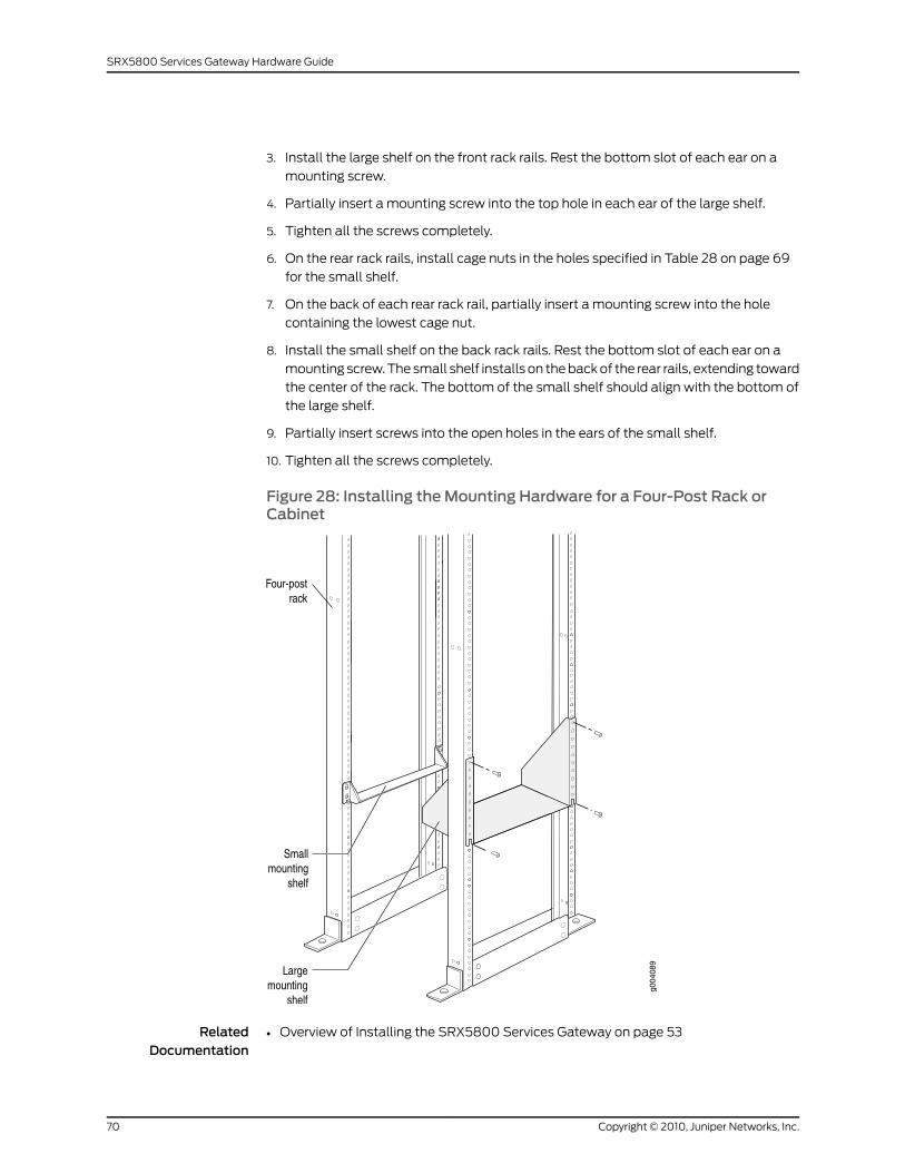
3. Install the large shelf on the front rack rails. Rest the bottom slot of each ear on a
mounting screw.
4. Partially insert a mounting screw into the top hole in each ear of the large shelf.
5. Tighten all the screws completely.
6. On the rear rack rails, install cage nuts in the holes specified in Table 28 on page 69
for the small shelf.
7. On the back of each rear rack rail, partially insert a mounting screw into the hole
containing the lowest cage nut.
8. Install the small shelf on the back rack rails. Rest the bottom slot of each ear on a
mounting screw. The small shelf installs on the back of the rear rails, extending toward
the center of the rack. The bottom of the small shelf should align with the bottom of
the large shelf.
9. Partially insert screws into the open holes in the ears of the small shelf.
10. Tighten all the screws completely.
Figure 28: Installing theMounting Hardware for a Four-Post Rack orCabinet
RelatedDocumentation
Overview of Installing the SRX5800 Services Gateway on page 53•
Copyright © 2010, Juniper Networks, Inc.70
SRX5800 Services Gateway Hardware Guide
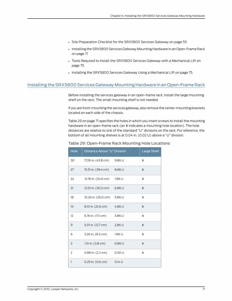
• Site Preparation Checklist for the SRX5800 Services Gateway on page 55
• Installing the SRX5800 Services Gateway Mounting Hardware in an Open-Frame Rack
on page 71
• Tools Required to Install the SRX5800 Services Gateway with a Mechanical Lift on
page 75
• Installing the SRX5800 Services Gateway Using a Mechanical Lift on page 75
Installing theSRX5800ServicesGatewayMountingHardware inanOpen-FrameRack
Before installing the services gateway in an open-frame rack, install the large mounting
shelf on the rack. The small mounting shelf is not needed.
If you are front-mounting the services gateway, also remove the center-mounting brackets
located on each side of the chassis.
Table 29 on page 71 specifies the holes in which you insert screws to install the mounting
hardware in an open-frame rack (an X indicates a mounting hole location). The hole
distances are relative to one of the standard “U” divisions on the rack. For reference, the
bottom of all mounting shelves is at 0.04 in. (0.02 U) above a “U” division.
Table 29: Open-Frame RackMounting Hole Locations
Large ShelfDistance Above “U” DivisionHole
X9.86 U17.26 in. (43.8 cm)30
X8.86 U15.51 in. (39.4 cm)27
X7.86 U13.76 in. (34.9 cm)24
X6.86 U12.01 in. (30.5 cm)21
X5.86 U10.26 in. (26.0 cm)18
X4.86 U8.51 in. (21.6 cm)15
X3.86 U6.76 in. (17.1 cm)12
X2.86 U5.01 in. (12.7 cm)9
X1.86 U3.26 in. (8.3 cm)6
X0.86 U1.51 in. (3.8 cm)3
X0.50 U0.88 in. (2.2 cm)2
0.14 U0.25 in. (0.6 cm)1
71Copyright © 2010, Juniper Networks, Inc.
Chapter 6: Installing the SRX5800 Services Gateway Mounting Hardware
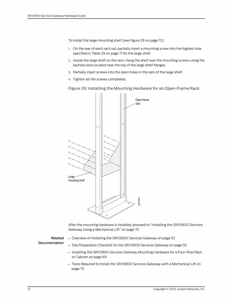
To install the large mounting shelf (see Figure 29 on page 72):
1. On the rear of each rack rail, partially insert a mounting screw into the highest hole
specified in Table 29 on page 71 for the large shelf.
2. Install the large shelf on the rack. Hang the shelf over the mounting screws using the
keyhole slots located near the top of the large shelf flanges.
3. Partially insert screws into the open holes in the ears of the large shelf.
4. Tighten all the screws completely.
Figure 29: Installing theMounting Hardware for an Open-Frame Rack
After the mounting hardware is installed, proceed to “Installing the SRX5800 Services
Gateway Using a Mechanical Lift” on page 75.
RelatedDocumentation
• Overview of Installing the SRX5800 Services Gateway on page 53
• Site Preparation Checklist for the SRX5800 Services Gateway on page 55
• Installing the SRX5800 Services Gateway Mounting Hardware for a Four-Post Rack
or Cabinet on page 69
• Tools Required to Install the SRX5800 Services Gateway with a Mechanical Lift on
page 75
Copyright © 2010, Juniper Networks, Inc.72
SRX5800 Services Gateway Hardware Guide

• Installing the SRX5800 Services Gateway Using a Mechanical Lift on page 75
• Site Preparation Checklist for the SRX5800 Services Gateway on page 55
73Copyright © 2010, Juniper Networks, Inc.
Chapter 6: Installing the SRX5800 Services Gateway Mounting Hardware

Copyright © 2010, Juniper Networks, Inc.74
SRX5800 Services Gateway Hardware Guide
CHAPTER 7
Installing theSRX5800ServicesGateway
This section includes the following topics:
• Tools Required to Install the SRX5800 Services Gateway with a Mechanical
Lift on page 75
• Installing the SRX5800 Services Gateway Using a Mechanical Lift on page 75
Tools Required to Install the SRX5800 Services Gatewaywith aMechanical Lift
To install the services gateway, you need the following tools:
• Mechanical lift
• Phillips (+) screwdrivers, number 2
RelatedDocumentation
Overview of Installing the SRX5800 Services Gateway on page 53•
• Tools and Parts Required for SRX5800 Services Gateway Connections on page 79
• Installing the SRX5800 Services Gateway Using a Mechanical Lift on page 75
Installing the SRX5800 Services Gateway Using aMechanical Lift
Because of the services gateway’s size and weight—up to 378 lb (172 kg) depending on
the configuration—we strongly recommend that you install the services gateway using
a mechanical lift. If you do not use a lift to install the services gateway, see “Installing
the SRX5800 Services Gateway Chassis in the Rack Manually” on page 269 for complete
instructions to install the services gateway safely.
CAUTION: Before front mounting the services gateway in a rack, have aqualified technician verify that the rack is strong enough to support theservices gateway's weight and is adequately supported at the installationsite.
To install the services gateway using a lift (see Figure 30 on page 77):
75Copyright © 2010, Juniper Networks, Inc.
1. Ensure the rack is in its permanent location and is secured to the building. Ensure that
the installation site allows adequate clearance for both airflow and maintenance.
2. Load the services gateway onto the lift, making sure it rests securely on the lift platform.
3. Using the lift, position the services gateway in front of the rack or cabinet, centering
it in front of the mounting shelves.
4. Lift the chassis approximately 0.75 in. above the surface of the mounting shelves and
position it as close as possible to the shelves.
5. Carefully slide the services gateway onto the mounting shelves so that the bottom
of the chassis and the mounting shelves overlap by approximately two inches.
6. Slide the services gateway onto the mounting shelves until the center-mounting
brackets or front-mounting flanges contact the rack rails. The shelves ensure that the
holes in the center-mounting brackets and the front-mounting flanges of the chassis
align with the holes in the rack rails.
7. Move the lift away from the rack.
8. To install the services gateway in an open-frame rack, install a mounting screw into
each of the open mounting holes aligned with the rack, starting from the bottom.
9. Visually inspect the alignment of the services gateway. If the services gateway is
installed properly in the rack, all the mounting screws on one side of the rack should
be aligned with the mounting screws on the opposite side and the services gateway
should be level.
Copyright © 2010, Juniper Networks, Inc.76
SRX5800 Services Gateway Hardware Guide
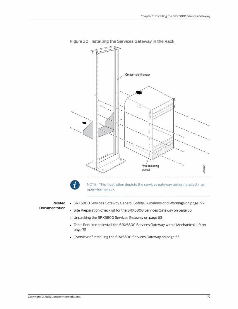
Figure 30: Installing the Services Gateway in the Rack
NOTE: This illustration depicts the services gateway being installed in anopen-frame rack.
RelatedDocumentation
• SRX5800 Services Gateway General Safety Guidelines and Warnings on page 197
• Site Preparation Checklist for the SRX5800 Services Gateway on page 55
• Unpacking the SRX5800 Services Gateway on page 63
• Tools Required to Install the SRX5800 Services Gateway with a Mechanical Lift on
page 75
• Overview of Installing the SRX5800 Services Gateway on page 53
77Copyright © 2010, Juniper Networks, Inc.
Chapter 7: Installing the SRX5800 Services Gateway

Copyright © 2010, Juniper Networks, Inc.78
SRX5800 Services Gateway Hardware Guide
CHAPTER 8
Connecting the SRX5800 ServicesGateway
This section includes the following topics:
• Tools and Parts Required for SRX5800 Services Gateway Connections on page 79
• Connecting the SRX5800 Services Gateway to Management and Alarm
Devices on page 80
• Connecting Network Cables to SRX5800 Services Gateway IOCs and Port
Modules on page 83
Tools and Parts Required for SRX5800 Services Gateway Connections
To connect the device to management devices and IOCs, you need the following tools
and parts:
• Phillips (+) screwdrivers, numbers 1 and 2
• 2.5-mm flat-blade (-) screwdriver
• 2.5 mm Phillips (+) screwdriver
• Electrostatic discharge (ESD) grounding wrist strap
RelatedDocumentation
Overview of Installing the SRX5800 Services Gateway on page 53•
• Connecting the SRX5800 Services Gateway to a Network for Out-of-Band Management
on page 80
• Connecting the SRX5800 Services Gateway to a Management Console or an Auxiliary
Device on page 81
• Connecting an SRX5800 Services Gateway to an External Alarm-Reporting Device on
page 82
• Connecting Network Cables to SRX5800 Services Gateway IOCs and Port Modules
on page 83
79Copyright © 2010, Juniper Networks, Inc.
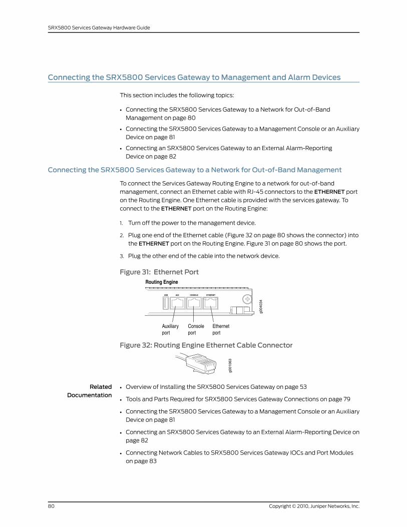
Connecting the SRX5800 Services Gateway toManagement and AlarmDevices
This section includes the following topics:
• Connecting the SRX5800 Services Gateway to a Network for Out-of-Band
Management on page 80
• Connecting the SRX5800 Services Gateway to a Management Console or an Auxiliary
Device on page 81
• Connecting an SRX5800 Services Gateway to an External Alarm-Reporting
Device on page 82
Connecting the SRX5800 Services Gateway to a Network for Out-of-BandManagement
To connect the Services Gateway Routing Engine to a network for out-of-band
management, connect an Ethernet cable with RJ-45 connectors to the ETHERNET port
on the Routing Engine. One Ethernet cable is provided with the services gateway. To
connect to the ETHERNET port on the Routing Engine:
1. Turn off the power to the management device.
2. Plug one end of the Ethernet cable (Figure 32 on page 80 shows the connector) into
the ETHERNET port on the Routing Engine. Figure 31 on page 80 shows the port.
3. Plug the other end of the cable into the network device.
Figure 31: Ethernet Port
Figure 32: Routing Engine Ethernet Cable Connector
RelatedDocumentation
Overview of Installing the SRX5800 Services Gateway on page 53•
• Tools and Parts Required for SRX5800 Services Gateway Connections on page 79
• Connecting the SRX5800 Services Gateway to a Management Console or an Auxiliary
Device on page 81
• Connecting an SRX5800 Services Gateway to an External Alarm-Reporting Device on
page 82
• Connecting Network Cables to SRX5800 Services Gateway IOCs and Port Modules
on page 83
Copyright © 2010, Juniper Networks, Inc.80
SRX5800 Services Gateway Hardware Guide
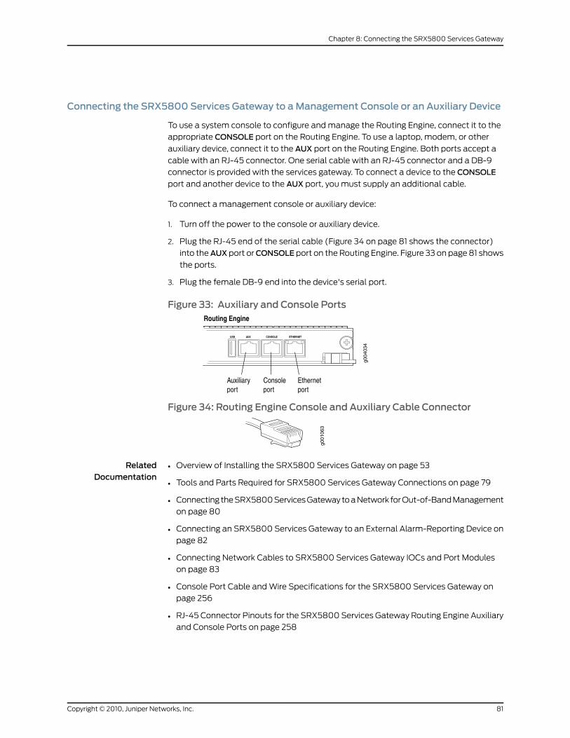
Connecting the SRX5800 Services Gateway to aManagement Console or an Auxiliary Device
To use a system console to configure and manage the Routing Engine, connect it to the
appropriate CONSOLE port on the Routing Engine. To use a laptop, modem, or other
auxiliary device, connect it to the AUX port on the Routing Engine. Both ports accept a
cable with an RJ-45 connector. One serial cable with an RJ-45 connector and a DB-9
connector is provided with the services gateway. To connect a device to the CONSOLE
port and another device to the AUX port, you must supply an additional cable.
To connect a management console or auxiliary device:
1. Turn off the power to the console or auxiliary device.
2. Plug the RJ-45 end of the serial cable (Figure 34 on page 81 shows the connector)
into theAUXport orCONSOLEport on the Routing Engine. Figure 33 on page 81 shows
the ports.
3. Plug the female DB-9 end into the device's serial port.
Figure 33: Auxiliary and Console Ports
Figure 34: Routing Engine Console and Auxiliary Cable Connector
RelatedDocumentation
Overview of Installing the SRX5800 Services Gateway on page 53•
• Tools and Parts Required for SRX5800 Services Gateway Connections on page 79
• Connecting the SRX5800 Services Gateway to a Network for Out-of-Band Management
on page 80
• Connecting an SRX5800 Services Gateway to an External Alarm-Reporting Device on
page 82
• Connecting Network Cables to SRX5800 Services Gateway IOCs and Port Modules
on page 83
• Console Port Cable and Wire Specifications for the SRX5800 Services Gateway on
page 256
• RJ-45 Connector Pinouts for the SRX5800 Services Gateway Routing Engine Auxiliary
and Console Ports on page 258
81Copyright © 2010, Juniper Networks, Inc.
Chapter 8: Connecting the SRX5800 Services Gateway
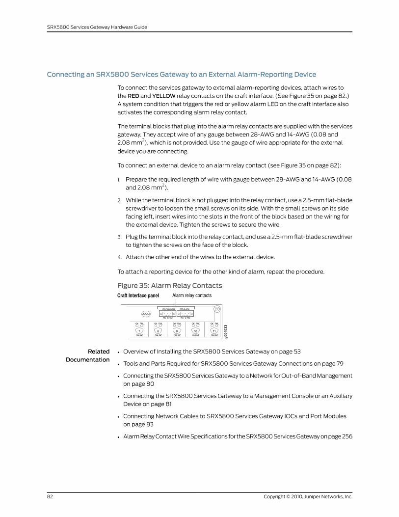
Connecting an SRX5800 Services Gateway to an External Alarm-Reporting Device
To connect the services gateway to external alarm-reporting devices, attach wires to
the RED and YELLOW relay contacts on the craft interface. (See Figure 35 on page 82.)
A system condition that triggers the red or yellow alarm LED on the craft interface also
activates the corresponding alarm relay contact.
The terminal blocks that plug into the alarm relay contacts are supplied with the services
gateway. They accept wire of any gauge between 28-AWG and 14-AWG (0.08 and
2.08 mm2), which is not provided. Use the gauge of wire appropriate for the external
device you are connecting.
To connect an external device to an alarm relay contact (see Figure 35 on page 82):
1. Prepare the required length of wire with gauge between 28-AWG and 14-AWG (0.08
and 2.08 mm2).
2. While the terminal block is not plugged into the relay contact, use a 2.5-mm flat-blade
screwdriver to loosen the small screws on its side. With the small screws on its side
facing left, insert wires into the slots in the front of the block based on the wiring for
the external device. Tighten the screws to secure the wire.
3. Plug the terminal block into the relay contact, and use a 2.5-mm flat-blade screwdriver
to tighten the screws on the face of the block.
4. Attach the other end of the wires to the external device.
To attach a reporting device for the other kind of alarm, repeat the procedure.
Figure 35: Alarm Relay Contacts
RelatedDocumentation
Overview of Installing the SRX5800 Services Gateway on page 53•
• Tools and Parts Required for SRX5800 Services Gateway Connections on page 79
• Connecting the SRX5800 Services Gateway to a Network for Out-of-Band Management
on page 80
• Connecting the SRX5800 Services Gateway to a Management Console or an Auxiliary
Device on page 81
• Connecting Network Cables to SRX5800 Services Gateway IOCs and Port Modules
on page 83
• Alarm Relay Contact Wire Specifications for the SRX5800 Services Gateway on page 256
Copyright © 2010, Juniper Networks, Inc.82
SRX5800 Services Gateway Hardware Guide
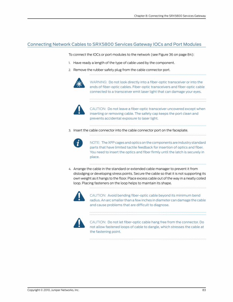
Connecting Network Cables to SRX5800 Services Gateway IOCs and Port Modules
To connect the IOCs or port modules to the network (see Figure 36 on page 84):
1. Have ready a length of the type of cable used by the component.
2. Remove the rubber safety plug from the cable connector port.
WARNING: Do not look directly into a fiber-optic transceiver or into theends of fiber-optic cables. Fiber-optic transceivers and fiber-optic cableconnected to a transceiver emit laser light that can damage your eyes.
CAUTION: Do not leave a fiber-optic transceiver uncovered except wheninserting or removing cable. The safety cap keeps the port clean andprevents accidental exposure to laser light.
3. Insert the cable connector into the cable connector port on the faceplate.
NOTE: TheXFPcagesandopticsonthecomponentsare industrystandardparts that have limited tactile feedback for insertion of optics and fiber.You need to insert the optics and fiber firmly until the latch is securely inplace.
4. Arrange the cable in the standard or extended cable manager to prevent it from
dislodging or developing stress points. Secure the cable so that it is not supporting its
own weight as it hangs to the floor. Place excess cable out of the way in a neatly coiled
loop. Placing fasteners on the loop helps to maintain its shape.
CAUTION: Avoid bending fiber-optic cable beyond its minimum bendradius.Anarc smaller thana few inches indiameter candamage thecableand cause problems that are difficult to diagnose.
CAUTION: Do not let fiber-optic cable hang free from the connector. Donot allow fastened loops of cable to dangle, which stresses the cable atthe fastening point.
83Copyright © 2010, Juniper Networks, Inc.
Chapter 8: Connecting the SRX5800 Services Gateway
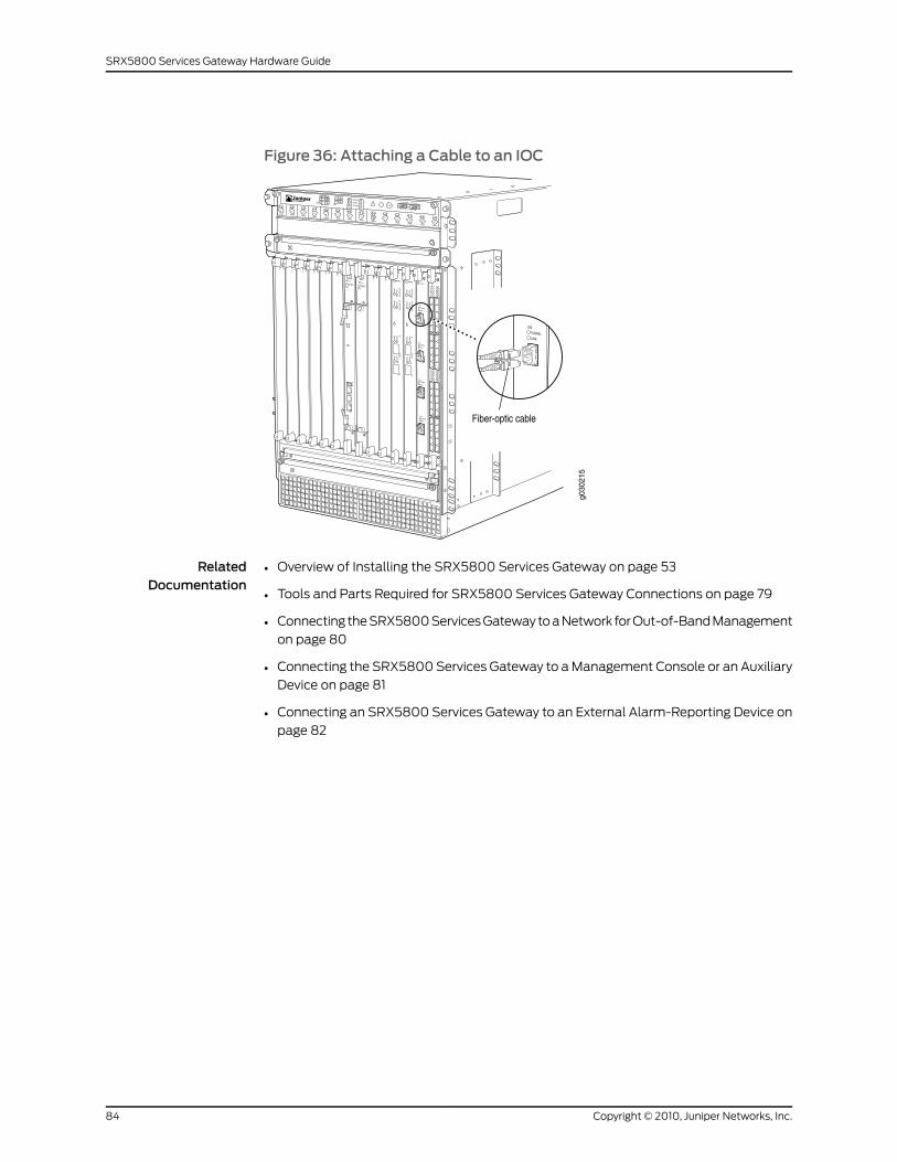
Figure 36: Attaching a Cable to an IOC
RelatedDocumentation
• Overview of Installing the SRX5800 Services Gateway on page 53
• Tools and Parts Required for SRX5800 Services Gateway Connections on page 79
• Connecting the SRX5800 Services Gateway to a Network for Out-of-Band Management
on page 80
• Connecting the SRX5800 Services Gateway to a Management Console or an Auxiliary
Device on page 81
• Connecting an SRX5800 Services Gateway to an External Alarm-Reporting Device on
page 82
Copyright © 2010, Juniper Networks, Inc.84
SRX5800 Services Gateway Hardware Guide
CHAPTER 9
Grounding and Providing Power to theSRX5800 Services Gateway
This section includes the following topics:
• Tools and Parts Required for SRX5800 Services Gateway Grounding and Power
Connections on page 85
• Grounding the SRX5800 Services Gateway on page 86
• Connecting Power to an AC-Powered SRX5800 Services Gateway on page 86
• Powering On an AC-Powered SRX5800 Services Gateway on page 90
• Connecting Power to a DC-Powered SRX5800 Services Gateway on page 91
• Powering On a DC-Powered SRX5800 Services Gateway on page 93
• Powering Off the SRX5800 Services Gateway on page 95
Tools and Parts Required for SRX5800 Services Gateway Grounding and PowerConnections
To ground and provide power to the services gateway, you need the following tools and
parts:
• Phillips (+) screwdrivers, numbers 1 and 2
• 2.5-mm flat-blade (–) screwdriver
• 7/16-in. hexagonal-head external drive socket wrench, or nut driver, with a torque range
between 23 lb-in. (2.6 Nm) and 25 lb-in. (2.8 Nm) tightening torque, for tightening nuts
to terminal studs on each power supply on a DC-powered services gateway.
• Wire cutters
• Electrostatic discharge (ESD) grounding wrist strap
RelatedDocumentation
Overview of Installing the SRX5800 Services Gateway on page 53•
• Grounding the SRX5800 Services Gateway on page 86
• Connecting Power to an AC-Powered SRX5800 Services Gateway on page 86
• Connecting Power to a DC-Powered SRX5800 Services Gateway on page 91
85Copyright © 2010, Juniper Networks, Inc.
Grounding the SRX5800 Services Gateway
You ground the services gateway by connecting a grounding cable to earth ground and
then attaching it to the chassis grounding points using two screws. You must provide the
grounding cables (the cable lugs are supplied with the services gateway).
1. Verify that a licensed electrician has attached the cable lug provided with the services
gateway to the grounding cable.
2. Attach an ESD grounding strap to your bare wrist and connect the strap to an approved
site ESD grounding point. See the instructions for your site.
3. Ensure that all grounding surfaces are clean and brought to a bright finish before
grounding connections are made.
4. Connect the grounding cable to a proper earth ground.
5. Detach the ESD grounding strap from the site ESD grounding point.
6. Attach an ESD grounding strap to your bare wrist, and connect the strap to one of the
ESD points on the chassis.
7. Place the grounding cable lug over the grounding points on the rear of the chassis.
The left pair is sized for M6 screws, and the right pair is sized for UNC 1/4-20 screws.
8. Secure the grounding cable lug to the grounding points, first with the washers, then
with the screws.
9. Dress the grounding cable and verify that it does not touch or block access to services
gateway components, and that it does not drape where people could trip on it.
RelatedDocumentation
Preventing Electrostatic Discharge Damage to the SRX5800 Services Gateway on
page 201
•
• Overview of Installing the SRX5800 Services Gateway on page 53
• Tools and Parts Required for SRX5800 Services Gateway Grounding and Power
Connections on page 85
• Connecting Power to an AC-Powered SRX5800 Services Gateway on page 86
• Connecting Power to a DC-Powered SRX5800 Services Gateway on page 91
Connecting Power to an AC-Powered SRX5800 Services Gateway
CAUTION: Do notmix AC and DC power supplies within the same servicesgateway. Damage to the services gatewaymight occur.
You connect AC power to the device by attaching power cords from the AC power sources
to the AC appliance inlets located on the chassis above the power supplies. If the services
gateway is powered by high-capacity power supplies, you also connect AC feeds to AC
Copyright © 2010, Juniper Networks, Inc.86
SRX5800 Services Gateway Hardware Guide
appliance inlets located on the power supplies themselves. The power cords are not
provided with the services gateway; you must order them separately.
To connect the AC power cords to the services gateway (see Figure 37 on page 88 and
Figure 38 on page 89):
1. Locate or obtain the power cords you will use with the services gateway. The power
cords must have a plug appropriate for your geographical location.
2. Attach an ESD grounding strap to your bare wrist, and connect the strap to one of the
ESD points on the chassis.
3. Move the AC input switch on the chassis above each power supply to the off (O)
position. If the services gateway is equipped with high-capacity AC power supplies,
you must also move the AC input switch on each power supply to the off (O) position.
4. For each installed AC power supply, connect a power cord to the appliance inlet on
the chassis directly above the power supply.
5. If your services gateway is equipped with high-capacity AC power supplies, you must
also connect a power cord to the appliance inlet located on each power supply.
6. Insert the power cord plugs into an external AC power source receptacle.
NOTE: Each power supply must be connected to a dedicated AC powerfeed and a dedicated customer site circuit breaker. We recommend thatyou use a 15 A (250 VAC)minimum, or as required by local code.
7. Dress the power cords appropriately. Verify that the power cords do not block the air
exhaust and access to services gateway components, or drape where people could
trip on them.
8. Repeat Step 3 through Step 7 for the remaining power supplies.
87Copyright © 2010, Juniper Networks, Inc.
Chapter 9: Grounding and Providing Power to the SRX5800 Services Gateway
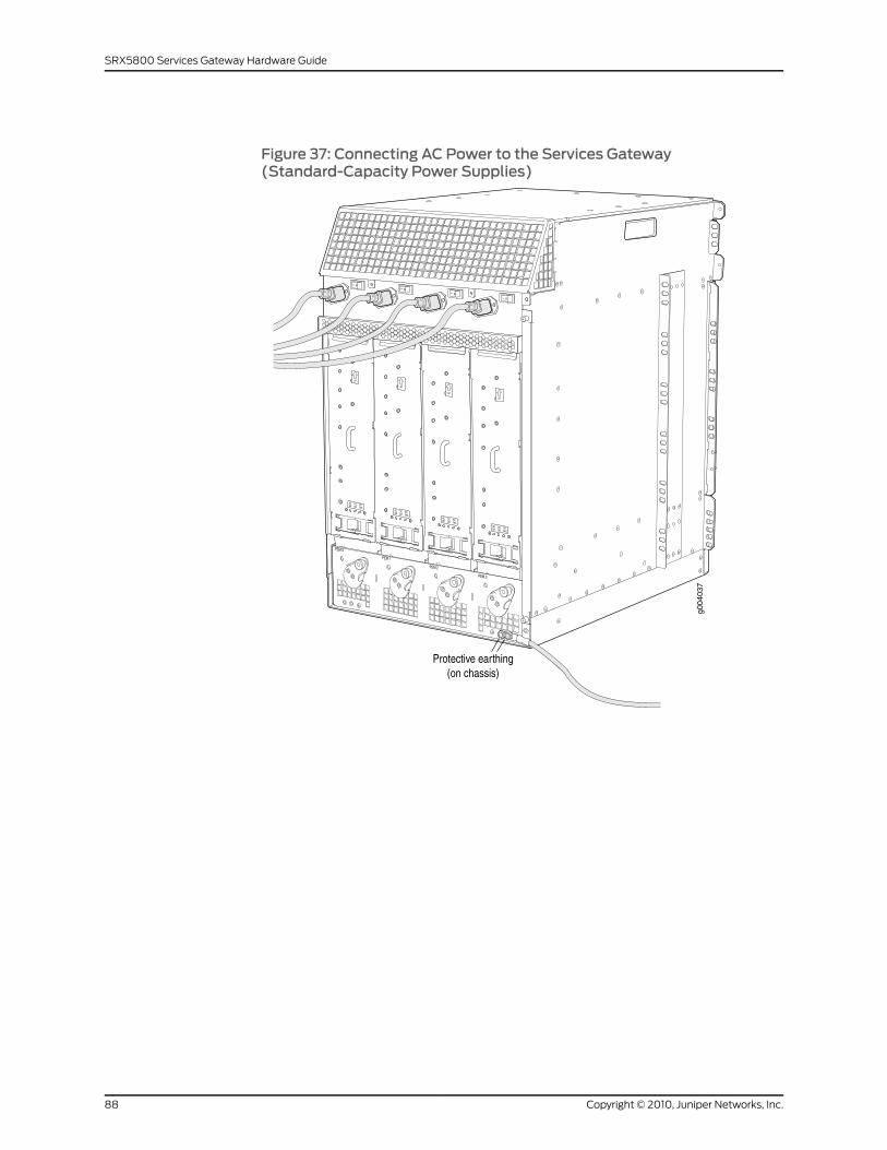
Figure 37: Connecting AC Power to the Services Gateway(Standard-Capacity Power Supplies)
Copyright © 2010, Juniper Networks, Inc.88
SRX5800 Services Gateway Hardware Guide
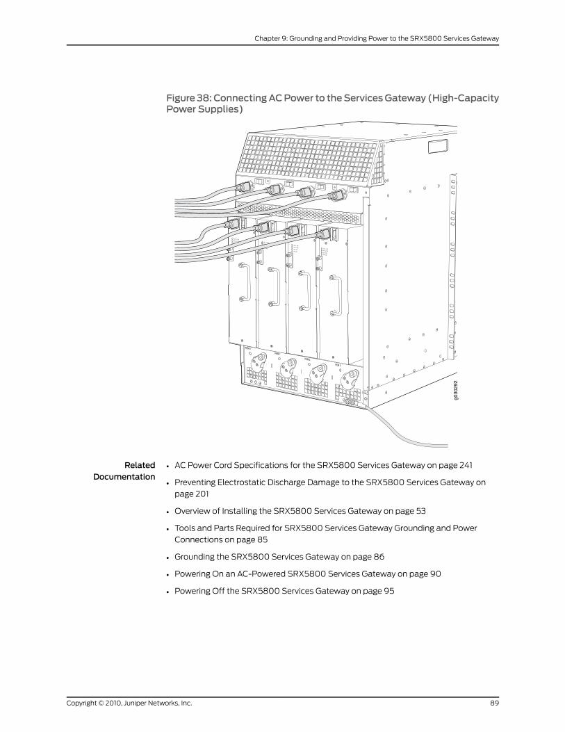
Figure 38: ConnectingACPower to theServicesGateway (High-CapacityPower Supplies)
g030
292
RelatedDocumentation
AC Power Cord Specifications for the SRX5800 Services Gateway on page 241•
• Preventing Electrostatic Discharge Damage to the SRX5800 Services Gateway on
page 201
• Overview of Installing the SRX5800 Services Gateway on page 53
• Tools and Parts Required for SRX5800 Services Gateway Grounding and Power
Connections on page 85
• Grounding the SRX5800 Services Gateway on page 86
• Powering On an AC-Powered SRX5800 Services Gateway on page 90
• Powering Off the SRX5800 Services Gateway on page 95
89Copyright © 2010, Juniper Networks, Inc.
Chapter 9: Grounding and Providing Power to the SRX5800 Services Gateway
Powering On an AC-Powered SRX5800 Services Gateway
To power on an AC-powered services gateway:
1. Verify that the power supplies are fully inserted in the chassis.
2. Verify that each AC power cord is securely inserted into its appliance inlet.
3. Verify that an external management device is connected to one of the Routing Engine
ports (AUX, CONSOLE, or ETHERNET).
4. Turn on the power to the external management device.
5. Switch on the dedicated customer site circuit breakers. Follow the ESD and safety
instructions for your site.
6. Attach an ESD grounding strap to your bare wrist, and connect the strap to one of the
ESD points on the chassis.
7. Switch the AC switch in the chassis above each power supply to the on (—) position.
8. If the services gateway has high-capacity power supplies installed, you must also
move the AC switch at the top of each power supply to the on (|) position.
9. Verify the following LED indications for each installed power supply:
• For standard-capacity AC power supplies, verify that the ACOK and DCOK LEDs
light steadily and the PS FAIL LED is not lit.
• For high-capacity AC power supplies, verify that the DCOK LED lights steadily, and
the PS FAIL LED is not lit. In addition, the AC-1 OK LED should light green steadily if
the upper AC feed (on the chassis above the power supply) is connected and
receiving power, and the AC-2 OK LED should light green steadily if the lower AC
feed (on the power supply itself) is connected and receiving power.
NOTE: After a power supply is powered on, it can take up to 60 secondsfor status indicators—such as the status LEDs on the power supply andthe show chassis command display—to indicate that the power supply isfunctioning normally. Ignore error indicators that appear during the first60 seconds.
If any of the status LEDs indicates that the power supply is not functioning normally,
repeat the installation and cabling procedures.
10. On the external management device connected to the Routing Engine, monitor the
startup process to verify that the system has booted properly.
Copyright © 2010, Juniper Networks, Inc.90
SRX5800 Services Gateway Hardware Guide
NOTE: If the system is completely powered off when you power on thepower supply, the Routing Engine boots as the power supply completesits startupsequence.Normally, theservicesgatewayboots fromthe JunosOS on the CompactFlash card.
After powering on apower supply,wait at least 60 seconds before turningit off.
RelatedDocumentation
Preventing Electrostatic Discharge Damage to the SRX5800 Services Gateway on
page 201
•
• Overview of Installing the SRX5800 Services Gateway on page 53
• Tools and Parts Required for SRX5800 Services Gateway Grounding and Power
Connections on page 85
• Grounding the SRX5800 Services Gateway on page 86
• Connecting Power to an AC-Powered SRX5800 Services Gateway on page 86
• Powering Off the SRX5800 Services Gateway on page 95
Connecting Power to a DC-Powered SRX5800 Services Gateway
CAUTION: Do notmix AC and DC power supplies within the same servicesgateway. Damage to the services gatewaymight occur.
WARNING: Before performing DC power procedures, ensure that power isremoved from theDC circuit. To ensure that all power is off, locate the circuitbreaker on the panel board that services the DC circuit, switch the circuitbreaker to the off position, and tape the switch handle of the circuit breakerin the off position.
You connect DC power to the services gateway by attaching power cables from the
external DC power sources to the terminal studs on the power supply faceplates. You
must provide the power cables (the cable lugs are supplied with the services gateway).
To connect the DC source power cables to the services gateway:
1. Switch off the dedicated customer site circuit breakers. Ensure that the voltage across
the DC power source cable leads is 0 V and that there is no chance that the cable
leads might become active during installation.
2. Attach an ESD grounding strap to your bare wrist, and connect the strap to one of the
ESD points on the chassis.
3. Move the DC circuit breaker on the power supply faceplate to the off (O) position.
91Copyright © 2010, Juniper Networks, Inc.
Chapter 9: Grounding and Providing Power to the SRX5800 Services Gateway
4. Remove the clear plastic cover protecting the terminal studs on the faceplate.
5. Verify that the DC power cables are correctly labeled before making connections to
the power supply. In a typical power distribution scheme where the return is connected
to chassis ground at the battery plant, you can use a multimeter to verify the resistance
of the –48V and RTN DC cables to chassis ground:
• The cable with very large resistance (indicating an open circuit) to chassis ground
is –48V.
• The cable with very low resistance (indicating a closed circuit) to chassis ground is
RTN.
CAUTION: Youmust ensure that power connectionsmaintain the properpolarity. The power source cablesmight be labeled (+)and (–) to indicate
their polarity. There is no standard color coding for DC power cables. Thecolor coding usedby the externalDCpower source at your site determinesthe color coding for the leads on the power cables that attach to theterminal studs on each power supply.
6. Remove the nuts and washers from the terminal studs. (Use a 7/16-in. nut driver or
socket wrench.)
7. Secure each power cable lug to the terminal studs, first with the split washer, then
with the nut (see Figure 39 on page 93). Apply between 23 lb-in. (2.6 Nm) and 25 lb-in.
(2.8 Nm) of torque to each nut. (Use a 7/16-in. nut driver or socket wrench.)
a. Secure each positive (+) DC source power cable lug to the RTN (return) terminal.
b. Secure each negative (–) DC source power cable lug to the –48V (input) terminal.
The DC power supplies in slotsPEM0 andPEM1must be powered by dedicated power
feeds derived from feed A, and the DC power supplies in slots PEM2 and PEM3 must
be powered by dedicated power feeds derived from feedB. This configuration provides
the commonly deployed A/B feed redundancy for the system.
8. Loosen the captive screw on the cable restraint on the lower edge of the power supply
faceplate.
9. Route the positive and negative DC power cables through the left and right sides of
the cable restraint.
10. Tighten the cable restraint captive screw to hold the power cables in place.
11. Replace the clear plastic cover over the terminal studs on the faceplate.
12. Verify that the power cables are connected correctly, that they are not touching or
blocking access to services gateway components, and that they do not drape where
people could trip on them.
13. Repeat Steps 3 through 12 for the remaining power supplies.
Copyright © 2010, Juniper Networks, Inc.92
SRX5800 Services Gateway Hardware Guide
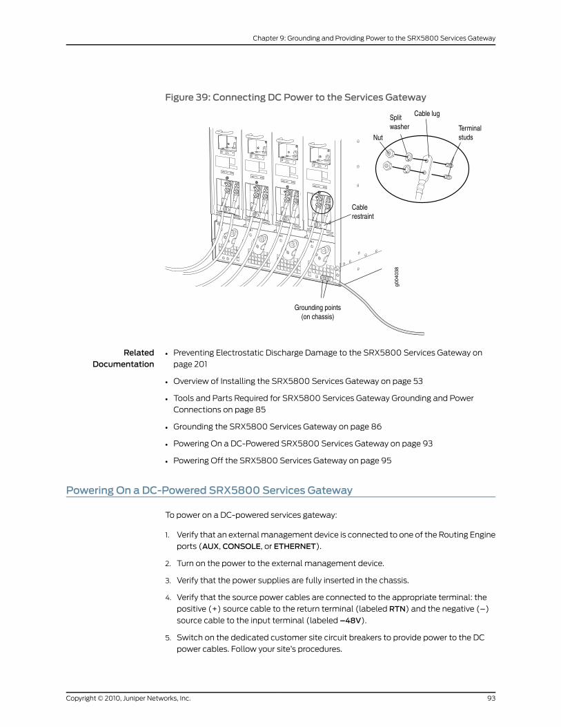
Figure 39: Connecting DC Power to the Services Gateway
RelatedDocumentation
Preventing Electrostatic Discharge Damage to the SRX5800 Services Gateway on
page 201
•
• Overview of Installing the SRX5800 Services Gateway on page 53
• Tools and Parts Required for SRX5800 Services Gateway Grounding and Power
Connections on page 85
• Grounding the SRX5800 Services Gateway on page 86
• Powering On a DC-Powered SRX5800 Services Gateway on page 93
• Powering Off the SRX5800 Services Gateway on page 95
Powering On a DC-Powered SRX5800 Services Gateway
To power on a DC-powered services gateway:
1. Verify that an external management device is connected to one of the Routing Engine
ports (AUX, CONSOLE, or ETHERNET).
2. Turn on the power to the external management device.
3. Verify that the power supplies are fully inserted in the chassis.
4. Verify that the source power cables are connected to the appropriate terminal: the
positive (+) source cable to the return terminal (labeled RTN) and the negative (–)
source cable to the input terminal (labeled –48V).
5. Switch on the dedicated customer site circuit breakers to provide power to the DC
power cables. Follow your site’s procedures.
93Copyright © 2010, Juniper Networks, Inc.
Chapter 9: Grounding and Providing Power to the SRX5800 Services Gateway
6. Check the INPUTOK LED is lit steadily green to verify that power is present.
7. If power is not present:
• Verify that the fuse is installed correctly and turn on the breaker at the battery
distribution fuse board or fuse bay.
• Check the voltage with a meter at the terminals of the power supply for correct
voltage level and polarity.
8. Attach an ESD grounding strap to your bare wrist, and connect the strap to one of the
ESD points on the chassis.
9. Move the DC circuit breaker on the DC power supplies to the on (|) position.
10. Verify that the BREAKERON LED is lit green steadily.
11. Verify that thePWROKLED is lit green steadily, indicating the power supply is correctly
installed and functioning normally.
NOTE: After a power supply is powered on, it can take up to 60 secondsfor status indicators—such as the status LEDs on the power supply andthe show chassis command display—to indicate that the power supply is
functioning normally. Ignore error indicators that appear during the first60 seconds.
If any of the status LEDs indicates that the power supply is not functioning normally,
repeat the installation and cabling procedures .
12. On the external management device connected to the Routing Engine, monitor the
startup process to verify that the system has booted properly.
NOTE: If the system is completely powered off when you power on thepower supply, the Routing Engine boots as the power supply completesits startupsequence.Normally, theservicesgatewayboots fromthe JunosOS on the CompactFlash card.
After powering on apower supply,wait at least 60 seconds before turningit off.
RelatedDocumentation
Preventing Electrostatic Discharge Damage to the SRX5800 Services Gateway on
page 201
•
• Overview of Installing the SRX5800 Services Gateway on page 53
• Tools and Parts Required for SRX5800 Services Gateway Grounding and Power
Connections on page 85
• Grounding the SRX5800 Services Gateway on page 86
• Connecting Power to a DC-Powered SRX5800 Services Gateway on page 91
• Powering Off the SRX5800 Services Gateway on page 95
Copyright © 2010, Juniper Networks, Inc.94
SRX5800 Services Gateway Hardware Guide
Powering Off the SRX5800 Services Gateway
NOTE: After powering off a power supply, wait at least 60 seconds beforeturning it back on.
To power off the services gateway:
1. On the external management device connected to the Routing Engine, issue the
request system halt operational mode command. The command shuts down the
Routing Engine cleanly, so its state information is preserved.
user@host> request system halt
2. Wait until a message appears on the console confirming that the operating system
has halted. For more information about the command, see the JunosOSSystemBasics
and Services Command Reference.
3. Attach an ESD grounding strap to your bare wrist, and connect the strap to one of the
ESD points on the chassis.
4. Switch off the power supplies:
• For an AC-powered services gateway, move the AC input switch on the chassis
above each AC power supply to the off (O) position. If the services gateway is
equipped with high-capacity AC power supplies, you must also move the AC input
switch on each power supply to the off (O) position.
• For a DC-powered services gateway, move the DC circuit breaker on each DC power
supply faceplate to the off (O) position.
RelatedDocumentation
• Preventing Electrostatic Discharge Damage to the SRX5800 Services Gateway on
page 201
• Overview of Installing the SRX5800 Services Gateway on page 53
• Powering On an AC-Powered SRX5800 Services Gateway on page 90
• Powering On a DC-Powered SRX5800 Services Gateway on page 93
95Copyright © 2010, Juniper Networks, Inc.
Chapter 9: Grounding and Providing Power to the SRX5800 Services Gateway

Copyright © 2010, Juniper Networks, Inc.96
SRX5800 Services Gateway Hardware Guide
CHAPTER 10
Configuring Junos OS for the SRX5800Services Gateway
This section includes the following topics:
• SRX5800 Services Gateway Software Configuration Overview on page 97
• Initially Configuring the SRX5800 Services Gateway on page 98
SRX5800 Services Gateway Software Configuration Overview
The services gateway is shipped with the Junos OS preinstalled and ready to be configured
when the device is powered on. There are three copies of the software: one on a
CompactFlash card (if installed) in the Routing Engine, one on the hard disk in the Routing
Engine, and one on a USB flash drive that can be inserted into the slot in the Routing
Engine faceplate.
When the device boots, it first attempts to start the image on the USB flash drive. If a
USB flash drive is not inserted into the Routing Engine or the attempt otherwise fails, the
device next tries the CompactFlash card (if installed), and finally the hard disk.
You configure the services gateway by issuing Junos OS command-line interface (CLI)
commands, either on a console device attached to the CONSOLE port on the Routing
Engine, or over a telnet connection to a network connected to the ETHERNET port on the
Routing Engine.
Gather the following information before configuring the device:
• Name the device will use on the network
• Domain name the device will use
• IP address and prefix length information for the Ethernet interface
• IP address of a default router
• IP address of a DNS server
• Password for the root user
RelatedDocumentation
Initially Configuring the SRX5800 Services Gateway on page 98•
97Copyright © 2010, Juniper Networks, Inc.
Initially Configuring the SRX5800 Services Gateway
This procedure connects the device to the network but does not enable it to forward
traffic. For complete information about enabling the device to forward traffic, including
examples, see the appropriate Junos OS configuration guides.
To configure the software:
1. Verify that the device is powered on.
2. Log in as the root user. There is no password.
3. Start the CLI.
root# cliroot@>
4. Enter configuration mode.
configure[edit]root@#
5. Set the root authentication password by entering either a cleartext password, an
encrypted password, or an SSH public key string (DSA or RSA).
[edit]root@# set system root-authentication plain-text-passwordNew password: passwordRetype new password: password
6. Configure an administrator account on the device. When prompted, enter the password
for the administrator account.
[edit]root@# set system login user admin class super-user authenticationplain-text-password
New password: passwordRetype new password: password
7. Commit the configuration to activate it on the device.
[edit]root@# commit
8. Log in as the administrative user you configured in step 6.
9. Configure the name of the device. If the name includes spaces, enclose the name in
quotation marks (“ ”).
configure[edit]admin@# set system host-name host-name
10. Configure the IP address and prefix length for the device’s Ethernet interface.
[edit]admin@# set interfaces fxp0 unit 0 family inet address address/prefix-length
11. Configure the traffic interface.
Copyright © 2010, Juniper Networks, Inc.98
SRX5800 Services Gateway Hardware Guide
[edit]admin@# set interfaces ge-6/2/0 unit 0 family inet address address/prefix-lengthadmin@# set interfaces ge-6/3/5 unit 0 family inet address address/prefix-length
12. Configure the default route.
[edit]admin@# set routing-options static route 0.0.0.0/0 next-hop gateway
13. Configure basic security zones and bind them to traffic interfaces.
[edit]admin@# set security zones security-zone trust interfaces ge-6/3/5admin@# set security zones security-zone untrust interfaces ge-6/2/0
14. Configure basic security policies.
[edit]admin@# set security policies from-zone trust to-zone untrust policy policy-namematch source-address any destination-address any application any
root@# set security policies from-zone trust to-zone untrust policy policy-name thenpermit
15. Check the configuration for validity.
[edit]admin@# commit checkconfiguration check succeeds
16. Commit the configuration to activate it on the device.
[edit]admin@# commitcommit complete
17. Optionally, display the configuration to verify that it is correct.
admin@# show
## Last changed: 2008-05-07 22:43:25 UTCversion "9.2I0 [builder]";system { autoinstallation; host-name henbert; root-authentication { encrypted-password "$1$oTVn2KY3$uQe4xzQCxpR2j7sKuV.Pa0"; ## SECRET-DATA } login { user admin { uid 928; class super-user; authentication { encrypted-password "$1$cdOPmACd$QvreBsJkNR1EF0uurTBkE."; ## SECRET-DATA } } } services { ssh; web-management { http { interface ge-0/0/0.0;
99Copyright © 2010, Juniper Networks, Inc.
Chapter 10: Configuring Junos OS for the SRX5800 Services Gateway
} } } syslog { user * { any emergency; } file messages { any any; authorization info; } file interactive-commands { interactive-commands any; } } license { autoupdate { url https://ae1.juniper.net/junos/key_retrieval; } }}interfaces { ge-0/0/0 { unit 0; } ge-6/2/0 { unit 0 { family inet { address 5.1.1.1/24; } } } ge-6/3/5 { unit 0 { family inet { address 192.1.1.1/24; } } } fxp0 { unit 0 { family inet { address 192.168.10.2/24; } } }}routing-options { static { route 0.0.0.0/0 next-hop 5.1.1.2; }}security { zones { security-zone trust { interfaces { ge-6/3/5.0; } } security-zone untrust { interfaces {
Copyright © 2010, Juniper Networks, Inc.100
SRX5800 Services Gateway Hardware Guide
ge-6/2/0.0; } } } policies { from-zone trust to-zone untrust { policy bob { match { source-address any; destination-address any; application any; } then { permit; } } } }}
18. Commit the configuration to activate it on the device.
[edit]admin@# commit
19. Optionally, configure additional properties by adding the necessary configuration
statements. Then commit the changes to activate them on the device.
[edit]admin@# commit
20. When you have finished configuring the device, exit configuration mode.
[edit]admin@# exitadmin@host>
RelatedDocumentation
• SRX5800 Services Gateway Software Configuration Overview on page 97
• Powering On an AC-Powered SRX5800 Services Gateway on page 90
• Powering On a DC-Powered SRX5800 Services Gateway on page 93
101Copyright © 2010, Juniper Networks, Inc.
Chapter 10: Configuring Junos OS for the SRX5800 Services Gateway

Copyright © 2010, Juniper Networks, Inc.102
SRX5800 Services Gateway Hardware Guide
PART 3
SRX5800 Services Gateway HardwareMaintenance, Replacement, andTroubleshooting Procedures
• Maintaining the SRX5800 Services Gateway Hardware Components on page 105
• Troubleshooting the SRX5800 Services Gateway Hardware Components on page 121
• Replacing SRX5800 Services Gateway Hardware Components on page 131
103Copyright © 2010, Juniper Networks, Inc.

Copyright © 2010, Juniper Networks, Inc.104
SRX5800 Services Gateway Hardware Guide
CHAPTER 11
Maintaining the SRX5800 ServicesGateway Hardware Components
This section includes the following topics:
• Tools and Parts Required to Maintain the SRX5800 Services Gateway on page 105
• Routine Maintenance Procedures for the SRX5800 Services Gateway on page 105
• Maintaining the SRX5800 Cooling System Components on page 106
• Maintaining the SRX5800 Services Gateway Host Subsystem and SCBs on page 108
• Maintaining the SRX5800 Packet Forwarding Engine Components on page 111
• Handling and Storing SRX5800 Services Gateway Cards on page 115
• Maintaining SRX5800 Services Gateway Power Supplies on page 119
Tools and Parts Required toMaintain the SRX5800 Services Gateway
To maintain hardware components, you need the following tools and parts:
• ESD grounding wrist strap
• Flat-blade (–) screwdriver
• Phillips (+) screwdriver, number 1
• Phillips (+) screwdriver, number 2
RelatedDocumentation
Routine Maintenance Procedures for the SRX5800 Services Gateway on page 105•
RoutineMaintenance Procedures for the SRX5800 Services Gateway
Purpose For optimum services gateway performance, perform preventive maintenance procedures
regularly.
Action Inspect the installation site for moisture, loose wires or cables, and excessive dust.
Make sure that airflow is unobstructed around the device and into the air intake vents.
•
• Check the status-reporting devices on the craft interface—System alarms and LEDs.
105Copyright © 2010, Juniper Networks, Inc.
• Inspect the air filter at the bottom front of the services gateway, replacing it every six
months for optimum cooling system performance. Do not run the device for more than
a few minutes without the air filter in place.
RelatedDocumentation
Tools and Parts Required to Maintain the SRX5800 Services Gateway on page 105•
• Maintaining the Air Filter on the SRX5800 Services Gateway on page 106
• Maintaining the Fan Trays on the SRX5800 Services Gateway on page 107
• Maintaining the SRX5800 Services Gateway Host Subsystem and SCBs on page 108
• Maintaining SPCs, IOCs, and Flex IOCs on the SRX5800 Services Gateway on page 111
• Maintaining Port Modules on the SRX5800 Services Gateway on page 113
• Maintaining SRX5800 Services Gateway Network Cables on page 114
• Maintaining SRX5800 Services Gateway Power Supplies on page 119
Maintaining the SRX5800 Cooling SystemComponents
This section includes the following topics:
• Maintaining the Air Filter on the SRX5800 Services Gateway on page 106
• Maintaining the Fan Trays on the SRX5800 Services Gateway on page 107
Maintaining the Air Filter on the SRX5800 Services Gateway
Purpose For optimum cooling, verify the condition of the air filters.
Action Regularly inspect the air filter. A dirty air filter restricts airflow in the unit, impeding the
ventilation of the chassis. The filter degrades over time. Periodically replace the filter
•
in use, as well as spares. We recommend that you replace the filter every six months.
Discard used filters, do not attempt to clean and reuse them.
CAUTION: Always keep the air filter in place while the services gateway isoperating. Because the fans are very powerful, they could pull small bitsof wire or other materials into the services gateway through the unfilteredair intake. This could damage the services gateway components.
• Use spare filters within one year of manufacture. Check the date of manufacture printed
on the filter. Store spare air filters in a dark, cool, and dry place. Storing air filters at
higher temperatures, or where they can be exposed to ultraviolet (UV) radiation,
hydrocarbon emissions, or vapors from solvents, can significantly reduce their life.
RelatedDocumentation
Tools and Parts Required to Maintain the SRX5800 Services Gateway on page 105•
• Replacing the SRX5800 Services Gateway Air Filter on page 140
Copyright © 2010, Juniper Networks, Inc.106
SRX5800 Services Gateway Hardware Guide
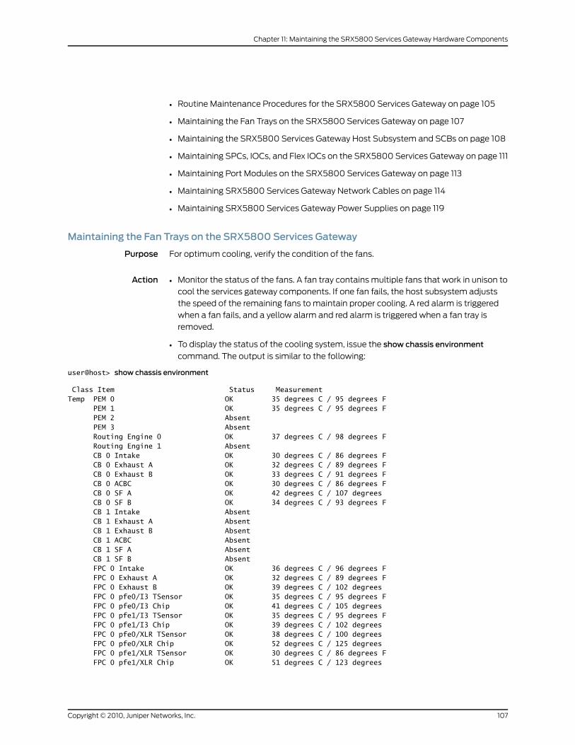
• Routine Maintenance Procedures for the SRX5800 Services Gateway on page 105
• Maintaining the Fan Trays on the SRX5800 Services Gateway on page 107
• Maintaining the SRX5800 Services Gateway Host Subsystem and SCBs on page 108
• Maintaining SPCs, IOCs, and Flex IOCs on the SRX5800 Services Gateway on page 111
• Maintaining Port Modules on the SRX5800 Services Gateway on page 113
• Maintaining SRX5800 Services Gateway Network Cables on page 114
• Maintaining SRX5800 Services Gateway Power Supplies on page 119
Maintaining the Fan Trays on the SRX5800 Services Gateway
Purpose For optimum cooling, verify the condition of the fans.
Action Monitor the status of the fans. A fan tray contains multiple fans that work in unison to
cool the services gateway components. If one fan fails, the host subsystem adjusts
•
the speed of the remaining fans to maintain proper cooling. A red alarm is triggered
when a fan fails, and a yellow alarm and red alarm is triggered when a fan tray is
removed.
• To display the status of the cooling system, issue the show chassis environment
command. The output is similar to the following:
user@host> show chassis environment
Class Item Status MeasurementTemp PEM 0 OK 35 degrees C / 95 degrees F PEM 1 OK 35 degrees C / 95 degrees F PEM 2 Absent PEM 3 Absent Routing Engine 0 OK 37 degrees C / 98 degrees F Routing Engine 1 Absent CB 0 Intake OK 30 degrees C / 86 degrees F CB 0 Exhaust A OK 32 degrees C / 89 degrees F CB 0 Exhaust B OK 33 degrees C / 91 degrees F CB 0 ACBC OK 30 degrees C / 86 degrees F CB 0 SF A OK 42 degrees C / 107 degrees CB 0 SF B OK 34 degrees C / 93 degrees F CB 1 Intake Absent CB 1 Exhaust A Absent CB 1 Exhaust B Absent CB 1 ACBC Absent CB 1 SF A Absent CB 1 SF B Absent FPC 0 Intake OK 36 degrees C / 96 degrees F FPC 0 Exhaust A OK 32 degrees C / 89 degrees F FPC 0 Exhaust B OK 39 degrees C / 102 degrees FPC 0 pfe0/I3 TSensor OK 35 degrees C / 95 degrees F FPC 0 pfe0/I3 Chip OK 41 degrees C / 105 degrees FPC 0 pfe1/I3 TSensor OK 35 degrees C / 95 degrees F FPC 0 pfe1/I3 Chip OK 39 degrees C / 102 degrees FPC 0 pfe0/XLR TSensor OK 38 degrees C / 100 degrees FPC 0 pfe0/XLR Chip OK 52 degrees C / 125 degrees FPC 0 pfe1/XLR TSensor OK 30 degrees C / 86 degrees F FPC 0 pfe1/XLR Chip OK 51 degrees C / 123 degrees
107Copyright © 2010, Juniper Networks, Inc.
Chapter 11: Maintaining the SRX5800 Services Gateway Hardware Components
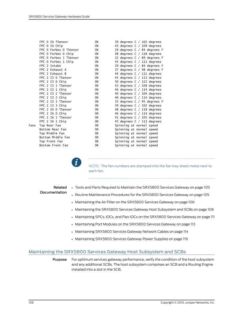
FPC 0 IA TSensor OK 39 degrees C / 102 degrees FPC 0 IA Chip OK 43 degrees C / 109 degrees FPC 0 Forbes 0 TSensor OK 29 degrees C / 84 degrees F FPC 0 Forbes 0 Chip OK 48 degrees C / 118 degrees FPC 0 Forbes 1 TSensor OK 32 degrees C / 89 degrees F FPC 0 Forbes 1 Chip OK 45 degrees C / 113 degrees FPC 2 Intake OK 29 degrees C / 84 degrees F FPC 2 Exhaust A OK 37 degrees C / 98 degrees F FPC 2 Exhaust B OK 44 degrees C / 111 degrees FPC 2 I3 0 TSensor OK 45 degrees C / 113 degrees FPC 2 I3 0 Chip OK 50 degrees C / 122 degrees FPC 2 I3 1 TSensor OK 43 degrees C / 109 degrees FPC 2 I3 1 Chip OK 46 degrees C / 114 degrees FPC 2 I3 2 TSensor OK 40 degrees C / 104 degrees FPC 2 I3 2 Chip OK 46 degrees C / 114 degrees FPC 2 I3 3 TSensor OK 35 degrees C / 95 degrees F FPC 2 I3 3 Chip OK 39 degrees C / 102 degrees FPC 2 IA 0 TSensor OK 48 degrees C / 118 degrees FPC 2 IA 0 Chip OK 46 degrees C / 114 degrees FPC 2 IA 1 TSensor OK 41 degrees C / 105 degrees FPC 2 IA 1 Chip OK 45 degrees C / 113 degreesFans Top Rear Fan OK Spinning at normal speed Bottom Rear Fan OK Spinning at normal speed Top Middle Fan OK Spinning at normal speed Bottom Middle Fan OK Spinning at normal speed Top Front Fan OK Spinning at normal speed Bottom Front Fan OK Spinning at normal speed
NOTE: The fan numbers are stamped into the fan tray sheet metal next toeach fan.
RelatedDocumentation
Tools and Parts Required to Maintain the SRX5800 Services Gateway on page 105•
• Routine Maintenance Procedures for the SRX5800 Services Gateway on page 105
• Maintaining the Air Filter on the SRX5800 Services Gateway on page 106
• Maintaining the SRX5800 Services Gateway Host Subsystem and SCBs on page 108
• Maintaining SPCs, IOCs, and Flex IOCs on the SRX5800 Services Gateway on page 111
• Maintaining Port Modules on the SRX5800 Services Gateway on page 113
• Maintaining SRX5800 Services Gateway Network Cables on page 114
• Maintaining SRX5800 Services Gateway Power Supplies on page 119
Maintaining the SRX5800 Services Gateway Host Subsystem and SCBs
Purpose For optimum services gateway performance, verify the condition of the host subsystem
and any additional SCBs. The host subsystem comprises an SCB and a Routing Engine
installed into a slot in the SCB.
Copyright © 2010, Juniper Networks, Inc.108
SRX5800 Services Gateway Hardware Guide
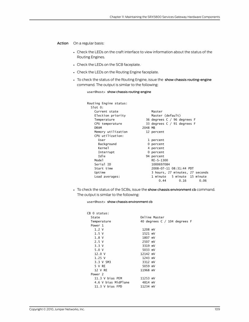
Action On a regular basis:
• Check the LEDs on the craft interface to view information about the status of the
Routing Engines.
• Check the LEDs on the SCB faceplate.
• Check the LEDs on the Routing Engine faceplate.
• To check the status of the Routing Engine, issue the show chassis routing-engine
command. The output is similar to the following:
user@host> show chassis routing-engine
Routing Engine status: Slot 0: Current state Master Election priority Master (default) Temperature 36 degrees C / 96 degrees F CPU temperature 33 degrees C / 91 degrees F DRAM 2048 MB Memory utilization 12 percent CPU utilization: User 1 percent Background 0 percent Kernel 4 percent Interrupt 0 percent Idle 94 percent Model RE-S-1300 Serial ID 1000697084 Start time 2008-07-11 08:31:44 PDT Uptime 3 hours, 27 minutes, 27 seconds Load averages: 1 minute 5 minute 15 minute 0.44 0.16 0.06
• To check the status of the SCBs, issue the show chassis environment cb command.
The output is similar to the following:
user@host> show chassis environment cb
CB 0 status: State Online Master Temperature 40 degrees C / 104 degrees F Power 1 1.2 V 1208 mV 1.5 V 1521 mV 1.8 V 1807 mV 2.5 V 2507 mV 3.3 V 3319 mV 5.0 V 5033 mV 12.0 V 12142 mV 1.25 V 1243 mV 3.3 V SM3 3312 mV 5 V RE 5059 mV 12 V RE 11968 mV Power 2 11.3 V bias PEM 11253 mV 4.6 V bias MidPlane 4814 mV 11.3 V bias FPD 11234 mV
109Copyright © 2010, Juniper Networks, Inc.
Chapter 11: Maintaining the SRX5800 Services Gateway Hardware Components
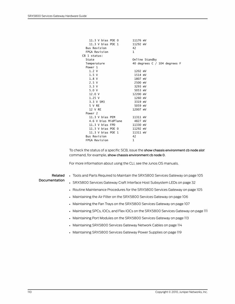
11.3 V bias POE 0 11176 mV 11.3 V bias POE 1 11292 mV Bus Revision 42 FPGA Revision 1CB 1 status: State Online Standby Temperature 40 degrees C / 104 degrees F Power 1 1.2 V 1202 mV 1.5 V 1514 mV 1.8 V 1807 mV 2.5 V 2500 mV 3.3 V 3293 mV 5.0 V 5053 mV 12.0 V 12200 mV 1.25 V 1260 mV 3.3 V SM3 3319 mV 5 V RE 5059 mV 12 V RE 12007 mV Power 2 11.3 V bias PEM 11311 mV 4.6 V bias MidPlane 4827 mV 11.3 V bias FPD 11330 mV 11.3 V bias POE 0 11292 mV 11.3 V bias POE 1 11311 mV Bus Revision 42 FPGA Revision 1
To check the status of a specific SCB, issue the show chassis environment cb node slot
command, for example, show chassis environment cb node 0.
For more information about using the CLI, see the Junos OS manuals.
RelatedDocumentation
Tools and Parts Required to Maintain the SRX5800 Services Gateway on page 105•
• SRX5800 Services Gateway Craft Interface Host Subsystem LEDs on page 32
• Routine Maintenance Procedures for the SRX5800 Services Gateway on page 105
• Maintaining the Air Filter on the SRX5800 Services Gateway on page 106
• Maintaining the Fan Trays on the SRX5800 Services Gateway on page 107
• Maintaining SPCs, IOCs, and Flex IOCs on the SRX5800 Services Gateway on page 111
• Maintaining Port Modules on the SRX5800 Services Gateway on page 113
• Maintaining SRX5800 Services Gateway Network Cables on page 114
• Maintaining SRX5800 Services Gateway Power Supplies on page 119
Copyright © 2010, Juniper Networks, Inc.110
SRX5800 Services Gateway Hardware Guide
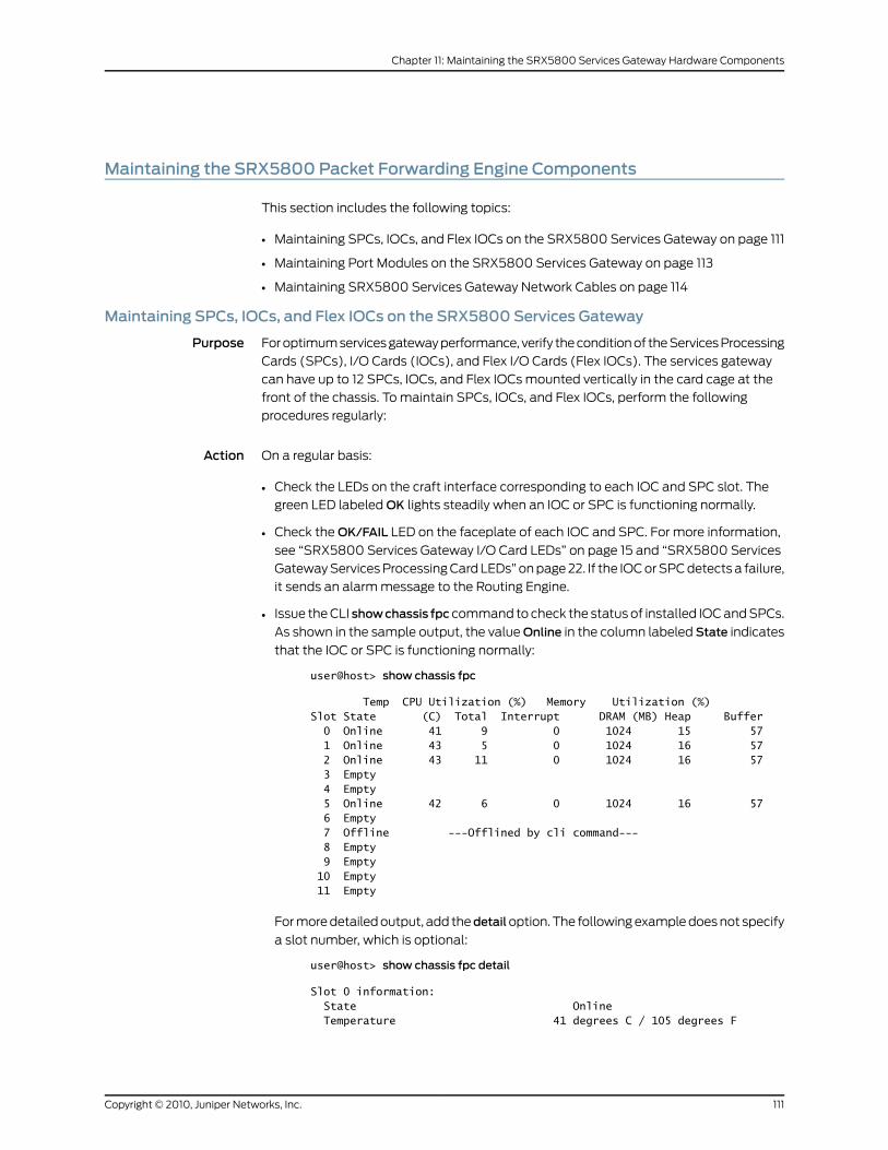
Maintaining the SRX5800 Packet Forwarding Engine Components
This section includes the following topics:
• Maintaining SPCs, IOCs, and Flex IOCs on the SRX5800 Services Gateway on page 111
• Maintaining Port Modules on the SRX5800 Services Gateway on page 113
• Maintaining SRX5800 Services Gateway Network Cables on page 114
Maintaining SPCs, IOCs, and Flex IOCs on the SRX5800 Services Gateway
Purpose For optimum services gateway performance, verify the condition of the Services Processing
Cards (SPCs), I/O Cards (IOCs), and Flex I/O Cards (Flex IOCs). The services gateway
can have up to 12 SPCs, IOCs, and Flex IOCs mounted vertically in the card cage at the
front of the chassis. To maintain SPCs, IOCs, and Flex IOCs, perform the following
procedures regularly:
Action On a regular basis:
• Check the LEDs on the craft interface corresponding to each IOC and SPC slot. The
green LED labeled OK lights steadily when an IOC or SPC is functioning normally.
• Check the OK/FAIL LED on the faceplate of each IOC and SPC. For more information,
see “SRX5800 Services Gateway I/O Card LEDs” on page 15 and “SRX5800 Services
Gateway Services Processing Card LEDs” on page 22. If the IOC or SPC detects a failure,
it sends an alarm message to the Routing Engine.
• Issue the CLI showchassis fpc command to check the status of installed IOC and SPCs.
As shown in the sample output, the valueOnline in the column labeled State indicates
that the IOC or SPC is functioning normally:
user@host> show chassis fpc
Temp CPU Utilization (%) Memory Utilization (%)Slot State (C) Total Interrupt DRAM (MB) Heap Buffer 0 Online 41 9 0 1024 15 57 1 Online 43 5 0 1024 16 57 2 Online 43 11 0 1024 16 57 3 Empty 4 Empty 5 Online 42 6 0 1024 16 57 6 Empty 7 Offline ---Offlined by cli command--- 8 Empty 9 Empty 10 Empty 11 Empty
For more detailed output, add thedetailoption. The following example does not specify
a slot number, which is optional:
user@host> show chassis fpc detail
Slot 0 information: State Online Temperature 41 degrees C / 105 degrees F
111Copyright © 2010, Juniper Networks, Inc.
Chapter 11: Maintaining the SRX5800 Services Gateway Hardware Components
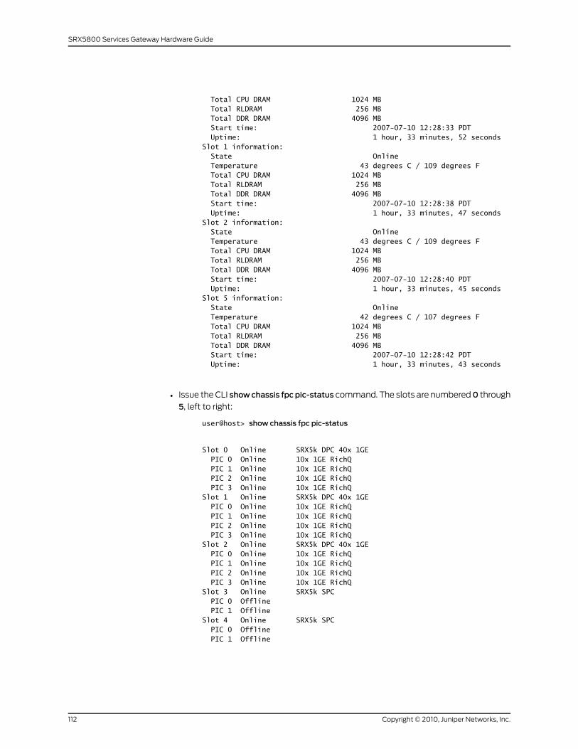
Total CPU DRAM 1024 MB Total RLDRAM 256 MB Total DDR DRAM 4096 MB Start time: 2007-07-10 12:28:33 PDT Uptime: 1 hour, 33 minutes, 52 secondsSlot 1 information: State Online Temperature 43 degrees C / 109 degrees F Total CPU DRAM 1024 MB Total RLDRAM 256 MB Total DDR DRAM 4096 MB Start time: 2007-07-10 12:28:38 PDT Uptime: 1 hour, 33 minutes, 47 secondsSlot 2 information: State Online Temperature 43 degrees C / 109 degrees F Total CPU DRAM 1024 MB Total RLDRAM 256 MB Total DDR DRAM 4096 MB Start time: 2007-07-10 12:28:40 PDT Uptime: 1 hour, 33 minutes, 45 secondsSlot 5 information: State Online Temperature 42 degrees C / 107 degrees F Total CPU DRAM 1024 MB Total RLDRAM 256 MB Total DDR DRAM 4096 MB Start time: 2007-07-10 12:28:42 PDT Uptime: 1 hour, 33 minutes, 43 seconds
• Issue the CLI showchassis fpc pic-status command. The slots are numbered0 through
5, left to right:
user@host> show chassis fpc pic-status
Slot 0 Online SRX5k DPC 40x 1GE PIC 0 Online 10x 1GE RichQ PIC 1 Online 10x 1GE RichQ PIC 2 Online 10x 1GE RichQ PIC 3 Online 10x 1GE RichQSlot 1 Online SRX5k DPC 40x 1GE PIC 0 Online 10x 1GE RichQ PIC 1 Online 10x 1GE RichQ PIC 2 Online 10x 1GE RichQ PIC 3 Online 10x 1GE RichQSlot 2 Online SRX5k DPC 40x 1GE PIC 0 Online 10x 1GE RichQ PIC 1 Online 10x 1GE RichQ PIC 2 Online 10x 1GE RichQ PIC 3 Online 10x 1GE RichQSlot 3 Online SRX5k SPC PIC 0 Offline PIC 1 OfflineSlot 4 Online SRX5k SPC PIC 0 Offline PIC 1 Offline
Copyright © 2010, Juniper Networks, Inc.112
SRX5800 Services Gateway Hardware Guide
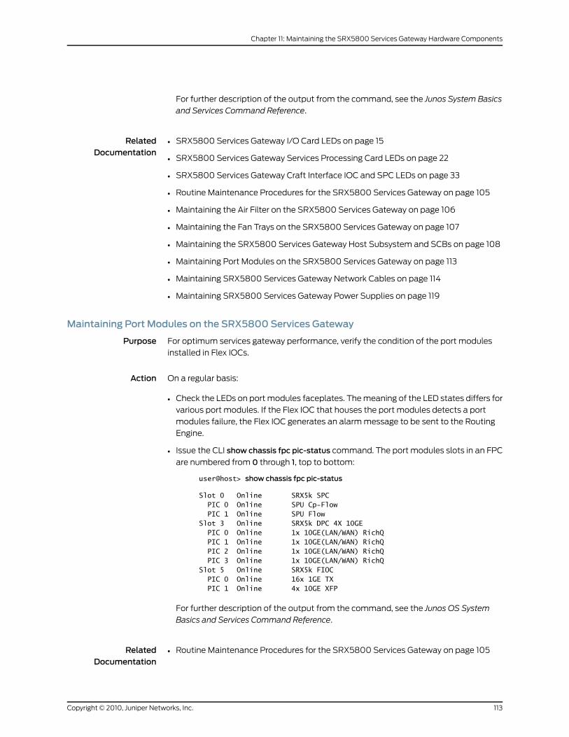
For further description of the output from the command, see the Junos System Basics
and Services Command Reference.
RelatedDocumentation
SRX5800 Services Gateway I/O Card LEDs on page 15•
• SRX5800 Services Gateway Services Processing Card LEDs on page 22
• SRX5800 Services Gateway Craft Interface IOC and SPC LEDs on page 33
• Routine Maintenance Procedures for the SRX5800 Services Gateway on page 105
• Maintaining the Air Filter on the SRX5800 Services Gateway on page 106
• Maintaining the Fan Trays on the SRX5800 Services Gateway on page 107
• Maintaining the SRX5800 Services Gateway Host Subsystem and SCBs on page 108
• Maintaining Port Modules on the SRX5800 Services Gateway on page 113
• Maintaining SRX5800 Services Gateway Network Cables on page 114
• Maintaining SRX5800 Services Gateway Power Supplies on page 119
Maintaining Port Modules on the SRX5800 Services Gateway
Purpose For optimum services gateway performance, verify the condition of the port modules
installed in Flex IOCs.
Action On a regular basis:
• Check the LEDs on port modules faceplates. The meaning of the LED states differs for
various port modules. If the Flex IOC that houses the port modules detects a port
modules failure, the Flex IOC generates an alarm message to be sent to the Routing
Engine.
• Issue the CLI show chassis fpc pic-status command. The port modules slots in an FPC
are numbered from 0 through 1, top to bottom:
user@host> show chassis fpc pic-status
Slot 0 Online SRX5k SPC PIC 0 Online SPU Cp-Flow PIC 1 Online SPU FlowSlot 3 Online SRX5k DPC 4X 10GE PIC 0 Online 1x 10GE(LAN/WAN) RichQ PIC 1 Online 1x 10GE(LAN/WAN) RichQ PIC 2 Online 1x 10GE(LAN/WAN) RichQ PIC 3 Online 1x 10GE(LAN/WAN) RichQSlot 5 Online SRX5k FIOC PIC 0 Online 16x 1GE TX PIC 1 Online 4x 10GE XFP
For further description of the output from the command, see the Junos OS System
Basics and Services Command Reference.
RelatedDocumentation
Routine Maintenance Procedures for the SRX5800 Services Gateway on page 105•
113Copyright © 2010, Juniper Networks, Inc.
Chapter 11: Maintaining the SRX5800 Services Gateway Hardware Components
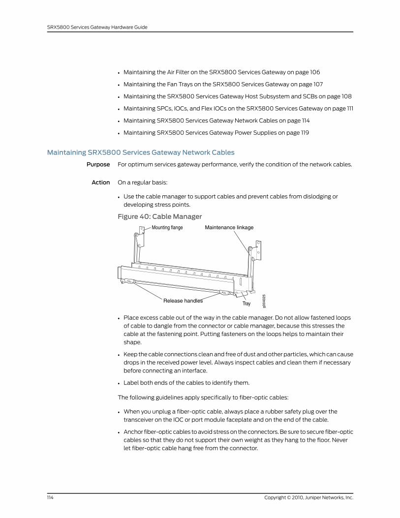
• Maintaining the Air Filter on the SRX5800 Services Gateway on page 106
• Maintaining the Fan Trays on the SRX5800 Services Gateway on page 107
• Maintaining the SRX5800 Services Gateway Host Subsystem and SCBs on page 108
• Maintaining SPCs, IOCs, and Flex IOCs on the SRX5800 Services Gateway on page 111
• Maintaining SRX5800 Services Gateway Network Cables on page 114
• Maintaining SRX5800 Services Gateway Power Supplies on page 119
Maintaining SRX5800 Services Gateway Network Cables
Purpose For optimum services gateway performance, verify the condition of the network cables.
Action On a regular basis:
• Use the cable manager to support cables and prevent cables from dislodging or
developing stress points.
Figure 40: Cable Manager
Release handles
Maintenance linkage
• Place excess cable out of the way in the cable manager. Do not allow fastened loops
of cable to dangle from the connector or cable manager, because this stresses the
cable at the fastening point. Putting fasteners on the loops helps to maintain their
shape.
• Keep the cable connections clean and free of dust and other particles, which can cause
drops in the received power level. Always inspect cables and clean them if necessary
before connecting an interface.
• Label both ends of the cables to identify them.
The following guidelines apply specifically to fiber-optic cables:
• When you unplug a fiber-optic cable, always place a rubber safety plug over the
transceiver on the IOC or port module faceplate and on the end of the cable.
• Anchor fiber-optic cables to avoid stress on the connectors. Be sure to secure fiber-optic
cables so that they do not support their own weight as they hang to the floor. Never
let fiber-optic cable hang free from the connector.
Copyright © 2010, Juniper Networks, Inc.114
SRX5800 Services Gateway Hardware Guide
• Avoid bending fiber-optic cable beyond its bend radius. An arc smaller than a few
inches can damage the cable and cause problems that are difficult to diagnose.
• Frequent plugging and unplugging of fiber-optic cable into and out of optical
instruments can cause damage to the instruments that is expensive to repair. Instead,
attach a short fiber extension to the optical equipment. Any wear and tear due to
frequent plugging and unplugging is then absorbed by the short fiber extension, which
is easy and inexpensive to replace.
• Keep fiber-optic cable connections clean. Small microdeposits of oil and dust in the
canal of the transceiver or cable connector could cause loss of light, reducing signal
power and possibly causing intermittent problems with the optical connection.
To clean the transceivers, use an appropriate fiber-cleaning device, such as RIFOCS
Fiber Optic Adaptor Cleaning Wands (part number 946). Follow the directions for the
cleaning kit you use.
After you clean an optical transceiver, make sure that the connector tip of the fiber-optic
cable is clean. Use only an approved alcohol-free fiber-optic cable cleaning kit, such
as the Opptex Cletop-S Fiber Cleaner. Follow the directions for the cleaning kit you
use.
RelatedDocumentation
Routine Maintenance Procedures for the SRX5800 Services Gateway on page 105•
• Maintaining the Air Filter on the SRX5800 Services Gateway on page 106
• Maintaining the Fan Trays on the SRX5800 Services Gateway on page 107
• Maintaining the SRX5800 Services Gateway Host Subsystem and SCBs on page 108
• Maintaining SPCs, IOCs, and Flex IOCs on the SRX5800 Services Gateway on page 111
• Maintaining Port Modules on the SRX5800 Services Gateway on page 113
• Maintaining SRX5800 Services Gateway Power Supplies on page 119
Handling and Storing SRX5800 Services Gateway Cards
This section includes the following topics:
• SRX5800 Services Gateway Card Terminology on page 115
• Holding an SRX5800 Services Gateway Card on page 116
• Storing an SRX5800 Services Gateway Card on page 118
SRX5800 Services Gateway Card Terminology
Regardless of orientation, this information uses the same terms for all four edges of the
card (see Figure 41 on page 116):
• Faceplate—Edge of the card that has connectors to which you connect cables or
sockets for SFP or XFP transceivers
• Connector edge—Edge opposite the faceplate; this edge has the connectors that attach
to the midplane
115Copyright © 2010, Juniper Networks, Inc.
Chapter 11: Maintaining the SRX5800 Services Gateway Hardware Components
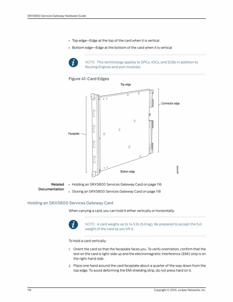
• Top edge—Edge at the top of the card when it is vertical
• Bottom edge—Edge at the bottom of the card when it is vertical
NOTE: This terminology applies to SPCs, IOCs, and SCBs in addition toRouting Engines and port modules
Figure 41: Card Edges
RelatedDocumentation
Holding an SRX5800 Services Gateway Card on page 116•
• Storing an SRX5800 Services Gateway Card on page 118
Holding an SRX5800 Services Gateway Card
When carrying a card, you can hold it either vertically or horizontally.
NOTE: A card weighs up to 14.5 lb (6.6 kg). Be prepared to accept the fullweight of the card as you lift it.
To hold a card vertically:
1. Orient the card so that the faceplate faces you. To verify orientation, confirm that the
text on the card is right-side up and the electromagnetic interference (EMI) strip is on
the right-hand side.
2. Place one hand around the card faceplate about a quarter of the way down from the
top edge. To avoid deforming the EMI shielding strip, do not press hard on it.
Copyright © 2010, Juniper Networks, Inc.116
SRX5800 Services Gateway Hardware Guide
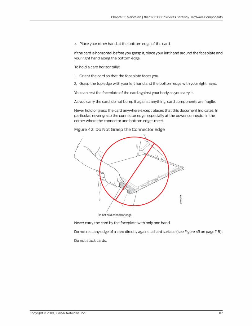
3. Place your other hand at the bottom edge of the card.
If the card is horizontal before you grasp it, place your left hand around the faceplate and
your right hand along the bottom edge.
To hold a card horizontally:
1. Orient the card so that the faceplate faces you.
2. Grasp the top edge with your left hand and the bottom edge with your right hand.
You can rest the faceplate of the card against your body as you carry it.
As you carry the card, do not bump it against anything. card components are fragile.
Never hold or grasp the card anywhere except places that this document indicates. In
particular, never grasp the connector edge, especially at the power connector in the
corner where the connector and bottom edges meet.
Figure 42: Do Not Grasp the Connector Edge
Never carry the card by the faceplate with only one hand.
Do not rest any edge of a card directly against a hard surface (see Figure 43 on page 118).
Do not stack cards.
117Copyright © 2010, Juniper Networks, Inc.
Chapter 11: Maintaining the SRX5800 Services Gateway Hardware Components
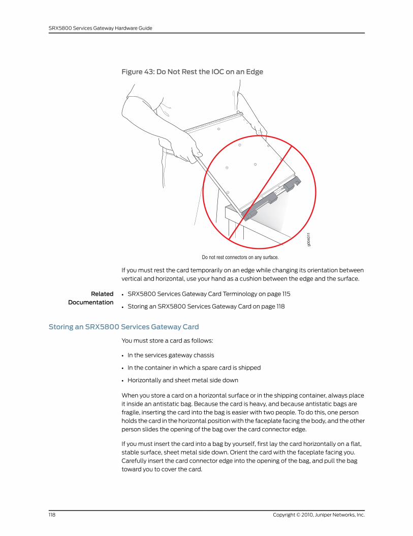
Figure 43: Do Not Rest the IOC on an Edge
If you must rest the card temporarily on an edge while changing its orientation between
vertical and horizontal, use your hand as a cushion between the edge and the surface.
RelatedDocumentation
SRX5800 Services Gateway Card Terminology on page 115•
• Storing an SRX5800 Services Gateway Card on page 118
Storing an SRX5800 Services Gateway Card
You must store a card as follows:
• In the services gateway chassis
• In the container in which a spare card is shipped
• Horizontally and sheet metal side down
When you store a card on a horizontal surface or in the shipping container, always place
it inside an antistatic bag. Because the card is heavy, and because antistatic bags are
fragile, inserting the card into the bag is easier with two people. To do this, one person
holds the card in the horizontal position with the faceplate facing the body, and the other
person slides the opening of the bag over the card connector edge.
If you must insert the card into a bag by yourself, first lay the card horizontally on a flat,
stable surface, sheet metal side down. Orient the card with the faceplate facing you.
Carefully insert the card connector edge into the opening of the bag, and pull the bag
toward you to cover the card.
Copyright © 2010, Juniper Networks, Inc.118
SRX5800 Services Gateway Hardware Guide
Never stack a card under or on top of any other component.
RelatedDocumentation
SRX5800 Services Gateway Card Terminology on page 115•
• Holding an SRX5800 Services Gateway Card on page 116
Maintaining SRX5800 Services Gateway Power Supplies
Purpose For optimum services gateway performance, verify the condition of the power supplies.
Action On a regular basis:
• To check the status of the power supplies, issue the show chassis environment pem
command. The output is similar to the following:
user@host> show chassis environment pem
PEM 0 status: State Online Temperature OK AC Input: OK DC Output Voltage Current Power Load 50 6 300 17PEM 1 status: State Online Temperature OK AC Input: OK DC Output Voltage Current Power Load 50 3 150 8
• Make sure that the power and grounding cables are arranged so that they do not
obstruct access to other services gateway components.
• Routinely check the status LEDs on the power supply faceplates and the craft interface
to determine if the power supplies are functioning normally.
• Check the red and yellow alarm LEDs on the craft interface. Power supply failure or
removal triggers an alarm that causes one or both of the LEDs to light. You can display
the associated error messages by issuing the following command:
user@host> show chassis alarms
• Periodically inspect the site to ensure that the grounding and power cables connected
to the device are securely in place and that there is no moisture accumulating near the
device.
RelatedDocumentation
• SRX5800 Services Gateway Craft Interface Power Supply LEDs on page 33
• SRX5800 Services Gateway Standard-Capacity AC Power Supply LEDs on page 43
• SRX5800 Services Gateway DC Power Supply LEDs on page 45
• Troubleshooting the SRX5800 Services Gateway with the Command-Line Interface
on page 121
• Routine Maintenance Procedures for the SRX5800 Services Gateway on page 105
119Copyright © 2010, Juniper Networks, Inc.
Chapter 11: Maintaining the SRX5800 Services Gateway Hardware Components
• Maintaining SRX5800 Services Gateway Network Cables on page 114
Copyright © 2010, Juniper Networks, Inc.120
SRX5800 Services Gateway Hardware Guide
CHAPTER 12
Troubleshooting the SRX5800 ServicesGateway Hardware Components
This section includes the following topics:
• Troubleshooting Resources for the SRX5800 Services Gateway on page 121
• Troubleshooting the SRX5800 Services Gateway Cooling System on page 124
• Troubleshooting SRX5800 Services Gateway IOCs and Flex IOCs on page 125
• Troubleshooting SRX5800 Services Gateway Port Modules on page 127
• Troubleshooting SRX5800 Services Gateway SPCs on page 127
• Troubleshooting the SRX5800 Services Gateway Power System on page 129
Troubleshooting Resources for the SRX5800 Services Gateway
This section includes the following topics:
• Troubleshooting the SRX5800 Services Gateway with the Command-Line
Interface on page 121
• Troubleshooting the SRX5800 Services Gateway with Chassis and Interface Alarm
Messages on page 122
• Troubleshooting the SRX5800 Services Gateway with Alarm Relay Contacts on page 122
• Troubleshooting the SRX5800 Services Gateway with the Craft Interface
LEDs on page 123
• Troubleshooting the SRX5800 Services Gateway with the Component LEDs on page 124
• Juniper Networks Technical Assistance Center on page 124
Troubleshooting the SRX5800 Services Gatewaywith the Command-Line Interface
The Junos OS command-line interface (CLI) is the primary tool for controlling and
troubleshooting services gateway hardware, the Junos OS, routing protocols, and network
connectivity. CLI commands display information from routing tables, information specific
to routing protocols, and information about network connectivity derived from the ping
and traceroute utilities.
You enter CLI commands on one or more external management devices connected to
ports on the Routing Engine.
121Copyright © 2010, Juniper Networks, Inc.
For information about using the CLI to troubleshoot the Junos OS, see the appropriate
Junos OS configuration guide.
RelatedDocumentation
Troubleshooting the SRX5800 Services Gateway with Chassis and Interface Alarm
Messages on page 122
•
• Troubleshooting the SRX5800 Services Gateway with Alarm Relay Contacts on page 122
• Troubleshooting the SRX5800 Services Gateway with the Craft Interface LEDs on
page 123
• Troubleshooting the SRX5800 Services Gateway with the Component LEDs on page 124
Troubleshooting the SRX5800 Services Gatewaywith Chassis and Interface AlarmMessages
When the Routing Engine detects an alarm condition, it lights the red or yellow alarm
LED on the craft interface as appropriate. To view a more detailed description of the
alarm cause, issue the show chassis alarms CLI command:
user@host> show chassis alarms
There are two classes of alarm messages:
• Chassis alarms—Indicate a problem with a chassis component such as the cooling
system or power supplies.
• Interface alarms—Indicate a problem with a specific network interface.
RelatedDocumentation
Troubleshooting the SRX5800 Services Gateway with the Command-Line Interface
on page 121
•
• Troubleshooting the SRX5800 Services Gateway with Alarm Relay Contacts on page 122
• Troubleshooting the SRX5800 Services Gateway with the Craft Interface LEDs on
page 123
• Troubleshooting the SRX5800 Services Gateway with the Component LEDs on page 124
Troubleshooting the SRX5800 Services Gatewaywith Alarm Relay Contacts
The craft interface has two alarm relay contacts for connecting the services gateway to
external alarm devices. Whenever a system condition triggers either the red or yellow
alarm on the craft interface, the alarm relay contacts are also activated. The alarm relay
contacts are located on the upper right of the craft interface.
RelatedDocumentation
Troubleshooting the SRX5800 Services Gateway with the Command-Line Interface
on page 121
•
• Troubleshooting the SRX5800 Services Gateway with Chassis and Interface Alarm
Messages on page 122
• Troubleshooting the SRX5800 Services Gateway with the Craft Interface LEDs on
page 123
• Troubleshooting the SRX5800 Services Gateway with the Component LEDs on page 124
Copyright © 2010, Juniper Networks, Inc.122
SRX5800 Services Gateway Hardware Guide
Troubleshooting the SRX5800 Services Gatewaywith the Craft Interface LEDs
The craft interface is the panel on the front of the services gateway located above the
card cage that contains LEDs and buttons that allow you to troubleshoot the device.
LEDs on the craft interface include the following:
• Alarm LEDs—One large red circular LED and one large yellow triangular LED, located
on the upper right of the craft interface, indicate two levels of alarm conditions. The
circular red LED lights to indicate a critical condition that can result in a system
shutdown. The triangular yellow LED lights to indicate a less severe condition that
requires monitoring or maintenance. Both LEDs can be lit simultaneously. A condition
that causes an alarm LED to light also activates the corresponding alarm relay contact
on the craft interface.
• Host subsystem LEDs—Three LEDs,MASTER,ONLINE, andOFFLINE, indicate the status
of the host subsystem. A green MASTER LED indicates that the host is functioning as
master. The ONLINE LED indicates the host is online. The OFFLINE LED indicates the
host is offline. The host subsystem LEDs are located on the left of the craft interface
and are labeled RE0 and RE1.
• Power supply LEDs—Two LEDs (PEM) indicate the status of each power supply. Green
indicates that the power supply is functioning normally. Red indicates that the power
supply is not functioning normally. The power supply LEDs are located in the center of
the craft interface, and are labeled 0 through 3.
• IOC and SPC LEDs—Two LEDs, OK and FAIL, indicate the status of each IOC or SPC.
Green indicates OK and red indicates a failure. The IOC and SPC LEDs are located along
the bottom of the craft interface, and are labeled 0 through 5, 2/6, and 7 through 11.
• SCB LEDs—Two LEDs, OK and FAIL, indicate the status of each SCB. Green indicates
OK and red indicates a failure. The SCB LEDs are located in the center of the craft
interface along the bottom, and are labeled 0 and 1.
• Fan LEDs—Two LEDs indicate the status of each fan tray. Green indicates OK and red
indicates FAIL. The fan LEDs are located on the upper left of the craft interface.
RelatedDocumentation
SRX5800 Services Gateway Craft Interface Host Subsystem LEDs on page 32•
• Troubleshooting the SRX5800 Services Gateway with the Command-Line Interface
on page 121
• Troubleshooting the SRX5800 Services Gateway with Chassis and Interface Alarm
Messages on page 122
• Troubleshooting the SRX5800 Services Gateway with Alarm Relay Contacts on page 122
• Troubleshooting the SRX5800 Services Gateway with the Component LEDs on page 124
123Copyright © 2010, Juniper Networks, Inc.
Chapter 12: Troubleshooting the SRX5800 Services Gateway Hardware Components
Troubleshooting the SRX5800 Services Gatewaywith the Component LEDs
The following LEDs are located on various services gateway components and display
the status of those components:
• IOC LED—One LED labeled OK/FAIL on each IOC faceplate indicates the IOC's status.
• SPC LED—One LED labeledOK/FAILon each SPC faceplate indicates the SPC's status.
• Port module LED—One LED labeled OK/FAIL on each port module faceplate indicates
the port module's status.
• SCB LEDs—Three LEDs, labeled FABRIC ACTIVE, FABRIC ONLY, and OK/FAIL , on each
SCB faceplate indicate the status of the SCB. If no LEDs are lit, the master Routing
Engine may still be booting or the SCB is not receiving power.
• Routing Engine LEDs—Four LEDs, labeled MASTER, HDD, ONLINE, and FAIL on the
Routing Engine faceplate indicate the status of the Routing Engine and hard disk drive.
• Power supply LEDs—Three or four LEDs on each power supply faceplate indicate the
status of that power supply.
RelatedDocumentation
Troubleshooting the SRX5800 Services Gateway with the Command-Line Interface
on page 121
•
• Troubleshooting the SRX5800 Services Gateway with Chassis and Interface Alarm
Messages on page 122
• Troubleshooting the SRX5800 Services Gateway with Alarm Relay Contacts on page 122
• Troubleshooting the SRX5800 Services Gateway with the Craft Interface LEDs on
page 123
Juniper Networks Technical Assistance Center
If you need assistance while troubleshooting a services gateway, open a support case
using the Case Manager link at: http://www.juniper.net/support/, or call 1-888-314-JTAC
(within the United States) or 1-408-745-9500.
RelatedDocumentation
Troubleshooting the SRX5800 Services Gateway with the Command-Line Interface
on page 121
•
• Troubleshooting the SRX5800 Services Gateway with Chassis and Interface Alarm
Messages on page 122
• Troubleshooting the SRX5800 Services Gateway with Alarm Relay Contacts on page 122
• Troubleshooting the SRX5800 Services Gateway with the Craft Interface LEDs on
page 123
• Troubleshooting the SRX5800 Services Gateway with the Component LEDs on page 124
Troubleshooting the SRX5800 Services Gateway Cooling System
Problem The fans in a fan tray are not functioning normally.
Copyright © 2010, Juniper Networks, Inc.124
SRX5800 Services Gateway Hardware Guide
Solution Follow these guidelines to troubleshoot the fans:
• Check the fan LEDs and alarm LEDs on the craft interface.
• If the red alarm LED on the craft interface lights, use the CLI to get information about
the source of an alarm condition: user@host> show chassis alarms.
If the CLI output lists only one fan failure, and the other fans are functioning normally,
the fan is most likely faulty and you must replace the fan tray.
• Place your hand near the exhaust vents at the side of the chassis to determine whether
the fans are pushing air out of the chassis.
• If a fan tray is removed, a yellow alarm and a red alarm occur.
• The following conditions automatically cause the fans to run at full speed and also
trigger the indicated alarm:
• A fan fails (red alarm).
• The services gateway temperature exceeds the “temperature warm” threshold
(yellow alarm).
• The temperature of the services gateway exceeds the maximum (“temperature
hot”) threshold (red alarm and automatic shutdown of the power supplies).
RelatedDocumentation
Troubleshooting the SRX5800 Services Gateway with the Command-Line Interface
on page 121
•
• Troubleshooting the SRX5800 Services Gateway with the Craft Interface LEDs on
page 123
• Troubleshooting the SRX5800 Services Gateway with Alarm Relay Contacts on page 122
Troubleshooting SRX5800 Services Gateway IOCs and Flex IOCs
Problem The IOCs or Flex IOCs are not functioning normally.
Solution • Monitor the green LED labeled OK on the craft interface corresponding to the slot as
soon as an IOC is seated in an operating services gateway.
The Routing Engine downloads the IOC software to it under two conditions: the IOC is
present when the Routing Engine boots Junos, and the IOC is installed and requested
online through the CLI or push button on the front panel. The IOC then runs diagnostics,
during which the OK LED blinks. When the IOC is online and functioning normally, the
OK LED lights green steadily.
• Make sure the IOC is properly seated in the midplane. Check that each ejector handle
has been turned clockwise and is tight.
• Check the OK/FAIL LED on the IOC and OK and FAIL LEDs for the slot on the craft
interface. When the IOC is online and functioning normally, the OK LED lights green
steadily.
125Copyright © 2010, Juniper Networks, Inc.
Chapter 12: Troubleshooting the SRX5800 Services Gateway Hardware Components

• Issue the CLI showchassis fpccommand to check the status of installed IOCs. As shown
in the sample output, the value Online in the column labeled State indicates that the
IOC is functioning normally:
user@host> show chassis fpc
Temp CPU Utilization (%) Memory Utilization (%)Slot State (C) Total Interrupt DRAM (MB) Heap Buffer
0 Online 41 9 0 1024 15 57 1 Online 43 5 0 1024 16 57 2 Online 43 11 0 1024 16 57 3 Empty 4 Empty 5 Online 42 6 0 1024 16 57
For more detailed output, add thedetailoption. The following example does not specify
a slot number, which is optional:
user@host> show chassis fpc detail
Slot 0 information: State Online Temperature 41 degrees C / 105 degrees F Total CPU DRAM 1024 MB Total RLDRAM 256 MB Total DDR DRAM 4096 MB Start time: 2007-07-10 12:28:33 PDT Uptime: 1 hour, 33 minutes, 52 secondsSlot 1 information: State Online Temperature 43 degrees C / 109 degrees F Total CPU DRAM 1024 MB Total RLDRAM 256 MB Total DDR DRAM 4096 MB Start time: 2007-07-10 12:28:38 PDT Uptime: 1 hour, 33 minutes, 47 secondsSlot 2 information: State Online Temperature 43 degrees C / 109 degrees F Total CPU DRAM 1024 MB Total RLDRAM 256 MB Total DDR DRAM 4096 MB Start time: 2007-07-10 12:28:40 PDT Uptime: 1 hour, 33 minutes, 45 secondsSlot 5 information: State Online Temperature 42 degrees C / 107 degrees F Total CPU DRAM 1024 MB Total RLDRAM 256 MB Total DDR DRAM 4096 MB Start time: 2007-07-10 12:28:42 PDT Uptime: 1 hour, 33 minutes, 43 seconds
Copyright © 2010, Juniper Networks, Inc.126
SRX5800 Services Gateway Hardware Guide
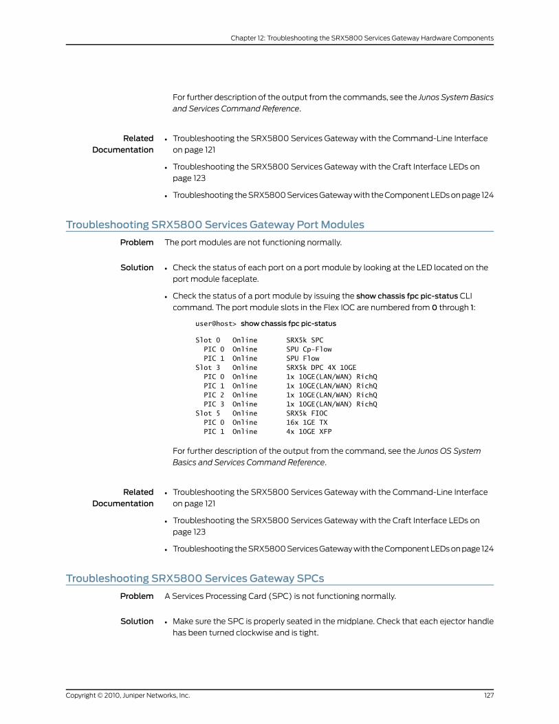
For further description of the output from the commands, see the Junos SystemBasics
and Services Command Reference.
RelatedDocumentation
Troubleshooting the SRX5800 Services Gateway with the Command-Line Interface
on page 121
•
• Troubleshooting the SRX5800 Services Gateway with the Craft Interface LEDs on
page 123
• Troubleshooting the SRX5800 Services Gateway with the Component LEDs on page 124
Troubleshooting SRX5800 Services Gateway Port Modules
Problem The port modules are not functioning normally.
Solution Check the status of each port on a port module by looking at the LED located on the
port module faceplate.
•
• Check the status of a port module by issuing the show chassis fpc pic-status CLI
command. The port module slots in the Flex IOC are numbered from 0 through 1:
user@host> show chassis fpc pic-status
Slot 0 Online SRX5k SPC PIC 0 Online SPU Cp-Flow PIC 1 Online SPU FlowSlot 3 Online SRX5k DPC 4X 10GE PIC 0 Online 1x 10GE(LAN/WAN) RichQ PIC 1 Online 1x 10GE(LAN/WAN) RichQ PIC 2 Online 1x 10GE(LAN/WAN) RichQ PIC 3 Online 1x 10GE(LAN/WAN) RichQSlot 5 Online SRX5k FIOC PIC 0 Online 16x 1GE TX PIC 1 Online 4x 10GE XFP
For further description of the output from the command, see the Junos OS System
Basics and Services Command Reference.
RelatedDocumentation
Troubleshooting the SRX5800 Services Gateway with the Command-Line Interface
on page 121
•
• Troubleshooting the SRX5800 Services Gateway with the Craft Interface LEDs on
page 123
• Troubleshooting the SRX5800 Services Gateway with the Component LEDs on page 124
Troubleshooting SRX5800 Services Gateway SPCs
Problem A Services Processing Card (SPC) is not functioning normally.
Solution Make sure the SPC is properly seated in the midplane. Check that each ejector handle
has been turned clockwise and is tight.
•
127Copyright © 2010, Juniper Networks, Inc.
Chapter 12: Troubleshooting the SRX5800 Services Gateway Hardware Components
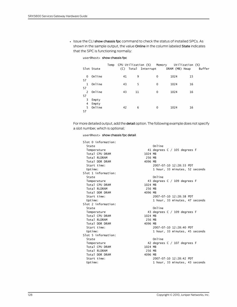
• Issue the CLI show chassis fpc command to check the status of installed SPCs. As
shown in the sample output, the value Online in the column labeled State indicates
that the SPC is functioning normally:
user@host> show chassis fpc
Temp CPU Utilization (%) Memory Utilization (%)Slot State (C) Total Interrupt DRAM (MB) Heap Buffer
0 Online 41 9 0 1024 15 57 1 Online 43 5 0 1024 16 57 2 Online 43 11 0 1024 16 57 3 Empty 4 Empty 5 Online 42 6 0 1024 16 57
For more detailed output, add thedetailoption. The following example does not specify
a slot number, which is optional:
user@host> show chassis fpc detail
Slot 0 information: State Online Temperature 41 degrees C / 105 degrees F Total CPU DRAM 1024 MB Total RLDRAM 256 MB Total DDR DRAM 4096 MB Start time: 2007-07-10 12:28:33 PDT Uptime: 1 hour, 33 minutes, 52 secondsSlot 1 information: State Online Temperature 43 degrees C / 109 degrees F Total CPU DRAM 1024 MB Total RLDRAM 256 MB Total DDR DRAM 4096 MB Start time: 2007-07-10 12:28:38 PDT Uptime: 1 hour, 33 minutes, 47 secondsSlot 2 information: State Online Temperature 43 degrees C / 109 degrees F Total CPU DRAM 1024 MB Total RLDRAM 256 MB Total DDR DRAM 4096 MB Start time: 2007-07-10 12:28:40 PDT Uptime: 1 hour, 33 minutes, 45 secondsSlot 5 information: State Online Temperature 42 degrees C / 107 degrees F Total CPU DRAM 1024 MB Total RLDRAM 256 MB Total DDR DRAM 4096 MB Start time: 2007-07-10 12:28:42 PDT Uptime: 1 hour, 33 minutes, 43 seconds
Copyright © 2010, Juniper Networks, Inc.128
SRX5800 Services Gateway Hardware Guide
For further description of the output from the commands, see the Junos SystemBasics
and Services Command Reference.
RelatedDocumentation
Troubleshooting the SRX5800 Services Gateway with the Command-Line Interface
on page 121
•
• Troubleshooting the SRX5800 Services Gateway with the Craft Interface LEDs on
page 123
• Troubleshooting the SRX5800 Services Gateway with the Component LEDs on page 124
Troubleshooting the SRX5800 Services Gateway Power System
Problem The power system is not functioning normally.
Solution Check the LEDs on each power supply faceplate.•
• If a standard-capacity AC power supply is correctly installed and functioning normally,
the ACOK and DCOK LEDs light steadily, and the PS FAIL LED is not lit.
• If a high-capacity AC power supply is correctly installed and functioning normally,
the DCOK LED lights steadily and the PS FAIL LED is not lit. In addition, the AC-1 OK
LED lights green steadily if the upper AC feed (on the chassis above the power supply)
is connected and receiving power, and the AC-2 OK LED lights green steadily if the
lower AC feed (on the power supply itself) is connected and receiving power.
• If a DC power supply is correctly installed and functioning normally, the PWROK,
BREAKERON, and INPUTOK LEDs light steadily.
• Issue the CLI showchassis environment pem command to check the status of installed
power supplies. As shown in the sample output, the value Online in the rows labeled
State indicates that each of the power supplies is functioning normally:
user@host> show chassis environment pem
PEM 0 status: State Online Temperature OK AC Input: OK DC Output Voltage Current Power Load 50 6 300 17PEM 1 status: State Online Temperature OK AC Input: OK DC Output Voltage Current Power Load 50 3 150 8
129Copyright © 2010, Juniper Networks, Inc.
Chapter 12: Troubleshooting the SRX5800 Services Gateway Hardware Components
If a power supply is not functioning normally, perform the following steps to diagnose
and correct the problem:
• If a red alarm condition occurs, issue the showchassis alarms command to determine
the source of the problem.
• If all power supplies have failed, the system temperature might have exceeded the
threshold, causing the system to shut down.
NOTE: If the system temperature exceeds the threshold, the Junos OSshuts down all power supplies so that no status is displayed.
The Junos OS also can shut down one of the power supplies for otherreasons. In this case, the remaining power supplies provide power to theservices gateway, and you can still view the system status through the CLIor display.
• Check that the power supplies are switched on:
• If the services gateway is equipped with standard-capacity AC power supplies, verify
that the AC switch on the chassis above each power supply is in the on (—) position.
• If the services gateway is equipped with high-capacity AC power supplies, verify that
the AC switch on the chassis above each power supply is in the on (—) position and
that the AC switch at the top of each power supply is in the on (|) position.
• If the services gateway is equipped with DC power supplies, verify that the DC circuit
breaker on the power supply (|) is in the on position.
• Verify that the source circuit breaker has the proper current rating. Each power supply
must be connected to a separate source circuit breaker.
• Verify that the AC power cords or DC power cables from the power sources to the
services gateway are not damaged. If the insulation is cracked or broken, immediately
replace the cord or cable.
• Connect the power supply to a different power source with a new power cord or power
cables. If the power supply status LEDs indicate that the power supply is not operating
normally, the power supply is the source of the problem. Replace the power supply
with a spare.
RelatedDocumentation
• Troubleshooting the SRX5800 Services Gateway with the Command-Line Interface
on page 121
• Troubleshooting the SRX5800 Services Gateway with the Craft Interface LEDs on
page 123
• Troubleshooting the SRX5800 Services Gateway with the Component LEDs on page 124
Copyright © 2010, Juniper Networks, Inc.130
SRX5800 Services Gateway Hardware Guide
CHAPTER 13
Replacing SRX5800 Services GatewayHardware Components
This section includes the following topics:
• SRX5800 Services Gateway Field-Replaceable Units on page 132
• Tools and Parts Required to Replace SRX5800 Services Gateway Hardware
Components on page 132
• Replacing the SRX5800 Services Gateway Craft Interface on page 134
• Replacing an SRX5800 Services Gateway Fan Tray on page 136
• Replacing the SRX5800 Services Gateway Air Filter on page 140
• Replacing SRX5800 Services Gateway Host Subsystem Components on page 142
• Replacing Connections to SRX5800 Services Gateway Routing Engine Interface
Ports on page 150
• Replacing SRX5800 Services Gateway IOCs on page 152
• Replacing SRX5800 Services Gateway Flex IOCs on page 157
• Replacing SRX5800 Services Gateway Port Modules on page 161
• Replacing an SRX5800 IOC or Port Module Cable on page 164
• Replacing SRX5800 Services Gateway SPCs on page 167
• Replacing SRX5800 Services Gateway XFP and SFP Transceivers on page 172
• Replacing an SRX5800 Services Gateway AC Power Supply on page 174
• Upgrading an SRX5800 Services Gateway from Standard-Capacity to High-Capacity
AC Power Supplies on page 179
• Replacing an SRX5800 Services Gateway DC Power Supply on page 180
• Replacing an SRX5800 Services Gateway AC Power Supply Cord on page 186
• Replacing an SRX5800 Services Gateway DC Power Supply Cable on page 188
• Replacing the SRX5800 Services Gateway Cable Manager on page 190
131Copyright © 2010, Juniper Networks, Inc.
SRX5800 Services Gateway Field-Replaceable Units
Field-replaceable units (FRUs) are services gateway components that can be replaced
at the customer site. The device uses the following types of FRUs:
• Hot-removable and hot-insertable FRUs—You can remove and replace these
components without powering off the device or disrupting the routing functions.
• Hot-pluggable FRUs—You can remove and replace these components without powering
off the device, but the routing functions of the system are interrupted when the
component is removed.
• Cold-swap-only FRUs—You must power off the device in order to remove, replace, or
add these components.
Table 30 on page 132 lists the FRUs for the services gateway.
Table 30: Field-Replaceable Units
Cold-swap-only FRUsHot-pluggable FRUsHot-removableandhot-insertableFRUs
Routing Engine
Switch Control Boards (SCBs)
Services Processing Cards (SPCs)
I/O Cards(IOCs)
Flex I/O Cards (Flex IOCs)
Port modules
Air filter
Fan tray
Craft interface
AC and DC power supplies (ifredundant)
SFP and XFP Transcievers
RelatedDocumentation
Tools and Parts Required to Replace SRX5800 Services Gateway Hardware
Components on page 132
•
Tools and Parts Required to Replace SRX5800 Services Gateway HardwareComponents
To replace hardware components, you must have the tools listed in Table 31 on page 132.
Table 31: Tools and Parts Required
ComponentsTool or part
Cables and connectors
DC power supply
7/16-in. nut driver or pliers
Copyright © 2010, Juniper Networks, Inc.132
SRX5800 Services Gateway Hardware Guide
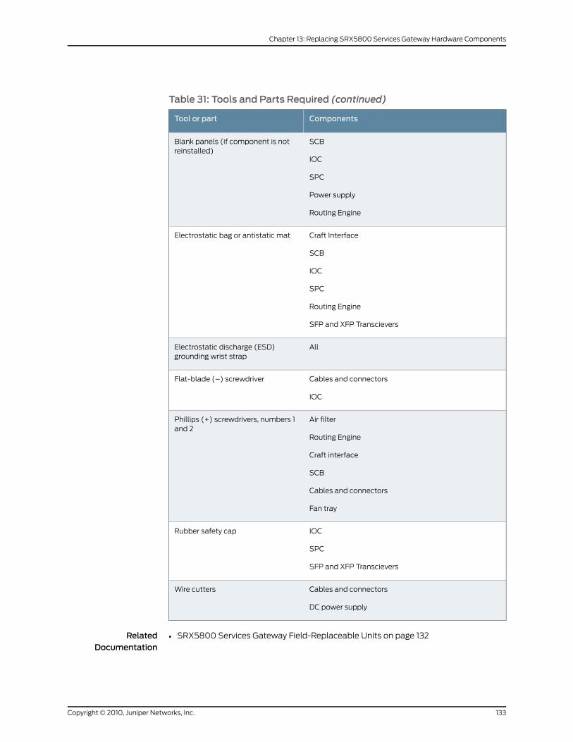
Table 31: Tools and Parts Required (continued)
ComponentsTool or part
SCB
IOC
SPC
Power supply
Routing Engine
Blank panels (if component is notreinstalled)
Craft Interface
SCB
IOC
SPC
Routing Engine
SFP and XFP Transcievers
Electrostatic bag or antistatic mat
AllElectrostatic discharge (ESD)grounding wrist strap
Cables and connectors
IOC
Flat-blade (–) screwdriver
Air filter
Routing Engine
Craft interface
SCB
Cables and connectors
Fan tray
Phillips (+) screwdrivers, numbers 1and 2
IOC
SPC
SFP and XFP Transcievers
Rubber safety cap
Cables and connectors
DC power supply
Wire cutters
RelatedDocumentation
SRX5800 Services Gateway Field-Replaceable Units on page 132•
133Copyright © 2010, Juniper Networks, Inc.
Chapter 13: Replacing SRX5800 Services Gateway Hardware Components
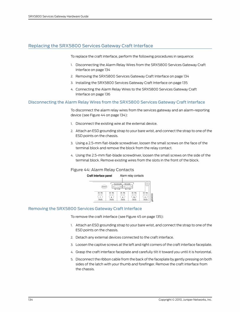
Replacing the SRX5800 Services Gateway Craft Interface
To replace the craft interface, perform the following procedures in sequence:
1. Disconnecting the Alarm Relay Wires from the SRX5800 Services Gateway Craft
Interface on page 134
2. Removing the SRX5800 Services Gateway Craft Interface on page 134
3. Installing the SRX5800 Services Gateway Craft Interface on page 135
4. Connecting the Alarm Relay Wires to the SRX5800 Services Gateway Craft
Interface on page 136
Disconnecting the Alarm RelayWires from the SRX5800 Services Gateway Craft Interface
To disconnect the alarm relay wires from the services gateway and an alarm-reporting
device (see Figure 44 on page 134):
1. Disconnect the existing wire at the external device.
2. Attach an ESD grounding strap to your bare wrist, and connect the strap to one of the
ESD points on the chassis.
3. Using a 2.5-mm flat-blade screwdriver, loosen the small screws on the face of the
terminal block and remove the block from the relay contact.
4. Using the 2.5-mm flat-blade screwdriver, loosen the small screws on the side of the
terminal block. Remove existing wires from the slots in the front of the block.
Figure 44: Alarm Relay Contacts
Removing the SRX5800 Services Gateway Craft Interface
To remove the craft interface (see Figure 45 on page 135):
1. Attach an ESD grounding strap to your bare wrist, and connect the strap to one of the
ESD points on the chassis.
2. Detach any external devices connected to the craft interface.
3. Loosen the captive screws at the left and right corners of the craft interface faceplate.
4. Grasp the craft interface faceplate and carefully tilt it toward you until it is horizontal.
5. Disconnect the ribbon cable from the back of the faceplate by gently pressing on both
sides of the latch with your thumb and forefinger. Remove the craft interface from
the chassis.
Copyright © 2010, Juniper Networks, Inc.134
SRX5800 Services Gateway Hardware Guide
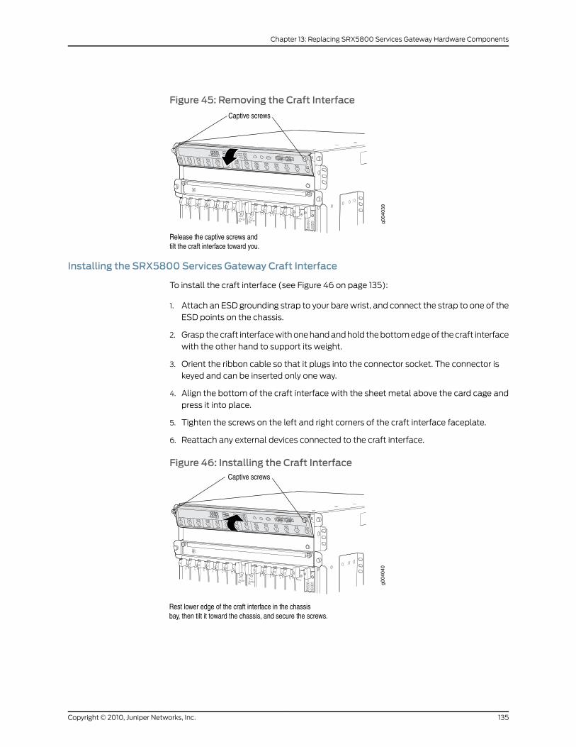
Figure 45: Removing the Craft Interface
Installing the SRX5800 Services Gateway Craft Interface
To install the craft interface (see Figure 46 on page 135):
1. Attach an ESD grounding strap to your bare wrist, and connect the strap to one of the
ESD points on the chassis.
2. Grasp the craft interface with one hand and hold the bottom edge of the craft interface
with the other hand to support its weight.
3. Orient the ribbon cable so that it plugs into the connector socket. The connector is
keyed and can be inserted only one way.
4. Align the bottom of the craft interface with the sheet metal above the card cage and
press it into place.
5. Tighten the screws on the left and right corners of the craft interface faceplate.
6. Reattach any external devices connected to the craft interface.
Figure 46: Installing the Craft Interface
1 01 0
1 0
1 01 0
1 10 0
1 01 01 0
g004
040
OK
0
FAIL
ONLINE
OK
1
FAIL
ONLINE
OK
2
FAIL
ONLINE
OK
3
FAIL
ONLINE
OK
4
FAIL
ONLINE
OK
5
FAIL
ONLINE
OK
0
FAIL
ONLINE
MASTERONLINEOFFLINE
RE0
FANPEM
1
0
0 1 2 3
RE1OK
1
FAIL
ONLINE
OK
7
FAIL
ONLINE
OK
8
FAIL
ONLINE
OK
9
FAIL
ONLINE
OK
10
FAIL
ONLINE
OK
11
FAIL
ONLINE
OK
2 6
FAIL
ONLINE
ACO/LT
YELLOW ALARM RED ALARM
NC NOC NC NOC
135Copyright © 2010, Juniper Networks, Inc.
Chapter 13: Replacing SRX5800 Services Gateway Hardware Components
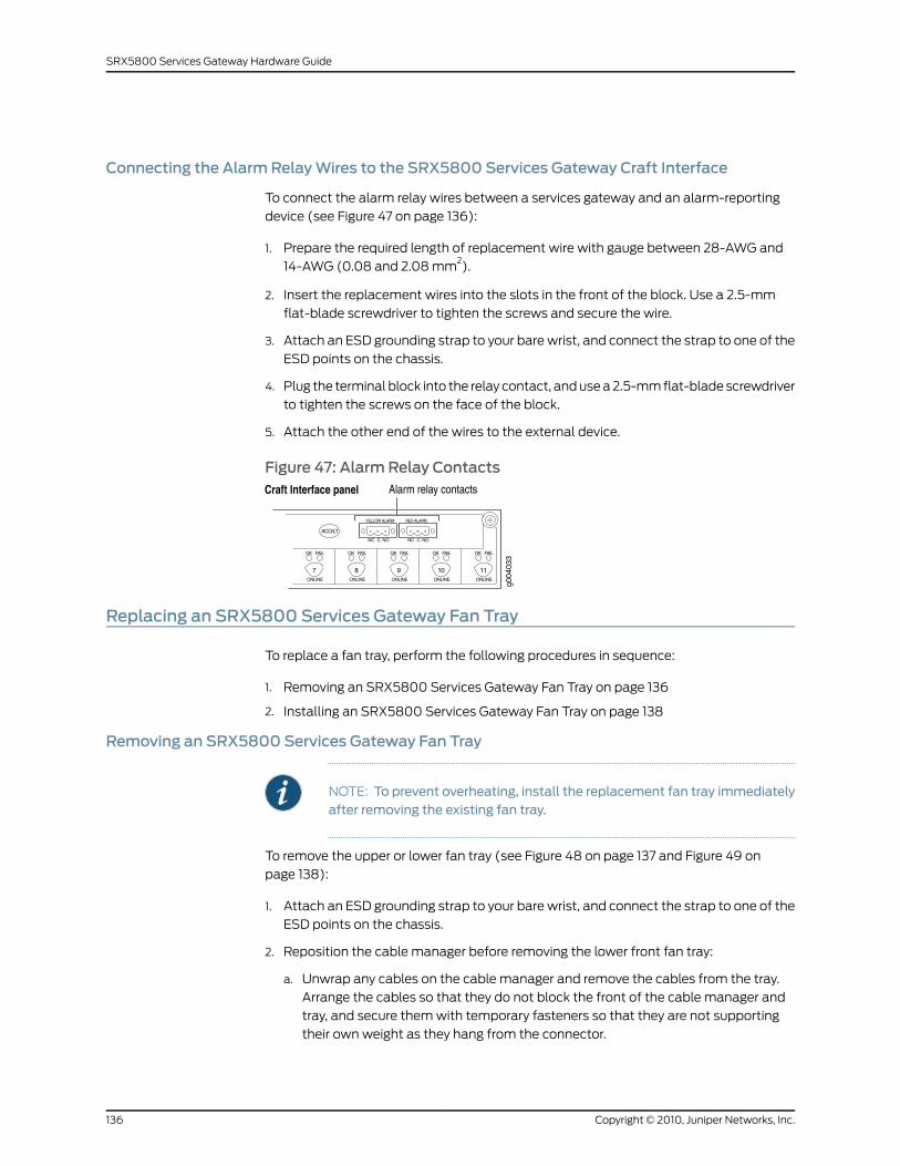
Connecting the Alarm RelayWires to the SRX5800 Services Gateway Craft Interface
To connect the alarm relay wires between a services gateway and an alarm-reporting
device (see Figure 47 on page 136):
1. Prepare the required length of replacement wire with gauge between 28-AWG and
14-AWG (0.08 and 2.08 mm2).
2. Insert the replacement wires into the slots in the front of the block. Use a 2.5-mm
flat-blade screwdriver to tighten the screws and secure the wire.
3. Attach an ESD grounding strap to your bare wrist, and connect the strap to one of the
ESD points on the chassis.
4. Plug the terminal block into the relay contact, and use a 2.5-mm flat-blade screwdriver
to tighten the screws on the face of the block.
5. Attach the other end of the wires to the external device.
Figure 47: Alarm Relay Contacts
Replacing an SRX5800 Services Gateway Fan Tray
To replace a fan tray, perform the following procedures in sequence:
1. Removing an SRX5800 Services Gateway Fan Tray on page 136
2. Installing an SRX5800 Services Gateway Fan Tray on page 138
Removing an SRX5800 Services Gateway Fan Tray
NOTE: To prevent overheating, install the replacement fan tray immediatelyafter removing the existing fan tray.
To remove the upper or lower fan tray (see Figure 48 on page 137 and Figure 49 on
page 138):
1. Attach an ESD grounding strap to your bare wrist, and connect the strap to one of the
ESD points on the chassis.
2. Reposition the cable manager before removing the lower front fan tray:
a. Unwrap any cables on the cable manager and remove the cables from the tray.
Arrange the cables so that they do not block the front of the cable manager and
tray, and secure them with temporary fasteners so that they are not supporting
their own weight as they hang from the connector.
Copyright © 2010, Juniper Networks, Inc.136
SRX5800 Services Gateway Hardware Guide
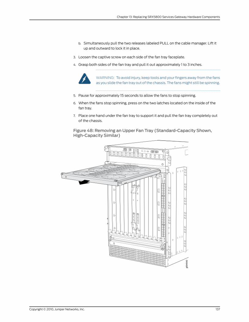
b. Simultaneously pull the two releases labeled PULL on the cable manager. Lift it
up and outward to lock it in place.
3. Loosen the captive screw on each side of the fan tray faceplate.
4. Grasp both sides of the fan tray and pull it out approximately 1 to 3 inches.
WARNING: Toavoid injury, keep tools and your fingers away from the fansas youslide the fan trayoutof thechassis. The fansmight still be spinning.
5. Pause for approximately 15 seconds to allow the fans to stop spinning.
6. When the fans stop spinning, press on the two latches located on the inside of the
fan tray.
7. Place one hand under the fan tray to support it and pull the fan tray completely out
of the chassis.
Figure 48: Removing an Upper Fan Tray (Standard-Capacity Shown,High-Capacity Similar)
OK
0
FAIL
ONLINE
OK
1
FAIL
ONLINE
OK
2
FAIL
ONLINE
OK
3
FAIL
ONLINE
OK
4
FAIL
ONLINE
OK
5
FAIL
ONLINE
OK
0
FAIL
ONLINE
MASTERONLINEOFFLINE
RE0
FANPEM
1
0
0 1 2 3
RE1OK
1
FAIL
ONLINE
OK
7
FAIL
ONLINE
OK
8
FAIL
ONLINE
OK
9
FAIL
ONLINE
OK
10
FAIL
ONLINE
OK
11
FAIL
ONLINE
OK
2 6
FAIL
ONLINE
ACO/LT
YELLOW ALARM RED ALARM
NC NOC NC NOC
1 01 0
1 0
1 01 0
1 10 0
1 01 01 0
g004
042
137Copyright © 2010, Juniper Networks, Inc.
Chapter 13: Replacing SRX5800 Services Gateway Hardware Components
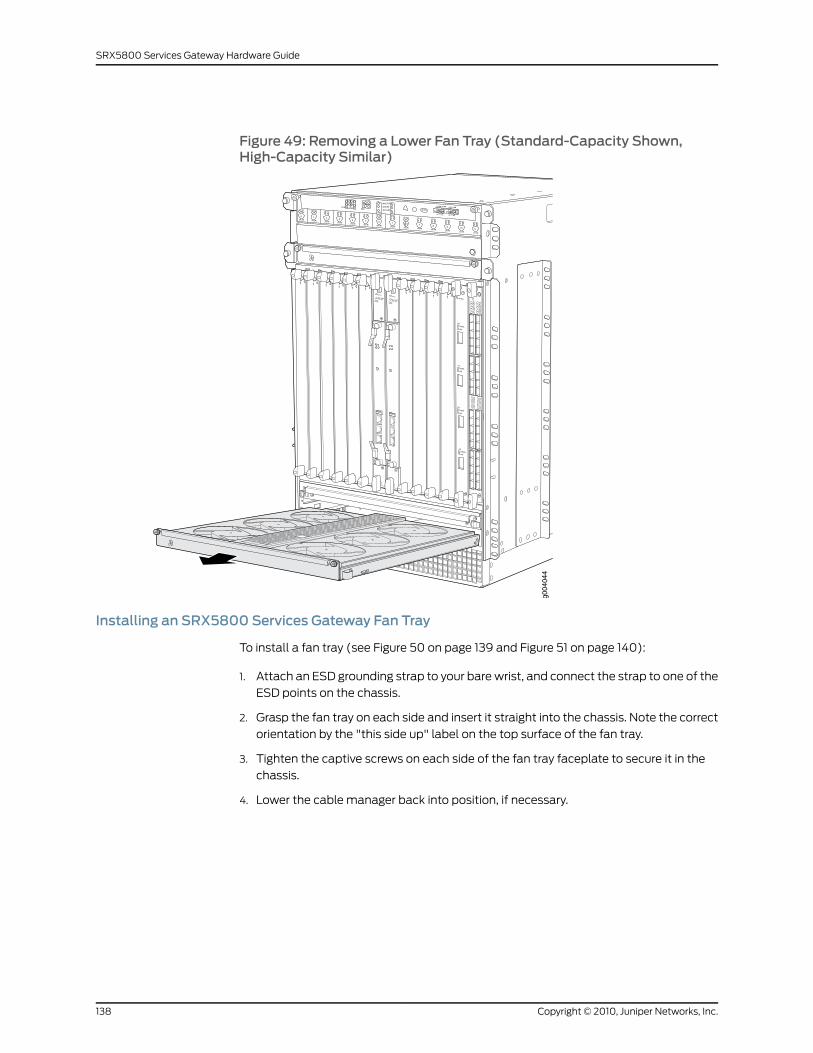
Figure 49: Removing a Lower Fan Tray (Standard-Capacity Shown,High-Capacity Similar)
OK
0
FAIL
ONLINE
OK
1
FAIL
ONLINE
OK
2
FAIL
ONLINE
OK
3
FAIL
ONLINE
OK
4
FAIL
ONLINE
OK
5
FAIL
ONLINE
OK
0
FAIL
ONLINE
MASTERONLINEOFFLINE
RE0
FANPEM
1
0
0 1 2 3
RE1OK
1
FAIL
ONLINE
OK
7
FAIL
ONLINE
OK
8
FAIL
ONLINE
OK
9
FAIL
ONLINE
OK
10
FAIL
ONLINE
OK
11
FAIL
ONLINE
OK
2 6
FAIL
ONLINE
ACO/LT
YELLOW ALARM RED ALARM
NC NOC NC NOC
1 01 0
1 0
1 01 0
1 10 0
1 01 01 0
g004
044
Installing an SRX5800 Services Gateway Fan Tray
To install a fan tray (see Figure 50 on page 139 and Figure 51 on page 140):
1. Attach an ESD grounding strap to your bare wrist, and connect the strap to one of the
ESD points on the chassis.
2. Grasp the fan tray on each side and insert it straight into the chassis. Note the correct
orientation by the "this side up" label on the top surface of the fan tray.
3. Tighten the captive screws on each side of the fan tray faceplate to secure it in the
chassis.
4. Lower the cable manager back into position, if necessary.
Copyright © 2010, Juniper Networks, Inc.138
SRX5800 Services Gateway Hardware Guide

Figure 50: Installing an Upper Fan Tray (Standard-Capacity Shown,High-Capacity Similar)
g004
043
OK
0
FAIL
ONLINE
OK
1
FAIL
ONLINE
OK
2
FAIL
ONLINE
OK
3
FAIL
ONLINE
OK
4
FAIL
ONLINE
OK
5
FAIL
ONLINE
OK
0
FAIL
ONLINE
MASTERONLINEOFFLINE
RE0
FANPEM
1
0
0 1 2 3
RE1OK
1
FAIL
ONLINE
OK
7
FAIL
ONLINE
OK
8
FAIL
ONLINE
OK
9
FAIL
ONLINE
OK
10
FAIL
ONLINE
OK
11
FAIL
ONLINE
OK
2 6
FAIL
ONLINE
ACO/LT
YELLOW ALARM RED ALARM
NC NOC NC NOC
1 01 0
1 0
1 01 0
1 10 0
1 01 01 0
139Copyright © 2010, Juniper Networks, Inc.
Chapter 13: Replacing SRX5800 Services Gateway Hardware Components
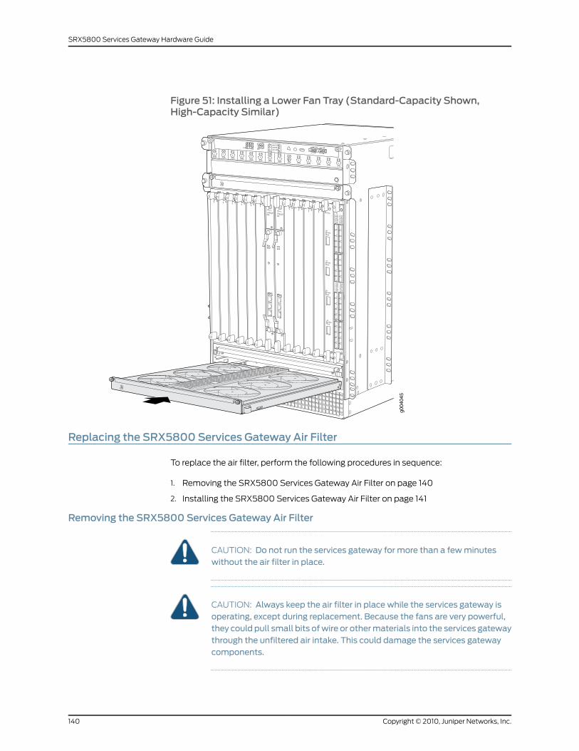
Figure 51: Installing a Lower Fan Tray (Standard-Capacity Shown,High-Capacity Similar)
OK
0
FAIL
ONLINE
OK
1
FAIL
ONLINE
OK
2
FAIL
ONLINE
OK
3
FAIL
ONLINE
OK
4
FAIL
ONLINE
OK
5
FAIL
ONLINE
OK
0
FAIL
ONLINE
MASTERONLINEOFFLINE
RE0
FANPEM
1
0
0 1 2 3
RE1OK
1
FAIL
ONLINE
OK
7
FAIL
ONLINE
OK
8
FAIL
ONLINE
OK
9
FAIL
ONLINE
OK
10
FAIL
ONLINE
OK
11
FAIL
ONLINE
OK
2 6
FAIL
ONLINE
ACO/LT
YELLOW ALARM RED ALARM
NC NOC NC NOC
1 01 0
1 0
1 01 0
1 10 0
1 01 01 0
g004
045
Replacing the SRX5800 Services Gateway Air Filter
To replace the air filter, perform the following procedures in sequence:
1. Removing the SRX5800 Services Gateway Air Filter on page 140
2. Installing the SRX5800 Services Gateway Air Filter on page 141
Removing the SRX5800 Services Gateway Air Filter
CAUTION: Do not run the services gateway for more than a fewminuteswithout the air filter in place.
CAUTION: Always keep the air filter in place while the services gateway isoperating, except during replacement. Because the fans are very powerful,they could pull small bits ofwire or othermaterials into the services gatewaythrough the unfiltered air intake. This could damage the services gatewaycomponents.
Copyright © 2010, Juniper Networks, Inc.140
SRX5800 Services Gateway Hardware Guide
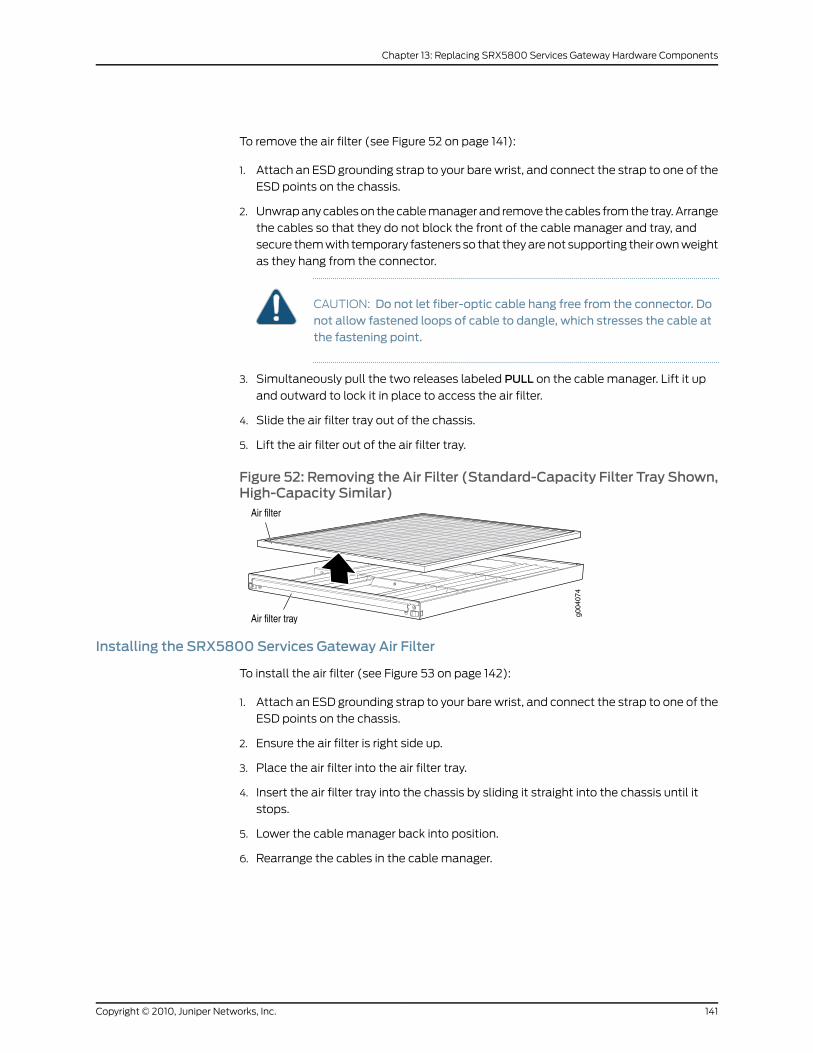
To remove the air filter (see Figure 52 on page 141):
1. Attach an ESD grounding strap to your bare wrist, and connect the strap to one of the
ESD points on the chassis.
2. Unwrap any cables on the cable manager and remove the cables from the tray. Arrange
the cables so that they do not block the front of the cable manager and tray, and
secure them with temporary fasteners so that they are not supporting their own weight
as they hang from the connector.
CAUTION: Do not let fiber-optic cable hang free from the connector. Donot allow fastened loops of cable to dangle, which stresses the cable atthe fastening point.
3. Simultaneously pull the two releases labeled PULL on the cable manager. Lift it up
and outward to lock it in place to access the air filter.
4. Slide the air filter tray out of the chassis.
5. Lift the air filter out of the air filter tray.
Figure 52: Removing the Air Filter (Standard-Capacity Filter Tray Shown,High-Capacity Similar)
Installing the SRX5800 Services Gateway Air Filter
To install the air filter (see Figure 53 on page 142):
1. Attach an ESD grounding strap to your bare wrist, and connect the strap to one of the
ESD points on the chassis.
2. Ensure the air filter is right side up.
3. Place the air filter into the air filter tray.
4. Insert the air filter tray into the chassis by sliding it straight into the chassis until it
stops.
5. Lower the cable manager back into position.
6. Rearrange the cables in the cable manager.
141Copyright © 2010, Juniper Networks, Inc.
Chapter 13: Replacing SRX5800 Services Gateway Hardware Components
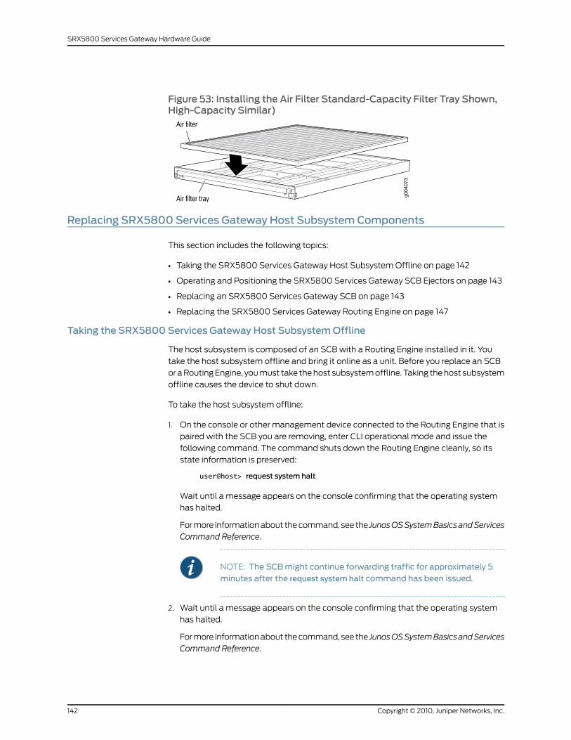
Figure 53: Installing the Air Filter Standard-Capacity Filter Tray Shown,High-Capacity Similar)
Replacing SRX5800 Services Gateway Host SubsystemComponents
This section includes the following topics:
• Taking the SRX5800 Services Gateway Host Subsystem Offline on page 142
• Operating and Positioning the SRX5800 Services Gateway SCB Ejectors on page 143
• Replacing an SRX5800 Services Gateway SCB on page 143
• Replacing the SRX5800 Services Gateway Routing Engine on page 147
Taking the SRX5800 Services Gateway Host SubsystemOffline
The host subsystem is composed of an SCB with a Routing Engine installed in it. You
take the host subsystem offline and bring it online as a unit. Before you replace an SCB
or a Routing Engine, you must take the host subsystem offline. Taking the host subsystem
offline causes the device to shut down.
To take the host subsystem offline:
1. On the console or other management device connected to the Routing Engine that is
paired with the SCB you are removing, enter CLI operational mode and issue the
following command. The command shuts down the Routing Engine cleanly, so its
state information is preserved:
user@host> request system halt
Wait until a message appears on the console confirming that the operating system
has halted.
For more information about the command, see the JunosOSSystemBasicsandServices
Command Reference.
NOTE: The SCBmight continue forwarding traffic for approximately 5minutes after the request system halt command has been issued.
2. Wait until a message appears on the console confirming that the operating system
has halted.
For more information about the command, see the JunosOSSystemBasicsandServices
Command Reference.
Copyright © 2010, Juniper Networks, Inc.142
SRX5800 Services Gateway Hardware Guide
NOTE: The SCBmight continue forwarding traffic for approximately 5minutes after the request system halt command has been issued.
RelatedDocumentation
Operating and Positioning the SRX5800 Services Gateway SCB Ejectors on page 143•
• Removing an SRX5800 Services Gateway SCB on page 144
• Installing an SRX5800 Services Gateway SCB on page 145
• Replacing the SRX5800 Services Gateway Routing Engine on page 147
• Replacing the Management Ethernet Cable on an SRX5800 Services Gateway on
page 150
Operating and Positioning the SRX5800 Services Gateway SCB Ejectors
• When removing or inserting an SCB, ensure that the SCBs or blank panels in adjacent
slots are fully inserted to avoid hitting them with the ejector handles. The ejector
handles require that all adjacent components be completely inserted so the ejector
handles do not hit them, which could result in damage.
• The ejector handles have a center of rotation and need to be stored toward the center
of the board. Ensure the long ends of the ejectors located at both the top and the
bottom of the board are vertical and pressed as far as possible towards the center of
the board.
• To insert or remove the SCB card, slide the ejector across the SCB horizontally, rotate
it, and slide it again another quarter of a turn. Turn the ejector again and repeat as
necessary. Use the indexing feature to maximize leverage and to avoid hitting any
adjacent components.
• Operate both ejector handles simultaneously. The insertion force on an SCB is too
great for one ejector.
RelatedDocumentation
Taking the SRX5800 Services Gateway Host Subsystem Offline on page 142•
• Replacing an SRX5800 Services Gateway SCB on page 143
• Replacing the SRX5800 Services Gateway Routing Engine on page 147
• Replacing the Management Ethernet Cable on an SRX5800 Services Gateway on
page 150
Replacing an SRX5800 Services Gateway SCB
Before replacing an SCB, read the guidelines in “Operating and Positioning the SRX5800
Services Gateway SCB Ejectors” on page 143. To replace an SCB, perform the following
procedures:
1. Removing an SRX5800 Services Gateway SCB on page 144
2. Installing an SRX5800 Services Gateway SCB on page 145
143Copyright © 2010, Juniper Networks, Inc.
Chapter 13: Replacing SRX5800 Services Gateway Hardware Components
Removing an SRX5800 Services Gateway SCB
To remove an SCB (see Figure 54 on page 145):
NOTE: The SCB and Routing Engine are removed as a unit. You can alsoremove the Routing Engine separately.
CAUTION: Before removing an SCB, ensure that you know how to operatethe ejector handles properly to avoid damage to the equipment.
1. Power off the device.
2. Place an electrostatic bag or antistatic mat on a flat, stable surface.
3. Attach an ESD grounding strap to your bare wrist, and connect the strap to one of the
ESD points on the chassis.
4. Rotate the ejector handles simultaneously counterclockwise to unseat the SCB.
5. Grasp the ejector handles and slide the SCB about halfway out of the chassis.
6. Place one hand underneath the SCB to support it and slide it completely out of the
chassis.
7. Place the SCB on the antistatic mat.
8. If you are not replacing the SCB now, install a blank panel over the empty slot.
Copyright © 2010, Juniper Networks, Inc.144
SRX5800 Services Gateway Hardware Guide
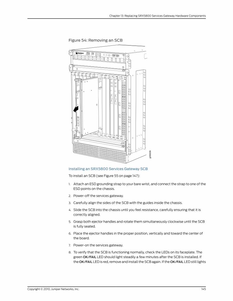
Figure 54: Removing an SCB
Installing an SRX5800 Services Gateway SCB
To install an SCB (see Figure 55 on page 147):
1. Attach an ESD grounding strap to your bare wrist, and connect the strap to one of the
ESD points on the chassis.
2. Power-off the services gateway.
3. Carefully align the sides of the SCB with the guides inside the chassis.
4. Slide the SCB into the chassis until you feel resistance, carefully ensuring that it is
correctly aligned.
5. Grasp both ejector handles and rotate them simultaneously clockwise until the SCB
is fully seated.
6. Place the ejector handles in the proper position, vertically and toward the center of
the board.
7. Power-on the services gateway.
8. To verify that the SCB is functioning normally, check the LEDs on its faceplate. The
green OK/FAIL LED should light steadily a few minutes after the SCB is installed. If
theOK/FAILLED is red, remove and install the SCB again. If theOK/FAILLED still lights
145Copyright © 2010, Juniper Networks, Inc.
Chapter 13: Replacing SRX5800 Services Gateway Hardware Components
steadily, the SCB is not functioning properly. Contact your customer support
representative.
To check the status of the SCB:
user@host> show chassis environment cb
CB 0 status: State Online Master Temperature 30 degrees C / 86 degrees F Power 1 1.2 V 1202 mV 1.5 V 1511 mV 1.8 V 1798 mV 2.5 V 2481 mV 3.3 V 3306 mV 5.0 V 4956 mV 12.0 V 12084 mV 1.25 V 1250 mV 3.3 V SM3 3287 mV 5.0 V RE 5046 mV 12.0 V RE 11910 mV Power 2 11.3 V bias PEM 11292 mV 4.6 V bias MidPlane 4833 mV 11.3 V bias FPD 11156 mV 11.3 V bias POE 0 11253 mV 11.3 V bias POE 1 11272 mV Bus Revision 42 FPGA Revision 1CB 1 status: State Online Temperature 31 degrees C / 87 degrees F Power 1 1.2 V 1205 mV 1.5 V 1508 mV 1.8 V 1817 mV 2.5 V 2507 mV 3.3 V 3306 mV 5.0 V 5053 mV 12.0 V 12200 mV 1.25 V 1256 mV 3.3 V SM3 3306 mV 5.0 V RE 5091 mV 12.0 V RE 0 mV Power 2 11.3 V bias PEM 11214 mV 4.6 V bias MidPlane 4821 mV 11.3 V bias FPD 11350 mV 11.3 V bias POE 0 11350 mV 11.3 V bias POE 1 11330 mV Bus Revision 42 FPGA Revision 0
Copyright © 2010, Juniper Networks, Inc.146
SRX5800 Services Gateway Hardware Guide
Figure 55: Installing an SCB
Replacing the SRX5800 Services Gateway Routing Engine
To replace the routing engine, perform the following procedures:
1. Removing the SRX5800 Services Gateway Routing Engine on page 147
2. Installing the SRX5800 Services Gateway Routing Engine on page 148
Removing the SRX5800 Services Gateway Routing Engine
CAUTION: Before you replace a Routing Engine, youmust take the hostsubsystem offline.
To remove the Routing Engine (see Figure 56 on page 148):
1. Take the host subsystem offline as described in “Taking the SRX5800 Services
Gateway Host Subsystem Offline” on page 142.
2. Place an electrostatic bag or antistatic mat on a flat, stable surface.
3. Attach an ESD grounding strap to your bare wrist, and connect the strap to one of the
ESD points on the chassis.
4. Loosen the captive screws at each end of the Routing Engine faceplate.
147Copyright © 2010, Juniper Networks, Inc.
Chapter 13: Replacing SRX5800 Services Gateway Hardware Components
5. Flip the ejector handles outward to unseat the Routing Engine.
6. Grasp the Routing Engine by the ejector handles and slide it about halfway out of the
chassis.
7. Place one hand underneath the Routing Engine to support it and slide it completely
out of the chassis.
8. Place the Routing Engine on the antistatic mat.
Figure 56: Removing the Routing Engine
Installing the SRX5800 Services Gateway Routing Engine
If you install only one Routing Engine in the services gateway, you must install it in the
slot in the front panel of SCB0. If you install a second routing engine to use the dual
chassis cluster control link feature, you install it in the slot in the front panel of SCB1.
To install a Routing Engine into an SCB (see Figure 57 on page 150):
1. If you have not already done so, take the host subsystem offline. See “Taking the
SRX5800 Services Gateway Host Subsystem Offline” on page 142.
2. Attach an ESD grounding strap to your bare wrist, and connect the strap to one of the
ESD points on the chassis.
Copyright © 2010, Juniper Networks, Inc.148
SRX5800 Services Gateway Hardware Guide

3. Ensure that the ejector handles are not in the locked position. If necessary, flip the
ejector handles outward.
4. Place one hand underneath the Routing Engine to support it.
5. Carefully align the sides of the Routing Engine with the guides inside the opening on
the SCB.
6. Slide the Routing Engine into the SCB until you feel resistance, and then press the
Routing Engine's faceplate until it engages the connectors.
7. Press both of the ejector handles inward to seat the Routing Engine.
8. Tighten the captive screws on the top and bottom of the Routing Engine faceplate.
9. Power-on the services gateway.
The Routing Engine might require several minutes to boot.
After the Routing Engine boots, verify that it is installed correctly by checking the RE0
andRE1LEDs on the craft interface. If the services gateway is operational and the Routing
Engine is functioning properly, the green ONLINE LED lights steadily. If the red FAIL LED
lights steadily instead, remove and install the Routing Engine again. If the red FAIL LED
still lights steadily, the Routing Engine is not functioning properly. Contact your customer
support representative.
To check the status of the Routing Engine, use the CLI command:
user@host> show chassis routing-engineRouting Engine status: Slot 0: Current state Master ...
For more information about using the CLI, see the Junos OS manuals.
149Copyright © 2010, Juniper Networks, Inc.
Chapter 13: Replacing SRX5800 Services Gateway Hardware Components
Figure 57: Installing the Routing Engine
ReplacingConnections toSRX5800ServicesGatewayRouting Engine InterfacePorts
This section includes the following topics:
• Replacing the Management Ethernet Cable on an SRX5800 Services
Gateway on page 150
• Replacing the SRX5800 Services Gateway Console or Auxiliary Cable on page 151
Replacing theManagement Ethernet Cable on an SRX5800 Services Gateway
One Ethernet cable with RJ-45 connectors is provided with the services gateway. To
replace the cable connected to the ETHERNET port:
1. Attach an ESD grounding strap to your bare wrist, and connect the strap to one of the
ESD points on the chassis.
2. Press the tab on the connector and pull the connector straight out of the port. Figure
58 on page 151 shows the connector.
3. Disconnect the cable from the network device.
Copyright © 2010, Juniper Networks, Inc.150
SRX5800 Services Gateway Hardware Guide
4. Plug one end of the replacement cable into the ETHERNET port. Figure 59 on page 151
shows the port.
5. Plug the other end of the cable into the network device.
Figure 58: Cable Connector
Figure 59: Ethernet Port
RelatedDocumentation
Preventing Electrostatic Discharge Damage to the SRX5800 Services Gateway on
page 201
•
• Replacing the SRX5800 Services Gateway Console or Auxiliary Cable on page 151
• Replacing the SRX5800 Services Gateway Routing Engine on page 147
Replacing the SRX5800 Services Gateway Console or Auxiliary Cable
To use a system console to configure and manage the Routing Engine, connect it to the
CONSOLE port on the Routing Engine. To use a laptop, modem, or other auxiliary device,
connect it to theAUXport on the Routing Engine. Both ports accept a cable with an RJ-45
connector. One RJ-45/DB-9 cable is provided with the services gateway. If you want to
connect a device to both ports, you must supply another cable.
To replace a cable connected to a management console or auxiliary device:
1. Attach an ESD grounding strap to your bare wrist, and connect the strap to one of the
ESD points on the chassis.
2. Press the tab on the connector and pull the connector straight out of the port.
3. Disconnect the cable from the console or auxiliary device.
4. Plug the RJ-45 end of the replacement serial cable into the CONSOLE or AUX port.
Figure 60 on page 152 shows the external device ports on the Routing Engine.
5. Plug the female DB-9 end into the console or auxiliary device's serial port.
151Copyright © 2010, Juniper Networks, Inc.
Chapter 13: Replacing SRX5800 Services Gateway Hardware Components
Figure 60: Auxiliary and Console Ports
RelatedDocumentation
Preventing Electrostatic Discharge Damage to the SRX5800 Services Gateway on
page 201
•
• Replacing the SRX5800 Services Gateway Routing Engine on page 147
• Replacing the Management Ethernet Cable on an SRX5800 Services Gateway on
page 150
Replacing SRX5800 Services Gateway IOCs
To replace an IOC, perform the following procedures:
1. Removing an SRX5800 Services Gateway IOC on page 152
2. Installing an SRX5800 Services Gateway IOC on page 154
Removing an SRX5800 Services Gateway IOC
An IOC weighs up to 13.1 lb (5.9 kg). Be prepared to accept its full weight.
To remove an IOC (see Figure 61 on page 154):
1. Have ready a replacement IOC or IOC blank panel and an antistatic mat for the IOC.
Also have ready rubber safety caps for each optical interface on the IOC you are
removing.
2. Attach an ESD grounding strap to your bare wrist, and connect the strap to one of the
ESD points on the chassis.
3. Label the cables connected to each port on the IOC so that you can later reconnect
the cables to the correct ports.
4. Use one of the following methods to take the IOC offline:
• Press and hold the corresponding IOC online button on the craft interface. The green
OK LED next to the button begins to blink. Hold the button down until the LED goes
off.
• Issue the following CLI command:
user@host>request chassis fpc slot slot-number offline
For more information about the command, see the Junos OS System Basics and
Services Command Reference.
5. Disconnect the cables from the IOC.
Copyright © 2010, Juniper Networks, Inc.152
SRX5800 Services Gateway Hardware Guide
WARNING: Do not look directly into a fiber-optic transceiver or into theends of fiber-optic cables. Fiber-optic transceivers and fiber-optic cableconnected to a transceiver emit laser light that can damage your eyes.
CAUTION: Do not leave a fiber-optic transceiver uncovered except wheninserting or removing cable. The safety cap keeps the port clean andprevents accidental exposure to laser light.
CAUTION: Avoid bending fiber-optic cable beyond its minimum bendradius.Anarc smaller thana few inches indiameter candamage thecableand cause problems that are difficult to diagnose.
6. Immediately cover each optical transceivers and the end of each fiber-optic cable
with a rubber safety cap.
7. Arrange the disconnected cables in the cable manager to prevent the cables from
developing stress points.
8. Simultaneously turn both of the ejector handles counterclockwise to unseat the IOC.
9. Grasp the handles and slide the IOC straight out of the card cage halfway.
10. Place one hand around the front of the IOC and the other hand under it to support it.
Slide the IOC completely out of the chassis, and place it on the antistatic mat or in
the electrostatic bag.
CAUTION: The weight of the IOC is concentrated in the back end. Beprepared to accept the full weight—up to 13.1 lb (5.9 kg)—as you slide theIOC out of the chassis.
When the IOC is out of the chassis, do not hold it by the ejector handles,bus bars, or edge connectors. They cannot support its weight.
Do not stack IOC on top of one another after removal. Place each oneindividually in an electrostatic bag or on its own antistatic mat on a flat,stable surface.
11. If you are not reinstalling an IOC into the empy slot within a short time, install a blank
IOC panel over the slot to maintain proper airflow in the card cage.
CAUTION: After removing an IOC from the chassis, wait at least 30seconds before reinserting it, removing an IOC from a different slot, orinserting an IOC into a different slot.
153Copyright © 2010, Juniper Networks, Inc.
Chapter 13: Replacing SRX5800 Services Gateway Hardware Components
Figure 61: Removing an IOC
Installing an SRX5800 Services Gateway IOC
An IOC weighs up to 14.5 lb (6.6 kg). Be prepared to accept its full weight.
To install an IOC (see Figure 62 on page 156):
1. Attach an ESD grounding strap to your bare wrist, and connect the strap to one of the
ESD points on the chassis.
2. Place the IOC on an antistatic mat or remove it from its electrostatic bag.
3. Identify the slot on the services gateway where it will be installed.
4. Verify that each fiber-optic transceiver is covered with a rubber safety cap. If it does
not, cover the transceiver with a safety cap.
5. Orient the IOC so that the faceplate faces you.
6. Lift the IOC into place and carefully align the top and bottom edges of the IOC with
the guides inside the card cage.
7. Slide the IOC all the way into the card cage until you feel resistance.
8. Grasp both ejector handles and rotate them clockwise simultaneously until the IOC
is fully seated.
9. Remove the rubber safety cap from each fiber-optic transceiver and cable.
Copyright © 2010, Juniper Networks, Inc.154
SRX5800 Services Gateway Hardware Guide
WARNING: Do not look directly into a fiber-optic transceiver or into theends of fiber-optic cables. Fiber-optic transceivers and fiber-optic cableconnected to a transceiver emit laser light that can damage your eyes.
10. Insert the cables into the cable connector ports on each IOC (see Figure 63 on page 157).
11. Arrange the cable in the cable manager to prevent it from dislodging or developing
stress points. Secure the cable so that it is not supporting its own weight as it hangs
to the floor. Place excess cable out of the way in a neatly coiled loop. Placing fasteners
on the loop helps to maintain its shape.
CAUTION: Do not let fiber-optic cable hang free from the connector. Donot allow fastened loops of cable to dangle, which stresses the cable atthe fastening point.
CAUTION: Avoid bending fiber-optic cable beyond its minimum bendradius.Anarc smaller thana few inches indiameter candamage thecableand cause problems that are difficult to diagnose.
12. Use one of the following methods to bring the IOC online:
• Press and hold the corresponding IOC online button on the craft interface until the
green OK LED next to the button lights steadily, in about 5 seconds.
• Issue the following CLI command:
user@host>request chassis fpc slot slot-number online
For more information about the command, see the Junos OS System Basics and
Services Command Reference.
CAUTION: After theOK LED turns green, wait at least 30 seconds before
removing the IOC again, removing an IOCfromadifferent slot, or insertingan IOC in a different slot.
You can also verify that the IOC is functioning correctly by issuing the show chassis fpc
and show chassis fpc pic-status commands.
155Copyright © 2010, Juniper Networks, Inc.
Chapter 13: Replacing SRX5800 Services Gateway Hardware Components
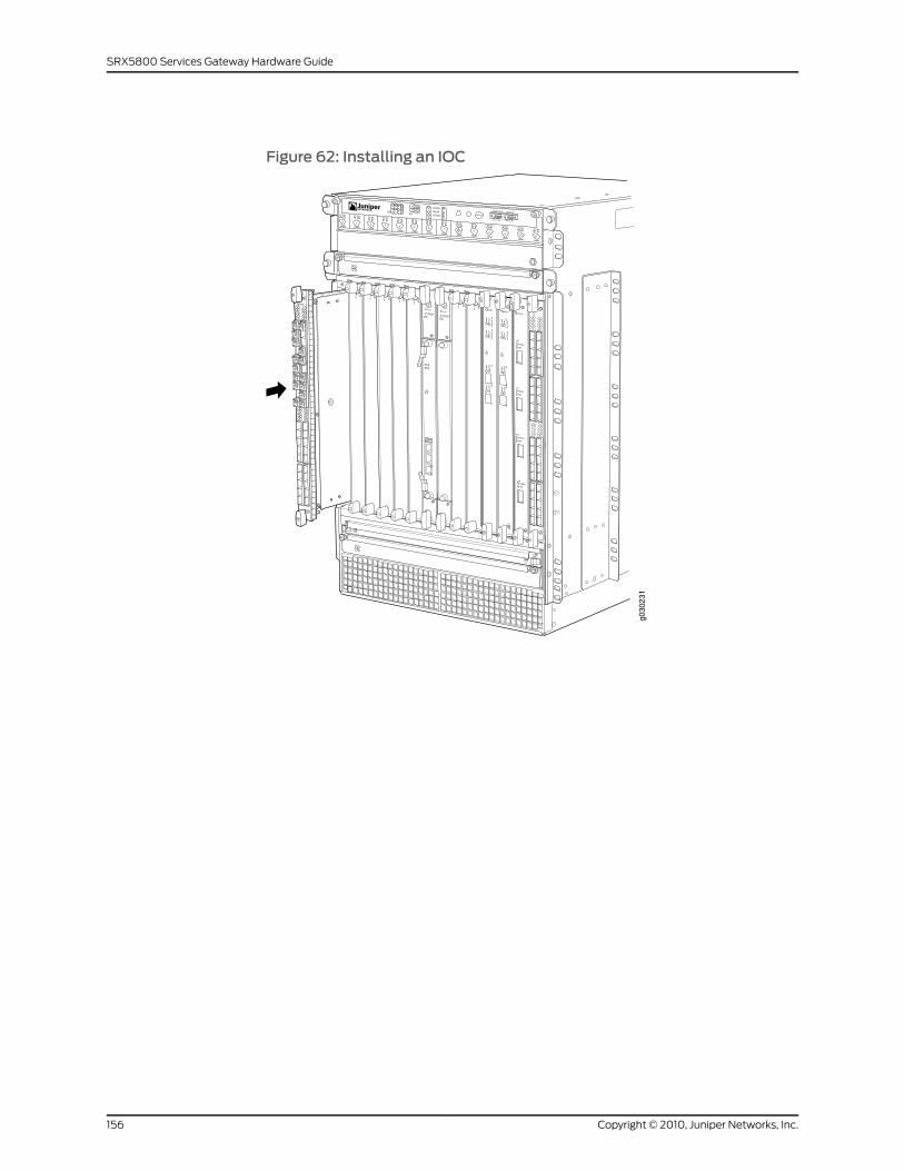
Figure 62: Installing an IOC
Copyright © 2010, Juniper Networks, Inc.156
SRX5800 Services Gateway Hardware Guide
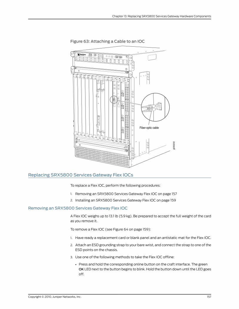
Figure 63: Attaching a Cable to an IOC
Replacing SRX5800 Services Gateway Flex IOCs
To replace a Flex IOC, perform the following procedures:
1. Removing an SRX5800 Services Gateway Flex IOC on page 157
2. Installing an SRX5800 Services Gateway Flex IOC on page 159
Removing an SRX5800 Services Gateway Flex IOC
A Flex IOC weighs up to 13.1 lb (5.9 kg). Be prepared to accept the full weight of the card
as you remove it.
To remove a Flex IOC (see Figure 64 on page 159):
1. Have ready a replacement card or blank panel and an antistatic mat for the Flex IOC.
2. Attach an ESD grounding strap to your bare wrist, and connect the strap to one of the
ESD points on the chassis.
3. Use one of the following methods to take the Flex IOC offline:
• Press and hold the corresponding online button on the craft interface. The green
OK LED next to the button begins to blink. Hold the button down until the LED goes
off.
157Copyright © 2010, Juniper Networks, Inc.
Chapter 13: Replacing SRX5800 Services Gateway Hardware Components
• Issue the following CLI command:
user@host>request chassis fpc slot slot-number offline
For more information about the command, see the JunosSystemBasics andServices
Command Reference.
4. If you have not already done so, remove the port modules installed in the Flex IOC.
5. Simultaneously turn both of the ejector handles counterclockwise to unseat the Flex
IOC.
6. Grasp the handles and slide the Flex IOC straight out of the card cage halfway.
7. Place one hand around the front of the Flex IOC and the other hand under it to support
it. Slide the Flex IOC completely out of the chassis, and place it on the antistatic mat
or in the electrostatic bag.
CAUTION: Theweight of the Flex IOC is concentrated in the back end. Beprepared to accept the full weight—up to 13.1 lb (5.9 kg)—as you slide theFlex IOC out of the chassis.
When the Flex IOC is out of the chassis, do not hold it by the ejectorhandles, bus bars, or edge connectors. They cannot support its weight.
Do not stack Flex IOCs on top of one another after removal. Place eachone individually in an electrostatic bag or on its own antistatic mat on aflat, stable surface.
8. If you are not reinstalling a replacement card into the empty slot within a short time,
install a blank panel over the slot to maintain proper airflow in the card cage.
CAUTION: After removing an IOC from the chassis, wait at least 30seconds before reinserting it, removing an IOC from a different slot, orinserting an IOC into a different slot.
Copyright © 2010, Juniper Networks, Inc.158
SRX5800 Services Gateway Hardware Guide
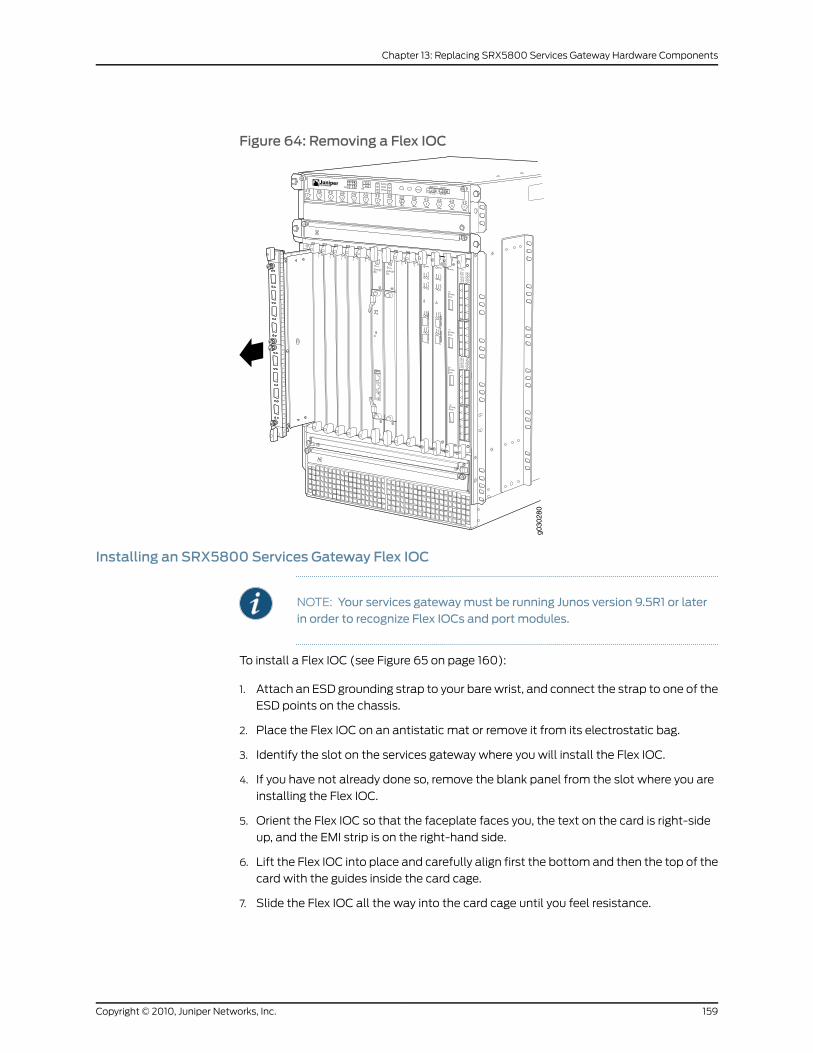
Figure 64: Removing a Flex IOC
g030
280
Installing an SRX5800 Services Gateway Flex IOC
NOTE: Your services gatewaymust be running Junos version 9.5R1 or laterin order to recognize Flex IOCs and port modules.
To install a Flex IOC (see Figure 65 on page 160):
1. Attach an ESD grounding strap to your bare wrist, and connect the strap to one of the
ESD points on the chassis.
2. Place the Flex IOC on an antistatic mat or remove it from its electrostatic bag.
3. Identify the slot on the services gateway where you will install the Flex IOC.
4. If you have not already done so, remove the blank panel from the slot where you are
installing the Flex IOC.
5. Orient the Flex IOC so that the faceplate faces you, the text on the card is right-side
up, and the EMI strip is on the right-hand side.
6. Lift the Flex IOC into place and carefully align first the bottom and then the top of the
card with the guides inside the card cage.
7. Slide the Flex IOC all the way into the card cage until you feel resistance.
159Copyright © 2010, Juniper Networks, Inc.
Chapter 13: Replacing SRX5800 Services Gateway Hardware Components
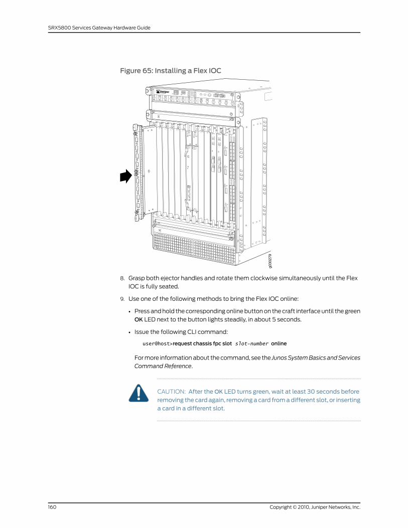
Figure 65: Installing a Flex IOC
g030
279
8. Grasp both ejector handles and rotate them clockwise simultaneously until the Flex
IOC is fully seated.
9. Use one of the following methods to bring the Flex IOC online:
• Press and hold the corresponding online button on the craft interface until the green
OK LED next to the button lights steadily, in about 5 seconds.
• Issue the following CLI command:
user@host>request chassis fpc slot slot-number online
For more information about the command, see the JunosSystemBasics andServices
Command Reference.
CAUTION: After theOK LED turns green, wait at least 30 seconds before
removing the cardagain, removinga card fromadifferent slot, or insertinga card in a different slot.
Copyright © 2010, Juniper Networks, Inc.160
SRX5800 Services Gateway Hardware Guide
Replacing SRX5800 Services Gateway Port Modules
To replace a port module, perform the following procedures:
1. Removing an SRX5800 Services Gateway Port Module on page 161
2. Installing an SRX5800 Services Gateway Port Module on page 163
Removing an SRX5800 Services Gateway Port Module
Port modules are installed in Flex IOCs in the services gateway card cage. A port module
weighs up to 3 lb (1.4 kg). Be prepared to accept its full weight when you remove or install
a port module.
To remove a port module (see Figure 66 on page 162):
1. Have ready a replacement port module or blank panel and an antistatic mat for the
port module. Also have ready rubber safety caps for each port on the port module
you are removing that uses an optical interface.
2. Attach an ESD grounding strap to your bare wrist, and connect the strap to one of the
ESD points on the chassis.
3. Label the cables connected to each port on the port module so that you can later
reconnect the cables to the correct ports.
4. Use one of the following methods to take the port module offline:
• Insert a pointed tool into the ONLINE pinhole on the front panel of the port module
to press the button behind it. Hold the button down until theOK/FAIL LED goes off.
• Issue the following CLI command:
user@host>request chassis fpc-slot slot-number pic-slot slot-number offline
For more information about the command, see the JunosSystemBasics andServices
Command Reference.
5. Disconnect the cables from the port module. If the port module uses fiber-optic cable,
immediately cover each transceiver and the end of each cable with a rubber safety
cap. Arrange the disconnected cables in the cable management system to prevent
the cables from developing stress points.
WARNING: Do not look directly into a fiber-optic transceiver or into theends of fiber-optic cables. Fiber-optic transceivers and fiber-optic cableconnected to a transceiver emit laser light that can damage your eyes.
CAUTION: Do not leave a fiber-optic transceiver uncovered except wheninserting or removing cable. The safety cap keeps the port clean andprevents accidental exposure to laser light.
161Copyright © 2010, Juniper Networks, Inc.
Chapter 13: Replacing SRX5800 Services Gateway Hardware Components
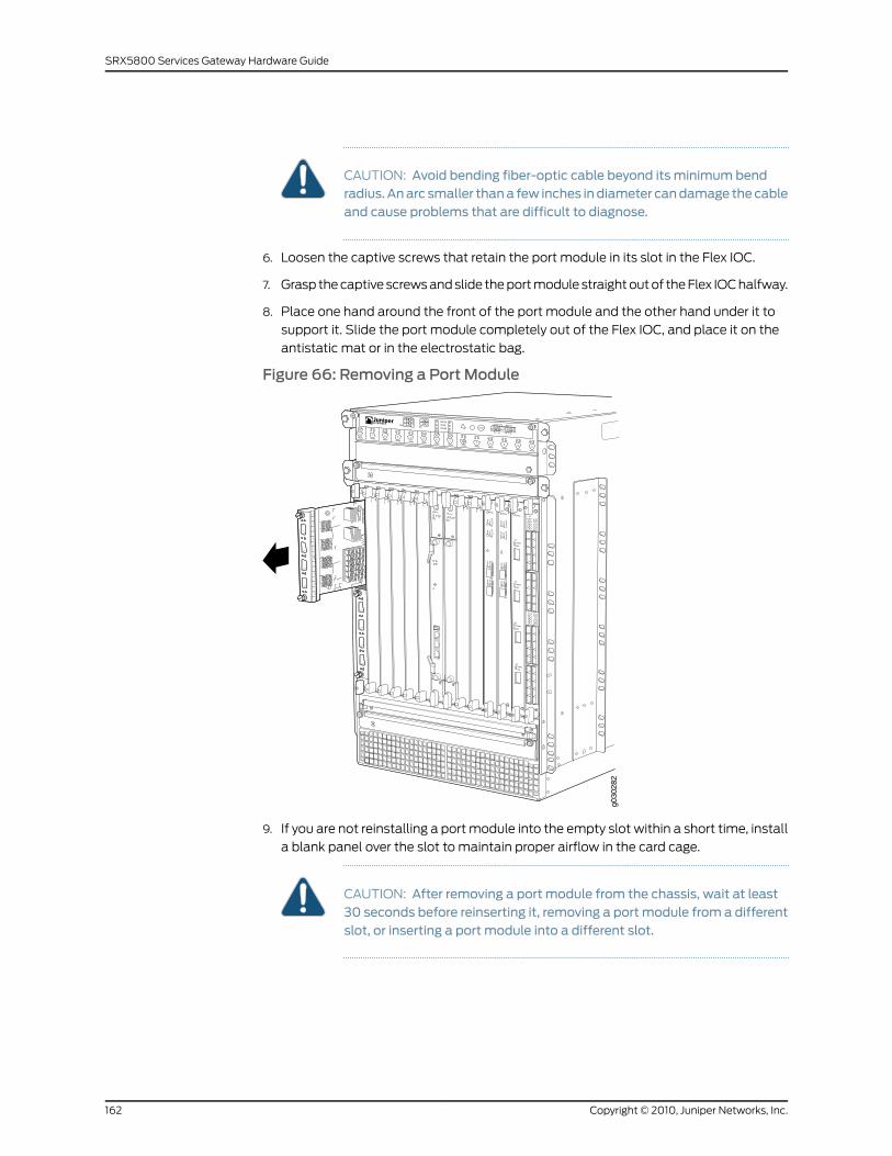
CAUTION: Avoid bending fiber-optic cable beyond its minimum bendradius.Anarc smaller thana few inches indiameter candamage thecableand cause problems that are difficult to diagnose.
6. Loosen the captive screws that retain the port module in its slot in the Flex IOC.
7. Grasp the captive screws and slide the port module straight out of the Flex IOC halfway.
8. Place one hand around the front of the port module and the other hand under it to
support it. Slide the port module completely out of the Flex IOC, and place it on the
antistatic mat or in the electrostatic bag.
Figure 66: Removing a Port Module
g030
282
9. If you are not reinstalling a port module into the empty slot within a short time, install
a blank panel over the slot to maintain proper airflow in the card cage.
CAUTION: After removing a port module from the chassis, wait at least30 seconds before reinserting it, removing a port module from a differentslot, or inserting a port module into a different slot.
Copyright © 2010, Juniper Networks, Inc.162
SRX5800 Services Gateway Hardware Guide
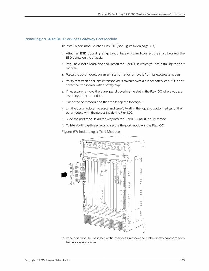
Installing an SRX5800 Services Gateway Port Module
To install a port module into a Flex IOC (see Figure 67 on page 163):
1. Attach an ESD grounding strap to your bare wrist, and connect the strap to one of the
ESD points on the chassis.
2. If you have not already done so, install the Flex IOC in which you are installing the port
module.
3. Place the port module on an antistatic mat or remove it from its electrostatic bag.
4. Verify that each fiber-optic transceiver is covered with a rubber safety cap. If it is not,
cover the transceiver with a safety cap.
5. If necessary, remove the blank panel covering the slot in the Flex IOC where you are
installing the port module.
6. Orient the port module so that the faceplate faces you.
7. Lift the port module into place and carefully align the top and bottom edges of the
port module with the guides inside the Flex IOC.
8. Slide the port module all the way into the Flex IOC until it is fully seated.
9. Tighten both captive screws to secure the port module in the Flex IOC.
Figure 67: Installing a Port Module
g030
281
10. If the port module uses fiber-optic interfaces, remove the rubber safety cap from each
transceiver and cable.
163Copyright © 2010, Juniper Networks, Inc.
Chapter 13: Replacing SRX5800 Services Gateway Hardware Components
WARNING: Do not look directly into a fiber-optic transceiver or into theends of fiber-optic cables. Fiber-optic transceivers and fiber-optic cableconnected to a transceiver emit laser light that can damage your eyes.
11. Insert the appropriate cables into the cable connector ports on each port module.
Secure the cables so that they are not supporting their own weight. Place excess cable
out of the way in a neatly coiled loop, using the cable management system. Placing
fasteners on a loop helps to maintain its shape.
CAUTION: Do not let fiber-optic cable hang free from the connector. Donot allow fastened loops of cable to dangle, which stresses the cable atthe fastening point.
CAUTION: Avoid bending fiber-optic cable beyond its minimum bendradius.Anarc smaller thana few inches indiameter candamage thecableand cause problems that are difficult to diagnose.
12. Use one of the following methods to take the port module online:
• Insert a pointed tool into the ONLINE pinhole on the front panel of the port module
to press the button behind it. Hold the button down until the OK/FAIL LED at the
opposite end of the front panel lights green steadily, in about 5 seconds.
• Issue the following CLI command:
user@host>request chassis fpc-slot slot-number pic-slot slot-number online
For more information about the command, see the JunosSystemBasics andServices
Command Reference.
CAUTION: After theOK/FAIL LED turns green, wait at least 30 seconds
before removing the port module again, removing a port module from adifferent slot, or inserting a port module in a different slot.
You can also verify that the port module is functioning correctly by issuing the
show chassis fpc and show chassis fpc pic-status commands.
Replacing an SRX5800 IOC or Port Module Cable
To replace an IOC or port module cable, perform the following procedures:
1. Removing an SRX5800 IOC or Port Module Cable on page 165
2. Installing an SRX5800 IOC or Port Module Cable on page 166
Copyright © 2010, Juniper Networks, Inc.164
SRX5800 Services Gateway Hardware Guide
Removing an SRX5800 IOC or Port Module Cable
Removing and installing IOC or port module cables does not affect services gateway
function, except that the component does not receive or transmit data while its cable is
disconnected.
To remove a fiber-optic cable from an IOC or a port module:
1. If the component connects to fiber-optic cable, have ready a rubber safety cap for
each cable and transceiver.
2. If removing all cables connected to the component, use one of the following methods
to take the component offline:
• To offline a port module:
• Press the online/offline button on the port module. Use a narrow-ended tool that
fits inside the opening that leads to the button. Press and hold the button until
the port module LED goes out (about 5 seconds).
• Issue the following CLI command:
user@host> requestchassispic fpc-slot fpc-slot pic-slot port-module-slot offline
For more information about the command, see the Junos OS System Basics and
Services Command Reference.
• To offline an IOC:
• Press and hold the corresponding online button on the craft interface. The green
OK LED next to the button begins to blink. Hold the button down until the LED
goes off.
• Issue the following CLI command:
user@host>request chassis fpc slot slot-number offline
For more information about the command, see the Junos OS System Basics and
Services Command Reference.
3. Unplug the cable from the cable connector port. If the port module uses fiber-optic
cable, immediately cover each transceiver and the end of each cable with a rubber
safety cap.
WARNING: Do not look directly into a fiber-optic transceiver or into theends of fiber-optic cables. Fiber-optic transceivers and fiber-optic cableconnected to a transceiver emit laser light that can damage your eyes.
165Copyright © 2010, Juniper Networks, Inc.
Chapter 13: Replacing SRX5800 Services Gateway Hardware Components
CAUTION: Do not leave a fiber-optic transceiver uncovered except wheninserting or removing cable. The safety cap keeps the port clean andprevents accidental exposure to laser light.
4. Remove the cable from the cable manager and detach it from the destination port.
Installing an SRX5800 IOC or Port Module Cable
To install a cable in an IOC or a port module::
1. Have ready a length of the type of cable used by the component.
2. If the cable connector port is covered by a rubber safety plug, remove the plug.
WARNING: Do not look directly into a fiber-optic transceiver or into theends of fiber-optic cables. Fiber-optic transceivers and fiber-optic cableconnected to a transceiver emit laser light that can damage your eyes.
CAUTION: Do not leave a fiber-optic transceiver uncovered except wheninserting or removing cable. The safety cap keeps the port clean andprevents accidental exposure to laser light.
3. Insert the cable connector into the cable connector port on the component faceplate.
4. Arrange the cable in the standard or extended cable manager to prevent it from
dislodging or developing stress points. Secure the cable so that it is not supporting its
own weight as it hangs to the floor. Place excess cable out of the way in a neatly coiled
loop. Placing fasteners on the loop helps to maintain its shape.
CAUTION: Avoid bending fiber-optic cable beyond its minimum bendradius.Anarc smaller thana few inches indiameter candamage thecableand cause problems that are difficult to diagnose.
CAUTION: Do not let fiber-optic cable hang free from the connector. Donot allow fastened loops of cable to dangle, which stresses the cable atthe fastening point.
5. Insert the other end of the cable into the destination port.
6. Repeat the previous steps for any additional cables.
7. If the component is offline (its failure indicator LED is lit), use one of the following
methods to bring it online.
• To bring an IOC online:
Copyright © 2010, Juniper Networks, Inc.166
SRX5800 Services Gateway Hardware Guide
• Press and hold the corresponding IOC online button on the craft interface until
the green OK LED next to the button lights steadily, in about 5 seconds.
• Issue the following CLI command:
user@host>request chassis fpc slot slot-number online
For more information about the command, see the Junos OS System Basics and
Services Command Reference.
• To bring a port module online:
• Press the port module online button until the PIC LED lights green. Use a
narrow-ended tool that fits inside the opening that leads to the button.
• Issue the following CLI command:
user@host>request chassis pic fpc-slot fpc-slot pic-slot pic-slot online
For more information about the command, see the Junos OS System Basics and
Services Command Reference.
The normal functioning indicator LED confirms that the component is online. You can
also verify correct IOC functioning by issuing the showchassis fpc command or correct
PIC functioning by issuing the show chassis fpc pic-status command.
Replacing SRX5800 Services Gateway SPCs
To replace an SPC, perform the following procedures:
1. Removing an SRX5800 Services Gateway SPC on page 167
2. Installing an SRX5800 Services Gateway SPC on page 169
Removing an SRX5800 Services Gateway SPC
An SPC weighs up to 13.1 lb (5.9 kg). Be prepared to accept its full weight.
To remove an SPC (see Figure 68 on page 169):
1. Have ready a replacement SPC or blank panel and an antistatic mat for the SPC. Also
have ready rubber safety caps for each SPC you are removing that uses an optical
interface.
2. Attach an ESD grounding strap to your bare wrist, and connect the strap to one of the
ESD points on the chassis.
3. Power-off the services gateway.
4. Label the cables connected to each port on the SPC so that you can later reconnect
the cables to the correct ports.
5. Disconnect the cables from the SPC. If the SPC uses fiber-optic cable, immediately
cover each transceiver and the end of each cable with a rubber safety cap. Arrange
the disconnected cables in the cable management system to prevent the cables from
developing stress points.
167Copyright © 2010, Juniper Networks, Inc.
Chapter 13: Replacing SRX5800 Services Gateway Hardware Components
WARNING: Do not look directly into a fiber-optic transceiver or into theends of fiber-optic cables. Fiber-optic transceivers and fiber-optic cableconnected to a transceiver emit laser light that can damage your eyes.
CAUTION: Do not leave a fiber-optic transceiver uncovered except wheninserting or removing cable. The safety cap keeps the port clean andprevents accidental exposure to laser light.
CAUTION: Avoid bending fiber-optic cable beyond its minimum bendradius.Anarc smaller thana few inches indiameter candamage thecableand cause problems that are difficult to diagnose.
CAUTION: Do not let fiber-optic cable hang free from the connector. Donot allow fastened loops of cable to dangle, which stresses the cable atthe fastening point.
6. Simultaneously turn both of the ejector handles counterclockwise to unseat the SPC.
7. Grasp the handles and slide the SPC straight out of the card cage halfway.
8. Place one hand around the front of the SPC and the other hand under it to support it.
Slide the SPC completely out of the chassis, and place it on the antistatic mat or in
the electrostatic bag.
CAUTION: The weight of the SPC is concentrated in the back end. Beprepared to accept the full weight—up to 13.1 lb (5.9 kg)—as you slide theSPC out of the chassis.
When the SPC is out of the chassis, do not hold it by the ejector handles,bus bars, or edge connectors. They cannot support its weight.
Do not stack SPCs on top of one another after removal. Place each oneindividually in an electrostatic bag or on its own antistatic mat on a flat,stable surface.
9. If you are not reinstalling an SPC into the empty slot within a short time, install a blank
panel over the slot to maintain proper airflow in the card cage.
Copyright © 2010, Juniper Networks, Inc.168
SRX5800 Services Gateway Hardware Guide
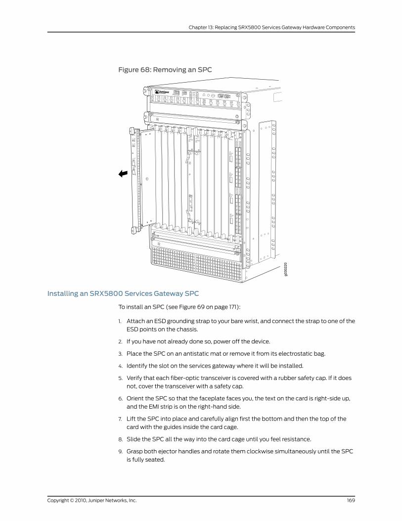
Figure 68: Removing an SPC
Installing an SRX5800 Services Gateway SPC
To install an SPC (see Figure 69 on page 171):
1. Attach an ESD grounding strap to your bare wrist, and connect the strap to one of the
ESD points on the chassis.
2. If you have not already done so, power off the device.
3. Place the SPC on an antistatic mat or remove it from its electrostatic bag.
4. Identify the slot on the services gateway where it will be installed.
5. Verify that each fiber-optic transceiver is covered with a rubber safety cap. If it does
not, cover the transceiver with a safety cap.
6. Orient the SPC so that the faceplate faces you, the text on the card is right-side up,
and the EMI strip is on the right-hand side.
7. Lift the SPC into place and carefully align first the bottom and then the top of the
card with the guides inside the card cage.
8. Slide the SPC all the way into the card cage until you feel resistance.
9. Grasp both ejector handles and rotate them clockwise simultaneously until the SPC
is fully seated.
169Copyright © 2010, Juniper Networks, Inc.
Chapter 13: Replacing SRX5800 Services Gateway Hardware Components
10. If the SPC uses fiber-optic cable, remove the rubber safety cap from each transceiver
and cable.
WARNING: Do not look directly into a fiber-optic transceiver or into theends of fiber-optic cables. Fiber-optic transceivers and fiber-optic cableconnected to a transceiver emit laser light that can damage your eyes.
11. Insert the appropriate cables into the cable connector ports on each SPC (see Figure
70 on page 172). Secure the cables so that they are not supporting their own weight.
Place excess cable out of the way in a neatly coiled loop, using the cable management
system. Placing fasteners on a loop helps to maintain its shape.
CAUTION: Do not let fiber-optic cable hang free from the connector. Donot allow fastened loops of cable to dangle, which stresses the cable atthe fastening point.
CAUTION: Avoid bending fiber-optic cable beyond its minimum bendradius.Anarc smaller thana few inches indiameter candamage thecableand cause problems that are difficult to diagnose.
12. Power-on the services gateway.
13. Verify that the SPC is functioning correctly by issuing the show chassis fpc and
show chassis fpc pic-status commands.
Copyright © 2010, Juniper Networks, Inc.170
SRX5800 Services Gateway Hardware Guide
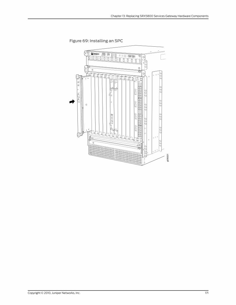
Figure 69: Installing an SPC
171Copyright © 2010, Juniper Networks, Inc.
Chapter 13: Replacing SRX5800 Services Gateway Hardware Components
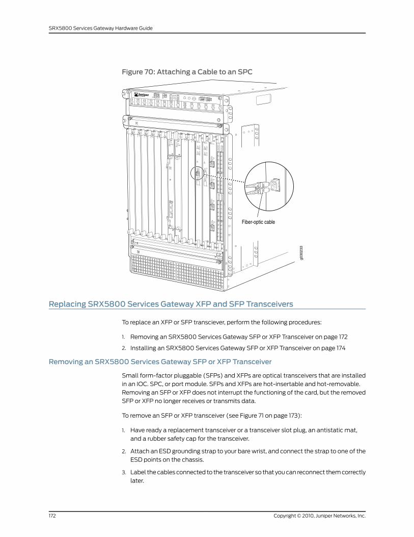
Figure 70: Attaching a Cable to an SPC
Replacing SRX5800 Services Gateway XFP and SFP Transceivers
To replace an XFP or SFP transciever, perform the following procedures:
1. Removing an SRX5800 Services Gateway SFP or XFP Transceiver on page 172
2. Installing an SRX5800 Services Gateway SFP or XFP Transceiver on page 174
Removing an SRX5800 Services Gateway SFP or XFP Transceiver
Small form-factor pluggable (SFPs) and XFPs are optical transceivers that are installed
in an IOC. SPC, or port module. SFPs and XFPs are hot-insertable and hot-removable.
Removing an SFP or XFP does not interrupt the functioning of the card, but the removed
SFP or XFP no longer receives or transmits data.
To remove an SFP or XFP transceiver (see Figure 71 on page 173):
1. Have ready a replacement transceiver or a transceiver slot plug, an antistatic mat,
and a rubber safety cap for the transceiver.
2. Attach an ESD grounding strap to your bare wrist, and connect the strap to one of the
ESD points on the chassis.
3. Label the cables connected to the transceiver so that you can reconnect them correctly
later.
Copyright © 2010, Juniper Networks, Inc.172
SRX5800 Services Gateway Hardware Guide
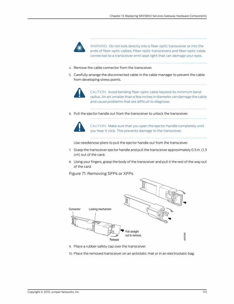
WARNING: Do not look directly into a fiber-optic transceiver or into theends of fiber-optic cables. Fiber-optic transceivers and fiber-optic cableconnected to a transceiver emit laser light that can damage your eyes.
4. Remove the cable connector from the transceiver.
5. Carefully arrange the disconnected cable in the cable manager to prevent the cable
from developing stress points.
CAUTION: Avoid bending fiber-optic cable beyond its minimum bendradius.Anarc smaller thana few inches indiameter candamage thecableand cause problems that are difficult to diagnose.
6. Pull the ejector handle out from the transceiver to unlock the transceiver.
CAUTION: Make sure that you open the ejector handle completely untilyou hear it click. This prevents damage to the transceiver.
Use needlenose pliers to pull the ejector handle out from the transceiver.
7. Grasp the transceiver ejector handle and pull the transceiver approximately 0.5 in. (1.3
cm) out of the card.
8. Using your fingers, grasp the body of the transceiver and pull it the rest of the way out
of the card.
Figure 71: Removing SFPs or XFPs
9. Place a rubber safety cap over the transceiver.
10. Place the removed transceiver on an antistatic mat or in an electrostatic bag.
173Copyright © 2010, Juniper Networks, Inc.
Chapter 13: Replacing SRX5800 Services Gateway Hardware Components
CAUTION: After removing a transceiver from the card, wait at least 30seconds before reinserting it or inserting a transceiver into a different socket.
Installing an SRX5800 Services Gateway SFP or XFP Transceiver
Small form-factor pluggable (SFPs) and XFPs are optical transceivers that are installed
in an IOC, SPC, or port module. SFPs and XFPs are hot-insertable and hot-removable.
Removing an SFP or XFP does not interrupt the functioning of the card, but the removed
SFP or XFP no longer receives or transmits data.
NOTE: Juniper strongly recommends the use of Juniper transceivers. Junipercannot guarantee correct operation if non-Juniper transceivers are used. Thetransceiver type can be different in each port, as long as a supported partnumber is used.
To install an SFP or XFP:
1. Attach an ESD grounding strap to your bare wrist, and connect the strap to one of the
ESD points on the chassis.
2. Take each transceiver to be installed out of its electrostatic bag and identify the slot
on the component where it will be installed.
3. Verify that each transceiver is covered by a rubber safety cap. If it is not, cover the
transceiver with a safety cap.
4. Carefully align the transceiver with the slots in the component. The connectors should
face the component.
5. Slide the transceiver until the connector is seated in the component slot. If you are
unable to fully insert the transceiver, make sure the connector is facing the right way.
6. Close the ejector handle of the transceiver.
7. Remove the rubber safety cap from the transceiver and the end of the cable. Insert
the cable into the transceiver.
8. Verify that the status LEDs on the component faceplate indicate that the SFP or XFP
is functioning correctly.
Replacing an SRX5800 Services Gateway AC Power Supply
To replace an AC power supply, perform the following procedures:
1. Removing an SRX5800 Services Gateway AC Power Supply on page 174
2. Installing an SRX5800 Services Gateway AC Power Supply on page 177
Removing an SRX5800 Services Gateway AC Power Supply
Before you remove a power supply, be aware of the following:
Copyright © 2010, Juniper Networks, Inc.174
SRX5800 Services Gateway Hardware Guide
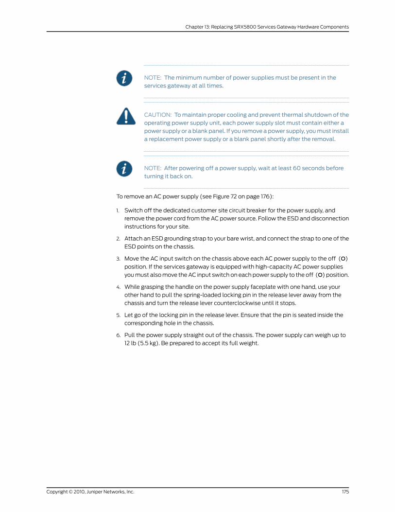
NOTE: Theminimum number of power supplies must be present in theservices gateway at all times.
CAUTION: Tomaintain proper cooling and prevent thermal shutdown of theoperating power supply unit, each power supply slot must contain either apower supply or a blankpanel. If you removeapower supply, youmust installa replacement power supply or a blank panel shortly after the removal.
NOTE: After powering off a power supply, wait at least 60 seconds beforeturning it back on.
To remove an AC power supply (see Figure 72 on page 176):
1. Switch off the dedicated customer site circuit breaker for the power supply, and
remove the power cord from the AC power source. Follow the ESD and disconnection
instructions for your site.
2. Attach an ESD grounding strap to your bare wrist, and connect the strap to one of the
ESD points on the chassis.
3. Move the AC input switch on the chassis above each AC power supply to the off (O)
position. If the services gateway is equipped with high-capacity AC power supplies
you must also move the AC input switch on each power supply to the off (O) position.
4. While grasping the handle on the power supply faceplate with one hand, use your
other hand to pull the spring-loaded locking pin in the release lever away from the
chassis and turn the release lever counterclockwise until it stops.
5. Let go of the locking pin in the release lever. Ensure that the pin is seated inside the
corresponding hole in the chassis.
6. Pull the power supply straight out of the chassis. The power supply can weigh up to
12 lb (5.5 kg). Be prepared to accept its full weight.
175Copyright © 2010, Juniper Networks, Inc.
Chapter 13: Replacing SRX5800 Services Gateway Hardware Components
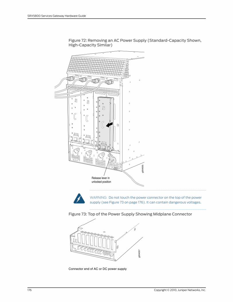
Figure 72: Removing an AC Power Supply (Standard-Capacity Shown,High-Capacity Similar)
WARNING: Do not touch the power connector on the top of the powersupply (see Figure 73 on page 176). It can contain dangerous voltages.
Figure 73: Top of the Power Supply ShowingMidplane Connector
g004
057
Connector end of AC or DC power supply
Copyright © 2010, Juniper Networks, Inc.176
SRX5800 Services Gateway Hardware Guide
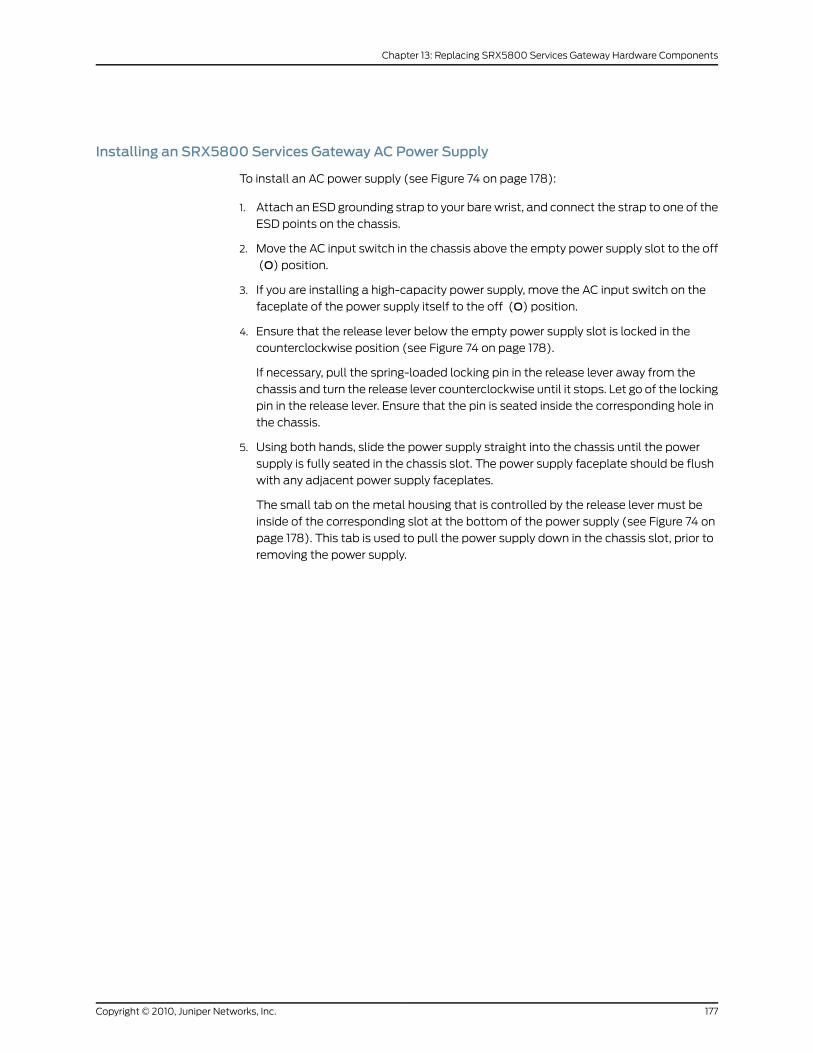
Installing an SRX5800 Services Gateway AC Power Supply
To install an AC power supply (see Figure 74 on page 178):
1. Attach an ESD grounding strap to your bare wrist, and connect the strap to one of the
ESD points on the chassis.
2. Move the AC input switch in the chassis above the empty power supply slot to the off
(O) position.
3. If you are installing a high-capacity power supply, move the AC input switch on the
faceplate of the power supply itself to the off (O) position.
4. Ensure that the release lever below the empty power supply slot is locked in the
counterclockwise position (see Figure 74 on page 178).
If necessary, pull the spring-loaded locking pin in the release lever away from the
chassis and turn the release lever counterclockwise until it stops. Let go of the locking
pin in the release lever. Ensure that the pin is seated inside the corresponding hole in
the chassis.
5. Using both hands, slide the power supply straight into the chassis until the power
supply is fully seated in the chassis slot. The power supply faceplate should be flush
with any adjacent power supply faceplates.
The small tab on the metal housing that is controlled by the release lever must be
inside of the corresponding slot at the bottom of the power supply (see Figure 74 on
page 178). This tab is used to pull the power supply down in the chassis slot, prior to
removing the power supply.
177Copyright © 2010, Juniper Networks, Inc.
Chapter 13: Replacing SRX5800 Services Gateway Hardware Components
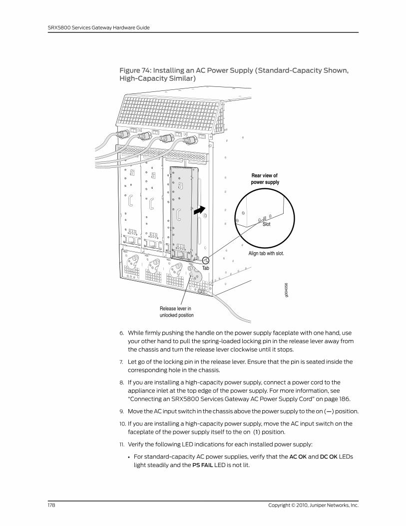
Figure 74: Installing an AC Power Supply (Standard-Capacity Shown,High-Capacity Similar)
6. While firmly pushing the handle on the power supply faceplate with one hand, use
your other hand to pull the spring-loaded locking pin in the release lever away from
the chassis and turn the release lever clockwise until it stops.
7. Let go of the locking pin in the release lever. Ensure that the pin is seated inside the
corresponding hole in the chassis.
8. If you are installing a high-capacity power supply, connect a power cord to the
appliance inlet at the top edge of the power supply. For more information, see
“Connecting an SRX5800 Services Gateway AC Power Supply Cord” on page 186.
9. Move the AC input switch in the chassis above the power supply to the on (—) position.
10. If you are installing a high-capacity power supply, move the AC input switch on the
faceplate of the power supply itself to the on (1) position.
11. Verify the following LED indications for each installed power supply:
• For standard-capacity AC power supplies, verify that the ACOK and DCOK LEDs
light steadily and the PS FAIL LED is not lit.
Copyright © 2010, Juniper Networks, Inc.178
SRX5800 Services Gateway Hardware Guide
• For high-capacity AC power supplies, verify that the DCOK LED lights steadily and
the PS FAIL LED is not lit. In addition, the AC-1 OK LED should light green steadily if
the upper AC feed (on the chassis above the power supply) is connected and
receiving power, and the AC-2 OK LED should light green steadily if the lower AC
feed (on the power supply itself) is connected and receiving power.
NOTE: After a power supply is powered on, it can take up to 60 secondsfor status indicators—such as the status LEDs on the power supply andthe show chassis command display—to indicate that the power supply isfunctioning normally. Ignore error indicators that appear during the first60 seconds.
If any of the status LEDs indicates that the power supply is not functioning normally,
repeat the installation and cabling procedures.
Upgrading an SRX5800 Services Gateway fromStandard-Capacity to High-CapacityAC Power Supplies
You can replace the standard-capacity AC power supplies in the SRX5800 Services
Gateway with either two or four high-capacity AC power supplies. Two high-capacity AC
power supplies provide adequate power for a fully loaded chassis; installing four
high-capacity AC power supplies provides redundancy in case one power supply in either
zone fails. You do not need to power off the device to upgrade to high-capacity AC power
supplies.
NOTE: The services gateway cannot be powered from standard-capacityand high-capacity AC power supplies simultaneously. The one exception isduring the process of replacing standard-capacity AC power supplies withhigh-capacity AC power supplies, when it is permissible to have both typesinstalled briefly.
To upgrade an operational SRX5800 Services Gateway from standard-capacity power
supplies to high-capacity power supplies:
1. Remove the power supply, if any, in slotPEM0, as described in “Removing an SRX5800
Services Gateway AC Power Supply” on page 174.
2. Install a high-capacity AC power supply in slot PEM0, as described in “Installing an
SRX5800 Services Gateway AC Power Supply” on page 177.
3. Repeat steps 1 through 2 for slot PEM1.
4. Remove the power supply, if any, in slotPEM2, as described in “Removing an SRX5800
Services Gateway AC Power Supply” on page 174.
5. If you are installing four high-capacity power supplies, install a high-capacity AC power
supply in slot PEM2, as described in “Installing an SRX5800 Services Gateway AC
179Copyright © 2010, Juniper Networks, Inc.
Chapter 13: Replacing SRX5800 Services Gateway Hardware Components
Power Supply” on page 177. If you are installing only two high-capacity power supplies,
install a blank slot cover over the PEM2 slot.
6. Repeat steps 4 through 5 for slot PEM3.
RelatedDocumentation
Removing an SRX5800 Services Gateway AC Power Supply on page 174•
• Installing an SRX5800 Services Gateway AC Power Supply on page 177
Replacing an SRX5800 Services Gateway DC Power Supply
To replace a DC power supply, perform the following procedures:
1. Removing an SRX5800 Services Gateway DC Power Supply on page 180
2. Installing an SRX5800 Services Gateway DC Power Supply on page 183
Removing an SRX5800 Services Gateway DC Power Supply
Before you remove a power supply, be aware of the following:
NOTE: Theminimum number of power supplies must be present in theservices gateway at all times.
WARNING: Before performing DC power procedures, ensure that power isremoved from theDC circuit. To ensure that all power is off, locate the circuitbreaker on the panel board that services the DC circuit, switch the circuitbreaker to the off position, and tape the switch handle of the circuit breakerin the off position.
CAUTION: Tomaintain proper cooling and prevent thermal shutdown of theoperating power supply unit, each power supply slot must contain either apower supply or a blankpanel. If you removeapower supply, youmust installa replacement power supply or a blank panel shortly after the removal.
NOTE: After powering off a power supply, wait at least 60 seconds beforeturning it back on.
To remove a DC power supply (see Figure 75 on page 182):
1. Switch off the dedicated customer site circuit breaker for the power supply being
removed. Follow your site's procedures for ESD.
2. Make sure that the voltage across the DC power source cable leads is 0 V and that
there is no chance that the cables might become active during the removal process.
Copyright © 2010, Juniper Networks, Inc.180
SRX5800 Services Gateway Hardware Guide

3. Verify that the INPUTOK LEDs on the power supply to be removed are not lit.
4. Attach an ESD grounding strap to your bare wrist, and connect the strap to one of the
ESD points on the chassis.
5. Move the DC circuit breaker on the power supply faceplate to the off (O) position.
6. Remove the clear plastic cover protecting the terminal studs on the faceplate.
7. Remove the nuts and washers from the terminal studs. (Use a 7/16-in. nut driver or
socket wrench.)
8. Remove the cable lugs from the terminal studs.
9. Loosen the captive screw on the cable restraint on the lower edge of the power supply
faceplate.
10. Carefully move the power cables out of the way.
11. While grasping the handle on the power supply faceplate with one hand, use your
other hand to pull the spring-loaded locking pin in the release lever away from the
chassis and turn the release lever counterclockwise until it stops.
12. Let go of the locking pin in the release lever. Ensure that the pin is seated inside the
corresponding hole in the chassis.
13. Pull the power supply straight out of the chassis. The power supply can weigh up to
5 lb (2.3 kg). Be prepared to accept its full weight.
181Copyright © 2010, Juniper Networks, Inc.
Chapter 13: Replacing SRX5800 Services Gateway Hardware Components
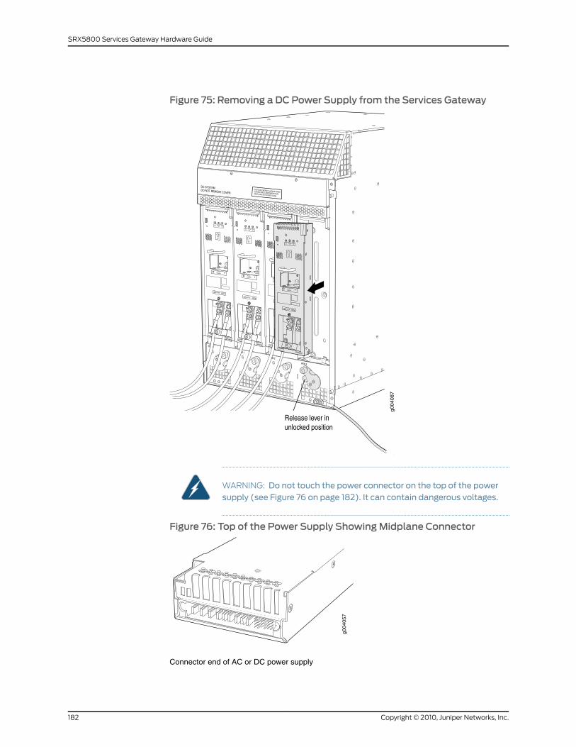
Figure 75: Removing a DC Power Supply from the Services Gateway
WARNING: Do not touch the power connector on the top of the powersupply (see Figure 76 on page 182). It can contain dangerous voltages.
Figure 76: Top of the Power Supply ShowingMidplane Connector
g004
057
Connector end of AC or DC power supply
Copyright © 2010, Juniper Networks, Inc.182
SRX5800 Services Gateway Hardware Guide
Installing an SRX5800 Services Gateway DC Power Supply
WARNING: Before performing DC power procedures, ensure that power isremoved from theDC circuit. To ensure that all power is off, locate the circuitbreaker on the panel board that services the DC circuit, switch the circuitbreaker to the off position, and tape the switch handle of the circuit breakerin the off position.
To install a DC power supply (see Figure 77 on page 184):
1. Ensure that the voltage across the DC power source cable leads is 0 V and that there
is no chance that the cable leads might become active during installation.
2. Attach an ESD grounding strap to your bare wrist, and connect the strap to one of the
ESD points on the chassis.
3. Move the DC circuit breaker on the power supply faceplate to the off (O) position.
4. Ensure that the release lever below the empty power supply slot is locked in the
counterclockwise position (see Figure 77 on page 184).
If necessary, pull the spring-loaded locking pin in the release lever away from the
chassis and turn the release lever counterclockwise until it stops. Let go of the locking
pin in the release lever. Ensure that the pin is seated inside the corresponding hole in
the chassis.
5. Using both hands, slide the power supply straight into the chassis until the power
supply is fully seated in the chassis slot. The power supply faceplate should be flush
with any adjacent power supply faceplates.
The small tab on the metal housing that is controlled by the release lever must be
inside of the corresponding slot at the bottom of the power supply (see Figure 77 on
page 184). This tab is used to pull the power supply down in the chassis slot, prior to
removing the power supply.
183Copyright © 2010, Juniper Networks, Inc.
Chapter 13: Replacing SRX5800 Services Gateway Hardware Components
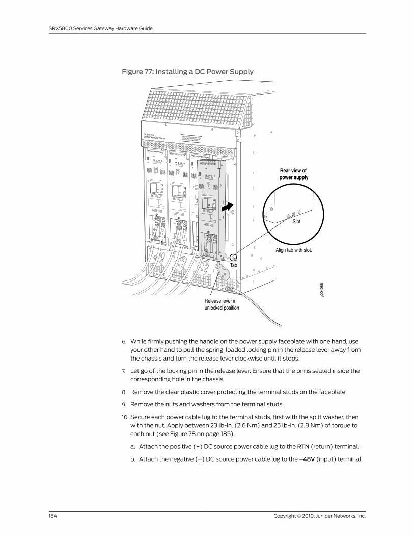
Figure 77: Installing a DC Power Supply
6. While firmly pushing the handle on the power supply faceplate with one hand, use
your other hand to pull the spring-loaded locking pin in the release lever away from
the chassis and turn the release lever clockwise until it stops.
7. Let go of the locking pin in the release lever. Ensure that the pin is seated inside the
corresponding hole in the chassis.
8. Remove the clear plastic cover protecting the terminal studs on the faceplate.
9. Remove the nuts and washers from the terminal studs.
10. Secure each power cable lug to the terminal studs, first with the split washer, then
with the nut. Apply between 23 lb-in. (2.6 Nm) and 25 lb-in. (2.8 Nm) of torque to
each nut (see Figure 78 on page 185).
a. Attach the positive (+) DC source power cable lug to the RTN (return) terminal.
b. Attach the negative (–) DC source power cable lug to the –48V (input) terminal.
Copyright © 2010, Juniper Networks, Inc.184
SRX5800 Services Gateway Hardware Guide
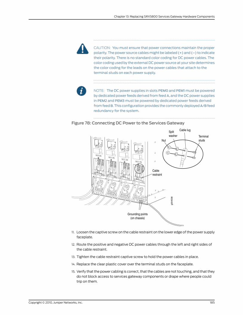
CAUTION: Youmust ensure that power connectionsmaintain the properpolarity. The power source cablesmight be labeled (+)and (–) to indicate
their polarity. There is no standard color coding for DC power cables. Thecolor coding usedby the externalDCpower source at your site determinesthe color coding for the leads on the power cables that attach to theterminal studs on each power supply.
NOTE: The DC power supplies in slots PEM0 and PEM1must be powered
bydedicatedpower feedsderived from feedA, and theDCpower supplies
in PEM2 and PEM3must be powered by dedicated power feeds derived
fromfeedB. This configurationprovides thecommonlydeployedA/B feed
redundancy for the system.
Figure 78: Connecting DC Power to the Services Gateway
11. Loosen the captive screw on the cable restraint on the lower edge of the power supply
faceplate.
12. Route the positive and negative DC power cables through the left and right sides of
the cable restraint.
13. Tighten the cable restraint captive screw to hold the power cables in place.
14. Replace the clear plastic cover over the terminal studs on the faceplate.
15. Verify that the power cabling is correct, that the cables are not touching, and that they
do not block access to services gateway components or drape where people could
trip on them.
185Copyright © 2010, Juniper Networks, Inc.
Chapter 13: Replacing SRX5800 Services Gateway Hardware Components
16. Switch on the dedicated customer site circuit breaker.
17. Verify that the INPUTOK LED on the power suppply is lit steadily.
18. Move the DC circuit breaker on the DC power supply to the on (|) position .
19. Verify that the BREAKERON LED is lit steadily.
20. Verify that the PWROK LED is lit steadily.
Replacing an SRX5800 Services Gateway AC Power Supply Cord
To replace an SRX5800 Services Gateway AC power supply cord, perform the following
procedures:
1. Disconnecting an SRX5800 Services Gateway AC Power Supply Cord on page 186
2. Connecting an SRX5800 Services Gateway AC Power Supply Cord on page 186
Disconnecting an SRX5800 Services Gateway AC Power Supply Cord
To disconnect an AC power cord:
1. Attach an ESD grounding strap to your bare wrist, and connect the strap to one of the
ESD points on the chassis.
2. Move the AC input switch nearest to the appliance inlet for the power cord you are
replacing to the off (O) position:
• For standard-capacity AC power supplies, there is only one AC input switch for each
power supply; it is located next to the appliance inlet on the chassis above the power
supply.
• For high-capacity AC power supplies, there is one AC input switch for each of the
two appliance inlets. One is located next to the AC inlet on the chassis above the
power supply, and the other is located next to the appliance inlet on the power
supply itself.
3. Unplug the power cord from the power source receptacle.
4. Unplug the power cord from the appliance inlet on the chassis or power supply.
Connecting an SRX5800 Services Gateway AC Power Supply Cord
NOTE: Power cords are not supplied with the services gateway. Youmustorder the power cords separately.
To connect an AC power cord:
1. Locate a replacement power cord with the type of plug appropriate for your
geographical location.
2. Attach an ESD grounding strap to your bare wrist, and connect the strap to one of the
ESD points on the chassis.
Copyright © 2010, Juniper Networks, Inc.186
SRX5800 Services Gateway Hardware Guide
3. Verify that the AC input switch nearest to the appliance inlet for the power cord you
are replacing is in the off (O) position:
• For standard-capacity AC power supplies, there is only one AC input switch for each
power supply; it is located next to the appliance inlet on the chassis above the power
supply.
• For high-capacity AC power supplies, there is one AC input switch for each of the
two appliance inlets. One switch is located next to the AC inlet on the chassis above
the power supply, and the other is located next to the appliance inlet on the power
supply itself.
4. Plug the replacement power cord into the corresponding appliance inlet located in
the chassis directly above the power supply, or, in the case of a high-capacity AC
power supply, at the top edge of the power supply itself.
5. Insert the power cord plug into an external AC power source receptacle.
NOTE: Each power supply must be connected to a dedicated AC powerfeed and a dedicated customer site circuit breaker. We recommend thatyou use a 15 A (250 VAC)minimum, or as required by local code.
6. Dress the power cord appropriately. Verify that the power cord does not block the air
exhaust and access to services gateway components, or drape where people could
trip on it.
7. Move the AC input switch nearest to the appliance inlet for the power cord you are
replacing to the on (|) position:
• For standard-capacity AC power supplies, there is only one AC input switch for each
power supply; it is located next to the appliance inlet on the chassis above the power
supply.
• For high-capacity AC power supplies, there is one AC input switch for each of the
two appliance inlets. One is located next to the AC inlet on the chassis above the
power supply, and the other is located next to the appliance inlet on the power
supply itself.
8. Verify the following LED indications for the power supply for which you replaced the
power cord:
• For standard-capacity AC power supplies, verify that the ACOK and DCOK LEDs
light steadily and the PS FAIL LED is not lit.
• For high-capacity AC power supplies, verify that the DCOK LED lights steadily and
the PS FAIL LED is not lit. In addition, the AC-1 OK LED should light green steadily if
the upper AC feed (on the chassis above the power supply) is connected and
receiving power, and the AC-2 OK LED should light green steadily if the lower AC
feed (on the power supply itself) is connected and receiving power.
If any of the status LEDs indicates that the power supply is not functioning normally,
repeat the installation and cabling procedures.
187Copyright © 2010, Juniper Networks, Inc.
Chapter 13: Replacing SRX5800 Services Gateway Hardware Components
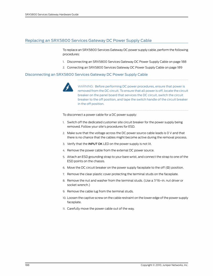
Replacing an SRX5800 Services Gateway DC Power Supply Cable
To replace an SRX5800 Services Gateway DC power supply cable, perform the following
procedures:
1. Disconnecting an SRX5800 Services Gateway DC Power Supply Cable on page 188
2. Connecting an SRX5800 Services Gateway DC Power Supply Cable on page 189
Disconnecting an SRX5800 Services Gateway DC Power Supply Cable
WARNING: Before performing DC power procedures, ensure that power isremoved from theDC circuit. To ensure that all power is off, locate the circuitbreaker on the panel board that services the DC circuit, switch the circuitbreaker to the off position, and tape the switch handle of the circuit breakerin the off position.
To disconnect a power cable for a DC power supply:
1. Switch off the dedicated customer site circuit breaker for the power supply being
removed. Follow your site's procedures for ESD.
2. Make sure that the voltage across the DC power source cable leads is 0 V and that
there is no chance that the cables might become active during the removal process.
3. Verify that the INPUTOK LED on the power supply is not lit.
4. Remove the power cable from the external DC power source.
5. Attach an ESD grounding strap to your bare wrist, and connect the strap to one of the
ESD points on the chassis.
6. Move the DC circuit breaker on the power supply faceplate to the off (O) position.
7. Remove the clear plastic cover protecting the terminal studs on the faceplate.
8. Remove the nut and washer from the terminal studs. (Use a 7/16–in. nut driver or
socket wrench.)
9. Remove the cable lug from the terminal studs.
10. Loosen the captive screw on the cable restraint on the lower edge of the power supply
faceplate.
11. Carefully move the power cable out of the way.
Copyright © 2010, Juniper Networks, Inc.188
SRX5800 Services Gateway Hardware Guide
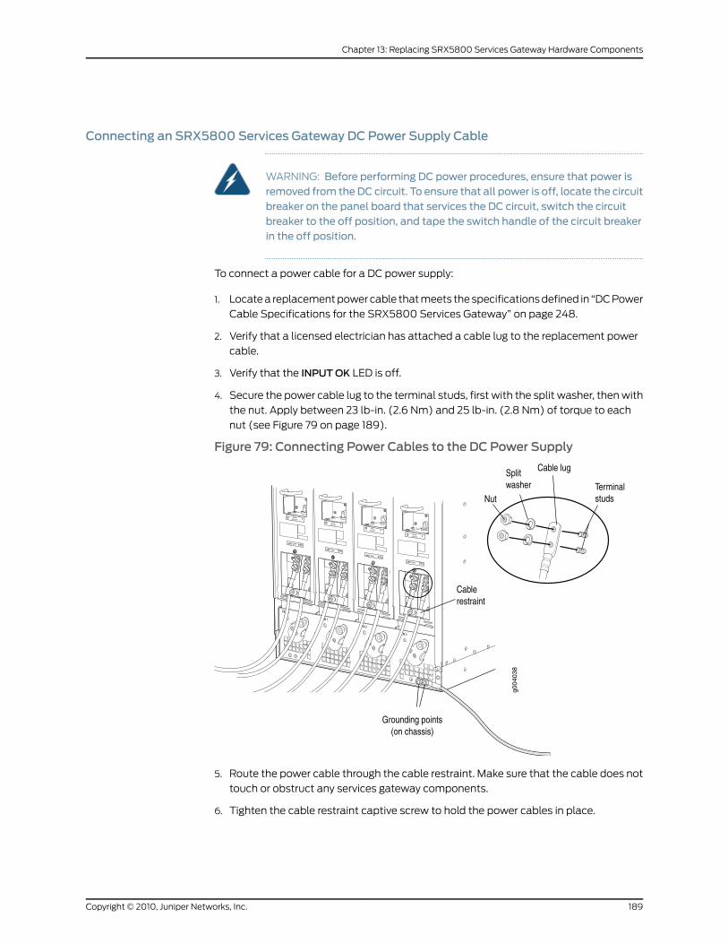
Connecting an SRX5800 Services Gateway DC Power Supply Cable
WARNING: Before performing DC power procedures, ensure that power isremoved from theDC circuit. To ensure that all power is off, locate the circuitbreaker on the panel board that services the DC circuit, switch the circuitbreaker to the off position, and tape the switch handle of the circuit breakerin the off position.
To connect a power cable for a DC power supply:
1. Locate a replacement power cable that meets the specifications defined in “DC Power
Cable Specifications for the SRX5800 Services Gateway” on page 248.
2. Verify that a licensed electrician has attached a cable lug to the replacement power
cable.
3. Verify that the INPUTOK LED is off.
4. Secure the power cable lug to the terminal studs, first with the split washer, then with
the nut. Apply between 23 lb-in. (2.6 Nm) and 25 lb-in. (2.8 Nm) of torque to each
nut (see Figure 79 on page 189).
Figure 79: Connecting Power Cables to the DC Power Supply
5. Route the power cable through the cable restraint. Make sure that the cable does not
touch or obstruct any services gateway components.
6. Tighten the cable restraint captive screw to hold the power cables in place.
189Copyright © 2010, Juniper Networks, Inc.
Chapter 13: Replacing SRX5800 Services Gateway Hardware Components
7. Verify that the DC power cable is connected correctly, that it does not touch or block
access to services gateway components, and that it does not drape where people
could trip on it.
8. Replace the clear plastic cover over the terminal studs on the faceplate.
9. Attach the power cable to the DC power source.
10. Turn on the dedicated customer site circuit breaker to the power supply.
11. Verify that the INPUTOK LED on the power supply is lit steadily.
12. Move the DC circuit breaker on the power supply to the on (|) position and observe
the status LEDs on the power supply faceplate. If the power supply is correctly installed
and functioning normally, the PWROK, BRKRON, and INPUTOK LEDs light green
steadily.
Replacing the SRX5800 Services Gateway Cable Manager
To replace the cable manager, perform the following procedures:
1. Removing the SRX5800 Services Gateway Cable Manager on page 190
2. Installing the SRX5800 Services Gateway Cable Manager on page 191
Removing the SRX5800 Services Gateway Cable Manager
To remove the cable manager (see Figure 80 on page 191):
1. Attach an ESD grounding strap to your bare wrist, and connect the strap to one of the
ESD points on the chassis.
2. Using a 7/16-in. nut driver, unscrew the nuts on the corners of the cable manager.
3. Grasp the bottom of the cable manager and pull it straight out from the studs on the
front of the chassis.
Copyright © 2010, Juniper Networks, Inc.190
SRX5800 Services Gateway Hardware Guide
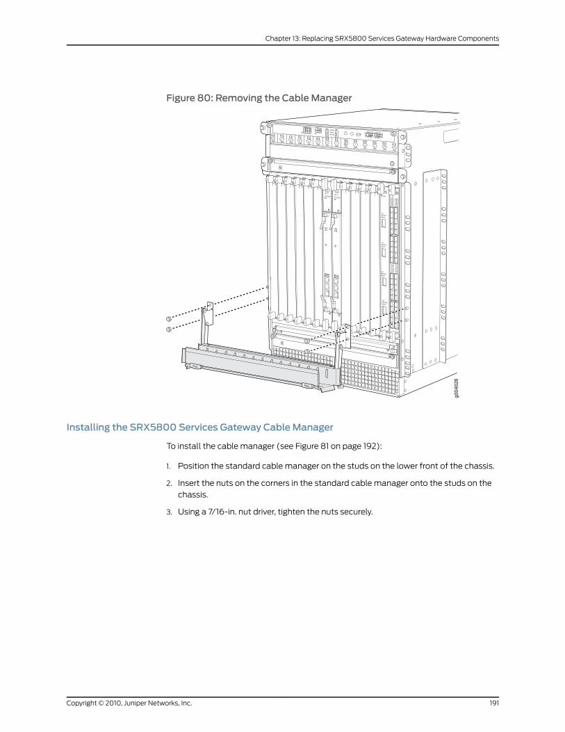
Figure 80: Removing the Cable Manager
Installing the SRX5800 Services Gateway Cable Manager
To install the cable manager (see Figure 81 on page 192):
1. Position the standard cable manager on the studs on the lower front of the chassis.
2. Insert the nuts on the corners in the standard cable manager onto the studs on the
chassis.
3. Using a 7/16-in. nut driver, tighten the nuts securely.
191Copyright © 2010, Juniper Networks, Inc.
Chapter 13: Replacing SRX5800 Services Gateway Hardware Components
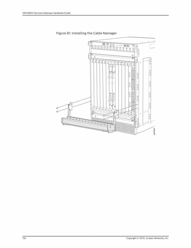
Figure 81: Installing the Cable Manager
Copyright © 2010, Juniper Networks, Inc.192
SRX5800 Services Gateway Hardware Guide
PART 4
Appendixes
• Safety and Regulatory Compliance Information on page 195
• SRX5800 Services Gateway Environmental Specifications on page 233
• SRX5800 Services Gateway Power Guidelines, Requirements, and
Specifications on page 235
• Cable and Wire Guidelines and Specifications for the SRX5800 Services
Gateway on page 251
• Cable Connector Pinouts on page 257
• Installing the SRX5800 Services Gateway Without a Mechanical Lift on page 259
• Contacting Customer Support and Returning the SRX5800 Services Gateway
Hardware on page 279
193Copyright © 2010, Juniper Networks, Inc.

Copyright © 2010, Juniper Networks, Inc.194
SRX5800 Services Gateway Hardware Guide

APPENDIX A
Safety and Regulatory ComplianceInformation
This section includes the following topics:
• SRX5800 Services Gateway Definition of Safety Warning Levels on page 195
• SRX5800 Services Gateway General Safety Guidelines and Warnings on page 197
• Additional SRX5800 Services Gateway Warnings on page 198
• Preventing Electrostatic Discharge Damage to the SRX5800 Services
Gateway on page 201
• SRX5800 Services Gateway Fire Safety Requirements and Fire Suppression
Equipment on page 203
• SRX5800 Services Gateway Installation Safety Guidelines and Warnings on page 204
• SRX5800 Services Gateway Laser and LED Safety Guidelines and Warnings on page 210
• SRX5800 Services Gateway Maintenance and Operational Safety Guidelines and
Warnings on page 214
• SRX5800 Services Gateway Electrical Safety Guidelines and Warnings on page 219
• SRX5800 Services Gateway Agency Approvals on page 230
• SRX5800 Services Gateway Compliance Statements for EMC Requirements on page 231
SRX5800 Services Gateway Definition of SafetyWarning Levels
This guide uses the following levels of safety warnings:
NOTE: Youmight find this information helpful in a particular situation ormight otherwise overlook it.
CAUTION: You need to observe the specified guidelines to avoidminor injuryor discomfort to you or severe damage to the services gateway.
195Copyright © 2010, Juniper Networks, Inc.
WARNING: This symbol alerts you to the risk of personal injury from a laser.
WARNING: This symbolmeansdanger.Youare inasituation thatcouldcausebodily injury. Before you work on any equipment, be aware of the hazardsinvolved with electrical circuitry and be familiar with standard practices forpreventing accidents.
Waarschuwing Dit waarschuwingssymbool betekent gevaar. U verkeert ineen situatie die lichamelijk letsel kan veroorzaken. Voordat u aan enigeapparatuur gaat werken, dient u zich bewust te zijn van de bij elektrischeschakelingen betrokken risico's en dient u opde hoogte te zijn van standaardmaatregelen om ongelukken te voorkomen.
Varoitus Tämä varoitusmerkki merkitsee vaaraa. Olet tilanteessa, joka voijohtaa ruumiinvammaan.Ennenkuin työskenteletminkään laitteistonparissa,ota selvää sähkökytkentöihin liittyvistä vaaroista ja tavanomaisistaonnettomuuksien ehkäisykeinoista.
AttentionCe symbole d'avertissement indique un danger. Vous vous trouvezdansunesituationpouvantcauserdesblessuresoudesdommagescorporels.Avant de travailler sur un équipement, soyez conscient des dangers poséspar les circuits électriques et familiarisez-vous avec les procédurescouramment utilisées pour éviter les accidents.
Warnung DiesesWarnsymbol bedeutet Gefahr. Sie befinden sich in einerSituation, die zu einer Körperverletzung führen könnte. Bevor Sie mit derArbeit an irgendeinemGerät beginnen, seien Sie sich der mit elektrischenStromkreisen verbundenen Gefahren und der Standardpraktiken zurVermeidung von Unfällen bewußt.
AvvertenzaQuesto simbolo di avvertenza indica un pericolo. La situazionepotrebbe causare infortuni alle persone. Prima di lavorare su qualsiasiapparecchiatura, occorre conoscere i pericoli relativi ai circuiti elettrici edessere al corrente delle pratiche standard per la prevenzione di incidenti.
AdvarselDette varselsymbolet betyr fare. Du befinner deg i en situasjon somkan føre til personskade. Før du utfører arbeid på utstyr, må du vareoppmerksom på de faremomentene som elektriske kretser innebærer, samtgjøre deg kjent med vanlig praksis når det gjelder å unngå ulykker.
Aviso Este símbolo de aviso indica perigo. Encontra-se numa situação quelhepoderá causar danos físicos. Antes de começar a trabalhar comqualquerequipamento, familiarize-se com os perigos relacionados com circuitoseléctricos, e com quaisquer práticas comuns que possam prevenir possíveisacidentes.
¡Atención! Este símbolo de aviso significa peligro. Existe riesgo para suintegridad física. Antes demanipular cualquier equipo, considerar los riesgos
Copyright © 2010, Juniper Networks, Inc.196
SRX5800 Services Gateway Hardware Guide
que entraña la corriente eléctrica y familiarizarse con los procedimientosestándar de prevención de accidentes.
Varning!Denna varningssymbol signalerar fara. Du befinner dig i en situationsom kan leda till personskada. Innan du utför arbete på någon utrustningmåste du varamedveten om farornamed elkretsar och känna till vanligtförfarande för att förebygga skador.
RelatedDocumentation
SRX5800 Services Gateway General Safety Guidelines and Warnings on page 197•
• Preventing Electrostatic Discharge Damage to the SRX5800 Services Gateway on
page 201
• SRX5800 Services Gateway Fire Safety Requirements and Fire Suppression Equipment
on page 203
SRX5800 Services Gateway General Safety Guidelines andWarnings
The following guidelines help ensure your safety and protect the services gateway from
damage. The list of guidelines might not address all potentially hazardous situations in
your working environment, so be alert and exercise good judgment at all times.
• Perform only the procedures explicitly described in this guide. Make sure that only
authorized service personnel perform other system services.
• Keep the area around the chassis clear and free from dust before, during, and after
installation.
• Keep tools away from areas where people could trip on them.
• Do not wear loose clothing or jewelry, such as rings, bracelets, or chains, which could
become caught in the chassis.
• Wear safety glasses if you are working under any conditions that could be hazardous
to your eyes.
• Do not perform any actions that create a potential hazard to people or that make the
equipment unsafe.
• Never attempt to lift an object that is too heavy for one person to handle.
• Never install or manipulate wiring during electrical storms.
• Never install electrical jacks in wet locations unless the jacks are specifically designed
for wet environments.
• Operate the services gateway only when it is properly grounded.
• Do not open or remove chassis covers or sheet metal parts unless instructions are
provided in this guide. Such an action could cause severe electrical shock.
• Do not push or force any objects through any opening in the chassis frame. Such an
action could result in electrical shock or fire.
197Copyright © 2010, Juniper Networks, Inc.
Appendix A: Safety and Regulatory Compliance Information
• Avoid spilling liquid onto the services gateway chassis or onto any services gateway
component. Such an action could cause electrical shock or could damage the services
gateway.
• Avoid touching uninsulated electrical wires or terminals that have not been
disconnected from their power source. Such an action could cause electrical shock.
RelatedDocumentation
SRX5800 Services Gateway Definition of Safety Warning Levels on page 195•
• Preventing Electrostatic Discharge Damage to the SRX5800 Services Gateway on
page 201
• SRX5800 Services Gateway Fire Safety Requirements and Fire Suppression Equipment
on page 203
Additional SRX5800 Services GatewayWarnings
This section includes the following topics:
• Qualified Personnel Warning on page 198
• Restricted Access Area Warning on page 199
Qualified PersonnelWarning
WARNING: Only trainedandqualified personnel should install or replace theservices gateway.
Waarschuwing Installatie en reparaties mogen uitsluitend door getraind enbevoegd personeel uitgevoerd worden.
VaroitusAinoastaankoulutettu japätevähenkilökuntasaaasentaatai vaihtaatämän laitteen.
Attention Tout installation ou remplacement de l'appareil doit être réalisépar du personnel qualifié et compétent.
WarnungGerät nur vongeschultem, qualifiziertemPersonal installierenoderauswechseln lassen.
Avvertenza Solo personale addestrato e qualificato deve essere autorizzatoad installare o sostituire questo apparecchio.
Advarsel Kun kvalifisert personell med riktig opplæring bør montere ellerbytte ut dette utstyret.
Aviso Este equipamento deverá ser instalado ou substituído apenas porpessoal devidamente treinado e qualificado.
¡Atención! Estos equipos deben ser instalados y reemplazadosexclusivamenteporpersonal técnicoadecuadamentepreparadoycapacitado.
Copyright © 2010, Juniper Networks, Inc.198
SRX5800 Services Gateway Hardware Guide
Varning! Denna utrustning ska endast installeras och bytas ut av utbildadoch kvalificerad personal.
RelatedDocumentation
Restricted Access Area Warning on page 199•
• SRX5800 Services Gateway General Safety Guidelines and Warnings on page 197
• SRX5800 Services Gateway Definition of Safety Warning Levels on page 195
• Preventing Electrostatic Discharge Damage to the SRX5800 Services Gateway on
page 201
• SRX5800 Services Gateway Fire Safety Requirements and Fire Suppression Equipment
on page 203
Restricted Access AreaWarning
WARNING: The services gateway is intended for installation in restrictedaccess areas. A restricted access area is an area to which access can begained only by service personnel through the use of a special tool, lock andkey, or other means of security, and which is controlled by the authorityresponsible for the location.
WaarschuwingDit toestel isbedoeldvoor installatieopplaatsenmetbeperktetoegang.Eenplaatsmetbeperkte toegang iseenplaatswaar toegangslechtsdoor servicepersoneel verkregen kan worden door middel van een speciaalinstrument, een slot en sleutel, of een ander veiligheidsmiddel, en welkebeheerd wordt door de overheidsinstantie die verantwoordelijk is voor delocatie.
Varoitus Tämä laite on tarkoitettu asennettavaksi paikkaan, johon pääsy onrajoitettua. Paikka, johon pääsy on rajoitettua, tarkoittaa paikkaa, johon vainhuoltohenkilöstö pääsee jonkin erikoistyökalun, lukkoon sopivan avaimentai jonkin muun turvalaitteen avulla ja joka on paikasta vastuussa olevientoimivaltaisten henkilöiden valvoma.
Attention Cet appareil est à installer dans des zones d'accès réservé. Cesdernières sontdeszonesauxquelles seul lepersonneldeservicepeutaccéderen utilisant un outil spécial, unmécanisme de verrouillage et une clé, ou toutautre moyen de sécurité. L'accès aux zones de sécurité est sous le contrôlede l'autorité responsable de l'emplacement.
Warnung Diese Einheit ist zur Installation in Bereichenmit beschränktemZutritt vorgesehen. Ein Bereichmit beschränktem Zutritt ist ein Bereich, zudem nurWartungspersonal mit einem Spezialwerkzeugs, Schloß undSchlüssel oder anderer Sicherheitsvorkehrungen Zugang hat, und der vondem für die Anlage zuständigen Gremium kontrolliert wird.
199Copyright © 2010, Juniper Networks, Inc.
Appendix A: Safety and Regulatory Compliance Information
AvvertenzaQuestaunitàdeveessere installata inun'areaadaccesso limitato.Un'area ad accesso limitato è un'area accessibile solo a personale diassistenza tramite un'attrezzo speciale, lucchetto, o altri dispositivi disicurezza, ed è controllata dall'autorità responsabile della zona.
Advarsel Denne enheten er laget for installasjon i områder med begrensetadgang.Etområdemedbegrensetadganggir kunadgangtil servicepersonalesom bruker et spesielt verktøy, lås og nøkkel, eller en annensikkerhetsanordning, og det kontrolleres av den autoriteten som er ansvarligfor området.
AvisoEstaunidade foi concebidapara instalaçãoemáreasdeacesso restrito.Uma área de acesso restrito é uma área à qual apenas temacesso o pessoalde serviço autorizado, que possua uma ferramenta, chave e fechaduraespecial, ou qualquer outra forma de segurança. Esta área é controlada pelaautoridade responsável pelo local.
¡Atención! Esta unidad ha sido diseñada para instalarse en áreas de accesorestringido. Área de acceso restringido significa un área a la que solamentetieneaccesoelpersonaldeserviciomediante lautilizacióndeunaherramientaespecial, cerradura con llave, o algún otromedio de seguridad, y que estábajo el control de la autoridad responsable del local.
Varning! Denna enhet är avsedd för installation i områdenmed begränsattillträde. Ett områdemed begränsat tillträde får endast tillträdas avservicepersonal med ett speciellt verktyg, lås och nyckel, eller annansäkerhetsanordning, och kontrolleras av den auktoritet som ansvarar förområdet.
RelatedDocumentation
Qualified Personnel Warning on page 198•
• SRX5800 Services Gateway General Safety Guidelines and Warnings on page 197
• SRX5800 Services Gateway Definition of Safety Warning Levels on page 195
• Preventing Electrostatic Discharge Damage to the SRX5800 Services Gateway on
page 201
• SRX5800 Services Gateway Fire Safety Requirements and Fire Suppression Equipment
on page 203
Copyright © 2010, Juniper Networks, Inc.200
SRX5800 Services Gateway Hardware Guide
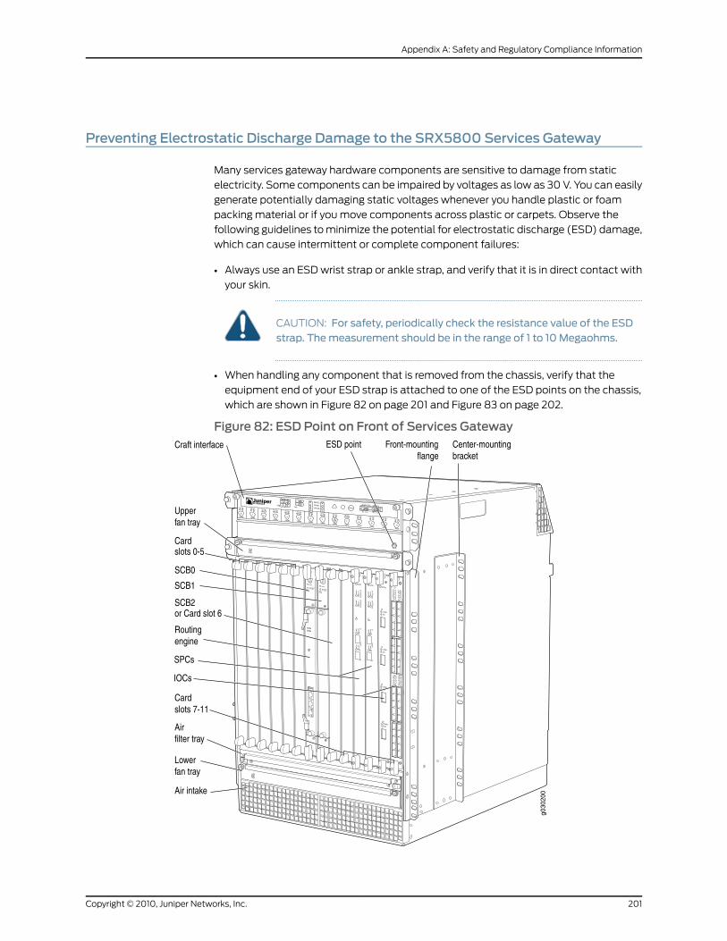
Preventing Electrostatic Discharge Damage to the SRX5800 Services Gateway
Many services gateway hardware components are sensitive to damage from static
electricity. Some components can be impaired by voltages as low as 30 V. You can easily
generate potentially damaging static voltages whenever you handle plastic or foam
packing material or if you move components across plastic or carpets. Observe the
following guidelines to minimize the potential for electrostatic discharge (ESD) damage,
which can cause intermittent or complete component failures:
• Always use an ESD wrist strap or ankle strap, and verify that it is in direct contact with
your skin.
CAUTION: For safety, periodically check the resistance value of the ESDstrap. Themeasurement should be in the range of 1 to 10 Megaohms.
• When handling any component that is removed from the chassis, verify that the
equipment end of your ESD strap is attached to one of the ESD points on the chassis,
which are shown in Figure 82 on page 201 and Figure 83 on page 202.
Figure 82: ESD Point on Front of Services Gateway
201Copyright © 2010, Juniper Networks, Inc.
Appendix A: Safety and Regulatory Compliance Information
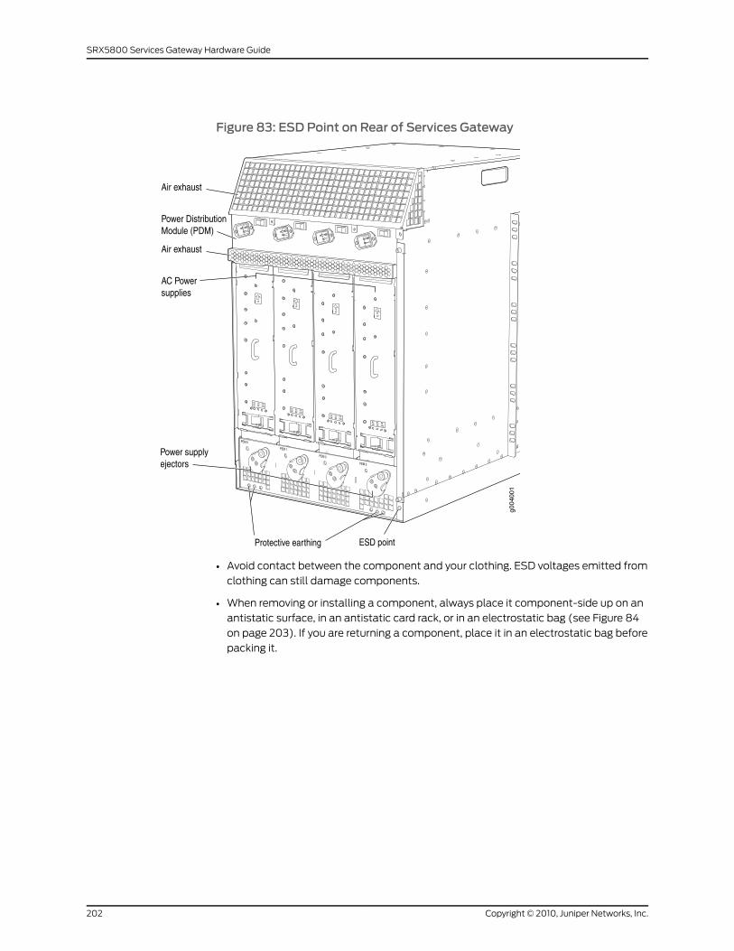
Figure 83: ESD Point on Rear of Services Gateway
• Avoid contact between the component and your clothing. ESD voltages emitted from
clothing can still damage components.
• When removing or installing a component, always place it component-side up on an
antistatic surface, in an antistatic card rack, or in an electrostatic bag (see Figure 84
on page 203). If you are returning a component, place it in an electrostatic bag before
packing it.
Copyright © 2010, Juniper Networks, Inc.202
SRX5800 Services Gateway Hardware Guide
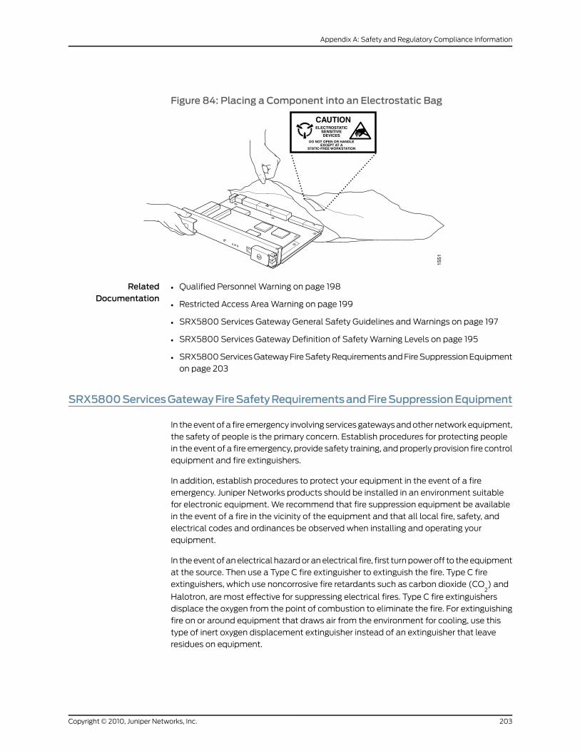
Figure 84: Placing a Component into an Electrostatic Bag
RelatedDocumentation
Qualified Personnel Warning on page 198•
• Restricted Access Area Warning on page 199
• SRX5800 Services Gateway General Safety Guidelines and Warnings on page 197
• SRX5800 Services Gateway Definition of Safety Warning Levels on page 195
• SRX5800 Services Gateway Fire Safety Requirements and Fire Suppression Equipment
on page 203
SRX5800ServicesGatewayFireSafetyRequirementsandFireSuppressionEquipment
In the event of a fire emergency involving services gateways and other network equipment,
the safety of people is the primary concern. Establish procedures for protecting people
in the event of a fire emergency, provide safety training, and properly provision fire control
equipment and fire extinguishers.
In addition, establish procedures to protect your equipment in the event of a fire
emergency. Juniper Networks products should be installed in an environment suitable
for electronic equipment. We recommend that fire suppression equipment be available
in the event of a fire in the vicinity of the equipment and that all local fire, safety, and
electrical codes and ordinances be observed when installing and operating your
equipment.
In the event of an electrical hazard or an electrical fire, first turn power off to the equipment
at the source. Then use a Type C fire extinguisher to extinguish the fire. Type C fire
extinguishers, which use noncorrosive fire retardants such as carbon dioxide (CO2) and
Halotron, are most effective for suppressing electrical fires. Type C fire extinguishers
displace the oxygen from the point of combustion to eliminate the fire. For extinguishing
fire on or around equipment that draws air from the environment for cooling, use this
type of inert oxygen displacement extinguisher instead of an extinguisher that leave
residues on equipment.
203Copyright © 2010, Juniper Networks, Inc.
Appendix A: Safety and Regulatory Compliance Information
Do not use multipurpose Type ABC chemical fire extinguishers (dry chemical fire
extinguishers) near Juniper Networks equipment. The primary ingredient in these fire
extinguishers is monoammonium phosphate, which is very sticky and difficult to clean.
In addition, in minute amounts of moisture, monoammonium phosphate can become
highly corrosive and corrodes most metals.
Any equipment in a room in which a chemical fire extinguisher has been discharged is
subject to premature failure and unreliable operation. The equipment is considered to
be irreparably damaged.
NOTE: Tokeepwarrantieseffective,donotuseadrychemical fireextinguisherto control a fire at or near a Juniper Networks services gateway. If a drychemical fire extinguisher is used, the unit is no longer eligible for coverageunder a service agreement.
We recommend that you dispose of any irreparably damaged equipment in an
environmentally responsible manner.
RelatedDocumentation
Qualified Personnel Warning on page 198•
• Restricted Access Area Warning on page 199
• SRX5800 Services Gateway General Safety Guidelines and Warnings on page 197
• SRX5800 Services Gateway Definition of Safety Warning Levels on page 195
• Preventing Electrostatic Discharge Damage to the SRX5800 Services Gateway on
page 201
SRX5800 Services Gateway Installation Safety Guidelines andWarnings
This section includes the following topics:
• Chassis Lifting Guidelines on page 204
• Installation Instructions Warning on page 205
• Rack-Mounting Requirements and Warnings on page 206
• Ramp Warning on page 209
Chassis Lifting Guidelines
The fully configured chassis with the cable manager weighs up to 350 lb (159 kg), or
150 lb (68 kg) with components removed. Observe the following guidelines for lifting
and moving the services gateway:
• Before moving the services gateway, check the Site Preparation Checklist to verify that
the intended site meets the specified power, environmental, and clearance
requirements.
• Do not attempt to lift a fully configured services gateway by yourself. Using a mechanical
lift to maneuver the services gateway into a rack is recommended. If a lift cannot be
Copyright © 2010, Juniper Networks, Inc.204
SRX5800 Services Gateway Hardware Guide
used, a minimum of three people are required to lift the services gateway, and you
must remove components from the chassis before lifting.
• Before lifting or moving the services gateway, disconnect all external cables.
• As when lifting any heavy object, lift most of the weight with your legs rather than your
back. Keep your knees bent and your back relatively straight and avoid twisting your
body as you lift. Balance the load evenly and be sure that your footing is solid.
RelatedDocumentation
SRX5800 Services Gateway General Safety Guidelines and Warnings on page 197•
• Installation Instructions Warning on page 205
• Rack-Mounting Requirements and Warnings on page 206
• Ramp Warning on page 209
Installation InstructionsWarning
WARNING: Read the installation instructionsbeforeyouconnect theservicesgateway to a power source.
WaarschuwingRaadpleegde installatie-aanwijzingenvoordatuhetsysteemmet de voeding verbindt.
VaroitusLueasennusohjeetennen järjestelmänyhdistämistävirtalähteeseen.
AttentionAvantdebrancher lesystèmesur lasourced'alimentation,consulterles directives d'installation.
Warnung Lesen Sie die Installationsanweisungen, bevor Sie das System andie Stromquelle anschließen.
AvvertenzaConsultare le istruzionidi installazioneprimadicollegare il sistemaall'alimentatore.
Advarsel Les installasjonsinstruksjonene før systemet kobles til strømkilden.
Aviso Leia as instruções de instalação antes de ligar o sistema à sua fontede energia.
¡Atención! Ver las instrucciones de instalación antes de conectar el sistemaa la red de alimentación.
Varning! Läs installationsanvisningarna innan du kopplar systemet till dessströmförsörjningsenhet.
RelatedDocumentation
Chassis Lifting Guidelines on page 204•
• SRX5800 Services Gateway General Safety Guidelines and Warnings on page 197
• Rack-Mounting Requirements and Warnings on page 206
205Copyright © 2010, Juniper Networks, Inc.
Appendix A: Safety and Regulatory Compliance Information
• Ramp Warning on page 209
Rack-Mounting Requirements andWarnings
Ensure that the equipment rack into which the services gateway is installed is evenly and
securely supported to avoid the hazardous condition that could result from uneven
mechanical loading.
WARNING: To prevent bodily injury whenmounting or servicing the servicesgateway in a rack, take the following precautions to ensure that the systemremains stable. The following directives helpmaintain your safety:
• The services gatewaymust be installed into a rack that is secured to thebuilding structure.
• The services gateway should bemounted at the bottom of the rack if it isthe only unit in the rack.
• Whenmounting the services gateway in a partially filled rack, load the rackfrom the bottom to the topwith the heaviest component at the bottom ofthe rack.
• If the rack is providedwith stabilizing devices, install the stabilizers beforemounting or servicing the services gateway in the rack.
WaarschuwingOm lichamelijk letsel te voorkomenwanneer u dit toestel ineen rekmonteert of het daar een servicebeurt geeft, moet u specialevoorzorgsmaatregelen nemen om ervoor te zorgen dat het toestel stabielblijft. De onderstaande richtlijnen worden verstrekt om uw veiligheid teverzekeren:
• De Juniper Networks services gatewaymoet in een stellage wordengeïnstalleerd die aan een bouwsel is verankerd.
• Dit toestel dient onderaan in het rek gemonteerd teworden als het toestelhet enige in het rek is.
• Wanneer u dit toestel in een gedeeltelijk gevuld rekmonteert, dient u hetrekvanonderennaarboven te ladenmethet zwaarsteonderdeelonderaanin het rek.
• Als het rek voorzien is van stabiliseringshulpmiddelen, dient u destabilisatoren temonteren voordat u het toestel in het rekmonteert of hetdaar een servicebeurt geeft.
VaroitusKun laiteasetetaan telineeseen taihuolletaansenollessa telineessä,onnoudatettavaerityisiävarotoimia järjestelmänvakavuudensäilyttämiseksi,jotta vältytään loukkaantumiselta. Noudata seuraavia turvallisuusohjeita:
Copyright © 2010, Juniper Networks, Inc.206
SRX5800 Services Gateway Hardware Guide
• Juniper Networks services gateway on asennettava telineeseen, joka onkiinnitetty rakennukseen.
• Jos telineessä ei ole muita laitteita, aseta laite telineen alaosaan.
• Jos laite asetetaan osaksi täytettyyn telineeseen, aloita kuormittaminensen alaosasta kaikkein raskaimmalla esineellä ja siirry sitten sen yläosaan.
• Jos telinettä varten on vakaimet, asenna ne ennen laitteen asettamistatelineeseen tai sen huoltamista siinä.
Attention Pour éviter toute blessure corporelle pendant les opérations demontage ou de réparation de cette unité en casier, il convient de prendre desprécautions spécialesafindemaintenir la stabilité du système. Lesdirectivesci-dessous sont destinées à assurer la protection du personnel:
• Le rack sur lequel estmonté le JuniperNetworks services gatewaydoit êtrefixé à la structure du bâtiment.
• Si cette unité constitue la seule unitémontéeencasier, elle doit êtreplacéedans le bas.
• Si cette unité est montée dans un casier partiellement rempli, charger lecasier de bas en haut en plaçant l'élément le plus lourd dans le bas.
• Si lecasier estéquipédedispositifs stabilisateurs, installer les stabilisateursavant demonter ou de réparer l'unité en casier.
WarnungZurVermeidungvonKörperverletzungbeimAnbringenoderWartendieser Einheit in einemGestell müssen Sie besondere Vorkehrungen treffen,um sicherzustellen, daß das System stabil bleibt. Die folgenden Richtliniensollen zur Gewährleistung Ihrer Sicherheit dienen:
• Der Juniper Networks services gatewaymuß in einemGestell installiertwerden, das in der Gebäudestruktur verankert ist.
• Wenn diese Einheit die einzige im Gestell ist, sollte sie unten im Gestellangebracht werden.
• Bei Anbringung dieser Einheit in einem zum Teil gefüllten Gestell ist dasGestell von unten nach oben zu laden, wobei das schwerste Bauteil untenim Gestell anzubringen ist.
• Wird das Gestell mit Stabilisierungszubehör geliefert, sind zuerst dieStabilisatoren zu installieren, bevor Sie die Einheit im Gestell anbringenoder sie warten.
AvvertenzaPerevitare infortuni fisici durante ilmontaggioo lamanutenzionedi questa unità in un supporto, occorre osservare speciali precauzioni pergarantire che il sistema rimanga stabile. Le seguenti direttive vengono forniteper garantire la sicurezza personale:
207Copyright © 2010, Juniper Networks, Inc.
Appendix A: Safety and Regulatory Compliance Information
• Il Juniper Networks services gateway deve essere installato in un telaio, ilquale deve essere fissato alla struttura dell'edificio.
• Questa unità deve venire montata sul fondo del supporto, se si trattadell'unica unità damontare nel supporto.
• Quando questa unità vienemontata in un supporto parzialmente pieno,caricare il supporto dal basso all'alto, con il componente più pesantesistemato sul fondo del supporto.
• Se il supporto è dotato di dispositivi stabilizzanti, installare tali dispositiviprimadimontareodiprocedereallamanutenzionedell'unitànel supporto.
AdvarselUnngå fysiske skader under montering eller reparasjonsarbeid pådenne enheten når den befinner seg i et kabinett. Vær nøyemed at systemeter stabilt. Følgende retningslinjer er gitt for å verne om sikkerheten:
• JuniperNetworksservicesgatewaymå installeres i et stativ somer forankrettil bygningsstrukturen.
• Denne enheten børmonteres nederst i kabinettet hvis dette er den enesteenheten i kabinettet.
• Vedmontering av denne enheten i et kabinett som er delvis fylt, skalkabinettet lastes frabunnenogoppmeddentyngstekomponentennedersti kabinettet.
• Hvis kabinettet er utstyrt med stabiliseringsutstyr, skal stabilisatoreneinstalleres før montering eller utføring av reparasjonsarbeid på enheten ikabinettet.
Aviso Para se prevenir contra danos corporais aomontar ou reparar estaunidade numaestante, deverá tomar precauções especiais para se certificarde que o sistema possui um suporte estável. As seguintes directrizesajudá-lo-ão a efectuar o seu trabalho com segurança:
• O Juniper Networks services gateway deverá ser instalado numaprateleirafixa à estrutura do edificio.
• Esta unidade deverá ser montada na parte inferior da estante, caso sejaesta a única unidade a ser montada.
• Aomontar esta unidade numa estante parcialmente ocupada, coloque ositensmais pesados na parte inferior da estante, arrumando-os de baixopara cima.
• Se a estante possuir um dispositivo de estabilização, instale-o antes demontar ou reparar a unidade.
¡Atención! Para evitar lesiones durante el montaje de este equipo sobre unbastidor, o posteriormente durante sumantenimiento, se debeponermuchocuidado en que el sistema quede bien estable. Para garantizar su seguridad,proceda según las siguientes instrucciones:
Copyright © 2010, Juniper Networks, Inc.208
SRX5800 Services Gateway Hardware Guide
• El Juniper Networks services gateway debe instalarse en un bastidor fijadoa la estructura del edificio.
• Colocar el equipo en la parte inferior del bastidor, cuando sea la únicaunidad en el mismo.
• Cuandoesteequiposevayaa instalarenunbastidorparcialmenteocupado,comenzar la instalación desde la parte inferior hacia la superior colocandoel equipomás pesado en la parte inferior.
• Si el bastidor dispone de dispositivos estabilizadores, instalar éstos antesdemontaroprocederalmantenimientodel equipo instaladoenelbastidor.
Varning! För att undvika kroppsskada när du installerar eller utförunderhållsarbete på denna enhet på en ställningmåste du vidta särskildaförsiktighetsåtgärder föratt försäkradigomattsystemetstår stadigt. Följanderiktlinjer ges för att trygga din säkerhet:
• Juniper Networks services gatewaymåste installeras i en ställning som ärförankrad i byggnadens struktur.
• Omdenna enhet är den enda enheten på ställningen skall den installeraslängst ned på ställningen.
• Omdenna enhet installeras på en delvis fylld ställning skall ställningenfyllasnedifrånochupp,meddetyngstaenheterna längstnedpåställningen.
• Omställningenär förseddmedstabiliseringsdonskalldessamonteras fastinnan enheten installeras eller underhålls på ställningen.
RelatedDocumentation
Chassis Lifting Guidelines on page 204•
• SRX5800 Services Gateway General Safety Guidelines and Warnings on page 197
• Installation Instructions Warning on page 205
• Ramp Warning on page 209
RampWarning
WARNING: When installing the services gateway, do not use a ramp inclinedat more than 10 degrees.
WaarschuwingGebruik een oprijplaat niet onder een hoek vanmeer dan 10graden.
VaroitusÄläkäytäsellaistakaltevaapintaa, jonkakaltevuusylittää 10astetta.
AttentionNe pas utiliser une rampe dont l'inclinaison est supérieure à 10degrés.
WarnungKeine Rampenmit einer Neigung vonmehr als 10 Grad verwenden.
209Copyright © 2010, Juniper Networks, Inc.
Appendix A: Safety and Regulatory Compliance Information
AvvertenzaNon usare una rampa con pendenza superiore a 10 gradi.
Advarsel Bruk aldri en rampe som heller mer enn 10 grader.
AvisoNão utilize uma rampa com uma inclinação superior a 10 graus.
¡Atención!No usar una rampa inclinadamás de 10 grados
Varning! Använd inte rampmed en lutning påmer än 10 grader.
RelatedDocumentation
Chassis Lifting Guidelines on page 204•
• SRX5800 Services Gateway General Safety Guidelines and Warnings on page 197
• Installation Instructions Warning on page 205
• Rack-Mounting Requirements and Warnings on page 206
SRX5800 Services Gateway Laser and LED Safety Guidelines andWarnings
This section includes the following topics:
• General Laser Safety Guidelines on page 210
• Class 1 Laser Warning on page 211
• Class 1 LED Product Warning on page 211
• Laser Beam Warning on page 212
• Radiation from Open Port Apertures Warning on page 213
General Laser Safety Guidelines
When working around the services gateway, observe the following safety guidelines to
prevent eye injury:
• Do not look into unterminated ports or at fibers that connect to unknown sources.
• Do not examine unterminated optical ports with optical instruments.
• Avoid direct exposure to the beam.
WARNING: Unterminated optical connectors can emit invisible laserradiation. The lens in the human eye focuses all the laser power on theretina, so focusing the eye directly on a laser source—even a low-powerlaser—could permanently damage the eye.
RelatedDocumentation
Class 1 Laser Warning on page 211•
• Class 1 LED Product Warning on page 211
• Laser Beam Warning on page 212
Copyright © 2010, Juniper Networks, Inc.210
SRX5800 Services Gateway Hardware Guide
• Radiation from Open Port Apertures Warning on page 213
Class 1 LaserWarning
WARNING: Class 1 laser product.
Waarschuwing Klasse-1 laser produkt.
Varoitus Luokan 1 lasertuote.
Attention Produit laser de classe I.
Warnung Laserprodukt der Klasse 1.
Avvertenza Prodotto laser di Classe 1.
Advarsel Laserprodukt av klasse 1.
Aviso Produto laser de classe 1.
¡Atención! Producto láser Clase I.
Varning! Laserprodukt av klass 1.
RelatedDocumentation
General Laser Safety Guidelines on page 210•
• Class 1 LED Product Warning on page 211
• Laser Beam Warning on page 212
• Radiation from Open Port Apertures Warning on page 213
Class 1 LED ProductWarning
WARNING: Class 1 LED product.
Waarschuwing Klasse 1 LED-product.
Varoitus Luokan 1 valodiodituote.
Attention Alarme de produit LED Class I.
Warnung Class 1 LED-Produktwarnung.
Avvertenza Avvertenza prodotto LED di Classe 1.
Advarsel LED-produkt i klasse 1.
Aviso Produto de classe 1 com LED.
¡Atención! Aviso sobre producto LED de Clase 1.
211Copyright © 2010, Juniper Networks, Inc.
Appendix A: Safety and Regulatory Compliance Information
Varning! Lysdiodprodukt av klass 1.
RelatedDocumentation
General Laser Safety Guidelines on page 210•
• Class 1 Laser Warning on page 211
• Laser Beam Warning on page 212
• Radiation from Open Port Apertures Warning on page 213
Laser BeamWarning
WARNING: Do not stare into the laser beam or view it directly with opticalinstruments.
WaarschuwingNiet in de straal staren of hem rechtstreeks bekijkenmetoptische instrumenten.
Varoitus Älä katso säteeseen äläkä tarkastele sitä suoraan optisen laitteenavulla.
AttentionNe pas fixer le faisceau des yeux, ni l'observer directement à l'aided'instruments optiques.
WarnungNicht direkt in den Strahl blicken und ihn nicht direktmit optischenGeräten prüfen.
AvvertenzaNon fissare il raggio con gli occhi né usare strumenti ottici perosservarlo direttamente.
Advarsel Stirr eller se ikke direkte p strlenmed optiske instrumenter.
AvisoNão olhe fixamente para o raio, nem olhe para ele directamente cominstrumentos ópticos.
¡Atención!Nomirar fijamente el haz ni observarlo directamente coninstrumentos ópticos.
Varning! Rikta inte blicken in mot strålen och titta inte direkt på den genomoptiska instrument.
RelatedDocumentation
General Laser Safety Guidelines on page 210•
• Class 1 Laser Warning on page 211
• Class 1 LED Product Warning on page 211
• Radiation from Open Port Apertures Warning on page 213
Copyright © 2010, Juniper Networks, Inc.212
SRX5800 Services Gateway Hardware Guide
Radiation fromOpen Port AperturesWarning
WARNING: Because invisible radiationmay be emitted from the aperture ofthe port when no fiber cable is connected, avoid exposure to radiation anddo not stare into open apertures.
Waarschuwing Aangezien onzichtbare straling vanuit de opening van depoort kan komen als er geen fiberkabel aangesloten is, dient blootstellingaan straling en het kijken in open openingen vermeden te worden.
Varoitus Koska portin aukosta voi emittoitua näkymätöntä säteilyä, kunkuitukaapelia ei ole kytkettynä, vältä säteilylle altistumista äläkä katsoavoimiin aukkoihin.
Attention Des radiations invisibles à l'il nu pouvant traverser l'ouverture duport lorsqu'aucun câble en fibre optique n'y est connecté, il est recommandéde ne pas regarder fixement l'intérieur de ces ouvertures.
Warnung Aus der Port-Öffnung können unsichtbare Strahlen emittieren,wenn kein Glasfaserkabel angeschlossen ist. Vermeiden Sie es, sich denStrahlungen auszusetzen, und starren Sie nicht in die Öffnungen!
AvvertenzaQuando i cavi in fibranonsono inseriti, radiazioni invisibili possonoessere emesse attraverso l'apertura della porta. Evitate di esporvi alleradiazioni e non guardate direttamente nelle aperture.
AdvarselUnngåutsettelse for stråling, ogstirr ikke inn i åpninger someråpne,fordi usynlig stråling kan emiteres fra portens åpning når det ikke er tilkobleten fiberkabel.
AvisoDadaapossibilidadedeemissãode radiação invisível atravésdoorifícioda via de acesso, quando esta não tiver nenhum cabo de fibra conectado,deverá evitar a exposição à radiação e não deverá olhar fixamente paraorifícios que se encontrarem a descoberto.
¡Atención!Debidoaque laaperturadelpuertopuedeemitir radiación invisiblecuando no existe un cable de fibra conectado, evitemirar directamente a lasaperturas para no exponerse a la radiación.
Varning!Osynlig strålning kan avges från en portöppning utan anslutenfiberkabel ochdubör därför undvika att bli utsatt för strålning genomatt intestirra in i oskyddade öppningar.
RelatedDocumentation
General Laser Safety Guidelines on page 210•
• Class 1 Laser Warning on page 211
• Class 1 LED Product Warning on page 211
• Laser Beam Warning on page 212
213Copyright © 2010, Juniper Networks, Inc.
Appendix A: Safety and Regulatory Compliance Information
SRX5800 Services GatewayMaintenance and Operational Safety Guidelines andWarnings
This section includes the following topics:
• Battery Handling Warning on page 214
• Jewelry Removal Warning on page 215
• Lightning Activity Warning on page 216
• Operating Temperature Warning on page 217
• Product Disposal Warning on page 219
Battery HandlingWarning
WARNING: Replacing the battery incorrectly might result in an explosion.Replace the battery only with the same or equivalent type recommended bythemanufacturer. Disposeof usedbatteries according to themanufacturer'sinstructions.
Waarschuwing Er is ontploffingsgevaar als de batterij verkeerd vervangenwordt. Vervang de batterij slechts met hetzelfde of een equivalent type datdoor de fabrikant aanbevolen is. Gebruikte batterijendienenovereenkomstigfabrieksvoorschriften weggeworpen te worden.
Varoitus Räjähdyksen vaara, jos akku on vaihdettu väärään akkuun. Käytävaihtamiseen ainoastaan saman- tai vastaavantyyppistä akkua, joka onvalmistajansuosittelema.Hävitäkäytetytakutvalmistajanohjeidenmukaan.
Attention Danger d'explosion si la pile n'est pas remplacée correctement.Ne la remplacer que par une pile de type semblable ou équivalent,recommandée par le fabricant. Jeter les piles usagées conformément auxinstructions du fabricant.
Warnung Bei Einsetzen einer falschen Batterie besteht Explosionsgefahr.Ersetzen Sie die Batterie nur durch den gleichen oder vomHerstellerempfohlenen Batterietyp. Entsorgen Sie die benutzten Batterien nach denAnweisungen des Herstellers.
Avvertenza Pericolo di esplosione se la batteria non è installatacorrettamente.Sostituiresoloconunadi tipougualeoequivalente, consigliatadalproduttore. Eliminare lebatterieusatesecondo le istruzionidelproduttore.
Advarsel Det kan være fare for eksplosjon hvis batteriet skiftes på feil måte.Skift kunmed sammeeller tilsvarende type somer anbefalt av produsenten.Kasser brukte batterier i henhold til produsentens instruksjoner.
AvisoExiste perigo de explosão se a bateria for substituída incorrectamente.Substitua a bateria por uma bateria igual ou de um tipo equivalente
Copyright © 2010, Juniper Networks, Inc.214
SRX5800 Services Gateway Hardware Guide
recomendado pelo fabricante. Destrua as baterias usadas conforme asinstruções do fabricante.
¡Atención! Existe peligro de explosión si la batería se reemplaza demaneraincorrecta. Reemplazar la batería exclusivamente con el mismo tipo o elequivalente recomendado por el fabricante. Desechar las baterías gastadassegún las instrucciones del fabricante.
Varning!Explosionsfara vid felaktigt batteribyte. Ersätt endast batterietmedsamma batterityp som rekommenderas av tillverkaren eller motsvarande.Följ tillverkarens anvisningar vid kassering av använda batterier.
RelatedDocumentation
Jewelry Removal Warning on page 215•
• Lightning Activity Warning on page 216
• Operating Temperature Warning on page 217
• Product Disposal Warning on page 219
Jewelry RemovalWarning
WARNING: Before working on equipment that is connected to power lines,remove jewelry, including rings, necklaces, and watches. Metal objects heatup when connected to power and ground and can cause serious burns orweld themetal object to the terminals.
Waarschuwing Alvorens aan apparatuur te werken die met elektrischeleidingen is verbonden, sieraden (inclusief ringen, kettingen en horloges)verwijderen. Metalen voorwerpen worden warmwanneer zemet stroom enaarde zijn verbonden, en kunnen ernstige brandwonden veroorzaken of hetmetalen voorwerp aan de aansluitklemmen lassen.
Varoitus Ennen kuin työskentelet voimavirtajohtoihin kytkettyjen laitteidenparissa, otapois kaikki korut (sormukset, kaulakorut ja kellotmukaan lukien).Metalliesineet kuumenevat, kun ne ovat yhteydessä sähkövirran ja maankanssa, janevoivataiheuttaavakaviapalovammoja tai hitsatametalliesineetkiinni liitäntänapoihin.
AttentionAvantd'accéderàcetéquipementconnectéaux lignesélectriques,ôter toutbijou(anneaux,colliersetmontrescompris). Lorsqu'ilssontbranchésà l'alimentation et reliés à la terre, les objets métalliques chauffent, ce quipeutprovoquerdesblessuresgravesousouder l'objetmétalliqueauxbornes.
Warnung Vor der Arbeit an Geräten, die an das Netz angeschlossen sind,jeglichen Schmuck (einschließlich Ringe, Ketten und Uhren) abnehmen.Metallgegenstände erhitzen sich, wenn sie an das Netz und die Erdeangeschlossen werden, und können schwere Verbrennungen verursachenoder an die Anschlußklemmen angeschweißt werden.
215Copyright © 2010, Juniper Networks, Inc.
Appendix A: Safety and Regulatory Compliance Information
Avvertenza Prima di intervenire su apparecchiature collegate alle linee dialimentazione, togliersi qualsiasi monile (inclusi anelli, collane, braccialettied orologi). Gli oggetti metallici si riscaldano quando sono collegati tra puntidi alimentazione emassa: possono causare ustioni gravi oppure il metallopuò saldarsi ai terminali.
Advarsel Fjern alle smykker (inkludert ringer, halskjeder og klokker) før duskal arbeidepåutstyr somer koblet til kraftledninger.Metallgjenstander somer koblet til kraftledninger og jord blir svært varme og kan forårsake alvorligebrannskader eller smelte fast til polene.
Aviso Antes de trabalhar em equipamento que esteja ligado a linhas decorrente, retire todas as jóias que estiver a usar (incluindo anéis, fios erelógios). Os objectosmetálicos aquecerão em contacto com a corrente eem contacto com a ligação à terra, podendo causar queimaduras graves ouficarem soldados aos terminais.
¡Atención! Antes de operar sobre equipos conectados a líneas dealimentación, quitarse las joyas (incluidos anillos, collares y relojes). Losobjetosdemetal secalientancuandoseconectana laalimentaciónyatierra,lo que puede ocasionar quemaduras graves o que los objetosmetálicosqueden soldados a los bornes.
Varning! Tag av alla smycken (inklusive ringar, halsband och armbandsur)innanduarbetarpåutrustningsomärkopplad till kraftledningar.Metallobjekthettas upp när de kopplas ihopmed ström och jord och kan förorsakaallvarliga brännskador; metallobjekt kan också sammansvetsasmedkontakterna.
RelatedDocumentation
Battery Handling Warning on page 214•
• Lightning Activity Warning on page 216
• Operating Temperature Warning on page 217
• Product Disposal Warning on page 219
Lightning ActivityWarning
WARNING: Donotworkon thesystemorconnectordisconnectcablesduringperiods of lightning activity.
Waarschuwing Tijdens onweer dat gepaard gaat met bliksem, dient u nietaan het systeem te werken of kabels aan te sluiten of te ontkoppelen.
Varoitus Älä työskentele järjestelmän parissa äläkä yhdistä tai irrotakaapeleita ukkosilmalla.
Copyright © 2010, Juniper Networks, Inc.216
SRX5800 Services Gateway Hardware Guide
AttentionNe pas travailler sur le système ni brancher ou débrancher lescâbles pendant un orage.
Warnung Arbeiten Sie nicht am System und schließen Sie keine Kabel anbzw. trennen Sie keine ab, wenn es gewittert.
AvvertenzaNon lavorare sul sistema o collegare oppure scollegare i cavidurante un temporale con fulmini.
AdvarselUtfør aldri arbeidpåsystemet, eller koble kabler til eller fra systemetnår det tordner eller lyner.
AvisoNão trabalhe no sistema ou ligue e desligue cabos durante períodosdemau tempo (trovoada).
¡Atención!No operar el sistema ni conectar o desconectar cables durante eltranscurso de descargas eléctricas en la atmósfera.
Varning!Vid åska skall du aldrig utföra arbete på systemet eller ansluta ellerkoppla loss kablar.
RelatedDocumentation
Battery Handling Warning on page 214•
• Jewelry Removal Warning on page 215
• Operating Temperature Warning on page 217
• Product Disposal Warning on page 219
Operating TemperatureWarning
WARNING: Toprevent theservicesgateway fromoverheating,donotoperateit in anarea that exceeds themaximumrecommendedambient temperatureof 104°F (40°C). To prevent airflow restriction, allow at least 6 in. (15.2 cm)of clearance around the ventilation openings.
WaarschuwingOmte voorkomendatwelke services gateway van de JuniperNetworks services gateway dan ook oververhit raakt, dient u deze niet tebedienen op een plaats waar demaximale aanbevolenomgevingstemperatuur van 40°Cwordt overschreden. Om te voorkomendat de luchtstroomwordt beperkt, dient erminstens 15,2 cm speling rond deventilatie-openingen te zijn.
VaroitusEttei JuniperNetworksservicesgateway-sarjan reititinylikuumentuisi,sitä ei saa käyttää tilassa, jonka lämpötila ylittää korkeimman suositellunympäristölämpötilan 40°C. Ettei ilmanvaihto estyisi, tuuletusaukkojenympärille on jätettävä ainakin 15,2 cm tilaa.
Attention Pour éviter toute surchauffe des routeurs de la gamme JuniperNetworks services gateway, ne l'utilisez pasdansune zoneoù la température
217Copyright © 2010, Juniper Networks, Inc.
Appendix A: Safety and Regulatory Compliance Information
ambiante est supérieure à 40°C. Pour permettre un flot d'air constant,dégagezunespaced'aumoins 15,2 cmautourdesouverturesdeventilations.
WarnungUm einen services gateway der services gateway vor Überhitzungzu schützen, darf dieser nicht in einer Gegend betrieben werden, in der dieUmgebungstemperatur das empfohlene Maximum von 40°C überschreitet.UmLüftungsverschlußzuverhindern, achtenSiedarauf, daßmindestens 15,2cm lichter Raum um die Lüftungsöffnungen herum frei bleibt.
Avvertenza Per evitare il surriscaldamento dei services gateway, nonadoperateli in un locale che ecceda la temperatura ambientale massima di40°C.Per evitareche lacircolazionedell'aria sia impedita, lasciateunospaziodi almeno 15.2 cm di fronte alle aperture delle ventole.
AdvarselUnngå overoppheting av eventuelle rutere i Juniper Networksservices gateway Disse skal ikke brukes på steder der den anbefaltemaksimale omgivelsestemperaturen overstiger 40°C (104°F). Sørg for atklaringen rundt lufteåpningene er minst 15,2 cm (6 tommer) for å forhindrenedsatt luftsirkulasjon.
Aviso Para evitar o sobreaquecimento do encaminhador Juniper Networksservices gateway, não utilize este equipamento numa área que exceda atemperaturamáxima recomendada de 40°C. Para evitar a restrição àcirculaçãodear, deixepelomenosumespaçode 15,2cmàvoltadasaberturasde ventilação.
¡Atención! Para impedir que un encaminador de la serie Juniper Networksservices gateway se recaliente, no lo haga funcionar en un área en la que sesupere la temperaturaambientemáximarecomendadade40°C.Para impedirla restricción de la entrada de aire, deje un espacio mínimo de 15,2 cmalrededor de las aperturas para ventilación.
Varning! Förhindra att en Juniper Networks services gateway överhettasgenomatt inteanvändaden iettområdedärdenmaximalt rekommenderadeomgivningstemperaturenpå40°Cöverskrids. Förhindra att luftcirkulationeninskränksgenomattse till attdet finns fritt utrymmepåminst 15,2cmomkringventilationsöppningarna.
RelatedDocumentation
Battery Handling Warning on page 214•
• Jewelry Removal Warning on page 215
• Lightning Activity Warning on page 216
• Product Disposal Warning on page 219
Copyright © 2010, Juniper Networks, Inc.218
SRX5800 Services Gateway Hardware Guide
Product DisposalWarning
WARNING: Disposalof thisproductmustbehandledaccording toall nationallaws and regulations.
Waarschuwing Dit produkt dient volgens alle landelijke wetten envoorschriften te worden afgedankt.
VaroitusTämän tuotteen lopullisesta hävittämisestä tulee huolehtia kaikkiavaltakunnallisia lakeja ja säännöksiä noudattaen.
Attention Lamise au rebut définitive de ce produit doit être effectuéeconformément à toutes les lois et réglementations en vigueur.
Warnung Dieses Produkt muß den geltenden Gesetzen und Vorschriftenentsprechend entsorgt werden.
Avvertenza L'eliminazione finale di questo prodotto deve essere eseguitaosservando le normative italiane vigenti in materia
AdvarselEndeligdisponeringavdetteproduktetmåskje ihenholdtil nasjonalelover og forskrifter.
Aviso A descartagem final deste produto deverá ser efectuada de acordocom os regulamentos e a legislação nacional.
¡Atención! El desecho final de este producto debe realizarse según todas lasleyes y regulaciones nacionales
Varning!Slutlig kasseringavdennaproduktbör skötas i enlighetmed landetsalla lagar och föreskrifter.
RelatedDocumentation
Battery Handling Warning on page 214•
• Jewelry Removal Warning on page 215
• Lightning Activity Warning on page 216
• Operating Temperature Warning on page 217
SRX5800 Services Gateway Electrical Safety Guidelines andWarnings
This section includes the following topics:
• In Case of Electrical Accident on page 220
• General Electrical Safety Guidelines and Warnings on page 220
• DC Power Electrical Safety Guidelines and Warnings on page 224
219Copyright © 2010, Juniper Networks, Inc.
Appendix A: Safety and Regulatory Compliance Information
In Case of Electrical Accident
If an electrical accident results in an injury, take the following actions in this order:
1. Use caution. Be aware of potentially hazardous conditions that could cause further
injury.
2. Disconnect power from the services gateway.
3. If possible, send another person to get medical aid. Otherwise, assess the condition
of the victim, then call for help.
RelatedDocumentation
General Electrical Safety Guidelines and Warnings on page 220•
• DC Power Electrical Safety Guidelines and Warnings on page 224
• SRX5800 Services Gateway Agency Approvals on page 230
General Electrical Safety Guidelines andWarnings
• Install the services gateway in compliance with the following local, national, or
international electrical codes:
• United States—National Fire Protection Association (NFPA 70), United States
National Electrical Code
• Canada—Canadian Electrical Code, Part 1, CSA C22.1
• Other countries—International Electromechanical Commission (IEC) 60364, Part 1
through Part 7
• Evaluated to the TN power system
• Locate the emergency power-off switch for the room in which you are working so that
if an electrical accident occurs, you can quickly turn off the power.
• Do not work alone if potentially hazardous conditions exist anywhere in your workspace.
• Never assume that power is disconnected from a circuit. Always check the circuit before
starting to work.
• Carefully look for possible hazards in your work area, such as moist floors, ungrounded
power extension cords, and missing safety grounds.
• Operate the services gateway within marked electrical ratings and product usage
instructions.
• For the services gateway and peripheral equipment to function safely and correctly,
use the cables and connectors specified for the attached peripheral equipment, and
make certain they are in good condition.
Grounded EquipmentWarning
Copyright © 2010, Juniper Networks, Inc.220
SRX5800 Services Gateway Hardware Guide
WARNING: The services gateway is intended to be grounded. Ensure thatthe services gateway is connected to earth ground during normal use.
Waarschuwing Deze apparatuur hoort geaard te worden Zorg dat dehost-computer tijdens normaal gebruik met aarde is verbonden.
Varoitus Tämä laitteisto on tarkoitettumaadoitettavaksi. Varmista, ettäisäntälaite on yhdistetty maahan normaalikäytön aikana.
Attention Cet équipement doit être relié à la terre. S'assurer que l'appareilhôte est relié à la terre lors de l'utilisation normale.
Warnung Dieses Gerät muß geerdet werden. Stellen Sie sicher, daß dasHost-Gerät während des normalen Betriebs an Erde gelegt ist.
AvvertenzaQuestaapparecchiaturadeveesserecollegataamassa.Accertarsiche il dispositivo host sia collegato alla massa di terra durante il normaleutilizzo.
AdvarselDette utstyret skal jordes. Forviss deg om vertsterminalen er jordetved normalt bruk.
Aviso Este equipamento deverá estar ligado à terra. Certifique-se que o hostse encontra ligado à terra durante a sua utilização normal.
¡Atención!Esteequipodebeconectarsea tierra.Asegurarsedequeel equipoprincipal esté conectado a tierra durante el uso normal.
Varning! Denna utrustning är avsedd att jordas. Se till att värdenheten ärjordad vid normal användning.
Midplane Energy HazardWarning
WARNING: High levels of electrical energyaredistributedacross the servicesgatewaymidplane. Be careful not to contact themidplane connectors, orany component connected to themidplane, with anymetallic object whileservicing components installed in the services gateway.
Multiple Power Supplies DisconnectionWarning
WARNING: Theservicesgatewayhasmorethanonepowersupplyconnection.All connectionsmust be removed completely to remove power from the unitcompletely.
WaarschuwingDeze eenheid heeft meer dan één stroomtoevoerverbinding;alle verbindingenmoetenvolledigwordenverwijderdomdestroomvandezeeenheid volledig te verwijderen.
221Copyright © 2010, Juniper Networks, Inc.
Appendix A: Safety and Regulatory Compliance Information
VaroitusTässä laitteessaonuseampiavirtalähdekytkentöjä.Kaikki kytkennäton irrotettava kokonaan, jotta virta poistettaisiin täysin laitteesta.
AttentionCetteunitéestéquipéedeplusieurs raccordementsd'alimentation.Pour supprimer tout courant électrique de l'unité, tous les cordonsd'alimentation doivent être débranchés.
WarnungDieseEinheit verfügtübermehralseinenStromanschluß;umStromgänzlichvonderEinheit fernzuhalten,müssenalleStromzufuhrenabgetrenntsein.
AvvertenzaQuestaunitàhapiùdiunaconnessioneperalimentatoreelettrico;tutte le connessioni devono essere completamente rimosse per toglierel'elettricità dall'unità.
AdvarselDenne enheten harmer enn én strømtilkobling. Alle tilkoblingermåkobles helt fra for å eliminere strøm fra enheten.
Aviso Este dispositivo possui mais do que uma conexão de fonte dealimentação de energia; para poder remover a fonte de alimentação deenergia, deverão ser desconectadas todas as conexões existentes.
¡Atención! Esta unidad tienemás de una conexión de suministros dealimentación; para eliminar la alimentación por completo, debendesconectarse completamente todas las conexiones.
Varning! Denna enhet har mer än en strömförsörjningsanslutning; allaanslutningar måste vara helt avlägsnade innan strömtillförseln till enhetenär fullständigt bruten.
Power DisconnectionWarning
WARNING: Before working on the services gateway or near power supplies,unplug the power cord fromanAC-powered services gateway; switch off thepower at the circuit breaker on a DC-powered services gateway.
Waarschuwing Voordat u aan een frame of in de nabijheid van voedingenwerkt, dient u bij wisselstroom toestellen de stekker van het netsnoer uit hetstopcontact te halen; voor gelijkstroom toestellen dient u de stroom uit teschakelen bij de stroomverbreker.
Varoitus Kytke irti vaihtovirtalaitteiden virtajohto ja katkaisetasavirtalaitteiden virta suojakytkimellä, ennen kuin teet mitäänasennuspohjalle tai työskentelet virtalähteiden läheisyydessä.
AttentionAvantde travailler surunchâssisouàproximitéd'unealimentationélectrique, débrancher le cordon d'alimentation des unités en courantalternatif; couper l'alimentation des unités en courant continu au niveau dudisjoncteur.
Copyright © 2010, Juniper Networks, Inc.222
SRX5800 Services Gateway Hardware Guide
Warnung Bevor Sie an einem Chassis oder in der Nähe von Netzgerätenarbeiten, ziehen Sie bei Wechselstromeinheiten das Netzkabel ab bzw.schalten Sie bei Gleichstromeinheiten den Strom amUnterbrecher ab.
AvvertenzaPrimadi lavorare suun telaioo intornoadalimentatori, scollegareil cavo di alimentazione sulle unità CA; scollegare l'alimentazioneall'interruttore automatico sulle unità CC.
Advarsel Før det utføres arbeid på kabinettet eller det arbeides i nærhetenav strømforsyningsenheter, skal strømledningen trekkes ut pvekselstrømsenheter og strømmen kobles fra ved strømbryteren pålikestrømsenheter.
AvisoAntesdetrabalharnumchassis,ouantesdetrabalharpertodeunidadesde fornecimento de energia, desligue o cabo de alimentação nas unidadesde corrente alternada; desligue a corrente no disjuntor nas unidades decorrente contínua.
¡Atención!Antes demanipular el chasis de un equipoo trabajar cerca deunafuentedealimentación, desenchufar el cabledealimentaciónen losequiposde corriente alterna (CA); cortar la alimentación desde el interruptorautomático en los equipos de corriente continua (CC).
Varning! Innanduarbetarmedettchassi ellernäraströmförsörjningsenheterskall du för växelströmsenheter dra ur nätsladden och för likströmsenheterbryta strömmen vid överspänningsskyddet.
TN PowerWarning
WARNING: Theservicesgateway isdesigned toworkwithTNpowersystems.
WaarschuwingHet apparaat is ontworpen om te functionerenmet TNenergiesystemen.
Varoitus Koje on suunniteltu toimimaan TN-sähkövoimajärjestelmienyhteydessä.
Attention Ce dispositif a été conçu pour fonctionner avec des systèmesd'alimentation TN.
WarnungDasGerät ist fürdieVerwendungmitTN-Stromsystemenausgelegt.
Avvertenza Il dispositivo è stato progettato per l'uso con sistemi dialimentazione TN.
AdvarselUtstyret er utfomet til brukmed TN-strømsystemer.
AvisoO dispositivo foi criado para operar com sistemas de corrente TN.
223Copyright © 2010, Juniper Networks, Inc.
Appendix A: Safety and Regulatory Compliance Information
¡Atención! El equipo está diseñado para trabajar con sistemas dealimentación tipo TN.
Varning! Enheten är konstruerad för användning tillsammansmedelkraftssystem av TN-typ.
Copper ConductorsWarning
WARNING: Use copper conductors only.
WaarschuwingGebruik alleen koperen geleiders.
Varoitus Käytä vain kuparijohtimia.
AttentionUtilisez uniquement des conducteurs en cuivre.
Warnung Verwenden Sie ausschließlich Kupferleiter.
AvvertenzaUsate unicamente dei conduttori di rame.
Advarsel Bruk bare kobberledninger.
AvisoUtilize apenas fios condutores de cobre.
¡Atención! Emplee sólo conductores de cobre.
Varning! Använd endast ledare av koppar.
RelatedDocumentation
In Case of Electrical Accident on page 220•
• DC Power Electrical Safety Guidelines and Warnings on page 224
• SRX5800 Services Gateway Agency Approvals on page 230
DC Power Electrical Safety Guidelines andWarnings
When working with DC-powered equipment, observe the following guidelines and
warnings:
• DC Power Electrical Safety Guidelines
• DC Power Disconnection Warning
• DC Power Grounding Requirements and Warning
• DC Power Wiring Sequence Warning
• DC Power Wiring Terminations Warning
DC Power Electrical Safety Guidelines
The following electrical safety guidelines apply to a DC-powered Services Gateway:
Copyright © 2010, Juniper Networks, Inc.224
SRX5800 Services Gateway Hardware Guide
• A DC-powered Services Gateway is equipped with a DC terminal block that is rated
for the power requirements of a maximally configured Services Gateway. To supply
sufficient power, terminate the DC input wiring on a facility DC source capable of
supplying at least 116 A @ –48 VDC for the system, or at least 58 A @ –48 VDC for
each power supply. We recommend that the 48 VDC facility DC source be equipped
with a circuit breaker rated at 80 A (–48 VDC) minimum, or as required by local code.
Incorporate an easily accessible disconnect device into the facility wiring. In the United
States and Canada, the –48 VDC facility should be equipped with a circuit breaker
rated a minimum of 125% of the power provisioned for the input in accordance with
the National Electrical Code in the US and the Canadian Electrical Code in Canada. Be
sure to connect the ground wire or conduit to a solid office (earth) ground. A closed
loop ring is recommended for terminating the ground conductor at the ground stud.
• Run two wires from the circuit breaker box to a source of 48 VDC. Use appropriate
gauge wire to handle up to 80 A.
• A DC-powered Services Gateway that is equipped with a DC terminal block is intended
only for installation in a restricted access location. In the United States, a restricted
access area is one in accordance with Articles 110-16, 110-17, and 110-18 of the National
Electrical Code ANSI/NFPA 70.
NOTE: Primary overcurrent protection is provided by the building circuitbreaker. This breaker should protect against excess currents, short circuits,and earth faults in accordance with NEC ANSI/NFPA70.
• Ensure that the polarity of the DC input wiring is correct. Under certain conditions,
connections with reversed polarity might trip the primary circuit breaker or damage
the equipment.
• For personal safety, connect the green and yellow wire to safety (earth) ground at both
the Services Gateway and the supply side of the DC wiring.
• The marked input voltage of –48 VDC for a DC-powered Services Gateway is the
nominal voltage associated with the battery circuit, and any higher voltages are only
to be associated with float voltages for the charging function.
• Because the Services Gateway is a positive ground system, you must connect the
positive lead to the terminal labeledRETURN, the negative lead to the terminal labeled
–48V, and the earth ground to the chassis grounding points.
DC Power DisconnectionWarning
WARNING: Before performing any of the following procedures, ensure thatpower is removed from the DC circuit. To ensure that all power is off, locatethe circuit breaker on the panel board that services the DC circuit, switch thecircuit breaker to theOFF position, and tape the switch handle of the circuit
breaker in theOFF position.
Waarschuwing Voordat u een van de onderstaande procedures uitvoert,dientu tecontrolerenofdestroomnaarhetgelijkstroomcircuit uitgeschakeld
225Copyright © 2010, Juniper Networks, Inc.
Appendix A: Safety and Regulatory Compliance Information
is. Om u ervan te verzekeren dat alle stroomUIT is geschakeld, kiest u op hetschakelbord de stroomverbreker die het gelijkstroom circuit bedient, draaitde stroomverbreker naar de UIT positie en plakt de schakelaarhendel van destroomverbreker met plakband in de UIT positie vast.
Varoitus Varmista, että tasavirtapiirissä ei ole virtaa ennen seuraavientoimenpiteiden suorittamista. Varmistaaksesi, että virta on KATKAISTUtäysin,paikannatasavirrastahuolehtivassakojetaulussasijaitsevasuojakytkin,käännä suojakytkin KATKAISTU-asentoon ja teippaa suojakytkimen varsiniin, että se pysyy KATKAISTU-asennossa.
Attention Avant de pratiquer l'une quelconque des procédures ci-dessous,vérifier que le circuit en courant continu n'est plus sous tension. Pour en êtresûr, localiser ledisjoncteur situésur lepanneaudeserviceducircuit encourantcontinu, placer le disjoncteur enposition fermée (OFF) et, à l'aide d'un rubanadhésif, bloquer la poignée du disjoncteur en position OFF.
Warnung Vor Ausführung der folgenden Vorgänge ist sicherzustellen, daßdie Gleichstromschaltung keinen Strom erhält. Um sicherzustellen, daßsämtlicher Strom abgestellt ist, machen Sie auf der Schalttafel denUnterbrecher für die Gleichstromschaltung ausfindig, stellen Sie denUnterbrecher auf AUS, und kleben Sie den Schaltergriff des Unterbrechersmit Klebeband in der AUS-Stellung fest.
AvvertenzaPrimadi svolgereunaqualsiasidelleprocedureseguenti, verificareche il circuito CC non sia alimentato. Per verificare che tutta l'alimentazionesia scollegata (OFF), individuare l'interruttore automatico sul quadrostrumenti che alimenta il circuito CC, mettere l'interruttore in posizione OFFe fissarlo con nastro adesivo in tale posizione.
Advarsel Før noen av disse prosedyrene utføres, kontroller at strømmen erfrakoblet likestrømkretsen. Sørg for at all strøm er slått AV. Dette gjøres vedå lokalisere strømbryteren på brytertavlen som betjener likestrømkretsen,slå strømbryterenAVog teipebryterhåndtaketpåstrømbryteren iAV-stilling.
AvisoAntes de executar umdos seguintes procedimentos, certifique-se quedesligou a fonte de alimentação de energia do circuito de corrente contínua.Para se assegurar que toda a corrente foi DESLIGADA, localize o disjuntor nopainel que serve o circuito de corrente contínua e coloque-o na posição OFF(Desligado), segurandonessaposiçãoamanivelado interruptor dodisjuntorcom fita isoladora.
¡Atención! Antes de proceder con los siguientes pasos, comprobar que laalimentacióndelcircuitodecorrientecontinua(CC)estécortada(OFF).Paraasegurarse de que toda la alimentación esté cortada (OFF), localizar elinterruptor automático en el panel que alimenta al circuito de corrientecontinua, cambiar el interruptor automático a la posicióndeApagado (OFF),y sujetar con cinta la palanca del interruptor automático en posición deApagado (OFF).
Copyright © 2010, Juniper Networks, Inc.226
SRX5800 Services Gateway Hardware Guide
Varning! Innan du utför någon av följande procedurer måste du kontrolleraatt strömförsörjningen till likströmskretsen är bruten. Kontrollera att allströmförsörjning är BRUTEN genomatt slå AV det överspänningsskydd somskyddar likströmskretsen och tejpa fast överspänningsskyddets omkopplarei FRÅN-läget.
DC Power Grounding Requirements andWarning
An insulated grounding conductor that is identical in size to the grounded and ungrounded
branch circuit supply conductors, but is identifiable by green and yellow stripes, is installed
as part of the branch circuit that supplies the unit. The grounding conductor is a separately
derived system at the supply transformer or motor generator set.
WARNING: When installing the Services Gateway, the ground connectionmust always bemade first and disconnected last.
WaarschuwingBij de installatie vanhet toestelmoetdeaardverbindingaltijdhet eerste worden gemaakt en het laatste worden losgemaakt.
Varoitus Laitetta asennettaessa onmaahan yhdistäminen aina tehtäväensiksi ja maadoituksen irti kytkeminen viimeiseksi.
Attention Lors de l'installation de l'appareil, la mise à la terre doit toujoursêtre connectée en premier et déconnectée en dernier.
Warnung Der Erdanschlußmuß bei der Installation der Einheit immer zuersthergestellt und zuletzt abgetrennt werden.
Avvertenza In fase di installazione dell'unità, eseguire sempre per primo ilcollegamento amassa e disconnetterlo per ultimo.
AdvarselNår enheten installeres, må jordledningen alltid tilkobles først ogfrakobles sist.
Aviso Ao instalar a unidade, a ligação à terra deverá ser sempre a primeira aser ligada, e a última a ser desligada.
¡Atención!Al instalar el equipo, conectar la tierra la primera y desconectarlala última.
Varning!Vid installationavenhetenmåste jordledningenalltid anslutas förstoch kopplas bort sist.
DC PowerWiring SequenceWarning
WARNING: Wire the DC power supply using the appropriate lugs. Whenconnecting power, the proper wiring sequence is ground to ground, +RTN to+RTN, then –48 V to –48 V.When disconnecting power, the proper wiring
227Copyright © 2010, Juniper Networks, Inc.
Appendix A: Safety and Regulatory Compliance Information
sequence is –48 V to –48 V, +RTN to +RTN, then ground to ground. Notethat thegroundwire shouldalwaysbe connected first anddisconnected last.
WaarschuwingDe juiste bedradingsvolgorde verbonden is aarde naar aarde,+RTN naar +RTN, en –48 V naar – 48 V. De juiste bedradingsvolgordelosgemaakt is en –48 V naar – 48 V, +RTN naar +RTN, aarde naar aarde.
VaroitusOikea yhdistettava kytkentajarjestys onmaajohtomaajohtoon,+RTN varten +RTN, –48 V varten – 48 V. Oikea irrotettava kytkentajarjestyson –48 V varten – 48 V, +RTN varten +RTN, maajohtomaajohtoon.
Attention Câblez l'approvisionnement d'alimentation CC En utilisant lescrochets appropriés à l'extrémité de câblage. En reliant la puissance, l'ordreapproprié de câblage est rectifié pour rectifier, +RTN à +RTN, puis –48 V à–48 V. En débranchant la puissance, l'ordre approprié de câblage est –48 Và–48V, +RTNà+RTN, a alors rectifié pour rectifier. Notez que le fil demassedevrait toujours être relié d'abord et débranché pour la dernière fois. Notezque le fil demasse devrait toujours être relié d'abord et débranché pour ladernière fois.
WarnungDieStromzufuhr ist nurmit geeignetenRingösenandasDCNetzteilanzuschliessen. Die richtige Anschlusssequenz ist: Erdanschluss zuErdanschluss, +RTN zu +RTN und dann –48V zu –48V. Die richtige Sequenzzum Abtrennen der Stromversorgung ist –48V zu –48V, +RTN zu +RTN unddannErdanschlusszuErdanschluss.Es ist zubeachtendassderErdanschlussimmer zuerst angeschlossen und als letztes abgetrennt wird.
AvvertenzaMostra lamorsettieradellalimentatoreCC.Cablare l'alimentatoreCC usando i connettori adatti all'estremità del cablaggio, come illustrato. Lacorretta sequenza di cablaggio è damassa amassa, da positivo a positivo(da linea ad L) e da negativo a negativo (da neutro aN). Tenere presente cheil filodimassadevesemprevenire collegatoperprimoescollegatoperultimo.
Advarsel Riktig tilkoples tilkoplingssekvens er jord til jord, +RTN til +RTN,–48V til – 48V. Riktig frakoples tilkoplingssekvens er –48V til – 48V, +RTNtil +RTN, jord til jord.
Aviso Ate con alambre la fuente de potencia cc Usando los terminalesapropiados en el extremo del cableado. Al conectar potencia, la secuenciaapropiada del cableado semuele paramoler, +RTN a +RTN, entonces –48V a –48 V. Al desconectar potencia, la secuencia apropiada del cableado es–48 V a –48 V, +RTN a +RTN, entoncesmolió paramoler. Observe que elalambrede tierra sedebeconectar siempreprimeroydesconectarporúltimo.Observe que el alambre de tierra se debe conectar siempre primero ydesconectar por último.
¡Atención!Wire a fonte de alimentaçãodeDCUsandoos talões apropriadosna extremidade da fiação. Ao conectar a potência, a seqüência apropriadada fiação émoída paramoer, +RTN a +RTN, então –48 V a –48 V. Aodesconectar a potência, a seqüência apropriada da fiação é –48 V a –48 V,
Copyright © 2010, Juniper Networks, Inc.228
SRX5800 Services Gateway Hardware Guide
+RTN a +RTN, moeu então paramoer. Anote que o fio à terra deve sempreser conectado primeiramente e desconectado por último. Anote que o fio àterra deve sempre ser conectado primeiramente e desconectado por último.
Varning! Korrekt kopplingssekvens ar jord till jord, +RTN till +RTN, –48 V till– 48V. Korrekt kopplas kopplingssekvens ar –48V till –48V, +RTN till +RTN,jord till jord.
DC PowerWiring TerminationsWarning
WARNING: When stranded wiring is required, use approved wiringterminations, such as closed-loop or spade-type with upturned lugs. Theseterminations should be the appropriate size for the wires and should clampboth the insulation and conductor.
WaarschuwingWanneer geslagen bedrading vereist is, dient u bedrading tegebruiken die voorzien is van goedgekeurde aansluitingspunten, zoals hetgesloten-lus typeofhetgrijperschop typewaarbij deaansluitpuntenomhoogwijzen. Deze aansluitpunten dienen de juistemaat voor de draden te hebbenen dienen zowel de isolatie als de geleider vast te klemmen.
Varoitus Jos säikeellinen johdinon tarpeen, käytähyväksyttyä johdinliitäntää,esimerkiksi suljettua silmukkaa tai kourumaista liitäntää, jossa on ylöspäinkäännetyt kiinnityskorvat. Tällaisten liitäntöjen tulee olla kooltaan johtimiinsopivia ja niiden tulee puristaa yhteen sekä eristeen että johdinosan.
AttentionQuand des fils torsadés sont nécessaires, utiliser des douillesterminales homologuées telles que celles à circuit fermé ou du type à plageouverte avec cosses rebroussées. Ces douilles terminales doivent être de lataille qui convient aux fils et doivent être refermées sur la gaine isolante etsur le conducteur.
WarnungWenn Litzenverdrahtung erforderlich ist, sind zugelasseneVerdrahtungsanschlüsse, z.B. Ringoesen oder gabelförmige Kabelschuhemit nach oben gerichteten Enden zu verwenden. Diese Abschlüsse solltendie angemessene Größe für die Drähte haben und sowohl die Isolierung alsauch den Leiter festklemmen.
AvvertenzaQuando occorre usare trecce, usare connettori omologati, comequelli a occhiello o a forcella con linguette rivolte verso l'alto. I connettoridevono avere lamisura adatta per il cablaggio e devono serrare sia l'isolanteche il conduttore.
AdvarselHvis det er nødvendigmed flertrådede ledninger, brukes godkjenteledningsavslutninger, som for eksempel lukket sløyfe eller spadetypemedoppoverbøyde kabelsko. Disse avslutningene skal ha riktig størrelse i forholdtil ledningene, og skal klemme sammen både isolasjonen og lederen.
229Copyright © 2010, Juniper Networks, Inc.
Appendix A: Safety and Regulatory Compliance Information
AvisoQuando forem requeridasmontagens de instalação eléctrica de cabotorcido,use terminaçõesdecaboaprovadas, tais como, terminaçõesdecaboem circuito fechado e planas com terminais de orelha voltados para cima.Estas terminações de cabo deverão ser do tamanho apropriado para osrespectivos cabos, e deverão prender simultaneamente o isolamento e o fiocondutor.
¡Atención! Cuando se necesite hilo trenzado, utilizar terminales para cableshomologados, tales como las de tipo "bucle cerrado" o "espada", con laslengüetas de conexión vueltas hacia arriba. Estos terminales deberán ser deltamañoapropiadopara loscablesqueseutilicen, y tendránquesujetar tantoel aislante como el conductor.
Varning!När flertrådiga ledningar krävsmåste godkända ledningskontakteranvändas, t.ex. kabelsko av sluten eller öppen typmed uppåtvänd tapp.Storlekenpådessakontaktermåstevaraavpassad till ledningarnaochmåstekunna hålla både isoleringen och ledaren fastklämda.
RelatedDocumentation
In Case of Electrical Accident on page 220•
• General Electrical Safety Guidelines and Warnings on page 220
• SRX5800 Services Gateway Agency Approvals on page 230
• SRX5800 Services Gateway DC Power Supply Specifications on page 244
• SRX5800 Services Gateway Chassis Grounding Specifications on page 235
SRX5800 Services Gateway Agency Approvals
The services gateway complies with the following standards:
• Safety
• CSA 60950-1 (2003) Safety of Information Technology Equipment
• UL 60950-1 (2003) Safety of Information Technology Equipment
• EN 60950-1 (2001) Safety of Information Technology Equipment
• IEC 60950-1 (2001) Safety of Information Technology Equipment (with country
deviations)
• EN 60825-1 +A1+A2 (1994) Safety of Laser Products - Part 1: Equipment Classification
• EMC
• EN 300 386 V1.3.3 (2005) Telecom Network Equipment - EMC requirements
• EMI
• FCC Part 15 Class A (2007) USA Radiated Emissions
Copyright © 2010, Juniper Networks, Inc.230
SRX5800 Services Gateway Hardware Guide
• EN 55022 Class A (2006) European Radiated Emissions
• VCCI Class A (2007) Japanese Radiated Emissions
• Immunity
• EN 55024 +A1+A2 (1998) Information Technology Equipment Immunity
Characteristics
• EN-61000-3-2 (2006) Power Line Harmonics
• EN-61000-3-3 +A1 +A2 +A3 (1995) Power Line Voltage Fluctuations
• EN-61000-4-2 +A1 +A2 (1995) Electrostatic Discharge
• EN-61000-4-3 +A1+A2 (2002) Radiated Immunity
• EN-61000-4-4 (2004) Electrical Fast Transients
• EN-61000-4-5 (2006) Surge
• EN-61000-4-6 (2007) Immunity to Conducted Disturbances
• EN-61000-4-11 (2004) Voltage Dips and Sags
RelatedDocumentation
In Case of Electrical Accident on page 220•
• General Electrical Safety Guidelines and Warnings on page 220
• DC Power Electrical Safety Guidelines and Warnings on page 224
SRX5800 Services Gateway Compliance Statements for EMC Requirements
• Canada on page 231
• European Community on page 231
• Japan on page 232
• United States on page 232
Canada
This Class A digital apparatus complies with Canadian ICES-003.
Cet appareil numérique de la classe A est conforme à la norme NMB-003 du Canada.
European Community
This is a Class A product. In a domestic environment this product may cause radio
interference in which case the user may be required to take adequate measures.
231Copyright © 2010, Juniper Networks, Inc.
Appendix A: Safety and Regulatory Compliance Information
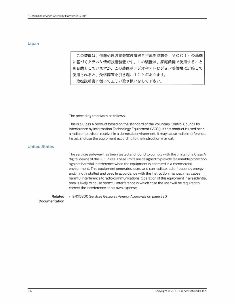
Japan
The preceding translates as follows:
This is a Class A product based on the standard of the Voluntary Control Council for
Interference by Information Technology Equipment (VCCI). If this product is used near
a radio or television receiver in a domestic environment, it may cause radio interference.
Install and use the equipment according to the instruction manual.
United States
The services gateway has been tested and found to comply with the limits for a Class A
digital device of the FCC Rules. These limits are designed to provide reasonable protection
against harmful interference when the equipment is operated in a commercial
environment. This equipment generates, uses, and can radiate radio frequency energy
and, if not installed and used in accordance with the instruction manual, may cause
harmful interference to radio communications. Operation of this equipment in a residential
area is likely to cause harmful interference in which case the user will be required to
correct the interference at his own expense.
RelatedDocumentation
• SRX5800 Services Gateway Agency Approvals on page 230
Copyright © 2010, Juniper Networks, Inc.232
SRX5800 Services Gateway Hardware Guide
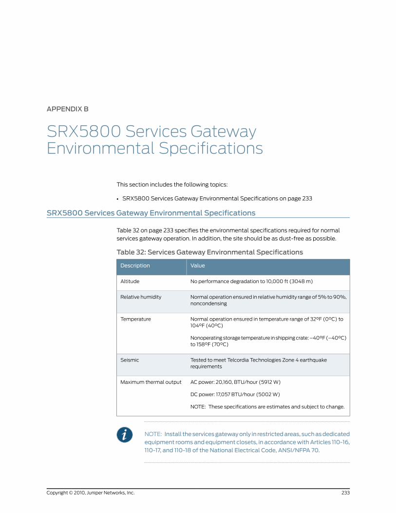
APPENDIX B
SRX5800 Services GatewayEnvironmental Specifications
This section includes the following topics:
• SRX5800 Services Gateway Environmental Specifications on page 233
SRX5800 Services Gateway Environmental Specifications
Table 32 on page 233 specifies the environmental specifications required for normal
services gateway operation. In addition, the site should be as dust-free as possible.
Table 32: Services Gateway Environmental Specifications
ValueDescription
No performance degradation to 10,000 ft (3048 m)Altitude
Normal operation ensured in relative humidity range of 5% to 90%,noncondensing
Relative humidity
Normal operation ensured in temperature range of 32°F (0°C) to104°F (40°C)
Nonoperating storage temperature in shipping crate: –40°F (–40°C)to 158°F (70°C)
Temperature
Tested to meet Telcordia Technologies Zone 4 earthquakerequirements
Seismic
AC power: 20,160, BTU/hour (5912 W)
DC power: 17,057 BTU/hour (5002 W)
NOTE: These specifications are estimates and subject to change.
Maximum thermal output
NOTE: Install theservicesgatewayonly in restrictedareas, suchasdedicatedequipment roomsandequipment closets, in accordancewithArticles 110-16,110-17, and 110-18 of the National Electrical Code, ANSI/NFPA 70.
233Copyright © 2010, Juniper Networks, Inc.
RelatedDocumentation
• SRX5800 Services Gateway Agency Approvals on page 230
• SRX5800 Services Gateway General Safety Guidelines and Warnings on page 197
• SRX5800 Services Gateway Fire Safety Requirements and Fire Suppression Equipment
on page 203
• SRX5800 Services Gateway Definition of Safety Warning Levels on page 195
• General Electrical Safety Guidelines and Warnings on page 220
Copyright © 2010, Juniper Networks, Inc.234
SRX5800 Services Gateway Hardware Guide
APPENDIX C
SRX5800 Services Gateway PowerGuidelines, Requirements, andSpecifications
This section includes the following topics:
• SRX5800 Services Gateway Chassis Grounding Specifications on page 235
• SRX5800 Services Gateway Grounding-Cable Lug Specification on page 238
• SRX5800 Services Gateway AC Power Specifications and Requirements on page 238
• SRX5800 Services Gateway DC Power Specifications and Requirements on page 243
• SRX5800 Services Gateway Electrical Wiring Guidelines on page 250
SRX5800 Services Gateway Chassis Grounding Specifications
To meet safety and electromagnetic interference (EMI) requirements and to ensure
proper operation, the services gateway must be adequately grounded before power is
connected. To ground AC-powered and DC-powered services gateways, you must connect
a grounding cable to earth ground and then attach it to the chassis grounding points (see
Figure 85 on page 236 or Figure 86 on page 237).
235Copyright © 2010, Juniper Networks, Inc.
Figure 85: Grounding Point on an AC-powered Services Gateway
Copyright © 2010, Juniper Networks, Inc.236
SRX5800 Services Gateway Hardware Guide
Figure 86: Grounding Point on a DC-powered Services Gateway
To ground AC-powered and DC-powered services gateways, connect a grounding cable
to earth ground and then attach it to the chassis grounding points using two screws. The
left pair of grounding points fits M6 screws (European), and the right pair fits UNC 1/4–20
screws (English). The grounding points are spaced at 0.625-in. (15.86-mm) centers. The
accessory box shipped with the services gateway includes the cable lug that attaches
to the grounding cable and two UNC 1/4–20 screws used to secure the grounding cable
to the right pair of grounding points.
WARNING: The services gateway is a pluggable type A equipment installedin restricted access location. It has a separate protective earthing terminal(Metric -M6 and English - ¼-20 screw ground lugs) provided on the chassisin addition to the grounding pin of the power supply cord. This separateprotective earth terminal must be permanently connected to earth.
The 48 VDC facility shall be equipped with a circuit breaker rated 40 A (–48 VDC), or
60 A (–48 VDC), and the grounding cable must be minimum 10 AWG, or as required by
the local code.
NOTE: Additional grounding is provided to anAC-powered services gatewaywhen you plug its power supplies into grounded AC power receptacles.
WARNING: The services gateway is installed in a restricted-access location.Ithasaseparateprotectiveearthing terminal (Metric [M6]andEnglish[¼-20]
237Copyright © 2010, Juniper Networks, Inc.
Appendix C: SRX5800 Services Gateway Power Guidelines, Requirements, and Specifications
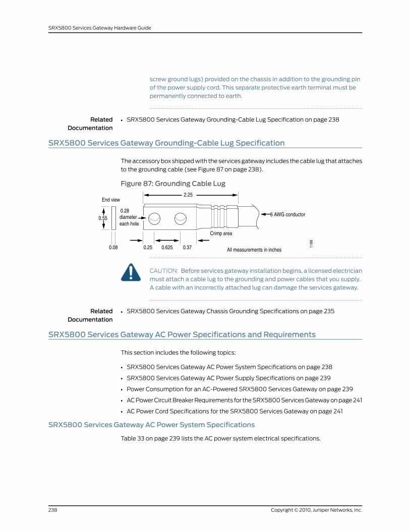
screw ground lugs) provided on the chassis in addition to the grounding pinof the power supply cord. This separate protective earth terminal must bepermanently connected to earth.
RelatedDocumentation
SRX5800 Services Gateway Grounding-Cable Lug Specification on page 238•
SRX5800 Services Gateway Grounding-Cable Lug Specification
The accessory box shipped with the services gateway includes the cable lug that attaches
to the grounding cable (see Figure 87 on page 238).
Figure 87: Grounding Cable Lug
CAUTION: Before services gateway installationbegins, a licensedelectricianmust attach a cable lug to the grounding and power cables that you supply.A cable with an incorrectly attached lug can damage the services gateway.
RelatedDocumentation
SRX5800 Services Gateway Chassis Grounding Specifications on page 235•
SRX5800 Services Gateway AC Power Specifications and Requirements
This section includes the following topics:
• SRX5800 Services Gateway AC Power System Specifications on page 238
• SRX5800 Services Gateway AC Power Supply Specifications on page 239
• Power Consumption for an AC-Powered SRX5800 Services Gateway on page 239
• AC Power Circuit Breaker Requirements for the SRX5800 Services Gateway on page 241
• AC Power Cord Specifications for the SRX5800 Services Gateway on page 241
SRX5800 Services Gateway AC Power SystemSpecifications
Table 33 on page 239 lists the AC power system electrical specifications.
Copyright © 2010, Juniper Networks, Inc.238
SRX5800 Services Gateway Hardware Guide
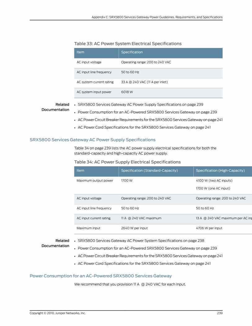
Table 33: AC Power System Electrical Specifications
SpecificationItem
Operating range: 200 to 240 VACAC input voltage
50 to 60 HzAC input line frequency
33 A @ 240 VAC (11 A per inlet)AC system current rating
6018 WAC system input power
RelatedDocumentation
SRX5800 Services Gateway AC Power Supply Specifications on page 239•
• Power Consumption for an AC-Powered SRX5800 Services Gateway on page 239
• AC Power Circuit Breaker Requirements for the SRX5800 Services Gateway on page 241
• AC Power Cord Specifications for the SRX5800 Services Gateway on page 241
SRX5800 Services Gateway AC Power Supply Specifications
Table 34 on page 239 lists the AC power supply electrical specifications for both the
standard-capacity and high-capacity AC power supply.
Table 34: AC Power Supply Electrical Specifications
Specification (High-Capacity)Specification (Standard-Capacity)Item
4100 W (two AC inputs)
1700 W (one AC input)
1700 WMaximum output power
Operating range: 200 to 240 VACOperating range: 200 to 240 VACAC input voltage
50 to 60 Hz50 to 60 HzAC input line frequency
13 A @ 240 VAC maximum per AC input11 A @ 240 VAC maximumAC input current rating
4706 W per input2640 W per inputMaximum input
RelatedDocumentation
SRX5800 Services Gateway AC Power System Specifications on page 238•
• Power Consumption for an AC-Powered SRX5800 Services Gateway on page 239
• AC Power Circuit Breaker Requirements for the SRX5800 Services Gateway on page 241
• AC Power Cord Specifications for the SRX5800 Services Gateway on page 241
Power Consumption for an AC-Powered SRX5800 Services Gateway
We recommend that you provision 11 A @ 240 VAC for each input.
239Copyright © 2010, Juniper Networks, Inc.
Appendix C: SRX5800 Services Gateway Power Guidelines, Requirements, and Specifications
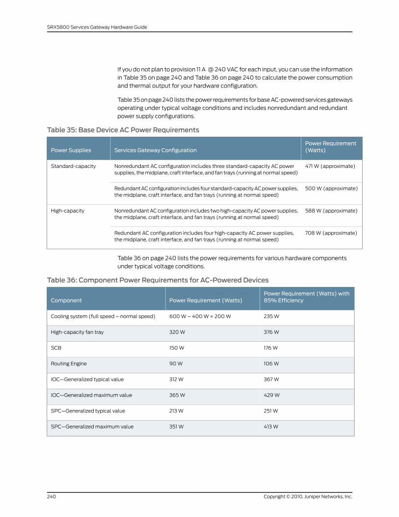
If you do not plan to provision 11 A @ 240 VAC for each input, you can use the information
in Table 35 on page 240 and Table 36 on page 240 to calculate the power consumption
and thermal output for your hardware configuration.
Table 35 on page 240 lists the power requirements for base AC-powered services gateways
operating under typical voltage conditions and includes nonredundant and redundant
power supply configurations.
Table 35: Base Device AC Power Requirements
Power Requirement(Watts)Services Gateway ConfigurationPower Supplies
471 W (approximate)Nonredundant AC configuration includes three standard-capacity AC powersupplies, the midplane, craft interface, and fan trays (running at normal speed)
Standard-capacity
500 W (approximate)Redundant AC configuration includes four standard-capacity AC power supplies,the midplane, craft interface, and fan trays (running at normal speed)
588 W (approximate)Nonredundant AC configuration includes two high-capacity AC power supplies,the midplane, craft interface, and fan trays (running at normal speed)
High-capacity
708 W (approximate)Redundant AC configuration includes four high-capacity AC power supplies,the midplane, craft interface, and fan trays (running at normal speed)
Table 36 on page 240 lists the power requirements for various hardware components
under typical voltage conditions.
Table 36: Component Power Requirements for AC-Powered Devices
Power Requirement (Watts) with85%EfficiencyPower Requirement (Watts)Component
235 W600 W – 400 W = 200 WCooling system (full speed – normal speed)
376 W320 WHigh-capacity fan tray
176 W150 WSCB
106 W90 WRouting Engine
367 W312 WIOC—Generalized typical value
429 W365 WIOC—Generalized maximum value
251 W213 WSPC—Generalized typical value
413 W351 WSPC—Generalized maximum value
Copyright © 2010, Juniper Networks, Inc.240
SRX5800 Services Gateway Hardware Guide
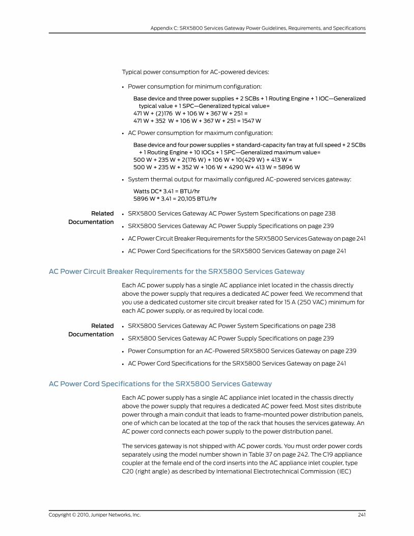
Typical power consumption for AC-powered devices:
• Power consumption for minimum configuration:
Base device and three power supplies + 2 SCBs + 1 Routing Engine + 1 IOC—Generalizedtypical value + 1 SPC—Generalized typical value=
471W + (2)176 W+ 106W+ 367W+ 251 =471W + 352 W+ 106W+ 367W+ 251 = 1547W
• AC Power consumption for maximum configuration:
Base device and four power supplies + standard-capacity fan tray at full speed+ 2SCBs+ 1 Routing Engine + 10 IOCs + 1 SPC—Generalizedmaximum value=
500W+ 235W+ 2(176W) + 106W+ 10(429W) + 413W=500W+ 235W+ 352W+ 106W+ 4290W+ 413W= 5896W
• System thermal output for maximally configured AC-powered services gateway:
Watts DC* 3.41 = BTU/hr5896W * 3.41 = 20,105 BTU/hr
RelatedDocumentation
SRX5800 Services Gateway AC Power System Specifications on page 238•
• SRX5800 Services Gateway AC Power Supply Specifications on page 239
• AC Power Circuit Breaker Requirements for the SRX5800 Services Gateway on page 241
• AC Power Cord Specifications for the SRX5800 Services Gateway on page 241
AC Power Circuit Breaker Requirements for the SRX5800 Services Gateway
Each AC power supply has a single AC appliance inlet located in the chassis directly
above the power supply that requires a dedicated AC power feed. We recommend that
you use a dedicated customer site circuit breaker rated for 15 A (250 VAC) minimum for
each AC power supply, or as required by local code.
RelatedDocumentation
SRX5800 Services Gateway AC Power System Specifications on page 238•
• SRX5800 Services Gateway AC Power Supply Specifications on page 239
• Power Consumption for an AC-Powered SRX5800 Services Gateway on page 239
• AC Power Cord Specifications for the SRX5800 Services Gateway on page 241
AC Power Cord Specifications for the SRX5800 Services Gateway
Each AC power supply has a single AC appliance inlet located in the chassis directly
above the power supply that requires a dedicated AC power feed. Most sites distribute
power through a main conduit that leads to frame-mounted power distribution panels,
one of which can be located at the top of the rack that houses the services gateway. An
AC power cord connects each power supply to the power distribution panel.
The services gateway is not shipped with AC power cords. You must order power cords
separately using the model number shown in Table 37 on page 242. The C19 appliance
coupler at the female end of the cord inserts into the AC appliance inlet coupler, type
C20 (right angle) as described by International Electrotechnical Commission (IEC)
241Copyright © 2010, Juniper Networks, Inc.
Appendix C: SRX5800 Services Gateway Power Guidelines, Requirements, and Specifications
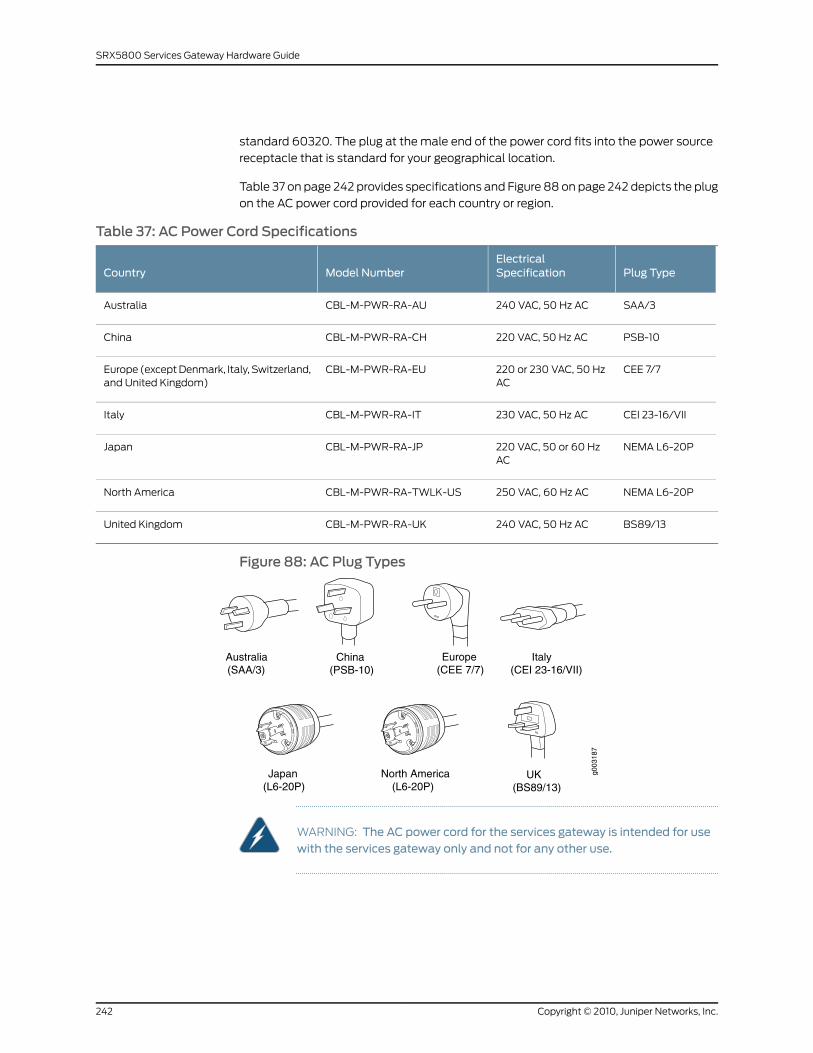
standard 60320. The plug at the male end of the power cord fits into the power source
receptacle that is standard for your geographical location.
Table 37 on page 242 provides specifications and Figure 88 on page 242 depicts the plug
on the AC power cord provided for each country or region.
Table 37: AC Power Cord Specifications
Plug TypeElectricalSpecificationModel NumberCountry
SAA/3240 VAC, 50 Hz ACCBL-M-PWR-RA-AUAustralia
PSB-10220 VAC, 50 Hz ACCBL-M-PWR-RA-CHChina
CEE 7/7220 or 230 VAC, 50 HzAC
CBL-M-PWR-RA-EUEurope (except Denmark, Italy, Switzerland,and United Kingdom)
CEI 23-16/VII230 VAC, 50 Hz ACCBL-M-PWR-RA-ITItaly
NEMA L6-20P220 VAC, 50 or 60 HzAC
CBL-M-PWR-RA-JPJapan
NEMA L6-20P250 VAC, 60 Hz ACCBL-M-PWR-RA-TWLK-USNorth America
BS89/13240 VAC, 50 Hz ACCBL-M-PWR-RA-UKUnited Kingdom
Figure 88: AC Plug Types
North America(L6-20P)
Australia(SAA/3)
g003
187
Japan(L6-20P)
China(PSB-10)
Italy(CEI 23-16/VII)
Europe(CEE 7/7)
UK(BS89/13)
WARNING: The AC power cord for the services gateway is intended for usewith the services gateway only and not for any other use.
Copyright © 2010, Juniper Networks, Inc.242
SRX5800 Services Gateway Hardware Guide
NOTE: In North America, AC power cordsmust not exceed 4.5m(approximately 14.75 ft) in length, to comply with National Electrical Code(NEC)Sections 400-8 (NFPA75, 5-2.2) and 210-52, andCanadian ElectricalCode (CEC)Section 4-010(3). The cords listed in Table 37 on page 242 are incompliance.
WARNING: The services gateway is a pluggable type A equipment installedin restricted access location. It has a separate protective earthing terminal[Metric -M6 and English -¼-20 screw) ground lugs] provided on the chassisin addition to the grounding pin of the power supply cord. This separateprotective earth terminal must be permanently connected to earth.
CAUTION: Powercordsandcablesmustnotblockaccess toservicesgatewaycomponents or drape where people could trip on them.
RelatedDocumentation
SRX5800 Services Gateway AC Power System Specifications on page 238•
• SRX5800 Services Gateway AC Power Supply Specifications on page 239
• Power Consumption for an AC-Powered SRX5800 Services Gateway on page 239
• AC Power Circuit Breaker Requirements for the SRX5800 Services Gateway on page 241
SRX5800 Services Gateway DC Power Specifications and Requirements
This section includes the following topics:
• SRX5800 Services Gateway DC Power System Specifications on page 243
• SRX5800 Services Gateway DC Power Supply Specifications on page 244
• Power Consumption for a DC-Powered SRX5800 Services Gateway on page 245
• DC Power Circuit Breaker Requirements for the SRX5800 Services Gateway on page 247
• DC Power Source Cabling for the SRX5800 Services Gateway on page 247
• DC Power Cable Specifications for the SRX5800 Services Gateway on page 248
• DC Power Cable Lug Specifications for the SRX5800 Services Gateway on page 249
SRX5800 Services Gateway DC Power SystemSpecifications
Table 38 on page 243 lists the DC power system electrical specifications.
Table 38: DC Power System Electrical Specifications
SpecificationItem
Operating range: –40 to –72 VDCDC input voltage
243Copyright © 2010, Juniper Networks, Inc.
Appendix C: SRX5800 Services Gateway Power Guidelines, Requirements, and Specifications
Table 38: DC Power System Electrical Specifications (continued)
SpecificationItem
116 A (58 A per feed) @ –48 VDC (nominal)DC system current rating
4987 WDC system input power
RelatedDocumentation
SRX5800 Services Gateway DC Power Supply Specifications on page 244•
• Power Consumption for a DC-Powered SRX5800 Services Gateway on page 245
• DC Power Circuit Breaker Requirements for the SRX5800 Services Gateway on page 247
• DC Power Source Cabling for the SRX5800 Services Gateway on page 247
• DC Power Cable Specifications for the SRX5800 Services Gateway on page 248
• DC Power Cable Lug Specifications for the SRX5800 Services Gateway on page 249
SRX5800 Services Gateway DC Power Supply Specifications
Table 39 on page 244 lists the DC power supply electrical specifications.
Table 39: DC Power Supply Electrical Specifications
SpecificationItem
2800 WMaximum output power
Nominal: –48 VDC
Operating range: –40 to –72 VDC
DC input voltage
70 A maximum @ –48 VDC (58 A nominal operating voltage)DC input current rating
3360 W per inputMaximum input
80 AInternal SupplementaryProtector
RelatedDocumentation
SRX5800 Services Gateway DC Power System Specifications on page 243•
• Power Consumption for a DC-Powered SRX5800 Services Gateway on page 245
• DC Power Circuit Breaker Requirements for the SRX5800 Services Gateway on page 247
• DC Power Source Cabling for the SRX5800 Services Gateway on page 247
• DC Power Cable Specifications for the SRX5800 Services Gateway on page 248
• DC Power Cable Lug Specifications for the SRX5800 Services Gateway on page 249
Copyright © 2010, Juniper Networks, Inc.244
SRX5800 Services Gateway Hardware Guide
Power Consumption for a DC-Powered SRX5800 Services Gateway
We recommend that you provision at least 116 A (58 A per feed) @ –48 VDC (nominal)
for the system.
If you do not plan to provision at least 116 A (58 A per feed) @ –48 VDC (nominal) for
the system, you can use the information in Table 40 on page 245 and Table 41 on page 245
to calculate the power consumption @ –48 VDC and thermal output for your hardware
configuration.
Table 40 on page 245 lists the power requirements for base DC-powered services gateways
operating under typical voltage conditions and includes nonredundant and redundant
power supply configurations.
NOTE: The base DC-powered services gateway includes themidplane, craftinterface, and fan trays running at normal speed.
Table 40: DC Base Services Gateway Power Requirements
CurrentRequirement(Amps@–48 VDC)
PowerRequirement(Watts)DC Power Supply Configuration
8.3 A(approximate)
400 W(approximate)
Nonredundant DC configuration includes two DC powersupplies, the midplane, craft interface, and fan traysrunning at normal speed.
8.3 A(approximate)
400 W(approximate)
Redundant DC configuration includes four DC powersupplies, the midplane, craft interface, and fan traysrunning at normal speed.
Table 41: Component DC Power Requirements
CurrentRequirement(Amps@–48 VDC)
PowerRequirement(Watts)Component
3.1 A150 WSCB
1.9 A90 WRouting Engine
4.2 A600 W – 400 W= 200 W
Cooling system (full speed – normal speed)
6.5 A312 WIOC—Generalized typical value
7.6 A365 WIOC—Generalized maximum value
4.4 A213 WSPC—Generalized typical value
245Copyright © 2010, Juniper Networks, Inc.
Appendix C: SRX5800 Services Gateway Power Guidelines, Requirements, and Specifications
Table 41: Component DC Power Requirements (continued)
CurrentRequirement(Amps@–48 VDC)
PowerRequirement(Watts)Component
7.3 A351 WSPC—Generalized maximum value
These examples use generalized values for DPCs.
Typical power consumption for DC-powered devices:
• Power consumption for minimum configuration:
Base device and two power supplies + 2 SCBs + 1 Routing Engine + 1 IOC—Generalizedtypical value + 1 SPC—Generalized typical value =
8.3 A + 2(3.1) A + 1.9 A + 6.5 A + 4.4 A =8.3 A + 6.2 A + 1.9 A + 6.5 A + 4.4 A = 27.3 A@–48 VDC = 1310W
• Power consumption for maximum configuration:
Base device and four power supplies + fan tray at full speed + 2 SCBs + 1 Routing Engine+ 10 IOCs—Generalized typical value + 1 SPC—Generalizedmaximum value =
8.3 A + 4.2 A + 2(3.1 A) + 1.9 A + 10(7.6 A) + 7.3 A =8.3 A + 4.2 A + 6.2 A + 1.9 A + 76 A + 7.3 A = 103.9 A@–48 VDC = 4987W
• Current requirement adjustment for fans running at full speed (high temperature
environment or cooling component failure):
Calculated system current (X) – Cooling (normal) + Cooling (full speed) =X A – 8.3 A + 12.5 A =X A + 4.2 A
• Input current from a DC source other than –48 VDC (based on maximum configuration;
applies to DC power supply only):
(–54 VDC input) * (input current X) = (–48 VDC input) * (input current Y)54 * X = 48 * 103.9 AX = 48 * 103.9 A/54 = 92.4 A
• System thermal output for maximally configured DC-powered services gateway:
Watts DC * 3.41 = BTU/hr4987 * 3.41= 17,006 BTU/hr
RelatedDocumentation
SRX5800 Services Gateway DC Power System Specifications on page 243•
• SRX5800 Services Gateway DC Power Supply Specifications on page 244
• DC Power Circuit Breaker Requirements for the SRX5800 Services Gateway on page 247
• DC Power Source Cabling for the SRX5800 Services Gateway on page 247
• DC Power Cable Specifications for the SRX5800 Services Gateway on page 248
• DC Power Cable Lug Specifications for the SRX5800 Services Gateway on page 249
Copyright © 2010, Juniper Networks, Inc.246
SRX5800 Services Gateway Hardware Guide
DC Power Circuit Breaker Requirements for the SRX5800 Services Gateway
If you plan to operate a maximally configured DC-powered services gateway, we
recommend that you provision at least 116 A (58 A per feed) @ –48 VDC (nominal) for
the system. Use a customer site circuit breaker rated for 80 A (–48 VDC) minimum for
each DC power supply.
If you plan to operate a DC-powered services gateway at less than the maximum
configuration and do not provision a 80 A (–48 VDC) circuit breaker, we recommend
that you provision a circuit breaker for each DC power supply rated for at least 125% of
the continuous current that the system draws at –48 VDC.
RelatedDocumentation
SRX5800 Services Gateway DC Power System Specifications on page 243•
• SRX5800 Services Gateway DC Power Supply Specifications on page 244
• Power Consumption for a DC-Powered SRX5800 Services Gateway on page 245
• DC Power Source Cabling for the SRX5800 Services Gateway on page 247
• DC Power Cable Specifications for the SRX5800 Services Gateway on page 248
• DC Power Cable Lug Specifications for the SRX5800 Services Gateway on page 249
DC Power Source Cabling for the SRX5800 Services Gateway
Figure 89 on page 247 shows a typical DC source cabling arrangement.
Figure 89: Typical DC Source Cabling to the Services Gateway
The DC power supplies in slots PEM0 and PEM1 must be powered by dedicated power
feeds derived from feed A, and the DC power supplies in slots PEM2 and PEM3 must be
powered by dedicated power feeds derived from feed B. This configuration provides the
commonly deployed A/B feed redundancy for the system.
247Copyright © 2010, Juniper Networks, Inc.
Appendix C: SRX5800 Services Gateway Power Guidelines, Requirements, and Specifications
CAUTION: Youmust ensure that power connectionsmaintain the properpolarity. The power source cablesmight be labeled (+) and (–) to indicate
their polarity. There is no standard color coding for DC power cables. Thecolor coding used by the external DC power source at your site determinesthe color coding for the leads on the power cables that attach to the terminalstuds on each power supply.
WARNING: For field-wiring connections, use copper conductors only.
CAUTION: Power cords and cablesmust not block access to devicecomponents or drape where people could trip on them.
RelatedDocumentation
SRX5800 Services Gateway DC Power System Specifications on page 243•
• SRX5800 Services Gateway DC Power Supply Specifications on page 244
• Power Consumption for a DC-Powered SRX5800 Services Gateway on page 245
• DC Power Circuit Breaker Requirements for the SRX5800 Services Gateway on page 247
• DC Power Cable Specifications for the SRX5800 Services Gateway on page 248
• DC Power Cable Lug Specifications for the SRX5800 Services Gateway on page 249
DC Power Cable Specifications for the SRX5800 Services Gateway
Table 42 on page 248 summarizes the specifications for the power cables, which you must
supply.
Table 42: DC Power Cable Specifications
Quantity and SpecificationCable Type
Eight 6-AWG (13.3 mm2), minimum 60°C wire, or as required by the localcode
Power
CAUTION: Youmust ensure that power connectionsmaintain the properpolarity. The power source cablesmight be labeled (+) and (–) to indicate
their polarity. There is no standard color coding for DC power cables. Thecolor coding used by the external DC power source at your site determinesthe color coding for the leads on the power cables that attach to the terminalstuds on each power supply.
RelatedDocumentation
SRX5800 Services Gateway DC Power System Specifications on page 243•
Copyright © 2010, Juniper Networks, Inc.248
SRX5800 Services Gateway Hardware Guide
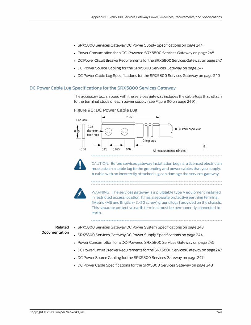
• SRX5800 Services Gateway DC Power Supply Specifications on page 244
• Power Consumption for a DC-Powered SRX5800 Services Gateway on page 245
• DC Power Circuit Breaker Requirements for the SRX5800 Services Gateway on page 247
• DC Power Source Cabling for the SRX5800 Services Gateway on page 247
• DC Power Cable Lug Specifications for the SRX5800 Services Gateway on page 249
DC Power Cable Lug Specifications for the SRX5800 Services Gateway
The accessory box shipped with the services gateway includes the cable lugs that attach
to the terminal studs of each power supply (see Figure 90 on page 249).
Figure 90: DC Power Cable Lug
CAUTION: Before services gateway installationbegins, a licensedelectricianmust attach a cable lug to the grounding and power cables that you supply.A cable with an incorrectly attached lug can damage the services gateway.
WARNING: The services gateway is a pluggable type A equipment installedin restricted access location. It has a separate protective earthing terminal[Metric -M6andEnglish -¼-20 screw) ground lugs] provided on the chassis.This separate protective earth terminal must be permanently connected toearth.
RelatedDocumentation
SRX5800 Services Gateway DC Power System Specifications on page 243•
• SRX5800 Services Gateway DC Power Supply Specifications on page 244
• Power Consumption for a DC-Powered SRX5800 Services Gateway on page 245
• DC Power Circuit Breaker Requirements for the SRX5800 Services Gateway on page 247
• DC Power Source Cabling for the SRX5800 Services Gateway on page 247
• DC Power Cable Specifications for the SRX5800 Services Gateway on page 248
249Copyright © 2010, Juniper Networks, Inc.
Appendix C: SRX5800 Services Gateway Power Guidelines, Requirements, and Specifications
SRX5800 Services Gateway ElectricalWiring Guidelines
• Distance limitations for signaling—Improperly installed wires can emit radio interference.
In addition, the potential for damage from lightning strikes increases if wires exceed
recommended distances or if wires pass between buildings. The electromagnetic pulse
(EMP) caused by lightning can damage unshielded conductors and destroy electronic
devices. If your site has previously experienced such problems, you might want to
consult experts in electrical surge suppression and shielding.
• Radio frequency interference—You can reduce or eliminate the emission of radio
frequency interference (RFI) from your site wiring by using twisted-pair cable with a
good distribution of grounding conductors. If you must exceed the recommended
distances, use a high-quality twisted-pair cable with one ground conductor for each
data signal when applicable.
• Electromagnetic compatibility—If your site is susceptible to problems with
electromagnetic compatibility (EMC), particularly from lightning or radio transmitters,
you might want to seek expert advice. Strong sources of electromagnetic interference
(EMI) can destroy the signal drivers and receivers in the routing platform and conduct
power surges over the lines into the equipment, resulting in an electrical hazard. It is
particularly important to provide a properly grounded and shielded environment and
to use electrical surge-suppression devices.
WARNING: Certain ports on the services gateway are designed for use asintrabuilding (within-the-building) interfaces only (Type 2 or Type 4 portsas described in GR-1089-CORE, Issue 4) and require isolation from theexposed outside plant (OSP) cabling. To comply with NEBS requirementsandprotectagainst lighteningsurgesandcommercialpowerdisturbances,the intrabuilding ports must not bemetallically connected to interfacesthatconnect to theOSPor itswiring.The intrabuildingportson theservicesgateway are suitable for connection to intrabuilding or unexposed wiringor cabling only. The addition of primary protectors is not sufficientprotection for connecting these interfacesmetallically to OSPwiring.
RelatedDocumentation
• General Electrical Safety Guidelines and Warnings on page 220
• Installation Instructions Warning on page 205
Copyright © 2010, Juniper Networks, Inc.250
SRX5800 Services Gateway Hardware Guide
APPENDIX D
Cable andWire Guidelines andSpecifications for the SRX5800 ServicesGateway
This section includes the following topics:
• Network Cable Specifications and Guidelines for the SRX5800 Services
Gateway on page 251
Network Cable Specifications and Guidelines for the SRX5800 Services Gateway
This section includes the following topics:
• Signal Loss in Multimode and Single-Mode Fiber-Optic Cable for the SRX5800 Services
Gateway on page 251
• Attenuation and Dispersion in Fiber-Optic Cable for the SRX5800 Services
Gateway on page 252
• Calculating Power Budget for Fiber-Optic Cable for the SRX5800 Services
Gateway on page 253
• Calculating Power Margin for Fiber-Optic Cable for the SRX5800 Services
Gateway on page 253
• Routing Engine Interface Cable and Wire Specifications for the SRX5800 Services
Gateway on page 255
• Alarm Relay Contact Wire Specifications for the SRX5800 Services Gateway on page 256
• Console Port Cable and Wire Specifications for the SRX5800 Services
Gateway on page 256
SignalLoss inMultimodeandSingle-ModeFiber-OpticCablefor theSRX5800ServicesGateway
Multimode fiber is large enough in diameter to allow rays of light to reflect internally
(bounce off the walls of the fiber). Interfaces with multimode optics typically use LEDs
as light sources. LEDs are not coherent sources, however. They spray varying wavelengths
of light into the multimode fiber, which reflects the light at different angles. Light rays
travel in jagged lines through a multimode fiber, causing signal dispersion. When light
traveling in the fiber core radiates into the fiber cladding, higher-order mode loss (HOL)
251Copyright © 2010, Juniper Networks, Inc.
results. Together these factors limit the transmission distance of multimode fiber
compared to single-mode fiber.
Single-mode fiber is so small in diameter that rays of light can reflect internally through
one layer only. Interfaces with single-mode optics use lasers as light sources. Lasers
generate a single wavelength of light, which travels in a straight line through the
single-mode fiber. Compared with multimode fiber, single-mode fiber has higher
bandwidth and can carry signals for longer distances. It is consequently more expensive.
RelatedDocumentation
Attenuation and Dispersion in Fiber-Optic Cable for the SRX5800 Services Gateway
on page 252
•
• Calculating Power Budget for Fiber-Optic Cable for the SRX5800 Services Gateway
on page 253
• Calculating Power Margin for Fiber-Optic Cable for the SRX5800 Services Gateway
on page 253
• Connecting Network Cables to SRX5800 Services Gateway IOCs and Port Modules
on page 83
Attenuation and Dispersion in Fiber-Optic Cable for the SRX5800 Services Gateway
Correct functioning of an optical data link depends on modulated light reaching the
receiver with enough power to be demodulated correctly. Attenuation is the reduction in
power of the light signal as it is transmitted. Attenuation is caused by passive media
components, such as cables, cable splices, and connectors. While attenuation is
significantly lower for optical fiber than for other media, it still occurs in both multimode
and single-mode transmission. An efficient optical data link must have enough light
available to overcome attenuation.
Dispersion is the spreading of the signal in time. The following two types of dispersion
can affect an optical data link:
• Chromatic dispersion—The spreading of the signal in time resulting from the different
speeds of light rays.
• Modal dispersion—The spreading of the signal in time resulting from the different
propagation modes in the fiber.
For multimode transmission, modal dispersion, rather than chromatic dispersion or
attenuation, usually limits the maximum bit rate and link length. For single-mode
transmission, modal dispersion is not a factor. However, at higher bit rates and over longer
distances, chromatic dispersion rather than modal dispersion limits maximum link length.
An efficient optical data link must have enough light to exceed the minimum power that
the receiver requires to operate within its specifications. In addition, the total dispersion
must be less than the limits specified for the type of link in Telcordia Technologies
document GR-253-CORE (Section 4.3) and International Telecommunications Union
(ITU) document G.957.
When chromatic dispersion is at the maximum allowed, its effect can be considered as
a power penalty in the power budget. The optical power budget must allow for the sum
Copyright © 2010, Juniper Networks, Inc.252
SRX5800 Services Gateway Hardware Guide
of component attenuation, power penalties (including those from dispersion), and a
safety margin for unexpected losses.
RelatedDocumentation
Signal Loss in Multimode and Single-Mode Fiber-Optic Cable for the SRX5800 Services
Gateway on page 251
•
• Calculating Power Budget for Fiber-Optic Cable for the SRX5800 Services Gateway
on page 253
• Calculating Power Margin for Fiber-Optic Cable for the SRX5800 Services Gateway
on page 253
• Connecting Network Cables to SRX5800 Services Gateway IOCs and Port Modules
on page 83
Calculating Power Budget for Fiber-Optic Cable for the SRX5800 Services Gateway
To ensure that fiber-optic connections have sufficient power for correct operation, you
need to calculate the link's power budget, which is the maximum amount of power it
can transmit. When you calculate the power budget, you use a worst-case analysis to
provide a margin of error, even though all the parts of an actual system do not operate
at the worst-case levels. To calculate the worst-case estimate of power budget (PB),
you assume minimum transmitter power (PT) and minimum receiver sensitivity (P
R):
PB= P
T– P
R
The following hypothetical power budget equation uses values measured in decibels
(dB) and decibels referred to one milliwatt (dBm):
PB= P
T– P
R
PB= –15 dBm– (–28 dBm)
PB= 13 dB
RelatedDocumentation
Signal Loss in Multimode and Single-Mode Fiber-Optic Cable for the SRX5800 Services
Gateway on page 251
•
• Attenuation and Dispersion in Fiber-Optic Cable for the SRX5800 Services Gateway
on page 252
• Calculating Power Margin for Fiber-Optic Cable for the SRX5800 Services Gateway
on page 253
• Connecting Network Cables to SRX5800 Services Gateway IOCs and Port Modules
on page 83
Calculating Power Margin for Fiber-Optic Cable for the SRX5800 Services Gateway
After calculating a link's power budget, you can calculate the power margin (PM
), which
represents the amount of power available after subtracting attenuation or link loss (LL)
from the power budget (PB). A worst-case estimate of P
Massumes maximum LL:
253Copyright © 2010, Juniper Networks, Inc.
Appendix D: Cable and Wire Guidelines and Specifications for the SRX5800 Services Gateway
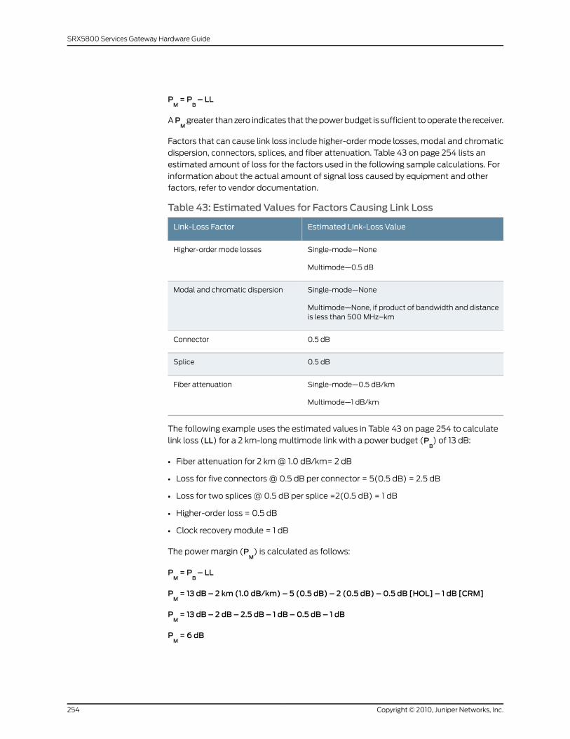
PM= P
B– LL
APM
greater than zero indicates that the power budget is sufficient to operate the receiver.
Factors that can cause link loss include higher-order mode losses, modal and chromatic
dispersion, connectors, splices, and fiber attenuation. Table 43 on page 254 lists an
estimated amount of loss for the factors used in the following sample calculations. For
information about the actual amount of signal loss caused by equipment and other
factors, refer to vendor documentation.
Table 43: Estimated Values for Factors Causing Link Loss
Estimated Link-Loss ValueLink-Loss Factor
Single-mode—None
Multimode—0.5 dB
Higher-order mode losses
Single-mode—None
Multimode—None, if product of bandwidth and distanceis less than 500 MHz–km
Modal and chromatic dispersion
0.5 dBConnector
0.5 dBSplice
Single-mode—0.5 dB/km
Multimode—1 dB/km
Fiber attenuation
The following example uses the estimated values in Table 43 on page 254 to calculate
link loss (LL) for a 2 km-long multimode link with a power budget (PB) of 13 dB:
• Fiber attenuation for 2 km @ 1.0 dB/km= 2 dB
• Loss for five connectors @ 0.5 dB per connector = 5(0.5 dB) = 2.5 dB
• Loss for two splices @ 0.5 dB per splice =2(0.5 dB) = 1 dB
• Higher-order loss = 0.5 dB
• Clock recovery module = 1 dB
The power margin (PM
) is calculated as follows:
PM= P
B– LL
PM= 13 dB – 2 km (1.0 dB/km) – 5 (0.5 dB) – 2 (0.5 dB) – 0.5 dB [HOL] – 1 dB [CRM]
PM= 13 dB – 2 dB – 2.5 dB – 1 dB – 0.5 dB – 1 dB
PM= 6 dB
Copyright © 2010, Juniper Networks, Inc.254
SRX5800 Services Gateway Hardware Guide
The following sample calculation for an 8 km-long single-mode link with a power budget
(PB) of 13 dB uses the estimated values from Table 43 on page 254 to calculate link loss
(LL) as the sum of fiber attenuation (8 km @ 0.5 dB/km, or 4 dB) and loss for seven
connectors (0.5 dB per connector, or 3.5 dB). The power margin (PM
) is calculated as
follows:
PM= P
B– LL
PM= 13 dB – 8 km (0.5 dB/km) – 7 (0.5 dB)
PM= 13 dB – 4 dB – 3.5 dB
PM= 5.5 dB
In both examples, the calculated power margin is greater than zero, indicating that the
link has sufficient power for transmission and does not exceed the maximum receiver
input power.
RelatedDocumentation
Signal Loss in Multimode and Single-Mode Fiber-Optic Cable for the SRX5800 Services
Gateway on page 251
•
• Attenuation and Dispersion in Fiber-Optic Cable for the SRX5800 Services Gateway
on page 252
• Calculating Power Budget for Fiber-Optic Cable for the SRX5800 Services Gateway
on page 253
• Connecting Network Cables to SRX5800 Services Gateway IOCs and Port Modules
on page 83
Routing Engine Interface Cable andWire Specifications for the SRX5800 Services Gateway
Table 44 on page 255 lists the specifications for the cables that connect to management
ports and the wires that connect to the alarm relay contacts.
Table44: Cable andWireSpecifications forRoutingEngineManagementand Alarm Interfaces
Routing EngineReceptacle
MaximumLength
Cable/WireSupplied
CableSpecificationPort
RJ-45 female6 ft (1.83 m)One 6-ft(1.83-m) lengthwith RJ-45/DB-9connectors
RS-232(EIA-232) serialcable
Routing Engineconsole orauxiliaryinterface
RJ-45autosensing
328 ft (100 m)One 15-ft(4.57-m) lengthwithRJ-45/RJ-45connectors
Category 5 cableor equivalentsuitable for100Base-Toperation
Routing EngineEthernetinterface
255Copyright © 2010, Juniper Networks, Inc.
Appendix D: Cable and Wire Guidelines and Specifications for the SRX5800 Services Gateway
RelatedDocumentation
Connecting the SRX5800 Services Gateway to a Management Console or an Auxiliary
Device on page 81
•
• Connecting the SRX5800 Services Gateway to a Network for Out-of-Band Management
on page 80
Alarm Relay ContactWire Specifications for the SRX5800 Services Gateway
Table 45 on page 256 lists the specifications for the wires that connect to the alarm relay
contacts.
Table 45: Cable andWire Specifications for Alarm Interfaces
Cable/WireSupplied
CableSpecificationPort
NoWire with gaugebetween28-AWG and14-AWG (0.08and 2.08 mm2)
Alarm relaycontacts
RelatedDocumentation
Connecting an SRX5800 Services Gateway to an External Alarm-Reporting Device on
page 82
•
Console Port Cable andWire Specifications for the SRX5800 Services Gateway
Table 46 on page 256 lists the specifications for the cable that connects aCONSOLEport
on the Routing Engine to a management console.
Table46:Cable andWireSpecifications forRoutingEngineManagementand Alarm Interfaces
ReceptacleMaximumLength
Cable/WireSupplied
CableSpecificationPort
RJ-45/DB-9male
6 ft (1.83 m)One 6-ft(1.83-m) lengthwith RJ-45/DB-9connectors
RS-232(EIA-232) serialcable
Routing Engineconsole orauxiliaryinterface
RelatedDocumentation
• Connecting the SRX5800 Services Gateway to a Management Console or an Auxiliary
Device on page 81
• RJ-45 Connector Pinouts for the SRX5800 Services Gateway Routing Engine Auxiliary
and Console Ports on page 258
Copyright © 2010, Juniper Networks, Inc.256
SRX5800 Services Gateway Hardware Guide
APPENDIX E
Cable Connector Pinouts
This section includes the following topics:
• RJ-45 Connector Pinouts for the SRX5800 Services Gateway Routing Engine Ethernet
Port on page 257
• RJ-45 Connector Pinouts for the SRX5800 Services Gateway Routing Engine Auxiliary
and Console Ports on page 258
RJ-45ConnectorPinouts for theSRX5800ServicesGatewayRoutingEngineEthernetPort
The port on the Routing Engine labeled ETHERNET is an autosensing 10/100-Mbps
Ethernet RJ-45 receptacle that accepts an Ethernet cable for connecting the Routing
Engine to a management LAN (or other device that supports out-of-band management).
Table 47 on page 257 describes the RJ-45 connector pinout.
Table47: RJ-45ConnectorPinout for theRoutingEngineETHERNETPort
SignalPin
TX+1
TX–2
RX+3
Termination network4
Termination network5
RX–6
Termination network7
Termination network8
RelatedDocumentation
Routing Engine Interface Cable and Wire Specifications for the SRX5800 Services
Gateway on page 255
•
257Copyright © 2010, Juniper Networks, Inc.
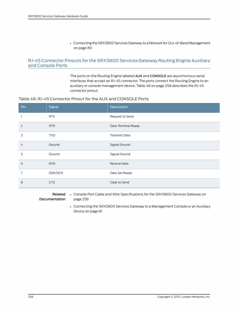
• Connecting the SRX5800 Services Gateway to a Network for Out-of-Band Management
on page 80
RJ-45Connector Pinouts for theSRX5800ServicesGatewayRoutingEngineAuxiliaryand Console Ports
The ports on the Routing Engine labeled AUX and CONSOLE are asynchronous serial
interfaces that accept an RJ-45 connector. The ports connect the Routing Engine to an
auxiliary or console management device. Table 48 on page 258 describes the RJ-45
connector pinout.
Table 48: RJ-45 Connector Pinout for the AUX and CONSOLE Ports
DescriptionSignalPin
Request to SendRTS1
Data Terminal ReadyDTR2
Transmit DataTXD3
Signal GroundGround4
Signal GroundGround5
Receive DataRXD6
Data Set ReadyDSR/DCD7
Clear to SendCTS8
RelatedDocumentation
• Console Port Cable and Wire Specifications for the SRX5800 Services Gateway on
page 256
• Connecting the SRX5800 Services Gateway to a Management Console or an Auxiliary
Device on page 81
Copyright © 2010, Juniper Networks, Inc.258
SRX5800 Services Gateway Hardware Guide
APPENDIX F
Installing theSRX5800ServicesGatewayWithout a Mechanical Lift
This section includes the following topics:
• Overview of Installing the SRX5800 Services Gateway Without a Mechanical
Lift on page 259
• Tools Required to Install the SRX5800 Services Gateway Without a Mechanical
Lift on page 260
• Removing Components from the SRX5800 Chassis Before Installing It Without a
Lift on page 260
• Installing the SRX5800 Services Gateway Chassis in the Rack Manually on page 269
• Reinstalling Components in the SRX5800 Services Gateway Chassis After Installing
It Without a Lift on page 271
Overview of Installing the SRX5800 Services GatewayWithout aMechanical Lift
If you cannot use a mechanical lift to install the services gateway (the preferred method),
you can install it manually. Before installing the services gateway manually, you must
first remove components from the chassis, and you must reinstall the components once
the services gateway is installed in the rack. At least three people are needed to safely
lift the chassis into the rack or cabinet. With components removed, the chassis weighs
approximately 150 lb (68 kg).
Before installing the services gateway in the rack, read the safety information in “Chassis
Lifting Guidelines” on page 204. Remove the services gateway from the shipping container
as described in “Unpacking the SRX5800 Services Gateway” on page 63. Install the
mounting hardware as described in “Installing the SRX5800 Services Gateway Mounting
Hardware for a Four-Post Rack or Cabinet” on page 69 or “Installing the SRX5800 Services
Gateway Mounting Hardware in an Open-Frame Rack” on page 71.
RelatedDocumentation
Tools Required to Install the SRX5800 Services Gateway Without a Mechanical Lift
on page 260
•
• Removing Components from the SRX5800 Chassis Before Installing It Without a Lift
on page 260
• Installing the SRX5800 Services Gateway Chassis in the Rack Manually on page 269
259Copyright © 2010, Juniper Networks, Inc.
• Reinstalling Components in the SRX5800 Services Gateway Chassis After Installing
It Without a Lift on page 271
Tools Required to Install the SRX5800 Services GatewayWithout aMechanical Lift
To install the services gateway, you need the following tools and parts:
• Phillips (+) screwdrivers, numbers 1 and 2
• 7/16-in. (11 mm) nut driver
• ESD grounding wrist strap
RelatedDocumentation
Overview of Installing the SRX5800 Services Gateway Without a Mechanical Lift on
page 259
•
• Removing Components from the SRX5800 Chassis Before Installing It Without a Lift
on page 260
• Installing the SRX5800 Services Gateway Chassis in the Rack Manually on page 269
• Reinstalling Components in the SRX5800 Services Gateway Chassis After Installing
It Without a Lift on page 271
Removing Components from the SRX5800 Chassis Before Installing ItWithout a Lift
If you cannot use a mechanical lift to install the services gateway (the preferred method),
you can install it manually. Before installing the services gateway manually, you must
first remove components from the chassis, and reinstall the components the chassis is
installed in the rack. With components removed, the chassis weighs approximately 150 lb
(68 kg).
1. Removing the Power Supplies Before Installing the SRX5800 Services Gateway
Without a Lift on page 261
2. Removing the Cable Manager Before Installing the SRX5800 Services Gateway
Without a Lift on page 262
3. Removing Fan Trays Before Installing the SRX5800 Services Gateway Without a
Lift on page 263
4. Removing SCBs Before Installing the SRX5800 Services Gateway Without a
Lift on page 265
5. Removing IOCs, Flex IOCs, and SPCs Before Installing the SRX5800 Services Gateway
Without a Lift on page 266
Copyright © 2010, Juniper Networks, Inc.260
SRX5800 Services Gateway Hardware Guide
Removing the Power Supplies Before Installing the SRX5800Services GatewayWithout a Lift
Remove the leftmost power supply first and then work your way to the right. To remove
each AC or DC power supply (see Figure 91 on page 262):
1. Attach an ESD grounding strap to your bare wrist, and connect the strap to one of the
ESD points on the chassis.
2. Switch off the services gateway power supplies:
• For an AC-powered services gateway, move the AC input switch on the chassis
above each AC power supply to the off (O) position. If the services gateway is
equipped with high-capacity AC power supplies, you must also move the AC input
switch on each power supply to the off (O) position.
• For DC-powered services gateway, move the DC circuit breaker on each power
supply faceplate to the off (O) position.
We recommend switching off the power supplies even though they are not connected
to power sources.
3. While grasping the handle on the power supply faceplate with one hand, use your
other hand to pull the spring-loaded locking pin in the release lever away from the
chassis and turn the release lever counterclockwise until it stops.
4. Let go of the locking pin in the release lever. Ensure that the pin is seated inside the
corresponding hole in the chassis.
5. Pull the power supply straight out of the chassis.
WARNING: Do not touch the power connector on the top of the powersupply. It can contain dangerous voltages.
261Copyright © 2010, Juniper Networks, Inc.
Appendix F: Installing the SRX5800 Services Gateway Without a Mechanical Lift
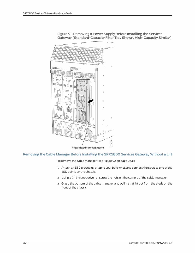
Figure 91: Removing a Power Supply Before Installing the ServicesGateway (Standard-Capacity Filter Tray Shown, High-Capacity Similar)
Removing the Cable Manager Before Installing the SRX5800 Services GatewayWithout a Lift
To remove the cable manager (see Figure 92 on page 263):
1. Attach an ESD grounding strap to your bare wrist, and connect the strap to one of the
ESD points on the chassis.
2. Using a 7/16-in. nut driver, unscrew the nuts on the corners of the cable manager.
3. Grasp the bottom of the cable manager and pull it straight out from the studs on the
front of the chassis.
Copyright © 2010, Juniper Networks, Inc.262
SRX5800 Services Gateway Hardware Guide
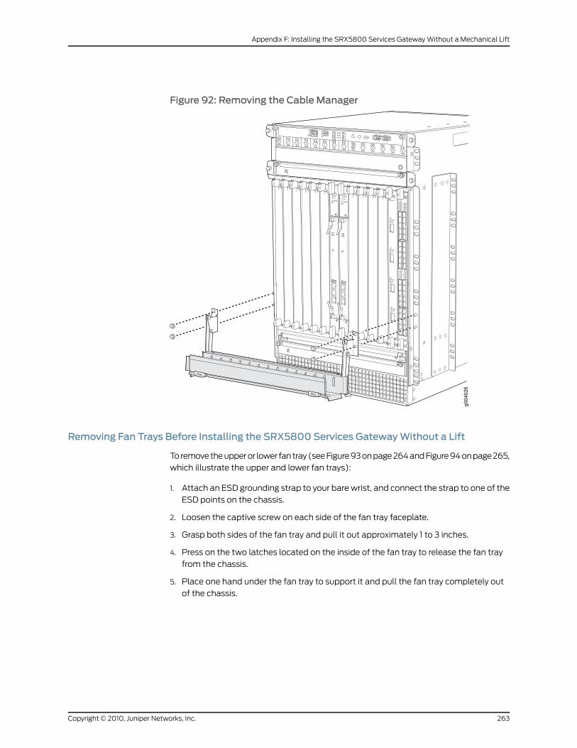
Figure 92: Removing the Cable Manager
Removing Fan Trays Before Installing the SRX5800 Services GatewayWithout a Lift
To remove the upper or lower fan tray (see Figure 93 on page 264 and Figure 94 on page 265,
which illustrate the upper and lower fan trays):
1. Attach an ESD grounding strap to your bare wrist, and connect the strap to one of the
ESD points on the chassis.
2. Loosen the captive screw on each side of the fan tray faceplate.
3. Grasp both sides of the fan tray and pull it out approximately 1 to 3 inches.
4. Press on the two latches located on the inside of the fan tray to release the fan tray
from the chassis.
5. Place one hand under the fan tray to support it and pull the fan tray completely out
of the chassis.
263Copyright © 2010, Juniper Networks, Inc.
Appendix F: Installing the SRX5800 Services Gateway Without a Mechanical Lift
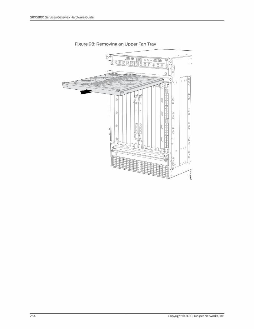
Figure 93: Removing an Upper Fan Tray
OK
0
FAIL
ONLINE
OK
1
FAIL
ONLINE
OK
2
FAIL
ONLINE
OK
3
FAIL
ONLINE
OK
4
FAIL
ONLINE
OK
5
FAIL
ONLINE
OK
0
FAIL
ONLINE
MASTERONLINEOFFLINE
RE0
FANPEM
1
0
0 1 2 3
RE1OK
1
FAIL
ONLINE
OK
7
FAIL
ONLINE
OK
8
FAIL
ONLINE
OK
9
FAIL
ONLINE
OK
10
FAIL
ONLINE
OK
11
FAIL
ONLINE
OK
2 6
FAIL
ONLINE
ACO/LT
YELLOW ALARM RED ALARM
NC NOC NC NOC
1 01 0
1 0
1 01 0
1 10 0
1 01 01 0
g004
042
Copyright © 2010, Juniper Networks, Inc.264
SRX5800 Services Gateway Hardware Guide
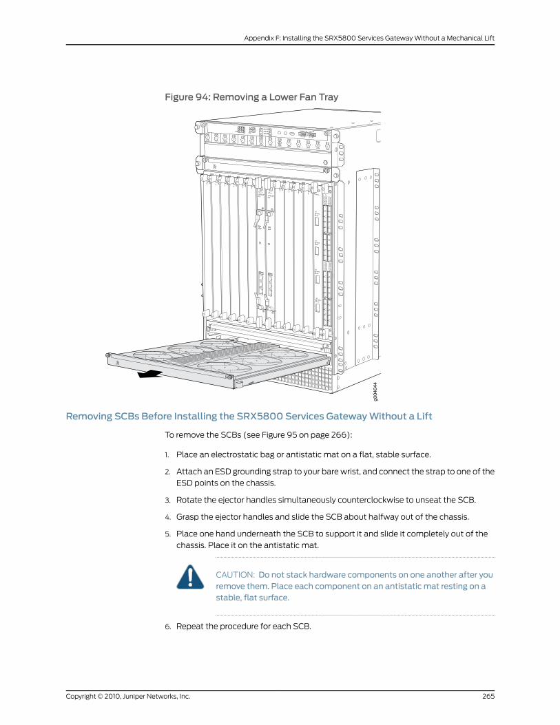
Figure 94: Removing a Lower Fan Tray
OK
0
FAIL
ONLINE
OK
1
FAIL
ONLINE
OK
2
FAIL
ONLINE
OK
3
FAIL
ONLINE
OK
4
FAIL
ONLINE
OK
5
FAIL
ONLINE
OK
0
FAIL
ONLINE
MASTERONLINEOFFLINE
RE0
FANPEM
1
0
0 1 2 3
RE1OK
1
FAIL
ONLINE
OK
7
FAIL
ONLINE
OK
8
FAIL
ONLINE
OK
9
FAIL
ONLINE
OK
10
FAIL
ONLINE
OK
11
FAIL
ONLINE
OK
2 6
FAIL
ONLINE
ACO/LT
YELLOW ALARM RED ALARM
NC NOC NC NOC
1 01 0
1 0
1 01 0
1 10 0
1 01 01 0
g004
044
Removing SCBs Before Installing the SRX5800 Services GatewayWithout a Lift
To remove the SCBs (see Figure 95 on page 266):
1. Place an electrostatic bag or antistatic mat on a flat, stable surface.
2. Attach an ESD grounding strap to your bare wrist, and connect the strap to one of the
ESD points on the chassis.
3. Rotate the ejector handles simultaneously counterclockwise to unseat the SCB.
4. Grasp the ejector handles and slide the SCB about halfway out of the chassis.
5. Place one hand underneath the SCB to support it and slide it completely out of the
chassis. Place it on the antistatic mat.
CAUTION: Do not stack hardware components on one another after youremove them. Place each component on an antistatic mat resting on astable, flat surface.
6. Repeat the procedure for each SCB.
265Copyright © 2010, Juniper Networks, Inc.
Appendix F: Installing the SRX5800 Services Gateway Without a Mechanical Lift
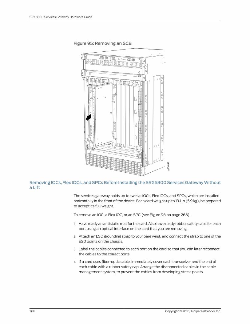
Figure 95: Removing an SCB
OK
0
FAIL
ONLINE
OK
1
FAIL
ONLINE
OK
2
FAIL
ONLINE
OK
3
FAIL
ONLINE
OK
4
FAIL
ONLINE
OK
5
FAIL
ONLINE
OK
0
FAIL
ONLINE
MASTERONLINEOFFLINE
RE0
FANPEM
1
0
0 1 2 3
RE1OK
1
FAIL
ONLINE
OK
7
FAIL
ONLINE
OK
8
FAIL
ONLINE
OK
9
FAIL
ONLINE
OK
10
FAIL
ONLINE
OK
11
FAIL
ONLINE
OK
2 6
FAIL
ONLINE
ACO/LT
YELLOW ALARM RED ALARM
NC NOC NC NOC
1 01 0
1 0
1 01 0
1 10 0
1 01 01 0
g004
048
Removing IOCs, Flex IOCs, andSPCsBefore Installing theSRX5800ServicesGatewayWithouta Lift
The services gateway holds up to twelve IOCs, Flex IOCs, and SPCs, which are installed
horizontally in the front of the device. Each card weighs up to 13.1 lb (5.9 kg), be prepared
to accept its full weight.
To remove an IOC, a Flex IOC, or an SPC (see Figure 96 on page 268):
1. Have ready an antistatic mat for the card. Also have ready rubber safety caps for each
port using an optical interface on the card that you are removing.
2. Attach an ESD grounding strap to your bare wrist, and connect the strap to one of the
ESD points on the chassis.
3. Label the cables connected to each port on the card so that you can later reconnect
the cables to the correct ports.
4. If a card uses fiber-optic cable, immediately cover each transceiver and the end of
each cable with a rubber safety cap. Arrange the disconnected cables in the cable
management system, to prevent the cables from developing stress points.
Copyright © 2010, Juniper Networks, Inc.266
SRX5800 Services Gateway Hardware Guide
WARNING: Do not look directly into a fiber-optic transceiver or into theends of fiber-optic cables. Fiber-optic transceivers and fiber-optic cableconnected to a transceiver emit laser light that can damage your eyes.
CAUTION: Do not leave a fiber-optic transceiver uncovered except wheninserting or removing cable. The safety cap keeps the port clean andprevents accidental exposure to laser light.
CAUTION: Avoid bending fiber-optic cable beyond its minimum bendradius.Anarc smaller thana few inches indiameter candamage thecableand cause problems that are difficult to diagnose.
5. Simultaneously turn both the ejector handles counterclockwise to unseat the IOC.
6. Grasp the handles and slide the card straight out of the card cage halfway.
7. Place one hand around the front of the card and the other hand under it to support it.
Slide the IOC completely out of the chassis, and place it on the antistatic mat or in
the electrostatic bag.
CAUTION: The weight of the card is concentrated in the back end. Beprepared to accept the full weight—up to 13.1 lb (5.9 kg)—as you slide thecard out of the chassis.
When the card is out of the chassis, do not hold it by the ejector handles,bus bars, or edge connectors. They cannot support its weight.
Do not stack cards on top of one another after removal. Place each oneindividually in an electrostatic bag or on its own antistatic mat on a flat,stable surface.
267Copyright © 2010, Juniper Networks, Inc.
Appendix F: Installing the SRX5800 Services Gateway Without a Mechanical Lift
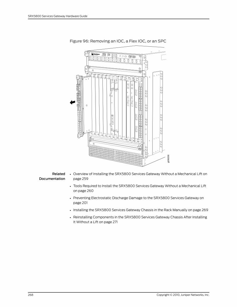
Figure 96: Removing an IOC, a Flex IOC, or an SPC
RelatedDocumentation
Overview of Installing the SRX5800 Services Gateway Without a Mechanical Lift on
page 259
•
• Tools Required to Install the SRX5800 Services Gateway Without a Mechanical Lift
on page 260
• Preventing Electrostatic Discharge Damage to the SRX5800 Services Gateway on
page 201
• Installing the SRX5800 Services Gateway Chassis in the Rack Manually on page 269
• Reinstalling Components in the SRX5800 Services Gateway Chassis After Installing
It Without a Lift on page 271
Copyright © 2010, Juniper Networks, Inc.268
SRX5800 Services Gateway Hardware Guide
Installing the SRX5800 Services Gateway Chassis in the RackManually
To install the services gateway in the rack (see Figure 97 on page 270):
CAUTION: If you are installingmore than one services gateway in a rack,install the lowest one first. Installing a services gateway in an upper positionin a rack or cabinet requires a lift.
CAUTION: Before front mounting the services gateway in a rack, have aqualified technician verify that the rack is strong enough to support theservices gateway's weight and is adequately supported at the installationsite.
CAUTION: Lifting the chassis andmounting it in a rack requires three people.The empty chassis weighs approximately 150 lb (68 kg).
1. Ensure that the rack is in its permanent location and is secured to the building. Ensure
that the installation site allows adequate clearance for both airflow and maintenance.
2. Position the services gateway in front of the rack or cabinet, centering it in front of the
mounting shelf. Use a pallet jack if one is available.
3. With one person on each side and one person in the front, hold onto the bottom of
the chassis and carefully lift it onto the large and small (if installed) mounting shelves.
WARNING: To prevent injury, keep your back straight and lift with yourlegs, not your back. Avoid twisting your body as you lift. Balance the loadevenly and be sure that your footing is solid.
4. Slide the services gateway onto the mounting shelves until the center-mounting
brackets or front-mounting flanges contact the rack rails. The shelves ensure that the
holes in the center-mounting brackets and the front-mounting flanges of the chassis
align with the holes in the rack rails.
5. To install the services gateway in an open-frame rack, install a mounting screw into
each of the open mounting holes aligned with the rack, starting from the bottom.
6. Visually inspect the alignment of the services gateway. If the services gateway is
installed properly in the rack, all the mounting screws on one side of the rack should
be aligned with the mounting screws on the opposite side and the services gateway
should be level.
269Copyright © 2010, Juniper Networks, Inc.
Appendix F: Installing the SRX5800 Services Gateway Without a Mechanical Lift
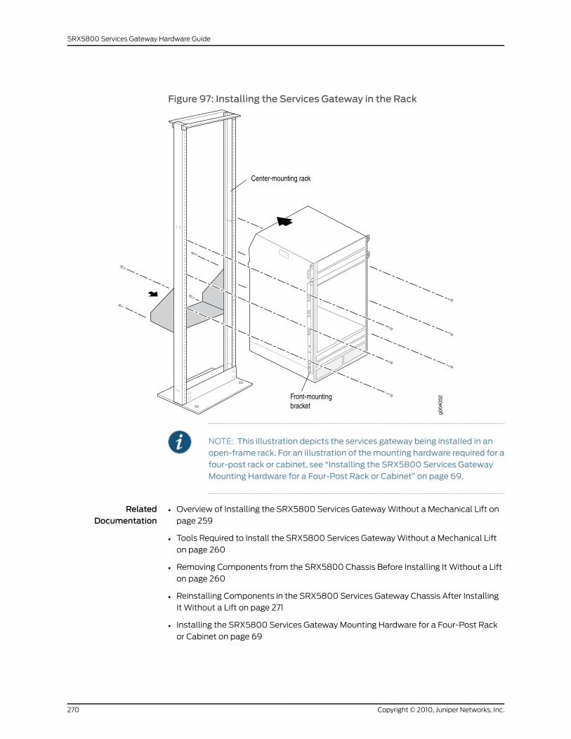
Figure 97: Installing the Services Gateway in the Rack
NOTE: This illustration depicts the services gateway being installed in anopen-frame rack. For an illustration of themounting hardware required for afour-post rack or cabinet, see “Installing the SRX5800 Services GatewayMounting Hardware for a Four-Post Rack or Cabinet” on page 69.
RelatedDocumentation
Overview of Installing the SRX5800 Services Gateway Without a Mechanical Lift on
page 259
•
• Tools Required to Install the SRX5800 Services Gateway Without a Mechanical Lift
on page 260
• Removing Components from the SRX5800 Chassis Before Installing It Without a Lift
on page 260
• Reinstalling Components in the SRX5800 Services Gateway Chassis After Installing
It Without a Lift on page 271
• Installing the SRX5800 Services Gateway Mounting Hardware for a Four-Post Rack
or Cabinet on page 69
Copyright © 2010, Juniper Networks, Inc.270
SRX5800 Services Gateway Hardware Guide
• Installing the SRX5800 Services Gateway Mounting Hardware in an Open-Frame Rack
on page 71
Reinstalling Components in the SRX5800 Services Gateway Chassis After InstallingItWithout a Lift
After the services gateway is installed in the rack, reinstall the removed components
before booting and configuring the services gateway. You reinstall components first in
the rear of the chassis, and then in the front:
1. Reinstalling Power Supplies After Installing the SRX5800 Services Gateway Without
a Lift on page 271
2. Reinstalling Fan Trays After Installing the SRX5800 Services Gateway Without a
Lift on page 273
3. Reinstalling SCBs After Installing the SRX5800 Services Gateway Without a
Lift on page 274
4. Reinstalling IOCs, Flex IOCs, and SPCs After Installing the SRX5800 Services Gateway
Without a Lift on page 275
5. Reinstalling the Cable Manager After Installing an SRX5800 Services Gateway Without
a Lift on page 277
Reinstalling Power Supplies After Installing the SRX5800 Services GatewayWithout a Lift
Reinstall the rightmost power supply first and then work your way to the left. To reinstall
the AC or DC power supplies, follow this procedure for each power supply (see Figure
98 on page 272, which shows the installation of the DC power supplies):
1. Attach an ESD grounding strap to your bare wrist, and connect the strap to one of the
ESD points on the chassis.
2. Verify that the power supplies are switched off:
• For an AC-powered services gateway, verify that the AC input switch on the chassis
above each AC power supply is in the off (O) position. If the services gateway is
equipped with high-capacity AC power supplies, also verify that the AC input switch
on each power supply is in the off (O) position.
• For DC-powered services gateway, verify that the DC circuit breaker on each power
supply faceplate is in the off (O) position.
We recommend verifying that the power supplies are switched off even though they
are not connected to power sources.
3. Ensure that the release lever below the empty power supply slot is locked in the
counterclockwise position (see Figure 98 on page 272).
If necessary, pull the spring-loaded locking pin in the release lever away from the
chassis and turn the release lever counterclockwise until it stops. Let go of the locking
pin in the release lever. Ensure that the pin is seated inside the corresponding hole in
the chassis.
271Copyright © 2010, Juniper Networks, Inc.
Appendix F: Installing the SRX5800 Services Gateway Without a Mechanical Lift
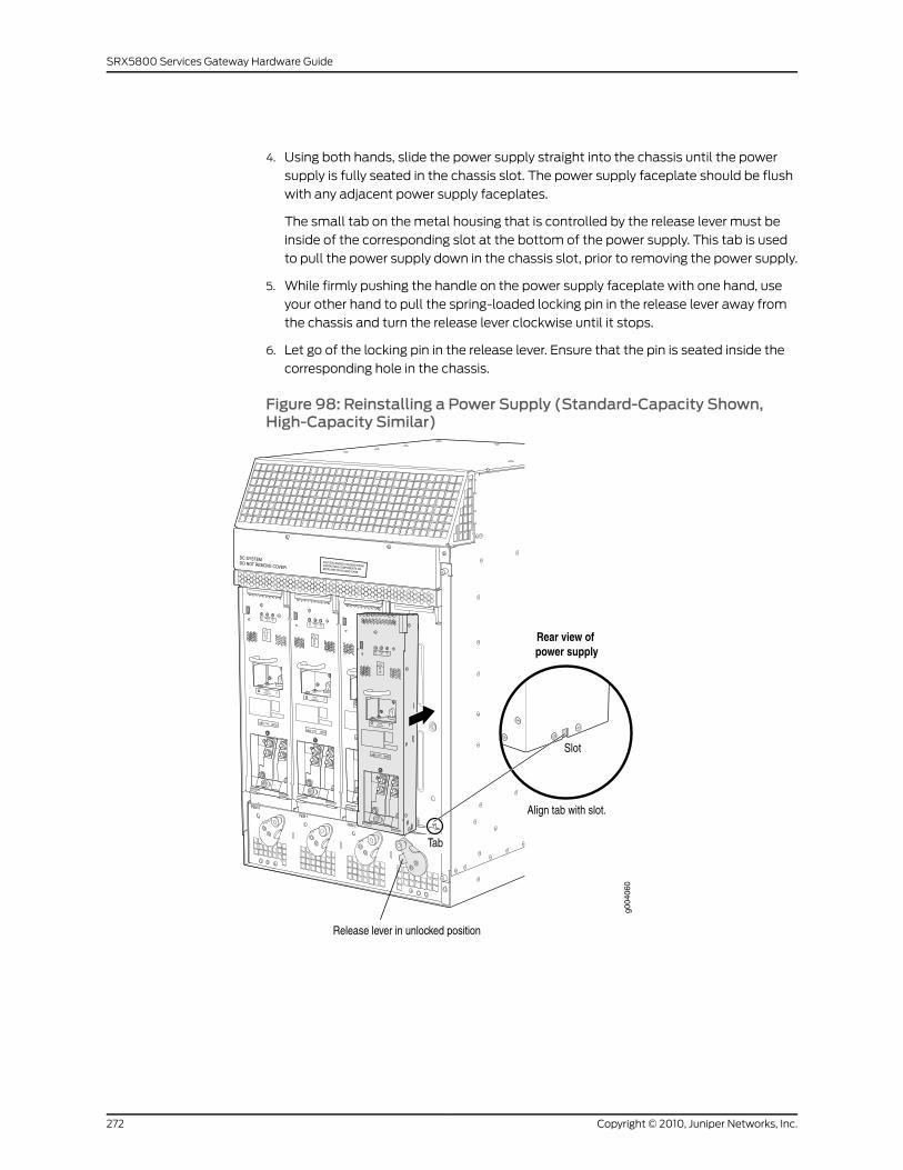
4. Using both hands, slide the power supply straight into the chassis until the power
supply is fully seated in the chassis slot. The power supply faceplate should be flush
with any adjacent power supply faceplates.
The small tab on the metal housing that is controlled by the release lever must be
inside of the corresponding slot at the bottom of the power supply. This tab is used
to pull the power supply down in the chassis slot, prior to removing the power supply.
5. While firmly pushing the handle on the power supply faceplate with one hand, use
your other hand to pull the spring-loaded locking pin in the release lever away from
the chassis and turn the release lever clockwise until it stops.
6. Let go of the locking pin in the release lever. Ensure that the pin is seated inside the
corresponding hole in the chassis.
Figure 98: Reinstalling a Power Supply (Standard-Capacity Shown,High-Capacity Similar)
Copyright © 2010, Juniper Networks, Inc.272
SRX5800 Services Gateway Hardware Guide
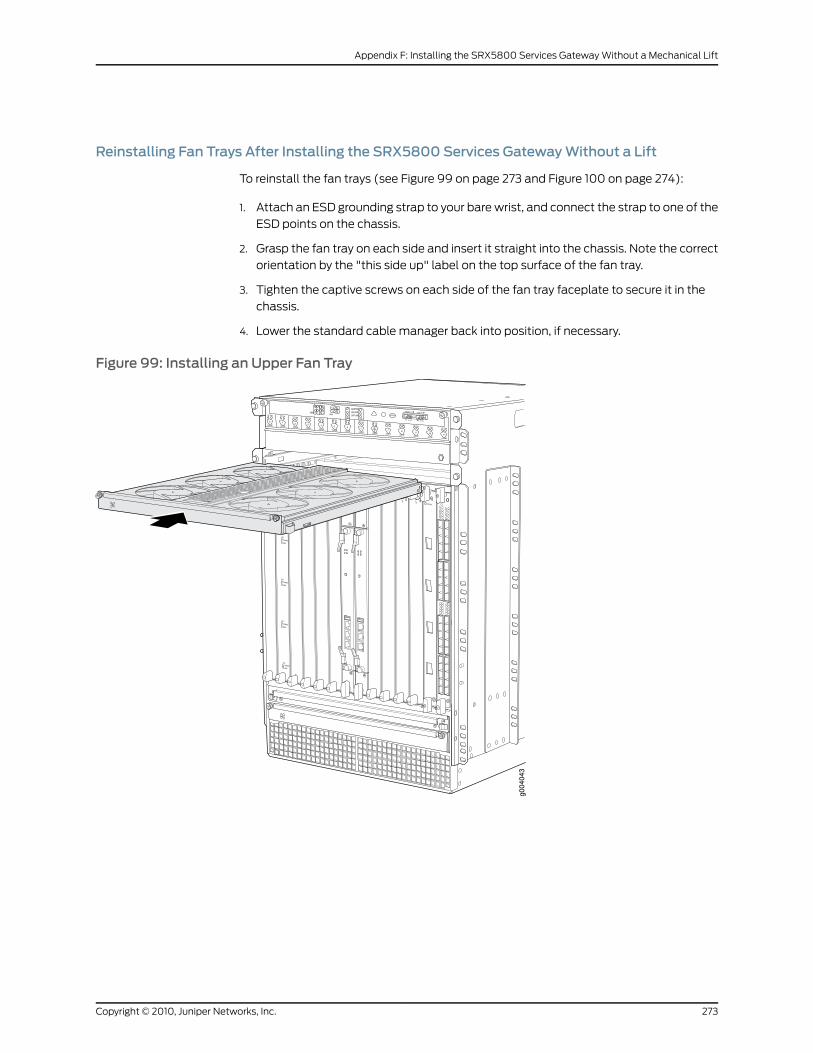
Reinstalling Fan Trays After Installing the SRX5800 Services GatewayWithout a Lift
To reinstall the fan trays (see Figure 99 on page 273 and Figure 100 on page 274):
1. Attach an ESD grounding strap to your bare wrist, and connect the strap to one of the
ESD points on the chassis.
2. Grasp the fan tray on each side and insert it straight into the chassis. Note the correct
orientation by the "this side up" label on the top surface of the fan tray.
3. Tighten the captive screws on each side of the fan tray faceplate to secure it in the
chassis.
4. Lower the standard cable manager back into position, if necessary.
Figure 99: Installing an Upper Fan Tray
g004
043
OK
0
FAIL
ONLINE
OK
1
FAIL
ONLINE
OK
2
FAIL
ONLINE
OK
3
FAIL
ONLINE
OK
4
FAIL
ONLINE
OK
5
FAIL
ONLINE
OK
0
FAIL
ONLINE
MASTERONLINEOFFLINE
RE0
FANPEM
1
0
0 1 2 3
RE1OK
1
FAIL
ONLINE
OK
7
FAIL
ONLINE
OK
8
FAIL
ONLINE
OK
9
FAIL
ONLINE
OK
10
FAIL
ONLINE
OK
11
FAIL
ONLINE
OK
2 6
FAIL
ONLINE
ACO/LT
YELLOW ALARM RED ALARM
NC NOC NC NOC
1 01 0
1 0
1 01 0
1 10 0
1 01 01 0
273Copyright © 2010, Juniper Networks, Inc.
Appendix F: Installing the SRX5800 Services Gateway Without a Mechanical Lift
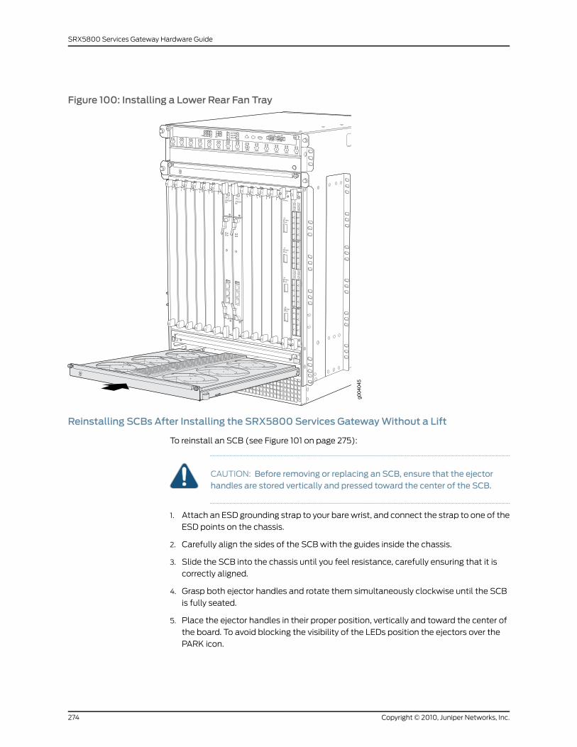
Figure 100: Installing a Lower Rear Fan Tray
OK
0
FAIL
ONLINE
OK
1
FAIL
ONLINE
OK
2
FAIL
ONLINE
OK
3
FAIL
ONLINE
OK
4
FAIL
ONLINE
OK
5
FAIL
ONLINE
OK
0
FAIL
ONLINE
MASTERONLINEOFFLINE
RE0
FANPEM
1
0
0 1 2 3
RE1OK
1
FAIL
ONLINE
OK
7
FAIL
ONLINE
OK
8
FAIL
ONLINE
OK
9
FAIL
ONLINE
OK
10
FAIL
ONLINE
OK
11
FAIL
ONLINE
OK
2 6
FAIL
ONLINE
ACO/LT
YELLOW ALARM RED ALARM
NC NOC NC NOC
1 01 0
1 0
1 01 0
1 10 0
1 01 01 0
g004
045
Reinstalling SCBs After Installing the SRX5800 Services GatewayWithout a Lift
To reinstall an SCB (see Figure 101 on page 275):
CAUTION: Before removing or replacing an SCB, ensure that the ejectorhandles are stored vertically and pressed toward the center of the SCB.
1. Attach an ESD grounding strap to your bare wrist, and connect the strap to one of the
ESD points on the chassis.
2. Carefully align the sides of the SCB with the guides inside the chassis.
3. Slide the SCB into the chassis until you feel resistance, carefully ensuring that it is
correctly aligned.
4. Grasp both ejector handles and rotate them simultaneously clockwise until the SCB
is fully seated.
5. Place the ejector handles in their proper position, vertically and toward the center of
the board. To avoid blocking the visibility of the LEDs position the ejectors over the
PARK icon.
Copyright © 2010, Juniper Networks, Inc.274
SRX5800 Services Gateway Hardware Guide
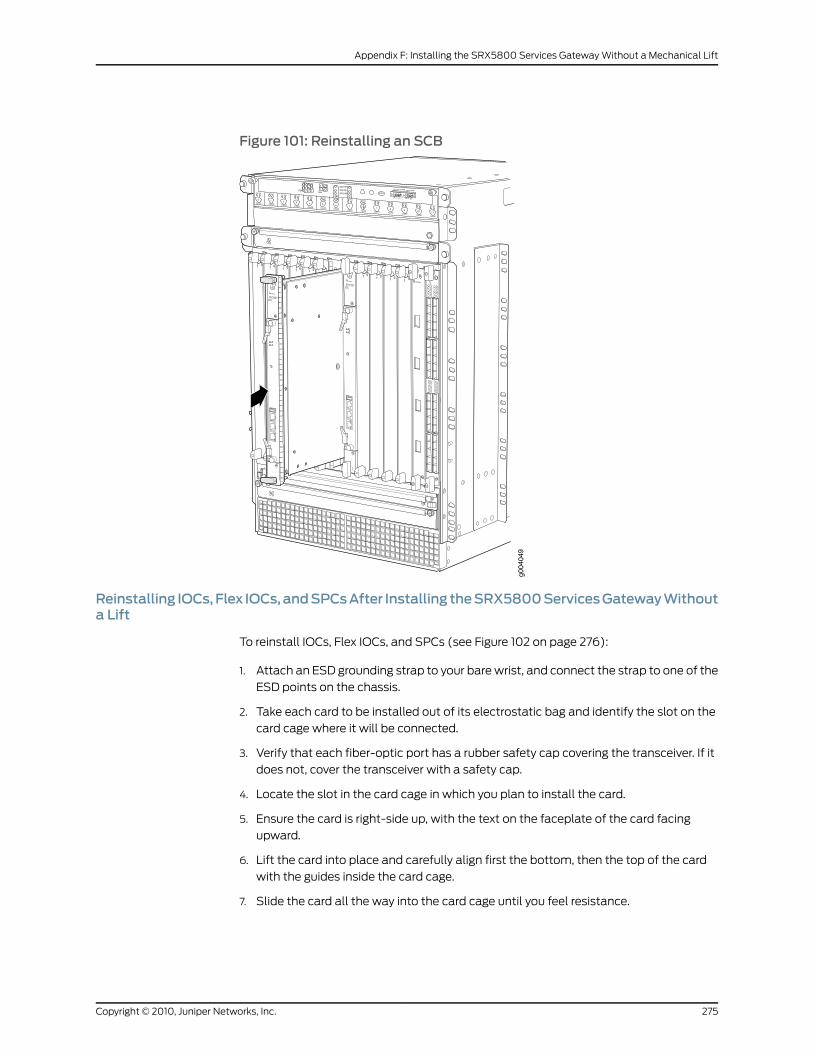
Figure 101: Reinstalling an SCB
OK
0
FAIL
ONLINE
OK
1
FAIL
ONLINE
OK
2
FAIL
ONLINE
OK
3
FAIL
ONLINE
OK
4
FAIL
ONLINE
OK
5
FAIL
ONLINE
OK
0
FAIL
ONLINE
MASTERONLINEOFFLINE
RE0
FANPEM
1
0
0 1 2 3
RE1OK
1
FAIL
ONLINE
OK
7
FAIL
ONLINE
OK
8
FAIL
ONLINE
OK
9
FAIL
ONLINE
OK
10
FAIL
ONLINE
OK
11
FAIL
ONLINE
OK
2 6
FAIL
ONLINE
ACO/LT
YELLOW ALARM RED ALARM
NC NOC NC NOC
1 01 0
1 0
1 01 0
1 10 0
1 01 01 0
g004
049
Reinstalling IOCs,Flex IOCs,andSPCsAfter Installing theSRX5800ServicesGatewayWithouta Lift
To reinstall IOCs, Flex IOCs, and SPCs (see Figure 102 on page 276):
1. Attach an ESD grounding strap to your bare wrist, and connect the strap to one of the
ESD points on the chassis.
2. Take each card to be installed out of its electrostatic bag and identify the slot on the
card cage where it will be connected.
3. Verify that each fiber-optic port has a rubber safety cap covering the transceiver. If it
does not, cover the transceiver with a safety cap.
4. Locate the slot in the card cage in which you plan to install the card.
5. Ensure the card is right-side up, with the text on the faceplate of the card facing
upward.
6. Lift the card into place and carefully align first the bottom, then the top of the card
with the guides inside the card cage.
7. Slide the card all the way into the card cage until you feel resistance.
275Copyright © 2010, Juniper Networks, Inc.
Appendix F: Installing the SRX5800 Services Gateway Without a Mechanical Lift
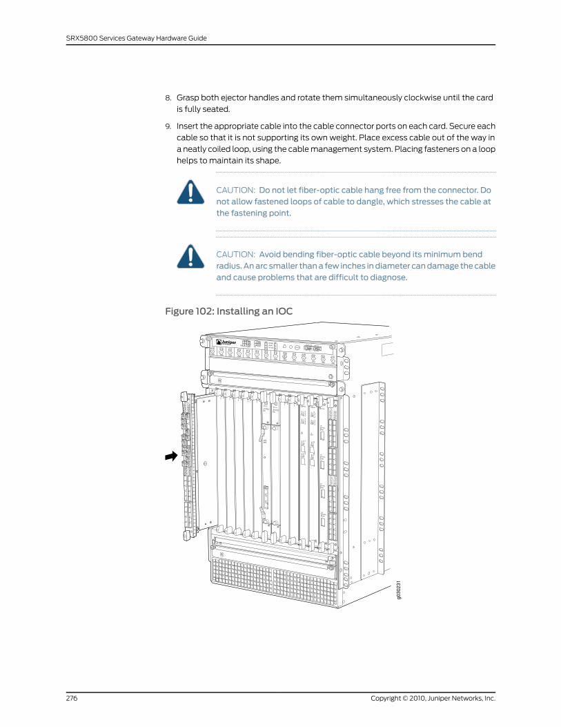
8. Grasp both ejector handles and rotate them simultaneously clockwise until the card
is fully seated.
9. Insert the appropriate cable into the cable connector ports on each card. Secure each
cable so that it is not supporting its own weight. Place excess cable out of the way in
a neatly coiled loop, using the cable management system. Placing fasteners on a loop
helps to maintain its shape.
CAUTION: Do not let fiber-optic cable hang free from the connector. Donot allow fastened loops of cable to dangle, which stresses the cable atthe fastening point.
CAUTION: Avoid bending fiber-optic cable beyond its minimum bendradius.Anarc smaller thana few inches indiameter candamage thecableand cause problems that are difficult to diagnose.
Figure 102: Installing an IOC
Copyright © 2010, Juniper Networks, Inc.276
SRX5800 Services Gateway Hardware Guide
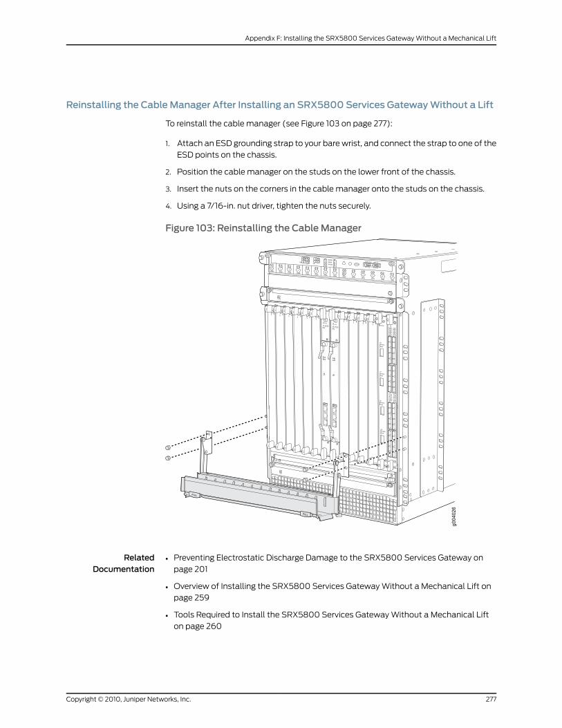
Reinstalling the Cable Manager After Installing an SRX5800 Services GatewayWithout a Lift
To reinstall the cable manager (see Figure 103 on page 277):
1. Attach an ESD grounding strap to your bare wrist, and connect the strap to one of the
ESD points on the chassis.
2. Position the cable manager on the studs on the lower front of the chassis.
3. Insert the nuts on the corners in the cable manager onto the studs on the chassis.
4. Using a 7/16-in. nut driver, tighten the nuts securely.
Figure 103: Reinstalling the Cable Manager
RelatedDocumentation
• Preventing Electrostatic Discharge Damage to the SRX5800 Services Gateway on
page 201
• Overview of Installing the SRX5800 Services Gateway Without a Mechanical Lift on
page 259
• Tools Required to Install the SRX5800 Services Gateway Without a Mechanical Lift
on page 260
277Copyright © 2010, Juniper Networks, Inc.
Appendix F: Installing the SRX5800 Services Gateway Without a Mechanical Lift

• Removing Components from the SRX5800 Chassis Before Installing It Without a Lift
on page 260
• Installing the SRX5800 Services Gateway Chassis in the Rack Manually on page 269
Copyright © 2010, Juniper Networks, Inc.278
SRX5800 Services Gateway Hardware Guide
APPENDIX G
Contacting Customer Support andReturning theSRX5800ServicesGatewayHardware
This section includes the following topics:
• Return Procedure for the SRX5800 Services Gateway on page 279
• Locating SRX5800 Services Gateway Component Serial Numbers on page 280
• Contacting Customer Support to Obtain Return Materials Authorization for the
SRX5800 Services Gateway on page 289
• Packing the SRX5800 Services Gateway or a Component for Shipment on page 290
Return Procedure for the SRX5800 Services Gateway
If a problem cannot be resolved by the JTAC technician, a Return Materials Authorization
(RMA) is issued. This number is used to track the returned material at the factory and to
return repaired or new components to the customer as needed.
NOTE: Do not return any component to Juniper Networks, Inc. unless youhave first obtained an RMA number. Juniper Networks, Inc. reserves the rightto refuse shipments that do not have an RMA. Refused shipments will bereturned to the customer via collect freight.
For more information about return and repair policies, see the customer support Web
page at http://www.juniper.net/support/guidelines.html .
To return a services gateway or component to Juniper Networks for repair or replacement:
1. Determine the part number and serial number of the services gateway or component.
2. Obtain a Return Materials Authorization (RMA) number from JTAC.
279Copyright © 2010, Juniper Networks, Inc.
NOTE: Do not return the services gateway or any component to JuniperNetworksunlessyouhave firstobtainedanRMAnumber. JuniperNetworksreserves the right to refuse shipments that do not have an RMA. Refusedshipments are returned to the customer via collect freight.
3. Pack the services gateway or component for shipping.
For more information about return and repair policies, see the customer support webpage
at http://www.juniper.net/support/guidelines.html .
For product problems or technical support issues, open a support case using the Case
Manager link athttp://www.juniper.net/support/or call 1-888-314-JTAC (within the United
States) or 1-408-745-9500 (outside the United States).
RelatedDocumentation
Listing the SRX5800 Services Gateway Component Serial Numbers with the
Command-Line Interface on page 281
•
• Locating the SRX5800 Services Gateway Chassis Serial Number Label on page 282
• Locating the SRX5800 Services Gateway SCB Serial Number Label on page 283
• Locating the SRX5800 Services Gateway IOC, Flex IOC, and SPC Serial Number Labels
on page 284
• Locating the SRX5800 Services Gateway Port Module Serial Number Labels on page 285
• Locating the SRX5800 Services Gateway Power Supply Serial Number Label on page 286
• Locating the SRX5800 Services Gateway Routing Engine Serial Number Label on
page 288
• Locating the SRX5800 Services Gateway Craft Interface Serial Number Label on
page 288
• Information You Might Need to Supply to JTAC on page 289
• Contacting Customer Support on page 290
Locating SRX5800 Services Gateway Component Serial Numbers
This section includes the following topics:
• Listing the SRX5800 Services Gateway Component Serial Numbers with the
Command-Line Interface on page 281
• Locating the SRX5800 Services Gateway Chassis Serial Number Label on page 282
• Locating the SRX5800 Services Gateway SCB Serial Number Label on page 283
• Locating the SRX5800 Services Gateway IOC, Flex IOC, and SPC Serial Number
Labels on page 284
• Locating the SRX5800 Services Gateway Port Module Serial Number Labels on page 285
• Locating the SRX5800 Services Gateway Power Supply Serial Number Label on page 286
Copyright © 2010, Juniper Networks, Inc.280
SRX5800 Services Gateway Hardware Guide
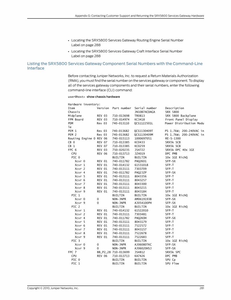
• Locating the SRX5800 Services Gateway Routing Engine Serial Number
Label on page 288
• Locating the SRX5800 Services Gateway Craft Interface Serial Number
Label on page 288
Listing the SRX5800 Services Gateway Component Serial Numbers with the Command-LineInterface
Before contacting Juniper Networks, Inc. to request a Return Materials Authorization
(RMA), you must find the serial number on the services gateway or component. To display
all of the services gateway components and their serial numbers, enter the following
command-line interface (CLI) command:
user@host> show chassis hardware
Hardware inventory:Item Version Part number Serial number DescriptionChassis JN10B7ACDAGA SRX 5800Midplane REV 03 710-013698 TR0813 SRX 5800 BackplaneFPM Board REV 03 710-014974 KC3418 Front Panel DisplayPDM Rev 03 740-013110 QCS1122501L Power Distribution ModulePEM 1 Rev 03 740-013682 QCS1130409T PS 1.7kW; 200-240VAC inPEM 2 Rev 03 740-013682 QCS1130409M PS 1.7kW; 200-240VAC inRouting Engine 0 REV 06 740-015113 1000697051 RE-S-1300CB 0 REV 07 710-013385 KC0433 SRX5k SCBCB 1 REV 07 710-013385 KC0259 SRX5k SCBFPC 6 REV 03 750-020235 JS4722 SRX5k DPC 40x 1GE CPU REV 06 710-013713 JZ4019 DPC PMB PIC 0 BUILTIN BUILTIN 10x 1GE RichQ Xcvr 0 REV 01 740-011782 PAQ2K01 SFP-SX Xcvr 1 REV 01 740-014132 61531018 SFP-T Xcvr 2 REV 01 740-013111 7303709 SFP-T Xcvr 4 REV 01 740-011782 PAQ2JZP SFP-SX Xcvr 5 REV 01 740-013111 8043356 SFP-T Xcvr 6 REV 01 740-013111 8043257 SFP-T Xcvr 7 REV 01 740-013111 8043300 SFP-T Xcvr 8 REV 01 740-013111 8043215 SFP-T Xcvr 9 REV 01 740-013111 8043184 SFP-T PIC 1 BUILTIN BUILTIN 10x 1GE RichQ Xcvr 0 0 NON-JNPR AM0619193B SFP-SX Xcvr 9 0 NON-JNPR AJ054100PH SFP-SX PIC 2 BUILTIN BUILTIN 10x 1GE RichQ Xcvr 1 REV 01 740-014132 61522010 SFP-T Xcvr 2 REV 01 740-013111 7303481 SFP-T Xcvr 4 REV 01 740-011782 PAQ2K0H SFP-SX Xcvr 5 REV 01 740-013111 8043179 SFP-T Xcvr 6 REV 01 740-013111 7522572 SFP-T Xcvr 7 REV 01 740-013111 8043157 SFP-T Xcvr 8 REV 01 740-013111 7522678 SFP-T Xcvr 9 REV 01 740-013111 7522683 SFP-T PIC 3 BUILTIN BUILTIN 10x 1GE RichQ Xcvr 0 0 NON-JNPR AJ06080TKC SFP-SX Xcvr 9 0 NON-JNPR AJ06020HSJ SFP-SXFPC 7 BB_P2_28 710-013699 JS4812 SRX5k SPC CPU REV 06 710-013713 KA7426 DPC PMB PIC 0 BUILTIN BUILTIN SPU Cp PIC 1 BUILTIN BUILTIN SPU Flow
281Copyright © 2010, Juniper Networks, Inc.
Appendix G: Contacting Customer Support and Returning the SRX5800 Services Gateway Hardware
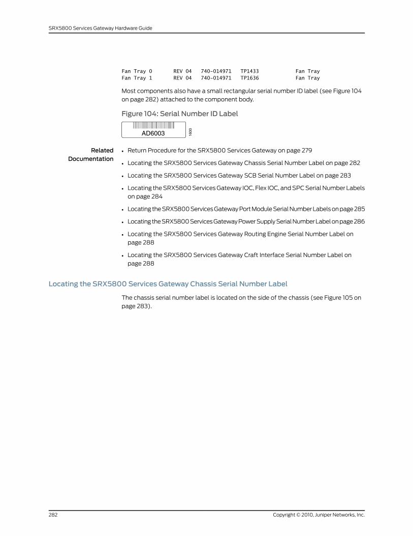
Fan Tray 0 REV 04 740-014971 TP1433 Fan TrayFan Tray 1 REV 04 740-014971 TP1636 Fan Tray
Most components also have a small rectangular serial number ID label (see Figure 104
on page 282) attached to the component body.
Figure 104: Serial Number ID Label
RelatedDocumentation
Return Procedure for the SRX5800 Services Gateway on page 279•
• Locating the SRX5800 Services Gateway Chassis Serial Number Label on page 282
• Locating the SRX5800 Services Gateway SCB Serial Number Label on page 283
• Locating the SRX5800 Services Gateway IOC, Flex IOC, and SPC Serial Number Labels
on page 284
• Locating the SRX5800 Services Gateway Port Module Serial Number Labels on page 285
• Locating the SRX5800 Services Gateway Power Supply Serial Number Label on page 286
• Locating the SRX5800 Services Gateway Routing Engine Serial Number Label on
page 288
• Locating the SRX5800 Services Gateway Craft Interface Serial Number Label on
page 288
Locating the SRX5800 Services Gateway Chassis Serial Number Label
The chassis serial number label is located on the side of the chassis (see Figure 105 on
page 283).
Copyright © 2010, Juniper Networks, Inc.282
SRX5800 Services Gateway Hardware Guide
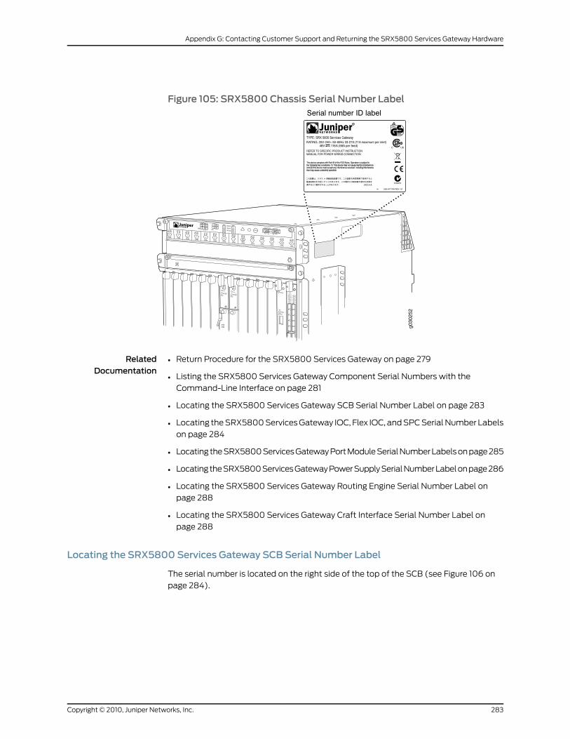
Figure 105: SRX5800 Chassis Serial Number Label
RelatedDocumentation
Return Procedure for the SRX5800 Services Gateway on page 279•
• Listing the SRX5800 Services Gateway Component Serial Numbers with the
Command-Line Interface on page 281
• Locating the SRX5800 Services Gateway SCB Serial Number Label on page 283
• Locating the SRX5800 Services Gateway IOC, Flex IOC, and SPC Serial Number Labels
on page 284
• Locating the SRX5800 Services Gateway Port Module Serial Number Labels on page 285
• Locating the SRX5800 Services Gateway Power Supply Serial Number Label on page 286
• Locating the SRX5800 Services Gateway Routing Engine Serial Number Label on
page 288
• Locating the SRX5800 Services Gateway Craft Interface Serial Number Label on
page 288
Locating the SRX5800 Services Gateway SCB Serial Number Label
The serial number is located on the right side of the top of the SCB (see Figure 106 on
page 284).
283Copyright © 2010, Juniper Networks, Inc.
Appendix G: Contacting Customer Support and Returning the SRX5800 Services Gateway Hardware
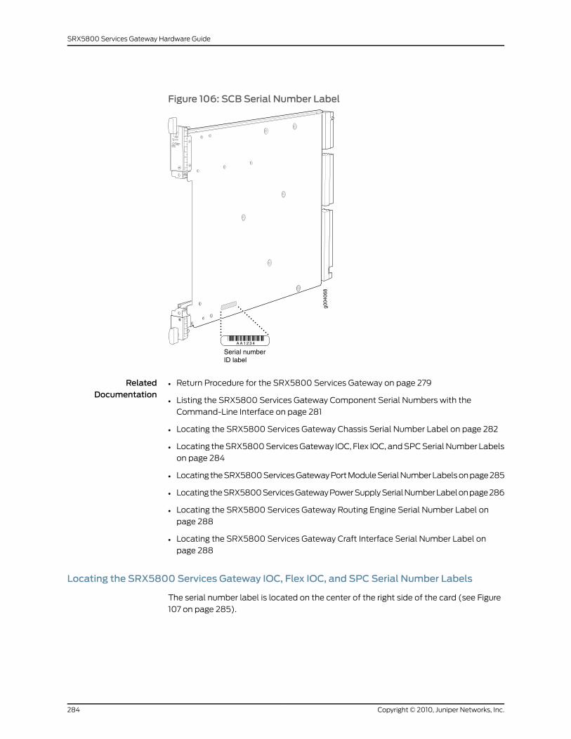
Figure 106: SCB Serial Number Label
g004
068
Serial numberID label
RelatedDocumentation
Return Procedure for the SRX5800 Services Gateway on page 279•
• Listing the SRX5800 Services Gateway Component Serial Numbers with the
Command-Line Interface on page 281
• Locating the SRX5800 Services Gateway Chassis Serial Number Label on page 282
• Locating the SRX5800 Services Gateway IOC, Flex IOC, and SPC Serial Number Labels
on page 284
• Locating the SRX5800 Services Gateway Port Module Serial Number Labels on page 285
• Locating the SRX5800 Services Gateway Power Supply Serial Number Label on page 286
• Locating the SRX5800 Services Gateway Routing Engine Serial Number Label on
page 288
• Locating the SRX5800 Services Gateway Craft Interface Serial Number Label on
page 288
Locating the SRX5800 Services Gateway IOC, Flex IOC, and SPC Serial Number Labels
The serial number label is located on the center of the right side of the card (see Figure
107 on page 285).
Copyright © 2010, Juniper Networks, Inc.284
SRX5800 Services Gateway Hardware Guide
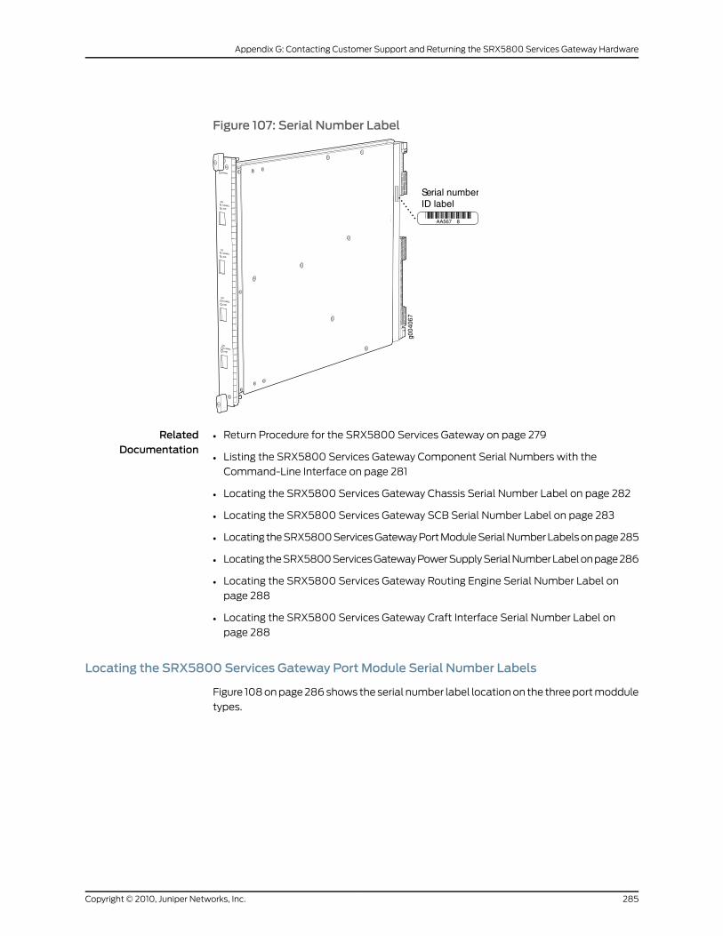
Figure 107: Serial Number Label
OK/FAIL
TUNNELLINK
1/0
TUNNELLINK
0/0
TUNNELLINK
2/0
TUNNELLINK
3/0
g004
067
AA567 8
Serial numberID label
RelatedDocumentation
Return Procedure for the SRX5800 Services Gateway on page 279•
• Listing the SRX5800 Services Gateway Component Serial Numbers with the
Command-Line Interface on page 281
• Locating the SRX5800 Services Gateway Chassis Serial Number Label on page 282
• Locating the SRX5800 Services Gateway SCB Serial Number Label on page 283
• Locating the SRX5800 Services Gateway Port Module Serial Number Labels on page 285
• Locating the SRX5800 Services Gateway Power Supply Serial Number Label on page 286
• Locating the SRX5800 Services Gateway Routing Engine Serial Number Label on
page 288
• Locating the SRX5800 Services Gateway Craft Interface Serial Number Label on
page 288
Locating the SRX5800 Services Gateway Port Module Serial Number Labels
Figure 108 on page 286 shows the serial number label location on the three port moddule
types.
285Copyright © 2010, Juniper Networks, Inc.
Appendix G: Contacting Customer Support and Returning the SRX5800 Services Gateway Hardware
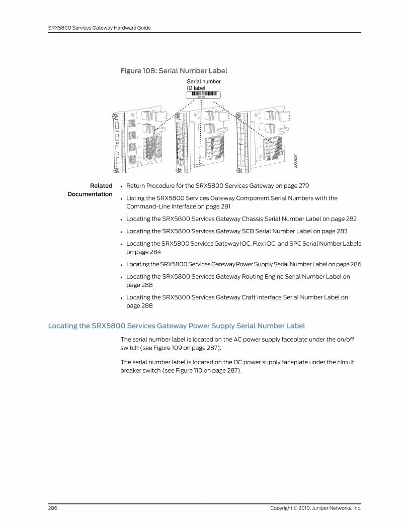
Figure 108: Serial Number Label
g030
287
JX0123
Serial numberID label
RelatedDocumentation
Return Procedure for the SRX5800 Services Gateway on page 279•
• Listing the SRX5800 Services Gateway Component Serial Numbers with the
Command-Line Interface on page 281
• Locating the SRX5800 Services Gateway Chassis Serial Number Label on page 282
• Locating the SRX5800 Services Gateway SCB Serial Number Label on page 283
• Locating the SRX5800 Services Gateway IOC, Flex IOC, and SPC Serial Number Labels
on page 284
• Locating the SRX5800 Services Gateway Power Supply Serial Number Label on page 286
• Locating the SRX5800 Services Gateway Routing Engine Serial Number Label on
page 288
• Locating the SRX5800 Services Gateway Craft Interface Serial Number Label on
page 288
Locating the SRX5800 Services Gateway Power Supply Serial Number Label
The serial number label is located on the AC power supply faceplate under the on/off
switch (see Figure 109 on page 287).
The serial number label is located on the DC power supply faceplate under the circuit
breaker switch (see Figure 110 on page 287).
Copyright © 2010, Juniper Networks, Inc.286
SRX5800 Services Gateway Hardware Guide
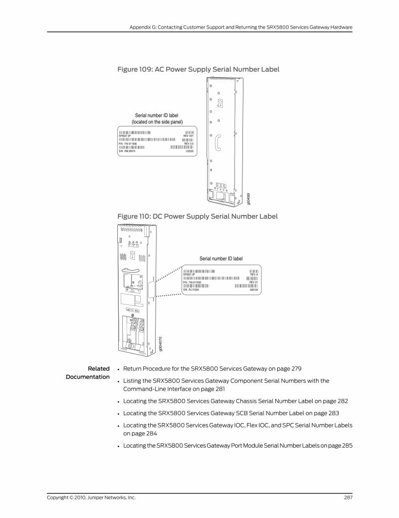
Figure 109: AC Power Supply Serial Number Label
Figure 110: DC Power Supply Serial Number Label
RelatedDocumentation
Return Procedure for the SRX5800 Services Gateway on page 279•
• Listing the SRX5800 Services Gateway Component Serial Numbers with the
Command-Line Interface on page 281
• Locating the SRX5800 Services Gateway Chassis Serial Number Label on page 282
• Locating the SRX5800 Services Gateway SCB Serial Number Label on page 283
• Locating the SRX5800 Services Gateway IOC, Flex IOC, and SPC Serial Number Labels
on page 284
• Locating the SRX5800 Services Gateway Port Module Serial Number Labels on page 285
287Copyright © 2010, Juniper Networks, Inc.
Appendix G: Contacting Customer Support and Returning the SRX5800 Services Gateway Hardware
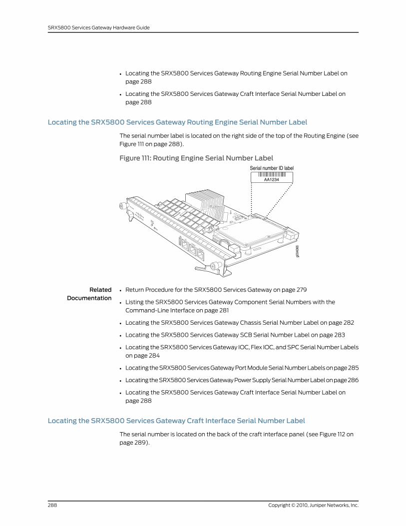
• Locating the SRX5800 Services Gateway Routing Engine Serial Number Label on
page 288
• Locating the SRX5800 Services Gateway Craft Interface Serial Number Label on
page 288
Locating the SRX5800 Services Gateway Routing Engine Serial Number Label
The serial number label is located on the right side of the top of the Routing Engine (see
Figure 111 on page 288).
Figure 111: Routing Engine Serial Number Label
RelatedDocumentation
Return Procedure for the SRX5800 Services Gateway on page 279•
• Listing the SRX5800 Services Gateway Component Serial Numbers with the
Command-Line Interface on page 281
• Locating the SRX5800 Services Gateway Chassis Serial Number Label on page 282
• Locating the SRX5800 Services Gateway SCB Serial Number Label on page 283
• Locating the SRX5800 Services Gateway IOC, Flex IOC, and SPC Serial Number Labels
on page 284
• Locating the SRX5800 Services Gateway Port Module Serial Number Labels on page 285
• Locating the SRX5800 Services Gateway Power Supply Serial Number Label on page 286
• Locating the SRX5800 Services Gateway Craft Interface Serial Number Label on
page 288
Locating the SRX5800 Services Gateway Craft Interface Serial Number Label
The serial number is located on the back of the craft interface panel (see Figure 112 on
page 289).
Copyright © 2010, Juniper Networks, Inc.288
SRX5800 Services Gateway Hardware Guide
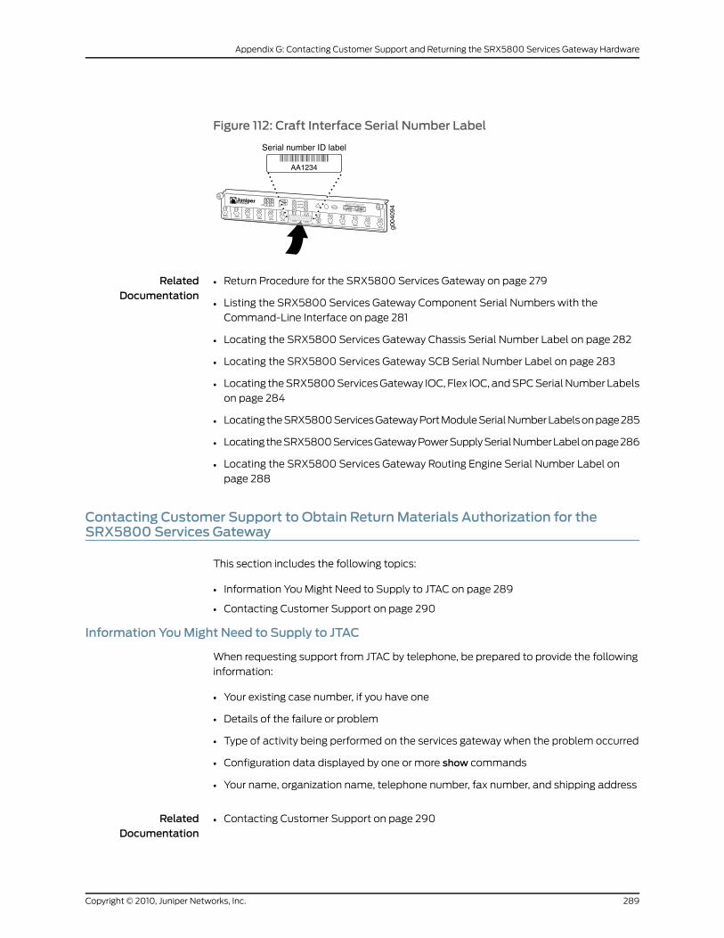
Figure 112: Craft Interface Serial Number Label
g004
094OK
0
FAIL
ONLINE
OK
1
FAIL
ONLINE
OK
2
FAIL
ONLINE
OK
3
FAIL
ONLINE
OK
4
FAIL
ONLINE
OK
5
FAIL
ONLINE
OK
0
FAIL
ONLINE
MASTER
ONLINE
OFFLINERE0
FANPEM
1
0
0 1 2 3
RE1OK
1
FAIL
ONLINE
OK
7
FAIL
ONLINE
OK
8
FAIL
ONLINE
OK
9
FAIL
ONLINE
OK
10
FAIL
ONLINE
OK
11
FAIL
ONLINE
OK
2 6
FAIL
ONLINE
ACO/LT
YELLOW ALARM RED ALARM
NC NOC NC NOC
AA1234
Serial number ID label
RelatedDocumentation
Return Procedure for the SRX5800 Services Gateway on page 279•
• Listing the SRX5800 Services Gateway Component Serial Numbers with the
Command-Line Interface on page 281
• Locating the SRX5800 Services Gateway Chassis Serial Number Label on page 282
• Locating the SRX5800 Services Gateway SCB Serial Number Label on page 283
• Locating the SRX5800 Services Gateway IOC, Flex IOC, and SPC Serial Number Labels
on page 284
• Locating the SRX5800 Services Gateway Port Module Serial Number Labels on page 285
• Locating the SRX5800 Services Gateway Power Supply Serial Number Label on page 286
• Locating the SRX5800 Services Gateway Routing Engine Serial Number Label on
page 288
Contacting Customer Support to Obtain ReturnMaterials Authorization for theSRX5800 Services Gateway
This section includes the following topics:
• Information You Might Need to Supply to JTAC on page 289
• Contacting Customer Support on page 290
Information YouMight Need to Supply to JTAC
When requesting support from JTAC by telephone, be prepared to provide the following
information:
• Your existing case number, if you have one
• Details of the failure or problem
• Type of activity being performed on the services gateway when the problem occurred
• Configuration data displayed by one or more show commands
• Your name, organization name, telephone number, fax number, and shipping address
RelatedDocumentation
Contacting Customer Support on page 290•
289Copyright © 2010, Juniper Networks, Inc.
Appendix G: Contacting Customer Support and Returning the SRX5800 Services Gateway Hardware
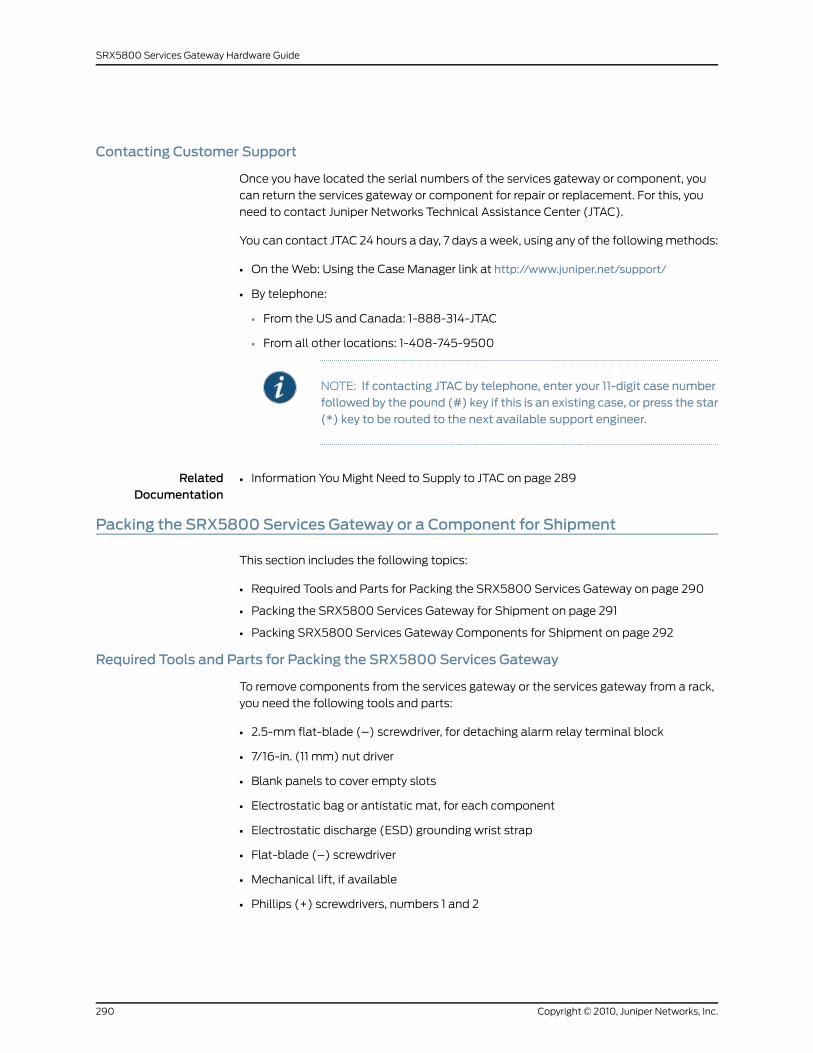
Contacting Customer Support
Once you have located the serial numbers of the services gateway or component, you
can return the services gateway or component for repair or replacement. For this, you
need to contact Juniper Networks Technical Assistance Center (JTAC).
You can contact JTAC 24 hours a day, 7 days a week, using any of the following methods:
• On the Web: Using the Case Manager link at http://www.juniper.net/support/
• By telephone:
• From the US and Canada: 1-888-314-JTAC
• From all other locations: 1-408-745-9500
NOTE: If contacting JTAC by telephone, enter your 11-digit case numberfollowed by the pound (#) key if this is an existing case, or press the star(*) key to be routed to the next available support engineer.
RelatedDocumentation
Information You Might Need to Supply to JTAC on page 289•
Packing the SRX5800 Services Gateway or a Component for Shipment
This section includes the following topics:
• Required Tools and Parts for Packing the SRX5800 Services Gateway on page 290
• Packing the SRX5800 Services Gateway for Shipment on page 291
• Packing SRX5800 Services Gateway Components for Shipment on page 292
Required Tools and Parts for Packing the SRX5800 Services Gateway
To remove components from the services gateway or the services gateway from a rack,
you need the following tools and parts:
• 2.5-mm flat-blade (–) screwdriver, for detaching alarm relay terminal block
• 7/16-in. (11 mm) nut driver
• Blank panels to cover empty slots
• Electrostatic bag or antistatic mat, for each component
• Electrostatic discharge (ESD) grounding wrist strap
• Flat-blade (–) screwdriver
• Mechanical lift, if available
• Phillips (+) screwdrivers, numbers 1 and 2
Copyright © 2010, Juniper Networks, Inc.290
SRX5800 Services Gateway Hardware Guide
• Rubber safety cap for fiber-optic interfaces or cable
• Wire cutters
RelatedDocumentation
Packing the SRX5800 Services Gateway for Shipment on page 291•
• Packing SRX5800 Services Gateway Components for Shipment on page 292
Packing the SRX5800 Services Gateway for Shipment
To pack the services gateway for shipment:
1. Retrieve the shipping crate and packing materials in which the services gateway was
originally shipped. If you do not have these materials, contact your Juniper Networks
representative about approved packaging materials.
2. On the console or other management device connected to the master Routing Engine,
enter CLI operational mode and issue the following command to shut down the
services gateway software.
user@host> request system halt
Wait until a message appears on the console confirming that the operating system
has halted.
For more information about the command, see the JunosOSSystemBasicsandServices
Command Reference.
3. Attach an ESD grounding strap to your bare wrist, and connect the strap to one of the
ESD points on the chassis.
4. Shut down power to the services gateway by pressing the AC input switch or DC circuit
breaker for all power supplies to the off (O) position.
5. Disconnect power from the services gateway.
6. Remove the cables that connect to all external devices.
7. Remove all field replaceable units (FRUs) from the services gateway.
8. Remove the services gateway chassis from the rack:
• If you are using a mechanical lift, place the lift platform under the chassis, unscrew
and remove the mounting screws from the rack, and move the chassis to the shipping
crate.
• If you are not using a mechanical lift and the chassis weight is fully supported by a
shelf or another device, unscrew and remove the mounting screws from the rack.
Three people can then lift the chassis and move it to the shipping crate.
• If you are not using a mechanical lift and the chassis weight is not fully supported
by a shelf or another device, three people should grasp the chassis while a fourth
person unscrews and removes the mounting screws from the rack. The three lifters
can then move the chassis to the shipping container.
291Copyright © 2010, Juniper Networks, Inc.
Appendix G: Contacting Customer Support and Returning the SRX5800 Services Gateway Hardware
9. Place the services gateway in the shipping crate or onto the pallet. If on a pallet, bolt
the services gateway to the pallet.
10. Cover the services gateway with an ESD bag and place the packing foam on top of
and around the services gateway.
11. Replace the accessory box on top of the packing foam.
12. Securely tape the box closed or place the crate cover over the services gateway.
13. Write the RMA number on the exterior of the box to ensure proper tracking.
RelatedDocumentation
Preventing Electrostatic Discharge Damage to the SRX5800 Services Gateway on
page 201
•
• Powering Off the SRX5800 Services Gateway on page 95
• Disconnecting an SRX5800 Services Gateway AC Power Supply Cord on page 186
• Disconnecting an SRX5800 Services Gateway DC Power Supply Cable on page 188
• Return Procedure for the SRX5800 Services Gateway on page 279
• Required Tools and Parts for Packing the SRX5800 Services Gateway on page 290
• Packing SRX5800 Services Gateway Components for Shipment on page 292
Packing SRX5800 Services Gateway Components for Shipment
Follow these guidelines for packing and shipping individual components of the services
gateway:
• When you return a component, make sure that it is adequately protected with packing
materials and packed so that the pieces are prevented from moving around inside the
carton.
• Use the original shipping materials if they are available.
• Place the individual component in an electrostatic bag.
• Write the Return Materials Authorization (RMA) number on the exterior of the box to
ensure proper tracking.
CAUTION: Do not stack any of the services gateway components duringpacking.
RelatedDocumentation
• Required Tools and Parts for Packing the SRX5800 Services Gateway on page 290
• Packing the SRX5800 Services Gateway for Shipment on page 291
Copyright © 2010, Juniper Networks, Inc.292
SRX5800 Services Gateway Hardware Guide

PART 5
Index
• Index on page 295
293Copyright © 2010, Juniper Networks, Inc.

Copyright © 2010, Juniper Networks, Inc.294
SRX5800 Services Gateway Hardware Guide
Index
Symbols#, comments in configuration statements...................xix
( ), in syntax descriptions....................................................xix
< >, in syntax descriptions.................................................xviii
[ ], in configuration statements........................................xix
{ }, in configuration statements........................................xix
| (pipe), in syntax descriptions..........................................xix
AAC plug types..........................................................................241
AC power cables
specifications.................................................................241
AC power supply
cord See AC power cord
description........................................................................42
electrical specifications...............................................42
high-capacity
description...............................................................39
electrical specifications......................................39
installing...........................................................................177
removing..................................................................174, 175
upgrading.........................................................................179
AC power supply cord
connecting......................................................................186
disconnecting................................................................186
specifications.................................................................241
AC specifications
circuit breaker.................................................................241
electrical.........................................................................238
accessory box
parts list.............................................................................65
removing............................................................................63
accident procedures, electrical.......................................220
agency approvals.................................................................230
air filter
installing............................................................................141
maintaining....................................................................106
removing...........................................................................141
routine inspection of...................................................105
airflow
required clearance around chassis for...................59
alarms
cutoff/lamp test button..............................................32
LEDs (red and yellow) on craft interface..............32
messages, list of............................................................122
relay contacts..................................................................35
connecting wire....................................................136
disconnecting wire..............................................134
wire specifications.............................................256
temperature, displaying.............................................125
altitude, acceptable range................................................233
antistatic mat, using............................................................201
attenuation in fiber-optic cable......................................252
AUX port See auxiliary port on Routing Engine
auxiliary port (for Routing Engine management)
cable
connection during initial installation..............81
connector pinouts (DB-9)..............................258
replacement instructions..................................151
specifications.............................................255, 256
auxiliary port on Routing Engine
description........................................................................30
Bbattery-handling warning..................................................214
booting the services gateway....................................90, 93
braces, in configuration statements................................xix
brackets
angle, in syntax descriptions...................................xviii
square, in configuration statements.......................xix
Ccable
auxiliary or console port (for Routing Engine
management)
connecting during initial installation..............81
replacing...................................................................151
cover
installation...............................................................83
295Copyright © 2010, Juniper Networks, Inc.
DPC
connecting during maintenance...................166
Ethernet port (for Routing Engine
management)
connecting during initial installation.............80
replacing.................................................................150
fiber-optic
attenuation............................................................252
cleaning instructions for transceivers...........114
dispersion...............................................................252
multimode and single-mode..........................251
transmission distance, maximum.................251
wavelength ranges..............................................251
grounding See DC power and grounding cables
IOC
disconnecting........................................................165
maintaining.............................................................114
port module
disconnecting........................................................165
power See AC power cord
cable management system
description.......................................................................48
fiber-optic cable, use with.........................................114
cable manager
installing...........................................................................191
reinstalling
after chassis installation...................................277
removing.........................................................................190
before chassis installation..............................262
chassis............................................................................................7
alarm messages See alarm, messages
dimensions..........................................................................7
ESD points...........................................................................7
grounding points........................................................9, 10
installing in rack..............................................................75
weight....................................................................................7
checklist for site preparation..............................................55
chromatic dispersion in fiber-optic cable...................252
class 1 laser warning..............................................................211
class 1 LED warning................................................................211
cleaning instructions
fiber-optic transceivers...............................................114
clearance, around rack.........................................................59
CLI
as troubleshooting tool...............................................121
command
to display chassis alarm messages..............122
to display IOC status.....................................111, 114
to display port module status..........................113
to display serial number....................................281
cold-swap-only components, description..................132
commands
ping......................................................................................121
show chassis alarms...................................................122
show chassis fpc
for IOC status..........................................................111
show chassis fpc pic-status......................................113
show chassis hardware..............................................281
show chassis IOC pic-status.....................................114
traceroute.........................................................................121
comments, in configuration statements.......................xix
compatibility, electromagnetic.......................................250
compliance statements for EMC requirements
Canada.............................................................................231
European Community.................................................231
Japan................................................................................232
United States.................................................................232
components
cable management system.......................................48
chassis...................................................................................7
cooling system................................................................46
craft interface...................................................................31
field replacement..........................................................132
Flex IOC...............................................................................16
host subsystem...............................................................24
IOC........................................................................................13
midplane.............................................................................12
port module......................................................................19
power supplies................................................................35
redundancy.........................................................................5
Routing Engine.................................................................27
SCB......................................................................................24
SPC.......................................................................................21
components, packing for shipment..............................292
connecting
AC power supply cord................................................186
DC power supply cable..............................................189
CONSOLE port See console port on Routing Engine
console port (for Routing Engine management)
cable
connection during initial installation..............81
connector pinout (RJ-45)......................257, 258
replacement instructions..................................151
specifications.............................................255, 256
console port on Routing Engine
description........................................................................30
Copyright © 2010, Juniper Networks, Inc.296
SRX5800 Services Gateway Hardware Guide
conventions
notice icons.....................................................................xvii
text and syntax.............................................................xviii
cooling system
description.......................................................................46
troubleshooting.............................................................125
craft interface
alarm cutoff/lamp test button.................................32
alarm relay contacts.....................................................35
description.........................................................................31
host subsystem LEDs...................................................32
installing...........................................................................135
IOC and SPC LEDs.........................................................33
LEDs
alarm (red and yellow)........................................32
online buttons.................................................................34
power supply LEDs........................................................33
removing..........................................................................134
routine inspection of...................................................105
curly braces, in configuration statements.....................xix
customer support, contacting........................................280
DDC power
source cabling...............................................................247
DC power circuit breaker....................................................247
DC power supply
cables See DC power supply cable,
specifications
description........................................................................44
electrical specifications...............................................44
installing..........................................................................183
removing.........................................................................180
DC power supply cable
connecting......................................................................189
disconnecting................................................................188
lugs....................................................................................249
specifications................................................................248
DC specifications
electrical................................................................243, 244
disconnecting
AC power supply cord................................................186
DC power supply cable..............................................188
dispersion in fiber-optic cable.........................................252
DPC
cable
installation instructions....................................166
Eearthquakes
tested toleration for seismic....................................233
EIA rack standards..................................................................57
electrical
accident procedures..................................................220
safety guidelines and warnings..............................220
electrical specifications........................238, 239, 243, 244
electricity
site wiring guidelines..................................................250
electromagnetic
compatibility See EMC
pulse.................................................................................250
electrostatic
bag, using to store components.............................201
EMC (EMI)
suppression...................................................................250
EMC requirements
Canada.............................................................................231
European Community.................................................231
Japan................................................................................232
United States.................................................................232
EMP...........................................................................................250
environmental specifications..........................................233
ESD
preventing damage to components by...............201
Ethernet port (for Routing Engine management)
cable
connection during initial installation.............80
replacement instructions.................................150
specifications.......................................................255
Ethernet port on Routing Engine
description........................................................................30
ETSI rack standards...............................................................57
Ffan tray
installing..........................................................................138
maintaining.....................................................................107
reinstalling
after chassis installation..................................273
removing..........................................................................136
before chassis installation..............................263
troubleshooting.............................................................125
fan trays
description.......................................................................46
field-replaceable units
listed..................................................................................132
fire safety requirements.....................................................203
297Copyright © 2010, Juniper Networks, Inc.
Index
Flex I/O Card See Flex IOC
Flex IOC.......................................................................................16
removing...........................................................................157
font conventions...................................................................xviii
Ggrounding (electrical) specifications
AC-powered services gateway...............................235
DC-powered services gateway...............................235
grounding cables
lug......................................................................................235
guidelines, electrical safety..............................................220
Hhardware components
power requirements.........................................239, 245
higher-order mode loss (HOL).........................................251
host subsystem
description........................................................................24
LEDs....................................................................................32
hot-pluggable components, description......................132
hot-removable and hot-insertable components,
description...........................................................................132
humidity (relative), acceptable.......................................233
II/O Card See IOC
installation
AC power, connecting..................................................86
instructions warning..................................................205
parts received, verifying...............................................65
unpacking the services gateway..............................63
installation instructions
alarm relay contact wires
tools required..........................................................79
cable, auxiliary or console port (for Routing
Engine management)
for maintenance or replacement....................151
tools required..........................................................79
cable, DPC
for maintenance or replacement..................166
cable, Ethernet port (for Routing Engine
management)
for maintenance or replacement..................150
tools required..........................................................79
cable, PIC
for maintenance or replacement..................166
DC power and grounding cables
tools required..........................................................79
installing
AC power supply............................................................177
air filter...............................................................................141
alarm relay contact wires
during initial installation.....................................82
for maintenance or replacement..........134, 136
cable manager................................................................191
cable, auxiliary or console port (for Routing
Engine management)
during initial installation......................................81
cable, Ethernet port (for Routing Engine
management)
during initial installation....................................80
chassis
tools required.......................................................260
craft interface.................................................................135
DC power supply..........................................................183
DC power, connecting...................................................91
fan tray.............................................................................138
IOC.....................................................................................154
IOC, connecting..............................................................83
PIC, connecting...............................................................83
power and grounding cables
tools required..........................................................85
Installing
SPC....................................................................................169
instructions
calculation
power requirements..........................................245
cleaning See cleaning instructions
maintenance
IOC..............................................................................114
port module............................................................113
interference
electromagnetic..........................................................250
radio frequency............................................................250
IOC.................................................................................................13
cable
removal instructions..........................................165
connecting........................................................................83
holding...............................................................................116
installing..........................................................................154
LEDs....................................................................................33
maintaining.......................................................................111
maintenance...................................................................114
removing..........................................................................152
status, checking..............................................111, 114, 125
storing................................................................................118
Copyright © 2010, Juniper Networks, Inc.298
SRX5800 Services Gateway Hardware Guide
IOCs
components......................................................................14
troubleshooting.............................................................125
Jjewelry removal warning.....................................................215
JTAC..........................................................................................290
Juniper Networks Technical Assistance Center
(JTAC)....................................................................................124
Juniper Technical Assistance Center See JTAC
Llaser beam warning..............................................................212
laser safety guidelines.........................................................210
LEDs
AC power supplies.........................................................43
alarm (red and yellow on craft interface)
description...............................................................32
DC power supplies.........................................................45
host subsystem...............................................................32
IOC.......................................................................................33
on components.............................................................124
on craft interface...........................................................123
power supplies................................................................33
SCB......................................................................................26
lightning activity warning...................................................216
link loss, calculating.............................................................253
lugs for DC power and grounding cables.....................235
lugs for DC power cables...................................................249
Mmaintaining
air filter.............................................................................106
fan tray..............................................................................107
IOC................................................................................111, 114
maintenance guidelines
IOC................................................................................111, 114
IOC cable..........................................................................114
port module.....................................................................113
management
port See Ethernet port on Routing Engine
midplane.....................................................................................12
description.........................................................................12
functions.............................................................................12
modal dispersion in fiber-optic cable...........................252
mode loss, higher-order......................................................251
multimode fiber-optic cable See cable, fiber-optic
Nnotice icons..............................................................................xvii
Oonline buttons
craft interface..................................................................34
operating temperature warning.......................................217
overview
services gateway...............................................................3
Ppacking services gateway
components for shipment.......................................292
parentheses, in syntax descriptions................................xix
PEMs See power supplies
physical specifications.............................................................7
PIC
cable
installation instructions....................................166
connecting........................................................................83
SONET/SDH
power budget calculation................................253
ping command........................................................................121
pinouts
RJ-45 cable connector ports
(auxiliary/console).................................................258
RJ-45 Ethernet cable connector port...................257
plug types
AC.......................................................................................241
port
auxiliary on Routing Engine See auxiliary port
on Routing Engine
console on Routing EngineSee console port on
Routing Engine
Ethernet on Routing Engine See Ethernet port
on Routing Engine
port module
components......................................................................19
maintenance...................................................................113
status, checking.............................................................113
Port module
cable
removal instructions..........................................165
troubleshooting.............................................................127
power
budget calculation......................................................253
cables and cordsSeeAC power cord; DC power
cables
margin calculation.......................................................253
299Copyright © 2010, Juniper Networks, Inc.
Index
requirements for hardware
components....................................................239, 245
surges...............................................................................250
power supplies
AC electrical specifications.....................................239
cables See DC power
DC electrical specifications.....................................244
description........................................................................35
LEDs......................................................................33, 43, 45
power supply
reinstalling
after chassis installation...................................271
removing
before chassis installation...............................261
power system
AC electrical specifications.....................................238
DC electrical specifications.....................................243
troubleshooting.............................................................129
powering off the services gateway..................................95
powering on the services gateway...........................90, 93
product disposal warning..................................................219
Qqualified personnel warning.............................................198
Rrack
clearance around, required........................................59
mounting bracket hole spacing................................58
size and strength required...........................................57
standards, EIA and ETSI..............................................57
rack mounting
shelves................................................................................10
rack requirements
mounting........................................................................206
radiation from open port apertures warning..............213
radio frequency interference, preventing....................250
redundancy..................................................................................5
reinstalling
cable manager
after chassis installation...................................277
fan tray
after chassis installation..................................273
power supply
after chassis installation...................................271
SCB
after chassis installation..................................274
relative humidity, acceptable...........................................233
removal instructions
cable
auxiliary or console port (for Routing
Engine management)....................................151
Ethernet port (for Routing Engine
management)..................................................150
IOC............................................................................165
port module...........................................................165
removing
AC power supply...................................................174, 175
air filter...............................................................................141
alarm relay contact wires..........................................134
cable manager..............................................................190
before chassis installation..............................262
craft interface.................................................................134
DC power supply..........................................................180
fan tray.............................................................................136
before chassis installation..............................263
IOC......................................................................................152
power supply
before chassis installation...............................261
SCB
before chassis installation..............................265
SFP.....................................................................................172
XFP.....................................................................................172
Removing
SPC.....................................................................................167
repair policies........................................................................280
restricted access area warning........................................199
return materials authorization.........................................279
return procedure...................................................................279
RFI..............................................................................................250
RJ-45 cable connector pinouts........................................257
RJ-45 cable connector pinouts (auxiliary and
console ports)...................................................................258
RMA See return materials authorization
Routing Engine
boot sequence................................................................30
components.....................................................................28
description........................................................................27
for dual chassis cluster control link.........................27
management ports
cable and wire specifications........................256
ports....................................................................................30
status indicator lights...................................................30
USB port.............................................................................27
Ssafety guidelines, laser........................................................210
Copyright © 2010, Juniper Networks, Inc.300
SRX5800 Services Gateway Hardware Guide
safety requirements
fire.....................................................................................203
fire suppression equipment....................................203
SCB
reinstalling
after chassis installation..................................274
removing
before chassis installation..............................265
SCBs
components.....................................................................26
description........................................................................24
LEDs....................................................................................26
seismic (earthquake)..........................................................233
serial number
in output from show chassis hardware
command...................................................................281
services gateway
parts list.............................................................................65
physical specifications....................................................7
returning..........................................................................279
unpacking.........................................................................63
weight....................................................................................7
Services Processing Card See SPC
Services Processing Unit See SPU
SFP
description.......................................................................172
installing...........................................................................174
removing...........................................................................172
shipment
packing the components..........................................292
shipping container
unpacking.........................................................................63
weight.................................................................................63
show chassis alarms command.....................122, 125, 129
show chassis fpc command
for IOC status...................................................................111
show chassis fpc pic-status command.................113, 114
show chassis hardware command................................281
show chassis IOC command............................................125
show chassis IOC detail command................................125
show chassis SPC command............................................127
show chassis SPC detail command...............................127
signal dispersion....................................................................251
signaling, distance limitations........................................250
single-mode fiber-optic cable See cable, fiber-optic
site
electrical wiring specifications...............................250
environmental specifications..................................233
preparation
checklist....................................................................55
routine inspection........................................................105
SPC................................................................................................21
installing..........................................................................169
removing..........................................................................167
status, checking.............................................................127
SPCs
troubleshooting.............................................................127
specifications
AC power cord...............................................................241
cable
power......................................................................248
Routing Engine management
ports..........................................................255, 256
clearance around rack..................................................59
DC power supply cable.............................................248
electrical...........................................................................241
cable and wiring..................................................250
environmental...............................................................233
power
drawn by hardware
components...........................................239, 245
power system......................................................239, 245
rack
front-mount flange hole spacing....................58
mounting bracket hole spacing.......................58
size and strength....................................................57
thermal output.............................................................233
wires to external alarm-reporting devices.........256
SPU................................................................................................21
startup, system
monitoring................................................................90, 93
support, requesting from JTAC.............................289, 290
surge protection....................................................................250
Switch Control Boards See SCBs
syntax conventions..............................................................xviii
Ttemperature, acceptable range......................................233
thermal output......................................................................233
tolerances
environmental...............................................................233
tools required
chassis
returning for repair or replacement.............290
hardware components
returning for repair or replacement.............290
301Copyright © 2010, Juniper Networks, Inc.
Index
maintaining....................................................................105
replacement...................................................................132
traceroute command............................................................121
transmission distances, fiber-optic cable....................251
troubleshooting
CLI commands................................................................121
cooling system...............................................................125
fans....................................................................................125
IOC......................................................................................125
port module.....................................................................127
power system.................................................................129
SPC.....................................................................................127
UU (rack unit)..............................................................................57
unpacking the services gateway.......................................63
Wwarning
battery-handling...........................................................214
class 1 laser.......................................................................211
class 1 LED........................................................................211
electrical safety guidelines......................................220
installation instructions............................................205
jewelry removal.............................................................215
laser beam.......................................................................212
lightning activity............................................................216
operating temperature................................................217
product disposal...........................................................219
rack-mount requirements.......................................206
radiation from open apertures................................213
wavelength ranges supported by fiber-optic
cable.......................................................................................251
wiring, electrical See electricity
XXFP
description.......................................................................172
installing...........................................................................174
removing...........................................................................172
Copyright © 2010, Juniper Networks, Inc.302
SRX5800 Services Gateway Hardware Guide
Related Documents