Materials Science and Engineering A 374 (2004) 90–100 Hardness-based flow stress and fracture models for numerical simulation of hard machining AISI 52100 bearing steel Domenico Umbrello a , Jiang Hua b , Rajiv Shivpuri b,∗ a University of Calabria, Rende, CS 87036, Italy b Department of Industrial, Welding, and System Engineering, Ohio State University, 210 Baker System Engineering Building, 1971 Neil Avenue, Columbus, OH 43210, USA Abstract The phenomenological models of flow stress and fracture typically used in the computer simulation of machining processes do not adequately represent the constitutive behavior in hard machining, where the workpiece is heat treated to 52–64 HRC prior to machining. This paper proposes the hardness-based flow stress and fracture models for numerical simulation of hard machining. These models are based on the well known Johnson–Cook flow stress model and the Brozzo’s facture criteria. The paper includes the development of the hardness-based flow stress model for the AISI 52100 bearing steel, the development of the hardness-hydrostatic stress based fracture criteria, the implementation of these models in a non-isothermal viscoplastic numerical model of machining, and the simulation of machining for various hardness values and machining parameters. Predicted results are validated by comparing them with experimental results from literature. They are found to predict reasonably well the cutting forces as well as the change in chip morphology from continuous to segmented chip as the hardness values change. © 2004 Elsevier B.V. All rights reserved. Keywords: Material modeling; Machining; FEM; Hardness; Flow stress; Fracture 1. Introduction Today, the hard machining technology is being widely used in various applications including mechanical finish- ing of hardened components such as transmission shafts, bearings and gears for the automotive industry, and landing gear struts for the aerospace industry. These components are typically machined from alloy steels with hardness be- tween 52 and 64 HRC using polycrystalline cubic boron nitride (PCBN or commonly CBN) inserts, which present high strength and reasonable tool life. Inspite of its popu- larity, hard machining is often used sub-optimally, as the mechanics of the process are not fully understood. Accord- ing to a survey conducted by Kennametal Inc. [1], the US industry chooses the correct tool less than 50% of the time, uses cutting tools at their rated cutting speed about 58% of the time, and uses cutting tools to their full life capability only about 38% of the time. These sub-optimal practices ∗ Corresponding author. Tel.: +1-614-2927874; fax: +1-614-2927852. E-mail addresses: [email protected] (D. Umbrello), [email protected] (J. Hua), [email protected] (R. Shivpuri). URLs: http://www.unical.it, http://www.osu.edu. are estimated to cost the US industry $10 billion per year. Consequently, there is a need to understand the physics of machining and develop the process models that can be used in determining optimal conditions. The published literature on hard machining can be cate- gorized into studies of the chip morphology, predictions of the wear characteristics of cutting tool, and investigations of the surface integrity of the machined surface. Most of these are empirical in nature. Many of them are directed towards hard machining of die steels, especially the high speed milling of H-13 die steel. Very little research effort is focused on carbon/high alloy bearing steels: either through hardening (typically AISI/SAE 52100) type or the case hardening (typically AISI 8620) type. In hard machining, a major focus of research has been on understanding the mechanism of “saw chip” formation, with the objective of relating the process characteristics and the stability of the cutting process to the chip morphology [2–5]. Efforts have also been directed towards understanding the effect of composition, temperature and wear characteris- tics of CBN cutting tools [6–10] on the flank wear and tool life. Lastly, researchers have investigated the effect of ma- chining parameters on the sub-surface residual stress profile 0921-5093/$ – see front matter © 2004 Elsevier B.V. All rights reserved. doi:10.1016/j.msea.2004.01.012

Welcome message from author
This document is posted to help you gain knowledge. Please leave a comment to let me know what you think about it! Share it to your friends and learn new things together.
Transcript

Materials Science and Engineering A 374 (2004) 90–100
Hardness-based flow stress and fracture models for numericalsimulation of hard machining AISI 52100 bearing steel
Domenico Umbrelloa, Jiang Huab, Rajiv Shivpurib,∗a University of Calabria, Rende, CS 87036, Italy
b Department of Industrial, Welding, and System Engineering, Ohio State University, 210 Baker System Engineering Building,1971 Neil Avenue, Columbus, OH 43210, USA
Abstract
The phenomenological models of flow stress and fracture typically used in the computer simulation of machining processes do notadequately represent the constitutive behavior in hard machining, where the workpiece is heat treated to 52–64 HRC prior to machining. Thispaper proposes the hardness-based flow stress and fracture models for numerical simulation of hard machining. These models are based on thewell known Johnson–Cook flow stress model and the Brozzo’s facture criteria. The paper includes the development of the hardness-based flowstress model for the AISI 52100 bearing steel, the development of the hardness-hydrostatic stress based fracture criteria, the implementationof these models in a non-isothermal viscoplastic numerical model of machining, and the simulation of machining for various hardness valuesand machining parameters. Predicted results are validated by comparing them with experimental results from literature. They are found topredict reasonably well the cutting forces as well as the change in chip morphology from continuous to segmented chip as the hardness valueschange.© 2004 Elsevier B.V. All rights reserved.
Keywords:Material modeling; Machining; FEM; Hardness; Flow stress; Fracture
1. Introduction
Today, the hard machining technology is being widelyused in various applications including mechanical finish-ing of hardened components such as transmission shafts,bearings and gears for the automotive industry, and landinggear struts for the aerospace industry. These componentsare typically machined from alloy steels with hardness be-tween 52 and 64 HRC using polycrystalline cubic boronnitride (PCBN or commonly CBN) inserts, which presenthigh strength and reasonable tool life. Inspite of its popu-larity, hard machining is often used sub-optimally, as themechanics of the process are not fully understood. Accord-ing to a survey conducted by Kennametal Inc.[1], the USindustry chooses the correct tool less than 50% of the time,uses cutting tools at their rated cutting speed about 58% ofthe time, and uses cutting tools to their full life capabilityonly about 38% of the time. These sub-optimal practices
∗ Corresponding author. Tel.:+1-614-2927874; fax:+1-614-2927852.E-mail addresses:[email protected] (D. Umbrello),
[email protected] (J. Hua), [email protected] (R. Shivpuri).URLs: http://www.unical.it, http://www.osu.edu.
are estimated to cost the US industry $10 billion per year.Consequently, there is a need to understand the physics ofmachining and develop the process models that can be usedin determining optimal conditions.
The published literature on hard machining can be cate-gorized into studies of the chip morphology, predictions ofthe wear characteristics of cutting tool, and investigationsof the surface integrity of the machined surface. Most ofthese are empirical in nature. Many of them are directedtowards hard machining of die steels, especially the highspeed milling of H-13 die steel. Very little research effort isfocused on carbon/high alloy bearing steels: either throughhardening (typically AISI/SAE 52100) type or the casehardening (typically AISI 8620) type.
In hard machining, a major focus of research has beenon understanding the mechanism of “saw chip” formation,with the objective of relating the process characteristics andthe stability of the cutting process to the chip morphology[2–5]. Efforts have also been directed towards understandingthe effect of composition, temperature and wear characteris-tics of CBN cutting tools[6–10] on the flank wear and toollife. Lastly, researchers have investigated the effect of ma-chining parameters on the sub-surface residual stress profile
0921-5093/$ – see front matter © 2004 Elsevier B.V. All rights reserved.doi:10.1016/j.msea.2004.01.012

D. Umbrello et al. / Materials Science and Engineering A 374 (2004) 90–100 91
and the formation of “white layer” in the machined surface[11–14].
Recently, numerical models for machining have beendeveloped with the objective of analyzing the cutting me-chanics, predicting the thermo-mechanical conditions at thetool–chip interface, and optimising the cutting conditions.These numerical models have the following features:
• Either the models use the computationally simple Eule-rian approach that assumes the process to be steady stateand does not require chip separation criteria or the morecomplex Lagrangian approach that considers the chip for-mation from the incipient to the steady-state configurationand needs definition of chip separation criterion.
• The material-constitutive laws often include the effectof strain (rigid–plastic or elastic–plastic), strain rate(rigid–viscoplastic or elastic–viscoplastic) and tempera-ture (thermal softening). Inclusion of the elastic responsedoes present computational challenges, but permits thecalculation of tool stresses and residual stresses in themachined surface.
• The chip separation criteria used includes either the el-ement level fracture criteria based on strain energy orshear/principal stress, or the mesh rezoning/element dele-tion criterion based on phenomenological parameters suchas plastic strain, normal stress and strain energy density.
• The frictional law used is either based on the Coulombfriction coefficient related to normal pressure, or shearfactor related to shear yield stress. These laws are oftenmodified to include sticking or sliding conditions presentat the chip–tool interface.
• The mechanical material behavior is often characterizedusing the hot tension, hot compression or Split Hop-kinson Pressure Bar (SHPB) configurations (tension,compression, torsion). The former is limited to smallstrain rates and the latter to low strains. Consequently, thetest results for low strain and strain-rate tests are oftenextrapolated to higher strains and strain rates using theMacGregor–Fisher[15] modified temperature approachchampioned by Oxley[16].
• Since the plastic strains (1–5) and the strain rates (103
to 106 s−1) are very high in typical machining opera-tions, many researchers use the actual machining tests todevelop the material flow stresses. The material modelis developed by fitting regression models to the test re-sults using the design of experiments approach. Theseregression models are then verified under many differentmachining conditions.
Developing numerical process models of hard machin-ing of bearing steels is even more difficult than models forconventional machining as the depth of cuts are very small(often less than the cutting edge radius), the cutting speedsare high, and the material hardness plays major roles in thechip segmentation, the surface integrity and the magnitudeof cutting forces. Recently, Guo and Liu[17], and Buozakisand Vidakis[18] investigated changes in material properties
of hardened bearing steel, and found that hardness playedcritical role in material behavior. The effect of hardness isespecially significant for the case-hardened bearing steel thathas significant amount of retained austenite in the marten-sitic matrix depending on the final hardness. The large noseradius CBN cutting tools normally used in hard machiningimpose ploughing or burnishing action on the cut surface,resulting in the generation of high hydrostatic stresses inthe cutting zones; the latter effecting chip segmentation andfracture. Existing material models in literature are mainlybased on strain, strain rate and temperature. These modelsmay be acceptable in conventional machining but are inad-equate for hard machining.
In this paper, a hardness-based flow stress model of ma-terial behavior and a hydrostatic stress based fracture chipseparation criterion are proposed for numerical modelingthe machining of 51000 bearing steels with hardness rangefrom 52 to 64 HRC. The hardness-based flow stress modelis developed using regression method to fit hot compressionand SHBP data published in literature. The effect of hy-drostatic pressure on chip segmentation is incorporated us-ing the Brozzo’s[19] facture criterion which includes meanstress. Hardness effect on the material ductility and fractureis included via a calibration curve for the material damagevalue (strain energy of fracture). These hardness and hy-drostatic pressure based models are then incorporated in acommercial rigid–viscoplastic non-isothermal finite elementmodel[20] of the orthogonal cutting process to predict thechip morphology in hard machining of 52100 steels at var-ious hardness and process conditions.
2. Material aspects and hardenability of 52100 steels
AISI 52100 (commonly, 100Cr6 in Europe) is a highcarbon-chrome-manganese through hardening steel whichfinds applications in several rotating parts like anti-frictionbearings, cams, crank shaft, etc. The chemical compositionand the key physical and mechanical properties of AISI52100 are listed inTable 1and plotted inFig. 1.
Table 1Chemical, mechanical and physical properties of the 52100 steel
Description Value
C 0.9–1.05Mn 0.25–0.45Si 0.15–0.35Cr 1.35–1.65Ni <0.3Mo –Other S< 0.025Young’s modulus (GPa) 210Poisson ratio 0.3Mass density (kg m−3 ) 7853Heat capacity (N mm−2 per ◦C) (SeeFig. 1a)Thermal conductivity (N s per◦C) (SeeFig. 1b)Emissivity 0.7

92 D. Umbrello et al. / Materials Science and Engineering A 374 (2004) 90–100
Fig. 1. Physical properties of the 5100 steel as a function of temperature: (a) heat capacity and (b) thermal conductivity[18].
High hardness is achieved in this steel by the in-duction hardening process. This material is generallysolution-treated to a temperature of 850◦C followed by oilquenching, and then tempered in the range 180–250◦C.This results in a microstructure of lightly tempered marten-site, primary carbides and up to about 5% retained austenite.The hardness of AISI 52100 can reach 58–62 HRC. Higherhardness possess lower fracture toughness and ductility.Due to its high hardenability this steel achieves a uniform“through” hardness.
It is known that austenitizing and tempering temperatureshave the most influence on the retained austenite in themartensitic matrix. In fact, in a recent study it was shown[21] that a specimen with low retained austenite presentshigh hardness. Furthermore, results of metallographic exam-ination show that fine martensite and dispersed carbides arepresent in the hardened layer up to a depth of 3.7 mm[22].The hardness remains almost constant to this depth.
An early study of hard turning 51000 steel was conductedby Poulachot and Moison[5], who investigated the chipmorphology when hardness was varied from 45 to 63 HRC(180–750 HV). They found that harder the work material,the more localized the chip occurred (saw chip morphology)even at lower cutting speeds. Significant cracking of thechip free surface and the presence of white (austenite) layerwas observed. They found that workpiece initial hardnessplayed a major role both in the thickness and segmentationof the chip. They also found that the hardness increase dur-ing the chip formation was larger for lower initial hardness(a 100% increase) with only a 15% increase measured at62 HRC. This confirms that initial hardness plays a criticalrole in the strain hardening response of the material.
Room temperature tensile tests confirm the role playedby initial hardness on the ductility of the material being ma-chined, the 62 HRC material exhibiting brittle behavior incompression. Since it was possible to machine this material,the ductility in machining must be due to the high hydrostaticstresses produced during the process. These hydrostaticstresses develop due to the low depths of cut and generousnose radii/edge honing used during hard machining.
Some authors[3,4,11] also evaluated the 51000 materialunder hot tensile, hot compression (conventional mate-rial testing machine and Gleeble testing machine) and hotdynamic compression (SHPB) tests. They reported smalleffects of strain and strain rate variations but strong sen-
sitivity to temperature changes with flow stress dropping60% for an increase in temperature from 500 to 700◦C.They caution extrapolating flow stresses beyond 700◦C asthe values decrease exponentially up to the melting point.
Two recent studies have also included flow stress char-acterization in the material behavior. The first is that ofMamalis et al.[23], who used compression tests to obtainyield stress for plastic strain up to one at low strain ratesof 1.6 s−1 and room temperature (20◦C) for 62 mean HRCmaterials. They also obtained the yield stress versus tem-perature curve for temperatures up to 1200◦C and founda significant drop after 700◦C confirming the results ofPoulachot et al.[4]. Finally, they extrapolated the low strainrate results to higher strain rates by using a hypotheticalrelation between yield strength increase and strain rate. Thesecond study is more scientific (Guo and Liu[17]). In thisstudy, high temperature tensile stress tests were carried outat strain rates from 1 to 100 s−1 and temperatures from20 to 1000◦C for the 62 HRC test material. They foundfairly brittle behavior at room temperature, with flow stressdecreasing and ductility increasing with increase in tem-perature. They used the modified temperature extrapolationtechnique of MacGregor and Fisher[15] to extend their re-sults to higher strain rates. A major limitation of their testingis that the tests were limited to low strains (lower than 0.10).
In this paper, the results of these experimental evaluationswill be used to develop the flow stress model and the chipseparation criterion (fracture criterion). The flow model willbe based on the initial hardness of the workpiece materialand the fracture criterion on the hydrostatic stress and theinitial hardness (used to calibrate the critical fracture value).
3. Procedure for modeling new material flow stress
For an accurate numerical simulation of hard machining,it is very important to know the mechanical and the thermalresponse of the workpiece material under the extreme con-ditions of the strain (2–5), the strain rate (104 to 106 s−1),the temperature in the cutting zone (up to 1200◦C) and theinitial hardness (52–64 HRC) of the workpiece material.Consequently, material models for machining must accountdeformation response to high rates of loading (high strainrates), large deformation strains (strain hardening or soft-ening) as well as large change in temperatures (temperature

D. Umbrello et al. / Materials Science and Engineering A 374 (2004) 90–100 93
softening). Several models have been developed for impactloading which represent the material response to varyingdegree of accuracy. Examples of these include phenomeno-logical models by Johnson–Cook[24], Zerilli– Amstrong[25], Steinberg et al.[26] and Follansbee–Kocks[27]. Therelationship derived by Maekawa et al.[28] is more detailedas it includes strain rate history effects, temperature effectsand the effects of blue brittleness relevant to carbon steels.More complex material descriptions including the effectsof composition, dislocations, phases, grain size etc canbe found in the model of Goldthorpe–Church[29]. Thesemodels include the effects of phase change from the lowtemperature ferrite (BCC structure) to the high temperatureaustenite (FCC structure) which is sensitive to strain rate.Presence of tempered martensite or retained austenite is notincluded in these models.
The Johnson–Cook (J–C) thermo-viscoplastic-hardeninglaw is the most popular with numerical analysts and widelyused in developing numerical models of the machining pro-cess. In this empirical model, the effects of strain, strain rateand temperature on the flow stress are individually consid-ered as strength multipliers. The strain hardening law usesinitial yield strength with a power work hardening (similarto many laws used in cold metal deformation). The strainrate hardening is modeled as a logarithmic function withstrain rate normalized with respect to a reference strain rateof 1.0 s−1. A homologous description of temperature is usedwith the flow stress reducing to zero at the melting temper-ature. It needs determination of five independent materialconstants,A, B, C, n andm, for a complete characterization,
σ(ε, ε̇, T) = (A + Bεn)[1 + C(ln(ε̇∗))][1 − (T ∗)m] (1)
The J–C approach of treating the effects of strain, strainrate (non-dimensional) and temperature (non-dimensional)as multipliers, is the basis for developing the hardness-basedmodel in this paper. This model does not explore couplingbetween strain, strain rate and temperature, but handles eachvariable separately. The J–C model assumes that the strengthis isotropic and independent of mean stress. This is not truein the machining of hard materials, where hardness and themean stress play a major role in the flow behavior and frac-ture. Consequently, the models will be modified to reflectthe hard machining process better.
High hardness in the machined workpiece can be achievedby two means: thermal treatment and the mechanical work.Since the mechanisms for these are significantly different(hardness involving microstructural changes, while mechan-ical work, dislocation dynamics), it was decided to modelthem separately. Due to their high quenching response, thehardness in 52100 steels is almost uniform throughout theworkpiece. In addition, the temperatures imposed on theworkpiece are lower than in conventional machining due tothe lower feed rate (0.2 mm per rev) and low depths of cut.Consequently, the hardness can be assumed to remain con-stant with negligible tempering during the machining pro-cess.
The 52100 chromium steels are unique in that the heat ca-pacity and thermal conductivity changes dramatically withchange in temperature. As shown inFig. 1, the heat capacityjumps when the phase changes from martensite to austeniteat A1 temperature (around 700◦C). This is also the tem-perature where the linear decrease in thermal conductivitychanges to a constant value for temperatures higher than700◦C. This is significant as one of the criteria for seg-mented chip is low thermal conductivity and the other beingpoor ductility.
The framework for developing the flow stress model isshown inFig. 2. The basic approach is to build step by stepthe influence of the effective strain, effective strain rate, tem-perature and hardness on the flow stress. In developing theflow stress model, the influence of the temperature and thestrain rate are considered as multiplier factors of the workhardening, while the influence of the hardness linearly mod-ifies the work hardening. In fact, the influence of hardnesson the flow stress can be divided into two aspects: (1) factorthat modifies the material strength and (2) the other factorthat modifies the strain hardening. Furthermore, the temper-ature factor B(T) is an exponential function (which includesa 5th order polynomial exponent), which is a best fit for thetemperature data obtained from published results[23]. Thedetails of procedure for the new material flow stress modelare explained in the following paragraphs.
3.1. Work hardening
The work hardening as a function of plastic strain forthe 52100 bearing steel is shown inFig. 3. The referencecurve is adopted from Konter’s work[30] for a strain rate1.6 s−1, room temperature 20◦C and hardness value 62 HRC(750 HV). The effect of initial hardness change will be incor-porated via the hardness multiplier. Using the Johnson–Cookapproach, it is assumed that the strain and strain-rate effectsare independent of each other. Hence, the relation at lowstrain rate can be used at higher strain rates.
By using a numerical regression of the data reported inMamalis et al.[23] this flow curve can be best expressed bythe power law,
σ = Cεn (2)
whereC is the strength multiplier,n the strain hardeningcoefficient andε the effective strain.
3.2. Influence of the strain rate on the reference curve
The influence of the strain rate on the flow stress forthe 52100 bearing steel is also adopted from[30]. Fig. 4shows a logarithmic relationship between the increase inyield stress with the increase in strain rate. In order to finda relationship between the flow stress value and differentstrain rates, a numerical adjustment is performed, so that atthe reference strain rate of 1.0 s−1 the effect of strain rate isnot zero (unity multiplier). The strength line inFig. 5which

94 D. Umbrello et al. / Materials Science and Engineering A 374 (2004) 90–100
Fig. 2. General framework used to build the new material flow stress model.
Fig. 3. Stress–strain flow curve at the reference strain rate 1.6 s−1 [30].
represents the increment of the flow stress at different strainrate is described as follow:
strain rate hardening multiplier= ln(ε̇)m − A (3)
Fig. 4. Strength increase as a function of increase in strain rate[30].
Fig. 5. Strain rate influence on strength as a function of logarithmic strainrate.
whereε̇ is the effective strain rate,mthe strain rate sensitivityfactor andA a material constant.
3.3. Influence of the temperature on the reference curve
Typically, in hard machining, the workpiece is at roomtemperature to start with, and the heat is generated at the
D. Umbrello et al. / Materials Science and Engineering A 374 (2004) 90–100 95
Fig. 6. Average influence of temperature on the flow stress[18,30].
primary and secondary shear zones due to deformation andat the took-rake-face due to friction. This heat raises thetemperature of the material being cut, resulting in lowerflow stress due to recovery processes, as shown inFig. 6.The time spent by the material being cut in the zones ofinterest is so small that the material does not transformto higher temperature structures. Examination of machinedchips typically shows large adiabatic shear bands separatedby un-transformed structure. In the finite element descrip-tion of the process, this physical behavior is represented bytreating the effect of strain, strain rate and temperature offlow stress separately. The tests are conducted with one pa-rameter being varied at a time. The test results can then beregressed individually.
It is observed in experimental results that the tempera-ture influences the yield stress and the tensile strength ina different manner. However, to obtain a unique equationto represent the flow stress, it is assumed in this study thatthe influence of temperature on the yield stress and tensilestrength is the same. Temperature relationship is shown inFig. 6, which shows two different slope of the curve due totempering (0–250◦C) and solutionizing (around 800◦C). Inthe proposed model, a single 5th order polynomial exponentwas found to best fit the influence curve for entire tempera-ture range, with the average influence factorB(T) being de-fined as the ratio between the material strength at unknowntemperature and at 20◦C,
Temperature softening multiplier
= B(T) = EXP(aT5 + bT4 + cT3 + dT2 + eT+ f) (4)
where T is the temperature in degree Celsius and thecoefficientsa to f are material constants (Table 2). Theexponent equation attains a zero value at the referencetemperature of 20◦C and attains a negative value at highertemperatures.
3.4. Influence of the hardness on the reference curve
Hardness is an important parameter in characterizing themachinability of alloy steels. It is believed that above alimit value (usually 45 HRC), alloy steels are difficult to ma-
Table 2Constant coefficients used in the thermal relationshipB(T)
Description Value
a 3.8121× E−15b −3.2927× E−12c −6.9118× E−9d 5.4993× E−6e −1.2419× E−3f 0.02443
chine[5], as the tool wear becomes significant at hardness>45 HRC.
For a given material, the hardness varies with differentheat treatment. The increase in workpiece strength at in-creased hardness is not due to mechanical work but dueto thermal treatment that changes the microstructure of thesteel. Consequently, it can be assumed that hardness is inde-pendent of mechanical work (effective strain and strain rate)and does not change with the short time in the high temper-ature cutting zone (shear zone). Therefore in this study, theinitial hardness of the workpiece is incorporated in the flowstress using the following procedure:
(1) Take yield stress and tensile strength as the start andthe end points for a specific flow stress curve. If thehardness is higher, then both the yield stress and tensilestrength are increasing. The points within this range areobtained by assuming a linear behavior, which will beadded to the reference work-hardening value.
(2) For the given material assume the Young’s modulus tobe independent of hardness. This is often the case formost materials.
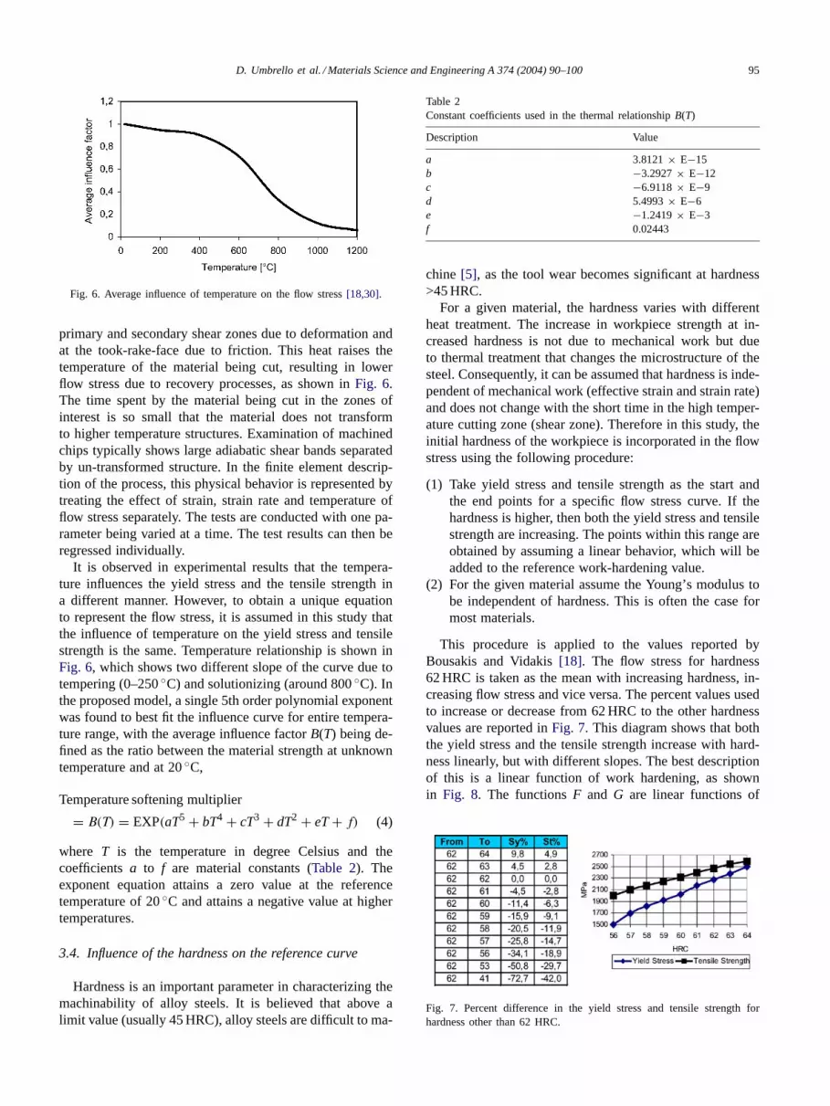
This procedure is applied to the values reported byBousakis and Vidakis[18]. The flow stress for hardness62 HRC is taken as the mean with increasing hardness, in-creasing flow stress and vice versa. The percent values usedto increase or decrease from 62 HRC to the other hardnessvalues are reported inFig. 7. This diagram shows that boththe yield stress and the tensile strength increase with hard-ness linearly, but with different slopes. The best descriptionof this is a linear function of work hardening, as shownin Fig. 8. The functionsF and G are linear functions of
Fig. 7. Percent difference in the yield stress and tensile strength forhardness other than 62 HRC.

96 D. Umbrello et al. / Materials Science and Engineering A 374 (2004) 90–100
Fig. 8. The basic approach to incorporate the hardness effect into the initial yield and the work hardening behavior.
Table 3Constants and coefficients used in the flow stress equation
Description Value Description Value
C 1092 MPa b −3.2927× E−12n 0.083 c −6.9118× E−9A 0.0567 d 5.4993× E−6m 0.1259 e −1.2419× E−3a 3.8121× E−15 f 0.02443
hardness which depend on the material state. The former,F,modifies the initial yield stress and the latter,G, the strainhardening curve. They are found for 52100 steel by usinglinear regression added to the strain term as follows:
Strain hardening term= (Cεn + F + Gε) (5)
where,
F(HRC) = 27.4 HRC− 1700.2 (6)
G(HRC) = 4.48 HRC− 279.9 (7)
Inserting Eqs. (3),(4) and (7)into Eq. (2), the genericexpression for flow stress as a function of effective strain,effective strain rate, temperature and hardness can be writtenas follows:
σ(ε, ε̇, T, HRC)=B(T)(Cεn+F + Gε)[1 + (ln(ε̇)m − A)]
(8)
The values of coefficientsa, b, c, d, e, f, C, n andm for the51000 steel are reported inTable 3.
Based on theEq. (8), Table 3andFig. 8, it can be seen thatthe hardness of the work material plays a role as importantas the work hardening. However, both the temperature andthe strain rate have a significant effect on the flow stressbehavior during the machining process.
4. Validation by finite element modeling
An FEM based numerical procedure was developed, thatincorporates this flow stress model to simulate the given
hard turning process. The predicted results from FEM sim-ulation were then validated by comparing predictions withpublished turning experiments, including the comparison ofcutting force for several cutting speed and chip morphologyfor several hardness values. The following assumptions aremade in the FEM model:
1. Rigid cutting tool.2. Isotropic material.3. Non-isothermal elastic-viscoplastic material governed by
the incremental theory of plasticity and the Von Misesyield criterion.
4. Brozzo’s criterion[19] is employed to predict the effectof hydrostatic stress on the chip segmentation during or-thogonal cutting. Brozzo’s criterion is expressed as:
∫ ε̄f
0
2σ1
3(σ1 − σm)dε̄ (9)
whereεf is the effective strain,σ1 principal stress,σm
the hydrostatic stress andD the material constant repre-senting resistance to failure (sometimes called “damagevalue”). Brozzo’s criterion says that when the integral ofthe left term (applied state) inEq. (8) reaches the valueof D (material state), the fracture occurs and the chipsegmentation process starts. This criterion is easy touse, because only one material constant has to be deter-mined. The other hydrostatic stress based fracture dam-age criteria, need two or more material constants to bedetermined.
Choosing the right critical material valueD in theBrozzo’s criterion is essential for accurate prediction offracture initiation and propogation. In this study, the de-termination of this critical damage valueD is based onthe following iterative procedure, which includes numeri-cal simulation and the comparison of predicted results topublished experimental evidence:
• Different critical damage values are found for the mate-rials with different hardness, because the change of hard-ness for the same material causes the change of materialflow behavior such as segmentation. This curve confirms

D. Umbrello et al. / Materials Science and Engineering A 374 (2004) 90–100 97
Fig. 9. Brozzo’s critical damage valueDcr as a function of workpiecehardness.
that as hardness increases, the fracture toughness (criticaldamage value) decreases.
• The critical damage value is chosen by a calibration curvefor hardnesses between 52 and 64 HRC, the hard turningrange. This curve is a linear interpolation as shows inFig. 9, wherex is the hardness value, whiley is the criticaldamage value for each level of hardness.
4.1. Finite element numerical model
Selected hard turning processes were modeled utilizingthe Deform-2D-V.7.2® finite element code[20]. The work-piece was meshed with 2500 isoparametric quadrilateralelements, while the tool, modeled as rigid, was meshedand subdivided into 600 elements. A plain-strain-coupledthermo-mechanical analysis was performed using orthog-onal assumption. The constitutive law utilized and imple-mented in the numerical model to take into account thiscomplex material behavior is that given in theEq. (8), withmaterial constants for 52100 steel inTable 3. The thermo-physical properties of workpiece are inTable 1and that ofthe cutting tool and interface inTable 4. As far as frictionmodeling is concerned, a simple model based on the con-stant shear hypothesis was implemented with the shear fac-tor kept atm = 0.5 based on the satisfactory result betweenpredicted and experimental cutting force.
4.2. Comparison of cutting force
A comparison of the predicted and experimentally mea-sured cutting forces is shown inFig. 10 for two cuttingspeeds 60 and 120 m/min. The experimental results are fromMamalis et al.[18] for 0.05 mm/rev feed rate and 0.1 mmdepth of cut. Hardness of the 52100 steel workpiece was
Table 4Thermal parameters of the cutting tool material utilized in the model
Tool (SANDVIK CC670 SNGN120408 T01020-PCBN)
Heat capacity (N mm−2 per ◦C) 2.76Thermal conductivity (N s−1 per ◦C) 40Emissivity 0.45
Heat transfer coefficient (N s−1 mm−1 per ◦C) 28
Fig. 10. Numerically predicted and experimentally measured cutting forcesat two cutting speeds.
62 HRC. The cutting tool was a PCBN insert with a rakeangle of−5◦, a clearance angle of 6◦, and a cutting edgeradius of 4�m (a sharp cutting edge).
It is seen that the cutting forces reduce at higher cuttingspeeds. At higher cutting speeds, the cutting temperatures aresignificantly higher. Forces reduce as the thermal softeningmore than offsets the increases due to higher strain rates. Itcan be also seen that the numerical model under-predicts thecutting force at both the cutting speeds with the differencebeing smaller at the higher speed. This is to be expected asthe large nose radii PCBN tool used in experiments developshigher cutting forces. The effect of nose geometry cannotbe modeled by the two-dimensional orthogonal numericalmodel adopted in this study.
4.3. Comparison of chip morphology
Recent studies have shown that the two main parametersinfluencing the chip morphology and segmentation are thehardness of the material and the cutting speed. It is reportedthat shear localization in the chip in hard steels occurs forhardness values greater than 53 HRC. However, it is alsoreported that shear localization also occurs when machiningmedium hard steel is at higher cutting speeds[5]. That showsthat the effects of the cutting speed (adiabatic shear) and theeffect of hardness (early fracture) on shear localization areinterdependent.
4.3.1. Case 1: AISI 52100 (41 HRC)During the simulation, the cutting speed was kept at
100 mm/min, while the feed was set at 0.1 mm/rev in accor-dance with the experimental test reported by Poulachot andMoison [5]. The cutting tool was a Sandvik CC670 withrake angleγ = −6◦ and flank angleα = 6◦, while the toolfillet chamfer was 20◦ ×0.1 mm. From the calibration curvein Fig. 9, the Brozzo’s critical value was chosen equal to0.31 for this case.
Fig. 11a and bshow the comparison between the ex-perimental chip morphology published in[5] and thenumerical simulation for 41 HRC. A uniform chip is ob-tained in experiments. This is also predicted by numericalsimulation. The thickness of the chip is also compara-

98 D. Umbrello et al. / Materials Science and Engineering A 374 (2004) 90–100
Fig. 11. Morphology of the chip during machining workpiece with aninitial hardness of 41HRC: (a) observed[5], (b) predicted.
ble in the two figures. Hence, the numerical model ad-equately predicts the metal flow mechanics (strain andstrain rate) and formation of shear zone that affect the chipmorphology.
4.3.2. Case 2: AISI 52100 (53 HRC)The parameters of the numerical simulation and the cut-
ting experiment (the cutting speed, the feed, depth of cut,the tool material and geometry) are the same in the previ-ous case. The workpiece hardness is now higher at 53 HRC.From Fig. 9, the Brozzo’s critical damage value was cho-sen equal to 0.068 for this hardness.Fig. 12a and bincludethe observed[5] and the predicted chip morphology. It canbe seen that there is a very good geometric agreement withboth showing chip segmentation (sawtooth chip). Averagemeasurements of the wavy chip (valley, peak and pitch) be-tween the experimental and the predicted result are includedin Table 5. The results for all the three geometric attributes
Fig. 12. Morphology of the chip during machining workpiece with aninitial hardness of 53 HRC: (a) observed[5], (b) predicted.
are incredibly close. This would have not been possible ifthe proposed flow stress and the fracture criteria did not ad-equately capture the physics of the process.
4.3.3. Case 3: AISI 52100 (60 HRC)During this simulation the cutting speed was set at
180 mm/min and the feed at 0.08 mm/rev in accordance tothe experimental test reported in[2]. The tool is a PCBNinsert with rake angleγ = −5◦ and flank angleα = 6◦,
Table 5Geometric attributes of the segmented chip with the initial workpiecehardness at 53 HRC (Dcr = 0.068)
Averagevalley (�m)
Averagepeak (�m)
Averagepitch (�m)
Experimental result 75 110 135Numerical result 72 115 140

D. Umbrello et al. / Materials Science and Engineering A 374 (2004) 90–100 99
Fig. 13. Morphology of the chip during machining workpiece with aninitial hardness of 60 HRC: (a) observed[2], (b) predicted.
while the tool fillet radius is equal to 0.025 mm. For thehardness 60HRC, the Brozzo’s critical damage value waschosen to be 0.064 fromFig. 9.
Fig. 13a and bshow the comparison between the ex-perimental result from[2] and the numerical simulation.The numerical models captures both the chip curvature andthe extreme segmentaion experienced at this hardness. Thethree geometrical attributes of the chip, average valley, aver-age peak and average pitch are all accurately predicted, seeTable 6.
Table 6Geometric attributes of the segmented chip with the initial workpiecehardness at 60 HRC (Dcr = 0.064)
Averagevalley (�m)
Averagepeak (�m)
Averagepitch (�m)
Experimental result 48 100 70Numerical result 49 90 80
Fig. 14. Morphology of the chip during machining workpiece with aninitial hardness of 62 HRC: (a) observed[5], (b) predicted.
4.3.4. Case 4: AISI 52100 (62 HRC)The parameters of the numerical simulation and the exper-
iments (the cutting speed, the feed, the tool material and ge-ometry) are the same as in Case 1 and Case 2. The Brozzo’scritical damage value was chosen equal to 0.056 for the 62HRC in Fig. 9.
Fig. 14a and bcompare the results of the experimen-tal published in[5] and the numerical simulation for 62HRC. The chip is a true sawtooth type and a key fea-ture in the machining of hard alloys. It can see that there
Table 7Geometric attributes of the segmented chip with the initial workpiecehardness at 62 HRC (Dcr = 0.056)
Averagevalley (�m)
Averagepeak (�m)
Averagepitch (�m)
Experimental result 20 100 165Numerical result 26 97 175
100 D. Umbrello et al. / Materials Science and Engineering A 374 (2004) 90–100
is a good matching between the experimental and thenumerical chip morphology. The values of the three ge-ometrical attributes for these chips are also very close(seeTable 7).
5. Conclusion
For an accurate modeling of hard machining process,it is very important to know the mechanical and the ther-mal properties of the workpiece material under the ex-treme condition imposed during cutting. In this research,a hardness-based flow stress model is developed by usinga regression approach and using the framework of the J–Cflow model. To capture the effect of hydrostatic stress onfracture, Brozzo’s criterion is used to predict the chip seg-mentation. A calibration curve is developed to express thelink between the Brozzo’s damage value and the workpiecehardness. This curve is obtained by using inverse calculationmethodology.
These models are then implemented in a visco-plasticnon-isothermal finite element model of the orthogonalcutting process. Based on the comparison with publishedresults, it can be concluded that the FEM model incorporat-ing the proposed flow stress model and Brozzo’s criterionadequately simulates the orthogonal cutting process, and rea-sonably predict both the cutting forces and chip morpholo-gies over a wide range of material hardness values. Hence,it will be a valuable tool in the optimisation of processmechanics.
The models presented in this paper are phenomenologi-cal in nature. They assume that the material state does notchange appreciably during the cutting process. If the statedoes change, more rigorous microstructure and dislocationbased material models may become necessary. Such willbe the case if the dynamic recovery or recrystallizationphenomena become important or if phase transformationchanges the material response. Such is not the case in hardmachining where the thermal phenomena are limited in ex-tremely small time scales due to relatively small deformationzone and high velocities of the material flowing through thiszone.
Acknowledgements
The authors wish to acknowledge the SFTC, ColumbusOH, for providing the FEA software DEFORMTM-2D andthe Laboratory for Excellence in Machining Technology atthe Ohio State University for the financial support.
References
[1] M.F. Huston, G.W. Knobeloch, in: Proceeding of CIRP-VDI Con-ference on High-Performance Tools, VDI Berichte 1399, November1998, pp. 21–53.
[2] G. Poulachot, B.P. Bandyopadhyay, I.S. Jawahir, S. Pheulpin, E.Seguin, Int. J. Machine Tools Manuf. 43 (2003) 139–144.
[3] Y. Matsumoto, M.M. Barash, C.R. Liu, Mater. Sci. Technol. 3 (1987)299–305.
[4] G. Poulachot, A.L. Moison, I.S. Jawahir, Ann. CIRP 50 (1) (2001)31–36.
[5] G. Poulachot, A.L. Moison, ASME J. Manuf. Sci. Eng. (2000)406–412.
[6] Y.K. Chou, C.J. Evans, M.M. Barash, J. Mater. Process. Technol.124 (2002) 274–283.
[7] N. Narutaki, Y. Yamane, Ann. CIRP 28 (1) (1979) 23–28.[8] T. Ueda, M. Al Huda, K. Yamada, K. Nakayama, Ann. CIRP 48 (1)
(1999) 63–66.[9] Y.K. Chou, C.J. Evans, Wear 212 (1997) 59–65.
[10] J. Barry, G. Byrne, Wear 247 (2001) 152–160.[11] H.K. Tonshoff, H.-G. Wobker, D. Brandt, Trans. NAMRI/SME XXIII
(1995) 215–220.[12] W. Konig, M. Klinger, R. Link, Ann. CIRP 39 (1) (1990) 61–64.[13] Y. Matsumoto, D. Magda, D.W. Hoeppner, T.Y. Kim, Trans. ASME
113 (1991) 154–159.[14] J. Barry, G. Byrne, Ann. CIRP 51 (1) (2002) 65–70.[15] C.F. MacGregor, J.C. Fisher, J. Appl. Mech. 13 (1946) 11–16.[16] P.L.B. Oxley, The Mechanics of Machining, Ellis Horwood, Chich-
ester, UK, 1989.[17] Y.B. Guo, C.R. Liu, ASME J. Manuf. Sci. Eng. 124 (2002) 1–9.[18] K.D. Bouzakis, N. Vidakis, Mater. Charact. 42 (1999) 1–12.[19] P. Brozzo, B. De Luca, R. Rendina, A new method for the prediction
of formability limit of metal sheet, in: Proceedings of the 7th BiennialConference of the International Deep Drawing Research Group, 1972.
[20] DEFORM 2D, User Manual V 7.2, Schientific Forming TechnologiesCorporation, Columbus, OH, USA, 2001.
[21] P.W. Mason, P.S. Prevey, J. Mater. Eng. Perform. 10 (1) (2001) 14–21.
[22] L.P. Xu, L. Li, Y.A. Min, M.H. Xu, J.P. Lu, R.H. Liu, Study onthe limited hardenability steel, bearing steels: into the 21st century,ASTM, STP 1327, 1998, pp. 321–332.
[23] A.G. Mamalis, A.S. Branis, D.E. Manolakos, J. Mater. Process.Technol. 123 (2000) 464–475.
[24] G.R. Johnson, W.H. Cook, A constitutive model and data for metalssubjected to large strains, high rates and high temperatures, in:Proceedings of the Seventh International Symposium on Ballastics,The Hague, The Netherlands, 1983, pp. 541–547.
[25] F.J. Zerilli, R.W. Armstrong, J. Appl. Phys. 61 (5) (1987) 1816–1825.[26] D.J. Steinberg, S.G. Cochran, M.W. Guinan, A constitutive model for
metals applicable at high-strain rate, Lawrence Livermore NationalLaboratory, UCRL-80465, Revision 2, 1979.
[27] P.S. Follansbee, U.F. Kocks, Acta Metall. 36 (1988) 81–93.[28] K. Maekawa, T. Shirakashi, T. Obikawa, Proc. Inst. Mech. Eng. 210
(1996) 233–242.[29] B.D. Goldthorpe, P. Church, Proceedings of the EURODYMAT 97,
J. de Physique IV, Colloque C8, vol. 7, pp. 753–759.[30] Ir.A.W.A. Konter, FEM analysis of contact problems in metal form-
ing and rubber application, MARC Analysis Research Corporation,Europe, Zoetermeer, April 1993.
Related Documents