Intertenancy Boundary Aged Care ZeroLot SCOPE This design guide contains product information, technical specification, construction details and design considerations for HardieSmart ™ Boundary wall system and HardieSmart ™ ZeroLot wall system when used in residential and multi-residential applications. IMPORTANT NOTES 1. This design guide must be read in conjunction with the relevant and current James Hardie ® product install guides and relevant building code and regulations. 2. The specifier or other responsible party for a project must ensure the information in this guide is appropriate for the application you are planning and that you undertake specific design and detailing for areas which fall outside the scope of these specifications. 3. Failure to install, finish or maintain these products in accordance with applicable building codes, regulations, standards and James Hardie’s written application instructions may lead to personal injury, affect system performance, violate local building codes, and void James Hardie’s product warranty. 4. HardieFire ™ Insulation must be used as the frame cavity infill and must be compressed 5mm at a minimum in both vertical and horizontal directions (I.e. Batt size must be at a minimum 5mm wider and longer than frame stud bay). Ensure there are no gaps in the installation; please refer to design considerations section. 5. Make sure your information is up to date. When specifying or installing James Hardie ® products, ensure you have the current manual or guide. If in doubt, or you need more information, visit www.jameshardie.com.au or Ask James Hardie ™ on 13 11 03. SYSTEM INFORMATION HARDIESMART ™ BOUNDARY WALL SYSTEM FRL (minutes) External Cladding Type (see table 3) Timber Stud Size (mm) Maximum stud spacing # (mm) Min. Wall thickness (mm) Max. Stud height * (mm) Acoustic performance (Rw) Thermal Performance (R-value) + Bracing Performance (kN/m) ^ Depth Width 60/60/60 -/60/60 Flat sheet 90 35 ^^ 450 ~ 102 3,000 47 2.8 4.0 –10.0 90 45 600 3,300 Weatherboards 90 35 ^^ 450 ~ 111 3,000 48 3.0 2.8–6.8 90 45 600 3,300 Planks 90 35 ^^ 450 ~ 105 3,000 47 2.8 2.8–6.8 90 45 600 3,300 HARDIESMART ™ ZEROLOT WALL SYSTEM FRL (minutes) Timber Stud Size (mm) Maximum stud spacing (mm)ˆ ˆ Min. Dual Boundary Wall thickness (mm) Max. stud height * (mm) Acoustic performance per wall (Rw) Thermal Performance (R-value) + Bracing Performance (kN/m) ^ Depth Width Boundary walls separation 60/60/60 -/60/60 90 35 ^^ 25 –100mm 450 ~ 234 3000 47 per wall** 2.8 per wall** 4.0 –10.0 per wall** 90 45 600 3,300 TABLE NOTES: * For increased heights, stud size may need to be increased. Please refer to James Hardie Fire and Acoustically Rated Walls Application Guide for more information. # Stud spacing is based on a load bearing capacity of 5 kN/stud. The stud spacing may need to be reduced in accordance with wind pressure installation requirements for the selected external cladding product, please refer to the relevant and respective literature for more information. The loadbearing capacities of the timber-framed walls must be determined in accordance with AS1684 ‘Residential timber-framed construction’ and AS1720.1 ‘Timber structures’ + Thermal value is based on using a single reflective vapour permeable membrane (e.g. HardieWrap ™ weather barrier) with an emissivity of 0.16. The total R-values for common systems are in accordance with AS4859.1:2002 and Amendment 1:2006 Materials for Thermal Insulation of Buildings. Note that the R-value will be reduced in cavities that are ventilated. ** HardieSmart ™ ZeroLot wall system consists of two external boundary walls with minimum offset and construction is commonly staged; therefore, acoustic requirements and above performance values are only measured for each external wall. ^ Additional fastener and design considerations may be required. Refer to James Hardie Structural Bracing Application guide for more information. ~ Stud spacing may be increased to 600mm centres with a reduced loadbearing capacity of 3.4 kN/stud. Please note that if specifying 600mm centres, cutting of HardieFire ™ Insulation will be required as sizes have been optimised for 45mm studs at 600mm. It is recommended to install 560mm batts horizontally to minimise cutting. Ensure a 5mm compression throughout and no gaps. ^^ A larger minimum timber stud size may be required, please refer to framing section under design considerations. Designed for buildings where external walls are in close proximity to the boundary as well as all bushfire zoned areas that require a Fire Resistance Level (FRL) of up to 1 hour. This integrated solution will not only satisfy fire requirements but will also provide you with excellent acoustic, energy efficiency and bracing performance. Please see the design considerations section for suitable James Hardie external cladding and lining products. HardieWrap ™ weather barrier James Hardie internal lining (table 2) 90mm Timber stud wall EasyLap ™ panels Designed for multi-occupancy projects, specifically, class 1 and 10 buildings where a dual boundary wall solution is required between tenancies. External walls are built at the zero lot boundary line. It has the distinct advantage of enabling fully detached construction in townhouses and terraces, resulting in flexibility of building process. Please see the design considerations section for suitable James Hardie external lining products. HardieFire ™ insulation HARDIESMART ™ BOUNDARY WALL SYSTEM HARDIESMART ™ ZEROLOT WALL SYSTEM Design Guide Australia | October 2014 James Hardie external cladding (table 1) HardieWrap ™ weather barrier HardieFire ™ insulation 90mm Timber stud wall James Hardie internal lining (table 2)

Welcome message from author
This document is posted to help you gain knowledge. Please leave a comment to let me know what you think about it! Share it to your friends and learn new things together.
Transcript

Intertenancy Boundary Aged CareZeroLot
SCOPEThis design guide contains product information, technical specification, construction details and design considerations for HardieSmart™ Boundary wall system and HardieSmart™ ZeroLot wall system when used in residential and multi-residential applications.
IMPORTANT NOTES1. This design guide must be read in conjunction with the relevant and current James Hardie® product install guides and relevant building code and regulations.
2. The specifier or other responsible party for a project must ensure the information in this guide is appropriate for the application you are planning and that you undertake specific design and detailing for areas which fall outside the scope of these specifications.
3. Failure to install, finish or maintain these products in accordance with applicable building codes, regulations, standards and James Hardie’s written application instructions may lead to personal injury, affect system performance, violate local building codes, and void James Hardie’s product warranty.
4. HardieFire™ Insulation must be used as the frame cavity infill and must be compressed 5mm at a minimum in both vertical and horizontal directions (I.e. Batt size must be at a minimum 5mm wider and longer than frame stud bay). Ensure there are no gaps in the installation; please refer to design considerations section.
5. Make sure your information is up to date. When specifying or installing James Hardie® products, ensure you have the current manual or guide. If in doubt, or you need more information, visit www.jameshardie.com.au or Ask James Hardie™ on 13 11 03.
SYSTEM INFORMATION
HARDIESMART™ BOUNDARY WALL SYSTEM
FRL (minutes)
External Cladding Type (see table 3)
Timber Stud Size (mm) Maximum stud spacing# (mm)
Min. Wall thickness (mm)
Max. Stud height* (mm)
Acoustic performance (Rw)
Thermal Performance (R-value)+
Bracing Performance (kN/m)^Depth Width
60/60/60 -/60/60
Flat sheet 90 35^^ 450~ 102 3,000 47 2.8 4.0 –10.0
90 45 600 3,300
Weatherboards 90 35^^ 450~ 111 3,000 48 3.0 2.8–6.8
90 45 600 3,300
Planks 90 35^^ 450~ 105 3,000 47 2.8 2.8–6.8
90 45 600 3,300
HARDIESMART™ ZEROLOT WALL SYSTEM
FRL (minutes)
Timber Stud Size (mm) Maximum stud spacing (mm)ˆ ˆ
Min. Dual Boundary Wall thickness (mm)
Max. stud height* (mm)
Acoustic performance per wall (Rw)
Thermal Performance (R-value)+
Bracing Performance (kN/m)^Depth Width Boundary walls
separation
60/60/60 -/60/60
90 35^^ 25 –100mm 450~ 234 3000 47 per wall**
2.8 per wall**
4.0 –10.0 per wall**
90 45 600 3,300
TABLE NOTES:* For increased heights, stud size may need to be increased. Please refer to James Hardie Fire and Acoustically Rated Walls Application Guide for more information. # Stud spacing is based on a load bearing capacity of 5 kN/stud. The stud spacing may need to be reduced in accordance with wind pressure installation requirements
for the selected external cladding product, please refer to the relevant and respective literature for more information. The loadbearing capacities of the timber-framed walls must be determined in accordance with AS1684 ‘Residential timber-framed construction’ and AS1720.1 ‘Timber structures’
+ Thermal value is based on using a single reflective vapour permeable membrane (e.g. HardieWrap™ weather barrier) with an emissivity of 0.16. The total R-values for common systems are in accordance with AS4859.1:2002 and Amendment 1:2006 Materials for Thermal Insulation of Buildings. Note that the R-value will be reduced in cavities that are ventilated.
** HardieSmart™ ZeroLot wall system consists of two external boundary walls with minimum offset and construction is commonly staged; therefore, acoustic requirements and above performance values are only measured for each external wall.
^ Additional fastener and design considerations may be required. Refer to James Hardie Structural Bracing Application guide for more information.~ Stud spacing may be increased to 600mm centres with a reduced loadbearing capacity of 3.4 kN/stud. Please note that if specifying 600mm centres, cutting
of HardieFire™ Insulation will be required as sizes have been optimised for 45mm studs at 600mm. It is recommended to install 560mm batts horizontally to minimise cutting. Ensure a 5mm compression throughout and no gaps.
^^ A larger minimum timber stud size may be required, please refer to framing section under design considerations.
Designed for buildings where external walls are in close proximity to the boundary as well as all bushfire zoned areas that require a Fire Resistance Level (FRL) of up to 1 hour. This integrated solution will not only satisfy fire requirements but will also provide you with excellent acoustic, energy efficiency and bracing performance.
Please see the design considerations section for suitable James Hardie external cladding and lining products.
HardieWrap™ weather barrier
James Hardie internal lining (table 2)
90mm Timber stud wall
EasyLap™ panels
Designed for multi-occupancy projects, specifically, class 1 and 10 buildings where a dual boundary wall solution is required between tenancies. External walls are built at the zero lot boundary line. It has the distinct advantage of enabling fully detached construction in townhouses and terraces, resulting in flexibility of building process.
Please see the design considerations section for suitable James Hardie external lining products.
HardieFire™ insulation
HARDIESMART™ BOUNDARY WALL SYSTEMHARDIESMART™ ZEROLOT WALL SYSTEM
Design GuideAustralia | October 2014
James Hardie external cladding (table 1)
HardieWrap™ weather barrierHardieFire™ insulation
90mm Timber stud wall
James Hardie internal lining (table 2)
PAGE 2 OF 8 | HARDIESMART™ BOUNDARY AND ZEROLOT WALLS – DESIGN GUIDE
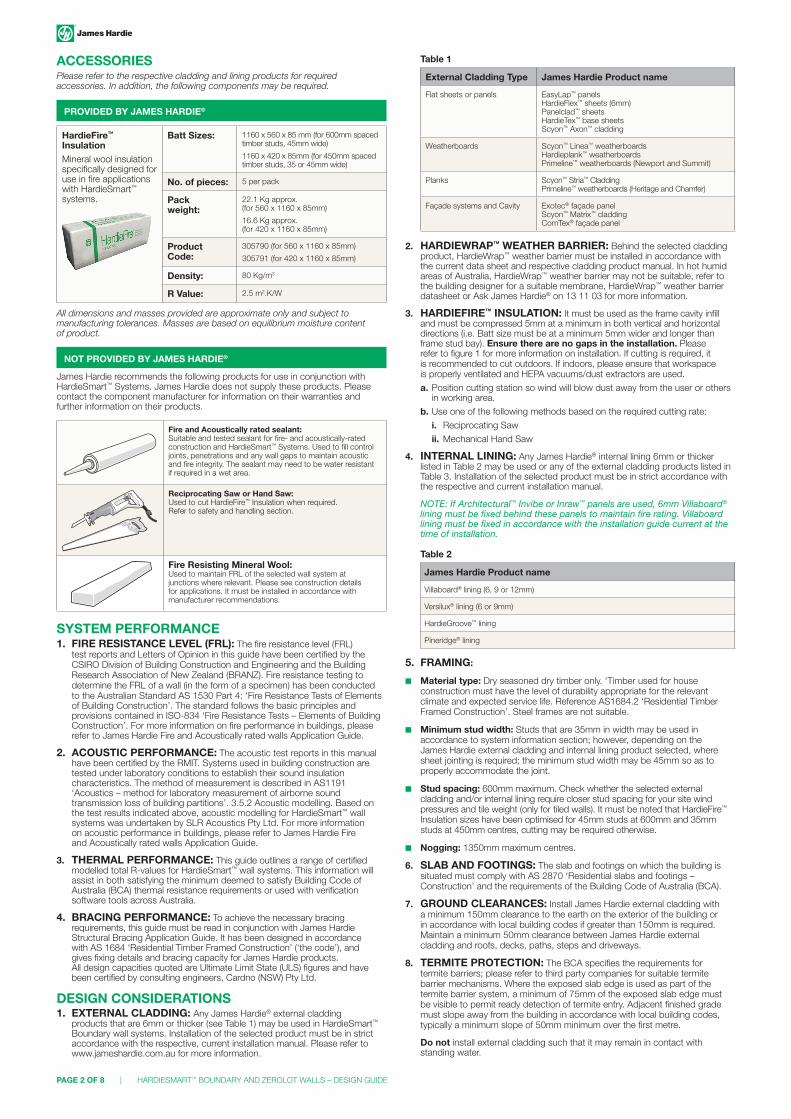
ACCESSORIESPlease refer to the respective cladding and lining products for required accessories. In addition, the following components may be required.
PROVIDED BY JAMES HARDIE®
HardieFire™ InsulationMineral wool insulation specifically designed for use in fire applications with HardieSmart™ systems.
Batt Sizes: 1160 x 560 x 85 mm (for 600mm spaced timber studs, 45mm wide)
1160 x 420 x 85mm (for 450mm spaced timber studs, 35 or 45mm wide)
No. of pieces: 5 per pack
Pack weight:
22.1 Kg approx. (for 560 x 1160 x 85mm)
16.6 Kg approx. (for 420 x 1160 x 85mm)
Product Code:
305790 (for 560 x 1160 x 85mm)
305791 (for 420 x 1160 x 85mm)
Density: 80 Kg/m3
R Value: 2.5 m2.K/W
All dimensions and masses provided are approximate only and subject to manufacturing tolerances. Masses are based on equilibrium moisture content of product.
NOT PROVIDED BY JAMES HARDIE®
James Hardie recommends the following products for use in conjunction with HardieSmart™ Systems. James Hardie does not supply these products. Please contact the component manufacturer for information on their warranties and further information on their products.
Fire and Acoustically rated sealant: Suitable and tested sealant for fire- and acoustically-rated construction and HardieSmart™ Systems. Used to fill control joints, penetrations and any wall gaps to maintain acoustic and fire integrity. The sealant may need to be water resistant if required in a wet area.
Reciprocating Saw or Hand Saw: Used to cut HardieFire™ Insulation when required. Refer to safety and handling section.
Fire Resisting Mineral Wool: Used to maintain FRL of the selected wall system at junctions where relevant. Please see construction details for applications. It must be installed in accordance with manufacturer recommendations.
SYSTEM PERFORMANCE1. FIRE RESISTANCE LEVEL (FRL): The fire resistance level (FRL)
test reports and Letters of Opinion in this guide have been certified by the CSIRO Division of Building Construction and Engineering and the Building Research Association of New Zealand (BRANZ). Fire resistance testing to determine the FRL of a wall (in the form of a specimen) has been conducted to the Australian Standard AS 1530 Part 4: ‘Fire Resistance Tests of Elements of Building Construction’. The standard follows the basic principles and provisions contained in ISO-834 ‘Fire Resistance Tests – Elements of Building Construction’. For more information on fire performance in buildings, please refer to James Hardie Fire and Acoustically rated walls Application Guide.
2. ACOUSTIC PERFORMANCE: The acoustic test reports in this manual have been certified by the RMIT. Systems used in building construction are tested under laboratory conditions to establish their sound insulation characteristics. The method of measurement is described in AS1191 ‘Acoustics – method for laboratory measurement of airborne sound transmission loss of building partitions’. 3.5.2 Acoustic modelling. Based on the test results indicated above, acoustic modelling for HardieSmart™ wall systems was undertaken by SLR Acoustics Pty Ltd. For more information on acoustic performance in buildings, please refer to James Hardie Fire and Acoustically rated walls Application Guide.
3. THERMAL PERFORMANCE: This guide outlines a range of certified modelled total R-values for HardieSmart™ wall systems. This information will assist in both satisfying the minimum deemed to satisfy Building Code of Australia (BCA) thermal resistance requirements or used with verification software tools across Australia.
4. BRACING PERFORMANCE: To achieve the necessary bracing requirements, this guide must be read in conjunction with James Hardie Structural Bracing Application Guide. It has been designed in accordance with AS 1684 ‘Residential Timber Framed Construction’ (‘the code’), and gives fixing details and bracing capacity for James Hardie products. All design capacities quoted are Ultimate Limit State (ULS) figures and have been certified by consulting engineers, Cardno (NSW) Pty Ltd.
DESIGN CONSIDERATIONS1. EXTERNAL CLADDING: Any James Hardie® external cladding
products that are 6mm or thicker (see Table 1) may be used in HardieSmart™ Boundary wall systems. Installation of the selected product must be in strict accordance with the respective, current installation manual. Please refer to www.jameshardie.com.au for more information.
Table 1
External Cladding Type James Hardie Product name
Flat sheets or panels EasyLap™ panels HardieFlex™ sheets (6mm) Panelclad™ sheets HardieTex™ base sheets Scyon™ Axon™ cladding
Weatherboards Scyon™ Linea™ weatherboards Hardieplank™ weatherboards Primeline™ weatherboards (Newport and Summit)
Planks Scyon™ Stria™ Cladding Primeline™ weatherboards (Heritage and Chamfer)
Façade systems and Cavity Exotec® façade panel Scyon™ Matrix™ cladding ComTex® façade panel
2. HARDIEWRAP™ WEATHER BARRIER: Behind the selected cladding product, HardieWrap™ weather barrier must be installed in accordance with the current data sheet and respective cladding product manual. In hot humid areas of Australia, HardieWrap™ weather barrier may not be suitable, refer to the building designer for a suitable membrane, HardieWrap™ weather barrier datasheet or Ask James Hardie® on 13 11 03 for more information.
3. HARDIEFIRE™ INSULATION: It must be used as the frame cavity infill and must be compressed 5mm at a minimum in both vertical and horizontal directions (i.e. Batt size must be at a minimum 5mm wider and longer than frame stud bay). Ensure there are no gaps in the installation. Please refer to figure 1 for more information on installation. If cutting is required, it is recommended to cut outdoors. If indoors, please ensure that workspace is properly ventilated and HEPA vacuums/dust extractors are used.
a. Position cutting station so wind will blow dust away from the user or others in working area.
b. Use one of the following methods based on the required cutting rate:
i. Reciprocating Saw
ii. Mechanical Hand Saw
4. INTERNAL LINING: Any James Hardie® internal lining 6mm or thicker listed in Table 2 may be used or any of the external cladding products listed in Table 3. Installation of the selected product must be in strict accordance with the respective and current installation manual.
NOTE: If Architectural™ Invibe or Inraw™ panels are used, 6mm Villaboard® lining must be fixed behind these panels to maintain fire rating. Villaboard lining must be fixed in accordance with the installation guide current at the time of installation.
Table 2
James Hardie Product name
Villaboard® lining (6, 9 or 12mm)
Versilux® lining (6 or 9mm)
HardieGroove™ lining
Pineridge® lining
5. FRAMING:
■ Material type: Dry seasoned dry timber only. ‘Timber used for house construction must have the level of durability appropriate for the relevant climate and expected service life. Reference AS1684.2 ‘Residential Timber Framed Construction’. Steel frames are not suitable.
■ Minimum stud width: Studs that are 35mm in width may be used in accordance to system information section; however, depending on the James Hardie external cladding and internal lining product selected, where sheet jointing is required; the minimum stud width may be 45mm so as to properly accommodate the joint.
■ Stud spacing: 600mm maximum. Check whether the selected external cladding and/or internal lining require closer stud spacing for your site wind pressures and tile weight (only for tiled walls). It must be noted that HardieFire™ Insulation sizes have been optimised for 45mm studs at 600mm and 35mm studs at 450mm centres, cutting may be required otherwise.
■ Nogging: 1350mm maximum centres.
6. SLAB AND FOOTINGS: The slab and footings on which the building is situated must comply with AS 2870 ‘Residential slabs and footings – Construction’ and the requirements of the Building Code of Australia (BCA).
7. GROUND CLEARANCES: Install James Hardie external cladding with a minimum 150mm clearance to the earth on the exterior of the building or in accordance with local building codes if greater than 150mm is required. Maintain a minimum 50mm clearance between James Hardie external cladding and roofs, decks, paths, steps and driveways.
8. TERMITE PROTECTION: The BCA specifies the requirements for termite barriers; please refer to third party companies for suitable termite barrier mechanisms. Where the exposed slab edge is used as part of the termite barrier system, a minimum of 75mm of the exposed slab edge must be visible to permit ready detection of termite entry. Adjacent finished grade must slope away from the building in accordance with local building codes, typically a minimum slope of 50mm minimum over the first metre.
Do not install external cladding such that it may remain in contact with standing water.

HARDIESMART™ BOUNDARY AND ZEROLOT WALLS – DESIGN GUIDE | PAGE 3 OF 8
9. FIRE AND ACOUSTICALLY RATED SEALANT: Use a tested and warranted fire sealant in junctions and gaps as indicated in construction details to maintain fire and acoustic integrity of the system. E.g. Bostik FireBan One.
10. FASTENER TYPE: Brad nail and/or adhesive fixing are NOT recommended in fire and acoustically rated systems. Please refer to the respective James Hardie product for alternative fixing methods.
11. PENETRATIONS: All penetrations require careful and comprehensive treatment. They should be fire stopped, kept to a minimum, kept as small as possible and designed to cater for thermal movement and shrinkage. Generally, dealing with penetrations in fire and acoustically rated systems can be avoided by placing them in external non-fire rated systems, or by building false walls or box/bulkheads, creating pockets in the fire rated element.
12. PAINT/TEXTURE: Refer to the respective James Hardie internal lining and external cladding installation manual for coating requirements. Please refer to coating manufacturer for suitability and specific requirements.
When installing Villaboard® lining in areas that are not exposed and there is no concern of aesthetics such as roof cavities, James Hardie™ Top coat and finishing coatings are not required to maintain FRL and acoustic performance. However, the joints must be sealed with an appropriate fire and acoustically rated sealant or alternatively James Hardie™ Base Coat.
SAFETY AND HANDLINGFor information refer to the respective products installation guide or data sheet and MSDS at www.jameshardie.com.au or www.accel.com.au; and the safe workplace government authority in your state.
DESIGN TOOLSJames Hardie has developed online tools for easy specification. Please refer to www.accel.com.au for more information on estimation tools, CAD details, system selector, site specific recommendations and more.
James Hardie internal lining
Gap sealed with fire and acoustic sealant
Concrete Slab
Damp proof course
Suitable ground clearance
HardieWrap™ weather barrier
HardieFire™ insulation
James Hardie external cladding
FIGURE 2 EXTERNAL WALL BASE TO SLAB
FIGURE 1 HARDIESMART™ BOUNDARY WALL SYSTEM
HardieFire™ insulation 5mm compression, ensure no gaps
HardieWrap™ weather barrier
90mm timber frame
James Hardie external cladding(see table 3)
EXTERIOR
INTERIOR
James Hardie internal lining(see table 4)
STANDARD CONSTRUCTION DETAILS
CONSTRUCTION DETAILS
BASE DETAILS
Concrete Slab
Damp proof course
Suitable ground clearance
HardieWrap™ weather barrier
HardieFire™ insulation
HardieFire™ insulationGap sealed with fire
and acoustic sealant
James Hardie external cladding
James Hardie internal lining
James Hardie internal lining
Structural flooring
Sacrificial 45mm solid timber batten to maintain FRL
FIGURE 3 EXTERNAL WALL BASE TO SUSPENDED GROUND FLOOR OPTION 1
FIGURE 4A EXTERNAL WALL BASE TO SUSPENDED GROUND FLOOR OPTION 2
Ant cap
HardieWrap™ weather barrier
HardieFire™ insulation
Corrossion resistant metal flashing with min. 75mm upstand and 10mm overhang
Horizontal timber support between piers or stumppier or
stump
200x50mm H4 treated timber plinth. *Refer to timber manufacturer for suitability
45mm timber bearers
Floor Joist
Fire rated sealant
HardieWrap™ weather barrier
James Hardie® external cladding
HardieFire™ insulation
Corrossion resistant metal flashing with min. 75mm upstand
6mm gap to allow moisture to escape
6mm gap to allow moisture to escape
Ant cap
45mm timber bearers
Floor Joist
Structural flooring
Fire rated sealant
James Hardieinternal lining
Continuous concrete strip footing
James Hardie® external cladding
Structural flooring
James Hardieinternal lining
FIGURE 4B EXTERNAL WALL BASE TO SUSPENDED GROUND FLOOR OPTION 3
Ant cap
HardieWrap™ weather barrier
HardieFire™ insulation
Corrossion resistant metal flashing with min. 75mm upstand and 10mm overhang
Horizontal timber support between piers or stumppier or
stump
200x50mm H4 treated timber plinth. *Refer to timber manufacturer for suitability
45mm timber bearers
Floor Joist
Fire rated sealant
HardieWrap™ weather barrier
James Hardie® external cladding
HardieFire™ insulation
Corrossion resistant metal flashing with min. 75mm upstand
6mm gap to allow moisture to escape
6mm gap to allow moisture to escape
Ant cap
45mm timber bearers
Floor Joist
Structural flooring
Fire rated sealant
James Hardieinternal lining
Continuous concrete strip footing
James Hardie® external cladding
Structural flooring
James Hardieinternal lining

PAGE 4 OF 8 | HARDIESMART™ BOUNDARY AND ZEROLOT WALLS – DESIGN GUIDE
James Hardie internal lining
James Hardie external cladding
James Hardie internal lining
Structural flooring
Sacrificial 45mm solid timber batten to maintain FRL
Ceiling lining
6mm gap sealed with fire and acoustic sealant
HardieWrap™ weather barrier
HardieFire™ insulation
Corrosion resistant flashing suitable for the selected James Hardie cladding
HardieFire™ insulation
6mm gap sealed with fire and acoustic sealant
FIGURE 5 EXTERNAL BOUNDARY WALL WITH UPPER STOREY FLOOR 1
James Hardie internal lining
James Hardie external cladding
James Hardie internal lining
Structural flooring
Sacrificial 45mm solid timber batten to maintain FRL
Ceiling lining
6mm gap sealed with fire and acoustic sealant
HardieWrap™ weather barrier
HardieFire™ insulation
Corrosion resistant flashing suitable for the selected James Hardie cladding
HardieFire™ insulation
6mm gap sealed with fire and acoustic sealant
FIGURE 6 EXTERNAL BOUNDARY WALL WITH UPPER STOREY FLOOR OPTION 2
FIGURE 8 EXTERNAL BOUNDARY WALL TO JAMES HARDIE EAVE LINING (RAKED) OPTION 2
James Hardie external cladding
Roofing installed in accordance with manufacturing with suitable sarking
James Hardie eaves lining
Non-combustible fascia
BCA Volume Two, Section 3.7.1.5 Requires a 60 minute FRL to only extend to the underside of a non-combustible eaves lining for class 1 and 10 buildings.
James Hardie internal lining
HardieWrap™ weather barrier
Seal with fire and acoustic sealant
Ceiling lining
HardieFire™ insulation
FIGURE 9 EXTERNAL BOUNDARY WALL TO ROOF WITH NO EAVE LINING
James Hardie external cladding
Roofing installed in accordance with manufacturing with suitable sarking
Fill with fire resistant mineral wool to retain FRL (HardieFire™ Insulation not suitable)
45mm sacrifical solid timber batten
No eave lining
Non-combustible fascia
James Hardie internal lining
HardieWrap™ weather barrier
Seal with fire and acoustic sealant
Ceiling lining
HardieFire™ insulation
FIGURE 10 EXTERNAL BOUNDARY WALL TO PARAPET ROOF
Villaboard® lining
James Hardie external cladding
James Hardie external cladding
James Hardie lining
Corrossion resistant metal capping with fall in accordance with manufacturer
Roofing installed in accordance with manufacturing with suitable sarking
50mm + height of water
HardieWrap™ weather barrier
HardieFire™ insulation
Seal with fire and acoustic sealant
Ceiling lining
FLOOR JUNCTIONS
FIGURE 7 EXTERNAL BOUNDARY WALL TO JAMES HARDIE EAVE LINING OPTION 1
James Hardie internal lining
James Hardie external cladding
HardieWrap™ weather barrier
Seal with fire and acoustic sealant
Ceiling lining
Roofing installed in accordance with manufacturing with suitable sarking
BCA Volume Two, Section 3.7.1.5 Requires a 60 minute FRL to only extend to the underside of a non-combustible eaves lining for class 1 and 10 buildings.
James Hardie eaves lining Non-combustible
fascia
HardieFire™insulation
ROOF JUNCTIONS

HARDIESMART™ BOUNDARY AND ZEROLOT WALLS – DESIGN GUIDE | PAGE 5 OF 8
FIGURE 11 NON-FIRE RATED INTERSECTING BOUNDARY WALL
James Hardie external cladding James Hardie
internal lining
6mm gap sealed with fire and acoustic sealant
Non- fire ratedinternal lining
HardieWrap™ weather barrier
HardieFire™ insulation
6mm gap sealed with fire and acoustic sealant
45mm sacrificial timber batten to maintain FRL
James Hardie internal lining
FIGURE 14 FIRE-RATED WALL PLUMBING PIPE PENETRATION – SECTION
20 mm vertical batten
90mm timber frame
HardieWrap™ weather barrier
James Hardie external cladding
Adequate horizontal support for taps
Suitable wet area sealant
HardieFire™ insulation
6mm Villaboard® lining
Suitable tiles with recommendedwaterproofing membrane (for wet areas)
FIGURE 15 FIRE-RATED WALL PLUMBING PIPE PENETRATION – PLAN
20 mm batten 20 mm batten
HardieFire™ insulation
Suitable wet area sealant
6mm Villaboard® lining
90mm timberframe
James Hardie external cladding
HardieWrap™
weather barrier
Suitable tiles with recommendedwaterproofing membrane (for wet areas)
WALL JUNCTIONS
FIGURE 12 FIRE-RATED EXTERNAL WINDOW AT BOUNDARY (GUIDE ONLY, PLEASE REFER TO WINDOW MANUFACTURER)
Gap sealed with fire and acoustic sealant
James Hardie internal lining
James Hardie external cladding
HardieWrap™ weather barrier
James Hardie internal lining
Internal window trim
Internal window trim
HardieFire™ insulation
Corrosion reistant flashing
Sealed continuously with fire and acoustic sealant
Suitable corrossion resistant flashing
Non-openable and suitable fire window with FRL of -/60/-
FIGURE 13 FIRE-RATED SWITCH PLATE OR GPO ELEVATION
James Hardie external cladding (if external) or Villaboard® (if internal)
James Hardie Mineral Wool
James Hardie internal lining
Switch plate
Fire rated switchbox as supplied by manufacturer
Switch plate bracket
Gap sealed with fire sealant e.g. Selleys® Fireblock™
HardieWrap™ weather barrier (only required if external)
PENETRATIONS
WINDOW DETAILS
PAGE 6 OF 8 | HARDIESMART™ BOUNDARY AND ZEROLOT WALLS – DESIGN GUIDE
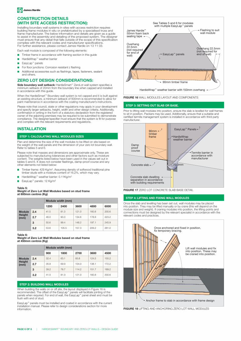
FIGURE 16 WALL MODULES LAYOUT AND COMPONENTS
HardieWrap™ weather barrier with 150mm overhang
Overhang 22.5mm(not required forend of wall)
Overhang 22.5mm(not required for end of wall)
James Hardie™
50mm foam backsealing tape
90mm timber frame
EasyLap™ panels
See Tables 5 and 6 for modules with multiple EasyLap™ panels
Flashing to suit wall module
FIGURE 18 LIFTING AND ANCHORING ZERO LOT WALL MODULES
Once anchored and fixed in position, fix temporary bracing.
Lift wall modules and fixinto position. These may be craned into position.
Anchor frame to slab in accordance with frame design
INSTALLATION
STEP 1: CALCULATING WALL MODULES SIZES
Plan and determine the size of the wall modules to be lifted on site based on the weight of the wall panels and the dimension of your zero lot boundary wall. Refer to tables 5 and 6.
Please note that masses and dimensions are approximate only. These are subjected to manufacturing tolerances and other factors such as moisture content. The weights listed below have been used in the values set out in tables 5 and 6. It does not consider flashings, damp-proof course and any other elements not listed below:
■ Timber frame: 429 Kg/m3. Assuming density of softwood traditional pine timber studs with a moisture content of 16.2%, which may vary.
■ HardieWrap™ weather barrier: 0.11Kg/m2
■ EasyLap™ panels: 12 Kg/m2
Table 5: Weight of Zero Lot Wall Modules based on stud frame at 600mm centres (Kg)
Module width (mm)
1200 2400 3600 4800 6000
Module Height (mm)
2.4 41.5 81.3 121.0 160.8 200.6
2.7 46.0 90.3 134.6 178.9 223.2
3 50.6 99.4 148.2 197.1 245.9
3.2 53.6 105.5 157.3 209.2 261.0
Table 6: Weight of Zero Lot Wall Modules based on stud frame at 450mm centres (Kg)
Module width (mm)
900 1800 2700 3600 4500
Module Height (mm)
2.4 32.4 63.1 93.8 124.5 155.2
2.7 35.8 69.9 104.0 138.1 172.2
3 39.2 76.7 114.2 151.7 189.2
3.2 41.5 81.3 121.0 160.8 200.6
STEP 3: SETTING OUT SLAB OR BASE.
Prior to lifting wall modules into position, ensure the slab is levelled for wall frames to sit in position. Packers may be used. Additionally, ensure that a suitable and certified termite management system is installed in accordance with third party manufacturer.
STEP 2: BUILDING WALL MODULES
When building the walls on or off site, the layout displayed in Figure 16 is recommended. The offset of the EasyLap™ panels will facilitate jointing of the panels when required. For end of wall, the EasyLap™ panel sheet end must be flush with end of stud.
EasyLap™ panels must be installed and coated in accordance with the current installation manual. Please refer to design considerations section for more information.
STEP 4: LIFTING AND FIXING WALL MODULES
Once the slab and levelling has been set out, wall modules may be placed into position. They may be lifted manually or by crane (this will depend on the module size and weight). If craning modules into position, the lifting points and connections must be designed by the relevant specialist in accordance with the relevant codes and practices.
FIGURE 17 ZERO LOT CONCRETE SLAB BASE DETAIL
Concrete slab dwelling separation in accordance with building requirements
Concrete slab
Dampproof course
90mm timber frame
EasyLap™ Panels
HardieWrapweather barrier
Termite barrier inaccordance withmanufacturer
20.0mm
CONSTRUCTION DETAILS (WITH SITE ACCESS RESTRICTION):Installing boundary wall systems in sites with access restriction requires building frame modules in-situ or prefabricated by a specialised truss and frame manufacturer. The below information and details are given as a guide to assist in the assembly and detailing of the proposed system. The designer must ensure that any detail that falls outside of the scope of this specification complies with the relevant codes and manufacturer specifications. For further assistance, please contact James Hardie on 13 11 03.
Each wall module is composed of the following elements:
■ Timber frame in accordance with framing section in this guide
■ HardieWrap™ weather barrier
■ EasyLap™ panels
■ For floor junctions: Corrosion resistant z flashing
■ Additional accessories such as flashings, tapes, fasteners, sealant and others.
ZERO LOT DESIGN CONSIDERATIONS:Side boundary wall setback: HardieSmart™ ZeroLot wall system specifies a minimum setback of 20mm from the boundary line when capped and installed in accordance with this guide.
When the HardieSmart™ Boundary wall system is not capped and it is built against an existing structure, a minimum setback of 500mm is recommended to allow for paint maintenance in accordance with the coating manufacturer’s instructions.
Please note that council, state or other regulations may apply in your development and specify larger setbacks, height, width and other design criteria. Additionally, confirmation in writing in the form of a statutory declaration from the registered owner of the adjoining premises may be required to be submitted to demonstrate compliance. The designer/specifier must ensure that the system is fit for purpose and complies with the relevant requirements and regulations.

HARDIESMART™ BOUNDARY AND ZEROLOT WALLS – DESIGN GUIDE | PAGE 7 OF 8
FIGURE 19 VERTICAL JOINT OF WALL MODULES
EasyLap™ panels
HardieWrap™ weather barrier with 150mm overhang
90mm timber fra
me
Tape HardieWrap™ ends with suitable tape
Fix studs together in accordance with framing manufacturer
FIGURE 20 ZERO LOT FLOOR JUNCTION PERSPECTIVE
Suitable structural flooring
Suitable floor joist
45mm solid timber pole plate
HardieFire™ Insulation
NOTE: For sectional detail, please refer to Figure 6 in this guide.
Suitable corrosionresitant flashing
Nogging
FIGURE 21 FIXING UPPER STOREY WALL MODULES
20mm
Corrosion resistant Z flashing with 100mm upstand
Once anchored and fixed in position, fix temporary bracing.
Lift wall modules and fix into position. These may be craned into position. Fix bottom plate to frame in accordance with frame design.
FIGURE 22 ZERO LOT PARAPET ROOF JUNCTION SECTION
Ceiling lining
HardieFire™
insulation
Suitable Corrosionresistant metalflashing with min.75mm upstand
HardiWrap™
weather barrier
EasyLap™ panels
Suitable corrosion resistant flashing to seal cavity
Suitable corrosion resistant steel capping
Selected James Hardie claddingVillaboard® lining
Ceiling Joists parallel
Trimmer for ceiling lining perimeter support
Roofing sheets/tilesinstalled in accordance with manufacturer
FIGURE 23 EXTERNAL NON-FIRE-RATED WALL ABUTTING TO HARDIESMART™ ZEROLOT WALL SYSTEM
FIGURE 24 EXTERNAL BRICK VENEER WALL ABUTTING TO HARDIESMART™ ZEROLOT WALL SYSTEM
Selected external cladding 75x75mm James Hardie™
Colourbond flashing
Scyon™ Axent™ trim
Sacrificial45mm timber batten
6mm gap sealed with fire and acoustic sealant
James Hardie internal liningHardiFire™
Insulation
HardieWrap™ Weather Barrier
EasyLap™ Panels
HardieWrap™ Weather Barrier
EasyLap™ Panels
6mm gap sealed with fire sealant e.g. Bostik®
FireBan One
HardieFire™ insulation
James Hardie Internal lining
Internal lining
Vapour permeablemembrane
Damp-proofcourse
Sacrificial treated 45mm solid timber batten to maintain FRL
STEP 5: FIXING HARDIEFIRE™ INSULATION AND JAMES HARDIE® INTERNAL LINING.
Finally, after all wall modules, floor and roof have been fixed, you may install the remaining HardieFire™ Insulation and the selected James Hardie® internal lining. Ensure to follow the recommended safety work practices specified in the respective James Hardie product manuals and data sheets as well as any state and code regulations.
When placing HardieFire™ Insulation batts inside the wall stud bays, ensure a minimum 5mm compression in all sides is maintained. If cutting is required, please allow 5mm in addition to the required dimension to achieve the required compression. Please refer to HardieFire™ Insulation Data Sheet for cutting tools and safe working practices.
After installing HardieFire™ Insulation, the selected James Hardie® lining must be installed in accordance with the current and respective installation guide. Please note that additional fasteners may be required if depending on the bracing value required. Please refer to James Hardie® structural bracing application guide for more information.
WARRANTYHardieSmart™ Boundary wall system and HardieSmart™ ZeroLot wall system have a James Hardie product warranty. The period varies for the selected system components. For terms and conditions of product warranty, refer to www.jameshardie.com.au or www.accel.com.au
FIGURE 25 HARDIEFIRE™ INSULATION AND JAMES HARDIE® INTERNAL LINING LAYOUT
Fix HardieFire Insulation with a minimum 5 mm compression along vertical and horizontal. Ensure no gaps
James Hardie internal lining installed in accordance with respective installation guides

Call 13 11 03 for information and advice | jameshardie.com.au
© 2014 James Hardie Australia Pty Ltd ABN 12 084 635 558. ™ and ® denote a trademark owned by James Hardie Technology Limited. JH_2207-12
Related Documents


