GND VDD OUT- OUT+ PWM EN VDD LRA / ERM CVDD Level Correction VDD Gate Drive Gate Drive Back-EMF Detection Control Engine M LRA or ERM Thermal Shutdown Overcurrent Shutdown Supply Correction Copyright © 2016, Texas Instruments Incorporated Product Folder Sample & Buy Technical Documents Tools & Software Support & Community Reference Design An IMPORTANT NOTICE at the end of this data sheet addresses availability, warranty, changes, use in safety-critical applications, intellectual property matters and other important disclaimers. PRODUCTION DATA. DRV2603 SLOS754C – JUNE 2012 – REVISED AUGUST 2016 DRV2603 Haptic Drive With Auto-Resonance Detection for Linear Resonance Actuators (LRA) 1 1 Features 1• Flexible Haptic/Vibra Driver – LRA (Linear Resonance Actuator) – ERM (Eccentric Rotating Mass) • Auto Resonance Tracking for LRA – No Frequency Calibration Required – Automatic Drive Commutation – Automatic Braking Algorithm – Wide Input PWM Frequency Range • Constant Vibration Strength Over Supply • Automatic Input Level Translation • 0% to 100% Duty Cycle Control Range • Fast Start Up Time • Differential Drive from Single-Ended Input • Wide Supply Voltage Range of 2.5 V to 5.2 V • Immersion TouchSense ® 3000 Compatible • 1.8-V Compatible, 5-V Tolerant Digital Pins • Available in a 2 mm × 2 mm × 0.75 mm Leadless QFN Package (RUN) 2 Applications • Mobile Phones and Tablets • Watches and Wearable Technology • Remote Controls, Mice, and Peripheral Devices • Electronic Point of Sale (ePOS) • Vibration Alerts and Notifications • Touch-Enabled Devices • Industrial Human-Machine Interfaces 3 Description The DRV2603 is a haptic driver designed specifically to solve common obstacles in driving both Linear Resonance Actuator (LRA) and Eccentric Rotating Mass (ERM) haptic elements. The DRV2603 is designed for low latency, high efficiency, and more drive strength for actuators commonly used for tactile feedback in the portable market. LRA actuators typically have a narrow frequency band over which they have an adequate haptic response. This frequency window is typically ±2.5 Hz wide or less, so driving an LRA actuator presents a challenge. The DRV2603 solves this problem by employing auto resonance tracking, which automatically detects and tracks the LRA resonant frequency in real time. This means that any input PWM frequency within the input range (10 kHz to 250 kHz) will automatically produce the correct resonant output frequency. As an additional benefit, the DRV2603 implements an automatic braking algorithm to prevent LRA ringing at the end of waveforms, leaving the user with a crisp haptic sensation. For both ERM and LRA actuators, the automatic input level translation solves issues with low voltage PWM sources without adding additional external components, so if the digital I/O levels vary, the output voltage does not change. The DRV2603 also has supply correction that ensures no supply regulation is required for constant vibration strength, allowing an efficient, direct-battery connection. Device Information (1) PART NUMBER PACKAGE BODY SIZE (NOM) DRV2603 WQFN (10) 2.00 mm × 2.00 mm (1) For all available packages, see the orderable addendum at the end of the datasheet. DRV2603 Block Diagram

Welcome message from author
This document is posted to help you gain knowledge. Please leave a comment to let me know what you think about it! Share it to your friends and learn new things together.
Transcript
GND
VDD
OUT-
OUT+
PWM
EN
VDD
LRA / ERM
CVDD
Level Correction
VDD
Gate
Drive
Gate
Drive
Back-EMF
DetectionControl Engine
MLRA
or
ERM
Thermal
Shutdown
Overcurrent
Shutdown
Supply Correction
Copyright © 2016, Texas Instruments Incorporated
Product
Folder
Sample &Buy
Technical
Documents
Tools &
Software
Support &Community
ReferenceDesign
An IMPORTANT NOTICE at the end of this data sheet addresses availability, warranty, changes, use in safety-critical applications,intellectual property matters and other important disclaimers. PRODUCTION DATA.
DRV2603SLOS754C –JUNE 2012–REVISED AUGUST 2016
DRV2603 Haptic Drive With Auto-Resonance Detection for Linear Resonance Actuators(LRA)
1
1 Features1• Flexible Haptic/Vibra Driver
– LRA (Linear Resonance Actuator)– ERM (Eccentric Rotating Mass)
• Auto Resonance Tracking for LRA– No Frequency Calibration Required– Automatic Drive Commutation– Automatic Braking Algorithm– Wide Input PWM Frequency Range
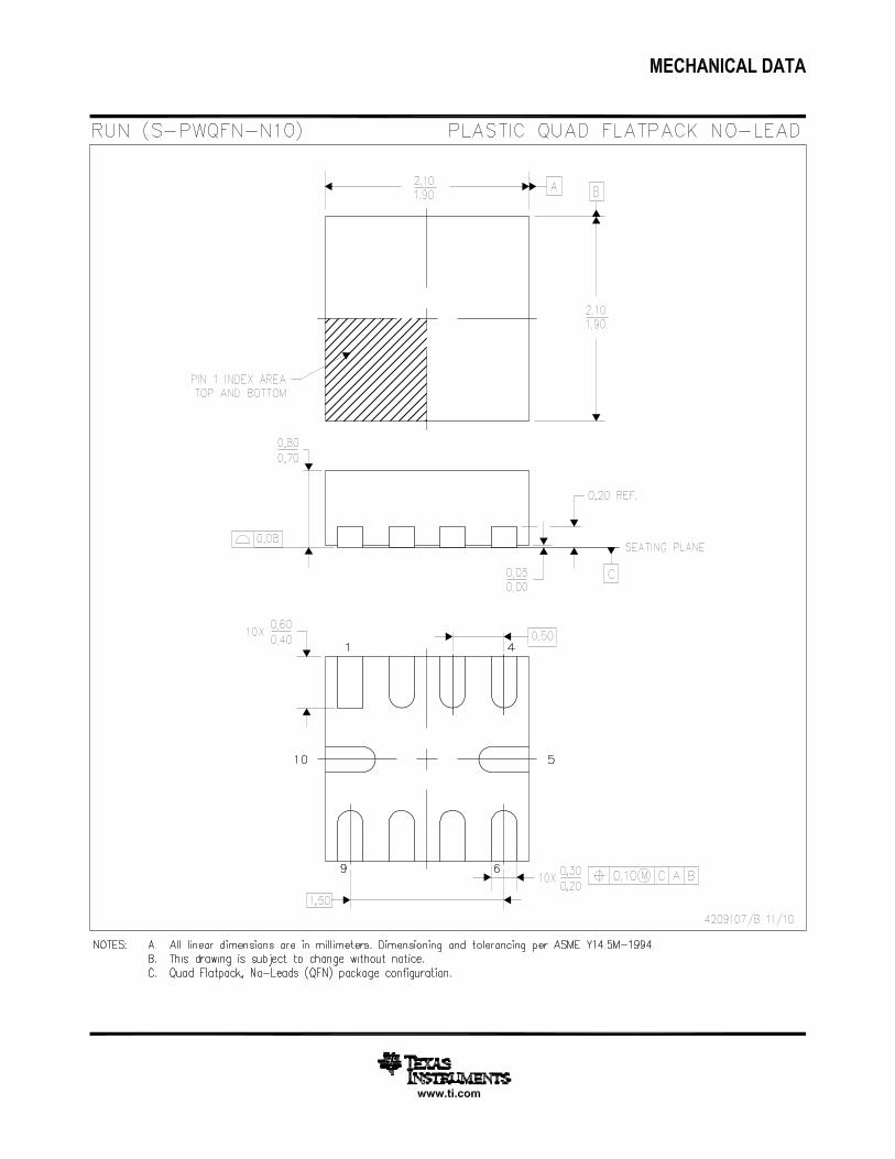
• Constant Vibration Strength Over Supply• Automatic Input Level Translation• 0% to 100% Duty Cycle Control Range• Fast Start Up Time• Differential Drive from Single-Ended Input• Wide Supply Voltage Range of 2.5 V to 5.2 V• Immersion TouchSense® 3000 Compatible• 1.8-V Compatible, 5-V Tolerant Digital Pins• Available in a 2 mm × 2 mm × 0.75 mm Leadless
QFN Package (RUN)
2 Applications• Mobile Phones and Tablets• Watches and Wearable Technology• Remote Controls, Mice, and Peripheral Devices• Electronic Point of Sale (ePOS)• Vibration Alerts and Notifications• Touch-Enabled Devices• Industrial Human-Machine Interfaces
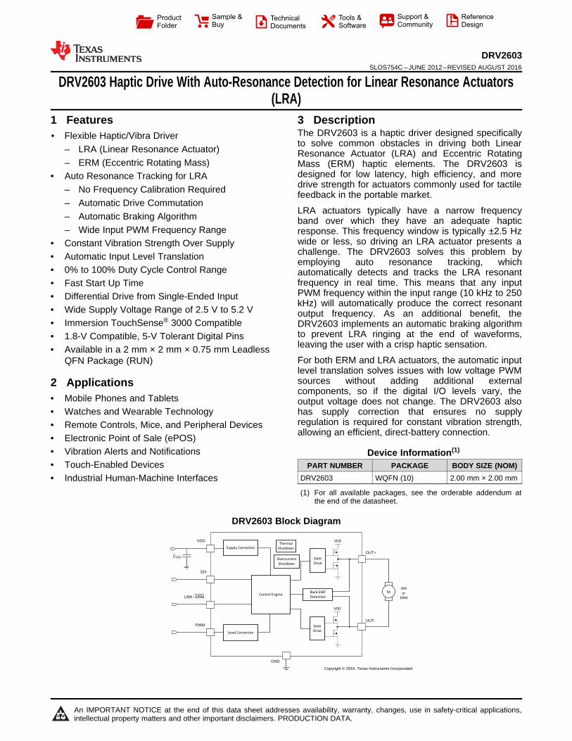
3 DescriptionThe DRV2603 is a haptic driver designed specificallyto solve common obstacles in driving both LinearResonance Actuator (LRA) and Eccentric RotatingMass (ERM) haptic elements. The DRV2603 isdesigned for low latency, high efficiency, and moredrive strength for actuators commonly used for tactilefeedback in the portable market.
LRA actuators typically have a narrow frequencyband over which they have an adequate hapticresponse. This frequency window is typically ±2.5 Hzwide or less, so driving an LRA actuator presents achallenge. The DRV2603 solves this problem byemploying auto resonance tracking, whichautomatically detects and tracks the LRA resonantfrequency in real time. This means that any inputPWM frequency within the input range (10 kHz to 250kHz) will automatically produce the correct resonantoutput frequency. As an additional benefit, theDRV2603 implements an automatic braking algorithmto prevent LRA ringing at the end of waveforms,leaving the user with a crisp haptic sensation.
For both ERM and LRA actuators, the automatic inputlevel translation solves issues with low voltage PWMsources without adding additional externalcomponents, so if the digital I/O levels vary, theoutput voltage does not change. The DRV2603 alsohas supply correction that ensures no supplyregulation is required for constant vibration strength,allowing an efficient, direct-battery connection.
Device Information(1)
PART NUMBER PACKAGE BODY SIZE (NOM)DRV2603 WQFN (10) 2.00 mm × 2.00 mm
(1) For all available packages, see the orderable addendum atthe end of the datasheet.
DRV2603 Block Diagram
2
DRV2603SLOS754C –JUNE 2012–REVISED AUGUST 2016 www.ti.com
Product Folder Links: DRV2603
Submit Documentation Feedback Copyright © 2012–2016, Texas Instruments Incorporated
Table of Contents1 Features .................................................................. 12 Applications ........................................................... 13 Description ............................................................. 14 Revision History..................................................... 25 Pin Configuration and Functions ......................... 36 Specifications......................................................... 3
6.1 Absolute Maximum Ratings ...................................... 36.2 ESD Ratings.............................................................. 36.3 Recommended Operating Conditions....................... 46.4 Thermal Information .................................................. 46.5 Electrical Characteristics........................................... 46.6 Typical Characteristics .............................................. 5
7 Parameter Measurement Information .................. 67.1 Test Setup for Graphs............................................... 67.2 Alternate Test Setup ................................................. 6
8 Detailed Description .............................................. 78.1 Overview ................................................................... 78.2 Functional Block Diagram ......................................... 78.3 Feature Description................................................... 7
8.4 Device Functional Modes.......................................... 99 Application and Implementation ........................ 11
9.1 Application Information............................................ 119.2 Typical Application ................................................. 11
10 Power Supply Recommendations ..................... 1410.1 Decoupling Capacitor............................................ 14
11 Layout................................................................... 1411.1 Layout Guidelines ................................................. 1411.2 Layout Example .................................................... 14
12 Device and Documentation Support ................. 1512.1 Device Support...................................................... 1512.2 Documentation Support ........................................ 1512.3 Receiving Notification of Documentation Updates 1512.4 Community Resources.......................................... 1512.5 Trademarks ........................................................... 1512.6 Electrostatic Discharge Caution............................ 1512.7 Glossary ................................................................ 15
13 Mechanical, Packaging, and OrderableInformation ........................................................... 15
4 Revision History
Changes from Revision B (September 2015) to Revision C Page
• Auto Resonance Engine for LRA, changed text From: "tracking range for LRA devices is 140 Hz to 140 Hz" To:"tracking range for LRA devices is 140 Hz to 220 Hz." .......................................................................................................... 8
Changes from Revision A (January 2014) to Revision B Page
• Added Pin Configuration and Functions section, ESD Ratings table, Feature Description section, Device FunctionalModes, Application and Implementation section, Power Supply Recommendations section, Layout section, Deviceand Documentation Support section, and Mechanical, Packaging, and Orderable Information section .............................. 1
Changes from Original (June 2012) to Revision A Page
• Changed from 1 page data sheet to full data sheet in product folder .................................................................................... 1
EN
PWM
NC OUT -
VDD
GND
OUT +
LRA / ERM
GND
GND
5
101
2
3
4
9
8
7
6
3
DRV2603www.ti.com SLOS754C –JUNE 2012–REVISED AUGUST 2016
Product Folder Links: DRV2603
Submit Documentation FeedbackCopyright © 2012–2016, Texas Instruments Incorporated
(1) I = Input, O = Output, P = Power
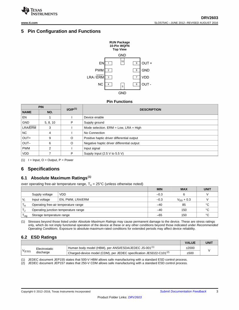
5 Pin Configuration and Functions
RUN Package10-Pin WQFN
Top View
Pin FunctionsPIN
I/O/P (1) DESCRIPTIONNAME NO.EN 1 I Device enableGND 5, 8, 10 P Supply groundLRA/ERM 3 I Mode selection. ERM = Low, LRA = HighNC 4 I No ConnectionOUT+ 9 O Positive haptic driver differential outputOUT– 6 O Negative haptic driver differential outputPWM 2 I Input signalVDD 7 P Supply Input (2.5 V to 5.5 V)
(1) Stresses beyond those listed under Absolute Maximum Ratings may cause permanent damage to the device. These are stress ratingsonly, which do not imply functional operation of the device at these or any other conditions beyond those indicated under RecommendedOperating Conditions. Exposure to absolute-maximum-rated conditions for extended periods may affect device reliability.
6 Specifications
6.1 Absolute Maximum Ratings (1)
over operating free-air temperature range, TA = 25°C (unless otherwise noted)MIN MAX UNIT
Supply voltage VDD –0.3 6 VVI Input voltage EN, PWM, LRA/ERM –0.3 VDD + 0.3 VTA Operating free-air temperature range –40 85 °CTJ Operating junction temperature range –40 150 °CTstg Storage temperature range –65 150 °C
(1) JEDEC document JEP155 states that 500-V HBM allows safe manufacturing with a standard ESD control process.(2) JEDEC document JEP157 states that 250-V CDM allows safe manufacturing with a standard ESD control process.
6.2 ESD RatingsVALUE UNIT
V(ESD)Electrostaticdischarge
Human body model (HBM), per ANSI/ESDA/JEDEC JS-001 (1) ±2000V
Charged-device model (CDM), per JEDEC specification JESD22-C101 (2) ±500
4
DRV2603SLOS754C –JUNE 2012–REVISED AUGUST 2016 www.ti.com
Product Folder Links: DRV2603
Submit Documentation Feedback Copyright © 2012–2016, Texas Instruments Incorporated
6.3 Recommended Operating ConditionsMIN TYP MAX UNIT
VDD Supply voltage VDD 2.5 5.2 VfPWM PWM Input frequency 10 250 kHzRL Load Impedance VDD = 5.2 V 8 Ω
F0 Supported LRA frequency Auto resonance tracking range for LRA 140 220 HzVIL Digital input low voltage EN, PWM, LRA/ERM 0.6 VVIH Digital input high voltage EN, PWM, LRA/ERM 1.2 V
TAOperating free-air temperaturerange -40 85 °C
(1) For more information about traditional and new thermal metrics, see the Semiconductor and IC Package Thermal Metrics applicationreport.
6.4 Thermal Information
THERMAL METRIC (1)DRV2603
UNITRUN (WQFN)10 PINS
RθJA Junction-to-ambient thermal resistance 153.7 °C/WRθJC(top) Junction-to-case (top) thermal resistance 86 °C/WRθJB Junction-to-board thermal resistance 70.4 °C/WψJT Junction-to-top characterization parameter 1.3 °C/WψJB Junction-to-board characterization parameter 70.4 °C/W
6.5 Electrical CharacteristicsTA = 25°C, VDD = 3.6 V (unless otherwise noted)
PARAMETER TEST CONDITIONS MIN TYP MAX UNIT|IIL| Digital input low current EN, PWM, LRA/ERM VDD = 5.0 V, VIN = 0 V 1 µA
|IIH| Digital input high currentEN VDD = 5.0 V, VIN = VDD 6 µAPWM, LRA/ERM VDD = 5.0 V, VIN = VDD 3 µA
ISD Shut down current VEN = 0 V 0.3 3 µAIDDQ Quiescent current VEN = VDD, ERM Mode, 50% duty cycle input, No load 1.7 2.5 mAROUT Output impedance in shutdown OUT+ to GND, OUT– to GND 15 kΩtSU Start-up time Time from EN high to output signal 1.3 msfSW PWM output frequency 19.5 20.3 21.5 kHz
IBAT,AVGAverage battery current duringoperation
Duty Cycle = 100%, LRA Mode, Load = 25 Ω LRA 55mADuty Cycle = 80%, ERM Mode, RL = 17 Ω, 2V rated
ERM 59
RDS-HS Drain to source resistance, high-side 1.05 Ω
RDS-LS Drain to source resistance, low-side 0.85 Ω
VOUT Differential output voltageDuty Cycle = 100%, LRA Mode, Load = 25 Ω LRA 2.2 VRMS
Duty Cycle = 100%, ERM Mode, RL = 20 Ω ERM 3.3 VThermal threshold 145 °CThermal Hysteresis 18 °C
t − Time − s
Vol
tage
− (
2V/d
iv)
0 40m 80m 120m 160m 200m
ENPWM (Filtered)[OUT+] − [OUT−] (Filtered)
VDD = 3.6 VLRA ModePWM Sequence = {100%, 87.5%, 75%, 62.5%, 0%}
t − Time − s
Vol
tage
− (
2V/d
iv)
0 40m 80m 120m 160m 200m
ENPWM (Filtered)[OUT+] − [OUT−] (Filtered)
VDD = 3.6 VERM ModePWM Sequence = {100%, 87.5%, 75%, 62.5%, 0%}
t − Time − s
Vol
tage
− (
2V/d
iv)
0 40m 80m 120m 160m 200m
ENPWMAccelerometer[OUT+] − [OUT−] (Filtered)
VDD = 3.6 VLRA Mode
t − Time − s
Vol
tage
− (
2V/d
iv)
0 40m 80m 120m 160m 200m
ENPWMAccelerometer[OUT+] − [OUT−] (Filtered)
VDD = 3.6 VERM Mode
t − Time − s
Vol
tage
− (
1V/d
iv)
0 1m 2m 3m 4m 5m 6m 7m 8m 9m 10m
EN, PWMOUT+OUT−
VDD = 4.2 VLRA ModeStartup Time = 1.3 ms
t − Time − s
Vol
tage
− (
1V/d
iv)
0 5m 10m 15m 20m 25m 30m 35m 40m 45m 50m
OUT+ (Filtered)OUT− (Filtered)[OUT+] − [OUT−] (Filtered)
VDD = 3.6 VLRA ModeFull−Scale InputVOUT(P−P) = 2.2 VRMS
5
DRV2603www.ti.com SLOS754C –JUNE 2012–REVISED AUGUST 2016
Product Folder Links: DRV2603
Submit Documentation FeedbackCopyright © 2012–2016, Texas Instruments Incorporated
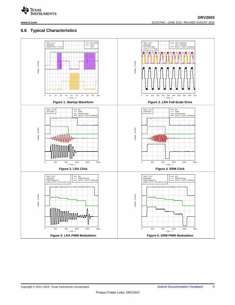
6.6 Typical Characteristics
Figure 1. Startup Waveform Figure 2. LRA Full-Scale Drive
Figure 3. LRA Click Figure 4. ERM Click
Figure 5. LRA PWM Modulation Figure 6. ERM PWM Modulation
ERM
Or
LRA
OUT+
OUT–
100kΩ
100kΩ
470 pF
470 pF
Ch1-Ch2
(Differential)
Oscilloscope
Ch1
Ch2
ERM
or
LRA
OUT+
OUT–
Ch1-Ch2
(Differential)
with Digital
Low-Pass Filter
Oscilloscope
Ch1
Ch2
6
DRV2603SLOS754C –JUNE 2012–REVISED AUGUST 2016 www.ti.com
Product Folder Links: DRV2603
Submit Documentation Feedback Copyright © 2012–2016, Texas Instruments Incorporated
7 Parameter Measurement Information
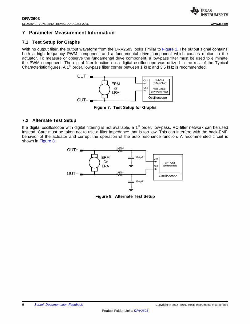
7.1 Test Setup for GraphsWith no output filter, the output waveform from the DRV2603 looks similar to Figure 1. The output signal containsboth a high frequency PWM component and a fundamental drive component which causes motion in theactuator. To measure or observe the fundamental drive component, a low-pass filter must be used to eliminatethe PWM component. The digital filter function on a digital oscilloscope was utilized in the rest of the TypicalCharacteristic figures. A 1st order, low-pass filter corner between 1 kHz and 3.5 kHz is recommended.
Figure 7. Test Setup for Graphs
7.2 Alternate Test SetupIf a digital oscilloscope with digital filtering is not available, a 1st order, low-pass, RC filter network can be usedinstead. Care must be taken not to use a filter impedance that is too low. This can interfere with the back-EMFbehavior of the actuator and corrupt the operation of the auto resonance function. A recommended circuit isshown in Figure 8.
Figure 8. Alternate Test Setup
GND
VDD
OUT-
OUT+
PWM
EN
VDD
LRA / ERM
CVDD
Level Correction
VDD
Gate
Drive
Gate
Drive
Back-EMF
DetectionControl Engine
MLRA
or
ERM
Thermal
Shutdown
Overcurrent
Shutdown
Supply Correction
Copyright © 2016, Texas Instruments Incorporated
7
DRV2603www.ti.com SLOS754C –JUNE 2012–REVISED AUGUST 2016
Product Folder Links: DRV2603
Submit Documentation FeedbackCopyright © 2012–2016, Texas Instruments Incorporated
8 Detailed Description
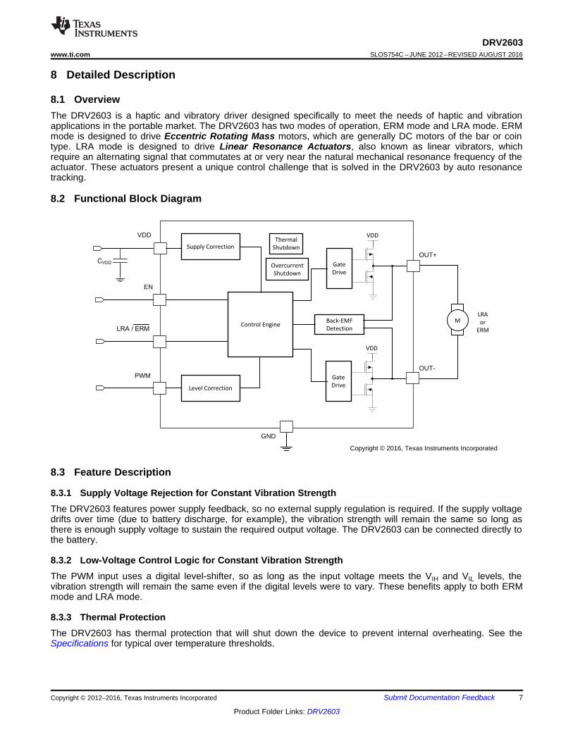
8.1 OverviewThe DRV2603 is a haptic and vibratory driver designed specifically to meet the needs of haptic and vibrationapplications in the portable market. The DRV2603 has two modes of operation, ERM mode and LRA mode. ERMmode is designed to drive Eccentric Rotating Mass motors, which are generally DC motors of the bar or cointype. LRA mode is designed to drive Linear Resonance Actuators, also known as linear vibrators, whichrequire an alternating signal that commutates at or very near the natural mechanical resonance frequency of theactuator. These actuators present a unique control challenge that is solved in the DRV2603 by auto resonancetracking.
8.2 Functional Block Diagram
8.3 Feature Description
8.3.1 Supply Voltage Rejection for Constant Vibration StrengthThe DRV2603 features power supply feedback, so no external supply regulation is required. If the supply voltagedrifts over time (due to battery discharge, for example), the vibration strength will remain the same so long asthere is enough supply voltage to sustain the required output voltage. The DRV2603 can be connected directly tothe battery.
8.3.2 Low-Voltage Control Logic for Constant Vibration StrengthThe PWM input uses a digital level-shifter, so as long as the input voltage meets the VIH and VIL levels, thevibration strength will remain the same even if the digital levels were to vary. These benefits apply to both ERMmode and LRA mode.
8.3.3 Thermal ProtectionThe DRV2603 has thermal protection that will shut down the device to prevent internal overheating. See theSpecifications for typical over temperature thresholds.
Frequency - HzfRESONANCE
Accele
rati
on
- g
8
DRV2603SLOS754C –JUNE 2012–REVISED AUGUST 2016 www.ti.com
Product Folder Links: DRV2603
Submit Documentation Feedback Copyright © 2012–2016, Texas Instruments Incorporated
Feature Description (continued)8.3.4 Overcurrent ProtectionThe DRV2603 has overcurrent protection that is useful in preventing damage from short conditions. Theovercurrent protection monitors current from VDD, GND, OUT+, and OUT-. See the Specifications for typicalovercurrent thresholds.
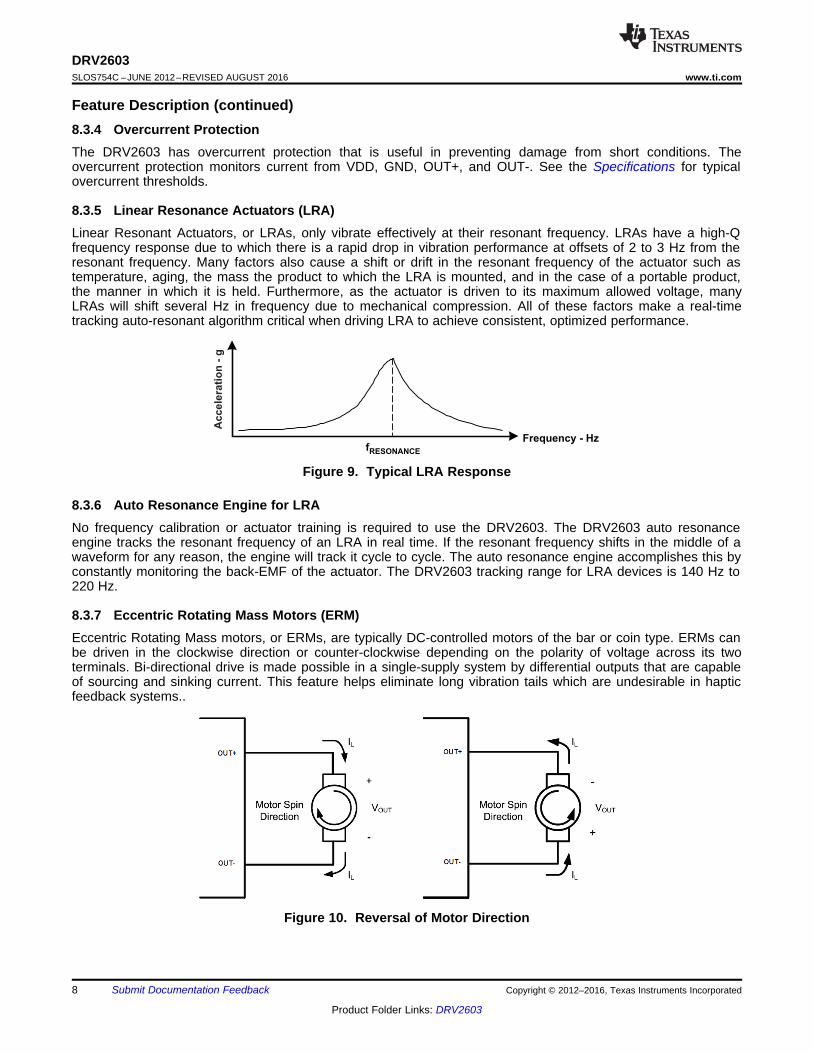
8.3.5 Linear Resonance Actuators (LRA)Linear Resonant Actuators, or LRAs, only vibrate effectively at their resonant frequency. LRAs have a high-Qfrequency response due to which there is a rapid drop in vibration performance at offsets of 2 to 3 Hz from theresonant frequency. Many factors also cause a shift or drift in the resonant frequency of the actuator such astemperature, aging, the mass the product to which the LRA is mounted, and in the case of a portable product,the manner in which it is held. Furthermore, as the actuator is driven to its maximum allowed voltage, manyLRAs will shift several Hz in frequency due to mechanical compression. All of these factors make a real-timetracking auto-resonant algorithm critical when driving LRA to achieve consistent, optimized performance.
Figure 9. Typical LRA Response
8.3.6 Auto Resonance Engine for LRANo frequency calibration or actuator training is required to use the DRV2603. The DRV2603 auto resonanceengine tracks the resonant frequency of an LRA in real time. If the resonant frequency shifts in the middle of awaveform for any reason, the engine will track it cycle to cycle. The auto resonance engine accomplishes this byconstantly monitoring the back-EMF of the actuator. The DRV2603 tracking range for LRA devices is 140 Hz to220 Hz.
8.3.7 Eccentric Rotating Mass Motors (ERM)Eccentric Rotating Mass motors, or ERMs, are typically DC-controlled motors of the bar or coin type. ERMs canbe driven in the clockwise direction or counter-clockwise depending on the polarity of voltage across its twoterminals. Bi-directional drive is made possible in a single-supply system by differential outputs that are capableof sourcing and sinking current. This feature helps eliminate long vibration tails which are undesirable in hapticfeedback systems..
Figure 10. Reversal of Motor Direction
é ùê úë û
OUT (RMS) = OUT (FULL-SCALE)Input Duty Cycle %
V V - 150
Input
Steady-StateOutput Drive
2.2 Vrms
1.1 Vrms
PWM Input Duty Cycle
0% 50% 100%
Full Braking
75%
9
DRV2603www.ti.com SLOS754C –JUNE 2012–REVISED AUGUST 2016
Product Folder Links: DRV2603
Submit Documentation FeedbackCopyright © 2012–2016, Texas Instruments Incorporated
Feature Description (continued)Another common approach to driving DC motors is the concept of overdrive voltage. To overcome the inertia ofthe motor's mass, they are often overdriven for a short amount of time before returning to the motor's ratedvoltage to sustain the motor's rotation. Negative overdrive is also used to stop (or brake) an ERM quickly byreversing the magnetic field of the driving coil(s).
8.3.8 Edge Rate ControlThe DRV2603 output driver implements Edge Rate Control (ERC). This ensures that the rise and fallcharacteristics of the output drivers do not emit levels of radiation that could interfere with other circuitry commonin mobile and portable platforms. Because of ERC, no output filter or ferrites are necessary.
8.4 Device Functional Modes
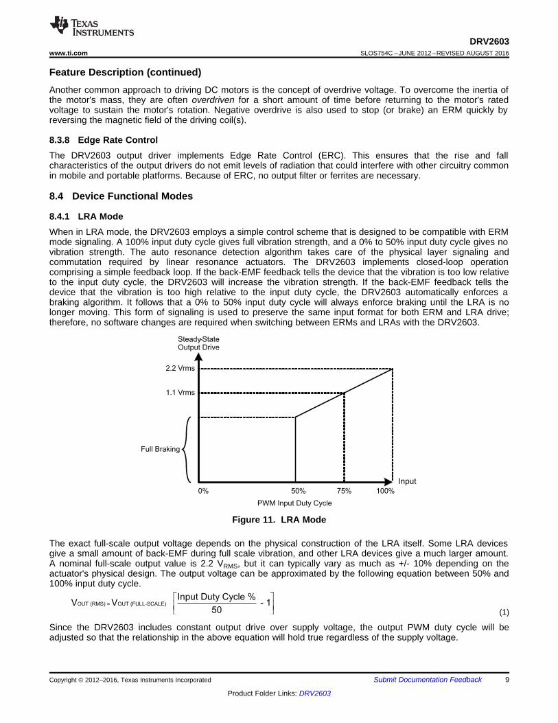
8.4.1 LRA ModeWhen in LRA mode, the DRV2603 employs a simple control scheme that is designed to be compatible with ERMmode signaling. A 100% input duty cycle gives full vibration strength, and a 0% to 50% input duty cycle gives novibration strength. The auto resonance detection algorithm takes care of the physical layer signaling andcommutation required by linear resonance actuators. The DRV2603 implements closed-loop operationcomprising a simple feedback loop. If the back-EMF feedback tells the device that the vibration is too low relativeto the input duty cycle, the DRV2603 will increase the vibration strength. If the back-EMF feedback tells thedevice that the vibration is too high relative to the input duty cycle, the DRV2603 automatically enforces abraking algorithm. It follows that a 0% to 50% input duty cycle will always enforce braking until the LRA is nolonger moving. This form of signaling is used to preserve the same input format for both ERM and LRA drive;therefore, no software changes are required when switching between ERMs and LRAs with the DRV2603.
Figure 11. LRA Mode
The exact full-scale output voltage depends on the physical construction of the LRA itself. Some LRA devicesgive a small amount of back-EMF during full scale vibration, and other LRA devices give a much larger amount.A nominal full-scale output value is 2.2 VRMS, but it can typically vary as much as +/- 10% depending on theactuator's physical design. The output voltage can be approximated by the following equation between 50% and100% input duty cycle.
(1)
Since the DRV2603 includes constant output drive over supply voltage, the output PWM duty cycle will beadjusted so that the relationship in the above equation will hold true regardless of the supply voltage.

é ùê úë û
OUT(FULL-SCALE)=
V Input Duty Cycle %Output Duty Cycle (%) - 1 100%
VDD 50
é ùê úë û
OUT = OUT (FULL-SCALE)Input Duty Cycle %
V V - 150
Input
Output Drive
3.3 V
0 V
0% 50% 100%
-3.3 V
PWM Input Duty Cycle
10
DRV2603SLOS754C –JUNE 2012–REVISED AUGUST 2016 www.ti.com
Product Folder Links: DRV2603
Submit Documentation Feedback Copyright © 2012–2016, Texas Instruments Incorporated
Device Functional Modes (continued)8.4.2 ERM ModeThe DRV2603 is a compact, cost-effective driver solution for ERM motors. Most competing solutions requireexternal components for biasing or level-shifting, but the DRV2603 requires only one decoupling capacitor givinga total approximate circuit size of 2 mm by 2 mm. This small solution size still comes packed with features suchas a level-shifted input, differential outputs for braking, constant drive strength over supply, edge rate control, anda wide input PWM frequency range.
When in ERM mode, the DRV2603 employs a simple control scheme. A 100% input duty cycle gives full-strengthforward rotation, a 50% input duty cycle give no rotation strength, and a 0% duty cycle give full-strength reverserotation. Forcing the motor velocity towards reverse rotation is used to implement motor braking in ERMs. Bystringing together various duty cycles over varying amounts of time, a haptic motor control signal will beconstructed at the output to precisely drive the motor.
Figure 12. ERM Mode
The full-scale, open-load output voltage of the DRV2603 in ERM mode is 3.6V. The output stage has a totalnominal RDS of 1.9 Ω. When driving a 20 Ω ERM at full-scale, the differential voltage seen at the outputs isapproximately 3.3 V. When driving a 10 Ω ERM at full-scale, the output voltage is approximately 3.0 V.
The voltage seen at the outputs as a function of input duty cycle is given by this equation.
(2)
Since the DRV2603 includes constant output drive over supply voltage, the output PWM duty cycle will beadjusted so that the relationship in the above equation will hold true regardless of the supply voltage. The outputduty cycle in ERM mode can be approximated by the following equation.
(3)
VDD
DRV2603
EN
Application
Processor
VDD
GPIO
PWM PWM GND
OUT+
OUT-
2.5 V to 5.2 V
CVDD
Linear Vibrator
(LRA)ERMLRA /
Copyright © 2016, Texas Instruments Incorporated
11
DRV2603www.ti.com SLOS754C –JUNE 2012–REVISED AUGUST 2016
Product Folder Links: DRV2603
Submit Documentation FeedbackCopyright © 2012–2016, Texas Instruments Incorporated
9 Application and Implementation
NOTEInformation in the following applications sections is not part of the TI componentspecification, and TI does not warrant its accuracy or completeness. TI’s customers areresponsible for determining suitability of components for their purposes. Customers shouldvalidate and test their design implementation to confirm system functionality.
9.1 Application InformationThe DRV2603 is designed to drive ERM and LRA actuators used for haptic feedback. ERM and LRA actuatorscan be used for numerous haptic feedback applications including vibration alerts, advanced vibrationcommunication, button replacement, and tactile feedback for touch surface or screens.
The DRV2603 output is controlled using PWM input. The duty-cycle of the PWM determines the amplitude of theoutput waveform. By varying the duty cycle, advanced haptic patterns and sequences can be created such asclick, bumps, pulses, ramps and many more.
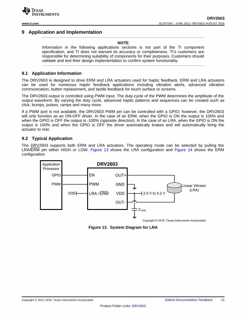
If a PWM port is not available, the DRV2603 PWM pin can be controlled with a GPIO; however, the DRV2603will only function as an ON-OFF driver. In the case of an ERM, when the GPIO is ON the output is 100% andwhen the GPIO is OFF the output is -100% (opposite direction). In the case of an LRA, when the GPIO is ON theoutput is 100% and when the GPIO is OFF the driver automatically brakes and will automatically bring theactuator to rest.
9.2 Typical ApplicationThe DRV2603 supports both ERM and LRA actuators. The operating mode can be selected by pulling theLRA/ERM pin either HIGH or LOW. Figure 13 shows the LRA configuration and Figure 14 shows the ERMconfiguration.
Figure 13. System Diagram for LRA

VDD
DRV2603
EN
Application
Processor
GND
GPIO
PWM PWM GND
OUT+
OUT-
2.5 V to 5.2 V
CVDD
DC Motor
(ERM)ERMLRA /
Copyright © 2016, Texas Instruments Incorporated
12
DRV2603SLOS754C –JUNE 2012–REVISED AUGUST 2016 www.ti.com
Product Folder Links: DRV2603
Submit Documentation Feedback Copyright © 2012–2016, Texas Instruments Incorporated
Typical Application (continued)
Figure 14. System Diagram for ERM
9.2.1 Design RequirementsThis design assumes the values listed in Table 1.
Table 1. Design ParametersDESIGN PARAMETER EXAMPLE VALUE
Interface PWMActuator Type ERM / LRA
Input Power Source Battery
9.2.2 Detailed Design Procedure
9.2.2.1 Actuator SelectionThe actuator decision is based on many factors including cost, form factor, vibration strength, powerconsumption requirements, haptic sharpness, reliability, and audible noise performance. The actuator selection isone of the most important design considerations of a haptic system and therefore the actuator should be the firstcomponent to consider when designing the system.
The following can be used to select the minimum required supply voltage.1. Find the rated and/or maximum operating voltage in the actuator datasheet; some actuator datasheets may
only have the rated voltage listed.2. Using the larger of the rated and maximum operating voltage, add 250mV to get the minimum operating
voltage. Adding 250mV provides operating headroom to account for internal driver losses.3. Check the supply voltage to ensure that the desired output is achieved.
A minimum supply current is also required based on the load. To ensure enough current can be sourced dividethe supply voltage above by the load resistance in the actuator datasheet. Compare this number with the currentcapability of the battery or voltage supply.
9.2.2.2 Power Supply SelectionThe DRV2603 supports supply voltages from 2.5 to 5.2V. The DRV2603 can be directly connected to manybattery types including common batteries like Lithium-Ion and Lithium-Polymer. The supply rejection feature ofthe DRV2603 eliminates the need for a voltage regulator between the battery and VDD.
9.2.2.3 Sending a Haptic EffectSending a haptic effect with the DRV2603 is straightforward. The procedure is the same for both ERM and LRAdrive. The ERM/LRA pin should be tied high or low as shown in the system diagrams. Optimum performance isachieved by using the following steps.

t − Time − s
Vol
tage
− (
2V/d
iv)
0 40m 80m 120m 160m 200m
ENPWM (Filtered)[OUT+] − [OUT−] (Filtered)
VDD = 3.6 VLRA ModePWM Sequence = {100%, 87.5%, 75%, 62.5%, 0%}
t − Time − s
Vol
tage
− (
2V/d
iv)
0 40m 80m 120m 160m 200m
ENPWM (Filtered)[OUT+] − [OUT−] (Filtered)
VDD = 3.6 VERM ModePWM Sequence = {100%, 87.5%, 75%, 62.5%, 0%}
t − Time − s
Vol
tage
− (
2V/d
iv)
0 40m 80m 120m 160m 200m
ENPWMAccelerometer[OUT+] − [OUT−] (Filtered)
VDD = 3.6 VLRA Mode
t − Time − s
Vol
tage
− (
2V/d
iv)
0 40m 80m 120m 160m 200m
ENPWMAccelerometer[OUT+] − [OUT−] (Filtered)
VDD = 3.6 VERM Mode
13
DRV2603www.ti.com SLOS754C –JUNE 2012–REVISED AUGUST 2016
Product Folder Links: DRV2603
Submit Documentation FeedbackCopyright © 2012–2016, Texas Instruments Incorporated
1. At or very near the same time, bring the EN pin high and start sourcing PWM waveform. No delays arerequired. The best startup behavior is usually achieved when momentarily overdriving the actuator for 20 msto 50 ms. Reference the specifications of the actuator for optimum overdrive characteristics.
2. Change the PWM level as needed to achieve the desired effect.3. When the effect is complete, set the PWM duty cycle to 0% if braking is desired. The EN pin must remain
high to actively brake the actuator. When braking is complete, set the EN pin low, concluding the hapticeffect. When braking an ERM, the user should take care not to brake the actuator for too long, or counter-rotation can occur. When braking an LRA, the auto-resonance engine automatically drives the actuator tozero vibration, so no significant reverse-phase vibration will ever occur.
9.2.3 Application Curves
Figure 15. LRA Click Figure 16. ERM Click
Figure 17. LRA PWM Modulation Figure 18. ERM PWM Modulation
CVDD
OUT+
OUT-
VDD
GND
EN
NC
LRA/ERM
PWM
GND
GND
Via
VDD
OUT+
OUT-
GND
GND
14
DRV2603SLOS754C –JUNE 2012–REVISED AUGUST 2016 www.ti.com
Product Folder Links: DRV2603
Submit Documentation Feedback Copyright © 2012–2016, Texas Instruments Incorporated
10 Power Supply RecommendationsThe DRV2603 can operate from 2.5V to 5.2V. The DRV2603 VDD pin can be connected directly to a battery toeliminate a linear regulator or switching power supply. A small decoupling capacitor should be placed close to theDRV2603 VDD pin.
10.1 Decoupling CapacitorThe DRV2603 has a switching output stage which pulls transient currents through the VDD pin. A 0.1 µF, lowequivalent-series-resistance (ESR) decoupling capacitor of the X5R or X7R type is recommended for smoothoperation of the output driver and the digital portion of the device.
11 Layout
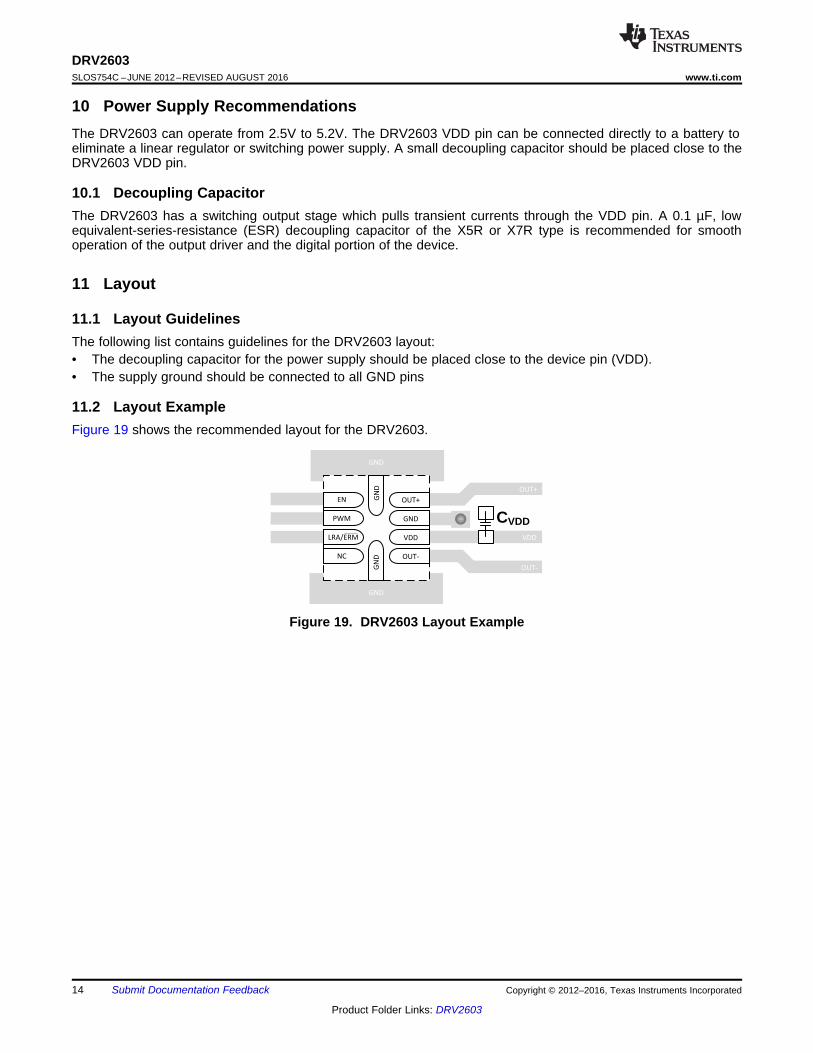
11.1 Layout GuidelinesThe following list contains guidelines for the DRV2603 layout:• The decoupling capacitor for the power supply should be placed close to the device pin (VDD).• The supply ground should be connected to all GND pins
11.2 Layout ExampleFigure 19 shows the recommended layout for the DRV2603.
Figure 19. DRV2603 Layout Example
15
DRV2603www.ti.com SLOS754C –JUNE 2012–REVISED AUGUST 2016
Product Folder Links: DRV2603
Submit Documentation FeedbackCopyright © 2012–2016, Texas Instruments Incorporated
12 Device and Documentation Support
12.1 Device Support
12.1.1 Development SupportThe DRV2603 is featured in several TI Designs, available online athttp://www.ti.com/general/docs/refdesignsearch.tsp. TI Designs are analog solutions created by TI’s applicationsexperts and offer the theory of operation, component selection, simulation, complete PCB schematic and layout,bill of materials, and measured performance of many useful circuits.• Haptics Enabled Gaming Controller Design - http://www.ti.com/tool/TIDM-LPBP-HAPTOUCH• DRV2603 Capacitive Touch Evaluation Module - http://www.ti.com/tool/drv2603evm-ct
12.2 Documentation Support
12.2.1 Related Documentation• Haptic Energy Consumption – SLOA194• Benefits of LRA Auto-Resonance Tracking - SLOA188• Haptics: Solutions for ERM and LRA Actuators - SSZB151
12.3 Receiving Notification of Documentation UpdatesTo receive notification of documentation updates, navigate to the device product folder on ti.com. In the upperright corner, click on Alert me to register and receive a weekly digest of any product information that haschanged. For change details, review the revision history included in any revised document.
12.4 Community ResourcesThe following links connect to TI community resources. Linked contents are provided "AS IS" by the respectivecontributors. They do not constitute TI specifications and do not necessarily reflect TI's views; see TI's Terms ofUse.
TI E2E™ Online Community TI's Engineer-to-Engineer (E2E) Community. Created to foster collaborationamong engineers. At e2e.ti.com, you can ask questions, share knowledge, explore ideas and helpsolve problems with fellow engineers.
Design Support TI's Design Support Quickly find helpful E2E forums along with design support tools andcontact information for technical support.
12.5 TrademarksE2E is a trademark of Texas Instruments.TouchSense is a registered trademark of Immersion Corporation.All other trademarks are the property of their respective owners.
12.6 Electrostatic Discharge CautionThese devices have limited built-in ESD protection. The leads should be shorted together or the device placed in conductive foamduring storage or handling to prevent electrostatic damage to the MOS gates.
12.7 GlossarySLYZ022 — TI Glossary.
This glossary lists and explains terms, acronyms, and definitions.
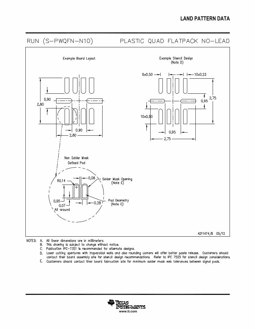
13 Mechanical, Packaging, and Orderable InformationThe following pages include mechanical, packaging, and orderable information. This information is the mostcurrent data available for the designated devices. This data is subject to change without notice and revision ofthis document. For browser-based versions of this data sheet, refer to the left-hand navigation.
PACKAGE OPTION ADDENDUM
www.ti.com 9-Aug-2016
Addendum-Page 1
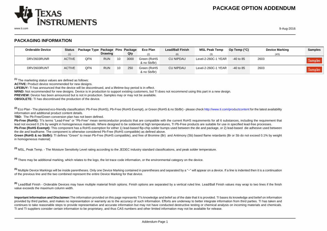
PACKAGING INFORMATION
Orderable Device Status(1)
Package Type PackageDrawing
Pins PackageQty
Eco Plan(2)
Lead/Ball Finish(6)
MSL Peak Temp(3)
Op Temp (°C) Device Marking(4/5)
Samples
DRV2603RUNR ACTIVE QFN RUN 10 3000 Green (RoHS& no Sb/Br)
CU NIPDAU Level-2-260C-1 YEAR -40 to 85 2603
DRV2603RUNT ACTIVE QFN RUN 10 250 Green (RoHS& no Sb/Br)
CU NIPDAU Level-2-260C-1 YEAR -40 to 85 2603
(1) The marketing status values are defined as follows:ACTIVE: Product device recommended for new designs.LIFEBUY: TI has announced that the device will be discontinued, and a lifetime-buy period is in effect.NRND: Not recommended for new designs. Device is in production to support existing customers, but TI does not recommend using this part in a new design.PREVIEW: Device has been announced but is not in production. Samples may or may not be available.OBSOLETE: TI has discontinued the production of the device.
(2) Eco Plan - The planned eco-friendly classification: Pb-Free (RoHS), Pb-Free (RoHS Exempt), or Green (RoHS & no Sb/Br) - please check http://www.ti.com/productcontent for the latest availabilityinformation and additional product content details.TBD: The Pb-Free/Green conversion plan has not been defined.Pb-Free (RoHS): TI's terms "Lead-Free" or "Pb-Free" mean semiconductor products that are compatible with the current RoHS requirements for all 6 substances, including the requirement thatlead not exceed 0.1% by weight in homogeneous materials. Where designed to be soldered at high temperatures, TI Pb-Free products are suitable for use in specified lead-free processes.Pb-Free (RoHS Exempt): This component has a RoHS exemption for either 1) lead-based flip-chip solder bumps used between the die and package, or 2) lead-based die adhesive used betweenthe die and leadframe. The component is otherwise considered Pb-Free (RoHS compatible) as defined above.Green (RoHS & no Sb/Br): TI defines "Green" to mean Pb-Free (RoHS compatible), and free of Bromine (Br) and Antimony (Sb) based flame retardants (Br or Sb do not exceed 0.1% by weightin homogeneous material)
(3) MSL, Peak Temp. - The Moisture Sensitivity Level rating according to the JEDEC industry standard classifications, and peak solder temperature.
(4) There may be additional marking, which relates to the logo, the lot trace code information, or the environmental category on the device.
(5) Multiple Device Markings will be inside parentheses. Only one Device Marking contained in parentheses and separated by a "~" will appear on a device. If a line is indented then it is a continuationof the previous line and the two combined represent the entire Device Marking for that device.
(6) Lead/Ball Finish - Orderable Devices may have multiple material finish options. Finish options are separated by a vertical ruled line. Lead/Ball Finish values may wrap to two lines if the finishvalue exceeds the maximum column width.
Important Information and Disclaimer:The information provided on this page represents TI's knowledge and belief as of the date that it is provided. TI bases its knowledge and belief on informationprovided by third parties, and makes no representation or warranty as to the accuracy of such information. Efforts are underway to better integrate information from third parties. TI has taken andcontinues to take reasonable steps to provide representative and accurate information but may not have conducted destructive testing or chemical analysis on incoming materials and chemicals.TI and TI suppliers consider certain information to be proprietary, and thus CAS numbers and other limited information may not be available for release.

PACKAGE OPTION ADDENDUM
www.ti.com 9-Aug-2016
Addendum-Page 2
In no event shall TI's liability arising out of such information exceed the total purchase price of the TI part(s) at issue in this document sold by TI to Customer on an annual basis.
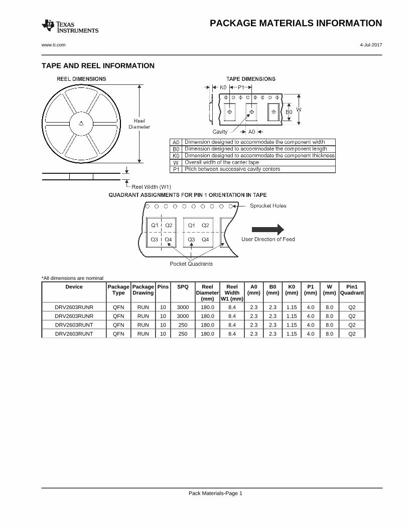
TAPE AND REEL INFORMATION
*All dimensions are nominal
Device PackageType
PackageDrawing
Pins SPQ ReelDiameter
(mm)
ReelWidth
W1 (mm)
A0(mm)
B0(mm)
K0(mm)
P1(mm)
W(mm)
Pin1Quadrant
DRV2603RUNR QFN RUN 10 3000 180.0 8.4 2.3 2.3 1.15 4.0 8.0 Q2
DRV2603RUNR QFN RUN 10 3000 180.0 8.4 2.3 2.3 1.15 4.0 8.0 Q2
DRV2603RUNT QFN RUN 10 250 180.0 8.4 2.3 2.3 1.15 4.0 8.0 Q2
DRV2603RUNT QFN RUN 10 250 180.0 8.4 2.3 2.3 1.15 4.0 8.0 Q2
PACKAGE MATERIALS INFORMATION
www.ti.com 4-Jul-2017
Pack Materials-Page 1
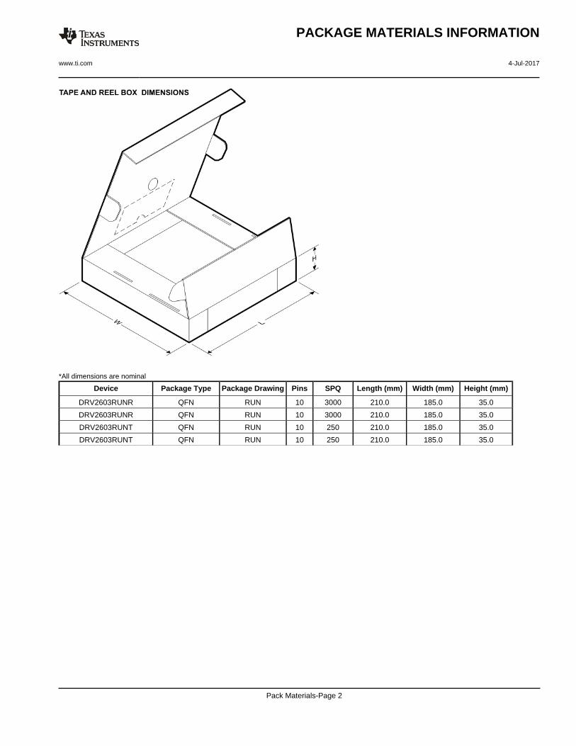
*All dimensions are nominal
Device Package Type Package Drawing Pins SPQ Length (mm) Width (mm) Height (mm)
DRV2603RUNR QFN RUN 10 3000 210.0 185.0 35.0
DRV2603RUNR QFN RUN 10 3000 210.0 185.0 35.0
DRV2603RUNT QFN RUN 10 250 210.0 185.0 35.0
DRV2603RUNT QFN RUN 10 250 210.0 185.0 35.0
PACKAGE MATERIALS INFORMATION
www.ti.com 4-Jul-2017
Pack Materials-Page 2
IMPORTANT NOTICE
Texas Instruments Incorporated (TI) reserves the right to make corrections, enhancements, improvements and other changes to itssemiconductor products and services per JESD46, latest issue, and to discontinue any product or service per JESD48, latest issue. Buyersshould obtain the latest relevant information before placing orders and should verify that such information is current and complete.TI’s published terms of sale for semiconductor products (http://www.ti.com/sc/docs/stdterms.htm) apply to the sale of packaged integratedcircuit products that TI has qualified and released to market. Additional terms may apply to the use or sale of other types of TI products andservices.Reproduction of significant portions of TI information in TI data sheets is permissible only if reproduction is without alteration and isaccompanied by all associated warranties, conditions, limitations, and notices. TI is not responsible or liable for such reproduceddocumentation. Information of third parties may be subject to additional restrictions. Resale of TI products or services with statementsdifferent from or beyond the parameters stated by TI for that product or service voids all express and any implied warranties for theassociated TI product or service and is an unfair and deceptive business practice. TI is not responsible or liable for any such statements.Buyers and others who are developing systems that incorporate TI products (collectively, “Designers”) understand and agree that Designersremain responsible for using their independent analysis, evaluation and judgment in designing their applications and that Designers havefull and exclusive responsibility to assure the safety of Designers' applications and compliance of their applications (and of all TI productsused in or for Designers’ applications) with all applicable regulations, laws and other applicable requirements. Designer represents that, withrespect to their applications, Designer has all the necessary expertise to create and implement safeguards that (1) anticipate dangerousconsequences of failures, (2) monitor failures and their consequences, and (3) lessen the likelihood of failures that might cause harm andtake appropriate actions. Designer agrees that prior to using or distributing any applications that include TI products, Designer willthoroughly test such applications and the functionality of such TI products as used in such applications.TI’s provision of technical, application or other design advice, quality characterization, reliability data or other services or information,including, but not limited to, reference designs and materials relating to evaluation modules, (collectively, “TI Resources”) are intended toassist designers who are developing applications that incorporate TI products; by downloading, accessing or using TI Resources in anyway, Designer (individually or, if Designer is acting on behalf of a company, Designer’s company) agrees to use any particular TI Resourcesolely for this purpose and subject to the terms of this Notice.TI’s provision of TI Resources does not expand or otherwise alter TI’s applicable published warranties or warranty disclaimers for TIproducts, and no additional obligations or liabilities arise from TI providing such TI Resources. TI reserves the right to make corrections,enhancements, improvements and other changes to its TI Resources. TI has not conducted any testing other than that specificallydescribed in the published documentation for a particular TI Resource.Designer is authorized to use, copy and modify any individual TI Resource only in connection with the development of applications thatinclude the TI product(s) identified in such TI Resource. NO OTHER LICENSE, EXPRESS OR IMPLIED, BY ESTOPPEL OR OTHERWISETO ANY OTHER TI INTELLECTUAL PROPERTY RIGHT, AND NO LICENSE TO ANY TECHNOLOGY OR INTELLECTUAL PROPERTYRIGHT OF TI OR ANY THIRD PARTY IS GRANTED HEREIN, including but not limited to any patent right, copyright, mask work right, orother intellectual property right relating to any combination, machine, or process in which TI products or services are used. Informationregarding or referencing third-party products or services does not constitute a license to use such products or services, or a warranty orendorsement thereof. Use of TI Resources may require a license from a third party under the patents or other intellectual property of thethird party, or a license from TI under the patents or other intellectual property of TI.TI RESOURCES ARE PROVIDED “AS IS” AND WITH ALL FAULTS. TI DISCLAIMS ALL OTHER WARRANTIES ORREPRESENTATIONS, EXPRESS OR IMPLIED, REGARDING RESOURCES OR USE THEREOF, INCLUDING BUT NOT LIMITED TOACCURACY OR COMPLETENESS, TITLE, ANY EPIDEMIC FAILURE WARRANTY AND ANY IMPLIED WARRANTIES OFMERCHANTABILITY, FITNESS FOR A PARTICULAR PURPOSE, AND NON-INFRINGEMENT OF ANY THIRD PARTY INTELLECTUALPROPERTY RIGHTS. TI SHALL NOT BE LIABLE FOR AND SHALL NOT DEFEND OR INDEMNIFY DESIGNER AGAINST ANY CLAIM,INCLUDING BUT NOT LIMITED TO ANY INFRINGEMENT CLAIM THAT RELATES TO OR IS BASED ON ANY COMBINATION OFPRODUCTS EVEN IF DESCRIBED IN TI RESOURCES OR OTHERWISE. IN NO EVENT SHALL TI BE LIABLE FOR ANY ACTUAL,DIRECT, SPECIAL, COLLATERAL, INDIRECT, PUNITIVE, INCIDENTAL, CONSEQUENTIAL OR EXEMPLARY DAMAGES INCONNECTION WITH OR ARISING OUT OF TI RESOURCES OR USE THEREOF, AND REGARDLESS OF WHETHER TI HAS BEENADVISED OF THE POSSIBILITY OF SUCH DAMAGES.Unless TI has explicitly designated an individual product as meeting the requirements of a particular industry standard (e.g., ISO/TS 16949and ISO 26262), TI is not responsible for any failure to meet such industry standard requirements.Where TI specifically promotes products as facilitating functional safety or as compliant with industry functional safety standards, suchproducts are intended to help enable customers to design and create their own applications that meet applicable functional safety standardsand requirements. Using products in an application does not by itself establish any safety features in the application. Designers mustensure compliance with safety-related requirements and standards applicable to their applications. Designer may not use any TI products inlife-critical medical equipment unless authorized officers of the parties have executed a special contract specifically governing such use.Life-critical medical equipment is medical equipment where failure of such equipment would cause serious bodily injury or death (e.g., lifesupport, pacemakers, defibrillators, heart pumps, neurostimulators, and implantables). Such equipment includes, without limitation, allmedical devices identified by the U.S. Food and Drug Administration as Class III devices and equivalent classifications outside the U.S.TI may expressly designate certain products as completing a particular qualification (e.g., Q100, Military Grade, or Enhanced Product).Designers agree that it has the necessary expertise to select the product with the appropriate qualification designation for their applicationsand that proper product selection is at Designers’ own risk. Designers are solely responsible for compliance with all legal and regulatoryrequirements in connection with such selection.Designer will fully indemnify TI and its representatives against any damages, costs, losses, and/or liabilities arising out of Designer’s non-compliance with the terms and provisions of this Notice.
Mailing Address: Texas Instruments, Post Office Box 655303, Dallas, Texas 75265Copyright © 2017, Texas Instruments Incorporated
Related Documents