Katalog 991228 EN/FR/DE/ES 10/2019 604 EFDS g Hansen P4 Hansen M4ACC Powerful solutions for cooling towers and air cooled condensers Solutions performantes pour aéroréfrigérants et condensateurs à air Leistungsstarke Lösungen für Kühltürme und Luftkondensatoren Potentes soluciones para torres de refrigeración y condensadores de aire

Welcome message from author
This document is posted to help you gain knowledge. Please leave a comment to let me know what you think about it! Share it to your friends and learn new things together.
Transcript
Katalog 991228 EN/FR/DE/ES 10/2019604 EFDS g
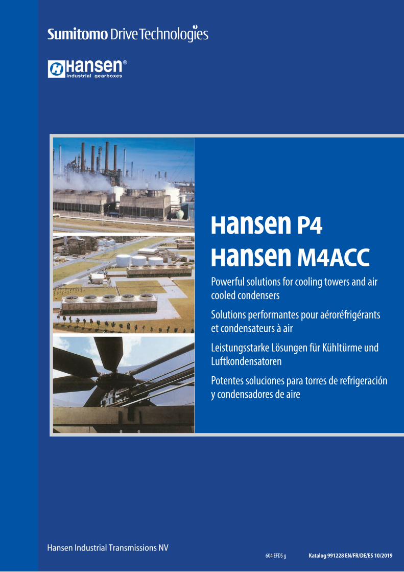
Hansen P4Hansen M4ACCPowerful solutions for cooling towers and air cooled condensers
Solutions performantes pour aéroréfrigérants et condensateurs à air
Leistungsstarke Lösungen für Kühltürme und Luftkondensatoren
Potentes soluciones para torres de refrigeración y condensadores de aire
COMPLETE AND POWERFUL
SOLUTIONS FOR
COOLING TOWERS
Because of the severe demands placed
on cooling tower fan drives, Hansen
Industrial Transmissions’ drives are specially
equipped to withstand exacting operating
conditions, while still using a maximum
of standard components. Taking these
operating conditions into account, several
accessories are included as standard.
Hansen Industrial Transmissions designs,
creates and services flexible gear units that
can be adapted to specific requirements.
This way Hansen Industrial Transmissions
created a range of drive solutions suitable
for the international cooling tower market .
Proof of the products’ reliability is the
ISO 9001 quality certificate, showing
outstanding quality, supported by an
international network of after-sales
Services Centres. Using standard compo-
nents, we offer a range of gear units fully
customised to the specific needs of the
industry applications.
c o o l i n g t o w e r i n d u s t r y
C O O L I N G T O W E R S C O O L I N G T O W E R S C O O L I N G T O W E R S
F O R A N O V E R V I E W O F W H A T ’ S A V A I L A B L E , C H E C K O U R C O M P R E H E N S I V E L I T E R A T U R E W I T H R E F . 4 1 5 - 2 2 0
_ g g
COMPLETE AND POWERFUL
SOLUTIONS FOR
COOLING TOWERS
Because of the severe demands placed
on cooling tower fan drives, Hansen
Transmissions’ drives are specially
equipped to withstand exacting operating
conditions, while still using a maximum
of standard components. Taking these
operating conditions into account, several
accessories are included as standard.
Hansen Transmissions designs, creates and
services flexible gear units that can be
adapted to specific requirements.
This way Hansen Transmissions created
a range of drive solutions suitable for the
international cooling tower market.
Proof of the products’ reliability is the
ISO 9001 quality certificate, showing
outstanding quality, supported by an
international network of after-sales
Services Centres. Using standard compo-
nents, we offer a range of gear units fully
customised to the specific needs of the
industry applications.
c o o l i n g t o w e r i n d u s t r y
C O O L I N G T O W E R S C O O L I N G T O W E R S C O O L I N G T O W E R S
F O R A N O V E R V I E W O F W H A T ’ S A V A I L A B L E , C H E C K O U R C O M P R E H E N S I V E L I T E R A T U R E W I T H R E F . 4 1 5 - 2 2 0
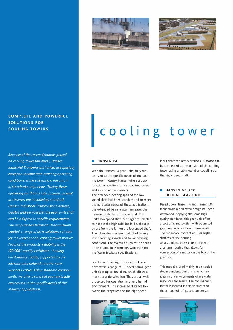
■■ HANSEN M4 ACC
HELICAL GEAR UNIT
Based upon Hansen P4 and Hansen M4
technology, a dedicated design has been
developed. Applying the same high
quality standards, this gear unit offers
a cost efficient solution with optimised
gear geometry for lower noise levels.
The monobloc concept ensures higher
stiffness of the housing.
As a standard, these units come with
a lantern housing that allows for
connection of a motor on the top of the
gear unit.
This model is used mainly in air-cooled
steam condensation plants which are
ideal in dry environments where water
resources are scarce. The cooling fan’s
motor is located in the air stream of
the air-cooled refrigerant condenser.
■ HANSEN P4:
BEVEL HELICAL GEAR UNIT
For vertical housings, the extended
bearing span of the low speed shaft has
been standardised to meet the particular
needs of the cooling tower industry:
the extended bearing span increases the
dynamic stability of the gear unit.
The increased distance between the
propeller and the high speed input shaft
reduces vibrations. A motor can be
connected to the outside of the cooling
tower using an all-metal disc coupling at
the high-speed shaft.
WHY HANSEN?
• Hansen matches the drive to the application and offers proven reliability underthe most severe conditions.
• Carburised and ground gearing of both bevel and helical gears excels in strength,torque capacity, surface durability and low noise performance.
• Large overhung load capacity of the gear unit.• A wide range of bearing configurations meet any application requirement,
while still providing a cost effective solution.• Bearings and shafts are dimensioned to go the distance, ensuring long bearing
life under heavy loads.
• Continuous oil circulation through the bearings ensures a long, trouble-freeworking life for the gear unit.
• Hansen P4’s unique Oil-Lock™ and Oil-Guard™ systems offer a maintenance-freesealing on high-speed shaft extensions as a standard.
• A greased labyrinth seal on the low speed shaft prevents water and moisturefrom entering the housing of the gear unit.
• The internal construction of the gear unit housing allows for simple and complete oil drainage.
• Positioning of the aerating, drainage and filling plugs makes it easy to connectservice piping towards the outside of the cooling tower.
• The larger units can be easily inspected and serviced on the spot, thanks to covers above the oil level.
• One-stop-shopping for complete drive package solutions.• In-depth engineering support and complete documentation before and after the order.• Hansen’s global service capability significantly reduces downtime.
_ g g
• The drywell, available on all models, prevents oil leakage on vertical
With the Hansen P4 gear units, fully cus-
tomized to the specifi c needs of the cool-
ing tower industry, Hansen offers a truly
functional solution for wet cooling towers
and air cooled condensers.
The extended bearing span of the low
speed shaft has been standardized to meet
the particular needs of these applications:
the extended bearing span increases the
dynamic stability of the gear unit. The
unit’s low speed shaft bearings are selected
to handle the high axial loads, i.e. the axial
thrust from the fan on the low speed shaft.
The lubrication system is adapted to very
low operating speeds and to windmilling
conditions. The overall design of this series
of gear units fully complies with the Cool-
ing Tower Institute specifi cations.
For the wet cooling tower drives, Hansen
now offers a range of 11 bevel helical gear
unit sizes up to 100 kNm, which allows a
more accurate selection. They are all well
protected for operation in a very humid
environment. The increased distance be-
tween the propeller and the high speed
COMPLETE AND POWERFUL
SOLUTIONS FOR
COOLING TOWERS
Because of the severe demands placed
on cooling tower fan drives, Hansen
Transmissions’ drives are specially
equipped to withstand exacting operating
conditions, while still using a maximum
of standard components. Taking these
operating conditions into account, several
accessories are included as standard.
Hansen Transmissions designs, creates and
services flexible gear units that can be
adapted to specific requirements.
This way Hansen Transmissions created
a range of drive solutions suitable for the
international cooling tower market.
Proof of the products’ reliability is the
ISO 9001 quality certificate, showing
outstanding quality, supported by an
international network of after-sales
Services Centres. Using standard compo-
nents, we offer a range of gear units fully
customised to the specific needs of the
industry applications.
c o o l i n g t o w e r i n d u s t r y
C O O L I N G T O W E R S C O O L I N G T O W E R S C O O L I N G T O W E R S
F O R A N O V E R V I E W O F W H A T ’ S A V A I L A B L E , C H E C K O U R C O M P R E H E N S I V E L I T E R A T U R E W I T H R E F . 4 1 5 - 2 2 0
■■ HANSEN M4 ACC
HELICAL GEAR UNIT
Based upon Hansen P4 and Hansen M4
technology, a dedicated design has been
developed. Applying the same high
quality standards, this gear unit offers
a cost efficient solution with optimised
gear geometry for lower noise levels.
The monobloc concept ensures higher
stiffness of the housing.
As a standard, these units come with
a lantern housing that allows for
connection of a motor on the top of the
gear unit.
This model is used mainly in air-cooled
steam condensation plants which are
ideal in dry environments where water
resources are scarce. The cooling fan’s
motor is located in the air stream of
the air-cooled refrigerant condenser.
■ HANSEN P4:
BEVEL HELICAL GEAR UNIT
For vertical housings, the extended
bearing span of the low speed shaft has
been standardised to meet the particular
needs of the cooling tower industry:
the extended bearing span increases the
dynamic stability of the gear unit.
The increased distance between the
propeller and the high speed input shaft
reduces vibrations. A motor can be
connected to the outside of the cooling
tower using an all-metal disc coupling at
the high-speed shaft.
WHY HANSEN?
• Hansen matches the drive to the application and offers proven reliability underthe most severe conditions.
• Carburised and ground gearing of both bevel and helical gears excels in strength,torque capacity, surface durability and low noise performance.
• Large overhung load capacity of the gear unit.• A wide range of bearing configurations meet any application requirement,
while still providing a cost effective solution.• Bearings and shafts are dimensioned to go the distance, ensuring long bearing
life under heavy loads.
• Continuous oil circulation through the bearings ensures a long, trouble-freeworking life for the gear unit.
• Hansen P4’s unique Oil-Lock™ and Oil-Guard™ systems offer a maintenance-freesealing on high-speed shaft extensions as a standard.
• A greased labyrinth seal on the low speed shaft prevents water and moisturefrom entering the housing of the gear unit.
• The internal construction of the gear unit housing allows for simple and complete oil drainage.
• Positioning of the aerating, drainage and filling plugs makes it easy to connectservice piping towards the outside of the cooling tower.
• The larger units can be easily inspected and serviced on the spot, thanks to covers above the oil level.
• One-stop-shopping for complete drive package solutions.• In-depth engineering support and complete documentation before and after the order.• Hansen’s global service capability significantly reduces downtime.
_ g g
• The drywell, available on all models, prevents oil leakage on vertical
input shaft reduces vibrations. A motor can
be connected to the outside of the cooling
tower using an all-metal disc coupling at
the high-speed shaft.
COMPLETE AND POWERFUL
SOLUTIONS FOR
COOLING TOWERS
Because of the severe demands placed
on cooling tower fan drives, Hansen
Transmissions’ drives are specially
equipped to withstand exacting operating
conditions, while still using a maximum
of standard components. Taking these
operating conditions into account, several
accessories are included as standard.
Hansen Transmissions designs, creates and
services flexible gear units that can be
adapted to specific requirements.
This way Hansen Transmissions created
a range of drive solutions suitable for the
international cooling tower market.
Proof of the products’ reliability is the
ISO 9001 quality certificate, showing
outstanding quality, supported by an
international network of after-sales
Services Centres. Using standard compo-
nents, we offer a range of gear units fully
customised to the specific needs of the
industry applications.
c o o l i n g t o w e r i n d u s t r y
C O O L I N G T O W E R S C O O L I N G T O W E R S C O O L I N G T O W E R S
F O R A N O V E R V I E W O F W H A T ’ S A V A I L A B L E , C H E C K O U R C O M P R E H E N S I V E L I T E R A T U R E W I T H R E F . 4 1 5 - 2 2 0
■■ HANSEN M4 ACC
HELICAL GEAR UNIT
Based upon Hansen P4 and Hansen M4
technology, a dedicated design has been
developed. Applying the same high
quality standards, this gear unit offers
a cost efficient solution with optimised
gear geometry for lower noise levels.
The monobloc concept ensures higher
stiffness of the housing.
As a standard, these units come with
a lantern housing that allows for
connection of a motor on the top of the
gear unit.
This model is used mainly in air-cooled
steam condensation plants which are
ideal in dry environments where water
resources are scarce. The cooling fan’s
motor is located in the air stream of
the air-cooled refrigerant condenser.
■ HANSEN P4:
BEVEL HELICAL GEAR UNIT
For vertical housings, the extended
bearing span of the low speed shaft has
been standardised to meet the particular
needs of the cooling tower industry:
the extended bearing span increases the
dynamic stability of the gear unit.
The increased distance between the
propeller and the high speed input shaft
reduces vibrations. A motor can be
connected to the outside of the cooling
tower using an all-metal disc coupling at
the high-speed shaft.
WHY HANSEN?
• Hansen matches the drive to the application and offers proven reliability underthe most severe conditions.
• Carburised and ground gearing of both bevel and helical gears excels in strength,torque capacity, surface durability and low noise performance.
• Large overhung load capacity of the gear unit.• A wide range of bearing configurations meet any application requirement,
while still providing a cost effective solution.• Bearings and shafts are dimensioned to go the distance, ensuring long bearing
life under heavy loads.
• Continuous oil circulation through the bearings ensures a long, trouble-freeworking life for the gear unit.
• Hansen P4’s unique Oil-Lock™ and Oil-Guard™ systems offer a maintenance-freesealing on high-speed shaft extensions as a standard.
• A greased labyrinth seal on the low speed shaft prevents water and moisturefrom entering the housing of the gear unit.
• The internal construction of the gear unit housing allows for simple and complete oil drainage.
• Positioning of the aerating, drainage and filling plugs makes it easy to connectservice piping towards the outside of the cooling tower.
• The larger units can be easily inspected and serviced on the spot, thanks to covers above the oil level.
• One-stop-shopping for complete drive package solutions.• In-depth engineering support and complete documentation before and after the order.• Hansen’s global service capability significantly reduces downtime.
_ g g
• The drywell, available on all models, prevents oil leakage on vertical
COMPLETE AND POWERFUL
SOLUTIONS FOR
COOLING TOWERS
Because of the severe demands placed
on cooling tower fan drives, Hansen
Transmissions’ drives are specially
equipped to withstand exacting operating
conditions, while still using a maximum
of standard components. Taking these
operating conditions into account, several
accessories are included as standard.
Hansen Transmissions designs, creates and
services flexible gear units that can be
adapted to specific requirements.
This way Hansen Transmissions created
a range of drive solutions suitable for the
international cooling tower market.
Proof of the products’ reliability is the
ISO 9001 quality certificate, showing
outstanding quality, supported by an
international network of after-sales
Services Centres. Using standard compo-
nents, we offer a range of gear units fully
customised to the specific needs of the
industry applications.
i n d u s t r y
C O O L I N G T O W E R S C O O L I N G T O W E R S C O O L I N G T O W E R S
F O R A N O V E R V I E W O F W H A T ’ S A V A I L A B L E , C H E C K O U R C O M P R E H E N S I V E L I T E R A T U R E W I T H R E F . 4 1 5 - 2 2 0
■■ HANSEN M4 ACC
HELICAL GEAR UNIT
Based upon Hansen P4 and Hansen M4
technology, a dedicated design has been
developed. Applying the same high
quality standards, this gear unit offers
a cost efficient solution with optimised
gear geometry for lower noise levels.
The monobloc concept ensures higher
stiffness of the housing.
As a standard, these units come with
a lantern housing that allows for
connection of a motor on the top of the
gear unit.
This model is used mainly in air-cooled
steam condensation plants which are
ideal in dry environments where water
resources are scarce. The cooling fan’s
motor is located in the air stream of
the air-cooled refrigerant condenser.
■ HANSEN P4:
BEVEL HELICAL GEAR UNIT
For vertical housings, the extended
bearing span of the low speed shaft has
been standardised to meet the particular
needs of the cooling tower industry:
the extended bearing span increases the
dynamic stability of the gear unit.
The increased distance between the
propeller and the high speed input shaft
reduces vibrations. A motor can be
connected to the outside of the cooling
tower using an all-metal disc coupling at
the high-speed shaft.
WHY HANSEN?
• Hansen matches the drive to the application and offers proven reliability underthe most severe conditions.
• Carburised and ground gearing of both bevel and helical gears excels in strength,torque capacity, surface durability and low noise performance.
• Large overhung load capacity of the gear unit.• A wide range of bearing configurations meet any application requirement,
while still providing a cost effective solution.• Bearings and shafts are dimensioned to go the distance, ensuring long bearing
life under heavy loads.
• Continuous oil circulation through the bearings ensures a long, trouble-freeworking life for the gear unit.
• Hansen P4’s unique Oil-Lock™ and Oil-Guard™ systems offer a maintenance-freesealing on high-speed shaft extensions as a standard.
• A greased labyrinth seal on the low speed shaft prevents water and moisturefrom entering the housing of the gear unit.
• The internal construction of the gear unit housing allows for simple and complete oil drainage.
• Positioning of the aerating, drainage and filling plugs makes it easy to connectservice piping towards the outside of the cooling tower.
• The larger units can be easily inspected and serviced on the spot, thanks to covers above the oil level.
• One-stop-shopping for complete drive package solutions.• In-depth engineering support and complete documentation before and after the order.• Hansen’s global service capability significantly reduces downtime.
_ g g
• The drywell, available on all models, prevents oil leakage on vertical
COMPLETE AND POWERFUL
SOLUTIONS FOR
COOLING TOWERS
Because of the severe demands placed
on cooling tower fan drives, Hansen
Transmissions’ drives are specially
equipped to withstand exacting operating
conditions, while still using a maximum
of standard components. Taking these
operating conditions into account, several
accessories are included as standard.
Hansen Transmissions designs, creates and
services flexible gear units that can be
adapted to specific requirements.
This way Hansen Transmissions created
a range of drive solutions suitable for the
international cooling tower market.
Proof of the products’ reliability is the
ISO 9001 quality certificate, showing
outstanding quality, supported by an
international network of after-sales
Services Centres. Using standard compo-
nents, we offer a range of gear units fully
customised to the specific needs of the
industry applications.
c o o l i n g t o w e r i n d u s t r y
C O O L I N G T O W E R S C O O L I N G T O W E R S C O O L I N G T O W E R S
F O R A N O V E R V I E W O F W H A T ’ S A V A I L A B L E , C H E C K O U R C O M P R E H E N S I V E L I T E R A T U R E W I T H R E F . 4 1 5 - 2 2 0
■■ HANSEN M4 ACC
HELICAL GEAR UNIT
Based upon Hansen P4 and Hansen M4
technology, a dedicated design has been
developed. Applying the same high
quality standards, this gear unit offers
a cost efficient solution with optimised
gear geometry for lower noise levels.
The monobloc concept ensures higher
stiffness of the housing.
As a standard, these units come with
a lantern housing that allows for
connection of a motor on the top of the
gear unit.
This model is used mainly in air-cooled
steam condensation plants which are
ideal in dry environments where water
resources are scarce. The cooling fan’s
motor is located in the air stream of
the air-cooled refrigerant condenser.
■ HANSEN P4:
BEVEL HELICAL GEAR UNIT
For vertical housings, the extended
bearing span of the low speed shaft has
been standardised to meet the particular
needs of the cooling tower industry:
the extended bearing span increases the
dynamic stability of the gear unit.
The increased distance between the
propeller and the high speed input shaft
reduces vibrations. A motor can be
connected to the outside of the cooling
tower using an all-metal disc coupling at
the high-speed shaft.
WHY HANSEN?
• Hansen matches the drive to the application and offers proven reliability underthe most severe conditions.
• Carburised and ground gearing of both bevel and helical gears excels in strength,torque capacity, surface durability and low noise performance.
• Large overhung load capacity of the gear unit.• A wide range of bearing configurations meet any application requirement,
while still providing a cost effective solution.• Bearings and shafts are dimensioned to go the distance, ensuring long bearing
life under heavy loads.
• Continuous oil circulation through the bearings ensures a long, trouble-freeworking life for the gear unit.
• Hansen P4’s unique Oil-Lock™ and Oil-Guard™ systems offer a maintenance-freesealing on high-speed shaft extensions as a standard.
• A greased labyrinth seal on the low speed shaft prevents water and moisturefrom entering the housing of the gear unit.
• The internal construction of the gear unit housing allows for simple and complete oil drainage.
• Positioning of the aerating, drainage and filling plugs makes it easy to connectservice piping towards the outside of the cooling tower.
• The larger units can be easily inspected and serviced on the spot, thanks to covers above the oil level.
• One-stop-shopping for complete drive package solutions.• In-depth engineering support and complete documentation before and after the order.• Hansen’s global service capability significantly reduces downtime.
_ g g
• The drywell, available on all models, prevents oil leakage on vertical
COMPLETE AND POWERFUL
SOLUTIONS FOR
COOLING TOWERS
Because of the severe demands placed
on cooling tower fan drives, Hansen
Transmissions’ drives are specially
equipped to withstand exacting operating
conditions, while still using a maximum
of standard components. Taking these
operating conditions into account, several
accessories are included as standard.
Hansen Transmissions designs, creates and
services flexible gear units that can be
adapted to specific requirements.
This way Hansen Transmissions created
a range of drive solutions suitable for the
international cooling tower market.
Proof of the products’ reliability is the
ISO 9001 quality certificate, showing
outstanding quality, supported by an
international network of after-sales
Services Centres. Using standard compo-
nents, we offer a range of gear units fully
customised to the specific needs of the
industry applications.
c o o l i n g t o w e r i n d u s t r y
C O O L I N G T O W E R S C O O L I N G T O W E R S C O O L I N G T O W E R S
F O R A N O V E R V I E W O F W H A T ’ S A V A I L A B L E , C H E C K O U R C O M P R E H E N S I V E L I T E R A T U R E W I T H R E F . 4 1 5 - 2 2 0
■■ HANSEN M4 ACC
HELICAL GEAR UNIT
Based upon Hansen P4 and Hansen M4
technology, a dedicated design has been
developed. Applying the same high
quality standards, this gear unit offers
a cost efficient solution with optimised
gear geometry for lower noise levels.
The monobloc concept ensures higher
stiffness of the housing.
As a standard, these units come with
a lantern housing that allows for
connection of a motor on the top of the
gear unit.
This model is used mainly in air-cooled
steam condensation plants which are
ideal in dry environments where water
resources are scarce. The cooling fan’s
motor is located in the air stream of
the air-cooled refrigerant condenser.
■ HANSEN P4:
BEVEL HELICAL GEAR UNIT
For vertical housings, the extended
bearing span of the low speed shaft has
been standardised to meet the particular
needs of the cooling tower industry:
the extended bearing span increases the
dynamic stability of the gear unit.
The increased distance between the
propeller and the high speed input shaft
reduces vibrations. A motor can be
connected to the outside of the cooling
tower using an all-metal disc coupling at
the high-speed shaft.
WHY HANSEN?
• Hansen matches the drive to the application and offers proven reliability underthe most severe conditions.
• Carburised and ground gearing of both bevel and helical gears excels in strength,torque capacity, surface durability and low noise performance.
• Large overhung load capacity of the gear unit.• A wide range of bearing configurations meet any application requirement,
while still providing a cost effective solution.• Bearings and shafts are dimensioned to go the distance, ensuring long bearing
life under heavy loads.
• Continuous oil circulation through the bearings ensures a long, trouble-freeworking life for the gear unit.
• Hansen P4’s unique Oil-Lock™ and Oil-Guard™ systems offer a maintenance-freesealing on high-speed shaft extensions as a standard.
• A greased labyrinth seal on the low speed shaft prevents water and moisturefrom entering the housing of the gear unit.
• The internal construction of the gear unit housing allows for simple and complete oil drainage.
• Positioning of the aerating, drainage and filling plugs makes it easy to connectservice piping towards the outside of the cooling tower.
• The larger units can be easily inspected and serviced on the spot, thanks to covers above the oil level.
• One-stop-shopping for complete drive package solutions.• In-depth engineering support and complete documentation before and after the order.• Hansen’s global service capability significantly reduces downtime.
_ g g
• The drywell, available on all models, prevents oil leakage on vertical
With the Hansen P4 gear units, fully cus-
tomized to the specifi c needs of the cool-
ing tower industry, Hansen offers a truly
functional solution for wet cooling towers
and air cooled condensers.
The extended bearing span of the low
speed shaft has been standardized to meet
the particular needs of these applications:
the extended bearing span increases the
dynamic stability of the gear unit. The
unit’s low speed shaft bearings are selected
to handle the high axial loads, i.e. the axial
thrust from the fan on the low speed shaft.
The lubrication system is adapted to very
low operating speeds and to windmilling
conditions. The overall design of this series
of gear units fully complies with the Cool-
ing Tower Institute specifi cations.
For the wet cooling tower drives, Hansen
now offers a range of 11 bevel helical gear
unit sizes up to 100 kNm, which allows a
more accurate selection. They are all well
protected for operation in a very humid
environment. The increased distance be-
tween the propeller and the high speed
COMPLETE AND POWERFUL
SOLUTIONS FOR
COOLING TOWERS
Because of the severe demands placed
on cooling tower fan drives, Hansen
Transmissions’ drives are specially
equipped to withstand exacting operating
conditions, while still using a maximum
of standard components. Taking these
operating conditions into account, several
accessories are included as standard.
Hansen Transmissions designs, creates and
services flexible gear units that can be
adapted to specific requirements.
This way Hansen Transmissions created
a range of drive solutions suitable for the
international cooling tower market.
Proof of the products’ reliability is the
ISO 9001 quality certificate, showing
outstanding quality, supported by an
international network of after-sales
Services Centres. Using standard compo-
nents, we offer a range of gear units fully
customised to the specific needs of the
industry applications.
c o o l i n g t o w e r i n d u s t r y
C O O L I N G T O W E R S C O O L I N G T O W E R S C O O L I N G T O W E R S
F O R A N O V E R V I E W O F W H A T ’ S A V A I L A B L E , C H E C K O U R C O M P R E H E N S I V E L I T E R A T U R E W I T H R E F . 4 1 5 - 2 2 0
■■ HANSEN M4 ACC
HELICAL GEAR UNIT
Based upon Hansen P4 and Hansen M4
technology, a dedicated design has been
developed. Applying the same high
quality standards, this gear unit offers
a cost efficient solution with optimised
gear geometry for lower noise levels.
The monobloc concept ensures higher
stiffness of the housing.
As a standard, these units come with
a lantern housing that allows for
connection of a motor on the top of the
gear unit.
This model is used mainly in air-cooled
steam condensation plants which are
ideal in dry environments where water
resources are scarce. The cooling fan’s
motor is located in the air stream of
the air-cooled refrigerant condenser.
■ HANSEN P4:
BEVEL HELICAL GEAR UNIT
For vertical housings, the extended
bearing span of the low speed shaft has
been standardised to meet the particular
needs of the cooling tower industry:
the extended bearing span increases the
dynamic stability of the gear unit.
The increased distance between the
propeller and the high speed input shaft
reduces vibrations. A motor can be
connected to the outside of the cooling
tower using an all-metal disc coupling at
the high-speed shaft.
WHY HANSEN?
• Hansen matches the drive to the application and offers proven reliability underthe most severe conditions.
• Carburised and ground gearing of both bevel and helical gears excels in strength,torque capacity, surface durability and low noise performance.
• Large overhung load capacity of the gear unit.• A wide range of bearing configurations meet any application requirement,
while still providing a cost effective solution.• Bearings and shafts are dimensioned to go the distance, ensuring long bearing
life under heavy loads.
• Continuous oil circulation through the bearings ensures a long, trouble-freeworking life for the gear unit.
• Hansen P4’s unique Oil-Lock™ and Oil-Guard™ systems offer a maintenance-freesealing on high-speed shaft extensions as a standard.
• A greased labyrinth seal on the low speed shaft prevents water and moisturefrom entering the housing of the gear unit.
• The internal construction of the gear unit housing allows for simple and complete oil drainage.
• Positioning of the aerating, drainage and filling plugs makes it easy to connectservice piping towards the outside of the cooling tower.
• The larger units can be easily inspected and serviced on the spot, thanks to covers above the oil level.
• One-stop-shopping for complete drive package solutions.• In-depth engineering support and complete documentation before and after the order.• Hansen’s global service capability significantly reduces downtime.
_ g g
• The drywell, available on all models, prevents oil leakage on vertical
COMPLETE AND POWERFUL
SOLUTIONS FOR
COOLING TOWERS
Because of the severe demands placed
on cooling tower fan drives, Hansen
Transmissions’ drives are specially
equipped to withstand exacting operating
conditions, while still using a maximum
of standard components. Taking these
operating conditions into account, several
accessories are included as standard.
Hansen Transmissions designs, creates and
services flexible gear units that can be
adapted to specific requirements.
This way Hansen Transmissions created
a range of drive solutions suitable for the
international cooling tower market.
Proof of the products’ reliability is the
ISO 9001 quality certificate, showing
outstanding quality, supported by an
international network of after-sales
Services Centres. Using standard compo-
nents, we offer a range of gear units fully
customised to the specific needs of the
industry applications.
c o o l i n g t o w e r i n d u s t r y
C O O L I N G T O W E R S C O O L I N G T O W E R S C O O L I N G T O W E R S
F O R A N O V E R V I E W O F W H A T ’ S A V A I L A B L E , C H E C K O U R C O M P R E H E N S I V E L I T E R A T U R E W I T H R E F . 4 1 5 - 2 2 0
■■ HANSEN M4 ACC
HELICAL GEAR UNIT
Based upon Hansen P4 and Hansen M4
technology, a dedicated design has been
developed. Applying the same high
quality standards, this gear unit offers
a cost efficient solution with optimised
gear geometry for lower noise levels.
The monobloc concept ensures higher
stiffness of the housing.
As a standard, these units come with
a lantern housing that allows for
connection of a motor on the top of the
gear unit.
This model is used mainly in air-cooled
steam condensation plants which are
ideal in dry environments where water
resources are scarce. The cooling fan’s
motor is located in the air stream of
the air-cooled refrigerant condenser.
■ HANSEN P4:
BEVEL HELICAL GEAR UNIT
For vertical housings, the extended
bearing span of the low speed shaft has
been standardised to meet the particular
needs of the cooling tower industry:
the extended bearing span increases the
dynamic stability of the gear unit.
The increased distance between the
propeller and the high speed input shaft
reduces vibrations. A motor can be
connected to the outside of the cooling
tower using an all-metal disc coupling at
the high-speed shaft.
WHY HANSEN?
• Hansen matches the drive to the application and offers proven reliability underthe most severe conditions.
• Carburised and ground gearing of both bevel and helical gears excels in strength,torque capacity, surface durability and low noise performance.
• Large overhung load capacity of the gear unit.• A wide range of bearing configurations meet any application requirement,
while still providing a cost effective solution.• Bearings and shafts are dimensioned to go the distance, ensuring long bearing
life under heavy loads.
• Continuous oil circulation through the bearings ensures a long, trouble-freeworking life for the gear unit.
• Hansen P4’s unique Oil-Lock™ and Oil-Guard™ systems offer a maintenance-freesealing on high-speed shaft extensions as a standard.
• A greased labyrinth seal on the low speed shaft prevents water and moisturefrom entering the housing of the gear unit.
• The internal construction of the gear unit housing allows for simple and complete oil drainage.
• Positioning of the aerating, drainage and filling plugs makes it easy to connectservice piping towards the outside of the cooling tower.
• The larger units can be easily inspected and serviced on the spot, thanks to covers above the oil level.
• One-stop-shopping for complete drive package solutions.• In-depth engineering support and complete documentation before and after the order.• Hansen’s global service capability significantly reduces downtime.
_ g g
• The drywell, available on all models, prevents oil leakage on vertical
COMPLETE AND POWERFUL
SOLUTIONS FOR
COOLING TOWERS
Because of the severe demands placed
on cooling tower fan drives, Hansen
Transmissions’ drives are specially
equipped to withstand exacting operating
conditions, while still using a maximum
of standard components. Taking these
operating conditions into account, several
accessories are included as standard.
Hansen Transmissions designs, creates and
services flexible gear units that can be
adapted to specific requirements.
This way Hansen Transmissions created
a range of drive solutions suitable for the
international cooling tower market.
Proof of the products’ reliability is the
ISO 9001 quality certificate, showing
outstanding quality, supported by an
international network of after-sales
Services Centres. Using standard compo-
nents, we offer a range of gear units fully
customised to the specific needs of the
industry applications.
c o o l i n g t o w e r i n d u s t r y
C O O L I N G T O W E R S C O O L I N G T O W E R S C O O L I N G T O W E R S
F O R A N O V E R V I E W O F W H A T ’ S A V A I L A B L E , C H E C K O U R C O M P R E H E N S I V E L I T E R A T U R E W I T H R E F . 4 1 5 - 2 2 0
■■ HANSEN M4 ACC
HELICAL GEAR UNIT
Based upon Hansen P4 and Hansen M4
technology, a dedicated design has been
developed. Applying the same high
quality standards, this gear unit offers
a cost efficient solution with optimised
gear geometry for lower noise levels.
The monobloc concept ensures higher
stiffness of the housing.
As a standard, these units come with
a lantern housing that allows for
connection of a motor on the top of the
gear unit.
This model is used mainly in air-cooled
steam condensation plants which are
ideal in dry environments where water
resources are scarce. The cooling fan’s
motor is located in the air stream of
the air-cooled refrigerant condenser.
■ HANSEN P4:
BEVEL HELICAL GEAR UNIT
For vertical housings, the extended
bearing span of the low speed shaft has
been standardised to meet the particular
needs of the cooling tower industry:
the extended bearing span increases the
dynamic stability of the gear unit.
The increased distance between the
propeller and the high speed input shaft
reduces vibrations. A motor can be
connected to the outside of the cooling
tower using an all-metal disc coupling at
the high-speed shaft.
WHY HANSEN?
• Hansen matches the drive to the application and offers proven reliability underthe most severe conditions.
• Carburised and ground gearing of both bevel and helical gears excels in strength,torque capacity, surface durability and low noise performance.
• Large overhung load capacity of the gear unit.• A wide range of bearing configurations meet any application requirement,
while still providing a cost effective solution.• Bearings and shafts are dimensioned to go the distance, ensuring long bearing
life under heavy loads.
• Continuous oil circulation through the bearings ensures a long, trouble-freeworking life for the gear unit.
• Hansen P4’s unique Oil-Lock™ and Oil-Guard™ systems offer a maintenance-freesealing on high-speed shaft extensions as a standard.
• A greased labyrinth seal on the low speed shaft prevents water and moisturefrom entering the housing of the gear unit.
• The internal construction of the gear unit housing allows for simple and complete oil drainage.
• Positioning of the aerating, drainage and filling plugs makes it easy to connectservice piping towards the outside of the cooling tower.
• The larger units can be easily inspected and serviced on the spot, thanks to covers above the oil level.
• One-stop-shopping for complete drive package solutions.• In-depth engineering support and complete documentation before and after the order.• Hansen’s global service capability significantly reduces downtime.
_ g g
• The drywell, available on all models, prevents oil leakage on vertical
COMPLETE AND POWERFUL
SOLUTIONS FOR
COOLING TOWERS
Because of the severe demands placed
on cooling tower fan drives, Hansen
Transmissions’ drives are specially
equipped to withstand exacting operating
conditions, while still using a maximum
of standard components. Taking these
operating conditions into account, several
accessories are included as standard.
Hansen Transmissions designs, creates and
services flexible gear units that can be
adapted to specific requirements.
This way Hansen Transmissions created
a range of drive solutions suitable for the
international cooling tower market.
Proof of the products’ reliability is the
ISO 9001 quality certificate, showing
outstanding quality, supported by an
international network of after-sales
Services Centres. Using standard compo-
nents, we offer a range of gear units fully
customised to the specific needs of the
industry applications.
c o o l i n g t o w e r i n d u s t r y
C O O L I N G T O W E R S C O O L I N G T O W E R S C O O L I N G T O W E R S
F O R A N O V E R V I E W O F W H A T ’ S A V A I L A B L E , C H E C K O U R C O M P R E H E N S I V E L I T E R A T U R E W I T H R E F . 4 1 5 - 2 2 0
■■ HANSEN M4 ACC
HELICAL GEAR UNIT
Based upon Hansen P4 and Hansen M4
technology, a dedicated design has been
developed. Applying the same high
quality standards, this gear unit offers
a cost efficient solution with optimised
gear geometry for lower noise levels.
The monobloc concept ensures higher
stiffness of the housing.
As a standard, these units come with
a lantern housing that allows for
connection of a motor on the top of the
gear unit.
This model is used mainly in air-cooled
steam condensation plants which are
ideal in dry environments where water
resources are scarce. The cooling fan’s
motor is located in the air stream of
the air-cooled refrigerant condenser.
■ HANSEN P4:
BEVEL HELICAL GEAR UNIT
For vertical housings, the extended
bearing span of the low speed shaft has
been standardised to meet the particular
needs of the cooling tower industry:
the extended bearing span increases the
dynamic stability of the gear unit.
The increased distance between the
propeller and the high speed input shaft
reduces vibrations. A motor can be
connected to the outside of the cooling
tower using an all-metal disc coupling at
the high-speed shaft.
WHY HANSEN?
• Hansen matches the drive to the application and offers proven reliability underthe most severe conditions.
• Carburised and ground gearing of both bevel and helical gears excels in strength,torque capacity, surface durability and low noise performance.
• Large overhung load capacity of the gear unit.• A wide range of bearing configurations meet any application requirement,
while still providing a cost effective solution.• Bearings and shafts are dimensioned to go the distance, ensuring long bearing
life under heavy loads.
• Continuous oil circulation through the bearings ensures a long, trouble-freeworking life for the gear unit.
• Hansen P4’s unique Oil-Lock™ and Oil-Guard™ systems offer a maintenance-freesealing on high-speed shaft extensions as a standard.
• A greased labyrinth seal on the low speed shaft prevents water and moisturefrom entering the housing of the gear unit.
• The internal construction of the gear unit housing allows for simple and complete oil drainage.
• Positioning of the aerating, drainage and filling plugs makes it easy to connectservice piping towards the outside of the cooling tower.
• The larger units can be easily inspected and serviced on the spot, thanks to covers above the oil level.
• One-stop-shopping for complete drive package solutions.• In-depth engineering support and complete documentation before and after the order.• Hansen’s global service capability significantly reduces downtime.
_ g g
• The drywell, available on all models, prevents oil leakage on vertical
input shaft reduces vibrations. A motor can
be connected to the outside of the cooling
tower using an all-metal disc coupling at
the high-speed shaft.
COMPLETE AND POWERFUL
SOLUTIONS FOR
COOLING TOWERS
Because of the severe demands placed
on cooling tower fan drives, Hansen
Transmissions’ drives are specially
equipped to withstand exacting operating
conditions, while still using a maximum
of standard components. Taking these
operating conditions into account, several
accessories are included as standard.
Hansen Transmissions designs, creates and
services flexible gear units that can be
adapted to specific requirements.
This way Hansen Transmissions created
a range of drive solutions suitable for the
international cooling tower market.
Proof of the products’ reliability is the
ISO 9001 quality certificate, showing
outstanding quality, supported by an
international network of after-sales
Services Centres. Using standard compo-
nents, we offer a range of gear units fully
customised to the specific needs of the
industry applications.
c o o l i n g t o w e r i n d u s t r y
C O O L I N G T O W E R S C O O L I N G T O W E R S C O O L I N G T O W E R S
F O R A N O V E R V I E W O F W H A T ’ S A V A I L A B L E , C H E C K O U R C O M P R E H E N S I V E L I T E R A T U R E W I T H R E F . 4 1 5 - 2 2 0
■■ HANSEN M4 ACC
HELICAL GEAR UNIT
Based upon Hansen P4 and Hansen M4
technology, a dedicated design has been
developed. Applying the same high
quality standards, this gear unit offers
a cost efficient solution with optimised
gear geometry for lower noise levels.
The monobloc concept ensures higher
stiffness of the housing.
As a standard, these units come with
a lantern housing that allows for
connection of a motor on the top of the
gear unit.
This model is used mainly in air-cooled
steam condensation plants which are
ideal in dry environments where water
resources are scarce. The cooling fan’s
motor is located in the air stream of
the air-cooled refrigerant condenser.
■ HANSEN P4:
BEVEL HELICAL GEAR UNIT
For vertical housings, the extended
bearing span of the low speed shaft has
been standardised to meet the particular
needs of the cooling tower industry:
the extended bearing span increases the
dynamic stability of the gear unit.
The increased distance between the
propeller and the high speed input shaft
reduces vibrations. A motor can be
connected to the outside of the cooling
tower using an all-metal disc coupling at
the high-speed shaft.
WHY HANSEN?
• Hansen matches the drive to the application and offers proven reliability underthe most severe conditions.
• Carburised and ground gearing of both bevel and helical gears excels in strength,torque capacity, surface durability and low noise performance.
• Large overhung load capacity of the gear unit.• A wide range of bearing configurations meet any application requirement,
while still providing a cost effective solution.• Bearings and shafts are dimensioned to go the distance, ensuring long bearing
life under heavy loads.
• Continuous oil circulation through the bearings ensures a long, trouble-freeworking life for the gear unit.
• Hansen P4’s unique Oil-Lock™ and Oil-Guard™ systems offer a maintenance-freesealing on high-speed shaft extensions as a standard.
• A greased labyrinth seal on the low speed shaft prevents water and moisturefrom entering the housing of the gear unit.
• The internal construction of the gear unit housing allows for simple and complete oil drainage.
• Positioning of the aerating, drainage and filling plugs makes it easy to connectservice piping towards the outside of the cooling tower.
• The larger units can be easily inspected and serviced on the spot, thanks to covers above the oil level.
• One-stop-shopping for complete drive package solutions.• In-depth engineering support and complete documentation before and after the order.• Hansen’s global service capability significantly reduces downtime.
_ g g
• The drywell, available on all models, prevents oil leakage on vertical
COMPLETE AND POWERFUL
SOLUTIONS FOR
COOLING TOWERS
Because of the severe demands placed
on cooling tower fan drives, Hansen
Transmissions’ drives are specially
equipped to withstand exacting operating
conditions, while still using a maximum
of standard components. Taking these
operating conditions into account, several
accessories are included as standard.
Hansen Transmissions designs, creates and
services flexible gear units that can be
adapted to specific requirements.
This way Hansen Transmissions created
a range of drive solutions suitable for the
international cooling tower market.
Proof of the products’ reliability is the
ISO 9001 quality certificate, showing
outstanding quality, supported by an
international network of after-sales
Services Centres. Using standard compo-
nents, we offer a range of gear units fully
customised to the specific needs of the
industry applications.
i n d u s t r y
C O O L I N G T O W E R S C O O L I N G T O W E R S C O O L I N G T O W E R S
F O R A N O V E R V I E W O F W H A T ’ S A V A I L A B L E , C H E C K O U R C O M P R E H E N S I V E L I T E R A T U R E W I T H R E F . 4 1 5 - 2 2 0
■■ HANSEN M4 ACC
HELICAL GEAR UNIT
Based upon Hansen P4 and Hansen M4
technology, a dedicated design has been
developed. Applying the same high
quality standards, this gear unit offers
a cost efficient solution with optimised
gear geometry for lower noise levels.
The monobloc concept ensures higher
stiffness of the housing.
As a standard, these units come with
a lantern housing that allows for
connection of a motor on the top of the
gear unit.
This model is used mainly in air-cooled
steam condensation plants which are
ideal in dry environments where water
resources are scarce. The cooling fan’s
motor is located in the air stream of
the air-cooled refrigerant condenser.
■ HANSEN P4:
BEVEL HELICAL GEAR UNIT
For vertical housings, the extended
bearing span of the low speed shaft has
been standardised to meet the particular
needs of the cooling tower industry:
the extended bearing span increases the
dynamic stability of the gear unit.
The increased distance between the
propeller and the high speed input shaft
reduces vibrations. A motor can be
connected to the outside of the cooling
tower using an all-metal disc coupling at
the high-speed shaft.
WHY HANSEN?
• Hansen matches the drive to the application and offers proven reliability underthe most severe conditions.
• Carburised and ground gearing of both bevel and helical gears excels in strength,torque capacity, surface durability and low noise performance.
• Large overhung load capacity of the gear unit.• A wide range of bearing configurations meet any application requirement,
while still providing a cost effective solution.• Bearings and shafts are dimensioned to go the distance, ensuring long bearing
life under heavy loads.
• Continuous oil circulation through the bearings ensures a long, trouble-freeworking life for the gear unit.
• Hansen P4’s unique Oil-Lock™ and Oil-Guard™ systems offer a maintenance-freesealing on high-speed shaft extensions as a standard.
• A greased labyrinth seal on the low speed shaft prevents water and moisturefrom entering the housing of the gear unit.
• The internal construction of the gear unit housing allows for simple and complete oil drainage.
• Positioning of the aerating, drainage and filling plugs makes it easy to connectservice piping towards the outside of the cooling tower.
• The larger units can be easily inspected and serviced on the spot, thanks to covers above the oil level.
• One-stop-shopping for complete drive package solutions.• In-depth engineering support and complete documentation before and after the order.• Hansen’s global service capability significantly reduces downtime.
_ g g
• The drywell, available on all models, prevents oil leakage on vertical
COMPLETE AND POWERFUL
SOLUTIONS FOR
COOLING TOWERS
Because of the severe demands placed
on cooling tower fan drives, Hansen
Transmissions’ drives are specially
equipped to withstand exacting operating
conditions, while still using a maximum
of standard components. Taking these
operating conditions into account, several
accessories are included as standard.
Hansen Transmissions designs, creates and
services flexible gear units that can be
adapted to specific requirements.
This way Hansen Transmissions created
a range of drive solutions suitable for the
international cooling tower market.
Proof of the products’ reliability is the
ISO 9001 quality certificate, showing
outstanding quality, supported by an
international network of after-sales
Services Centres. Using standard compo-
nents, we offer a range of gear units fully
customised to the specific needs of the
industry applications.
c o o l i n g t o w e r i n d u s t r y
C O O L I N G T O W E R S C O O L I N G T O W E R S C O O L I N G T O W E R S
F O R A N O V E R V I E W O F W H A T ’ S A V A I L A B L E , C H E C K O U R C O M P R E H E N S I V E L I T E R A T U R E W I T H R E F . 4 1 5 - 2 2 0
■■ HANSEN M4 ACC
HELICAL GEAR UNIT
Based upon Hansen P4 and Hansen M4
technology, a dedicated design has been
developed. Applying the same high
quality standards, this gear unit offers
a cost efficient solution with optimised
gear geometry for lower noise levels.
The monobloc concept ensures higher
stiffness of the housing.
As a standard, these units come with
a lantern housing that allows for
connection of a motor on the top of the
gear unit.
This model is used mainly in air-cooled
steam condensation plants which are
ideal in dry environments where water
resources are scarce. The cooling fan’s
motor is located in the air stream of
the air-cooled refrigerant condenser.
■ HANSEN P4:
BEVEL HELICAL GEAR UNIT
For vertical housings, the extended
bearing span of the low speed shaft has
been standardised to meet the particular
needs of the cooling tower industry:
the extended bearing span increases the
dynamic stability of the gear unit.
The increased distance between the
propeller and the high speed input shaft
reduces vibrations. A motor can be
connected to the outside of the cooling
tower using an all-metal disc coupling at
the high-speed shaft.
WHY HANSEN?
• Hansen matches the drive to the application and offers proven reliability underthe most severe conditions.
• Carburised and ground gearing of both bevel and helical gears excels in strength,torque capacity, surface durability and low noise performance.
• Large overhung load capacity of the gear unit.• A wide range of bearing configurations meet any application requirement,
while still providing a cost effective solution.• Bearings and shafts are dimensioned to go the distance, ensuring long bearing
life under heavy loads.
• Continuous oil circulation through the bearings ensures a long, trouble-freeworking life for the gear unit.
• Hansen P4’s unique Oil-Lock™ and Oil-Guard™ systems offer a maintenance-freesealing on high-speed shaft extensions as a standard.
• A greased labyrinth seal on the low speed shaft prevents water and moisturefrom entering the housing of the gear unit.
• The internal construction of the gear unit housing allows for simple and complete oil drainage.
• Positioning of the aerating, drainage and filling plugs makes it easy to connectservice piping towards the outside of the cooling tower.
• The larger units can be easily inspected and serviced on the spot, thanks to covers above the oil level.
• One-stop-shopping for complete drive package solutions.• In-depth engineering support and complete documentation before and after the order.• Hansen’s global service capability significantly reduces downtime.
_ g g
• The drywell, available on all models, prevents oil leakage on vertical
COMPLETE AND POWERFUL
SOLUTIONS FOR
COOLING TOWERS
Because of the severe demands placed
on cooling tower fan drives, Hansen
Industrial Transmissions’ drives are specially
equipped to withstand exacting operating
conditions, while still using a maximum
of standard components. Taking these
operating conditions into account, several
accessories are included as standard.
Hansen Industrial Transmissions designs,
creates and services flexible gear units that
can be adapted to specific requirements.
This way Hansen Industrial Transmissions
created a range of drive solutions suitable
for the international cooling tower market .
Proof of the products’ reliability is the
ISO 9001 quality certificate, showing
outstanding quality, supported by an
international network of after-sales
Services Centres. Using standard compo-
nents, we offer a range of gear units fully
customised to the specific needs of the
industry applications.
c o o l i n g t o w e r i n d u s t r y
C O O L I N G T O W E R S C O O L I N G T O W E R S C O O L I N G T O W E R S
F O R A N O V E R V I E W O F W H A T ’ S A V A I L A B L E , C H E C K O U R C O M P R E H E N S I V E L I T E R A T U R E W I T H R E F . 4 1 5 - 2 2 0
_ g gPage 1
COMPLETE AND POWERFUL
SOLUTIONS FOR
COOLING TOWERS
Because of the severe demands placed
on cooling tower fan drives, Hansen
Industrial Transmissions’ drives are specially
equipped to withstand exacting operating
conditions, while still using a maximum
of standard components. Taking these
operating conditions into account, several
accessories are included as standard.
Hansen Industrial Transmissions designs,
creates and services flexible gear units that
can be adapted to specific requirements.
This way Hansen Industrial Transmissions
created a range of drive solutions suitable
for the international cooling tower market .
Proof of the products’ reliability is the
ISO 9001 quality certificate, showing
outstanding quality, supported by an
international network of after-sales
Services Centres. Using standard compo-
nents, we offer a range of gear units fully
customised to the specific needs of the
industry applications.
c o o l i n g t o w e r i n d u s t r y
C O O L I N G T O W E R S C O O L I N G T O W E R S C O O L I N G T O W E R S
F O R A N O V E R V I E W O F W H A T ’ S A V A I L A B L E , C H E C K O U R C O M P R E H E N S I V E L I T E R A T U R E W I T H R E F . 4 1 5 - 2 2 0
_ g g
COMPLETE AND POWERFUL
SOLUTIONS FOR
COOLING TOWERS
Because of the severe demands placed
on cooling tower fan drives, Hansen
Transmissions’ drives are specially
equipped to withstand exacting operating
conditions, while still using a maximum
of standard components. Taking these
operating conditions into account, several
accessories are included as standard.
Hansen Transmissions designs, creates and
services flexible gear units that can be
adapted to specific requirements.
This way Hansen Transmissions created
a range of drive solutions suitable for the
international cooling tower market.
Proof of the products’ reliability is the
ISO 9001 quality certificate, showing
outstanding quality, supported by an
international network of after-sales
Services Centres. Using standard compo-
nents, we offer a range of gear units fully
customised to the specific needs of the
industry applications.
c o o l i n g t o w e r i n d u s t r y
C O O L I N G T O W E R S C O O L I N G T O W E R S C O O L I N G T O W E R S
F O R A N O V E R V I E W O F W H A T ’ S A V A I L A B L E , C H E C K O U R C O M P R E H E N S I V E L I T E R A T U R E W I T H R E F . 4 1 5 - 2 2 0
■■ HANSEN M4 ACC
HELICAL GEAR UNIT
Based upon Hansen P4 and Hansen M4
technology, a dedicated design has been
developed. Applying the same high
quality standards, this gear unit offers
a cost efficient solution with optimised
gear geometry for lower noise levels.
The monobloc concept ensures higher
stiffness of the housing.
As a standard, these units come with
a lantern housing that allows for
connection of a motor on the top of the
gear unit.
This model is used mainly in air-cooled
steam condensation plants which are
ideal in dry environments where water
resources are scarce. The cooling fan’s
motor is located in the air stream of
the air-cooled refrigerant condenser.
■ HANSEN P4:
BEVEL HELICAL GEAR UNIT
For vertical housings, the extended
bearing span of the low speed shaft has
been standardised to meet the particular
needs of the cooling tower industry:
the extended bearing span increases the
dynamic stability of the gear unit.
The increased distance between the
propeller and the high speed input shaft
reduces vibrations. A motor can be
connected to the outside of the cooling
tower using an all-metal disc coupling at
the high-speed shaft.
WHY HANSEN?
• Hansen matches the drive to the application and offers proven reliability underthe most severe conditions.
• Carburised and ground gearing of both bevel and helical gears excels in strength,torque capacity, surface durability and low noise performance.
• Large overhung load capacity of the gear unit.• A wide range of bearing configurations meet any application requirement,
while still providing a cost effective solution.• Bearings and shafts are dimensioned to go the distance, ensuring long bearing
life under heavy loads.
• Continuous oil circulation through the bearings ensures a long, trouble-freeworking life for the gear unit.
• Hansen P4’s unique Oil-Lock™ and Oil-Guard™ systems offer a maintenance-freesealing on high-speed shaft extensions as a standard.
• A greased labyrinth seal on the low speed shaft prevents water and moisturefrom entering the housing of the gear unit.
• The internal construction of the gear unit housing allows for simple and complete oil drainage.
• Positioning of the aerating, drainage and filling plugs makes it easy to connectservice piping towards the outside of the cooling tower.
• The larger units can be easily inspected and serviced on the spot, thanks to covers above the oil level.
• One-stop-shopping for complete drive package solutions.• In-depth engineering support and complete documentation before and after the order.• Hansen’s global service capability significantly reduces downtime.
_ g g
• The drywell, available on all models, prevents oil leakage on vertical
With the Hansen P4 gear units, fully cus-
tomized to the specifi c needs of the cool-
ing tower industry, Hansen offers a truly
functional solution for wet cooling towers
and air cooled condensers.
The extended bearing span of the low
speed shaft has been standardized to meet
the particular needs of these applications:
the extended bearing span increases the
dynamic stability of the gear unit. The
unit’s low speed shaft bearings are selected
to handle the high axial loads, i.e. the axial
thrust from the fan on the low speed shaft.
The lubrication system is adapted to very
low operating speeds and to windmilling
conditions. The overall design of this series
of gear units fully complies with the Cool-
ing Tower Institute specifi cations.
For the wet cooling tower drives, Hansen
now offers a range of 11 bevel helical gear
unit sizes up to 100 kNm, which allows a
more accurate selection. They are all well
protected for operation in a very humid
environment. The increased distance be-
tween the propeller and the high speed
COMPLETE AND POWERFUL
SOLUTIONS FOR
COOLING TOWERS
Because of the severe demands placed
on cooling tower fan drives, Hansen
Transmissions’ drives are specially
equipped to withstand exacting operating
conditions, while still using a maximum
of standard components. Taking these
operating conditions into account, several
accessories are included as standard.
Hansen Transmissions designs, creates and
services flexible gear units that can be
adapted to specific requirements.
This way Hansen Transmissions created
a range of drive solutions suitable for the
international cooling tower market.
Proof of the products’ reliability is the
ISO 9001 quality certificate, showing
outstanding quality, supported by an
international network of after-sales
Services Centres. Using standard compo-
nents, we offer a range of gear units fully
customised to the specific needs of the
industry applications.
c o o l i n g t o w e r i n d u s t r y
C O O L I N G T O W E R S C O O L I N G T O W E R S C O O L I N G T O W E R S
F O R A N O V E R V I E W O F W H A T ’ S A V A I L A B L E , C H E C K O U R C O M P R E H E N S I V E L I T E R A T U R E W I T H R E F . 4 1 5 - 2 2 0
■■ HANSEN M4 ACC
HELICAL GEAR UNIT
Based upon Hansen P4 and Hansen M4
technology, a dedicated design has been
developed. Applying the same high
quality standards, this gear unit offers
a cost efficient solution with optimised
gear geometry for lower noise levels.
The monobloc concept ensures higher
stiffness of the housing.
As a standard, these units come with
a lantern housing that allows for
connection of a motor on the top of the
gear unit.
This model is used mainly in air-cooled
steam condensation plants which are
ideal in dry environments where water
resources are scarce. The cooling fan’s
motor is located in the air stream of
the air-cooled refrigerant condenser.
■ HANSEN P4:
BEVEL HELICAL GEAR UNIT
For vertical housings, the extended
bearing span of the low speed shaft has
been standardised to meet the particular
needs of the cooling tower industry:
the extended bearing span increases the
dynamic stability of the gear unit.
The increased distance between the
propeller and the high speed input shaft
reduces vibrations. A motor can be
connected to the outside of the cooling
tower using an all-metal disc coupling at
the high-speed shaft.
WHY HANSEN?
• Hansen matches the drive to the application and offers proven reliability underthe most severe conditions.
• Carburised and ground gearing of both bevel and helical gears excels in strength,torque capacity, surface durability and low noise performance.
• Large overhung load capacity of the gear unit.• A wide range of bearing configurations meet any application requirement,
while still providing a cost effective solution.• Bearings and shafts are dimensioned to go the distance, ensuring long bearing
life under heavy loads.
• Continuous oil circulation through the bearings ensures a long, trouble-freeworking life for the gear unit.
• Hansen P4’s unique Oil-Lock™ and Oil-Guard™ systems offer a maintenance-freesealing on high-speed shaft extensions as a standard.
• A greased labyrinth seal on the low speed shaft prevents water and moisturefrom entering the housing of the gear unit.
• The internal construction of the gear unit housing allows for simple and complete oil drainage.
• Positioning of the aerating, drainage and filling plugs makes it easy to connectservice piping towards the outside of the cooling tower.
• The larger units can be easily inspected and serviced on the spot, thanks to covers above the oil level.
• One-stop-shopping for complete drive package solutions.• In-depth engineering support and complete documentation before and after the order.• Hansen’s global service capability significantly reduces downtime.
_ g g
• The drywell, available on all models, prevents oil leakage on vertical
COMPLETE AND POWERFUL
SOLUTIONS FOR
COOLING TOWERS
Because of the severe demands placed
on cooling tower fan drives, Hansen
Transmissions’ drives are specially
equipped to withstand exacting operating
conditions, while still using a maximum
of standard components. Taking these
operating conditions into account, several
accessories are included as standard.
Hansen Transmissions designs, creates and
services flexible gear units that can be
adapted to specific requirements.
This way Hansen Transmissions created
a range of drive solutions suitable for the
international cooling tower market.
Proof of the products’ reliability is the
ISO 9001 quality certificate, showing
outstanding quality, supported by an
international network of after-sales
Services Centres. Using standard compo-
nents, we offer a range of gear units fully
customised to the specific needs of the
industry applications.
c o o l i n g t o w e r i n d u s t r y
C O O L I N G T O W E R S C O O L I N G T O W E R S C O O L I N G T O W E R S
F O R A N O V E R V I E W O F W H A T ’ S A V A I L A B L E , C H E C K O U R C O M P R E H E N S I V E L I T E R A T U R E W I T H R E F . 4 1 5 - 2 2 0
■■ HANSEN M4 ACC
HELICAL GEAR UNIT
Based upon Hansen P4 and Hansen M4
technology, a dedicated design has been
developed. Applying the same high
quality standards, this gear unit offers
a cost efficient solution with optimised
gear geometry for lower noise levels.
The monobloc concept ensures higher
stiffness of the housing.
As a standard, these units come with
a lantern housing that allows for
connection of a motor on the top of the
gear unit.
This model is used mainly in air-cooled
steam condensation plants which are
ideal in dry environments where water
resources are scarce. The cooling fan’s
motor is located in the air stream of
the air-cooled refrigerant condenser.
■ HANSEN P4:
BEVEL HELICAL GEAR UNIT
For vertical housings, the extended
bearing span of the low speed shaft has
been standardised to meet the particular
needs of the cooling tower industry:
the extended bearing span increases the
dynamic stability of the gear unit.
The increased distance between the
propeller and the high speed input shaft
reduces vibrations. A motor can be
connected to the outside of the cooling
tower using an all-metal disc coupling at
the high-speed shaft.
WHY HANSEN?
• Hansen matches the drive to the application and offers proven reliability underthe most severe conditions.
• Carburised and ground gearing of both bevel and helical gears excels in strength,torque capacity, surface durability and low noise performance.
• Large overhung load capacity of the gear unit.• A wide range of bearing configurations meet any application requirement,
while still providing a cost effective solution.• Bearings and shafts are dimensioned to go the distance, ensuring long bearing
life under heavy loads.
• Continuous oil circulation through the bearings ensures a long, trouble-freeworking life for the gear unit.
• Hansen P4’s unique Oil-Lock™ and Oil-Guard™ systems offer a maintenance-freesealing on high-speed shaft extensions as a standard.
• A greased labyrinth seal on the low speed shaft prevents water and moisturefrom entering the housing of the gear unit.
• The internal construction of the gear unit housing allows for simple and complete oil drainage.
• Positioning of the aerating, drainage and filling plugs makes it easy to connectservice piping towards the outside of the cooling tower.
• The larger units can be easily inspected and serviced on the spot, thanks to covers above the oil level.
• One-stop-shopping for complete drive package solutions.• In-depth engineering support and complete documentation before and after the order.• Hansen’s global service capability significantly reduces downtime.
_ g g
• The drywell, available on all models, prevents oil leakage on vertical
COMPLETE AND POWERFUL
SOLUTIONS FOR
COOLING TOWERS
Because of the severe demands placed
on cooling tower fan drives, Hansen
Transmissions’ drives are specially
equipped to withstand exacting operating
conditions, while still using a maximum
of standard components. Taking these
operating conditions into account, several
accessories are included as standard.
Hansen Transmissions designs, creates and
services flexible gear units that can be
adapted to specific requirements.
This way Hansen Transmissions created
a range of drive solutions suitable for the
international cooling tower market.
Proof of the products’ reliability is the
ISO 9001 quality certificate, showing
outstanding quality, supported by an
international network of after-sales
Services Centres. Using standard compo-
nents, we offer a range of gear units fully
customised to the specific needs of the
industry applications.
c o o l i n g t o w e r i n d u s t r y
C O O L I N G T O W E R S C O O L I N G T O W E R S C O O L I N G T O W E R S
F O R A N O V E R V I E W O F W H A T ’ S A V A I L A B L E , C H E C K O U R C O M P R E H E N S I V E L I T E R A T U R E W I T H R E F . 4 1 5 - 2 2 0
■■ HANSEN M4 ACC
HELICAL GEAR UNIT
Based upon Hansen P4 and Hansen M4
technology, a dedicated design has been
developed. Applying the same high
quality standards, this gear unit offers
a cost efficient solution with optimised
gear geometry for lower noise levels.
The monobloc concept ensures higher
stiffness of the housing.
As a standard, these units come with
a lantern housing that allows for
connection of a motor on the top of the
gear unit.
This model is used mainly in air-cooled
steam condensation plants which are
ideal in dry environments where water
resources are scarce. The cooling fan’s
motor is located in the air stream of
the air-cooled refrigerant condenser.
■ HANSEN P4:
BEVEL HELICAL GEAR UNIT
For vertical housings, the extended
bearing span of the low speed shaft has
been standardised to meet the particular
needs of the cooling tower industry:
the extended bearing span increases the
dynamic stability of the gear unit.
The increased distance between the
propeller and the high speed input shaft
reduces vibrations. A motor can be
connected to the outside of the cooling
tower using an all-metal disc coupling at
the high-speed shaft.
WHY HANSEN?
• Hansen matches the drive to the application and offers proven reliability underthe most severe conditions.
• Carburised and ground gearing of both bevel and helical gears excels in strength,torque capacity, surface durability and low noise performance.
• Large overhung load capacity of the gear unit.• A wide range of bearing configurations meet any application requirement,
while still providing a cost effective solution.• Bearings and shafts are dimensioned to go the distance, ensuring long bearing
life under heavy loads.
• Continuous oil circulation through the bearings ensures a long, trouble-freeworking life for the gear unit.
• Hansen P4’s unique Oil-Lock™ and Oil-Guard™ systems offer a maintenance-freesealing on high-speed shaft extensions as a standard.
• A greased labyrinth seal on the low speed shaft prevents water and moisturefrom entering the housing of the gear unit.
• The internal construction of the gear unit housing allows for simple and complete oil drainage.
• Positioning of the aerating, drainage and filling plugs makes it easy to connectservice piping towards the outside of the cooling tower.
• The larger units can be easily inspected and serviced on the spot, thanks to covers above the oil level.
• One-stop-shopping for complete drive package solutions.• In-depth engineering support and complete documentation before and after the order.• Hansen’s global service capability significantly reduces downtime.
_ g g
• The drywell, available on all models, prevents oil leakage on vertical
COMPLETE AND POWERFUL
SOLUTIONS FOR
COOLING TOWERS
Because of the severe demands placed
on cooling tower fan drives, Hansen
Transmissions’ drives are specially
equipped to withstand exacting operating
conditions, while still using a maximum
of standard components. Taking these
operating conditions into account, several
accessories are included as standard.
Hansen Transmissions designs, creates and
services flexible gear units that can be
adapted to specific requirements.
This way Hansen Transmissions created
a range of drive solutions suitable for the
international cooling tower market.
Proof of the products’ reliability is the
ISO 9001 quality certificate, showing
outstanding quality, supported by an
international network of after-sales
Services Centres. Using standard compo-
nents, we offer a range of gear units fully
customised to the specific needs of the
industry applications.
c o o l i n g t o w e r i n d u s t r y
C O O L I N G T O W E R S C O O L I N G T O W E R S C O O L I N G T O W E R S
F O R A N O V E R V I E W O F W H A T ’ S A V A I L A B L E , C H E C K O U R C O M P R E H E N S I V E L I T E R A T U R E W I T H R E F . 4 1 5 - 2 2 0
■■ HANSEN M4 ACC
HELICAL GEAR UNIT
Based upon Hansen P4 and Hansen M4
technology, a dedicated design has been
developed. Applying the same high
quality standards, this gear unit offers
a cost efficient solution with optimised
gear geometry for lower noise levels.
The monobloc concept ensures higher
stiffness of the housing.
As a standard, these units come with
a lantern housing that allows for
connection of a motor on the top of the
gear unit.
This model is used mainly in air-cooled
steam condensation plants which are
ideal in dry environments where water
resources are scarce. The cooling fan’s
motor is located in the air stream of
the air-cooled refrigerant condenser.
■ HANSEN P4:
BEVEL HELICAL GEAR UNIT
For vertical housings, the extended
bearing span of the low speed shaft has
been standardised to meet the particular
needs of the cooling tower industry:
the extended bearing span increases the
dynamic stability of the gear unit.
The increased distance between the
propeller and the high speed input shaft
reduces vibrations. A motor can be
connected to the outside of the cooling
tower using an all-metal disc coupling at
the high-speed shaft.
WHY HANSEN?
• Hansen matches the drive to the application and offers proven reliability underthe most severe conditions.
• Carburised and ground gearing of both bevel and helical gears excels in strength,torque capacity, surface durability and low noise performance.
• Large overhung load capacity of the gear unit.• A wide range of bearing configurations meet any application requirement,
while still providing a cost effective solution.• Bearings and shafts are dimensioned to go the distance, ensuring long bearing
life under heavy loads.
• Continuous oil circulation through the bearings ensures a long, trouble-freeworking life for the gear unit.
• Hansen P4’s unique Oil-Lock™ and Oil-Guard™ systems offer a maintenance-freesealing on high-speed shaft extensions as a standard.
• A greased labyrinth seal on the low speed shaft prevents water and moisturefrom entering the housing of the gear unit.
• The internal construction of the gear unit housing allows for simple and complete oil drainage.
• Positioning of the aerating, drainage and filling plugs makes it easy to connectservice piping towards the outside of the cooling tower.
• The larger units can be easily inspected and serviced on the spot, thanks to covers above the oil level.
• One-stop-shopping for complete drive package solutions.• In-depth engineering support and complete documentation before and after the order.• Hansen’s global service capability significantly reduces downtime.
_ g g
• The drywell, available on all models, prevents oil leakage on vertical
input shaft reduces vibrations. A motor can
be connected to the outside of the cooling
tower using an all-metal disc coupling at
the high-speed shaft.
COMPLETE AND POWERFUL
SOLUTIONS FOR
COOLING TOWERS
Because of the severe demands placed
on cooling tower fan drives, Hansen
Transmissions’ drives are specially
equipped to withstand exacting operating
conditions, while still using a maximum
of standard components. Taking these
operating conditions into account, several
accessories are included as standard.
Hansen Transmissions designs, creates and
services flexible gear units that can be
adapted to specific requirements.
This way Hansen Transmissions created
a range of drive solutions suitable for the
international cooling tower market.
Proof of the products’ reliability is the
ISO 9001 quality certificate, showing
outstanding quality, supported by an
international network of after-sales
Services Centres. Using standard compo-
nents, we offer a range of gear units fully
customised to the specific needs of the
industry applications.
c o o l i n g t o w e r i n d u s t r y
C O O L I N G T O W E R S C O O L I N G T O W E R S C O O L I N G T O W E R S
F O R A N O V E R V I E W O F W H A T ’ S A V A I L A B L E , C H E C K O U R C O M P R E H E N S I V E L I T E R A T U R E W I T H R E F . 4 1 5 - 2 2 0
■■ HANSEN M4 ACC
HELICAL GEAR UNIT
Based upon Hansen P4 and Hansen M4
technology, a dedicated design has been
developed. Applying the same high
quality standards, this gear unit offers
a cost efficient solution with optimised
gear geometry for lower noise levels.
The monobloc concept ensures higher
stiffness of the housing.
As a standard, these units come with
a lantern housing that allows for
connection of a motor on the top of the
gear unit.
This model is used mainly in air-cooled
steam condensation plants which are
ideal in dry environments where water
resources are scarce. The cooling fan’s
motor is located in the air stream of
the air-cooled refrigerant condenser.
■ HANSEN P4:
BEVEL HELICAL GEAR UNIT
For vertical housings, the extended
bearing span of the low speed shaft has
been standardised to meet the particular
needs of the cooling tower industry:
the extended bearing span increases the
dynamic stability of the gear unit.
The increased distance between the
propeller and the high speed input shaft
reduces vibrations. A motor can be
connected to the outside of the cooling
tower using an all-metal disc coupling at
the high-speed shaft.
WHY HANSEN?
• Hansen matches the drive to the application and offers proven reliability underthe most severe conditions.
• Carburised and ground gearing of both bevel and helical gears excels in strength,torque capacity, surface durability and low noise performance.
• Large overhung load capacity of the gear unit.• A wide range of bearing configurations meet any application requirement,
while still providing a cost effective solution.• Bearings and shafts are dimensioned to go the distance, ensuring long bearing
life under heavy loads.
• Continuous oil circulation through the bearings ensures a long, trouble-freeworking life for the gear unit.
• Hansen P4’s unique Oil-Lock™ and Oil-Guard™ systems offer a maintenance-freesealing on high-speed shaft extensions as a standard.
• A greased labyrinth seal on the low speed shaft prevents water and moisturefrom entering the housing of the gear unit.
• The internal construction of the gear unit housing allows for simple and complete oil drainage.
• Positioning of the aerating, drainage and filling plugs makes it easy to connectservice piping towards the outside of the cooling tower.
• The larger units can be easily inspected and serviced on the spot, thanks to covers above the oil level.
• One-stop-shopping for complete drive package solutions.• In-depth engineering support and complete documentation before and after the order.• Hansen’s global service capability significantly reduces downtime.
_ g g
• The drywell, available on all models, prevents oil leakage on vertical
COMPLETE AND POWERFUL
SOLUTIONS FOR
COOLING TOWERS
Because of the severe demands placed
on cooling tower fan drives, Hansen
Transmissions’ drives are specially
equipped to withstand exacting operating
conditions, while still using a maximum
of standard components. Taking these
operating conditions into account, several
accessories are included as standard.
Hansen Transmissions designs, creates and
services flexible gear units that can be
adapted to specific requirements.
This way Hansen Transmissions created
a range of drive solutions suitable for the
international cooling tower market.
Proof of the products’ reliability is the
ISO 9001 quality certificate, showing
outstanding quality, supported by an
international network of after-sales
Services Centres. Using standard compo-
nents, we offer a range of gear units fully
customised to the specific needs of the
industry applications.
i n d u s t r y
C O O L I N G T O W E R S C O O L I N G T O W E R S C O O L I N G T O W E R S
F O R A N O V E R V I E W O F W H A T ’ S A V A I L A B L E , C H E C K O U R C O M P R E H E N S I V E L I T E R A T U R E W I T H R E F . 4 1 5 - 2 2 0
■■ HANSEN M4 ACC
HELICAL GEAR UNIT
Based upon Hansen P4 and Hansen M4
technology, a dedicated design has been
developed. Applying the same high
quality standards, this gear unit offers
a cost efficient solution with optimised
gear geometry for lower noise levels.
The monobloc concept ensures higher
stiffness of the housing.
As a standard, these units come with
a lantern housing that allows for
connection of a motor on the top of the
gear unit.
This model is used mainly in air-cooled
steam condensation plants which are
ideal in dry environments where water
resources are scarce. The cooling fan’s
motor is located in the air stream of
the air-cooled refrigerant condenser.
■ HANSEN P4:
BEVEL HELICAL GEAR UNIT
For vertical housings, the extended
bearing span of the low speed shaft has
been standardised to meet the particular
needs of the cooling tower industry:
the extended bearing span increases the
dynamic stability of the gear unit.
The increased distance between the
propeller and the high speed input shaft
reduces vibrations. A motor can be
connected to the outside of the cooling
tower using an all-metal disc coupling at
the high-speed shaft.
WHY HANSEN?
• Hansen matches the drive to the application and offers proven reliability underthe most severe conditions.
• Carburised and ground gearing of both bevel and helical gears excels in strength,torque capacity, surface durability and low noise performance.
• Large overhung load capacity of the gear unit.• A wide range of bearing configurations meet any application requirement,
while still providing a cost effective solution.• Bearings and shafts are dimensioned to go the distance, ensuring long bearing
life under heavy loads.
• Continuous oil circulation through the bearings ensures a long, trouble-freeworking life for the gear unit.
• Hansen P4’s unique Oil-Lock™ and Oil-Guard™ systems offer a maintenance-freesealing on high-speed shaft extensions as a standard.
• A greased labyrinth seal on the low speed shaft prevents water and moisturefrom entering the housing of the gear unit.
• The internal construction of the gear unit housing allows for simple and complete oil drainage.
• Positioning of the aerating, drainage and filling plugs makes it easy to connectservice piping towards the outside of the cooling tower.
• The larger units can be easily inspected and serviced on the spot, thanks to covers above the oil level.
• One-stop-shopping for complete drive package solutions.• In-depth engineering support and complete documentation before and after the order.• Hansen’s global service capability significantly reduces downtime.
_ g g
• The drywell, available on all models, prevents oil leakage on vertical
COMPLETE AND POWERFUL
SOLUTIONS FOR
COOLING TOWERS
Because of the severe demands placed
on cooling tower fan drives, Hansen
Transmissions’ drives are specially
equipped to withstand exacting operating
conditions, while still using a maximum
of standard components. Taking these
operating conditions into account, several
accessories are included as standard.
Hansen Transmissions designs, creates and
services flexible gear units that can be
adapted to specific requirements.
This way Hansen Transmissions created
a range of drive solutions suitable for the
international cooling tower market.
Proof of the products’ reliability is the
ISO 9001 quality certificate, showing
outstanding quality, supported by an
international network of after-sales
Services Centres. Using standard compo-
nents, we offer a range of gear units fully
customised to the specific needs of the
industry applications.
c o o l i n g t o w e r i n d u s t r y
C O O L I N G T O W E R S C O O L I N G T O W E R S C O O L I N G T O W E R S
F O R A N O V E R V I E W O F W H A T ’ S A V A I L A B L E , C H E C K O U R C O M P R E H E N S I V E L I T E R A T U R E W I T H R E F . 4 1 5 - 2 2 0
■■ HANSEN M4 ACC
HELICAL GEAR UNIT
Based upon Hansen P4 and Hansen M4
technology, a dedicated design has been
developed. Applying the same high
quality standards, this gear unit offers
a cost efficient solution with optimised
gear geometry for lower noise levels.
The monobloc concept ensures higher
stiffness of the housing.
As a standard, these units come with
a lantern housing that allows for
connection of a motor on the top of the
gear unit.
This model is used mainly in air-cooled
steam condensation plants which are
ideal in dry environments where water
resources are scarce. The cooling fan’s
motor is located in the air stream of
the air-cooled refrigerant condenser.
■ HANSEN P4:
BEVEL HELICAL GEAR UNIT
For vertical housings, the extended
bearing span of the low speed shaft has
been standardised to meet the particular
needs of the cooling tower industry:
the extended bearing span increases the
dynamic stability of the gear unit.
The increased distance between the
propeller and the high speed input shaft
reduces vibrations. A motor can be
connected to the outside of the cooling
tower using an all-metal disc coupling at
the high-speed shaft.
WHY HANSEN?
• Hansen matches the drive to the application and offers proven reliability underthe most severe conditions.
• Carburised and ground gearing of both bevel and helical gears excels in strength,torque capacity, surface durability and low noise performance.
• Large overhung load capacity of the gear unit.• A wide range of bearing configurations meet any application requirement,
while still providing a cost effective solution.• Bearings and shafts are dimensioned to go the distance, ensuring long bearing
life under heavy loads.
• Continuous oil circulation through the bearings ensures a long, trouble-freeworking life for the gear unit.
• Hansen P4’s unique Oil-Lock™ and Oil-Guard™ systems offer a maintenance-freesealing on high-speed shaft extensions as a standard.
• A greased labyrinth seal on the low speed shaft prevents water and moisturefrom entering the housing of the gear unit.
• The internal construction of the gear unit housing allows for simple and complete oil drainage.
• Positioning of the aerating, drainage and filling plugs makes it easy to connectservice piping towards the outside of the cooling tower.
• The larger units can be easily inspected and serviced on the spot, thanks to covers above the oil level.
• One-stop-shopping for complete drive package solutions.• In-depth engineering support and complete documentation before and after the order.• Hansen’s global service capability significantly reduces downtime.
_ g g
• The drywell, available on all models, prevents oil leakage on vertical
COMPLETE AND POWERFUL
SOLUTIONS FOR
COOLING TOWERS
Because of the severe demands placed
on cooling tower fan drives, Hansen
Transmissions’ drives are specially
equipped to withstand exacting operating
conditions, while still using a maximum
of standard components. Taking these
operating conditions into account, several
accessories are included as standard.
Hansen Transmissions designs, creates and
services flexible gear units that can be
adapted to specific requirements.
This way Hansen Transmissions created
a range of drive solutions suitable for the
international cooling tower market.
Proof of the products’ reliability is the
ISO 9001 quality certificate, showing
outstanding quality, supported by an
international network of after-sales
Services Centres. Using standard compo-
nents, we offer a range of gear units fully
customised to the specific needs of the
industry applications.
c o o l i n g t o w e r i n d u s t r y
C O O L I N G T O W E R S C O O L I N G T O W E R S C O O L I N G T O W E R S
F O R A N O V E R V I E W O F W H A T ’ S A V A I L A B L E , C H E C K O U R C O M P R E H E N S I V E L I T E R A T U R E W I T H R E F . 4 1 5 - 2 2 0
■■ HANSEN M4 ACC
HELICAL GEAR UNIT
Based upon Hansen P4 and Hansen M4
technology, a dedicated design has been
developed. Applying the same high
quality standards, this gear unit offers
a cost efficient solution with optimised
gear geometry for lower noise levels.
The monobloc concept ensures higher
stiffness of the housing.
As a standard, these units come with
a lantern housing that allows for
connection of a motor on the top of the
gear unit.
This model is used mainly in air-cooled
steam condensation plants which are
ideal in dry environments where water
resources are scarce. The cooling fan’s
motor is located in the air stream of
the air-cooled refrigerant condenser.
■ HANSEN P4:
BEVEL HELICAL GEAR UNIT
For vertical housings, the extended
bearing span of the low speed shaft has
been standardised to meet the particular
needs of the cooling tower industry:
the extended bearing span increases the
dynamic stability of the gear unit.
The increased distance between the
propeller and the high speed input shaft
reduces vibrations. A motor can be
connected to the outside of the cooling
tower using an all-metal disc coupling at
the high-speed shaft.
WHY HANSEN?
• Hansen matches the drive to the application and offers proven reliability underthe most severe conditions.
• Carburised and ground gearing of both bevel and helical gears excels in strength,torque capacity, surface durability and low noise performance.
• Large overhung load capacity of the gear unit.• A wide range of bearing configurations meet any application requirement,
while still providing a cost effective solution.• Bearings and shafts are dimensioned to go the distance, ensuring long bearing
life under heavy loads.
• Continuous oil circulation through the bearings ensures a long, trouble-freeworking life for the gear unit.
• Hansen P4’s unique Oil-Lock™ and Oil-Guard™ systems offer a maintenance-freesealing on high-speed shaft extensions as a standard.
• A greased labyrinth seal on the low speed shaft prevents water and moisturefrom entering the housing of the gear unit.
• The internal construction of the gear unit housing allows for simple and complete oil drainage.
• Positioning of the aerating, drainage and filling plugs makes it easy to connectservice piping towards the outside of the cooling tower.
• The larger units can be easily inspected and serviced on the spot, thanks to covers above the oil level.
• One-stop-shopping for complete drive package solutions.• In-depth engineering support and complete documentation before and after the order.• Hansen’s global service capability significantly reduces downtime.
_ g g
• The drywell, available on all models, prevents oil leakage on vertical
With the Hansen P4 gear units, fully cus-
tomized to the specifi c needs of the cool-
ing tower industry, Hansen offers a truly
functional solution for wet cooling towers
and air cooled condensers.
The extended bearing span of the low
speed shaft has been standardized to meet
the particular needs of these applications:
the extended bearing span increases the
dynamic stability of the gear unit. The
unit’s low speed shaft bearings are selected
to handle the high axial loads, i.e. the axial
thrust from the fan on the low speed shaft.
The lubrication system is adapted to very
low operating speeds and to windmilling
conditions. The overall design of this series
of gear units fully complies with the Cool-
ing Tower Institute specifi cations.
For the wet cooling tower drives, Hansen
now offers a range of 11 bevel helical gear
unit sizes up to 100 kNm, which allows a
more accurate selection. They are all well
protected for operation in a very humid
environment. The increased distance be-
tween the propeller and the high speed
COMPLETE AND POWERFUL
SOLUTIONS FOR
COOLING TOWERS
Because of the severe demands placed
on cooling tower fan drives, Hansen
Transmissions’ drives are specially
equipped to withstand exacting operating
conditions, while still using a maximum
of standard components. Taking these
operating conditions into account, several
accessories are included as standard.
Hansen Transmissions designs, creates and
services flexible gear units that can be
adapted to specific requirements.
This way Hansen Transmissions created
a range of drive solutions suitable for the
international cooling tower market.
Proof of the products’ reliability is the
ISO 9001 quality certificate, showing
outstanding quality, supported by an
international network of after-sales
Services Centres. Using standard compo-
nents, we offer a range of gear units fully
customised to the specific needs of the
industry applications.
c o o l i n g t o w e r i n d u s t r y
C O O L I N G T O W E R S C O O L I N G T O W E R S C O O L I N G T O W E R S
F O R A N O V E R V I E W O F W H A T ’ S A V A I L A B L E , C H E C K O U R C O M P R E H E N S I V E L I T E R A T U R E W I T H R E F . 4 1 5 - 2 2 0
■■ HANSEN M4 ACC
HELICAL GEAR UNIT
Based upon Hansen P4 and Hansen M4
technology, a dedicated design has been
developed. Applying the same high
quality standards, this gear unit offers
a cost efficient solution with optimised
gear geometry for lower noise levels.
The monobloc concept ensures higher
stiffness of the housing.
As a standard, these units come with
a lantern housing that allows for
connection of a motor on the top of the
gear unit.
This model is used mainly in air-cooled
steam condensation plants which are
ideal in dry environments where water
resources are scarce. The cooling fan’s
motor is located in the air stream of
the air-cooled refrigerant condenser.
■ HANSEN P4:
BEVEL HELICAL GEAR UNIT
For vertical housings, the extended
bearing span of the low speed shaft has
been standardised to meet the particular
needs of the cooling tower industry:
the extended bearing span increases the
dynamic stability of the gear unit.
The increased distance between the
propeller and the high speed input shaft
reduces vibrations. A motor can be
connected to the outside of the cooling
tower using an all-metal disc coupling at
the high-speed shaft.
WHY HANSEN?
• Hansen matches the drive to the application and offers proven reliability underthe most severe conditions.
• Carburised and ground gearing of both bevel and helical gears excels in strength,torque capacity, surface durability and low noise performance.
• Large overhung load capacity of the gear unit.• A wide range of bearing configurations meet any application requirement,
while still providing a cost effective solution.• Bearings and shafts are dimensioned to go the distance, ensuring long bearing
life under heavy loads.
• Continuous oil circulation through the bearings ensures a long, trouble-freeworking life for the gear unit.
• Hansen P4’s unique Oil-Lock™ and Oil-Guard™ systems offer a maintenance-freesealing on high-speed shaft extensions as a standard.
• A greased labyrinth seal on the low speed shaft prevents water and moisturefrom entering the housing of the gear unit.
• The internal construction of the gear unit housing allows for simple and complete oil drainage.
• Positioning of the aerating, drainage and filling plugs makes it easy to connectservice piping towards the outside of the cooling tower.
• The larger units can be easily inspected and serviced on the spot, thanks to covers above the oil level.
• One-stop-shopping for complete drive package solutions.• In-depth engineering support and complete documentation before and after the order.• Hansen’s global service capability significantly reduces downtime.
_ g g
• The drywell, available on all models, prevents oil leakage on vertical
COMPLETE AND POWERFUL
SOLUTIONS FOR
COOLING TOWERS
Because of the severe demands placed
on cooling tower fan drives, Hansen
Transmissions’ drives are specially
equipped to withstand exacting operating
conditions, while still using a maximum
of standard components. Taking these
operating conditions into account, several
accessories are included as standard.
Hansen Transmissions designs, creates and
services flexible gear units that can be
adapted to specific requirements.
This way Hansen Transmissions created
a range of drive solutions suitable for the
international cooling tower market.
Proof of the products’ reliability is the
ISO 9001 quality certificate, showing
outstanding quality, supported by an
international network of after-sales
Services Centres. Using standard compo-
nents, we offer a range of gear units fully
customised to the specific needs of the
industry applications.
c o o l i n g t o w e r i n d u s t r y
C O O L I N G T O W E R S C O O L I N G T O W E R S C O O L I N G T O W E R S
F O R A N O V E R V I E W O F W H A T ’ S A V A I L A B L E , C H E C K O U R C O M P R E H E N S I V E L I T E R A T U R E W I T H R E F . 4 1 5 - 2 2 0
■■ HANSEN M4 ACC
HELICAL GEAR UNIT
Based upon Hansen P4 and Hansen M4
technology, a dedicated design has been
developed. Applying the same high
quality standards, this gear unit offers
a cost efficient solution with optimised
gear geometry for lower noise levels.
The monobloc concept ensures higher
stiffness of the housing.
As a standard, these units come with
a lantern housing that allows for
connection of a motor on the top of the
gear unit.
This model is used mainly in air-cooled
steam condensation plants which are
ideal in dry environments where water
resources are scarce. The cooling fan’s
motor is located in the air stream of
the air-cooled refrigerant condenser.
■ HANSEN P4:
BEVEL HELICAL GEAR UNIT
For vertical housings, the extended
bearing span of the low speed shaft has
been standardised to meet the particular
needs of the cooling tower industry:
the extended bearing span increases the
dynamic stability of the gear unit.
The increased distance between the
propeller and the high speed input shaft
reduces vibrations. A motor can be
connected to the outside of the cooling
tower using an all-metal disc coupling at
the high-speed shaft.
WHY HANSEN?
• Hansen matches the drive to the application and offers proven reliability underthe most severe conditions.
• Carburised and ground gearing of both bevel and helical gears excels in strength,torque capacity, surface durability and low noise performance.
• Large overhung load capacity of the gear unit.• A wide range of bearing configurations meet any application requirement,
while still providing a cost effective solution.• Bearings and shafts are dimensioned to go the distance, ensuring long bearing
life under heavy loads.
• Continuous oil circulation through the bearings ensures a long, trouble-freeworking life for the gear unit.
• Hansen P4’s unique Oil-Lock™ and Oil-Guard™ systems offer a maintenance-freesealing on high-speed shaft extensions as a standard.
• A greased labyrinth seal on the low speed shaft prevents water and moisturefrom entering the housing of the gear unit.
• The internal construction of the gear unit housing allows for simple and complete oil drainage.
• Positioning of the aerating, drainage and filling plugs makes it easy to connectservice piping towards the outside of the cooling tower.
• The larger units can be easily inspected and serviced on the spot, thanks to covers above the oil level.
• One-stop-shopping for complete drive package solutions.• In-depth engineering support and complete documentation before and after the order.• Hansen’s global service capability significantly reduces downtime.
_ g g
• The drywell, available on all models, prevents oil leakage on vertical
COMPLETE AND POWERFUL
SOLUTIONS FOR
COOLING TOWERS
Because of the severe demands placed
on cooling tower fan drives, Hansen
Transmissions’ drives are specially
equipped to withstand exacting operating
conditions, while still using a maximum
of standard components. Taking these
operating conditions into account, several
accessories are included as standard.
Hansen Transmissions designs, creates and
services flexible gear units that can be
adapted to specific requirements.
This way Hansen Transmissions created
a range of drive solutions suitable for the
international cooling tower market.
Proof of the products’ reliability is the
ISO 9001 quality certificate, showing
outstanding quality, supported by an
international network of after-sales
Services Centres. Using standard compo-
nents, we offer a range of gear units fully
customised to the specific needs of the
industry applications.
c o o l i n g t o w e r i n d u s t r y
C O O L I N G T O W E R S C O O L I N G T O W E R S C O O L I N G T O W E R S
F O R A N O V E R V I E W O F W H A T ’ S A V A I L A B L E , C H E C K O U R C O M P R E H E N S I V E L I T E R A T U R E W I T H R E F . 4 1 5 - 2 2 0
■■ HANSEN M4 ACC
HELICAL GEAR UNIT
Based upon Hansen P4 and Hansen M4
technology, a dedicated design has been
developed. Applying the same high
quality standards, this gear unit offers
a cost efficient solution with optimised
gear geometry for lower noise levels.
The monobloc concept ensures higher
stiffness of the housing.
As a standard, these units come with
a lantern housing that allows for
connection of a motor on the top of the
gear unit.
This model is used mainly in air-cooled
steam condensation plants which are
ideal in dry environments where water
resources are scarce. The cooling fan’s
motor is located in the air stream of
the air-cooled refrigerant condenser.
■ HANSEN P4:
BEVEL HELICAL GEAR UNIT
For vertical housings, the extended
bearing span of the low speed shaft has
been standardised to meet the particular
needs of the cooling tower industry:
the extended bearing span increases the
dynamic stability of the gear unit.
The increased distance between the
propeller and the high speed input shaft
reduces vibrations. A motor can be
connected to the outside of the cooling
tower using an all-metal disc coupling at
the high-speed shaft.
WHY HANSEN?
• Hansen matches the drive to the application and offers proven reliability underthe most severe conditions.
• Carburised and ground gearing of both bevel and helical gears excels in strength,torque capacity, surface durability and low noise performance.
• Large overhung load capacity of the gear unit.• A wide range of bearing configurations meet any application requirement,
while still providing a cost effective solution.• Bearings and shafts are dimensioned to go the distance, ensuring long bearing
life under heavy loads.
• Continuous oil circulation through the bearings ensures a long, trouble-freeworking life for the gear unit.
• Hansen P4’s unique Oil-Lock™ and Oil-Guard™ systems offer a maintenance-freesealing on high-speed shaft extensions as a standard.
• A greased labyrinth seal on the low speed shaft prevents water and moisturefrom entering the housing of the gear unit.
• The internal construction of the gear unit housing allows for simple and complete oil drainage.
• Positioning of the aerating, drainage and filling plugs makes it easy to connectservice piping towards the outside of the cooling tower.
• The larger units can be easily inspected and serviced on the spot, thanks to covers above the oil level.
• One-stop-shopping for complete drive package solutions.• In-depth engineering support and complete documentation before and after the order.• Hansen’s global service capability significantly reduces downtime.
_ g g
• The drywell, available on all models, prevents oil leakage on vertical
COMPLETE AND POWERFUL
SOLUTIONS FOR
COOLING TOWERS
Because of the severe demands placed
on cooling tower fan drives, Hansen
Transmissions’ drives are specially
equipped to withstand exacting operating
conditions, while still using a maximum
of standard components. Taking these
operating conditions into account, several
accessories are included as standard.
Hansen Transmissions designs, creates and
services flexible gear units that can be
adapted to specific requirements.
This way Hansen Transmissions created
a range of drive solutions suitable for the
international cooling tower market.
Proof of the products’ reliability is the
ISO 9001 quality certificate, showing
outstanding quality, supported by an
international network of after-sales
Services Centres. Using standard compo-
nents, we offer a range of gear units fully
customised to the specific needs of the
industry applications.
c o o l i n g t o w e r i n d u s t r y
C O O L I N G T O W E R S C O O L I N G T O W E R S C O O L I N G T O W E R S
F O R A N O V E R V I E W O F W H A T ’ S A V A I L A B L E , C H E C K O U R C O M P R E H E N S I V E L I T E R A T U R E W I T H R E F . 4 1 5 - 2 2 0
■■ HANSEN M4 ACC
HELICAL GEAR UNIT
Based upon Hansen P4 and Hansen M4
technology, a dedicated design has been
developed. Applying the same high
quality standards, this gear unit offers
a cost efficient solution with optimised
gear geometry for lower noise levels.
The monobloc concept ensures higher
stiffness of the housing.
As a standard, these units come with
a lantern housing that allows for
connection of a motor on the top of the
gear unit.
This model is used mainly in air-cooled
steam condensation plants which are
ideal in dry environments where water
resources are scarce. The cooling fan’s
motor is located in the air stream of
the air-cooled refrigerant condenser.
■ HANSEN P4:
BEVEL HELICAL GEAR UNIT
For vertical housings, the extended
bearing span of the low speed shaft has
been standardised to meet the particular
needs of the cooling tower industry:
the extended bearing span increases the
dynamic stability of the gear unit.
The increased distance between the
propeller and the high speed input shaft
reduces vibrations. A motor can be
connected to the outside of the cooling
tower using an all-metal disc coupling at
the high-speed shaft.
WHY HANSEN?
• Hansen matches the drive to the application and offers proven reliability underthe most severe conditions.
• Carburised and ground gearing of both bevel and helical gears excels in strength,torque capacity, surface durability and low noise performance.
• Large overhung load capacity of the gear unit.• A wide range of bearing configurations meet any application requirement,
while still providing a cost effective solution.• Bearings and shafts are dimensioned to go the distance, ensuring long bearing
life under heavy loads.
• Continuous oil circulation through the bearings ensures a long, trouble-freeworking life for the gear unit.
• Hansen P4’s unique Oil-Lock™ and Oil-Guard™ systems offer a maintenance-freesealing on high-speed shaft extensions as a standard.
• A greased labyrinth seal on the low speed shaft prevents water and moisturefrom entering the housing of the gear unit.
• The internal construction of the gear unit housing allows for simple and complete oil drainage.
• Positioning of the aerating, drainage and filling plugs makes it easy to connectservice piping towards the outside of the cooling tower.
• The larger units can be easily inspected and serviced on the spot, thanks to covers above the oil level.
• One-stop-shopping for complete drive package solutions.• In-depth engineering support and complete documentation before and after the order.• Hansen’s global service capability significantly reduces downtime.
_ g g
• The drywell, available on all models, prevents oil leakage on vertical
input shaft reduces vibrations. A motor can
be connected to the outside of the cooling
tower using an all-metal disc coupling at
the high-speed shaft.
COMPLETE AND POWERFUL
SOLUTIONS FOR
COOLING TOWERS
Because of the severe demands placed
on cooling tower fan drives, Hansen
Transmissions’ drives are specially
equipped to withstand exacting operating
conditions, while still using a maximum
of standard components. Taking these
operating conditions into account, several
accessories are included as standard.
Hansen Transmissions designs, creates and
services flexible gear units that can be
adapted to specific requirements.
This way Hansen Transmissions created
a range of drive solutions suitable for the
international cooling tower market.
Proof of the products’ reliability is the
ISO 9001 quality certificate, showing
outstanding quality, supported by an
international network of after-sales
Services Centres. Using standard compo-
nents, we offer a range of gear units fully
customised to the specific needs of the
industry applications.
c o o l i n g t o w e r i n d u s t r y
C O O L I N G T O W E R S C O O L I N G T O W E R S C O O L I N G T O W E R S
F O R A N O V E R V I E W O F W H A T ’ S A V A I L A B L E , C H E C K O U R C O M P R E H E N S I V E L I T E R A T U R E W I T H R E F . 4 1 5 - 2 2 0
■■ HANSEN M4 ACC
HELICAL GEAR UNIT
Based upon Hansen P4 and Hansen M4
technology, a dedicated design has been
developed. Applying the same high
quality standards, this gear unit offers
a cost efficient solution with optimised
gear geometry for lower noise levels.
The monobloc concept ensures higher
stiffness of the housing.
As a standard, these units come with
a lantern housing that allows for
connection of a motor on the top of the
gear unit.
This model is used mainly in air-cooled
steam condensation plants which are
ideal in dry environments where water
resources are scarce. The cooling fan’s
motor is located in the air stream of
the air-cooled refrigerant condenser.
■ HANSEN P4:
BEVEL HELICAL GEAR UNIT
For vertical housings, the extended
bearing span of the low speed shaft has
been standardised to meet the particular
needs of the cooling tower industry:
the extended bearing span increases the
dynamic stability of the gear unit.
The increased distance between the
propeller and the high speed input shaft
reduces vibrations. A motor can be
connected to the outside of the cooling
tower using an all-metal disc coupling at
the high-speed shaft.
WHY HANSEN?
• Hansen matches the drive to the application and offers proven reliability underthe most severe conditions.
• Carburised and ground gearing of both bevel and helical gears excels in strength,torque capacity, surface durability and low noise performance.
• Large overhung load capacity of the gear unit.• A wide range of bearing configurations meet any application requirement,
while still providing a cost effective solution.• Bearings and shafts are dimensioned to go the distance, ensuring long bearing
life under heavy loads.
• Continuous oil circulation through the bearings ensures a long, trouble-freeworking life for the gear unit.
• Hansen P4’s unique Oil-Lock™ and Oil-Guard™ systems offer a maintenance-freesealing on high-speed shaft extensions as a standard.
• A greased labyrinth seal on the low speed shaft prevents water and moisturefrom entering the housing of the gear unit.
• The internal construction of the gear unit housing allows for simple and complete oil drainage.
• Positioning of the aerating, drainage and filling plugs makes it easy to connectservice piping towards the outside of the cooling tower.
• The larger units can be easily inspected and serviced on the spot, thanks to covers above the oil level.
• One-stop-shopping for complete drive package solutions.• In-depth engineering support and complete documentation before and after the order.• Hansen’s global service capability significantly reduces downtime.
_ g g
• The drywell, available on all models, prevents oil leakage on vertical
COMPLETE AND POWERFUL
SOLUTIONS FOR
COOLING TOWERS
Because of the severe demands placed
on cooling tower fan drives, Hansen
Transmissions’ drives are specially
equipped to withstand exacting operating
conditions, while still using a maximum
of standard components. Taking these
operating conditions into account, several
accessories are included as standard.
Hansen Transmissions designs, creates and
services flexible gear units that can be
adapted to specific requirements.
This way Hansen Transmissions created
a range of drive solutions suitable for the
international cooling tower market.
Proof of the products’ reliability is the
ISO 9001 quality certificate, showing
outstanding quality, supported by an
international network of after-sales
Services Centres. Using standard compo-
nents, we offer a range of gear units fully
customised to the specific needs of the
industry applications.
i n d u s t r y
C O O L I N G T O W E R S C O O L I N G T O W E R S C O O L I N G T O W E R S
F O R A N O V E R V I E W O F W H A T ’ S A V A I L A B L E , C H E C K O U R C O M P R E H E N S I V E L I T E R A T U R E W I T H R E F . 4 1 5 - 2 2 0
■■ HANSEN M4 ACC
HELICAL GEAR UNIT
Based upon Hansen P4 and Hansen M4
technology, a dedicated design has been
developed. Applying the same high
quality standards, this gear unit offers
a cost efficient solution with optimised
gear geometry for lower noise levels.
The monobloc concept ensures higher
stiffness of the housing.
As a standard, these units come with
a lantern housing that allows for
connection of a motor on the top of the
gear unit.
This model is used mainly in air-cooled
steam condensation plants which are
ideal in dry environments where water
resources are scarce. The cooling fan’s
motor is located in the air stream of
the air-cooled refrigerant condenser.
■ HANSEN P4:
BEVEL HELICAL GEAR UNIT
For vertical housings, the extended
bearing span of the low speed shaft has
been standardised to meet the particular
needs of the cooling tower industry:
the extended bearing span increases the
dynamic stability of the gear unit.
The increased distance between the
propeller and the high speed input shaft
reduces vibrations. A motor can be
connected to the outside of the cooling
tower using an all-metal disc coupling at
the high-speed shaft.
WHY HANSEN?
• Hansen matches the drive to the application and offers proven reliability underthe most severe conditions.
• Carburised and ground gearing of both bevel and helical gears excels in strength,torque capacity, surface durability and low noise performance.
• Large overhung load capacity of the gear unit.• A wide range of bearing configurations meet any application requirement,
while still providing a cost effective solution.• Bearings and shafts are dimensioned to go the distance, ensuring long bearing
life under heavy loads.
• Continuous oil circulation through the bearings ensures a long, trouble-freeworking life for the gear unit.
• Hansen P4’s unique Oil-Lock™ and Oil-Guard™ systems offer a maintenance-freesealing on high-speed shaft extensions as a standard.
• A greased labyrinth seal on the low speed shaft prevents water and moisturefrom entering the housing of the gear unit.
• The internal construction of the gear unit housing allows for simple and complete oil drainage.
• Positioning of the aerating, drainage and filling plugs makes it easy to connectservice piping towards the outside of the cooling tower.
• The larger units can be easily inspected and serviced on the spot, thanks to covers above the oil level.
• One-stop-shopping for complete drive package solutions.• In-depth engineering support and complete documentation before and after the order.• Hansen’s global service capability significantly reduces downtime.
_ g g
• The drywell, available on all models, prevents oil leakage on vertical
COMPLETE AND POWERFUL
SOLUTIONS FOR
COOLING TOWERS
Because of the severe demands placed
on cooling tower fan drives, Hansen
Transmissions’ drives are specially
equipped to withstand exacting operating
conditions, while still using a maximum
of standard components. Taking these
operating conditions into account, several
accessories are included as standard.
Hansen Transmissions designs, creates and
services flexible gear units that can be
adapted to specific requirements.
This way Hansen Transmissions created
a range of drive solutions suitable for the
international cooling tower market.
Proof of the products’ reliability is the
ISO 9001 quality certificate, showing
outstanding quality, supported by an
international network of after-sales
Services Centres. Using standard compo-
nents, we offer a range of gear units fully
customised to the specific needs of the
industry applications.
c o o l i n g t o w e r i n d u s t r y
C O O L I N G T O W E R S C O O L I N G T O W E R S C O O L I N G T O W E R S
F O R A N O V E R V I E W O F W H A T ’ S A V A I L A B L E , C H E C K O U R C O M P R E H E N S I V E L I T E R A T U R E W I T H R E F . 4 1 5 - 2 2 0
■■ HANSEN M4 ACC
HELICAL GEAR UNIT
Based upon Hansen P4 and Hansen M4
technology, a dedicated design has been
developed. Applying the same high
quality standards, this gear unit offers
a cost efficient solution with optimised
gear geometry for lower noise levels.
The monobloc concept ensures higher
stiffness of the housing.
As a standard, these units come with
a lantern housing that allows for
connection of a motor on the top of the
gear unit.
This model is used mainly in air-cooled
steam condensation plants which are
ideal in dry environments where water
resources are scarce. The cooling fan’s
motor is located in the air stream of
the air-cooled refrigerant condenser.
■ HANSEN P4:
BEVEL HELICAL GEAR UNIT
For vertical housings, the extended
bearing span of the low speed shaft has
been standardised to meet the particular
needs of the cooling tower industry:
the extended bearing span increases the
dynamic stability of the gear unit.
The increased distance between the
propeller and the high speed input shaft
reduces vibrations. A motor can be
connected to the outside of the cooling
tower using an all-metal disc coupling at
the high-speed shaft.
WHY HANSEN?
• Hansen matches the drive to the application and offers proven reliability underthe most severe conditions.
• Carburised and ground gearing of both bevel and helical gears excels in strength,torque capacity, surface durability and low noise performance.
• Large overhung load capacity of the gear unit.• A wide range of bearing configurations meet any application requirement,
while still providing a cost effective solution.• Bearings and shafts are dimensioned to go the distance, ensuring long bearing
life under heavy loads.
• Continuous oil circulation through the bearings ensures a long, trouble-freeworking life for the gear unit.
• Hansen P4’s unique Oil-Lock™ and Oil-Guard™ systems offer a maintenance-freesealing on high-speed shaft extensions as a standard.
• A greased labyrinth seal on the low speed shaft prevents water and moisturefrom entering the housing of the gear unit.
• The internal construction of the gear unit housing allows for simple and complete oil drainage.
• Positioning of the aerating, drainage and filling plugs makes it easy to connectservice piping towards the outside of the cooling tower.
• The larger units can be easily inspected and serviced on the spot, thanks to covers above the oil level.
• One-stop-shopping for complete drive package solutions.• In-depth engineering support and complete documentation before and after the order.• Hansen’s global service capability significantly reduces downtime.
_ g g
• The drywell, available on all models, prevents oil leakage on vertical
COMPLETE AND POWERFUL
SOLUTIONS FOR
COOLING TOWERS
Because of the severe demands placed
on cooling tower fan drives, Hansen
Industrial Transmissions’ drives are specially
equipped to withstand exacting operating
conditions, while still using a maximum
of standard components. Taking these
operating conditions into account, several
accessories are included as standard.
Hansen Industrial Transmissions designs,
creates and services flexible gear units that
can be adapted to specific requirements.
This way Hansen Industrial Transmissions
created a range of drive solutions suitable
for the international cooling tower market .
Proof of the products’ reliability is the
ISO 9001 quality certificate, showing
outstanding quality, supported by an
international network of after-sales
Services Centres. Using standard compo-
nents, we offer a range of gear units fully
customised to the specific needs of the
industry applications.
c o o l i n g t o w e r i n d u s t r y
C O O L I N G T O W E R S C O O L I N G T O W E R S C O O L I N G T O W E R S
F O R A N O V E R V I E W O F W H A T ’ S A V A I L A B L E , C H E C K O U R C O M P R E H E N S I V E L I T E R A T U R E W I T H R E F . 4 1 5 - 2 2 0
_ g gPage 1

Cooling Towers 991228 10/2019
SECTION A - SECTION A - TEIL A - SECCIÓN A
Air cooled condenser drivesContents A
Commande des ventilateurs des condensateurs à airIndex A10
Antriebsgruppen für LuftkondensatorenInhaltverzeichnis A20
Las transmisiones del ventilador de los condensadores de aireÍndice A30
SECTION B - SECTION B - TEIL B - SECCIÓN B
Cooling tower drivesContents B
Commande des ventilateurs pour aéroréfrigérantsIndex B10
Antriebsgruppen für KühltürmeInhaltverzeichnis B20
Las transmisiones del ventilador para torres de refrigeraciónÍndice B30
English E
Français F
Deutsch
Español
D
S
Page
E
F
D
S
Page 1
ES
DE
FR
EN

Cooling Towers 991228 10/2019

Cooling Towers 991228 10/2019 A
AIR COOLED CONDENSER DRIVES
Hansen M4 ACC standardized gear units
Programme - Selection A2
Description A3 - A4
Selection A5 - A6
Request for quotation A7 - A8
Accessories and options A39 - A40
Rating tablesMechanical power ratings and rated thrust load A41
Exact ratio's iex and moments of inertia J A41
Thermal power ratings A42
Dimensional drawingsHansen M4 ACC gear units without oil filter A43
Hansen M4 ACC gear units with oil filter A44
Hansen P4 standardized gear units
Programme - Selection A2
Description A45 - A46
Selection A47 - A48
Request for quotation A49 - A50
Accessories and options A69 - A70
Rating tablesMechanical power ratings and rated thrust load A71
Exact ratio's iex and moments of inertia J A71
Thermal power ratings A72
Dimensional drawingHansen P4 gear units, parallel shafts, two stages A73
SECTION A - CONTENTS
E
A
Page 1
AIR COOLED CONDENSER DRIVES
EN

Cooling Towers 991228 10/2019A1

Cooling Towers 991228 10/2019 A2
STANDARDISED GEAR UNITS FOR AIR COOLED CONDENSER DRIVES
PROGRAMME - SELECTION
500
400
355
315
280
250
225
200
160
132
110
90
75
55
45
6,3 7,1 8 9 10 11,2 12,5 14 16 18 20 22,4 25
Nominal ratio
Motor Power
Pm (kW - 1500 min-1) / SF = 1,75
QVP.2 - UDN
C F
DA FX
PVP..2U - UDN
E
IN
A2
Page 1
EN
PROGRAMME - SELECTION
Standardised gear units for Air Cooled Condenser Drives

Cooling Towers 991228 10/2019A3
DESCRIPTIONHANSEN M4 ACC GEAR UNITS
FOR AIR COOLED CONDENSER DRIVES
Coding
Type1 : series P : Hansen M42 : V : vertical low speed shaft3 : P : parallel shafts4 : Size : DA-> FX 5 : number of stages: 2
Application6 : ACC: Air Cooled Condenser
Shaft arrangement 7 : high speed shaft extension : U : up8 : low speed shaft extension : D : down9 : low speed shaft type : N: normal solid shaft
Ratio10 : nominal ratio of the gear unit
Drive package 11 : K: lantern drive package
Motor 12 : motor size and number of poles
Units are designed to comply with the standard CTI-111 specificationsfor gear units.The mechanical power ratings shown in the tables relate respectively toinput speeds of 1800, 1500, 1200, 1000, 900 and 750 RPM at thehigh speed shaft. They are also valid for asynchronous speeds whichare max. 3% lower than the synchronous speeds.Interpolation will yield power rating values for intermediate speeds. Thepower rating for speeds lower than 750 RPM is based on thecontinuous torque rating of that speed.For input speeds exceeding 1800 RPM, please refer to us.
Basic components
Helical gearsDesigned and rated in accordance with AGMA for maximum loadcapacity, minimum losses and quiet operation.All geared components are manufactured from alloy steel, gas carburized, hardened and precision ground.
Low speed shaftsThe low speed shafts are in solid version.Length of the shaft extension according to customer's specification.
BearingsHeavy duty roller bearings of the tapered, cylindrical or spherical rollertype.Calculated in compliance with ISO and renowned bearing manufacturers.The low speed shaft bearings are selected to allow considerable thrustloads. The nominal permissible thrust load FxN mentioned in the table,page A41, is defined for a SFmin = 2, low speed shaft rotating counter-clockwise and guarantees a calculated bearing life of 100000hours.
Housings, lantern housings and coversMade from grey pearlitic cast iron.Machined on CNC machining centers.Designed to ensure strength and rigidity.Unused tapped holes are plugged.Monobloc housing.
Systems
LubricationLubricants: mineral oils are normally used. Lubricants should alwayscontain adequate EP-additives (refer to Service Manual).Pump lubrication for the upper bearings is standard available.The lubrication is guaranteed for input speeds down to 50 min-1
(windmilling conditions).The gear unit housing acts as a large oil sump.Grease point with nipple according to DIN 71412 for grease lubri-cation of the bearing at side of the low speed shaft end.Checking of the oil level is done by means of the gear unit dipstick(always in the plugged position).
Cooling Heat generated in the gear unit due to losses, can be dissipated by:
• natural cooling through the housing• additional fan cooling, shaft driven axial fan incorpo-
rated in the lantern housingFree air entry at the suction side should always be guaranteed
Thermal checks: refer to us.Fill in "Request for quotation" on page A7.
SealingStatic: • generalized use of sealing compound
• inspection cover on the gear unit: re-usable flat seal• low speed shaft: drywell
Rotary: • high speed shaft: standard : dust lip oil seal
option: regreasable labyrinth • low speed shaft: standard : double dust lip oil seal
option: regreasable labyrinth
The gear unit
1
P2
V 3
P4 5
2 U - 6 A C C - 7
U8
D9
N - 10 - 11 K - 12
A3
Page 1
DESCRIPTION
Hansen M4 ACC gear units for Air Cooled Condenser Drives

Cooling Towers 991228 10/2019 A4
DESCRIPTIONHANSEN M4 ACC GEAR UNITS
FOR AIR COOLED CONDENSER DRIVES
Motors
The gear units are to be fitted with standard flange mounted IEC motors (type B5). For more information on motors, refer to motor catalogues.For Nema motors, refer to us.Use of two speed motors: when changing speed with two speed motors, the motor has to be slowed down below the low speed, be-
fore energising the slow speed winding.
Optional devices
Some devices can optionally be provided (refer to pages A39-A40).More detailed information about the optional devices is mentioned inseparate technical manuals. Refer to us.
Backstop Built-in backstop to prevent the fan from "windmilling". Internallubrication is assured. The backstop is accessible after removing themotor and the lantern housing.
FilterWith incorporated pressure relief valve.A filter with incorporated pressure relief valve and visual or electricalcontamination indicator is available as an option.
HeatersElectrical heating devices for low temperature start-up are availablefor Hansen M4 ACC gear units.
Oil level switchTo control the oil level in the gear unit, an oil level switch can be provided. This switch can trigger an alarm signal when the oil levelfalls beneath a specified limit.
Pressure switch or pressure transmitterTo control the oil pressure, a pressure switch or pressure transmittercan be provided. They can trigger an alarm signal when the oil pressure falls beneath a specified limit.
Pt100To control the oil bath temperature. The Pt100 can trigger an alarmsignal when the oil temperature is higher than a specified limit.
Shipping conditions
Inspection prior to shipment• Test run: all gear units are tested under no load• Conformity Check
Protection• Shaft extension: greased and protected with waxed
waterproof paper
Lubricants• Hansen M4 ACC gear units are shipped without oil.
• Grease lubrication points are factory filled.
For information relating to storage, handling, installation,start-up and maintenance, refer to the service manual which issupplied together with each gear unit.
Protection
Standard protection systems• As a standard, Hansen M4 ACC gear units are provided with apainting system that is suitable to be applied in the atmospheric-corrosivity category “C4 (L)” according to ISO 12944-2 (and ISO12944-5).The choice of colour has no influence on the technical quality of thepainting system.Other painting systems can be offered to meet the required atmos-pheric-corrosivity category for your application.
• Bolts and nuts provided with appropriate protection.
A4
E
Page 1
DESCRIPTION
EN

Cooling Towers 991228 10/2019A5
SELECTIONMechanical power rating
AIR COOLED CONDENSER DRIVES
A5
refer to page A7
refer to page A2
for ratios < 9 refer to us
Procedure Reference Data
Mechanical powerrating P
Ratio
2
3
for
• • • • - - • • • - Ratio
P V P 2U - ACC - U D N
1
SELECTION DATA
Pm , Pa , nHSS , nLSS , iN
Thrust load
Fx
PROGRAMME SELECTION
Absorbed Power Pa
PMotor Power Pm
and
x SF =1,75
x SF = 2
≥
PSize
S
E
L
E
C
T
I
O
N
C
H
E
C
K
Fx : ... kN
Pay attention to direction of Fx ! (Always downwards)
Check if
Size
P
Start-up torque TS
Check if
≤TS 1,5 x T T =
P x 9,55n
P: mechanical power rating (kW), see page A41
Mechanical torque of the gear unit (kNm)
n: shaft speed (min-1)
≤Fx FxNFxN
see p. A41
see p. A41
1000000
100000
10000
1000
100
10
1
1,0 1,1 1,2 1,41,3 1,5
Des
ign
tota
l sta
rt-u
p ti
me
@ 1
500
min
-1 (
hrs)
(
t S @
150
0)
Refer to factory
Not allowed
Allowed
A
Thermal rating see pages A6, A42
Total start-up time tS
For other input speeds (n1), following equation can be applied:
tS @ n1 = 1500
x tS @ 1500 n1
Note: make sure that Ts, T and n refer to the same shaft (speed);
Design total start-up time @ 1500 min-1 refers to the total start-uptime over the design lifetime of the gear unit, taking into account:
- number of start-ups- duration of a single start-up- input speed equal to 1500 min-1
A = TS : start-up torque (kNm)T : mechanical torque rating of the gear unit (kNm)
Page 1
SELECTION
Mechanical power rating / Air Cooled Condenser Drives

Cooling Towers 991228 10/2019 A6
SELECTIONThermal power rating
AIR COOLED CONDENSER DRIVES
Ptn for gear unit without forced cooling
factor a for ambient temperature without forced cooling
Reduction
Ratio
Ambient temperature in °C
15 to 25 25 to 35 35 to 45
6,3 11,2
12,5 18
≥ 20
Size
1
1
0,81
0,85
1
DA FX
0,87
DA FX
0,68
0,71
0,55
0,66
0,75
DA DX
0,74
EA FX
OK
Thermal check
Pa ≤ Ptn • a • b • c ?
Cooling fan possible
No forced cooling required
Ptf for gear unit with 1 fan
Pa ≤ Ptf • d • b ? One fan
factor b for duration of service
h/year
3
h/day (max)
10 >16
1000
2000
≥ 4000
Size
1,2
-
1,3
-
-
DA DX
-
EA FX
1,15
1,1
1,2
1,1
-
DA DX
-
EA FX
1,15
1,1
1
DA FX
factor d for ambient temperature with forced cooling
Number of
stages
Ambient temperature in °C
15 to 25 25 to 35 35 to 45 45 to 55
with forcedcooling 2 1 0,86 0,72 0,59
Reference Data
OK
factor c for air circulation (without fan)
Mounting
Indoors- small enclosure
Air flow
≥ 0,5 m/s 0,73 0,70
Indoors- normal working areas
Outdoors- protected against sun
Size
≥ 1,4 m/s
≥ 3,0 m/s
1
1,33
DA DX
1
1,36
EA FX
PtPtn, Ptf
forsee p.A42
Pt
• • • • - - • • • - Ratio
P V P 2U - ACC - U D N
Size
E
A6
Air flow to be selected according to the structure:
Open structure: gear units installed in an open steel frame structure
allowing the cooling tower air flow to pass over the gear unit's housing.
Closed structure: gear units installed on a solid concrete plinth or enclosed
steel frame. This structure prevents the cooling tower air flow from passing
over the gear unit's housing.
Page 1
SELECTION
EN
Thermal power rating / Air Cooled Condenser Drives

Cooling Towers 991228 10/2019A7
REQUEST FOR QUOTATION
AIR COOLED CONDENSER DRIVES
A7
Ref : Date : Name : Signature :
1. LOAD PARAMETERS
Motor power Pm = kW at min-1
Absorbed power Pa = kW
Absorbed torque Ta = kNm
Running time in h/day ≤3
Peak torque in excess of 200% Ta =
Number of starts/stops per 10 hours :
≤10
.....
>10
%
2. SPEED
High speed shaft (HSS)
Constant speed(s) n1(HSS) = ........ or/and ........ min-1
Variable speed .......... ≤ n1(HSS) ≤ ........... min-1
Direction of rotation: CW
Low speed shaft (LSS)
Constant speed(s) n2 (LSS) = ........ or/and ........ min-1
Variable speed .......... ≤ n2 (LSS) ≤ ........... min-1
Tolerance on speed LSS ± ...... % ± ........... min-1
Direction of rotation: CCW
3. SHAFT CONFIGURATION :
Parallel shafts
4. THRUST LOAD ON LOW SPEED SHAFT Y N
Weight of fan and coupling
Aerodynamic thrust load away from gear unit
5. INSTALLATION PARAMETERS
=
=
Ambient temperature (°C) near the gear unit :
Structure (see page A6) open
Air speed near the gear unit :
-kN
kN
min: .....
max: .....
....... m/s
closed
Location
Direct sun exposure
Atmosphere: corrosion category (according to ISO 12944-2): ....
Electric installation
Y
AC
Main power supply
Auxiliary power supply
Protection requirement: ........
3 Ph
N
V Hz
.... ....
.... ....
Insulation: ........
6. NOISE (gear unit + motor)
Max. noise power: dBA
Max. noise pressure:
7. OPTIONAL SPECIFICATIONS
Options to be indicated on pages A39-A40
dBA at ..... m
Motor mount IEC frame: ........
(if not IEC, add dimensional drawing)
Shafts inch
extended shaft end: indicate on sketch of application
Painting (see page A4)
(*) : Durability range according to ISO 12944-1
L : low
M : medium
H : high
Note : the durability range is NOT a "guarantee time".
Durability is a technical consideration that can help
the owner set up a maintenance programme.
(**) : Contains additional layer on 2A, 2B and 2C to avoid chalking.
Not allowable materials Al
Cu
Other
8. BACKSTOP REQUIRED Y
.....
N
9. SHIPMENT Transport by
vessel
train
truck
Other data available in :
CCW
Selection:tick where
appropriate
2• 3•
System
Corrosion category according to ISO 12944-2
L (*)
C1
M H L
C2
M H L
C3
M
2A
2B
3A (**)
3B (**)
2C 3C (**)
Selection:tick where
appropriate
2• 3•
System
2A 3A (**)
2B
2C
3B (**)
3C (**)
Corrosion category according to ISO 12944-2
C4
L (*) M H L
Not allowed
C5-I
M H
C5-M
L M
Mandatory (minimum requirement)
Upon customer request
H
H
Selection of corrosion category: tick where appropriate
C1 C2 C3 C4 C5-I C5-M
Page 1
REQUEST FOR QUOTATION
Air Cooled Condenser Drives

Cooling Towers 991228 10/2019 A8
REQUEST FOR QUOTATION
EN
Sketch of application
TOP VIEW
SIDE VIEW
Cooling Towers 991228 10/2019A9

Cooling Towers 991228 10/2019 A10
COMMANDE DES VENTILATEURS DES CONDENSATEURS A AIR
Réducteurs standard Hansen M4 ACC
Programme - Sélection A12
Description A13 - A14
Sélection A15 - A16
Demande d'offre A17 - A18
Accessoires et options A39 - A40
Tables de sélectionPuissances mécaniques nominales et charge axiale nominale A41
Rapports de réduction exacts iex et moments d'inertie J A41
Puissances thermiques nominales A42
Plans d'encombrementRéducteurs Hansen M4 ACC sans filtre d'huile A43
Réducteurs Hansen M4 ACC avec filtre d'huile A44
Réducteurs standard Hansen P4
Programme - Sélection A12
Description A51 - A52
Sélection A53 - A54
Demande d'offre A55 - A56
Accessoires et options A69 - A70
Tables de sélectionPuissances mécaniques nominales et charge axiale nominale A71
Rapports de réduction exacts iex et moments d'inertie J A71
Puissances thermiques nominales A72
Plan d'encombrementRéducteurs Hansen P4, arbres parallèles, deux étages A73
SECTION A - INDEX F
A10
Page 1
COMMANDE DES VENTILATEURS DES CONDENSATEURS A AIR
FR

Cooling Towers 991228 10/2019A11
GEAR UNIT SPECIFICATIONS
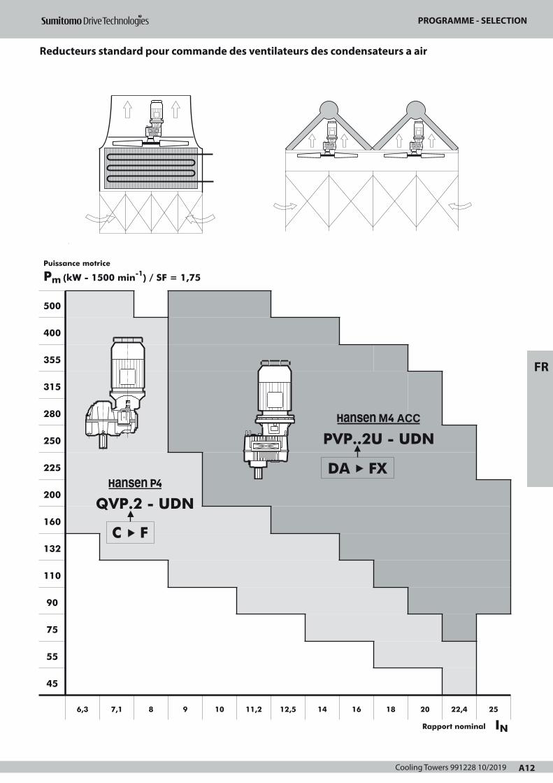
Cooling Towers 991228 10/2019 A12
REDUCTEURS STANDARD POUR COMMANDE DESVENTILATEURS DES CONDENSATEURS A AIR
PROGRAMME - SELECTION
500
400
355
315
280
250
225
200
160
132
110
90
75
55
45
6,3 7,1 8 9 10 11,2 12,5 14 16 18 20 22,4 25
Rapport nominal IN
Puissance motrice
Pm (kW - 1500 min-1) / SF = 1,75
QVP.2 - UDN
C F
DA FX
PVP..2U - UDN
F
A12
Page 1
PROGRAMME - SELECTION
Reducteurs standard pour commande des ventilateurs des condensateurs a air
FR

Cooling Towers 991228 10/2019A13
DESCRIPTIONRÉDUCTEURS HANSEN M4 ACC POUR COMMANDE
DES VENTILATEURS DES CONDENSATEURS A AIR
Codification
Type1 : série P : Hansen M42 : V : arbre petite vitesse vertical3 : P : arbres parallèles4 : Taille: DA-> FX 5 : nombre de trains d'engrenages: 2
Application6 : ACC: Condensateur à air
Shaft arrangement 7 : bout d'arbre grande vitesse : U : vers le haut8 : bout d'arbre petite vitesse: D : vers le bas9 : type d'arbre petite vitesse: N : arbre plein normal
Rapport de réduction10 : rapport de réduction nominal du réducteur
Groupe de commande 11 : K: entraînement avec lanterne et moteur
Moteur 12 : taille du moteur et nombre de pôles
Les réducteurs sont conçus conformes aux spécifications standard CTI-111.Les puissances mécaniques nominales mentionnées dans les tableaux serapportent respectivement à des vitesses d'entrée de 1800, 1500, 1200,1000, 900 et 750 min-1 de l'arbre grande vitesse.Elles sont également valables pour des vitesses asynchrones jusqu'à 3 %inférieures aux vitesses de synchronisme des moteurs. Pour la puissance àdes vitesses intermédiaires il suffit d'interpoler.Le couple considéré constant, calculé à 750 min-1, servira de base à ladétermination de la puissance pour les vitesses inférieures. Pour desvitesses d'entrée supérieures à 1800 min-1, veuillez nous consulter.
Composants de base
Engrenages hélicoïdauxConçus et calculés conformes aux normes AGMA en vigueur pourobtenir une capacité de charge maximum, des pertes minimales et unfonctionnement silencieux.Tous les engrenages sont fabriqués en acier allié, traités parcémentation, trempés et rectifiés.
Arbres petite vitesseLes arbres petite vitesse sont disponibles en exécution pleine.Longueur du bout d'arbre suivant la spécification du client.
RoulementsRoulements de haute capacité à rouleaux cylindriques, coniques ousphériques.Calculés suivant les normes ISO et suivant les spécifications defabricants de roulements renommés.Les roulements de l'arbre petite vitesse sont dimensionnés poursupporter des charges axiales considérables. Les charges axiales,nominales admissibles FxN mentionnées dans le tableau, pages A41,sont valables pour un SFmin = 2, un sens de rotation anti-horlogiquede l'arbre petite vitesse et garantissent une durée de vie de 100000heures.
Carters, paliers et couverclesCoulés en fonte perlitique grise.Usinés sur des centres d'usinage à commande numérique.Conçus en fonction de la résistance et de la rigidité.Les trous taraudés non utilisés sont fermés par des bouchons.Carter monobloc.
Systèmes
LubrificationLubrifiants : normalement des huiles minérales sont utilisées. Leslubrifiants doivent toujours comporter des additifs "EP" adéquats (voirManuel d'Entretien).La lubrification par pompe des roulements supérieurs est standard.La lubrification est garantie pour une vitesse d'entrée supérieure ouégale à 50 min-1 (conditions d'autorotation).Le réducteur constitue un réservoir d'huile volumineux.Les points de graissage à nipple sont conformes à la norme DIN71412. Le roulement du côté du bout d'arbre petite vitesse est lubrifiéà la graisse.Le contrôle du niveau d'huile se fait par la jauge d'huile du réducteur(en position vissée).
Refroidissement La chaleur produite par les pertes du réducteur, peut être dissipéepar:
• refroidissement naturel par le carter• refroidissement supplémentaire par ventilateur axial
incorporé dans la lanterneL’entrée libre de l'air du côté aspiration doit toujours être garantie
Contrôles thermiques: veuillez nous consulter.Remplir le formulaire "Demande d'offre" à la page A17.
EtanchéitéStatique: • utilisation généralisée d'une pâte hermétique
• couvercle d'inspection au réducteur : joint plat réutilisable
• arbre petite vitesse: buselure à rebord Dynamique: • arbre grande vitesse:
standard: bagues d'étanchéité à lèvre anti-poussière
option: étanchéité par labyrinthe regraissable
• arbre petite vitesse:standard : double bagues d'étanchéité à
lèvre anti-poussièreoption: étanchéité par labyrinthe
regraissable
Le réducteur
1
P2
V 3
P4 5
2 U - 6 A C C - 7
U8
D9
N - 10 - 11 K - 12
A13
Page 1
DESCRIPTION
Réducteurs Hansen M4 ACC pour commande des ventilateurs des condensateurs a air

Cooling Towers 991228 10/2019 A14
DESCRIPTIONRÉDUCTEURS HANSEN M4 ACC POUR COMMANDE
DES VENTILATEURS DES CONDENSATEURS A AIR
Moteurs
Les réducteurs à arbres parallèles sont entraînés par des moteurs àbride CEI (type B5). Pour plus d'information concernant les moteurs,consultez le catalogue des moteurs.Pour des moteurs NEMA: veuillez nous consulter.L’emploi de moteurs à 2 vitesses : la commutation des moteurs à 2vitesses à la vitesse inférieure ne peut se faire qu'après que la vitessedu moteur soit inférieure à la vitesse minimale.
Dispositifs optionnels
Certains dispositifs peuvent être livrés en option (voir pages A39 -A40). Des feuilles techniques spécifiques relatives aux dispositifsoptionnels sont disponibles. Veuillez nous consulter.
Antidévireur Antidévireur incorporé afin d'empêcher que le ventilateur ne tourneen sens inverse. Lubrification par le bain d'huile. L'antidévireur estaccessible après démontage du moteur et de la lanterne.
FiltreAvec soupape de surpression incorporée.Un filtre avec soupape de surpression incorporée et indicateur decolmatage mécanique ou électrique est disponible en option.
RéchauffeursDes réchauffeurs électriques pour démarrage à basse températuresont disponibles pour les réducteurs Hansen M4 ACC.
Interrupteur de niveau d'huileAfin de contrôler le niveau d'huile dans le réducteur, un interrupteurde niveau d'huile peut être prévu. Cet interrupteur peut enclencher unsignal d'alarme lorsque le niveau du bain d'huile est inférieur à unevaleur déterminée.
Interrupteur de pression ou transmetteur de pressionAfin de contrôler la pression d'huile, un interrupteur de pression ouun transmetteur de pression peut être prévu. Cet interrupteur peutenclencher un signal d'alarme lorsque la pression d'huile estinférieure à une valeur déterminée.
Pt100Afin de contrôler la température du bain d'huile, un Pt100 peut êtreprévu. Le Pt100 peut enclencher un signal d'alarme lorsque latempérature du bain d'huile est supérieure à une valeur déterminée.
Etat des réducteurs à la livraison
Inspection avant expédition• Essai: tous les réducteurs sont soumis à un essai à vide• Contrôle de conformité
Protection• Bouts d'arbre sortants: enduits d'une couche de graisse et
protégés par du papier huilé
Lubrifiants• Les réducteurs Hansen M4 ACC sont livrés sans huile.
• Les points de graissage sont garnis de graisse avant livraison.
En ce qui concerne llll''''eeeennnnttttrrrreeeeppppoooossssaaaaggggeeee,,,, llllaaaa mmmmaaaannnnuuuutttteeeennnnttttiiiioooonnnn,,,, llll''''iiiinnnnssssttttaaaallllllllaaaattttiiiioooonnnn,,,, llllaaaammmmiiiisssseeee eeeennnn mmmmaaaarrrrcccchhhheeee eeeetttt llll''''eeeennnnttttrrrreeeettttiiiieeeennnn, veuillez consulter le Manuel d'Entretienqui est livré avec chaque réducteur.
Protection
Systèmes de protection standard• En standard, les réducteurs Hansen M4 ACC sont munis d'un
système de peinture qui convient pour être appliqué dans la corro-
sivité atmosphérique catégorie "C4 (L)" suivant ISO 12944-2 (et ISO
12944-5).Le choix de la couleur n’affecte pas la qualité technique du système
de peinture.D'autres systèmes de peinture peuvent être offerts pour répondre à
la catégorie de corrosivité atmosphérique requise pour votre appli-
cation.
• Boulons et écrous: munis d'une protection appropriée.
F
A14
Page 1
DESCRIPTION
FR

Cooling Towers 991228 10/2019A15
Puissancemécanique nominale P
Rapport voir p. A41
SELECTIONPuissance mécanique nominale
COMMANDE DES VENTILATEURS DES CONDENSATEURS A AIR
A15
consulter page A17
consulter page A12
pour rapports < 9 consulter nous
Procédure Données de référence
2
3
pour
• • • • - - • • • - Rapport
P V P 2U - ACC - U D N
1
DONNEES DE SELECTION
Pm , Pa , nHSS , nLSS , iN
Charge axiale
Fx
SELECTION DU PROGRAMME
Puissance absorbée Pa
PPuissance motrice Pm
et
x SF =1,75
x SF = 2
≥
Taille
S
E
L
E
C
T
I
O
N
V
E
R
I
F
I
E
R
Taille
P
Puissance thermique voir pages A16, A42
Couple de démarrage TS
Vérifier si
≤TS 1,5 x T
P
Fx : ... kN
Faire attention à la direction de Fx ! (Toujours vers le bas)
Vérifier si
≤Fx FxNFxN
voir p. A41
T = P x 9,55
n
P: puissance mécanique nominale (kw), voir page A41
Couple mécanique nominal du réducteur (kNm)
n: vitesse de sortie (min-1)
1000000
100000
10000
1000
100
10
1
1,0 1,1 1,2 1,41,3 1,5Tem
ps d
e dé
mar
rage
tota
l de
conc
epti
on @
150
0 m
in-1
(h)
(t S
@ 1
500 )
Consulter l'usine
Non permis
Permis
A
Temps de démarrage total tS
Pour d’autres vitesses d’entrée (n1), l’équation suivante peut êtreappliquée:
tS @ n1 = 1500 n1
x tS @ 1500
Remarque: soyez certain que Ts, T et n se rapportent au même arbre(vitesse);
Temps de démarrage total de conception @ 1500 min-1 se rapporteau temps de démarrage total pour la durée de vie de conception duréducteur, tenat compte de :
- le nombre de démarrages- la durée d’un démarrage- la vitesse d’entrée de 1500 min-1
A = TS : couple de démarrage (kNm)T : couple mécanique nominal du réducteur (kNm)
Page 1
SÉLECTION
Puissance mécanique nominale commande des ventilateurs des condensateurs a air
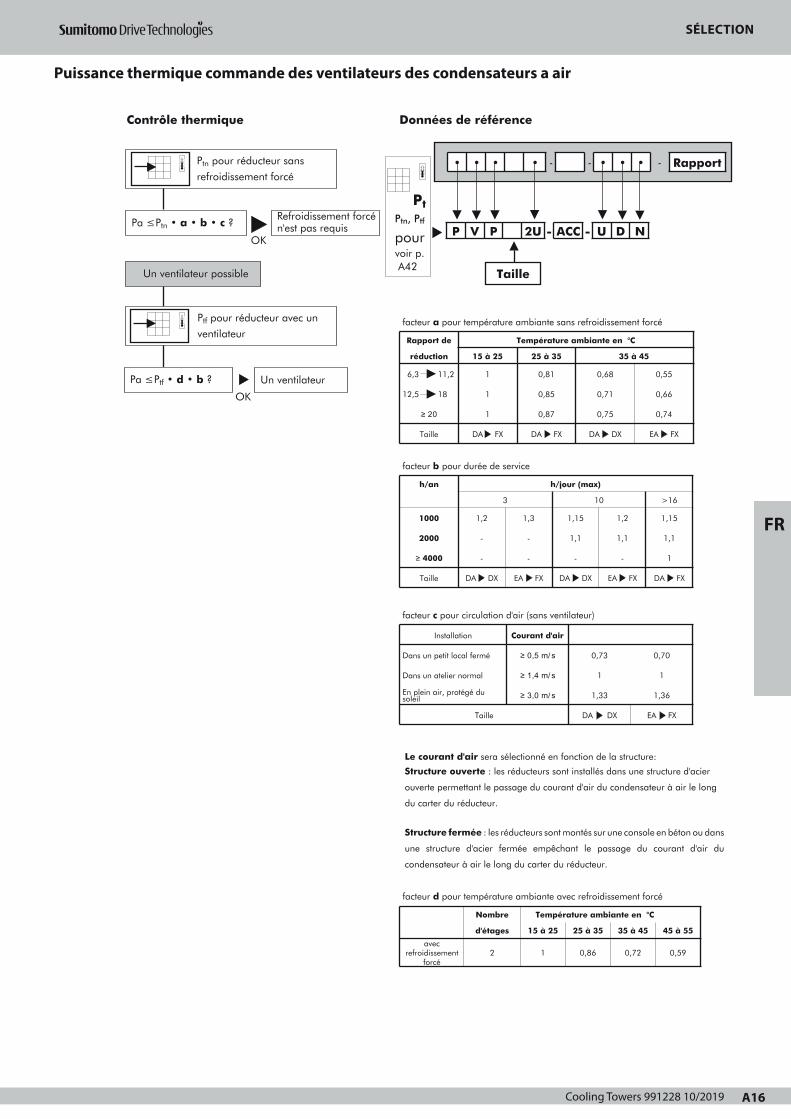
Cooling Towers 991228 10/2019 A16
Puissancemécanique nominale P
Rapport voir p. A41
SELECTIONPuissance mécanique nominale
COMMANDE DES VENTILATEURS DES CONDENSATEURS A AIR
A15
consulter page A17
consulter page A12
pour rapports < 9 consulter nous
Procédure Données de référence
2
3
pour
• • • • - - • • • - Rapport
P V P 2U - ACC - U D N
1
DONNEES DE SELECTION
Pm , Pa , nHSS , nLSS , iN
Charge axiale
Fx
SELECTION DU PROGRAMME
Puissance absorbée Pa
PPuissance motrice Pm
et
x SF =1,75
x SF = 2
≥
Taille
S
E
L
E
C
T
I
O
N
V
E
R
I
F
I
E
R
Taille
P
Puissance thermique voir pages A16, A42
Couple de démarrage TS
Vérifier si
≤TS 1,5 x T
P
Fx : ... kN
Faire attention à la direction de Fx ! (Toujours vers le bas)
Vérifier si
≤Fx FxNFxN
voir p. A41
T = P x 9,55
n
P: puissance mécanique nominale (kw), voir page A41
Couple mécanique nominal du réducteur (kNm)
n: vitesse de sortie (min-1)
1000000
100000
10000
1000
100
10
1
1,0 1,1 1,2 1,41,3 1,5Tem
ps d
e dé
mar
rage
tota
l de
conc
epti
on @
150
0 m
in-1
(h)
(t S
@ 1
500)
Consulter l'usine
Non permis
Permis
A
Temps de démarrage total tS
Pour d’autres vitesses d’entrée (n1), l’équation suivante peut êtreappliquée:
tS @ n1 = 1500 n1
x tS @ 1500
Remarque: soyez certain que Ts, T et n se rapportent au même arbre(vitesse);
Temps de démarrage total de conception @ 1500 min-1 se rapporteau temps de démarrage total pour la durée de vie de conception duréducteur, tenat compte de :
- le nombre de démarrages- la durée d’un démarrage- la vitesse d’entrée de 1500 min-1
A = TS : couple de démarrage (kNm)T : couple mécanique nominal du réducteur (kNm)
Page 1
SELECTIONPuissance thermique
COMMANDE DES VENTILATEURS DES CONDENSATEURS A AIR
Ptn pour réducteur sans
refroidissement forcé
facteur a pour température ambiante sans refroidissement forcé
Rapport de
réduction
Température ambiante en °C
15 à 25 25 à 35 35 à 45
6,3 11,2
12,5 18
≥ 20
Taille
1
1
0,81
0,85
1
DA FX
0,87
DA FX
0,68
0,71
0,55
0,66
0,75
DA DX
0,74
EA FX
OK
Contrôle thermique
Pa ≤ Ptn • a • b • c ?
Un ventilateur possible
Refroidissement forcén'est pas requis
Ptf pour réducteur avec un
ventilateur
Pa ≤ Ptf • d • b ? Un ventilateur
facteur b pour durée de service
h/an
3
h/jour (max)
10 >16
1000
2000
≥ 4000
Taille
1,2
-
1,3
-
-
DA DX
-
EA FX
1,15
1,1
1,2
1,1
-
DA DX
-
EA FX
1,15
1,1
1
DA FX
facteur d pour température ambiante avec refroidissement forcé
Nombre
d'étages
Température ambiante en °C
15 à 25 25 à 35 35 à 45 45 à 55
avecrefroidissement
forcé2 1 0,86 0,72 0,59
Données de référence
OK
facteur c pour circulation d'air (sans ventilateur)
Installation
Dans un petit local fermé
Courant d'air
≥ 0,5 m/s 0,73 0,70
Dans un atelier normal
En plein air, protégé dusoleil
Taille
≥ 1,4 m/s
≥ 3,0 m/s
1
1,33
DA DX
1
1,36
EA FX
Pt
Ptn, Ptf
pourvoir p.A42
Pt
• • • • - - • • • - Rapport
P V P 2U - ACC - U D N
Taille
F
A16
Le courant d'air sera sélectionné en fonction de la structure:
Structure ouverte : les réducteurs sont installés dans une structure d'acier
ouverte permettant le passage du courant d'air du condensateur à air le long
du carter du réducteur.
Structure fermée : les réducteurs sont montés sur une console en béton ou dans
une structure d'acier fermée empêchant le passage du courant d'air du
condensateur à air le long du carter du réducteur.
Page 1
SÉLECTION
FR
Puissance thermique commande des ventilateurs des condensateurs a air
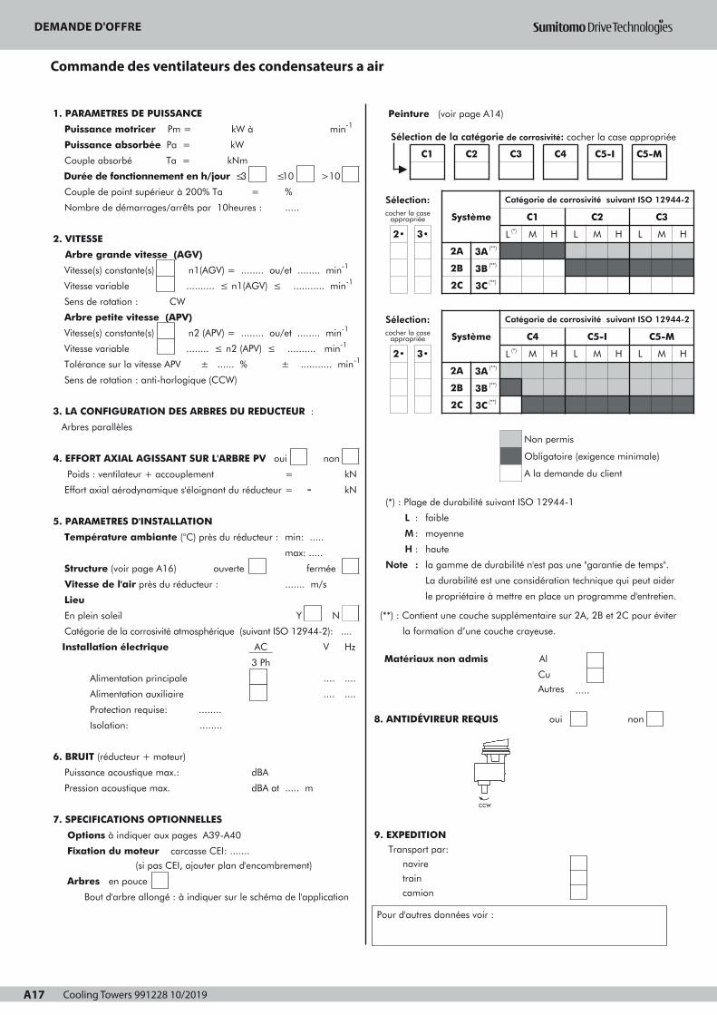
Cooling Towers 991228 10/2019A17 A17
1. PARAMETRES DE PUISSANCE
Puissance motricer Pm = kW à min-1
Puissance absorbée Pa = kW
Couple absorbé Ta = kNm
Durée de fonctionnement en h/jour ≤3
Couple de point supérieur à 200% Ta =
Nombre de démarrages/arrêts par 10heures :
≤10 >10
%
.....
2. VITESSE
Arbre grande vitesse (AGV)
Vitesse(s) constante(s) n1(AGV) = ........ ou/et ........ min-1
Vitesse variable .......... ≤ n1(AGV) ≤ ........... min-1
Sens de rotation : CW
Arbre petite vitesse (APV)
Vitesse(s) constante(s) n2 (APV) = ........ ou/et ........ min-1
Vitesse variable ........ ≤ n2 (APV) ≤ .......... min-1
Tolérance sur la vitesse APV ± ...... % ± ........... min-1
Sens de rotation : anti-horlogique (CCW)
3. LA CONFIGURATION DES ARBRES DU REDUCTEUR :
Arbres parallèles
4. EFFORT AXIAL AGISSANT SUR L'ARBRE PV oui non
Poids : ventilateur + accouplement
Effort axial aérodynamique s'éloignant du réducteur
5. PARAMETRES D'INSTALLATION
Température ambiante (°C) près du réducteur :
Structure (voir page A16) ouverte
Vitesse de l'air près du réducteur :
=
= -kN
kN
min: .....
max: .....
....... m/s
fermée
Lieu
En plein soleil
Catégorie de la corrosivité atmosphérique (suivant ISO 12944-2): ....
Installation électrique AC
Alimentation principale
Alimentation auxiliaire
Protection requise: ........
3 Ph
Y N
V Hz
.... ....
.... ....
Isolation: ........
6. BRUIT (réducteur + moteur)
Puissance acoustique max.: dBA
Pression acoustique max.
7. SPECIFICATIONS OPTIONNELLES
Options à indiquer aux pages A39-A40
dBA at ..... m
Fixation du moteur carcasse CEI: .......
(si pas CEI, ajouter plan d'encombrement)
Arbres en pouce
Bout d'arbre allongé : à indiquer sur le schéma de l'application
Peinture (voir page A14)
(*) : Plage de durabilité suivant ISO 12944-1
L : faible
M : moyenne
H : haute
Note : la gamme de durabilité n'est pas une "garantie de temps".
La durabilité est une considération technique qui peut aider
le propriétaire à mettre en place un programme d'entretien.
(**) : Contient une couche supplémentaire sur 2A, 2B et 2C pour éviter
la formation d’une couche crayeuse.
Matériaux non admis Al
Cu
Autres .....
8. ANTIDÉVIREUR REQUIS oui non
9. EXPEDITION Transport par:
navire
train
camion
Pour d'autres données voir :
CCW
DEMANDE D'OFFRE
COMMANDE DES VENTILATEURS DES CONDENSATEURS A AIR
Ref : Date : Nom : Signature :
Sélection:cocher la case
appropriée
2• 3•
Système
Catégorie de corrosivité suivant ISO 12944-2
L (*)
C1
M H L
C2
M H L
C3
M
2A
2B
3A (**)
3B (**)
2C 3C (**)
Sélection:cocher la case
appropriée
2• 3•
Système
2A 3A (**)
2B
2C
3B (**)
3C (**)
Catégorie de corrosivité suivant ISO 12944-2
C4
L (*) M H L
Non permis
C5-I
M H
C5-M
L M
Obligatoire (exigence minimale)
A la demande du client
H
H
Sélection de la catégorie de corrosivité: cocher la case appropriée
C1 C2 C3 C4 C5-I C5-M
Page 1
DEMANDE D'OFFRE
Commande des ventilateurs des condensateurs a air
Cooling Towers 991228 10/2019 A18
DEMANDE D'OFFRE
FR
VUE EN PLAN
VUE DE COTE
Cooling Towers 991228 10/2019A19
SELECTION

Cooling Towers 991228 10/2019 A20
LUFTKONDENSATORANTRIEBE
Hansen M4 ACC Normzahnradgetriebe
Programm – Auswahl A22
Beschreibung A23 - A24
Auswahl A25 - A26
Technische Erläuterung für Anfrage A27 - A28
Zubehör und Optionen A39 - A40
AuswahltabellenMechanische Nennleistungen und Nennaxialbelastung A41
Exakte Übersetzungen iex und Massenträgheitsmomente J A41
Wärmegrenzleistungen A42
MaßzeichnungenHansen M4 ACC Getriebe ohne Ölfilter A43
Hansen M4 ACC Getriebe mit Ölfilter A44
Hansen P4 Normzahnradgetriebe
Programm – Auswahl A22
Beschreibung A57 - A58
Auswahl A59 - A60
Technische Erläuterung für Anfrage A61 - A62
Zubehör und Optionen A69 - A70
AuswahltabellenMechanische Nennleistungen und Nennaxialbelastung A71
Exakte Übersetzungen iex und Massenträgheitsmomente J A71
Wärmegrenzleistungen A72
MaßzeichnungHansen P4 Getriebe, Stirnräder, Zweistufig A73
Teil A - INHALTVERZEICHNIS
DD
A20
Page 1
LUFTKONDENSATORANTRIEBE
DE

Cooling Towers 991228 10/2019A21
SELECTION

Cooling Towers 991228 10/2019 A22A17
1. PARAMETRES DE PUISSANCE
Puissance motricer Pm = kW à min-1
Puissance absorbée Pa = kW
Couple absorbé Ta = kNm
Durée de fonctionnement en h/jour ≤3
Couple de point supérieur à 200% Ta =
Nombre de démarrages/arrêts par 10heures :
≤10 >10
%
.....
2. VITESSE
Arbre grande vitesse (AGV)
Vitesse(s) constante(s) n1(AGV) = ........ ou/et ........ min-1
Vitesse variable .......... ≤ n1(AGV) ≤ ........... min-1
Sens de rotation : CW
Arbre petite vitesse (APV)
Vitesse(s) constante(s) n2 (APV) = ........ ou/et ........ min-1
Vitesse variable ........ ≤ n2 (APV) ≤ .......... min-1
Tolérance sur la vitesse APV ± ...... % ± ........... min-1
Sens de rotation : anti-horlogique (CCW)
3. LA CONFIGURATION DES ARBRES DU REDUCTEUR :
Arbres parallèles
4. EFFORT AXIAL AGISSANT SUR L'ARBRE PV oui non
Poids : ventilateur + accouplement
Effort axial aérodynamique s'éloignant du réducteur
5. PARAMETRES D'INSTALLATION
Température ambiante (°C) près du réducteur :
Structure (voir page A16) ouverte
Vitesse de l'air près du réducteur :
=
= -kN
kN
min: .....
max: .....
....... m/s
fermée
Lieu
En plein soleil
Catégorie de la corrosivité atmosphérique (suivant ISO 12944-2): ....
Installation électrique AC
Alimentation principale
Alimentation auxiliaire
Protection requise: ........
3 Ph
Y N
V Hz
.... ....
.... ....
Isolation: ........
6. BRUIT (réducteur + moteur)
Puissance acoustique max.: dBA
Pression acoustique max.
7. SPECIFICATIONS OPTIONNELLES
Options à indiquer aux pages A39-A40
dBA at ..... m
Fixation du moteur carcasse CEI: .......
(si pas CEI, ajouter plan d'encombrement)
Arbres en pouce
Bout d'arbre allongé : à indiquer sur le schéma de l'application
Peinture (voir page A14)
(*) : Plage de durabilité suivant ISO 12944-1
L : faible
M : moyenne
H : haute
Note : la gamme de durabilité n'est pas une "garantie de temps".
La durabilité est une considération technique qui peut aider
le propriétaire à mettre en place un programme d'entretien.
(**) : Contient une couche supplémentaire sur 2A, 2B et 2C pour éviter
la formation d’une couche crayeuse.
Matériaux non admis Al
Cu
Autres .....
8. ANTIDÉVIREUR REQUIS oui non
9. EXPEDITION Transport par:
navire
train
camion
Pour d'autres données voir :
CCW
DEMANDE D'OFFRE
COMMANDE DES VENTILATEURS DES CONDENSATEURS A AIR
Ref : Date : Nom : Signature :
Sélection:cocher la case
appropriée
2• 3•
Système
Catégorie de corrosivité suivant ISO 12944-2
L (*)
C1
M H L
C2
M H L
C3
M
2A
2B
3A (**)
3B (**)
2C 3C (**)
Sélection:cocher la case
appropriée
2• 3•
Système
2A 3A (**)
2B
2C
3B (**)
3C (**)
Catégorie de corrosivité suivant ISO 12944-2
C4
L (*) M H L
Non permis
C5-I
M H
C5-M
L M
Obligatoire (exigence minimale)
A la demande du client
H
H
Sélection de la catégorie de corrosivité: cocher la case appropriée
C1 C2 C3 C4 C5-I C5-M
Page 1
PROGRAMM AUSWAHL
Normzahnradgetriebe für Luftkondensatorantriebe
DE

Cooling Towers 991228 10/2019A23
BESCHREIBUNGHANSEN M4 ACC NORMZAHNRADGETRIEBE FÜR
LUFTKONDENSATORANTRIEBE
Bezeichnung
Typ1 : Reihe P : Hansen M42 : V : vertikale langsamdrehende Welle3 : P : parallele Wellen4 : Baugröße: DA-> FX 5 : Stufenzahl: 2
Anwendung6 : ACC: Luftkondensator
Wellenanordnung 7 : schnelldrehende Welle ausragend: U : nach oben8 : langsamdrehende Welle ausragend: D : nach unten9 : Abtriebswellentyp: N : normale Vollwelle
Übersetzun10 : Nennübersetzung für Getriebe
Getriebepaket 11 : K: Antriebe mit Laterne und Motor
Motor 12 : Motor: Baugröße und Polzahl
Getriebe werden nach der Norm CTI-111 (Cooling Tower Institute)Spezifizierung ausgelegt.Die in den Tabellen aufgeführten mechanischen Nennleistungen,beziehen sich auf die Antriebsdrehzahlen 1800, 1500, 1200, 1000,900 und 750 min-1. Sie sind auch gültig für Asynchrondrehzahlen, die max. 3% niedrigerals die Synchrondrehzahlen der Motoren liegen. Für die Leistungs-übermittlung bei anderen Drehzahlen genügt es zu interpolieren. DieLeistung bei Drehzahlen kleiner als 750 min-1 entspricht demNenndrehmoment bei 750 min-1. Für Eingangsdrehzahlen größer als1800 min-1, ist eine Rückfrage zu empfehlen.
Hauptbauteile
Schrägverzahnte StirnräderEntwurf und Auslegung nach AGMA für eine maximale Belastbarkeit,minimale Verluste und einen geräuscharmen Lauf.Sämtliche Zahnräder sind aus legiertem Stahl; sie werden ein-satzgehärtet und geschliffen.
Langsamdrehende WellenDie langsamdrehenden Wellen sind in Vollwellenausführung.Länge der Wellenverlängerung entsprechend Spezifikation des Kunden.
LagerReichlich bemessene Kegelrollen-, Pendelrollen- oder Zylinderrollen-lager; berechnet nach ISO und bekannten LagerherstellerDie Lager an der Abtriebswelle sind ausgelegt zur Aufnahme vonerheblichen Axiallasten. Die in den Tabellen, auf Seite A41,aufgeführte zulässige Nennaxiallast FxN ist gültig für SFmin = 2, eineDrehrichtung entgegen Uhrzeigersinn für die Langsamdrehende Welleund garantiert eine berechnete Lagerlebensdauer von 100000Stunden.
Gehäuse, Deckel und LagergehäuseAus perlitischem Grauguß.Bearbeitung auf CNC gesteuerten Bearbeitungszentren.Robuste und steife Konstruktion.Nicht verwendete Gewindelöcher sind mit Stopfen verschlossen Block-gehäuse.
Systems
SchmierungSchmiermittel: In der Regel werden Mineralöle verwendet.Die Schmiermittel müssen allerdings „extreme pressure Additive“enthalten (siehe Betriebsanleitung).Druckumlaufschmierung für die oberen Lager ist standardmäßigerhältlich.
Die Schmierung ist für die Drehzahl unten zu 50 min-1 garantiert(Mitdrehen im Fahrtwindzustände - Bedingungen).Das Gehäuse bildet einen reichlich bemessenen Ölbehälter.Fettschmierpunkte mit Nippel entsprechend DIN 71412 fürFettschmierung des Lagers an dem Seite des Abtriebswellenendes.Der Ölstand ist entweder mittels (eingeschraubten) Gewinde-Ölmeßstab meßbar.
KühlungDie Wärmeabführung der im Gehäuse entstandenen Verlustwärmeerfolgt mittels:
• Eigenkühlung vom Gehäuse• Ventilatorkühlung, Welle angetriebener axialer Ventilator
integriert im LaternegehäuseFreier Lufteintrag auf der Saugseite sollte immer gewährleistetsein
Thermische Kontrollen: Rückfrage zu empfehlen. "Technische Erläuterung für Anfrage" auf Seite A27 ausfüllen.
AbdichtungFeste Teile: • allgemeine Verwendung einer Dichtungspaste
• Schaulochdeckel an Getriebe: mehrfachverwendbare flache Dichtung
• langsamdrehende Welle: Steigrohr Umlaufende Teile:
• schnelldrehende Welle:Norm: Dichtungsring mit StaublippeOption: nachschmierbares Labyrinth
• langsamdrehende Welle:Norm : doppelte Dichtungsring
mit StaublippeOption: nachschmierbares Labyrinth
Das Getriebe
1
P2
V 3
P4 5
2 U - 6 A C C - 7
U8
D9
N - 10 - 11 K - 12
A23
Page 1
BESCHREIBUNG
Hansen M4 ACC Normzahnradgetriebe für Luftkondensatorantriebe

Cooling Towers 991228 10/2019 A24
BESCHREIBUNGHANSEN M4 ACC NORMZAHNRADGETRIEBE FÜR
LUFTKONDENSATORANTRIEBE
Motoren
Die Getriebe werden mit IEC Motoren in Flanschausführungausgerüstet (Bauform B5). Für mehr Information über Motoren, SieheMotorkatalog.Für NEMA-Motoren: Rückfrage zu empfehlen.Polumschaltbare Motoren: polumschaltbare Motoren dürfen erstdann auf die niedrige Drehzahl umgeschaltet werden, wenn dieDrehzahl des Motors bis unter die niedrige Drehzahl abgefallen ist.
Optionale Zusatzeinrichtungen
Bestimmte Zusatzeinrichtungen sind optional verfügbar (siehe SeitenA39 - A40). Detaillierte Information über optionale Zusatz-einrichtungen ist den separaten Betriebsvorschriften für diese Teile zuentnehmen. Rückfrage zu empfehlen.
Rücklaufsperre Eingebaute Rücklaufsperre vermeidet unerwünschter Drehen desVentilators. Schmierung der Rücklaufsperre erfolgt durch dieSchmieranlage vom Getriebe. Die Rücklaufsperre ist zugänglich,nachdem er den Motor und das Laternegehäuse entfernt hat.
FilterMit eingebautem Überdruckventil.Ein Filter mit eingebautem Überdruckventil und optischem odermechanischem Verschmutzungsanzeiger ist als Option vorhanden.
HeizstäbeElektrisch erwärmte Heizstäbe für Anlauf bei niedrigen Temperaturensind vorhanden für Hansen M4 ACC Getriebe.
ÖlstandschalterEin Ölstandschalter zur Überprüfung des Ölstandes im Getriebe kannvorgesehen werden. Der Schalter kann ein Alarmsignal auslösen,wenn der Stand vom Ölbad unterhalb eines bestimmten Wertes fällt.
Druckschalter oder DruckübermittlerEin Druckschalter oder Druckübermittler zur Überprüfung desÖldrucks kann vorgesehen werden. Der Schalter oder Übermittlerkann ein Alarmsignal auslösen, wenn der Öldruck unterhalb einesbestimmten Wertes fällt.
Pt100Der Pt100 steuert die Ölbadtemperatur. Der Pt100 kann ein Alarmsignal auslösen, wenn das Öltemperaturhöher ist als die spezifizierte Begrenzung.
Lieferzustand
Kontrolle vor dem Versand• Probelauf: alle Getriebe werden einen unbelasteten Probelauf
unterzogen• Gleichförmigkeitskontrolle
Schutz• Ausragendes Wellenende: fettgeschmiert und mit einem
wasserbeständigen, wachsartigen Papier geschützt
Schmierstoffe• Hansen M4 ACC Getriebe werden ohne Ölfüllung geliefert.
• Alle Fettschmierstellen werden jedoch vor dem Versand mit Fett gefüllt.
Hinsichtlich LLLLaaaaggggeeeerrrruuuunnnngggg,,,, HHHHaaaannnnddddhhhhaaaabbbbuuuunnnngggg,,,, MMMMoooonnnnttttaaaaggggeeee,,,, IIIInnnnbbbbeeeettttrrrriiiieeeebbbbsssseeeettttzzzzuuuunnnngggguuuunnnndddd WWWWaaaarrrrttttuuuunnnngggg ddddeeeerrrr GGGGeeeettttrrrriiiieeeebbbbeeee, gibt die Betriebsanleitung, diezusammen mit den Getrieben geliefert wird, wertvolle Hinweise.
Schutzmaßnahmen
Standard Schutzsysteme• Als Standard werden Hansen M4 ACC Getriebe mit einem
Anstrichsystem versehen, das geeignet ist für eine Umgebung nach
Korrosionsschutzklasse "C4 (L)" entsprechend ISO 12944-2 (und
ISO 12944-5).Die Wahl der Farbe hat keinen Einfluss auf die technische Qualität
des Anstrichsystems.Andere Anstrichsysteme können angeboten werden, um die erfor-
derliche Korrosionsschutzklasse für Ihre Anwendung zu erfüllen.
• Bolzen und Schrauben ausgestattet mit passendem Schutz.
D
A24
Page 1
BESCHREIBUNG
DE

Cooling Towers 991228 10/2019A25
AUSWAHLmechanische Nennleistung
LUFTKONDENSATORANTRIEBE
A25
siehe Seite A27
siehe Seite A22
für Übersetzungen < 9 ist Rückfrage erforderlich
Verfahren Referenzdaten
Mechanische Nennleistung P
Übersetzung
2
3
für
• • • • - - • • • - Nennüber-setzung
P V P 2U - ACC - U D N
1
AUSWAHLDATEN
Pm , Pa , nHSS , nLSS , iN
Axialkraft
Fx
ROGRAMMAUSWAHL
Abtriebsleistung Pa
PMotorleistung Pm
und
x SF =1,75
x SF = 2
≥
siehe S. A41
P Größe
A
U
S
W
A
H
L
K
O
N
T
R
O
L
L
E
Größe
P
Wärmegrenzleistung: siehe Seiten A26, A42
Anlaufdrehmoment TS
Kontrolle, wenn
≤TS 1,5 x T
Fx : ... kN
Richtung von Fx beachten ! (Immer nach unten)
Kontrolle, wenn
≤Fx FxNFxN
Siehe S. A41
1000000
100000
10000
1000
100
10
1
1,0 1,1 1,2 1,41,3 1,5
Entw
urf g
esam
t Anl
aufz
eit @
150
0 m
in-1
(St
d.)
(t S
@ 1
500)
Fabrik rückfragen
Nicht zulässig
Zulässig
A
Gesamt Anlaufzeit tS
Für andere Antriebsdrehzahlen (n1) kann folgende Gleichungangewendet werden:
tS @ n1 = 1500 n1
x tS @ 1500
T = P x 9,55
n
P: mechanische Nennleistung (kW), siehe Seite A41
Mechanisches Nenndrehmoment des Getriebes (kNm)
n: Wellendrehzahl (min-1)
Hinweis: stellen Sie sicher dass Ts, T und n der gleichen Welle beziehen;
Entwurf gesamt Anlaufzeit @ 1500 min-1 bezieht sich auf die gesamteAnlaufzeit über die Auslegungslebensdauer des Getriebes, unterBerücksichtigung von:
- Anzahl der Einschaltungen (Anlauf)- Dauer eines einzigen Anlauf (Anlaufzeit)- Antriebsdrehzahl gleich 1500 min-1
A = TS : Anlaufmoment (kNm)T : mechanisches Nenndrehmoment des Getriebes (kNm)
Page 1
AUSWAHL
Mechanische Nennleistung Luftkondensatorantriebe

Cooling Towers 991228 10/2019 A26
AUSWAHLWärmegrenzleistung
LUFTKONDENSATORANTRIEBE
Ptn für Getriebe ohne
Fremdkühlung
Faktor a für Umgebungstemperatur ohne Fremdkühlung
Übersetzung Umgebungstemperatur in °C
15 bis 25 25 bis 35 35 bis 45
6,3 11,2
12,5 18
≥ 20
Baugröße
1
1
0,81
0,85
1
DA FX
0,87
DA FX
0,68
0,71
0,55
0,66
0,75
DA DX
0,74
EA FX
OK
Thermische Kontrolle
Pa ≤ Ptn • a • b • c ?
Lüfter ist möglich
Fremdkühlung istnicht erforderlich
Ptf für Getriebe mit einem
Lüfter
Pa ≤ Ptf • d • b ? Ein Lüfter
Faktor b für Betriebsdauer
h/Jahr
3
h/Tag (max)
10 >16
1000
2000
≥ 4000
Baugröße
1,2
-
1,3
-
-
DA DX
-
EA FX
1,15
1,1
1,2
1,1
-
DA DX
-
EA FX
1,15
1,1
1
DA FX
Faktor d für Umgebungstemperatur mit Fremdkühlung
Stufenzahl Umgebungstemperatur in °C
15 bis 25 25 bis 35 35 bis 45 45 bis 55
Fremdkühlung 2 1 0,86 0,72 0,59
Referenzdaten
OK
Faktor c für Luftzirkulation (ohne Lüfter)
Aufstellung
In klein. geschlos. Raum
Luftströmung
≥ 0,5 m/s 0,73 0,70
In normalem Arbeitsraum
Aufstellung im Freien, Son-nenschutz
Baugröße
≥ 1,4 m/s
≥ 3,0 m/s
1
1,33
DA DX
1
1,36
EA FX
PtPtn, Ptf
fürsiehe S.
A42
• • • • - - • • • - Über-setzung
P V P 2U - ACC - U D N
Größe
D
A26
Luftströmung sollte entsprechend der Struktur gewählt werden:
Offene Struktur: bei Getrieben aufgestellt in offener Stahlstruktur kann der
Luftstrom vom Kondensator über das Getriebegehäuse geführt werden.
Geschlossene Struktur: bei Getrieben aufgestellt auf einem Beton-sockel
oder in einer geschlossenen Stahlstruktur kann der Luftstrom vom Kondensator
nicht über das Getriebegehäuse geführt werden.
Pt
Page 1
DE
AUSWAHL
Wärmegrenzleistung Luftkondensatorantriebe
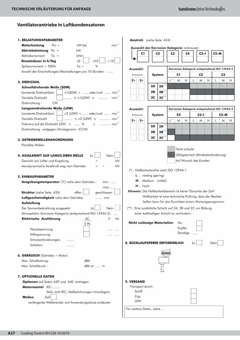
Cooling Towers 991228 10/2019A27
ANFRAGEVENTILATORANTRIEBE IN LUFTKONDENSATOREN
A27
1. BELASTUNGSPARAMETER
Motorleistung Pm = kW bei min-1
Abtriebsleistung Pa = kW
Abtriebsmoment Ta = kNm
Einsatzdauer in h/Tag ≤3
Spitzenmoment > 200% Ta =
Anzahl der Einschaltungen/Abschaltungen pro 10 Stunden :
≤10 >10
%
.....
2. DREHZAHL
Schnelldrehende Welle (SDW)
konstante Drehzahl(en) n1(SDW) = ...... oder/und ...... min-1
Variable Drehzahl ......... ≤ n1(LDW) ≤ .......... min-1
Drehrichtung : CW
Langsamdrehende Welle (LDW)
konstante Drehzahl(en) n2 (LDW) = ...... oder/und ...... min-1
Variable Drehzahl ......... ≤ n2 (LDW) ≤ .......... min-1
Toleranz auf die Drehzahl LDW ± ...... % ± ........... min-1
Drehrichtung : entgegen Uhrzeigersinn (CCW)
3. GETRIEBEWELLENANORDNUNG
Parallele Wellen
4. AXIALKRAFT AUF LANGS.DREH.WELLE Ja Nein
Gewicht von Lüfter und Kupplung
Aerodynamische Axialkraft weg vom Getriebe
5. EINBAUPARAMETER
Umgebungstemperatur (°C) nahe dem Getriebe :
Struktur (siehe Seite A26) offen
Luftgeschwindigkeit nahe dem Getriebe:
=
= -kN
kN
min: .....
max: .....
geschlossen
....... m/s
Aufstellung
Der Sonnenbestrahlung ausgesetzt
Atmosphäre: Korrosion Kategorie (entsprechend ISO 12944-2): ....
Elektrische Ausführung
Ja
AC
Hauptspannung
Hilfsspannung
Schutzanforderungen: ........
3 Ph
Nein
V Hz
.... ....
.... ....
Isolation: ........
6. GERÄUSCH (Getriebe + Motor)
Max. Schalleistung: dBA
Max. Schalldruck :
7. OPTIONELLE DATEN
Optionen auf Seiten A39 und A40 eintragen
dBA at ..... m
Motormantel IEC: .......
(falls nicht IEC, Maßzeichnungen hinzufügen)
Wellen Zoll
verlängertes Wellenende: auf Anwendungsskizze andeuten
Anstrich (siehe Seite A24)
(*) : Haltbarkeitsreihe nach ISO 12944-1
L : niedrig (gering)
M : Medium (mittel)
H : hoch
Hinweis: Die Haltbarkeitsbereich ist keine "Garantie der Zeit".
Haltbarkeit ist eine technische Prüfung, dass der Besitzer
helfen kann für das Einrichten einem Wartungsprogramm.
(**) : Eine zusätzliche Schicht auf 2A, 2B und 2C um Bildung
einer kalkhaltigen Schicht zu verhindern.
Nicht zulässige Materialien Alu
Kupfer
Sonstige .....
8. RÜCKLAUFSPERRE ERFORDERLICH Ja Nein
9. VERSAND Transport durch:
Schiff
Zug
LKW
Für weitere Daten, siehe ...
CCW
Ref : Datum : Name : Unterschrift :
Auswahl:
Ankreuzen
2• 3•
System
Korrosion Kategorie entsprechend ISO 12944-2
L (*)
C1
M H L
C2
M H L
C3
M
2A
2B
3A (**)
3B (**)
2C 3C (**)
Auswahl:
Ankreuzen
2• 3•
System
2A 3A (**)
2B
2C
3B (**)
3C (**)
Korrosion Kategorie entsprechend ISO 12944-2
C4
L (*) M H L
Nicht erlaubt
C5-I
M H
C5-M
L M
Obligatorisch (Mindestanforderung)
Auf Wunsch des Kunden
H
H
Auswahl der Korrosion Kategorie: ankreuzen
C1 C2 C3 C4 C5-I C5-M
Page 1
TECHNISCHE ERLÄUTERUNG FÜR ANFRAGE
Ventilatorantriebe in Luftkondensatoren

Cooling Towers 991228 10/2019 A28
DE
TECHNISCHE ERLÄUTERUNG FÜR ANFRAGE
DRAUFSICHT
SEITENANSICHT
Cooling Towers 991228 10/2019A29
BESCHREIBUNG

Cooling Towers 991228 10/2019 A30
LAS TRANSMISIONES DEL VENTILADOR DE LOSCONDENSADORES DE AIRE
Reductores normalizados Hansen M4 ACC
Programa – Selección A32
Descripción A33 - A34
Selección A35 - A36
Petición de oferta A37 - A38
Accesorios y opciones A39 - A40
Tablas de selecciónPotencias mecánicas nominales y la carga axial nomínal A41
Indices exactos de reducción iex y momentos de inercia J A41
Potencias térmicas nominales A42
Planos de dimensionesReductores Hansen M4 ACC sin el filtro de aceite A43
Reductores Hansen M4 ACC con el filtro de aceite A44
Reductores normalizados Hansen P4
Programa – Selección A32
Descripción A63 - A64
Selección A65 - A66
Petición de oferta A67 - A68
Accesorios y opciones A69 - A70
Tablas de selecciónPotencias mecánicas nominales y la carga axial nomínal A71
Indices exactos de reducción iex y momentos de inercia J A71
Potencias térmicas nominales A72
Plano de dimensionesReductores Hansen P4, ejes paralelos, dos etapas A73
SECCION A - INDICE
S
A30
Page 1
Las transmisiones del ventilador de los condensadores de aire
ES

Cooling Towers 991228 10/2019A31
AUSWAHL

Cooling Towers 991228 10/2019 A32
LAS TRANSMISIONES DEL VENTILADOR DE LOSCONDENSADORES DE AIRE
PROGRAMA – SELECCION
500
400
355
315
280
250
225
200
160
132
110
90
75
55
45
6,3 7,1 8 9 10 11,2 12,5 14 16 18 20 22,4 25
Índice nominal IN
Potencia del motor
Pm (kW - 1500 min-1) / SF = 1,75
QVP.2 - UDN
C F
DA FX
PVP..2U - UDN
S
A32
Page 1
PROGRAMA SELECCIÓN
Las transmisiones del ventilador de los condensadores de aire
ES
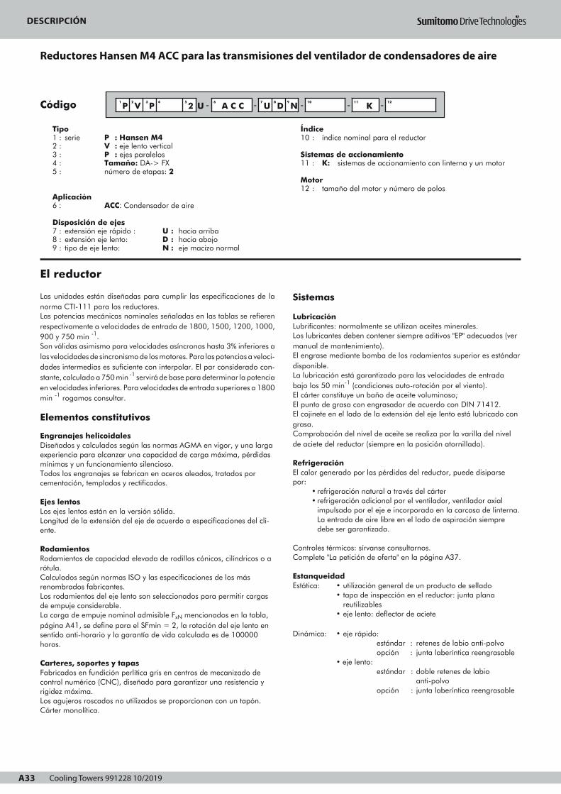
Cooling Towers 991228 10/2019A33
DESCRIPCIONREDUCTORES HANSEN M4 ACC PARA LAS TRANSMISIONES DEL
VENTILADOR DE CONDENSADORES DE AIRE
Código
Tipo1 : serie P : Hansen M42 : V : eje lento vertical3 : P : ejes paralelos4 : Tamaño: DA-> FX 5 : número de etapas: 2
Aplicación6 : ACC: Condensador de aire
Disposición de ejes 7 : extensión eje rápido : U : hacia arriba8 : extensión eje lento: D : hacia abajo9 : tipo de eje lento: N : eje macizo normal
Índice10 : índice nominal para el reductor
Sistemas de accionamiento 11 : K: sistemas de accionamiento con linterna y un motor
Motor 12 : tamaño del motor y número de polos
Las unidades están diseñadas para cumplir las especificaciones de lanorma CTI-111 para los reductores.Las potencias mecánicas nominales señaladas en las tablas se refierenrespectivamente a velocidades de entrada de 1800, 1500, 1200, 1000,900 y 750 min -1.Son válidas asimismo para velocidades asíncronas hasta 3% inferiores alas velocidades de sincronismo de los motores. Para las potencias a veloci-dades intermedias es suficiente con interpolar. El par considerado con-stante, calculado a 750 min -1 servirá de base para determinar la potenciaen velocidades inferiores. Para velocidades de entrada superiores a 1800min -1 rogamos consultar.
Elementos constitutivos
Engranajes helicoidalesDiseñados y calculados según las normas AGMA en vigor, y una largaexperiencia para alcanzar una capacidad de carga máxima, pérdidasmínimas y un funcionamiento silencioso.Todos los engranajes se fabrican en aceros aleados, tratados porcementación, templados y rectificados.
Ejes lentosLos ejes lentos están en la versión sólida.Longitud de la extensión del eje de acuerdo a especificaciones del cli-ente.
RodamientosRodamientos de capacidad elevada de rodillos cónicos, cilíndricos o arótula.Calculados según normas ISO y las especificaciones de los másrenombrados fabricantes.Los rodamientos del eje lento son seleccionados para permitir cargasde empuje considerable.La carga de empuje nominal admisible FxN mencionados en la tabla,página A41, se define para el SFmin = 2, la rotación del eje lento ensentido anti-horario y la garantía de vida calculada es de 100000horas.
Carteres, soportes y tapasFabricados en fundición perlítica gris en centros de mecanizado decontrol numérico (CNC), diseñado para garantizar una resistencia yrigidez máxima.Los agujeros roscados no utilizados se proporcionan con un tapón.Cárter monolítica.
Sistemas
LubricaciónLubrificantes: normalmente se utilizan aceites minerales.Los lubricantes deben contener siempre aditivos "EP" adecuados (vermanual de mantenimiento).El engrase mediante bomba de los rodamientos superior es estándardisponible.La lubricación está garantizado para las velocidades de entradabajo los 50 min-1 (condiciones auto-rotación por el viento).El cárter constituye un baño de aceite voluminoso;El punto de grasa con engrasador de acuerdo con DIN 71412. El cojinete en el lado de la extensión del eje lento está lubricado congrasa.Comprobación del nivel de aceite se realiza por la varilla del nivelde aciete del reductor (siempre en la posición atornillado).
Refrigeración El calor generado por las pérdidas del reductor, puede disiparsepor:
• refrigeración natural a través del cárter• refrigeración adicional por el ventilador, ventilador axial
impulsado por el eje e incorporado en la carcasa de linterna.La entrada de aire libre en el lado de aspiración siempredebe ser garantizada.
Controles térmicos: sírvanse consultarnos.Complete "La petición de oferta" en la página A37.
EstanqueidadEstática: • utilización general de un producto de sellado
• tapa de inspección en el reductor: junta planareutilizables
• eje lento: deflector de aciete
Dinámica: • eje rápido:estándar : retenes de labio anti-polvoopción : junta laberíntica reengrasable
• eje lento: estándar : doble retenes de labio
anti-polvoopción : junta laberíntica reengrasable
El reductor
1
P2
V 3
P4 5
2 U - 6 A C C - 7
U8
D9
N - 10 - 11 K - 12
A33
Page 1
DESCRIPCIÓN
Reductores Hansen M4 ACC para las transmisiones del ventilador de condensadores de aire

Cooling Towers 991228 10/2019 A34
DESCRIPCIONREDUCTORES HANSEN M4 ACC PARA LAS TRANSMISIONES DEL
VENTILADOR DE CONDENSADORES DE AIRE
Motores
Los reductores de ejes paralelos están impulsados por motores debrida IEC (tipo B5). Para obtener más información sobre los motores,consulte los catálogos de motor.Para los motores Nema, rogamos consultar.En el uso de motores de 2 velocidades, antes del cambio a la bajavelocidad, debe esperarse a que el accionamiento reduzca su veloci-dad por debajo de la nueva velocidad de régimen.
Dispositivos opcionales
Algunos dispositivos se puede proporcionar opcionalmente (consultelas páginas A39-A40). Más información detallada sobre los dispositi-vos opcionales se menciona por separado en manuales técnicos,rogamos consultar.
Antirretroceso Antirretroceso incorporado para evitar que el ventilador esté funcion-ando en la dirección opuesta. Lubricación por baño de aceite delreductor. El antirretroceso es accesible después de retirar el motor yla carcasa de linterna.
FiltroCon válvula de sobrepresión incorporada.Un filtro con válvula de sobrepresión incorporado e indicador decontaminación visual o eléctrica está disponible como una opción.
CalentadoresLos aparatos de calefacción eléctricos para el arranque en bajas temperaturas, están disponibles para los reductores Hansen M4 ACC.
Interruptor de nivel de aceitePara controlar el nivel de aceite en el reductor, un interruptor de nivelde aceite puede ser proporcionado. Este interruptor puede activaruna señal de alarma cuando el nivel de aceite cae por debajo de unlímite determinado.
Interruptor de presión o transmisor de presiónPara controlar la presión de aceite, un interruptor de presión o detransmisor de presión puede ser proporcionada. Se puede activaruna señal de alarma cuando la presión de aceite cae por debajo deun límite determinado.
Pt100Para controlar la temperatura del baño de aceite. El Pt100 puedeprovocar una señal de alarma cuando la temperatura del aceite essuperior a un límite determinado.
Condiciones de suministro
Inspección previa al envío• Prueba: todos los reductores se prueban en virtud de sin
carga• Control de conformidad
Protección• Extremos de ejes: cubiertos con capa de grasa y protegidos
con papel anti-humedad.
Lubricantes• Los reductores Hansen M4 ACC se suministran sin aceite.
• Los puntos con grasa salen engrasados de fábrica.
Para información relativa al aaaallllmmmmaaaacccceeeennnnaaaammmmiiiieeeennnnttttoooo,,,, mmmmaaaannnniiiippppuuuullllaaaacccciiiióóóónnnn,,,, iiiinnnnssssttttaaaallllaaaa----cccciiiióóóónnnn,,,, ppppuuuueeeessssttttaaaa eeeennnn mmmmaaaarrrrcccchhhhaaaa yyyy mmmmaaaannnntttteeeennnniiiimmmmiiiieeeennnnttttoooo ver manual de instruccionesque se suministra con cada reductor.
Protección
Los sistemas de protección estándar• Estándar, los reductores Hansen M4 ACC se proporcionan con
un sistema de pintura adecuado para la categoría de corrosión
atmosférica "C4 (L)", conforme a ISO 12944-2 (e ISO 12944-5).La opción del color no afecta a la calidad técnica del sistema depintura.Otros sistemas de pintura pueden ser ofrecidos para cumplir lacategoría de corrosividad atmosférica necesaria para su aplicación.
• Pernos y tuercas proporcionadas con una protección adecuada. S
A34
Page 1
DESCRIPCIÓN
ES

Cooling Towers 991228 10/2019A35
SELECCIONPotencia mecánica nominal
LAS TRANSMISIONES DEL VENTILADOR DE LOS CONDENSADORES DE AIRE
A35
consulte la página A37
consulte la página A32
para los índices de reducción < 9 rogamos consultar.
Procedimiento Información de referencia
Potencia mecánica nominal P
Índice de reducción
2
3
por
• • • • - - • • • - Índice de reducción
P V P 2U - ACC - U D N
1
DATOS DE LA SELECCION
Pm , Pa , nHSS , nLSS , iN
Carga axial
Fx
SELECCION DE PROGRAMA
Potencia absorbida Pa
PPotencia motor Pm
y
x SF =1,75
x SF = 2
≥
ver p. A41
PTamaño
S
E
L
E
C
C
I
O
N
COMP
R
OBA
C
ION
Tamaño
P
Potencia térmica: consulte las páginas A36, A42
Par de arranque TS
Comprobar si
≤TS 1,5 x T
Fx : ... kN
Preste atención a la dirección de Fx ! (Siempre hacia abajo)
Comprobar si
≤Fx FxNFxN
ver p. A41
T = P x 9,55
n
P: potencia mecánica nominal (kW), consulte la página A41
Par de mecánico nominal del reductor (kNm)
n: velocidad del eje (min-1)
1000000
100000
10000
1000
100
10
1
1,0 1,1 1,2 1,41,3 1,5
Tiem
po to
tal d
e ar
ranq
ue d
e la
con
cepc
ión
@ 1
500
min
-1 /
n1
(h)
(
t S @
150
0)
Consulte conla fábrica
No se permite
Se permite
A
Tiempo total de arranque tS
Para velocidades de entrada otros (n1), la siguiente ecuación se puedeaplicar:
tS @ n1 = 1500 n1
x tS @ 1500
Nota: asegúrese de que Ts, T y n se refieren al mismo eje;
Tiempo total de arranque de la concepción @ 1500 min-1 se refiereal total de tiempo de arranque durante la vida diseño del reductor,teniendo en cuenta:
- número de arranques- la duración de un único arranque- velocidad de entrada de igual a 1500 min-1
A = TS : par de arranque (kNm)T : par de mecánico nominal del reductor (kNm)
Page 1
SELECCIÓN
Potencia mecánica nominal las transmisiones del ventilador de los condensadores de aire

Cooling Towers 991228 10/2019 A36
SELECCIONPotencia térmica
LAS TRANSMISIONES DEL VENTILADOR DE LOS CONDENSADORES DE AIRE
Ptn del reductorsin refrigeración forzada
factor a por temperatura ambiente sin refrigeración forzada
Índice de
reducción
Temperatura ambiente en °C
15 a 25 25 a 35 35 a 45
6,3 11,2
12,5 18
≥ 20
Tamaño
1
1
0,81
0,85
1
DA FX
0,87
DA FX
0,68
0,71
0,55
0,66
0,75
DA DX
0,74
EA FX
OK
Comprobación potencia térmica
Pa ≤ Ptn • a • b • c ?
Posibilidad de ventilador
No se requiere refri-geración forzada
Ptf para un reductor con 1
ventilador
Pa ≤ Ptf • d • b ? Un ventilador
factor b por duración de servicio
h/año
3
h/día (máximo)
10 >16
1000
2000
≥ 4000
Tamaño
1,2
-
1,3
-
-
DA DX
-
EA FX
1,15
1,1
1,2
1,1
-
DA DX
-
EA FX
1,15
1,1
1
DA FX
factor d por temperatura ambiente con ventilación forzada
Número
de etapas
Temperatura ambiente en °C
15 a 25 25 a 35 35 a 45 45 a 55
con ventilaciónforzada 2 1 0,86 0,72 0,59
Información de referencia
OK
factor c por circulación de aire (sin ventilador)
Instalación
Interior, local pequeño
Flujo de aire
≥ 0,5 m/s 0,73 0,70
Interior área de trabajo normalExt., protegido cont. radi.Solar
Tamaño
≥ 1,4 m/s
≥ 3,0 m/s
1
1,33
DA DX
1
1,36
EA FX
Pt
Ptn, Ptf
paraver p.A42
Pt
• • • • - - • • • - Índice dereducción
P V P 2U - ACC - U D N
Tamaño
S
A36
El flujo de aire se seleccionarán de acuerdo con la estructura:
Estructura abierta: reductores instalados en una estructura de acero de
marco abierto permiten que el flujo de aire del condensador pase por la casa
del reductor.
Estructura cerrada: reductores instalados en un pedestal de hormigón o en
una estructura de acero cerrado.
Esta estructura evita que el aire del condensador pase por la casa del reductor.
Page 1
SELECCIÓN
Potencia térmica las transmisiones del ventilador de los condensadores de aire

Cooling Towers 991228 10/2019A37 A37
1. LOS PARÁMETROS DE CARGA
Potencia motor Pm = kW à min-1
Potencia absorbida Pa = kW
Par absorbido Ta = kNm
Funcionamiento en h/dia ≤3
Par punta superior a 200% Ta =
Número de arranques/paradas por 10 horas :
≤10 >10
%
.....
2. VELOCIDAD
Eje rápido (ER)
Velocidad(es) constante(s) n1(ER) = ........ o/y ........ min-1
Velocidad variable .......... ≤ n1(ER) ≤ ........... min-1
sentido de giro: CW= horario
Eje lento (EL)
Velocidad(es) constante(s) n2 (EL) = ........ ou/et ........ min-1
Velocidad variable ........ ≤ n2 (EL) ≤ .......... min-1
La tolerancia de velocidad EL ± ...... % ± ........... min-1
Sentido de giro: CCW = Anti-horario
3. LA CONFIGURACIÓN DE LOS EJES DEL REDUCTOR:
Ejes paralelos
4. EL CARGA AXIAL EN EL EJE LENTO sí no
Peso del ventilador y de acoplamiento
Carga axial aerodinámico, sentido alejándose del reductor:
5. PARÁMETROS DE INSTALACIÓN
Temperatura ambiente (°C) cerca del reductor:
Estructura (ver página A36) abierto
Velocidad del aire cerca del reductor:
=
= -
kN
kN
min: .....
max: .....
....... m/s
cerrado
Situación
A pleno sol
Ambiente: la categoría de corrosión atmosférica
(según la norma ISO 12944-2): ....
Instalación eléctrica
Alimentación principal
Alimentación auxiliar
AC
3 Ph
sí no
V Hz
....
....
....
....
Protección requerida: ........
Aislamiento: ........
6. RUIDO (reductor + motor)
Potencia de ruido max.:
Presión de ruido max.:
7. ESPECIFICACIONES OPCIONALES
dBA
dBA at ..... m
Opciones, para indicar en las páginas A39-A40
Montaje del motor marco IEC: ...........
(si no IEC, añadir el croquis de dimensiones)
Eje, pulgada (inch)
el extremo del eje extendido: indicar en el esquema de aplicación
Pintura (ver página A34)
(*) : Rango de durabilidad según la norma ISO 12944-1
L : bajo
M : medio
H : alto
Nota : el rango de durabilidad NNNNOOOO es una "garantía de tiempo".
La durabilidad es una consideración técnica que puede
ayudar al dueño de establecer un programa
de mantenimiento
(**) : Contiene una capa adicional en 2A, 2B y 2C para evitar
la formación de una capa calcárea.
Materiales no permitidos Aluminio (Al)
Cobre (Cu)
Otro .....
8. ANTIRRETROCESO NECESARIO sí no
9. ENTREGA Transporte por:
barco (navío)
tren (envío por ferrocarril)
camión
Para otros datos ver:
CCW
PETICION DE OFERTA
LAS TRANSMISIONES DEL VENTILADOR DE LOS CONDENSADORES DE AIRE
Ref : Fecha : Nombre : Firma :
Selección: marque la casillacorrespondiente
2• 3•
Sistema
La categoría de corrosión según ISO 12944-2
L (*)
C1
M H L
C2
M H L
C3
M
2A
2B
3A (**)
3B (**)
2C 3C (**)
Selección: marque la casillacorrespondiente
2• 3•
Sistema
2A 3A (**)
2B
2C
3B (**)
3C (**)
La categoría de corrosión según ISO 12944-2
C4
L (*) M H L
No se permite
C5-I
M H
C5-M
L M
Obligatoria (requisito mínimo)
A petición del cliente
H
H
Selección de la categoría de corrosión: marque la casilla correspondiente
C1 C2 C3 C4 C5-I C5-M
Page 1
PETICIÓN DE OFERTA
Las transmisiones del ventilador de los condensadores de aire

Cooling Towers 991228 10/2019 A38
PETICIÓN DE OFERTA
ES
VISTA EN PLANTA
VISTA LATERAL

Cooling Towers 991228 10/2019A39
t°
Gear unit
Vertical low speed shaft
Parallel shafts
Size
Gear sets
Réducteur à engrenages
Arbre P.V. vertical
Taille
Jeux d'engrenages
Zahnradgetriebe
Langsamdr. Welle: vertikal
Stirnräder
Baugröße
Stufenzahl
Reductor
Eje lento vertical
Ejes paralelos
Tamaño
N° de etapas
PVP
DA FX2U
Standard accessoriesAccessoires standard Standardzubehör Accesorios estándar
Optional accessoriesAccesoires en optionOptionales ZubehörAccesorios opcionales
Low speed shaft
Arbre petitevitesse
Langsamdre-hende Welle
Eje lento
High speedshaft
Arbre grandevitesse
SchnelldrehendeWelle
Eje rápido
Housing
Carter
Gehäuse
Cárter
42a
75
13
P
15
12a
25
11a
16 18
t°
19
24
21
10
11
12b
1
9
1a
12c
20
17
23
2214 22a
12
Accessories and Accessoires et Zubehör und Accesorios yoptions options Optionen opciones
For air cooled Pour commandes des Für Ventilatorantriebe Para las impulsionescondenser fan ventilateurs des in Luftkondensatoren del ventilador dedrives condensateurs à air los condensadores de aire
A39
Arbres parallèles
2
86
3
Page 1

Cooling Towers 991228 10/2019 A40
1
:::: ooooppppttttiiiioooonnnnaaaallll
normal solid output shaft
1a
2
extended solid output shaft
double oil seal or
1
:::: eeeennnn ooooppppttttiiiioooonnnn
arbre petite vitesse normal 1
1a
2
plein
arbre petite vitesse allongé 1a
plein
double bague d'étanchéité ou 2
2a
3
4
regreasable labyrinth
(DIN 71412)
drywell
thrust washer with bolt
5
6
regreasable labyrinth
(DIN 71412)
built-in backstop
2a
3
4
labyrinthe regraissable
(DIN 71412)
2a
buselure à rebord
rondelle de butée avec
3
4
5
6
boulon
labyrinthe regraissable 5
(DIN 71412)
antidévireur incorporé 6
7
8
9
axial fan
elastic block-type coupling
oil filling plug
10
11
11a
dipstick with magnet
draining plug
drain cock with hose
coupling
7
8
9
ventilateur axial
accouplement élastique
7
8
à tampons
bouchon de remplissage 9
10
11
11a
jauge d'huile avec aimant
bouchon de vidange
10
11
robinet de vidange avec
raccord pour tuyau
11a
12
12a
12b
breather plug or
anti-humidity breather plug or
dust-proof breather plug or
12c
13
special breather with anti-
humidity filter
gear unit inspection cover
12
12a
12b
reniflard ou
reniflard anti-humidité ou
12
12a
reniflard anti-poussière ou 12b
12c
13
reniflard spécial avec filtre 12c
anti-humidité
couvercle d'inspection du 13
14
15
grease point (DIN 71412)
pump lubrication
16
17
18
oil sight glass
mounting pin
heater
14
15
réducteur
point de graissage (DIN 71412) 14
lubrification par pompe 15
16
17
18
voyant d'huile 16
goujon de montage
réchauffeur
17
18
19
20
21
Pt100 for oil sump temperature
oil filter
pressure gauge
22
22a
23
24
pressure switch or
pressure transmitter
oil level switch
vibration switch for
19
20
21
Pt100 pour la température
du bain d'huile
19
filtre d'huile
indicateur de pression
20
21
22
22a
23
24
contacteur de pression ou
transmetteur de pression
22
22a
contacteur de niveau d'huile
interrupteur de vibrations pour
23
24
25
condenser fan
SPM nipple 25
le ventilateur du condensateur
nipple SPM 25
:::: OOOOppppttttiiiioooonnnn
Normale Abtriebswelle: 1
Vollwelle
verlängerte Abtriebswelle:
Vollwelle
doppelte Wellendichtung oder
1a
2
: OOOOppppcccciiiióóóónnnn
eje lento: eje macizo normal
eje lento extendido:
eje macizo
doble retén o
nachschmierbares
Labyrinth (DIN 71412)
Steigrohr
Scheibe mit Schraube
2a
3
4
nachschmierbares
Labyrinth (DIN 71412)
eingebaute Rücklaufsperre
5
6
junta laberíntica reengra-
sable (DIN 71412)
deflector de aciete
arandela de toque con perno
junta laberíntica reengra-
sable (DIN 71412)
antirretrocesso incorporado
Axiallüfter
Elastische Klauenkupplung
Öleinfullschraube
7
8
9
Ölmeßstab mit Magnet
Ablaßschraube
Ölablaßhahn mit
Rohranschluß
10
11
11a
ventilador axial
acoplamiento elástico
a tampones
tapón de llenado
varilla del nivel con imán
tapón de drenaje
llave de vaciado con racor
Entlüftungsschraube oder
Entlüftungsschraube für
feuchte Umgebung oder
Entlüftungsschraube mit Staub-
12
12a
12b
filter oder
Entlüftungsschraube mit
Feuchtigkeitsfilter
Getriebe-Schaulochdeckel
12c
13
tapón de aireación o
tapón de aireación anti-
humedad o
tapón de aireación anti-
polvo o
tapón de aireación con fil-
tro anti-humedad
tapa de inspección del
Fettschmierpunkt (DIN 71412)
Pumpenschmierung
14
15
Ölschauglas
Montagestift
Heizstab
16
17
18
reductor
punto de la lubricación
(DIN 71412)
lubricación par bomba
mirilla para el control del
nivel de aceite
pasador de montaje
calentador
Pt100 für Ölbadtemperatur
Ölfilter
Druckmeßgerät
19
20
21
Druckschalter oder
Drucksensor
Ölstandschalter
Schwingungsschalter für
22
22a
23
24
Pt100 para temperatura del
baño de aceite
filtro de aceite
indicador de presión
interruptor de presión o
transmisor de presión
interruptor nivel de aceite
interruptor de vibración para
Ventilator in Luftkondensator
SPM Nippel 25
el ventilador del condensador
entre rosca de SPM
Gear unit
Vertical low speed shaft
Parallel shafts
Size
Gear sets
Réducteur à engrenages
Arbre P.V. vertical
Taille
Jeux d'engrenages
Zahnradgetriebe
Langsamdr. Welle: vertikal
Stirnräder
Baugröße
Stufenzahl
Reductor
Eje lento vertical
Ejes paralelos
Tamaño
N° de etapas
PVP
DA FX2U
Accessories and Accessoires et Zubehör und Accesorios yoptions options Optionen opciones
For air cooled Pour commandes des Für Ventilatorantriebe Para las impulsionescondenser fan ventilateurs des in Luftkondensatoren del ventilador dedrives condensateurs à air los condensadores de aire
Arbres parallèles
A40
Page 1

Cooling Towers 991228 10/2019A41
Gear unit
Vertical low speed shaft
Parallel shafts
Size
Two stages
Réducteur à engrenages
Arbre P.V. vertical
Arbres parallèles
Taille
Deux étages
Zahnradgetriebe
Langsamdr. Welle: vertikal
Stirnräder
Baugröße
Zweistufig
Reductor
Eje lento vertical
Ejes paralelos
Tamaño
Dos etapas
FxN
A41
Mechanical Puissances méca- Nennleistungen Potencias mecá-power ratings niques nominales nicas nominales
Rated thrust load Charge axiale Nennaxial- Carga axialnominale belastung nominal
P (kW) FxN (kN) iex J (kgm2)
iN min-1
n1 n2
Size - Taille - Baugröße - TamañoDA DX EA EX FA FX
Size - Taille - Baugröße - TamañoDA DX EA EX FA FX
Size - Taille - Baugröße - TamañoDA DX EA EX FA FX
18001500
200165
12001000
135110
510430
600530
340285
440370
700630
880770
500420
650540
1100950
13001150
780650
980820
2324,5
21,522,5
26,527,5
2425
3637
3234
4041
3739
6060
6060
6060
6060
8,7468 8,5447 8,9662 8,621 8,7546 8,2989
900750
10083
18001500
180150
12001000
120100
900750
9075
260215
330275
460380
520450
380320
490410
670560
760670
300255
380310
230190
285235
450370
570480
340280
430360
590490
740620
920810
11501050
27,529
25,527
2425,5
23,524,5
670560
860750
510420
680570
2727,5
24,526,5
28,530
26,528
4243
3941
3638
3537
6060
6060
6060
6060
4042
3839
4345
4042
6060
6060
6060
6060
0,0654 0,1018
9,916 9,9755
0,1267 0,2012
10,0741 9,8311
0,0559 0,0824 0,1082 0,1661
0,2615 0,4144
10,1693 9,5812
0,2136 0,3401
18001500
160135
12001000
10589
900750
8067
18001500
145120
410340
510440
270230
350290
610510
700630
410340
510430
205170
260220
360300
460390
300255
380320
540450
680560
12001000
9680
900750
7260
18001500
130105
12001000
8671
240200
310255
180150
230195
360300
450380
270225
340285
320265
410350
210175
275230
470390
610510
310260
410340
910770
1100950
620520
790670
2526
2323,5
27,528,5
2526,5
470390
610510
790680
920810
2930
27,528
25,527
23,524,5
3839
3637
4143
3940
6060
6060
6060
6060
4445
4243
3940
3638
6060
6060
6060
6060
540450
680580
410340
520440
28,529,5
2627,5
3030
2829
750630
910780
510420
640540
2627,5
24,525
2930
2728
4244
4041
4545
4344
6060
6060
6060
6060
4042
3839
4445
4143
6060
6060
6060
6060
11,0695 10,7877 11,1515 11,0676
0,0486 0,0733
12,5294 12,2297
0,0957 0,1417
12,6222 12,4352
11,0222 10,7315
0,1929 0,2873
12,6296 12,4656
0,042 0,0621 0,0837 0,1201
14,3137 13,6524 14,4198 13,7652
0,1656 0,2328
13,5965 13,5111
900750
6454
18001500
11594
12001000
7563
900750
5647
160135
205175
295245
370300
235195
310260
430360
540450
195165
245205
150125
185150
290240
360300
215180
275230
18001500
10083
12001000
6756
900750
5042
18001500
9075
255215
320265
170145
215180
370310
480400
250210
320265
130110
160135
225185
300250
190155
240200
340285
440370
380320
490410
660550
790680
3030
2929,5
2728
24,526,5
440370
560470
330280
420360
29,530
27,528,5
3030
29,530
4545
4345
4142
3940
6060
6060
6060
6060
4445
4244
4545
4445
6060
6060
6060
6060
550460
750650
370310
520440
2829
2627
3030
28,529,5
285235
400330
510430
660550
3030
3030
3030
2627,5
4344
3941
4545
4345
6060
6060
6060
6060
4545
4545
4545
4041
6060
6060
6060
6060
12001000
6050
900750
4538
18001500
8067
12001000
5445
150125
200165
11594
150125
230190
295245
170145
220185
185155
255215
125105
170145
285235
370310
190160
250210
900750
4033
18001500
7260
12001000
4840
900750
3630
9479
130110230190
145120
190160360295
155130115
96
240200180150
340285
450370
260215
340280
3030
2930
3030
3030
400340
550460
270225
370310
3030
2829
3030
3030
4545
4445
4545
4545
6060
6060
6060
6060
4545
4244
4545
4545
6060
6060
6060
6060
205170
285235530440
3030
30303030
360300270225
30303030
4545
45454445
6060
60606060
45454545
60606060
0,0364 0,0535
15,3633 15,4529
0,0715 0,1054
15,6863 15,5806
0,0334 0,0458 0,0647 0,0913
0,1518 0,2092
15,6013 15,4815
0,1285 0,1781
17,451 17,6536 18,0148 17,7994
0,0289 0,0394
20,0686 18,9481
0,0551 0,0773
19,6706 19,3627
17,0069 16,6667
0,1153 0,1625
20,0586 19,1242
0,028 0,0359 0,054 0,0696
22,6863 21,5229 22,6311 22,237
0,1108 0,1366
21,725 20,8472
0,0274 0,0309
24,4314
0,0526 0,0588
24,1412
0,0297 0,0573
0,109 0,1222
24,3789
0,1164
9
10
11,2
12,5
14
16
18
20
22,4
25
P (kW)
FxN (kN)
PVP
DA FX2U
iN Nominal ratio iN Rapport nominal iN Nennübersetzung iN Índice nominaln1, 2iex
Nominal speed (rpm)Exact ratio
n1, 2iex
Vitesse nominaleRapport exact
n1, 2iex
NenndrehzahlExakte Ubersetzung
n1, 2iex
Velocidades nominales (r.p.m.)Indice exactos
J Moments of inertia Jrelated to the HSS
J Moments d'inertie Jrapportés à l'arbre G.V.
J MassenträgheitsmomenteJ beziehen sich auf die SDW
J Momentos de inercia Jrelativos al eje rápido
Page 1

Cooling Towers 991228 10/2019 A42
Gear unit
Vertical low speed shaft
Parallel shafts
Size
Two stages
Réducteur à engrenages
Arbre P.V. vertical
Arbres parallèles
Taille
Deux étages
Zahnradgetriebe
Langsamdr. Welle: vertikal
Stirnräder
Baugröße
Zweistufig
Reductor
Eje lento vertical
Ejes paralelos
Tamaño
Dos etapas
PVP
DA FX2U
Thermal Puissances ther- Wärmegrenz- Potencias térmi-power ratings miques nominales leistungen cas nominales Pt (kW)
Number of fans. Nombre de ventilateurs. Lüfterzahl. Número de ventiladores.Correction factors - see p. A6
Facteurs de correction -voir p. A16
Korrekturfaktoren -Siehe S. A26
Factores de correcciónver pag. A36
For Pt-values of gear unitswith fan: refer to us.
Pour les valeurs Pt desreducteurs avec ventilateur: veuillez nous
Für Pt-Werte der Getriebemit Ventilator: Rückfragezu empfehlen.
Para los valores Pt delreductores con ventilador:sírvanse consultanos.
iN Nominal ratio iN
consulter.
Rapport nominal iN Nennübersetzung iN Índice nominaln1, 2 Nominal speed (rpm) n1, 2 Vitesse nominale n1, 2 Nenndrehzahl n1, 2 Velocidades nominales (r.p.m.)
iNmin-1
n1
1800 -
Size - Taille - Baugröße - TamañoDA185
DX200
EA225
EX245
FA255
FX285
1500
1-
1200
1-
185 200
175 190
225 245
220 240
260 300
265 310
1000
1-
900
1-
750
1-
1800
1-
170 185
170 180
215 235
210 230
160 175
155 175
205 220
190 220
260 300
255 295
245 290
225 255
1500
1-
1200
1-
1000
1-
900
1-
155 175
150 165
185 220
180 210
145 165
140 160
180 205
175 200
750
1-
1800
1-
1500
1-
1200
1-
130 150
145 150
165 195
155 175
140 150
135 145
155 170
150 170
225 260
220 255
215 250
210 245
205 235
185 205
185 205
185 205
1000
1-
900
1-
750
1-1
130 140
125 135
145 160
140 160
120 130 135 150
180 200
180 195
170 190
9
11,2
12,5
16
18
25
A42
Page 1
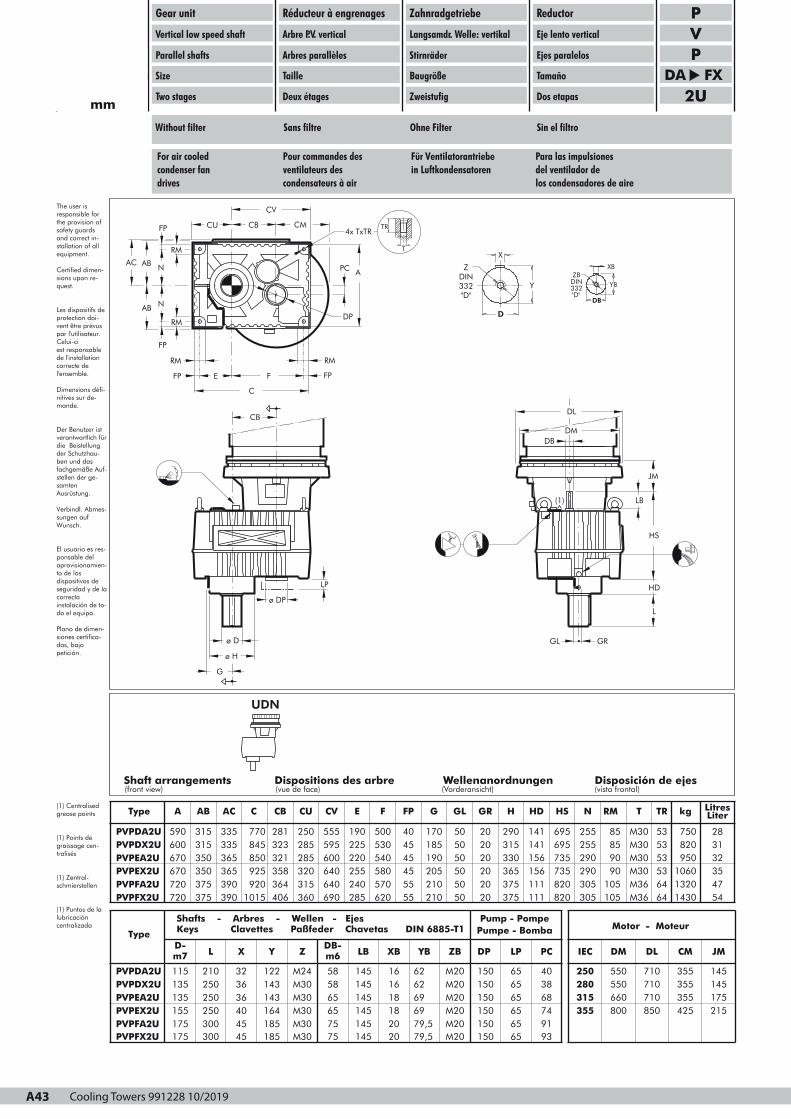
Cooling Towers 991228 10/2019A43
UDN
Shaft arrangements Dispositions des arbre Wellenanordnungen Disposición de ejes(front view) (vue de face) (Vorderansicht) (vista frontal)
(1) LB
JM
HS
HD
L
GRGL
DB
DM
DL
RM
FP E F FP
RM
C
PC
DP
A
CU CB CM
CV
RM
RM
FP
N
N
FP
AB
AB
AC
4x TxTR
T
TR
X
Y
D
Z
DIN
332
"D"
ZB DIN 332
"D"DB
YB
XB
ø DP
CB
ø D
ø H
G
LP
97PU0-VP2N4001N3C
Gear unit
Vertical low speed shaft
Parallel shafts
Size
Two stages
Réducteur à engrenages
Arbre P.V. vertical
Arbres parallèles
Taille
Deux étages
Zahnradgetriebe
Langsamdr. Welle: vertikal
Stirnräder
Baugröße
Zweistufig
Reductor
Eje lento vertical
Ejes paralelos
Tamaño
Dos etapas
PVP
DA FX2Umm
The user isresponsible forthe provision ofsafety guardsand correct in-stallation of allequipment.
Certified dimen-sions upon re-quest.
Les dispositifs deprotection doi-vent être prévuspar l'utilisateur.Celui-ci est responsablede l'installationcorrecte del'ensemble.
Dimensions défi-nitives sur de-mande.
Der Benutzer istverantwortlich fürdie Beistellungder Schutzhau-ben und dasfachgemäße Auf-stellen der ge-samtenAusrüstung.
Verbindl. Abmes-sungen aufWunsch.
El usuario es res-ponsable delaprovisionamien-to de los dispositivos deseguridad y de lacorrectainstalación de to-do el equipo.
Plano de dimen-siones certifica-das, bajopetición.
(1) Centralisedgrease points
(1) Points degraissage cen-tralisés
(1) Zentral-schmierstellen
(1) Puntos de lalubricacióncentralizada
Without filter Sans filtre Ohne Filter Sin el filtro
For air cooled Pour commandes des Für Ventilatorantriebe Para las impulsionescondenser fan ventilateurs des in Luftkondensatoren del ventilador dedrives condensateurs à air los condensadores de aire
Type A AB AC C CB CU CV E F FP G GL GR H HD HS N RM T TR kg LitresLiter
PVPDA2UPVPDX2U
590600
315315
335335
770845
281323
250285
555595
190225
500530
4045
170185
5050
2020
290315
141141
695695
255255
8585
M30M30
5353
750820
2831
PVPEA2UPVPEX2UPVPFA2UPVPFX2U
670670
350350
720720
375375
365365
850925
390390
9201015
321358
285320
364406
315360
600640
220255
640690
240285
540580
4545
570620
5555
190205
5050
210210
5050
2020
330365
2020
375375
156156
735735
111111
820820
290290
9090
305305
105105
M30M30
5353
M36M36
6464
9501060
3235
13201430
4754
Type
Shafts - Arbres - Wellen - Ejes Keys Clavettes Paßfeder Chavetas DIN 6885-T1
PVPDA2U
D-m7
115
L
210
X
32
Y
122
Z
M24
DB-m6
58
LB
145
XB
16
YB
62
ZB
M20
Pump - PompePumpe - Bomba
DP
150
LP
65
PC
40
Motor - Moteur
IEC
250
DM
550
DL
710
CM
355
JM
145PVPDX2UPVPEA2UPVPEX2UPVPFA2U
135135
250250
155175
250300
3636
143143
4045
164185
M30M30
5865
M30M30
6575
145145
1618
145145
1820
6269
M20M20
6979,5
M20M20
150150
6565
150150
6565
38687491
280315
550660
355 800
710710
355355
850 425
145175215
PVPFX2U 175 300 45 185 M30 75 145 20 79,5 M20 150 65 93
A43
Page 1

Cooling Towers 991228 10/2019 A44
UDN
Shaft arrangements Dispositions des arbre Wellenanordnungen Disposición de ejes(front view) (vue de face) (Vorderansicht) (vista frontal)
RM
FP E F FP
RM
C
F1
F2
PC
DP
A
BF
CU CB CM
CV
RM
RM
FP
N
N
FP
AB
AB
AC
4x TxTR
T
TR
F4
F3
(1) LB
JM
HS
HD
L
GRGL
DB
DM
DL
X
Y
D
Z
DIN
332
"D"
ZB DIN 332
"D"DB
YB
XB
øDP
CB
ø D
ø H
G
LP
97PU0-VP2N4011N3C
Gear unit
Vertical low speed shaft
Parallel shafts
Size
Two stages
Réducteur à engrenages
Arbre P.V. vertical
Arbres parallèles
Taille
Deux étages
Zahnradgetriebe
Langsamdr. Welle: vertikal
Stirnräder
Baugröße
Zweistufig
Reductor
Eje lento vertical
Ejes paralelos
Tamaño
Dos etapas
PVP
DA FX2Umm
The user is responsible forthe provision ofsafety guardsand correct in-stallation of allequipment.
Certified dimen-sions upon re-quest.
Les dispositifs deprotection doi-vent être prévuspar l'utilisateur.Celui-ci est responsablede l'installationcorrecte del'ensemble.
Dimensions défi-nitives sur de-mande.
Der Benutzer istverantwortlich fürdie Beistellungder Schutzhau-ben und dasfachgemäße Auf-stellen der ge-samtenAusrüstung.
Verbindl. Abmes-sungen aufWunsch.
El usuario es res-ponsable delaprovisionamien-to de los dispositivos deseguridad y de lacorrectainstalación de to-do el equipo.
Plano de dimen-siones certifica-das, bajopetición.
(1) Centralisedgrease points
(1) Points degraissage cen-tralisés
(1) Zentral-schmierstellen
(1) Puntos de lalubricacióncentralizada
With filter Avec filtre Mit Filter Con el filtro
For air cooled Pour commandes des Für Ventilatorantriebe Para las impulsionescondenser fan ventilateurs des in Luftkondensatoren del ventilador dedrives condensateurs à air los condensadores de aire
Type A AB AC BF C CB CU CV E F FP F1 F2 F3 F4 G GL GR H HD HS N RM T TR kgLitresLiter
PVPDA2UPVPDX2U
590600
315315
335335
415415
770845
281323
250285
555595
190225
500530
4045
8080
231273
364364
340340
170185
5050
2020
290315
141141
695695
255255
8585
M30M30
5353
750820
2831
PVPEA2UPVPEX2UPVPFA2UPVPFX2U
670670
350350
720720
375375
365365
435440
390390
465465
850925
321358
9201015
364406
285320
600640
315360
640690
220255
540580
240285
570620
4545
8080
5555
8080
271309
404404
314357
489489
340340
190205
340340
210210
5050
2020
5050
2020
330365
156156
375375
111111
735735
290290
820820
305305
9090
M30M30
105105
M36M36
5353
9501060
6464
13201430
32354754
Type
Shafts - Arbres - Wellen - Ejes Keys Clavettes Paßfeder Chavetas DIN 6885-T1
PVPDA2U
D-m7115
L
210
X
32
Y
122
Z
M24
DB-m658
LB
145
XB
16
YB
62
ZB
M20
Pump - PompePumpe - Bomba
DP
150
LP
65
PC
40
Motor - Moteur
IEC
222255550000
DM
550
DL
710
CM
355
JM
145PVPDX2UPVPEA2UPVPEX2UPVPFA2U
135135
250250
155175
250300
3636
143143
4045
164185
M30M30
5865
M30M30
6575
145145
1618
145145
1820
6269
M20M20
6979,5
M20M20
150150
6565
150150
6565
38687491
222288880000333311115555
550660
333355555555 800
710710
355355
850 425
145175215
PVPFX2U 175 300 45 185 M30 75 145 20 79,5 M20 150 65 93
A44
Page 1
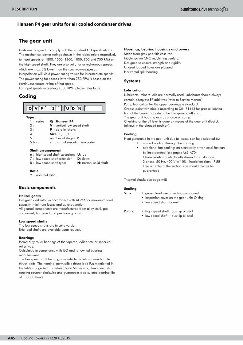
Cooling Towers 991228 10/2019A45
DESCRIPTIONHANSEN P4 GEAR UNITS
FOR AIR COOLED CONDENSER DRIVES
A45
The gear unit
Units are designed to comply with the standard CTI specifications.The mechanical power ratings shown in the tables relate respectively
to input speeds of 1800, 1500, 1200, 1000, 900 and 750 RPM at
the high speed shaft. They are also valid for asynchronous speeds
which are max. 3% lower than the synchronous speeds.Interpolation will yield power rating values for intermediate speeds.
The power rating for speeds lower than 750 RPM is based on the
continuous torque rating of that speed.For input speeds exceeding 1800 RPM, please refer to us.
Coding
Type1 : series Q : Hansen P42 : V : vertical low speed shaft3 : P : parallel shafts4 : Size: C, ..., F5 : number of stages: 25 bis : / : normal execution (no code)
Shaft arrangement6 : high speed shaft extension: U: up7 : low speed shaft extension: D: down8 : low speed shaft type: N: normal solid shaft
Ratio9 : nominal ratio
Basic components
Helical gearsDesigned and rated in accordance with AGMA for maximum loadcapacity, minimum losses and quiet operation.All geared components are manufactured from alloy steel, gascarburized, hardened and precision ground.
Low speed shaftsThe low speed shafts are in solid version.Extended shafts are available upon request.
BearingsHeavy duty roller bearings of the tapered, cylindrical or sphericalroller type.Calculated in compliance with ISO and renowned bearingmanufacturers.The low speed shaft bearings are selected to allow considerablethrust loads. The nominal permissible thrust load FxN mentioned inthe tables, page A71, is defined for a SFmin = 2, low speed shaftrotating counter-clockwise and guarantees a calculated bearing lifeof 100000 hours.
1
Q2
V3
P4 5
25 bis
-6
U7
D8
N -9
Housings, bearing housings and coversMade from grey pearlitic cast iron.Machined on CNC machining centers.Designed to ensure strength and rigidity.Unused tapped holes are plugged.Horizontal split housing.
Systems
LubricationLubricants: mineral oils are normally used. Lubricants should always
contain adequate EP-additives (refer to Service Manual).Pump lubrication for the upper bearings is standard.Grease point with nipple according to DIN 71412 for grease lubrica-tion of the bearing at side of the low speed shaft end.The gear unit housing acts as a large oil sump.Checking of the oil level is done by means of the gear unit dipstick (always in the plugged position).
Cooling Heat generated in the gear unit due to losses, can be dissipated by:
• natural cooling through the housing• additional fan cooling: an electrically driven axial fan can
be incorporated (see pages A69-A70)Characteristics of electrically driven fans: standard3 phase, 50 Hz, 400 V ± 10%, insulation class: IP 55Free air entry at the suction side should always be guaranteed
Thermal checks see page A48
SealingStatic: • generalized use of sealing compound
• inspection cover on the gear unit: O-ring• low speed shaft: drywell
Rotary: • high speed shaft: dust lip oil seal
• low speed shaft: dust lip oil seal
Page 1
DESCRIPTION
Hansen P4 gear units for air cooled condenser drives

Cooling Towers 991228 10/2019 A46
DESCRIPTIONHANSEN P4 GEAR UNITS
FOR AIR COOLED CONDENSER DRIVES
Motors
Parallel shaft gear units are to be fitted with standard flangemounted IEC motors (type B5). For more information on motors, refer to motor catalogues.For Nema motors, refer to us.Use of two speed motors: when changing speed with two speed mo-tors, the motor has to be slowed down below the low speed, beforeenergising the slow speed winding.
Optional devices
Some devices can optionally be provided (refer to pages A69-A70). More detailed information about the optional devices is mentionedin separate technical manuals. Refer to us.
Backstop Built-in backstop to prevent the fan from "wind-milling". Internallubrication is assured.
FilterWith incorporated pressure relief valve.A filter with incorporated pressure relief valve and visual or electricalcontamination indicator is available as an option.
HeatersElectrical heating devices for low temperature start-up are available.
Flow switchWhen gear units are pump lubricated, a flow switch can be providedto check the oil flow to the gear unit. This switch can trigger analarm signal when the oil supply is inadequate. The gear unit has tobe stopped at once and the cause of the interruption of the oil sup-ply has to be removed.
Oil level switchTo control the oil level in the gear unit, an oil level switch can beprovided. This switch can trigger an alarm signal when the oil bathfalls beneath a specified limit.
Pt100To control the oil bath temperature. The Pt100 can trigger an alarmsignal when the oil temperature is higher than a specified limit.
Shipping conditions
Inspection prior to shipment• Test run: all gear units are tested under no load• Conformity Check
Protection• Shaft extension: greased and protected with waxed
waterproof paper
Lubricants• Hansen P4 gear units are shipped without oil.• Grease lubrication points are factory filled.
For information relating to storage, handling, installation,start-up and maintenance, refer to the service manual which issupplied together with each gear unit.
Protection
Standard protection systems• As a standard, Hansen P4 gear units are provided with a paint-ing system that is suitable to be applied in the atmospheric-corrosiv-ity category “C1” according to ISO 12944-2 (and ISO 12944-5).The choice of colour has no influence on the technical quality of thepainting system.Other painting systems can be offered to meet the required atmos-pheric-corrosivity category for your application.
• Bolts and nuts provided with appropriate protection.
Aggressive environmentFor air cooled condenser drives in aggressive environment, an additional protection system can be offered: refer to us.
E
A46
Page 1
DESCRIPTION
EN
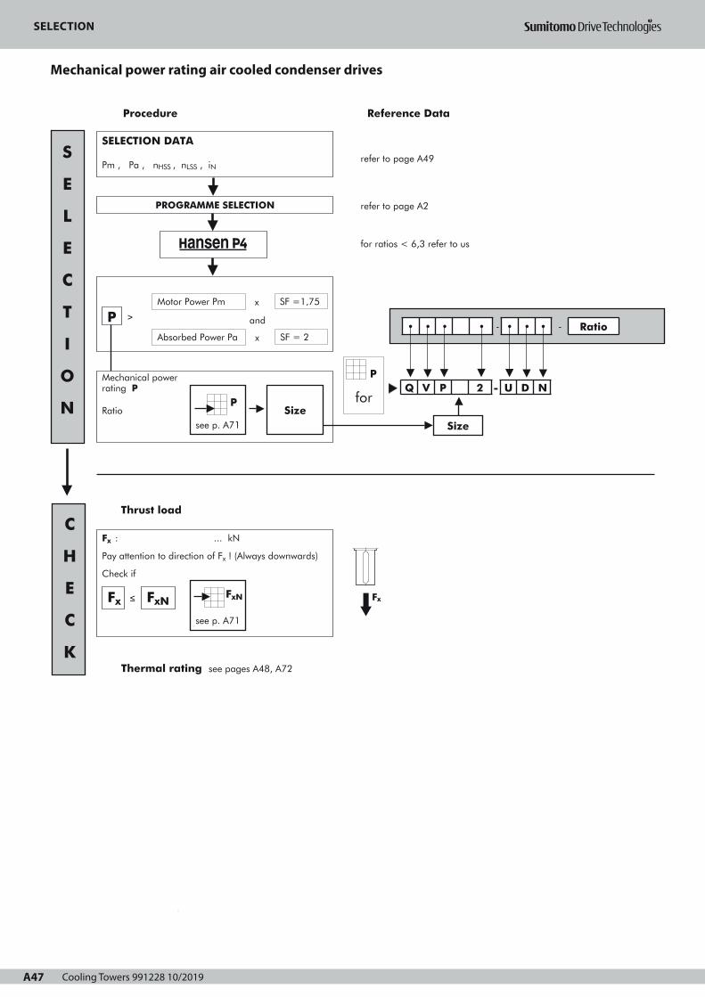
Cooling Towers 991228 10/2019A47
SELECTIONMechanical power rating
AIR COOLED CONDENSER DRIVES
A47
refer to page A49
refer to page A2
for ratios < 6,3 refer to us
Procedure Reference Data
Mechanical powerrating P
Ratio
2
3
for
• • • • - • • • - Ratio
Q V P 2 - U D N
1
SELECTION DATA
Pm , Pa , nHSS , nLSS , iN
Thrust load
Fx
PROGRAMME SELECTION
Absorbed Power Pa
PMotor Power Pm
and
x SF =1,75
x SF = 2
≥
see p. A71
PSize
S
E
L
E
C
T
I
O
N
C
H
E
C
K
Size
P
Thermal rating see pages A48, A72
Fx : ... kN
Pay attention to direction of Fx ! (Always downwards)
Check if
≤Fx FxNFxN
see p. A71
Page 1
SELECTION
Mechanical power rating air cooled condenser drives

Cooling Towers 991228 10/2019 A48
SELECTIONThermal power rating
AIR COOLED CONDENSER DRIVES
Ptn for gear unit without forced cooling
factor a for ambient temperature without forced cooling
Reduction
Ratio
Ambient temperature in °C
15 to 25 25 to 35 35 to 45
6,3 11,2
12,5 18
≥ 20
Size
1
1
0,81
0,85
1
C F
0,87
C F
0,68
0,71
0,55
0,66
0,75
C D
0,74
E F
OK
Thermal check
Pa ≤ Ptn • a • b • c ?
Cooling fan possible
No forced cooling required
Ptf for gear unit with 1 fan
Pa ≤ Ptf • d • b ? One fan
factor b for duration of service
h/year
3
h/day (max)
10 >16
1000
2000
≥ 4000
Size
1,2
-
1,3
-
-
C F
-
C F
1,15
1,1
1,2
1,1
-
C D
-
E F
1,15
1,1
1
C F
factor d for ambient temperature with forced cooling
Number of
stages
Ambient temperature in °C
15 to 25 25 to 35 35 to 45 45 to 55
with forcedcooling 2 1 0,86 0,72 0,59
Reference Data
OK
factor c for air circulation (without fan)
Mounting
Indoors- small enclosure
Air flow
≥ 0,5 m/s 0,73 0,70
Indoors- normal working areas
Outdoors- protected against sun
Size
≥ 1,4 m/s
≥ 3,0 m/s
1
1,33
C D
1
1,36
E F
Pt
Ptn, Ptf
forsee p.A72
Pt
• • • • - • • • - Ratio
Q V P 2 - U D N
Size
E
A48
Air flow to be selected according to the structure:
Open structure: gear units installed in an open steel frame structure
allowing the cooling tower air flow to pass over the gear unit's housing.
Closed structure: gear units installed on a solid concrete plinth or enclosed
steel frame. This structure prevents the cooling tower air flow from passing
over the gear unit's housing.
Page 1
SELECTION
EN
Thermal power rating air cooled condenser drives

Cooling Towers 991228 10/2019A49
REQUEST FOR QUOTATION
AIR COOLED CONDENSER DRIVES
A49
1. LOAD PARAMETERS
Motor power Pm = kW at min-1
Absorbed power Pa = kW
Absorbed torque Ta = kNm
Running time in h/day ≤3
Peak torque in excess of 200% Ta =
Number of starts/stops per 10 hours :
≤10
.....
>10
%
2. SPEED
High speed shaft (HSS)
Constant speed(s) n1(HSS) = ........ or/and ........ min-1
Variable speed .......... ≤ n1(HSS) ≤ ........... min-1
Direction of rotation: CW
Low speed shaft (LSS)
Constant speed(s) n2(LSS) = ........ or/and ........ min-1
Variable speed .......... ≤ n2(LSS) ≤ ........... min-1
Tolerance on speed LSS ± ...... % ± ........... min-1
Direction of rotation: CCW
3. SHAFT CONFIGURATION :
Parallel shafts
4. THRUST LOAD ON LOW SPEED SHAFT Y N
Weight of fan and coupling
Aerodynamic thrust load away from gear unit
5. INSTALLATION PARAMETERS
=
=
Ambient temperature (°C) near the gear unit :
Structure (see page A48) open
Air speed near the gear unit :
-kN
kN
min: .....
max: .....
....... m/s
closed
Location
Direct sun exposure
Atmosphere: corrosion category (according to ISO 12944-2): ....
Electric installation AC
Main power supply
Auxiliary power supply
Protection requirement: ........
3 Ph
Y N
V Hz
.... ....
.... ....
Insulation: ........
6. NOISE (gear unit + motor)
Max. noise power: dBA
Max. noise pressure:
7. OPTIONAL SPECIFICATIONS
Options to be indicated on pages A69-A70
dBA at ..... m
Motor mount IEC frame: ........
(if not IEC, add dimensional drawing)
Shafts inch
extended shaft end: indicate on sketch of application
Ref : Date : Name : Signature :
Painting (see page A46)
(*) : Durability range according to ISO 12944-1
L : low
M : medium
H : high
Note : the durability range is NOT a "guarantee time".
Durability is a technical consideration that can help
the owner set up a maintenance programme.
(**) : Contains additional layer on 2A, 2B and 2C to avoid chalking.
Not allowable materials Al
Cu
Other
8. BACKSTOP REQUIRED Y
.....
N
9. SHIPMENT Transport by
vessel
train
truck
Other data available in :
Selection:tick where
appropriate
2• 3•
System
Corrosion category according to ISO 12944-2
L (*)
C1
M H L
C2
M H L
C3
M
2A
2B
3A (**)
3B (**)
2C 3C (**)
Selection:tick where
appropriate
2• 3•
System
2A 3A (**)
2B
2C
3B (**)
3C (**)
Corrosion category according to ISO 12944-2
C4
L (*) M H L
Not allowed
C5-I
M H
C5-M
L M
Mandatory (minimum requirement)
Upon customer request
H
H
Selection of corrosion category: tick where appropriate
C1 C2 C3 C4 C5-I C5-M
CCW
Page 1
REQUEST FOR QUOTATION
Air cooled condenser drives
Cooling Towers 991228 10/2019 A50
REQUEST FOR QUOTATION
EN
TOP VIEW
SIDE VIEW
Sketch of application

Cooling Towers 991228 10/2019A51
DESCRIPTIONRÉDUCTEURS HANSEN P4 POUR COMMANDE
DES VENTILATEURS DES CONDENSATEURS A AIR
A51
Le réducteur
Les réducteurs sont conçus conformes aux spécifications standard CTI-111.Les puissances mécaniques nominales mentionnées dans les tableaux serapportent respectivement à des vitesses d'entrée de 1800, 1500, 1200,
1000, 900 et 750 min-1 de l'arbre grande vitesse.Elles sont également valables pour des vitesses asynchrones jusqu'à 3 %inférieures aux vitesses de synchronisme des moteurs. Pour la puissance àdes vitesses intermédiaires il suffit d'interpoler.
Le couple considéré constant, calculé à 750 min-1, servira de base à ladétermination de la puissance pour les vitesses inférieures. Pour des
vitesses d'entrée supérieures à 1800 min-1, veuillez nous consulter.
Codification
Type1 : série Q : Hansen P42 : V : arbre petite vitesse vertical3 : P : arbres parallèles4 : Taille: C, ..., F5 : nombre de trains d'engrenages: 25 bis : / : exécution normale (pas de code)
Disposition des arbres6 : bout d'arbre grande vitesse : U: vers le haut7 : bout d'arbre petite vitesse: D: vers le bas8 : type d'arbre petite vitesse: N: arbre plein normal
Rapport de réduction9 : rapport de réduction nominal du réducteur
Composants de base
Engrenages hélicoïdauxConçus et calculés conformes aux normes AGMA en vigueur pour obtenir une capacité de charge maximum, des pertes minimales et un fonctionnement silencieux.Tous les engrenages sont fabriqués en acier allié, traités par cémentation, trempés et rectifiés.
Arbres petite vitesseLes arbres petite vitesse sont disponibles en exécution pleine.Bout d'arbre allongé disponible sur demande.
RoulementsRoulements de haute capacité à rouleaux cylindriques, coniques ou sphériques.Calculés suivant les normes ISO et suivant les spécifications de fabricants de roulements renommés.Les roulements de l'arbre petite vitesse sont dimensionnés pour supporter des charges axiales considérables. Les charges axiales, nominales admissibles FxN mentionnées dans le tableau, pages A71, sont valables pour un SFmin = 2, un sens de rotation anti-horlogique de l'arbre petite vitesse et garantissent une durée de vie de 100000 heures.
1
Q2
V3
P4 5
25 bis
-6
U7
D8
N -9
Carters, paliers et couverclesCoulés en fonte perlitique grise.Usinés sur des centres d'usinage à commande numérique.Conçus en fonction de la résistance et de la rigidité.Les trous taraudés non utilisés sont fermés par des bouchons.Carter à plan de joint horizontal.
Systèmes
LubrificationLubrifiants : normalement des huiles minérales sont utilisées. Leslubrifiants doivent toujours comporter des additifs "EP" adéquats (voirManuel d'Entretien).La lubrification par pompe des roulements supérieurs est standardLe réducteur constitue un réservoir d'huile volumineux.Les points de graissage à nipple sont conformes à la norme DIN71412. Le roulement du côté du bout d'arbre petite vitesse est lubrifiéà la graisse.Le contrôle du niveau d'huile se fait par la jauge d'huile du réducteur(en position vissée).
Refroidissement La chaleur produite par les pertes du réducteur, peut être dissipée par:
• refroidissement naturel par le carter• refroidissement supplémentaire par ventilateur:
un ventilateur axial électrique peut être incorporé (voir pages A69-A70)Caractéristiques des ventilateurs électriques : exécution standard, 3 phases, 50 Hz, 400V ±10%, classe d’isolation : IP 55L’entrée d'air libre du côté aspiration doit toujours être garantie
Contrôles thermiques voir page A54
EtanchéitéStatique: • utilisation généralisée d'une pâte hermétique
• couvercle d'inspection au réducteur : joint torique • arbre petite vitesse: buselure à rebord
Dynamique: • arbre grande vitesse: bagues d'étanchéité à lèvre anti-poussière
• arbre petite vitesse: bagues d'étanchéité à lèvre anti-poussière
Page 1
DESCRIPTIONRÉDUCTEURS HANSEN P4 POUR COMMANDE
DES VENTILATEURS DES CONDENSATEURS A AIR
Moteurs
Les réducteurs à arbres parallèles sont entraînés par des moteurs àbride CEI (type B5). Pour plus d'information concernant les moteurs,consultez le catalogue des moteursPour des moteurs NEMA, veuillez nous consulter.L’emploi de moteurs à 2 vitesses : la commutation des moteurs à 2vitesses à la vitesse inférieure ne peut se faire qu'après que la vitessedu moteur soit inférieure à la vitesse minimale.
Dispositifs optionnels
Certains dispositifs peuvent être livrés en option (voir pages A69 -A70). Des feuilles techniques spécifiques relatives aux dispositifsoptionnels sont disponibles. Veuillez nous consulter.
Antidévireur Antidévireur incorporé afin d'empêcher que le ventilateur ne tourneen sens inverse. Lubrification par le bain d'huile.
FiltreAvec soupape de surpression incorporée.Un filtre avec soupape de surpression incorporée et indicateur decolmatage mécanique ou électrique est disponible en option.
RéchauffeursDes réchauffeurs électriques pour démarrage à basse températuresont disponibles.
Interrupteur de débitLes réducteurs lubrifiés par pompe à huile peuvent être équipés d'uninterrupteur de débit pour contrôler le débit d'huile vers le réducteur.Cet interrupteur peut enclencher un signal d'alarme lorsque le débit d'huile est insuffisant. Le réducteur doit être immédiatement arrêté et la cause de l'interruption de l'approvisionnement en huile doit être éliminée.
Interrupteur de niveau d'huileAfin de contrôler le niveau d'huile dans le réducteur, un interrupteurde niveau d'huile peut être prévu. Cet interrupteur peut enclencherun signal d'alarme lorsque le niveau du bain d'huile est inférieur àune valeur déterminée.
Pt100Afin de contrôler la température du bain d'huile, un Pt100 peut êtreprévu. L'appareil Pt100 peut enclencher un signal d'alarme lorsquela température du bain d'huile est supérieure à une valeurdéterminée.
Etat des réducteurs à la livraison
Inspection avant expédition• Essai: tous les réducteurs sont soumis à un essai à vide• Contrôle de conformité
Protection• Bouts d'arbre sortants: enduits d'une couche de graisse et
protégés par du papier huilé
Lubricants• Les réducteurs Hansen P4 sont livrés sans huile.• Grease lubrication points are factory filled
En ce qui concerne llll''''eeeennnnttttrrrreeeeppppoooossssaaaaggggeeee,,,, llllaaaa mmmmaaaannnnuuuutttteeeennnnttttiiiioooonnnn,,,, llll''''iiiinnnnssssttttaaaallllllllaaaattttiiiioooonnnn,,,, llllaaaammmmiiiisssseeee eeeennnn mmmmaaaarrrrcccchhhheeee eeeetttt llll''''eeeennnnttttrrrreeeettttiiiieeeennnn, veuillez consulter le Manuel d'Entretienqui est livré avec chaque réducteur.
Protection
Systèmes de protection standard• En standard, les réducteurs Hansen P4 sont munis d'un système depeinture qui convient pour être appliqué dans la corrosivité atmosphé-rique catégorie "C1" suivant ISO 12944-2 (et ISO 12944-5).Le choix de la couleur n’affecte pas la qualité technique du systèmede peinture.D'autres systèmes de peinture peuvent être offerts pour répondre à lacatégorie de corrosivité atmosphérique requise pour votre application.
• Boulons et écrous: munis d'une protection appropriée.
Ambiance agressivePour les groupes de commande des ventilateurs des condensateurs àair travaillant en ambiance agressive, un système de protectionsupplémentaire peut être offert. Veuillez nous consulter.
F
A52
Page 1
DESCRIPTION
Réducteurs Hansen P4 pour commande des ventilateurs des condensateurs a air

Cooling Towers 991228 10/2019 A52
DESCRIPTIONRÉDUCTEURS HANSEN P4 POUR COMMANDE
DES VENTILATEURS DES CONDENSATEURS A AIR
Moteurs
Les réducteurs à arbres parallèles sont entraînés par des moteurs àbride CEI (type B5). Pour plus d'information concernant les moteurs,consultez le catalogue des moteursPour des moteurs NEMA, veuillez nous consulter.L’emploi de moteurs à 2 vitesses : la commutation des moteurs à 2vitesses à la vitesse inférieure ne peut se faire qu'après que la vitessedu moteur soit inférieure à la vitesse minimale.
Dispositifs optionnels
Certains dispositifs peuvent être livrés en option (voir pages A69 -A70). Des feuilles techniques spécifiques relatives aux dispositifsoptionnels sont disponibles. Veuillez nous consulter.
Antidévireur Antidévireur incorporé afin d'empêcher que le ventilateur ne tourneen sens inverse. Lubrification par le bain d'huile.
FiltreAvec soupape de surpression incorporée.Un filtre avec soupape de surpression incorporée et indicateur decolmatage mécanique ou électrique est disponible en option.
RéchauffeursDes réchauffeurs électriques pour démarrage à basse températuresont disponibles.
Interrupteur de débitLes réducteurs lubrifiés par pompe à huile peuvent être équipés d'uninterrupteur de débit pour contrôler le débit d'huile vers le réducteur.Cet interrupteur peut enclencher un signal d'alarme lorsque le débit d'huile est insuffisant. Le réducteur doit être immédiatement arrêté et la cause de l'interruption de l'approvisionnement en huile doit être éliminée.
Interrupteur de niveau d'huileAfin de contrôler le niveau d'huile dans le réducteur, un interrupteurde niveau d'huile peut être prévu. Cet interrupteur peut enclencherun signal d'alarme lorsque le niveau du bain d'huile est inférieur àune valeur déterminée.
Pt100Afin de contrôler la température du bain d'huile, un Pt100 peut êtreprévu. L'appareil Pt100 peut enclencher un signal d'alarme lorsquela température du bain d'huile est supérieure à une valeurdéterminée.
Etat des réducteurs à la livraison
Inspection avant expédition• Essai: tous les réducteurs sont soumis à un essai à vide• Contrôle de conformité
Protection• Bouts d'arbre sortants: enduits d'une couche de graisse et
protégés par du papier huilé
Lubricants• Les réducteurs Hansen P4 sont livrés sans huile.• Grease lubrication points are factory filled
En ce qui concerne llll''''eeeennnnttttrrrreeeeppppoooossssaaaaggggeeee,,,, llllaaaa mmmmaaaannnnuuuutttteeeennnnttttiiiioooonnnn,,,, llll''''iiiinnnnssssttttaaaallllllllaaaattttiiiioooonnnn,,,, llllaaaammmmiiiisssseeee eeeennnn mmmmaaaarrrrcccchhhheeee eeeetttt llll''''eeeennnnttttrrrreeeettttiiiieeeennnn, veuillez consulter le Manuel d'Entretienqui est livré avec chaque réducteur.
Protection
Systèmes de protection standard• En standard, les réducteurs Hansen P4 sont munis d'un système depeinture qui convient pour être appliqué dans la corrosivité atmosphé-rique catégorie "C1" suivant ISO 12944-2 (et ISO 12944-5).Le choix de la couleur n’affecte pas la qualité technique du systèmede peinture.D'autres systèmes de peinture peuvent être offerts pour répondre à lacatégorie de corrosivité atmosphérique requise pour votre application.
• Boulons et écrous: munis d'une protection appropriée.
Ambiance agressivePour les groupes de commande des ventilateurs des condensateurs àair travaillant en ambiance agressive, un système de protectionsupplémentaire peut être offert. Veuillez nous consulter.
F
A52
Page 1
DESCRIPTION
FR
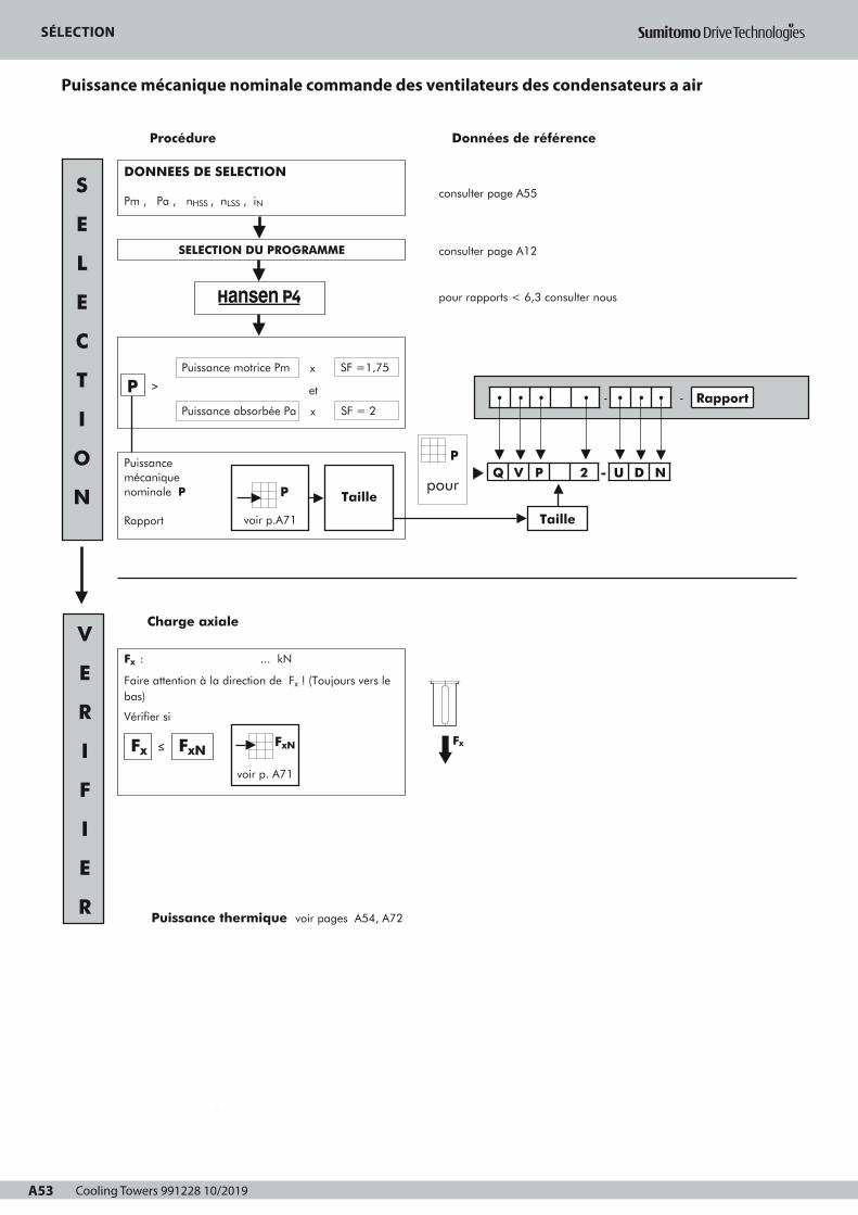
Cooling Towers 991228 10/2019A53
SELECTIONPuissance mécanique nominale
COMMANDE DES VENTILATEURS DES CONDENSATEURS A AIR
A53
consulter page A55
consulter page A12
pour rapports < 6,3 consulter nous
Procédure
Puissancemécanique nominale P
Rapport
Données de référence
2
3
pour
• • • • - • • • - Rapport
Q V P 2 - U D N
1
DONNEES DE SELECTION
Pm , Pa , nHSS , nLSS , iN
Charge axiale
Fx
SELECTION DU PROGRAMME
Puissance absorbée Pa
PPuissance motrice Pm
et
x SF =1,75
x SF = 2
≥
voir p.A71
P Taille
S
E
L
E
C
T
I
O
N
V
E
R
I
F
I
E
R
Taille
P
Puissance thermique voir pages A54, A72
Fx : ... kN
Faire attention à la direction de Fx ! (Toujours vers lebas)
Vérifier si
≤Fx FxNFxN
voir p. A71
Page 1
SELECTIONPuissance thermique
COMMANDE DES VENTILATEURS DES CONDENSATEURS A AIR
Ptn pour réducteur sans
refroidissement forcé
facteur a pour température ambiante sans refroidissement forcé
Rapport de
réduction
Température ambiante en °C
15 à 25 25 à 35 35 à 45
6,3 11,2
12,5 18
≥ 20
Taille
1
1
0,81
0,85
1
C F
0,87
C F
0,68
0,71
0,55
0,66
0,75
C D
0,74
C F
OK
Contrôle thermique
Pa ≤ Ptn • a • b • c ?
Un ventilateur possible
Refroidissement forcén'est pas requis
Ptf pour réducteur avec un
ventilateur
Pa ≤ Ptf • d • b ? Un ventilateur
facteur b pour durée de service
h/an
3
h/jour (max)
10 >16
1000
2000
≥ 4000
Taille
1,2
-
1,3
-
-
C F
-
C F
1,15
1,1
1,2
1,1
-
C D
-
E F
1,15
1,1
1
C F
facteur d pour température ambiante avec refroidissement forcé
Nombre
d'étages
Température ambiante en °C
15 à 25 25 à 35 35 à 45 45 à 55
avecrefroidissement
forcé2 1 0,86 0,72 0,59
Données de référence
OK
facteur c pour circulation d'air (sans ventilateur)
Installation
Dans un petit local fermé
Courant d'air
≥ 0,5 m/s 0,73 0,70
Dans un atelier normal
En plein air, protégé dusoleil
Taille
≥ 1,4 m/s
≥ 3,0 m/s
1
1,33
C D
1
1,36
E F
Pt
Pt
Ptn, Ptf
pourvoir p.A72
• • • • - • • • - Rapport
Q V P 2 - U D N
Taille
F
A54
Le courant d'air sera sélectionné en fonction de la structure:
Structure ouverte : les réducteurs sont installés dans une structure d'acier
ouverte permettant le passage du courant d'air du condensateur à air le long
du carter du réducteur.
Structure fermée : les réducteurs sont montés sur une console en béton ou
dans une structure d'acier fermée empêchant le passage du courant d'air du
condensateur à air le long du carter du réducteur.
Page 1
SÉLECTION
Puissance mécanique nominale commande des ventilateurs des condensateurs a air
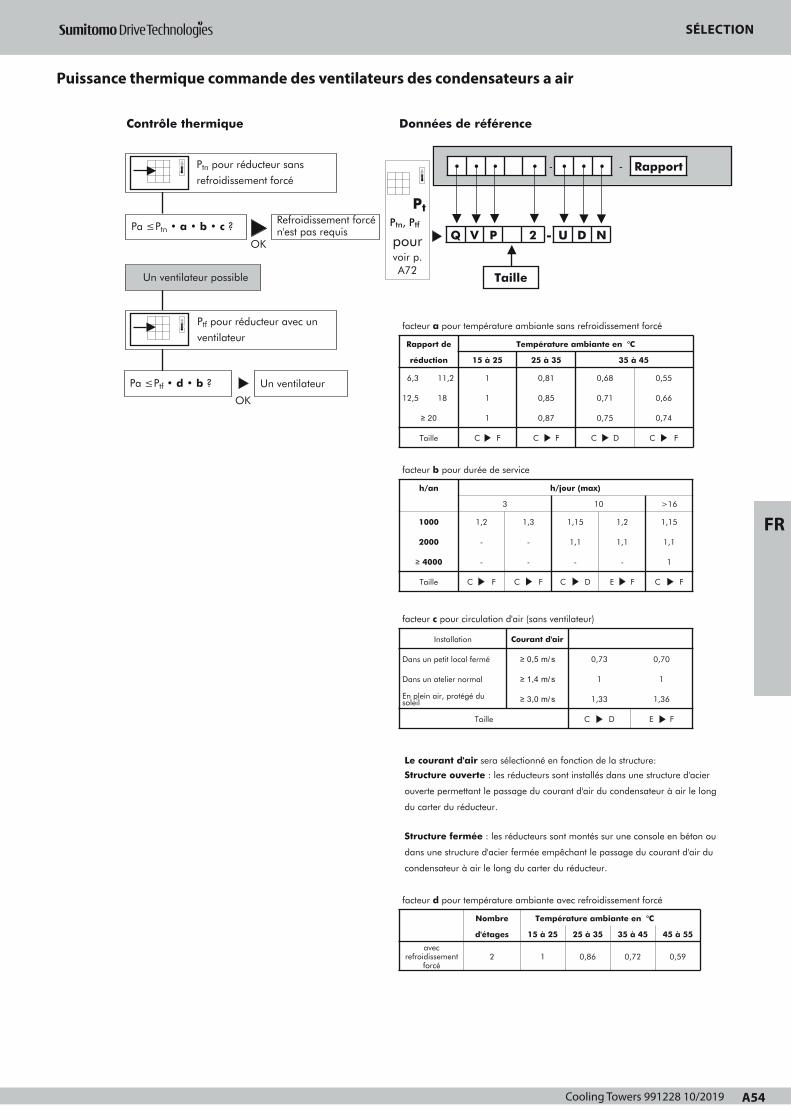
Cooling Towers 991228 10/2019 A54
FR
SELECTIONPuissance thermique
COMMANDE DES VENTILATEURS DES CONDENSATEURS A AIR
Ptn pour réducteur sans
refroidissement forcé
facteur a pour température ambiante sans refroidissement forcé
Rapport de
réduction
Température ambiante en °C
15 à 25 25 à 35 35 à 45
6,3 11,2
12,5 18
≥ 20
Taille
1
1
0,81
0,85
1
C F
0,87
C F
0,68
0,71
0,55
0,66
0,75
C D
0,74
C F
OK
Contrôle thermique
Pa ≤ Ptn • a • b • c ?
Un ventilateur possible
Refroidissement forcén'est pas requis
Ptf pour réducteur avec un
ventilateur
Pa ≤ Ptf • d • b ? Un ventilateur
facteur b pour durée de service
h/an
3
h/jour (max)
10 >16
1000
2000
≥ 4000
Taille
1,2
-
1,3
-
-
C F
-
C F
1,15
1,1
1,2
1,1
-
C D
-
E F
1,15
1,1
1
C F
facteur d pour température ambiante avec refroidissement forcé
Nombre
d'étages
Température ambiante en °C
15 à 25 25 à 35 35 à 45 45 à 55
avecrefroidissement
forcé2 1 0,86 0,72 0,59
Données de référence
OK
facteur c pour circulation d'air (sans ventilateur)
Installation
Dans un petit local fermé
Courant d'air
≥ 0,5 m/s 0,73 0,70
Dans un atelier normal
En plein air, protégé dusoleil
Taille
≥ 1,4 m/s
≥ 3,0 m/s
1
1,33
C D
1
1,36
E F
Pt
Pt
Ptn, Ptf
pourvoir p.A72
• • • • - • • • - Rapport
Q V P 2 - U D N
Taille
F
A54
Le courant d'air sera sélectionné en fonction de la structure:
Structure ouverte : les réducteurs sont installés dans une structure d'acier
ouverte permettant le passage du courant d'air du condensateur à air le long
du carter du réducteur.
Structure fermée : les réducteurs sont montés sur une console en béton ou
dans une structure d'acier fermée empêchant le passage du courant d'air du
condensateur à air le long du carter du réducteur.
Page 1
SÉLECTION
Puissance thermique commande des ventilateurs des condensateurs a air

Cooling Towers 991228 10/2019A55
DEMANDE D'OFFRECOMMANDE DES VENTILATEURS DES CONDENSATEURS A AIR
A55
1. PARAMETRES DE PUISSANCE
Puissance motricer Pm = kW à min-1
Puissance absorbée Pa = kW
Couple absorbé Ta = kNm
Durée de fonctionnement en h/jour ≤3
Couple de point supérieur à 200% Ta =
Nombre de démarrages/arrêts par 10heures :
≤10 >10
%
.....
2. VITESSE
Arbre grande vitesse (AGV)
Vitesse(s) constante(s) n1(AGV) = ........ ou/et ........ min-1
Vitesse variable .......... ≤ n1(AGV) ≤ ........... min-1
Sens de rotation : CW
Arbre petite vitesse (APV)
Vitesse(s) constante(s) n2 (APV) = ........ ou/et ........ min-1
Vitesse variable ........ ≤ n2 (APV) ≤ .......... min-1
Tolérance sur la vitesse APV ± ...... % ± ........... min-1
Sens de rotation : anti-horlogique (CCW)
3. LA CONFIGURATION DES ARBRES DU REDUCTEUR :
Arbres parallèles
4. EFFORT AXIAL AGISSANT SUR L'ARBRE PV oui non
Poids : ventilateur + accouplement
Effort axial aérodynamique s'éloignant du réducteur
5. PARAMETRES D'INSTALLATION
Température ambiante (°C) près du réducteur :
Structure (voir page A54) ouverte
Vitesse de l'air près du réducteur :
=
= -kN
kN
min: .....
max: .....
....... m/s
fermée
Lieu
En plein soleil
Catégorie de la corrosivité atmosphérique (suivant ISO 12944-2): ....
Installation électrique AC
Alimentation principale
Alimentation auxiliaire
Protection requise: ........
3 Ph
Y N
V Hz
.... ....
.... ....
Isolation: ........
6. BRUIT (réducteur + moteur)
Puissance acoustique max.: dBA
Pression acoustique max.
7. SPECIFICATIONS OPTIONNELLES
Options à indiquer aux pages A69-A70
dBA at ..... m
Fixation du moteur carcasse CEI: .......
(si pas CEI, ajouter plan d'encombrement)
Arbres en pouce
Bout d'arbre allongé : à indiquer sur le schéma de l'application
Pour d'autres données voir :
Ref : Date : Nom : Signature :
Peinture (voir page A52)
(*) : Plage de durabilité suivant ISO 12944-1
L : faible
M : moyenne
H : haute
Note : la gamme de durabilité n'est pas une "garantie de temps".
La durabilité est une considération technique qui peut aider
le propriétaire à mettre en place un programme d'entretien.
(**) : Contient une couche supplémentaire sur 2A, 2B et 2C pour éviter
la formation d’une couche crayeuse.
Matériaux non admis Al
Cu
Autres .....
8. ANTIDÉVIREUR REQUIS oui non
9. EXPEDITION Transport par:
navire
train
camion
Pour d'autres données voir :
Sélection:cocher la case
appropriée
2• 3•
Système
Catégorie de corrosivité suivant ISO 12944-2
L (*)
C1
M H L
C2
M H L
C3
M
2A
2B
3A (**)
3B (**)
2C 3C (**)
Sélection:cocher la case
appropriée
2• 3•
Système
2A 3A (**)
2B
2C
3B (**)
3C (**)
Catégorie de corrosivité suivant ISO 12944-2
C4
L (*) M H L
Non permis
C5-I
M H
C5-M
L M
Obligatoire (exigence minimale)
A la demande du client
H
H
Sélection de la catégorie de corrosivité: cocher la case appropriée
C1 C2 C3 C4 C5-I C5-M
CCW
Page 1
DEMANDE D'OFFRE
Commande des ventilateurs des condensateurs a air
Cooling Towers 991228 10/2019 A56
FR
DEMANDE D'OFFRE
Schéma de l'application
VUE EN PLAN
VUE DE COTE

Cooling Towers 991228 10/2019A57
BESCHREIBUNGHANSEN P4 NORMZAHNRADGETRIEBE FÜR
LUFTKONDENSATORANTRIEBE
A57
Das Getriebe
Getriebe werden nach der Norm CTI-111 (Cooling Tower Institute)Spezifizierung ausgelegt.Die in den Tabellen aufgeführten mechanischen Nennleistungen,beziehen sich auf die Antriebsdrehzahlen 1800, 1500, 1200, 1000,
900 und 750 min-1. Sie sind auch gültig für Asynchrondrehzahlen, die max. 3% niedrigerals die Synchrondrehzahlen der Motoren liegen. Für die Leistungs-übermittlung bei anderen Drehzahlen genügt es zu interpolieren. Die
Leistung bei Drehzahlen kleiner als 750 min-1 entspricht dem
Nenndrehmoment bei 750 min-1. Für Eingangsdrehzahlen größer als1800 min-1, ist eine Rückfrage zu empfehlen.
Bezeichnung
Typ1 : Reihe Q : Hansen P42 : V : vertikale langsamdrehende Welle3 : P : parallele Wellen4 : Baugröße: C, ..., F5 : Stufenzahl: 25 bis : / : normale Ausführung (keine Bezeichnung)
Wellenanordnung6 : schnelldrehende Welle ausragend : U: oben7 : langsamdrehende Welle ausragend: D: unten8 : Art der langsamdrehenden Welle: N: normale
Vollwelle
Übersetzung9 : Nennübersetzung
Hauptbauteile
Schrägverzahnte StirnräderEntwurf und Auslegung nach AGMA für eine maximale Belastbarkeit,minimale Verluste und einen geräuscharmen Lauf.Sämtliche Zahnräder sind aus legiertem Stahl; sie werden ein-satzgehärtet und geschliffen.
Langsamdrehende WellenDie langsamdrehenden Wellen sind in Vollwellenausführung.Verlängerte Wellen sind auf Wunsch erhältlich.
LagerReichlich bemessene Kegelrollen-, Pendelrollen- oder Zylinder-Rollenlager; berechnet nach ISO und bekannten LagerherstellerDie Lager an der Abtriebswelle sind ausgelegt zur Aufnahme vonerheblichen Axiallasten. Die in den Tabellen, auf Seite A71,aufgeführte zulässige Nennaxiallast FxN ist gültig für SFmin = 2,eine Drehrichtung entgegen Uhrzeigersinn für die LangsamdrehendeWelle und garantiert eine berechnete Lagerlebensdauer von 100000 Stunden.
1
Q2
V3
P4 5
25 bis
-6
U7
D8
N -9
Gehäuse, Deckel und LagergehäuseAus perlitischem Grauguß.Bearbeitung auf CNC gesteuerten Bearbeitungszentren.Robuste und steife Konstruktion.Nicht verwendete Gewindelöcher sind mit Stopfen verschlossen.Gehäuse mit horizontaler Trennfuge.
Systeme
SchmierungSchmiermittel: In der Regel werden Mineralöle verwendet.Die Schmiermittel müssen allerdings „extreme pressure Additive“enthalten (siehe Betriebsanleitung).Druckumlaufschmierung für die oberen Lager ist standardmäßigerhältlich. Das Gehäuse bildet einen reichlich bemessenen Ölbehälter.Fettschmierpunkte mit Nippel entsprechend DIN 71412 fürFettschmierung des Lagers an dem Seite des Abtriebswellenendes.Der Ölstand ist mittels (eingeschraubten) Gewinde-Ölmeßstab meßbar.
Kühlung Die Wärmeabführung der im Gehäuse entstandenen Verlustwärmeerfolgt mittels:
• Eigenkühlung vom Gehäuse• Ventilatorkühlung: ein elektrisch angetriebener
Axialventilator kann eingebaut werden (siehe Seiten A69-A70)Merkmale der elektrisch angetriebenen Ventilatoren:
Standard, dreiphasig, 50Hz, 400 V ± 10%, Schutzart: IP55Freier Luft-Eintrag auf der Saugseite sollte immer gewährleistet sein
Thermische Kontrollen siehe Seite A60
AbdichtungFeste Teile: • allgemeine Verwendung einer Dichtungspaste
• Schaulochdeckel an Getriebe : O-Ring • langsamdrehende Welle: Steigrohr
Umlaufende Teile:• Schnelldrehende Welle: Dichtungsring mit
Staublippe• Langsamdrehende Welle: Dichtungsring mit
Staublippe
Page 1
BESCHREIBUNGHANSEN P4 NORMZAHNRADGETRIEBE FÜR
LUFTKONDENSATORANTRIEBE
Motoren
Die Getriebe werden mit IEC Motoren in Flanschausführungausgerüstet (Bauform B5). Für mehr Information über Motoren,Siehe Motorkatalog.Für NEMA-Motoren: Rückfrage zu empfehlen.Polumschaltbare Motoren: polumschaltbare Motoren dürfen erstdann auf die niedrige Drehzahl umgeschaltet werden, wenn dieDrehzahl des Motors bis unter die niedrige Drehzahl abgefallen ist.
Optionale Zusatzeinrichtungen
Bestimmte Zusatzeinrichtungen sind optional verfügbar (siehe SeitenA69 - A70). Detaillierte Information über optionale Zusatz-einrichtungen ist den separaten Betriebsvorschriften für diese Teile zuentnehmen. Rückfrage zu empfehlen.
Rücklaufsperre Eingebaute Rücklaufsperre vermeidet unerwünschter Drehen desVentilators. Schmierung der Rücklaufsperre erfolgt durch dieSchmieranlage vom Getriebe.
FilterMit eingebautem Überdruckventil.Ein Filter mit eingebautem Überdruckventil und mit optischem oderelektrischem Verschmutzungsanzeiger ist als Option vorhanden.
HeizstäbeElektrisch erwärmte Heizstäbe für Anlauf bei niedrigen Temperaturensind vorhanden.
StrömungskontrollschalterGetriebe mit Pumpenschmierung können mit einemStrömungskontrollschalter ausgerüstet werden. Der Schalter löst beiunzureichendem Ölzufuhr ein Alarmsignal aus. Im betreffenden Falldas Getriebe sofort abschalten und die Ursache der Störung in derÖlzufuhr beseitigen.
ÖlstandschalterEin Ölstandschalter zur Überprüfung des Ölstandes im Getriebekann vorgesehen werden. Der Schalter kann ein Alarmsignalauslösen, wenn der Stand vom Ölbad unterhalb eines bestimmtenWertes fällt.
Pt100Der Pt100 steuert die Ölbadtemperatur. Der Pt100 kann ein Alarmsignal auslösen, wenn das Öltemperaturhöher ist als die spezifizierte Begrenzung.
Lieferzustand
Kontrolle vor dem Versand• Probelauf: alle Getriebe werden einen unbelasteten Probelauf
unterzogen• Gleichförmigkeitskontrolle
Schutz• Ausragendes Wellenende: fettgeschmiert und mit einem
wasserbeständigen, wachsartigen Papier geschützt
Schmierstoffe• Hansen P4 Getriebe werden ohne Ölfüllung geliefert.• Alle Fettschmierstellen werden jedoch vor dem Versand mit
Fett gefüllt.
Hinsichtlich LLLLaaaaggggeeeerrrruuuunnnngggg,,,, HHHHaaaannnnddddhhhhaaaabbbbuuuunnnngggg,,,, MMMMoooonnnnttttaaaaggggeeee,,,, IIIInnnnbbbbeeeettttrrrriiiieeeebbbbsssseeeettttzzzzuuuunnnngggg uuuunnnnddddWWWWaaaarrrrttttuuuunnnngggg ddddeeeerrrr GGGGeeeettttrrrriiiieeeebbbbeeee, gibt die Betriebsanleitung, die zusammen mitden Getrieben geliefert wird, wertvolle Hinweise.
Schutzmaßnahmen
Standard Schutzsysteme• Als Standard werden Hansen P4 Getriebe mit einem Anstrichsystem
versehen, das geeignet ist für eine Umgebung nach Korrosionsschutz-
klasse "C1" entsprechend ISO 12944-2 (und ISO 12944-5).Die Wahl der Farbe hat keinen Einfluss auf die technische Qualität des
Anstrichsystems.Andere Anstrichsysteme können angeboten werden, um die erforderli-
che Korrosionsschutzklasse für Ihre Anwendung zu erfüllen.
• Bolzen und Schrauben ausgestattet mit passendem Schutz.
Aggressive UmgebungFür die Luftkondensatorantriebe in aggressiver Umgebung kann ein
zusätzlicher Schutzsystem angeboten werden: : Rückfrage zu empfeh-
len.
D
A58
Page 1
BESCHREIBUNG
Hansen P4 Normzahnradgetriebe für Luftkondensatorantriebe

Cooling Towers 991228 10/2019 A58
BESCHREIBUNGHANSEN P4 NORMZAHNRADGETRIEBE FÜR
LUFTKONDENSATORANTRIEBE
Motoren
Die Getriebe werden mit IEC Motoren in Flanschausführungausgerüstet (Bauform B5). Für mehr Information über Motoren,Siehe Motorkatalog.Für NEMA-Motoren: Rückfrage zu empfehlen.Polumschaltbare Motoren: polumschaltbare Motoren dürfen erstdann auf die niedrige Drehzahl umgeschaltet werden, wenn dieDrehzahl des Motors bis unter die niedrige Drehzahl abgefallen ist.
Optionale Zusatzeinrichtungen
Bestimmte Zusatzeinrichtungen sind optional verfügbar (siehe SeitenA69 - A70). Detaillierte Information über optionale Zusatz-einrichtungen ist den separaten Betriebsvorschriften für diese Teile zuentnehmen. Rückfrage zu empfehlen.
Rücklaufsperre Eingebaute Rücklaufsperre vermeidet unerwünschter Drehen desVentilators. Schmierung der Rücklaufsperre erfolgt durch dieSchmieranlage vom Getriebe.
FilterMit eingebautem Überdruckventil.Ein Filter mit eingebautem Überdruckventil und mit optischem oderelektrischem Verschmutzungsanzeiger ist als Option vorhanden.
HeizstäbeElektrisch erwärmte Heizstäbe für Anlauf bei niedrigen Temperaturensind vorhanden.
StrömungskontrollschalterGetriebe mit Pumpenschmierung können mit einemStrömungskontrollschalter ausgerüstet werden. Der Schalter löst beiunzureichendem Ölzufuhr ein Alarmsignal aus. Im betreffenden Falldas Getriebe sofort abschalten und die Ursache der Störung in derÖlzufuhr beseitigen.
ÖlstandschalterEin Ölstandschalter zur Überprüfung des Ölstandes im Getriebekann vorgesehen werden. Der Schalter kann ein Alarmsignalauslösen, wenn der Stand vom Ölbad unterhalb eines bestimmtenWertes fällt.
Pt100Der Pt100 steuert die Ölbadtemperatur. Der Pt100 kann ein Alarmsignal auslösen, wenn das Öltemperaturhöher ist als die spezifizierte Begrenzung.
Lieferzustand
Kontrolle vor dem Versand• Probelauf: alle Getriebe werden einen unbelasteten Probelauf
unterzogen• Gleichförmigkeitskontrolle
Schutz• Ausragendes Wellenende: fettgeschmiert und mit einem
wasserbeständigen, wachsartigen Papier geschützt
Schmierstoffe• Hansen P4 Getriebe werden ohne Ölfüllung geliefert.• Alle Fettschmierstellen werden jedoch vor dem Versand mit
Fett gefüllt.
Hinsichtlich LLLLaaaaggggeeeerrrruuuunnnngggg,,,, HHHHaaaannnnddddhhhhaaaabbbbuuuunnnngggg,,,, MMMMoooonnnnttttaaaaggggeeee,,,, IIIInnnnbbbbeeeettttrrrriiiieeeebbbbsssseeeettttzzzzuuuunnnngggg uuuunnnnddddWWWWaaaarrrrttttuuuunnnngggg ddddeeeerrrr GGGGeeeettttrrrriiiieeeebbbbeeee, gibt die Betriebsanleitung, die zusammen mitden Getrieben geliefert wird, wertvolle Hinweise.
Schutzmaßnahmen
Standard Schutzsysteme• Als Standard werden Hansen P4 Getriebe mit einem Anstrichsystem
versehen, das geeignet ist für eine Umgebung nach Korrosionsschutz-
klasse "C1" entsprechend ISO 12944-2 (und ISO 12944-5).Die Wahl der Farbe hat keinen Einfluss auf die technische Qualität des
Anstrichsystems.Andere Anstrichsysteme können angeboten werden, um die erforderli-
che Korrosionsschutzklasse für Ihre Anwendung zu erfüllen.
• Bolzen und Schrauben ausgestattet mit passendem Schutz.
Aggressive UmgebungFür die Luftkondensatorantriebe in aggressiver Umgebung kann ein
zusätzlicher Schutzsystem angeboten werden: : Rückfrage zu empfeh-
len.
D
A58
Page 1
BESCHREIBUNG
DE
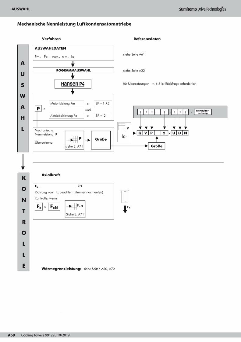
Cooling Towers 991228 10/2019A59
AUSWAHLmechanische Nennleistung
LUFTKONDENSATORANTRIEBE
A59
siehe Seite A61
siehe Seite A22
für Übersetzungen < 6,3 ist Rückfrage erforderlich
Verfahren Referenzdaten
Mechanische Nennleistung P
Übersetzung
2
3
1
AUSWAHLDATEN
Pm , Pa , nHSS , nLSS , iN
Axialkraft
ROGRAMMAUSWAHL
Abtriebsleistung Pa
PMotorleistung Pm
und
x SF =1,75
x SF = 2
≥
siehe S. A71
P Größe
A
U
S
W
A
H
L
K
O
N
T
R
O
L
L
E Wärmegrenzleistung: siehe Seiten A60, A72
für
• • • • - • • • - Nennüber-setzung
Q V P 2 - U D N
Größe
P
Fx
Fx : ... kN
Richtung von Fx beachten ! (Immer nach unten)
Kontrolle, wenn
≤Fx FxNFxN
Siehe S. A71
Page 1
AUSWAHLWärmegrenzleistung
LUFTKONDENSATORANTRIEBE
Ptn für Getriebe ohne
Fremdkühlung
Faktor a für Umgebungstemperatur ohne Fremdkühlung
Übersetzung Umgebungstemperatur in °C
15 bis 25 25 bis 35 35 bis 45
6,3 11,2
12,5 18
≥ 20
Baugröße
1
1
0,81
0,85
1
C F
0,87
C F
0,68
0,71
0,55
0,66
0,75
C D
0,74
E F
OK
Thermische Kontrolle
Pa ≤ Ptn • a • b • c ?
Lüfter ist möglich
Fremdkühlung istnicht erforderlich
Ptf für Getriebe mit einem
Lüfter
Pa ≤ Ptf • d • b ? Ein Lüfter
Faktor b für Betriebsdauer
h/Jahr
3
h/Tag (max)
10 >16
1000
2000
≥ 4000
Baugröße
1,2
-
1,3
-
-
C F
-
C F
1,15
1,1
1,2
1,1
-
C D
-
E F
1,15
1,1
1
C F
Faktor d für Umgebungstemperatur mit Fremdkühlung
Stufenzahl Umgebungstemperatur in °C
15 bis 25 25 bis 35 35 bis 45 45 bis 55
Fremdkühlung 2 1 0,86 0,72 0,59
Referenzdaten
OK
Faktor c für Luftzirkulation (ohne Lüfter)
Aufstellung
In klein. geschlos. Raum
Luftströmung
≥ 0,5 m/s 0,73 0,70
In normalem Arbeitsraum
Aufstellung im Freien, Son-nenschutz
Baugröße
≥ 1,4 m/s
≥ 3,0 m/s
1
1,33
C D
1
1,36
E F
Pt
Pt
Ptn, Ptf
fürsiehe S.
A72
• • • • - • • • - Über-setzung
Q V P 2 - U D N
Größe
D
A60
Luftströmung sollte entsprechend der Struktur gewählt werden:
Offene Struktur: bei Getrieben aufgestellt in offener Stahlstruktur kann der
Luftstrom vom Kondensator über das Getriebegehäuse geführt werden.
Geschlossene Struktur: bei Getrieben aufgestellt auf einem Beton-sockel
oder in einer geschlossenen Stahlstruktur kann der Luftstrom vom Kondensator
nicht über das Getriebegehäuse geführt werden.
Page 1
AUSWAHL
Mechanische Nennleistung Luftkondensatorantriebe

Cooling Towers 991228 10/2019 A60
DE
AUSWAHLWärmegrenzleistung
LUFTKONDENSATORANTRIEBE
Ptn für Getriebe ohne
Fremdkühlung
Faktor a für Umgebungstemperatur ohne Fremdkühlung
Übersetzung Umgebungstemperatur in °C
15 bis 25 25 bis 35 35 bis 45
6,3 11,2
12,5 18
≥ 20
Baugröße
1
1
0,81
0,85
1
C F
0,87
C F
0,68
0,71
0,55
0,66
0,75
C D
0,74
E F
OK
Thermische Kontrolle
Pa ≤ Ptn • a • b • c ?
Lüfter ist möglich
Fremdkühlung istnicht erforderlich
Ptf für Getriebe mit einem
Lüfter
Pa ≤ Ptf • d • b ? Ein Lüfter
Faktor b für Betriebsdauer
h/Jahr
3
h/Tag (max)
10 >16
1000
2000
≥ 4000
Baugröße
1,2
-
1,3
-
-
C F
-
C F
1,15
1,1
1,2
1,1
-
C D
-
E F
1,15
1,1
1
C F
Faktor d für Umgebungstemperatur mit Fremdkühlung
Stufenzahl Umgebungstemperatur in °C
15 bis 25 25 bis 35 35 bis 45 45 bis 55
Fremdkühlung 2 1 0,86 0,72 0,59
Referenzdaten
OK
Faktor c für Luftzirkulation (ohne Lüfter)
Aufstellung
In klein. geschlos. Raum
Luftströmung
≥ 0,5 m/s 0,73 0,70
In normalem Arbeitsraum
Aufstellung im Freien, Son-nenschutz
Baugröße
≥ 1,4 m/s
≥ 3,0 m/s
1
1,33
C D
1
1,36
E F
Pt
Pt
Ptn, Ptf
fürsiehe S.
A72
• • • • - • • • - Über-setzung
Q V P 2 - U D N
Größe
D
A60
Luftströmung sollte entsprechend der Struktur gewählt werden:
Offene Struktur: bei Getrieben aufgestellt in offener Stahlstruktur kann der
Luftstrom vom Kondensator über das Getriebegehäuse geführt werden.
Geschlossene Struktur: bei Getrieben aufgestellt auf einem Beton-sockel
oder in einer geschlossenen Stahlstruktur kann der Luftstrom vom Kondensator
nicht über das Getriebegehäuse geführt werden.
Page 1
AUSWAHL
Wärmegrenzleistung Luftkondensatorantriebe

Cooling Towers 991228 10/2019A61
ANFRAGEVENTILATORANTRIEBE IN LUFTKONDENSATOREN
A61
1. BELASTUNGSPARAMETER
Motorleistung Pm = kW bei min-1
Abtriebsleistung Pa = kW
Abtriebsmoment Ta = kNm
Einsatzdauer in h/Tag ≤3
Spitzenmoment > 200% Ta =
Anzahl der Einschaltungen/Abschaltungen pro 10 Stunden :
≤10 >10
%
.....
2. DREHZAHL
Schnelldrehende Welle (SDW)
konstante Drehzahl(en) n1(SDW) = ...... oder/und ...... min-1
Variable Drehzahl ......... ≤ n1(SDW) ≤ .......... min-1
Drehrichtung : CW
Langsamdrehende Welle (LDW)
konstante Drehzahl(en) n2 (LDW) = ...... oder/und ...... min-1
Variable Drehzahl ......... ≤ n2 (LDW) ≤ .......... min-1
Toleranz auf die Drehzahl LDW ± ...... % ± ........... min-1
Drehrichtung : entgegen Uhrzeigersinn (CCW)
3. GETRIEBEWELLENANORDNUNG
Parallele Wellen
4. AXIALKRAFT AUF LANGS.DREH.WELLE Ja Nein
Gewicht von Lüfter und Kupplung
Aerodynamische Axialkraft weg vom Getriebe
5. EINBAUPARAMETER
Umgebungstemperatur (°C) nahe dem Getriebe :
Struktur (siehe Seite A60) offen
Luftgeschwindigkeit nahe dem Getriebe:
=
= -kN
kN
min: .....
max: .....
geschlossen
....... m/s
Aufstellung
Der Sonnenbestrahlung ausgesetzt
Atmosphäre: Korrosion Kategorie (entsprechend ISO 12944-2): ....
Elektrische Ausführung
Ja
AC
Hauptspannung
Hilfsspannung
Schutzanforderungen: ........
3 Ph
Nein
V Hz
.... ....
.... ....
Isolation: ........
6. GERÄUSCH (Getriebe + Motor)
Max. Schalleistung: dBA
Max. Schalldruck :
7. OPTIONELLE DATEN
Optionen auf Seiten A69 und A70 eintragen
dBA at ..... m
Motormantel IEC: .......
(falls nicht IEC, Maßzeichnungen hinzufügen)
Wellen Zoll
verlängertes Wellenende: auf Anwendungsskizze andeuten
Für weitere Daten, siehe ...
Ref : Datum : Name : Unterschrift :
Anstrich (siehe Seite A58)
(*) : Haltbarkeitsreihe nach ISO 12944-1
L : niedrig (gering)
M : Medium (mittel)
H : hoch
Hinweis: Die Haltbarkeitsbereich ist keine "Garantie der Zeit".
Haltbarkeit ist eine technische Prüfung, dass der Besitzer
helfen kann für das Einrichten einem Wartungsprogramm.
(**) : Eine zusätzliche Schicht auf 2A, 2B und 2C um Bildung
einer kalkhaltigen Schicht zu verhindern.
Nicht zulässige Materialien Alu
Kupfer
Sonstige .....
8. RÜCKLAUFSPERRE ERFORDERLICH Ja Nein
9. VERSAND Transport durch:
Schiff
Zug
LKW
Für weitere Daten, siehe ...
Auswahl:
Ankreuzen
2• 3•
System
Korrosion Kategorie entsprechend ISO 12944-2
L (*)
C1
M H L
C2
M H L
C3
M
2A
2B
3A (**)
3B (**)
2C 3C (**)
Auswahl:
Ankreuzen
2• 3•
System
2A 3A (**)
2B
2C
3B (**)
3C (**)
Korrosion Kategorie entsprechend ISO 12944-2
C4
L (*) M H L
Nicht erlaubt
C5-I
M H
C5-M
L M
Obligatorisch (Mindestanforderung)
Auf Wunsch des Kunden
H
H
Auswahl der Korrosion Kategorie: ankreuzen
C1 C2 C3 C4 C5-I C5-M
CCW
Page 1
TECHNISCHE ERLÄUTERUNG FÜR ANFRAGE
Ventilatorantriebe in Luftkondensatoren

Cooling Towers 991228 10/2019 A62
DE
DRAUFSICHT
SEITENANSICHT
TECHNISCHE ERLÄUTERUNG FÜR ANFRAGE
Skizze der Anwendung
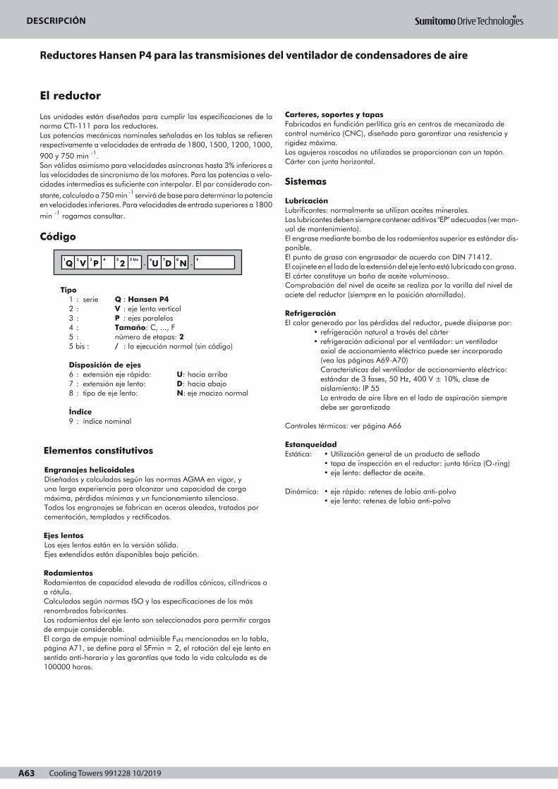
Cooling Towers 991228 10/2019A63
DESCRIPCIONREDUCTORES HANSEN P4 PARA LAS TRANSMISIONES DEL
VENTILADOR DE CONDENSADORES DE AIRE
A63
El reductor
Las unidades están diseñadas para cumplir las especificaciones de lanorma CTI-111 para los reductores.Las potencias mecánicas nominales señaladas en las tablas se refierenrespectivamente a velocidades de entrada de 1800, 1500, 1200, 1000,
900 y 750 min -1.Son válidas asimismo para velocidades asíncronas hasta 3% inferiores alas velocidades de sincronismo de los motores. Para las potencias a velo-cidades intermedias es suficiente con interpolar. El par considerado con-
stante, calculado a 750 min -1 servirá de base para determinar la potenciaen velocidades inferiores. Para velocidades de entrada superiores a 1800
min -1 rogamos consultar.
Código
Tipo1 : serie Q : Hansen P42 : V : eje lento vertical3 : P : ejes paralelos4 : Tamaño: C, ..., F5 : número de etapas: 25 bis : / : la ejecución normal (sin código)
Disposición de ejes6 : extensión eje rápido: U: hacia arriba7 : extensión eje lento: D: hacia abajo8 : tipo de eje lento: N: eje macizo normal
Índice9 : índice nominal
Elementos constitutivos
Engranajes helicoidalesDiseñados y calculados según las normas AGMA en vigor, y una larga experiencia para alcanzar una capacidad de carga máxima, pérdidas mínimas y un funcionamiento silencioso.Todos los engranajes se fabrican en aceros aleados, tratados por cementación, templados y rectificados.
Ejes lentosLos ejes lentos están en la versión sólida.Ejes extendidos están disponibles bajo petición.
RodamientosRodamientos de capacidad elevada de rodillos cónicos, cilíndricos oa rótula.Calculados según normas ISO y las especificaciones de los másrenombrados fabricantes.Los rodamientos del eje lento son seleccionados para permitir cargasde empuje considerable.El carga de empuje nominal admisible FxN mencionados en la tabla,página A71, se define para el SFmin = 2, el rotación del eje lento ensentido anti-horario y las garantías que toda la vida calculada es de100000 horas.
1
Q2
V3
P4 5
25 bis
-6
U7
D8
N -9
Carteres, soportes y tapasFabricados en fundición perlítica gris en centros de mecanizado decontrol numérico (CNC), diseñado para garantizar una resistencia yrigidez máxima.Los agujeros roscados no utilizados se proporcionan con un tapón.Cárter con junta horizontal.
Sistemas
LubricaciónLubrificantes: normalmente se utilizan aceites minerales.Los lubricantes deben siempre contener aditivos "EP" adecuados (ver man-ual de mantenimiento).El engrase mediante bomba de los rodamientos superior es estándar dis-ponible.El punto de grasa con engrasador de acuerdo con DIN 71412. El cojinete en el lado de la extensión del eje lento está lubricado con grasa.El cárter constituye un baño de aceite voluminoso.Comprobación del nivel de aceite se realiza por la varilla del nivel de aciete del reductor (siempre en la posición atornillado).
Refrigeración El calor generado por las pérdidas del reductor, puede disiparse por:
• refrigeración natural a través del cárter• refrigeración adicional por el ventilador: un ventilador
axial de accionamiento eléctrico puede ser incorporado (vea las páginas A69-A70)Características del ventilador de accionamiento eléctrico: estándar de 3 fases, 50 Hz, 400 V ± 10%, clase de aislamiento: IP 55La entrada de aire libre en el lado de aspiración siempre debe ser garantizada
Controles térmicos: ver página A66
EstanqueidadEstática: • Utilización general de un producto de sellado
• tapa de inspección en el reductor: junta tórica (O-ring)• eje lento: deflector de aceite.
Dinámica: • eje rápido: retenes de labio anti-polvo
• eje lento: retenes de labio anti-polvo
Page 1
DESCRIPCIONREDUCTORES HANSEN P4 PARA LAS TRANSMISIONES DEL
VENTILADOR DE CONDENSADORES DE AIRE
Motores
Los reductores de ejes paralelos están impulsados por motores debrida IEC (tipo B5). Para obtener más información sobre los motores,consulte los catálogos de motor.Para los motores Nema, rogamos consultar.En el uso de motores de 2 velocidades, antes del cambio a la bajavelocidad, debe esperarse a que el accionamiento reduzca su veloci-dad por debajo de la nueva velocidad de régimen.
Dispositivos opcionales
Algunos dispositivos se puede proporcionar opcionalmente (consultelas páginas A69-A70). Más información detallada sobre los dispositi-vos opcionales se menciona por separado en manuales técnicos,rogamos consultar.
Antirretroceso Antirretroceso incorporado para evitar que el ventilador esté funcion-ando en la dirección opuesta. Lubricación por baño de aceite delreductor. El antirretroceso es accesible después de retirar el motor yla carcasa de linterna.
FiltroCon válvula de sobrepresión incorporada.Un filtro con válvula de sobrepresión incorporada e indicador decontaminación visual o eléctrica está disponible como una opción.
CalentadoresLos aparatos de calefacción eléctricos para el arranque en bajastemperaturas, están disponibles.
Interruptor de caudalCuando los reductores están lubricados por una bomba, uninterruptor de caudal se puede proporcionar para comprobar elcaudal de aceite en el reductor. Este interruptor puede activar unaseñal de alarma cuando el caudal de aceite es insuficiente.El reductor tiene que ser detenido de inmediato y la causa de lainterrupción del caudal de aceite tiene que ser eliminado.
Interruptor de nivel de aceitePara controlar el nivel de aceite en el reductor, un interruptor de nivelde aceite puede ser proporcionado. Este interruptor puede activaruna señal de alarma cuando el nivel de aceite cae por debajo de unlímite determinado.
Pt100Para controlar la temperatura del baño de aceite. El Pt100 puedeprovocar una señal de alarma cuando la temperatura del aceite essuperior a un límite determinado.
Condiciones de suministro
Inspección previa al envío• Prueba: todos los reductores se prueban en virtud de sin
carga• Control de conformidad
Protección• Extremos de ejes: cubiertos con capa de grasa y protegidos
con papel anti-humedad.
Lubricantes• Los reductores Hansen P4 se suministran sin aceite.
• Los puntos con grasa salen engrasados de fábrica.
Para información relativa al aaaallllmmmmaaaacccceeeennnnaaaammmmiiiieeeennnnttttoooo,,,, mmmmaaaannnniiiippppuuuullllaaaacccciiiióóóónnnn,,,, iiiinnnnssssttttaaaa----llllaaaacccciiiióóóónnnn,,,, ppppuuuueeeessssttttaaaa eeeennnn mmmmaaaarrrrcccchhhhaaaa yyyy mmmmaaaannnntttteeeennnniiiimmmmiiiieeeennnnttttoooo ver manual de instruc-ciones que se suministra con cada reductor.
Protección
Los sistemas de protección estándar• Estándar, los reductores Hansen P4 se proporcionan con un
sistema de pintura adecuado para la categoría de corrosión
atmosférica "C1", conforme a ISO 12944-2 (e ISO 12944-5).La opción del color no afecta a la calidad técnica del sistema depintura.Otros sistemas de pintura pueden ser ofrecidos para cumplir lacategoría de corrosividad atmosférica necesaria para su aplicación.
• PPPPeeeerrrrnnnnoooossss yyyy ttttuuuueeeerrrrccccaaaassss proporcionadas con una protección adecuada.
Ambiente agresivoPara las transmisiones del ventilador de los condensadores de aireen ambiente agresivo, se pueden ofrecer un sistema de protecciónadicional: rogamos consultar.
S
A64
Page 1
DESCRIPCIÓN
Reductores Hansen P4 para las transmisiones del ventilador de condensadores de aire

Cooling Towers 991228 10/2019 A64
DESCRIPCIONREDUCTORES HANSEN P4 PARA LAS TRANSMISIONES DEL
VENTILADOR DE CONDENSADORES DE AIRE
Motores
Los reductores de ejes paralelos están impulsados por motores debrida IEC (tipo B5). Para obtener más información sobre los motores,consulte los catálogos de motor.Para los motores Nema, rogamos consultar.En el uso de motores de 2 velocidades, antes del cambio a la bajavelocidad, debe esperarse a que el accionamiento reduzca su veloci-dad por debajo de la nueva velocidad de régimen.
Dispositivos opcionales
Algunos dispositivos se puede proporcionar opcionalmente (consultelas páginas A69-A70). Más información detallada sobre los dispositi-vos opcionales se menciona por separado en manuales técnicos,rogamos consultar.
Antirretroceso Antirretroceso incorporado para evitar que el ventilador esté funcion-ando en la dirección opuesta. Lubricación por baño de aceite delreductor. El antirretroceso es accesible después de retirar el motor yla carcasa de linterna.
FiltroCon válvula de sobrepresión incorporada.Un filtro con válvula de sobrepresión incorporada e indicador decontaminación visual o eléctrica está disponible como una opción.
CalentadoresLos aparatos de calefacción eléctricos para el arranque en bajastemperaturas, están disponibles.
Interruptor de caudalCuando los reductores están lubricados por una bomba, uninterruptor de caudal se puede proporcionar para comprobar elcaudal de aceite en el reductor. Este interruptor puede activar unaseñal de alarma cuando el caudal de aceite es insuficiente.El reductor tiene que ser detenido de inmediato y la causa de lainterrupción del caudal de aceite tiene que ser eliminado.
Interruptor de nivel de aceitePara controlar el nivel de aceite en el reductor, un interruptor de nivelde aceite puede ser proporcionado. Este interruptor puede activaruna señal de alarma cuando el nivel de aceite cae por debajo de unlímite determinado.
Pt100Para controlar la temperatura del baño de aceite. El Pt100 puedeprovocar una señal de alarma cuando la temperatura del aceite essuperior a un límite determinado.
Condiciones de suministro
Inspección previa al envío• Prueba: todos los reductores se prueban en virtud de sin
carga• Control de conformidad
Protección• Extremos de ejes: cubiertos con capa de grasa y protegidos
con papel anti-humedad.
Lubricantes• Los reductores Hansen P4 se suministran sin aceite.
• Los puntos con grasa salen engrasados de fábrica.
Para información relativa al aaaallllmmmmaaaacccceeeennnnaaaammmmiiiieeeennnnttttoooo,,,, mmmmaaaannnniiiippppuuuullllaaaacccciiiióóóónnnn,,,, iiiinnnnssssttttaaaa----llllaaaacccciiiióóóónnnn,,,, ppppuuuueeeessssttttaaaa eeeennnn mmmmaaaarrrrcccchhhhaaaa yyyy mmmmaaaannnntttteeeennnniiiimmmmiiiieeeennnnttttoooo ver manual de instruc-ciones que se suministra con cada reductor.
Protección
Los sistemas de protección estándar• Estándar, los reductores Hansen P4 se proporcionan con un
sistema de pintura adecuado para la categoría de corrosión
atmosférica "C1", conforme a ISO 12944-2 (e ISO 12944-5).La opción del color no afecta a la calidad técnica del sistema depintura.Otros sistemas de pintura pueden ser ofrecidos para cumplir lacategoría de corrosividad atmosférica necesaria para su aplicación.
• PPPPeeeerrrrnnnnoooossss yyyy ttttuuuueeeerrrrccccaaaassss proporcionadas con una protección adecuada.
Ambiente agresivoPara las transmisiones del ventilador de los condensadores de aireen ambiente agresivo, se pueden ofrecer un sistema de protecciónadicional: rogamos consultar.
S
A64
Page 1
DESCRIPCIÓN
ES

Cooling Towers 991228 10/2019A65
SELECCIONPotencia mecánica nominal
LAS TRANSMISIONES DEL VENTILADOR DE LOS CONDENSADORES DE AIRE
A65
consulte la página A67
consulte la página A32
para los índices de reducción < 6,3 rogamos consultar.
Procedimiento Información de referencia
Potencia mecánica nominal P
Índice de reducción
2
3
1
DATOS DE LA SELECCION
Pm , Pa , nHSS , nLSS , iN
Carga axial
SELECCION DE PROGRAMA
Potencia absorbida Pa
PPotencia motor Pm
y
x SF =1,75
x SF = 2
≥
ver p. A71
PTamaño
S
E
L
E
C
C
I
O
N
C
O
M
P
R
O
B
A
C
I
O
NPotencia térmica: consulte las páginas A66, A72
por
• • • • - • • • - Índice de reducción
Q V P 2 - U D N
Tamaño
P
Fx
Fx : ... kN
Preste atención a la dirección de Fx ! (Siempre haciaabajo)
Comprobar si
≤Fx FxNFxN
ver p. A71
Page 1
SELECCIONPotencia térmica
LAS TRANSMISIONES DEL VENTILADOR DE LOS CONDENSADORES DE AIRE
Ptn del reductorsin refrigeración forzada
factor a por temperatura ambiente sin refrigeración forzada
Índice de
reducción
Temperatura ambiente en °C
15 a 25 25 a 35 35 a 45
6,3 11,2
12,5 18
≥ 20
Tamaño
1
1
0,81
0,85
1
C F
0,87
C F
0,68
0,71
0,55
0,66
0,75
C D
0,74
E F
OK
Comprobación potencia térmica
Pa ≤ Ptn • a • b • c ?
Posibilidad de ventilador
No se requiere refri-geración forzada
Ptf para un reductor con 1
ventilador
Pa ≤ Ptf • d • b ? Un ventilador
factor b por duración de servicio
h/año
3
h/día (máximo)
10 >16
1000
2000
≥ 4000
Tamaño
1,2
-
1,3
-
-
C F
-
C F
1,15
1,1
1,2
1,1
-
C D
-
E F
1,15
1,1
1
C F
factor d por temperatura ambiente con ventilación forzada
Número
de etapas
Temperatura ambiente en °C
15 a 25 25 a 35 35 a 45 45 a 55
con ventilaciónforzada 2 1 0,86 0,72 0,59
Información de referencia
OK
factor c por circulación de aire (sin ventilador)
Instalación
Interior, local pequeño
Flujo de aire
≥ 0,5 m/s 0,73 0,70
Interior área de trabajo normal
Ext., protegido cont. radi.Solar
Tamaño
≥ 1,4 m/s
≥ 3,0 m/s
1
1,33
C D
1
1,36
E F
Pt
Pt
Ptn, Ptf
paraver p.
A72
• • • • - • • • -Índice dereducción
Q V P 2 - U D N
Tamaño
S
A66
El flujo de aire se seleccionarán de acuerdo con la estructura:
Estructura abierta: reductores instalados en una estructura de acero de
marco abierto permiten que el flujo de aire del condensador pase por la casa
del reductor.
Estructura cerrada: reductores instalados en un pedestal de hormigón o en
una estructura de acero cerrado.
Esta estructura evita que el aire del condensador pase por la casa del reductor.
Page 1
SELECCIÓN
Potencia mecánica nominal las transmisiones del ventilador de los condensadores de aire

Cooling Towers 991228 10/2019 A66
SELECCIONPotencia térmica
LAS TRANSMISIONES DEL VENTILADOR DE LOS CONDENSADORES DE AIRE
Ptn del reductorsin refrigeración forzada
factor a por temperatura ambiente sin refrigeración forzada
Índice de
reducción
Temperatura ambiente en °C
15 a 25 25 a 35 35 a 45
6,3 11,2
12,5 18
≥ 20
Tamaño
1
1
0,81
0,85
1
C F
0,87
C F
0,68
0,71
0,55
0,66
0,75
C D
0,74
E F
OK
Comprobación potencia térmica
Pa ≤ Ptn • a • b • c ?
Posibilidad de ventilador
No se requiere refri-geración forzada
Ptf para un reductor con 1
ventilador
Pa ≤ Ptf • d • b ? Un ventilador
factor b por duración de servicio
h/año
3
h/día (máximo)
10 >16
1000
2000
≥ 4000
Tamaño
1,2
-
1,3
-
-
C F
-
C F
1,15
1,1
1,2
1,1
-
C D
-
E F
1,15
1,1
1
C F
factor d por temperatura ambiente con ventilación forzada
Número
de etapas
Temperatura ambiente en °C
15 a 25 25 a 35 35 a 45 45 a 55
con ventilaciónforzada 2 1 0,86 0,72 0,59
Información de referencia
OK
factor c por circulación de aire (sin ventilador)
Instalación
Interior, local pequeño
Flujo de aire
≥ 0,5 m/s 0,73 0,70
Interior área de trabajo normal
Ext., protegido cont. radi.Solar
Tamaño
≥ 1,4 m/s
≥ 3,0 m/s
1
1,33
C D
1
1,36
E F
Pt
Pt
Ptn, Ptf
paraver p.
A72
• • • • - • • • -Índice dereducción
Q V P 2 - U D N
Tamaño
S
A66
El flujo de aire se seleccionarán de acuerdo con la estructura:
Estructura abierta: reductores instalados en una estructura de acero de
marco abierto permiten que el flujo de aire del condensador pase por la casa
del reductor.
Estructura cerrada: reductores instalados en un pedestal de hormigón o en
una estructura de acero cerrado.
Esta estructura evita que el aire del condensador pase por la casa del reductor.
Page 1
SELECCIÓN
Potencia térmica las transmisiones del ventilador de los condensadores de aire
ES
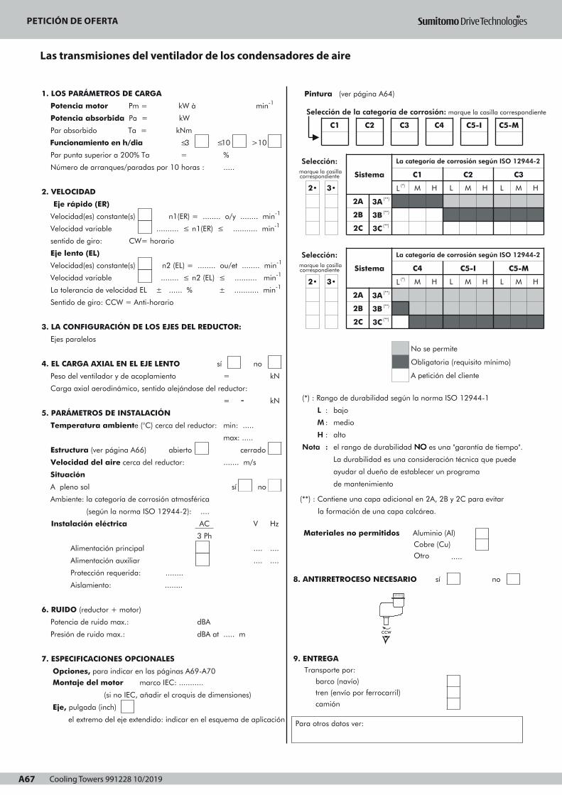
Cooling Towers 991228 10/2019A67
PETICION DE OFERTALAS TRANSMISIONES DEL VENTILADOR DE LOS CONDENSADORES DE AIRE
A67
1. LOS PARÁMETROS DE CARGA
Potencia motor Pm = kW à min-1
Potencia absorbida Pa = kW
Par absorbido Ta = kNm
Funcionamiento en h/dia ≤3
Par punta superior a 200% Ta =
Número de arranques/paradas por 10 horas :
≤10 >10
%
.....
2. VELOCIDAD
Eje rápido (ER)
Velocidad(es) constante(s) n1(ER) = ........ o/y ........ min-1
Velocidad variable .......... ≤ n1(ER) ≤ ........... min-1
sentido de giro: CW= horario
Eje lento (EL)
Velocidad(es) constante(s) n2 (EL) = ........ ou/et ........ min-1
Velocidad variable ........ ≤ n2 (EL) ≤ .......... min-1
La tolerancia de velocidad EL ± ...... % ± ........... min-1
Sentido de giro: CCW = Anti-horario
3. LA CONFIGURACIÓN DE LOS EJES DEL REDUCTOR:
Ejes paralelos
4. EL CARGA AXIAL EN EL EJE LENTO sí no
Peso del ventilador y de acoplamiento
Carga axial aerodinámico, sentido alejándose del reductor:
5. PARÁMETROS DE INSTALACIÓN
Temperatura ambiente (°C) cerca del reductor:
Estructura (ver página A66) abierto
Velocidad del aire cerca del reductor:
=
= -
kN
kN
min: .....
max: .....
....... m/s
cerrado
Situación
A pleno sol
Ambiente: la categoría de corrosión atmosférica
(según la norma ISO 12944-2): ....
Instalación eléctrica
Alimentación principal
Alimentación auxiliar
AC
3 Ph
sí no
V Hz
....
....
....
....
Protección requerida: ........
Aislamiento: ........
6. RUIDO (reductor + motor)
Potencia de ruido max.:
Presión de ruido max.:
7. ESPECIFICACIONES OPCIONALES
dBA
dBA at ..... m
Opciones, para indicar en las páginas A69-A70
Montaje del motor marco IEC: ...........
(si no IEC, añadir el croquis de dimensiones)
Eje, pulgada (inch)
el extremo del eje extendido: indicar en el esquema de aplicación
Ref : Fecha : Nombre : Firma :
Pintura (ver página A64)
(*) : Rango de durabilidad según la norma ISO 12944-1
L : bajo
M : medio
H : alto
Nota : el rango de durabilidad NNNNOOOO es una "garantía de tiempo".
La durabilidad es una consideración técnica que puede
ayudar al dueño de establecer un programa
de mantenimiento
(**) : Contiene una capa adicional en 2A, 2B y 2C para evitar
la formación de una capa calcárea.
Materiales no permitidos Aluminio (Al)
Cobre (Cu)
Otro .....
8. ANTIRRETROCESO NECESARIO sí no
9. ENTREGA Transporte por:
barco (navío)
tren (envío por ferrocarril)
camión
Para otros datos ver:
Selección: marque la casillacorrespondiente
2• 3•
Sistema
La categoría de corrosión según ISO 12944-2
L (*)
C1
M H L
C2
M H L
C3
M
2A
2B
3A (**)
3B (**)
2C 3C (**)
Selección: marque la casillacorrespondiente
2• 3•
Sistema
2A 3A (**)
2B
2C
3B (**)
3C (**)
La categoría de corrosión según ISO 12944-2
C4
L (*) M H L
No se permite
C5-I
M H
C5-M
L M
Obligatoria (requisito mínimo)
A petición del cliente
H
H
Selección de la categoría de corrosión: marque la casilla correspondiente
C1 C2 C3 C4 C5-I C5-M
CCW
Page 1
PETICIÓN DE OFERTA
Las transmisiones del ventilador de los condensadores de aire
Cooling Towers 991228 10/2019 A68
PETICIÓN DE OFERTA
Esquema de aplicación
ES
VISTA EN PLANTA
VISTA LATERAL
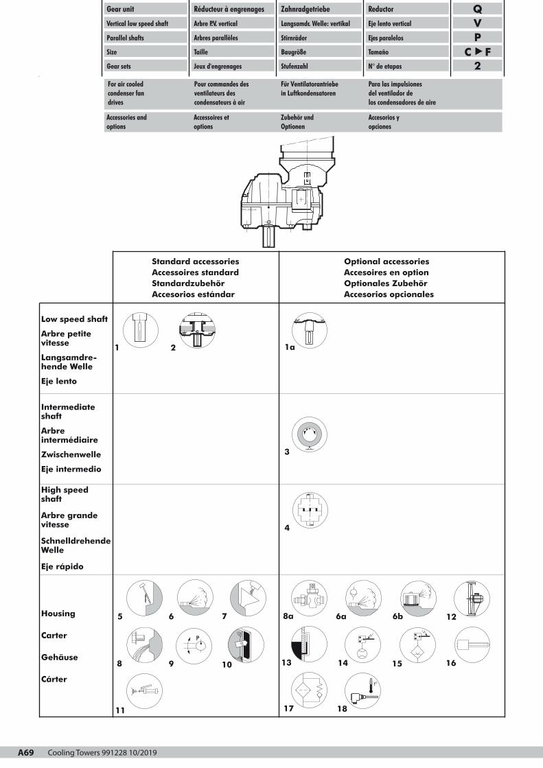
Cooling Towers 991228 10/2019A69
t°
Gear unit
Vertical low speed shaft
Parallel shafts
Size
Gear sets
Réducteur à engrenages
Arbre P.V. vertical
Taille
Jeux d'engrenages
Zahnradgetriebe
Langsamdr. Welle: vertikal
Stirnräder
Baugröße
Stufenzahl
Reductor
Eje lento vertical
Ejes paralelos
Tamaño
N° de etapas
QVP
C F2
Standard accessoriesAccessoires standard Standardzubehör Accesorios estándar
Optional accessoriesAccesoires en optionOptionales ZubehörAccesorios opcionales
Low speed shaft
Arbre petitevitesse
Langsamdre-hende Welle
Eje lento
Intermediateshaft
Arbreintermédiaire
Zwischenwelle
Eje intermedio
High speedshaft
Arbre grandevitesse
SchnelldrehendeWelle
Eje rápido
Housing
Carter
Gehäuse
Cárter
P
9 13 15
8a 12
14
6
•
11
16
1 1a
3
6a
108
Accessories and Accessoires et Zubehör und Accesorios yoptions options Optionen opciones
For air cooled Pour commandes des Für Ventilatorantriebe Para las impulsionescondenser fan ventilateurs des in Luftkondensatoren del ventilador dedrives condensateurs à air los condensadores de aire
A69
2
5 7
Arbres parallèles
t°
1817
6b
4
Page 1

Cooling Towers 991228 10/2019 A70
1
:::: ooooppppttttiiiioooonnnnaaaallll
normal solid output shaft
1a
2
extended solid output shaft
drywell
1
:::: eeeennnn ooooppppttttiiiioooonnnn
arbre petite vitesse normal 1
1a
2
plein
arbre petite vitesse allongé 1a
plein
buselure à rebord 2
3
4
5
built-in backstop
standard elastic block-type
coupling
dipstick
6
6a
6b
breather plug or
anti-humidity breather plug or
dust-proof breather plug
3
4
5
antidévireur incorporé
accouplement élastique
3
4
standard à tampons
jauge d'huile 5
6
6a
6b
reniflard ou
reniflard anti-humidité ou
6
6a
reniflard anti-poussière 6b
7
8
oil filling plug
draining plug (with magnet) or
8a
9
10
drain cock with hose
coupling
pump lubrication
gear unit inspection cover
7
8
bouchon de remplissage 7
bouchon de vidange
(avec aimant) ou
8
8a
9
10
robinet de vidange avec
raccord pour tuyau
8a
lubrification par pompe
couvercle d'inspection du
9
10
11
12
grease point (DIN 71412)
axial fan with electric motor
13
14
15
oil level glass
flow switch
oil level switch
11
12
réducteur
point de graissage (DIN 71412) 11
ventilateur axial avec moteur 12
13
14
15
électrique
indicateur de niveau d'huile 13
contacteur de débit
contacteur de niveau d'huile
14
15
16
17
18
heater
oil filter
Pt 100 meter for oil sump
temperature
16
17
18
réchauffeur
filtre d'huile
16
17
appareil de mesure Pt 100 pour
la température du bain d'huile
18
:::: OOOOppppttttiiiioooonnnn
Normale Abtriebswelle: 1
Vollwelle
verlängerte Abtriebswelle:
Vollwelle
Steigrohr
1a
2
: OOOOppppcccciiiióóóónnnn
eje lento: eje macizo normal
eje lento extendido:
eje macizo
deflector de aceite
eingebaute Rücklaufsperre
Standard elastische Klauen-
kupplung
Ölmeßstab
3
4
5
Entlüftungsschraube oder
Entlüftungsschraube für
feuchte Umgebung oder
Entlüftungsschraube mit Staub-
6
6a
6b
antirretroceso incorporado
acoplamiento elástico normal
a tampones
varilla del nivel
tapón de aireación o
tapón de aireación anti-
humedad o
tapón de aireación anti-
filter
Öleinfüllschraube
Ablaßschraube (mit Magnet)
oder
7
8
Ölablaßhahn mit
Rohranschluß
Pumpenschmierung
Getriebe-Schaulochdeckel
8a
9
10
polvo
tapón de llenado
tapón de drenaje (con el imán)
o
llave de vaciado con racor
lubricación para bomba
tapa de inspección del
Fettschmierpunkt (DIN 71412)
Axiallüfter mit Elektromotor
11
12
Ölstandglas
Strömungsschalter
Ölstandschalter
13
14
15
reductor
punto de la lubricación
(DIN 71412)
ventilador axial con el motor
eléctrico
indicador de nivel de aceite
interruptor de caudal
interruptor nivel de aceite
Heizstab
Ölfilter
Pt 100 für Ölbadtemperatur-
messung
16
17
18
calentador
filtro de aceite
medidor Pt100 para tempera-
tura del baño de aceite
Gear unit
Vertical low speed shaft
Parallel shafts
Size
Gear sets
Réducteur à engrenages
Arbre P.V. vertical
Taille
Jeux d'engrenages
Zahnradgetriebe
Langsamdr. Welle: vertikal
Stirnräder
Baugröße
Stufenzahl
Reductor
Eje lento vertical
Ejes paralelos
Tamaño
N° de etapas
QVP
C F2
Accessories and Accessoires et Zubehör und Accesorios yoptions options Optionen opciones
For air cooled Pour commandes des Für Ventilatorantriebe Para las impulsionescondenser fan ventilateurs des in Luftkondensatoren del ventilador dedrives condensateurs à air los condensadores de aire
Arbres parallèles
A70
Page 1

Cooling Towers 991228 10/2019A71
Gear unit
Vertical low speed shaft
Parallel shafts
Size
Two stages
Réducteur à engrenages
Arbre P.V. vertical
Arbres parallèles
Taille
Deux étages
Zahnradgetriebe
Langsamdr. Welle: vertikal
Stirnräder
Baugröße
Zweistufig
Reductor
Eje lento vertical
Ejes paralelos
Tamaño
Dos etapas
FxN
A71
Mechanical Puissances méca- Nennleistungen Potencias mecá-power ratings niques nominales nicas nominales
Rated thrust load Charge axiale Nennaxialbelastung Carge axialnominale nomínal
P (kW) FxN (kN) iex J (kgm2)
iN min-1
n1 n2
Size - Taille - Baugröße - TamañoC D E F
Size - Taille - Baugröße - TamañoC D E F
Size - Taille - Baugröße - TamañoC D E F
18001500
285240
12001000
190160
360320
546470
265230
400340
940790
13501150
640530
940790
2728,5
26,528,5
3030
3131
3538
6670
4246
7681
6,2296 6,4156 6,1875 6,4699
900750
145120
18001500
255210
12001000
170140
900750
125105
205175
310260
330290
490430
480400
710600
820690
12001000
240200
360300
180150
270225
550460
820690
420350
620520
3132
3233
27,529
27,529
4648
8486
3639
6873
29,530
3031
3132
3233
4446
7985
4648
8688
0,0547 0,108
7,1594 7,2524
0,213 0,423
7,1188 7,0074
0,0514 0,103 0,2 0,408
18001500
225190
12001000
150125
900750
11594
18001500
200165
320270
460410
225190
330280
770650
1150950
520440
770640
175145
250210
285240
420360
390330
580490
670560
1000830
12001000
135110
900750
10083
18001500
180150
12001000
120100
195160
290245
145120
220185
450380
670560
340285
510430
260225
390330
185155
265220
610510
890740
410340
600500
28,529,5
2931
3031
3132
3842
7076
4647
8285
3132
3334
2929,5
29,530
4849
8689
4043
7479
7,7364 7,9673 7,6261 7,9849
0,0415 0,0823
8,8911 9,0065
0,162 0,322
8,7738 8,64833031
3132
3233
3334
4647
8587
4850
8891
3030
3031
3132
3334
4346
7883
4849
8688
0,0394 0,0787 0,154 0,312
9,7673 10,059 9,7903 10,326
900750
9075
18001500
160135
12001000
10589
900750
8067
140115
200165
230190
340285
310260
450380
520440
780650
155130
230195
11597
175145
350295
520440
265225
400330
18001500
145120
12001000
9680
900750
7260
18001500
130105
210180
310260
145120
210175
490410
710590
330275
480400
11091
160135
180150
275230
250210
360300
420350
620520
3334
3436
29,531
3132
5052
9092
4546
8185
3232
3334
3334
3536
4849
8890
5052
9194
0,0314 0,0623
11,225 11,371
0,12 0,236
11,264 11,183
0,0301 0,0601 0,114 0,23
3131
3233
3233
3435
4648
8486
5051
8991
3436
3637
3132
3233
5253
9395
4748
8688
12,54 12,73 12,176 13
0,0239 0,048
14,412 14,39
0,0926 0,181
14,009 14,0812001000
8671
900750
6454
18001500
11594
12001000
7563
120100
185155
9176
140115
285240
420350
215180
320265
175145
245205
11598
165135
380320
580480
255215
390330
900750
5647
18001500
10083
12001000
6756
900750
5042
8874
125105
145120
210175
195160
295245
330275
510420
9781
140120
7361
10590
220185
340285
165140
255215
3334
3435
3538
3639
5051
9193
5254
9497
3132
3334
3435
3537
4850
8689
5253
9294
0,0231 0,0466 0,0892 0,178
15,557 16,461 15,745 16,036
3639
3841
3233
3435
5458
9598
4850
8891
3437
3638
3841
4143
5254
9496
5660
98100
0,0191 0,0368
17,879 18,608
0,0698 0,145
18,115 17,368
0,0186 0,0359 0,0677 0,142
18001500
9075
12001000
6050
900750
4538
18001500
8067
135115
200170
9277
135115
310255
470390
205175
310260
6958
10085
11595
175145
155130
235195
265220
410340
12001000
5445
900750
4033
7664
11598
5748
8874
180150
275230
135110
205170
3334
3435
3638
3740
5052
8992
5455
9597
4043
4245
3335
3536
5863
98105
5052
9194
19,969 20,069 19,671 20,059
0,0152 0,0305
22,949 22,686
0,0555 0,115
22,631 21,7253840
3942
4245
4447
5458
9799
6166
100110
0,0149 0,0299 0,0542 0,114
6,3
7,1
8
9
10
11,2
12,5
14
16
18
20
22,4
P (kW)
FxN (kN)
QVP
C F2
iN Nominal ratio iN Rapport nominal iN Nennübersetzung iN Índice nominaln1, 2iex
Nominal speed (rpm)Exact ratio
n1, 2iex
Vitesse nominaleRapport exact
n1, 2iex
NenndrehzahlExakte Ubersetzung
n1, 2iex
Velocidades nominales (r.p.m.)Indice exactos
J Moments of inertia Jrelated to the HSS
J Moments d'inertie Jrapportés à l'arbre G.V.
J MassenträgheitsmomenteJ beziehen sich auf die SDW
J Momentos de inercia Jrelativos al eje rápido
Page 1

Cooling Towers 991228 10/2019 A72
Gear unit
Vertical low speed shaft
Parallel shafts
Size
Two stages
Réducteur à engrenages
Arbre P.V. vertical
Arbres parallèles
Taille
Deux étages
Zahnradgetriebe
Langsamdr. Welle: vertikal
Stirnräder
Baugröße
Zweistufig
Reductor
Eje lento vertical
Ejes paralelos
Tamaño
Dos etapas
QVP
C F2
Thermal Puissances ther- Wärmegrenz- Potencias térmi-power ratings miques nominales leistungen cas nominales
iNmin-1
n1
1800 -
Size - Taille - Baugröße - TamañoC46
D46
E F
1500
1-
1200
1-
17570
23086
19084
260110
34069
360
360120
430140
1000
1-
900
1-
750
1-
1800
1-
19590
270120
19092
265120
370140
460170
370145
460185
19092
265125
18067
25580
360150
460200
35073
45071
1500
1-
1200
1-
1000
1-
900
1-
17076
23596
17581
235105
320105
390125
330125
400160
17082
235110
16581
230110
320130
400170
310135
390170
750
1-
1800
1-
1500
1-
1200
1-
16078
225105
15065
21582
310135
380180
29587
370105
14067
20089
13567
20091
255100
330130
255110
330140
1000
1-
900
1-
750
1-1
13066
19090
12564
18588
250110
320150
235110
310150
12062
18085
115 170
230110
300150
220 290
6,3
9
10
14
16
22,4
Pt (kW)
A72
Number of fans. Nombre de ventilateurs. Lüfterzahl. Número de ventiladores.Correction factors -see p. A48
Facteurs de correction -voir p. A54
Korrekturfaktoren -Siehe S. A60
Factores de correcciónver pag. A66
iN Nominal ratio iN Rapport nominal iN Nennübersetzung iN Índice nominal
n1, 2 Nominal speed (rpm) n1, 2 Vitesse nominale n1, 2 Nenndrehzahl n1, 2 Velocidades nominales (r.p.m.)
Page 1

Cooling Towers 991228 10/2019A73
97QU-VP2N40013 A
Gear unit
Vertical low speed shaft
Parallel shafts
Size
Two stages
Réducteur à engrenages
Arbre P.V. vertical
Arbres parallèles
Taille
Deux étages
Zahnradgetriebe
Langsamdr. Welle: vertikal
Stirnräder
Baugröße
Zweistufig
Reductor
Eje lento vertical
Ejes paralelos
Tamaño
Dos etapas
QVP
C F2mm
UDN
FP
CU
CM
CV
4xT
FP
RM
EE
RM
FP
FP
RM
M
E
E
C
AB
AB
RM
C
(2)
PC
BC
JSTR
L DP
D
LB
DB
DM
CB
JP
(2)DF
LF
(2)HS
JM
PB
X
Y
D
Z
DIN
332
"D"
ZB DIN 332
"D"DB
YB
XB
HF
For air cooled condenser Pour commandes des Für Ventilatorantriebe Para las impulsiones del ventiladorfan drives condensateurs à air in Luftkondensatoren de los condensadores de aire
The user isresponsible forthe provision ofsafety guardsand correct in-stallation of allequipment.
Certified dimen-sions upon re-quest.
Les dispositifs deprotection doi-vent être prévuspar l'utilisateur.Celui-ci est responsablede l'installationcorrecte del'ensemble.
Dimensions défi-nitives sur de-mande.
Der Benutzer istverantwortlich fürdie Beistellungder Schutzhau-ben und dasfachgemäße Auf-stellen der ge-samtenAusrüstung.
Verbindl. Abmes-sungen aufWunsch.
El usuario es res-ponsable delaprovisionamien-to de los dispositivos deseguridad y de lacorrectainstalación de to-do el equipo.
Plano de dimen-siones certifica-das, bajopetición.
(1) Space forpump removal(2) Greaselubricationpoint(3) +90 mmfor explosionproof execu-tion
(1) Espace dedégagementde la pompe(2) Point degraissage(3) +90 mmpour exécutionantidéfla-grante
(1) FreierRaum fürDemontageder Pumpe(2)Fettschmier-stelle(3) +90 mmfür ex-SchutzAusführung
(1) Espaciopara retirar labomba(2) Punto deengrase(3) +90 mmpara la ejecu-ción a pruebade explosiones
Shaft arrangements Dispositions des arbres Wellenanordnungen Disposición de ejes(front view) (vue de face) (Vorderansicht) (vista delantera)
Type AB BC C CB CU CV E FP HS JS M RM T TR kg LitresLiter
QVPC2QVPD2
255285
280290
470530
345397
260290
487553
200225
3540
520605
204207
165195
9595
2835
3840
410590
2934
QVPE2QVPF2
320365
335372
600690
459525
326370
637720
260295
4050
665735
245243
225265
105135
3542
4552
8801200
5580
Type Shafts - Arbres - Wellen - Ejes Keys Clavettes Paßfeder Chavetas ISO/R773-1969
QVPC2
D-m6
105
L
210
X
28
Y
111
Z
M24
DB
48k6
LB
110
XB
14
YB
51,5
ZB
M16
Fan-VentilateurLüfter - Ventilador
DF
410
HF
212
Pump - Pompe Pumpe - Bomba
LF (3)
910
DP (1)
110
JP
29
PB (1)
75
PC (1)
110QVPD2QVPE2QVPF2
115135
210250
155 250
3236
122143
40 164
M24M30
58m665m6
M30 75m6
140140
1618
140 20
6269
M20M20
79,5 M20
480510
245280
560 320
9801050
110145
1145 145
19-1
6550
6 60
110145145
MOTOR - MOTEUR Hansen P4
DM QVPC2
CM JM
QVPD2
CM JM
QVPE2
CM JM
QVPF2
CM
CouplingAccouplement
KupplungAcoplamientoJM
225250280315
450550
570620
550660
620675
145145 672145175
672727
145 734145175
734789
145145175 855
Refer to usVeuillez nous consulter
175Rückfrage zu empfehlen
Sírvanse consultar355 800 859 215 925 215
IECCEIV1
A73
Page 1

Cooling Towers 991228 10/2019 A74

Cooling Towers 991228 10/2019A75

Cooling Towers 991228 10/2019 B
COOLING TOWER DRIVES
Hansen P4 standardized gear units
Programme - Selection B2
Description B3 - B4
Selection B5 - B6
Request for quotation B7 - B8
Accessories and options B39 - B42
Rating tables
Mechanical power ratings B43 - B44
Rated thrust load B45 - B46
Thermal power ratings B47
Exact ratio's iex and moments of inertia J B48
Dimensional drawing
Hansen P4 gear units, right-angle shafts, two stages B49 - B53
SECTION B - CONTENTS
E
B
Page 1
COOLING TOWER DRIVES
EN

Cooling Towers 991228 10/2019B1
STANDARDISED GEAR UNITS FOR COOLING TOWER DRIVES
PROGRAMME - SELECTION
800
710
630
560
500
400
355
315
280
250
225
200
160
132
110
90
75
55
45
37
30
22
18,5
3,55 4 4,5 5 5,6 6,3 7,1 8 9 10 11,2 12,5 14 16 18 20 22,4
QVR.2. - CUN
C H
QVR.2 - CUN
Z B
Motor Power
Pm (kW - 1500 min-1) / SF = 1,75
QVR.2L - CUN
Z B
E
B2
INNominal ratio
Page 1
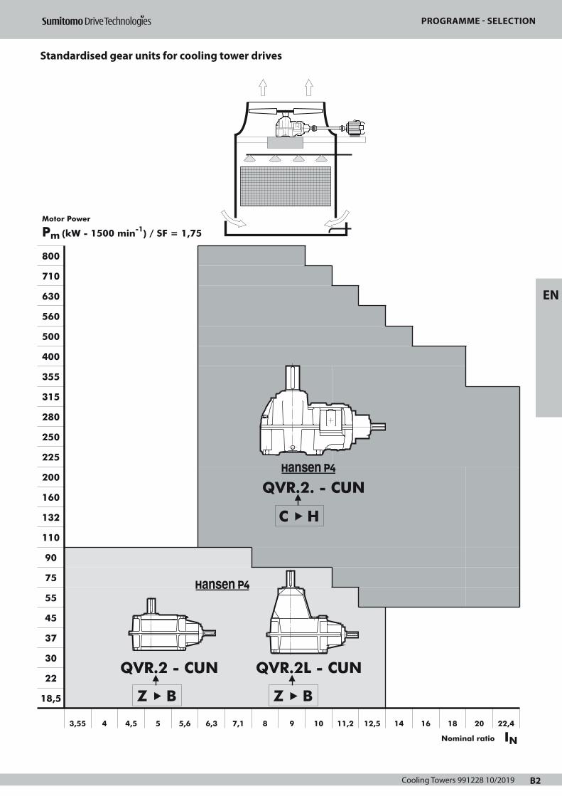
Cooling Towers 991228 10/2019 B2
STANDARDISED GEAR UNITS FOR COOLING TOWER DRIVES
PROGRAMME - SELECTION
800
710
630
560
500
400
355
315
280
250
225
200
160
132
110
90
75
55
45
37
30
22
18,5
3,55 4 4,5 5 5,6 6,3 7,1 8 9 10 11,2 12,5 14 16 18 20 22,4
QVR.2. - CUN
C H
QVR.2 - CUN
Z B
Motor Power
Pm (kW - 1500 min-1) / SF = 1,75
QVR.2L - CUN
Z B
E
B2
INNominal ratio
Page 1
PROGRAMME - SELECTION
Standardised gear units for cooling tower drives
EN

Cooling Towers 991228 10/2019B3
DESCRIPTIONHANSEN P4 GEAR UNITS
FOR COOLING TOWER DRIVES
B3
The gear unit
Units are designed to comply with the standard CTI specifications.The mechanical power ratings shown in the tables relate respectivelyto input speeds of 1800, 1500, 1200, 1000, 900 and 750 RPM atthe high speed shaft. They are also valid for asynchronous speedswhich are max. 3% lower than the synchronous speeds.Interpolation will yield power rating values for intermediate speeds.The power rating for speeds lower than 750 RPM is based on thecontinuous torque rating of that speed.For input speeds exceeding 1800 RPM, please refer to us.
Coding
Type1 : series Q : Hansen P42 : V : vertical low speed shaft3 : R : right-angle shafts4 : Size: Z, A, B, ... H5 : number of stages: 25 bis: / : standard gear unit (no code)
L : extended bearing housing (sizes Z, A, B)X : intermediate size
Shaft arrangement6 : high speed shaft extension: C: right-angle7 : low speed shaft extension: U: up8 : low speed shaft type: N: normal solid shaft
Ratio9 : nominal ratio
Basic components
Helical and spiral bevel gearsDesigned and rated in accordance with AGMA for maximum loadcapacity, minimum losses and quiet operation.All geared components are manufactured from alloy steel, gascarburized, hardened and precision ground.
Low speed shaftsThe low speed shafts are in solid version.Extended shafts are available upon request.For all executions, input and output shafts are located in the samevertical plane.
BearingsHeavy duty roller bearings of the tapered, cylindrical or sphericalroller type.Calculated in compliance with ISO and renowned bearingmanufacturers.The low speed shaft bearings are selected to allow considerablethrust loads. The nominal permissible thrust load FxN mentioned inthe tables, pages B45-B46, is defined for a SFmin = 2, low speedshaft rotating clockwise and guarantees a calculated bearing life of 100000 hours.
1
Q2
V3
R4 5
25 bis
-6
C7
U8
N -9
Housings, bearing housings and coversMade from grey pearlitic cast iron.Machined on CNC machining centers.Designed to ensure strength and rigidity.Unused tapped holes are plugged.Horizontal split housing.
Systems
LubricationLubricants: mineral oils are normally used. Lubricants should alwayscontain adequate EP-additives (refer to Service Manual).Pump lubrication for the upper bearings is standard or optionally avai-lable.The gear unit housing acts as a large oil sumpLow speed shafts are provided with a regreasable labyrinth. Greasenipples, if any, are according to DIN 71412. When using external ser-vice piping, the nipple can be moved outside the fan stack. Checking of the oil level is done by means of the gear unit dipstick (al-ways in the plugged position). To expedite routine maintenance of wet cooling tower fan drives,service piping outside the fan stack (not provided by Hansen IndustrialTransmissions nv), is recommended. This piping is arranged so that theoil can be drained and refilled from outside the stack. The standardbreather and draining plug, fitted in the gear unit on delivery, shouldbe removed and plugged in outside the stack (away from the directstream of moist air).For ease of maintenance a dipstick outside the fan stack is recom-mended. Periodically, the external dipstick should be checked against the gearunit dipstick.
Cooling Heat generated in the gear unit due to losses, can be dissipated by:
• natural cooling through the housing• additional fan cooling: a shaft driven axial fan can be
incorporated (see page B41)Free air entry at the suction side should be guaranteed
Thermal checks see page B6
SealingStatic: • Generalized use of sealing compound
• Inspection cover on the gear unit: O-ring Rotary: • High speed shaft: depending on gear unit type
Refer to description of each type of gear unit on pages B39 up to B42Oil LockTM: - dual purpose labyrinth
- maintenance free - oil return to sump• Low speed shaft: - dust lip oil seal - grease purged labyrinth
Page 1
DESCRIPTIONHANSEN P4 GEAR UNITS
FOR COOLING TOWER DRIVES
Motors
Right-angle gear units are driven by foot mounted IEC motors (typeB3). For more information on motors, refer to motor catalogues.For Nema motors, refer to us.Use of two speed motors: when changing speed with two speed mo-tors, the motor has to be slowed down below the low speed, beforeenergising the slow speed winding.
Optional devices
Some devices can optionally be provided (refer to pages B39 up toB46). More detailed information about the optional devices is men-tioned in separate technical manuals. Refer to us.
Backstop Built-in backstop to prevent the fan from "wind-milling". Internallubrication is assured.
FilterWith incorporated pressure relief valve.A filter with incorporated pressure relief valve and visual or electricalcontamination indicator is available as an option.
HeatersElectrical heating devices for low temperature start-up are availablefor Hansen P4 gear units from sizes C to H.
Flow switchWhen gear units are pump lubricated, a flow switch can be providedto check the oil flow to the gear unit. This switch can trigger analarm signal when the oil supply is inadequate. The gear unit has tobe stopped at once and the cause of the interruption of the oil sup-ply has to be removed.
Oil level switchTo control the oil level in the gear unit, an oil level switch can beprovided. This switch can trigger an alarm signal when the oil bathfalls beneath a specified limit.
Pt100To control the oil bath temperature. The Pt100 can trigger an alarmsignal when the oil temperature is higher than a specified limit.
Shipping conditions
Inspection prior to shipment• Test run: all gear units are tested under no load• Conformity Check
Protection• Shaft extension: greased and protected with waxed
waterproof paper
Lubricants• Hansen P4 gear units are shipped without oil.
• Grease lubrication points are factory filled.
For information relating to storage, handling, installation,start-up and maintenance, refer to the service manual which issupplied together with each gear unit.
Protection
Standard protection systems• As a standard, Hansen P4 gear units for cooling tower drives areprovided with a painting system that is suitable to be applied in theatmospheric-corrosivity category “C4 (L)” according to ISO 12944-2(and ISO 12944-5).The choice of colour has no influence on the technical quality of thepainting system.Other painting systems can be offered to meet the required atmos-pheric-corrosivity category for your application.
• Bolts and nuts provided with appropriate protection.
Aggressive environmentFor wet cooling tower drives in aggressive environment, an addi-
tional protection system can be offered: refer to us.
E
B4
Page 1
DESCRIPTION
Hansen P4 gear units for cooling tower drives
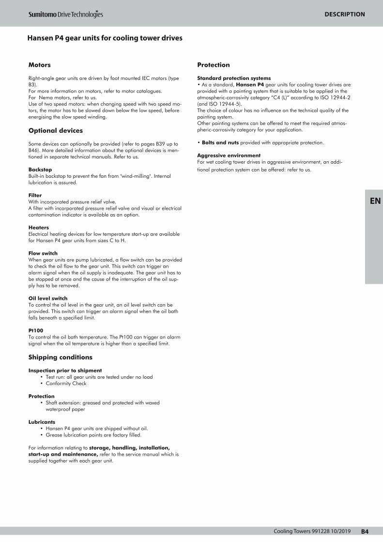
Cooling Towers 991228 10/2019 B4
DESCRIPTIONHANSEN P4 GEAR UNITS
FOR COOLING TOWER DRIVES
Motors
Right-angle gear units are driven by foot mounted IEC motors (typeB3). For more information on motors, refer to motor catalogues.For Nema motors, refer to us.Use of two speed motors: when changing speed with two speed mo-tors, the motor has to be slowed down below the low speed, beforeenergising the slow speed winding.
Optional devices
Some devices can optionally be provided (refer to pages B39 up toB46). More detailed information about the optional devices is men-tioned in separate technical manuals. Refer to us.
Backstop Built-in backstop to prevent the fan from "wind-milling". Internallubrication is assured.
FilterWith incorporated pressure relief valve.A filter with incorporated pressure relief valve and visual or electricalcontamination indicator is available as an option.
HeatersElectrical heating devices for low temperature start-up are availablefor Hansen P4 gear units from sizes C to H.
Flow switchWhen gear units are pump lubricated, a flow switch can be providedto check the oil flow to the gear unit. This switch can trigger analarm signal when the oil supply is inadequate. The gear unit has tobe stopped at once and the cause of the interruption of the oil sup-ply has to be removed.
Oil level switchTo control the oil level in the gear unit, an oil level switch can beprovided. This switch can trigger an alarm signal when the oil bathfalls beneath a specified limit.
Pt100To control the oil bath temperature. The Pt100 can trigger an alarmsignal when the oil temperature is higher than a specified limit.
Shipping conditions
Inspection prior to shipment• Test run: all gear units are tested under no load• Conformity Check
Protection• Shaft extension: greased and protected with waxed
waterproof paper
Lubricants• Hansen P4 gear units are shipped without oil.
• Grease lubrication points are factory filled.
For information relating to storage, handling, installation,start-up and maintenance, refer to the service manual which issupplied together with each gear unit.
Protection
Standard protection systems• As a standard, Hansen P4 gear units for cooling tower drives areprovided with a painting system that is suitable to be applied in theatmospheric-corrosivity category “C4 (L)” according to ISO 12944-2(and ISO 12944-5).The choice of colour has no influence on the technical quality of thepainting system.Other painting systems can be offered to meet the required atmos-pheric-corrosivity category for your application.
• Bolts and nuts provided with appropriate protection.
Aggressive environmentFor wet cooling tower drives in aggressive environment, an addi-
tional protection system can be offered: refer to us.
E
B4
Page 1
DESCRIPTION
Hansen P4 gear units for cooling tower drives
EN

Cooling Towers 991228 10/2019B5
SELECTIONMechanical power rating
COOLING TOWER DRIVES
B5
refer to page B7
refer to page B2
for ratio's < smallest ratio in the rating tables (p. B43-B44): refer to us
Procedure Reference Data
Mechanical powerrating P
Ratio
2
3
for
• • • • • • - • • • - Ratio
Q V R 2 • - C U N
1
SELECTION DATA
Pm , Pa , nHSS , nLSS , iN
Thrust load
Fx
PROGRAMME SELECTION
Absorbed Power Pa
PMotor Power Pm
and
x SF =1,75
x SF = 2
≥
see p. B43-B44 *
PSize
S
E
L
E
C
T
I
O
N
C
H
E
C
K
Size
* Remark: values for P and Fx (p. B43-B46) are the same for QVR.2
and QVR.2L
P
Thermal rating see pages B6, B47
/ = standard gear unit (no code)
LX
=
=
extended bearing housing (sizes Z, A, B)
intermediate size
Fx : ... kN
Pay attention to direction of Fx ! (Always downwards)
Check if
≤Fx FxN
see p. B45-B46 *
FxN
Page 1
SELECTIONThermal power rating
COOLING TOWER DRIVES
Ptn for gear unit without forced cooling
factor a for ambient temperature without forced cooling
Reduction
Ratio 15 to 25
Ambient temperature in °C
25 to 35 35 to 45
6,3 11,2
12,5 18
≥ 20
Size
1
1
0,81
0,85
1
Z H
0,87
Z H
0,68
0,71
0,55
0,66
0,75
Z D
0,74
E H
OK
Thermal check
Pa ≤ Ptn • a • c • e ?
Cooling fan possible
No forced cooling required
Ptf for gear unit with 1 fan
Pa ≤ Ptf • d • e ? One fan
Reference Data
OK
Pt
Ptn, Ptf
forsee p.B47
Pt
factor c for air circulation (without fan)
Mounting
Indoors- small enclosure
Air flow
≥ 0,5 m/s 0,73 0,70
Indoors- normal working areas
Outdoors- protected against sun
Size
≥ 1,4 m/s
≥ 3,0 m/s
1
1,33
Z D
1
1,36
E H
factor d for ambient temperature with forced cooling
Number of
stages
Ambient temperature in °C
15 to 25 25 to 35 35 to 45 45 to 55
with forced cooling 2 1 0,86 0,72 0,59
factor e for relative air humidity
Relative air humidity
< 100% = 100%
1 1,15
E• • • • • • - • • • - Ratio
Q V R 2 • - C U N
Size/ = standard gear unit (no code)
LX
=
=
extended bearing housing (sizes Z, A, B)
intermediate size
B6
Air flow to be selected according to the structure:
Open structure: gear units installed in an open steel frame structure
allowing the cooling tower air flow to pass over the gear unit's housing.
Closed structure: gear units installed on a solid concrete plinth or enclosed
steel frame. This structure prevents the cooling tower air flow from passing
over the gear unit's housing.
Page 1
SELECCIÓN
Mechanical power rating cooling tower drives

Cooling Towers 991228 10/2019 B6
SELECTIONThermal power rating
COOLING TOWER DRIVES
Ptn for gear unit without forced cooling
factor a for ambient temperature without forced cooling
Reduction
Ratio 15 to 25
Ambient temperature in °C
25 to 35 35 to 45
6,3 11,2
12,5 18
≥ 20
Size
1
1
0,81
0,85
1
Z H
0,87
Z H
0,68
0,71
0,55
0,66
0,75
Z D
0,74
E H
OK
Thermal check
Pa ≤ Ptn • a • c • e ?
Cooling fan possible
No forced cooling required
Ptf for gear unit with 1 fan
Pa ≤ Ptf • d • e ? One fan
Reference Data
OK
Pt
Ptn, Ptf
forsee p.B47
Pt
factor c for air circulation (without fan)
Mounting
Indoors- small enclosure
Air flow
≥ 0,5 m/s 0,73 0,70
Indoors- normal working areas
Outdoors- protected against sun
Size
≥ 1,4 m/s
≥ 3,0 m/s
1
1,33
Z D
1
1,36
E H
factor d for ambient temperature with forced cooling
Number of
stages
Ambient temperature in °C
15 to 25 25 to 35 35 to 45 45 to 55
with forced cooling 2 1 0,86 0,72 0,59
factor e for relative air humidity
Relative air humidity
< 100% = 100%
1 1,15
E• • • • • • - • • • - Ratio
Q V R 2 • - C U N
Size/ = standard gear unit (no code)
LX
=
=
extended bearing housing (sizes Z, A, B)
intermediate size
B6
Air flow to be selected according to the structure:
Open structure: gear units installed in an open steel frame structure
allowing the cooling tower air flow to pass over the gear unit's housing.
Closed structure: gear units installed on a solid concrete plinth or enclosed
steel frame. This structure prevents the cooling tower air flow from passing
over the gear unit's housing.
Page 1
SELECCIÓN
Thermal power rating cooling tower drives
EN
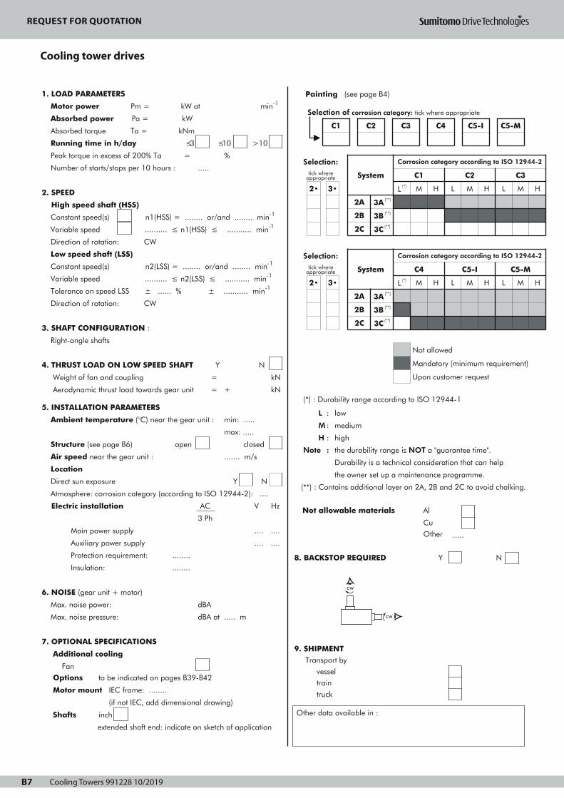
Cooling Towers 991228 10/2019B7
REQUEST FOR QUOTATION
COOLING TOWER DRIVES
B7
1. LOAD PARAMETERS
Motor power Pm = kW at min-1
Absorbed power Pa = kW
Absorbed torque Ta = kNm
Running time in h/day ≤3
Peak torque in excess of 200% Ta =
Number of starts/stops per 10 hours :
≤10
.....
>10
%
2. SPEED
High speed shaft (HSS)
Constant speed(s) n1(HSS) = ........ or/and ........ min-1
Variable speed .......... ≤ n1(HSS) ≤ ........... min-1
Direction of rotation: CW
Low speed shaft (LSS)
Constant speed(s) n2(LSS) = ........ or/and ........ min-1
Variable speed .......... ≤ n2(LSS) ≤ ........... min-1
Tolerance on speed LSS ± ...... % ± ........... min-1
Direction of rotation: CW
3. SHAFT CONFIGURATION :
Right-angle shafts
4. THRUST LOAD ON LOW SPEED SHAFT Y N
Weight of fan and coupling
Aerodynamic thrust load towards gear unit
5. INSTALLATION PARAMETERS
=
=
Ambient temperature (°C) near the gear unit :
Structure (see page B6) open
Air speed near the gear unit :
+
kN
kN
min: .....
max: .....
....... m/s
closed
Location
Direct sun exposure
Atmosphere: corrosion category (according to ISO 12944-2): ....
Electric installation AC
Main power supply
Auxiliary power supply
Protection requirement: ........
3 Ph
Y N
V Hz
.... ....
.... ....
Insulation: ........
6. NOISE (gear unit + motor)
Max. noise power: dBA
Max. noise pressure:
7. OPTIONAL SPECIFICATIONS
Additional cooling
dBA at ..... m
Fan
Options to be indicated on pages B39-B42
Motor mount IEC frame: ........
(if not IEC, add dimensional drawing)
Shafts inch
extended shaft end: indicate on sketch of application
Ref : Date : Name : Signature :
Painting (see page B4)
(*) : Durability range according to ISO 12944-1
L : low
M : medium
H : high
Note : the durability range is NOT a "guarantee time".
Durability is a technical consideration that can help
the owner set up a maintenance programme.
(**) : Contains additional layer on 2A, 2B and 2C to avoid chalking.
Not allowable materials Al
Cu
Other
8. BACKSTOP REQUIRED Y
.....
N
9. SHIPMENT Transport by
vessel
train
truck
Other data available in :
Selection:tick where
appropriate
2• 3•
System
Corrosion category according to ISO 12944-2
L (*)
C1
M H L
C2
M H L
C3
M
2A
2B
3A (**)
3B (**)
2C 3C (**)
Selection:tick where
appropriate
2• 3•
System
2A 3A (**)
2B
2C
3B (**)
3C (**)
Corrosion category according to ISO 12944-2
C4
L (*) M H L
Not allowed
C5-I
M H
C5-M
L M
Mandatory (minimum requirement)
Upon customer request
H
H
Selection of corrosion category: tick where appropriate
C1 C2 C3 C4 C5-I C5-M
CW
CW
Page 1
REQUEST FOR QUOTATION
Cooling tower drives

Cooling Towers 991228 10/2019 B8
REQUEST FOR QUOTATION
EN
TOP VIEW
SIDE VIEW
Sketch of application

Cooling Towers 991228 10/2019B9
COMMANDES D'AEROREFRIGERANTS
Réducteurs standard Hansen P4
Programme – Sélection B12
Description B13 - B14
Sélection B15 - B16
Demande d'offre B17 - B18
Accessoires et options B39 - B42
Tables de sélection
Puissances mécaniques nominales B43 - B44
Charge axiale nominale B45 - B46
Puissances thermiques nominales B47
Rapports de réduction exacts iex et moments d'inertie J B48
Plan d'encombrement
Réducteurs Hansen P4, arbres perpendiculaires,deux étages B49 - B53
SECTION B - INDEX F
B10
Page 1
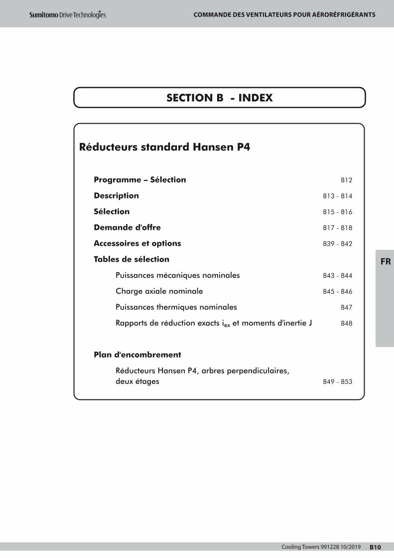
Cooling Towers 991228 10/2019 B10
COMMANDES D'AEROREFRIGERANTS
Réducteurs standard Hansen P4
Programme – Sélection B12
Description B13 - B14
Sélection B15 - B16
Demande d'offre B17 - B18
Accessoires et options B39 - B42
Tables de sélection
Puissances mécaniques nominales B43 - B44
Charge axiale nominale B45 - B46
Puissances thermiques nominales B47
Rapports de réduction exacts iex et moments d'inertie J B48
Plan d'encombrement
Réducteurs Hansen P4, arbres perpendiculaires,deux étages B49 - B53
SECTION B - INDEX F
B10
Page 1
COMMANDE DES VENTILATEURS POUR AÉRORÉFRIGÉRANTS
FR
Cooling Towers 991228 10/2019B11
RÉDUCTEURS STANDARD POUR COMMANDES DESAEROREFRIGERANTS
PROGRAMME - SELECTION
800
710
630
560
500
400
355
315
280
250
225
200
160
132
110
90
75
55
45
37
30
22
18,5
3,55 4 4,5 5 5,6 6,3 7,1 8 9 10 11,2 12,5 14 16 18 20 22,4
QVR.2. - CUN
C H
QVR.2 - CUN
Z B
Puissance motrice
Pm (kW - 1500 min-1) / SF = 1,75
QVR.2L - CUN
Z B
F
B12
Rapport nominal IN
Page 1

Cooling Towers 991228 10/2019 B12
RÉDUCTEURS STANDARD POUR COMMANDES DESAEROREFRIGERANTS
PROGRAMME - SELECTION
800
710
630
560
500
400
355
315
280
250
225
200
160
132
110
90
75
55
45
37
30
22
18,5
3,55 4 4,5 5 5,6 6,3 7,1 8 9 10 11,2 12,5 14 16 18 20 22,4
QVR.2. - CUN
C H
QVR.2 - CUN
Z B
Puissance motrice
Pm (kW - 1500 min-1) / SF = 1,75
QVR.2L - CUN
Z B
F
B12
Rapport nominal IN
Page 1
PROGRAMME SÉLECTION
Réducteurs standard pour commandes des aerorefrigerants
FR
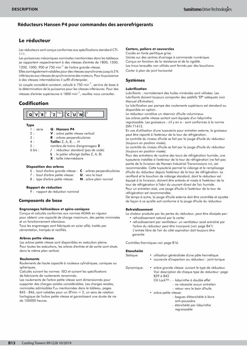
Cooling Towers 991228 10/2019B13
DESCRIPTIONRÉDUCTEURS HANSEN P4 POUR COMMANDES
DES AEROREFRIGERANTS
B13
Le réducteur
Les réducteurs sont conçus conformes aux spécifications standard CTI-111.Les puissances mécaniques nominales mentionnées dans les tableauxse rapportent respectivement à des vitesses d'entrée de 1800, 1500,
1200, 1000, 900 et 750 min-1 de l'arbre grande vitesse.Elles sont également valables pour des vitesses asynchrones jusqu'à 3 %inférieures aux vitesses de synchronisme des moteurs. Pour la puissanceà des vitesses intermédiaires il suffit d'interpoler.
Le couple considéré constant, calculé à 750 min-1, servira de base àla détermination de la puissance pour les vitesses inférieures. Pour des
vitesses d'entrée supérieures à 1800 min-1, veuillez nous consulter.
Codification
Type1 : série Q : Hansen P42 : V : arbre petite vitesse vertical3 : R : arbres perpendiculaires4 : Taille: Z, A, B, ... H5 : nombre de trains d'engrenages: 26 bis : / : réducteur standard (pas de code)
L : le palier allongé (tailles Z, A, B)X : taille intermédiaire
Disposition des arbres6 : bout d'arbre grande vitesse : C : arbres perpendiculaires7 : bout d'arbre petite vitesse: U : vers le haut8 : type d'arbre petite vitesse: N : arbre plein normal
Rapport de réduction9 : rapport de réduction nominal
Composants de base
Engrenages hélicoïdaux et spiro-coniquesConçus et calculés conformes aux normes AGMA en vigueur pour obtenir une capacité de charge maximum, des pertes minimaleset un fonctionnement silencieux.Tous les engrenages sont fabriqués en acier allié, traités par cémentation, trempés et rectifiés.
Arbres petite vitesseLes arbres petite vitesse sont disponibles en exécution pleine.Pour toutes les exécutions, les arbres d'entrée et de sortie sont situés dans le même plan vertical.
RoulementsRoulements de haute capacité à rouleaux cylindriques, coniques ou sphériques.Calculés suivant les normes ISO et suivant les spécifications de fabricants de roulements renommés.Les roulements de l'arbre petite vitesse sont dimensionnés pour supporter des charges axiales considérables. Les charges axiales, nominales admissibles FxN mentionnées dans le tableau, pages B45 - B46, sont valables pour un SFmin = 2, un sens de rotation horlogique de l'arbre petite vitesse et garantissent une durée de vie de 100000 heures.
Carters, paliers et couverclesCoulés en fonte perlitique grise.Usinés sur des centres d'usinage à commande numérique.Conçus en fonction de la résistance et de la rigidité.Les trous taraudés non utilisés sont fermés par des bouchons.
Carter à plan de joint horizontal
Systèmes
LubrificationLubrifiants : normalement des huiles minérales sont utilisées. Leslubrifiants doivent toujours comporter des additifs "EP" adéquats (voirManuel d'Entretien).La lubrification par pompe des roulements supérieurs est standard oudisponible en option.Le réducteur constitue un réservoir d'huile volumineux.Les arbres petite vitesse sortant sont équipés d'un labyrintheregraissable. Les graisseurs - s'il y en a - sont conformes à la normeDIN 71412.En cas d'utilisation d'une tuyauterie pour entretien externe, le graisseurpeut être reporté à l'extérieur de la tour de réfrigération.Le contrôle du niveau d'huile se fait par la jauge d'huile du réducteur(toujours en position vissée).Le contrôle du niveau d'huile se fait par la jauge d'huile du réducteur(toujours en position vissée).Pour des entretiens de routine des tours de réfrigération humide, unetuyauterie installée à l'extérieur de la tour de réfrigération (ne fait paspartie de la livraison de Hansen Industrial Transmissions nv), estrecommandée. Cette tuyauterie permet la vidange et le remplissaged'huile du réducteur depuis l'extérieur de la tour de réfrigération. Lereniflard et le bouchon de vidange standard, dont le réducteur estéquipé à la livraison, doivent être enlevés et vissés à l'extérieur de latour de réfrigération à l'abri du courant direct de l'air humide. Pour un entretien aisé, une jauge d'huile à l'extérieur de la tour deréfrigération est recommandée.De temps à autre, la jauge d'huile externe doit être contrôlée et ajustéede façon à ce qu'elle soit conforme à la jauge d'huile du réducteur.
Refroidissement La chaleur produite par les pertes du réducteur, peut être dissipée par:
• refroidissement naturel par le carter• refroidissement par ventilateur: un ventilateur axial entraîné par
l'arbre du réducteur peut être incorporé (voir page B41)L’entrée libre de l'air du côté aspiration doit toujours être garantie
Contrôles thermiques voir page B16.
EtanchéitéStatique: • utilisation généralisée d'une pâte hermétique
• couvercle d'inspection au réducteur : joint torique
Dynamique: • arbre grande vitesse: suivant le type de réducteur.Voir description de chaque type de réducteur: page B39 à B42Oil LockTM : - labyrinthe à double effet
- ne nécessite aucun entretien - retour vers le bain d'huile
• arbre petite vitesse:- bagues d'étanchéité à lèvre
anti-poussière- étanchéité par labyrinthe
regraissable
1
Q2
V3
R4 5
25 bis
-6
C7
U8
N -9
Page 1
DESCRIPTIONRÉDUCTEURS HANSEN P4 POUR COMMANDES
DES AEROREFRIGERANTS
Moteurs
Des réducteurs à arbres perpendiculaires sont entraînés par desmoteurs CEI à pattes (type B3). Pour plus d'information concernant les moteurs, consulter lecatalogue correspondant.Pour des moteurs NEMA, veuillez nous consulter.Emploi de moteurs à 2 vitesses : la commutation des moteurs à 2vitesses à la vitesse inférieure ne peut se faire qu'après que la vitessedu moteur soit inférieure à la vitesse minimale.
Dispositifs optionnels
Certains dispositifs peuvent être livrés en option (voir pages B39 –B46).Des feuilles techniques spécifiques relatives aux dispositifs optionnelssont disponibles. Veuillez nous consulter.
Antidévireur Antidévireur incorporé afin d'empêcher que le ventilateur ne tourneen sens inverse. Lubrification par le bain d'huile.
FiltreAvec soupape de surpression incorporée.Un filtre avec soupape de surpression incorporée et indicateur decolmatage mécanique ou électrique est disponible en option.
RéchauffeursDes réchauffeurs électriques pour démarrage à basse températuresont disponibles pour réducteurs Hansen P4 de tailles C à H.
Interrupteur de débitLes réducteurs lubrifiés par pompe à huile peuvent être équipés d'uninterrupteur de débit pour contrôler le débit d'huile vers le réducteur.Cet interrupteur peut enclencher un signal d'alarme lorsque le débit d'huile est insuffisant. Le réducteur doit être immédiatement arrêté et la cause de l'interruption de l'approvisionnement en huile doit être éliminée.
Interrupteur de niveau d'huileAfin de contrôler le niveau d'huile dans le réducteur, un interrupteurde niveau d'huile peut être prévu. Cet interrupteur peut enclencherun signal d'alarme lorsque le niveau du bain d'huile est inférieur àune valeur déterminée.
Pt100Afin de contrôler la température du bain d'huile, un Pt100 peut êtreprévu. Le Pt100 peut enclencher un signal d'alarme lorsque latempérature du bain d'huile est supérieure à une valeur déterminée.
Etat des réducteurs à la livraison
Inspection avant expédition• Essai: tous les réducteurs sont soumis à un essai à vide• Contrôle de conformité
Protection• Bouts d'arbre sortants : enduits d'une couche de graisse et
protégés par du papier huilé
Lubrifiants• Les réducteurs Hansen P4 sont livrés sans huile
• Les points de graissage sont garnis de graisse avant livraison.
En ce qui concerne l'entreposage, la manutention,l'installation, la mise en marche et l'entretien, veuillezconsulter le Manuel d'Entretien qui est livré avec chaque réducteur.
Protection
Systèmes de protection standard• En standard, les réducteurs Hansen P4 pour commandes des
aéroréfrigérants sont munis d'un système de peinture qui convient
pour être appliqué dans la corrosivité atmosphérique catégorie"C4 (L)" suivant ISO 12944-2 (et ISO 12944-5).Le choix de la couleur n’affecte pas la qualité technique du système
de peinture.D'autres systèmes de peinture peuvent être offerts pour répondre à
la catégorie de corrosivité atmosphérique requise pour votre appli-
cation.
• Boulons et écrous: munis d'une protection appropriée.
Ambiance agressivePour les groupes de commande des ventilateurs des aéroréfigérants
travaillant en ambiance agressive, un système de protection
supplémentaire peut être offert. Veuillez nous consulter.
F
B14
Page 1
DESCRIPTION
Réducteurs Hansen P4 pour commandes des aerorefrigerants
Cooling Towers 991228 10/2019 B14
DESCRIPTIONRÉDUCTEURS HANSEN P4 POUR COMMANDES
DES AEROREFRIGERANTS
Moteurs
Des réducteurs à arbres perpendiculaires sont entraînés par desmoteurs CEI à pattes (type B3). Pour plus d'information concernant les moteurs, consulter lecatalogue correspondant.Pour des moteurs NEMA, veuillez nous consulter.Emploi de moteurs à 2 vitesses : la commutation des moteurs à 2vitesses à la vitesse inférieure ne peut se faire qu'après que la vitessedu moteur soit inférieure à la vitesse minimale.
Dispositifs optionnels
Certains dispositifs peuvent être livrés en option (voir pages B39 –B46).Des feuilles techniques spécifiques relatives aux dispositifs optionnelssont disponibles. Veuillez nous consulter.
Antidévireur Antidévireur incorporé afin d'empêcher que le ventilateur ne tourneen sens inverse. Lubrification par le bain d'huile.
FiltreAvec soupape de surpression incorporée.Un filtre avec soupape de surpression incorporée et indicateur decolmatage mécanique ou électrique est disponible en option.
RéchauffeursDes réchauffeurs électriques pour démarrage à basse températuresont disponibles pour réducteurs Hansen P4 de tailles C à H.
Interrupteur de débitLes réducteurs lubrifiés par pompe à huile peuvent être équipés d'uninterrupteur de débit pour contrôler le débit d'huile vers le réducteur.Cet interrupteur peut enclencher un signal d'alarme lorsque le débit d'huile est insuffisant. Le réducteur doit être immédiatement arrêté et la cause de l'interruption de l'approvisionnement en huile doit être éliminée.
Interrupteur de niveau d'huileAfin de contrôler le niveau d'huile dans le réducteur, un interrupteurde niveau d'huile peut être prévu. Cet interrupteur peut enclencherun signal d'alarme lorsque le niveau du bain d'huile est inférieur àune valeur déterminée.
Pt100Afin de contrôler la température du bain d'huile, un Pt100 peut êtreprévu. Le Pt100 peut enclencher un signal d'alarme lorsque latempérature du bain d'huile est supérieure à une valeur déterminée.
Etat des réducteurs à la livraison
Inspection avant expédition• Essai: tous les réducteurs sont soumis à un essai à vide• Contrôle de conformité
Protection• Bouts d'arbre sortants : enduits d'une couche de graisse et
protégés par du papier huilé
Lubrifiants• Les réducteurs Hansen P4 sont livrés sans huile
• Les points de graissage sont garnis de graisse avant livraison.
En ce qui concerne l'entreposage, la manutention,l'installation, la mise en marche et l'entretien, veuillezconsulter le Manuel d'Entretien qui est livré avec chaque réducteur.
Protection
Systèmes de protection standard• En standard, les réducteurs Hansen P4 pour commandes des
aéroréfrigérants sont munis d'un système de peinture qui convient
pour être appliqué dans la corrosivité atmosphérique catégorie"C4 (L)" suivant ISO 12944-2 (et ISO 12944-5).Le choix de la couleur n’affecte pas la qualité technique du système
de peinture.D'autres systèmes de peinture peuvent être offerts pour répondre à
la catégorie de corrosivité atmosphérique requise pour votre appli-
cation.
• Boulons et écrous: munis d'une protection appropriée.
Ambiance agressivePour les groupes de commande des ventilateurs des aéroréfigérants
travaillant en ambiance agressive, un système de protection
supplémentaire peut être offert. Veuillez nous consulter.
F
B14
Page 1
DESCRIPTION
FR
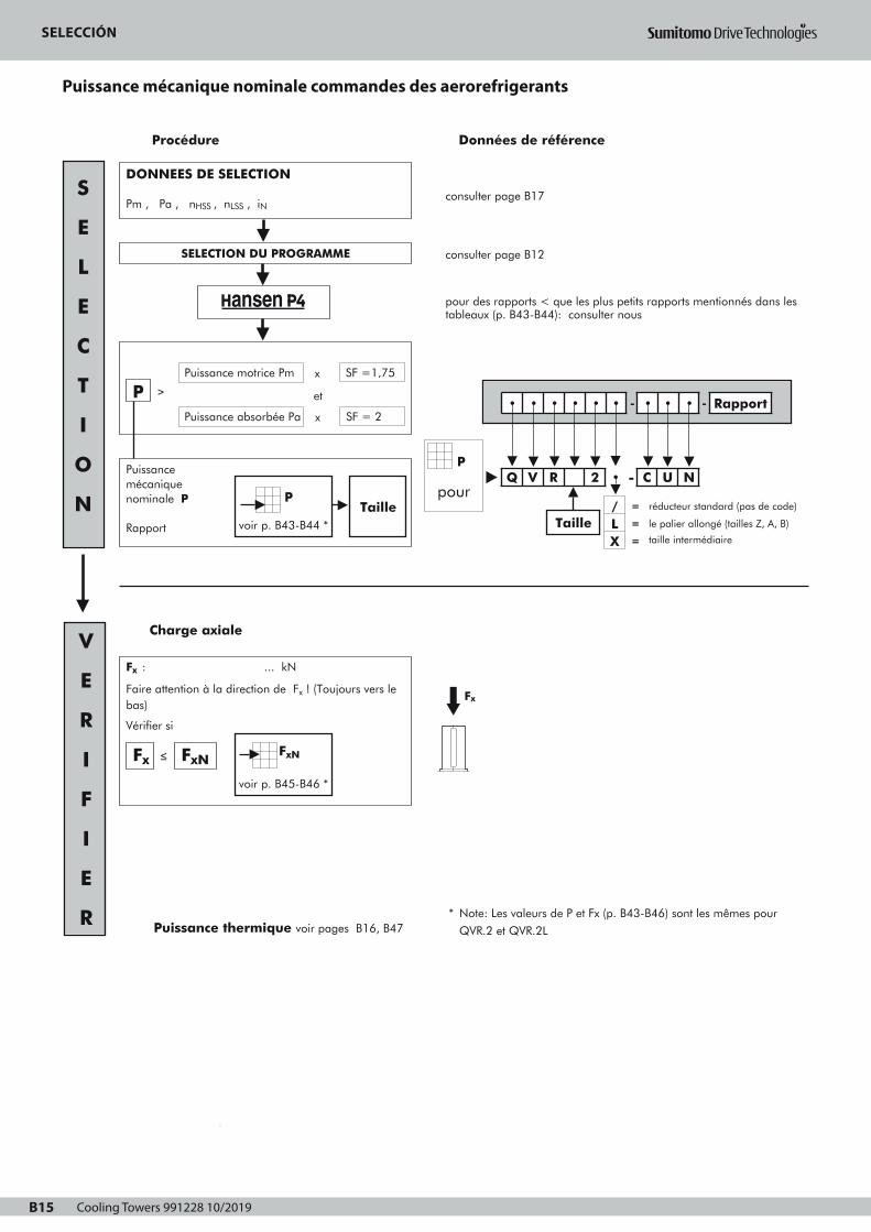
Cooling Towers 991228 10/2019B15
SELECTIONPuissance mécanique nominale
COMMANDES DES AEROREFRIGERANTS
B15
consulter page B17
consulter page B12
pour des rapports < que les plus petits rapports mentionnés dans lestableaux (p. B43-B44): consulter nous
Procédure Données de référence
Puissance mécanique nominale P
Rapport
2
3
1
DONNEES DE SELECTION
Pm , Pa , nHSS , nLSS , iN
Charge axiale
SELECTION DU PROGRAMME
Puissance absorbée Pa
PPuissance motrice Pm
et
x SF =1,75
x SF = 2
≥
Taille
S
E
L
E
C
T
I
O
N
V
E
R
I
F
I
E
R * Note: Les valeurs de P et Fx (p. B43-B46) sont les mêmes pour
QVR.2 et QVR.2L Puissance thermique voir pages B16, B47
Fx
pour
• • • • • • - • • • - Rapport
Q V R 2 • - C U N
Taille
P
/ = réducteur standard (pas de code)
LX
=
=
le palier allongé (tailles Z, A, B)
taille intermédiairevoir p. B43-B44 *
P
Fx : ... kN
Faire attention à la direction de Fx ! (Toujours vers lebas)
Vérifier si
≤Fx FxNFxN
voir p. B45-B46 *
Page 1
SELECTIONPuissance thermique
COMMANDES DES AEROREFRIGERANTS
Ptn pour réducteur sans
refroidissement forcé
facteur a pour température ambiante sans refroidissement forcé
Rapport de
réduction
Température ambiante en °C
15 à 25 25 à 35 35 à 45
6,3 11,2
12,5 18
≥ 20
Taille
1
1
0,81
0,85
1
Z H
0,87
Z H
0,68
0,71
0,55
0,66
0,75
Z D
0,74
E H
OK
Contrôle thermique
Pa ≤ Ptn • a • c • e ?
Un ventilateur possible
Refroidissement forcén'est pas requis
Ptf pour réducteur avec un
ventilateur
Pa ≤ Ptf • d • e ? Un ventilateur
facteur d pour température ambiante avec refroidissement forcé
Nombre
d'étages
Température ambiante en °C
15 à 25 25 à 35 35 à 45 45 à 55
avecrefroidissement
forcé2 1 0,86 0,72 0,59
Données de référence
OK
facteur c pour circulation d'air (sans ventilateur)
Installation
Dans un petit local fermé
Courant d'air
≥ 0,5 m/s 0,73 0,70
Dans un atelier normal
En plein air, protégé dusoleil
Taille
≥ 1,4 m/s
≥ 3,0 m/s
1
1,33
Z D
1
1,36
E H
Pt
facteur e pour l'humidité relative de l'air
Humidité relative de l'air
< 100% = 100%
1 1,15
F Pt
Ptn, Ptf
pourvoir p.B47
• • • • • • - • • • - Rapport
Q V R 2 • - C U N p. B47
Taille/ = réducteur standard (pas de code)
LX
=
=
le palier allongé (tailles Z, A, B)
taille intermédiaire
B16
Le courant d'air sera sélectionné en fonction de la structure:
Structure ouverte : les réducteurs sont installés dans une structure d'acier
ouverte permettant le passage du courant d'air du condensateur à air le long
du carter du réducteur.
Structure fermée : les réducteurs sont montés sur une console en béton ou dans
une structure d'acier fermée empêchant le passage du courant d'air du
condensateur à air le long du carter du réducteur.
Page 1
SELECCIÓN
Puissance mécanique nominale commandes des aerorefrigerants
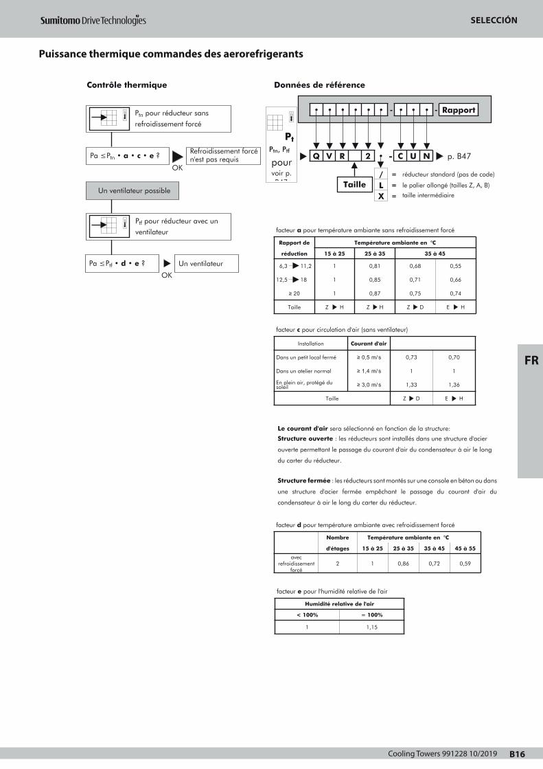
Cooling Towers 991228 10/2019 B16
FR
SELECTIONPuissance thermique
COMMANDES DES AEROREFRIGERANTS
Ptn pour réducteur sans
refroidissement forcé
facteur a pour température ambiante sans refroidissement forcé
Rapport de
réduction
Température ambiante en °C
15 à 25 25 à 35 35 à 45
6,3 11,2
12,5 18
≥ 20
Taille
1
1
0,81
0,85
1
Z H
0,87
Z H
0,68
0,71
0,55
0,66
0,75
Z D
0,74
E H
OK
Contrôle thermique
Pa ≤ Ptn • a • c • e ?
Un ventilateur possible
Refroidissement forcén'est pas requis
Ptf pour réducteur avec un
ventilateur
Pa ≤ Ptf • d • e ? Un ventilateur
facteur d pour température ambiante avec refroidissement forcé
Nombre
d'étages
Température ambiante en °C
15 à 25 25 à 35 35 à 45 45 à 55
avecrefroidissement
forcé2 1 0,86 0,72 0,59
Données de référence
OK
facteur c pour circulation d'air (sans ventilateur)
Installation
Dans un petit local fermé
Courant d'air
≥ 0,5 m/s 0,73 0,70
Dans un atelier normal
En plein air, protégé dusoleil
Taille
≥ 1,4 m/s
≥ 3,0 m/s
1
1,33
Z D
1
1,36
E H
Pt
facteur e pour l'humidité relative de l'air
Humidité relative de l'air
< 100% = 100%
1 1,15
F Pt
Ptn, Ptf
pourvoir p.B47
• • • • • • - • • • - Rapport
Q V R 2 • - C U N p. B47
Taille/ = réducteur standard (pas de code)
LX
=
=
le palier allongé (tailles Z, A, B)
taille intermédiaire
B16
Le courant d'air sera sélectionné en fonction de la structure:
Structure ouverte : les réducteurs sont installés dans une structure d'acier
ouverte permettant le passage du courant d'air du condensateur à air le long
du carter du réducteur.
Structure fermée : les réducteurs sont montés sur une console en béton ou dans
une structure d'acier fermée empêchant le passage du courant d'air du
condensateur à air le long du carter du réducteur.
Page 1
SELECCIÓN
Puissance thermique commandes des aerorefrigerants

Cooling Towers 991228 10/2019B17
DEMANDE D'OFFRE
COMMANDES DES AEROREFRIGERANTS
B17
1. PARAMETRES DE PUISSANCE
Puissance motricer Pm = kW à min-1
Puissance absorbée Pa = kW
Couple absorbé Ta = kNm
Durée de fonctionnement en h/jour ≤3
Couple de point supérieur à 200% Ta =
Nombre de démarrages/arrêts par 10heures :
≤10 >10
%
.....
2. VITESSE
Arbre grande vitesse (AGV)
Vitesse(s) constante(s) n1(AGV) = ........ ou/et ........ min-1
Vitesse variable .......... ≤ n1(AGV) ≤ ........... min-1
Sens de rotation : CW Arbre petite vitesse (APV)
Vitesse(s) constante(s) n2 (APV) = ........ ou/et ........ min-1
Vitesse variable ........ ≤ n2 (APV) ≤ .......... min-1
Tolérance sur la vitesse APV ± ...... % ± ........... min-1
sens de rotation : horlogique (CW)
3. LA CONFIGURATION DES ARBRES DU REDUCTEUR :
Arbres perpendiculaires
4. EFFORT AXIAL AGISSANT SUR L'ARBRE PV oui non
Poids : ventilateur + accouplement
Effort axial aérodynamique vers le réducteur
5. PARAMETRES D'INSTALLATION
Température ambiante (°C) près du réducteur :
Structure (voir page B16) ouverte
Vitesse de l'air près du réducteur :
=
= +
kN
kN
min: .....
max: .....
....... m/s
fermée
Lieu
En plein soleil
Catégorie de la corrosivité atmosphérique (suivant ISO 12944-2): ....
Installation électrique AC
Alimentation principale
Alimentation auxiliaire
Protection requise: ........
3 Ph
oui non
V Hz
.... ....
.... ....
Isolation: ........
6. BRUIT (réducteur + moteur)
Puissance acoustique max.: dBA
Pression acoustique max.
7. SPECIFICATIONS OPTIONNELLES
Options à indiquer aux pages B39-B42
dBA at ..... m
Fixation du moteur carcasse CEI: .......
(si pas CEI, ajouter plan d'encombrement)
Arbres en pouce
bout d'arbre allongé : à indiquer sur le schéma de l'application
Ref : Date : Nom : Signature :
Peinture (voir page B14)
(*) : Plage de durabilité suivant ISO 12944-1
L : faible
M : moyenne
H : haute
Note : la gamme de durabilité n'est pas une "garantie de temps".
La durabilité est une considération technique qui peut aider
le propriétaire à mettre en place un programme d'entretien.
(**) : Contient une couche supplémentaire sur 2A, 2B et 2C pour éviter
la formation d’une couche crayeuse.
Matériaux non admis Al
Cu
Autres .....
8. ANTIDÉVIREUR REQUIS oui non
9. EXPEDITION Transport par:
navire
train
camion
Pour d'autres données voir :
Sélection:cocher la case
appropriée
2• 3•
Système
Catégorie de corrosivité suivant ISO 12944-2
L (*)
C1
M H L
C2
M H L
C3
M
2A
2B
3A (**)
3B (**)
2C 3C (**)
Sélection:cocher la case
appropriée
2• 3•
Système
2A 3A (**)
2B
2C
3B (**)
3C (**)
Catégorie de corrosivité suivant ISO 12944-2
C4
L (*) M H L
Non permis
C5-I
M H
C5-M
L M
Obligatoire (exigence minimale)
A la demande du client
H
H
Sélection de la catégorie de corrosivité: cocher la case appropriée
C1 C2 C3 C4 C5-I C5-M
CW
CW
Page 1
DEMANDE D'OFFRE
Commandes des aerorefrigerants

Cooling Towers 991228 10/2019 B18
FR
Schéma de l'application
VUE EN PLAN
VUE DE COTE
DEMANDE D'OFFRE
Cooling Towers 991228 10/2019B19
KÜHLTURMANTRIEBE
Hansen P4 Normzahnradgetriebe
Programm – Auswahl B22
Beschreibung B23 - B24
Auswahl B25 - B26
Technische Erläuterung für Anfrage B27 - B28
Zubehör und Optionen B39 - B42
Auswahltabellen
Mechanische Nennleistungen B43 - B44
Nennaxialbelastung B45 - B46
Wärmegrenzleistungen B47
Exakte Übersetzungen iex und Massenträgheitsmomente J B48
Maßzeichnung
Hansen P4 Getriebe, Kegelstirnradgetriebe, Zweistufig B49 - B53
TEIL B - INHALTVERZEICHNIS
D
B20
Page 1
Cooling Towers 991228 10/2019 B20
DE
ANTRIEBSGRUPPEN FÜR KÜHLTÜRME
KÜHLTURMANTRIEBE
Hansen P4 Normzahnradgetriebe
Programm – Auswahl B22
Beschreibung B23 - B24
Auswahl B25 - B26
Technische Erläuterung für Anfrage B27 - B28
Zubehör und Optionen B39 - B42
Auswahltabellen
Mechanische Nennleistungen B43 - B44
Nennaxialbelastung B45 - B46
Wärmegrenzleistungen B47
Exakte Übersetzungen iex und Massenträgheitsmomente J B48
Maßzeichnung
Hansen P4 Getriebe, Kegelstirnradgetriebe, Zweistufig B49 - B53
TEIL B - INHALTVERZEICHNIS
D
B20
Page 1

Cooling Towers 991228 10/2019B21
NORMZAHNRADGETRIEBE FÜRKÜHLTURMANTRIEBEPROGRAMM – AUSWAHL
800
710
630
560
500
400
355
315
280
250
225
200
160
132
110
90
75
55
45
37
30
22
18,5
3,55 4 4,5 5 5,6 6,3 7,1 8 9 10 11,2 12,5 14 16 18 20 22,4
QVR.2.- CUN
C H
QVR.2 - CUN
Z B
Motorleistung
Pm (kW - 1500 min-1) / SF = 1,75
Nennübersetzung
QVR.2L - CUN
Z B
D
B22
IN
Page 1
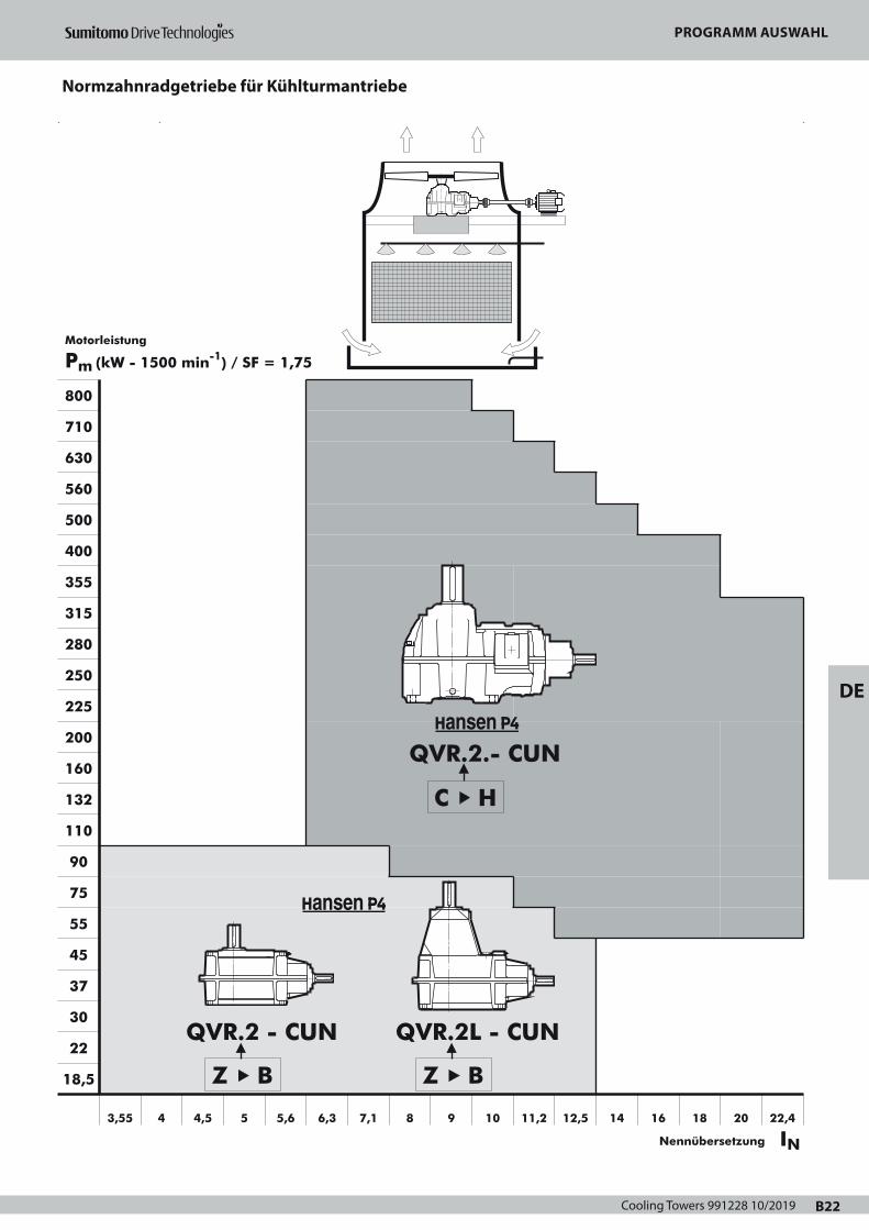
Cooling Towers 991228 10/2019 B22
DE
NORMZAHNRADGETRIEBE FÜRKÜHLTURMANTRIEBEPROGRAMM – AUSWAHL
800
710
630
560
500
400
355
315
280
250
225
200
160
132
110
90
75
55
45
37
30
22
18,5
3,55 4 4,5 5 5,6 6,3 7,1 8 9 10 11,2 12,5 14 16 18 20 22,4
QVR.2.- CUN
C H
QVR.2 - CUN
Z B
Motorleistung
Pm (kW - 1500 min-1) / SF = 1,75
Nennübersetzung
QVR.2L - CUN
Z B
D
B22
IN
Page 1
PROGRAMM AUSWAHL
Normzahnradgetriebe für Kühlturmantriebe

Cooling Towers 991228 10/2019B23
BESCHREIBUNGHANSEN P4 GETRIEBE FÜR VENTILATORANTRIEBE
IN KÜHLTÜRMEN
B23
Das Getriebe
Getriebe werden nach der Norm CTI-111 (Cooling Tower Institute)Spezifizierung ausgelegt.Die in den Tabellen aufgeführten mechanischen Nennleistungen,beziehen sich auf die Antriebsdrehzahlen 1800, 1500, 1200, 1000,
900 und 750 min-1. Sie sind auch gültig für Asynchrondrehzahlen, die max. 3% niedrigerals die Synchrondrehzahlen der Motoren liegen. Für die Leistungs-übermittlung bei anderen Drehzahlen genügt es zu interpolieren.
Die Liestung bei Drehzahlen kleiner als 750 min-1 entspricht dem
Nenndrehmoment bei 750 min-1. Für Eingangsdrehzahlen größer als1800 min-1, ist eine Rückfrage zu empfehlen.
Bezeichnung
Typ1 : Reihe Q : Hansen P42 : V : vertikale langsamdrehende Welle3 : R : rechtwinklige Wellen4 : Baugröße: Z, A, B, ... H5 : Stufenzahl: 25 bis : / : Standard Getriebe (kein Code, freilassen)
L : verlängertes Lagergehäuse (Baugrößen Z, A, B)
X : Zwischengröße, nur für Getriebe mit zwei Stufen
Wellenanordnung6 : schnelldrehende Welle ausragend : C : rechtwinklige
Wellen7 : langsamdrehende Welle ausragend: U : oben8 : Art der langsamdrehenden Welle: N : normale
Vollwelle
Übersetzung9 : Nennübersetzung
Hauptbauteile
Schrägverzahnte Stirnräder und spiralverzahnteKegelräderEntwurf und Auslegung nach AGMA für eine maximale Belastbarkeit, minimale Verluste und einen geräuscharmen Lauf.Sämtliche Zahnräder sind aus legiertem Stahl; sie werden einsatzgehärtet und geschliffen.
Langsamdrehende WellenDie langsamdrehenden Wellen sind in Vollwellenausführung.Für alle Ausführungen, Antriebs- und Abtriebswellen liegen in der gleichen vertikalen Ebene.
LagerReichlich bemessene Kegelrollen-, Pendelrollen- oder Zylinder-Rollenlager; berechnet nach ISO und bekannten Lagerhersteller.Die Lager an der Abtriebswelle sind ausgelegt zur Aufnahme von erheblichen Axiallasten. Die in den Tabellen, auf Seite B45 - B46, aufgeführte zulässige Nennaxiallast FxN ist gültig für SFmin = 2, eine Drehrichtung in Uhrzeigersinn für die Langsamdrehende Welle und garantiert eine berechnete Lagerlebensdauer von 100000 Stunden.
Gehäuse, Deckel und LagergehäuseAus perlitischem Grauguß.Bearbeitung auf CNC gesteuerten Bearbeitungszentren.Robuste und steife Konstruktion.Nicht verwendete Gewindelöcher sind mit Stopfen verschlossen.Gehäuse mit horizontaler Trennfuge.
Systeme
SchmierungSchmiermittel: In der Regel werden Mineralöle verwendet.Die Schmiermittel müssen allerdings „extreme pressure Additive“enthalten (siehe Betriebsanleitung).Druckumlaufschmierung für die oberen Lager ist standardmäßig oderals option erhältlich.Das Gehäuse bildet einen reichlich bemessenen Ölbehälter.Die ausragenden langsamdrehenden Wellen sind mit einemnachschmierbaren Labyrinth ausgerüstet. Nippel, wenn vorhanden,entsprechen DIN 71412. Beim Einsatz von äußeren Serviceleitungen kann der Nippel außerhalbdes Kühlturms angeordnet werden. Der Ölstand ist mittels (eingeschraubten) Gewinde-Ölmeßstab meßbar.Für Routinewartung von Naßkühlturmantrieben ist es ratsamServiceleitungen außerhalb des Kühlturms vorzusehen (gehören nichtzum Hansen Industrial Transmissions nv Lieferumfang). Die Leitungensind so angeordnet, daß das öl von außerhalb des Kühlturms gefülltund abgelassen werden kann. Die Standardentlüftungs- undAblaßschraube, mit der das Getriebe bei Auslieferung ausgerüstet ist,muß entfernt werden und außerhalb des Kühlturms angeschlossenwerden (außerhalb des direkten Feuchtluftstromes).Für einfache Wartung wird empfohlen ein Ölmeßstab außerhalb desKühlturms vorzusehen.Von Zeit zu Zeit muß geprüft werden ob der äußere Ölmeßstab mitdem Getriebeölmeßstab übereinstimmt.
Kühlung Die Wärmeabführung der im Gehäuse entstandenen Verlustwärmeerfolgt mittels:
• Eigenkühlung vom Gehäuse• Ventilatorkühlung: ein durch die Welle angetriebener
Axialventilator kann eingebaut werden (siehe Seite B41)Freier Lufteintrag auf der Saugseite sollte immer gewährleistet sein.
Thermische Kontrollen, siehe Seite B26
AbdichtungFeste Teile: • allgemeine Verwendung einer Dichtungspaste
• Schaulochdeckel an Getriebe: O-Ring Umlaufende Teile:
• Schnelldrehende Welle: abhängig von Getriebewelle Siehe Beschreibung von jedem Getriebetyp: Seite B39
bis B42 Oil LockTM : - doppelwirkendes Labyrinth - wartungsfrei
- Ölrückkehr zum Ölbad• Langsamdrehende Welle:
- Dichtungsring mit Staublippe - Nachschmierbares Labyrinth
1
Q2
V3
R4 5
25 bis
-6
C7
U8
N -9
Page 1
BESCHREIBUNGHANSEN P4 GETRIEBE FÜR VENTILATORANTRIEBE
IN KÜHLTÜRMEN
Motoren
Die Getriebe werden mit IEC Motoren in Fußausführung ausgerüstet(Bauform B3). Für mehr Information über Motoren, SieheMotorkatalog.Für NEMA-Motoren: Rückfrage zu empfehlen.Polumschaltbare Motoren: polumschaltbare Motoren dürfen erstdann auf die niedrige Drehzahl umgeschaltet werden, wenn dieDrehzahl des Motors bis unter die niedrige Drehzahl abgefallen ist.
Optionale Zusatzeinrichtungen
Bestimmte Zusatzeinrichtungen sind optional verfügbar (siehe SeitenB39 bis B46). Detaillierte Information über optionale Zusatz-einrichtungen ist den separaten Betriebsvorschriften für diese Teile zuentnehmen. Rückfrage zu empfehlen.
Rücklaufsperre Eingebaute Rücklaufsperre vermeidet unerwünschter Drehen desVentilators. Schmierung der Rücklaufsperre erfolgt durch dieSchmieranlage vom Getriebe.
FilterMit eingebautem Überdruckventil.Ein Filter mit eingebautem Überdruckventil und mit optischem oderelektrischem Verschmutzungsanzeiger ist als Option vorhanden.
HeizstäbeElektrisch erwärmte Heizstäbe für Anlauf bei niedrigen Temperaturensind vorhanden für Hansen P4 Getriebegrößen C bis H.
StrömungskontrollschalterGetriebe mit Pumpenschmierung können mit einemStrömungskontrollschalter ausgerüstet werden. Der Schalter löst beiunzureichendem Ölzufuhr ein Alarmsignal aus. Im betreffenden Falldas Getriebe sofort abschalten und die Ursache der Störung in derÖlzufuhr beseitigen.
ÖlstandschalterEin Ölstandschalter zur Überprüfung des Ölstandes im Getriebekann vorgesehen werden. Der Schalter kann ein Alarmsignalauslösen, wenn der Stand vom Ölbad unterhalb eines bestimmtenWertes fällt.
Pt100Der Pt100 steuert die Ölbadtemperatur. Der Pt100 kann ein Alarmsignal auslösen, wenn das Öltemperaturhöher ist als die spezifizierte Begrenzung.
Lieferzustand
Kontrolle vor dem Versand• Probelauf: alle Getriebe werden einen unbelasteten Probelauf
unterzogen• Gleichförmigkeitskontrolle
Schutz• Ausragendes Wellenende: fettgeschmiert und mit einem
wasserbeständigen, wachsartigen Papier geschützt
Schmierstoffe• Hansen P4 Getriebe werden ohne Ölfüllung geliefert.• Alle Fettschmierstellen werden jedoch vor dem Versand mit
Fett gefüllt.
Hinsichtlich Lagerung, Handhabung, Montage,Inbetriebsetzung und Wartung der Getriebe, gibt dieBetriebsanleitung, die zusammen mit den Getrieben geliefert wird,wertvolle Hinweise.
Schutzmaßnahmen
Standard Schutzsysteme• Als Standard werden Hansen P4 Getriebe für Ventilatorantriebe
in Kühltürmen mit einem Anstrichsystem versehen, das geeignet ist
für eine Umgebung nach Korrosionsschutzklasse "C4 (L)" entspre-
chend ISO 12944-2 (und ISO 12944-5).Die Wahl der Farbe hat keinen Einfluss auf die technische Qualität
des Anstrichsystems.Andere Anstrichsysteme können angeboten werden, um die erfor-
derliche Korrosionsschutzklasse für Ihre Anwendung zu erfüllen.
• Bolzen und Schrauben ausgestattet mit passendem Schutz.
Aggressive UmgebungFür die Kühltürmantriebe in aggressiver Umgebung kann ein
zusätzlicher Schutzsystem angeboten werden: Rückfrage zu empfeh-
len.
D
B24
Page 1
BESCHREIBUNG
Hansen P4 Getriebe für Ventilatorantriebe in Kühltürmen
Cooling Towers 991228 10/2019 B24
DE
BESCHREIBUNGHANSEN P4 GETRIEBE FÜR VENTILATORANTRIEBE
IN KÜHLTÜRMEN
Motoren
Die Getriebe werden mit IEC Motoren in Fußausführung ausgerüstet(Bauform B3). Für mehr Information über Motoren, SieheMotorkatalog.Für NEMA-Motoren: Rückfrage zu empfehlen.Polumschaltbare Motoren: polumschaltbare Motoren dürfen erstdann auf die niedrige Drehzahl umgeschaltet werden, wenn dieDrehzahl des Motors bis unter die niedrige Drehzahl abgefallen ist.
Optionale Zusatzeinrichtungen
Bestimmte Zusatzeinrichtungen sind optional verfügbar (siehe SeitenB39 bis B46). Detaillierte Information über optionale Zusatz-einrichtungen ist den separaten Betriebsvorschriften für diese Teile zuentnehmen. Rückfrage zu empfehlen.
Rücklaufsperre Eingebaute Rücklaufsperre vermeidet unerwünschter Drehen desVentilators. Schmierung der Rücklaufsperre erfolgt durch dieSchmieranlage vom Getriebe.
FilterMit eingebautem Überdruckventil.Ein Filter mit eingebautem Überdruckventil und mit optischem oderelektrischem Verschmutzungsanzeiger ist als Option vorhanden.
HeizstäbeElektrisch erwärmte Heizstäbe für Anlauf bei niedrigen Temperaturensind vorhanden für Hansen P4 Getriebegrößen C bis H.
StrömungskontrollschalterGetriebe mit Pumpenschmierung können mit einemStrömungskontrollschalter ausgerüstet werden. Der Schalter löst beiunzureichendem Ölzufuhr ein Alarmsignal aus. Im betreffenden Falldas Getriebe sofort abschalten und die Ursache der Störung in derÖlzufuhr beseitigen.
ÖlstandschalterEin Ölstandschalter zur Überprüfung des Ölstandes im Getriebekann vorgesehen werden. Der Schalter kann ein Alarmsignalauslösen, wenn der Stand vom Ölbad unterhalb eines bestimmtenWertes fällt.
Pt100Der Pt100 steuert die Ölbadtemperatur. Der Pt100 kann ein Alarmsignal auslösen, wenn das Öltemperaturhöher ist als die spezifizierte Begrenzung.
Lieferzustand
Kontrolle vor dem Versand• Probelauf: alle Getriebe werden einen unbelasteten Probelauf
unterzogen• Gleichförmigkeitskontrolle
Schutz• Ausragendes Wellenende: fettgeschmiert und mit einem
wasserbeständigen, wachsartigen Papier geschützt
Schmierstoffe• Hansen P4 Getriebe werden ohne Ölfüllung geliefert.• Alle Fettschmierstellen werden jedoch vor dem Versand mit
Fett gefüllt.
Hinsichtlich Lagerung, Handhabung, Montage,Inbetriebsetzung und Wartung der Getriebe, gibt dieBetriebsanleitung, die zusammen mit den Getrieben geliefert wird,wertvolle Hinweise.
Schutzmaßnahmen
Standard Schutzsysteme• Als Standard werden Hansen P4 Getriebe für Ventilatorantriebe
in Kühltürmen mit einem Anstrichsystem versehen, das geeignet ist
für eine Umgebung nach Korrosionsschutzklasse "C4 (L)" entspre-
chend ISO 12944-2 (und ISO 12944-5).Die Wahl der Farbe hat keinen Einfluss auf die technische Qualität
des Anstrichsystems.Andere Anstrichsysteme können angeboten werden, um die erfor-
derliche Korrosionsschutzklasse für Ihre Anwendung zu erfüllen.
• Bolzen und Schrauben ausgestattet mit passendem Schutz.
Aggressive UmgebungFür die Kühltürmantriebe in aggressiver Umgebung kann ein
zusätzlicher Schutzsystem angeboten werden: Rückfrage zu empfeh-
len.
D
B24
Page 1
BESCHREIBUNG
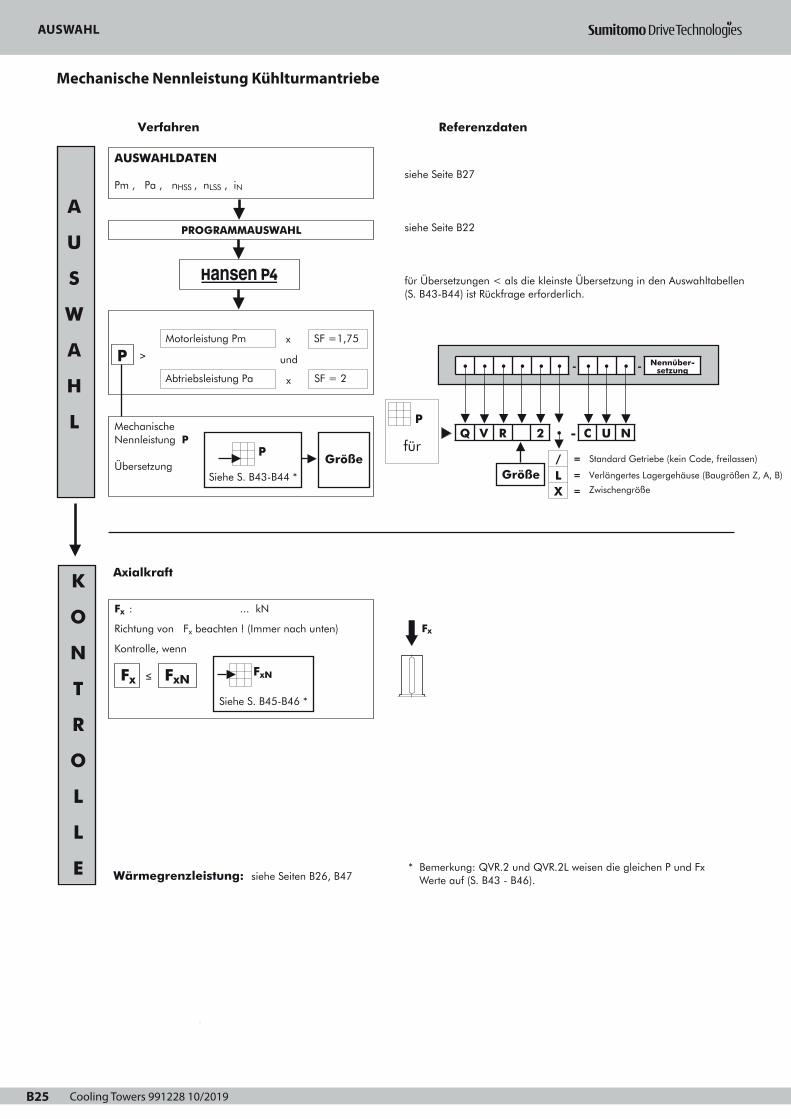
Cooling Towers 991228 10/2019B25
AUSWAHLMechanische Nennleistung
KÜHLTURMANTRIEBE
B25
siehe Seite B27
siehe Seite B22
für Übersetzungen < als die kleinste Übersetzung in den Auswahltabellen(S. B43-B44) ist Rückfrage erforderlich.
Verfahren Referenzdaten
Mechanische Nennleistung P
Übersetzung
2
3
1
AUSWAHLDATEN
Pm , Pa , nHSS , nLSS , iN
Axialkraft
PROGRAMMAUSWAHL
Abtriebsleistung Pa
PMotorleistung Pm
und
x SF =1,75
x SF = 2
≥
Größe
A
U
S
W
A
H
L
K
O
N
T
R
O
L
L
E * Bemerkung: QVR.2 und QVR.2L weisen die gleichen P und Fx Werte auf (S. B43 - B46). Wärmegrenzleistung: siehe Seiten B26, B47
Fx
für
• • • • • • - • • • - Nennüber-setzung
Q V R 2 • - C U N
Größe
P
/ = Standard Getriebe (kein Code, freilassen)
LX
=
=
Verlängertes Lagergehäuse (Baugrößen Z, A, B)
ZwischengrößeSiehe S. B43-B44 *
P
Fx : ... kN
Richtung von Fx beachten ! (Immer nach unten)
Kontrolle, wenn
≤Fx FxNFxN
Siehe S. B45-B46 *
Page 1
AUSWAHLWärmegrenzleistung
KÜHLTURMANTRIEBE
Ptn für Getriebe ohne
Fremdkühlung
Faktor a für Umgebungstemperatur ohne Fremdkühlung
Übersetzung Umgebungstemperatur in °C
15 bis 25 25 bis 35 35 bis 45
6,3 11,2
12,5 18
≥ 20
Baugröße
1
1
0,81
0,85
1
Z H
0,87
Z H
0,68
0,71
0,55
0,66
0,75
Z D
0,74
E H
OK
Thermische Kontrolle
Pa ≤ Ptn • a • c • e ?
Lüfter ist möglich
Fremdkühlung istnicht erforderlich
Ptf für Getriebe mit einem
Lüfter
Pa ≤ Ptf • d • e ? Ein Lüfter
Faktor d für Umgebungstemperatur mit Fremdkühlung
Stufenzahl Umgebungstemperatur in °C
15 bis 25 25 bis 35 35 bis 45 45 bis 55
Fremdkühlung 2 1 0,86 0,72 0,59
Referenzdaten
OK
Faktor c für Luftzirkulation (ohne Lüfter)
Aufstellung
In klein. geschlos. Raum
Luftströmung
≥ 0,5 m/s 0,73 0,70
In normalem Arbeitsraum
Aufstellung im Freien, Son-nenschutz
Baugröße
≥ 1,4 m/s
≥ 3,0 m/s
1
1,33
Z D
1
1,36
E H
Pt
Faktor e für die relative Luftfeuchtigkeit
Relative Luftfeuchtigkeit
< 100% = 100%
1 1,15
Pt
Ptn, Ptf
fürsiehe S.
B47
• • • • • • - • • • - Nennüber-setzung
Q V R 2 • - C U N
Größe/ =
Standard Getriebe (kein Code, freilassen)
L
X
=
=
Verlängertes Lagergehäuse(Baugrößen Z, A, B)
Zwischengröße
D
B26
Luftströmung sollte entsprechend der Struktur gewählt werden:
Offene Struktur: bei Getrieben aufgestellt in offener Stahlstruktur kann der
Luftstrom vom Kondensator über das Getriebegehäuse geführt werden.
Geschlossene Struktur: bei Getrieben aufgestellt auf einem Beton-sockel
oder in einer geschlossenen Stahlstruktur kann der Luftstrom vom Kondensator
nicht über das Getriebegehäuse geführt werden.
Page 1
AUSWAHL
Mechanische Nennleistung Kühlturmantriebe

Cooling Towers 991228 10/2019 B26
DE
AUSWAHLWärmegrenzleistung
KÜHLTURMANTRIEBE
Ptn für Getriebe ohne
Fremdkühlung
Faktor a für Umgebungstemperatur ohne Fremdkühlung
Übersetzung Umgebungstemperatur in °C
15 bis 25 25 bis 35 35 bis 45
6,3 11,2
12,5 18
≥ 20
Baugröße
1
1
0,81
0,85
1
Z H
0,87
Z H
0,68
0,71
0,55
0,66
0,75
Z D
0,74
E H
OK
Thermische Kontrolle
Pa ≤ Ptn • a • c • e ?
Lüfter ist möglich
Fremdkühlung istnicht erforderlich
Ptf für Getriebe mit einem
Lüfter
Pa ≤ Ptf • d • e ? Ein Lüfter
Faktor d für Umgebungstemperatur mit Fremdkühlung
Stufenzahl Umgebungstemperatur in °C
15 bis 25 25 bis 35 35 bis 45 45 bis 55
Fremdkühlung 2 1 0,86 0,72 0,59
Referenzdaten
OK
Faktor c für Luftzirkulation (ohne Lüfter)
Aufstellung
In klein. geschlos. Raum
Luftströmung
≥ 0,5 m/s 0,73 0,70
In normalem Arbeitsraum
Aufstellung im Freien, Son-nenschutz
Baugröße
≥ 1,4 m/s
≥ 3,0 m/s
1
1,33
Z D
1
1,36
E H
Pt
Faktor e für die relative Luftfeuchtigkeit
Relative Luftfeuchtigkeit
< 100% = 100%
1 1,15
Pt
Ptn, Ptf
fürsiehe S.
B47
• • • • • • - • • • - Nennüber-setzung
Q V R 2 • - C U N
Größe/ =
Standard Getriebe (kein Code, freilassen)
L
X
=
=
Verlängertes Lagergehäuse(Baugrößen Z, A, B)
Zwischengröße
D
B26
Luftströmung sollte entsprechend der Struktur gewählt werden:
Offene Struktur: bei Getrieben aufgestellt in offener Stahlstruktur kann der
Luftstrom vom Kondensator über das Getriebegehäuse geführt werden.
Geschlossene Struktur: bei Getrieben aufgestellt auf einem Beton-sockel
oder in einer geschlossenen Stahlstruktur kann der Luftstrom vom Kondensator
nicht über das Getriebegehäuse geführt werden.
Page 1
AUSWAHL
Wärmegrenzleistung Kühlturmantriebe

Cooling Towers 991228 10/2019B27
ANFRAGEVENTILATORANTRIEBE IN KÜHLTÜRMEN
B27
1. BELASTUNGSPARAMETER
Motorleistung Pm = kW bei min-1
Abtriebsleistung Pa = kW
Abtriebsmoment Ta = kNm
Einsatzdauer in h/Tag ≤ 3
Spitzenmoment > 200% Ta =
Anzahl der Einschaltungen/Abschaltungen pro 10 Stunden :
≤ 10 >10
%
.....
2. DREHZAHL
Schnelldrehende Welle (SDW)
konstante Drehzahl(en) n1(SDW) = ...... oder/und ...... min-1
Variable Drehzahl ......... ≤ n1(SDW) ≤ .......... min-1
Drehrichtung : CW
Langsamdrehende Welle (LDW)
konstante Drehzahl(en) n2 (LDW) = ...... oder/und ...... min-1
Variable Drehzahl ......... ≤ n2 (LDW) ≤ .......... min-1
Toleranz auf die Drehzahl LDW ± ...... % ± ........... min-1
Drehrichtung : Uhrzeigersinn (CW)
3. GETRIEBEWELLENANORDNUNG
Rechtwinklige Wellen
4. AXIALKRAFT AUF LANGS.DREH.WELLE Ja Nein
Gewicht von Lüfter und Kupplung
Aerodynamische Axialkraft weg vom Getriebe
5. EINBAUPARAMETER
Umgebungstemperatur (°C) nahe dem Getriebe :
Struktur (siehe Seite B26) offen
Luftgeschwindigkeit nahe dem Getriebe:
=
= -kN
kN
min: .....
max: .....
geschlossen
....... m/s
Aufstellung
Der Sonnenbestrahlung ausgesetzt
Atmosphäre: Korrosion Kategorie (entsprechend ISO 12944-2): ....
Elektrische Ausführung
Ja
AC
Hauptspannung
Hilfsspannung
Schutzanforderungen: ........
3 Ph
Nein
V Hz
.... ....
.... ....
Isolation: ........
6. GERÄUSCH (Getriebe + Motor)
Max. Schalleistung: dBA
Max. Schalldruck :
7. OPTIONELLE DATEN
Optionen auf Seiten B39 bis B42 eintragen
dBA at ..... m
Motormantel IEC: .......
(falls nicht IEC, Maßzeichnungen hinzufügen)
Wellen Zoll
verlängertes Wellenende: auf Anwendungsskizze andeuten
Ref : Datum : Name : Unterschrift :
Anstrich (siehe Seite B24)
(*) : Haltbarkeitsreihe nach ISO 12944-1
L : niedrig (gering)
M : Medium (mittel)
H : hoch
Hinweis: Die Haltbarkeitsbereich ist keine "Garantie der Zeit".
Haltbarkeit ist eine technische Prüfung, dass der Besitzer
helfen kann für das Einrichten einem Wartungsprogramm.
(**) : Eine zusätzliche Schicht auf 2A, 2B und 2C um Bildung
einer kalkhaltigen Schicht zu verhindern.
Nicht zulässige Materialien Alu
Kupfer
Sonstige .....
8. RÜCKLAUFSPERRE ERFORDERLICH Ja Nein
9. VERSAND Transport durch:
Schiff
Zug
LKW
Für weitere Daten, siehe ...
Auswahl:
Ankreuzen
2• 3•
System
Korrosion Kategorie entsprechend ISO 12944-2
L (*)
C1
M H L
C2
M H L
C3
M
2A
2B
3A (**)
3B (**)
2C 3C (**)
Auswahl:
Ankreuzen
2• 3•
System
2A 3A (**)
2B
2C
3B (**)
3C (**)
Korrosion Kategorie entsprechend ISO 12944-2
C4
L (*) M H L
Nicht erlaubt
C5-I
M H
C5-M
L M
Obligatorisch (Mindestanforderung)
Auf Wunsch des Kunden
H
H
Auswahl der Korrosion Kategorie: ankreuzen
C1 C2 C3 C4 C5-I C5-M
CW
CW
Page 1
Ventilatorantriebe in Kühltürmen
TECHNISCHE ERLÄUTERUNG FÜR ANFRAGE
Cooling Towers 991228 10/2019 B28
DRAUFSICHT
SEITENANSICHT
Skizze der Anwendung
DE
TECHNISCHE ERLÄUTERUNG FÜR ANFRAGE

Cooling Towers 991228 10/2019B29
LAS TRANSMISIONES DE VENTILADORES PARA TORRES DE REFRIGERACION
Reductores normalizados Hansen P4
Programa – Selección B32
Descripción B33 - B34
Selección B35 - B36
Petición de oferta B37 - B38
Accesorios y opciones B39 - B42
Tablas de selección
Potencias mecánicas nominales B43 - B44
La carga axial nomínal B45 - B46
Potencias térmicas nominales B47
Indices exactos de reducción iex y momentos de inercia J B48
Plano de dimensiones
Reductores Hansen P4, ejes perpendiculares,dos etapas B49 - B53
SECCION B - INDICE
S
B30
Page 1

Cooling Towers 991228 10/2019 B30
ES
LAS TRANSMISIONES DE VENTILADORES PARA TORRES DE REFRIGERACION
Reductores normalizados Hansen P4
Programa – Selección B32
Descripción B33 - B34
Selección B35 - B36
Petición de oferta B37 - B38
Accesorios y opciones B39 - B42
Tablas de selección
Potencias mecánicas nominales B43 - B44
La carga axial nomínal B45 - B46
Potencias térmicas nominales B47
Indices exactos de reducción iex y momentos de inercia J B48
Plano de dimensiones
Reductores Hansen P4, ejes perpendiculares,dos etapas B49 - B53
SECCION B - INDICE
S
B30
Page 1
LAS TRANSMISIONES DEL VENTILADOR PARA TORRES DE REFRIGERACIÓN

Cooling Towers 991228 10/2019B31
LAS TRANSMISIONES DE VENTILADORES PARA TORRES DE REFRIGERACIÓN
PROGRAMA – SELECCION
800
710
630
560
500
400
355
315
280
250
225
200
160
132
110
90
75
55
45
37
30
22
18,5
3,55 4 4,5 5 5,6 6,3 7,1 8 9 10 11,2 12,5 14 16 18 20 22,4
QVR.2. - CUN
C H
QVR.2 - CUN
Z B
Potencia del motor
Pm (kW - 1500 min-1) / SF = 1,75
Índice nominal IN
QVR.2L - CUN
Z B
S
B32
Page 1
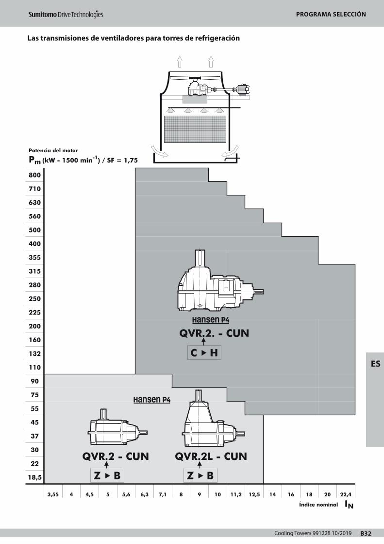
Cooling Towers 991228 10/2019 B32
ES
LAS TRANSMISIONES DE VENTILADORES PARA TORRES DE REFRIGERACIÓN
PROGRAMA – SELECCION
800
710
630
560
500
400
355
315
280
250
225
200
160
132
110
90
75
55
45
37
30
22
18,5
3,55 4 4,5 5 5,6 6,3 7,1 8 9 10 11,2 12,5 14 16 18 20 22,4
QVR.2. - CUN
C H
QVR.2 - CUN
Z B
Potencia del motor
Pm (kW - 1500 min-1) / SF = 1,75
Índice nominal IN
QVR.2L - CUN
Z B
S
B32
Page 1
PROGRAMA SELECCIÓN
Las transmisiones de ventiladores para torres de refrigeración
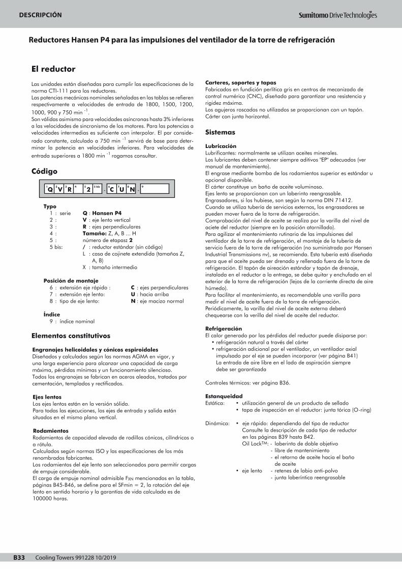
Cooling Towers 991228 10/2019B33
DESCRIPCIONREDUCTORES HANSEN P4 PARA LAS IMPULSIONES DEL
VENTILADOR DE LA TORRE DE REFRIGERACIÓN
B33
El reductor
Las unidades están diseñadas para cumplir las especificaciones de lanorma CTI-111 para los reductores.Las potencias mecánicas nominales señaladas en las tablas se refierenrespectivamente a velocidades de entrada de 1800, 1500, 1200,
1000, 900 y 750 min -1.Son válidas asimismo para velocidades asíncronas hasta 3% inferioresa las velocidades de sincronismo de los motores. Para las potencias avelocidades intermedias es suficiente con interpolar. El par conside-
rado constante, calculado a 750 min -1 servirá de base para deter-minar la potencia en velocidades inferiores. Para velocidades de
entrada superiores a 1800 min -1 rogamos consultar.
Código
Typo1 : serie Q : Hansen P42 : V : eje lento vertical3 : R : ejes perpendiculares4 : Tamaño: Z, A, B ... H5 : número de etapas: 25 bis: / : reductor estándar (sin código)
L : casa de cojinete extendida (tamaños Z, A, B)
X : tamaño intermedio
Posición de montaje6 : extensión eje rápido : C : ejes perpendiculares7 : extensión eje lento: U : hacia arriba8 : tipo de eje lento: N : eje macizo normal
Índice9 : índice nominal
Elementos constitutivos
Engranajes helicoidales y cónicos espiroidalesDiseñados y calculados según las normas AGMA en vigor, y una larga experiencia para alcanzar una capacidad de carga máxima, pérdidas mínimas y un funcionamiento silencioso.Todos los engranajes se fabrican en aceros aleados, tratados por cementación, templados y rectificados.
Ejes lentosLos ejes lentos están en la versión sólida.Para todas las ejecuciones, los ejes de entrada y salida están situados en el mismo plano vertical.
RodamientosRodamientos de capacidad elevada de rodillos cónicos, cilíndricos o a rótula.Calculados según normas ISO y las especificaciones de los másrenombrados fabricantes.Los rodamientos del eje lento son seleccionados para permitir cargasde empuje considerable.El carga de empuje nominal admisible FXN mencionados en la tabla,páginas B45-B46, se define para el SFmin = 2, la rotación del ejelento en sentido horario y la garantías de vida calculada es de100000 horas.
Carteres, soportes y tapasFabricados en fundición perlítica gris en centros de mecanizado decontrol numérico (CNC), diseñado para garantizar una resistencia yrigidez máxima.Los agujeros roscados no utilizados se proporcionan con un tapón.Cárter con junta horizontal.
Sistemas
LubricaciónLubrificantes: normalmente se utilizan aceites minerales.Los lubricantes deben contener siempre aditivos "EP" adecuados (vermanual de mantenimiento).El engrase mediante bomba de los rodamientos superior es estándar uopcional disponible.El cárter constituye un baño de aceite voluminoso.Ejes lento se proporcionan con un laberinto reengrasable.Engrasadores, si los hubiese, son según la norma DIN 71412.Cuando se utiliza tubería de servicios externos, los engrasadores sepueden mover fuera de la torre de refrigeración.Comprobación del nivel de aceite se realiza por la varilla del nivel deaciete del reductor (siempre en la posición atornillado).Para agilizar el mantenimiento rutinario de las impulsiones delventilador de la torre de refrigeración, el montaje de la tubería deservicio fuera de la torre de refrigeración (no suministrada por HansenIndustrial Transmissions nv), se recomienda. Esta tubería está diseñadapara que el aceite pueda ser drenado y rellenado fuera de la torre derefrigeración. El tapón de aireación estándar y tapón de drenaje,instalada en el reductor a la entrega, se debe quitar y enchufado en elexterior de la torre de refrigeración (lejos de la corriente directa de airehúmedo).Para facilitar el mantenimiento, es recomendable una varilla paramedir el nivel de aceite fuera de la torre de refrigeración.Periódicamente, la varilla del nivel de aceite externa deberáchequearse con la verilla del nivel de aceite del reductor.
RefrigeraciónEl calor generado por las pérdidas del reductor puede disiparse por:
• refrigeración natural a través del cárter• refrigeración adicional por el ventilador, un ventilador axial
impulsado por el eje se pueden incorporar (ver página B41)La entrada de aire libre en el lado de aspiración siempre debe ser garantizada
Controles térmicos: ver página B36.
EstanqueidadEstática: • utilización general de un producto de sellado
• tapa de inspección en el reductor: junta tórica (O-ring) Dinámica: • eje rápido: dependiendo del tipo de reductor
Consulte la descripción de cada tipo de reductor en las páginas B39 hasta B42.Oil LockTM: - laberinto de doble objetivo
- libre de mantenimiento- el retorno de aceite hacia el baño
de aceite• eje lento - retenes de labio anti-polvo
- junta laberíntica reengrasable
1
Q2
V3
R4 5
25 bis
-6
C7
U8
N -9
Page 1
DESCRIPCIONREDUCTORES HANSEN P4 PARA LAS IMPULSIONES DEL
VENTILADOR DE LA TORRE DE REFRIGERACIÓN
Motores
Los reductores de ejes perpendiculares están impulsados pormotores con patas de fijación IEC (tipo B3). Para obtener másinformación sobre los motores, consulte los catálogos de motor.Para los motores Nema, rogamos consultar.En el uso de motores de 2 velocidades, antes del cambio a la bajavelocidad, debe esperarse a que el accionamiento reduzca suvelocidad por debajo de la nueva velocidad de régimen.
Dispositivos opcionales
Algunos dispositivos se puede proporcionaropcionalmente (consultelas páginas B39 a B46). Más información detallada sobre los dis-positivos opcionales se menciona por separado en manuales técni-cos, rogamos consultar.
Antirretroceso Antirretroceso incorporado para evitar que el ventilador esté fun-cionando en la dirección opuesta. Lubricación por baño de aceitedel reductor.
FiltroCon válvula de sobrepresión incorporada.Un filtro con válvula de sobrepresión incorporada e indicador decontaminación visual o eléctrica está disponible como una opción.
CalentadoresLos aparatos de calefacción eléctricos para el arranque en bajastemperaturas, están disponibles para Hansen P4 reductores tamañoC a H.
Interruptor de caudalCuando los reductores están lubricados por una bomba, uninterruptor de caudal se puede proporcionar para comprobar elcaudal de aceite en el reductor. Este interruptor puede activar unaseñal de alarma cuando el caudal de aceite es insuficiente.El reductor tiene que ser detenido de inmediato y la causa de lainterrupción del caudal de aceite tiene que ser eliminado.
Interruptor de nivel de aceitePara controlar el nivel de aceite en el reductor, un interruptor denivel de aceite puede ser proporcionado. Este interruptor puede acti-var una señal de alarma cuando el nivel de aceite cae por debajode un límite determinado.
Pt100Para controlar la temperatura del baño de aceite. El Pt100 puedeprovocar una señal de alarma cuando la temperatura del aceite essuperior a un límite determinado.
Condiciones de suministro
Inspección previa al envío• Prueba: todos los reductores se prueban en virtud de sin
carga• Control de conformidad
Protección• Extremos de ejes: cubiertos con capa de grasa y protegidos
con papel anti-humedad
Lubricantes• Los Hansen P4 reductores se suministran sin aceite.
• Los puntos con grasa salen engrasados de fábrica.
Para información relativa a almacenamiento, manutención,instalación, puesta en marcha y mantenimiento ver manualde instrucciones que se suministra con cada reductor.
Protección
Los sistemas de protección estándar• Estándar, los reductores Hansen P4 para las impulsiones del
ventilador de la torre de refrigeración se proporcionan con un
sistema de pintura adecuado para la categoría de corrosión
atmosférica "C4 (L)", conforme a ISO 12944-2 (e ISO 12944-5).La opción del color no afecta a la calidad técnica del sistema depintura.Otros sistemas de pintura pueden ser ofrecidos para cumplir lacategoría de corrosividad atmosférica necesaria para su aplicación.
• Pernos y tuercas proporcionadas con una protección adecuada.
Ambiente agresivoPara las transmisiones del ventilador de de torres de réfrigeraciónen ambiente agresivo, se puede ofrecer un sistema de protecciónadicional: rogamos consultar.
S
B34
Page 1
DESCRIPCIÓN
Reductores Hansen P4 para las impulsiones del ventilador de la torre de refrigeración
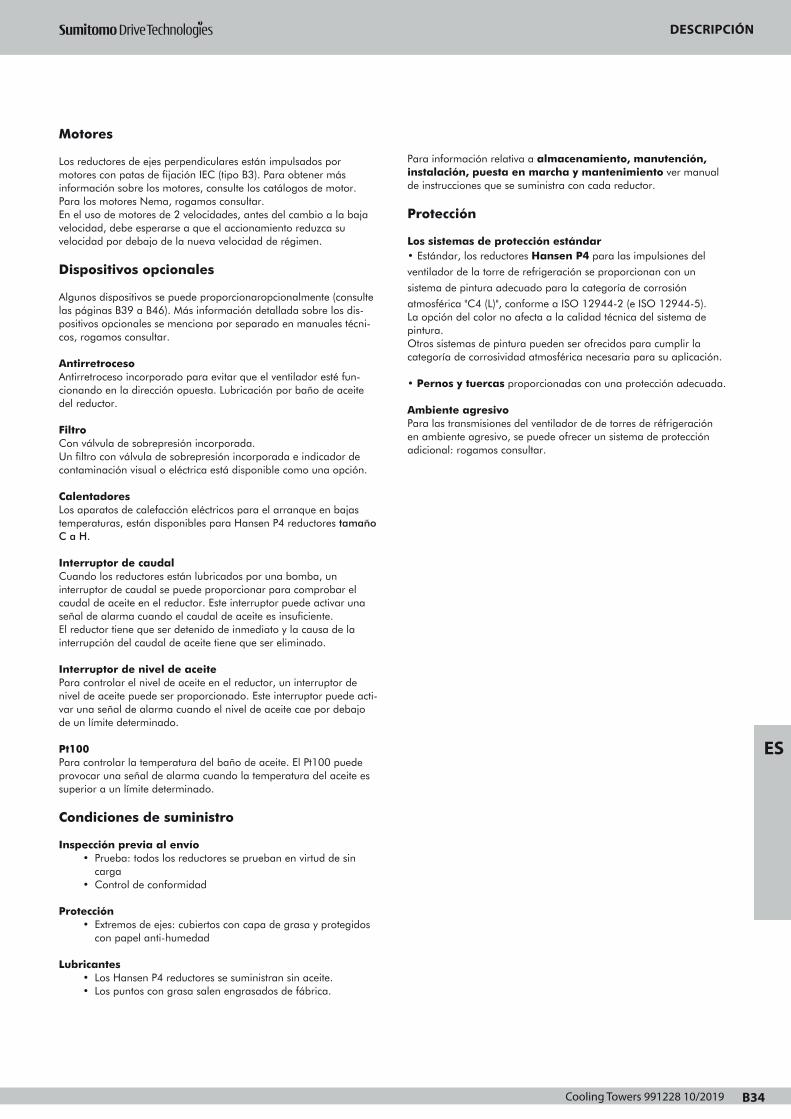
Cooling Towers 991228 10/2019 B34
ES
DESCRIPCIONREDUCTORES HANSEN P4 PARA LAS IMPULSIONES DEL
VENTILADOR DE LA TORRE DE REFRIGERACIÓN
Motores
Los reductores de ejes perpendiculares están impulsados pormotores con patas de fijación IEC (tipo B3). Para obtener másinformación sobre los motores, consulte los catálogos de motor.Para los motores Nema, rogamos consultar.En el uso de motores de 2 velocidades, antes del cambio a la bajavelocidad, debe esperarse a que el accionamiento reduzca suvelocidad por debajo de la nueva velocidad de régimen.
Dispositivos opcionales
Algunos dispositivos se puede proporcionaropcionalmente (consultelas páginas B39 a B46). Más información detallada sobre los dis-positivos opcionales se menciona por separado en manuales técni-cos, rogamos consultar.
Antirretroceso Antirretroceso incorporado para evitar que el ventilador esté fun-cionando en la dirección opuesta. Lubricación por baño de aceitedel reductor.
FiltroCon válvula de sobrepresión incorporada.Un filtro con válvula de sobrepresión incorporada e indicador decontaminación visual o eléctrica está disponible como una opción.
CalentadoresLos aparatos de calefacción eléctricos para el arranque en bajastemperaturas, están disponibles para Hansen P4 reductores tamañoC a H.
Interruptor de caudalCuando los reductores están lubricados por una bomba, uninterruptor de caudal se puede proporcionar para comprobar elcaudal de aceite en el reductor. Este interruptor puede activar unaseñal de alarma cuando el caudal de aceite es insuficiente.El reductor tiene que ser detenido de inmediato y la causa de lainterrupción del caudal de aceite tiene que ser eliminado.
Interruptor de nivel de aceitePara controlar el nivel de aceite en el reductor, un interruptor denivel de aceite puede ser proporcionado. Este interruptor puede acti-var una señal de alarma cuando el nivel de aceite cae por debajode un límite determinado.
Pt100Para controlar la temperatura del baño de aceite. El Pt100 puedeprovocar una señal de alarma cuando la temperatura del aceite essuperior a un límite determinado.
Condiciones de suministro
Inspección previa al envío• Prueba: todos los reductores se prueban en virtud de sin
carga• Control de conformidad
Protección• Extremos de ejes: cubiertos con capa de grasa y protegidos
con papel anti-humedad
Lubricantes• Los Hansen P4 reductores se suministran sin aceite.
• Los puntos con grasa salen engrasados de fábrica.
Para información relativa a almacenamiento, manutención,instalación, puesta en marcha y mantenimiento ver manualde instrucciones que se suministra con cada reductor.
Protección
Los sistemas de protección estándar• Estándar, los reductores Hansen P4 para las impulsiones del
ventilador de la torre de refrigeración se proporcionan con un
sistema de pintura adecuado para la categoría de corrosión
atmosférica "C4 (L)", conforme a ISO 12944-2 (e ISO 12944-5).La opción del color no afecta a la calidad técnica del sistema depintura.Otros sistemas de pintura pueden ser ofrecidos para cumplir lacategoría de corrosividad atmosférica necesaria para su aplicación.
• Pernos y tuercas proporcionadas con una protección adecuada.
Ambiente agresivoPara las transmisiones del ventilador de de torres de réfrigeraciónen ambiente agresivo, se puede ofrecer un sistema de protecciónadicional: rogamos consultar.
S
B34
Page 1
DESCRIPCIÓN

Cooling Towers 991228 10/2019B35
SELECCIONPotencia mecánica nominal
LAS TRANSMISIONES DEL VENTILADOR DE LA TORRE DE REFRIGERACIÓN
B35
consulte la página B37
consulte la página B32
Para los índices de reducción < que el menor índice de la reducción enlas tablas de selección (p. B47-B48): rogamos consultar.
Procedimiento Información de referencia
Potencia mecánica nominal P
Índice de reducción
2
3
1
DATOS DE LA SELECCION
Pm , Pa , nHSS , nLSS , iN
Carga axial
SELECCION DE PROGRAMA
Potencia absorbida Pa
PPotencia motor Pm
y
x SF =1,75
x SF = 2
≥
Tamaño
S
E
L
E
C
C
I
O
N
C
O
M
P
R
O
B
A
C
I
O
N * Nota: los valores de P y Fx (p. B43-B46) son los mismos para
QVR.2 y QVR.2L Potencia térmica: consulte las páginas
B36, B47
Fx
por
• • • • • • - • • • - Índice dereducción
Q V R 2 • - C U N
Tamaño
P
/ = reductor estándar (sin código)
LX
=
=
casa de cojinete extendida (tamaños Z, A, B)
tamaño intermedio ver P. B43-B44 *
P
Fx : ... kN
Preste atención a la dirección de Fx ! (Siempre haciaabajo)
Comprobar si
≤Fx FxN
ver p. B45-B46 *
FxN
Page 1
Información de referencia
SELECCIONPotencia térmica
LAS TRANSMISIONES DEL VENTILADOR DE LA TORRE DE REFRIGERACIÓN
Ptn del reductorsin refrigeración forzada
factor a por temperatura ambiente sin refrigeración forzada
Índice de
reducción
Temperatura ambiente en °C
15 a 25 25 a 35 35 a 45
6,3 11,2
12,5 18
≥ 20
Tamaño
1
1
0,81
0,85
1
Z H
0,87
Z H
0,68
0,71
0,55
0,66
0,75
Z D
0,74
E H
OK
Comprobación potencia térmica
Pa ≤ Ptn • a • c • e ?
Posibilidad de ventilador
No se requiere refri-geración forzada
Ptf para un reductor con 1
ventilador
Pa ≤ Ptf • d • e ? Un ventilador
factor d por temperatura ambiente con ventilación forzada
Número
de etapas
Temperatura ambiente en °C
15 a 25 25 a 35 35 a 45 45 a 55
con ventilaciónforzada 2 1 0,86 0,72 0,59
OK
factor c por circulación de aire (sin ventilador)
Instalación
Interior, local pequeño
Flujo de aire
≥ 0,5 m/s 0,73 0,70
Interior área de trabajo normal
Ext., protegido cont. radi.Solar
Tamaño
≥ 1,4 m/s
≥ 3,0 m/s
1
1,33
Z D
1
1,36
E H
Pt
factor e por humedad relativa del aire
Humedad relativa del aire
< 100% = 100%
1 1,15
Pt
Ptn, Ptf
porver p.B47
• • • • • • - • • • - Índice dereducción
Q V R 2 • - C U N
Tamaño/ = reductor estándar (sin código)
LX
=
=
casa de cojinete extendida (tamaños Z, A, B)
tamaño intermedio
S
B36
El flujo de aire se seleccionarán de acuerdo con la estructura:
Estructura abierta: reductores instalados en una estructura de acero de
marco abierto permiten que el flujo de aire del condensador pase por la casa
del reductor.
Estructura cerrada: reductores instalados en un pedestal de hormigón o en
una estructura de acero cerrado.
Esta estructura evita que el aire del condensador pase por la casa del reductor.
Page 1
SELECCIÓN
Potencia mecánica nominal las transmisiones del ventilador de la torre de refrigeración

Cooling Towers 991228 10/2019 B36
ES
Información de referencia
SELECCIONPotencia térmica
LAS TRANSMISIONES DEL VENTILADOR DE LA TORRE DE REFRIGERACIÓN
Ptn del reductorsin refrigeración forzada
factor a por temperatura ambiente sin refrigeración forzada
Índice de
reducción
Temperatura ambiente en °C
15 a 25 25 a 35 35 a 45
6,3 11,2
12,5 18
≥ 20
Tamaño
1
1
0,81
0,85
1
Z H
0,87
Z H
0,68
0,71
0,55
0,66
0,75
Z D
0,74
E H
OK
Comprobación potencia térmica
Pa ≤ Ptn • a • c • e ?
Posibilidad de ventilador
No se requiere refri-geración forzada
Ptf para un reductor con 1
ventilador
Pa ≤ Ptf • d • e ? Un ventilador
factor d por temperatura ambiente con ventilación forzada
Número
de etapas
Temperatura ambiente en °C
15 a 25 25 a 35 35 a 45 45 a 55
con ventilaciónforzada 2 1 0,86 0,72 0,59
OK
factor c por circulación de aire (sin ventilador)
Instalación
Interior, local pequeño
Flujo de aire
≥ 0,5 m/s 0,73 0,70
Interior área de trabajo normal
Ext., protegido cont. radi.Solar
Tamaño
≥ 1,4 m/s
≥ 3,0 m/s
1
1,33
Z D
1
1,36
E H
Pt
factor e por humedad relativa del aire
Humedad relativa del aire
< 100% = 100%
1 1,15
Pt
Ptn, Ptf
porver p.B47
• • • • • • - • • • - Índice dereducción
Q V R 2 • - C U N
Tamaño/ = reductor estándar (sin código)
LX
=
=
casa de cojinete extendida (tamaños Z, A, B)
tamaño intermedio
S
B36
El flujo de aire se seleccionarán de acuerdo con la estructura:
Estructura abierta: reductores instalados en una estructura de acero de
marco abierto permiten que el flujo de aire del condensador pase por la casa
del reductor.
Estructura cerrada: reductores instalados en un pedestal de hormigón o en
una estructura de acero cerrado.
Esta estructura evita que el aire del condensador pase por la casa del reductor.
Page 1
SELECCIÓN
Potencia térmica las transmisiones del ventilador de la torre de refrigeración
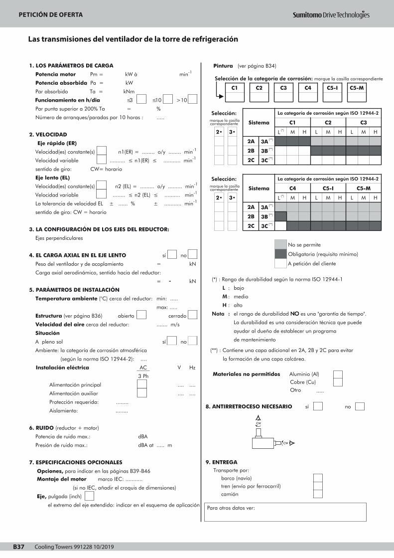
Cooling Towers 991228 10/2019B37
PETICION DE OFERTALAS TRANSMISIONES DEL VENTILADOR DE LA TORRE DE REFRIGERACIÓN
B37
1. LOS PARÁMETROS DE CARGA
Potencia motor Pm = kW à min-1
Potencia absorbida Pa = kW
Par absorbido Ta = kNm
Funcionamiento en h/dia ≤3
Par punta superior a 200% Ta =
Número de arranques/paradas por 10 horas :
≤10 >10
%
.....
2. VELOCIDAD
Eje rápido (ER)
Velocidad(es) constante(s) n1(ER) = ........ o/y ........ min-1
Velocidad variable .......... ≤ n1(ER) ≤ ........... min-1
sentido de giro: CW= horario
Eje lento (EL)
Velocidad(es) constante(s) n2 (EL) = ......... o/y ......... min-1
Velocidad variable ........ ≤ n2 (EL) ≤ .......... min-1
La tolerancia de velocidad EL ± ...... % ± ........... min-1
sentido de giro: CW = horario
3. LA CONFIGURACIÓN DE LOS EJES DEL REDUCTOR:
Ejes perpendiculares
4. EL CARGA AXIAL EN EL EJE LENTO sí no
Peso del ventilador y de acoplamiento
Carga axial aerodinámico, sentido hacia del reductor:
5. PARÁMETROS DE INSTALACIÓN
Temperatura ambiente (°C) cerca del reductor:
Estructura (ver página B36) abierto
Velocidad del aire cerca del reductor:
=
= -
kN
kN
min: .....
max: .....
....... m/s
cerrado
Situación
A pleno sol
Ambiente: la categoría de corrosión atmosférica
(según la norma ISO 12944-2): ....
Instalación eléctrica
Alimentación principal
Alimentación auxiliar
AC
3 Ph
sí no
V Hz
....
....
....
....
Protección requerida: ........
Aislamiento: ........
6. RUIDO (reductor + motor)
Potencia de ruido max.:
Presión de ruido max.:
7. ESPECIFICACIONES OPCIONALES
dBA
dBA at ..... m
Opciones, para indicar en las páginas B39-B46
Montaje del motor marco IEC: ...........
(si no IEC, añadir el croquis de dimensiones)
Eje, pulgada (inch)
el extremo del eje extendido: indicar en el esquema de aplicación
Ref : Fecha : Nombre : Firma :
Pintura (ver página B34)
(*) : Rango de durabilidad según la norma ISO 12944-1
L : bajo
M : medio
H : alto
Nota : el rango de durabilidad NNNNOOOO es una "garantía de tiempo".
La durabilidad es una consideración técnica que puede
ayudar al dueño de establecer un programa
de mantenimiento
(**) : Contiene una capa adicional en 2A, 2B y 2C para evitar
la formación de una capa calcárea.
Materiales no permitidos Aluminio (Al)
Cobre (Cu)
Otro .....
8. ANTIRRETROCESO NECESARIO sí no
9. ENTREGA Transporte por:
barco (navío)
tren (envío por ferrocarril)
camión
Para otros datos ver:
Selección: marque la casillacorrespondiente
2• 3•
Sistema
La categoría de corrosión según ISO 12944-2
L (*)
C1
M H L
C2
M H L
C3
M
2A
2B
3A (**)
3B (**)
2C 3C (**)
Selección: marque la casillacorrespondiente
2• 3•
Sistema
2A 3A (**)
2B
2C
3B (**)
3C (**)
La categoría de corrosión según ISO 12944-2
C4
L (*) M H L
No se permite
C5-I
M H
C5-M
L M
Obligatoria (requisito mínimo)
A petición del cliente
H
H
Selección de la categoría de corrosión: marque la casilla correspondiente
C1 C2 C3 C4 C5-I C5-M
CW
CW
Page 1
PETICIÓN DE OFERTA
Las transmisiones del ventilador de la torre de refrigeración

Cooling Towers 991228 10/2019 B38
PETICIÓN DE OFERTA
ES
VISTA EN PLANTA
VISTA LATERAL
Esquema de aplicación

Cooling Towers 991228 10/2019B39
t°
Gear unit
Vertical low speed shaft
Right-angle shafts
Size
Gear sets
Réducteur à engrenages
Arbre P.V. vertical
Taille
Jeux d'engrenages
Zahnradgetriebe
Langsamdr. Welle: vertikal
Kegel- und Stirnräder
Baugröße
Stufenzahl
Reductor
Eje lento vertical
Ejes perpendiculares
Tamaño
N° de etapas
QVR
Z B2 (L)
Standard accessories Accessoires standard Standardzubehör Accesorios estándar
Optional accessories Accesoires en optionOptionales Zubehör Accesorios opcionales
Low speed shaft
Arbre petitevitesse
Langsamdre-hende Welle
Eje lento
High speedshaft
Arbre grandevitesse
SchnelldrehendeWelle
Eje rápido
Housing
Carter
Gehäuse
Cárter
Outside thecooling tower
A l’extérieure dela tour de réfrigération
Außerhalb desKühlturms
Fuera de latorre derefrigeración
10
8
16
1
4
13
2°
2°
12
B39
5
11
Arbres perpendiculaires
For cooling tower Pour commandes d'aéro- Für Ventilatorantriebe Para las impulsiones del ventiladorfan drives réfrigérants in Kühltürmen de la torre de refrigeración
Accessories and Accessoires et Zubehör und Accesorios yoptions options Optionen opciones
15
7
2
P
9
3
6
14
Page 1

Cooling Towers 991228 10/2019 B40
1
:::: ooooppppttttiiiioooonnnnaaaallll
normal solid output shaft
2
3
regreasable labyrinth
(DIN 71412)
oil seal and labyrinth
1
:::: eeeennnn ooooppppttttiiiioooonnnn
arbre petite vitesse normal 1
2
3
plein
labyrinthe regraissable 2
(DIN 71412)
bague d'étanchéité et labyrinthe 3
4
5
6
7
backstop,
dipstick
magnetic plug
extended bearing housing:
8
9
QVR.2L
centralized lubrication points
(DIN 71412)
pump lubrication
4
5
6
7
antidévireur
jauge d'huile
4
5
bouchon aimanté
palier allongé: QVR.2L
6
7
8
9
points de graissage centralisés 8
(DIN 71412)
lubrification par pompe 9
LLLLooooccccaaaatttteeeedddd oooouuuuttttssssiiiiddddeeee tttthhhheeee ccccoooooooolllliiiinnnngggg ttttoooowwwweeeerrrr
10
11
breather plug
oil filling plug
12
13
draining plug
draining plug for water of
condensation.
Not of H.I.T. supply. *
LLLLooooccccaaaalllliiiisssséééé àààà llll’’’’eeeexxxxttttéééérrrriiiieeeeuuuurrrreeee ddddeeee llllaaaa ttttoooouuuurrrr
ddddeeee rrrrééééffffrrrriiiiggggéééérrrraaaattttiiiioooonnnn
10
11
LLLLooookkkkaaaalllliiiissssiiiieeeerrrrtttt aaaauuuußßßßeeeerrrrhhhhaaaallllbbbb ddddeeeessss KKKKüüüühhhhllllttttuuuurrrrmmmmssss
reniflard
bouchon de remplissage
10
11
12
13
bouchon de vidange
bouchon de vidange de l'eau
12
13
de condensation. Ne fait pas
partie de la livraison de H.I.T. *
14 tapped holes with plug in
the housing for external tubing
connection .
Tubes and elbows are not of
15
H.I.T. supply. *
external dipstick. To be
14 trous taraudés avec bouchon,
dans le carter pour
14
le raccordement de tubes
externes.
15
Les tubes et coudes ne font
pas partie de la livraison
de H.I.T. *
jauge d'huile externe. 15
16
calibrated with gear unit
dipstick (supplied loose).
oil level glass (supplied loose),
not to be used together with
anti-humidity breather.
16
A calibrer suivant la jauge
du réducteur (livraison
séparée).
indicateur de niveau d'huile 16
(livraison séparée),ne pas utiliser
ensemble avec reniflard
anti-humidité.
* H.I.T. = Hansen Industrial Transmissions nv
:::: OOOOppppttttiiiioooonnnn
Normale Abtriebswelle: 1
Vollwelle
nachschmierbares
Labyrinth (DIN 71412)
Afdichtungsring und Labyrinth
2
3
: OOOOppppcccciiiióóóónnnn
eje lento: eje macizo normal
junta laberíntica reengra-
sable (DIN 71412)
retén y junta laberíntica
Rücklaufsperre
Ölmeßstab
Magnetschraube
verlängertes Lagergehäuse:
4
5
6
7
QVR.2L
zentrale Schmierpunkte
(DIN 71412)
Pumpenschmierung
8
9
antirretrocesso
varilla del nivel
tapón magnético
soporte del cojinete extendido:
QVR.2L
Puntos de la lubricación
centralizada (DIN 71412)
lubricación par bomba
Entlüftungsschraube
Öleinfullschraube
SSSSiiiittttuuuuaaaaddddoooo ffffuuuueeeerrrraaaa ddddeeee llllaaaa ttttoooorrrrrrrreeee ddddeeee
rrrreeeeffffrrrriiiiggggeeeerrrraaaacccciiiióóóónnnn
10
11
Ablaßschraube
Ablaßschraube für Kondenz-
wasser. Gehört nicht zum
H.I.T. Lieferumfang. *
12
13
tapón de aireación
tapón de llenado
tapón de drenaje
tapón de vaciado para el agua
de condensación. No forma
parte de la entrega de H.I.T. *
Gewindebohrungen im
Gehäuse, mit Schraube,
für externe Rohrverbindung.
Die Rohre und Knierohre
14
gehören nicht zum H.I.T.
Lieferumfang. *
externer Ölmeßstab. Mit 15
agujeros roscados en la cárter,
con tapón, para la conexión
de tubos externos.
Los tubos y codos no forman
parte de la entrega de
H.I.T. *
la varilla del nivel de aceite
Getriebe-Ölmeßstab
abzustimmen (Lose mit-
geliefert)
Ölstandglas (Lose mitgeliefert), 16
nicht zusammen mit Entlüftung
für feuchte Umgebung
verwenden.
externo. A calibrar según
la varilla del nivel de aceite del
reductor (entrega separada).
indicador de nivel de aceite
(entrega separada), no utilizar
juntos con tapón de aireación
anti-humedad.
Gear unit
Vertical low speed shaft
Right-angle shafts
Size
Gear sets
Réducteur à engrenages
Arbre P.V. vertical
Taille
Jeux d'engrenages
Zahnradgetriebe
Langsamdr. Welle: vertikal
Kegel- und Stirnräder
Baugröße
Stufenzahl
Reductor
Eje lento vertical
Ejes perpendiculares
Tamaño
N° de etapas
QVR
Z B2 (L)
For cooling tower Pour commandes d'aéro- Für Ventilatorantriebe Para las impulsiones del ventiladorfan drives réfrigérants in Kühltürmen de la torre de refrigeración
Accessories and Accessoires et Zubehör und Accesorios yoptions options Optionen opciones
Arbres perpendiculaires
B40
Page 1

Cooling Towers 991228 10/2019B41
t°
Gear unit
Vertical low speed shaft
Right-angle shafts
Size
Gear sets
Réducteur à engrenages
Arbre P.V. vertical
Taille
Jeux d'engrenages
Zahnradgetriebe
Langsamdr. Welle: vertikal
Kegel- und Stirnräder
Baugröße
Stufenzahl
Reductor
Eje lento vertical
Ejes perpendiculares
Tamaño
N° de etapas
QVR
C H2
Standard accessoriesAccessoires standard Standardzubehör Accesorios estándar
Optional accessoriesAccesoires en optionOptionales ZubehörAccesorios opcionales
Low speed shaft
Arbre petitevitesse
Langsamdre-hende Welle
Eje lento
High speedshaft
Arbre grandevitesse
SchnelldrehendeWelle
Eje rápido
Housing
Carter
Gehäuse
Cárter
Outside thecooling tower
A l’extérieure dela tour de réfrigération
Außerhalb desKühlturms
Fuera de latorre derefrigeración
OIL-LOCKTM3
7
P
8
14 20
2
4
1716
B41
6
15
Arbres perpendiculaires
For cooling tower Pour commandes d'aéro- Für Ventilatorantriebe Para las impulsiones del ventiladorfan drives réfrigérants in Kühltürmen de la torre de refrigeración
Accessories and Accessoires et Zubehör und Accesorios yoptions options Optionen opciones
19
•
9
10 11 12
1
t°
13
Intermediate size Taille intermédiaire Zwischengröße Tamaño intermedio (X)
5
2°
2°
18
Page 1

Cooling Towers 991228 10/2019 B42
1
:::: ooooppppttttiiiioooonnnnaaaallll
normal solid output shaft
2
3
regreasable labyrinth
(DIN 71412)
Oil-LockTM seal
1
:::: eeeennnn ooooppppttttiiiioooonnnn
arbre petite vitesse normal 1
2
3
plein
labyrinthe regraissable 2
(DIN 71412)
étanchéité Oil-LockTM 3
4
5
6
7
backstop
axial fan
dipstick
magnetic plug
8
9
10
11
pump lubrication
inspection cover
heater
oil level switch
4
5
6
7
antidévireur
ventilateur axial
4
5
jauge d'huile
bouchon aimanté
6
7
8
9
10
11
lubrification par pompe
couvercle d'inspection
8
9
réchauffeur
contacteur de niveau d'huile
10
11
12
13
LLLLooooccccaaaatttteeeedddd oooouuuuttttssssiiiiddddeeee tttthhhheeee ccccoooooooolllliiiinnnngggg ttttoooowwwweeeerrrr
flow switch
Pt 100 meter for oil sump
temperature
14
15
16
breather plug
oil filling plug
draining plug
12
13
LLLLooooccccaaaalllliiiisssséééé àààà llll’’’’eeeexxxxttttéééérrrriiiieeeeuuuurrrreeee ddddeeee llllaaaa ttttoooouuuurrrr
contacteur de débit
appareil de mesure Pt 100 pour
12
13
la température du bain d'huile
LLLLooookkkkaaaalllliiiissssiiiieeeerrrrtttt aaaauuuußßßßeeeerrrrhhhhaaaallllbbbb ddddeeeessss KKKKüüüühhhhllllttttuuuurrrrmmmmssss
ddddeeee rrrrééééffffrrrriiiiggggéééérrrraaaattttiiiioooonnnn
14
15
16
reniflard 14
bouchon de remplissage
bouchon de vidange
15
16
17
18
draining plug for water of
condensation.
Not of H.I.T. supply. *
tapped holes with plug in
the housing for external tubing
connection .
Tubes and elbows are not of
H.I.T. supply. *
17
18
bouchon de vidange de l'eau
de condensation. Ne fait pas
17
partie de la livraison de H.I.T. *
trous taraudés avec bouchon, 18
dans le carter pour
le raccordement de tubes
externes.
Les tubes et coudes ne font
19 external dipstick. To be
calibrated with gear unit
20
dipstick (supplied loose).
oil level glass (supplied loose),
not to be used together with
19
pas partie de la livraison
de H.I.T. *
jauge d'huile externe.
A calibrer suivant la jauge
19
20
du réducteur (livraison
séparée).
indicateur de niveau d'huile
(livraison séparée),ne pas utiliser
20
anti-humidity breather.
* H.I.T. = Hansen Industrial Transmissions nv
ensemble avec reniflard
anti-humidité.
:::: OOOOppppttttiiiioooonnnn
Normale Abtriebswelle: 1
Vollwelle
nachschmierbares
Labyrinth (DIN 71412)
Oil-LockTM Dichtung
2
3
: OOOOppppcccciiiióóóónnnn
eje lento: eje macizo normal
junta laberíntica reengra-
sable (DIN 71412)
junta Oil-LockTM
Rücklaufsperre
Axiallüfter
Ölmeßstab
Magnetschraube
4
5
6
7
Pumpenschmierung
Schaulochdeckel
Heizstab
Ölstandschalter
8
9
10
11
antirretrocesso
ventilador axial
varilla del nivel
tapón magnético
lubricación par bomba
tapa de inspección
calentador
interruptor nivel de aceite
Strömungsschalter
Pt 100 für Ölbadtemperatur-
messung
12
13
SSSSiiiittttuuuuaaaaddddoooo ffffuuuueeeerrrraaaa ddddeeee llllaaaa ttttoooorrrrrrrreeee ddddeeee
Entlüftungsschraube
Öleinfullschraube
Ablaßschraube
rrrreeeeffffrrrriiiiggggeeeerrrraaaacccciiiióóóónnnn
14
15
16
interruptor de caudal
medidor Pt100 para tempera-
tura del baño de aceite
tapón de aireación
tapón de llenado
tapón de drenaje
Ablaßschraube für Kondenz-
wasser. Gehört nicht zum
H.I.T. Lieferumfang. *
Gewindebohrungen im
17
18
Gehäuse, mit Schraube,
für externe Rohrverbindung.
Die Rohre und Knierohre
gehören nicht zum H.I.T.
tapón de vaciado para el agua
de condensación. No forma
parte de la entrega de H.I.T. *
agujeros roscados en la cárter,
con tapón, para la conexión
de tubos externos.
Los tubos y codos no forman
parte de la entrega de
Lieferumfang. *
externer Ölmeßstab. Mit
Getriebe-Ölmeßstab
19
abzustimmen (Lose mit-
geliefert)
Ölstandglas (Lose mitgeliefert),
nicht zusammen mit Entlüftung
20
H.I.T. *
la varilla del nivel de aceite
externo. A calibrar según
la varilla del nivel de aceite del
reductor (entrega separada).
indicador del nivel de aceite
(entrega separada), no utilizar
für feuchte Umgebung
verwenden.
juntos con tapón de aireación
anti-humedad.
Gear unit
Vertical low speed shaft
Right-angle shafts
Size
Gear sets
Réducteur à engrenages
Arbre P.V. vertical
Taille
Jeux d'engrenages
Zahnradgetriebe
Langsamdr. Welle: vertikal
Kegel- und Stirnräder
Baugröße
Stufenzahl
Reductor
Eje lento vertical
Ejes perpendiculares
Tamaño
N° de etapas
QVR
C H2
Arbres perpendiculaires
For cooling tower Pour commandes d'aéro- Für Ventilatorantriebe Para las impulsiones del ventiladorfan drives réfrigérants in Kühltürmen de la torre de refrigeración
Accessories and Accessoires et Zubehör und Accesorios yoptions options Optionen opciones
Intermediate size Taille intermédiaire Zwischengröße Tamaño intermedio (X)
B42
Page 1

Cooling Towers 991228 10/2019B43
Gear unit
Vertical low speed shaft
Right-angle shafts
Size
Two stages
Réducteur à engrenages
Arbre P.V. vertical
Arbres perpendiculaires
Taille
Deux étages
Zahnradgetriebe
Langsamdr. Welle: vertikal
Kegel- und Stirnräder
Baugröße
Zweistufig
Reductor
Eje lento vertical
Ejes perpendiculares
Tamaño
Dos etapas
B43
min-1 Size - Taille - Baugröße - TamañoiN n1
1800
n2
510Z297
A2145
B2225
C2 D2 E2 E2X F2 F2X G2 H2
15001200
420340
1000900
280255
8266
12599
5550
8375
190155130115
7501800
210450
15001200
380300
1000900
250225
7501800
190400
4297
63145
8266
12599
98225190155
5550
8375
4297
63145
130115
98225
15001200
330265
1000900
220200
7501800
165360
15001200
300240
8266
12599
5550
8375
190155130115
4297
63145
8266
12599
98225190155
1000900
200180
7501800
150320
15001200
270215
1000900
180160
5550
8375
4294
63145
130115
98225
8066
12599
5550
8375
190155130115
7501800
135285
15001200
240190
1000900
160145
7501800
120255
4287
63145
7460
12599
98225 350190155
300255
5045
8375
3878
63145
130115
215195
98225
160310
15001200
210170
1000900
140125
7501800
105225
15001200
190150
6552
12599
4439
8375
190155
275230
130115
195180
3371
63105
5948
9072
96175
150295
145115
255210
590 810510410
710580
1100920760
340310
490440
260530
370810
630570480
1100
20501700140011501050
8801800
440360
690550
300270
460420
920750630570
225480
350760
410330
640510
810480970
710580
840670
155012501050
930
1100780
1650920760
14001150
210018001450
1000900
125115
7501800
94200
15001200
165135
1000900
110100
4036
6054
3062
46105
9788
175160
73165
135270
5242
9072
3531
6054
140110
230190
9485
160145
7501800
83180
15001200
150120
1000900
10090
7501800
75160
2756
46120
4738
10081
71170
120245
145120
210170
3229
6861
2449
5196
9989
145130
75155
115220
275245
430390
205420
320660
490440
570520
370800
440910
350285
550440
240215
370330
670540
780640
450410
540490
660600
950850
5001100
7101500
12001100
9201850
920760
12501000
650590
840750
155012501050
940180390
280610
320260
510410
340770
410800
650520
680560
215195
340310
165340
260530
440390
460420
330640
350760
4901050
6301300
890710
1100870
780175014501200
590540
730660
450990
5501150
990890740
150015001200
135105
1000900
8980
750 67
4133
8165
2825
5449
130105
190155
8778
130115
21 41 65 97
280225
440360
190170
300270
540430
650520
360330
430390
145 225 275 330
830670
960770
560510
650580
12501000
840760
420 490 640
3,55
4
4,5
5
5,6
6,3
7,1
8
9
10
11,2
QVR
Z H2
Mechanical Puissances méca- Nennleistungen Potencias mecá-power ratings niques nominales nicas nominales P (kW)
Intermediate size Taille intermédiaire Zwischengröße Tamaño intermedio (X)
iN Nominal ratio iN Rapport nominal iN Nennübersetzung iN Índice nominaln1, 2 Nominal speed (rpm) n1, 2 Vitesse nominale n1, 2 Nenndrehzahl n1, 2 Velocidades nominales (r.p.m.)
Page 1
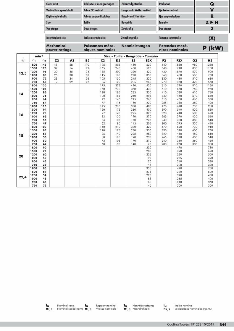
Cooling Towers 991228 10/2019 B44
Intermediate size Taille intermédiaire Zwischengröße Tamaño intermedio (X)
Gear unit
Vertical low speed shaft
Right-angle shafts
Size
Two stages
Réducteur à engrenages
Arbre P.V. vertical
Arbres perpendiculaires
Taille
Deux étages
Zahnradgetriebe
Langsamdr. Welle: vertikal
Kegel- und Stirnräder
Baugröße
Zweistufig
Reductor
Eje lento vertical
Ejes perpendiculares
Tamaño
Dos etapas
min-1 Size - Taille - Baugröße - TamañoiN n1
1800
n2
145Z245
A268
B2110
C2195
D2295
E2480
E2X620
F2640
F2X850
G2980
H21350
15001200
12096
1000900
8072
3730
5645
2523
3834
9274
165135
6256
115105
245200
400320
165150
270245
520420
540430
350320
360330
710570
830670
480430
560510
1100900750680
7501800
60130
15001200
10586
1000900
7164
7501800
54115
19 29 47 86175150120100
9277
145
125275
205420
230185
360285
265520
270610
430350
510410
155140
240215
115210
180330
295265
340310
220480
255470
360790
420910
660530
760610
5601150
960780
440400
510460
330640
380730
650580490980
15001200
9475
1000900
6356
7501800
47100
15001200
8367
12097827462
140120
961000900
5650
7501800
4290
15001200
7560
1000900
5045
807260
175140
280225
120105
190170
400320
390320
270245
265240
90210
145330
175140
280225
205420
200470
350280
390320
540440
620500
370330
420380
830670560510
275620
320730
520410
600480
420910760610
120105
190170
90 140
235210
265240
175330
200
280225190170
340310
400360
260470
300
510460380730
390320265240
620500420380
7501800
3880
15001200
6754
1000900
4540
750 33
145330275220185165140
200470390320
320730600480
265240200
400360300
QVR
Z H2
Mechanical Puissances méca- Nennleistungen Potencias mecá-power ratings niques nominales nicas nominales P (kW)
12,5
14
16
18
20
22,4
B44
iN Nominal ratio iN Rapport nominal iN Nennübersetzung iN Índice nominaln1, 2 Nominal speed (rpm) n1, 2 Vitesse nominale n1, 2 Nenndrehzahl n1, 2 Velocidades nominales (r.p.m.)
Page 1
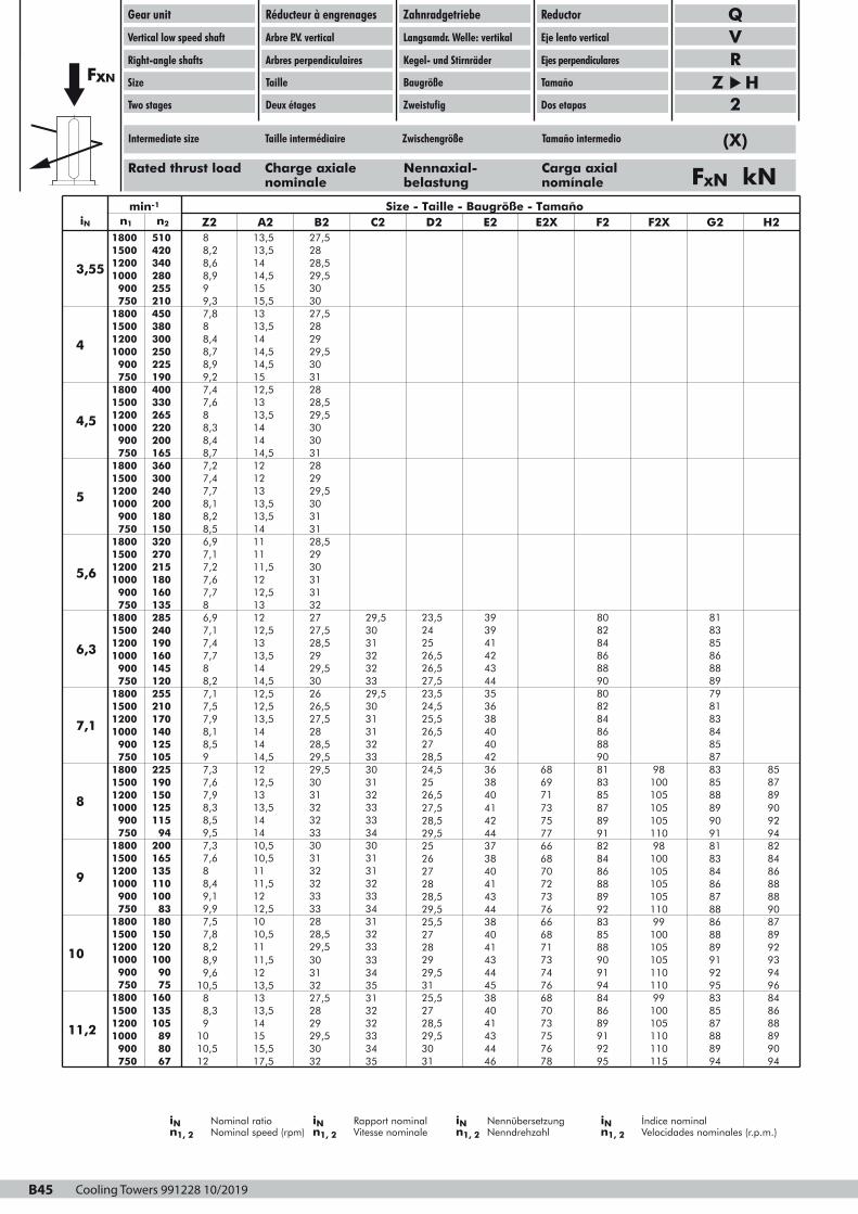
Cooling Towers 991228 10/2019B45
Gear unit
Vertical low speed shaft
Right-angle shafts
Size
Two stages
Réducteur à engrenages
Arbre P.V. vertical
Arbres perpendiculaires
Taille
Deux étages
Zahnradgetriebe
Langsamdr. Welle: vertikal
Kegel- und Stirnräder
Baugröße
Zweistufig
Reductor
Eje lento vertical
Ejes perpendiculares
Tamaño
Dos etapas
QVR
Z H2
iN Nominal ratio iN Rapport nominal iN Nennübersetzung iN Índice nominaln1, 2 Nominal speed (rpm) n1, 2 Vitesse nominale n1, 2 Nenndrehzahl n1, 2 Velocidades nominales (r.p.m.)
Rated thrust load Charge axiale Nennaxial- Carga axialnominale belastung nomínale FxN kN
FxN
min-1 Size - Taille - Baugröße - TamañoiN n1
1800
n2
510Z28
A213,5
B227,5
C2 D2 E2 E2X F2 F2X G2 H2
15001200
420340
1000900
280255
8,28,6
13,514
8,99
14,515
2828,529,530
7501800
210450
15001200
380300
1000900
250225
7501800
190400
9,37,8
15,513
88,4
13,514
3027,52829
8,78,9
14,514,5
9,27,4
1512,5
29,5303128
15001200
330265
1000900
220200
7501800
165360
15001200
300240
7,68
1313,5
8,38,4
1414
28,529,53030
8,77,2
14,512
7,47,7
1213
31282929,5
1000900
200180
7501800
150320
15001200
270215
1000900
180160
8,18,2
13,513,5
8,56,9
1411
30313128,5
7,17,2
1111,5
7,67,7
1212,5
29303131
7501800
135285
15001200
240190
1000900
160145
7501800
120255
86,9
1312
7,17,4
12,513
3227 29,527,528,5
3031
7,78
13,514
8,27,1
14,512,5
2929,5
3232
3026
3329,5
15001200
210170
1000900
140125
7501800
105225
15001200
190150
7,57,9
12,513,5
8,18,5
1414
26,527,5
3031
2828,5
3132
97,3
14,512
7,67,9
12,513
29,529,5
3330
3031
3132
23,5 392425
3941
808284
26,526,5
4243
27,523,5
4435
86889080
81838586888979
24,525,5
3638
26,527
4040
82848688
28,524,5
4236
2526,5
3840
689081
6971
8385
81838485
988783
100105
8588
858789
1000900
125115
7501800
94200
15001200
165135
1000900
110100
8,38,5
13,514
9,57,3
1410,5
3232
3333
3330
3430
7,68
10,511
8,49,1
11,512
3132
3131
3233
3233
7501800
83180
15001200
150120
1000900
10090
7501800
75160
9,97,5
12,510
7,88,2
10,511
3328
3431
28,529,5
3233
8,99,6
11,512
10,58
13,513
3031
3334
3227,5
3531
27,528,5
4142
29,525
4437
7375
8789
7766
9182
2627
3840
2828,5
4143
6870
8486
7273
8889
105105
8990
11098
9181
90929482
100105
8384
105105
8687
84868888
29,525,5
4438
2728
4041
7666
9283
6871
8588
2929,5
4344
3125,5
4538
7374
9091
7668
9484
11099
8886
100105
8889
90878992
105110
9192
11099
9583
93949684
15001200
135105
1000900
8980
750 67
8,39
13,514
1010,5
1515,5
2829
3232
29,530
3334
12 17,5 32 35
2728,5
4041
29,530
4344
7073
8689
7576
9192
31 46 78 95
100105
8587
110110
8889
86888990
115 94 94
3,55
4
4,5
5
5,6
6,3
7,1
8
9
10
11,2
B45
Intermediate size Taille intermédiaire Zwischengröße Tamaño intermedio (X)
Page 1

Cooling Towers 991228 10/2019 B46
Gear unit
Vertical low speed shaft
Right-angle shafts
Size
Two stages
Réducteur à engrenages
Arbre P.V. vertical
Arbres perpendiculaires
Taille
Deux étages
Zahnradgetriebe
Langsamdr. Welle: vertikal
Kegel- und Stirnräder
Baugröße
Zweistufig
Reductor
Eje lento vertical
Ejes perpendiculares
Tamaño
Dos etapas
QVR
Z H 2
iN Nominal ratio iN Rapport nominal iN Nennübersetzung iN Índice nominaln1, 2 Nominal speed (rpm) n1, 2 Vitesse nominale n1, 2 Nenndrehzahl n1, 2 Velocidades nominales (r.p.m.)
Rated thrust load Charge axiale Nennaxial- Carga axialnominale belastung nomínale FxN kN
FxN
min-1 Size - Taille - Baugröße - TamañoiN n1
1800
n2
145Z28
A213
B231
C232
D228
E241
E2X69
F286
F2X100
G286
H290
15001200
12096
1000900
8072
8,59,4
1414,5
10,511
15,516,5
3233
3334
3435
3535
29,530
4244
3232
4546
7173
8891
7677
9395
105110
8890
110110
9295
91939598
7501800
60130
15001200
10586
1000900
7164
7501800
54115
12 18 37 3732333435363834
3427
4840
2829,5
4144
7970
9787
7375
8992
3031
4546
3432
4846
7779
9496
8172
9890
115105
9985
105110
8688
100868890
110115
9294
115105
9886
9396
10089
15001200
9475
1000900
6356
7501800
47100
15001200
8367
3536373941333435
1000900
5650
7501800
4290
15001200
7560
1000900
5045
383942
3334
4849
3537
5152
7578
9295
8081
9899
4029
5443
3032
4446
8373
10090
7578
9295
110110
8891
115115
9698
919498
100120105
10586
110115
8892
105889094
3336
4749
39 54
8082
9899
8679
105
81848688
115120
9699
120110
105
98100105
89115115120120
9297
100105
7501800
3880
15001200
6754
1000900
4540
750 33
93767881848894
125110115115
110909398
120120130
105105110
12,5
14
16
18
20
22,4
Intermediate size Taille intermédiaire Zwischengröße Tamaño intermedio (X)
B46
Page 1
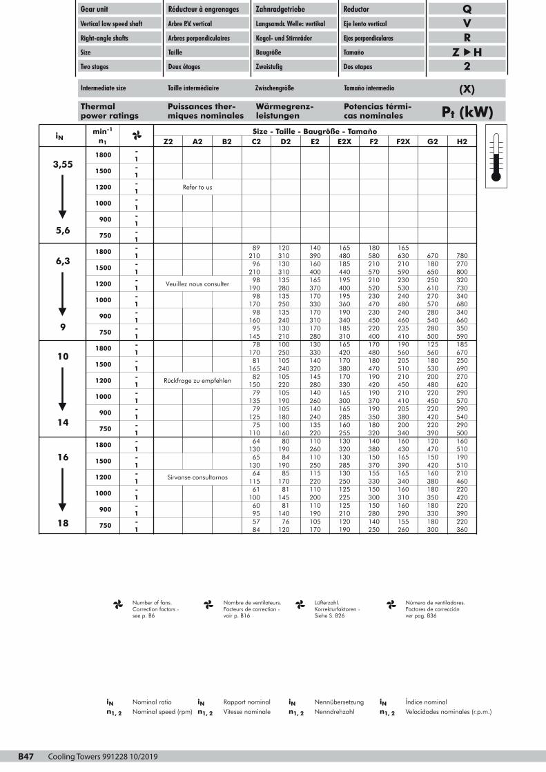
Cooling Towers 991228 10/2019B47
Gear unit
Vertical low speed shaft
Right-angle shafts
Size
Two stages
Réducteur à engrenages
Arbre P.V. vertical
Arbres perpendiculaires
Taille
Deux étages
Zahnradgetriebe
Langsamdr. Welle: vertikal
Kegel- und Stirnräder
Baugröße
Zweistufig
Reductor
Eje lento vertical
Ejes perpendiculares
Tamaño
Dos etapas
QVR
Z H 2
Thermal Puissances ther- Wärmegrenz- Potencias térmi-power ratings miques nominales leistungen cas nominales Pt (kW)
Number of fans. Nombre de ventilateurs. Lüfterzahl. Número de ventiladores.Correction factors -see p. B6
Facteurs de correction -voir p. B16
Korrekturfaktoren -Siehe S. B26
Factores de correcciónver pag. B36
iN Nominal ratio iN Rapport nominal iN Nennübersetzung iN Índice nominal
n1, 2 Nominal speed (rpm) n1, 2 Vitesse nominale n1, 2 Nenndrehzahl n1, 2 Velocidades nominales (r.p.m.)
iNmin-1
n1
1800 -Z2 A2
Size - Taille - Baugröße - TamañoB2 C2 D2 E2 E2X F2 F2X G2 H2
1500
1-
1200
1-
Refer to us
1000
1-
900
1-
750
1-
1800
1- 89 120 140 165 180 165
1500
1-
1200
1-
1000
1-
900
1-
Veuillez nous consulter
21096
21098
19098
17098
750
1-
1800
1-
1500
1-
1200
1-
16095
14578
Rückfrage zu empfehlen
17081
16582
310130
390160
310135
400165
480185
580210
440195
570210
280135
370170
250135
330170
400195
520230
360190
470230
630210
670180
590230
650250
780270800320
530240
610270
480240
570280
730340680340
240130
310170
210100
280130
340185
450220
310165
400170
250105
330140
240105
320145
420170
480180
380170
470190
460235
540280
410190
500125
660350590185
560205
560180
510210
530200
670250690270
1000
1-
900
1-
750
1-
1800
1-
15079
13579
12575
11064
1500
1-
1200
1-
1000
1-
900
1-
Sírvanse consultarnos
13065
13064
11561
10060
220105
280140
190105
260140
330165
420190
300165
370190
180100
240135
16080
220110
285160
350180
255130
320140
450210
480220
410205
450220
620290570290
380200
420220
340160
390120
540290500160
19084
260110
19085
250115
320130
380150
285130
370155
17081
220110
14581
200110
250125
330150
225125
300150
430165
470150
390165
420160
510190510210
340160
380180
310160
350180
460220420220
750
1-1
955784
14076
190105
120 170
210120
280140
190 250
290155
330180
260 300
390220360
3,55
5,6
6,3
9
10
14
16
18
B47
Intermediate size Taille intermédiaire Zwischengröße Tamaño intermedio (X)
Page 1
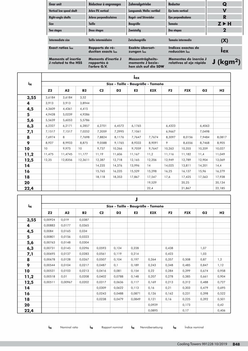
Cooling Towers 991228 10/2019 B48
Gear unit
Vertical low speed shaft
Right-angle shafts
Size
Two stages
Réducteur à engrenages
Arbre P.V. vertical
Arbres perpendiculaires
Taille
Deux étages
Zahnradgetriebe
Langsamdr. Welle: vertikal
Kegel- und Stirnräder
Baugröße
Zweistufig
Reductor
Eje lento vertical
Ejes perpendiculares
Tamaño
Dos etapas
iN
iex
Z2 A2 B2
Size - Taille - Baugröße - Tamaño
C2 D2 E2 E2X F2 F2X G2 H2
3,5544,55
3,6184
3,913
3,6184
3,913
4,3609
4,9428
4,4361
5,0239
3,52
3,8944
4,415
4,9286
5,66,37,18
5,5639
6,2327
5,6053
6,2171
7,1517
7,6974
7,1517
8
91011,212,5
8,927
10
8,9933
9,975
11,475
12,35
11,4745
12,8356
5,5786
6,2857 6,2701
7,0252
7,7698
7,2059
7,8824
6,4572 6,1765
7,2995
8,1176
7,1061
7,7647
8,875
10
9,0588
9,737
11,177
12,3611
11,19
12,387
9,1765
10,266
8,9333
9,7059
11,606
12,718
11,167
12,165
6,4323
7,7674
6,9667
8,3097
6,4063
8,0156
7,0498
7,9484
8,9091
9,7647
9
10,263
11,2
12,206
11,116
12,949
8,6556
10,355
8,7468
10,359
11,182
12,789
11,4
12,904
8,0817
8,905
10,027
11,049
13,069
1416182022,4
14,235
15,765
18,118
14,376
16,235
13,996
15,529
18,353 17,867
14
15,298
14,025
16,25
17,547
19,529
17,6
13,811
16,137
14,201
15,96
17,425
20,25
17,563
22,4 21,867
14,4
16,279
17,938
20,134
22,185
QVR
Z H 2
Exact ratios iex Rapports de ré- Exakte überset- Indices exactos deduction exacts iex zungen iex reducción iex
Moments of inertia Moments d'inertie J Massenträgheits- Momentos de inercia JJ related to the HSS rapportés à momente J bezie- relativos al eje rápido
l'arbre G.V. hen sich auf die SDW
iex
J (kgm2)
iN
J
Z2 A2 B2
Size - Taille - Baugröße - Tamaño
C2 D2 E2 E2X F2 F2X G2 H2
3,5544,55
0,00924
0,00883
0,019
0,0177
0,0084
0,00801
0,0165
0,0156
0,0387
0,0365
0,034
0,0323
5,66,37,18
0,00763
0,00731
0,0148
0,0145
0,00695
0,00678
0,0137
0,0128
91011,212,5
0,00544
0,00531
0,0104
0,0103
0,00518
0,00511
0,01
0,00967
0,0304
0,0296 0,0593
0,0283
0,0267
0,0561
0,0507
0,124 0,228
0,119
0,104
0,214
0,197
0,0217
0,0213
0,0487
0,0416
0,0208
0,0202
0,0402
0,0317
0,1
0,081
0,189
0,154
0,0788
0,0636
0,148
0,117
0,438
0,264
0,423
0,357
1,07
0,508
1,03
0,87
0,243
0,22
0,348
0,284
0,207
0,169
0,278
0,213
0,485
0,399
0,847
0,674
0,385
0,312
0,661
0,488
1,2
1,12
0,958
0,904
0,727
1416182022,4
0,0309
0,0243
0,0238
0,0622
0,0488
0,113
0,0871
0,0479 0,0849
0,16
0,126
0,21
0,162
0,121
0,0929
0,16
0,303
0,231
0,479
0,398
0,225
0,173
0,392
0,0895 0,17
0,695
0,522
0,501
0,42
0,406
Intermediate size Taille intermédiaire Zwischengröße Tamaño intermedio (X)
B48
iN Nominal ratio iN Rapport nominal iN Nennübersetzung iN Índice nominal
Page 1

Cooling Towers 991228 10/2019B49
97QU-VR2N40033 B
Gear unit
Vertical low speed shaft
Right-angle shafts
Size
Two stages
Réducteur à engrenages
Arbre P.V. vertical
Arbres perpendiculaires
Taille
Deux étages
Zahnradgetriebe
Langsamdr. Welle: vertikal
Kegel- und Stirnräder
Baugröße
Zweistufig
Reductor
Eje lento vertical
Ejes perpendiculares
Tamaño
Dos etapas
QVR
Z B2mm
CUN
RM VX RM
FP E F FP
C
SP
SP
NP
N
N
NP
A
4 x øT
VY
VYDB
V
CU IB
LB
TRHS
J
L (1)
D
KRX
R
RY
AB BC
X
Y
D
ZDIN332"D"
ZB DIN 332
"D"DB
YB
XB
(1)
(1)
For cooling tower Pour commandes d'aéro- Für Ventilatorantriebe Para las impulsiones del ventiladorfan drives réfrigérants in Kühltürmen de la torre de refrigeración
The user isresponsible forthe provision ofsafety guardsand correct in-stallation of allequipment.
Certified dimen-sions upon re-quest.
Les dispositifs deprotection doi-vent être prévuspar l'utilisateur.Celui-ci est responsablede l'installationcorrecte del'ensemble.
Dimensions défi-nitives sur de-mande.
Der Benutzer istverantwortlich fürdie Beistellungder Schutzhau-ben und dasfachgemäße Auf-stellen der ge-samtenAusrüstung.
Verbindl. Abmes-sungen aufWunsch.
El usuario es res-ponsable delaprovisionamien-to de los dispositivos deseguridad y de lacorrectainstalación de to-do el equipo.
Plano de dimen-siones certifica-das, bajopetición.
External dimen-sions are not af-fected whenmounting a back-stop(1) Grease points(2) Approximatevalues; only themarkings on thegear unit dipstickare determinantfor the oil level
Le montage d'unantidévireur n'af-fecte pas les di-mensions exté-rieures(1) Points degraissage(2) Valeurs indic-atives; marquag-es sur la jauged'huile du réduc-teur sont détermi-nants pour le ni-veau d'huile
Montage einerRücklaufsperreändert dieAußenabmessungen nicht(1) Schmierstellen(2) Richtwerte;maßgebend fürdie Ölmengesind nur die Mar-kierungen amGetriebe-Ölmeßstab
Montando unantirretroceso noafecta a lasdimensionesexteriores(1) Puntos deengrase(2) Valoresaproximados;sólo las marcasde la varilla delnivel de aceitedel reductor sondeterminantespara el nivel deaceite
Shaft arrangements Dispositions des arbre Wellenanordnungen Disposición de ejes(front view) (vue de face) (Vorderansicht) (vista delantera)
Type A AB BC C CU E F FP HS IB J N NP RM SP T TR
QVRZ2QVRA2
320355
165182,5
165182,5
375425
165185
105125
220250
2525
150150
457550
310340
135152,5
2525
6060
6060
1919
2525
QVRB2 400 206 206 490 208 140 290 30 165 602 355 170 30 72 72 24 30
Type kg Litres
QVRZ2
D
60m7
L
140
X
18
Y
64
Z
M20
DB
35k6
LB
80
XB
10
YB
38
ZB
M12
R
R 3/4"
RX
65
RY
82
V
R 3/4"
VX
150
VY
108 120
Liter
4
K (2)
120QVRA2QVRB2
80m790m7
170170
2225
8595
M20M24
40k650k6
110110
1214
4353,5
M16M16
R 3/4"R 3/4"
6567
100110
R 3/4"R 3/4"
180210
120140
170230
57
115 130
Shafts - Arbres - Wellen - Assen
Keys Clavettes Paßfeder Chavetas ISO/R773-1969DDDDrrrraaaaiiiinnnniiiinnnngggg VVVViiiiddddaaaannnnggggeeeeÖÖÖÖllllaaaabbbbllllaaaaßßßß VVVVaaaacccciiiiaaaaddddoooo
VVVVeeeennnnttttiiiillllaaaattttiiiioooonnnn AAAAeeeerrrraaaattttiiiioooonnnnEEEEnnnnttttlllluuuuffffttttuuuunnnngggg AAAAiiiirrrreeeeaaaacccciiiióóóónnnn
OOOOiiiillll lllleeeevvvveeeellll NNNNiiiivvvveeeeaaaauuuu dddd''''hhhhuuuuiiiilllleeeeÖÖÖÖllllnnnniiiivvvveeeeaaaauuuu NNNNiiiivvvveeeellll ddddeeee aaaacccceeeeiiiitttteeee
B49
Page 1

Cooling Towers 991228 10/2019 B50
97QU-VR2N40133 B
Gear unit
Vertical low speed shaft
Right-angle shafts
Size
Two stages
Réducteur à engrenages
Arbre P.V. vertical
Arbres perpendiculaires
Taille
Deux étages
Zahnradgetriebe
Langsamdr. Welle: vertikal
Kegel- und Stirnräder
Baugröße
Zweistufig
Reductor
Eje lento vertical
Ejes perpendiculares
Tamaño
Dos etapas
QVR
Z B2mm
CUN
TR
J
HS
L
LB
CU IB
D
RM VX RM
FP E F FP
C
SP
SP
NP
N
N
NP
A
4 x øT
VY
VYDB
V
R
RXK
RY
AB BC
X
Y
D
ZDIN332"D"
ZB DIN 332
"D"DB
YB
XB
(1)
(1)
(1)
(1)
For cooling tower Pour commandes d'aéro- Für Ventilatorantriebe Para las impulsiones del ventiladorfan drives réfrigérants in Kühltürmen de la torre de refrigeración
The user is responsible forthe provision ofsafety guardsand correct in-stallation of allequipment.
Certified dimen-sions upon re-quest.
Les dispositifs deprotection doi-vent être prévuspar l'utilisateur.Celui-ci est responsablede l'installationcorrecte del'ensemble.
Dimensions défi-nitives sur de-mande.
Der Benutzer istverantwortlich fürdie Beistellungder Schutzhau-ben und dasfachgemäße Auf-stellen der ge-samtenAusrüstung.
Verbindl. Abmes-sungen aufWunsch.
El usuario es res-ponsable delaprovisionamien-to de los dispositivos deseguridad y de lacorrectainstalación de to-do el equipo.
Plano de dimen-siones certifica-das, bajopetición.
External dimen-sions are not af-fected whenmounting a back-stop(1) Grease points(2) Approximatevalues; only themarkings on thegear unit dipstickare determinantfor the oil level
Le montage d'unantidé-vireur n'af-fecte pas les di-mensions exté-rieures(1) Points degraissage(2) Valeurs indic-atives; marquag-es sur la jauged'huile du réduc-teur sont détermi-nants pour leniveau d'huile
Montage einerRücklaufsperreändert dieAußenabmessungen nicht(1) Schmierstellen(2) Richtwerte;maßgebend fürdie Öl-mengesind nur die Mar-kierungen amGetriebe-Ölmeßstab
Montando unantirretroceso noafecta a lasdimensionesexteriores(1) Puntos deengrase(2) Valoresaproximados;sólo las marcasde la varilla delnivel de aceitedel reductor sondeterminantespara el nivel deaceite
Shaft arrangements Dispositions des arbre Wellenanordnungen Disposición de ejes(front view) (vue de face) (Vorderansicht) (vista delantera)
Extended bearing Palier allongé Verlängertem Lager- Eje lento alargadohousing gehäuse L
Type A AB BC C CU E F FP HS IB J N NP RM SP T TR
QVRZ2LQVRA2L
320355
165182,5
165182,5
375425
165185
105125
220250
2525
150150
457550
440520
135152,5
2525
6060
6060
1919
2525
QVRB2L 400 206 206 490 208 140 290 30 165 602 590 170 30 72 72 24 30
Type kg Litres
QVRZ2L
D
60m7
L
140
X
18
Y
64
Z
M20
DB
35k6
LB
80
XB
10
YB
38
ZB
M12
R
R 3/4"
RX
65
RY
82
V
R 3/4"
VX
150
VY
103 150
Liter
4
K (2)
120QVRA2LQVRB2L
80m790m7
170170
2225
8595
M20M24
40k650k6
110110
1214
4353,5
M16M16
R 3/4"R 3/4"
6567
100110
R 3/4"R 3/4"
180190
120140
200260
57
115 130
Shafts - Arbres - Wellen - Assen
Keys Clavettes Paßfeder Chavetas ISO/R773-1969DDDDrrrraaaaiiiinnnniiiinnnngggg VVVViiiiddddaaaannnnggggeeeeÖÖÖÖllllaaaabbbbllllaaaaßßßß VVVVaaaacccciiiiaaaaddddoooo
VVVVeeeennnnttttiiiillllaaaattttiiiioooonnnn AAAAeeeerrrraaaattttiiiioooonnnnEEEEnnnnttttlllluuuuffffttttuuuunnnngggg AAAAiiiirrrreeeeaaaacccciiiióóóónnnn
OOOOiiiillll lllleeeevvvveeeellll NNNNiiiivvvveeeeaaaauuuu dddd''''hhhhuuuuiiiilllleeeeÖÖÖÖllllnnnniiiivvvveeeeaaaauuuu NNNNiiiivvvveeeellll ddddeeee aaaacccceeeeiiiitttteeee
B50
Page 1
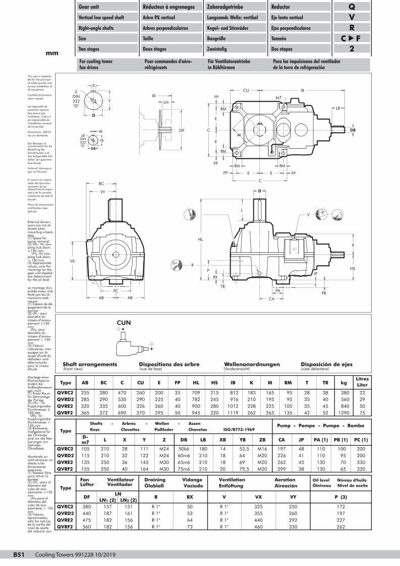
Cooling Towers 991228 10/2019B51
97QU-VR2N40223 A
Gear unit
Vertical low speed shaft
Right-angle shafts
Size
Two stages
Réducteur à engrenages
Arbre P.V. vertical
Arbres perpendiculaires
Taille
Deux étages
Zahnradgetriebe
Langsamdr. Welle: vertikal
Kegel- und Stirnräder
Baugröße
Zweistufig
Reductor
Eje lento vertical
Ejes perpendiculares
Tamaño
Dos etapas
QVR
C F2mm
FP
RM
E
C
E
RM
FP
FP
RM
E E
C
FP
RM
M
CU IB
LB
DB
4xT
AB AB
PC
BC
VX
VY
X
Y
D
Z
DIN
332
"D"
ZB DIN 332
"D"DB
YB
XB
IB
LN
DF
PB
HL
TR
JP
CA
HS
K
D
L
R
P
RX
V
PA
For cooling tower Pour commandes d'aéro- Für Ventilatorantriebe Para las impulsiones del ventiladorfan drives réfrigérants in Kühltürmen de la torre de refrigeración
The user is responsi-ble for the provisionof safety guards andcorrect installation ofall equipment.
Certified dimensionsupon request.
Les dispositifs deprotection doiventêtre prévus parl'utilisateur. Celui-ci est responsable del'installation correctede l'ensemble.
Dimensions définiti-ves sur demande.
Der Benutzer istverantwortlich für dieBeistellung derSchutzhauben unddas fachgemäße Auf-stellen der gesamtenAusrüstung.
Verbindl. Abmessun-gen auf Wunsch.
El usuario es respon-sable del aprovisio-namiento de los dispositivos de seguri-dad y de la correctainstalación de todo elequipo.
Plano de dimensionescertificadas, bajopetición.
External dimen-sions are not af-fected whenmounting a back-stop(1) Space forpump removal(2) LN1: for cou-pling hub diam.≤ 150 mm, LN2: for cou-pling hub diam.> 150 mm(3) Approximatevalues; only themarkings on thegear unit dipstickare determinantfor the oil level
Le montage d'unantidé-vireur n'af-fecte pas les di-mensions exté-rieures(1) Espace de dé-gagement de lapompe(2) LN1: pourdiamètre dumoyeu d’accou-plement ≤ 150mm LN2: pourdiamètre dumoyeu d’accou-plement > 150mm(3) Valeursindicatives; mar-quages sur lajauge d'huile duréducteur sontdéterminantspour le niveaud'huile
Montage einerRücklaufsperreändert dieAußenabmessungen nicht(1) Freier Raumfür Demontageder Pumpe(2) LN1: fürKupplungsnabeDurchmesser ≤150 mm LN2: fürKupplungsnabeDurchmesser >150 mm(3) Richtwerte;maßgebend fürdie Ölmengesind nur die Mar-kierungen amGetriebe-Ölmeßstab
Montando unantirretroceso noafecta a lasdimensionesexteriores(1) Espasio librepara retirar labomba(2) LN1: para eldiámetro delcubo de aco-plamiento ≤ 150mm LN2:para eldiámetro delcubo de aco-plamiento > 150mm(3) Valoresaproximados;sólo las marcasde la varilla delnivel de aceitedel reductor sondeterminantespara el nivel deaceite
Shafts - Arbres - Wellen - Assen DDDDrrrraaaaiiiinnnniiiinnnngggg VVVViiiiddddaaaannnnggggeeee VVVVeeeennnnttttiiiillllaaaattttiiiioooonnnn AAAAeeeerrrraaaattttiiiioooonnnn
CUN
Shaft arrangements Dispositions des arbre Wellenanordnungen Disposición de ejes(front view) (vue de face) (Vorderansicht) (vista delantera)
Type AB BC C CU E FP HL HS IB K M RM T TR kgLitresLiter
QVRC2QVRD2
255285
280290
470530
260290
200225
3540
709782
215245
812916
183210
165195
9595
2835
3840
380560
2229
QVRE2QVRF2
320365
335372
600690
326370
260295
4050
900945
280320
10121119
228262
225265
105135
3542
4552
8401290
5075
Type
QVRC2
D-m7105
L
210
X
28
Y
111
Z
M24
DB
50k6
LB
180
XB
14
YB
53,5
ZB
M16
CA
197
JP
48
PA (1)
110
PB (1)
100
PC (1)
200QVRD2QVRE2QVRF2
115135
210250
155 250
3236
122143
40 164
M24M30
60m665m6
M30 75m6
210210
1818
210 20
6469
M20M20
79,5 M20
226262
4143
299 38
110130
9570
130 65
200330330
Pump - Pompe - Pumpe - Bomba Shafts - Arbres - Wellen - Assen
Keys Clavettes Paßfeder Chavetas ISO/R773-1969
Type
DFLN
LN1 (2) LN2 (2)R RX V
QVRC2QVRD2QVRE2QVRF2
380440
157187
475560
182182
131161
R 1"R 1"
156156
R 1"R 1"
5053
R 1"R 1"
6473
R 1"R 1"
VX VY P (3)
325355
250260
440460
292330
172197227262
Draining VidangeÖlablaß Vaciado
Ventilation AerationEntlüftung Aireación
Oil level Niveau d'huile Ölniveau Nivel de aceite
B51
Fan Ventilateur Lüfter Ventilador
Page 1
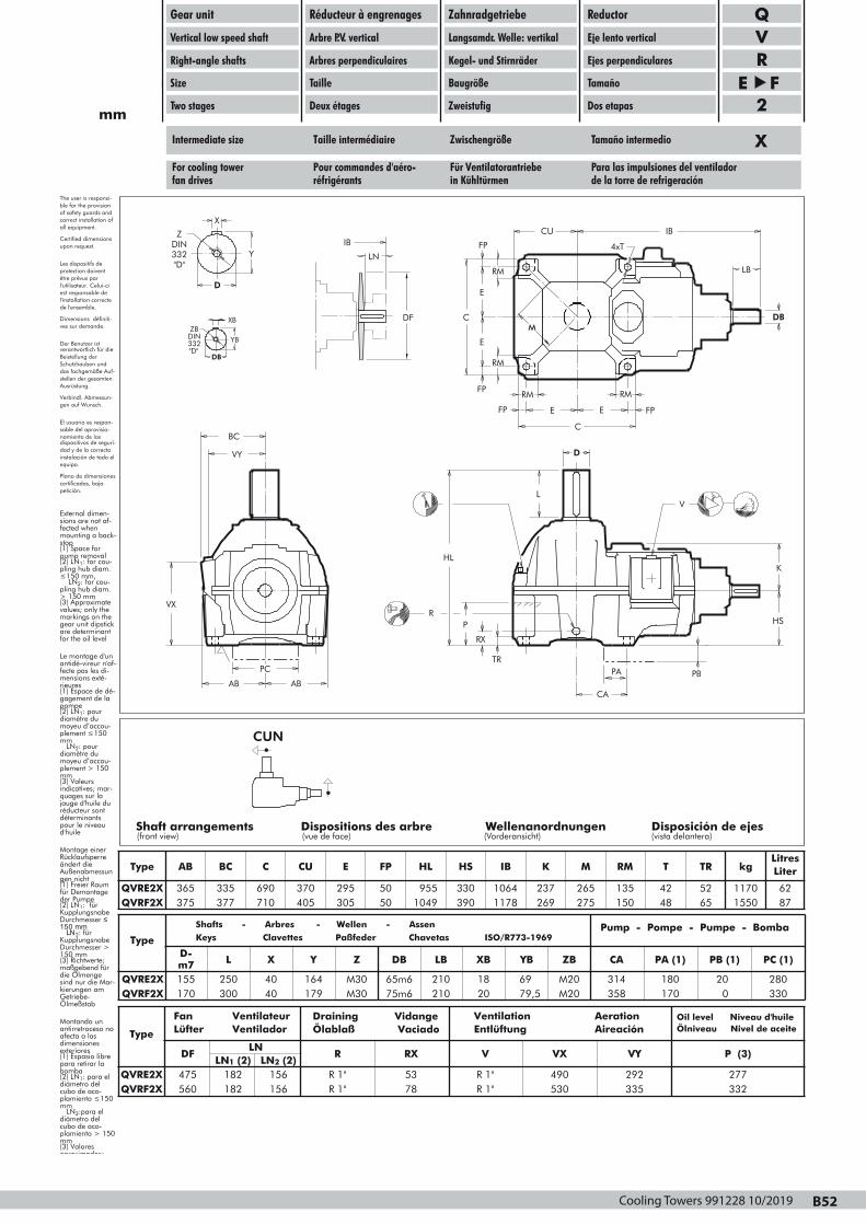
Cooling Towers 991228 10/2019 B52
97QU-VR2N40413 A
Gear unit
Vertical low speed shaft
Right-angle shafts
Size
Two stages
Réducteur à engrenages
Arbre P.V. vertical
Arbres perpendiculaires
Taille
Deux étages
Zahnradgetriebe
Langsamdr. Welle: vertikal
Kegel- und Stirnräder
Baugröße
Zweistufig
Reductor
Eje lento vertical
Ejes perpendiculares
Tamaño
Dos etapas
QVR
E F2mm
FP
RM
E
C
E
RM
FP
FP
RM
E E
C
FP
RM
M
CU IB
LB
DB
4xT
HL
TR
CA
HS
K
D
L
PB
R
P
RX
V
AB AB
PC
BC
VX
VY
X
Y
D
Z
DIN
332
"D"
ZB DIN 332
"D"DB
YB
XB
IB
LN
DF
PA
Intermediate size Taille intermédiaire Zwischengröße Tamaño intermedio
The user is responsi-ble for the provisionof safety guards andcorrect installation ofall equipment.
Certified dimensionsupon request.
Les dispositifs deprotection doiventêtre prévus parl'utilisateur. Celui-ci est responsable del'installation correctede l'ensemble.
Dimensions définiti-ves sur demande.
Der Benutzer istverantwortlich für dieBeistellung derSchutzhauben unddas fachgemäße Auf-stellen der gesamtenAusrüstung.
Verbindl. Abmessun-gen auf Wunsch.
El usuario es respon-sable del aprovisio-namiento de los dispositivos de seguri-dad y de la correctainstalación de todo elequipo.
Plano de dimensionescertificadas, bajopetición.
External dimen-sions are not af-fected whenmounting a back-stop(1) Space forpump removal(2) LN1: for cou-pling hub diam.≤ 150 mm, LN2: for cou-pling hub diam.> 150 mm (3) Approximatevalues; only themarkings on thegear unit dipstickare determinantfor the oil level
Le montage d'unantidé-vireur n'af-fecte pas les di-mensions exté-rieures(1) Espace de dé-gagement de lapompe(2) LN1: pourdiamètre dumoyeu d’accou-plement ≤ 150mm LN2: pourdiamètre dumoyeu d’accou-plement > 150mm(3) Valeursindicatives; mar-quages sur lajauge d'huile duréducteur sontdéterminantspour le niveaud'huile
Montage einerRücklaufsperreändert dieAußenabmessungen nicht(1) Freier Raumfür Demontageder Pumpe(2) LN1: fürKupplungsnabeDurchmesser ≤150 mm LN2: fürKupplungsnabeDurchmesser >150 mm(3) Richtwerte;maßgebend fürdie Ölmengesind nur die Mar-kierungen amGetriebe-Ölmeßstab
Montando unantirretroceso noafecta a lasdimensionesexteriores(1) Espasio librepara retirar labomba(2) LN1: para eldiámetro delcubo de aco-plamiento ≤ 150mm LN2:para eldiámetro delcubo de aco-plamiento > 150mm(3) Valoresaproximados;sólo las marcasde la varilla delnivel de aceitedel reductor sondeterminantespara el nivel deaceite
CUN
Shaft arrangements Dispositions des arbre Wellenanordnungen Disposición de ejes(front view) (vue de face) (Vorderansicht) (vista delantera)
Type AB BC C CU E FP HL HS IB K M RM T TR kgLitresLiter
QVRE2XQVRF2X
365375
335377
690710
370405
295305
5050
9551049
330390
10641178
237269
265275
135150
4248
5265
11701550
6287
For cooling tower Pour commandes d'aéro- Für Ventilatorantriebe Para las impulsiones del ventiladorfan drives réfrigérants in Kühltürmen de la torre de refrigeración
X
Type
QVRE2X
D-m7155
L
250
X
40
Y
164
Z
M30
DB
65m6
LB
210
XB
18
YB
69
ZB
M20
CA
314
PA (1)
180
PB (1)
20
PC (1)
280QVRF2X 170 300 40 179 M30 75m6 210 20 79,5 M20 358 170 0 330
Pump - Pompe - Pumpe - Bomba Shafts - Arbres - Wellen - Assen
Keys Clavettes Paßfeder Chavetas ISO/R773-1969
Type
DFLN
LN1 (2) LN2 (2)R RX V
QVRE2XQVRF2X
475560
182182
156156
R 1"R 1"
5378
R 1"R 1"
VX VY P (3)
490530
292335
277332
Draining VidangeÖlablaß Vaciado
Ventilation AerationEntlüftung Aireación
Oil level Niveau d'huile Ölniveau Nivel de aceite
Fan Ventilateur Lüfter Ventilador
B52
Page 1

Cooling Towers 991228 10/2019B53
97QU-VR2N40323 A
Gear unit
Vertical low speed shaft
Right-angle shafts
Size
Two stages
Réducteur à engrenages
Arbre P.V. vertical
Arbres perpendiculaires
Taille
Deux étages
Zahnradgetriebe
Langsamdr. Welle: vertikal
Kegel- und Stirnräder
Baugröße
Zweistufig
Reductor
Eje lento vertical
Ejes perpendiculares
Tamaño
Dos etapas
QVR
G H2mm
For cooling tower Pour commandes d'aéro- Für Ventilatorantriebe Para las impulsiones del ventiladorfan drives réfrigérants in Kühltürmen de la torre de refrigeración
CU IB
6xTFP
RM
RM
N
N
A
FP
FP
RM
E E
C
FS
RMRM
FP
RP
RP
LB
DB
NR
FP
NR
FP
HL
TR
HS
(2)
D
L
(1)
AB AB
(1)
BC
X
Y
D
Z
DIN
332
"D"
ZB DIN 332
"D"DB
YB
XB
K
V
CA
JPPB
RX
PR
M
PC
VX
VY
IB
LN
DF
PA
The user is responsi-ble for the provisionof safety guards andcorrect installation ofall equipment.
Certified dimensionsupon re-quest.
Les dispositifs de pro-tection doivent êtreprévus par l'utilisa-teur. Celui-ci est responsable del'installation correctede l'ensemble.
Dimensions définiti-ves sur demande.
Der Benutzer istverantwortlich für dieBeistellung derSchutzhauben unddas fachgemäße Auf-stellen der gesamtenAusrüstung.
Verbindl. Abmessun-gen auf Wunsch.
El usuario es respon-sable del aprovisio-namiento de los dispositivos de seguri-dad y de la correctainstalación de todo elequipo.
Plano de dimensionescertificadas, bajopetición.
External dimen-sions are not af-fected whenmounting a back-stop(1) Grease lubri-cation point(2) 4 x jackingscrew(3) Space forpump removal(4) LN1: for cou-pling hub diam.≤ 150 mm, LN2: for cou-pling hub diam.> 150 mm(5) Approximatevalues; only themarkings on thegear unit dipstickare determinantfor the oil level
Le montage d'unantidé-vireur n'af-fecte pas les di-mensions exté-rieures(1) Point degraissage(2) 4 x vis deréglage(3) Espace de dé-gagement de lapompe(4) LN1: pourdiamètre dumoyeu d’accou-plement ≤ 150mm LN2: pourdiamètre dumoyeu d’accou-plement > 150mm(5) Valeursindicatives; mar-quages sur lajauge d'huile duréducteur sontdéterminantspour le niveaud'huile
Montage einerRücklaufsperreändert dieAußenabmessungen nicht(1) Fettschmier-stelle(2) 4 xEinstellschraube(3) Freier Raumfür Demontageder Pumpe(4) LN1: fürKupplungsnabeDurchmesser ≤150 mm LN2: fürKupplungsnabeDurchmesser >150 mm(5) Richtwerte;maßgebend fürdie Ölmengesind nur die Mar-kierungen amGetriebe-Ölmeßstab
Montando unantirretroceso noafecta a lasdimensionesexteriores(1) Punto deengrase(2) 4 x tornillo dereglaje(3) Espasio librepara retirar labomba(4) LN1: para eldiámetro delcubo de aco-plamiento ≤ 150mm LN2:para eldiámetro delcubo de aco-plamiento > 150mm(5) Valoresaproximados;sólo las marcasde la varilla delnivel de aceitedel reductor sondeterminantespara el nivel deaceite
CUN
Type A AB BC C CU E FP FS HL HS IB K M N NR RM RP T TR kgLitresLiter
QVRG2QVRH2
770770
405435
435435
11201232
420460
305345
5050
410442
10491099
390390
12411313
352352
290310
335335
275275
140140
120120
4242
6060
17001800
109121
Shaft arrangements Dispositions des arbre Wellenanordnungen Disposición de ejes(front view) (vue de face) (Vorderansicht) (vista delantera)
B53
Type
QVRG2
D-m7180
L
300
X
45
Y
190
Z
M30
DB-m6100
LB
210
XB
28
YB
106
ZB
M24
CA
341
JP
15
PA (3)
180
PB (3)
85
PC (3)
420QVRH2 190 350 45 200 M30 100 210 28 106 M24 413 15 180 85 420
Pump - Pompe - Pumpe - Bomba Shafts - Arbres - Wellen - Assen
Keys Clavettes Paßfeder Chavetas ISO/R773-1969
Type
DF LN R RX V VX
QVRG2QVRH2
600600
152152
R 1"R 1"
7474
R 1"R 1"
475475
VY P (5)
420420
300300
Draining VidangeÖlablaß Vaciado
Ventilation AerationEntlüftung Aireación
Oil level Niveau d'huile Ölniveau Nivel de aceite
Fan Ventilateur Lüfter Ventilador
Page 1

COMPLETE AND POWERFUL
SOLUTIONS FOR
COOLING TOWERS
Because of the severe demands placed
on cooling tower fan drives, Hansen
Industrial Transmissions’ drives are specially
equipped to withstand exacting operating
conditions, while still using a maximum
of standard components. Taking these
operating conditions into account, several
accessories are included as standard.
Hansen Industrial Transmissions designs,
creates and services flexible gear units that
can be adapted to specific requirements.
This way Hansen Industrial Transmissions
created a range of drive solutions suitable
for the international cooling tower market .
Proof of the products’ reliability is the
ISO 9001 quality certificate, showing
outstanding quality, supported by an
international network of after-sales
Services Centres. Using standard compo-
nents, we offer a range of gear units fully
customised to the specific needs of the
industry applications.
c o o l i n g t o w e r i n d u s t r y
C O O L I N G T O W E R S C O O L I N G T O W E R S C O O L I N G T O W E R S
F O R A N O V E R V I E W O F W H A T ’ S A V A I L A B L E , C H E C K O U R C O M P R E H E N S I V E L I T E R A T U R E W I T H R E F . 4 1 5 - 2 2 0
_ g g
COMPLETE AND POWERFUL
SOLUTIONS FOR
COOLING TOWERS
Because of the severe demands placed
on cooling tower fan drives, Hansen
Transmissions’ drives are specially
equipped to withstand exacting operating
conditions, while still using a maximum
of standard components. Taking these
operating conditions into account, several
accessories are included as standard.
Hansen Transmissions designs, creates and
services flexible gear units that can be
adapted to specific requirements.
This way Hansen Transmissions created
a range of drive solutions suitable for the
international cooling tower market.
Proof of the products’ reliability is the
ISO 9001 quality certificate, showing
outstanding quality, supported by an
international network of after-sales
Services Centres. Using standard compo-
nents, we offer a range of gear units fully
customised to the specific needs of the
industry applications.
c o o l i n g t o w e r i n d u s t r y
C O O L I N G T O W E R S C O O L I N G T O W E R S C O O L I N G T O W E R S
F O R A N O V E R V I E W O F W H A T ’ S A V A I L A B L E , C H E C K O U R C O M P R E H E N S I V E L I T E R A T U R E W I T H R E F . 4 1 5 - 2 2 0
■■ HANSEN M4 ACC
HELICAL GEAR UNIT
Based upon Hansen P4 and Hansen M4
technology, a dedicated design has been
developed. Applying the same high
quality standards, this gear unit offers
a cost efficient solution with optimised
gear geometry for lower noise levels.
The monobloc concept ensures higher
stiffness of the housing.
As a standard, these units come with
a lantern housing that allows for
connection of a motor on the top of the
gear unit.
This model is used mainly in air-cooled
steam condensation plants which are
ideal in dry environments where water
resources are scarce. The cooling fan’s
motor is located in the air stream of
the air-cooled refrigerant condenser.
■ HANSEN P4:
BEVEL HELICAL GEAR UNIT
For vertical housings, the extended
bearing span of the low speed shaft has
been standardised to meet the particular
needs of the cooling tower industry:
the extended bearing span increases the
dynamic stability of the gear unit.
The increased distance between the
propeller and the high speed input shaft
reduces vibrations. A motor can be
connected to the outside of the cooling
tower using an all-metal disc coupling at
the high-speed shaft.
WHY HANSEN?
• Hansen matches the drive to the application and offers proven reliability underthe most severe conditions.
• Carburised and ground gearing of both bevel and helical gears excels in strength,torque capacity, surface durability and low noise performance.
• Large overhung load capacity of the gear unit.• A wide range of bearing configurations meet any application requirement,
while still providing a cost effective solution.• Bearings and shafts are dimensioned to go the distance, ensuring long bearing
life under heavy loads.
• Continuous oil circulation through the bearings ensures a long, trouble-freeworking life for the gear unit.
• Hansen P4’s unique Oil-Lock™ and Oil-Guard™ systems offer a maintenance-freesealing on high-speed shaft extensions as a standard.
• A greased labyrinth seal on the low speed shaft prevents water and moisturefrom entering the housing of the gear unit.
• The internal construction of the gear unit housing allows for simple and complete oil drainage.
• Positioning of the aerating, drainage and filling plugs makes it easy to connectservice piping towards the outside of the cooling tower.
• The larger units can be easily inspected and serviced on the spot, thanks to covers above the oil level.
• One-stop-shopping for complete drive package solutions.• In-depth engineering support and complete documentation before and after the order.• Hansen’s global service capability significantly reduces downtime.
_ g g
• The drywell, available on all models, prevents oil leakage on vertical
With the Hansen P4 gear units, fully cus-
tomized to the specifi c needs of the cool-
ing tower industry, Hansen offers a truly
functional solution for wet cooling towers
and air cooled condensers.
The extended bearing span of the low
speed shaft has been standardized to meet
the particular needs of these applications:
the extended bearing span increases the
dynamic stability of the gear unit. The
unit’s low speed shaft bearings are selected
to handle the high axial loads, i.e. the axial
thrust from the fan on the low speed shaft.
The lubrication system is adapted to very
low operating speeds and to windmilling
conditions. The overall design of this series
of gear units fully complies with the Cool-
ing Tower Institute specifi cations.
For the wet cooling tower drives, Hansen
now offers a range of 11 bevel helical gear
unit sizes up to 100 kNm, which allows a
more accurate selection. They are all well
protected for operation in a very humid
environment. The increased distance be-
tween the propeller and the high speed
COMPLETE AND POWERFUL
SOLUTIONS FOR
COOLING TOWERS
Because of the severe demands placed
on cooling tower fan drives, Hansen
Transmissions’ drives are specially
equipped to withstand exacting operating
conditions, while still using a maximum
of standard components. Taking these
operating conditions into account, several
accessories are included as standard.
Hansen Transmissions designs, creates and
services flexible gear units that can be
adapted to specific requirements.
This way Hansen Transmissions created
a range of drive solutions suitable for the
international cooling tower market.
Proof of the products’ reliability is the
ISO 9001 quality certificate, showing
outstanding quality, supported by an
international network of after-sales
Services Centres. Using standard compo-
nents, we offer a range of gear units fully
customised to the specific needs of the
industry applications.
c o o l i n g t o w e r i n d u s t r y
C O O L I N G T O W E R S C O O L I N G T O W E R S C O O L I N G T O W E R S
F O R A N O V E R V I E W O F W H A T ’ S A V A I L A B L E , C H E C K O U R C O M P R E H E N S I V E L I T E R A T U R E W I T H R E F . 4 1 5 - 2 2 0
■■ HANSEN M4 ACC
HELICAL GEAR UNIT
Based upon Hansen P4 and Hansen M4
technology, a dedicated design has been
developed. Applying the same high
quality standards, this gear unit offers
a cost efficient solution with optimised
gear geometry for lower noise levels.
The monobloc concept ensures higher
stiffness of the housing.
As a standard, these units come with
a lantern housing that allows for
connection of a motor on the top of the
gear unit.
This model is used mainly in air-cooled
steam condensation plants which are
ideal in dry environments where water
resources are scarce. The cooling fan’s
motor is located in the air stream of
the air-cooled refrigerant condenser.
■ HANSEN P4:
BEVEL HELICAL GEAR UNIT
For vertical housings, the extended
bearing span of the low speed shaft has
been standardised to meet the particular
needs of the cooling tower industry:
the extended bearing span increases the
dynamic stability of the gear unit.
The increased distance between the
propeller and the high speed input shaft
reduces vibrations. A motor can be
connected to the outside of the cooling
tower using an all-metal disc coupling at
the high-speed shaft.
WHY HANSEN?
• Hansen matches the drive to the application and offers proven reliability underthe most severe conditions.
• Carburised and ground gearing of both bevel and helical gears excels in strength,torque capacity, surface durability and low noise performance.
• Large overhung load capacity of the gear unit.• A wide range of bearing configurations meet any application requirement,
while still providing a cost effective solution.• Bearings and shafts are dimensioned to go the distance, ensuring long bearing
life under heavy loads.
• Continuous oil circulation through the bearings ensures a long, trouble-freeworking life for the gear unit.
• Hansen P4’s unique Oil-Lock™ and Oil-Guard™ systems offer a maintenance-freesealing on high-speed shaft extensions as a standard.
• A greased labyrinth seal on the low speed shaft prevents water and moisturefrom entering the housing of the gear unit.
• The internal construction of the gear unit housing allows for simple and complete oil drainage.
• Positioning of the aerating, drainage and filling plugs makes it easy to connectservice piping towards the outside of the cooling tower.
• The larger units can be easily inspected and serviced on the spot, thanks to covers above the oil level.
• One-stop-shopping for complete drive package solutions.• In-depth engineering support and complete documentation before and after the order.• Hansen’s global service capability significantly reduces downtime.
_ g g
• The drywell, available on all models, prevents oil leakage on vertical
COMPLETE AND POWERFUL
SOLUTIONS FOR
COOLING TOWERS
Because of the severe demands placed
on cooling tower fan drives, Hansen
Transmissions’ drives are specially
equipped to withstand exacting operating
conditions, while still using a maximum
of standard components. Taking these
operating conditions into account, several
accessories are included as standard.
Hansen Transmissions designs, creates and
services flexible gear units that can be
adapted to specific requirements.
This way Hansen Transmissions created
a range of drive solutions suitable for the
international cooling tower market.
Proof of the products’ reliability is the
ISO 9001 quality certificate, showing
outstanding quality, supported by an
international network of after-sales
Services Centres. Using standard compo-
nents, we offer a range of gear units fully
customised to the specific needs of the
industry applications.
c o o l i n g t o w e r i n d u s t r y
C O O L I N G T O W E R S C O O L I N G T O W E R S C O O L I N G T O W E R S
F O R A N O V E R V I E W O F W H A T ’ S A V A I L A B L E , C H E C K O U R C O M P R E H E N S I V E L I T E R A T U R E W I T H R E F . 4 1 5 - 2 2 0
■■ HANSEN M4 ACC
HELICAL GEAR UNIT
Based upon Hansen P4 and Hansen M4
technology, a dedicated design has been
developed. Applying the same high
quality standards, this gear unit offers
a cost efficient solution with optimised
gear geometry for lower noise levels.
The monobloc concept ensures higher
stiffness of the housing.
As a standard, these units come with
a lantern housing that allows for
connection of a motor on the top of the
gear unit.
This model is used mainly in air-cooled
steam condensation plants which are
ideal in dry environments where water
resources are scarce. The cooling fan’s
motor is located in the air stream of
the air-cooled refrigerant condenser.
■ HANSEN P4:
BEVEL HELICAL GEAR UNIT
For vertical housings, the extended
bearing span of the low speed shaft has
been standardised to meet the particular
needs of the cooling tower industry:
the extended bearing span increases the
dynamic stability of the gear unit.
The increased distance between the
propeller and the high speed input shaft
reduces vibrations. A motor can be
connected to the outside of the cooling
tower using an all-metal disc coupling at
the high-speed shaft.
WHY HANSEN?
• Hansen matches the drive to the application and offers proven reliability underthe most severe conditions.
• Carburised and ground gearing of both bevel and helical gears excels in strength,torque capacity, surface durability and low noise performance.
• Large overhung load capacity of the gear unit.• A wide range of bearing configurations meet any application requirement,
while still providing a cost effective solution.• Bearings and shafts are dimensioned to go the distance, ensuring long bearing
life under heavy loads.
• Continuous oil circulation through the bearings ensures a long, trouble-freeworking life for the gear unit.
• Hansen P4’s unique Oil-Lock™ and Oil-Guard™ systems offer a maintenance-freesealing on high-speed shaft extensions as a standard.
• A greased labyrinth seal on the low speed shaft prevents water and moisturefrom entering the housing of the gear unit.
• The internal construction of the gear unit housing allows for simple and complete oil drainage.
• Positioning of the aerating, drainage and filling plugs makes it easy to connectservice piping towards the outside of the cooling tower.
• The larger units can be easily inspected and serviced on the spot, thanks to covers above the oil level.
• One-stop-shopping for complete drive package solutions.• In-depth engineering support and complete documentation before and after the order.• Hansen’s global service capability significantly reduces downtime.
_ g g
• The drywell, available on all models, prevents oil leakage on vertical
COMPLETE AND POWERFUL
SOLUTIONS FOR
COOLING TOWERS
Because of the severe demands placed
on cooling tower fan drives, Hansen
Transmissions’ drives are specially
equipped to withstand exacting operating
conditions, while still using a maximum
of standard components. Taking these
operating conditions into account, several
accessories are included as standard.
Hansen Transmissions designs, creates and
services flexible gear units that can be
adapted to specific requirements.
This way Hansen Transmissions created
a range of drive solutions suitable for the
international cooling tower market.
Proof of the products’ reliability is the
ISO 9001 quality certificate, showing
outstanding quality, supported by an
international network of after-sales
Services Centres. Using standard compo-
nents, we offer a range of gear units fully
customised to the specific needs of the
industry applications.
c o o l i n g t o w e r i n d u s t r y
C O O L I N G T O W E R S C O O L I N G T O W E R S C O O L I N G T O W E R S
F O R A N O V E R V I E W O F W H A T ’ S A V A I L A B L E , C H E C K O U R C O M P R E H E N S I V E L I T E R A T U R E W I T H R E F . 4 1 5 - 2 2 0
■■ HANSEN M4 ACC
HELICAL GEAR UNIT
Based upon Hansen P4 and Hansen M4
technology, a dedicated design has been
developed. Applying the same high
quality standards, this gear unit offers
a cost efficient solution with optimised
gear geometry for lower noise levels.
The monobloc concept ensures higher
stiffness of the housing.
As a standard, these units come with
a lantern housing that allows for
connection of a motor on the top of the
gear unit.
This model is used mainly in air-cooled
steam condensation plants which are
ideal in dry environments where water
resources are scarce. The cooling fan’s
motor is located in the air stream of
the air-cooled refrigerant condenser.
■ HANSEN P4:
BEVEL HELICAL GEAR UNIT
For vertical housings, the extended
bearing span of the low speed shaft has
been standardised to meet the particular
needs of the cooling tower industry:
the extended bearing span increases the
dynamic stability of the gear unit.
The increased distance between the
propeller and the high speed input shaft
reduces vibrations. A motor can be
connected to the outside of the cooling
tower using an all-metal disc coupling at
the high-speed shaft.
WHY HANSEN?
• Hansen matches the drive to the application and offers proven reliability underthe most severe conditions.
• Carburised and ground gearing of both bevel and helical gears excels in strength,torque capacity, surface durability and low noise performance.
• Large overhung load capacity of the gear unit.• A wide range of bearing configurations meet any application requirement,
while still providing a cost effective solution.• Bearings and shafts are dimensioned to go the distance, ensuring long bearing
life under heavy loads.
• Continuous oil circulation through the bearings ensures a long, trouble-freeworking life for the gear unit.
• Hansen P4’s unique Oil-Lock™ and Oil-Guard™ systems offer a maintenance-freesealing on high-speed shaft extensions as a standard.
• A greased labyrinth seal on the low speed shaft prevents water and moisturefrom entering the housing of the gear unit.
• The internal construction of the gear unit housing allows for simple and complete oil drainage.
• Positioning of the aerating, drainage and filling plugs makes it easy to connectservice piping towards the outside of the cooling tower.
• The larger units can be easily inspected and serviced on the spot, thanks to covers above the oil level.
• One-stop-shopping for complete drive package solutions.• In-depth engineering support and complete documentation before and after the order.• Hansen’s global service capability significantly reduces downtime.
_ g g
• The drywell, available on all models, prevents oil leakage on vertical
COMPLETE AND POWERFUL
SOLUTIONS FOR
COOLING TOWERS
Because of the severe demands placed
on cooling tower fan drives, Hansen
Transmissions’ drives are specially
equipped to withstand exacting operating
conditions, while still using a maximum
of standard components. Taking these
operating conditions into account, several
accessories are included as standard.
Hansen Transmissions designs, creates and
services flexible gear units that can be
adapted to specific requirements.
This way Hansen Transmissions created
a range of drive solutions suitable for the
international cooling tower market.
Proof of the products’ reliability is the
ISO 9001 quality certificate, showing
outstanding quality, supported by an
international network of after-sales
Services Centres. Using standard compo-
nents, we offer a range of gear units fully
customised to the specific needs of the
industry applications.
c o o l i n g t o w e r i n d u s t r y
C O O L I N G T O W E R S C O O L I N G T O W E R S C O O L I N G T O W E R S
F O R A N O V E R V I E W O F W H A T ’ S A V A I L A B L E , C H E C K O U R C O M P R E H E N S I V E L I T E R A T U R E W I T H R E F . 4 1 5 - 2 2 0
■■ HANSEN M4 ACC
HELICAL GEAR UNIT
Based upon Hansen P4 and Hansen M4
technology, a dedicated design has been
developed. Applying the same high
quality standards, this gear unit offers
a cost efficient solution with optimised
gear geometry for lower noise levels.
The monobloc concept ensures higher
stiffness of the housing.
As a standard, these units come with
a lantern housing that allows for
connection of a motor on the top of the
gear unit.
This model is used mainly in air-cooled
steam condensation plants which are
ideal in dry environments where water
resources are scarce. The cooling fan’s
motor is located in the air stream of
the air-cooled refrigerant condenser.
■ HANSEN P4:
BEVEL HELICAL GEAR UNIT
For vertical housings, the extended
bearing span of the low speed shaft has
been standardised to meet the particular
needs of the cooling tower industry:
the extended bearing span increases the
dynamic stability of the gear unit.
The increased distance between the
propeller and the high speed input shaft
reduces vibrations. A motor can be
connected to the outside of the cooling
tower using an all-metal disc coupling at
the high-speed shaft.
WHY HANSEN?
• Hansen matches the drive to the application and offers proven reliability underthe most severe conditions.
• Carburised and ground gearing of both bevel and helical gears excels in strength,torque capacity, surface durability and low noise performance.
• Large overhung load capacity of the gear unit.• A wide range of bearing configurations meet any application requirement,
while still providing a cost effective solution.• Bearings and shafts are dimensioned to go the distance, ensuring long bearing
life under heavy loads.
• Continuous oil circulation through the bearings ensures a long, trouble-freeworking life for the gear unit.
• Hansen P4’s unique Oil-Lock™ and Oil-Guard™ systems offer a maintenance-freesealing on high-speed shaft extensions as a standard.
• A greased labyrinth seal on the low speed shaft prevents water and moisturefrom entering the housing of the gear unit.
• The internal construction of the gear unit housing allows for simple and complete oil drainage.
• Positioning of the aerating, drainage and filling plugs makes it easy to connectservice piping towards the outside of the cooling tower.
• The larger units can be easily inspected and serviced on the spot, thanks to covers above the oil level.
• One-stop-shopping for complete drive package solutions.• In-depth engineering support and complete documentation before and after the order.• Hansen’s global service capability significantly reduces downtime.
_ g g
• The drywell, available on all models, prevents oil leakage on vertical
input shaft reduces vibrations. A motor can
be connected to the outside of the cooling
tower using an all-metal disc coupling at
the high-speed shaft.
COMPLETE AND POWERFUL
SOLUTIONS FOR
COOLING TOWERS
Because of the severe demands placed
on cooling tower fan drives, Hansen
Transmissions’ drives are specially
equipped to withstand exacting operating
conditions, while still using a maximum
of standard components. Taking these
operating conditions into account, several
accessories are included as standard.
Hansen Transmissions designs, creates and
services flexible gear units that can be
adapted to specific requirements.
This way Hansen Transmissions created
a range of drive solutions suitable for the
international cooling tower market.
Proof of the products’ reliability is the
ISO 9001 quality certificate, showing
outstanding quality, supported by an
international network of after-sales
Services Centres. Using standard compo-
nents, we offer a range of gear units fully
customised to the specific needs of the
industry applications.
c o o l i n g t o w e r i n d u s t r y
C O O L I N G T O W E R S C O O L I N G T O W E R S C O O L I N G T O W E R S
F O R A N O V E R V I E W O F W H A T ’ S A V A I L A B L E , C H E C K O U R C O M P R E H E N S I V E L I T E R A T U R E W I T H R E F . 4 1 5 - 2 2 0
■■ HANSEN M4 ACC
HELICAL GEAR UNIT
Based upon Hansen P4 and Hansen M4
technology, a dedicated design has been
developed. Applying the same high
quality standards, this gear unit offers
a cost efficient solution with optimised
gear geometry for lower noise levels.
The monobloc concept ensures higher
stiffness of the housing.
As a standard, these units come with
a lantern housing that allows for
connection of a motor on the top of the
gear unit.
This model is used mainly in air-cooled
steam condensation plants which are
ideal in dry environments where water
resources are scarce. The cooling fan’s
motor is located in the air stream of
the air-cooled refrigerant condenser.
■ HANSEN P4:
BEVEL HELICAL GEAR UNIT
For vertical housings, the extended
bearing span of the low speed shaft has
been standardised to meet the particular
needs of the cooling tower industry:
the extended bearing span increases the
dynamic stability of the gear unit.
The increased distance between the
propeller and the high speed input shaft
reduces vibrations. A motor can be
connected to the outside of the cooling
tower using an all-metal disc coupling at
the high-speed shaft.
WHY HANSEN?
• Hansen matches the drive to the application and offers proven reliability underthe most severe conditions.
• Carburised and ground gearing of both bevel and helical gears excels in strength,torque capacity, surface durability and low noise performance.
• Large overhung load capacity of the gear unit.• A wide range of bearing configurations meet any application requirement,
while still providing a cost effective solution.• Bearings and shafts are dimensioned to go the distance, ensuring long bearing
life under heavy loads.
• Continuous oil circulation through the bearings ensures a long, trouble-freeworking life for the gear unit.
• Hansen P4’s unique Oil-Lock™ and Oil-Guard™ systems offer a maintenance-freesealing on high-speed shaft extensions as a standard.
• A greased labyrinth seal on the low speed shaft prevents water and moisturefrom entering the housing of the gear unit.
• The internal construction of the gear unit housing allows for simple and complete oil drainage.
• Positioning of the aerating, drainage and filling plugs makes it easy to connectservice piping towards the outside of the cooling tower.
• The larger units can be easily inspected and serviced on the spot, thanks to covers above the oil level.
• One-stop-shopping for complete drive package solutions.• In-depth engineering support and complete documentation before and after the order.• Hansen’s global service capability significantly reduces downtime.
_ g g
• The drywell, available on all models, prevents oil leakage on vertical
COMPLETE AND POWERFUL
SOLUTIONS FOR
COOLING TOWERS
Because of the severe demands placed
on cooling tower fan drives, Hansen
Transmissions’ drives are specially
equipped to withstand exacting operating
conditions, while still using a maximum
of standard components. Taking these
operating conditions into account, several
accessories are included as standard.
Hansen Transmissions designs, creates and
services flexible gear units that can be
adapted to specific requirements.
This way Hansen Transmissions created
a range of drive solutions suitable for the
international cooling tower market.
Proof of the products’ reliability is the
ISO 9001 quality certificate, showing
outstanding quality, supported by an
international network of after-sales
Services Centres. Using standard compo-
nents, we offer a range of gear units fully
customised to the specific needs of the
industry applications.
i n d u s t r y
C O O L I N G T O W E R S C O O L I N G T O W E R S C O O L I N G T O W E R S
F O R A N O V E R V I E W O F W H A T ’ S A V A I L A B L E , C H E C K O U R C O M P R E H E N S I V E L I T E R A T U R E W I T H R E F . 4 1 5 - 2 2 0
■■ HANSEN M4 ACC
HELICAL GEAR UNIT
Based upon Hansen P4 and Hansen M4
technology, a dedicated design has been
developed. Applying the same high
quality standards, this gear unit offers
a cost efficient solution with optimised
gear geometry for lower noise levels.
The monobloc concept ensures higher
stiffness of the housing.
As a standard, these units come with
a lantern housing that allows for
connection of a motor on the top of the
gear unit.
This model is used mainly in air-cooled
steam condensation plants which are
ideal in dry environments where water
resources are scarce. The cooling fan’s
motor is located in the air stream of
the air-cooled refrigerant condenser.
■ HANSEN P4:
BEVEL HELICAL GEAR UNIT
For vertical housings, the extended
bearing span of the low speed shaft has
been standardised to meet the particular
needs of the cooling tower industry:
the extended bearing span increases the
dynamic stability of the gear unit.
The increased distance between the
propeller and the high speed input shaft
reduces vibrations. A motor can be
connected to the outside of the cooling
tower using an all-metal disc coupling at
the high-speed shaft.
WHY HANSEN?
• Hansen matches the drive to the application and offers proven reliability underthe most severe conditions.
• Carburised and ground gearing of both bevel and helical gears excels in strength,torque capacity, surface durability and low noise performance.
• Large overhung load capacity of the gear unit.• A wide range of bearing configurations meet any application requirement,
while still providing a cost effective solution.• Bearings and shafts are dimensioned to go the distance, ensuring long bearing
life under heavy loads.
• Continuous oil circulation through the bearings ensures a long, trouble-freeworking life for the gear unit.
• Hansen P4’s unique Oil-Lock™ and Oil-Guard™ systems offer a maintenance-freesealing on high-speed shaft extensions as a standard.
• A greased labyrinth seal on the low speed shaft prevents water and moisturefrom entering the housing of the gear unit.
• The internal construction of the gear unit housing allows for simple and complete oil drainage.
• Positioning of the aerating, drainage and filling plugs makes it easy to connectservice piping towards the outside of the cooling tower.
• The larger units can be easily inspected and serviced on the spot, thanks to covers above the oil level.
• One-stop-shopping for complete drive package solutions.• In-depth engineering support and complete documentation before and after the order.• Hansen’s global service capability significantly reduces downtime.
_ g g
• The drywell, available on all models, prevents oil leakage on vertical
COMPLETE AND POWERFUL
SOLUTIONS FOR
COOLING TOWERS
Because of the severe demands placed
on cooling tower fan drives, Hansen
Transmissions’ drives are specially
equipped to withstand exacting operating
conditions, while still using a maximum
of standard components. Taking these
operating conditions into account, several
accessories are included as standard.
Hansen Transmissions designs, creates and
services flexible gear units that can be
adapted to specific requirements.
This way Hansen Transmissions created
a range of drive solutions suitable for the
international cooling tower market.
Proof of the products’ reliability is the
ISO 9001 quality certificate, showing
outstanding quality, supported by an
international network of after-sales
Services Centres. Using standard compo-
nents, we offer a range of gear units fully
customised to the specific needs of the
industry applications.
c o o l i n g t o w e r i n d u s t r y
C O O L I N G T O W E R S C O O L I N G T O W E R S C O O L I N G T O W E R S
F O R A N O V E R V I E W O F W H A T ’ S A V A I L A B L E , C H E C K O U R C O M P R E H E N S I V E L I T E R A T U R E W I T H R E F . 4 1 5 - 2 2 0
■■ HANSEN M4 ACC
HELICAL GEAR UNIT
Based upon Hansen P4 and Hansen M4
technology, a dedicated design has been
developed. Applying the same high
quality standards, this gear unit offers
a cost efficient solution with optimised
gear geometry for lower noise levels.
The monobloc concept ensures higher
stiffness of the housing.
As a standard, these units come with
a lantern housing that allows for
connection of a motor on the top of the
gear unit.
This model is used mainly in air-cooled
steam condensation plants which are
ideal in dry environments where water
resources are scarce. The cooling fan’s
motor is located in the air stream of
the air-cooled refrigerant condenser.
■ HANSEN P4:
BEVEL HELICAL GEAR UNIT
For vertical housings, the extended
bearing span of the low speed shaft has
been standardised to meet the particular
needs of the cooling tower industry:
the extended bearing span increases the
dynamic stability of the gear unit.
The increased distance between the
propeller and the high speed input shaft
reduces vibrations. A motor can be
connected to the outside of the cooling
tower using an all-metal disc coupling at
the high-speed shaft.
WHY HANSEN?
• Hansen matches the drive to the application and offers proven reliability underthe most severe conditions.
• Carburised and ground gearing of both bevel and helical gears excels in strength,torque capacity, surface durability and low noise performance.
• Large overhung load capacity of the gear unit.• A wide range of bearing configurations meet any application requirement,
while still providing a cost effective solution.• Bearings and shafts are dimensioned to go the distance, ensuring long bearing
life under heavy loads.
• Continuous oil circulation through the bearings ensures a long, trouble-freeworking life for the gear unit.
• Hansen P4’s unique Oil-Lock™ and Oil-Guard™ systems offer a maintenance-freesealing on high-speed shaft extensions as a standard.
• A greased labyrinth seal on the low speed shaft prevents water and moisturefrom entering the housing of the gear unit.
• The internal construction of the gear unit housing allows for simple and complete oil drainage.
• Positioning of the aerating, drainage and filling plugs makes it easy to connectservice piping towards the outside of the cooling tower.
• The larger units can be easily inspected and serviced on the spot, thanks to covers above the oil level.
• One-stop-shopping for complete drive package solutions.• In-depth engineering support and complete documentation before and after the order.• Hansen’s global service capability significantly reduces downtime.
_ g g
• The drywell, available on all models, prevents oil leakage on vertical
COMPLETE AND POWERFUL
SOLUTIONS FOR
COOLING TOWERS
Because of the severe demands placed
on cooling tower fan drives, Hansen
Transmissions’ drives are specially
equipped to withstand exacting operating
conditions, while still using a maximum
of standard components. Taking these
operating conditions into account, several
accessories are included as standard.
Hansen Transmissions designs, creates and
services flexible gear units that can be
adapted to specific requirements.
This way Hansen Transmissions created
a range of drive solutions suitable for the
international cooling tower market.
Proof of the products’ reliability is the
ISO 9001 quality certificate, showing
outstanding quality, supported by an
international network of after-sales
Services Centres. Using standard compo-
nents, we offer a range of gear units fully
customised to the specific needs of the
industry applications.
c o o l i n g t o w e r i n d u s t r y
C O O L I N G T O W E R S C O O L I N G T O W E R S C O O L I N G T O W E R S
F O R A N O V E R V I E W O F W H A T ’ S A V A I L A B L E , C H E C K O U R C O M P R E H E N S I V E L I T E R A T U R E W I T H R E F . 4 1 5 - 2 2 0
■■ HANSEN M4 ACC
HELICAL GEAR UNIT
Based upon Hansen P4 and Hansen M4
technology, a dedicated design has been
developed. Applying the same high
quality standards, this gear unit offers
a cost efficient solution with optimised
gear geometry for lower noise levels.
The monobloc concept ensures higher
stiffness of the housing.
As a standard, these units come with
a lantern housing that allows for
connection of a motor on the top of the
gear unit.
This model is used mainly in air-cooled
steam condensation plants which are
ideal in dry environments where water
resources are scarce. The cooling fan’s
motor is located in the air stream of
the air-cooled refrigerant condenser.
■ HANSEN P4:
BEVEL HELICAL GEAR UNIT
For vertical housings, the extended
bearing span of the low speed shaft has
been standardised to meet the particular
needs of the cooling tower industry:
the extended bearing span increases the
dynamic stability of the gear unit.
The increased distance between the
propeller and the high speed input shaft
reduces vibrations. A motor can be
connected to the outside of the cooling
tower using an all-metal disc coupling at
the high-speed shaft.
WHY HANSEN?
• Hansen matches the drive to the application and offers proven reliability underthe most severe conditions.
• Carburised and ground gearing of both bevel and helical gears excels in strength,torque capacity, surface durability and low noise performance.
• Large overhung load capacity of the gear unit.• A wide range of bearing configurations meet any application requirement,
while still providing a cost effective solution.• Bearings and shafts are dimensioned to go the distance, ensuring long bearing
life under heavy loads.
• Continuous oil circulation through the bearings ensures a long, trouble-freeworking life for the gear unit.
• Hansen P4’s unique Oil-Lock™ and Oil-Guard™ systems offer a maintenance-freesealing on high-speed shaft extensions as a standard.
• A greased labyrinth seal on the low speed shaft prevents water and moisturefrom entering the housing of the gear unit.
• The internal construction of the gear unit housing allows for simple and complete oil drainage.
• Positioning of the aerating, drainage and filling plugs makes it easy to connectservice piping towards the outside of the cooling tower.
• The larger units can be easily inspected and serviced on the spot, thanks to covers above the oil level.
• One-stop-shopping for complete drive package solutions.• In-depth engineering support and complete documentation before and after the order.• Hansen’s global service capability significantly reduces downtime.
_ g g
• The drywell, available on all models, prevents oil leakage on vertical
With the Hansen P4 gear units, fully cus-
tomized to the specifi c needs of the cool-
ing tower industry, Hansen offers a truly
functional solution for wet cooling towers
and air cooled condensers.
The extended bearing span of the low
speed shaft has been standardized to meet
the particular needs of these applications:
the extended bearing span increases the
dynamic stability of the gear unit. The
unit’s low speed shaft bearings are selected
to handle the high axial loads, i.e. the axial
thrust from the fan on the low speed shaft.
The lubrication system is adapted to very
low operating speeds and to windmilling
conditions. The overall design of this series
of gear units fully complies with the Cool-
ing Tower Institute specifi cations.
For the wet cooling tower drives, Hansen
now offers a range of 11 bevel helical gear
unit sizes up to 100 kNm, which allows a
more accurate selection. They are all well
protected for operation in a very humid
environment. The increased distance be-
tween the propeller and the high speed
COMPLETE AND POWERFUL
SOLUTIONS FOR
COOLING TOWERS
Because of the severe demands placed
on cooling tower fan drives, Hansen
Transmissions’ drives are specially
equipped to withstand exacting operating
conditions, while still using a maximum
of standard components. Taking these
operating conditions into account, several
accessories are included as standard.
Hansen Transmissions designs, creates and
services flexible gear units that can be
adapted to specific requirements.
This way Hansen Transmissions created
a range of drive solutions suitable for the
international cooling tower market.
Proof of the products’ reliability is the
ISO 9001 quality certificate, showing
outstanding quality, supported by an
international network of after-sales
Services Centres. Using standard compo-
nents, we offer a range of gear units fully
customised to the specific needs of the
industry applications.
c o o l i n g t o w e r i n d u s t r y
C O O L I N G T O W E R S C O O L I N G T O W E R S C O O L I N G T O W E R S
F O R A N O V E R V I E W O F W H A T ’ S A V A I L A B L E , C H E C K O U R C O M P R E H E N S I V E L I T E R A T U R E W I T H R E F . 4 1 5 - 2 2 0
■■ HANSEN M4 ACC
HELICAL GEAR UNIT
Based upon Hansen P4 and Hansen M4
technology, a dedicated design has been
developed. Applying the same high
quality standards, this gear unit offers
a cost efficient solution with optimised
gear geometry for lower noise levels.
The monobloc concept ensures higher
stiffness of the housing.
As a standard, these units come with
a lantern housing that allows for
connection of a motor on the top of the
gear unit.
This model is used mainly in air-cooled
steam condensation plants which are
ideal in dry environments where water
resources are scarce. The cooling fan’s
motor is located in the air stream of
the air-cooled refrigerant condenser.
■ HANSEN P4:
BEVEL HELICAL GEAR UNIT
For vertical housings, the extended
bearing span of the low speed shaft has
been standardised to meet the particular
needs of the cooling tower industry:
the extended bearing span increases the
dynamic stability of the gear unit.
The increased distance between the
propeller and the high speed input shaft
reduces vibrations. A motor can be
connected to the outside of the cooling
tower using an all-metal disc coupling at
the high-speed shaft.
WHY HANSEN?
• Hansen matches the drive to the application and offers proven reliability underthe most severe conditions.
• Carburised and ground gearing of both bevel and helical gears excels in strength,torque capacity, surface durability and low noise performance.
• Large overhung load capacity of the gear unit.• A wide range of bearing configurations meet any application requirement,
while still providing a cost effective solution.• Bearings and shafts are dimensioned to go the distance, ensuring long bearing
life under heavy loads.
• Continuous oil circulation through the bearings ensures a long, trouble-freeworking life for the gear unit.
• Hansen P4’s unique Oil-Lock™ and Oil-Guard™ systems offer a maintenance-freesealing on high-speed shaft extensions as a standard.
• A greased labyrinth seal on the low speed shaft prevents water and moisturefrom entering the housing of the gear unit.
• The internal construction of the gear unit housing allows for simple and complete oil drainage.
• Positioning of the aerating, drainage and filling plugs makes it easy to connectservice piping towards the outside of the cooling tower.
• The larger units can be easily inspected and serviced on the spot, thanks to covers above the oil level.
• One-stop-shopping for complete drive package solutions.• In-depth engineering support and complete documentation before and after the order.• Hansen’s global service capability significantly reduces downtime.
_ g g
• The drywell, available on all models, prevents oil leakage on vertical
COMPLETE AND POWERFUL
SOLUTIONS FOR
COOLING TOWERS
Because of the severe demands placed
on cooling tower fan drives, Hansen
Transmissions’ drives are specially
equipped to withstand exacting operating
conditions, while still using a maximum
of standard components. Taking these
operating conditions into account, several
accessories are included as standard.
Hansen Transmissions designs, creates and
services flexible gear units that can be
adapted to specific requirements.
This way Hansen Transmissions created
a range of drive solutions suitable for the
international cooling tower market.
Proof of the products’ reliability is the
ISO 9001 quality certificate, showing
outstanding quality, supported by an
international network of after-sales
Services Centres. Using standard compo-
nents, we offer a range of gear units fully
customised to the specific needs of the
industry applications.
c o o l i n g t o w e r i n d u s t r y
C O O L I N G T O W E R S C O O L I N G T O W E R S C O O L I N G T O W E R S
F O R A N O V E R V I E W O F W H A T ’ S A V A I L A B L E , C H E C K O U R C O M P R E H E N S I V E L I T E R A T U R E W I T H R E F . 4 1 5 - 2 2 0
■■ HANSEN M4 ACC
HELICAL GEAR UNIT
Based upon Hansen P4 and Hansen M4
technology, a dedicated design has been
developed. Applying the same high
quality standards, this gear unit offers
a cost efficient solution with optimised
gear geometry for lower noise levels.
The monobloc concept ensures higher
stiffness of the housing.
As a standard, these units come with
a lantern housing that allows for
connection of a motor on the top of the
gear unit.
This model is used mainly in air-cooled
steam condensation plants which are
ideal in dry environments where water
resources are scarce. The cooling fan’s
motor is located in the air stream of
the air-cooled refrigerant condenser.
■ HANSEN P4:
BEVEL HELICAL GEAR UNIT
For vertical housings, the extended
bearing span of the low speed shaft has
been standardised to meet the particular
needs of the cooling tower industry:
the extended bearing span increases the
dynamic stability of the gear unit.
The increased distance between the
propeller and the high speed input shaft
reduces vibrations. A motor can be
connected to the outside of the cooling
tower using an all-metal disc coupling at
the high-speed shaft.
WHY HANSEN?
• Hansen matches the drive to the application and offers proven reliability underthe most severe conditions.
• Carburised and ground gearing of both bevel and helical gears excels in strength,torque capacity, surface durability and low noise performance.
• Large overhung load capacity of the gear unit.• A wide range of bearing configurations meet any application requirement,
while still providing a cost effective solution.• Bearings and shafts are dimensioned to go the distance, ensuring long bearing
life under heavy loads.
• Continuous oil circulation through the bearings ensures a long, trouble-freeworking life for the gear unit.
• Hansen P4’s unique Oil-Lock™ and Oil-Guard™ systems offer a maintenance-freesealing on high-speed shaft extensions as a standard.
• A greased labyrinth seal on the low speed shaft prevents water and moisturefrom entering the housing of the gear unit.
• The internal construction of the gear unit housing allows for simple and complete oil drainage.
• Positioning of the aerating, drainage and filling plugs makes it easy to connectservice piping towards the outside of the cooling tower.
• The larger units can be easily inspected and serviced on the spot, thanks to covers above the oil level.
• One-stop-shopping for complete drive package solutions.• In-depth engineering support and complete documentation before and after the order.• Hansen’s global service capability significantly reduces downtime.
_ g g
• The drywell, available on all models, prevents oil leakage on vertical
COMPLETE AND POWERFUL
SOLUTIONS FOR
COOLING TOWERS
Because of the severe demands placed
on cooling tower fan drives, Hansen
Transmissions’ drives are specially
equipped to withstand exacting operating
conditions, while still using a maximum
of standard components. Taking these
operating conditions into account, several
accessories are included as standard.
Hansen Transmissions designs, creates and
services flexible gear units that can be
adapted to specific requirements.
This way Hansen Transmissions created
a range of drive solutions suitable for the
international cooling tower market.
Proof of the products’ reliability is the
ISO 9001 quality certificate, showing
outstanding quality, supported by an
international network of after-sales
Services Centres. Using standard compo-
nents, we offer a range of gear units fully
customised to the specific needs of the
industry applications.
c o o l i n g t o w e r i n d u s t r y
C O O L I N G T O W E R S C O O L I N G T O W E R S C O O L I N G T O W E R S
F O R A N O V E R V I E W O F W H A T ’ S A V A I L A B L E , C H E C K O U R C O M P R E H E N S I V E L I T E R A T U R E W I T H R E F . 4 1 5 - 2 2 0
■■ HANSEN M4 ACC
HELICAL GEAR UNIT
Based upon Hansen P4 and Hansen M4
technology, a dedicated design has been
developed. Applying the same high
quality standards, this gear unit offers
a cost efficient solution with optimised
gear geometry for lower noise levels.
The monobloc concept ensures higher
stiffness of the housing.
As a standard, these units come with
a lantern housing that allows for
connection of a motor on the top of the
gear unit.
This model is used mainly in air-cooled
steam condensation plants which are
ideal in dry environments where water
resources are scarce. The cooling fan’s
motor is located in the air stream of
the air-cooled refrigerant condenser.
■ HANSEN P4:
BEVEL HELICAL GEAR UNIT
For vertical housings, the extended
bearing span of the low speed shaft has
been standardised to meet the particular
needs of the cooling tower industry:
the extended bearing span increases the
dynamic stability of the gear unit.
The increased distance between the
propeller and the high speed input shaft
reduces vibrations. A motor can be
connected to the outside of the cooling
tower using an all-metal disc coupling at
the high-speed shaft.
WHY HANSEN?
• Hansen matches the drive to the application and offers proven reliability underthe most severe conditions.
• Carburised and ground gearing of both bevel and helical gears excels in strength,torque capacity, surface durability and low noise performance.
• Large overhung load capacity of the gear unit.• A wide range of bearing configurations meet any application requirement,
while still providing a cost effective solution.• Bearings and shafts are dimensioned to go the distance, ensuring long bearing
life under heavy loads.
• Continuous oil circulation through the bearings ensures a long, trouble-freeworking life for the gear unit.
• Hansen P4’s unique Oil-Lock™ and Oil-Guard™ systems offer a maintenance-freesealing on high-speed shaft extensions as a standard.
• A greased labyrinth seal on the low speed shaft prevents water and moisturefrom entering the housing of the gear unit.
• The internal construction of the gear unit housing allows for simple and complete oil drainage.
• Positioning of the aerating, drainage and filling plugs makes it easy to connectservice piping towards the outside of the cooling tower.
• The larger units can be easily inspected and serviced on the spot, thanks to covers above the oil level.
• One-stop-shopping for complete drive package solutions.• In-depth engineering support and complete documentation before and after the order.• Hansen’s global service capability significantly reduces downtime.
_ g g
• The drywell, available on all models, prevents oil leakage on vertical
COMPLETE AND POWERFUL
SOLUTIONS FOR
COOLING TOWERS
Because of the severe demands placed
on cooling tower fan drives, Hansen
Transmissions’ drives are specially
equipped to withstand exacting operating
conditions, while still using a maximum
of standard components. Taking these
operating conditions into account, several
accessories are included as standard.
Hansen Transmissions designs, creates and
services flexible gear units that can be
adapted to specific requirements.
This way Hansen Transmissions created
a range of drive solutions suitable for the
international cooling tower market.
Proof of the products’ reliability is the
ISO 9001 quality certificate, showing
outstanding quality, supported by an
international network of after-sales
Services Centres. Using standard compo-
nents, we offer a range of gear units fully
customised to the specific needs of the
industry applications.
c o o l i n g t o w e r i n d u s t r y
C O O L I N G T O W E R S C O O L I N G T O W E R S C O O L I N G T O W E R S
F O R A N O V E R V I E W O F W H A T ’ S A V A I L A B L E , C H E C K O U R C O M P R E H E N S I V E L I T E R A T U R E W I T H R E F . 4 1 5 - 2 2 0
■■ HANSEN M4 ACC
HELICAL GEAR UNIT
Based upon Hansen P4 and Hansen M4
technology, a dedicated design has been
developed. Applying the same high
quality standards, this gear unit offers
a cost efficient solution with optimised
gear geometry for lower noise levels.
The monobloc concept ensures higher
stiffness of the housing.
As a standard, these units come with
a lantern housing that allows for
connection of a motor on the top of the
gear unit.
This model is used mainly in air-cooled
steam condensation plants which are
ideal in dry environments where water
resources are scarce. The cooling fan’s
motor is located in the air stream of
the air-cooled refrigerant condenser.
■ HANSEN P4:
BEVEL HELICAL GEAR UNIT
For vertical housings, the extended
bearing span of the low speed shaft has
been standardised to meet the particular
needs of the cooling tower industry:
the extended bearing span increases the
dynamic stability of the gear unit.
The increased distance between the
propeller and the high speed input shaft
reduces vibrations. A motor can be
connected to the outside of the cooling
tower using an all-metal disc coupling at
the high-speed shaft.
WHY HANSEN?
• Hansen matches the drive to the application and offers proven reliability underthe most severe conditions.
• Carburised and ground gearing of both bevel and helical gears excels in strength,torque capacity, surface durability and low noise performance.
• Large overhung load capacity of the gear unit.• A wide range of bearing configurations meet any application requirement,
while still providing a cost effective solution.• Bearings and shafts are dimensioned to go the distance, ensuring long bearing
life under heavy loads.
• Continuous oil circulation through the bearings ensures a long, trouble-freeworking life for the gear unit.
• Hansen P4’s unique Oil-Lock™ and Oil-Guard™ systems offer a maintenance-freesealing on high-speed shaft extensions as a standard.
• A greased labyrinth seal on the low speed shaft prevents water and moisturefrom entering the housing of the gear unit.
• The internal construction of the gear unit housing allows for simple and complete oil drainage.
• Positioning of the aerating, drainage and filling plugs makes it easy to connectservice piping towards the outside of the cooling tower.
• The larger units can be easily inspected and serviced on the spot, thanks to covers above the oil level.
• One-stop-shopping for complete drive package solutions.• In-depth engineering support and complete documentation before and after the order.• Hansen’s global service capability significantly reduces downtime.
_ g g
• The drywell, available on all models, prevents oil leakage on vertical
input shaft reduces vibrations. A motor can
be connected to the outside of the cooling
tower using an all-metal disc coupling at
the high-speed shaft.
COMPLETE AND POWERFUL
SOLUTIONS FOR
COOLING TOWERS
Because of the severe demands placed
on cooling tower fan drives, Hansen
Transmissions’ drives are specially
equipped to withstand exacting operating
conditions, while still using a maximum
of standard components. Taking these
operating conditions into account, several
accessories are included as standard.
Hansen Transmissions designs, creates and
services flexible gear units that can be
adapted to specific requirements.
This way Hansen Transmissions created
a range of drive solutions suitable for the
international cooling tower market.
Proof of the products’ reliability is the
ISO 9001 quality certificate, showing
outstanding quality, supported by an
international network of after-sales
Services Centres. Using standard compo-
nents, we offer a range of gear units fully
customised to the specific needs of the
industry applications.
c o o l i n g t o w e r i n d u s t r y
C O O L I N G T O W E R S C O O L I N G T O W E R S C O O L I N G T O W E R S
F O R A N O V E R V I E W O F W H A T ’ S A V A I L A B L E , C H E C K O U R C O M P R E H E N S I V E L I T E R A T U R E W I T H R E F . 4 1 5 - 2 2 0
■■ HANSEN M4 ACC
HELICAL GEAR UNIT
Based upon Hansen P4 and Hansen M4
technology, a dedicated design has been
developed. Applying the same high
quality standards, this gear unit offers
a cost efficient solution with optimised
gear geometry for lower noise levels.
The monobloc concept ensures higher
stiffness of the housing.
As a standard, these units come with
a lantern housing that allows for
connection of a motor on the top of the
gear unit.
This model is used mainly in air-cooled
steam condensation plants which are
ideal in dry environments where water
resources are scarce. The cooling fan’s
motor is located in the air stream of
the air-cooled refrigerant condenser.
■ HANSEN P4:
BEVEL HELICAL GEAR UNIT
For vertical housings, the extended
bearing span of the low speed shaft has
been standardised to meet the particular
needs of the cooling tower industry:
the extended bearing span increases the
dynamic stability of the gear unit.
The increased distance between the
propeller and the high speed input shaft
reduces vibrations. A motor can be
connected to the outside of the cooling
tower using an all-metal disc coupling at
the high-speed shaft.
WHY HANSEN?
• Hansen matches the drive to the application and offers proven reliability underthe most severe conditions.
• Carburised and ground gearing of both bevel and helical gears excels in strength,torque capacity, surface durability and low noise performance.
• Large overhung load capacity of the gear unit.• A wide range of bearing configurations meet any application requirement,
while still providing a cost effective solution.• Bearings and shafts are dimensioned to go the distance, ensuring long bearing
life under heavy loads.
• Continuous oil circulation through the bearings ensures a long, trouble-freeworking life for the gear unit.
• Hansen P4’s unique Oil-Lock™ and Oil-Guard™ systems offer a maintenance-freesealing on high-speed shaft extensions as a standard.
• A greased labyrinth seal on the low speed shaft prevents water and moisturefrom entering the housing of the gear unit.
• The internal construction of the gear unit housing allows for simple and complete oil drainage.
• Positioning of the aerating, drainage and filling plugs makes it easy to connectservice piping towards the outside of the cooling tower.
• The larger units can be easily inspected and serviced on the spot, thanks to covers above the oil level.
• One-stop-shopping for complete drive package solutions.• In-depth engineering support and complete documentation before and after the order.• Hansen’s global service capability significantly reduces downtime.
_ g g
• The drywell, available on all models, prevents oil leakage on vertical
COMPLETE AND POWERFUL
SOLUTIONS FOR
COOLING TOWERS
Because of the severe demands placed
on cooling tower fan drives, Hansen
Transmissions’ drives are specially
equipped to withstand exacting operating
conditions, while still using a maximum
of standard components. Taking these
operating conditions into account, several
accessories are included as standard.
Hansen Transmissions designs, creates and
services flexible gear units that can be
adapted to specific requirements.
This way Hansen Transmissions created
a range of drive solutions suitable for the
international cooling tower market.
Proof of the products’ reliability is the
ISO 9001 quality certificate, showing
outstanding quality, supported by an
international network of after-sales
Services Centres. Using standard compo-
nents, we offer a range of gear units fully
customised to the specific needs of the
industry applications.
i n d u s t r y
C O O L I N G T O W E R S C O O L I N G T O W E R S C O O L I N G T O W E R S
F O R A N O V E R V I E W O F W H A T ’ S A V A I L A B L E , C H E C K O U R C O M P R E H E N S I V E L I T E R A T U R E W I T H R E F . 4 1 5 - 2 2 0
■■ HANSEN M4 ACC
HELICAL GEAR UNIT
Based upon Hansen P4 and Hansen M4
technology, a dedicated design has been
developed. Applying the same high
quality standards, this gear unit offers
a cost efficient solution with optimised
gear geometry for lower noise levels.
The monobloc concept ensures higher
stiffness of the housing.
As a standard, these units come with
a lantern housing that allows for
connection of a motor on the top of the
gear unit.
This model is used mainly in air-cooled
steam condensation plants which are
ideal in dry environments where water
resources are scarce. The cooling fan’s
motor is located in the air stream of
the air-cooled refrigerant condenser.
■ HANSEN P4:
BEVEL HELICAL GEAR UNIT
For vertical housings, the extended
bearing span of the low speed shaft has
been standardised to meet the particular
needs of the cooling tower industry:
the extended bearing span increases the
dynamic stability of the gear unit.
The increased distance between the
propeller and the high speed input shaft
reduces vibrations. A motor can be
connected to the outside of the cooling
tower using an all-metal disc coupling at
the high-speed shaft.
WHY HANSEN?
• Hansen matches the drive to the application and offers proven reliability underthe most severe conditions.
• Carburised and ground gearing of both bevel and helical gears excels in strength,torque capacity, surface durability and low noise performance.
• Large overhung load capacity of the gear unit.• A wide range of bearing configurations meet any application requirement,
while still providing a cost effective solution.• Bearings and shafts are dimensioned to go the distance, ensuring long bearing
life under heavy loads.
• Continuous oil circulation through the bearings ensures a long, trouble-freeworking life for the gear unit.
• Hansen P4’s unique Oil-Lock™ and Oil-Guard™ systems offer a maintenance-freesealing on high-speed shaft extensions as a standard.
• A greased labyrinth seal on the low speed shaft prevents water and moisturefrom entering the housing of the gear unit.
• The internal construction of the gear unit housing allows for simple and complete oil drainage.
• Positioning of the aerating, drainage and filling plugs makes it easy to connectservice piping towards the outside of the cooling tower.
• The larger units can be easily inspected and serviced on the spot, thanks to covers above the oil level.
• One-stop-shopping for complete drive package solutions.• In-depth engineering support and complete documentation before and after the order.• Hansen’s global service capability significantly reduces downtime.
_ g g
• The drywell, available on all models, prevents oil leakage on vertical
COMPLETE AND POWERFUL
SOLUTIONS FOR
COOLING TOWERS
Because of the severe demands placed
on cooling tower fan drives, Hansen
Transmissions’ drives are specially
equipped to withstand exacting operating
conditions, while still using a maximum
of standard components. Taking these
operating conditions into account, several
accessories are included as standard.
Hansen Transmissions designs, creates and
services flexible gear units that can be
adapted to specific requirements.
This way Hansen Transmissions created
a range of drive solutions suitable for the
international cooling tower market.
Proof of the products’ reliability is the
ISO 9001 quality certificate, showing
outstanding quality, supported by an
international network of after-sales
Services Centres. Using standard compo-
nents, we offer a range of gear units fully
customised to the specific needs of the
industry applications.
c o o l i n g t o w e r i n d u s t r y
C O O L I N G T O W E R S C O O L I N G T O W E R S C O O L I N G T O W E R S
F O R A N O V E R V I E W O F W H A T ’ S A V A I L A B L E , C H E C K O U R C O M P R E H E N S I V E L I T E R A T U R E W I T H R E F . 4 1 5 - 2 2 0
■■ HANSEN M4 ACC
HELICAL GEAR UNIT
Based upon Hansen P4 and Hansen M4
technology, a dedicated design has been
developed. Applying the same high
quality standards, this gear unit offers
a cost efficient solution with optimised
gear geometry for lower noise levels.
The monobloc concept ensures higher
stiffness of the housing.
As a standard, these units come with
a lantern housing that allows for
connection of a motor on the top of the
gear unit.
This model is used mainly in air-cooled
steam condensation plants which are
ideal in dry environments where water
resources are scarce. The cooling fan’s
motor is located in the air stream of
the air-cooled refrigerant condenser.
■ HANSEN P4:
BEVEL HELICAL GEAR UNIT
For vertical housings, the extended
bearing span of the low speed shaft has
been standardised to meet the particular
needs of the cooling tower industry:
the extended bearing span increases the
dynamic stability of the gear unit.
The increased distance between the
propeller and the high speed input shaft
reduces vibrations. A motor can be
connected to the outside of the cooling
tower using an all-metal disc coupling at
the high-speed shaft.
WHY HANSEN?
• Hansen matches the drive to the application and offers proven reliability underthe most severe conditions.
• Carburised and ground gearing of both bevel and helical gears excels in strength,torque capacity, surface durability and low noise performance.
• Large overhung load capacity of the gear unit.• A wide range of bearing configurations meet any application requirement,
while still providing a cost effective solution.• Bearings and shafts are dimensioned to go the distance, ensuring long bearing
life under heavy loads.
• Continuous oil circulation through the bearings ensures a long, trouble-freeworking life for the gear unit.
• Hansen P4’s unique Oil-Lock™ and Oil-Guard™ systems offer a maintenance-freesealing on high-speed shaft extensions as a standard.
• A greased labyrinth seal on the low speed shaft prevents water and moisturefrom entering the housing of the gear unit.
• The internal construction of the gear unit housing allows for simple and complete oil drainage.
• Positioning of the aerating, drainage and filling plugs makes it easy to connectservice piping towards the outside of the cooling tower.
• The larger units can be easily inspected and serviced on the spot, thanks to covers above the oil level.
• One-stop-shopping for complete drive package solutions.• In-depth engineering support and complete documentation before and after the order.• Hansen’s global service capability significantly reduces downtime.
_ g g
• The drywell, available on all models, prevents oil leakage on vertical
COMPLETE AND POWERFUL
SOLUTIONS FOR
COOLING TOWERS
Because of the severe demands placed
on cooling tower fan drives, Hansen
Industrial Transmissions’ drives are specially
equipped to withstand exacting operating
conditions, while still using a maximum
of standard components. Taking these
operating conditions into account, several
accessories are included as standard.
Hansen Industrial Transmissions designs,
creates and services flexible gear units that
can be adapted to specific requirements.
This way Hansen Industrial Transmissions
created a range of drive solutions suitable
for the international cooling tower market .
Proof of the products’ reliability is the
ISO 9001 quality certificate, showing
outstanding quality, supported by an
international network of after-sales
Services Centres. Using standard compo-
nents, we offer a range of gear units fully
customised to the specific needs of the
industry applications.
c o o l i n g t o w e r i n d u s t r y
C O O L I N G T O W E R S C O O L I N G T O W E R S C O O L I N G T O W E R S
F O R A N O V E R V I E W O F W H A T ’ S A V A I L A B L E , C H E C K O U R C O M P R E H E N S I V E L I T E R A T U R E W I T H R E F . 4 1 5 - 2 2 0
_ g gPage 1
Worldwide locationsWorld Headquarters JAPANSumitomo Heavy Industries Ltd.PTC GroupThink Park Tower, 1-1Osaki 2-chomeShinagawa-ku, Tokyo 141-6025, Japanwww.cyclo.shi.co.jpwww.sumitomodrive.com
Headquarters & Manufacturing CHINASumitomo (SHI) Cyclo Drive China, Ltd. Shanghai Branch10F, SMEG Plaza, No.1386Hongqiao RoadShanghai, China (P.C.200336)
Headquarters & Manufacturing EUROPEGermanySumitomo (SHI) Cyclo Drive Germany GmbHEuropean HeadquartersCyclostraße 9285229 Markt IndersdorfGermanyTel. +49 8136 66-0www.sumitomodrive.com
Our Subsidiaries & Sales Offices in EUROPE, MIDDLE EAST, AFRICA & INDIAAustriaSumitomo (SHI) Cyclo Drive Germany GmbHSales Office AustriaGruentalerstraße 30 A4020 Linz, AustriaTel. +43 732 330958
Belgium, Netherlands, LuxemburgHansen Industrial Transmissions NVLeonardo da Vincilaan 1-32650 Edegem, BelgiumTel. +32 3 450 12 11
FranceSM-Cyclo France S.A.S.8 Avenue Christian Doppler77700 Serris, FranceTel. +33 1 64171717
IndiaSumi-Cyclo Drive India Pvt. Ltd.Gat No. 186, Global Raisoni Industrial ParkAlandi Markal Road, Fulgao Pune 411 033, IndiaTel. +91 20 6674 2900
ItalySM-Cyclo Italy S.R.L.Via dell’Artigianato 2320010 Cornaredo (MI), ItalyTel. +39 2 93481101
Middle EastHansen Industrial Transmissions NVLeonardo da Vincilaan 1-32650 Edegem, BelgiumTel. +32 3 450 12 11
Headquarters & Manufacturing AMERICASSumitomo Drive TechnologiesSumitomo Machinery Corp. of America4200 Holland BoulevardChesapeake, VA 23323, USAwww.sumitomodrive.com
Headquarters ASIA PACIFICSumitomo (SHI) Cyclo Drive Asia Pacific Pte. Ltd.15 Kwong Min RoadSingapore, 628718 Singapore
BelgiumHansen Industrial Transmissions NVLeonardo da Vincilaan 1-32650 EdegemBelgiumTel. +32 3 450 12 11www.sumitomodrive.com
Sweden, Denmark, Norway, Finland, Estonia, Latvia – NORDICSM-Cyclo UK, Ltd.Unit 29, Bergen Way,Sutton Fields Industrial EstateKingston upon HullHU7 0YQ, East Yorkshire, United KingdomTel. +44 1482 790340
SpainSociedad Industrial de Transmisiones, S.A.C/Gran Vía nº 63 BIS, planta 1, departamento 1B48011 Bilbao – VizcayaTel. + 34 944 805389
SpainSociedad Industrial de Transmisiones, S.A.Paseo de Ubarburu, 6720014 San SebastiánTel. + 34 943 457 200
South Africa, Sub-Saharan Africa – Sales PartnerBMG BEARING MAN GROUP (PTY) LTDPO Box 33431; Jeppestown Johannesburg 2043; South AfricaTel. +27 11 620 1615
TurkeySumitomo Cyclo Güç Aktarım Sis. Tic. Ltd.Sti.Barbaros Mh. Çiğdem Sk. Ağaoğlu My Office İş Mrk.No:1 Kat:4 D.18 34746 Ataşehir / Istanbul – TurkeyTel . +90 216 250 6069
United KingdomSM-Cyclo UK, Ltd.Unit 29, Bergen Way,Sutton Fields Industrial EstateKingston upon HullHU7 0YQ, East Yorkshire, United KingdomTel. +44 1482 790340
Sumitomo (SHI) Cyclo Drive Germany GmbH
Hansen P4 / Hansen
M4ACC
Related Documents