Classical Electrodynamics Coupled to Quantum Mechanics for Calculation of Molecular Optical Properties: a RT-TDDFT/FDTD Approach Hanning Chen, Jeffrey M. McMahon, Mark A. Ratner, and George C. Schatz* Argonne-Northwestern Solar Energy Research Center, Department of Chemistry, Northwestern UniVersity, 2145 Sheridan Road, EVanston, Illinois 60208 ReceiVed: May 12, 2010; ReVised Manuscript ReceiVed: June 22, 2010 A new multiscale computational methodology was developed to effectively incorporate the scattered electric field of a plasmonic nanoparticle into a quantum mechanical (QM) optical property calculation for a nearby dye molecule. For a given location of the dye molecule with respect to the nanoparticle, a frequency-dependent scattering response function was first determined by the classical electrodynamics (ED) finite-difference time- domain (FDTD) approach. Subsequently, the time-dependent scattered electric field at the dye molecule was calculated using the FDTD scattering response function through a multidimensional Fourier transform to reflect the effect of polarization of the nanoparticle on the local field at the molecule. Finally, a real-time time-dependent density function theory (RT-TDDFT) approach was employed to obtain a desired optical property (such as absorption cross section) of the dye molecule in the presence of the nanoparticle’s scattered electric field. Our hybrid QM/ED methodology was demonstrated by investigating the absorption spectrum of the N3 dye molecule and the Raman spectrum of pyridine, both of which were shown to be significantly enhanced by a 20 nm diameter silver sphere. In contrast to traditional quantum mechanical optical calculations in which the field at the molecule is entirely determined by intensity and polarization direction of the incident light, in this work we show that the light propagation direction as well as polarization and intensity are important to nanoparticle-bound dye molecule response. At no additional computation cost compared to conventional ED and QM calculations, this method provides a reliable way to couple the response of the dye molecule’s individual electrons to the collective dielectric response of the nanoparticle. I. Introduction Optical response is one of the fundamental characteristics of any physical system, usually providing a measure of the charge redistribution induced by an applied radiation field. The perturbation induced by light on a microscopic charge distribu- tion is externally reflected in such macroscopic electromagnetic phenomena as absorption, refraction, luminescence, and scat- tering of light. In general, no two physical objects exhibit the same optical properties unless they are identical to each other, making the optical spectrum a powerful tool to detect, identify, and measure chemical substances. Among the many optical techniques available nowadays, absorption spectroscopy 1 and Raman spectroscopy 2 are widely used as a result of a number of technological advances, including the development of highly coherent and narrowly diverging monochromatic lasers. 3 A major challenge of Raman spectroscopy is with its feeble sensitivity; however, the amplification of this signal when molecules are adsorbed on silver nanoparticle substrates provides an important technique for circumventing this limitation. 4 Most of this enhancement is now considered to arise from local field enhancement that results from plasmon excitation in the silver particles, 5 although chemical contributions to the enhancement factor likely also exist. Other examples of photophysical phenomena associated with light interacting with a system composed of plasmonic metal particles and molecules are also of interest. For example, photoinduced electron transfer in a single-molecule-junction (SMJ) has recently gained attention, where it was demonstrated that switching from conducting to insulating states in a photochromic molecule anchored between two gold electrodes occurs under visible light irradiation. 6 Although the unambigu- ous observation of photoconductance is rather hard to prove due to associated thermal expansion 7 and charge trapping, 8 it has been argued that the incident light in resonance with electronic transitions between molecule and electrodes can amplify the photocurrent by orders of magnitude when the Fermi energy of the electrode lies between the molecule’s HOMO and LUMO. 9 The nonequilibrium Green’s function (NEGF) formal- ism 10 has been generalized for both light absorption 11 and Raman scattering, 12 providing a rationalization for the strong mediation between bridge molecule and metal electrodes that arises from electronic and vibrational couplings. Plasmonic enhancement has also been applied to dye-sensitized solar cells (DSSC), 13 where it has recently been shown that photocurrent can be enhanced by nearly a factor of 10 when the thickness of a TiO 2 layer on the silver particles is reduced from 4.8 to 2.0 nm for a low-efficiency cell. 14 The development of a theory for processes that couple light both with nanoparticles at the 100 nm size scale and with molecules at the <1 nm size scale is very challenging. Most past work has treated the particle with classical electrodynamics in the absence of the molecule, and then the field arising from plasmonic excitation in the particle is assumed to be applied to the molecule as an external constant field. 15 There have also been studies in which both molecule and particle are treated with quantum mechanics, but these have been limited to particles that are ∼100 atoms or smaller. 16 Some hybrid approaches have been proposed in which classical electrodynamics in the particle * To whom correspondence should be addressed. Fax: 847-491-7713. Phone: 847-491-5657. E-mail: [email protected]. J. Phys. Chem. C 2010, 114, 14384–14392 14384 10.1021/jp1043392 2010 American Chemical Society Published on Web 08/10/2010

Hanning Chen et al- Classical Electrodynamics Coupled to Quantum Mechanics for Calculation of Molecular Optical Properties: a RT-TDDFT/FDTD Approach
Jul 28, 2015
Welcome message from author
This document is posted to help you gain knowledge. Please leave a comment to let me know what you think about it! Share it to your friends and learn new things together.
Transcript
Classical Electrodynamics Coupled to Quantum Mechanics for Calculation of MolecularOptical Properties: a RT-TDDFT/FDTD Approach
Hanning Chen, Jeffrey M. McMahon, Mark A. Ratner, and George C. Schatz*Argonne-Northwestern Solar Energy Research Center, Department of Chemistry, Northwestern UniVersity,2145 Sheridan Road, EVanston, Illinois 60208
ReceiVed: May 12, 2010; ReVised Manuscript ReceiVed: June 22, 2010
A new multiscale computational methodology was developed to effectively incorporate the scattered electricfield of a plasmonic nanoparticle into a quantum mechanical (QM) optical property calculation for a nearbydye molecule. For a given location of the dye molecule with respect to the nanoparticle, a frequency-dependentscattering response function was first determined by the classical electrodynamics (ED) finite-difference time-domain (FDTD) approach. Subsequently, the time-dependent scattered electric field at the dye molecule wascalculated using the FDTD scattering response function through a multidimensional Fourier transform toreflect the effect of polarization of the nanoparticle on the local field at the molecule. Finally, a real-timetime-dependent density function theory (RT-TDDFT) approach was employed to obtain a desired opticalproperty (such as absorption cross section) of the dye molecule in the presence of the nanoparticle’s scatteredelectric field. Our hybrid QM/ED methodology was demonstrated by investigating the absorption spectrumof the N3 dye molecule and the Raman spectrum of pyridine, both of which were shown to be significantlyenhanced by a 20 nm diameter silver sphere. In contrast to traditional quantum mechanical optical calculationsin which the field at the molecule is entirely determined by intensity and polarization direction of the incidentlight, in this work we show that the light propagation direction as well as polarization and intensity areimportant to nanoparticle-bound dye molecule response. At no additional computation cost compared toconventional ED and QM calculations, this method provides a reliable way to couple the response of the dyemolecule’s individual electrons to the collective dielectric response of the nanoparticle.
I. Introduction
Optical response is one of the fundamental characteristics ofany physical system, usually providing a measure of the chargeredistribution induced by an applied radiation field. Theperturbation induced by light on a microscopic charge distribu-tion is externally reflected in such macroscopic electromagneticphenomena as absorption, refraction, luminescence, and scat-tering of light. In general, no two physical objects exhibit thesame optical properties unless they are identical to each other,making the optical spectrum a powerful tool to detect, identify,and measure chemical substances. Among the many opticaltechniques available nowadays, absorption spectroscopy1 andRaman spectroscopy2 are widely used as a result of a numberof technological advances, including the development of highlycoherent and narrowly diverging monochromatic lasers.3 Amajor challenge of Raman spectroscopy is with its feeblesensitivity; however, the amplification of this signal whenmolecules are adsorbed on silver nanoparticle substrates providesan important technique for circumventing this limitation.4 Mostof this enhancement is now considered to arise from local fieldenhancement that results from plasmon excitation in the silverparticles,5 although chemical contributions to the enhancementfactor likely also exist.
Other examples of photophysical phenomena associated withlight interacting with a system composed of plasmonic metalparticles and molecules are also of interest. For example,photoinduced electron transfer in a single-molecule-junction(SMJ) has recently gained attention, where it was demonstrated
that switching from conducting to insulating states in aphotochromic molecule anchored between two gold electrodesoccurs under visible light irradiation.6 Although the unambigu-ous observation of photoconductance is rather hard to provedue to associated thermal expansion7 and charge trapping,8 ithas been argued that the incident light in resonance withelectronic transitions between molecule and electrodes canamplify the photocurrent by orders of magnitude when the Fermienergy of the electrode lies between the molecule’s HOMO andLUMO.9 The nonequilibrium Green’s function (NEGF) formal-ism10 has been generalized for both light absorption11 and Ramanscattering,12 providing a rationalization for the strong mediationbetween bridge molecule and metal electrodes that arises fromelectronic and vibrational couplings. Plasmonic enhancementhas also been applied to dye-sensitized solar cells (DSSC),13
where it has recently been shown that photocurrent can beenhanced by nearly a factor of 10 when the thickness of a TiO2
layer on the silver particles is reduced from 4.8 to 2.0 nm fora low-efficiency cell.14
The development of a theory for processes that couple lightboth with nanoparticles at the 100 nm size scale and withmolecules at the <1 nm size scale is very challenging. Mostpast work has treated the particle with classical electrodynamicsin the absence of the molecule, and then the field arising fromplasmonic excitation in the particle is assumed to be applied tothe molecule as an external constant field.15 There have alsobeen studies in which both molecule and particle are treatedwith quantum mechanics, but these have been limited to particlesthat are ∼100 atoms or smaller.16 Some hybrid approaches havebeen proposed in which classical electrodynamics in the particle
* To whom correspondence should be addressed. Fax: 847-491-7713.Phone: 847-491-5657. E-mail: [email protected].
J. Phys. Chem. C 2010, 114, 14384–1439214384
10.1021/jp1043392 2010 American Chemical SocietyPublished on Web 08/10/2010
has been explicitly coupled to electronic structure calculationsin the molecule. These include work by Corni and Tomasi, whodescribed the metal particle polarization effects in the frequencydomain by effective charges that were included into molecule’sHamiltonian under the quasi-static approximation.17 Also, Neu-hauser developed a localized two-level random phase ap-proximation (RPA) model to evaluate the molecule’s populationtransfer rate in the presence of surface plasmons (described withFDTD) by means of a density matrix evolution.18 Most recentlyMasiello and Schatz applied a many body Green’s functionmethod to plasmon-enhanced molecular absorption.19 In thispaper we present a new formalism that couples electrodynamicsfor the nanoparticle, as described via the finite-difference time-domain (FDTD) method, with electronic structure theory for anearby molecule that is described using real-time time-dependentdensity functional theory (RT-TDDFT). The disparate spatialand time scales needed to describe the optical response of theparticle and molecule are such that the calculations are donesequentially, and in this version we neglect the “back-coupling”19 of the molecule on the particle. However theformalism is completely general, providing us with the capabilityof determining local field enhancement effects on absorptionand scattering that include for the wavevector dependence ofincident light. In addition, the influence of polarization of theelectromagnetic field near the particle surface and its couplingwith transition moments associated with excitations in themolecule are automatically taken into account.
In section 2, we briefly describe the RT-TDDFT and FDTDmethods, and then the coupling between RT-TDDFT and FDTDthrough a scattering response function is discussed in detail. Insection 3, the hybrid QM/ED method is applied to study (1)surface-enhanced absorption in a system that includes the DSSCruthenium-based dye molecule N3 and (2) the SERS spectrumof pyridine. A 20 nm diameter silver sphere is used in bothapplications. In section 4, the applicability of the QM/EDmethod to linear optical property calculations is validated andits possible extension to nonlinear optics is discussed.
2. Methodology
a. Real-Time Time-Dependent Density Function Theory(RT-TDDFT). For a molecule exposed to a time-dependentexternal electric field, Ei, along axis i, the dipole moment, Pj,along axis j, in a first-order (linear) approximation is
where Pj0 is the permanent dipole moment and Rij is the linearpolarizability tensor. The Einstein summation convention is usedin this formula and throughout the paper when appropriate. Inthe time domain, eq 1 can be written as
where Rij(t - t1) is related to the frequency domain polarizabilityvia
Combining eq 2 and eq 3, we obtain
If the induced dipole, Pj1(t), is defined as
its frequency domain form is easily recognized as
where
Equation 7 relates a molecule’s frequency-dependent polariz-ability tensor, Rij(ω), to the evolution of its induced dipolemoment, Pj
1(t), under a time-dependent external electric field,Ei(t). Note that we have added a damping factor Γ to eq 7 toreflect the finite lifetime of excited electronic states due toquantum dephasing and vibronic coupling. This ad hoc proce-dure allows us to incorporate the effect of coupling to the metalparticle on the excited state dynamics of the molecule. A morerigorous method for introducing this effect has recently beendescribed,19 but we have not attempted to implement it here.The ad hoc method is consistent with earlier work using pureQM methods that we used to describe resonance Raman andSERS,16 and it makes it possible for us to use a relatively shorttime integration to evaluate optical properties. The commonlyused value of 0.1 eV was chosen for Γ in the applications wepresent below. Note that damping is not applied to thedenominator in eq 7 as this is the applied field rather than thepolarization response to this field.
Within the framework of density functional theory (DFT),the Pb(t) can be calculated from the perturbed electron densitythat arises when the system is subjected to an applied field, Eb0(t),by using the time-dependent Schrodinger equation (TDSE)20
Here the four operators in square brackets on the right-handside correspond to the kinetic energy, Coulomb repulsion,exchange-correlation energy, and external electric field, respec-tively. We note that the coupling Hamiltonian between theexternal electric field and the molecule is given by
where the asterisk indicates the complex conjugate operator.Although an analytical solution is typically not available forthe TDSE, it can be propagated by numerical integration
Pj ) Pj0 + RijEi (1)
Pj(t) ) Pj0 + ∫ dt1Rij(t - t1)Ei(t1) (2)
Rij(t - t1) ) ∫ dω2π
e-iω(t-t1)Rij(ω) (3)
Pj(t) ) Pj0 + ∫ dt1 ∫ dω2π
e-iω(t-t1)Rij(ω)Ei(t1) ) Pj0 +
∫ dω2π
e-iωtRij(ω)Ei(ω) (4)
Pj1(t) ) Pj(t) - Pj0 (5)
Pj1(ω) ) Rij(ω)Ei(ω) (6)
Rij(ω) )Pj
1(ω)
Ei(ω))
∫ dteiωtPj1(t)e-Γt
∫ dteiωtEi(t)(7)
i∂
∂t(r, t) ) [-1
2∇2 + ∫ dr′ F(r′, t)
|r - r′| +δExc[F(r, t)]
δF(r, t)-
Eb0 · rb](r, t) (8)
-∫*(r)Eb0 · rb(r) dr ) -Eb0 · ∫*(r) rb(r) ) -Eb0 ·Pb
(9)
Calculation of Molecular Optical Properties J. Phys. Chem. C, Vol. 114, No. 34, 2010 14385
schemes, such as the first-order Crank-Nicholson approxima-tion21 or the enforced time reversible symmetry (ETRS) algo-rithm.22 For an isolated and freely rotated molecule, theabsorption cross section σ(ω) can be obtained from23
where ⟨⟩imag denotes the imaginary part and c is the speed oflight. In addition, the Raman differential cross section for a givenvibrational normal mode, p, is provided by24
where || denotes the complex modulus, ε0 is the vacuumpermittivity, Vin is the wavenumber of the incident light, Vp isthe wavenumber of the normal mode, h is Planck’s constant, kb
is the Boltzmann constant, and T is temperature. In addition,Rp and γp are the isotropic and anisotropic polarizabilityderivatives, respectively, as shown below
b. The Finite-Difference Time-Domain (FDTD) Method.In FDTD simulations, light is assumed incident on a systemthat is discretized into many small building blocks eachcharacterized by a dielectric permittivity, ε(r), and a magneticpermeability, µ(r). Then Maxwell equations25
are solved in the real time domain to obtain the evolution ofthe electric field, Eb(r,t), magnetic field, Hb(r,t), and electriccurrent density, Jb(r,t). The electromagnetic properties can alsobe determined in the frequency domain through Fouriertransform. To study a broad spectral range, a time-shiftedGaussian wave is typically chosen as the incident field.26 Sincethe total electric field, Ebtotal(r,ω), at a given observation point ris a combination of the scattered field, Ebsca(r,ω), and the incidentfield, Eb0(r,ω),
a scattering response function (SRF), λ(r,ω), can be defined as
Note that λ(r,ω), which provides a measure of local fieldenhancement, is a complex tensor that depends on both thepropagation and polarization directions of the incident light.Normally the light propagation direction is irrelevant in quantumchemistry due to the small size of molecular systems comparedto the wavelength of light; however, in the present context wherethe metal particle is coupled to a molecule, it can play a role aswill be demonstrated later.
c. Hybrid Quantum Mechanics/Classical Electrodynamics(QM/ED). Under the assumption of a uniform scattered electricfield inside a dielectric building block where the dye moleculeis located, the Hamiltonian operator of the dye molecule in thepresence of an incident field Eb0(t) can be rewritten as
where the electric field, Ebsca(t), imposed by the polarizednanoparticle is included. Using the definition of λ(r,ω), Ebsca(t)can be expressed as a two-dimensional Fourier transform ofEb0(t) and λ(ω)
If the incident light is a stepwise pulse with short duration ∆T,where
Ebsca(t) can then be reduced to the one-dimensional Fouriertransform of λ(ω), i.e.
d. Optical Property Evaluation for a Particle-CoupledDye Molecule under Irradiation with Fixed PropagationDirection and Randomly Distributed Polarization Direction.As reflected in eq 17 and eq 19, the optical response of a dyemolecule bound to a metal particle is a function of the lightpropagation direction and polarization direction, for example zand x, respectively, through λ(r,ω). In most experimentalsettings, the relative orientation of the dye molecule with respectto the metal particle is fixed. Without loss of generality, thedye’s molecular frame, denoted by three Cartesian axes i,j,k,is assumed to have its k axis to overlap with the light propagationaxis z of the experimental frame denoted by x,y,z. Therefore,
σ(ω) ) 4πωc ⟨13(Rii(ω) + Rjj(ω) + Rkk(ω))⟩imag
(10)
dσdΩ
) π2
ε02(Vin - Vp)
4 h
8π2cVp
(45|RP|2 + 7γP2
45 ) 1
1 - e-hcVp/kbT
(11)
Rp ) 13(∂Rii
∂p+
∂Rjj
∂p+
∂Rkk
∂p ) (12)
rp2 ) 1
2(|∂Rii
∂p-
∂Rjj
∂p |2 + |∂Rii
∂p-
∂Rkk
∂p |2+|∂Rjj
∂p-
∂Rkk
∂p |2 + 6(|∂Rii
∂p |2 + |∂Rjj
∂p |2 + |∂Rkk
∂p |2)) (13)
ε(r)∂
∂tEb(r, t) ) ∇ × Hb(r, t) - Jb(r, t) (14)
µ(r)∂
∂tHb(r, t) ) -∇ × Eb(r, t) (15)
Ebtotal(r, ω) ) Ebsca(r, ω) + Eb0(r, ω) (16)
λij(r, ω) )Ei,total(r, ω)
Ej0(r, ω)- δij (17)
H(t) ) -12
∇2 + ∫ dr′ F(r′, t)|r - r′| +
δExc[F(r, t)]
δF(r, t)-
Eb0(t) · rb - Ebsca(t) · rb (18)
Ei,sca(t) )1
2π ∫ dω eiωtEi,sca(ω) )
12π ∫ dω eiωt ∑
j
λij(ω)Ej0(ω) )
12π ∫ dω eiωt ∑
j
λij(ω)∫ dt1 e-iωt1Ej0(t1) )
12π ∑
j∫ ∫ dω dt1 eiω(t-t1)λij(ω)Ej0(t1) (19)
Ej0(t) ) Ej0 0 < t < ∆TEj0(t) ) 0 otherwise
(20)
Ei,sca(t) ≈ 12π ∑
j
Ej0∆T∫ dωeiωtλij(ω) (21)
14386 J. Phys. Chem. C, Vol. 114, No. 34, 2010 Chen et al.
the spatial average of the polarizability tensor diagonal com-ponent, Rj xx, under the condition of randomly distributedpolarization direction is given by
where (a,b) ∈ (i,j,k) and xa and xb are the angles between axisx and axis a and b, respectively. Since
Rj xx can be reduced to
After averaging over the rotation angles between the coordinateaxes, we end up with
Similarly, the average value of λxx is given by
Under steady-state conditions, the absorption cross section, σ(ω),of the particle-bound dye molecule is related to its stimulatedtransition rate, R, and the incident photon flux density, I, using
where Ex is the electric field imposed on the dye molecule andPx is its corresponding dipole moment component. For plane-wave incident radiation Ex0 cos(ωt)
where and θ represent the phase shift of scattering responsefunction λ and polarizability R relative to incident light,respectively. After some mathematical manipulations
In the molecular frame, the absorption cross section σk(ω) fora bound dye molecule irradiated by light with fixed propagationdirection k is
where the anisotropic polarizability is
Following a similar procedure, the Raman differential crosssection, dσ/dΩ, of such a bound dye molecule can be inferredfollowing Long27
where the isotropic polarizability derivative, Rp,k, and theanisotropic polarizability derivative, γp,k, are defined as
and
Note that the (1 + λk) term in eq 34 is evaluated at the Stokesfrequency while the polarizability derivative term is at theincident frequency. In our evaluations we assumed the zeroStoke’s shift limit of this expression.
3. Numerical Results
a. Scattering Response Function of a 20 nm DiameterSilver Sphere. In this first application, we study the effect ofpolarization on the field enhancement factor λ(r,ω) as definedin eq 17 for the scattering of light from a sphere. For a 20 nmdiameter silver sphere centered at (0, 0, 0), λ(r,ω) was calculatedby FDTD for each of five observation points: (11, 0, 0), (12, 0,0), (13, 0, 0), (14, 0, 0), and (15, 0, 0). Please note that aCartesian coordinate system with a unit length of 1 nm wasused in all of our calculations involving the silver sphere. Thelight propagation direction is fixed along the +z axis in allFDTD simulations, which were performed using the JFDTD3Dpackage.28 A small grid size of 0.25 nm was chosen to smoothlydiscretize a cubic simulation box with a side length of 40 nm,making a total of 4096000 grid cells. Each grid cell ischaracterized by ε and µ values based on its distance to thecenter of the silver sphere. The values of ε and µ for silverwere determined from experiment,29 while they are ε0 and µ0
in vacuum, respectively. The incident light pulse was injectedfrom the plane at z ) -16 using the functional form
Rxx ) ∑a
∑b
Rab cos(xa) cos(xb) (22)
cos(xk) ) cos(π2 ) ) 0 (23)
Rxx ) Rii cos(ix) cos(ix) + Rij cos(ix) cos(jx) +Rji cos(jx) cos(ix) + Rjj cos(jx) cos(jx) (24)
Rxx )12
(Rii + Rjj) ) Rk (25)
λxx )12
(λii + λjj) ) λk (26)
σ(ω) ) RI)
4πEx
hωdPx
dtc
2hω|Ex|
2) 4π
c ( 2
|Ex|2Ex
dPx
dt ) (27)
Ex ) Ex0 cos(ωt) + Ex0|λxx| cos(ωt - ) (28)
Px ) Px0 + |Rxx|Ex0 cos(ωt - θ) (29)
σ(ω) ) 4πωc
(|Rxx| sin θ + |Rxx| |λxx| sin θ cos -
|Rxx| |λxx|cos θ sin ) ) 4πωc
(⟨Rxx⟩imag + ⟨Rxxλxx*⟩imag) )
4πωc
⟨Rxx(1 + λxx*)⟩imag (30)
σk(ω) ) 4πωc ⟨Rk(1 + λk*) + 1
8γk⟩imag
(31)
γk ) (Rii - Rjj)(λii* - λjj
*) + (Rij + Rji)(λij* + λji
*)(32)
dσdΩ
) π2
ε02(Vin - Vp)
4 h
8π2cVp
|8Rk,p + γk,p
8 |2 1
1 - e-hcVp/kbT
(33)
Rp,k ) (1 + λk)∂Rk
∂p(34)
γp,k ) ((∂Rii
∂p-
∂Rjj
∂p )(λii - λjj) + (∂Rij
∂p+
∂Rji
∂p )(λij + λji))(35)
E0(t) ) e-(t-t0)2/σ2sin(ω0t) (36)
Calculation of Molecular Optical Properties J. Phys. Chem. C, Vol. 114, No. 34, 2010 14387
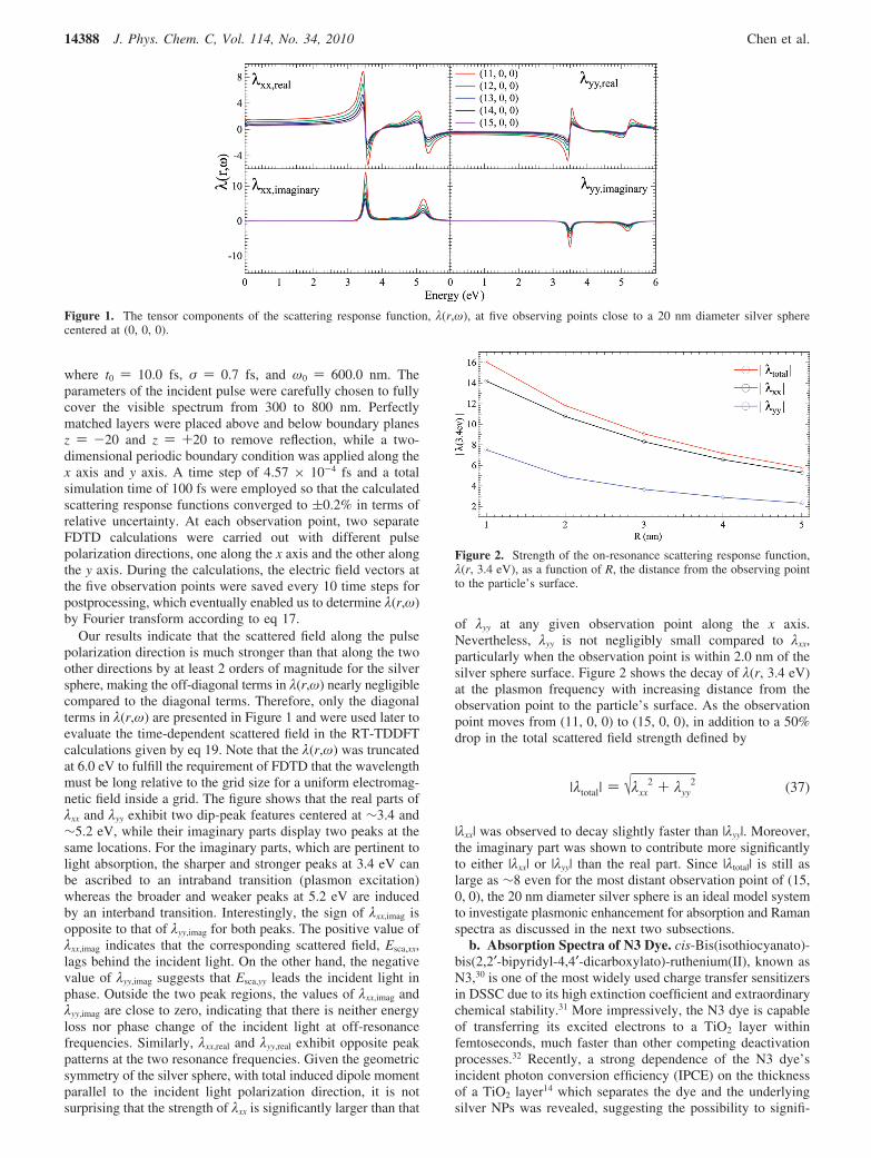
where t0 ) 10.0 fs, σ ) 0.7 fs, and ω0 ) 600.0 nm. Theparameters of the incident pulse were carefully chosen to fullycover the visible spectrum from 300 to 800 nm. Perfectlymatched layers were placed above and below boundary planesz ) -20 and z ) +20 to remove reflection, while a two-dimensional periodic boundary condition was applied along thex axis and y axis. A time step of 4.57 × 10⁻⁴ fs and a totalsimulation time of 100 fs were employed so that the calculatedscattering response functions converged to (0.2% in terms ofrelative uncertainty. At each observation point, two separateFDTD calculations were carried out with different pulsepolarization directions, one along the x axis and the other alongthe y axis. During the calculations, the electric field vectors atthe five observation points were saved every 10 time steps forpostprocessing, which eventually enabled us to determine λ(r,ω)by Fourier transform according to eq 17.
Our results indicate that the scattered field along the pulsepolarization direction is much stronger than that along the twoother directions by at least 2 orders of magnitude for the silversphere, making the off-diagonal terms in λ(r,ω) nearly negligiblecompared to the diagonal terms. Therefore, only the diagonalterms in λ(r,ω) are presented in Figure 1 and were used later toevaluate the time-dependent scattered field in the RT-TDDFTcalculations given by eq 19. Note that the λ(r,ω) was truncatedat 6.0 eV to fulfill the requirement of FDTD that the wavelengthmust be long relative to the grid size for a uniform electromag-netic field inside a grid. The figure shows that the real parts ofλxx and λyy exhibit two dip-peak features centered at ∼3.4 and∼5.2 eV, while their imaginary parts display two peaks at thesame locations. For the imaginary parts, which are pertinent tolight absorption, the sharper and stronger peaks at 3.4 eV canbe ascribed to an intraband transition (plasmon excitation)whereas the broader and weaker peaks at 5.2 eV are inducedby an interband transition. Interestingly, the sign of λxx,imag isopposite to that of λyy,imag for both peaks. The positive value ofλxx,imag indicates that the corresponding scattered field, Esca,xx,lags behind the incident light. On the other hand, the negativevalue of λyy,imag suggests that Esca,yy leads the incident light inphase. Outside the two peak regions, the values of λxx,imag andλyy,imag are close to zero, indicating that there is neither energyloss nor phase change of the incident light at off-resonancefrequencies. Similarly, λxx,real and λyy,real exhibit opposite peakpatterns at the two resonance frequencies. Given the geometricsymmetry of the silver sphere, with total induced dipole momentparallel to the incident light polarization direction, it is notsurprising that the strength of λxx is significantly larger than that
of λyy at any given observation point along the x axis.Nevertheless, λyy is not negligibly small compared to λxx,particularly when the observation point is within 2.0 nm of thesilver sphere surface. Figure 2 shows the decay of λ(r, 3.4 eV)at the plasmon frequency with increasing distance from theobservation point to the particle’s surface. As the observationpoint moves from (11, 0, 0) to (15, 0, 0), in addition to a 50%drop in the total scattered field strength defined by
|λxx| was observed to decay slightly faster than |λyy|. Moreover,the imaginary part was shown to contribute more significantlyto either |λxx| or |λyy| than the real part. Since |λtotal| is still aslarge as ∼8 even for the most distant observation point of (15,0, 0), the 20 nm diameter silver sphere is an ideal model systemto investigate plasmonic enhancement for absorption and Ramanspectra as discussed in the next two subsections.
b. Absorption Spectra of N3 Dye. cis-Bis(isothiocyanato)-bis(2,2′-bipyridyl-4,4′-dicarboxylato)-ruthenium(II), known asN3,30 is one of the most widely used charge transfer sensitizersin DSSC due to its high extinction coefficient and extraordinarychemical stability.31 More impressively, the N3 dye is capableof transferring its excited electrons to a TiO2 layer withinfemtoseconds, much faster than other competing deactivationprocesses.32 Recently, a strong dependence of the N3 dye’sincident photon conversion efficiency (IPCE) on the thicknessof a TiO2 layer14 which separates the dye and the underlyingsilver NPs was revealed, suggesting the possibility to signifi-
Figure 1. The tensor components of the scattering response function, λ(r,ω), at five observing points close to a 20 nm diameter silver spherecentered at (0, 0, 0).
Figure 2. Strength of the on-resonance scattering response function,λ(r, 3.4 eV), as a function of R, the distance from the observing pointto the particle’s surface.
|λtotal| ) √λxx2 + λyy
2 (37)
14388 J. Phys. Chem. C, Vol. 114, No. 34, 2010 Chen et al.
cantly improve the dye molecule’s light absorption throughplasmonic enhancement.
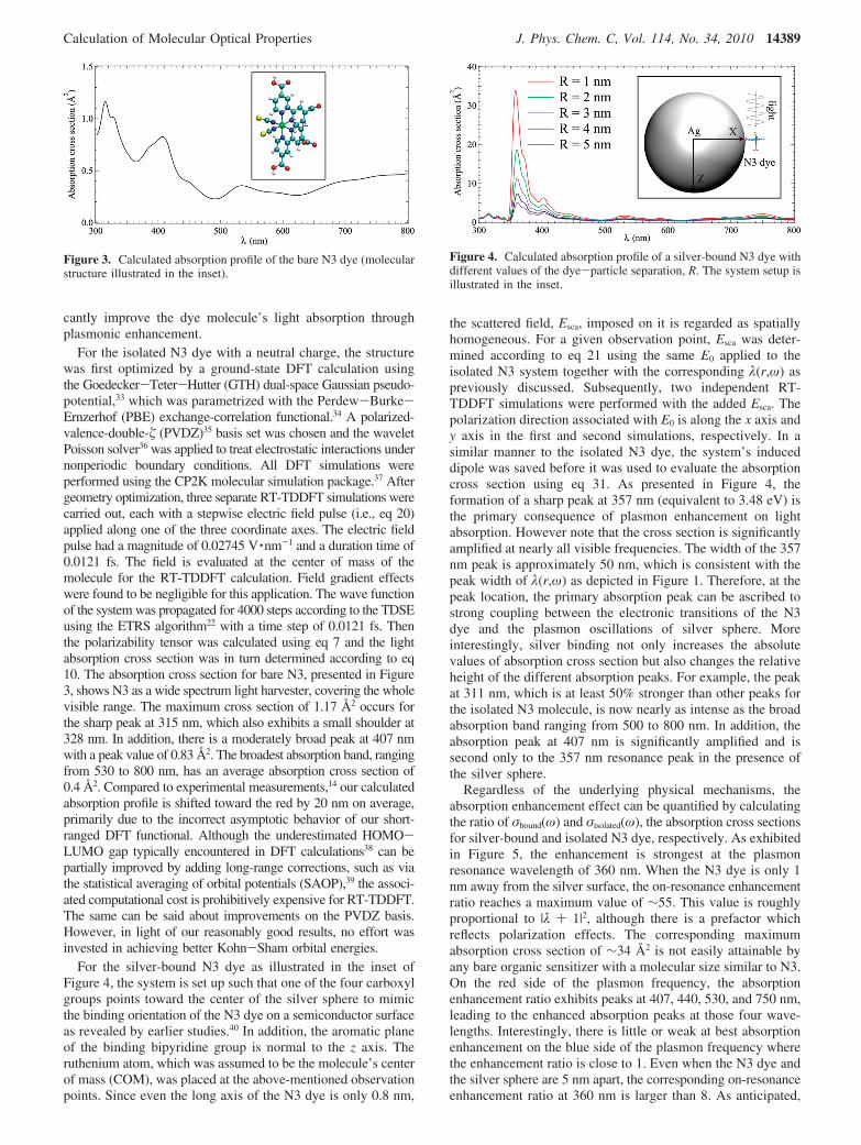
For the isolated N3 dye with a neutral charge, the structurewas first optimized by a ground-state DFT calculation usingthe Goedecker-Teter-Hutter (GTH) dual-space Gaussian pseudo-potential,33 which was parametrized with the Perdew-Burke-Ernzerhof (PBE) exchange-correlation functional.34 A polarized-valence-double- (PVDZ)35 basis set was chosen and the waveletPoisson solver36 was applied to treat electrostatic interactions undernonperiodic boundary conditions. All DFT simulations wereperformed using the CP2K molecular simulation package.37 Aftergeometry optimization, three separate RT-TDDFT simulations werecarried out, each with a stepwise electric field pulse (i.e., eq 20)applied along one of the three coordinate axes. The electric fieldpulse had a magnitude of 0.02745 V ·nm-1 and a duration time of0.0121 fs. The field is evaluated at the center of mass of themolecule for the RT-TDDFT calculation. Field gradient effectswere found to be negligible for this application. The wave functionof the system was propagated for 4000 steps according to the TDSEusing the ETRS algorithm22 with a time step of 0.0121 fs. Thenthe polarizability tensor was calculated using eq 7 and the lightabsorption cross section was in turn determined according to eq10. The absorption cross section for bare N3, presented in Figure3, shows N3 as a wide spectrum light harvester, covering the wholevisible range. The maximum cross section of 1.17 Å2 occurs forthe sharp peak at 315 nm, which also exhibits a small shoulder at328 nm. In addition, there is a moderately broad peak at 407 nmwith a peak value of 0.83 Å2. The broadest absorption band, rangingfrom 530 to 800 nm, has an average absorption cross section of0.4 Å2. Compared to experimental measurements,14 our calculatedabsorption profile is shifted toward the red by 20 nm on average,primarily due to the incorrect asymptotic behavior of our short-ranged DFT functional. Although the underestimated HOMO-LUMO gap typically encountered in DFT calculations38 can bepartially improved by adding long-range corrections, such as viathe statistical averaging of orbital potentials (SAOP),39 the associ-ated computational cost is prohibitively expensive for RT-TDDFT.The same can be said about improvements on the PVDZ basis.However, in light of our reasonably good results, no effort wasinvested in achieving better Kohn-Sham orbital energies.
For the silver-bound N3 dye as illustrated in the inset ofFigure 4, the system is set up such that one of the four carboxylgroups points toward the center of the silver sphere to mimicthe binding orientation of the N3 dye on a semiconductor surfaceas revealed by earlier studies.40 In addition, the aromatic planeof the binding bipyridine group is normal to the z axis. Theruthenium atom, which was assumed to be the molecule’s centerof mass (COM), was placed at the above-mentioned observationpoints. Since even the long axis of the N3 dye is only 0.8 nm,
the scattered field, Esca, imposed on it is regarded as spatiallyhomogeneous. For a given observation point, Esca was deter-mined according to eq 21 using the same E0 applied to theisolated N3 system together with the corresponding λ(r,ω) aspreviously discussed. Subsequently, two independent RT-TDDFT simulations were performed with the added Esca. Thepolarization direction associated with E0 is along the x axis andy axis in the first and second simulations, respectively. In asimilar manner to the isolated N3 dye, the system’s induceddipole was saved before it was used to evaluate the absorptioncross section using eq 31. As presented in Figure 4, theformation of a sharp peak at 357 nm (equivalent to 3.48 eV) isthe primary consequence of plasmon enhancement on lightabsorption. However note that the cross section is significantlyamplified at nearly all visible frequencies. The width of the 357nm peak is approximately 50 nm, which is consistent with thepeak width of λ(r,ω) as depicted in Figure 1. Therefore, at thepeak location, the primary absorption peak can be ascribed tostrong coupling between the electronic transitions of the N3dye and the plasmon oscillations of silver sphere. Moreinterestingly, silver binding not only increases the absolutevalues of absorption cross section but also changes the relativeheight of the different absorption peaks. For example, the peakat 311 nm, which is at least 50% stronger than other peaks forthe isolated N3 molecule, is now nearly as intense as the broadabsorption band ranging from 500 to 800 nm. In addition, theabsorption peak at 407 nm is significantly amplified and issecond only to the 357 nm resonance peak in the presence ofthe silver sphere.
Regardless of the underlying physical mechanisms, theabsorption enhancement effect can be quantified by calculatingthe ratio of σbound(ω) and σisolated(ω), the absorption cross sectionsfor silver-bound and isolated N3 dye, respectively. As exhibitedin Figure 5, the enhancement is strongest at the plasmonresonance wavelength of 360 nm. When the N3 dye is only 1nm away from the silver surface, the on-resonance enhancementratio reaches a maximum value of ∼55. This value is roughlyproportional to |λ + 1|2, although there is a prefactor whichreflects polarization effects. The corresponding maximumabsorption cross section of ∼34 Å2 is not easily attainable byany bare organic sensitizer with a molecular size similar to N3.On the red side of the plasmon frequency, the absorptionenhancement ratio exhibits peaks at 407, 440, 530, and 750 nm,leading to the enhanced absorption peaks at those four wave-lengths. Interestingly, there is little or weak at best absorptionenhancement on the blue side of the plasmon frequency wherethe enhancement ratio is close to 1. Even when the N3 dye andthe silver sphere are 5 nm apart, the corresponding on-resonanceenhancement ratio at 360 nm is larger than 8. As anticipated,
Figure 3. Calculated absorption profile of the bare N3 dye (molecularstructure illustrated in the inset).
Figure 4. Calculated absorption profile of a silver-bound N3 dye withdifferent values of the dye-particle separation, R. The system setup isillustrated in the inset.
Calculation of Molecular Optical Properties J. Phys. Chem. C, Vol. 114, No. 34, 2010 14389
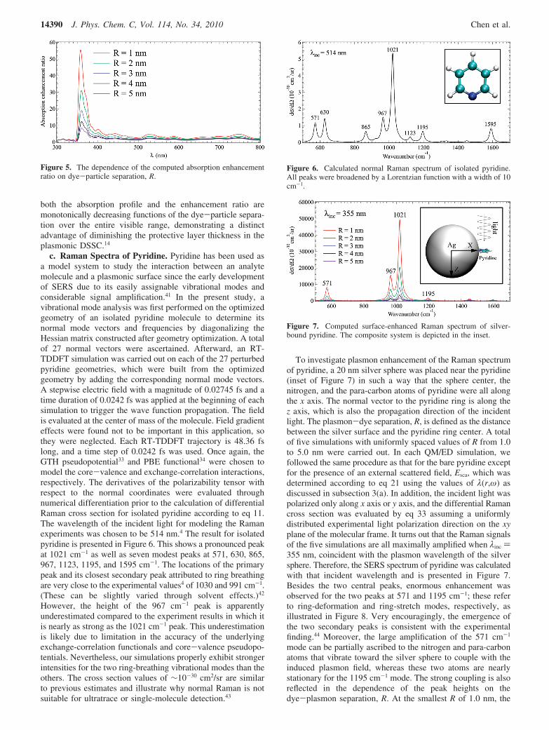
both the absorption profile and the enhancement ratio aremonotonically decreasing functions of the dye-particle separa-tion over the entire visible range, demonstrating a distinctadvantage of diminishing the protective layer thickness in theplasmonic DSSC.14
c. Raman Spectra of Pyridine. Pyridine has been used asa model system to study the interaction between an analytemolecule and a plasmonic surface since the early developmentof SERS due to its easily assignable vibrational modes andconsiderable signal amplification.41 In the present study, avibrational mode analysis was first performed on the optimizedgeometry of an isolated pyridine molecule to determine itsnormal mode vectors and frequencies by diagonalizing theHessian matrix constructed after geometry optimization. A totalof 27 normal vectors were ascertained. Afterward, an RT-TDDFT simulation was carried out on each of the 27 perturbedpyridine geometries, which were built from the optimizedgeometry by adding the corresponding normal mode vectors.A stepwise electric field with a magnitude of 0.02745 fs and atime duration of 0.0242 fs was applied at the beginning of eachsimulation to trigger the wave function propagation. The fieldis evaluated at the center of mass of the molecule. Field gradienteffects were found not to be important in this application, sothey were neglected. Each RT-TDDFT trajectory is 48.36 fslong, and a time step of 0.0242 fs was used. Once again, theGTH pseudopotential33 and PBE functional34 were chosen tomodel the core-valence and exchange-correlation interactions,respectively. The derivatives of the polarizability tensor withrespect to the normal coordinates were evaluated throughnumerical differentiation prior to the calculation of differentialRaman cross section for isolated pyridine according to eq 11.The wavelength of the incident light for modeling the Ramanexperiments was chosen to be 514 nm.4 The result for isolatedpyridine is presented in Figure 6. This shows a pronounced peakat 1021 cm-1 as well as seven modest peaks at 571, 630, 865,967, 1123, 1195, and 1595 cm-1. The locations of the primarypeak and its closest secondary peak attributed to ring breathingare very close to the experimental values4 of 1030 and 991 cm-1.(These can be slightly varied through solvent effects.)42
However, the height of the 967 cm-1 peak is apparentlyunderestimated compared to the experiment results in which itis nearly as strong as the 1021 cm-1 peak. This underestimationis likely due to limitation in the accuracy of the underlyingexchange-correlation functionals and core-valence pseudopo-tentials. Nevertheless, our simulations properly exhibit strongerintensities for the two ring-breathing vibrational modes than theothers. The cross section values of ∼10-30 cm2/sr are similarto previous estimates and illustrate why normal Raman is notsuitable for ultratrace or single-molecule detection.43
To investigate plasmon enhancement of the Raman spectrumof pyridine, a 20 nm silver sphere was placed near the pyridine(inset of Figure 7) in such a way that the sphere center, thenitrogen, and the para-carbon atoms of pyridine were all alongthe x axis. The normal vector to the pyridine ring is along thez axis, which is also the propagation direction of the incidentlight. The plasmon-dye separation, R, is defined as the distancebetween the silver surface and the pyridine ring center. A totalof five simulations with uniformly spaced values of R from 1.0to 5.0 nm were carried out. In each QM/ED simulation, wefollowed the same procedure as that for the bare pyridine exceptfor the presence of an external scattered field, Esca, which wasdetermined according to eq 21 using the values of λ(r,ω) asdiscussed in subsection 3(a). In addition, the incident light waspolarized only along x axis or y axis, and the differential Ramancross section was evaluated by eq 33 assuming a uniformlydistributed experimental light polarization direction on the xyplane of the molecular frame. It turns out that the Raman signalsof the five simulations are all maximally amplified when λinc )355 nm, coincident with the plasmon wavelength of the silversphere. Therefore, the SERS spectrum of pyridine was calculatedwith that incident wavelength and is presented in Figure 7.Besides the two central peaks, enormous enhancement wasobserved for the two peaks at 571 and 1195 cm-1; these referto ring-deformation and ring-stretch modes, respectively, asillustrated in Figure 8. Very encouragingly, the emergence ofthe two secondary peaks is consistent with the experimentalfinding.44 Moreover, the large amplification of the 571 cm-1
mode can be partially ascribed to the nitrogen and para-carbonatoms that vibrate toward the silver sphere to couple with theinduced plasmon field, whereas these two atoms are nearlystationary for the 1195 cm-1 mode. The strong coupling is alsoreflected in the dependence of the peak heights on thedye-plasmon separation, R. At the smallest R of 1.0 nm, the
Figure 5. The dependence of the computed absorption enhancementratio on dye-particle separation, R.
Figure 6. Calculated normal Raman spectrum of isolated pyridine.All peaks were broadened by a Lorentzian function with a width of 10cm-1.
Figure 7. Computed surface-enhanced Raman spectrum of silver-bound pyridine. The composite system is depicted in the inset.
14390 J. Phys. Chem. C, Vol. 114, No. 34, 2010 Chen et al.
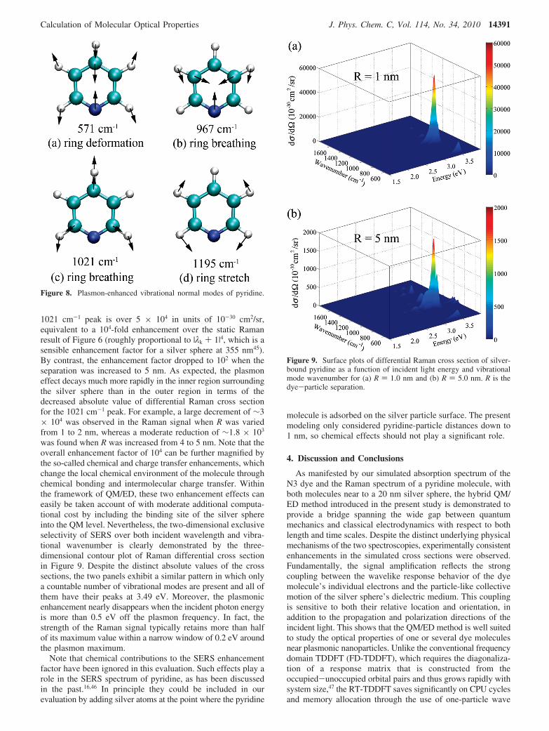
1021 cm-1 peak is over 5 × 10⁴ in units of 10-30 cm2/sr,equivalent to a 104-fold enhancement over the static Ramanresult of Figure 6 (roughly proportional to |λk + 1|4, which is asensible enhancement factor for a silver sphere at 355 nm45).By contrast, the enhancement factor dropped to 102 when theseparation was increased to 5 nm. As expected, the plasmoneffect decays much more rapidly in the inner region surroundingthe silver sphere than in the outer region in terms of thedecreased absolute value of differential Raman cross sectionfor the 1021 cm-1 peak. For example, a large decrement of ∼3× 10⁴ was observed in the Raman signal when R was variedfrom 1 to 2 nm, whereas a moderate reduction of ∼1.8 × 10³
was found when R was increased from 4 to 5 nm. Note that theoverall enhancement factor of 104 can be further magnified bythe so-called chemical and charge transfer enhancements, whichchange the local chemical environment of the molecule throughchemical bonding and intermolecular charge transfer. Withinthe framework of QM/ED, these two enhancement effects caneasily be taken account of with moderate additional computa-tional cost by including the binding site of the silver sphereinto the QM level. Nevertheless, the two-dimensional exclusiveselectivity of SERS over both incident wavelength and vibra-tional wavenumber is clearly demonstrated by the three-dimensional contour plot of Raman differential cross sectionin Figure 9. Despite the distinct absolute values of the crosssections, the two panels exhibit a similar pattern in which onlya countable number of vibrational modes are present and all ofthem have their peaks at 3.49 eV. Moreover, the plasmonicenhancement nearly disappears when the incident photon energyis more than 0.5 eV off the plasmon frequency. In fact, thestrength of the Raman signal typically retains more than halfof its maximum value within a narrow window of 0.2 eV aroundthe plasmon maximum.
Note that chemical contributions to the SERS enhancementfactor have been ignored in this evaluation. Such effects play arole in the SERS spectrum of pyridine, as has been discussedin the past.16,46 In principle they could be included in ourevaluation by adding silver atoms at the point where the pyridine
molecule is adsorbed on the silver particle surface. The presentmodeling only considered pyridine-particle distances down to1 nm, so chemical effects should not play a significant role.
4. Discussion and Conclusions
As manifested by our simulated absorption spectrum of theN3 dye and the Raman spectrum of a pyridine molecule, withboth molecules near to a 20 nm silver sphere, the hybrid QM/ED method introduced in the present study is demonstrated toprovide a bridge spanning the wide gap between quantummechanics and classical electrodynamics with respect to bothlength and time scales. Despite the distinct underlying physicalmechanisms of the two spectroscopies, experimentally consistentenhancements in the simulated cross sections were observed.Fundamentally, the signal amplification reflects the strongcoupling between the wavelike response behavior of the dyemolecule’s individual electrons and the particle-like collectivemotion of the silver sphere’s dielectric medium. This couplingis sensitive to both their relative location and orientation, inaddition to the propagation and polarization directions of theincident light. This shows that the QM/ED method is well suitedto study the optical properties of one or several dye moleculesnear plasmonic nanoparticles. Unlike the conventional frequencydomain TDDFT (FD-TDDFT), which requires the diagonaliza-tion of a response matrix that is constructed from theoccupied-unoccupied orbital pairs and thus grows rapidly withsystem size,47 the RT-TDDFT saves significantly on CPU cyclesand memory allocation through the use of one-particle wave
Figure 8. Plasmon-enhanced vibrational normal modes of pyridine.
Figure 9. Surface plots of differential Raman cross section of silver-bound pyridine as a function of incident light energy and vibrationalmode wavenumber for (a) R ) 1.0 nm and (b) R ) 5.0 nm. R is thedye-particle separation.
Calculation of Molecular Optical Properties J. Phys. Chem. C, Vol. 114, No. 34, 2010 14391
function propagations starting from occupied orbitals.48 Inaddition, the time scale of the propagation is relatively shortdue to the assumed damping of the molecular excited state. Asa result, the size of a system that can be treated at the QM levelin the QM/ED calculations can be expanded to a few hundredatoms, large enough to cover most organic dye molecules ofinterest. To examine the validity of our assumption of uniformscattered electric field across such a small molecule as N3 andpyridine, a justification calculation was performed on the SERSof pyridine by including the coupling between its quadrupolemoment and the electric field gradient. In that calculation, adye-particle separation of 1.0 nm was chosen for a large electricfield gradient near the silver sphere surface. It turns out thatthe SERS differential cross section was only slightly changedby less than 1%, suggesting that the effect of electric fieldgradient can be safely ignored in the present study. The FDTDmethod was selected as the counterpart of RT-TDDFT at EDlevel, because it proceeds in the real time domain and thus isable to generate the frequency-dependent field-enhancementfactor λ(r,ω) in a single simulation through Fourier transforma-tion. Note however that it is convenient to express the couplingbetween ED and QM via λ(r,ω) in the frequency domain dueto the different ways that time is used in FDTD and RT-TDDFT.In FDTD, the time starts when the incident wave leaves itssource. On the other hand, the timer in RT-TDDFT is triggeredwhen the incident light actually reaches the molecule. Sincewe use the frequency domain to interconnect ED and QM, EDmethods that work in the frequency domain can be used directlyinstead of FDTD. For example, the finite element method(FEM)49 might be used to advantage here as this can circumventsome of the errors in FDTD such as the stair-casing errors thatoccur in the treatment of curved surfaces. In addition to theflexible coupling scheme between the QM and ED levels oftheory, QM/ED allows for an arbitrary number of incident lightpulses with any choice of propagation and polarization direc-tions, paving the way to the investigation of time-resolvedoptical phenomena. Following this successful application of QM/ED for linear optical properties such as absorption and Raman,its extension to nonlinear optical (NLO) materials50 is antici-pated. Other generalizations of this work will arise in thetreatment of layers of molecules near metal particles wherethe self-consistent coupling of the dielectric properties of themolecules to the optical response of the metal particles will beimportant. In this case it will be necessary to use fields fromthe QM calculations as input to the ED calculations.
Acknowledgment. The research was supported by theANSER Energy Frontier Research Center (DE-SC0001785)funded by the US Department of Energy, Office of Science,Office of Basic Energy Sciences. The computational resourcesutilized in this research were provided by Quest cluster systemadministered by Northwestern University Information Technol-ogy (NUIT) unit.
References and Notes
(1) Kirchhoff, G.; Bunsen, R. Ann. Phys. Chem. 1860, 186 (6), 161–189.
(2) Raman, C. V.; Krishnan, K. S. Nature 1928, 121, 501–502.(3) Oulton, R. F.; Sorger, V. J.; Zentgraf, T.; Ma, R.-M.; Gladden, C.;
Dai, L.; Bartal, G.; Zhang, X. Nature 2009, 461 (7264), 629–632.(4) Jeanmaire, D. L.; Van Duyne, R. P. J. Electroanal. Chem. 1977,
84 (1), 1–20.(5) King, F. W.; Van Duyne, R. P.; Schatz, G. C. J. Chem. Phys. 1978,
69 (10), 4472–4481.(6) Dulic, D.; van der Molen, S. J.; Kudernac, T.; Jonkman, H. T.; de
Jong, J. J. D.; Bowden, T. N.; van Esch, J.; Feringa, B. L.; van Wees, B. J.Phys. ReV. Lett. 2003, 91, 207402.
(7) Grafstrom, S. J. Appl. Phys. 2002, 91 (4), 1717–1753.(8) Nakanishi, H.; Bishop, K. J. M.; Kowalczyk, B.; Nitzan, A.; Weiss,
E. A.; Tretiakov, K. V.; Apodaca, M. M.; Klajn, R.; Stoddart, J. F.;Grzybowski, B. A. Nature 2009, 460 (7253), 371–375.
(9) (a) Viljas, J. K.; Pauly, F.; Cuevas, J. C. Phys. ReV. B 2007, 76,033403. (b) Galperin, M.; Nitzan, A. J. Chem. Phys. 2006, 124 (23),234709–17.
(10) Galperin, M.; Nitzan, A. Phys. ReV. Lett. 2005, 95, 206802.(11) Galperin, M.; Tretiak, S. J. Chem. Phys. 2008, 128 (12), 124705–
9.(12) Galperin, M.; Ratner, M. A.; Nitzan, A. Nano Lett. 2009, 9 (2),
758–762.(13) Zhao, G.; Kozuka, H.; Yoko, T. Sol. Energy Mater. Sol. Cells 1997,
46 (3), 219–231.(14) Standridge, S. D.; Schatz, G. C.; Hupp, J. T. J. Am. Chem. Soc.
2009, 131 (24), 8407–8409.(15) Zhao, J.; Pinchuk, A. O.; McMahon, J. M.; Li, S.; Ausman, L. K.;
Atkinson, A. L.; Schatz, G. C. Acc. Chem. Res. 2008, 41, 1710–1720.(16) Jensen, L.; Aikens, C. M.; Schatz, G. C. Chem. Soc. ReV. 2008, 37
(5), 1061–1073.(17) Corni, S.; Tomasi, J. J. Chem. Phys. 2001, 114 (8), 3739–3751.(18) Lopata, K.; Neuhauser, D. J. Chem. Phys. 2009, 130 (10), 104707–
7.(19) Masiello, D.; Schatz, G. C. J. Chem. Phys. 2010, 132, 064102.(20) Schrodinger, E. Phys. ReV. 1926, 28 (6), 1049.(21) Crank, J.; Nicolson, P. AdV. Comput. Math. 1996, 6 (1), 207–226.(22) Castro, A.; Marques, M. A. L.; Rubio, A. J. Chem. Phys. 2004,
121 (8), 3425–3433.(23) Castro, A.; Appel, H.; Oliveira, M.; Rozzi, C. A.; Andrade, X.;
Lorenzen, F.; Marques, M. A. L.; Gross, E. K. U.; Rubio, A. Phys. StatusSolidi B 2006, 243 (11), 2465–2488.
(24) Neugebauer, J.; Reiher, M.; Kind, C.; Hess, B. A. J. Comput. Chem.2002, 23 (9), 895–910.
(25) Maxwell, J. C. Philos. Trans. R. Soc. London 1865, 155, 459–512.(26) Furse, C. M.; Mathur, S. P.; Gandhi, O. P. IEEE Trans. MicrowaVe
Theory Tech. 1990, 38 (7), 919–927.(27) Long, D. A., Raman Spectroscopy; McGraw-Hill: New York, 1977.(28) McMahon, J. M.; Wang, Y.; Sherry, L. J.; Van Duyne, R. P.; Marks,
L. D.; Gray, S. K.; Schatz, G. C. J. Phys. Chem. C 2009, 113 (7), 2731–2735.
(29) Johnson, P. B.; Christy, R. W. Phys. ReV. B 1972, 6, 4370.(30) Gratzel, M. J. Photochem. Photobiol., C 2003, 4 (2), 145–153.(31) Nazeeruddin, M. K.; Kay, A.; Rodicio, I.; Humphry-Baker, R.;
Mueller, E.; Liska, P.; Vlachopoulos, N.; Graetzel, M. J. Am. Chem. Soc.1993, 115 (14), 6382–6390.
(32) Hannappel, T.; Burfeindt, B.; Storck, W.; Willig, F. J. Phys. Chem.B 1997, 101 (35), 6799–6802.
(33) Krack, M. Theor. Chem. Acc. 2005, 114 (1), 145–152.(34) Perdew, J. P.; Burke, K.; Ernzerhof, M. Phys. ReV. Lett. 1996, 77,
3865.(35) Woon, D. E.; Dunning, J. T. H. J. Chem. Phys. 1994, 100 (4),
2975–2988.(36) Genovese, L.; Deutsch, T.; Neelov, A.; Goedecker, S.; Beylkin,
G. J. Chem. Phys. 2006, 125 (7), 074105–5.(37) VandeVondele, J.; Krack, M.; Mohamed, F.; Parrinello, M.;
Chassaing, T.; Hutter, J. r. Comput. Phys. Commun. 2005, 167 (2), 103–128.
(38) Gritsenko, O.; Baerends, E. J. J. Chem. Phys. 2004, 121 (2), 655–660.
(39) Gritsenko, O. V.; Schipper, P. R. T.; Baerends, E. J. Chem. Phys.Lett. 1999, 302 (3-4), 199–207.
(40) Duncan, W. R.; Prezhdo, O. V. Annu. ReV. Phys. Chem. 2007, 58(1), 143–184.
(41) Creighton, J. A. Notes Rec. R. Soc. 2010, 64, 175–183.(42) Johnson, A. E.; Myers, A. B. J. Phys. Chem. 1996, 100 (19), 7778–
7788.(43) Nie, S.; Emory, S. R. Science 1997, 275 (5303), 1102–1106.(44) Arenas, J. F.; Lopez Tocon, I.; Otero, J. C.; Marcos, J. I. J. Phys.
Chem. 1996, 100 (22), 9254–9261.(45) Kelly, K. L.; Coronado, E.; Zhao, L. L.; Schatz, G. C. J. Phys.
Chem. B 2003, 107 (3), 668–677.(46) (a) Lombardi, J. R.; Birke, R. L. J. Phys. Chem. C 2008, 112, 5605–
5617. (b) Morton, S. M.; Jensen, L. J. Am. Chem. Soc. 2009, 131 (11),4090–4098.
(47) Casida, M. E.; Jamorski, C.; Casida, K. C.; Salahub, D. R. J. Chem.Phys. 1998, 108 (11), 4439–4449.
(48) Takimoto, Y.; Vila, F. D.; Rehr, J. J. J. Chem. Phys. 2007, 127(15), 154114–10.
(49) Coccioli, R.; Itoh, T.; Pelosi, G.; Silvester, P. P. IEEE. Trans.Antennas Propag. 1996, 38 (6), 34–48.
(50) Eaton, D. F. Science 1991, 253 (5017), 281–287.
JP1043392
14392 J. Phys. Chem. C, Vol. 114, No. 34, 2010 Chen et al.
Related Documents