HANDOFF PERFORMANCE METRICS • Cell blocking probability – probability of a new call being blocked • Call dropping probability – probability that a call is terminated due to a handoff • Call completion probability – probability that an admitted call is not dropped before it terminates • Probability of unsuccessful handoff – probability that a handoff is executed while the reception conditions are inadequate Cellular Wireless Networks 13-29

Welcome message from author
This document is posted to help you gain knowledge. Please leave a comment to let me know what you think about it! Share it to your friends and learn new things together.
Transcript
HANDOFF PERFORMANCE METRICS
• Cell blocking probability – probability of a new call being blocked
• Call dropping probability – probability that a call is terminated due to a handoff
• Call completion probability – probability that an admitted call is not dropped before it terminates
• Probability of unsuccessful handoff – probability that a handoff is executed while the reception conditions are inadequate
Cellular Wireless Networks 13-29
HANDOFF PERFORMANCE METRICS
• Handoff blocking probability – probability that a handoff cannot be successfully completed
• Handoff probability – probability that a handoff occurs before call termination
• Rate of handoff – number of handoffs per unit time• Interruption duration – duration of time during a
handoff in which a mobile is not connected to either base station
• Handoff delay – distance the mobile moves from the point at which the handoff should occur to the point at which it does occur
Cellular Wireless Networks 13-30
HANDOFF STRATEGIES USED TO DETERMINE INSTANT OF HANDOFF
• Relative signal strength
• Relative signal strength with threshold
• Relative signal strength with hysteresis
• Relative signal strength with hysteresis and threshold
• Prediction techniques
Cellular Wireless Networks 13-31
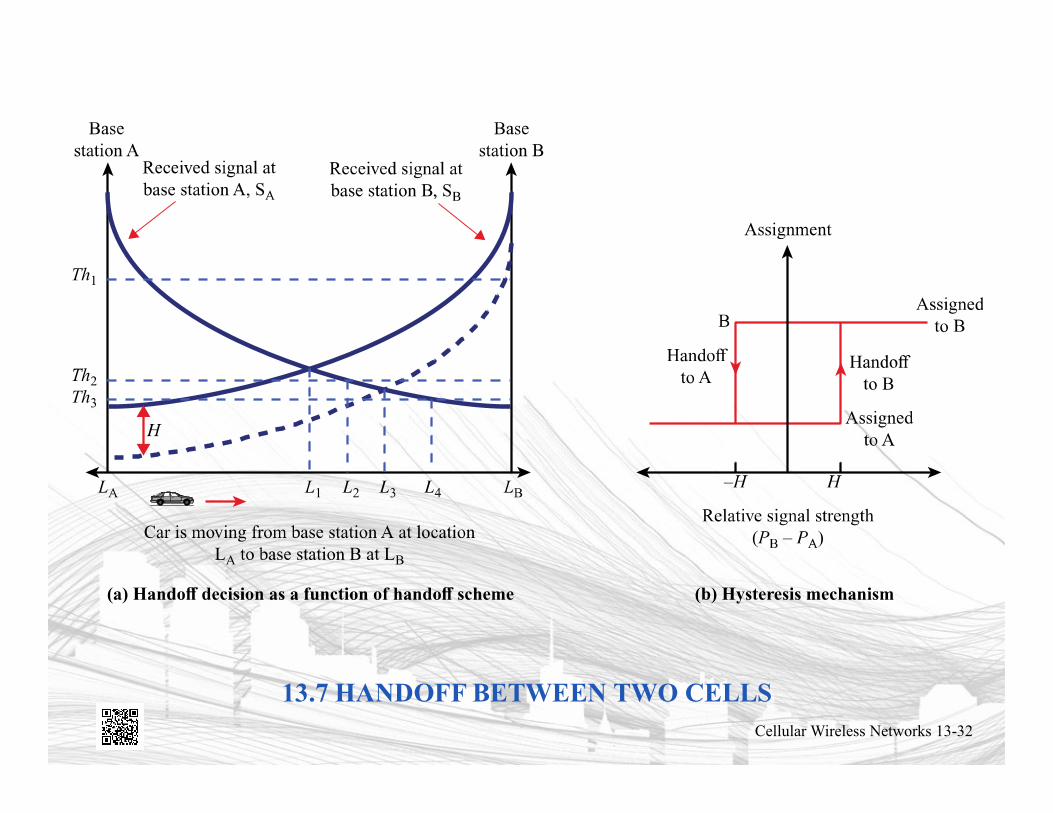
13.7 HANDOFF BETWEEN TWO CELLSCellular Wireless Networks 13-32

POWER CONTROL
• Reasons to include dynamic power control in a cellular system– Received power must be sufficiently above the background
noise for effective communication– Desirable to minimize power in the transmitted signal from
the mobile• Reduce co-channel interference, alleviate health concerns, save
battery power
– In SS systems using CDMA, it’s necessary to equalize the received power level from all mobile units at the BS
Cellular Wireless Networks 13-33
TYPES OF POWER CONTROL
• Open-loop power control– Depends solely on mobile unit– No feedback from BS– Not as accurate as closed-loop, but can react quicker to
fluctuations in signal strength
• Closed-loop power control– Adjusts signal strength in reverse channel based on metric
of performance– BS makes power adjustment decision and communicates to
mobile on control channel
Cellular Wireless Networks 13-34
FIRST-GENERATION ANALOG
• Advanced Mobile Phone Service (AMPS)– In North America, two 25-MHz bands allocated to
AMPS• One for transmission from base to mobile unit (869 MHz-894
MHz)• One for transmission from mobile unit to base(824 MHz -849
MHz– Each band split in two to encourage competition
• Each split is for one operator. In each split, with 30 KHzspaced for each channel, total channels result in 416 channels, where 395 channel for voice or traffic and 21 channels for control
– Frequency reuse exploited
Cellular Wireless Networks 13-35
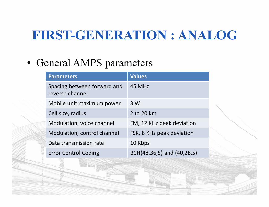
FIRST-GENERATION : ANALOG
• General AMPS parametersParameters Values
Spacing between forward and reverse channel
45 MHz
Mobile unit maximum power 3 W
Cell size, radius 2 to 20 km
Modulation, voice channel FM, 12 KHz peak deviation
Modulation, control channel FSK, 8 KHz peak deviation
Data transmission rate 10 Kbps
Error Control Coding BCH(48,36,5) and (40,28,5)

AMPS OPERATION
• Subscriber initiates call by keying in phone number and presses send key
• MTSO verifies number and authorizes user• MTSO issues message to user’s cell phone indicating
send and receive traffic channels• MTSO sends ringing signal to called party• Party answers; MTSO establishes circuit and initiates
billing information• Either party hangs up; MTSO releases circuit, frees
channels, completes billing
Cellular Wireless Networks 13-37
DIFFERENCES BETWEEN FIRST AND SECOND GENERATION SYSTEMS
• Digital traffic channels – first-generation systems are almost purely analog; second-generation systems are digital– Using FDMA/TDMA or CDMA
• Encryption – all second generation systems provide encryption to prevent eavesdropping
• Error detection and correction – second-generation digital traffic allows for detection and correction, giving clear voice reception
• Channel access – second-generation systems allow channels to be dynamically shared by a number of users
Cellular Wireless Networks 13-38
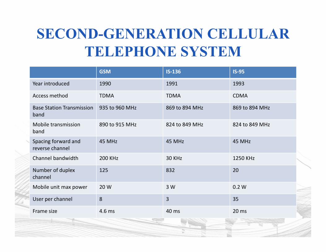
SECOND-GENERATION CELLULAR TELEPHONE SYSTEM
GSM IS-136 IS-95
Year introduced 1990 1991 1993
Access method TDMA TDMA CDMA
Base Station Transmission band
935 to 960 MHz 869 to 894 MHz 869 to 894 MHz
Mobile transmission band
890 to 915 MHz 824 to 849 MHz 824 to 849 MHz
Spacing forward and reverse channel
45 MHz 45 MHz 45 MHz
Channel bandwidth 200 KHz 30 KHz 1250 KHz
Number of duplex channel
125 832 20
Mobile unit max power 20 W 3 W 0.2 W
User per channel 8 3 35
Frame size 4.6 ms 40 ms 20 ms
GLOBAL SYSTEM FOR MOBILE COMMUNICATIONS (GSM)
• FDMA/TDMA approach• Developed to provide a common second-generation
technology for Europe– Over 6.9 billion subscriber units by the end of 2013
• Mobile station communicates across the Um interface (air interface) with base station transceiver in the same cell as mobile unit
• Mobile equipment (ME) – physical terminal, such as a telephone or PCS– ME includes radio transceiver, digital signal processors and
subscriber identity module (SIM)• GSM subscriber units are generic until SIM is inserted
– SIMs roam, not necessarily the subscriber devices
Cellular Wireless Networks 13-40

13.9 OVERALL GSM ARCHITECTURECellular Wireless Networks 13-41
BASE STATION SUBSYSTEM (BSS)
• BSS consists of base station controller and one or more base transceiver stations (BTS)
• Each BTS defines a single cell– Includes radio antenna, radio transceiver and a link to a
base station controller (BSC)
• BSC reserves radio frequencies, manages handoff of mobile unit from one cell to another within BSS, and controls paging
Cellular Wireless Networks 13-42
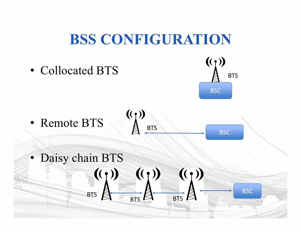
BSS CONFIGURATION
• Collocated BTS
• Remote BTS
• Daisy chain BTS
BSC
BTS
BSCBTS
BSCBTSBTS BTS
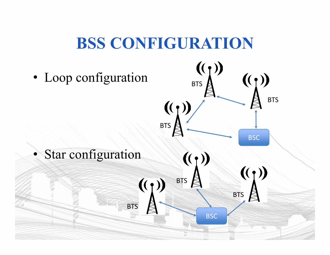
BSS CONFIGURATION
• Loop configuration
• Star configuration
BSC
BTS
BTS
BTS
BSCBTS
BTS
BTS
NETWORK SUBSYSTEM (NS)
• NS provides link between cellular network and public switched telecommunications networks– Controls handoffs between cells in different BSSs
– Authenticates users and validates accounts
– Enables worldwide roaming of mobile users
• Central element of NS is the mobile switching center (MSC)– Does mostly the functions a NS provides
– Also collect billing data
Cellular Wireless Networks 13-45
MOBILE SWITCHING CENTER (MSC) DATABASES
• Home location register (HLR) database – stores information about each subscriber that belongs to it
• Visitor location register (VLR) database – maintains information about subscribers currently physically in the region
• Authentication center database (AuC) – used for authentication activities, holds encryption keys
• Equipment identity register database (EIR) – keeps track of the type of equipment that exists at the mobile station
Cellular Wireless Networks 13-46
IDENTIFIER IN GSM SYSTEM
• Mobile Station Identifier– IMSI : International Mobile Subscriber Identity
• Unique number identifying a GSM subscriber, usually 15 digits
• Stored in SIM, doesn’t change over time
– MSISDN (Mobile Station International Subscriber Directory Number): The number that is dialed • Different MSISDN can be associated to a SIM
– IMEI :International Mobile Equipment Identity• Identify the physical unit mobile equipment
• Optionally stored in AuC for validation
IDENTIFIER IN GSM SYSTEM
• Other type of identifiers– TMSI : Temporary Mobile Subscriber Identity
• To protect true identity (IMSI) of subscriber.• It is issued and stored within a VLR when an IMSI attach takes
place or Location Area update take place
– Ki : Authentication Key : Secret key assigned by service provider to subscriber
– Kc : Cipher Key : Computed by network and mobile station• A Location Area Identity (LAI) uniquely identifies a
Location Area within a mobile network– Consist of Mobile Country Code– Mobile Network Code– Location Area Code
HOME LOCATION REGISTER(HLR)
• HLR is a database that stores subscription and set of functions needed to manage subscriber data in one area– Any administrative action by the service provider or
changes made by subscriber is first carried out on HLR and then update Visitor Location Register (VLR)
– Subscriber data which frequently change• IMSI and MSISDN• Service Restriction• Bearer Service• Supplementary Services
– HLR communicate with other VLR
VISITOR LOCATION REGISTER
• VLR is a database containing the information about all the mobile station currently located MSC service area.– Always integrated with MSC to avoid the signaling load in the system– If MS moves into new MSC, VLR request the HLR to provide the
relevant data and store it• Can be also viewed as a subset of a HLR
– VLR and HLR connect each other through D interface– VLR is responsible for :
• Setting up and controlling call• Continuity of call during hand off• Location updating and registration• Allocating TIMSI• Retrieve data from HLR• Attach or Detach IMSI
Related Documents