PUBLISHED: 11-MAY-2011 2006.50 XK RANGE (X150), 501-14 HANDLES, LOCKS, LATCHES AND ENTRY SYSTEMS FRONT DOOR LOCK ACTUATOR (G531598)

Welcome message from author
This document is posted to help you gain knowledge. Please leave a comment to let me know what you think about it! Share it to your friends and learn new things together.
Transcript
PUBLISHED: 11-MAY-20112006.50 XK RANGE (X150), 501-14
HANDLES, LOCKS, LATCHES AND ENTRY SYSTEMS
FRONT DOOR LOCK ACTUATOR (G531598)
REMOVAL AND INSTALLATION
REMOVAL
Remove the window regulator.
For additional information, refer to: (501-11 Glass, Frames and Front Door Window Regulator
Mechanisms, Removal and Installation).
1.
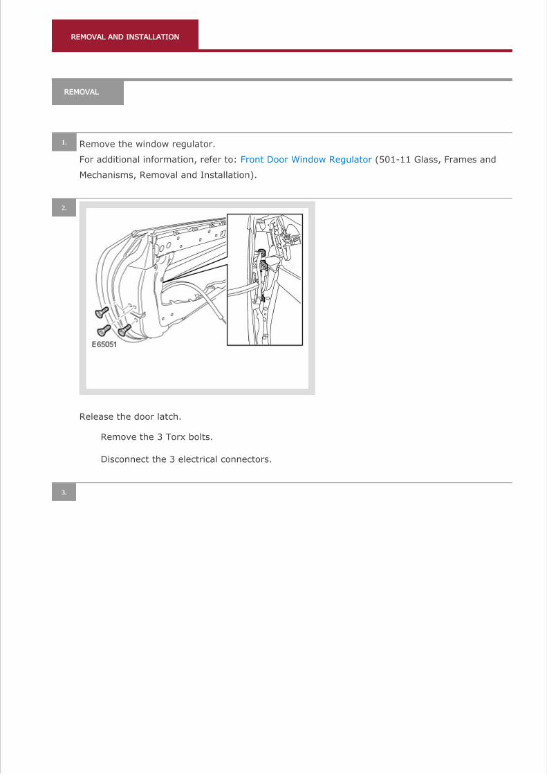
Release the door latch.
2.
Remove the 3 Torx bolts.
Disconnect the 3 electrical connectors.
3.
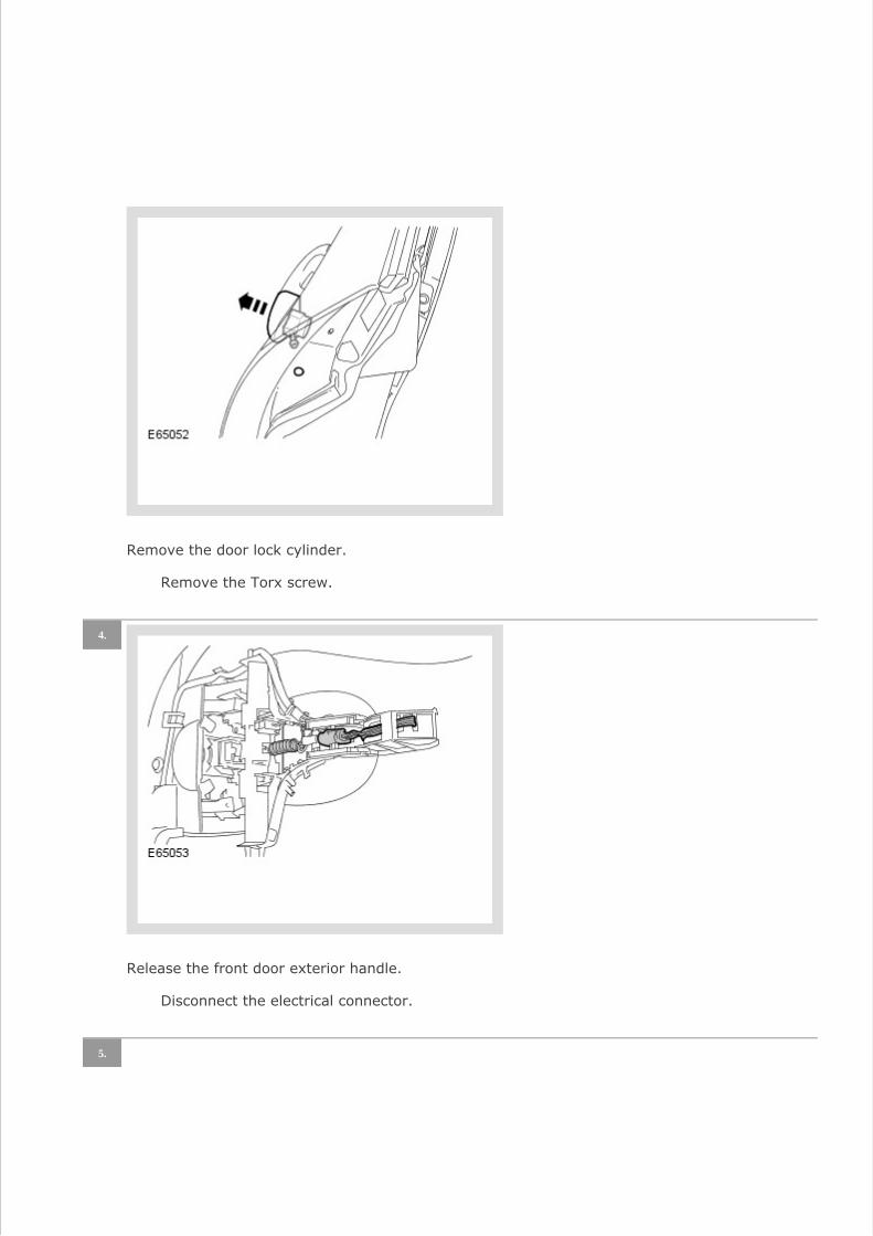
Remove the door lock cylinder.
Remove the Torx screw.
Release the front door exterior handle.
4.
Disconnect the electrical connector.
5.

Remove the front door exterior handle.
Release from the door handle mechanism.
Remove the door handle mechanism and latch assembly.
6.
Remove the Torx screw.
Release the retainer.
7.
NOTE:
Do not disassemble further if the component is removed for access only.
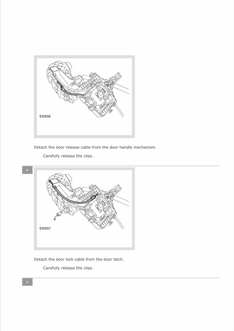
Detach the door release cable from the door handle mechanism.
Carefully release the clips.
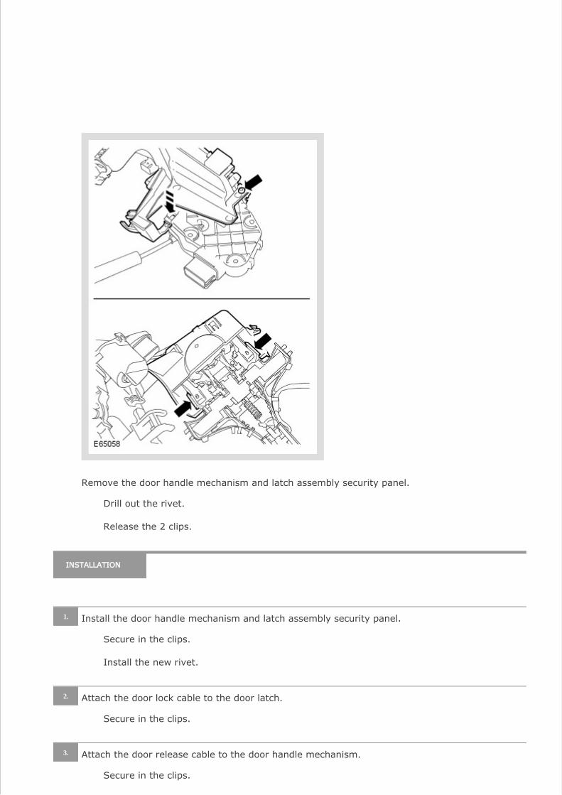
Detach the door lock cable from the door latch.
8.
Carefully release the clips.
9.
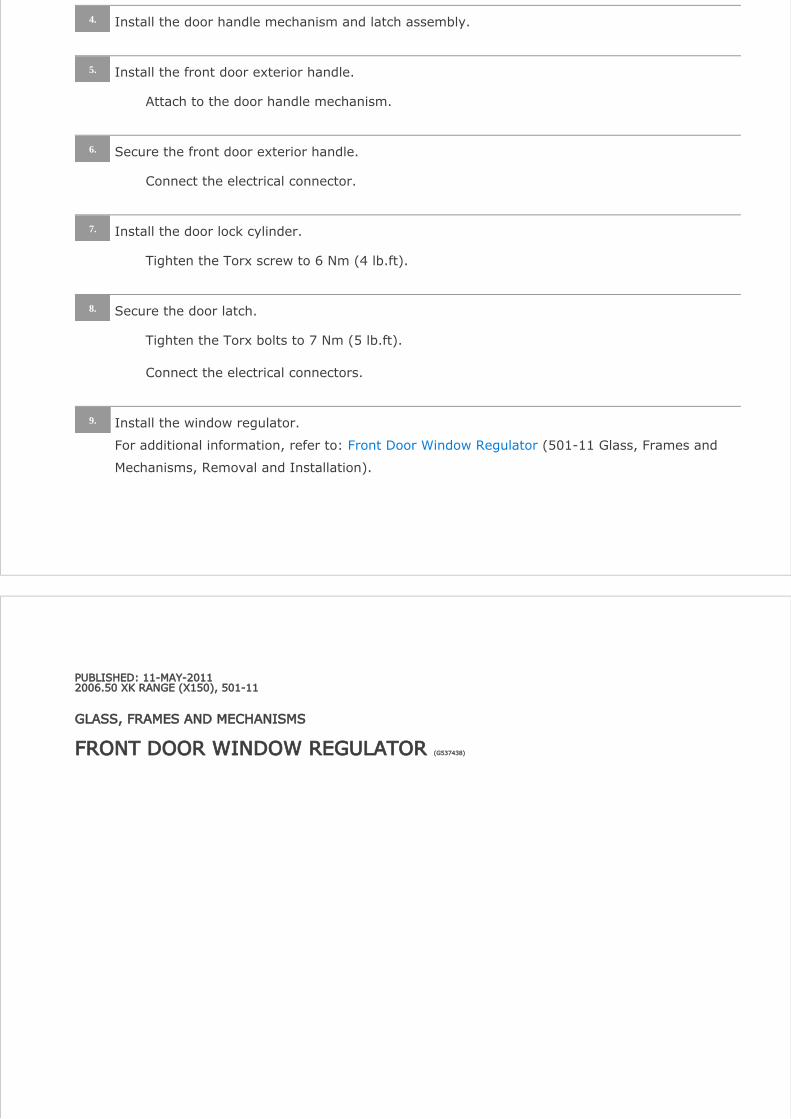
Remove the door handle mechanism and latch assembly security panel.
Drill out the rivet.
Release the 2 clips.
INSTALLATION
Install the door handle mechanism and latch assembly security panel.1.
Secure in the clips.
Install the new rivet.
Attach the door lock cable to the door latch.2.
Secure in the clips.
Attach the door release cable to the door handle mechanism.3.
Secure in the clips.
PUBLISHED: 11-MAY-20112006.50 XK RANGE (X150), 501-11
GLASS, FRAMES AND MECHANISMS
FRONT DOOR WINDOW REGULATOR (G537438)
Install the door handle mechanism and latch assembly.4.
Install the front door exterior handle.5.
Attach to the door handle mechanism.
Secure the front door exterior handle.6.
Connect the electrical connector.
Install the door lock cylinder.7.
Tighten the Torx screw to 6 Nm (4 lb.ft).
Secure the door latch.8.
Tighten the Torx bolts to 7 Nm (5 lb.ft).
Connect the electrical connectors.
Install the window regulator.
For additional information, refer to: (501-11 Glass, Frames and Front Door Window Regulator
Mechanisms, Removal and Installation).
9.

REMOVAL AND INSTALLATION
REMOVAL
Raise the window glass.1.
Remove the cover and disconnect the battery ground cable.
For additional information, refer to: Specifications (414-00, Specifications).
2.
Remove the front door trim panel.
For additional information, refer to: (501-05 Interior Trim and Front Door Trim Panel
Ornamentation, Removal and Installation).
3.
Remove the window regulator motor.
4.
Disconnect the electrical connector.
Remove the 3 Torx screws.
5.

Release the front door inner weathershield.
Disconnect the 3 electrical connectors.
Release the 9 wiring harness clips.
Remove the front door inner weathershield.
6.
Remove the 12 Torx bolts.
Release the front door interior handle cable.
Carefully remove the outer waist seal.7.
Release each end of the seal from the door frame.
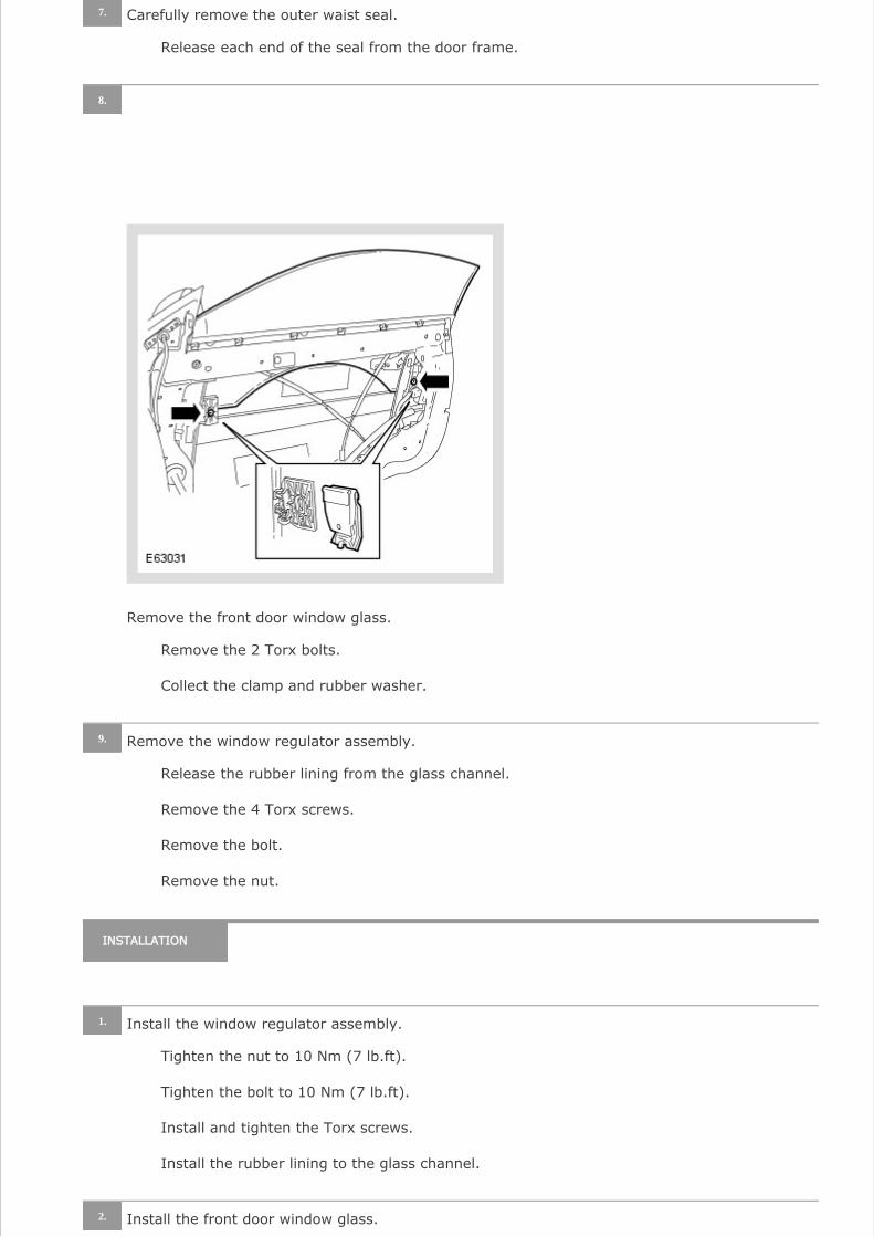
Remove the front door window glass.
8.
Remove the 2 Torx bolts.
Collect the clamp and rubber washer.
Remove the window regulator assembly.9.
Release the rubber lining from the glass channel.
Remove the 4 Torx screws.
Remove the bolt.
Remove the nut.
INSTALLATION
Install the window regulator assembly.1.
Tighten the nut to 10 Nm (7 lb.ft).
Tighten the bolt to 10 Nm (7 lb.ft).
Install and tighten the Torx screws.
Install the rubber lining to the glass channel.
Install the front door window glass.2.
Attach the clamp and rubber washer.
Install the Torx bolts, but do not tighten fully at this stage.
Install the outer waist seal.3.
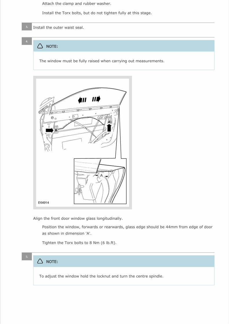
Align the front door window glass longitudinally.
4.
NOTE:
The window must be fully raised when carrying out measurements.
Position the window, forwards or rearwards, glass edge should be 44mm from edge of door
as shown in dimension 'A'.
Tighten the Torx bolts to 8 Nm (6 lb.ft).
5.
NOTE:
To adjust the window hold the locknut and turn the centre spindle.
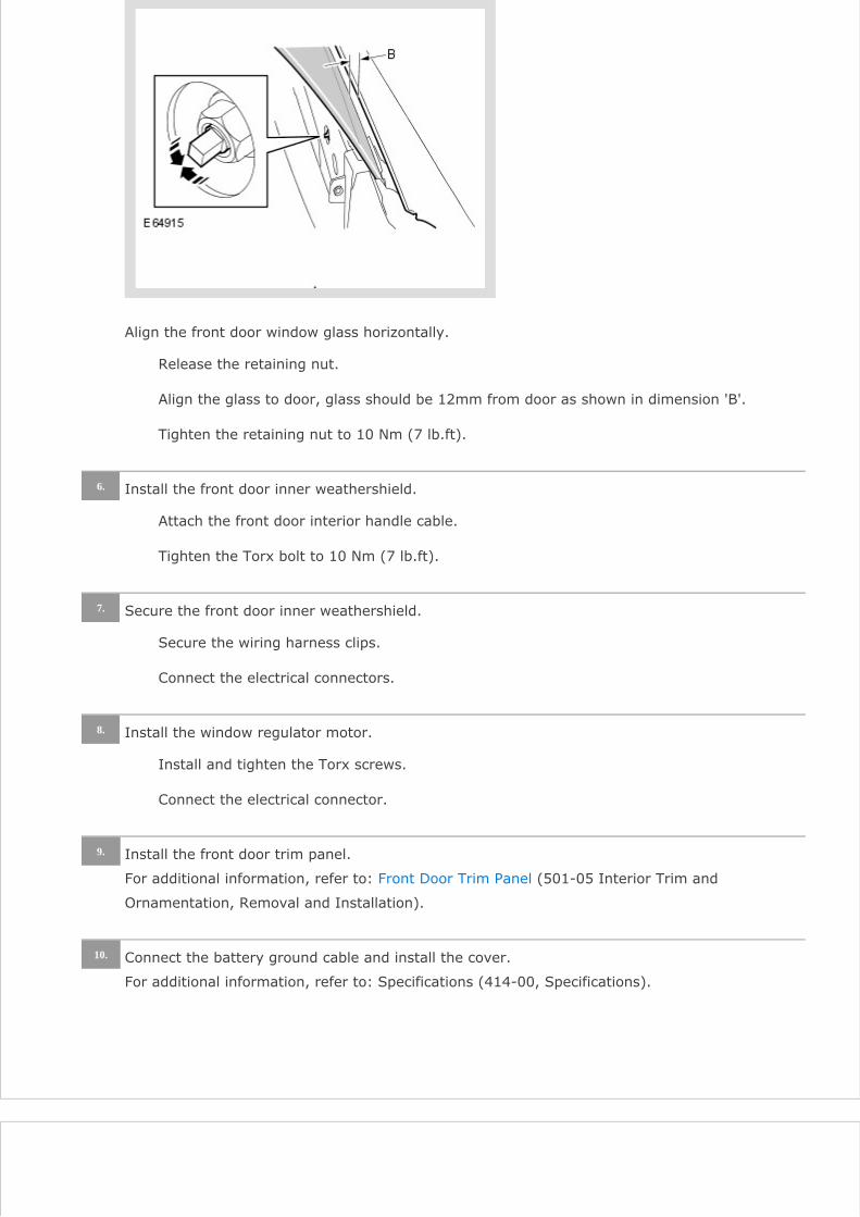
Align the front door window glass horizontally.
Release the retaining nut.
Align the glass to door, glass should be 12mm from door as shown in dimension 'B'.
Tighten the retaining nut to 10 Nm (7 lb.ft).
Install the front door inner weathershield.6.
Attach the front door interior handle cable.
Tighten the Torx bolt to 10 Nm (7 lb.ft).
Secure the front door inner weathershield.7.
Secure the wiring harness clips.
Connect the electrical connectors.
Install the window regulator motor.8.
Install and tighten the Torx screws.
Connect the electrical connector.
Install the front door trim panel.
For additional information, refer to: (501-05 Interior Trim and Front Door Trim Panel
Ornamentation, Removal and Installation).
9.
Connect the battery ground cable and install the cover.
For additional information, refer to: Specifications (414-00, Specifications).
10.

PUBLISHED: 11-MAY-20112006.50 XK RANGE (X150), 501-05
INTERIOR TRIM AND ORNAMENTATION
FRONT DOOR TRIM PANEL (G531701)

REMOVAL AND INSTALLATION
76.34.01
FRONT DOOR TRIM
PAD - RENEW
ALL DERIVATIVES
0.4 USED WITHINS
REMOVAL
Remove the exterior mirror trim panel.
1.
Release the 3 clips.
Disconnect the electrical connector.
2.
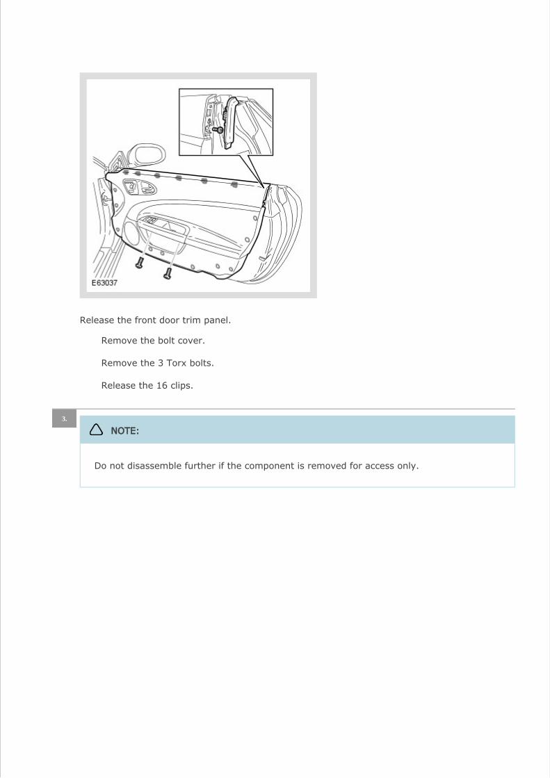
Release the front door trim panel.
Remove the bolt cover.
Remove the 3 Torx bolts.
Release the 16 clips.
3.
NOTE:
Do not disassemble further if the component is removed for access only.

Remove the front door trim panel.
Release the front door interior handle cable.
Disconnect the 2 electrical connectors.
Remove the front door latch remote control handle.
4.
Release from the 5 clips.

Remove the grab handle cover.
5.
Release from the 6 clips.
Remove the window control switch.
6.
Release from the 3 clips.
Disconnect the electrical connector.
7.

Remove the seat control switch.
Remove the 4 Torx screws.
Disconnect the electrical connector.
INSTALLATION
Install the seat control switch.1.
Connect the electrical connector.
Install and tighten the Torx screws.
Install the window control switch.2.
Connect the electrical connector.
Secure in the clips.
Install the grab handle cover.3.
Secure in the clips.
Install the front door latch remote control handle.4.
Secure in the clips.
CAUTION:
Make sure that the cable remains correctly installed to the front door trim panel.
Install the front door trim panel.
5.
Attach the front door interior handle cable.

Connect the electrical connectors.
Secure the front door trim panel.6.
Secure in the clips.
Tighten the Torx bolts to 10 Nm.
Install the bolt cover.
Install the exterior mirror trim panel.7.
Connect the electrical connector.
Secure with the clips.
Check the operation of the door latch remote control handle.8.
With the door closed, check the latch operation of the door latch remote control handle.
With the door closed, check the lock operation of the door latch remote control handle.
Related Documents