Chapter 9 – Optical systems applications in passive optical networks 241 CHAPTER 9 OPTICAL SYSTEM APPLICATIONS IN PASSIVE OPTICAL NETWORKS Introduction Progress in multimedia technologies has led to active development of many types of broadband services such as delivery of data, voice and video (triple-play) services. PONs (passive optical networks) can provide these services cost-effectively. PONs are optical access networks that extend from an operator central office into individual homes, apartment houses and business offices. PONs are generally characterized by the absence of active components, with the exception of the sites where the OLT (optical line termination) and the ONU/ONT (optical network unit / optical network termination) are placed. However, a PON can also include a RE (reach extender), which contains active components, when a long distance between the OLT and the ONU is required. PONs are generally based on tree network topologies that use passive optical splitters. The general structure of a PON network is shown in Figure 9-1. HB-OF(09)_F9-1 OLT Splitter ODN ONT ONU NT ONU NT Central office Cabinet curb Building Home NT ODN OLT Network Termination Optical Distribution Network Optical Line Termination ONT ONU Optical Network Termination Optical Network Unit Figure 9-1 – General structure of a PON At the network side there is an OLT, which is usually installed at the local central office (CO). The OLT is the interface between all the users connected to the given PON and the metro network. Such users have access to the services offered by the network, through the network terminal (NT), and to the optical network through the ONU/ONTs. The OLT and the ONUs are connected via an optical distribution network (ODN), which in many cases has a point-to-multipoint configuration with one or more splitters. Typical splitting factors include 1:16/1:32/1:64 or more. PON splitters can be placed near the OLT or at the user sites, depending on the availability of fibres in the ODN, and/or on the ODN deployment strategy adopted by network operators.

Welcome message from author
This document is posted to help you gain knowledge. Please leave a comment to let me know what you think about it! Share it to your friends and learn new things together.
Transcript
Chapter 9 – Optical systems applications in passive optical networks 241
CHAPTER 9
OPTICAL SYSTEM APPLICATIONS IN PASSIVE OPTICAL NETWORKS
Introduction Progress in multimedia technologies has led to active development of many types of broadband services such as delivery of data, voice and video (triple-play) services. PONs (passive optical networks) can provide these services cost-effectively. PONs are optical access networks that extend from an operator central office into individual homes, apartment houses and business offices.
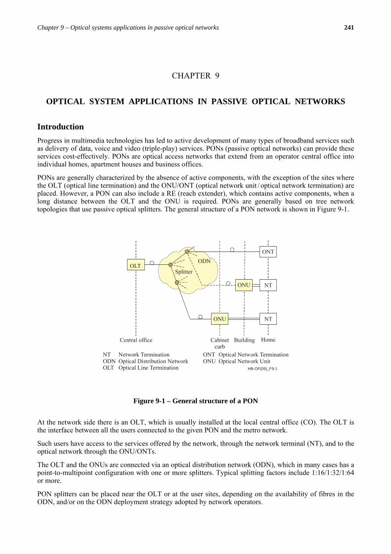
PONs are generally characterized by the absence of active components, with the exception of the sites where the OLT (optical line termination) and the ONU/ONT (optical network unit / optical network termination) are placed. However, a PON can also include a RE (reach extender), which contains active components, when a long distance between the OLT and the ONU is required. PONs are generally based on tree network topologies that use passive optical splitters. The general structure of a PON network is shown in Figure 9-1.
HB-OF(09)_F9-1
OLTSplitter
ODNONT
ONU NT
ONU NT
Central office Cabinetcurb
Building Home
NTODNOLT
Network Termination Optical Distribution Network Optical Line Termination
ONTONU
Optical Network Termination Optical Network Unit
Figure 9-1 – General structure of a PON
At the network side there is an OLT, which is usually installed at the local central office (CO). The OLT is the interface between all the users connected to the given PON and the metro network.
Such users have access to the services offered by the network, through the network terminal (NT), and to the optical network through the ONU/ONTs.
The OLT and the ONUs are connected via an optical distribution network (ODN), which in many cases has a point-to-multipoint configuration with one or more splitters. Typical splitting factors include 1:16/1:32/1:64 or more.
PON splitters can be placed near the OLT or at the user sites, depending on the availability of fibres in the ODN, and/or on the ODN deployment strategy adopted by network operators.

242 Optical fibres, cables and systems
The PON shown in Figure 9-1 is completely passive and the maximum distance between the OLT and the ONU is typically limited to 20 km at nominal split ratios. However, there are also solutions that include deployment of active elements in the network structure (e.g. optical amplifiers) when it is necessary to achieve a longer reach (e.g. up to 60 km) or to reduce the number of CO sites (CO concentration), or to connect a larger number of users to a single OLT port (e.g. where higher power budget is required due to a higher split ratio). Such solutions are typically referred to as “long-reach PON”.
As shown in Figure 9-1, a PON can be deployed in a FTTH (fibre to the home) architecture, where an ONU is provided at the subscriber’s premises, or in FTTB (fibre to the building), FTTC (fibre to the curb) or FTTCab (fibre to the cabinet) architectures, depending on local demands. In the latter cases, the optical link is terminated at the ONU, and the last stretch to the subscriber’s premises is typically deployed as part of the copper network using e.g. existing xDSL lines. Various types of xDSL family technologies are typically used, e.g. VDSL2 (very high speed digital subscriber line 2).
In the upstream channel (from subscriber to the OLT), access to a shared fibre channel is guaranteed by the use of the TDMA (Time Division Multiple Access) mechanism, where a certain bandwidth is assigned to each ONU by the OLT. In the downstream channel (from the OLT to the subscribers), there is only one transmitter located at the OLT, and data to individual ONUs is transmitted using TDM (Time Division Multiplexing). Figure 9-2 shows the use of these techniques in downstream and upstream channels.
HB-OF(09)_F9-2
OLTA B C
ONT
A
B
C
A
A
A
B
B
B
C
C
C
ONT
ONT
OLTA B C
ONT
A
B
C
B
C
A
ONT
ONT
TDM: Time Division Multiplexing TDMA: Time Division Multiple Access
Figure 9-2 – TDM / TDMA technique
The downstream channel works in continuous mode, i.e. the cells/packets to be sent to the different ONTs are queued with no time gap between them. Idle cells/packets are generated by the OLT when necessary, in order to assure a continuous data flow in the downstream direction. This allows the ONTs to recover their own clock from the downstream data flow. The upstream channel works in burst mode instead, and when the cells/packets reach the OLT receiver, they have different amplitude, because the branches of the ODN have very likely different length and attenuation. A suitable guard time is guaranteed between consecutive cells/packets by the MAC (media access control) protocol. In case of poor upstream traffic, the OLT receiver must be able to cope with the reception of a cell/packet after a relatively long period of “silence”. Moreover, the length of the upstream cells/packets is not fixed, thanks to the DBA (Dynamic Bandwidth Assignment) algorithm, which assigns more bandwidth to the ONTs that have more upstream traffic to be transmitted at a particular moment. Also in the downstream direction, an ONT can receive more cells/packets than another one, but this is not reflected in Figure 9-2, for the sake of simplicity.
Based on the supported upstream and downstream data rate, there two main categories of PON: the BPON (broadband PON) and the G-PON (gigabit capable PON).
Chapter 9 – Optical systems applications in passive optical networks 243
In order to reduce the need for dual fibre ODNs, the aforementioned PON systems can take advantage of the WDM signal multiplexing technique, where downstream and upstream channels are transmitted at different wavelengths: 1 260-1 360 nm for the upstream and 1 480-1 500 nm for the downstream. It is also possible to add another optical signal, to e.g. carry radio-frequency-video signals, in the bandwidth 1 530-1 580 nm, called the enhancement band.
BPON systems specifications are included in the ITU-T G.983 x-series of Recommendations, while those of the G-PON systems are included in the ITU-T G.984 x-series of Recommendations.
This handbook deals only with the network architecture (clause 1) and with the physical layer aspects of PON systems: the ODN (clauses 2-9) and the transmission systems (BPON / G-PON) between OLTs and ONUs (clauses 10-15). Aspects related with mechanisms for efficient use of downstream and upstream channels to guarantee collision-free data transmission using TDM/TDMA, as well as the management issues, are out of the scope of this handbook. Readers should refer directly to the above mentioned ITU-T Recommendations series for further information.
Moreover, considering that BPON and G-PON systems are very similar at the physical layer (with the main difference being the supported data rates), the remainder of this Chapter focuses on G-PON systems, which represent an evolutionary upgrade from BPON with:
i) higher capacity (BPON 622 Mbit/s downstream / 155 Mbit/s upstream, G-PON 2 488 Mbit/s downstream / 1 244 Mbit/s upstream);
ii) higher split ratio (BPON 1:32, G-PON 1:64 with potential support for 1:128);
iii) maximum reach (BPON 20 km, G-PON supports optical amplifiers in the ODN, called reach extenders, which extend the system reach up to 60 km).
1 Local access network architecture An optical access network is the set of access links that share the same network-side interfaces and are supported by optical access transmission systems.
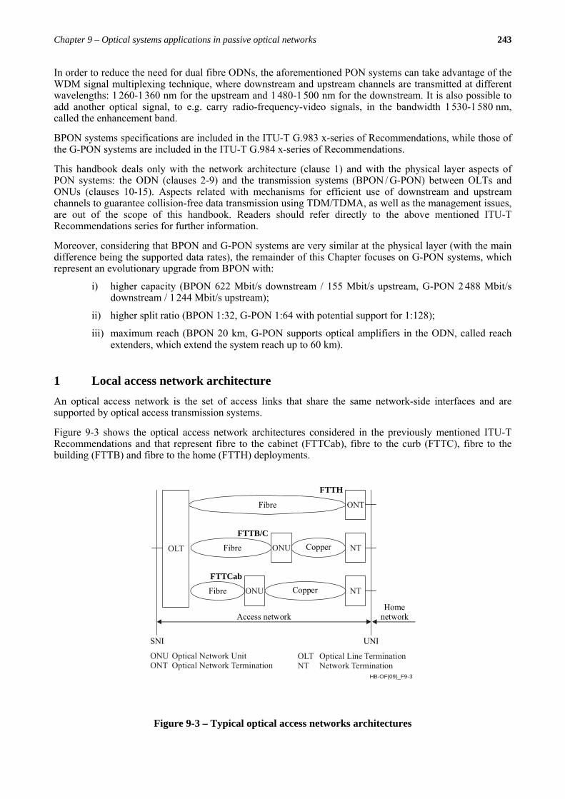
Figure 9-3 shows the optical access network architectures considered in the previously mentioned ITU-T Recommendations and that represent fibre to the cabinet (FTTCab), fibre to the curb (FTTC), fibre to the building (FTTB) and fibre to the home (FTTH) deployments.
HB-OF(09)_F9-3
Fibre
Fibre
Fibre
Copper
Copper
Access networkHome
network
UNISNI
FTTCab
FTTH
FTTB/C
ONUONT
Optical Network UnitOptical Network Termination
OLTNT
Optical Line TerminationNetwork Termination
ONT
ONU
ONU
NT
NT
OLT
Figure 9-3 – Typical optical access networks architectures
244 Optical fibres, cables and systems
In the FTTCab configuration, an ONU is installed in a street side cabinet. The connection between the OLT in the central office and the ONU is realized over an optical fibre link, while the connection between the ONU and the customer premises is realized using the copper lines of an existing local distribution network.
In the FTTB/FTTC configurations, an ONU is installed in a local curb or in the building (e.g. in the basement) where customers are located. Connectivity between individual network elements is realized exactly the same way as in the case of the FTTCab scenario described above.
In the FTTH configuration the complete link between the OLT and the ONU is realized with optical fibres, because the ONU is installed in the customer’s premises.
The FTTCab, FTTC, FTTB, and FTTH network configurations can support different services.
As for the physical layer aspects, the meaning of the terms ODN, OLT and ONU is the following:
i) optical distribution network (ODN) is the physical network connecting the OLT and the ONU;
ii) optical line termination (OLT) is a device that terminates the common endpoint of an ODN;
iii) optical network termination (ONT) is a subscriber device that terminates any one of the distributed endpoints of an ODN. An ONT is a special case of an ONU;
iv) optical network unit (ONU) is a generic term denoting a device that terminates any one of the distributed endpoints of an ODN.
1.1 FTTC and FTTCab scenarios
For these deployment scenarios, the following service categories are typically considered:
i) Asymmetric data rate broadband services (e.g. digital broadcast services, VOD (video on demand), file download, online gaming, etc.);
ii) Symmetric data rate broadband services (e.g. content broadcast, e-mail, file exchange, distance learning, telemedicine, etc.);
iii) POTS and ISDN. The access network must be able to provide, in a flexible way, narrow-band telephone services with the appropriate timing;
iv) xDSL backhaul.
1.2 FTTB scenario
The FTTB scenario is divided into two sub-scenarios, one for multi-dwelling units (MDU) and the other one for business applications. Each scenario has specific service categories:
FTTB for MDU
i) Asymmetric data rate broadband services (e.g. digital broadcast services, VOD, file download, etc.);
ii) Symmetric data rate broadband services (e.g. content broadcast, e-mail, file exchange, distance learning, telemedicine, online-gaming, etc.);
iii) POTS and ISDN. The access network must be able to provide, in a flexible way, narrow-band telephone services with appropriate timing.
FTTB for business
i) Symmetric data rate broadband services (e.g. group software, content broadcast, e-mail, file exchange, etc.);
ii) POTS and ISDN. The access network must be able to provide, in a flexible way, narrow-band telephone services with the appropriate timing;
iii) Private line. The access network must be able to provide, in a flexible way, private line services at various rates, depending on customer needs.
Chapter 9 – Optical systems applications in passive optical networks 245
1.3 FTTH scenario
In this scenario, the following service categories have been considered:
i) Asymmetric data rate broadband services (e.g. digital broadcast services, VOD, file download, etc.);
ii) Symmetric data rate broadband services (e.g. content broadcast, e-mail, file exchange, distance learning, telemedicine, online-gaming, etc.);
iii) POTS and ISDN. The access network must be able to provide, in a flexible way, narrow-band telephone services with the appropriate timing.
2 ODN Architectures (For further information see Recommendation ITU-T L.42).
As already stated, an ODN is the physical network connecting the OLT and the ONU. It includes the optical fibres in the access network, power or wavelength splitters, filters, and other passive optical devices.
When designing or constructing an ODN, there are several possible architectures which can be considered. The most widely used ODN architectures include point-to-point and point-to-multipoint, each with specific advantages and drawbacks. The point-to-multipoint architecture seems to be at this moment the preferred one for most cases, mainly for its lower cost.
The following discussion will be mainly focused on the point-to-multipoint architecture.
2.1 Point-to-point ODN architecture
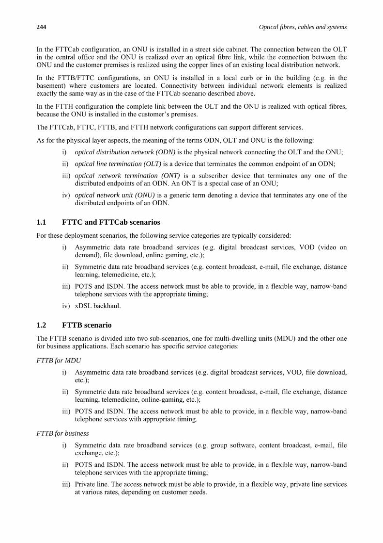
The basic configuration for a point-to-point optical access network is shown in Figure 9-4.
Central office
OLT
ONU
Optical fibre
OLT
OLT
ONU
ONU
Building, apartment house or residential premises
Optical Line TerminalOptical Network Unit
OLTONU
Figure 9-4 – Point-to-point network
Such an architecture distributes one or more fibres individually from the OLT located in the CO to ONUs typically located at customer premises. Therefore, a large number of fibres are installed in the outside plant and distributed from the CO to the customers. This configuration has typically low optical loss, does not require subscriber network resource sharing and supports a large distance between the CO and local customers. Moreover, such architecture may be suitable for customers with high bandwidth and/or high security requirements.
246 Optical fibres, cables and systems
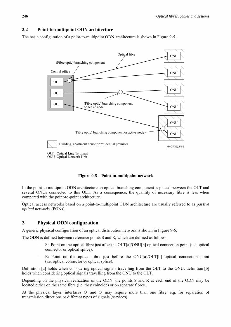
2.2 Point-to-multipoint ODN architecture The basic configuration of a point-to-multipoint ODN architecture is shown in Figure 9-5.
Optical fibre
OLT
ONU
ONU
ONU
OLT
OLT
ONU
ONU
ONU
(Fibre optic) branching component
(Fibre optic) branching componentor active node
(Fibre optic) branching component or active node
Central office
Optical Line TerminalOptical Network Unit
OLTONU
Figure 9-5 – Point-to-multipoint network
In the point-to multipoint ODN architecture an optical branching component is placed between the OLT and several ONUs connected to this OLT. As a consequence, the quantity of necessary fibre is less when compared with the point-to-point architecture.
Optical access networks based on a point-to-multipoint ODN architecture are usually referred to as passive optical networks (PONs).
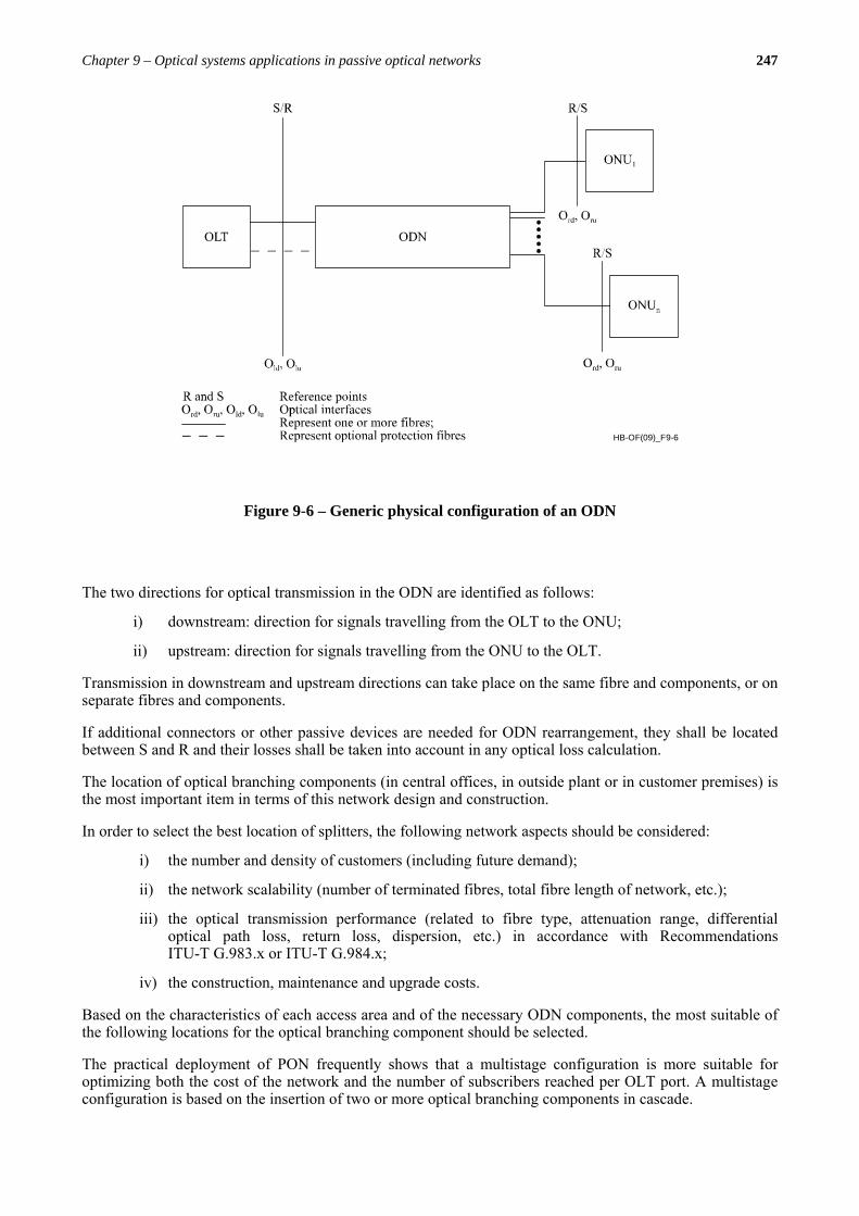
3 Physical ODN configuration A generic physical configuration of an optical distribution network is shown in Figure 9-6.
The ODN is defined between reference points S and R, which are defined as follows:
– S: Point on the optical fibre just after the OLT[a]/ONU[b] optical connection point (i.e. optical connector or optical splice).
– R: Point on the optical fibre just before the ONU[a]/OLT[b] optical connection point (i.e. optical connector or optical splice).
Definition [a] holds when considering optical signals travelling from the OLT to the ONU; definition [b] holds when considering optical signals travelling from the ONU to the OLT.
Depending on the physical realization of the ODN, the points S and R at each end of the ODN may be located either on the same fibre (i.e. they coincide) or on separate fibres.
At the physical layer, interfaces Or and Ol may require more than one fibre, e.g. for separation of transmission directions or different types of signals (services).
Chapter 9 – Optical systems applications in passive optical networks 247
HB-OF(09)_F9-6
Figure 9-6 – Generic physical configuration of an ODN
The two directions for optical transmission in the ODN are identified as follows:
i) downstream: direction for signals travelling from the OLT to the ONU;
ii) upstream: direction for signals travelling from the ONU to the OLT.
Transmission in downstream and upstream directions can take place on the same fibre and components, or on separate fibres and components.
If additional connectors or other passive devices are needed for ODN rearrangement, they shall be located between S and R and their losses shall be taken into account in any optical loss calculation.
The location of optical branching components (in central offices, in outside plant or in customer premises) is the most important item in terms of this network design and construction.
In order to select the best location of splitters, the following network aspects should be considered:
i) the number and density of customers (including future demand);
ii) the network scalability (number of terminated fibres, total fibre length of network, etc.);
iii) the optical transmission performance (related to fibre type, attenuation range, differential optical path loss, return loss, dispersion, etc.) in accordance with Recommendations ITU-T G.983.x or ITU-T G.984.x;
iv) the construction, maintenance and upgrade costs.
Based on the characteristics of each access area and of the necessary ODN components, the most suitable of the following locations for the optical branching component should be selected.
The practical deployment of PON frequently shows that a multistage configuration is more suitable for optimizing both the cost of the network and the number of subscribers reached per OLT port. A multistage configuration is based on the insertion of two or more optical branching components in cascade.
248 Optical fibres, cables and systems
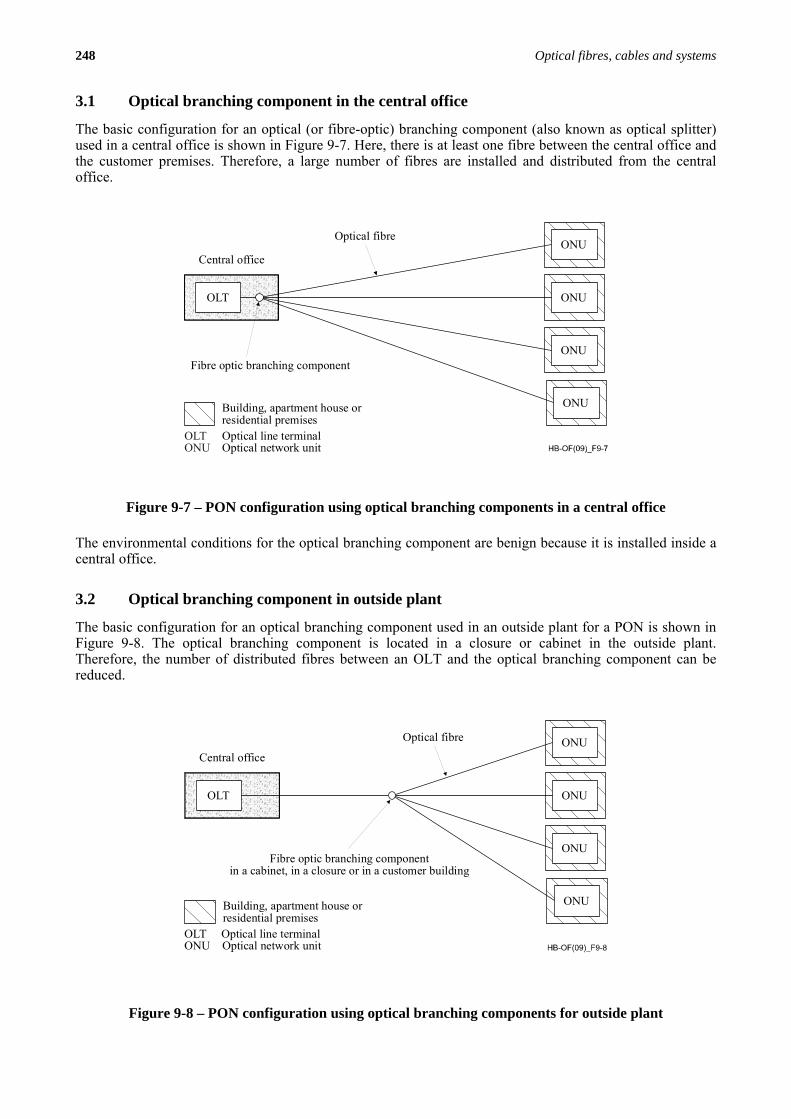
3.1 Optical branching component in the central office
The basic configuration for an optical (or fibre-optic) branching component (also known as optical splitter) used in a central office is shown in Figure 9-7. Here, there is at least one fibre between the central office and the customer premises. Therefore, a large number of fibres are installed and distributed from the central office.
Central office
OLT
ONU
ONU
ONU
ONU
Optical fibre
Fibre optic branching component
Building, apartment house orresidential premises
OLTONU
Optical line terminalOptical network unit
Figure 9-7 – PON configuration using optical branching components in a central office
The environmental conditions for the optical branching component are benign because it is installed inside a central office.
3.2 Optical branching component in outside plant
The basic configuration for an optical branching component used in an outside plant for a PON is shown in Figure 9-8. The optical branching component is located in a closure or cabinet in the outside plant. Therefore, the number of distributed fibres between an OLT and the optical branching component can be reduced.
Central office
OLT
ONU
ONU
ONU
ONU
Optical fibre
Fibre optic branching componentin a cabinet, in a closure or in a customer building
Building, apartment house orresidential premises
OLT Optical line terminalONU Optical network unit
Figure 9-8 – PON configuration using optical branching components for outside plant
Chapter 9 – Optical systems applications in passive optical networks 249
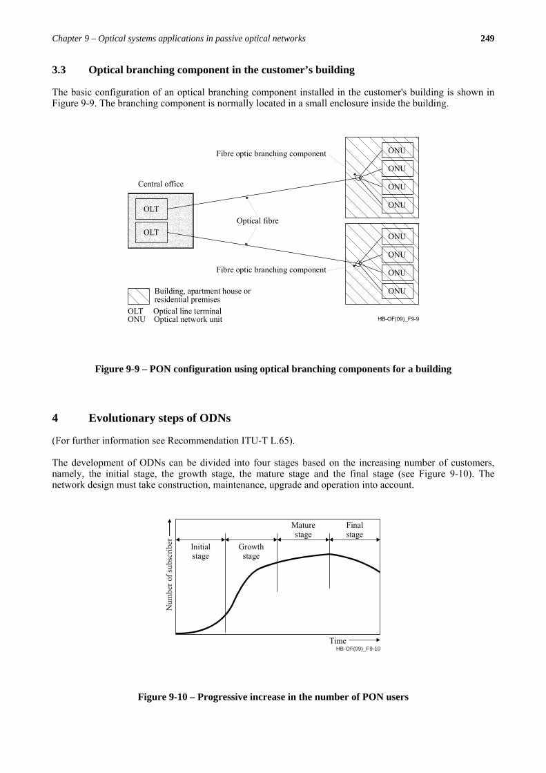
3.3 Optical branching component in the customer’s building
The basic configuration of an optical branching component installed in the customer's building is shown in Figure 9-9. The branching component is normally located in a small enclosure inside the building.
Central office
OLT
ONU
Fibre optic branching component
Building, apartment house orresidential premises
OLT
ONU
ONU
ONU
ONU
ONU
ONU
ONU
Fibre optic branching component
Optical fibre
OLT Optical line terminalONU Optical network unit
Figure 9-9 – PON configuration using optical branching components for a building
4 Evolutionary steps of ODNs
(For further information see Recommendation ITU-T L.65).
The development of ODNs can be divided into four stages based on the increasing number of customers, namely, the initial stage, the growth stage, the mature stage and the final stage (see Figure 9-10). The network design must take construction, maintenance, upgrade and operation into account.
HB-OF(09)_F9-10Time
Initialstage
Growthstage
Maturestage
Finalstage
Num
ber o
f sub
scrib
er
Figure 9-10 – Progressive increase in the number of PON users
250 Optical fibres, cables and systems
4.1 Initial stage
At the initial stage, the demand for optical fibre will be dispersed over a wide area. Therefore it is important for the optical fibre distribution scheme to take into account the potential demand in the growth and mature stages. For example, the number of fibres in the cables and the number of branches for the branching devices in an optical distribution network are important parameters, as far as future demand is concerned. Technologies that support deferred cost for subsequent up-scaling of fibre capacity could be considered.
4.2 Growth stage
At the growth stage, the demand for optical fibres will occur randomly in a wide area. It is therefore very important for the optical fibre distribution scheme to be able to quickly respond to this demand. Moreover, at this stage it is important to be able to easily maintain and operate the optical access network infrastructure. For example, there will be a need to use the optical fibre network maintenance support, monitoring and testing system described in Chapter 10 and in Recommendations ITU-T L.40 and ITU-T L.53. In addition, an optical access network infrastructure database will need to be constructed and used to operate and administer the huge infrastructure expansion. Additionally, it is anticipated that overlay of fibre networks into areas of legacy copper networks will eventually occur, presenting challenges for both aerial and underground deployment.
It will be important to use existing facilities, such as cable ducts, for the effective and economical installation of optical fibre cables. For example, several optical fibre cables could be installed in a single cable duct. This is because the optical access network infrastructure will increase and the available facilities may become scarce. Consideration could be given to active cable duct management solutions to ensure their future economical usability.
4.3 Mature stage
At the mature stage, the demand for new optical fibres will be slow and a huge optical access network infrastructure will be already deployed. Therefore, it is of utmost importance that the optical fibre distribution scheme be easy to maintain and operate. This will require an optical fibre network maintenance support, monitoring and testing system, and a corresponding database.
In addition, customers who require very high reliability should be provided with two or more fibres using a ring network.
4.4 Final stage
At the final stage, demographic considerations may determine that the demand for optical fibre may decline and the plant and land re-used for a different purpose or purposes, e.g. industrial, commercial, retail or residential, or a mix of these uses. Such events may be common in urban areas. It is likely that there will be a threshold at which systems and networks will become uneconomic to operate and need to be decommissioned.
Telecom operators should select appropriate architectures and optical components (e.g. optical fibre cable and passive optical components), and design and construct optical access networks taking into account of the above factors in each stage.
5 Upgrading a PON
(For further information see Recommendation ITU-T L.42).
Chapter 9 – Optical systems applications in passive optical networks 251
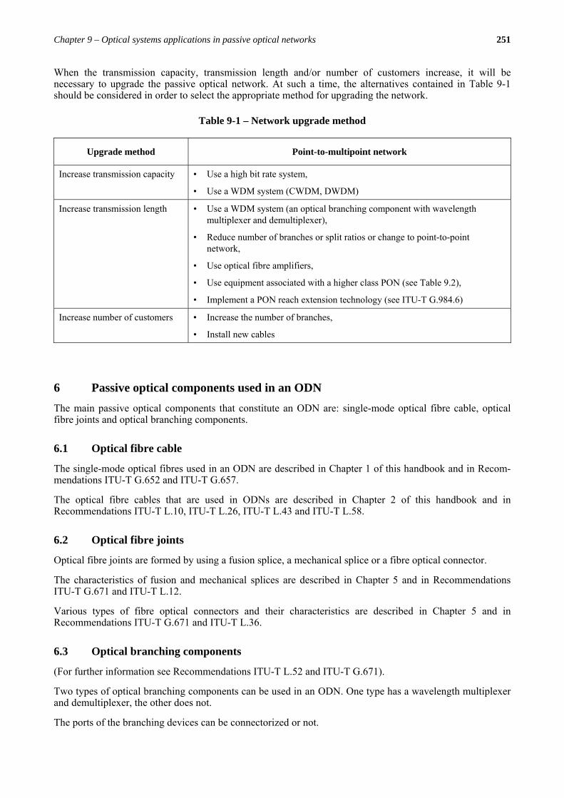
When the transmission capacity, transmission length and/or number of customers increase, it will be necessary to upgrade the passive optical network. At such a time, the alternatives contained in Table 9-1 should be considered in order to select the appropriate method for upgrading the network.
6 Passive optical components used in an ODN The main passive optical components that constitute an ODN are: single-mode optical fibre cable, optical fibre joints and optical branching components.
6.1 Optical fibre cable
The single-mode optical fibres used in an ODN are described in Chapter 1 of this handbook and in Recom-mendations ITU-T G.652 and ITU-T G.657.
The optical fibre cables that are used in ODNs are described in Chapter 2 of this handbook and in Recommendations ITU-T L.10, ITU-T L.26, ITU-T L.43 and ITU-T L.58.
6.2 Optical fibre joints
Optical fibre joints are formed by using a fusion splice, a mechanical splice or a fibre optical connector.
The characteristics of fusion and mechanical splices are described in Chapter 5 and in Recommendations ITU-T G.671 and ITU-T L.12.
Various types of fibre optical connectors and their characteristics are described in Chapter 5 and in Recommendations ITU-T G.671 and ITU-T L.36.
6.3 Optical branching components
(For further information see Recommendations ITU-T L.52 and ITU-T G.671).
Two types of optical branching components can be used in an ODN. One type has a wavelength multiplexer and demultiplexer, the other does not.
The ports of the branching devices can be connectorized or not.
Table 9-1 – Network upgrade method
Upgrade method Point-to-multipoint network
Increase transmission capacity • Use a high bit rate system,
• Use a WDM system (CWDM, DWDM)
Increase transmission length • Use a WDM system (an optical branching component with wavelength multiplexer and demultiplexer),
• Reduce number of branches or split ratios or change to point-to-point network,
• Use optical fibre amplifiers,
• Use equipment associated with a higher class PON (see Table 9.2),
• Implement a PON reach extension technology (see ITU-T G.984.6)
Increase number of customers • Increase the number of branches,
• Install new cables
252 Optical fibres, cables and systems
6.3.1 Optical branching components without wavelength multiplexer and demultiplexer
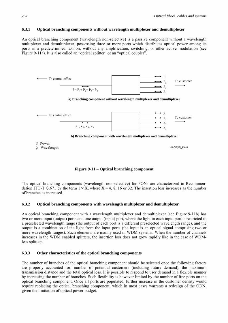
An optical branching component (wavelength non-selective) is a passive component without a wavelength multiplexer and demultiplexer, possessing three or more ports which distributes optical power among its ports in a predetermined fashion, without any amplification, switching, or other active modulation (see Figure 9-11a). It is also called an “optical splitter” or an “optical coupler”.
To central office To customerP1
P2
P3
P4
To central office To customer
a) Branching component without wavelength multiplexer and demultiplexer
P= P + P + P + P1 2 3 4
b) Branching component with wavelength multiplexer and demultiplexer
Figure 9-11 – Optical branching component
The optical branching components (wavelength non-selective) for PONs are characterized in Recommen-dation ITU-T G.671 by the term 1 × X, where X = 4, 8, 16 or 32. The insertion loss increases as the number of branches is increased.
6.3.2 Optical branching components with wavelength multiplexer and demultiplexer
An optical branching component with a wavelength multiplexer and demultiplexer (see Figure 9-11b) has two or more input (output) ports and one output (input) port, where the light in each input port is restricted to a preselected wavelength range (the output of each port is a different preselected wavelength range), and the output is a combination of the light from the input ports (the input is an optical signal comprising two or more wavelength ranges). Such elements are mainly used in WDM systems. When the number of channels increases in the WDM enabled splitters, the insertion loss does not grow rapidly like in the case of WDM-less splitters.
6.3.3 Other characteristics of the optical branching components
The number of branches of the optical branching component should be selected once the following factors are properly accounted for: number of potential customers (including future demand), the maximum transmission distance and the total optical loss. It is possible to respond to user demand in a flexible manner by increasing the number of branches. Such flexibility is however limited by the number of free ports on the optical branching component. Once all ports are populated, further increase in the customer density would require replacing the optical branching component, which in most cases warrants a redesign of the ODN, given the limitation of optical power budget.
Chapter 9 – Optical systems applications in passive optical networks 253
The optical performance of the optical branching components (PON splitters) is described in Chapter 5 and in Recommendation ITU-T G.671.
Environmental conditions, namely, temperature, humidity and mechanical conditions, may affect performance. Such environmental conditions differ from region to region, especially when using an optical branching component in the ODN. The optical branching components should be designed and protected from the environmental conditions, such as temperature, vibrations, water, etc., to enable it to operate under such conditions taking into account Recommendation ITU-T L.37.
Moreover the optical branching component should be protected from adverse biological factors. For further information on this specific issue see Recommendation ITU-T L.46.
6.4 Other passive optical components
i) Optical attenuators
An optical attenuator with either fixed or variable attenuation may be necessary to adjust optical power budgets to the required ranges. The characteristics of the optical attenuators are described in Chapter 5 and in Recommendations ITU-T G.671 and Recommendation ITU-T L.31.
ii) Optical filters
An optical filter may be necessary to filter out the required wavelengths used for a particular service and to reject other service's wavelength bands or optical test wavelengths transported in the ODN. Such filters have properly formed spectral responses, in such a way that they can select very narrow or very broad wavelength regions depending on the target application. The optical filter performance should follow the specifications of Recommendation ITU-T G.671.
iii) Passive optical nodes
Passive optical nodes properly store and protect all compatible passive devices, such as splices, branching devices and connectors, without altering their performances. Moreover they contain, protect and manage the fibre extra length.
The general characteristics of the passive optical nodes are described in Chapter 5 and in Recommendation ITU-T L.51.
Depending on the environment, they can be classified as:
– for indoor applications (optical distribution frame, ODF), as described in Chapter 5 and in Recommendation ITU-T L.50;
– for the outside plant (joint closures) in aerial and underground applications (described in Chapter 5 and in Recommendation ITU-T L.13) or in street cabinets.
7 ODN model loss calculations
(For further information see Recommendation ITU-T G.982).
Loss allowance for the optical power budget is defined as the loss (expressed in dB), between specific reference points of the ODN (S/R and R/S). This includes the loss due to fibre length and passive optical components (e.g. optical branching devices, splices and connectors). The loss allowance has the same value both in the downstream and the upstream direction. Even if the fibre loss and all passive components losses are wavelength dependent, the loss allowance is assumed in ITU-T Recommendations to have the same value for both the downstream and the upstream directions.
254 Optical fibres, cables and systems
The following parameters are important for the overall system performance:
– maximum difference of loss between the optical paths of the ODN;
– maximum allowable path loss, defined as the difference between minimum transmitter output power and maximum receiver sensitivity, both under end of life conditions (including variations due to temperature, ageing, etc.);
– minimum allowable loss, defined as the difference between maximum transmitter output power and minimum receiver overload, both under end of life conditions.
These maximum and minimum losses shall be defined as the worst case loss values over the required environmental and wavelength ranges and not just measured at a given wavelength, time and temperature.
These definitions are analogous to those of Recommendation ITU-T G.957, where the attenuation ranges for SDH optical interfaces are specified.
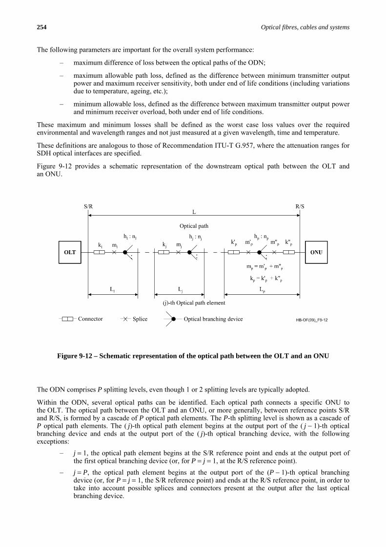
Figure 9-12 provides a schematic representation of the downstream optical path between the OLT and an ONU.
Optical path
Connector Splice Optical branching device
:::
k'p
R/SS/R
OLT
Figure 9-12 – Schematic representation of the optical path between the OLT and an ONU
The ODN comprises P splitting levels, even though 1 or 2 splitting levels are typically adopted.
Within the ODN, several optical paths can be identified. Each optical path connects a specific ONU to the OLT. The optical path between the OLT and an ONU, or more generally, between reference points S/R and R/S, is formed by a cascade of P optical path elements. The P-th splitting level is shown as a cascade of P optical path elements. The ( j)-th optical path element begins at the output port of the ( j − 1)-th optical branching device and ends at the output port of the ( j)-th optical branching device, with the following exceptions:
– j = 1, the optical path element begins at the S/R reference point and ends at the output port of the first optical branching device (or, for P = j = 1, at the R/S reference point).
– j = P, the optical path element begins at the output port of the (P − 1)-th optical branching device (or, for P = j = 1, the S/R reference point) and ends at the R/S reference point, in order to take into account possible splices and connectors present at the output after the last optical branching device.

Chapter 9 – Optical systems applications in passive optical networks 255
The ( j)-th optical path element consists of optical fibre of length Lj and of the following passive optical components (the sequence of components in each path element is arbitrary):
– the ( j)-th optical branching device with split ratio hj:nj (hj ≥ 1, nj ≥ 1); – kj connectors, with kj ≥ 0; – mj splices, with:
where:
djm : the average number of planned splices per unit length of fibre in the first installation phase;
rjm : the average number of repair splices per unit length of fibre, foreseen in the operational phase;
ajm : the number of additional planned splices not taken into account in the figure jdjLm , in the first installation phase; maj takes into account the splices due to the installation of the optical branching device and the extra splices at the termination points of the ODN (e.g. at an optical distribution frame inside the central office, at the optical termination point at ONU side).
In conclusion, the whole optical path consists of the optical fibre of length ∑=
=p
jjLL
1and of the following
passive optical components:
– P = number of optical branching devices, with split ratio hj:nj (hj ≥ 1, nj ≥ 1, j = 1, ..., P);
– ∑=
=p
jjkk
1connectors;
– ∑=
=p
jjmm
1splices.
The overall split ratio of the optical path is: ∏=
=p
jjnn
1.
In the case of a point-to-point ODN configuration, there is no optical branching device in the optical signal path. Consequently, only one optical path element is considered, and the previous evaluations are still valid provided that any reference to the optical branching device is excluded from calculations.
The optical loss of the given ODN optical path is calculated by adding the losses of all optical components along such an optical path. A statistical approach can be used in the summation of the terms related with the attenuation of the fibre, splices and connectors, in order to avoid over-specification of the ODN. The statistical distribution of the overall optical path loss can be obtained by combining the statistical distributions of losses of the various components of the optical path. This can be done using various statistical techniques, some being more accurate than others. For further information see Chapter 7, Recommendation ITU-T G.982 and Supplement 39 to the ITU-T G-series of Recommendations.
8 General characteristics of G-PON systems The general characteristics of G-PON systems are described in Recommendation ITU-T G.984.1.
As said above, G-PON systems are characterized, in general, by an optical line termination (OLT) system and an optical network unit (ONU) or optical network termination (ONT) with a passive optical distribution network (ODN) interconnecting them. There is, in general, a one-to-many relationship between the OLT and the ONU, respectively. The optical section of a local access network system can be either active or passive, and its architecture can be either point-to-point or point-to-multipoint. The architectures considered are essentially fibre to the cabinet (FTTCab), fibre to the curb (FTTC), fibre to the building (FTTB) and fibre to the home (FTTH).
256 Optical fibres, cables and systems
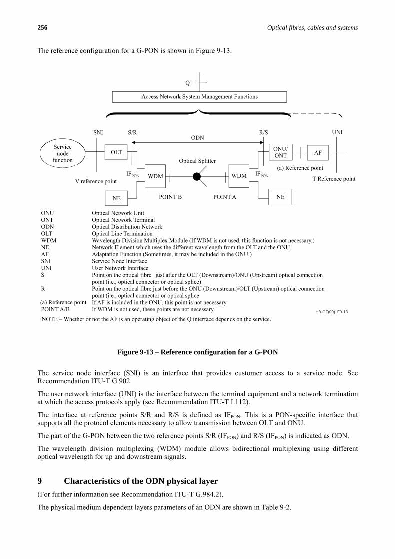
The reference configuration for a G-PON is shown in Figure 9-13.
HB-OF(09)_F9-13
Q
UNI
R/S
S/R
SNI
V reference point T Reference point
Access Network System Management Functions
Optical Splitter
OLT
WDM
NE
WDM
AF
NE
ODN
POINT A
POINT B
(a) Reference point
Optical Network UnitOptical Network TerminalOptical Distribution NetworkOptical Line TerminationWavelength Division Multiplex Module (If WDM is not used, this function is not necessary.)Network Element which uses the different wavelength from the OLT and the ONUAdaptation Function (Sometimes, it may be included in the ONU.)Service Node InterfaceUser Network InterfacePoint on the optical fibre just after the OLT (Downstream)/ONU (Upstream) optical connectionpoint (i.e., optical connector or optical splice)Point on the optical fibre just before the ONU (Downstream)/OLT (Upstream) optical connectionpoint (i.e., optical connector or optical spliceIf AF is included in the ONU, this point is not necessary.If WDM is not used, these points are not necessary.
ONUONTODNOLTWDMNEAFSNIUNIS
R
(a) Reference pointPOINT A/B
Servicenode
function
ONU/ONT
IFPON
NOTE – Whether or not the AF is an operating object of the Q interface depends on the service.
IFPON
Figure 9-13 – Reference configuration for a G-PON
The service node interface (SNI) is an interface that provides customer access to a service node. See Recommendation ITU-T G.902.
The user network interface (UNI) is the interface between the terminal equipment and a network termination at which the access protocols apply (see Recommendation ITU-T I.112).
The interface at reference points S/R and R/S is defined as IFPON. This is a PON-specific interface that supports all the protocol elements necessary to allow transmission between OLT and ONU.
The part of the G-PON between the two reference points S/R (IFPON) and R/S (IFPON) is indicated as ODN.
The wavelength division multiplexing (WDM) module allows bidirectional multiplexing using different optical wavelength for up and downstream signals.
9 Characteristics of the ODN physical layer (For further information see Recommendation ITU-T G.984.2).
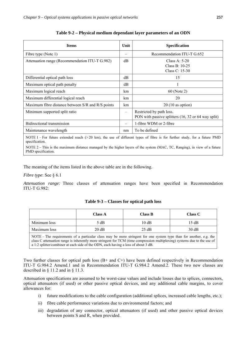
The physical medium dependent layers parameters of an ODN are shown in Table 9-2.
Chapter 9 – Optical systems applications in passive optical networks 257
The meaning of the items listed in the above table are in the following.
Fibre type: See § 6.1
Attenuation range: Three classes of attenuation ranges have been specified in Recommendation ITU-T G.982:
Two further classes for optical path loss (B+ and C+) have been defined respectively in Recommendation ITU-T G.984.2 Amend.1 and in Recommendation ITU-T G.984.2 Amend.2. These two new classes are described in § 11.2 and in § 11.3.
Attenuation specifications are assumed to be worst-case values and include losses due to splices, connectors, optical attenuators (if used) or other passive optical devices, and any additional cable margins, to cover allowances for:
i) future modifications to the cable configuration (additional splices, increased cable lengths, etc.); ii) fibre cable performance variations due to environmental factors; and iii) degradation of any connector, optical attenuators (if used) and other passive optical devices
between points S and R, when provided.
Table 9-2 – Physical medium dependant layer parameters of an ODN
Items Unit Specification
Fibre type (Note 1) – Recommendation ITU-T G.652
Attenuation range (Recommendation ITU-T G.982) dB Class A: 5-20 Class B: 10-25 Class C: 15-30
Differential optical path loss dB 15
Maximum optical path penalty dB 1
Maximum logical reach km 60 (Note 2)
Maximum differential logical reach km 20
Maximum fibre distance between S/R and R/S points km 20 (10 as option)
Minimum supported split ratio – Restricted by path loss. PON with passive splitters (16, 32 or 64 way split)
Bidirectional transmission – 1-fibre WDM or 2-fibre
Maintenance wavelength nm To be defined
NOTE 1 – For future extended reach (> 20 km), the use of different types of fibre is for further study, for a future PMD specification. NOTE 2 – This is the maximum distance managed by the higher layers of the system (MAC, TC, Ranging), in view of a future PMD specification.
Table 9-3 – Classes for optical path loss
Class A Class B Class C
Minimum loss 5 dB 10 dB 15 dB
Maximum loss 20 dB 25 dB 30 dB
NOTE – The requirements of a particular class may be more stringent for one system type than for another, e.g. the class C attenuation range is inherently more stringent for TCM (time compression multiplexing) systems due to the use of a 1:2 splitter/combiner at each side of the ODN, each having a loss of about 3 dB.
258 Optical fibres, cables and systems
Differential optical path loss means the optical path loss difference (i.e. between any two ONU) between the highest and lowest optical path loss in the same ODN. The maximum differential optical path loss should be 15 dB (see Recommendation ITU-T G.983.1).
Maximum optical path penalty. The receiver is required to tolerate an optical path penalty not exceeding 1 dB to account for total degradations due to reflections, inter-symbol interference, mode partition noise, and laser chirp.
Maximum logical reach is the maximum distance that can be achieved between ONU and OLT except for the limitation of the physical layer. In G-PON, the maximum logical reach is defined as 60 km (see Recom-mendation ITU-T G.982).
In other words, the maximum logical reach is the maximum distance managed by the higher layers of the system (MAC, TC, ranging), in view of a future PMD specification.
Maximum differential logical reach means the logical reach difference between the highest and lowest logical reach in the same ODN. The maximum differential logical reach should be 20 km.
The maximum fibre distance between S/R and R/S points is 20 km.
In G-PON, two options are defined for the physical reach: 10 km and 20 km. While MLM laser types are not applicable to support the full ODN fibre distance of 20 km, such lasers can be used if the maximum ODN fibre distance between R/S and S/R is restricted to 10 km.
Minimum supported split ratio is related to path loss.
Split ratios of up to 1:64 are realistic for the physical layer given the current technology. However, anticipating the continued evolution of optical modules, the traffic control (TC) layer also considers split ratios up to 1:128. While a 1:128 split is physically possible in G-PON, the maximum number of connected ONUs is limited by the addressing space of ONU-ID to 126 at most.
Basically, the larger the split ratio is for G-PON, the more attractive it is for operators. However, a larger split ratio implies greater optical splitting which creates the need for an increased power budget to support the physical reach. There is obviously a trade-off between increasing the optical budget and the cost of such a technical solution. Thus, operators must usually carefully balance deployment costs and business models. In practical cases, in order to increase income per central office, operators try to increase subscriber density per OLT port, using high split systems and maximizing take ratios. Such an approach is typically referred to as “deploy as you grow”, where additional branches of PON are added to infrastructure when the capacity of the existing branches is exhausted. Alternatively, some operators deploy a lot of dark fibre (ODN without connected subscriber units), which is lit when local demand occurs. Note however that such an approach requires higher up-front investment.
Bidirectional transmission can be made on the same fibre and components (diplex working/ duplex working) or on separate fibres and components (simplex working).
In Recommendation ITU-T G.983.1, diplex working and duplex working are defined as follows:
i) Diplex working: bidirectional communication using a different wavelength for each direction of transmission over a single fibre.
ii) Duplex working: a bidirectional communication using the same wavelength for both directions of transmission over a single fibre.
Currently deployed G-PON systems usually adopt diplex transmission.
Maintenance wavelength. (See § 14.)
Chapter 9 – Optical systems applications in passive optical networks 259
10 G-PON systems: physical media dependent (PMD) layer specifications
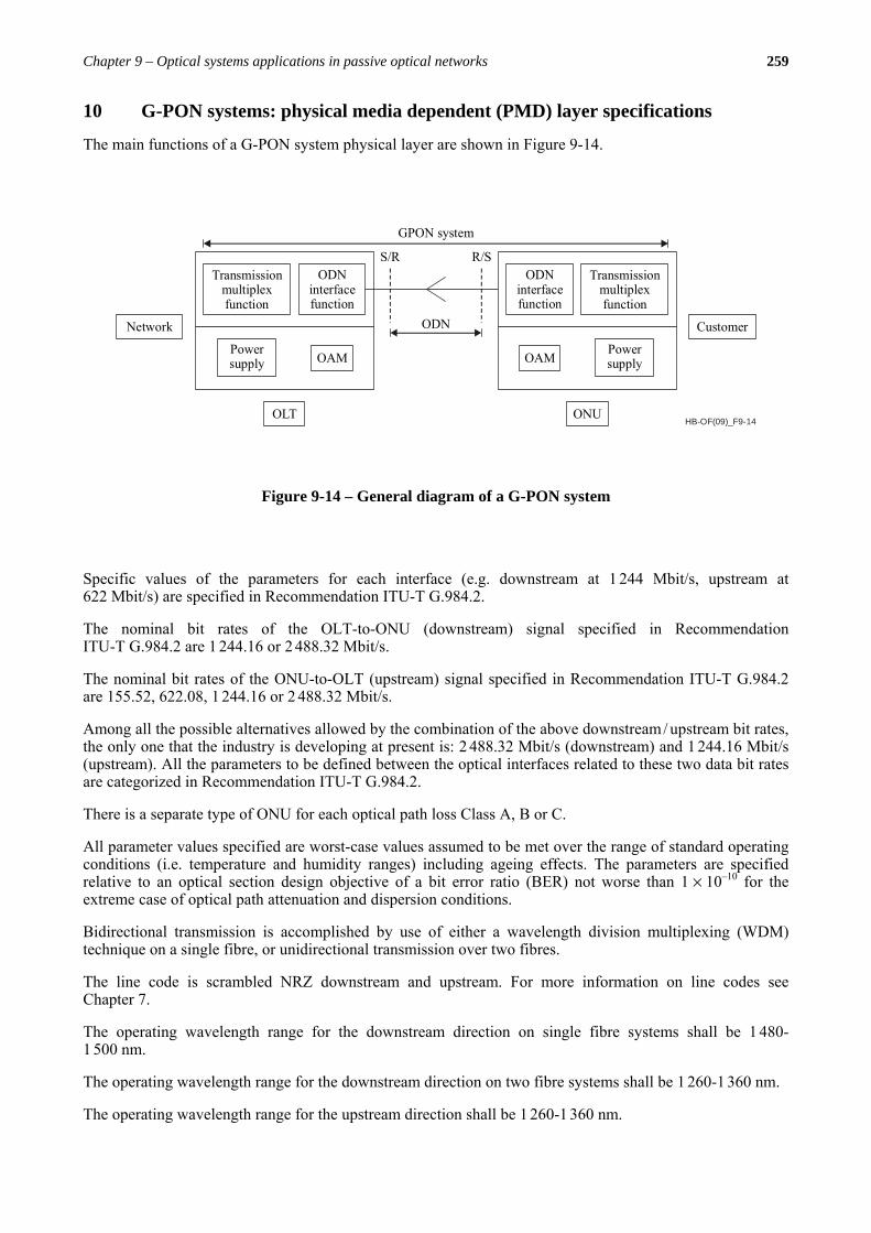
The main functions of a G-PON system physical layer are shown in Figure 9-14.
HB-OF(09)_F9-14
R/SS/R
ODN
Transmissionmultiplexfunction
OAMPowersupply
ODNinterfacefunction
Customer
ONU
Transmissionmultiplexfunction
OAMPowersupply
ODNinterfacefunction
Network
OLT
GPON system
Figure 9-14 – General diagram of a G-PON system
Specific values of the parameters for each interface (e.g. downstream at 1 244 Mbit/s, upstream at 622 Mbit/s) are specified in Recommendation ITU-T G.984.2.
The nominal bit rates of the OLT-to-ONU (downstream) signal specified in Recommendation ITU-T G.984.2 are 1 244.16 or 2 488.32 Mbit/s.
The nominal bit rates of the ONU-to-OLT (upstream) signal specified in Recommendation ITU-T G.984.2 are 155.52, 622.08, 1 244.16 or 2 488.32 Mbit/s.
Among all the possible alternatives allowed by the combination of the above downstream / upstream bit rates, the only one that the industry is developing at present is: 2 488.32 Mbit/s (downstream) and 1 244.16 Mbit/s (upstream). All the parameters to be defined between the optical interfaces related to these two data bit rates are categorized in Recommendation ITU-T G.984.2.
There is a separate type of ONU for each optical path loss Class A, B or C.
All parameter values specified are worst-case values assumed to be met over the range of standard operating conditions (i.e. temperature and humidity ranges) including ageing effects. The parameters are specified relative to an optical section design objective of a bit error ratio (BER) not worse than 1 × 10⁻¹⁰ for the extreme case of optical path attenuation and dispersion conditions.
Bidirectional transmission is accomplished by use of either a wavelength division multiplexing (WDM) technique on a single fibre, or unidirectional transmission over two fibres.
The line code is scrambled NRZ downstream and upstream. For more information on line codes see Chapter 7.
The operating wavelength range for the downstream direction on single fibre systems shall be 1 480-1 500 nm.
The operating wavelength range for the downstream direction on two fibre systems shall be 1 260-1 360 nm.
The operating wavelength range for the upstream direction shall be 1 260-1 360 nm.
260 Optical fibres, cables and systems
11 G-PON systems specification
11.1 2 488 Gbit/s downstream, 1 244 Gbit/s upstream G-PON
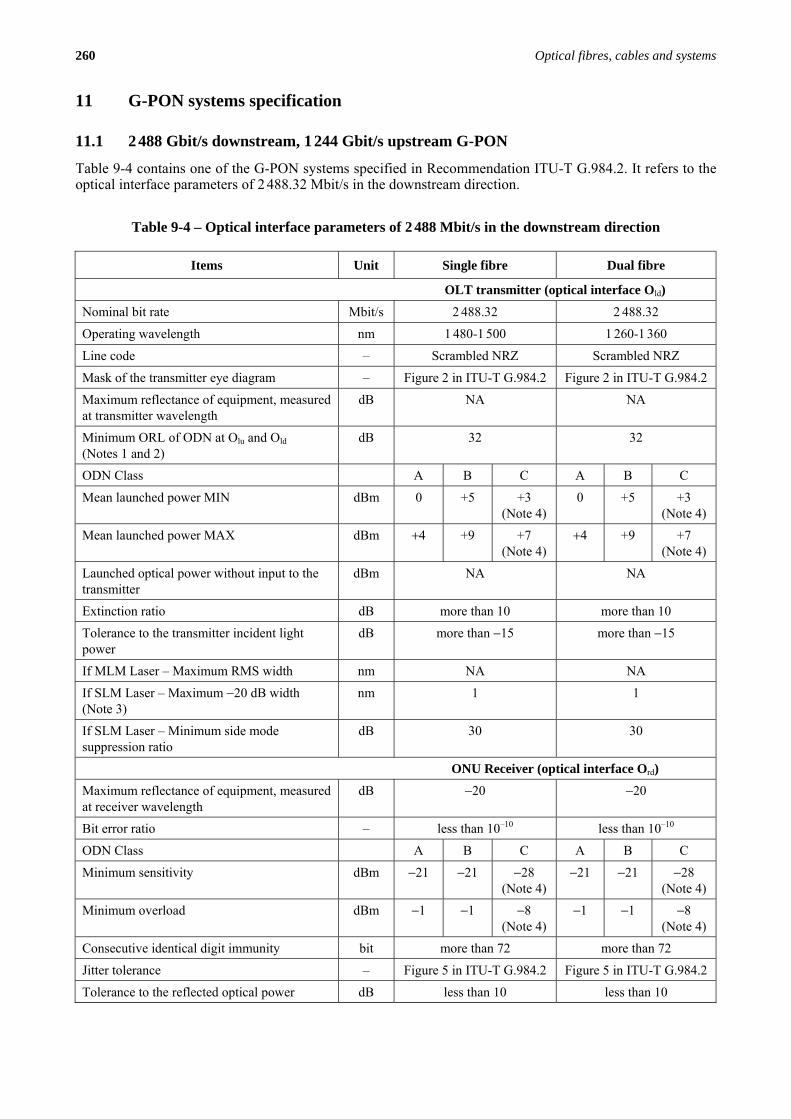
Table 9-4 contains one of the G-PON systems specified in Recommendation ITU-T G.984.2. It refers to the optical interface parameters of 2 488.32 Mbit/s in the downstream direction.
Table 9-4 – Optical interface parameters of 2 488 Mbit/s in the downstream direction
Items Unit Single fibre Dual fibre
OLT transmitter (optical interface Old)
Nominal bit rate Mbit/s 2 488.32 2 488.32
Operating wavelength nm 1 480-1 500 1 260-1 360
Line code – Scrambled NRZ Scrambled NRZ
Mask of the transmitter eye diagram – Figure 2 in ITU-T G.984.2 Figure 2 in ITU-T G.984.2
Maximum reflectance of equipment, measured at transmitter wavelength
dB NA NA
Minimum ORL of ODN at Olu and Old (Notes 1 and 2)
dB 32 32
ODN Class A B C A B C
Mean launched power MIN dBm 0 +5 +3 (Note 4)
0 +5 +3 (Note 4)
Mean launched power MAX dBm +4 +9 +7 (Note 4)
+4 +9 +7 (Note 4)
Launched optical power without input to the transmitter
dBm NA NA
Extinction ratio dB more than 10 more than 10
Tolerance to the transmitter incident light power
dB more than −15 more than −15
If MLM Laser – Maximum RMS width nm NA NA
If SLM Laser – Maximum −20 dB width (Note 3)
nm 1 1
If SLM Laser – Minimum side mode suppression ratio
dB 30 30
ONU Receiver (optical interface Ord)
Maximum reflectance of equipment, measured at receiver wavelength
dB −20 −20
Bit error ratio – less than 10–10 less than 10–10
ODN Class A B C A B C
Minimum sensitivity dBm −21 −21 −28 (Note 4)
−21 −21 −28 (Note 4)
Minimum overload dBm −1 −1 −8 (Note 4)
−1 −1 −8 (Note 4)
Consecutive identical digit immunity bit more than 72 more than 72
Jitter tolerance – Figure 5 in ITU-T G.984.2 Figure 5 in ITU-T G.984.2
Tolerance to the reflected optical power dB less than 10 less than 10
Chapter 9 – Optical systems applications in passive optical networks 261
The meaning of all these parameters is explained in Recommendation ITU-T G.984.2. Most of them are also used for the metro and for the backbone networks and are dealt with in Chapter 6.
11.2 Attenuation class B+ for the 2 488 Gbit/s downstream, 1 244 Gbit/s upstream G-PON
(For further information see Recommendation ITU-T G.984.2, Amend.1).
The widespread interest in the 2.4 Gbit/s downstream, 1.2 Gbit/s upstream G-PON system has provided increased visibility into the feasibility of loss budgets for this system. The industry most recent best practices for this rate combination are outlined in the following.
The notable variations from the loss budgets described in § 11.1 include:
• overall loss budgets midway between class B and class C;
• different value of optical path penalties;
• the OLT must support FEC in the downstream.
These variations can provide increased capabilities for operation of G-PON systems.
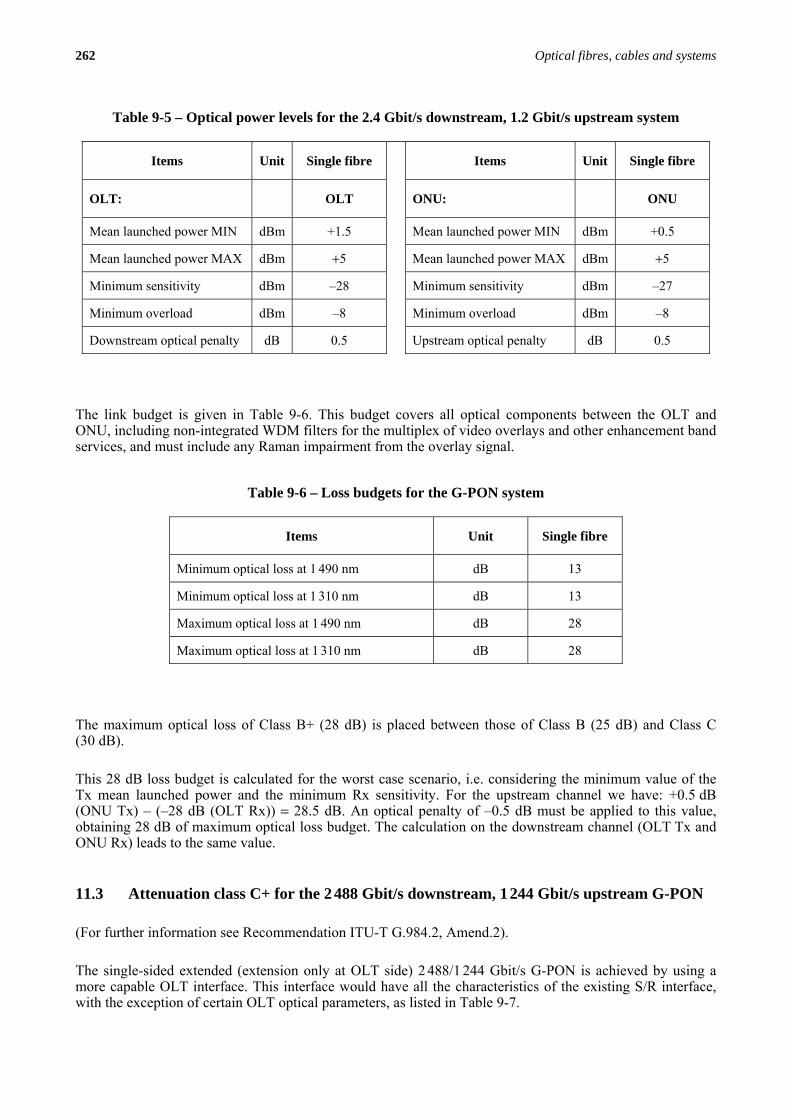
The optical specifications for the OLT and ONU optics are given in Table 9-5. This table refers to power levels measured at the interface points shown in Figure 9-14. These specifications are meant to augment similar specifications found in Table 9-4. All other specifications found elsewhere in the table still apply.
The ONU sensitivity can be achieved either using an APD without FEC, or a PIN with FEC. The choice is a matter of ONU implementation. The APD solution is seen as an immediately available option, while the PIN with FEC solution is a longer-term option that depends on the introduction of higher performance receiver circuitry.
Notes to Table 9-4:
NOTE 1 – The value of “minimum ORL of ODN at point Oru and Ord, and Olu and Old” should be more than 20 dB in the optional cases that are described in Recommendation ITU-T G.983.1, Appendix I.
NOTE 2 – The values on ONU transmitter reflectance for the case that the value of “minimum ORL of ODN at point Oru and Ord, and Olu and Old” is 20 dB are described in Recommendation ITU-T G.983.1, Appendix II.
NOTE 3 – Values of maximum −20 dB width, and minimum side mode suppression ratio are referred to in Recommendation ITU-T G.957.
NOTE 4 – These values assume the use of a high-power DFB laser for the OLT transmitter and of an APD-based receiver for the ONU. Taking future developments of SOA technology into account, a future alternative implementation could use a DFB laser + SOA, or a higher power laser diode, for the OLT transmitter, allowing a PIN-based receiver for the ONU. The assumed values would then be (conditional to eye-safety regulation and practice):
Mean launched power MAX OLT Transmitter: +12 dBm,
Mean launched power MIN OLT Transmitter: +8 dBm,
Minimum sensitivity ONU Receiver: −23 dBm,
Minimum overload ONU Receiver: −3 dBm.
262 Optical fibres, cables and systems
The link budget is given in Table 9-6. This budget covers all optical components between the OLT and ONU, including non-integrated WDM filters for the multiplex of video overlays and other enhancement band services, and must include any Raman impairment from the overlay signal.
The maximum optical loss of Class B+ (28 dB) is placed between those of Class B (25 dB) and Class C (30 dB).
This 28 dB loss budget is calculated for the worst case scenario, i.e. considering the minimum value of the Tx mean launched power and the minimum Rx sensitivity. For the upstream channel we have: +0.5 dB (ONU Tx) – (–28 dB (OLT Rx)) = 28.5 dB. An optical penalty of –0.5 dB must be applied to this value, obtaining 28 dB of maximum optical loss budget. The calculation on the downstream channel (OLT Tx and ONU Rx) leads to the same value.
11.3 Attenuation class C+ for the 2 488 Gbit/s downstream, 1 244 Gbit/s upstream G-PON
(For further information see Recommendation ITU-T G.984.2, Amend.2).
The single-sided extended (extension only at OLT side) 2 488/1 244 Gbit/s G-PON is achieved by using a more capable OLT interface. This interface would have all the characteristics of the existing S/R interface, with the exception of certain OLT optical parameters, as listed in Table 9-7.
Table 9-5 – Optical power levels for the 2.4 Gbit/s downstream, 1.2 Gbit/s upstream system
Items Unit Single fibre Items Unit Single fibre
OLT: OLT ONU: ONU
Mean launched power MIN dBm +1.5 Mean launched power MIN dBm +0.5
Mean launched power MAX dBm +5 Mean launched power MAX dBm +5
Minimum sensitivity dBm –28 Minimum sensitivity dBm –27
Minimum overload dBm –8 Minimum overload dBm –8
Downstream optical penalty dB 0.5
Upstream optical penalty dB 0.5
Table 9-6 – Loss budgets for the G-PON system
Items Unit Single fibre
Minimum optical loss at 1 490 nm dB 13
Minimum optical loss at 1 310 nm dB 13
Maximum optical loss at 1 490 nm dB 28
Maximum optical loss at 1 310 nm dB 28

Chapter 9 – Optical systems applications in passive optical networks 263
The single-sided extended ODN link budget is given in Table 9-8.
Table 9-7 – Optical power levels for the 2.4 Gbit/s downstream, 1.2 Gbit/s upstream single-sided reach extended system (Class C+)
Items Unit Single fibre
Reach Extended OLT: OLT
Mean launched power MIN dBm +3
Mean launched power MAX dBm +7
Downstream optical penalty dB 1
Bit error ratio (pre-FEC) (Note 1) 10–4
Minimum sensitivity (Note 1) dBm –32
Minimum overload dBm –12
Upstream wavelength range (ITU-T G.984.5) nm 1 290 ~ 1 330
ONU: – ONU
Mean launched power MIN dBm +0.5
Mean launched power MAX dBm +5
Upstream optical penalty dB 0.5
Upstream wavelength range (ITU-T G.984.5) nm 1 290 ~ 1 330
Bit error ratio (pre-FEC) (Note 2) – 10–4
Minimum sensitivity (Note 2) dBm –30
Minimum overload (Note 3) dBm –8
NOTE 1 – The OLT sensitivity assumes the use of the optional RS (255,239) FEC capability of the G-PON TC layer, as well as intrinsic detector technology improvements, e.g. SOA pre-amplification.
NOTE 2 – The ONU sensitivity assumes the use of the optional RS (255,239) FEC capability of the G-PON TC layer with the current class B+ ONU detector technology.
NOTE 3 – The ONU overload is set at –8 dBm to be common with the class B+ value, even though in this application –10 dBm is sufficient.
Table 9-8 – Loss budgets for the single-sided extended G-PON system (class C+)
Items Unit Single fibre
Minimum optical loss at 1 490 nm dB 17
Minimum optical loss at 1 310 nm dB 17
Maximum optical loss at 1 490 nm dB 32
Maximum optical loss at 1 310 nm dB 32
Maximum fibre length km 60
264 Optical fibres, cables and systems
Class C+ allows the operation of G-PON systems with a maximum loss of 32 dB, i.e. higher than that of Class C (30 dB). As already stated, this improvement is achieved by using a more capable OLT interface. The ONU optical parameters of Table 9-6 are in fact those specified for the Class B+. Therefore, telecom operators and/or service providers can use a higher split ratio (up to 1:128) without changing the already deployed ONUs. Only a new C+ optical interface is necessary at the OLT side, i.e. in the central office.
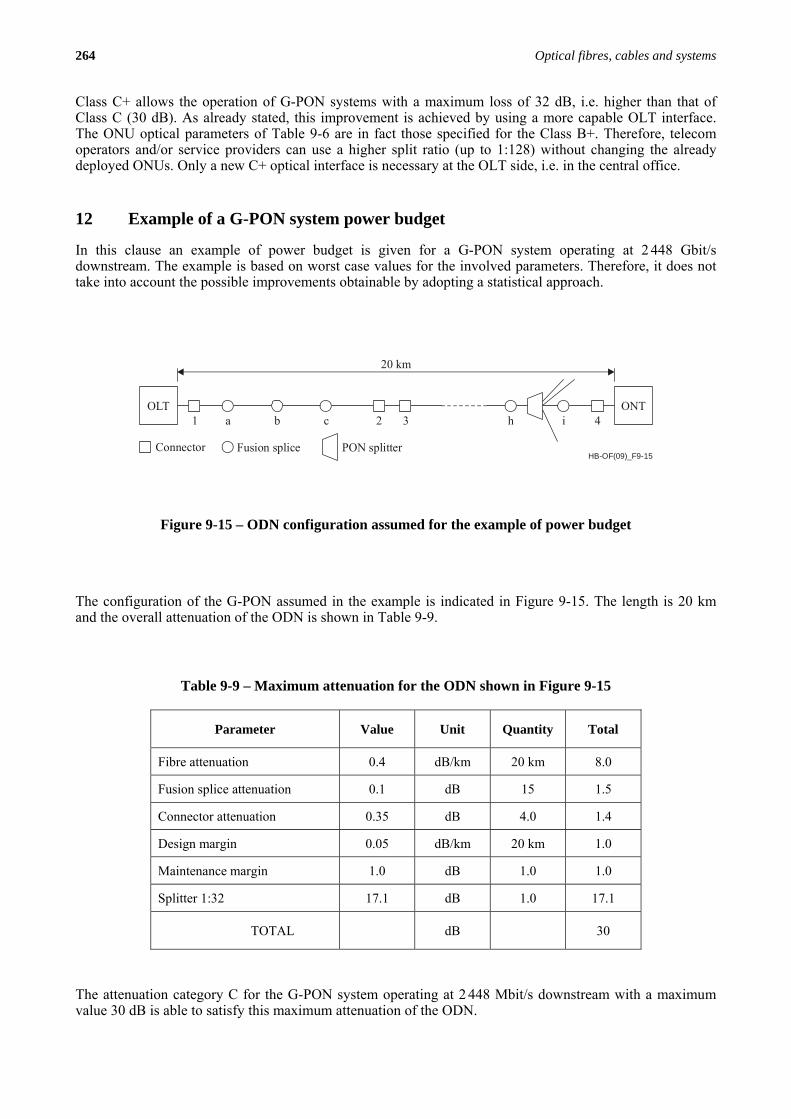
12 Example of a G-PON system power budget
In this clause an example of power budget is given for a G-PON system operating at 2 448 Gbit/s downstream. The example is based on worst case values for the involved parameters. Therefore, it does not take into account the possible improvements obtainable by adopting a statistical approach.
HB-OF(09)_F9-15
OLT ONT
Connector Fusion splice PON splitter
1 2 3 4a b c h i
20 km
Figure 9-15 – ODN configuration assumed for the example of power budget
The configuration of the G-PON assumed in the example is indicated in Figure 9-15. The length is 20 km and the overall attenuation of the ODN is shown in Table 9-9.
The attenuation category C for the G-PON system operating at 2 448 Mbit/s downstream with a maximum value 30 dB is able to satisfy this maximum attenuation of the ODN.
Table 9-9 – Maximum attenuation for the ODN shown in Figure 9-15
Parameter Value Unit Quantity Total
Fibre attenuation 0.4 dB/km 20 km 8.0
Fusion splice attenuation 0.1 dB 15 1.5
Connector attenuation 0.35 dB 4.0 1.4
Design margin 0.05 dB/km 20 km 1.0
Maintenance margin 1.0 dB 1.0 1.0
Splitter 1:32 17.1 dB 1.0 17.1
TOTAL dB 30
Chapter 9 – Optical systems applications in passive optical networks 265
13 Operating wavelengths
13.1 Basic band The wavelength range of the G-PON specified in Recommendation ITU-T G.984.2 is 1 480-1 500 nm for the downstream signal (single fibre system) and 1 260-1 360 nm for the upstream signal.
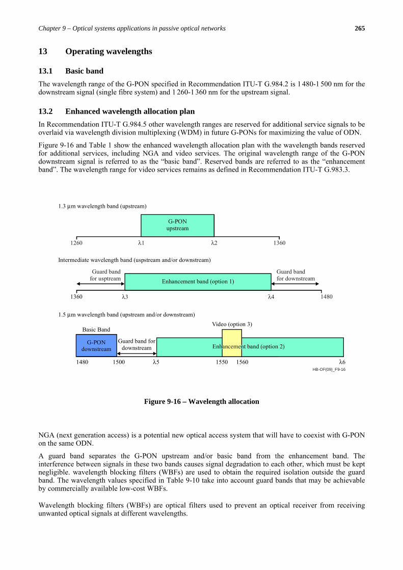
13.2 Enhanced wavelength allocation plan In Recommendation ITU-T G.984.5 other wavelength ranges are reserved for additional service signals to be overlaid via wavelength division multiplexing (WDM) in future G-PONs for maximizing the value of ODN.
Figure 9-16 and Table 1 show the enhanced wavelength allocation plan with the wavelength bands reserved for additional services, including NGA and video services. The original wavelength range of the G-PON downstream signal is referred to as the “basic band”. Reserved bands are referred to as the “enhancement band”. The wavelength range for video services remains as defined in Recommendation ITU-T G.983.3.
HB-OF(09)_F9-16
1.3 m wavelength band (upstream)μ
Intermediate wavelength band (uspstream and/or downstream)
Guard bandfor usptream
Guard bandfor downstream
1260 λ1 1360
1.5 m wavelength band (upstream and/or downstream)μ
G-PONdownstream
G-PONupstream
Enhancement band (option 1)
λ2
Guard band fordownstream
1360 λ4λ3 1480
1480 1500 1550λ5 λ6
Video (option 3)
Basic Band
1560
nt band (option 2)Enhanceme
Figure 9-16 – Wavelength allocation
NGA (next generation access) is a potential new optical access system that will have to coexist with G-PON on the same ODN.
A guard band separates the G-PON upstream and/or basic band from the enhancement band. The interference between signals in these two bands causes signal degradation to each other, which must be kept negligible. wavelength blocking filters (WBFs) are used to obtain the required isolation outside the guard band. The wavelength values specified in Table 9-10 take into account guard bands that may be achievable by commercially available low-cost WBFs.
Wavelength blocking filters (WBFs) are optical filters used to prevent an optical receiver from receiving unwanted optical signals at different wavelengths.
266 Optical fibres, cables and systems
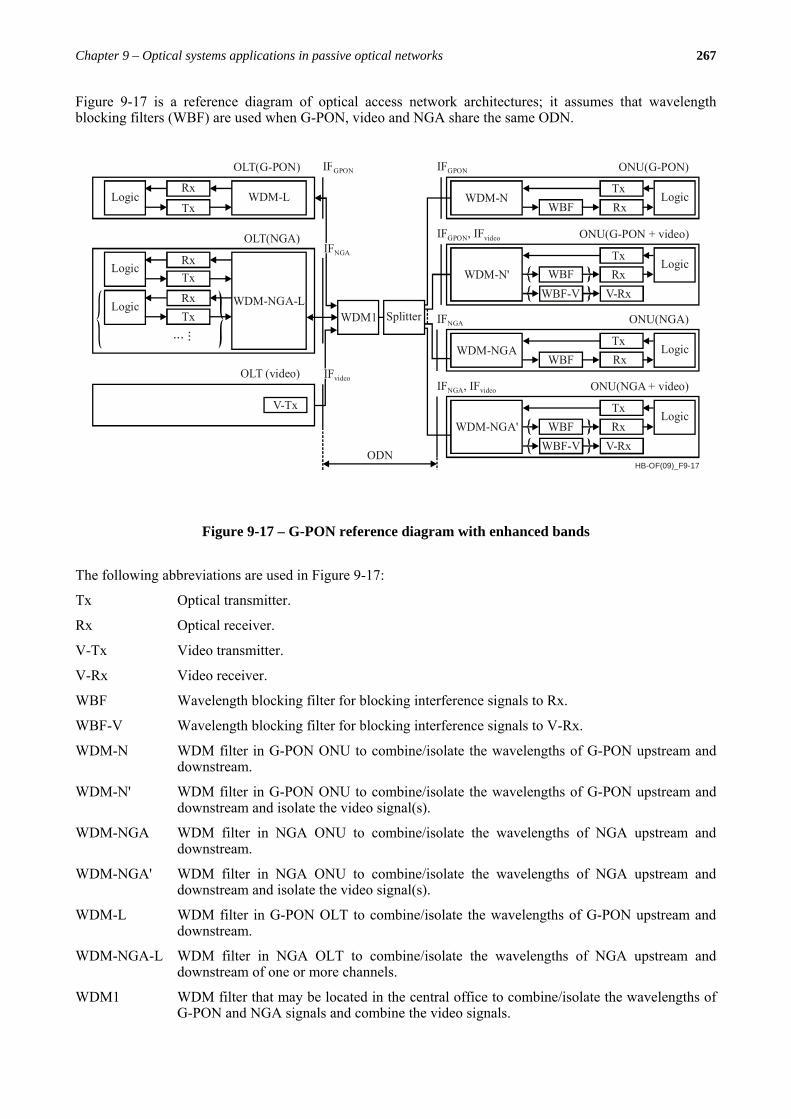
13.3 G-PON reference diagrams with enhanced bands There can be several types of ODN architectures to achieve the coexistence of G-PON and additional services including next generation access (NGA) and video distribution services.
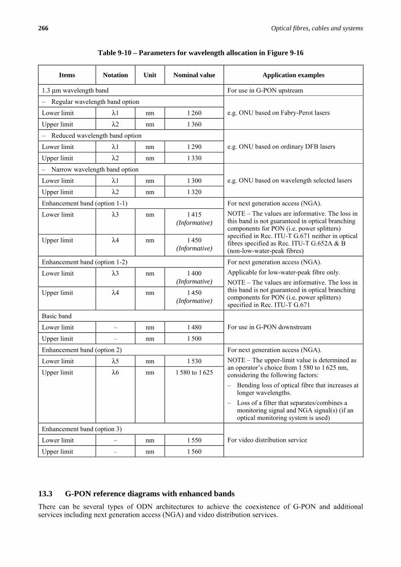
Table 9-10 – Parameters for wavelength allocation in Figure 9-16
Items Notation Unit Nominal value Application examples
1.3 μm wavelength band For use in G-PON upstream
– Regular wavelength band option
Lower limit λ1 nm 1 260
Upper limit λ2 nm 1 360
e.g. ONU based on Fabry-Perot lasers
– Reduced wavelength band option
Lower limit λ1 nm 1 290
Upper limit λ2 nm 1 330
e.g. ONU based on ordinary DFB lasers
– Narrow wavelength band option
Lower limit λ1 nm 1 300
Upper limit λ2 nm 1 320
e.g. ONU based on wavelength selected lasers
Enhancement band (option 1-1)
Lower limit λ3 nm 1 415 (Informative)
Upper limit λ4 nm 1 450 (Informative)
For next generation access (NGA). NOTE – The values are informative. The loss in this band is not guaranteed in optical branching components for PON (i.e. power splitters) specified in Rec. ITU-T G.671 neither in optical fibres specified as Rec. ITU-T G.652A & B (non-low-water-peak fibres)
Enhancement band (option 1-2)
Lower limit λ3 nm 1 400 (Informative)
Upper limit λ4 nm 1 450 (Informative)
For next generation access (NGA). Applicable for low-water-peak fibre only. NOTE – The values are informative. The loss in this band is not guaranteed in optical branching components for PON (i.e. power splitters) specified in Rec. ITU-T G.671
Basic band
Lower limit – nm 1 480
Upper limit – nm 1 500
For use in G-PON downstream
Enhancement band (option 2)
Lower limit λ5 nm 1 530
Upper limit λ6 nm 1 580 to 1 625
For next generation access (NGA). NOTE – The upper-limit value is determined as an operator’s choice from 1 580 to 1 625 nm, considering the following factors: – Bending loss of optical fibre that increases at
longer wavelengths. – Loss of a filter that separates/combines a
monitoring signal and NGA signal(s) (if an optical monitoring system is used)
Enhancement band (option 3)
Lower limit – nm 1 550
Upper limit – nm 1 560
For video distribution service
Chapter 9 – Optical systems applications in passive optical networks 267
Figure 9-17 is a reference diagram of optical access network architectures; it assumes that wavelength blocking filters (WBF) are used when G-PON, video and NGA share the same ODN.
HB-OF(09)_F9-17
LogicTxRxWBF
WDM-N
IFGPON ONU(G-PON)
LogicTxRxWBFWDM-N'
IF , IFGPON video ONU(G-PON + video)
V-RxWBF-V
LogicTxRxWBF
WDM-NGA
IFNGA ONU(NGA)
LogicTxRxWBFWDM-NGA'
IF , IFNGA video ONU(NGA + video)
V-RxWBF-V
WDM-LTx
RxLogic
IFGPONOLT(G-PON)
WDM-NGA-L
TxRx
LogicIFNGA
OLT(NGA)
RxTx
Logic
V-Tx
IFvideoOLT (video)
SplitterWDM1
... ...
ODN
Figure 9-17 – G-PON reference diagram with enhanced bands
The following abbreviations are used in Figure 9-17:
Tx Optical transmitter.
Rx Optical receiver.
V-Tx Video transmitter.
V-Rx Video receiver.
WBF Wavelength blocking filter for blocking interference signals to Rx.
WBF-V Wavelength blocking filter for blocking interference signals to V-Rx.
WDM-N WDM filter in G-PON ONU to combine/isolate the wavelengths of G-PON upstream and downstream.
WDM-N' WDM filter in G-PON ONU to combine/isolate the wavelengths of G-PON upstream and downstream and isolate the video signal(s).
WDM-NGA WDM filter in NGA ONU to combine/isolate the wavelengths of NGA upstream and downstream.
WDM-NGA' WDM filter in NGA ONU to combine/isolate the wavelengths of NGA upstream and downstream and isolate the video signal(s).
WDM-L WDM filter in G-PON OLT to combine/isolate the wavelengths of G-PON upstream and downstream.
WDM-NGA-L WDM filter in NGA OLT to combine/isolate the wavelengths of NGA upstream and downstream of one or more channels.
WDM1 WDM filter that may be located in the central office to combine/isolate the wavelengths of G-PON and NGA signals and combine the video signals.

268 Optical fibres, cables and systems
14 Wavelength for maintenance
(For further information see Recommendation ITU-T L.41).
In-service maintenance of optical fibre should be done in such a way that it does not interfere with the normal operation and expected performance of the information channels. The wavelengths for in-service maintenance shown in Table 9-11 should be used.
Case 1: This usually applies to single mode fibre. Transmission system uses only the 1 310 nm-window.
Case 2: This usually applies to dispersion shifted fibre. Transmission system uses only the 1 550 nm-window.
Case 3: This usually applies to single mode fibre. Transmission system uses two or more wavelengths in the 1 310 nm and 1 550 nm windows.
Case 4: The maximum transmission wavelength is under study in ITU-T, but is limited to less than or equal to 1 625 nm.
Wavelength is independent of types of fibre (single mode fibre or dispersion shifted fibre).
15 Reach extension of the G-PON
Recommendation ITU-T G.984.6 describes G-PON systems with optical link budgets up to the logical limits (60 km) of the transmission convergence (TC) layer. This increased optical capability, which includes both increased overall fibre length and increased overall split ratio, is referred in the following as “reach extension”.
For reach extension, Recommendation ITU-T G.984.6 considers mid-span extension, which uses an active extension node placed in the middle of the ODN. Two system architectures are considered as providing reach extension at the physical layer: optical amplification, and optoelectronic regeneration. The key interfaces and functional blocks in each of these architectures are specified in Recommendation ITU-T G.984.6.
Table 9-11 – Maintenance wavelength assignment
1 310 nm-window 1 550 nm-window 1 625 nm-windowb) 1 650 nm-windowa), b)
Case 1 Active Vacant or maintenance Vacant or maintenance Vacant or maintenance
Case 2 Vacant or maintenance Active Vacant or maintenance Vacant or maintenance
Case 3 Active Active Vacant or maintenance Vacant or maintenance
Case 4 Active or vacant Active Active Vacant or Maintenance
a) When there is no optical light (nominally below −60 dBm) from the OTDR laser at all wavelengths equal to or below the maximum client signal wavelength (see case 4) at point “R”, it is not necessary to consider interference with transmission.
b) These OTDR wavelengths are suitable only for systems with client signals at wavelengths less than 1 565 nm. Applicability for client signals at longer wavelengths is under study.

Chapter 9 – Optical systems applications in passive optical networks 269
15.1 Optical extension schemes and architectures The architecture considered for an ODN with reach extension is illustrated in Figure 9-18. A mid-span extender device is inserted between the ODN and an optical trunk line (OTL) that is connected to the OLT. This architecture extends the reach of the PON by the length of the OTL, and may also increase the split ratio of the PON.
HB-OS(09)_F9-18
ONU
ONU
UNI
ODNS'/R'R'/S'
OLTS/R
OLTSNI
R/S
Mid-Spamextender
UNIR/S
Figure 9-18 – Mid-span reach extension
As said above, there are two general classes of extenders. The first is an optical amplifier (OA), shown in Figure 9-19, which provides gain in optical power.
HB-OF(09)_F9-19
OAOBF
(optional)
Diplexer Diplexer
OBF(optional) OA
S'/R' R'/S'
Figure 9-19 – The two basic extender architectures: a) Optical Amplifier
The second is an optical-electrical-optical (OEO) regenerator (Rx + Tx) (Figure 9-20), which receives an optical signal, reshapes and retimes it in the electrical domain and retransmits in the optical domain. Further hybrid schemes are possible, for example, to use optical amplification in the downstream and regeneration in the upstream.
HB-OF(09)_F9-20
Rx Tx
Diplexer Diplexer
Tx Rx
S'/R' R'/S'Clock
Figure 9-20 – The two basic extender architectures: b) Regenerator
270 Optical fibres, cables and systems
The mid-span extender will require electrical power. This may be an issue when the extender is located in the field. Also, the power source will need to have protection against failures of the primary power source, typically using batteries as a backup. Therefore, power consumption should be reduced as much as possible.
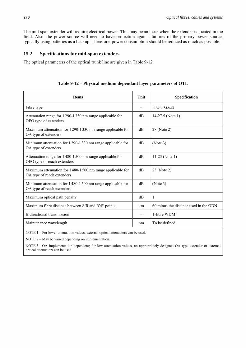
15.2 Specifications for mid-span extenders
The optical parameters of the optical trunk line are given in Table 9-12.
Table 9-12 – Physical medium dependant layer parameters of OTL
Items Unit Specification
Fibre type – ITU-T G.652
Attenuation range for 1 290-1 330 nm range applicable for OEO type of extenders
dB 14-27.5 (Note 1)
Maximum attenuation for 1 290-1 330 nm range applicable for OA type of extenders
dB 28 (Note 2)
Minimum attenuation for 1 290-1 330 nm range applicable for OA type of extenders
dB (Note 3)
Attenuation range for 1 480-1 500 nm range applicable for OEO type of reach extenders
dB 11-23 (Note 1)
Maximum attenuation for 1 480-1 500 nm range applicable for OA type of reach extenders
dB 23 (Note 2)
Minimum attenuation for 1 480-1 500 nm range applicable for OA type of reach extenders
dB (Note 3)
Maximum optical path penalty dB 1
Maximum fibre distance between S/R and R'/S' points km 60 minus the distance used in the ODN
Bidirectional transmission – 1-fibre WDM
Maintenance wavelength nm To be defined
NOTE 1 – For lower attenuation values, external optical attenuators can be used.
NOTE 2 – May be varied depending on implementation.
NOTE 3 – OA implementation-dependent; for low attenuation values, an appropriately designed OA type extender or external optical attenuators can be used.
Related Documents