14 Implication of Zeolite Chemistry in Electrochemical Science and Applications of Zeolite-Modified Electrodes Alain Walcarius Centre National de la Recherche Scientifique (CNRS)—Universite ´ Henri Poincare ´ (UHP) Nancy I, Villers-le `s-Nancy, France I. INTRODUCTION The growing interest for zeolite molecular sieves in electrochemistry arises from the synergistic combination of the attractive properties of these materials with electrochemical interfaces. The attractive zeolite characteristics that are liable to affect the electron transfer reactions at an electrode–solution interphase are (a) the size and shape selectivity due to the rigid structure made of pores and channels of molecular dimensions; (b) the cation- exchange capacity arising from the charge compensation of the negatively charged aluminosilicate lattice by mobile extraframework cations; and (c) the catalytic properties of both intrinsic and extrinsic sites of the microporous materials. This has led to the design, preparation, and use of various zeolite-modified electrodes, which form a sub-category of the so-called chemically modified electrodes (CMEs). The concept of CMEs was introduced by Murray (1). It consists of intelligently designing the surface of conventional electrodes in order to control or to improve their response by combining the intrinsic properties of the modifier to a selected electro- chemical reaction. This electrochemist’s desire was the starting point of overwhelming developments in the past two decades. Most of the traditional and advanced applica- tions for CMEs are based on the ability of such ‘‘integrated chemical systems’’ to impart both catalytic properties to the electrode surface and to selectively incorporate a target analyte prior to its sensitive electrochemical detection. Electrocatalysis and electroanalysis are two major aims that have driven the fruitful design of CME surfaces (2). The former relies on circumventing the slow heterogeneous reaction kinetics often associated with an electrochemical event by lowering the electron free energy, while the latter is directed to improving both sensitivity and selectivity for a target substrate by exclusive preconcentration at the electrode–solution interface. The efficiency of both of these applications is strongly related to the nature of CMEs, helping to explain the enormous chemical diversity observed in the molecular design of electrode surfaces (3–6). Copyright © 2003 Marcel Dekker, Inc.

Welcome message from author
This document is posted to help you gain knowledge. Please leave a comment to let me know what you think about it! Share it to your friends and learn new things together.
Transcript
14Implication of Zeolite Chemistry inElectrochemical Science and Applicationsof Zeolite-Modified Electrodes
Alain WalcariusCentre National de la Recherche Scientifique (CNRS)—Universite Henri Poincare (UHP)Nancy I, Villers-les-Nancy, France
I. INTRODUCTION
The growing interest for zeolite molecular sieves in electrochemistry arises from thesynergistic combination of the attractive properties of these materials with electrochemicalinterfaces. The attractive zeolite characteristics that are liable to affect the electron transferreactions at an electrode–solution interphase are (a) the size and shape selectivity due to therigid structure made of pores and channels of molecular dimensions; (b) the cation-exchange capacity arising from the charge compensation of the negatively chargedaluminosilicate lattice by mobile extraframework cations; and (c) the catalytic propertiesof both intrinsic and extrinsic sites of the microporous materials. This has led to the design,preparation, and use of various zeolite-modified electrodes, which form a sub-category ofthe so-called chemically modified electrodes (CMEs).
The concept of CMEs was introduced by Murray (1). It consists of intelligentlydesigning the surface of conventional electrodes in order to control or to improve theirresponse by combining the intrinsic properties of the modifier to a selected electro-chemical reaction. This electrochemist’s desire was the starting point of overwhelmingdevelopments in the past two decades. Most of the traditional and advanced applica-tions for CMEs are based on the ability of such ‘‘integrated chemical systems’’ toimpart both catalytic properties to the electrode surface and to selectively incorporate atarget analyte prior to its sensitive electrochemical detection. Electrocatalysis andelectroanalysis are two major aims that have driven the fruitful design of CME surfaces(2). The former relies on circumventing the slow heterogeneous reaction kinetics oftenassociated with an electrochemical event by lowering the electron free energy, whilethe latter is directed to improving both sensitivity and selectivity for a target substrateby exclusive preconcentration at the electrode–solution interface. The efficiency ofboth of these applications is strongly related to the nature of CMEs, helping toexplain the enormous chemical diversity observed in the molecular design of electrodesurfaces (3–6).
Copyright © 2003 Marcel Dekker, Inc.
This chapter will focus primarily on state-of-the-art of CMEs involving zeolites.It includes (a) a description of the various approaches to preparing zeolite-modifiedelectrodes (ZMEs); (b) the effect of confining zeolites at an electrode surface on its res-ponse to various electroactive probes; (c) the electrochemistry of zeolites modified withion-exchanged or encapsulated electroactive guests; (d) the mutual interest between zeolitechemistry and electrochemical science; and (e) numerous advanced applications of ZMEs.
Several reviews have appeared in the literature during the past decade, devotedentirely (7–13) or in part (14–21) to the implication of zeolites in electrochemistry. Theyillustrate the intense activity in combining zeolite properties with electrode processes. Dueto the electronically insulating character of zeolites, their implication in electrochemistryrequires close contact to an electronically conducting material. This step in creating aninterphase containing an electrode and a zeolite is not trivial (partly because of thepowdered form of the aluminosilicate) and various strategies were applied to prepareZMEs from zeolite particles and conventional electrode materials. The electrochemicalbehavior of ZMEs depends on (a) the nature of the electroactive guest and the nature andstructure of the zeolite host; (b) the type of ZME; (c) the nature and concentration of the so-called supporting electrolyte* (especially the cation size and charge) in the solutionsurrounding the ZME surface; (d) the location and mobility of the electroactive guest(and other counterions) inside the microporous solid; (e) the time afforded to the ZME tocontact the electrolyte solution; (f ) the temperature; and (g) the solvent (most electro-chemical experiments have been carried out in aqueous medium, although some studieshave been done in organic solvents). A fundamental question that arises when combiningzeolites and electrochemistry is, when an electroactive guest is initially exchanged orencapsulated within a zeolite particle, according to what pathway(s) do/can charge-transferreactions occur at ZMEs? Although some controversial discussions have appeared in theliterature to support an intracrystalline or an extracrystalline electron transfer mechanism(9,11,22–26), it is now established that the major part of the electrochemical response ofZMEs is due to two main components: extrazeolite electroactive species (always observedwith ion exchangeable species, by nature) and/or electroactive species located in oroccluded within the cages or channels situated at the boundary of zeolite particlescontacting the electrode surface. The relative weight of these two species in the electro-chemical response is controlled by the interplay between charge-transfer and mass trans-port processes occurring at ZMEs, which can be very different depending on variousexperimental parameters.
In addition to the fascinating fundamental studies aimed at understanding the basicbehavior of ZMEs, many advanced applications have been achieved by exploiting theintersection between zeolite chemistry and electrochemical science. These include electro-catalysis directed to sensing or organic synthesis, various aspects of electroanalysis(preconcentration and permselectivity, indirect amperometric detection, potentiometry,biosensors), dispersion electrolysis, solid electrolytes for power sources, photoelectrochem-
*Most electrochemical experiments are performed in solutions containing (in addition to theanalyte) a high concentration of inert electrolyte, called supporting electrolyte, in order to minimizethe phenomenon of migration of the electroactive ions caused by the electric field. It also confinesthe interfacial potential difference to the distance of closest approach of solvated ions to the
electrode. This has a concentration at least 100 times that of the electroactive analytes and is theprincipal source of electrically conducting ionic species. At ZMEs, the supporting electrolyte cationplays an important role for charge compensation in zeolites.
Copyright © 2003 Marcel Dekker, Inc.

istry, as well as the exploitation of the electrochemical techniques to characterize ion-exchange and diffusion processes in zeolites.
II. HISTORICAL ACCOUNT OF ELECTROCHEMISTRYINVOLVING ZEOLITES
The first report using zeolites for electrochemical purposes, dated 1939, has beendescribed by Marshall (27) and involves the potentiometric response of zeolite-containingmembrane electrodes to various mono- and divalent cations. This work and somesubsequent investigations by the same group (28–31) considered the inorganic mem-branes as polyelectrolytes with mobile cations, allowing for the characterization of cationactivities similar to the way that the glass membrane electrode is used for determininghydrogen ion activities. This pioneering approach was then pursued by Barrer and James(32) in 1960, providing a more quantitative treatment of the zeolite membrane potentialand discussing its relation to the selectivity with respect to cation mixtures in solution.Such potentiometric applications exploit the solution-like ionic conduction of zeolites. Afew years later, the solid-state ionic conduction of zeolites was utilized in electro-chemistry by designing solid-state batteries (33,34) and fuel cells (35,36), with zeoliteparticles acting as a solid electrolyte and as a host for the catholite (in batteries) or forelectroreactants or water (in fuel cells). Finally, at the end of the 1970s, Susic andPetranovic (37–40) investigated the electrochemical behavior of dry zeolite crystals attemperatures above 200jC, where dry zeolite displays solid-state ionic conduction (41).At these high temperatures, the zeolite acted as a ‘‘solvent’’ for the charge-compensatingcations that can be reduced on platinum; examples are available for reduction of Na+
(38), Cd2+ (39), and Ag+ (40). These latter investigations are the first examples ofelectrodics* involving zeolites, while the above potentiometric experiments were onlyconcerned with ionics.y
Modern fields of investigation concerning the zeolite–electrochemistry intersectionbegan in the 1980s with considerable research on ZMEs since 1988. It is noteworthy thatthe (often) preliminary works performed in this initial mid 80’s period suggested most ofthe application types as well as electrode configurations. Some milestones are:
� Pereira-Ramos et al. (42,43) prepared zeolite-supported metal catalysts usingelectrochemical techniques. By means of a pressed composite electrode made ofgraphite and silver-exchange mordenite particles, they were able to produceelectrochemically some clusters of metallic silver within the mordenite particles,and crystallites or dendritic deposits on the graphite particles (43).
� One year later, Murray et al. (44) grew electrogenerated coatings comprisingzeolites; this was achieved by continuous potential cycling at a rotated disk elec-trode (Pt or C) in an organic solvent containing fine zeolite particles in suspensionand an appropriate soluble electroreactant.
� Concurrent and competing with this approach is the evaporative deposition of azeolite-polystyrene composite layer on solid electrode surfaces, which is carried
*The term electrodics concerns the part of electrochemistry that involves the study of processes in
which transfer of an electron occurs across an electrochemical interface, often made between anelectrode and an ionically conducting medium.
yThe term ionics is related to the part of electrochemistry devoted to the study of only the ionicallyconducting phases (without any associated electron transfer reaction).
Copyright © 2003 Marcel Dekker, Inc.
out with suspensions of powdered zeolite in polymer solutions, as first describedby de Vismes et al. (45). They have also incorporated some metal porphyrins intothe ZME and explored their electrocatalytic properties; in this case, the zeolite isthought to enhance the chemical stability of the catalyst.
� Hernandez et al. (46) described the first zeolite-modified carbon paste electrode,by mixing graphite particles with a natural zeolite from the Canary Islands and amineral oil binder, and applied it to the voltammetric analysis of HgII afterchemical accumulation by ion exchange within the zeolite.
� Finally, the group of Shaw (47,48) initiated what has become one of the largestchallenges of ZME electrochemistry: (a) to determine and, if possible, controlthe factors affecting the behavior of ZMEs; and (b) to understand the origin ofthe electrochemical response of ZMEs by proposing mechanistic models forcharge transfer.
At the end of the 1980s, the two main methods for preparing ZMEs were zeolite overlayerson solid electrodes and zeolite dispersions into a composite electrode material. Subsequentefforts were often directed to optimizing these generic procedures to get longer durabilityand better electrochemical perspectives, rather than evaluating totally new directions(e.g., in situ grown zeolite films on conducting substrates like gold or mercury (49–51).An exception is the unconfined metal-doped zeolite dispersions used by Rolison et al.(52,53) as electrode-modified zeolites. The main applications predicted during thisstartup period, including electrocatalysis and several aspects of electroanalysis andsensors, were largely developed during the last decade of the 20th century. One shouldalso mention that the field of energy storage that exploits the adsorbent properties ofzeolites was still growing in the 1980s, especially prompted by Coetzer (54,55), andthat the use of zeolites as solid electrolytes in batteries remains common.
III. DESIGN AND PREPARATION OF ZEOLITE MODIFIED ELECTRODES
Starting an electrochemical study with electronically insulating zeolite particles impliesconfining them at an electrode surface. This construction step should be reasonably easyand should provide ZMEs with good conductivity properties (low resistance and lowcapacitance), high mechanical stability and long-term durability, as well as reproduciblecharacteristics (for both their fabrication procedures and their electrochemical responses).Of course, such ideal conditions leading to high-quality chemically modified electrodes thatwould display adequate electrochemical signals (3,6) are not easily fulfilled when zeolite isused as the electrode modifier. This is because its insulating character will lower theelectrode conductivity, and individual solid crystals of micrometer dimension and rigidstructure will result in heterogeneous composition and configuration of the modifiedelectrode material. This in turn could impart rather low mechanical stability in stirredmedia due to possible leaching of zeolite particles into the solution. These are some of thereasons why many efforts have been directed to finding the best strategies to prepare ZMEs,as illustrated in Table 1. The corresponding references are provided to give a rapid view onthe most widely used electrode configurations, as well as experimental details required tobuild a particular ZME. In spite of the aforementioned difficulties, several ZMEs withsatisfactory characteristics have been obtained, with electrode design being most oftendictated by the target application.
Table 1 shows that most ZMEs are prepared according to two main methods: (a)zeolite-polymer films coated on solid electrode surfaces and (b) bulky zeolite-carbon orzeolite-carbon-binder composites or, alternatively, a combination of these two generic
Copyright © 2003 Marcel Dekker, Inc.
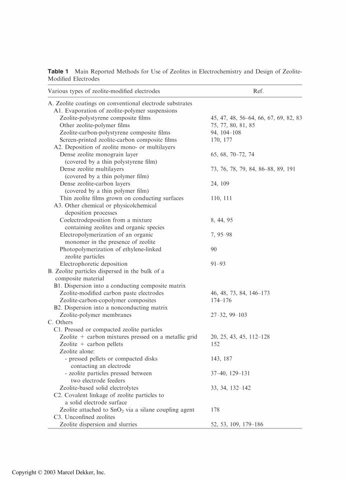
Table 1 Main Reported Methods for Use of Zeolites in Electrochemistry and Design of Zeolite-Modified Electrodes
Various types of zeolite-modified electrodes Ref.
A. Zeolite coatings on conventional electrode substratesA1. Evaporation of zeolite-polymer suspensionsZeolite-polystyrene composite films 45, 47, 48, 56–64, 66, 67, 69, 82, 83
Other zeolite-polymer films 75, 77, 80, 81, 85Zeolite-carbon-polystyrene composite films 94, 104–108Screen-printed zeolite-carbon composite films 170, 177
A2. Deposition of zeolite mono- or multilayers
Dense zeolite monograin layer(covered by a thin polystyrene film)
65, 68, 70–72, 74
Dense zeolite multilayers
(covered by a thin polymer film)
73, 76, 78, 79, 84, 86–88, 89, 191
Dense zeolite-carbon layers(covered by a thin polymer film)
24, 109
Thin zeolite films grown on conducting surfaces 110, 111A3. Other chemical or physicolchemical
deposition processes
Coelectrodeposition from a mixturecontaining zeolites and organic species
8, 44, 95
Electropolymerization of an organicmonomer in the presence of zeolite
7, 95–98
Photopolymerization of ethylene-linkedzeolite particles
90
Electrophoretic deposition 91–93
B. Zeolite particles dispersed in the bulk of acomposite materialB1. Dispersion into a conducting composite matrix
Zeolite-modified carbon paste electrodes 46, 48, 73, 84, 146–173Zeolite-carbon-copolymer composites 174–176
B2. Dispersion into a nonconducting matrix
Zeolite-polymer membranes 27–32, 99–103C. OthersC1. Pressed or compacted zeolite particlesZeolite + carbon mixtures pressed on a metallic grid 20, 25, 43, 45, 112–128
Zeolite + carbon pellets 152Zeolite alone:- pressed pellets or compacted disks
contacting an electrode
143, 187
- zeolite particles pressed betweentwo electrode feeders
37–40, 129–131
Zeolite-based solid electrolytes 33, 34, 132–142C2. Covalent linkage of zeolite particles to
a solid electrode surfaceZeolite attached to SnO2 via a silane coupling agent 178
C3. Unconfined zeolitesZeolite dispersion and slurries 52, 53, 109, 179–186
Copyright © 2003 Marcel Dekker, Inc.

approaches. The various ZME designs obtained from these basic configurations are brieflydescribed hereafter, wth special emphasis on their advantages and limitations. Most ofthem have been discussed in the literature (9,11).
A classical route to chemically modify an electrode surface is to cover it by an adhesivelayer of the modifying agent. This simple approach was successfully applied to polymermodified electrodes, but it is prevented here as the zeolite particles do not stick by themselvesto the surface of conventional electrodes. Cohesion would require a binder. This is what hasmotivated the development of zeolite-polymer films coated on solid electrode surfaces.
Several cases have been reported and are schematically illustrated in Fig. 1. Acomposite zeolite-polymer film can be easily deposited on a solid electrode by evaporationof an organic solution containing a dissolved polymer (mainly polystyrene) and suspendedzeolite particles. This rather simple procedure has been widely used (45,47,48,56–89)and gives rise to porous films that enable diffusion processes to occur at the electrode–film–solution interfaces by way of the free space (‘‘void’’) remaining in the composite aftersolvent evaporation. Such films are, however, somewhat heterogeneous because of theusually weak zeolite–polymer interactions (while the polymer often adheres strongly to theelectrode surface) (48) and must be used only in unstirred solutions to avoid leaching ofzeolite particles into solution. A modified approach is to deposit first a pure zeolite layer onthe electrode surface and then to cover it with a thin porous polymer film to ensuremechanical stability. Two configurations are possible: (a) the dense monograin layer
Fig. 1 Schematic representation of zeolite-polymer film–based ZMEs. (A) Zeolite-polymer filmobtained by evaporation of zeolite particles suspended in a polymer solution; (B) zeolite monograin
layer covered with a thin polymer film; (C) zeolite multilayer covered with a thin polymer film.
Copyright © 2003 Marcel Dekker, Inc.
introduced by Calzaferri’s group (74,90), which requires zeolite particles of monodispersesize; and (b) the dense zeolite multilayer (73,76) that does not require absolutely homoge-neous morphologies and sizes of the zeolite particles. This last design results in small ‘‘void’’spaces in the zeolite layer because of a random distribution of particles, whose packing canbe improved by electrophoretic deposition of zeolites that leads to more mechanicalstability (91–93). These dense films are claimed to be robust enough to be used in a stirredmedium (11). Though sometimes used in nonaqueous media (47,63,94), the zeolite-polymerfilms are more stable in aqueous solutions because of possible (fortunately slow) dissolutionof the polymer binder in organic solvents.
Alternative methods to produce films comprising zeolite particles in an organicbinder were also suggested. Zeolite can be embedded into an organic matrix during itsformation by electrodeposition, i.e., reduction of 1,4-dinitrobenzene (8,44) or reduction ofphenosafranine (95) on carbon electrodes. Composite films made of zeolite dispersed intoan electrogenerated conducting polymer were synthesized by electropolymerization of amonomer solution containing zeolite particles in suspension (96–98). This led to zeolite-polymer composites of better conductivity than the corresponding zeolite-polystyrenecoatings. One should also mention the nonconducting zeolite-polymer membranes madeof a zeolite dispersion within an inert organic resin (27,32,99–103), which are suited forpotentiometric measurements via exploitation of the ionic conduction of zeolites.
Another way to improve the conductivity of ZMEs made of two resistive elements(i.e., polystyrene and zeolite) is to add carbon powder to the film. This is readily achievedby grinding together carbon and zeolite particles prior to dispersing them in the polymericbinder (94,104–106). Coating of such zeolite-carbon-polymer films on ultramicro-electrodes (10 Am diameter) was reported (107,108). Carbon was also used to increasethe area of electrical conductor in direct contact to the zeolite in dense films covered by athin polystyrene overlayer (24,109). If resistance of these films was indeed lowered ascompared with that of carbon-free coatings, it should be emphasized that capacitance ofthe ZME was also significantly increased due to a much higher area of the electrodesurface. Thin zeolite films grown on conducting surfaces are also reported (110,111).
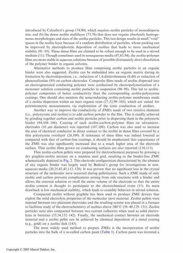
Thin zeolite-carbon pellets were prepared for electrochemical purposes by pressing adry graphite-zeolite mixture on a stainless steel grid, resulting in the binder-free ZMEschematically depicted in Fig. 2. This electrode configuration characterized by the absenceof any organic binder was largely used by Bedioui’s group for investigations in non-aqueous media (20,25,43,45,112–128). It was proven that no significant loss in the crystalstructure of the molecular sieve occurred during pelletization. Such a ZME made of onlyzeolite and carbon prevents complications arising from side reactions with a binder andallows the external solution to swell the entire volume of the electrode so that the entirezeolite content is thought to participate to the electrochemical event (11). Its maindrawback is low mechanical stability, which leads to crumbly behavior in stirred solution.
Compacted zeolite without graphite has been used to produce ZME devices thatexploit the solid electrolyte properties of the molecular sieve material. Zeolite pellets wereinserted between two platinum electrodes and the resulting system was placed in a furnaceto facilitate study of the electrochemistry of zeolites above 200jC (38–40,129–131). Zeoliteparticles were also compacted between two current collectors when used as solid electro-lytes in batteries (33,34,132–142). Finally, the mechanical contact between an electrodematerial and a zeolite pellet can be achieved by chemical deposition of a metal coating(e.g., gold) on a zeolite disk (143).
The most widely used method to prepare ZMEs is the incorporation of zeoliteparticles into the bulk of a so-called carbon paste (Table 1). Carbon paste was invented a
Copyright © 2003 Marcel Dekker, Inc.
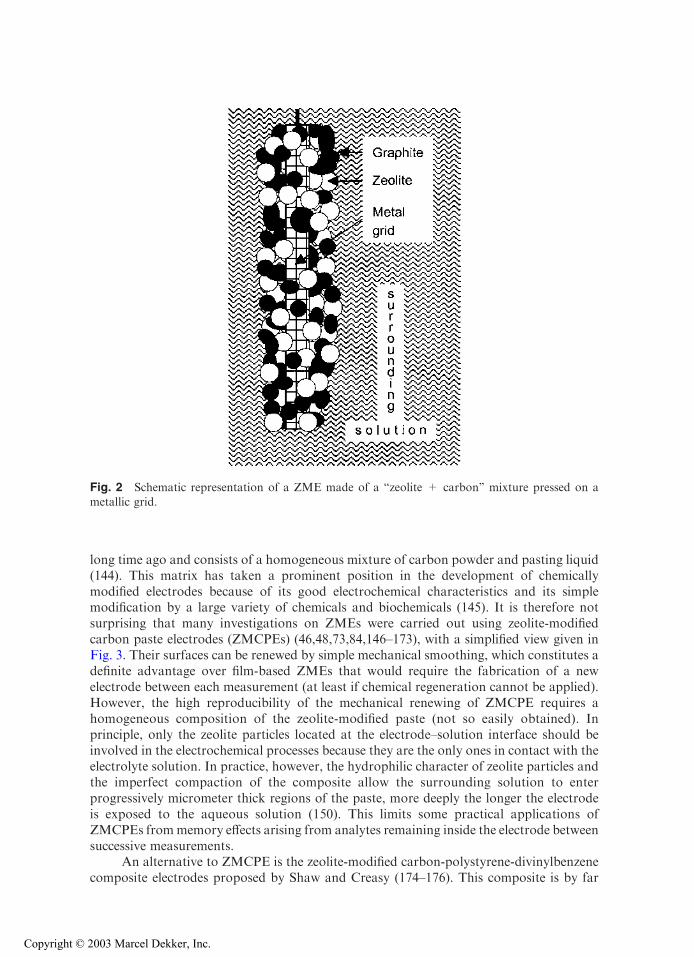
long time ago and consists of a homogeneous mixture of carbon powder and pasting liquid(144). This matrix has taken a prominent position in the development of chemicallymodified electrodes because of its good electrochemical characteristics and its simplemodification by a large variety of chemicals and biochemicals (145). It is therefore notsurprising that many investigations on ZMEs were carried out using zeolite-modifiedcarbon paste electrodes (ZMCPEs) (46,48,73,84,146–173), with a simplified view given inFig. 3. Their surfaces can be renewed by simple mechanical smoothing, which constitutes adefinite advantage over film-based ZMEs that would require the fabrication of a newelectrode between each measurement (at least if chemical regeneration cannot be applied).However, the high reproducibility of the mechanical renewing of ZMCPE requires ahomogeneous composition of the zeolite-modified paste (not so easily obtained). Inprinciple, only the zeolite particles located at the electrode–solution interface should beinvolved in the electrochemical processes because they are the only ones in contact with theelectrolyte solution. In practice, however, the hydrophilic character of zeolite particles andthe imperfect compaction of the composite allow the surrounding solution to enterprogressively micrometer thick regions of the paste, more deeply the longer the electrodeis exposed to the aqueous solution (150). This limits some practical applications ofZMCPEs frommemory effects arising from analytes remaining inside the electrode betweensuccessive measurements.
An alternative to ZMCPE is the zeolite-modified carbon-polystyrene-divinylbenzenecomposite electrodes proposed by Shaw and Creasy (174–176). This composite is by far
Fig. 2 Schematic representation of a ZME made of a ‘‘zeolite + carbon’’ mixture pressed on ametallic grid.
Copyright © 2003 Marcel Dekker, Inc.
more robust than carbon paste and can also be renewed by simple mechanical smoothing.No diffusion of the external solution in the bulk of the electrode was reported, but theexistence of some remaining micro- or nanocracks (formed during the copolymer synthesis)can lead to some memory effects that cannot be eliminated by the simple mechanicalsmoothing step.
A more recent approach to zeolite-carbon-polymer composites exploits screen–print-ing technology to prepare single-use ZMEs (170,177). The process consists of dispersion ofzeolite particles into carbon ink, which is subsequently deposited on a ceramic substrate.After solvent evaporation, one obtains a thick (c200 Am) composite film containingzeolite particles embedded in a carbon-polymer matrix. This kind of ZME can bemanufactured in series and is therefore promising for routine analysis purposes.
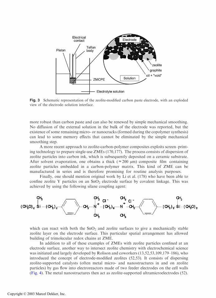
Finally, one should mention original work by Li et al. (178) who have been able toconfine zeolite Y particles on an SnO2 electrode surface by covalent linkage. This wasachieved by using the following silane coupling agent:
which can react with both the SnO2 and zeolite surfaces to give a mechanically stablezeolite layer on the electrode surface. This particular spatial arrangement has allowedbuilding of trimolecular redox chains at ZME.
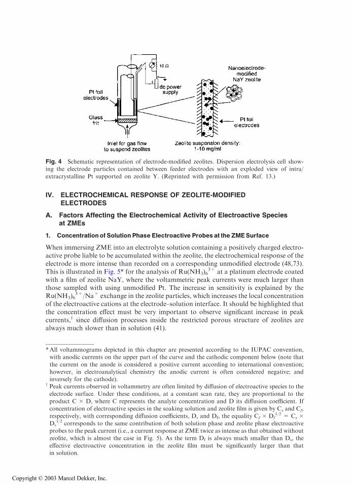
In addition to all of these examples of ZMEs with zeolite particles confined at anelectrode surface, another way to intersect zeolite chemistry with electrochemical sciencewas initiated and largely developed by Rolison and coworkers (13,52,53,109,179–186), whointroduced the concept of electrode-modified zeolites (52,53). It consists of dispersingzeolite-supported catalysts (often metal micro- and nanostructures in and on zeoliteparticles) by gas flow into electroreactors made of two feeder electrodes on the cell walls(Fig. 4). The metal nanostructures then act as zeolite-supported ultramicroelectrodes (52).
Fig. 3 Schematic representation of the zeolite-modified carbon paste electrode, with an explodedview of the electrode–solution interface.
Copyright © 2003 Marcel Dekker, Inc.
IV. ELECTROCHEMICAL RESPONSE OF ZEOLITE-MODIFIEDELECTRODES
A. Factors Affecting the Electrochemical Activity of Electroactive Speciesat ZMEs
1. Concentration of Solution Phase Electroactive Probes at the ZMESurface
When immersing ZME into an electrolyte solution containing a positively charged electro-active probe liable to be accumulated within the zeolite, the electrochemical response of theelectrode is more intense than recorded on a corresponding unmodified electrode (48,73).This is illustrated in Fig. 5* for the analysis of Ru(NH3)6
3+ at a platinum electrode coatedwith a film of zeolite NaY, where the voltammetric peak currents were much larger thanthose sampled with using unmodified Pt. The increase in sensitivity is explained by theRu(NH3)6
3+/Na+ exchange in the zeolite particles, which increases the local concentrationof the electroactive cations at the electrode–solution interface. It should be highlighted thatthe concentration effect must be very important to observe significant increase in peakcurrents,y since diffusion processes inside the restricted porous structure of zeolites arealways much slower than in solution (41).
Fig. 4 Schematic representation of electrode-modified zeolites. Dispersion electrolysis cell show-ing the electrode particles contained between feeder electrodes with an exploded view of intra/
extracrystalline Pt supported on zeolite Y. (Reprinted with permission from Ref. 13.)
*All voltammograms depicted in this chapter are presented according to the IUPAC convention,with anodic currents on the upper part of the curve and the cathodic component below (note that
the current on the anode is considered a positive current according to international convention;however, in electroanalytical chemistry the anodic current is often considered negative; andinversely for the cathode).
y Peak currents observed in voltammetry are often limited by diffusion of electroactive species to the
electrode surface. Under these conditions, at a constant scan rate, they are proportional to theproduct C � D, where C represents the analyte concentration and D its diffusion coefficient. Ifconcentration of electroactive species in the soaking solution and zeolite film is given by Cs and Cf,respectively, with corresponding diffusion coefficients, Ds and Df, the equality Cf � Df
1/2 = Cs �Ds
1/2 corresponds to the same contribution of both solution phase and zeolite phase electroactiveprobes to the peak current (i.e., a current response at ZME twice as intense as that obtained withoutzeolite, which is almost the case in Fig. 5). As the term Df is always much smaller than Ds, the
effective electroactive concentration in the zeolite film must be significantly larger than thatin solution.
Copyright © 2003 Marcel Dekker, Inc.
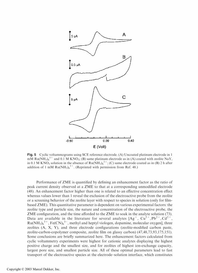
Performance of ZME is quantified by defining an enhancement factor as the ratio ofpeak current density observed at a ZME to that at a corresponding unmodified electrode(48). An enhancement factor higher than one is related to an effective concentration effectwhereas values lower than 1 reveal the exclusion of the electroactive probe from the zeoliteor a screening behavior of the zeolite layer with respect to species in solution (only for film-based ZME). This quantitative parameter is dependent on various experimental factors: thezeolite type and particle size, the nature and concentration of the electroactive probe, theZME configuration, and the time afforded to the ZME to soak in the analyte solution (73).Data are available in the literature for several analytes [Ag+, Cu2+,Pb2+,Cd2+,Ru(NH3)6
3+, Fe(CN)63�, methyl and heptyl viologen, dopamine, molecular oxygen], three
zeolites (A, X, Y), and three electrode configurations (zeolite-modified carbon paste,zeolite-carbon-copolymer composite, zeolite film on glassy carbon) (47,48,73,93,175,151).Some conclusions are briefly summarized here. The enhancement factors calculated fromcyclic voltammetry experiments were highest for cationic analytes displaying the highestpositive charge and the smallest size, and for zeolites of highest ion-exchange capacity,largest pore size, and smallest particle size. All of these optimal parameters lead to fasttransport of the electroactive species at the electrode–solution interface, which constitutes
Fig. 5 Cyclic voltammograms using SCE reference electrode. (A) Uncoated platinum electrode in 1mM Ru(NH3)6
3+ and 0.1 M KNO3; (B) same platinum electrode as in (A) coated with zeolite NaY,in 0.1 M KNO3 solution in the absence of Ru(NH3)6
3+; (C) same electrode coated as in (B) 2 h afteraddition of 1 mM Ru(NH3)6
3+. (Reprinted with permission from Ref. 48.)
Copyright © 2003 Marcel Dekker, Inc.
the rate-determining process when ZMEs are used in the preconcentration-voltammetricdetection scheme. Peak heights were also found to increase by increasing the duration ofZME exposure to the solution prior to electrochemical analysis because longer soakingtimes resulted in a larger amount of electroactive cations exchanged in zeolites. Peakcurrents recorded as a function of time leveled off more quickly for higher analyteconcentrations. On the other hand, the lower the analyte concentration, more efficientthe preconcentration, especially when the zeolite exhibits significant preference for theelectroactive cation over the electrolyte cation (e.g., in the case of ion-exchange isothermsdictating equivalent fractions of the electroactive cation higher in the zeolite than insolution). In general, bulk zeolite–modified electrodes gave faster enhancement behaviorcompared to zeolite film–based electrodes. This is because zeolite particles are in directcontact with the electroactive analyte in the former case upon immersion of the electrodeinto solution, whereas reaching the zeolite layer might be delayed in the latter case dueto the hydrophobic character of the polymer binder (or overlayer). Among the bulkzeolite-carbon-based materials, the zeolite-carbon-polystyrene-divinylbenzene and thescreen-printed zeolite-carbon composites usually gave better performance than the zeo-lite-modified carbon paste electrodes (170,175). Depending on the above-mentionedparameters, the observed experimental enhancement factors ranged between 1 and 10 forvarious analytes, with the exception of silver(I) for which values as high as 40 were obtainedafter 15 min exposure to a 1 mM Ag+ solution (73). Size-excluded electroactive cations(those of size larger than the zeolite pore aperture) and charge-excluded species (anions) didnot result in any enhancement of the voltammetric peaks.
The approaches just described aim to investigate the behavior of ZMEs with respectto solution phase electroactive probes. However, much of the work on ZMEs, has beenperformed with electrode systems made of zeolites previously loaded with an electroactivespecies. A major distinction has to be made between species incorporated in zeolites by ionexchange, which are therefore liable to undergo back exchange when soaking ZME into anelectrolyte solution, and species encapsulated in a zeolite host as ‘‘ship-in-a-bottle’’complexes that have restricted freedom of movement inside the molecular sieve.
2. Electrochemical Activity of Electroactive Species Ion Exchanged in Zeolites
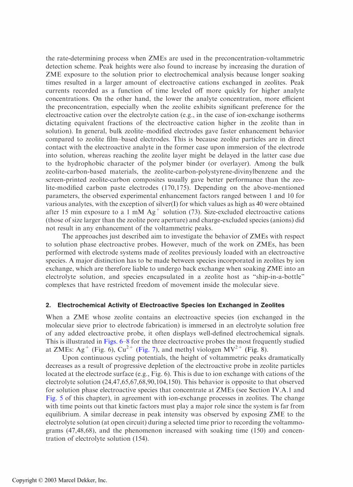
When a ZME whose zeolite contains an electroactive species (ion exchanged in themolecular sieve prior to electrode fabrication) is immersed in an electrolyte solution freeof any added electroactive probe, it often displays well-defined electrochemical signals.This is illustrated in Figs. 6–8 for the three electroactive probes the most frequently studiedat ZMEs: Ag+ (Fig. 6), Cu2+ (Fig. 7), and methyl viologen MV2+ (Fig. 8).
Upon continuous cycling potentials, the height of voltammetric peaks dramaticallydecreases as a result of progressive depletion of the electroactive probe in zeolite particleslocated at the electrode surface (e.g., Fig. 6). This is due to ion exchange with cations of theelectrolyte solution (24,47,65,67,68,90,104,150). This behavior is opposite to that observedfor solution phase electroactive species that concentrate at ZMEs (see Section IV.A.1 andFig. 5 of this chapter), in agreement with ion-exchange processes in zeolites. The changewith time points out that kinetic factors must play a major role since the system is far fromequilibrium. A similar decrease in peak intensity was observed by exposing ZME to theelectrolyte solution (at open circuit) during a selected time prior to recording the voltammo-grams (47,48,68), and the phenomenon increased with soaking time (150) and concen-tration of electrolyte solution (154).
Copyright © 2003 Marcel Dekker, Inc.
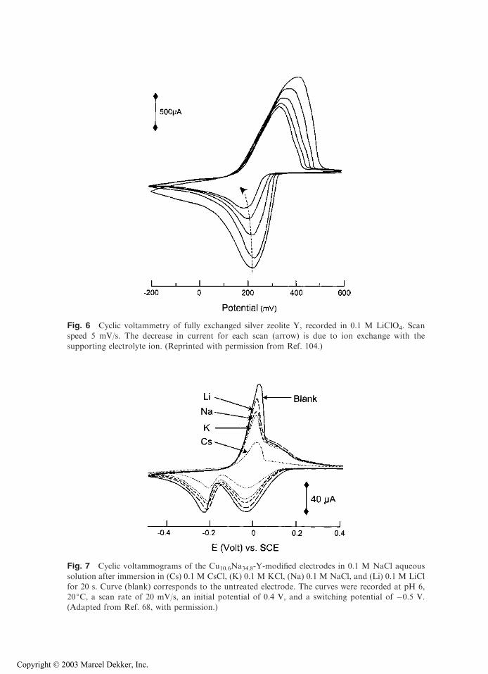
Fig. 6 Cyclic voltammetry of fully exchanged silver zeolite Y, recorded in 0.1 M LiClO4. Scan
speed 5 mV/s. The decrease in current for each scan (arrow) is due to ion exchange with thesupporting electrolyte ion. (Reprinted with permission from Ref. 104.)
Fig. 7 Cyclic voltammograms of the Cu10.6Na34.8-Y-modified electrodes in 0.1 M NaCl aqueous
solution after immersion in (Cs) 0.1 M CsCl, (K) 0.1 M KCl, (Na) 0.1 M NaCl, and (Li) 0.1 M LiClfor 20 s. Curve (blank) corresponds to the untreated electrode. The curves were recorded at pH 6,20jC, a scan rate of 20 mV/s, an initial potential of 0.4 V, and a switching potential of �0.5 V.
(Adapted from Ref. 68, with permission.)
Copyright © 2003 Marcel Dekker, Inc.
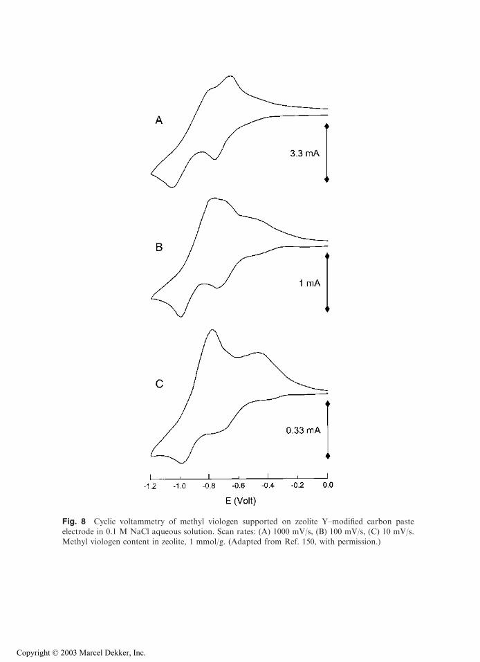
Fig. 8 Cyclic voltammetry of methyl viologen supported on zeolite Y–modified carbon pasteelectrode in 0.1 M NaCl aqueous solution. Scan rates: (A) 1000 mV/s, (B) 100 mV/s, (C) 10 mV/s.Methyl viologen content in zeolite, 1 mmol/g. (Adapted from Ref. 150, with permission.)
Copyright © 2003 Marcel Dekker, Inc.
The leaching process is rather fast and depends on the nature of the electrolyte cation(68). For example, experiments carried out immediately after immersion of copper-exchanged ZME in a NaCl electrolyte solution, and after a 20-s treatment in stirredsolutions containing either CsCl, KCl, NaCl, or LiCl at the same concentration, show thatCuII species rapidly leach out of zeolites, at a rate in the order Li+<Na+< K+< Cs+
(Fig. 7). This order agrees well with the size of hydrated cations, which govern the speedof the exchange process (in most cages). Accordingly, the electrochemical response ofZMEs exchanged with electroactive species (without any pretreatment) is more intensethe smaller the size of the (hydrated) electrolyte cation and the higher its concentration(43,64,68,76,150,167). Peak currents observed for an AgY-modified electrode as a functionof quaternary ammonium ion concentration in solution were found to increase linearly withconcentration of the non-size-excluded cations, with slopes decreasing in the order NH4
+
> NMe4+ > NEt4
+ > NPr4+ (64). The use of the large size–excluded NBu4
+ species asthe electrolyte cation results in nearly insignificant responses attributed to exchange ofelectroactive probes located on the external surfaces of zeolite particles or slow intrazeoliteexchange under forcing conditions (64). Also, the use of ZMEs comprising zeolites ofdifferent pore apertures leads to voltammetric peaks that increase in intensity with size of thezeolite pores and channels (for the same particle size) (73,167). All of these observationsindicate that diffusion processes play an important role in the overall transformation of anelectroactive probe at ZMEs.
This is further proven by the evolution of voltammetric peaks with scan rate(illustrated for MV2+ at ZMCPE on Fig. 8). These display a linear dependence of peakheight with the square root of scan rate (151), which is typical for diffusion-controlledcharge-transfer reactions (188). Such dependency is often observed for ion-exchangeableelectroactive species at ZMEs (61,148,159), except when electrochemically distinct ions areinvolved [several successive signals for the same species, see below (65,70,76,104)], or whenleaching the electroactive probe from the zeolite is prevented (57). This latter case has beenobserved with electrodes coated with zeolite Y containing porphyrin adsorbed onto—andviologen species exchanged inside—the zeolite particles. The porphyrin monolayer effec-tively seals up the zeolite against exchange of encapsulated viologens with solution phasecations while acting as an electron shuttle between the electrode surface and the viologenentities (57).
One of the most striking points in the electrochemistry of ZMEs is the wide diversityof electrode configurations (especially from the microscopic point of view), which, coupledwith the wide range of experimental parameters liable to affect the electrochemicalresponse (all of them being rarely investigated in a single study), makes comparisonamong the various cases very difficult. Even when applying the same preparationprocedure, the resulting ZME will display variable composition and structure at bothnano- and microscale levels. This would be very difficult to reproduce exactly, as one canimagine from the oversimplified schematic views of ZMEs depicted on Figs. 1–3. Thesenano- and microstructures (including those within zeolites), wherein the electroactiveguests are liable to experience very different environments, are thought to affect theelectrochemical response of ZMEs to various degrees. However, electrochemical measure-ments provide macroscopic data, often obtained under nonequilibrium conditions, thatare related to complex processes occurring in microscopic heterogeneous domains.Although some macroscopic electrochemical data have been successfully exploited tocharacterize microscopic host–guest effects, i.e., cation site effects or ion-exchangedynamics (66,67,69,70,76,83,104,109,127), this duality of global electrochemical measure-ment resulting from many different localized nano- and microscopic events remains (in this
Copyright © 2003 Marcel Dekker, Inc.
author’s opinion) the main barrier to the full control and complete understanding ofthe electrochemical behavior of ZMEs. It is noteworthy that this drawback is largelycompensated for by the presence of various attractive applications following fundamentalstudies (see Section V). In any event, advances in the basic understanding of ZMEs havebeen achieved, and general trends can be gleaned from analysis of the available literature.
At first glance, it has appears that voltammetric signals obtained with ZMEs thatcontain exchanged electroactive species, especially those recorded using ZMCPE, do notdiffer significantly from those resulting from solution phase electroactive probes, at leastwith respect to their shape and position (47,60,148,150,159). This is in good agreementwith the progressive leaching of probes from zeolite particles into the surroundingsolution. Nevertheless, electrochemical behavior is clearly affected by type of electroactiveprobe, ion exchange extent and cation site effects (and therefore zeolite type), electrodecomposition and configuration, and nature and concentration of supporting electrolyte aswell as solvent. Some illustrative examples are now provided.
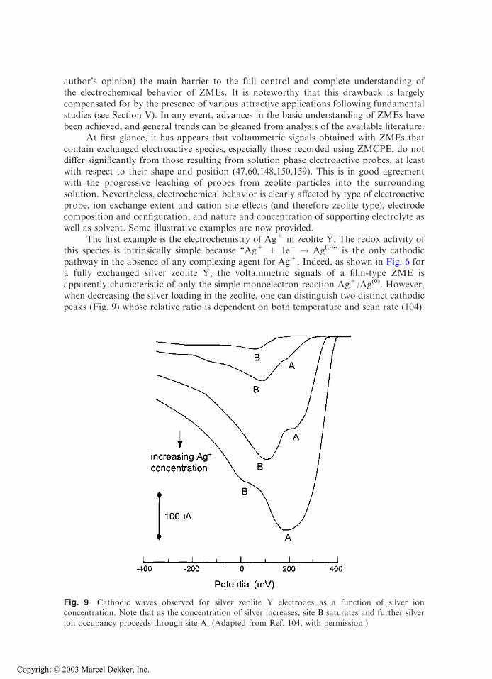
The first example is the electrochemistry of Ag+ in zeolite Y. The redox activity ofthis species is intrinsically simple because ‘‘Ag+ + 1e� ! Ag(0)’’ is the only cathodicpathway in the absence of any complexing agent for Ag+. Indeed, as shown in Fig. 6 fora fully exchanged silver zeolite Y, the voltammetric signals of a film-type ZME isapparently characteristic of only the simple monoelectron reaction Ag+/Ag(0). However,when decreasing the silver loading in the zeolite, one can distinguish two distinct cathodicpeaks (Fig. 9) whose relative ratio is dependent on both temperature and scan rate (104).
Fig. 9 Cathodic waves observed for silver zeolite Y electrodes as a function of silver ionconcentration. Note that as the concentration of silver increases, site B saturates and further silverion occupancy proceeds through site A. (Adapted from Ref. 104, with permission.)
Copyright © 2003 Marcel Dekker, Inc.
These two signals (referred to as A and B in Fig. 9) were attributed to Ag+ ions located intwo different ion exchange sites, respectively, on the walls of supercages (site II) and in thehexagonal prisms (site I) (104). Reduction of Ag+ from site II is easier than that from siteI, and occurs at lower cathodic potential values, because site I encompasses Ag+ in a moreconfined environment than site II. The relative intensities of peaks A and B are controlledby the Ag+ ion occupancy in the zeolite. They are governed during the electrochemicalexperiment by the speed of interconversion of Ag+ from one site to another, which occursas a consequence of consumption of either species as a function of the applied potential.The activation energy for intracrystalline ion exchange between the large- and small-channel systems is 35 kJ mol�1, which is significantly higher than that corresponding tocounterdiffusion of silver and sodium cations in the large-channel network (30 kJ mol�1),as measured from chronoamperometric experiments (66). This technique is also able todetermine the intrazeolite diffusion coefficient, which was reported as 2–4 10�8 cm2 s�1 forAg+ in zeolite Y (78).
So why does the fully exchanged zeolite not give the two signals? Diffusionalprocesses involving a large amount of Ag+ in the large channels are so fast that theamount transformed during the electrochemical event is also large and, consequently,leads to large voltammetric peaks that smooth the eventual splitting effect due to variousion-exchange sites. Seeing the less accessible sites requires either low exchange degrees orthe use of ZMEs in which the electroactive cations are exclusively located in the moreconfined sites.
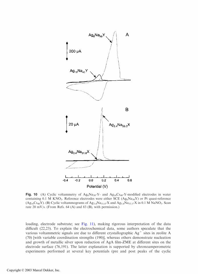
The relative Ag+ population of sites I and II is also sensitive to the type ofcocation. Figure 10A compares the electrochemical response of a zeolite Y containing asmall amount of Ag+ ions distributed randomly in the zeolite structure (sampleAg6Na50Y) with another Y sample containing a little more Ag+ species but almostexclusively in the small channels (Ag16Cs40Y). The voltammetric signals observed withthe low-Ag+ zeolite are much larger. Once again, this behavior is explained by the easyexchange of Ag+ located in the large cages, whereas those located in the small channelsare not accessible to the Cs+ electrolyte cation (Cs+ is known to be excluded from thesodalite cages) (64). Even when using an electrolyte cation liable to diffuse into the smallcages, very low currents are observed because of the slow interconversion between Ag+
from small- to large-pore systems (67). This is further exemplified in Fig. 10B for zeoliteX. Increasing the Ag+ content slightly from 3.4 to 5.4 ions per unit cell results in a50-fold enhancement of the voltammetric response recorded at ZME. This indicates thatAg+ ions are almost exclusively located in the small-channel network in Ag3.4Na51.8-Xwhile some supercage sites are occupied in Ag5.4Na53.5-X (83). The electrochemicalresponse of silver species ion exchanged in supercages is governed by the size ofhydrated electrolyte cation (as also observed in preconcentration analysis; see Sec.IV.A.1 of this chapter), but the Faradaic currents due to silver initially located in thesmall cages is monitored by the ionic radii and dehydration energies of the electrolytecations (67).
On the other hand, no distinct voltammetric peaks have been observed for ZMEsloaded with methyl viologen in zeolite Y (47,71,89,150,154,170), probably because MV2+
species are exclusively located in the supercages (189). However, this statement must bequalified because ZMEs made of zeolite A exchanged with silver display complexbehavior with several electrochemically distinct species. These species correspond toAg+ reduction (70,76), despite the fact that all of the exchange sites are located in thesame type of cages (41). The relative intensity of each voltammetric signal is stronglydependent on various experimental parameters (scan rate, supporting electrolyte, Ag+
Copyright © 2003 Marcel Dekker, Inc.
loading, electrode substrate; see Fig. 11), making rigorous interpretation of the datadifficult (22,23). To explain the electrochemical data, some authors speculate that thevarious voltammetric signals are due to different crystallographic Ag+ sites in zeolite A(70) [with variable coordination strengths (190)], whereas others demonstrate nucleationand growth of metallic silver upon reduction of AgA film-ZME at different sites on theelectrode surface (76,191). The latter explanation is supported by chronoamperometricexperiments performed at several key potentials (pre and post peaks of the cyclic
Fig. 10 (A) Cyclic voltammetry of Ag6Na50-Y- and Ag16Cs40-Y-modified electrodes in watercontaining 0.1 M KNO3. Reference electrodes were either SCE (Ag6Na50Y) or Pt quasi-reference
(Ag16Cs40Y). (B) Cyclic voltammograms of Ag3.4Na51.8-X and Ag5.4Na53.5-X in 0.1 M NaNO3. Scanrate 20 mV/s. (From Refs. 64 (A) and 83 (B), with permission.)
Copyright © 2003 Marcel Dekker, Inc.
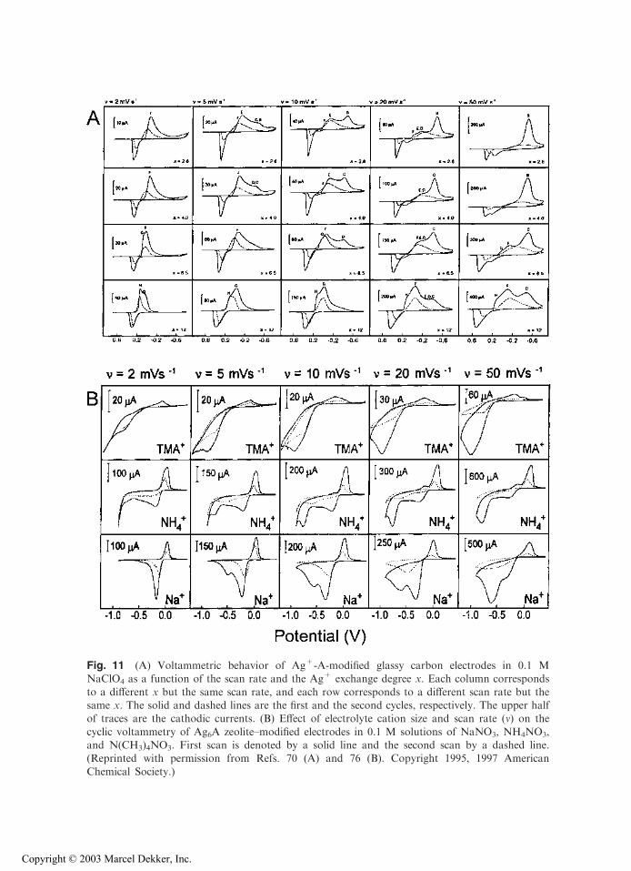
Fig. 11 (A) Voltammetric behavior of Ag+-A-modified glassy carbon electrodes in 0.1 MNaClO4 as a function of the scan rate and the Ag+ exchange degree x. Each column corresponds
to a different x but the same scan rate, and each row corresponds to a different scan rate but thesame x. The solid and dashed lines are the first and the second cycles, respectively. The upper halfof traces are the cathodic currents. (B) Effect of electrolyte cation size and scan rate (m) on the
cyclic voltammetry of Ag6A zeolite–modified electrodes in 0.1 M solutions of NaNO3, NH4NO3,and N(CH3)4NO3. First scan is denoted by a solid line and the second scan by a dashed line.(Reprinted with permission from Refs. 70 (A) and 76 (B). Copyright 1995, 1997 American
Chemical Society.)
Copyright © 2003 Marcel Dekker, Inc.
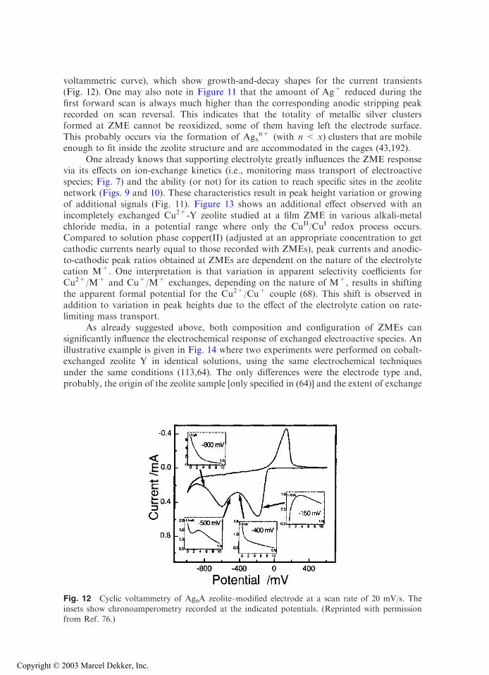
voltammetric curve), which show growth-and-decay shapes for the current transients(Fig. 12). One may also note in Figure 11 that the amount of Ag+ reduced during thefirst forward scan is always much higher than the corresponding anodic stripping peakrecorded on scan reversal. This indicates that the totality of metallic silver clustersformed at ZME cannot be reoxidized, some of them having left the electrode surface.This probably occurs via the formation of Agx
n+ (with n < x) clusters that are mobileenough to fit inside the zeolite structure and are accommodated in the cages (43,192).
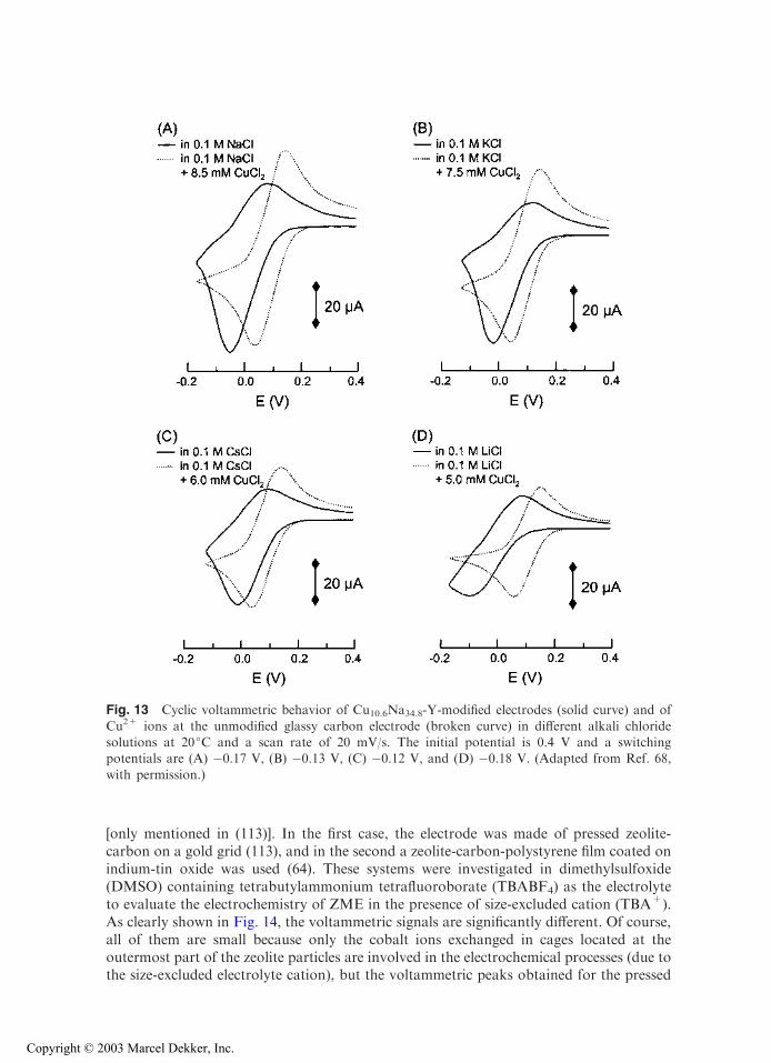
One already knows that supporting electrolyte greatly influences the ZME responsevia its effects on ion-exchange kinetics (i.e., monitoring mass transport of electroactivespecies; Fig. 7) and the ability (or not) for its cation to reach specific sites in the zeolitenetwork (Figs. 9 and 10). These characteristics result in peak height variation or growingof additional signals (Fig. 11). Figure 13 shows an additional effect observed with anincompletely exchanged Cu2+-Y zeolite studied at a film ZME in various alkali-metalchloride media, in a potential range where only the CuII/CuI redox process occurs.Compared to solution phase copper(II) (adjusted at an appropriate concentration to getcathodic currents nearly equal to those recorded with ZMEs), peak currents and anodic-to-cathodic peak ratios obtained at ZMEs are dependent on the nature of the electrolytecation M+. One interpretation is that variation in apparent selectivity coefficients forCu2+/M+ and Cu+/M+ exchanges, depending on the nature of M+, results in shiftingthe apparent formal potential for the Cu2+/Cu+ couple (68). This shift is observed inaddition to variation in peak heights due to the effect of the electrolyte cation on rate-limiting mass transport.
As already suggested above, both composition and configuration of ZMEs cansignificantly influence the electrochemical response of exchanged electroactive species. Anillustrative example is given in Fig. 14 where two experiments were performed on cobalt-exchanged zeolite Y in identical solutions, using the same electrochemical techniquesunder the same conditions (113,64). The only differences were the electrode type and,probably, the origin of the zeolite sample [only specified in (64)] and the extent of exchange
Fig. 12 Cyclic voltammetry of Ag6A zeolite–modified electrode at a scan rate of 20 mV/s. Theinsets show chronoamperometry recorded at the indicated potentials. (Reprinted with permissionfrom Ref. 76.)
Copyright © 2003 Marcel Dekker, Inc.
[only mentioned in (113)]. In the first case, the electrode was made of pressed zeolite-carbon on a gold grid (113), and in the second a zeolite-carbon-polystyrene film coated onindium-tin oxide was used (64). These systems were investigated in dimethylsulfoxide(DMSO) containing tetrabutylammonium tetrafluoroborate (TBABF4) as the electrolyteto evaluate the electrochemistry of ZME in the presence of size-excluded cation (TBA+).As clearly shown in Fig. 14, the voltammetric signals are significantly different. Of course,all of them are small because only the cobalt ions exchanged in cages located at theoutermost part of the zeolite particles are involved in the electrochemical processes (due tothe size-excluded electrolyte cation), but the voltammetric peaks obtained for the pressed
Fig. 13 Cyclic voltammetric behavior of Cu10.6Na34.8-Y-modified electrodes (solid curve) and of
Cu2+ ions at the unmodified glassy carbon electrode (broken curve) in different alkali chloridesolutions at 20jC and a scan rate of 20 mV/s. The initial potential is 0.4 V and a switchingpotentials are (A) �0.17 V, (B) �0.13 V, (C) �0.12 V, and (D) �0.18 V. (Adapted from Ref. 68,
with permission.)
Copyright © 2003 Marcel Dekker, Inc.
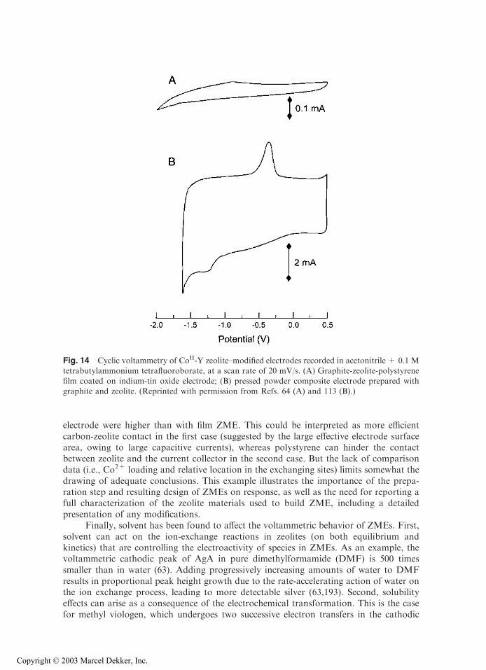
electrode were higher than with film ZME. This could be interpreted as more efficientcarbon-zeolite contact in the first case (suggested by the large effective electrode surfacearea, owing to large capacitive currents), whereas polystyrene can hinder the contactbetween zeolite and the current collector in the second case. But the lack of comparisondata (i.e., Co2+ loading and relative location in the exchanging sites) limits somewhat thedrawing of adequate conclusions. This example illustrates the importance of the prepa-ration step and resulting design of ZMEs on response, as well as the need for reporting afull characterization of the zeolite materials used to build ZME, including a detailedpresentation of any modifications.
Finally, solvent has been found to affect the voltammetric behavior of ZMEs. First,solvent can act on the ion-exchange reactions in zeolites (on both equilibrium andkinetics) that are controlling the electroactivity of species in ZMEs. As an example, thevoltammetric cathodic peak of AgA in pure dimethylformamide (DMF) is 500 timessmaller than in water (63). Adding progressively increasing amounts of water to DMFresults in proportional peak height growth due to the rate-accelerating action of water onthe ion exchange process, leading to more detectable silver (63,193). Second, solubilityeffects can arise as a consequence of the electrochemical transformation. This is the casefor methyl viologen, which undergoes two successive electron transfers in the cathodic
Fig. 14 Cyclic voltammetry of CoII-Y zeolite–modified electrodes recorded in acetonitrile + 0.1 M
tetrabutylammonium tetrafluoroborate, at a scan rate of 20 mV/s. (A) Graphite-zeolite-polystyrenefilm coated on indium-tin oxide electrode; (B) pressed powder composite electrode prepared withgraphite and zeolite. (Reprinted with permission from Refs. 64 (A) and 113 (B).)
Copyright © 2003 Marcel Dekker, Inc.
direction, MV2+ ! MV.+ ! MV(0), where MV2+ and MV
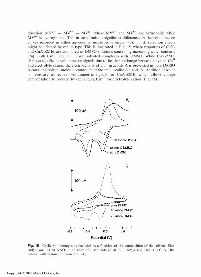
.+ are hydrophilic whileMV(0) is hydrophobic. This in turn leads to significant differences in the voltammetriccurves recorded in either aqueous or nonaqueous media (47). Third, solvation effectsmight be affected by zeolite type. This is illustrated in Fig. 15, where responses of CuY-and CuA-ZMEs are compared in DMSO solutions containing increasing water contents(24). Both Cu2+ and Cu+ form solvated complexes with DMSO. While CuY-ZMEdisplays significant voltammetric signals due to fast ion exchange between solvated CuII
and electrolyte cation, the electroactivity of CuII in zeolite A is prevented in pure DMSObecause this solvent molecule cannot enter the small zeolite A structure. Addition of wateris necessary to recover voltammetric signals for CuA-ZME, which allows chargecompensation to proceed by exchanging Cu2+ for electrolyte cation (Fig. 15).
Fig. 15 Cyclic voltammograms recorded as a function of the composition of the solvent. Elec-trolyte was 0.1 M KNO3 in all cases and scan rate equal to 10 mV/s: (A) CuY; (B) CuA. (Re-
printed with permission from Ref. 24.)
Copyright © 2003 Marcel Dekker, Inc.

3. Electrochemical Activity of Electroactive Species Physically Entrappedin Zeolites
If a ZME contains electroactive species that have been encapsulated as ship-in-a-bottlecomplexes in the porous zeolite network, its electrochemical behavior is fundamentallydifferent from those containing ion-exchanged electroactive probes. This arises from thevery limited degree of freedom (restricted movement inside the rigid structure) experiencedby these physically entrapped moieties. Nevertheless, electroactive complexes encapsulatedin ZMEs give rise to electrochemical signals (see examples below), but their real origin hasbeen controversial (9,11,22–26,109,194). The electrochemistry of zeolite-encapsulatedcomplexes has been largely studied by Bedioui’s group (18,20,112–119,121–123,127), aswell as some others (24,79,87,108,109,185).
In addition to large species simply adsorbed onto the external surface of zeoliteparticles, such as porphyrins (45,57,120), the size-excluded electroactive probes thathave been studied in electrochemistry as encapsulated complexes are of three types:metal–tris-bipyridine moieties, metal-phthalocyanines, and metal–Schiff base complexes(see above). These are most often synthesized directly inside the molecular sieve byallowing a metal-exchanged zeolite to react with the appropriate ligand, but syntheticprocedures involving the zeolite building around the preformed complexes have alsobeen reported (112,122). On the basis of their state of confinement, one can distinguishthree kinds of environments experienced by the complexes: (a) the outermost externalsurface where complexes are simply bound to the particle surface (adsorbed or ionexchanged) and can be readily displaced in solution under appropriate conditions; (b)the first layer of complete or broken cages located at the particle boundary wherecomplexes are (at least partially) occluded in or in strong interaction with these cages,so that they cannot easily leave their site but can be readily reached by the externalsolution; and (c) the bulk zeolite where complexes are entirely entrapped in the three-dimensional lattice and therefore cannot move from one site to another and of coursecannot leave the zeolite structure (unless being decomposed, i.e., by removal of ligands).The first two environments are likely to participate in an electrochemical reaction due totheir direct contact with a conducting substrate (i.e., electrode feeder), close enough toallow the electron transfer. However, the redox transformation of complexes located
Copyright © 2003 Marcel Dekker, Inc.
deeper in the bulk zeolite (if occurring)* would require either a mobile non-size-excludedmediator or very close contact of encapsulated species to facilitate electron hoppingbetween them [as was demonstrated for photoassisted electron transfer in the channelmolecular sieve structure of zeolite L (189)].
Following are some examples and conclusions regarding the electrochemistry ofZMEs containing the three electroactive species represented in Scheme 1. Fe(bpy)3
2+
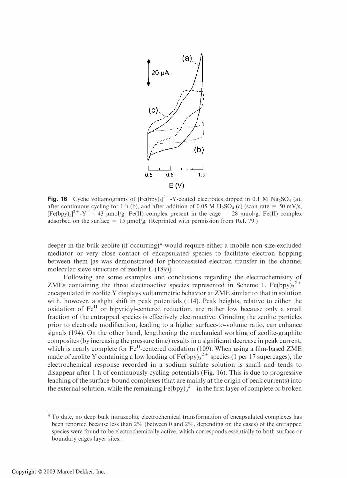
encapsulated in zeolite Y displays voltammetric behavior at ZME similar to that in solutionwith, however, a slight shift in peak potentials (114). Peak heights, relative to either theoxidation of FeII or bipyridyl-centered reduction, are rather low because only a smallfraction of the entrapped species is effectively electroactive. Grinding the zeolite particlesprior to electrode modification, leading to a higher surface-to-volume ratio, can enhancesignals (194). On the other hand, lengthening the mechanical working of zeolite-graphitecomposites (by increasing the pressure time) results in a significant decrease in peak current,which is nearly complete for FeII-centered oxidation (109). When using a film-based ZMEmade of zeolite Y containing a low loading of Fe(bpy)3
2+ species (1 per 17 supercages), theelectrochemical response recorded in a sodium sulfate solution is small and tends todisappear after 1 h of continuously cycling potentials (Fig. 16). This is due to progressiveleaching of the surface-bound complexes (that are mainly at the origin of peak currents) intothe external solution, while the remaining Fe(bpy)3
2+ in the first layer of complete or broken
Fig. 16 Cyclic voltamograms of [Fe(bpy)3]2+-Y-coated electrodes dipped in 0.1 M Na2SO4 (a),
after continuous cycling for 1 h (b), and after addition of 0.05 M H2SO4 (c) (scan rate = 50 mV/s,[Fe(bpy)3]
2+-Y = 43 Amol/g. Fe(II) complex present in the cage = 28 Amol/g. Fe(II) complexadsorbed on the surface = 15 Amol/g. (Reprinted with permission from Ref. 79.)
*To date, no deep bulk intrazeolite electrochemical transformation of encapsulated complexes hasbeen reported because less than 2% (between 0 and 2%, depending on the cases) of the entrapped
species were found to be electrochemically active, which corresponds essentially to both surface orboundary cages layer sites.
Copyright © 2003 Marcel Dekker, Inc.
cages located at the particle boundary are not sufficiently numerous to provide a significantelectrochemical response [which requires higher concentrations (127)]. To reveal theelectrochemical activity of bulk Fe(bpy)3
2+ species, it is necessary to work in the presenceof strong acid (Fig. 16) that disintegrates the zeolite structure with concomitant leaching ofthe bulk complexes into solution in close proximity to the electrode surface (79). Similarresults are obtained for the zeolite Y-Ru(bpy)3
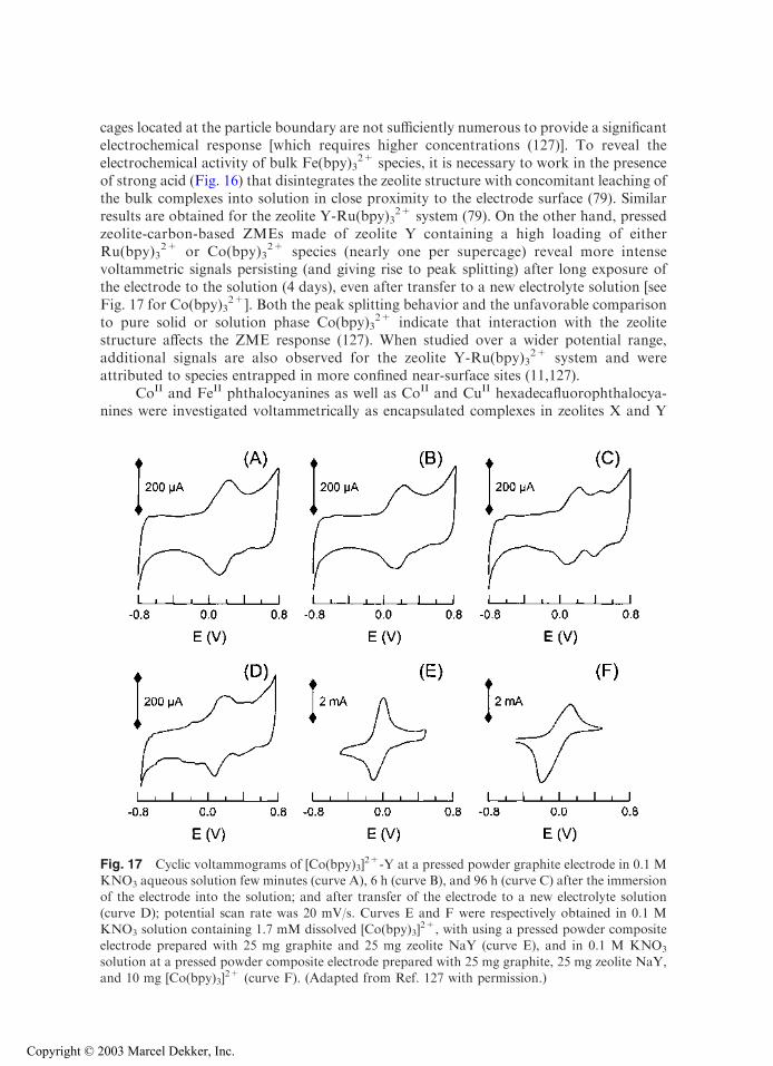
2+ system (79). On the other hand, pressedzeolite-carbon-based ZMEs made of zeolite Y containing a high loading of eitherRu(bpy)3
2+ or Co(bpy)32+ species (nearly one per supercage) reveal more intense
voltammetric signals persisting (and giving rise to peak splitting) after long exposure ofthe electrode to the solution (4 days), even after transfer to a new electrolyte solution [seeFig. 17 for Co(bpy)3
2+]. Both the peak splitting behavior and the unfavorable comparisonto pure solid or solution phase Co(bpy)3
2+ indicate that interaction with the zeolitestructure affects the ZME response (127). When studied over a wider potential range,additional signals are also observed for the zeolite Y-Ru(bpy)3
2+ system and wereattributed to species entrapped in more confined near-surface sites (11,127).
CoII and FeII phthalocyanines as well as CoII and CuII hexadecafluorophthalocya-nines were investigated voltammetrically as encapsulated complexes in zeolites X and Y
Fig. 17 Cyclic voltammograms of [Co(bpy)3]2+-Y at a pressed powder graphite electrode in 0.1 M
KNO3 aqueous solution few minutes (curve A), 6 h (curve B), and 96 h (curve C) after the immersionof the electrode into the solution; and after transfer of the electrode to a new electrolyte solution
(curve D); potential scan rate was 20 mV/s. Curves E and F were respectively obtained in 0.1 MKNO3 solution containing 1.7 mM dissolved [Co(bpy)3]
2+, with using a pressed powder compositeelectrode prepared with 25 mg graphite and 25 mg zeolite NaY (curve E), and in 0.1 M KNO3
solution at a pressed powder composite electrode prepared with 25 mg graphite, 25 mg zeolite NaY,and 10 mg [Co(bpy)3]
2+ (curve F). (Adapted from Ref. 127 with permission.)
Copyright © 2003 Marcel Dekker, Inc.
(108,112,116–118,122). In general, their behavior is similar to that observed for monomersin solution, but they usually display better defined signals due to confinement that preventsthe aggregation of complexes, which is known to induce kinetic complications in solution(122). Also, site isolation of RhIII phthalocyanine in zeolite Y enables the observation ofreversible behavior for this complex at ZME (only species trapped in the outermostsupercages are electroactive (123) while giving irreversible voltammetric peaks whenstudied as solution phase species because of dimerization upon reduction RhIII/RhII (195).
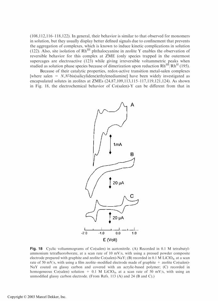
Because of their catalytic properties, redox-active transition metal-salen complexes[where salen = N,NV-bis(salicylidene)ethylenediamine] have been widely investigated asencapsulated solutes in zeolites at ZMEs (24,87,109,113,115–117,119,121,124). As shownin Fig. 18, the electrochemical behavior of Co(salen)-Y can be different from that in
Fig. 18 Cyclic voltammograms of Co(salen) in acetonitrile. (A) Recorded in 0.1 M tetrabutyl-ammonium tetrafluoroborate, at a scan rate of 10 mV/s, with using a pressed powder compositeelectrode prepared with graphite and zeolite Co(salen)-NaY; (B) recorded in 0.1 M LiClO4, at a scan
rate of 50 mV/s, with using a film zeolite–modified electrode made of graphite + zeolite Co(salen)-NaY coated on glassy carbon and covered with an acrylic-based polymer; (C) recorded inhomogeneous Co(salen) solution + 0.1 M LiClO4, at a scan rate of 50 mV/s, with using an
unmodified glassy carbon electrode. (From Refs. 113 (A) and 24 (B and C).)
Copyright © 2003 Marcel Dekker, Inc.
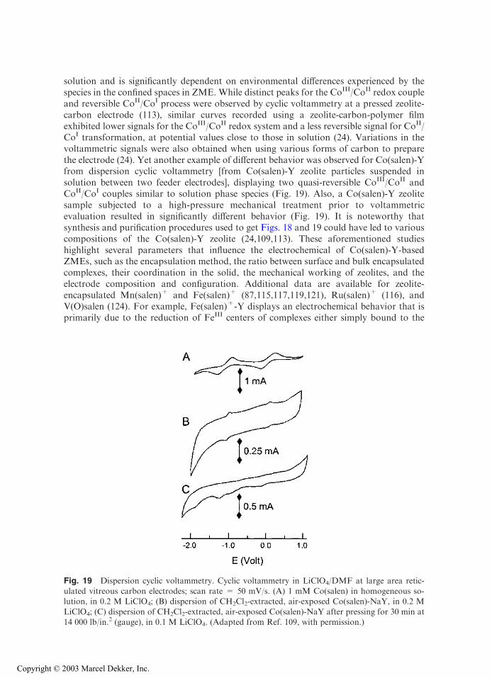
solution and is significantly dependent on environmental differences experienced by thespecies in the confined spaces in ZME. While distinct peaks for the CoIII/CoII redox coupleand reversible CoII/CoI process were observed by cyclic voltammetry at a pressed zeolite-carbon electrode (113), similar curves recorded using a zeolite-carbon-polymer filmexhibited lower signals for the CoIII/CoII redox system and a less reversible signal for CoII/CoI transformation, at potential values close to those in solution (24). Variations in thevoltammetric signals were also obtained when using various forms of carbon to preparethe electrode (24). Yet another example of different behavior was observed for Co(salen)-Yfrom dispersion cyclic voltammetry [from Co(salen)-Y zeolite particles suspended insolution between two feeder electrodes], displaying two quasi-reversible CoIII/CoII andCoII/CoI couples similar to solution phase species (Fig. 19). Also, a Co(salen)-Y zeolitesample subjected to a high-pressure mechanical treatment prior to voltammetricevaluation resulted in significantly different behavior (Fig. 19). It is noteworthy thatsynthesis and purification procedures used to get Figs. 18 and 19 could have led to variouscompositions of the Co(salen)-Y zeolite (24,109,113). These aforementioned studieshighlight several parameters that influence the electrochemical of Co(salen)-Y-basedZMEs, such as the encapsulation method, the ratio between surface and bulk encapsulatedcomplexes, their coordination in the solid, the mechanical working of zeolites, and theelectrode composition and configuration. Additional data are available for zeolite-encapsulated Mn(salen)+ and Fe(salen)+ (87,115,117,119,121), Ru(salen)+ (116), andV(O)salen (124). For example, Fe(salen)+-Y displays an electrochemical behavior that isprimarily due to the reduction of FeIII centers of complexes either simply bound to the
Fig. 19 Dispersion cyclic voltammetry. Cyclic voltammetry in LiClO4/DMF at large area retic-ulated vitreous carbon electrodes; scan rate = 50 mV/s. (A) 1 mM Co(salen) in homogeneous so-lution, in 0.2 M LiClO4; (B) dispersion of CH2Cl2-extracted, air-exposed Co(salen)-NaY, in 0.2 M
LiClO4; (C) dispersion of CH2Cl2-extracted, air-exposed Co(salen)-NaY after pressing for 30 min at14 000 lb/in.2 (gauge), in 0.1 M LiClO4. (Adapted from Ref. 109, with permission.)
Copyright © 2003 Marcel Dekker, Inc.
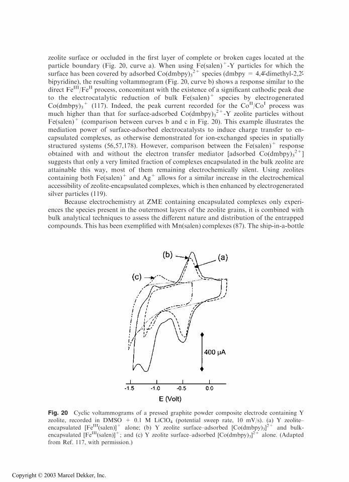
zeolite surface or occluded in the first layer of complete or broken cages located at theparticle boundary (Fig. 20, curve a). When using Fe(salen)+-Y particles for which thesurface has been covered by adsorbed Co(dmbpy)3
2+ species (dmbpy = 4,4V-dimethyl-2,2V-bipyridine), the resulting voltammogram (Fig. 20, curve b) shows a response similar to thedirect FeIII/FeII process, concomitant with the existence of a significant cathodic peak dueto the electrocatalytic reduction of bulk Fe(salen)+ species by electrogeneratedCo(dmbpy)3
+ (117). Indeed, the peak current recorded for the CoII/CoI process wasmuch higher than that for surface-adsorbed Co(dmbpy)3
2+-Y zeolite particles withoutFe(salen)+ (comparison between curves b and c in Fig. 20). This example illustrates themediation power of surface-adsorbed electrocatalysts to induce charge transfer to en-capsulated complexes, as otherwise demonstrated for ion-exchanged species in spatiallystructured systems (56,57,178). However, comparison between the Fe(salen)+ responseobtained with and without the electron transfer mediator [adsorbed Co(dmbpy)3
2+]suggests that only a very limited fraction of complexes encapsulated in the bulk zeolite areattainable this way, most of them remaining electrochemically silent. Using zeolitescontaining both Fe(salen)+ and Ag+ allows for a similar increase in the electrochemicalaccessibility of zeolite-encapsulated complexes, which is then enhanced by electrogeneratedsilver particles (119).
Because electrochemistry at ZME containing encapsulated complexes only experi-ences the species present in the outermost layers of the zeolite grains, it is combined withbulk analytical techniques to assess the different nature and distribution of the entrappedcompounds. This has been exemplified with Mn(salen) complexes (87). The ship-in-a-bottle
Fig. 20 Cyclic voltammograms of a pressed graphite powder composite electrode containing Y
zeolite, recorded in DMSO + 0.1 M LiClO4 (potential sweep rate, 10 mV/s). (a) Y zeolite–encapsulated [FeIII(salen)]+ alone; (b) Y zeolite surface–adsorbed [Co(dmbpy)3]
2+ and bulk-encapsulated [FeIII(salen)]+; and (c) Y zeolite surface–adsorbed [Co(dmbpy)3]
2+ alone. (Adapted
from Ref. 117, with permission.)
Copyright © 2003 Marcel Dekker, Inc.

synthesis of Mn(salen)+ within microporous solids requires multistep formation fromMnII
salts, which are oxidized to MnIII by molecular oxygen. The oxidation step is usuallyincomplete in the bulk zeolite (typically 15–20%), as evidenced by EPR spectroscopy. Incontrast, electrochemical measurements have revealed a predominance of MnIII at theexternal surface, indicating that oxidation is only complete in the outermost layers ofzeolite particles (87). The presence of MnV in these regions was also detected by electro-chemistry (while not observable by spectroscopy), highlighting the importance of electro-chemistry at ZME as a surface characterization tool capable of refining data obtained withbulk analytical techniques.
4. Electrochemistryof the Molecular Sieve Alone
Electrochemical experiments carried out with the zeolite alone have existed for a long time(37–39); voltammetric curves are obtained from pressed pellets heated to 200–500jC, wherezeolite becomes ionically conductive. Strictly speaking, the electroactivity is due to thecharge-compensating countercations present (i.e., Na+ or Cd2+ in zeolite A), and not toany real transformation of the zeolite network or one of its components. Similar electro-activity of heated dry zeolite crystals doped with various metal species was also reported(129,130). The first study dealing with the electrochemical transformation of the zeolitebackbone is a cyclic voltammetric investigation of a mordenite gel in poly(ethylene ox-ide) oligomers (196). It shows destruction of the Al-O bond at an anodic potential close to 1V and the extrusion of Al(OH)3 on scan reversal.
Less destructive approaches with ZMEs have been applied to characterize theelectrochemical behavior of molecular sieves containing elements isoelectronic with Al3+
or Si4+ substituted into the framework lattice. The voltammetric behavior of titanosilicalitereveals the possible reduction of tetrahedrally coordinated Ti4+ to Ti3+, without apparentexpulsion of titanium from the framework sites (149). The electron transfer reaction, whichgives quasi-reversible signals in cyclic voltammetry [similar to Ti(OC2H5)4], impliesdiffusion of electrolyte cations to these sites for ensuring charge compensation. Due tothe insulating character of the material, the redox process is very likely restricted to the siteslocated at the outermost surface. Titanosilicalites with various Si/Ti ratios gave peakheights directly proportional to the Ti amount up to 2 wt % Ti content (153). On the otherhand, three peak couples characterize the voltammetric behavior of Ti-beta zeolites: oneoriginates from Ti leached in solution and the other signals are related to two framework Tipopulations (88). It has been suggested that these could be due to Ti tetrahedrallycoordinated to the framework, and the other, which is sensitive to the coordinating abilityof electrolyte counteranions, would correspond to surface titanol groups.
Vanadium silicalites and vanadium aluminophosphates can be electrochemically re-duced via their V5+ centers. Cyclic voltammetry at corresponding ZMEs usually displaystwo distinct signals, which are both attributed to the V5+/V4+ couple resulting from struc-turally distinct sites (20,107,125,126). In spite of these confinement effects, the electro-chemical response is mainly due to the boundaries of the molecular sieve particles assustained by the rather low accessibility of the redox active sites (only a few percentagepoints) (126).
In cyclic voltammetric studies of electrically conducting octahedral molecular sievessuch as natural and synthetic synthetic heulandite and todorokite, either as such or ion-exchanged with copper(II) species, framework manganese and tunnel copper cations weredistinguished (197). Impedance spectroscopy was also applied to zeolite single crystals tocharacterize their conductivity under various conditions (198).
Copyright © 2003 Marcel Dekker, Inc.
B. Interplay Between Charge Transfer and Mass Transport:Electron Transfer Mechanisms
The numerous examples depicted in Figs. 5–20 illustrate the rich electrochemical activityof ZMEs. They also point out that multiple experimental factors are affecting the electrontransfer processes and that mass transport plays a very important role in the overall redoxtransformation. A central and intrinsically basic question regards the way in which theelectrons are transferred to (or from) an electroactive species located in the rigid micro-porous structure of an insulating zeolite material. This has generated substantial researchefforts and several controversial discussions in the ZME literature. These will not beelaborated upon here, but the interested reader is directed to critical reviews (9,11),comparative works (20,24,109,127), and comments (22,23,25,26).
The two main requirements for an electroactive probe ion exchanged or encapsu-lated in a zeolite network to undergo a charge transfer reaction are the following:
1. The electroactive species must be connected to a conductive electrode material(either in physical contact to the electrode, close enough to experience directelectron transfer, or mobile enough to freely diffuse to the electrode surface);alternatively, the electroactive species can undergo indirect charge transfer byway of either a suitable mediator that can act as a relay between the electrodeand the probe (electrocatalysis) or a sufficiently high density population of theelectroactive probes that allows self-exchange of electrons between them(electron hopping);
2. Charge balance must be maintained in the zeolite; therefore, the overallcharge-transfer reaction is inevitably associated with a mass transport process:at any time the amount of fixed negative charges in the zeolite network mustbe counterbalanced by an equivalent amount of cation, so that any reductionof a cationic probe initially exchanged in the zeolite would require the ingressof another cationic species in the bulk material; similar charge compensationwould be achieved by cation expulsion from the zeolite upon oxidation of theelectroactive probe.
This interplay between charge transfer and mass transport is at the origin of themechanisms proposed in the literature to explain the electrochemical behavior of ZMEs,and underscores the key role played by diffusion of both electroactive probes andelectrolyte cations in affecting the voltammetric responses.
According to the original model of Shaw and coworkers (48) and subsequentamendment by Dutta and Ledney (19), three distinct pathways for describing charge-transfer reactions occurring at ZMEs can be operative. Beside the purely intrazeolitic[Eq. (1)] or extrazeolitic [Eqs. (2a) and (2b)] electron transfer processes, the concept ofsurface-mediated charge transfer [Eqs. (3)–(5)] was introduced by distinguishing betweenbulk- and surface-located ion-exchange sites.
Mechanism I:
EmþðZÞ þ ne� þ nCþ
ðSÞZEðm�nÞþðZÞ þ nCþ
ðZÞ ð1Þ
Mechanism II:
EmþðZÞ þmCþ
ðSÞZEmþðSÞ þmCþ
ðZÞ ð2aÞEmþðSÞ þ ne�ZE
ðm�nÞþðSÞ ð2bÞ
Copyright © 2003 Marcel Dekker, Inc.
Mechanism III (three subgroups):
EmþðZ;surf Þ þ ne� þ nCþ
ðSÞZEðm�nÞþðZ;surf Þ þ nCþ
ðZ;surf Þ ð3aÞ
Eðm�nÞþðZ;surf Þ þ nCþ
ðZ;surf Þ þ EmþðZ;bulkÞZE
ðm�nÞþðZ;bulkÞ þ nCþ
ðZ;bulkÞ þ EmþðZ;surf Þ ð3bÞ
MmþðSÞ þ ne�ZM
ðm�nÞþðSÞ ð4aÞ
Mðm�nÞþðSÞ þ nCþ
ðSÞ þ EmþðZ;surf ÞZE
ðm�nÞþðZ;surf Þ þ nCþ
ðZ;surf Þ þMmþðSÞ ð4bÞ
MmþðZ;surf Þ þ ne� þ nCþ
ðSÞZMðm�nÞþðZ;surf Þ þ nCþ
ðZ;surf Þ ð5aÞ
Mðm�nÞþðZ;surf Þ þ nCþ
ðZ;surf Þ þ EmþðZ;bulkÞZE
ðm�nÞþðZ;bulkÞ þ nCþ
ðZ;bulkÞ þMmþðZ;surf Þ ð5bÞ
where E is the electroactive species with charge m+, C+ represents the electrolyte cation(chosen as monovalent for convenience), M is a mediator (chosen with charge m+ forconvenience), the subscripts z and s refer to the zeolite phase and the solution, respectively,and the subscripts surf and bulk refer to the zeolite surface (either external surface oroutermost subsurface layer of cages) and bulk ion-exchange sites.
Mechanism I is purely intrazeolitic, where the electroactive species undergoesintracrystalline electron transfer while charge balance is maintained by solution phaseelectrolyte cations entering the zeolite framework [Eq. (1)]. Note that this mechanism doesnot distinguish between species located deep in the bulk zeolite and those situated in theboundary region of the zeolite grains. Mechanism II is purely extrazeolitic and involvesthe ion exchange of the electroactive probes for the electrolyte cations [Eq. (2a)] prior totheir electrochemical transformation in the solution phase [Eq. (2b)]. The group ofmechanisms III distinguishes between the electroactive probes located in the bulk zeoliteand those situated at the external boundary of the particle. The first case is the directelectron transfer to electroactive species situated at the outer surface of the zeoliteparticles (i.e., those easily accessible to the electrons), with charge compensation ensuredby the electrolyte cation [Eq. (3a)]. This step can be (but is not necessarily) followed byelectron hopping to the probes located in the bulk of the solid, with concomitantmigration of the electrolyte cation inside the zeolite structure [Eq. (3b)]. In the presenceof a charge-transfer mediator either dissolved in solution or adsorbed on the zeolitesurface, electrochemical transformation [Eqs. (4a) and (5a)] can lead to indirect chargetransfer to either surface-confined or bulk-located electroactive probes [Eqs. (4b) and(5b)]. Although some unambiguous evidence is available to support one or another ofthese mechanisms, all of these theoretical pathways have yet to be demonstrated atpractical levels.
More versatility can be added to these mechanistic pathways by defining topologicalregions of a zeolite as experienced by an electrochemical probe molecule. This concept wasintroduced by Bessel and Rolison (109), according to a terminology that was previouslyspecified for photoelectron transfer reactions in zeolites (199). Four topological redoxisomers can be designated: (a) the solution phase redox solute originating from the zeoliteinterior; (b) the electroactive probes located at the zeolite boundary (either adsorbed on
Copyright © 2003 Marcel Dekker, Inc.
the outer surface or occluded in defect sites, or even encapsulated in the outermost layerof the zeolite particle); (c) the redox probes situated in the bulk zeolite but free to ex-perience the global pore lattice over the time scale of the experiment; and (d) the electro-active solutes strictly confined in the zeolite interior by physical entrapment preventingthem from motion from one site to another. In the various mechanisms described byEqs. (1)–(5), the first species are assigned as ‘‘S’’ (solution phase), the second as ‘‘surf’’(zeolite surface boundary), and the third and fourth as ‘‘bulk’’ (zeolite interior).
Based on the electrochemical behaviors described above (see Sec. IV.A of thischapter), and others from the literature, a briefly summarized (and consequentlyrestricted) view of the actual situation dealing with electron transfer mechanisms atZMEs, is the distinction between two categories of solutes in zeolite:
1. Ion-exchangeable electroactive probes that are mobile in the zeolite lattice andcan therefore be subjected to ion exchange with the electrolyte cations. Theseundergo extracrystalline electron transfer according to mechanism II [Eqs. (2a)and (2b)]. Several experiments indicate that a chemical ion-exchange step occursprior to traditional electrochemical transformation of the probe at the electrode–solution interface (47,64,66,68,69,76,78,151). While intrazeolite electron transferwas suggested for non-size-excluded redox probes (70,71), no unequivocaldemonstration was provided for this, except when using appropriate spatiallyarranged mediators [Eqs. (4) and (5)] (56,57,178). Note that intrazeolite masstransport processes (i.e., site-to-site diffusion from small to large cages) mayinfluence extracrystalline electron transfer.
2. Encapsulated complexes that are physically trapped in the zeolite pore structureand are therefore experiencing high steric constraints. These are amenable toelectron transfer if located in the boundary region of the zeolite grains. Animportant question is the exact nature of these species situated in the outermostlayers of the zeolite grains, which are considered either as extrazeolitic [Eq. (3a)] orintrazeolitic [Eq. (1)] depending on the authors (9,11,25,26). This leads to a largeamount of electrochemically silent species (those located in the bulk zeolite, i.e.,98–99%), which can be slightly but not dramatically improved by the use ofadsorbed mediators [Eqs. (5a) and (5b)].
These conclusions are upheld by the representative fundamental investigations illustratedabove (Figs. 5–20), and the reader interested in more detail is directed to the abundantliterature treating, at least in part, the question of the electron transfer mechanismsat ZMEs (9,11,17,20,24,47,66–71,76,78,79,84,87,89,109,119,120,122,123,127,151,159).
C. Compilation of the Electroactive Probes and Zeolite Types Investigatedat ZMEs
Table 2 presents a compilation of most electroactive species and zeolites that have beenstudied by means of ZMEs. Electroactive probes can be classified into three categories:metallic species, organic species, and encapsulated organometallic complexes. The mostfrequently studied probes are AgI, CuII, methyl viologen, and metal-bipyridine andmetal(salen) complexes, which consequently constitute the main illustrations depicted inthis chapter. The most popular zeolites used to build ZMEs are the synthetic molecularsieves of type A, X, and Y, with a marked preference for zeolite Y, for two main reasons:its large-channel network provides high diffusion rates to the small non-size-excludedcations, and electroactive complexes can be encapsulated in its supercages.
Copyright © 2003 Marcel Dekker, Inc.
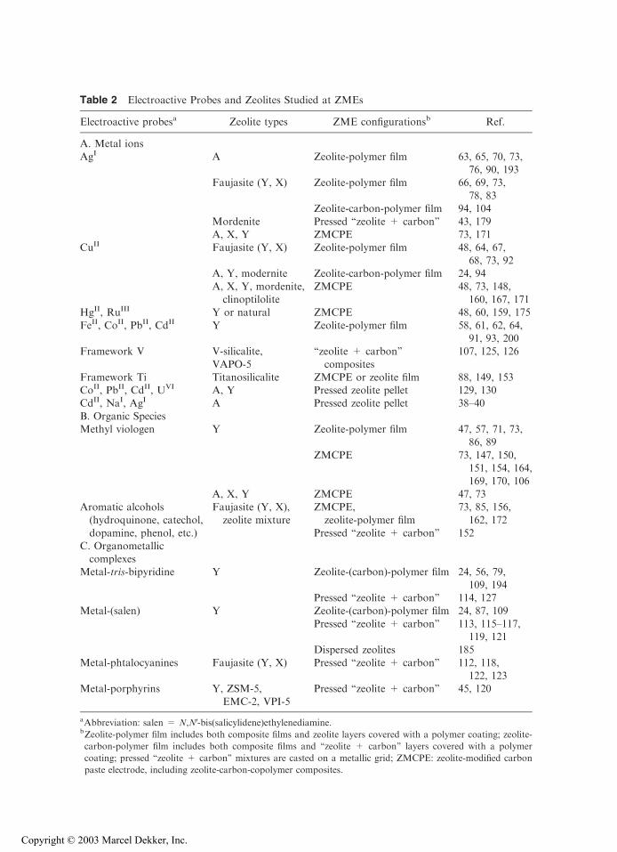
Table 2 Electroactive Probes and Zeolites Studied at ZMEs
Electroactive probesa Zeolite types ZME configurationsb Ref.
A. Metal ions
AgI A Zeolite-polymer film 63, 65, 70, 73,76, 90, 193
Faujasite (Y, X) Zeolite-polymer film 66, 69, 73,
78, 83Zeolite-carbon-polymer film 94, 104
Mordenite Pressed ‘‘zeolite + carbon’’ 43, 179A, X, Y ZMCPE 73, 171
CuII Faujasite (Y, X) Zeolite-polymer film 48, 64, 67,68, 73, 92
A, Y, modernite Zeolite-carbon-polymer film 24, 94
A, X, Y, mordenite,clinoptilolite
ZMCPE 48, 73, 148,160, 167, 171
HgII, RuIII Y or natural ZMCPE 48, 60, 159, 175
FeII, CoII, PbII, CdII Y Zeolite-polymer film 58, 61, 62, 64,91, 93, 200
Framework V V-silicalite,
VAPO-5
‘‘zeolite + carbon’’
composites
107, 125, 126
Framework Ti Titanosilicalite ZMCPE or zeolite film 88, 149, 153CoII, PbII, CdII, UVI A, Y Pressed zeolite pellet 129, 130CdII, NaI, AgI A Pressed zeolite pellet 38–40
B. Organic SpeciesMethyl viologen Y Zeolite-polymer film 47, 57, 71, 73,
86, 89
ZMCPE 73, 147, 150,151, 154, 164,169, 170, 106
A, X, Y ZMCPE 47, 73Aromatic alcohols(hydroquinone, catechol,
Faujasite (Y, X),zeolite mixture
ZMCPE,zeolite-polymer film
73, 85, 156,162, 172
dopamine, phenol, etc.) Pressed ‘‘zeolite + carbon’’ 152C. Organometalliccomplexes
Metal-tris-bipyridine Y Zeolite-(carbon)-polymer film 24, 56, 79,
109, 194Pressed ‘‘zeolite + carbon’’ 114, 127
Metal-(salen) Y Zeolite-(carbon)-polymer film 24, 87, 109
Pressed ‘‘zeolite + carbon’’ 113, 115–117,119, 121
Dispersed zeolites 185
Metal-phtalocyanines Faujasite (Y, X) Pressed ‘‘zeolite + carbon’’ 112, 118,122, 123
Metal-porphyrins Y, ZSM-5,EMC-2, VPI-5
Pressed ‘‘zeolite + carbon’’ 45, 120
aAbbreviation: salen = N,NV-bis(salicylidene)ethylenediamine.bZeolite-polymer film includes both composite films and zeolite layers covered with a polymer coating; zeolite-
carbon-polymer film includes both composite films and ‘‘zeolite + carbon’’ layers covered with a polymer
coating; pressed ‘‘zeolite + carbon’’ mixtures are casted on a metallic grid; ZMCPE: zeolite-modified carbon
paste electrode, including zeolite-carbon-copolymer composites.
Copyright © 2003 Marcel Dekker, Inc.
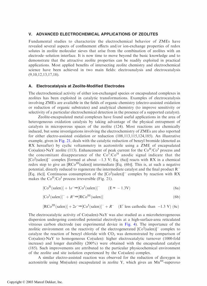
V. ADVANCED ELECTROCHEMICAL APPLICATIONS OF ZEOLITES
Fundamental studies to characterize the electrochemical behavior of ZMEs haverevealed several aspects of confinement effects and/or ion-exchange properties of redoxsolutes in zeolite molecular sieves that arise from the combination of zeolites with anelectrode–solution interface. It is now time to move beyond the basic knowledge and todemonstrate that the attractive zeolite properties can be readily exploited in practicalapplications. Most applied benefits of intersecting zeolite chemistry and electrochemicalscience have been achieved in two main fields: electroanalysis and electrocatalysis(9,10,12,13,17,18).
A. Electrocatalysis at Zeolite-Modified Electrodes
The electrochemical activity of either ion-exchanged species or encapsulated complexes inzeolites has been exploited in catalytic transformations. Examples of electrocatalysisinvolving ZMEs are available in the fields of organic chemistry (electro-assisted oxidationor reduction of organic substrates) and analytical chemistry (to improve sensitivity orselectivity of a particular electrochemical detection in the presence of a supported catalyst).
Zeolite-encapsulated metal complexes have found useful applications in the area ofheterogeneous oxidation catalysis by taking advantage of the physical entrapment ofcatalysts in microporous spaces of the zeolite (124). Most reactions are chemicallyinduced, but some investigations involving the electrochemistry of ZMEs are also reportedfor either electro-assisted oxidation or reduction (108,113,115,124,185). An illustrativeexample, given in Fig. 21, deals with the catalytic reduction of benzyl bromide (denoted asRX hereafter) by cyclic voltammetry in acetonitrile using a ZME of encapsulatedCo(salen)-NaY zeolite (113). Enhancement of peak current for the CoII/CoI process andthe concomitant disappearance of the CoI/CoII anodic signal indicate that the[CoI(salen)]� complex [formed at about �1.3 V; Eq. (6a)] reacts with RX in a chemicalredox step to give an [RCoIII(salen)] intermediate [Eq. (6b)]. This is, at such a negativepotential, directly reduced to regenerate the intermediate catalyst and the final product R�
[Eq. (6c)]. Continuous consumption of the [CoI(salen)]� complex by reaction with RXmakes the CoII/CoI process irreversible (Fig. 21).
½CoIIðsalenÞ� þ 1e�Z ½CoIðsalenÞ�� ðEc� 1:3VÞ ð6aÞ
½CoIðsalenÞ�� þ RþZ ½RCoIIIðsalenÞ� ð6bÞ
½RCoIIIðsalenÞ� þ 2e�Z ½CoIðsalenÞ�� þ R� ðE0 less cathodic than �1:3 VÞ ð6cÞThe electrocatalytic activity of Co(salen)-NaY was also studied as a microheterogeneousdispersion undergoing controlled potential electrolysis at a high-surface-area reticulatedvitreous carbon electrode (see experimental device in Fig. 4). The importance of thezeolitic environment on the reactivity of the electrogenerated [CoI(salen)]� complex tocatalyze the reaction of benzyl chloride with CO2 was demonstrated by comparison ofCo(salen)-NaY to homogeneous Co(salen): higher electrocatalytic turnover (1000-foldincrease) and longer durability (200%) were obtained with the encapsulated catalyst(185). Such improvements are attributed to the particular physicochemical environmentof the zeolite and site isolation experienced by the Co(salen) complex.
A similar electro-assisted reaction was observed for the reduction of dioxygen inacetonitrile using Mn(salen) encapsulated in zeolite Y, which gives an MnIII-superoxo
Copyright © 2003 Marcel Dekker, Inc.
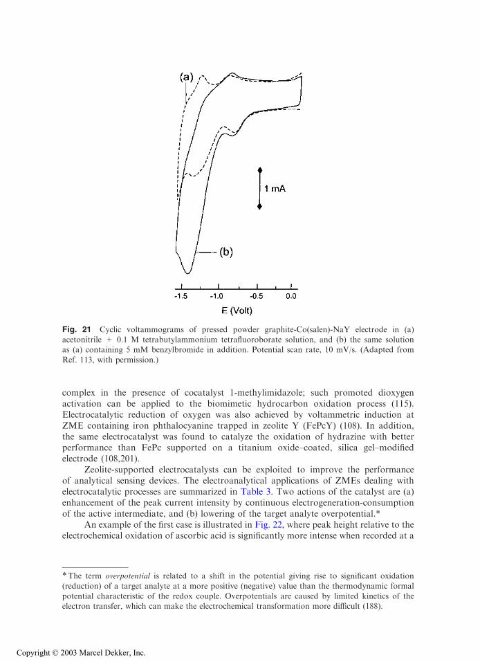
complex in the presence of cocatalyst 1-methylimidazole; such promoted dioxygenactivation can be applied to the biomimetic hydrocarbon oxidation process (115).Electrocatalytic reduction of oxygen was also achieved by voltammetric induction atZME containing iron phthalocyanine trapped in zeolite Y (FePcY) (108). In addition,the same electrocatalyst was found to catalyze the oxidation of hydrazine with betterperformance than FePc supported on a titanium oxide–coated, silica gel–modifiedelectrode (108,201).
Zeolite-supported electrocatalysts can be exploited to improve the performanceof analytical sensing devices. The electroanalytical applications of ZMEs dealing withelectrocatalytic processes are summarized in Table 3. Two actions of the catalyst are (a)enhancement of the peak current intensity by continuous electrogeneration-consumptionof the active intermediate, and (b) lowering of the target analyte overpotential.*
An example of the first case is illustrated in Fig. 22, where peak height relative to theelectrochemical oxidation of ascorbic acid is significantly more intense when recorded at a
*The term overpotential is related to a shift in the potential giving rise to significant oxidation
(reduction) of a target analyte at a more positive (negative) value than the thermodynamic formalpotential characteristic of the redox couple. Overpotentials are caused by limited kinetics of theelectron transfer, which can make the electrochemical transformation more difficult (188).
Fig. 21 Cyclic voltammograms of pressed powder graphite-Co(salen)-NaY electrode in (a)acetonitrile + 0.1 M tetrabutylammonium tetrafluoroborate solution, and (b) the same solutionas (a) containing 5 mM benzylbromide in addition. Potential scan rate, 10 mV/s. (Adapted from
Ref. 113, with permission.)
Copyright © 2003 Marcel Dekker, Inc.
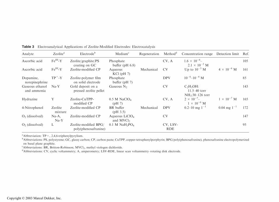
Table 3 Electroanalytical Applications of Zeolite-Modified Electrodes: Electrocatalysis
Analyte Zeolitea Electrodeb Mediumc Regeneration Methodd Concentration range Detection limit Ref.
Ascorbic acid FeIII-Y Zeolite/graphite/PS
coating on GC
Phosphate
buffer (pH 6.8)
CV, A 1.6 � 10�6–
2.1 � 10�2 M
105
Ascorbic acid FeIII-Y Zeolite-modified CP AqueousKCl (pH 7)
Mechanical CV Up to 10�3 M 4 � 10�6 M 161
Dopamine,
norepinephrine
TP+-Y Zeolite-polymer film
on solid electrode
Phosphate
buffer (pH 7)
DPV 10�6–10�4 M 85
Gaseous ethanoland ammonia
Na-Y Gold deposit on apressed zeolite pellet
Gaseous N2 CV C2H5OH:11.5–40 torr
143
NH3:30–126 torrHydrazine Y Zeolite-CuTPP-
modified CP0.5 M NaClO4
(pH 7)CV, A 2 � 10�7–
1 � 10�6 M1 � 10�7 M 165
4-Nitrophenol Zeolitemixture
Zeolite-modified CP BR buffer(pH 3.5)
Mechanical DPV 0.2–10 mg 1�1 0.04 mg 1�1 172
O2 (dissolved) Na-A,
Na-Y
Zeolite-modified CP Aqueous LiClO4
and MVCl2
CV 147
O2 (dissolved) L Zeolite-modified BPG/poly(phenosafranine)
0.1 M NaH2PO4 CV, LSV-RDE
95
aAbbreviation: TP+, 2,4,6-triphenylpyrylium.bAbbreviations: PS, polystyrene; GC, glassy carbon; CP, carbon paste; CuTPP, copper-tetraphenylporphyrin; BPG/poly(phenosafranine), phenosafranine electropolymerized
on basal plane graphite.cAbbreviations: BR, Britton-Robinson; MVCl2, methyl viologen dichloride.dAbbreviations: CV, cyclic voltammetry; A, amperometry; LSV-RDE, linear scan voltammetry–rotating disk electrode.
Copyright © 2003 Marcel Dekker, Inc.
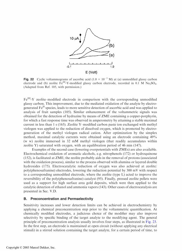
FeIII-Y zeolite–modified electrode in comparison with the corresponding unmodifiedglassy carbon. This improvement, due to the mediated oxidation of the analyte by electro-generated FeII species, leads to more sensitive detection of ascorbic acid and was applied toanalysis of fruit samples (105). Similar enhancement of the voltammetric signals wasobtained for the detection of hydrazine by means of ZME containing a copper-porphyrin,for which a fast response time was observed in amperometry by attaining a stable maximalcurrent in less than 1 s (165). Zeolite Y–modified carbon paste ion exchanged with methylviologen was applied to the reduction of dissolved oxygen, which is promoted by electro-generation of the methyl viologen radical cation. After optimization by the simplexmethod, maximal catalytic currents were obtained using an electrode containing 49%(w w) zeolite immersed in 32 mM methyl viologen (that readily accumulates withinzeolite Y) saturated with oxygen, with an equilibration period of 46 min (147).
Examples of the second case (lowering overpotentials with ZMEs) are also available.Electrochemical oxidation of aromatic alcohols, e.g. nitrophenols (172) or hydroquinone(152), is facilitated at ZME; the zeolite probably aids in the removal of protons (associatedwith the oxidation process), similar to the process observed with alumina or layered doublehydroxides (175). Electrocatalytic reduction of oxygen was also achieved at zeolite/poly(phenosafranine) electrodes, lowering the reduction potential by 300 mV with respectto a corresponding unmodified electrode, where the zeolite (type L) acted to improve thereversibility of the poly(phenosafranine) catalyst (95). Finally, pressed zeolite pellets wereused as a support for high surface area gold deposits, which were then applied to thecatalytic detection of ethanol and ammonia vapors (143). Other cases of electrocatalysis arepresented in Sec. V.D.
B. Preconcentration and Permselectivity
Sensitivity increases and lower detection limits can be achieved in electrochemistry byapplying a chemical preconcentration step prior to the voltammetric quantification. Atchemically modified electrodes, a judicious choice of the modifier may also improveselectivity by specific binding of the target analyte to the modifying agent. The generalprinciple of preconcentration analysis usually involves four steps, as illustrated in Fig. 23.In the first step, an electrode is maintained at open circuit (without applying any electricalstimuli) in a stirred solution containing the target analyte, for a certain period of time, to
Fig. 22 Cyclic voltammograms of ascorbic acid (1.0 � 10�3 M) at (a) unmodified glassy carbon
electrode and (b) zeolite FeIII-Y-modified glassy carbon electrode, recorded in 0.1 M Na2SO4.(Adapted from Ref. 105, with permission.)
Copyright © 2003 Marcel Dekker, Inc.
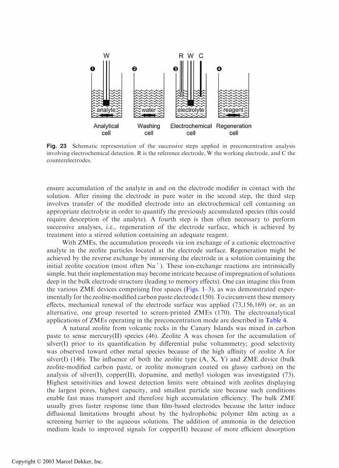
ensure accumulation of the analyte in and on the electrode modifier in contact with thesolution. After rinsing the electrode in pure water in the second step, the third stepinvolves transfer of the modified electrode into an electrochemical cell containing anappropriate electrolyte in order to quantify the previously accumulated species (this couldrequire desorption of the analyte). A fourth step is then often necessary to performsuccessive analyses, i.e., regeneration of the electrode surface, which is achieved bytreatment into a stirred solution containing an adequate reagent.
With ZMEs, the accumulation proceeds via ion exchange of a cationic electroactiveanalyte in the zeolite particles located at the electrode surface. Regeneration might beachieved by the reverse exchange by immersing the electrode in a solution containing theinitial zeolite cocation (most often Na+). These ion-exchange reactions are intrinsicallysimple, but their implementationmay become intricate because of impregnation of solutionsdeep in the bulk electrode structure (leading to memory effects). One can imagine this fromthe various ZME devices comprising free spaces (Figs. 1–3), as was demonstrated exper-imentally for the zeolite-modified carbon paste electrode (150). To circumvent thesememoryeffects, mechanical renewal of the electrode surface was applied (73,156,169) or, as analternative, one group resorted to screen-printed ZMEs (170). The electroanalyticalapplications of ZMEs operating in the preconcentration mode are described in Table 4.
A natural zeolite from volcanic rocks in the Canary Islands was mixed in carbonpaste to sense mercury(II) species (46). Zeolite A was chosen for the accumulation ofsilver(I) prior to its quantification by differential pulse voltammetry; good selectivitywas observed toward other metal species because of the high affinity of zeolite A forsilver(I) (146). The influence of both the zeolite type (A, X, Y) and ZME device (bulkzeolite-modified carbon paste, or zeolite monograin coated on glassy carbon) on theanalysis of silver(I), copper(II), dopamine, and methyl viologen was investigated (73).Highest sensitivities and lowest detection limits were obtained with zeolites displayingthe largest pores, highest capacity, and smallest particle size because such conditionsenable fast mass transport and therefore high accumulation efficiency. The bulk ZMEusually gives faster response time than film-based electrodes because the latter inducediffusional limitations brought about by the hydrophobic polymer film acting as ascreening barrier to the aqueous solutions. The addition of ammonia in the detectionmedium leads to improved signals for copper(II) because of more efficient desorption
Fig. 23 Schematic representation of the successive steps applied in preconcentration analysis
involving electrochemical detection. R is the reference electrode, W the working electrode, and C thecounterelectrodes.
Copyright © 2003 Marcel Dekker, Inc.
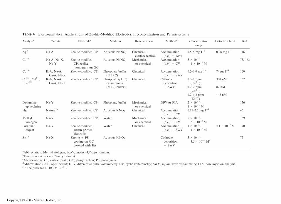
Table 4 Electroanalytical Applications of Zeolite-Modified Electrodes: Preconcentration and Permselectivity
Analytea Zeolite Electrodec Medium Regeneration Methodd Concentration
range
Detection limit Ref.
Ag+ Na-A Zeolite-modified CP Aqueous NaNO3 Chemical +
electrochemical
Accumulation
(o.c.) + DPV
0.5–5 mg 1�1 0.08 mg 1�1 146
Cu2+ Na-A, Na-X,
Na-Y
Zeolite-modified
CP, zeolite
monograin on GC
Aqueous NaNO3 Mechanical
or chemical
Accumulation
(o.c.) + CV
5 � 10�5–
1 � 10�3 M
73, 163
Cu2+ K-A, Na-A,
Ca-A, Na-X
Zeolite-modified CP Phosphate buffer
(pH 4.2)
Chemical Accumulation
(o.c.) + SWV
0.3–1.0 mg 1�1 74 Ag 1�1 160
Cu2+, Cd2+,
Zn2+K-A, Na-A,
Ca-A, Na-X
Zeolite-modified CP Phosphate (pH 6)
or ammonia
Chemical Cathodic
deposition
0.3–1 ppm
(Cu2+)
300 nM 157
(pH 9) buffers + SWV 0.2–2 ppm
(Cd2+)
87 nM
0.2–1.2 ppm
(Zn2+)
145 nM
Dopamine,
epinephrine
Na-Y Zeolite-modified CP Phosphate buffer Mechanical
or chemical
DPV or FIA 2 � 10�5–
1 � 10�3 M
156
Hg2+ Naturalb Zeolite-modified CP Aqueous KNO3 Chemical Accumulation
(o.c.) + CV
0.11–2.2 mg 1�1 46
Methyl
viologen
Na-Y Zeolite-modified CP Water Mechanical
or chemical
Accumulation
(o.c.) + CV
5 � 10�5–
5 � 10�3 M
169
Paraquat,
diquat
Na-Y Zeolite-modified
screen-printed
electrode
Water Chemical Accumulation
(o.c.) + SWV
1 � 10�6–
1 � 10�5 M
<1 � 10�7 M 170
Zn2+ Na-X Zeolite + PS
coating on GC
covered with Hg
Aqueous KNO3 Cathodic
deposition
+ SWV
5 � 10�7–
3.5 � 10�6 Me77
aAbbreviation: Methyl viologen, N,NV-dimethyl-4,4V-bipyridinium.bFrom volcanic rocks (Canary Islands).cAbbreviations: CP, carbon paste; GC, glassy carbon; PS, polystyrene.dAbbreviations: o.c., open circuit; DPV, differential pulse voltammetry; CV, cyclic voltammetry; SWV, square wave voltammetry; FIA, flow injection analysis.eIn the presence of 10 AM Cu2+.
Copyright © 2003 Marcel Dekker, Inc.
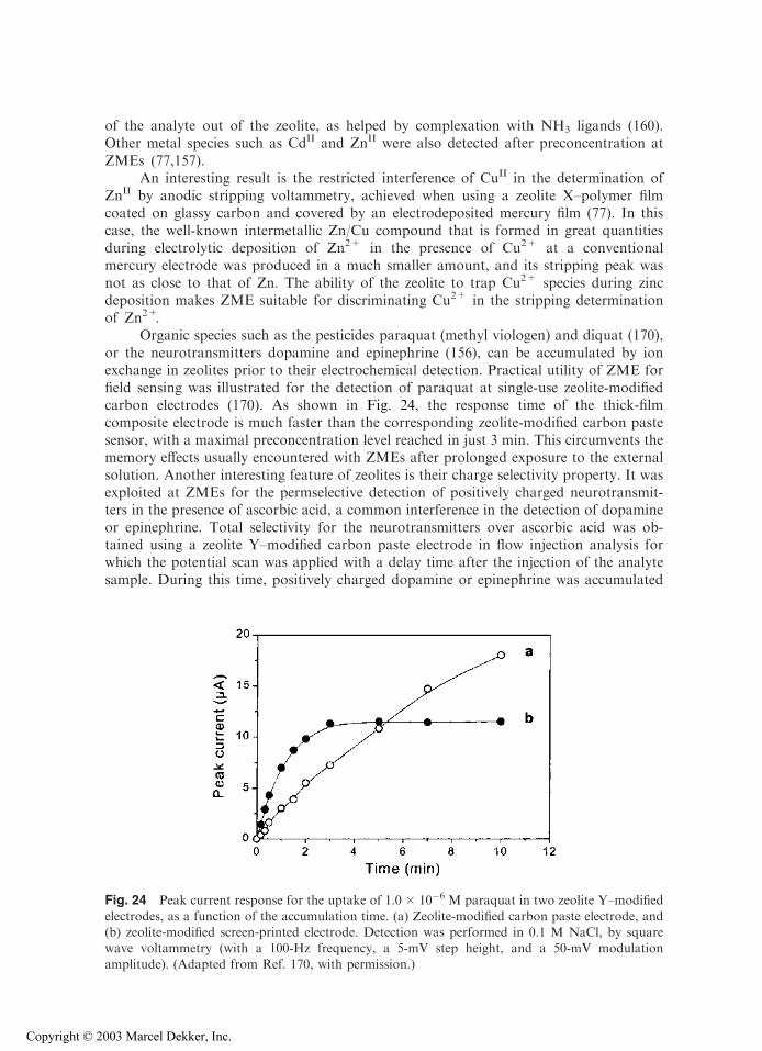
of the analyte out of the zeolite, as helped by complexation with NH3 ligands (160).Other metal species such as CdII and ZnII were also detected after preconcentration atZMEs (77,157).
An interesting result is the restricted interference of CuII in the determination ofZnII by anodic stripping voltammetry, achieved when using a zeolite X–polymer filmcoated on glassy carbon and covered by an electrodeposited mercury film (77). In thiscase, the well-known intermetallic Zn/Cu compound that is formed in great quantitiesduring electrolytic deposition of Zn2+ in the presence of Cu2+ at a conventionalmercury electrode was produced in a much smaller amount, and its stripping peak wasnot as close to that of Zn. The ability of the zeolite to trap Cu2+ species during zincdeposition makes ZME suitable for discriminating Cu2+ in the stripping determinationof Zn2+.
Organic species such as the pesticides paraquat (methyl viologen) and diquat (170),or the neurotransmitters dopamine and epinephrine (156), can be accumulated by ionexchange in zeolites prior to their electrochemical detection. Practical utility of ZME forfield sensing was illustrated for the detection of paraquat at single-use zeolite-modifiedcarbon electrodes (170). As shown in Fig. 24, the response time of the thick-filmcomposite electrode is much faster than the corresponding zeolite-modified carbon pastesensor, with a maximal preconcentration level reached in just 3 min. This circumvents thememory effects usually encountered with ZMEs after prolonged exposure to the externalsolution. Another interesting feature of zeolites is their charge selectivity property. It wasexploited at ZMEs for the permselective detection of positively charged neurotransmit-ters in the presence of ascorbic acid, a common interference in the detection of dopamineor epinephrine. Total selectivity for the neurotransmitters over ascorbic acid was ob-tained using a zeolite Y–modified carbon paste electrode in flow injection analysis forwhich the potential scan was applied with a delay time after the injection of the analytesample. During this time, positively charged dopamine or epinephrine was accumulated
Fig. 24 Peak current response for the uptake of 1.0 � 10�6 M paraquat in two zeolite Y–modified
electrodes, as a function of the accumulation time. (a) Zeolite-modified carbon paste electrode, and(b) zeolite-modified screen-printed electrode. Detection was performed in 0.1 M NaCl, by squarewave voltammetry (with a 100-Hz frequency, a 5-mV step height, and a 50-mV modulationamplitude). (Adapted from Ref. 170, with permission.)
Copyright © 2003 Marcel Dekker, Inc.
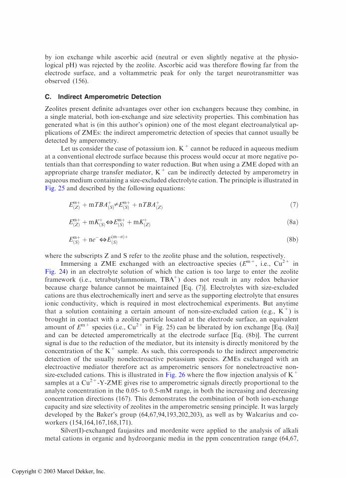
by ion exchange while ascorbic acid (neutral or even slightly negative at the physio-logical pH) was rejected by the zeolite. Ascorbic acid was therefore flowing far from theelectrode surface, and a voltammetric peak for only the target neurotransmitter wasobserved (156).
C. Indirect Amperometric Detection
Zeolites present definite advantages over other ion exchangers because they combine, ina single material, both ion-exchange and size selectivity properties. This combination hasgenerated what is (in this author’s opinion) one of the most elegant electroanalytical ap-plications of ZMEs: the indirect amperometric detection of species that cannot usually bedetected by amperometry.
Let us consider the case of potassium ion. K+ cannot be reduced in aqueous mediumat a conventional electrode surface because this process would occur at more negative po-tentials than that corresponding to water reduction. But when using a ZME doped with anappropriate charge transfer mediator, K+ can be indirectly detected by amperometry inaqueous medium containing a size-excluded electrolyte cation. The principle is illustrated inFig. 25 and described by the following equations:
EmþðZÞ þmTBAþ
ðSÞpEmþðSÞ þ nTBAþ
ðZÞ ð7Þ
EmþðZÞ þmKþ
ðSÞZEmþðSÞ þmKþ
ðZÞ ð8aÞ
EmþðSÞ þ ne�ZE
ðm�nÞþðSÞ ð8bÞ
where the subscripts Z and S refer to the zeolite phase and the solution, respectively.Immersing a ZME exchanged with an electroactive species (Em+, i.e., Cu2+ in
Fig. 24) in an electrolyte solution of which the cation is too large to enter the zeoliteframework (i.e., tetrabutylammonium, TBA+) does not result in any redox behaviorbecause charge balance cannot be maintained [Eq. (7)]. Electrolytes with size-excludedcations are thus electrochemically inert and serve as the supporting electrolyte that ensuresionic conductivity, which is required in most electrochemical experiments. But anytimethat a solution containing a certain amount of non-size-excluded cation (e.g., K+) isbrought in contact with a zeolite particle located at the electrode surface, an equivalentamount of Em+ species (i.e., Cu2+ in Fig. 25) can be liberated by ion exchange [Eq. (8a)]and can be detected amperometrically at the electrode surface [Eq. (8b)]. The currentsignal is due to the reduction of the mediator, but its intensity is directly monitored by theconcentration of the K+ sample. As such, this corresponds to the indirect amperometricdetection of the usually nonelectroactive potassium species. ZMEs exchanged with anelectroactive mediator therefore act as amperometric sensors for nonelectroactive non-size-excluded cations. This is illustrated in Fig. 26 where the flow injection analysis of K+
samples at a Cu2+-Y-ZME gives rise to amperometric signals directly proportional to theanalyte concentration in the 0.05- to 0.5-mM range, in both the increasing and decreasingconcentration directions (167). This demonstrates the combination of both ion-exchangecapacity and size selectivity of zeolites in the amperometric sensing principle. It was largelydeveloped by the Baker’s group (64,67,94,193,202,203), as well as by Walcarius and co-workers (154,164,167,168,171).
Silver(I)-exchanged faujasites and mordenite were applied to the analysis of alkalimetal cations in organic and hydroorganic media in the ppm concentration range (64,67,
Copyright © 2003 Marcel Dekker, Inc.
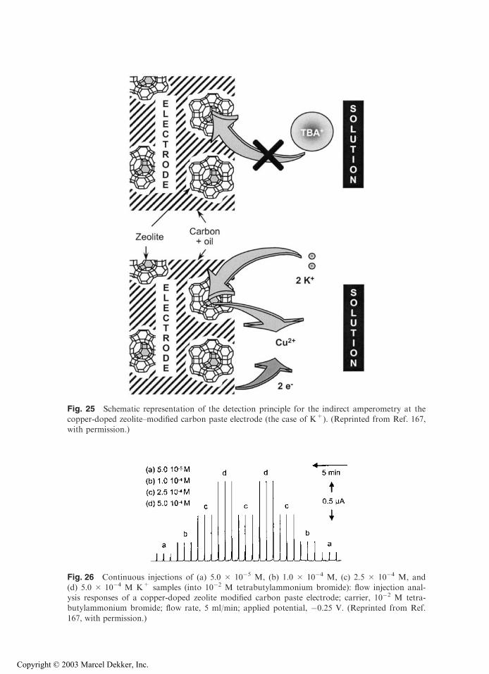
Fig. 25 Schematic representation of the detection principle for the indirect amperometry at thecopper-doped zeolite–modified carbon paste electrode (the case of K+). (Reprinted from Ref. 167,with permission.)
Fig. 26 Continuous injections of (a) 5.0 � 10�5 M, (b) 1.0 � 10�4 M, (c) 2.5 � 10�4 M, and(d) 5.0 � 10�4 M K+ samples (into 10�2 M tetrabutylammonium bromide): flow injection anal-ysis responses of a copper-doped zeolite modified carbon paste electrode; carrier, 10�2 M tetra-butylammonium bromide; flow rate, 5 ml/min; applied potential, �0.25 V. (Reprinted from Ref.
167, with permission.)
Copyright © 2003 Marcel Dekker, Inc.
94,193). The amperometric signals are monitored by the amount of Ag+ that is releasedfrom the zeolite by ion exchange with the cationic analyte. Therefore, the peak height isproportional to the concentration of alkali metal cations (similar to Fig. 26), in a rangedepending on the analyte (Table 5), and the amperometric intensity is directly related to thespeed of the Ag+–cationic analyte exchange. For zeolites containing Ag+ species locatedmainly in the large cages, the selectivity series was Cs+>K+>Na+>Li+. According tothe size of hydrated cations, the smaller analytes gave the higher signals. This was the caseof Ag-Y and Ag-mordenite (67,94,193). On the other hand, the zeolite Ag-X that containsmore Ag+ in the small cages had the highest sensitivity for K+, with currents decreasingaccording to K+ > Na+ > Cs+ f Li+ (67). This series arises from two componentsacting in opposite directions on the electrode response: ion exchange of the mediatorlocated in the large cages, which is controlled by the hydrated radii of the cationic sample,and those located in the small cages for which the exchange is depending on solvationenergies and ionic radii of cations (137). The ammonium series was also investigated inwater-methanol mixtures using Ag-Y zeolite (64) or in pure water using MV-Y zeolite(154,164), giving a response decreasing as follows: ammonium > tetramethylammonium> tetraethylammonium tetrapropylammonium. This is in agreement with the size ofthe analytes.
Indirect amperometric detection at ZME was applied in aqueous medium for theanalysis of alkali metal, alkaline earth, and ammonium ions in both batch and flowinjection modes, using methyl viologen or copper(II) as the mediator and various zeolitetypes (154,167,168). In every case, the electrode response increased with charge of thepositive ion and as the hydrated ion size decreased. Therefore, the mediators contributingeffectively to the electrochemical signal are mainly or exclusively those located in the largechannel network of the zeolite. The selectivity series Ca2+, Mg2+, Cs+ > K+ > Na+,NH4
+ > Li+ is unaffected by the nature of the zeolite used (167). Even when using theNH4
+-selective clinoptilolite (doped with Cu2+), no significant increase in peak currentfor NH4
+ was observed with respect to other cations (168). This confirms that the indirectdetection process [Eq. (8b)] is controlled mainly by kinetics associated with ion exchange[Eq. (8a)], and thus by diffusion in the zeolite lattice, rather than by the thermodynamicsrelative to the affinity of the zeolite for one cation or another. This is further confirmed bythe effect of pore aperture and particle size of zeolites on the amperometric response: peakheights increase with ‘‘openness’’ of the zeolite structure and with decrease in the particlesize (167). In addition, the use of the more mobile Ag+ mediator, instead of Cu2+,resulted in a twofold enhancement of peak currents (171).
Additional electroanalytical applications of indirect amperometric detection at ZMEhave been derived from solvent effects that were observed from voltammetric studies ofelectroactive species exchanged in zeolites (see Sec. IV.A.2 of this chapter). For example,peak currents recorded for AgA in pure dimethylformamide (DMF) containing a non-size-excluded electrolyte (LiClO4) are several hundred times smaller than in water becausenonaqueous ion exchange occurs slowly in contrast to fast ion exchange in water (63).Figure 27 shows that gradual addition of water (in the ppm range) to dry DMF+LiClO4
results in a proportional increase in peak currents sampled by anodic stripping voltamme-try at an AgA-modified electrode. This electrode is thus a sensor for trace water in organicsolvents containing a small amount of alkali metal cation (202,203), with a linear responsein the 1- to 10-ppm concentration range and a detection limit close to 20 ppb (63,193),which is by far better than the classical Karl Fischer method. An experimental setup basedon this detection scheme, which displays a long useful lifetime, was recently designed bycoupling a zeolite AgA column to a classical thin-layer electrochemical cell (193). This
Copyright © 2003 Marcel Dekker, Inc.

Table 5 Electroanalytical Applications of Zeolite Modified Electrodes: Indirect Amperometric Detection
Analytea Zeoliteb Electrodec Mediumd Regeneration MethodeConcentration
range
Detection
limit Ref.
Alkali-metal ions Ag-Y Zeolite/graphite/PS DMF, CH3CN, Reduction + 1–10 ppm (Li+) <1 ppm 94
coating on ITO MeOH (+TBAP) ASV 1–35 ppm (Na+)
1–25 ppm (K+)
Alkali-metal ions,
NH4+, TMA+,
TEA+, TPA+
Ag-X, Ag-Y,
Ag-mordenite
Zeolite/graphite/PS
coating on ITO
MeOH/water
(+TBAP)
CV (reduction) 1 � 10�4–
1 � 10�3 M
64, 67, 193
Alkali metal,
alkaline earth,
NH4+ ions
MV-Y Zeolite-modified CP Aqueous TBABr Mechanical
or chemical
A (reduction)
BIA, FIA
1 � 10�3–1 M 1 � 10�4 M 154, 164
Alkali metal,
alkaline earth,
NH4+ ions
Cu-A, Cu-X,
Cu-Y,
Cu-clinoptilolite
Zeolite-modified CP Aqueous TBABr Chemical A (reduction)
FIA
5 � 10�6–
5 � 10�4 M
4 � 10�7–
2 � 10�6 Mf
167
Alkali metal,
alkaline earth,
NH4+ ions
Cu-A, Cu-X,
Cu-Y, Ag-A,
Ag-X, Ag-Y
Zeolite-modified CP Pure water
(without added
electrolyte)
Chemical A (reduction)
FIA, IC
5 � 10�6–
5 � 10�4 M
5 � 10�7–
2 � 10�6 Mf
171
Ammonium ions Cu-clinoptilolite Zeolite-modified CP Aqueous TBABr Chemical A (reduction)
FIA
2 � 10�5–
1 � 10�3 M
5 � 10�6 M 168
Benzene,
trichloro-
ethylene
Ag-A Zeolite/graphite/
PS coating on
ITO or RVC
Aqueous medium Reduction +
DPASV or
FIA
20–100 ppm 193
H2O Ag-A Zeolite/graphite/PS
coating on ITO
DMF, LiClO4 Reduction +
ASV
1–10 ppm 20 ppb 63, 193
TMA+ Silicalite Zeolite layer
grown on Hg
Water/
dichloro-
ethane interface
Polarization
of ITIES
111
aAbbreviations: TMA+, tetramethylammonium; TEA+, tetraethylammonium; TPA+, tetrapropylammonium.
bAbbreviation: MV-Y, methyl viologen-exchanged zeolite Y.
cAbbreviations: PS, polystyrene; ITO, indium tin oxide; CP, carbon paste; RVC, reticulated vitreous carbon.dAbbreviations: DMF, dimethylformamide; CH3CN, acetonitrile; MeOH, methanol; TBAP, tetrabutylammonium perchlorate; TBABr, tetrabutylammonium bromide.
eAbbreviations: ASV, anodic stripping voltammetry; CV, cyclic voltammetry; A, amperometry; BIA, batch injection analysis; FIA, flow injection analysis; IC, ion chromatography; DPASV,
differential pulse anodic stripping voltammetry; ITIES, interface between two immiscible electrolyte solutions.fDepending on the cationic analyte (for Cu-Y).
Copyright © 2003 Marcel Dekker, Inc.
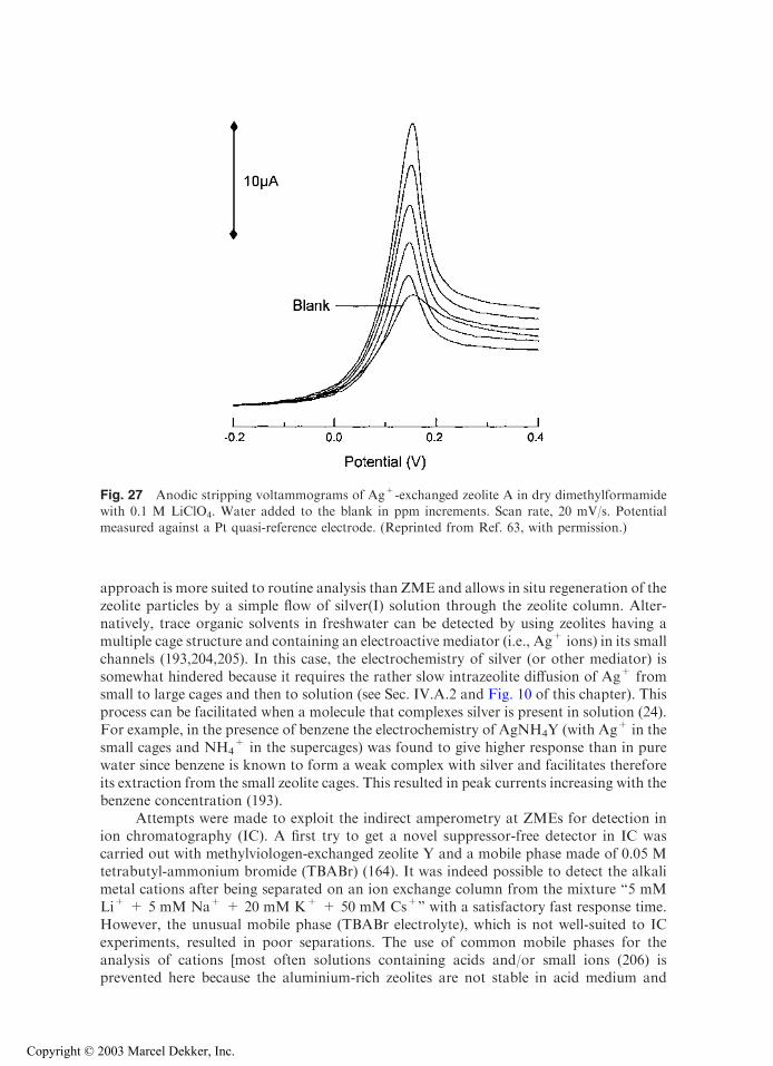
approach is more suited to routine analysis than ZME and allows in situ regeneration of thezeolite particles by a simple flow of silver(I) solution through the zeolite column. Alter-natively, trace organic solvents in freshwater can be detected by using zeolites having amultiple cage structure and containing an electroactive mediator (i.e., Ag+ ions) in its smallchannels (193,204,205). In this case, the electrochemistry of silver (or other mediator) issomewhat hindered because it requires the rather slow intrazeolite diffusion of Ag+ fromsmall to large cages and then to solution (see Sec. IV.A.2 and Fig. 10 of this chapter). Thisprocess can be facilitated when a molecule that complexes silver is present in solution (24).For example, in the presence of benzene the electrochemistry of AgNH4Y (with Ag+ in thesmall cages and NH4
+ in the supercages) was found to give higher response than in purewater since benzene is known to form a weak complex with silver and facilitates thereforeits extraction from the small zeolite cages. This resulted in peak currents increasing with thebenzene concentration (193).
Attempts were made to exploit the indirect amperometry at ZMEs for detection inion chromatography (IC). A first try to get a novel suppressor-free detector in IC wascarried out with methylviologen-exchanged zeolite Y and a mobile phase made of 0.05 Mtetrabutyl-ammonium bromide (TBABr) (164). It was indeed possible to detect the alkalimetal cations after being separated on an ion exchange column from the mixture ‘‘5 mMLi+ + 5 mM Na+ + 20 mM K+ + 50 mM Cs+’’ with a satisfactory fast response time.However, the unusual mobile phase (TBABr electrolyte), which is not well-suited to ICexperiments, resulted in poor separations. The use of common mobile phases for theanalysis of cations [most often solutions containing acids and/or small ions (206) isprevented here because the aluminium-rich zeolites are not stable in acid medium and
Fig. 27 Anodic stripping voltammograms of Ag+-exchanged zeolite A in dry dimethylformamidewith 0.1 M LiClO4. Water added to the blank in ppm increments. Scan rate, 20 mV/s. Potential
measured against a Pt quasi-reference electrode. (Reprinted from Ref. 63, with permission.)
Copyright © 2003 Marcel Dekker, Inc.

would therefore lose the mediator in the presence of protons. Overcoming this problemhas led to the evaluation of ZME in the absence of supporting electrolyte, in order todetermine whether the detector can be applied in IC working with conventional mobilephases and suppressor devices. Figure 28 shows that ZMEs give effective currentresponses upon injection of cationic analytes, and that they are even more sensitivethan when recorded in the presence of TBABr. When using NaY zeolite, only smallcapacitive currents are observed, but the CuY gives rise to an additional component dueto the reduction of Cu2+ upon ion exchange with the cationic analyte. The analyte playstwo roles: as a transient electrolyte when sample is passing the electrode surface and as asource of faradic current by liberating the mediator that is detected amperometrically(171). The system is thus applicable to detection in IC after chemical suppression of themobile phase electrolyte, as exemplified in Figure 29, which shows a satisfactory responseof the copper(II)-doped ZME as similar to the conventional conductivity detector. Thepossible use of the modified electrode in the absence of added electrolyte opens the doorto exploit other ion exchangers that do not necessarily display molecular sievingproperties, such as polymeric resins, in designing indirect amperometric detection forIC (207).
Finally, another type of amperometric detection at ZME was recently proposed,based on the polarization of an interface between two immiscible electrolyte solutions(ITIES) modified by a zeolite membrane (111). Polarization of ITIES results in the ob-servation of an electric current only when potential is sufficiently high (absolute value) topromote the crossing of the analyte from one phase to another (usually hydrophilic cationsfrom aqueous to organic medium) (208,209). For example, crossing the unmodified water/1,2-dichloroethane liquid-liquid interface is favoured thermodynamically for tetraethy-lammonium (TEA) relative to tetramethylammonium (TMA). Figure 30 shows thatmodifying such an interface by a silicalite membrane results in the suppression of theelectrochemically driven transfer of the TEA cation while still allowing the transfer ofTMA, because of the molecular sieving effect of the zeolite membrane. This illustrates the
Fig. 28 Flow injection responses obtained at (1) an undoped zeolite Y–modified electrode and (2) acopper-exchanged zeolite Y–modified electrode. (A) Injection of 1.0 � 10�5 M Na+ (in water);
carrier, water; flow rate, 1.5 ml/min; applied potential, �0.4 V. (B) Injection of 1.0 � 10�3 M Na+
(into 10�2 M tetrabutylammonium bromide); carrier, 10�2 M tetrabutylammonium bromide); flowrate, 5 ml/min; applied potential, �0.4 V. (From Ref. 171, with permission.)
Copyright © 2003 Marcel Dekker, Inc.
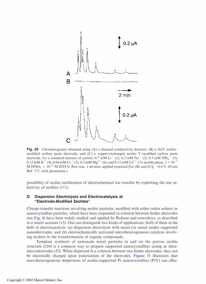
possibility of zeolite rectification of electrochemical ion transfer by exploiting the size se-lectivity of zeolites (111).
D. Dispersion Electrolysis and Electrocatalysis at‘‘Electrode-Modified Zeolites’’
Charge-transfer reactions involving zeolite particles, modified with either redox solutes ornanocrystalline particles, which have been suspended in solution between feeder electrodes(see Fig. 4) have been widely studied and applied by Rolison and coworkers, as describedin a recent account (13). One can distinguish two kinds of applications, both of them in thefield of electrocatalysis: (a) dispersion electrolysis with metal (or metal oxide)–supportednanoelectrodes, and (b) electrochemically activated microheterogeneous catalysis involv-ing zeolites in the transformation of organic compounds.
Template synthesis of nanoscale metal particles in and on the porous zeolitestructure (210) is a common way to prepare supported nanocrystallites acting as ultra-microelectrodes (52). When dispersed in a solution between two feeder electrodes, they canbe electrically charged upon polarization of the electrodes. Figure 31 illustrates thatmicroheterogeneous dispersions of zeolite-supported Pt nanocrystallites (PtY) can effec-
Fig. 29 Chromatograms obtained using (A) a classical conductivity detector, (B) a NaY zeolite–modified carbon paste electrode, and (C) a copper-exchanged zeolite Y–modified carbon paste
electrode, for a standard mixture of cations: 0.7 mM Li+ (1), 0.2 mM Na+ (2), 0.3 mM NH4+ (3),
0.13 mMK+ (4), 0.04 mMCs+ (5), 0.2 mMMg2+ (6), and 0.13 mMCa2+ (7); mobile phase, 3� 10�3
M HNO3 + 10�4 M EDTA; flow rate, 1 ml/min; applied potential [for (B) and (C)], �0.4 V. (From
Ref. 171, with permission.)
Copyright © 2003 Marcel Dekker, Inc.
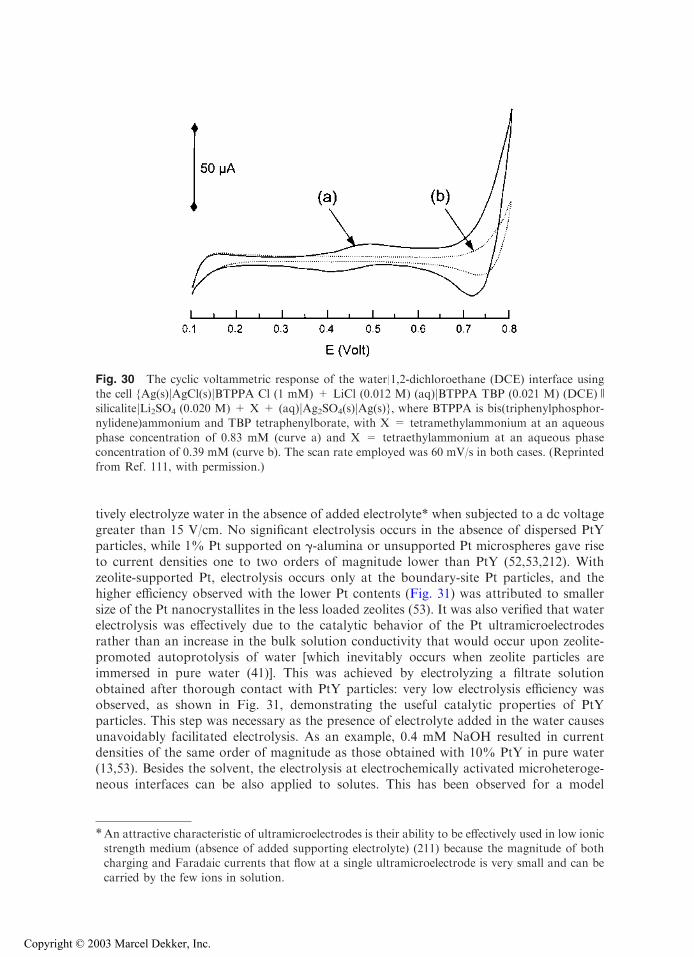
tively electrolyze water in the absence of added electrolyte* when subjected to a dc voltagegreater than 15 V/cm. No significant electrolysis occurs in the absence of dispersed PtYparticles, while 1% Pt supported on g-alumina or unsupported Pt microspheres gave riseto current densities one to two orders of magnitude lower than PtY (52,53,212). Withzeolite-supported Pt, electrolysis occurs only at the boundary-site Pt particles, and thehigher efficiency observed with the lower Pt contents (Fig. 31) was attributed to smallersize of the Pt nanocrystallites in the less loaded zeolites (53). It was also verified that waterelectrolysis was effectively due to the catalytic behavior of the Pt ultramicroelectrodesrather than an increase in the bulk solution conductivity that would occur upon zeolite-promoted autoprotolysis of water [which inevitably occurs when zeolite particles areimmersed in pure water (41)]. This was achieved by electrolyzing a filtrate solutionobtained after thorough contact with PtY particles: very low electrolysis efficiency wasobserved, as shown in Fig. 31, demonstrating the useful catalytic properties of PtYparticles. This step was necessary as the presence of electrolyte added in the water causesunavoidably facilitated electrolysis. As an example, 0.4 mM NaOH resulted in currentdensities of the same order of magnitude as those obtained with 10% PtY in pure water(13,53). Besides the solvent, the electrolysis at electrochemically activated microheteroge-neous interfaces can be also applied to solutes. This has been observed for a model
*An attractive characteristic of ultramicroelectrodes is their ability to be effectively used in low ionicstrength medium (absence of added supporting electrolyte) (211) because the magnitude of bothcharging and Faradaic currents that flow at a single ultramicroelectrode is very small and can be
carried by the few ions in solution.
Fig. 30 The cyclic voltammetric response of the water|1,2-dichloroethane (DCE) interface usingthe cell {Ag(s)jAgCl(s)jBTPPA Cl (1 mM) + LiCl (0.012 M) (aq)jBTPPA TBP (0.021 M) (DCE)OsilicalitejLi2SO4 (0.020 M) + X + (aq)jAg2SO4(s)jAg(s)}, where BTPPA is bis(triphenylphosphor-
nylidene)ammonium and TBP tetraphenylborate, with X = tetramethylammonium at an aqueousphase concentration of 0.83 mM (curve a) and X = tetraethylammonium at an aqueous phaseconcentration of 0.39 mM (curve b). The scan rate employed was 60 mV/s in both cases. (Reprinted
from Ref. 111, with permission.)
Copyright © 2003 Marcel Dekker, Inc.
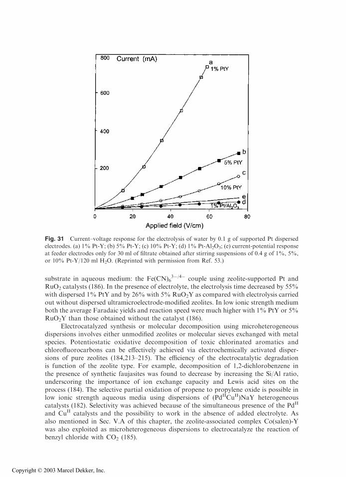
substrate in aqueous medium: the Fe(CN)63�/4� couple using zeolite-supported Pt and
RuO2 catalysts (186). In the presence of electrolyte, the electrolysis time decreased by 55%with dispersed 1% PtY and by 26% with 5% RuO2Y as compared with electrolysis carriedout without dispersed ultramicroelectrode-modified zeolites. In low ionic strength mediumboth the average Faradaic yields and reaction speed were much higher with 1% PtY or 5%RuO2Y than those obtained without the catalyst (186).
Electrocatalyzed synthesis or molecular decomposition using microheterogeneousdispersions involves either unmodified zeolites or molecular sieves exchanged with metalspecies. Potentiostatic oxidative decomposition of toxic chlorinated aromatics andchlorofluorocarbons can be effectively achieved via electrochemically activated disper-sions of pure zeolites (184,213–215). The efficiency of the electrocatalytic degradationis function of the zeolite type. For example, decomposition of 1,2-dichlorobenzene inthe presence of synthetic faujasites was found to decrease by increasing the Si/Al ratio,underscoring the importance of ion exchange capacity and Lewis acid sites on theprocess (184). The selective partial oxidation of propene to propylene oxide is possible inlow ionic strength aqueous media using dispersions of (PdIICuII)NaY heterogeneouscatalysts (182). Selectivity was achieved because of the simultaneous presence of the PdII
and CuII catalysts and the possibility to work in the absence of added electrolyte. Asalso mentioned in Sec. V.A of this chapter, the zeolite-associated complex Co(salen)-Ywas also exploited as microheterogeneous dispersions to electrocatalyze the reaction ofbenzyl chloride with CO2 (185).
Fig. 31 Current–voltage response for the electrolysis of water by 0.1 g of supported Pt dispersedelectrodes. (a) 1% Pt-Y; (b) 5% Pt-Y; (c) 10% Pt-Y; (d) 1% Pt-Al2O3; (e) current-potential response
at feeder electrodes only for 30 ml of filtrate obtained after stirring suspensions of 0.4 g of 1%, 5%,or 10% Pt-Y/120 ml H2O. (Reprinted with permission from Ref. 53.)
Copyright © 2003 Marcel Dekker, Inc.
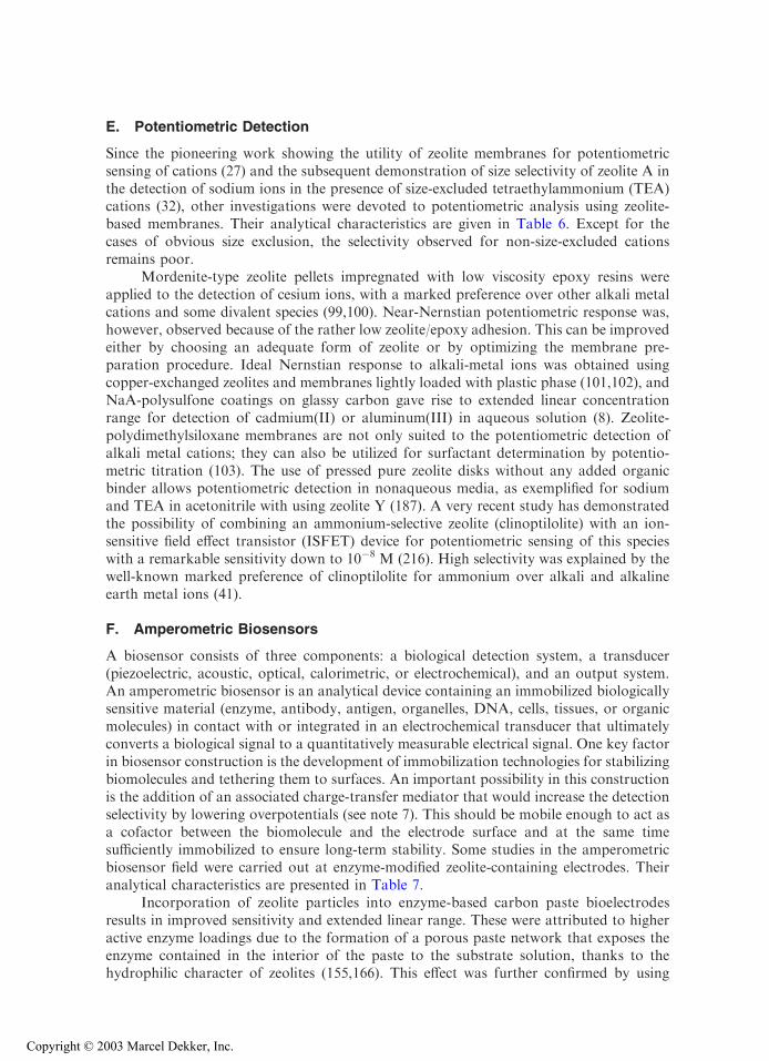
E. Potentiometric Detection
Since the pioneering work showing the utility of zeolite membranes for potentiometricsensing of cations (27) and the subsequent demonstration of size selectivity of zeolite A inthe detection of sodium ions in the presence of size-excluded tetraethylammonium (TEA)cations (32), other investigations were devoted to potentiometric analysis using zeolite-based membranes. Their analytical characteristics are given in Table 6. Except for thecases of obvious size exclusion, the selectivity observed for non-size-excluded cationsremains poor.
Mordenite-type zeolite pellets impregnated with low viscosity epoxy resins wereapplied to the detection of cesium ions, with a marked preference over other alkali metalcations and some divalent species (99,100). Near-Nernstian potentiometric response was,however, observed because of the rather low zeolite/epoxy adhesion. This can be improvedeither by choosing an adequate form of zeolite or by optimizing the membrane pre-paration procedure. Ideal Nernstian response to alkali-metal ions was obtained usingcopper-exchanged zeolites and membranes lightly loaded with plastic phase (101,102), andNaA-polysulfone coatings on glassy carbon gave rise to extended linear concentrationrange for detection of cadmium(II) or aluminum(III) in aqueous solution (8). Zeolite-polydimethylsiloxane membranes are not only suited to the potentiometric detection ofalkali metal cations; they can also be utilized for surfactant determination by potentio-metric titration (103). The use of pressed pure zeolite disks without any added organicbinder allows potentiometric detection in nonaqueous media, as exemplified for sodiumand TEA in acetonitrile with using zeolite Y (187). A very recent study has demonstratedthe possibility of combining an ammonium-selective zeolite (clinoptilolite) with an ion-sensitive field effect transistor (ISFET) device for potentiometric sensing of this specieswith a remarkable sensitivity down to 10�8 M (216). High selectivity was explained by thewell-known marked preference of clinoptilolite for ammonium over alkali and alkalineearth metal ions (41).
F. Amperometric Biosensors
A biosensor consists of three components: a biological detection system, a transducer(piezoelectric, acoustic, optical, calorimetric, or electrochemical), and an output system.An amperometric biosensor is an analytical device containing an immobilized biologicallysensitive material (enzyme, antibody, antigen, organelles, DNA, cells, tissues, or organicmolecules) in contact with or integrated in an electrochemical transducer that ultimatelyconverts a biological signal to a quantitatively measurable electrical signal. One key factorin biosensor construction is the development of immobilization technologies for stabilizingbiomolecules and tethering them to surfaces. An important possibility in this constructionis the addition of an associated charge-transfer mediator that would increase the detectionselectivity by lowering overpotentials (see note 7). This should be mobile enough to act asa cofactor between the biomolecule and the electrode surface and at the same timesufficiently immobilized to ensure long-term stability. Some studies in the amperometricbiosensor field were carried out at enzyme-modified zeolite-containing electrodes. Theiranalytical characteristics are presented in Table 7.
Incorporation of zeolite particles into enzyme-based carbon paste bioelectrodesresults in improved sensitivity and extended linear range. These were attributed to higheractive enzyme loadings due to the formation of a porous paste network that exposes theenzyme contained in the interior of the paste to the substrate solution, thanks to thehydrophilic character of zeolites (155,166). This effect was further confirmed by using
Copyright © 2003 Marcel Dekker, Inc.
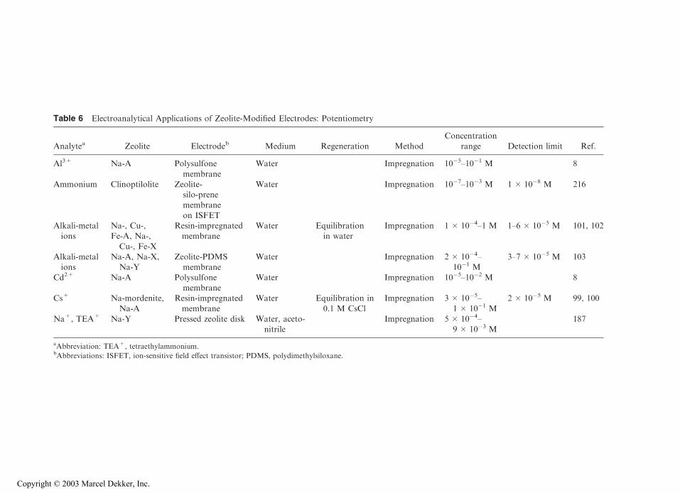
Table 6 Electroanalytical Applications of Zeolite-Modified Electrodes: Potentiometry
Analytea Zeolite Electrodeb Medium Regeneration MethodConcentration
range Detection limit Ref.
Al3+ Na-A Polysulfone
membrane
Water Impregnation 10�5–10�1 M 8
Ammonium Clinoptilolite Zeolite-silo-prenemembrane
on ISFET
Water Impregnation 10�7–10�3 M 1 � 10�8 M 216
Alkali-metalions
Na-, Cu-,Fe-A, Na-,
Cu-, Fe-X
Resin-impregnatedmembrane
Water Equilibrationin water
Impregnation 1 � 10�4–1 M 1–6 � 10�5 M 101, 102
Alkali-metalions
Na-A, Na-X,Na-Y
Zeolite-PDMSmembrane
Water Impregnation 2 � 10�4–10�1 M
3–7 � 10�5 M 103
Cd2+ Na-A Polysulfonemembrane
Water Impregnation 10�5–10�2 M 8
Cs+ Na-mordenite,
Na-A
Resin-impregnated
membrane
Water Equilibration in
0.1 M CsCl
Impregnation 3 � 10�5–
1 � 10�1 M
2 � 10�5 M 99, 100
Na+, TEA+ Na-Y Pressed zeolite disk Water, aceto-nitrile
Impregnation 5 � 10�4–9 � 10�3 M
187
aAbbreviation: TEA+, tetraethylammonium.bAbbreviations: ISFET, ion-sensitive field effect transistor; PDMS, polydimethylsiloxane.
Copyright © 2003 Marcel Dekker, Inc.
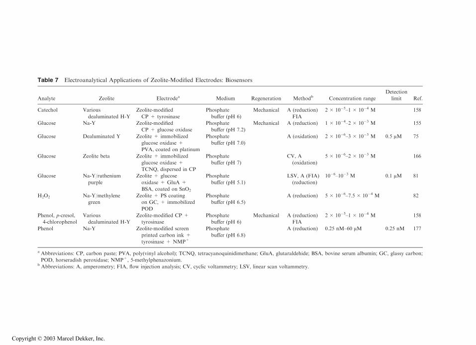
Table 7 Electroanalytical Applications of Zeolite-Modified Electrodes: Biosensors
Analyte Zeolite Electrodea Medium Regeneration Methodb Concentration range
Detection
limit Ref.
Catechol Various
dealuminated H-Y
Zeolite-modified
CP + tyrosinase
Phosphate
buffer (pH 6)
Mechanical A (reduction)
FIA
2 � 10�5–1 � 10�4 M 158
Glucose Na-Y Zeolite-modified
CP + glucose oxidase
Phosphate
buffer (pH 7.2)
Mechanical A (reduction) 1 � 10�4–2 � 10�3 M 155
Glucose Dealuminated Y Zeolite + immobilized
glucose oxidase +
PVA, coated on platinum
Phosphate
buffer (pH 7.0)
A (oxidation) 2 � 10�6–3 � 10�3 M 0.5 AM 75
Glucose Zeolite beta Zeolite + immobilized
glucose oxidase +
TCNQ, dispersed in CP
Phosphate
buffer (pH 7)
CV, A
(oxidation)
5 � 10�6–2 � 10�3 M 166
Glucose Na-Y/ruthenium
purple
Zeolite + glucose
oxidase + GluA +
BSA, coated on SnO2
Phosphate
buffer (pH 5.1)
LSV, A (FIA)
(reduction)
10�6–10�3 M 0.1 AM 81
H2O2 Na-Y/methylene
green
Zeolite + PS coating
on GC, + immobilized
POD
Phosphate
buffer (pH 6.5)
A (reduction) 5 � 10�6–7.5 � 10�4 M 82
Phenol, p-cresol,
4-chlorophenol
Various
dealuminated H-Y
Zeolite-modified CP +
tyrosinase
Phosphate
buffer (pH 6)
Mechanical A (reduction)
FIA
2 � 10�5–1 � 10�4 M 158
Phenol Na-Y Zeolite-modified screen
printed carbon ink +
tyrosinase + NMP+
Phosphate
buffer (pH 6.8)
A (reduction) 0.25 nM–60 AM 0.25 nM 177
a Abbreviations: CP, carbon paste; PVA, poly(vinyl alcohol); TCNQ, tetracyanoquinidimethane; GluA, glutaraldehide; BSA, bovine serum albumin; GC, glassy carbon;
POD, horseradish peroxidase; NMP+, 5-methylphenazonium.b Abbreviations: A, amperometry; FIA, flow injection analysis; CV, cyclic voltammetry; LSV, linear scan voltammetry.
Copyright © 2003 Marcel Dekker, Inc.
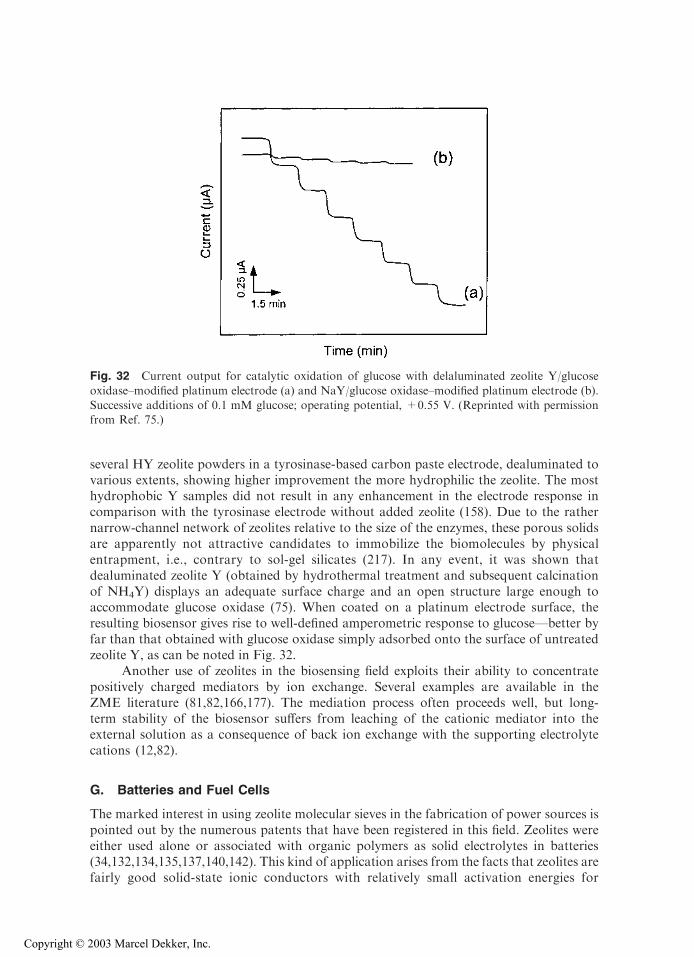
several HY zeolite powders in a tyrosinase-based carbon paste electrode, dealuminated tovarious extents, showing higher improvement the more hydrophilic the zeolite. The mosthydrophobic Y samples did not result in any enhancement in the electrode response incomparison with the tyrosinase electrode without added zeolite (158). Due to the rathernarrow-channel network of zeolites relative to the size of the enzymes, these porous solidsare apparently not attractive candidates to immobilize the biomolecules by physicalentrapment, i.e., contrary to sol-gel silicates (217). In any event, it was shown thatdealuminated zeolite Y (obtained by hydrothermal treatment and subsequent calcinationof NH4Y) displays an adequate surface charge and an open structure large enough toaccommodate glucose oxidase (75). When coated on a platinum electrode surface, theresulting biosensor gives rise to well-defined amperometric response to glucose—better byfar than that obtained with glucose oxidase simply adsorbed onto the surface of untreatedzeolite Y, as can be noted in Fig. 32.
Another use of zeolites in the biosensing field exploits their ability to concentratepositively charged mediators by ion exchange. Several examples are available in theZME literature (81,82,166,177). The mediation process often proceeds well, but long-term stability of the biosensor suffers from leaching of the cationic mediator into theexternal solution as a consequence of back ion exchange with the supporting electrolytecations (12,82).
G. Batteries and Fuel Cells
The marked interest in using zeolite molecular sieves in the fabrication of power sources ispointed out by the numerous patents that have been registered in this field. Zeolites wereeither used alone or associated with organic polymers as solid electrolytes in batteries(34,132,134,135,137,140,142). This kind of application arises from the facts that zeolites arefairly good solid-state ionic conductors with relatively small activation energies for
Fig. 32 Current output for catalytic oxidation of glucose with delaluminated zeolite Y/glucose
oxidase–modified platinum electrode (a) and NaY/glucose oxidase–modified platinum electrode (b).Successive additions of 0.1 mM glucose; operating potential, +0.55 V. (Reprinted with permissionfrom Ref. 75.)
Copyright © 2003 Marcel Dekker, Inc.

conduction and are stable over a wide temperature range. In early 1965, in a pioneeringstudy, Freeman had already proposed a design of zeolite batteries operating well at bothlow and high temperatures (�78jC and 500jC) (33). The cell composition was made of amultilayer arrangement of a gold cathode contact, a copper-exchanged zeolite X catholyte,a sodium zeolite X separator, and a zinc anode (Au|CuIIX|NaX|Zn). Operational workingof the cell involves Zn oxidation and CuII reduction accompanied by charge compensationvia the NaX separator (migration of Na+ toward the cathodic part of the cell). FollowingFreeman’s idea, zeolite-based microporous solid electrolytes were used in the fabrication oflithium secondary batteries, with the zeolite acting as a host for lithium ions (134,137,138,140–142,218). Zeolite was also host for ZnII in zinc-manganese oxide batteries (136), forPbII in lead-acid batteries (133), or for Na+ to prepare sodium anodes (55). When zeolite-polymer composites are used as solid electrolytes, the zeolite component is often exploitedto increase ionic conductivity, which is especially useful for operation of batteries at lowtemperature (132,137,139). Titanosilicalites are also interesting in this respect (219,220).The desiccant properties of zeolites were exploited in manufacturing batteries to removetrace water from nonaqueous electrolytes after assembly of the cell (134,217,221–226),which contributes to lowering the self-discharge rate of the battery. In sealed lead-acidbatteries, the addition of zeolite enhances the absorption of oxygen and suppresses theevolution of hydrogen (227,228). It also acts as an oxygen concentrator in zinc-oxygenbatteries (229) or as a gas-adsorbing material between the anodic and cathodic parts of thecell (230). Zeolite modification of organic cathodes was proposed as a clean technology forimproved cycle life of the zinc-chloranil organic secondary battery (231). In addition, oneshould mention the use of dehydrated zeolite crystals as host structures for liquid and/orvolatile electrochemically active species in designing solid-state batteries: examples areavailable for zeolite/iodine and zeolite/sulfur (or selenium) cathodes, which can be readilyapplied at room temperature (54,55,132).
Ionically conductive zeolites are attractive materials in the fabrication of fuel cellelectrodes. They often serve as a support for catalytic metals such as Ag and Pd (35), orother noble metals such as Rh, Pt, Ru, and Ni (232,233). Zeolites were also added in themembrane of hydrogen-oxygen fuel cells for their water-absorptive capacity (36). Theintrinsic catalytic properties of zeolites NaA and NaX were exploited in oxygen-methanolfuel cells with efficiencies comparable to those of noble metal cathodes (234,235). Silver-exchanged zeolite A was found to electrocatalyze oxygen reduction in such fuel cells(236). Zeolite membranes separating the anode and cathode compartments allow thepassage of ions through the membrane to carry an electric current in methanol fuel cellsusing a basic electrolyte such as carbonate: the zeolite membrane prevents the escape ofmethanol into the atmosphere, which enables the fuel cell to operate at higher temper-ature and hence to be more efficient (237). Acidic zeolite matrices for fuel cells were alsoreported (238).
H. Photoelectrochemistry
Zeolites are excellent templates for the fabrication of multicomponent electron transfersystems, but most often these are photochemically induced (see Chapter 13 in thisvolume), with the sacrificial electron feeder or consumer being a chemical oxidant orreducer and not an electrode surface (180). It is somewhat surprising that photoelec-trochemistry involving zeolite molecular sieves has been so sparingly considered.
The photocatalytic oxidation of water to molecular oxygen can be achieved on thinAgCl-coated electrodes, with the metallic silver produced during the process being
Copyright © 2003 Marcel Dekker, Inc.
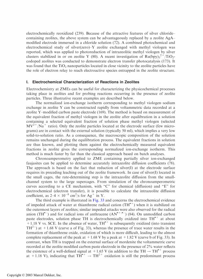
electrochemically reoxidized (239). Because of the attractive features of silver chloride–containing zeolites, the above system can be advantageously replaced by a zeolite AgA–modified electrode immersed in a chloride solution (72). A combined photochemical andelectrochemical study of silver(zero)–Y zeolite exchanged with methyl viologen wasreported, which was applied to photoreduction of intrazeolitic methyl viologen by silverclusters stabilized in or on zeolite Y (80). A recent investigation of Ru(bpy)3
2+/TiO2-codoped zeolites was conducted to demonstrate electron transfer photocatalysis (173). Itwas found that the TiO2 nanoparticles located in close vicinity to the zeolite particles havethe role of electron relay to reach electroactive species entrapped in the zeolite structure.
I. Electrochemical Characterization of Reactions in Zeolites
Electrochemistry at ZMEs can be useful for characterizing the physicochemical processestaking place in zeolites and for probing reactions occurring in the presence of zeoliteparticles. Three illustrative recent examples are described below.
The normalized ion-exchange isotherm corresponding to methyl viologen–sodiumexchange in zeolite Y can be constructed rapidly from voltammetric data recorded at azeolite Y–modified carbon paste electrode (169). The method is based on measurement ofthe equivalent fraction of methyl viologen in the zeolite after equilibration in a solutioncontaining a selected equivalent fraction of solution phase methyl viologen (selectedMV2+/Na+ ratio). Only the zeolite particles located at the electrode surface (few micro-grams) are in contact with the external solution (typically 50 ml), which implies a very lowsolid-to-solution ratio. As a consequence, the macroscopic composition of the solutionremains unchanged during the equilibration process. The equivalent fractions in solutionare thus known, and plotting them against the electrochemically measured equivalentfractions in zeolite gives the corresponding normalized ion-exchange isotherm. Thismethod is much faster by far than the classical approach based on batch analyses.
Chronoamperometry applied to ZME containing partially silver ion-exchangedfaujasites can be applied to determine accurately intrazeolite diffusion coefficients (78).The approach is based on the fact that reduction of silver(I) at the electrode surfacerequires its preceding leaching out of the zeolite framework. In case of silver(I) located inthe small cages, the rate-determining step is the intrazeolite diffusion from the small-channel system to the large supercages. From simulation of the chronoamperometriccurves according to a CE mechanism, with ‘‘C’’ for chemical (diffusion) and ‘‘E’’ forelectrochemical (electron transfer), it is possible to calculate the intrazeolite diffusioncoefficient, as 2–4 � 10�8 cm2/s for Ag+ in Y.
The third example is illustrated in Fig. 33 and concerns the electrochemical evidenceof impeded attack of water at thianthrene radical cation (TH
.+) when it is stabilized onthe outermost layers of zeolites; similar impeded attacks were also observed for the radicalanion (TH
.�) and for radical ions of anthracene (AN.+/.�) (84). On unmodified carbon
paste electrodes, solution phase TH is electrochemically oxidized into TH.+ at about
+1.18 V vs. SCE. In the absence of water, TH.+ is subsequently oxidized (into transient
TH2�) at +1.68 V (curve a of Fig. 33), whereas the presence of trace water results in theformation of thianthrene oxide, oxidation of which is more difficult, leading to the almostcomplete replacement of the peak at +1.68 V by a peak at +1.82 V (curve b of Fig. 33). Incontrast, when TH is trapped on the external surface of mordenite the voltammetric curverecorded at the zeolite modified carbon paste electrode in the presence of 2% water reflectsthe existence of a well-defined signal at +1.65 V (in addition to the TH ! TH
.+ processat +1.18 V), indicating that TH
.+ ! TH2+ oxidation is still the predominant process
Copyright © 2003 Marcel Dekker, Inc.
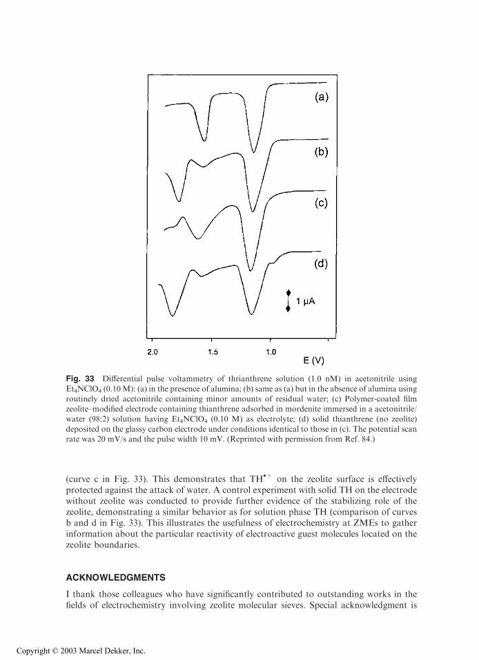
(curve c in Fig. 33). This demonstrates that TH.+ on the zeolite surface is effectively
protected against the attack of water. A control experiment with solid TH on the electrodewithout zeolite was conducted to provide further evidence of the stabilizing role of thezeolite, demonstrating a similar behavior as for solution phase TH (comparison of curvesb and d in Fig. 33). This illustrates the usefulness of electrochemistry at ZMEs to gatherinformation about the particular reactivity of electroactive guest molecules located on thezeolite boundaries.
ACKNOWLEDGMENTS
I thank those colleagues who have significantly contributed to outstanding works in thefields of electrochemistry involving zeolite molecular sieves. Special acknowledgment is
Fig. 33 Differential pulse voltammetry of thrianthrene solution (1.0 nM) in acetonitrile using
Et4NClO4 (0.10M): (a) in the presence of alumina; (b) same as (a) but in the absence of alumina usingroutinely dried acetonitrile containing minor amounts of residual water; (c) Polymer-coated filmzeolite–modified electrode containing thianthrene adsorbed in mordenite immersed in a acetonitrile/
water (98:2) solution having Et4NClO4 (0.10 M) as electrolyte; (d) solid thianthrene (no zeolite)deposited on the glassy carbon electrode under conditions identical to those in (c). The potential scanrate was 20 mV/s and the pulse width 10 mV. (Reprinted with permission from Ref. 84.)
Copyright © 2003 Marcel Dekker, Inc.
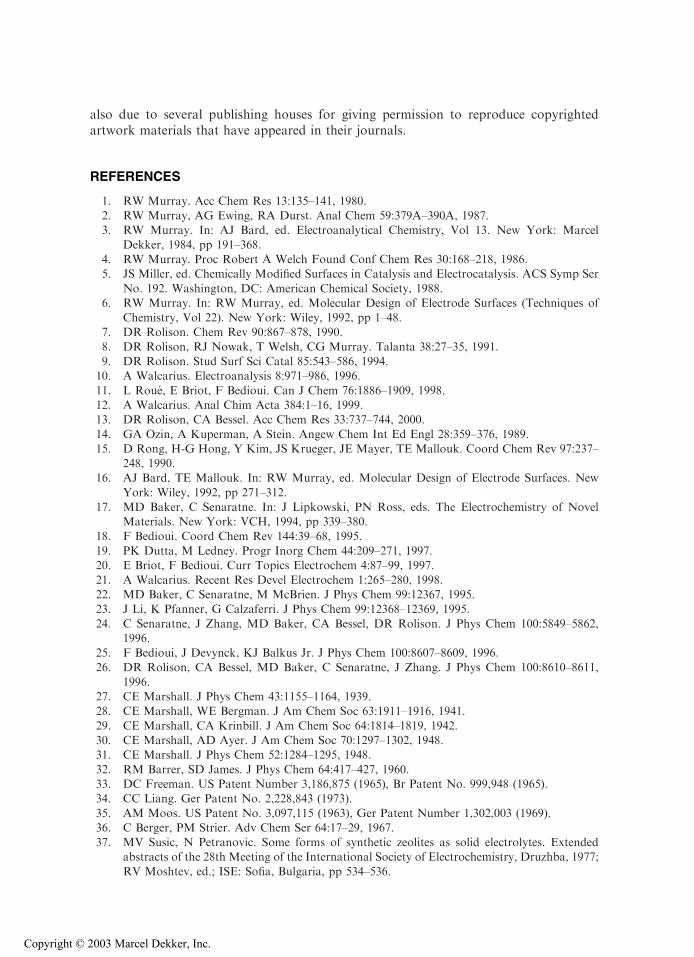
also due to several publishing houses for giving permission to reproduce copyrightedartwork materials that have appeared in their journals.
REFERENCES
1. RW Murray. Acc Chem Res 13:135–141, 1980.2. RW Murray, AG Ewing, RA Durst. Anal Chem 59:379A–390A, 1987.3. RW Murray. In: AJ Bard, ed. Electroanalytical Chemistry, Vol 13. New York: Marcel
Dekker, 1984, pp 191–368.4. RW Murray. Proc Robert A Welch Found Conf Chem Res 30:168–218, 1986.5. JS Miller, ed. Chemically Modified Surfaces in Catalysis and Electrocatalysis. ACS Symp Ser
No. 192. Washington, DC: American Chemical Society, 1988.6. RW Murray. In: RW Murray, ed. Molecular Design of Electrode Surfaces (Techniques of
Chemistry, Vol 22). New York: Wiley, 1992, pp 1–48.7. DR Rolison. Chem Rev 90:867–878, 1990.
8. DR Rolison, RJ Nowak, T Welsh, CG Murray. Talanta 38:27–35, 1991.9. DR Rolison. Stud Surf Sci Catal 85:543–586, 1994.10. A Walcarius. Electroanalysis 8:971–986, 1996.
11. L Roue, E Briot, F Bedioui. Can J Chem 76:1886–1909, 1998.12. A Walcarius. Anal Chim Acta 384:1–16, 1999.13. DR Rolison, CA Bessel. Acc Chem Res 33:737–744, 2000.
14. GA Ozin, A Kuperman, A Stein. Angew Chem Int Ed Engl 28:359–376, 1989.15. D Rong, H-G Hong, Y Kim, JS Krueger, JE Mayer, TE Mallouk. Coord Chem Rev 97:237–
248, 1990.16. AJ Bard, TE Mallouk. In: RW Murray, ed. Molecular Design of Electrode Surfaces. New
York: Wiley, 1992, pp 271–312.17. MD Baker, C Senaratne. In: J Lipkowski, PN Ross, eds. The Electrochemistry of Novel
Materials. New York: VCH, 1994, pp 339–380.
18. F Bedioui. Coord Chem Rev 144:39–68, 1995.19. PK Dutta, M Ledney. Progr Inorg Chem 44:209–271, 1997.20. E Briot, F Bedioui. Curr Topics Electrochem 4:87–99, 1997.
21. A Walcarius. Recent Res Devel Electrochem 1:265–280, 1998.22. MD Baker, C Senaratne, M McBrien. J Phys Chem 99:12367, 1995.23. J Li, K Pfanner, G Calzaferri. J Phys Chem 99:12368–12369, 1995.
24. C Senaratne, J Zhang, MD Baker, CA Bessel, DR Rolison. J Phys Chem 100:5849–5862,1996.
25. F Bedioui, J Devynck, KJ Balkus Jr. J Phys Chem 100:8607–8609, 1996.26. DR Rolison, CA Bessel, MD Baker, C Senaratne, J Zhang. J Phys Chem 100:8610–8611,
1996.27. CE Marshall. J Phys Chem 43:1155–1164, 1939.28. CE Marshall, WE Bergman. J Am Chem Soc 63:1911–1916, 1941.
29. CE Marshall, CA Krinbill. J Am Chem Soc 64:1814–1819, 1942.30. CE Marshall, AD Ayer. J Am Chem Soc 70:1297–1302, 1948.31. CE Marshall. J Phys Chem 52:1284–1295, 1948.
32. RM Barrer, SD James. J Phys Chem 64:417–427, 1960.33. DC Freeman. US Patent Number 3,186,875 (1965), Br Patent No. 999,948 (1965).34. CC Liang. Ger Patent No. 2,228,843 (1973).
35. AM Moos. US Patent No. 3,097,115 (1963), Ger Patent Number 1,302,003 (1969).36. C Berger, PM Strier. Adv Chem Ser 64:17–29, 1967.37. MV Susic, N Petranovic. Some forms of synthetic zeolites as solid electrolytes. Extended
abstracts of the 28th Meeting of the International Society of Electrochemistry, Druzhba, 1977;
RV Moshtev, ed.; ISE: Sofia, Bulgaria, pp 534–536.
Copyright © 2003 Marcel Dekker, Inc.
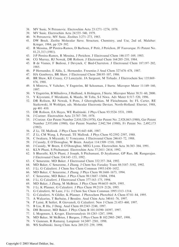
38. MV Susic, N Petranovic. Electrochim Acta 23:1271–1274, 1978.39. MV Susic. Electrochim Acta 24:535–540, 1979.40. N Petranovic, MV Susic. Zeolites 3:271–273, 1983.
41. DW Breck. Zeolite Molecular Sieve. Structure, Chemistry, and Use, 2nd ed. Malabar:Krieger, 1984, pp 529–592.
42. R Messina, JP Pereira-Ramos, D Barboux, F Petit, J Perichon, JF Fauvarque. Fr Patent No.
81,21,313 (1981).43. J-P Pereira-Ramos, R Messina, J Perichon. J Electroanal Chem 146:157–169, 1983.44. CG Murray, RJ Nowak, DR Rolison. J Electroanal Chem 164:205–210, 1984.
45. B de Vismes, F Bedioui, J Devynck, C Bied-Charreton. J Electroanal Chem 187:197–202,1985.
46. P Hernandez, E Alda, L. Hernandez. Fresenius J Anal Chem 327:676–678, 1987.
47. HA Gemborys, BR Shaw. J Electroanal Chem 208:95–107, 1986.48. BR Shaw, KE Creasy, CJ Lanczycki. JA Sargeant, M Tirhado. J Electrochem Soc 135:869–
876, 1988.49. S Mintova, V Valtchev, V Engstrom, BJ Schoeman, J Sterte. Micropor Mater 11:149–160,
1997.50. V Engstrom, B Mihailova, J Hedlund, A Holmgren, J Sterte. Micropor Mater 38:51–60, 2000.51. Y Kiyozumi, F Mizukami, K Maeda, M Toba, S-I Niwa. Adv Mater 8:517–520, 1996.
52. DR Rolison, RJ Nowak, S Pons, J Ghoroghchian, M Fleischmann. In: FL Carter, RESiatkowski, H Wohltjen, eds. Molecular Electronic Devices. North-Holland: Elsevier, 1988,pp 401–410.
53. DR Rolison, EA Hayes, WE Rudzinski. J Phys Chem 93:5524–5531, 1989.54. J Coetzer. Electrochim Acta 23:787–789, 1978.55. J Coetzer. Ger Patent Number 2,810,320 (1978), Ger Patent No. 2,928,863 (1980), Ger Patent
Number 2,935,686 (1980), Ger Patent Number 2,942,764 (1980), Fr Patent No. 2,492,173(1982).
56. Z Li, TE Mallouk. J Phys Chem 91:643–648, 1987.57. Z Li, CM Wang, L Persaud, TE Mallouk. J Phys Chem 92:2592–2597, 1988.
58. C Iwakura, S Miyazaki, U Yoneyama. J Electroanal Chem 246:63–72, 1988.59. J Cassidy, E O’Donoghue, W Breen. Analyst 114:1509–1510, 1989.60. J Cassidy, W Breen, E O’Donoghue, MEG Lyons. Electrochim Acta 36:383–384, 1991.
61. KLN Phani, S Pitchumani. Electrochim Acta 37:2411–2414, 1992.62. S Bharathi, KLN Phani, J Joseph, S Pitchumani, D Jeyakumar, GP Rao, SK Rangarajan.
J Electroanal Chem 334:145–153, 1992.
63. C Senaratne, MD Baker. J Electroanal Chem 332:357–364, 1992.64. MD Baker, C Senaratne, J Zhang. J Chem Soc Faraday Trans 88:3187–3192, 1992.65. J Li, G Calzaferri. J Chem Soc Chem Commun 1993:1430–1432.66. MD Baker, C Senaratne, J Zhang. J Phys Chem 98:1668–1673, 1994.
67. C Senaratne, MD Baker. J Phys Chem 98:13687–13694, 1994.68. J Li, G Calzaferri. J Electroanal Chem 377:163–175, 1994.69. MD Baker, J Zhang, M McBrien. J Phys Chem 99:6635–6639, 1995.
70. J Li, K Pfanner, G Calzaferri. J Phys Chem 99:2119–2126, 1995.71. G Calzaferri, M Lanz, J Li. J Chem Soc Chem Commun 1995:1313–1314.72. G Calzaferri, N Gfeller, K Pfanner. J Photochem Photobiol A Chem 87:81–84, 1995.
73. A Walcarius, T Barbaise, J Bessiere. Anal Chim Acta 340:61–76, 1997.74. P Laine, R Seifert, R Giovanoli, G Calzaferri. New J Chem 21:453–460, 1997.75. B Liu, R Hu, J Deng. Anal Chem 69:2343–2248, 1997.
76. DH Brouwer, MD Baker. J Phys Chem B 101:10390–10397, 1997.77. L Mogensen, L Kryger, Electroanalysis 10:1285–1287, 1998.78. MD Baker, M McBrien, I Burgess, J Phys Chem B 102:2905–2907, 1998.79. V Ganesan, R Ramaraj. Langmuir 14:2497–2501, 1998.
80. WS Szulbinski. Inorg Chim Acta 269:253–259, 1998.
Copyright © 2003 Marcel Dekker, Inc.
81. CF Chen, CM Wang. J Electroanal Chem 466:82–89, 1999.82. B Liu, F Yan, J Kong, J Deng. Anal Chim Acta 386:31–39, 1999.83. MD Baker, C Senaratne. Phys Chem Chem Phys 1:1673–1677, 1999.
84. A Domenech, I Casades, H Garcia. J Org Chem 64:3731–3735, 1999.85. A Domenech, MT Domenech-Carbo, H Garcia, MS Galletero. Chem Commun 1999:2173–
2174.
86. MD Baker, TW Hui. Electrochemistry of methyl viologen-exchanged zeolite Y modifiedelectrodes. Proceedings of the 12th International Zeolite Conference, Baltimore, 1999; MMJTreacy, ed.; Materials Research Society, Warrendale, PA, pp 2073–2078.
87. A Domenech, P Formentin, H Garcia, MJ Sabater. Eur J Inorg Chem 2000:1339–1344.88. A Domenech, A Corma, H Garcia, S Valencia. Topics Catal 11/12:401–407, 2000.89. TW Hui, MD Baker. J Phys Chem B 105:3204–3210, 2001.
90. G Calzaferri, K Hadener, J Li. J Chem Soc Chem Commun 1991:653–654.91. JB Talbot, CB Ahlers. Electrophoretic deposition of zeolites. Abstract of the 217th ACS
National Meeting, Anaheim, 1999, pp 21–25.92. CB Ahlers, JB Talbot. J Electrochem Soc 146:3259–3263, 1999.
93. CB Ahlers, JB Talbot. Electrochim Acta 45:3379–3387, 2000.94. MD Baker, C Senaratne. Anal Chem 64:697–700, 1992.95. V Ganesan, R Ramaraj. J Appl Electrochem 30:757–760, 2000.
96. KLN Phani, S Pitchumani, SK Ravichandran. Langmuir 9:2455–2459, 1993.97. Y-X Jiang, W-B Song, Y Liu, N Lu, M-Z Zou, H-D Xu, A-L Zhang. Chem J Chinese Univ
20:717–721, 1999.
98. SK Ravichandran, KLN Phani, S Pitchumani. Zeolite-conducting polyaniline hybrid:synthesis and its electrochemical behavior. Proceedings of the IUPAC InternationalSymposium on Advanced Polymer Science and Technology. KSV Srinivasan, ed.; Allied
Publishers, Ltd., New Delhi, India, 1:347–350, 1998.99. G Johansson, L Risinger, L Falth. Anal Chim Acta 119:25–32, 1980.100. G Johansson, L Falth, L Risinger. Hung Sci Instr 49:47–51, 1980.101. M Demertzis, NP Evmiridis. J Chem Soc Faraday Trans I 82:3647–3655, 1986.
102. NP Evmiridis, MA Demertzis, AG Vlessidis. Fresenius J Anal Chem 340:145–152, 1991.103. S Matysik, F-M Matysik, J Mattusch, W-D Einicke. Electroanalysis 10:98–102, 1998.104. MD Baker, J Zhang. J Phys Chem 94:8703–8708, 1990.
105. Y Jiang, M Zou, K Yuan, H Xu. Electroanalysis 11:254–259, 1999.106. K Lee, C Lee, JW Park, YS Park, KB Yoon. Bull Korean Chem Soc 20:1365–1367, 1999.107. N Venkatathri, MP Vinod, K Vijayamohanan, S Sivasanker. J Chem Soc Faraday Trans
92:473–478, 1996.108. MP Vinod, TK Das, AJ Chandwadkar, K Vijayamohanan, JG Chandwadkar. Mater Chem
Phys 58:37–43, 1999.109. CA Bessel, DR Rolison. J Phys Chem B 101:1148–1157, 1997.
110. KE Creasy, YP Deng, J Park, EVR Borgstedt, SP Davis, SL Suib, BR Shaw. Mater Res SocSymp Proc 233:157–167, 1991.
111. RAW Dryfe, SM Holmes. J Electroanal Chem 483:144–149, 2000.
112. F Bedioui, E de Boysson, J Devynck, KJ Balkus Jr. J Electroanal Chem 315:313–318, 1991.113. F Bedioui, E de Boysson, J Devynck, KJ Balkus Jr. J Chem Soc Faraday Trans 87:3831–3834,
1991.
114. K Mesfar, B Carre, F Bedioui, J Devynck. J Mater Chem 3:873–876, 1993.115. L Gaillon, N Sajot, F Bedioui, J Devynck, KJ Balkus Jr. J Electroanal Chem 345:157–167,
1993.
116. F Bedioui, L Roue, L Gaillon, J Devynck, SL Bell, KJ Balkus Jr. Prepr Am Chem Soc Div PetChem 38:529–535, 1993.
117. F Bedioui, L Roue, E Briot, J Devynck, SL Bell, KJ Balkus Jr. J Electroanal Chem 373:19–29,1994.
118. AGGabrielov, KJ Balkus Jr, SL Bell, F Bedioui, J Devynck. Micropor Mater 2:119–126, 1994.
Copyright © 2003 Marcel Dekker, Inc.
119. F Bedioui, L Roue, J Devynck, KJ Balkus Jr. J Electrochem Soc 141:3049–3052, 1994.120. L Gaillon, F Bedioui, J Devynck. J Mater Chem 4:1215–1218, 1994.121. F Bedioui, L Roue, J Devynck, KJ Balkus Jr. Stud Surf Sci Catal 84:917–924, 1994.
122. KJ Balkus Jr, AG Gabrielov, S Bell, F Bedioui, L Roue, J Devynck. Inorg Chem 33:67–72,1994.
123. F Bedioui, L Roue, E Briot, J Devynck, KJ Balkus Jr, JF Diaz. New J Chem 20:1235–1241,
1996.124. KJ Balkus Jr, AK Khanmamedova, KM Dixon, F Bedioui. Appl Catal A 143:159–173,
1996.
125. F Bedioui, E Briot, J Devynck, KJ Balkus Jr. Mater Res Soc Symp Proc 431:45–50, 1996.126. F Bedioui, E Briot, J Devynck, KJ Balkus Jr. Inorg Chim Acta 254:151–155, 1997.127. E Briot, F Bedioui, KJ Balkus Jr. J Electroanal Chem 454:83–89, 1998.
128. MANDA Lemos, P Sousa, F Lemos, AJL Pombeiro, FR Ribeiro. Stud Surf Sci Catal122:443–446, 1999.
129. BR Shaw, KE Creasy. Electrochemistry in dry zeolite crystals. Abstract of the 8thInternational Zeolite Conference, Amsterdam, 1989.
130. KE Creasy, BR Shaw. J Electrochem Soc 137:2353–2354, 1990.131. N Petranovic, D Minic. Ceram Int 22:317–320, 1996.132. MM Thackeray, J Coetzer. Solid State Ionics 6:135-138, 1982; J Coetzer, MJ Nolte, A
Steynberg. Fr Patent No. 2,463,982 (1981).133. Furukawa Battery Co., Ltd. Jp Patent No. 58,012,263 (1983).134. Sanyo Electric Co., Ltd. Jp Patent No. 58,103,776 (1983).
135. D Wang, W Yu, B Zhu, W Yuan, X Jia. Chn Patent No. 86,103,796 (1987).136. W Yang, H Yang, J Zhang. Dianchi 21:3–5, 1991.137. S Slane, M Salomon. J Power Sources 55:7–10, 1995.
138. Y Fang. Yingyong Huaxue 12:24–28, 1995.139. N Munichandraiah, LG Scanlon, RA Marsh, B Kumar, AK Sircar. J Appl Electrochem
25:857–863, 1995.140. T Inemasu, H Yoshihisa. Jp Patent No. 10,270,018 (1998).
141. F Gao, PH Mitchell, J Barker, J Swoyer. US Patent No. 5,728,489 (1998).142. DH Jang, SH Kim, HJ Kim, SM Hong. World Patent No. 2000,038,263 (2000).143. O Enea. Electrochim Acta 34:1647–1651, 1989.
144. RN Adams. Electrochemistry at Solid Elecrodes. New York: Marcel Dekker, 1969.145. K Kalcher, J-M Kauffmann, J Wang, I Svancara, K Vytras, C Neuhold, Z Yang.
Electroanalysis 7:5–22, 1995.
146. J Wang, T Martinez. Anal Chim Acta 207:95–102, 1988.147. KE Creasy, BR Shaw. Electrochim Acta 33:551–556, 1988.148. N El Murr, M Kerkeni, A Sellami, Y Bentaarit. J Electroanal Chem 246:461–465, 1988.149. S de Castro-Martins, S Khouzami, A Tuel, Y Bentaarit, N El Murr, A Sellami. J Electroanal
Chem 350:15–28, 1993.150. A Walcarius, L Lamberts, EG Derouane. Electrochim Acta 38:2257–2266, 1993.151. A Walcarius, L Lamberts, EG Derouane. Electrochim Acta 38:2267–2276, 1993.
152. M Xu, W Horsthemke, M Schell. Electrochim Acta 38:919–925, 1993.153. S de Castro-Martins, A Tuel, Y Bentaarit. Zeolites 14:130–136, 1994.154. A Walcarius, L Lamberts, EG Derouane. Electroanalysis 7:120–128, 1995.
155. J Wang, A Walcarius. J Electroanal Chem 404:237–242, 1996.156. J Wang, A Walcarius. J Electroanal Chem 407:183–187, 1996.157. C Bing, L Kryger. Talanta 43:153–160, 1996.
158. G Marko-Varga, E Burestedt, CJ Svensson, J Emneus, L Gorton, T Ruzgas, M Lutz, KKUnger. Electroanalysis 8:1121–1126, 1996.
159. A Walcarius, L Lamberts. J Electroanal Chem 422:77–89, 1997.160. B Chen, N-K Goh, L-S Chia. Electrochim Acta 42:595–604, 1997.
161. MZ Zou, HD Xu, J Lu, QH Ru. Chinese Chem Lett 8:247–250, 1997.
Copyright © 2003 Marcel Dekker, Inc.
162. IN Rodriguez, JA Munoz-Leyva, JL Hidalgo-Hidalgo de Cisneros. Anal Chim Acta 344:167–173, 1997.
163. A Walcarius, T Barbaise, J Bessiere. Ion exchange voltammetry at zeolite modified electrodes
versus ion exchange in zeolites. Proceedings of the Joint 142th Meeting of the Electro-chemical Society and 48th Meeting of the International Society of Electrochemistry, Paris,1997, Vol 97-19; AJ Ricco, MA Butler, P Vanysek, G Horval, AF Silva, eds,; ECS: Pen-
nington, NJ, pp 504–513.164. A Walcarius, L Lamberts. Anal Lett 31:585–599, 1998.165. SV Guerra, CR Xavier, S Nakagaki, LT Kubota. Electroanalysis 10:462–466, 1998.
166. B-H Liu, R-Q Hu, H-Y Liu, J-Q Deng. Acta Chim Sinica 56:682–687, 1998.167. A Walcarius. Anal Chim Acta 388:79–91, 1999.168. A Walcarius, V Vromman, J Bessiere. Sensors Actuators B 56:136–143, 1999.
169. A Walcarius, P Mariaulle, L Lamberts. J Electroanal Chem 463:100–108, 1999.170. A Walcarius, S Rozanska, J Bessiere, J Wang. Analyst 124:1185–1190, 1999.171. A Walcarius, P Mariaulle, C Louis, L Lamberts. Electroanalysis 11:393–400, 1999.172. M Cordero-Rando, M Barea-Zamora, JM Barbera-Salvador, IN Rodriguez, JA Munoz-
Leyva, JL Hidalgo-Hidalgo de Cisneros. Mikrochim Acta 132:7–11, 1999.173. SH Bossmann, C Turro, C Schnabel, MR Pokhrel, LM Payawan Jr, B Baumeister, M
Worner. J Phys Chem B 105:5374–5382, 2001.
174. BR Shaw, KE Creasy. Anal Chem 60:1241–1244, 1988.175. BR Shaw, KE Creasy. J Electroanal Chem 243:209–217, 1988.176. BR. Shaw, KE Creasy. US Patent No. 4,957,593 (1990).
177. H Kotte, B Grundig, K-D Vorlop, B Strehlitz, U Stottmeister. Anal Chem 67:65–70, 1995.178. Z Li, C Lai, TE Mallouk. Inorg Chem 28:178–182, 1989.179. J Sarradin, J-M Louvet, R Messina, J Perichon. Zeolites 4:157–162, 1984.
180. JS Krueger, TE Mallouk. In: M Gratzel, K Kalyanasundaram, eds. Kinetics and Catalysis inMicroheterogeneous Systems. Surf Sci Ser 38:461–490, 1991.
181. DR Rolison, JZ Stemple, DJ Curran. Electrochemical and electric-field effects at dispersions ofzeolites. Proceedings of the 9th International Zeolite Conference, Montreal, 1992, pp 699–708.
182. DR Rolison, JZ Stemple. J Chem Soc Chem Commun 1993:25–27.183. DN Blauch, DR Rolison. J Electroanal Chem 370:305–308, 1994.184. EA Hayes, JZ Stemple, DR Rolison. In: TL Rose, OJ Murphy, eds. Water Purification by
Photoelectrochemical, Photochemical, and Electrochemical Processes. Pennington: Electro-chemical Society, 1994, pp 121–130.
185. CA Bessel, DR Rolison. J Am Chem Soc 119:12673–12674, 1997.
186. CA Bessel, DR Rolison. J Electroanal Chem 439:97–105, 1997.187. RAW Dryfe, P Hayes, SM Holmes. Analyst 126:733–735, 2001.188. AJ Bard, LR Faulkner. Electrochemical Methods: Fundamentals and Applications. New
York: Wiley, 1980.
189. KB Yoon. Chem Rev 93:321–339, 1993.190. Y Kim, K Seff. J Phys Chem 82:1071–1077, 1978.191. MD Baker, M McBrien, C Liu, DH Brouwer. Silver nucleation and growth at zeolite
modified electrodes. Proceedings of the 12th International Zeolite Conference, Baltimore,1999, pp 2137–2142.
192. T Sun, K Seff. Chem Rev 94:857–870, 1994.
193. C Senaratne, J. Zhang, J Fox, I Burgess, MD Baker. Micropor Mesopor Mater 33:281–289,1999.
194. CA Bessel, DR Rolison. Stud Surf Sci Catal 98:114–115, 1995.
195. T Nyokong. J Chem Soc Dalton Trans 90:1359–1365, 1994.196. G Shi, G Xue, W Hou, J Dong, G Wang. J Electroanal Chem 344:363–366, 1993.197. RN de Guzman, YF Shen, BR Shaw, SL Suib, CL O’Young. Chem Mater 5:1395–1400, 1993.198. O Schaf, H Ghobarkar, AC Steinbach, U Guth. Fresenius J Anal Chem 367:388–392, 2000.
Copyright © 2003 Marcel Dekker, Inc.
199. NJ Turro, M Garcia-Garibay. In: V Ramamurthy, ed. Photochemistry in Organized Media.New York: VCH, 1991, pp 1–38.
200. S Bharathi, KLN Phani, J Joseph, S Pitchumani, D Jeyakumar, GP Rao. J Electroanal Chem
360:347–349, 1993.201. LT Kubota, Y Gushikem, J Perez, AA Tanaka. Langmuir 11:1009–1013, 1995.202. MD Baker, C Senaratne. Brit UK Patent No. GB 2,252,831 (1992).
203. MD Baker. Can Chem News 44:16–17, 1992.204. MD Baker, C Senaratne. Can Patent No. CA 2,179,472 (1997).205. MD Baker, C Senaratne. US Patents Nos. 5,733,437 and 5,730,857 (1998).
206. WW Buchberger, PR Haddad. J Chromatogr A 789:67–83, 1997.207. P Mariaulle, F Sinapi, L Lamberts, A Walcarius. Electrochim Acta 46:3543–3553, 2001.208. HH Girault. In: JO Bockris, ed. Modern Aspects of Electrochemistry, Vol. 25. New York:
Plenum, 1993, pp 1–62.209. F Reymond, D Fermin, HJ Lee, HH Girault. Electrochim Acta 45:2647–2662, 2000.210. PA Jacobs, NI Jaeger, P Jiru, G Schultz-Ekloff, eds. Metal Microstructures in Zeolites:
Preparation, Properties, Applications. Amsterdam: Elsevier, 1982.
211. J Heinze. Angew Chem Int Ed Engl 30:1268–1288, 1993.212. M Fleischmann, J Ghoroghchian, DR Rolison, S Pons. J Phys Chem 90:6392–6400, 1986.213. DR Rolison, J Stemple. US Patent No. 5,282,936 (1994).
214. DR Rolison, J Stemple. US Patent No. 5,288,371 (1994).215. DR Rolison, J Stemple. US Patent No. 5,296,106 (1994).216. ML Hamlaoui, R Kherrat, M Marakchi, N Jaffrezic-Renault, A Walcarius. Mater Sci Eng C
21:25–28, 2002.217. A Walcarius. Electroanalysis 13:701–718, 2001.218. W Huang, Y Yan, C Wan, J Wang. Qinghua Daxue Xuebao Ziran Kexueban 40:70–73, 2000.
219. SM Kuznicki, JS Curran, X Yang. World Patent No. 9,832,695 (1998).220. J Rocha, MW Anderson. Eur J Inorg Chem 5:801–818, 2000.221. M Inagaki, H Nagura, T Murata, Y Harada. Jp Patent No. 11,204,143 (1999).222. H Nemoto. Eur Patent No. 942,485 (1999).
223. S Kamiharashi, H Jinbo, K Naruse, S Fukuda. Jp Patent No. 63,019,765 (1988).224. Fuji Electrochemical Co., Ltd. Jp Patent No. 59,224,071 (1984).225. Hitachi Maxell, Ltd. Jap Patent No. 59,081,869 (1984).
226. JE Casey Jr, RF Chireau. US Patent No. 3,864,168 (1975).227. Kamiharashi, K Naruse, H Jinbo. Jp Patent No. 62,168,349 (1987).228. T Inoue, K Kobayashi, K Matsuo. Jp Patent No. 62,193,060 (1987).
229. V Gartstein, JB Camden. World Patent No. 9,960,654 (1999).230. T Hatakezawa, T Hara, T Endo, K Hatta. Jp Patent No. 2001,155,790 (2001).231. D Kalaiselvi, R Renuka. J Chem Technol Biotechnol 75:285–293, 2000.232. AS Berchielli, RF Chireau. Ger Patent No. 2,938,523 (1980).
233. M Shelef. US Patent No. 6,117,581 (2000).234. M Cruceanu, E Popovici, A Vasile. Rom Patent No. 78,511 (1982).235. M Cruceanu, E Popovici, A Vasile. Rom Rev Chim 32:973–975, 1981.
236. A Vasile, E Popovici, M Cruceanu. Rom Rev Chim 47:847–851, 1996.237. GJ Bratton, T Naylor, ACC Tseung. World Patent No. 9,852,243 (1998).238. K Miwa, K Iwayama, H Fukui. Jp Patent No. 62,241,265 (1987).
239. M Lanz, G Calzaferri. J Photochem Photobiol A Chem 109:87–89, 1997.
Copyright © 2003 Marcel Dekker, Inc.
Related Documents