MUNICIPALITY ENERGY CONSUMPTION Handbook of Energy Conservation - for waste water pump systems March 2006 The Working Group under the PSO - Research and Development Project 336-055 Conserving Energy by Optimising Pressurised Waste Water Systems

Welcome message from author
This document is posted to help you gain knowledge. Please leave a comment to let me know what you think about it! Share it to your friends and learn new things together.
Transcript
MUNICIPALITY
ENERGY
CONSUM
PTION
Handbook of Energy Conservation
- for waste water pump systems March 2006 The Working Group under the PSO - Research and Development Project 336-055 Conserving Energy by Optimising Pressurised Waste Water Systems
Handbook of Energy Conservation - for waste water pump systems
- 1 -
Table of Contents 1 Introduction................................................................................................................2 2 What Is a Pumping System?......................................................................................3 3 How Is the Energy Used? ..........................................................................................3 4 Pick the Fruit from the Lowest Branch .......................................................................4 5 Check the Condition of the Pumping System.............................................................4
5.1 Non-Return Valve ...............................................................................................4 5.2 Coupling Base ....................................................................................................4 5.3 Pump Impeller.....................................................................................................5 5.4 Valves.................................................................................................................6 5.5 Leaks..................................................................................................................6 5.6 Unwelcome Water ..............................................................................................6
6 Electricity-Consuming Units.......................................................................................7 6.1 Save on Heating .................................................................................................7 6.2 Save on Ventilation.............................................................................................8 6.3 Save on Lighting .................................................................................................8 6.4 Compressor Operation........................................................................................8 6.5 Vacuum Pumps ..................................................................................................9 6.6 Hydraulic Station.................................................................................................9
7 Use Your Operating Data ..........................................................................................9 8 Pump Operation ......................................................................................................10
8.1 Load .................................................................................................................11 8.2 Back-Pressure ..................................................................................................11 8.3 Pumps ..............................................................................................................13 8.4 Operating Conditions ........................................................................................17
9 Frequency Regulation .............................................................................................20 9.1 Which Pumping Stations Make Sense to Regulate? .........................................20 9.2 Frequency Converter Prices .............................................................................21 9.3 Installation Prices..............................................................................................22 9.4 Is It Always Possible to Save on Energy through Frequency Regulation?.........22 9.5 Other Good Reasons to Regulate the Frequency of Pumping Stations.............23 9.6 What Are the Disadvantages of Installing a Frequency Converter?...................25
10 Choosing a Frequency Converter ............................................................................26 11 Number of Frequency Converters............................................................................26 12 Positioning the Frequency Converter.......................................................................26 13 Installation of Frequency Converters .......................................................................27
13.1 Regulating Frequency Converters.....................................................................27 13.2 Electric Noise (EMC).........................................................................................29 13.3 Other Adjustments ............................................................................................30
14 Controlling Frequency Converters ...........................................................................30 14.1 Pump Start........................................................................................................30 14.2 Holding Time ....................................................................................................30 14.3 Reference Level................................................................................................31
15 Reference Frequency ..............................................................................................32 16 Decision Diagram for the Installation of Frequency Converters................................33 17 Checklist for Frequency Converter Installation.........................................................34 18 Checklist for Possible Energy Savings.....................................................................35
Handbook of Energy Conservation - for waste water pump systems
- 2 -
1 Introduction This handbook was written and published by the operational branch of the PSO - Research and Development Project 336-055 - with the title: "Conserving Energy by Optimising Pressurised Waste Water Systems". The project was completed by a working group consisting of the Municipality of Aarhus, Danfoss, ITT Flygt and Carl Bro, and in cooperation with 20 other Danish municipalities. This handbook is first and foremost intended for operations personnel responsible for the daily functioning of the municipal wastewater pumping stations. However, it will also benefit other professional groups involved in the planning, operation and maintenance of wastewater installations. The goal of this handbook is to conserve energy. At the same time, however, the energy-saving suggestions found here were first decided upon by ensuring that working environments and operating safety and dependability are not worsened as a result of their implementation. The handbook describes the different components found in an ordinary wastewater pumping station, and what can be done to reduce their energy consumption. First, it takes a look at the individual components normally installed in a pumping station. It then considers what influence they have on energy consumption, and what can be done to lessen their effects. Next, it describes how energy can be saved by regulating the frequency of the pumps, which pumping stations can benefit from frequency regulation, the savings and costs involved, as well as how a frequency converter is best installed and operated. It should be underlined here that only general considerations are described in the handbook. All pumping stations are distinct and cannot be directly compared, and it is therefore necessary to undertake an individual evaluation of each one. Energy savings can only be demonstrated through a comparison with past energy use, which is to say, the difference between how much energy is used now in relation to earlier consumption. It goes without saying that this comparison does not apply to newly-constructed pumping stations, however, the different considerations and suggestions described in this handbook can surely be implemented when new stations are being planned. The earlier in the building process these cost-saving measures are put into practice, the cheaper and more energy efficient the pumping station becomes. Energy consumption at Danish pumping stations are almost exclusively based on electricity. We therefore deal exclusively with electricity consumption at electric-powered pumping stations. Finally, the handbook offers an overview of the different means of conserving energy. We hope this overview will be copied and hung up on bulletin boards for daily inspiration. We hope as well that this handbook will be printed and left out in the canteens so that colleagues will be able to flip through it when there is time and opportunity to do so.
Handbook of Energy Conservation - for waste water pump systems
- 3 -
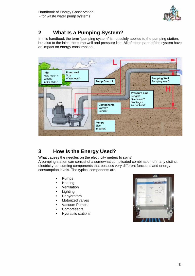
2 What Is a Pumping System? In this handbook the term "pumping system" is not solely applied to the pumping station, but also to the inlet, the pump well and pressure line. All of these parts of the system have an impact on energy consumption.
3 How Is the Energy Used? What causes the needles on the electricity meters to spin? A pumping station can consist of a somewhat complicated combination of many distinct electricity-consuming components that possess very different functions and energy consumption levels. The typical components are:
• Pumps • Heating • Ventilation • Lighting • Dehydrators • Motorized valves • Vacuum Pumps • Compressors • Hydraulic stations
Pumping WellPumping level? Pump Control
Pump well Size Water level?
Pressure Line Length? Dimension? Blockage? Air pockets?
PumpsSize Impeller?
ComponentsValves? Bends?
Inlet How much? When? Entry level?
Handbook of Energy Conservation - for waste water pump systems
- 4 -
4 Pick the Fruit from the Lowest Branch It doesn't make sense to climb to the top of the tree to pick apples if you can just as easily stand on the ground and still reach them. If you translate this idea into energy conservation, it means you must first begin with the cost-saving tips that do not demand investments and that can be implemented today (or the next time you're out at the pumping station!). When these energy-saving tips are put in place, you can begin with the next series.
5 Check the Condition of the Pumping System The first thing you should do is examine the pumping station to see if it is operating as you expect. Do the alternating pumps function for equal lengths of time? Do they run longer than usual? Do they have more start-ups? Does the operating time correspond sensibly to the rainy and dry weather periods? Do all the pumping system's components function as they should? If the pumping system is not operating as it should, it will often result in higher than necessary energy consumption.
5.1 Non-Return Valve If a non-return valve is leaky, water runs from the pressure line back through the pump and into the well. The pump must therefore use energy to pump the same water several times. One indicator of a leaky non-return valve can be that the pump's number of operating hours increases, or a change in the pumps' operating hours (if they alternate). Whirlpools around the suction lines can also sometimes be observed. If the non-return valve does not open all the way while the pump is running, the pressure in the pressure line increases and the pump's capacity decreases. It must therefore use more energy to pump the same amount of water. It is most commonly the vertically mounted flap valves that have a tendency to "clog up" because rocks and rubbish fall down on top of a valve's flap and hinder it from opening all the way. Non-return flap valves should therefore always be mounted on level pipe sections. Over time, the ball in the non-return ball valve can lose its rubber surface due to wear and tear. If the rubber is missing, the valve seat wears out quickly. It is a good idea to perform regular inspections of the non-return valve to ensure that the sealing compound and the valve seat are clean and completely functioning.
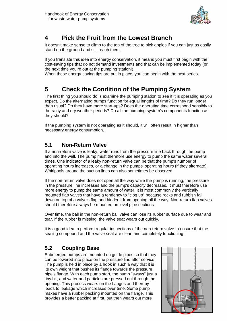
5.2 Coupling Base Submerged pumps are mounted on guide pipes so that they can be lowered into place on the pressure line after service. The pump is held in place by a hook in such a way that it is its own weight that pushes its flange towards the pressure pipe's flange. With each pump start, the pump "sways" just a tiny bit, and water and particles are pressed out through the opening. This process wears on the flanges and thereby leads to leakage which increases over time. Some pump makes have a rubber packing mounted on the flange. This provides a better packing at first, but then wears out more
Handbook of Energy Conservation - for waste water pump systems
- 5 -
quickly. The greater the back pressure in the pressure line, the more this becomes a loss.
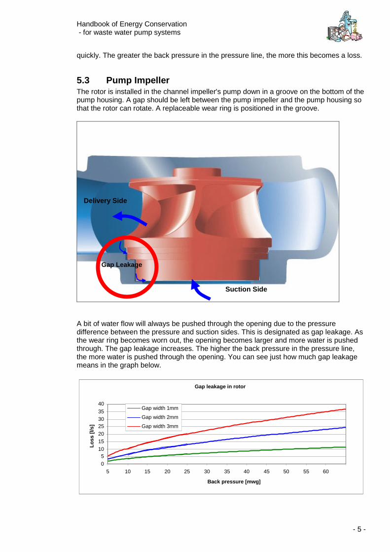
5.3 Pump Impeller The rotor is installed in the channel impeller's pump down in a groove on the bottom of the pump housing. A gap should be left between the pump impeller and the pump housing so that the rotor can rotate. A replaceable wear ring is positioned in the groove.
A bit of water flow will always be pushed through the opening due to the pressure difference between the pressure and suction sides. This is designated as gap leakage. As the wear ring becomes worn out, the opening becomes larger and more water is pushed through. The gap leakage increases. The higher the back pressure in the pressure line, the more water is pushed through the opening. You can see just how much gap leakage means in the graph below.
Gap leakage in rotor
0 5
10 15 20 25 30 35 40
5 10 15 20 25 30 35 40 45 50 55 60
Back pressure [mwg]
Lo
ss [
l/s]
Gap width 1mm
Gap width 2mm
Gap width 3mm
Delivery Side
Suction Side
Gap Leakage
Handbook of Energy Conservation - for waste water pump systems
- 6 -
In order to keep gap leakage at a minimum, you must continuously keep an eye out for it. If it becomes more than what the pump manufacturer describes, the pump must be adjusted or the wear ring must be replaced.
5.4 Valves Regular hand-operated slide valves can be jolted a bit when they are exposed to vibrations and pressure surges. As a result, they can close on their own over time. It is therefore a good idea to get into the habit of making sure that all valves are properly positioned. If a valve has a tendency of "readjusting itself", it can be fastened with a string or chain.
5.5 Leaks All of the above mentioned components should be leak-tight. This is first and foremost in the interest of the working environment; but leak-tight components also ensure that no air is pushed through the pump or the pipeline system when the pump stops (vacuum in the pressurised system can occur as a result of pressure surge). The consequences of air in the pressurised system is described below under "Air pockets".
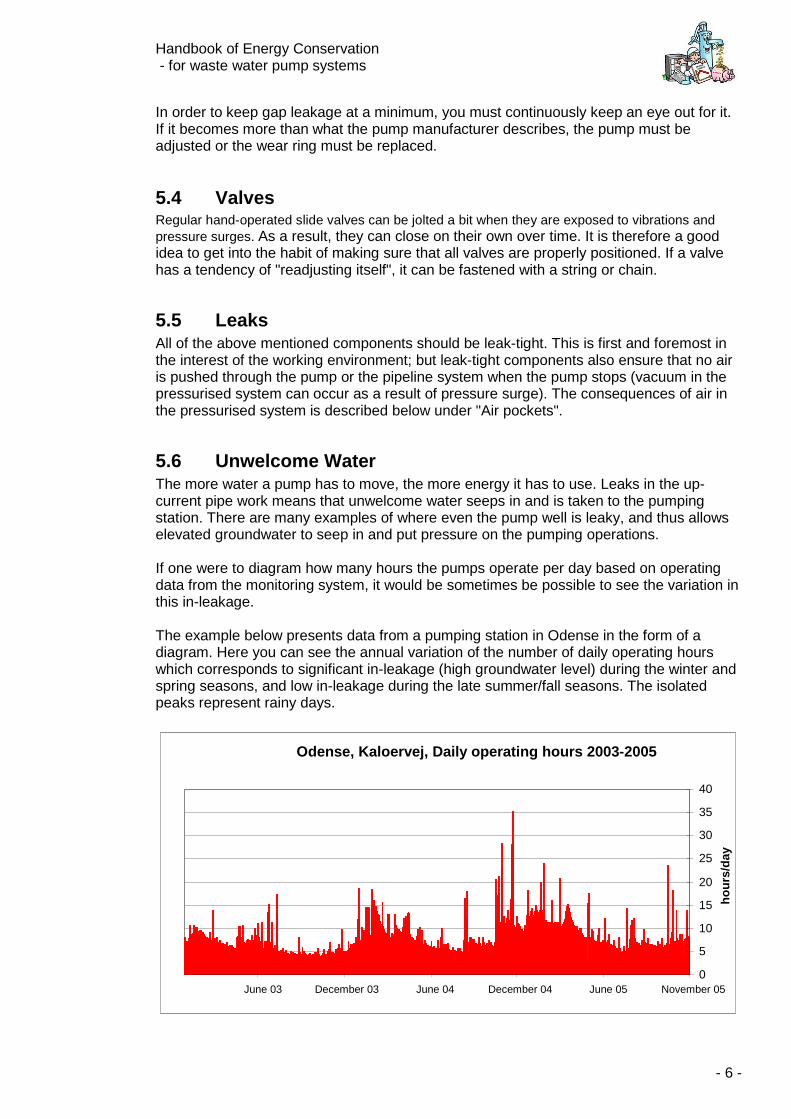
5.6 Unwelcome Water The more water a pump has to move, the more energy it has to use. Leaks in the up-current pipe work means that unwelcome water seeps in and is taken to the pumping station. There are many examples of where even the pump well is leaky, and thus allows elevated groundwater to seep in and put pressure on the pumping operations. If one were to diagram how many hours the pumps operate per day based on operating data from the monitoring system, it would be sometimes be possible to see the variation in this in-leakage. The example below presents data from a pumping station in Odense in the form of a diagram. Here you can see the annual variation of the number of daily operating hours which corresponds to significant in-leakage (high groundwater level) during the winter and spring seasons, and low in-leakage during the late summer/fall seasons. The isolated peaks represent rainy days.
Odense, Kaloervej, Daily operating hours 2003-2005
0
5
10
15
20
25
30
35
40
November 05June 05 December 04June 04December 03June 03
ho
urs
/day
Handbook of Energy Conservation - for waste water pump systems
- 7 -
6 Electricity-Consuming Units Now that the pumping system has been carefully considered, it's time to take a look at the different machines and apparatus in the pumping station that also consume energy. It is often possible to fit the smaller units (those that only use one phase, 230 volts) with simple energy meter for a certain period of time. (Energy meters can be purchased at supermarkets for around 200 DKK.) In this way one can quickly get an impression of the different units' energy use. However, one should also be aware that significant seasonal variations in energy consumption can occur.
6.1 Save on Heating Heating devices like electric heating panels are installed in most pumping stations. Electricity used in heating can be quite significant. There are examples of pumping stations using up to 40-50% of its total electricity consumption on heating. How much does your station use? Electricity used on heating is more expensive than that used by the pumps and the rest of the pumping station's operations. This is due to the fact that extra fees are applied to electricity used on heating. The fees are at 0.57 DKK per kWh. + moms (or VAT). This is to say that it costs almost twice as much as "processing electricity". It is rarely necessary to heat pumping stations in the first place. The most important reason for heating pumping stations is to avoid frost and condensation, and to ensure that there is hot water for hand washing after inspections.
6.1.1 Frost Protection Frost usually occurs only in above ground pumping stations. This is to say that there is rarely any reason to protect underground stations from frost. In order to keep the above ground stations free from frost, it is usually enough to set the heating panel thermostat at 4-5 degrees. It is a waste of money to set the thermostat any higher. Nevertheless, pumping stations are often warmed heated up to 15-18 degrees. While it may be comfortable to make inspection rounds in stations such as these, it should be remembered that, as a rule there are only between 4-12 inspection hours per year. Needless to say, this is a very expensive amenity! 5% is saved for every degree the temperature is dropped. What's the temperature at your pumping station?
6.1.2 Condensation Condensation occurs when the air's normal moisture content condenses on cold surfaces like steel pipe work (waste water is normally 7-8 degrees warm) or the walls of an underground station. Dehumidification by warming is a very expensive solution. A cheaper and just as effective solution is to install a dehydrator that only uses a fraction of the electricity of a heating device. Another advantage of this is that the electricity a dehydrator consumes is listed as "processing electricity", and due to lower fees, it costs only half of what "heating electricity" does. Whether or not condensation is even a problem should also be taken into consideration. Except for the control panel, all components at a pumping station can withstand moisture. If the control panel is placed in its own switch cabinet above ground, it should be determined whether or not dehydration should take place at all. If condensation is a big problem, insulating the top meter of the pumping station is one possible solution. It is typically on this part of the surface that moisture condenses.
Handbook of Energy Conservation - for waste water pump systems
- 8 -
6.1.3 Water Heaters Many pumping stations are also equipped with water heaters so it is possible for one to wash his/her hands after servicing. In many cases, 10-50 litre hot-water tanks are heated using electric heaters that keep the water temperature between 40-60 degrees. This is a lot of water to maintain heated all year-long just to be able to wash hands a few times (even though part of the heat loss benefits the rest of the station), and the heat loss from the holding tank is 400-800 kWh per year. If warm water is needed for a wash basin, a more energy-efficient solution would be to install a little flow water heater. The flow water heater consumes almost no energy in standby mode, only when water is drained.
6.2 Save on Ventilation If the pumping station's operating room or pump room are not directly connected to the pump well (or other areas with exposed waste water levels), ventilation may not be necessary. If harmful moisture is not deemed to be a risk for a particular room, it is sufficient to ventilate when work is taking place within it. This must of course be taken up with your safety organisation to ensure that laws applying to the working environment are upheld. It cost money to run a ventilator (500-200 kWh per year if it is left to operate all the time), and it costs energy to heat the air that replaces that which blown outside. You can install different operations in the ventilator. Two examples might be a hygrostat that starts the ventilator when there is too much moisture, or a thermostat that shuts the ventilator off when it becomes too cold. The ventilator can also be connected to the light switch, prompting it to start up when the lights are switched on.
6.3 Save on Lighting Energy used on lighting at pumping stations can be next to nothing if lights are switched off when the personnel leave the building. If forgetting to switch off the lights is a common occurrence, motion sensors can be installed that automatically shut off the light after a certain amount of time. Many stations also have lights installed in the pump well, whose power switch is installed in the operating room/pump room. In these cases, there is always a risk of forgetting to switch off the light after inspection. To ensure that the light is indeed switched off, a timer can be installed in the switch that automatically shuts off the lights after 15 minutes, for example.
6.4 Compressor Operation Compressors can produce compressed air, which is used in many different operations, such as:
• Pneumatically driven valves and dampers. • Maintenance of air/water level in pressure tanks (air bottles) • Ejector systems used for evacuating air via the pump impellers
Pressurised air is an easy but expensive means of transmitting power. One should always consider whether or not it is possible to replace pressurised air drives with direct motor drives, for example. Generally with pressurised air, compression pressure should be held to a minimum. There is no reason to pressurise the air with 7 bars of pressure if only 4 bars are needed to
Handbook of Energy Conservation - for waste water pump systems
- 9 -
operate the valves. One can save 7-8% in energy use for each bar that is reduced in pressure. It is important to maintain the compressed air system leak-tight. A one millimetre hole in the pipeline can add up to 1500-5000 kWh in extra electricity consumption per year. And the higher the pressure, the more expensive it becomes. It should be realized that it is not always possible to hear leaks because the sound is below our range of hearing. A special measuring instrument designed to find these types of leaks can be purchased. In order to find out how much electricity is used in operating the compressor, simply take a reading of the elapsed time indicator (on large compressors) during the next inspection, and afterwards multiply the amount by the kW-consumption that is listed on the compressor's manufacturer plate. An energy meter can be installed in smaller units (239 Volt).
6.5 Vacuum Pumps Vacuum pumps are used to remove (evacuate) air via the pump impellers when they are placed above the water level in the tank. It is important that the evacuation system is completely leak-free so that no air seeps in, and so that the sensor that measures under pressure does not block. If either of these situations occurs, the vacuum pump will run longer than necessary.
6.6 Hydraulic Station Hydraulics is used to open and close valves and dampers. Just like pressurised air, it is an expensive way to transmit power. It is worth considering whether or not the work can be completed by another unit, such as a motor drive.
7 Use Your Operating Data Most pumping stations transmit data and alarm signals (or information on the station's operations and present condition) back to the central monitoring unit. As described in section 5 ("Check the Condition of the Pumping System"), by comparing these with earlier data, it is possible to obtain information on initial irregularities in the pump's operation. Many of these data can also be used to map out the existing possibilities for conserving energy. First and foremost, data can be found concerning:
• daily operating time • number of starts • electricity consumption • volume of water pumped (flow) • rainfall • simultaneous operation of several pumps
In most cases, only information pertaining to daily operating time and the number of starts are registered. In order to utilise this data, it must be accessible. It is not enough that only daily or monthly data can be seen. To reap their full benefit, one must have the data for a longer period of time in order to see the development and variation in the pumping station's operations. This requires that the central monitoring unit is ready to store these amounts of data, and
Handbook of Energy Conservation - for waste water pump systems
- 10 -
that they can be accessed at all times. The monitoring unit must therefore be configured to:
• save data as daily data • save data for at least 3 years • allow people to retrieve and analyse data themselves
Data can be used to create key figures, such as the number of operating hours or starts the pumps normally should have. If it becomes apparent that the pumps exceed a key figure, or that one runs more than the other, it may be a sign that an error is about to occur in the pumping station -- an error that otherwise would have first been discovered through an alarm. By using data to generate graphs over the last couple of years, it is possible to create a picture of how large an in-leakage there is in the surrounding area (see section 5.6, "Unwelcome Water") and use this if considering sewage work. Past data can also be used to see how much "overcapacity" the pumps have. This information can be used if considering changing pumps or regulating their frequency. Information on the pumping station's electricity use is very important when it comes to energy conservation. You need to know what you have used, before you can know what you have saved. Data on the pumping station's electricity consumption does not always come "home" along with the rest of the data to the central monitoring unit. This information is most often retrieved by taking a manual reading out at the station during inspection, or when the electricity bill comes from the energy company. By comparing electricity consumption with the number of operating hours, it is possible to get a key figure for how much energy is used per operating hour. Even if there are other "energy users" (used in heating, ventilation, etc.) at the pumping station, this gives a chance to see if electricity consumption increases without immediate explanation. The more often one receives information on electricity use, the greater the chance is for discovering a similar increase in consumption.
8 Pump Operation It is hardly surprising that the greatest energy consumers at a pumping station are the pumps. The different conditions that have an effect on the pumps' electricity consumption are described here below. They are listed according to how easy it is to alter the condition and thereby save energy. At the top of the list are the operating conditions that cannot immediately be changed, and at the bottom are those that can be altered today. (or "the apples hanging lowest to the ground").
• Load Water Flow
• Back-Pressure Geometric Elevating Height (Hgeo) Pipe Length and Dimension Component and Individual Loss
• Pumps Adjustment of the Pump's Capacity
Handbook of Energy Conservation - for waste water pump systems
- 11 -
System Efficiency Impeller
• Operating Conditions Pipe's Roughness and Accumulation Air Pockets Well Size Number of Starts
Specific Energy Consumption When we talk about different pumps' energy consumption, it is because we want to know just "what we're getting for the money". To do so, we need to use an expression called "specific energy consumption", which can be shortened to Espec. This is an expression for how many kilowatt-hours are used in moving a cubic meter of water [kWh/m3] in the present pumping system. The same pump has differing specific energy consumption depending on how high, how long and how quickly it must move the water.
8.1 Load The pumping station's load is an expression for how much water flows to the station and when. The more water that flows in, the more energy there must be used in further transporting it. Water volume can only be adjusted by removing unwelcome water or by separating the surrounding area.
8.2 Back-Pressure The back-pressure that the pumps must overcome has a great influence on energy consumption. It is decided by the following factors: how high up the water must be pumped (the geometric elevating height or the geometric back-pressure, expressed as Hgeo), how far it must be pumped, through which pipe dimensions and bends it must be pumped, as well as at which speed it is pumped. How high and how far the water must be pumped cannot be immediately altered. This could ordinarily happen when planning a new pumping station (or when modifying/replacing pressure pipelines) where it is possible to influence the choice of the pipeline's layout. Large stations facing restoration should undertake the piping and manifolds layout, along with the choice of the valves, so that back-pressure is kept to a minimum. A portion of the total back-pressure (expressed as Htot) stems from "friction" that occurs when the water must be pushed through the manifold and pressure piping. This is called dynamic back-pressure, and is expressed as Hdyn. The faster it must be pushed through, the higher the "friction", and as a result, energy consumption also increases. It is the equivalent of a car that consumes more petrol per kilometre when it is driven at 130 km/hour, than when driven at 80 km/hour. While it may arrive at its destination more quickly, it still costs more per kilometre. Hgeo The geometric back-pressure How high up the water must be pumped Hdyn The dynamic back-pressure How much "friction" there is in the pipe
work Htot The total back-pressure Hgeo + Hdyn
Handbook of Energy Conservation - for waste water pump systems
- 12 -
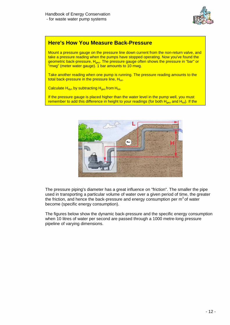
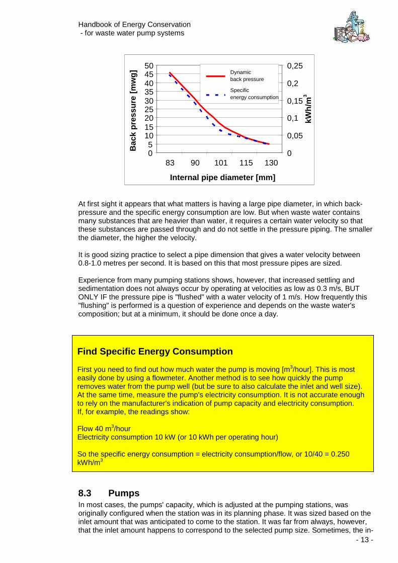
The pressure piping's diameter has a great influence on "friction". The smaller the pipe used in transporting a particular volume of water over a given period of time, the greater the friction, and hence the back-pressure and energy consumption per m3 of water become (specific energy consumption). The figures below show the dynamic back-pressure and the specific energy consumption when 10 litres of water per second are passed through a 1000 metre-long pressure pipeline of varying dimensions.
Here's How You Measure Back-Pressure Mount a pressure gauge on the pressure line down current from the non-return valve, and take a pressure reading when the pumps have stopped operating. Now you've found the geometric back-pressure, Hgeo. The pressure gauge often shows the pressure in "bar" or "mwg" (meter water gauge). 1 bar amounts to 10 mwg. Take another reading when one pump is running. The pressure reading amounts to the total back-pressure in the pressure line, Htot. Calculate Hdyn by subtracting Hgeo from Htot. If the pressure gauge is placed higher than the water level in the pump well, you must remember to add this difference in height to your readings (for both Hgeo and Htot). If the
Handbook of Energy Conservation - for waste water pump systems
- 13 -
At first sight it appears that what matters is having a large pipe diameter, in which back-pressure and the specific energy consumption are low. But when waste water contains many substances that are heavier than water, it requires a certain water velocity so that these substances are passed through and do not settle in the pressure piping. The smaller the diameter, the higher the velocity. It is good sizing practice to select a pipe dimension that gives a water velocity between 0.8-1.0 metres per second. It is based on this that most pressure pipes are sized. Experience from many pumping stations shows, however, that increased settling and sedimentation does not always occur by operating at velocities as low as 0.3 m/s, BUT ONLY IF the pressure pipe is "flushed" with a water velocity of 1 m/s. How frequently this "flushing" is performed is a question of experience and depends on the waste water's composition; but at a minimum, it should be done once a day.
8.3 Pumps In most cases, the pumps' capacity, which is adjusted at the pumping stations, was originally configured when the station was in its planning phase. It was sized based on the inlet amount that was anticipated to come to the station. It was far from always, however, that the inlet amount happens to correspond to the selected pump size. Sometimes, the in-
0 5
10 15 20 25 30 35 40 45 50
83 90 101 115 130
Internal pipe diameter [mm]
Bac
k p
ress
ure
[m
wg
]
0
0,05
0,1
0,15
0,2
0,25
kWh
/m3
Dynamicback pressure
Specificenergy consumption
Find Specific Energy Consumption First you need to find out how much water the pump is moving [m3/hour]. This is most easily done by using a flowmeter. Another method is to see how quickly the pump removes water from the pump well (but be sure to also calculate the inlet and well size). At the same time, measure the pump's electricity consumption. It is not accurate enough to rely on the manufacturer's indication of pump capacity and electricity consumption. If, for example, the readings show: Flow 40 m3/hour Electricity consumption 10 kW (or 10 kWh per operating hour) So the specific energy consumption = electricity consumption/flow, or 10/40 = 0.250 kWh/m3
Handbook of Energy Conservation - for waste water pump systems
- 14 -
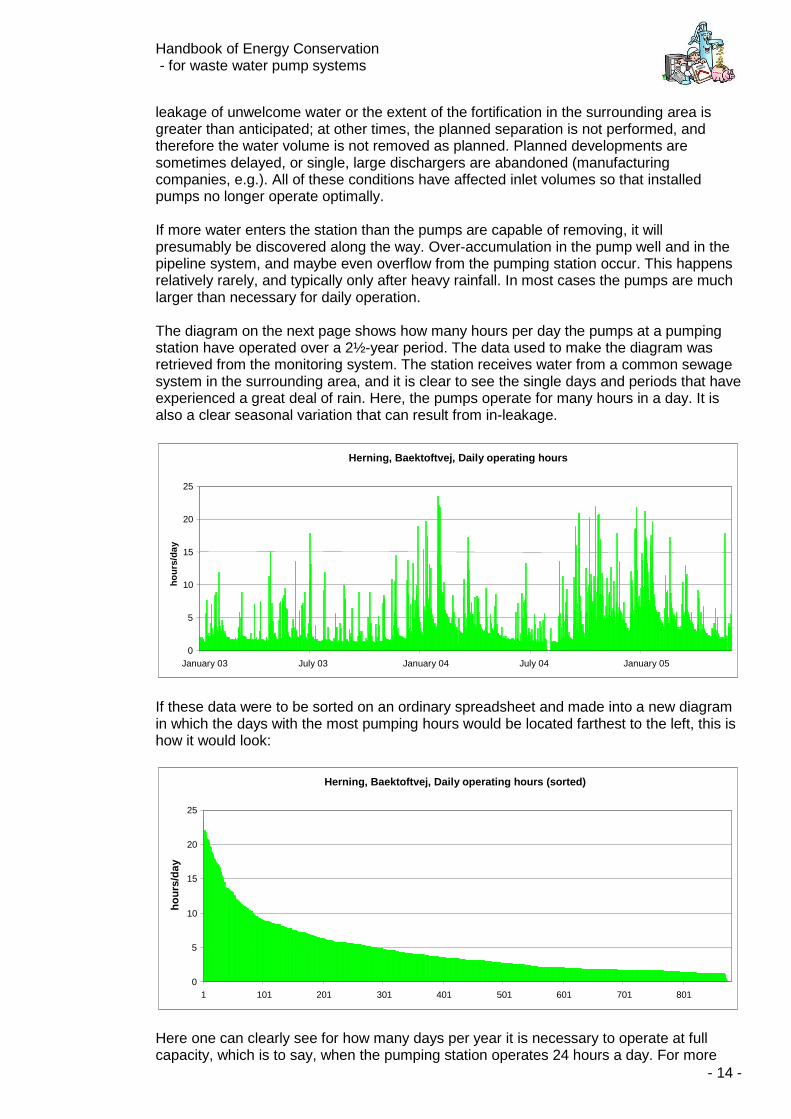
leakage of unwelcome water or the extent of the fortification in the surrounding area is greater than anticipated; at other times, the planned separation is not performed, and therefore the water volume is not removed as planned. Planned developments are sometimes delayed, or single, large dischargers are abandoned (manufacturing companies, e.g.). All of these conditions have affected inlet volumes so that installed pumps no longer operate optimally. If more water enters the station than the pumps are capable of removing, it will presumably be discovered along the way. Over-accumulation in the pump well and in the pipeline system, and maybe even overflow from the pumping station occur. This happens relatively rarely, and typically only after heavy rainfall. In most cases the pumps are much larger than necessary for daily operation. The diagram on the next page shows how many hours per day the pumps at a pumping station have operated over a 2½-year period. The data used to make the diagram was retrieved from the monitoring system. The station receives water from a common sewage system in the surrounding area, and it is clear to see the single days and periods that have experienced a great deal of rain. Here, the pumps operate for many hours in a day. It is also a clear seasonal variation that can result from in-leakage.
If these data were to be sorted on an ordinary spreadsheet and made into a new diagram in which the days with the most pumping hours would be located farthest to the left, this is how it would look:
Here one can clearly see for how many days per year it is necessary to operate at full capacity, which is to say, when the pumping station operates 24 hours a day. For more
Herning, Baektoftvej, Daily operating hours
0
5
10
15
20
25
January 03 July 03 January 04 July 04 January 05
ho
urs
/day
Herning, Baektoftvej, Daily operating hours (sorted)
0
5
10
15
20
25
1 101 201 301 401 501 601 701 801
ho
urs
/day
Handbook of Energy Conservation - for waste water pump systems
- 15 -
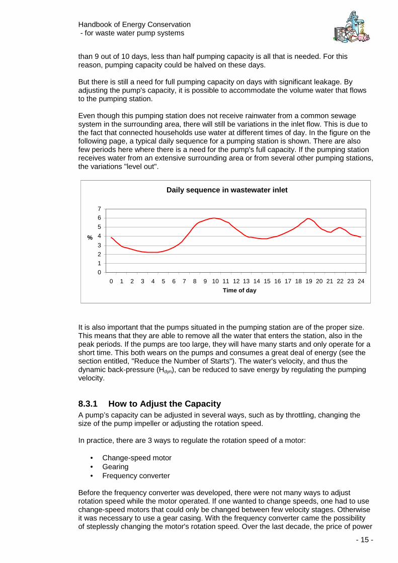
than 9 out of 10 days, less than half pumping capacity is all that is needed. For this reason, pumping capacity could be halved on these days. But there is still a need for full pumping capacity on days with significant leakage. By adjusting the pump's capacity, it is possible to accommodate the volume water that flows to the pumping station. Even though this pumping station does not receive rainwater from a common sewage system in the surrounding area, there will still be variations in the inlet flow. This is due to the fact that connected households use water at different times of day. In the figure on the following page, a typical daily sequence for a pumping station is shown. There are also few periods here where there is a need for the pump's full capacity. If the pumping station receives water from an extensive surrounding area or from several other pumping stations, the variations "level out".
It is also important that the pumps situated in the pumping station are of the proper size. This means that they are able to remove all the water that enters the station, also in the peak periods. If the pumps are too large, they will have many starts and only operate for a short time. This both wears on the pumps and consumes a great deal of energy (see the section entitled, "Reduce the Number of Starts"). The water's velocity, and thus the dynamic back-pressure (Hdyn), can be reduced to save energy by regulating the pumping velocity.
8.3.1 How to Adjust the Capacity A pump’s capacity can be adjusted in several ways, such as by throttling, changing the size of the pump impeller or adjusting the rotation speed. In practice, there are 3 ways to regulate the rotation speed of a motor:
• Change-speed motor • Gearing • Frequency converter
Before the frequency converter was developed, there were not many ways to adjust rotation speed while the motor operated. If one wanted to change speeds, one had to use change-speed motors that could only be changed between few velocity stages. Otherwise it was necessary to use a gear casing. With the frequency converter came the possibility of steplessly changing the motor's rotation speed. Over the last decade, the price of power
Daily sequence in wastewater inlet
0 1 2 3 4 5 6 7
0 1 2 3 4 5 6 7 8 9 10 11 12 13 14 15 16 17 18 19 20 21 22 23 24
Time of day
%
Handbook of Energy Conservation - for waste water pump systems
- 16 -
electronics has fallen so much that the frequency converter can be used for speed regulation, even in smaller pumping installations. In section 9, "Frequency Regulation", you can read much more about frequency converters.
8.3.2 Efficiency If one imagines all the electricity passing through the supply cable being used to transport the water through the pressure pipeline, the pumping station's efficiency would be 100%. Unfortunately, though, this is impossible. Loss will always occur in the motors, pumps, frequency converters or belt drives. Listed below are the normal efficiency rates for different components:
• Motors, approximately 90-95% • Pumps, approx. 45-70% • Belt drives, approx. 95% • Frequency converters, approx. 95-98%
These efficiency rates should be multiplied together to find the pumping station's total efficiency rating. The efficiency rating for a normal pumping station is between 35-60%. The energy that is lost is converted into heat. The theoretical specific energy consumption, or where there is no loss and the efficiency rate is at 100%, is 0.0027 kWh/m3 per meter water gauge [mwg] of total back-pressure.
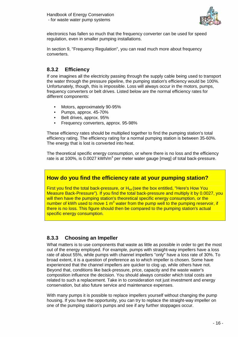
8.3.3 Choosing an Impeller What matters is to use components that waste as little as possible in order to get the most out of the energy employed. For example, pumps with straight-way impellers have a loss rate of about 55%, while pumps with channel impellers "only" have a loss rate of 30%. To broad extent, it is a question of preference as to which impeller is chosen. Some have experienced that the channel impellers are quicker to clog up, while others have not. Beyond that, conditions like back-pressure, price, capacity and the waste water's composition influence the decision. You should always consider which total costs are related to such a replacement. Take in to consideration not just investment and energy conservation, but also future service and maintenance expenses. With many pumps it is possible to replace impellers yourself without changing the pump housing. If you have the opportunity, you can try to replace the straight-way impeller on one of the pumping station's pumps and see if any further stoppages occur.
How do you find the efficiency rate at your pumping station? First you find the total back-pressure, or Htot (see the box entitled, "Here's How You Measure Back-Pressure"). If you find the total back-pressure and multiply it by 0.0027, you will then have the pumping station's theoretical specific energy consumption, or the number of kWh used to move 1 m3 water from the pump well to the pumping reservoir, if there is no loss. This figure should then be compared to the pumping station's actual specific energy consumption.
Handbook of Energy Conservation - for waste water pump systems
- 17 -
Straight-Way Impeller (Vortex Impeller) Channel Impeller
8.3.4 Coating the Impeller A portion of the energy loss in a pump occurs due to the water's friction against the pump housing and impeller. It is now possible to coat the pump housing and impeller, which is to say, a smooth layer of plastic material can be applied to surfaces that have contact with the water. By doing this, friction is reduced along with energy loss. The method is best suited for large pumps, where changing the pump impeller can be costly.
8.4 Operating Conditions
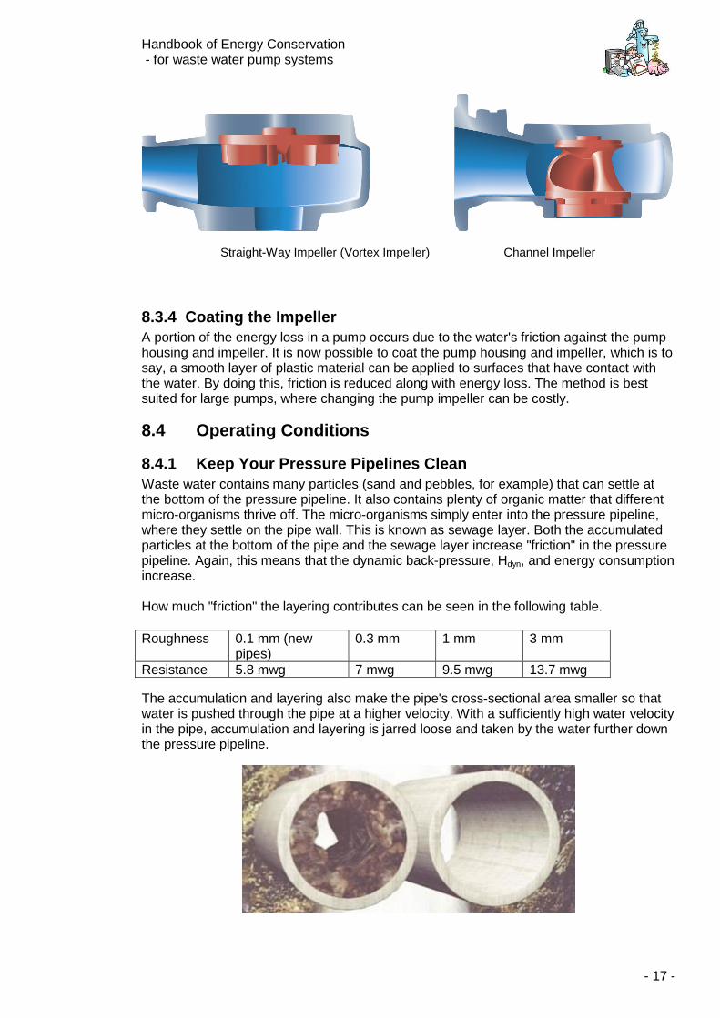
8.4.1 Keep Your Pressure Pipelines Clean Waste water contains many particles (sand and pebbles, for example) that can settle at the bottom of the pressure pipeline. It also contains plenty of organic matter that different micro-organisms thrive off. The micro-organisms simply enter into the pressure pipeline, where they settle on the pipe wall. This is known as sewage layer. Both the accumulated particles at the bottom of the pipe and the sewage layer increase "friction" in the pressure pipeline. Again, this means that the dynamic back-pressure, Hdyn, and energy consumption increase. How much "friction" the layering contributes can be seen in the following table.
The accumulation and layering also make the pipe's cross-sectional area smaller so that water is pushed through the pipe at a higher velocity. With a sufficiently high water velocity in the pipe, accumulation and layering is jarred loose and taken by the water further down the pressure pipeline.
Roughness 0.1 mm (new pipes)
0.3 mm 1 mm 3 mm
Resistance 5.8 mwg 7 mwg 9.5 mwg 13.7 mwg
Handbook of Energy Conservation - for waste water pump systems
- 18 -
Consequently, equilibrium occurs, which means that the water is moved as it should be, even though it uses more energy than necessary. This is an everyday occurrence for most pressure pipelines across the country. At many pumping stations, it is possible to inject "cleaning pigs" into the pipelines, either from the sending station or by dismantling the valves. Cleaning pigs are sent through the pressure pipelines with the help of the pump delivery pressure and are collected in the pumping reservoir. It is important not to continue this procedure in any gravitation pipe that will become blocked. Cleaning pigs come in many different shapes, sizes and degrees of hardness. Ask your supplier which type is best for your station. Cleaning pigs very rarely settle in the pressure pipeline. In this situation, the pump delivery pressure will push the pigs farther down the pipeline after a short time. It is, however, possible to fit the pig with a transmitter so it can be traced from ground level.
8.4.2 Avoid Air Pockets in the Pressure Pipeline Pumping air is costly. Air pockets in the pressure pipeline should therefore be avoided. Air in the pressure pipeline can appear when:
• The pumps suck in air if the well level is drained too low
• The inlet conditions in the well lead to air being "whipped" into the water.
• Air is sucked in through leaky connections during pump stop (vacuum by pressure surge)
• Waste water in the pressure pipeline releases gases The many small air bubbles collect in the pressure pipeline's high points and can, with some difficulty, be pumped further. Therefore it is essential that the pressure pipeline is built with as few high points as possible and that at the local high points it is possible for the pipeline to release air through the vents (either manual or automatic). Automatic vents have a tendency to jam. If automatic vents are installed at the high points, they must be inspected on regular intervals. It is a good idea to mark this regular task on the operations calendar. If it is not possible to ventilate at the top points, a cleaning pig can sometimes temporarily solve the problem.
Handbook of Energy Conservation - for waste water pump systems
- 19 -
a
b
Stop level
c
a+b+cactualdelivery head
Geometricdelivery head
Additionaldelivery headdue to air
Pumping well
Pumping well
a
b
Stop level
c
a+b+cactualdelivery head
Geometricdelivery head
Additionaldelivery headdue to air
Pumping well
Pumping well
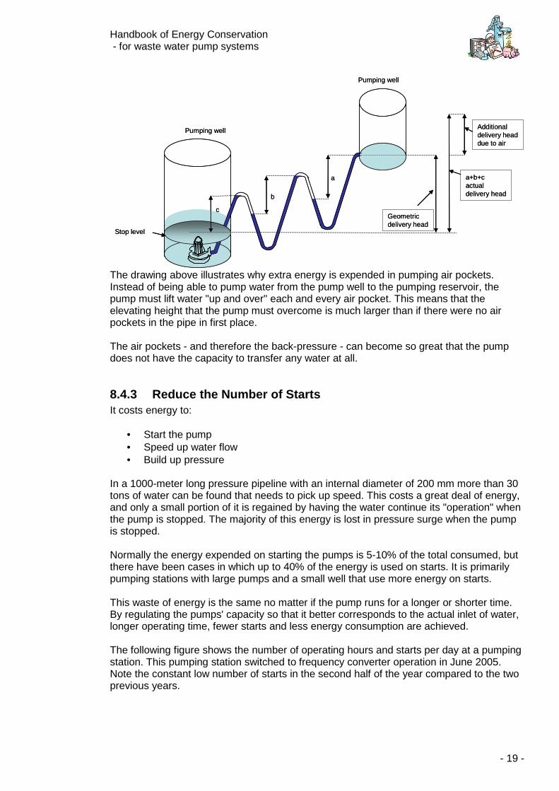
The drawing above illustrates why extra energy is expended in pumping air pockets. Instead of being able to pump water from the pump well to the pumping reservoir, the pump must lift water "up and over" each and every air pocket. This means that the elevating height that the pump must overcome is much larger than if there were no air pockets in the pipe in first place. The air pockets - and therefore the back-pressure - can become so great that the pump does not have the capacity to transfer any water at all.
8.4.3 Reduce the Number of Starts It costs energy to:
• Start the pump • Speed up water flow • Build up pressure
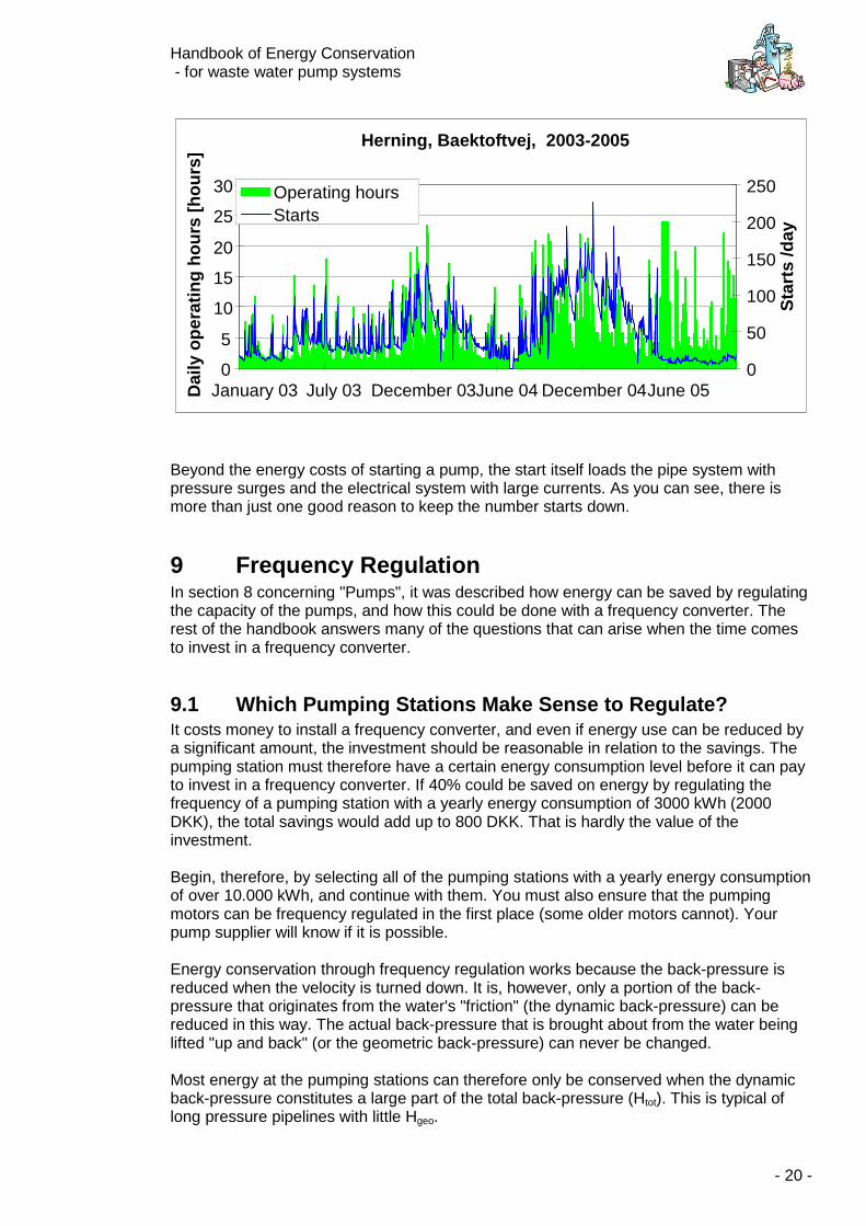
In a 1000-meter long pressure pipeline with an internal diameter of 200 mm more than 30 tons of water can be found that needs to pick up speed. This costs a great deal of energy, and only a small portion of it is regained by having the water continue its "operation" when the pump is stopped. The majority of this energy is lost in pressure surge when the pump is stopped. Normally the energy expended on starting the pumps is 5-10% of the total consumed, but there have been cases in which up to 40% of the energy is used on starts. It is primarily pumping stations with large pumps and a small well that use more energy on starts. This waste of energy is the same no matter if the pump runs for a longer or shorter time. By regulating the pumps' capacity so that it better corresponds to the actual inlet of water, longer operating time, fewer starts and less energy consumption are achieved. The following figure shows the number of operating hours and starts per day at a pumping station. This pumping station switched to frequency converter operation in June 2005. Note the constant low number of starts in the second half of the year compared to the two previous years.
Handbook of Energy Conservation - for waste water pump systems
- 20 -
Beyond the energy costs of starting a pump, the start itself loads the pipe system with pressure surges and the electrical system with large currents. As you can see, there is more than just one good reason to keep the number starts down.
9 Frequency Regulation In section 8 concerning "Pumps", it was described how energy can be saved by regulating the capacity of the pumps, and how this could be done with a frequency converter. The rest of the handbook answers many of the questions that can arise when the time comes to invest in a frequency converter.
9.1 Which Pumping Stations Make Sense to Regulate? It costs money to install a frequency converter, and even if energy use can be reduced by a significant amount, the investment should be reasonable in relation to the savings. The pumping station must therefore have a certain energy consumption level before it can pay to invest in a frequency converter. If 40% could be saved on energy by regulating the frequency of a pumping station with a yearly energy consumption of 3000 kWh (2000 DKK), the total savings would add up to 800 DKK. That is hardly the value of the investment. Begin, therefore, by selecting all of the pumping stations with a yearly energy consumption of over 10.000 kWh, and continue with them. You must also ensure that the pumping motors can be frequency regulated in the first place (some older motors cannot). Your pump supplier will know if it is possible. Energy conservation through frequency regulation works because the back-pressure is reduced when the velocity is turned down. It is, however, only a portion of the back-pressure that originates from the water's "friction" (the dynamic back-pressure) can be reduced in this way. The actual back-pressure that is brought about from the water being lifted "up and back" (or the geometric back-pressure) can never be changed. Most energy at the pumping stations can therefore only be conserved when the dynamic back-pressure constitutes a large part of the total back-pressure (Htot). This is typical of long pressure pipelines with little Hgeo.
Herning, Baektoftvej, 2003-2005
0
5
10
15
20
25
30
January 03 July 03 December 03June 04 December 04 June 05 Dai
ly o
per
atin
g h
ou
rs [
ho
urs
]
0
50
100
150
200
250
Sta
rts
/day
Operating hours Starts
Handbook of Energy Conservation - for waste water pump systems
- 21 -
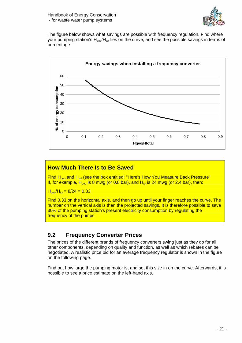
The figure below shows what savings are possible with frequency regulation. Find where your pumping station's Hgeo/Htot lies on the curve, and see the possible savings in terms of percentage.
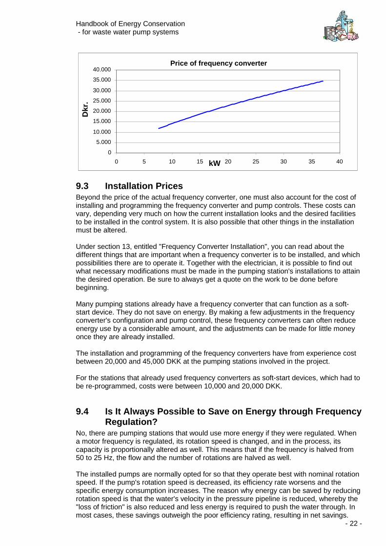
9.2 Frequency Converter Prices The prices of the different brands of frequency converters swing just as they do for all other components, depending on quality and function, as well as which rebates can be negotiated. A realistic price bid for an average frequency regulator is shown in the figure on the following page. Find out how large the pumping motor is, and set this size in on the curve. Afterwards, it is possible to see a price estimate on the left-hand axis.
How Much There Is to Be Saved
Find Hgeo and Htot (see the box entitled: "Here's How You Measure Back Pressure" If, for example, Hgeo is 8 mwg (or 0.8 bar), and Htot
is 24 mwg (or 2.4 bar), then:
Hgeo/Htot = 8/24 = 0.33
Find 0.33 on the horizontal axis, and then go up until your finger reaches the curve. The number on the vertical axis is then the projected savings. It is therefore possible to save 30% of the pumping station's present electricity consumption by regulating the frequency of the pumps.
Energy savings when installing a frequency converter
0
10
20
30
40
50
60
0 0,1 0,2 0,3 0,4 0,5 0,6 0,7 0,8 0,9
Hgeo/Htotal
% o
f en
erg
y co
nsu
mp
tio
n
Handbook of Energy Conservation - for waste water pump systems
- 22 -
9.3 Installation Prices Beyond the price of the actual frequency converter, one must also account for the cost of installing and programming the frequency converter and pump controls. These costs can vary, depending very much on how the current installation looks and the desired facilities to be installed in the control system. It is also possible that other things in the installation must be altered. Under section 13, entitled "Frequency Converter Installation", you can read about the different things that are important when a frequency converter is to be installed, and which possibilities there are to operate it. Together with the electrician, it is possible to find out what necessary modifications must be made in the pumping station's installations to attain the desired operation. Be sure to always get a quote on the work to be done before beginning. Many pumping stations already have a frequency converter that can function as a soft-start device. They do not save on energy. By making a few adjustments in the frequency converter's configuration and pump control, these frequency converters can often reduce energy use by a considerable amount, and the adjustments can be made for little money once they are already installed. The installation and programming of the frequency converters have from experience cost between 20,000 and 45,000 DKK at the pumping stations involved in the project. For the stations that already used frequency converters as soft-start devices, which had to be re-programmed, costs were between 10,000 and 20,000 DKK.
9.4 Is It Always Possible to Save on Energy through Frequency Regulation?
No, there are pumping stations that would use more energy if they were regulated. When a motor frequency is regulated, its rotation speed is changed, and in the process, its capacity is proportionally altered as well. This means that if the frequency is halved from 50 to 25 Hz, the flow and the number of rotations are halved as well. The installed pumps are normally opted for so that they operate best with nominal rotation speed. If the pump's rotation speed is decreased, its efficiency rate worsens and the specific energy consumption increases. The reason why energy can be saved by reducing rotation speed is that the water's velocity in the pressure pipeline is reduced, whereby the "loss of friction" is also reduced and less energy is required to push the water through. In most cases, these savings outweigh the poor efficiency rating, resulting in net savings.
Price of frequency converter
0 5.000
10.000 15.000 20.000 25.000 30.000 35.000 40.000
0 5 10 15 20 25 30 35 40kW
Dkr
.
Handbook of Energy Conservation - for waste water pump systems
- 23 -
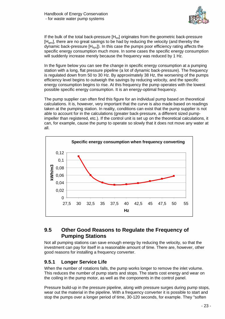
If the bulk of the total back-pressure [Htot] originates from the geometric back-pressure [Hgeo], there are no great savings to be had by reducing the velocity (and thereby the dynamic back-pressure [Hdyn]). In this case the pumps poor efficiency rating affects the specific energy consumption much more. In some cases the specific energy consumption will suddenly increase merely because the frequency was reduced by 1 Hz. In the figure below you can see the change in specific energy consumption at a pumping station with a long, flat pressure pipeline (a lot of dynamic back-pressure). The frequency is regulated down from 50 to 30 Hz. By approximately 38 Hz, the worsening of the pumps efficiency level begins to outweigh the savings by reducing velocity, and the specific energy consumption begins to rise. At this frequency the pump operates with the lowest possible specific energy consumption. It is an energy-optimal frequency. The pump supplier can often find this figure for an individual pump based on theoretical calculations. It is, however, very important that the curve is also made based on readings taken at the pumping station. In reality, conditions can exist that the pump supplier is not able to account for in the calculations (greater back-pressure, a different sized pump-impeller than registered, etc.). If the control unit is set up on the theoretical calculations, it can, for example, cause the pump to operate so slowly that it does not move any water at all.
9.5 Other Good Reasons to Regulate the Frequency of Pumping Stations
Not all pumping stations can save enough energy by reducing the velocity, so that the investment can pay for itself in a reasonable amount of time. There are, however, other good reasons for installing a frequency converter.
9.5.1 Longer Service Life When the number of rotations falls, the pump works longer to remove the inlet volume. This reduces the number of pump starts and stops. The starts cost energy and wear on the coiling in the pump motor, as well as the components in the control panel. Pressure build-up in the pressure pipeline, along with pressure surges during pump stops, wear out the material in the pipeline. With a frequency converter it is possible to start and stop the pumps over a longer period of time, 30-120 seconds, for example. They "soften
Specific energy consumption when frequency converting
0
0,02
0,04
0,06
0,08
0,1
0,12
27,5 30 32,5 35 37,5 40 42,5 45 47,5 50 55
Hz
kWh
/m3
Handbook of Energy Conservation - for waste water pump systems
- 24 -
up", and the speed reduction can lessen, or even do away with, damaging pressure surges and thus lengthen the pressure pipelines service life. Again, this means it is possible to remove any pressure tanks connected to the pumping system in order to absorb the surges. The mechanical wear on the pump impeller, bearings and shaft seals exponentially decrease with velocity reduction. As you can see, the pump does not become more worn by operating for longer periods of time at lower speeds - quite the contrary.
9.5.2 Continuous Inlet to the Treatment Plant If the pumping station pumps directly to the treatment plant or other regulated pumping stations, the inlet of these is more evenly distributed on a daily basis. This can make it easier to control the processes at the treatment plant.
9.5.3 Replace Soft Start Devices At pump start the rotation speed increases over a long period of time, by which the supply mains and the whole installations is less strained. It serves the same function as a soft starter - but it works better. When mounting or replacing soft start devices, it should always be taken into consideration whether or not a frequency converter would be a better solution.
9.5.4 Greater Pumping Capacity Along with frequency converter operation it is possible to run super-synchronous operation, or more than 50 Hz whereby pump speed - and thus capacity - increase. Over-synchronous operation does contribute to significantly greater energy use and component wear than normal operation. Over-synchronous operation should therefore not be used as a permanent solution for stations of lower capacity.
9.5.5 Cavitation If the pumps at a station are exposed to cavitation, they can experience significant damages in the pump housings and impellers. A reduction in speed - and thereby suction pressure - will reduce or do away with the risk of cavitation. This increases the pumps' service life. Cavitation also leads to higher energy consumption.
9.5.6 Obstruction of the Pressure Pipeline Due to the longer operations time, there will be fewer periods when the water is left still in the pressure pipeline. Lighter solid particles will therefore not sediment.
9.5.7 Noise By operating at a lower rotation speed, noise in the pipes and vents is reduced. If the pressurised system has resonant frequencies that make noise, it is possible to program the frequency converter so that it will not operate with these frequencies.
Handbook of Energy Conservation - for waste water pump systems
- 25 -
9.6 What Are the Disadvantages of Installing a Frequency Converter?
9.6.1 Supply and Installation Costs As a rule of thumb, frequency converters cost 1.500 DKK/kW for 5-10 kW, and 1,000 DKK/kW for converters greater than 30 kW. Installation costs are more difficult to determine when dependent on which control unit is presently used at the pumping station, and which facilities are desired for frequency converter operation.
9.6.2 Service Life Like all other electronic components, a frequency converter has a certain service lifetime, after which it must be replaced. The supplier can provide information on the individual brand, but the usual service life is between 10 and 20 years.
9.6.3 Obstruction of the Pressure Pipeline There is a risk that the slower flow in the pressure pipeline - which is a result of speed reduction - will lead to more solid particles becoming deposited in the pressure pipeline. There is also a chance that sewage layer on the pipes is not removed. It is therefore necessary to regularly clean the pressure pipeline using cleaning pigs. When regulating the waste water pumps, the operation procedure should always contain periods when the pump runs at full capacity - at pump start, for example - so that the deposited material is transported further along in the pressure pipeline.
9.6.4 Acoustic Noise Frequency converters installed in older pump motors can put out a great deal of acoustic noise. When operating on low frequencies, screeching can sometimes be produced.
9.6.5 Electric Noise If the necessary precautions are not taken, electro-magnetic noise can be released from the frequency converters and motor cables, which can adversely affect other nearby electronic components.
9.6.6 Bearing Surges For motors larger than 55-75 kW, there can be a risk that the frequency converter causes creeping currents, which due to sparking can ruin a motor's bearings. In order to avoid these bearing surges, some motor manufacturers recommend using non-conducting bearings in their motors if they are controlled by a frequency converter.
9.6.7 Choosing the Wrong Frequency Converter It is essential that the frequency converter selected can deliver a sufficient start and breakaway torque to get the pump going. If a frequency converter with too little breakaway torque is chosen, the pump will not be able to start.
9.6.8 Instructing the Operations Personnel When installing a frequency converter, it will be necessary to change the operating procedure for pump operation. This means there will be a running-in period before optimal
Handbook of Energy Conservation - for waste water pump systems
- 26 -
operation is reached. Furthermore, the operations personnel should be instructed on how to make use of the options involved in regulated operating, as well as on which risk groups are involved. If a transport system with frequency converters is not correctly regulated, it can result in more energy consumption than in unregulated operating. In the beginning this requires paying close attention when the operations personnel must act upon the operating data sent to the monitoring unit.
10 Choosing a Frequency Converter Price is not the only major factor to consider when choosing a frequency converter. Other factors include: Size (electronic and physical), breakaway torque and the type of torque (variable or constant). It is therefore necessary to inform the supplier of the pump size that is to be regulated. Power rating (kW) and current rating (A) are listed on the pump's manufacturer plate or can be given by the pump supplier. The frequency converter's physical size and cladding can influence whether it can be installed in the existing control panel, or must be moved outside. The supplier must guarantee that the available breakaway torque in the frequency converter is greater than the pump motor's in all existing situations, which is to say, that the frequency converter can deliver sufficient torque to activate the pump, also if a cloth is resting in the impeller. The motor's breakaway torque depends on the waste water's composition and the pump' dimension.
11 Number of Frequency Converters Installing a frequency converter in each pump is recommended, partly because this provides greater operational reliability so that all pumps are not operated by the same regulating unit, and partly because it provides a simpler (and therefore cheaper) installation. Even if it means buying another frequency converter, the lesser installation costs often result in the best solution, financially speaking. At a pumping station with more than 2 pumps, there is seldom any reason to install more than 2 frequency converters. As a rule, 2 or more pumps run simultaneously only during rainy weather, and in these situations the pumps run at /unregulated) full power anyway. At pumping stations where more than one pump cannot/must not operate at the same time (no joint operation), one converter will sometimes be enough. As frequency converters only have one outlet for supplying the pumps, the supply cable between the frequency converter and the motor are split in a set contactor that is operated from the pump control unit. This means that the pump control unit informs the contactors as to which of the pumps must be supplied with power (some frequency converters also have this facility to control the signal to the contactors). Be sure that the contactors, which do carry power to the frequency converter, are enclosed to cut down on electro-magnetic noise. The solution with 2 frequency converters will provide an improved operational reliability.
12 Positioning the Frequency Converter Out of consideration for cable length and heat build-up, it is appropriate to position the frequency converter outside of the panel if possible. In that case, it must be IP54/IP55 enclosed. If placed in a cabinet, this high cladding class is not necessary. At pumping
Handbook of Energy Conservation - for waste water pump systems
- 27 -
stations where the panel is placed in a free-standing cabinet above ground, the frequency converter must obviously be placed in the panel, or if there is no room, in its own cabinet.
13 Installation of Frequency Converters
13.1 Regulating Frequency Converters
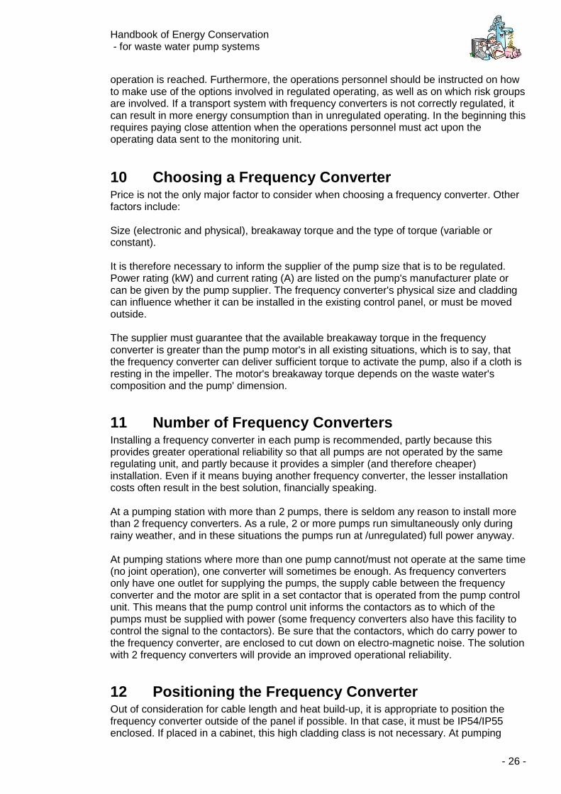
13.1.1 Pump Control without a Frequency Converter A normal pumping installation with ancillary control equipment is illustrated below:
Pump 1 Pump 2
Levelgauge
Pump control
unit
Controlpanel
Supply cableCommunikation/surveillance
Start/stop signal
Information
Motor cables
To achieve variable operation by installing a frequency converter, several alterations must be made. The frequency converter cannot just inform if it is running or not. It must also be sent signals as to which frequency it must operate, depending on the level in the pumping station. This information is obtained through an analogue signal from a pressure transmitter or another analogue level measurement. If the pumping station is not already controlled from dynamic measuring of the pump well's level (analogue signal from transducer in the well), but is only controlled by on/off signals (level switch, rod electrodes), an analogue 4-20 mA level meter must be established. The frequency converter can receive the analogue signal from:
• the same transducer that sends signals to the SRO-installation (the signal is "split" in two in an isolation amplifier)
• the SRO-installation (requires that there is an extra analogue outlet in the SRO-installation)
Description The level meter (ultrasonic gauge, pressure transducer, float switch or rod electrodes) in the pump well gives a start/stop signal to the pump control unit. The pump control unit sends a start/stop signal to the switches in the control panel that alternately start/stop the pumps. Information can be sent from the control panel to the pump control unit on any possible fault indications (thermal fault in the motor, etc.) The pump control can send operational data to a central monitoring unit.
Handbook of Energy Conservation - for waste water pump systems
- 28 -
• independent transducer in the pump well If the pump well level is not registered with the help of the analogue signal (if only an on/off signal appears - signal from the level switch or from rod electrodes), this must be installed. A comparatively dependable solution is to install a pressure transmitter or ultrasonic gauge to measure the water level. The pump control unit has not yet received any analogue signals in - and it does not constantly need to receive them. It is sufficient that the analogue signal runs directly in the frequency converter, which then takes charge of the regulating part of operations as described above.
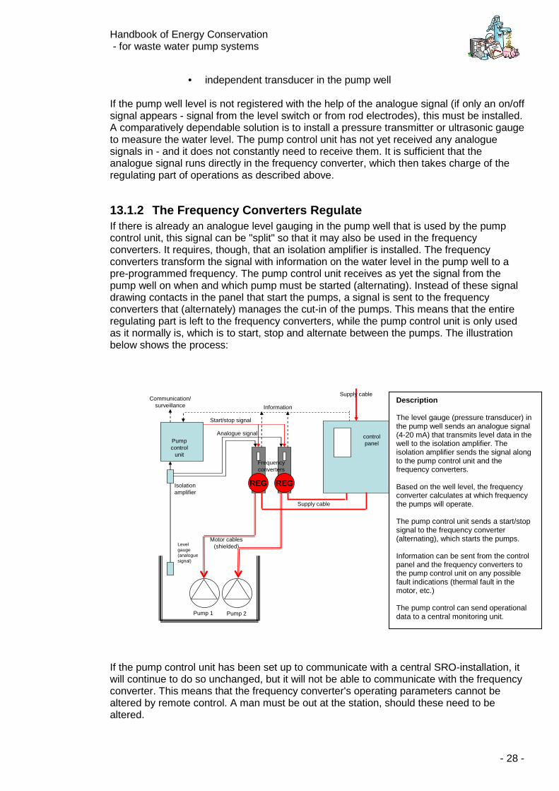
13.1.2 The Frequency Converters Regulate If there is already an analogue level gauging in the pump well that is used by the pump control unit, this signal can be "split" so that it may also be used in the frequency converters. It requires, though, that an isolation amplifier is installed. The frequency converters transform the signal with information on the water level in the pump well to a pre-programmed frequency. The pump control unit receives as yet the signal from the pump well on when and which pump must be started (alternating). Instead of these signal drawing contacts in the panel that start the pumps, a signal is sent to the frequency converters that (alternately) manages the cut-in of the pumps. This means that the entire regulating part is left to the frequency converters, while the pump control unit is only used as it normally is, which is to start, stop and alternate between the pumps. The illustration below shows the process:
Motor cables(shielded)Level
gauge (analoguesignal)
Pump 1 Pump 2
Pumpcontrol
unit
controlpanel
Supply cableCommunication/
surveillance Information
Supply cable
Start/stop signal
Analogue signal
Frequencyconverters
REG REGIsolation amplifier
If the pump control unit has been set up to communicate with a central SRO-installation, it will continue to do so unchanged, but it will not be able to communicate with the frequency converter. This means that the frequency converter's operating parameters cannot be altered by remote control. A man must be out at the station, should these need to be altered.
Description The level gauge (pressure transducer) in the pump well sends an analogue signal (4-20 mA) that transmits level data in the well to the isolation amplifier. The isolation amplifier sends the signal along to the pump control unit and the frequency converters. Based on the well level, the frequency converter calculates at which frequency the pumps will operate. The pump control unit sends a start/stop signal to the frequency converter (alternating), which starts the pumps. Information can be sent from the control panel and the frequency converters to the pump control unit on any possible fault indications (thermal fault in the motor, etc.) The pump control can send operational data to a central monitoring unit.
Handbook of Energy Conservation - for waste water pump systems
- 29 -
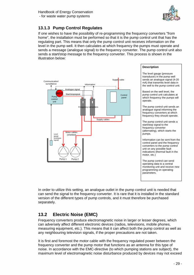
13.1.3 Pump Control Regulates If one wishes to have the possibility of re-programming the frequency converters "from home", the installation must be performed so that it is the pump control unit that has the regulating part. This means that only the pump control unit receives information on the level in the pump well. It then calculates at which frequency the pumps must operate and sends a message (analogue signal) to the frequency converter. The pump control unit also sends a start/stop message to the frequency converter. This process is shown in the illustration below:
Motor cables(shielded)Level
gauge (analoguesignal)
Pump 1 Pump 2
Pump control
unit
Controlpanel
Supply cableCommunication/
surveillance Information
REG
Supply cables
Start/stopsignal
Analogue signal
Freqyency converters
In order to utilize this setting, an analogue outlet in the pump control unit is needed that can send the signal to the frequency converter. It is rare that it is installed in the standard version of the different types of pump controls, and it must therefore be purchased separately.
13.2 Electric Noise (EMC) Frequency converters produce electromagnetic noise in larger or lesser degrees, which can adversely affect different electronic devices (radios, televisions, mobile phones, measuring equipment, etc.). This means that it can affect both the pump control as well as any neighbouring television signals, if the proper precautions are not taken. It is first and foremost the motor cable with the frequency regulated power between the frequency converter and the pump motor that functions as an antenna for this type of noise. In accordance with the EMC-directive (to which pumping stations are subject), the maximum level of electromagnetic noise disturbance produced by devices may not exceed
Description The level gauge (pressure transducer) in the pump well sends an analogue signal (4-20 mA) that transmits level data in the well to the pump control unit. Based on the well level, the pump control unit calculates at which frequency the pumps will operate. The pump control unit sends an analogue signal informing the frequency converters at which frequency they should operate. The pump control unit sends a start/stop signal to the frequency converter (alternating), which starts the pumps. Information can be sent from the control panel and the frequency converters to the pump control unit on any possible fault indications (thermal fault in the motor, etc.) The pump control can send operating data to a central monitoring unit and receive new programming on operating parameters.
Handbook of Energy Conservation - for waste water pump systems
- 30 -
the level needed to disturb the operation of other electronic equipment. The directive contains standards that set more exact values for noise production. In order to avoid releasing electromagnetic noise into the surrounding area, the frequency converter manufacturer's recommendations must always be followed. Normally, there must be an uninterrupted cable shielded between the frequency converter and the pump motor. If the interruption or separation possibility (CEE-plug) on the cable is desired, the necessary noise provisions must be made. (This can be relevant if safety switches are required in the immediate proximity of the pump.) Additionally, all analogue signal cables should be shielded.
13.3 Other Adjustments All electrical installations are equipped with a fault current relay, which protects against fault currents. When installing a frequency converter, it is required that the installation is given extra protection, either through neutralising, grounding or safety relays (an AC/DC relay, for example), depending on local conditions. One should also have the electrician investigate which demands apply to the pumping station's supply area. If protection by an AC/DC relay is chosen, one relay per frequency converter must be utilized. Beyond the cost of an AC/DC fault current circuit-breaker, the device itself takes up more physical space and may require an extension of the panel. Some frequency converters require the use of an extra filter in order to prevent damages to the motor due to voltage peaks.
14 Controlling Frequency Converters It is important that the control of the frequency converter is properly installed, out of respect to both energy consumption and operating safety.
14.1 Pump Start At pump start the frequency converter is used as a soft start device, in which the frequency and thereby the rotation speed is increased to full capacity (50 Hz) in the span of 10-30 seconds. In this way, severe surges in the vents, manifold and pressure pipeline are avoided, which generally come with on/off start-up. The electrical components in the control panel are also less strained by soft starting. Precisely how long the "up-ramping" from 0 to 50 Hz lasts depends on the pressure pipeline, among other things, the pressure pipeline's length and the geometric elevating height, Hgeo. The longer and higher it is, the more time the up-ramping lasts.
14.2 Holding Time When the pump is up at full rotation (50 Hz), this frequency is held until there is full flow in the system. This means that the "water line" throughout the length of the entire pressure pipeline moves at maximum speed, which is of course the speed for which the system was originally designed. Typically 0.8-1.2 m/s. By doing so, the pressure pipeline's self-cleaning ability is assured. This means that sand, pebbles and other particular substances that have settled in the pressure pipeline from the last pump stop are swirled up and moved along so that they cannot clog the pipes. How long this "flushing" lasts again depends on the piping system, and it is best decided upon
Handbook of Energy Conservation - for waste water pump systems
- 31 -
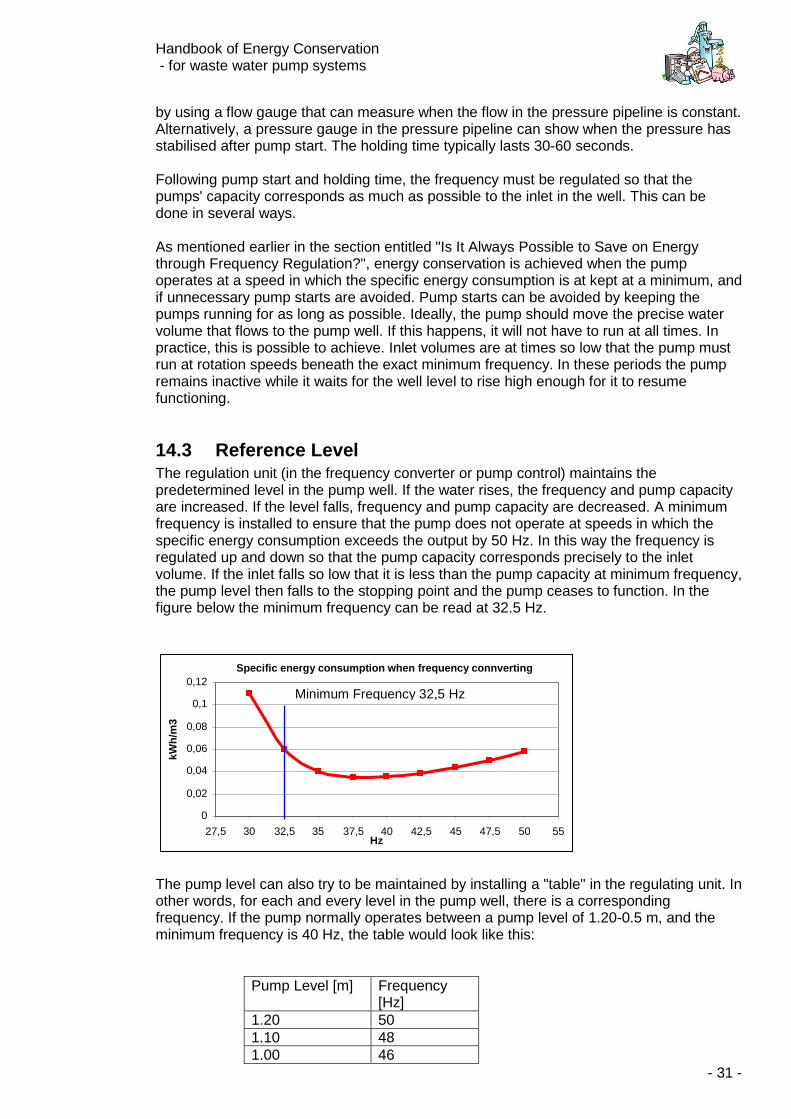
by using a flow gauge that can measure when the flow in the pressure pipeline is constant. Alternatively, a pressure gauge in the pressure pipeline can show when the pressure has stabilised after pump start. The holding time typically lasts 30-60 seconds. Following pump start and holding time, the frequency must be regulated so that the pumps' capacity corresponds as much as possible to the inlet in the well. This can be done in several ways. As mentioned earlier in the section entitled "Is It Always Possible to Save on Energy through Frequency Regulation?", energy conservation is achieved when the pump operates at a speed in which the specific energy consumption is at kept at a minimum, and if unnecessary pump starts are avoided. Pump starts can be avoided by keeping the pumps running for as long as possible. Ideally, the pump should move the precise water volume that flows to the pump well. If this happens, it will not have to run at all times. In practice, this is possible to achieve. Inlet volumes are at times so low that the pump must run at rotation speeds beneath the exact minimum frequency. In these periods the pump remains inactive while it waits for the well level to rise high enough for it to resume functioning.
14.3 Reference Level The regulation unit (in the frequency converter or pump control) maintains the predetermined level in the pump well. If the water rises, the frequency and pump capacity are increased. If the level falls, frequency and pump capacity are decreased. A minimum frequency is installed to ensure that the pump does not operate at speeds in which the specific energy consumption exceeds the output by 50 Hz. In this way the frequency is regulated up and down so that the pump capacity corresponds precisely to the inlet volume. If the inlet falls so low that it is less than the pump capacity at minimum frequency, the pump level then falls to the stopping point and the pump ceases to function. In the figure below the minimum frequency can be read at 32.5 Hz.
The pump level can also try to be maintained by installing a "table" in the regulating unit. In other words, for each and every level in the pump well, there is a corresponding frequency. If the pump normally operates between a pump level of 1.20-0.5 m, and the minimum frequency is 40 Hz, the table would look like this:
Pump Level [m] Frequency [Hz]
1.20 50 1.10 48 1.00 46
Specific energy consumption when frequency connverting
0 0,02
0,04 0,06 0,08
0,1 0,12
27,5 30 32,5 35 37,5 40 42,5 45 47,5 50 55 Hz
kWh
/m3
Minimum Frequency 32,5 Hz
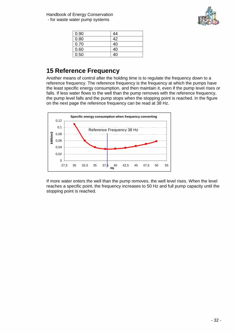
Handbook of Energy Conservation - for waste water pump systems
- 32 -
0.90 44 0.80 42 0.70 40 0.60 40 0.50 40
15 Reference Frequency Another means of control after the holding time is to regulate the frequency down to a reference frequency. The reference frequency is the frequency at which the pumps have the least specific energy consumption, and then maintain it, even if the pump level rises or falls. If less water flows to the well than the pump removes with the reference frequency, the pump level falls and the pump stops when the stopping point is reached. In the figure on the next page the reference frequency can be read at 38 Hz.
If more water enters the well than the pump removes, the well level rises. When the level reaches a specific point, the frequency increases to 50 Hz and full pump capacity until the stopping point is reached.
Specific energy consumption when frequency converting
0 0,02
0,04 0,06 0,08
0,1 0,12
27,5 30 32,5 35 37,5 40 42,5 45 47,5 50 55 Hz
kWh
/m3
Reference Frequency 38 Hz
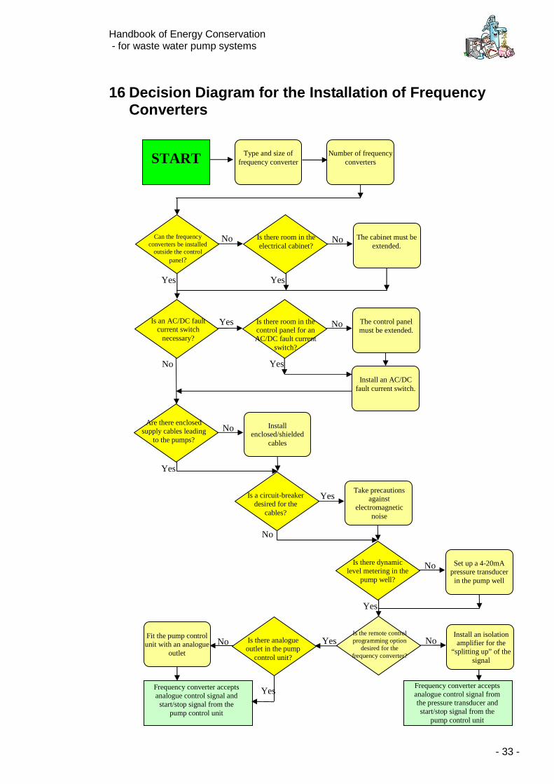
Handbook of Energy Conservation - for waste water pump systems
- 33 -
16 Decision Diagram for the Installation of Frequency Converters
Type and size of
frequency converter
Number of frequency
converters
Can the frequency
converters be installed outside the control
panel?
Is there room in the electrical cabinet?
The cabinet must be
extended.
Yes
No No
Yes
Is an AC/DC fault
current switch necessary?
Is there room in the control panel for an AC/DC fault current
switch?
The control panel must be extended.
Yes
No
No
Yes
Are there enclosed
supply cables leading to the pumps?
Install
enclosed/shielded cables
No
Yes
Is a circuit-breaker desired for the
cables?
Take precautions
against electromagnetic
noise
No
Yes
Is there dynamic level metering in the
pump well?
Set up a 4-20mA
pressure transducer in the pump well
No
Yes
Is the remote control programming option
desired for the frequency converter?
Install an isolation amplifier for the
“splitting up” of the signal
No Yes
Frequency converter accepts analogue control signal from the pressure transducer and start/stop signal from the
pump control unit
Is there analogue outlet in the pump
control unit?
Fit the pump control unit with an analogue
outlet
No
Frequency converter accepts analogue control signal and
start/stop signal from the pump control unit
START
Install an AC/DC
fault current switch.
Yes
Handbook of Energy Conservation - for waste water pump systems
- 34 -
17 Checklist for Frequency Converter Installation
1. Choose pumping stations that already have frequency converters set up for soft starting and stopping.
2. Choose other pumping stations with a yearly electricity consumption greater than
10,000 kWh.
3. Utilise the "savings curve" to find possible savings.
4. Check with the pump/motor supplier to see if the motor can operate under frequency regulation.
5. Have information on the pumps and the pressure pipeline ready.
6. Get the pump supplier to generate a curve for the pump's specific energy
consumption under frequency regulated operation along with minimum frequency.
7. Consider which regulation method you will utilise, as well as other facilities you will have installed when the pumping station will operate under frequency regulation.
8. Get a quote on the installation costs from your supplier. Use illustrations and
descriptions from the handbook. Be aware of the conditions in the EMC.
9. Order a frequency converter that is calculated to waste water pumping, which is to say, it must have sufficient breakaway torque so that it can always get the pump properly started.
10. Install frequency converter and install controls. Be sure the electrician understands
the control description. Contact the prospective pump control supplier.
11. Be sure that you and your colleagues receive proper operating instruction and that the documentation is correct and written in English.
12. Verify the specific energy consumption. Find the correct minimum frequency.
13. Keep a close eye on the operating hours, starts and energy consumption in the first
few months.
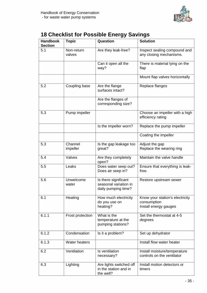
Handbook of Energy Conservation - for waste water pump systems
- 35 -
18 Checklist for Possible Energy Savings Handbook Section
Topic Question Solution
5.1 Non-return valves
Are they leak-free? Inspect sealing compound and any closing mechanisms.
Can it open all the way?
There is material lying on the flap
Mount flap valves horizontally
5.2 Coupling base Are the flange surfaces intact?
Replace flanges
Are the flanges of corresponding size?
5.3 Pump impeller Choose an impeller with a high efficiency rating
Is the impeller worn? Replace the pump impeller
Coating the impeller
5.3 Channel impeller
Is the gap leakage too great?
Adjust the gap Replace the wearing ring
5.4 Valves Are they completely open?
Maintain the valve handle
5.5 Leaks Does water seep out? Does air seep in?
Ensure that everything is leak-free.
5.6 Unwelcome water
Is there significant seasonal variation in daily pumping time?
Restore upstream sewer
6.1 Heating How much electricity do you use on heating?
Know your station's electricity consumption Install energy gauges
6.1.1 Frost protection What is the temperature at the pumping stations?
Set the thermostat at 4-5 degrees
6.1.2 Condensation Is it a problem? Set up dehydrator
6.1.3 Water heaters Install flow water heater
6.2 Ventilation Is ventilation necessary?
Install moisture/temperature controls on the ventilator
6.3 Lighting Are lights switched off in the station and in the well?
Install motion detectors or timers
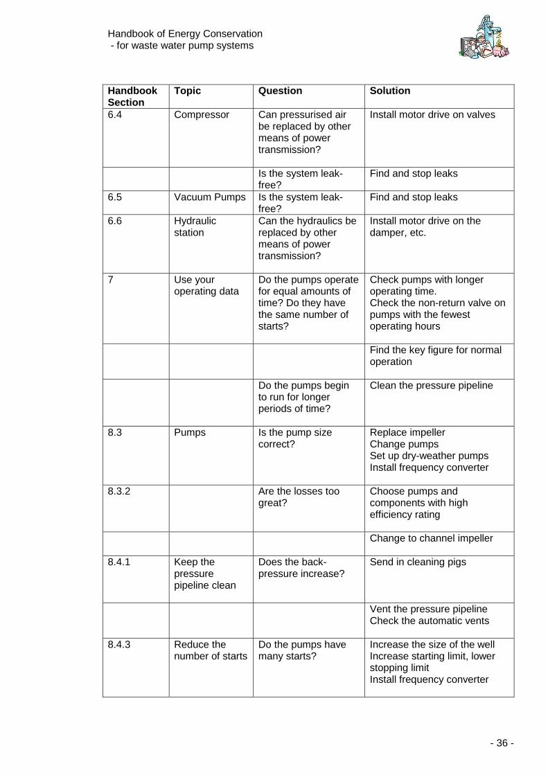
Handbook of Energy Conservation - for waste water pump systems
- 36 -
Handbook Section
Topic Question Solution
6.4 Compressor Can pressurised air be replaced by other means of power transmission?
Install motor drive on valves
Is the system leak-free?
Find and stop leaks
6.5 Vacuum Pumps Is the system leak-free?
Find and stop leaks
6.6 Hydraulic station
Can the hydraulics be replaced by other means of power transmission?
Install motor drive on the damper, etc.
7 Use your operating data
Do the pumps operate for equal amounts of time? Do they have the same number of starts?
Check pumps with longer operating time. Check the non-return valve on pumps with the fewest operating hours
Find the key figure for normal operation
Do the pumps begin to run for longer periods of time?
Clean the pressure pipeline
8.3 Pumps Is the pump size correct?
Replace impeller Change pumps Set up dry-weather pumps Install frequency converter
8.3.2 Are the losses too great?
Choose pumps and components with high efficiency rating
Change to channel impeller
8.4.1 Keep the pressure pipeline clean
Does the back-pressure increase?
Send in cleaning pigs
Vent the pressure pipeline Check the automatic vents
8.4.3 Reduce the number of starts
Do the pumps have many starts?
Increase the size of the well Increase starting limit, lower stopping limit Install frequency converter
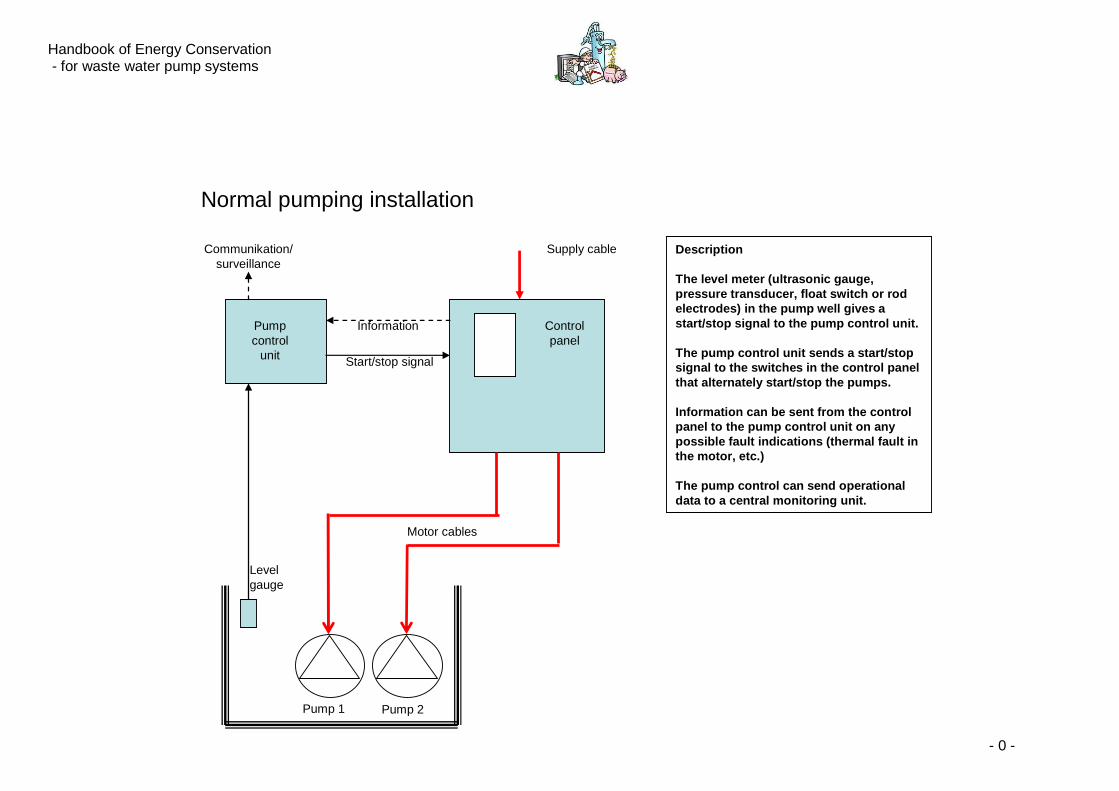
Handbook of Energy Conservation - for waste water pump systems
- 0 -
Description
The level meter (ultrasonic gauge, pressure transducer, float switch or rod electrodes) in the pump well gives a start/stop signal to the pump control unit.
The pump control unit sends a start/stop signal to the switches in the control panel that alternately start/stop the pumps.
Information can be sent from the control panel to the pump control unit on any possible fault indications (thermal fault in the motor, etc.)
The pump control can send operational data to a central monitoring unit.
Pump 1 Pump 2
Levelgauge
Pump control
unit
Controlpanel
Supply cableCommunikation/surveillance
Start/stop signal
Information
Motor cables
Normal pumping installation
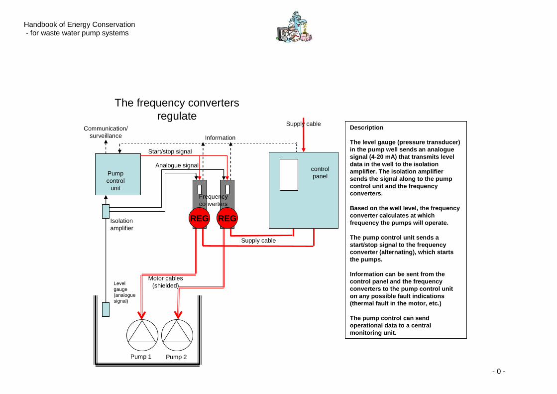
Handbook of Energy Conservation - for waste water pump systems
- 0 -
Description
The level gauge (pressure transducer) in the pump well sends an analogue signal (4-20 mA) that transmits level data in the well to the isolation amplifier. The isolation amplifier sends the signal along to the pump control unit and the frequency converters.
Based on the well level, the frequency converter calculates at which frequency the pumps will operate.
The pump control unit sends a start/stop signal to the frequency converter (alternating), which starts the pumps.
Information can be sent from the control panel and the frequency converters to the pump control unit on any possible fault indications (thermal fault in the motor, etc.)
The pump control can send operational data to a central monitoring unit.
The frequency convertersregulate
Motor cables(shielded)Level
gauge (analoguesignal)
Pump 1 Pump 2
Pumpcontrol
unit
controlpanel
Supply cableCommunication/
surveillance Information
Supply cable
Start/stop signal
Analogue signal
Frequencyconverters
REG REGIsolation amplifier
Handbook of Energy Conservation - for waste water pump systems
- 1 -
Description
The level meter (ultrasonic gauge, pressure transducer, float switch or rod electrodes) in the pump well gives a start/stop signal to the pump control unit.
The pump control unit sends a start/stop signal to the switches in the control panel that alternately start/stop the pumps.
Information can be sent from the control panel to the pump control unit on any possible fault indications (thermal fault in the motor, etc.)
The pump control can send operational data to a central monitoring unit.
Pump control regulates
Motor cables(shielded)Level
gauge (analoguesignal)
Pump 1 Pump 2
Pump control
unit
Controlpanel
Supply cableCommunication/
surveillance Information
REG
Supply cables
Start/stopsignal
Analogue signal
Freqyency converters
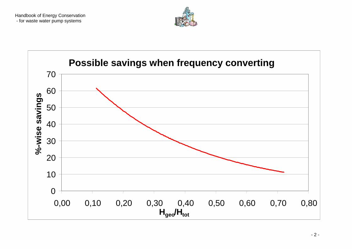
Handbook of Energy Conservation - for waste water pump systems
- 2 -
Possible savings when frequency converting
0
10
20
30
40
50
60
70
0,00 0,10 0,20 0,30 0,40 0,50 0,60 0,70 0,80
Hgeo/Htot
%-w
ise
savi
ng
s

Rev. 2006-08-07130R0330 MG20L102
*MG20L102*
Related Documents