HAND-HELD DEVICE FOR DETECTION OF AIR POLLUTANTS IN VEHICLES Mini Project submitted in partial fulfillment of requirement for the award of degree of Master of Engineering in Embedded System & Computing by Mr. Talib Divan Guide Prof. Girish Talmale Department of Computer Science and Engineering G.H. Raisoni College of Engineering, Nagpur (An autonomous Institute under UGC act 1956 & affiliated to Rastrasanta Tukadoji Maharaj Nagpur University, Nagpur) April 2014 Cover Page

Welcome message from author
This document is posted to help you gain knowledge. Please leave a comment to let me know what you think about it! Share it to your friends and learn new things together.
Transcript
HAND-HELD DEVICE FOR DETECTION OF AIR POLLUTANTS IN VEHICLES
Mini Project submitted in
partial fulfillment of requirement for the award of degree of
Master of Engineeringin
Embedded System & Computing
by
Mr. Talib Divan
Guide
Prof. Girish Talmale
Department of Computer Science and Engineering
G.H. Raisoni College of Engineering, Nagpur(An autonomous Institute under UGC act 1956 & affiliated to Rastrasanta Tukadoji Maharaj
Nagpur University, Nagpur)
April 2014
Cover Page
HAND-HELD DEVICE FOR DETECTION OF AIR POLLUTANTS IN VEHICLES
Mini Project submitted in
partial fulfillment of requirement for the award of degree of
Master of Engineeringin
Embedded System & Computing
by
Talib Divan
Guide
Prof. Girish Talmale
Department of Computer Science and Engineering
G.H. Raisoni College of Engineering, Nagpur(An autonomous Institute under UGC act 1956 & affiliated to Rastrasanta Tukadoji Maharaj
Nagpur University, Nagpur)
April 2014
© G.H.Raisoni College of Engineering, Nagpur 2014
Declaration
I, hereby declare that the Mini Project titled “Hand-Held device for Detection of
Air Pollutants in Vehicles” submitted herein has been carried out by me in the Department
of Computer Science and Engineering of G.H. Raisoni College of Engineering, Nagpur. The
work is original and has not been submitted earlier as a whole or in part for the award of any
degree / diploma at this or any other Institution / University.
Talib Divan
Date:
CertificateThe Mini Project titled “Hand-Held device for Detection of Air Pollutants in
Vehicles” submitted by Talib Divan for the award of degree of Master of Engineering in
Embedded System and Computing, has been carried out under my supervision at the
Department of Computer Science and Engineering of G.H. Raisoni College of Engineering,
Nagpur .The work is comprehensive, complete and fit for evaluation.
Dr.L.G.Malik Prof. Girish Talmale Head Of Department, Assistant Professor,Department of Computer Science Department of Computer & Engineering, Science & Engineering,G.H.R.C.E, Nagpur G.H.R.C.E, Nagpur
ABSTRACT
Vehicles have become an integral part of every one's life. However, apart from the
convenience and luxury they provide, they also have the side effects of causing air pollution.
Every vehicle emits pollutants but the problem occurs when it is beyond the standardized
values. The primary reason for this breach of emission level is due to the improper
maintenance of vehicles. In this project, a MQ-7 (CO detector sensor) can be used to detect
vehicle emissions & also indicate on meter. When the emission level shoots beyond the
already set threshold level there will be a buzz in the vehicle to indicate that the limit has
been breached and the vehicle will stop after a certain period of time. The synchronization
and execution of the entire process is monitored and controlled by a microcontroller.
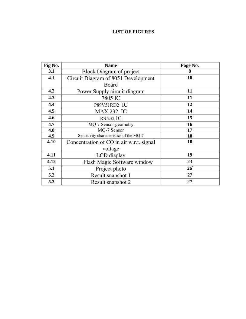
LIST OF FIGURES
Fig No. Name Page No.3.1 Block Diagram of project 8
4.1 Circuit Diagram of 8051 Development Board
10
4.2 Power Supply circuit diagram 114.3 7805 IC 11
4.4 P89V51RD2 IC 124.5 MAX 232 IC 144.6 RS 232 IC 15
4.7 MQ 7 Sensor geometry 164.8 MQ-7 Sensor 174.9 Sensitivity characteristics of the MQ-7 184.10 Concentration of CO in air w.r.t. signal
voltage18
4.11 LCD display 194.12 Flash Magic Software window 235.1 Project photo 26`
5.2 Result snapshot 1 275.3 Result snapshot 2 27
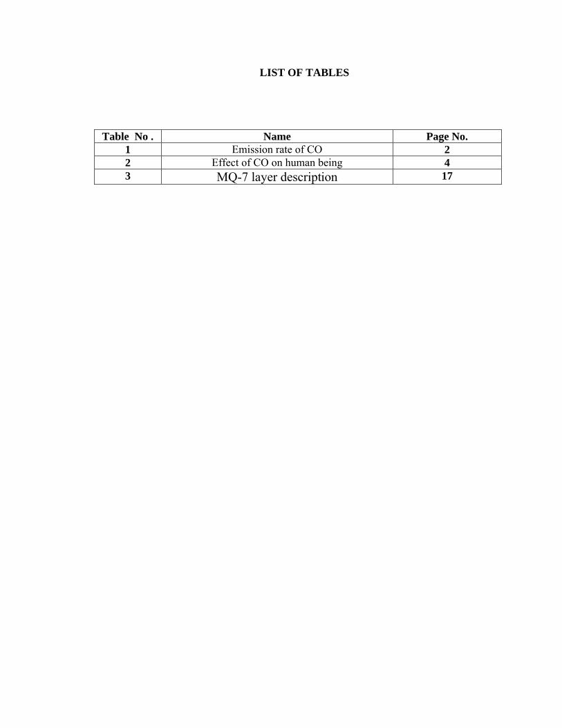
LIST OF TABLES
Table No . Name Page No.1 Emission rate of CO 22 Effect of CO on human being 43 MQ-7 layer description 17
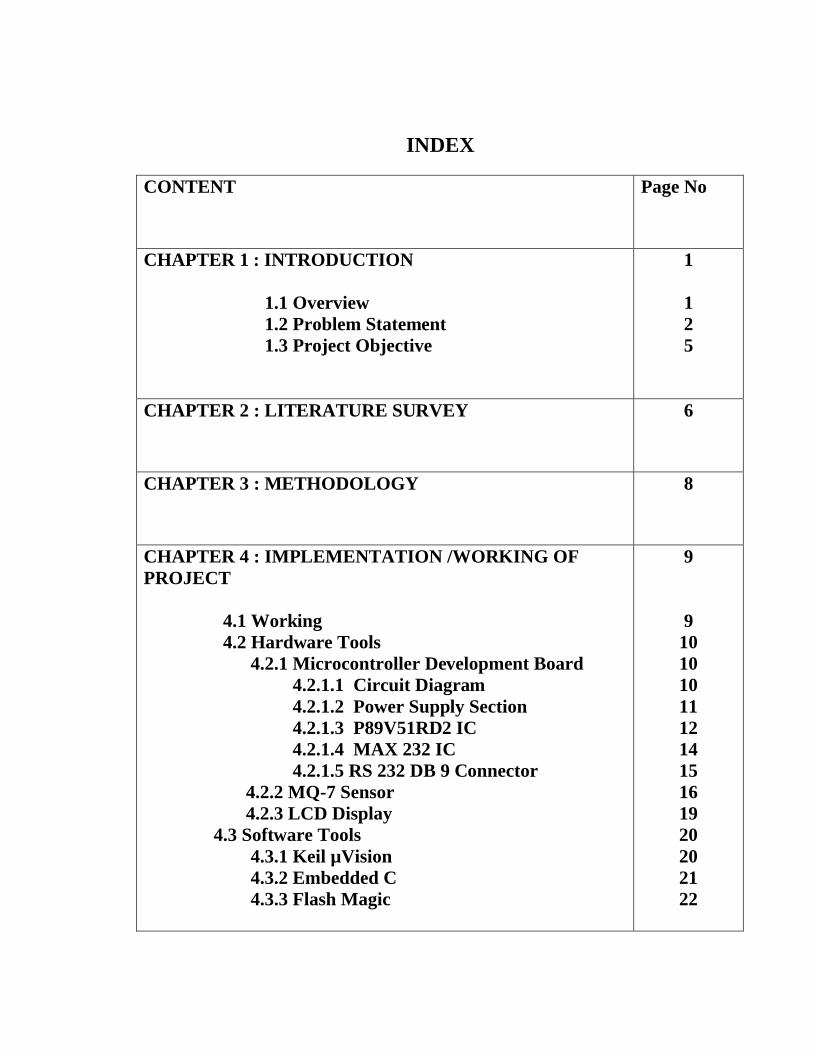
INDEX
CONTENT Page No
CHAPTER 1 : INTRODUCTION
1.1 Overview 1.2 Problem Statement 1.3 Project Objective
1
125
CHAPTER 2 : LITERATURE SURVEY 6
CHAPTER 3 : METHODOLOGY 8
CHAPTER 4 : IMPLEMENTATION /WORKING OF PROJECT 4.1 Working 4.2 Hardware Tools 4.2.1 Microcontroller Development Board 4.2.1.1 Circuit Diagram 4.2.1.2 Power Supply Section 4.2.1.3 P89V51RD2 IC 4.2.1.4 MAX 232 IC 4.2.1.5 RS 232 DB 9 Connector 4.2.2 MQ-7 Sensor 4.2.3 LCD Display 4.3 Software Tools 4.3.1 Keil µVision 4.3.2 Embedded C 4.3.3 Flash Magic
9
910101011121415161920202122
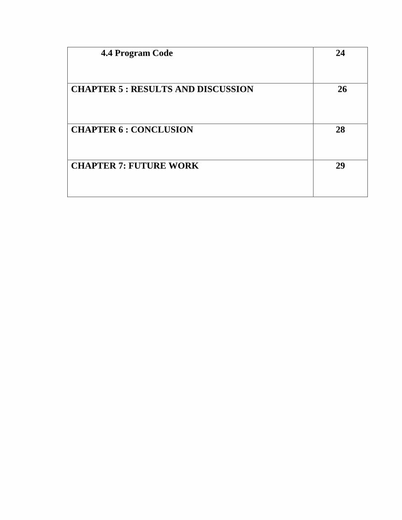
4.4 Program Code
24
CHAPTER 5 : RESULTS AND DISCUSSION 26
CHAPTER 6 : CONCLUSION 28
CHAPTER 7: FUTURE WORK 29
1
CHAPTER 1
INTRODUCTION
1.1 Overview
Air pollution contributes to the green houses gases, which causes the green house
effect, whose side effects are now well known to all of us after the findings about the hole in
the ozone layer. Air pollution is not only harmful to the environment but, also to all other
living beings on earth. Air pollutants that are inhaled have serious impact on human health
affecting the lungs and the respiratory system; they are also taken up by the blood and
pumped all round the body. These pollutants are also deposited on soil, plants, and in the
water, further contributing to human exposure and also affecting the sea life Vehicles are
one of the major contributors to air pollution apart from industries. The main pollutants from
vehicles are the oxides of carbon and nitrogen, which can be easily detected these days with
the help of semi-conductor gas sensors.
Therefore, in this project a handheld device is designed which will be helpful in
reducing the amount of pollution from vehicles. Later on the device can be compact in a
VLSI circuit and can be equipped with number of sensors like CO,NOX etc. The device can
be used by law enforcement for checking the level of harmful gases from vehicle & penalize
them if level exceed beyond standard level.
2
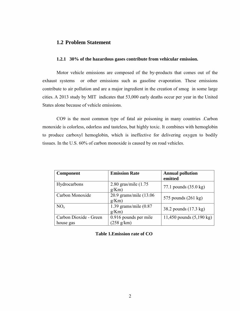
1.2 Problem Statement
1.2.1 30% of the hazardous gases contribute from vehicular emission.
Motor vehicle emissions are composed of the by-products that comes out of the
exhaust systems or other emissions such as gasoline evaporation. These emissions
contribute to air pollution and are a major ingredient in the creation of smog in some large
cities. A 2013 study by MIT indicates that 53,000 early deaths occur per year in the United
States alone because of vehicle emissions.
CO9 is the most common type of fatal air poisoning in many countries .Carbon
monoxide is colorless, odorless and tasteless, but highly toxic. It combines with hemoglobin
to produce carboxyl hemoglobin, which is ineffective for delivering oxygen to bodily
tissues. In the U.S. 60% of carbon monoxide is caused by on road vehicles.
Component Emission Rate Annual pollution emitted
Hydrocarbons 2.80 gras/mile (1.75 g/Km)
77.1 pounds (35.0 kg)
Carbon Monoxide 20.9 grams/mile (13.06 g/Km)
575 pounds (261 kg)
NOx 1.39 grams/mile (0.87 g/Km)
38.2 pounds (17.3 kg)
Carbon Dioxide - Green house gas
0.916 pounds per mile (258 g/km)
11,450 pounds (5,190 kg)
Table 1.Emission rate of CO
3
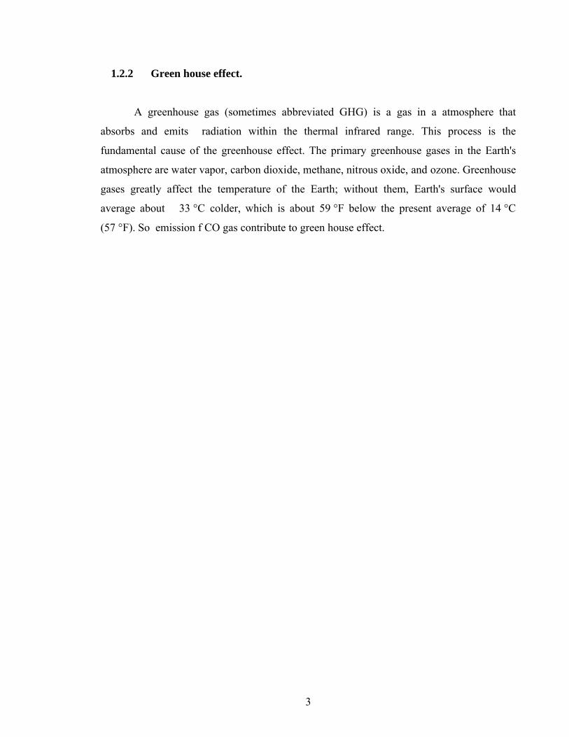
1.2.2 Green house effect.
A greenhouse gas (sometimes abbreviated GHG) is a gas in a atmosphere that
absorbs and emits radiation within the thermal infrared range. This process is the
fundamental cause of the greenhouse effect. The primary greenhouse gases in the Earth's
atmosphere are water vapor, carbon dioxide, methane, nitrous oxide, and ozone. Greenhouse
gases greatly affect the temperature of the Earth; without them, Earth's surface would
average about 33 °C colder, which is about 59 °F below the present average of 14 °C
(57 °F). So emission f CO gas contribute to green house effect.
4
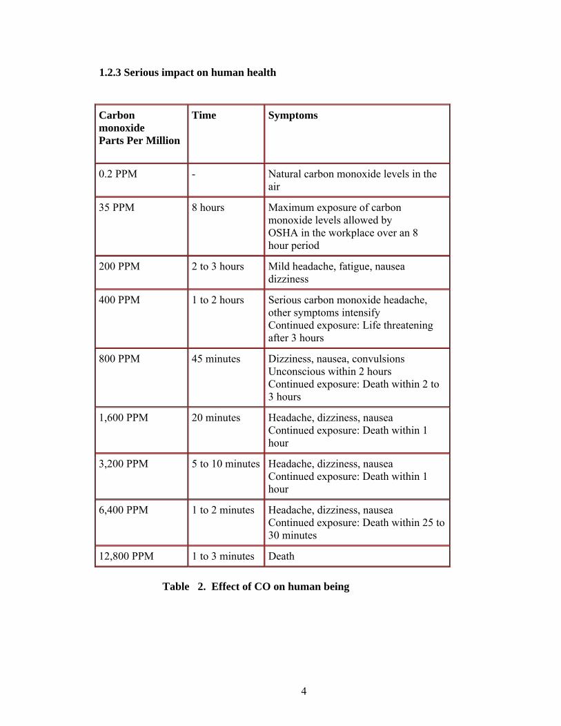
1.2.3 Serious impact on human health
Carbon monoxideParts Per Million
Time Symptoms
0.2 PPM - Natural carbon monoxide levels in the air
35 PPM 8 hours Maximum exposure of carbon monoxide levels allowed byOSHA in the workplace over an 8hour period
200 PPM 2 to 3 hours Mild headache, fatigue, nauseadizziness
400 PPM 1 to 2 hours Serious carbon monoxide headache, other symptoms intensifyContinued exposure: Life threatening after 3 hours
800 PPM 45 minutes Dizziness, nausea, convulsionsUnconscious within 2 hoursContinued exposure: Death within 2 to 3 hours
1,600 PPM 20 minutes Headache, dizziness, nauseaContinued exposure: Death within 1 hour
3,200 PPM 5 to 10 minutes Headache, dizziness, nauseaContinued exposure: Death within 1 hour
6,400 PPM 1 to 2 minutes Headache, dizziness, nauseaContinued exposure: Death within 25 to 30 minutes
12,800 PPM 1 to 3 minutes Death
Table 2. Effect of CO on human being

5
1.3 Project Objective
To detect air pollution caused due to vehicle by emission of harmful gases.
To develop a device which detect whether vehicle is under pollution control which
can be used by law enforcement.
To make people aware about the ill effect caused from inhalation of CO gas.
6
CHAPTER 2
LITERATURE SURVEY
Over the years, there have been several regulations made by the Government to
control the emission from vehicles; most of them being unsuccessful at the same. The
standards and the timeline for implementation are set by the Central Pollution Control Board
under the Ministry of Environment & Forests. Bharat stage emission standards are emission
standards instituted by the Government of India to regulate the output of air pollutants from
internal combustion engine equipment, including motor vehicles. The first emission norms
were introduced in India in 1991 for petrol and 1992 for diesel vehicles. These were
followed by making the Catalytic converter mandatory for petrol vehicles and the
introduction of unleaded petrol in the market. On April 29, 1999 the Supreme Court of India
ruled that all vehicles in India have to meet Euro I or India 2000 norms by June 1, 1999 and
Euro II will be mandatory inthe NCR by April 2000. Car makers were not prepared for this
transition and in a subsequent judgment the implementation date for Euro II was not
enforced.
The standards, based on European regulations were first introduced in 2000.
Progressively stringent norms have been rolled out since then. All new vehicles
manufactured after the implementation of the norms have to be compliant with the
regulations. Since October 2010, Bharat stage III norms have been enforced across the
country. In 13 major cities, Bharat stage IV emission norms are in place since April 2010.
The phasing out of 2 stroke engine for two wheelers, the stoppage of production of various
old model cars &introduction of electronic controls have been due to the regulations related
7
to vehicular emissions. The sensing of the emitted gases are done using various sensors and
devices.
The past decade, has seen several research activities that have been taking place to
develop semiconductor gas sensors. In the year 2000, K. Galatsis, W. Woldarsla, Y.X. Li
and K. Kalantar-zadeh, “A Vehicle air quality monitor using gas sensors for improved
safety”, this paper focuses on A vehicle cabin air quality monitor using carbon monoxide
(CO)and oxygen (02) gas sensors has been designed, developed and on-road tested. The
continuous monitoring of oxygen and carbon monoxide provides added vehicle safety as
alarms could be set off when dangerous gas concentrations are reached, preventing driver
fatigue, drowsiness, and exhaust gas suicides.
In the year of 2012, V.Ramya, B. Palaniappan, “Embedded Technology for vehicle
cabin safety Monitoring and Alerting System ”, this paper focuses on, car cabin air quality
monitoring can be effectively analyzed using metal oxide semiconducting (MOS) gas
sensors. In this paper, commercially available gas sensors are compared with fabricated
Moo3 based sensors possessed comparable gas sensing properties. The sensor has response
74% higher relative to the hest commercial sensor tested .
In the year of 2013, Siva Shankar Chandrasekaran, Sudharshan Muthukumar,has
presented a paper, “Automated Control System for Air Pollution Detection in Vehicles” In
this paper , the semiconductor sensors have been used to detect the pollutant level of the
vehicles. That paper concentrates mainly on three blocks; smoke detector, microcontroller
and fuel injector. The smoke detector detects the pollutants (CO, NOx, etc.) continuously.
The microcontroller compares the level of pollutants with the stipulated level allowed by the
government. When the pollutant level exceeds the standardized limit, it sends a signal to the
fuel injector. On receiving a signal from the controller, the fuel injector stops the fuel supply
to the engine after a particular period of time.
8
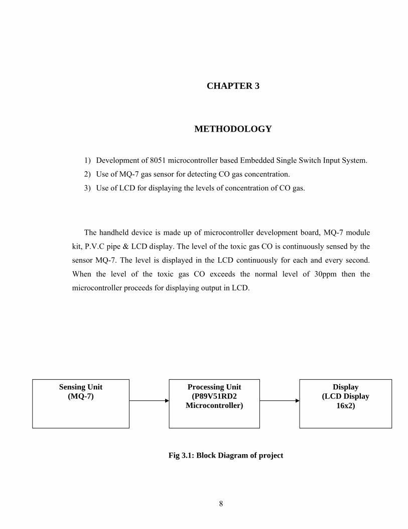
CHAPTER 3
METHODOLOGY
1) Development of 8051 microcontroller based Embedded Single Switch Input System.
2) Use of MQ-7 gas sensor for detecting CO gas concentration.
3) Use of LCD for displaying the levels of concentration of CO gas.
The handheld device is made up of microcontroller development board, MQ-7 module
kit, P.V.C pipe & LCD display. The level of the toxic gas CO is continuously sensed by the
sensor MQ-7. The level is displayed in the LCD continuously for each and every second.
When the level of the toxic gas CO exceeds the normal level of 30ppm then the
microcontroller proceeds for displaying output in LCD.
Fig 3.1: Block Diagram of project
Sensing Unit(MQ-7)
Processing Unit(P89V51RD2
Microcontroller)
Display(LCD Display
16x2)
9
CHAPTER 4
IMPLEMENTATION /WORKING OF PROJECT
4.1 Working of project
The handheld device is made up of microcontroller development board, MQ-
7 module kit, P.V.C pipe & LCD display. First we have to calibrate the
potentiometer connected at MQ-7 module kit to a suitable standard value. Then we
have to start the vehicle and attached a pipe to the silencer of vehicle. If the green
light glows, it indicate that the level is maintained & red light glows it indicate that
the level of CO gas level is beyond standard level.
10
4.2 Hardware tools
4.2.1 Microcontroller 89C51 Development Board
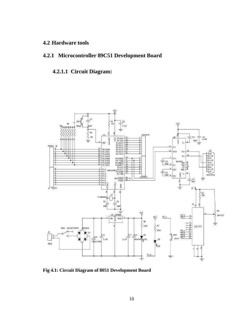
4.2.1.1 Circuit Diagram:
Fig 4.1: Circuit Diagram of 8051 Development Board
11
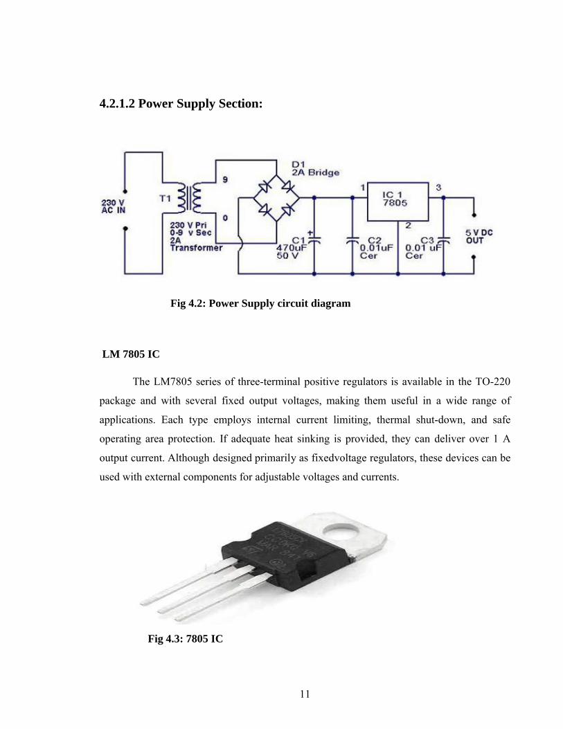
4.2.1.2 Power Supply Section:
Fig 4.2: Power Supply circuit diagram
LM 7805 IC
The LM7805 series of three-terminal positive regulators is available in the TO-220
package and with several fixed output voltages, making them useful in a wide range of
applications. Each type employs internal current limiting, thermal shut-down, and safe
operating area protection. If adequate heat sinking is provided, they can deliver over 1 A
output current. Although designed primarily as fixedvoltage regulators, these devices can be
used with external components for adjustable voltages and currents.
Fig 4.3: 7805 IC
12
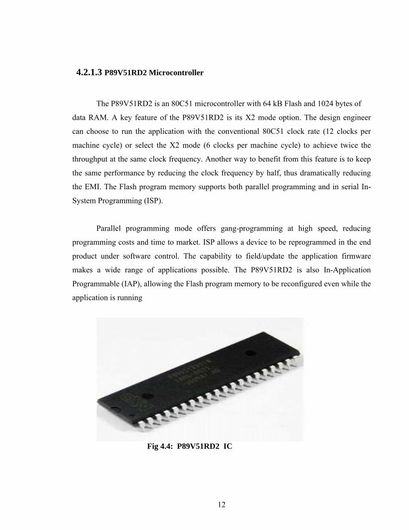
4.2.1.3 P89V51RD2 Microcontroller
The P89V51RD2 is an 80C51 microcontroller with 64 kB Flash and 1024 bytes of
data RAM. A key feature of the P89V51RD2 is its X2 mode option. The design engineer
can choose to run the application with the conventional 80C51 clock rate (12 clocks per
machine cycle) or select the X2 mode (6 clocks per machine cycle) to achieve twice the
throughput at the same clock frequency. Another way to benefit from this feature is to keep
the same performance by reducing the clock frequency by half, thus dramatically reducing
the EMI. The Flash program memory supports both parallel programming and in serial In-
System Programming (ISP).
Parallel programming mode offers gang-programming at high speed, reducing
programming costs and time to market. ISP allows a device to be reprogrammed in the end
product under software control. The capability to field/update the application firmware
makes a wide range of applications possible. The P89V51RD2 is also In-Application
Programmable (IAP), allowing the Flash program memory to be reconfigured even while the
application is running
Fig 4.4: P89V51RD2 IC

13
Features
80C51 Central Processing Unit
5 V Operating voltage from 0 to 40 MHz
64 kB of on-chip Flash program memory with ISP (In-System Programming) and
IAP (In-Application Programming) & SPI (Serial Peripheral Interface)
Supports 12-clock (default) or 6-clock mode selection via software or ISP
SPI (Serial Peripheral Interface) and enhanced UART
PCA (Programmable Counter Array) with PWM and Capture/Compare functions
Four 8-bit I/O ports with three high-current Port 1 pins (16 mA each)
Three 16-bit timers/counters
Programmable Watchdog timer (WDT)
Eight interrupt sources with four priority levels
Second DPTR register
Low EMI mode (ALE inhibit)
14
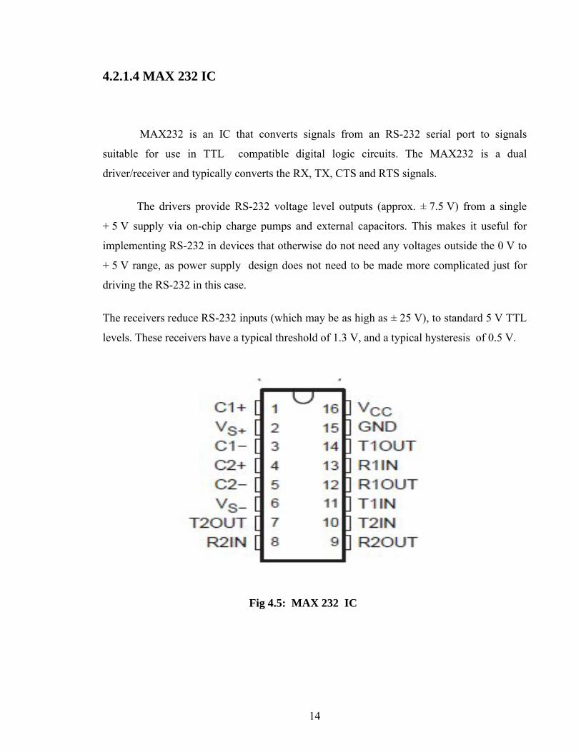
4.2.1.4 MAX 232 IC
MAX232 is an IC that converts signals from an RS-232 serial port to signals
suitable for use in TTL compatible digital logic circuits. The MAX232 is a dual
driver/receiver and typically converts the RX, TX, CTS and RTS signals.
The drivers provide RS-232 voltage level outputs (approx. ± 7.5 V) from a single
+ 5 V supply via on-chip charge pumps and external capacitors. This makes it useful for
implementing RS-232 in devices that otherwise do not need any voltages outside the 0 V to
+ 5 V range, as power supply design does not need to be made more complicated just for
driving the RS-232 in this case.
The receivers reduce RS-232 inputs (which may be as high as ± 25 V), to standard 5 V TTL
levels. These receivers have a typical threshold of 1.3 V, and a typical hysteresis of 0.5 V.
Fig 4.5: MAX 232 IC
15
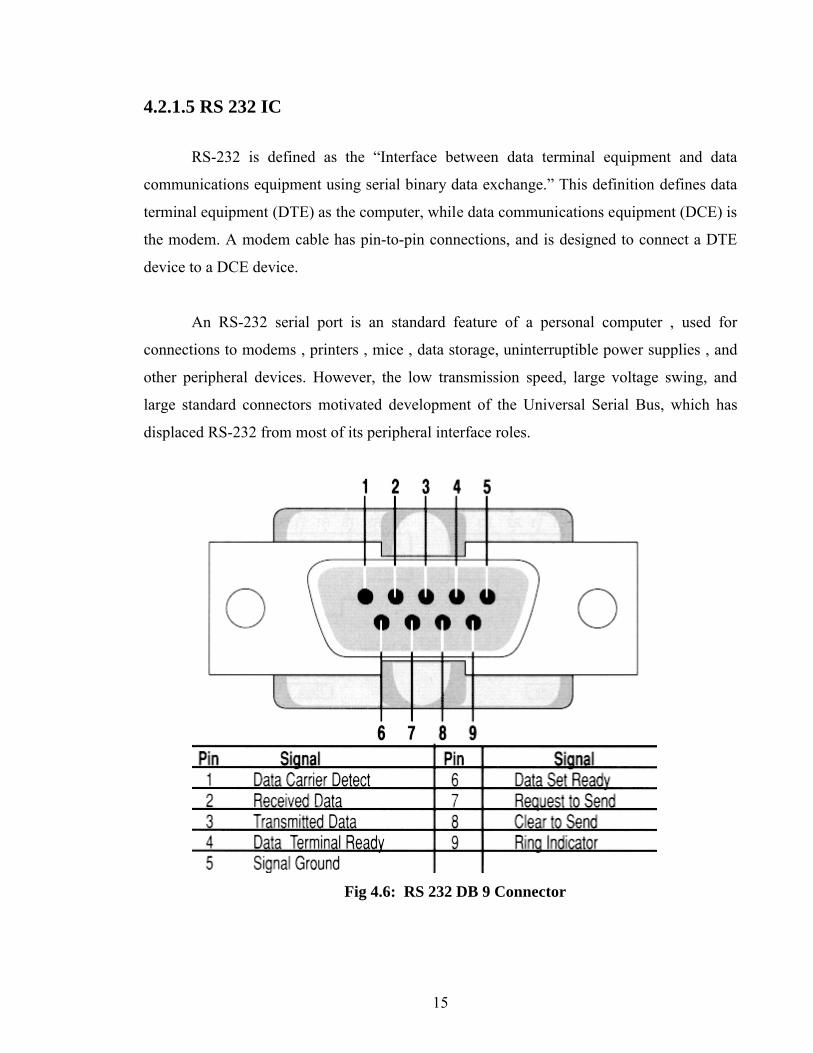
4.2.1.5 RS 232 IC
RS-232 is defined as the “Interface between data terminal equipment and data
communications equipment using serial binary data exchange.” This definition defines data
terminal equipment (DTE) as the computer, while data communications equipment (DCE) is
the modem. A modem cable has pin-to-pin connections, and is designed to connect a DTE
device to a DCE device.
An RS-232 serial port is an standard feature of a personal computer , used for
connections to modems , printers , mice , data storage, uninterruptible power supplies , and
other peripheral devices. However, the low transmission speed, large voltage swing, and
large standard connectors motivated development of the Universal Serial Bus, which has
displaced RS-232 from most of its peripheral interface roles.
Fig 4.6: RS 232 DB 9 Connector
16
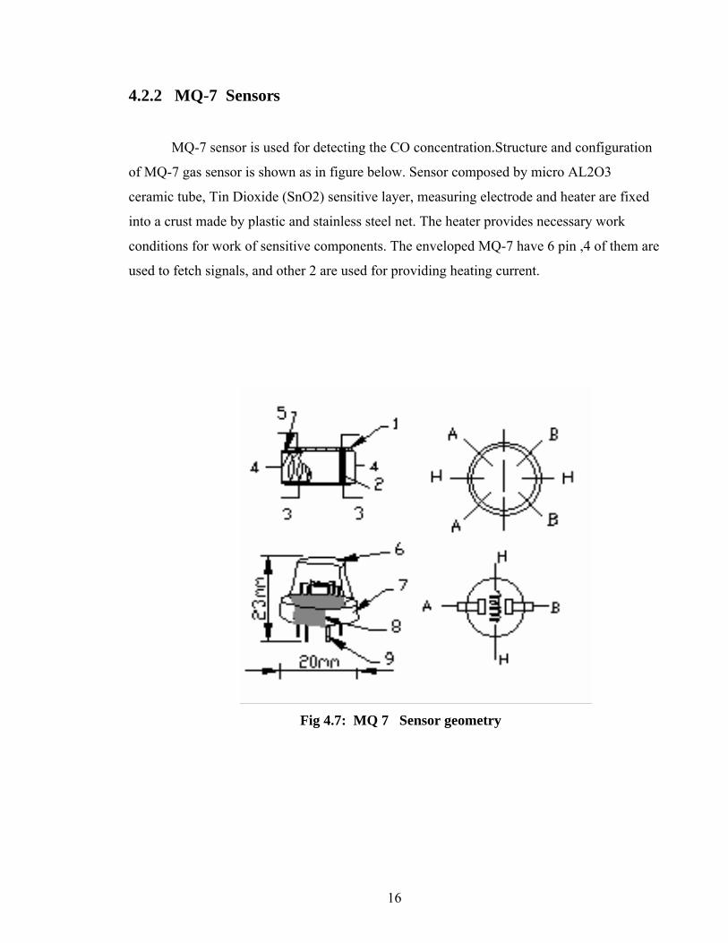
4.2.2 MQ-7 Sensors
MQ-7 sensor is used for detecting the CO concentration.Structure and configuration
of MQ-7 gas sensor is shown as in figure below. Sensor composed by micro AL2O3
ceramic tube, Tin Dioxide (SnO2) sensitive layer, measuring electrode and heater are fixed
into a crust made by plastic and stainless steel net. The heater provides necessary work
conditions for work of sensitive components. The enveloped MQ-7 have 6 pin ,4 of them are
used to fetch signals, and other 2 are used for providing heating current.
Fig 4.7: MQ 7 Sensor geometry
17
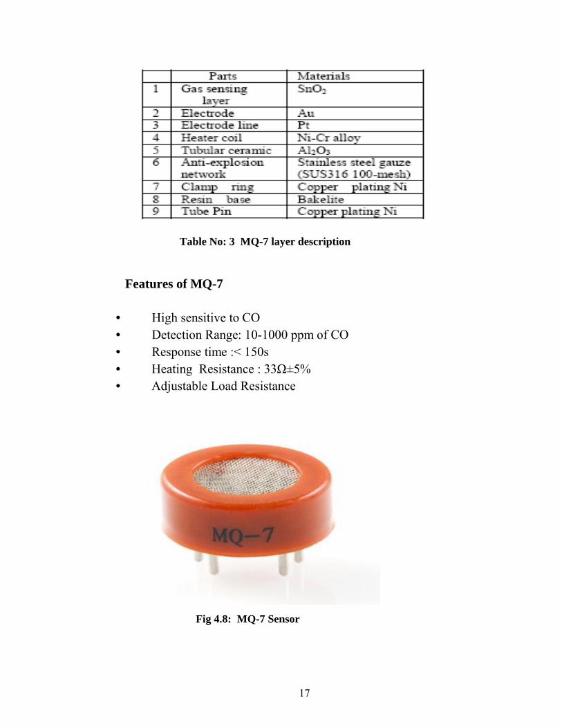
Table No: 3 MQ-7 layer description
Features of MQ-7
• High sensitive to CO• Detection Range: 10-1000 ppm of CO• Response time :< 150s• Heating Resistance : 33Ω±5%• Adjustable Load Resistance
Fig 4.8: MQ-7 Sensor
18
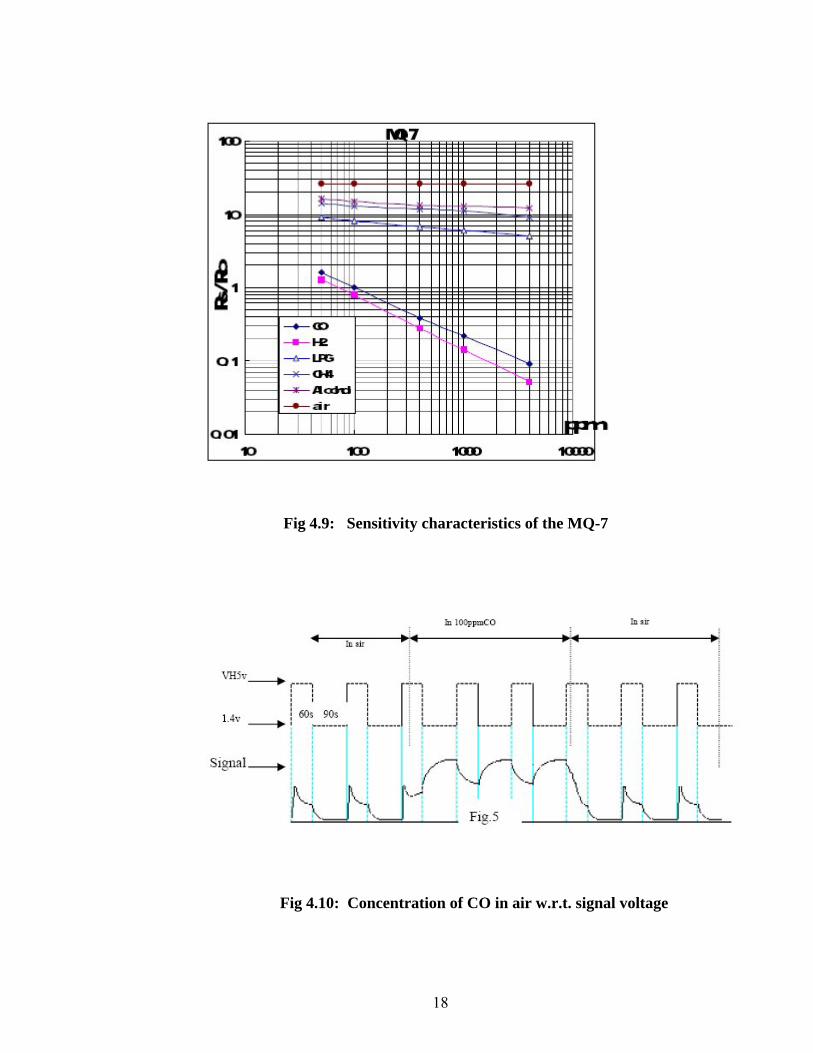
Fig 4.9: Sensitivity characteristics of the MQ-7
Fig 4.10: Concentration of CO in air w.r.t. signal voltage
19
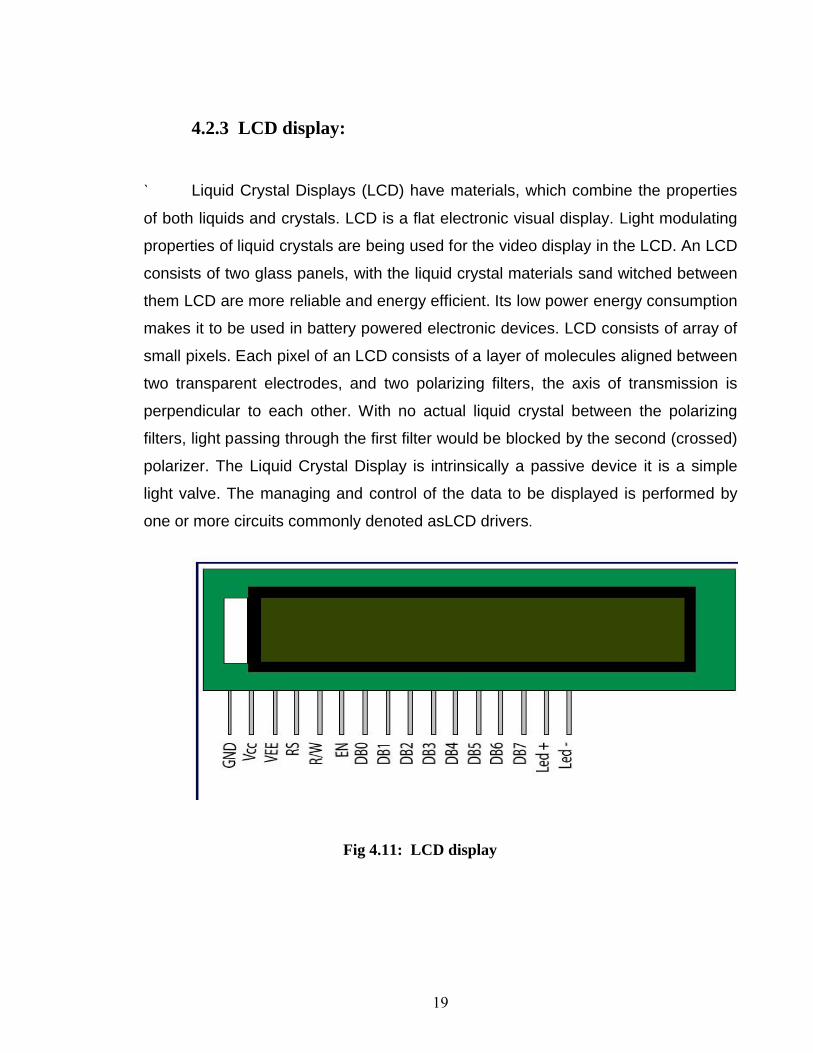
4.2.3 LCD display:
` Liquid Crystal Displays (LCD) have materials, which combine the properties
of both liquids and crystals. LCD is a flat electronic visual display. Light modulating
properties of liquid crystals are being used for the video display in the LCD. An LCD
consists of two glass panels, with the liquid crystal materials sand witched between
them LCD are more reliable and energy efficient. Its low power energy consumption
makes it to be used in battery powered electronic devices. LCD consists of array of
small pixels. Each pixel of an LCD consists of a layer of molecules aligned between
two transparent electrodes, and two polarizing filters, the axis of transmission is
perpendicular to each other. With no actual liquid crystal between the polarizing
filters, light passing through the first filter would be blocked by the second (crossed)
polarizer. The Liquid Crystal Display is intrinsically a passive device it is a simple
light valve. The managing and control of the data to be displayed is performed by
one or more circuits commonly denoted asLCD drivers.
Fig 4.11: LCD display

20
4.3 Software Tools Required
4.3.1 Keil µVision
What is µVision2?
µVision2 is an IDE (Integrated Development Environment) that helps you write, compile,
and debug embedded programs. It encapsulates the following components:
A project manager.
A make facility.
Tool configuration.
Editor.
A powerful debugger.
Steps for creating an Application in µVision2
To create a new project in µVision2, we must follow following steps:
1. Select Project - New Project.
2. Select a directory and enter the name of the project file.
3. Select Project - Select Device and select an 8051, 251, or C16x/ST10 device from
the Device Database™.
4. Create source files to add to the project.
5. Select Project - Targets, Groups, Files. Add/Files, select Source Group1, and add the
source files to the project.
6. Select Project - Options and set the tool options. Note when you select the target
device from the Device Database™ all special options are set automatically. You
typically only need to configure the memory map of your target hardware. Default
memory model settings are optimal for most applications.
7. Select Project - Rebuild all target files or Build target.
21
4.3.2 Embedded C
Embedded C is not a part of the C language as such. Rather, it is a C language that is
the subject of a technical report by the ISO working group named “Extensions for the
Programming Language C to support Embedded Processors”. It aims to provide portability
and access to common performance-increasing features of processors used in domain of the
DSP and embedded processing. The embedded C specification for fixed-point, named
address spaces and named register gives the programmers direct access to the features in the
target processor there by significantly improving the performance of the applications. The
hardware I/O extension is a portability feature of Embedded C. Its goal is to allow easy
porting of device-driver code betweensystems. Embedded C is designed to bridge the
performance mismatch between the Standard C and the embedded hardware and application
architecture. It extends the C language with the primitives that are needed by signal
processing applications and that are commonly provided by the DSP processors. Embedded
C makes life easier for application programmers. The primitives provided are the primitives
that fit the conceptual model of the application which brings back the roots of C to the
embedded systems as primarily a high-level language means of accessing the processor.
22
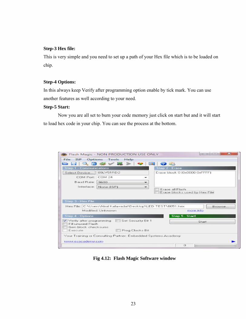
4.3.3 Flash Magic
Flash Magic is a tool which used to program hex code in EEPROM of micro-
controller. it is a freeware tool. It only supports the micro-controller of Philips and NXP.
You can burn a hex code into those controller which supports ISP (in system programming)
feature. To check whether your micro-controller supports ISP or not take look at its
datasheet. So if your device supports ISP then you can easily burn a hex code into EEPROM
of your device.
Flash magic supports several chips like ARM Cortex M0, M3, M4, ARM7 and 8051.
The procedure to program code memory is very easy and needs only five steps to configure
Flash magic for better operation. Flash magic use Serial or Ethernet protocol to program the
flash of device. Below is the screenshot of flash magic
Step-1 Communication:
Select your target device
2) Select your com port and if you are using USB to serial converter make sure that you will
select proper com port otherwise you can not communicate
3) Now select baud rate ideally it should be 9600 (recommended). Avoid higher than 9600
for proper communication
4) Now select your interface if you are using DB-9 then it will be None (ISP)
Step-2 Erase:
Now here tick mark the Erase all Flash option. This is the most crucial thing because wrong
selection in this step can be result into lost of boot loader in your chip. Nothing to worry if
you lost your boot loader because you can again load it but to load boot loader you must
program you chip through universal programmer or any other programmer which is not
depend upon boot loader for loading hex code. After loading boot loader you can again able
to program your chip using flash magic.
23
Step-3 Hex file:
This is very simple and you need to set up a path of your Hex file which is to be loaded on
chip.
Step-4 Options:
In this always keep Verify after programming option enable by tick mark. You can use
another features as well according to your need.
Step-5 Start:
Now you are all set to burn your code memory just click on start but and it will start
to load hex code in your chip. You can see the process at the bottom.
Fig 4.12: Flash Magic Software window
24
4.4 Program Code
#include<reg51.h>#include<lare_delay.h>#include<prolcd.h>#include<serial.h>
#define CO_SENSOR p10#define BUZZER p17#define BUZZ_ON 0#define BUZZ_OFF 1
void alarm(void);void beep(void);
void main(){CO_SENSOR=1;BUZZER=0;BUZZER=1;
LCD_INIT();
LCD_STRING("MONITORING");DELAY(1000);LCD_CLEAR();LCD_STRING("CO Level Normal ");
25
while(1){
if(CO_SENSOR) alarm();} //end of while} //end of main//******************************************************void alarm(void){LCD_CLEAR();LCD_STRING("Warning: High CO");LCD_LINE2();LCD_STRING("Level Detected "); while(CO_SENSOR) beep();
LCD_CLEAR();LCD_STRING("CO Level Normal ");}//******************************************************void beep(void){BUZZER=BUZZ_ON;DELAY(200);BUZZER=BUZZ_OFF;DELAY(200); }
26
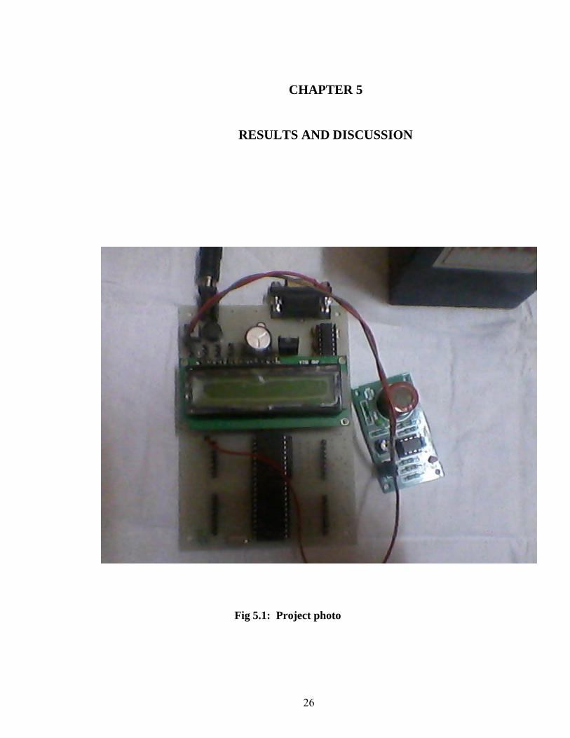
CHAPTER 5
RESULTS AND DISCUSSION
Fig 5.1: Project photo
27
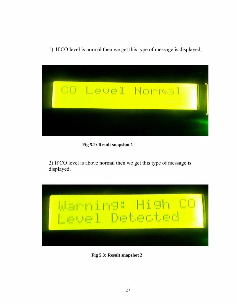
1) If CO level is normal then we get this type of message is displayed,
Fig 5.2: Result snapshot 1
2) If CO level is above normal then we get this type of message is displayed,
Fig 5.3: Result snapshot 2
28
CHAPTER 6
CONCLUSION
Finally from the project we have concluded that device will be one of the greatest
improvements in technology to keep the Environment free from vehicular emission and
bring it to a halt if the Pollution level is more than the Standards mentioned by the
Government.
Also we have tested the device in different vehicles and found that the device work
properly showing the pollution level. It also indicate the high level of CO gas by an
indication.
29
CHAPTER 7
FUTURE WORK
This device can be made into a handheld by equipment of more other sensors like
SOX, NOX etc. So that the concentration of certain harmful gas can be measured and can be
controlled to a large extent.
The device can be handed over to law enforcement for checking the pollutant level in
vehicle & penalize them if level exceeded the normal level.
30
REFERENCES
[1] Siva Shankar Chandrasekaran , Sudharshan Muthukumar and Sabeshkumar Rajendran.
“Automated Control System for Air Pollution Detection in Vehicles”, 2013 4th International
Conference on Intelligent Systems, Modeling and Simulation.
[2] N. Kularatna and B. H. Sudantha, “An environmental air pollution monitoring system
based on the IEEE 1451 standard for low cost requirements ”,IEEE Sensors J., vol. 8, pp.
415–422, Apr. 2008.
[3] V.Ramya1 and B. Palaniappan “Embedded Technology for vehicle cabin safety
Monitoring and Alerting System”,International Journal of Computer Science, Engineering
and Applications (IJCSEA) Vol.2, No.2, April 2012
[4] Kosmas Galatsis1 and Wojtek Wlodarski2, “Car Cabin Air Quality Sensors and
Systems”, Sensor 2008
[5] A.R.Ali, E. Imran Zualkerman, and Fadi Aloul, “A Mobile GPRS-Sensors Array for Air
Pollution Monitoring”, vol. 8, pp. 415-422, 2010.
[6] George F. Fine, Leon M. Cavanagh, Ayo Afonja and Russell Binions “Metal Oxide
Semi-Conductor Gas Sensors in Environmental Monitoring”, Sensors 2010
Related Documents