HAMMERHEAD CHARGER 48V Electric Vehicle Operator’s Manual

Welcome message from author
This document is posted to help you gain knowledge. Please leave a comment to let me know what you think about it! Share it to your friends and learn new things together.
Transcript

HAMMERHEADCHARGER 48V
Electric Vehicle Operator’s Manual

Hammerhead Charger Electric Vehicle Operator’s Manual Page 1
TABLE OF CONTENTS
SAFETY INFORMATION ............................................................................................................................. 3
GENERAL OPERATION INSTRUCTIONS .............................................................................................. 4
MAINTENANCE SAFETY INSTRUCTIONS ............................................................................................ 4
VENTILATION .................................................................................................................................... 4
DISPLAY OF WARNING LABELS ................................................................................................................. 5
DISPLAY OF CONTROLS ............................................................................................................................. 7
BEFORE INITIAL USE .................................................................................................................................. 8
BATTERIES ......................................................................................................................................... 9
ON‐BOARD CHARGER ....................................................................................................................... 9
CONTROLS AND INDICATORS ................................................................................................................. 10
KEY / LIGHT SWITCH ....................................................................................................................... 10
DIRECTION SELECTOR ..................................................................................................................... 11
STATE OF CHARGING METER .......................................................................................................... 11
COMBINATION LEVER (Turning Signals, High Beam Lights, Horn) .................................................. 11
HAZARD LIGHT SWITCH .................................................................................................................. 12
SPEEDOMETER ................................................................................................................................ 12
ACCELERATOR PEDAL ..................................................................................................................... 13
BRAKE PEDAL .................................................................................................................................. 13
PARKING BRAKE LEVER ................................................................................................................... 13
BED USE .................................................................................................................................................. 14
MANUAL LIFT BED OPERATION ...................................................................................................... 15
TAIL GATE OPERATION ................................................................................................................... 16
OPERATING THE VEHICLE ....................................................................................................................... 17

Hammerhead Charger Electric Vehicle Operator’s Manual Page 2
STARTING AND DRIVING ................................................................................................................. 17
STARING VEHICLE ON A HILL .......................................................................................................... 18
VEHICLE CLEARNING AND CARE ............................................................................................................. 19
REPAIR .................................................................................................................................................... 20
WHEELS AND TIRES ......................................................................................................................... 20
FUSE REPLACEMENT ....................................................................................................................... 20
SERVICE AND MAINTENANCE ................................................................................................................. 22
Vehicle Identification Plate Location .............................................................................................. 22
Periodic Maintenance Schedule ..................................................................................................... 23
Tire Inspection ................................................................................................................................ 24
Brakes ............................................................................................................................................. 24
Rear Axle ......................................................................................................................................... 24
Fasteners ........................................................................................................................................ 24
BATTERIES AND CHARGING .................................................................................................................... 25
Batteries ......................................................................................................................................... 25
Charger ........................................................................................................................................... 25
GENERAL SPECIFICATIONS ...................................................................................................................... 26
LIMITED WARRANTY POLICY ................................................................................................................. 28

Hammerhead Charger Electric Vehicle Operator’s Manual Page 3
SAFETY INFORMATION
Thank you for purchasing Hammerhead electrical vehicle. For safe and enjoyable
operation of your electric vehicle, be sure to follow the instructions and
recommendations in this owner’s manual. This manual has been designed to assist
the owner‐operator in operating and maintaining the vehicle in accordance with
procedures developed by the manufacturer. Your manual includes instructions
for minor maintenance, but major repairs should be performed only by a Certified
Dealer Technician. Due to constant improvements in the design and quality of
production components, some minor discrepancies may result between the actual
vehicle and the information presented in this publication. Procedures in this
publication are intended for reference use only. No liability can be accepted for
omissions or inaccuracies.
Many vehicles are used for a variety of different tasks beyond the original intended
use of the vehicle; therefore it is impossible to warn against every possible
combination of circumstances that may occur. No warning can take place of good
common sense and prudent driving practices.
With electric powered vehicles, be sure that all electrical accessories are grounded
directly to the (‐) post. Never uses chassis or body as a ground connection. Never
modify the vehicle in any way that will alter the weight distribution of the vehicle,
decrease its stability or increase the speed beyond the factory specification. Such
modifications can cause serious personal Injuries or death. Do not make any such
modifications or changes. The manufacturer prohibits and disclaims responsibility
for any such modifications or any other alternation which would adversely affect and
safety of the vehicle.
Once again thank you for purchasing Hammerhead product, and we hope you will
have an enjoyable experience.

Hammerhead Charger Electric Vehicle Operator’s Manual Page 4
GENERAL OPERATION INSTRUCTIONS
‐ Always use the vehicle in responsible manner and maintain the vehicle in safe
operation condition.
‐ Always read and observe all warning and operation instructions labels affixed to
the vehicle.
‐ Always follow all safety rules established in area where the vehicle is being
operated.
‐ Always reduce speed for bad terrain or road conditions.
‐ Always apply brake to controls peed on steep grades.
‐ Always maintain adequate distance between vehicles.
‐ Always reduce speed in wet areas.
‐ Always use extreme caution when approaching sharp or blind turns.
MAINTENANCE SAFETY INSTRUCTIONS
‐ Always maintain your vehicle in accordance with manufacturer’s periodic service
schedule.
‐ Always follow the manufacturer’s directions if you do any maintenance on your
vehicle.
‐ Always insulate any tools used within the battery area in order to prevent sparks
or battery explosion caused by shorting the battery terminals or associated
wiring. Remove the batteries or cover exposed terminals with insulating
materials.
‐ Always use specified replacement parts.
‐ Always test drive the vehicle after any repairs or maintenance. All tests must
be conducted in a safe area that is free of both vehicles and pedestrian traffic.
VENTILATION
‐ Hydrogen gas is generated in charging cycle of batteries and is explosive in
concentrations as low as 4%. Because hydrogen gas is lighter than air, it will
collect in the ceiling or buildings necessitating proper ventilation. Five air
exchanges per hour is considered the minimum requirements.
‐ Never charge a battery in an area that is subject to flame or spark. Pay
particular attention to natural gas or propane gas water heaters and furnaces.
‐ Battery charger must be operated according to manufacturer’s instructions.
Please refer to battery charger’s separate operator’s manual for further
instructions.
Hammerhead Charger Electric Vehicle Operator’s Manual Page 5
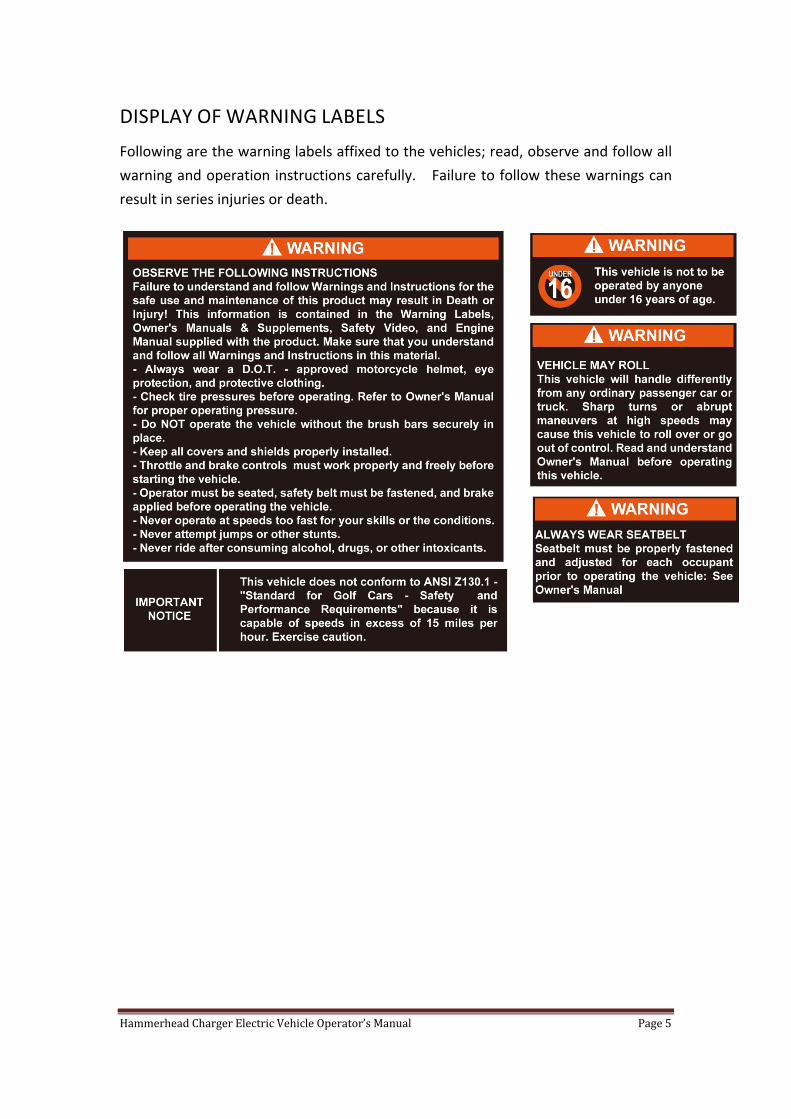
DISPLAY OF WARNING LABELS
Following are the warning labels affixed to the vehicles; read, observe and follow all
warning and operation instructions carefully. Failure to follow these warnings can
result in series injuries or death.

Hammerhead Charger Electric Vehicle Operator’s Manual Page 6
DISPLAY OF WARNING LABELS ‐ 2
Hammerhead Charger Electric Vehicle Operator’s Manual Page 7
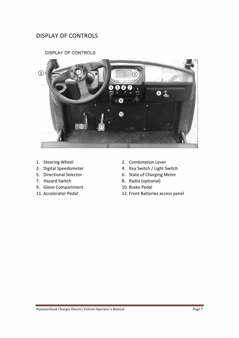
DISPLAY OF CONTROLS
1. Steering Wheel 2. Combination Lever 3. Digital Speedometer 4. Key Switch / Light Switch 5. Directional Selector 6. State of Charging Meter 7. Hazard Switch 8. Radio (optional) 9. Glove Compartment 10. Brake Pedal 11. Accelerator Pedal 12. Front Batteries access panel

Hammerhead Charger Electric Vehicle Operator’s Manual Page 8
BEFORE INITIAL USE
Read, understand and follow the safety label on the instrument panel. Be sure you
understand how to operate the vehicle, its equipment and how to use it safely.
Hydrogen gas is generated in charging cycle of batteries and is explosive in
concentrations as low as 4%. Because hydrogen gas is lighter than air, it will
collect in the ceiling or buildings necessitating proper ventilation. Five air
exchanges per hour is considered the minimum requirements.
Never charge a battery in an area that is subject to flame or spark. Pay particular
attention to natural gas or propane gas water heaters and furnaces.
Before a new vehicle is put into operation, the “Initial Service Check List” below must
be performed to ensure safety operation of the vehicle. Determine and record
braking distance required to stop vehicle for future brake performance tests.
Initial Service Check List
Fully charge batteries
Check brake operation and adjust if necessary
Check brake hydraulic brake fluid level
Check parking brake and adjust if necessary
Check accelerator pedal and brake pedal make sure they are not sticking
Check tire pressure (see SPECIFICATION)
Check head lights, turn signals, brake lights

Hammerhead Charger Electric Vehicle Operator’s Manual Page 9
BATTERIES
This electric vehicle runs on a 48‐Volts system. It uses six 8‐Volts batteries connected
in series. There are two batteries located under the front hood that can be access
through an access panel below the dash. There are another four batteries located
underneath the bench seat. (See location image below)
ON‐BOARD CHARGER
The 110‐Volts Delta‐Q onboard charger is located under the seat on the driver’s side
of the vehicle (see image below). It is wired directly to the batteries. There is also a
charging port below the driver’s seat that can be plugged directly into any 110 Volt
wall outlets. (See location image below). For more information about Delta‐Q
Charger, please reference included copy of Delta‐Q charger’s operators manual.

Hammerhead Charger Electric Vehicle Operator’s Manual Page 10
The Delta‐Q charger is programmed to run Trojan batteries. If batteries need to
be changed, please contact your authorized dealer for compatibility questions.
CONTROLS AND INDICATORS
Vehicle controls and indicators consist of the followings:
Key/ Lights switches
Direction selector
State of charge meter
Combination lever (Lights/Horn/Turn Signals)
Hazard light switch
Speedometer
Accelerator pedal
Brake pedal
Parking brake lever
KEY / LIGHT SWITCH
Located on the dash panel, this switch enables the basic electric system of the
vehicle to be turned on and off by turning the key. To prevent inadvertent
operation of the vehicle when left unattended, the key should be turned to the ‘OFF’
position and removed. The key switch also has a position for turn on the head
lights. (See image below)

Hammerhead Charger Electric Vehicle Operator’s Manual Page 11
DIRECTION SELECTOR
Located on the control panel, this switch permits the select of either “FWD” for
forward moving, “REV” for reverse, or Neutral (the position between forward and
reverse). Vehicle should be left in neutral when unattended. (See Image Below)
To reduce the possibility of component damage, the vehicle must be completely
stopped before moving the direction selector.
STATE OF CHARGING METER
Located in the dash, the state of charging meter indicates the amount of usable
power remaining in the batteries. (See image below)
COMBINATION LEVER (TURNING SIGNALS, HIGH BEAM LIGHTS, HORN)
Much like a car’s turning signal lever, this combination lever is located below the
steering wheel on the steering column operates turning signals, high/low beam lights
and horn. Push down on the combination lever to signal turning left, push up the
lever to signal turning right. Push in on the lever to turn on high beam, pull back on
the lever to turn on the high beam. Push in on the end of the lever to horn. (See
image below)

Hammerhead Charger Electric Vehicle Operator’s Manual Page 12
HAZARD LIGHT SWITCH
Hazard light switch is located on the dash control cluster. Turn on this switch to
activate hazardous lights.
SPEEDOMETER
Digital speedometer is located in the middle of the console. It displays current
speed information in MPH, as well as odometer in Miles. At the bottom of the
speedometer are turning signal indicators, parking brake indicator and high beam
indicator. (See image below)

Hammerhead Charger Electric Vehicle Operator’s Manual Page 13
ACCELERATOR PEDAL
With the key switch “ON”, release the parking brake, depressing the accelerator
starts the motor. When pedal is released, the motor will stop. To stop the vehicle
more quickly, depress the brake pedal. (See image below)
BRAKE PEDAL
This vehicle is equipped with hydraulic brake system that controls a set of four brake
discs; one on each wheel. To slow down the vehicle or to stop the vehicle, depress
the brake pedal. Depressing the brake pedal further will increase the effectiveness of
braking. (See Image Below)
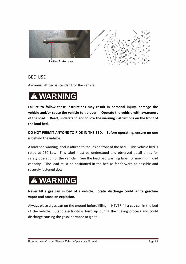
PARKING BRAKE LEVER
This vehicle is equipped with parking brake lever. Push the release button and then
pull the parking brake lever up to active parking brake. When parking the vehicle,
pull up the parking brake and then turn the key to “OFF” position. (See image below)
To release the parking brake, push the release button in and then push the parking
brake lever down.
Hammerhead Charger Electric Vehicle Operator’s Manual Page 14
BED USE
A manual lift bed is standard for the vehicle.
Failure to follow these instructions may result in personal injury, damage the
vehicle and/or cause the vehicle to tip over. Operate the vehicle with awareness
of the load. Read, understand and follow the warning instructions on the front of
the load bed.
DO NOT PERMIT ANYONE TO RIDE IN THE BED. Before operating, ensure no one
is behind the vehicle.
A load bed warning label is affixed to the inside front of the bed. This vehicle bed is
rated at 250 Lbs. This label must be understood and observed at all times for
safety operation of the vehicle. See the load bed warning label for maximum load
capacity. The load must be positioned in the bed as far forward as possible and
securely fastened down.
Never fill a gas can in bed of a vehicle. Static discharge could ignite gasoline
vapor and cause an explosion.
Always place a gas can on the ground before filling. NEVER fill a gas can in the bed
of the vehicle. Static electricity is build up during the fueling process and could
discharge causing the gasoline vapor to ignite.

Hammerhead Charger Electric Vehicle Operator’s Manual Page 15
MANUAL LIFT BED OPERATION
Exercise caution while operating the manual lift bed to ensure the bed is not
released during lifting or lowering procedure. Severe injury could result if bed is
released and traps finger or other body parts.
To lift the manual lift bed, push down on the latch release handle behind the seat.
Raise the bed using handle on the side of the bed. The gas struts will assist in
raising the empty load bed and will keep the bed raised.
To lower the manual lift bed, grasp the bed handle and lower the bed to the rest
position. Be sure fingers are not trapped by the bed.
Hammerhead Charger Electric Vehicle Operator’s Manual Page 16
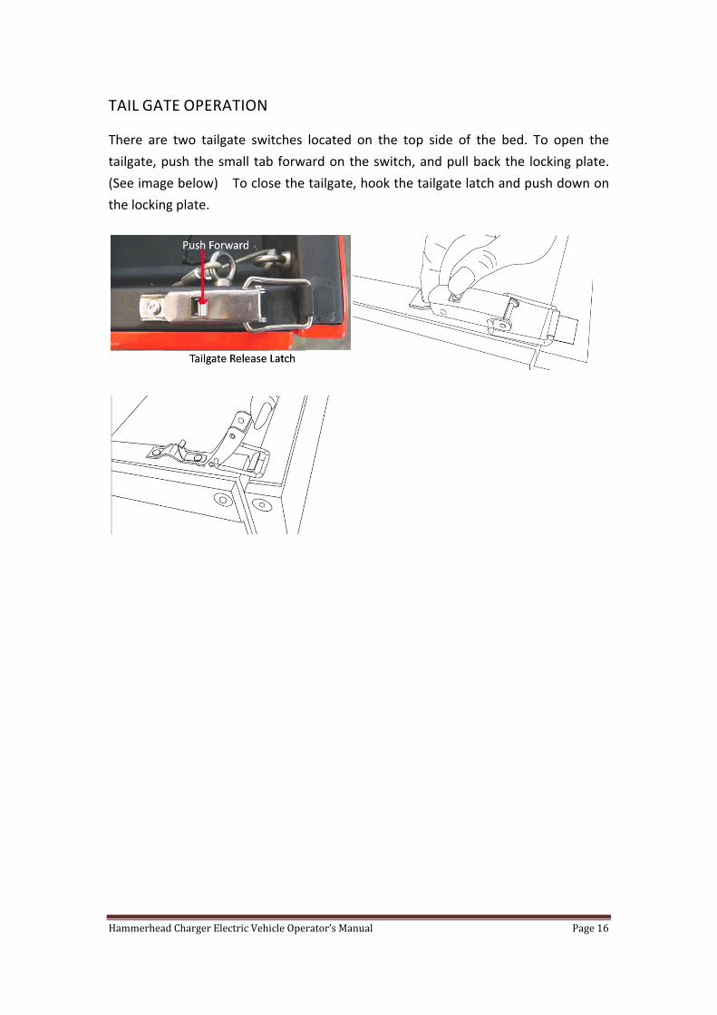
TAIL GATE OPERATION
There are two tailgate switches located on the top side of the bed. To open the
tailgate, push the small tab forward on the switch, and pull back the locking plate.
(See image below) To close the tailgate, hook the tailgate latch and push down on
the locking plate.

Hammerhead Charger Electric Vehicle Operator’s Manual Page 17
OPERATING THE VEHICLE
Read and understand the following warnings before attempting to operate the
vehicle.
To reduce the possibility of severe injury or death resulting from loss of vehicle
control, the following warnings must be observed:
When driving vehicle, consider the terrain, traffic conditions and environmental
factors which effect the terrain and the ability to control the vehicle.
Use extra care and reduced speed when driving on poor surfaces, such as loose dirt,
wet grass, gravel, etc.
Stay in designated areas and avoid extremely rough terrains.
Maintain a safe speed when driving down hill. Use brake to control speed when
traveling down an incline. A sudden stop or change of direction may result in loss
of control.
To prevent loss of control, do not move the direction selector of a vehicle while the
vehicle is in motion. Moving the selector will result in a sudden slowing of the
vehicle and beeping of a warning device.
Slow down before and during turns. All turns should be proceed with reduced
speed.
Never drive vehicle up, down or across an incline that exceeds 14 degrees.
STARTING AND DRIVING
To avoid the possible of roll back which could result in severe injury or vehicle
damage, do not release the brake until motor has started.
Remove charger plug from vehicle receptacle and properly store the cables before
moving the vehicle.
To operate vehicle:

Hammerhead Charger Electric Vehicle Operator’s Manual Page 18
Apply the foot brake, place the key in the key switch and turn it to the “ON”
position.
Move the direction selector to the direction desired.
Release the parking brake by pushing down the parking brake release button
and push down the parking brake lever.
Slowly depress the accelerator pedal to start the motor.
When the accelerator pedal is released, the motor stops. To stop the vehicle
more quickly, depress the foot brake pedal.
Note: When the direction selector is in the reserve position, a warning signal will
sound to indicate that the vehicle is ready to run in reverse.
STARING VEHICLE ON A HILL
To reduce the possibility of roll‐back which could result in severe injury or vehicle
damage, do not release the parking brake lever until motor has started.
Do not hold the vehicle on a hill by using accelerator and motor. Leaving motor in
a stalled condition for more than 3‐4 seconds will cause permanent damage to the
motor.
To reduce the possibility of permanent damage to the drive system, it is important to
prevent excessive roll‐back when starting the vehicle on a hill.
Place left foot on foot brake and release the parking brake. Depress the accelerator
with right foot and release the foot brake by lifting the left foot.

Hammerhead Charger Electric Vehicle Operator’s Manual Page 19
VEHICLE CLEARNING AND CARE
When cleaning the exterior of the vehicle, do not use pressure in excess of 700 psi.
To reduce the possibility of cosmetic damage, do not use any abrasive or reactive
solvents to clean plastic parts.
Normal cleaning of vinyl seats and plastic or rubber trim requires the use of a mild
soap solution applied with a sponge or soft brush and wipe with damp cloth. Rinse
with clear water.

Hammerhead Charger Electric Vehicle Operator’s Manual Page 20
REPAIR
To reduce the possibility of severe injury or death from a vehicle falling from a
jack:
Be sure the vehicle is on a firm and level surface.
Never get under a vehicle while it is supported by a jack.
Use jack stands and test the stability of the vehicle on the stands
Always place chocks in front and behind the wheels not being raised.
Use extreme care since the vehicle is extremely unstable during the lifting process.
WHEELS AND TIRES
Use caution when inflating tires. Due to the low volume of the small tires, over
inflation can occur in seconds. Over inflation could cause the tire to separate from
the wheel or cause the tire to explode.
Tire inflation should be determined by the condition of the terrain. See GENERAL
SPECIFICATIONS section for recommended tire inflation pressure. For outdoor
applications with major use on grassy areas, the following should be considered.
On hard turf, it is desirable to have a slightly higher inflation pressure. On very soft
turf, a lower pressure reduces the possible of tire cutting into the turf. For vehicles
being used on paved or hard surfaces, tire inflation pressure should be in the higher
allowable range, but under no circumstances should inflation pressure be higher
than recommended on the tire sidewall. All four tires should have the same
pressure for optimum handling characteristics. Be sure to install the valve dust cap
after checking or inflating.
The vehicle is fitted with low pressure tubeless tires mounted on one piece rims;
therefore, the most cost effective way to repair a puncture in the thread is to use a
commercial tire plug.
FUSE REPLACEMENT
To replace fuses, locate the fuse block under the bench seat. Pull out old fuse and
replace with new fuse. Fuses are available from local authorized repair center.

Hammerhead Charger Electric Vehicle Operator’s Manual Page 21
(See images below). There are three types of fuses used on this vehicle, see wiring
diagram for details.
Do not attempt any type of repairs beyond your technical skills; contact your local
authorized repair center for help. Unauthorized repairs can cause serious safety
hazard to the operator, as well as permanent damage to the vehicle.
Hammerhead Charger Electric Vehicle Operator’s Manual Page 22
SERVICE AND MAINTENANCE
To reduce the possibility of severe injury or death from improper servicing
techniques:
Do not attempt any type of servicing operating before reading and understanding
all notes, cautions and warnings in this manual. Any servicing requiring
adjustments to be made on the motor while the motor is running must be made
with both drive wheels raised and vehicle properly supported on stands. To
reduce the possibility of motor damage, never operate vehicle at full throttle for
more than 4‐5 seconds while vehicle is in a ‘no load’ condition.
To reduce the possibility of causing an electrical arc, which could result in a battery
explosion, turn off all electrical loads from the battery before removing battery
wires.
The electrolyte in a battery is an acid solution which can cause severe burns to the
skin and eyes. Treat all electrolyte spills to the body and eyes with extended
flushing with clear water. Contact a physician immediately.
Any electrolyte spills should be neutralized with a solution of 2 teaspoons (10ml) of
sodium bicarbonate (baking soda) dissolved in 1 quart (1 liters) of water and
flushed with water.
It is in the best interest of vehicle owner to keep up with preventative maintenance
schedule for keeping the vehicle both dependable and economical. This vehicle will
give years of satisfactory service, providing it receives regular maintenance schedule
listed below.
VEHICLE IDENTIFICATION PLATE LOCATION
The vehicle Identification plate is on the vehicle behind the driver’s seat. (See
image below). Design changes take place on an ongoing basis. In order to obtain
the correct components for the vehicle, the VIN number must be provided when
ordering service parts.

Hammerhead Charger Electric Vehicle Operator’s Manual Page 23
PERIODIC MAINTENANCE SCHEDULE
To perform service that is in this schedule but not described in this manual, contact a local
authorized service center for this vehicle.
Daily Service
Before Use:
Check brake operation
Check parking brake operation
Check warning device function in reverse
Check Lights, turning Signals, Horns
Check tire condition
Check overall vehicle condition
Recharge battery to full state of charge after each day’s use
Weekly Service
Tires: Exam for cuts, excessive war and pressure
Wheels: Check for bent rims, missing or loose lug nuts
Monthly Service or Every 20 Hours (includes list in weekly service above)
Front Axle: Check for damage to axle and loose or missing hardware
Shock Absorbers: Check front and rear shock absorbers for oil leakage and loose fasteners
Front Wheel Alignment: Check for unusual tire wear, align if required
Parking Brake: Check for bent/binding linkage rod.
Hardware and fasteners: Check for loose or missing hardware and components.
Semi‐Annual or Every 125 Hours (includes list in previous service above)
Direction Selector: Check for wear and smooth movements
Steering Assembly: Check for rack and pinion seal or damage or grease leakage
Rod End ball Joints: Check for excessive play, Lubricate.
Rear Axle: check for unusual noise and loose or missing mounting hardware
Annual or Every 250 Hours (includes list in previous service above)
Front wheel bearings: Check and adjust as required.
Rear Axle: Check lubricant, add lubricant (SAE 30 oil) as required
Brake: Clean and adjust. Check for brake pads linings. Check brake fluid.

Hammerhead Charger Electric Vehicle Operator’s Manual Page 24
TIRE INSPECTION
Tire conditions should be inspected per the Periodic maintenance schedule above.
Inflation pressure should be checked when the tires are cool. Be sure to install the
valve dust caps after checking or inflating.
BRAKES
To reduce the possibility of severe injury or death, always evaluate pedal travel
before operating a vehicle to verify some braking function is present.
Check master cylinder fluid annually or if there is a decrease in braking effectiveness.
Inspect components for damage or wear.
REAR AXLE
The rear axle is provided with a lubricant level check/fill plug located on the bottom
of the differential. Unless leakage is evident, the lubricant need only be replaced
after five years.
FASTENERS
Periodically, the vehicle should be inspected for loose fasteners.

Hammerhead Charger Electric Vehicle Operator’s Manual Page 25
BATTERIES AND CHARGING
BATTERIES
Flooded batteries need to be watered periodically. The frequency depends upton
battery usage and operating temperature. Check new batteries every few weeks to
determine the watering frequency for your application. It is normal for batteries to
need more watering as they age.
Fully charge the batteries prior to adding water. Only add water to discharged
or partially charged batteries if the plates are exposed. In this case, add just
enough water to cover the plates and then charge the batteries and continue
with the watering procedures below.
Remove the vent caps and place them upside down so that dirt does not get on
the underside of the cap for batteries, simply flip open the cap. Check the
electrolyte level.
If the electrolyte level is well above the plates, then it is not necessary to add
more water.
If the electrolyte level is barely covering the plates, add distilled or de‐ionized
water to a level 1/8” (3mm) below the vent well (this is the plastic shield inside
the vent hole) for standard batteries and to the maximum (MAX) level indicator
for PLUS Series batteries.
After adding water, secure vent cap back on batteries.
This vehicle uses Deep Cycle Deep Acid battery from Trojan. Please read “Trojan
Battery Users Guide” for more information.
CHARGER
The Delta‐Q charger is programmed to run Trojan batteries. If batteries need to
be changed, please contact your authorized dealer for compatibility questions.
This vehicle uses a 48 Volt Delta‐Q Charger. Please read included “Delta‐Q Charger
Owner’s Manual” for more information.

Hammerhead Charger Electric Vehicle Operator’s Manual Page 26
GENERAL SPECIFICATIONS
STANDARD EQUIPMENT
Motor Type Frame Controller Front Suspension Rear Suspension Steering Brake Battery System Charger Top Speed Front Tire Front Tire Pressure Rear Tire Rear Tire Pressure Weight Length Width Height Wheelbase Ground Clearance Cargo Bed Capacity Vehicle Payload
48 Volt 4000 Watts 5.5 HP Motor Power Coated Seamless Tube Curtis 500 AMP Controller Independent A‐Arm Independent Rear Suspension Rack and Pinion Steering All Wheels Hydraulic Disc Brakes Six 8 Volts Deep Cycle Battery 220 Volt Delta‐Q On Board Charger 25 MPH Tubeless 21 x 8 ‐10 Maximum 36 PSI Tubeless 23 x 8.5 ‐ 12 Maximum 36 PSI 990 lbs (450 KG) 85” (2330 mm) 49” (1300 mm) 71” (1750 mm) 63” (1600 mm) 8.6” (220 mm) 39” x 23” x 11” (970 x 590 x 280 mm) 1200 Lbs (550 KG)
*Specification subject to change without notice

Hammerhead Charger Electric Vehicle Operator’s Manual Page 27

Hammerhead Charger Electric Vehicle Operator’s Manual Page 28
LIMITED WARRANTY POLICY
This warranty policy only applies to vehicles set up and delivered by an authorized
dealer, and that under normal use and service is found to have defects in parts or
workmanship under the following terms and conditions.
This warranty does not apply to any part, which in opinion of seller was defective
because of improper maintenance, improper assembly, alternation, abuse,
negligence or accident.
Should warranty service be required on your electrical vehicle during the warranty
period, please contact your nearest authorized dealer for repairs.
Vehicle Warranty Terms
Vehicle Frame: 1 Year
Electric Motor: 1 Year
Controller and Electricals: 6 Months
Battery Charger: 6 Months
Batteries are warranties through Battery Original Manufacturer
Suspension Parts: 90 Days
Brake: 90 Days
What is not covered under this Warranty
This warranty does not cover damage or faults caused by misuse, negligence,
alternation, accidents or any abnormal use including the use of none genuine replace
parts, renting or leasing, competition or racing. This warranty does not cover loss
of use of the vehicle or loss of time, inconvenience. This warranty also does not
cover normal wear and deterioration of consumable items such as tires, brakes,
suspension parts, light bulbs, tires, batteries and etc.

Congratulations on your purchase from Trojan Battery Company, the manufacturer of the world’s most trusted deep cycle batteries. The battery you purchased was engineered by Trojan to deliver superior power, performance, durability and reliability for use in a broad range of demanding applications.
TROJAN BATTERY USER’S GUIDE


TROJAN BATTERY USER’S GUIDE
Table of Contents
Equipment Needed1. . . . . . . . . . . . . . . . . . . . . . . . . . . . . . . . . . . . . . . . . . . . . . . . . . . . . . . .4
Battery 2. Installation . . . . . . . . . . . . . . . . . . . . . . . . . . . . . . . . . . . . . . . . . . . . . . . . . . . . . . . .4Safety2.1. . . . . . . . . . . . . . . . . . . . . . . . . . . . . . . . . . . . . . . . . . . . . . . . . . . . . . . . . . . . .4Battery Connections2.2. . . . . . . . . . . . . . . . . . . . . . . . . . . . . . . . . . . . . . . . . . . . . . . . . .5
Cable Size2.2.1. . . . . . . . . . . . . . . . . . . . . . . . . . . . . . . . . . . . . . . . . . . . . . . . . .5Torque Values2.2.2. . . . . . . . . . . . . . . . . . . . . . . . . . . . . . . . . . . . . . . . . . . . . . .6Terminal Protection2.2.3. . . . . . . . . . . . . . . . . . . . . . . . . . . . . . . . . . . . . . . . . . .6
Ventilation2.3. . . . . . . . . . . . . . . . . . . . . . . . . . . . . . . . . . . . . . . . . . . . . . . . . . . . . . . . . .6Connecting Batteries to Increase System Power2.4. . . . . . . . . . . . . . . . . . . . . . . . . . . .7
Series Connections2.4.1. . . . . . . . . . . . . . . . . . . . . . . . . . . . . . . . . . . . . . . . . . .7Parallel Connections2.4.2. . . . . . . . . . . . . . . . . . . . . . . . . . . . . . . . . . . . . . . . . .7Series/Parallel Connections2.4.3. . . . . . . . . . . . . . . . . . . . . . . . . . . . . . . . . . . .8
Battery Orientation2.5. . . . . . . . . . . . . . . . . . . . . . . . . . . . . . . . . . . . . . . . . . . . . . . . . . .8
Preventative Maintenance3. . . . . . . . . . . . . . . . . . . . . . . . . . . . . . . . . . . . . . . . . . . . . . . . . .9Inspection3.1. . . . . . . . . . . . . . . . . . . . . . . . . . . . . . . . . . . . . . . . . . . . . . . . . . . . . . . . . .9Cleaning 3.2. . . . . . . . . . . . . . . . . . . . . . . . . . . . . . . . . . . . . . . . . . . . . . . . . . . . . . . . . .9Watering (flooded/wet batteries ONLY)3.3. . . . . . . . . . . . . . . . . . . . . . . . . . . . . . . . . . . .10, 11Charging and Equalizing3.4. . . . . . . . . . . . . . . . . . . . . . . . . . . . . . . . . . . . . . . . . . . . . . .12
Charging3.4.1. . . . . . . . . . . . . . . . . . . . . . . . . . . . . . . . . . . . . . . . . . . . . . . . . . .12, 13Equalizing (flooded/wet batteries ONLY) 3.4.2. . . . . . . . . . . . . . . . . . . . . . . . . .14
Storage 4. . . . . . . . . . . . . . . . . . . . . . . . . . . . . . . . . . . . . . . . . . . . . . . . . . . . . . . . . . . . . . . . . . 14, 15Storage in Hot Environments (greater than 90°F or 32°C)4.1. . . . . . . . . . . . . . . . . . . . .16Storage in Cold Environments (less than 32°F or 0°C)4.2. . . . . . . . . . . . . . . . . . . . . . . .16
How To Maximize the Performance of Your Trojan Battery5. . . . . . . . . . . . . . . . . . . . .16
What to Expect from Your Trojan Battery6. . . . . . . . . . . . . . . . . . . . . . . . . . . . . . . . . . . .16
Trouble-Shooting7. . . . . . . . . . . . . . . . . . . . . . . . . . . . . . . . . . . . . . . . . . . . . . . . . . . . . . . . . .17Preparation for Testing7.1. . . . . . . . . . . . . . . . . . . . . . . . . . . . . . . . . . . . . . . . . . . . . . . .17On-Charge Voltage Testing7.2. . . . . . . . . . . . . . . . . . . . . . . . . . . . . . . . . . . . . . . . . . . . .17Specific Gravity Testing7.3. . . . . . . . . . . . . . . . . . . . . . . . . . . . . . . . . . . . . . . . . . . . . . . .18Open Circuit Voltage Testing7.4. . . . . . . . . . . . . . . . . . . . . . . . . . . . . . . . . . . . . . . . . . .18Discharge Testing7.5. . . . . . . . . . . . . . . . . . . . . . . . . . . . . . . . . . . . . . . . . . . . . . . . . . . .19
Battery Recycling8. . . . . . . . . . . . . . . . . . . . . . . . . . . . . . . . . . . . . . . . . . . . . . . . . . . . . . . . . .20


4
This User’s Guide was created by Trojan’s applications engineers and contains vital information regarding proper care and maintenance of your new battery. Please read through this user’s guide carefully and completely before using your battery. It will help you achieve optimum performance and long life from your new investment.
Equipment Needed1.
Goggles and gloves•Distilled or treated water (i.e. de-ionized, reverse osmosis, etc.)•Rubber-handled wrench•Baking soda•Post protector (i.e. petroleum jelly, anti-corrosion spray, etc.)•Voltmeter (for flooded/wet, gel and AGM batteries)•Hydrometer (for flooded/wet batteries)•Discharge tester (if available)•Battery charger•
Battery Installation2.
To ensure you install your batteries properly and safely please use the following guidelines:
Safety2.1.
Always wear protective clothing, gloves and goggles when handling batteries•Do not smoke near batteries•Keep sparks, flames and metal objects away from batteries•Use a wrench with a rubber handle when making battery connections•The electrolyte is a solution of acid and water, so avoid skin contact•If acid contacts your skin or eyes, flush with water immediately• Check that all cable connections to the terminal are properly tightened; connections •that are too tight or too loose could result in post breakage, meltdown or fireTo avoid short circuits do not lay objects on top of battery •Charge batteries in a well-ventilated area•Never add acid to a battery•
TROJAN BATTERY USER’S GUIDE
5
Battery Connections2.2.
Battery cables provide the link between the batteries, equipment and charging system. Faulty connections can lead to poor performance and terminal damage, meltdown or fire. To ensure proper connections, please use the following guidelines for cable size, torque values and terminal protection.
Cable Size2.2.1.
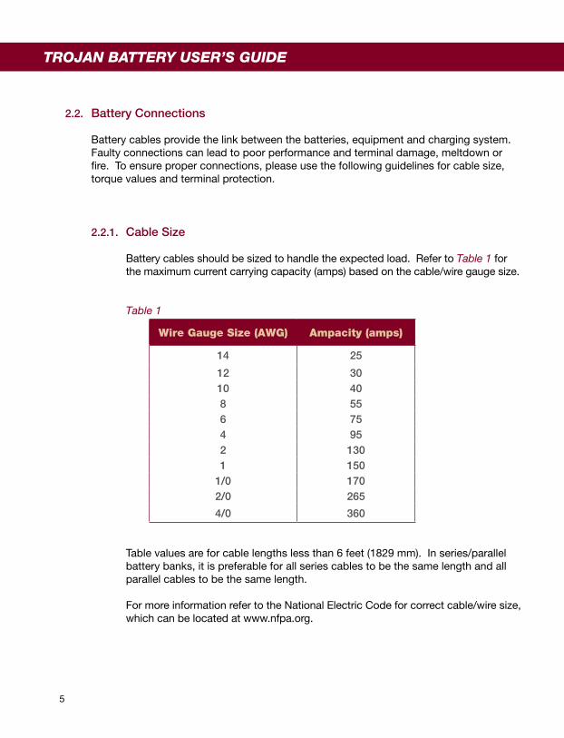
Battery cables should be sized to handle the expected load. Refer to Table 1 for the maximum current carrying capacity (amps) based on the cable/wire gauge size.
Table 1
Wire Gauge Size (AWG) Ampacity (amps)
14 25
12 3010 408 556 754 952 1301 150
1/0 1702/0 265
4/0 360
Table values are for cable lengths less than 6 feet (1829 mm). In series/parallel battery banks, it is preferable for all series cables to be the same length and all parallel cables to be the same length.
For more information refer to the National Electric Code for correct cable/wire size, which can be located at www.nfpa.org.
TROJAN BATTERY USER’S GUIDE

6
Torque Values2.2.2.
Tighten all cable connections to the proper specification to make sure there is good contact with the terminals. Over-tightening the connection to the terminal can result in terminal breakage and loose connections which can result in meltdown or fire. Refer to Table 2 for the proper torque values based on the type of terminal on your battery.
Table 2
Terminal Type Torque (in lbs)
AP 50 - 70
LT 100 - 120LPT, HPT, WNT, DWNT, UT 95 - 105
ST 120 - 180
* For DT (Automotive Post & Stud) refer to AP or ST type
WARNING: Use a wrench with a rubber handle when making battery connections.
Terminal Protection2.2.3.
Corrosion can build up on terminals if they are not kept clean and dry. To prevent corrosion apply a thin coat of petroleum jelly or terminal protector that can be purchased through your local battery dealer.
Ventilation2.3.
Flooded/wet lead acid batteries release small amounts of gas during usage, particularly during the charging process. Gel and AGM batteries generally do not release gas but can if too much pressure builds up during charging. It is critical to charge batteries in a properly ventilated area. For more assistance in calculating ventilation needs, please contact Trojan Battery Company’s technical support engineers at 800-423-6569 or +1-562-236-3000.

7
TROJAN BATTERY USER’S GUIDE
Connecting Batteries to Increase System Power2.4.
Series Connections2.4.1.
To increase voltage, connect batteries in series. This will not increase the system capacity. Refer to Diagram 1 for series connections.
Diagram 1
Parallel Connections2.4.2.
To increase capacity, connect batteries in parallel. This will not increase the system voltage. Refer to Diagram 2 for parallel connections.
Diagram 2
Example :Two T-105, 6V Batteries rated at 225AH Connected in Series System Voltage: 6V + 6V = 12VSystem Capacity = 225AH
Example :Two T-105, 6V Batteries rated at 225AH Connected in Parallel System Voltage: 6VSystem Capacity = 225AH + 225AH = 450AH

Series/Parallel Connections2.4.3.
To increase both voltage and capacity, connect additional batteries in series and parallel. Refer to Diagram 3 for series/parallel connections.
Diagram 3
Battery Orientation2.5.
Flooded/wet batteries must be placed upright at all times. Fluid in the battery will spill if the battery is placed on its side or at an angle. Gel or AGM batteries are spill-proof so they can be placed either upright or on its side.
8
Example :Four T-105, 6V Batteries rated at 225AH Connected in Series/Parallel System Voltage: 6V + 6V = 12VSystem Capacity = 225AH + 225AH = 450AH

Preventative Maintenance3.
Inspection3.1.
Examine the outside appearance of the battery. The tops of the batteries and •terminal connections should be clean, free of dirt and corrosion, and dry. Refer to Cleaning section 3.2 If fluids are on the top of a flooded/wet battery this may mean that the battery is •being over-watered. Refer to Watering section 3.3 for proper watering procedure. If fluid is on the top of a gel or AGM battery this means that the battery is being overcharged and the performance and life will be reduced Check battery cables and connections. Replace any damaged cables. Tighten any •loose connections. Refer to Torque Values section 2.2.2
Cleaning3.2.
Check that all vent caps are secured properly on the battery• Clean the top of the battery, terminals and connections with a cloth or brush and a •solution of baking soda and water. Do not allow cleaning solution to get inside the batteryRinse with water and dry with a clean cloth• Apply a thin coat of petroleum jelly or terminal protector that can be purchased •through your local battery dealerKeep the area around batteries clean and dry•
9
TROJAN BATTERY USER’S GUIDE
Watering (flooded/wet batteries ONLY)3.3.
Water should never be added to gel or AGM batteries as they do not lose water during use. Flooded/wet batteries need to be watered periodically. The frequency depends upon battery usage and operating temperatures. Check new batteries every few weeks to determine the watering frequency for your application. It is normal for batteries to need more watering as they age.
Fully charge the batteries prior to adding water. Only add water to discharged or •partially charged batteries if the plates are exposed. In this case, add just enough water to cover the plates and then charge the batteries and continue with the watering procedure below Remove the vent caps and place them upside down so that dirt does not get on the •underside of the cap or for Plus Series™ batteries, simply flip open the cap. Check the electrolyte level If the electrolyte level is well above the plates then it is not necessary to add more •water If the electrolyte level is barely covering the plates, add distilled or de-ionized water •to a level 1/8” (3 mm) below the vent well (this is the plastic shield inside the vent hole) for standard batteries and to the maximum (MAX) level indicator for Plus Series™ batteries After adding water, secure vent caps back on batteries• Tap water may be used if the levels of impurities are within acceptable limits. Refer •to Table 3 for Water Impurity Limits
10

TROJAN BATTERY USER’S GUIDE
11
Table 3
Recommended Maximum Allowable ImpuritiesIn Water for Battery Use
Impurity Parts Per Million Effects of Impurity
Color Clear and “White” -
Suspended Matter Trace -
Total Solids 100.00 -
Organic and Volatile Matter 50.0 Corrosion of positive plate
Ammonia 8.0 Slight self-discharge of both plates
Antimony 5.0 Self-discharge by local action, reduces life, lower on-charge voltage
Arsenic 0.5 Self-discharge, can form poisonous gas at negative
Calcium 40.0 Increase of positive shedding
Chloride 5.0 Loss of capacity in both plates, greater loss in positive
Copper 5.0 Increased self-discharge, lower on-charge voltage
Iron 3.0 Increased self-discharge at both plates, lower on-charge voltage
Magnesium 40.0 Reduced life
Nickel None Allowed Intense lowering of on-charge voltage
Nitrates 10.0 Increased sulfation at negative
Nitrites 5.0 Corrosion at both plates, loss of capacity, reduced life
Platinum None Allowed Violent self-discharge, lower on-charge voltage
Selenium 2.0 Positive shedding
Zinc 4.0 Slight self-discharge at negative
12
Charging and Equalizing3.4.
Charging3.4.1.
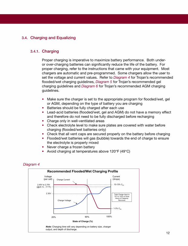
Proper charging is imperative to maximize battery performance. Both under- or over-charging batteries can significantly reduce the life of the battery. For proper charging, refer to the instructions that came with your equipment. Most chargers are automatic and pre-programmed. Some chargers allow the user to set the voltage and current values. Refer to Diagram 4 for Trojan’s recommended flooded/wet charging guidelines, Diagram 5 for Trojan’s recommended gel charging guidelines and Diagram 6 for Trojan’s recommended AGM charging guidelines.
Make sure the charger is set to the appropriate program for flooded/wet, gel •or AGM, depending on the type of battery you are chargingBatteries should be fully charged after each use• Lead-acid batteries (flooded/wet, gel and AGM) do not have a memory effect •and therefore do not need to be fully discharged before rechargingCharge only in well-ventilated areas• Check electrolyte level to make sure plates are covered with water before •charging (flooded/wet batteries only) Check that all vent caps are secured properly on the battery before charging• Flooded/wet batteries will gas (bubble) towards the end of charge to ensure •the electrolyte is properly mixedNever charge a frozen battery•Avoid charging at temperatures above 120°F (49°C)•
Diagram 4
Recommended Flooded/Wet Charging Profile
2.35V
20% 90% 100%
1-3% C20
10-13% C20
Voltage(per cell)
Current(Amps)
2.45V to 2.70V(@25 oC , 77 0F)
State of Charge (%)
Total Charge Input is107 to 120% of Amp
Hours of CapacityRemoved
Charge Current
Charge Voltage
Note: Charging time will vary depending on battery size, chargeroutput, and depth of discharge.

13
TROJAN BATTERY USER’S GUIDE
Diagram 5
Recommended Trojan Deep-Cycle Gel™ Charging Profile
2.35V to 2.40V(@ 25 oC , 77 0F)
Charge Current
Charge Voltage
Current(Amps)
Voltage(per cell)
20% 80%
State of Charge (%)
100%
C20/5
Note: Charging time will vary depending on battery size, chargeroutput, and depth of discharge.
Total Charge Input is105 to 109% of AmpHours of Capacity
Removed
Approximately C20/200Will increase with age
Diagram 6
2.35 to 2.45V(@25 oC, 77 0F)
Charge Current
Charge Voltage
CurrentVoltage(per cell) (Amps)
20% 80%
State of Charge (%)
100%
C20/5
Note: Charging time will vary depending on battery size, chargeroutput, and depth of discharge.
Approximately C20/200Will increase with age
Recommended Trojan AGM Charging Profile
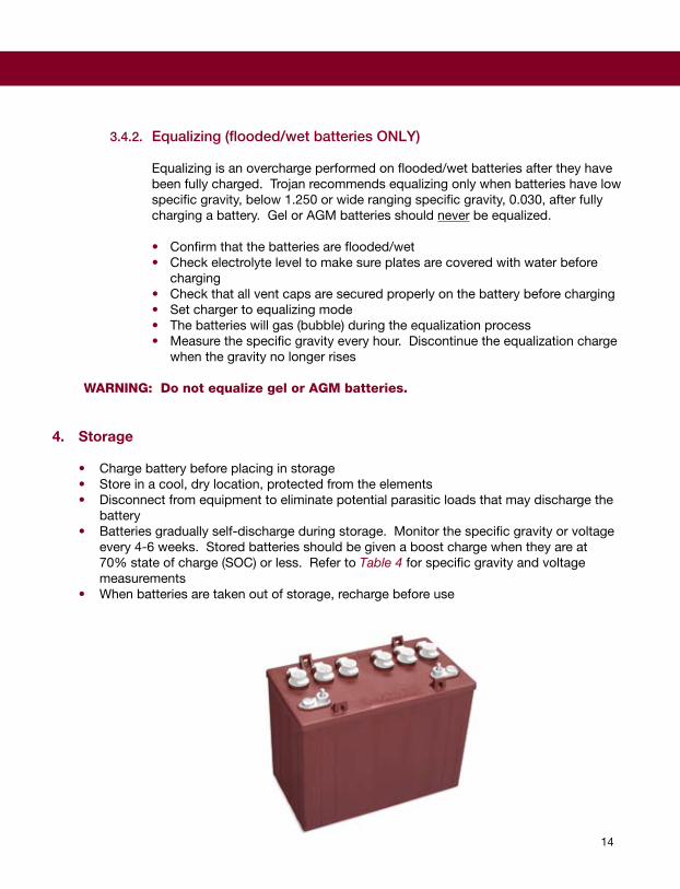
Equalizing (flooded/wet batteries ONLY)3.4.2.
Equalizing is an overcharge performed on flooded/wet batteries after they have been fully charged. Trojan recommends equalizing only when batteries have low specific gravity, below 1.250 or wide ranging specific gravity, 0.030, after fully charging a battery. Gel or AGM batteries should never be equalized.
Confirm that the batteries are flooded/wet• Check electrolyte level to make sure plates are covered with water before •chargingCheck that all vent caps are secured properly on the battery before charging•Set charger to equalizing mode•The batteries will gas (bubble) during the equalization process• Measure the specific gravity every hour. Discontinue the equalization charge •when the gravity no longer rises
WARNING: Do not equalize gel or AGM batteries.
Storage4.
Charge battery before placing in storage•Store in a cool, dry location, protected from the elements• Disconnect from equipment to eliminate potential parasitic loads that may discharge the •battery Batteries gradually self-discharge during storage. Monitor the specific gravity or voltage •every 4-6 weeks. Stored batteries should be given a boost charge when they are at 70% state of charge (SOC) or less. Refer to Table 4 for specific gravity and voltage measurementsWhen batteries are taken out of storage, recharge before use•
14
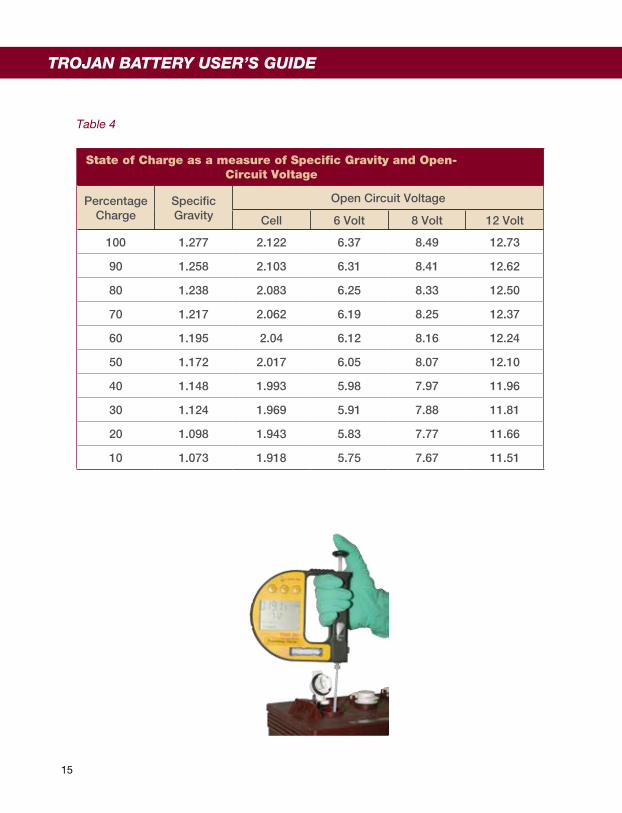
Table 4
State of Charge as a measure of Specific Gravity and Open-Circuit Voltage
Percentage Charge
SpecificGravity
Open Circuit Voltage
Cell 6 Volt 8 Volt 12 Volt
100 1.277 2.122 6.37 8.49 12.73
90 1.258 2.103 6.31 8.41 12.62
80 1.238 2.083 6.25 8.33 12.50
70 1.217 2.062 6.19 8.25 12.37
60 1.195 2.04 6.12 8.16 12.24
50 1.172 2.017 6.05 8.07 12.10
40 1.148 1.993 5.98 7.97 11.96
30 1.124 1.969 5.91 7.88 11.81
20 1.098 1.943 5.83 7.77 11.66
10 1.073 1.918 5.75 7.67 11.51
15
TROJAN BATTERY USER’S GUIDE

16
Storage in Hot Environments (greater than 90°F or 32°C)4.1.
Avoid direct exposure to heat sources, if possible, during storage. Batteries self-discharge faster in high temperatures. If batteries are stored during hot, summer months, monitor the specific gravity or voltage more frequently (approximately every 2-4 weeks).
Storage in Cold Environments (less than 32°F or 0°C)4.2.
Avoid locations where freezing temperatures are expected, if possible, during storage. Batteries can freeze in cold temperatures if they are not fully charged. If batteries are stored during cold, winter months, it is critical that they are kept fully charged.
How To Maximize the Performance of Your Trojan Battery5.
Follow all the procedures in this User’s Guide for proper installation, maintenance and •storage Do not discharge your battery more than 80%. This safety factor will eliminate the chance •of over-discharging and damaging your battery If you have any questions or concerns about battery care, please contact Trojan Battery •Company’s technical support engineers at 800-423-6569 or +1-562-236-3000 before a problem develops
What to Expect from Your Trojan Battery6.
A new battery will not deliver its full rated capacity. This is normal and should be expected •as it takes time to “work the battery up”Trojan’s batteries take between 50 – 100 cycles to work up to providing full, peak capacity• When operating batteries at temperatures below 80°F (27°C) they will deliver less than the •rated capacity. For example at 0°F (-18°C) the battery will deliver 50% of its capacity and at 80°F (27°C) it will deliver 100% of its capacity When operating batteries at temperatures above 80°F (27°C) they will deliver more than •the rated capacity but the battery life will be reduced The life of a battery is difficult to predict as it will vary with application, frequency of usage •and level of maintenance
17
Trouble-Shooting7.
These battery testing procedures are guidelines only for identifying a battery that may need to be replaced. Unique situations may be observed that are not identified within this procedure. Please contact Trojan Battery Company’s technical support engineers at 800-423-6569 or +1-562-236-3000 for help interpreting the test data.
Preparation for Testing7.1.
Check that all vent caps are secured properly on the battery• Clean the top of the battery, terminals and connections with a cloth or brush and a •solution of baking soda and water. Do not allow cleaning solution to get inside the battery. Rinse with water and dry with a clean cloth Check battery cables and connections. Replace any damaged cables. Tighten any •loose connections. Refer to Torque Values section 2.2.2 For flooded/wet batteries, check the electrolyte level and add water if necessary. •Refer to Watering section 3.3 Fully charge batteries•
On-Charge Voltage Testing7.2.
Disconnect and reconnect DC plug to restart charger• While the batteries are on-charge record the current in the last ½ hour of charge (if •possible) and measure the battery set voltage If the current at the end of charge is below 5 amps and the battery set voltage is •above: 56V for a 48V system; 42V for a 36V system; 28V for a 24V system; 14V for a 12V battery; 9.3V for a 8V battery or 7V for a 6V battery, then proceed to the next step. Otherwise check the charger for proper output and recharge the batteries if necessary. If the set voltages are still low, you may have a failed batteryWhile the batteries are on-charge measure the individual battery voltages• If any battery voltage is below: 7V for 6V battery, 9.3V for 8V battery and 14V for 12V •battery, and a voltage variation is greater than 0.5V for 6V battery or 1.0V for a 12V battery, from any other battery in set, it may be a failed battery
TROJAN BATTERY USER’S GUIDE

Specific Gravity Testing (flooded/wet batteries ONLY)7.3.
Fill and drain the hydrometer 2-3 times before drawing a sample from the battery• Measure specific gravity readings for all battery cells• Correct specific gravity readings for temperature by adding 0.004 for every 10°F •(5°C) above 80°F (27°C) and subtract 0.004 for every 10°F (5°C) below 80°F (27°C) If every cell in the battery set is below 1.250 the batteries may be undercharged; •recharge batteries If any battery has a specific gravity variation of more than 0.050 between cells •equalize the setIf there is still a variation there may be a failed battery•
Open Circuit Voltage Testing 7.4.
This is the least preferred method of evaluating the performance of a battery.
For accurate voltage readings, batteries must remain idle at least 6 hours (but •preferably up to 24 hours)Measure the individual battery voltages• If any battery voltage is greater than 0.3V from any other battery in set, equalize the •set (flooded/wet batteries ONLY). Refer to equalizing section 3.4.2Remeasure the individual battery voltages• If any battery voltage is still greater than 0.3V from any other battery in set you may •have a failed battery
18

Discharge Testing7.5.
Connect and start discharger•Record the runtime (minutes) when discharge is complete• Correct runtime minutes for temperature using the following formula (valid between •24°C (75°F) and 32°C (90°F):
o Mc = Mr [1 – 0.009 (T - 27)] where Mc is the corrected minutes, Mr is the minutes recorded and T is the temperature at the end of discharge in °C
If the discharge time is greater than 50% of the batteries’ rated capacity then all the •batteries are operational Reconnect the discharger to record the individual battery voltage while still under •load (current being drawn) If the discharge runtime is less than 50% of the batteries’ rated capacity, the •batteries with a voltage that is 0.5V lower than the highest voltage may be a failed battery
There are other methods of testing batteries including internal resistance (i.e. CCA testers) and carbon-pile discharge testers. However these are not suitable testing methods for deep cycle batteries.
19
TROJAN BATTERY USER’S GUIDE
TROJAN BATTERY USER’S GUIDE
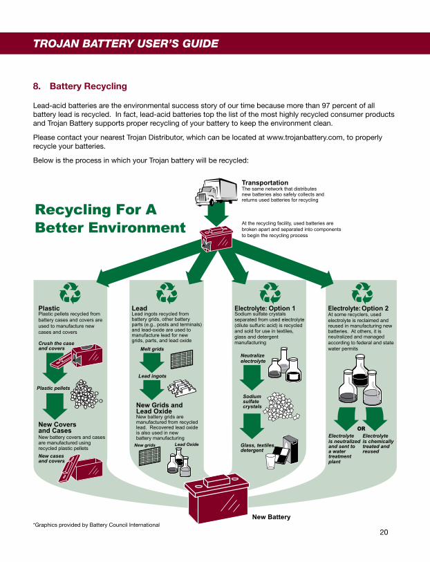
Recycling For ABetter Environment
TransportationThe same network that distributesnew batteries also safely collects andreturns used batteries for recycling
At the recycling facility, used batteries arebroken apart and separated into componentsto begin the recycling process
Plastic Plastic pellets recycled from battery cases and covers are used to manufacture new cases and covers
LeadLead ingots recycled frombattery grids, other batteryparts (e.g., posts and terminals)and lead-oxide are used tomanufacture lead for new grids, parts, and lead oxide
Electrolyte: Option 1 Sodium sulfate crystalsseparated from used electrolyte(dilute sulfuric acid) is recycledand sold for use in textiles,glass and detergentmanufacturing
Electrolyte: Option 2 At some recyclers, usedelectrolyte is reclaimed andreused in manufacturing newbatteries. At others, it isneutralized and managedaccording to federal and statewater permits
New Battery
New Grids andLead Oxide New battery grids aremanufactured from recycledlead. Recovered lead oxideis also used in newbattery manufacturing
Crush the caseand covers
Plastic pellets
New Coversand CasesNew battery covers and casesare manufactured usingrecycled plastic pellets
New cases and covers
Lead OxideNew grids
Lead ingots
Melt gridsNeutralizeelectrolyte
Electrolyteis chemicallytreated andreused
Electrolyteis neutralizedand sent toa watertreatmentplant
Sodiumsulfatecrystals
Glass, textiles,detergent
OR
*Graphics provided by Battery Council International20
Battery Recycling8.
Lead-acid batteries are the environmental success story of our time because more than 97 percent of all battery lead is recycled. In fact, lead-acid batteries top the list of the most highly recycled consumer products and Trojan Battery supports proper recycling of your battery to keep the environment clean.
Please contact your nearest Trojan Distributor, which can be located at www.trojanbattery.com, to properly recycle your batteries.
Below is the process in which your Trojan battery will be recycled:
TROJAN BATTERY USER’S GUIDE
© 2010 Trojan Battery CompanyAll rights reserved.
Trojan Battery Company 12380 Clark St. Santa Fe Springs, CA 90670 USA
Call 800-423-6569 or +1-562-236-3000
This publication is protected by copyright and all rights are reserved. No part of it may be reproduced or transmitted by any means or in any form, without prior consent in writing from Trojan Battery Company.
Trojan Battery Company is not liable for direct, indirect, special, exemplary, incidental or consequential damages that may result from any information provided in or omitted from this manual, under any circumstances.
Trojan Battery Company reserves the right to make adjustments to this manual at any time, without notices or obligation.
Trojan Battery Company and the Trojan Battery logo are registered trademarks of Trojan Battery Company.
Plus Series is a trademark of Trojan Battery Company in the United States and other countries.
Trojan Battery Company would like to thank you for selecting our battery. With over 80 years of experience, Trojan Battery is the world’s most trusted name in deep cycle battery technology backed by our outstanding technical support. We look forward to serving your battery needs.

Notes

TRJN0109•02/10–TR
JN0109_TR
JNUsersG
uide
For more information call 800-423-6569 or +1-562-236-3000 www.trojanbattery.com

User’s Guide
SAVE THESE IMPORTANT SAFETY INSTRUCTIONS
This manual contains important safety and operating instructions – read before using charger.
Warning: Use charger only with an algorithm selected that is appropriate to the specific battery type. Other usa ge may cause personal injury and damage. Lead acid batteries may generate explosive hydrogen gas during normal operation. Ke ep sparks, flames, and smoking materials away from batteries. Provide adequate ventilation during charging. Never charge a frozen battery. Study all battery manufacturers’ specific precautio ns, ie. maximum charge rates and if cell caps should be removed whi le charging.
Danger: Risk of electric shock. Connect charger power cor d to an outlet that has been properly installed and grou nded in accordance with all local codes and ordinances. A g rounded outlet is required to reduce risk of electric shock – do n ot use ground adapters or modify plug. Do not touch uninsulated p ortion of output connector or uninsulated battery terminals. Disconn ect the AC supply before making or breaking the connections to the battery. Do not open or disassemble charger. Do not operate thi s charger if the AC supply cord is damaged or if the charger has rec eived a sharp blow, been dropped, or otherwise damaged in any way – refer all repair work to the manufacturer, or qualified perso nnel. This appliance is not intended for use by persons (inclu ding children) with reduced physical, sensory or mental capabiliti es, or lack of experience and knowledge, unless they have been giv en supervision or instruction concerning use of the ap pliance by a person responsible for their safety. Children shoul d be supervised to ensure that they do not play with the appliance.
INFORMATIONS IMPORTANTES DE SÉCURITÉ
Ce manuel contient des instructions importantes concernant la sécurité et le fonctionnement.
Attention: Utiliser le chargeur seulement avec un algorithme approprié au type spécifique de batterie. D´autres types de batteries pourraient éclater et causer des blessures ou domma ges. Les batteries peuvent produire des gaz explosifs en ser vice normal. Ne jamais fumer près de la batterie et éviter toute ét incelle ou flamme nue à proximité des batteries. Fournissez une venti lation adéquate du chargement. Ne jamais charger une batterie gelée . Prendre connaissance des mesures de précaution spécifiées p ar le fabricant de la batterie, p. ex., vérifier s´il faut enlever les bouchons des cellules lors du chargement, et les taux de chargem ent.
Danger: Risque de chocs électriques. Ne pas toucher les parties non isolées du connecteur de sortie ou les bornes non isolées de la batterie. Toujours connecter le charg eur à une prise de courant mise à la terre. Déconnectez la source AC avant de faire ou défaire les connections à la batterie en chargement . Ne pas utiliser le chargeur si le cordon d’alimentation AC est endo mmagé ou si le chargeur est abîmé suite à une chute ou autre indic ent. Ne pas ouvrir ni désassembler le chargeur – référer toute réparation aux personnes qualifiées. Cet appareil n’est pas desti né à un usage par des personnes (dont les enfants) avec des facultés motrices, sensorielles ou mentales réduites, ou ayant une exp érience et des connaissances insuffisantes, à moins qu’elles sont sous la supervision ou reçoivent les instructions sur l’uti lisation de l’appareil d’un répondant garant de leur sécurité. Les enfants devraient être surveillés afin qu’il ne jouent en a ucun temps avec l’appareil.
Operating Instructions - CAUTION: Charger enclosure may be hot during charging. Use hand protection if handling the charger while charging.
1. Extension cords must be 3-wire cord no longer than 30m(100’) at 10AWG or 7.5m(25’) at 16AWG per UL guidelines.
2. Only connect ONE QuiQ charger to a single 15A circuit or the circuit may become overloaded.
3. Charger 10-LED Display:
LED Colour Indication (following “Power-On Self Test”)
Ammeter (Amber)
Solid: Displays approximate scale of current output during bulk phase.
Flashing: High internal charger temperature. Output reduced. Also displays algorithm #1-6 for 11 seconds if no
battery is connected.
80% Charge (Amber)
Solid: Bulk charge phase complete, 80% charged. In Absorption phase.
Flashing: With no battery connected, indicates algorithm # selected by number of flashes.
100% Charge (Green)
Solid: Charging complete. Charger in Maintenance Mode.
Flashing: Absorption phase complete. In Finish phase
AC On (Amber)
Solid: AC Power good
Flashing: Low AC Voltage, check voltage and extension cord length (see above for guidelines).
Fault (Red)
Flashing: Charger error. Reset charger power and refer to Troubleshooting Instructions below.

Note: This is a Class A product complying with Unit ed States Federal Communications Commission, Code o f Federal Regulations; 47CFR part 15. In a domestic environment this product may cause radio interferen ce, in which case the user may be required to take adequate measures.
2009 © Delta-Q Technologies Corp. All rights reser ved. PN: 710-0098 Rev 1
4. Optional Charger Single-LED Display (internal or external)
LED Colour Indication (following “Power-On Self Test”)
Green Solid: Charging complete. Charger in Maintenance Mode.
Flashing: Short: <80% Charge.
Long: >80% Charge.
When battery is not connected: Algorithm Number display.
Amber Flashing: Reduced Power Mode: Low AC Voltage or High internal charger temperature.
Red Flashing: Charger error. Reset charger power and refer to Troubleshooting Instructions below.
Maintenance Instructions - 1. Do not expose charger to oil, dirt, mud or direct heavy water spray when cleaning vehicle.
2. If the detachable input power supply cord set is damaged, replace with a cord that is:
a.) for North America - UL or CSA listed/approved detachable cord, 3 conductor, 16AWG minimum, and rated SJT; terminating in a grounding type IEC 60320 C14 plug rated 250V, 13A minimum; or
b.) for all other countries – a safety approved detachable cord, 3 conductor, 1.5mm² minimum, rated appropriately for industrial use. The cord set must be terminated on one end with a grounding type input connector appropriate for use in the country of destination and, on the other end, an output grounding type IEC 60320 C14 plug.
3. The enclosure of the charger has been tested successfully to EN60529, meeting IP66. The AC supply inlet is rated to IP20, which is suitable for indoor use only. Keep all AC connections clean and dry.
Troubleshooting Instructions - If a fault occurs, count the number of red flashes between pauses and refer to the table below:
Red Flashes Cause Solution
Battery High Voltage Check battery size and condition and reset charger
(interrupt AC power for 15 seconds).
Battery Low Voltage Check battery size and condition and reset charger
(interrupt AC power for 15 seconds).
Charge Timeout caused by battery pack not reaching required voltage. Charger output was reduced due to high temperatures
Check connections.
Operate charger at a lower ambient temperature.
Check Battery: battery could not be trickle charged up to minimum voltage
Check for shorted or damaged cells.
Over-Temperature: Charger shut down due to high internal temperature.
Ensure sufficient cooling air flow and reset charger (interrupt AC power for 15 seconds).
Charger Internal Fault Reset charger (interrupt AC power for 15 seconds).
Return to qualified service depot if fault persists.
Related Documents


