Intelligent Ventilation since 1983 HAMILTON-T1 161006, 161009, 1610060,1610090 REF Operator's Manual 624369/06 | 2020-04-20 Software version 2.2.x Valid for devices with SN 3000 or higher

Welcome message from author
This document is posted to help you gain knowledge. Please leave a comment to let me know what you think about it! Share it to your friends and learn new things together.
Transcript
Intelligent Ventilation since 1983
HAMILTON-T1
161006, 161009, 1610060,1610090REF
Operator's Manual
624369/06 | 2020-04-20
Software version 2.2.x
Valid for devices with SN 3000 or higher


HAMILTON-T1Operator's Manual

© 2020 Hamilton Medical AG. All rights reserved. Printed in Switzerland. No part of this publication may be reproduced or stored in a database or retrieval system, nor transmitted, in any form or by any means, electronic, mechanical, by photocopy-ing, recording, or otherwise, without the prior written permis-sion of Hamilton Medical.
This manual may be revised or replaced by Hamilton Medical at any time and without notice. Ensure that you have the most current applicable version of this manual; if in doubt, contact Hamilton Medical AG Marketing Department. While the infor-mation set forth is believed to be accurate, it is not a substitute for the exercise of professional judgment.
Nothing in this manual shall limit or restrict in any way Hamil-ton Medical’s right to revise or otherwise change or modify the equipment (including its software) described herein, without notice. In the absence of an express, written agreement to the contrary, Hamilton Medical has no obligation to furnish any such revisions, changes, or modifications to the owner or user of the equipment (including software) described herein.
The equipment must be operated and serviced by trained pro-fessionals only. Hamilton Medical’s sole responsibility with respect to the equipment and its use is as stated in the Limited Warranty provided in this manual.
Product and company names mentioned herein may be the trademarks of their respective owners.
Hamilton Medical will make available on request circuit dia-grams, component parts lists, descriptions, calibration instruc-tions, or other information that will assist the user’s authorized trained personnel to repair those parts of the equipment deemed by Hamilton Medical to be repairable.
624369/06 v

Manufacturer
Hamilton Medical AGVia Crusch 8CH-7402 BonaduzSwitzerlandPhone: (+41) 58 610 10 20Fax: (+41) 58 610 00 [email protected]
vi 624369/06
HAMILTON-T1 software informationThe software version for the HAMILTON-T1 is visible in the Sys-tem -> Info window. The software version should match the version on the title page of this manual. See Section 3.3.1 for details.
Document conventions
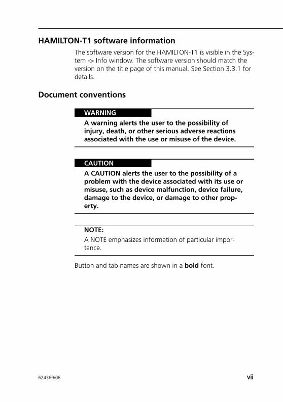
WARNINGA warning alerts the user to the possibility of injury, death, or other serious adverse reactions associated with the use or misuse of the device.
CAUTIONA CAUTION alerts the user to the possibility of a problem with the device associated with its use or misuse, such as device malfunction, device failure, damage to the device, or damage to other prop-erty.
NOTE:A NOTE emphasizes information of particular impor-tance.
Button and tab names are shown in a bold font.
624369/06 vii
Intended use
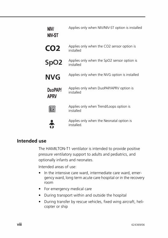
The HAMILTON-T1 ventilator is intended to provide positive pressure ventilatory support to adults and pediatrics, and optionally infants and neonates.
Intended areas of use:
• In the intensive care ward, intermediate care ward, emer-gency ward, long term acute care hospital or in the recoveryroom
• For emergency medical care
• During transport within and outside the hospital
• During transfer by rescue vehicles, fixed wing aircraft, heli-copter or ship
Applies only when NIV/NIV-ST option is installed
Applies only when the CO2 sensor option is installed
Applies only when the SpO2 sensor option is installed
Applies only when the NVG option is installed
Applies only when DuoPAP/APRV option is installed
Applies only when Trend/Loops option is installed
Applies only when the Neonatal option is installed.
viii 624369/06
The HAMILTON-T1 ventilator is a medical device intended for use by qualified, trained personnel under the direction of a physician and within the limits of its stated technical specifica-tions.
CAUTION(USA only): Federal law restricts this device to sale by or on the order of a physician.
General cautions and notes
WARNINGModifications to the device are not permitted.
CAUTIONUse in rescue vehicles, fixed wing aircraft, helicop-ter, or ship may increase the risk of autotriggering. Adjust flow trigger if needed.
General operation notes• The use of this equipment is restricted to one patient at a
time.
• Additional information about installing the medical equip-ment, as well as additional technical information, is pro-vided in the Service Manual.
• If there is visible damage to any part of the ventilator, do not use the device. Technical service is required.
• The intended patient population ranges from neonatal patients with 0.2 kg to 30 kg body weight to pediatric patients with 30 cm height (3 kg ideal body weight) up to adults up to 250 cm height (139 kg ideal body weight). The minimum tidal volume delivered shall be equal to or greater than 20 ml for adults/pediatrics, 2 ml for neonates.
624369/06 ix
• The displays shown in this manual may not exactly match what you see on your own ventilator.
• Familiarize yourself with this operator’s manual before using the ventilator on a patient.
• Do not simultaneously touch conductive components (for example, the USB port) or conductive parts of the ventilator enclosure and the patient.
• Displayed information that is ghosted is not active and may not be selected.
• Dashes displayed in place of monitored data indicate that valid values are not yet available or do not apply.
• If a ventilator control does not respond when selected by touch or by the turn of a dial, the control is not active in this particular instance or the function is not implemented.
• Use in rescue vehicles, fixed wing aircraft, helicopter or ship: The HAMILTON-T1 must always be appropriately secured during transport. For mounting options and details, see the HAMILTON-T1 System Integration brochure (PN 689487).
Monitoring and alarms• The HAMILTON-T1 is not intended to be a comprehensive
vital sign monitor for patients on life-support equipment. Patients on life-support equipment should be appropriately monitored by qualified medical personnel and suitable monitoring devices. The use of an alarm monitoring system does not give absolute assurance of warning for every type of issue that may arise with the ventilator. Alarm messages may not exactly pinpoint a problem; the exercise of clinical judgment is necessary.
• An alternative means of ventilation must be available when-ever the ventilator is in use. If a fault is detected in the ven-tilator or its life-support functions are in doubt, disconnect the HAMILTON-T1 from the patient and immediately start ventilation with such a device (for example, a resuscitation bag), using PEEP and/or increased oxygen concentration when appropriate. The ventilator must be removed from
x 624369/06
clinical use and serviced by a Hamilton Medical authorized service engineer.
• It is recommended that additional independent monitoring devices be used during mechanical ventilation. The opera-tor of the ventilator must still maintain full responsibility for proper ventilation and patient safety in all situations.
• Do not silence the audible alarm when leaving the patient unattended.
• Do not use the exhaust port of the expiratory valve for spi-rometry. Due to the HAMILTON-T1’s base flow, the exhaust gas output is larger than the patient’s actual exhaled vol-ume.
• Do not put a vessel filled with a liquid on the ventilator. If a liquid enters the product, a fire and/or electric shock may occur.
Fire and other hazards• To reduce the risk of fire or explosion, do not place the ven-
tilator in a combustible or explosive environment (for exam-ple, around flammable anaesthetics or other ignition sources) or insufficiently ventilated areas. Do not use it with any equipment contaminated with oil or grease. Highly compressed oxygen together with flammable sources could lead to spontaneous explosions.
• To minimize the risk of fire, do not use high-pressure gas hoses that are worn or contaminated with combustible materials like grease or oil.
• The HAMILTON-T1 can be used in an oxygen-enriched envi-ronment. To reduce the risk of fire, use only breathing cir-cuits intended for use in oxygen-enriched environments. Do not use antistatic or electrically conductive tubing.
• In case of fire, immediately secure the patient’s ventilatory needs, switch off the ventilator, and disconnect it from its gas and electrical sources.
• Do not use if primary power source cables are damaged.
• To ensure that toxic constituents are not entrained into the breathing gas ventilate the patient with 100% O2.
624369/06 xi
Service and testing• To ensure proper servicing and to prevent possible physical
injury, only Hamilton Medical authorized service personnelshould attempt to service the ventilator.
• To reduce the risk of electrical shock, disconnect electricalpower from the ventilator before servicing. Be aware thatbattery power remains even after the mains is discon-nected. Be aware that if the power switch is off, some partsstill carry high voltage.
• Do not attempt service procedures other than those speci-fied in the service manual.
• Use replacement parts supplied by Hamilton Medical only.
• Any attempt to modify the ventilator hardware or softwarewithout the express written approval of Hamilton Medicalautomatically voids all warranties and liabilities.
• The preventive maintenance program requires a generalservice every 5000 hours or yearly, whichever comes first.
• To ensure the ventilator’s safe operation, always run thepreoperational check before using the ventilator on apatient. If the ventilator fails any tests, remove it from clini-cal use immediately. Do not use the ventilator until neces-sary repairs are completed and all tests have passed.
• The manufacturer can only be responsible for the safety,reliability, and performance of the ventilator if all of thefollowing requirements are met:
– Appropriately trained personnel carry out assemblyoperations, extensions, readjustments, modifications,maintenance, or repairs.
– The electrical installation of the relevant room complieswith the appropriate requirements.
– The ventilator system is used in accordance with theoperator’s manual.
xii 624369/06
Electromagnetic susceptibility
WARNINGMR UNSAFE. Keep away from magnetic resonance imaging (MRI) equipment. The HAMILTON-T1 poses unacceptable risks to the patient, medical staff, or other persons within the MR environment.
The HAMILTON-T1 complies with the IEC 60601-1-2 EMC (Electromagnetic Compatibility) Collateral Standard. It is intended for use in the electromagnetic environment described in Tables A-17 through A-22.
General standards and approvals
NOTE:Where standards are mentioned, the HAMILTON-T1 com-plies with the versions listed in Table 1.
Table 1. Standards and approvals, valid versions
IEC 60601-1:2005/A1:2012
ANSI/AAMI ES60601-1:2005/(R)2012
CAN/CSA-C22.2 No. 60601-1:14
IEC 60601-1-2:2007
ISO 80601-2-12:2011 + Cor.:2011
ISO 80601-2-55:2011
IEC 61000-3-2:2005
IEC 61000-3-3:2008
IEC 61000-4-2:2008
IEC 61000-4-3:2006+A1:2007+A2:2010
IEC 61000-4-4:2004
624369/06 xiii
For further Information see Section A.12.
IEC 61000-4-5:2005
IEC 61000-4-6:2003+A1:2004+A2:2006
IEC 61000-4-8:2009
IEC 61000-4-11:2004
MIL STD-461E
EN ISO 5359:2008+A1: 2011
EN ISO 13485:2012/AC:2012
IEC 60950-1:2013
ISO 15883-1:2006+A1:2014
ISO 15883-2:2006
ISO 15883-3: 2006
ISO 15883-4:2008
ISO 11607-1: 2006 + AMD1:2014
EN ISO 9001:2008
EN 794-3:1998+A2:2009
EN 1789:2007+A1:2010
EN ISO 5356-1:2004
ISO 4135:2001
Table 1. Standards and approvals, valid versions
xiv 624369/06
Units of measure
NOTE:In this manual pressure is indicated in cmH2O and length in cm.
On the HAMILTON-T1 pressures are indicated in cmH2O, mbar or hPa. Hectopascals (hPa) are used by some institutions instead. Since 1 mbar equals 1 hPa, which equals 1.016 cmH2O, the units may be used interchangeably. Length is indicated in cm or inch.
DisposalAll parts removed from the device must be considered contam-inated and pose infection risk. Dispose of all parts removed from the device according to your institution’s protocol. Follow all local, state, and federal regulations with respect to environ-mental protection, especially when disposing of the electronic device or parts of it (for example oxygen cell, batteries).
Year of manufactureThe year of manufacture is shown on the serial number label on the HAMILTON-T1 ventilation unit.
624369/06 xv

xvi 624369/06
Table of Contents
Preface . . . . . . . . . . . . . . . . . . . . . . . . . . . . . . . . . . . . . . . . . . . . . . . . . . vHAMILTON-T1 software information . . . . . . . . . . . . . . . . . . . . . . viiDocument conventions . . . . . . . . . . . . . . . . . . . . . . . . . . . . . . . . viiIntended use . . . . . . . . . . . . . . . . . . . . . . . . . . . . . . . . . . . . . . . . viiiGeneral cautions and notes . . . . . . . . . . . . . . . . . . . . . . . . . . . . . . ixElectromagnetic susceptibility . . . . . . . . . . . . . . . . . . . . . . . . . . . xiiiGeneral standards and approvals . . . . . . . . . . . . . . . . . . . . . . . . . xiiiUnits of measure . . . . . . . . . . . . . . . . . . . . . . . . . . . . . . . . . . . . . xvDisposal . . . . . . . . . . . . . . . . . . . . . . . . . . . . . . . . . . . . . . . . . . . xvYear of manufacture . . . . . . . . . . . . . . . . . . . . . . . . . . . . . . . . . . xv
Table of Contents . . . . . . . . . . . . . . . . . . . . . . . . . . . . . . . . . . . . . . . xvii
Chapter 1 General information . . . . . . . . . . . . . . . . . . . . . . . . . . . 1-11.1 Introduction . . . . . . . . . . . . . . . . . . . . . . . . . . . . . . . . . . . 1-21.2 Functional description . . . . . . . . . . . . . . . . . . . . . . . . . . . . 1-6
1.2.1 System overview . . . . . . . . . . . . . . . . . . . . . . . . . . . 1-61.2.2 Gas supply and delivery . . . . . . . . . . . . . . . . . . . . . . 1-71.2.3 Gas monitoring with the flow sensor . . . . . . . . . . . . 1-9
1.3 Physical description . . . . . . . . . . . . . . . . . . . . . . . . . . . . . 1-101.3.1 Breathing circuits and accessories. . . . . . . . . . . . . . 1-101.3.2 Ventilator unit . . . . . . . . . . . . . . . . . . . . . . . . . . . . 1-121.3.3 Main display . . . . . . . . . . . . . . . . . . . . . . . . . . . . . 1-19
1.4 Symbols used on device labels and packaging . . . . . . . . . 1-21
Chapter 2 Preparing for ventilation . . . . . . . . . . . . . . . . . . . . . . . 2-12.1 Introduction . . . . . . . . . . . . . . . . . . . . . . . . . . . . . . . . . . . 2-32.2 Installing the humidifier. . . . . . . . . . . . . . . . . . . . . . . . . . . 2-52.3 Installing the patient breathing circuit . . . . . . . . . . . . . . . . 2-6
2.3.1 Installing the bacteria filter or HMEF/HME . . . . . . . . 2-82.3.2 Installing the expiratory valve . . . . . . . . . . . . . . . . . . 2-92.3.3 Selecting the breathing circuit . . . . . . . . . . . . . . . . . 2-92.3.4 Assembling the patient breathing circuit . . . . . . . . 2-112.3.5 Positioning the breathing circuit. . . . . . . . . . . . . . . 2-15
2.4 Installing the pneumatic nebulizer . . . . . . . . . . . . . . . . . . 2-16
624369/06 xvii
Table of Contents
2.5 Setting up CO2 monitoring . . . . . . . . . . . . . . . . . . . . . . .2-172.5.1 CO2 mainstream measurement. . . . . . . . . . . . . . . .2-192.5.2 CO2 sidestream measurement . . . . . . . . . . . . . . . .2-22
2.6 Installing the Aeroneb Pro nebulizer . . . . . . . . . . . . . . . . .2-252.7 Using an expiratory filter . . . . . . . . . . . . . . . . . . . . . . . . .2-252.8 Connecting to a power source . . . . . . . . . . . . . . . . . . . . .2-26
2.8.1 Connecting to AC power . . . . . . . . . . . . . . . . . . . .2-262.8.2 Connecting to DC power . . . . . . . . . . . . . . . . . . . .2-27
2.9 About the batteries . . . . . . . . . . . . . . . . . . . . . . . . . . . . .2-282.10 Connecting the oxygen supply . . . . . . . . . . . . . . . . . . . .2-31
2.10.1 Using a low-pressure oxygen supply . . . . . . . . . . . .2-332.10.2 Connecting the oxygen supply to the ventilator . . .2-342.10.3 Selecting the oxygen source type . . . . . . . . . . . . . .2-35
2.11 Ensuring an adequate oxygen supply for patient transport . . . . . . . . . . . . . . . . . . . . . . . . . . . . . . . . . . . . .2-36
2.11.1 Reviewing current oxygen consumption . . . . . . . . .2-372.11.2 Calculating estimated oxygen consumption . . . . . .2-382.11.3 Estimated oxygen consumption graph. . . . . . . . . . .2-46
2.12 Working with the trolley . . . . . . . . . . . . . . . . . . . . . . . . .2-482.13 Installing the patient tubing support arm . . . . . . . . . . . . .2-49
2.13.1 Preparing the trolley for intrahospital transport . . . .2-492.14 Connecting to an external patient monitor or other
device . . . . . . . . . . . . . . . . . . . . . . . . . . . . . . . . . . . . . . .2-502.15 Turning on the ventilator . . . . . . . . . . . . . . . . . . . . . . . . .2-512.16 Turning off the ventilator . . . . . . . . . . . . . . . . . . . . . . . . .2-522.17 Display navigation guidelines . . . . . . . . . . . . . . . . . . . . . .2-52
Chapter 3 Tests, calibrations and utilities . . . . . . . . . . . . . . . . . . .3-13.1 Introduction . . . . . . . . . . . . . . . . . . . . . . . . . . . . . . . . . . . .3-23.2 Running the preoperational check . . . . . . . . . . . . . . . . . . .3-33.3 System functions . . . . . . . . . . . . . . . . . . . . . . . . . . . . . . . .3-5
3.3.1 Info: Viewing device-specific information . . . . . . . . .3-63.3.2 Tests & calib: Running calibrations and the
tightness test . . . . . . . . . . . . . . . . . . . . . . . . . . . . . .3-63.3.3 Sensors on/off: Enabling/disabling O2, CO2, and
SpO2 monitoring . . . . . . . . . . . . . . . . . . . . . . . . . .3-153.3.4 Setting day and night display brightness . . . . . . . . .3-173.3.5 Setting date and time . . . . . . . . . . . . . . . . . . . . . . .3-19
xviii 624369/06
3.4 Utilities . . . . . . . . . . . . . . . . . . . . . . . . . . . . . . . . . . . . . . 3-203.4.1 Data transfer: Copying event log data to a
USB memory device . . . . . . . . . . . . . . . . . . . . . . . . 3-213.5 Alarm tests . . . . . . . . . . . . . . . . . . . . . . . . . . . . . . . . . . . 3-22
3.5.1 High pressure. . . . . . . . . . . . . . . . . . . . . . . . . . . . . 3-233.5.2 Low minute volume . . . . . . . . . . . . . . . . . . . . . . . . 3-233.5.3 Low oxygen alarm . . . . . . . . . . . . . . . . . . . . . . . . . 3-233.5.4 Disconnection on patient side . . . . . . . . . . . . . . . . 3-243.5.5 Loss of external power . . . . . . . . . . . . . . . . . . . . . . 3-243.5.6 Exhalation obstructed . . . . . . . . . . . . . . . . . . . . . . 3-243.5.7 Apnea . . . . . . . . . . . . . . . . . . . . . . . . . . . . . . . . . . 3-24
Chapter 4 Ventilator settings . . . . . . . . . . . . . . . . . . . . . . . . . . . . 4-14.1 Introduction . . . . . . . . . . . . . . . . . . . . . . . . . . . . . . . . . . . 4-24.2 Patient grouping . . . . . . . . . . . . . . . . . . . . . . . . . . . . . . . . 4-34.3 Quick setup settings . . . . . . . . . . . . . . . . . . . . . . . . . . . . . 4-34.4 Patient setup. . . . . . . . . . . . . . . . . . . . . . . . . . . . . . . . . . . 4-44.5 Modes window: Setting the ventilation mode . . . . . . . . . . 4-74.6 Specifying mode settings. . . . . . . . . . . . . . . . . . . . . . . . . . 4-8
4.6.1 Changing parameter settings . . . . . . . . . . . . . . . . . . 4-94.6.2 Changing parameter settings with mode change . . 4-114.6.3 About apnea backup ventilation . . . . . . . . . . . . . . 4-114.6.4 Table of control parameter settings . . . . . . . . . . . . 4-13
4.7 Working with alarms. . . . . . . . . . . . . . . . . . . . . . . . . . . . 4-174.7.1 Setting alarm limits . . . . . . . . . . . . . . . . . . . . . . . . 4-184.7.2 Adjusting alarm volume (loudness). . . . . . . . . . . . . 4-204.7.3 Buffer: Viewing alarm information . . . . . . . . . . . . . 4-224.7.4 Table of alarm limit settings . . . . . . . . . . . . . . . . . . 4-22
Chapter 5 Neonatal ventilation. . . . . . . . . . . . . . . . . . . . . . . . . . . 5-15.1 Introduction . . . . . . . . . . . . . . . . . . . . . . . . . . . . . . . . . . . 5-25.2 Setting up for neonatal ventilation . . . . . . . . . . . . . . . . . . 5-3
5.2.1 Installing the neonatal expiratory valve. . . . . . . . . . . 5-35.2.2 Setting the patient group and weight . . . . . . . . . . . 5-65.2.3 Selecting the ventilation mode . . . . . . . . . . . . . . . . . 5-75.2.4 Setting up the breathing circuit . . . . . . . . . . . . . . . . 5-95.2.5 Performing tests and calibrations . . . . . . . . . . . . . . 5-175.2.6 Performing the preoperational check . . . . . . . . . . . 5-25
624369/06 xix
Table of Contents
5.3 Calculating O2 consumption for neonatal transport . . . . .5-275.4 Ventilation modes for neonates . . . . . . . . . . . . . . . . . . . .5-27
5.4.1 About the nCPAP mode . . . . . . . . . . . . . . . . . . . . .5-285.4.2 About the nCPAP-PC mode . . . . . . . . . . . . . . . . . .5-30
5.5 Parameters for neonatal ventilation . . . . . . . . . . . . . . . . .5-325.5.1 Weight . . . . . . . . . . . . . . . . . . . . . . . . . . . . . . . . . .5-335.5.2 TI max. . . . . . . . . . . . . . . . . . . . . . . . . . . . . . . . . . .5-345.5.3 P-ramp . . . . . . . . . . . . . . . . . . . . . . . . . . . . . . . . . .5-345.5.4 Flow and Insp Flow . . . . . . . . . . . . . . . . . . . . . . . . .5-34
5.6 Alarms for neonatal ventilation . . . . . . . . . . . . . . . . . . . .5-355.6.1 Flow alarm . . . . . . . . . . . . . . . . . . . . . . . . . . . . . . .5-365.6.2 Volume-related alarms, Vt and ExpMinVol . . . . . . .5-36
5.7 O2 enrichment for neonates . . . . . . . . . . . . . . . . . . . . . .5-37
Chapter 6 Monitoring ventilation . . . . . . . . . . . . . . . . . . . . . . . . .6-16.1 Introduction . . . . . . . . . . . . . . . . . . . . . . . . . . . . . . . . . . . .6-26.2 Viewing numeric patient data . . . . . . . . . . . . . . . . . . . . . .6-3
6.2.1 About the main monitoring parameters (MMP) . . . . .6-46.2.2 Viewing patient data in the Monitoring window . . . .6-5
6.3 Waveforms and graphs . . . . . . . . . . . . . . . . . . . . . . . . . . .6-66.3.1 Selecting a graphical view of patient data . . . . . . . . .6-6
6.4 About graphic types. . . . . . . . . . . . . . . . . . . . . . . . . . . . . .6-86.4.1 Waveforms . . . . . . . . . . . . . . . . . . . . . . . . . . . . . . . .6-86.4.2 Dynamic Lung. . . . . . . . . . . . . . . . . . . . . . . . . . . . .6-116.4.3 Vent Status . . . . . . . . . . . . . . . . . . . . . . . . . . . . . . .6-116.4.4 ASV Graph . . . . . . . . . . . . . . . . . . . . . . . . . . . . . . .6-11
6.5 Trends . . . . . . . . . . . . . . . . . . . . . . . . . . . . . . . . . . . . . . .6-116.5.1 Displaying trends . . . . . . . . . . . . . . . . . . . . . . . . . .6-13
6.6 Loops. . . . . . . . . . . . . . . . . . . . . . . . . . . . . . . . . . . . . . . .6-146.6.1 Displaying loops . . . . . . . . . . . . . . . . . . . . . . . . . . .6-146.6.2 Storing loops . . . . . . . . . . . . . . . . . . . . . . . . . . . . .6-15
6.7 Table of monitored parameters . . . . . . . . . . . . . . . . . . . .6-166.8 Freeze and cursor measurement. . . . . . . . . . . . . . . . . . . .6-24
xx 624369/06
Chapter 7 Intelligent panels . . . . . . . . . . . . . . . . . . . . . . . . . . . . . 7-17.1 Dynamic Lung panel . . . . . . . . . . . . . . . . . . . . . . . . . . . . . 7-2
7.1.1 Displaying the Dynamic Lung . . . . . . . . . . . . . . . . . . 7-37.1.2 Tidal volume (Vt) . . . . . . . . . . . . . . . . . . . . . . . . . . . 7-37.1.3 Compliance (Cstat) . . . . . . . . . . . . . . . . . . . . . . . . . 7-47.1.4 Patient triggering: Muscle . . . . . . . . . . . . . . . . . . . . 7-47.1.5 Resistance (Rinsp): Bronchial tree . . . . . . . . . . . . . . . 7-5
7.2 Vent Status panel . . . . . . . . . . . . . . . . . . . . . . . . . . . . . . . 7-67.2.1 Displaying the Vent Status panel . . . . . . . . . . . . . . . 7-8
7.3 ASV Graph panel . . . . . . . . . . . . . . . . . . . . . . . . . . . . . . . 7-97.3.1 Displaying the ASV Graph . . . . . . . . . . . . . . . . . . . . 7-9
Chapter 8 Responding to alarms. . . . . . . . . . . . . . . . . . . . . . . . . . 8-18.1 Introduction . . . . . . . . . . . . . . . . . . . . . . . . . . . . . . . . . . . 8-28.2 Responding to an alarm . . . . . . . . . . . . . . . . . . . . . . . . . . 8-68.3 Alarm buffer . . . . . . . . . . . . . . . . . . . . . . . . . . . . . . . . . . . 8-78.4 About the event log . . . . . . . . . . . . . . . . . . . . . . . . . . . . . 8-98.5 Alarm troubleshooting table . . . . . . . . . . . . . . . . . . . . . . 8-10
Chapter 9 Special functions . . . . . . . . . . . . . . . . . . . . . . . . . . . . . . 9-19.1 Introduction . . . . . . . . . . . . . . . . . . . . . . . . . . . . . . . . . . . 9-29.2 Standby . . . . . . . . . . . . . . . . . . . . . . . . . . . . . . . . . . . . . . 9-39.3 Alarm silence . . . . . . . . . . . . . . . . . . . . . . . . . . . . . . . . . . 9-69.4 O2 enrichment . . . . . . . . . . . . . . . . . . . . . . . . . . . . . . . . . 9-79.5 Suctioning tool . . . . . . . . . . . . . . . . . . . . . . . . . . . . . . . . . 9-89.6 Manual breath/inspiratory hold . . . . . . . . . . . . . . . . . . . . . 9-99.7 Nebulizer . . . . . . . . . . . . . . . . . . . . . . . . . . . . . . . . . . . . 9-109.8 Print screen . . . . . . . . . . . . . . . . . . . . . . . . . . . . . . . . . . . 9-119.9 Screen Lock/unlock . . . . . . . . . . . . . . . . . . . . . . . . . . . . . 9-129.10 Day/Night . . . . . . . . . . . . . . . . . . . . . . . . . . . . . . . . . . . . 9-13
9.10.1 Using the Day/Night key with NVG. . . . . . . . . . . . . 9-14
Chapter 10 Maintenance . . . . . . . . . . . . . . . . . . . . . . . . . . . . . . . . 10-110.1 Introduction . . . . . . . . . . . . . . . . . . . . . . . . . . . . . . . . . . 10-210.2 Cleaning, disinfection, and sterilization . . . . . . . . . . . . . . 10-2
10.2.1 General guidelines for cleaning . . . . . . . . . . . . . . . 10-510.2.2 General guidelines for disinfection . . . . . . . . . . . . . 10-610.2.3 General guidelines for reprocessing . . . . . . . . . . . . 10-9
624369/06 xxi
Table of Contents
10.3 Preventive maintenance . . . . . . . . . . . . . . . . . . . . . . . . .10-1310.3.1 Servicing the air intake and fan filters . . . . . . . . . .10-1510.3.2 Working with the battery . . . . . . . . . . . . . . . . . . .10-1710.3.3 Replacing the oxygen cell . . . . . . . . . . . . . . . . . . .10-20
10.4 Storage . . . . . . . . . . . . . . . . . . . . . . . . . . . . . . . . . . . . .10-2110.5 Repacking and shipping . . . . . . . . . . . . . . . . . . . . . . . . .10-2110.6 Reprocessing the autoclavable expiratory valve. . . . . . . .10-23
10.6.1 Expiratory valve reprocessing overview . . . . . . . . .10-2410.6.2 Preparing and reprocessing the expiratory
valve after use. . . . . . . . . . . . . . . . . . . . . . . . . . . .10-2510.6.3 Cleaning and disinfecting the expiratory valve. . . .10-2510.6.4 Visual test . . . . . . . . . . . . . . . . . . . . . . . . . . . . . . .10-2910.6.5 Packaging . . . . . . . . . . . . . . . . . . . . . . . . . . . . . . .10-2910.6.6 Sterilization. . . . . . . . . . . . . . . . . . . . . . . . . . . . . .10-2910.6.7 Testing before use . . . . . . . . . . . . . . . . . . . . . . . .10-3010.6.8 Expiratory valve life span . . . . . . . . . . . . . . . . . . . .10-3010.6.9 Autoclaved and packaged expiratory valve:
life span and storage conditions . . . . . . . . . . . . . .10-3010.6.10 Disposal . . . . . . . . . . . . . . . . . . . . . . . . . . . . . . . .10-30
Appendix A Specifications . . . . . . . . . . . . . . . . . . . . . . . . . . . . . . A-1A.1 Physical characteristics . . . . . . . . . . . . . . . . . . . . . . . . . . . A-2A.2 Environmental requirements. . . . . . . . . . . . . . . . . . . . . . . A-3A.3 Pneumatic specifications . . . . . . . . . . . . . . . . . . . . . . . . . A-4A.4 Electrical specifications . . . . . . . . . . . . . . . . . . . . . . . . . . . A-6A.5 Control settings . . . . . . . . . . . . . . . . . . . . . . . . . . . . . . . . A-8A.6 Monitored parameters . . . . . . . . . . . . . . . . . . . . . . . . . . A-14A.7 Alarms . . . . . . . . . . . . . . . . . . . . . . . . . . . . . . . . . . . . . . A-20A.8 Configuration specifications . . . . . . . . . . . . . . . . . . . . . . A-22A.9 Ventilator breathing system specifications . . . . . . . . . . . A-24A.10 Technical performance data . . . . . . . . . . . . . . . . . . . . . . A-25
A.10.1 Accuracy testing . . . . . . . . . . . . . . . . . . . . . . . . . . A-27A.10.2 Essential performance . . . . . . . . . . . . . . . . . . . . . . A-28
A.11 Pulse oximeter sensor data . . . . . . . . . . . . . . . . . . . . . . . A-29A.12 Standards and approvals . . . . . . . . . . . . . . . . . . . . . . . . A-30A.13 EMC declarations (IEC 60601-1-2) . . . . . . . . . . . . . . . . . A-31
xxii 624369/06
A.14 Warranty. . . . . . . . . . . . . . . . . . . . . . . . . . . . . . . . . . . . . A-37A.15 Miscellaneous . . . . . . . . . . . . . . . . . . . . . . . . . . . . . . . . . A-39A.16 Adjustable alarm setting resolution . . . . . . . . . . . . . . . . . A-39
Appendix B Modes of ventilation . . . . . . . . . . . . . . . . . . . . . . . . . B-1B.1 Introduction . . . . . . . . . . . . . . . . . . . . . . . . . . . . . . . . . . . B-2B.2 The biphasic concept. . . . . . . . . . . . . . . . . . . . . . . . . . . . . B-5B.3 Mandatory modes. . . . . . . . . . . . . . . . . . . . . . . . . . . . . . . B-8
B.3.1 (S)CMV+ mode (APVcmv) . . . . . . . . . . . . . . . . . . . . B-8B.3.2 PCV+ mode . . . . . . . . . . . . . . . . . . . . . . . . . . . . . . B-10
B.4 Spontaneous modes (SPONT and NIV) . . . . . . . . . . . . . . . B-12B.5 SIMV modes . . . . . . . . . . . . . . . . . . . . . . . . . . . . . . . . . . B-16
B.5.1 SIMV+ mode (APVsimv) . . . . . . . . . . . . . . . . . . . . . B-17B.5.2 PSIMV+ mode . . . . . . . . . . . . . . . . . . . . . . . . . . . . B-19B.5.3 NIV-ST mode . . . . . . . . . . . . . . . . . . . . . . . . . . . . . B-23
B.6 DuoPAP (Duo positive airway pressure) mode . . . . . . . . . B-26B.6.1 The many faces of DuoPAP . . . . . . . . . . . . . . . . . . B-27B.6.2 Pressure support in DuoPAP breaths. . . . . . . . . . . . B-27B.6.3 Synchronization . . . . . . . . . . . . . . . . . . . . . . . . . . . B-28B.6.4 DuoPAP controls . . . . . . . . . . . . . . . . . . . . . . . . . . B-29
B.7 APRV (airway pressure release ventilation) mode . . . . . . . B-31B.7.1 Initialization of APRV . . . . . . . . . . . . . . . . . . . . . . . B-31B.7.2 Sustained high-pressure recruitment maneuvers. . . B-32B.7.3 APRV controls . . . . . . . . . . . . . . . . . . . . . . . . . . . . B-33
B.8 Safety mode and ambient state. . . . . . . . . . . . . . . . . . . . B-34
Appendix C ASV, adaptive support ventilation . . . . . . . . . . . . . . C-1C.1 Introduction . . . . . . . . . . . . . . . . . . . . . . . . . . . . . . . . . . . C-2C.2 ASV use in clinical practice . . . . . . . . . . . . . . . . . . . . . . . . C-3C.3 Detailed functional description of ASV . . . . . . . . . . . . . . C-15
C.3.1 Normal minute ventilation . . . . . . . . . . . . . . . . . . . C-15C.3.2 Targeted minute ventilation . . . . . . . . . . . . . . . . . . C-16C.3.3 Lung-protective rules strategy . . . . . . . . . . . . . . . . C-17C.3.4 Optimal breath pattern . . . . . . . . . . . . . . . . . . . . . C-20C.3.5 Dynamic adjustment of lung protection . . . . . . . . . C-24C.3.6 Dynamic adjustment of optimal breath pattern . . . C-24
C.4 Minimum work of breathing (Otis’ equation). . . . . . . . . . C-26
624369/06 xxiii
Table of Contents
C.5 ASV technical data . . . . . . . . . . . . . . . . . . . . . . . . . . . . . C-28C.6 ASV startup . . . . . . . . . . . . . . . . . . . . . . . . . . . . . . . . . . C-30C.7 References . . . . . . . . . . . . . . . . . . . . . . . . . . . . . . . . . . . C-31
Appendix D NIV, noninvasive ventilation . . . . . . . . . . . . . . . . . . D-1D.1 Introduction . . . . . . . . . . . . . . . . . . . . . . . . . . . . . . . . . . . D-2D.2 Benefits of noninvasive ventilation . . . . . . . . . . . . . . . . . . D-3D.3 Required conditions for use . . . . . . . . . . . . . . . . . . . . . . . D-4D.4 Contraindications. . . . . . . . . . . . . . . . . . . . . . . . . . . . . . . D-4D.5 Potential adverse reactions . . . . . . . . . . . . . . . . . . . . . . . . D-5D.6 Selecting a patient interface . . . . . . . . . . . . . . . . . . . . . . . D-5D.7 Control settings . . . . . . . . . . . . . . . . . . . . . . . . . . . . . . . . D-6D.8 Alarms . . . . . . . . . . . . . . . . . . . . . . . . . . . . . . . . . . . . . . . D-7D.9 Monitored parameters . . . . . . . . . . . . . . . . . . . . . . . . . . . D-8D.10 Additional notes about using noninvasive ventilation . . . . D-8D.11 References . . . . . . . . . . . . . . . . . . . . . . . . . . . . . . . . . . . D-11
Appendix E CO2 sensor option: Volumetric capnography . . . . . .E-1E.1 Introduction . . . . . . . . . . . . . . . . . . . . . . . . . . . . . . . . . . . . E-2E.2 CO2 elimination (V’CO2) . . . . . . . . . . . . . . . . . . . . . . . . . . E-2E.3 End-tidal CO2 (PetCO2 and FetCO2) . . . . . . . . . . . . . . . . . E-4E.4 Airway dead space (VDaw). . . . . . . . . . . . . . . . . . . . . . . . . E-5E.5 Alveolar minute ventilation (V’alv) . . . . . . . . . . . . . . . . . . . E-6E.6 Capnogram shape . . . . . . . . . . . . . . . . . . . . . . . . . . . . . . . E-7E.7 Formulas . . . . . . . . . . . . . . . . . . . . . . . . . . . . . . . . . . . . . . E-8E.8 References . . . . . . . . . . . . . . . . . . . . . . . . . . . . . . . . . . . . . E-9
Appendix F Pneumatic diagram . . . . . . . . . . . . . . . . . . . . . . . . . . . F-1
Appendix G Parts and accessories . . . . . . . . . . . . . . . . . . . . . . . . G-1
Appendix H Communications interface . . . . . . . . . . . . . . . . . . . . H-1H.1 Introduction . . . . . . . . . . . . . . . . . . . . . . . . . . . . . . . . . . . H-2H.2 About the protocols . . . . . . . . . . . . . . . . . . . . . . . . . . . . . H-3H.3 Using the COM1 communication interface. . . . . . . . . . . . H-4
H.3.1 Connecting to a patient monitor. . . . . . . . . . . . . . . H-4H.3.2 Connecting to a PDMS or computer . . . . . . . . . . . . H-6H.3.3 COM1 connector pin assignments . . . . . . . . . . . . . H-8
xxiv 624369/06
H.4 Using the Nurse call (6-pin) communication interface . . . . H-8H.4.1 Sending alarm signals to a remote device. . . . . . . . . H-9H.4.2 Sending inspiratory:expiratory (I:E) timing signals . . . H-9H.4.3 Nurse 6-pin connector pin assignments . . . . . . . . . H-10
Appendix I Configuration . . . . . . . . . . . . . . . . . . . . . . . . . . . . . . . . I-1I.1 Introduction . . . . . . . . . . . . . . . . . . . . . . . . . . . . . . . . . . . . I-2I.2 Entering Configuration mode . . . . . . . . . . . . . . . . . . . . . . . I-2I.3 Configuring general settings . . . . . . . . . . . . . . . . . . . . . . . . I-3
I.3.1 Language: Selecting the default language . . . . . . . . . I-3I.3.2 Selecting the default units of measure . . . . . . . . . . . . I-4I.3.3 Enabling the communication interface . . . . . . . . . . . . I-5I.3.4 Setting the minimum alarm loudness (volume) . . . . . . I-6
I.4 Setting breath timing and mode naming options. . . . . . . . . I-7I.4.1 Setting breath timing options for PCV+ and
(S)CMV+ modes. . . . . . . . . . . . . . . . . . . . . . . . . . . . . I-7I.4.2 Choosing the mode naming convention. . . . . . . . . . . I-8
I.5 Configuring default MMP display . . . . . . . . . . . . . . . . . . . . I-8I.6 Setup window (quick setup configuration) . . . . . . . . . . . . . I-9
I.6.1 Configuring individual setup settings . . . . . . . . . . . . . I-9I.6.2 Selecting a default quick setup. . . . . . . . . . . . . . . . . I-15
I.7 Configuring pulse oximeter sensor settings . . . . . . . . . . . . I-16I.8 Copying configuration settings . . . . . . . . . . . . . . . . . . . . . I-16I.9 Configuring software and hardware options . . . . . . . . . . . I-17
I.9.1 Reviewing installed options . . . . . . . . . . . . . . . . . . . I-17I.9.2 Adding software options . . . . . . . . . . . . . . . . . . . . . I-17I.9.3 Enabling hardware options . . . . . . . . . . . . . . . . . . . I-19I.9.4 Removing options . . . . . . . . . . . . . . . . . . . . . . . . . . I-20
Chapter J Pulse oximetry. . . . . . . . . . . . . . . . . . . . . . . . . . . . . . . . .J-1J.1 Introduction . . . . . . . . . . . . . . . . . . . . . . . . . . . . . . . . . . . .J-3J.2 SpO2 monitoring with Masimo SET . . . . . . . . . . . . . . . . . . .J-7
J.2.1 Pulse oximetry components . . . . . . . . . . . . . . . . . . . .J-7J.3 Working with pulse oximetry data. . . . . . . . . . . . . . . . . . . .J-8
J.3.1 Enabling SpO2 monitoring . . . . . . . . . . . . . . . . . . . . .J-8J.3.2 Monitored parameters and settings . . . . . . . . . . . . .J-10
624369/06 xxv
Table of Contents
J.4 Viewing pulse oximetry data . . . . . . . . . . . . . . . . . . . . . . J-11J.4.1 Viewing data in the Monitoring window . . . . . . . . . J-12J.4.2 Viewing SpO2 data on the main display . . . . . . . . . J-13J.4.3 Dynamic Lung panel with SpO2 . . . . . . . . . . . . . . . J-14J.4.4 Displaying the plethysmogram . . . . . . . . . . . . . . . . J-15J.4.5 Displaying trends . . . . . . . . . . . . . . . . . . . . . . . . . . J-17
J.5 Working with alarms . . . . . . . . . . . . . . . . . . . . . . . . . . . . J-17J.5.1 Setting alarm limits . . . . . . . . . . . . . . . . . . . . . . . . . J-17J.5.2 SpO2 alarm delay . . . . . . . . . . . . . . . . . . . . . . . . . . J-18J.5.3 Pulse-oximetry-related alarms and settings . . . . . . . J-18
J.6 Connecting the pulse oximetry system . . . . . . . . . . . . . . . J-22J.6.1 Connecting the components. . . . . . . . . . . . . . . . . . J-25J.6.2 Verifying sensor measurements . . . . . . . . . . . . . . . . J-27J.6.3 Disconnecting the SpO2 adapter. . . . . . . . . . . . . . . J-28J.6.4 Connecting the adapter for transport . . . . . . . . . . . J-29
J.7 Configuring and enabling the pulse oximeter . . . . . . . . . . J-30J.7.1 Enabling the hardware . . . . . . . . . . . . . . . . . . . . . . J-30J.7.2 Selecting SpO2 sensor data options . . . . . . . . . . . . J-31
J.8 Troubleshooting. . . . . . . . . . . . . . . . . . . . . . . . . . . . . . . . J-35J.9 Cleaning and maintenance. . . . . . . . . . . . . . . . . . . . . . . . J-37
J.9.1 Cleaning the adapter and sensor. . . . . . . . . . . . . . . J-38J.9.2 Replacing the adapter, cables, or sensor . . . . . . . . . J-38J.9.3 Disposing of the adapter, cables, and sensor. . . . . . J-38
J.10 About the SpO2/FiO2 ratio. . . . . . . . . . . . . . . . . . . . . . . . J-39
Glossary. . . . . . . . . . . . . . . . . . . . . . . . . . . . . . . .Glossary-1
Index . . . . . . . . . . . . . . . . . . . . . . . . . . . . . . . . . . . . Index-1
Addendum to the Operator´s Manual, sofware version 2.2.x . . . . . . . . . . . . . . . . . . .Addendum-1
xxvi 624369/06
1 General information
1.1 Introduction 1-2
1.2 Functional description 1-6
1.2.1 System overview 1-6
1.2.2 Gas supply and delivery 1-7
1.2.3 Gas monitoring with the flow sensor 1-9
1.3 Physical description 1-11
1.3.1 Breathing circuits and accessories 1-11
1.3.2 Ventilator unit 1-13
1.3.3 Main display 1-20
1.4 Symbols used on device labels and packaging 1-22
624369/06 1-1
1 General information
1.1 Introduction
The HAMILTON-T1 ventilator is intended to provide positive pressure ventilatory support to adults and pediatrics, and optionally infants and neonates.
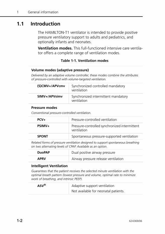
Ventilation modes. This full-functioned intensive care ventila-tor offers a complete range of ventilation modes.
Table 1-1. Ventilation modes
Volume modes (adaptive pressure) Delivered by an adaptive volume controller, these modes combine the attributes of pressure-controlled with volume-targeted ventilation.
(S)CMV+/APVcmv Synchronized controlled mandatory ventilation
SIMV+/APVsimv Synchronized intermittent mandatory ventilation
Pressure modesConventional pressure-controlled ventilation.
PCV+ Pressure-controlled ventilation
PSIMV+ Pressure-controlled synchronized intermittent ventilation
SPONT Spontaneous pressure-supported ventilation
Related forms of pressure ventilation designed to support spontaneous breathing on two alternating levels of CPAP. Available as an option.
DuoPAP Dual positive airway pressure
APRV Airway pressure release ventilation
Intelligent Ventilation Guarantees that the patient receives the selected minute ventilation with the optimal breath pattern (lowest pressure and volume, optimal rate to minimize work of breathing, and intrinsic PEEP).
ASV® Adaptive support ventilationNot available for neonatal patients.
1-2 624369/06
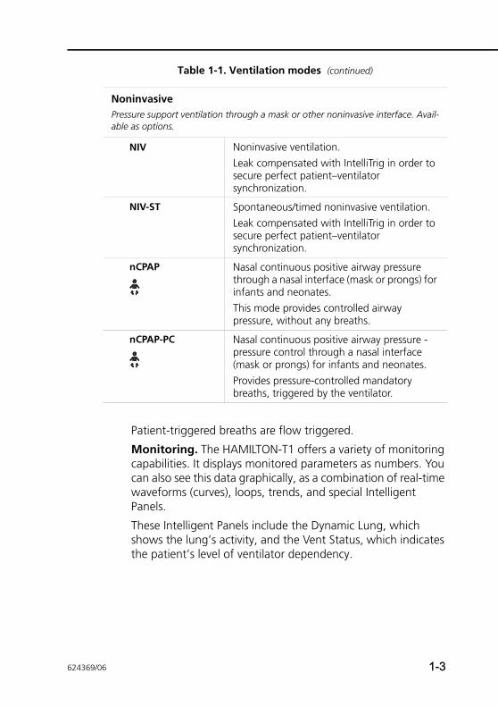
Patient-triggered breaths are flow triggered.
Monitoring. The HAMILTON-T1 offers a variety of monitoring capabilities. It displays monitored parameters as numbers. You can also see this data graphically, as a combination of real-time waveforms (curves), loops, trends, and special Intelligent Panels.
These Intelligent Panels include the Dynamic Lung, which shows the lung’s activity, and the Vent Status, which indicates the patient’s level of ventilator dependency.
NoninvasivePressure support ventilation through a mask or other noninvasive interface. Avail-able as options.
NIV Noninvasive ventilation. Leak compensated with IntelliTrig in order to secure perfect patient–ventilator synchronization.
NIV-ST Spontaneous/timed noninvasive ventilation.Leak compensated with IntelliTrig in order to secure perfect patient–ventilator synchronization.
nCPAP Nasal continuous positive airway pressure through a nasal interface (mask or prongs) for infants and neonates. This mode provides controlled airway pressure, without any breaths.
nCPAP-PC Nasal continuous positive airway pressure - pressure control through a nasal interface (mask or prongs) for infants and neonates. Provides pressure-controlled mandatory breaths, triggered by the ventilator.
Table 1-1. Ventilation modes (continued)
624369/06 1-3
1 General information
The HAMILTON-T1’s monitored data is based on pressure and flow measurements collected by the Hamilton Medical proxi-mal flow sensor1, between the Y-piece and the patient, and on FiO2 measurements by the integrated oxygen monitor.
Alarms. The HAMILTON-T1’s operator-adjustable and non-adjustable alarms help ensure your patient’s safety.
User interface. The ventilator’s ergonomic design, including a 8.4 in. color touchscreen, a press-and-turn dial, and keys, lets you easily access the ventilator settings and monitored parameters.
Customizability. You can customize the HAMILTON-T1 so that it starts up with institution-defined settings.
Power. The HAMILTON-T1 uses AC or DC power as its primary source. If the primary power source fails, the ventilator auto-matically switches to backup batteries.
Mounting variations for the HAMILTON-T1 include a standard trolley, a compact carrying device including an oxygen cylinder mount and different handles for wall, ceiling, and bed mount with specific adapters. For details, see the HAMILTON-T1 System Integration brochure (PN 689487).
Nebulization function. The nebulization function lets your HAMILTON-T1 power a pneumatic nebulizer connected to the nebulizer outlet. Pneumatic nebulization is disabled during neo-natal ventilation.
Options2
The following options are available for the HAMILTON-T1:
1. In the neonatal nCPAP and nCPAP-PC modes, a pressure line is used instead of a flow sensor.2. Not all options are available in all markets
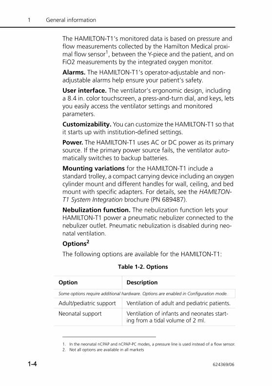
Table 1-2. Options
Option Description
Some options require additional hardware. Options are enabled in Configuration mode.
Adult/pediatric support Ventilation of adult and pediatric patients.
Neonatal support Ventilation of infants and neonates start-ing from a tidal volume of 2 ml.
1-4 624369/06
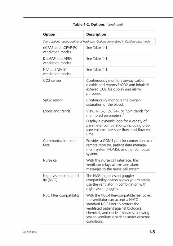
nCPAP and nCPAP-PC ventilation modes
See Table 1-1.
DuoPAP and APRV ventilation modes
See Table 1-1.
NIV and NIV-ST ventilation modes
See Table 1-1.
CO2 sensor Continuously monitors airway carbon dioxide and reports EtCO2 and inhaled/exhaled CO2 for display and alarm purposes.
SpO2 sensor Continuously monitors the oxygen saturation of the blood.
Loops and trends View 1-, 6-, 12-, 24-, or 72-h trends for monitored parameters.1
Display a dynamic loop for a variety of parameter combinations, including pres-sure-volume, pressure-flow, and flow-vol-ume.
Communication inter-face
Provides a COM1 port for connection to a remote monitor, patient data manage-ment system (PDMS), or other computer system.
Nurse call With the nurse call interface, the ventilator relays alarms and alarm messages to the nurse call system.
Night vision compatibil-ity (NVG)
The NVG (night vision goggle) compatibility option allows you to safely use the ventilator in combination with night vision goggles.
NBC filter compatibility With the NBC-filter-compatible rear cover, the ventilator can accept a NATO-standard NBC filter to protect the ventilated patient against biological, chemical, and nuclear hazards, allowing you to ventilate a patient under extreme conditions.
Table 1-2. Options (continued)
Option Description
Some options require additional hardware. Options are enabled in Configuration mode.
624369/06 1-5
1 General information
1.2 Functional description
The following paragraphs describe the operation of the HAMILTON-T1 ventilator hardware.
1.2.1 System overviewThe HAMILTON-T1 is an electronically controlled pneumatic ventilation system with an integrated air compressing system. It runs on AC or DC power with battery backup to protect against power failure or unstable power and to facilitate intra-hospital transport. The HAMILTON-T1’s pneumatics deliver gas, and its electrical systems control pneumatics, monitor alarms, and distribute power.
The user provides inputs to the HAMILTON-T1 microprocessor system through a touch screen, keys, and a press-and-turn knob. These inputs become instructions for the HAMILTON-T1’s pneumatics to deliver a precisely controlled gas mixture to the patient. The HAMILTON-T1 receives inputs from the proximal flow sensor and other sensors within the ventilator. Based on this monitored data, the HAMILTON-T1 adjusts gas delivery to the patient. Monitored data is also displayed by the graphic user interface.
The HAMILTON-T1’s microprocessor system controls gas deliv-ery and monitors the patient. The gas delivery and monitoring functions are cross-checked by an alarm controller. This cross-checking helps prevent simultaneous failure of these two main functions and minimizes the possible hazards of software failure.
A comprehensive system of visual and audible alarms helps ensure the patient’s safety. Clinical alarms can indicate an abnormal physiological condition. Technical alarms, triggered by the ventilator’s self-tests including ongoing background checks, can indicate a hardware or software failure. In the case of some technical alarms, a special safety mode ensures basic minute ventilation while giving the user time for corrective actions. When a condition is critical enough to possibly com-promise safe ventilation, the HAMILTON-T1 is placed into the
1. 72-h trends not available in all markets.
1-6 624369/06
ambient state. The inspiratory channel and expiratory valves are opened, letting the patient inspire room air through the inspiratory channel and exhale through the expiratory valve.
The HAMILTON-T1 has several means to ensure that safe patient or respiratory pressures are maintained. The maximum working pressure is ensured by the high pressure alarm limit. If the set high pressure limit is reached, the ventilator cycles into exhalation. The ventilator pressure cannot exceed 60 cmH2O.
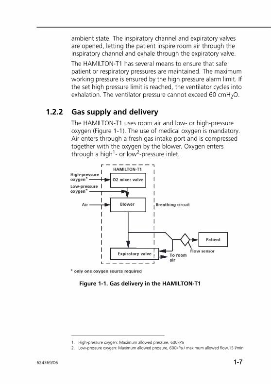
1.2.2 Gas supply and deliveryThe HAMILTON-T1 uses room air and low- or high-pressure oxygen (Figure 1-1). The use of medical oxygen is mandatory. Air enters through a fresh gas intake port and is compressed together with the oxygen by the blower. Oxygen enters through a high1- or low2-pressure inlet.
Figure 1-1. Gas delivery in the HAMILTON-T1
1. High-pressure oxygen: Maximum allowed pressure, 600kPa2. Low-pressure oxygen: Maximum allowed pressure, 600kPa / maximum allowed flow,15 l/min
624369/06 1-7
1 General information
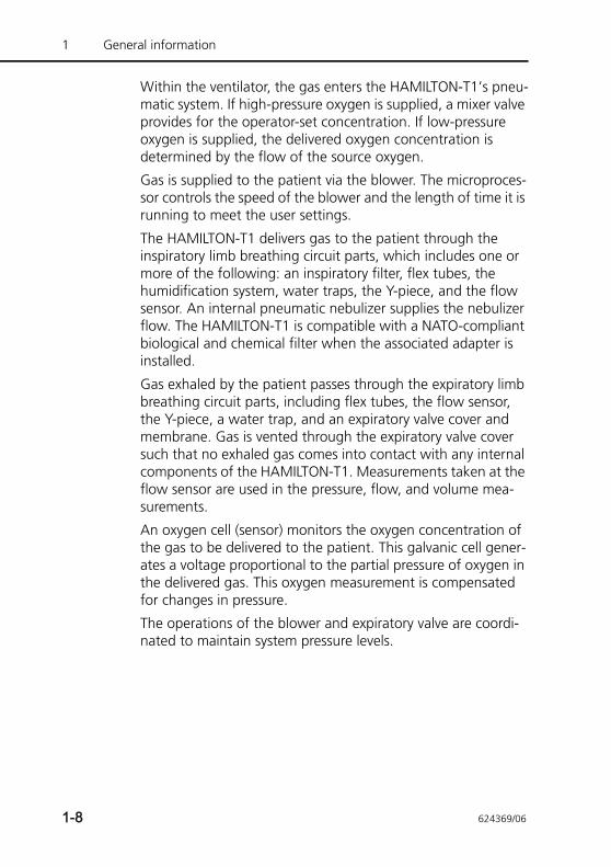
Within the ventilator, the gas enters the HAMILTON-T1’s pneu-matic system. If high-pressure oxygen is supplied, a mixer valve provides for the operator-set concentration. If low-pressure oxygen is supplied, the delivered oxygen concentration is determined by the flow of the source oxygen.
Gas is supplied to the patient via the blower. The microproces-sor controls the speed of the blower and the length of time it is running to meet the user settings.
The HAMILTON-T1 delivers gas to the patient through the inspiratory limb breathing circuit parts, which includes one or more of the following: an inspiratory filter, flex tubes, the humidification system, water traps, the Y-piece, and the flow sensor. An internal pneumatic nebulizer supplies the nebulizer flow. The HAMILTON-T1 is compatible with a NATO-compliant biological and chemical filter when the associated adapter is installed.
Gas exhaled by the patient passes through the expiratory limb breathing circuit parts, including flex tubes, the flow sensor, the Y-piece, a water trap, and an expiratory valve cover and membrane. Gas is vented through the expiratory valve cover such that no exhaled gas comes into contact with any internal components of the HAMILTON-T1. Measurements taken at the flow sensor are used in the pressure, flow, and volume mea-surements.
An oxygen cell (sensor) monitors the oxygen concentration of the gas to be delivered to the patient. This galvanic cell gener-ates a voltage proportional to the partial pressure of oxygen in the delivered gas. This oxygen measurement is compensated for changes in pressure.
The operations of the blower and expiratory valve are coordi-nated to maintain system pressure levels.
1-8 624369/06
1.2.3 Gas monitoring with the flow sensorThe HAMILTON-T1 accurately measures flow, volume, and pressure in the patient’s airway with the Hamilton Medical flow sensor. This proximal flow sensor lets the HAMILTON-T1 sense even weak patient breathing efforts. Between its highly sensi-tive flow trigger and fast response time, the HAMILTON-T1 helps minimize the patient’s work of breathing.
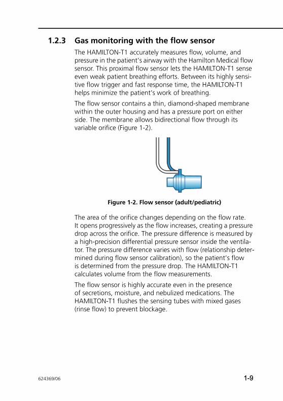
The flow sensor contains a thin, diamond-shaped membrane within the outer housing and has a pressure port on either side. The membrane allows bidirectional flow through its variable orifice (Figure 1-2).
Figure 1-2. Flow sensor (adult/pediatric)
The area of the orifice changes depending on the flow rate. It opens progressively as the flow increases, creating a pressure drop across the orifice. The pressure difference is measured by a high-precision differential pressure sensor inside the ventila-tor. The pressure difference varies with flow (relationship deter-mined during flow sensor calibration), so the patient’s flow is determined from the pressure drop. The HAMILTON-T1 calculates volume from the flow measurements.
The flow sensor is highly accurate even in the presence of secretions, moisture, and nebulized medications. The HAMILTON-T1 flushes the sensing tubes with mixed gases (rinse flow) to prevent blockage.
624369/06 1-9
1 General information
1.3 Physical description
1.3.1 Breathing circuits and accessories
WARNINGTo ensure proper ventilation operation, use only parts and accessories specified in Appendix G and in the prod-uct catalog, or that are specified as being compatible with this ventilator.
NOTE:Pressure and volume measurement accuracy may be affected by using a breathing circuit with high resistance. Accuracy was tested with Hamilton Medical devices using the breathing circuits PN 281592 for neonates, and PN 260086 for adults and pediatrics.
Figure 1-3 shows the HAMILTON-T1 with its breathing circuit and accessories. Contact your Hamilton Medical representative for details on breathing circuits and accessories supplied by Hamilton Medical.
See Appendix G of this manual and the product catalog for information on compatible breathing circuits and accessories.
1-10 624369/06
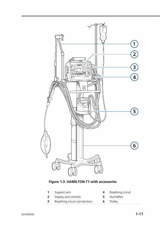
Figure 1-3. HAMILTON-T1 with accessories
1 Support arm 4 Breathing circuit2 Display and controls 5 Humidifier3 Breathing circuit connections 6 Trolley
624369/06 1-11
1 General information
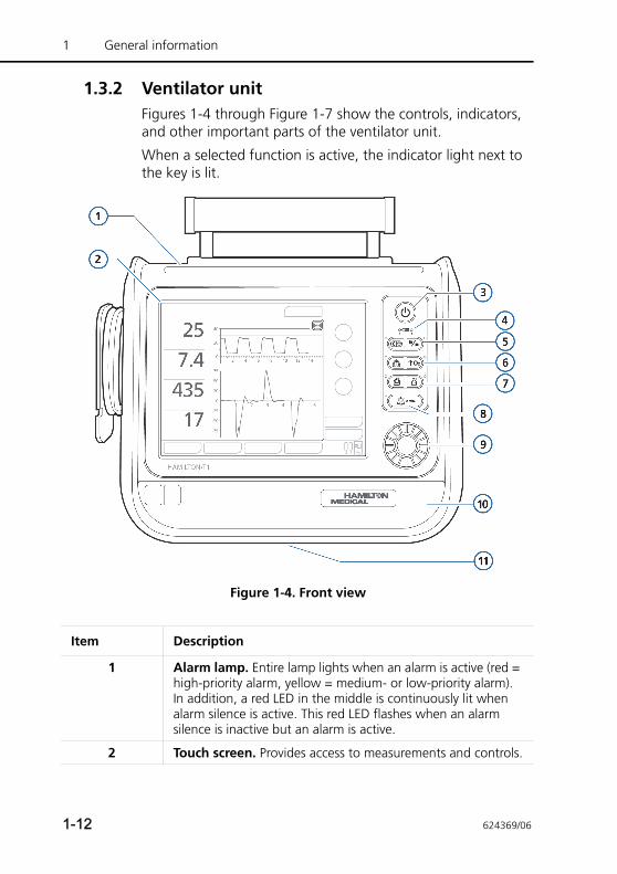
1.3.2 Ventilator unitFigures 1-4 through Figure 1-7 show the controls, indicators, and other important parts of the ventilator unit.
When a selected function is active, the indicator light next to the key is lit.
Figure 1-4. Front view
Item Description
1 Alarm lamp. Entire lamp lights when an alarm is active (red = high-priority alarm, yellow = medium- or low-priority alarm). In addition, a red LED in the middle is continuously lit when alarm silence is active. This red LED flashes when an alarm silence is inactive but an alarm is active.
2 Touch screen. Provides access to measurements and controls.
1-12 624369/06
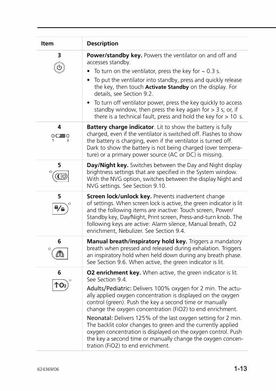
3 Power/standby key. Powers the ventilator on and off and accesses standby.• To turn on the ventilator, press the key for ~ 0.3 s.• To put the ventilator into standby, press and quickly release
the key, then touch Activate Standby on the display. For details, see Section 9.2.
• To turn off ventilator power, press the key quickly to access standby window, then press the key again for > 3 s; or, if there is a technical fault, press and hold the key for > 10 s.
4 Battery charge indicator. Lit to show the battery is fully charged, even if the ventilator is switched off. Flashes to show the battery is charging, even if the ventilator is turned off. Dark to show the battery is not being charged (over tempera-ture) or a primary power source (AC or DC) is missing.
5 Day/Night key. Switches between the Day and Night display brightness settings that are specified in the System window. With the NVG option, switches between the display Night and NVG settings. See Section 9.10.
5 Screen lock/unlock key. Prevents inadvertent change of settings. When screen lock is active, the green indicator is lit and the following items are inactive: Touch screen, Power/Standby key, Day/Night, Print screen, Press-and-turn knob. The following keys are active: Alarm silence, Manual breath, O2 enrichment, Nebulizer. See Section 9.4.
6 Manual breath/inspiratory hold key. Triggers a mandatory breath when pressed and released during exhalation. Triggers an inspiratory hold when held down during any breath phase. See Section 9.6. When active, the green indicator is lit.
6 O2 enrichment key. When active, the green indicator is lit. See Section 9.4.Adults/Pediatric: Delivers 100% oxygen for 2 min. The actu-ally applied oxygen concentration is displayed on the oxygen control (green). Push the key a second time or manually change the oxygen concentration (FiO2) to end enrichment.Neonatal: Delivers 125% of the last oxygen setting for 2 min. The backlit color changes to green and the currently applied oxygen concentration is displayed on the oxygen control. Push the key a second time or manually change the oxygen concen-tration (FiO2) to end enrichment.
Item Description
624369/06 1-13
1 General information
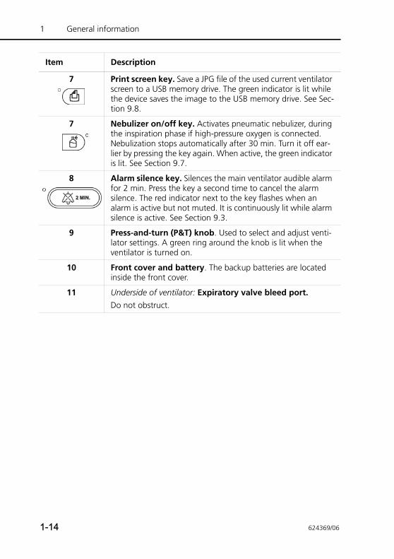
7 Print screen key. Save a JPG file of the used current ventilator screen to a USB memory drive. The green indicator is lit while the device saves the image to the USB memory drive. See Sec-tion 9.8.
7 Nebulizer on/off key. Activates pneumatic nebulizer, during the inspiration phase if high-pressure oxygen is connected. Nebulization stops automatically after 30 min. Turn it off ear-lier by pressing the key again. When active, the green indicator is lit. See Section 9.7.
8 Alarm silence key. Silences the main ventilator audible alarm for 2 min. Press the key a second time to cancel the alarm silence. The red indicator next to the key flashes when an alarm is active but not muted. It is continuously lit while alarm silence is active. See Section 9.3.
9 Press-and-turn (P&T) knob. Used to select and adjust venti-lator settings. A green ring around the knob is lit when the ventilator is turned on.
10 Front cover and battery. The backup batteries are located inside the front cover.
11 Underside of ventilator: Expiratory valve bleed port. Do not obstruct.
Item Description
1-14 624369/06
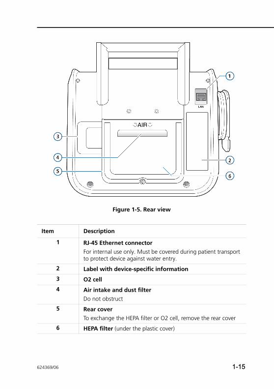
Figure 1-5. Rear view
Item Description
1 RJ-45 Ethernet connectorFor internal use only. Must be covered during patient transport to protect device against water entry.
2 Label with device-specific information
3 O2 cell
4 Air intake and dust filterDo not obstruct
5 Rear coverTo exchange the HEPA filter or O2 cell, remove the rear cover
6 HEPA filter (under the plastic cover)
624369/06 1-15
1 General information
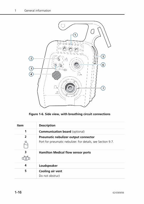
Figure 1-6. Side view, with breathing circuit connections
Item Description
1 Communication board (optional)
2 Pneumatic nebulizer output connectorPort for pneumatic nebulizer. For details, see Section 9.7.
3 Hamilton Medical flow sensor ports
4 Loudspeaker
5 Cooling air ventDo not obstruct
1-16 624369/06
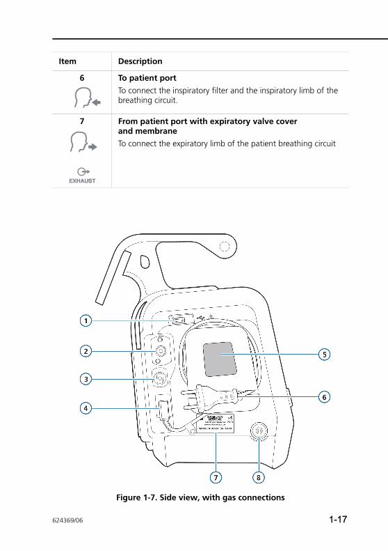
Figure 1-7. Side view, with gas connections
6 To patient portTo connect the inspiratory filter and the inspiratory limb of the breathing circuit.
7 From patient port with expiratory valve cover and membraneTo connect the expiratory limb of the patient breathing circuit
Item Description
624369/06 1-17
1 General information
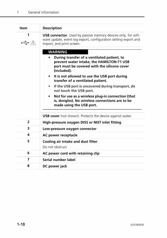
Item Description
1 USB connector. Used by passive memory devices only, for soft-ware update, event log export, configuration setting export and import, and print screen.
WARNING• During transfer of a ventilated patient, to
prevent water intake, the HAMILTON-T1 USB port must be covered with the silicone cover (included).
• It is not allowed to use the USB port during transfer of a ventilated patient.
• If the USB port is uncovered during transport, do not touch the USB port.
• Not for use as a wireless plug-in connection (that is, dongles). No wireless connections are to be made using the USB port.
USB cover (not shown). Protects the device against water.
2 High-pressure oxygen DISS or NIST inlet fitting
3 Low-pressure oxygen connector
4 AC power receptacle
5 Cooling air intake and dust filterDo not obstruct
6 AC power cord with retaining clip
7 Serial number label
8 DC power jack
1-18 624369/06
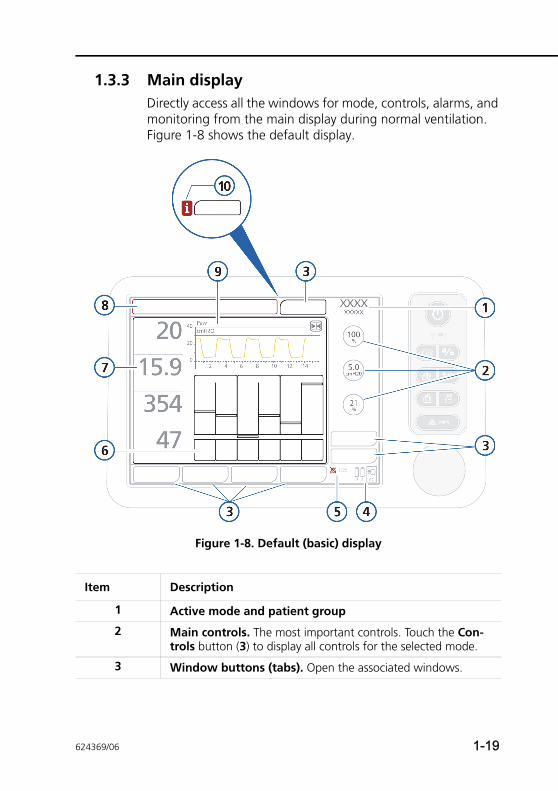
1.3.3 Main displayDirectly access all the windows for mode, controls, alarms, and monitoring from the main display during normal ventilation. Figure 1-8 shows the default display.
Figure 1-8. Default (basic) display
Item Description
1 Active mode and patient group
2 Main controls. The most important controls. Touch the Con-trols button (3) to display all controls for the selected mode.
3 Window buttons (tabs). Open the associated windows.
624369/06 1-19
1 General information
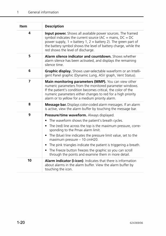
4 Input power. Shows all available power sources. The framed symbol indicates the current source (AC = mains, DC = DC power supply, 1 = battery 1, 2 = battery 2). The green part of the battery symbol shows the level of battery charge, while the red shows the level of discharge.
5 Alarm silence indicator and countdown. Shows whether alarm silence has been activated, and displays the remaining silence time.
6 Graphic display. Shows user-selectable waveform or an Intelli-gent Panel graphic (Dynamic Lung, ASV graph, Vent Status).
7 Main monitoring parameters (MMP). You can view other numeric parameters from the monitored parameter windows. If the patient’s condition becomes critical, the color of the numeric parameters either changes to red for a high priority alarm or to yellow for a medium priority alarm.
8 Message bar. Displays color-coded alarm messages. If an alarm is active, view the alarm buffer by touching the message bar.
9 Pressure/time waveform. Always displayed. • The waveform shows the patient’s breath cycles.• The (red) line across the top is the maximum pressure, corre-
sponding to the Pmax alarm limit.• The (blue) line indicates the pressure limit value, set to the
maximum pressure – 10 cmH20.• The pink triangles indicate the patient is triggering a breath.• The Freeze button freezes the graphic so you can scroll
through the points and examine them in more detail.
10 Alarm indicator (i-icon). Indicates that there is information about alarms in the alarm buffer. View the alarm buffer by touching the icon.
Item Description
1-20 624369/06
1.4 Symbols used on device labels and packaging
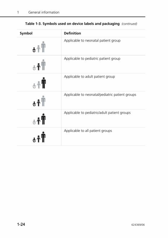
Table 1-3. Symbols used on device labels and packaging
Symbol Definition
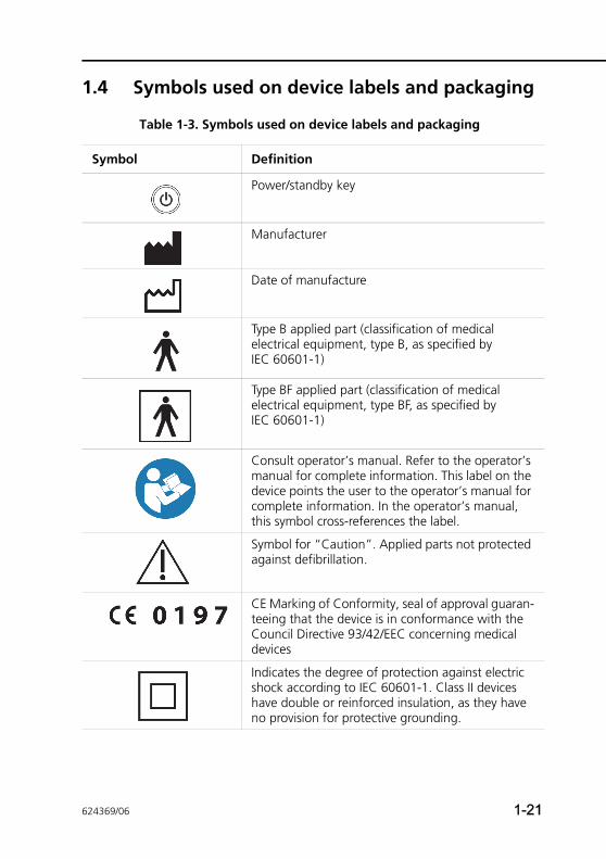
Power/standby key
Manufacturer
Date of manufacture
Type B applied part (classification of medical electrical equipment, type B, as specified by IEC 60601-1)
Type BF applied part (classification of medical electrical equipment, type BF, as specified by IEC 60601-1)
Consult operator’s manual. Refer to the operator’s manual for complete information. This label on the device points the user to the operator’s manual for complete information. In the operator’s manual, this symbol cross-references the label.
Symbol for “Caution”. Applied parts not protected against defibrillation.
CE Marking of Conformity, seal of approval guaran-teeing that the device is in conformance with the Council Directive 93/42/EEC concerning medical devices
Indicates the degree of protection against electric shock according to IEC 60601-1. Class II devices have double or reinforced insulation, as they have no provision for protective grounding.
624369/06 1-21
1 General information
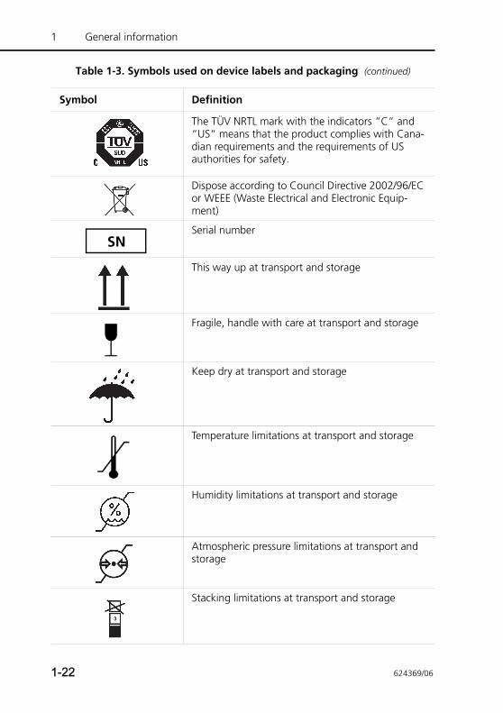
The TÜV NRTL mark with the indicators “C“ and “US“ means that the product complies with Cana-dian requirements and the requirements of US authorities for safety.
Dispose according to Council Directive 2002/96/EC or WEEE (Waste Electrical and Electronic Equip-ment)
Serial number
This way up at transport and storage
Fragile, handle with care at transport and storage
Keep dry at transport and storage
Temperature limitations at transport and storage
Humidity limitations at transport and storage
Atmospheric pressure limitations at transport and storage
Stacking limitations at transport and storage
Table 1-3. Symbols used on device labels and packaging (continued)
Symbol Definition
SN
1-22 624369/06
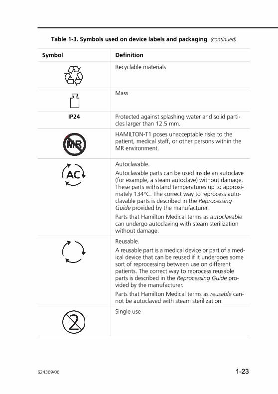
Recyclable materials
Mass
IP24 Protected against splashing water and solid parti-cles larger than 12.5 mm.
HAMILTON-T1 poses unacceptable risks to the patient, medical staff, or other persons within the MR environment.
Autoclavable. Autoclavable parts can be used inside an autoclave (for example, a steam autoclave) without damage. These parts withstand temperatures up to approxi-mately 134°C. The correct way to reprocess auto-clavable parts is described in the Reprocessing Guide provided by the manufacturer. Parts that Hamilton Medical terms as autoclavable can undergo autoclaving with steam sterilization without damage.
Reusable.A reusable part is a medical device or part of a med-ical device that can be reused if it undergoes some sort of reprocessing between use on different patients. The correct way to reprocess reusable parts is described in the Reprocessing Guide pro-vided by the manufacturer. Parts that Hamilton Medical terms as reusable can-not be autoclaved with steam sterilization.
Single use
Table 1-3. Symbols used on device labels and packaging (continued)
Symbol Definition
624369/06 1-23
1 General information
Applicable to neonatal patient group
Applicable to pediatric patient group
Applicable to adult patient group
Applicable to neonatal/pediatric patient groups
Applicable to pediatric/adult patient groups
Applicable to all patient groups
Table 1-3. Symbols used on device labels and packaging (continued)
Symbol Definition
1-24 624369/06
2 Preparing for ventilation
2.1 Introduction 2-3
2.2 Installing the humidifier 2-5
2.3 Installing the patient breathing circuit 2-6
2.3.1 Installing the bacteria filter orHMEF/HME 2-8
2.3.2 Installing the expiratory valve 2-9
2.3.3 Selecting the breathing circuit 2-9
2.3.4 Assembling the patient breathingcircuit 2-11
2.3.5 Positioning the breathing circuit 2-15
2.4 Installing the pneumatic nebulizer 2-16
2.5 Setting up CO2 monitoring 2-17
2.5.1 CO2 mainstream measurement 2-19
2.5.2 CO2 sidestream measurement 2-22
2.6 Installing the Aeroneb Pro nebulizer 2-25
2.7 Using an expiratory filter 2-25
2.8 Connecting to a power source 2-26
2.8.1 Connecting to AC power 2-26
2.8.2 Connecting to DC power 2-27
2.9 About the batteries 2-28
2.10 Connecting the oxygen supply 2-31
2.10.1 Using a low-pressure oxygen supply 2-33
2.10.2 Connecting the oxygen supply tothe ventilator 2-34
2.10.3 Selecting the oxygen source type 2-35
2.11 Ensuring an adequate oxygen supply forpatient transport 2-36
2.11.1 Reviewing current oxygenconsumption 2-37
624369/06 2-1
2 Preparing for ventilation
2.11.2 Calculating estimated oxygenconsumption 2-38
2.11.3 Estimated oxygen consumption graph 2-46
2.12 Working with the trolley 2-48
2.13 Installing the patient tubing support arm 2-49
2.13.1 Preparing the trolley forintrahospital transport 2-49
2.14 Connecting to an external patient monitor or other device 2-50
2.15 Turning on the ventilator 2-51
2.16 Turning off the ventilator 2-52
2.17 Display navigation guidelines 2-52
2-2 624369/06
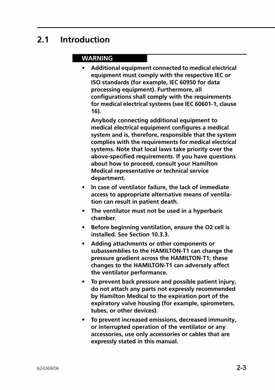
2.1 Introduction
WARNING• Additional equipment connected to medical electrical
equipment must comply with the respective IEC or ISO standards (for example, IEC 60950 for data processing equipment). Furthermore, all configurations shall comply with the requirements for medical electrical systems (see IEC 60601-1, clause 16).
Anybody connecting additional equipment to medical electrical equipment configures a medical system and is, therefore, responsible that the system complies with the requirements for medical electrical systems. Note that local laws take priority over the above-specified requirements. If you have questions about how to proceed, consult your Hamilton Medical representative or technical service department.
• In case of ventilator failure, the lack of immediate access to appropriate alternative means of ventila-tion can result in patient death.
• The ventilator must not be used in a hyperbaric chamber.
• Before beginning ventilation, ensure the O2 cell is installed. See Section 10.3.3.
• Adding attachments or other components or subassemblies to the HAMILTON-T1 can change the pressure gradient across the HAMILTON-T1; these changes to the HAMILTON-T1 can adversely affect the ventilator performance.
• To prevent back pressure and possible patient injury, do not attach any parts not expressly recommended by Hamilton Medical to the expiration port of the expiratory valve housing (for example, spirometers, tubes, or other devices).
• To prevent increased emissions, decreased immunity, or interrupted operation of the ventilator or any accessories, use only accessories or cables that are expressly stated in this manual.
624369/06 2-3
2 Preparing for ventilation
• To prevent interrupted operation of the ventilator due to electromagnetic interference, avoid using it adjacent to or stacking other devices on it. If adjacent or stacked use is necessary, verify the ventilator’s normal operation in the configuration in which it will be used.
• For important safety information about using the HAMILTON-T1 trolley, see Section 2.12.
CAUTION• Before using the ventilator for the first time, we rec-
ommend that you clean its exterior and sterilize its components as described in Chapter 10.
• To electrically isolate the ventilator circuits from all poles of the primary power supply simultaneously, disconnect the power plug.
• To prevent possible patient injury, do not block the holes at the back and the side (cooling fan) of the ventilator. These holes are vents for the fresh air intake and the cooling fan.
• Ensure that the accessories used during transport are adequately protected against water ingress.
2-4 624369/06
2.2 Installing the humidifier
WARNING• To prevent possible patient injury and possible water
damage to the ventilator, make sure the humidifier is set to appropriate temperature and humidification settings.
• To prevent possible patient injury and equipment damage, do not turn the humidifier on until the gas flow has started and is regulated. Starting the heater or leaving it on without gas flow for prolonged peri-ods may result in heat build-up, causing hot air to be delivered to the patient. Circuit tubing may melt under these conditions. Turn the heater power switch off before stopping gas flow.
CAUTION• Regularly check the water traps and the breathing
circuit hoses for water accumulation. Empty as required.
• During transport only use humidifiers that are approved for transport operation.
Install a humidifier to the HAMILTON-T1 using the slide bracket on the trolley column. Prepare the humidifier as described in the manufacturer’s operation manual.
624369/06 2-5
2 Preparing for ventilation
2.3 Installing the patient breathing circuit
WARNING• To minimize the risk of bacterial contamination or
physical damage, handle bacteria filters with care.
• Make sure a HEPA filter is installed.
• To prevent patient or ventilator contamination, always use a bacteria filter or HMEF/HME between the patient and the inspiratory port.
• To reduce the risk of fire, use only breathing circuits intended for use in oxygen-enriched environments. Do not use antistatic or electrically conductive tubing.
• Only use approved CE-labeled consumables as accessories.
NOTE:• Any bacteria filter, HMEF/HME, or additional accessories
in the expiratory limb may substantially increase flow resistance and impair ventilation.
• To ensure that all breathing circuit connections are leak-tight, perform the tightness test every time you install a circuit or change a circuit part.
• Do not combine the neonatal CO2 airway adapter and the adult flow sensor. Artifacts during the measurement are possible.
• For optimal ventilator operation, use Hamilton Medical breathing circuits or other circuits that meet the specifi-cations given in Appendix A. When altering the Hamil-ton Medical breathing circuit configurations (for example, when adding components), make sure not to exceed these inspiratory and expiratory resistance val-ues of the ventilator breathing system, as required by ISO 80601-2-12.
2-6 624369/06
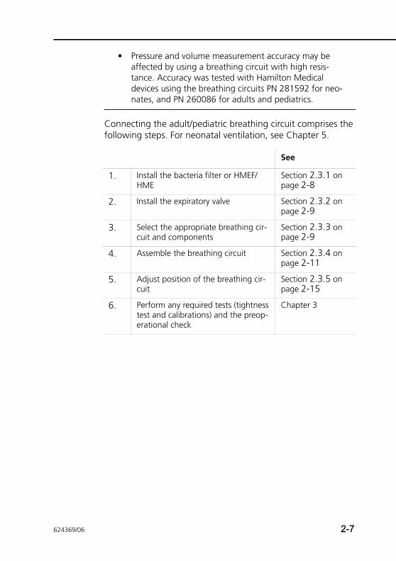
• Pressure and volume measurement accuracy may be affected by using a breathing circuit with high resis-tance. Accuracy was tested with Hamilton Medical devices using the breathing circuits PN 281592 for neo-nates, and PN 260086 for adults and pediatrics.
Connecting the adult/pediatric breathing circuit comprises the following steps. For neonatal ventilation, see Chapter 5.
See
1. Install the bacteria filter or HMEF/HME
Section 2.3.1 on page 2-8
2. Install the expiratory valve Section 2.3.2 on page 2-9
3. Select the appropriate breathing cir-cuit and components
Section 2.3.3 on page 2-9
4. Assemble the breathing circuit Section 2.3.4 on page 2-11
5. Adjust position of the breathing cir-cuit
Section 2.3.5 on page 2-15
6. Perform any required tests (tightness test and calibrations) and the preop-erational check
Chapter 3
624369/06 2-7
2 Preparing for ventilation
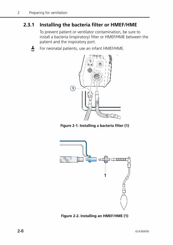
2.3.1 Installing the bacteria filter or HMEF/HMETo prevent patient or ventilator contamination, be sure to install a bacteria (inspiratory) filter or HMEF/HME between the patient and the inspiratory port.
For neonatal patients, use an infant HMEF/HME.
Figure 2-1. Installing a bacteria filter (1)
Figure 2-2. Installing an HMEF/HME (1)
2-8 624369/06
2.3.2 Installing the expiratory valve
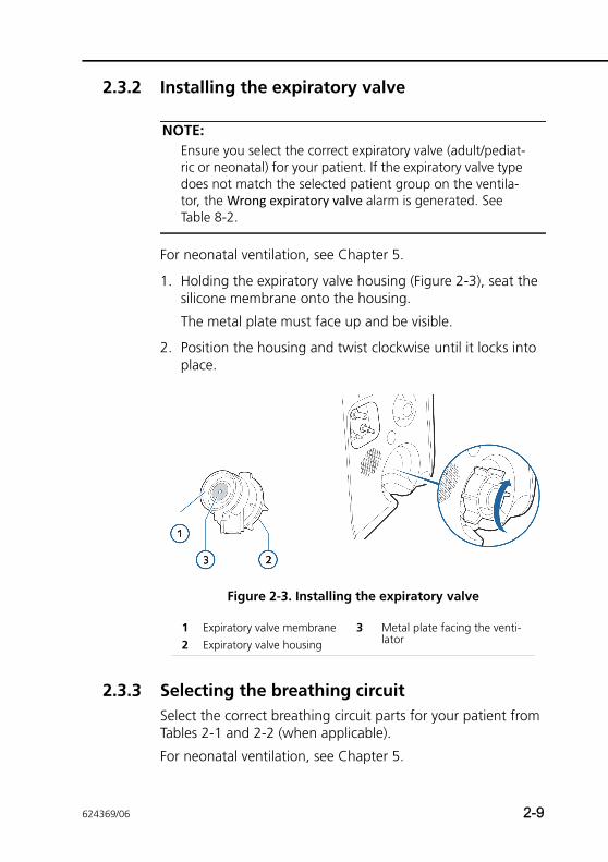
NOTE:Ensure you select the correct expiratory valve (adult/pediat-ric or neonatal) for your patient. If the expiratory valve type does not match the selected patient group on the ventila-tor, the Wrong expiratory valve alarm is generated. See Table 8-2.
For neonatal ventilation, see Chapter 5.
1. Holding the expiratory valve housing (Figure 2-3), seat the silicone membrane onto the housing.
The metal plate must face up and be visible.
2. Position the housing and twist clockwise until it locks into place.
Figure 2-3. Installing the expiratory valve
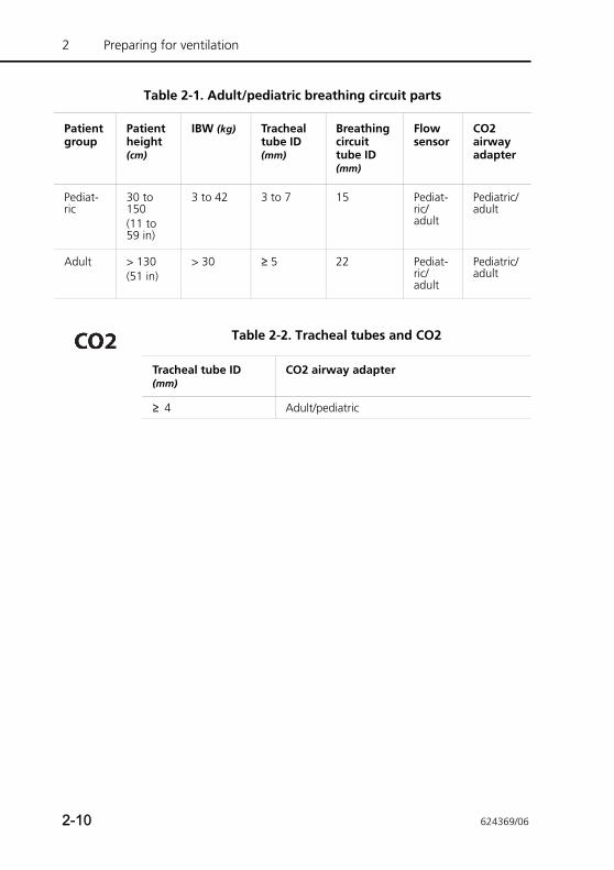
2.3.3 Selecting the breathing circuitSelect the correct breathing circuit parts for your patient from Tables 2-1 and 2-2 (when applicable).
For neonatal ventilation, see Chapter 5.
1 Expiratory valve membrane 3 Metal plate facing the venti-lator2 Expiratory valve housing
624369/06 2-9
2 Preparing for ventilation
Table 2-1. Adult/pediatric breathing circuit parts
Patient group
Patient height (cm)
IBW (kg) Tracheal tube ID (mm)
Breathing circuit tube ID (mm)
Flow sensor
CO2 airway adapter
Pediat-ric
30 to 150(11 to 59 in)
3 to 42 3 to 7 15 Pediat-ric/adult
Pediatric/adult
Adult > 130(51 in)
> 30 ≥ 5 22 Pediat-ric/adult
Pediatric/adult
Table 2-2. Tracheal tubes and CO2
Tracheal tube ID (mm)
CO2 airway adapter
≥ 4 Adult/pediatric
2-10 624369/06
2.3.4 Assembling the patient breathing circuitAssembling the adult/pediatric breathing circuit comprises the following steps:
2.3.4.1 Connecting the breathing circuitFigures 2-4 through 2-6 show typical adult/pediatric breathing circuits. For neonatal ventilation, see Chapter 5.
For ordering information, contact your Hamilton Medical repre-sentative. Follow the specific guidelines for the different parts.
Connect the components as appropriate for your patient.
See
1. Connect the circuit Figures 2-4 and 2-5 on page 2-12
2. Install the flow sensor Section 2.3.4.2 on page 2-15
624369/06 2-11
2 Preparing for ventilation
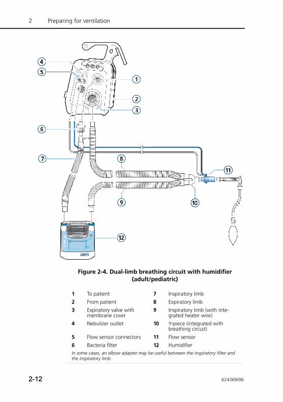
Figure 2-4. Dual-limb breathing circuit with humidifier (adult/pediatric)
1 To patient 7 Inspiratory limb2 From patient 8 Expiratory limb3 Expiratory valve with
membrane cover9 Inspiratory limb (with inte-
grated heater wire)4 Nebulizer outlet 10 Y-piece (integrated with
breathing circuit)5 Flow sensor connectors 11 Flow sensor6 Bacteria filter 12 HumidifierIn some cases, an elbow adapter may be useful between the inspiratory filter and the inspiratory limb.
2-12 624369/06
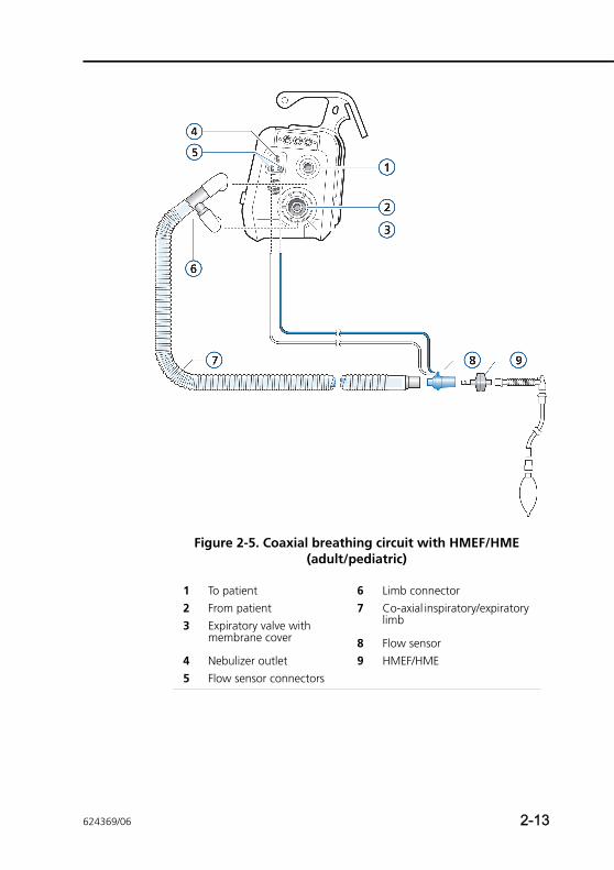
Figure 2-5. Coaxial breathing circuit with HMEF/HME (adult/pediatric)
1 To patient 6 Limb connector2 From patient 7 Co-axial inspiratory/expiratory
limb3 Expiratory valve with membrane cover 8 Flow sensor
4 Nebulizer outlet 9 HMEF/HME5 Flow sensor connectors
624369/06 2-13
2 Preparing for ventilation
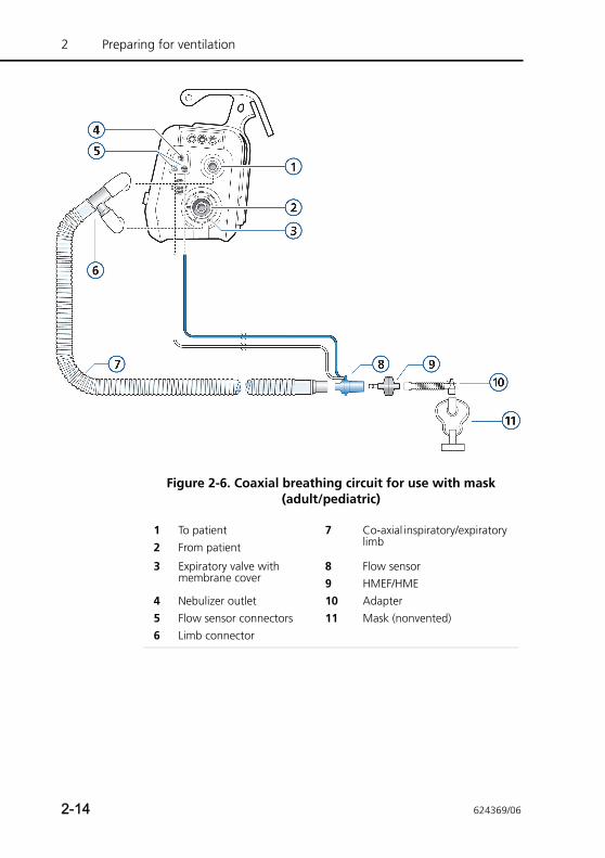
Figure 2-6. Coaxial breathing circuit for use with mask (adult/pediatric)
1 To patient 7 Co-axial inspiratory/expiratory limb 2 From patient
3 Expiratory valve with membrane cover
8 Flow sensor 9 HMEF/HME
4 Nebulizer outlet 10 Adapter5 Flow sensor connectors 11 Mask (nonvented)6 Limb connector
2-14 624369/06
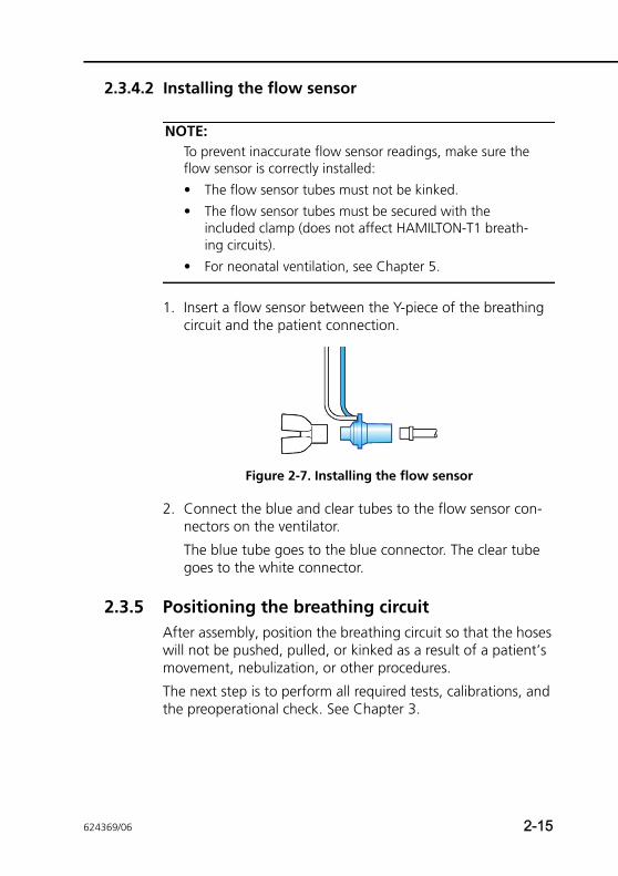
2.3.4.2 Installing the flow sensor
NOTE:To prevent inaccurate flow sensor readings, make sure the flow sensor is correctly installed:
• The flow sensor tubes must not be kinked.
• The flow sensor tubes must be secured with the included clamp (does not affect HAMILTON-T1 breath-ing circuits).
• For neonatal ventilation, see Chapter 5.
1. Insert a flow sensor between the Y-piece of the breathing circuit and the patient connection.
Figure 2-7. Installing the flow sensor
2. Connect the blue and clear tubes to the flow sensor con-nectors on the ventilator.
The blue tube goes to the blue connector. The clear tube goes to the white connector.
2.3.5 Positioning the breathing circuitAfter assembly, position the breathing circuit so that the hoses will not be pushed, pulled, or kinked as a result of a patient’s movement, nebulization, or other procedures.
The next step is to perform all required tests, calibrations, and the preoperational check. See Chapter 3.
624369/06 2-15
2 Preparing for ventilation
2.4 Installing the pneumatic nebulizer
WARNING• Do not use an expiratory filter or HMEF in the
patient’s breathing circuit during nebulization. Nebu-lization can cause an expiratory side filter to clog, substantially increasing flow resistance and impair-ing ventilation.
• Connect the nebulizer in the inspiratory limb per your institution’s policy and procedures. Connecting the nebulizer between the flow sensor and the endotracheal tube increases dead space and causes incorrect volume measurements.
• To prevent the expiratory valve from sticking due to nebulized medications, use only medications approved for nebulization and regularly check and clean or replace the expiratory valve membrane.
• Be aware that nebulization affects delivered oxygen concentration.
NOTE:Pneumatic nebulization is disabled during neonatal ventila-tion.
The nebulization feature provides a stable driving pressure to power a pneumatic nebulizer connected to the nebulizer out-let, optimally specified for a flow of approximately 8 l/min.
Connect the nebulizer and accessories as shown in Figure 2-8. See Appendix G for information about compatible nebulizers.
2-16 624369/06
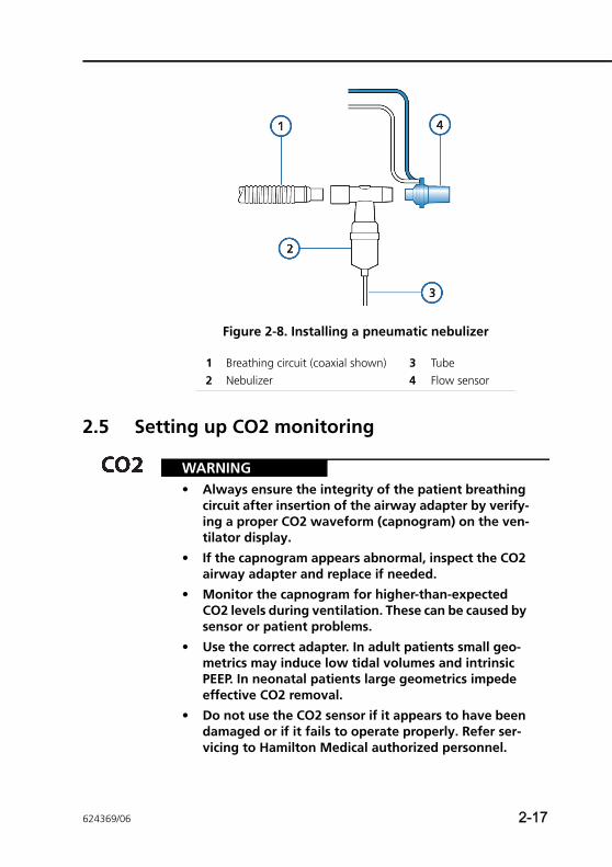
Figure 2-8. Installing a pneumatic nebulizer
2.5 Setting up CO2 monitoring
WARNING• Always ensure the integrity of the patient breathing
circuit after insertion of the airway adapter by verify-ing a proper CO2 waveform (capnogram) on the ven-tilator display.
• If the capnogram appears abnormal, inspect the CO2 airway adapter and replace if needed.
• Monitor the capnogram for higher-than-expected CO2 levels during ventilation. These can be caused by sensor or patient problems.
• Use the correct adapter. In adult patients small geo-metrics may induce low tidal volumes and intrinsic PEEP. In neonatal patients large geometrics impede effective CO2 removal.
• Do not use the CO2 sensor if it appears to have been damaged or if it fails to operate properly. Refer ser-vicing to Hamilton Medical authorized personnel.
1 Breathing circuit (coaxial shown) 3 Tube2 Nebulizer 4 Flow sensor
624369/06 2-17
2 Preparing for ventilation
• To reduce the risk of explosion, do not place the CO2 sensor in a combustible or explosive environment (for example, around flammable anesthetics or other ignition sources).
• Do not use the CO2 sensor when it is wet or has exte-rior condensation.
• To prevent increased PaCO2 do not use an adult sensor adapter for neonates as it will increase dead space.
CAUTION• Position airway adapters with windows in a vertical,
not a horizontal, position. This helps keep patient secretions from pooling on the windows.
• To prevent premature failure of the CO2 sensor, Ham-ilton Medical recommends that you remove it from the circuit whenever an aerosolized medication is delivered. This is due to the increased viscosity of the medication, which may contaminate the airway adapter window.
• All devices are not protected against reanimation with a defibrillator.
• Avoid permanent direct contact of the CO2 sensor with the body.
• Nebulization may influence the CO2 measurements.
• Disconnect the CO2 sensor before using a defibrilla-tor on the patient.
NOTE:The environmental limitations for the CO2 sensors may be different from those for the ventilator. The ventilator can operate in conditions up to 50°C (122°F). The supported mainstream CO2 sensor is rated to 45°C (113°F); the sup-ported sidestream sensor, to 40°C (104°F).
2-18 624369/06
CO2 monitoring is used for various applications in order to gain information such as the assessment of the patient’s airway integrity or the proper endotracheal tube placement.
The HAMILTON-T1 offers two monitoring options:
• Mainstream CO2 measurement
• Sidestream CO2 measurement
Whether mainstream or sidestream CO2 is used to monitor end-tidal CO2 depends on the clinical setting. A volumetric capnogram as described in Appendix E is only possible with a mainstream CO2 sensor.
2.5.1 CO2 mainstream measurement
WARNINGIn NIV and neonatal ventilation with uncuffed tubes, leaks may influence the volumetric capnogram and the measured numerical monitoring parameters.
The optional mainstream CO2 sensor is a solid-state infrared sensor, which is attached to an airway adapter that connects to an endotracheal (ET) tube or other airway and measures bases flowing through these breathing circuit components.
The sensor generates infrared light and beams it through the airway adapter or sample cell to a detector on the opposite side. CO2 from the patient, flowing through the mainstream airway adapter or aspirated into the sample cell, absorbs some of this infrared energy. The HAMILTON-T1 determines the CO2 concentration in the breathing gases by measuring the amount of light absorbed by gases flowing through the airway or sam-ple cell.
The HAMILTON-T1 can display measurements derived from the CO2 sensor as numeric values, waveforms, trends, and loops. The waveform is a valuable clinical tool that can be used to assess patient airway integrity and proper endotracheal (ET) tube placement.
The CO2 sensor can be easily transferred from one HAMILTON-T1 ventilator to another, even “on the fly”, during ventilation.
624369/06 2-19
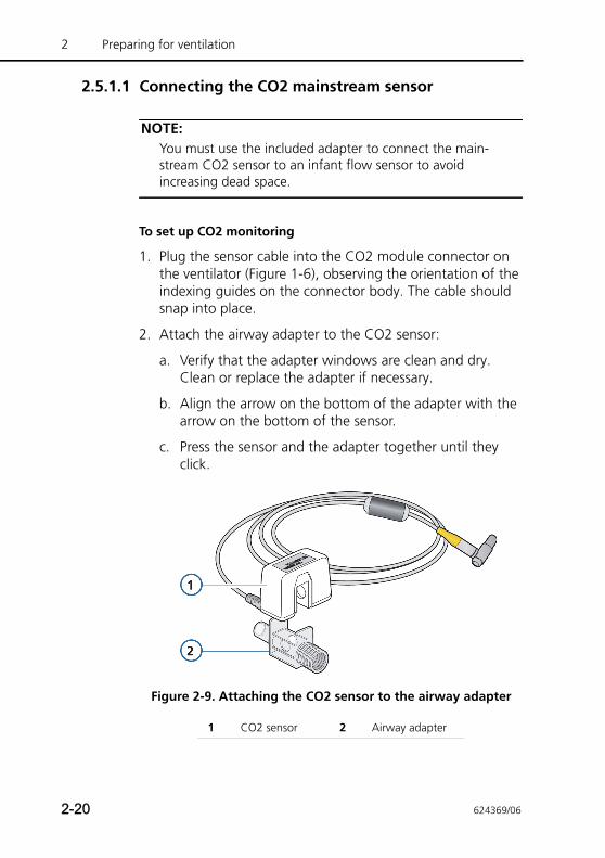
2 Preparing for ventilation
2.5.1.1 Connecting the CO2 mainstream sensor
NOTE:You must use the included adapter to connect the main-stream CO2 sensor to an infant flow sensor to avoid increasing dead space.
To set up CO2 monitoring
1. Plug the sensor cable into the CO2 module connector on the ventilator (Figure 1-6), observing the orientation of the indexing guides on the connector body. The cable should snap into place.
2. Attach the airway adapter to the CO2 sensor:
a. Verify that the adapter windows are clean and dry. Clean or replace the adapter if necessary.
b. Align the arrow on the bottom of the adapter with the arrow on the bottom of the sensor.
c. Press the sensor and the adapter together until they click.
Figure 2-9. Attaching the CO2 sensor to the airway adapter
1 CO2 sensor 2 Airway adapter
2-20 624369/06
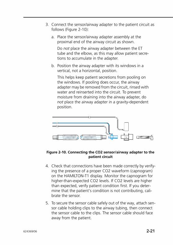
3. Connect the sensor/airway adapter to the patient circuit as follows (Figure 2-10):
a. Place the sensor/airway adapter assembly at the proximal end of the airway circuit as shown.
Do not place the airway adapter between the ET tube and the elbow, as this may allow patient secre-tions to accumulate in the adapter.
b. Position the airway adapter with its windows in a vertical, not a horizontal, position.
This helps keep patient secretions from pooling on the windows. If pooling does occur, the airway adapter may be removed from the circuit, rinsed with water and reinserted into the circuit. To prevent moisture from draining into the airway adapter, do not place the airway adapter in a gravity-dependent position.
Figure 2-10. Connecting the CO2 sensor/airway adapter to the patient circuit
4. Check that connections have been made correctly by verify-ing the presence of a proper CO2 waveform (capnogram) on the HAMILTON-T1 display. Monitor the capnogram for higher-than-expected CO2 levels. If CO2 levels are higher than expected, verify patient condition first. If you deter-mine that the patient’s condition is not contributing, cali-brate the sensor.
5. To secure the sensor cable safely out of the way, attach sen-sor cable holding clips to the airway tubing, then connect the sensor cable to the clips. The sensor cable should face away from the patient.
624369/06 2-21
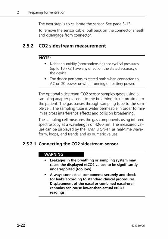
2 Preparing for ventilation
The next step is to calibrate the sensor. See page 3-13.
To remove the sensor cable, pull back on the connector sheath and disengage from connector.
2.5.2 CO2 sidestream measurement
NOTE:• Neither humidity (noncondensing) nor cyclical pressures
(up to 10 kPa) have any effect on the stated accuracy of the device.
• The device performs as stated both when connected to AC or DC power or when running on battery power.
The optional sidestream CO2 sensor samples gases using a sampling adapter placed into the breathing circuit proximal to the patient. The gas passes through sampling tube to the sam-ple cell. The sampling tube is water permeable in order to min-imize cross interference effects and collision broadening.
The sampling cell measures the gas components using infrared spectroscopy at a wavelength of 4260 nm. The measured val-ues can be displayed by the HAMILTON-T1 as real-time wave-form, loops, and trends and as numeric values.
2.5.2.1 Connecting the CO2 sidestream sensor
WARNING• Leakages in the breathing or sampling system may
cause the displayed etCO2 values to be significantly underreported (too low).
• Always connect all components securely and check for leaks according to standard clinical procedures. Displacement of the nasal or combined nasal-oral cannulas can cause lower-than-actual etCO2 readings.
2-22 624369/06
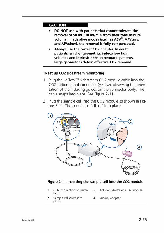
CAUTION• DO NOT use with patients that cannot tolerate the
removal of 50 ml ±10 ml/min from their total minute volume. In adaptive modes (such as ASV®, APVcmv, and APVsimv), the removal is fully compensated.
• Always use the correct CO2 adapter. In adult patients, smaller geometrics induce low tidal volumes and intrinsic PEEP. In neonatal patients, large geometrics detain effective CO2 removal.
To set up CO2 sidestream monitoring
1. Plug the LoFlow™ sidestream CO2 module cable into the CO2 option board connector (yellow), observing the orien-tation of the indexing guides on the connector body. The cable snaps into place. See Figure 2-11.
2. Plug the sample cell into the CO2 module as shown in Fig-ure 2-11. The connector “clicks” into place.
Figure 2-11. Inserting the sample cell into the CO2 module
1 CO2 connection on venti-lator
3 LoFlow sidestream CO2 module
2 Sample cell clicks into place
4 Airway adapter
624369/06 2-23
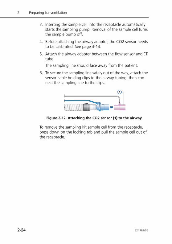
2 Preparing for ventilation
3. Inserting the sample cell into the receptacle automatically starts the sampling pump. Removal of the sample cell turns the sample pump off.
4. Before attaching the airway adapter, the CO2 sensor needs to be calibrated. See page 3-13.
5. Attach the airway adapter between the flow sensor and ET tube.
The sampling line should face away from the patient.
6. To secure the sampling line safely out of the way, attach the sensor cable holding clips to the airway tubing, then con-nect the sampling line to the clips.
Figure 2-12. Attaching the CO2 sensor (1) to the airway
To remove the sampling kit sample cell from the receptacle, press down on the locking tab and pull the sample cell out of the receptacle.
2-24 624369/06
2.6 Installing the Aeroneb Pro nebulizer
NOTE:Connect only approved piezo nebulizers to the HAMILTON-T1 ventilator.
The Aerogen Aeroneb Pro nebulizer system is available as an option for the HAMILTON-T1. Attach it to the mounting bracket. Consult the operating instructions supplied with the nebulizer for further installation and operating information.
2.7 Using an expiratory filter
CAUTION• The use of an expiratory filter can lead to a
significant increase in expiratory circuit resistance. Excessive expiratory circuit resistance can compromise ventilation and increase patient work of breathing or AutoPEEP or both.
• Nebulization of drugs can cause an occlusion and increased resistance of the filter.
NOTE:Monitored parameters for increased expiratory resistance are not specific to the breathing circuit and may indicate increased patient airway resistance and/or increased resis-tance of the artificial airway (if used). Always check the patient and confirm adequate ventilation.
An expiratory filter is not required on the HAMILTON-T1, but you may use one according to your institution’s protocol. An expiratory filter is not required, because the expiratory valve design prevents internal ventilator components from contact with the patient’s exhaled gas.
624369/06 2-25
2 Preparing for ventilation
If you do use an expiratory filter, place it on the patient side of the expiratory valve cover. Remove any expiratory filter or HMEF/HME during nebulization. Monitor closely for increased expiratory circuit resistance. An Exhalation obstructed alarm may also indicate excessive expiratory circuit resistance. If the Exhalation obstructed alarm occurs repeatedly, remove the expi-ratory filter immediately. If you otherwise suspect increased expiratory circuit resistance, remove the expiratory filter or install a new filter to eliminate it as a potential cause.
2.8 Connecting to a power source
NOTE:• To prevent unintentional disconnection of the power
cord, make sure it is well seated into the ventilator socket and secured with the power cord retaining clip.
• Install the ventilator in a location where the primary power can be easily disconnected.
• The HAMILTON-T1 does not require protective earth grounding, because it is a class II device, as classified according to IEC 60601-1.
Either AC or DC can supply the primary power to the HAMILTON-T1.
2.8.1 Connecting to AC powerConnect the HAMILTON-T1 to an outlet that supplies AC power between 100 and 240 V AC, 50/60 Hz.
Always check the reliability of the AC outlet. When connected to AC power, the AC symbol in the bottom right-hand corner of the screen shows a frame around it.
2-26 624369/06
2.8.2 Connecting to DC power
WARNING• Connect the HAMILTON-T1 to an outlet that supplies
DC power between 12 and 28 V DC.
• Use only cables supplied by Hamilton Medical
CAUTION• Check the DC cable. Do not use if there are any open
contacts or damage.
• Only qualified technicians are allowed to configure the open end of the DC cable that is supplied with open contacts.
NOTE:• All of the HAMILTON-T1 DC cables are only allowed for
use with the HAMILTON-T1 ventilator.
• Use only UL-listed plugs with the assembled DC cable.
• The DC cables are for use only with a 12–28 V DC elec-trical power supply. A 15-amp fuse is included.
• Connect DC cables to the DC jack of the ventilator.
• The HAMILTON-T1 DC cables ensure that the ventilator batteries are charged.
• Always check the reliability of the DC outlet. When DC power is connected, the DC symbol in the bottom right-hand corner of the screen shows a frame around it.
The following DC cables are available for use with the ventila-tor. See also the HAMILTON-T1 Product Catalog (PN 689394).
DC cable, metal (with MIL standard connector) 161624
DC cable open, metal (for individual assembly) 161622
Car cable, metal (for cigarette lighter) 161623
624369/06 2-27
2 Preparing for ventilation
The DC cable is for use during transport in ambulances, fixed-wing aircraft, helicopters, and ships that are provided with an appropriate electrical power supply.
A DC cable kit (referred to as the assembled DC cable), which includes a stripped end with two strands, is available. This cable must only be assembled using a UL-listed plug, by autho-rized personnel.
The DC car cable is intended for use during transport in ambu-lances and other rescue vehicles that are provided with appro-priate plug connectors.
2.9 About the batteries
WARNING• The batteries will not charge if the ambient
temperature is above 43°C.
• Be aware that ventilation stops if the internal batteries are fully discharged and no external supply is available.
• Periodically check or replace the battery.
NOTE:• The use of one battery is mandatory. The battery is used
as internal backup battery.
• HAMILTON MEDICAL recommends that the ventilator’s batteries be fully charged before you ventilate a patient. Regularly monitor the battery charge level to ensure an adequate power supply.
• The device generates alarms to alert you to low battery capacity. For details, see the Battery low alarm description on page 8-11.
• Two batteries can be used. One battery is fixed; one can be exchanged (hot-swappable).
• The battery depletion rate may vary according to the age of the battery, ventilation mode, temperature, set-tings, etc.
2-28 624369/06
A backup battery protects the ventilator from low power or failure of the primary power source. When the primary power source fails, the ventilator automatically switches to operation on backup battery with no interruption in ventilation. An alarm sounds to signal the switchover.
Silence the alarm to confirm notification of the power system change; this resets the alarm.
If the optional battery (battery 2) is available and adequately charged, the ventilator switches to this battery first. When it is depleted or not installed, the ventilator switches to the stan-dard battery (battery 1).
The batteries power the ventilator until the primary power source is again adequate or until the battery is depleted.
Hamilton Medical uses high-capacity batteries1 that provide a longer charge. When installed, the text High-Cap appears next to the battery capacity information in the System -> Info win-dow.
It also has a capacitor-driven backup buzzer that sounds con-tinuously for at least 2 min when battery power is completely lost.
The ventilator charges the battery whenever the ventilator is connected to the primary power supply (AC or DC), with or without the ventilator being turned on. The battery charge indicator lights show that the battery is being charged.
1. Hamilton Medical Li-Ion batteries, revision 4 and later
624369/06 2-29
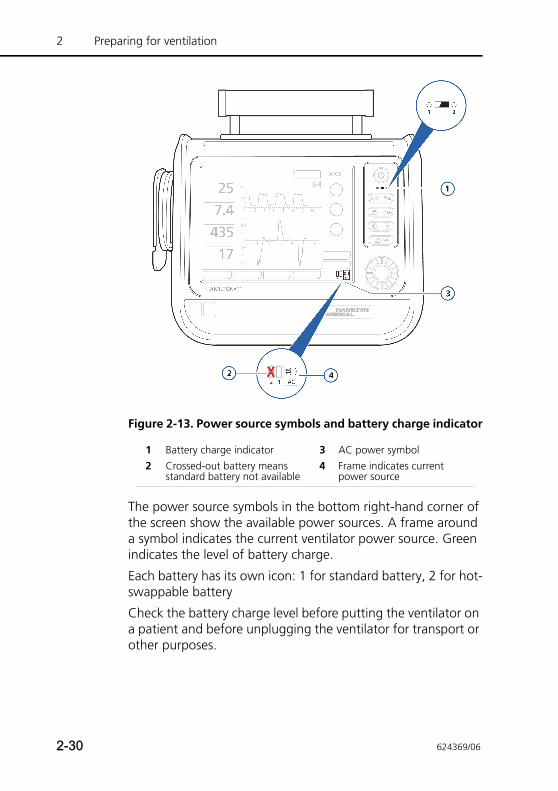
2 Preparing for ventilation
Figure 2-13. Power source symbols and battery charge indicator
The power source symbols in the bottom right-hand corner of the screen show the available power sources. A frame around a symbol indicates the current ventilator power source. Green indicates the level of battery charge.
Each battery has its own icon: 1 for standard battery, 2 for hot-swappable battery
Check the battery charge level before putting the ventilator on a patient and before unplugging the ventilator for transport or other purposes.
1 Battery charge indicator 3 AC power symbol2 Crossed-out battery means
standard battery not available4 Frame indicates current
power source
2-30 624369/06
The charge level is indicated as follows:
• A green symbol indicates a fully charged battery.
• An orange and green symbol indicates a partially charged battery.
• If the battery symbol is crossed out, the battery is discharged or defective.
If a battery is not fully charged, recharge it by connecting the ventilator to the primary power source for a minimum of 4 hours, until the battery charge level is 80% to 100%. Alterna-tively, the battery can also be charged with the external char-ger.
Chapter 10 describes how to charge and replace the battery.
2.10 Connecting the oxygen supply
WARNING• It is NOT permitted to use the equipment with
flammable gases or anaesthetic agents. Danger of fire!
• Before transporting the patient, ensure an adequate oxygen supply by checking the O2 consumption parameter (in the System Info window) and ensuring it is adequate for your estimated travel time and current oxygen capacity. For details, see Section 2.11.
• It is NOT permitted to use the ventilator with helium or mixtures of helium.
• An O2 cell must be installed.
CAUTION• Always check the status of the oxygen cylinders or
other supply before using the ventilator during transport.
• Make sure oxygen cylinders are equipped with pres-sure-reducing valves.
• To minimize the risk of fire, do not use high-pressure gas hoses that are worn or contaminated with com-bustible materials like grease or oil.
624369/06 2-31
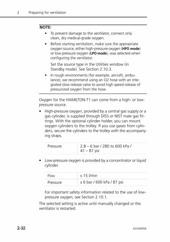
2 Preparing for ventilation
NOTE:• To prevent damage to the ventilator, connect only
clean, dry medical-grade oxygen.
• Before starting ventilation, make sure the appropriate oxygen source, either high-pressure oxygen (HPO mode) or low-pressure oxygen (LPO mode), was selected when configuring the ventilator.
Set the source type in the Utilities window (in Standby mode). See Section 2.10.3.
• In rough environments (for example, aircraft, ambu-lance), we recommend using an O2 hose with an inte-grated slow release valve to avoid high speed release of pressurized oxygen from the hose.
Oxygen for the HAMILTON-T1 can come from a high- or low-pressure source.
• High-pressure oxygen, provided by a central gas supply or a gas cylinder, is supplied through DISS or NIST male gas fit-tings. With the optional cylinder holder, you can mount oxygen cylinders to the trolley. If you use gases from cylin-ders, secure the cylinders to the trolley with the accompany-ing straps.
• Low-pressure oxygen is provided by a concentrator or liquid cylinder.
For important safety information related to the use of low-pressure oxygen, see Section 2.10.1.
The selected setting is active until manually changed or the ventilator is restarted.
Pressure 2.8 – 6 bar / 280 to 600 kPa / 41 – 87 psi
Flow ≤ 15 l/min
Pressure ≤ 6 bar / 600 kPa / 87 psi
2-32 624369/06
2.10.1 Using a low-pressure oxygen supply
CAUTION• To reduce the risk of fire:
– DO NOT use a low-pressure oxygen source that deliv-ers a flow greater than 15 l/min.
– Ensure adequate ventilation at the rear of the venti-lator.
– Switch off the oxygen source when the ventilator is not in a ventilating mode.
• To prevent possible patient injury when the ventila-tor is sourced from an oxygen concentrator, never operate the concentrator with a humidifier. Any humidifier system supplied with the concentrator must be drained or removed before using the ventila-tor.
• The ventilator’s Oxygen control is not active when low-pressure oxygen is used. It is the operator’s responsibility to control the oxygen setting.
• To prevent possible patient injury, use low-pressure oxygen only in cases where the low-pressure source can provide an adequate level of oxygenation.
• To prevent possible patient injury, ensure that an emergency backup oxygen supply (for example, a cylinder) is available in case the low-pressure oxygen source fails.
• To calibrate the O2 cell, disconnect all O2 supplies. Calibration is done at 21%.
• To protect the oxygen control system, do not supply both high- and low-pressure oxygen to the ventilator simultaneously.
Using the low-pressure oxygen supply involves two steps:
• Connecting the supply to the ventilator (Section 2.10.2)
• Selecting the source type on the ventilator (Section 2.10.3)
624369/06 2-33
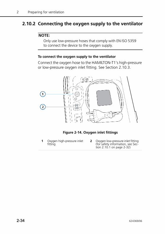
2 Preparing for ventilation
2.10.2 Connecting the oxygen supply to the ventilator
NOTE:Only use low-pressure hoses that comply with EN ISO 5359 to connect the device to the oxygen supply.
To connect the oxygen supply to the ventilator
Connect the oxygen hose to the HAMILTON-T1’s high-pressure or low-pressure oxygen inlet fitting. See Section 2.10.3.
Figure 2-14. Oxygen inlet fittings
1 Oxygen high-pressure inlet fitting
2 Oxygen low-pressure inlet fitting (for safety information, see Sec-tion 2.10.1 on page 2-32)
2-34 624369/06
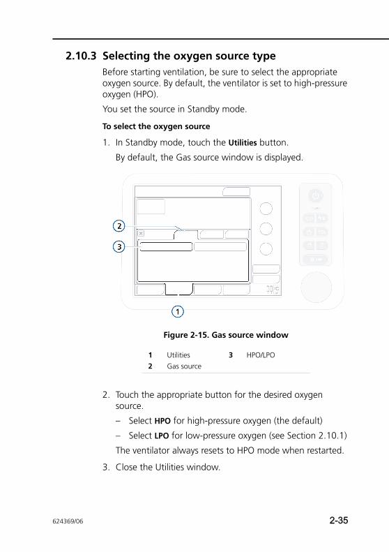
2.10.3 Selecting the oxygen source typeBefore starting ventilation, be sure to select the appropriate oxygen source. By default, the ventilator is set to high-pressure oxygen (HPO).
You set the source in Standby mode.
To select the oxygen source
1. In Standby mode, touch the Utilities button.
By default, the Gas source window is displayed.
Figure 2-15. Gas source window
2. Touch the appropriate button for the desired oxygen source.
– Select HPO for high-pressure oxygen (the default)
– Select LPO for low-pressure oxygen (see Section 2.10.1)
The ventilator always resets to HPO mode when restarted.
3. Close the Utilities window.
1 Utilities 3 HPO/LPO2 Gas source
624369/06 2-35
2 Preparing for ventilation
2.11 Ensuring an adequate oxygen supply for patient transport
WARNING• Before transporting the patient, ensure an adequate
oxygen supply by checking the O2 consumption parameter (in the System Info window) and ensuring it is adequate for your estimated travel time and current oxygen capacity.
Use the appropriate calculation method, listed on page 2-40, to estimate total oxygen requirements for the patient.
• The oxygen consumption of a nebulizer attached to the device is not included in the O2 consumption parameter value. To calculate it, see page 2-43.
Before transporting a patient, it is important to ensure that you have enough oxygen for the journey.
Be sure to:
• Review current oxygen consumption, shown in the System Info window (Section 2.11.1)
• Calculate the patient’s estimate oxygen requirement using the calculation methods provided in Section 2.11.2
Use Method III on 2-42 to calculate consumption for neona-tal patients.
2-36 624369/06
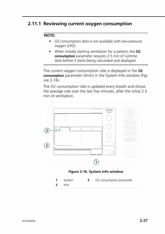
2.11.1 Reviewing current oxygen consumption
NOTE:• O2 consumption data is not available with low-pressure
oxygen (LPO).
• When initially starting ventilation for a patient, the O2 consumption parameter requires 2.5 min of runtime data before it starts being calculated and displayed.
The current oxygen consumption rate is displayed in the O2 consumption parameter (l/min) in the System Info window (Fig-ure 2-16).
The O2 consumption rate is updated every breath and shows the average rate over the last five minutes, after the initial 2.5 min of ventilation.
Figure 2-16. System Info window
1 System 3 O2 consumption parameter2 Info
624369/06 2-37
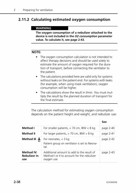
2 Preparing for ventilation
2.11.2 Calculating estimated oxygen consumption
WARNINGThe oxygen consumption of a nebulizer attached to the device is not included in the O2 consumption parameter value. To calculate it, see page 2-43.
NOTE:• The oxygen consumption calculation is not intended to
affect therapy decisions and should be used solely to estimate the amount of oxygen required for the dura-tion of transport, before connecting the ventilator to the patient.
• The calculations provided here are valid only for systems without leaks on the patient end. For systems with leaks (for example, when using mask ventilation), oxygen consumption will be higher.
• The calculations show the result in l/min. You must mul-tiply the result by the planned duration of transport for the final estimate.
The calculation method for estimating oxygen consumption depends on the patient height and weight, and nebulizer use:
See
Method I For smaller patients, < 70 cm, IBW < 8 kg page 2-40
Method II For larger patients, > 70 cm, IBW > 8 kg page 2-41
Method III For neonates, < 3 kgPatient group on ventilator is set to Neona-tal.
page 2-42
Method IV: Nebulizer in use
Additional amount to add to the result of Method I or II to account for the nebulizer oxygen use
page 2-43
2-38 624369/06
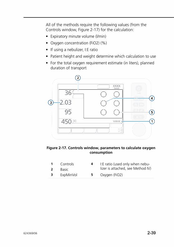
All of the methods require the following values (from the Controls window, Figure 2-17) for the calculation:
• Expiratory minute volume (l/min)
• Oxygen concentration (FiO2) (%)
• If using a nebulizer, I:E ratio
• Patient height and weight determine which calculation to use
• For the total oxygen requirement estimate (in liters), planned duration of transport
Figure 2-17. Controls window, parameters to calculate oxygen consumption
1 Controls 4 I:E ratio (used only when nebu-lizer is attached, see Method IV)2 Basic
3 ExpMinVol 5 Oxygen (FiO2)
624369/06 2-39
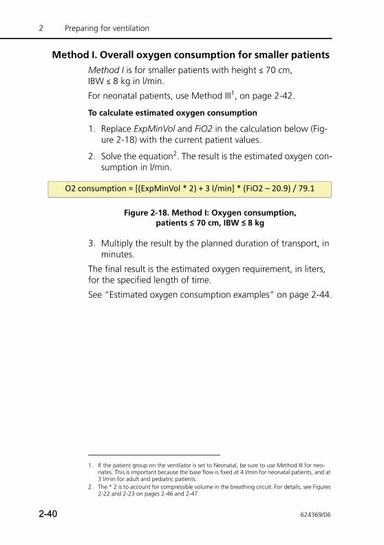
2 Preparing for ventilation
Method I. Overall oxygen consumption for smaller patients Method I is for smaller patients with height ≤ 70 cm, IBW ≤ 8 kg in l/min.
For neonatal patients, use Method III1, on page 2-42.
To calculate estimated oxygen consumption
1. Replace ExpMinVol and FiO2 in the calculation below (Fig-ure 2-18) with the current patient values.
2. Solve the equation2. The result is the estimated oxygen con-sumption in l/min.
Figure 2-18. Method I: Oxygen consumption, patients ≤ 70 cm, IBW ≤ 8 kg
3. Multiply the result by the planned duration of transport, in minutes.
The final result is the estimated oxygen requirement, in liters, for the specified length of time.
See “Estimated oxygen consumption examples” on page 2-44.
1. If the patient group on the ventilator is set to Neonatal, be sure to use Method III for neo-nates. This is important because the base flow is fixed at 4 l/min for neonatal patients, and at 3 l/min for adult and pediatric patients.
2. The * 2 is to account for compressible volume in the breathing circuit. For details, see Figures 2-22 and 2-23 on pages 2-46 and 2-47.
O2 consumption = [(ExpMinVol * 2) + 3 l/min] * (FiO2 – 20.9) / 79.1
2-40 624369/06
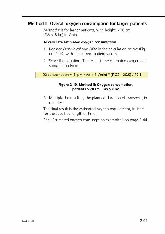
Method II. Overall oxygen consumption for larger patients Method II is for larger patients, with height > 70 cm, IBW > 8 kg) in l/min.
To calculate estimated oxygen consumption
1. Replace ExpMinVol and FiO2 in the calculation below (Fig-ure 2-19) with the current patient values.
2. Solve the equation. The result is the estimated oxygen con-sumption in l/min.
Figure 2-19. Method II: Oxygen consumption, patients > 70 cm, IBW > 8 kg
3. Multiply the result by the planned duration of transport, in minutes.
The final result is the estimated oxygen requirement, in liters, for the specified length of time.
See “Estimated oxygen consumption examples” on page 2-44.
O2 consumption = (ExpMinVol + 3 l/min) * (FiO2 – 20.9) / 79.1
624369/06 2-41
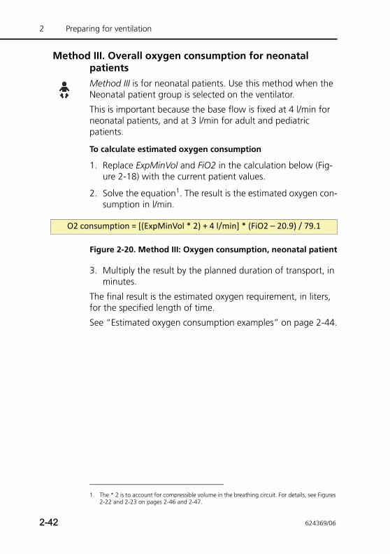
2 Preparing for ventilation
Method III. Overall oxygen consumption for neonatal patients Method III is for neonatal patients. Use this method when the Neonatal patient group is selected on the ventilator.
This is important because the base flow is fixed at 4 l/min for neonatal patients, and at 3 l/min for adult and pediatric patients.
To calculate estimated oxygen consumption
1. Replace ExpMinVol and FiO2 in the calculation below (Fig-ure 2-18) with the current patient values.
2. Solve the equation1. The result is the estimated oxygen con-sumption in l/min.
Figure 2-20. Method III: Oxygen consumption, neonatal patient
3. Multiply the result by the planned duration of transport, in minutes.
The final result is the estimated oxygen requirement, in liters, for the specified length of time.
See “Estimated oxygen consumption examples” on page 2-44.
1. The * 2 is to account for compressible volume in the breathing circuit. For details, see Figures 2-22 and 2-23 on pages 2-46 and 2-47.
O2 consumption = [(ExpMinVol * 2) + 4 l/min] * (FiO2 – 20.9) / 79.1
2-42 624369/06
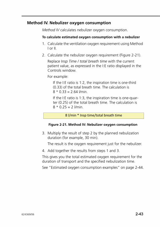
Method IV. Nebulizer oxygen consumption
Method IV calculates nebulizer oxygen consumption.
To calculate estimated oxygen consumption with a nebulizer
1. Calculate the ventilation oxygen requirement using Method I or II.
2. Calculate the nebulizer oxygen requirement (Figure 2-21).
Replace Insp Time / total breath time with the current patient value, as expressed in the I:E ratio displayed in the Controls window.
For example:
If the I:E ratio is 1:2, the inspiration time is one-third (0.33) of the total breath time. The calculation is 8 * 0.33 = 2.64 l/min.
If the I:E ratio is 1:3, the inspiration time is one-quar-ter (0.25) of the total breath time. The calculation is 8 * 0.25 = 2 l/min.
Figure 2-21. Method IV: Nebulizer oxygen consumption
3. Multiply the result of step 2 by the planned nebulization duration (for example, 30 min).
The result is the oxygen requirement just for the nebulizer.
4. Add together the results from steps 1 and 3.
This gives you the total estimated oxygen requirement for the duration of transport and the specified nebulization time.
See “Estimated oxygen consumption examples” on page 2-44.
8 l/min * Insp time/total breath time
624369/06 2-43
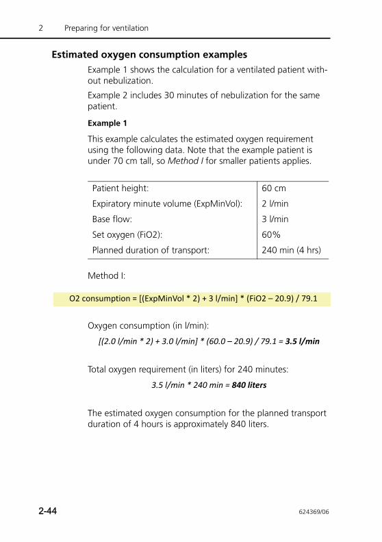
2 Preparing for ventilation
Estimated oxygen consumption examplesExample 1 shows the calculation for a ventilated patient with-out nebulization.
Example 2 includes 30 minutes of nebulization for the same patient.
Example 1
This example calculates the estimated oxygen requirement using the following data. Note that the example patient is under 70 cm tall, so Method I for smaller patients applies.
Method I:
Oxygen consumption (in l/min):
[(2.0 l/min * 2) + 3.0 l/min] * (60.0 – 20.9) / 79.1 = 3.5 l/min
Total oxygen requirement (in liters) for 240 minutes:
3.5 l/min * 240 min = 840 liters
The estimated oxygen consumption for the planned transport duration of 4 hours is approximately 840 liters.
Patient height: 60 cm
Expiratory minute volume (ExpMinVol): 2 l/min
Base flow: 3 l/min
Set oxygen (FiO2): 60%
Planned duration of transport: 240 min (4 hrs)
O2 consumption = [(ExpMinVol * 2) + 3 l/min] * (FiO2 – 20.9) / 79.1
2-44 624369/06
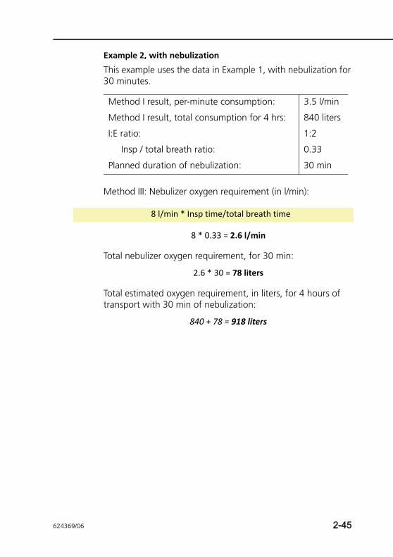
Example 2, with nebulization
This example uses the data in Example 1, with nebulization for 30 minutes.
Method III: Nebulizer oxygen requirement (in l/min):
8 * 0.33 = 2.6 l/min
Total nebulizer oxygen requirement, for 30 min:
2.6 * 30 = 78 liters
Total estimated oxygen requirement, in liters, for 4 hours of transport with 30 min of nebulization:
840 + 78 = 918 liters
Method I result, per-minute consumption: 3.5 l/min
Method I result, total consumption for 4 hrs: 840 liters
I:E ratio: 1:2
Insp / total breath ratio: 0.33
Planned duration of nebulization: 30 min
8 l/min * Insp time/total breath time
624369/06 2-45
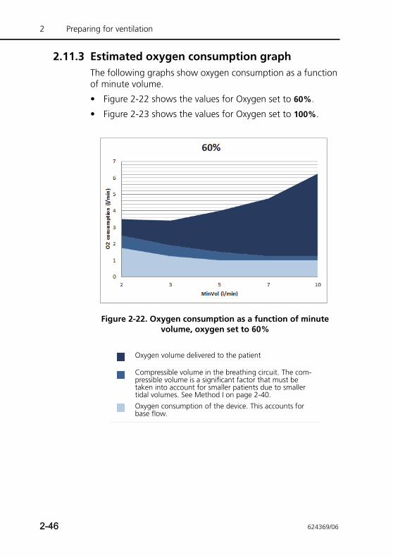
2 Preparing for ventilation
2.11.3 Estimated oxygen consumption graphThe following graphs show oxygen consumption as a function of minute volume.
• Figure 2-22 shows the values for Oxygen set to 60%.
• Figure 2-23 shows the values for Oxygen set to 100%.
Figure 2-22. Oxygen consumption as a function of minute volume, oxygen set to 60%
Oxygen volume delivered to the patient
Compressible volume in the breathing circuit. The com-pressible volume is a significant factor that must be taken into account for smaller patients due to smaller tidal volumes. See Method I on page 2-40.Oxygen consumption of the device. This accounts for base flow.
2-46 624369/06
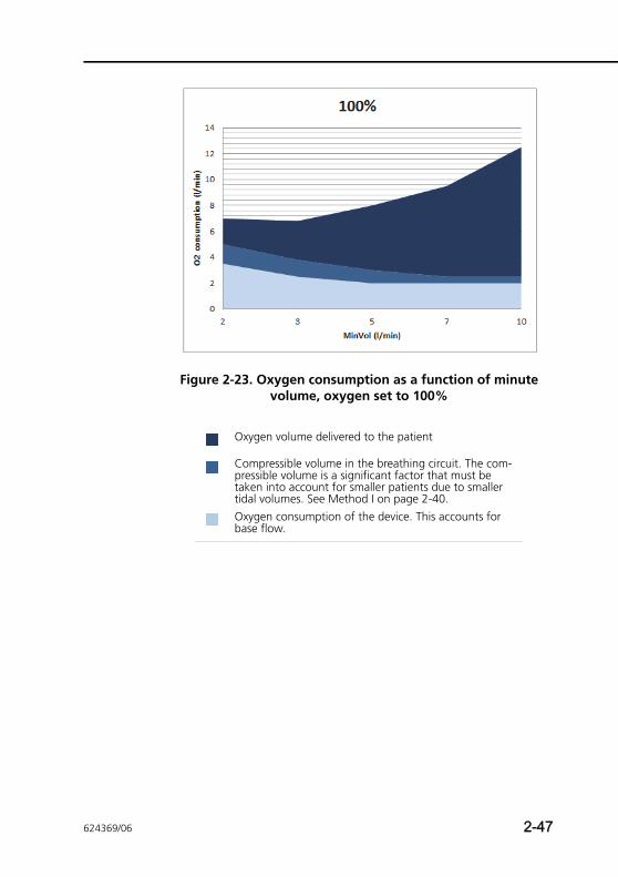
Figure 2-23. Oxygen consumption as a function of minute volume, oxygen set to 100%
Oxygen volume delivered to the patient
Compressible volume in the breathing circuit. The com-pressible volume is a significant factor that must be taken into account for smaller patients due to smaller tidal volumes. See Method I on page 2-40.Oxygen consumption of the device. This accounts for base flow.
624369/06 2-47
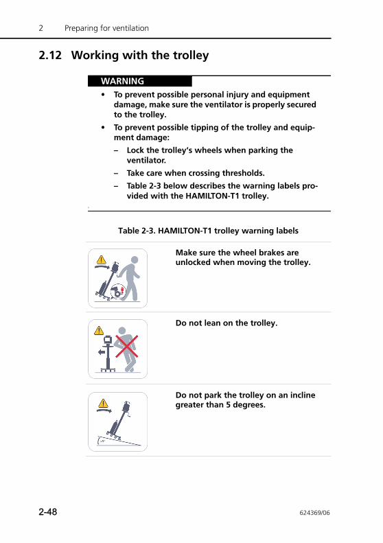
2 Preparing for ventilation
2.12 Working with the trolley
WARNING• To prevent possible personal injury and equipment
damage, make sure the ventilator is properly secured to the trolley.
• To prevent possible tipping of the trolley and equip-ment damage:
– Lock the trolley’s wheels when parking the ventilator.
– Take care when crossing thresholds.
– Table 2-3 below describes the warning labels pro-vided with the HAMILTON-T1 trolley.
§
Table 2-3. HAMILTON-T1 trolley warning labels
Make sure the wheel brakes are unlocked when moving the trolley.
Do not lean on the trolley.
Do not park the trolley on an incline greater than 5 degrees.
2-48 624369/06
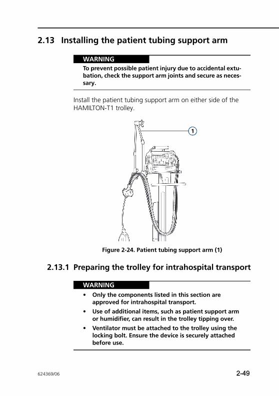
2.13 Installing the patient tubing support arm
WARNINGTo prevent possible patient injury due to accidental extu-bation, check the support arm joints and secure as neces-sary.
Install the patient tubing support arm on either side of the HAMILTON-T1 trolley.
Figure 2-24. Patient tubing support arm (1)
2.13.1 Preparing the trolley for intrahospital transport
WARNING• Only the components listed in this section are
approved for intrahospital transport.
• Use of additional items, such as patient support arm or humidifier, can result in the trolley tipping over.
• Ventilator must be attached to the trolley using the locking bolt. Ensure the device is securely attached before use.
624369/06 2-49
2 Preparing for ventilation
NOTE:The following requirements apply only to transport using ventilators mounted on a HAMILTON-T1 trolley. They do not apply to other mounting solutions.
If using a HAMILTON-T1 trolley, the ventilator and its compo-nents, as well as the trolley, must be configured and posi-tioned as follows during transport within the hospital:
• The ventilator must be securely mounted on the trolley
• The O2 cylinder must be securely attached to the trolley
• Only the following components are allowed to be connected during transport:
– Breathing circuit
– Flow sensor (or pressure line)
– CO2 sensor (mainstream or sidestream)
– SpO2 sensor
– O2 cylinder
2.14 Connecting to an external patient monitor or other device
WARNINGAll devices connected to the HAMILTON-T1 must be for medical use and meet the requirements of standard IEC 60950.
You can connect your ventilator to a patient monitor, a Patient Data Monitoring System (PDMS), or a computer via the COM1 port. For details on the communication interface, see Appendix H.
2-50 624369/06
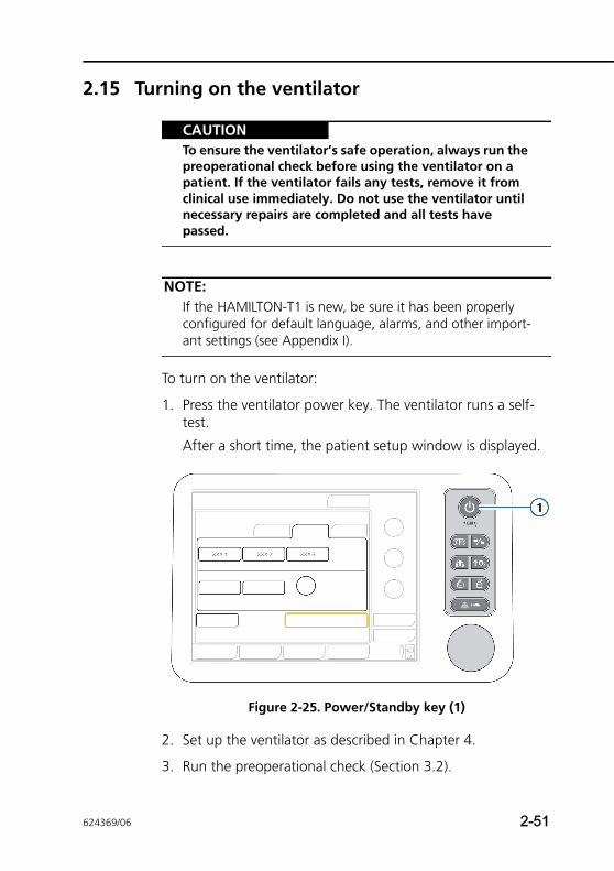
2.15 Turning on the ventilator
CAUTIONTo ensure the ventilator’s safe operation, always run the preoperational check before using the ventilator on a patient. If the ventilator fails any tests, remove it from clinical use immediately. Do not use the ventilator until necessary repairs are completed and all tests have passed.
NOTE:If the HAMILTON-T1 is new, be sure it has been properly configured for default language, alarms, and other import-ant settings (see Appendix I).
To turn on the ventilator:
1. Press the ventilator power key. The ventilator runs a self-test.
After a short time, the patient setup window is displayed.
Figure 2-25. Power/Standby key (1)
2. Set up the ventilator as described in Chapter 4.
3. Run the preoperational check (Section 3.2).
624369/06 2-51
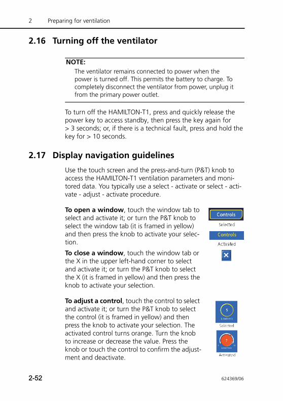
2 Preparing for ventilation
2.16 Turning off the ventilator
NOTE:The ventilator remains connected to power when the power is turned off. This permits the battery to charge. To completely disconnect the ventilator from power, unplug it from the primary power outlet.
To turn off the HAMILTON-T1, press and quickly release the power key to access standby, then press the key again for > 3 seconds; or, if there is a technical fault, press and hold the key for > 10 seconds.
2.17 Display navigation guidelines
Use the touch screen and the press-and-turn (P&T) knob to access the HAMILTON-T1 ventilation parameters and moni-tored data. You typically use a select - activate or select - acti-vate - adjust - activate procedure.
To open a window, touch the window tab to select and activate it; or turn the P&T knob to select the window tab (it is framed in yellow) and then press the knob to activate your selec-tion.
To close a window, touch the window tab or the X in the upper left-hand corner to select and activate it; or turn the P&T knob to select the X (it is framed in yellow) and then press the knob to activate your selection.
To adjust a control, touch the control to select and activate it; or turn the P&T knob to select the control (it is framed in yellow) and then press the knob to activate your selection. The activated control turns orange. Turn the knob to increase or decrease the value. Press the knob or touch the control to confirm the adjust-ment and deactivate.
2-52 624369/06

To scroll through a list using the scroll bar or arrows, touch the scroll bar to select and acti-vate it; or turn the P&T knob to select the scroll bar (it is framed in yellow) and then press it to activate your selection. Your selection turns orange when activated. Now turn the knob to scroll through the log. Touch the scroll bar or press the knob to deactivate.
624369/06 2-53

2 Preparing for ventilation
2-54 624369/06
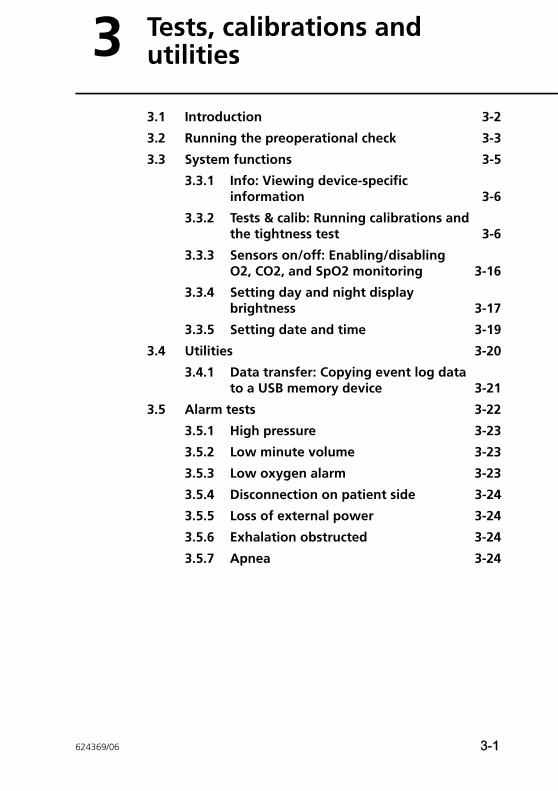
3 Tests, calibrations and utilities
3.1 Introduction 3-2
3.2 Running the preoperational check 3-3
3.3 System functions 3-5
3.3.1 Info: Viewing device-specific information 3-6
3.3.2 Tests & calib: Running calibrations and the tightness test 3-6
3.3.3 Sensors on/off: Enabling/disabling O2, CO2, and SpO2 monitoring 3-16
3.3.4 Setting day and night display brightness 3-17
3.3.5 Setting date and time 3-19
3.4 Utilities 3-20
3.4.1 Data transfer: Copying event log data to a USB memory device 3-21
3.5 Alarm tests 3-22
3.5.1 High pressure 3-23
3.5.2 Low minute volume 3-23
3.5.3 Low oxygen alarm 3-23
3.5.4 Disconnection on patient side 3-24
3.5.5 Loss of external power 3-24
3.5.6 Exhalation obstructed 3-24
3.5.7 Apnea 3-24
624369/06 3-1
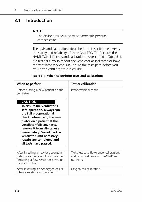
3 Tests, calibrations and utilities
3.1 Introduction
NOTE:The device provides automatic barometric pressure compensation.
The tests and calibrations described in this section help verify the safety and reliability of the HAMILTON-T1. Perform the HAMILTON-T1’s tests and calibrations as described in Table 3-1. If a test fails, troubleshoot the ventilator as indicated or have the ventilator serviced. Make sure the tests pass before you return the ventilator to clinical use.
Table 3-1. When to perform tests and calibrations
When to perform Test or calibration
Before placing a new patient on the ventilator
CAUTIONTo ensure the ventilator’s safe operation, always run the full preoperational check before using the ven-tilator on a patient. If the ventilator fails any tests, remove it from clinical use immediately. Do not use the ventilator until necessary repairs are completed and all tests have passed.
Preoperational check
After installing a new or decontami-nated breathing circuit or component (including a flow sensor or pressure-monitoring line)
Tightness test, flow sensor calibration, and circuit calibration for nCPAP and nCPAP-PC
After installing a new oxygen cell or when a related alarm occurs
Oxygen cell calibration
3-2 624369/06
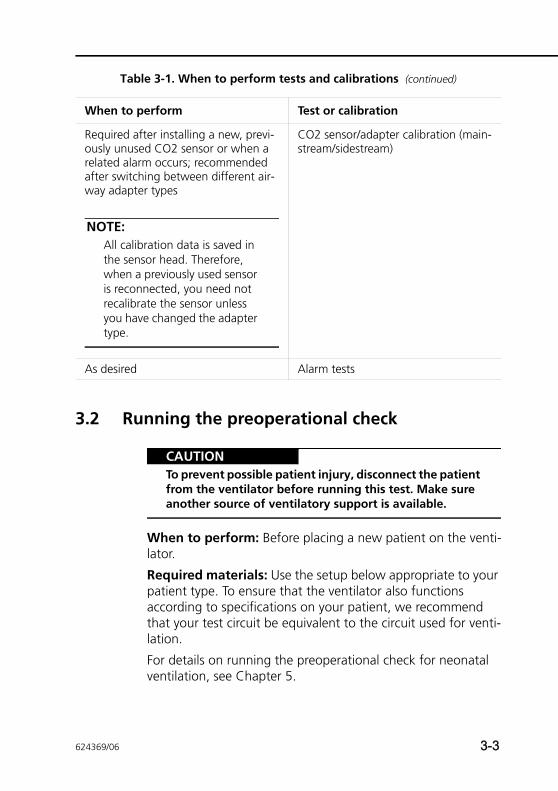
3.2 Running the preoperational check
CAUTIONTo prevent possible patient injury, disconnect the patient from the ventilator before running this test. Make sure another source of ventilatory support is available.
When to perform: Before placing a new patient on the venti-lator.
Required materials: Use the setup below appropriate to your patient type. To ensure that the ventilator also functions according to specifications on your patient, we recommend that your test circuit be equivalent to the circuit used for venti-lation.
For details on running the preoperational check for neonatal ventilation, see Chapter 5.
Required after installing a new, previ-ously unused CO2 sensor or when a related alarm occurs; recommended after switching between different air-way adapter types
NOTE:All calibration data is saved in the sensor head. Therefore, when a previously used sensor is reconnected, you need not recalibrate the sensor unless you have changed the adapter type.
CO2 sensor/adapter calibration (main-stream/sidestream)
As desired Alarm tests
Table 3-1. When to perform tests and calibrations (continued)
When to perform Test or calibration
624369/06 3-3
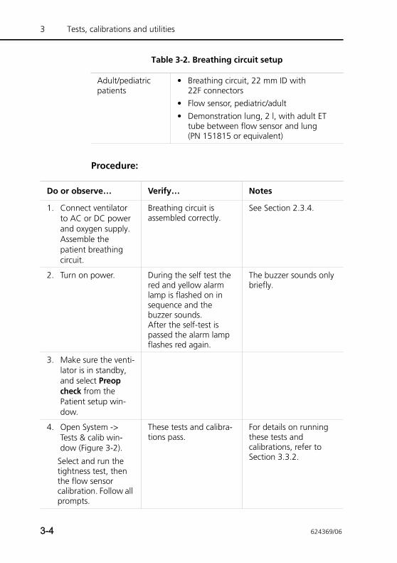
3 Tests, calibrations and utilities
Procedure:
Table 3-2. Breathing circuit setup
Adult/pediatric patients
• Breathing circuit, 22 mm ID with 22F connectors
• Flow sensor, pediatric/adult• Demonstration lung, 2 l, with adult ET
tube between flow sensor and lung (PN 151815 or equivalent)
Do or observe… Verify… Notes
1. Connect ventilator to AC or DC power and oxygen supply. Assemble the patient breathing circuit.
Breathing circuit is assembled correctly.
See Section 2.3.4.
2. Turn on power. During the self test the red and yellow alarm lamp is flashed on in sequence and the buzzer sounds. After the self-test is passed the alarm lamp flashes red again.
The buzzer sounds only briefly.
3. Make sure the venti-lator is in standby, and select Preop check from the Patient setup win-dow.
4. Open System -> Tests & calib win-dow (Figure 3-2).
Select and run the tightness test, then the flow sensor calibration. Follow all prompts.
These tests and calibra-tions pass.
For details on running these tests and calibrations, refer to Section 3.3.2.
3-4 624369/06
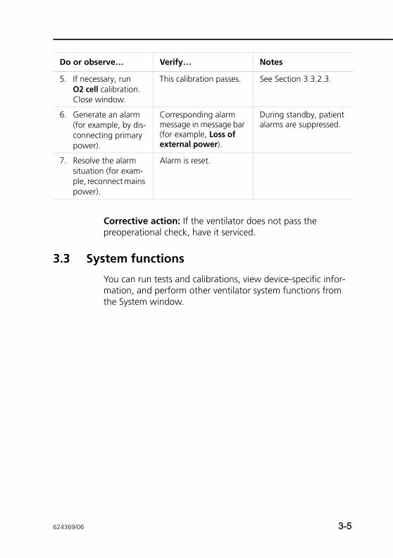
Corrective action: If the ventilator does not pass the preoperational check, have it serviced.
3.3 System functions
You can run tests and calibrations, view device-specific infor-mation, and perform other ventilator system functions from the System window.
5. If necessary, run O2 cell calibration. Close window.
This calibration passes. See Section 3.3.2.3.
6. Generate an alarm (for example, by dis-connecting primary power).
Corresponding alarm message in message bar (for example, Loss of external power).
During standby, patient alarms are suppressed.
7. Resolve the alarm situation (for exam-ple, reconnect mains power).
Alarm is reset.
Do or observe… Verify… Notes
624369/06 3-5
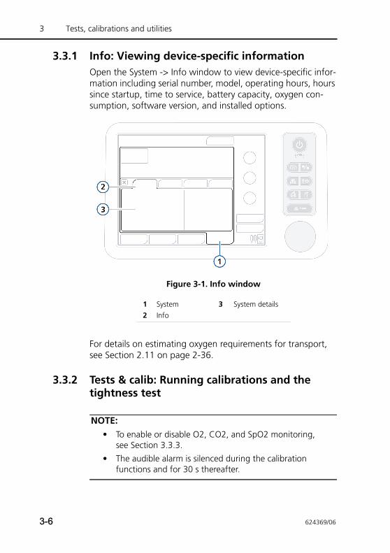
3 Tests, calibrations and utilities
3.3.1 Info: Viewing device-specific informationOpen the System -> Info window to view device-specific infor-mation including serial number, model, operating hours, hours since startup, time to service, battery capacity, oxygen con-sumption, software version, and installed options.
Figure 3-1. Info window
For details on estimating oxygen requirements for transport, see Section 2.11 on page 2-36.
3.3.2 Tests & calib: Running calibrations and the tightness test
NOTE:• To enable or disable O2, CO2, and SpO2 monitoring,
see Section 3.3.3.
• The audible alarm is silenced during the calibration functions and for 30 s thereafter.
1 System 3 System details2 Info
3-6 624369/06
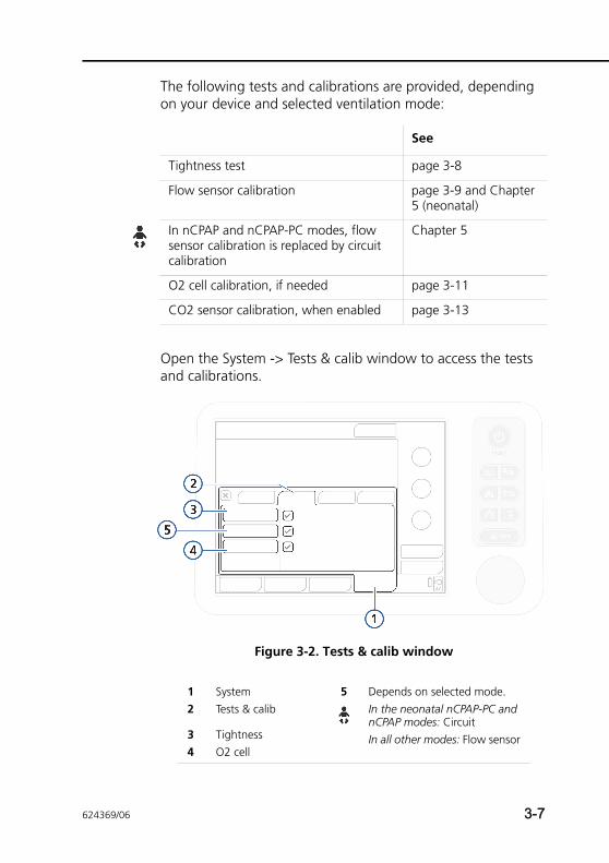
The following tests and calibrations are provided, depending on your device and selected ventilation mode:
Open the System -> Tests & calib window to access the tests and calibrations.
Figure 3-2. Tests & calib window
See
Tightness test page 3-8
Flow sensor calibration page 3-9 and Chapter 5 (neonatal)
In nCPAP and nCPAP-PC modes, flow sensor calibration is replaced by circuit calibration
Chapter 5
O2 cell calibration, if needed page 3-11
CO2 sensor calibration, when enabled page 3-13
1 System 5 Depends on selected mode.In the neonatal nCPAP-PC and nCPAP modes: CircuitIn all other modes: Flow sensor
2 Tests & calib
3 Tightness4 O2 cell
624369/06 3-7
3 Tests, calibrations and utilities
3.3.2.1 Tightness test
NOTE:• Make sure another source of ventilatory support is avail-
able during this test. The patient must be disconnected from the ventilator during the test.
• To cancel the tightness test while it is in progress, select Tightness again.
Description: This test checks for leakage in the patient breath-ing circuit. The ventilator is pressurized to 45 cmH2O. The cir-cuit is considered tight if this pressure can be maintained.
Procedure:
1. Set the ventilator up as for normal ventilation, complete with the breathing circuit.
2. Activate Tightness test from the Tests & calib window (Figure 3-2).
The text Disconnect patient is now displayed.
3. Disconnect the breathing circuit at the patient side of the flow sensor. Do not block the open end of the flow sensor.
The text Tighten patient system is now displayed.
4. Block the opening (wearing a sterilized glove is recom-mended).
The text Connect patient is now displayed.
5. Connect the patient.
6. When the test is complete, verify that there is a green check mark in the Tightness checkbox.
3-8 624369/06
In case of test failure
If the test fails, a red X is displayed in the Tightness checkbox.
Perform the following checks, repeating the tightness test after each one, until the test is successful:
• Check the breathing circuit for a disconnection between the ventilator and the flow sensor, or for other large leaks (for example, breathing circuit, humidifier).
• Check that the expiratory valve is correctly installed.
• Replace the breathing circuit, flow sensor, and expiratory valve.
If the problem still persists, have the ventilator serviced.
3.3.2.2 Flow sensor calibration
NOTE:• Make sure another source of ventilatory support is avail-
able during this calibration. The patient must be discon-nected from the ventilator during the test.
• To cancel the flow sensor calibration while it is in prog-ress, select Flow Sensor again.
• Circuit resistance compensation is measured during cal-ibration.
• If you are using a LiteCircuit, block the opening of the whisper valve with your finger.
• If there is a mismatch between the active patient profile and the flow sensor type you are using, the calibration fails. Ensure you are using the correct flow sensor for the patient.
• Noninvasive neonatal ventilation does not use a flow sensor. For details about neonatal ventilation, tests, and calibration, see Chapter 5.
624369/06 3-9
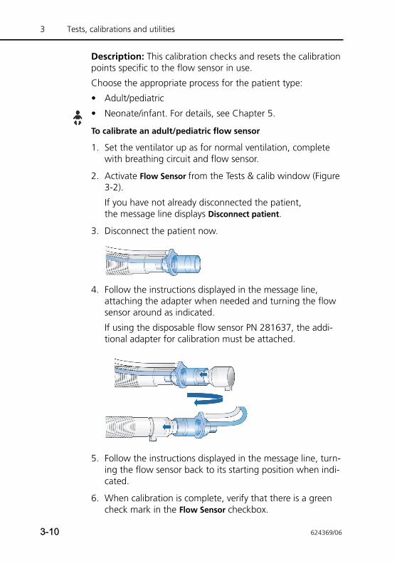
3 Tests, calibrations and utilities
Description: This calibration checks and resets the calibration points specific to the flow sensor in use.
Choose the appropriate process for the patient type:
• Adult/pediatric
• Neonate/infant. For details, see Chapter 5.
To calibrate an adult/pediatric flow sensor
1. Set the ventilator up as for normal ventilation, complete with breathing circuit and flow sensor.
2. Activate Flow Sensor from the Tests & calib window (Figure 3-2).
If you have not already disconnected the patient, the message line displays Disconnect patient.
3. Disconnect the patient now.
4. Follow the instructions displayed in the message line, attaching the adapter when needed and turning the flow sensor around as indicated.
If using the disposable flow sensor PN 281637, the addi-tional adapter for calibration must be attached.
5. Follow the instructions displayed in the message line, turn-ing the flow sensor back to its starting position when indi-cated.
6. When calibration is complete, verify that there is a green check mark in the Flow Sensor checkbox.
3-10 624369/06
7. When successful, touch the Start ventilation button in the Standby window, and connect the patient, as indicated.
In case of calibration failure
If the calibration fails, a red X is displayed in the Flow Sensor checkbox.
Perform the following checks, repeating the calibration after each one, until calibration is successful:
• Check the breathing circuit for a disconnection between the ventilator and the flow sensor, or for other large leaks (for example, breathing circuit, humidifier).
• Check that the correct flow sensor is connected, and that the flow sensor and expiratory valve/membrane are prop-erly seated.
• If the calibration fails again, replace the flow sensor.
• If the calibration still fails, replace the expiratory valve/mem-brane.
If the problem persists, have the ventilator serviced.
3.3.2.3 Oxygen cell calibration
NOTE:• The oxygen cell calibration requires that the ventilator’s
oxygen monitoring be enabled. To check for an oxygen cell, see Section 10.3.3. To determine whether oxygen monitoring is enabled, check the System -> Sensors on/off window and ensure the O2 cell checkbox is selected.
• If using the low-pressure-mode, disconnect all O2 sup-plies during calibration. After reconnecting, the oxygen concentration is set to 21%.
• The O2 cell requires approximately 30 minutes warm-up time to reach stable values. O2 monitoring during this time period may be more variable. We recommend performing the calibration after the O2 cell is warmed up.
624369/06 3-11
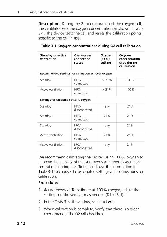
3 Tests, calibrations and utilities
Description: During the 2-min calibration of the oxygen cell, the ventilator sets the oxygen concentration as shown in Table 3-1. The device tests the cell and resets the calibration points specific to the cell in use.
We recommend calibrating the O2 cell using 100% oxygen to improve the stability of measurements at higher oxygen con-centrations during use. To this end, use the information in Table 3-1 to choose the associated settings and connections for calibration.
Procedure:
1. Recommended. To calibrate at 100% oxygen, adjust the settings on the ventilator as needed (Table 3-1).
2. In the Tests & calib window, select O2 cell.
3. When calibration is complete, verify that there is a green check mark in the O2 cell checkbox.
Table 3-1. Oxygen concentrations during O2 cell calibration
Standby or active ventilation
Gas source/connection status
Oxygen (FiO2) setting
Oxygen concentration used during calibration
Recommended settings for calibration at 100% oxygen
Standby HPO/connected
> 21% 100%
Active ventilation HPO/connected
> 21% 100%
Settings for calibration at 21% oxygen
Standby HPO/disconnected
any 21%
Standby HPO/connected
21% 21%
Standby LPO/disconnected
any 21%
Active ventilation HPO/connected
21% 21%
Active ventilation LPO/disconnected
any 21%
3-12 624369/06
In case of calibration failure
If the calibration fails, a red X is displayed in the O2 cell check-box.
Perform the following checks, repeating the calibration after each one, until calibration is successful:
• Ensure O2 cell is connected and a Hamilton Medical O2 cell is used (PN 396200).
• If the second calibration attempt fails, replace the O2 cell.
If the problem persists, have the ventilator serviced.
3.3.2.4 CO2 sensor/adapter zero calibration
CAUTION• Always calibrate the CO2 sensor with the airway
attached.
• Be sure NOT to cover both ends of the airway adapter with your fingers.
NOTE:• Wait at least 20 s – and for best results, 2 min – to per-
form the CO2 sensor/adapter calibration after removing the adapter from the patient’s airway. This time allows any CO2 remaining in the adapter to dissipate.
• If you close the Tests & calib window when the calibra-tion has failed, the HAMILTON-T1 starts or continues ventilating, but continues to display CO2 sensor calibra-tion needed. This may result in inaccurate monitoring.
Description: The CO2 sensor/adapter zero calibration com-pensates for the optical differences between airway adapters and for sensor drift.
Procedure:
1. Before you begin, ensure:
– The CO2 hardware option is installed and activated
– CO2 monitoring is enabled (System -> Sensors on/off)
624369/06 3-13
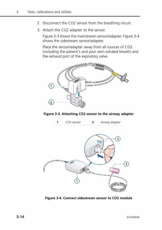
3 Tests, calibrations and utilities
2. Disconnect the CO2 sensor from the breathing circuit.
3. Attach the CO2 adapter to the sensor.
Figure 3-3 shows the mainstream sensor/adapter. Figure 3-4 shows the sidestream sensor/adapter.
Place the sensor/adapter away from all sources of CO2 (including the patient's and your own exhaled breath) and the exhaust port of the expiratory valve.
Figure 3-3. Attaching CO2 sensor to the airway adapter
Figure 3-4. Connect sidestream sensor to CO2 module
1 CO2 sensor 2 Airway adapter
3-14 624369/06
4. Connect the adapter cable to the CO2 connection on the ventilator.
5. Ensure CO2 monitoring is enabled (System -> Sensors on/off).
Once enabled, the sensor requires approximately 90 seconds to warm up.
6. Touch System -> Tests & calib window, and then select CO2.
Sensor calibration takes place.
Do not move the sensor during calibration.
7. Verify that there is a green check mark in the CO2 checkbox.
In case of calibration failure
If the calibration fails, a red X is displayed in the CO2 checkbox.
Perform the following checks, repeating the calibration after each one, until calibration is successful:
• Check airway adapter and clean if necessary.
• Re-calibrate the sensor, making sure there is no source of CO2 near the airway adapter.
• Connect a new airway adapter.
• Install a new CO2 sensor.
If the problem persists, have the ventilator serviced.
3.3.3 Sensors on/off: Enabling/disabling O2, CO2, and SpO2 monitoring
CAUTIONThe HAMILTON-T1’s oxygen monitoring function can be disabled. Ensure that an alternative means of oxygen monitoring is always available and enabled.
1 LoFlow™ sidestream CO2 module 3 Airway adapter2 Sample cell clicks into place
624369/06 3-15
3 Tests, calibrations and utilities
NOTE:To enable the optional CO2 and SpO2 monitoring, you must first enable the associated hardware option in config-uration.
1. Open the System -> Sensors on/off window.
2. Select the appropriate check boxes (O2, CO2, SpO2) to enable/disable the monitoring functions, as desired.
O2 cell monitoring is enabled by default.
3-16 624369/06
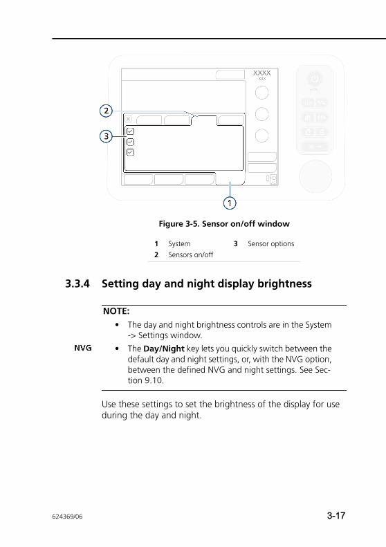
Figure 3-5. Sensor on/off window
3.3.4 Setting day and night display brightness
NOTE:• The day and night brightness controls are in the System
-> Settings window.
• The Day/Night key lets you quickly switch between the default day and night settings, or, with the NVG option, between the defined NVG and night settings. See Sec-tion 9.10.
Use these settings to set the brightness of the display for use during the day and night.
1 System 3 Sensor options2 Sensors on/off
624369/06 3-17
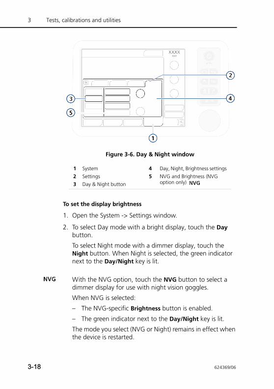
3 Tests, calibrations and utilities
Figure 3-6. Day & Night window
To set the display brightness
1. Open the System -> Settings window.
2. To select Day mode with a bright display, touch the Day button.
To select Night mode with a dimmer display, touch the Night button. When Night is selected, the green indicator next to the Day/Night key is lit.
With the NVG option, touch the NVG button to select a dimmer display for use with night vision goggles.
When NVG is selected:
– The NVG-specific Brightness button is enabled.
– The green indicator next to the Day/Night key is lit.
The mode you select (NVG or Night) remains in effect when the device is restarted.
1 System 4 Day, Night, Brightness settings2 Settings 5 NVG and Brightness (NVG
option only) 3 Day & Night button
3-18 624369/06
3. Adjust the brightness of the display in each mode using the Brightness control. The setting you choose becomes the new default for that mode.
4. To have the device control the brightness based on ambient light, touch the Automatic button.
The device senses the available light and dynamically adjusts the display brightness. This does not apply to NVG settings.
You can quickly switch the display brightness between the Day and Night settings, or Night and NVG settings by pressing the Day/Night key1 on the ventilator. For details, see Section 9.10.
3.3.5 Setting date and time
NOTE:• The date and time controls are in the System-> Settings
window.
• Make sure the date and time are set correctly so that event log entries have accurate time and date stamps.
Setting Brightness range Default
Day 10% to 100% 80%
Night 10% to 100% 40%
NVG 1 to 10 5
1. Not available in all markets.
624369/06 3-19
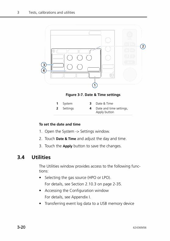
3 Tests, calibrations and utilities
Figure 3-7. Date & Time settings
To set the date and time
1. Open the System -> Settings window.
2. Touch Date & Time and adjust the day and time.
3. Touch the Apply button to save the changes.
3.4 Utilities
The Utilities window provides access to the following func-tions:
• Selecting the gas source (HPO or LPO).
For details, see Section 2.10.3 on page 2-35.
• Accessing the Configuration window
For details, see Appendix I.
• Transferring event log data to a USB memory device
1 System 3 Date & Time2 Settings 4 Date and time settings,
Apply button
3-20 624369/06
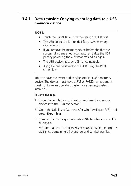
3.4.1 Data transfer: Copying event log data to a USB memory device
NOTE:• Touch the HAMILTON-T1 before using the USB port.
• The USB connector is intended for passive memory devices only.
• If you remove the memory device before the files are successfully transferred, you must reinitialize the USB port by powering the ventilator off and on again.
• The USB device must be USB 1.1 compatible.
• A jpg file can be stored to the USB using the Print screen key.
You can save the event and service logs to a USB memory device. The device must have a FAT or FAT32 format and it must not have an operating system or a security system installed.
To save the logs
1. Place the ventilator into standby and insert a memory device into the USB connector.
2. Open the Utilities -> Data transfer window (Figure 3-8), and select Export logs.
3. Remove the memory device when File transfer successful is displayed.
A folder named “T1_sn<Serial Number>” is created on the USB stick containing all event log and service log files.
624369/06 3-21
3 Tests, calibrations and utilities
Figure 3-8. Data transfer window 1
3.5 Alarm tests
The HAMILTON-T1 performs a self-check during start-up and continuously during operation. This self-check verifies the alarm functionality. You may also want to run alarm tests, which demonstrate the alarms’ operation.
Before performing the alarm tests, set the HAMILTON-T1 up as for normal ventilation, complete with breathing circuit and 2 l demonstration lung assembly with ET tube.
1 Utilities 3 Export logs2 Data transfer
3-22 624369/06
3.5.1 High pressure
1. Make sure a 2 l demonstration lung assembly is connected to the ventilator.
2. Put the ventilator into the PCV+ mode.
3. Set the Pressure alarm limit to 15 cmH2O above the mea-sured Ppeak.
4. Squeeze the demonstration lung hard during inspiration.
5. Verify that the High pressure alarm is activated, the ventila-tor cycles into exhalation, and pressure falls to the PEEP/CPAP level.
3.5.2 Low minute volume
1. Let the ventilator deliver 10 breaths with no alarms.
2. Adjust the minimum ExpMinVol alarm limit so it is higher than the measured value.
3. Verify that the Low minute volume alarm is activated.
3.5.3 Low oxygen alarm
1. Set the Oxygen control to 50%.
2. Wait for 2 min.
3. Disconnect the oxygen supply.
4. Verify the following:
– The Oxygen concentration displayed in the monitoring window decreases.
– The Low oxygen alarm activates.
5. Wait 30 s or until the oxygen concentration falls below 40%.
6. Reconnect the oxygen supply.
7. Verify that the Low oxygen alarm resets. The Low oxygen alarm should reset when the measured oxygen exceeds 45%.
624369/06 3-23
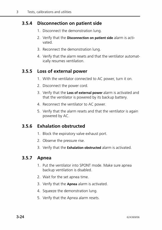
3 Tests, calibrations and utilities
3.5.4 Disconnection on patient side
1. Disconnect the demonstration lung.
2. Verify that the Disconnection on patient side alarm is acti-vated.
3. Reconnect the demonstration lung.
4. Verify that the alarm resets and that the ventilator automat-ically resumes ventilation.
3.5.5 Loss of external power
1. With the ventilator connected to AC power, turn it on.
2. Disconnect the power cord.
3. Verify that the Loss of external power alarm is activated and that the ventilator is powered by its backup battery.
4. Reconnect the ventilator to AC power.
5. Verify that the alarm resets and that the ventilator is again powered by AC.
3.5.6 Exhalation obstructed
1. Block the expiratory valve exhaust port.
2. Observe the pressure rise.
3. Verify that the Exhalation obstructed alarm is activated.
3.5.7 Apnea
1. Put the ventilator into SPONT mode. Make sure apnea backup ventilation is disabled.
2. Wait for the set apnea time.
3. Verify that the Apnea alarm is activated.
4. Squeeze the demonstration lung.
5. Verify that the Apnea alarm resets.
3-24 624369/06
4 Ventilator settings
4.1 Introduction 4-2
4.2 Patient grouping 4-3
4.3 Quick setup settings 4-3
4.4 Patient setup 4-4
4.5 Modes window: Setting the ventilation mode 4-7
4.6 Specifying mode settings 4-8
4.6.1 Changing parameter settings 4-9
4.6.2 Changing parameter settings with mode change 4-11
4.6.3 About apnea backup ventilation 4-11
4.6.4 Table of control parameter settings 4-13
4.7 Working with alarms 4-17
4.7.1 Setting alarm limits 4-18
4.7.2 Adjusting alarm volume (loudness) 4-20
4.7.3 Buffer: Viewing alarm information 4-22
4.7.4 Table of alarm limit settings 4-22
624369/06 4-1
4 Ventilator settings
4.1 Introduction
CAUTION• To prevent possible patient injury, make sure the
ventilator is set up for the appropriate patient group with the appropriate breathing circuit parts as described in Chapter 2.
• To ensure the ventilator’s safe operation, always run the required tests and calibrations before using the ventilator on a patient.
• To ensure the ventilator’s safe operation, always run the preoperational check before using the ventilator on a patient. If the ventilator fails any tests, remove it from clinical use immediately. Do not use the venti-lator until necessary repairs are completed and all tests have passed.
• It is the clinician’s responsibility to ensure that all ventilator settings are appropriate, even when “automatic” features such as ASV or standard set-tings are used.
This section explains how to set up the HAMILTON-T1 for ventilation on an individual patient. Prepare the ventilator as instructed in Chapter 2.
When ventilating neonatal patients, see also Chapter 5.
You must be familiar with using the touch screen and using the Press-and-turn knob to select, activate, and confirm parame-ters. For details, see Section 2.17.
4-2 624369/06
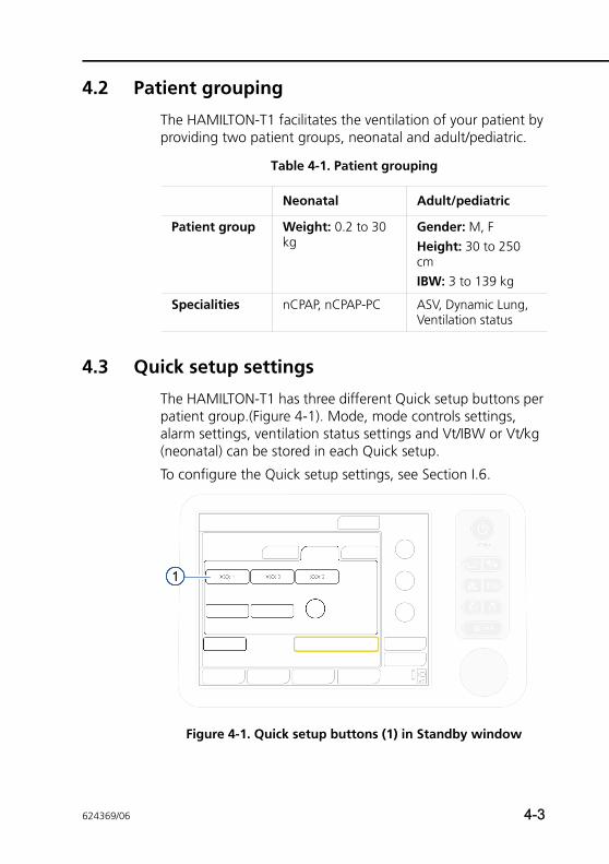
4.2 Patient grouping
The HAMILTON-T1 facilitates the ventilation of your patient by providing two patient groups, neonatal and adult/pediatric.
4.3 Quick setup settings
The HAMILTON-T1 has three different Quick setup buttons per patient group.(Figure 4-1). Mode, mode controls settings, alarm settings, ventilation status settings and Vt/IBW or Vt/kg (neonatal) can be stored in each Quick setup.
To configure the Quick setup settings, see Section I.6.
Figure 4-1. Quick setup buttons (1) in Standby window
Table 4-1. Patient grouping
Neonatal Adult/pediatric
Patient group Weight: 0.2 to 30 kg
Gender: M, FHeight: 30 to 250 cmIBW: 3 to 139 kg
Specialities nCPAP, nCPAP-PC ASV, Dynamic Lung, Ventilation status
624369/06 4-3
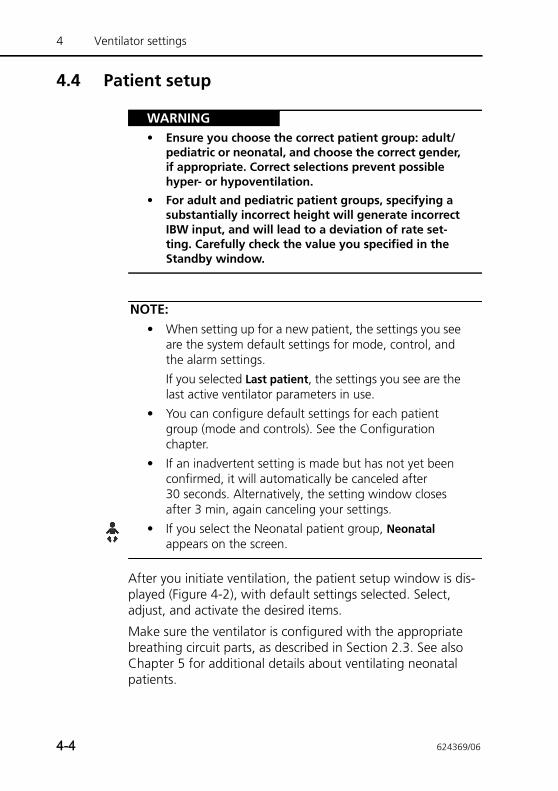
4 Ventilator settings
4.4 Patient setup
WARNING• Ensure you choose the correct patient group: adult/
pediatric or neonatal, and choose the correct gender, if appropriate. Correct selections prevent possible hyper- or hypoventilation.
• For adult and pediatric patient groups, specifying a substantially incorrect height will generate incorrect IBW input, and will lead to a deviation of rate set-ting. Carefully check the value you specified in the Standby window.
NOTE:• When setting up for a new patient, the settings you see
are the system default settings for mode, control, and the alarm settings.
If you selected Last patient, the settings you see are the last active ventilator parameters in use.
• You can configure default settings for each patient group (mode and controls). See the Configuration chapter.
• If an inadvertent setting is made but has not yet been confirmed, it will automatically be canceled after 30 seconds. Alternatively, the setting window closes after 3 min, again canceling your settings.
• If you select the Neonatal patient group, Neonatal appears on the screen.
After you initiate ventilation, the patient setup window is dis-played (Figure 4-2), with default settings selected. Select, adjust, and activate the desired items.
Make sure the ventilator is configured with the appropriate breathing circuit parts, as described in Section 2.3. See also Chapter 5 for additional details about ventilating neonatal patients.
4-4 624369/06
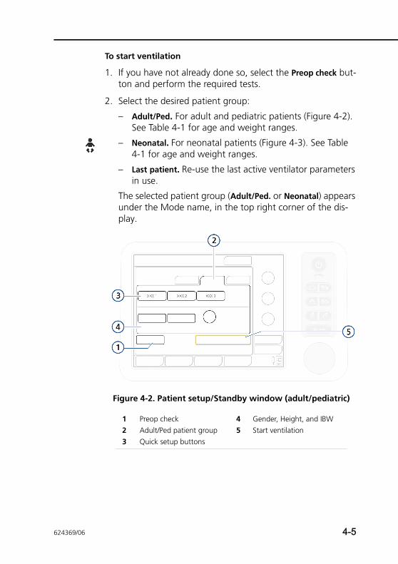
To start ventilation
1. If you have not already done so, select the Preop check but-ton and perform the required tests.
2. Select the desired patient group:
– Adult/Ped. For adult and pediatric patients (Figure 4-2). See Table 4-1 for age and weight ranges.
– Neonatal. For neonatal patients (Figure 4-3). See Table 4-1 for age and weight ranges.
– Last patient. Re-use the last active ventilator parameters in use.
The selected patient group (Adult/Ped. or Neonatal) appears under the Mode name, in the top right corner of the dis-play.
Figure 4-2. Patient setup/Standby window (adult/pediatric)
1 Preop check 4 Gender, Height, and IBW2 Adult/Ped patient group 5 Start ventilation3 Quick setup buttons
624369/06 4-5
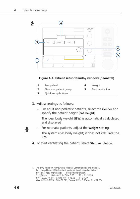
4 Ventilator settings
Figure 4-3. Patient setup/Standby window (neonatal)
3. Adjust settings as follows:
– For adult and pediatric patients, select the Gender and specify the patient height (Pat. height).
The ideal body weight (IBW) is automatically calculated and displayed1.
– For neonatal patients, adjust the Weight setting.
The system uses body weight; it does not calculate the IBW.
4. To start ventilating the patient, select Start ventilation.
1 Preop check 4 Weight2 Neonatal patient group 5 Start ventilation3 Quick setup buttons
1. The IBW, based on Pennsylvania Medical Center (adults) and Traub SL. Am J Hosp Pharm 1980 (pediatric patients), is calculated as follows:IBW: Ideal Body Weight [kg] BH: Body Height [cm] BH ≤ 70 cm IBW = 0.125 x BH – 0.75 70 < BH ≤ 128IBW = 0.0037 x BH – 0.4018 x BH + 18.62 BH ≥ 129Male IBW = 0.9079 x BH – 88.022, Female IBW = 0.9049 x BH – 92.006
4-6 624369/06
4.5 Modes window: Setting the ventilation mode
NOTE:• For details on modes, see:
– Chapter 5 for the neonatal-only modes, nCPAP and nCPAP-PC
– Appendix C (adaptive support ventilation, ASV)
– Appendix D (noninvasive ventilation)
– Appendix B (for all other modes)• ASV mode is not supported for neonatal patients.
The active ventilation mode is displayed at the top right-hand corner of the display.
When first starting to ventilate a patient, a default mode is pre-selected. You can change it, if needed, as described next.
For details about modes and their controls, see Section 4.6 on page 4-8.
To change the mode
1. Open the Modes window. See Figure 4-4.
2. Select the mode to change to.
3. Touch Confirm to select the mode and display the control settings for the selected mode. The Controls window opens.
4. Review and, if needed, adjust the control settings (Section 4.6.2), and touch Confirm in the Controls window to enable the new mode.
The newly selected mode is not active until you select Confirm in the Controls window. If you do not touch Confirm, the currently active mode remains in place.
Note that the Confirm button is only displayed when chang-ing modes.
624369/06 4-7
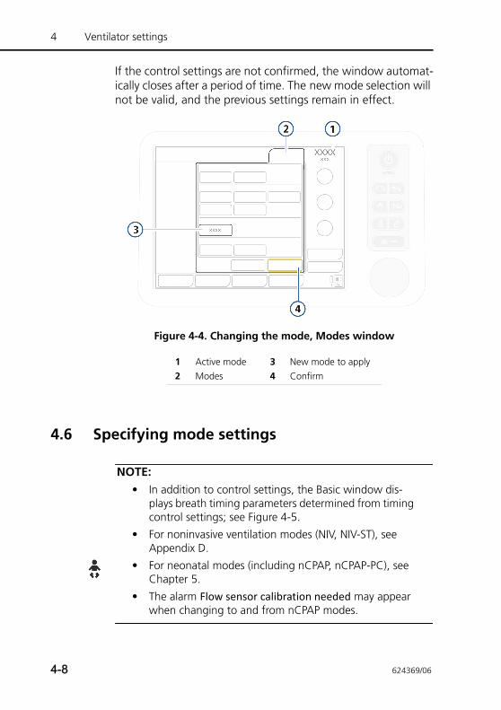
4 Ventilator settings
If the control settings are not confirmed, the window automat-ically closes after a period of time. The new mode selection will not be valid, and the previous settings remain in effect.
Figure 4-4. Changing the mode, Modes window
4.6 Specifying mode settings
NOTE:• In addition to control settings, the Basic window dis-
plays breath timing parameters determined from timing control settings; see Figure 4-5.
• For noninvasive ventilation modes (NIV, NIV-ST), see Appendix D.
• For neonatal modes (including nCPAP, nCPAP-PC), see Chapter 5.
• The alarm Flow sensor calibration needed may appear when changing to and from nCPAP modes.
1 Active mode 3 New mode to apply2 Modes 4 Confirm
4-8 624369/06
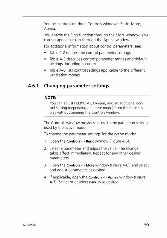
You set controls on three Controls windows: Basic, More, Apnea.
You enable the Sigh function through the More window. You can set apnea backup through the Apnea window.
For additional information about control parameters, see:
• Table 4-2 defines the control parameter settings.
• Table A-5 describes control parameter ranges and default settings, including accuracy.
• Table A-6 lists control settings applicable to the different ventilation modes.
4.6.1 Changing parameter settings
NOTE:You can adjust PEEP/CPAP, Oxygen, and an additional con-trol setting (depending on active mode) from the main dis-play without opening the Controls window.
The Controls window provides access to the parameter settings used by the active mode.
To change the parameter settings for the active mode:
1. Open the Controls -> Basic window (Figure 4-5).
2. Select a parameter and adjust the value. The change takes effect immediately. Repeat for any other desired parameters.
3. Open the Controls -> More window (Figure 4-6), and select and adjust parameters as desired.
4. If applicable, open the Controls -> Apnea window (Figure 4-7). Select or deselect Backup as desired.
624369/06 4-9
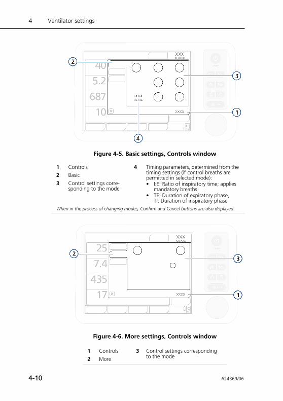
4 Ventilator settings
Figure 4-5. Basic settings, Controls window
Figure 4-6. More settings, Controls window
1 Controls 4 Timing parameters, determined from the timing settings (if control breaths are permitted in selected mode):• I:E: Ratio of inspiratory time; applies
mandatory breaths• TE: Duration of expiratory phase,
TI: Duration of inspiratory phase
2 Basic3 Control settings corre-
sponding to the mode
When in the process of changing modes, Confirm and Cancel buttons are also displayed.
1 Controls 3 Control settings corresponding to the mode2 More
4-10 624369/06
4.6.2 Changing parameter settings with mode changeAfter you select a different mode, the Basic window automati-cally opens (Figure 4-5), showing the new mode name and parameter settings. Review and confirm these proposed set-tings or the mode change will not be accepted.
To review and confirm the control settings:
1. Select a parameter and adjust the value. The change takes effect as soon as you confirm the mode change. Repeat for any other desired parameters.
2. Open the Controls -> More window (Figure 4-6), and select and adjust parameters as desired.
3. If applicable, open the Controls -> Apnea window (Figure 4-7).
Select or deselect Backup as desired. For details, see Section 4.6.3.
Adjust parameters as desired. For details, see Section 4.6.4.
4.6.3 About apnea backup ventilation
CAUTIONHamilton Medical recommends that apnea backup venti-lation be enabled whenever a mode that allows sponta-neous breathing is selected. For safety reasons, apnea backup is enabled by default.
The HAMILTON-T1 provides apnea backup ventilation, a mech-anism that minimizes possible patient injury due to apnea or cessation of respiration. Apnea can occur in all modes except (S)CMV+, PCV+, ASV, PSIMV+, NIV-ST, and nCPAP-PC.
When the ventilator is in such a mode and no inspiratory efforts are detected or control breaths are delivered during an operator-set interval, it assumes that apnea is present. If apnea backup ventilation is enabled, ventilation continues.
624369/06 4-11
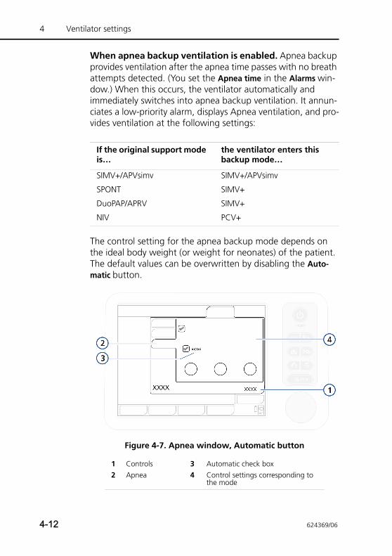
4 Ventilator settings
When apnea backup ventilation is enabled. Apnea backup provides ventilation after the apnea time passes with no breath attempts detected. (You set the Apnea time in the Alarms win-dow.) When this occurs, the ventilator automatically and immediately switches into apnea backup ventilation. It annun-ciates a low-priority alarm, displays Apnea ventilation, and pro-vides ventilation at the following settings:
The control setting for the apnea backup mode depends on the ideal body weight (or weight for neonates) of the patient. The default values can be overwritten by disabling the Auto-matic button.
Figure 4-7. Apnea window, Automatic button
If the original support mode is…
the ventilator enters this backup mode…
SIMV+/APVsimv SIMV+/APVsimv
SPONT SIMV+
DuoPAP/APRV SIMV+
NIV PCV+
1 Controls 3 Automatic check box2 Apnea 4 Control settings corresponding to
the mode
4-12 624369/06
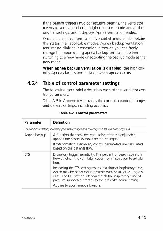
If the patient triggers two consecutive breaths, the ventilator reverts to ventilation in the original support mode and at the original settings, and it displays Apnea ventilation ended.
Once apnea backup ventilation is enabled or disabled, it retains this status in all applicable modes. Apnea backup ventilation requires no clinician intervention, although you can freely change the mode during apnea backup ventilation, either switching to a new mode or accepting the backup mode as the new mode.
When apnea backup ventilation is disabled, the high-pri-ority Apnea alarm is annunciated when apnea occurs.
4.6.4 Table of control parameter settingsThe following table briefly describes each of the ventilator con-trol parameters.
Table A-5 in Appendix A provides the control parameter ranges and default settings, including accuracy.
Table 4-2. Control parameters
Parameter Definition
For additional details, including parameter ranges and accuracy, see Table A-5 on page A-8.
Apnea backup A function that provides ventilation after the adjustable apnea time passes without breath attempts.If “Automatic” is enabled, control parameters are calculated based on the patients IBW.
ETS Expiratory trigger sensitivity. The percent of peak inspiratory flow at which the ventilator cycles from inspiration to exhala-tion.Increasing the ETS setting results in a shorter inspiratory time, which may be beneficial in patients with obstructive lung dis-ease. The ETS setting lets you match the inspiratory time of pressure-supported breaths to the patient’s neural timing.Applies to spontaneous breaths.
624369/06 4-13
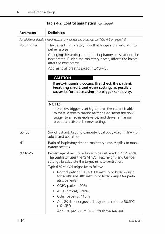
4 Ventilator settings
Flow trigger The patient’s inspiratory flow that triggers the ventilator to deliver a breath. Changing the setting during the inspiratory phase affects the next breath. During the expiratory phase, affects the breath after the next breath.Applies to all breaths except nCPAP-PC.
CAUTIONIf auto-triggering occurs, first check the patient, breathing circuit, and other settings as possible causes before decreasing the trigger sensitivity.
NOTE:If the flow trigger is set higher than the patient is able to meet, a breath cannot be triggered. Reset the flow trigger to an achievable value, and deliver a manual breath to activate the new setting.
Gender Sex of patient. Used to compute ideal body weight (IBW) for adults and pediatrics.
I:E Ratio of inspiratory time to expiratory time. Applies to man-datory breaths.
%MinVol Percentage of minute volume to be delivered in ASV mode. The ventilator uses the %MinVol, Pat. height, and Gender settings to calculate the target minute ventilation. Typical %MinVol might be as follows:
• Normal patient,100% (100 ml/min/kg body weight for adults and 300 ml/min/kg body weight for pedi-atric patients)
• COPD patient, 90%• ARDS patient, 120%• Other patients, 110%• Add 20% per degree of body temperature > 38.5°C
(101.3°F) Add 5% per 500 m (1640 ft) above sea level
Table 4-2. Control parameters (continued)
Parameter Definition
For additional details, including parameter ranges and accuracy, see Table A-5 on page A-8.
4-14 624369/06
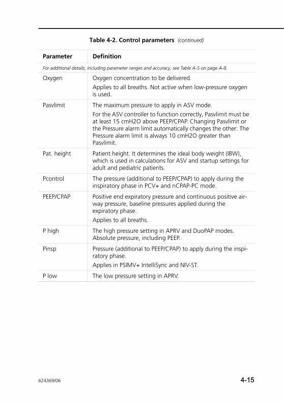
Oxygen Oxygen concentration to be delivered.Applies to all breaths. Not active when low-pressure oxygen is used.
Pasvlimit The maximum pressure to apply in ASV mode.For the ASV controller to function correctly, Pasvlimit must be at least 15 cmH2O above PEEP/CPAP. Changing Pasvlimit or the Pressure alarm limit automatically changes the other: The Pressure alarm limit is always 10 cmH2O greater than Pasvlimit.
Pat. height Patient height. It determines the ideal body weight (IBW), which is used in calculations for ASV and startup settings for adult and pediatric patients.
Pcontrol The pressure (additional to PEEP/CPAP) to apply during the inspiratory phase in PCV+ and nCPAP-PC mode.
PEEP/CPAP Positive end expiratory pressure and continuous positive air-way pressure, baseline pressures applied during the expiratory phase.Applies to all breaths.
P high The high pressure setting in APRV and DuoPAP modes. Absolute pressure, including PEEP.
Pinsp Pressure (additional to PEEP/CPAP) to apply during the inspi-ratory phase.Applies in PSIMV+ IntelliSync and NIV-ST.
P low The low pressure setting in APRV.
Table 4-2. Control parameters (continued)
Parameter Definition
For additional details, including parameter ranges and accuracy, see Table A-5 on page A-8.
624369/06 4-15
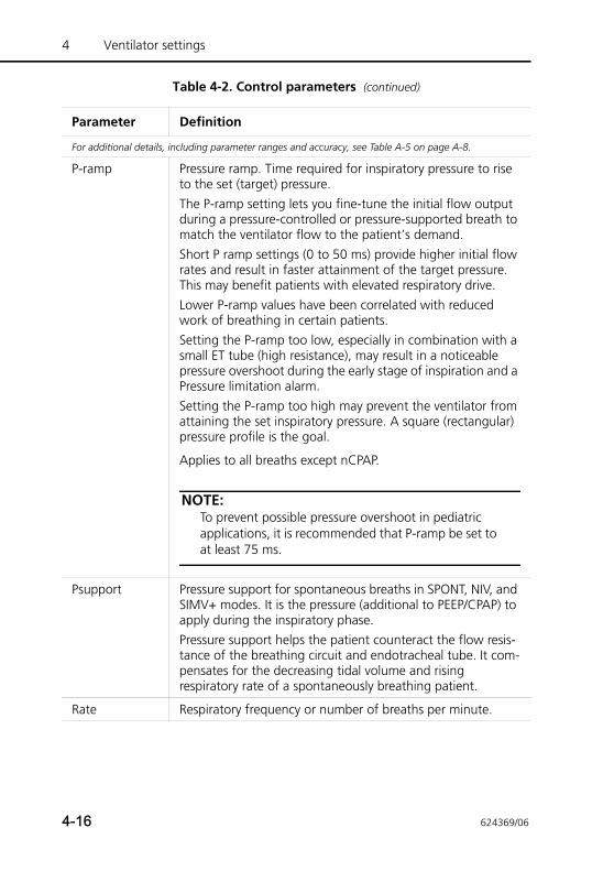
4 Ventilator settings
P-ramp Pressure ramp. Time required for inspiratory pressure to rise to the set (target) pressure.The P-ramp setting lets you fine-tune the initial flow output during a pressure-controlled or pressure-supported breath to match the ventilator flow to the patient’s demand. Short P ramp settings (0 to 50 ms) provide higher initial flow rates and result in faster attainment of the target pressure. This may benefit patients with elevated respiratory drive.Lower P-ramp values have been correlated with reduced work of breathing in certain patients.Setting the P-ramp too low, especially in combination with a small ET tube (high resistance), may result in a noticeable pressure overshoot during the early stage of inspiration and a Pressure limitation alarm.Setting the P-ramp too high may prevent the ventilator from attaining the set inspiratory pressure. A square (rectangular) pressure profile is the goal.
Applies to all breaths except nCPAP.
NOTE:To prevent possible pressure overshoot in pediatric applications, it is recommended that P-ramp be set to at least 75 ms.
Psupport Pressure support for spontaneous breaths in SPONT, NIV, and SIMV+ modes. It is the pressure (additional to PEEP/CPAP) to apply during the inspiratory phase.Pressure support helps the patient counteract the flow resis-tance of the breathing circuit and endotracheal tube. It com-pensates for the decreasing tidal volume and rising respiratory rate of a spontaneously breathing patient.
Rate Respiratory frequency or number of breaths per minute.
Table 4-2. Control parameters (continued)
Parameter Definition
For additional details, including parameter ranges and accuracy, see Table A-5 on page A-8.
4-16 624369/06
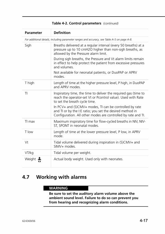
4.7 Working with alarms
WARNINGBe sure to set the auditory alarm volume above the ambient sound level. Failure to do so can prevent you from hearing and recognizing alarm conditions.
Sigh Breaths delivered at a regular interval (every 50 breaths) at a pressure up to 10 cmH2O higher than non-sigh breaths, as allowed by the Pressure alarm limit. During sigh breaths, the Pressure and Vt alarm limits remain in effect to help protect the patient from excessive pressures and volumes.Not available for neonatal patients, or DuoPAP or APRV modes.
T high Length of time at the higher pressure level, P high, in DuoPAP and APRV modes.
TI Inspiratory time, the time to deliver the required gas (time to reach the operator-set Vt or Pcontrol value). Used with Rate to set the breath cycle time.In PCV+ and (S)CMV+ modes, TI can be controlled by rate and TI or by the I:E ratio; you set the desired method in Configuration. All other modes are controlled by rate and TI.
TI max Maximum inspiratory time for flow-cycled breaths in NIV, NIV-ST, SPONT in neonatal modes.
T low Length of time at the lower pressure level, P low, in APRV mode.
Vt Tidal volume delivered during inspiration in (S)CMV+ and SIMV+ modes.
VT/kg Tidal volume per weight.
Weight Actual body weight. Used only with neonates.
Table 4-2. Control parameters (continued)
Parameter Definition
For additional details, including parameter ranges and accuracy, see Table A-5 on page A-8.
624369/06 4-17
4 Ventilator settings
Use the Alarms window to:
• Set alarm limits (Section 4.7.1)
• Adjust the alarm volume (Section 4.7.2)
• View active alarms (Section 4.7.3)
Details about device alarms are provided as follows:
• Table 4-3 describes each of the adjustable alarms
• Table 8-2 in Chapter 8 provides troubleshooting details
• Table A-9 in Appendix A provides ranges and accuracy information
4.7.1 Setting alarm limits
CAUTIONTo prevent possible patient injury, make sure the alarm limits are appropriately set before you place the patient on the ventilator.
NOTE:• If the ventilator is in the (S)CMV+, or SIMV+ mode, be
sure the Pressure alarm is appropriately set. This alarm provides a safety pressure limit for the device to appro-priately adjust the inspiratory pressure necessary to achieve the target tidal volume. The maximum available inspiratory pressure is 10 cmH2O below the Pressure limit, indicated by a blue line on the pressure waveform display.
Set Pressure to a safe value (e.g., 45 cmH2O, which lim-its the pressure target to a maximum of 35 cmH2O). If Pressure is set too low, there may not be enough mar-gin for the device to adjust its inspiratory pressure in order to deliver the target tidal volume.
4-18 624369/06
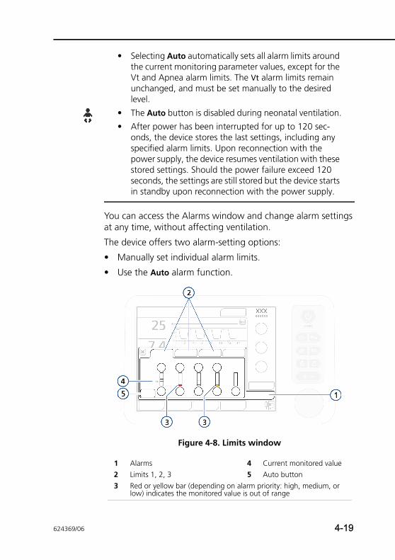
• Selecting Auto automatically sets all alarm limits around the current monitoring parameter values, except for the Vt and Apnea alarm limits. The Vt alarm limits remain unchanged, and must be set manually to the desired level.
• The Auto button is disabled during neonatal ventilation.
• After power has been interrupted for up to 120 sec-onds, the device stores the last settings, including any specified alarm limits. Upon reconnection with the power supply, the device resumes ventilation with these stored settings. Should the power failure exceed 120 seconds, the settings are still stored but the device starts in standby upon reconnection with the power supply.
You can access the Alarms window and change alarm settings at any time, without affecting ventilation.
The device offers two alarm-setting options:
• Manually set individual alarm limits.
• Use the Auto alarm function.
Figure 4-8. Limits window
1 Alarms 4 Current monitored value2 Limits 1, 2, 3 5 Auto button3 Red or yellow bar (depending on alarm priority: high, medium, or
low) indicates the monitored value is out of range
624369/06 4-19
4 Ventilator settings
To review and adjust alarms
1. Touch the Alarms button.
The Limits 1 window is displayed (Figure 4-8).
2. To set an alarm individually, select the alarm control and adjust the value. Repeat for any other alarm.
Additional alarm settings are available in the Limits 2, and if used, Limits 3 windows.
3. To set alarm limits automatically, select the Auto button in the Limits 1 window.
Selecting Auto automatically sets all alarm limits around the current monitoring parameter values, except for the Vt and apnea alarm limits. The Vt alarm limits remain unchanged, and must be set manually to the desired level.
4. Close the window.
4.7.2 Adjusting alarm volume (loudness)
WARNINGBe sure to set the auditory alarm volume above the ambient sound level. Failure to do so can prevent you from hearing and recognizing alarm conditions.
NOTE:• The alarm volume cannot be set lower than the mini-
mum specified for the device in Configuration (Section I.3.4).
• If the alarm volume was set to < 5 before the ventilator was turned off, it will be reset to 5 when the ventilator is turned back on.
However, if the minimum loudness setting is configured and is set to a value greater than 5, the higher value is set.
• If you decrease the alarm volume during the night shift, do not forget to return it to its daytime setting.
• The alarm volume control is on the Settings tab.
4-20 624369/06
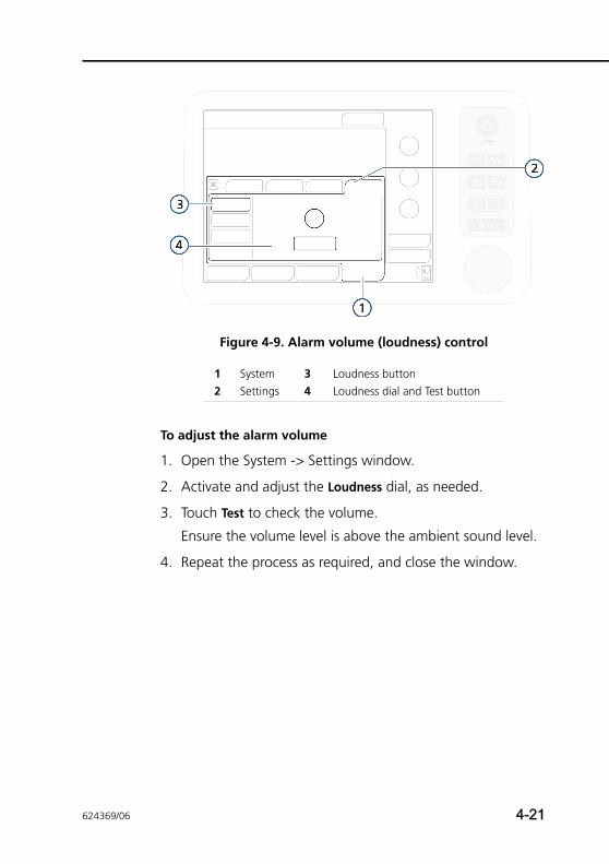
Figure 4-9. Alarm volume (loudness) control
To adjust the alarm volume
1. Open the System -> Settings window.
2. Activate and adjust the Loudness dial, as needed.
3. Touch Test to check the volume.
Ensure the volume level is above the ambient sound level.
4. Repeat the process as required, and close the window.
1 System 3 Loudness button2 Settings 4 Loudness dial and Test button
624369/06 4-21
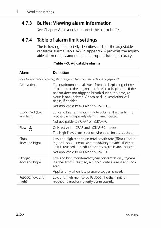
4 Ventilator settings
4.7.3 Buffer: Viewing alarm informationSee Chapter 8 for a description of the alarm buffer.
4.7.4 Table of alarm limit settingsThe following table briefly describes each of the adjustable ventilator alarms. Table A-9 in Appendix A provides the adjust-able alarm ranges and default settings, including accuracy.
Table 4-3. Adjustable alarms
Alarm Definition
For additional details, including alarm ranges and accuracy, see Table A-9 on page A-20.
Apnea time The maximum time allowed from the beginning of one inspiration to the beginning of the next inspiration. If the patient does not trigger a breath during this time, an alarm is annunciated. Apnea backup ventilation will begin, if enabled. Not applicable to nCPAP or nCPAP-PC.
ExpMinVol (low and high)
Low and high expiratory minute volume. If either limit is reached, a high-priority alarm is annunciated. Not applicable to nCPAP or nCPAP-PC.
Flow Only active in nCPAP and nCPAP-PC modes. The High Flow alarm sounds when the limit is reached.
fTotal(low and high)
Low and high monitored total breath rate (fTotal), includ-ing both spontaneous and mandatory breaths. If either limit is reached, a medium-priority alarm is annunciated. Not applicable to nCPAP or nCPAP-PC.
Oxygen(low and high)
Low and high monitored oxygen concentration (Oxygen). If either limit is reached, a high-priority alarm is annunci-ated.Applies only when low-pressure oxygen is used.
PetCO2 (low and high)
Low and high monitored PetCO2. If either limit is reached, a medium-priority alarm sounds.
4-22 624369/06
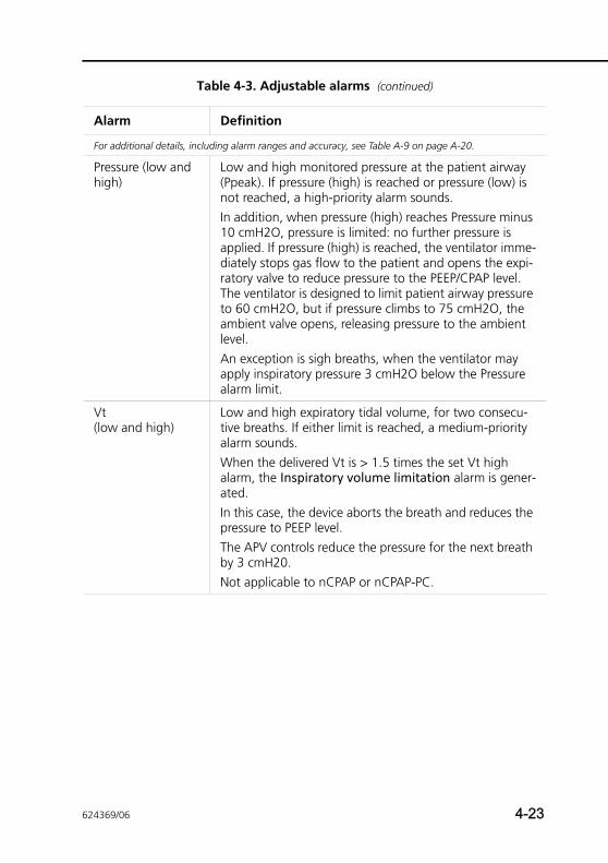
Pressure (low and high)
Low and high monitored pressure at the patient airway (Ppeak). If pressure (high) is reached or pressure (low) is not reached, a high-priority alarm sounds.In addition, when pressure (high) reaches Pressure minus 10 cmH2O, pressure is limited: no further pressure is applied. If pressure (high) is reached, the ventilator imme-diately stops gas flow to the patient and opens the expi-ratory valve to reduce pressure to the PEEP/CPAP level. The ventilator is designed to limit patient airway pressure to 60 cmH2O, but if pressure climbs to 75 cmH2O, the ambient valve opens, releasing pressure to the ambient level.An exception is sigh breaths, when the ventilator may apply inspiratory pressure 3 cmH2O below the Pressure alarm limit.
Vt(low and high)
Low and high expiratory tidal volume, for two consecu-tive breaths. If either limit is reached, a medium-priority alarm sounds. When the delivered Vt is > 1.5 times the set Vt high alarm, the Inspiratory volume limitation alarm is gener-ated. In this case, the device aborts the breath and reduces the pressure to PEEP level.The APV controls reduce the pressure for the next breath by 3 cmH20.Not applicable to nCPAP or nCPAP-PC.
Table 4-3. Adjustable alarms (continued)
Alarm Definition
For additional details, including alarm ranges and accuracy, see Table A-9 on page A-20.
624369/06 4-23

4 Ventilator settings
4-24 624369/06
5 Neonatal ventilation
5.1 Introduction 5-2
5.2 Setting up for neonatal ventilation 5-3
5.2.1 Installing the neonatal expiratory valve 5-3
5.2.2 Setting the patient group and weight 5-6
5.2.3 Selecting the ventilation mode 5-7
5.2.4 Setting up the breathing circuit 5-9
5.2.5 Performing tests and calibrations 5-17
5.2.6 Performing the preoperational check 5-25
5.3 Calculating O2 consumption for neonataltransport 5-27
5.4 Ventilation modes for neonates 5-27
5.4.1 About the nCPAP mode 5-28
5.4.2 About the nCPAP-PC mode 5-30
5.5 Parameters for neonatal ventilation 5-32
5.5.1 Weight 5-33
5.5.2 TI max 5-34
5.5.3 P-ramp 5-34
5.5.4 Flow and Insp Flow 5-34
5.6 Alarms for neonatal ventilation 5-35
5.6.1 Flow alarm 5-36
5.6.2 Volume-related alarms, Vt andExpMinVol 5-36
5.7 O2 enrichment for neonates 5-37
624369/06 5-1
5 Neonatal ventilation
5.1 Introduction
WARNING• To prevent possible patient injury, make sure the
ventilator is set up correctly for the neonatal patient. The ventilator must have the appropriate breathing circuit parts and neonatal flow sensor or neonatal pressure line (nCPAP/nCPAP-PC modes).
• Make sure you perform all tests and calibrations before using the ventilator.
CAUTIONTo prevent increased PaCO2 do not use an adult airway adapter for neonates as it will increase dead space.
NOTE:• When changing from an Adult/Pediatric to a Neonatal
patient group or vice versa, you must calibrate the flow sensor or circuit (pressure line), and perform the tight-ness test.
• When changing from nCPAP/nCPAP-PC to another mode or vice versa, you must calibrate the flow sensor or circuit (pressure line).
• After connecting a new or decontaminated breathing circuit or component, perform a tightness test, and cal-ibrate the flow sensor or circuit (pressure line, for nCPAP/nCPAP-PC modes).
• Pneumatic nebulization is disabled during neonatal ven-tilation.
While the process for ventilating neonates is very similar to that for other patients, neonatal ventilation presents some unique challenges and requirements. This chapter provides a compre-hensive overview of these requirements and special conditions.
5-2 624369/06
5.2 Setting up for neonatal ventilation
Setting up for neonatal ventilation comprises the following steps:
5.2.1 Installing the neonatal expiratory valve
CAUTIONMake sure the correct type of expiratory valve for your patient is installed:
• Ensure the Neonatal patient group is selected on the ventilator when using the neonatal expiratory valve. It cannot be used with the Adult/Ped patient group.
• You must use a neonatal expiratory valve for neonates.
NOTE:Ensure you select the correct expiratory valve (adult/pediat-ric or neonatal) for your patient. If the expiratory valve type does not match the selected patient group on the ventila-tor, the Wrong expiratory valve alarm is generated. For details, see the Alarm troubleshooting table in Section 8.5.
See
1. Install the neonatal expiratory valve. Section 5.2.1 on page 5-3
2. On the ventilator, select the patient group and specify weight.
Section 5.2.2 on page 5-6
3. Select the ventilation mode. Section 5.2.3 on page 5-7
4. Set up the breathing circuit. Section 5.2.4 on page 5-9
5. Perform any required tests (tightness test and calibrations) and the preoperational check.
Section 5.2.5 on page 5-17
624369/06 5-3
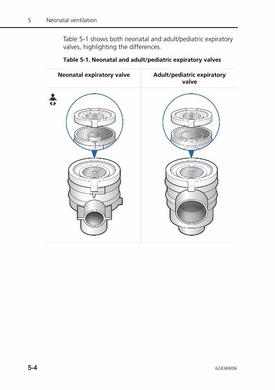
5 Neonatal ventilation
Table 5-1 shows both neonatal and adult/pediatric expiratory valves, highlighting the differences.
Table 5-1. Neonatal and adult/pediatric expiratory valves
Neonatal expiratory valve Adult/pediatric expiratory valve
5-4 624369/06
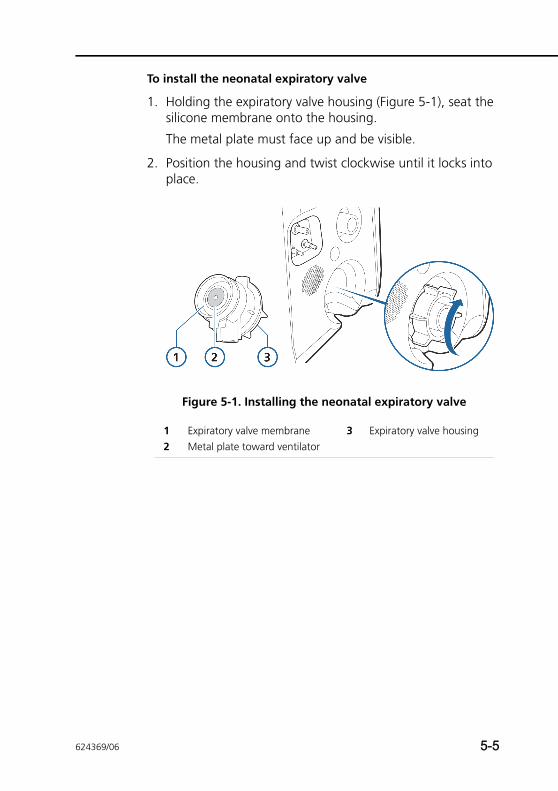
To install the neonatal expiratory valve
1. Holding the expiratory valve housing (Figure 5-1), seat the silicone membrane onto the housing.
The metal plate must face up and be visible.
2. Position the housing and twist clockwise until it locks into place.
Figure 5-1. Installing the neonatal expiratory valve
1 Expiratory valve membrane 3 Expiratory valve housing2 Metal plate toward ventilator
624369/06 5-5
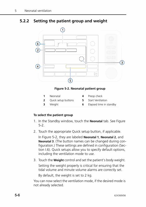
5 Neonatal ventilation
5.2.2 Setting the patient group and weight
Figure 5-2. Neonatal patient group
To select the patient group
1. In the Standby window, touch the Neonatal tab. See Figure 5-2.
2. Touch the appropriate Quick setup button, if applicable.
In Figure 5-2, they are labeled Neonatal 1, Neonatal 2, and Neonatal 3. (The button names can be changed during con-figuration.) These settings are defined in configuration (Sec-tion I.6). Quick setups allow you to specify default options, including the ventilation mode to use.
3. Touch the Weight control and set the patient’s body weight.
Setting the weight properly is critical for ensuring that the tidal volume and minute volume alarms are correctly set.
By default, the weight is set to 2 kg.
You can now select the ventilation mode, if the desired mode is not already selected.
1 Neonatal 4 Preop check2 Quick setup buttons 5 Start Ventilation3 Weight 6 Elapsed time in standby
5-6 624369/06
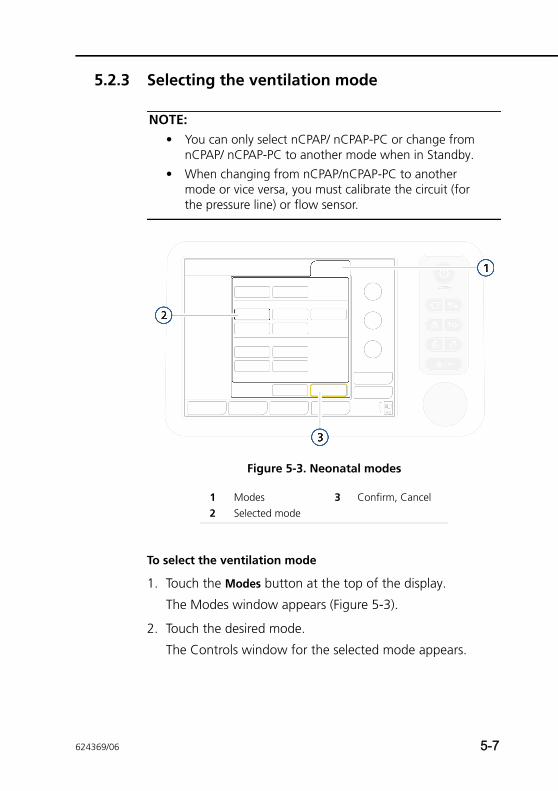
5.2.3 Selecting the ventilation mode
NOTE:• You can only select nCPAP/ nCPAP-PC or change from
nCPAP/ nCPAP-PC to another mode when in Standby.
• When changing from nCPAP/nCPAP-PC to another mode or vice versa, you must calibrate the circuit (for the pressure line) or flow sensor.
Figure 5-3. Neonatal modes
To select the ventilation mode
1. Touch the Modes button at the top of the display.
The Modes window appears (Figure 5-3).
2. Touch the desired mode.
The Controls window for the selected mode appears.
1 Modes 3 Confirm, Cancel2 Selected mode
624369/06 5-7
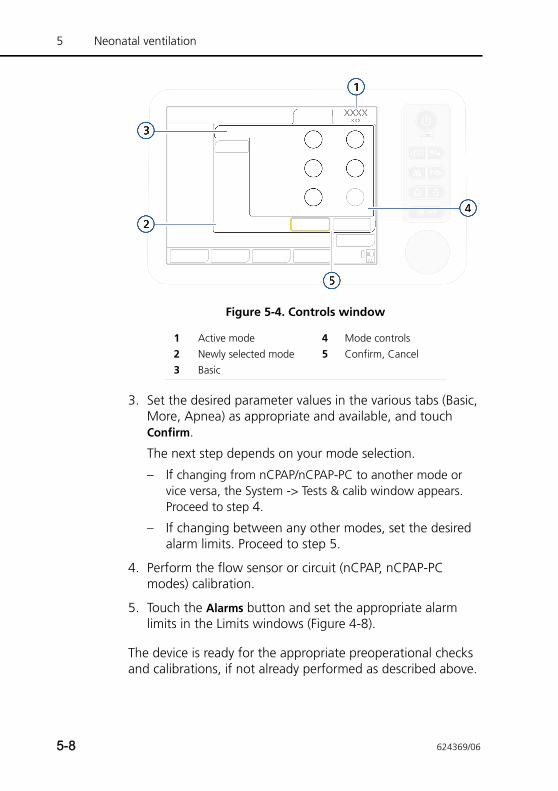
5 Neonatal ventilation
Figure 5-4. Controls window
3. Set the desired parameter values in the various tabs (Basic, More, Apnea) as appropriate and available, and touch Confirm.
The next step depends on your mode selection.
– If changing from nCPAP/nCPAP-PC to another mode or vice versa, the System -> Tests & calib window appears. Proceed to step 4.
– If changing between any other modes, set the desired alarm limits. Proceed to step 5.
4. Perform the flow sensor or circuit (nCPAP, nCPAP-PC modes) calibration.
5. Touch the Alarms button and set the appropriate alarm limits in the Limits windows (Figure 4-8).
The device is ready for the appropriate preoperational checks and calibrations, if not already performed as described above.
1 Active mode 4 Mode controls2 Newly selected mode 5 Confirm, Cancel3 Basic
5-8 624369/06
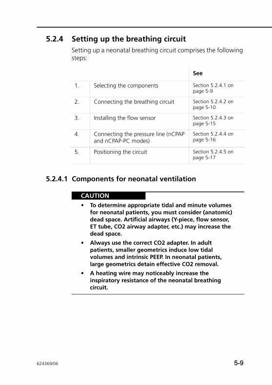
5.2.4 Setting up the breathing circuitSetting up a neonatal breathing circuit comprises the following steps:
5.2.4.1 Components for neonatal ventilation
CAUTION• To determine appropriate tidal and minute volumes
for neonatal patients, you must consider (anatomic) dead space. Artificial airways (Y-piece, flow sensor, ET tube, CO2 airway adapter, etc.) may increase the dead space.
• Always use the correct CO2 adapter. In adult patients, smaller geometrics induce low tidal volumes and intrinsic PEEP. In neonatal patients, large geometrics detain effective CO2 removal.
• A heating wire may noticeably increase the inspiratory resistance of the neonatal breathing circuit.
See
1. Selecting the components Section 5.2.4.1 on page 5-9
2. Connecting the breathing circuit Section 5.2.4.2 on page 5-10
3. Installing the flow sensor Section 5.2.4.3 on page 5-15
4. Connecting the pressure line (nCPAP and nCPAP-PC modes)
Section 5.2.4.4 on page 5-16
5. Positioning the circuit Section 5.2.4.5 on page 5-17
624369/06 5-9
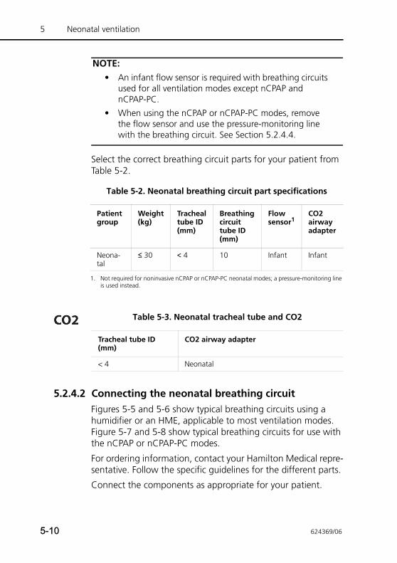
5 Neonatal ventilation
NOTE:• An infant flow sensor is required with breathing circuits
used for all ventilation modes except nCPAP and nCPAP-PC.
• When using the nCPAP or nCPAP-PC modes, remove the flow sensor and use the pressure-monitoring line with the breathing circuit. See Section 5.2.4.4.
Select the correct breathing circuit parts for your patient from Table 5-2.
5.2.4.2 Connecting the neonatal breathing circuitFigures 5-5 and 5-6 show typical breathing circuits using a humidifier or an HME, applicable to most ventilation modes. Figure 5-7 and 5-8 show typical breathing circuits for use with the nCPAP or nCPAP-PC modes.
For ordering information, contact your Hamilton Medical repre-sentative. Follow the specific guidelines for the different parts.
Connect the components as appropriate for your patient.
Table 5-2. Neonatal breathing circuit part specifications
Patient group
Weight (kg)
Tracheal tube ID (mm)
Breathing circuit tube ID (mm)
Flow sensor1
CO2 airway adapter
Neona-tal
≤ 30 < 4 10 Infant Infant
1. Not required for noninvasive nCPAP or nCPAP-PC neonatal modes; a pressure-monitoring line is used instead.
Table 5-3. Neonatal tracheal tube and CO2
Tracheal tube ID (mm)
CO2 airway adapter
< 4 Neonatal
5-10 624369/06
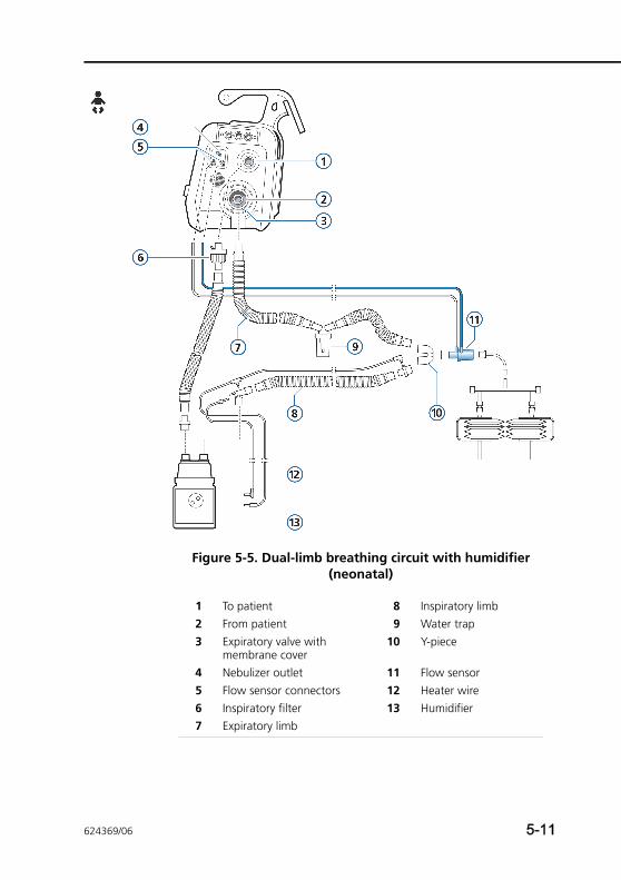
Figure 5-5. Dual-limb breathing circuit with humidifier (neonatal)
1 To patient 8 Inspiratory limb2 From patient 9 Water trap3 Expiratory valve with
membrane cover10 Y-piece
4 Nebulizer outlet 11 Flow sensor5 Flow sensor connectors 12 Heater wire6 Inspiratory filter 13 Humidifier7 Expiratory limb
624369/06 5-11
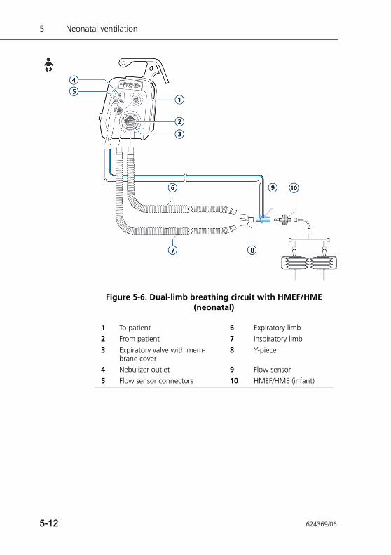
5 Neonatal ventilation
Figure 5-6. Dual-limb breathing circuit with HMEF/HME (neonatal)
1 To patient 6 Expiratory limb2 From patient 7 Inspiratory limb3 Expiratory valve with mem-
brane cover8 Y-piece
4 Nebulizer outlet 9 Flow sensor5 Flow sensor connectors 10 HMEF/HME (infant)
5-12 624369/06
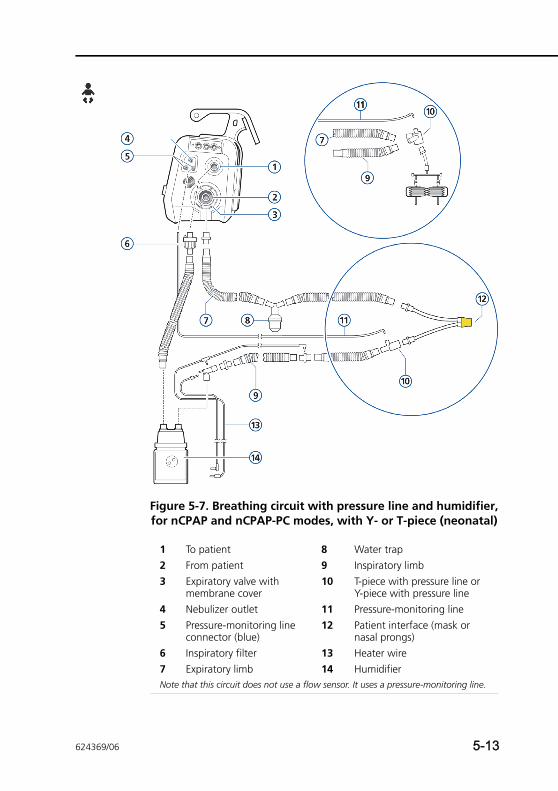
Figure 5-7. Breathing circuit with pressure line and humidifier, for nCPAP and nCPAP-PC modes, with Y- or T-piece (neonatal)
1 To patient 8 Water trap2 From patient 9 Inspiratory limb3 Expiratory valve with
membrane cover10 T-piece with pressure line or
Y-piece with pressure line4 Nebulizer outlet 11 Pressure-monitoring line5 Pressure-monitoring line
connector (blue)12 Patient interface (mask or
nasal prongs)6 Inspiratory filter 13 Heater wire7 Expiratory limb 14 HumidifierNote that this circuit does not use a flow sensor. It uses a pressure-monitoring line.
624369/06 5-13
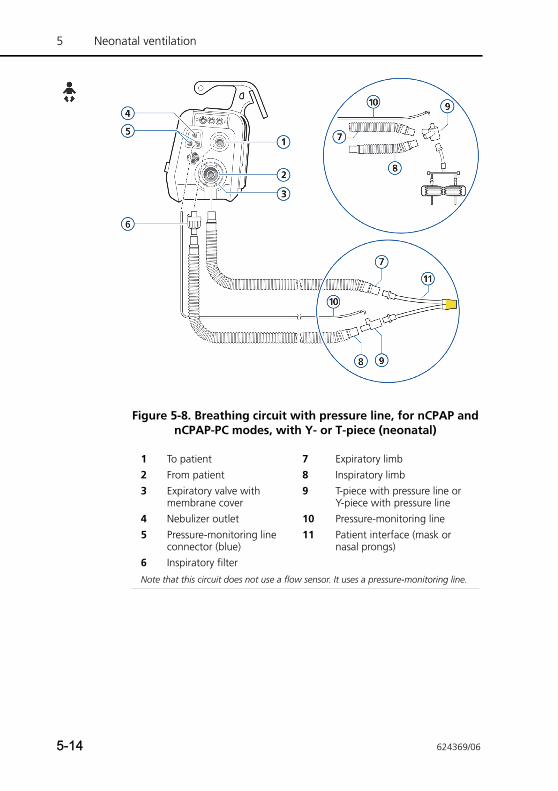
5 Neonatal ventilation
Figure 5-8. Breathing circuit with pressure line, for nCPAP and nCPAP-PC modes, with Y- or T-piece (neonatal)
1 To patient 7 Expiratory limb2 From patient 8 Inspiratory limb3 Expiratory valve with
membrane cover9 T-piece with pressure line or
Y-piece with pressure line4 Nebulizer outlet 10 Pressure-monitoring line5 Pressure-monitoring line
connector (blue)11 Patient interface (mask or
nasal prongs)6 Inspiratory filter
Note that this circuit does not use a flow sensor. It uses a pressure-monitoring line.
5-14 624369/06
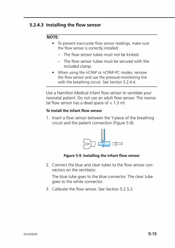
5.2.4.3 Installing the flow sensor
NOTE:• To prevent inaccurate flow sensor readings, make sure
the flow sensor is correctly installed:
– The flow sensor tubes must not be kinked.
– The flow sensor tubes must be secured with the included clamp.
• When using the nCPAP or nCPAP-PC modes, remove the flow sensor and use the pressure-monitoring line with the breathing circuit. See Section 5.2.4.4.
Use a Hamilton Medical infant flow sensor to ventilate your neonatal patient. Do not use an adult flow sensor. The neona-tal flow sensor has a dead space of < 1.3 ml.
To install the infant flow sensor
1. Insert a flow sensor between the Y-piece of the breathing circuit and the patient connection (Figure 5-9).
Figure 5-9. Installing the infant flow sensor
2. Connect the blue and clear tubes to the flow sensor con-nectors on the ventilator.
The blue tube goes to the blue connector. The clear tube goes to the white connector.
3. Calibrate the flow sensor. See Section 5.2.5.2.
624369/06 5-15
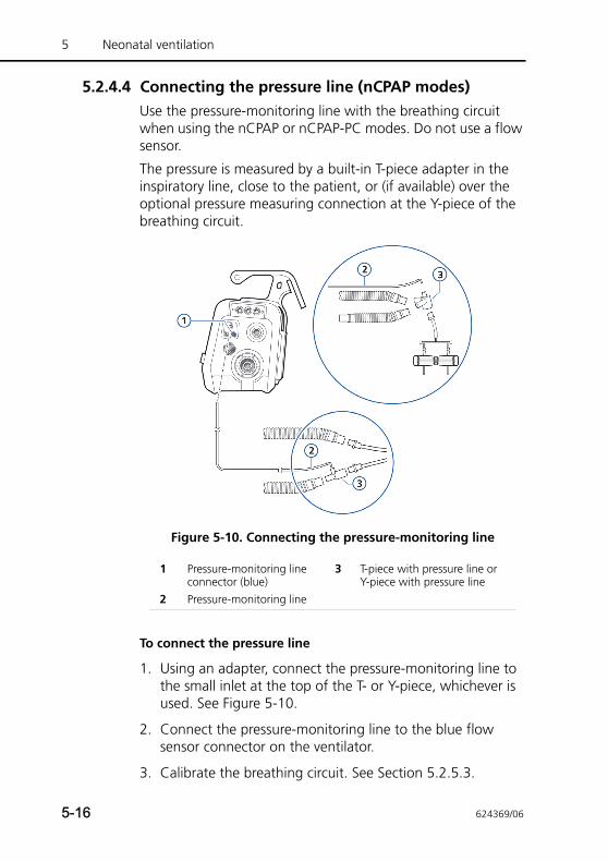
5 Neonatal ventilation
5.2.4.4 Connecting the pressure line (nCPAP modes)Use the pressure-monitoring line with the breathing circuit when using the nCPAP or nCPAP-PC modes. Do not use a flow sensor.
The pressure is measured by a built-in T-piece adapter in the inspiratory line, close to the patient, or (if available) over the optional pressure measuring connection at the Y-piece of the breathing circuit.
Figure 5-10. Connecting the pressure-monitoring line
To connect the pressure line
1. Using an adapter, connect the pressure-monitoring line to the small inlet at the top of the T- or Y-piece, whichever is used. See Figure 5-10.
2. Connect the pressure-monitoring line to the blue flow sensor connector on the ventilator.
3. Calibrate the breathing circuit. See Section 5.2.5.3.
1 Pressure-monitoring line connector (blue)
3 T-piece with pressure line or Y-piece with pressure line
2 Pressure-monitoring line
5-16 624369/06
5.2.4.5 Positioning the breathing circuitAfter assembly, position the breathing circuit so that the hoses will not be pushed, pulled, or kinked as a result of a patient’s movement, nebulization, or other procedures.
5.2.5 Performing tests and calibrationsBe sure to perform a tightness test, and flow sensor or breath-ing circuit calibration, in addition to the preoperational checks. See Chapter 3 for details, as well as additional tests and proce-dures, for example, O2 cell and CO2 sensor calibration.
This section describes the following basic tests and calibrations required for neonatal ventilation:
5.2.5.1 Performing the tightness test
NOTE:• Make sure another source of ventilatory support is avail-
able during this test. The patient must be disconnected from the ventilator for the duration of the test.
• To cancel the tightness test while it is in progress, select Tightness again.
• Perform this test after installing a new or decontami-nated breathing circuit or component (including a flow sensor or pressure line).
See
1. Perform the tightness test Section 5.2.5.1 on page 5-17
2. Calibrate the infant flow sensor Section 5.2.5.2 on page 5-20
Calibrate the neonatal breathing circuit (nCPAP or nCPAP-PC modes only)
Section 5.2.5.3 on page 5-23
3. Perform the preoperational check Section 5.2.6 on page 5-25
624369/06 5-17
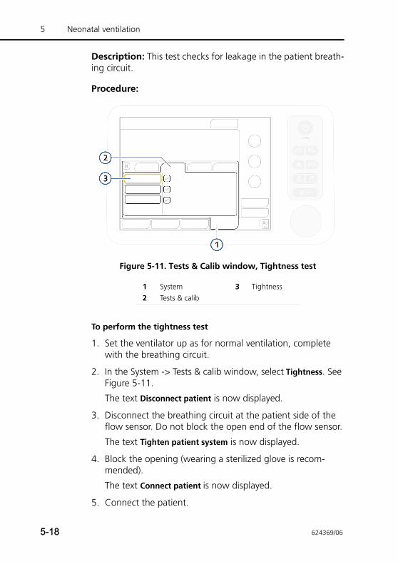
5 Neonatal ventilation
Description: This test checks for leakage in the patient breath-ing circuit.
Procedure:
Figure 5-11. Tests & Calib window, Tightness test
To perform the tightness test
1. Set the ventilator up as for normal ventilation, complete with the breathing circuit.
2. In the System -> Tests & calib window, select Tightness. See Figure 5-11.
The text Disconnect patient is now displayed.
3. Disconnect the breathing circuit at the patient side of the flow sensor. Do not block the open end of the flow sensor.
The text Tighten patient system is now displayed.
4. Block the opening (wearing a sterilized glove is recom-mended).
The text Connect patient is now displayed.
5. Connect the patient.
1 System 3 Tightness2 Tests & calib
5-18 624369/06
6. When the test is complete, verify that there is a green check mark in the Tightness checkbox.
In case of test failure
If the test fails, a red X is displayed in the Tightness checkbox.
Perform the following checks, repeating the tightness test after each one, until the test is successful:
• Check the breathing circuit for a disconnection between the ventilator and the flow sensor or pressure-monitoring line (nCPAP, nCPAP-PC modes), or for other large leaks (for example, breathing circuit, humidifier).
• Check that the expiratory valve is correctly installed.
• Replace the breathing circuit, and flow sensor or pressure-monitoring line (nCPAP, nCPAP-PC modes), and expiratory valve.
If the problem still persists, have the ventilator serviced.
624369/06 5-19
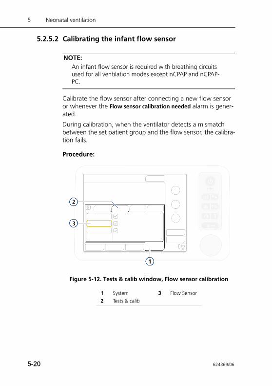
5 Neonatal ventilation
5.2.5.2 Calibrating the infant flow sensor
NOTE:An infant flow sensor is required with breathing circuits used for all ventilation modes except nCPAP and nCPAP-PC.
Calibrate the flow sensor after connecting a new flow sensor or whenever the Flow sensor calibration needed alarm is gener-ated.
During calibration, when the ventilator detects a mismatch between the set patient group and the flow sensor, the calibra-tion fails.
Procedure:
Figure 5-12. Tests & calib window, Flow sensor calibration
1 System 3 Flow Sensor2 Tests & calib
5-20 624369/06
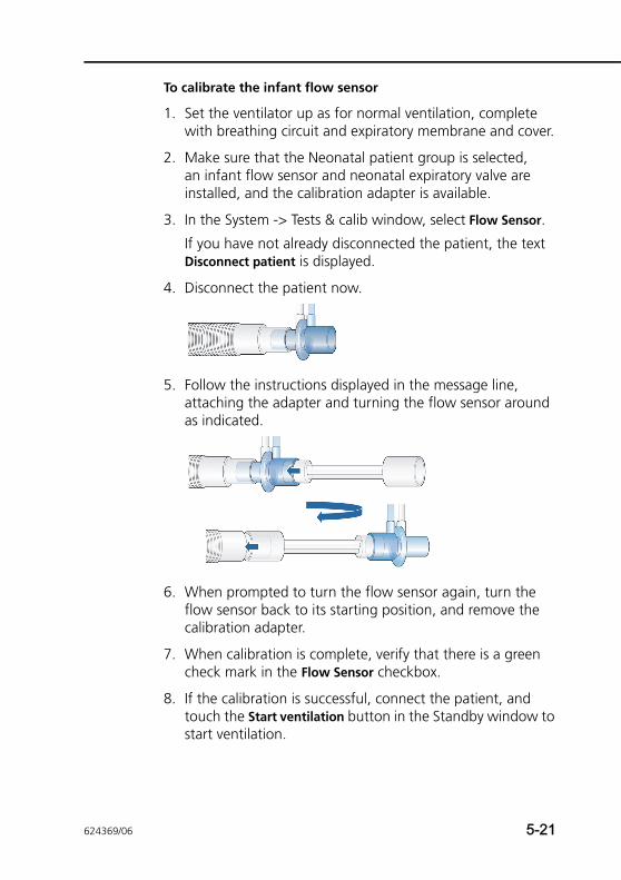
To calibrate the infant flow sensor
1. Set the ventilator up as for normal ventilation, complete with breathing circuit and expiratory membrane and cover.
2. Make sure that the Neonatal patient group is selected, an infant flow sensor and neonatal expiratory valve are installed, and the calibration adapter is available.
3. In the System -> Tests & calib window, select Flow Sensor.
If you have not already disconnected the patient, the text Disconnect patient is displayed.
4. Disconnect the patient now.
5. Follow the instructions displayed in the message line, attaching the adapter and turning the flow sensor around as indicated.
6. When prompted to turn the flow sensor again, turn the flow sensor back to its starting position, and remove the calibration adapter.
7. When calibration is complete, verify that there is a green check mark in the Flow Sensor checkbox.
8. If the calibration is successful, connect the patient, and touch the Start ventilation button in the Standby window to start ventilation.
624369/06 5-21
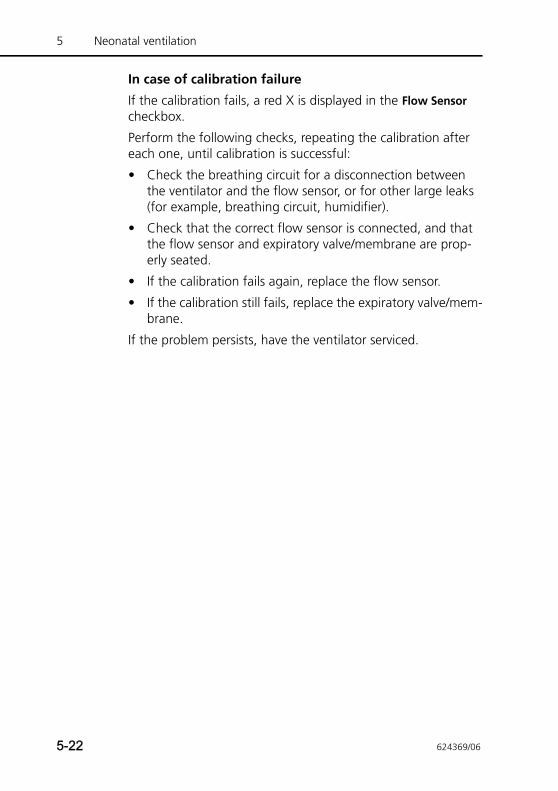
5 Neonatal ventilation
In case of calibration failure
If the calibration fails, a red X is displayed in the Flow Sensor checkbox.
Perform the following checks, repeating the calibration after each one, until calibration is successful:
• Check the breathing circuit for a disconnection between the ventilator and the flow sensor, or for other large leaks (for example, breathing circuit, humidifier).
• Check that the correct flow sensor is connected, and that the flow sensor and expiratory valve/membrane are prop-erly seated.
• If the calibration fails again, replace the flow sensor.
• If the calibration still fails, replace the expiratory valve/mem-brane.
If the problem persists, have the ventilator serviced.
5-22 624369/06
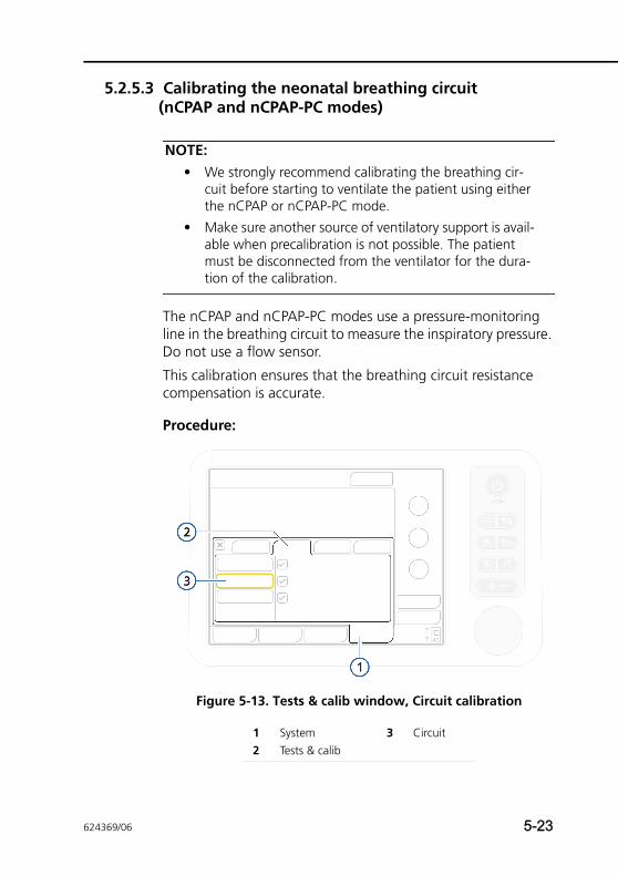
5.2.5.3 Calibrating the neonatal breathing circuit (nCPAP and nCPAP-PC modes)
NOTE:• We strongly recommend calibrating the breathing cir-
cuit before starting to ventilate the patient using either the nCPAP or nCPAP-PC mode.
• Make sure another source of ventilatory support is avail-able when precalibration is not possible. The patient must be disconnected from the ventilator for the dura-tion of the calibration.
The nCPAP and nCPAP-PC modes use a pressure-monitoring line in the breathing circuit to measure the inspiratory pressure. Do not use a flow sensor.
This calibration ensures that the breathing circuit resistance compensation is accurate.
Procedure:
Figure 5-13. Tests & calib window, Circuit calibration
1 System 3 Circuit2 Tests & calib
624369/06 5-23
5 Neonatal ventilation
To calibrate the circuit with the pressure-monitoring line
1. In the System -> Tests & calib window, select Circuit.
If you have not already disconnected the patient, the text Disconnect patient is displayed.
2. Disconnect patient as follows:
– If using a Y-piece, disconnect the breathing circuit from the patient.
– If using a T-piece, disconnect the interface from the patient.
3. Follow the instructions displayed in the message line.
4. When calibration is complete, verify that there is a green check mark in the Circuit checkbox.
5. When successful, touch the Start ventilation button in the Standby window, and connect the patient, as indicated.
In case of calibration failure
If the calibration fails, a red X is displayed in the Circuit check-box.
Perform the following checks, repeating the calibration after each one, until calibration is successful:
• Check the breathing circuit for a disconnection between the ventilator and the pressure-monitoring line, or for other large leaks (for example, breathing circuit, humidifier).
• Check that the pressure-monitoring line and expiratory valve/membrane are properly seated.
• If the calibration fails, replace the pressure-monitoring line.
• If the calibration still fails, replace the breathing circuit and expiratory valve/membrane.
If the problem persists, have the ventilator serviced.
5-24 624369/06
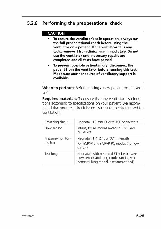
5.2.6 Performing the preoperational check
CAUTION• To ensure the ventilator’s safe operation, always run
the full preoperational check before using the ventilator on a patient. If the ventilator fails any tests, remove it from clinical use immediately. Do not use the ventilator until necessary repairs are completed and all tests have passed.
• To prevent possible patient injury, disconnect the patient from the ventilator before running this test. Make sure another source of ventilatory support is available.
When to perform: Before placing a new patient on the venti-lator.
Required materials: To ensure that the ventilator also func-tions according to specifications on your patient, we recom-mend that your test circuit be equivalent to the circuit used for ventilation.
Breathing circuit Neonatal, 10 mm ID with 10F connectors
Flow sensor Infant, for all modes except nCPAP and nCPAP-PC
Pressure-monitor-ing line
Neonatal, 1.4, 2.1, or 3.1 m lengthFor nCPAP and nCPAP-PC modes (no flow sensor)
Test lung Neonatal, with neonatal ET tube between flow sensor and lung model (an IngMar neonatal lung model is recommended)
624369/06 5-25
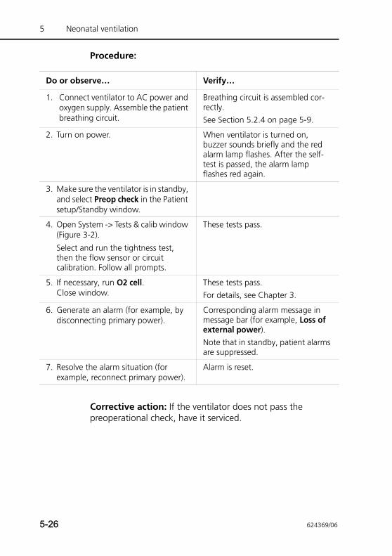
5 Neonatal ventilation
Procedure:
Corrective action: If the ventilator does not pass the preoperational check, have it serviced.
Do or observe… Verify…
1. Connect ventilator to AC power and oxygen supply. Assemble the patient breathing circuit.
Breathing circuit is assembled cor-rectly.See Section 5.2.4 on page 5-9.
2. Turn on power. When ventilator is turned on, buzzer sounds briefly and the red alarm lamp flashes. After the self-test is passed, the alarm lamp flashes red again.
3. Make sure the ventilator is in standby, and select Preop check in the Patient setup/Standby window.
4. Open System -> Tests & calib window (Figure 3-2).
Select and run the tightness test, then the flow sensor or circuit calibration. Follow all prompts.
These tests pass.
5. If necessary, run O2 cell. Close window.
These tests pass.For details, see Chapter 3.
6. Generate an alarm (for example, by disconnecting primary power).
Corresponding alarm message in message bar (for example, Loss of external power).Note that in standby, patient alarms are suppressed.
7. Resolve the alarm situation (for example, reconnect primary power).
Alarm is reset.
5-26 624369/06
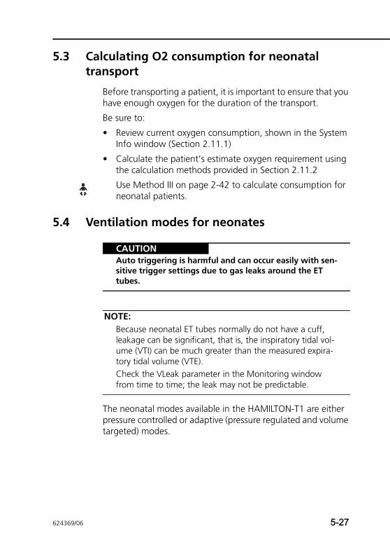
5.3 Calculating O2 consumption for neonatal transport
Before transporting a patient, it is important to ensure that you have enough oxygen for the duration of the transport.
Be sure to:
• Review current oxygen consumption, shown in the System Info window (Section 2.11.1)
• Calculate the patient’s estimate oxygen requirement using the calculation methods provided in Section 2.11.2
Use Method III on page 2-42 to calculate consumption for neonatal patients.
5.4 Ventilation modes for neonates
CAUTIONAuto triggering is harmful and can occur easily with sen-sitive trigger settings due to gas leaks around the ET tubes.
NOTE:Because neonatal ET tubes normally do not have a cuff, leakage can be significant, that is, the inspiratory tidal vol-ume (VTI) can be much greater than the measured expira-tory tidal volume (VTE). Check the VLeak parameter in the Monitoring window from time to time; the leak may not be predictable.
The neonatal modes available in the HAMILTON-T1 are either pressure controlled or adaptive (pressure regulated and volume targeted) modes.
624369/06 5-27
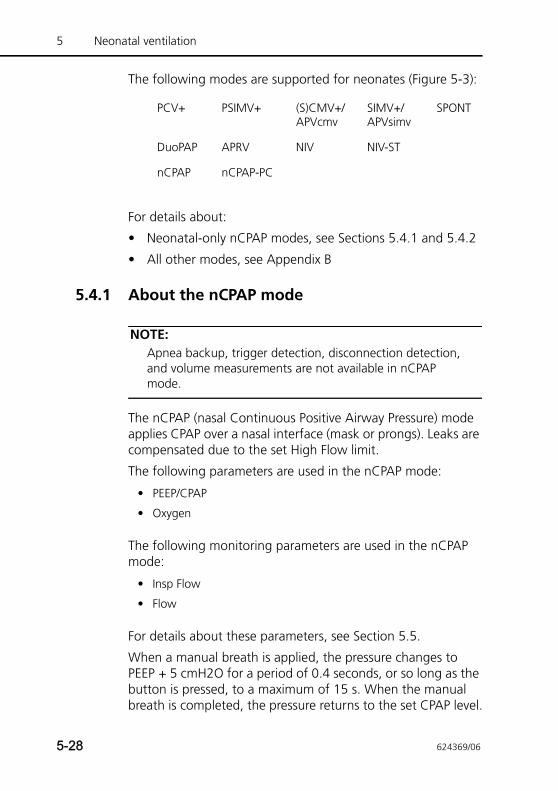
5 Neonatal ventilation
The following modes are supported for neonates (Figure 5-3):
For details about:
• Neonatal-only nCPAP modes, see Sections 5.4.1 and 5.4.2
• All other modes, see Appendix B
5.4.1 About the nCPAP mode
NOTE:Apnea backup, trigger detection, disconnection detection, and volume measurements are not available in nCPAP mode.
The nCPAP (nasal Continuous Positive Airway Pressure) mode applies CPAP over a nasal interface (mask or prongs). Leaks are compensated due to the set High Flow limit.
The following parameters are used in the nCPAP mode:
The following monitoring parameters are used in the nCPAP mode:
For details about these parameters, see Section 5.5.
When a manual breath is applied, the pressure changes to PEEP + 5 cmH2O for a period of 0.4 seconds, or so long as the button is pressed, to a maximum of 15 s. When the manual breath is completed, the pressure returns to the set CPAP level.
PCV+ PSIMV+ (S)CMV+/APVcmv
SIMV+/APVsimv
SPONT
DuoPAP APRV NIV NIV-ST
nCPAP nCPAP-PC
• PEEP/CPAP
• Oxygen
• Insp Flow
• Flow
5-28 624369/06
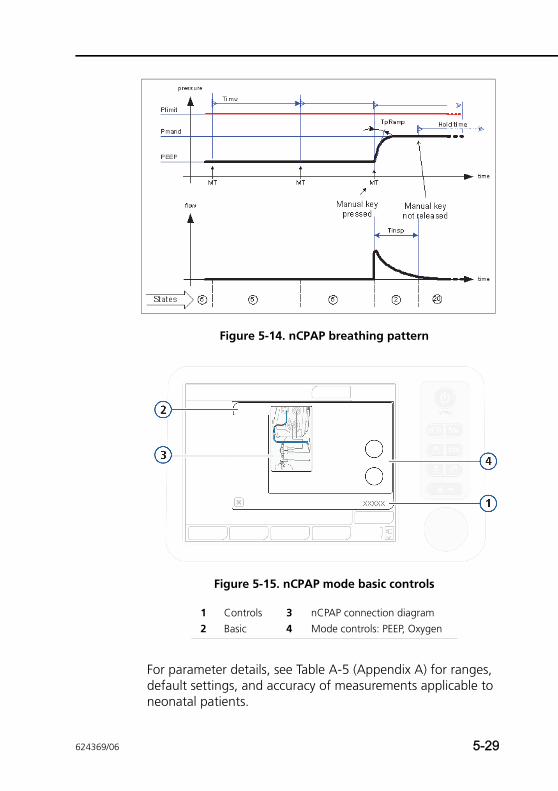
Figure 5-14. nCPAP breathing pattern
Figure 5-15. nCPAP mode basic controls
For parameter details, see Table A-5 (Appendix A) for ranges, default settings, and accuracy of measurements applicable to neonatal patients.
1 Controls 3 nCPAP connection diagram2 Basic 4 Mode controls: PEEP, Oxygen
624369/06 5-29
5 Neonatal ventilation
5.4.2 About the nCPAP-PC mode
NOTE:Apnea backup, trigger detection, disconnection detection, and volume measurements are not available in nCPAP-PC mode.
The nCPAP-PC (nasal Continuous Positive Airway Pressure - Pressure Control) mode delivers, in addition to the set CPAP, intermittent, time-cycled, and pressure-controlled breaths. This results in a biphasic breathing pattern.
The patient can also breathe freely at both pressure levels. The inspiratory flow follows the respiratory effort of the patient on both pressure levels. Leaks are compensated due to the set High Flow limit.
The following parameters are used in the nCPAP-PC mode:
The following monitoring parameters are used in the nCPAP mode:
For details about these parameters, see Section 5.5.4.
When a manual breath is applied, the pressure changes to the Pcontrol setting for the length of time set by the TI (inspiratory time) or so long as the button is pressed, to a maximum of 15 s. When the manual breath is completed, the pressure returns to the set CPAP level.
• Rate • P-ramp
• Pcontrol • PEEP/CPAP
• TI • Oxygen
• Insp Flow
• Flow
5-30 624369/06
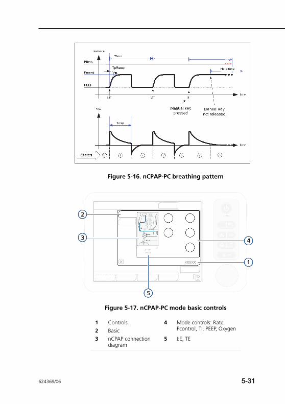
Figure 5-16. nCPAP-PC breathing pattern
Figure 5-17. nCPAP-PC mode basic controls
1 Controls 4 Mode controls: Rate, Pcontrol, TI, PEEP, Oxygen2 Basic
3 nCPAP connection diagram
5 I:E, TE
624369/06 5-31
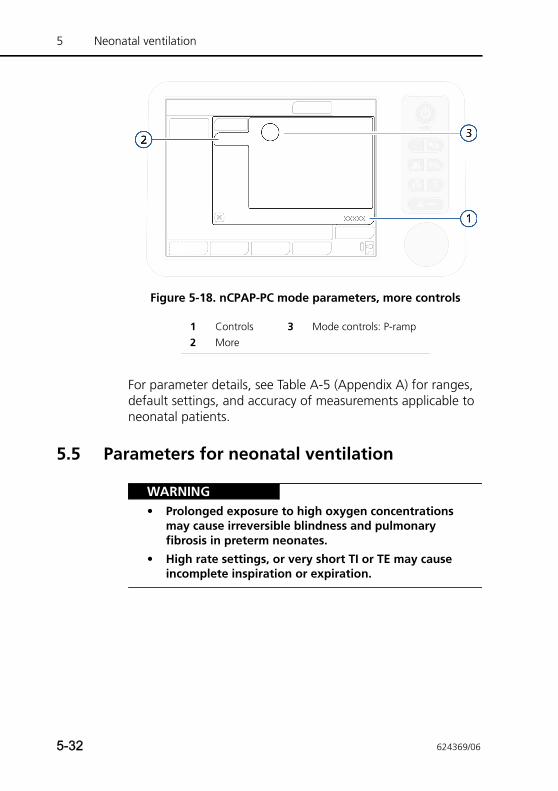
5 Neonatal ventilation
Figure 5-18. nCPAP-PC mode parameters, more controls
For parameter details, see Table A-5 (Appendix A) for ranges, default settings, and accuracy of measurements applicable to neonatal patients.
5.5 Parameters for neonatal ventilation
WARNING• Prolonged exposure to high oxygen concentrations
may cause irreversible blindness and pulmonary fibrosis in preterm neonates.
• High rate settings, or very short TI or TE may cause incomplete inspiration or expiration.
1 Controls 3 Mode controls: P-ramp2 More
5-32 624369/06
NOTE:• Pneumatic nebulization is disabled in neonatal ventila-
tion. If needed, use the Aerogen nebulizer in neonatal ventilation.
• The ventilator generates a continuous and constant base flow from the inspiratory outlet to the expiratory outlet during the later part of exhalation. The base flow is set to a fixed 4 l/min for neonatal patients.
• For O2 consumption calculation details, see Section 2.11.
Some of the ventilation parameters require special consider-ation when setting up the ventilator for a neonatal patient.
This section briefly describes the following parameters:
For additional information on these and all other parameters, see:
• Table 4-2 (Chapter 4) for definitions of the ventilator control parameters
• Tables A-5 and A-7 for parameter ranges, default settings, and accuracy of measurements applicable to neonatal patients
5.5.1 WeightFor neonates, the ventilator uses actual body weight. Be sure to set the correct patient weight on the Patient setup screen before starting ventilation. See Section 5.2.1 on page 5-3.
Setting the Weight parameter correctly is very important in neonatal ventilation, as tidal volume and minute volume alarm limits are set based on patient weight.
By default, neonatal weight is set to 2 kg.
For parameter details, see Table A-5, Control settings, ranges and accuracy.
• Weight • P-ramp
• ETS • Flow (monitoring parameter)
• TI max
624369/06 5-33
5 Neonatal ventilation
5.5.2 TI maxThe TI max (maximum inspiratory time) parameter is set for spontaneous breaths in NIV and NIV-ST modes.
For all patient groups, the switchover from inspiration to exha-lation in spontaneous breaths is normally controlled by the ETS (expiratory trigger sensitivity). If gas leakage is significant, how-ever, the set ETS may never be reached. The TI max setting pro-vides a backup so inspiration can be terminated. The ventilator switches over to exhalation when the set TI max is reached.
For parameter details, see Table A-5, Control settings, ranges and accuracy.
5.5.3 P-rampP-ramp is the pressure ramp, the time required for inspiratory pressure to rise to the set (target) pressure.
Note that P-ramp time cannot exceed one-third of the inspira-tory time (TI). In the following modes, the maximum setting is 200 ms: SPONT, NIV, NIV-ST, nCPAP, nCPAP-PC.
By default, P-ramp is set to 50 ms for neonates.
If a neonatal patient has stiff lungs (for example, RDS), be care-ful when using a short P-ramp (pressure rise time). A very short P-ramp in this case may cause pressure overshoot.
For parameter details, see Table A-5, Control settings, ranges and accuracy.
5.5.4 Flow and Insp Flow
NOTE:• Flow is only active in nCPAP and nCPAP-PC modes.
• A trend graph cannot be generated using the Flow parameter.
The Flow and Insp Flow parameters monitor average and peak flow, respectively, in nCPAP and nCPAP-PC modes, as described below.
5-34 624369/06
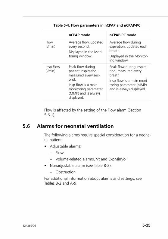
Flow is affected by the setting of the Flow alarm (Section 5.6.1).
5.6 Alarms for neonatal ventilation
The following alarms require special consideration for a neona-tal patient:
• Adjustable alarms:
– Flow
– Volume-related alarms, Vt and ExpMinVol
• Nonadjustable alarm (see Table 8-2):
– Obstruction
For additional information about alarms and settings, see Tables 8-2 and A-9.
Table 5-4. Flow parameters in nCPAP and nCPAP-PC
nCPAP mode nCPAP-PC mode
Flow (l/min)
Average flow, updated every second.Displayed in the Moni-toring window.
Average flow during expiration, updated each breath.Displayed in the Monitor-ing window.
Insp Flow (l/min)
Peak flow during patient inspiration, measured every sec-ond.Insp flow is a main monitoring parameter (MMP) and is always displayed.
Peak flow during inspira-tion, measured every breath.Insp flow is a main moni-toring parameter (MMP) and is always displayed.
624369/06 5-35
5 Neonatal ventilation
5.6.1 Flow alarm
CAUTIONBe sure to set the Flow alarm limit to an appropriate level above the current monitored peak flow to avoid potential gastric overinflation, and to be able to detect leaks and disconnection of the patient interface.
NOTE:Only active in nCPAP and nCPAP-PC modes.
The primary purpose of the medium-priority Flow alarm is to help detect disconnection of the patient interface by monitor-ing the inspiratory flow (Insp Flow parameter).
When the flow exceeds the set limit, in addition to generating the High Flow alarm, the system reduces the delivered flow, and, as a result, the delivered pressure may be reduced.
To minimize the incidence of this alarm, observe the Insp Flow values, and then set the limit to a value above the average Insp Flow reading + known minimum leakage.
If the alarm sounds, check the patient interface and breathing circuit for disconnection or excessive leakage, and check the ventilator settings and alarm limits.
The alarm is adjustable from 8 to 30 l/min. By default, the flow limit is set to 15 l/min.
For additional details, see Table A-9.
5.6.2 Volume-related alarms, Vt and ExpMinVolNote that the following adjustable alarms use patient weight to set the initial alarm limits:
• Tidal volume, high and low (VT)
• Minute volume, high and low (ExpMinVol)
Be sure to set the correct patient weight on the Patient setup screen in standby before starting ventilation. See Section 5.2.1.
5-36 624369/06
5.7 O2 enrichment for neonates
WARNINGProlonged exposure to high oxygen concentrations may cause irreversible blindness and pulmonary fibrosis in preterm neonates.
NOTE:In nCPAP and nCPAP-PC modes, starting O2 enrichment or changing the Oxygen setting sets the flow to 10 l/min for 60 seconds. The flow then returns to its previous setting.
During the O2 enrichment maneuver the applied oxygen con-centration is increased by 25% of the last oxygen setting (for example, if the last oxygen setting is 40%, resulting oxygen concentration during O2 enrichment maneuver is 50%).
The currently applied oxygen concentration is displayed on the Oxygen control. Oxygen enrichment continues for 2 min unless you terminate it by pressing the O2 enrichment key again or manually activating and confirming the Oxygen control.
624369/06 5-37

5 Neonatal ventilation
5-38 624369/06
6 Monitoring ventilation
6.1 Introduction 6-2
6.2 Viewing numeric patient data 6-3
6.2.1 About the main monitoring parameters (MMP) 6-4
6.2.2 Viewing patient data in the Monitoring window 6-5
6.3 Waveforms and graphs 6-6
6.3.1 Selecting a graphical view of patient data 6-6
6.4 About graphic types 6-8
6.4.1 Waveforms 6-8
6.4.2 Dynamic Lung 6-11
6.4.3 Vent Status 6-11
6.4.4 ASV Graph 6-11
6.5 Trends 6-11
6.5.1 Displaying trends 6-13
6.6 Loops 6-14
6.6.1 Displaying loops 6-14
6.6.2 Storing loops 6-15
6.7 Table of monitored parameters 6-16
6.8 Freeze and cursor measurement 6-24
624369/06 6-1
6 Monitoring ventilation
6.1 Introduction
CAUTION• To ensure that oxygen monitoring is always fully
functional, replace an exhausted or missing oxygen cell as soon as possible or use an external monitor that complies with ISO 80601-2-55.
• The HAMILTON-T1’s oxygen monitoring function can be disabled. Ensure that an alternative means of oxy-gen monitoring is always available and enabled.
• In case of a problem developing with the ventilator’s built-in monitoring and in order to maintain an adequate level of patient monitoring at all times, it is recommended that additional independent monitoring devices be used. The operator of the ventilator must still maintain full responsibility for proper ventilation and patient safety in all situations.
During ventilation, you can view patient data on the HAMILTON-T1 screen (Figure 6-1). You can configure the screen layout with different waveforms, loops or trends, or with Intelligent Panel graphics to suit your institution’s needs. Access the Monitoring window at any time without affecting breath delivery.
6-2 624369/06
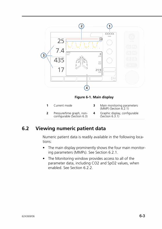
Figure 6-1. Main display
6.2 Viewing numeric patient data
Numeric patient data is readily available in the following loca-tions:
• The main display prominently shows the four main monitor-ing parameters (MMPs). See Section 6.2.1.
• The Monitoring window provides access to all of the parameter data, including CO2 and SpO2 values, when enabled. See Section 6.2.2.
1 Current mode 3 Main monitoring parameters (MMP) (Section 6.2.1)
2 Pressure/time graph, non-configurable (Section 6.3)
4 Graphic display, configurable (Section 6.3.1)
624369/06 6-3
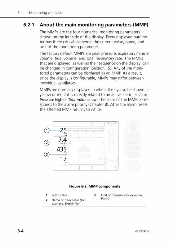
6 Monitoring ventilation
6.2.1 About the main monitoring parameters (MMP)The MMPs are the four numerical monitoring parameters shown on the left side of the display. Every displayed parame-ter has three critical elements: the current value, name, and unit of the monitoring parameter.
The factory default MMPs are peak pressure, expiratory minute volume, tidal volume, and total respiratory rate. The MMPs that are displayed, as well as their sequence on the display, can be changed in configuration (Section I.5). Any of the moni-tored parameters can be displayed as an MMP. As a result, since the display is configurable, MMPs may differ between individual ventilators.
MMPs are normally displayed in white. It may also be shown in yellow or red if it is directly related to an active alarm, such as Pressure high or Tidal volume low. The color of the MMP corre-sponds to the alarm priority (Chapter 8). After the alarm resets, the affected MMP returns to white.
Figure 6-2. MMP components
1 MMP value 3 Unit of measure (for example, l/min)2 Name of parameter (for
example, ExpMinVol)
6-4 624369/06
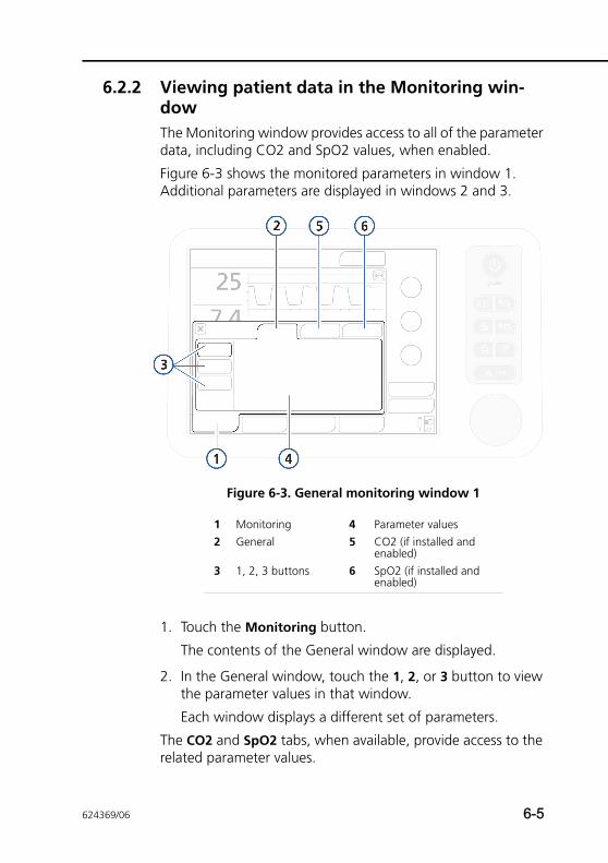
6.2.2 Viewing patient data in the Monitoring win-dowThe Monitoring window provides access to all of the parameter data, including CO2 and SpO2 values, when enabled.
Figure 6-3 shows the monitored parameters in window 1. Additional parameters are displayed in windows 2 and 3.
Figure 6-3. General monitoring window 1
1. Touch the Monitoring button.
The contents of the General window are displayed.
2. In the General window, touch the 1, 2, or 3 button to view the parameter values in that window.
Each window displays a different set of parameters.
The CO2 and SpO2 tabs, when available, provide access to the related parameter values.
1 Monitoring 4 Parameter values2 General 5 CO2 (if installed and
enabled)3 1, 2, 3 buttons 6 SpO2 (if installed and
enabled)
624369/06 6-5
6 Monitoring ventilation
6.3 Waveforms and graphs
The HAMILTON-T1 offers two primary graphic areas on the dis-play.
• The pressure/time waveform. This graph is always displayed and is not configurable. See item 4 in Figure 6-1.
• The following graphic views of the patient data: trends, loops, graphics (Intelligent panels), and waveforms. Table 6-1 shows the options for each graphic type.
Detailed information about the Intelligent Panels is provided in Chapter 7.
6.3.1 Selecting a graphical view of patient data
To select a graphic to display
1. Touch anywhere in the graphic area of the display to open the graphics window. See (1) in Figure 6-4.
Table 6-1. Graphics options
Graphic type Options
Trends 1-, 6-, 12-, 24-, or 72-h1 trend data for a selected parameter
1. 72-h trends not available in all markets.
Loops • Pressure/volume• Pressure/flow• Flow/volume
• Volume/PCO2• Volume/FCO2
Graphics • Dynamic Lung• Vent Status
• ASV Graph
Waveforms • Flow• Volume• Off
• PCO2• FCO2
6-6 624369/06
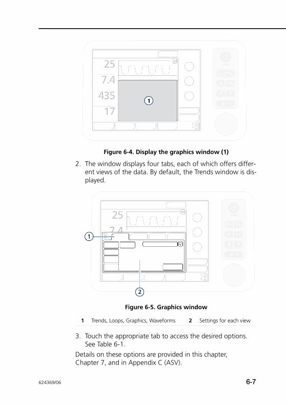
Figure 6-4. Display the graphics window (1)
2. The window displays four tabs, each of which offers differ-ent views of the data. By default, the Trends window is dis-played.
Figure 6-5. Graphics window
3. Touch the appropriate tab to access the desired options. See Table 6-1.
Details on these options are provided in this chapter, Chapter 7, and in Appendix C (ASV).
1 Trends, Loops, Graphics, Waveforms 2 Settings for each view
624369/06 6-7
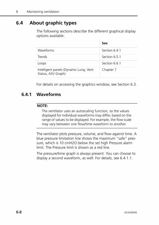
6 Monitoring ventilation
6.4 About graphic types
The following sections describe the different graphical display options available:
For details on accessing the graphics window, see Section 6.3.
6.4.1 Waveforms
NOTE:The ventilator uses an autoscaling function, so the values displayed for individual waveforms may differ, based on the range of values to be displayed. For example, the flow scale may vary between one flow/time waveform to another.
The ventilator plots pressure, volume, and flow against time. A blue pressure limitation line shows the maximum “safe” pres-sure, which is 10 cmH2O below the set high Pressure alarm limit. The Pressure limit is shown as a red line.
The pressure/time graph is always present. You can choose to display a second waveform, as well. For details, see 6.4.1.1.
See
Waveforms Section 6.4.1
Trends Section 6.5.1
Loops Section 6.6.1
Intelligent panels (Dynamic Lung, Vent Status, ASV Graph)
Chapter 7
6-8 624369/06
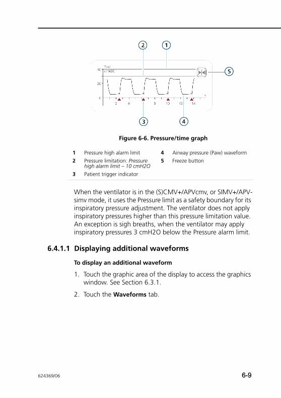
Figure 6-6. Pressure/time graph
When the ventilator is in the (S)CMV+/APVcmv, or SIMV+/APV-simv mode, it uses the Pressure limit as a safety boundary for its inspiratory pressure adjustment. The ventilator does not apply inspiratory pressures higher than this pressure limitation value. An exception is sigh breaths, when the ventilator may apply inspiratory pressures 3 cmH2O below the Pressure alarm limit.
6.4.1.1 Displaying additional waveforms
To display an additional waveform
1. Touch the graphic area of the display to access the graphics window. See Section 6.3.1.
2. Touch the Waveforms tab.
1 Pressure high alarm limit 4 Airway pressure (Paw) waveform2 Pressure limitation: Pressure
high alarm limit – 10 cmH2O5 Freeze button
3 Patient trigger indicator
624369/06 6-9
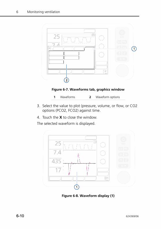
6 Monitoring ventilation
Figure 6-7. Waveforms tab, graphics window
3. Select the value to plot (pressure, volume, or flow, or CO2 options (PCO2, FCO2) against time.
4. Touch the X to close the window.
The selected waveform is displayed.
Figure 6-8. Waveform display (1)
1 Waveforms 2 Waveform options
6-10 624369/06
6.4.2 Dynamic LungThe Dynamic Lung panel visualizes tidal volume, lung compli-ance, patient triggering, and resistance in real-time.
For details about the panel and how to display it, see Chapter 7.
6.4.3 Vent StatusThe Vent Status panel visualizes parameters related to oxygen-ation, CO2 elimination, and patient activity, and indicates the patient’s level of ventilator dependence and when discontinu-ing ventilation should be considered.
For details about the panel and how to display it, see Chapter 7.
6.4.4 ASV GraphAvailable in ASV mode, the ASV graph shows how the adap-tive lung controller moves toward its targets. The graph shows both the target and real-time patient data for tidal volume, fre-quency, pressure, and minute ventilation.
For details about the panel and how to display it, see Chapter 7 and Appendix C.
6.5 Trends
NOTE:• 72-h trends not available in all markets.
• The neonatal Flow parameter cannot be selected for a trend graph.
You can view monitored parameters as 1-, 6-, 12-, 24-, or 72-h trends. Trend data includes all data for the selected parameter since you switched on the ventilator for the past 1, 6, 12, 24, or 72 hours.
624369/06 6-11
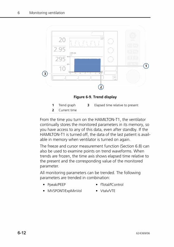
6 Monitoring ventilation
Figure 6-9. Trend display
From the time you turn on the HAMILTON-T1, the ventilator continually stores the monitored parameters in its memory, so you have access to any of this data, even after standby. If the HAMILTON-T1 is turned off, the data of the last patient is avail-able in memory when ventilator is turned on again.
The freeze and cursor measurement function (Section 6.8) can also be used to examine points on trend waveforms. When trends are frozen, the time axis shows elapsed time relative to the present and the corresponding value of the monitored parameter.
All monitoring parameters can be trended. The following parameters are trended in combination:
1 Trend graph 3 Elapsed time relative to present2 Current time
• Ppeak/PEEP • fTotal/fControl
• MVSPONT/ExpMinVol • Vtalv/VTE
6-12 624369/06
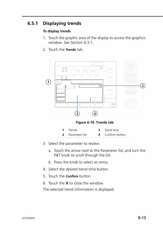
6.5.1 Displaying trends
To display trends
1. Touch the graphic area of the display to access the graphics window. See Section 6.3.1.
2. Touch the Trends tab.
Figure 6-10. Trends tab
3. Select the parameter to review:
a. Touch the arrow next to the Parameter list, and turn the P&T knob to scroll through the list.
b. Press the knob to select an entry.
4. Select the desired trend time button.
5. Touch the Confirm button.
6. Touch the X to close the window.
The selected trend information is displayed.
1 Trends 3 Trend time2 Parameter list 4 Confirm button
624369/06 6-13
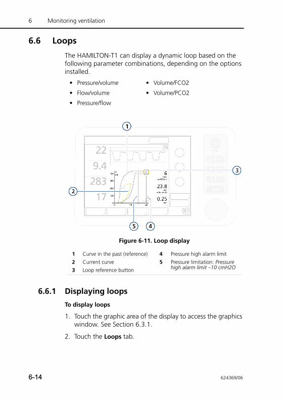
6 Monitoring ventilation
6.6 Loops
The HAMILTON-T1 can display a dynamic loop based on the following parameter combinations, depending on the options installed.
Figure 6-11. Loop display
6.6.1 Displaying loops
To display loops
1. Touch the graphic area of the display to access the graphics window. See Section 6.3.1.
2. Touch the Loops tab.
• Pressure/volume • Volume/FCO2
• Flow/volume • Volume/PCO2
• Pressure/flow
1 Curve in the past (reference) 4 Pressure high alarm limit2 Current curve 5 Pressure limitation: Pressure
high alarm limit –10 cmH2O3 Loop reference button
6-14 624369/06
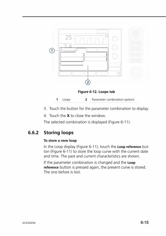
Figure 6-12. Loops tab
3. Touch the button for the parameter combination to display.
4. Touch the X to close the window.
The selected combination is displayed (Figure 6-11).
6.6.2 Storing loops
To store a new loop
In the Loop display (Figure 6-11), touch the Loop reference but-ton (Figure 6-11) to store the loop curve with the current date and time. The past and current characteristics are shown.
If the parameter combination is changed and the Loop reference button is pressed again, the present curve is stored. The one before is lost.
1 Loops 2 Parameter combination options
624369/06 6-15
6 Monitoring ventilation
6.7 Table of monitored parameters
NOTE:The HAMILTON-T1 automatically measures inspiratory resis-tance (Rinsp), compliance (Cstat), and AutoPEEP breath by breath, during mandatory and spontaneous breaths in all modes, without interruption in ventilation. To obtain these measurements, the HAMILTON-T1 uses a statistical technique called the Least Squares Fitting (LSF) method. This method is applied on a breath-by-breath basis, without the need for special inspiratory flow patterns and occlusion maneuvers, provided that the patient is relaxed or nearly relaxed.Actively breathing patients can create artifacts or noise, which can affect the accuracy of these measurements, however. The more active the patient, the less accurate the measurements. To minimize patient participation during these measurements, you may want to increase Psupport by 10 cmH2O. After completion, return this control to its former setting.
Table 6-2 is an alphabetical list of the HAMILTON-T1’s monitored parameters. These parameters are displayed in the individual parameter windows 1, 2, and 3 (Figure 6-3). The display of monitored parameters is updated every breath.
Table A-7 in Appendix A provides the parameter ranges and accuracy.
6-16 624369/06
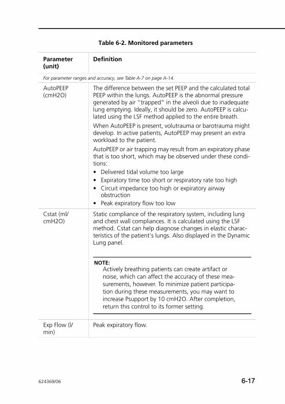
Table 6-2. Monitored parameters
Parameter (unit)
Definition
For parameter ranges and accuracy, see Table A-7 on page A-14.
AutoPEEP (cmH2O)
The difference between the set PEEP and the calculated total PEEP within the lungs. AutoPEEP is the abnormal pressure generated by air “trapped” in the alveoli due to inadequate lung emptying. Ideally, it should be zero. AutoPEEP is calcu-lated using the LSF method applied to the entire breath.When AutoPEEP is present, volutrauma or barotrauma might develop. In active patients, AutoPEEP may present an extra workload to the patient.AutoPEEP or air trapping may result from an expiratory phase that is too short, which may be observed under these condi-tions:• Delivered tidal volume too large• Expiratory time too short or respiratory rate too high• Circuit impedance too high or expiratory airway
obstruction• Peak expiratory flow too low
Cstat (ml/cmH2O)
Static compliance of the respiratory system, including lung and chest wall compliances. It is calculated using the LSF method. Cstat can help diagnose changes in elastic charac-teristics of the patient’s lungs. Also displayed in the Dynamic Lung panel.
NOTE:Actively breathing patients can create artifact or noise, which can affect the accuracy of these mea-surements, however. To minimize patient participa-tion during these measurements, you may want to increase Psupport by 10 cmH2O. After completion, return this control to its former setting.
Exp Flow (l/min)
Peak expiratory flow.
624369/06 6-17
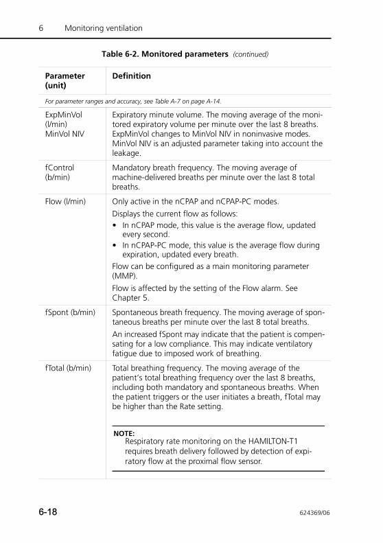
6 Monitoring ventilation
ExpMinVol (l/min)MinVol NIV
Expiratory minute volume. The moving average of the moni-tored expiratory volume per minute over the last 8 breaths. ExpMinVol changes to MinVol NIV in noninvasive modes. MinVol NIV is an adjusted parameter taking into account the leakage.
fControl (b/min)
Mandatory breath frequency. The moving average of machine-delivered breaths per minute over the last 8 total breaths.
Flow (l/min) Only active in the nCPAP and nCPAP-PC modes. Displays the current flow as follows: • In nCPAP mode, this value is the average flow, updated
every second.• In nCPAP-PC mode, this value is the average flow during
expiration, updated every breath. Flow can be configured as a main monitoring parameter (MMP). Flow is affected by the setting of the Flow alarm. See Chapter 5.
fSpont (b/min) Spontaneous breath frequency. The moving average of spon-taneous breaths per minute over the last 8 total breaths.An increased fSpont may indicate that the patient is compen-sating for a low compliance. This may indicate ventilatory fatigue due to imposed work of breathing.
fTotal (b/min) Total breathing frequency. The moving average of the patient’s total breathing frequency over the last 8 breaths, including both mandatory and spontaneous breaths. When the patient triggers or the user initiates a breath, fTotal may be higher than the Rate setting.
NOTE:Respiratory rate monitoring on the HAMILTON-T1 requires breath delivery followed by detection of expi-ratory flow at the proximal flow sensor.
Table 6-2. Monitored parameters (continued)
Parameter (unit)
Definition
For parameter ranges and accuracy, see Table A-7 on page A-14.
6-18 624369/06
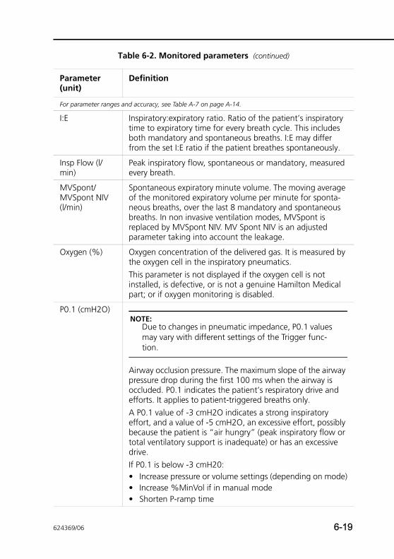
I:E Inspiratory:expiratory ratio. Ratio of the patient’s inspiratory time to expiratory time for every breath cycle. This includes both mandatory and spontaneous breaths. I:E may differ from the set I:E ratio if the patient breathes spontaneously.
Insp Flow (l/min)
Peak inspiratory flow, spontaneous or mandatory, measured every breath.
MVSpont/MVSpont NIV(l/min)
Spontaneous expiratory minute volume. The moving average of the monitored expiratory volume per minute for sponta-neous breaths, over the last 8 mandatory and spontaneous breaths. In non invasive ventilation modes, MVSpont is replaced by MVSpont NIV. MV Spont NIV is an adjusted parameter taking into account the leakage.
Oxygen (%) Oxygen concentration of the delivered gas. It is measured by the oxygen cell in the inspiratory pneumatics.This parameter is not displayed if the oxygen cell is not installed, is defective, or is not a genuine Hamilton Medical part; or if oxygen monitoring is disabled.
P0.1 (cmH2O)NOTE:
Due to changes in pneumatic impedance, P0.1 values may vary with different settings of the Trigger func-tion.
Airway occlusion pressure. The maximum slope of the airway pressure drop during the first 100 ms when the airway is occluded. P0.1 indicates the patient’s respiratory drive and efforts. It applies to patient-triggered breaths only.A P0.1 value of -3 cmH2O indicates a strong inspiratory effort, and a value of -5 cmH2O, an excessive effort, possibly because the patient is “air hungry” (peak inspiratory flow or total ventilatory support is inadequate) or has an excessive drive. If P0.1 is below -3 cmH20:• Increase pressure or volume settings (depending on mode)• Increase %MinVol if in manual mode• Shorten P-ramp time
Table 6-2. Monitored parameters (continued)
Parameter (unit)
Definition
For parameter ranges and accuracy, see Table A-7 on page A-14.
624369/06 6-19
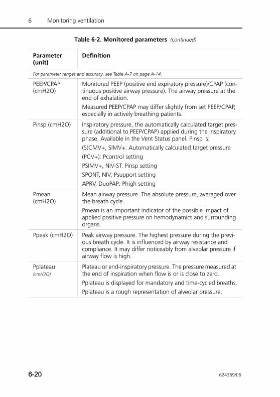
6 Monitoring ventilation
PEEP/CPAP (cmH2O)
Monitored PEEP (positive end expiratory pressure)/CPAP (con-tinuous positive airway pressure). The airway pressure at the end of exhalation.Measured PEEP/CPAP may differ slightly from set PEEP/CPAP, especially in actively breathing patients.
Pinsp (cmH2O) Inspiratory pressure, the automatically calculated target pres-sure (additional to PEEP/CPAP) applied during the inspiratory phase. Available in the Vent Status panel. Pinsp is:(S)CMV+, SIMV+: Automatically calculated target pressure(PCV+): Pcontrol settingPSIMV+, NIV-ST: Pinsp settingSPONT, NIV: Psupport settingAPRV, DuoPAP: Phigh setting
Pmean (cmH2O)
Mean airway pressure. The absolute pressure, averaged over the breath cycle.Pmean is an important indicator of the possible impact of applied positive pressure on hemodynamics and surrounding organs.
Ppeak (cmH2O) Peak airway pressure. The highest pressure during the previ-ous breath cycle. It is influenced by airway resistance and compliance. It may differ noticeably from alveolar pressure if airway flow is high.
Pplateau (cmH2O)
Plateau or end-inspiratory pressure. The pressure measured at the end of inspiration when flow is or is close to zero.Pplateau is displayed for mandatory and time-cycled breaths.Pplateau is a rough representation of alveolar pressure.
Table 6-2. Monitored parameters (continued)
Parameter (unit)
Definition
For parameter ranges and accuracy, see Table A-7 on page A-14.
6-20 624369/06

PTP (cmH2O*s) Inspiratory pressure time product. The measured pressure drop required to trigger the breath multiplied by the time interval until the PEEP/CPAP level is reached at the beginning of inspiration.The PTP indicates work by the patient to trigger the breath. The work depends on• The intensity of the patient’s effort• The trigger sensitivity• The volume and resistance of the breathing circuitPTP is valid for patient-initiated breaths only.The PTP does not indicate total patient work. But it is a good indicators of how well the ventilator is adapted to the patient.If PTP values increase…• Check and remove water in tubes• Increase trigger sensitivity
RCexp (s) Expiratory time constant. The rate at which the lungs empty, as follows:Actual TE % emptying1 x RCexp 63%2 x RCexp 86.5%3 x RCexp 95%4 x RCexp 98%RCexp is calculated as the ratio between VTE and flow at 75% of the VTE.In adults, an RCexp value above 1.2 s indicates airway obstruction, and a value below 0.5 s indicates a severe restrictive disease.Use RCexp to set optimal TE (Goal: TE ≥ 3 x RCexp):• In passive patients: Adjust rate and I:E.• In active patients: Increase Psupport and/or ETS to achieve
a longer TE. These actions may reduce the incidence of AutoPEEP.
Table 6-2. Monitored parameters (continued)
Parameter (unit)
Definition
For parameter ranges and accuracy, see Table A-7 on page A-14.
624369/06 6-21
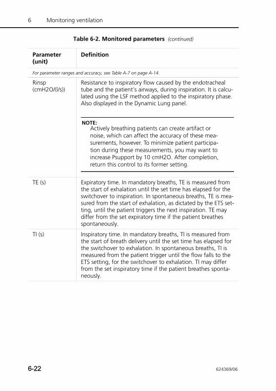
6 Monitoring ventilation
Rinsp (cmH2O/(l/s))
Resistance to inspiratory flow caused by the endotracheal tube and the patient’s airways, during inspiration. It is calcu-lated using the LSF method applied to the inspiratory phase. Also displayed in the Dynamic Lung panel.
NOTE:Actively breathing patients can create artifact or noise, which can affect the accuracy of these mea-surements, however. To minimize patient participa-tion during these measurements, you may want to increase Psupport by 10 cmH2O. After completion, return this control to its former setting.
TE (s) Expiratory time. In mandatory breaths, TE is measured from the start of exhalation until the set time has elapsed for the switchover to inspiration. In spontaneous breaths, TE is mea-sured from the start of exhalation, as dictated by the ETS set-ting, until the patient triggers the next inspiration. TE may differ from the set expiratory time if the patient breathes spontaneously.
TI (s) Inspiratory time. In mandatory breaths, TI is measured from the start of breath delivery until the set time has elapsed for the switchover to exhalation. In spontaneous breaths, TI is measured from the patient trigger until the flow falls to the ETS setting, for the switchover to exhalation. TI may differ from the set inspiratory time if the patient breathes sponta-neously.
Table 6-2. Monitored parameters (continued)
Parameter (unit)
Definition
For parameter ranges and accuracy, see Table A-7 on page A-14.
6-22 624369/06
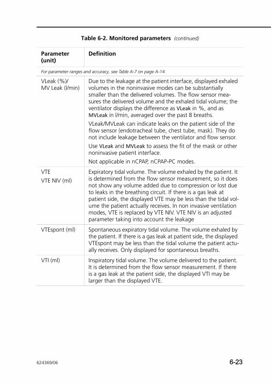
VLeak (%)/MV Leak (l/min)
Due to the leakage at the patient interface, displayed exhaled volumes in the noninvasive modes can be substantially smaller than the delivered volumes. The flow sensor mea-sures the delivered volume and the exhaled tidal volume; the ventilator displays the difference as VLeak in %, and as MVLeak in l/min, averaged over the past 8 breaths. VLeak/MVLeak can indicate leaks on the patient side of the flow sensor (endotracheal tube, chest tube, mask). They do not include leakage between the ventilator and flow sensor.Use VLeak and MVLeak to assess the fit of the mask or other noninvasive patient interface.Not applicable in nCPAP, nCPAP-PC modes.
VTEVTE NIV (ml)
Expiratory tidal volume. The volume exhaled by the patient. It is determined from the flow sensor measurement, so it does not show any volume added due to compression or lost due to leaks in the breathing circuit. If there is a gas leak at patient side, the displayed VTE may be less than the tidal vol-ume the patient actually receives. In non invasive ventilation modes, VTE is replaced by VTE NIV. VTE NIV is an adjusted parameter taking into account the leakage
VTEspont (ml) Spontaneous expiratory tidal volume. The volume exhaled by the patient. If there is a gas leak at patient side, the displayed VTEspont may be less than the tidal volume the patient actu-ally receives. Only displayed for spontaneous breaths.
VTI (ml) Inspiratory tidal volume. The volume delivered to the patient. It is determined from the flow sensor measurement. If there is a gas leak at the patient side, the displayed VTI may be larger than the displayed VTE.
Table 6-2. Monitored parameters (continued)
Parameter (unit)
Definition
For parameter ranges and accuracy, see Table A-7 on page A-14.
624369/06 6-23
6 Monitoring ventilation
6.8 Freeze and cursor measurement
This function lets you freeze the display of a graphic for up to 30 s.
The freeze function is particularly useful when you perform a breath hold maneuver. The screen automatically freezes following a successful inspiratory maneuver.
To freeze the graphic
1. In the pressure/time waveform, touch the Freeze button in the right upper corner (item 5 in Figure 6-6). The graphic is frozen for 30 s.
2. To analyze the curves, turn the Press-and-turn knob.
3. Unfreeze by pressing the Freeze button again or by pressing the Press-and-turn knob.
6-24 624369/06
7 Intelligent panels
7.1 Dynamic Lung panel 7-2
7.1.1 Displaying the Dynamic Lung 7-3
7.1.2 Tidal volume (Vt) 7-3
7.1.3 Compliance (Cstat) 7-4
7.1.4 Patient triggering: Muscle 7-4
7.1.5 Resistance (Rinsp): Bronchial tree 7-5
7.2 Vent Status panel 7-6
7.2.1 Displaying the Vent Status panel 7-8
7.3 ASV Graph panel 7-9
7.3.1 Displaying the ASV Graph 7-9
624369/06 7-1
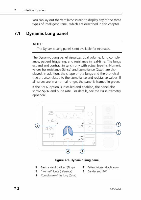
7 Intelligent panels
You can lay out the ventilator screen to display any of the three types of Intelligent Panel, which are described in this chapter.
7.1 Dynamic Lung panel
NOTE: The Dynamic Lung panel is not available for neonates.
The Dynamic Lung panel visualizes tidal volume, lung compli-ance, patient triggering, and resistance in real-time. The lungs expand and contract in synchrony with actual breaths. Numeric values for resistance (Rinsp) and compliance (Cstat) are dis-played. In addition, the shape of the lungs and the bronchial tree are also related to the compliance and resistance values. If all values are in a normal range, the panel is framed in green.
If the SpO2 option is installed and enabled, the panel also shows SpO2 and pulse rate. For details, see the Pulse oximetry appendix.
Figure 7-1. Dynamic Lung panel
1 Resistance of the lung (Rinsp) 4 Patient trigger (diaphragm)2 “Normal” lungs (reference) 5 Gender and IBW3 Compliance of the lung (Cstat)
7-2 624369/06
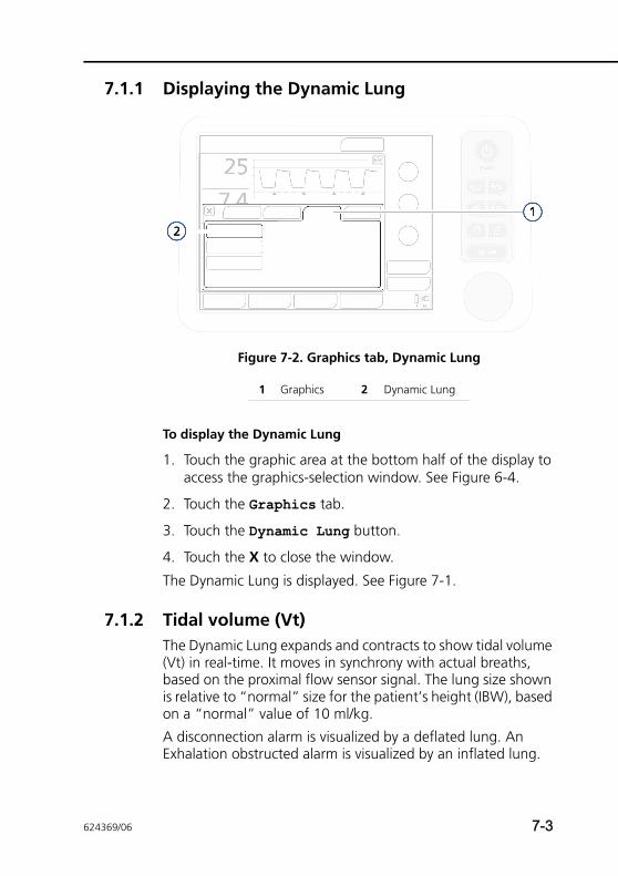
7.1.1 Displaying the Dynamic Lung
Figure 7-2. Graphics tab, Dynamic Lung
To display the Dynamic Lung
1. Touch the graphic area at the bottom half of the display to access the graphics-selection window. See Figure 6-4.
2. Touch the Graphics tab.
3. Touch the Dynamic Lung button.
4. Touch the X to close the window.
The Dynamic Lung is displayed. See Figure 7-1.
7.1.2 Tidal volume (Vt)The Dynamic Lung expands and contracts to show tidal volume (Vt) in real-time. It moves in synchrony with actual breaths, based on the proximal flow sensor signal. The lung size shown is relative to “normal” size for the patient’s height (IBW), based on a “normal” value of 10 ml/kg.
A disconnection alarm is visualized by a deflated lung. An Exhalation obstructed alarm is visualized by an inflated lung.
1 Graphics 2 Dynamic Lung
624369/06 7-3
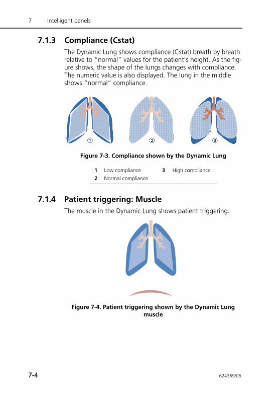
7 Intelligent panels
7.1.3 Compliance (Cstat)The Dynamic Lung shows compliance (Cstat) breath by breath relative to “normal” values for the patient’s height. As the fig-ure shows, the shape of the lungs changes with compliance. The numeric value is also displayed. The lung in the middle shows “normal” compliance.
Figure 7-3. Compliance shown by the Dynamic Lung
7.1.4 Patient triggering: MuscleThe muscle in the Dynamic Lung shows patient triggering.
Figure 7-4. Patient triggering shown by the Dynamic Lung muscle
1 Low compliance 3 High compliance2 Normal compliance
7-4 624369/06
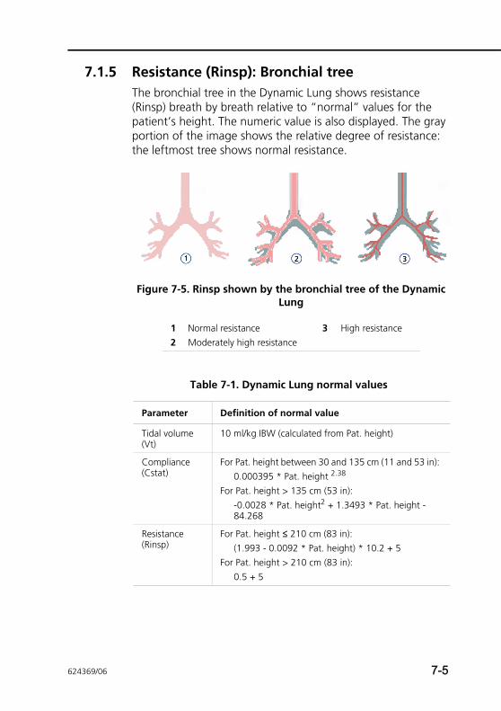
7.1.5 Resistance (Rinsp): Bronchial treeThe bronchial tree in the Dynamic Lung shows resistance (Rinsp) breath by breath relative to “normal” values for the patient’s height. The numeric value is also displayed. The gray portion of the image shows the relative degree of resistance: the leftmost tree shows normal resistance.
Figure 7-5. Rinsp shown by the bronchial tree of the Dynamic Lung
1 Normal resistance 3 High resistance2 Moderately high resistance
Table 7-1. Dynamic Lung normal values
Parameter Definition of normal value
Tidal volume (Vt)
10 ml/kg IBW (calculated from Pat. height)
Compliance (Cstat)
For Pat. height between 30 and 135 cm (11 and 53 in): 0.000395 * Pat. height 2.38
For Pat. height > 135 cm (53 in):-0.0028 * Pat. height2 + 1.3493 * Pat. height -84.268
Resistance (Rinsp)
For Pat. height ≤ 210 cm (83 in): (1.993 - 0.0092 * Pat. height) * 10.2 + 5
For Pat. height > 210 cm (83 in): 0.5 + 5
624369/06 7-5
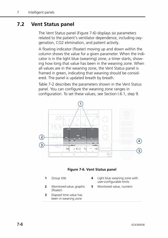
7 Intelligent panels
7.2 Vent Status panel
The Vent Status panel (Figure 7-6) displays six parameters related to the patient’s ventilator dependence, including oxy-genation, CO2 elimination, and patient activity.
A floating indicator (floater) moving up and down within the column shows the value for a given parameter. When the indi-cator is in the light blue (weaning) zone, a timer starts, show-ing how long that value has been in the weaning zone. When all values are in the weaning zone, the Vent Status panel is framed in green, indicating that weaning should be consid-ered. The panel is updated breath by breath.
Table 7-2 describes the parameters shown in the Vent Status panel. You can configure the weaning zone ranges in configuration. To set these values, see Section I.6.1, step 9.
Figure 7-6. Vent Status panel
1 Group title 4 Light blue weaning zone with user-configurable limits
2 Monitored value, graphic (floater)
5 Monitored value, numeric
3 Elapsed time value has been in weaning zone
7-6 624369/06
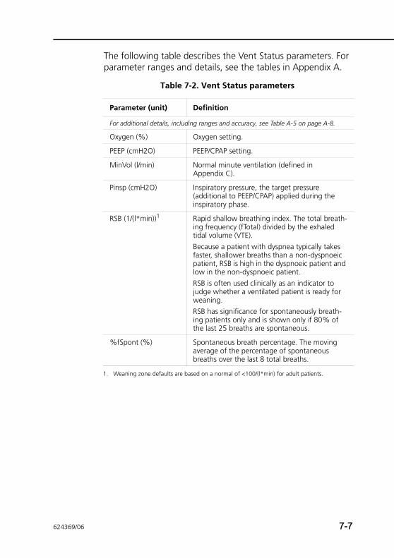
The following table describes the Vent Status parameters. For parameter ranges and details, see the tables in Appendix A.
Table 7-2. Vent Status parameters
Parameter (unit) Definition
For additional details, including ranges and accuracy, see Table A-5 on page A-8.
Oxygen (%) Oxygen setting.
PEEP (cmH2O) PEEP/CPAP setting.
MinVol (l/min) Normal minute ventilation (defined in Appendix C).
Pinsp (cmH2O) Inspiratory pressure, the target pressure (additional to PEEP/CPAP) applied during the inspiratory phase.
RSB (1/(l*min))1 Rapid shallow breathing index. The total breath-ing frequency (fTotal) divided by the exhaled tidal volume (VTE).Because a patient with dyspnea typically takes faster, shallower breaths than a non-dyspnoeic patient, RSB is high in the dyspnoeic patient and low in the non-dyspnoeic patient.RSB is often used clinically as an indicator to judge whether a ventilated patient is ready for weaning.RSB has significance for spontaneously breath-ing patients only and is shown only if 80% of the last 25 breaths are spontaneous.
%fSpont (%) Spontaneous breath percentage. The moving average of the percentage of spontaneous breaths over the last 8 total breaths.
1. Weaning zone defaults are based on a normal of <100/(l*min) for adult patients.
624369/06 7-7
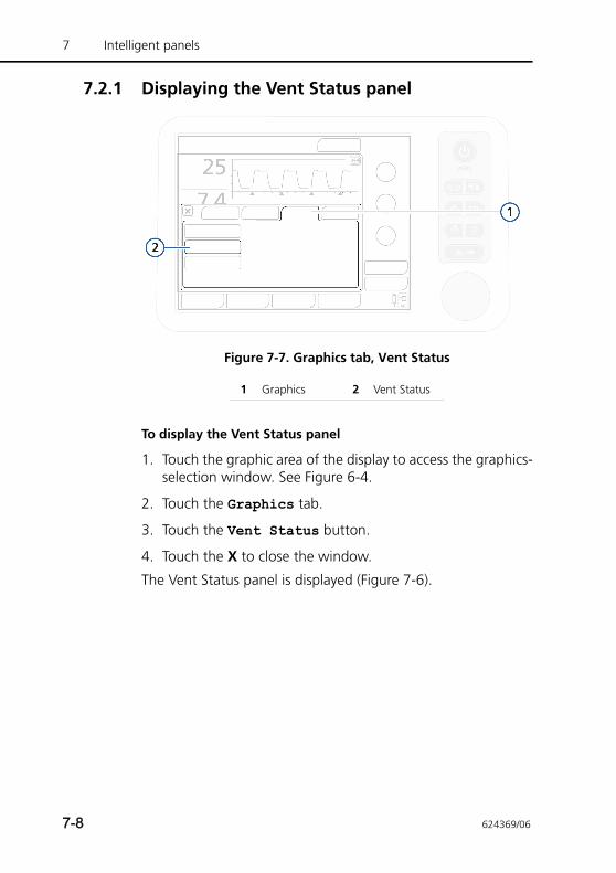
7 Intelligent panels
7.2.1 Displaying the Vent Status panel
Figure 7-7. Graphics tab, Vent Status
To display the Vent Status panel
1. Touch the graphic area of the display to access the graphics-selection window. See Figure 6-4.
2. Touch the Graphics tab.
3. Touch the Vent Status button.
4. Touch the X to close the window.
The Vent Status panel is displayed (Figure 7-6).
1 Graphics 2 Vent Status
7-8 624369/06
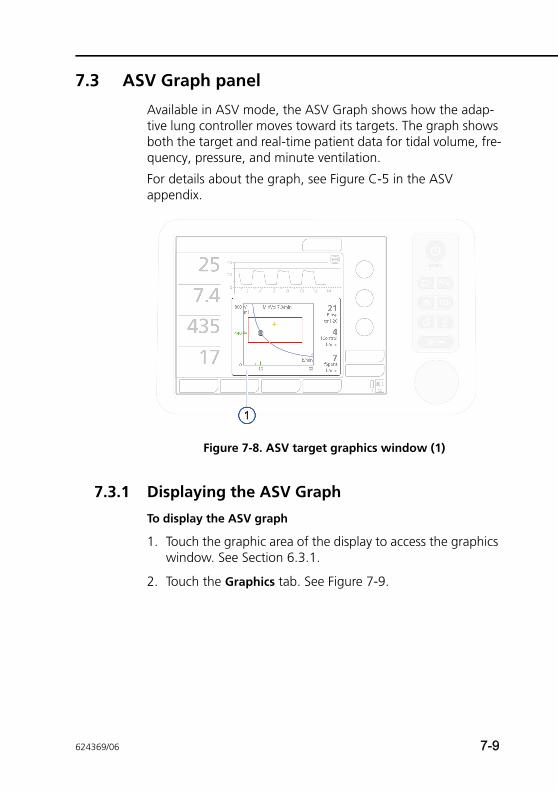
7.3 ASV Graph panel
Available in ASV mode, the ASV Graph shows how the adap-tive lung controller moves toward its targets. The graph shows both the target and real-time patient data for tidal volume, fre-quency, pressure, and minute ventilation.
For details about the graph, see Figure C-5 in the ASV appendix.
Figure 7-8. ASV target graphics window (1)
7.3.1 Displaying the ASV Graph
To display the ASV graph
1. Touch the graphic area of the display to access the graphics window. See Section 6.3.1.
2. Touch the Graphics tab. See Figure 7-9.
624369/06 7-9
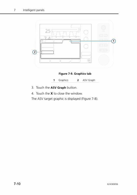
7 Intelligent panels
Figure 7-9. Graphics tab
3. Touch the ASV Graph button.
4. Touch the X to close the window.
The ASV target graphic is displayed (Figure 7-8).
1 Graphics 2 ASV Graph
7-10 624369/06
8 Responding to alarms
8.1 Introduction 8-2
8.2 Responding to an alarm 8-6
8.3 Alarm buffer 8-7
8.4 About the event log 8-9
8.5 Alarm troubleshooting table 8-10
624369/06 8-1
8 Responding to alarms
8.1 Introduction
The HAMILTON-T1 alarms notify the operator of problems.
These alarms can be categorized as:
• High priority
• Medium priority
• Low priority
Additionally there are other alarms conditions associated with technical fault alarms and operator messages.
The main monitoring parameters (MMP) change their colors when a corresponding alarm activates. The color reflects the priority of the alarm.
Table 8-1 shows the audio and visual characteristics of these types of alarm and tells you how to respond. Figure 8-1 shows the ventilator’s visual alarm indications. You can view active alarms in the active alarm buffer (Figure 8-4). Information about the alarm is also stored in an event log (Section 8.4).
When an alarm condition is serious enough to possibly com-promise safe ventilation, the device defaults to the ambient state (Appendix B). The inspiratory valve closes, and the ambi-ent and expiratory valves are opened, letting the patient breathe room air unassisted.
For details on setting alarm limits, see Section 4.7.1.
8-2 624369/06
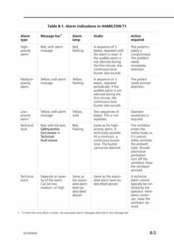
1.
Table 8-1. Alarm indications in HAMILTON-T1
Alarm type
Message bar1 Alarm lamp
Audio Action required
High-priority alarm
Red, with alarm message
Red, flashing
A sequence of 5 beeps, repeated until the alarm is reset. If the audible alarm is not silenced during the first minute, the continuous-tone buzzer also sounds.
The patient’s safety is compromised. The problem needs immediate attention.
Medium-priority alarm
Yellow, with alarm message
Yellow, flashing
A sequence of 3 beeps, repeated periodically. If the audible alarm is not silenced during the first minute, the continuous-tone buzzer also sounds.
The patient needs prompt attention.
Low-priority alarm
Yellow, with alarm message
Yellow, solid
Two sequences of beeps. This is not repeated.
Operator awareness is required.
Technical fault
Red, with the text, Safetyventila-tion:xxxxxx or Technical-fault:xxxxxx
Red, flashing
Same as for high-priority alarm, if technically possible. At a minimum, a continuous buzzer tone. The buzzer cannot be silenced.
The ventilator enters the safety mode, or, if it cannot safely ventilate, the ambient state. Provide alternative ventilation. Turn off the ventilator. Have the ventilator serviced.
Technical event
Depends on sever-ity of the event. Can be low, medium, or high.
Same as the associ-ated alarm level (as described above)
Same as the associ-ated alarm level (as described above).
A technical alarm cannot typically be cor-rected by the operator. Venti-lation contin-ues. Have the ventilator ser-viced.
If more than one alarm is active, the associated alarm messages alternate in the message bar.
624369/06 8-3
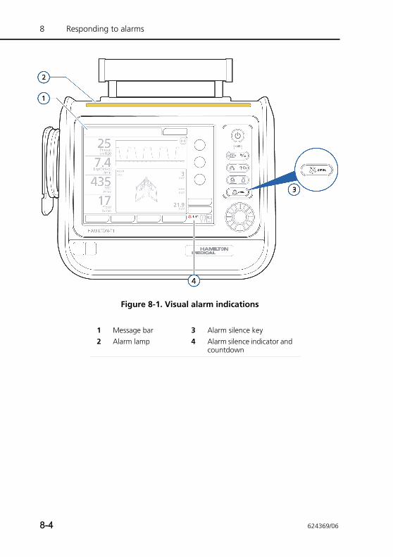
8 Responding to alarms
Figure 8-1. Visual alarm indications
1 Message bar 3 Alarm silence key2 Alarm lamp 4 Alarm silence indicator and
countdown
8-4 624369/06
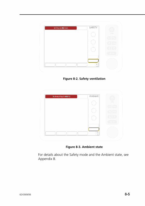
Figure 8-2. Safety ventilation
Figure 8-3. Ambient state
For details about the Safety mode and the Ambient state, see Appendix B.
624369/06 8-5
8 Responding to alarms
8.2 Responding to an alarm
WARNING• To prevent possible patient injury when alarms are
active, check the patient for adequate ventilation. Identify and remove the cause of the alarms. Read-just the alarm limits only when they are inappropri-ately set for the current conditions.
• To prevent possible patient injury arising from any issues with the device, Hamilton Medical recom-mends that you immediately remove any ventilator with a technical fault from use, record the technical fault code, and have the ventilator serviced.
CAUTIONSetting alarm limits to extreme values can render the alarm system useless.
NOTE:• Be aware that an alarm may result from either a clinical
condition or an equipment problem.
• Be aware that one alarm condition can induce multiple alarms. Normally only one or two indicate the root cause of the alarm; the rest are resultant. Your search for the causes of the alarm condition should be assisted by, but not limited to, the alarm messages displayed.
To respond to an alarm
1. Approach the patient immediately. Secure sufficient and effective ventilation for the patient. You may silence the alarm if possible.
2. Correct the alarm condition from the alarm messages, referring to Table 8-2. For low-, medium-, and high-priority alarms, when the alarm triggering condition is corrected, the ventilator automatically resets the alarm. For a technical fault alarm, switch off ventilator power first; then correct the problem.
8-6 624369/06
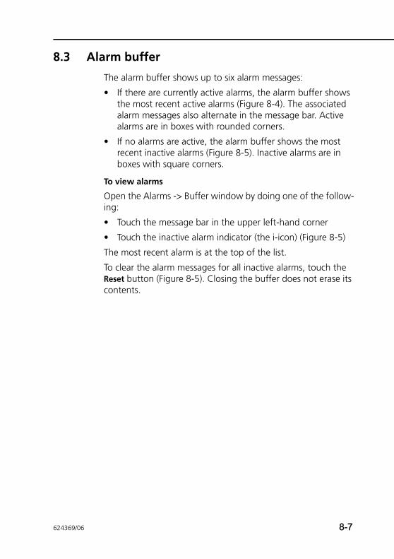
8.3 Alarm buffer
The alarm buffer shows up to six alarm messages:
• If there are currently active alarms, the alarm buffer shows the most recent active alarms (Figure 8-4). The associated alarm messages also alternate in the message bar. Active alarms are in boxes with rounded corners.
• If no alarms are active, the alarm buffer shows the most recent inactive alarms (Figure 8-5). Inactive alarms are in boxes with square corners.
To view alarms
Open the Alarms -> Buffer window by doing one of the follow-ing:
• Touch the message bar in the upper left-hand corner
• Touch the inactive alarm indicator (the i-icon) (Figure 8-5)
The most recent alarm is at the top of the list.
To clear the alarm messages for all inactive alarms, touch the Reset button (Figure 8-5). Closing the buffer does not erase its contents.
624369/06 8-7
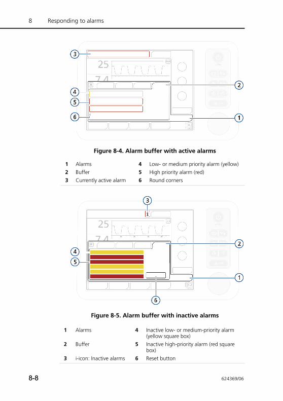
8 Responding to alarms
Figure 8-4. Alarm buffer with active alarms
Figure 8-5. Alarm buffer with inactive alarms
1 Alarms 4 Low- or medium priority alarm (yellow)2 Buffer 5 High priority alarm (red)3 Currently active alarm 6 Round corners
1 Alarms 4 Inactive low- or medium-priority alarm (yellow square box)
2 Buffer 5 Inactive high-priority alarm (red square box)
3 i-icon: Inactive alarms 6 Reset button
8-8 624369/06

8.4 About the event log
Once the ventilator is turned on, several event logs collect data about clinically relevant ventilator activities, including alarms, setting changes, calibrations, maneuvers, and special func-tions. The date, time, and a unique identification reference (ID) for event classification is included. Alarms are shown in color, depending on priority level (yellow for low or medium, red for high). Note that a more extensive log including technical and configuration information is available to service engineers.
When setting up a new patient:
• Data is appended to the existing event log when you select the Last patient tab.
• The event log is cleared and starts anew when you select a different patient group tab (Adult/Ped. or Neonatal).
Event log data persists after shutting off the ventilator or in the event of a power loss. A maximum of 1000 events is stored. When a log buffer is full, new events overwrite the oldest log entries.
View the event log in the Events window.
Figure 8-6. Events window
1 Events 3 Low- or medium-priority alarm (yellow)2 All 4 High-priority alarm (red)
624369/06 8-9
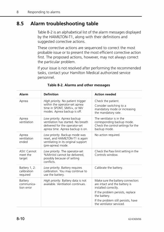
8 Responding to alarms
8.5 Alarm troubleshooting table
Table 8-2 is an alphabetical list of the alarm messages displayed by the HAMILTON-T1, along with their definitions and suggested corrective actions.
These corrective actions are sequenced to correct the most probable issue or to present the most efficient corrective action first. The proposed actions, however, may not always correct the particular problem.
If your issue is not resolved after performing the recommended tasks, contact your Hamilton Medical authorized service personnel.
Table 8-2. Alarms and other messages
Alarm Definition Action needed
Apnea High priority. No patient trigger within the operator-set apnea time in SPONT, SIMV+, or NIV modes. Apnea backup is off.
Check the patient.Consider switching to a mandatory mode or increasing the mandatory rate.
Apnea ventilation
Low priority. Apnea backup ventilation has started. No breath delivered for the operator-set apnea time. Apnea backup is on.
The ventilator is in the corresponding backup mode. Check the control settings for the backup mode.
Apnea ventilation ended
Low priority. Backup mode was reset, and HAMILTON-T1 is again ventilating in its original support (pre-apnea) mode.
No action required.
ASV: Cannot meet the target
Low priority. The operator-set %MinVol cannot be delivered, possibly because of setting conflicts.
Check the Pasv limit setting in the Controls window.
Battery 1, 2: calibration required
Low priority. Battery requires calibration. You may continue to use the battery.
Calibrate the battery.
Battery communica-tion error
High priority. Battery data is not available. Ventilation continues.
Make sure the battery connectors are intact and the battery is installed correctly. If the problem persists, replace the battery. If the problem still persists, have the ventilator serviced.
8-10 624369/06
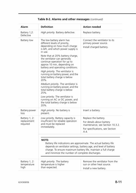
Battery 1,2: Defective
High priority. Battery defective. Replace battery.
Battery low The low battery alarm has different levels of priority, depending on how much charge is left, and which power supply is in use.Note that at 20% battery charge, the ventilator can generally continue operation for up to approx 10 min, depending on battery and operating conditions. High priority. The ventilator is running on battery power, and the total battery charge is below 20%. Medium priority. The ventilator is running on battery power, and the total battery charge is below 25%. Low priority. The ventilator is running on AC or DC power, and the total battery charge is below 20%.
Connect the ventilator to its primary power source.Install charged battery.
Battery power loss
High priority. No battery is present.
Insert a battery.
Battery 1, 2: replacement required
Low priority. Battery capacity is insufficient for reliable operation and must be replaced immediately.
Replace the battery.For details about battery maintenance, see Section 10.3.2.For specifications, see Section A.4.
NOTE:Battery life indications are approximate. The actual battery life depends on ventilator settings, battery age, and level of battery charge. To ensure maximum battery life, maintain a full charge and minimize the number of complete discharges.
Battery 1, 2: temperature high
High priority. The battery temperature is higher than expected.
Remove the ventilator from the sun or other heat source.Install a new battery.
Table 8-2. Alarms and other messages (continued)
Alarm Definition Action needed
624369/06 8-11
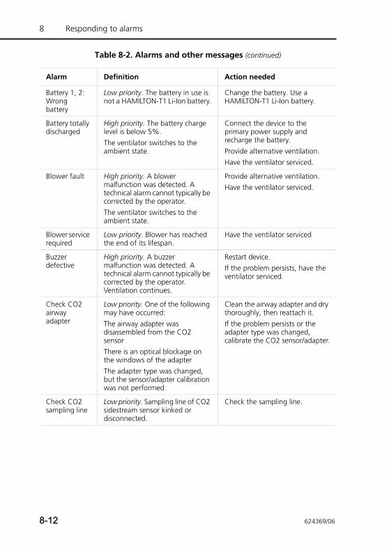
8 Responding to alarms
Battery 1, 2: Wrong battery
Low priority. The battery in use is not a HAMILTON-T1 Li-Ion battery.
Change the battery. Use a HAMILTON-T1 Li-Ion battery.
Battery totally discharged
High priority. The battery charge level is below 5%. The ventilator switches to the ambient state.
Connect the device to the primary power supply and recharge the battery. Provide alternative ventilation. Have the ventilator serviced.
Blower fault High priority. A blower malfunction was detected. A technical alarm cannot typically be corrected by the operator. The ventilator switches to the ambient state.
Provide alternative ventilation. Have the ventilator serviced.
Blower service required
Low priority. Blower has reached the end of its lifespan.
Have the ventilator serviced
Buzzer defective
High priority. A buzzer malfunction was detected. A technical alarm cannot typically be corrected by the operator. Ventilation continues.
Restart device. If the problem persists, have the ventilator serviced.
Check CO2 airway adapter
Low priority. One of the following may have occurred:The airway adapter was disassembled from the CO2 sensorThere is an optical blockage on the windows of the adapterThe adapter type was changed, but the sensor/adapter calibration was not performed
Clean the airway adapter and dry thoroughly, then reattach it.If the problem persists or the adapter type was changed, calibrate the CO2 sensor/adapter.
Check CO2 sampling line
Low priority. Sampling line of CO2 sidestream sensor kinked or disconnected.
Check the sampling line.
Table 8-2. Alarms and other messages (continued)
Alarm Definition Action needed
8-12 624369/06
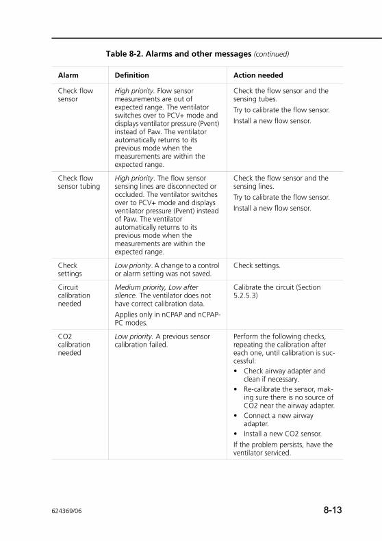
Check flow sensor
High priority. Flow sensor measurements are out of expected range. The ventilator switches over to PCV+ mode and displays ventilator pressure (Pvent) instead of Paw. The ventilator automatically returns to its previous mode when the measurements are within the expected range.
Check the flow sensor and the sensing tubes.Try to calibrate the flow sensor.Install a new flow sensor.
Check flow sensor tubing
High priority. The flow sensor sensing lines are disconnected or occluded. The ventilator switches over to PCV+ mode and displays ventilator pressure (Pvent) instead of Paw. The ventilator automatically returns to its previous mode when the measurements are within the expected range.
Check the flow sensor and the sensing lines. Try to calibrate the flow sensor.Install a new flow sensor.
Check settings
Low priority. A change to a control or alarm setting was not saved.
Check settings.
Circuit calibration needed
Medium priority, Low after silence. The ventilator does not have correct calibration data. Applies only in nCPAP and nCPAP-PC modes.
Calibrate the circuit (Section 5.2.5.3)
CO2 calibration needed
Low priority. A previous sensor calibration failed.
Perform the following checks, repeating the calibration after each one, until calibration is suc-cessful: • Check airway adapter and
clean if necessary. • Re-calibrate the sensor, mak-
ing sure there is no source of CO2 near the airway adapter.
• Connect a new airway adapter.
• Install a new CO2 sensor. If the problem persists, have the ventilator serviced.
Table 8-2. Alarms and other messages (continued)
Alarm Definition Action needed
624369/06 8-13
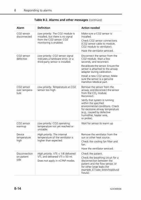
8 Responding to alarms
CO2 sensor disconnected
Low priority. The CO2 module is installed, but there is no signal from the CO2 sensor. CO2 monitoring is enabled.
Make sure a CO2 sensor is installed.Check CO2 sensor connections (CO2 sensor cable to module, CO2 module to ventilator).Have the ventilator serviced.
CO2 sensor defective
Low priority. CO2 sensor signal indicates a hardware error; or a third-party sensor is installed.
Disconnect the sensor from the CO2 module. Wait a few seconds, and reconnect.Recalibrate the sensor. Ensure the sensor is attached to the airway adapter during calibration. Install a new CO2 sensor. Make sure the sensor is a genuine Hamilton Medical part.
CO2 sensor over tempera-ture
Low priority. Temperature at CO2 sensor too high.
Remove the sensor from the airway, and disconnect the sensor from the CO2 module. Reconnect.Verify that system is running within the specified environmental conditions. Check for excessive airway temperature (e.g., caused by defective humidifier, heater wire, or probe).
CO2 sensor warmup
Low priority. CO2 operating temperature not yet reached or unstable.
Wait for sensor to warm up
Device temperature high
High priority. The internal temperature of the ventilator is higher than expected.
Remove the ventilator from the sun or other heat source.Check the cooling fan filter and fan.Have the ventilator serviced.
Disconnection on patient side
High priority. VTE < 1/8 delivered VTI, and delivered VTI > 50 ml.Does not apply in nCPAP modes.
Check the patient.Check the breathing circuit for a disconnection between the patient and the flow sensor, or for other large leaks (for example, ET tube, bronchopleural fistula).
Table 8-2. Alarms and other messages (continued)
Alarm Definition Action needed
8-14 624369/06
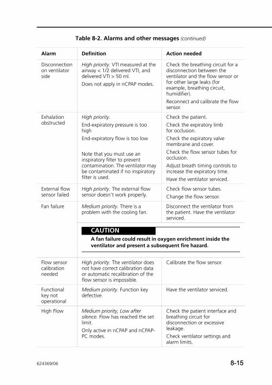
Disconnection on ventilator side
High priority. VTI measured at the airway < 1/2 delivered VTI, and delivered VTI > 50 ml.Does not apply in nCPAP modes.
Check the breathing circuit for a disconnection between the ventilator and the flow sensor or for other large leaks (for example, breathing circuit, humidifier).Reconnect and calibrate the flow sensor.
Exhalation obstructed
High priority. End-expiratory pressure is too highEnd-expiratory flow is too low
Note that you must use an inspiratory filter to prevent contamination. The ventilator may be contaminated if no inspiratory filter is used.
Check the patient.Check the expiratory limb for occlusion.Check the expiratory valve membrane and cover.Check the flow sensor tubes for occlusion.Adjust breath timing controls to increase the expiratory time.Have the ventilator serviced.
External flow sensor failed
High priority. The external flow sensor doesn’t work properly.
Check flow sensor tubes.Change the flow sensor.
Fan failure Medium priority. There is a problem with the cooling fan.
Disconnect the ventilator from the patient. Have the ventilator serviced.
CAUTIONA fan failure could result in oxygen enrichment inside the ventilator and present a subsequent fire hazard.
Flow sensor calibration needed
High priority. The ventilator does not have correct calibration data or automatic recalibration of the flow sensor is impossible.
Calibrate the flow sensor.
Functional key not operational
Medium priority. Function key defective.
Have the ventilator serviced.
High Flow Medium priority, Low after silence. Flow has reached the set limit. Only active in nCPAP and nCPAP-PC modes.
Check the patient interface and breathing circuit for disconnection or excessive leakage. Check ventilator settings and alarm limits.
Table 8-2. Alarms and other messages (continued)
Alarm Definition Action needed
624369/06 8-15
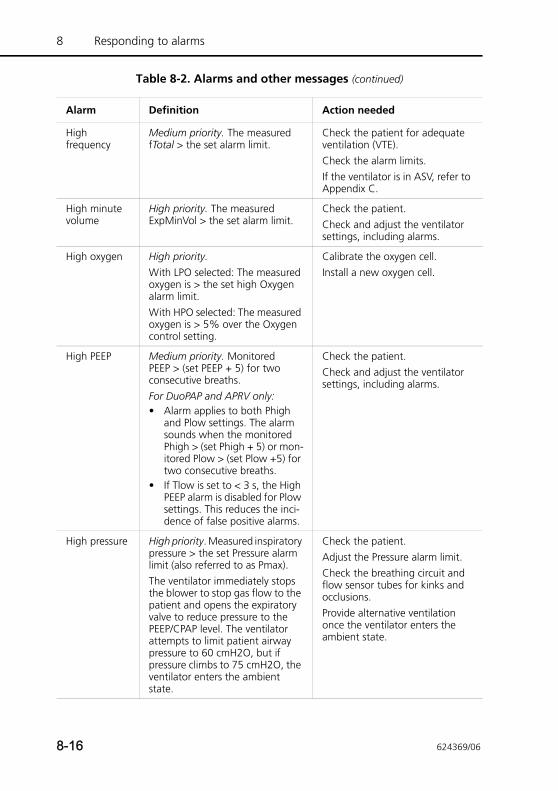
8 Responding to alarms
High frequency
Medium priority. The measured fTotal > the set alarm limit.
Check the patient for adequate ventilation (VTE).Check the alarm limits.If the ventilator is in ASV, refer to Appendix C.
High minute volume
High priority. The measured ExpMinVol > the set alarm limit.
Check the patient.Check and adjust the ventilator settings, including alarms.
High oxygen High priority. With LPO selected: The measured oxygen is > the set high Oxygen alarm limit. With HPO selected: The measured oxygen is > 5% over the Oxygen control setting.
Calibrate the oxygen cell.Install a new oxygen cell.
High PEEP Medium priority. Monitored PEEP > (set PEEP + 5) for two consecutive breaths.For DuoPAP and APRV only:• Alarm applies to both Phigh
and Plow settings. The alarm sounds when the monitored Phigh > (set Phigh + 5) or mon-itored Plow > (set Plow +5) for two consecutive breaths.
• If Tlow is set to < 3 s, the High PEEP alarm is disabled for Plow settings. This reduces the inci-dence of false positive alarms.
Check the patient. Check and adjust the ventilator settings, including alarms.
High pressure High priority. Measured inspiratory pressure > the set Pressure alarm limit (also referred to as Pmax). The ventilator immediately stops the blower to stop gas flow to the patient and opens the expiratory valve to reduce pressure to the PEEP/CPAP level. The ventilator attempts to limit patient airway pressure to 60 cmH2O, but if pressure climbs to 75 cmH2O, the ventilator enters the ambient state.
Check the patient.Adjust the Pressure alarm limit.Check the breathing circuit and flow sensor tubes for kinks and occlusions.Provide alternative ventilation once the ventilator enters the ambient state.
Table 8-2. Alarms and other messages (continued)
Alarm Definition Action needed
8-16 624369/06
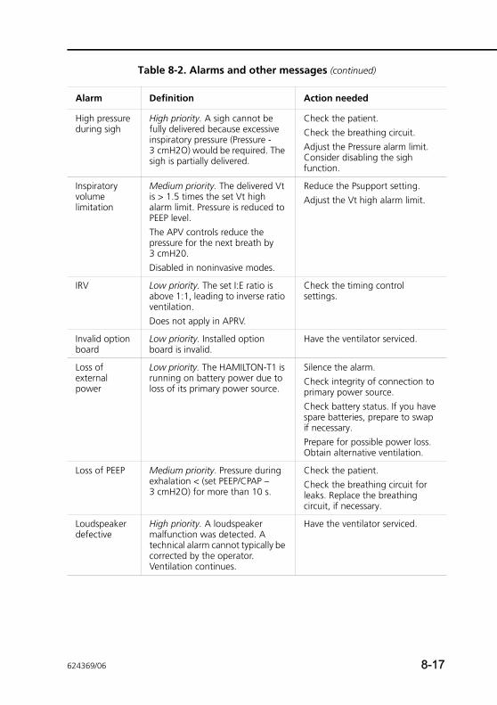
High pressure during sigh
High priority. A sigh cannot be fully delivered because excessive inspiratory pressure (Pressure - 3 cmH2O) would be required. The sigh is partially delivered.
Check the patient.Check the breathing circuit.Adjust the Pressure alarm limit. Consider disabling the sigh function.
Inspiratory volume limitation
Medium priority. The delivered Vt is > 1.5 times the set Vt high alarm limit. Pressure is reduced to PEEP level.The APV controls reduce the pressure for the next breath by 3 cmH20.Disabled in noninvasive modes.
Reduce the Psupport setting.Adjust the Vt high alarm limit.
IRV Low priority. The set I:E ratio is above 1:1, leading to inverse ratio ventilation.Does not apply in APRV.
Check the timing control settings.
Invalid option board
Low priority. Installed option board is invalid.
Have the ventilator serviced.
Loss of external power
Low priority. The HAMILTON-T1 is running on battery power due to loss of its primary power source.
Silence the alarm.Check integrity of connection to primary power source.Check battery status. If you have spare batteries, prepare to swap if necessary.Prepare for possible power loss. Obtain alternative ventilation.
Loss of PEEP Medium priority. Pressure during exhalation < (set PEEP/CPAP – 3 cmH2O) for more than 10 s.
Check the patient.Check the breathing circuit for leaks. Replace the breathing circuit, if necessary.
Loudspeaker defective
High priority. A loudspeaker malfunction was detected. A technical alarm cannot typically be corrected by the operator. Ventilation continues.
Have the ventilator serviced.
Table 8-2. Alarms and other messages (continued)
Alarm Definition Action needed
624369/06 8-17
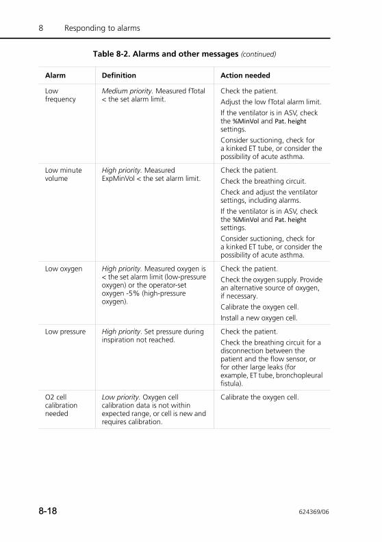
8 Responding to alarms
Low frequency
Medium priority. Measured fTotal < the set alarm limit.
Check the patient.Adjust the low fTotal alarm limit.If the ventilator is in ASV, check the %MinVol and Pat. height settings. Consider suctioning, check for a kinked ET tube, or consider the possibility of acute asthma.
Low minute volume
High priority. Measured ExpMinVol < the set alarm limit.
Check the patient.Check the breathing circuit.Check and adjust the ventilator settings, including alarms.If the ventilator is in ASV, check the %MinVol and Pat. height settings. Consider suctioning, check for a kinked ET tube, or consider the possibility of acute asthma.
Low oxygen High priority. Measured oxygen is < the set alarm limit (low-pressure oxygen) or the operator-set oxygen -5% (high-pressure oxygen).
Check the patient.Check the oxygen supply. Provide an alternative source of oxygen, if necessary.Calibrate the oxygen cell.Install a new oxygen cell.
Low pressure High priority. Set pressure during inspiration not reached.
Check the patient.Check the breathing circuit for a disconnection between the patient and the flow sensor, or for other large leaks (for example, ET tube, bronchopleural fistula).
O2 cell calibration needed
Low priority. Oxygen cell calibration data is not within expected range, or cell is new and requires calibration.
Calibrate the oxygen cell.
Table 8-2. Alarms and other messages (continued)
Alarm Definition Action needed
8-18 624369/06
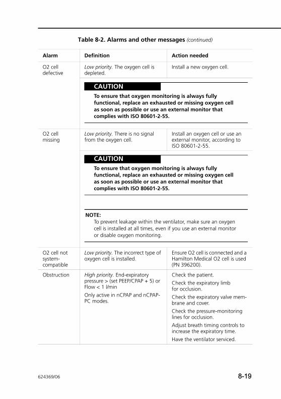
O2 cell defective
Low priority. The oxygen cell is depleted.
Install a new oxygen cell.
CAUTIONTo ensure that oxygen monitoring is always fully functional, replace an exhausted or missing oxygen cell as soon as possible or use an external monitor that complies with ISO 80601-2-55.
O2 cell missing
Low priority. There is no signal from the oxygen cell.
Install an oxygen cell or use an external monitor, according to ISO 80601-2-55.
CAUTIONTo ensure that oxygen monitoring is always fully functional, replace an exhausted or missing oxygen cell as soon as possible or use an external monitor that complies with ISO 80601-2-55.
NOTE:To prevent leakage within the ventilator, make sure an oxygen cell is installed at all times, even if you use an external monitor or disable oxygen monitoring.
O2 cell not system-compatible
Low priority. The incorrect type of oxygen cell is installed.
Ensure O2 cell is connected and a Hamilton Medical O2 cell is used (PN 396200).
Obstruction High priority. End-expiratory pressure > (set PEEP/CPAP + 5) or Flow < 1 l/minOnly active in nCPAP and nCPAP-PC modes.
Check the patient.Check the expiratory limb for occlusion.Check the expiratory valve mem-brane and cover.Check the pressure-monitoring lines for occlusion.Adjust breath timing controls to increase the expiratory time.Have the ventilator serviced.
Table 8-2. Alarms and other messages (continued)
Alarm Definition Action needed
624369/06 8-19
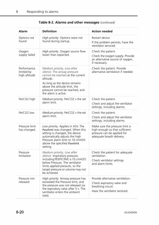
8 Responding to alarms
Options not found
High priority. Options were not found during startup.
Restart device. If the problem persists, have the ventilator serviced.
Oxygen supply failed
High priority. Oxygen source flow lower than expected.
Check the patient.Check the oxygen supply. Provide an alternative source of oxygen, if necessary.
Performance limited by high altitude
Medium priority, Low after silence. The airway pressure cannot be reached at the current altitude. As long as the device remains above the altitude limit, the pressure cannot be reached, and the alarm is active.
Check the patient. Provide alternative ventilation if needed.
PetCO2 high Medium priority. PetCO2 > the set alarm limit.
Check the patient.Check and adjust the ventilator settings, including alarms.
PetCO2 low Medium priority. PetCO2 < the set alarm limit.
Check the patient.Check and adjust the ventilator settings, including alarms.
Pressure limit has changed
Low priority. Applies in ASV. The Pasvlimit was changed. When this setting is changed, the device automatically adjusts the high Pressure alarm limit to 10 cmH20 above the specified Pasvlimit setting.
Make sure the pressure limit is high enough so that sufficient pressure can be applied for adequate breath delivery.
Pressure limitation
Medium priority, Low after silence. Inspiratory pressure, including PEEP/CPAP, is 10 cmH2O below Pressure. The ventilator limits applied pressure, so the target pressure or volume may not be achieved.
Check the patient for adequate ventilation.Check ventilator settings and alarm limits.
Pressure not released
High priority. Airway pressure has exceeded the Pressure limit, and the pressure was not released via the expiratory valve after 5 s. The ventilator enters the ambient state.
Provide alternative ventilation.Check expiratory valve and breathing circuit.Have the ventilator serviced.
Table 8-2. Alarms and other messages (continued)
Alarm Definition Action needed
8-20 624369/06
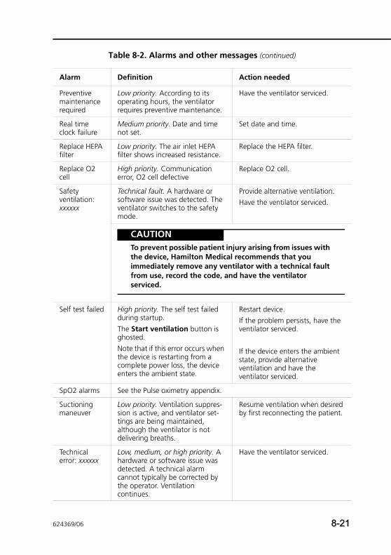
Preventive maintenance required
Low priority. According to its operating hours, the ventilator requires preventive maintenance.
Have the ventilator serviced.
Real time clock failure
Medium priority. Date and time not set.
Set date and time.
Replace HEPA filter
Low priority. The air inlet HEPA filter shows increased resistance.
Replace the HEPA filter.
Replace O2 cell
High priority. Communication error, O2 cell defective
Replace O2 cell.
Safety ventilation: xxxxxx
Technical fault. A hardware or software issue was detected. The ventilator switches to the safety mode.
Provide alternative ventilation.Have the ventilator serviced.
CAUTIONTo prevent possible patient injury arising from issues with the device, Hamilton Medical recommends that you immediately remove any ventilator with a technical fault from use, record the code, and have the ventilator serviced.
Self test failed High priority. The self test failed during startup. The Start ventilation button is ghosted.Note that if this error occurs when the device is restarting from a complete power loss, the device enters the ambient state.
Restart device. If the problem persists, have the ventilator serviced.
If the device enters the ambient state, provide alternative ventilation and have the ventilator serviced.
SpO2 alarms See the Pulse oximetry appendix.
Suctioning maneuver
Low priority. Ventilation suppres-sion is active, and ventilator set-tings are being maintained, although the ventilator is not delivering breaths.
Resume ventilation when desired by first reconnecting the patient.
Technical error: xxxxxx
Low, medium, or high priority. A hardware or software issue was detected. A technical alarm cannot typically be corrected by the operator. Ventilation continues.
Have the ventilator serviced.
Table 8-2. Alarms and other messages (continued)
Alarm Definition Action needed
624369/06 8-21
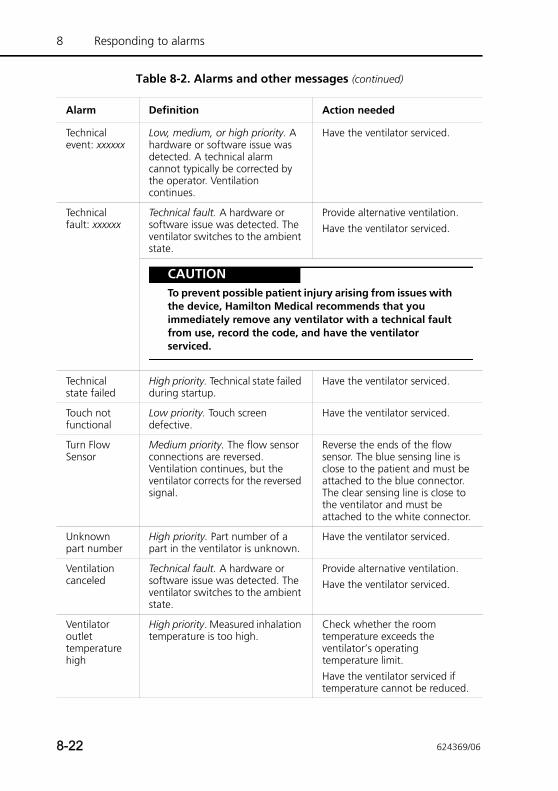
8 Responding to alarms
Technical event: xxxxxx
Low, medium, or high priority. A hardware or software issue was detected. A technical alarm cannot typically be corrected by the operator. Ventilation continues.
Have the ventilator serviced.
Technical fault: xxxxxx
Technical fault. A hardware or software issue was detected. The ventilator switches to the ambient state.
Provide alternative ventilation.Have the ventilator serviced.
CAUTIONTo prevent possible patient injury arising from issues with the device, Hamilton Medical recommends that you immediately remove any ventilator with a technical fault from use, record the code, and have the ventilator serviced.
Technical state failed
High priority. Technical state failed during startup.
Have the ventilator serviced.
Touch not functional
Low priority. Touch screen defective.
Have the ventilator serviced.
Turn Flow Sensor
Medium priority. The flow sensor connections are reversed. Ventilation continues, but the ventilator corrects for the reversed signal.
Reverse the ends of the flow sensor. The blue sensing line is close to the patient and must be attached to the blue connector. The clear sensing line is close to the ventilator and must be attached to the white connector.
Unknown part number
High priority. Part number of a part in the ventilator is unknown.
Have the ventilator serviced.
Ventilation canceled
Technical fault. A hardware or software issue was detected. The ventilator switches to the ambient state.
Provide alternative ventilation.Have the ventilator serviced.
Ventilator outlet temperature high
High priority. Measured inhalation temperature is too high.
Check whether the room temperature exceeds the ventilator’s operating temperature limit.Have the ventilator serviced if temperature cannot be reduced.
Table 8-2. Alarms and other messages (continued)
Alarm Definition Action needed
8-22 624369/06
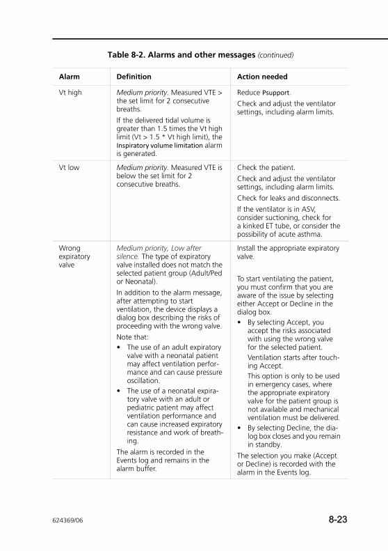
Vt high Medium priority. Measured VTE > the set limit for 2 consecutive breaths. If the delivered tidal volume is greater than 1.5 times the Vt high limit (Vt > 1.5 * Vt high limit), the Inspiratory volume limitation alarm is generated.
Reduce Psupport.Check and adjust the ventilator settings, including alarm limits.
Vt low Medium priority. Measured VTE is below the set limit for 2 consecutive breaths.
Check the patient.Check and adjust the ventilator settings, including alarm limits.Check for leaks and disconnects.If the ventilator is in ASV, consider suctioning, check for a kinked ET tube, or consider the possibility of acute asthma.
Wrong expiratory valve
Medium priority, Low after silence. The type of expiratory valve installed does not match the selected patient group (Adult/Ped or Neonatal). In addition to the alarm message, after attempting to start ventilation, the device displays a dialog box describing the risks of proceeding with the wrong valve. Note that:• The use of an adult expiratory
valve with a neonatal patient may affect ventilation perfor-mance and can cause pressure oscillation.
• The use of a neonatal expira-tory valve with an adult or pediatric patient may affect ventilation performance and can cause increased expiratory resistance and work of breath-ing.
The alarm is recorded in the Events log and remains in the alarm buffer.
Install the appropriate expiratory valve.
To start ventilating the patient, you must confirm that you are aware of the issue by selecting either Accept or Decline in the dialog box. • By selecting Accept, you
accept the risks associated with using the wrong valve for the selected patient. Ventilation starts after touch-ing Accept.This option is only to be used in emergency cases, where the appropriate expiratory valve for the patient group is not available and mechanical ventilation must be delivered.
• By selecting Decline, the dia-log box closes and you remain in standby.
The selection you make (Accept or Decline) is recorded with the alarm in the Events log.
Table 8-2. Alarms and other messages (continued)
Alarm Definition Action needed
624369/06 8-23

8 Responding to alarms
Wrong flow sensor
High priority. The type of flow sensor connected does not match the selected patient group (Adult/Ped or Neonatal).
Connect the appropriate flow sensor.Calibrate again.
Table 8-2. Alarms and other messages (continued)
Alarm Definition Action needed
8-24 624369/06
9 Special functions
9.1 Introduction 9-2
9.2 Standby 9-3
9.3 Alarm silence 9-6
9.4 O2 enrichment 9-7
9.5 Suctioning tool 9-8
9.6 Manual breath/inspiratory hold 9-9
9.7 Nebulizer 9-10
9.8 Print screen 9-11
9.9 Screen Lock/unlock 9-12
9.10 Day/Night 9-13
9.10.1 Using the Day/Night key with NVG 9-14
624369/06 9-1
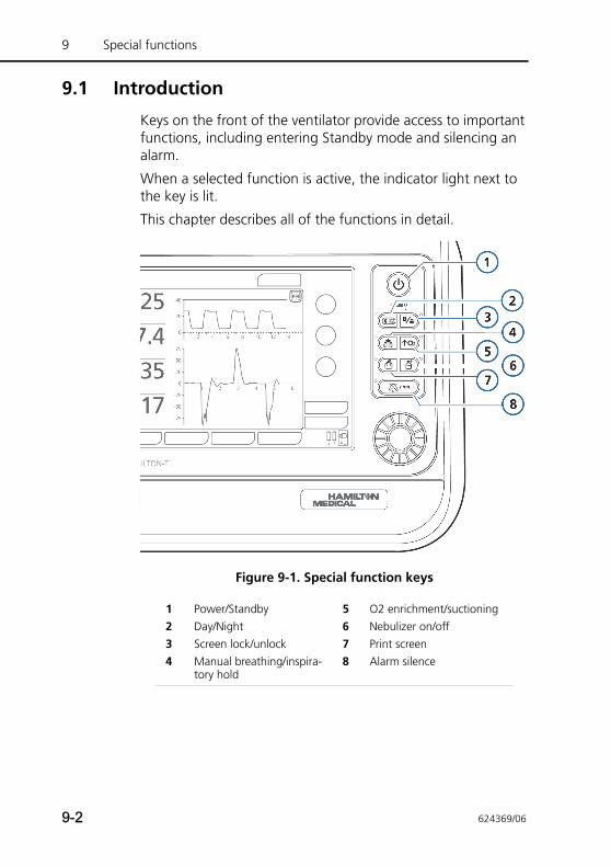
9 Special functions
9.1 Introduction
Keys on the front of the ventilator provide access to important functions, including entering Standby mode and silencing an alarm.
When a selected function is active, the indicator light next to the key is lit.
This chapter describes all of the functions in detail.
Figure 9-1. Special function keys
1 Power/Standby 5 O2 enrichment/suctioning2 Day/Night 6 Nebulizer on/off3 Screen lock/unlock 7 Print screen4 Manual breathing/inspira-
tory hold8 Alarm silence
9-2 624369/06
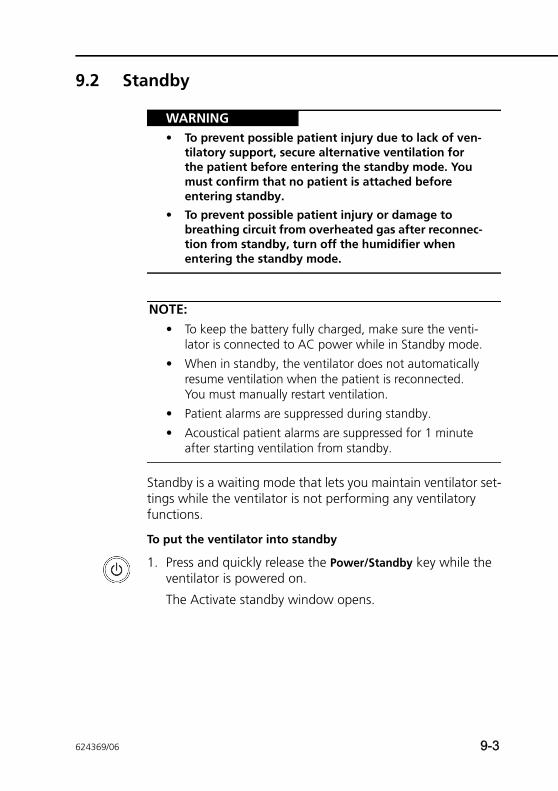
9.2 Standby
WARNING• To prevent possible patient injury due to lack of ven-
tilatory support, secure alternative ventilation for the patient before entering the standby mode. You must confirm that no patient is attached before entering standby.
• To prevent possible patient injury or damage to breathing circuit from overheated gas after reconnec-tion from standby, turn off the humidifier when entering the standby mode.
NOTE:• To keep the battery fully charged, make sure the venti-
lator is connected to AC power while in Standby mode.
• When in standby, the ventilator does not automatically resume ventilation when the patient is reconnected. You must manually restart ventilation.
• Patient alarms are suppressed during standby.
• Acoustical patient alarms are suppressed for 1 minute after starting ventilation from standby.
Standby is a waiting mode that lets you maintain ventilator set-tings while the ventilator is not performing any ventilatory functions.
To put the ventilator into standby
1. Press and quickly release the Power/Standby key while the ventilator is powered on.
The Activate standby window opens.
624369/06 9-3
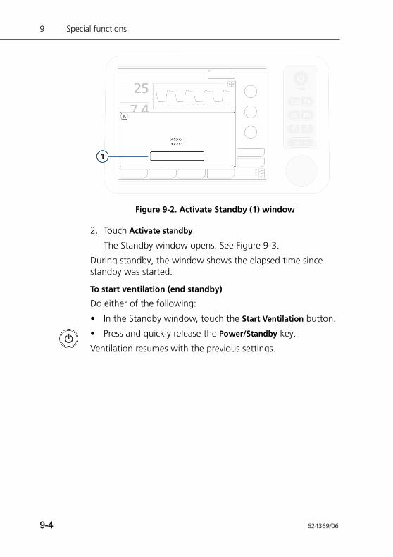
9 Special functions
Figure 9-2. Activate Standby (1) window
2. Touch Activate standby.
The Standby window opens. See Figure 9-3.
During standby, the window shows the elapsed time since standby was started.
To start ventilation (end standby)
Do either of the following:
• In the Standby window, touch the Start Ventilation button.
• Press and quickly release the Power/Standby key.
Ventilation resumes with the previous settings.
9-4 624369/06
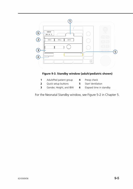
Figure 9-3. Standby window (adult/pediatric shown)
For the Neonatal Standby window, see Figure 5-2 in Chapter 5.
1 Adult/Ped patient group 4 Preop check2 Quick setup buttons 5 Start Ventilation3 Gender, Height, and IBW 6 Elapsed time in standby
624369/06 9-5
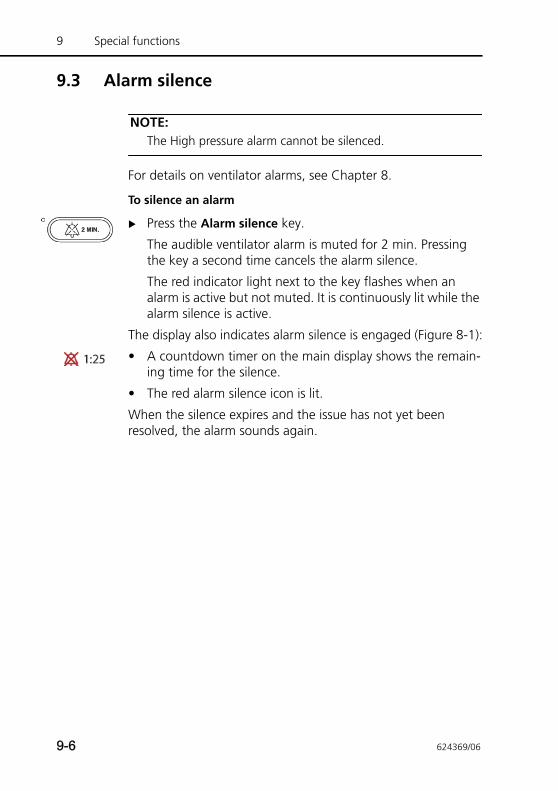
9 Special functions
9.3 Alarm silence
NOTE:The High pressure alarm cannot be silenced.
For details on ventilator alarms, see Chapter 8.
To silence an alarm
Press the Alarm silence key.
The audible ventilator alarm is muted for 2 min. Pressing the key a second time cancels the alarm silence.
The red indicator light next to the key flashes when an alarm is active but not muted. It is continuously lit while the alarm silence is active.
The display also indicates alarm silence is engaged (Figure 8-1):
• A countdown timer on the main display shows the remain-ing time for the silence.
• The red alarm silence icon is lit.
When the silence expires and the issue has not yet been resolved, the alarm sounds again.
9-6 624369/06
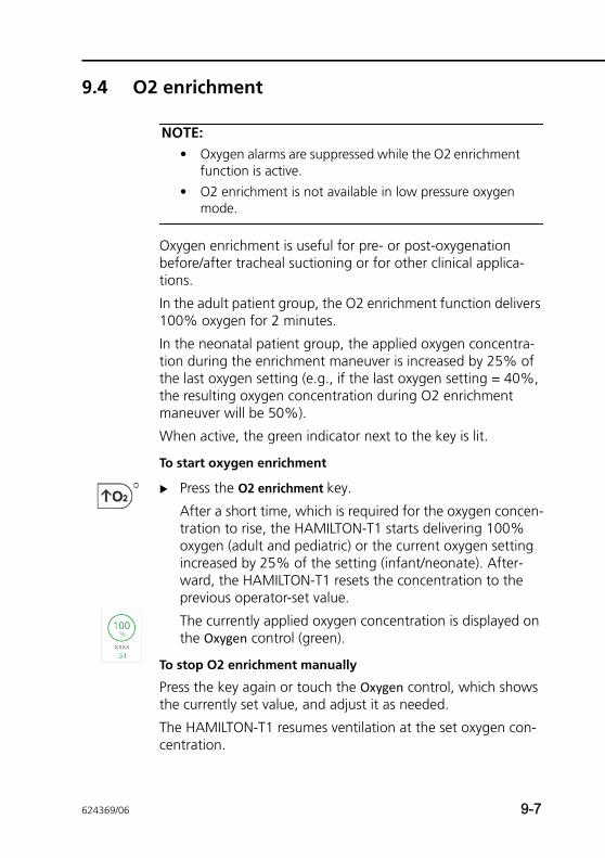
9.4 O2 enrichment
NOTE:• Oxygen alarms are suppressed while the O2 enrichment
function is active.
• O2 enrichment is not available in low pressure oxygen mode.
Oxygen enrichment is useful for pre- or post-oxygenation before/after tracheal suctioning or for other clinical applica-tions.
In the adult patient group, the O2 enrichment function delivers 100% oxygen for 2 minutes.
In the neonatal patient group, the applied oxygen concentra-tion during the enrichment maneuver is increased by 25% of the last oxygen setting (e.g., if the last oxygen setting = 40%, the resulting oxygen concentration during O2 enrichment maneuver will be 50%).
When active, the green indicator next to the key is lit.
To start oxygen enrichment
Press the O2 enrichment key.
After a short time, which is required for the oxygen concen-tration to rise, the HAMILTON-T1 starts delivering 100% oxygen (adult and pediatric) or the current oxygen setting increased by 25% of the setting (infant/neonate). After-ward, the HAMILTON-T1 resets the concentration to the previous operator-set value.
The currently applied oxygen concentration is displayed on the Oxygen control (green).
To stop O2 enrichment manually
Press the key again or touch the Oxygen control, which shows the currently set value, and adjust it as needed.
The HAMILTON-T1 resumes ventilation at the set oxygen con-centration.
624369/06 9-7
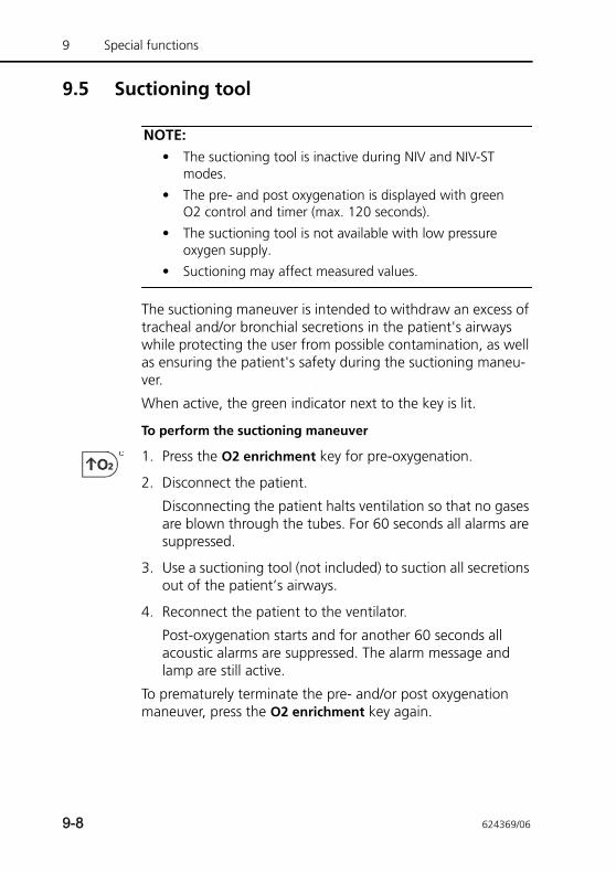
9 Special functions
9.5 Suctioning tool
NOTE:• The suctioning tool is inactive during NIV and NIV-ST
modes.
• The pre- and post oxygenation is displayed with green O2 control and timer (max. 120 seconds).
• The suctioning tool is not available with low pressure oxygen supply.
• Suctioning may affect measured values.
The suctioning maneuver is intended to withdraw an excess of tracheal and/or bronchial secretions in the patient's airways while protecting the user from possible contamination, as well as ensuring the patient's safety during the suctioning maneu-ver.
When active, the green indicator next to the key is lit.
To perform the suctioning maneuver
1. Press the O2 enrichment key for pre-oxygenation.
2. Disconnect the patient.
Disconnecting the patient halts ventilation so that no gases are blown through the tubes. For 60 seconds all alarms are suppressed.
3. Use a suctioning tool (not included) to suction all secretions out of the patient’s airways.
4. Reconnect the patient to the ventilator.
Post-oxygenation starts and for another 60 seconds all acoustic alarms are suppressed. The alarm message and lamp are still active.
To prematurely terminate the pre- and/or post oxygenation maneuver, press the O2 enrichment key again.
9-8 624369/06
9.6 Manual breath/inspiratory hold
This function lets you deliver a manually triggered breath or perform an inspiratory hold maneuver.
When active, the green indicator next to the key is lit.
To deliver a manual breath only
Press and release the Manual breath key (Figure 9-1) during exhalation.
In nCPAP mode, you can deliver a manual breath at any time.
Do not press the key quickly and repeatedly. The manual breath uses the mandatory breath settings (standard or operator set).
If you try to initiate a manual breath during the early stage of inspiration or the early stage of exhalation, the breath will not be delivered. This does not apply in nCPAP mode.
To perform an inspiratory hold
Hold down the Manual breath key during any breath phase.
If the ventilator is in exhalation, it delivers a mandatory breath, then performs a hold maneuver until the key is released, up to 15 seconds in addition to the set inspiratory time.
If the ventilator is in inspiration, it performs a hold maneu-ver at the end of inspiration, lasting until the key is released, for up to 15 additional seconds.
624369/06 9-9
9 Special functions
9.7 Nebulizer
CAUTION• Do not use an expiratory filter or HMEF/HME in the
patient’s breathing circuit during nebulization. Nebu-lization can cause an expiratory side filter to clog, substantially increasing flow resistance and impair-ing ventilation.
• To prevent the expiratory valve from sticking due to nebulized medications, use only medications approved for nebulization and regularly check and clean the expiratory valve.
NOTE:• The pneumatic nebulizer is inactive when low pressure
oxygen (LPO) is used.
• Delivered ventilation is compensated for the contribu-tion of the internal nebulizer so that the expected vol-ume and pressure are delivered.
• Pneumatic nebulization is disabled during neonatal ven-tilation.
The HAMILTON-T1’s pneumatic nebulization function powers a standard inline nebulizer for delivery of prescribed medications in the ventilator circuit. When nebulization is active, the nebu-lizer flow is synchronized with the inspiratory phase of each breath for 30 min. Nebulization can be activated in all modes of ventilation.
When active, the green indicator next to the key is lit.
To start nebulization
Press the Nebulizer key.
To stop nebulization
Press the Nebulizer key again.
For effective nebulization, use a pneumatic nebulizer jar (see Appendix G). Section 2.4 briefly describes how to install the nebulizer.
9-10 624369/06

9.8 Print screen
NOTE:Touch the HAMILTON-T1 before using the USB port.
The print screen function saves a JPG file of the current ventila-tor screen to a USB memory drive.
To create a screen shot
1. Insert a USB memory drive into the USB port.
2. Press the Print screen key while the desired display is shown.
The device saves the image to the memory drive. The green indicator next to the key is lit while the device saves the image.
The filename takes this format:
screenshot_yyyymmdd_hhmmss.jpg
where:
yyyy is the year
mm is the month
dd is the date
hh is the hour (in 24-hour format)
mm is the minute
ss is the second
624369/06 9-11
9 Special functions
9.9 Screen Lock/unlock
The Screen Lock/unlock function prevents inadvertent touch screen and device entries. When touching the locked screen, an acoustic BEEP sounds and a Screen lock active message is displayed.
When active, the green indicator next to the key is lit.
When screen lock is active, some device controls remain avail-able, while others are disabled, as follows:
To lock or unlock the screen
Press the Screen Lock/unlock key.
Active • Alarm silence key
• Manual breath key
• O2 enrichment key
• Day/Night key
• Nebulizer key
Inactive • Touch screen
• Power/Standby key
• Print screen key
• P&T knob
9-12 624369/06
9.10 Day/Night
The Day/Night key1 allows you to quickly switch between the display Day and Night settings. The device uses the brightness settings specified in the System window (Section 3.3.4).
If the NVG option is installed on the ventilator, the key switches between the Night and NVG settings. See Section 9.10.1.
When the Night setting is active, the green indicator next to the key is lit.
To change the display brightness to the pre-set Day or Night setting
Press the Day/Night key.
The device changes the display brightness as follows.
1. Not available in Japan.
Table 9-1. Day/Night key actions
The current brightness setting (in System window) is ...
When Day/Night key is pressed, the device switches to the default setting for ...
Day NightWhen the Night setting is active, the green light next to the Day/Night key is lit.
Night Day
Automatic NightWhen the device is restarted, it resets the display brightness to the Day set-ting.
624369/06 9-13
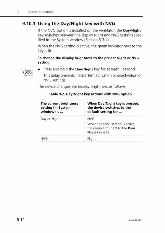
9 Special functions
9.10.1 Using the Day/Night key with NVGIf the NVG option is installed on the ventilator, the Day/Night key switches between the display Night and NVG settings spec-ified in the System window (Section 3.3.4).
When the NVG setting is active, the green indicator next to the key is lit.
To change the display brightness to the pre-set Night or NVG setting
Press and hold the Day/Night key for at least 1 second.
This delay prevents inadvertent activation or deactivation of NVG settings.
The device changes the display brightness as follows.
Table 9-2. Day/Night key actions with NVG option
The current brightness setting (in System window) is ...
When Day/Night key is pressed, the device switches to the default setting for ...
Day or Night NVGWhen the NVG setting is active, the green light next to the Day/Night key is lit.
NVG Night
9-14 624369/06
10 Maintenance
10.1 Introduction 10-2
10.2 Cleaning, disinfection, and sterilization 10-2
10.2.1 General guidelines for cleaning 10-5
10.2.2 General guidelines for disinfection 10-6
10.2.3 General guidelines for reprocessing 10-9
10.3 Preventive maintenance 10-13
10.3.1 Servicing the air intake and fan filters 10-15
10.3.2 Working with the battery 10-17
10.3.3 Replacing the oxygen cell 10-20
10.4 Storage 10-21
10.5 Repacking and shipping 10-21
10.6 Reprocessing the autoclavable expiratory valve 10-23
624369/06 10-1
10 Maintenance
10.1 Introduction
WARNINGNo modification of this equipment is allowed. Servicing must be performed by Hamilton Medical-authorized per-sonnel using the instructions provided in the Service Manual.
You must comply with these maintenance procedures to ensure the safety and reliability of the HAMILTON-T1. All the procedures in this manual are to be performed by the operator. For additional maintenance requirements, contact your Hamil-ton Medical service representative.
10.2 Cleaning, disinfection, and sterilization
WARNING• Always disconnect the device from electrical power
before cleaning and disinfection to reduce the risk of electric shock.
• DO NOT reuse single-use bacteria filters, flow sen-sors, and other accessories. They must be discarded after use. Follow your hospital procedures for dis-posal.
• Reusing, disassembling, cleaning, disinfecting, or sterilizing a single-use part may compromise its func-tionality and system performance, leading to a possi-ble operator or patient hazard.
• Performance is not guaranteed if an item labeled as single-use is reused.
• Reuse of a single-use product voids the warranty.
• Always use caution when handling bacteria filters to minimize the risk of bacterial contamination or phys-ical damage. Dispose of used filters immediately after use. Follow your hospital procedures for dis-posal.
10-2 624369/06
• To prevent patient exposure to sterilizing agents and to prevent premature deterioration of parts, sterilize parts using the techniques recommended in this section only.
CAUTION• DO NOT attempt to sterilize the interior components
of the ventilator. DO NOT attempt to sterilize the entire device with ETO gas.
• Exposure to sterilizing agents may reduce the useful life of certain parts. Using more than one sterilization technique on a single part may damage a part.
• Intrusion of fluids, or immersing parts in fluids, will damage the device.
• Do not pour fluids onto the device surfaces.
• Do not use abrasives materials (for example, steel wool or silver polish) on surfaces.
• You can use bleaching agents according to the manu-facturer’s recommendations and the instructions pro-vided in the Compatibility of cleaning / disinfectant agents with HAMILTON MEDICAL ventilators state-ment.
• Incorrect concentrations or residence times of steril-ization agents may lead to bacterial resistance.
NOTE:• Because sanitation practices vary among institutions,
Hamilton Medical cannot specify specific practices that will meet all needs or be responsible for the effective-ness of these practices.
• This manual only provides general guidelines for clean-ing, disinfecting, and sterilizing. It is the operator’s responsibility to ensure the validity and effectiveness of the actual methods used.
• For specific information on cleaning, disinfecting, and sterilizing autoclavable (reusable) accessories and com-ponents, refer to the appropriate Reprocessing Guide and Instructions for Use provided with each part.
624369/06 10-3
10 Maintenance
The following sections provide general recommendations for cleaning, disinfecting, and sterilizing parts. Table 10-4 provides an overview of how to reprocess each part. For parts not sup-plied by Hamilton Medical, comply with the manufacturers’ recommendations.
DO NOT attempt decontamination procedures unless specified by Hamilton Medical or the original manufacturer.
If you have any questions about the use of a particular cleaning or disinfection agent, contact the manufacturer of the agent.
If you are unsure how to clean and decontaminate a given part, contact your hospital hygiene administrator. This is espe-cially important to avoid the spread of Hepatitis and HIV. Ensure you follow your hospital infection control procedures, as well as all local, state, and federal regulations.
After cleaning and decontaminating parts, perform any required tests and calibrations described in Chapter 3.
The following sections provide a general overview of how to clean and disinfect ventilator-related parts. Additional informa-tion for each part is included in Table 10-3.
10-4 624369/06
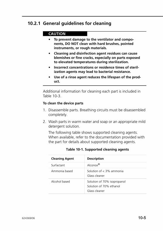
10.2.1 General guidelines for cleaning
CAUTION• To prevent damage to the ventilator and compo-
nents, DO NOT clean with hard brushes, pointed instruments, or rough materials.
• Cleaning and disinfection agent residues can cause blemishes or fine cracks, especially on parts exposed to elevated temperatures during sterilization.
• Incorrect concentrations or residence times of steril-ization agents may lead to bacterial resistance.
• Use of a rinse agent reduces the lifespan of the prod-uct.
Additional information for cleaning each part is included in Table 10-3.
To clean the device parts
1. Disassemble parts. Breathing circuits must be disassembled completely.
2. Wash parts in warm water and soap or an appropriate mild detergent solution.
The following table shows supported cleaning agents. When available, refer to the documentation provided with the part for details about supported cleaning agents.
Table 10-1. Supported cleaning agents
Cleaning Agent Description
Surfactant Alconox®
Ammonia based Solution of < 3% ammoniaGlass cleaner
Alcohol based Solution of 70% isopropanolSolution of 70% ethanolGlass cleaner
624369/06 10-5
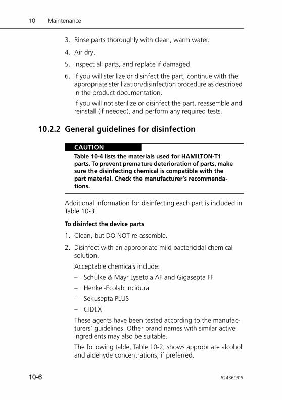
10 Maintenance
3. Rinse parts thoroughly with clean, warm water.
4. Air dry.
5. Inspect all parts, and replace if damaged.
6. If you will sterilize or disinfect the part, continue with the appropriate sterilization/disinfection procedure as described in the product documentation.
If you will not sterilize or disinfect the part, reassemble and reinstall (if needed), and perform any required tests.
10.2.2 General guidelines for disinfection
CAUTIONTable 10-4 lists the materials used for HAMILTON-T1 parts. To prevent premature deterioration of parts, make sure the disinfecting chemical is compatible with the part material. Check the manufacturer’s recommenda-tions.
Additional information for disinfecting each part is included in Table 10-3.
To disinfect the device parts
1. Clean, but DO NOT re-assemble.
2. Disinfect with an appropriate mild bactericidal chemical solution.
Acceptable chemicals include:
– Schülke & Mayr Lysetola AF and Gigasepta FF
– Henkel-Ecolab Incidura
– Sekusepta PLUS
– CIDEX
These agents have been tested according to the manufac-turers’ guidelines. Other brand names with similar active ingredients may also be suitable.
The following table, Table 10-2, shows appropriate alcohol and aldehyde concentrations, if preferred.
10-6 624369/06
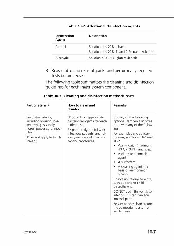
3. Reassemble and reinstall parts, and perform any required tests before reuse.
The following table summarizes the cleaning and disinfection guidelines for each major system component.
Table 10-2. Additional disinfection agents
Disinfection Agent
Description
Alcohol Solution of ≤70% ethanolSolution of ≤70% 1- and 2-Propanol solution
Aldehyde Solution of ≤3.6% glutaraldehyde
Table 10-3. Cleaning and disinfection methods parts
Part (material) How to clean and disinfect
Remarks
Ventilator exterior, including housing, bas-ket, tray, gas supply hoses, power cord, mod-ules(Does not apply to touch screen.)
Wipe with an appropriate bactericidal agent after each patient use.Be particularly careful with infectious patients, and fol-low your hospital infection control procedures.
Use any of the following options. Dampen a lint-free cloth with any of the follow-ing. For examples and concen-trations, see Tables 10-1 and 10-2.• Warm water (maximum
40°C (104°F)) and soap.• A dilute and nonacid
agent• A surfactant• A cleaning agent in a
base of ammonia or alcohol
Do not use strong solvents, such as acetone or Tri-chlorethylene.DO NOT clean the ventilator interior. This can damage internal parts.Be sure to only clean around the connection ports, not inside them.
624369/06 10-7
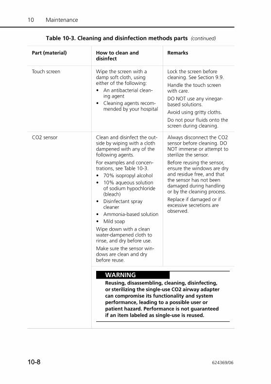
10 Maintenance
Touch screen Wipe the screen with a damp soft cloth, using either of the following:• An antibacterial clean-
ing agent• Cleaning agents recom-
mended by your hospital
Lock the screen before cleaning. See Section 9.9.Handle the touch screen with care. DO NOT use any vinegar-based solutions. Avoid using gritty cloths.Do not pour fluids onto the screen during cleaning.
CO2 sensor Clean and disinfect the out-side by wiping with a cloth dampened with any of the following agents. For examples and concen-trations, see Table 10-3.• 70% isopropyl alcohol• 10% aqueous solution
of sodium hypochloride (bleach)
• Disinfectant spray cleaner
• Ammonia-based solution• Mild soapWipe down with a clean water-dampened cloth to rinse, and dry before use.Make sure the sensor win-dows are clean and dry before reuse.
Always disconnect the CO2 sensor before cleaning. DO NOT immerse or attempt to sterilize the sensor.Before reusing the sensor, ensure the windows are dry and residue free, and that the sensor has not been damaged during handling or by the cleaning process. Replace if damaged or if excessive secretions are observed.
WARNINGReusing, disassembling, cleaning, disinfecting, or sterilizing the single-use CO2 airway adapter can compromise its functionality and system performance, leading to a possible user or patient hazard. Performance is not guaranteed if an item labeled as single-use is reused.
Table 10-3. Cleaning and disinfection methods parts (continued)
Part (material) How to clean and disinfect
Remarks
10-8 624369/06
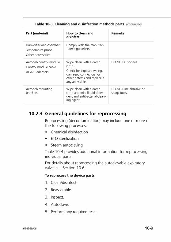
10.2.3 General guidelines for reprocessingReprocessing (decontamination) may include one or more of the following processes:
• Chemical disinfection
• ETO sterilization
• Steam autoclaving
Table 10-4 provides additional information for reprocessing individual parts.
For details about reprocessing the autoclavable expiratory valve, see Section 10.6.
To reprocess the device parts
1. Clean/disinfect.
2. Reassemble.
3. Inspect.
4. Autoclave.
5. Perform any required tests.
Humidifier and chamberTemperature probeOther accessories
Comply with the manufac-turer’s guidelines
Aeroneb control moduleControl module cableAC/DC adapters
Wipe clean with a damp cloth. Check for exposed wiring, damaged connectors, or other defects and replace if any are visible.
DO NOT autoclave.
Aeroneb mounting brackets
Wipe clean with a damp cloth and mild liquid deter-gent and antibacterial clean-ing agent.
DO NOT use abrasive or sharp tools.
Table 10-3. Cleaning and disinfection methods parts (continued)
Part (material) How to clean and disinfect
Remarks
624369/06 10-9
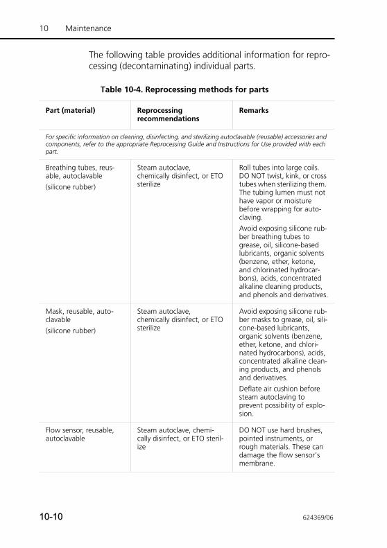
10 Maintenance
The following table provides additional information for repro-cessing (decontaminating) individual parts.
Table 10-4. Reprocessing methods for parts
Part (material) Reprocessing recommendations
Remarks
For specific information on cleaning, disinfecting, and sterilizing autoclavable (reusable) accessories and components, refer to the appropriate Reprocessing Guide and Instructions for Use provided with each part.
Breathing tubes, reus-able, autoclavable(silicone rubber)
Steam autoclave, chemically disinfect, or ETO sterilize
Roll tubes into large coils. DO NOT twist, kink, or cross tubes when sterilizing them. The tubing lumen must not have vapor or moisture before wrapping for auto-claving.Avoid exposing silicone rub-ber breathing tubes to grease, oil, silicone-based lubricants, organic solvents (benzene, ether, ketone, and chlorinated hydrocar-bons), acids, concentrated alkaline cleaning products, and phenols and derivatives.
Mask, reusable, auto-clavable(silicone rubber)
Steam autoclave, chemically disinfect, or ETO sterilize
Avoid exposing silicone rub-ber masks to grease, oil, sili-cone-based lubricants, organic solvents (benzene, ether, ketone, and chlori-nated hydrocarbons), acids, concentrated alkaline clean-ing products, and phenols and derivatives.Deflate air cushion before steam autoclaving to prevent possibility of explo-sion.
Flow sensor, reusable, autoclavable
Steam autoclave, chemi-cally disinfect, or ETO steril-ize
DO NOT use hard brushes, pointed instruments, or rough materials. These can damage the flow sensor’s membrane.
10-10 624369/06
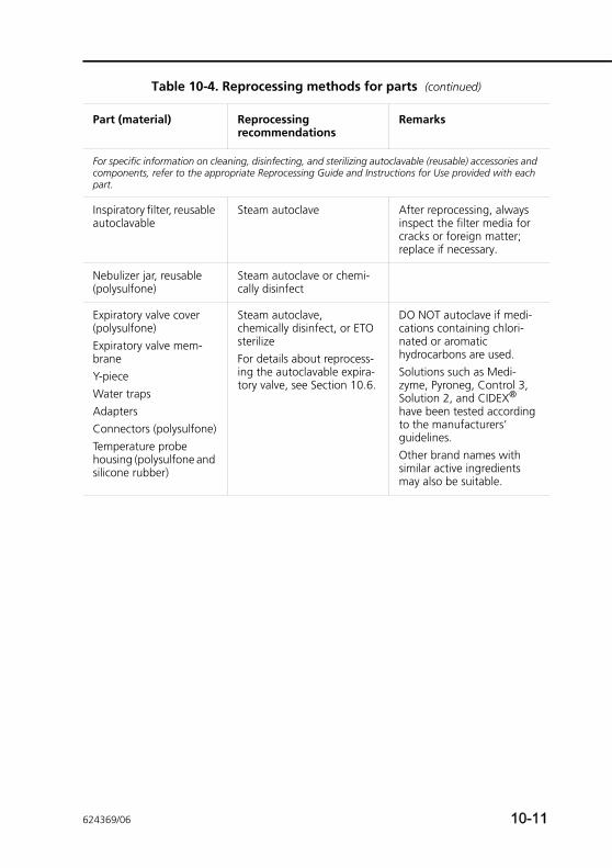
Inspiratory filter, reusable autoclavable
Steam autoclave After reprocessing, always inspect the filter media for cracks or foreign matter; replace if necessary.
Nebulizer jar, reusable (polysulfone)
Steam autoclave or chemi-cally disinfect
Expiratory valve cover (polysulfone)Expiratory valve mem-braneY-pieceWater trapsAdaptersConnectors (polysulfone)Temperature probe housing (polysulfone and silicone rubber)
Steam autoclave, chemically disinfect, or ETO sterilizeFor details about reprocess-ing the autoclavable expira-tory valve, see Section 10.6.
DO NOT autoclave if medi-cations containing chlori-nated or aromatic hydrocarbons are used.Solutions such as Medi-zyme, Pyroneg, Control 3, Solution 2, and CIDEX® have been tested according to the manufacturers’ guidelines. Other brand names with similar active ingredients may also be suitable.
Table 10-4. Reprocessing methods for parts (continued)
Part (material) Reprocessing recommendations
Remarks
For specific information on cleaning, disinfecting, and sterilizing autoclavable (reusable) accessories and components, refer to the appropriate Reprocessing Guide and Instructions for Use provided with each part.
624369/06 10-11
10 Maintenance
CO2 sensor airway adapter, reusable (poly-etherimide), aluminum, black oxide finish, Al2O3-sapphire)
Chemically disinfect, then steam autoclave (adult adapters only) at 121°C (250°F) for 20 min, unwrapped.
Acceptable chemical disin-fectants include:• 70% isopropyl alcohol• 10% aqueous solution
of sodium hypochlorite (bleach)
• 2% glutaraldehyde solu-tion such as CIDEX or Steris System 1® (refer to the disinfectant manu-facturer’s instructions for use)
• AmmoniaRinse with sterile water and dry. With proper care and if not otherwise damaged, adapt-ers can be disinfected/steril-ized according to the stated validated methods at least 100 times. Before reusing the adapter, make sure the windows are dry and residue free, and that the adapter has not been damaged during han-dling or by the cleaning/ster-ilizing process. Replace if damaged or if excessive secretions are observed.
Aeroneb adapter Autoclave wrapped parts using steam sterilization pre-vacuum cycle, a mini-mum of 134°C (270°F – 275°F) for 20 minutes with drying cycle (sometimes referred to as a “Prion cycle”).
DO NOT reassemble parts prior to autoclaving.
Table 10-4. Reprocessing methods for parts (continued)
Part (material) Reprocessing recommendations
Remarks
For specific information on cleaning, disinfecting, and sterilizing autoclavable (reusable) accessories and components, refer to the appropriate Reprocessing Guide and Instructions for Use provided with each part.
10-12 624369/06
10.3 Preventive maintenance
NOTE:• Dispose of all parts removed from the device according
to your institution’s protocols. Comply with all local, state, and federal regulations with respect to environ-mental protection, especially when disposing of the electronic device or parts of it (for example, oxygen cell, batteries).
• Any attempt to modify the ventilator hardware or soft-ware without the express written approval of Hamilton Medical automatically voids all warranties and liabilities.
• Hamilton Medical recommends that you document all maintenance procedures.
• It is not allowed to perform service or maintenance on the device while a patient is connected.
Perform preventive maintenance on your HAMILTON-T1 according to the schedule shown in Table 10-5. You can view the hours of ventilator operation in the System -> Info window. The following subsections provide details for some of these preventive maintenance procedures.
Table 10-5. Preventive maintenance schedule
Interval Part/accessory Procedure
Between patients and according to hospital policy
Breathing circuit (including mask, inspiratory filter, flow sensor, nebulizer jar, exhalation valve cover and membrane)
Replace with sterilized or new single-patient use parts. Run the tightness test and the appropriate calibration (Chapter 3).
Entire ventilator Run the preoperational checks (Section 3.2).
Every 2 days or according to hospital policy
Breathing circuit Empty any water from breathing tubes or water traps.Inspect parts for damage. Replace as necessary.
624369/06 10-13
10 Maintenance
Every month (or more often, if required)
WARNINGTo reduce the risk of patient cross-contamination through the fan filter, always perform maintenance at the prescribed interval.
Fan filter (rear panel) Check for dust and lint. If needed, clean or replace.
Every 6 months Batteries Recharge batteries by plugging the ventilator into a primary power source for at least 4 hours.
Yearly or every 5000 hours, which-ever comes first, or as necessary
Oxygen cell Replace if depleted.
NOTE:Oxygen cell life specifications are approximate. The actual cell life depends on operating environment. Operation at higher temperatures or higher oxygen concentrations shortens cell life.
Air intake HEPA filter Replace.
Ventilator Perform service-related preventive maintenance.1
CO2 sensor If the CO2 option is installed, have a CO2 accuracy check performed
Dynamic lifetime surveillance Typically 8 years
Blower Replace if indicated1
1. Must be performed by Hamilton Medical authorized service personnel according to instructions in the Service Manual.
Table 10-5. Preventive maintenance schedule (continued)
Interval Part/accessory Procedure
10-14 624369/06
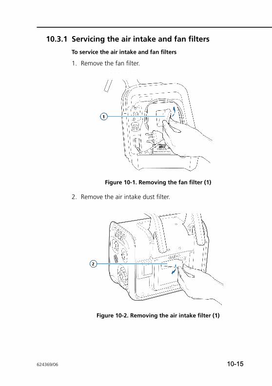
10.3.1 Servicing the air intake and fan filters
To service the air intake and fan filters
1. Remove the fan filter.
Figure 10-1. Removing the fan filter (1)
2. Remove the air intake dust filter.
Figure 10-2. Removing the air intake filter (1)
624369/06 10-15
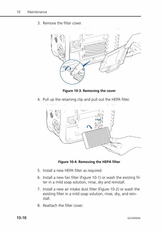
10 Maintenance
3. Remove the filter cover.
Figure 10-3. Removing the cover
4. Pull up the retaining clip and pull out the HEPA filter.
Figure 10-4. Removing the HEPA filter
5. Install a new HEPA filter as required.
6. Install a new fan filter (Figure 10-1) or wash the existing fil-ter in a mild soap solution, rinse, dry and reinstall.
7. Install a new air intake dust filter (Figure 10-2) or wash the existing filter in a mild soap solution, rinse, dry, and rein-stall.
8. Reattach the filter cover.
10-16 624369/06
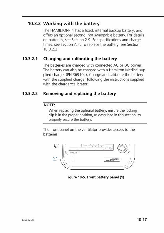
10.3.2 Working with the batteryThe HAMILTON-T1 has a fixed, internal backup battery, and offers an optional second, hot swappable battery. For details on batteries, see Section 2.9. For specifications and charge times, see Section A.4. To replace the battery, see Section 10.3.2.2.
10.3.2.1 Charging and calibrating the batteryThe batteries are charged with connected AC or DC power. The battery can also be charged with a Hamilton Medical sup-plied charger (PN 369104). Charge and calibrate the battery with the supplied charger following the instructions supplied with the charger/calibrator.
10.3.2.2 Removing and replacing the battery
NOTE:When replacing the optional battery, ensure the locking clip is in the proper position, as described in this section, to properly secure the battery.
The front panel on the ventilator provides access to the batteries.
Figure 10-5. Front battery panel (1)
624369/06 10-17

10 Maintenance
To remove the battery
1. Using the handle on the left side of the front panel, pull the cover off. The replaceable battery is on the left side.
2. Turn the metal locking clip to the left and all the way up, to allow access to the battery.
3. Pull the white tab on the end of the battery to pull the bat-tery out of the compartment.
10-18 624369/06
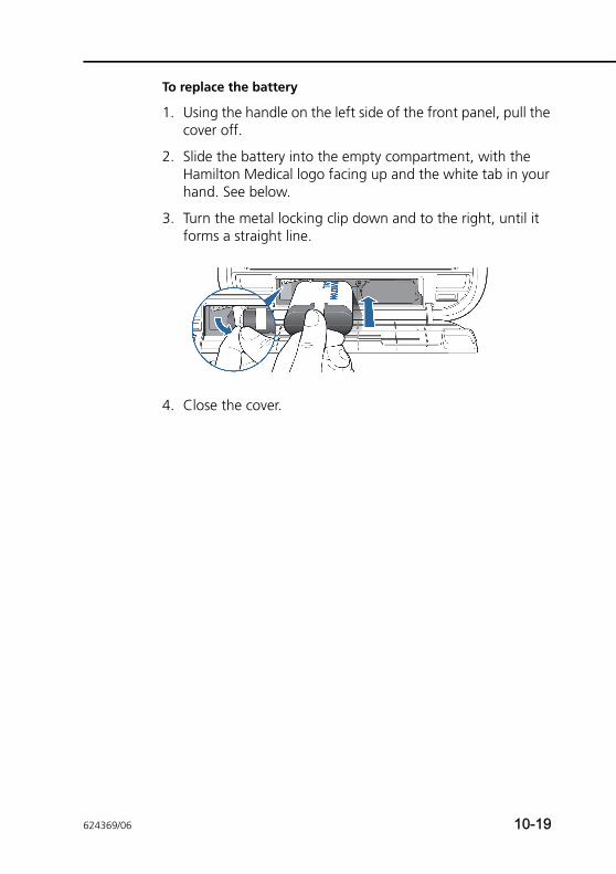
To replace the battery
1. Using the handle on the left side of the front panel, pull the cover off.
2. Slide the battery into the empty compartment, with the Hamilton Medical logo facing up and the white tab in your hand. See below.
3. Turn the metal locking clip down and to the right, until it forms a straight line.
4. Close the cover.
624369/06 10-19
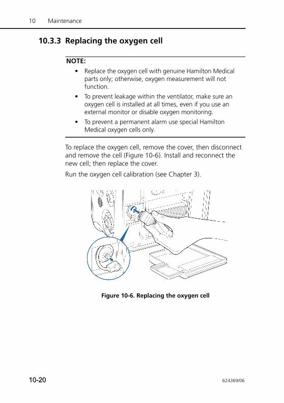
10 Maintenance
10.3.3 Replacing the oxygen cell
NOTE:• Replace the oxygen cell with genuine Hamilton Medical
parts only; otherwise, oxygen measurement will not function.
• To prevent leakage within the ventilator, make sure an oxygen cell is installed at all times, even if you use an external monitor or disable oxygen monitoring.
• To prevent a permanent alarm use special Hamilton Medical oxygen cells only.
To replace the oxygen cell, remove the cover, then disconnect and remove the cell (Figure 10-6). Install and reconnect the new cell; then replace the cover.
Run the oxygen cell calibration (see Chapter 3).
Figure 10-6. Replacing the oxygen cell
10-20 624369/06
10.4 Storage
To maintain the battery charge and to prolong the life of the battery, keep the ventilator connected to its primary power source. Have the battery recharged every 6 months, depending on storage conditions (see specifications in Appendix A).
10.5 Repacking and shipping
CAUTIONInform Hamilton Medical if you are shipping a contami-nated (nonsterilized and nondisinfected) device for ser-vice.
If you must ship the ventilator, use the original packing materials. If these materials are not available, contact your Hamilton Medical representative for replacement materials.
624369/06 10-21

10 Maintenance
10-22 624369/06
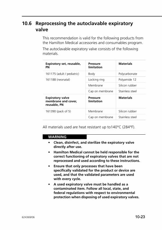
10.6 Reprocessing the autoclavable expiratory valve
This recommendation is valid for the following products from the Hamilton Medical accessories and consumables program.
The autoclavable expiratory valve consists of the following materials.
All materials used are heat resistant up to140°C (284°F).
WARNING• Clean, disinfect, and sterilize the expiratory valve
directly after use.
• Hamilton Medical cannot be held responsible for the correct functioning of expiratory valves that are not reprocessed and used according to these instructions.
• Ensure that only processes that have been specifically validated for the product or device are used, and that the validated parameters are used with every cycle.
• A used expiratory valve must be handled as a contaminated item. Follow all local, state, and federal regulations with respect to environmental protection when disposing of used expiratory valves.
Expiratory set, reusable, PN
Pressure limitation
Materials
161175 (adult / pediatric) Body Polycarbonate
161188 (neonatal) Locking ring Polyamide 12
Membrane Silicon rubber
Cap on membrane Stainless steel
Expiratory valve membrane and cover, reusable, PN
Pressure limitation
Materials
161390 (pack of 5) Membrane Silicon rubber
Cap on membrane Stainless steel
624369/06 10-23
10 Maintenance
• Follow hospital infection control procedures, as well as local laws and regulations. This applies in particular to the various regulations regarding an effective deactivation of prions.
CAUTION• The autoclavable expiratory valve has a limited life
span. The expiratory valve may be damaged due to the use of hard brushes, scouring agents, or by the exertion of too much force.
• The use of rinse aids will reduce the life span of the expiratory valve, as it can lead to early failure and cracks in the plastic expiratory valve body.
• The expiratory valve must not be autoclaved if medication containing aromatic or chlorinated hydrocarbons has been applied via a nebulizer. Discard the valve.
Make sure that the reprocessing does not damage the steel ring and the membrane.
The steel ring is there to reinforce the membrane and to improve tightness. Make sure the ring does not get bent out of shape.
10.6.1 Expiratory valve reprocessing overviewThe expiratory valve must be cleaned, disinfected, and steril-ized before every use.
Reprocessing comprises the following steps:
1. Cleaning and disinfecting the valves.
2. Visually inspecting the valves after disinfection.
3. Packaging the valves.
4. Sterilizing the packaged valves.
These steps are described in this section, both for mechanical and manual reprocessing of the valves.
10-24 624369/06
After each reprocessing cycle, the expiratory valve housing must be inspected for damage. If any changes are visible, the valve must be discarded. Perform a tightness test after each reprocessing cycle. If the test fails, it may be repeated once. The expiratory valve must be replaced if the tightness test fails the second time.
Rinse aids will cause premature damage and reduce product life span, and should not be used. Hamilton Medical does not guarantee the expiratory valve’s life span if rinse aids are used.
10.6.2 Preparing and reprocessing the expiratory valve after useThe expiratory valve must be handled in accordance with all local, state, and federal regulations. Reprocess the expiratory valve immediately after use. The reprocessing cycle comprises cleaning, disinfection, and sterilization.
Remove macroscopic impurities of the expiratory valve by rins-ing or wiping. You can add an aldehyde-free disinfection agent to the rinse water. You must not use any hard tools or hard brushes to remove resilient impurities.
Prior to sterilization, the expiratory valve must be cleaned and disinfected.
10.6.3 Cleaning and disinfecting the expiratory valveThe expiratory valve can be disinfected mechanically or manu-ally.
NOTE:Since mechanical disinfection is more effective and consis-tent, manual cleaning and disinfection is only permitted when no mechanical process is available.
Follow the chemical concentrations and soak times as stated in the corresponding manufacturer’s instructions for use. Only use freshly made solutions. The disinfection solution must not foam.
624369/06 10-25
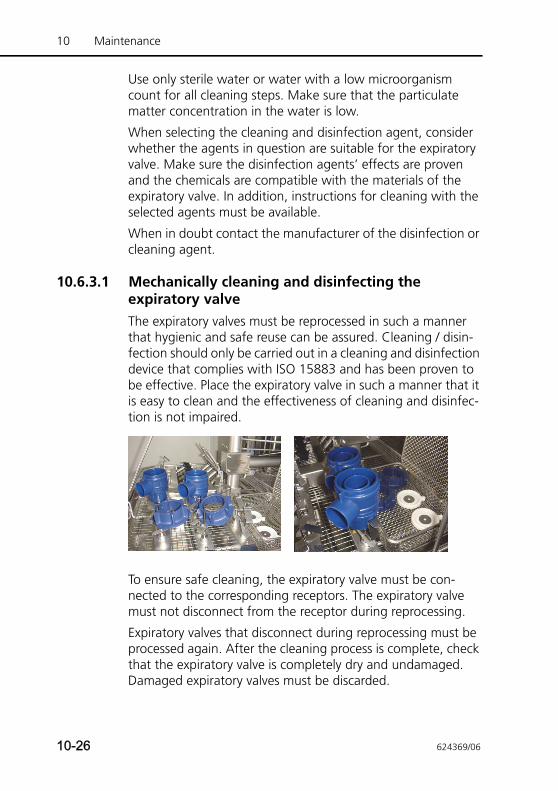
10 Maintenance
Use only sterile water or water with a low microorganism count for all cleaning steps. Make sure that the particulate matter concentration in the water is low.
When selecting the cleaning and disinfection agent, consider whether the agents in question are suitable for the expiratory valve. Make sure the disinfection agents’ effects are proven and the chemicals are compatible with the materials of the expiratory valve. In addition, instructions for cleaning with the selected agents must be available.
When in doubt contact the manufacturer of the disinfection or cleaning agent.
10.6.3.1 Mechanically cleaning and disinfecting the expiratory valveThe expiratory valves must be reprocessed in such a manner that hygienic and safe reuse can be assured. Cleaning / disin-fection should only be carried out in a cleaning and disinfection device that complies with ISO 15883 and has been proven to be effective. Place the expiratory valve in such a manner that it is easy to clean and the effectiveness of cleaning and disinfec-tion is not impaired.
To ensure safe cleaning, the expiratory valve must be con-nected to the corresponding receptors. The expiratory valve must not disconnect from the receptor during reprocessing.
Expiratory valves that disconnect during reprocessing must be processed again. After the cleaning process is complete, check that the expiratory valve is completely dry and undamaged. Damaged expiratory valves must be discarded.
10-26 624369/06
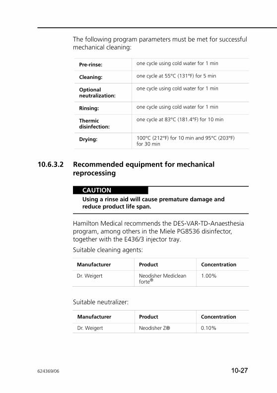
The following program parameters must be met for successful mechanical cleaning:
10.6.3.2 Recommended equipment for mechanical reprocessing
CAUTIONUsing a rinse aid will cause premature damage and reduce product life span.
Hamilton Medical recommends the DES-VAR-TD-Anaesthesia program, among others in the Miele PG8536 disinfector, together with the E436/3 injector tray.
Suitable cleaning agents:
Suitable neutralizer:
Pre-rinse: one cycle using cold water for 1 min
Cleaning: one cycle at 55°C (131°F) for 5 min
Optional neutralization:
one cycle using cold water for 1 min
Rinsing: one cycle using cold water for 1 min
Thermic disinfection:
one cycle at 83°C (181.4°F) for 10 min
Drying: 100°C (212°F) for 10 min and 95°C (203°F) for 30 min
Manufacturer Product Concentration
Dr. Weigert Neodisher Mediclean forte®
1.00%
Manufacturer Product Concentration
Dr. Weigert Neodisher Z® 0.10%
624369/06 10-27
10 Maintenance
10.6.3.3 Manually cleaning the expiratory valve
1. Disassemble the expiratory valve.
2. Submerge the expiratory valve in the cleaning solution (for example, Neodisher Mediclean forte®) and let it soak for the time defined by the manufacturer of the disinfection or cleaning agent. Make sure that all parts of the expiratory valve are fully submerged in the solution.
3. Rinse all parts at the beginning and the end of the soak time with the cleaning agent at least five times.
4. Remove matter and larger exterior impurities by carefully scrubbing the expiratory valve with a soft brush or soft towel.
5. Rinse the expiratory valve at least five times intensively, or according to the validated cleaning plan, in freshly distilled or deionized water.
6. Repeat the cleaning process if the last cleaning solution was not clear or there are still visible impurities on the expiratory valve.
10.6.3.4 Manually disinfecting the expiratory valve
1. Disassemble the expiratory valve and submerge it in the dis-infection solution, and let it soak for the time defined by the manufacturer of the disinfection agent (for example, CIDEX® OPA). Make sure that all parts of the expiratory valve are fully submerged in the solution.
2. Rinse the expiratory valve at the beginning and at the end of the soak time with the disinfection solution at least five times, or in accordance with the validated disinfection plan.
3. Rinse the expiratory valve in freshly distilled or deionized water at least five times intensively, or according to the val-idated cleaning plan.
4. Repeat the cleaning process if the last cleaning solution was not clear or there are still visible impurities on the expiratory valve.
10-28 624369/06
5. Dry the expiratory valve with filtered, oil-free compressed air.
6. Immediately package the expiratory valve using appropriate packaging.
10.6.4 Visual testAfter each cleaning and disinfection cycle, the expiratory valve must be macroscopically clean, that is, free of visible residual matter and other impurities. If it is not, the entire cleaning and disinfection process must be repeated.
Visually check for external damage, such as cracks, broken or deformed parts, or discoloration.
10.6.5 PackagingMake sure that the expiratory valves are not moist during pack-aging.
The packaging must conform to ISO 11607 and be suitable for vapor sterilization (heat resistance up to 141.0°C (285.8°F)) and be sufficiently permeable to vapor.
Only use packaging suitable for sterilization.
10.6.6 SterilizationSterilize the expiratory valve after cleaning and disinfection before use. Use one of the following methods:
• 134.0°C (273.2°F) with or without prevacuum, with an exposure time of a minimum of 3 min and a maximum of 18 min
• 121.0°C (249.8°F) with or without prevacuum, with an exposure time of a minimum of 30 min
Place the expiratory valve parts horizontally into the sterilizer; do not stack them. Note that Hamilton Medical is not responsi-ble for the efficacy of any sterilization method, including but not limited to hot-air, ethylene oxide, formaldehyde, radiation, and low-temperature plasma sterilization.
624369/06 10-29
10 Maintenance
10.6.7 Testing before use
WARNINGDefective expiratory valves or expiratory valves that fail the tightness test must not be used.
Carry out a visual check and a tightness test as described in the ventilator’s operator’s manual. Replace defective expiratory valves.
10.6.8 Expiratory valve life spanThe expiratory valve can be cleaned, disinfected, and auto-claved at least 40 times. As long as the expiratory valve passes the tightness test during the preoperational check, the expira-tory valve can be used. Tests and calibrations have to be carried out as specified in the ventilator’s operator’s manual. It is the user’s responsibility to validate the processes used if the repro-cessing procedures used differ from those in this guide.
10.6.9 Autoclaved and packaged expiratory valve: life span and storage conditionsThe life span of an autoclaved and packaged expiratory valve depends on how long the packaging can keep the expiratory valve sterile. Follow the packaging manufacturer’s specifica-tions. At a minimum, the expiratory valve must be autoclaved every two years. Storage is subject to the same guidelines as the Hamilton Medical ventilator, as specified in the ventilator’s operator’s manual.
10.6.10 DisposalA used expiratory valve must be handled as a contaminated item. Follow all local, state, and federal regulations with respect to environmental protection when disposing of used expiratory valves.
10-30 624369/06
APPENDIX
A Specifications
A.1 Physical characteristics A-2
A.2 Environmental requirements A-3
A.3 Pneumatic specifications A-4
A.4 Electrical specifications A-6
A.5 Control settings A-8
A.6 Monitored parameters A-14
A.7 Alarms A-20
A.8 Configuration specifications A-22
A.9 Ventilator breathing system specifications A-24
A.10 Technical performance data A-25
A.10.1 Accuracy testing A-27
A.10.2 Essential performance A-28
A.11 Pulse oximeter sensor data A-29
A.12 Standards and approvals A-29
A.13 EMC declarations (IEC 60601-1-2) A-31
A.14 Warranty A-37
A.15 Miscellaneous A-39
A.16 Adjustable alarm setting resolution A-39
624369/06 A-1
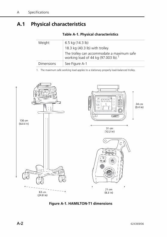
A Specifications
A.1 Physical characteristics
Figure A-1. HAMILTON-T1 dimensions
Table A-1. Physical characteristics
Weight 6.5 kg (14.3 lb)18.3 kg (40.3 lb) with trolleyThe trolley can accommodate a maximum safe working load of 44 kg (97.003 lb).1
Dimensions See Figure A-1
1. The maximum safe working load applies to a stationary properly load-balanced trolley.
A-2 624369/06
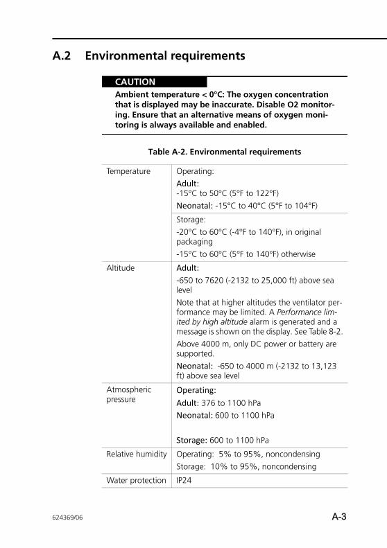
A.2 Environmental requirements
CAUTIONAmbient temperature < 0°C: The oxygen concentration that is displayed may be inaccurate. Disable O2 monitor-ing. Ensure that an alternative means of oxygen moni-toring is always available and enabled.
Table A-2. Environmental requirements
Temperature Operating: Adult:-15°C to 50°C (5°F to 122°F)Neonatal: -15°C to 40°C (5°F to 104°F)
Storage: -20°C to 60°C (-4°F to 140°F), in original packaging-15°C to 60°C (5°F to 140°F) otherwise
Altitude Adult: -650 to 7620 (-2132 to 25,000 ft) above sea levelNote that at higher altitudes the ventilator per-formance may be limited. A Performance lim-ited by high altitude alarm is generated and a message is shown on the display. See Table 8-2.Above 4000 m, only DC power or battery are supported.Neonatal: -650 to 4000 m (-2132 to 13,123 ft) above sea level
Atmospheric pressure
Operating: Adult: 376 to 1100 hPaNeonatal: 600 to 1100 hPa
Storage: 600 to 1100 hPa
Relative humidity Operating: 5% to 95%, noncondensingStorage: 10% to 95%, noncondensing
Water protection IP24
624369/06 A-3
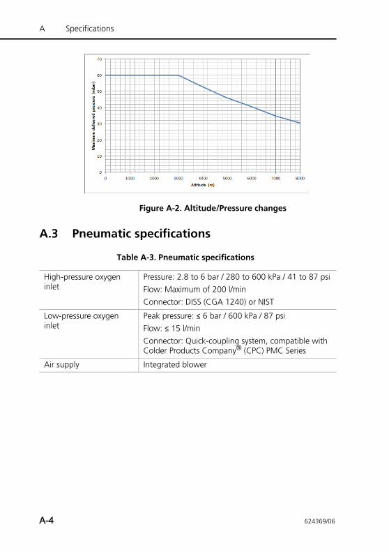
A Specifications
Figure A-2. Altitude/Pressure changes
A.3 Pneumatic specifications
Table A-3. Pneumatic specifications
High-pressure oxygen inlet
Pressure: 2.8 to 6 bar / 280 to 600 kPa / 41 to 87 psiFlow: Maximum of 200 l/minConnector: DISS (CGA 1240) or NIST
Low-pressure oxygen inlet
Peak pressure: ≤ 6 bar / 600 kPa / 87 psiFlow: ≤ 15 l/minConnector: Quick-coupling system, compatible with Colder Products Company® (CPC) PMC Series
Air supply Integrated blower
A-4 624369/06
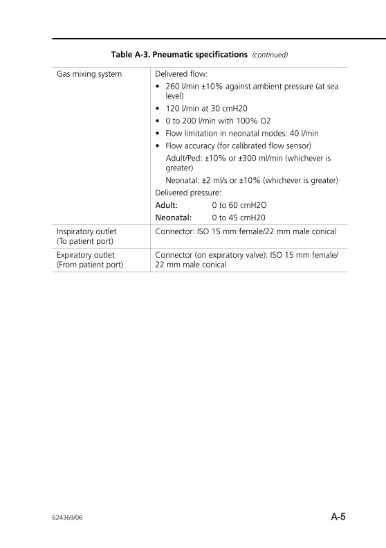
Gas mixing system Delivered flow: • 260 l/min ±10% against ambient pressure (at sea
level)• 120 l/min at 30 cmH20 • 0 to 200 l/min with 100% O2• Flow limitation in neonatal modes: 40 l/min• Flow accuracy (for calibrated flow sensor)
Adult/Ped: ±10% or ±300 ml/min (whichever is greater)Neonatal: ±2 ml/s or ±10% (whichever is greater)
Delivered pressure: Adult: 0 to 60 cmH2ONeonatal: 0 to 45 cmH20
Inspiratory outlet (To patient port)
Connector: ISO 15 mm female/22 mm male conical
Expiratory outlet (From patient port)
Connector (on expiratory valve): ISO 15 mm female/22 mm male conical
Table A-3. Pneumatic specifications (continued)
624369/06 A-5
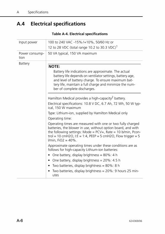
A Specifications
A.4 Electrical specifications
Table A-4. Electrical specifications
Input power 100 to 240 VAC -15% /+10%, 50/60 Hz or12 to 28 VDC (total range 10.2 to 30.3 VDC)1
Power consump-tion
50 VA typical, 150 VA maximum
Battery NOTE:
Battery life indications are approximate. The actual battery life depends on ventilator settings, battery age, and level of battery charge. To ensure maximum bat-tery life, maintain a full charge and minimize the num-ber of complete discharges.
Hamilton Medical provides a high-capacity2 battery. Electrical specifications: 10.8 V DC, 6.7 Ah, 72 Wh, 50 W typ-ical, 150 W maximum Type: Lithium-ion, supplied by Hamilton Medical onlyOperating time:Operating times are measured with one or two fully charged batteries, the blower in use, without option board, and with the following settings: Mode = PCV+, Rate = 10 b/min, Pcon-trol = 10 cmH2O, I:E = 1:4, PEEP = 5 cmH2O, Flow trigger = 5 l/min, FiO2 = 40%. Approximate operating times under these conditions are as follows for high-capacity Lithium-ion batteries:• One battery, display brightness = 80%: 4 h• One battery, display brightness = 20%: 4.5 h• Two batteries, display brightness = 80%: 8 h• Two batteries, display brightness = 20%: 9 hours 25 min-
utes
A-6 624369/06
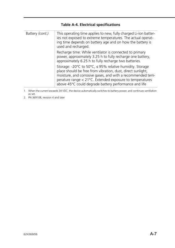
Battery (cont.) This operating time applies to new, fully charged Li-ion batter-ies not exposed to extreme temperatures. The actual operat-ing time depends on battery age and on how the battery is used and recharged.Recharge time: While ventilator is connected to primary power, approximately 3.25 h to fully recharge one battery, approximately 6.25 h to fully recharge two batteries.Storage: -20°C to 50°C, ≤ 95% relative humidity. Storage place should be free from vibration, dust, direct sunlight, moisture, and corrosive gases, and with a recommended tem-perature range < 21°C. Extended exposure to temperatures above 45°C could degrade battery performance and life
1. When the current exceeds 34 VDC, the device automatically switches to battery power, and continues ventilation as set.
2. PN 369108, revision 4 and later
Table A-4. Electrical specifications
624369/06 A-7
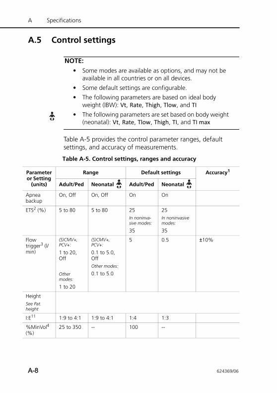
A Specifications
A.5 Control settings
NOTE:• Some modes are available as options, and may not be
available in all countries or on all devices.
• Some default settings are configurable.
• The following parameters are based on ideal body weight (IBW): Vt, Rate, Thigh, Tlow, and TI
• The following parameters are set based on body weight (neonatal): Vt, Rate, Tlow, Thigh, TI, and TI max
Table A-5 provides the control parameter ranges, default settings, and accuracy of measurements.
Table A-5. Control settings, ranges and accuracy
Parameter or Setting
(units)
Range Default settings Accuracy1
Adult/Ped Neonatal Adult/Ped Neonatal
Apnea backup
On, Off On, Off On On
ETS2 (%) 5 to 80 5 to 80 25In noninva-sive modes:
35
25In noninvasive modes:
35
Flow trigger3 (l/min)
(S)CMV+, PCV+:
1 to 20, Off
Other modes:
1 to 20
(S)CMV+, PCV+:
0.1 to 5.0, OffOther modes:
0.1 to 5.0
5 0.5 ±10%
HeightSee Pat. height
I:E11 1:9 to 4:1 1:9 to 4:1 1:4 1:3
%MinVol4 (%)
25 to 350 -- 100 --
A-8 624369/06
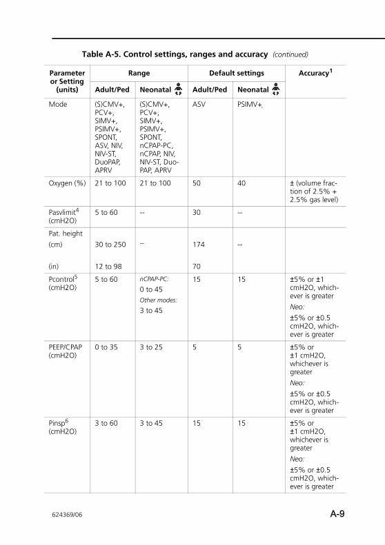
Mode (S)CMV+, PCV+, SIMV+, PSIMV+, SPONT, ASV, NIV, NIV-ST, DuoPAP, APRV
(S)CMV+, PCV+, SIMV+, PSIMV+, SPONT, nCPAP-PC, nCPAP, NIV, NIV-ST, Duo-PAP, APRV
ASV PSIMV+
Oxygen (%) 21 to 100 21 to 100 50 40 ± (volume frac-tion of 2.5% + 2.5% gas level)
Pasvlimit4 (cmH2O)
5 to 60 -- 30 --
Pat. height (cm)
(in)
30 to 250
12 to 98
-- 174
70
--
Pcontrol5 (cmH2O)
5 to 60 nCPAP-PC:
0 to 45Other modes:
3 to 45
15 15 ±5% or ±1 cmH2O, which-ever is greaterNeo:±5% or ±0.5 cmH2O, which-ever is greater
PEEP/CPAP (cmH2O)
0 to 35 3 to 25 5 5 ±5% or ±1 cmH2O, whichever is greaterNeo:±5% or ±0.5 cmH2O, which-ever is greater
Pinsp6 (cmH2O)
3 to 60 3 to 45 15 15 ±5% or ±1 cmH2O, whichever is greaterNeo:±5% or ±0.5 cmH2O, which-ever is greater
Table A-5. Control settings, ranges and accuracy (continued)
Parameter or Setting
(units)
Range Default settings Accuracy1
Adult/Ped Neonatal Adult/Ped Neonatal
624369/06 A-9
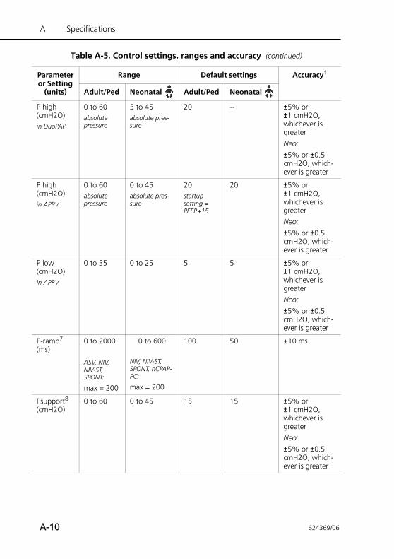
A Specifications
P high (cmH2O)in DuoPAP
0 to 60absolute pressure
3 to 45absolute pres-sure
20 -- ±5% or ±1 cmH2O, whichever is greaterNeo:±5% or ±0.5 cmH2O, which-ever is greater
P high (cmH2O)in APRV
0 to 60absolute pressure
0 to 45absolute pres-sure
20startup setting = PEEP+15
20 ±5% or ±1 cmH2O, whichever is greaterNeo:±5% or ±0.5 cmH2O, which-ever is greater
P low (cmH2O)in APRV
0 to 35 0 to 25 5 5 ±5% or ±1 cmH2O, whichever is greaterNeo:±5% or ±0.5 cmH2O, which-ever is greater
P-ramp7 (ms)
0 to 2000
ASV, NIV, NIV-ST, SPONT:
max = 200
0 to 600
NIV, NIV-ST, SPONT, nCPAP-PC:
max = 200
100 50 ±10 ms
Psupport8 (cmH2O)
0 to 60 0 to 45 15 15 ±5% or ±1 cmH2O, whichever is greaterNeo:±5% or ±0.5 cmH2O, which-ever is greater
Table A-5. Control settings, ranges and accuracy (continued)
Parameter or Setting
(units)
Range Default settings Accuracy1
Adult/Ped Neonatal Adult/Ped Neonatal
A-10 624369/06
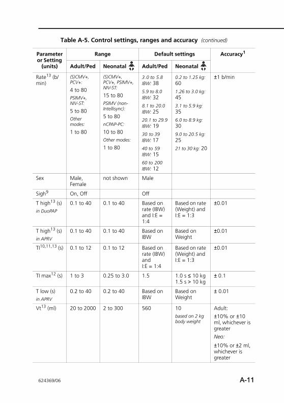
Rate13 (b/min)
(S)CMV+, PCV+:
4 to 80PSIMV+, NIV-ST:
5 to 80Other modes:
1 to 80
(S)CMV+, PCV+, PSIMV+, NIV-ST:
15 to 80PSIMV (non-Intellisync):
5 to 80nCPAP-PC:
10 to 80Other modes:
1 to 80
3.0 to 5.8 IBW: 385.9 to 8.0 IBW: 328.1 to 20.0 IBW: 2520.1 to 29.9 IBW: 1930 to 39 IBW: 1740 to 59 IBW: 1560 to 200 IBW: 12
0.2 to 1.25 kg: 601.26 to 3.0 kg: 453.1 to 5.9 kg: 356.0 to 8.9 kg: 309.0 to 20.5 kg: 2521 to 30 kg: 20
±1 b/min
Sex Male, Female
not shown Male
Sigh9 On, Off Off
T high13 (s)in DuoPAP
0.1 to 40 0.1 to 40 Based on rate (IBW) and I:E = 1:4
Based on rate (Weight) and I:E = 1:3
±0.01
T high13 (s)in APRV
0.1 to 40 0.1 to 40 Based on IBW
Based on Weight
±0.01
TI10,11,13 (s) 0.1 to 12 0.1 to 12 Based on rate (IBW) and I:E = 1:4
Based on rate (Weight) and I:E = 1:3
±0.01
TI max12 (s) 1 to 3 0.25 to 3.0 1.5 1.0 s ≤ 10 kg1.5 s > 10 kg
± 0.1
T low (s)in APRV
0.2 to 40 0.2 to 40 Based on IBW
Based on Weight
± 0.01
Vt13 (ml) 20 to 2000 2 to 300 560 10based on 2 kg body weight
Adult:±10% or ±10 ml, whichever is greaterNeo:
±10% or ±2 ml, whichever is greater
Table A-5. Control settings, ranges and accuracy (continued)
Parameter or Setting
(units)
Range Default settings Accuracy1
Adult/Ped Neonatal Adult/Ped Neonatal
624369/06 A-11
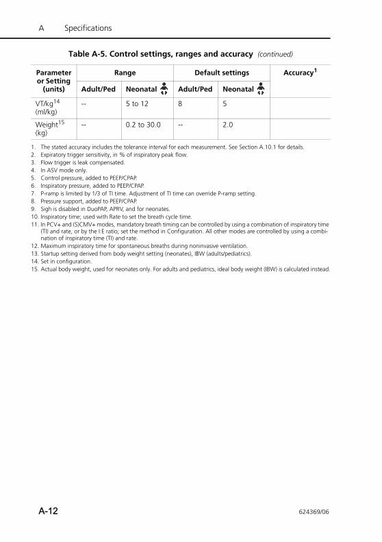
A Specifications
VT/kg14 (ml/kg)
-- 5 to 12 8 5
Weight15 (kg)
-- 0.2 to 30.0 -- 2.0
1. The stated accuracy includes the tolerance interval for each measurement. See Section A.10.1 for details. 2. Expiratory trigger sensitivity, in % of inspiratory peak flow.3. Flow trigger is leak compensated.4. In ASV mode only.5. Control pressure, added to PEEP/CPAP.6. Inspiratory pressure, added to PEEP/CPAP.7. P-ramp is limited by 1/3 of TI time. Adjustment of TI time can override P-ramp setting.8. Pressure support, added to PEEP/CPAP.9. Sigh is disabled in DuoPAP, APRV, and for neonates. 10. Inspiratory time; used with Rate to set the breath cycle time. 11. In PCV+ and (S)CMV+ modes, mandatory breath timing can be controlled by using a combination of inspiratory time
(TI) and rate, or by the I:E ratio; set the method in Configuration. All other modes are controlled by using a combi-nation of inspiratory time (TI) and rate.
12. Maximum inspiratory time for spontaneous breaths during noninvasive ventilation.13. Startup setting derived from body weight setting (neonates), IBW (adults/pediatrics).14. Set in configuration.15. Actual body weight, used for neonates only. For adults and pediatrics, ideal body weight (IBW) is calculated instead.
Table A-5. Control settings, ranges and accuracy (continued)
Parameter or Setting
(units)
Range Default settings Accuracy1
Adult/Ped Neonatal Adult/Ped Neonatal
A-12 624369/06
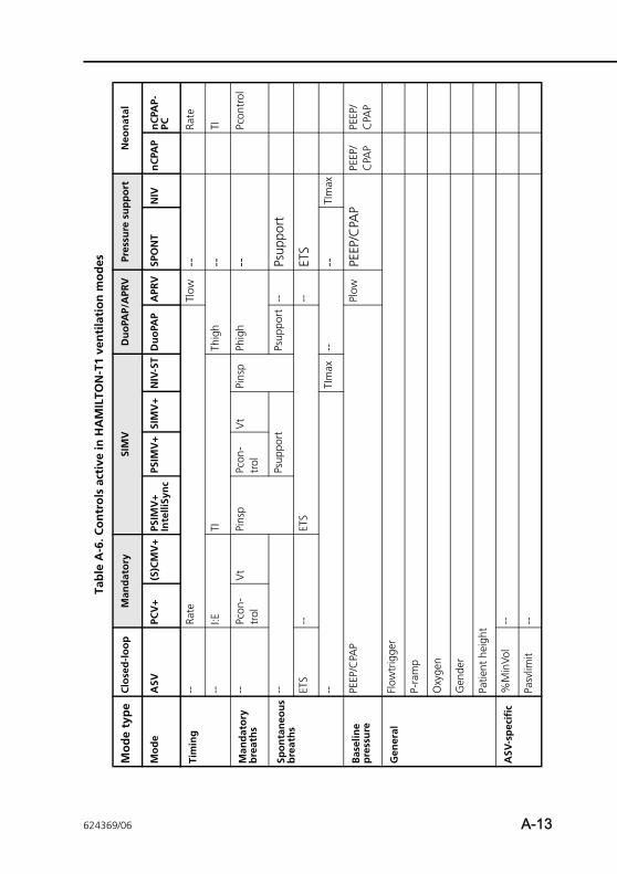
Tab
le A
-6. C
on
tro
ls a
ctiv
e in
HA
MIL
TON
-T1
ven
tila
tio
n m
od
es
Mo
de
typ
eC
lose
d-l
oo
pM
and
ato
rySI
MV
Du
oPA
P/A
PRV
Pres
sure
su
pp
ort
N
eon
atal
Mo
de
ASV
PCV
+(S
)CM
V+
PSIM
V+
Inte
lliSy
nc
PSIM
V+
SIM
V+
NIV
-ST
Du
oPA
PA
PRV
SPO
NT
NIV
nC
PAP
nC
PAP-
PC
Tim
ing
--Ra
teTl
ow--
Rate
--I:E
TITh
igh
--TI
Man
dat
ory
b
reat
hs
--Pc
on-
trol
Vt
Pins
pPc
on-
trol
Vt
Pins
pPh
igh
--Pc
ontr
ol
Spo
nta
neo
us
bre
ath
s--
Psup
port
Psup
port
--Ps
uppo
rt
ETS
--ET
S--
ETS
--TI
max
----
TIm
ax
Bas
elin
e p
ress
ure
PEEP
/CPA
PPl
owPE
EP/C
PAP
PEEP
/C
PAP
PEEP
/C
PAP
Gen
eral
Flow
trig
ger
P-ra
mp
Oxy
gen
Gen
der
Patie
nt h
eigh
t
ASV
-sp
ecif
ic%
Min
Vol
--
Pasv
limit
--
624369/06 A-13
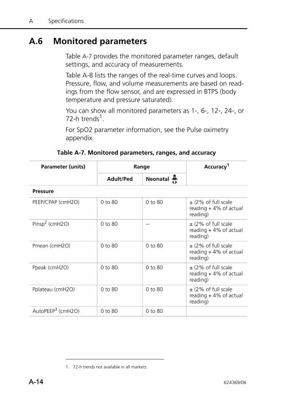
A Specifications
A.6 Monitored parameters
Table A-7 provides the monitored parameter ranges, default settings, and accuracy of measurements.
Table A-8 lists the ranges of the real-time curves and loops. Pressure, flow, and volume measurements are based on read-ings from the flow sensor, and are expressed in BTPS (body temperature and pressure saturated).
You can show all monitored parameters as 1-, 6-, 12-, 24-, or 72-h trends1.
For SpO2 parameter information, see the Pulse oximetry appendix.
1. 72-h trends not available in all markets.
Table A-7. Monitored parameters, ranges, and accuracy
Parameter (units) Range Accuracy1
Adult/Ped Neonatal
Pressure
PEEP/CPAP (cmH2O) 0 to 80 0 to 80 ± (2% of full scale reading + 4% of actual reading)
Pinsp2 (cmH2O) 0 to 80 -- ± (2% of full scale reading + 4% of actual reading)
Pmean (cmH2O) 0 to 80 0 to 80 ± (2% of full scale reading + 4% of actual reading)
Ppeak (cmH2O) 0 to 80 0 to 80 ± (2% of full scale reading + 4% of actual reading)
Pplateau (cmH2O) 0 to 80 0 to 80 ± (2% of full scale reading + 4% of actual reading)
AutoPEEP3 (cmH2O) 0 to 80 0 to 80
A-14 624369/06
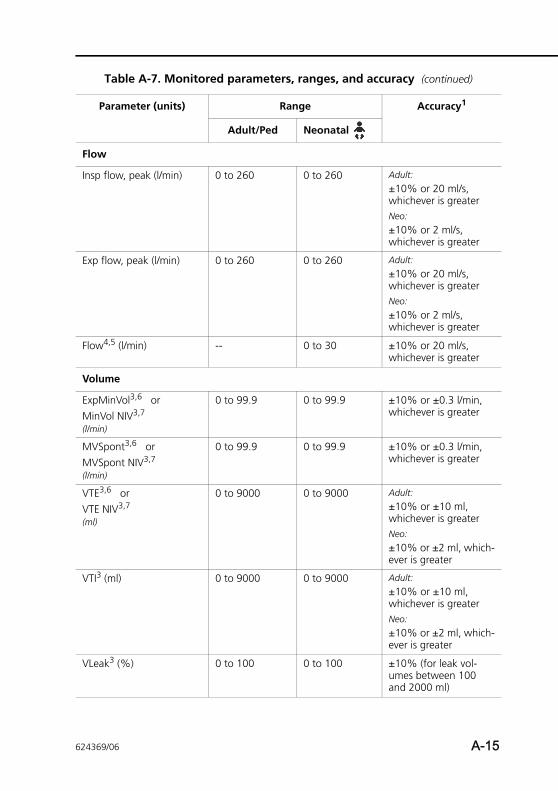
Flow
Insp flow, peak (l/min) 0 to 260 0 to 260 Adult:
±10% or 20 ml/s, whichever is greaterNeo:
±10% or 2 ml/s, whichever is greater
Exp flow, peak (l/min) 0 to 260 0 to 260 Adult:
±10% or 20 ml/s, whichever is greaterNeo:
±10% or 2 ml/s, whichever is greater
Flow4,5 (l/min) -- 0 to 30 ±10% or 20 ml/s, whichever is greater
Volume
ExpMinVol3,6 or MinVol NIV3,7
(l/min)
0 to 99.9 0 to 99.9 ±10% or ±0.3 l/min, whichever is greater
MVSpont3,6 or MVSpont NIV3,7
(l/min)
0 to 99.9 0 to 99.9 ±10% or ±0.3 l/min, whichever is greater
VTE3,6 orVTE NIV3,7
(ml)
0 to 9000 0 to 9000 Adult:
±10% or ±10 ml, whichever is greaterNeo:
±10% or ±2 ml, which-ever is greater
VTI3 (ml) 0 to 9000 0 to 9000 Adult:
±10% or ±10 ml, whichever is greaterNeo:
±10% or ±2 ml, which-ever is greater
VLeak3 (%) 0 to 100 0 to 100 ±10% (for leak vol-umes between 100 and 2000 ml)
Table A-7. Monitored parameters, ranges, and accuracy (continued)
Parameter (units) Range Accuracy1
Adult/Ped Neonatal
624369/06 A-15
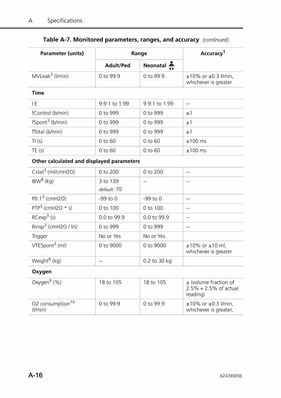
A Specifications
MVLeak3 (l/min) 0 to 99.9 0 to 99.9 ±10% or ±0.3 l/min, whichever is greater
Time
I:E 9.9:1 to 1:99 9.9:1 to 1:99 --
fControl (b/min) 0 to 999 0 to 999 ±1
fSpont3 (b/min) 0 to 999 0 to 999 ±1
fTotal (b/min) 0 to 999 0 to 999 ±1
TI (s) 0 to 60 0 to 60 ±100 ms
TE (s) 0 to 60 0 to 60 ±100 ms
Other calculated and displayed parameters
Cstat3 (ml/cmH2O) 0 to 200 0 to 200 --
IBW8 (kg) 3 to 139default: 70
-- --
P0.13 (cmH2O) -99 to 0 -99 to 0 --
PTP3 (cmH2O * s) 0 to 100 0 to 100 --
RCexp3 (s) 0.0 to 99.9 0.0 to 99.9 --
Rinsp3 (cmH2O / l/s) 0 to 999 0 to 999 --
Trigger No or Yes No or Yes
VTESpont3 (ml) 0 to 9000 0 to 9000 ±10% or ±10 ml, whichever is greater
Weight8 (kg) -- 0.2 to 30 kg
Oxygen
Oxygen9 (%) 18 to 105 18 to 105 ± (volume fraction of 2.5% + 2.5% of actual reading)
O2 consumption10 (l/min)
0 to 99.9 0 to 99.9 ±10% or ±0.3 l/min, whichever is greater,
Table A-7. Monitored parameters, ranges, and accuracy (continued)
Parameter (units) Range Accuracy1
Adult/Ped Neonatal
A-16 624369/06
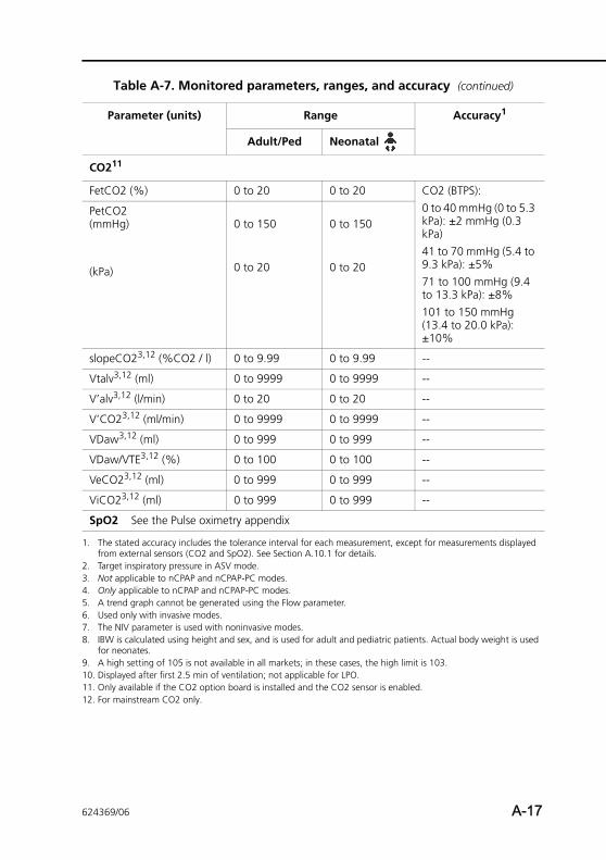
CO211
FetCO2 (%) 0 to 20 0 to 20 CO2 (BTPS):0 to 40 mmHg (0 to 5.3 kPa): ±2 mmHg (0.3 kPa)41 to 70 mmHg (5.4 to 9.3 kPa): ±5%71 to 100 mmHg (9.4 to 13.3 kPa): ±8%101 to 150 mmHg (13.4 to 20.0 kPa): ±10%
PetCO2 (mmHg)
(kPa)
0 to 150
0 to 20
0 to 150
0 to 20
slopeCO23,12 (%CO2 / l) 0 to 9.99 0 to 9.99 --
Vtalv3,12 (ml) 0 to 9999 0 to 9999 --
V’alv3,12 (l/min) 0 to 20 0 to 20 --
V’CO23,12 (ml/min) 0 to 9999 0 to 9999 --
VDaw3,12 (ml) 0 to 999 0 to 999 --
VDaw/VTE3,12 (%) 0 to 100 0 to 100 --
VeCO23,12 (ml) 0 to 999 0 to 999 --
ViCO23,12 (ml) 0 to 999 0 to 999 --
SpO2 See the Pulse oximetry appendix
1. The stated accuracy includes the tolerance interval for each measurement, except for measurements displayed from external sensors (CO2 and SpO2). See Section A.10.1 for details.
2. Target inspiratory pressure in ASV mode.3. Not applicable to nCPAP and nCPAP-PC modes. 4. Only applicable to nCPAP and nCPAP-PC modes.5. A trend graph cannot be generated using the Flow parameter.6. Used only with invasive modes. 7. The NIV parameter is used with noninvasive modes. 8. IBW is calculated using height and sex, and is used for adult and pediatric patients. Actual body weight is used
for neonates.9. A high setting of 105 is not available in all markets; in these cases, the high limit is 103.10. Displayed after first 2.5 min of ventilation; not applicable for LPO.11. Only available if the CO2 option board is installed and the CO2 sensor is enabled.12. For mainstream CO2 only.
Table A-7. Monitored parameters, ranges, and accuracy (continued)
Parameter (units) Range Accuracy1
Adult/Ped Neonatal
624369/06 A-17
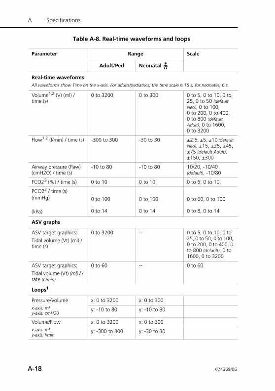
A Specifications
Table A-8. Real-time waveforms and loops
Parameter Range Scale
Adult/Ped Neonatal
Real-time waveformsAll waveforms show Time on the x-axis. For adults/pediatrics, the time scale is 15 s; for neonates, 6 s.
Volume1,2 (V) (ml) / time (s)
0 to 3200 0 to 300 0 to 5, 0 to 10, 0 to 25, 0 to 50 (default Neo), 0 to 100, 0 to 200, 0 to 400, 0 to 800 (default Adult), 0 to 1600, 0 to 3200
Flow1,2 (l/min) / time (s) -300 to 300 -30 to 30 ±2.5, ±5, ±10 (default Neo), ±15, ±25, ±45, ±75 (default Adult), ±150, ±300
Airway pressure (Paw) (cmH2O) / time (s)
-10 to 80 -10 to 80 10/20, -10/40 (default), -10/80
FCO23 (%) / time (s) 0 to 10 0 to 10 0 to 6, 0 to 10
PCO23 / time (s)(mmHg)
(kPa)
0 to 100
0 to 14
0 to 100
0 to 14
0 to 60, 0 to 100
0 to 8, 0 to 14
ASV graphs
ASV target graphics:Tidal volume (Vt) (ml) / time (s)
0 to 3200 -- 0 to 5, 0 to 10, 0 to 25, 0 to 50, 0 to 100, 0 to 200, 0 to 400, 0 to 800 (default), 0 to 1600, 0 to 3200
ASV target graphics:Tidal volume (Vt) (ml) / / rate (b/min)
0 to 60 -- 0 to 60
Loops1
Pressure/Volumex-axis: mly-axis: cmH20
x: 0 to 3200 x: 0 to 300
y: -10 to 80 y: -10 to 80
Volume/Flowx-axis: mly-axis: l/min
x: 0 to 3200 x: 0 to 300
y: -300 to 300 y: -30 to 30
A-18 624369/06
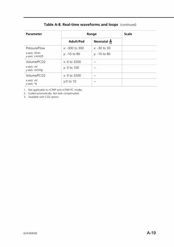
Pressure/Flowx-axis: l/miny-axis: cmH20
x: -300 to 300 x: -30 to 30
y: -10 to 80 y: -10 to 80
Volume/PCO2x-axis: mly-axis: mmHg
x: 0 to 3200 --
y: 0 to 100 --
Volume/FCO2x-axis: mly-axis: %
x: 0 to 3200 --
y:0 to 10 --
1. Not applicable to nCPAP and nCPAP-PC modes.2. Scaled automatically. Not leak compensated.3. Available with CO2 option.
Table A-8. Real-time waveforms and loops (continued)
Parameter Range Scale
Adult/Ped Neonatal
624369/06 A-19
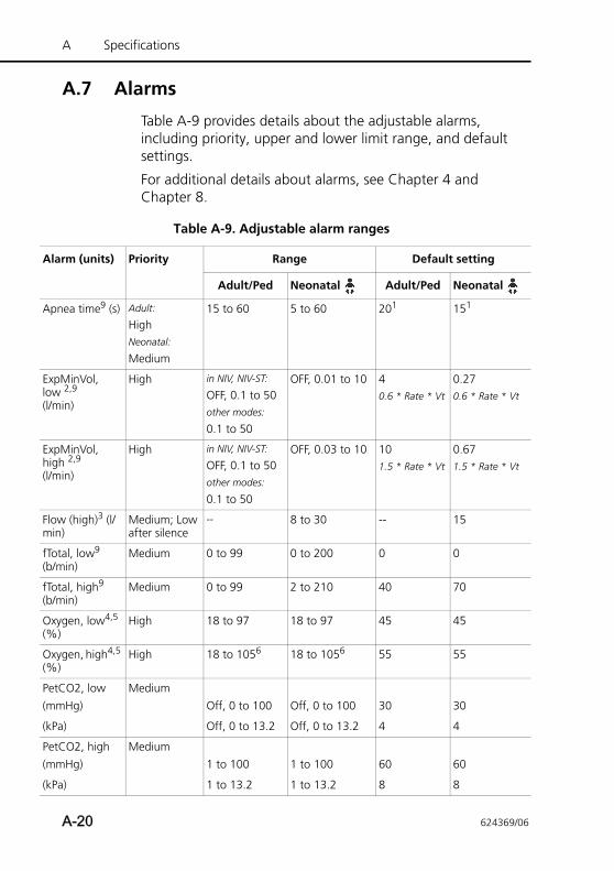
A Specifications
A
A
Elo(l
Eh(l
Flm
fT(b
fT(b
O(%
O(%
P(m
(k
P(m
(k
A.7 Alarms
Table A-9 provides details about the adjustable alarms, including priority, upper and lower limit range, and default settings.
For additional details about alarms, see Chapter 4 and Chapter 8.
Table A-9. Adjustable alarm ranges
larm (units) Priority Range Default setting
Adult/Ped Neonatal Adult/Ped Neonatal
pnea time9 (s) Adult:
HighNeonatal:
Medium
15 to 60 5 to 60 201 151
xpMinVol, w 2,9
/min)
High in NIV, NIV-ST:
OFF, 0.1 to 50other modes:
0.1 to 50
OFF, 0.01 to 10 40.6 * Rate * Vt
0.270.6 * Rate * Vt
xpMinVol, igh 2,9 /min)
High in NIV, NIV-ST:
OFF, 0.1 to 50other modes:
0.1 to 50
OFF, 0.03 to 10 101.5 * Rate * Vt
0.671.5 * Rate * Vt
ow (high)3 (l/in)
Medium; Low after silence
-- 8 to 30 -- 15
otal, low9 /min)
Medium 0 to 99 0 to 200 0 0
otal, high9 /min)
Medium 0 to 99 2 to 210 40 70
xygen, low4,5 )
High 18 to 97 18 to 97 45 45
xygen, high4,5 )
High 18 to 1056 18 to 1056 55 55
etCO2, lowmHg)
MediumOff, 0 to 100 Off, 0 to 100 30 30
Pa) Off, 0 to 13.2 Off, 0 to 13.2 4 4
etCO2, highmHg)
Medium1 to 100 1 to 100 60 60
Pa) 1 to 13.2 1 to 13.2 8 8
A-20 624369/06
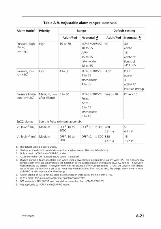
Pr(P(c
Pr(c
Prtio
Sp
V
V
1.2.3.4.5.
6.7.8.9.
A
essure, high max)mH2O)
High 15 to 70 nCPAP, nCPAP-PC:
10 to 55APRV:
15 to 55other modes:
18 to 55
40 40nCPAP:
15nCPAP-PC:
Pcontrol +PEEP+5
essure, low mH2O)
High 4 to 60 nCPAP, nCPAP-PC:
2 to 55other modes:
4 to 55
PEEP PEEPnCPAP:
3nCPAP-PC:
PEEP at startup
essure limita-n (cmH2O)
Medium; Low after silence
5 to 60 nCPAP, nCPAP-PC:
PmaxAPRV:
5 to 45other modes:
8 to 45
Pmax - 10 Pmax - 10
O2 alarms See the Pulse oximetry appendix.
t, low7,9 (ml) Medium OFF8, 10 to 3000
OFF8, 0.1 to 300 2800.5 * Vt
50.5 * Vt
t, high7,9 (ml) Medium OFF8, 10 to 3000
OFF8, 0.1 to 300 8501.5 * Vt
151.5 * Vt
The default setting is configurable.Startup setting derived from body weight setting (neonates), IBW (adults/pediatrics).Only active in nCPAP and nCPAP-PC modes.Active only when O2 monitoring (O2 sensor) is enabled.Oxygen alarm limits are adjustable only when using a low-pressure oxygen (LPO) supply. With HPO, the high and low oxygen alarm limits are automatically set in relation to the current oxygen setting as follows: O2 setting + 5 (Oxygen high limit) and O2 setting - 5 (Oxygen low limit). For example, if the Oxygen setting is 70%, the Oxygen high limit is set to 75 and the low limit is set to 65. Note that when switching from HPO to LPO, the oxygen alarm limits in force with HPO remain in place after the change. A high setting of 105 is not available in all markets; in these cases, the high limit is 103. In ASV mode, this alarm only applies for spontaneous breaths.OFF available in NIV, NIV-ST, and neonatal modes (other than nCPAP/nCPAP-PC).Not applicable to nCPAP and nCPAP-PC modes.
Table A-9. Adjustable alarm ranges (continued)
larm (units) Priority Range Default setting
Adult/Ped Neonatal Adult/Ped Neonatal
624369/06 A-21
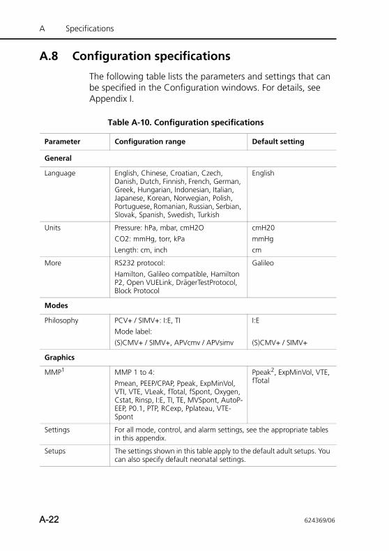
A Specifications
A.8 Configuration specifications
The following table lists the parameters and settings that can be specified in the Configuration windows. For details, see Appendix I.
Table A-10. Configuration specifications
Parameter Configuration range Default setting
General
Language English, Chinese, Croatian, Czech, Danish, Dutch, Finnish, French, German, Greek, Hungarian, Indonesian, Italian, Japanese, Korean, Norwegian, Polish, Portuguese, Romanian, Russian, Serbian, Slovak, Spanish, Swedish, Turkish
English
Units Pressure: hPa, mbar, cmH2OCO2: mmHg, torr, kPaLength: cm, inch
cmH20mmHgcm
More RS232 protocol: Hamilton, Galileo compatible, Hamilton P2, Open VUELink, DrägerTestProtocol, Block Protocol
Galileo
Modes
Philosophy PCV+ / SIMV+: I:E, TIMode label: (S)CMV+ / SIMV+, APVcmv / APVsimv
I:E
(S)CMV+ / SIMV+
Graphics
MMP1 MMP 1 to 4:Pmean, PEEP/CPAP, Ppeak, ExpMinVol, VTI, VTE, VLeak, fTotal, fSpont, Oxygen, Cstat, Rinsp, I:E, TI, TE, MVSpont, AutoP-EEP, P0.1, PTP, RCexp, Pplateau, VTE-Spont
Ppeak2, ExpMinVol, VTE, fTotal
Settings For all mode, control, and alarm settings, see the appropriate tables in this appendix.
Setups The settings shown in this table apply to the default adult setups. You can also specify default neonatal settings.
A-22 624369/06
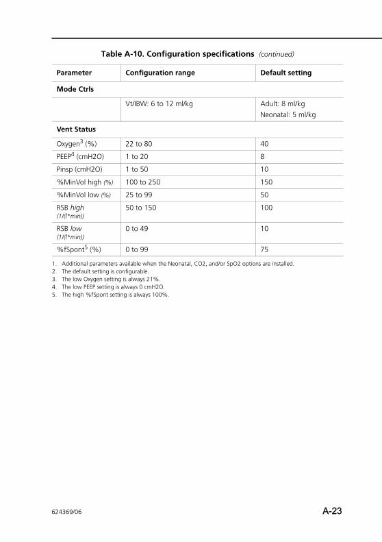
Mode Ctrls
Vt/IBW: 6 to 12 ml/kg Adult: 8 ml/kgNeonatal: 5 ml/kg
Vent Status
Oxygen3 (%) 22 to 80 40
PEEP4 (cmH2O) 1 to 20 8
Pinsp (cmH2O) 1 to 50 10
%MinVol high (%) 100 to 250 150
%MinVol low (%) 25 to 99 50
RSB high(1/(l*min))
50 to 150 100
RSB low(1/(l*min))
0 to 49 10
%fSpont5 (%) 0 to 99 75
1. Additional parameters available when the Neonatal, CO2, and/or SpO2 options are installed.2. The default setting is configurable.3. The low Oxygen setting is always 21%. 4. The low PEEP setting is always 0 cmH2O.5. The high %fSpont setting is always 100%.
Table A-10. Configuration specifications (continued)
Parameter Configuration range Default setting
624369/06 A-23
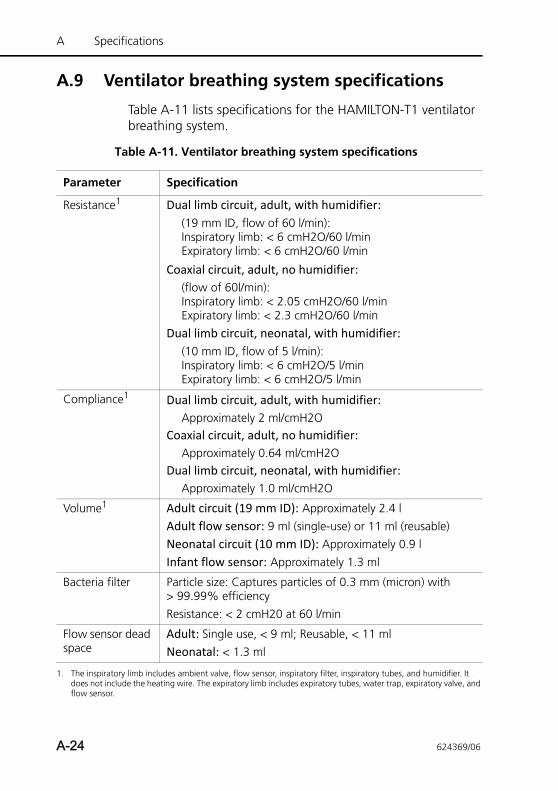
A Specifications
A.9 Ventilator breathing system specifications
Table A-11 lists specifications for the HAMILTON-T1 ventilator breathing system.
Table A-11. Ventilator breathing system specifications
Parameter Specification
Resistance1 Dual limb circuit, adult, with humidifier: (19 mm ID, flow of 60 l/min):Inspiratory limb: < 6 cmH2O/60 l/minExpiratory limb: < 6 cmH2O/60 l/min
Coaxial circuit, adult, no humidifier: (flow of 60l/min):Inspiratory limb: < 2.05 cmH2O/60 l/minExpiratory limb: < 2.3 cmH2O/60 l/min
Dual limb circuit, neonatal, with humidifier: (10 mm ID, flow of 5 l/min):Inspiratory limb: < 6 cmH2O/5 l/minExpiratory limb: < 6 cmH2O/5 l/min
Compliance1 Dual limb circuit, adult, with humidifier:Approximately 2 ml/cmH2O
Coaxial circuit, adult, no humidifier:Approximately 0.64 ml/cmH2O
Dual limb circuit, neonatal, with humidifier:Approximately 1.0 ml/cmH2O
Volume1 Adult circuit (19 mm ID): Approximately 2.4 lAdult flow sensor: 9 ml (single-use) or 11 ml (reusable)Neonatal circuit (10 mm ID): Approximately 0.9 lInfant flow sensor: Approximately 1.3 ml
Bacteria filter Particle size: Captures particles of 0.3 mm (micron) with > 99.99% efficiencyResistance: < 2 cmH20 at 60 l/min
Flow sensor dead space
Adult: Single use, < 9 ml; Reusable, < 11 mlNeonatal: < 1.3 ml
1. The inspiratory limb includes ambient valve, flow sensor, inspiratory filter, inspiratory tubes, and humidifier. It does not include the heating wire. The expiratory limb includes expiratory tubes, water trap, expiratory valve, and flow sensor.
A-24 624369/06
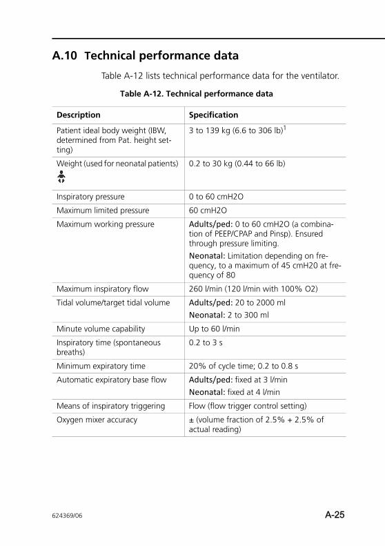
A.10 Technical performance data
Table A-12 lists technical performance data for the ventilator.
Table A-12. Technical performance data
Description Specification
Patient ideal body weight (IBW, determined from Pat. height set-ting)
3 to 139 kg (6.6 to 306 lb)1
Weight (used for neonatal patients) 0.2 to 30 kg (0.44 to 66 lb)
Inspiratory pressure 0 to 60 cmH2O
Maximum limited pressure 60 cmH2O
Maximum working pressure Adults/ped: 0 to 60 cmH2O (a combina-tion of PEEP/CPAP and Pinsp). Ensured through pressure limiting.Neonatal: Limitation depending on fre-quency, to a maximum of 45 cmH20 at fre-quency of 80
Maximum inspiratory flow 260 l/min (120 l/min with 100% O2)
Tidal volume/target tidal volume Adults/ped: 20 to 2000 mlNeonatal: 2 to 300 ml
Minute volume capability Up to 60 l/min
Inspiratory time (spontaneous breaths)
0.2 to 3 s
Minimum expiratory time 20% of cycle time; 0.2 to 0.8 s
Automatic expiratory base flow Adults/ped: fixed at 3 l/minNeonatal: fixed at 4 l/min
Means of inspiratory triggering Flow (flow trigger control setting)
Oxygen mixer accuracy ± (volume fraction of 2.5% + 2.5% of actual reading)
624369/06 A-25
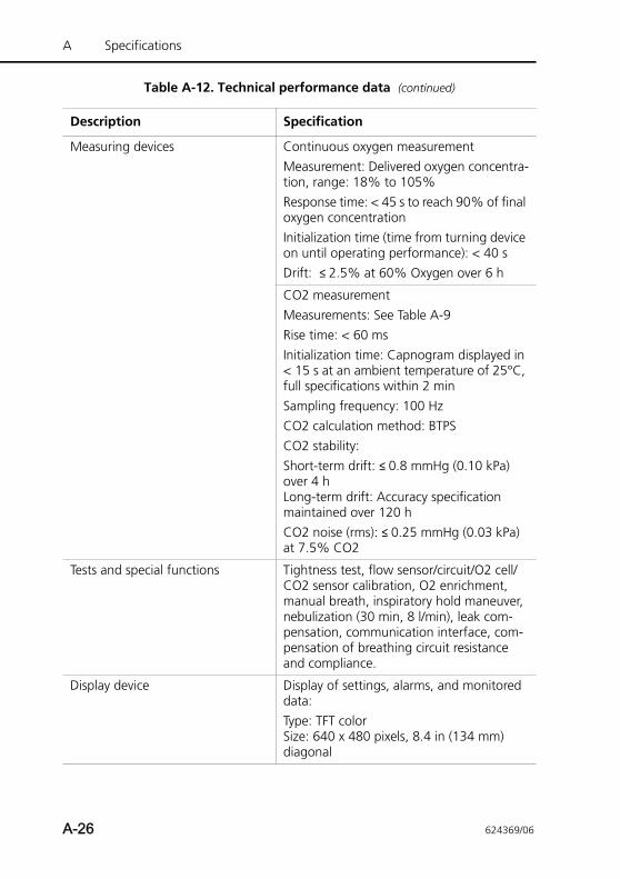
A Specifications
Measuring devices Continuous oxygen measurementMeasurement: Delivered oxygen concentra-tion, range: 18% to 105%Response time: < 45 s to reach 90% of final oxygen concentrationInitialization time (time from turning device on until operating performance): < 40 sDrift: ≤ 2.5% at 60% Oxygen over 6 h
CO2 measurementMeasurements: See Table A-9Rise time: < 60 msInitialization time: Capnogram displayed in < 15 s at an ambient temperature of 25°C, full specifications within 2 minSampling frequency: 100 HzCO2 calculation method: BTPSCO2 stability: Short-term drift: ≤ 0.8 mmHg (0.10 kPa) over 4 hLong-term drift: Accuracy specification maintained over 120 hCO2 noise (rms): ≤ 0.25 mmHg (0.03 kPa) at 7.5% CO2
Tests and special functions Tightness test, flow sensor/circuit/O2 cell/CO2 sensor calibration, O2 enrichment, manual breath, inspiratory hold maneuver, nebulization (30 min, 8 l/min), leak com-pensation, communication interface, com-pensation of breathing circuit resistance and compliance.
Display device Display of settings, alarms, and monitored data:Type: TFT colorSize: 640 x 480 pixels, 8.4 in (134 mm) diagonal
Table A-12. Technical performance data (continued)
Description Specification
A-26 624369/06
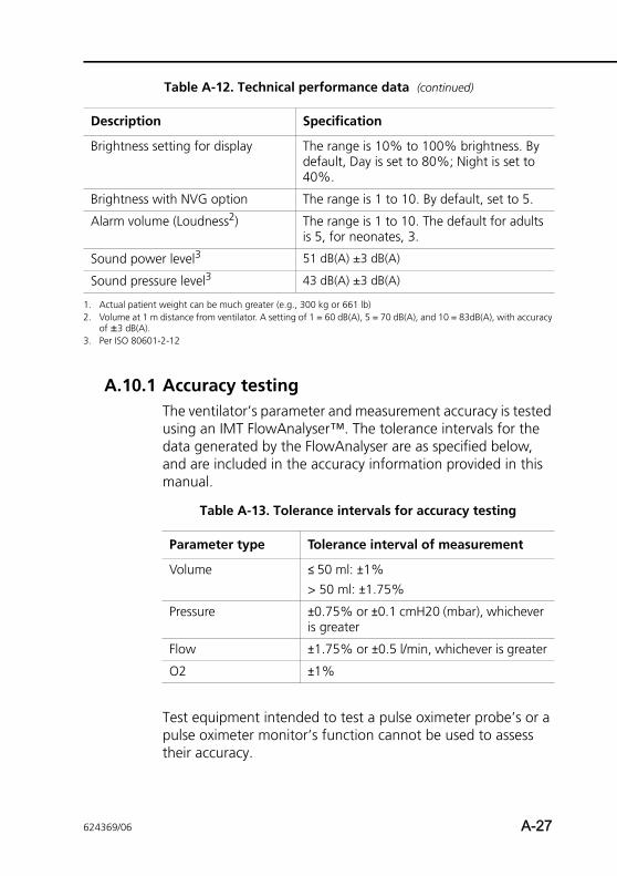
A.10.1 Accuracy testingThe ventilator’s parameter and measurement accuracy is tested using an IMT FlowAnalyser™. The tolerance intervals for the data generated by the FlowAnalyser are as specified below, and are included in the accuracy information provided in this manual.
Test equipment intended to test a pulse oximeter probe’s or a pulse oximeter monitor’s function cannot be used to assess their accuracy.
Brightness setting for display The range is 10% to 100% brightness. By default, Day is set to 80%; Night is set to 40%.
Brightness with NVG option The range is 1 to 10. By default, set to 5.
Alarm volume (Loudness2) The range is 1 to 10. The default for adults is 5, for neonates, 3.
Sound power level3 51 dB(A) ±3 dB(A)
Sound pressure level3 43 dB(A) ±3 dB(A)
1. Actual patient weight can be much greater (e.g., 300 kg or 661 lb)2. Volume at 1 m distance from ventilator. A setting of 1 = 60 dB(A), 5 = 70 dB(A), and 10 = 83dB(A), with accuracy
of ±3 dB(A).3. Per ISO 80601-2-12
Table A-12. Technical performance data (continued)
Description Specification
Table A-13. Tolerance intervals for accuracy testing
Parameter type Tolerance interval of measurement
Volume ≤ 50 ml: ±1%> 50 ml: ±1.75%
Pressure ±0.75% or ±0.1 cmH20 (mbar), whichever is greater
Flow ±1.75% or ±0.5 l/min, whichever is greater
O2 ±1%
624369/06 A-27
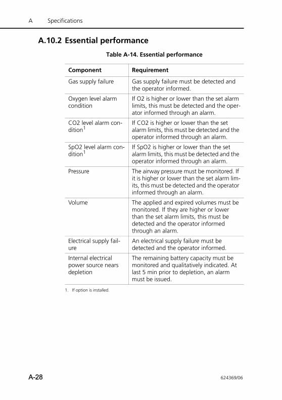
A Specifications
A.10.2 Essential performance
Table A-14. Essential performance
Component Requirement
Gas supply failure Gas supply failure must be detected and the operator informed.
Oxygen level alarm condition
If O2 is higher or lower than the set alarm limits, this must be detected and the oper-ator informed through an alarm.
CO2 level alarm con-dition1
1. If option is installed.
If CO2 is higher or lower than the set alarm limits, this must be detected and the operator informed through an alarm.
SpO2 level alarm con-dition1
If SpO2 is higher or lower than the set alarm limits, this must be detected and the operator informed through an alarm.
Pressure The airway pressure must be monitored. If it is higher or lower than the set alarm lim-its, this must be detected and the operator informed through an alarm.
Volume The applied and expired volumes must be monitored. If they are higher or lower than the set alarm limits, this must be detected and the operator informed through an alarm.
Electrical supply fail-ure
An electrical supply failure must be detected and the operator informed.
Internal electrical power source nears depletion
The remaining battery capacity must be monitored and qualitatively indicated. At last 5 min prior to depletion, an alarm must be issued.
A-28 624369/06
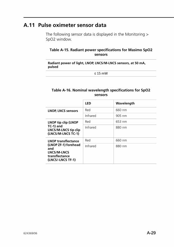
A.11 Pulse oximeter sensor data
The following sensor data is displayed in the Monitoring > SpO2 window.
Table A-15. Radiant power specifications for Masimo SpO2 sensors
Radiant power of light, LNOP, LNCS/M-LNCS sensors, at 50 mA, pulsed
≤ 15 mW
Table A-16. Nominal wavelength specifications for SpO2 sensors
LED Wavelength
LNOP, LNCS sensors Red 660 nm
Infrared 905 nm
LNOP tip clip (LNOP TC-1) andLNCS/M-LNCS tip clip (LNCS/M-LNCS TC-1)
Red 653 nm
Infrared 880 nm
LNOP transflectance (LNOP ZF-1) forehead andLNCS/M-LNCS transflectance (LNCS/-LNCS TF-1)
Red 660 nm
Infrared 880 nm
624369/06 A-29
A Specifications
A.12 Standards and approvals
NOTE:Where standards are mentioned, the HAMILTON-T1 com-plies with the versions listed in Table 1 on page xiii.
The HAMILTON-T1 was developed in accordance with perti-nent international standards.
The ventilator is manufactured within an EN ISO 13485 and EN ISO 9001, Council Directive 93/42/EEC, Annex II, Article 3 certi-fied quality management system.
The ventilator meets the Essential Requirements of Council Directive 93/42/EEC, Annex I.
The ventilator meets relevant parts of, among others, the fol-lowing standards:
• IEC 60601-1: Medical electrical equipment, Part 1: General requirements for basic safety and essential performance. The device classification is: Class II, Type B applied part (ven-tilator breathing system, VBS), type BF applied part (CO2 sensor including CO2 module connector; SpO2 sensor including adapter), continuous operation
• IEC 60601-1-2: Medical electrical equipment - Part 1-2: General requirements for basic safety and essential perfor-mance - Collateral standard: Electromagnetic compatibility - Requirements and tests
• ISO 80601-2-12: Medical electrical equipment - Part 2-12: Particular requirements for the basic safety and essential performance of critical care ventilators
• CAN/CSA-C22.2 No. 60601-1: Lung ventilators - Part 1: Particular requirements for critical care ventilators
• ANSI/AAMI ES 60601-1: Medical electrical equipment: General requirements for safety
• EN 1789: Medical vehicles and their equipment - Road ambulances
• EN 794-3: Lung ventilators - Part 3: Particular requirements for emergency and transport ventilators
A-30 624369/06
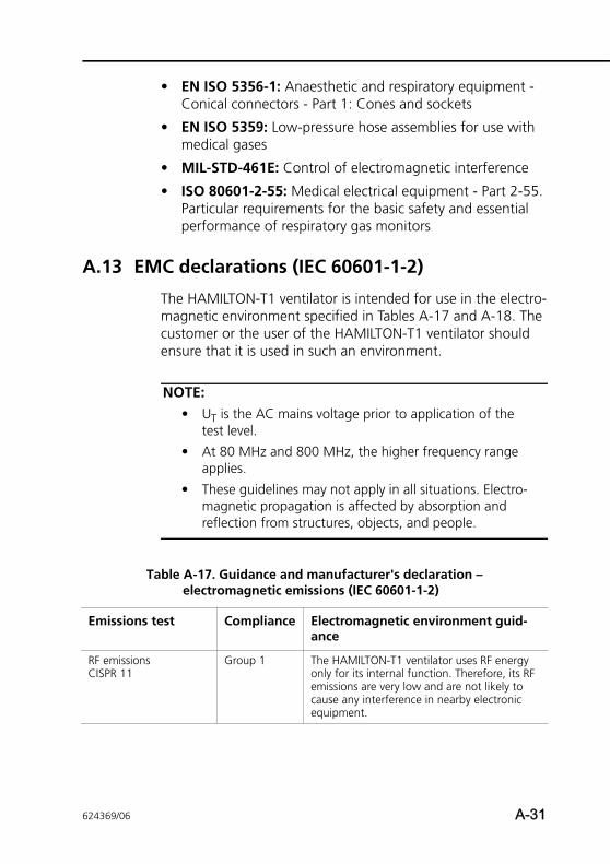
• EN ISO 5356-1: Anaesthetic and respiratory equipment - Conical connectors - Part 1: Cones and sockets
• EN ISO 5359: Low-pressure hose assemblies for use with medical gases
• MIL-STD-461E: Control of electromagnetic interference
• ISO 80601-2-55: Medical electrical equipment - Part 2-55. Particular requirements for the basic safety and essential performance of respiratory gas monitors
A.13 EMC declarations (IEC 60601-1-2)
The HAMILTON-T1 ventilator is intended for use in the electro-magnetic environment specified in Tables A-17 and A-18. The customer or the user of the HAMILTON-T1 ventilator should ensure that it is used in such an environment.
NOTE:• UT is the AC mains voltage prior to application of the
test level.
• At 80 MHz and 800 MHz, the higher frequency range applies.
• These guidelines may not apply in all situations. Electro-magnetic propagation is affected by absorption and reflection from structures, objects, and people.
Table A-17. Guidance and manufacturer's declaration – electromagnetic emissions (IEC 60601-1-2)
Emissions test Compliance Electromagnetic environment guid-ance
RF emissionsCISPR 11
Group 1 The HAMILTON-T1 ventilator uses RF energy only for its internal function. Therefore, its RF emissions are very low and are not likely to cause any interference in nearby electronic equipment.
624369/06 A-31
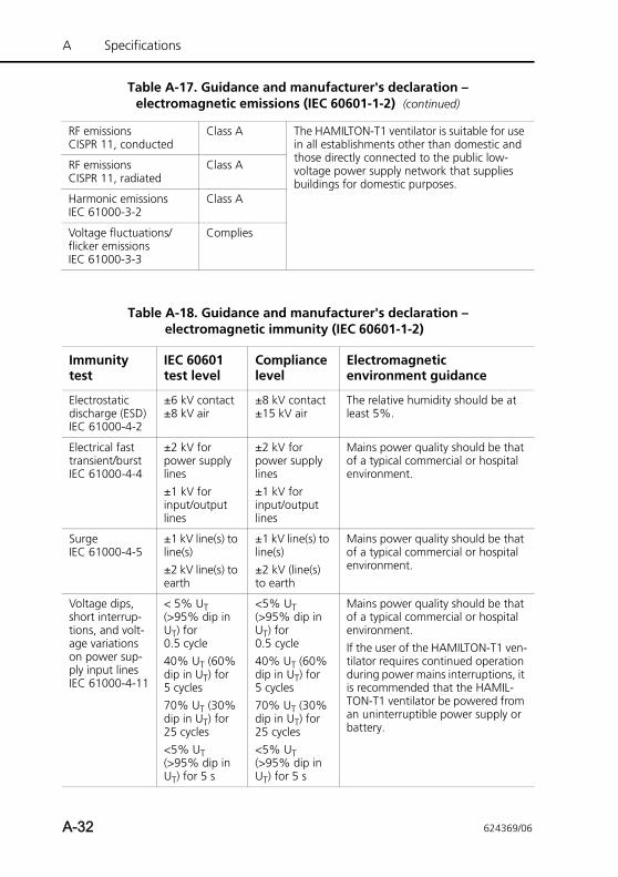
A Specifications
RF emissionsCISPR 11, conducted
Class A The HAMILTON-T1 ventilator is suitable for use in all establishments other than domestic and those directly connected to the public low-voltage power supply network that supplies buildings for domestic purposes.
RF emissionsCISPR 11, radiated
Class A
Harmonic emissionsIEC 61000-3-2
Class A
Voltage fluctuations/flicker emissionsIEC 61000-3-3
Complies
Table A-17. Guidance and manufacturer's declaration – electromagnetic emissions (IEC 60601-1-2) (continued)
Table A-18. Guidance and manufacturer's declaration – electromagnetic immunity (IEC 60601-1-2)
Immunity test
IEC 60601 test level
Compliance level
Electromagneticenvironment guidance
Electrostatic discharge (ESD)IEC 61000-4-2
±6 kV contact±8 kV air
±8 kV contact±15 kV air
The relative humidity should be at least 5%.
Electrical fast transient/burst IEC 61000-4-4
±2 kV for power supply lines±1 kV for input/output lines
±2 kV for power supply lines±1 kV for input/output lines
Mains power quality should be that of a typical commercial or hospital environment.
SurgeIEC 61000-4-5
±1 kV line(s) to line(s) ±2 kV line(s) to earth
±1 kV line(s) to line(s)±2 kV (line(s) to earth
Mains power quality should be that of a typical commercial or hospital environment.
Voltage dips, short interrup-tions, and volt-age variations on power sup-ply input lines IEC 61000-4-11
< 5% UT (>95% dip in UT) for 0.5 cycle40% UT (60% dip in UT) for 5 cycles70% UT (30% dip in UT) for 25 cycles<5% UT (>95% dip in UT) for 5 s
<5% UT (>95% dip in UT) for 0.5 cycle40% UT (60% dip in UT) for 5 cycles70% UT (30% dip in UT) for 25 cycles<5% UT (>95% dip in UT) for 5 s
Mains power quality should be that of a typical commercial or hospital environment.If the user of the HAMILTON-T1 ven-tilator requires continued operation during power mains interruptions, it is recommended that the HAMIL-TON-T1 ventilator be powered from an uninterruptible power supply or battery.
A-32 624369/06
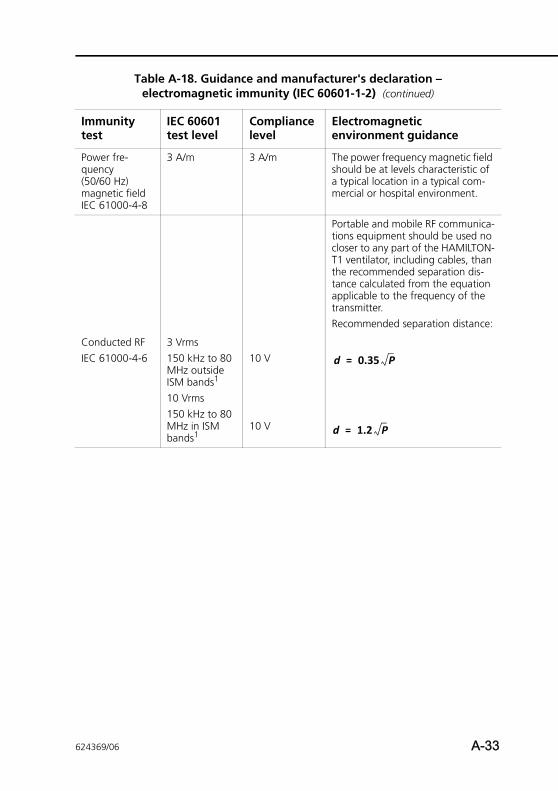
Power fre-quency (50/60 Hz) magnetic field IEC 61000-4-8
3 A/m 3 A/m The power frequency magnetic field should be at levels characteristic of a typical location in a typical com-mercial or hospital environment.
Portable and mobile RF communica-tions equipment should be used no closer to any part of the HAMILTON-T1 ventilator, including cables, than the recommended separation dis-tance calculated from the equation applicable to the frequency of the transmitter.Recommended separation distance:
Conducted RFIEC 61000-4-6
3 Vrms150 kHz to 80 MHz outside ISM bands1
10 Vrms150 kHz to 80 MHz in ISM bands1
10 V
10 V
Table A-18. Guidance and manufacturer's declaration – electromagnetic immunity (IEC 60601-1-2) (continued)
Immunity test
IEC 60601 test level
Compliance level
Electromagneticenvironment guidance
d 0.35 P=
d 1.2 P=
624369/06 A-33
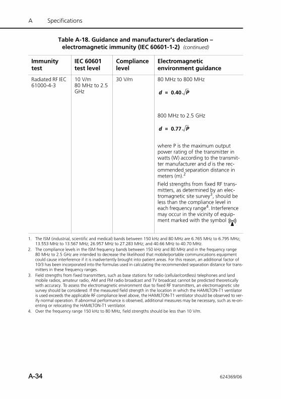
A Specifications
Radiated RF IEC 61000-4-3
10 V/m80 MHz to 2.5 GHz
30 V/m 80 MHz to 800 MHz
800 MHz to 2.5 GHz
where P is the maximum output power rating of the transmitter in watts (W) according to the transmit-ter manufacturer and d is the rec-ommended separation distance in meters (m).2
Field strengths from fixed RF trans-mitters, as determined by an elec-tromagnetic site survey3, should be less than the compliance level in each frequency range4. Interference may occur in the vicinity of equip-ment marked with the symbol
1. The ISM (industrial, scientific and medical) bands between 150 kHz and 80 MHz are 6.765 MHz to 6.795 MHz; 13.553 MHz to 13.567 MHz; 26.957 MHz to 27.283 MHz; and 40.66 MHz to 40.70 MHz.
2. The compliance levels in the ISM frequency bands between 150 kHz and 80 MHz and in the frequency range 80 MHz to 2.5 GHz are intended to decrease the likelihood that mobile/portable communications equipment could cause interference if it is inadvertently brought into patient areas. For this reason, an additional factor of 10/3 has been incorporated into the formulas used in calculating the recommended separation distance for trans-mitters in these frequency ranges.
3. Field strengths from fixed transmitters, such as base stations for radio (cellular/cordless) telephones and land mobile radios, amateur radio, AM and FM radio broadcast and TV broadcast cannot be predicted theoretically with accuracy. To assess the electromagnetic environment due to fixed RF transmitters, an electromagnetic site survey should be considered. If the measured field strength in the location in which the HAMILTON-T1 ventilator is used exceeds the applicable RF compliance level above, the HAMILTON-T1 ventilator should be observed to ver-ify normal operation. If abnormal performance is observed, additional measures may be necessary, such as re-ori-enting or relocating the HAMILTON-T1 ventilator.
4. Over the frequency range 150 kHz to 80 MHz, field strengths should be less than 10 V/m.
Table A-18. Guidance and manufacturer's declaration – electromagnetic immunity (IEC 60601-1-2) (continued)
Immunity test
IEC 60601 test level
Compliance level
Electromagneticenvironment guidance
d 0.40 P=
d 0.77 P=
A-34 624369/06
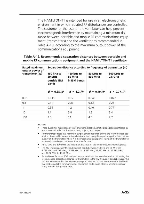
The HAMILTON-T1 is intended for use in an electromagnetic environment in which radiated RF disturbances are controlled. The customer or the user of the ventilator can help prevent electromagnetic interference by maintaining a minimum dis-tance between portable and mobile RF communications equip-ment (transmitters) and the ventilator as recommended in Table A-19, according to the maximum output power of the communications equipment.
NOTES:• These guidelines may not apply in all situations. Electromagnetic propagation is affected by
absorption and reflection from structures, objects, and people.• For transmitters rated at a maximum output power not listed above, the recommended sep-
aration distance d in meters (m) can be determined using the equation applicable to the fre-quency of the transmitter, where P is the maximum output power rating of the transmitter in watts (W) according to the transmitter manufacturer.
• At 80 MHz and 800 MHz, the separation distance for the higher frequency range applies.• The ISM (industrial, scientific and medical) bands between 150 kHz and 80 MHz are
6.765 MHz to 6.795 MHz; 13.553 MHz to 13.567 MHz; 26.957 MHz to 27.283 MHz; and 40.66 MHz to 40.70 MHz.
• An additional factor of 10/3 has been incorporated into the formulas used in calculating the recommended separation distance for transmitters in the ISM frequency bands between 150 kHz and 80 MHz and in the frequency range 80 MHz to 2.5 GHz to decrease the likelihood that mobile/portable communications equipment could cause interference if it is inadver-tently brought into patient areas.
Table A-19. Recommended separation distances between portable and mobile RF communications equipment and the HAMILTON-T1 ventilator
Rated maximum output power of transmitter (W)
Separation distance according to frequency of transmitter (m)
150 kHz to 80 MHzoutside ISM bands
150 kHz to 80 MHzin ISM bands
80 MHz to 800 MHz
800 MHz to 2.5 GHz
0.01 0.035 0.12 0.040 0.077
0.1 0.11 0.38 0.13 0.24
1 0.35 1.2 0.40 0.77
10 1.1 3.8 1.3 2.4
100 3.5 12 4.0 7.7
d 0.35 P= d 1.2 P= d 0.40 P= d 0.77 P=
624369/06 A-35
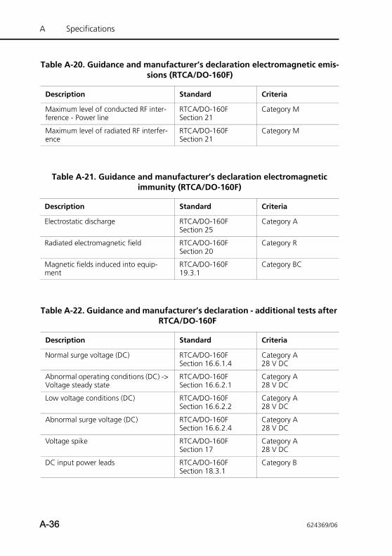
A Specifications
Table A-20. Guidance and manufacturer’s declaration electromagnetic emis-sions (RTCA/DO-160F)
Description Standard Criteria
Maximum level of conducted RF inter-ference - Power line
RTCA/DO-160FSection 21
Category M
Maximum level of radiated RF interfer-ence
RTCA/DO-160FSection 21
Category M
Table A-21. Guidance and manufacturer’s declaration electromagnetic immunity (RTCA/DO-160F)
Description Standard Criteria
Electrostatic discharge RTCA/DO-160FSection 25
Category A
Radiated electromagnetic field RTCA/DO-160FSection 20
Category R
Magnetic fields induced into equip-ment
RTCA/DO-160F19.3.1
Category BC
Table A-22. Guidance and manufacturer’s declaration - additional tests after RTCA/DO-160F
Description Standard Criteria
Normal surge voltage (DC) RTCA/DO-160FSection 16.6.1.4
Category A28 V DC
Abnormal operating conditions (DC) -> Voltage steady state
RTCA/DO-160FSection 16.6.2.1
Category A28 V DC
Low voltage conditions (DC) RTCA/DO-160FSection 16.6.2.2
Category A28 V DC
Abnormal surge voltage (DC) RTCA/DO-160FSection 16.6.2.4
Category A28 V DC
Voltage spike RTCA/DO-160FSection 17
Category A28 V DC
DC input power leads RTCA/DO-160FSection 18.3.1
Category B
A-36 624369/06
A.14 Warranty
LIMITED WARRANTY
THE WARRANTY DESCRIBED IN THIS AGREEMENT IS IN LIEU OF ANY AND ALL OTHER WARRANTIES, EXPRESS OR IMPLIED, INCLUDING IMPLIED WARRANTIES OF MERCHANTABILITY AND FITNESS FOR A PARTICULAR PURPOSE. HOWEVER, IMPLIED WARRANTIES ARE NOT DISCLAIMED DURING THE PERIOD OF THIS LIMITED WARRANTY.
Hamilton Medical guarantees its products to be shipped free from defects in material and workmanship. The warranty does not include disposable items. Disposable items and consum-able products are considered to be of single use or of limited use only and must be replaced regularly as required for proper operation of the product following the operator’s manual.
Hamilton Medical and the manufacturer shall have no obliga-tions nor liabilities in connection with the product other than what is specified herein, including without limitation, obliga-tions and/ or liabilities for alleged negligence, or for strict liabil-ity. In no event shall the company be liable for incidental or consequential damages, either direct or contingent.
This Limited Warranty shall be void and not apply:
1. If the product has not been installed and connected by an authorized local representative of Hamilton Medical in accordance with the instructions furnished by Hamilton Medical and by a Hamilton Medical representative.
2. If replacements and/or repairs have not been performed by authorized or properly trained personnel.
3. If no evidence is present that the occurrence of damage/ repair happened within the certified warranty period.
4. If the serial number has been altered, effaced or removed and there is no bill of sale or evidence to verify the product’s purchase date.
624369/06 A-37
A Specifications
5. If the defects arise from misuse, negligence, or accidents or from repair, adjustment, modification or replacement made outside Hamilton Medical’s factories or other than an authorized service center or authorized service representa-tive.
6. If the product has been modified, or in any nature altered without prior written authorization from Hamilton Medical.
7. If yearly maintenance is not performed.
8. If the product is or has been used in any way that is not specified under “Intended Use” (see “General cautions and notes”).
9. If the product has been used by anyone, but properly trained personnel under the supervision of a physician.
Replacements and/or repairs furnished under this Limited War-ranty do not carry a new warranty, but carry only the unexpired portion of the original Limited Warranty. The warranty of repaired and/or replaced components does not exceed the Lim-ited Warranty of the device.
To obtain service under this Limited Warranty, claimant must promptly notify the country’s sales partner of Hamilton Medical regarding the nature of the problem, serial number and the date of purchase of the Product.
Except as stated above, Hamilton Medical shall not be liable for any damages, claims or liabilities including, but not limited to, personal bodily injury, or incidental, consequential, or special damages. Nor will Hamilton Medical be liable for any damages, claims or liabilities including, but not limited to, personal bodily injury, or incidental, consequential, or special damages result-ing from misuse of the device or failure to comply with any of the provisions made in this manual.
A-38 624369/06
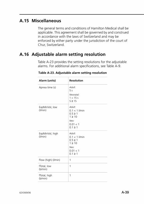
A.15 Miscellaneous
The general terms and conditions of Hamilton Medical shall be applicable. This agreement shall be governed by and construed in accordance with the laws of Switzerland and may be enforced by either party under the jurisdiction of the court of Chur, Switzerland.
A.16 Adjustable alarm setting resolution
Table A-23 provides the setting resolutions for the adjustable alarms. For additional alarm specifications, see Table A-9.
Table A-23. Adjustable alarm setting resolution
Alarm (units) Resolution
Apnea time (s) Adult: 5 s
Neonatal: 1 < 15 s5 ≥ 15
ExpMinVol, low(l/min)
Adult:
0.1 < 1 l/min0.5 ≥ 11 ≥ 10Neo:
0.01 < 10.1 ≥ 1
ExpMinVol, high (l/min)
Adult:
0.1 < 1 l/min0.5 ≥ 1 1 ≥ 10Neo:
0.01 < 10.1 ≥ 1
Flow (high) (l/min) 1
fTotal, low (b/min)
1
fTotal, high (b/min)
1
624369/06 A-39
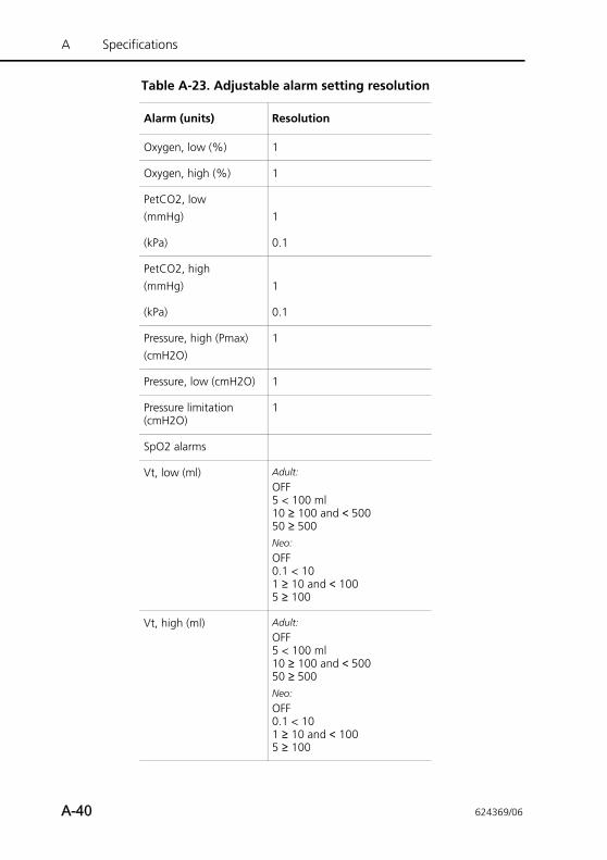
A Specifications
Oxygen, low (%) 1
Oxygen, high (%) 1
PetCO2, low(mmHg) 1
(kPa) 0.1
PetCO2, high(mmHg) 1
(kPa) 0.1
Pressure, high (Pmax)(cmH2O)
1
Pressure, low (cmH2O) 1
Pressure limitation (cmH2O)
1
SpO2 alarms
Vt, low (ml) Adult:
OFF5 < 100 ml10 ≥ 100 and < 50050 ≥ 500Neo:
OFF0.1 < 101 ≥ 10 and < 1005 ≥ 100
Vt, high (ml) Adult:
OFF5 < 100 ml10 ≥ 100 and < 50050 ≥ 500Neo:
OFF0.1 < 101 ≥ 10 and < 1005 ≥ 100
Table A-23. Adjustable alarm setting resolution
Alarm (units) Resolution
A-40 624369/06
APPENDIX
B Modes of ventilation
B.1 Introduction B-2
B.2 The biphasic concept B-5
B.3 Mandatory modes B-8
B.3.1 (S)CMV+ mode (APVcmv) B-8
B.3.2 PCV+ mode B-10
B.4 Spontaneous modes (SPONT and NIV) B-12
B.5 SIMV modes B-16
B.5.1 SIMV+ mode (APVsimv) B-17
B.5.2 PSIMV+ mode B-19
B.5.3 NIV-ST mode B-23
B.6 DuoPAP (duo positive airway pressure) mode B-26
B.6.1 The many faces of DuoPAP B-27
B.6.2 Pressure support in DuoPAP breaths B-27
B.6.3 Synchronization B-28
B.6.4 DuoPAP controls B-29
B.7 APRV (airway pressure release ventilation) mode B-31
B.7.1 Initialization of APRV B-31
B.7.2 Sustained high-pressure recruitmentmaneuvers B-32
B.7.3 APRV controls B-33
B.8 Safety mode and ambient state B-34
624369/06 B-1
B Modes of ventilation
B.1 Introduction
NOTE:• For details about the neonatal-only nCPAP and nCPAP-
PC modes, see Chapter 5.
• Some modes use different parameters for the Neonatal patient group. When present, these differences are shown.
• The Sigh setting is only for adult/pediatric patients. It does not apply to neonatal patients.
This section discusses the principles of operation for the HAM-ILTON-T1 ventilation modes. It lays the groundwork by describ-ing the biphasic concept, which is at the heart of the device’s pneumatic design and which is vital to understanding how the HAMILTON-T1 ventilates in all modes.
The HAMILTON-T1 has a full range of ventilation modes that provide full and partial ventilatory support. Table B-1 classifies these modes according to a scheme developed by Branson et al1. The table classifies modes based on primary breath type and characteristics of mandatory breaths in that mode. Table A-6 lists the controls active in all modes.
Volume modes in the HAMILTON-T1 are delivered by an adap-tive volume controller. Combining the advantages of pressure-controlled ventilation with volume-targeted ventilation, the adaptive volume controller ensures that the target tidal volume is delivered but without undue application of pressure, even when lung characteristics change. The operation of the adap-tive volume controller is described as part of the (S)CMV+ mode description, Section B.3.1.
1. Branson RD, Hess DR, Chatburn RL. Respiratory Care Equipment. Philadelphia: Lippincott Williams & Wilkins Publishers, 1999;359-93.
B-2 624369/06
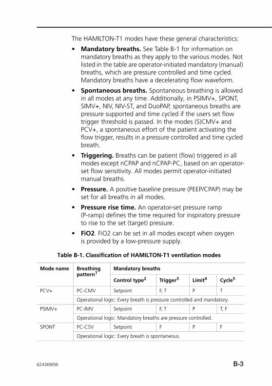
The HAMILTON-T1 modes have these general characteristics:
• Mandatory breaths. See Table B-1 for information on mandatory breaths as they apply to the various modes. Not listed in the table are operator-initiated mandatory (manual) breaths, which are pressure controlled and time cycled. Mandatory breaths have a decelerating flow waveform.
• Spontaneous breaths. Spontaneous breathing is allowed in all modes at any time. Additionally, in PSIMV+, SPONT, SIMV+, NIV, NIV-ST, and DuoPAP, spontaneous breaths are pressure supported and time cycled if the users set flow trigger threshold is passed. In the modes (S)CMV+ and PCV+, a spontaneous effort of the patient activating the flow trigger, results in a pressure controlled and time cycled breath.
• Triggering. Breaths can be patient (flow) triggered in all modes except nCPAP and nCPAP-PC, based on an operator-set flow sensitivity. All modes permit operator-initiated manual breaths.
• Pressure. A positive baseline pressure (PEEP/CPAP) may be set for all breaths in all modes.
• Pressure rise time. An operator-set pressure ramp (P-ramp) defines the time required for inspiratory pressure to rise to the set (target) pressure.
• FiO2. FiO2 can be set in all modes except when oxygen is provided by a low-pressure supply.
Table B-1. Classification of HAMILTON-T1 ventilation modes
Mode name Breathing pattern1
Mandatory breaths
Control type2 Trigger3 Limit4 Cycle5
PCV+ PC-CMV Setpoint F, T P T
Operational logic: Every breath is pressure controlled and mandatory.
PSIMV+ PC-IMV Setpoint F, T P T, F
Operational logic: Mandatory breaths are pressure controlled.
SPONT PC-CSV Setpoint F P F
Operational logic: Every breath is spontaneous.
624369/06 B-3
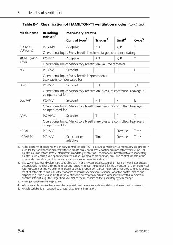
B Modes of ventilation
(S)CMV+ (APVcmv)
PC-CMV Adaptive F, T V, P T
Operational logic: Every breath is volume targeted and mandatory.
SIMV+ (APV-simv)
PC-IMV Adaptive F, T V, P T
Operational logic: Mandatory breaths are volume targeted.
NIV PC-CSV Setpoint F P F
Operational logic: Every breath is spontaneous. Leakage is compensated for.
NIV-ST PC-IMV Setpoint F, T P T, F
Operational logic: Mandatory breaths are pressure controlled. Leakage is compensated for.
DuoPAP PC-IMV Setpoint F, T P F, T
Operational logic: Mandatory breaths are pressure controlled. Leakage is compensated for.
APRV PC-APRV Setpoint T P T
Operational logic: Mandatory breaths are pressure controlled. Leakage is compensated for.
nCPAP PC-IMV --- --- Pressure Time
nCPAP-PC PC-IMV Set-point or adaptive
Time Pressure Time
1. A designator that combines the primary control variable (PC = pressure control) for the mandatory breaths (or in CSV, for the spontaneous breaths) with the breath sequence (CMV = continuous mandatory ventil ation – all breaths are mandatory, IMV = intermittent mandatory ventilation – spontaneous breaths between mandatory breaths, CSV = continuous spontaneous ventilation –all breaths are spontaneous). The control variable is the independent variable that the ventilator manipulates to cause inspiration.
2. The way pressure and volume are controlled within or between breaths. Setpoint means the ventilator output automatically matches a constant, unvarying, operator preset input value (like the production of a constant inspi-ratory pressure or tidal volume from breath to breath). Optimum is a control scheme that uses automatic adjust-ment of setpoints to optimize other variables as respiratory mechanics change. Adaptive control means one setpoint (e.g., the pressure limit) of the ventilator is automatically adjusted over several breaths to maintain another setpoint (e.g., the target tidal volume) as the mechanics of the respiratory system change.
3. A trigger variable starts inspiration.4. A limit variable can reach and maintain a preset level before inspiration ends but it does not end inspiration.5. A cycle variable is a measured parameter used to end inspiration.
Table B-1. Classification of HAMILTON-T1 ventilation modes (continued)
Mode name Breathing pattern1
Mandatory breaths
Control type2 Trigger3 Limit4 Cycle5
B-4 624369/06
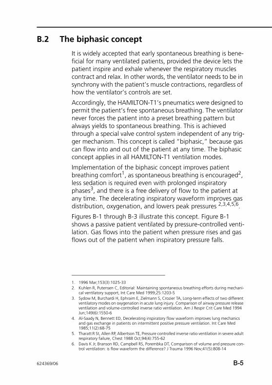
B.2 The biphasic concept
It is widely accepted that early spontaneous breathing is bene-ficial for many ventilated patients, provided the device lets the patient inspire and exhale whenever the respiratory muscles contract and relax. In other words, the ventilator needs to be in synchrony with the patient’s muscle contractions, regardless of how the ventilator’s controls are set.
Accordingly, the HAMILTON-T1’s pneumatics were designed to permit the patient’s free spontaneous breathing. The ventilator never forces the patient into a preset breathing pattern but always yields to spontaneous breathing. This is achieved through a special valve control system independent of any trig-ger mechanism. This concept is called “biphasic,” because gas can flow into and out of the patient at any time. The biphasic concept applies in all HAMILTON-T1 ventilation modes.
Implementation of the biphasic concept improves patient breathing comfort1, as spontaneous breathing is encouraged2, less sedation is required even with prolonged inspiratory phases3, and there is a free delivery of flow to the patient at any time. The decelerating inspiratory waveform improves gas distribution, oxygenation, and lowers peak pressures 2,3,4,5,6.
Figures B-1 through B-3 illustrate this concept. Figure B-1 shows a passive patient ventilated by pressure-controlled venti-lation. Gas flows into the patient when pressure rises and gas flows out of the patient when inspiratory pressure falls.
1. 1996 Mar;153(3):1025-332. Kuhlen R, Putensen C, Editorial: Maintaining spontaneous breathing efforts during mechani-
cal ventilatory support, Int Care Med 1999;25:1203-53. Sydow M, Burchardi H, Ephraim E, Zielmann S, Crozier TA, Long-term effects of two different
ventilatory modes on oxygenation in acute lung injury. Comparison of airway pressure release ventilation and volume-controlled inverse ratio ventilation. Am J Respir Crit Care Med 1994 Jun;149(6):1550-6
4. Al-Saady N, Bennett ED, Decelerating inspiratory flow waveform improves lung mechanics and gas exchange in patients on intermittent positive pressure ventilation. Int Care Med 1985;11(2):68-75
5. Tharatt R St, Allen RP, Albertson TE, Pressure controlled inverse ratio ventilation in severe adult respiratory failure, Chest 1988 Oct;94(4):755-62
6. Davis K Jr, Branson RD, Campbell RS, Porembka DT, Comparison of volume and pressure con-trol ventilation: is flow waveform the difference? J Trauma 1996 Nov;41(5):808-14
624369/06 B-5
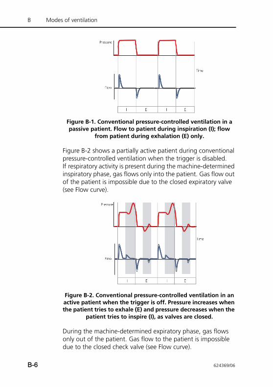
B Modes of ventilation
Figure B-1. Conventional pressure-controlled ventilation in a passive patient. Flow to patient during inspiration (I); flow
from patient during exhalation (E) only.
Figure B-2 shows a partially active patient during conventional pressure-controlled ventilation when the trigger is disabled. If respiratory activity is present during the machine-determined inspiratory phase, gas flows only into the patient. Gas flow out of the patient is impossible due to the closed expiratory valve (see Flow curve).
Figure B-2. Conventional pressure-controlled ventilation in an active patient when the trigger is off. Pressure increases when the patient tries to exhale (E) and pressure decreases when the
patient tries to inspire (I), as valves are closed.
During the machine-determined expiratory phase, gas flows only out of the patient. Gas flow to the patient is impossible due to the closed check valve (see Flow curve).
B-6 624369/06
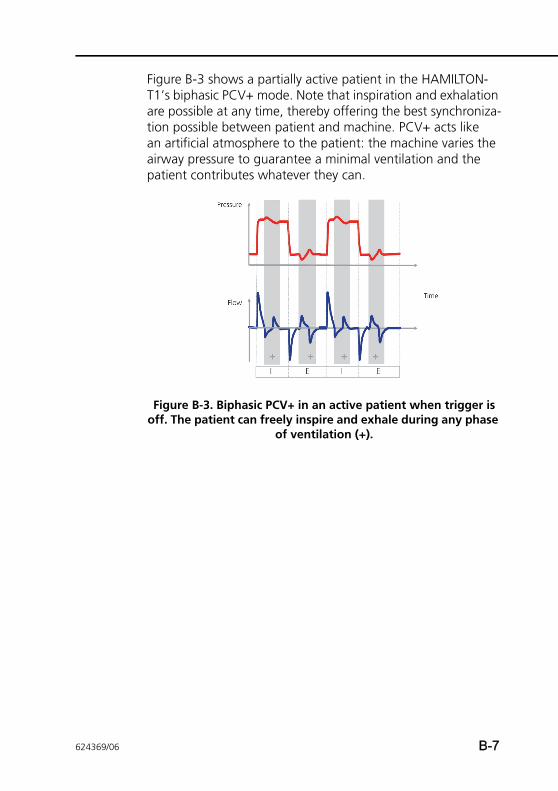
Figure B-3 shows a partially active patient in the HAMILTON-T1’s biphasic PCV+ mode. Note that inspiration and exhalation are possible at any time, thereby offering the best synchroniza-tion possible between patient and machine. PCV+ acts like an artificial atmosphere to the patient: the machine varies the airway pressure to guarantee a minimal ventilation and the patient contributes whatever they can.
Figure B-3. Biphasic PCV+ in an active patient when trigger is off. The patient can freely inspire and exhale during any phase
of ventilation (+).
624369/06 B-7
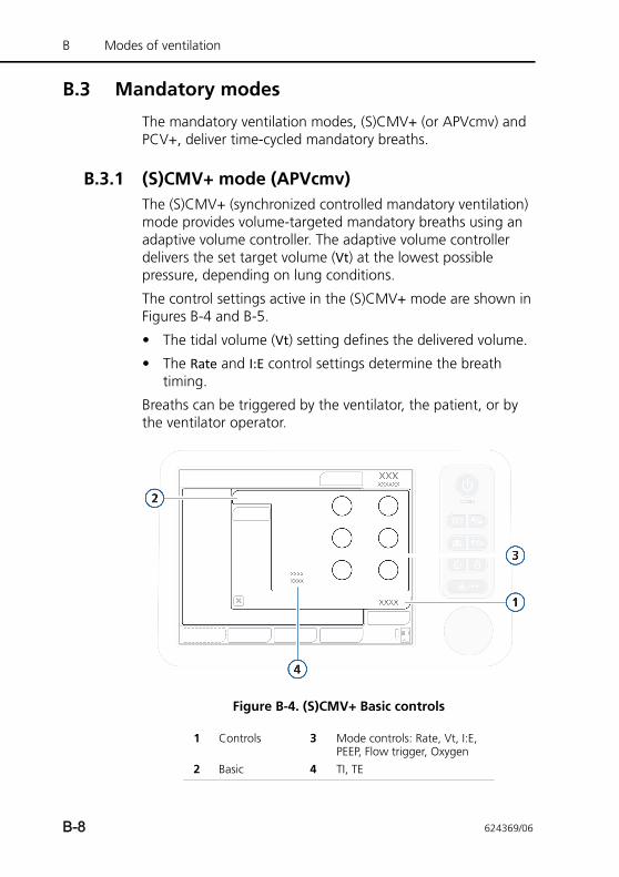
B Modes of ventilation
B.3 Mandatory modes
The mandatory ventilation modes, (S)CMV+ (or APVcmv) and PCV+, deliver time-cycled mandatory breaths.
B.3.1 (S)CMV+ mode (APVcmv)The (S)CMV+ (synchronized controlled mandatory ventilation) mode provides volume-targeted mandatory breaths using an adaptive volume controller. The adaptive volume controller delivers the set target volume (Vt) at the lowest possible pressure, depending on lung conditions.
The control settings active in the (S)CMV+ mode are shown in Figures B-4 and B-5.
• The tidal volume (Vt) setting defines the delivered volume.
• The Rate and I:E control settings determine the breath timing.
Breaths can be triggered by the ventilator, the patient, or by the ventilator operator.
Figure B-4. (S)CMV+ Basic controls
1 Controls 3 Mode controls: Rate, Vt, I:E, PEEP, Flow trigger, Oxygen
2 Basic 4 TI, TE
B-8 624369/06
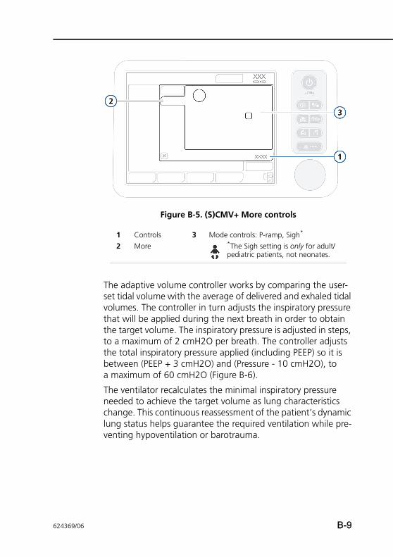
Figure B-5. (S)CMV+ More controls
The adaptive volume controller works by comparing the user-set tidal volume with the average of delivered and exhaled tidal volumes. The controller in turn adjusts the inspiratory pressure that will be applied during the next breath in order to obtain the target volume. The inspiratory pressure is adjusted in steps, to a maximum of 2 cmH2O per breath. The controller adjusts the total inspiratory pressure applied (including PEEP) so it is between (PEEP + 3 cmH2O) and (Pressure - 10 cmH2O), to a maximum of 60 cmH2O (Figure B-6).
The ventilator recalculates the minimal inspiratory pressure needed to achieve the target volume as lung characteristics change. This continuous reassessment of the patient’s dynamic lung status helps guarantee the required ventilation while pre-venting hypoventilation or barotrauma.
1 Controls 3 Mode controls: P-ramp, Sigh*
2 More *The Sigh setting is only for adult/pediatric patients, not neonates.
624369/06 B-9
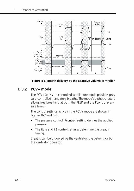
B Modes of ventilation
Figure B-6. Breath delivery by the adaptive volume controller
B.3.2 PCV+ modeThe PCV+ (pressure-controlled ventilation) mode provides pres-sure-controlled mandatory breaths. The mode’s biphasic nature allows free breathing at both the PEEP and the Pcontrol pres-sure levels.
The control settings active in the PCV+ mode are shown in Figures B-7 and B-8.
• The pressure control (Pcontrol) setting defines the applied pressure.
• The Rate and I:E control settings determine the breath timing.
Breaths can be triggered by the ventilator, the patient, or by the ventilator operator.
B-10 624369/06
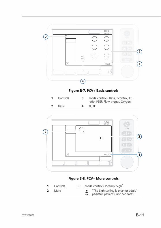
Figure B-7. PCV+ Basic controls
Figure B-8. PCV+ More controls
1 Controls 3 Mode controls: Rate, Pcontrol, I:E ratio, PEEP, Flow trigger, Oxygen
2 Basic 4 TI, TE
1 Controls 3 Mode controls: P-ramp, Sigh*
2 More *The Sigh setting is only for adult/pediatric patients, not neonates.
624369/06 B-11
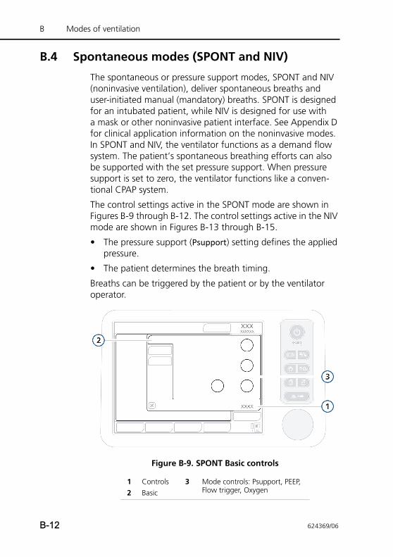
B Modes of ventilation
B.4 Spontaneous modes (SPONT and NIV)
The spontaneous or pressure support modes, SPONT and NIV (noninvasive ventilation), deliver spontaneous breaths and user-initiated manual (mandatory) breaths. SPONT is designed for an intubated patient, while NIV is designed for use with a mask or other noninvasive patient interface. See Appendix D for clinical application information on the noninvasive modes. In SPONT and NIV, the ventilator functions as a demand flow system. The patient’s spontaneous breathing efforts can also be supported with the set pressure support. When pressure support is set to zero, the ventilator functions like a conven-tional CPAP system.
The control settings active in the SPONT mode are shown in Figures B-9 through B-12. The control settings active in the NIV mode are shown in Figures B-13 through B-15.
• The pressure support (Psupport) setting defines the applied pressure.
• The patient determines the breath timing.
Breaths can be triggered by the patient or by the ventilator operator.
Figure B-9. SPONT Basic controls
1 Controls 3 Mode controls: Psupport, PEEP, Flow trigger, Oxygen2 Basic
B-12 624369/06
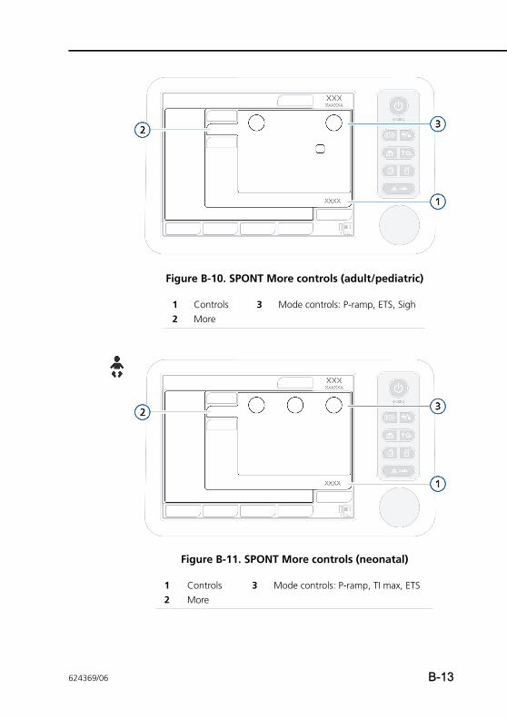
Figure B-10. SPONT More controls (adult/pediatric)
Figure B-11. SPONT More controls (neonatal)
1 Controls 3 Mode controls: P-ramp, ETS, Sigh2 More
1 Controls 3 Mode controls: P-ramp, TI max, ETS2 More
624369/06 B-13
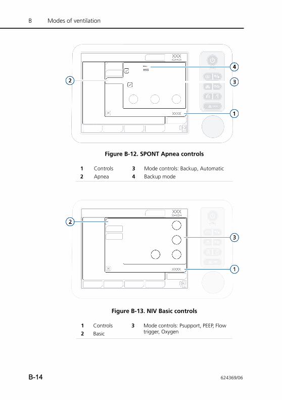
B Modes of ventilation
Figure B-12. SPONT Apnea controls
Figure B-13. NIV Basic controls
1 Controls 3 Mode controls: Backup, Automatic2 Apnea 4 Backup mode
1 Controls 3 Mode controls: Psupport, PEEP, Flow trigger, Oxygen2 Basic
B-14 624369/06
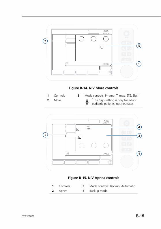
Figure B-14. NIV More controls
Figure B-15. NIV Apnea controls
1 Controls 3 Mode controls: P-ramp, TI max, ETS, Sigh*
2 More *The Sigh setting is only for adult/pediatric patients, not neonates.
1 Controls 3 Mode controls: Backup, Automatic2 Apnea 4 Backup mode
624369/06 B-15
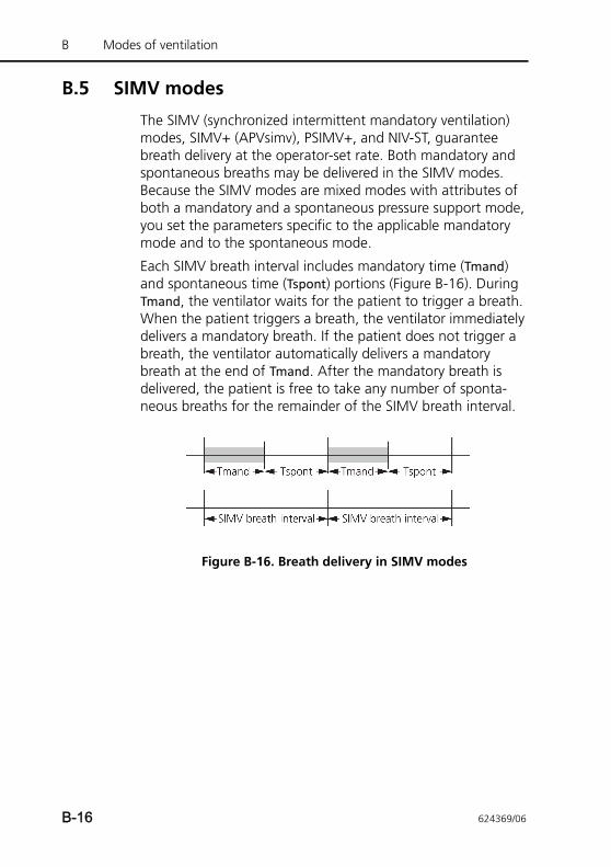
B Modes of ventilation
B.5 SIMV modes
The SIMV (synchronized intermittent mandatory ventilation) modes, SIMV+ (APVsimv), PSIMV+, and NIV-ST, guarantee breath delivery at the operator-set rate. Both mandatory and spontaneous breaths may be delivered in the SIMV modes. Because the SIMV modes are mixed modes with attributes of both a mandatory and a spontaneous pressure support mode, you set the parameters specific to the applicable mandatory mode and to the spontaneous mode.
Each SIMV breath interval includes mandatory time (Tmand) and spontaneous time (Tspont) portions (Figure B-16). During Tmand, the ventilator waits for the patient to trigger a breath. When the patient triggers a breath, the ventilator immediately delivers a mandatory breath. If the patient does not trigger a breath, the ventilator automatically delivers a mandatory breath at the end of Tmand. After the mandatory breath is delivered, the patient is free to take any number of sponta-neous breaths for the remainder of the SIMV breath interval.
Figure B-16. Breath delivery in SIMV modes
B-16 624369/06
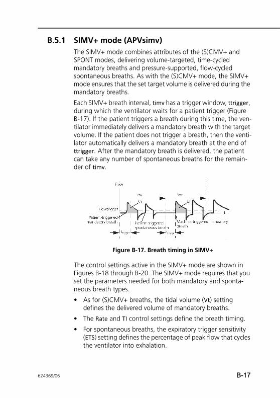
B.5.1 SIMV+ mode (APVsimv)The SIMV+ mode combines attributes of the (S)CMV+ and SPONT modes, delivering volume-targeted, time-cycled mandatory breaths and pressure-supported, flow-cycled spontaneous breaths. As with the (S)CMV+ mode, the SIMV+ mode ensures that the set target volume is delivered during the mandatory breaths.
Each SIMV+ breath interval, timv has a trigger window, ttrigger, during which the ventilator waits for a patient trigger (Figure B-17). If the patient triggers a breath during this time, the ven-tilator immediately delivers a mandatory breath with the target volume. If the patient does not trigger a breath, then the venti-lator automatically delivers a mandatory breath at the end of ttrigger. After the mandatory breath is delivered, the patient can take any number of spontaneous breaths for the remain-der of timv.
Figure B-17. Breath timing in SIMV+
The control settings active in the SIMV+ mode are shown in Figures B-18 through B-20. The SIMV+ mode requires that you set the parameters needed for both mandatory and sponta-neous breath types.
• As for (S)CMV+ breaths, the tidal volume (Vt) setting defines the delivered volume of mandatory breaths.
• The Rate and TI control settings define the breath timing.
• For spontaneous breaths, the expiratory trigger sensitivity (ETS) setting defines the percentage of peak flow that cycles the ventilator into exhalation.
624369/06 B-17
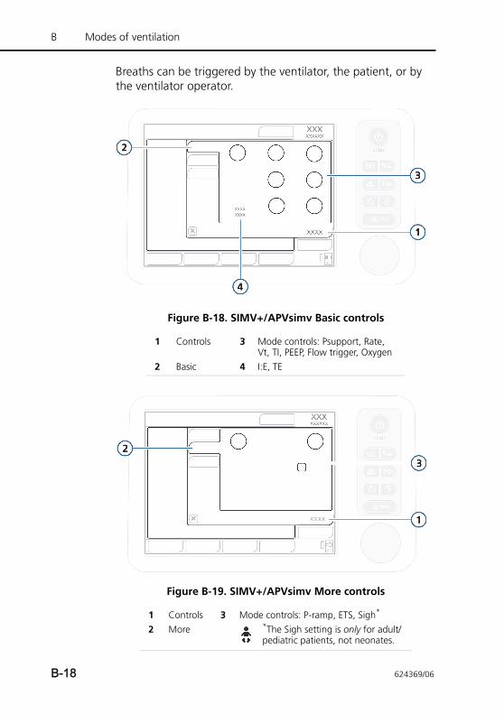
B Modes of ventilation
Breaths can be triggered by the ventilator, the patient, or by the ventilator operator.
Figure B-18. SIMV+/APVsimv Basic controls
Figure B-19. SIMV+/APVsimv More controls
1 Controls 3 Mode controls: Psupport, Rate, Vt, TI, PEEP, Flow trigger, Oxygen
2 Basic 4 I:E, TE
1 Controls 3 Mode controls: P-ramp, ETS, Sigh*
2 More *The Sigh setting is only for adult/pediatric patients, not neonates.
B-18 624369/06
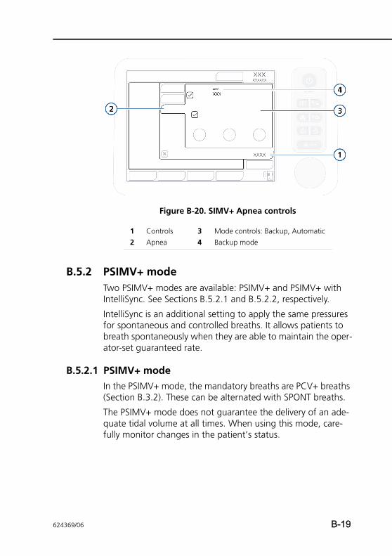
Figure B-20. SIMV+ Apnea controls
B.5.2 PSIMV+ modeTwo PSIMV+ modes are available: PSIMV+ and PSIMV+ with IntelliSync. See Sections B.5.2.1 and B.5.2.2, respectively.
IntelliSync is an additional setting to apply the same pressures for spontaneous and controlled breaths. It allows patients to breath spontaneously when they are able to maintain the oper-ator-set guaranteed rate.
B.5.2.1 PSIMV+ modeIn the PSIMV+ mode, the mandatory breaths are PCV+ breaths (Section B.3.2). These can be alternated with SPONT breaths.
The PSIMV+ mode does not guarantee the delivery of an ade-quate tidal volume at all times. When using this mode, care-fully monitor changes in the patient’s status.
1 Controls 3 Mode controls: Backup, Automatic2 Apnea 4 Backup mode
624369/06 B-19
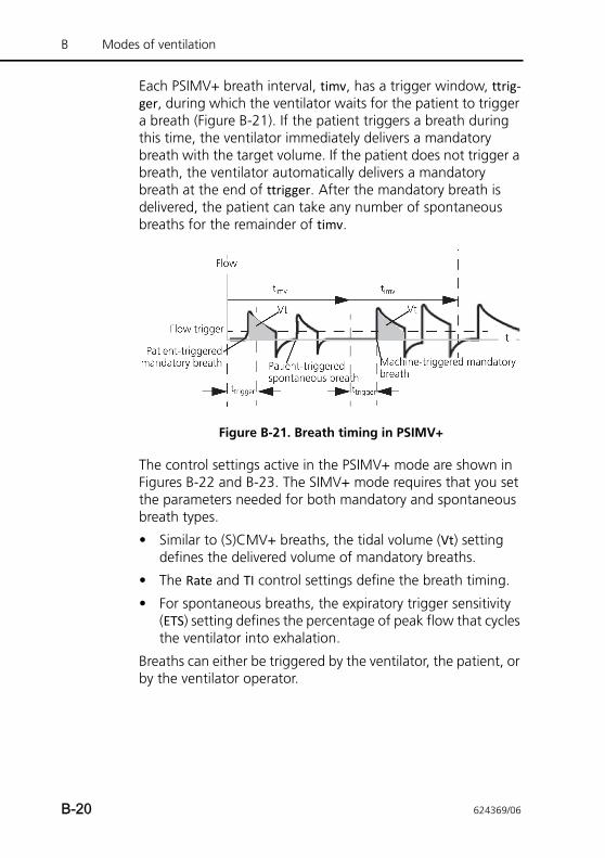
B Modes of ventilation
Each PSIMV+ breath interval, timv, has a trigger window, ttrig-ger, during which the ventilator waits for the patient to trigger a breath (Figure B-21). If the patient triggers a breath during this time, the ventilator immediately delivers a mandatory breath with the target volume. If the patient does not trigger a breath, the ventilator automatically delivers a mandatory breath at the end of ttrigger. After the mandatory breath is delivered, the patient can take any number of spontaneous breaths for the remainder of timv.
Figure B-21. Breath timing in PSIMV+
The control settings active in the PSIMV+ mode are shown in Figures B-22 and B-23. The SIMV+ mode requires that you set the parameters needed for both mandatory and spontaneous breath types.
• Similar to (S)CMV+ breaths, the tidal volume (Vt) setting defines the delivered volume of mandatory breaths.
• The Rate and TI control settings define the breath timing.
• For spontaneous breaths, the expiratory trigger sensitivity (ETS) setting defines the percentage of peak flow that cycles the ventilator into exhalation.
Breaths can either be triggered by the ventilator, the patient, or by the ventilator operator.
B-20 624369/06
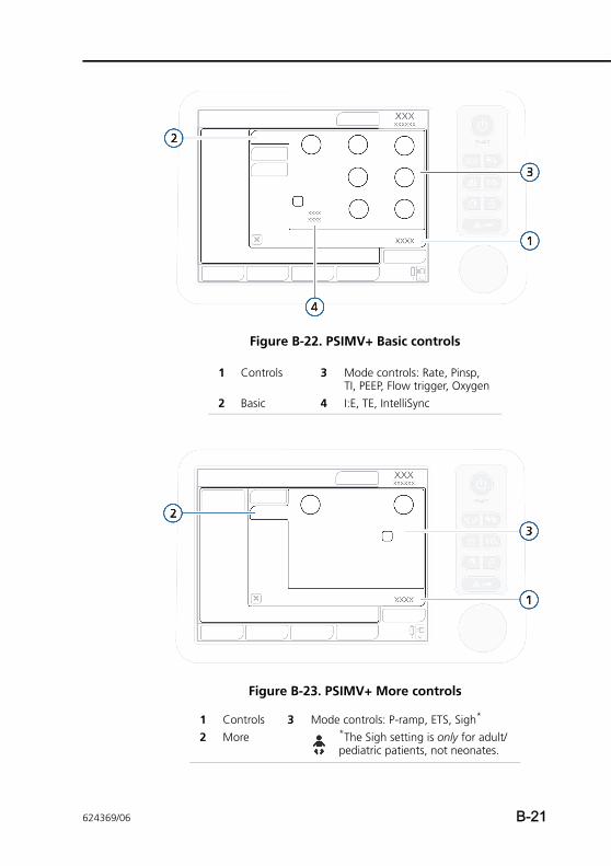
Figure B-22. PSIMV+ Basic controls
Figure B-23. PSIMV+ More controls
1 Controls 3 Mode controls: Rate, Pinsp, TI, PEEP, Flow trigger, Oxygen
2 Basic 4 I:E, TE, IntelliSync
1 Controls 3 Mode controls: P-ramp, ETS, Sigh*
2 More *The Sigh setting is only for adult/pediatric patients, not neonates.
624369/06 B-21
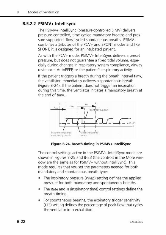
B Modes of ventilation
B.5.2.2 PSIMV+ IntellisyncThe PSIMV+ IntelliSync (pressure-controlled SIMV) delivers pressure-controlled, time-cycled mandatory breaths and pres-sure-supported, flow-cycled spontaneous breaths. PSIMV+ combines attributes of the PCV+ and SPONT modes and like SPONT, it is designed for an intubated patient.
As with the PCV+ mode, PSIMV+ IntelliSync delivers a preset pressure, but does not guarantee a fixed tidal volume, espe-cially during changes in respiratory system compliance, airway resistance, AutoPEEP, or the patient’s respiratory activity.
If the patient triggers a breath during the breath interval timv, the ventilator immediately delivers a spontaneous breath (Figure B-24). If the patient does not trigger an inspiration during this time, the ventilator initiates a mandatory breath at the end of timv.
Figure B-24. Breath timing in PSIMV+ IntelliSync
The control settings active in the PSIMV+ IntelliSync mode are shown in Figures B-25 and B-23 (the controls in the More win-dow are the same as for PSIMV+ without IntelliSync). This mode requires that you set the parameters needed for both mandatory and spontaneous breath types.
• The inspiratory pressure (Pinsp) setting defines the applied pressure for both mandatory and spontaneous breaths.
• The Rate and TI (inspiratory time) control settings define the breath timing.
• For spontaneous breaths, the expiratory trigger sensitivity (ETS) setting defines the percentage of peak flow that cycles the ventilator into exhalation.
B-22 624369/06
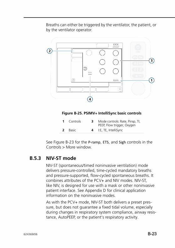
Breaths can either be triggered by the ventilator, the patient, or by the ventilator operator.
Figure B-25. PSIMV+ IntelliSync basic controls
See Figure B-23 for the P-ramp, ETS, and Sigh controls in the Controls > More window.
B.5.3 NIV-ST modeNIV-ST (spontaneous/timed noninvasive ventilation) mode delivers pressure-controlled, time-cycled mandatory breaths and pressure-supported, flow-cycled spontaneous breaths. It combines attributes of the PCV+ and NIV modes. NIV-ST, like NIV, is designed for use with a mask or other noninvasive patient interface. See Appendix D for clinical application information on the noninvasive modes.
As with the PCV+ mode, NIV-ST both delivers a preset pres-sure, but does not guarantee a fixed tidal volume, especially during changes in respiratory system compliance, airway resis-tance, AutoPEEP, or the patient’s respiratory activity.
1 Controls 3 Mode controls: Rate, Pinsp, TI, PEEP, Flow trigger, Oxygen
2 Basic 4 I:E, TE, IntelliSync
624369/06 B-23
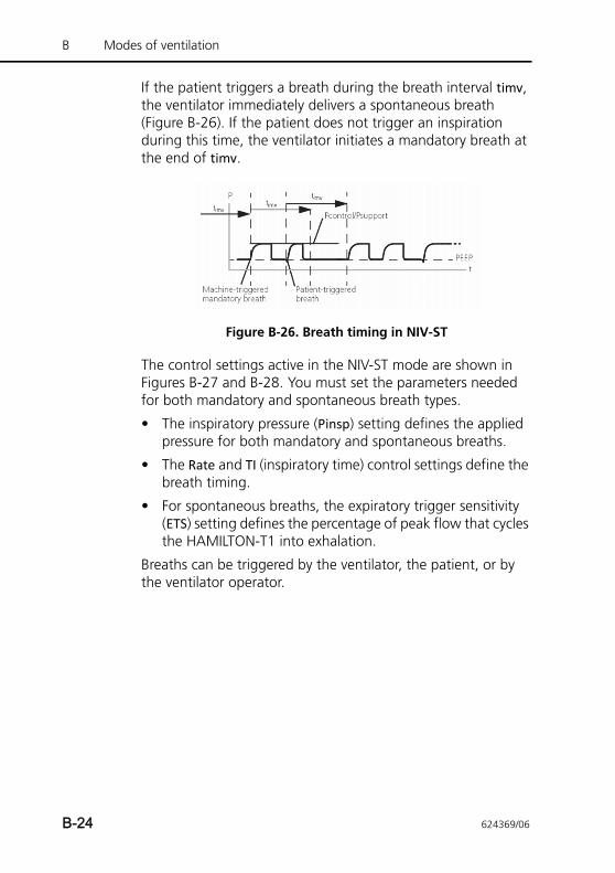
B Modes of ventilation
If the patient triggers a breath during the breath interval timv, the ventilator immediately delivers a spontaneous breath (Figure B-26). If the patient does not trigger an inspiration during this time, the ventilator initiates a mandatory breath at the end of timv.
Figure B-26. Breath timing in NIV-ST
The control settings active in the NIV-ST mode are shown in Figures B-27 and B-28. You must set the parameters needed for both mandatory and spontaneous breath types.
• The inspiratory pressure (Pinsp) setting defines the applied pressure for both mandatory and spontaneous breaths.
• The Rate and TI (inspiratory time) control settings define the breath timing.
• For spontaneous breaths, the expiratory trigger sensitivity (ETS) setting defines the percentage of peak flow that cycles the HAMILTON-T1 into exhalation.
Breaths can be triggered by the ventilator, the patient, or by the ventilator operator.
B-24 624369/06
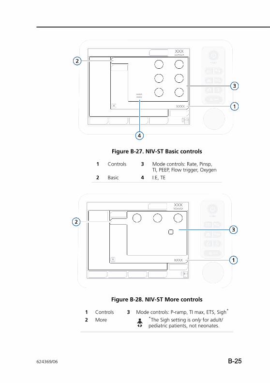
Figure B-27. NIV-ST Basic controls
Figure B-28. NIV-ST More controls
1 Controls 3 Mode controls: Rate, Pinsp, TI, PEEP, Flow trigger, Oxygen
2 Basic 4 I:E, TE
1 Controls 3 Mode controls: P-ramp, TI max, ETS, Sigh*
2 More *The Sigh setting is only for adult/pediatric patients, not neonates.
624369/06 B-25
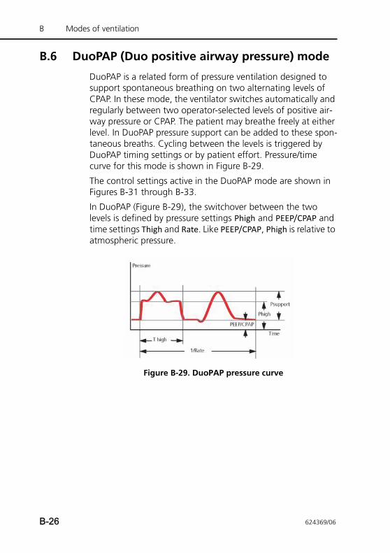
B Modes of ventilation
B.6 DuoPAP (Duo positive airway pressure) mode
DuoPAP is a related form of pressure ventilation designed to support spontaneous breathing on two alternating levels of CPAP. In these mode, the ventilator switches automatically and regularly between two operator-selected levels of positive air-way pressure or CPAP. The patient may breathe freely at either level. In DuoPAP pressure support can be added to these spon-taneous breaths. Cycling between the levels is triggered by DuoPAP timing settings or by patient effort. Pressure/time curve for this mode is shown in Figure B-29.
The control settings active in the DuoPAP mode are shown in Figures B-31 through B-33.
In DuoPAP (Figure B-29), the switchover between the two levels is defined by pressure settings Phigh and PEEP/CPAP and time settings Thigh and Rate. Like PEEP/CPAP, Phigh is relative to atmospheric pressure.
Figure B-29. DuoPAP pressure curve
B-26 624369/06
B.6.1 The many faces of DuoPAPWith different patients and with different combinations of control settings, DuoPAP can be made to resemble a variety of conventional ventilation modes.
At conventional settings and in the absence of spontaneous breathing, DuoPAP resembles PCV+. As you decrease the rate, keeping Thigh short relative to the time at the lower pressure level, the modes look more like PSIMV+, with spontaneous breaths following mandatory breaths. If Thigh almost set to breath cycle time with just enough time at the low level to allow full or near-full exhalation, these mode looks like APRV. By setting PEEP/CPAP and Phigh equal to one another and adjusting other parameters, the mode can be made to resem-ble SPONT.
B.6.2 Pressure support in DuoPAP breathsPressure support can be set to assist spontaneous breaths in DuoPAP, whether they occur at the PEEP/CPAP or Phigh level. Psupport is set relative to PEEP/CPAP the target pressure becomes PEEP/CPAP. That means that spontaneous breaths at the Phigh level are supported only when this target pressure is greater than Phigh. Figure B-30 (a) shows the situation where breaths at both the PEEP and Phigh level are pressure-sup-ported. Figure B-30 (b) shows the situation where only breaths at the PEEP/CPAP level are pressure-supported.
624369/06 B-27
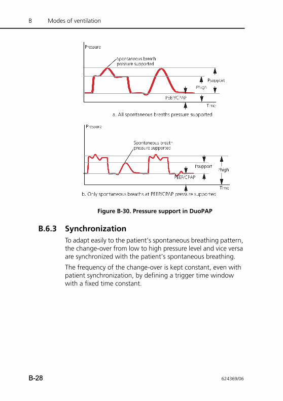
B Modes of ventilation
Figure B-30. Pressure support in DuoPAP
B.6.3 SynchronizationTo adapt easily to the patient’s spontaneous breathing pattern, the change-over from low to high pressure level and vice versa are synchronized with the patient’s spontaneous breathing.
The frequency of the change-over is kept constant, even with patient synchronization, by defining a trigger time window with a fixed time constant.
B-28 624369/06
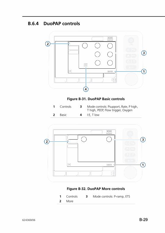
B.6.4 DuoPAP controls
Figure B-31. DuoPAP Basic controls
Figure B-32. DuoPAP More controls
1 Controls 3 Mode controls: Psupport, Rate, P high, T high, PEEP, Flow trigger, Oxygen
2 Basic 4 I:E, T low
1 Controls 3 Mode controls: P-ramp, ETS2 More
624369/06 B-29
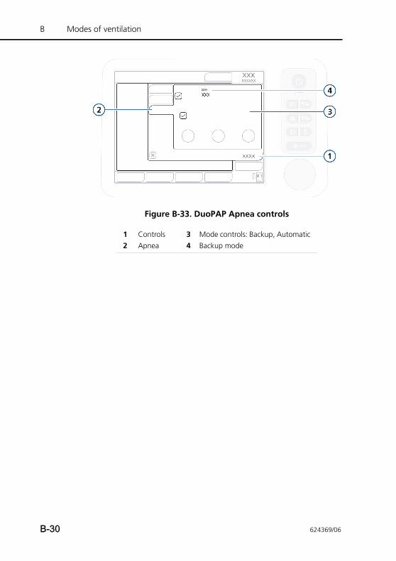
B Modes of ventilation
Figure B-33. DuoPAP Apnea controls
1 Controls 3 Mode controls: Backup, Automatic2 Apnea 4 Backup mode
B-30 624369/06
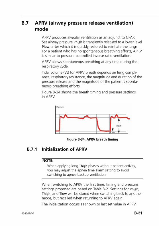
B.7 APRV (airway pressure release ventilation) mode
APRV produces alveolar ventilation as an adjunct to CPAP. Set airway pressure Phigh is transiently released to a lower level Plow, after which it is quickly restored to reinflate the lungs. For a patient who has no spontaneous breathing efforts, APRV is similar to pressure-controlled inverse ratio ventilation.
APRV allows spontaneous breathing at any time during the respiratory cycle.
Tidal volume (Vt) for APRV breath depends on lung compli-ance, respiratory resistance, the magnitude and duration of the pressure release and the magnitude of the patient’s sponta-neous breathing efforts.
Figure B-34 shows the breath timing and pressure settings in APRV.
Figure B-34. APRV breath timing
B.7.1 Initialization of APRV
NOTE:When applying long Thigh phases without patient activity, you may adjust the apnea time alarm setting to avoid switching to apnea backup ventilation.
When switching to APRV the first time, timing and pressure settings proposed are based on Table B-2. Settings for Phigh, Thigh, and Tlow will be stored when switching back to another mode, but recalled when returning to APRV again.
The initialization occurs as shown or last set value in APRV.
624369/06 B-31
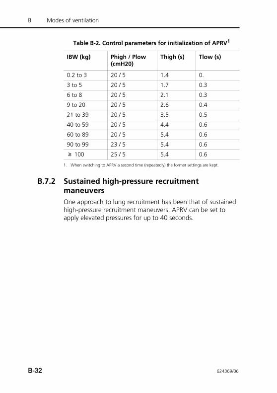
B Modes of ventilation
B.7.2 Sustained high-pressure recruitment maneuversOne approach to lung recruitment has been that of sustained high-pressure recruitment maneuvers. APRV can be set to apply elevated pressures for up to 40 seconds.
Table B-2. Control parameters for initialization of APRV1
IBW (kg) Phigh / Plow (cmH20)
Thigh (s) Tlow (s)
0.2 to 3 20 / 5 1.4 0.
3 to 5 20 / 5 1.7 0.3
6 to 8 20 / 5 2.1 0.3
9 to 20 20 / 5 2.6 0.4
21 to 39 20 / 5 3.5 0.5
40 to 59 20 / 5 4.4 0.6
60 to 89 20 / 5 5.4 0.6
90 to 99 23 / 5 5.4 0.6
≥ 100 25 / 5 5.4 0.6
1. When switching to APRV a second time (repeatedly) the former settings are kept.
B-32 624369/06
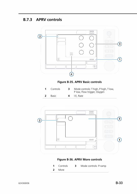
B.7.3 APRV controls
Figure B-35. APRV Basic controls
Figure B-36. APRV More controls
1 Controls 3 Mode controls: T high, P high, T low, P low, Flow trigger, Oxygen
2 Basic 4 I:E, Rate
1 Controls 3 Mode controls: P-ramp2 More
624369/06 B-33
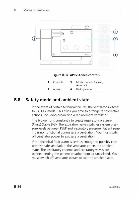
B Modes of ventilation
Figure B-37. APRV Apnea controls
B.8 Safety mode and ambient state
In the event of certain technical failures, the ventilator switches to SAFETY mode. This gives you time to arrange for corrective actions, including organizing a replacement ventilator.
The blower runs constantly to create inspiratory pressure (Pinsp) (Table B-3). The expiratory valve switches system pres-sure levels between PEEP and inspiratory pressure. Patient sens-ing is nonfunctional during safety ventilation. You must switch off ventilator power to exit safety ventilation.
If the technical fault alarm is serious enough to possibly com-promise safe ventilation, the ventilator enters the ambient state. The inspiratory channel and expiratory valves are opened, letting the patient breathe room air unassisted. You must switch off ventilator power to exit the ambient state.
1 Controls 3 Mode controls: Backup, Automatic
2 Apnea 4 Backup mode
B-34 624369/06
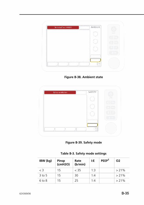
Figure B-38. Ambient state
Figure B-39. Safety mode
Table B-3. Safety mode settings
IBW (kg) Pinsp (cmH2O)
Rate (b/min)
I:E PEEP1 O2
< 3 15 < 35 1:3 > 21%
3 to 5 15 30 1:4 > 21%
6 to 8 15 25 1:4 > 21%
624369/06 B-35
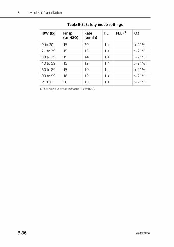
B Modes of ventilation
9 to 20 15 20 1:4 > 21%
21 to 29 15 15 1:4 > 21%
30 to 39 15 14 1:4 > 21%
40 to 59 15 12 1:4 > 21%
60 to 89 15 10 1:4 > 21%
90 to 99 18 10 1:4 > 21%
≥ 100 20 10 1:4 > 21%
1. Set PEEP plus circuit resistance (+ 5 cmH2O).
Table B-3. Safety mode settings
IBW (kg) Pinsp (cmH2O)
Rate (b/min)
I:E PEEP1 O2
B-36 624369/06
CAPPENDIX
ASV, adaptive support ventilation
C.1 Introduction C-2
C.2 ASV use in clinical practice C-3
C.3 Detailed functional description of ASV C-15
C.3.1 Normal minute ventilation C-15
C.3.2 Targeted minute ventilation C-16
C.3.3 Lung-protective rules strategy C-17
C.3.4 Optimal breath pattern C-20
C.3.5 Dynamic adjustment of lung protection C-24
C.3.6 Dynamic adjustment of optimal breath pattern C-24
C.4 Minimum work of breathing (Otis’ equation) C-25
C.5 ASV technical data C-28
C.6 ASV startup C-30
C.7 References C-31
624369/06 C-1
C ASV, adaptive support ventilation
C.1 Introduction
WARNINGThis appendix describes ASV as it is implemented in the HAMILTON-T1. It does not replace the clinical judgment of a physician and is not to be used for clinical decision making.
NOTE:ASV is not supported in neonatal ventilation.
In 1977, Hewlett et al. introduced mandatory minute volume (MMV). “The basic concept is that the system is supplied with a metered, preselected minute volume of fresh gas, from which the patient breathes as much as he is able, the remain-der being delivered to him via a ventilator. Thus the patient is obliged to breathe, one way or the other, a Mandatory Minute Volume MMV” (Hewlett 1977).
Since then, many ventilators have included versions of MMV under different names. However, all commercially available MMV algorithms have clear limitations, which lead to certain risks for the patient (Quan 1990). These include rapid shallow breathing, inadvertent PEEP creation, excessive dead space ventilation, and inadvertent wrong operator settings due to very complicated use.
Adaptive Support Ventilation (ASV) was designed to minimize those risks and limitations. ASV maintains an operator-preset, minimum minute ventilation independent of the patient‘s activity. The target breathing pattern (tidal volume and rate) is calculated using Otis’ equation, based on the assumption that if the optimal breath pattern results in the least work of breath-ing, it also results in the least amount of ventilator-applied inspiratory pressure when the patient is passive. Inspiratory pressure and machine rate are then adjusted to meet the targets. A lung protection strategy ensures ASV’s safety.
C-2 624369/06
In contrast to MMV, ASV attempts to guide the patient using a favorable breathing pattern and avoids potentially detrimental patterns like rapid shallow breathing, excessive dead space ventilation, breath stacking (inadvertent PEEP), and excessively large breaths.
Contrary to some opinions, ASV does not eliminate the need for a physician or clinician. However, ASV alleviates the need for tedious tasks and laborious readjustments of the ventilator; thus, it is a modern tool for the clinician. As such, ASV does not make clinical decisions. ASV executes a general command from the clinician and the clinician can modify it. This command can be summarized, where the modifiable parts are in bold:
Maintain a present minimum minute ventilation,
• take spontaneous breathing into account,
• prevent tachypnea,
• prevent AutoPEEP,
• prevent excessive dead space ventilation,
• fully ventilate in apnea or low respiratory drive,
• give control to the patient if breathing activity is okay, and
• all this without exceeding a plateau pressure of 10 cmH2O below the upper pressure limit.
This appendix explains in practical terms how to use ASV at the patient’s bedside and provides a detailed functional descrip-tion. Since Otis’ equation (Otis 1950) is the cornerstone of the optimal-breath pattern calculation, this equation is included and described. A table of detailed technical specifications and pertinent references is also given.
C.2 ASV use in clinical practice
ASV does not require a special sequence of actions. It is used in much the same way as are conventional modes of ventilation. Figure C-1 summarizes how to use ASV, while the subsequent sections explain it in detail. Figures C-2 and C-3 show the con-trol settings active in the ASV mode.
624369/06 C-3
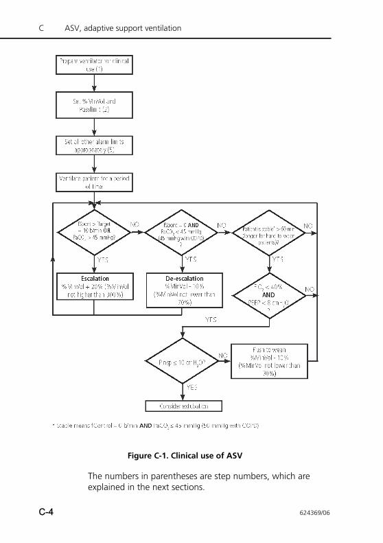
C ASV, adaptive support ventilation
Figure C-1. Clinical use of ASV
The numbers in parentheses are step numbers, which are explained in the next sections.
C-4 624369/06
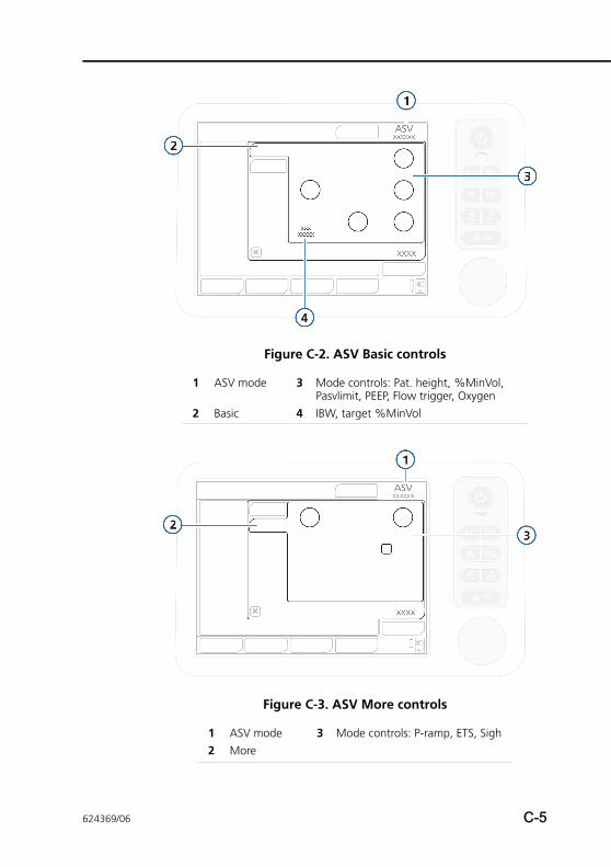
Figure C-2. ASV Basic controls
Figure C-3. ASV More controls
1 ASV mode 3 Mode controls: Pat. height, %MinVol, Pasvlimit, PEEP, Flow trigger, Oxygen
2 Basic 4 IBW, target %MinVol
1 ASV mode 3 Mode controls: P-ramp, ETS, Sigh2 More
624369/06 C-5
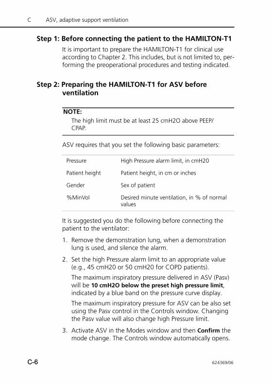
C ASV, adaptive support ventilation
Step 1: Before connecting the patient to the HAMILTON-T1It is important to prepare the HAMILTON-T1 for clinical use according to Chapter 2. This includes, but is not limited to, per-forming the preoperational procedures and testing indicated.
Step 2: Preparing the HAMILTON-T1 for ASV before ventilation
NOTE:The high limit must be at least 25 cmH2O above PEEP/CPAP.
ASV requires that you set the following basic parameters:
It is suggested you do the following before connecting the patient to the ventilator:
1. Remove the demonstration lung, when a demonstration lung is used, and silence the alarm.
2. Set the high Pressure alarm limit to an appropriate value (e.g., 45 cmH20 or 50 cmH20 for COPD patients).
The maximum inspiratory pressure delivered in ASV (Pasv) will be 10 cmH2O below the preset high pressure limit, indicated by a blue band on the pressure curve display.
The maximum inspiratory pressure for ASV can be also set using the Pasv control in the Controls window. Changing the Pasv value will also change high Pressure limit.
3. Activate ASV in the Modes window and then Confirm the mode change. The Controls window automatically opens.
Pressure High Pressure alarm limit, in cmH20
Patient height Patient height, in cm or inches
Gender Sex of patient
%MinVol Desired minute ventilation, in % of normal values
C-6 624369/06
4. Specify the following control settings:
– Patient height
– Gender
– %MinVol. A logical starting point is a %MinVol that will result in the same minute volume as a previous mode, if applicable. The %MinVol for a normal patient might be 100%; for a COPD patient, 90%; for an ARDS patient, 120%; and for other patients, 110%. Add 20% if body temperature > 38.5°C (101.3°F) and 5% per 500 m (1640 ft) above sea level.
– Trigger. Suggested settings are a Flowtrigger of 2 l/min; or you can leave the previous patient trigger method and sensitivity, if applicable.
– ETS. A suggested setting is 25% (40% for a COPD patient); or you can you can leave this unchanged, if applicable.
– Other settings. Set PEEP/CPAP and Oxygen values according to clinical requirements. You can leave the P-ramp setting at its standard value unless clinical judg-ment calls for adjustment. To set it, see Chapter 4.
5. Confirm the settings.
6. Connect the patient to the ventilator if applicable. This will initiate three test breaths.
624369/06 C-7
C ASV, adaptive support ventilation
Step 3: Compensation for changes in apparatus dead space
NOTE:Changes in alveolar dead space due to ventilation/perfu-sion mismatch must be compensated via the %MinVol con-trol.
The HAMILTON-T1 calculates the (anatomical or “series”) dead space based on the IBW calculated from the patient height input. Dead space is calculated as 2.2 ml per kg (1 ml per lb). This dead space is a nominal value that is valid, on average, for intubated patients whose endotracheal tube is connected to the Y-piece of the ventilator by a standard catheter mount. If this dead space is altered by an artificial airway configuration such as a the use of a heat and moisture exchanging filter (HMEF) or nonstandard tubing, modify the Patient height set-ting accordingly to take into account the added or removed dead space.
Consider the following when compensating dead space:
• A shorter-than-standard endotracheal or tracheostomy tube probably does not require compensation.
• Different sizes of endotracheal tube probably do not require compensation.
• A much longer-than-normal catheter mount may require compensation.
• A bacterial filter or an HMEF may require compensation. The volume of these devices, for an adult, is on average 50 to 60 ml, but may be as high as 95 ml (Mallinckrodt Hygroster). For an HMEF, a simple rule of thumb is to add 10% to the IBW (by adjusting the Patient height control).
C-8 624369/06
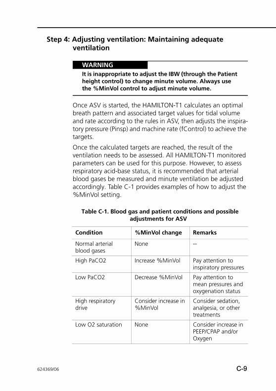
Step 4: Adjusting ventilation: Maintaining adequate ventilation
WARNINGIt is inappropriate to adjust the IBW (through the Patient height control) to change minute volume. Always use the %MinVol control to adjust minute volume.
Once ASV is started, the HAMILTON-T1 calculates an optimal breath pattern and associated target values for tidal volume and rate according to the rules in ASV, then adjusts the inspira-tory pressure (Pinsp) and machine rate (fControl) to achieve the targets.
Once the calculated targets are reached, the result of the ventilation needs to be assessed. All HAMILTON-T1 monitored parameters can be used for this purpose. However, to assess respiratory acid-base status, it is recommended that arterial blood gases be measured and minute ventilation be adjusted accordingly. Table C-1 provides examples of how to adjust the %MinVol setting.
Table C-1. Blood gas and patient conditions and possible adjustments for ASV
Condition %MinVol change Remarks
Normal arterial blood gases
None --
High PaCO2 Increase %MinVol Pay attention to inspiratory pressures
Low PaCO2 Decrease %MinVol Pay attention to mean pressures and oxygenation status
High respiratory drive
Consider increase in %MinVol
Consider sedation, analgesia, or other treatments
Low O2 saturation None Consider increase in PEEP/CPAP and/or Oxygen
624369/06 C-9
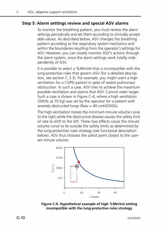
C ASV, adaptive support ventilation
Step 5: Alarm settings review and special ASV alarmsTo monitor the breathing pattern, you must review the alarm settings periodically and set them according to clinically accept-able values. As described below, ASV changes the breathing pattern according to the respiratory system mechanics and within the boundaries resulting from the operator’s settings for ASV. However, you can closely monitor ASV’s actions through the alarm system, since the alarm settings work totally inde-pendently of ASV.
It is possible to select a %MinVol that is incompatible with the lung-protective rules that govern ASV (for a detailed descrip-tion, see section C.3.3). For example, you might want a high ventilation for a COPD patient in spite of severe pulmonary obstruction. In such a case, ASV tries to achieve the maximum possible ventilation and alarms that ASV: Cannot meet target. Such a case is shown in Figure C-4, where a high ventilation (300% at 70 kg) was set by the operator for a patient with severely obstructed lungs (Raw = 40 cmH2O/(l/s).
The high ventilation moves the minimum minute volume curve to the right while the obstructive disease causes the safety limit of rate to shift to the left. These two effects cause the minute volume curve to lie outside the safety limits as determined by the lung-protective rules strategy (see functional description below). ASV thus chooses the safest point closest to the user-set minute volume.
Figure C-4. Hypothetical example of high %MinVol setting incompatible with the lung-protective rules strategy
C-10 624369/06
The open circle denotes the actual target, the closed triangle (never shown on the ventilator) denotes the (energetically) optimal target according to Otis’ equation. The HAMILTON-T1 will alarm and inform the user that the ASV target cannot be achieved.
Step 6: Monitoring ASVASV interacts with the patient continuously. Whenever the patient’s respiratory mechanics change, ASV adapts to this change. Whenever the patient’s breathing activity changes, ASV adapts. To let you view the current status, the HAMILTON-T1 provides the ASV target graphics (ASV Graph) window (Figure C-5).
To monitor progress over time, it is recommended that you plot trends for Pinsp, fTotal, and fSpont. Interpret these trends, together with the %MinVol setting. Tables C-2 through C-4 provide interpretation of typical ventilatory patterns.
For details on displaying the ASV Graph, see Section 7.3.
624369/06 C-11
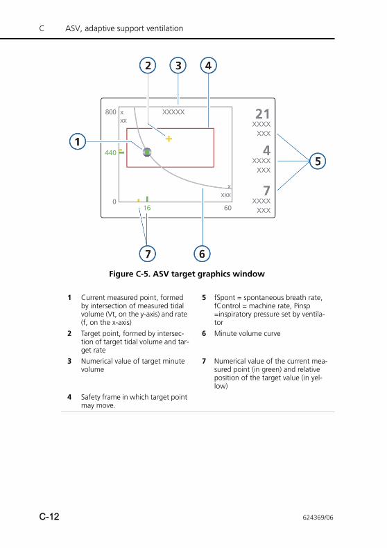
C ASV, adaptive support ventilation
Figure C-5. ASV target graphics window
1 Current measured point, formed by intersection of measured tidal volume (Vt, on the y-axis) and rate (f, on the x-axis)
5 fSpont = spontaneous breath rate, fControl = machine rate, Pinsp =inspiratory pressure set by ventila-tor
2 Target point, formed by intersec-tion of target tidal volume and tar-get rate
6 Minute volume curve
3 Numerical value of target minute volume
7 Numerical value of the current mea-sured point (in green) and relative position of the target value (in yel-low)
4 Safety frame in which target point may move.
C-12 624369/06
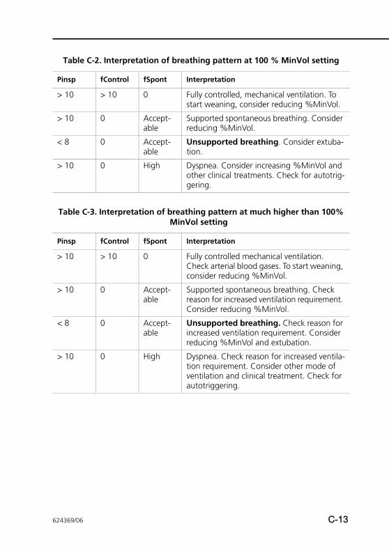
Table C-2. Interpretation of breathing pattern at 100 % MinVol setting
Pinsp fControl fSpont Interpretation
> 10 > 10 0 Fully controlled, mechanical ventilation. To start weaning, consider reducing %MinVol.
> 10 0 Accept-able
Supported spontaneous breathing. Consider reducing %MinVol.
< 8 0 Accept-able
Unsupported breathing. Consider extuba-tion.
> 10 0 High Dyspnea. Consider increasing %MinVol and other clinical treatments. Check for autotrig-gering.
Table C-3. Interpretation of breathing pattern at much higher than 100% MinVol setting
Pinsp fControl fSpont Interpretation
> 10 > 10 0 Fully controlled mechanical ventilation. Check arterial blood gases. To start weaning, consider reducing %MinVol.
> 10 0 Accept-able
Supported spontaneous breathing. Check reason for increased ventilation requirement. Consider reducing %MinVol.
< 8 0 Accept-able
Unsupported breathing. Check reason for increased ventilation requirement. Consider reducing %MinVol and extubation.
> 10 0 High Dyspnea. Check reason for increased ventila-tion requirement. Consider other mode of ventilation and clinical treatment. Check for autotriggering.
624369/06 C-13
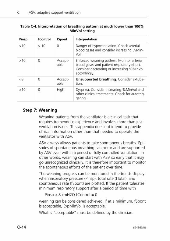
C ASV, adaptive support ventilation
Step 7: WeaningWeaning patients from the ventilator is a clinical task that requires tremendous experience and involves more than just ventilation issues. This appendix does not intend to provide clinical information other than that needed to operate the ventilator with ASV.
ASV always allows patients to take spontaneous breaths. Epi-sodes of spontaneous breathing can occur and are supported by ASV even within a period of fully controlled ventilation. In other words, weaning can start with ASV so early that it may go unrecognized clinically. It is therefore important to monitor the spontaneous efforts of the patient over time.
The weaning progress can be monitored in the trends display when inspiratory pressure (Pinsp), total rate (fTotal), and spontaneous rate (fSpont) are plotted. If the patient tolerates minimum respiratory support after a period of time with
Pinsp < 8 cmH2O fControl = 0
weaning can be considered achieved, if at a minimum, fSpont is acceptable, ExpMinVol is acceptable.
What is “acceptable” must be defined by the clinician.
Table C-4. Interpretation of breathing pattern at much lower than 100% MinVol setting
Pinsp fControl fSpont Interpretation
>10 > 10 0 Danger of hypoventilation. Check arterial blood gases and consider increasing %Min-Vol.
>10 0 Accept-able
Enforced weaning pattern. Monitor arterial blood gases and patient respiratory effort. Consider decreasing or increasing %MinVol accordingly.
<8 0 Accept-able
Unsupported breathing. Consider extuba-tion.
>10 0 High Dyspnea. Consider increasing %MinVol and other clinical treatments. Check for autotrig-gering.
C-14 624369/06
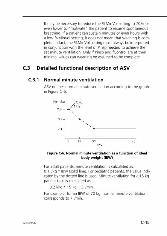
It may be necessary to reduce the %MinVol setting to 70% or even lower to “motivate” the patient to resume spontaneous breathing. If a patient can sustain minutes or even hours with a low %MinVol setting, it does not mean that weaning is com-plete. In fact, the %MinVol setting must always be interpreted in conjunction with the level of Pinsp needed to achieve the set minute ventilation. Only if Pinsp and fControl are at their minimal values can weaning be assumed to be complete.
C.3 Detailed functional description of ASV
C.3.1 Normal minute ventilationASV defines normal minute ventilation according to the graph in Figure C-6.
Figure C-6. Normal minute ventilation as a function of ideal body weight (IBW)
For adult patients, minute ventilation is calculated as 0.1 l/kg * IBW (solid line). For pediatric patients, the value indi-cated by the dotted line is used. Minute ventilation for a 15 kg patient thus is calculated as
0.2 l/kg * 15 kg = 3 l/min
For example, for an IBW of 70 kg, normal minute ventilation corresponds to 7 l/min.
624369/06 C-15
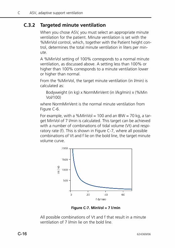
C ASV, adaptive support ventilation
C.3.2 Targeted minute ventilationWhen you chose ASV, you must select an appropriate minute ventilation for the patient. Minute ventilation is set with the %MinVol control, which, together with the Patient height con-trol, determines the total minute ventilation in liters per min-ute.
A %MinVol setting of 100% corresponds to a normal minute ventilation, as discussed above. A setting less than 100% or higher than 100% corresponds to a minute ventilation lower or higher than normal.
From the %MinVol, the target minute ventilation (in l/min) is calculated as:
Bodyweight (in kg) x NormMinVent (in l/kg/min) x (%MinVol/100)
where NormMinVent is the normal minute ventilation from Figure C-6.
For example, with a %MinVol = 100 and an IBW = 70 kg, a tar-get MinVol of 7 l/min is calculated. This target can be achieved with a number of combinations of tidal volume (Vt) and respi-ratory rate (f). This is shown in Figure C-7, where all possible combinations of Vt and f lie on the bold line, the target minute volume curve.
Figure C-7. MinVol = 7 l/min
All possible combinations of Vt and f that result in a minute ventilation of 7 l/min lie on the bold line.
C-16 624369/06
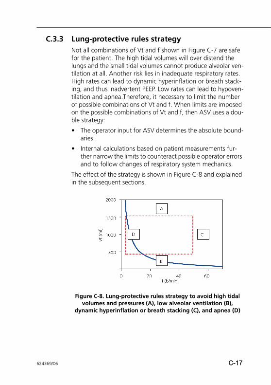
C.3.3 Lung-protective rules strategy Not all combinations of Vt and f shown in Figure C-7 are safe for the patient. The high tidal volumes will over distend the lungs and the small tidal volumes cannot produce alveolar ven-tilation at all. Another risk lies in inadequate respiratory rates. High rates can lead to dynamic hyperinflation or breath stack-ing, and thus inadvertent PEEP. Low rates can lead to hypoven-tilation and apnea.Therefore, it necessary to limit the number of possible combinations of Vt and f. When limits are imposed on the possible combinations of Vt and f, then ASV uses a dou-ble strategy:
• The operator input for ASV determines the absolute bound-aries.
• Internal calculations based on patient measurements fur-ther narrow the limits to counteract possible operator errors and to follow changes of respiratory system mechanics.
The effect of the strategy is shown in Figure C-8 and explained in the subsequent sections.
Figure C-8. Lung-protective rules strategy to avoid high tidal volumes and pressures (A), low alveolar ventilation (B),
dynamic hyperinflation or breath stacking (C), and apnea (D)
624369/06 C-17
C ASV, adaptive support ventilation
A: High tidal volume limit
WARNINGCheck Vt high setting to make sure the target minute ventilation can be reached in passive patients.
The tidal volume applied by ASV is limited (see A in Figure C-8) by three operator settings: high Pressure alarm limit, Vt high alarm limit, and Patient height.
The operator must set the high Pressure limit before connect-ing a patient to the ventilator. It was recommended by a group of physicians (Slutsky 1994) that the plateau pressure not exceed 35 cmH2O. To achieve this with ASV, the high Pressure limit must be set to 45 cmH2O. The maximum pressure to be applied in the ASV mode is 10 cmH2O below the high Pressure limit.
For example, a normal 70 kg normal (post-operative) patient would have a compliance of about 50 ml/cmH2O. A high Pres-sure limit of 45 cmH2O will result in a maximum applied pres-sure of 35 cmH2O. With a PEEP level of 5 cmH2O, the effective pressure swing will be 30 cmH2O. This in turn leads to an effective Vt of equal to, or less than 1500 ml. If the patient‘s lungs stiffen, to a compliance of 30 ml/cmH2O, the maximum tidal volume becomes 900 ml.
If the operator sets the Pressure limit to a very high pressure, say 60 cmH2O, the target volume is limited by the second criterion: 22 x IBW. For the 70 kg sample patient, a maximum target volume of 1540 ml results.
Additionally the target volume is limited to 1.5 * VT high limit, and pressure support actually is limited in a way that the inspired volume does not exceed Vt high limit in mechanical breaths for more than a few breaths.
C-18 624369/06
B: Low tidal volume limit
To determine the minimum target Vt in ASV (see B in Figure C-8) use the IBW calculated from the Patient height, which cor-responds to 4.4 ml/kg. In this example for a 70 kg patient, the minimum target Vt is 308 ml.
The operator must use caution with low tidal volumes to avoid insufficient alveolar ventilation. The determining parameter for alveolar ventilation is dead space (VDaw). Tidal volume value must always be greater than the VDaw value. It is widely accepted that a first approximation of dead space can be obtained by the following simple equation (Radford 1954):
The lower limit for tidal volume is based on this equation and calculated to be at least twice the dead space. Or, the mini-mum Vt is 4.4 x IBW.
VDaw = 2.2 * IBW (1)
C: High rate limit
You derive the maximum rate (see C in Figure C-8) from the operator-set %MinVol and the calculated IBW, which is calcu-lated from the operator-set Patient height. The equation used to calculate the maximum rate is:
fmax = target MinVol / minimum Vt (2)
For example, the 70 kg patient described above will have a maximum rate of 22 b/min, when %MinVol is set to 100%.
However, as an example, if you choose an excessively high %MinVol of 350%, the maximum rate becomes 77 b/min. To protect the patient against such high rates, ASV employs a fur-ther safety mechanism, which takes into account the patient’s ability to exhale.
A measure of the ability to exhale is the expiratory time con-stant (RCexp) (Marini 1989, Brunner 1995). To achieve a nearly complete exhalation to the equilibrium point of the respiratory system (90% of the maximum potential volume change), an expiratory time of at least 2 x RCexp is theoretically required.
624369/06 C-19
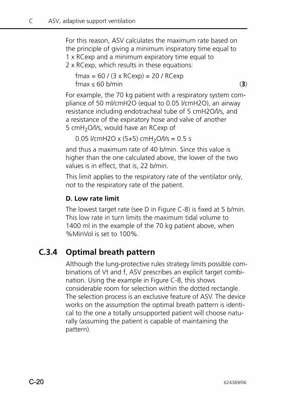
C ASV, adaptive support ventilation
For this reason, ASV calculates the maximum rate based on the principle of giving a minimum inspiratory time equal to 1 x RCexp and a minimum expiratory time equal to 2 x RCexp, which results in these equations:
fmax = 60 / (3 x RCexp) = 20 / RCexpfmax ≤ 60 b/min (3)
For example, the 70 kg patient with a respiratory system com-pliance of 50 ml/cmH2O (equal to 0.05 l/cmH2O), an airway resistance including endotracheal tube of 5 cmH2O/l/s, and a resistance of the expiratory hose and valve of another 5 cmH2O/l/s, would have an RCexp of
0.05 l/cmH2O x (5+5) cmH2O/l/s = 0.5 s
and thus a maximum rate of 40 b/min. Since this value is higher than the one calculated above, the lower of the two values is in effect, that is, 22 b/min.
This limit applies to the respiratory rate of the ventilator only, not to the respiratory rate of the patient.
D. Low rate limit
The lowest target rate (see D in Figure C-8) is fixed at 5 b/min. This low rate in turn limits the maximum tidal volume to 1400 ml in the example of the 70 kg patient above, when %MinVol is set to 100%.
C.3.4 Optimal breath patternAlthough the lung-protective rules strategy limits possible com-binations of Vt and f, ASV prescribes an explicit target combi-nation. Using the example in Figure C-8, this shows considerable room for selection within the dotted rectangle. The selection process is an exclusive feature of ASV. The device works on the assumption the optimal breath pattern is identi-cal to the one a totally unsupported patient will choose natu-rally (assuming the patient is capable of maintaining the pattern).
C-20 624369/06
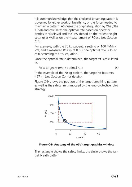
It is common knowledge that the choice of breathing pattern is governed by either work of breathing, or the force needed to maintain a pattern. ASV uses the original equation by Otis (Otis 1950) and calculates the optimal rate based on operator entries of %MinVol and the IBW (based on the Patient height setting) as well as on the measurement of RCexp (see Section C.4).
For example, with the 70 kg patient, a setting of 100 %Min-Vol, and a measured RCexp of 0.5 s, the optimal rate is 15 b/min according to Otis’ equation.
Once the optimal rate is determined, the target Vt is calculated as:
Vt = target MinVol / optimal rate (4)
In the example of the 70 kg patient, the target Vt becomes 467 ml (see Section C.4 for details).
Figure C-9 shows the position of the target breathing pattern as well as the safety limits imposed by the lung-protective rules strategy.
Figure C-9. Anatomy of the ASV target graphics window
The rectangle shows the safety limits; the circle shows the tar-get breath pattern.
624369/06 C-21
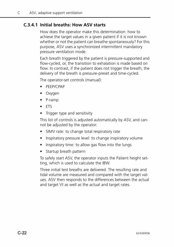
C ASV, adaptive support ventilation
C.3.4.1 Initial breaths: How ASV startsHow does the operator make this determination: how to achieve the target values in a given patient if it is not known whether or not the patient can breathe spontaneously? For this purpose, ASV uses a synchronized intermittent mandatory pressure ventilation mode.
Each breath triggered by the patient is pressure-supported and flow-cycled, or, the transition to exhalation is made based on flow. In contrast, if the patient does not trigger the breath, the delivery of the breath is pressure-preset and time-cycled.
The operator-set controls (manual):
• PEEP/CPAP
• Oxygen
• P-ramp
• ETS
• Trigger type and sensitivity
This list of controls is adjusted automatically by ASV, and can-not be adjusted by the operator:
• SIMV rate: to change total respiratory rate
• Inspiratory pressure level: to change inspiratory volume
• Inspiratory time: to allow gas flow into the lungs
• Startup breath pattern
To safely start ASV, the operator inputs the Patient height set-ting, which is used to calculate the IBW.
Three initial test breaths are delivered. The resulting rate and tidal volume are measured and compared with the target val-ues. ASV then responds to the differences between the actual and target Vt as well as the actual and target rates.
C-22 624369/06
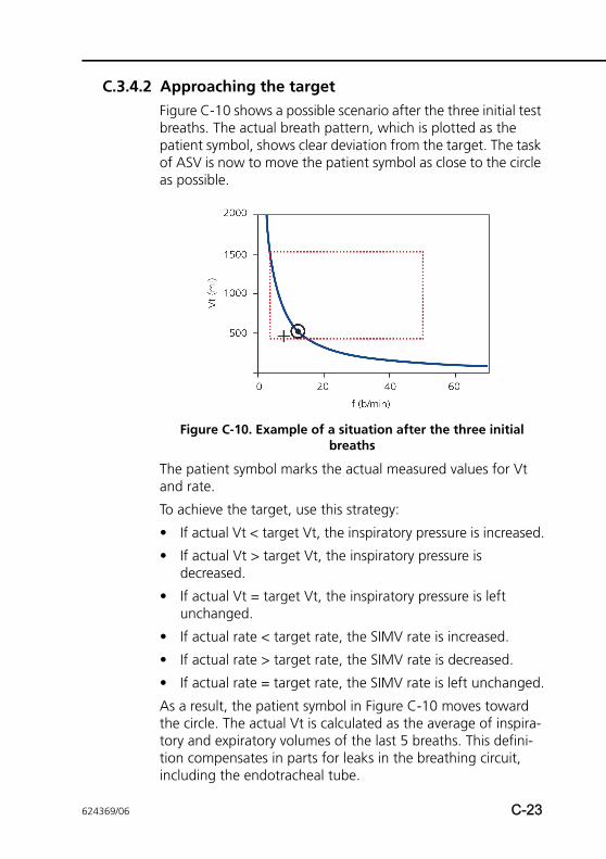
C.3.4.2 Approaching the targetFigure C-10 shows a possible scenario after the three initial test breaths. The actual breath pattern, which is plotted as the patient symbol, shows clear deviation from the target. The task of ASV is now to move the patient symbol as close to the circle as possible.
Figure C-10. Example of a situation after the three initial breaths
The patient symbol marks the actual measured values for Vt and rate.
To achieve the target, use this strategy:
• If actual Vt < target Vt, the inspiratory pressure is increased.
• If actual Vt > target Vt, the inspiratory pressure is decreased.
• If actual Vt = target Vt, the inspiratory pressure is left unchanged.
• If actual rate < target rate, the SIMV rate is increased.
• If actual rate > target rate, the SIMV rate is decreased.
• If actual rate = target rate, the SIMV rate is left unchanged.
As a result, the patient symbol in Figure C-10 moves toward the circle. The actual Vt is calculated as the average of inspira-tory and expiratory volumes of the last 5 breaths. This defini-tion compensates in parts for leaks in the breathing circuit, including the endotracheal tube.
624369/06 C-23
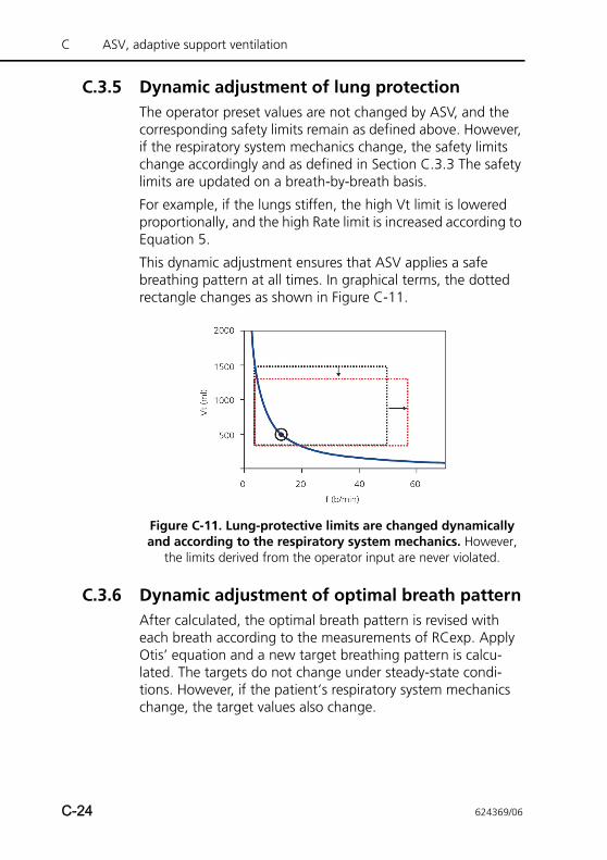
C ASV, adaptive support ventilation
C.3.5 Dynamic adjustment of lung protectionThe operator preset values are not changed by ASV, and the corresponding safety limits remain as defined above. However, if the respiratory system mechanics change, the safety limits change accordingly and as defined in Section C.3.3 The safety limits are updated on a breath-by-breath basis.
For example, if the lungs stiffen, the high Vt limit is lowered proportionally, and the high Rate limit is increased according to Equation 5.
This dynamic adjustment ensures that ASV applies a safe breathing pattern at all times. In graphical terms, the dotted rectangle changes as shown in Figure C-11.
Figure C-11. Lung-protective limits are changed dynamically and according to the respiratory system mechanics. However,
the limits derived from the operator input are never violated.
C.3.6 Dynamic adjustment of optimal breath patternAfter calculated, the optimal breath pattern is revised with each breath according to the measurements of RCexp. Apply Otis’ equation and a new target breathing pattern is calcu-lated. The targets do not change under steady-state condi-tions. However, if the patient‘s respiratory system mechanics change, the target values also change.
C-24 624369/06
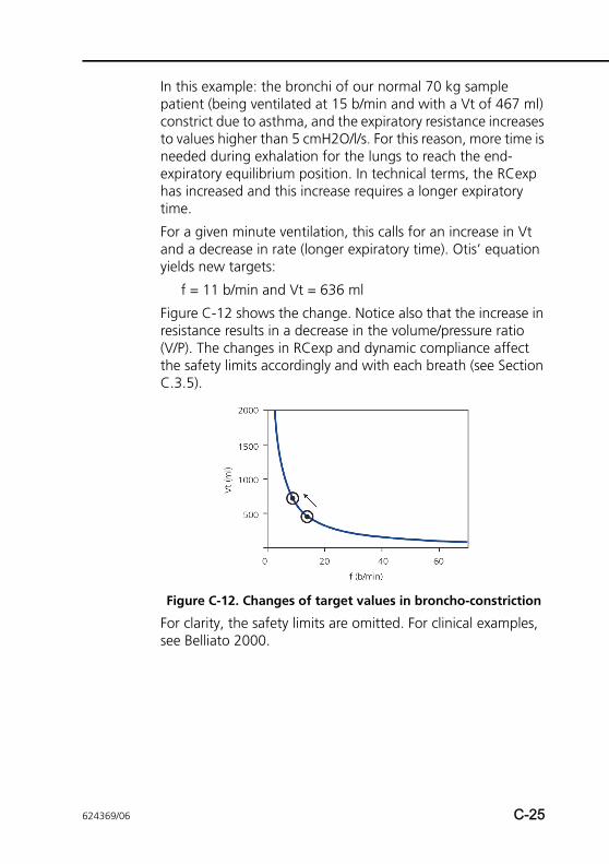
In this example: the bronchi of our normal 70 kg sample patient (being ventilated at 15 b/min and with a Vt of 467 ml) constrict due to asthma, and the expiratory resistance increases to values higher than 5 cmH2O/l/s. For this reason, more time is needed during exhalation for the lungs to reach the end-expiratory equilibrium position. In technical terms, the RCexp has increased and this increase requires a longer expiratory time.
For a given minute ventilation, this calls for an increase in Vt and a decrease in rate (longer expiratory time). Otis’ equation yields new targets:
f = 11 b/min and Vt = 636 ml
Figure C-12 shows the change. Notice also that the increase in resistance results in a decrease in the volume/pressure ratio(V/P). The changes in RCexp and dynamic compliance affect the safety limits accordingly and with each breath (see Section C.3.5).
Figure C-12. Changes of target values in broncho-constriction
For clarity, the safety limits are omitted. For clinical examples, see Belliato 2000.
624369/06 C-25
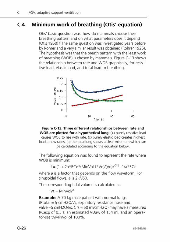
C ASV, adaptive support ventilation
C.4 Minimum work of breathing (Otis’ equation)
Otis’ basic question was: how do mammals choose their breathing pattern and on what parameters does it depend (Otis 1950)? The same question was investigated years before by Rohrer and a very similar result was obtained (Rohrer 1925). The hypothesis was that the breath pattern with the least work of breathing (WOB) is chosen by mammals. Figure C-13 shows the relationship between rate and WOB graphically, for resis-tive load, elastic load, and total load to breathing.
Figure C-13. Three different relationships between rate and WOB are plotted for a hypothetical lung: (+) purely resistive load causes WOB to rise with rate, (x) purely elastic load creates highest
load at low rates, (o) the total lung shows a clear minimum which can be calculated according to the equation below.
The following equation was found to represent the rate where WOB is minimum:
f = (1 + 2a*RCe*(MinVol-f*Vd)/(Vd))-0.5 -1/a*RCe
where a is a factor that depends on the flow waveform. For sinusoidal flows, a is 2π2/60.
The corresponding tidal volume is calculated as:
Vt = MinVol/f
Example: A 70 kg male patient with normal lungs (Rtotal = 5 cmH2O/l/s, expiratory resistance hose and valve =5 cmH2O/l/s, Crs = 50 ml/cmH2O) may have a measured RCexp of 0.5 s, an estimated VDaw of 154 ml, and an opera-tor-set %MinVol of 100%.
C-26 624369/06

With these values, the target MinVol becomes
MinVol = 100% x 70 kg x 0.1 l/min/kg = 7 l/min
Next, Otis’ equation is applied with the following parameters:
MinVol = 7 l/min
VDaw = 154 ml
RCexp = 0.5s
a = 2π2/60
f = 10 b/min (this is always used as a starting value)
The result is a new rate f(1)
f(1) = 15 b/min
This rate is again inserted into Otis’ equation, the calculation is performed again, and the next estimate for rate f(2) is obtained. This procedure is repeated until the difference between subsequent results for rate (f) becomes lower than 0.5 b/min. In the present example, one iteration step is suffi-cient, i.e.,
ftarget = 15 b/min
Finally, the target tidal volume is obtained by dividing MinVol by f:
Vtarget = 7000 ml/min / 15 b/min = 467 ml
624369/06 C-27
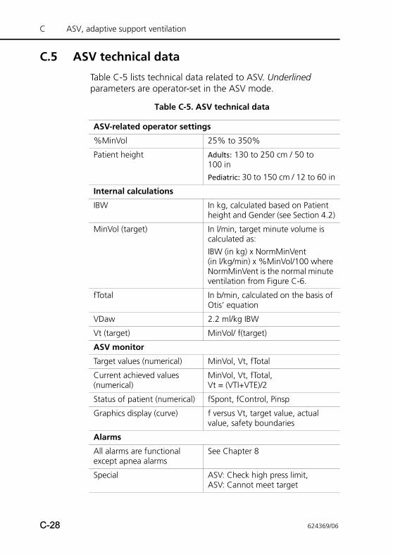
C ASV, adaptive support ventilation
C.5 ASV technical data
Table C-5 lists technical data related to ASV. Underlined parameters are operator-set in the ASV mode.
Table C-5. ASV technical data
ASV-related operator settings
%MinVol 25% to 350%
Patient height Adults: 130 to 250 cm / 50 to 100 inPediatric: 30 to 150 cm / 12 to 60 in
Internal calculations
IBW In kg, calculated based on Patient height and Gender (see Section 4.2)
MinVol (target) In l/min, target minute volume is calculated as:IBW (in kg) x NormMinVent (in l/kg/min) x %MinVol/100 where NormMinVent is the normal minute ventilation from Figure C-6.
fTotal In b/min, calculated on the basis of Otis’ equation
VDaw 2.2 ml/kg IBW
Vt (target) MinVol/ f(target)
ASV monitor
Target values (numerical) MinVol, Vt, fTotal
Current achieved values (numerical)
MinVol, Vt, fTotal, Vt = (VTI+VTE)/2
Status of patient (numerical) fSpont, fControl, Pinsp
Graphics display (curve) f versus Vt, target value, actual value, safety boundaries
Alarms
All alarms are functional except apnea alarms
See Chapter 8
Special ASV: Check high press limit, ASV: Cannot meet target
C-28 624369/06
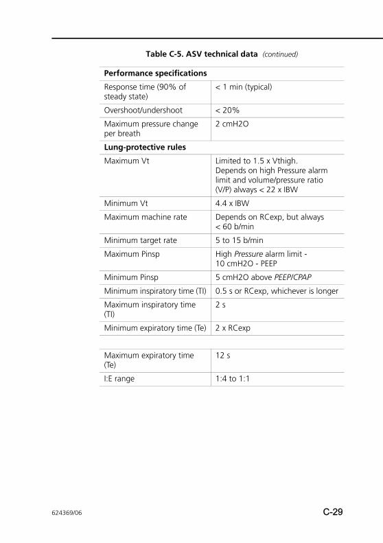
Performance specifications
Response time (90% of steady state)
< 1 min (typical)
Overshoot/undershoot < 20%
Maximum pressure change per breath
2 cmH2O
Lung-protective rules
Maximum Vt Limited to 1.5 x Vthigh.Depends on high Pressure alarm limit and volume/pressure ratio (V/P) always < 22 x IBW
Minimum Vt 4.4 x IBW
Maximum machine rate Depends on RCexp, but always < 60 b/min
Minimum target rate 5 to 15 b/min
Maximum Pinsp High Pressure alarm limit - 10 cmH2O - PEEP
Minimum Pinsp 5 cmH2O above PEEP/CPAP
Minimum inspiratory time (TI) 0.5 s or RCexp, whichever is longer
Maximum inspiratory time (TI)
2 s
Minimum expiratory time (Te) 2 x RCexp
Maximum expiratory time (Te)
12 s
I:E range 1:4 to 1:1
Table C-5. ASV technical data (continued)
624369/06 C-29
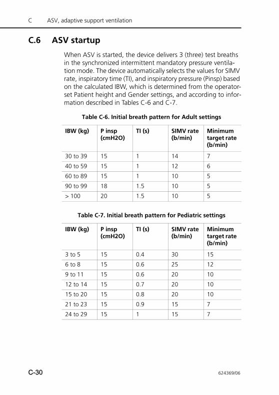
C ASV, adaptive support ventilation
C.6 ASV startup
When ASV is started, the device delivers 3 (three) test breaths in the synchronized intermittent mandatory pressure ventila-tion mode. The device automatically selects the values for SIMV rate, inspiratory time (TI), and inspiratory pressure (Pinsp) based on the calculated IBW, which is determined from the operator-set Patient height and Gender settings, and according to infor-mation described in Tables C-6 and C-7.
Table C-6. Initial breath pattern for Adult settings
IBW (kg) P insp (cmH2O)
TI (s) SIMV rate (b/min)
Minimum target rate (b/min)
30 to 39 15 1 14 7
40 to 59 15 1 12 6
60 to 89 15 1 10 5
90 to 99 18 1.5 10 5
> 100 20 1.5 10 5
Table C-7. Initial breath pattern for Pediatric settings
IBW (kg) P insp (cmH2O)
TI (s) SIMV rate (b/min)
Minimum target rate (b/min)
3 to 5 15 0.4 30 15
6 to 8 15 0.6 25 12
9 to 11 15 0.6 20 10
12 to 14 15 0.7 20 10
15 to 20 15 0.8 20 10
21 to 23 15 0.9 15 7
24 to 29 15 1 15 7
C-30 624369/06
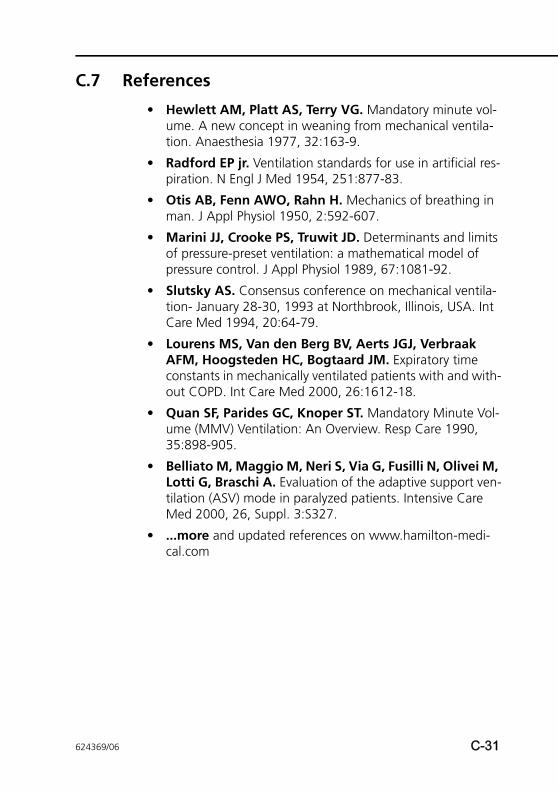
C.7 References
• Hewlett AM, Platt AS, Terry VG. Mandatory minute vol-ume. A new concept in weaning from mechanical ventila-tion. Anaesthesia 1977, 32:163-9.
• Radford EP jr. Ventilation standards for use in artificial res-piration. N Engl J Med 1954, 251:877-83.
• Otis AB, Fenn AWO, Rahn H. Mechanics of breathing in man. J Appl Physiol 1950, 2:592-607.
• Marini JJ, Crooke PS, Truwit JD. Determinants and limits of pressure-preset ventilation: a mathematical model of pressure control. J Appl Physiol 1989, 67:1081-92.
• Slutsky AS. Consensus conference on mechanical ventila-tion- January 28-30, 1993 at Northbrook, Illinois, USA. Int Care Med 1994, 20:64-79.
• Lourens MS, Van den Berg BV, Aerts JGJ, Verbraak AFM, Hoogsteden HC, Bogtaard JM. Expiratory time constants in mechanically ventilated patients with and with-out COPD. Int Care Med 2000, 26:1612-18.
• Quan SF, Parides GC, Knoper ST. Mandatory Minute Vol-ume (MMV) Ventilation: An Overview. Resp Care 1990, 35:898-905.
• Belliato M, Maggio M, Neri S, Via G, Fusilli N, Olivei M, Lotti G, Braschi A. Evaluation of the adaptive support ven-tilation (ASV) mode in paralyzed patients. Intensive Care Med 2000, 26, Suppl. 3:S327.
• ...more and updated references on www.hamilton-medi-cal.com
624369/06 C-31

C ASV, adaptive support ventilation
C-32 624369/06
APPENDIX
D NIV, noninvasive ventilation
D.1 Introduction D-2
D.2 Benefits of noninvasive ventilation D-3
D.3 Required conditions for use D-4
D.4 Contraindications D-4
D.5 Potential adverse reactions D-5
D.6 Selecting a patient interface D-5
D.7 Control settings D-6
D.8 Alarms D-7
D.9 Monitored parameters D-8
D.10 Additional notes about using noninvasive ventilation D-8
D.11 References D-11
624369/06 D-1
D NIV, noninvasive ventilation
D.1 Introduction
NOTE:• Noninvasive ventilation in critically ill patients should
only be used by properly trained and experienced per-sonnel.
• As a precaution, you must be prepared to intubate the patient and start invasive ventilation at any time while noninvasive ventilation is in use.
• The use of a mask can increase dead space. Always comply with the mask manufacturer’s instructions when using noninvasive ventilation.
• If you are using the neonatal noninvasive modes, nCPAP and nCPAP-PC, see Chapter 5.
The noninvasive ventilation mode (NIV) and the spontaneous/timed noninvasive ventilation mode (NIV-ST) are implementa-tions of noninvasive positive pressure ventilation (NPPV). NPPV can use as its patient interface a mask, mouthpiece, or helmet-type interface, rather than an invasive conduit such as an endo-tracheal tube.
Used for years in home care and subacute care settings, NPPV can also benefit intensive care ventilation patients by decreas-ing the need for intubation and promoting early extubation. Benefits such as reduced mortality (COPD patients), reduced ventilation time (COPD and ARF patients), and reduced compli-cation rates (of ventilator-associated pneumonias) have been clearly demonstrated1,2.
1. Mehta S et al. Noninvasive ventilation. Am J Respir Crit Care Med 2001 Feb;163(2):540-77.2. Hess DR. The evidence for noninvasive positive-pressure ventilation in the care of patients in
acute respiratory failure: a systematic review of the literature. Respiratory Care 2004 Jul;49(7):810-25.
D-2 624369/06
Intended for actively breathing patients, noninvasive ventila-tion is provided through a nonvented or nonported mask inter-face. Because this open breathing circuit permits air to leak around the mask or through the mouth, the ventilator achieves and maintains the prescribed pressure by adjusting the inspira-tory flow. If the leak is large, the ventilator’s inspiratory flow can be large—up to 260 l/min—thus compensating at least in part for most leaks. The NIV modes were also designed to min-imize nuisance leak-related alarms.
NIV is an adaptation of the SPONT mode, while NIV-ST is an adaptation of the PSIMV+ mode. The primary difference between SPONT and NIV or PSIMV+ and NIV-ST is that SPONT and PSIMV+ are designed for an intubated patient, while the NIV modes are designed for use with a mask or other noninva-sive patient interface. See Appendix A for technical details about the ventilator’s noninvasive modes.
D.2 Benefits of noninvasive ventilation
Noninvasive ventilation offers these short-term benefits1,2:
• Relieves respiratory symptoms
• Optimizes patient comfort
• Reduces work of breathing
• Improves or stabilizes gas exchange
• Improves patient-ventilator synchrony
• Minimizes risks associated with aspiration, intubation, injury to the mucus membranes and teeth, and circulatory reactions
Noninvasive ventilation offers these long-term benefits:
• Improves sleep duration and quality
• Maximizes quality of life
• Enhances functional status
• Prolongs survival
1. Mehta S et al. Noninvasive ventilation. Am J Respir Crit Care Med 2001 Feb;163(2):540-77.2. Hess DR. The evidence for noninvasive positive-pressure ventilation in the care of patients in
acute respiratory failure: a systematic review of the literature. Respiratory Care 2004 Jul;49(7):810-25.
624369/06 D-3
D NIV, noninvasive ventilation
D.3 Required conditions for use
CAUTION• To prevent possible patient injury, DO NOT use non-
invasive ventilation on patients with no or irregular spontaneous breaths. Noninvasive ventilation was intended to provide supplemental ventilatory sup-port to patients with regular spontaneous breaths.
• To prevent possible patient injury, DO NOT attempt to use noninvasive ventilation on intubated patients.
Ensure these requirements are met to use noninvasive ventilation:
• The clinician’s instructions must be strictly followed.
• The patient must not be intubated.
• The patient must be able to trigger the ventilator and must have regular spontaneous breaths.
• The patient must be conscious.
• The patient must be able to maintain an adequate airway.
• The patient must be monitored by external monitors.
• Intubation must be possible at any time.
• The mask should fit face structures well.
D.4 Contraindications
• Intolerance of interface
• Inability to trigger breath
• Facial or brain injury
• Recent upper airway or esophageal surgery
• Hemodynamic instability
• Gastric distension
• Inability to protect airway
D-4 624369/06
D.5 Potential adverse reactions
• Skin breakdown from interface (pressures sores)
• Aspiration
• Conjunctivitis
• Gastric insufflation
• Claustrophobic reaction
• Potential hemodynamic instability
D.6 Selecting a patient interface
CAUTIONMake sure to follow the instructions for use of the man-ufacturer when using any noninvasive patient interface. Incorrectly used masks can cause skin irritations.
The quality and performance of the patient interface largely determine the effectiveness of noninvasive ventilation.
The following types of interfaces are supported:
• Face (oronasal) mask that covers the mouth and nose
• Nasal mask that covers the nose only
• Mouthpiece
• Helmet
In general, an interface used with the noninvasive modes must meet these requirements:
• It must be of the nonvented/nonported design
• Gas leakage should be controllable at low mask application pressures
• The material in contact with the face should be soft, bio-compatible, and nonallergenic
• It should be easy to install and remove
• It should remain properly positioned when the patient moves their head
624369/06 D-5
D NIV, noninvasive ventilation
If you try using a nasal mask, but there is significant gas leak-age through the open mouth, switch to a face mask.
D.7 Control settings
WARNINGThe exhaled volume from the patient can differ from the measured exhaled volume due to leaks around the mask.
CAUTION• When ventilating with a mask, avoid high airway
pressures. High pressures may cause gastric disten-sion.
• Peak pressures exceeding 33 cmH2O may increase the risk of aspiration due to gastric insufflation1. When ventilating with such pressures, consider using an invasive mode.
When a significant leak occurs, the inspiratory flow can never fall below ETS, thus not allowing the ventilator to cycle into exhalation and resulting in endless inspiration. For this reason, the TI max setting was added, providing an alternative way to cycle into exhalation. When inspiration lasts longer than TI max, the ventilator cycles into exhalation.
When the ventilator cycles are based on ETS setting rather than TI max, it is the most comfortable for the patient. Ensure the TI max setting is sufficiently long to give ETS the chance to cycle the ventilator. Adjusting the TI max setting increases or decreases the allowable inspiratory time. Increasing ETS above the default 25% allows the ventilator to cycle to terminate inspiration at a higher flow, to accommodate larger leaks.
1. Bach JR, Alba AS, Saporito LR. Intermittent positive pressure ventilation via the mouth as an alternative to tracheostomy for 257 ventilator users. Chest 1993;103:174-182.
D-6 624369/06
Other controls require special attention. Carefully observe the patient/ventilator interaction. The leakage in this mode reduces the actual applied PEEP/CPAP and give rise to autotriggering. Adjust Psupport or Pinsp to obtain appropriate tidal volumes. Adjust PEEP/CPAP further, considering oxygenation and AutoPEEP.
D.8 Alarms
NOTE:The Inspiratory volume limitation alarm is inactive in noninva-sive modes.
Due to the changing and unpredictable amount of leakage, volume alarms are less meaningful in noninvasive than in other modes. Alarms are based on the returned expiratory gas vol-ume measured at the flow sensor; this value can be signifi-cantly lower than the delivered tidal volume, because the delivered tidal volume is the sum of the displayed VTE and the leakage volume. To avoid nuisance volume alarms, set the low Vt and ExpMinVol alarms to a low level.
Because the noninvasive modes are pressure modes, however, do pay attention to the pressure-related alarms. If the defined PEEP and inspiratory pressure can be maintained, the ventilator is compensating the gas leak sufficiently.
624369/06 D-7
D NIV, noninvasive ventilation
D.9 Monitored parameters
NOTE:Due to the changing and unpredictable amount of leakage, these numeric monitoring parameters cannot be used for reliable analysis of patient conditions: ExpMinVol, RCexp, Rinsp, Insp Flow, AutoPEEP, and Cstat. Continuous monitoring of the clinical parameters and patient comfort is of critical importance.
Due to the leakage at the patient interface, displayed exhaled volumes in the noninvasive modes can be substantially smaller than the delivered volumes. The flow sensor measures the delivered volume and the exhaled tidal volume; the ventilator displays the difference as VLeak in %, and as MVLeak in l/min. Use VLeak and MVLeak to assess the fit of the mask or other noninvasive patient interface.
While a leak at the patient interface influences the tidal volume measurement, leaks in the breathing circuit itself do not influ-ence the tidal volume measurement.
Besides all the other clinical parameters, TI, Ppeak, PEEP/CPAP, I:E, fTotal, Pmean, and fSpont can be used to assess the patient’s ventilatory status.
D.10 Additional notes about using noninvasive ventilation
NOTE:If the mask fit cannot be improved, select an alternative treatment method.
Due to some unique characteristics of noninvasive ventilation, consider the following points when using it. Consistent with best practices, monitor the patient closely to evaluate the adequacy of the prescribed therapy.
D-8 624369/06
IntelliTrig (intelligent trigger) function. With its IntelliTrig function, the ventilator can automatically adapt to changing breath patterns and system leaks to achieve optimum synchro-nization between patient and device.
To synchronize, IntelliTrig compensates any leaks and resis-tances between the ventilator and the patient, and with each breath it measures the leakage at the patient interface (mask). With this information IntelliTrig adapts the trigger mechanism so leakage and the changing breath pattern do not influence the operator-set trigger sensitivity (flow trigger).
Maintaining PEEP and preventing autotriggering. Signifi-cant leakage can be present in noninvasive ventilation, which can serve to reduce the actual applied PEEP/CPAP and give rise to autotriggering. If you cannot reach the set PEEP/CPAP, check the mask fit.
The ventilator maintains PEEP with the expiratory valve in combination with a compensating base flow delivered by the check valve through the breathing circuit.
The Loss of PEEP alarm alerts you to uncompensated leaks (that is, when the measured PEEP/CPAP is 3 cmH2O lower than the set PEEP/CPAP).
Inspect mask fit and position. For noninvasive ventilation to function as intended, the mask must fit well and remain in place. It is desirable to maintain a good seal and minimize leakage.
Inspect the mask position regularly and adjust as necessary. If the mask slides away from the mouth and nose (patient disconnection), reinstall and secure it. React promptly and appropriately to any alarms.
The ventilator’s Leak parameter provides one indicator of mask fit. To check the proper fit of the mask verify that the patient can trigger and flow-cycle inspiration and by verify that:
Ppeak = (PEEP/CPAP + Psupport/Pinsp) ±3 cmH2O
624369/06 D-9
D NIV, noninvasive ventilation
CO2 rebreathing in noninvasive ventilation. CO2 rebreathing per breath can increase in noninvasive ventilation. Typically this is not critical, because there is also generally sig-nificant leakage in noninvasive ventilation. CO2 rebreathing can occur because there is not the usual dead space reduction from an endotracheal tube or tracheostomy. And because the mask or other noninvasive interface creates additional dead space. Consider this additional dead space when prescribing a specific type of noninvasive patient interface. Despite the use of a noninvasive interface, the dead space ventilation per min-ute can decrease when the therapy results in an increase in tidal volume and decrease in respiratory rate.
D-10 624369/06
D.11 References
• Hess DR. The evidence for noninvasive positive-pressure ventilation in the care of patients in acute respiratory fail-ure: a systematic review of the literature. Respir Care 2004 Jul;49(7):810-25.
• Mehta S et al. Noninvasive ventilation. Am J Respir Crit Care Med 2001 Feb;163(2):540-77.
• Arroliga AC. Noninvasive positive pressure ventilation in acute respiratory failure: does it improve outcome? Cleve-land Clin J Med. 2001 Aug;68(8):677-80.
• Hill NS. Noninvasive ventilation in chronic obstructive pul-monary disease. Clin Chest Med. 2000 Dec;21(4):783-97.
• AARC. Consensus statement: Noninvasive positive pressure ventilation. Respir Care 1997;42(4):365-9.
• Evans TW et al. Noninvasive positive pressure ventilation in acute respiratory failure: Report of an international con-sensus conference in intensive care medicine, Paris, France, 13 - 14 April 2000. Reanimation 2001;10:112-25.
624369/06 D-11

D NIV, noninvasive ventilation
D-12 624369/06
EAPPENDIX
CO2 sensor option: Volumetric capnography
E.1 Introduction E-2
E.2 CO2 elimination (V’CO2) E-2
E.3 End-tidal CO2 (PetCO2 and FetCO2) E-4
E.4 Airway dead space (VDaw) E-5
E.5 Alveolar minute ventilation (V’alv) E-6
E.6 Capnogram shape E-7
E.7 Formulas E-7
E.8 References E-8
624369/06 E-1
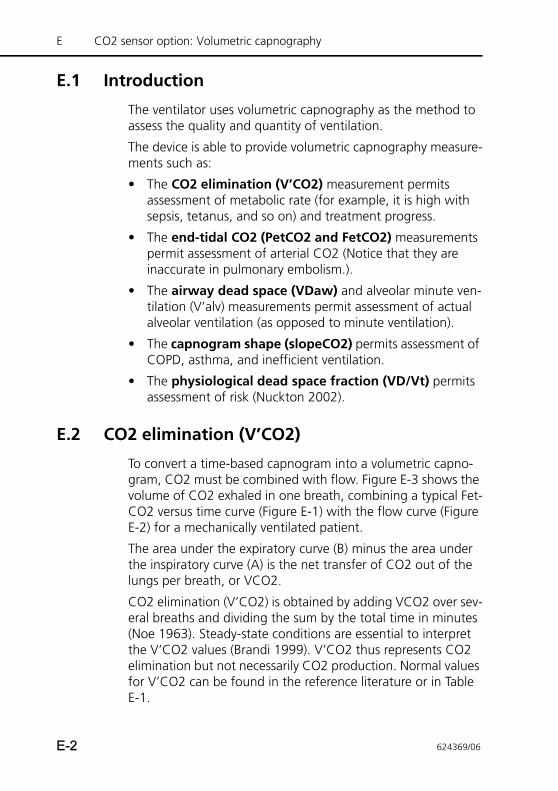
E CO2 sensor option: Volumetric capnography
E.1 Introduction
The ventilator uses volumetric capnography as the method to assess the quality and quantity of ventilation.
The device is able to provide volumetric capnography measure-ments such as:
• The CO2 elimination (V’CO2) measurement permits assessment of metabolic rate (for example, it is high with sepsis, tetanus, and so on) and treatment progress.
• The end-tidal CO2 (PetCO2 and FetCO2) measurements permit assessment of arterial CO2 (Notice that they are inaccurate in pulmonary embolism.).
• The airway dead space (VDaw) and alveolar minute ven-tilation (V’alv) measurements permit assessment of actual alveolar ventilation (as opposed to minute ventilation).
• The capnogram shape (slopeCO2) permits assessment of COPD, asthma, and inefficient ventilation.
• The physiological dead space fraction (VD/Vt) permits assessment of risk (Nuckton 2002).
E.2 CO2 elimination (V’CO2)
To convert a time-based capnogram into a volumetric capno-gram, CO2 must be combined with flow. Figure E-3 shows the volume of CO2 exhaled in one breath, combining a typical Fet-CO2 versus time curve (Figure E-1) with the flow curve (Figure E-2) for a mechanically ventilated patient.
The area under the expiratory curve (B) minus the area under the inspiratory curve (A) is the net transfer of CO2 out of the lungs per breath, or VCO2.
CO2 elimination (V’CO2) is obtained by adding VCO2 over sev-eral breaths and dividing the sum by the total time in minutes (Noe 1963). Steady-state conditions are essential to interpret the V’CO2 values (Brandi 1999). V’CO2 thus represents CO2 elimination but not necessarily CO2 production. Normal values for V’CO2 can be found in the reference literature or in Table E-1.
E-2 624369/06
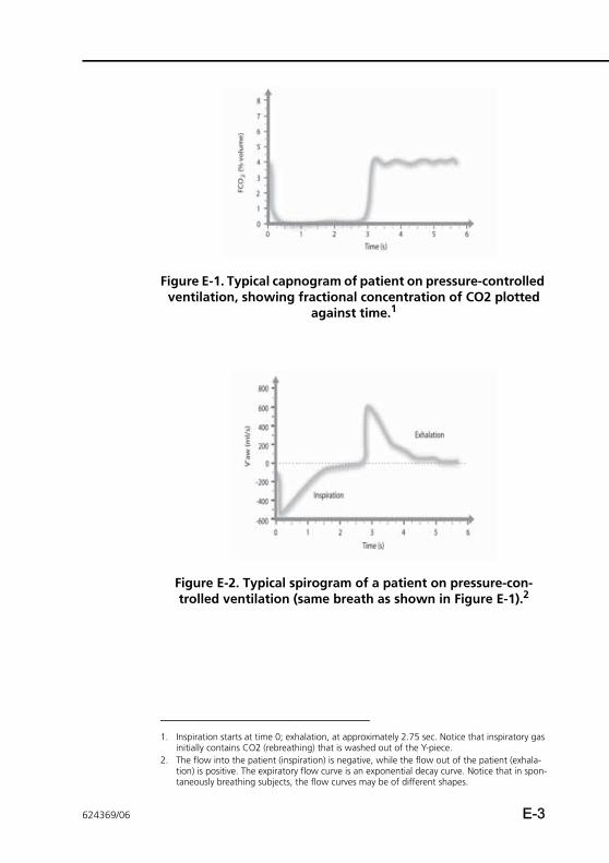
Figure E-1. Typical capnogram of patient on pressure-controlled ventilation, showing fractional concentration of CO2 plotted
against time.1
Figure E-2. Typical spirogram of a patient on pressure-con-trolled ventilation (same breath as shown in Figure E-1).2
1. Inspiration starts at time 0; exhalation, at approximately 2.75 sec. Notice that inspiratory gas initially contains CO2 (rebreathing) that is washed out of the Y-piece.
2. The flow into the patient (inspiration) is negative, while the flow out of the patient (exhala-tion) is positive. The expiratory flow curve is an exponential decay curve. Notice that in spon-taneously breathing subjects, the flow curves may be of different shapes.
624369/06 E-3
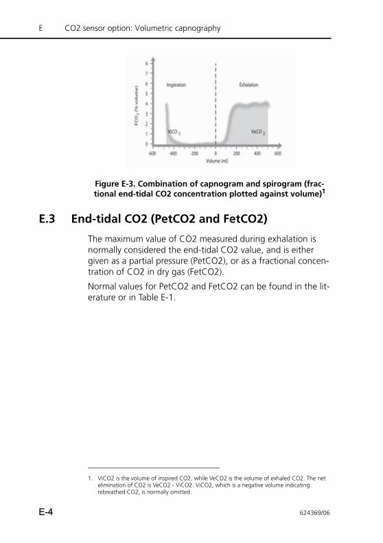
E CO2 sensor option: Volumetric capnography
Figure E-3. Combination of capnogram and spirogram (frac-tional end-tidal CO2 concentration plotted against volume)1
E.3 End-tidal CO2 (PetCO2 and FetCO2)
The maximum value of CO2 measured during exhalation is normally considered the end-tidal CO2 value, and is either given as a partial pressure (PetCO2), or as a fractional concen-tration of CO2 in dry gas (FetCO2).
Normal values for PetCO2 and FetCO2 can be found in the lit-erature or in Table E-1.
1. ViCO2 is the volume of inspired CO2, while VeCO2 is the volume of exhaled CO2. The net elimination of CO2 is VeCO2 - ViCO2. ViCO2, which is a negative volume indicating rebreathed CO2, is normally omitted.
E-4 624369/06
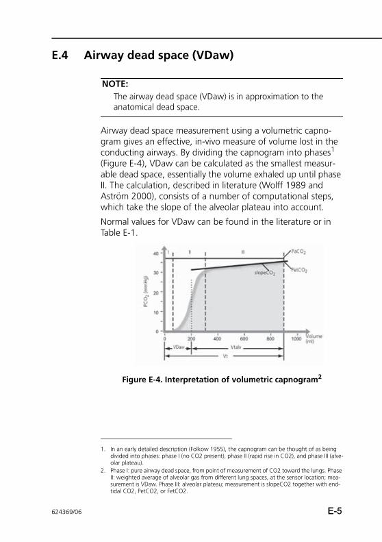
E.4 Airway dead space (VDaw)
NOTE:The airway dead space (VDaw) is in approximation to the anatomical dead space.
Airway dead space measurement using a volumetric capno-gram gives an effective, in-vivo measure of volume lost in the conducting airways. By dividing the capnogram into phases1 (Figure E-4), VDaw can be calculated as the smallest measur-able dead space, essentially the volume exhaled up until phase II. The calculation, described in literature (Wolff 1989 and Aström 2000), consists of a number of computational steps, which take the slope of the alveolar plateau into account.
Normal values for VDaw can be found in the literature or in Table E-1.
Figure E-4. Interpretation of volumetric capnogram2
1. In an early detailed description (Folkow 1955), the capnogram can be thought of as being divided into phases: phase I (no CO2 present), phase II (rapid rise in CO2), and phase III (alve-olar plateau).
2. Phase I: pure airway dead space, from point of measurement of CO2 toward the lungs. Phase II: weighted average of alveolar gas from different lung spaces, at the sensor location; mea-surement is VDaw. Phase III: alveolar plateau; measurement is slopeCO2 together with end-tidal CO2, PetCO2, or FetCO2.
624369/06 E-5
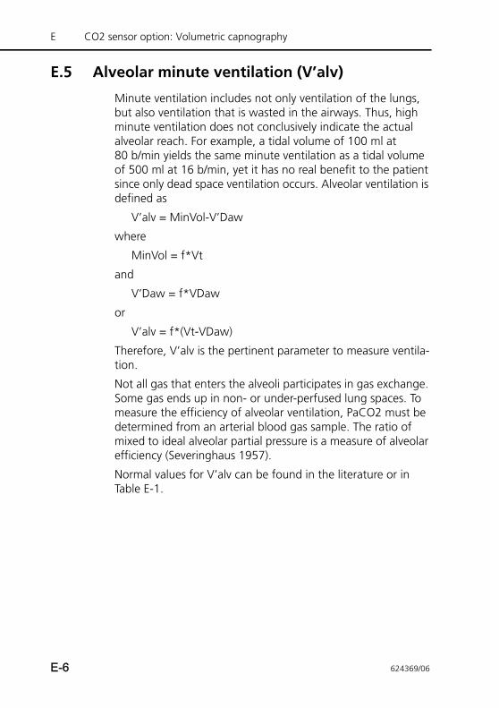
E CO2 sensor option: Volumetric capnography
E.5 Alveolar minute ventilation (V’alv)
Minute ventilation includes not only ventilation of the lungs, but also ventilation that is wasted in the airways. Thus, high minute ventilation does not conclusively indicate the actual alveolar reach. For example, a tidal volume of 100 ml at80 b/min yields the same minute ventilation as a tidal volume of 500 ml at 16 b/min, yet it has no real benefit to the patient since only dead space ventilation occurs. Alveolar ventilation is defined as
V’alv = MinVol-V’Daw
where
MinVol = f*Vt
and
V’Daw = f*VDaw
or
V’alv = f*(Vt-VDaw)
Therefore, V’alv is the pertinent parameter to measure ventila-tion.
Not all gas that enters the alveoli participates in gas exchange. Some gas ends up in non- or under-perfused lung spaces. To measure the efficiency of alveolar ventilation, PaCO2 must be determined from an arterial blood gas sample. The ratio of mixed to ideal alveolar partial pressure is a measure of alveolar efficiency (Severinghaus 1957).
Normal values for V’alv can be found in the literature or in Table E-1.
E-6 624369/06
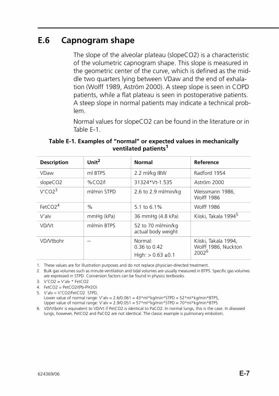
E.6 Capnogram shape
The slope of the alveolar plateau (slopeCO2) is a characteristic of the volumetric capnogram shape. This slope is measured in the geometric center of the curve, which is defined as the mid-dle two quarters lying between VDaw and the end of exhala-tion (Wolff 1989, Aström 2000). A steep slope is seen in COPD patients, while a flat plateau is seen in postoperative patients. A steep slope in normal patients may indicate a technical prob-lem.
Normal values for slopeCO2 can be found in the literature or in Table E-1.
Table E-1. Examples of “normal” or expected values in mechanically ventilated patients1
Description Unit2 Normal Reference
VDaw ml BTPS 2.2 ml/kg IBW Radford 1954
slopeCO2 %CO2/l 31324*Vt-1.535 Aström 2000
V’CO23 ml/min STPD 2.6 to 2.9 ml/min/kg Weissmann 1986, Wolff 1986
FetCO24 % 5.1 to 6.1% Wolff 1986
V’alv mmHg (kPa) 36 mmHg (4.8 kPa) Kiiski, Takala 19945
VD/Vt ml/min BTPS 52 to 70 ml/min/kg actual body weight
VD/Vtbohr -- Normal: 0.36 to 0.42High: > 0.63 ±0.1
Kiiski, Takala 1994, Wolff 1986, Nuckton 20026
1. These values are for illustration purposes and do not replace physician-directed treatment.2. Bulk gas volumes such as minute ventilation and tidal volumes are usually measured in BTPS. Specific gas volumes
are expressed in STPD. Conversion factors can be found in physics textbooks.3. V’CO2 = V’alv * FetCO24. FetCO2 = PetCO2/(Pb-PH2O)5. V’alv = V’CO2/FetCO2 STPD,
Lower value of normal range: V’alv = 2.6/0.061 = 43*ml*kg/min*STPD = 52*ml*kg/min*BTPS, Upper value of normal range: V’alv = 2.9/0.051 = 57*ml*kg/min*STPD = 70*ml*kg/min*BTPS
6. VD/Vtbohr is equivalent to VD/Vt if PetCO2 is identical to PaCO2. In normal lungs, this is the case. In diseased lungs, however, PetCO2 and PaCO2 are not identical. The classic example is pulmonary embolism.
624369/06 E-7
E CO2 sensor option: Volumetric capnography
E.7 Formulas
Alveolar tidal ventilation (Vtalv)
Vtalv = Vt-VDaw
Alveolar minute ventilation (V’alv)
V’alv =f*Vtalv
Volume of CO2 eliminated in one breath (VCO2)
VCO”2 = VeCO2-ViCO2
Fractional concentration of CO2 in exhaled gas (FeCO2)
FeCO2 = V’CO2/MinVol
Partial pressure of CO2 in exhaled gas (PeCO2)
PeCO2 = FeCO2*(Pb-PH2O)
Bohr dead space fraction (VDbohr/Vt)
(Note: Vt in this formula needs to be in ml STPD)
VDbohr/Vt = 1-(VeCO2/(Vt*FeCO2))
Physiological dead space fraction (VD/Vt)
VD/Vt = 1-((VeCO2/Vt)/(paCO2/Pb-PH2O))
E-8 624369/06
E.8 References
• Astrom E, Niklason L, Drefeldt B, Bajc M, Jonson B. Par-titioning of dead space – a method and reference values in the awake human. Eur Respir J. 2000 Oct; 16(4):659-664.
• Brandi LS, Bertolini R, Santini L, Cavani S. Effects of ven-tilator resetting on indirect calorimetry measurement in the critically ill surgical patient. Crit Care Med.1999 Mar; 27(3):531-539.
• Kiiski R, Takala J, Eissa NT. Measurement of alveolar ven-tilation and changes in deadspace by indirect calorimetry during mechanical ventilation: a laboratory and clinical vali-dation. Crit Care Med. 1991 Oct; 19(10):1303-1309.
• Noe FE. Computer analysis of curves from an infrared CO2 analyzer and screen-type airflow meter. J Appl PhysioI 1963; 18:149-157.
• Nuckton TJ, Alonso JA, Kallet RH, Daniel BM, Pittet JF, Eisner MD, Matthay MA. Pulmonary dead-space fraction as a risk factor for death in the acute respiratory distress syndrome. N Engl J Med. 2002 Apr 25; 346(17):1281-1286.
• Radford EP. Ventilation standards for use in artificial respi-ration. N Engl J Med 1954; 251:877-883.
• Severinghaus JW, Stupfel M. Alveolar dead space as an index of distribution of blood flow in pulmonary capillaries. J Appl Physiol 1957; 10:335-348.
• Weissman C, Kemper M, Elwyn DH, Askanazi J, Hyman AI, Kinney JM. The energy expenditure of the mechanically ventilated critically ill patient. An analysis. Chest. 1986 Feb; 89(2):254-259.
• Wolff G, Brunner JX, Weibel W, et al. Anatomical and series dead space volume: concept and measurement in clinical practice. Appl Cardiopul Pathophysiol 1989; 2:299-307.
• Wolff G, Brunner JX, Grädel E. Gas exchange during mechanical ventilation and spontaneous breathing. Inter-mittent mandatory ventilation after open heart surgery. Chest. 1986 Jul; 90(1):11-17
624369/06 E-9

E CO2 sensor option: Volumetric capnography
E-10 624369/06
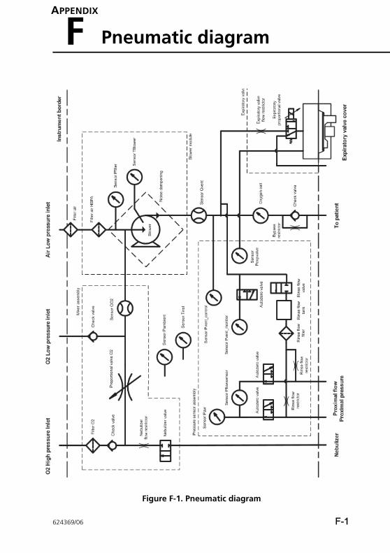
APPENDIX
F Pneumatic diagram
Figure F-1. Pneumatic diagram
624369/06 F-1

F Pneumatic diagram
F-2 624369/06
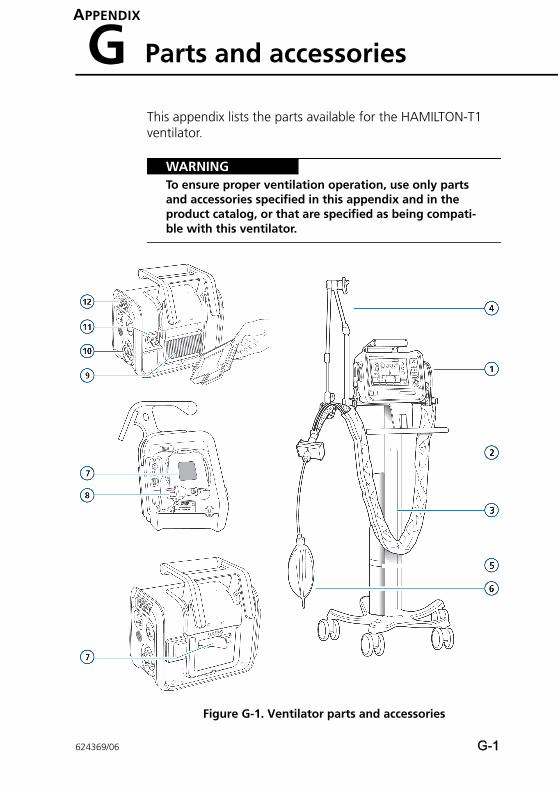
APPENDIX
G Parts and accessories
This appendix lists the parts available for the HAMILTON-T1 ventilator.
WARNINGTo ensure proper ventilation operation, use only parts and accessories specified in this appendix and in the product catalog, or that are specified as being compati-ble with this ventilator.
Figure G-1. Ventilator parts and accessories
624369/06 G-1
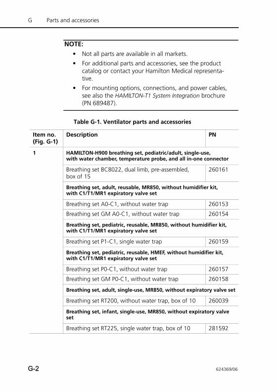
G Parts and accessories
NOTE:• Not all parts are available in all markets.
• For additional parts and accessories, see the product catalog or contact your Hamilton Medical representa-tive.
• For mounting options, connections, and power cables, see also the HAMILTON-T1 System Integration brochure (PN 689487).
Table G-1. Ventilator parts and accessories
Item no.(Fig. G-1)
Description PN
1 HAMILTON-H900 breathing set, pediatric/adult, single-use, with water chamber, temperature probe, and all in-one connector
Breathing set BC8022, dual limb, pre-assembled, box of 15
260161
Breathing set, adult, reusable, MR850, without humidifier kit, with C1/T1/MR1 expiratory valve set
Breathing set A0-C1, without water trap 260153
Breathing set GM A0-C1, without water trap 260154
Breathing set, pediatric, reusable, MR850, without humidifier kit, with C1/T1/MR1 expiratory valve set
Breathing set P1-C1, single water trap 260159
Breathing set, pediatric, reusable, HMEF, without humidifier kit, with C1/T1/MR1 expiratory valve set
Breathing set P0-C1, without water trap 260157
Breathing set GM P0-C1, without water trap 260158
Breathing set, adult, single-use, MR850, without expiratory valve set
Breathing set RT200, without water trap, box of 10 260039
Breathing set, infant, single-use, MR850, without expiratory valve set
Breathing set RT225, single water trap, box of 10 281592
G-2 624369/06
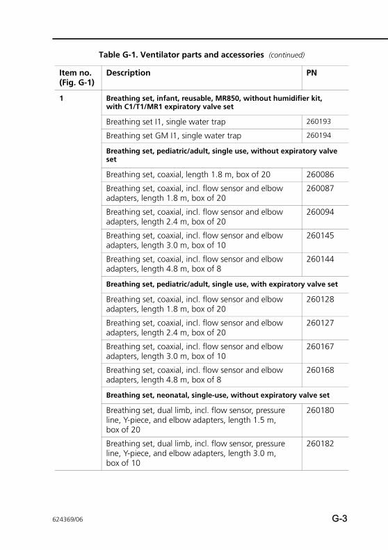
1 Breathing set, infant, reusable, MR850, without humidifier kit, with C1/T1/MR1 expiratory valve set
Breathing set I1, single water trap 260193
Breathing set GM I1, single water trap 260194
Breathing set, pediatric/adult, single use, without expiratory valve set
Breathing set, coaxial, length 1.8 m, box of 20 260086
Breathing set, coaxial, incl. flow sensor and elbow adapters, length 1.8 m, box of 20
260087
Breathing set, coaxial, incl. flow sensor and elbow adapters, length 2.4 m, box of 20
260094
Breathing set, coaxial, incl. flow sensor and elbow adapters, length 3.0 m, box of 10
260145
Breathing set, coaxial, incl. flow sensor and elbow adapters, length 4.8 m, box of 8
260144
Breathing set, pediatric/adult, single use, with expiratory valve set
Breathing set, coaxial, incl. flow sensor and elbow adapters, length 1.8 m, box of 20
260128
Breathing set, coaxial, incl. flow sensor and elbow adapters, length 2.4 m, box of 20
260127
Breathing set, coaxial, incl. flow sensor and elbow adapters, length 3.0 m, box of 10
260167
Breathing set, coaxial, incl. flow sensor and elbow adapters, length 4.8 m, box of 8
260168
Breathing set, neonatal, single-use, without expiratory valve set
Breathing set, dual limb, incl. flow sensor, pressure line, Y-piece, and elbow adapters, length 1.5 m, box of 20
260180
Breathing set, dual limb, incl. flow sensor, pressure line, Y-piece, and elbow adapters, length 3.0 m, box of 10
260182
Table G-1. Ventilator parts and accessories (continued)
Item no.(Fig. G-1)
Description PN
624369/06 G-3
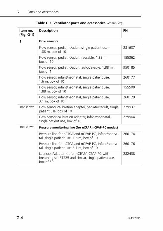
G Parts and accessories
1 Flow sensors
Flow sensor, pediatric/adult, single patient use, 1.88 m, box of 10
281637
Flow sensor, pediatric/adult, reusable, 1.88 m, box of 10
155362
Flow sensor, pediatric/adult, autoclavable, 1.88 m, box of 1
950185
Flow sensor, infant/neonatal, single patient use, 1.6 m, box of 10
260177
Flow sensor, infant/neonatal, single patient use, 1.88 m, box of 10
155500
Flow sensor, infant/neonatal, single patient use, 3.1 m, box of 10
260179
not shown Flow sensor calibration adapter, pediatric/adult, single patient use, box of 10
279937
Flow sensor calibration adapter, infant/neonatal, single patient use, box of 10
279964
not shown Pressure-monitoring line (for nCPAP, nCPAP-PC modes)
Pressure line for nCPAP and nCPAP-PC, infant/neona-tal, single patient use, 1.6 m, box of 10
260174
Pressure line for nCPAP and nCPAP-PC, infant/neona-tal, single patient use, 3.1 m, box of 10
260176
Luerlock Adapter Kit for nCPAP/nCPAP-PC with breathing set RT225 and similar, single patient use, box of 50
282438
Table G-1. Ventilator parts and accessories (continued)
Item no.(Fig. G-1)
Description PN
G-4 624369/06
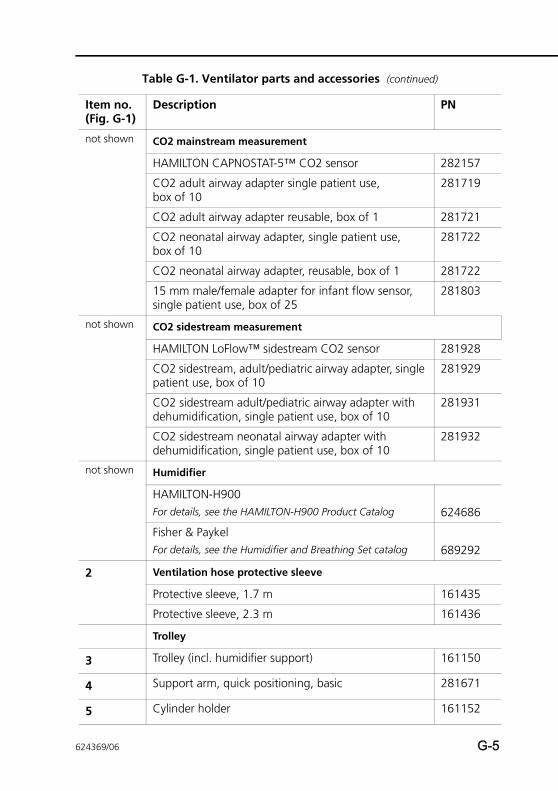
not shown CO2 mainstream measurement
HAMILTON CAPNOSTAT-5™ CO2 sensor 282157
CO2 adult airway adapter single patient use, box of 10
281719
CO2 adult airway adapter reusable, box of 1 281721
CO2 neonatal airway adapter, single patient use, box of 10
281722
CO2 neonatal airway adapter, reusable, box of 1 281722
15 mm male/female adapter for infant flow sensor, single patient use, box of 25
281803
not shown CO2 sidestream measurement
HAMILTON LoFlow™ sidestream CO2 sensor 281928
CO2 sidestream, adult/pediatric airway adapter, single patient use, box of 10
281929
CO2 sidestream adult/pediatric airway adapter with dehumidification, single patient use, box of 10
281931
CO2 sidestream neonatal airway adapter with dehumidification, single patient use, box of 10
281932
not shown Humidifier
HAMILTON-H900For details, see the HAMILTON-H900 Product Catalog 624686
Fisher & PaykelFor details, see the Humidifier and Breathing Set catalog 689292
2 Ventilation hose protective sleeve
Protective sleeve, 1.7 m 161435
Protective sleeve, 2.3 m 161436
Trolley
3 Trolley (incl. humidifier support) 161150
4 Support arm, quick positioning, basic 281671
5 Cylinder holder 161152
Table G-1. Ventilator parts and accessories (continued)
Item no.(Fig. G-1)
Description PN
624369/06 G-5
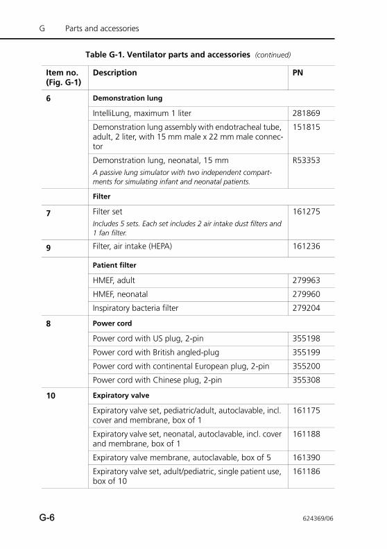
G Parts and accessories
6 Demonstration lung
IntelliLung, maximum 1 liter 281869
Demonstration lung assembly with endotracheal tube, adult, 2 liter, with 15 mm male x 22 mm male connec-tor
151815
Demonstration lung, neonatal, 15 mmA passive lung simulator with two independent compart-ments for simulating infant and neonatal patients.
R53353
Filter
7 Filter setIncludes 5 sets. Each set includes 2 air intake dust filters and 1 fan filter.
161275
9 Filter, air intake (HEPA) 161236
Patient filter
HMEF, adult 279963
HMEF, neonatal 279960
Inspiratory bacteria filter 279204
8 Power cord
Power cord with US plug, 2-pin 355198
Power cord with British angled-plug 355199
Power cord with continental European plug, 2-pin 355200
Power cord with Chinese plug, 2-pin 355308
10 Expiratory valve
Expiratory valve set, pediatric/adult, autoclavable, incl. cover and membrane, box of 1
161175
Expiratory valve set, neonatal, autoclavable, incl. cover and membrane, box of 1
161188
Expiratory valve membrane, autoclavable, box of 5 161390
Expiratory valve set, adult/pediatric, single patient use, box of 10
161186
Table G-1. Ventilator parts and accessories (continued)
Item no.(Fig. G-1)
Description PN
G-6 624369/06
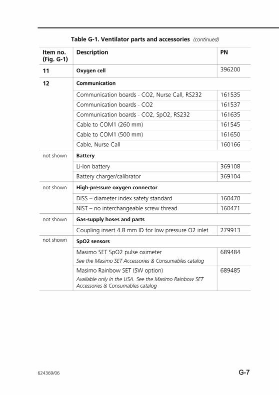
11 Oxygen cell 396200
12 Communication
Communication boards - CO2, Nurse Call, RS232 161535
Communication boards - CO2 161537
Communication boards - CO2, SpO2, RS232 161635
Cable to COM1 (260 mm) 161545
Cable to COM1 (500 mm) 161650
Cable, Nurse Call 160166
not shown Battery
Li-Ion battery 369108
Battery charger/calibrator 369104
not shown High-pressure oxygen connector
DISS – diameter index safety standard 160470
NIST – no interchangeable screw thread 160471
not shown Gas-supply hoses and parts
Coupling insert 4.8 mm ID for low pressure O2 inlet 279913
not shown SpO2 sensors
Masimo SET SpO2 pulse oximeterSee the Masimo SET Accessories & Consumables catalog
689484
Masimo Rainbow SET (SW option)Available only in the USA. See the Masimo Rainbow SET Accessories & Consumables catalog
689485
Table G-1. Ventilator parts and accessories (continued)
Item no.(Fig. G-1)
Description PN
624369/06 G-7
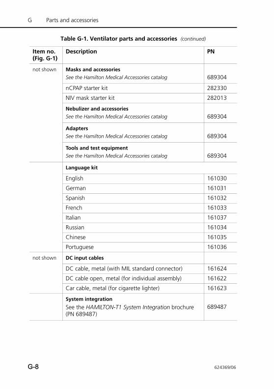
G Parts and accessories
not shown Masks and accessoriesSee the Hamilton Medical Accessories catalog 689304
nCPAP starter kit 282330
NIV mask starter kit 282013
Nebulizer and accessoriesSee the Hamilton Medical Accessories catalog 689304
AdaptersSee the Hamilton Medical Accessories catalog 689304
Tools and test equipmentSee the Hamilton Medical Accessories catalog 689304
Language kit
English 161030
German 161031
Spanish 161032
French 161033
Italian 161037
Russian 161034
Chinese 161035
Portuguese 161036
not shown DC input cables
DC cable, metal (with MIL standard connector) 161624
DC cable open, metal (for individual assembly) 161622
Car cable, metal (for cigarette lighter) 161623
System integration
See the HAMILTON-T1 System Integration brochure (PN 689487)
689487
Table G-1. Ventilator parts and accessories (continued)
Item no.(Fig. G-1)
Description PN
G-8 624369/06

Extended warranty
Extended warranty of 1 year 700403
Extended warranty of 2 years 700404
Extended warranty of 3 years 700405
Table G-1. Ventilator parts and accessories (continued)
Item no.(Fig. G-1)
Description PN
624369/06 G-9

G Parts and accessories
G-10 624369/06
APPENDIX
H Communications interface
H.1 Introduction H-2
H.2 About the protocols H-3
H.3 Using the COM1 communication interface H-4
H.3.1 Connecting to a patient monitor H-4
H.3.2 Connecting to a PDMS or computer H-6
H.3.3 COM1 connector pin assignments H-8
H.4 Using the Nurse call (6-pin) communication interface H-8
H.4.1 Sending alarm signals to a remote device H-9
H.4.2 Sending inspiratory:expiratory (I:E) timing signals H-9
H.4.3 Nurse 6-pin connector pin assignments H-10
624369/06 H-1
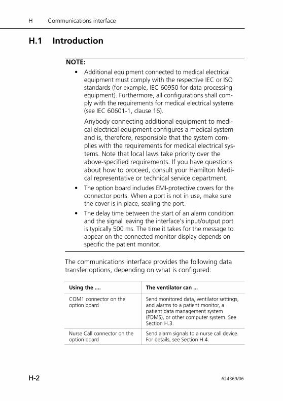
H Communications interface
H.1 Introduction
NOTE:• Additional equipment connected to medical electrical
equipment must comply with the respective IEC or ISO standards (for example, IEC 60950 for data processing equipment). Furthermore, all configurations shall com-ply with the requirements for medical electrical systems (see IEC 60601-1, clause 16).
Anybody connecting additional equipment to medi-cal electrical equipment configures a medical system and is, therefore, responsible that the system com-plies with the requirements for medical electrical sys-tems. Note that local laws take priority over the above-specified requirements. If you have questions about how to proceed, consult your Hamilton Medi-cal representative or technical service department.
• The option board includes EMI-protective covers for the connector ports. When a port is not in use, make sure the cover is in place, sealing the port.
• The delay time between the start of an alarm condition and the signal leaving the interface’s input/output port is typically 500 ms. The time it takes for the message to appear on the connected monitor display depends on specific the patient monitor.
The communications interface provides the following data transfer options, depending on what is configured:
Using the .... The ventilator can ...
COM1 connector on the option board
Send monitored data, ventilator settings, and alarms to a patient monitor, a patient data management system (PDMS), or other computer system. See Section H.3.
Nurse Call connector on the option board
Send alarm signals to a nurse call device. For details, see Section H.4.
H-2 624369/06
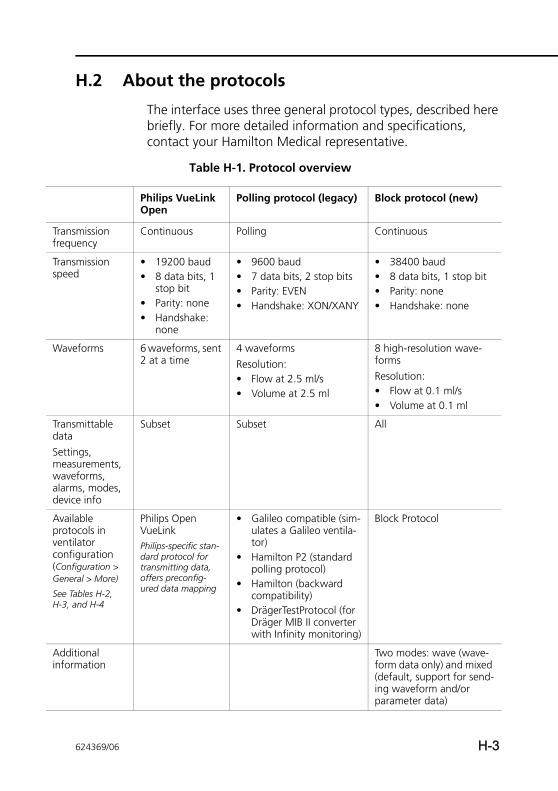
Trafre
Traspe
Wa
TradatSetmewaaladev
Avprovencon(CoGe
SeeH-3
Adinf
H.2 About the protocols
The interface uses three general protocol types, described here briefly. For more detailed information and specifications, contact your Hamilton Medical representative.
Table H-1. Protocol overview
Philips VueLink Open
Polling protocol (legacy) Block protocol (new)
nsmission quency
Continuous Polling Continuous
nsmission ed
• 19200 baud• 8 data bits, 1
stop bit• Parity: none• Handshake:
none
• 9600 baud• 7 data bits, 2 stop bits• Parity: EVEN• Handshake: XON/XANY
• 38400 baud• 8 data bits, 1 stop bit• Parity: none• Handshake: none
veforms 6 waveforms, sent 2 at a time
4 waveformsResolution: • Flow at 2.5 ml/s• Volume at 2.5 ml
8 high-resolution wave-formsResolution: • Flow at 0.1 ml/s• Volume at 0.1 ml
nsmittable atings, asurements, veforms, rms, modes, ice info
Subset Subset All
ailable tocols in tilator figuration
nfiguration > neral > More)
Tables H-2, , and H-4
Philips Open VueLinkPhilips-specific stan-dard protocol for transmitting data, offers preconfig-ured data mapping
• Galileo compatible (sim-ulates a Galileo ventila-tor)
• Hamilton P2 (standard polling protocol)
• Hamilton (backward compatibility)
• DrägerTestProtocol (for Dräger MIB II converter with Infinity monitoring)
Block Protocol
ditional ormation
Two modes: wave (wave-form data only) and mixed (default, support for send-ing waveform and/or parameter data)
624369/06 H-3
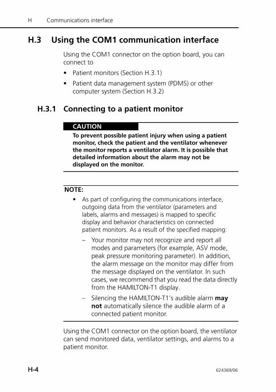
H Communications interface
H.3 Using the COM1 communication interface
Using the COM1 connector on the option board, you can connect to
• Patient monitors (Section H.3.1)
• Patient data management system (PDMS) or other computer system (Section H.3.2)
H.3.1 Connecting to a patient monitor
CAUTIONTo prevent possible patient injury when using a patient monitor, check the patient and the ventilator whenever the monitor reports a ventilator alarm. It is possible that detailed information about the alarm may not be displayed on the monitor.
NOTE:• As part of configuring the communications interface,
outgoing data from the ventilator (parameters and labels, alarms and messages) is mapped to specific display and behavior characteristics on connected patient monitors. As a result of the specified mapping:
– Your monitor may not recognize and report all modes and parameters (for example, ASV mode, peak pressure monitoring parameter). In addition, the alarm message on the monitor may differ from the message displayed on the ventilator. In such cases, we recommend that you read the data directly from the HAMILTON-T1 display.
– Silencing the HAMILTON-T1’s audible alarm may not automatically silence the audible alarm of a connected patient monitor.
Using the COM1 connector on the option board, the ventilator can send monitored data, ventilator settings, and alarms to a patient monitor.
H-4 624369/06
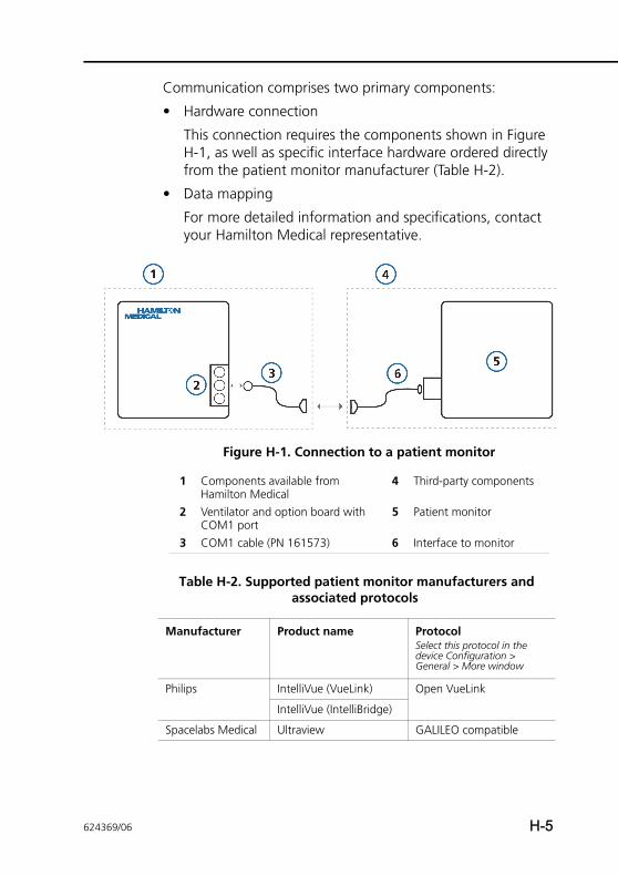
Communication comprises two primary components:
• Hardware connection
This connection requires the components shown in Figure H-1, as well as specific interface hardware ordered directly from the patient monitor manufacturer (Table H-2).
• Data mapping
For more detailed information and specifications, contact your Hamilton Medical representative.
Figure H-1. Connection to a patient monitor
1 Components available from Hamilton Medical
4 Third-party components
2 Ventilator and option board with COM1 port
5 Patient monitor
3 COM1 cable (PN 161573) 6 Interface to monitor
Table H-2. Supported patient monitor manufacturers and associated protocols
Manufacturer Product name ProtocolSelect this protocol in the device Configuration > General > More window
Philips IntelliVue (VueLink) Open VueLink
IntelliVue (IntelliBridge)
Spacelabs Medical Ultraview GALILEO compatible
624369/06 H-5
H Communications interface
H.3.2 Connecting to a PDMS or computerUsing the COM1 connector on the option board, the ventilator can send monitored data, ventilator settings, and alarms to a patient data management system (PDMS) at a hospital, or to another computer system.
Access to the data can be useful for data management and clinical studies. Data from the ventilator can be analyzed using a variety of software tools, and can also be made part of a patient’s electronic health record (EHR).
In addition, you can use the HAMILTON MEDICAL DataLogger software for research purposes. For details, contact your Ham-ilton Medical representative.
This connection requires the hardware shown in Figure H-2.
Table H-3 lists supported PDMS manufacturers and the associ-ated protocol to use.
In some cases, additional middleware solutions may be required to interface to the desired system; see Table H-4.
Nihon Kohden BSM-9101K (v12-06 or later)
Hamilton
BSM-6000K (v02-10 or later)
Dräger Infinity DrägerTestProtocol
Mindray Beneview Hamilton / Hamilton P2
Table H-2. Supported patient monitor manufacturers and associated protocols (continued)
Manufacturer Product name ProtocolSelect this protocol in the device Configuration > General > More window
H-6 624369/06
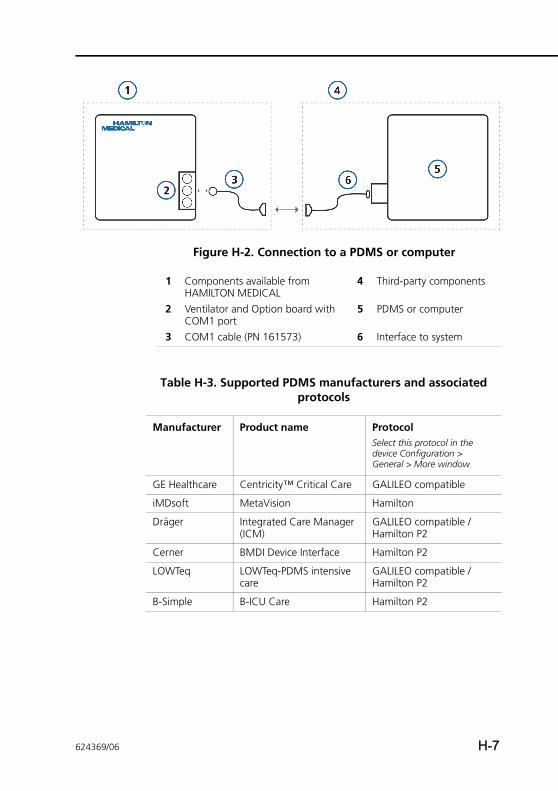
Figure H-2. Connection to a PDMS or computer
1 Components available from HAMILTON MEDICAL
4 Third-party components
2 Ventilator and Option board with COM1 port
5 PDMS or computer
3 COM1 cable (PN 161573) 6 Interface to system
Table H-3. Supported PDMS manufacturers and associated protocols
Manufacturer Product name ProtocolSelect this protocol in the device Configuration > General > More window
GE Healthcare Centricity™ Critical Care GALILEO compatible
iMDsoft MetaVision Hamilton
Dräger Integrated Care Manager (ICM)
GALILEO compatible / Hamilton P2
Cerner BMDI Device Interface Hamilton P2
LOWTeq LOWTeq-PDMS intensive care
GALILEO compatible / Hamilton P2
B-Simple B-ICU Care Hamilton P2
624369/06 H-7
H Communications interface
H.3.3 COM1 connector pin assignmentsFor details on the COM1 cable, connector, and pin assign-ments, see the Cable to COM1 User Note (PN 624442).
H.4 Using the Nurse call (6-pin) communication interface
CAUTIONThe maximum allowable voltage and current between the relay contacts are 0.2 A, 48 V.
The 6-pin connector on the option board is labeled Nurse.
Using the Nurse connector on the option board, the ventilator can send the following signals to a nurse call device or other device in a different location:
• Alarm signals (Section H.4.1)
• I:E timing signals (Section H.4.2)
The ability to send alarm signals to an external device is referred to as remote alarm or nurse call capability.
Table H-4. Supported middleware and associated protocols
Manufacturer Product name Protocol name/Protocol typeSelect this protocol in the device Configuration > General > More window
Capsule Tech-nologie
DataCaptor Hamilton P2
Bridge-Tech Device Connectivity Solu-tion (DCS)
Hamilton / Hamilton P2
H-8 624369/06
H.4.1 Sending alarm signals to a remote device
WARNINGBefore using the remote alarm function, check that alarms are being properly transmitted to the remote device.
CAUTIONIf the remote alarm function is used in an isolation ward, regularly check that alarms are being properly transmit-ted to the remote device.
The remote alarm (nurse call) capability allows alarms to be displayed and heard at locations other than the ventilator. This function is useful, for example, when the ventilator is in an isolation room, and the alarm signals must be transmitted to a different location.
The ventilator Alarm Silence key silences the audible portions of the alarms at both the ventilator and the remote device.
The remote alarm capability is based on relays inside the venti-lator. This application requires the 6-pin Nurse Call cable (PN 160166) and final assembly of the cable at your site. For details about the cable, connectors, and pin assignments, see the Nurse Call Cable Setup Guide (PN 624344).
H.4.2 Sending inspiratory:expiratory (I:E) timing signalsUsing the 6-pin Nurse connector on the option board, the ventilator can send I:E timing signals to an external device.
This application requires the hardware shown in Figure H-3.
The I:E timing capability is based on a relay inside the ventilator. For details, see the Nurse Call Cable Setup Guide (PN 624344).
624369/06 H-9
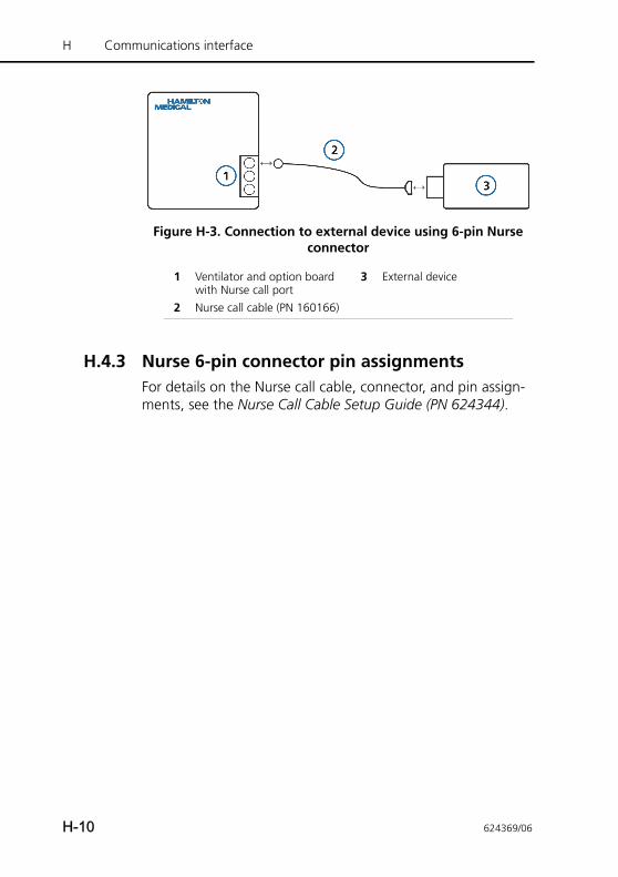
H Communications interface
Figure H-3. Connection to external device using 6-pin Nurse connector
H.4.3 Nurse 6-pin connector pin assignmentsFor details on the Nurse call cable, connector, and pin assign-ments, see the Nurse Call Cable Setup Guide (PN 624344).
1 Ventilator and option board with Nurse call port
3 External device
2 Nurse call cable (PN 160166)
H-10 624369/06
APPENDIX
I Configuration
I.1 Introduction I-2
I.2 Entering Configuration mode I-2
I.3 Configuring general settings I-3
I.3.1 Language: Selecting the defaultlanguage I-3
I.3.2 Selecting the default units of measure I-4
I.3.3 Enabling the communication interface I-5
I.3.4 Setting the minimum alarm loudness (volume) I-6
I.4 Setting breath timing and mode namingoptions I-7
I.4.1 Setting breath timing options forPCV+ and (S)CMV+ modes I-7
I.4.2 Choosing the mode naming convention I-8
I.5 Configuring default MMP display I-8
I.6 Setup window (quick setup configuration) I-9
I.6.1 Configuring individual setup settings I-9
I.6.2 Selecting a default quick setup I-15
I.7 Configuring pulse oximeter sensor settings I-16
I.8 Copying configuration settings I-16
I.9 Configuring software and hardware options I-17
I.9.1 Reviewing installed options I-17
I.9.2 Adding software options I-17
I.9.3 Enabling hardware options I-19
I.9.4 Removing options I-20
624369/06 I-1
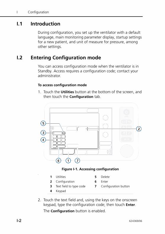
I Configuration
I.1 Introduction
During configuration, you set up the ventilator with a default language, main monitoring parameter display, startup settings for a new patient, and unit of measure for pressure, among other settings.
I.2 Entering Configuration mode
You can access configuration mode when the ventilator is in Standby. Access requires a configuration code; contact your administrator.
To access configuration mode
1. Touch the Utilities button at the bottom of the screen, and then touch the Configuration tab.
Figure I-1. Accessing configurationa
2. Touch the text field and, using the keys on the onscreen keypad, type the configuration code; then touch Enter.
The Configuration button is enabled.
1 Utilities 5 Delete2 Configuration 6 Enter3 Text field to type code 7 Configuration button4 Keypad
I-2 624369/06
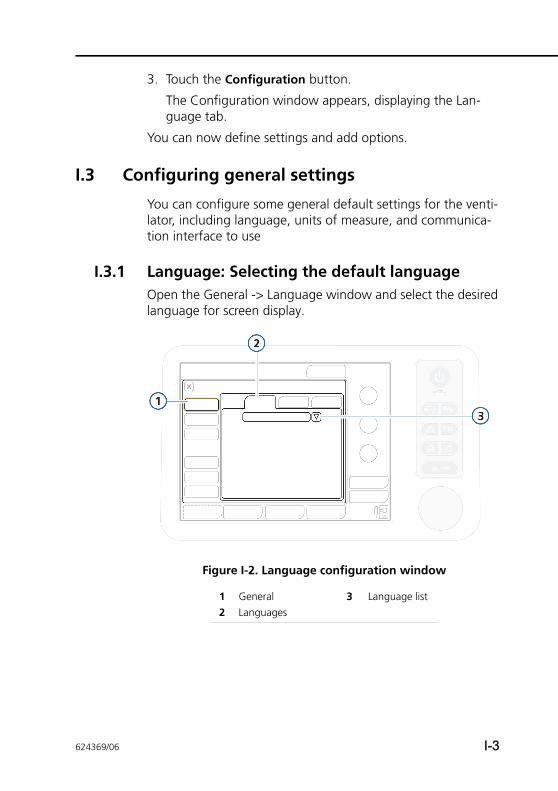
3. Touch the Configuration button.
The Configuration window appears, displaying the Lan-guage tab.
You can now define settings and add options.
I.3 Configuring general settings
You can configure some general default settings for the venti-lator, including language, units of measure, and communica-tion interface to use
I.3.1 Language: Selecting the default languageOpen the General -> Language window and select the desired language for screen display.
Figure I-2. Language configuration window
1 General 3 Language list2 Languages
624369/06 I-3
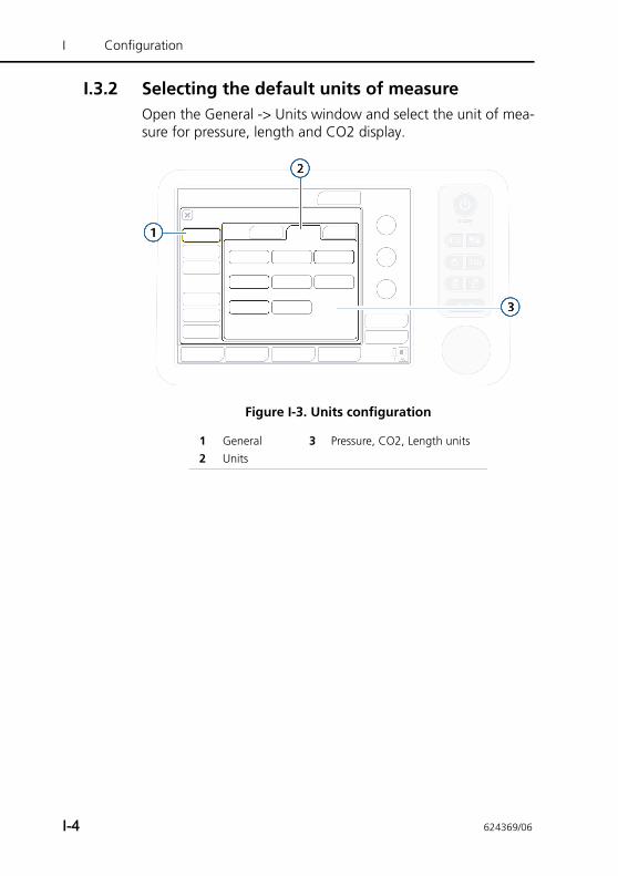
I Configuration
I.3.2 Selecting the default units of measureOpen the General -> Units window and select the unit of mea-sure for pressure, length and CO2 display.
Figure I-3. Units configuration
1 General 3 Pressure, CO2, Length units2 Units
I-4 624369/06
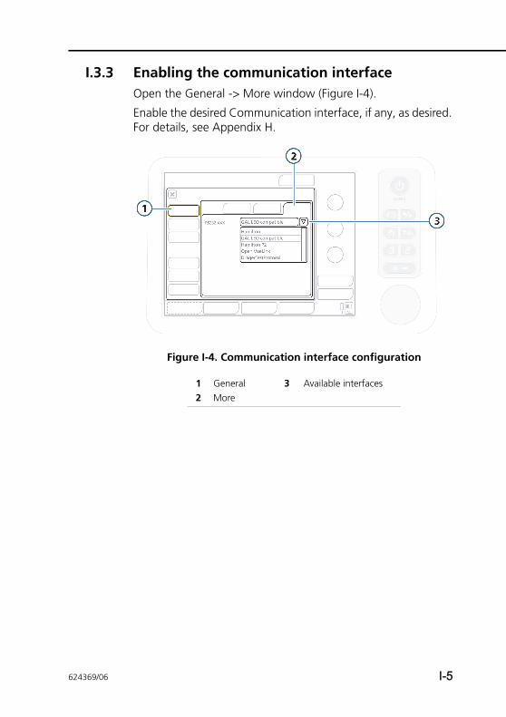
I.3.3 Enabling the communication interfaceOpen the General -> More window (Figure I-4).
Enable the desired Communication interface, if any, as desired. For details, see Appendix H.
Figure I-4. Communication interface configuration
1 General 3 Available interfaces2 More
624369/06 I-5
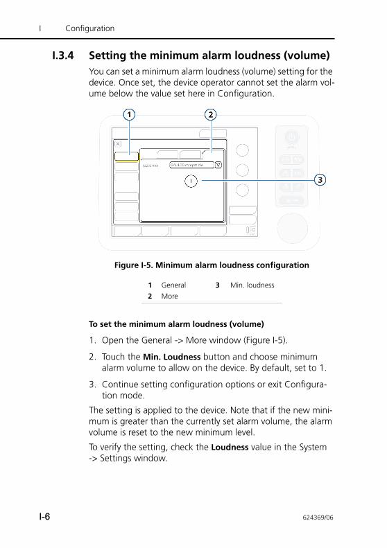
I Configuration
I.3.4 Setting the minimum alarm loudness (volume)You can set a minimum alarm loudness (volume) setting for the device. Once set, the device operator cannot set the alarm vol-ume below the value set here in Configuration.
Figure I-5. Minimum alarm loudness configuration
To set the minimum alarm loudness (volume)
1. Open the General -> More window (Figure I-5).
2. Touch the Min. Loudness button and choose minimum alarm volume to allow on the device. By default, set to 1.
3. Continue setting configuration options or exit Configura-tion mode.
The setting is applied to the device. Note that if the new mini-mum is greater than the currently set alarm volume, the alarm volume is reset to the new minimum level.
To verify the setting, check the Loudness value in the System -> Settings window.
1 General 3 Min. loudness2 More
I-6 624369/06
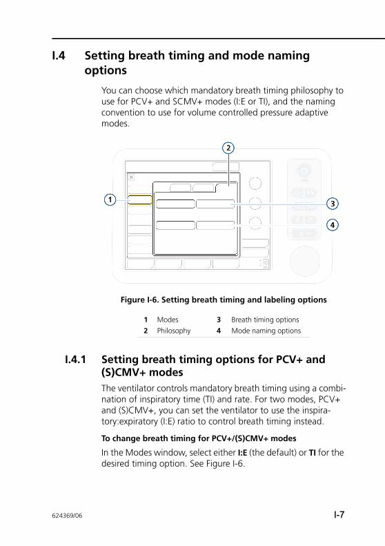
I.4 Setting breath timing and mode naming options
You can choose which mandatory breath timing philosophy to use for PCV+ and SCMV+ modes (I:E or TI), and the naming convention to use for volume controlled pressure adaptive modes.
Figure I-6. Setting breath timing and labeling options
I.4.1 Setting breath timing options for PCV+ and (S)CMV+ modesThe ventilator controls mandatory breath timing using a combi-nation of inspiratory time (TI) and rate. For two modes, PCV+ and (S)CMV+, you can set the ventilator to use the inspira-tory:expiratory (I:E) ratio to control breath timing instead.
To change breath timing for PCV+/(S)CMV+ modes
In the Modes window, select either I:E (the default) or TI for the desired timing option. See Figure I-6.
1 Modes 3 Breath timing options2 Philosophy 4 Mode naming options
624369/06 I-7
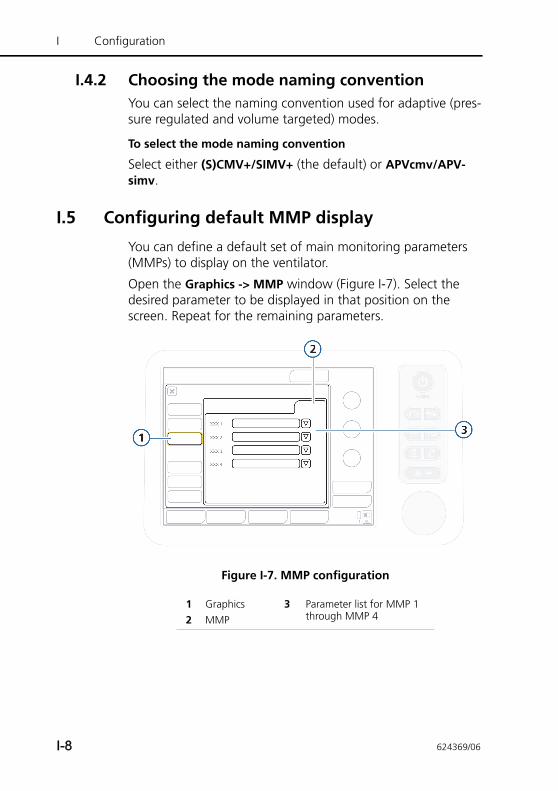
I Configuration
I.4.2 Choosing the mode naming conventionYou can select the naming convention used for adaptive (pres-sure regulated and volume targeted) modes.
To select the mode naming convention
Select either (S)CMV+/SIMV+ (the default) or APVcmv/APV-simv.
I.5 Configuring default MMP display
You can define a default set of main monitoring parameters (MMPs) to display on the ventilator.
Open the Graphics -> MMP window (Figure I-7). Select the desired parameter to be displayed in that position on the screen. Repeat for the remaining parameters.
Figure I-7. MMP configuration
1 Graphics 3 Parameter list for MMP 1 through MMP 42 MMP
I-8 624369/06
I.6 Setup window (quick setup configuration)
A Quick setup refers to a group of settings you define, includ-ing patient characteristics (group and weight), mode selection and control settings, alarm limit settings, and weaning zone limits, that is automatically applied when the setup is selected in the Standby window.
You can configure up to three Quick setups, and can specify a setup to be selected by default when the ventilator is turned on (Section I.6.2).
I.6.1 Configuring individual setup settings
To configure a Quick setup
1. In Standby mode, configure the ventilator with the parame-ters you will save as a Quick setup. Select:
– Patient group and gender/height (adult/pediatric) or weight (neonatal)
– Ventilation mode
– Mode control settings
– Alarm limits
2. Enter Configuration mode (Section I.2).
3. In the Configuration window, touch Setups, and then touch the button (1, 2, or 3, or your custom-defined labels) for the setup to configure.
624369/06 I-9
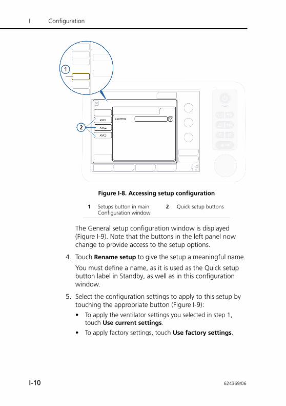
I Configuration
Figure I-8. Accessing setup configuration
The General setup configuration window is displayed (Figure I-9). Note that the buttons in the left panel now change to provide access to the setup options.
4. Touch Rename setup to give the setup a meaningful name.
You must define a name, as it is used as the Quick setup button label in Standby, as well as in this configuration window.
5. Select the configuration settings to apply to this setup by touching the appropriate button (Figure I-9):• To apply the ventilator settings you selected in step 1,
touch Use current settings.
• To apply factory settings, touch Use factory settings.
1 Setups button in main Configuration window
2 Quick setup buttons
I-10 624369/06
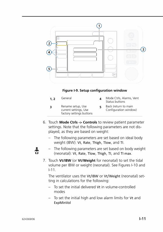
Figure I-9. Setup configuration window
6. Touch Mode Ctrls -> Controls to review patient parameter settings. Note that the following parameters are not dis-played, as they are based on weight:
– The following parameters are set based on ideal body weight (IBW): Vt, Rate, Thigh, Tlow, and TI.
– The following parameters are set based on body weight (neonatal): Vt, Rate, Tlow, Thigh, TI, and TI max.
7. Touch Vt/IBW (or Vt/Weight for neonatal) to set the tidal volume per IBW or weight (neonatal). See Figures I-10 and I-11.
The ventilator uses the Vt/IBW or Vt/Weight (neonatal) set-ting in calculations for the following:
– To set the initial delivered Vt in volume-controlled modes
– To set the initial high and low alarm limits for Vt and ExpMinVol
1, 2 General 4 Mode Ctrls, Alarms, Vent Status buttons
3 Rename setup, Use current settings, Use factory settings buttons
5 Back (return to main Configuration window)
624369/06 I-11
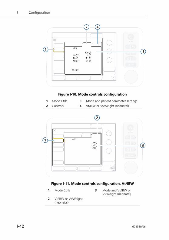
I Configuration
Figure I-10. Mode controls configuration
Figure I-11. Mode controls configuration, Vt/IBW
1 Mode Ctrls 3 Mode and patient parameter settings2 Controls 4 Vt/IBW or Vt/Weight (neonatal)
1 Mode Ctrls 3 Mode and Vt/IBW or Vt/Weight (neonatal)
2 Vt/IBW or Vt/Weight (neonatal)
I-12 624369/06
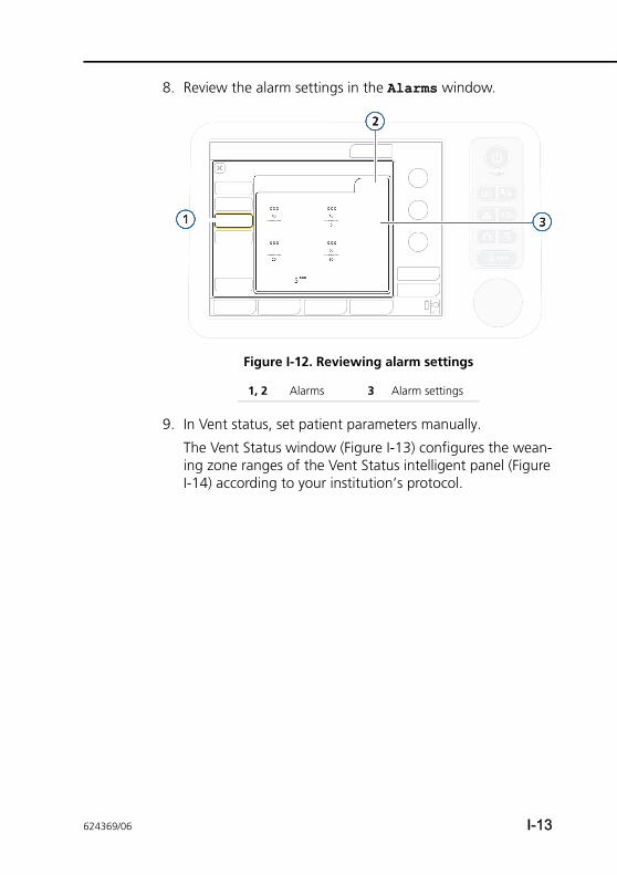
8. Review the alarm settings in the Alarms window.
Figure I-12. Reviewing alarm settings
9. In Vent status, set patient parameters manually.
The Vent Status window (Figure I-13) configures the wean-ing zone ranges of the Vent Status intelligent panel (Figure I-14) according to your institution’s protocol.
1, 2 Alarms 3 Alarm settings
624369/06 I-13
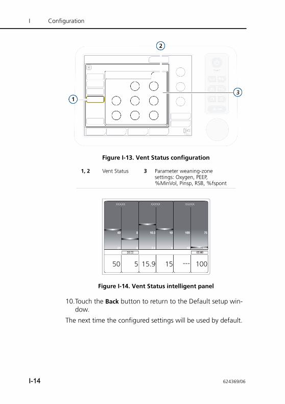
I Configuration
Figure I-13. Vent Status configuration
Figure I-14. Vent Status intelligent panel
10.Touch the Back button to return to the Default setup win-dow.
The next time the configured settings will be used by default.
1, 2 Vent Status 3 Parameter weaning-zone settings: Oxygen, PEEP, %MinVol, Pinsp, RSB, %fspont
I-14 624369/06
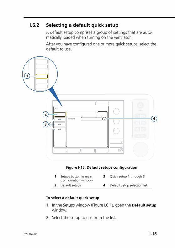
I.6.2 Selecting a default quick setupA default setup comprises a group of settings that are auto-matically loaded when turning on the ventilator.
After you have configured one or more quick setups, select the default to use.
Figure I-15. Default setups configuration
To select a default quick setup
1. In the Setups window (Figure I.6.1), open the Default setup window.
2. Select the setup to use from the list.
1 Setups button in main Configuration window
3 Quick setup 1 through 3
2 Default setups 4 Default setup selection list
624369/06 I-15
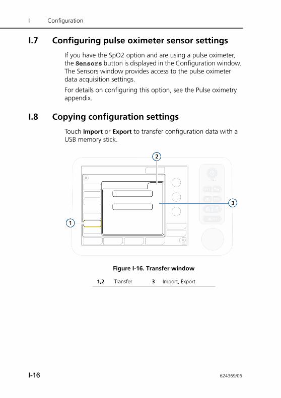
I Configuration
I.7 Configuring pulse oximeter sensor settings
If you have the SpO2 option and are using a pulse oximeter, the Sensors button is displayed in the Configuration window. The Sensors window provides access to the pulse oximeter data acquisition settings.
For details on configuring this option, see the Pulse oximetry appendix.
I.8 Copying configuration settings
Touch Import or Export to transfer configuration data with a USB memory stick.
Figure I-16. Transfer window
1,2 Transfer 3 Import, Export
I-16 624369/06
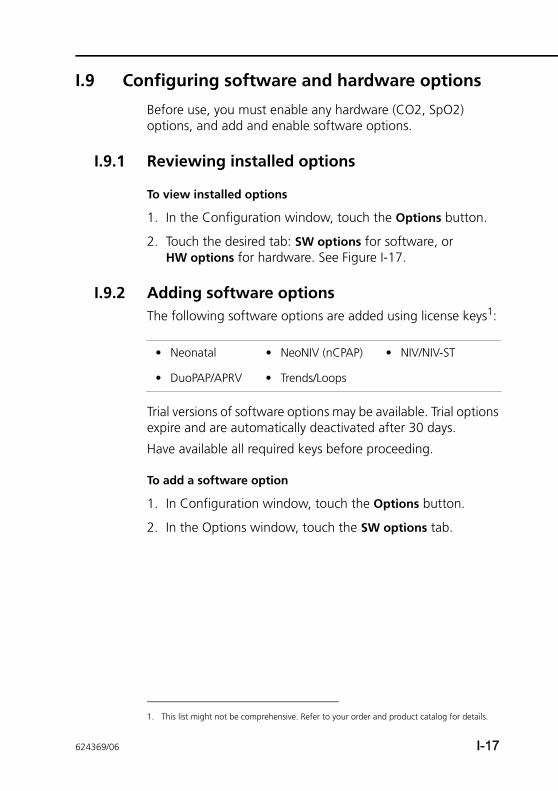
I.9 Configuring software and hardware options
Before use, you must enable any hardware (CO2, SpO2) options, and add and enable software options.
I.9.1 Reviewing installed options
To view installed options
1. In the Configuration window, touch the Options button.
2. Touch the desired tab: SW options for software, or HW options for hardware. See Figure I-17.
I.9.2 Adding software optionsThe following software options are added using license keys1:
Trial versions of software options may be available. Trial options expire and are automatically deactivated after 30 days.
Have available all required keys before proceeding.
To add a software option
1. In Configuration window, touch the Options button.
2. In the Options window, touch the SW options tab.
1. This list might not be comprehensive. Refer to your order and product catalog for details.
• Neonatal • NeoNIV (nCPAP) • NIV/NIV-ST
• DuoPAP/APRV • Trends/Loops
624369/06 I-17
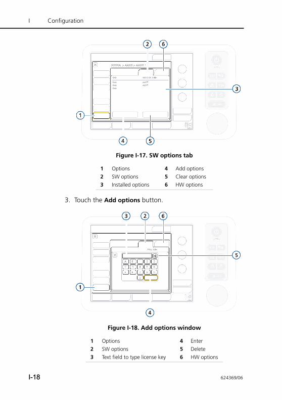
I Configuration
Figure I-17. SW options tab
3. Touch the Add options button.
Figure I-18. Add options window
1 Options 4 Add options2 SW options 5 Clear options3 Installed options 6 HW options
1 Options 4 Enter2 SW options 5 Delete3 Text field to type license key 6 HW options
I-18 624369/06
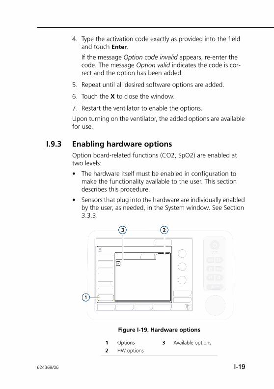
4. Type the activation code exactly as provided into the field and touch Enter.
If the message Option code invalid appears, re-enter the code. The message Option valid indicates the code is cor-rect and the option has been added.
5. Repeat until all desired software options are added.
6. Touch the X to close the window.
7. Restart the ventilator to enable the options.
Upon turning on the ventilator, the added options are available for use.
I.9.3 Enabling hardware optionsOption board-related functions (CO2, SpO2) are enabled at two levels:
• The hardware itself must be enabled in configuration to make the functionality available to the user. This section describes this procedure.
• Sensors that plug into the hardware are individually enabled by the user, as needed, in the System window. See Section 3.3.3.
Figure I-19. Hardware options
1 Options 3 Available options2 HW options
624369/06 I-19
I Configuration
To enable hardware options in configuration
1. Touch Options.
2. In the Options window, touch the HW options tab. See Figure I-19.
The window lists installed hardware that requires activation.
3. Select the check box for options to enable.
Upon exiting configuration, the enabled hardware is available for use.
I.9.4 Removing options
NOTE:• The Clear options function removes all non-trial
options. You cannot remove just one or a few. If that is your goal, clear the options and re-add those that are needed.
• The patient groups on the ventilator, Adult/Ped and Neonatal, are both treated as options. Clearing options also removes these patient groups and the associated ventilation modes.
Before the ventilator can be used on a patient, the required patient groups (and associated modes) must be re-added. Follow the steps to add options (Section I.9.2) and add the necessary patient groups. The associated ventilation modes are also added.
• Options are removed after restarting the ventilator.
To remove software options
You can remove all non-trial software options from the ventila-tor.
1. In the SW options window, touch Clear options.
You are prompted to confirm deletion of all non-trial options, including the Adult/Ped and/or Neonatal patient groups. See Note above.
I-20 624369/06
2. Touch Clear options to remove the options.
Touch Cancel to leave the options installed.
3. Restart the ventilator.
Once you restart the ventilator, all options (including patient groups) listed in the window are cleared.
4. To re-add the patient groups and any other desired options, re-enter Configuration mode.
5. Add the required patient groups and any desired options, as appropriate. See Section I.9.2.
I.9.4.1 Disabling hardware optionsIn the HW options window, clear the check boxes for the hard-ware to disable. See Section I.9.3.
624369/06 I-21

I Configuration
I-22 624369/06
APPENDIX
J Pulse oximetry
J.1 Introduction J-3
J.2 SpO2 monitoring with Masimo SET J-7
J.2.1 Pulse oximetry components J-7
J.3 Working with pulse oximetry data J-8
J.3.1 Enabling SpO2 monitoring J-8
J.3.2 Monitored parameters and settings J-10
J.4 Viewing pulse oximetry data J-11
J.4.1 Viewing data in the Monitoringwindow J-12
J.4.2 Viewing SpO2 data on the maindisplay J-13
J.4.3 Dynamic Lung panel with SpO2 J-14
J.4.4 Displaying the plethysmogram J-15
J.4.5 Displaying trends J-17
J.5 Working with alarms J-17
J.5.1 Setting alarm limits J-17
J.5.2 SpO2 alarm delay J-18
J.5.3 Pulse-oximetry-related alarms andsettings J-18
J.6 Connecting the pulse oximetry system J-22
J.6.1 Connecting the components J-25
J.6.2 Verifying sensor measurements J-27
J.6.3 Disconnecting the SpO2 adapter J-28
J.6.4 Connecting the adapter for transport J-29
J.7 Configuring and enabling the pulse oximeter J-30
J.7.1 Enabling the hardware J-30
J.7.2 Selecting SpO2 sensor data options J-31
J.8 Troubleshooting J-35
J.9 Cleaning and maintenance J-37
624369/06 J-1
J Pulse oximetry
J.9.1 Cleaning the adapter and sensor J-38
J.9.2 Replacing the adapter, cables, or sensor J-38
J.9.3 Disposing of the adapter, cables, and sensor J-38
J.10 About the SpO2/FiO2 ratio J-39
J-2 624369/06
J.1 Introduction
This appendix is designed to be added to your ventilator Oper-ator’s Manual folder, and refers to information provided in the Operator’s Manual.
The Masimo SET® pulse oximeter (also referred to as a pulse CO-oximeter) comprises a sensor (also referred to as a probe), cables, and adapter.
WARNING• A pulse CO-oximeter should be considered an early
warning device. As a trend towards patient hypoxemia is indicated, blood samples should be analyzed by laboratory instruments to completely understand the patient’s condition.
• Verify the compatibility of the adapter, sensor, and cables before use. Use of incompatible components can result in patient injury.
• SpO2 is empirically calibrated to functional arterial oxygen saturation in healthy adult volunteers with normal levels of carboxyhaemoglobin (COHb) and methaemoglobin (MetHb). A pulse oximeter can not measure elevated levels of COHb or MetHb. Increases in either COHb or MetHb will affect the accuracy of the SpO2 measurement.
– For increased COHb: COHb levels above normal tend to increase the level of SpO2. The level of increase is approximately equal to the amount of COHb that is present.
Note that high levels of COHb may occur with a seemingly normal SpO2. When elevated levels of COHb are suspected, laboratory analysis (CO-oxime-try) of a blood sample should be performed.
– For increased MetHb: The SpO2 may be decreased by levels of MetHb of up to approximately 10% to 15%. At higher levels of MetHb, the SpO2 may tend to read in the low to mid 80s. When elevated levels of MetHb are suspected, laboratory analysis (CO-oxime-try) of a blood sample should be performed.
624369/06 J-3
J Pulse oximetry
• To ensure patient electrical isolation, connect only to other equipment with electrically isolated circuits.
• Do not use the pulse CO-oximeter during magnetic resonance imaging (MRI) scanning. Induced current could potentially cause burns. The pulse CO-oximeter may affect the MRI image, and the MRI unit may affect the accuracy of the oximetry measurements.
• The pulsations from intra-aortic balloon support can be additive to the pulse rate on the oximeter pulse rate display. Verify patient's pulse rate against the ECG heart rate.
• Elevated levels of total Bilirubin may lead to inaccurate SpO2 measurements.
• Loss of pulse signal can occur when
– The sensor is too tight
– The patient has hypotension, severe vasoconstric-tion, severe anemia, or hypothermia
– There is arterial occlusion proximal to the sensor
– The patient is in cardiac arrest or is in shock
• In case of anemia and blood loss, the SpO2 sensor is unable to detect tissue hypoxia.
• SpO2 measurement can be incorrect if
– The patient’s carboxyhaemoglobin or methaemoglo-bin increases abnormally
– Dye is injected into the blood
– An electrosurgical unit is used
– During CPR
– Measuring at a site with venous pulse
– There is body movement
– The pulse wave is small (insufficient peripheral circu-lation)
• Severe anemia may cause erroneous SpO2 readi ngs.
• Skin pigmentation can affect the SpO2 value. Verify SpO2 by checking the plethysmographic waveform and the quality index of the measured SpO2 value.
• SpO2 measurement in case of patients with carbon monoxide poisoning can be incorrect.
J-4 624369/06
• Interfering substances: Dyes, or any substance con-taining dyes, that change usual blood pigmentation may cause erroneous readings.
• When there is abnormally high methaemoglobin and carboxyhaemoglobin, the SpO2 reading is incorrect.
• Pulse rate measurement is based on the optical detection of a peripheral flow pulse and therefore may not detect certain arrhythmias. The pulse CO-oximeter should not be used as a replacement or sub-stitute for ECG-based arrhythmia analysis.
• With very low perfusion at the monitored site, the readings may read lower than core arterial oxygen saturation.
• Venous pulsations may cause erroneous low readings (for example, tricuspid valve regurgitation).
• The pulse CO-oximeter is NOT intended for use as an apnea monitor.
• Incorrect measurements can also be caused by
– Excessive patient movement
– Incorrect application or use of the pulse oximetry components
CAUTION• If using pulse CO-oximetry during full body
irradiation, keep the sensor out of the irradiation field. If the sensor is exposed to the irradiation, the reading might be inaccurate or the unit might read zero for the duration of the active irradiation period.
• Verify SpO2 periodically by observing the plethysmographic wave form and the quality index (QI-SpO2) of the measured SpO2 value.
• Verify SpO2 periodically by comparing measured SpO2 against patients’ SaO2 with an ABG (Arterial Blood Gas) measurement.
• All devices are NOT protected against the effect of the discharge of a cardiac defibrillator.
• Detach the SpO2 sensor before defibrillation.
624369/06 J-5
J Pulse oximetry
• Under normal conditions, this probe is almost unaf-fected by light. However, when measuring under strong light (surgical light, sunlight), cover the probe with a blanket or cloth. Otherwise, measurement accuracy is affected.
NOTE:• U.S. Federal law restricts this device to sale by or on the
order of a physician.
• Only use components specified by Hamilton Medical.
• Use only Masimo sensors for SpO2 measurements.
• DO NOT use or store outside of specified environmental conditions.
• The environmental limitations for the SpO2 sensors may be different from those for the ventilator. The ventilator can operate in conditions up to 50°C (122°F). The sup-ported SpO2 sensors are rated to 40°C (104°F).
• Read all of the safety information before using the sen-sor. Before use, carefully read the sensor’s Directions for use.
• Equipment used to test pulse oximeter components (probe, adapter) cannot be used to assess their mea-surement accuracy.
• Only qualified personnel may operate the pulse oxime-ter. Read this manual, safety information, accessory directions for use, and specifications before use.
This appendix includes several descriptions, warnings and spec-ifications for the Masimo adapter and sensors.Not all of the information is included here. For detailed infor-mation, see the Masimo Starter Kit documentation, sensor inserts, and the manufacturer’s Directions for use. Be sure to also read the safety information for the ventilator, provided in the device Operator’s Manual.Additional information may also be available at the manufac-turers’ website: http://www.masimo.com. For information on Masimo patents, see www.masimo.com/patents.htm.
J-6 624369/06
Note that possession or purchase of this device does not con-vey any express or implied license to use the device with unau-thorized sensors or cables which would, alone or in combination with this device, fall within the scope of one or more of the patents relating to this device.
J.2 SpO2 monitoring with Masimo SET
The Masimo SET® pulse oximeter comprises a sensor, cables, and adapter.
The sensor takes a reading every second to provide accurate, reliable data for SpO2, heart rate (pulse), and perfusion index, together with a signal quality indicator. Working with the adapter, the sensor sends this information to the ventilator.
The values of these parameters are integrated into the ventila-tor’s display, support trend graphics and a plethysmogram, and are subject to applicable alarms, all of which are controlled at the ventilator.
J.2.1 Pulse oximetry componentsSupport for pulse oximetry is available with installation of the SpO2-enabled option board (PN 161635).
Figure J-1 shows the system components (the option board is not shown).
For connection and setup information, see Section J.6.
624369/06 J-7
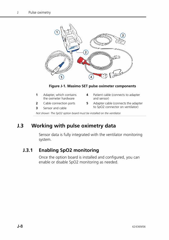
J Pulse oximetry
Figure J-1. Masimo SET pulse oximeter components
J.3 Working with pulse oximetry data
Sensor data is fully integrated with the ventilator monitoring system.
J.3.1 Enabling SpO2 monitoringOnce the option board is installed and configured, you can enable or disable SpO2 monitoring as needed.
1 Adapter, which contains the oximeter hardware
4 Patient cable (connects to adapter and sensor)
2 Cable connection ports 5 Adapter cable (connects the adapter to SpO2 connector on ventilator)3 Sensor and cable
Not shown: The SpO2 option board must be installed on the ventilator.
J-8 624369/06
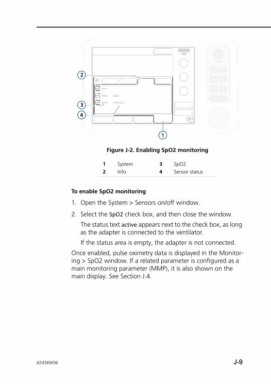
Figure J-2. Enabling SpO2 monitoring
To enable SpO2 monitoring
1. Open the System > Sensors on/off window.
2. Select the SpO2 check box, and then close the window.
The status text active appears next to the check box, as long as the adapter is connected to the ventilator.
If the status area is empty, the adapter is not connected.
Once enabled, pulse oximetry data is displayed in the Monitor-ing > SpO2 window. If a related parameter is configured as a main monitoring parameter (MMP), it is also shown on the main display. See Section J.4.
1 System 3 SpO2 2 Info 4 Sensor status
624369/06 J-9
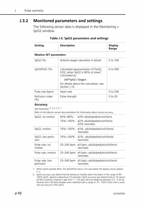
J Pulse oximetry
J.3.2 Monitored parameters and settingsThe following sensor data is displayed in the Monitoring > SpO2 window.
Table J-3. SpO2 parameters and settings
Setting Description Display Range
Masimo SET parameters
SpO2 (%) Arterial oxygen saturation in blood 0 to 100
SpO2/FiO2 (%) Calculated approximation of PaO2/FiO2, when SpO2 is 94% or lower1. Calculated as:
100*SpO2 / OxygenFor details about this calculation, see Section J.10.
0 to 500
Pulse rate (bpm) Heart rate 0 to 240
Perfusion index (%)
Pulse strength 0 to 20
Accuracy See footnotes 2, 3, 4, 5, 6, 7.
Refer to the Masimo sensor documentation for information about sensor accuracy.
SpO2, no motion 60%–80%: ±3% adults/pediatrics/infants70%–100%: ±2% adults/pediatrics/infants;
±3% neonates
SpO2, motion 70%–100%: ±3%, adults/pediatrics/infants/neonates
SpO2, low perfu-sion
70%–100%: ±2%, adults/pediatrics/infants/neonates
Pulse rate, no motion
25–240 bpm: ±3 bpm, adults/pediatrics/infants/neonates
Pulse rate, motion 25–240 bpm: ±5 bpm, adults/pediatrics/infants/neonates
Pulse rate, low perfusion
25–240 bpm: ±5 bpm, adults/pediatrics/infants/neonates
1. When SpO2 exceeds 94%, the SpO2/FiO2 ratio is not calculated; the display shows dashes (---).
2. SpO2 accuracy was determined by testing on healthy adult volunteers in the range of 60-100% SpO2, against a laboratory CO-oximeter. SpO2 accuracy was determined on 16 neona-tal NICU patients ranging in age from 7 - 135 days old and weighing between 0.5 - 4.25 kg. Seventy-nine (79) data samples were collected over a range of 70 - 100% SaO2 with a resul-tant accuracy of 2.9% SpO2.
J-10 624369/06
J.4 Viewing pulse oximetry data
NOTE:When a parameter shows dashes or no value, it is not used in any calculations.
Pulse oximeter sensor data is measured and updated every second.
This data is readily available as follows:
• In the Monitoring window (Section J.4.1)
• On the main display (Section J.4.2)
• In the Dynamic Lung panel (Section J.4.3)
• In a plethysmogram (Section J.4.4)
• As a trend graph (Section J.4.5)
3. The Masimo sensors have been validated for no-motion accuracy in human blood studies on healthy adult male and female volunteers with light to dark skin pigmentation in induced hypoxia studies in the range of 70-100% SpO2 against a laboratory CO-oximeter and ECG monitor. This variation equals plus or minus one standard deviation, which encompasses 68% of the population.
4. The Masimo sensors have been validated for motion accuracy in human blood studies on healthy adult male and female volunteers with light to dark skin pigmentation in induced hypoxia studies in the range of 70-100% SpO2 against a laboratory CO-oximeter and ECG monitor. This variation equals plus or minus one standard deviation, which encompasses 68% of the population.
5. The Masimo SET technology has been validated for low-perfusion accuracy in bench-top test-ing against a Biotek Index 2 simulator and Masimo’s simulator with signal strengths of greater than 0.02% and transmission of greater than 5% for saturations ranging from 70 to 100%. This variation equals plus or minus one standard deviation, which encompasses 68% of the population.
6. The Masimo sensors have been validated for pulse-rate accuracy for the range of 25-240 bpm in bench-top testing against a Biotek Index 2 simulator. This variation equals plus or minus one standard deviation, which encompasses 68% of the population.
7. The following substances may interfere with pulse CO-oximetry measurements:Severe anemia may cause erroneous SpO2 measurements.Dyes or any substance containing dyes that change usual blood pigmentation may cause erro-neous readings.Elevated levels of total bilirubin may lead to inaccurate SpO2 measurements.
624369/06 J-11
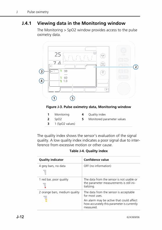
J Pulse oximetry
J.4.1 Viewing data in the Monitoring windowThe Monitoring > SpO2 window provides access to the pulse oximetry data.
Figure J-3. Pulse oximetry data, Monitoring window
The quality index shows the sensor’s evaluation of the signal quality. A low quality index indicates a poor signal due to inter-ference from excessive motion or other cause.
1 Monitoring 4 Quality index2 SpO2 5 Monitored parameter values3 1 (SpO2 values)
Table J-4. Quality index
Quality indicator Confidence value
4 grey bars, no data OFF (no information)
1 red bar, poor quality The data from the sensor is not usable or the parameter measurements is still ini-tializing.
2 orange bars, medium quality The data from the sensor is acceptable for most uses. An alarm may be active that could affect how accurately this parameter is currently measured.
J-12 624369/06
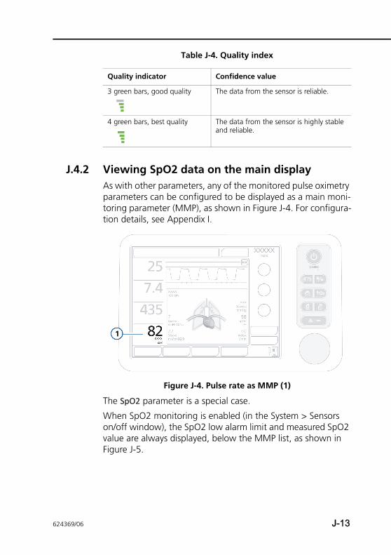
J.4.2 Viewing SpO2 data on the main displayAs with other parameters, any of the monitored pulse oximetry parameters can be configured to be displayed as a main moni-toring parameter (MMP), as shown in Figure J-4. For configura-tion details, see Appendix I.
Figure J-4. Pulse rate as MMP (1)
The SpO2 parameter is a special case.
When SpO2 monitoring is enabled (in the System > Sensors on/off window), the SpO2 low alarm limit and measured SpO2 value are always displayed, below the MMP list, as shown in Figure J-5.
3 green bars, good quality The data from the sensor is reliable.
4 green bars, best quality The data from the sensor is highly stable and reliable.
Table J-4. Quality index
Quality indicator Confidence value
624369/06 J-13
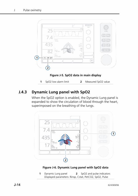
J Pulse oximetry
Figure J-5. SpO2 data in main display
J.4.3 Dynamic Lung panel with SpO2When the SpO2 option is enabled, the Dynamic Lung panel is expanded to show the circulation of blood through the heart, superimposed on the breathing of the lungs.
Figure J-6. Dynamic Lung panel with SpO2 data
1 SpO2 low alarm limit 2 Measured SpO2 value
1 Dynamic Lung panel 2 SpO2 and pulse indicatorsDisplayed parameters: Rinsp, Cstat, PetCO2, SpO2, Pulse
J-14 624369/06
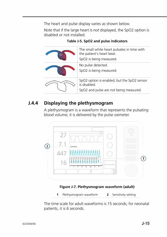
The heart and pulse display varies as shown below.
Note that if the large heart is not displayed, the SpO2 option is disabled or not installed.
J.4.4 Displaying the plethysmogramA plethysmogram is a waveform that represents the pulsating blood volume; it is delivered by the pulse oximeter.
Figure J-7. Plethysmogram waveform (adult)
The time scale for adult waveforms is 15 seconds; for neonatal patients, it is 6 seconds.
Table J-5. SpO2 and pulse indicators
The small white heart pulsates in time with the patient’s heart beat. SpO2 is being measured.
No pulse detected. SpO2 is being measured.
SpO2 option is enabled, but the SpO2 sensor is disabled. SpO2 and pulse are not being measured.
1 Plethysmogram waveform 2 Sensitivity setting
624369/06 J-15
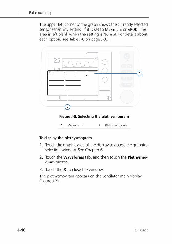
J Pulse oximetry
The upper left corner of the graph shows the currently selected sensor sensitivity setting, if it is set to Maximum or APOD. The area is left blank when the setting is Normal. For details about each option, see Table J-8 on page J-33.
Figure J-8. Selecting the plethysmogram
To display the plethysmogram
1. Touch the graphic area of the display to access the graphics-selection window. See Chapter 6.
2. Touch the Waveforms tab, and then touch the Plethysmo-gram button.
3. Touch the X to close the window.
The plethysmogram appears on the ventilator main display (Figure J-7).
1 Waveforms 2 Plethysmogram
J-16 624369/06
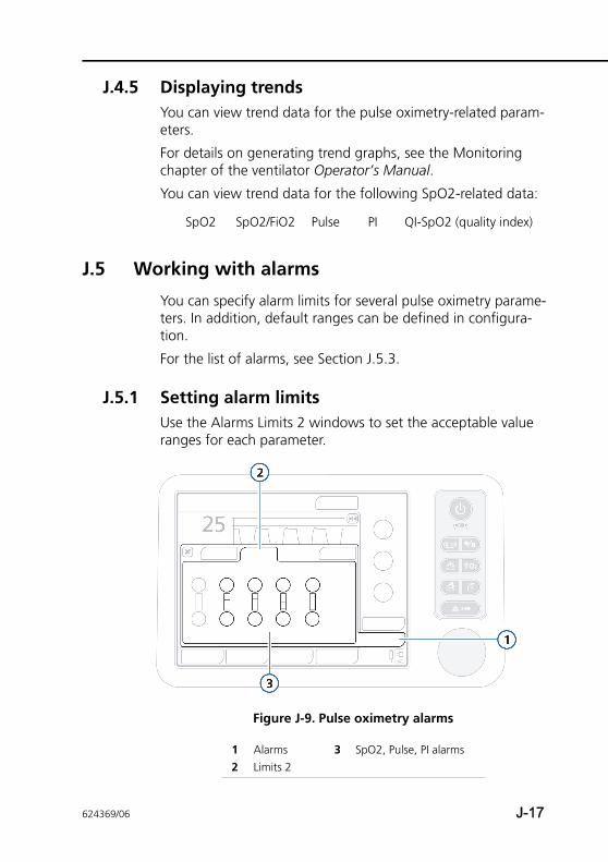
J.4.5 Displaying trendsYou can view trend data for the pulse oximetry-related param-eters.
For details on generating trend graphs, see the Monitoring chapter of the ventilator Operator’s Manual.
You can view trend data for the following SpO2-related data:
J.5 Working with alarms
You can specify alarm limits for several pulse oximetry parame-ters. In addition, default ranges can be defined in configura-tion.
For the list of alarms, see Section J.5.3.
J.5.1 Setting alarm limitsUse the Alarms Limits 2 windows to set the acceptable value ranges for each parameter.
Figure J-9. Pulse oximetry alarms
SpO2 SpO2/FiO2 Pulse PI QI-SpO2 (quality index)
1 Alarms 3 SpO2, Pulse, PI alarms2 Limits 2
624369/06 J-17
J Pulse oximetry
The SpO2 high and low alarm limits are a special case:
• When SpO2 monitoring is enabled (in the System > Sensors on/off window), the SpO2 low alarm limit and measured SpO2 value are always displayed below the MMP list, as shown in Figure J-5 (Section J.4.2).
• You can set a short alarm delay (Section J.5.2)
For details on how to set and work with alarms, see the Responding to alarms chapter.
J.5.2 SpO2 alarm delayOxygen saturation levels can be relatively variable but the changes are transient, and as such, do not generally require clinical intervention. These changes can exceed the limits set for high or low SpO2 for brief periods of time, which can generate frequent alarms.
To reduce the number of alarms that are not actionable (nuisance alarms), a short delay of up to 15 seconds can be configured after an SpO2 low or SpO2 high alarm condition occurs before the system displays the message and sounds the alarm.
The alarm delay is set in configuration. See the Configuration appendix.
J.5.3 Pulse-oximetry-related alarms and settingsTable J-6 lists the pulse-oximetry-related adjustable alarms, ranges, default settings, and resolution.
Table J-7 lists the pulse-oximetry-related alarms alphabetically and provides alarm priority, the messages displayed by the ventilator, and potential corrective actions. The proposed actions, however, may not always correct the particular problem.
J-18 624369/06
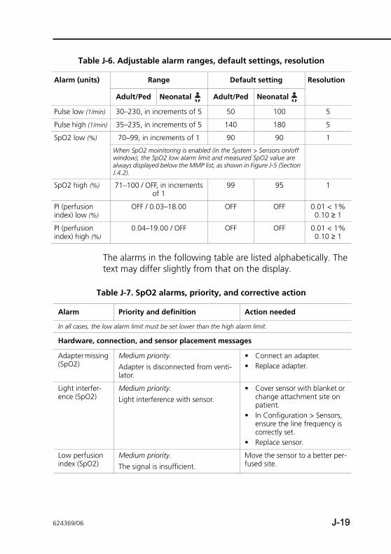
The alarms in the following table are listed alphabetically. The text may differ slightly from that on the display.
Table J-6. Adjustable alarm ranges, default settings, resolution
Alarm (units) Range Default setting Resolution
Adult/Ped Neonatal Adult/Ped Neonatal
Pulse low (1/min) 30–230, in increments of 5 50 100 5
Pulse high (1/min) 35–235, in increments of 5 140 180 5
SpO2 low (%) 70–99, in increments of 1 90 90 1
When SpO2 moinitoring is enabled (in the System > Sensors on/off window), the SpO2 low alarm limit and measured SpO2 value are always displayed below the MMP list, as shown in Figure J-5 (Section J.4.2).
SpO2 high (%) 71–100 / OFF, in increments of 1
99 95 1
PI (perfusion index) low (%)
OFF / 0.03–18.00 OFF OFF 0.01 < 1%0.10 ≥ 1
PI (perfusion index) high (%)
0.04–19.00 / OFF OFF OFF 0.01 < 1%0.10 ≥ 1
Table J-7. SpO2 alarms, priority, and corrective action
Alarm Priority and definition Action needed
In all cases, the low alarm limit must be set lower than the high alarm limit.
Hardware, connection, and sensor placement messages
Adapter missing (SpO2)
Medium priority. Adapter is disconnected from venti-lator.
• Connect an adapter.• Replace adapter.
Light interfer-ence (SpO2)
Medium priority. Light interference with sensor.
• Cover sensor with blanket or change attachment site on patient.
• In Configuration > Sensors, ensure the line frequency is correctly set.
• Replace sensor.
Low perfusion index (SpO2)
Medium priority. The signal is insufficient.
Move the sensor to a better per-fused site.
624369/06 J-19
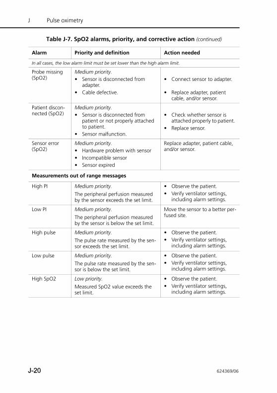
J Pulse oximetry
Probe missing (SpO2)
Medium priority. • Sensor is disconnected from
adapter. • Cable defective.
• Connect sensor to adapter.
• Replace adapter, patient cable, and/or sensor.
Patient discon-nected (SpO2)
Medium priority. • Sensor is disconnected from
patient or not properly attached to patient.
• Sensor malfunction.
• Check whether sensor is attached properly to patient.
• Replace sensor.
Sensor error (SpO2)
Medium priority. • Hardware problem with sensor• Incompatible sensor• Sensor expired
Replace adapter, patient cable, and/or sensor.
Measurements out of range messages
High PI Medium priority. The peripheral perfusion measured by the sensor exceeds the set limit.
• Observe the patient. • Verify ventilator settings,
including alarm settings.
Low PI Medium priority. The peripheral perfusion measured by the sensor is below the set limit.
Move the sensor to a better per-fused site.
High pulse Medium priority. The pulse rate measured by the sen-sor exceeds the set limit.
• Observe the patient. • Verify ventilator settings,
including alarm settings.
Low pulse Medium priority. The pulse rate measured by the sen-sor is below the set limit.
• Observe the patient. • Verify ventilator settings,
including alarm settings.
High SpO2 Low priority.Measured SpO2 value exceeds the set limit.
• Observe the patient. • Verify ventilator settings,
including alarm settings.
Table J-7. SpO2 alarms, priority, and corrective action (continued)
Alarm Priority and definition Action needed
In all cases, the low alarm limit must be set lower than the high alarm limit.
J-20 624369/06
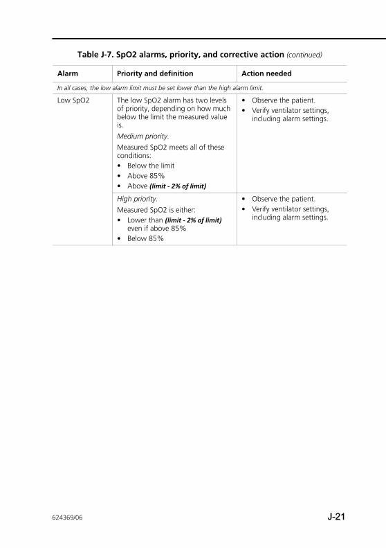
Low SpO2 The low SpO2 alarm has two levels of priority, depending on how much below the limit the measured value is.Medium priority. Measured SpO2 meets all of these conditions:• Below the limit • Above 85%• Above (limit - 2% of limit)
• Observe the patient. • Verify ventilator settings,
including alarm settings.
High priority.Measured SpO2 is either:• Lower than (limit - 2% of limit)
even if above 85%• Below 85%
• Observe the patient. • Verify ventilator settings,
including alarm settings.
Table J-7. SpO2 alarms, priority, and corrective action (continued)
Alarm Priority and definition Action needed
In all cases, the low alarm limit must be set lower than the high alarm limit.
624369/06 J-21
J Pulse oximetry
J.6 Connecting the pulse oximetry system
WARNING• Never use the SpO2 adapter in the presence of any
flammable anesthetic gas or high concentration oxygen atmosphere or nitrous oxide. Failure to comply with this warning can cause explosion or fire.
• Never use the SpO2 adapter in a hyperbaric oxygen chamber. Failure to comply with this warning can cause explosion or fire.
• If the SpO2 adapter is used with SpO2 sensors other than those specified, the patient and operator can receive an electric shock and the SpO2 adapter can become hot.
• If a sensor or cable is damaged in any way, discontinue use immediately. Do not use a sensor or patient cable with exposed optical or electrical components.
• Avoid permanent contact of the SpO2 adapter and the body.
• Do not diagnose patients based solely on the data from the pulse oximeter. Overall judgment must be made by a physician who understands the limitations and characteristics of the pulse oximeter and can read the biomedical signals acquired by other instruments.
• Use disposable sensors only once. They cannot be sterilized and can cause cross infection.
• To avoid cross contamination, only use Masimo
single-use sensors on the same patient.
• Tissue damage can occur due to incorrect placement of sensor.
• If the attachment site is unclean, clean the attachment site before attaching the sensor. If there is nail polish on the attachment site, remove the polish. Otherwise, the amount of transmitted light decreases, and the measured value can be incorrect or measurement may be unable to be performed.
J-22 624369/06
• Do not pull or bend the sensor cable, and do not let caster feet run over the sensor cable. Failure to follow these cautions may cause cable discontinuity, short circuit, skin burn on the patient and incorrect measurement data. Replace any broken sensor with a new one.
• Tissue damage can be caused by incorrect application or use of a sensor, for example by wrapping the sensor too tightly. Inspect the sensor site as directed in the sensor’s Directions for use to ensure skin integrity and correct positioning and adhesion of the sensor.
• Misapplied sensors or sensors that become partially dislodged may cause either over or under reading of actual arterial oxygen saturation.
• Keep the patient away from the cable as much as possible. If the cable coils around the patient by their body movement, the patient can get injured. If this happens, remove the cable promptly.
• The sensor cable must face away from the patient. Safely secure the sensor cable out of the way, to do so, attach the sensor cable holding clips to the airway tubing, and then connect the sensor cable to the clips.
• High intensity extreme lights (including pulsating strobe lights) directed on the sensor may not allow the pulse CO-oximeter to obtain readings.
• Inaccurate measurements or loss of pulse signal may be cause by placement of a sensor on an extremity with a blood pressure cuff, arterial catheter, or intravascular line.
• Avoid placing the sensor on any extremity with an arterial catheter or blood pressure cuff.
• Always remove the sensor from the patient and completely disconnect the patient from the patient cable before bathing the patient.
• Regularly change the measurement site of the sensors according to the skin of the patient. Take extreme care with the following patients: patient with fever, patient with peripheral circulation insufficiency, neonate or low-birth-weight infant with delicate skin
624369/06 J-23
J Pulse oximetry
• The site must be checked at least every four (4) hours to ensure adequate adhesion, circulation, skin integrity and correct optical alignment. If the circulatory condition or skin integrity has deteriorated, the sensor should be applied to a different site.
• Do not use tape to secure the sensor to the site; this can restrict blood flow and cause inaccurate readings. Use of additional tape can cause skin damage or damage the sensor.
• Turning or twisting the sensor cable can permanently damage the sensor.
• If the sensor is wrapped too tightly or supplemental tape is used, venous congestion/pulsations may occur causing erroneous readings.
• Sensors wrapped too tightly may cause erroneously low readings or cause pressure injuries.
• Venous congestion may cause under-reading of actual arterial oxygen saturation. Therefore, assure proper venous outflow from monitored site. The sensor should not be below heart level (for example, sensor on hand of a patient in bed with arm dangling to the floor).
CAUTION• Exercise caution when applying a sensor to a site
with compromised skin integrity. Applying tape or pressure to such a site may reduce circulation and/or cause further skin deterioration.
• Redness or skin irritation may appear on the attachment site. Take extreme care of patients with weak skin. In case of redness or skin irritation, change the attachment site or stop using the sensor.
• Circulation distal to the sensor site should be checked routinely.
• Do not modify or alter the sensor in any way. Alterations or modification may affect performance and/or accuracy.
J-24 624369/06
Before you begin, ensure that:
• The SpO2 option board is already installed
• You have all of the components (Figure J-1)
For the system to be operational, you must also:
• Connect all of the components (Section J.6.1)
• Enable the option board (Section J.7.1)
• Configure sensor data settings (Section J.7.2)
J.6.1 Connecting the componentsConnecting the components comprises the following steps:
• Attach the adapter to a rail (Figure J-10)
• Connect the cables (Figure J-11)
• Attach the sensor to the patient (not shown)
624369/06 J-25
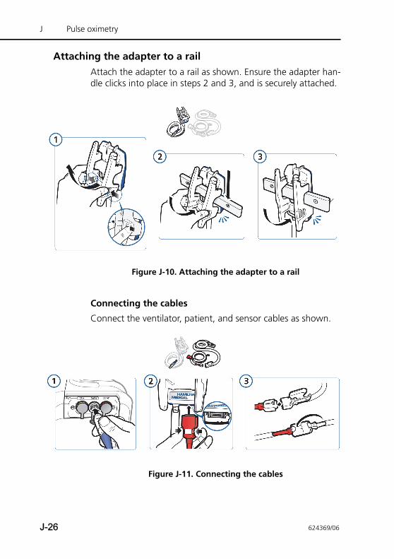
J Pulse oximetry
Attaching the adapter to a railAttach the adapter to a rail as shown. Ensure the adapter han-dle clicks into place in steps 2 and 3, and is securely attached.
Figure J-10. Attaching the adapter to a rail
Connecting the cables
Connect the ventilator, patient, and sensor cables as shown.
Figure J-11. Connecting the cables
J-26 624369/06
J.6.2 Verifying sensor measurementsMeasurements recorded by the pulse oximeter are displayed in the Monitoring > SpO2 window.
To verify that measurements are being recorded
On the ventilator, touch the Monitoring button, and then touch the SpO2 tab (Figure J-3 on page J-12).
The SpO2 value is displayed approximately 10 seconds after placing the sensor.
If the device does not detect a pulse for 30 seconds, the venti-lator generates a Patient disconnected alarm.
If you do not see any oximeter-related measurements, ensure that the SpO2 sensor is enabled in the System > Sensor on/off window. See Section J.3.1.
624369/06 J-27
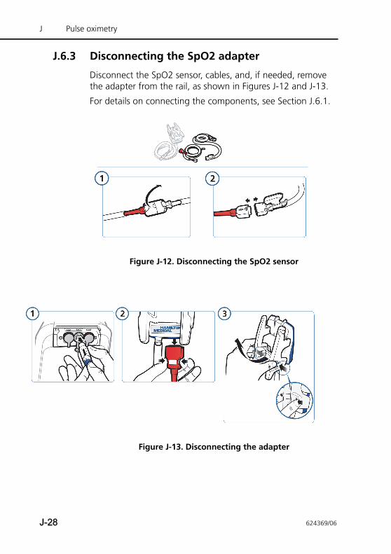
J Pulse oximetry
J.6.3 Disconnecting the SpO2 adapter
Disconnect the SpO2 sensor, cables, and, if needed, remove the adapter from the rail, as shown in Figures J-12 and J-13.
For details on connecting the components, see Section J.6.1.
Figure J-12. Disconnecting the SpO2 sensor
Figure J-13. Disconnecting the adapter
J-28 624369/06
J.6.4 Connecting the adapter for transport The SpO2 adapter is provided with a transport case for use when a rail is not available. The case completely encloses and protects the adapter, while leaving the bottom free for the cables.
To connect the adapter for transport
1. Detach the SpO2 adapter rail-mount handle top piece from the base by squeezing the sides together and pulling out and up, then unhooking it from the base.
2. Place the SpO2 adapter into the transport case and fasten the straps tightly. The case fits snugly around the adapter.
3. Place the adapter over the breathing circuit near the con-nections to the ventilator, with the cable connections at the bottom, and wrap the Velcro fastener around one of the breathing limbs. Tighten the strap, being careful not to exert pressure on the breathing limb.
The adapter should now be securely attached to the limb, above the breathing circuit sleeve.
4. Connect the ventilator cable and the patient cable to the bottom of the adapter.
5. Connect the ventilator cable to the SpO2 connector on the option board.
6. Attach the patient cable to the SpO2 sensor.
624369/06 J-29
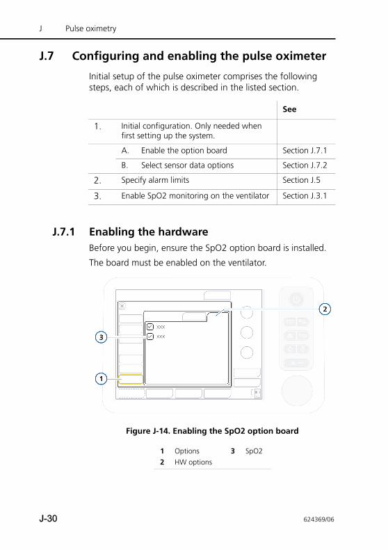
J Pulse oximetry
J.7 Configuring and enabling the pulse oximeter
Initial setup of the pulse oximeter comprises the following steps, each of which is described in the listed section.
J.7.1 Enabling the hardwareBefore you begin, ensure the SpO2 option board is installed.
The board must be enabled on the ventilator.
Figure J-14. Enabling the SpO2 option board
See
1. Initial configuration. Only needed when first setting up the system.
A. Enable the option board Section J.7.1
B. Select sensor data options Section J.7.2
2. Specify alarm limits Section J.5
3. Enable SpO2 monitoring on the ventilator Section J.3.1
1 Options 3 SpO22 HW options
J-30 624369/06
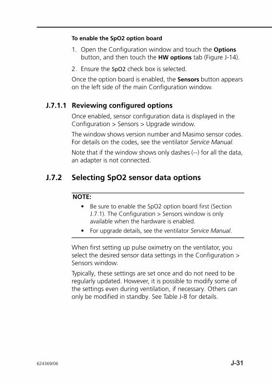
To enable the SpO2 option board
1. Open the Configuration window and touch the Options button, and then touch the HW options tab (Figure J-14).
2. Ensure the SpO2 check box is selected.
Once the option board is enabled, the Sensors button appears on the left side of the main Configuration window.
J.7.1.1 Reviewing configured optionsOnce enabled, sensor configuration data is displayed in the Configuration > Sensors > Upgrade window.
The window shows version number and Masimo sensor codes. For details on the codes, see the ventilator Service Manual.
Note that if the window shows only dashes (--) for all the data, an adapter is not connected.
J.7.2 Selecting SpO2 sensor data options
NOTE:• Be sure to enable the SpO2 option board first (Section
J.7.1). The Configuration > Sensors window is only available when the hardware is enabled.
• For upgrade details, see the ventilator Service Manual.
When first setting up pulse oximetry on the ventilator, you select the desired sensor data settings in the Configuration > Sensors window.
Typically, these settings are set once and do not need to be regularly updated. However, it is possible to modify some of the settings even during ventilation, if necessary. Others can only be modified in standby. See Table J-8 for details.
624369/06 J-31
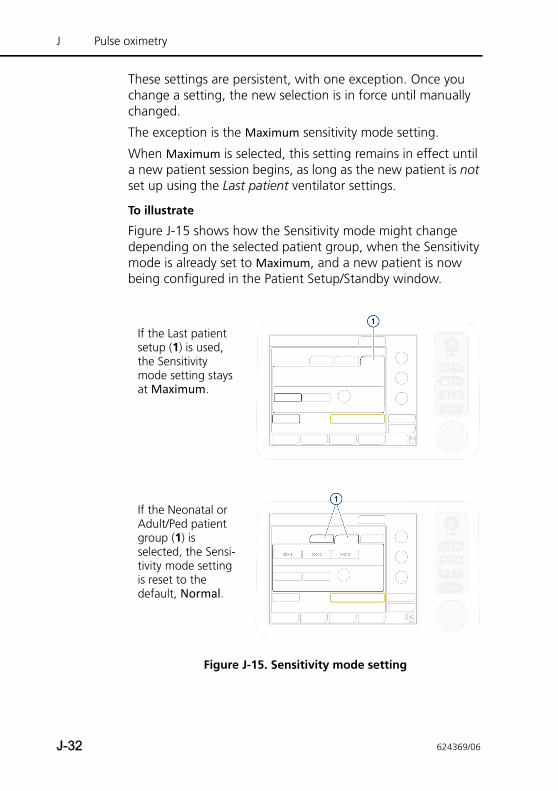
J Pulse oximetry
These settings are persistent, with one exception. Once you change a setting, the new selection is in force until manually changed.
The exception is the Maximum sensitivity mode setting.
When Maximum is selected, this setting remains in effect until a new patient session begins, as long as the new patient is not set up using the Last patient ventilator settings.
To illustrate
Figure J-15 shows how the Sensitivity mode might change depending on the selected patient group, when the Sensitivity mode is already set to Maximum, and a new patient is now being configured in the Patient Setup/Standby window.
Figure J-15. Sensitivity mode setting
If the Last patient setup (1) is used, the Sensitivity mode setting stays at Maximum.
If the Neonatal or Adult/Ped patient group (1) is selected, the Sensi-tivity mode setting is reset to the default, Normal.
J-32 624369/06
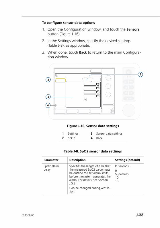
To configure sensor data options
1. Open the Configuration window, and touch the Sensors button (Figure J-16).
2. In the Settings window, specify the desired settings (Table J-8), as appropriate.
3. When done, touch Back to return to the main Configura-tion window.
Figure J-16. Sensor data settings
1 Settings 3 Sensor data settings2 SpO2 4 Back
Table J-8. SpO2 sensor data settings
Parameter Description Settings (default)
SpO2 alarm delay
Specifies the length of time that the measured SpO2 value must be outside the set alarm limits before the system generates the alarm. For details, see Section J.5.2.Can be changed during ventila-tion.
In seconds. 05 (default)1015
624369/06 J-33
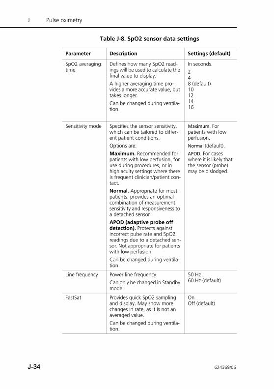
J Pulse oximetry
SpO2 averaging time
Defines how many SpO2 read-ings will be used to calculate the final value to display. A higher averaging time pro-vides a more accurate value, but takes longer. Can be changed during ventila-tion.
In seconds.248 (default)10121416
Sensitivity mode Specifies the sensor sensitivity, which can be tailored to differ-ent patient conditions. Options are:Maximum. Recommended for patients with low perfusion, for use during procedures, or in high acuity settings where there is frequent clinician/patient con-tact.Normal. Appropriate for most patients, provides an optimal combination of measurement sensitivity and responsiveness to a detached sensor. APOD (adaptive probe off detection). Protects against incorrect pulse rate and SpO2 readings due to a detached sen-sor. Not appropriate for patients with low perfusion. Can be changed during ventila-tion.
Maximum. For patients with low perfusion. Normal (default). APOD. For cases where it is likely that the sensor (probe) may be dislodged.
Line frequency Power line frequency. Can only be changed in Standby mode.
50 Hz60 Hz (default)
FastSat Provides quick SpO2 sampling and display. May show more changes in rate, as it is not an averaged value. Can be changed during ventila-tion.
OnOff (default)
Table J-8. SpO2 sensor data settings
Parameter Description Settings (default)
J-34 624369/06
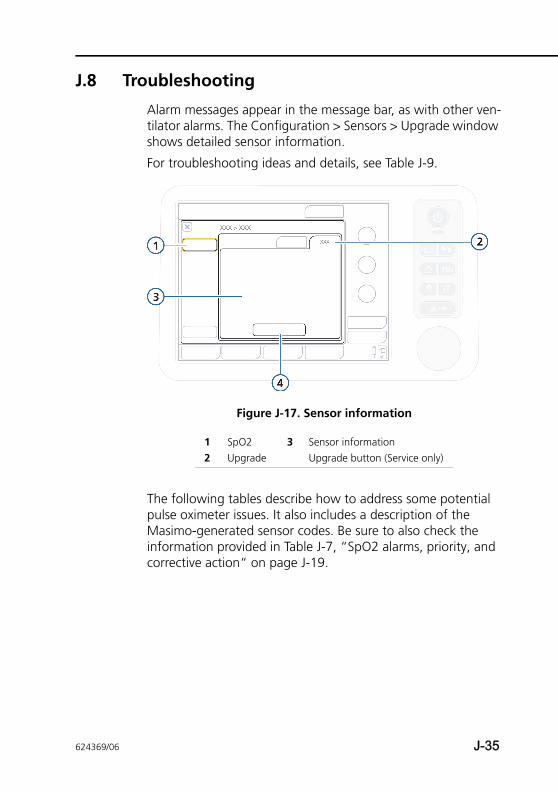
J.8 Troubleshooting
Alarm messages appear in the message bar, as with other ven-tilator alarms. The Configuration > Sensors > Upgrade window shows detailed sensor information.
For troubleshooting ideas and details, see Table J-9.
Figure J-17. Sensor information
The following tables describe how to address some potential pulse oximeter issues. It also includes a description of the Masimo-generated sensor codes. Be sure to also check the information provided in Table J-7, “SpO2 alarms, priority, and corrective action“ on page J-19.
1 SpO2 3 Sensor information2 Upgrade Upgrade button (Service only)
624369/06 J-35
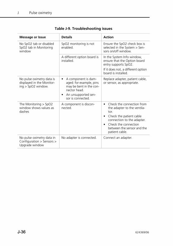
J Pulse oximetry
Table J-9. Troubleshooting issues
Message or Issue Details Action
No SpO2 tab or disabled SpO2 tab in Monitoring window
SpO2 monitoring is not enabled.
Ensure the SpO2 check box is selected in the System > Sen-sors on/off window.
A different option board is installed.
In the System Info window, ensure that the Option board entry supports SpO2.If it does not, a different option board is installed.
No pulse oximetry data is displayed in the Monitor-ing > SpO2 window.
• A component is dam-aged: for example, pins may be bent in the con-nector head.
• An unsupported sen-sor is connected.
Replace adapter, patient cable, or sensor, as appropriate.
The Monitoring > SpO2 window shows values as dashes
A component is discon-nected.
• Check the connection from the adapter to the ventila-tor.
• Check the patient cable connection to the adapter.
• Check the connection between the sensor and the patient cable.
No pulse oximetry data in Configuration > Sensors > Upgrade window
No adapter is connected. Connect an adapter.
J-36 624369/06
J.9 Cleaning and maintenance
WARNING• If a sensor or cable is damaged in any way,
discontinue use immediately. Do not use a sensor or patient cable with exposed optical or electrical components.
• Do not soak or immerse the sensor or cables in any liquid solution. The sensor and connectors are not waterproof.
• Unless otherwise specified, do not sterilize sensors or patient cables by irradiation, steam, autoclave, or ethylene oxide. See the cleaning instructions in the Directions for use for the Masimo reusable sensors.
• Do not attempt to reprocess, recondition, or recycle any Masimo sensors or patient cables as these processes may damage the electrical components, potentially leading to harm.
• Before maintenance or cleaning, disconnect the SpO2 adapter from the device. Failure to comply with this instruction can result in electrical shock and SpO2 problems or both.
CAUTION• Do not modify or alter the adapter or sensor in any
way. Alterations or modification may affect performance and/or accuracy.
• Do not disinfect and sterilize the SpO2 adapter. Doing so will damage the adapter.
• Do not immerse the SpO2 adapter in any chemical solution or water. If the adapter is immersed, wipe off liquid with a dry cloth and thoroughly dry the adapter.
• After cleaning and before use, wipe liquid off with a dry cloth and thoroughly dry the adapter.
This section provides cleaning, replacement, and disposal recommendations.
624369/06 J-37
J Pulse oximetry
J.9.1 Cleaning the adapter and sensor
NOTE:Before proceeding, review the safety information at the beginning of this section.
To clean the adapter
Periodically clean the SpO2 adapter by wiping it with a soft cloth moistened with ethanol (15°C (59°F), 76.9% to 81.4% by volume).
To clean a reusable sensor
1. Remove the sensor from the patient.
2. Disconnect the sensor and the patient cable from the adapter.
3. Wipe the components with a soft cloth moistened with a 70% isopropyl solution.
4. Allow to air dry before reuse.
J.9.2 Replacing the adapter, cables, or sensorWhen an SpO2 adapter, cable, or sensor is broken, cracked, or visibly damaged, immediately stop using it and replace it with a new one.
J.9.3 Disposing of the adapter, cables, and sensorFollow your local laws for disposing of the SpO2 adapter, cables, and sensor. For detailed information, contact your Hamilton Medical representative.
J-38 624369/06
J.10 About the SpO2/FiO2 ratio
For the diagnosis of ARDS and ALI, the PaO2/FiO2 ratio index is used, where PaO2 is the partial pressure of oxygen in the arte-rial blood measured by arterial blood gas test, and FiO2 is the fraction of inspired oxygen (Oxygen control) set on the ventila-tor. PaO2/FiO2 is used as a measure of blood hypoxia.
The SpO2/FiO2 ratio (%) is an approximation of the PaO2/FiO2 ratio, which, in contrast to PaO2/FiO2, can be calculated non-invasively and continuously.
As an example, adult SpO2/FiO2 ratios of 235 and 315, and child ratios of 201 and 263 correspond to PaO2/FiO2 ratios of 200 and 3001, respectively.
Therefore, SpO2/FiO2 ratio is a useful monitoring value for bedside assessment of a patient’s oxygenation status, and can be helpful relative to ALI and ARDS diagnosis and status follow up of these patients.
The ventilator calculates and displays the SpO2/FiO2 ratio when the measured SpO2 is 94% or lower.
When SpO2 exceeds 94%, the SpO2/FiO2 ratio is not calcu-lated; the display shows dashes (---). This is because at these higher oxygen saturation levels, the correlation between SpO2 and PaO2 is poor (the oxygen-haemoglobin curve flattens out), so SpO2/FiO2 is no longer a good approximation of PaO2/FiO2. See Figure J-18.
1. References: Rice TW, Wheeler AP, Bernard GR, Hayden DL, Schoenfeld DA, Ware LB. Comparison on the SpO2/FiO2 ratio and the PaO2/FiO2 ratio in patients with acute lung injury or ARDS. Chest. 2007 Aug;132(2):410-7. Epub 2007 Jun 15.
Khemani RG, Patel NR, Bart RD 3rd, Newth CJ. Comparison of the pulse oximetric saturation/fraction of inspired oxygen ratio and the PaO2/fraction of inspired oxygenation in children. Chest. 2009 Mar;135(3):662-8. Epub 2008 Nov 24.
624369/06 J-39
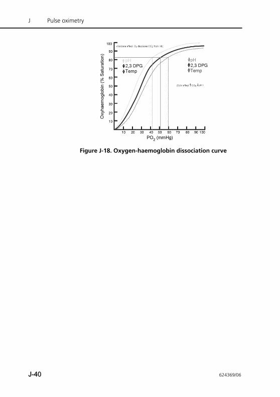
J Pulse oximetry
Figure J-18. Oxygen-haemoglobin dissociation curve
J-40 624369/06
Glossary
A Ampere, a unit of current.
AC Alternating current.
alarm buffer Contains information on the four most recent alarm occurrences.
alarm lamp Lamp atop the ventilator that lights in a color corresponding to the active alarm.
alarm silence key Silences alarm sound for 2 min.
ambient state An emergency state in which the ventilator opens the inspiratory channel and expiratory valve. This lets the patient breathe room air unassisted by the ventilator.
apnea Cessation of breathing.
Apnea time The maximum time allowed without a breath trigger, an alarm setting.
APRV Airway Pressure Release Ventilation.
ASV target graphics panel
ASV graphical data representation, an Intelligent Panel.
ASV monitored data window
ASV numeric patient data, an Intelligent Panel.
ATP Ambient temperature and pressure.
ATPD Ambient temperature and pressure, dry.
AutoPEEP Unintended positive end-expiratory pressure, a monitored parameter.
Backup Apnea backup ventilation.
backup buzzer The buzzer designed to sound for at least 2 min as a backup to the alarm speaker.
base flow A continuous and constant gas flow from the inspiratory outlet to the expiratory outlet.
624369/06 Glossary-1
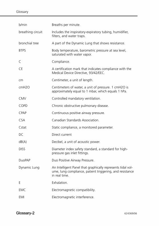
Glossary
b/min Breaths per minute.
breathing circuit Includes the inspiratory-expiratory tubing, humidifier, filters, and water traps.
bronchial tree A part of the Dynamic Lung that shows resistance.
BTPS Body temperature, barometric pressure at sea level, saturated with water vapor.
C Compliance.
CE A certification mark that indicates compliance with the Medical Device Directive, 93/42/EEC.
cm Centimeter, a unit of length.
cmH2O Centimeters of water, a unit of pressure. 1 cmH2O is approximately equal to 1 mbar, which equals 1 hPa.
CMV Controlled mandatory ventilation.
COPD Chronic obstructive pulmonary disease.
CPAP Continuous positive airway pressure.
CSA Canadian Standards Association.
Cstat Static compliance, a monitored parameter.
DC Direct current
dB(A) Decibel, a unit of acoustic power.
DISS Diameter index safety standard, a standard for high-pressure gas inlet fittings.
DuoPAP Duo Positive Airway Pressure.
Dynamic Lung An Intelligent Panel that graphically represents tidal vol-ume, lung compliance, patient triggering, and resistance in real time.
E Exhalation.
EMC Electromagnetic compatibility.
EMI Electromagnetic interference.
Glossary-2 624369/06
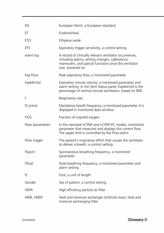
EN European Norm, a European standard.
ET Endotracheal.
ETO Ethylene oxide.
ETS Expiratory trigger sensitivity, a control setting.
event log A record of clinically relevant ventilator occurrences, including alarms, setting changes, calibrations, maneuvers, and special functions since the ventilator was powered on.
Exp Flow Peak expiratory flow, a monitored parameter.
ExpMinVol Expiratory minute volume, a monitored parameter and alarm setting. In the Vent Status panel, ExpMinVol is the percentage of normal minute ventilation, based on IBW.
f Respiratory rate.
fControl Mandatory breath frequency, a monitored parameter. It is displayed in monitored data window.
FiO2 Fraction of inspired oxygen.
Flow (parameter) In the neonatal nCPAP and nCPAP-PC modes, monitored parameter that measures and displays the current flow. The upper limit is controlled by the Flow alarm.
Flow trigger The patient’s inspiratory effort that causes the ventilator to deliver a breath, a control setting.
fSpont Spontaneous breathing frequency, a monitored parameter.
fTotal Total breathing frequency, a monitored parameter and alarm setting.
ft Foot, a unit of length.
Gender Sex of patient, a control setting.
HEPA High efficiency particle air filter.
HME, HMEF Heat and moisture exchanger (artificial nose), heat and moisture exchanging filter
624369/06 Glossary-3
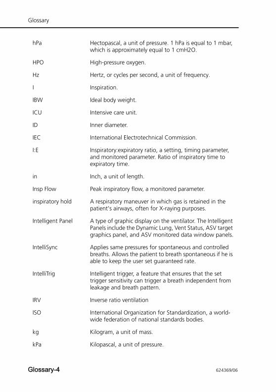
Glossary
hPa Hectopascal, a unit of pressure. 1 hPa is equal to 1 mbar, which is approximately equal to 1 cmH2O.
HPO High-pressure oxygen.
Hz Hertz, or cycles per second, a unit of frequency.
I Inspiration.
IBW Ideal body weight.
ICU Intensive care unit.
ID Inner diameter.
IEC International Electrotechnical Commission.
I:E Inspiratory:expiratory ratio, a setting, timing parameter, and monitored parameter. Ratio of inspiratory time to expiratory time.
in Inch, a unit of length.
Insp Flow Peak inspiratory flow, a monitored parameter.
inspiratory hold A respiratory maneuver in which gas is retained in the patient’s airways, often for X-raying purposes.
Intelligent Panel A type of graphic display on the ventilator. The Intelligent Panels include the Dynamic Lung, Vent Status, ASV target graphics panel, and ASV monitored data window panels.
IntelliSync Applies same pressures for spontaneous and controlled breaths. Allows the patient to breath spontaneous if he is able to keep the user set guaranteed rate.
IntelliTrig Intelligent trigger, a feature that ensures that the set trigger sensitivity can trigger a breath independent from leakage and breath pattern.
IRV Inverse ratio ventilation
ISO International Organization for Standardization, a world-wide federation of national standards bodies.
kg Kilogram, a unit of mass.
kPa Kilopascal, a unit of pressure.
Glossary-4 624369/06
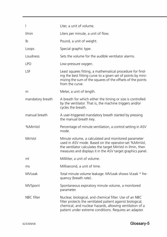
l Liter, a unit of volume.
l/min Liters per minute, a unit of flow.
lb Pound, a unit of weight.
Loops Special graphic type.
Loudness Sets the volume for the audible ventilator alarms.
LPO Low-pressure oxygen.
LSF Least squares fitting, a mathematical procedure for find-ing the best fitting curve to a given set of points by mini-mizing the sum of the squares of the offsets of the points from the curve.
m Meter, a unit of length.
mandatory breath A breath for which either the timing or size is controlled by the ventilator. That is, the machine triggers and/or cycles the breath.
manual breath A user-triggered mandatory breath started by pressing the manual breath key.
%MinVol Percentage of minute ventilation, a control setting in ASV mode.
MinVol Minute volume, a calculated and monitored parameter used in ASV mode. Based on the operator-set %MinVol, the ventilator calculates the target MinVol in l/min, then measures and displays it in the ASV target graphics panel.
ml Milliliter, a unit of volume.
ms Millisecond, a unit of time.
MVLeak Total minute volume leakage. MVLeak shows VLeak * fre-quency (breath rate).
MVSpont Spontaneous expiratory minute volume, a monitored parameter.
NBC filter Nuclear, biological, and chemical filter. Use of an NBC filter protects the ventilated patient against biological, chemical, and nuclear hazards, allowing ventilation of a patient under extreme conditions. Requires an adapter.
624369/06 Glossary-5
Glossary
nCPAP Neonatal-only ventilation mode that applies CPAP over a nasal interface (mask or prongs).
nCPAP-PC Neonatal-only ventilation mode that delivers, in addition to the set CPAP, intermittent, time-cycled, and pressure-controlled breaths.
NIST Noninterchangeable screw thread, a standard for high-pressure gas inlet fittings.
NIV Noninvasive ventilation, a ventilation mode.
NIV-ST Spontaneous/timed noninvasive ventilation, a ventilation mode.
NPPV Noninvasive positive pressure ventilation.
NVG Night vision goggles. The NVG compatibility option allows you to safely use the ventilator in combination with night vision goggles.
O2 Oxygen.
Oxygen Oxygen concentration of the delivered gas, a control set-ting, monitored parameter, and, in LPO mode, an alarm setting.
P&T knob Press-and-turn knob. Used to navigate the display, select list items, activate controls and set values.
Pasvlimit Maximum pressure to be applied in ASV, a control setting.
Pat. height A control setting. It is used to compute the patient’s ideal body weight (IBW) in calculations for ASV and start-up settings.
Paw Airway pressure.
Pcontrol Pressure control, a control setting in PCV+ mode. Pressure (additional to PEEP/CPAP) to be applied during the inspi-ratory phase.
PCV+ Pressure controlled ventilation
PDMS Patient data management system
Glossary-6 624369/06
PEEP/CPAP PEEP (positive end-expiratory pressure) and CPAP (contin-uous positive airway pressure), a control setting and mon-itored parameter. PEEP and CPAP are constant pressures applied during both the inspiratory and expiratory phases.
Phigh High pressure in APRV and DuoPAP mode
Pinsp Inspiratory pressure, the target pressure (additional to PEEP/CPAP) to be applied during the inspiratory phase. It is operator-set in the PSIMV+ and NIV-ST and a displayed parameter in the Vent Status panel and the ASV target graphics panel.
Plethysmogram The waveform that visualizes the pulsating blood volume; it is delivered by the pulse oximeter.
Plow Low pressure in APRV mode
Pmax High pressure alarm limit
Press-and-turn knob
Also called P&T knob. Used to navigate the display, select list items, activate controls and set values.
Pressure Maximum pressure allowed in the patient breathing circuit, an alarm setting.
Pmean Mean airway pressure, a monitored parameter.
PN Part number.
Ppeak Peak airway pressure, a monitored parameter.
Pplateau Plateau or end-inspiratory pressure. The pressure mea-sured at the end of inspiration when flow is or is close to zero.
P-ramp Pressure ramp, a control setting. The time required for the inspiratory pressure to rise to the set (target) pressure.
pressure control Maintenance of a consistent transrespiratory pressure waveform despite changing respiratory system mechan-ics.
psi Pounds per square inch, a unit of pressure.
PSIMV+ Pressure-controlled synchronized intermittent mandatory ventilation mode.
624369/06 Glossary-7
Glossary
Psupport Pressure support, a control setting valid during sponta-neous breaths in SPONT, SIMV+, and NIV modes. Psup-port is pressure (additional to PEEP/CPAP) to be applied during the inspiratory phase.
Rate Breath frequency or number of breaths per minute, a control setting.
RCexp Expiratory time constant, a monitored parameter.
Rinsp Inspiratory flow resistance, a monitored parameter.
s Second, a unit of time.
safety mode An emergency state that ensures a basic minute ventila-tion while giving the user time for corrective actions in case of some technical fault alarms. The default inspira-tory pressure is maintained, the expiratory valve opens as needed to switch system pressure levels between PEEP and inspiratory pressure, and patient sensing is non-functional.
(S)CMV+ Synchronized controlled mandatory ventilation mode.
sigh Breaths delivered to deliberately increase tidal volume at a regular interval. If enabled, a sigh breath is delivered every 50 breaths with an additional 10 cmH2O.
SIMV+ Synchronized intermittent mandatory ventilation mode.
SpO2 Oxygen saturation
SPONT Spontaneous (pressure support) mode of ventilation.
spontaneous breath
A breath for which both the timing and size are con-trolled by the patient. That is, the patient both triggers and cycles the breath.
standby The ventilator is in a waiting state, during which time there is no breath delivery.
STPD Standard temperature and pressure, dry. Defined as dry gas at 0°C (32°F) at 758 mmHg (101 kPa) pressure at sea level.
TE Expiratory time, a monitored parameter.
Glossary-8 624369/06
technical fault A type of alarm, resulting because HAMILTON-T1’s ability to ventilate safely is questionable.
TF Technical fault.
Thigh Maximum time in APRV and DuoPAP mode
TI Inspiratory time, a control setting and monitored parameter.
TI max Maximum inspiratory time, a control setting in NIV and NIV-ST modes.
timv SIMV breath interval.
ttrigger Trigger window in SIMV modes.
Tlow Minimum time in APRV mode
Trends Special graphic type.
V Volt, a unit of electric potential or volume.
VA Volt-ampere, a unit of electric power.
VDaw Airway dead space.
ventilator breath-ing system (VBS)
A breathing system bounded by the low-pressure gas input port(s), the gas intake port(s), and the patient connection port, together with the fresh-gas inlet and exhaust port(s), if fresh-gas inlet or exhaust ports are provided, as described in ISO 4135:2001.
Vent Status panel An Intelligent Panel that visualizes six parameters related to the patient’s ventilator dependency, including oxygen-ation and patient activity.
VLBW Very Low Birth Weight
VLeak Leakage percent, a monitored parameter.
Vt Tidal volume, a control setting, an alarm setting and a monitored parameter in the Vent Status panel.
VTE Expiratory tidal volume, a monitored parameter. It is the integral of all negative flow measurements during exhalation.
VTI Inpiratory tidal volume, a monitored parameter.
624369/06 Glossary-9

Glossary
Glossary-10 624369/06
Index
AAccessories
about 1-10list of G-1
Aeroneb Pro nebulizer 2-25Airway pressure, mean. See PmeanAlarm silence key 9-6Alarms
Alarm silence key, description 9-6buffer, contents of 8-7buffer, viewing 8-7defaults settings for each A-20lamp on top of ventilator, about 1-12list of 8-10loudness, adjusting 4-20priorities of each A-20ranges for each A-20responding to 8-21sending to remote device H-9setting 4-18silencing 9-6SpO2 related, setting J-17tests to ensure proper functioning 3-22troubleshooting 8-10viewing 8-7viewing active and inactive 8-7visual and audible indications 8-3volume (loudness), setting minimum I-6volume, adjusting 4-20with ASV, setting C-10
Alarms, adjustableApnea 4-22Apnea time A-20, A-39ExpMinVol 4-22, A-20, A-39Flow (nCPAP, nCPAP-PC) 4-22, A-20,
A-39fTotal 4-22, A-20, A-39in neonatal ventilation 5-35Oxygen 4-22, A-20, A-40PetCO2 4-22, A-20, A-40Pressure 4-23, A-21, A-40Pressure limitation A-21, A-40pulse-oximetry related J-18SpO2 related J-17, J-18Vt 4-23, A-21, A-40
Alarms, SpO2
Adapter missing J-19Light interference J-19Low perfusion index J-19Patient disconnected J-20PI high J-20PI low J-20PI (perfusion index) high J-19PI (perfusion index) low J-19Probe missing J-20Pulse high J-19Pulse low J-19Pulse rate high J-20Pulse rate low J-20ranges and defaults J-19Sensor error J-20SpO2 high J-19SpO2 low J-19SpO2 too high J-20SpO2 too low J-21troubleshooting J-19
Alarms. See entries for individual alarmsAmbient state, about B-34Apnea alarms
Apnea 8-10Apnea time 4-22, A-20, A-39Apnea ventilation 8-10Apnea ventilation ended 8-10troubleshooting 8-10
Apnea backup ventilationabout 4-11, 4-13enabling/disabling 4-11ranges, accuracy A-8
APOD sensitivity mode, about J-34APRV mode A-13, B-4, B-31
high-pressure recruitment maneuvers B-32
initialization B-31APVcmv mode B-4, B-8
selecting naming convention for I-8APVsimv mode B-4, B-16, B-17, B-18
selecting naming convention for I-8ASV mode A-13
about C-2, C-15alarms C-10ASV graph C-12ASV graph, ranges and scales used A-18
624369/06 Index-1
Index
breathing patterns C-13Cannot meet the target alarm 8-10clinical workflow chart C-4controls in C-5dead space compensation C-8monitoring requirements C-9, C-11preparing for use C-6target graphics window 7-9, C-11weaning C-14
AutoPEEPdefinition 6-17ranges, accuracy A-14
BBackup ventilation. See Apnea backup
ventilationBacteria filter, connecting 2-8Base flow
for adults/pediatrics A-25for neonates 5-33, A-25specifications A-25
Batteriesabout 2-28replacing 10-17specifications A-6
Battery alarmsBattery calibration required 8-10Battery communication error 8-10Battery low 8-11Battery power loss 8-11Battery replacement required 8-11Battery temperature high 8-11Battery totally discharged 8-12Loss of external power 8-17Wrong battery 8-12
Biphasic ventilation, about B-5Blower fault alarm 8-12Breath timing options, selecting for PCV+
and (S)CMV+ modes I-7Breathing circuits
Adult/ped, coaxial with HMEF/HME 2-13
Adult/ped, coaxial with mask 2-13Adult/ped, dual limb with humidifier
2-12bacteria filter, connecting 2-8by patient group (adult/ped) 2-10by patient group (neo) 5-9, 5-10
calibrating (nCPAP, nCPAP-PC modes) 5-23
components (adult/ped) 2-10components (neo) 5-9, 5-10connecting (adult/ped) 2-6HMEF/HME, connecting 2-8Neonatal, dual-limb with HMEF/HME
5-12Neonatal, dual-limb with humidifier
5-11Neonatal, nCPAP/nCPAP-PC modes,
with HMEF/HME 5-14Neonatal, nCPAP/nCPAP-PC modes,
with humidifier 5-13neonatal, setting up 5-9specifications A-24
Buzzer defective alarm 8-12
CCalibrating 3-6
circuit (neo) 5-23CO2 sensor 3-13flow sensor (adult/ped) 3-9flow sensor (neo) 5-20oxygen cell 3-11when to perform calibrations 3-2
Cannot meet the target (ASV) alarm 8-10Check flow sensor alarm 8-13Check flow sensor tubing alarm 8-13Check settings alarm 8-13Circuit calibration needed alarm 8-13Circuits. See Breathing circuitsCO2 alarms
Check CO2 sensor airway adapter 8-12Check CO2 sensor sampling line 8-12CO2 sensor calibration needed 8-13CO2 sensor defect 8-14CO2 sensor disconnected 8-14CO2 sensor over temperature 8-14PetCO2 high 8-20PetCO2 low 8-20
CO2 measurementattaching mainstream sensor to adapter
3-14attaching sidestream sensor to adapter
3-14CO2 sensor, calibrating 3-13enabling/disabling 3-15mainstream sensor, connecting 2-20
Index-2 624369/06
mainstream, about 2-19sidestream sensor, connecting 2-22sidestream, about 2-22
CO2 sensors. See CO2 measurementCOM1 connector, using to send data H-4Communications interface
about H-1COM1, about H-4connecting to computer, PDMS H-6connecting to patient monitor H-4Nurse call connector, about H-8protocols, about H-3sending data and alarms to remote
device H-9Compliance. See CstatConfiguration
accessing Configuration mode I-2alarm volume (loudness), setting
minimum I-6communication interface, enabling I-5copying configuration to other
ventilators (via USB) I-16default settings A-22enabling/disabling SpO2 option J-30initial/default ventilator settings,
configuring I-1language, selecting I-3quick setup settings, configuring I-9quick setup settings, selecting default
I-15reviewing configured pulse oximetry
options J-31specifications A-22SpO2 alarm delay J-18SpO2 sensor data options, setting J-31units of measure, setting I-4vent status panel settings, configuring
I-14weaning zone ranges, configuring I-14See also Software options
Connecting to other devices, about H-1Control settings
accuracy of measurements A-8default settings A-8defined 4-13list of 4-13ranges A-8setting 4-9
Cstat (compliance)
definition 6-17in Dynamic Lung panel 7-4ranges, accuracy A-16
Curves. See Waveforms
DDate and time, setting 3-19Day and Night display brightness
Day/Night key 9-13setting 3-17
DC power cables, supported 2-27Device temperature high alarm 8-14Disconnection alarms
Disconnection on patient side 8-14Disconnection on ventilator side 8-15
Display, locking the touch screen 9-12DuoPAP mode A-13, B-4, B-26, B-29
pressure support in B-27synchronization B-28
Dynamic Lung panelabout 7-2compliance (Cstat), about 7-4display of SpO2 and pulse rate J-15displaying 7-3illustrated 7-2patient triggering, illustrated 7-4resistance (Rinsp), about 7-5SpO2 data J-14tidal volume (Vt), about 7-3
EElectrical specifications A-6End-expiratory pause pressure. See PplateauEnvironmental specifications A-3ETS (expiratory trigger sensitivity)
definition 4-13, 5-34ranges, accuracy A-8
Event logabout 8-9copying to USB device 3-21
Exhalation obstructed alarm 8-15Exp flow (peak expiratory flow)
definition 6-17ranges, accuracy A-15
Expiratory filter, using 2-25Expiratory flow. See Exp flowExpiratory minute volume. See ExpMinVolExpiratory tidal volume. See VTEExpiratory time constant. See RCexp
624369/06 Index-3
Index
Expiratory time. See TEExpiratory trigger sensitivity. See ETSExpiratory valves
adult/ped and neonatal, compared 5-4installing (adult/ped) 2-9installing (neo) 5-3, 5-5Wrong expiratory valve alarm 8-23
ExpMinVol alarmsdefinition 4-22ranges and defaults A-20, A-39
ExpMinVol (expiratory minute volume)definition 5-36ranges, accuracy A-15
ExpMinVol/MinVol NIV (expiratory minute volume)
definition 6-18External flow sensor failed alarm 8-15
FFan failure alarm 8-15fControl (mandatory breath rate)
definition 6-18ranges, accuracy A-16
FetCO2definition E-4ranges, accuracy A-17
Filterair intake (dust and HEPA), cleaning and
replacing 10-15expiratory, using 2-25fan, cleaning and replacing 10-15inspiratory
particle size and efficiency A-24Flow alarm
definition 4-22, 5-36range and default A-20, A-39
Flow (average flow in nCPAP, nCPAP-PC)definition 6-18ranges, accuracy A-15
Flow sensor alarmsCheck flow sensor 8-13Check flow sensor tubing 8-13External flow sensor failed 8-15Flow sensor calibration required 8-15Turn flow sensor 8-22Wrong flow sensor 8-24
Flow sensorsabout 1-9calibrating (adult/ped) 3-9
calibrating (neo) 5-20connecting (neo) 5-15installing (adult/ped) 2-15installing (neo) 5-15installing (neonatal) 5-15
Flow triggerdefinition 4-14ranges, accuracy A-8
Frequencymandatory breath. See fControlspontaneous breath. See fSponttotal breath. See fTotalSee also Rate
%fSpont(Vent Status) definition 7-7(Vent Status) range and default A-23
fSpont (spontaneous breath frequency)definition 6-18ranges, accuracy A-16
fTotal (total respiratory rate)alarms 4-22, A-20, A-39definition 6-18ranges, accuracy A-16
Function test. See Preoperational check
GGas mixing system, specifications A-5Gas source
source type (HPO, LPO), selecting 2-35window, about 2-35
Gas supplyconnecting 2-31See also Oxygen supply
Gender parameter, definition 4-14Graphics
ASV Graph 6-11available graphical views of data 6-8Dynamic Lung 6-11Loops 6-14pressure/time graph, illustrated 6-9selecting to display 6-6trends 6-11Vent Status 6-11waveforms 6-8, 6-9
HHigh Flow alarm 8-15High frequency alarm 8-16High minute volume alarm 8-16
Index-4 624369/06
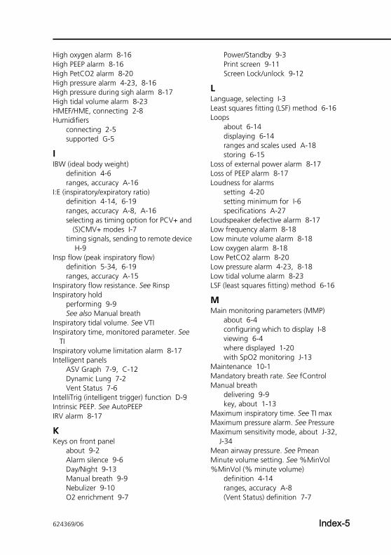
High oxygen alarm 8-16High PEEP alarm 8-16High PetCO2 alarm 8-20High pressure alarm 4-23, 8-16High pressure during sigh alarm 8-17High tidal volume alarm 8-23HMEF/HME, connecting 2-8Humidifiers
connecting 2-5supported G-5
IIBW (ideal body weight)
definition 4-6ranges, accuracy A-16
I:E (inspiratory/expiratory ratio)definition 4-14, 6-19ranges, accuracy A-8, A-16selecting as timing option for PCV+ and
(S)CMV+ modes I-7timing signals, sending to remote device
H-9Insp flow (peak inspiratory flow)
definition 5-34, 6-19ranges, accuracy A-15
Inspiratory flow resistance. See RinspInspiratory hold
performing 9-9See also Manual breath
Inspiratory tidal volume. See VTIInspiratory time, monitored parameter. See
TIInspiratory volume limitation alarm 8-17Intelligent panels
ASV Graph 7-9, C-12Dynamic Lung 7-2Vent Status 7-6
IntelliTrig (intelligent trigger) function D-9Intrinsic PEEP. See AutoPEEPIRV alarm 8-17
KKeys on front panel
about 9-2Alarm silence 9-6Day/Night 9-13Manual breath 9-9Nebulizer 9-10O2 enrichment 9-7
Power/Standby 9-3Print screen 9-11Screen Lock/unlock 9-12
LLanguage, selecting I-3Least squares fitting (LSF) method 6-16Loops
about 6-14displaying 6-14ranges and scales used A-18storing 6-15
Loss of external power alarm 8-17Loss of PEEP alarm 8-17Loudness for alarms
setting 4-20setting minimum for I-6specifications A-27
Loudspeaker defective alarm 8-17Low frequency alarm 8-18Low minute volume alarm 8-18Low oxygen alarm 8-18Low PetCO2 alarm 8-20Low pressure alarm 4-23, 8-18Low tidal volume alarm 8-23LSF (least squares fitting) method 6-16
MMain monitoring parameters (MMP)
about 6-4configuring which to display I-8viewing 6-4where displayed 1-20with SpO2 monitoring J-13
Maintenance 10-1Mandatory breath rate. See fControlManual breath
delivering 9-9key, about 1-13
Maximum inspiratory time. See TI maxMaximum pressure alarm. See PressureMaximum sensitivity mode, about J-32,
J-34Mean airway pressure. See PmeanMinute volume setting. See %MinVol%MinVol (% minute volume)
definition 4-14ranges, accuracy A-8(Vent Status) definition 7-7
624369/06 Index-5
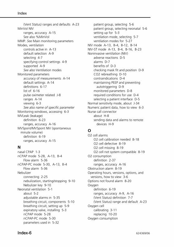
Index
(Vent Status) ranges and defaults A-23MinVol NIV
ranges, accuracy A-15See also %MinVol
MMP. See Main monitoring parametersModes, ventilation
controls active in A-13default selection A-9selecting 4-7specifying control settings 4-9supported A-9See also Ventilation modes
Monitored parametersaccuracy of measurements A-14default settings A-14definitions 6-17list of 6-16pulse oximeter related J-8ranges A-14viewing 6-3See also name of specific parameter
Monitoring windows, accessing 6-3MVLeak (leakage)
definition 6-23ranges, accuracy A-16
MVSpont/MVSpont NIV (spontaneous minute volume)
definition 6-19ranges, accuracy A-15
Nnasal CPAP 1-3nCPAP mode 5-28, A-13, B-4
Flow alarm 5-36nCPAP-PC mode 5-30, A-13, B-4
Flow alarm 5-36Nebulizer
connecting 2-25nebulization, starting/stopping 9-10Nebulizer key 9-10
Neonatal ventilation 5-1about 5-2adjustable alarms in 5-35breathing circuit, components 5-10breathing circuit, setting up 5-9expiratory valve, installing 5-3nCPAP mode 5-28nCPAP-PC mode 5-30parameters used in 5-32
patient group, selecting 5-6patient group, selecting neonatal 5-6setting up for 5-3ventilation mode, selecting 5-7ventilation modes for 5-27
NIV mode A-13, B-4, B-12, B-14NIV-ST mode A-13, B-4, B-16, B-23Noninvasive ventilation (NIV)
adverse reactions D-5alarms D-7benefits of D-3checking mask fit and position D-9CO2 rebreathing D-10contraindications D-4maintaining PEEP and preventing
autotriggering D-9monitored parameters D-8required conditions for use D-4selecting a patient interface D-5
Normal sensitivity mode, about J-34Numeric patient data, how to view 6-3Nurse call connector
about H-8sending data and alarms to remote
devices H-9
OO2 cell alarms
O2 cell calibration needed 8-18O2 cell defective 8-19O2 cell missing 8-19O2 cell not system compatible 8-19
O2 consumptiondefinition 2-37ranges, accuracy A-16
Obstruction alarm 8-19Operating hours, versions, options, and
versions, how to view 3-6Options not found alarm 8-20Oxygen
definition 6-19ranges, accuracy A-9, A-16(Vent Status) definition 7-7(Vent Status) range and default A-23
Oxygen cellcalibrating 3-11replacing 10-20
Oxygen consumption
Index-6 624369/06
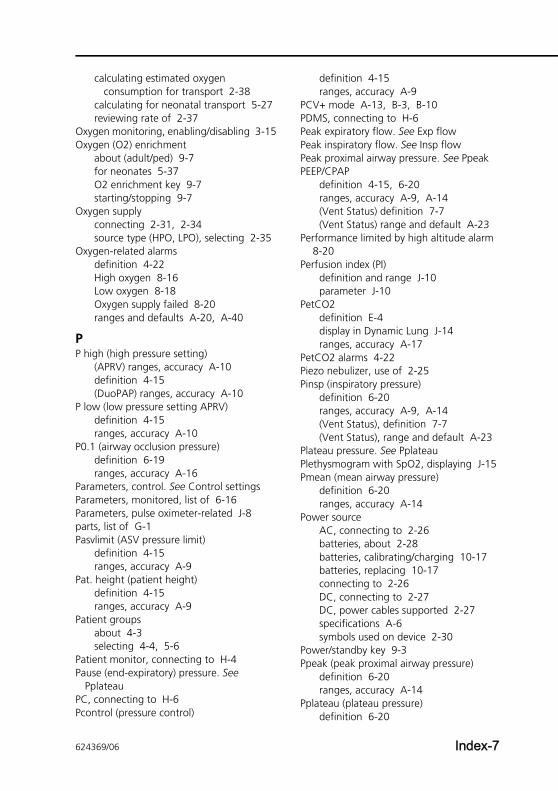
calculating estimated oxygen consumption for transport 2-38
calculating for neonatal transport 5-27reviewing rate of 2-37
Oxygen monitoring, enabling/disabling 3-15Oxygen (O2) enrichment
about (adult/ped) 9-7for neonates 5-37O2 enrichment key 9-7starting/stopping 9-7
Oxygen supplyconnecting 2-31, 2-34source type (HPO, LPO), selecting 2-35
Oxygen-related alarmsdefinition 4-22High oxygen 8-16Low oxygen 8-18Oxygen supply failed 8-20ranges and defaults A-20, A-40
PP high (high pressure setting)
(APRV) ranges, accuracy A-10definition 4-15(DuoPAP) ranges, accuracy A-10
P low (low pressure setting APRV)definition 4-15ranges, accuracy A-10
P0.1 (airway occlusion pressure)definition 6-19ranges, accuracy A-16
Parameters, control. See Control settingsParameters, monitored, list of 6-16Parameters, pulse oximeter-related J-8parts, list of G-1Pasvlimit (ASV pressure limit)
definition 4-15ranges, accuracy A-9
Pat. height (patient height)definition 4-15ranges, accuracy A-9
Patient groupsabout 4-3selecting 4-4, 5-6
Patient monitor, connecting to H-4Pause (end-expiratory) pressure. See
PplateauPC, connecting to H-6Pcontrol (pressure control)
definition 4-15ranges, accuracy A-9
PCV+ mode A-13, B-3, B-10PDMS, connecting to H-6Peak expiratory flow. See Exp flowPeak inspiratory flow. See Insp flowPeak proximal airway pressure. See PpeakPEEP/CPAP
definition 4-15, 6-20ranges, accuracy A-9, A-14(Vent Status) definition 7-7(Vent Status) range and default A-23
Performance limited by high altitude alarm 8-20
Perfusion index (PI)definition and range J-10parameter J-10
PetCO2definition E-4display in Dynamic Lung J-14ranges, accuracy A-17
PetCO2 alarms 4-22Piezo nebulizer, use of 2-25Pinsp (inspiratory pressure)
definition 6-20ranges, accuracy A-9, A-14(Vent Status), definition 7-7(Vent Status), range and default A-23
Plateau pressure. See PplateauPlethysmogram with SpO2, displaying J-15Pmean (mean airway pressure)
definition 6-20ranges, accuracy A-14
Power sourceAC, connecting to 2-26batteries, about 2-28batteries, calibrating/charging 10-17batteries, replacing 10-17connecting to 2-26DC, connecting to 2-27DC, power cables supported 2-27specifications A-6symbols used on device 2-30
Power/standby key 9-3Ppeak (peak proximal airway pressure)
definition 6-20ranges, accuracy A-14
Pplateau (plateau pressure)definition 6-20
624369/06 Index-7
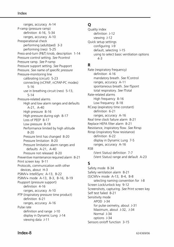
Index
ranges, accuracy A-14P-ramp (pressure ramp)
definition 4-16, 5-34ranges, accuracy A-10
Preoperational checkperforming (adult/ped) 3-3performing (neo) 5-25
Press-and-turn (P&T) knob, description 1-14Pressure control setting. See PcontrolPressure ramp. See P-rampPressure support setting. See PsupportPressure. See name of specific pressurePressure-monitoring line
calibrating (circuit) 5-23connecting (nCPAP, nCPAP-PC modes)
5-16use in breathing circuit (neo) 5-13,
5-14Pressure-related alarms
High and low alarm ranges and defaults A-21, A-40
High pressure 8-16High pressure during sigh 8-17Loss of PEEP 8-17Low pressure 8-18Performance limited by high altitude
8-20Pressure limit has changed 8-20Pressure limitation 8-20Pressure limitation alarm ranges and
defaults A-21, A-40Pressure not released 8-20
Preventive maintenance required alarm 8-21Print screen key 9-11Protocols, communication with other
devices, about H-3PSIMV+ IntelliSync A-13, B-22PSIMV+ mode A-13, B-3, B-16, B-19Psupport (pressure support)
definition 4-16ranges, accuracy A-10
PTP (inspiratory pressure time product)definition 6-21ranges, accuracy A-16
Pulse ratedefinition and range J-10display in Dynamic Lung J-14viewing data J-11
QQuality index
definition J-12viewing J-12
Quick setup settingsconfiguring I-9default, selecting I-15using to select basic ventilation options
4-3
RRate (respiratory frequency)
definition 4-16mandatory breath. See fControlranges, accuracy A-11spontaneous breath. See fSponttotal respiratory. See fTotal
Rate-related alarmsHigh frequency 8-16Low frequency 8-18
RCexp (expiratory time constant)definition 6-21ranges, accuracy A-16
Real time clock failure alarm 8-21Replace HEPA filter alarm 8-21Resistance, inspiratory flow. See RinspRinsp (inspiratory flow resistance)
definition 6-22display in Dynamic Lung 7-5ranges, accuracy A-16
RSB(Vent Status) definition 7-7(Vent Status) range and default A-23
SSafety mode B-34Safety ventilation alarm 8-21(S)CMV+ mode A-13, B-4, B-8
selecting naming convention for I-8Screen Lock/unlock key 9-12Screenshots, capturing. See Print screen keySelf test failed 8-21Sensitivity mode
APOD J-34for pulse oximetry, about J-31Maximum, about J-32, J-34Normal J-34options J-34
Sensors on/off function 3-15
Index-8 624369/06
Setup, ventilator 2-53Sidestream CO2 sensor
about 2-22connecting 2-22See also CO2 measurement
Sighdefinition 4-17ranges, accuracy A-11setting 4-9
Silencing alarms 9-6SIMV+ mode A-13, B-4, B-16, B-17, B-18
selecting naming convention for I-8slopeCO2, ranges, accuracy A-17Software options
adding I-17enabling I-19removing I-20
Specificationsaccuracy testing A-27alarms, settings and ranges, adjustable
A-20breathing system A-24electrical A-6EMC declarations A-31environmental A-3environmental requirements A-3essential performance A-27gas mixing system A-5inspiratory filter, particle size and
efficiency A-24pneumatic A-4standards and approvals A-30technical performance data A-25ventilator dimensions A-2
SpO2 low alarm J-13, J-18SpO2 (oxygen saturation)
definition and range J-10displayed as MMP J-13, J-18indicators in Dynamic Lung, definition
J-15viewing data J-11
SpO2 pulse oximetryattaching adapter to rail J-26components J-8connecting components J-22, J-25connecting the cables J-26disconnecting components J-28display in Dynamic Lung panel J-14disposal of components J-38
enabling/disabling hardware (configuration) J-30
enabling/disabling sensor J-30parameters and settings J-10plethysmogram J-15reviewing configured options
(Configuration) J-31SpO2 and pulse indicators in Dynamic
Lung J-15SpO2 sensor data options, configuring
(configuration) J-31SpO2/FiO2 ratio, about J-39trends for SpO2 parameters, viewing
J-17troubleshooting J-35verifying measurements J-27viewing data J-11viewing data in Monitoring window
J-12viewing SpO2 as MMP J-13viewing SpO2 data on main display J-13
SpO2 pulse oximetry alarms J-17, J-18ranges and defaults J-19setting J-17SpO2 alarm delay, setting J-18SpO2 low alarm, MMP display J-13,
J-18troubleshooting J-19
SPONT mode A-13, B-3, B-12Spontaneous breath frequency. See fSpontSpontaneous minute volume. See MVSpont,
MVSpont NIVStandby
about 9-3Adult/ped Standby window 9-5entering and exiting 9-3Neonatal Standby window 5-6putting ventilator into 9-3
Starting ventilation 9-4Storage, requirements 10-21Suctioning
performing 9-8use of O2 enrichment key 9-8
Symbols, definitions 1-21Synchronized controlled mandatory
ventilation mode. See (S)CMV+Synchronized intermittent mandatory
ventilation. See SIMV+ (APVsimv), PSIMV+, NIV-ST
624369/06 Index-9
Index
TT high
(APRV) ranges, accuracy A-11definition 4-17(DuoPAP) ranges, accuracy A-11
T lowdefinition 4-17ranges, accuracy A-11
TE (expiratory time)definition 6-22ranges, accuracy A-16
Technical event alarm 8-21, 8-22Technical fault alarm 8-22, B-34Tests
alarm tests 3-22preoperational checks, performing
(adult/ped) 3-3preoperational checks, performing (neo)
5-25when to perform 3-2
TI (inspiratory time)definition 4-17, 6-22ranges, accuracy A-11, A-16selecting as timing option for PCV+ and
(S)CMV+ modes I-7TI max (maximum inspiratory time)
definition 4-17, 5-34ranges, accuracy A-11
Tidal volume setting or alarm. See VtTightness test
performing (adult/ped) 3-8performing (neo) 5-17when to perform 3-4
Time constant, expiratory. See RCexpTime, expiratory (monitored parameter). See
TETime, inspiratory (monitored parameter). See
TITotal respiratory rate. See fTotalTouch screen, locking the display 9-12Transport
calculating estimated O2 consumption for 2-38
preparing trolley for intrahospital transport 2-49
Trendsabout 6-11displaying 6-13
for SpO2 parameters, viewing J-17Trigger, ranges, accuracy A-16Trolley
patient support arm 2-49use guidelines 2-48
Troubleshooting alarms, what to do 8-10Turn the Flow Sensor alarm 8-22Turning ventilator on/off 2-51
UUltrasonic nebulizer. See AeroNeb Pro
ultrasonic nebulizer systemUnits of measure, setting I-4USB device
copying configuration settings using I-16
copying Event log using 3-21USB port, location 1-18
VV’alv, ranges, accuracy A-17V’CO2, ranges, accuracy A-17VDaw, ranges, accuracy A-17VDaw/VTE, ranges, accuracy A-17VeCO2, ranges, accuracy A-17Vent Status panel 7-6
list of parameters 7-7weaning zone ranges, configuring I-14
Ventilation modesabout B-2characteristics of B-3control settings active in each mode
A-13controls, setting 4-9default mode A-9naming convention for adaptive modes,
selecting I-8neonatal modes, selecting 5-7selecting 4-7supported A-9See also Modes, ventilation
Ventilation modes, list ofAmbient state B-34APRV B-4, B-31ASV C-5DuoPAP B-4, B-26mandatory ((S)CMV+, PCV+) B-8nCPAP 5-28, B-4nCPAP-PC 5-30, B-4
Index-10 624369/06
neonatal 5-27NIV B-4, B-12NIV-ST B-4, B-16, B-23PCV+ B-3, B-10PSIMV+ B-3, B-16, B-19PSIMV+ IntelliSync B-22Safety B-34(S)CMV+ (APVcmv) B-4, B-8SIMV+ (APVsimv) B-4, B-16, B-17SPONT B-3, B-12spontaneous (SPONT, NIV) B-12Standby 9-3
Ventilatorcomponents, illustrated 1-12entering and exiting Standby 9-3starting ventilation 9-4turning on 2-51viewing operating hours, options, and
versions 3-6Ventilator keys (front panel)
about 9-2Alarm silence 9-6Day/Night 9-13Manual breath 9-9Nebulizer 9-10O2 enrichment 9-7Power/standby 9-3Print screen 9-11Screen Lock/unlock 9-12
Ventilator outlet temperature high alarm 8-22
ViCO2, ranges, accuracy A-17VLeak (leakage)
definition 6-23ranges, accuracy A-15
Volumeexpiratory minute volume. See
ExpMinVolexpiratory tidal (monitored parameter).
See VTEinspiratory tidal (monitored parameter).
See VTIleakage. See VLeakspontaneous minute (monitored
parameter). See MVSpont, MVSpont NIV
tidal. See VtVolume (loudness) for alarms
setting 4-20
setting minimum I-6specifications A-27
Volume-related alarmsHigh minute volume 8-16Low minute volume 8-18Vt high 8-23, A-21, A-40Vt low 8-23, A-21, A-40
Vt alarmsdefinition 4-23Vt high alarm 8-23Vt low alarm 8-23
Vt (tidal volume)definition 4-17, 5-36ranges, accuracy A-11
Vtalv, ranges, accuracy A-17VTEspont (spontaneous exp tidal volume)
definition 6-23ranges, accuracy A-16
VTE/VTE NIVdefinition 6-23ranges, accuracy A-15
VTI (inspiratory tidal volume)definition 6-23ranges, accuracy A-15
VT/kgdefinition 4-17ranges, accuracy A-12
WWarranty A-37Waveforms
about 6-8ranges and scales used A-18
Weaning, with ASV mode C-14Weight
definition 4-17, 5-33ranges, accuracy A-12, A-16
Wrong battery alarm 8-12Wrong expiratory valve alarm 8-23Wrong flow sensor alarm 8-24
624369/06 Index-11

Index
Index-12 624369/06
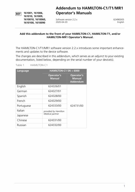
Addendum to HAMILTON-C1/T1/MR1 Operator’s Manuals
Software version 2.2.x 624983/052020-04-20 English
161001, 161006, 161010, 161009, 1610010, 1610060, 1610100, 1610090
Add this addendum to the front of your HAMILTON-C1, HAMILTON-T1, and/or HAMILTON-MR1 Operator’s Manual.
The HAMILTON-C1/T1/MR1 software version 2.2.x introduces some important enhance-ments and updates to the device software.
The changes are described in this addendum, which serves as an adjunct to your existing documentation, listed below, depending on the serial number of your device(s).
Table 1 HAMILTON-C1
Language HAMILTON-C1 SN < 6000
Operator’s Manual
Operator’s Manual
Addendum
English 624326/01
624731/00
German 624327/01
Spanish 624328/00
French 624329/00
Portuguese 624333/00
Italian provided by Hamilton Medical partnerJapanese
Chinese 624331/00
Russian 624332/00
1
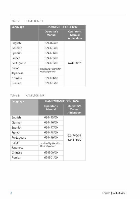
Table 2 HAMILTON-T1
Language HAMILTON-T1 SN < 3000
Operator’s Manual
Operator’s Manual
Addendum
English 624369/02
624730/01
German 624370/00
Spanish 624371/00
French 624372/00
Portuguese 624373/00
Italian provided by Hamilton Medical partnerJapanese
Chinese 624374/00
Russian 624375/00
Table 3 HAMILTON-MR1
Language HAMILTON-MR1 SN < 2000
Operator’s Manual
Operator’s Manual
Addendum
English 624495/00
624760/01624815/00
German 624496/00
Spanish 624497/00
French 624498/00
Portuguese 624499/00
Italian provided by Hamilton Medical partnerJapanese
Chinese 624500/00
Russian 624501/00
2 English | 624983/05
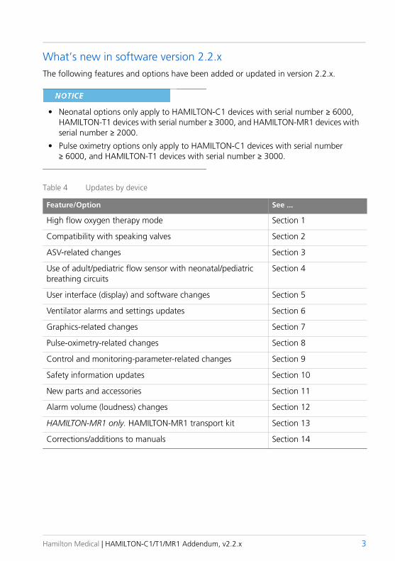
What’s new in software version 2.2.xThe following features and options have been added or updated in version 2.2.x.
NOTE
• Neonatal options only apply to HAMILTON-C1 devices with serial number ≥ 6000, HAMILTON-T1 devices with serial number ≥ 3000, and HAMILTON-MR1 devices with serial number ≥ 2000.
• Pulse oximetry options only apply to HAMILTON-C1 devices with serial number ≥ 6000, and HAMILTON-T1 devices with serial number ≥ 3000.
Table 4 Updates by device
Feature/Option See ...
High flow oxygen therapy mode Section 1
Compatibility with speaking valves Section 2
ASV-related changes Section 3
Use of adult/pediatric flow sensor with neonatal/pediatric breathing circuits
Section 4
User interface (display) and software changes Section 5
Ventilator alarms and settings updates Section 6
Graphics-related changes Section 7
Pulse-oximetry-related changes Section 8
Control and monitoring-parameter-related changes Section 9
Safety information updates Section 10
New parts and accessories Section 11
Alarm volume (loudness) changes Section 12
HAMILTON-MR1 only. HAMILTON-MR1 transport kit Section 13
Corrections/additions to manuals Section 14
Hamilton Medical | HAMILTON-C1/T1/MR1 Addendum, v2.2.x 3

4 English | 624983/05
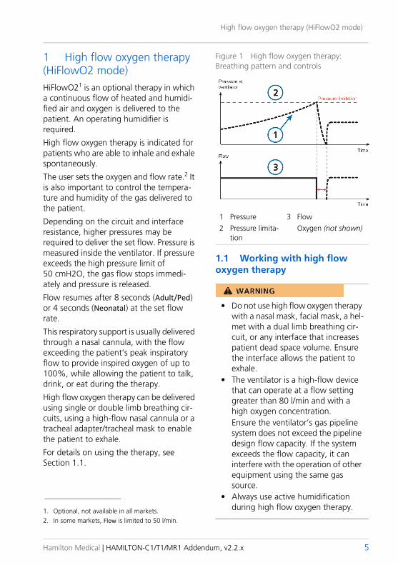
High flow oxygen therapy (HiFlowO2 mode)
1 High flow oxygen therapy (HiFlowO2 mode)HiFlowO21 is an optional therapy in which a continuous flow of heated and humidi-fied air and oxygen is delivered to the patient. An operating humidifier is required.
High flow oxygen therapy is indicated for patients who are able to inhale and exhale spontaneously.
The user sets the oxygen and flow rate.2 It is also important to control the tempera-ture and humidity of the gas delivered to the patient.
Depending on the circuit and interface resistance, higher pressures may be required to deliver the set flow. Pressure is measured inside the ventilator. If pressure exceeds the high pressure limit of 50 cmH2O, the gas flow stops immedi-ately and pressure is released.
Flow resumes after 8 seconds (Adult/Ped) or 4 seconds (Neonatal) at the set flow rate.
This respiratory support is usually delivered through a nasal cannula, with the flow exceeding the patient’s peak inspiratory flow to provide inspired oxygen of up to 100%, while allowing the patient to talk, drink, or eat during the therapy.
High flow oxygen therapy can be delivered using single or double limb breathing cir-cuits, using a high-flow nasal cannula or a tracheal adapter/tracheal mask to enable the patient to exhale.
For details on using the therapy, see Section 1.1.
Figure 1 High flow oxygen therapy: Breathing pattern and controls
1 Pressure 3 Flow2 Pressure limita-
tionOxygen (not shown)
1.1 Working with high flow oxygen therapy
• Do not use high flow oxygen therapy with a nasal mask, facial mask, a hel-met with a dual limb breathing cir-cuit, or any interface that increases patient dead space volume. Ensure the interface allows the patient to exhale.
• The ventilator is a high-flow device that can operate at a flow setting greater than 80 l/min and with a high oxygen concentration. Ensure the ventilator’s gas pipeline system does not exceed the pipeline design flow capacity. If the system exceeds the flow capacity, it can interfere with the operation of other equipment using the same gas source.
• Always use active humidification during high flow oxygen therapy.1. Optional, not available in all markets.
2. In some markets, Flow is limited to 50 l/min.
Hamilton Medical | HAMILTON-C1/T1/MR1 Addendum, v2.2.x 5
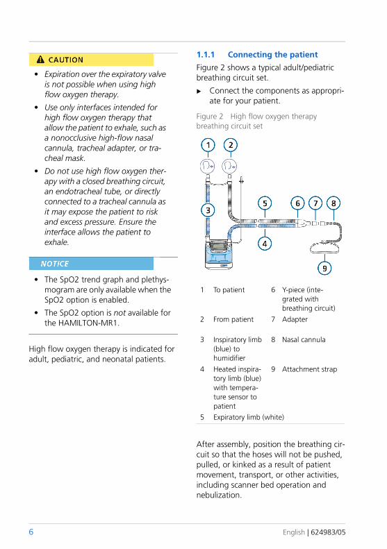
• Expiration over the expiratory valve is not possible when using high flow oxygen therapy.
• Use only interfaces intended for high flow oxygen therapy that allow the patient to exhale, such as a nonocclusive high-flow nasal cannula, tracheal adapter, or tra-cheal mask.
• Do not use high flow oxygen ther-apy with a closed breathing circuit, an endotracheal tube, or directly connected to a tracheal cannula as it may expose the patient to risk and excess pressure. Ensure the interface allows the patient to exhale.
• The SpO2 trend graph and plethys-mogram are only available when the SpO2 option is enabled.
• The SpO2 option is not available for the HAMILTON-MR1.
High flow oxygen therapy is indicated for adult, pediatric, and neonatal patients.
1.1.1 Connecting the patient
Figure 2 shows a typical adult/pediatric breathing circuit set.
Connect the components as appropri-ate for your patient.
Figure 2 High flow oxygen therapy breathing circuit set
1 To patient 6 Y-piece (inte-grated with breathing circuit)
2 From patient 7 Adapter
3 Inspiratory limb (blue) to humidifier
8 Nasal cannula
4 Heated inspira-tory limb (blue) with tempera-ture sensor to patient
9 Attachment strap
5 Expiratory limb (white)
After assembly, position the breathing cir-cuit so that the hoses will not be pushed, pulled, or kinked as a result of patient movement, transport, or other activities, including scanner bed operation and nebulization.
6 English | 624983/05
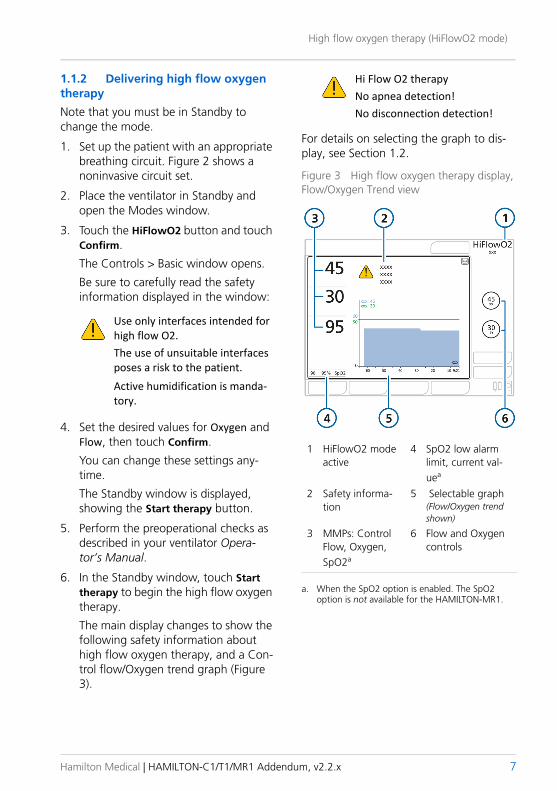
High flow oxygen therapy (HiFlowO2 mode)
1.1.2 Delivering high flow oxygen therapy
Note that you must be in Standby to change the mode.
1. Set up the patient with an appropriate breathing circuit. Figure 2 shows a noninvasive circuit set.
2. Place the ventilator in Standby and open the Modes window.
3. Touch the HiFlowO2 button and touch Confirm.
The Controls > Basic window opens.
Be sure to carefully read the safety information displayed in the window:
Use only interfaces intended for high flow O2. The use of unsuitable interfaces poses a risk to the patient. Active humidification is manda-tory.
4. Set the desired values for Oxygen and Flow, then touch Confirm.
You can change these settings any-time.
The Standby window is displayed, showing the Start therapy button.
5. Perform the preoperational checks as described in your ventilator Opera-tor’s Manual.
6. In the Standby window, touch Start therapy to begin the high flow oxygen therapy.
The main display changes to show the following safety information about high flow oxygen therapy, and a Con-trol flow/Oxygen trend graph (Figure 3).
Hi Flow O2 therapy No apnea detection!No disconnection detection!
For details on selecting the graph to dis-play, see Section 1.2.
Figure 3 High flow oxygen therapy display, Flow/Oxygen Trend view
1 HiFlowO2 mode active
4 SpO2 low alarm limit, current val-uea
2 Safety informa-tion
5 Selectable graph (Flow/Oxygen trend shown)
3 MMPs: Control Flow, Oxygen, SpO2a
a. When the SpO2 option is enabled. The SpO2 option is not available for the HAMILTON-MR1.
6 Flow and Oxygen controls
Hamilton Medical | HAMILTON-C1/T1/MR1 Addendum, v2.2.x 7
1.2 Changing the high flow oxygen therapy displayAny of the following graphs can be dis-played when delivering high flow oxygen therapy:
• Flow/Oxygen trend, the default (Figure 3)
• SpO2/Oxygen trend1
• Plethysmogram (Figure 4)1
You can also disable graphs altogether. Other elements of the display are not adjustable.
To change the display in HiFlowO2 mode
1. Touch the graph.
The graphics selection window appears.
2. For the Trends graph (Figure 3):
a. Touch the Trends tab.
b. Select the desired trend option and touch Confirm.
3. For the plethysmogram (Figure 4):
a. Touch the Waveforms tab.
b. Touch the Plethysmogram button.
The window closes and the selected graph is displayed.
Figure 4 High flow oxygen therapy display, Plethysmogram view (1)
To disable graphs
1. In the graphics selection window, touch the Waveforms tab.
2. Touch the Off button.
The window closes; the graph area is empty.
1.3 Alarms in HiFlowO2 modeThe following alarm is specific to the HiFlowO2 mode.
Table 1 HiFlowO2-mode-specific alarms
Alarms Description
Check patient interface
High priority
The pressure has reached the limit of 50 cmH2O. The flow stops while the device releases pressure. After a set time (8 seconds Adult/Ped, 4 seconds Neonatal), the flow restarts.
1. When the SpO2 option is enabled. The SpO2 option is not available for the HAMILTON-MR1.
8 English | 624983/05
Compatibility with speaking valves
When using LPO, or HPO with the Set oxy-gen alarm limits manually option selected (Section 6.1.1), you can adjust the high/low Oxygen limits in the Alarms > Limits 2 window.1
1.4 Parameters monitored in HiFlowO2 modeWhen high flow oxygen therapy is in pro-gress, the following parameters are moni-tored2:
• Oxygen • PEEP/CPAP
• Control Flow (in trend and as MMP)
• SpO2 related (when enabled)
The specifications for the Control Flow parameter are provided in Section 9.1. Specifications for the other parameters are provided in your ventilator Operator’s Manual.
1.5 Functions unavailable in HiFlowO2 modeThe following functions are deactivated when HiFlowO2 mode is selected:
• Inspiratory hold
• Manual breath
• Suctioning tool
• Pneumatic nebulizer
Note that you must be in Standby to change the mode.
2 Compatibility with speaking valvesA speaking valve allows certain tracheos-tomized adult and pediatric patients to communicate verbally, in addition to numerous other clinical benefits.
2.1 Compatible modesSpeaking valve compatibility is an option available for Adult/Ped invasive ventilation when using any of the following modes: PCV+, PSIMV+, and SPONT.
2.2 Setting up the patientSet up the patient in the following order:
1. In HiFlowO2 mode, the Alarms > Limits 1 tab is not displayed.
2. If flow sensor or pressure line is connected. With high flow oxygen therapy, PEEP/CPAP indicates the pressure at the patient interface.
Table 2 Patient setup with speaking valve
To ... See ...
Connect speaking valve
Select a compatible mode. Section 2.1
Activate speaking valve com-patibility.
Section 2.3
Deflate the tracheostomy cuff.
Connect the speaking valve to the breathing circuit set and patient.
Section 2.4
Review control settings and alarm limits.
Sections 2.6, 2.7
Start ventilationTouch the Start ventilation button.
--
Remove speaking valve
Remove speaking valve.
Deactivate speaking valve compatibility.
Section 2.5
Inflate tracheostomy cuff.
Hamilton Medical | HAMILTON-C1/T1/MR1 Addendum, v2.2.x 9
2.3 Activating speaking valve compatibility
• Do not leave the patient unattend-ed when speaking valve compati-bility is activated and a speaking valve is connected to the patient.
• When compatibility is activated:
– Apnea backup ventilation is disabled.
When compatibility is turned off, apnea backup ventilation returns to its previous setting.
– Some alarm limits are changed and some alarms are disabled. For details, see Table 3.
– Some changes apply to monitor-ing parameters. For details, see Section 2.7.
If PEEP > 0, auto-triggering can occur while using a speaking valve.
By default, speaking valve compatibility is deactivated (OFF).
Figure 5 SpeakValve window
1 Controls 4 Important safety information
2 SpeakValve 5 Apply3 SpeakValve ON
SpeakValve OFF
To activate the use of a speaking valve with the ventilator
1. Open the Controls window.
2. Touch the SpeakValve tab.
Be sure to carefully read the safety information displayed in the window.
3. Be sure to do the following:
a. Deflate the tracheostomy cuff.
b. Connect a speaking valve.
4. To activate compatibility, touch the SpeakValve ON button, then touch Apply.
Consider setting PEEP to 0 while com-patibility is activated.
Review control settings and alarm limits.
Sections 2.6, 2.7
Table 2 Patient setup with speaking valve
To ... See ...
10 English | 624983/05
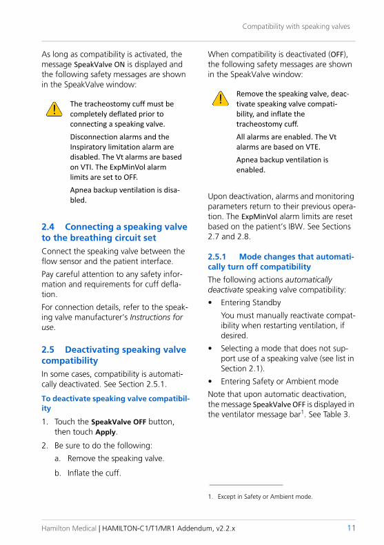
Compatibility with speaking valves
As long as compatibility is activated, the message SpeakValve ON is displayed and the following safety messages are shown in the SpeakValve window:
The tracheostomy cuff must be completely deflated prior to connecting a speaking valve.Disconnection alarms and the Inspiratory limitation alarm are disabled. The Vt alarms are based on VTI. The ExpMinVol alarm limits are set to OFF.Apnea backup ventilation is disa-bled.
2.4 Connecting a speaking valve to the breathing circuit setConnect the speaking valve between the flow sensor and the patient interface.
Pay careful attention to any safety infor-mation and requirements for cuff defla-tion.
For connection details, refer to the speak-ing valve manufacturer’s Instructions for use.
2.5 Deactivating speaking valve compatibilityIn some cases, compatibility is automati-cally deactivated. See Section 2.5.1.
To deactivate speaking valve compatibil-ity
1. Touch the SpeakValve OFF button, then touch Apply.
2. Be sure to do the following:
a. Remove the speaking valve.
b. Inflate the cuff.
When compatibility is deactivated (OFF), the following safety messages are shown in the SpeakValve window:
Remove the speaking valve, deac-tivate speaking valve compati-bility, and inflate the tracheostomy cuff.All alarms are enabled. The Vt alarms are based on VTE. Apnea backup ventilation is enabled.
Upon deactivation, alarms and monitoring parameters return to their previous opera-tion. The ExpMinVol alarm limits are reset based on the patient’s IBW. See Sections 2.7 and 2.8.
2.5.1 Mode changes that automati-cally turn off compatibility
The following actions automatically deactivate speaking valve compatibility:
• Entering Standby
You must manually reactivate compat-ibility when restarting ventilation, if desired.
• Selecting a mode that does not sup-port use of a speaking valve (see list in Section 2.1).
• Entering Safety or Ambient mode
Note that upon automatic deactivation, the message SpeakValve OFF is displayed in the ventilator message bar1. See Table 3.
1. Except in Safety or Ambient mode.
Hamilton Medical | HAMILTON-C1/T1/MR1 Addendum, v2.2.x 11
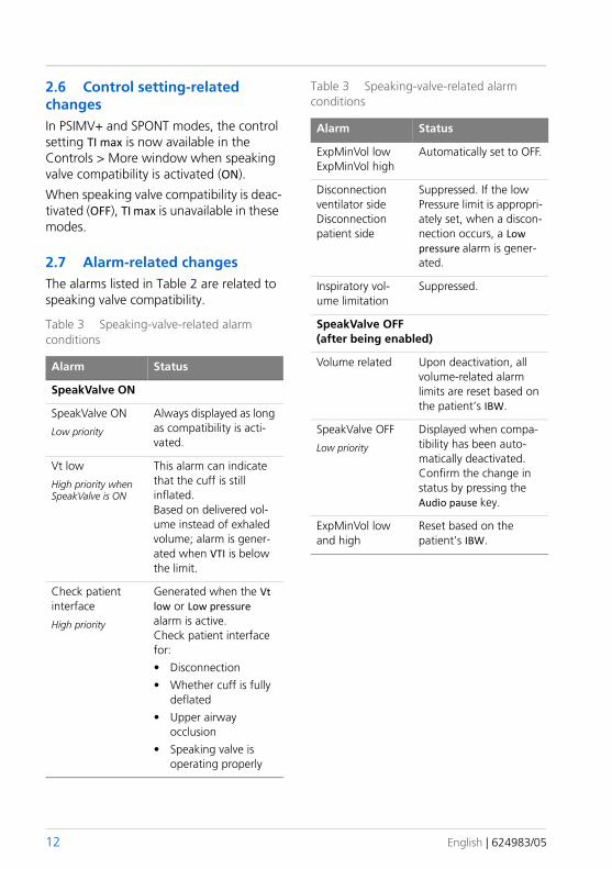
2.6 Control setting-related changesIn PSIMV+ and SPONT modes, the control setting TI max is now available in the Controls > More window when speaking valve compatibility is activated (ON).
When speaking valve compatibility is deac-tivated (OFF), TI max is unavailable in these modes.
2.7 Alarm-related changesThe alarms listed in Table 2 are related to speaking valve compatibility.
Table 3 Speaking-valve-related alarm conditions
Alarm Status
SpeakValve ON
SpeakValve ON
Low priority
Always displayed as long as compatibility is acti-vated.
Vt low
High priority when SpeakValve is ON
This alarm can indicate that the cuff is still inflated.Based on delivered vol-ume instead of exhaled volume; alarm is gener-ated when VTI is below the limit.
Check patient interface
High priority
Generated when the Vt low or Low pressure alarm is active. Check patient interface for:• Disconnection• Whether cuff is fully
deflated• Upper airway
occlusion• Speaking valve is
operating properly
ExpMinVol low ExpMinVol high
Automatically set to OFF.
Disconnection ventilator sideDisconnection patient side
Suppressed. If the low Pressure limit is appropri-ately set, when a discon-nection occurs, a Low pressure alarm is gener-ated.
Inspiratory vol-ume limitation
Suppressed.
SpeakValve OFF (after being enabled)
Volume related Upon deactivation, all volume-related alarm limits are reset based on the patient’s IBW.
SpeakValve OFF
Low priority
Displayed when compa-tibility has been auto-matically deactivated. Confirm the change in status by pressing the Audio pause key.
ExpMinVol low and high
Reset based on the patient’s IBW.
Table 3 Speaking-valve-related alarm conditions
Alarm Status
12 English | 624983/05
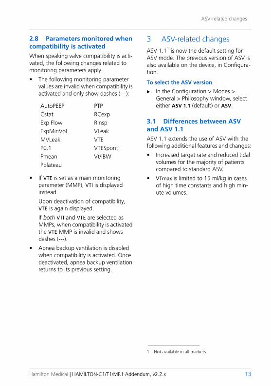
ASV-related changes
2.8 Parameters monitored when compatibility is activatedWhen speaking valve compatibility is acti-vated, the following changes related to monitoring parameters apply.
• The following monitoring parameter values are invalid when compatibility is activated and only show dashes (---):
AutoPEEP PTPCstat RCexpExp Flow RinspExpMinVol VLeakMVLeak VTEP0.1 VTESpontPmean Vt/IBWPplateau
• If VTE is set as a main monitoring parameter (MMP), VTI is displayed instead.
Upon deactivation of compatibility, VTE is again displayed.
If both VTI and VTE are selected as MMPs, when compatibility is activated the VTE MMP is invalid and shows dashes (---).
• Apnea backup ventilation is disabled when compatibility is activated. Once deactivated, apnea backup ventilation returns to its previous setting.
3 ASV-related changesASV 1.11 is now the default setting for ASV mode. The previous version of ASV is also available on the device, in Configura-tion.
To select the ASV version
In the Configuration > Modes > General > Philosophy window, select either ASV 1.1 (default) or ASV.
3.1 Differences between ASV and ASV 1.1 ASV 1.1 extends the use of ASV with the following additional features and changes:
• Increased target rate and reduced tidal volumes for the majority of patients compared to standard ASV.
• VTmax is limited to 15 ml/kg in cases of high time constants and high min-ute volumes.
1. Not available in all markets.
Hamilton Medical | HAMILTON-C1/T1/MR1 Addendum, v2.2.x 13
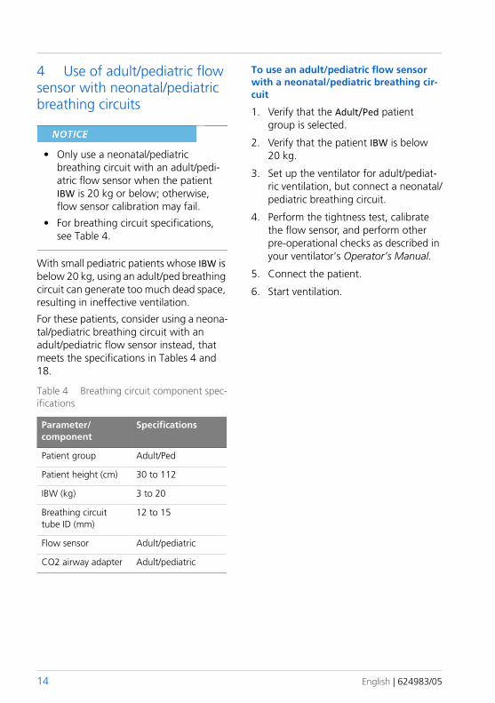
4 Use of adult/pediatric flow sensor with neonatal/pediatric breathing circuits
• Only use a neonatal/pediatric breathing circuit with an adult/pedi-atric flow sensor when the patient IBW is 20 kg or below; otherwise, flow sensor calibration may fail.
• For breathing circuit specifications, see Table 4.
With small pediatric patients whose IBW is below 20 kg, using an adult/ped breathing circuit can generate too much dead space, resulting in ineffective ventilation.
For these patients, consider using a neona-tal/pediatric breathing circuit with an adult/pediatric flow sensor instead, that meets the specifications in Tables 4 and 18.
Table 4 Breathing circuit component spec-ifications
Parameter/component
Specifications
Patient group Adult/Ped
Patient height (cm) 30 to 112
IBW (kg) 3 to 20
Breathing circuit tube ID (mm)
12 to 15
Flow sensor Adult/pediatric
CO2 airway adapter Adult/pediatric
To use an adult/pediatric flow sensor with a neonatal/pediatric breathing cir-cuit
1. Verify that the Adult/Ped patient group is selected.
2. Verify that the patient IBW is below 20 kg.
3. Set up the ventilator for adult/pediat-ric ventilation, but connect a neonatal/pediatric breathing circuit.
4. Perform the tightness test, calibrate the flow sensor, and perform other pre-operational checks as described in your ventilator’s Operator’s Manual.
5. Connect the patient.
6. Start ventilation.
14 English | 624983/05
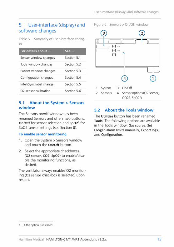
User-interface (display) and software changes
5 User-interface (display) and software changes
Table 5 Summary of user-interface chang-es
For details about ... See ...
Sensor window changes Section 5.1
Tools window changes Section 5.2
Patient window changes Section 5.3
Configuration changes Section 5.4
IntelliSync label change Section 5.5
O2 sensor calibration Section 5.6
5.1 About the System > Sensors windowThe Sensors on/off window has been renamed Sensors and offers two buttons: On/Off for sensor selection and SpO21 for SpO2 sensor settings (see Section 8).
To enable sensor monitoring
1. Open the System > Sensors window and touch the On/Off button.
2. Select the appropriate checkboxes (O2 sensor, CO2, SpO2) to enable/disa-ble the monitoring functions, as desired.
The ventilator always enables O2 monitor-ing (O2 sensor checkbox is selected) upon restart.
Figure 6 Sensors > On/Off window
1 System 3 On/Off2 Sensors 4 Sensor options (O2 sensor,
CO21, SpO21)
5.2 About the Tools windowThe Utilities button has been renamed Tools. The following options are available in the Tools window: Gas source, Set Oxygen alarm limits manually, Export logs, and Configuration.
1. If the option is installed.
Hamilton Medical | HAMILTON-C1/T1/MR1 Addendum, v2.2.x 15
5.3 About the Patient windowThe Patient window provides access to patient settings during ventilation and to the ventilation timer (Section 5.3.2).
5.3.1 Adjusting patient settings during ventilation
If patient data is changed during active ventilation, ONLY the following settings are automatically updated by the device:• Apnea backup settings (if backup is
set to Automatic)
• Startup values for Safety mode
• Other control settings and alarm lim-its are not updated
After setting up a new patient and starting ventilation, you can adjust the sex and patient height (Adult/Ped), or weight (Neonatal) in the Controls > Patient window.1
Adjusting adult/pediatric data changes the calculated IBW.
Figure 7 Patient window
1 Controls 5 Calculated IBW (Adult/Ped)
2 Patient 6 Ventilation time3 Sex (Adult/Ped) 7 Reset4 Height (Adult/Ped), Weight (Neonatal)
To access the Patient window
Touch the Controls button, then the Patient tab.
1. In some markets, the Patient tab is only available when ventilating in ASV mode.
16 English | 624983/05
User-interface (display) and software changes
5.3.2 About the ventilation timer
The Controls > Patient window displays a timer that shows how long the patient has been ventilated1,2.
The timer records time as follows:
• The timer starts when you start venti-lation.
• When you enter Standby, the timer pauses. It picks up again from the last value when you exit Standby and return to active ventilation.
• When you set up a new patient in the Standby window and start ventilation, the timer resets to 0.
• When you select Last Patient in the Standby window, the timer continues from the last total time recorded.
• When you touch the Reset button, the timer resets to 0.
When the timer is reset, an entry is made to the Event log recording the time of the reset, as well as how long the ventilator had been running prior to the reset.
To reset the timer to 0
1. Open the Controls > Patient window.
2. Touch the Reset button.
The timer starts again at 00d 00h 00min.
5.4 Configuration changesThe Configuration > General > More win-dow now shows the following message when you change the communication pro-tocol:
Please wait 10 seconds and restart the device after changing the protocol.
The Configuration window now shows all installed options in a single window. Use the scroll bar if needed.
5.5 IntelliSync label changeThe label IntelliSync in the Controls win-dow (when available) has been renamed PSync.
5.6 O2 sensor calibration
When using an oxygen supply < 99% (HPO) or low pressure oxygen (LPO), calibrate the O2 sensor at 21%. This information is displayed in the Calibra-tion window.
When calibrating the O2 sensor at 21% or when using LPO, be sure to disconnect the oxygen supply before calibration.
For details, see your ventilator Operator’s Manual.
1. Not available in all markets.2. The ventilation timer does not record time during
High flow oxygen therapy.
Hamilton Medical | HAMILTON-C1/T1/MR1 Addendum, v2.2.x 17
6 Ventilator alarms and settings updates
Table 6 Summary of updates to ventilator alarms and settings
For details about ... See ...
HiFlowO2 alarm Section 1.3
Speaking valve alarms Section 2.7
Oxygen alarm changes Section 6.1
Battery alarm changes Section 6.2
Vt low alarm limita
a. Not available in all markets.
Section 6.3
IBW/Weight in alarm limits Section 6.3
Reset button in alarms Section 6.3
6.1 Changes to oxygen supply and setting the Oxygen alarm limitsThe following changes have been made to oxygen supply settings and setting the Oxygen alarm limits when using a high-pressure oxygen (HPO) gas source:
• The selected gas source setting (HPO or LPO) is active until manually changed, regardless of whether the device is restarted.
• When using high-pressure oxygen (HPO gas source), you can choose whether to:
– Set the Oxygen high/low alarms manually1 using the Set Oxygen alarm limits manually checkbox.
– Have the device automatically set the Oxygen alarm limits to the current setting ± 5%, the same as in software version 2.1.x. This is the default setting.
• The setting (manual or auto) is active until manually changed, regardless of whether the device is restarted.
• When using low-pressure oxygen (LPO)2, the alarm limits are always set manually.
6.1.1 Setting the Oxygen alarm limits when using HPO
Figure 8 Setting Oxygen alarm limit options with HPO3
1 Tools 3 Gas source: HPO2 Utilities 4 Set Oxygen alarm
limits manually checkbox selected
1. Not available in all markets.
2. Not available on HAMILTON-MR1.3. Not available in all markets.
18 English | 624983/05
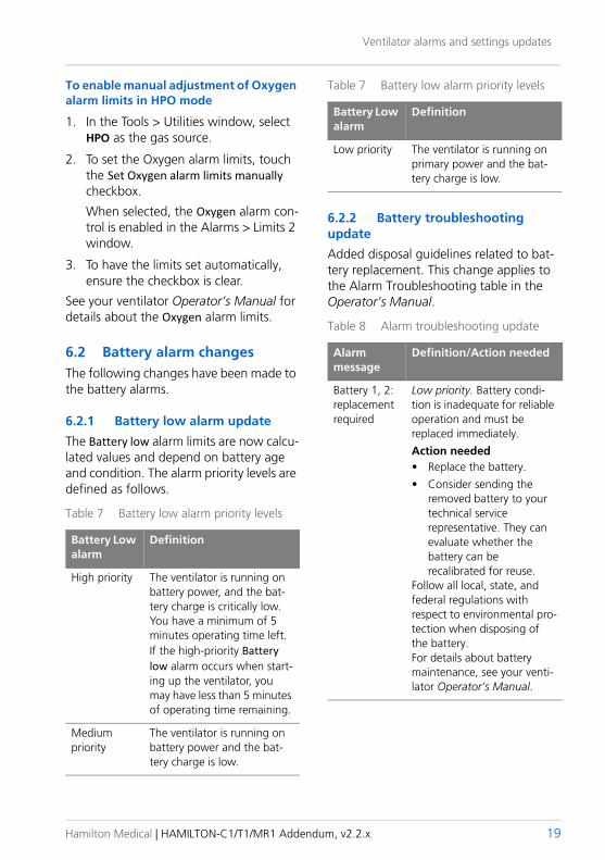
Ventilator alarms and settings updates
To enable manual adjustment of Oxygen alarm limits in HPO mode
1. In the Tools > Utilities window, select HPO as the gas source.
2. To set the Oxygen alarm limits, touch the Set Oxygen alarm limits manually checkbox.
When selected, the Oxygen alarm con-trol is enabled in the Alarms > Limits 2 window.
3. To have the limits set automatically, ensure the checkbox is clear.
See your ventilator Operator’s Manual for details about the Oxygen alarm limits.
6.2 Battery alarm changesThe following changes have been made to the battery alarms.
6.2.1 Battery low alarm update
The Battery low alarm limits are now calcu-lated values and depend on battery age and condition. The alarm priority levels are defined as follows.
Table 7 Battery low alarm priority levels
Battery Low alarm
Definition
High priority The ventilator is running on battery power, and the bat-tery charge is critically low. You have a minimum of 5 minutes operating time left.If the high-priority Battery low alarm occurs when start-ing up the ventilator, you may have less than 5 minutes of operating time remaining.
Medium priority
The ventilator is running on battery power and the bat-tery charge is low.
Low priority The ventilator is running on primary power and the bat-tery charge is low.
6.2.2 Battery troubleshooting update
Added disposal guidelines related to bat-tery replacement. This change applies to the Alarm Troubleshooting table in the Operator’s Manual.
Table 8 Alarm troubleshooting update
Alarm message
Definition/Action needed
Battery 1, 2: replacement required
Low priority. Battery condi-tion is inadequate for reliable operation and must be replaced immediately. Action needed• Replace the battery.• Consider sending the
removed battery to your technical service representative. They can evaluate whether the battery can be recalibrated for reuse.
Follow all local, state, and federal regulations with respect to environmental pro-tection when disposing of the battery.For details about battery maintenance, see your venti-lator Operator’s Manual.
Table 7 Battery low alarm priority levels
Battery Low alarm
Definition
Hamilton Medical | HAMILTON-C1/T1/MR1 Addendum, v2.2.x 19
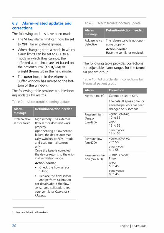
6.3 Alarm-related updates and correctionsThe following updates have been made.
• The Vt low alarm limit can now be set to OFF1 for all patient groups.
• When changing from a mode in which alarm limits can be set to OFF to a mode in which they cannot, the affected alarm limits are set based on the patient’s IBW (Adult/Ped) or weight (Neonatal) in the new mode.
• The Reset button in the Alarms > Buffer window has moved to the bot-tom of the window.
The following table provides troubleshoot-ing updates for alarms.
Table 9 Alarm troubleshooting update
Alarm message
Definition/Action needed
External flow sensor failed
High priority. The external flow sensor does not work properly.Upon sensing a flow sensor failure, the device automati-cally switches to PCV+ mode and uses internal sensors only. Once the issue is corrected, the device returns to the orig-inal ventilation mode. Action needed• Check the flow sensor
tubing• Replace the flow sensor
and perform calibrationFor details about the flow sensor and calibration, see your ventilator Operator’s Manual.
Release valve defective
The release valve is not oper-ating properly.Action neededHave the ventilator serviced.
The following table provides corrections for adjustable alarm ranges for the Neona-tal patient group.
Table 10 Adjustable alarm corrections for Neonatal patient group
Alarm Correction
Apnea time (s) Cannot be set to OFF.
The default apnea time for neonatal patients has been changed to 5 seconds.
Pressure high (Pmax) (cmH2O)
nCPAP, nCPAP-PC:10 to 55APRV: 15 to 55other modes: 18 to 55
Pressure, low (cmH2O)
nCPAP, nCPAP-PC: 2 to 55other modes: 4 to 55
Pressure limita-tion (cmH2O)
nCPAP, nCPAP-PC: PmaxAPRV:5 to 45other modes: 8 to 45
1. Not available in all markets.
Table 9 Alarm troubleshooting update
Alarm message
Definition/Action needed
20 English | 624983/05
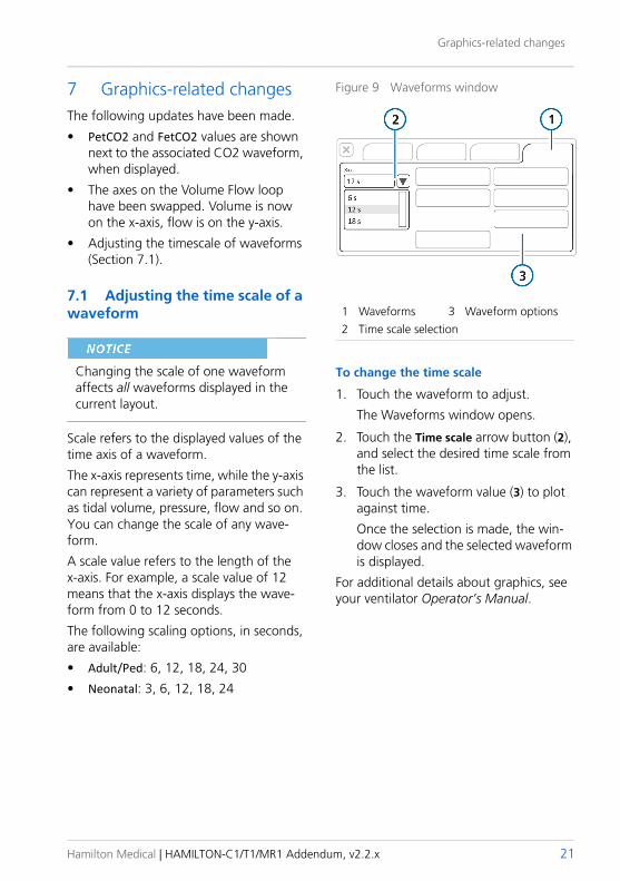
Graphics-related changes
7 Graphics-related changesThe following updates have been made.
• PetCO2 and FetCO2 values are shown next to the associated CO2 waveform, when displayed.
• The axes on the Volume Flow loop have been swapped. Volume is now on the x-axis, flow is on the y-axis.
• Adjusting the timescale of waveforms (Section 7.1).
7.1 Adjusting the time scale of a waveform
Changing the scale of one waveform affects all waveforms displayed in the current layout.
Scale refers to the displayed values of the time axis of a waveform.
The x-axis represents time, while the y-axis can represent a variety of parameters such as tidal volume, pressure, flow and so on. You can change the scale of any wave-form.
A scale value refers to the length of the x-axis. For example, a scale value of 12 means that the x-axis displays the wave-form from 0 to 12 seconds.
The following scaling options, in seconds, are available:
• Adult/Ped: 6, 12, 18, 24, 30
• Neonatal: 3, 6, 12, 18, 24
Figure 9 Waveforms window
1 Waveforms 3 Waveform options2 Time scale selection
To change the time scale
1. Touch the waveform to adjust.
The Waveforms window opens.
2. Touch the Time scale arrow button (2), and select the desired time scale from the list.
3. Touch the waveform value (3) to plot against time.
Once the selection is made, the win-dow closes and the selected waveform is displayed.
For additional details about graphics, see your ventilator Operator’s Manual.
Hamilton Medical | HAMILTON-C1/T1/MR1 Addendum, v2.2.x 21
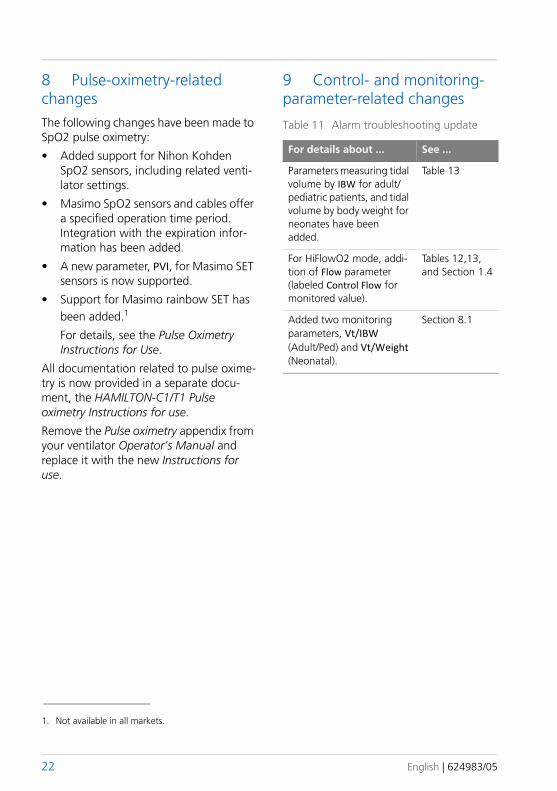
8 Pulse-oximetry-related changesThe following changes have been made to SpO2 pulse oximetry:
• Added support for Nihon Kohden SpO2 sensors, including related venti-lator settings.
• Masimo SpO2 sensors and cables offer a specified operation time period. Integration with the expiration infor-mation has been added.
• A new parameter, PVI, for Masimo SET sensors is now supported.
• Support for Masimo rainbow SET has been added.1
For details, see the Pulse Oximetry Instructions for Use.
All documentation related to pulse oxime-try is now provided in a separate docu-ment, the HAMILTON-C1/T1 Pulse oximetry Instructions for use.
Remove the Pulse oximetry appendix from your ventilator Operator’s Manual and replace it with the new Instructions for use.
9 Control- and monitoring- parameter-related changes
Table 11 Alarm troubleshooting update
For details about ... See ...
Parameters measuring tidal volume by IBW for adult/pediatric patients, and tidal volume by body weight for neonates have been added.
Table 13
For HiFlowO2 mode, addi-tion of Flow parameter (labeled Control Flow for monitored value).
Tables 12,13, and Section 1.4
Added two monitoring parameters, Vt/IBW (Adult/Ped) and Vt/Weight (Neonatal).
Section 8.1
1. Not available in all markets.
22 English | 624983/05
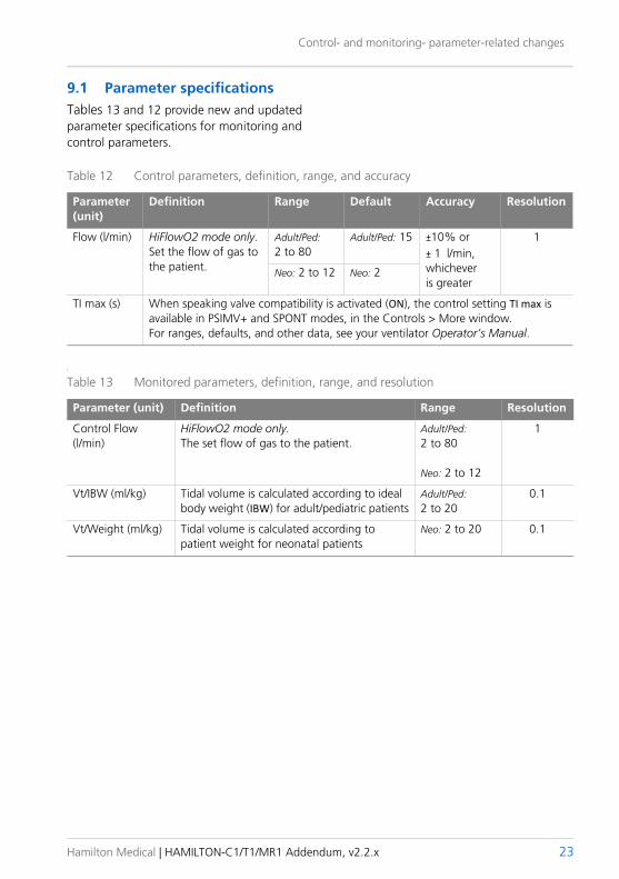
Control- and monitoring- parameter-related changes
9.1 Parameter specificationsTables 13 and 12 provide new and updated parameter specifications for monitoring and control parameters.
Table 12 Control parameters, definition, range, and accuracy
Parameter (unit)
Definition Range Default Accuracy Resolution
Flow (l/min) HiFlowO2 mode only.Set the flow of gas to the patient.
Adult/Ped: 2 to 80
Adult/Ped: 15 ±10% or ± 1 l/min, whichever is greater
1
Neo: 2 to 12 Neo: 2
TI max (s) When speaking valve compatibility is activated (ON), the control setting TI max is available in PSIMV+ and SPONT modes, in the Controls > More window. For ranges, defaults, and other data, see your ventilator Operator’s Manual.
Table 13 Monitored parameters, definition, range, and resolution
Parameter (unit) Definition Range Resolution
Control Flow (l/min)
HiFlowO2 mode only.The set flow of gas to the patient.
Adult/Ped: 2 to 80
Neo: 2 to 12
1
Vt/IBW (ml/kg) Tidal volume is calculated according to ideal body weight (IBW) for adult/pediatric patients
Adult/Ped: 2 to 20
0.1
Vt/Weight (ml/kg) Tidal volume is calculated according to patient weight for neonatal patients
Neo: 2 to 20 0.1
l
Hamilton Medical | HAMILTON-C1/T1/MR1 Addendum, v2.2.x 23
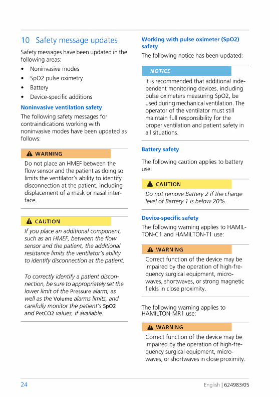
10 Safety message updatesSafety messages have been updated in the following areas:
• Noninvasive modes
• SpO2 pulse oximetry
• Battery
• Device-specific additions
Noninvasive ventilation safety
The following safety messages for contraindications working with noninvasive modes have been updated as follows:
Do not place an HMEF between the flow sensor and the patient as doing so limits the ventilator’s ability to identify disconnection at the patient, including displacement of a mask or nasal inter-face.
If you place an additional component, such as an HMEF, between the flow sensor and the patient, the additional resistance limits the ventilator’s ability to identify disconnection at the patient.
To correctly identify a patient discon-nection, be sure to appropriately set the lower limit of the Pressure alarm, as well as the Volume alarms limits, and carefully monitor the patient’s SpO2 and PetCO2 values, if available.
Working with pulse oximeter (SpO2) safety
The following notice has been updated:
It is recommended that additional inde-pendent monitoring devices, including pulse oximeters measuring SpO2, be used during mechanical ventilation. The operator of the ventilator must still maintain full responsibility for the proper ventilation and patient safety in all situations.
Battery safety
The following caution applies to battery use:
Do not remove Battery 2 if the charge level of Battery 1 is below 20%.
Device-specific safety
The following warning applies to HAMIL-TON-C1 and HAMILTON-T1 use:
Correct function of the device may be impaired by the operation of high-fre-quency surgical equipment, micro-waves, shortwaves, or strong magnetic fields in close proximity.
The following warning applies to HAMILTON-MR1 use:
Correct function of the device may be impaired by the operation of high-fre-quency surgical equipment, micro-waves, or shortwaves in close proximity.
24 English | 624983/05
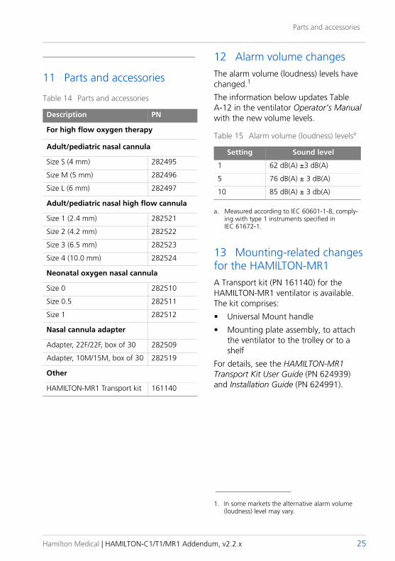
Parts and accessories
11 Parts and accessories
Table 14 Parts and accessories
Description PN
For high flow oxygen therapy
Adult/pediatric nasal cannula
Size S (4 mm) 282495
Size M (5 mm) 282496
Size L (6 mm) 282497
Adult/pediatric nasal high flow cannula
Size 1 (2.4 mm) 282521
Size 2 (4.2 mm) 282522
Size 3 (6.5 mm) 282523
Size 4 (10.0 mm) 282524
Neonatal oxygen nasal cannula
Size 0 282510
Size 0.5 282511
Size 1 282512
Nasal cannula adapter
Adapter, 22F/22F, box of 30 282509
Adapter, 10M/15M, box of 30 282519
Other
HAMILTON-MR1 Transport kit 161140
12 Alarm volume changesThe alarm volume (loudness) levels have changed.1
The information below updates Table A-12 in the ventilator Operator’s Manual with the new volume levels.
Table 15 Alarm volume (loudness) levelsa
a. Measured according to IEC 60601-1-8, comply-ing with type 1 instruments specified in IEC 61672-1.
Setting Sound level
1 62 dB(A) ±3 dB(A)
5 76 dB(A) ± 3 dB(A)
10 85 dB(A) ± 3 db(A)
13 Mounting-related changes for the HAMILTON-MR1A Transport kit (PN 161140) for the HAMILTON-MR1 ventilator is available. The kit comprises:
• Universal Mount handle
• Mounting plate assembly, to attach the ventilator to the trolley or to a shelf
For details, see the HAMILTON-MR1 Transport Kit User Guide (PN 624939) and Installation Guide (PN 624991).
1. In some markets the alternative alarm volume (loudness) level may vary.
Hamilton Medical | HAMILTON-C1/T1/MR1 Addendum, v2.2.x 25
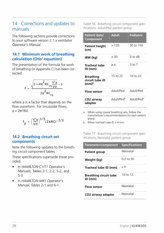
14 Corrections and updates to manualsThe following sections provide corrections to your software version 2.1.x ventilator Operator’s Manual.
14.1 Minimum work of breathing calculation (Otis’ equation)The presentation of the formula for work of breathing (in Appendix C) has been cor-rected:
f1 4π2RCrs
V′aVd---------+ 1–
2π2RCrs
----------------------------------------------------------=
where a is a factor that depends on the flow waveform. For sinusoidal flows, a = 2π2/60.
fpV′aVd--------- 1 3/
2πRC( ) 2 3/–=
14.2 Breathing circuit set componentsNote the following updates to the breath-ing circuit component tables.
These specifications supersede those pro-vided:
• In HAMILTON-C1/T1 Operator’s Manuals, Tables 2-1, 2-2, 5-2, and 5-3.
• In HAMILTON-MR1 Operator’s Manual, Tables 2-1 and 6-1.
Table 16 Breathing circuit component spec-ifications, Adult/Ped patient group
Patient data/Component
Adult Pediatric
Patient height (cm)
> 130 30 to 150
IBW (kg) > 30 3 to 48
Tracheal tube ID (mm)
≥ 4 3 to 7
Breathing circuit tube ID (mm)a
a. When using coaxial breathing sets, follow the manufacturer’s recommendations for each patient group.
15 to 22 10 to 22
Flow sensor Adult/Ped Adult/Ped
CO2 airway adapter
Adult/Pedb
b. When tracheal tube ID > 4 mm.
Adult/Pedb
Table 17 Breathing circuit component spec-ifications, Neonatal patient group
Parameter/component Specifications
Patient group Neonatal
Weight (kg) 0.2 to 30
Tracheal tube ID (mm) ≤ 4
Breathing circuit tube ID (mm)
10 to 12
Flow sensor Neonatal
CO2 airway adapter Neonatal
26 English | 624983/05
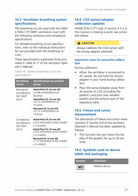
Corrections and updates to manuals
14.3 Ventilator breathing system specificationsThe breathing circuits used with the HAM-ILTON-C1/T1/MR1 ventilators must fulfil the following resistance and compliance specifications.
For detailed breathing circuit specifica-tions, refer to the individual Instructions for use provided with the breathing cir-cuits.
These specifications supersede those pro-vided in Table A-11 of the ventilator Oper-ator’s Manual.
Table 18 General breathing circuit set specifications
Breathing circuit
Specifications by patient group
Resistanceaccording to ISO 5367: 2014
Adult/Ped (15–22 mm ID)≤ 0.06 cmH2O/l/min at 30 l/minAdult/Ped (12–15 mm ID)≤ 0.12 cmH2O/l/min at 15 l/minNeonatal (9–12 mm ID)≤ 0.12 cmH2O/l/min at 15 l/min
Complianceaccording to ISO 5367: 2014
Adult/Ped (15–22 mm ID)≤ 4.0 ml/cmH2O at 60 cmH2O ± 3 cmH2OAdult/Ped (12–15 mm ID)≤ 4.0 ml/cmH2O at 60 cmH2O ± 3 cmH2ONeonatal (9–12 mm ID)≤ 1.5 ml/cmH2O at 60 cmH2O ± 3 cmH2O
14.4 CO2 sensor/adapter calibration updatesHAMILTON-C1/T1 only. In Section 3.3.2.4, the Caution is missing a word; see correc-tion below.
Always calibrate the CO2 sensor with the airway adapter attached.
Important notes for successful calibra-tion
During calibration:
• When the ventilator is connected to AC power, do not hold the sensor/adapter in your hand during calibra-tion.
• Place the sensor/adapter away from all sources of CO2 (including the patient's and your own exhaled breath) and the exhaust port of the expiratory valve.
14.5 Freeze and cursor measurementThe description of freeze and cursor meas-urement in Section 6.8 of the ventilator Operator’s Manual has been updated as follows:
• This function lets you freeze the dis-play of the graphic for up to 30 sec-onds.
14.6 Symbols used on device labels and packaging
Symbol Definition
Medical device
Hamilton Medical | HAMILTON-C1/T1/MR1 Addendum, v2.2.x 27
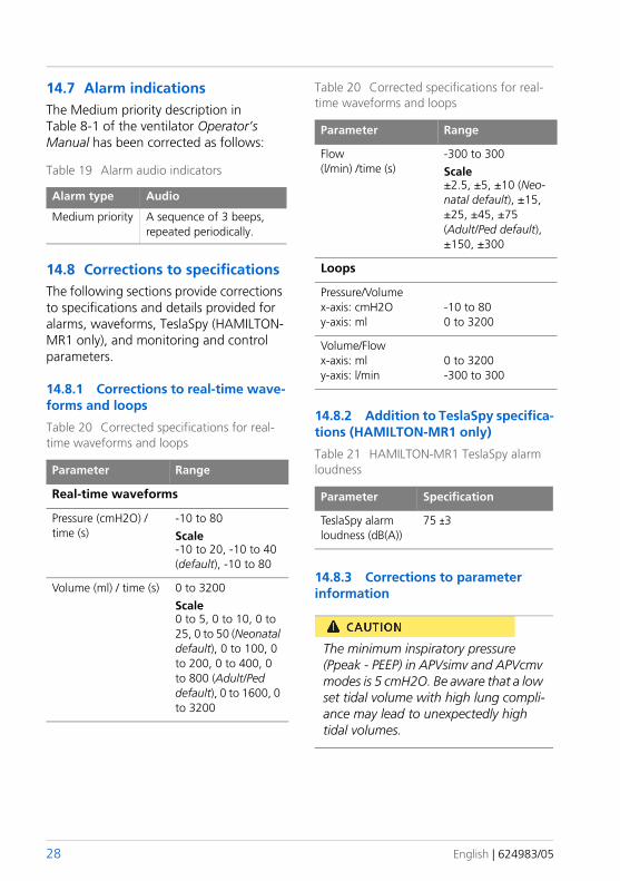
14.7 Alarm indicationsThe Medium priority description in Table 8-1 of the ventilator Operator’s Manual has been corrected as follows:
Table 19 Alarm audio indicators
Alarm type Audio
Medium priority A sequence of 3 beeps, repeated periodically.
14.8 Corrections to specificationsThe following sections provide corrections to specifications and details provided for alarms, waveforms, TeslaSpy (HAMILTON-MR1 only), and monitoring and control parameters.
14.8.1 Corrections to real-time wave-forms and loops
Table 20 Corrected specifications for real-time waveforms and loops
Parameter Range
Real-time waveforms
Pressure (cmH2O) / time (s)
-10 to 80Scale-10 to 20, -10 to 40 (default), -10 to 80
Volume (ml) / time (s) 0 to 3200Scale0 to 5, 0 to 10, 0 to 25, 0 to 50 (Neonatal default), 0 to 100, 0 to 200, 0 to 400, 0 to 800 (Adult/Ped default), 0 to 1600, 0 to 3200
Flow(l/min) /time (s)
-300 to 300Scale±2.5, ±5, ±10 (Neo-natal default), ±15, ±25, ±45, ±75 (Adult/Ped default), ±150, ±300
Loops
Pressure/Volumex-axis: cmH2Oy-axis: ml
-10 to 800 to 3200
Volume/Flowx-axis: mly-axis: l/min
0 to 3200-300 to 300
14.8.2 Addition to TeslaSpy specifica-tions (HAMILTON-MR1 only)
Table 21 HAMILTON-MR1 TeslaSpy alarm loudness
Parameter Specification
TeslaSpy alarm loudness (dB(A))
75 ±3
14.8.3 Corrections to parameter information
The minimum inspiratory pressure (Ppeak - PEEP) in APVsimv and APVcmv modes is 5 cmH2O. Be aware that a low set tidal volume with high lung compli-ance may lead to unexpectedly high tidal volumes.
Table 20 Corrected specifications for real-time waveforms and loops
Parameter Range
28 English | 624983/05

Corrections and updates to manuals
Table 22 Parameter accuracy corrections for Neonatal patient group
Parameter Accuracy
Insp Flow, peak Neo: ±10% or 2 ml/s, whichever is greaterExp Flow, peak
Tables 23 and 24 provide corrected infor-mation related to monitoring and control parameter value ranges.
Hamilton Medical | HAMILTON-C1/T1/MR1 Addendum, v2.2.x 29
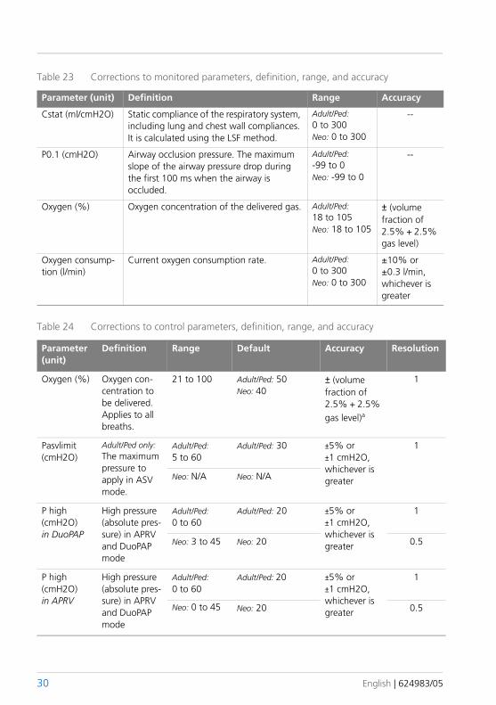
Table 23 Corrections to monitored parameters, definition, range, and accuracy
Parameter (unit) Definition Range Accuracy
Cstat (ml/cmH2O) Static compliance of the respiratory system, including lung and chest wall compliances. It is calculated using the LSF method.
Adult/Ped: 0 to 300Neo: 0 to 300
--
P0.1 (cmH2O) Airway occlusion pressure. The maximum slope of the airway pressure drop during the first 100 ms when the airway is occluded.
Adult/Ped: -99 to 0Neo: -99 to 0
--
Oxygen (%) Oxygen concentration of the delivered gas. Adult/Ped: 18 to 105Neo: 18 to 105
± (volume fraction of 2.5% + 2.5% gas level)
Oxygen consump-tion (l/min)
Current oxygen consumption rate. Adult/Ped: 0 to 300Neo: 0 to 300
±10% or ±0.3 l/min, whichever is greater
Table 24 Corrections to control parameters, definition, range, and accuracy
Parameter (unit)
Definition Range Default Accuracy Resolution
Oxygen (%) Oxygen con-centration to be delivered.Applies to all breaths.
21 to 100 Adult/Ped: 50Neo: 40
± (volume fraction of 2.5% + 2.5% gas level)a
1
Pasvlimit (cmH2O)
Adult/Ped only:The maximum pressure to apply in ASV mode.
Adult/Ped: 5 to 60
Adult/Ped: 30 ±5% or ±1 cmH2O, whichever is greater
1
Neo: N/A Neo: N/A
P high (cmH2O)in DuoPAP
High pressure (absolute pres-sure) in APRV and DuoPAP mode
Adult/Ped: 0 to 60
Adult/Ped: 20 ±5% or ±1 cmH2O, whichever is greater
1
Neo: 3 to 45 Neo: 20 0.5
P high (cmH2O)in APRV
High pressure (absolute pres-sure) in APRV and DuoPAP mode
Adult/Ped: 0 to 60
Adult/Ped: 20 ±5% or ±1 cmH2O, whichever is greater
1
Neo: 0 to 45 Neo: 20 0.5
30 English | 624983/05
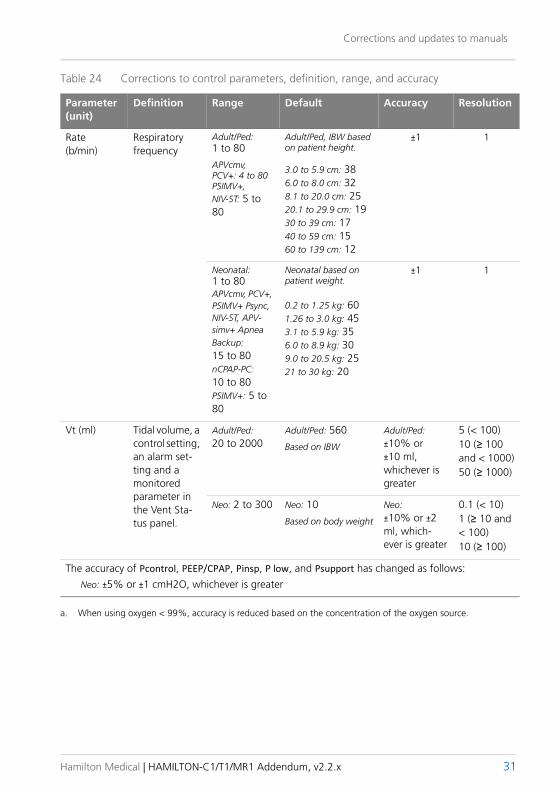
Corrections and updates to manuals
Rate (b/min)
Respiratory frequency
Adult/Ped:1 to 80
APVcmv, PCV+: 4 to 80PSIMV+, NIV-ST: 5 to 80
Adult/Ped, IBW based on patient height.
3.0 to 5.9 cm: 386.0 to 8.0 cm: 328.1 to 20.0 cm: 2520.1 to 29.9 cm: 1930 to 39 cm: 1740 to 59 cm: 1560 to 139 cm: 12
±1 1
Neonatal:1 to 80APVcmv, PCV+, PSIMV+ Psync, NIV-ST, APV-simv+ Apnea Backup: 15 to 80nCPAP-PC: 10 to 80PSIMV+: 5 to 80
Neonatal based on patient weight.
0.2 to 1.25 kg: 601.26 to 3.0 kg: 453.1 to 5.9 kg: 356.0 to 8.9 kg: 309.0 to 20.5 kg: 2521 to 30 kg: 20
±1 1
Vt (ml) Tidal volume, a control setting, an alarm set-ting and a monitored parameter in the Vent Sta-tus panel.
Adult/Ped: 20 to 2000
Adult/Ped: 560
Based on IBW
Adult/Ped: ±10% or ±10 ml, whichever is greater
5 (< 100) 10 (≥ 100 and < 1000) 50 (≥ 1000)
Neo: 2 to 300 Neo: 10
Based on body weight
Neo: ±10% or ±2 ml, which-ever is greater
0.1 (< 10) 1 (≥ 10 and < 100) 10 (≥ 100)
The accuracy of Pcontrol, PEEP/CPAP, Pinsp, P low, and Psupport has changed as follows:Neo: ±5% or ±1 cmH2O, whichever is greater
a. When using oxygen < 99%, accuracy is reduced based on the concentration of the oxygen source.
Table 24 Corrections to control parameters, definition, range, and accuracy
Parameter (unit)
Definition Range Default Accuracy Resolution
Hamilton Medical | HAMILTON-C1/T1/MR1 Addendum, v2.2.x 31

32 English | 624983/05


www.hamilton-t1.comMore information and free software simulation:
Hamilton Medical AG
Via Crusch 8, 7402 Bonaduz, Switzerland
( +41 (0)58 610 10 20
www.hamilton-medical.com
medin Innovations GmbH
Adam-Geisler-Strasse 1
DE – 82140 Olching
Related Documents