Welcome message from author
This document is posted to help you gain knowledge. Please leave a comment to let me know what you think about it! Share it to your friends and learn new things together.
Transcript


We just struck gold with a miniature, high qual- ity and very reliable DTMF decoder at a rock bottom price of $59.95. Our DTD-I will decode 5040, 4 digit codes with the security of wrong digit reset. I t contains a crystal controlled. single chip DTMF decoder that works great in bad sig- nal to noise environments and provides latched and momentary outputs. Why carry that heavy gear when its size is only 1.25 x 2.0 x .4 inches and it comes with our etched in stone. legendary. one year warranty.
#COMMUNICATIONS Instead of sifting through the field.. .search- - SPfcAllSTS
4 2 0 \\ l6 i l [ \ \c . ( )I<III~C. C'\ t)2fd&42k1~ ing .useoursuperquickonedaydel iveryand I , , . , I ( ~ I J I ~ N X - ~ ~ ? I ~ I A X I ~ I ~ ) O ~ ~ - ~ ~ ~ O
Ga - V M
cash in on a rare find. Entire U.S.A. 1-800-853-0537 - fl 104

6r.1 (50 54 MH7) 10 W orltplrl olus all HF A r lnlc\lr hanrlc (100 Wo111p11tl E ~ t ~ n r l i , t l l irn rc,c:rivr!r frequfnry mngcx 45 MH,, I t i 60 MH? Sprcs q~ r ;~ ran l t~ rd frc>rr~ '10 10 54 Mtir ' i7nrc f i~r i i : l~~)ns iil [Ire TS~l4OS t ix(:~pt apllonal ' JOX IVOX-(1 rt:ilt~irecl f(11 VOX ollt?rallclnl P r ~ ~ a r ~ ~ j l ~ f ~ ? ~ 1111 6 :~n(t 10 l i l ~ ! l c ~ r band
Conlnlel* sorvtce I~~RIIII~~C are ava~lahle lor all Kcnwoorl rr.inscrii,er' andrno.;r acressofirc S[~c~ctl~c;il~ons lci~lufes ~ ~ r ~ d ~ ) r ~ c ~ ~ ~ ~ ~ f ~ s t ~ b ~ ~ ~ . f l n r t ~ ~ i f ~ ~ ~ ~ ~ ~ f ~ ~ ~ ~ ~ r ~ r ~ ~ ~ l : ~ ~ ~ o r r J t J l ! q : l l ~ ~ Nr1
K30F, page 22 WRIF, page 82
MARCH 1990 Volume 23, Number 3
Publisher 81 Editor-in-Chief: T.H. TENNEY. JR.. W l N L B
EDITORIAL STAFF Editor: TERRY NORTHU? KA lSTC
Consulting Technical Editors: Mar t y Du rham, N B l H D a v ~ d McLanahan , W A l F H B Al f red W ~ l s o n , WGNIF Rober t D Wilson, W A l T K H
Associate Edltors: Peter B e r t ~ n ~ . K l Z J H Tom McMul len. W l S L J o s e p h J. Schroeder, W 9 J U V
Production Editor: Susan Shorrock Copy Editor: P e g g y Tenney, K A l O D G Editorial Assistant: B e t h M c C o r m a c k
Editorial Review Board: Forrest Gehrke. KPBT Michae l Gruchal la, P E . Hunter Harrts. W l S l B o b Lewis, W2EBS M a s o n Logan. K 4 M T Vern Riportella, WA2LOO E d Welherhold, W 3 N O N
PUBLISHING STAFF Assistant Publisher: J. C R A I G CLARK. JR.. N X l G
Advertising Manager: M a r l y Du rham. N B l H
Advertising Production Manager: Dorothy Sargent. K A I Z K
Circulation Manager: Susan Shorrock Circulation: Mar lon Tuttle Traffic Manager: P h ~ l A l ~ x . N l F P X Book Store: l 'r~scil la Gauv in
Cover photo: Corne l l Drentea. WBSJZO. Shot is of a n Aurora B o r e a l ~ s over WB3JZO's OTH.
SKYWAVE COMMUNICATIONS Corne l l Drentea. WB3JZO
The Weekender: ANOTHER LOOK AT HF MOBILE ANTENNAS J a c k Nalork. W5FG
Microwaves: LASER COMMUNICATION SYSTEMS B o b Atkms, K A lGT
BUILD YOUR OWN SUPERCHARGER W. C. Cloninger, Jr.. K 3 0 F
EFFECTIVE NOISE TEMPERATURE, PART 2 EQUIVALENT NOISE TEMPERATURE AND NF 33 M ~ c h a e l E Gruchalla, F' f
Ham Radio Techniques: 160-METER ANTENNA PROBLEMS AND SOLUTIONS 49 Bll l Orr. W6SAI
DIGITAL VOICE STORAGE IN THE HAM SHACK Car l Lyster, WA4A D G
Practically Speaking: ANALOG METER MOVEMENTS: HOW TO USE THEM 68 J o s e p h J. Carr. K41PV
UNDERSTANDING COMPUTER-GENERATED RFI Bryan P. Bergeron, NU IN
The Weekender: AN LED MILLIVOLTMETER Yardley Beers. W0JF
BACKSCATTER 4 SHORT CIRCUITS 87 COMMENTS 6 FLEAMARKET 88,89 HAM NOTEBOOK 42 ADVERTISERS INDEX 90 NEW PRODUCTS 73,74 READER SERVICE 90 DX FORECASTER 85
HAM RADIO Magazlne(1SSN 0148-5989) lspubllshed monthly by Commun~cat~ons Techndbgy, Inc Me~n Street. Greenv~lle. New Hampshlre 03048 0498 Telephone 603-878-1441 FAX 603.878.1951 SubsCripllon Rates. Unrled Slates one year. $22 95. two years. $3895 lhree years. U995.CanadaandMexro oneyear.Wl00 m y e a r s . $5500 threeyean.$74 00 All~3her~untnns one year $35 00vrasurtace mall only All subscrlpllon orders payable In U S funds, vla ~nternaltonal poslal money orderorcheck drawn on LJ S bank lnternatlonal Subscripllon Aqents: paqe 89
M~croltlmcop~esateava~lablr~mmBuckmazler Puh11sh~ngM1nernl.V1rg1nra23I17 Casseltelapesolselectndart~cleslrom HAM RADlOareava~laoleto Ihe blmd and ohvslcallvhand8ca~Ded trom Recorded Per~od~cals. 919 Walnut Strenl. Ph~ladelphra. Penn sylvanla 19107
Copyrlghl 1990 by Commun~catrons Technology. Inc Title regrslered at U S Palent OfflCe Second-class poslage pad at Greenvrlle. New Hampshlre 03048.0498 and al addrlronal matllng otfrces Sendchangeoleddress to HAM RADIO. Greerwrlle. New Hampshlm 03048.0498

Amateur Radio growth?
I understand that the running number of radio Amateurs remains nearly constant. That is to say, the popula- tion is not increasing. To combat this, a no-code VHF license has been proposed that presumably will remove a large stumbling block for the would-be ham. The result will be more radio Amateurs in the long run, making the Amateur Radio service more viable and healthy. Right3
Perhaps. However, we may be barking up the wrong tree. I suggest you take an hour or so and listen to the spectrum between 26 and 29 MHz. CB radio, as it was known, has disappeared and a new form of "hobby" radio has grown up in its place. The full 3-MHz range is chock full of SSB stations going about their business in a "ham-like" attitude. Seemingly absent are the loud-mouthed ignorarriuses who made CB radio a shambles a few years ago. In their place are thousands of operators, behaving themselves, and having fun! There's plenty of DX in this range, too. I counted 14 countries in about 30 minutes listening time. Not much talk about equip- ment, but a lot of chatter about friendships and local color. It sounded very interesting. Too bad these thousands of operators are not hams!
But why should they be hams? What's the advantage? They can converse and enjoy themselves with no danger from the FCC. They exchange QSL cards and other pleasantries - and they have 3 MHz of space to do it! More frequencies than any HF ham band. The future radio hams are already on the air, and I don't see any chance of them becoming licensed Amateurs because there's little in it for them! They don't need Amateur Radio as we know it. A modified ham transceiver and a store-bought beam puts the operator on the air, ready to work DX and make new friends. To add insult to injury, I recently received a QSL from an English Amateur. On the card were his call letters and also his "identifier" for CB radio. tie had the best of all possible worlds.
As long as the FCC and other licensing bodies allow unlicensed communications to take place in the 27-MHz region, we can't expect Amateur Radio to have much growth. The competition is too strong. And Amateur Radio shouldn't be blamed for either this problem or the lack of growth of the Amateur population! I'm not sure what the solution is, but I do know that a lot of happy people are enjoying the fruits of Amateur Radio the easy way. Can you blame them?
I propose that the ARRL initiate special broadcasts from W1AW in the 27-MHz range. This will, however, require special authorization from the FCC. These daily voice transmissions would include information about Amateur Radio, giving an address to send for more information on how to get a ham license. As time goes on, lessons in Morse code, rules and regulations of the Amateur service, and help with the Amateur exam could be given. A regular on-the-air course in Amateur Radio should be initiated and it could be broadcast right where it's most needed - in the middle of the "hobby" frequency range. I think that 1 d-kW PEP intoa multi-element Yagi aimed at the heart of the country would gain a lot of attention among those whoare potential radio Amateurs. Just as the Voice of America aims its broadcasts to selected areas of the world, the ARRL could aim its special 27-MHz transmissions at would-be Amateurs. Let's convince them that there is value in getting an Amateur Radio license!
Bill Orr, WGSAI
4 Ham Radio/March 1990

Creative recruitment; Productive leisure time Dear HR
It is basic construction articles like W3RMD's ("The Five-Band Junkbox Transmitter," Ham Radio, December 1989 and "The 80140-meter Junkbox Rig Revisiting, Ham Radio, January 1990) which, in my view, will go far to excite the imaginations of prospective hams and bring them into the fold.
Just as many of us got our feet wet with crystal control and "graduated" to additional frequencies and modes via VFOs and upgrading, so ... might begin- ning with discrete components be the route for today's beginner to license upgrading and state-of-the-art tech- nical skill and knowledge.
We Elmers with well-stocked junk- boxes would do well to share our goodies with beginners, young and old, 807s anyone? How about an ARC-5?
Can we target as propective hams not only those with demonstrated tech- nical skills and interests but also youth and adults who seek a leisure time activity that is not necessarily related to their intended or actual vocations or professions? I think such a strategy would be particularly relevant to older persons, whose numbers in our soci- ety are increasing dramatically and for whom Amateur Radio is an oppor- tunity for continued active involvement in life and living that is service orient- ed. Three eminent hams come to mind in this regard - Senator Barry Gold- water, the late General Curtis LeMay, and King Hussein of Jordan.
Finally, can't we market CW as a second language to prospective hams rather than endure the frustration of defendinglrejecting an arguably out- moded if not obsolete communications mode. Those of us who have mastered CW are, after all, bilingual.
Carlton D. Trotman, W3BRX, York Pennyslvania
lated with those using AM. Listen to 14.286 MHz just about anytime and you will find it quite busy. Good 'Ole 160 is still the local favorite for the lower powered AM signal; we use 1890 here in Hawaii. Also, KH6CC and KH6B can be heard often on 7290 kHz using AM. We call your attention to the publica- tion, The AM Press/Exchange, pub- lished by K4KY V. Also, Electric Radio, put out by N6CSWl0. No, AM is far
Relaying in Our ~ ~ ~ t s from dead! We have heard that it's the fastest arowina mode. Manv modern
Dear HR solid-stGe r i ~s i ave an AM mode posi- What's all the "Bruhaha" about in tion (wondeFwh~). Those who, f i r the
regard to third-party traffic on the ham first time, heard Amateur AM signals bands? As long as it doesn't violate any have switched their rigs over to AM rule or regulation, national or inter- and have noticed the "quality mode." national, what's the problem? Bill Orr, WGSAI, has had kind words
Looking back at the early begin- towards AM in the past. See "Ham nings of Amateur Radio, wasn't the Radio Techniques" in the February "relaying of messages" one of the very 1984 issue of Ham Radio. many public services that the Amateur To conclude, we would like to state Radio operator helped develop, and that many of us started in Amateur very efficiently at that? This activity was Radio with low powered rigs on instrumental in promoting the founding 160 meters. Among them are KHGCC, of the ARRL (American Radio Relay KHGB, and we've heard that W6SAI League). (under his first call sign) spent a lot of
As for self-policing, no group or his teenage years on 160 AM! society can achieve successful results Jack Wheeler, KH6CC and with that method alone. Dean Manley, KHGB, Hilo, Hawaii
We still need a strong FCC which needs all the help we can offer; i.e., offi- cial observers.
Alex Hellman, WPOEQ, Woodhaven, New York Pracf ical and
thorough ... Dear HR
Please let me report that John Piunichny's article on the dual eccentric
AM alive and well! Dear HR
This is in reference to "Ham Radio Techniques," by Bill Orr, WGSAI, appearing in the December 1989 issue of Ham Radio. We take issue with the statement: "Too bad the days of ampli- tude modulation are past.. ." It's a matter of fact that 29.0 to 29.1 MHz is popu-
capacitor drive ("Near Linear Tuning with Dual Eccentric Pulleys," January 1990) is the best article I've seen in the ham radio journals for a good long time. Let me also suggest that articles of this practical value and thorough- ness be printed as often as possible. I hope we see more contributions by Mr: Piunichny in the future.
J. A. Smith, Hudson, Wisconsin
6 Ham Radio/March 1990


MFJ Grandmaster Memory Keyer" More than user-friendly . . . it's really easy-to-use
Made in U.S.A.
Simple. . . intuitive. . . you instantly know which knob to turn, what button to press. It's unmistakable.
That's the MFJ Grandmaster concept -- more than user friendly. . . it's really easy to use.
There's no keypad, no complex keystroke sequences to confuse you.
The new MFJ-486 Grandmaster Memory KeyerTM gives you the best of both worlds -- all the features you'll ever need and the easy-to-use MFJ Grandmaster concept.
Exclusive CW Word ProcessorTM NIFJ's exclusive CW Word Proces-
sorTM lets you change a message in memory without having torekey it all in.
Special function keys make it simple to move around within any message. insert, delete and change your message until It'sjust the way you want it.
With other memory keyers you have to rrase an entire message and rekev it all in to make even the smallest change.
Combine messages into other messages
The MFJ486 lets you combine frequently used messages into other messages.
You can store QTH. rigantenna. QSL info and other comments in separatr memories.
Then you can easily build a new message by keying in memory numbers wherever you want that info in your message.
MFJ's Custom-SpeedlM Control Customize your speed control to fit
you! By pressing the Speed Set button.
you can set your slowest speed to start at 4 .5 .6 --any speed up to 20 WPM -- and your fastest speed is20 to 100 WPM.
Matching CW speed to a QSO is best done by ear as you adjust a speed knob.
With keypads you have to figure out the exact speed of your contact and then go through an awkward keystroke
keypad is so demanding. Without MFJ's Custom-SpeedTM. a
widr range speed control Is very hard to use. because the slightest touch causes radical speed changes.
Built-in CW Course The MFJ-486 gives you a well-
organized three step CW course for upgrading and teaching.
The first step gives you random five character groups. After you learn the letters you can add punctuation.
The second step gives you random 1-8 character groups for real-world code practice.
The third step gives you an infinite nuniher of random plain English QSOs In the sameformat as FCC ham license tests.
When vou can copy these random QSOs. you're ready to pass your test and upgrade!
You also get Farnsworth option, answer-replay to check your copy, punctuation on1 offand earphone jack for private practice.
Remote Control.. . for memories and function keys The MFJ-77 remote control lets you
control your message memories and CW Word ProcessorTM function keys at your key paddle for only. . . $19.95.
It's a lot more useful than a remote that gives you no editing functions and only lets vou control a few memories.
MFJ Keyers are used year after year
Not so long ago there was a glut of keypad keyers. They were novel, and a lot of hams spent their money.
But because they were hard to use they ended up in drawers and closets.
They were soon no longer made. Most original MFJ keyers are still
being used --day after day and year after year. Why? Because they're easy-to-use.
And that's why more new MFJ keyers are being put on-the-air today than ever.
More for your money Tomake it really easy-to-use. It cost
more to build the MFJ Grandmaster.
you what's going on. Plus it takes more labor, more software, more everything.
It's a real bargain compared to cheaper-to-build but harder-to-use keypad keyers.
Plus More . . . You get over 8000 characters in 10
soft-partitioned memories -- far more than you'll ever need.
You also get . . . lithium battery backup. automatic serial numbering, automatic message repeat. beaconing. A or B type iambic keying. manual or automatic word spacing. speaker. ear- phone jack. easy-to-use front panel con- trols for speed, volume, tone, weight and delay, tune control. powerful 2-80 microprocessor plus much more. 9x21lut6 inches. Use 12- 15 VDC or 1 10 VAC with MFJ-1312. $12.95.
One Full Year No Matter WhatTM Guarantee
You get MFJ's full,one year no matter whatmguarantee.
That means MFJ will repair or re- place your MFJ-486 (at our option) no matter what happens to it for a full year.
Others give you a 90 day limited warranty.
What do you do after 90 days when it burns up. Or before 90 days when they say. "Sorry. your limited warranty doesn't cover that?"
Why take chances when MFJ gives you no matter what protection for one full year?
Don't struggle d t h keypads - enjoy the easy-to-use MFJ Grandmaster Don't struggle with ahard-to-use
keypad and complicated keystroke sequences.
Choose the memory keyer that's really easy-to-use and has all the features you'll ever need -the new MFJ-486 Grandmaster.
Get yours today . . . you'll love it!
Nearest DealerlOrders: 800-647-1800
MFJ MFJ ENTERPRISES, INC. I ( r 1 9 I:,.). M ~ s s . S I ; I I ~ XIS 39762 t i 0 I -:1'L:l-FiXfi!k 7'EI.EX. 534590 F A S : ($0 I-:12:%-655 I :111c'lutlc. s/h
sequencr. It just takes more hardware -- knobs That's why matching speed with a to turn. buttons to press. LEDs to show MFJ . . . making quality aflordable
I!lH!4 by MFJ Enlrrprlws. Inc. / 105

COMMUNICATIONS PART 1 A brief account of the propagation phenomena
By Cornell Drentea, WB3JZO
'70 account for the transmission of waves through space containing no ordinary matter it seems necessary to assume the existence of a universal medium filling all space and even interpenetrating matter itself." From A Text Book of Physics, by A. W. Duff, circa 1908.
The ether If radio signals were transmitted in free space regardless
of their frequency, they would appear to propagate along straight lines, only to be curved by time itself within the theory of quantum electrodynamics. Within this concept, waves from a transmitter's antenna (providing that a true omnidirectional pattern could be obtained) radiate an electromagnetic field in the entire space surrounding it. In this ideal case, a receiving antenna in its field would receive a certain amount of the transmitted energy, which would be inversely proportional to the distance from the transmitter. That is, power flux degrades inversely as the square of dis- tance from the transmitter point. Propagation would then be defined as the transfer of energy without the transfer of matter. This is the modern theory of free space propagation.
However, this theory wasn't always known. Until recently, scientists believed that in order for electromagnetic waves to propagate, there had to be a medium (versus a vacuum) -just as air or some other medium is needed for mechan- ical sound propagation. For some time, it was believed that a certain exotic substance called "ether" filled the universe. The ether theory came about in 1865 when the British phys- icist James Clerk Maxwell described mathematically how wavelike disturbances in the combined electromagnetic field would travel at a fixed speed. The speed of light was first measured in 1676 by the Danish astronomer Ole
Christensen Roemer. He observed differences in events happening with Jupiter's moons which led him to the con- clusion that light travels at a finite speed. Imprecise meas- urements taken at the time indicated that this speed was 225,308 km per second (or about 140,000 miles per second) rather then the modern value of 300,000 km per second (or about 186,000 miles per second).
Maxwell showed that if the distance between the wave peaks (the wavelength) is a meter or more in length, you have radio waves. Consequently, shorter wavelengths would be known as microwaves, infrared, visible light, ultraviolet, x-rays, and gamma rays.
Maxwell's theory was very advanced and accounted for the present theory of relativity which says, among other things, that light travels at a finite speed. However, at the time, an older Newtonian theory existed which said that the speed of anything was to be measured relative to some- thing fixed - just like the speed of sound in the air.
It was then suggested that electromagnetic energy was propagating through the mysterious substance, and that the speed of electromagnetic energy was measured against this fixed ether. As a result, different observers moving rela- tive to the ether on twc~ separate points on earth would per- ceive light coming toward them or moving away from them at different speeds, but the light speed relative to the ether always remained fixed. According to this theory, as the earth was turning around its axis and floating in ether, the apparent speed of light from a single source was higher or lower - depending upon the location of the observers. But experiments carried out in 1887 by Albert Michelson and Edward Morley at the Case School of Applied Science in Cleveland, Ohio indicated that the speed of light observed in the direction of earth's rotation was exactly the same as that at right angles to the earth's motion.
This defeated the mechanical wave propagation in the air model and, of course, the ether theory. It was proven soon after, in a famous paper written in 1905 by a clerk named Albert Einstein of the Swiss patent office, that the
Ham Radio/March 1990 9

whole theory of ether was unnecessary if one was willing to abandon the idea of absolute time. Thus, the theory of relativity was born. Einstein's theory said simply that the laws of physics should be the same for all free moving observers, no matter what their speed. Since then the term ether has been used only to recall our naive vision of the universe during those beginning radio days. (Our knowledge today may st111 be naive in view of what we will learn tomorrow,)
Electromagnetic wave propagation on earth
I have discussed how, in the ideal propagation model, a space-transmitted RF signal leaves the antenna and propagates in all directions without the help of ether. This energy would be received at a point located on an infinite number of imaginary spheres surrounding each other like the layers of an onion. There is a big departure from this simple concept when you look at what actually happens to wave propagation on earth. First, these ideal spheres are broken up by the earth's mass and magnetic field, so the ground may indeed act as part of the transmission circuit. This interaction usually results in losses which diminish the groundwave with distance. We know today that different ground conditions provide different degrees of attenuation. For example, over a good conductor like seawater, absorp- tion tends to be minimal for very low frequency (VLF), low frequency (LF), and some medium frequency (MF) waves - a condition used to enhance maritime services ranging from 10 to 100 kHz.
In addition, depending on the frequency of an RF signal, complex and not entirely predictable interaction with the composition of the earth's atmosphere exists due to the sun's indirect meteorological impact. Things are further complicated by the interaction of the sun's radiation with the matter in the atmosphere. This is known as the ionospheric phenomenon and is further impacted by the earth's magnetic field. Propagation of high frequency waves on earth is therefore impacted, in addition to the free space loss discussed earlier, by the ionosphere absorption, dis- persive loss, and by ionospheric focusing and defocusing.
The short path and the long path The shortest possible communication route between any
two points on earth follows a curved path around the earth between the two points. This is known as the short path. The line is part of an imaginary circle drawn around the earth's curvature, called the great circle line. This line touches the two points and is an extension of the short path. The longer route between the two points on the great cir- cle line is known as the long path. Finding the great circle line of any two points on a globe is easily achieved by stretching a rubber band around the globe and touching the two points. With the earth's circumference of 38,624 km (24,000 miles), there will be only one instance in which the paths are equal; that is, when the two points are 19,312 km (12,000 miles) away from each other. In all other instances, there will always be a short and a long path. In general, the short path is used for communications, but not neces- sarily via direct waves. Long path communication occurs if low angle ionosphere reflections and refractions exist, and there is evidence that both paths can be engaged at the
same time in high frequency (HF) communications. The propagation via the two paths and the ionosphere is defined as skywave communication.
The challenge of predicting propagation In general, HF radio communication depends upon the
ability of the ionosphere to reflect the transmitted radio energy back to earth over the short and long paths. Although this is a well-known concept, predicting the degree of ionizi3tion in the various regions of the ionosphere, anticipat~ng the expected skywave signal at any point on earth, and cornparing this information with the expected local radio noise environment at a particular time, have been the subjects of much work intended to prove the reliability of radio circuits. This work has also had an additional impact on the design and development of radio communications receivers.
The prediction of ionospheric performance has been based mostly on empirical work. The problem lies in properly defin~ng ionospheric absorption equations and combining them with the theoretical ground loss, dispersive loss, free space loss, power focusing and defocusing, and antenna gain factors. This is further aggravated by the effects of solar activity, and the seasonal and diurnal variations.
Despite all these difficulties, computer models of parabolic distribution (the ionosphere looks like a concave mirror from earth) of electron density have been developed along with new concepts. In addition to the great circle line-single ray concept discussed earlier, these concepts concern such new things as complex azimuth diversity and coverage by stochastic (refers to independence of events of random vari- able nature) scattering phenomenon.
The art of HF propagation prediction has been furthered by field tests and backed by a worldwide network of vertical incidence ionosondes intended to measure the diverse parameters at heights of up to 300 km (186 miles). Addi- tional work has been performed at Arecibo Observatory with a new technique known as incoherent scatter obserh- tion (observation of the scattering of the transmitted waves by the individual electrons in the ionosphere). This tech- nique allows scientists to observe the ionospheric condi- tions to heights of about 1,995 km (1,240 miles). Heating and artificial excitation of the ionosphere have also been done through the observatory's ionospheric modification facility (nicknamed "the heater") near Arecibo. This facility has 58 acres of log-periodic antennas powered by an 800-kW transmitter which can concentrate energy in the atmosphere at wavelengths of 20 to 200 meters. The heated electrons and their interaction can then be studied by the 1,000-foot radio telescope. Worldwide radio noise measure- ment records have been compiled since 1963 in a famous report entitled "World Distribution and Characteristics of Atmospheric Radio Noise."'
Despite all Ihese advances, the science of propagation prediction remains an inexact one. In part 2, 1'11 look at what is known about the ionosphere. a
REFERENCE 1 'World D!str!but~on and Characterlstlcs of Atrnospherlc Radto No~se Comlte Consutatlf Inter natlonal des Radiocornrnun~cat~on, CClR Report no 322, lnternatlonal Telecornrnun~cat~on Un~on ITU Geneva
10 Ham Radio/March 1990

ght in Oc us here ir . .. 0
tober 191 1 Lake Wc 8. 0 . 0
The Night of the Aurora It was a beautiful clear ni!
Indian summer was still with country, and a full moon was majesr~cairy atsplay the cold evening sky. The smell of leaves mz think of the Minnesota winter just around the Suddenly, I felt isolated from the rest of the wo overcome with a strong desire to search the e other lonely beings. Tuning across the bands prc a couple of short contacts, but signals were fa rubbery - like weak, fluttering voices at the e tunnel. I could still hear a faraway storm crusl way through the south. And then ... it all tur silence. There was nothing but a slowly growin which covered every band. My digital clock a 3:17:30 a.m. when I decided to listen to the propaga- tion bulletin just coming up on my WWV receiver. But I couldn't hear anything there either. I thought this must have been the way the bands were before the radio, filled only with pulsating noise which to1 everything. Through the window I could now growing purple light, which at times seemed brlghter than the light coming from the moon. "It must be Aurora Borealis," I determined as I turned off all radios and rushed out into the yard. And there it was: majestic. right above my head with Ion: lrapesextending all the way to the ground; i I I could almost touch them with my bare han an overpowering electrical feeling which I have experienced only once before, while watching fireball lightning at sea during an electrical storm in the tropics. The light was waving slowly and changing colors. Then it stopped for a moment, only to st' \g again.
I rushed in for rr a and tri' appears on the cove ;sue. Ed.) it can only express a traction of the orlglnai TL,,.. ., . experienced when I took it. I wrote this story in an effort to share the experience. The work which accompanies it is intended to further your knowledge about the sun and ionosphere, and how they affect cations. Although much has been wr ject of propagation, this three-part arti the scientific base. I intend to clarify rne conc HF communications rather than chronologic data. Because the subject is so vast, I chose to t size certain technical areas that cannot usually bc in one single publication, and combine them wi and experiences of my own. The work begins free space propagation concept, concentrates c plex ionospheric physics made simple, and cor w~th a discussion on tools for predicting propa In presenting the propagation software at the part 3, 1 do not make any claim as to performar a1 lent of any of the companic 01 ;ted in obtaining more inforr s( ;hould contact the produc obtaln the information from advertis~
art movir iy camer !r of this is ..
1 purple c t seemec ds. I had i
pod. (Thc Like any . . , ,
radio c o ~ itten on tl cle will st1
?s involve nation ab :ers dire imontc
ide me corner. rld and *hr\. fnr 11 !GI IUI
xjuced .int and nd of a hing its ned to g noise .h,-,,.,eA
days of ok over I see a
. .
5 result picture, aolinn I
nmuni- i e sub- ick with mntc nf 'Yy." "I
ally list 2mpha- e found th facts ~ i t h the )n com-
gati ion. end of Ice, nor d. Any- lout this ctly, or
\
SUBSCRIBE AND RENEW
TOLL-FREE I
r -7- .--,
HAM RADIO
1 YR - $22.95 2YRS - $38:95
3 YRS - $49.95 Prices U.S. only [m] -
MASTERCARD BILL ME VISA Please have your charge card ready
DATATE L 800*
800-341-1 522 Weekdays 8 AM - 9 PM EST Saturdays 9 AM - 5 PM EST
IN MAINE CALL COLLECT (207) 236-2896
OUR800 NUMBW IS FOR SUBSCRIPTION ORDERS ONLY!
For Errors or Change of Address CALL ham rad~o d~rect at (603) 878-1441 8-5 EST
\ 1
Ham Rad/o/March 1990 11
ANOTHER LOOK AT HF MOBILE ANTENNAS By Jack Najork, WSFG, 723 Flamingo, Duncanville, Texas 757 76
A fter reading NC0B's excellent article on HF mobile antennas in Ham Radio's September 1989 issue,' I was inspired to look up some data I recorded
many years ago on inductively loaded mobile antennas. I'd like to offer some additional thoughts on this subject.
Loading coils It has long been stressed that HF antennas requiring
inductive loading should use high Q, low loss coils. This concept is employed in the "bug catcher" type coil. The coil is perhaps 3 to 5 inches in diameter and space wound with no. 12 or no. 14 wire to give the optimum form factor for maximum Q. A length-to-diameter ratio of 0.4 to 0.5 results in the shortest length of wire and, therefore, the lowest RF resistance for a given inductance.
While this form of loading coil is generally an improve- ment over some commercial designs, it's not the optimum when used as part of the overall mobile radiation system.
Tests indicated that the Q factor of the coil IS secondary to its physical shape. A long, narrow coil (still low loss) of lower Q consistently produced a stronger radiated signal than the short, fat, high Q coil when all other factors of the system were equal.
Shape versus Q One theory for the superiority of the long coil was given
by E.L. Gardiner, GGGR, in Radio communication.^ He pointed out that any radiated field in space must have both an electrostatic and an electromagnetic field which are cor- rectly related. Neither field by itself will produce meaning- ful radiation.
In the typical loaded mobile whip, current in the lower section generates a magnetic field. Th~s field won't be radi- ated unless an adequate electrostatic component is also present in the form of an RF potential difference between the ends of the conductor carrying the current; that is, the base and tip of the whip. These components will be in phase because the antenna is a resonant circuit. The major portion of the potential difference appears across the ends
of the coil, as is normal in a parallel-tuned circuit. The elec- trostatic field strength setup is proportional to the distance between these two high potential points - namely, the length of the coil.
For example, 100 volts across 1 meter represents an elec- trostatic field of 100 volts per meter, while the same poten- tial across 1 centimeter represents only 1 percent of this field. This leads to the conclusion that however strong the electromagnetic field component may be, it can be fully transformed into radiation instead of heat only if an ade- quate electrostatic field is present, and vice versa.
Practical considerations From a practical standpoint, the optimum length for this
type of loading coil is 14 to 20 inches for 160 meters and 10 to 14 inches for 75 meters, with corresponding diameters of 1 to 2 inches. The lower wind resistance of such a coil allows it to be located higher up on the vehicle. This places the radiated field away from the car body and reduces losses.
For maximurn radiation and efficiency, the loading coil should be placed as high above the vehicle as possible. I have seen bug catcher type coils mounted on vans with a spacing of a foot or so from the metal body - a sure method of converting most of the RF to heat instead of radiation.
It isn't difficult to homebrew efficient mobile antennas. You can use any sturdy material for the bottom section. I use fiber glass wound with copper tape. I also use fiber glass for the top section. My loading coil forms are polyethelene bottles of the desired diameter. I remove the top and bot- tom of each bottle to produce a hollow form. I use foam tape on the fiber glass whip to build it up to a diameter which is a snug fit for the top and bottom of the form. For 75 meters, you may need two forms situated one above the other. After winding, cement the coil to the taped segments. Because the fiber glass whip passes through the coil, it receives very little physical stress. This method also eliminates the need for any large metal fittings near the field of the coil which would reduce Q. The only metal parts near
12 Ham Radio/March 1990


the coil are two 4-40 brass bolts and nuts used to anchor the ends of the winding.
Coils are space wound with no. 18 wire for 75 meters and no. 16, 14, and 12 for progressively higher frequency bands. If you use fiber glass for the complete top section, make the segment conductive by slipping on braid from coax cable. Because you want maximum capacity above the coil, cover the entire surface of this section with the braid. A single piece of wire (no. 14, for example) taped to the fiber glass will work but the capacity will be lower, requiring more inductance on the coil.
After you prune the coil to frequency, give it a layer of PVC tape for weatherproofing and to eliminate "bug catch- ing" between turns. Drill several holes through the layers of tape at the bottom to let the inside of the coil breathe and to prevent moisture buildup.
Please note that this is a single band antenna. I change bands by changing top sections, each of which is optimum for one band. The inconvenience of changing top sections is offset by the "home station" reports I receive.
Tuning the antenna Commercial mobile antennas are generally close to
resonance and require only slight adjustment of the top section to bring them on frequency. Homebrew antennas, however, can initially be megahertz away; this can pose a tune-up problem.
The usual method of finding resonance involves coup- ling a grid dip oscillator (GDO) to a one-turn loop connected between the base of the antenna and car body (ground). You then find the frequency of the GDO on a calibrated receiver.
If you don't have a GDO, you can get the same results with a 79-cent Radio Shack buzzer and some flashlight cells. Couple a loop from the buzzer-battery connection to the loop at the base of the antenna. Temporarily shield the buzzer by sticking it in a cake tin or wrapping it in foil. With the buzzer fired up, the antenna will be shock excited and radiate a weak, raspy signal at its resonant frequency. You'll be able to pick up this signal on your receiver. If the band is busy, you may need to run a piece of coax from the receiver to the vicinity of the antenna to pick up antenna radiation only. This system works best on the lower fre- quency bands where the Q of the antenna IS higher; with buzzer noise peaking over a 20 to 30-kHz segment of the band.
After you fracture your rib cage laughing at this scheme, I'll tell you that I filched the idea from the broadcast lndus- try. In the days before fancy instruments, the same system was used to determine the resonant frequency of scaled broadcast towers. If your library is as old as mine, you'll find this technique in The Radio Engineering Handbook by Ke~th Henney.3
After you determine the resonant frequency (hopefully at a lower than desired frequency) remove turns from the load- ing coil, one at a time, until you observe resonance on the high frequency end of the band you want. Turns must be removed, not shorted; a shorted turn will lower the Q of the coil.
On 160, 75, and 40 meters, it's easiest to retune to lower frequencies with a remotely controlled roller coil in the car trunk, as described by K9MLD in Ham Radio, October 1988.4 1 used this system back in the fifties running 35 watts
AM on 75 meters and can vouch for its convenience. The secret of efficient operation is to peak the antenna alone at the high frequency end of the band and then use just enough roller coil inductance to restore resonance on lower frequencies. Because the roller coil IS bottled up in your trunk, any radiat~on it produces isn't going anywhere, so use as little inductance as possible. The best resonance indicator for this system is a field strength meter at the driver's position; this will quickly tell you when the system is peaked to maximum output.
Some homebrewers use a sliding section type whip above the coil to tune. Unfortunately, the conventional auto type collapsible whip will quickly develop intermittent con- tact at the sliding joints, resulting in noisy reception and erratic loading on transmit. Sliding joints are recommended only if you devise some way of fastening them securely after adjustment via a set screw to ensure low loss continuity. Even a few watts of RF power will affect joints in this man- ner - they just aren't designed to pass RF current.
In lieu of a roller coil, you can make limited excursions lower in frequency using an alligator clip and a short (2 to 3 inch) piece of wire clipped above the loading coil to increase capacity. After a few trials, you can readily deter- mine where to locate the clip in order to hit the desired band segment.
SWR No story on antennas is complete without a discussion
of SWR. I may shock the majority of you by saying that the usual obsession with a low SWR doesn't really apply to mobile HF antennas. Other than to satisfy a fussy solid-state rig, a low SWR isn't essential. In some cases it's actually detrimental.
Your objective is to obtain maximum radiation from an antenna system which is, by its physical properties, rela- tively inefficient. The fallacy of striving for a low SWR lies in the fact that you can doctor the antenna to produce a low SWR and, in so doing, actually reduce the effective radi- ation of the system. The best method of tuning a mobile antenna is with a field strength meter, adjusting for maxi- mum radiation. Once you've done this, you can check the SWR. On the lower frequency bands it can be 2:1, or even 3:l. Because most transmission line runs on mobiles are short (less than 20 feet), the losses incurred from such ratios are negligible. If your sold-state rig doesn't like this condi- tion, a simple "L" network at the rig will make things right.
It's entirely feasible to use inductive or capacitive match- ing devices at the feedpoint (base) of the antenna to improve the SWR. However, these are generally one-band devices requiring readjustment for each band. So, if you're an SWR fanatic, you can use base matching or an "L" net- work. But remember that each requires attention for a band change.
The interstate bonus For the crowded 20-meter band, I built two top sections.
For in-town use I have a shorter section with a total height of 9 feet. On the interstate, where most overpasses are at least 14 feet, I go to a longer top section with the loading coil 10 feet above ground and a total height of 13 feet. This begins to look l~ke a full quarter wave, and with my 100- watt homebrew mobile, performance begins to approach home station efficiency. The real interstate bonus comes
14 Ham RadiolMarch 1990

BOOMER ANTENNAS
A N T E N N A S
VHFIUHF BOOMER ANTENNAS Antennas'so efficient, powerful and successful that they
defy comparison. They have established new VHFIUHF dis- 6 METER BOOMER tance records. Boomers' computer based design has be- Our 617-68 has more gain than ony antenno In its class! Serious come the standard of comparison. operators oppreciote the deslgn durob~llty of this long boom 6
~ 1 1 cushcraft B~~~~~ are built with stainless steel hard- meter antenna. The excellent gain and front to bock ratio are
ware. ultraviolet stabilized element insulators, coaxial balun ~ ~ u m ~ ~ ~ i ~ ~ ~ n ~ ~ ~ ~ ~ ~ ~ ~ ~ ~ ~ ~ ~ ~ ~ ~ ~ r ~ ~ ~ ~ ~ ~ and heavy wall boom material with stainless steel locking pins. conditions, They are consistent winners in every antenna gain measuring 61 7-60 50-51 MHz 6 Element 34' BOOMER contest and they are the choice of VHF and UHF antennas for hams around the world. Built to perform and built to lad. The best your money can buy. FM BOOMERS
Our F k l DUUI 1 ~ 1 3 ~soture the latest widebond technology togive
SIDEBAND CW BOOMERS the high performance required for FM and Packet or sideband and CW. There are three high performance models for two
The antennas VHF/UHF operators choose for EME Meteor scatter and metenandtwomodek for the new 220MHz novice phone band. contesting. They all hove balanced T-Match feed systems and Mgon All are designed for quick, easy assembly and horizontal or reflectors for precise potterns and maximum performance. vertical mounting.
4218XL 144-145 MHz 18 Element 28' BOOMER 124WB 144-148 MHz 4 Element 4' BOOMER 32-19 144-146 MHz 19 Element 22' BOOMER 215WB 144-148 MHz 15 Element 15' BOOMER 215Wf3 144-148 MHz 15 Element 15' BOOMER 230WB 144-148 MHz 2x15 Element BOOMER
2208 220-223 MHz 17 Element 19 BOOMER 224WB 226225 MHz 4 Element 3' BOOMER 4248 424-435 MHz 24 Element 17' BOOMER 225WB 220225 MHz 15 Element 10' BOOMER
48 Perlmeter Road, P.O. Box 4680, Manchester, NH 03108 USA c ~ H Telephone: 603-627-7877 . Telex: 4949472 FAX: 603-627-1764 O V P n a 1 li N AVAILABLE THROUGH DEALERS WORLDWIDE

Qeneral Chairman, Ed Hillman, N8ALN
Giant 3 day flea market Exhibits License exams Free bus service CW proficiency test Door prizes
Asst. Qeneral Chairman, Dave Qrubb, KC8CF
1890 Deadlines Award Nominations: March 1 5 License Exams: March 26 Advance Registration and banquet:
USA - April 4 Canada - March 3 1 Nea Market Space: Spaces will be allocated by the Hamvention committee from all orders received prior to Februsu 1. Express Mail NOT necessary1 Notification of space assignment will be mailed by March 15, 1990 Checks will not be deposited until after the selection process is complete.
Flea market tickets and grand banquet tickets are limited. Place your reservations early, please.
Plea Market Tickets A maximum of 3 spaces per person (non-ttansferable). Tickets (valid all 3 days) will be sold IN ADVANCE ONLY. No spaces sold at gate. Vendors MUST order registration ticket when ordering flea market spaces.
Special Awards lnfwmation Nominations are requested for 'Radio Amateur of Cteneral Information: (5 13) 433-7720 the Year,' 'Special Achievement' and 'Technical or, Box 2205, Dayton, OH 4540 1 Achievement' awards. Contact; Hamvention Awards Lodging Information: (5 13) 223-26 12 Chairman, Box 964, Dayton, OH 4540 1. (No Reservations By Phone)
Flea Market Information: (5 13) 845-3683 Ucense Exams Novice thru Extra exams scheduled Saturday and Lodging Sunday by appointment only. Send FCC form 6 10 Please write to Lodging, Dayton Hamvendon. Chamber
(Aug. 1985 or later) - with requested elements shown plaza. 5th & Mdn streets, Dayton. OH 45402 or refer to OL
at top of form, copy of present license and check for 1989 Hamvention program for lodging information prevailing ARRL rates (payable to ARRL/VE;C) to: which includes a listing of hotel/motels located in Exam Registration, 8830 Windbluff Point, Dayton, the areas surrounding Dayton. OH 45458 ,
HAMVENTION is sponsored by the Dayton Amateur Radio Association Inc.
hrance Registration Form m ;sion d all 3 d
Banwe
ton Hamventlon 1990 ,ervation Deadline - USA-April 4, can ad^ 3 Market Reservation Deadline: FebruarJ
Wome (Sat1 (Sur --- .,
;lose check or money order for amount il I send a self addressed stamped (# 10) em
Enc and
: or Print : your PIE s clearly, laTKeK ,L~J/ 1 a p c. 3 spac 112 adjac rssion tidr~ 1/3 adjac dered with r r w mruhet tickets lk
- RS) et must L n-- ---
CILG
ent ,ent $-
me and Addresr
-
or. if avz
to - Dayton HAMVEFT Address
Mail 1 to - Dayton ~~I
Rox 2205 "ity State Zip H 3

Can we solve your applications crystal problem?
For over 40 years. ICM has For spectal purpose manufactured the flnest ~n 1 crystals, speclal holders. quartz crystals for every speclal slzes, call our crystal conce~vable purpose sales department We will
be pleased to provlde recommended data
are available to f ~ t most any requirement Our compi~ter database contalns crystal parameters for thousands of equipment types
International Crystal Need crystals for Manufacturing Co., Inc. commun~cattons, telemetry. ~ndustr~al, or sclentlflc PO BOX 26330 701 W Sher~dan appllcatlons7 Let ICM s Oklahoma city OK 731 26-0330 sales department asstst you Phone 1405) 236 374 1
to determine whtch type of Telex 747-147 Facs1m11~ 14051 735-1904
crystal IS best for you
courtesy of the highway's construct~on With them large masses of steel relnforclng bars under the concrete, these hlghways constitute an excelleht ground system wh~ch Improves moblle operation slgnlficantly It's the next best thlng to driving over salt water (uslng a brldge, of course), so don't be surprised to flnd that slgnals drop suddenly when you leave the Interstate for a country road1
You can always Improve your moblle antenna system by becoming a flxed moblle When parked at an off-the-road slte, clip a quarter-wave length of wlre to the bottom of the loadlng cod and throw the other end up Into a nearby tree Thls IS most effectlve on 75 and 40 meters where antenna efflclency IS lowest
One ham I know kept an Important 40-meter sked wlth thls system Unfortunately, he was out ~n west Texas and there were no trees around, so he had his XYL hold up the far en'd of the wlre wlth h ~ s flshlng pole Needless to say, the QSO was short Q RErERENCES 1 Robert Sherwood NCQB HF Moble Antennas Ham Radm Seplemher 1989 paqr 9 2 F L Gardlrier G6GR The Prarttc.~l Des~qn ot Moblle Acr8,ils Radro Communrcarron PSGR JUIV 1971 paqe 450 3 he~lh Henney The Radro Engmeenng Handbook 4th Ed111on Ctiaptrr 14 paqc 613 4 Joel Eschm,lnn K9MLD Thr Werkpnder Rrrnole Tuner lor 75 Melrr Mob~les Ham fladrit Oclotx=r 1988 p a w 36
WIN AN ICOM 1275, OR AEA FS430!
OR ONE OF SEVERAL OTHER PRIZES !
YOU^ home video about any aspect of Ham Radio could win !
Enter the WWATSIATVQ Ham Video Contest.
For rules and entry form send SASE to: WWATSIATVQ Video Contest
1545 Lee Street, #73 Des Plaines, lL 60018
Entry deadline March 1, 1990. Enter today.
Contest sponsored by Western Washington ATV Society and Amateur Television Quarterly Magazine. Winners announced at Dayton 1990.

Microwaves
Bob Atkins, KAlGT ing stimulated emission (the amplifica- tion process) in the same direction as the incident quantum. Because there are mirrors at the ends of the laser
LASER tube, light quanta are reflected back
COMMUNICATION and forth along the tube making many collisions with excited atoms in the
SYSTEMS process. This further amplifies the light and sustains the emission process
Over the last year or two it seems that a growing number of Amateurs have been building laser communication 'systems. This is probably the result of two factors. First, the availability of sur- plus lasers is increasing while the cost is decreasing. Second, many of the VHF/UHF/Microwave contests now award extra points for laser contacts. Last fall at the Mid-Atlantic States VHF Conference I gave a talk on laser com- munications which seemed to gener- ate a lot of interest, so I thought I'd cover laser communication systems in my first few columns. Understanding how to build and operate such systems requires knowledge of three factors: laser transmitters, laser receivers, and atmospheric effects on laser propaga- tion. While a number of complex het- erodyne laser communication tech- niques are possible, they are out of the realm of Amateur operation, so I'll deal only with simple direct detection sys- tems here. This month I'll discuss the laser transmitter end of the link.
I think a little historical background would be useful. In 1917 Einstein postulated - as part of his theory of blackbody radiation - that when an atom in an excited state was hit by a quantum of radiation, it could be induced to emit radiation with the same frequency, phase, and direction as the incident quantum. The original incoming quantum of radiation isn't absorbed and amplification has been achieved because one radiation quan- tum has now become two. This proc- ess is known as the stimulated emis- sion of radiation. The first practical use of this process came in the invention of a microwave amplifier in the early 1950s. This device was the MASER, which stands for Microwave Amplifica- tion by Stimulated Emission of Radia- tion. Later, the same principle was applied to optical frequencies and the optical maser was developed. This is now called the LASER, and stands for
Light Amplification by Stimulated Emis- sion of Radiation. Most lasers are used as light sources rather than amplifiers by using positive feedback (more on this later).
The many different types of laser are usually classified by the nature of the lasing medium. This medium can be a gas, liquid, or solid. The lasers which show up on the surplus market are almost always gas lasers. A mixture of helium and neon make up the lasing material. They are known as helium- neon or He-Ne lasers. Semiconductor lasers also show up from time to time, but they are generally less useful for DX communications purposes, so I won't deal with them here. The basic construction of a typical He-Ne laser is shown in Figure 1. A hollow glass or ceramic tube is closed off at each end by mirrors and filled with a mixture of helium and neon. One of the mirrors is 100 percent reflective; the other is only partly reflective, allowing some light to pass through. An electrical dis- charge is then set up in the tube, excit- ing some of the neon atoms. A few of these atoms emit light quanta through a process known as spontaneous emission. These light quanta can then collide with other excited atoms, caus-
through positive feedback. A small amount of light leaks out through the partially reflective mirror; this is the out- put laser beam. The wavelength of the output light is determined by the com- position of the gas in a laser and the design of the tube and end mirrors. He-Ne lasers are normally designed to emit red light at a wavelength of 632.8 nm, but they can be designed to emit green light or even infrared radi- ation at lower efficiency. Other gas lasers, like the helium-cadmium (He-Cd) and argon (Ar), emit light mainly in the blue and blue-green regions of the spectrum. Note that the nature of the light output by a laser is usually characterized by its wave- length. A number of units are com- monly used. They are:
Nanometers = 10-9 meters Angstroms = 10-10 meters Microns = 10-6 meters
The frequency of the output beam is rarely, if ever, used. Thus the red beam from a He-Ne laser can be character- ized as one of the following, all of which are equivalent:
632.8 nm (nanometers) 6328 A (angstroms) 0.6328 p (microns)
100 % REFLECTIVE OUTPUT BEAM MIRROR-
MIXTURE OF REFLECTIVE HELIUM Ah i 0 NEON MIRROR
Simple He-Ne Laser.
18 Ham Rad/o/March 1990

Expressed as a frequency these become:
I 474.35 THz 474,350 GHz 474,350,000 MHz
Most of the He-Ne lasers on the sur- plus market have a power output of 1 to 5 mW, which is quite adequate for even long range DX contacts. Prices range from $40 to $200 depending on power output and condition.
A laser beam has several properties which distinquish it from other light sources. It consists of light of a single wavelength (or a very narrow wave- length range), in contrast to light from a flashlight which emits light over a very broad wavelength range. For an RF analogy, you might equate the laser with a single frequency crystal- controlled carrier, while the flashlight would be analogous to the output from a noise diode or even a spark trans- mitter! A second important characteris- tic of the output beam from a typical gas laser is its very small divergence (beam spreading). Even at a distance of about a mile, the beam from a small He-Ne laser spreads only to a diameter of 5 feet. A third unique feature of laser light is that it is coherent; that is, every light quantum, or photon is emitted in phase. This is very important in certain laser applications, like holography, but isn't a requirement for efficient DX com- munication.
LASER
X d = - ?T r
where B is the beam divergence in radians. (1 radian = 57.3")
X is the wavelength r is the beam radius (X and r are measured in the same units.)
For a He-Ne laser with a 1-mm diameter beam.
Total beam divergence = 0.806 mR or 0.046"
Diffraction limited beam spreading. Both 0 and rare measured at the point at which the beam has an intensity of
the Intensity in the beam center (assuming a Gausian beam). 0 then corresponds to the 4.3-dB beamwidth of the beam.
divergence. The laws of physics indi- cate that all beams diverge, no matter how perfectly collimated (parallel) they are to start with, as a result of diffrac- tion. The degree of divergence is directly related to the beam diameter - the larger the beam, the lower the divergence. A radio analogy can be found in parabolic antennas. A very large antenna produces a very wide initial beam with a very small beam- width (divergence), whereas a small antenna produces a small initial beam with a large beamwidth (divergence). You can also look at this as a conse- quence of diffraction. The same equa- tions govern both the spreading of a laser beam and the beamwidth of a parabolic dish. The geometry of diffraction spreading is shown in Figure 2.
dl INPUT -
f BEAM = ,-A) = 1 g?LLuT
fl = (negative) focal length of diverging lens (input) f2 = (positlve) focal length of converging lens (output) Beam expansion = flIf2 Lens separation = d = f2 - fl With an input lens of focal length (-) 1 cm and an output lens of focal length 4 cm: The beam will expand by 4x. The lens separation will be 3 cm.
Laser beam expander.
Ham Radio/March 1990 19

Increasing the beam diameter of a laser is analogous to using a higher gain antenna. Optically this is accom- plished by means of a beam expander, as shown in Figure 3. This is akin to a Gallilean telescope used in reverse; that is, the beam enters through the eyepiece and exits through the objec- tive. While such a decrease in beam divergence may be desirable for OX communication, it is not without signifi- cant problems. Most small He-Ne lasers have an intrinsic beam diver- gence of about 1 milliradian (1/20 degree). This means that the laser must be pointed at a distant receiving station with an accuracy of better than 1120 degree. If the beam is expanded five times, the beam divergence drops by a factor of 5, and the required point- ing accuracy becomes 11100 degree. Obtaining such a pointing accuracy isn't an easy task. It requires a very solid mounting system and a capabil- ity for very fine positional adjustment, not only in azimuth but also in eleva- tion. You can achieve this by using a system like the one shown in Figure 4. You can also try adding a sighting tel- escope as an alignment aid.
In order to transmit information via a laser beam, you must achieve some form of beam modulation. Mechani- cally interrupting the beam is the sim- plest, cheapest, and most effic!ent modulation scheme. At reasonable CW speeds you can do this using a sole- noid operated shutter. This would cor- respond to A1A emission using the WARC '79 scheme. Alternatively, you can modulate the beam at an audio frequency by passing the beam through a rapidly rotating wheel with slots cut in it (try the blades of a fan). This modulated beam can be keyed on and off mechanically. This is modu- lated CW (MCW), or A2A modulation, under the WARC '79 designation. The advantage of using MCW is that it lets you use a simpler receiver system which I'll describe later.
If you want analog (voice) or high speed digital modulation, there are a couple of ways you can accomplish it. The preferred method is to use an acousto-optic modulator. This device is made up of a special type of crystal which is acoustically modulated at a very high frequency (several MHz) by the application of an RF field. The process is similar to the piezo-electric effect exhibited by quartz crystals. This acoustic modulation sets up standing
FINE PITCH -- SCREW FOR ELEVATION
STURDY TRIPOD
I I
ELEVATION ADJUST-
RETURN SPRING^ - F I N E PITCH SCREW FOR AZIMUTH CONTROL
Azimuth-elevation mount for laser. Note: The geater the plvot-azimuth screw and hinge- elevation screw distances, and the finer the screw pitches, the better the fine adlustmsnt capability. Never point laser at any person, animal, or vehicle.
pressure and density fluctuation in the crystal which can diffract a laser beam passing through it. As a result, a sin- gle input beam is diffracted into two (or more) output beams. The relative inten- sity of the power in the beams is a func- tion of the RF modulating powe,: When the RF power is modulated, the output beams are amplitude modulated. While this method is capable of effi- cient and rapid analog or digital modu- lation (with bandwidths in excess of 1 MHz), its disadvantages are high cost (new acousto-optic modulators are $500++) and the complexity of the drive electronics. Surplus equipment (from laser printers or FAX machines) containing acousto-optic modulators is sometimes available on the surplus market for $50 to $100.
A second method of amplitude modulation involves modulating the high voltage supply to the laser. This isn't very efficient because the maxi- mum amplitude variation in the output laser beam is about 15 percent (typi- cally it's much lower), but it can be done inexpensively. The reason for the low modulation amplitude lies in the discharge process in the laser tube. It operates somewhat like a common
neon bulb. A certain voltage is required to "strike" the discharge, but if the volt- age is too high, the resultant high cur- rent will destroy the tube. Because the tube voltage must be held within quite tight limits, the resultant power output doesn't change greatly. The voltage modulation can be achieved by con- necting one side of a well-insulated transformer in the lead carrying the high voltage to the laser tube. The other side of the transformer is then connected to an audio modulation source. You may need to experiment to find the optimum conditions for max- imum laser modulation amplitude; some lasers may be more amenable to this type of modulation than others. Typical modulation levels will be on the order of a few percent.
There are numerous other modula- tion methods. These include: reflecting the laser beam from a small mirror attached to a loudspeaker, using trans- mission type liquid crystal displays (LCDs) as a shutter, and various kinds of magneto-optic and electro-optic devices (Kerr cells and Pockels cells). Though all of these methods can be made to work, they will generally be less convenient and less efficient than
20 Ham Radio/March 1990
beam interruption or the use of an acousto-optic modulator.
The small, 1 to 5 mW, He-Ne lasers found on the surplus market require power supplies which produce 1 to 2 kV at a current of a few milliamps. Because the current drain is so low, you can build a fairly simple power supply using diode and capacitor volt- age multipliers. For portable use, try using a transistorized DC inverter to generate an AC output of a few hun- dred volts which can then be multiplied up to the required voltage. WA6EJO described such a power supply in the December 1986 issue of Ham Radio. Very compact encapsulated power supplies are commercially available. A power supply for a 2-mW laser which runs off 12 volts DC would be about 3 x 0.75 x 1 inches and would draw about 1 A. You can find commercial supplies running off 117 volts AC for around $35; 12 volts DC supplies are more expensive at around $90 and up.
While most of my comments have dealt with He-Ne lasers, other types of laser are also suitable for communica- tions use. In fact, KY7B and WA7LYI used He-CD (blue) lasers to set a DX record of 95 miles in August 1988. I've concentrated on He-Ne lasers because they are by far the most com- mon and least expensive lasers found on the surplus market. It's also true that red light will suffer less attenuation than blue light in its passage through the atmosphere. (I'II discuss this further in a future column.)
The final, and perhaps most impor- tant, point to be made about lasers is that they can be dangerous. Laser power supplies produce high voltages. Even though only low currents are involved, such supplies can be lethal. The output beam, though low in total power, has a very high power density. When focused through the lens of the eye onto the retina it can easily destroy tissue, causing partial or total blind- ness. The degree of danger is a func- tion of the laser power. Lasers of less than 1 mW are generally safe, and even direct exposure to the beam isn't likely to be harmful. At power levels of 1 to 5 mW, the light is so bright that there's a natural tendency to blink and turn away from it, thusavoiding damage to the eye. At power levels of 10 mW and above, the blinklaversion response is often not fast enough to prevent injury. Remember that these are aver- age effects in normal adults. Injury
thresholds of some adults, children, or animals may be lower. Of course, there's nothing special about lasers; any intense light source can be dan- gerous. Staring at the sun or an elec- tric arc welder can also lead to eye damage. Responsible and safe hand- ling of lasers is incumbent on all users; they aren't toys and should never be pointed at any person, animal, or vehicle.
The following is a list of surplus laser and laser equipment suppliers. It's not an exhaustive list, and inclusion or omission of any supplier does not imply endorsement or otherwise. MKW Industries, 1440 S. State College Boulevard, Building 38, Anaheim, California 92806. Telephone: (800)356- 7714 or (714)956-8497. Laser surplus specialists. Lasers, power supplies, modulators, optic, books, and project kits. Edmund Scientific, 101 E. Gloucester Pike, Barrington, New Jersey 08007. Telephone: (609)573-6259. New lasers, power supplies, and optics. Marlin P. Jones, PO. Box 12685, Lake Park, Florida 33403. Telephone (407)884-8764. Surplus electronics, some lasers power supplies, and optics. Heathkit, PO. Box 8589, Benton Harbor, Michigan 49022-8589. Telephone: (800)253-0570. "Laser Training Sys- tem," 0.4 to 0.9-mW laser, power sup- ply, and receiver. Laser can be ampli-
how to estimate sensitivity and "noise figure."
Microwave product news Avantek has recently announced a
component which may be of interest to those building microwave equip- ment. It's an active double balanced mixerIlF amplifier, type IAM-81018, and is priced at $38.90 (small quantities). The device is packaged in surface mount configuration (0.165 inch square) and consumes only 60 mW at 5 volts. For an RF (2 GHz) to IF (250 MHz) conversion gain of around 8 dB, only -5 dBm of local oscillator power is required. (From the spec sheet it looks as if operation with only -15 dBm LO power is possible with reduced conversion gain.) The IF out- put range is from DC to 1 GHz and the RF input range isfrom 50 MHzto5GHz. It appears that this device could be the heart of a multiband receive converter system, as it's a wideband device with 50-ohm input and output matching. The effective SSB noise figure at 2 GHz is 15 dB, so preamps would be required for good performance.
Well, that's all for now. Please send any questions, comments, or column ideas to me at 103 Division Avenue, Millington, New Jersey 07946.
miscellaneous items. Sometimes car- ries lasers and power supplies.
Those of you wishing to learn more about lasers might want to check out the following: The Laser Cookbook, by Gordon McComb. TAB Books Inc., Blue Ridge Summit, Pennsylvania 17294-0850. Covers the basic ~ r i nc i~ l es of the laser,
ELICTRKAL SPECIFICITIONS Measured gal" 12dBd LPlane beammdlh 38deg H Plane beamrldfh 42 deg 5ldelobe allenuallon
111 E Plane - 2 2 d B 1st H Plane 16 dB
LWR r I 5 I 440 450 MHz ~ I B ratlo 21 d~ l m ~ s d s n ~ e 50 ohm PDlarlzdllOn Worlz or "Dl,
MECHANICAL SPECIFICATIONS ~ e n g l n 611 ear ~ o u n ! Room TI0 6061 T 6 Alumtnum Elsmenll 3/76 Alvmlnvm rod Wind rvrr8vs PO+MPH M191 YDIO 1 5 d,arnerer Elsmsnl In5"lal.rs Wac* Dsllln 51dlnlesl 51881 hardWa18
, r Lasers, Radio Shack .......................................................................... -.-. '.. We supply I~OSB hard lo flnd pans for the home butldsr
62-1333, $4.95. Good introductory ~ ~ d 6 s S D " : ' ~ ~ ~ " , b 9 ' ~ . " d h Z I ~ ~ ~ ~ ~ n ' e 5 s k w B P e ' s S 1 o ' 1 o o $7 We91 of MISSISIIPDI
guide to the principles and operation PA resraenls add 6% stale sales tax
construction of laser power supplies, {-
of lasers. I RUTLAND ARRAYS "Commmunicating on 474,038 GHz," 1703 Warren Street. New Cumberland, PA 17070
(717) 774-5298 7-10 P.M. EST bv Steve NOH, WAGEJO, Ham Radio, Dealer inquires are invited
,s.csDl V-mllr, Ced. rDnnsClDl N l l D 0
december 1986, page 10. L 1
Next month I'll talk about optical J 109 receivers, including their design and
Ham Radio/March 1990 21
and a number of laser related projects ALSO AVAILABLE (holography, light shows, fiberoptics, F0.12-144, FO-16.220. FO-22.432, FO-25.432, FO-33-43
interferometrv). I POWER DlvlDEus . STACKING FRAMES

BUILD YOUR OWN
Charge 75 NiCds at one time
By W C. Cloninger; Jr, K30F; 4409 Buckthorn Court, Rockville, Maryland 20853
andheld transceiver (HT), cordless screwdriver, rechargeable flashlight, extra HT battery pack, portable frequency counter, tape recorder.. . Do
these ~tems sound familiafl Most of them, and many other electrical devices, have something in common - recharge- able NiCd (nickel cadmium) batteries.
Most rechargeable devices come with their own charger, usually a small AC or DC wall transformer. They are gener- ally single purpose. They charge a discharged battery to full charge, typically in 10 to 16 hours. They aren't designed for continued or trickle charging and may damage the bat- tery if left on after the normal full charge period.
It's often desirable to keep NiCds completely charged and ready for use. Some of your rechargeable devices may sit for months before you use them. The solution to con- tinual readiness is to keep your batteries on a maintenance or trickle charge.
Here's how to charge and trickle charge with the same unit. And why limit yourself to one charge0 You can build a NiCd charger that will maintain the batteries in all of your rechargeable devices at the same time.
I've built a device that I call the Su~ercharaer. The one shown in Photos A and B will charge andlor'irickle 75 or more NiCds spread among up to six different rechargeable devices!
Photos C through E show the Supercharger in various stages of assembly to give you an idea of parts placement and wiring arrangement.
Theory of operation The basic building block of the Supercharger is a simple
DC power supply with current limiting and adjustable volt- age. The circuit shown in Figure 1 uses the popular 723 voltage regulator. This regulator wasdiscussed in a previous Ham Radio article! The Supercharger uses fewer compon- ents than a regular power supply because it doesn't need RF protection. All components are inexpensive and readily available.
The basic 723 regulator circuit. Vin is typically 15 to 28 volts to suit your needs.
The Supercharger with four of the six outputs located on the front panel. The switches are for highllow charge rates on two of the outputs.
22 Ham Radio/March 1990

E ASTRON ...try Irvine, CA 9271 8
C 0 R PORAT 1 O N (7141 458-7277
SPECIAL FEATURES PERFORMANCE SPECIFICATIONS SOLID STATE ELECTRONICALLY REGULATED INPUT VOLTAGE: 105-125 VAC FOLD-BACK CURRENT LIMITING Protects Pwer Supply OUTPUT VOLTAGE: 13.8 VDC f 0.05 volts from excessive current 8 continuous shorted output (Internally Adjustable: 11-15 VDC) CROWBAR OVER VOLTAGE PROTECTION on all Models RIPPLE Less than 5mv peak to peak (full load 8
5'14 X 19 X 8% 5% x 19 x 12'Iz 5% X 19 X 12'h
Volt and Amp Meters
3 x 41% x 5% 3% x 6% x 9
3% x 6'ia x 7% 33% x 6'11 x 9
4 x 7% x 10314 4 x 71;~ x 1031.
Sw~tchable volt and Amp meter 4l1z X 8 X 9
volt and Amp meters '
e from 2-15 volts Current limit adjustable from 1.5 amps
Variable rack mount power supplies
MODEL VS-35M
4 x 71/2 x 103% 4 % x 8 x 9 5 x 9 x to'/?
'ICS-Intermittent Communication Service (50% Duty Cycle Win . on 5 min. off) f l 110

Flash! The RC-96 Repeater Controller two year warranty now includes lightning coverage.
The '96 is tough. A three-terminal gas discharge tube across the phone line and transient supressors on each input and output slgnal stop lightning from taking your system down. The '96 is so well protected that its provcn performance in the field allows u s to offer two year warranty coverage which Includes damage causcd by lightning1
Your users wlll be thunderstruck by the outstandlng patch and auto- dialer. with room for 200 phone numbers. The talking S-meter will let them chcck their signal strength into the repeater. Itcmote base support for up to six bands allows linking your repeater to others. I'lus support for pocket pagers and a bullrun h a r d .
You'll hear thunderous applause Your technical crew will light u p when you install a '96 controller on when they see the bullt-in keypad your repeater. Remote programming and tncllcators. And the ease of will let you easily make changes to hookup with shleldcd DIN cables. your repeater from anywhere with- With pots and DIP switches easily out a trip to the hill. ChanEc codes. aecessiblc at the rear of the unlt. autodiai numbers . ID and tail messages and more. with rellablc to hook UP. storage in EzPROM memory. The RC-96 Repeater Controller - a n
cnlightcning cxpcrience for your
QCC advanced computer controls, inc.
2356 Walsh Avenue. Santa Clara. CA 95051 (408) 727-3330 v Iron Powder ond Ferrite
TOROIDAL CORES Shielding Beads, Shielded Coil Forms Ferrite Rods, Pot Cores, Baluns, Etc.
Small Orders Welcome Free 'Tech-Data' Flyer
A M ' D J ~ ~ ! Since ,963
12033 Otsego Street, North Hollywood, Calif. 91607
24 Ham Radro/March 1990
1984Scan F I ~ . ~ ~ I P I I T I P ~ ?, IG:i+-nrch Glr,ups
!nr.nls por seronrl H ~ i i l r 111 RS?i2contp11lr! ~ n l ~ r l a c r
.Sizr. j 'Hr 5 " W r i --TI \rill 21b iOaz Supplied w~rh AC R Df:powrr rnrrls T~ l r scop lc
. ~ - -
COMMUNICATIONS 10707E. 106th St. Lndpls.. IN46256
oU Free 800-445-7717
Read All About Your Favorite Modes Of
Digital Communications! * Subscribe Today! * Digital Digest 4063 N. Goldenrod Road Winter Park, FL 32792
Per Year u.s. $22 00 Elsewhere s160°
Pi,vahl~ ,, I 1 . I ) v I c . 0 .~1~ C h ~ r b or M 0 Prp1prrt-d
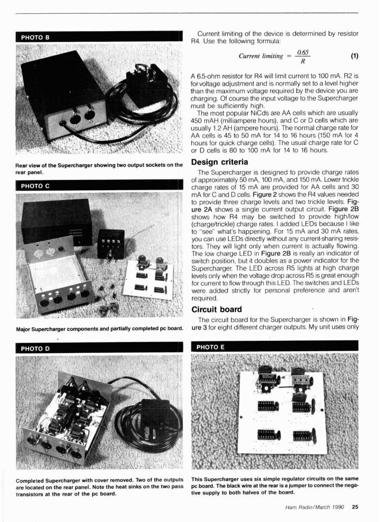
Current limiting of the device is determined by resistor R4. Use the following formula:
Rear view of the Supercharger showing two output sockets on the rear panel.
Major Supercharger components and partially completed pc board. -
0.65 Current limiting = - R (1)
A 6.5-ohm resistor for R4 will limit current to 100 mA. R2 is forvoltage adjustment and is normally set to a level higher than the maximum voltage required by the device you are charging. Of course the input voltage to the Supercharger must be sufficiently high.
The most popular NiCds are AA cells which are usually 450 mAH (milliampere hours), and C or D cells which are usually 1.2 AH (ampere hours). The normal charge rate for AA cells is 45 to 50 mA for 14 to 16 hours (150 mA for 4 hours for quick charge cells). The usual charge rate for C or D cells is 80 to 100 mA for 14 to 16 hours.
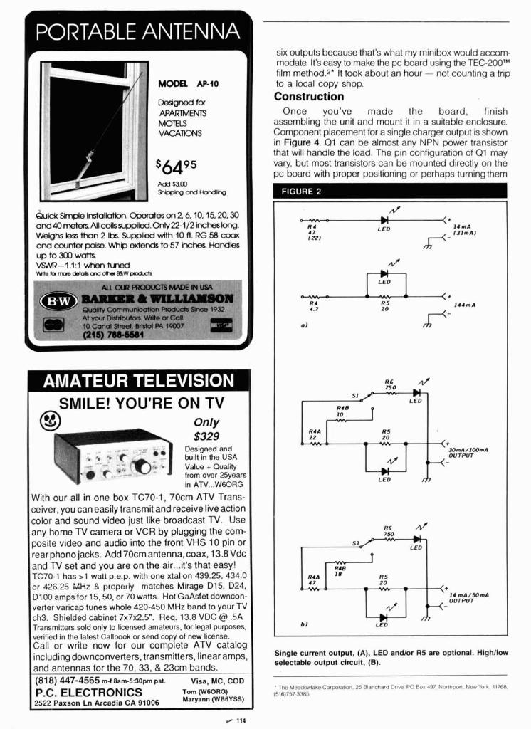
Design criteria The Supercharger is designed to provide charge rates
of approximately 50 mA, 100 mA, and 150 mA. Lower trickle charge rates of 15 mA are provided for AA cells and 30 mA for C and D cells. Figure 2 shows the R4 values needed to provide three charge levels and two trickle levels. Fig- ure 2A shows a single current output circuit. Figure 28 shows how R4 may be switched to provide highllow (chargeltrickle) charge rates. I added LEDs because I like to "see" what's happening. For 15 mA and 30 mA rates, you can use LEDs directly without any current-sharing resis- tors. They will light only when current is actually flowing. The low charge LED in Figure 26 is really an indicator of switch position, but it doubles as a power indicator for the Supercharger. The LED across R5 lights at high charge levels only when the voltage drop across R5 is great enough for current to flow through this LED. The switches and LEDs were added strictly for personal preference and aren't required.
Circuit board The circuit board for the Supercharger is shown in Fig-
ure 3 for eight different charger outputs. My unit uses only
Completed Supercharger with cover removed. l k o of the outputs This Supercharger uses six simple regulator circuits on the same are located on the rear panel. Note the heat sinks on the two pass pc board. The black wire at the rear Is a jumper to connect the nega- transistors at the rear of the pc board. tive supply to both halves of the board.
Ham Rad~o/March 1990 25
MODEL AP40
Designed f a APARTMENTS MOTELS VACATIONS
s6495 Add $3.00
Quick Slmple Installation. Opemtes on 2 6,10.15,20.30 and 40 metets. All coils supplied. OnIy22-112 inches long. Weighs less than 2 Its. Supplied wlth 10 ft. RG 58 coax and counter poise. Whip extends to 57 inches. Handles up to 300 watts. VSWR-1.1:l when tuned H m r e k l r o r e d e t d h ~ d h e r B E W ~
At yoti DisMbuton. Write or Col (0 C-l Street, bI*l PA ?Pm: (215) 78e-Wl
1 SMILE! YOU'RE ON TV I Only I
built In the USA
With our all in one box TC70-1, 70cm ATV Trans- ceiver, you can easily transmit and receive live action color and sound video just like broadcast N. Use any home TV camera or VCR by plugging the corn- posite video and audio into the front VHS 10 pin or rearphono jacks. Add 70cm antenna, coax, 13.8 Vdc and TV set and you are on the air ... it's that easy! TC70-1 has >1 watt p.e.p. with one xtal on 439.25,434.0 o i 426.25 MHz 8 properly matches Mlrage 015, D24, D l 00 amps for 15,50, or 70 watts. Hot GaAsfet downcon- verter varicap tunes whole 420-450 MHz band to your TV ch3. Shielded cabinet 7 ~ 7 ~ 2 . 5 " . Req. 13.8 VDC @ .5A Transmitters sold only to licensed amateurs, for legal purposes. verified in the latest Callbook or send copy of new license. Call or write now for our complete ATV catalog including downconverters, transmitters, linear amps, and antennas for the 70,33, & 23crn bands. (81 8) 447-4565 m-t aam-5:sopm pst. Visa, MC, COD
P.C. ELECTRONICS om (WBORG) 2522 Paxson Ln Arcadia CA 91006 (WB6YSS)
six outputs because that's what my minibox would accom- modate. It's easy to make the pc board using the TEC-200'" film method.2" It took about an hour - not counting a trip to a local copy shop. Construction
Once you've made the board, finish assembling the unit and mount it in a suitable enclosure. Component placement for a single charger output is shown in Figure 4. Q1 can be almost any NPN power transistor that will handle the load. The pin configuration of Q1 may vary, but most transistors can be mounted directly on the pc board with proper positioning or perhaps turning them
N' - = U
n < +
R 4 L E D l 4 m A 47 122)
R4 B 1 0
RS 20 - - - <+
#)rnA/100rnA
# OUTPUT -
LED m
Single current output, (A), LED andlor R5 are optional. Highllow selectable output circuit, (B).
The Meadowlake Corporalton. 25 Blanchard DIIW, PO Rox 497. Northporl. New York. 11768. (516)757 3385

Digital Storage Scopes v-212 - -9 DC to l ~ ~ ~ ~ z Dual Channe l
7 vc$E B%dM!h? $435 Delayed Sweef CRT Readout
2K Word Memory i
S w e e p T ~ m e Capaclty Au to rang lng
a $2349.00 "-'060 $1,359 Trlgger L o c k
BI DC to 20MHz 2 m ~ Sens l t l v l t l
Advanced storage fundlons create new dtmenslons In scows such as one shot obsewat~on, flicker lree d~splay, I Dual Channel List f 1595 bnght display for even h~gh speed event. trace 0bSe~attdn LIST PRICE SAVE for low speed event, hard copy by plotter and data output to V-422 40MHz D.T.. 1 mV sans. DC Otlsat Ven Mode Tngger. Alt Mag $940 $740 $200
computer V-423 40MHz D.T.. 1mV sens. Delayed Sweep. DC Onset. Alt Mag $1.025 $825 $200 V-425 40MHr D.T.. 1mV sens. DC Onset. CRT Readout. Cursor Meas $1.070 $849 $221
V-5 4 0 m 4K Word m r Y (-11) V-660 60MHr D.T., 2mV sens. Delayed Sweep. CRT Readout 81.295 $1.145 $150
20MHz Dual Trace Oscilloscope
X-Y Opera t ion Z Axis
, MDM-1180
Current Adapts
RF F r e q 100K.450MHz
0.20V a t 1 A

The Best 2=Meter Power You'll Ever Use With the LOWEST noise GaAs-FET pre-amp in the industry
B-3030-G 144 MHz
30W in - 300W out
High-speed RF switching relay-(5 ms or less typical switch time) Dual-gate GaAs-MESlFET pre-amp, typical gain of greater than 22dB
Dynamic wide-range overload protection Over-temp and high VSWR shut-down
There are a lot of amps on the market, but few ruggedized bricks. Whether your interests are H-F, 6-meters, 2-meters, 220 MHz or 440 MHz, our FULL line of ruggedized amps are in-stock, and ready to ship.
Complete your rig with any of KLM's 2-Meter antennas. Anyt hlng from short-range YAGl's or verticals to long-range satellite circulars.
2M-16LBX Bandwidth. . . . . .144-148 MHz Gain. . . . . . . . . .13.2-14.5 dBd VSWR . . . . . . . . . . . . . . . . 1.2:l FIB. . . . . . . . . . . . . .20 dB min. Element Length. . .40%" max. Boom Length. . . . . . . . . .28 ft. Windload. . . . . . . . .2.44 sq. ft. Turn Radius. . . . . . . l 5 ft., 5 in. Weight.. . . . . . . . . . . . . I0 Ibs.
2M-22C Bandwidth. . . . . .144-148 MHz Gain.. . . . . . . . . . . . . . .13 dBc VSWR. . . . . . .better than 1 . 5 1 FIB.. . . . . . . . . . . . .20 dB min. Element Length.. . . .41" max. Boom Length. . . . . . l 9 ft., 1 in. Windload. . . . . . . . . l .85 sq. ft. Turn Radius.. . . . . . . . . .13 ft. Weight.. . . . . . . . . . . . . l l Ibs.
2M-11X Bandwidth. . . . . .144-148 MHz
. . . . . . . . . . .
. . . . . . . . . . . . . . . . Gain.. . l2 .5 dBd
. . . . . . . . . . . . VSWR 1.23 FIB. .20 dB min. Element Length. . .405/~" max. Boom Length. . . . . .15 ft., 4 in. Windload. . . . . . . . . l .38 sq. ft. Turn Radius. . . . . . .15 ft., 4 in.
. . . . . . . . . . . . Weight. .5.5 Ibs.
435-40CX . . . Bandwidth.. .410-450 MHz
Gain. . . . . . . . . . . . . . .15.2 dBc . . . . . . . . . . . . . . . . VSWR 1.5:l
FIB. . . . . . . . . . . . . .20 dB min. Element Length. 13.625" max.
. . . . Boom Length.. .175.5 in. Windload.. . . . . . . . l .16 sq. ft. Turn Radius.. . . . . . . . . lo5 in.
435-40CX Weight . . . . . . . . . . . . . . 10Ibs .
Antennagain figures used by MIRAGElklm are measured according to the National Bureau of Standards. These figures are actual gain listed in dB at free space measured over a dipole. Some manufacturers do not choose to use this standard and therefore indicate gain figures that appear to be higher.
To order, contact your local dealer, or call us direct.
P.O. Box 1000 Morgan Hill, CA 95037 I M/RC\GE/KLM (408) 779-7363 (800) 538-2140 (outside C*)
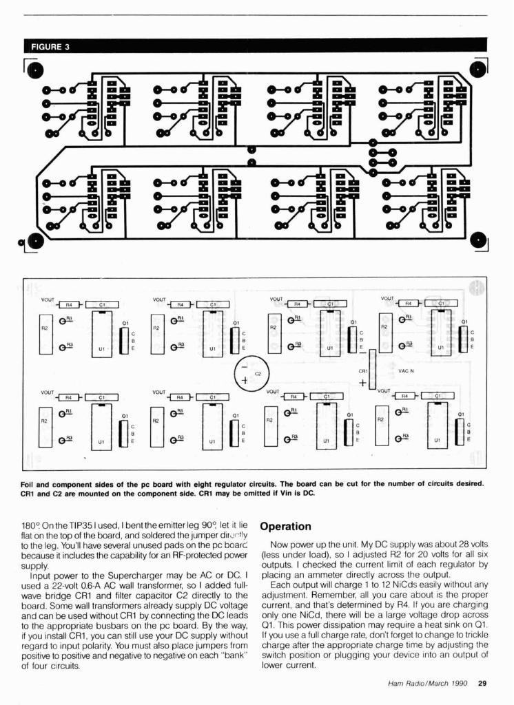
VOUT 4 - VOUT i R 4 r j
VOUT - I - r j
VOUT < R 4 l r ]
o w @ l o i 1" CP 1" CP 1" CP noc E
OOUT "0 + VACN
VOUT F I r j
VOUT c l j iR4Im
VOUT + T I - 7 1
E
Foil and component sides of the pc board with eight regulator circuits. The board can be cut for the number of circuits desired. CR1 and C2 are mounted on the component side. CRl may be omitted if Vin is DC.
1809 On the TIP35 I used, I bent the emitter leg 909 let it lie flat on the top of the board, and soldered the jumper dirxtly to the leg. You'll have several unused pads on the pc board because it includes the capability for an RF-protected power supply.
Input power to the Supercharger may be AC or DC. I used a 22-volt 0.6-A AC wall transformer, so I added full- wave bridge CRI and filter capacitor C2 directly to the board. Some wall transformers already supply DC voltage and can be used without CR1 by connecting the DC leads to the appropriate busbars on the pc board. By the way, if you install CR1, you can still use your DC supply without regard to input polarity. You must also place jumpers from positive to positive and negative to negat~ve on each "bank" of four c~rcuits.
Operation
Now power up the unit. My DC supply was about 28 volts (less under load), so I adjusted R2 for 20 volts for all six outputs. I checked the current limit of each regulator by placing an ammeter directly across the output.
Each output will charge 1 to 12 NiCds easily without any adjustment. Remember, all you care about is the proper current, and that's determined by R4. If you are charging only one NiCd, there will be a large voltage drop across Q1. This power dissipation may require a heat sink on Q1. If you use a full charge rate, don't forget to change to trickle charge after the appropriate charge time by adjusting the switch position or plugging your device into an output of lower current.
Ham Radio/March 1990 29
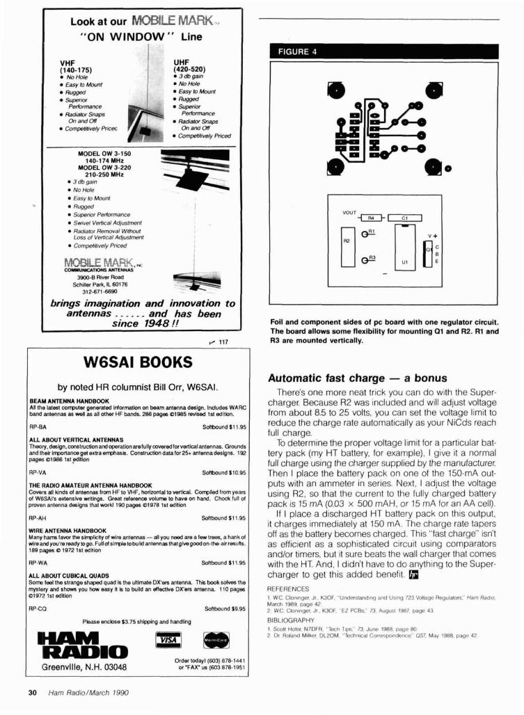
WGSAI BOOKS
I
by noted HR columnist Bill Orr, WGSAI. BEAM ANTENNA HANDBOOK An the latest corrpvler generated I~40rmlon on beam antenna design. Indudes WARC band antennas as well as all other HF bands. 286 pages el985 revised 1st edilbn.
~ o o k at our F . i ~ ~ ~ F$s$-z<$ , d
"ON WINDOW" Line
A U ABOUT VERTICAL ANTENNAS Theory, deslgn, cnnstwctlon and cperatlonafefully mveredlorvefllcalantennaa. G r ~ n d s and thelr Irrponanm gel extra ermasis. Constru*h datafor 25+ antennadesigns. 192 pages 81 986 Is1 ,ed#lon
VHF (1 40-1 75)
No Hole a Easy lo Mnmf
Ragged . Superrw
I RPYA Soflbound $10.95 I
UHF (420-520)
3 db garn No Hole Easy to Mwnt flogged
I THE R A N 0 AMATEUR ANTENNA HANDBOOK I
Performance • Supenw r-, Radralor Perlomame Snaps Compefmvely P m On and On
Competfl~vely Pnced
MODEL OW 3-1 50 140-174 MHz
MODEL OW 3-220 210-250 MHz
3 db garn No Hole Easy to Mount
a Rugged Supermr Perlonnance Swrvel Verlrcal Ad/ustmmt
%? Radralor Removal W h M Loss of Vertrcal Adlustment I
Compehhvely Pnced I
iz $4 eg-- I .-.-& ;=; -.. --=,.a COUYVWlUrWmS ANTENNA?,
3900.8 River Road Schlller Park. IL 601 76
31 2-671 -6690 * brings imagination and innovation to
antennas . . . . , . and has been since 1948 !!
I Covers all kinds of antenna8 from HF to WF, horizonla1 to nwlical. Conpiled from yean of WGSAl's extensbe writinas. Great referem volume to have on hand. Chodc tun of I ( pmven antenna designs thaiworkl 190 pages 81978 1st edition I I RP-AH Sdtbwnd $1 1.95 I WlRE ANTENNA HANDBOOK Many h a m favor the sinpliiily of wire antennas -dl you need are a few trees, a hank of wireand you'reready lo go. F u l l d s i ~ t o b u i l d antennastha givegoodon-the-akresulla. 189 paees O 1972 1st ednion
I RP-WA Solbound S 11.95 I A U ABOUT CUBICAL W A D S S m feel the strange shaped quad la the uhhate DX'ers amenna Thhi book 6olv8~ the mystery and shows you how easy I is to bufld an elleakre DX'em antenna 110 pages 81972 1st ednion
I Please enclose $3.75 shipping and handling I HAM PI - - .
RADIO Order todeyl(603) 878-1441
Greenvllle, N.H. 03048 or 'FAX' US (603 878-1951
Foil and component sldes of pc board with one regulator circuit. The board allows some flexibility for mounting 01 and R2. R1 and R3 are mounted vertically.
Automatic fast charge - a bonus There's one more neat tr~ck you can do with the Super-
charger. Because R2 was included and will adjust voltage from about 8.5 to 25 volts, you can set the voltage limit to reduce the charge rate automatically as your N IC~S reach full charge.
To determine the proper voltage limit for a particular bat- tery pack (my HT battery, for example), I give it a normal full charge using the charger supplied by the manufacturer: Then I place the battery pack on one of the 150-mA out- puts with an ammeter in series. Next, I adjust the voltage using R2, so that the current to the fully charged battery pack is 15 mA (0.03 x 500 mAH, or 15 mA for an AA cell).
If I place a discharged HT battery pack on this output, it charges immediately at 150 mA. The charge rate tapers off as the battery becomes charged. This "fast charge" isn't as efficient as a sophisticated circuit using comparators andlor timers, but it sure beats the wall charger that comes with the HT. And, I didn't have to do anything to the Super- charger to get this added benefit.
REFERENCES 1 WC Clon~nger. Jr. WOF. "Undersland~ng and Us~nq 723 Vollage Regulators:' Ham Radro. March 1989, page 42 2 WC Clontnqer, Jr . WOF. "EZ PCBs:' 73. Augusl 1987, page 43
BIBLIOGRAPHY 1 Scott Hole< N7DFR. "Tech Tlps." 73. June 1988, page 80 2 Or Roland M~lker. DL20M. "Techn~cal Correspondence" OST. May 1988, page 42
1 I
30 Ham Radio/March 1990

With F h k ~ a i l N ow AEA's popular I'K-223 multi-niode data controller has
new features you've been asking fir ... P a k ~ a i l ' " Mailbox with selectable third-party traffic. seven-character AMTOR
(('C'IK R.025) crtll identity. TDM ('l'ime Division Multiplex) receiving for SWUs. and Prioritizetl Acknowledgement (ACK) protocot for improved packet performance. Compatible with almost every computer or asynchronous data temiinal. you can en.joy the full spectrum of amateur digital communications with AEA's new PK-232MBX.
All Operating Modes. The PK-232MBX includes a11 authorized amateur digital modes available today ... Morse, Baudot. ASCII, AMTOR/SITOR 476 antl 625. Packet. WEFAX receive ant1 transmit. as well as commercial standard NAVTEX automatetl marine information services.
Superior Modem. An eight-pole Chebyshev bandpass filter liniiter- discriniinator modem improves the signal-to-noise ratio at the tletector ancl virtually eliminates interference fiom acljacent signals. System performance has been proven superior to that of P1-L modems designed for telephone line services.
PakMail."' ~ a k ~ a i l ' " mailbox with selective control of third- party trnffic is now a standard feature. Your friends can now leave you messages around the clock. Your 1oc:tl full-service BRS can auto~natically forward your mesaages directly to your
m - . - .- --.-:-+x- - PK-232MBX.
-- -,.- -~ - . - - - - -- . - . . - - . -. . WEFAX Transmission and Reception. AEA brought you -- 1 '
the first multi-mode controller to aentl and receive WEFAX (wcather facsimile) charts. The PK-279MBX directly suplmrts the widest range of printers on the market using the optional KS-232/printer cable.
1 Host Mode. Only AEA provides the type of full-featured Host Mode prcl'erred by niany professional programmers for efficient control of the PK-237MBX. AEA's Host Motle programs include PC-Pakri~tt with FAX for the IRM PC's and compatible MS-DOS computers. COM- Pokratt with FAX for the Commodore C-64 and C- 128. and now MacRAIT with FAX for the Apple Mac- Intosh.
Two Radio Ports. Independent radio conaection ports allow convenicnt. interchangeable all-mode operation regurtlless of port selection. You can connect two VHF/III-IF radios, an HF and a VtfF/UHF radio, or two HF radios. select;lble by a front-panel switch.
Signal Analysis. The PK-232MBX's internal software features AEA's exclusive SIAM (Signal lcientificrrtion and Acquisition Mode). The PK-322MBX automaticnlly identifies Ritl~dot. ASCII, AMTOR/SITOK and TDM signals. then measures signal speetl antl polarity. A simple " O K " conlniand autoniatically switches the PK-332MBX to the recognized mode and starts the data (lisplay.
PakMailr" Upgrade Kit. The easily-installed ~ a k ~ a i l ' ~ upgrade hit inclutlcs a plug-in ho:trd and new sofiware EPROMs. ant1 is fully compatible with all existing PK-332's. Please contact hutory Ibr tlctaila.
You Deserve The Original. AEA produced the first multi- mocle data controller. The I'K-232 continues to he the standard against which all other multi-mode controllers are judged: the choice of critical amateurs. corn~ncrcial services antl government agencies. Don't settle thr less than the hest.
AEA Brings You A Better Experience. Advanced Electronic Applications, Inc.
2006-196th St. SW1P.0. BOX 2160 Lynnwood, WA 98036
206-775-7373
I Prices and specifications subject to change w~thout not~ce or obligoion Dealer inquiries invited. Copyr~ght 1989.
~ught our re1 s befo NOW YOU CAN BUY DIRECT FROM US, THE MANUFACTUFrtn!
r nent bl
CONVERTIBLE BATTERY 8 Cells - Alkaline
Alkal~ne Batteries
PB-21-$13.75, PB-25-$20 PB-26-$20.00 ICOM INSERTS
ICOM CHARGERS AVAILABLE
Mastercard and Visa BATTERY REPLACEMENT NEE1 cards accepted. NYS residents add 8%% Y & w ASSOCIATE
Parsons Boulevard, Flushing, N.7 ORLD WIDE DISTRIBUTORSHIPS AVAILABLE. PLEASE INQUIRE.
'elex: 51060 16795 Wi
dl Toll Fre
SIGNAL-TO-NOISE Voting Comparator
Improve coverage by adding receivers
Expandable to 32 Channels Continuous Voting 19" Rack Mountable SelectlDisable Switches for Manual Override Can be used with RF Links or Dedicated Lines LED Indicators Hundreds in Service More
-Competitively Priced- For more informat ion cal l o r write:
Doug Hal l Electronics 815 E. Hudson St.
Columbus, O h i o 4321 1 (614) 261-8871
UlUNlCC DS.
OR COLLECT OLD RADIOS, YOU NEED ...
ANTIgUE RADIO CLASSIFIED FREE SAMPLE COPY!
Antique Radio's Largest Monthly Magazine Classifieds -Ads for Parts & Services
Articles - Auction Prices-Flea Market Info. Also: Early TV, Ham Equip., Books, Telegraph,
Art Deco, 40's & 50's Radios & more... Free 20-wordad each month. Don't miss out!
6-Month Trial - $11. 1-Year: $20 ($30 by 1st Class)
Foreign by alr - Canada: $32; Mexlco: $30; Other: $60.
A.R.C., P.O. Box 802-A5, Carlisle, MA 01741
WRITTEN TEST STUDY GUIDES All word-for-word quesllons, rnultlple choices. . . answers. Choose Novlce. Technlclan, General, Advanced or Extra Class Answer explanations supplied! $4.95 Each version + $1.50 shlpplng. All five manuals: $22.95 postpald.
HAM RADIO Q & A MANUAL All 1.932 questions. multiple choices and answers found in every ham license exam. Novice through Extra Class. $9.95 Shlpped postpald.
MORSE CODE TEST PREPARATION Set contains two 2-hr. cassette tapes Code Teacher, 0-5 WPM $9.95 General Code. 3-15 WPM 59.95 Extra Code. 12-21 WPM 59.95 Plus 51.50 shlpplng per set.
All ManualslCode Tapes: 549.95 New §Part 97 Ham Rules: $ 2.95
Order shipped same day received! Credit card phone orders: 10 a.m. - 2 p.m.
W5YI MARKETING P.O. Box #565101 - Dallas, TX 75356
Tel: (817) 461-6443 - 24 hours
32 Ham Radio/March 7990
EFFECTIVE NOISE TEMPERATURE PART 2 EQUIVALENT NOISE TEMPERATURE AND NF
Understanding optimum noise performance By Michael E. Gruchalla, I? E., 4816 Palo Duro N. E., Albuquerque, New Mexico 871 10
n "Effective Noise Temperature, Part 1," I gave an introduction to and background on the concept of effec- tive noise temperature. Part 2 picks up the discussion
of the limiting value of source voltage, and goes on to talk about noise figure phenomena and amplifier equivalent noise temperature.
When the source in the small signal example in part 1 IS fed to a matched 50-ohm load, the load signal and nose voltages are each 0.561 pV. The power delivered to the load is 6.29 x 10⁻¹⁵ watts. That is precisely the power you'd expect to be available to a matched load from a room tem- perature resistive source and nM-MHz noise bandwidth using Equation 1 from part 1.
Noise power and a matched load It's important to note that the noise power available to a
"matched" load is independent of the source resistance. This is implied by Equation 1. It's a bit difficult to see, because if you look at Equation 5 from part 1 you'll note that changing the source resistance changes the equlva- lent noise voltage (or current in Equation 6, part 1). How- ever, if you change the source resistance - lower it to reduce thermal noise voltage, for example - the matched load is changed to the same value. You can take the model of Figure 3, part 1 in terms of the general source resistance
and compute the noilse power delivered to the load using Equation 5.
PL = EL2/RL
= [(RLI(RL + R 3 ) (2 - W ; R ~ ) ~ / R ~
= (R1./(RL + R,) P 4 k T BW,, (Rs /Rd
but RL = R, for a rriatched load. Thus:
The result in Equation 7 is the same as that given in Equation 1. Th~s IS to be expected because you worked forward from Equation 1 to arrive at Equation 5. However, taking the analysis f l~l l circle to the starting point should demonstrate that the thermal noise power available at a matched load is independent of the actual resistance, even though the actual equivalent noise voltage and current are functions of the resistance.
Maximum thermal noise power The implication of Equation 1 is very important. Because
the noise power available at a matched load is indepen- dent of the source impedance (resistance and reactance), you may compute the maximum thermal noise power avail- able to a load (an arrlplifier input, for example) without any information about the amplifier or the system in which it is used. From Equation 1, that power level at room tempera- ture is about 4 x 10-21 wattsIHz of noise bandwidth, or -174 dBmlHz. This may seem like a very small level, but remember the value is for a "1-Hz" bandwidth. In the preceding example -with a aM-MHz noise bandwidth, the limiting thermal noise power would be -112 dBm. The 1.12- pV thermal noise voltage of the 50-ohm source resistor with a ~12-MHz noise bandwidth delivered 0.56 pV to a matched load. Consequently, the thermal noise power available at the load from the source resistance is 6.29 x 10⁻¹⁵ watts, or -112 dam.
Ham Radio/March 1990 33
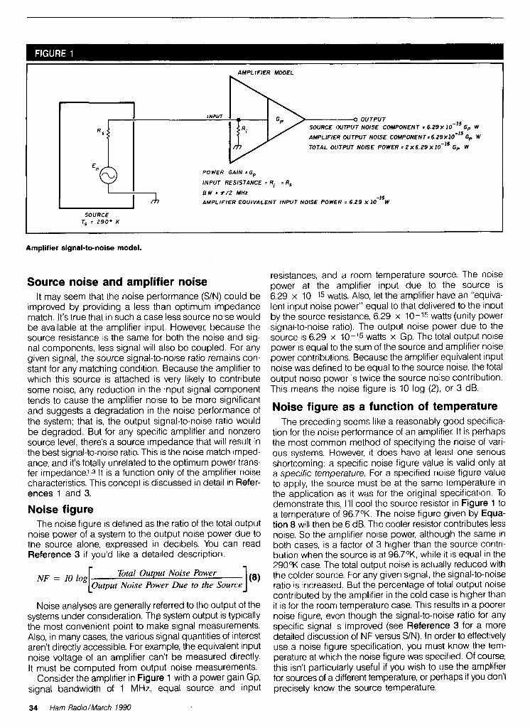
AMPLIFIER MODEL
INPUT , ---4 OUTPUT
SOURCE OUTPUT NOlSE COMPONENT = 6 . 2 9 ~ 1 0 - ~ ~ Gp W
AMPLIFIER OUTPUT NOISE C O M P O N E N T = ~ . ~ ~ X I O - ~ ~ Gp W
TOTAL OLITPUT NOlSE POWER = 2 ~ 6 . 2 9 X I O - ' ~ Gp W
'L POWER GAIN = Gp
INPUT RESISTANCE = Ri = Rs
B W = r / 2 MHz
AMPLIFIER EQUIVALENT INPUT NOISE POWER = 6 .29 X ~ O - ' ~ W
SOURCE T, = 2 9 0 ° K
Amplifier signal-to-noise model.
Source noise and amplifier noise It may seem that the noise performance (SIN) could be
improved by providing a less than optimum impedance match. It's true that in such a case less source noise would be available at the amplifier input. However, because the source resistance is the same for both the noise and sig- nal components, less signal will also be coupled. For any given signal, the source signal-to-noise ratio remains con- stant for any matching condition. Because the amplifier to which this source is attached is very likely to contribute some noise, any reduction in the input signal component tends to cause the amplifier noise to be more significant and suggests a degradation in the noise performance of the system; that is, the output signal-to-noise ratio would be degraded. But for any specific amplifier and nonzero source level, there's a source impedance that will result in the best signal-to-noise ratio. This is the noise match imped- ance, and it's totally unrelated to the optimum power trans- fer impedance.l.3 It is a function only of the amplifier noise characteristics. This concept is discussed in detail in Refer- ences 1 and 3.
Noise figure The noise flgure is defined as the ratio of the total output
noise power of a system to the output noise power due to the source alone, expressed in decibels. You can read Reference 3 if you'd like a detailed descript~on.
NF = 10 log Total Output Noise Power Noise Power Due to the Source
Noise analyses are generally referred to the output of the systems under consideration. The system output is typically the most convenient point to make signal measurements. Also, in many cases, the various signal quantities of interest aren't directly accessible. For example, the equivalent input noise voltage of an amplifier can't be measured directly. It muqt be computed from output noise measurements.
Consider the amplifier in Figure 1 with a power gain Gp, signal bandwidth of 1 MHz, equal source and input
resistances, and a room temperature source. The noise power at the amplifier input due to the source is 6.29 x 10⁻¹⁵ watts. Also, let the amplifier have an "equiva- lent input noise power" equal to that delivered to the input by the source resistance, 6.29 x 10⁻¹⁵ watts (unity power signal-to-noise ratio). The output noise power due to the source is 6.29 x 10⁻¹⁵ watts x Gp. The total output noise power is equal to the sum of the source and amplifier noise power contributions. Because the amplifier equivalent input noise was defined to be equal to the source noise, the total output noise power is twice the source noise contribution. This means the noise figure is 10 log (2), or 3 dB.
Noise figure as a function of temperature The preceding seems like a reasonably good specifica-
tion for the noise performance of an amplifier. It is perhaps the most common method of specifying the noise of vari- ous systems. However, it does have at least one serlous shortcoming: a specific noise figure value is valid only at a specific temperature. For a specified noise figure value to apply, the source must be at the same temperature in the application as it was for the original specification. To demonstrate this, I'll cool the source resistor in Figure 1 to a temperature of 96.7OK. The noise figure given by Equa- tion 8 will then be 6 dB. The cooler resistor contributes less noise. So the arnplifier noise power, although the same in both cases, is a factor of 3 higher than the source contri- bution when the source is at 96.7OK, while it is equal in the 290°K case. The total output noise is actually reduced with the colder source. For any given signal, the signal-to-noise ratio is increased. But the percentage of total output noise contributed by the amplifier in the cold case is higher than it is for the roorrl temperature case. This results in a poorer noise figure, even though the signal-to-noise ratio for any specific signal IS improved (see Reference 3 for a more detailed discussion of NF versus SIN). In order to effectively use a noise f ig~~re specification, you must know the tem- perature at which the noise figure was specified. Of course, this isn't particularly useful if you wish to use the amplifier for sources of a different temperature, or perhaps if you don't precisely know the source temperature.
34 Ham RadiolMarch 1990

Equivalent noise temperature The noise characteristics of an amplifier may be specified
in an alternative manner. From Equation 1, the maximum noise power available at the input to a system is a function of only the source temperature and the noise bandwidth (and of course Boltzmann's constant). This maximum avail- able noise power occurs only for a power-matched condi- tion of the source and amplifier input. For any real system, a value of temperature for the matched source may be com- puted by rearranging Equation 1 so the noise contribution due to the source at some point in the system of interest (usually the output as discussed above) is the same as that contribution at that same point from the noisy amplifier itself.
The equivalent noise temperature of the amplifier is the temperature to which a power-matched source resistance must be set to provide a source output noise power component equal to the amplifier com- ponent of output noise power.
In the amplifier example with the room temperature (290°K) source, the source noise contribution and ampli- fier noise contribution are equal. Here, the source must be at 290°K to provide an output noise component equal to that of the amplifier. That amplifier is then a 290°K ampli- fier. If this amplifier were used with the 96.7OK source, it would still be a 290°K amplifier. It's important to remember that equivalent noise temperature is a property of the ampli- fier (or other system characterized) - somewhat like gain - and is independent of the application.
Ideal and real noise applications The noise temperature specification has a shortcoming.
It is a specification of noise performance when the source
is power matched to the amplifier and may be thought of as a type of ideal specification. It usually doesn't represent the performance provided in a real application. If an unmatched source is used with an amplifier of some speci- fied noise temperature, the output signal-to-noise ratio will be different from that obtained with ideal matching (it could be better or poorer). tiowever, the noise temperature speci- fied for the amplifier would still be correct because it's based on performance in a specific configuration. Further, because the noise temperature is based on an input power- matched condition, it provides no information about the optimum performance that may be obtained in a noise- matched input. A similar noise temperature versus signal- to-noise ratio comparison could be made as presented in Reference 3 for noise figure versus signal-to-noise ratio. Just because an amplifier has a very low noise temperature doesn't mean it will provide best signal-to-noise ratio in a specific application. It's very likely that a higher noise tem- perature amplifier with an input well noise matched3 to the source will provide a much better signal-to-noise ratio than an amplifier of much lower noise temperature with a poorly noise-matched input. The optimum noise-matched source resistance is given by the ratio of the equivalent input noise voltage and the equivalent input noise current. See Refer- ences 1 and 3 for a thorough review of noise matching.
Noise-matching example 290°K amplifier. Consider the amplifier in Figure 2. It's
the same as that of Figure 1 with a signal added. The ampli- fier equivalent noise temperature is 290°K, input resistance is50 ohms, signal bandwidth is 1 MHz, and power gain is Gp. For convenience, I chose 2x1.12 rms as the input source signal. This is twice the source thermal noise level. The sig- nal at the amplifier input is then 1.12 pV rms and the output
AMPLIFIER MODEL
SOURCE RESISTANCE
INPUT O OUTPUT
U T W T SIGNAL POWER = 25.1 X I O - ' ~ G ~ W
SOURCE OUTPUT NOISE COMPONENT = 6 . 2 9 XIO-l5 Gp W
AMPLIFIER OUTPUT NOISE COMPONENT = 6 2 9 ~ 1 0 - ' ~ GP W
TOTAL OUTPUT NOISE POWER = 2 ~ 6 . 2 9 ~ 1 0 - ' ~ Gp W
POWER GAIN = Gp
INPUT RESISTANCE = Ri = R, = 5 0 OHMS
BW, = r/z MHZ
AMPLIFIER EQUIVALENT INPUT NOISE POWER = 6 .29 X 1 0 - I 5 ~
SOURCE
290°K amplifier model.
Ham Radio/March 1990 35

put signal power 25.1 x 10⁻¹⁵ Gp watts. The noise voltage available at the amplifier input from the 290°K source is0.561 pV, an output noise power due to the source of 6.29 x 10⁻¹⁵ watts. Because the amplifier has a 290°K noise temperature, its equivalent input noise power is the same as that of the 290°K source, or 6.29 x 10 -15 watts. As a result, the total out- put noise power is 12.58 x 10⁻¹⁵ Gp watts. This means the power signal-to-noise ratio is 2, or 3 dB.
145°K amplifier. With this same source, I'll try another amplifier with a noise temperature of 145OK. This is a factor of 2 lower than the 290°K unit, but with a 10-ohm input resis- tance - a factor of 5 lower than the matched case. I chose these values for convenience of calculation; they aren't intended to represent any realistic application. However, the 145" value is a modest specification, and the 10-ohm value of input resistance isn't too unreasonable. An NE13783 low noise FET exhibits about a 10-ohm resistive input impedance at 12 GHz. These values are actually quite realistic.
This amplifier is shown in Figure 3. Because this is a mis- matched case, you need additional information about the amplifier to make truly accuratecomputations. The noise volt- age and current sources at the amplifier input are the "equivalent input noise sources."l The values shown give an optimum noise match and 145OK noise temperature at the specified 10-ohm source resistance. There's a family of equivalent input voltage and current source values that will provide a 145°K noise temperature. In a real application of computing noise performance, the equivalent sources would be accurately measured. For this example, the values of Figure 3 are the defined amplifier characteristics.
Noise temperature verification. First I'll verify that the amplifier is a 145OK unit. The input noise power due to the two amplifier noise sources alone when attached to a matched 10-ohm noiseless (zero degree) source is 3.14 x 10⁻¹⁵ watts, and the output noise power is 3.14 x 10⁻¹⁵ Gp watts. According to Equation 1, the temperature to
which a souce resistance must be raised to deliver that ther- mal noise power to a matched load with a ~12-MHz noise bandwidth is 145°K. The amplifier is then indeed a 145OK unit.
The noise power at the amplifier input due to the 290°K, 50-ohm source and the amplifier equivalent noise sources in Figure 3 is 8.03 x 10⁻¹⁵ watts. This yields a total out- put noise power of 8.03 x 10-75 Gp watts. The input sig- nal voltage is 0.374 pV which produces an output signal power of 14.0 x 10 -15 Gp watts. The power signal-to-noise ratio is then 1.74, or 2.4 dB.
Analysis. Substituting a lower noise amplifier in the sys- tem with the 50-ohm source resulted in a poorer signaldo- noise ratio. But what would happen if you had a source with a 10-ohm source resistance and the 145°K amplifier? This is the optimum "noise-matched" resistance for the ampli- fier in Figure 3. (It's also the optimum power match in this case, but that isn't significant.3) This impedance transfor- mation may be very conveniently and realistically accom- plished using a transformer with a 2.24:1 turns ratio. By using an ideal transformer, you maintain the source signal power constant and can easily compare various power signal-to-noise ratio results. The transformed source tem- perature remains 290°K. The amplifier noise temperature is still 145°K because that specification is independent of application. In this case the input signal power will be 25.1 x 10⁻¹⁵ wattsand the output signal 25.1 x 10⁻¹⁵ Gp watts. The total output noise power from the 10-ohm, 290°K source and the amplifier noise sources will be 9.43 x 10⁻¹⁵ Gp watts. That results in an output power signal-to-noise ratio of 2.66:1, or 4.3 dB.
All noise parameters must be recognized I started with a 290°K amplifier with a 50-ohm input resis-
tance and a 290°K, 50-ohm source and obtained a 3-dB signal-to-noise ratio with a 2.24-pV source signal voltage.
SOURCE RESISTANCE
OUTPUT uTPuT SIGNAL PowERO. 14 .0 x 10-l5 Gp w
E OUTPUT NOISE COMPONENT 3.49 X 10-Is Gp W
AMPLIFIER OUTPUT NOISE COMPONENT. 4 .54 ~ 1 0 - l ~ Gp W
TOTAL OUTPUT NOISE = 8 .03 X Gp W
POWER GAIN 3 Gp
INPUT RESISTANCE = Ri = 10 OHMS
BW,, = r/2 MHz
AMPLIFIER EQUIVALENT INPUT NOISE TEMPERA-URE : 1 4 S e K
l E i n 0 . 2 5 0 7 p V r m r J
SOURCE ( I l n = 25 .07nA r m r J
145OK amplifier model.
36 Ham Rad/o/March 1990
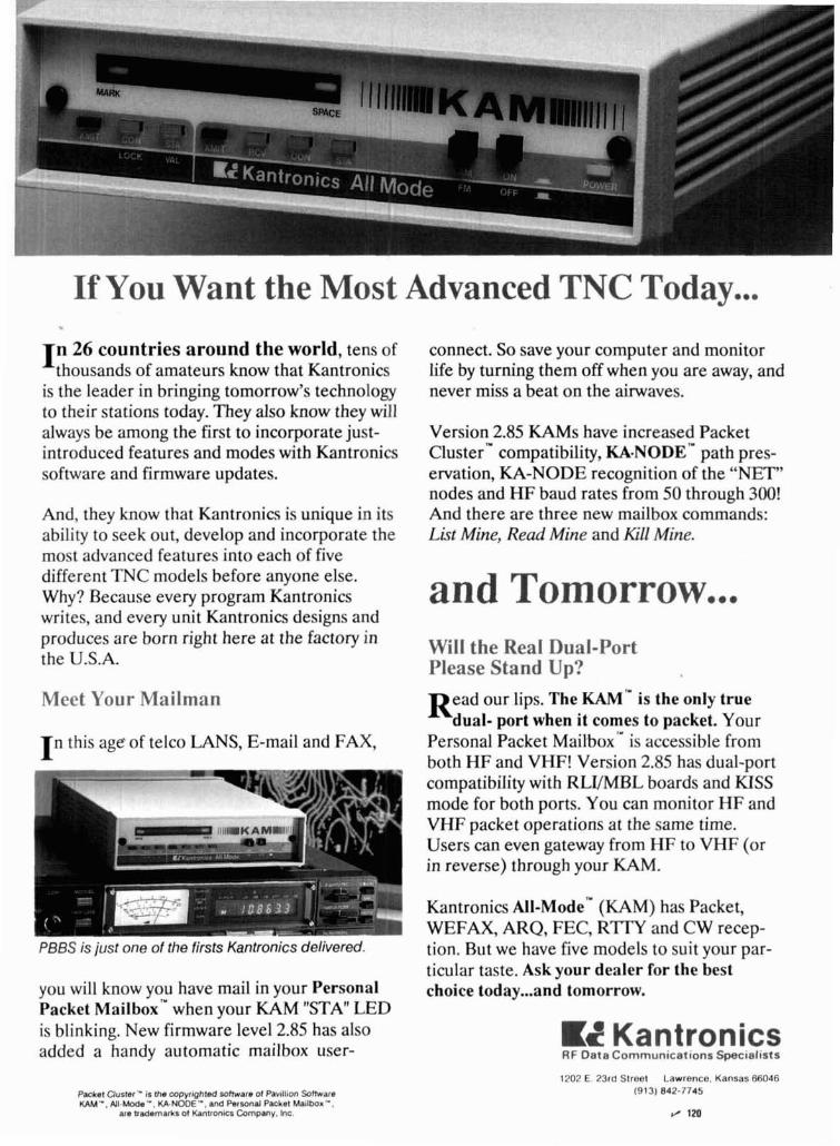
If You Want the Most Advanced TNC Today ... I n 26 countries around the world, tens of
thousands of amateurs know that Kantronics is the leader in bringing tomorrow's technology to their stations today. They also know they will always be among the first to incorporate just- introduced features and modes with Kantronics software and firmware updates.
And, they know that Kantronics is unique in its ability to seek out, develop and incorporate the most advanced features into each of five different TNC models before anyone else. Why? Because every program Kantronics
connect. So save your computer and monitor life by turning them off when you are away, and never miss a beat on the airwaves.
Version 2.85 KAMs have increased Packet clusterm compatibility, KA-NODE" path pres- ervation, KA-NODE recognition of the "NET" nodes and HF baud rates from 50 through 300! And there are three new mailbox commands: Lkt Mine, Read Mine and Ell Mine.
and Tomorrow... writes, and every unit Kantronics designs and produces are born right here at the factory in the U.S.A.
Will the Real Dual-Port Please Stand Up?
Meet Your Mailman R e a d our lips. The KAM'" is the only true dual- port when it comes to packet. Your
T n this age of telco LANS, E-mail and FAX, Personal Packet Mailbox" is accessible from both HF and VHF! Version 2.85 has dual-port compatibility with RLVMBL boards and KISS mode for both ports. You can monitor HF and VHF packet operations at the same time. Users can even gateway from HF to VHF (or in reverse) through your KAM.
Kantronics AII- ode'^ (KAM) has Packet, WEFAX, ARQ, FEC, RTTY and CW recep-
PBBS is ji~st one of the firsts Kantronics delivered. tion. Rut we have five models to suit your par- ticular taste. Ask your dealer for the best
you will know you have mail in your Personal choice today ... and tomorrow. Packet ailb box'* when your KAM "STA" LED is blinking. New firmware level 2.85 has also added a handy automatic mailbox user-
KZ Kantronics H F Data Commun~cat~ons Special~sts
Psckst Cluster" is the copyrightad mmupre 01 Pavillion Softwars KAM ", All-Mode", U-NODE '-, and Permoll Packel Ma~lbox".
are trademarks of Kantfon~cs Company, Inc.
1202 E. 23rd Street Lawrence. Kansas 66046 (913) 842-7745

AMPLIFIER MODEL
"(a I AMPLIFIER EFFECTIVE NOISE TEMPERATURE = T, O K
I POWER GAIN = G,
I 'I INPUT RESISTANCE = Ri = R,
BWn = r/2 MHz
SOURCE
SOURCE TEMPERATURE = T, 0 K
Model for comparing noise figure and effective noise temperature.
I then substituted a lower noise 145OK amplifier with the same signal source and obtained a 2.4-dB signal-to-noise ratio. The lower temperature and lower noise amplifier provided a 0.6 dB poorer signal-to-noise ratio than the higher noise 290°K amplifier with the 50-ohm room tem- perature source. Then I transformed the 50-ohm, 290°K source to a 10-ohm optimum noise-matched value, still at 290 OK. With the same 145OK amplifier that provided the 2.4-dB signal-to-noise ratio with the 50-ohm source, I then obtained a 4.3-dB signal-to-noise ratio. So this 145OK ampli- fier with a fixed source power provided a 2.4-dB signal-to- noise ratio with one source resistance and a 4.3-dB value with another. But the noise temperature was constant. Can this be correct? Is there an error here?
The calculations are correct, and indeed this result can easily occur in practice. Although the higher noise temper- ature amplifier generally exhibits higher noise than the lower temperature unit, it provides a better noise match to the 50-ohm source than did the specified 145OK unit. This gives a better signal-to-noise ratio for any given signal. In the final example, the 10-ohm source provides an optimum noise match resulting in the best signal-to-noise obtainable with the particular amplifier being modeled. What's important here is that the lower noise temperature amplifier has the capability to provide the better noise performance. But to actually obtain improved performance, all of the noise processes must be well understood and the various noise parameters used correctly.
Importance of understanding noise parameters
In practice you rarely know the exact resistances involved. You have to ask: What is the actual source resistance of an antenna? Is it the radiation resistance? The element resis- tance? The connecting transmission line resistance? Or is it a combination of all of these? What is the effective tem- perature of the source(s)? Further, what is the actual input resistance of a low noise amplifier (LNA)? Worse yet, does the LNA even come close to providing a good noise match to your source? These are all very difficult questions to
answer. Careful measurement of the noise parameters must be completed before you can accomplish any true optimi- zation. It's actually possible to replace one LNA with a lower noise temperature unit and achieve a poorer signal-to-noise ratio. Those of you who have experimented with various "inexpensive" LNAs may have stumbled on this paradox. Because these amplifiers are manufactured more for low cost than consistency, they tend to exhibit cons~derable variation in performance parameters from unit to unit. Even when substituting two identical models, you may see a considerable difference in noise. Of course, a noisier unit may also be defective, or a quieter one could be a premium low noise unit. An understanding of the actual noise processes is critical for successfully optimizing system noise performance.
Comparing noise temperature and NF As a final thought, it might be useful to compare noise
temperature and noise figure. Both of these specifications are measures of device noise, so it should be possible to compare them effectively. To do this, use Equation 8 and the amplifier model in Figure 4. This amplifier configura- tion is similar to those shown earlier, but has a general source temperature Ts and an amplifier equivalent temper- ature T,. Because the configuration in Figure 4 offers a matched load to the source, you know the noise power delivered to the amplifier input from Equation 1. The out- put noise power due to the source alone, P,, is then given by Equation 9.
source output noise power = P, = k Ts BW, Gp (9)
Now when the amplifier IS attached to a power-matched source at a temperature equal to the effective temperature of the amplifier, the source and amplifier contribute equal noise components to the total output noise. This is essen- tially the definition of effective noise temperature. The com- ponent of the amplifier output noise, Pa, is simply equal to the noise that would be output if the amplifier were noise- less and the source were at a temperature T,. By the defi- nition of effective temperature, T, is that temperature to
38 Ham Radio/March 1990

CALL FOR ORDERS .---. --A ---- 1 (800) 231-303 1 I (713) 520-7300 or 1 (713) 520-0550 FAX 1 1713) 358-0051
TEXAS ORDERS CALL COLLECT. - p
ALL ITEMS ARE GUARANTEED OR SALES PRICE REFUNDED.
Arnp~re VHF UHF GaAsFET preamps Call 150 I
...-- . \ - - - - - - - -
82 61 N Male (Amphend) 350 82 202 1006 N Male (99 13) Double Female UHF
New Yaesu FT 1OM)D r 1,1, w ~nled 76 each 40
Kenwood TH215A TH25AT Trade ~n your o l r l HT Elbow PL25sS0239 each $1 .. Rece~v~na tubes 5090% on llsl ~ r t ce New Kenwood TS 950 SD Call
,L", 8 8 , "., . .. . . . . NYE MB5A Tuner .. . . Alpha Della Transtlrap
I f poss~ble let us know four lo SIX weeks before you move and we w~ll make sure your HAM RADIO Magazine arrlves on schedule. Just remove the mailing label from th~s magazlne and affix below. Then complete your new address (or any other correct~ons) in the space provided and we'll take care of the rest.
ham Allow 4-6 weeks for radio correction. Magazine
~ r e e n v ~ l k . NH 03048
Thanks for helping us to serve you better. r--\ r - - I I I I I
L-1
1 AFFIX
/ 1 ; LABEL
Measure Up With Coaxial Dynamics Model
83000A RF Peak Reading Wattmeter Take a PEAK with Coaxial Dynamics "NEW" Model 83000A, designed to measure both FWDlRFL power in CW and FM systems simply and quickly. Then with a "FLIP" of a switch, measure "PEAK POWER" in most AM, SSB or pulse systems. Our Model 83000A features a complete se- lection of plug-in-elements plus a 2 year warranty. This makes the Model 83000A an investment worth looking at. So go ahead, take a "PEAK", you'll l ike "WATT" you see!
Contact us for your nearest autho- rized Coaxial Dynamics representa- tive or distributor in our world-wide sales network.
15210 lndustr~al Parkway , Cleveland, Ohio 44135 216-267-2233 1 -800-COAXIAL Telex 98-0630
Service and Dependability. . . a Part of Every Product See us at Dayton Booths # 401 - 402!

Featuring hlgh performance at low cost!
on* $2 1 9'= Completely assembled and tested - not a kit1 Supports 1200 baud MSK transmit and PSK recelve lor MICROSAT access Supports 1200 baud PSK transmit and recelve for terrestrial use Receives 400 baud satellite telemetry signals Doppler shlft compensating radio tuning interface Eas~ly attaches toany TNCmodem disconnect header, cable prov~ded Telemetry s~gnals output via RS-232 port
For complere rnlo 6 specrlrcaf~ofis Call ,813, 874-2980 To Order Call
IN I Toll Frn: 1-800-223.311 1 DECEMBER M,r~or Credrr Lards ~ c c e p ~ e d ~
---=-----------,--,-~
PacComrn 3652 West Cypress Street Tampa. Florrda 33607 I n /I
0 Please send more info on the MICROSAT PSK Modem FREE Catalog 1 Name _- Call I
I ' Address Il
I Ph # I
P State - ZIP Cardct Exp Date I II
MONEY BACK GUARANTEE! Add $4 00 shfppfng handl~ng per order FL resfdents addb% sales tax 1 Malor Cred~l Card gtve number. explralron and srgnattrre FAX 813-872-8696 (
I-,,,,,,,,,,-,,,,,--------------------- / 125
/ RELY ON JAN
FOR 3-WAY HELP: 1. TECHNICALLY
CORRECT CRYSTALS TO YOUR SPECS.
2. QUICK TURNAROUND WITH HUGE INVENTORY, PROMPT SERVICE, AND OUR EMERGENCY ORDER PLAN.
3. LOW PRICES.
QUARTZ CRYSTALS FOR TWO-WAY - HDUSTRY MARINE - AMATEURS
SCANNERS - CBS MICROPROCESSORS
FOR FREE CATALOG, CALL OR WRITE:
JAN CRYSTALS P.O. BOX 06017
~ R T MYERS n 33906 (813) 936-2397 VM I I -
TOLL-FREE: 1-800-JAN-XTAL \ FAX ORDERS: 1-813-936-3750
EVERY ISSUE of HAM RADIO
now available on
The entire run of Ham Radio Magazine (March, 1968 thru last year) is ready to ship to you in one, easy to use format.
Our 24x microfiche is easy to read and very compact. We offer a hand held reader for $75, and a desk model for $220. Libraries have these readers.
As a bonus, you will receive Ham Radio Horizons (3/77 t hru 1 2/80) free.
Everything is included, front cover to back - ads too!
Annual updates will be offered for $10.
Send $205 payment (visalmc accepted) to:
BUCKMASTER PUBLISHING Route 3. Box 56
Mlneral. Virglnla 23117 70318965777 vlsalmc 8001282-5828
MADE IN 54129 95
Covers 100 MHz to 199.999 MHz in 1 kHz steps with thumbwheel dial Accuracy +/- 1 part per 10 million at all frequencies Internal FM adjustable from 0 to 100 kHz at a 1 kHz rate External FM input accepts tones or voice Spurs and noise at least 60 dB below carrier Out- put adjustable from 5-500 mV at 50 Ohms
Operates on 12 Vdc @ l/2 Amp Available for immediate delivery $429.95 delivered Add-on accessories available to extend freq range, add infinite resolu- tion, AM, and a precision 120 dB attenuator
Call or write for details Phone in your order for fast COD shipment.
VANGUARDLABS 198-23 Jamalca Ave.. Hollls. NY 11423 Phone: (718) 468-2720 Mon. thru Thu.
which you must raise the source if the amplifier were noise- less to produce an output noise equal to that of the actual noisy amplifier with a noiseless source. Once again, the input power is given by Equation 1 and the corresponding amplifier output noise power contribution by Equation 10.
ampl$kr output noise power = k T, BW, ~p (10)
By combining Equations 8, 9, and 10, you can express the noise figure in terms of the source temperature and the amplifier effective temperature.
NF = 10 log ps + pa [ ps I = I O log F Ts BWn Gp) F Te BWn Gp) I
NF = 10 Log [7 + Te/TJ (11)
Equation 11 then lets you compute the noise figure of an amplifier from its effective noise temperature. For exam- ple, if you have a room temperature source of 290°K (T, = 290°K), a 290% amplifier (Te = 290%) will exhibit a 3-dB noise figure as expected. You may also compute the effective noise temperature from the noise figure by solv- ing Equation 11 for Te. That result is shown in Equation 12.
Closing remarks Hopefully, all this has shown you just what the concept
of effective noise temperature means and how it was der- ived. Unlike noise figure, the noise temperature is a device parameter (like gain) and is independent of the application of the device. On the other hand, noise figure is a compar- ison of the output noise power of a system due to the source alone - a real source, any source, matched or not - to the total output noise power of the system. So, the noise figure is a type of "practical" noise specification showing the performance of a real system, while the noise tempera- ture is a type of standard specification defined under very specific conditions.
Both equivalent noise temperature and noise figure are useful parameters, but both have shortcomings. The suc- cessful use of any parameter depends upon a thorough understanding of that parameter. Obtaining optimum noise performance depends greatly on your understanding of the noise processes and careful application of the optimizing principles discussed in this article and the references.Q
REFERENCES 1 C D Molchenbacher, and FC Frlchen. LowNorse Elechonrc Deogn, Wdey. New York, 197.3 2 S P Parker. McGraw-H111 Drcl~onary 01 Sc~enlrhc and Technrcal Terms, Th~rd Edrt~on. McGraw- Hill New York, 1984 3 M E Gfuchalla. "Undersfandlng Norse F~gure." Ham Rad~o. Apr~l 1987. page 89
BIBLIOGRAPHY 1 Joe Carr, K41W. "Praclrcally Speak~ng Nose. S~gnals, and Ampllllers." Ham Radro. February 1988, page 77
or further dl
'W
?I dealer or etails contact your loci Orion.
ORION P.O. Box 9577
BUSINESS Canoga Park, CA 91309 Tel: (818) 888-4927 Fax: (818) 888-5112 INTERNATIONAL, I NC, Telex: 697-4899
TM
Every month Monitoring Tjmes brings everything you need to make the most of your general coverage transceiver: the latest information on international broadcasting schedules, frequency listings, international DX reports, propagation charts, and tips on how to hear the rare stations. Monitoring Times also keeps you up to date on government, military, police and fire networks. as well as tios on monitor- ing everything ship-to-shore! facsimile and :
ORDER
from air- signals tc ;pace col
YOUR
.to-ground and I radioteletype, nrnunications.
SUBSCRIP- u TION TODAY before another rssue goes by. In the U.S., 1 year, $18; foreign and Canada, 1 year, $26. For a sample issue, send$2 (foreian, send 5 IRCs). For MCNISA ord& ($15 minlmum), call 1-704-837-9200
MONITORING TIMES
P.O. Box 98 A Brasstown, N.C. 28902 1
Ham Radio/March 1990 41

An RF Current Loop Here's a handy device for tracking down RF current in your antenna. Knowing your antenna means know- ing where RF current flows. Does your
feedline radiate? It shouldn't, even if it's made of open wire line. How about the phone lines or guy wires? These and other objects could be robbing you of RF or distorting your radiation pattern. The circuit shown in Figure 1 and pic- tured in Photo A will give you a true representation of your antenna by detecting RF current.
Loop components versus frequency of operat~on.
'Wire loop Frequency, MHz L1, inches c1, PF c2, PF 16 - 30 15 none 95 - 420 9 - 16 26 none 95 - 420 7 - 8 26 560 95 - 420 3.7 - 4.0 26 2200 95 . 420
Cut length of copper-weld wlre
Completed RF tracker. Operation
RF current loop.
Silver mica. See Table 1 for value. 95 to 420-pF trimmer (Radio Shack) Ceramic capacitor, 0. l-sF. 100 volt Diode, IN914 Wire loop. See Table 1 for length. Meter, 0 to 1 mA Resistor, 56ohm carbon composltlon 5 percent, 1/4 watt Potentiometer, 10 k 1-50-2 (Amldon), wound wlth 15 turns no. 26 AWG - leave a 7"plgtall'
Limited range of C2 and tolerance ot parts may requlre up to a 10-percent change of C1 value.
Amldon Asaoclates. 12033 Otsego Street, North Hollywood, Calltornla 91607 I
of the suspected object whileobserving meter deflection. Maximum meter indi- cation occurs when the wire edge of the loop is parallel with the direction of current. A meter zero (null) will occur at angles perpendicular to current flow.
Remember that current peaks repeat every half wavelength, so that maximum meter indication may be one-quarter wavelength from where you initially probed. There will be little or no indication at voltage maxima.
Calibration Carefully tune the loop using a grid-
dip meter. Adjust C2 until resonance is indicated. You may want to monitor the grid-dip frequency with your station receiver to verify meter accuracy.
An alternative tuning method would be to hold the loop near the antenna and adjust C2 for maximum. The peak will be sharp, so adjust carefully.
The key to the loop's performance is its relatively high Q afforded by toroidal transformer TI. The loop should be operated within about 150 kHzof reson- ance for best sensitivity and results.
Construction Shape a piece of no. 14 copper-weld
wire into a square and thread it
42 Ham Radio/March 7990

through transformer TI. See Table 1 for appointed because it would not tune loop length. Secure the loop to one Updafjng The Viking my 160-meter antenna. tiere are two end of a 5116 by 24-lnch dowel. Be MB-VA Antenna Tuner solutions to the problem. sure to leave about a 1-inch aao in the I could leave the antenna tuner wirina
~ -~ ~
loop to mount C2. Twist the leuads of TI After purchasing and connecting a the way it was. Then, for 160-met; and run them down the dowel about Vikina antenna tuner MB-VA, I was dis- operation, I could mount a 2000-pF 6 ~nches
Mount the detector components cons~stlna of R1, CR1, and C3 to the I dowel and wrap them with electrical tape. Attach the wires from C3 to the meter and sensitivity pot located near the handle.
Final remarks I have discussed a simple means of
detecting antenna currents with the aid of the RF current loop. Now that the currents can be identified, they can be contained. Past Ham Radio articles and the ARRL Antenna Book contain some excellent suggestions to help reduce unwanted radiation and pickup. It should now be easy to evalu- ate the best solution for vour antenna
S E E TEXT- * 230 2000 195 195 195 - - -
system Let's go for top berformance 1 and put that RF up where 11 belongs!
Tom Rehmg K9PIQ Schematic showing changes to the Viking ME-VA antenna tuner.
WHITE RED
WHITE BLUE
Manufacturer's diagram of the Viking ME-VA tuner.
Ham Radio/March 1990 43
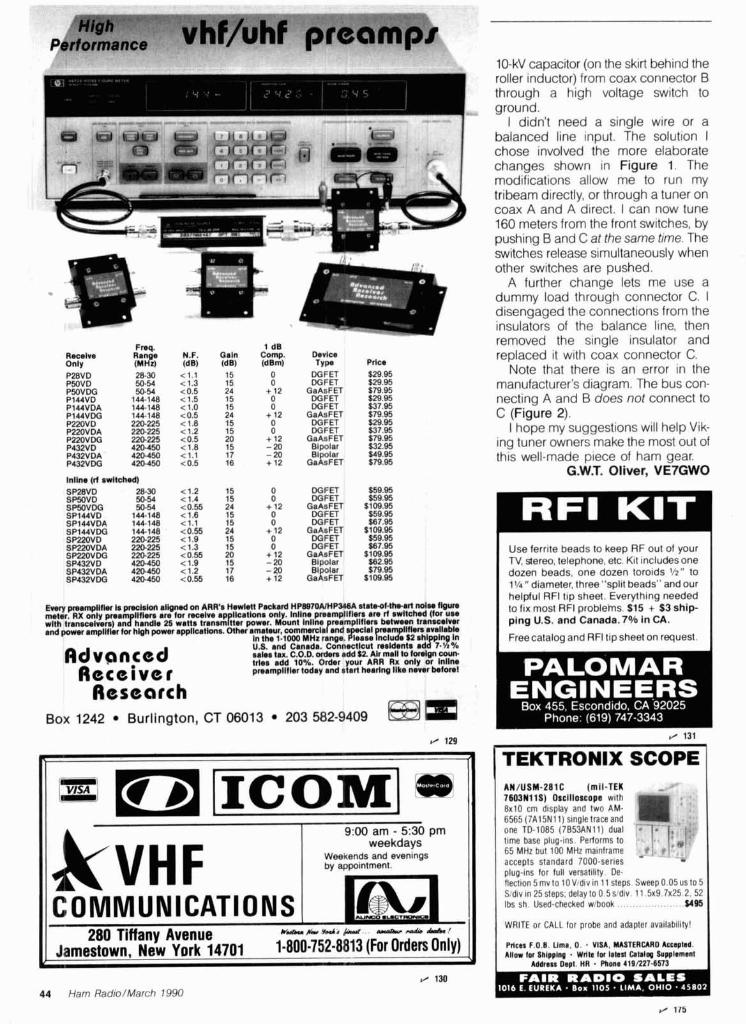
Fnq. 1 dB Rocelva Range N.F. Oaln Comp. D.rlt% Only (MHz) (dB) (dB) (dBm) TYP. Pdt%
Inllne (rt 8wltch.d)
DGFET DGFET
GeAsFET DGFET DGFET
GaAsFET DGFET DG F ET
GaAsFET B~polar Bipolar
GaAsFET
DGFET DGFET
GaAsFET DGFET DGFET
GaAsFET DGFET DGFET
GaAsFET B~polar B~polar
GaAsFET
E w y pmampllRu la pmehhnt aligmd an ARR's H w l M P&rd HP887OUHPS4014 rtrtmd-lb-arl ndr f t O ~ meter. RX only pmam Illlem are lor twelve appllcallona only. lnllna pmempllflam am rf arr l tdnd (for use wlth transcelvem) anxhandle 25 watla tnnsm tter power. Mount lnllne nempllflem between trmacelvar end power ampllfler for hlgh power appllcatlons. other amateur, commerclafand s ampllflem available
In the 1.1000 MHz range. G F i K l u d e $2 shl plng In U.S. and Canada. Connectlcut realdents a d 1 7.'/.%
Advsnced sales trlas tax. add C.O.D. 10%. orders Order add your $2. ARR Alr mall R X to only foreign or Intlne coun.
Receiver preampllller today and star( hearlng llke never belorel
Research Box 1242 Burlington, CT 06013 203 582-9409 EEm
10-kV capacitor (on the skirt behind the roller inductor) from coax connector B through a high voltage switch to ground.
I didn't need a single wire or a balanced line input. The solution I chose involved the more elaborate changes shown in Figure 1. The modifications allow me to run my tribeam directly, or through a tuner on coax A and A direct. I can now tune 160 meters from the front switches, by pushing B and C at the same time. The switches release simultaneously when other switches are pushed.
A further change lets me use a dummy load through connector C. I disengaged the connections from the insulators of the balance line, then removed the single insulator and replaced it with coax connector C.
Note that there is an error in the manufacturer's diagram. The bus con- necting A and B does not connect to C (Figure 2).
I hope my suggestions will help Vik- ing tuner owners make the most out of this well-made piece of ham gear.
G.W.T. Oliver, VE7GWO
Use ferr~te beads to keep RF out of your TV, stereo, telephone, etc K I ~ lncludes one dozen beads, one dozen toroids %" to 1'/4 " diameter, three ''split beads" and our helpful RFI t ~ p sheet. Everyth~ng needed to fix most RFi probiehs. $15 + $3 ship- ping U.S. and Canada. 7Oh in CA.
F 4
I Free catalog and RFI tip sheet on request 1
/ 131
TEKTRONIX SCOPE
~ V H F COMMUNICATIONS
AN/USM-281C (mil-TEK 760311115) Oscilloscope w~th 8x10 crn dlsplay and two AM- 6565 (7Al5Nll) s~ngle trace and one TD-1085 (7B53ANll) dual tlrne base plug-~ns Performs to 65 MHz but 100 MHz mainframe * accepts standard 7000-ser~es - plug-~ns for full versatlllty De flect~on 5 rnv to 10V d~v In 1 1 steps Sweep 0 05 us to 5 S d ~ v ~n 25 steps. delay to 0 5 s dlv 11 5x9 7x25 2. 52 Ibs sh Used-checked wlbook $495
9:00 am - 530 pm weekdays
Weekends and evenlngs by appointment.
1-j -- .UCTIDN I WRITE or CALL lor probe and adapter availability! I 280 Tiffany Avenue U ' P ( ~ J ~ J I , & . " I w ' a w 4 M . l
Jarnestown, New York 14701 1-800-752-8813 (For Orders Only) Prlca F.O.I . Uma. 0. VISA. MASTERCARD Actrphd. Allow lor Shlpplng . Wrlh Iw lalest Cllalm Suwlemanl
Address Dwl. HR . Phons 419LZ27.6572 I fl 130
44 Ham Radio/March 1990

50 biz I PPN 10 M H z O v e n Osc i l ln tor 8'' A 3"'
Hz to 1.2 M ACCUR/
ALL MODELS I- --. !-.*..ll-,
{AVE I YEP a -*?,.-.-.&-,
rR WARRAI FOR DEALfR LOCATIONS OR PHONE ORDERS
800-RS4 15F.G 8560 ProOuctlon Avenue
Snn Dieno. CA '12121 Cnlllornln Call 619.578-717.
Teli-r ~6q71?~-DATAMAX- i ACCURACV OVER RFAD ITIVITV T I P POWER TEMPERATURE OUTS SJ HY 'it MU? I 2s MHz 450 MHt R E 0
PC-12 AC-ADkPTER 58 35 T l?OO RNC RASE 71' ANT 95 BAC13 534 995 RACS $29 95
/ 132
I 7 MHZ I PPM 17' 35'C - - TCXO I G t r l TlMF RASE - 1 x 1 2 I $%9m I 50 w ) - i 2 G H ? 0 1 PPM W J I P C
PROPOWIONAL 012137 I WXJS5 I l O H r l ? C ; H z 10 MHz OVEN
rg Surge Protected - ' * ' I
f D 4 5 a rrr:
R F Q FOR 15 !I. 50 M V I to VAC
9 8 ' 5 i liC
I 4-Position RF Coax Switch
I r r mnectc an I I I * ~ f o r max H i t 14 away +
- an Alpha Uclta f l r s t l lncorpor l tcs tl!r, famous replaceatlle Pluq car t r ~ d a " for cont~nuuus p rn te~ o f l l l e active i n t cnnn c~rcu l t Ilnusec antenna clrcrlrtq are automatlcally qroirndsd - an Alpha Delta f l r% t l I
The Model DFLTA 4 Swltch fent l~res a P o s l t l v ~ detent rollpr bearlnq switch custom c1oslqnr.d cast houslnq witt! d r ~ v r tell\ you wh l t h posltlov you IP l n constant ~ r n p r ~ r l ~ ~ n c e rnlcro str lp cdvlty w l t t l o l~ t 0uesblnq wlthout Inohlng tonstrurt~ori f r r orrtstandlnq performance DELTA 4 han r l l ~s fri l l I ~ g a l p o w ~ r t h ro~ rgh LlHF No lo5sy wafer zwltches DPs~qned and p rc r l ~ced In the U S A by are u w d Alpha Orlta
d grorrricJs a ! m u v p r o t r ~ rorn t t ! ~ sta
I Irlcl l l t l4. \: Derncululator 80 Page Manual soft u t i r e T'utorial C'a~cet~e I I . r tq~~rnry list Intcrprelafion Guide
Fmturc.s: Print on Ep.;on, or FlP 1,aser Jet I)i\k Save, Zooming, image prc~essing I I tinattended Imnpre Capture and much n1nt-e I
M o d e l DELTA.4 (UHF c o n n ~ c t o r s . SO0 MHz) $74 95 M o d e l DELTA-4/N (N t y p e connec to rs 1 3 GHz) $89 95
A v a ~ l a b l e f r o m y o u r loca l A lpha De l t a Dealer o r d ~ r e c t A d d em
$4 00 s h ~ p p ~ n o and h a n d l ~ n q (U S A on l y ) Expo r t5 q u o t e d 1..I. See D a t a S h w t f o r surqe l ~ r n ~ t a t ~ o n s a
LARGEST HAM OUTLET IN THE WORLD
Advanced Electronic
Applications
PK-232 Multi-mode Data Controller Now with PakMail function
.W IBM Fax Screen . i' - , Display Program Available ",- TransmitlReceive on Six Modes
CW/R'ITY/ASCII/ AMTOR/Packet/FAX IBM and Commodore terminal programs available Radio Ports for HF and VHF
In Stock for Quick Delivery woo 5".lh;.~me~":
1 4O'TUBULA!!%! 1, + w ~ A L E : $629
MA-550e 55' TUBULAR TOWER
-4Ha69SA ." $999 Handles 10 sq I t at 50 rnph
Pleases ne~ghbors with tubular strearnllned look
CTX-455 SALE! $1389 1 55' FREESTANDING CRANK-UP
Handles 18 sq 11 at 50 rnph No guylng requ~red Extra-strength Constructlon Can add ralslng and motor drlve accessories ~ . D * ~ - O O O ~ ~
U I l R .o,or N Y
TOWERS RATED TO EIA SPECIFICATIONS OTHER MODELS AT GREAT PRICES
ORION BUSINESS OR12300 ll I I R' .*jTIQNAL INC
Reliable Worm Gear Drive Sta~nless Steel Hardware Reversal Delay C~rcu~t & Var~able Soeed Control -<-
F~ts Most ~owers
Full W J line - stocked in
depth!
MFJ.. mak~r~qquallty aflordable Al' MFJ Tuners Stocked!
MFJ-949D 300 Watt Tuner Built-in dummy load Newpeak and Average Llghted 2- color Cross-Needle SWWWallrneter Built-in antenna switch. balun Covers 1.8-30 MHz
All NFJ Packets Stocked!
MFJ- 12 78 Multi-mode All 9 digital modes Easy MailTM Personal Mallbox 20 LED Precision Tunlng Indlcator Includes free power supply Includesfree eprom upgrade
Call now for all MFJ products ... wattmeters. dummy loads. coax switches. keyers. clocks, speaker1 mics. software. books and more! One year unconditional guarantee.
R ~ Y I A S C I I I A M X ) R I C W I W ~ ~ ~ ~ ~ ~ Fax Programmable MARK and SPACE tones
.Terminal programs for PC compatibles and Commodore WEFAX programs for PC, Commodore, and Macintosh
Contemporary design, quality and a One-year Warranty 5 year warranty on parts and labor. $1295 $1159.95 rFLl;'FRE3 I' I ;.
46 Ham Radio/March 1990
TRANSCEIVER
THE ULTIMATE HF ALL BAND TRANSCEIVER Maximum Operation Flexibility
150 W, ALL BAND HF TRANSCEIVER
SAL&!CALL FOP PRICE
A Models 25 WATE 1 C 0 M H Models 100 WATTS HAND-HELD
IC-275A/275H, 138-174 M H ~
2 M E I ~ H M u n l L t b
GREPT "RICE
Bob b m r 0 W R J ATLANTA GA 30340 OAKLAND. CA 94608 SALEM. NH 03079 WOODBRIDGE. VA 2219l VAN NUYS. CA 91411 Pres~denllOwner 6071 ~ u ~ o r d ~ w y 2210 Llvln ston S1 224 N firoddway 14803 Build Amerlca Drrw 6265 Sepulveda fllvd
Jlm Ratlsrty NBRJ g") 263 f15) 9 4 !,a 1 800 444 0047 (703) 643 1063 1 800 444.4799 (818) 988 2212
VP Nal~onal rW Mqr WD4AGW ~ch . Mgr W W B Curt~s Mqr WR4KZL Llnda Mgr Kfl4ZYT Al Mgr KWRA s~~~~ Oormlle 1 ml north of 1-285 IS 880 a1 23rd Aw Ramp 28 miles nonh al Boston url 1 193 Ex11 54 195 South lo US RT 1 Sari 0 le~0 Fwy at Victory Bhd
Ham Rad~o/March 1990 47
QUAWZ CRYSTALS FOR Industrial Equipmentllnstrumentation
M cro-processor control Comp.terr/Moaernr
General Communications Cnanne elemen! Ser, ce (VHFILdf) Ldno M o o ~ l e 2 ha)
t elernerry Cu%lom M J ~ ? (ry\,aii Cnlaloq Mon~tors/kannerr/Pagers
AmateurslZ-MeterlGeneral Coverage CBlHobbiestlExperimenter
. The Pulse of Dependable Communications.. Cytek Crystalsofferr lhelr new 16 pageFREEcdtalag ofcrptalsand by the latert automated technology Custom der~gned or off the orc~llators Offenngrtateof theancrystal componentr manufaflured shell Cryrlek rneelr the need worldw~de Wr~le or cdii fcddyl
CRYSTEK CORPORATION DIVISION OF WHITEHALL CORPORATION 235112371 Crystal D r ~ v e Ft Myers FL 33907
P 0 Box 0 6 1 35 Ft Myers FL 33906 6 1 35 TOLL A(EE 1-800-237-3061
PH 813-936-2109rTWX 510-951-74481FAX 813-939-4226 TOU FREE IN THE U.S.A. €XCW FLORIDA. ALASKA, HAWAII
NEMAL ELECTRONICS Womplete Cable Assemb facilities MIGSl'D-05208 L Wormnerci.1 Accounts we me- Quantity pricing %me day shipp most orders *Factory authorid distributor for Alpha, Amphenol, Belden, Kings,?imes Fikr
Call NEMAL for computer cabk, CATV cable, RPt cable, semi-rigid cabk, telephone cable, crimping tools, D-sub connecton, heat shrink, cabk tks, high voltage connectors
-
Electronic Repair Center Servicing
Amateur Commercial Radio The most complete repair facility on
the East Coast. Large parts inventory and factory authorized warranty service for
Kenwood, lcom and Yaesu.
SEND US YOUR PROBLEMS Servicing "Hams" for 30 years, no rig
too old or new for us.
ilNe 4033 Brownsville Road
Trevose, Pa. 19047
2 1 5-557-1 400 m
. -
MAKE CIRCUIT BOARDS THE NEW, EASY WAY
HARDLINE 50 OHM M l 2 l f l AknJnun BIsk JEW ........................ .89/n ncrz I/Y c.bhmn CW. ccoppu L I I ~ j~ ...... 1.69m KC78 7 P C .bhmn ~ . o c o p p u lld ........ 4 Zrn NMlZCC N corm l / r con c v m/l ............ 25.00 N M 7 a N 0- 7 P con c- m/? ............ 54.00
COAXIAL CABLES (pW #) 11W e E w N 0013 bwy la* lou .......................... 55
........ Iol -/v d#M la* lou bvn 36 1110 Rage OM rN.ld (mld 8) .............................. ii 11.W ffi213/v 05% d#M d l rp.e K V /ht ........ 1140 RO?f4/V d u .Ikw ddd I d .................. 1.8S 170~ ffil42Bfl dbl .~lm ~lld. I.- h ........... 1 50 1310 RG217/v SO d m w d d~ sNd ......... 98
.......... 145OflG174/vSO d m . 1 W o d m Y r p . e 14
ROTOR CABLE4 CONDUCTOR 63.922 2-iepr md smm ..................................... .25 e lc l la 2- lwe md 6- ..................................... . . 3
WITH TEC-200 FILM JUST3 EASYSTEPS:
Copy circuit on TEC-200 film using any plain paper copier Iron film on to copper clad board Peel off film and etch
SATISFACTION GUARANTEED convenient 8% x 11 size
5-Sheets for $3.95 10 sheets only $5.95
add $1.25 postape - NY rss. add sales tax
The MEADOWLAKE Corp. 0 ~ r n . C , P.O. BOX 497
Northport, New York 11768
CONNECTORSMADE IN USA M720 Typ. N phg br 8.ldn W13 ...................... Urn
.......................... ~ ~ 7 2 3 ~ y p . N /r* br 8.ldw, m i 9 4m ~LZSUM krldrnd FWSO ............................................. .m - 5 0 ~ ~ -SO t m h ~ / M W pl.hd ...................... 1.59 PL~W h m d r M . (bud) ................... 165
............... ffi175/u,178 ndvcr Ibr ffi58W (W@) .22 ...................... ffi21m N pfug b? R04211214 Sk.r 335
~ ; d 3 8 N -59 d*, .................... .sx~ ................. f f i I 4M SO230 IO N N dQhr hlkn dSO
ms 8 BK: @q &&, ......... 4.29 ........... ~ 0 2 3 0 4 ~ (IMF ch.ul. m( n c . p h c k ~ 89
UG88C BNC RG5& 223, 142 1 4!
GROUND STRAP-GROUND WIRE (per H ) ................................ a S j d 3 ~ t h W c o p p w b n l d 40
a 1 2 l /Y timed coppw bnld ................................ 50 oslco 1-I/Y h o q timod cqrp.r bnld .............. 2.00
........................... w m (~g. h u u l a r(nd.d vln 39 ................. Awl4 l lg. khm vln CCS 14
"ONLINE" U.S. CALL DIRECTORY
HamcaII service gives you ell hams via your computer B modem. Updated each month1 Only $29.95 per year. Unlimited use - you pay for phone call.
BUCKMASTER PUBLISHING Route 3, Box 56
Mineral, Vlrglnla 231 17 7031894-5777 v ldmc 8001282-5628 Rkcs do not include shipping. $3 minimum, VisalMastercard $30 min, COD add S3M)
CrWormWr b ? ~ ~ ~ @ & p k m & t Y l t 8 m 40- CABLEAND CONMECTORSELECTFON GUIDE k .nHW . ) n o c h u g . w l l h o r d n r d U O o r m a n , o r . I m o o r t d U l r l l h c M p J n t n u d W r y l q o r d e r .
I NEMAL ELECTRONICS, INC. l2240 NE 14th Avu N. Miami, FL 33161 (305) 8933924 Tekx 6W5377 24hr FAX (305)895-8178 I
48 Ham Radio/March 1990

Ham Radio Technimes
Bill Or< W6SAI
ANTENNA PROBLEMS AND SOLUTIONS The quarter-wave Marconi working against ground is a popular and inex- pensive antenna for 160 meters. A lot of newcomers to the band favor this simple antenna because it's easy to put up, it isn't too big, and it works.
I erected such an antenna a few years ago. I had an enjoyable time and worked a lot of stations on 160, but the signal reports I received weren't very ego budding. Worst of all, many of the local 160-meter crowd were working DX I couldn't even hear! That was a bad sign. It meant that something had to be done about the antenna. I couldn't go to a vertical, and the posi- tion of the house on the lot precluded putting more wire up in the air. I had to make do with what I had.
The Marconi installation is shown in Figure 1. It would have been nice to get the flat top higher in the air, but that was impossible. Because I couldn't use a bigger antenna, I had to look else- where to improve my signal. Knowing that the transmitter power had to flow through the ground connection, this seemed a logical place to make an improvement in my signal. The ground consisted of the copper water system in the house plus one ground rod. Dis- cussions with DXers on the band quickly convinced me that my ground wasn't as good as I'd hoped it would be. A lot of RF was being wasted in ground resistance. To monitor Improve- ments, if any, I placed an RF ammeter in series with the antenna. With a power output of 80 watts, I logged 1.27-A antenna current. Ohm's law showed my antenna feedpoint resis- tance was about 49.6 ohms - a good match to my transceiver, even if DX performance was unimpressive.
Improving the ground connection
I suspected that a lot of my output power wasn't going into the ground connection. Where else could it go? Perhaps it was going down the line cord and into the house wiring. Acting on thrs supposition, I wrapped the line cord around a ferrite rod and noticed the antenna current had now increased to 1.65 A. The feedpoint resistance of the antenna had dropped to 29.4 ohms. That indicated less ground loss. But now it was more diffi- cult to match the antenna to the trans- ceiver. I needed an antenna matching unit to achieve a 50-ohm interface.
My next step was to add two quarter- wave radials to the system. These wires ran about a foot above the ground and wound in and out through the shrub- bery in the yard. It was the best I could do. Unfortunately, there was no room to add additional radials. I had to be content with what I had. The radials
brought the antenna current up to 1.82 A. This was another step in the fight direction. Now the computed feed- point resistance of the antenna was about 24.2 ohms.
There seemed to be a modest irriprovement in the antenna. I now found I could work some DX. Mine wasn't the loudest signal on the band, but the little antenna provided a lot of fun when the DX guns were occupied elsewhere. However, a nagging thought remajned in the back of my mind. How efficient was the antenna? Had I really conquered the ground loss ~roblem?
Computer analysis of the antenna
I didn't do much more with the antenna installation, and during the warm summer months I lost interest in 160-meter operation. But last fall I decided to get back on the band. Now I was able to analyze the antenna with the new KGSTI computer program dis- cussed in my last column.' The analy- sis revealed that the true feedpoint resistance of my antenna over typical soil in this location was only 7.8 ohms! E3ecause my measurement of antenna current indicated a feedpoint resistance of about 24.2 ohms, the inescapable
+----- 100 f t . - d INSULATOR
- - - -
"Old Faithful" 160-meter Marconi antenna is full of surprises that will fool the unwary user. Antenna is self-resonant at 1.85 MHz.
Ham Radio/March 1990 49
NEW BOOKS 1990 EDITION-
1990 RADIO AMATEUR CALLBOOKS NORTH AMERICAN EDITION Fully u dated and edlted to ~ncludr all the lal8st KC and lorelpn povernrnent WllslQns and addresses tor Hams In ~olthgmerlca Includes lentyo, handy0 erallnp aldssuchas llme chans (ISL bunau addresses censuslnfor mahon and much more d a l ~ s f r o m ~ n ~ y ~anadatalroplcal~anama NWIS the tlme to buy anew Callbook when you II pet the most use out of your lovestment 01989 00-USgO smbmJ!d Sn.95 INTERNATIONAL EDITION OSLsarea very ~mportantpartof our hobb All sorts of awards mcludlng the cweled OXCC requlre conllrmatlon olcontactbeforetheawardcan bejssued d;speclallnterest addressesare be!ngaddeddaIlyforHams~ntheUSSR and olhercountrles Whlle ln no means com lete 11 s a stan and will be of tremendoushelp m genlnsOSLs Handy operatlop alds round out lhlssuper bookvayue 01989 l JCB-F90 SDnbound $29.95.
BUY'EM BOTH SPECIAL Reg. $57.90 Only $52.95 SAVE $4.95
Please enclose $375 sh~pp~ng & handl~ng
HAM RADIO'S BOOKSTORE Greenville, NH 03048 603-878-1441 FAX (603) 878-1951

I-20 ft.--t----80 ft. 91
Mp rnn r t - 7 7 r "Twin-lead" Marconi antenna. TV-type 300-ohm line is shorted 20 feet from end to account for velocity factor of line.
WOODEN SPREADERS EVERY TEN FEET
(TYPICAL) Yf
Three-wire Marconi provides high value of feedpoint resistance. If outer wires had half the diameter of the inner fed wire, the impedance step up would have been 9:l.
conclusion was that the difference between the two figures (16.4 ohms) represented ground loss. My antenna efficiency was only about 32 percent! That meant that out of 80 watts, I was radiat~ng only about 25 watts. The rest of my power (55 watts) was just warm- ing the ground.
This also meant that I suffered about 4-dB s~gnal loss in reception. No won- der I couldn't hear some of the weak DX on the band!
The solution: the folded Marconi antenna
In early spring I decided to change the single wire Marconi antenna to a folded system using two parallel wires (Figure 2). One wire was fed and the other returned to the ground connec- tion. Thls provided an impedance step- up of four, and allowed an improved value of radiation resistance of 7.8 x
4, or 31.2 ohms. The ground resistance remained the same value as before (16.4 ohms), indicating that antenna efficiency was now about 66 percent. I had picked up 3 dB in transmitted power and had gained 3 dB in signal reception! Not a bad improvement for substituting 300-ohm ribbon line for the no. 14 wire in the antenna.
My final idea was to go to a three- wire folded antenna, which would pro- vide an impedance step-up of about 11:l (Figure 3). The antenna feedpoint resistance would then be 7.8 x 11, or 85.8 ohms. With 16.4 ohms ground resistance (which I didn't seem to be able to eliminate), the overall antenna efficiency rose to 84 percent! The small series of improvements gave me nearly 4-dB boost in transmission and recep- tion at little cost.*
'That's an Increase In power ratto of 2 51 1 Ed
As I had no three-wire conductor on hand, I made one out of three no. 14 wires spaced 1 inch apart with a num- ber of 4 inch long wooden spreaders. The assembly was a rat's nest on the ground but it straightened out when I got it up in the air and under tension.
A final run of the computer program showed that the Marconi exhibited about 3-dB directivity in the direction 01 feed, as Marconi had predicted long ago. In addition, the computer showed that the greater the length of the verti- ci3l portion of the Marconi, as com- pared with the horizontal section, the greater the feedpo~nt resistance. The lirnit, of course, is when the whole antenna is vertical. A single conductor has a feedpoint resistance of about 37 ohms (Figure 4).
How were my operating results? Much, much improved over the original design. At times, I even had DX sta- tions answer my CQ. WOW!
Running the MN antenna program
Last month I explained the tech- nique of preparing antenna data for inclusion in K6STl's antenna analysis program.1 The discussion covered pro- gram theory, the coordinate system used, and wire, segment pulses, and sources. All of this information is placed in a special format and input to the computer. The antenna in ques- tion may be modeled in free space or above ground. The program lets you specify ground conductivity in the area of the antenna. I model antennas in free space as the program runs more quickly. Elevation plots for antennas above ground are available in many handbooks. However, the books can't show the effect of lossy ground on the elevation patterns. This can be very pronounced, and isn't often something you can figure out intuitively. Thus, after the antenna is modeled in free space with satisfactory results, it's a good idea to run it again over simulated ground. 'Your local conductivity factor will give ,you an insight into the reflection gain.
Modeling a sample antenna As a working example, I'll discuss a
popular 20-meter, three-element beam. The design isshown in Figure5. The antenna is built on a 22-foot boom. Elements are assumed to be 1 inch in diameter. (Element diameter and taper will be discussed in my next column.)
While linear element dimensions are
Ham Radio/March 1990 51

I REF DE DIR I
Bent-wire Marconi has low feedpoint resistance, depending on ratio of L, to L,. When L., is 0.1 wavelength, for example, feedpoint resistance is about 15 ohms.
shown, the MN program requires infor- mation in a different form. The tip position of all elements is expressed in X-Y-Z Cartesian coordinates. (Because the antenna is only two dimensional, the Z coordinates are zero.) The appropriate XY-2 data for this beam, plus other required information, are shown in Table 1.
To create an antenna file, you need a text editor or word processor. The MN package includes a text editor called TED. This is a short program and works much in the manner of WordStarTM. YOU can use other pro- grams, like EDLIN, if you wish. But TED does the job quickly and easily.
Once the information has been
placed in the word processor in the proper form, give the data a name and an extension (.ANT), and the file is entered into the antenna program. In this case, the name used is 3LYAGI.ANT
After you view the antenna file for accuracy, start the computation to determine the gain, front-to-back ratio, and input resistance (impedance) by giving the command "G': In this exarn- pie (using a math coprocessor) the matrix fill time is 21 seconds. The corn- puted antenna information is shown in Table 2.
This particular antenna is designed for good gain with a high degree of front-to-back ratio. About 1 dB of the
I Program for 20-meter beam. See Reference 1 for explanation of entries. I Three-element 20-Meter Yagi 14.175 MHz Free Space 3 wires, feet 10 -10.7,-17.32,O -10.7,17.32,0 10 -1.28,-16.6,O -1.28,16.6,0 10 10.7,-15.67,O 10.7,15.67,0 1 source 14 0
Three-element 20-meter Yagi. Design fre- quency is 14.175 MHz.
maximum possible gain is sacrificed to achieve this favorable ratio. Input impedance is good, with the driven element being slightly short for the design frequency of 14.175 MHz.
Note that my printer used an italic "xu in place of the percentage sign in the beamwidth pr~ntout. IBM clones and printers occasionally have little idi- osyncracies like this and some diddling with the dip switches is required (sigh).
The last step in the program is to dis- play the directive pattern. If you want to print it, you'll need a dot matrix printer (see Figure 6). And there you have it! All of this vital data is derived without cutting a single piece of alumi- num or climbing even one foot up a tower!
The antenna file The MN program has a library of
many different antenna files which you can examine before you input your own design. It's a good idea to exam- ine these files to get the "feel" of how the program works and how the data is input to the program. Start with a simple antenna, like a dipole or two- element Yagi. Note how the X-Y-Z coor- dinates are derived and pay attention to the spaces between statements, let- ters, and numbers within the individual lines. If results seem odd, examine the RUN file to see if you have allocated pulses and the source properly. You'll find that reviewing the antennas in the file, before you run your own program, pays big dividends. MN has built-in prompts which lead you step by step to the conclusion. You may be dis- mayed at some of the ego-deflating gain figures for beam antennas
--
52 Ham RadiolMarch 7990

INTRODUCING OUR NEW GaAs FET COMPUTER-CONTROLLED
If you always ;'1ought a C O ~ ? ~ D U : ~ T - c o n t ~ ~ l l e d ;' better value than our original khPG-!'-', 1 repeater had to be expensive, LOCI< AGAIW! "ou 1; - ' ! , " r ,
could easily spend this much just for a controller. Same fine rf modules as REP-m but ; ONLY 7-59 1 with COR-4 Controller. Can add As ahnays, Hamtronics stthrss to hre superb perl0rfnanCe at - autopatch, dlmf decoder. CTCSS, either r H""rt*"
modest COS~! In this case, a premfum repeater with versatile ! now or later Kit only $675. w/t $975. FEATURES: computer control, autopatch, and many dtmf control features at - - - -- -- - . Ve low nolso: 0.7dB vM. 0 8dB uM less than many charge for a bare-bones repeater! ~ c ~ ~ ~ a ~ < ! R V P 7
. Hi$ galn: 13-20dB, depends on freq
We don't skimp on rf modules, either! Check the features on . Wide dynamic range - resist overload
R144 Receker, instance. FET 1' COR.? i;rpr:i. :J : - . r ~ i ! ~ ; i i bt StabIe:low-fe~bac*duai-gateFET F~~~~~~ tail *S(x.crfv n a ! , r s r a n p 21i.30. 46 5 6 137-150.
resonators, shar crystal filters, hysteresis squelch. timers, solid-state relay, courtesy "". "' 730. 474 " BW beep. We compIet$ re-thou ht the whole idea of what a repeater 1 and , , , , , , , , ug , should be, to give the bestgeatures at the lowest cost. C't i ln . . Diode programmed any time I
In the field, adjustable tone, speed, and I ONLY S1295! iimer. togowtn COR-3 ..................... $59 i MINIATURE
GnAs FET Pr3EAMP
ONLY S24!kn. $39 r!rrd8tretrd . GaAs FET Preamp similar to LNG. except designed for low cost & small slze. Only 518W x 1-5/6L x 314H. Easily mounts In many radios.
NEW COR-4 kt. Complete COR and ' S I ~ C ~ fwuw range: 25 35. 3555, 55-80, I - Available for the 10M. 6M. 2M. 220MHz,440MHz. 902MHz ham bands. CWlD all on one board for easy con- " 'so zw, "O, " uxrsoo
struction. CMOS logic for low power - . - - . . . - - - - -. FCC type occepled models also available for vhf and uhf commeroal bands. Many new features. - Rugged exciter and PA, designed for continuous duty. . Power output 1Sl8W (25W opl~on) on 2M or hi-band; I LV cfl22CIMU: 10W On EP"M programed: v w " l l $90 Dhl S-(*)
uhf or 902MHz. Accessory add-on PA's available with power levels up to 1 WW. IN-LINE PREAMP Five courtesy beep types, including a pleasant multi-tone sequenca. - AUTOPATCH: e~ther open or closed access, tol l tal l reshlct, auto-dixonnecl. ONLY $ 7 9 ' k a . $99 wired tested . Reverse Autopatch two types: auto-answer or rlng tone on the alr. . GaAs FET Preamp with feahwes simHar DTMF CONTROL. wer 45 funct~ons can be controlled by touch-lone. .%Pafate NEW to L N ~ series, except aulomatlcally 4-d~g~t control code for each funcl~on, plus extra 4-diglt owner password. Ownel can Inhibit autopa1Fn or repeater, enable e l l l a or cl&.- DECODERENCOr ! A & ~ M awltchn out of line d d n g transmit.
for repeater or autopatch. and enable toll calls, reverse patch, kerchunk filter, 'Or any tone. Designed especially i Use wl'h base up
slte alarm. aux rcvr, and other opllons, including Iwo aux~liary external circuas. mth remote 1 25W Tower rountlng brackets Incl'
. T~~ cwd message, command codes, and owncr.spcclficd delaulf ters for coc and cwid l~mers and tones are burned tnlo the eprom at the factory. - Cw speed and tone, courtesy beep and tall tlmers, and courlesy beep type can all be changed at any time by owner-password-protecled dmf commands. - Many built-in diagnostic 8 testing funcl~ons uslng microprocessor
activate/deactivate provisions ........... $24 r 'Specity nmrng range r7ir775. 2m240. Or 4 W 5 W Mlb
1 . H E : 'DER C r "- I- - TT'.'LLi ~' - Full 16 d~gits, with toll-call restrlctor, programmable. Can turn 5 ki 7: !-I CAL RESONATOR funct~ons onloff. Great for selective call- ing. too! $79
PREAPfl PS Color coded led's indicate status of all major functions PreampswiM3oc4sectionheAcal Welded partttions for exclter, pa, receiver, and controller. PEM nuts fw covers. resonators reduce Intermod & c m r c 31!2 ~nch alumlnurn rack panel, finlshed In eggshell wh~te and black. - Auxiliary receiver input for Independent control or cross linking repeaten.
Th.m 4 n my other leatuna. too numermt to nnnrlon. R.gue.l c4r4rog Iw lull &dh
HIGH PERFORMANCE XMTRS & qCVRS FOR REPEATERS, AF &
D!G!TAL LINKS, TE!.LMEKRY, ETC. AP-3 AUTOPATCH kl:. Use with a b m '
FM EXCITERS: kits - - _ $99, wn $1 69. m contin- uous duty. TCXO kxtal oven options available. FCC fype accepted for
RECEIVING corn'/ uhf & h i bands. . TA51 for 10M. 6M. 2M. Low noise converters to rwelve vhf and
150-1 74.220MHz. uhf bands on a 10M receiver. Choice - TA451 for uhf of kk wlch case 8 BNC jacks, kit with pcb • TAW1 lor 902-926MHz. , only, or wA unit ln a case Other models
0 5W out (wfi onv. $169). avallable for other Inlout ranges 8 atv. VHF & UHF AMPLIFIERS. , Request catalog lor complete /!slings. For fm ssb atv Output VHF lnpul ranges avall: 136.138, from 1 OW 16 IOOW. Several models. kits 144-146. 145.147. 146-148. 220-222.
Fh~RECEIVERS:kitsS139.~h5189. R144/R220 FM RECEIVERS fW 2M. 150-1 74. or 220MHz. GeAs F R front end. 0.15uV sensltrvtyl Both crystal 8 ceramtc If fillers plus helical resonator front end for excepbonal seleclw~ty: >100dB at +12kHz (best ava~lable anywhere!) Flutter-prwf hysteresls squelch; afc tracks drift. . R451 UHF FM RCVR, simllarto
TRAMSMITING abnve . R901 902-928MHz FM RCVR. Tr~pleconvers~on. GaAs FET lront end. R76 ECONOMY FM RCVR for 10M. 6M. 2M. 220MHz. W/O helical res Of alc KI:~ $ 129. . Weather satellite & AM a l r m n rcm also available. your applrcation!
1 w-=- ---- ~ -
I
- - .

l llyl lly L U U L G U llyUIG3 YIVGI I Uy 3Vl l lG
beam antenna manufacturers, but that's the way it is.
Next month I'll review the Yagi optimizer program which lets you manipulate the dimensions of your antenna and see what happens when you change length, spacing, and taper of Yagi antennas. Stay tuned!
The Dead Band Quiz Thanks to the following additional
readers who responded to my pro- blem about the snowplow. (See last month's column for the solution.) They are: AC5C KE2M0, NGSVI, NG5F, WY7U14, James Conley (no call given), WGMUR, WA7HVT and K4KQS.
Some readers have requested a "literary quiz" instead of a mathematical-type problem. So here are two little quizzes to whet your appetite:
"Remain on patrol in vicinity of Rockall."
I This unusual s i~nal was sent by
Azimuth pattern of *&meter b g i combines good gain with emllent front-to-back ratio. whom to wGat was the approx- imate date the sianal was sent, and
Twenty-meter beam has 5.95 dBd gain, over 31 dB front-to-back ratio and feed- point impedance of about 22 ohms. (See text regarding beamwidth printout.)
Matrix F~ll Time 0:21 Matrlx Factor Time 0:02
Impedance 22 3 -I 3.9 ohms SWR 2.26 for Z = 50 ohms
Forward Ga~n 5.95 dBd FIB 31.83 dB
Maximum Sidelobe 26.98 dB down at 124x Azimuth Azimuth Beamwidth 63x Elevation Beamwidth 100x
what was the sigiificance? What, or who. is Rockall? What is the storv and . , - . - . - - - , who is the authofl
The second quizconcerns a popular TV show now in rerun. Who said the following and under what circum- stances?
"Brain! Brain! What is brain?" Good luck and see you down the
log. Written replies to these little brain teasers will be acknowledged in this column. My QTH: Box 7805, Menlo Park, California 94025.M
REFERENCES 1 0111 Orr WGSAI Ham Rad~o Techn~ques The MN Analys~s Program (That was lhen th~s IS now) Ham Rad~o February
1990 page 34
NO TUNERS! NO RADIALS!
NO RESISTORS! NO COMPROMISE!
FOUR EXCELLENT REVIEWS JUST DON'T HAPPEN BY CHANCE.
CALL US FOR A FREE CATALOGUE. *See revlew In Oct 73, 1984 'Sept 73, 1985
'March 73, 1986 *Dec 88, CQ
BlLAL COMPANY 137 Manchester Dr. * Florissant, Colo. 80816
(7 19) 687-0650
hTWI The classlc "Antenna Blblc"
now In a Lhoroughly-rtvlsed, much-enlarged edlllon
ANTENNAS 2nd edition
by John Kraus, W8JK Ohlo Stale L'nlverslty
Coven both theory and ik applications to pact~cal systems. With design lormulas, taMes and refer- ences. Over 1 O(X) illusbalions. 'Modern, complete, a classic', Microwave Journal.
917 pages, hardcover, $51.95 Add $2.50 per book for shipping and handling US., $5.03 elsewhere.
CYCKUS-QUASAR BOOKS P.O. Box 85, Powdl, Ohlo 43065
Tel. 614-548-7895

SOFTWARE ACCU WEATHER FORECASTER IS a menu drlven pro
gram that allows the user to tap Into Accu Weathers extenswe cornputer~zed database In add~tlon to Accu
Weathers forecasts, you can get hourly updates from Nattonal Weather Service Off~ces natlonwlde
Maps graphs pictures, charts, and narrattve descrlptlons are just part of what can be downloaded to your MS DOS computer To save telephone and hook up charges, tell your computer flrst exactly what ~nformat~on you want Then call ACCU WEATHER the computer will download the flles you want and save them to disk lnforrnat~on can be obtalned for the enttre Un~ted States or a speclf~c geographical reglon
Several d~fferent servlces are available from ACCU WEATHER Prtce varles wtth the servlce and tlme of day that the computer IS accessed Add $3 50 for sh~pplng and handl~ng I 1 MC IBM $89 95 L1 MC MAC $89 95
Please enclose $375 s h ~ p p ~ n g 8 h a n d l ~ n g
HAM RADIO BOOKSTORE lzE
GREENVILLE, N H 03048 603-878-l441 m
tf"
RF power dlv~ders provrdes the best way to feed rn phase 2 and 4 antenna arrays to maxlmlze system gam and at the same tlme reduce lossestoamlnlmum Coverlng 144 th r~ 1296 MHz thlsserlesot VHFI UHF~owerdlvldersarepremmerRF dev8cesdeslgnedfora long servlce lhle wlth low SWR and broad op eratlng bandwidth
Extruded alumlnum body wllh a durableenamelf!nlSh In addlllon to rll~con sealong at connector llanges ~BSUIIS ~n a ruggedued unll tor all array installations Avallaole ~8 th N type connectors only these units are uncond~t~onally guaran teed tot 2 years
MODEL 144-2P 144.48 220-2P 220.4P 430-2P 430-4P 902-2P 802-4P
1296-2P 1296-4P
(2 POfiS) (4 POW (2 Ports) (4 Ports) (2 Ports! (4 Ports!
SHIPPING NOT INCLUOED
PRICE $54 00 $61 00 $53 00 $60 00 $51 00 $59 00 $51 00 $59 00 $52 00 $60 00
S T R I D S B E R G E N G I N E E R I N G . CO. @ P O Box 7973 Shreveport , LA 71 107 USA
Phone (318) 865-0523 a r / 142
WGSAI BOOKS by noted HR columnist Bill Orr, WGSAI.
ALL ABWT VERTICAL ANTENNAS Theory, design, mstructlon and operation are fully mveredlorveflloalanlennas. Grounds and thelr lrrpoflanm get extra enphask. Construetion datalor 25+ antennadeslgns. 192 pages OIBW 1st edition
RP-V A Sofhund $10.95
THE RADIO AMATEUR ANTENNA HANDBOOK Covers all kinds ol antenMs f r a t HF to VHF, horizontal to vefllcal. Compiled fmm years ol W6SAI's exlensbe writings. Great reference volume to have on hand. Chock full ol proven antenna dmlgns that w r k l 190 pages 01978 1st ediiion
RP-AH Softbound $1 1.95
INTERFERENCE HANDBOOK by WA6FQO Wnh homed rapidly filling with vulnerable electronic equpment, knowing how to solve Interference ~roblems !a a nUSt. WA6FCG has years ol exwrienm and tells you everylhlng you need to know to solve even the thorniest lnterferenca problem. 0 1981 I st edition
RP-IH Sdibound $1 1.95
THE RADIO HANDBOOK 23rd edition Great technical resource to have available In your Ham workshop. Full d all kinds ol projecls, antennas and the tast mmpllatbn of HF and VHF amplifiers in the Amateur Radb lleld. Indudes new easy-to-use charla. graphs and tables. Best value in Amateur Radio today. 1 2 M pages Q1986 23 edi t in
22424 (Reg $29.95 SAM $3) Hardbound 526.95
Please enclose $3.75 shipping and handling
HAM w] RnIIno Order todavl 16031 870-1441 - ~~
Greenville, N.H. 03048 or 'FAX' Ls'(603 878-1951
r \
BLACK DACRONB POLYESTER ANTENNA ROPE
UV-PROTECTED HIGH ABRASION RESISTANCE REQUIRES NO EXPENSIVE POTTING HEADS EASY TO TIE & UNTIE KNOTS EASY TO CUT WITH OUR HOT KNIFE SIZES: 3/32" 3/16" 5/16" SATISFIED CUSTOMERS DECLARE EXCEL- LENCE THROUGHOUT U.S.A.
L E T U S INTRODUCE O U R DACRON" ROPE T O Y O U 9 S E N D YOUR N A M E A N D ADDRESS A N D WE'LCSEND Y O U FREE SAMPLES O F EACH SIZE A N D COMPLETE ORDERING INFORMATION.
Dealer Inquiries lnv~ted
2472 EASTMAN AVE. BUILDING 21 s y n t h e t i c VENTURA C A L I F O R N I A ~ ~ W ~ t ex t i l e s , i nc . (805) ~5s-iso3
,.,""". ,, . ,,,,, "". ., ... ",, ...,, "... \ J
DC-900 MHZ SWITCHES
Loss .15dB, Isol. LolirOdB, Hi150dB, Power low, VSWR 1.3, SetlReset 4msec, 12-15 VDC, usable to 1200 MHz. RRSl (SPDT) - to switch two antennas, receivers or as TxlRx - $77 + $4 TRS1-to bypass a preamp, to insert a padlfilter, to build a matrix - $98 10-900 MHz PIN DUPLEXER
DUP1-Tx Power lOOW, TxIRx lso1.40dB150MHz, 30dB1150MHz, Loss .25dB150MHz, .7dB1900MHz, VSWR LoM.2, Hi11.5 - $179
# O D WlLAM TECHNOLOGY P.O. Box 5174, MASSENA, N.Y. 13662
(315) 769-8334 -
Ham Radio/March 1990 55

IN THE HAM SHACK Digital voice storage on the IBM PC
By Carl Lyster; WAdADG, 4412 Damas Road, Knox- ville, Tennessee 37921
n my February 1989 Ham Radio article,' I described the basic principles of a digital voice storage playback only device suitable for use as a repeater IDer. This month
I'll discuss the hardware and software required to add dig- ital voice storage capability to any of the IBM series of PCs or clones. In addition to giving you the ability to store and play back audio in the range of 1 Hz to 5 kHz, this project lets you program audio passages in ROM for use with the voice IDer.
This device is the result of years of tinkering with AID and DIA converters attached to microcomputers. My initial work was done wih a South West Technical Products 6800 com- puter. I then progressed through PDP-11134s to the IBM PC. I made each transition in search of more memory in an effort to lengthen the storage time. The IBM, with its 640K of memory and bussed card slots, is a natural choice for hard- ware experimentation.
In 1987 1 packed an IBM PC along with a gas generator and an earlier version of this card to the Dayton HamventionTM flea market. I was overwhelmed by the interest shown and suggestions of possible uses for this concept. It has taken a year of reworking the design to make it easily reproducible and I hope it may form a de facto standard for Amateur Radio digital voice on the IBM. The applications for this technology are limitless and can be put to immediate use by hams in such areas as aids to the blind, simplex repeaters, and voice mailboxes. I'm hoping this article will inspire professional programmers to create some sophisticated software packages.
Description This card, when installed in an IBM or clone, allows the
digitization of human speech, storage of the passage on hard or floppy disk, editing of the digitized voice, and
playback through a suitable audio amplifier or transmitter. A frequency response of 5 kHz gives a fidelity comparable to a narrowband FM 2-meter signal. The digitization rate is 10K samples per second set by software timing loops and therefore changeable by keyboard command. At this standard rate of 10K samples/second a 640K IBM CPU will store about 46 seconds of continuous voice. Some memory is used by DOS, the BASIC interpreter, and the digitizing program itself. I chose to use the BASIC language because it handles binary files easily and is almost universally popular.
Technical information My hardware takes advantage of some clever design
work by the people at IBM. They realized the need to dedi- cate a small portion of the I10 address space available in the PC to "hardware hacker" types like me. This I10 area lies in the range of 300 hex to 31F hex and is given to the whim of the computer user. Any user-supplied device oper- ating in this I10 area should be free of interference to or from the computer. Naturally, several mail order electronics firms realized this potential and have developed easy-to- use prototyping cards which operate in this user I10 area. To date, my work has been done with a prototyping card called the PR2, sold by JDR Microdevices. I recommend their card for this project and any other which requires bus interfacing to the IBM.
Hardware description Your project can take one of two forms. First, you may
purchase a PR2 card and hand assemble the circuit (see Figure 1) on the card using its on-board logic. This reduces the complexity somewhat but results in greater expense. Second, you rnay follow the pc board artwork I have provided (see Figures 2 and 3). It contains all of the elec-
56 Ham Radio/March 7990

NYE Takes the fear out of full power antenna tuners, and the guesswork out of PEP measurement with these two MUST SEE PRODUCTS!!
Discover this durably built, feature packed MB-V-A Antenna Get correct easy to read measurements of PEP for SSB. tuner. You'll find operating conveniences that make antenna AM, and Pulsealong with full timecompletely automatic tuning a snap and value engineered to do the job over wide SWR display with this unique Power Monitor System. operating ranges. Compare quality, features and the NYE Two models to choose from: The RFM-003 for 3KW VIKING TWO YEAR WARRANTY. indication and The RFM-005 for 5KW.
CHECK THE FEATURES: PI Network Low Pass PI Network tunlng 1 8-30 MHz Heavy duty sllver plated cont~nuously varlable lnductor w ~ t h 25 1 vernler d~a l 7000 volt var~able capacitor and 10 OOOv sw~tch selected f~xed capacitors on output S I ~ P T I I ~ P ~ 40 2000 ohms loads Good Harmonlc suppresslonl
Automatic SWR. Hands free meterlng of SWR No reset or calibration needed Separate power meter-300 or 3000 w f s automatically sw~tched Easy to read 2 5" recessed and back-l~ghted taut band meters
Antenna Swltch. PUSH-BUTTON antenna sw~tchlng to (4) antennas (2 coax slnqle wlre and twln lead) Coax bypassed on l ~ r s t coax output We des~gned thls sw~tch to take the power Rated at lOKV and 20 amps
3 KW Balun. Trifler wound triple core torroid glves balanced output to twin feeder from 200 to 1000 ohms and unbalanced otrtput down to 20 ohms
Maximum P w u Translu. Match your transmitter output impedence to almost any antenna system for maxlmum power transfer. Ampllf~ers only run at their deslgned 0 when properly matched
Model Options. ~ 8 - I V - ~ 1 Includes all MB-V-A features less antenna sw~tch and balun MR-IV-A2 IS ~dentlcal to ME-IV-A1 w ~ t h the add~tlon of a tr~ple core balun
18 MHz will not tune on some antennas.
131Mods-Peak Average and Peak and Hold with a un~quenon-dr~ft Sample8 r Hold Analog memory clrcuit.
121 Range8 - Automat~cally switched power scales to 5 KW
Fully AutomHc SWR - Full time meter displays ratlos directly without drift
Built-In ALO - Protect your ampl~fier tube investment w ~ t h thls fast acting lockoirt
Remote Cwp lm - SIX feet remotes the interchangeable callbraled couplers
T N ~ RMS Conversion - H F couplers use forward biased full wave detection
Ruggad Cmrhuction - Heavy gauge aluminum construction Top quallty glass epoxy PCB Thls meter IS built to last
Amracy - Guaranteed to + 5% F S
Warranty -TWO FULL YEARS
Added Fsctursr - Switchable reverse power all mode metering - Full status LED Olsplay - Adl~~stable ALO IS sw~tchable SWRIREFL power - Heavy duty N~cad batter~es charged by the appl~ed RF lor the held and a charger is suppl~ed lor last charglng and backl~ghtlng of the taut band meters for the ham shack
OTHER NYE VIKING PRODUCTS Phone Patches - Electronic and Memory Keyers - Squeeze Keys - Straight Keys - Code
Practice Sets - Antenna Switches - Low Pass Filters - All Band Antennas and more.. . ASK FOR A FREE FULL LINE CATALOG.
TO ORDER, CALL YOUR FAVORITE DEALER Amateur Electronic Supply C-Comm Ham Radio Outlet Ross Distributing Henry Radio Quement Electronics Madison Electronics LaCue Communications EGE Ham Station R&L Electronics rf enterprises Barry Electronics
In Europe: Kneisner & Doering, Braunschweig, W-Germany
Wm. M. Nye Co. Inc. 1614 130th Ave. N.E. Bellevue, WA 98005 TEL: (206) 454-4524 FAX: (206) 453-5704
--
Ham Radio/March 1990 57

tronics on a one-third length double-sided pc board. This is the simplest and most compact method and will provide better rejection of computer-generated noise. I've built many units using both types of construction and have been pleased with all of them.
The digitization and playback is performed by a pair of ICs produced by analog devices. I used the AD 7224 DIA converter for playback and the AD 7574 AID converter for recording. These are eight-bit converters which fit the addressing scheme of the IBM nicely (one data point or sample equals eight bits or one byte). The dynamic range of the recording is approximately 48 dB with a frequency response of 1 Hz to 5 kHz.
Signal flow for the one-third length card is as follows. During recording, audio enters the card at a maximum level of 0.5 volts p-p and is amplified and level shifted by op amp IC1. The gain is set to 10 by R1 and R2, and the DC offset or "bias" of the amplified signal is adjusted by pot VR1 to 2.5 volts DC with no audio present. The resulting level- shifted audio will swing from 0 to 5 volts for an input of 0.5 volts p-p. Under software timing, a machine language write to I10 port 304 hex starts the AID conversion sequence.
The AID IC-11 converter responds by lowering its busy flag (pin 14), which causes IC2 (a sample and hold chip) to store temporarily the present amplitude of the audio signal. A sample and hold chip is analogous to a capacitor that can be turned on or off by a TTL level (the busy flag). The stored output of the sample and hold chip is then filtered by an eighth order equal component Sallen-Key low pass filter. I described the operation of this filter in my Feb- ruary 1989 article, so I won't go into detail here. After about 20 ps the AID converter finishes digitizing the sampled audio and clears its busy flag. The sofhyare timing loop then issues a read command to I10 port 304 hex. This retrieves the digitized data from the AID converter and stores it in the CPU, which transfers the data byte to RAM memory. The timing loop restarts the entire process 1110,000 of a second later for the next data point. When the desired RAM space has been filled, the software program halts the recording process.
The digitized passage is reproduced when the CPU retrieves a data byte from RAM and sends it via a machine language write to 110 port 308 hex, DIA converter IClO. The AD 7224 digital to analog converter produces an output voltage proportional to the magnitude of the binary num- ber it is sent. Binary 00000000=0 volt DC, binary 10000000=2.5 volts DC, and binary 11111111 =5 volts DC. The analog voltage output is then filtered by an eighth order Sallen-Key low pass filter, identical to the one in the recording unit, to remove any frequency components above 5 kHz that would cause aliasing. The reproduced audio is sent off the card to an external audio amplifier or transmitter. Soft- ware timing loops instruct the CPU to retrieve the next data point from RAM 1110,000 of a second later and repeat the process until the desired time has elapsed,
IC 7, 8, and 9 form an I10 port decoder which operates in the user I10 area. Pin 14 of the decoder (IC9) goes low for address 304 hex to 307 hex to select the AID converter; pin 13 goes low for address 308 hex to 308 hex to select the DIA converter. I didn't provide external bus buffering because both converters contain on-chip buffering, which has proven to be sufficient for the most heavily populated motherboards. You can obtain power for this card from the
computer's busses, but my experience has shown them to be too noisy for low level audio use. Because of this, I use two voltage regulators and twozener diodes to ensure ripple free power. Raw * 12 volt supplies from the computer's card slot are first regulated down to & 8 volts for the low pass filters and the sample and hold chip. The 8-volt sup- plies are then regulated down by Zener diodes to rt 5 volt supplies that are used as references for the converter chips. The CPU's bulk 5-volt logic supply powers the Vcc require- ments of the voice cilrd's ICs directly.
Those who elect to build their project on a PR2 card won't need to assemble the I10 port decoder because the PR2 contains nearly identical electronics.
Checkout and adjustment After you've built the card and inserted it into the com-
puter, you can run two short programs* to verify proper operation and adjustment of pot VR1. Program ADTEST. BAS (Listing 1) is used to adjust VRI. This program is loaded under BASIC just like any other. It samples the voltage pre- sent at the audio input jack continuously and displays the magnitude, in decimal, of the converted data point. With no audio applied to the card, adjust pot VR1 to display a value of 128 * 1 on the screen. This corresponds to 2.5 volts DC. After you've adjusted VRl correctly, connect an audio source of 0.5 volts p-p to the card and run ADTESTBAS again. Data point values ranging between 0 and 255 should appear randomly on the screen. This pro- gram samples the AID converter much too slowly to store audio; it is for test purposes only.
DATEST.BAS (Listing 2) checks the DIA converter for proper operation. This program generates a slow saw- toothed waveform that can be observed with a scope or meter movement type multimeter. A clean ramp from 0 to 5 volts DC on the scope or a smoothly moving needle on the multimeter indicates a functional DIA converter and low pass filter.
Please keep in mind that the audio output of this card is DC coupled and may need to be isolated from your exter- nal device by a blocking capacitor of about 5 pF.
Operating software The software to perform the voice digitization and play-
back consists of two machine languagesubroutines(Listings 3 and 4) that are "poked" by BASIC into RAM memory. The bulk of the BASlC program, HAMTALK (Listing 5), is used to save and retrieve binary files containing the digitized audio. My program is limited due to the lack of space and a desire to spare you from having to enter several hundred lines of code. It does provide the ability to save ana retrieve voice on disk, alter the sampling rate for experimentation purposes, and program ROM for the voice IDer. Because of the simplicity of this program, it will only store up to 25 seconds of voice. A rnore sophisticated program that makes use of the full memory capacity of the IBM and allows edit- ing of the recording in memory is available from me on two 5.25-inch floppy disks.
The program HAMTALK.BAS will operate with GWBASIC or BASICA. When starting BASIC, you must use the IM switch to set aside RAM space for the machine language subroutines. Do so by typing BASICA /M:15000 and, after receiving the BASIC " O K prompt, starting the program by
Listings 1 -5 are available from Ham Rad~o for an SASE with 5.25 postage
Ham Rad~o/March 7990 59

7 18M CARD PIN NO.
Circuit diagram.
typing RUN HAMTALK. The screen will clear and a menu will appear. I've set aside 256K of memory for the voice buffer. This corresponds to about 25 seconds of continuous voice. Your machine must have at least 512K of RAM to operate. Any less will result in your voice buffer overwriting DOS, which will hopelessly lock up your computer: A short summary of the menu choices follows.
R The R command starts the recording of 256K worth of memory, normally about 25 seconds.
P The P command starts the playback of the 256K voice buffer.
D The D command allows keyboard selection of the dig- ital sampling rate. The default value is 11, which cor- responds to 10K samples per second on a 4.77-MHz machine. If your PC operates faster than 4.77 MHz, you'll have to increase D proportionately.
Q The Q command returns you to DOS. DIR The DIR command displays a directory of the voice
files contained on the default disk drive (the drive where BASICA resides).
S The S cornmand saves the voice buffer to disk. The buffer is c;omposed of four files of 64K. Each file is 6.4 seconds long. If you wish to save the first 12
60 Ham Rad/o/March 1990

\ I \ I i
10k 1Ok
5.Ik 5. lk VOICE OUT
5Vp-P
IC6 IC6 LM324 LM3P4
slor
I - - INPUT 0.5v p -p
+ 8 V 9
seconds of the buffer, you must save two files. Three files would save the first 19 seconds and four files would save the entire 25-second buffer. You'll be prompted to enter the number of files to save and then asked for a name to store the files under. For instance, if you enter four files with the name TEST, the program will save your buffer as four files with the names TEST1 .BAS, TEST2.BAS, TEST3.BAS, and TEST4.BAS. Each file will represent one 64K segment of the voice buffer.
G The G command retrieves voice files from disk and stores them in the voice buffer. You are prompted for
the number of files you want to retrieve and the file names.
Hard drive notes I strongly recommend that you use a hard drive. There's
a quantum leap in fie access time between a floppy and a hard disk. If you place your software on a hard disk, do not store the voice program or voice files in a subdirectory; place them in the root directory. I have found that the use of subdirectories slows the access time of the hard disk by a factor of 4.
Ham Radio/March 1990 61

Manufacturers of Quality Communications Eguipment -.
.Repeaters
.Links
.Remote Base
.VHF,UHF
.Receivers
.Transmitters
.Antennas
---. . - --
EXPANDABLE REPEATEf
.Standard and Computerized Controllers
*Standard and Computerized Auto Patches
.Duplexers
SYSTEM A NEW CONCEPT IN REPEATER DESIGN. THE Hi Pro "E" IS AN EXPANWBLE REPEATER WITH THE F O L W N G FEATURES' A BASIC REPEATER WHICH WOULD IN-
CLUDE A COMPLETE RECEIVER. TRANSMITTER. COR. FRONT PANEL CONTROLS AND INDICATORS. LOCAL SPEAKER AND MtC JACK AND CAPABLE OF FUTURE EXPANSION. ALL HOUSED IN AN U(TREMELY RUGGED. ENCLOSED. ISINCH RACK MOUNTABLE CABINET
THIS SYSTEM CAN BE MPANDED AT TIME OF PURCHASE OR CAN BE AN AFIER-PURCHASE ADD ON. THE ADD ONS ARE--HIGHER POWER. 110m0 VAC POWER SUPPLY. IDENTIFIER. AUTO PATCH, OR COMPUTER CONTROLLERS. IN ADDITKIN m THESE ADD ONS AN ADDITIONAL RECEIVER AND TRANSMITER CAN BE
MOUMED INTERNALLY FOR USE AS CONTROL LINKS, REMOTE BASE OR DUAL BAND OPERATION. ETC.
AN EXENSION PANEL IS AVAILABLE FOR LOCAL MONlTORtNG OF THE REPEATER AND CONTAINS ALL NECESSARY METERING. STATUS LIGHTS AND INDICPTRS ALL
ADD ONS ARE AVAILABLE FROM THE COMPANY AND ARE COMPLETE INCLUDING INSTRUCTIONS.
MAGGIORE ELECTRONIC LAB. m] Telex 0741 MELco 600 Westtown Rd. West Chester, PA 19382 Phone (215) 436-6051 FAX 215-436-6268
How You Can Save Money I on Cable Reia I Fees
lsrrold. Pioneer, kientilic Atlanta. Oak. Zenith, FA@ and olbcr famow manufactumrj
&st RetaiWholcsalc Prices 30 days money back guaranlte
FREE 16 page Catalog
To11 Free: 1 -800-445-9285 U.S.Cable T.V. I n c Ikpt. KB6 4100 N.Powerline Rd., Suite F-4
Pomoano Beach. FL 33073
THE RF CONNECTION "SPECIALIST IN RF CONNECTORS AND COAX
h r l No. Daurlpnon Rlcr 321-t1W-3 BNC 2 P S I 21) volt CO~II~I nlq.
Am)kmol lntsrllon lw: 0 fo 0.7MHt. 0 tOd0 Pwer nlly: 0 h O.Mlh. 1W walls CW. 2 h p a l Irolatton. 0.1 Gk14%4. 0.2 6tkl $25 used 4Odb. 0 4 GHz'35db M s d
83822 PL 259 leflon. Afnphenol 1 75 PL-25961 UHI Male S~lver Tellon. USA 1 50 UG-2ID/U N Male RG-8,213,214, Amphenol 3 25 UG-210IU N Male RG-8,213,214, Klngs 4 00 9913lPIN N Male Ptn for 9913.9086.8214
fits UG-2tDIU 8 UG-210IU N's 1 50 UG-21019913 N Male tor RG-8 wllh 9913 Pln 3 95 UG.21019913 N Male lor RG-8 wllh 9913 Pin 5 75 UG-146AJU N Male to S0.239. Teflon USA 6 00 UG-83AJU N Female to S0.239. Tellon USA 6 00
v i l s LIST REPRESENTS ONLY A FRACTlON OF OUR HUGE INVENTORY"
THE R.F. CONNECTION 213 North Frederick Ave. #11
Ga~thersburg, MD 20877
(301 ) 840-5477 VISAIMASTERCARD Add 4%
Pr~ces Do Not Include Sh~pping
62 Ham Radio/March 1990
ANTENNA 'SOFTWARE New Releases
MN 2.00 analyzes free-space antennas 2 3 tlmes laster than before, w~th twtceas many analystssegments avail- able New plonlng features enhance pattern shape and deta~l Benerplot printouts Analyze almost any antenna made of wlre ortubtng. In free Space or over reallst~cally- modeled earth Compute forward gatn. FIB. beamw~dth. s~delobes current. Impedance. SWR.take off angle. and patterns Compute the lnteracllon among several nearby antennas MN Includes l~branesofantennaandplot f~les. a f~le ed~tor, and eaenslve documentat~on $75
YO 2.00 featuresa powerful new ga~n-FiE-SWR tradeoff mechan~sm, opttmlzatlon across a frequency band, con- trol of all s~delobes, and full EGA color Better des~gns. nlcer plots YO optlmlzes Yag~ des~gns by automatically adjust~ng element lengths 8 spactngs for maxlmum for- ward galn, maxlmum F/B,and mlnlmum SWR YO~sex- lremely fast, and can compute several lnal des~gns per second YO ~ncludes models for gamma. T, halrpln, and beta matches, element tapering, mountlng plates, and frequency scallng A Yag~ Ihbrary, flle ed~tor, and exlen- slve dacumentat~on are Included $90
Upgrade from prevlous verstons for $50 8 $60 Add 6% for Cal~fornla 8 forelgn orders For iBM-PC
Send check or fnternahonal money order to Bnan Beezley. KGSTI. 507.112 Taylor. Vtsta. CA 92084

I I b
I 6 l a F INPUT
PC hnrrd srlwark. comwnent side.
I Caoacitors Semiconductors I - - 7 - - -
1 120-pF 50-volts DC dlsc 2 IN751 5-volt zener 8 0.0039-rF 50-volts DC metallzed Illm, DlgCKey P4558 2 LM324 quad op amp 1 0.001-pF 50-volts DC disc 1 LF398 sample and hold amp 8 0.012-pF . 50-volts DC metallized tllm. DIgCKey W514 1 LM741 hlgh pertonnance op amp 4 O.I-,AF 50-volts DC disc 1 MC7808 three term. +8 w l t , 1 4 regulator 3 10-pF 16-volt electrolytic ( M I a l ) 1 MC7908 three term, -8 w l t , 1 4 regulator
1 74LS00 quad 2 input NAND gate Reslston 1 100 ohm, 1/4 watt 1 74LS05 hex inverter
1 220 ohm. 1/4 watt 1 74LS138 expandable 3/8 decoder
1 1 k, 114 wan 1 AD7224' D/A converter
17 5.1 k, 114 watt 1 AD7574' N D converter
9 10 k. 1/4 watt 1 prlnted clrcult board"
7 36 k; 114 watt 1 51 k, 1/4 watt Ava~lable from Allled Eleclronlcs and P~oneer Standard Electron~cs
1 150 k, 114 watt outlets nat~onw~de
1 510 k, 1/4 watt " Ava~lablefromFARC~rcu~ts. 18N640F1eldCourt. Dundee. llllno~s 60118
Potentiometer for $15 each Boards do not have plated-through holes and component
1 2-k trlmpot, Dlgl-Key DlAA23 leads must be soldered on each s~de of the PC board
Mathematical theorems - hearing With a low pass filter response of 5 KHz, a D of 11 is abso- lutely the slowest sampling rate that falls within the rules
is believing! of the Nyquist theorem. When the D value IS chanaed to In my first article, I gavea brief description of voice storage 12, which slows the sampling rate to about 9.5 k~;, you
and the theories of digital sampling. You may recall the can literally hear the reproduced audio "falling apart." This Nyquist theorem stated that a sine wave must be sampled is characterized by a ringing sensation that's the result of at least twice per cycle in order to be reproducible. This misreproduced frequencies. I have provided the ability to project can convey the reality of the Nyquist theorem far change the sampling rate just for this purpose, to illustrate better than any text book. I stated earlier that the sampling graphically a rule which we are becoming more dependent rate will be 10 kHz with a 4.77-MHz CPU and a "D" of 11. upon each day.
Ham Rad~o/March 1990 63
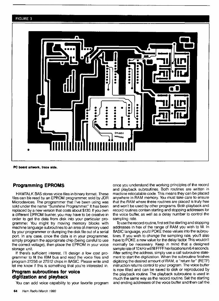
PC board artwork, trace side.
Programming EPROMS
HAMTALKBAS stores voice files in binary format. These files can b'e read by an EPROM programmer, sold by JDR Microdevices. The programmer that I've been using was sold under the name "Sunshine Programmer." It has been replaced by a new version that costs about $130. If you own a different EPROM burner, you may have to be creative in order to get the data from disk into your particular pro- grammer. You might try moving memory blocks with machine language subroutines to an area of memory used by your programmer or dumping the disk file out of a serial port. In any case, once the data is in your programmer, simply program the appropriate chip (being careful to use the correct voltage), then place the EPROM in your voice storage unit.
If there's sufficient interest, I'll design a low cost pro- grammer to fit the IBM bus and read the voice files and program 27256 or 27512 chips in BASIC. Please write and let me know if this is something that you're interested in.
Program subroutines for voice digitization and playback
You can add voice capability to your favorite program
once you understand the working principles of the record and playback subroutines. Both routines are written in machine relocatable code. This means they can be placed anywhere in RAM memory. You must take care to ensure that the RAM where these routines are placed is truly free and won't be used by other programs. Both playback and record routines contain starting and stopping addresses for the voice buffer, as well as a delay number to control the sampling rate.
To use the record routine, first set the starting and stopping addresses in hex of the range of RAM you wish to fill. In BASIC language, you'd POKE these values into the subrou- tines. If you wish to change the sampling rate, you'll also have to POKE a new value for the delay factor. This wouldn't normally be necessary. Keep in mind that a designed sample rate of 10 kHz will fill FFFF hex locations in 6.4 seconds. After setting the address, simply use a call subroutine state- ment to start the digitization. When the subroutine finishes digitizing the desired amount of RAM, a "return far" (RETF) instruction returns control to your program. The voice buffer is now filled and can be saved to disk or reproduced by the playback routine. The playback subroutine is used in much the same way as the record routine. Set the starting and ending addresses of the voice buffer and then call the
64 Ham Radio/March 1990

400 WATTS (144-148 MHz)
TE SYSTEMS new HPA Series of high power amplifiers now available through select national distributors.
AH amplifiers are linear (all-mode), automatic TIR switching, and incorporate optional GaAs FET preamp. Amps are usable with a wide in- put drive level range. Thermal shutdown protec- tion and remote control capability included. All units are designed to ICAS ratings and meet FCC part 97 regulations. Approx. size is 2.8 x 10 x 11.5" and weight is 8 Ibs.
'm *Or- -, ,- 5" w e .
Consult your local dealer or send directly for Models also available without GaAs FET preamp (delete G suffix on model I) . All units further product information. cover full amateur band - specify 10 MHz bandwidth for 420-450 MHz amplifier. Con-
tinuous duty repeater amps also available.
TE SYSTEMS P.O. Box 25845
Los Angeles. CA 9 0 0 2 5
Amplifier capabilities: 100-200 MHz, 225400 MHz, 1-2 GHz, Military (28V). Commercial, etc. also available -consult factory.
Tutorial Cassette
Ultracornpact 5' x S 1 n " x 1 ' 1 " . Ol'lO isolated output . Battery or DC powered ' Full funct~on larnblc Keyer Adjustable speed and
we~ght One Year Ace Systems Warranty
- See Your Ace Dealer - l Amateur Electronics Supply l Barry Electronics l KJI Electronics l Madison Electronics l Oklahoma Comm. Center l R. F. Enterprises l R & L Electronics l Rlvendell Electronics
Ace Systen~s . ID I . Box 81 . MICOX. PA 15870
f l 1 5 5 . f l 157
Ham Radio/March 1990 65
DOWN EAST MICROWAVE
E MICROWAVE ANTENNAS AND EQUIPMENT . Loop Vqtw Power Mvlden LIwr AmplH1.n Completm Arrays. Mlcrowmve Trwnsvertmn CwAs FET Preamp8
TROW. EYE .Wmmk Slgnal OSCAR. 902 1269 12W 2 3 0 4 2400.3456 MHz 1345LY 45.1 IoopYWgl 1MMMZ ?WBI SlW 1345LY 45.1 IoopYwgl 2304MHz 2WBI 189 3333~Y 33.1 IocpYmpl 902MHz 18.MBI 1109
Above anlmnas e m b l e d and lWl.d Klls available. Add $8 UPS SIH, $1 1 Weol of !he MIUDSIPPI
MICROWVE LINEAR AMPLIFIERS SSB. ATV. REPEATER. OSCAR
2311PA 1w1n tawout 1~40.1300 MHZ IS.~V 1265 2335PA 10w1n35ww1 1240-I~WMHZ 13.W ~31.5 JH8PA 1wlnlOw w t 90Q930MHx 13.W 1265 3335PA 10w1n40w WI 9 0 0 - 9 3 0 ~ ~ 1 13.W $320 23LNA pmmnp 0.7dB N.F. 1296MHl 1 90 33LNA prmwmp 0.0dB N.F. 902 MHz 1 90
~ M M - w i r s SHF systems rnlcmrnva tnnmr lan kltl mllablw. * hXnnc.r.np
w**usTM~CROUE Bl l l Olson. W3HQT
Box 2310. RR 1. Troy. ME 04987 (207) 948-3741

3nt that The I ic
Satellite TV is still full of the wondermc made it so popular in the early '80s. - tinkerers are there, the programminq I, there, and never has the cost ( ning a dish owner been so low.
So, how do you find out about this exciting entertainment?
Through publications devoted specifically to satellite TV, that's how!
I America's Weekly Guide To Satellite TV
OnSat is unsurpassed for the most up-to- date listings of satellite programming. Dr. Dish, Mail bag, and the Transponder Service Watch are all geared to help you make the best use of your satellite TV system. A sample issue can be obtained for only $1.
I The Complete Monthly Guide To Satellite N STV Guide contains over 300 pages of programming information, product reviews, home troubleshooting, and information about satellite TV. A sample issue can be obtainedfor only $2.
Both OnSat and STV Guide contain listings for over 120 channels and Prime Time Grids for over 50 channels. Subscribe to either the weekly OnSat or the monthly STV Guide for only $48 per year.
To start receiving the best in satellite TV guides and information, call toll-free (800) 234-0021. VISA1*' and Mastercard accepted.
STV Guidetonsat PO Box 2384 Shelby, NC 281 51-2384
66 Ham Radio/March 1990
subroutine. It is assumed that your program has either previ- ously digitized a passage into the voice buffer or filled the buffer from disk. The RETF command returns control to your program after the voice passage has been reproduced.
Before I present a detailed operation of the subroutines, a short simplified description of how the IBM addresses its RAM will eliminate a great deal of confusion. A common CPU, like the old 8080, addresses memory with 16 binary address lines A0 to A15. This gives 65,536 separate addressable bytes, 0 to FFFF hex. The 8088 can address 1,048,576 bytes directly using address lines A0 to A19, cor- responding to 0 to FFFFF hex. The addressing confusion arises when you try to store a 20-bit wide address in a 16-bit wide register! Intel has solved the problem using a segment register and an offset register combined to produce a 20-bit wide address. For the purposes of this software and to keep life simple, consider the segment register to be nothing more than a bank select register which allows you to choose one of 16 64K byte banks. The offset register contains the address location in the currently selected 64K bank. The correct method of describing a memory address using this scheme would look like this: segment address to the left of the colon, offset address to the right of the colon. One example might be 1000:3FFF, which corresponds to bank 1 offset 3FFF. For your purposes, the segment reg- ister or "bank select" register will only contain one of 16 values. These are in hex and range from 0000 to F000. The first digit is the "bank number" and the 000 portion is neces- sary filler. The banks are tabulated below. 0000:= 1st 64K bank 8000:= 9th 64K bank 1000:= 2nd 64K bank 9000:=10th 64K bank 2000:= 3rd 64K bank A000:=11th 64K bank 3000:= 4th 64K bank B000:=12th 64K bank 4000:= 5th 64K bank C000:=13th 64K bank 5000:= 6th 64K bank D000:=14th 64K bank 6000:= 7th 64K bank E000:=15th 64K bank 7000:= 8th 64K bank F000:=16th 64K bank
This scheme forms a simple method for the voice rou- tines to access the entire RAM space of the CPU. When one 64K byte bank is full, simply increment the segment register by 1000 hex to select the next 64K byte bank. In reality, the segmentoffset operation of the CPU is much more complicated than this brief description.
One last important point. Because the timing loops for the digitization are software generated, all processing by the CPU must be halted during the voice routine operation; this includes the keyboard input! To accomplish this, each voice routine turns off all possible interrupts while running and then enables interrupts at completion of the routine. Both routines load the voice buffer starting address with an MOV BX,0000 for the offset address and an MOV D1,2000 for the bank address. This equates to byte zero of the third bank - just above and out of the way of BASIC. The ending addresses are loaded as part of compare instructions like CMP BX,0000 for the offset register and CMP D1,6000 for the segment register. You may change these starting and stopping points to any location in RAM as long as you don't overwrite a resident program, like DOS!
Next time I'll discuss combining a clone motherboard with this month's project, along with ROM or RAM based soft- ware, into a digital voice storage simplex repeater suitable for whatever RF frequency you choose. Q

ALL AMATEUR WIRE AND CABLE fmm the
WIREMAN CERTIFIED OUALITY The only warp and cabk by amaleun I@ amaleu1S
hllnly O4XLllA ThclopoIW PUORMAN SWNJLINE hlpr R m W W
bradandnon conlan~~nalmqlacket
OFLEXI 4x1 BrandW~l&abwe-samcsuperlaImsl13dW100'@ 2mclem) bulnw l l cx~bleeow~h lor mlors I l p m r s elc No more lumpers"'
0 nYU AncnhancedvernonolMILSP€C unlh24mombraMvnns belle, flex characlerlslkcs MIL SRC IIA lackel
08X Theold slandb, mlnl 8 wfh rclvrr grayrr l lec t l~ lackel
0 BXllA Alabwe plu15Iky b lxkMIL SPEC IIA non conlamlnaltn9 lackel
0 BXMlM Ne. heavydulymm8 hl.temp h w m t r m m crushnsls Ian1 IIA~ackel lor marmeand moOlle use
OCOPPERCLAO Dcsqndloranlmnar(then1sad1tlennccI~n18 18 14 13 mg solad rlrandsd rnull!Ptranded lnsulatsd etc
O.mN L€RD 450 300 R ohm lransmlswon hne
0 R(TIOR 12 Slandafd and custom rolor cables
Also hardline Quyrnn sh~eldcdaudlo magncl buss prwnd brad g rand mdr burs ban connfflm wreanlconas balum kllr anlPnnaaccesswlc5
Whoksale and rttall - anyamotml - Oeakr3 OK
CaIalog $1 Rl~ndable wIMdl l
1-800-727-WIRE (9473) 803-895 4195 (tech he lp and ragchew)
a03 ass 5811 (FAX)
cnnlnEo co~mun~cmons THE rnREmrn7 261 Pl l lmdn Road Landrum. SC 29356
ArnplGer Repair I Alpha - Arneritron - AMP - Henry Dentron - Heathkit - TenTec - Etc.
I 35 Years Experience as the - - Service Manager with a - 1 maior manufacturer 1
ELECTRONICS I 4209 Live Oak Road Raleigh, NC 27604
919-832-1025
E You March I l t h - W E C A F E S T '90 West C h e s t e r . NY
FT -767GX. FT -757GX l l . FT -747GX.
SWL . M o m C o a c h
A U T H O R I Z E D
E x p o r t 0rd.r. S h l p p d I m m d l m t o l y . T E L E X 12-7070
ATV CONVERTERS HF LINEAR AMPLIFIERS DISCOVER THE WORLD OF H a M E L l F 1 6 R S c MOTOROLA BULLETINS
FAST SCAN v ! ? p % y ! : m . 81400
A N I I I JOOW 8IW.IO 1811 I IOW l l 8 . l r AN761 l lOW 8 0 1 15 EB17A IOOW l t l 9 . n UEAT SINK MATERIAL AN7101 IOW 8 81 70 EBIMOOOW IU8 .15 ......... ANI~PH l o w t 01 10 AR105 IOOW SJ81.51 ~ 4 . 1 W H", Snh(6 5.12.11) 8 11.00 ..... AR113 IOOW 8 lO l 00 c n a - 6 corm sr...m(ran~/4) I 18.80
W W C I U _ W A T T I - U M H I A- W. 4.0 n t - ~ 144-t.-FW m. POWER SPLITTERS 4 COMBINERS CHIP C A P S - K d I A T C
METALCLAD MICA CAPS-Un*../m.
A N 1 110-450 G.15-FET 1w.m RF POWER TRANSISTORS
ATV4 001-011 JG.As-FETI::::::::l I 0 05 K11 l@W W-I PEP I - P ( ,g.gs MINI-CIRCUIT MIXERS .................... I100 W.ll PEP I- 110.OI 381 -1 I 5OOM. 1 LU ............... SBL-11 ;O-IOO~M. 1 7.95
~ ~ " ? c m . c " ~ ~ o ' . . ! ~ . ! ~ ~ ~ ~ r ~k - -PULL LINEAR ARCO vu1oo-30 T R I ~ ~ ~ ~ I W S a0 RF cbk . I 1.10 S k F - ................ .......... %- 1 0 0 - 6 l 10 F.",,. B d 1 .m
.......... I n.eS KH KEBI7-PK (KH).. .............................. 1 1 ~ . 2 5 B r ~ d b l r d HF T~.n.famn.
......... 1110.05 ~k UEB6I-PC8 (PC I).rdI .................... 8 18.00 ............................... AV.OI.~I. an ut a ~,..r/t-t.r KER61-I (Mmnw(J 1 5.00 Add I 1.50 f w ahippvl. I* Mk. F a &I& k(arn.l@a r* prr... c.II r r.k. fru f r r r -uS.
#hip Communication Concepts Inc
Xanm. Ohm 453B5 ( 5 1 3 ) 426-8600 F A X 1513) 429-3811
/ 159
Ham Radio/Mafch 1990 67

Joseph J. Car6 K4IPV
ANALOG METER MOVEMENTS: HOW TO USE THEM Although the digital meter has popped up all over the electronics industry, it's noteworthy that a lot of Amateur Radio equipment, both factory made and homebrew, still uses the analog meter movement. At the last large hamfest I attended, I saw that analog meters were popular among those who pored over the tailgaters' offerings.
Why, in an age of digital everything, is the analog meter still popular? I think there are two basic reasons. First, the analog meter isn't terribly sensitive to RF fields that surround Amateur Radio gear. Second, this meter is most often used in Amateur Radio to find peaks and dips rather than an actual value. While the digital meter has a certain edge over analog types when it comes to reading values with ease, its very nature makes looking for peaks and dips annoying - especially if the integration of the digital meter is long!
In this month's column I'II look at analog meters and their applications. While I don't expect to exhaust the field, this information should be useful for a wide variety of Amateur Radio metering applications. I'II examine the basic DC meter movements and a method or two for making them read AC values.
DC instruments The two most common forms of DC
meter movement are the DNrsonval and taut band designs. Both move- ments are examples of a general class called permanent magnet moving coil (PMMC) galvanometers. These devices work on the same basic prin- ciple as the DC motor. A simplified view of the PMMC movement is shown in Figures 1A and 18. A movable coil is mounted in the magnetic field between
L O O P /SIDE VIEW) I
(A) Permanent magnet moving coil (PMMC) galvanometer. (B) Side view.
POINTER
JEWEL I \ BEARING-
\PIVOT SPRING
JEWEL BEARING
Side view of the D'Arsonval meter movement.
the two poles of a permanent magnet. A current flowing in the wire generates a magnetic field. The polarity of the magnetic field is determined by the direction of the current flow, while the strength of the field is determined by the current magnitude.
The coil of a PMMC movement is mounted so it can rotate in the space between the magnet poles. A current in the coil creates a magnetic field that either aids or opposes the field of the nearby magnet poles. Current flow in one direction causes a clockwise rota- tion; current flow In the opposite direc- tion causes a counterclockwise rotation. The amount of rotational position change is proportional to the current magnitude.
The D'Arsonval meter movement
Figure 2 shows the D'Arsonval meter movement. A side view of the meter movement, without the permanent magnet, appears in Figure 2A; a front view of the magnet is shown in Figure 28. The coil in Figure 2A is wound on an armature (or bobbin) which is mounted on a pair of jeweled bearings to reduce friction (see Figure 28).
When a current flows in the coil, the armature assembly deflects clockwise (as illustrated in Figure 28) by an amount proportional to the current strength. The amount of deflection can be marked in units of current on the
FS
POINTER
LOW STOP HIGH STOP
-ARMATURE
PERMANENT MAGNET 1 I I
End view of the movement.
68 Ham Radio/March 1990
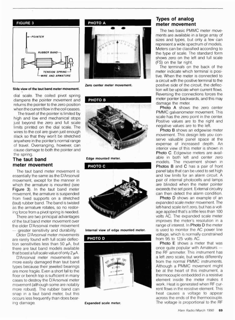
Types of analog meter movement
(L, RUBBER B A N D - ,
TENSION SPRING--J WIRE AND ARMATURE
The two basic PMMC meter move- ments are available in a large array of sizes and types, but only a few can represent a wide spectrum of models. Meters can be classified according to the type of scale. The standard form shows zero on the left and full scale (FS) on the far right.
The terminals on the back of the meter indicate which terminal is posi- tive. When the meter is connected to a circuit with the positive terminal to the
Zero center meter movement. positive side of the circuit, the deflec- Side view of the taut band meter movement. tion will be u~scale when current flows.
dial scale. The coiled pivot spring dampens the pointer movement and returns the pointer to the zero position when thecurrent flow in thecoil ceases.
The travel of the pointer is limited by high and low end mechanical stops just beyond the zero and full scale l~mits printed on the dial scale. The wires to the coil are given just enough slack so that they won't be stretched anywhere in the pointer's normal range of travel. Overranging, however, can cause damage to both the pointer and the spring. The taut band meter movement
The taut band meter movement is essentially the same as the D'Arsonval movement, except for the manner in which the armature is mounted (see Figure 3). In the taut band meter movement, the armature is suspended from fixed supports on a stretched (taut) rubber band. The band is twisted as the armature rotates, so no restor- ing force from a pivot spring is needed.
There are two principal advantages of the taut band meter movement over the older D'Arsonval meter movement - areater sensitivitv and durabilitv.
Reversing the connections forces the meter pointer backwards, and this may damaae the meter.
Edae mounted meter.
~ h g o A shows the zero center PMMC galvanometer movement. This scale has the zero point in the center. Positive values are to the right and negative values are to the left.
Photo B shows an edgewise meter movement. This design lets you con- serve valuable panel space at the expense of increased depth. An interior view of this meter is shown in Photo C. Edgewise meters are avail- able in both left and center zero models. The movement shown in Photos B and C has a pair of front panel tabs that can be used to set high and low limits for an alarm circuit. A pair of internal photocells and lamps are blinded when the meter pointer exceeds the set point. External circuitry can then detect the alarm condition.
Photo D shows an example of an expanded scale meter movement. The left-hand scale isn't zero, but has a volt- age applied that's a little less than 100 volts AC. The expanded scale meter improves the meter's resolution in a range of interest. In Photo D the meter
Internal view of edge mounted meter. is used to monitor the AC power line 6der D'Arsonval meter movements voltage, which is normally constrained
are rarely found w~th full scale deflec- from 95 to 125 volts AC. tion sensitivities less than 50 pA, but there are taut band models available that boast a full scale value of only ZpA.
D'Arsonval meter movements are more easily damaged than taut band types because their jeweled bearings are more fragile. Even a short fall to the floor or bench top is sufficient in many cases to destroy the D'Arsonval meter movement (although some are notably more robust). The rubber band can snap in a taut band meter, but this occurs less frequently than does bear- ing damage. Expanded scale meter.
Photo E shows a meter that was once quite popular with Amateurs - the RF ammeter. This jnstrument has a left zero scale, but works differently from the normal PMMC instruments. Although a PMMC movement might be at the heart of this instrument, a thermocouple embedded in a resistive element inside the meter makes it work. Heat is generated when RF cur- rent flows in the resistive element. This heat causes a voltage to appear across the ends of the thermocouple. The voltage is proportional to the RF
Ham Rad~o/March 7990 69
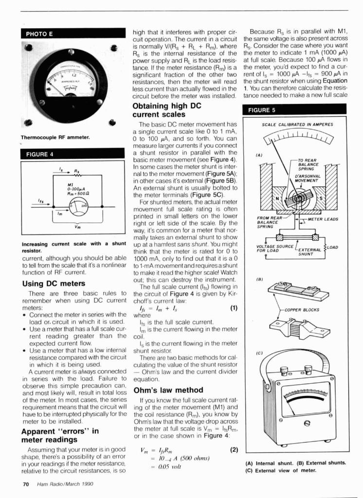
high that it interferes with proper cir- Because R, is in parallel with MI, cult operation. The current In a circuit the same voltage is also present across
Using DC meters There are three basic rules to
remember when using DC current meters:
Connect the meter in series with the load or-circuit in which it is used. Use a meter that has a full scale cur- rent reading greater than the expected current flow. Use a meter that has a low internal resistance compared with the circuit in whlch it is being used. A current meter is always connected
in series with the load. Failure to observe this simple precaution can, and most likely will, result in total loss of the meter. In most cases, the series requirement means that the circuit will have to be interrupted physically for the meter to be installed.
Apparent "errors" in meter readings
Assuming that your meter is in good shape, there's a possibility of an error in your readings if the meter resistance, relative to the circuit resistances, is so
is normally V/(R, + RL + R,,,), where R,. Consider the case where you want R, is the internal resistance of the the meter to indicate 1 mA (1000 d ) power supply and RL is the load resis- at full scale. Because 100 d flows in tance. If the meter resistance (R,) is a the meter, you'd expect to find a cur- significant fraction of the other two rent of I, = 1000 d -Ifs = 900 d in resistances, then the meter will read the shunt resistor when using Equation less current than actually flowed in the 1. You can therefore calculate the resis- circuit before the meter was installed. tance needed to make a new full scale
Obtaining high DC
out; this can destroy the instrument. The full scale current (If,) flowing in
the circuit of Figure 4 is given by Kir- choff's current law:
I /s = 1," + 1,s (1) where
If, is the full scale current. I, is the current flowing in the meter
coil. I, is the current flowing in the meter
shunt resistor. There are two basic methods for cal-
culating the value of the shunt resistor - Ohm's law and the current div~der equation.
Ohm's law method
SCALE CALIBRATED IN AMPERES
current scales @ The basic DC meter movement has
a single current scale like 0 to 1 mA, Thermocouple RF ammeter. 0 to 100 pA, and so forth. You can
measure larger currents if you connect a shunt resistor in parallel with the
If you know the full scale current rat- ing of the meter movement (MI) and the coil resistance (R,), you know by Ohm's law that the voltage drop across the meter at full scale is V, = If,Rm, or in the case shown in Figure 4:
o-loopn Rm m 5 0 0 0 LKl LJ
vm
= A (500 ohms) = 0.05 rfolt
basic meter movement (see Figure 4). In some cases the meter shunt IS inter- nal to the meter movement (Figure 5A); in other cases it's external (Figure 5B). An external shunt is usually bolted to
the For meter shunted terminals meters, (Figure the actual 5C). meter movement full scale rating is often printed in small letters on the lower right or left side of the scale. By the way, it's common for a meter that nor-
)-COPPER BLOCKS
mally takes an external shunt to show Incmaslng current sale d t h a shunt up at a hamfest sans shunt. You might resistor. think that the meter is rated for 0 to current, although you should be able 1000 mA, only to find out that it is a 0 to tell from the scale that it's a nonlinear to 1-mA movement and requiresashunt function of RF current. to make it read the higher scale! Watch
(A) Internal shunt. (B) External shunts. (C) External view of meter.
70 Ham Radro/March 1990


current If,' by:
= (0.05 volts DC)/(9 x 10-4 A) = 55.556 ohms Put in another form, this procedure
reduces to:
Current divider method The alternative method takes advan-
tage of the current divider equation:
If you solve this equation for R,, you find the resistance of the shunt:
Voltage measurement from the DC current meter
You can measure voltage on a DC current meter if you connect a mul- tiplier resistor (Rmx) in series with the meter movement, as in Figure 6A. The circuit is redrawn in Figure 68 to make it easier to understand. The current in the circuit is:
(A) Multiplier resistor makes current meter into a voltmeter. (B) Circuit redrawn.
Bridge rectifier makes DC meter into an AC
its sensitivity: Z = V f s x S (1 0) You need to know the impedance
when determining whether or not a particular meter will load the circuit.
Reading AC on DC meters Although there are several different
forms of AC meters, it's common prac- tice to use a DC meter movement for measuring AC values in multimeters and other applications. The simplest method is to use a bridge instrumen- tation rectifier (see Figure 7). This rec- tifier circuit will produce a reading that's approximately 0.9 times the peak voltage, but you can calibrate the scale in terms of rms voltage. However, that calibration is based-on the premise that the AC remains a sine wave. If the sine wave is distorted, or if a non- sinusoidal wave is being measured, then the calibration is shot.
The rectifiers used in Figure 7 (CR1 to CR4) are, ideally, copper oxide instrumentation rectifiers for 60-Hz work. You can use silicon (1N4148) or germanium (1N60) rectifiers as well - especially if you're making RF meas- urements.
A more complex form of rectifier is based on the fact that op amp circuitry can be used to calculate the true rms value of the waveform. Several IC manufacturers offer devices that are listed as rms-to-DC converters.
Next month meter.
By solving Equation 7 for Rmx, you This month I've examined the meter can calculate the required value of movement itself and some applica- multiplier resistor: Voltmeter sensitivity tions, like voltmeter and AC meter. In
The sensitivity of the DC voltmeter is the next (and final) installment of this V' - ImRm R, = (8) measured in terms of ohms per volt. series I'll take a look at some meter
1, It depends on the full scale current of applications circuits. Q the basic DC meter movement used in
where the circuit. You can find the sensitivity Rmx is the multiplier resistance. quickly by taking the reciprocal of the Vfs is the desired full scale voltage. full scale current rating:
72 Ham Radio/March 1990

NEW PRODUCTS
Commander HF-2500 Linear Amplifier
Command Technolog~es introduces the Com- mander HF-2500 lrnear amplifier. The HF-2500 operateson 160.80.40.20, and 15 meters. It also performs on the WARC bands, and can operate on 12 and 10 meters with user mod~ficat~on.
This amplifier delivers 1.500 watts of continu- ous carrier output using a pair of Eimac 3CX800A7 triodes requiring only 50 to 80 watts of drive. High duty cycle emissions like RTTY, SSN, EM, and AM present no problems. Tuned input and ALC adjustments can be made from the rear panel. The interior chassis layout pro- vides full cabinet pressurized forced air cooling. Parts and labor are covered by a three-year limited warranty. With sales and service factory direct, the Commander HF-2500 sells for $2.188.
Write to Command Technologies. Inc, PO Box 939. Bryan, Ohio 43506 for further information or call toll free (800)736-0443.
Clmk #303 on Reader Service Card.
CM-1200 SWRIPower Meter NCG has announced the new CM-1200 Ultra-
compact SWRlPower Meter for 1200 MHz. It's rated at maximum power 60 watts for power ranges of 10 to 60 watts. Insertion loss is 0.25 dB and normal impedance is 50 ohms. The con- nectors are N type; d~mensions are 2.25" width x 2.55" height x 1.1" diameter.
For more information contact NCG Company, 1275 N. Grovestreet, Anaheim. California92806.
Circle #304 on Reader Service Card.
Morse Code Terminal Kit and New Repeater Log
Dynarnlc Electronics Inc. announces a Morse Code Terminal Kit that converts a Radio Shack color computer into a Morse terminal. The con- version kit lets you send Morse code by press- ing a key on the keyboard - decoding and prlnting the characters on the television screen or monitor. Interface cables (included) connect from the receiver's audio to the right joystick port and from the key jack to the printer or RS-232 port. The keyer cable is wired for a three con- ductor 114-inch plug and can be adapted to a two conductor 118-inch plug with an adapter (not included).
Features include automatic speed tracking on receive, preprogrammed message transmission with asingle keystroke, and message transmission from a file on a tape or disk.
The program works on all 32K and larger
Radio Shack color computers with extended BASIC using either tape or disk drives. The kqrer will key a solid-state transceiver with a maximum keyup voltage of 15 volts. The cost of the kit is only $39.95 plus $3 shipping. Specify tape or disk software.
Dynamic Electronics Inc. also has a new Repeater Log Program for Tandy color disk and IBM compatibile computers. The log lets you enter up to 200 repeaters in a file and list them by frequency, city, or callsign. Each file has spaces for city, repeater callsign, offset used. and comments. Addit~onal files can be loaded for different beam headings or states. The cost is $14.95 plus $2 shipping. Please state IBM or Tandy color computer.
More information about the Morse Terminal Kit and Repeater Log Program can be obtained by contacting Dynamic Electronics Inc., PO Box 896, Hartselle. Alabama 35640. Phone: (205)773-2758.
Clrcle #305 on Reader Servlce Card.
Communicator Enhancer Electronlc Speclal~sts improved modular con-
nector communrcat~on enhancers now Include Common Mode RFI and low frequency interfer- ence filtering. Available as integral parts of Spike6urge Suppressors, the improved models prov~de modem and FAX transmissions w~th greatly reduced errors.
Dubbed theTURB0, improvedcommunication enhancers are available for the standard slngle llne modular plug (RJ-11) systems and commer- cral multi-l~ne connector systems such as RJ-13. -14 and -45. Mult~ple connector systems can also be custom engineered. Models lncorporatlng AC power line conditioners, filters or fllterlsup- pressors are available.
TURBO models are available fmm stock, start- ing at $49. For more detalls contact Electronlc Specialists, Inc.. 171 So. Main Street. Natick. Massachusetts 01760. Call toll free: (800) 225-4876.
Clrcle 11306 on Reader Service Card.
Two New Rotatable Dipoles SV Products has two new rotatable d~poles.
The model 18240 (25-foot elements) covers the two new WARC bands, 12 and 17 meters. The 21280 (22.4-foot elements) is for the DXer's bands, 10 and 15 meters. KD9SV uses a new trap design for high strength and power handling capability. The trap has been tested to 25 kV and will eas~ly handle full legal power. Antenna elements are made from high strength T-60612 aluminum alloy. Windloadlng is less than 1 square foot and the antenna will rotate with a standard N rotator. Introductory prlce for both antennas is $89.95 plus $5 shipping and handling.
For more information contact Gary Nichols. KDSSV, 4100 Fahlsing Road, Woodburn, lllinols 46797.
Clmle 11307 on Redor Service Card.
Transistor Radio Kit and Training Course
The AM-FM-108 Transistor Radio Kit is des~gned to expand your understanding of basic radio theory. Circuits are lard out in systematic order on an oversized pc board so you can eas- ily understand the flow of the radio s~gnals from antenna lo speaker.
Conslruction begins with the building of the AM Radio, static testing of each circult, and then dynamic testlng with voltage and signals. After completing the AM Rad~o section, you construct and test the FM Rad~o circuit. Alignment proce dures complete the projects. The radio kit pc board needs no cabinet. A special bracket pro- vides support to use or display the radio in any location.
A complete manual is included along with a magic wand that assists in the alignment of RF circuits. Earphone, battery, and magic wand are included. The list prlce of the kit is $29.95.
For further informailon contact Elenco Elec- tronics. Inc., 150 W. Carpenter Avenue. Wheel- ing, Illinois 60090. Telephone: (312)541-3800. FAX:(312)520-0085.
Clmle #308 on Reader Senlce CMd.
Ham Radio/March 1990 73

Scanner and Shortwave Answer Book
Bob Grove's Scanner and Shortwave Answer Book answers hundreds of questions asked by shortwave Ilsteners. This 160-page reference was compiled from eight years of questions submit- ted to Monitoring Times by its readers.
Grove's book 1s $12.95 (plus $2 shipping In the U.S.) and is available from Grove Enterprises, PO Box 98. Brasstown. North Carolina 28902. Telephone (704)837-9200.
Clrcle 1309 on Reader Service Card.
ICOM Options for the IG901 Fiber Optic Multi- band Transceiver
The IC-901 flber optlc remote mount multt- band transcelver offers a varlety of optlons to meet your moblle needs New opt~ons avallable to complete your IC-901 mult~band package Include
Suggested Untt Descr~pt~on Refall Pr~ce UX.S92A 2 meter SSB band $59900
unit complete with USB. LSB and CW modes
SP 12 Slim Llne External $ 2599 Speaker w~th Vlsor Cl~p tor moblles
OPC.23 DC cable $ 3349 EX-766 Interface-A Connector $ 47.99 EX-767 Interface-B Connector $ 4 2 99
For details contact ICOM Amerlca Inc., 2380 116th Avenue NE. PO Box C-90029. Bellevue, Washington 98009-9029.
Clrcle 1310 on Reader Sewlce Card.
Kantronics Data/ Voice Radio
Kanlrontcs has introduced the flrst rad~o speck flcally des~gned for the packet enthuslast The new Kantrontcs dvr 2-2 prov~des h~gh speed TIR sw~tchlng for today's dlgltal world
The dvr 2-2 reaches full power output (rated at 2 watts) w~thln 5 ms after push-to-talk IS actl- vated In add~t~on, the dvr 2-2 has a fast carrier detect output that reacts wtthln 10 ms after a slg- nal IS recelved Thls lets you set your TXDELAY to 2 (20 ms) when talking to another dvr 2-2 user Thls carrler detect helps reduce coll~srons, as the rad~o senses actlvlty faster and s~gnals the TNC that the channel ts In use
The dvr 2-2 also has dlscrlmlnator output avail- able on the rear panel connector, whtch means you don't have to modlfy the rad~o for h~gh speed packet The unlt was designed with the ablllty to operate at up to 9600 baud w~thout mod~fl-
cation. The connections to your packet modem are all provided on a single DB-9 data port on the rear panel.
The dvr 2-2 data port is designed to be pln- for-p~n compatible with Kantronics TNCs, but the dvr 2-2 will operate with other manufacturers' units also. The Increase In speed realized by our pin diode TIR switching can result In a reduc- tion of your TXDELAY setting by as much as 90 percent or more.
The dvr 2-2 has a microphone jack on the rear panel, allowing you to connect the optional Kan- tronlcs mlc and an external speaker for volce operation You don't have to disconnect your packet un~t to talk.
The suggested retail price for the dvr 2-2 is $199. For detalls contact Kantronlcs. 1202 E. 23rd Street, Lawrence, Kansas 66046. Tele- phone: (913)842-7745.
Circle 1311 on Reader Service Card.
Heil Sound's Concept 2000 Hell Sound has Introduced the Conceot 2000
product llne Included In the llneup are the HM-10 mtcrophone. AB-1 adjustable mlcro. phone mount. FS-1 foot swttch, and FL-1 prlvate llghtlng system
The Hell HM 10 uses the Hell "Key Element" mlcrophone cartr~dge for maxlmum artlculat~on of SSB transmlsslons The HM-10 1s avallable wlth etther the HC-5 or the HC-4 Key Element The HC.5 IS a full range element rolling off below 300 Hz and has a 6-dB peak at 2100 Hz The HC-4 "DX Dream Machlne" was des~gned by Hell for breaklng the DX plleups It has the last octave rolled off at 600 Hz and has a IO-dB peak at 2100 Hz
A spec~al model of the HM-10 IS avallable w~th both the HC 4 and the HC-5 installed A profes- s~onal four-p~n Cannon connector In the base of the HM 10 IS used to connect the mlcrophone to your transcelver A second mcro-swltch selects e~ther the HC-4 or the HC-5
The HM 10, shipped w~th matlng cable assem- bl~es, wlll match the HM-10 w~th your type of transcelver The red cable IS wlred for Kenwood Blue mates the ICOM, yellow matches up the YAESU, and a wh~te cable IS used for other tran- scelvers and labeled as such The sl~de swltch on the HM-10 case IS wlred for standard push- to-talk whlle the Key Element IS wlred stralght through for VOX operation all the tlme w~thout specla1 swltch~ng or cabllng
The AB-1 IS an adjustable mount to support the HM-10 or slmllar profess~onal microphones Its adjustable boom and mountlng assembly can be used In a vartety of ways
The FS-1 has been designed to control the push-to-talk llnes of a radlo transmitter, allowing hands-free operation. This device has a 2-A momentary switch connected to a 4-foot shielded cable and IS designed to switch low voltage clrcu~try. Switching 110-volt AC circuits w~th the FS-1 is not recommended.
The cable is terminated w~th a 114-inch phone plug. Should your equipment requlre a d~ffer- ent interface, it IS not recommended that you use any type of adapter but rather replace the exist- ing connector w~th the correct matching plug.
The FL-1 IS a prlvate lightlng system to illuminate rad~o panels, log sheets, or operating positions. The FL-1 IS sh~pped with a conven- tional 12-volt incandescent lamp that can be powered with any 12 to 14-volt 100-mA power supplies. A halogen bulb IS available to fit Inside the FL-1 should you want more candlepower.
Additional Information on Concept 2000 pro- ducts 1s available from Heil Sound, Ltd.. 2 Heil Drlve. Marlssa, llllnols 62257. Telephone: (618)295-3000.
Clrcle 1312 on Reader Sewlce Card.
Evaluation/Pmtotyping Board with Sockets: TFM Series Mixers
RF Prototype Systems introduces the TFMl Oulck Board. The TFM, IS for evaluation or bread- boarding using the following MI~I-C~rcuits devlces, and equivalent devices manufactured by Pulsar Microwave, Tele-Tech, Engelmann Microwave. Synergy Microwave and Olektron: TFM mixers. TSC splitters and TDC couplers. Connections to BNC. SMA, or SMB connectors are vla 50-ohm mlcrostr~p lines.
Mountlng holes for three bulkhead BNC. PCB, SMA or SMB connectors are provided.
A socketed version. TFMIS, allows the dwlces and TFMIS to be reused easlly wlthout solder- Ing for frequenc~es up to 2 GHz
Thls board IS doubleslded FR-4 (h~gh temper- ature G-10) wlth plated-through holes
For more ~nformatlon, contact RF Prototype Systems. 12730 Kestrel Street. San Dlego. Cal~forn~a 92129 Phone (619)538-6771
Clrcle 1313 on Reader Sewlce Card.
74 Ham Radio/March 1990

COMPUTER-GENERATED RFI Some remedies for this malady
By Bryan I? Bergeron, NUIN, 30 Gardner Road, Apt. 1G, Brookline, Massachusetts 02146
adio Frequency Interference (RFI) has always been a source of concern for the Radio Amateur. Until the recent introduction of com~lex circuitrv in the
home (like microcomputer systems, VCRS, and midrowave ovens), our communications gear has been the main source of potential RFI. In this computerized age of ours, increas- ingly complex and sensitwe receivers are being barraged by these and other sources of RFI.
Microcomputers have become an integral part of the con- temporary Amateur Radio station. Virtually all modern receivers and transceivers rely on microcomputer-controlled circuitry for their internal operation. But more important, from the perspective of RFI generation, is the external stand- alone microcomputer system. This system can be found in an ever-increasing number of Amateur Radio stations run- ning programs for predicting HF propagation, logging and checking QSOs, printing QSL cards, and even controlling transceivers. Unfortunately, many computer systems radi- ate a significant amount of RF into the shack. This is espe- cially true on the HF bands, where even a small amount of RFI can mask an otherwise readable signal. This article examines the microcomputer as a source of RFI, and sug- gests some steps you can take to contain it.
To understand how the microcomputer can be a source of RF interference, you must have some knowledge of how microcomputers are constructed, how they operate, and how they are normally connected to other devices.
Physical Construction On the most basic or physical level, most microcomputers
are composed of a system unit, power supply, keyboard, and display screen. Depend~ng on the make and model of the microcomputer, these components may be physically separate, as in the IBM PC, or found in a single package, as in many portable computers. Many m~crocomputers include the power supply and at least one floppy disk drive in the same physical enclosure as the system unit. Other models have the power supply and disk drives packaged separately. Many of the popular microcomputers have slots
for extending the basic system with plug-in modems, mem- ory cards, and video cards for a variety of screens.
Few of us make do with the minimal system configura- tion. The most common add~tions are printers, extra disk drives, and modems. Adventuresome hams have packet controllers and interfaces to their microcomputer-based transceivers. All of these additional devlces, and the cables that connect them to the system unit, are potential sources of RFI.
Logical operation For the purposes of this discussion, consider the
microcomputer to be composed of a Central Processing Unit (CPU), memory, and a system clock. The CPU is the heart of the microcomputer. It not only performs operations on data that resides in memory, but also keeps track of the current status of the executing program and handles com- munications with memory and inputloutput devices like printers and modems. All of this activlty must be carefully orchestrated for the rnicrocomputer to function properly. The metronome for this activity, and a potential source of RFI, is the all-important system clock.
The system clock creates the timing signals used to syn- chronize all activities within the computer. And as in our modern transceivers, a quartz crystal normally serves as the basis for this timing. In some microcomputer systems the CPU contains the oscillator circuitry, so an external crystal is simply conrlected between two plns of the CPU chip. In other systems, separate dedicated chips are used to generate the timing signals. In the IBM PCtAT for exam- ple, there's a clock generator chip and a programmable timer chip. The clock generator chip, which uses a quartz crystal, creates the basic timing signals used by the computer.
The programmable timer ch~p is related to the clock generator chip. Think. of it as a programmable array of flip- flops that produces an output signal every so many clock cycles. For instance, if the basic clock cycle is 6 MHz (as in the original IBM-AT,,, and you want to perform some event every 1160,000 second, the programmable timer chip can
Ham Rad~o/March 1990 75
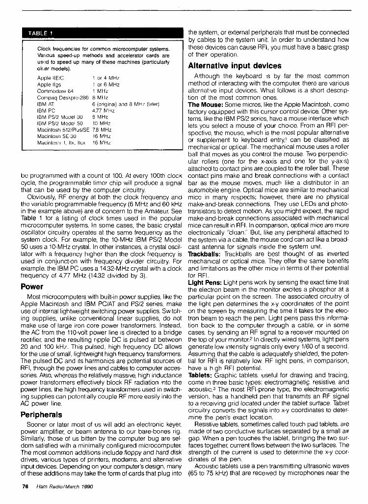
I clock frequencies for common microcomputer systems, t k s e devices can cause RFI. You must have a basic grasp Various speed-up methods and accelerator cards are I of their operation.
I usl!d to speed up many of these machines (particularly ok,er models). I Alternative input devices
76 Ham Radio/March 1990
Apple IlElC 1 or 4 MHz Apple llgs I or 6 MHZ Commodore 64 1 MHz Compaq ~eskpro-286 8 MHZ IBM AT 6 (or~g~nal) and 8 MHz (later) IBM PC 4.77 MHz IBM PSI^ Model 30 8 MHz IBMPS12Model50 10MHz Macintosh 5121PluslSE 7.8 MHz Macintosh SE-30 16 MHz Macintosh 1 1 , IIX, IICX 16 MHz
Although the keyboard is by far the most common method of interacting with the computer, there are various alternative input devices. What follows is a short descrip- tion of the most common ones. The Mouse: Some micros, like the Apple Macintosh, come factory equipped with this cursor control device. Other sys- tems, like the IBM PSI2 series, have a mouse interface whlch lets you select a mouse of your choice. From an RFI per- spective, the mouse, which is the most popular alternative or supplement to keyboard entry? can be classified as mechanical or optical. The mechanical mouse uses a roller ball that moves as you control the mouse. Two perpendic- ular rollers (one for the x-axis and one for the y-axis) attached to contact pins are coupled to the roller ball. These
be programmed with a count of 100. At every 100th clock contact pins make and break connections with a contact cycle, the programmable timer chip will produce a signal bar as the mouse moves, much like a distributor in an that can be used by the computer circuitry. automobile engine. Optical mice are similar to mechanical
Obviously, RF energy at both the clock frequency and mice in many respects; however, there are no physical the variable programmable frequency (6 MHz and 60 kHz make-and-break connections. They use LEDs and photo- in the example above) are of concern to the Amateur. See transistors to detect motion. As you might expect, the rapid Table 1 for a listing of clock times used in the popular make-and-break connections associated with mechanical microcomputer systems. In some cases, the basic crystal mice can result in RFI. In comparison, optical mice are more oscillator circuitry operates at the same frequency as the electronically "clean." But, like any peripheral attached to system clock. For example, the 10-MHz IBM PSI2 Model the system via a cable, the mouse cord can act like a broad- 50 uses a 10-MHz crystal. In other instances, a crystal oscil- cast antenna for signals inside the system unit. lator with a frequency higher than the clock frequency is Trackballs: Trackballs are best thought of as inverted used in conjunction with frequency divider circuitry. For mechanical or optical mice. They offer the same benefits example, the IBM PC uses a 14.32-MHz crystal with a clock and limitations as the other mice in terms of their potential frequency of 4.77 MHz (14.32 divided by 3). for RFI.
Power Light Pens: Light pens work by sensing the exact time that the electron beam in the monitor excites a phosphor at a
Most microcomputers with built-in power supplies, like the particular point on the screen. The associated circuitry of Apple Macintosh and IBM PCIAT and PSI2 series, make the light pen determines the x-y coordinates of the point use of internal lightweight switching power supplies. Switch- on the screen by measuring the time it takes for the elec- ing supplies, unlike conventional linear supplies, do not tron beam to reach the pen. Light pens pass this informa- make use of large iron core power transformers. Instead, tion back to the computer through a cable, or in some the AC from the 110-volt power line is directed to a bridge cases, by sending an RF signal to a receiver mounted on rectifier, and the resulting ripple DC is pulsed at between the top of your monitor.2 In directly wired systems, light pens 20 and 100 kHz. This pulsed, high frequency DC allows generate low intensity signals only every 1/60 of a second. for the use of small, lightweight high frequency transformers. Assuming that the cable is adequately shielded, the poten- The pulsed DC and its harmonics are potential sources of tial for RFI is relatively low. RF light pens, in comparison, RFI, through the power lines and cables to computer acces- have a high RFI potential. sories. Also, whereas the relatively massive, high inductance Tablets: Graphic tablets, useful for drawing and tracing, power transformers effectively block RF radiation into the come In three basic types: electromagnetic, resistive, and power lines, the high frequency transformers used in switch- acoustic.3 The rrlost RFI-prone type, the electromagnetic ing suppliescan potentially couple RF more easily into the version, has a handheld pen that transmits an RF signal AC power line. to a receiving grid located under the tablet surface. Tablet
circuitry converts the signals into x-y coordinates to deter- Peripherals mine the pen's exact location.
Sooner or later most of us will add an electronic keyer, Resistive tablets, sometimes called touch pad tablets, are power amplifier, or beam antenna to our bare-bones rig. made of two conductive surfaces separated by a small air Similarly, those of us bitten by the computer bug are sel- gap. When a pen touches the tablet, bringing the two sur- dom satisfied with a minimally configured microcomputer. faces together, current flows between the two surfaces. The The most common additions include floppy and hard disk strength of the current is used to determine the x-y coor- drives, various types of printers, modems, and alternative dinates of the pen. input devices. Depending on your computer's design, many Acoustic tablets use a pen transmitting ultrasonic waves of these additions may take the form of cards that plug into (65 to 75 kHz) that are received by microphones near the

In 1937. Stan Burghardt (WDIT), because of his intense interest in amateur radio, began selling and servicing amateur radio equipment in conjunction with his radio parts business. We stand proud of this long-lasting tradition of Honest Dealing. Quality Products and Dependable "S-E-R-V-I-C-E"!
Above all, we fully intend to carry on this proud tradition with even more new product lines plus the same "fair" treatment you've come to rely on. Our reconditioned equipment is of the finest quality with 30, 60 and even 90-day parts and labor warranties on selected pieces. And always remembec
- WE SERVICE WHAT WE SELL -
STORE HOURS: 9.5 P.M. lal)
*Q~OAI m rr~afii WIN SAIUIDhlS
fr" 9.1 P.M lcsl) C L W D
MOIIII Wol lDAn
B L W Daiwa Palomar AE A Alinco Belden Hustler Radio Callbook Ameritron Bencher Kantronics Ritron Amphenol Bird Kenwood Rohn Ampire Butternut Larsen TelexlHygain Antenna Centurion MFJ Ten-Tec Specialists CES MiragelKLM UnadIllalReyco
Astron Cushcraft Mosley Yaesu 182 N. Maple
HAM EQUIPMENT C'CIII III Wr i l t . l l \ I'IKI.I\ I.OI JOLICIIC!
You'll Find Us 10 h r ('ou~.~~.r,u\. Knc~ulc.dgr:ihlr and tionchl
PHONE (605) 886-73 14 FAX (605) 886-3444
Get the most of HF Mob111ng
Y aesu FT-747GX
SPECIAL OFFER!
CALL TODAY FOR SPECIAL QUOTE P.O. Box 73
Watertown. SD 57201 -
Brinm mur slatan mlo the mmpulcr a* n t h LOGWRITE. the mnu h l ~ n , -t fwndl* k,p#n~ p m p m mllrn hv Fd Tro, IYOIV I WGWRITE m lk p r f s l -,n for the mmpkw b m slmlnn I t .tmpl$fr. mu* o y n t ~ , n and mlrn
mu ~ h c m m p N t t t s ~ cd* in mn!olmn# m n d I)\ in@ LOC.WRITE m,tb wth all IRM PC', and ~ t > r n p r l ~ h k
Instant call sgn or prehx search - Print Edrt. or V w records - plenty of room lor notes 8 addresses - AutomatlC l~meldate stampng
Tm p m n n r fat- ~YIOMIIC wrd m p . hvbprc mr m. and nol l~nl TDmv m r yw, pen m n d ppcrl
kmpm Chnwll in~ P a I** 5.H. Ruckinphnrn. I'A In912
I Or call (215)345-n&4 toorder with ViclalMaster- card. (Please specify 3.5 or 5.25 inch floppy.)
FAX (215) 345-1309
Safe OPT0 Isolated oulpul Built-in side tone 2 V " speaker Baltnry or DC powered Positive
keying to 30 volts man. Un~que "POWERILOGIC" LED One Year Ace Systems Warranty - See Your Ace Dealer -
Amateur Electronics Supply Barry Electronics KJI Electronics Madison Electronics Oklahoma Comm. Center R. F. Enterprises R & L Electronics Rivendell Electronics
Ace Systems RD 1 . Box 83 W~Icox. PA 15870 (8 14) 965-5937
MultiBand Antenna 10 thru 160 Mctcr
Factory Wired & Tested Introductory Price E
$39.95 Plus f 4 Shipping E I
Aulhorhed %, MBWC Dealer ..
('2 1 oME G . Visa 81 h4asl.r Card
ELECTRONICS 4209 Live Oak Road Raleigh, NC 27604
919-832-1025

2 x 4 2 BASE
ANTENNA T,HE HIGHEST GAIN DUAL BAND BASE/REPEATER ANTENNA
HIGH POWER 200 WAITS
CENTER FREQUENCY 146.500 MHz 446.500 MHz
GAIN: VHF - 8.2dB UHF - 1 1.5dB VSWR - 1 .-1.2 or less
CONNECTOR: N TYPE FEMALE
LIGHTNING PROTECTION GROUNDED DIRECT
LENGTH: 16 FT. WEIGHT: 5 LBS. 3 02. WIND LOAD: 90 MPH MOUNTING: UP TO 2 IN. MAST CAN SIMULCAST ON BOTH BANDS
WATERPROOF CONNECTING JOINTS
UPS SHIPPABLE
AMATEUR SPECIAL
I275 NORTH GROVE ST. ANAHEIU. CAI.IF. 92806 (714) 630-4541
CAR1.E: NATCOI,(;IL FAX (714) 630-7024
1500 + WATT TRANSMATCH KIT $169.95 OTHER KITS
........... GJRUH. PSK Packet Modem. .$111.00 ... G3RUH. OSCAR 13 Telemetry Demod.. .$144.95
QRP 20, 5w, 20 meter Transceiver (HR 1189).$124.95 . . . . . . . QRP 15, 5w, 15 meter Transceiver.. $129.95
. . . . . . . . . . WlFB 160180 Pre Amp (QST 8/88). $22.95 .......... K9CW Memory Contest Keyer. ,5109.00
. Yaesu FRG-9600, .1 to 60 MHz Converter.. .$84.95 ...... 20m CW, 15w Transceiver (H.R. 6\87). $ 159.95
.................. 50W 75M SSB SCVR. .$I 79.95 BASIC KIT-INDIVIDUAL ITEMS Factory Wlred 1-rotary inductor 28fih.. . . . . . . . . . .$59.00 Complete AmeritronKen-Tec Line CALL .................
. . . . . . . . . . . . . . .............................. 2-6:l ball drives. $13.0° ea. B8W PT-2500A Amp $1,695.00 1-0-100 turns counter. . . . . . . . . . . .$65.75 BBW vs 1 5 0 0 ~ Tuner $415.00 ............................... 1-turns counter, economy (Groth). . .$19.95 el-Tech DVK-100A (Free Repeat Option).$269.00 2-variable capacitors Visit Our New Store Al
............ 25-245 pf 4500 v. $44.00 ea. 15 Londondeny Rd. Unit 8 C~talog 11.00 Londonderry, New Hsmpshim VISAIH*S~.~C**
OPTIONS- enclosure (pictured In Sept. 86 CQ). . $78.00 RADIOKIT * P.O. BOX 973 H Shipplng Extm 4:l balun kit.. .................. .$22.50 Pelham, NH 03076 (603) 437-2722 dlals. terminals, chassls. ctramk rtmdolfs, hardware, torolds, amp componenls. 06W coil dock, stc.
fl 187
78 Ham Radio/March 1990

work area. Through triangulation, the relative strength of the received signal at each microphone is used to calcu- late the relative x-y coordinates of the pen. Touch screens: Touch screens, like light pens, are useful for selecting objects on the screen. The most common var- ieties are mechanical, optical, and capacitive. Optical screens use rows and columns of infrared LEDs - photo- transistor pairs mounted opposite each other along the edges of the screen. Touching a particular point on the screen with your finger blocks one or more x-y beams of light. The touch screen sends the coordinates of the bro- ken beams to the computer, which calculates the cor- responding x-y location on the screen.
Mechanical switching panels are composed of trans- parent, conductive membrane switches mounted over the display screen. Pressing your finger on the panel brings the two conductive surfaces together and completes the circuit. One sheet determines the x-axis and the other the y-axis location of the contact.
Capacitive touch screens have a capacitive coating on the CRT screen that acts as one plate of a capacitor. When you make contact with the screen, current flows into your body from the contact point. Sensors on the screen detect the location of the current drain and calculate the corres- ponding x-y location. In my experience, capacitive systems are more prone to RFI than either the mechanical or opti- cal versions. Joysticks: Although they are more popular as a game interface than a way of manipulating Amateur software pro- grams, joysticks should not be overlooked as a source of RFI. The vast majority of joysticks are mechan~cal, com- posed of switches andlor potentiometers. The largest RFI threat from these simple devices occurs when the connect- ing cable acts as a radiator for system unit signals.
Modems Modems (named for MODulator-DEModulator) let digital computers communicate over analog phone lines. In some microcomputer systems, like the Apple II series and the IBM PCIXTIAT, modem cards can be inserted easily into slots in the system unit. Along with minimizing the potential for RFI, these internal modems have the added benefit of providing a less cluttered ham shack. The more RFI-prone external modems, also popular on the IBM PC and other microcomputers, must be connected by a cable to the sys- tem unit. Purchasing an internal modem doesn't guaran- tee freedom from RFI, however, because the telephone cable represents a potential RF antenna.
Printers Printers range from simple dot-matrix units to complex
laser printers that contain their own RF-producing microcomputer systems. Although a few printers attach directly to the system unit (primarily on portable models), the vast majority are connected to the system via cables. In my experience, the mechanical printers are less likely to cause RFI, but the acoustic noise they produce is hardly bearable during a QSO. The relatively silent laser printers, by comparison, emit considerable RF energy.
RF modulators Many of the lower priced microcomputers are designed
to work with TV receivers as monitors. RF modulators con-
vert the video signal into a VHF signal that can be handled by a TV receiver (commonly on channel 3 or 4). These so- called "RF bricks" are potential sources of RFI - especially when the output is unshielded 300-ohm flat line.
Local area networks A local area network lets microcomputers communicate
with other devices connected to the network, including modems, printers, computerized communications gear, and other microcomputers. IC;OM1s system allows multiple ICOM receivers and transceivers to communicate with each other and with microcomputer:;. Because this system directly con- nects your computer system to your communications gear, there's ample opportun~ty for RFI. In my experience with the ICOM system, there's no detectable RFI as long as the integrity of the cable and associated connectors are main- tained. Other networks, like Apple's AppleTalk, can cause considerable RFI. Appl12Talk is a low speed network often run over standard (unshielded) telephone cable. Receive on my ICOM 751A is rendered practically useless when AppleTalk is in operation.
Minimizing computer-generated RFI There are a number of steps you can take to minimize
computer-generated RFI in your shack. In some cases, your problem may be cleared up by following only one or two of these measures. In more difficult situations, you may have to try all of these suggestions for acceptable results. Check the FCC rating before you buy: Microcomputers are rated by the FCC as either Class A or Class B devices, depending on the amount of RFI produced by the equip- ment (seeTable2). Paraldoxically, the often cheaper Class B machines, intended for home use, are less prone to RFI than the Class A mach~nes. The more expensive Class A micros, including many micros based on the Intel 80386 chip and several of the large monitors, have less stringent RFI ratings. Unfortunately, many hams use the more power- ful and more RFI-prone "business class" machines at home.
Think twice about a micro with a Class A FCC rating. Taming a machine with a Class B rating is difficult enough! Check the Modellserial number tag on all computer equip- ment, including modems, printers, scanners, and mice before you buy. You should see an FCC ID number, together with a statement like "Certified to comply with the limits for Class B computing device pursuant to Subpart J of Part 15
Radiation limits applied to microcomputers manufactured after January 1, 1981, based on data from subpart J of Part 15 of FCC rules.
Maximum radiation measured at 3 meters
Class A Class El 30-88 MHz 3,000 ,~Vlm 100 ,~Vlm 88-216 MHz 5.000 ,~Vlm 150 ~ V l m 216-1000 MHz 7,000 @Vim 200 pVlm
Maximum conduction into the AC power line
0.45-1.6 MHz 1000 ,uV 250 PV 1.6-30 MHz 3000 ,1V 250 PV
Ham Radio/March 1990 79

MARCH CATALOG HAM SAVE ME a m o n n
m from RADWO ~ a o l u r o ~ ~ SHOP BY MAIL
OR C A U TODAY!
THE ARRL ELECTRONICS DATA BOOK NEW BOOKS
bv Dmm OaMaw. WIFE II~, lggO nrolo AMATEUR cALuoors 7 ~ n e A R ~ L 5 new DATA BWK was written wt~h you In mtnd N O I ~ aulhor DeMaw glves y w Ihe benet11 of h ~ s years 01 ex pertenre In l h~s handy relerence manual Fully upualed chock lull ol the blest lnlormatmn every ham needs al lhelr llngenlps Useful for all Amaleurs RF englneers IeChntCMnS and experlmenfers 1989 2nd Edlllon I AR-DB Sonbound H 1 95
PASSPORT TO WORLOBANO RADIO 1990 Editbn Brand new and lully revlsed Expanded lo 416 pages thr bmk now Includes a blqger and beller buyer s gulde an lnlervlew w~lh James Mlchenrr an exclllnq real llle drama ol one SWL s escape lrom Iran plus much more Also ~ncludns all Ihe lalest broadcasl Schedules trom counlrles around the world 416 pages 1989
IBS-RD189 Sollbound 114 95
FROM SPARK TO SPACE a plctorbl Journey Through The Hbtory of Amateur Radb The ARRL has publtshed FROM SPARK TO SPACE lo commemorale 11s 75lh annlversdry yrar Slanlng al Amaleur Radto s rwls you reltve Ihe lhr~ll and can alms1 smell the ozone and hear !he rackel lrom spark lransmlllers Taklng you on a sen llmenlal lourney lhrough WW I the roarlng Twent~es Ihe Depression WW 2 up lo OSCAR I s launch and a Iwk at Ihe future Ih~s WOk w~ll be a lasc~naltng experfence tor all Radlo Amaleurs Chock lull 01 pictures' I989 1 1 edltton
An-FSS Hardbound $19 95
NOVICE NOTES Jusl whal the doclor ordered lor the new Radlo Amaleur Taken l r m the pages ol OST lhts anthology IS lull ol lnlormal~on lor the beglnner Covers lust about every quesllon a new Amaleur could have Plenw of helpful lnlormal~on on hcw lo gst on and gel a s ~ g ~ l OUI 01 your Shack plus much more 1989 Is l edlt~on
AR-NN Sdlbond $5 95
THE COMPLETE DX'ER rm 2nd rdmon by Bob Lochor. W9KNI Rev~sed and up dalra Locher s OX ers Dary IS one ol the most readable books ever wrlnen aboul Amateur Radlo Share ln !he I O ~ S 01 WOrklng a new slallon feel the lrustral~on ol havlng mlssad oul Learn lrom Ihe lop CW DXCC Honor Roll OX cn what 11
lakes to gel on the honor roll Htnts ups and trrks taken lrom years d on the atr expermnce wrlnen In a ldksy dwwn to eanh slyle Greal lor Ihe beglnner lun lor Ihe exwrlenred DX er PI989 2nd aclnmn
ID-CDX Jo(muMSl1 95
MFJ EASY-DX Rognm and Rcket lntsrflcs (MS-DOS computer) Here s a unque Iw l lhal organizes your DXCC quesl lnlo a slmple easy lo use lormal Enler a call Easy OX gwes you aztmulh and sunrlse sunsel lome I! also lells you whether or not you need Ihe contact lor a m Cwnlry. band or mode Packel radlo users gel a bull! In termlnal program destgned lo make Ihe most 01 Pav~ll~on Soltwam s Packet Cluster ru system or any olher Dackel node When conneelea Easv OX alerts MU When a m n t w vou need IS sootled 'omt.5 on two 5 25 d~sks Hard . . drtve recommended Lalesl vers!onktll be sh~pbed
FMFJ-EOX (MS-WSI $39 95
ANTENNA COMPENDIUM vd. z Includes MS-OOS prognm Ihllnps Anlenrias are Ihe I1 loptc of lnleresl among amateurs ARRL annually recelves far more anlenna anlcles lhan 11 can use ~n OST So lhev decldea lo ~ u b l ~ s h lhem In THE ANTENNA COMPENDIUM These never Belore oublnhed an~clss run Ihe ranoe from slmple easy lo conslruct anlennas lo sophlsllcaled destgns SIX program llsllngs are lncluded You can also get the pro- arams on a MS WS disk lor an addlllonal charae 1989 Isl edllton 208 Daoes LIAR-AC2 Se l l bed B ~ k O ~ S 1 1 9 5 OFAR-AC2 (MS-DOS) OkkOn)119 95
OAR-FACZIIUY 'EM BOTH SPECIAL llrok6 0hkS17 95
MICROWAVE UPDATE 89 - Dct. 58 ,1989 Some 01 lhr mosl up lo date work In mtcrowave cwnrnunkallon was presenled at the Arllnglon Teas conlerence A partial lhsl~ng of Ihe papers lnCludeS 900 MHz lransvener NRO EME operatmn LNA update No lune transwner lor 2304 MHz Htgh power lube ampl~lmrs 1 1 2304 MHz 10 GHz slot anlenna, and more A total ol 30 papers lrom sme d Ilm bsst UHF operalors In lne cwnlcy all In one book' 1989 1sl edllton 214 pages
AR-MU89 S-11195
1989 CENTRAL STATES VHF SOClEW 23rd CONFERENCE procsrdtngs July 1989 Here are Ihe papers lhat were presenled a! Ms July 1989 meetlng ol Ms Central Stares VHF Soctety A brel lhsl~ng ol Ihe papers presenled Include EME perlormance measurements Parabolic lempbtes Selecllon ol an Opllmum Dlsh Feed 432 MHz EME porlable US lo Eurape SIX meter propagation models and 74 GHz anlenna range 27 dtlferent arttCbS should cover lust aboul everyone s lnlerests In VHF and UHF operation 1989 l s l edlllon I68 paaes
AR-VUF89 Sellband $11 95
8th COMPUTER NFTWORKING CONFERENCE - October 1989 11 s sometimes hard lo belleve lhal packel rad~o has come so lar tn a lew shon years' Papers presenled In th~s slale.01 arl b m l are at Ihe loretront ol packel lechology Several papers are presenled on TCPIIP and ROSE nelworklng Others Include hlgh speed RF nelworklng t mbps packet dala lhnk Adapllve lank level prolocol TAPR RADIO Prolecl plus much much more Slay packet up to dale' 1989 Is1 edlllon 22 pages
AR-CNCB S d l b a n d t l l 95
NIGHT SIGNALS cynmr wan uiln Thls act~on packed advenlure story IS wrtlten In Ihe Irad~l~on ol Ihe lamus Tmmy Rocklord serles Marc Lawrence IS slramed hlgh In Ihe Cascades HIS leg IS broken and h ~ s radms are nm worklng When he dwsn I show up for hls sked w~th Ktm a local h~gh schwl senlor she mob~llzes rescue forces and conducls one of the largesl rescue ellons Ihe Norlhwesl has ever seen Greal advenlure story lor all levels ol lnleresl Great gllf Idea I989
AR-NS Sellbamd U 95
WORLDBOOK RADIO TV HANOBOOK Loaded wllh dl1 Ihe lalest Callslqns lrequenc~es and other ~mponanl lnlormallon for radto and TV broadcasllng around the world Covers LF MF shorlwave and TV selvlres Also has epulpmenl revlews and other spec~al ledtures 1989 44th Ed~lton
ILGL-WRNW Soltbwnd $19 95
NORTH AMERICAN EDITION Fully updale0 am! ealled lo lncluoe all the latest FCC and lorergn governmenl callslans and addresses lor dams In North Ame1.u i c . d r s pten1;ol nand, operalnng ads sbch as lame charls. OSL b,rrdt. aooresses census ~nlormalton and much I more Calls lrom snowy Canada lo tropcal Panama N w 15 Ihr tlme lo buy a new Callbwk when yw II get Ihe most use out of your Investment Ti 1989
CI-US90 SotlbaundS27.91
INTERNATIONAL EDITION OSLs are d verv lmoortant Dart ol w r hobbv All sms d ~ ~ , - - - - awarc5 ncl~alng Ine covelea DXCC, requre ccmltrmal~on of conlacl belore Ine awara can be ~ssuea 01 swcta, ~nlerut ad. I . -. dresses are belng added dally lor Hams In I ~ ~ U S S R and other counlrles Whde by no means cmpbte II s a slan and HIII be ol lremendous help In gettlng OSLs Handy operating alds round out lhls super book value 5 1989 . CB-F90 SmbDund S 29 95
BUY 'EM BOTH SPECIAL ~~CB-USFOO Reg. $57.90 Onlyf52.95 SAVEU.95
THE 1990 ARRL HANDBOOK Revised and upualed wllh Ihe lalesl In Amateur lechnology. now IS the tlme lo order your very own copy 01 Ihe world famous ARRL HANDBOOK In addlllon 10 being the deflntlwe reference volume lor your Ham Shack there are plenty of prolec~s lor every lnleresl In Amateur Radto - from antennas lor every ap. pltcallon to Ine lalesl State.ol.the-atl prqects - you II ltnd tt all In the 1990 HANDBOOK Over 11132 pages :<I I989 :_;AR-HB90 Hardbound 122.05
NEW SOFWARE ANODE Circuit Analysk Program (MS-DOS) by Howard Wslnstsln K3HW ANODE allows you lo create and mmDuter test a number ol all- ferenr clrcutt lypes from simple audlo networks 10 cunplex RF leedback ampl~llers ANODE contatns many leatures lound only In Ihe mosl expenswe electrwllcs englneerlng CADICAM pro grams The abtl~ly lo computer des~gn and model c~rcutls will SlmpI~lY deslgnlng prolecls and allow you to maxlmlze perlor malice Greal tool for englneers and electronic hobby~sts allke LFHW-ANODE (MS-DOS) 139 95
ON4UN PRACTICAL YAGl DESIGN (MS-DOS) by John Devoldere ON4UN 1111s tomprehens~ve ~ d g ~ deslgn program IS based upon tested antennas no1 lheorel~cal un proven models Contatns 100 dl1 lerenl HF anlennas deslgned lesled and opttmlzed by ON4UN Also contatns a number 01 classtc deslgns by noled antenna ex- pens W2PV WGSAI and others Includes mechanical deslgn of elemenls and 01 Ihe rotallng mast Fully delalled Read me l~ l e IS destgned lo help the user gel maxtmum resulls from Ihe program 1989
FON-YAGI (MS-WS) S'h" 6 3%" Dirk AvaY $69 95
WA9GFR COMMUNICATIONS ENGINEERING Verston 3 1 by Lynn Ger~g WA9GFR lnlrrrstlng progrdm lhal will a t ~ w you lo predlcl communlca (tons ranges based upon your slallon s operational capabllllles Uselul lrom 3 5 MHz lo 3 5 GHz Also Includes helpful Smllh chan program lor any type of matchlng network Provldes Im pedance resulls In both labular and hlgh resolullon Smllh Chart graphtcs Great value al a low prce
FGFR-00s (MS-DOSI $19 95 FGFR-C64 (Commodm C-64) 119 95
MICROSMITH Smrth Chart Ufflily Rogram (MS-DOS) by Was Hayward. W7ZOI M~cro\tn~l)l 15 d worktnq Smlth chan thal has been OpttmlZed tor lmoeadnce malchlnq appl~callons The user can modtly all variables lo meel spec~l~c matchtng goals Includes a clear and concise lulor~al lhal all levels ol tnteresl will llnd helpful Com plele text explanallons with graphs a ~ d lull comprehens~on of the malerlal
FWH-MS (MS-DOS) $29 00
HAM PLEASE ENCLOSE $3.75 SHIPPING AND HANDLING
-10 GREENVILLE. NH 03048 ORDERS: (603) 878-1 441, FAX: (603) 878-1 951

FCC rules." These rules are designed to provide "reasonable" protection against RFI in a residential installation. Shielding: Don't defeat the shielding in your computer or per~pherals. You may be tempted to remove the aluminized plastic backing from the Macintosh SE or Commodore 64 mothert?oard to prevent heat buildup. Don't! You will have a very cool-running RFI machine. Also, keep the rear metal card covers on your system unit intact. If you remove an internal card, make certain that you replace the original slot cover.
The new IBM PSI2 machines, like the original Macintosh series of computers, make heavy use of metalized plastic for shielding. Unlike the original PC and many of the PC clones these new lightweight machines limit metal shielding mainly to the power supply. If you aren't careful when open- ing these plastic cases, you m~ght chip or wear away the conductive paint, and have a less than perfect RFI shield. Cables: Use shielded cables whenever possible, and add snap-on ferrite inductors to peripheral cables - especially if they aren't shielded. You can use ferrite snap-on toroids to increase the series inductance of cables, raising their impedance to HF signals. Although adding significant inductance may have the effect of reducing the computer signals, the high frequency RF components will be attenu- ated to a greater degree. Peripherals (like external disk drives) that can create their own RF signals should have ferrite snap-on inductors attached to both ends of the cable. The inductor near the per~pheral attenuates signals gener- ated from within the peripheral, while the inductor near the computer system attenuates signals generated by the sys- tem clock that may be inadvertently coupled to the peripheral "antenna." Don't forget to add an inductor to the telephone cable where it exits your modem. Bypassing: Judicious use of RF bypass capacitors with reslstlve touch pads, mechanical mice, and joysticks often pays off. Power Conditioning: The simplest way to provide a good degree of isolation between your computer equipment and your receiver IS to make certain that each system is con- trolled by different circuit breakers. Plug your computer and peripherals into a wall socket that is not connected to the socket used for your communications gear.
If using sepirate power circuits fails to remedy your RFI problem, or if all of the sockets in your shack are controlled by a single circuit breaker, try adding two good surge pro- tectors to your shack - one for your communications gear and one for the computer equipment. A simple protector with MOVs won't do. The best method of isolating signals coupled through the power line uses a combination of RF line filters and transient suppressors. You can realize a 60-dB attenuation of interference above a few hundred kHz with RF line filter^.^ Ground: Although you have no doubt heard it before, a good ground is essential for minimizing RFI. It's surprising how many hams who have 6-foot ground rods connected by heavy coaxial braid to their gear fail to ground their com- puter equipment. Treat your computer system, including all peripherals, like your communications gear where ground IS concerned, and you should be well on your way to minimizing potential RFI. Layout: Minimize cable lengths. When possible, use an internal modem instead of an external one with ~ts associated cables. If RFI persists, try rearranging your equipment. Move your micro and peripherals as far from
your receiver as possible. In some cases, interference can be minimized to acceptable levels through proper layout of equipment and judicious cable runs. Obviously, running your external disk drive cable parallel and adjacent to the antenna feedline is asking for trouble. Communications Gear Modifications: Try to minimize the number of possible entry potnts for computer-generated RFI into your system. If you have an external speaker with more than a few inches of cable, use a low pass filter and shield- ing to prevent the speaker wire from acting as an antenna. Software Design: If you develop your own software, try to min~mlze the reading and writing of data to disk. Simi- larly, when you purchase software developed by others, run the program and make note of how often the disk drive whirs. The stepper motors and associated drive circuitry are extremely noisy in the RF spectrum.
Summary The best way to handle computer-generated RFI IS to
th~nk of your computer system as you would any other plece of RF comrnunlcat~ons gear, w~th perrpheral cables, phone connecttons, and power cords actlng as the antenna sys- tem Use low pass ftlters on all antennas (snap-on torolds on all cables and power cords), make certaln that you pro- v~de a good system ground, use sh~elded cables of mlnl- mum length, and start w~th "RF-clean" gear Use bypass capacitors whenever poss~ble, and keep the computer "antenna system" away from your communlcattons gear REFERENCES 1 B Howard Mtre lor Malnslream Appl~caltons PC Maga71ne 1987 paqes 117 144 2 F H Rose and P W?swll L~qhlwns For Onscreen Drawlnq PC Maqanne 1987 paqes 105 114 3 A Poor TablPls lor Prec~s~on Graphics PC Maqazrrrr 1987 paqes 159 166 4 P Horowflr and W Hnll TIIP Arl olClecrron~cs Camtlrldqe Un~wrs~lv Press Camhrldqe 1980
1990 HAM CALENDARS ORDER YOUR'S NOW
Ham the year away with your own copy of the 1990 Amateur Radio Operator Calendar and Operating Aid.
Looks great in your shack. Keep up-to- date on all the important Amateur Radio events from contests, meteor shower, phases of the Moon, CQ and ITU zones, prefix and zone multiplier lists, USSR Oblast list, plus much, much more.
You also get a special four page commemorative insert on Edward H. Armstrong. Includes rare photos.
Calendar covers through February 1991. $10.95 (plus $3.75 shipping and handling)
HAM RADIO'S BOOKSrORE GREENVILLE, NH 03048
I CALL (603) 878-1 441 ~ B ~ # I I I ~ # I ~ # # I I I I I I
FAX (603) 878-1951
[rnl - I

AN LED MILLIVOLTMETER
By Yardley Beers, W0JF; 740 Willowbrook Road, Bouldel; Colorado 80302
I 've found a way to use light-emitting diodes (LEDs) to display rapid changes in voltage. Here are the construc- tion details for a device with four LEDs where the
number illuminated depends upon the Input voltage. With- out amplification, the voltages which turn on the lights are about 100, 200, 300, and 400 mV, respectively. A built-in DC amplifier can be switched In to increase the voltage sen- sitivity by a factor of 100.
Some uses A gadget of this type can serve as an inexpensive and
compact substitute for a cathode-ray oscilloscope. You can display changes in voltage and see them from a consider- able distance. It's especially useful when the voltages are changing very rapidly. You can also use it to display the output of a signal strength meter which is remotely located from a circuit being adjusted for maximum signal strength. The device is useful for demonstrating the generation of induced emfs to a class of beginners. Just connect a 1-112 inch coil with 25 turns to the input. Using a string, pull a small bar magnet through the coil. All four LEDs will light briefly.
I've included information for designing your own instru- ment using different numbers of LEDs to improve the reso- lution. You can also make the response logarithmic instead of linear.
R2, connected between ground and the battery's positive terminal. The comparator acts as a switch which turns on the LED when the input voltage exceeds a critical value. This value is determined by the voltage on the positive input terminal. Such a circuit serves as a building block for a more complex instrument made from a number of these units, with the negative inputs connected in parallel and the posi- tive input terminals connected to various taps on a voltage divider.
The value of current-limiting resistance RL is found from Ohm's law by dividing the battery voltage minus the drop across the LED and comparator (about 2 volts for red and 3 volts for green LEDs) by the desired current.
A practical instrument A simple instrument based on Figure 1 could have some
uses in the Amateur station. However, ICs with multiple com- parator circuits are available. Chips containing four units (type 339) are the most common and are available from Radio Shack and elsewhere. My device is based on one of these chips. The circuit in Figure 2 is a composite of two previously published diagrams. The more important por- tion is taken from page 87 of Reference 3.
The voltage divider, which establishes the reference vol- tages of the positive terminals, consists of four 1-k resistors in series with a 100-k trimpot. The trimpot sets the input voltageat which thefirst LED turnson, normally about 100 mV. It's possible to make it turn on at about 40 mV but with reduced brilliance.
The portion of the circuit containing the 324 op amp is based on Figure 3 of Reference 4, but the gain is held con- stant by making the feedback resistor fixed at 100 k. The gain control, consisting of a potentiometer across the input, can be used with the amplifier both in and out. I've included
sive but low resolution oscilloscope using a square array of LEDs.2 R I
How it works The principle of operation is illustrated by the circuit in
Figure 1. Its principal components are an LED and an inte- grated circuit, U1 - a comparator. This IC, like an op amp, has two inputs and an output. However, there's no internal feedback which tends to make the voltages at the input ter- minals equal. The LED and a current-limiting resistor, RL, are connected in series between the output terminal and the positive terminal of the battery, which powers the instru- ment The signal is the negative input Basic c iml t diagram. When the input voltage exceeds a value de- terminal, while the positive input terminal is c~r~nected to termined by the voltage on the + terminal, comparator UI acts as a voltage determined by resistive voltage divider R1 and a ,l,h ,,d turns on the LED.
82 Ham Rad~o/March 1990
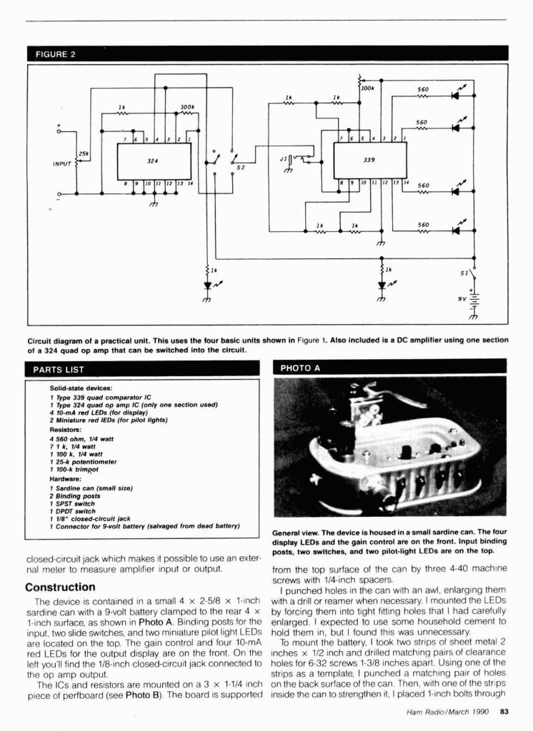
Circuit diagram of a practical unit. This uses the four basic units shown in Figure 1. Also included is a DC amplifier using one section of a 324 quad op amp that can be switched into the circuit.
I 1 Connector for 9-voit bstfery (88lv8gd from dead bsftey) I
closed-circuit jack which makes it possible to use an exter- nal meter to measure ampl~fier input or output.
Construction The device is contained in a small 4 x 2-518 x 1-inch
sardine can with a 9-volt battery clamped to the rear 4 x l-inch surface, as shown in Photo A. Binding posts for the input, two slide switches, and two miniature pilot light LEDs are located on the top. The gain control and four 10-mA red LEDs for the output display are on the front. On the left you'll find the 118-inch closed-circuit jack connected to the op amp output.
The ICs and resistors are mounted on a 3 x 1-114 inch piece of perfboard (see Photo 6). The board is supported
General view. The device is housed in a small sardine can. The four display LEDs and the gain control are on the front. input binding posts, two switches, and two pilot-light LEDs are on the top.
from the top surface of the can by three 4-40 machlne screws with 114-inch spacers.
I punched holes in the can with an awl, enlarging them with a drill or reamer when necessary. I mounted the LEDs by forcing them into tight fitting holes that I had carefully enlarged. I expected to use some household cement to hold them in, but I found this was unnecessary.
To mount the battery, I took two strips of sheet metal 2 inches x 112 inch and drilled matching pairs of clearance holes for 6-32 screws 1-318 inches apart. Using one of the strips as a template, I punched a matching pair of holes on the back surface of the can. Then, with one of the str~ps inside the can to strengthen it, I placed 1-inch bolts through
Ham Radio/March 1990 83

I NEW SOFTWARE I I WUGFR COMMUNICATIONS ENGINEERING version 3.1 bv Lvnn Gerio. WASGFR I , , ., . lnler~strt~g proqrotn tnat wr a low y ~ u to pred~ctcommun~cahons ranges based I I w o n rorr stat,on s ooerat~onarroab~l~t~es Useful from 3 5 MHz to 3 I GHz I Also lnciudes helpful Sm~th chart program for any type of matchlng network. Prov~des Impedance results In both tubular and hlgh resolut~on Sm~th chart graphlcs Great value at a low prlce
GFR-DOS (MS-DOS) Sl9.95 ! GFR-C64 (Commodore C-64) $19 95
,MICROSMITH Smith Chart Utility Program MS-DOS by Wes Hayward, W Z O l M~croSmttli IS a worklng Sm~th chart that has been optimued for impedance matchlnq appl~cat~ons The user can mod~fy all variables to meet spec~flc matchlng goals Includes a clear and conclse tulor~al that all levels of In- terest wtll ftnd helpful Complete text explanat~ons wlth graphs a ~ d full com- prehens~on of the mater~al
'WH-MS (MS-00s) $29.00
WPGGE CONTEST PROGRAMS (MS-DOS) by Jack Schultz, W2GGE Great contest logglng programs! Written in machine language for maximum flex~brllty arid speed Compatible with most MS-DOS PCs. Shows log, coun- tr~es worked, all band score on screen. Super fast dupe checking. Prints out log checki~st and OSLs. ; IGGE-AR A ~ R L OX Contest (WOO OSO'r par contest) $39.95 I GGE-WPX CP Prefix Conlast (5000 PSO's per band) $39.95
CONTEST PROGRAMS (MS-DOS) by John Berp. KAlHVU and Clint Wise, WlXN If you haven t yet don? a contest w~ th a computer, you're mlsslng one of llfe s true pleasures1 No more dupe or log sheets strewn around your oper- atlnq table Instantaneous scorlnq ellm~nates hours of work at the end of me contesl Prlnt out Ihe dupe sheets and log, f~ l l out the entry and mall to the contest committee The following contest logs are ava~lable (ALL MS DOS)
BW-OX ARRL OX Contest $39.95 i BW-WPX CO Prefix Contest $39.95
BW-C6O C(1 160 Contest 539 95
I BOOKSTORE - Greenri l le. NH 01048 (603) 876-1441 I
TORE
GREENVILLE. NH 03048 (603) 878-1441
FAX (603) 878-1951
Please enc lose $3.75 shipping 8 h a n d l ~ n g
UTER PROGRAMS . , - - . . - . . . . . . , - -
,..sl aoout v w r y rllrreZl n1 nred ISCOIR~-hDmanlennadesignandoptimiration to general oprralinq prc.qratn5 Anlt.nt~n programs tncldde. shunt and serles lnoul L n e m t k aeslgn. tcrd tne IrantlormPr. <hunt network destgn. SWR calculat~on. plus 11 more1 General ham p1OI)rdmS IIICIUOP runr sr/sunset great clrcle distances. gray1 ne. vertical anlenna des gn oruoram sLnrt5r calendar ~ l u s 9 rnorpf The bestm ue Incomputer soffwareava.ODle loflay ' i986 1 UN-Apple l ld l lc r UN.MS (Ms.oog L UN.CPMll(aypro I UN-C-128 (COMMOOORE) I UN-MAC (MACINTOSH)
U9# 88. $39.95 sa. $39.95 sa. $39.95 ea.
549.95
LOW BAND DX'ING by John Oevoldere. ON4UN Now Avatlablel The new. 2ndeditionofthedefinitivebookon Low BandDX'ing. Based upon years of practical on-the-air experience, learn thesecrets of how ON4UN has been so successful on the low bands. Extensive coverage 1s glven to transm~t and recelve antennas w~th clear concise explanat~ons and plenty of illustrations-d~poles. inverted V's. slopers, phased array5 and Rwerages-they'reall in f i ls book. Also covered: propa- gallon. transrnltters, receivers, operating, software and an extens~ve Low Band b ~ b - Ilography. Golng to be a best seller1 Get yours today 1987 2nd Edtt~on. 200 pages.
I A R W Sdmolnd $9.95
ON4UN PRACTICAL YAGl DESIGN (mS-00s) by John Owoldem, ON4UN Thls rornprPh~nslve Ydq~ des~gn pro ram IS based upon tested antennas, not theo- retlcal un proven models Contams 180 d~fferent HF antennas, des~gned, tested and optlmlzed by ON4UN Also contalns a number of classlc des~gns by noted antenna experts W2PV W6SAI andothers Includes mechan~cal des~gnofelements and ofthe rotatlng mast You can also add to the database your own des~gns Fully detalled Rpad me f ~ l e IS des~gned to help the user get maxmum results from the program
1989 10N.VAGl (mS-00s) $5995
Bottom view. The resistors and ICs are mounted on a piece of perf- board supported from the top of the can by three machine screws with spacers. The 324 op amp IC is to the left; the 339 comparator IC is at top center. the holes facing outward. I then attached lock washers and nuts on the outside. The other strip and another pair of nuts hold the battery in place.
I wired the components on the can and perfboard separately as best I could. 1 provided terminals on the perf- board or leads that extended beyond it for the interconnec- tion between the board and the can. I spliced some of these leads to those of the LEDs. Because it'seasy to makeconnec- tions the first time but difficult to separate them for correcting wiring errors, I checked the wiring on the perfboard very carefully with a volt-ohmeter as I went along. This care paid off; the device worked the first tlme I turned it on.
Discussion Because decimal number systems are commonly used,
you might like to have ten LEDs rather than four. You can build such a system with three type 339 chips, leaving two comparators unused. I think it's logical to arrange the volt- age divider so the input-voltage increment which causes adjacent LEDs to light up is one-tenth rather than one- quarter of the voltage needed to light the last LED. This improves the resolution. Actually, ICs with ten comparators on the same chip are designed for this purpose. These chips are known as "bar graph drivers." A bar graph is a chip containing the equivalent of ten LEDs. These chips are often built into various instruments like signal strength meters. The bar graphs are more convenient in such appli- cations, but are visible only at short distances.
There are other possible variations in the design of this device. You can arrange the taps on the voltage divider so the input-voltage increments correspond to a fixed number of decibels rather than a fixed amount of voltage. You can make a device with considerable flexibility by using a switch which connects the positive terminals of the comparators to different sets of taps on the voltage divider. Circuit dia- grams for some of these alternative designs are found in Reference 3.
It's easy and fun to build this project. You can amuse visi- tors with demonstrations of induced emfs, antenna patterns, and a variety of physical effects. a REFERENCES 1 b r n McMullen. WISL. "V~sual A~ds - Ltghl Emtntng D~odes: Ham Radro. July 1989. page 56 2 Forresl M M~ms. Ill. EngfneerB Norehook 11. Rad~o Shack. 1982. page 92 Author says more dela~ls can be found In h ~ s arl~cle In Popular Eleclronrcs. August 1979. page 78 3 Forresl M Mlms. Ill. Engmeerk Nolebook /I. Rad~o Shack. 1982. pages 87 and 90-93 4 Yardley Beers. WQJF, "A Slrnp4e DC Arnpllfler for Your Meter," Harn Radro. June 1989, paqe 10

By Garth Stonehocker; KDRYW
SPRING FREQUENCY CHANGES It's time for spring; winter is just about over. Are you ready for a change? How did your DXing fare this winter? Are your antennas still up? Is your oper- ation in need of maintenance or changes? Why not get to work on these items before spring cleanup or summer yard work starts taking up your time?
Several aspects of propagation that affect DXing change during the spring and fall. The length of the day, while nearly equal to night (exactly equal this year on March 20th at 2119 UTC), changes rapidly from shorter to longer during this month and into the first weeks of April. This means that the maximum usable frequencies (MUF) for a particular path change quite rapidly. The HF commercial radio users - mainly maritimelaeronautical and broadcasters - transmitting point to point or to specific areas, need to obtain new frequency allocations from the International Telecommunication Union (ITU) during a two month inter- val. The annual allocation intervals of frequency usage are March to April, May to August, September to October, and November to February. Their allocations are in bands like ours: roughly 300 to 900 kHz wide at 2, 4, 6, 8, 12, 16, and 22 MHz for maritime radio, and 200 to 350 kHz wide at 6, 9, 11, 15, 18, and 21 MHz for broad- casters. Each of the maritime users have calling and working frequencies in each band. The ships use one set, the shore stations the other. They are able to use any band that's propagat- ing to shore or ship stations in order to transact their business, so this operation mode automatically takes care of the seasonal changes of MUFs for the distance involved. Older opera- tors have a working knowledge of propagation. To help the new operators, the shore stations send ship com- panies charts of frequencies to use out to concentric circles of distance at sea
gation is concerned, for the seasons and sunspot cycle.
Hams have quite a bit of freedom to shift frequencies and bands at will. We are limited only by our knowledge of propagation and our equipment (antennas on hand) to change fre- quency with the hour of the day, season, and sunspot cycle to work the DX or get the message through. You can see why communicators put so much significance on propagation for
from the station. Operators listen to the frequency allocation. It's important for stations call in^ or working the bands hams too! to verify whickwill work f& them. This system serves them well even when Last-minute forcast using selective calling to a specific ship. Aeronautical traffic control and the airlines, through aeronautical com- munication companies like ARlNC or Collins, use a similar system.
The broadcasters transmit in one or two bands of allocated frequencies that should work to a target area.* The frequency and time schedule is sent to those listeners who request it and is published in magazines like Popular Communications, Monitoring Times, or World Radio TV Handbook. Broad- casters are the main users of the ITU's four allocation intervqls to change fre- quency with the season and sunspot cycle. They are restricted to this predetermined schedule, unlike the maritimelaeronautical operators who can jump from band to band until the message is passed. Those who listen to broadcast stations need to know they will be broadcasting where the ~ublished schedule indicates. Limited
Conditions will be excellent for DX on the higher frequency bands (10 to 30 meters) the second and third full weeks of March. The MUFs will be high because of a solar flux maximum. Openings will be noticeably longer into the? evening. Late evening one long hop transequatorial openings are most probable on the 5th, 14th, 23rd, and 31st, when a disturbance in the geomagnetic field and ionosphere is expected. The lower bands should provide the best DX around the 5th. Spring thunderstorms may cause local noise, but strong signals should over- come the noise - except for the actual time of the flash. Poor signals and QSB during the disturbed periods could be the big problems this month on the lower frequencies, especially on east- west paths. Spring equinox occurs on March 20th at 2119 UTC. A full moon appears on the 11th and will be at ~er iaee on the 1st and 28th. . -
schedule changes (usually for QRM) are allowed by the ITU, but at the broadcasters' risk of losing their Ten, 15, and 17 meters will be open audience. You can imagine the chaos fr'om morning to early evening almost if all the broadcasters began shifting daily in most areas of the world. Expect frequencies and bands at will! By higher band openings to be southerly, using experienced propagationists, the shorter, and closer to local noon. Tran- broadcasters request frequency alloca- sequatorial propagation on these tions. The ITU then uses its computers bands is likely to be toward evening to juggle frequency assignments for during times of high solar flux and dis- the hours of the day for each season. turbed geomatic field conditions. It can be chaotic keeping signals Twenty and 30 meters will be useful within the bandwidth (adjacent channel almost 24 hours a day. Daytime con- interference), because propagation ditions will resemble those on 17 prediction is far from reality (by months, meters, but skip and signal strength days, or hours) and some countries nnay decrease during midday on days don't abide by the rules. Yet this sys- with high solar flux values. Look for tem works pretty well, as far as propa- good nighttime use - except after
Ham RadiolMarch 1990 85
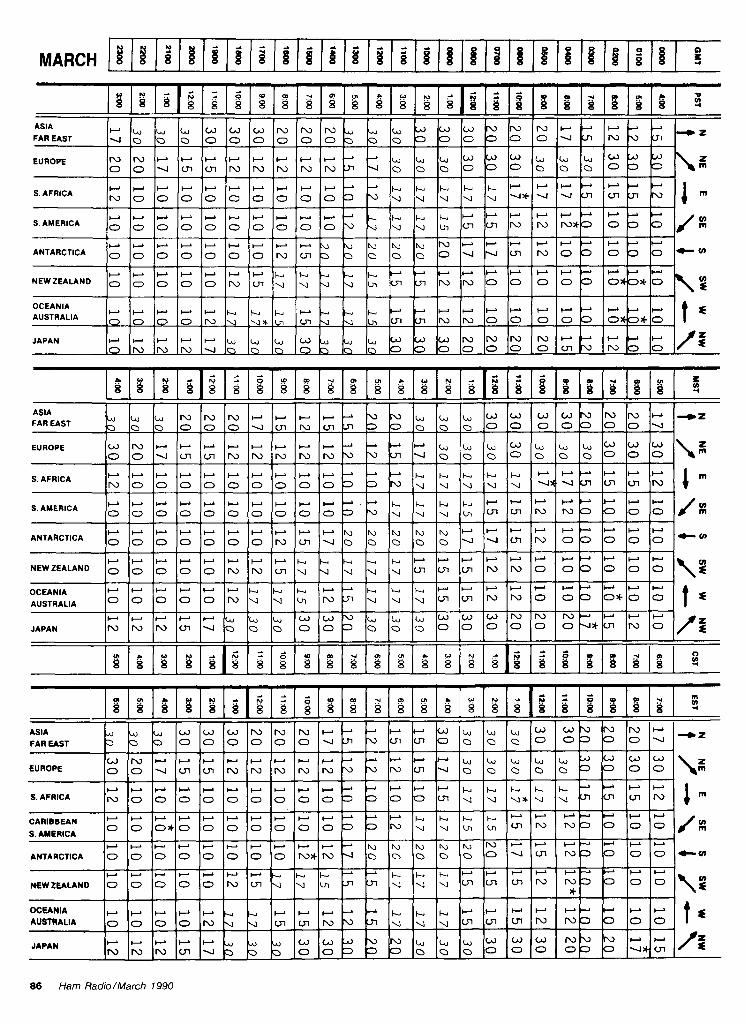
d 2 2 d d - .
g ; i g ; i . g g ; g ; ; ; ; ; g z r o g g i g g g 3
3
ASlA b b W C J W N N N ~ L J L J W W W - U N N ' - ~ ~ ~ ~
FAR EAST V O O O O O O O O O ~ Q Q O O O O O O V C ~ N U L ~ ~ ~
EUROPE ~ ~ r r r r r r r r - - b u b W W W b L J b U d Z O O V U l U l N N N N N n U Q 0 0 0 0 0 0 ~ m
r + + + + + + r - - C C k k C ~ + + + + + ~ S. AFRICA N O O O O O O O O 0 3 ~ ~ ~ ~ ~ w ~ * ~ u ~ ~ ~ ~
C C k k + + + I - +
+ r r + r r r r r u E y l y l y E y N ~ + w ~ + + ~ ~ + ANTARCTICA 0 0 0 0 a 0 0 r\) m 0 0 Q Q Q 0 u u N 0 0 0 0 0 CV,
r r r r r - r k b w + r+c1 NEWZEALAND 0 0 0 0 0 N y y 5 y, cn cn N N 0 0 0 0 0 0*0*0
V) €
OCEANIA
Q 0 0 0 N
JAPAN 0
2 .A 2 a d d
3
ASlA b b * , N N N + - N ~ , ~ W W W G ) ' U N N w + z
FAR EAST O O Q O O O ~ ~ ~ N ~ ~ L ~ ~ O Q ~ ~ O O O ~ ~ O O V
EUROPE ~ ~ r r r r r r r r - - r r ~ b ~ ~ W ~ ~ b b u W W O O ~ ~ ~ N N N N N ~ ~ ~ ~ 0 0 0 ~ 0 0 ~
-
S. AFRICA
+ + r
l - ~ t - + + ~ ~ + " " k " k + ~ r + + + + + ' + I -
86 Ham Radio/March 1990
OCEANIA AUSTRALIA
JAPAN
d d A rn 3
ASlA FAR EAST
EUROPE
r r + + + r + + r r - P r + + " k k k C P + c - - ' - S. AFRICA
CARIBBEAN r r + r + " " " " ' + - O O 0 * 0 O O O O O O P O N U ~ ~ L n L " ~ ~ = ' ~
r r ~ k + + + I - -
0 0 0 0 0 N U U YI N m y y y cn cn N N 0 ok o*o 0 1 s
S. AMERICA
ANTARCTICA
NFWZEALAND
OCEANIA AUSTRALIA
JAPAN
0
0
0 0
0 0 0 0
o o o o ~ y
0
r
r r r r r ~ , ~ ~ N N N L n ~ O O O
0 0 0
N L n W
~ ~ N V U I
0
y
y
y
w w d V ' U ~ . - , , u W w 0 0 3 3 0 0 ~ 0 0 0 ~
+ r r r r r + r r r - A b u E y r v u N + ~ P O * N q
VI
y
3
m u 7
0
" " - + C k C + + + ~ m
u 7 N
O
W
N 3 O
0
y
r C . 0
-
0
r r + - ' + ~ l u k + + ~ ~ ~ ~ ~
N v 0 3 V* Ln
0
Q
W m c n
t s
0
c n N
cn IU3
*
+ - - + - a a a CV,
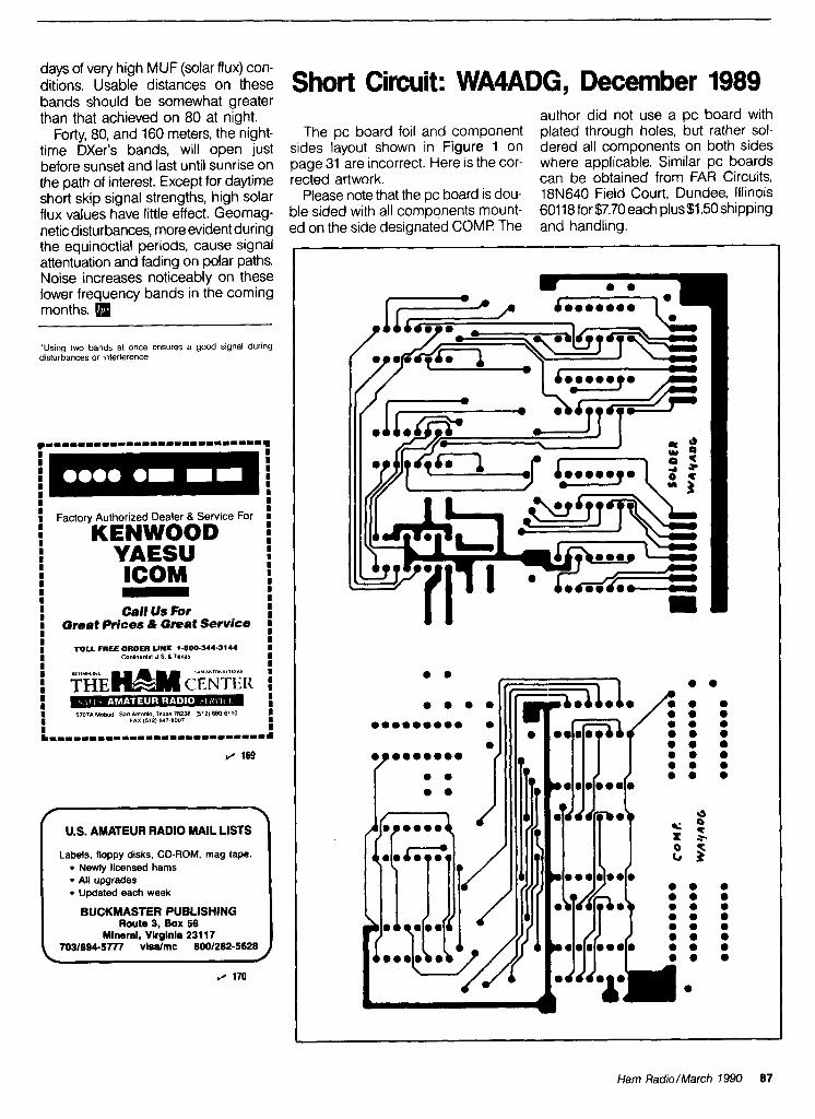
days of very high MUF (solar flux) con- ditions. Usable distances on these bands should be somewhat greater than that achieved on 80 at night.
Forty, 80, and 160 meters, the night- time DXer's bands, will open just before sunset and last until sunrise on the path of interest. Except for daytime short skip signal strengths, high solar flux values have little effect. Geomag- netic disturbances, more evident during the equinoctial periods, cause signal attentuation and fading on polar paths. Noise increases noticeably on these lower frequency bands in the coming months.
'Us~ng two bands at once ensures a good slgnal during d~sturbances or ~nterlerence.
I I Factory Authorized Dealer & Sew~ce For I 5 KENWOOD I I I I
YAESU I I I
lCOM I -
I I Call Us For I Great Prices & Great Service I I TOLL FREE ORDER LINE 1-000-344-3144 I conmema u s a rs'rs
' U.S. AMATEUR RADIO MAIL LISTS \
Labels, floppy disks, CD-ROM, mag tape. Newly licensed hams All upgrades Updated each week
BUCKMASTER PUBLISHING Route 3, Box 56
Mineral, Virglnia 231 17 7031894-5777 v i d m c 8001282-5628
Short Circuit: WA4ADG, December 1989
The pc board foil and component sides layout shown in Figure 1 on page 31 are incorrect. Here is the cor- rected artwork.
Please note that the pc board is dou- ble sided with all components mount- ed on the side designated COMP The
author did not use a pc board with plated through holes, but rather sol- dered all components on both sides where applicable. Similar pc boards can be obtained from FAR Circuits, 18N640 Field Court, Dundee, Illinois 60118for$7.70 each plus$1.50 shipping and handling.
Ham Radio/March 1990 87

PACKS" ICOM. BP5 $43.95. BP8S $58.95. YAESU: FNB2 $19.95, FNBIOSlFNB12 $44.95, SANTEC: 142/1200 $22.95. TELEPHONEIPAGERICOMPUTERlCOMMERClAL PACKS-Free catalo Add $3.00 ship inglorder. PA + 6% VISAIMC add $2.00. ~ U N A R D . RD 6. &x 104. Bedford, PA 15522. (814) 6237000.
PC DRILL BITS slzes 55 ,56 ,58 ,60 ,62 ,65 ,66 ,68 ,70 . $1 25 each or 5 lor $5. Free shipping. S Systems, Box 1724, Tempe, AZ 85260-1724.
KENWOOD TS-930-SIAT transceiver $995 55 fool Trlstao tuoular tower, completely relurblshed, extended hetght 62 feet. $595 Trl-Ex MC.50toer motor control m11$345 Tle-Ex TA54-L
. .
DIGITAL AUTOMATIC DISPLAY. Any Radio. Be specific. Large ¢ SASE. GRAND SYSTEMS. POB 2171. Blaine. WA 98230
- -
tilt over accessory $345. Custom built 6 meter half kilowatt. lo drlve $395. Colltns 758-3 with AM. CW. SSB filters $375. Custom built 1296 MHz transverter 80 watts out. .5 DB front end, 28 MHz IF, $595. Rlch Shideler, 139 W. Walnut. Visalia. CA 93277. 1209) 564-3960.
-
450 MHz SPECTRUM ANALYZER. Adapted from Nov 85 QST article bv Al Helfrick. K2BLA. Features: Three digit LED cen- . .
- VIBROPLEX COLLECTOR'S GUIDE. WIIMQ's new illus- ter frequency digital readout. 12 position cali6rated Scan
Width, 1 kHz to 50 MHz, switchable bandwidth; Wide 300 kHz, Narrow 5 10 kHz. Use your low frequency scope for the display portton. Swltchable I 0 kHz video filter. Variable IF attenuator, LOG output calibrated in 10 db steps. For com- plete kit. order r450KIT $459.95 lus $4.50 slh. For assem- bled and tested unit, order 450-A$~, $799.95 plus $6.50 slh. Calif residents add 6% sales tax. Foreign orders add 15% for shipping. A 8 A Engineering. 2521 W. LaPalma, YK, Anaheim. CA 92801. (714) 952-21 14.
Board with instructions $9.95. FM DET switch $5.00. Crystal $5.00. SQNOL $24.95 plus $2.00 slh. MORNING DIS-
RIBUTORS, PO Box 717, Hialeah, FL 3301 1. (305) 884-8686. FLEA MARKE
R A T E S Noncommerc~a l ads 10e oer word:
IMRA lnternat~onal M~ss~on Radlo Assoc~at~on helps mlsslon. arles Equ~pment loaned Weemday net. 14 280 MHz. 1-3 PM Eastern Nlne hundred Amateurs In 40 countries Rev Thomas
GREAT FAMILY HOME on hill In Worcester, MA. Large private lot, 4 bedroom colonial, 2 baths, 2 enclosed porches, eat-in kitchen, formal dining, living room, cozy den, fireplace. double garage. built-in ham shack $152,000. Call (617) 894- 3943 evenings. -- CHASSIS AND CABINET KITS. SASE. K31WK, 5220 Harmony Grove Rd, Dover, PA 17315.
-
. ~ . . -- commercia l a d s 600 per word b ~ t h ' ~ a ~ a b l e in advance. N o cash discounts or agency com- missions allowed.
H A M F E S T S Sponsored b y non-profit or- ganizations receive o n e t ree Flea Market a d (subject t o our edit ing) on a space available basis only. Repeat insertions of hamfest ads pay the non-commercia l rate.
COPY N o special layout or arrangements available. Material should be typewritten or clearly pr inted ( n o t a l l capitals) and must in- c lude full name a n d address. W e reserve the r ~ g h t to reject unsuitable copy. Ham Rad io can- no t check each advertiser a n d thus cannot b e he ld responsible for c la ims made. L iab i l~ ty for correctness of material l imited to corrected a d in next available issue.
DEADLINE 15th of second p r e c e d ~ n g month.
SEND M A T E R I A L TO: Flea Market , H a m Radio, Greenvil le. N. H . 03048.
Sable, S.J., University of Screnton, Scranton, PA 18510.
INTERESTED IN PUBLIC SERVICE? Join vour Local Radio Emergency Associated Commun~cat~ons ~ e a m In Pennsyl. vanla call (71 7) 938-6943 or wrlle REACT. 1160 Old Tiall Rd, Etters. PA 17319 - -
RTTY JOURNAL oublished 10 tlmes oer vear for those RUBBER STAMPS: 3 lines $5 00 PPD. Send check or MO lo G.L. Pierce, 5521 Birkdale Way. San Diego, CA 92117. SASE brings information.
~ n t e r e s l i ~ ;n dl612 iommun~cat~ons b a d ' aoout R r r Y AMTOR MSO'S PACKET. RTTY DX and Contestong Plus leChnlCdl arllcles concerning the dlgllal modes $12 50 per vear (forelqn higher) RTTY JOURNAL 9085 La Caslta Ave
ELECTRON TUBES: Receiving, transmitting, microwave ... all t pes available. Large stock. Next day delivery, most cases. ~ A I L Y ELECTRONICS. PO Box 5029, Compton. CA 90224. (213) 774-1255.
Founiain Vallei, CA 92708.
CUSTOM MADE EMBROIDERED PATCHES. Anv size. shape colors Flve patch mlnlmum Free sample pr~&s and orderlnq ~nformat~on HElN SPECIALTIES Inc 7960 SW Man~tou Tra~l Glen Arbor. MI 49636 (618) 334 4385 RECONDITIONED TEST EQUIPMENT $1.25 tor catalog.
Walter, 2697 Nickel. San Pablo. CA 94806. IBM-PC RTTYICW. New CompRny II is the complete RTTYICW oroaram for IBM-PC's and compatibles. Now with larger buffers, better support for packet units, ictures, much more. Virtually any speed ASCII. BAUDOT. &. Text entry via built-in screen ed~lor! Adjustable split screen display Instand modelspeed change. Hardcopy, d~skcopy, break-in buffer, select calling, text file transfer, customizable full screen log in 24 programmable 1000 character messages. Ideal f o r k ~ g ~ and traffic handlin Requires 256k PC or AT com- patible, serial port. RS-23X 7". $65. Send call letters (~nclud- ing MARS) with order. David A. Rice, KC2HO. 144 N. Putt Corners Rd. New Paltz. NY 12561.
COMING EVENTS Activities - "Places to go . . ."
BEGINNER'S RADIO CLEARINGHOUSE. On a space avail- able basis, we are going to offer you, OUR SUBSCRIBER. free of charoe. a chance to find a home for vour used equlD-
LET THE GOVERNMENT FINANCE your small business. Grantslloans to $500.000. Free recorded message: 707-448- 0270. (KH5). SPECIAL REQUEST TO ALL AMATEUR RADIO PUBLICITY
COORDINATORS: PLEASE INDICATE IN YOUR ment with anew Ham. Please send us a short description of what you want to sell along with price, name, address and phone number. We'll run it once in a special sectlon of the classified ads under the heading of BEGINNER'S RADIO CLEARINGHOUSE. Please llmlt your ad to 20 words or less. -
QSL SALE! 100 OSL cards $8. 200/$11. 1000/$33. Guaran- teed correct! Shipping included. Wr~te or phone for samples. Shell Printing, KDSKW, Box 50B. Rockton, IL 61072. (815) 629-21 93.
CLOUGH-BRENGLE SIGNAL GENERATOR. Model 299A Can someone please help me W I I ~ schematic or lull manual W2BLL. RD2. Box 72. Boonton. NJ 07005
ABILITY FOR SALE: Heathull Audlo Generator. Heathklt RF Genera- tor. Heathklt Condenser Checker. RCA 3" OSClllOSCOpe $200 WAZMCF Charles Maklsh. 137-06 Laburnum Ave. Flushlno.
- KENTUCKY: March 3. The 14th annual Glasgow Swapfest sponsored b the Mammoth Cave ARC Cave Cit Conven- tion Center. la "e City Starts 8 AM. ~dmission $4. Yables $3. each. Exams wlll be lven Talk in on 146.34195. For inlorma- tlon N4HCO. 1379 W\iles~hapel Road. Glasgow. KY 42141.
NY 1 1355. (71 8) 4450558.
WANTED: Ham equipment and other property. The Radio Club of Junior H~gh School 22 NYC, Inc, is a nonprolit organi- zation, granted 501(C) (3) status by the IRS, incorporated with the ooal of uslno the theme of Ham Radio to further and
BEAT THE COLD1 Melbourne. FL QTH: 4:2:2 (3100 sqlfl) house. 1.6 + acres. 220V wired shack with coax races bullt in. RHON125 pad, workshop, pool, sprinkler system, In the country no restnctions, many tall plnes and oaks, easy com- mute to Cape Canaveral, close to fishinglbeacheslshopp~ng. SAE lor detalls and photos. $209,000. NODHU.
MISSOURI: March 9. 30th annual Amateur Radio Auction sponsored b Ihe Jefferson Barracks ARC Concordia Turner's Hall. 6432 i ravo~s , south St. LOUIS it;. MASSACHUSETTS: March 10. The Barnstable Radlo Club's annual Hamfest Oak Ridge School Sandwich. 0 en 10 AM to buyers. 8 ~d for sellers. ~dvance tables $8. I t the door $10. Amateur exams given. Contact Don, WAl AlC (508) 778- 5673 or Henrv (508) 255-2818
enh&ce the edu&lon of vouno oeoole nat~onw~de Your OrOD- erty donatlon or Lnamial ;upp& wohd be greally appreciated and acknowledged wlth a recelpt lor your tax deducllble con- trlbutlon It s easler faster and usually more profitable to donate than to sell Most Important you're helplng Jo~n us on Ihe Classroom Net 7 238 at 1200 UTC and 21 395 1330 UTC dally Wrlte us at PO Box 1052 New York NY 10002
AVANTEK ATF10135, $12.00, MMIC's, P.C. board, SASE: WAJIAC, 7148 Montague St, Philadelphia. PA 19135. - "HAMLOG" COMPUTER PROGRAM. Full features, 18 niod- ules. Autologs. 7-band WASIDXCC. Apple. IBM. CP/M. KAYPRO. Tandy. C128 $24.95 HA-KAIAWH. POB 2015. Peabody, MA 01960
. . . NEW JERSEY: March 10. Springlest '90 sponsored by the Shore Points ARC. Holy Spirit H ~ g h School, Rt 9. Absecon. Doors open 9 AM. Admission $3. Sellers spaces $5 each. Talk In on 146,3851,985 and 146.52. For information wrlte SPARC, PO Box 142. Absecon, NJ 08201.
Round the clock hotline: (516) 674-4072
TEST EQUIPMENT-Recond~tioned (guaranteed), terrific prlces. NBS calibration available. Vlsa. MIC, Amex. COD. Electronic Surplus Inc. 4350 Town Plaza. Suite 203. Hous- ton, TX 77045. (713) 7;28]-9718
220 MHz REPEATER FOR SALE. Spectrum Communlcatlons SCR-IOWA commercial rade repeater tuned for 222 72 rcv1224 32 xmlt. 35 watts 81.500 Wacom Products WP 652 duplexer for above- $500 IC-03AT $225 IC-38A $289 220 MHz Rlngo Ranger $40 220 MHz Cushcrafl Trunk Mount $39 220 MHz Cushcrafl Mag Mount $39 220 MHz Cushcrafl4- pole antenna $75 All equipment In perfect operating condl tlon Contact K5ZCO at (214) 6800475 days or (214) 3635858 evenlngs
NEW VORK: March 11 WECAFEST '90 sponsored oy the Westchester Emergency communlcatlons Assoclet~on New locatnon-Mount Pleasanl Armorv Valhalla 8 30 AM to 3 30
FREE LIST of low cost ham equi ment. Write to Jlm Braddy, WA4DSO. 3037 Audrey Drive. eastonla. NC 28054
WANTED: BUY & SELL. All types ol Electron Tubes. Call toll free 1-800-421-9397 or 1-612-429-9397. C 8 N Electronics, Harold Bramstedt. 6104 Egg Lake Road. Hugo. MN 55038.
G r s i n ; N ~ d ~ ~ i r ~ a r a h WIISO~.~~ZE?X, 2 ~ou"dv~ew Ave- nue, Apt AS. Wh~te Plalns. NY 10606 (914) 997-8491 BATTERY PACK REBUILDING: Don't pitch it-mail it--for
FAST--PROFESSIONAL service! Satisfaction guaranteed! ICOM: BPZBP3 $19.95. BPS $25.95. BP7lBP81BP70 $32.95. KENWOOD: PB21 $15.95. PB2IH $21.95. PE25125H126 $24.95. YAESU: FNB9 $19.95, FNBlO $23-95, FNB414A S.38 95 TEN-TEC. $24 95 "U-DO-IT INSERTS" ICOM: BP3
RADIO SHACK Color Computer Ham Software and Hardware. Free catalog. Dynamic Electronics. POB 896. Hartselle. AL 35640. (205) 773-2758.
ILLINOIS: March 11. The 30th annual Hamfest sponsored by the SterlingRock Falls ARS, Sterling High School Fieldhouse. 1608-4th Avenue. Sterling. Doors open 730 AM. Tickets $3/advance; $4ldoor. Tables $5 incl elec. Talk in on 146.251146.85 W9MEP Repeater. For information, tables or tickets contact Sue Peters. Sterling Rock Falls ARA, PO box 521. Sterling. IL 61081 or call AC (815) 625-9262.
HAM SOFTWARE IBMICompatibles 10 disks $26.95. MCNISAIDiscover. N5ABV EAPCOIH, Bx 14, Keller. TX 76248-001 4. (81 7) 498-4242. 1-800-869-7208.
$ii 9 < ' e k $2295:6~7/8 $27 50. KENWOOD ~ 8 2 i $12 95. PB24125126 $19 95. TEMPO St-151SERIES $22 95, YAESU FNB414A532 95. FNBlO$18 95. AZDEN 300$t9 95, NEW
88 Ham Radio/March 7990

MICHIGAN: March 17. 29th annual Michlgan Crossroads Hamfest. Marshall High School, Marshall. Sponsored by the Southern Mich~gan ARS and the Marshall HS Photo Elec- tronics Club. 8 AM to 3 PM. Tlckets 531door; $2ladvance, please SASE For informalion wrile SMARS, PO Box 934, Bat- tle Creek. MI 49016
NEW HAMPSHIRE: Interstate Repeater Society's Hamfest. Lton's Club, Llons Avenue. Hudson. 8 AM to 4 PM Admls- Slon $2. Tables $10. Talk in on 146.85. 146.55 Contact IRS. PO Box 693. Derry. NH 03038. Wheelchair accessible.
MICHIGAN: A r111 32nd annual ARRL Hamfest/Swapn-Shop sponsored by fhe South Eastern Michlgan ARA, Grosse Potnte North Hlgh School 707 Vernler Rd, Grosse Polnte Woods 8 AM to 2 PM T~ckets $2/advance, 54ldoor Tables $8ladvance $tO/dwr For lnformatlon SASE to SEMARA SWAP. PO Box 846. St Clalr Shores, MI 48080-0846 (313) 323-4099
LAUREL ARC monthly (except December) Amateur exam ses- sion!; for all license classes. No fee is charged. Preregistration IS required Call (301) 725-1212, Maryland Radio Center. 8576 Laureldale Drlve. Laurel. MD 20707 - - AMATEUR RADIO CLASSES: For those people Interested an ot~talnlng a Novlce (bass level) Ham llcense or upgrad~ng to TajchlGeneral. the Chelsea CIVII Defense. In cooperation wltn QRA Radlo Club, will sponsor Amateur Radlo Commu- INDIANA: April 7 The Columbus ARC Hamfest, Bartholomew
County 4-H Fairgrounds. State Rd 11, Columbus 8AM to2 PM. Talk in on 146.79-600 Hz. For information Marion Winter- berg. WD9HTN. 11941 W. Sawmill Road, Columbus. IN 47201. (812) 342-4670.
MINNESOTA: April 7. Rochester Area Electronic and Com- puter Show. John Adams Junior High School, 1525 NW 31st St. Rochester. Doorsopen 8:30 AM. Talk in on 146.22182, For lnformation RARC, 2824 NW 24th St. Rochester, MN 55901
nlcatlons classes evenlngs at Chelsea Hlgh Scl~ool startlng MAFICH 7. 1989 For more lnformatlon wrote Frank Masuccl. KIBPN 136 Grove Street Chelsea. MA 02150 Please
TEXAS: March 17-18. The Midland ARC'S annual St. Patrick's Day Swapfest. Midland County Exhibit Buildin East High- wav 80. Mtdland. 10-5 Saturdav and 8-230 8;ndav. Pre-
eniose your telephone number
regktratlon 55 56ldoor Tables $6 each VE tests ~ d r Infor- matlon and reservattons contact Mtdland ARC. PO Box 4401 M~dland. TX 79704
NORTH CAROLINA: March 17-18. Charlotte Hamfest and Computerfair, Charlotte Convention Center, 4th and College Streets. uptown Charlotte. Sat 9-5, Sun 9-2 Tickets 55ladvance; 571door. Children under 12 free. Tables $12 advance only. Tickets and tables ood for both days For infor- mation and reservatrons wrtte zharlotte Hamfest. PO Box 221136, Charlotte, NC 28222-1136 or call (704) 536-7373
--
ONTARIO: April 7. The 9th annual Durham RRolon Amateur Rad~o and Computer Flea Markc Pickering ARC. V
, . COLORADO: April 7. Swapfest sponsored by the Longmont ARC Boulder County Fair rounds, Longmont. 8 AM to 3 PM. ~dmks ion $3. Tables $7. i o r information or resewattons con- tact Bob Dornan, WAZEKU. 1106 Fordham St, Longmont. CO 80501 (303) 651-361 3.
MASSACHUSETTS: April 8. The Framingham ARA is spon- soring a Flea Market and license exams for all classes. Framin- gham Civtc League Bullding, 214 Concord St. Rt 126, down- town Framlngham. General admission, 10 AM, $2. Early Bird admlsslon, 9AM. $5. Talk In on 147.15. For table information Jon, KIVVC. (508) 877-7166 Exam lnformation Dlck. WAIKUG. (508) 877-0568
Say You FLORIDA: March 17-18. The 20th annual North Florida HamISwapfest sponsored by the Playground ARC, Shrlne Fairgrounds. Ft. Walton Beach. Doors open 8 AM both days Talk in on 146,19179 repeater. For lnformation contact the Playground ARC, PO Box 873, Ft. Walton Beach, FL 32549. Playground ARC, PO B
OHIO: March 18. The Toledo Mobile Radio Associations's
Saw It in Hamfest. Lucas County Recreation Center, Key Street, Mau- mee @AM to 5 PM Admiss~on 53 50ladvance $4ldoor Talk ln on 147 27 rptr. 442 85 reptr ~ o n t i c i ~ o n ori is. WBBZIM 28141 Glenwood Rd. Perrysburg, OH 43551 (419) 666-8063,
CONNECTICUT: March 18 The Insurance Clty Repeater Club's annual Flea Market, American School for the Deal, West Hartford 9 AM to 2 PM. Admission $2 Tables 515 Talke in on 146.28188, Contact Chuck Motes. KPDFS, 22 Woodslde Lane, Plalnvllle, CT 06062 OPERATING EVENTS
"Things to do . . ." KENTUCKY: March 24. 1 I th annual Harnfest sponsored by the Lincoln Trail ARC. Pritchard Community Center. El~zabethtown Admission 54ladvance. $5/door For tickets. resewatlons, lnformation contact Chuck Straln. AA4ZD. PO Box 342. Vine Grove. KY 40175. (502) 351-1715. March 17-1 8. The Plscataway ARC (PARC) will operate their
annual spec~al event commemorating the Voice of America Relay statlon. WBOU, which operated during WW II In the Bound Brook section of Piscataway. NJ. Members will use their own callsi ns signing NOA. CW. Novice poriions Phone- ~ o w e r third o18enera1 on 75,40,20, 15 M and Novice,portion ol10M band. For certificate send # I 0 or 9x1 2 SASE wlth QSL to PARC. att: KB2UV, PO Box 1233, Piscataway. NJ 08854.
NEW JERSEY: March 24. Flea Market sponsored by the Chestnut Ridge Radio Club. Education Building. Saddle River Reformed Church, East Saddle Rlver Road at Weiss Road, Upper Saddle River. Donatlon $1. Tables $10 first; $5 each additional. Tailgating $5. Contact Jack Meagher, W2EHD (201) 768-8360
CONNECTICUT: March 24 Annual Auct~on of the Rad~o Sot,. ety 0fFIow1ch. Uncasvllle VFW. Uncasvllle Setup 9 AM Auc tlon starts 10 AM Admlsslon IS tree Wneelcha~r accesslole
THROUGHOUT 1990 the Major Armstrong Memorlal Amateur Radlo Club (MAMARC) w~l l sponsor events commemorating
Foreign Subscription Agents for Ham Radio Magazine
Ham Radio France SM Electronic 20 bis. Ave des Clarions F-89000 Auxerre France
Ham Rad~o Canada C.A R F P . 0 Box 356 Kingston. ON Canada K7L 4W2 Prlces in Canadian funds 1 yr $38.00, 2 yrs $67.00 3 yrs $90.00
Ham Radio Japan Katsum~ Electronc Co . Ltd 27-5 lkegamt 4 Chome. Ota-Ku Tokyo 146. Japan Telephone (03) 753-2405
Ham Radio England clo R.S G.B.
Lambda House Cranborne Road Potters Bar Hens EN6 3JW England
Major Edwin Howard Armstrong's achievements in the field of radio broadcastina. The club is seeking other Amateur oper- Brmg equipment to be auctioned. Talk In on 146.73 repeater.
For intormat~on call KAIBB at (203) 739-8016. ators around the woad who are willing tiresearch Major Arm- strong's accomplishments and become official MAMARC spe cia1 events stations. Major Armstmng was a ploneer responsible for the creatlon of Wideband FM and the inven- tor of the superhetrodyne receiver. If ou are interested in par- ticipating and becoming an oific~al LAMARC special event station contact Barry Groupp. NBHDW, MAMARC, clo 100th Birthday Committee, PO Box 581, Alpine. NJ 07620. Please SASE.
OHIO: March 25. The 12th annual Lake County Hamfest. Madison High School, Burns and Middle Ridge Roads, Madi- son. 8 AM to 3 PM. Admiss~on 54ldoor $3ladvance. 6' tables $5. 8' tables Talk in on 147.21181. 222.901224.50. Contact LCARA Hamfest. 5777 Fenwood Ct. Mentor-on-Lake, OH 44060. (216) 257-2036.
ILLINOIS: March 25 Annual LAMARSFEST sponsored oy the L~bertyv~lle and Mundeleln ARS. Lalte Count Falrgrodnds Rt 120 8 45, Grayslake Doors open 8 AM Jeneral admos-
March 2: Grand Island. Nebraska. ARC will operate ARS WOCUO to celebrate the annual return of the Sand Hills crane to the Platte River refu e. 00002 March 2 to 24002 March 4. SSB. CW. PKT, A M T ~ R and RTTY in all lower portions of General and Novice bands. For Certificate send QSL and SASE to ARC WOCUO. PO Box 642, Grand Island, NE 68802.
sion $3/advance;~$4ldoor. Swap tables $7. For informallon SASE to LAMARS, PO Box 751, Libertyville, IL 60048 or call Bob Dick. NY9E 1708) 362-9634 after 7 PM. . . -- NEW JERSEY: March 25. HAMCOMP '90, the 18th annual flea market, sponsored by the Delaware Valley Radlo Associ- ation. New Jersey National Guard 112th Field Artillery Armory. Eggerts Crosstng Road, Lawrence Township. Trenlon. Hand1 access~ble. 8 AM to 2 PM. Admission 53ladvance; $4ldoor. Talk in on 146.07-.67. For information and space resewations write HAMCOMP'SO. c/o KBZZY, RD 1 . Box 259. Stockton, NJ 08559. Please SASE.
YOUTH LINK NET. Open to all Hams under age 18. Satur- days at 2000 UTC, 28.425 MHz. For more information con- tact Net Control. George Manning. WBSNMH, 602 Glendale St. Burkburnett. TX 76354.
WEST VIRGINIA: March 31. Hamfest and Computer Show sponsored by the Kanawha ARC and the Tri-Count Ham Radio Club. 9 AM to 3 PM. Charleston Civic Center. ~Kar les- ton. Admlss~on $5. VE exams. Talk in on 146,88128 and 146.52. Contact Betty Palmer. WCBS, PO Box 8400. South Charleston, WV 25303. (304) 346-1348.
nando County ARA. PC
AMATEUR EXAMS. March 10. May 19. July 14. September 8. November 17 St. Mary Medical Center, 3333 No. Semi- nary Street. Galesburg, IL 61401. 12 Noon to 2 PM. For infor- matlon contact Carry Heller, KASPCU, 1436 Brown Avenue. Galesburg. IL 61401. (309) 342-5977. NEW JERSEY: March 31. Rain or Shlne. The Cherryvllle
Repeater Assoc~ation's Flemington Hamfest. Hunterdon Cen- tral High Schokol Fleld House. Flemington. 8 AM. Admission 54ladvance; 55ldoor. Chuldren under 12 and unlicensed spouses free. Table reservations and info from Many Grozln- skl, NSPK, 6 Kirkbride Rd, Flemington, NJ 08822. (201) 788- 4080. 5-1 1 PM EST.
Monthly Ham Exams. The MIT UHF Repeater Association and the MIT Radio Society offer monthly ham exams, all classes Novice to extra: next-to-last Wednesday of each month. (March 211 7:30 om. MIT Room 1-150. 77 Mass Ave- nue, ginb bridge, MA. reservation requested a couple of days in advance, walk-ins welcome; call the shack (617) 253-3776, or Nich Allenbernd (617) 437-0320. Exam fee $4.95. Bring copies of your current license (if any) and Certificates of Corn- plerion (if any), two forms o l icture ID, and a completed form 610, available from the F c ~ . (617) 770-4023
ILLINOIS: March 31. Rockford Hamfest. 90.5533-1 l t h Street. Rockford. 8 AM to 3 PM. Tickets 53ladvance; 54ldoor. For information call Joe Rolin N9HEZ (815) 3919-6995 or SASE to PO Box 10003, ~oc&rd , IL 61131.
Ham Radlo/March 1990 89
ADVERTISER'S INDEX AND READER SERVICE NUMBERS Listed below are the pageand readersewice number for each advertiser in this issue . For more informationon their products. select the appropriate reader sewice number make a check mark in the space provided . Mail this form to
f o r amateur. marine. a n d ham radio Reader Sewice. I.C.A., P.O. Box 2558. Woburn. M A 01801 .
bus iness rad io servicing Call
--
S t a t e Z i p .-
Please use before April 30. 1990 .
o . Contact Martin Durham at 603-878-1441 or program tailored to suit your needs .
PAGE # READER SERVICE # PAGE #
-1 21 . Madison Electronics Supply ........................ 39
* . Maggiore Electronic Laboratory ....................... 62
-137 -The Meadowlake Corp .................................. 48
-105 . MFJ Enterprises ............................................. 8
-.I 15 . MlrageIKLM ................................................. 28
-171 . Missour1 Radio Center ................................... 91
-117 . Moblle Mark Inc ........................................ 30
-124 -Monitoring Times ...................... ..... ........... 41
-167 -NCG ......................................................... 78 MRF264 12.50 216080 9.00 SC1027 useSAU4
* -Amateur Television Quarterly ........................ 17 . Nemal Electronics .......................................... 48
-1 39 . Nuts 8 Volts .................................................. 50
-148 .Wm . M . NyeCo . Inc .................................... 57
-Omega Electronics ........................................... 67
-165 -Omega Electronics ........................................... 77
-1 72 . OPTOelectronics ........................................ 32
MRF427 17.00 2SC1946A 16.75 ~ K D ~ G E 18.95 . Barker 8 Williamson ....................................... 26 . Or~on Business International. Inc ...................... 41 MRF428 50.00 2SC1947 9.75 6L6GC 11.95 MRF429 39.00 2SC1955 9.00 6LF6o~ 16.95 . ......................................... . ........................................... Barry Electronics 67 -1 14 P.C. Electronics 26
-125 . Pac-Comm Packet Radio Systems. Inc ............ 40
* . Brian Beezley. K6STI .................................... 62 -131 . Palomar Engineers ..................................... 44 MRF449A 18.25 2SC2028 1.95 Match k t 2 14975 MRF45O 13.50 2SC2029 2 50 Match Set84 299.50 . ................................ . ....................................................... * Buckmaster Publishing 40 -166 Radiokit 78
blishing .... . . . . . . . . . . . . . . . . . . . . . . . . . . 48 -161 . Ramsey Electronics . Inc ........................... 71
-153 -The RF Connection . . . . . . . . . . . . . . . . . . . . . . . . . . . . . . . 62
. RF parts . . . . . . . . . . . . . . . . . . . . . . . . . . . . . . . . . . . . . . . 90
-109 . Rutland Arrays ........................................ 21
-1 33 . Software Systems ........................................ 45
-157 . Software Systems ......................................... 65
-142 . Stridsburg Engineering Co ............................... 55
-1 60 . SNIOnSat ..................................................... 66
-143 -Synthetic Textiles . Inc ................................. 55
1 5 4 . TE Systems ........................................ 65
* . Universal Radio ............................................. 67
-152 . U S C a b l e N lnc ....................... .. ................... 62 MRF630 3.75 2SC2640 15.00 8874 359.50
. ...................................... WAF641 20.50 2SC2641 16.00 8875 399.95 ............................................. Dayton Hamvention 16 -128 -Vanguard Labs 40
-1 30 . VHF Commun~cations .................................... 44
-1 74 . W 8 W Associates .......... ... .......................... 32
. W5Yl Marketing ............................................. 32
. ................................. . .......................................... 118 Doug Hall Electronics 32 -144 Wilam Technology 55
' . Yaesu USA .............................................. CIII Prices SubJeet ro Change Wlthout Notice . . . . . . . . . . . . . . . . . . . . .
MATCHED 6 SELECTED TUBE ANDTRANSISTOR FINALS Engineering Consulting 50
IN STOCK FOR AMATEUR AND COMMERCIAL EOUIPMENT -1 75 . Fair Radio Sales .......................................... 44 PRODUCT REVIEWINEW PRODUCT Orders received by 1 PM PST shipped UPS same day . . .................................. Next day UPS delivery available . We Export -135 Ham Radio Outlet 46. 47 No extra charge for C.O.D. (cash) or VlSAiMC Orders . .............. . . . ShipiHand . 1 Ib . U.S. or Foreign Sm Pkl Air 8 02 . $5.00
........................... * Ham Radlo's Bookstore 30 55. 80 81 84 -303 -Command Technologies Inc 73
Minimum Order $20 Ouanlity Pricing Available -140 . Hamtronics. NY .......................................... 53 -305 . Dynamic Electronics Inc .................................. 73 ORDERS ONLY . (800) 854-1 927 .NO TECHNICAL * . Hamtronics. PA ........................................ 48 -306 . Electronic Specialists Inc .............................. -73
* . ICM ......................................................... 1 7 -- 308 . Elenco Electronics Inc .................................. 73
. .. . . . . . . . . . . . . . . . . . . . . . . . . . . . . ............................................. .- 103 ICOM America. Inc CII -309 -Grove Enterprises 74
-106 . ICOM America . Inc ... . . . . . . . . . . . . . . . . . . . . . . . . . . . . 13 -312 . Heil Sound Ltd ................................................ 74
127 -Jan Crystals . . . . . . . . . . . . . . . . . . . . . . . . . . . . . . . . . . . 40 -310 . ICOM America Inc ....................................... 74
-149 . Jun's Electronics ....................................... 58 -31 1 . Kantroncs ................................................... 74
-120 . Kantronics ....................................................... 37 -304 . NCG ............................................................ 73
-169 . KComm . The Ham Center ............................. 87 -313 . RF Prototype Systems ..................................... 74
. Kenwood USA Corporation ................ 2. 5 . 7. CIV -307 . SV Products ................................................... 72
90 Ham Rad~o/March 1990
FT-1000 THE BEST OF THE BEST
Nt W H t ll?AN!>l.EIVER
200 Watts Output B u ~ l t - ~ n Automat~c Antenna
All Amateur Bands Tuner and Power Supply 99 Memories 100 W Output
DDS-Direct Digltal Synthesis CALL FOR DETAILS AND
ORDER TODAY! CALL FOR ALL THE DETAILS!
Receive on both Bands at Same Time Extended Receiver Range More Features for the Money Than Anyone Else
CALL TODAY!
7
lC-725 &M~~SS!!@k? .OMPACT
- CEIVER
SSB. CW. FM on 2 Meters
* AL-80A A M P L I F I E R
and 70 cm T S - 1 4 0 s AFFORDABLE DX 1ngf USBILSBICW. AM Rece~ve Full Kilowatt Output
Opt1onal50 MHz. 220 MHz or Opl~onal Module lor AM 160.15 Meters . HF Transceiver Wlth Transm~l and FM TXlRX 3-500 Z Tube for Maximum Life
General Coverage Receiver . 160-10~ Operat~on 100 w OUI~UI Precise and Easy Tuning All HF Amateur Bands Rece~ve 30 kHz to33 MHz Step-Start Inrush ProtectionTM 100 W Output 10 Watts Output on 6 Meters . 26 Mernorles wilh Band
r Compact. Lots of Features Slacklng Registers SPECIAL SALE!
COMPACT DUAL BAND, FM
Crossband Full
4 DTMF Code Memories
f i ASTRO KENWOOD TH-225A
HIGHER POWER 2 METER H T . . .. - COMPACT DUAL BAND
FM HANDHELD (2M170CM)
Now 5 Watts Output Odd Off Sets W~deband Frequency
' 4 Coverage 9'
rl Same Accessories F asTH.215
21 Memories tor Each Band Dual VFO's for Each Band Up 10 5 Watts Power Bullr.ln CTCSS Bulll.rn 10.Memory DTMF Autodialer ( I CALLTODAY! I
---- [ CHECK OUT ALLTHE FEATURES! 1 I . R S ~ ~ A $139 . VS5OM $232 1
LARGEST STOCK OF ALL YOUR MFJ FAVORITE
ACCESSORIES
0
HOT WINTER SPECIAL 2 Meter Sale Your Favorite Mobiles At Tremendous Savings!
MULTI MO[JE TNC IC-228A, 25 watts AMTOR. ASCII. Baudot, CW. 1'2-228H, 45 watts FAX. NAVTEX, Packet HR-2600 10 M e t e r Mobile . PAKMAIL,UMalIbox With
IC-28A, 25 watts
$229.95 Delivered T h ~ r d Party T ra f f~c IC-28H, 45 watts
Two Rad~o Ports DON'T WAIT-CALL TODAY Great Deals On Scanners Too!
1 CALL THE ORIGINAL MULTI.MODETNC SAVE SAVE SAVE
CALLTODAY FOR 1 . . - BEST PRICE I : f
S m..... z M FJ-1278
a Y
Multi-Mode Data Controller CALL FOR EXTRA SAVINGS
0 -
-ree-9am - 6pm Mon.-Fri. 9am - 2pm Sat. 1 , 2 Kansas C Sall Toll f 102 SASE For Used ;-+
iHCRAFT DlAk
N.W. Bus rk Lane - In Missouri Call-816.741-8118 1
WANTED: QUALITY USED GEAR, CASH OR TRADE -1 3 HYGAIN
L-,a, - IOND

frequency counters lncorporotlng many unlque features usually found only on laboratory bench counters
These counters are des~gned for vrrturally every measurement appllcatlon from DC through M~crowave lncludlng meosurlng RF transmlsslon frequencies at the maxi- mum posslble dlstance
The UTC 3000 does all of thls and IS also the world's flrst Hand Held universal counter tlmer wlth Perlod, Tlme Interval, and Rotlo measurement capobllity
10 D~glt LCD D~sploy w~th Gate, Funct~on, and lnput Annunc~otors Dlrect count (1 Hz resolut~on ~n 1 Sec) to over 150 MHz 16 Segment Borgraph d~sploys lnput Slgnal Level Ensures rel~oble counting, proven effecttve In locotlng concealed tronsmlners H~oh Accurocv 1 oom 10 MHz Crvstal T~me Base IS stondord with oa~onol 0 2 ppm' icxo ovolloble
I More usable Sens~t~v~ty than ~n any other counter for effluent antenna p~ck up measurements Four push button selectable Gate tlmes NI-Cad battery pack and AC adopter-charger Included
Include Porlod. Ratlo, and Tlme Interval and Average Slngle Shot Tlme Interval 100 ns, 1 ns averaged Two Input channels w~th H~gh Impedance and 50 ohm ~nput
Also Avo~lotllt~ frorrt nptoelectron~cs 8 01g1l LED Hond Held Frequency Counters Model 2210 10 Hc 2 2 GHz Generol Purpose Audlo to M~crowove $219 Modfll 1300H/A 1 MHz 13 GHz RF Counter $169 Model CCB Reiatlve RF Slgnal Stren lh Bar Graph Meter Wtth 10 Segment LED Dlsploy S89
Model 2 W H 5325 Model UTC 3 0 0 0 $375 Model TCXO-30 Model TAlOOS Telescop~ng Wh~p Antenno 5 12
' 5821 N.E 14th Avenue. For1 Louderdole, f lor~tla 333.14
1-800~327.5912 FL (305) 771-2050 FAX (305) 771-2052 r / 172

1 ) i r t ~ t . t l ) i g i l i ~ l S! r i t l i t , \ i \ I. t \ \ o IL>II-I)II Z ( I d i t i o ~ t i i l I.~~;I~III~C~\: I O S c I l ~ LI! II~IIII IL I d ~ ~ i c c s . 1 1 ( \ 1 i t
1 ) I ) S ~ I L I \ ~ l ~ r ~ , c s c i g l l t - t ~ ~ t 1 1 1 15 lor 1-:I\[ l o ~ , h - 1 1 1 7 t 1 1 1 1 i - 1 7 ; 1 1 i ~ l l<S ;ir i tc1111;1 \L. IL-~ IOI l 7 1 1 1 l t - 1 1 1 L~IL*C~IIOI~IL~ h~s!~.r
,111cl IO\\L,I- \! ~ i t l i ~ ~ \ i / c ~ - IIOI\C tl1:111 o t l i c r ~I-;ILII~I~IIIJI 1110c l11 l ' ~ \ t L - l - c o (lll~ll rL-L ,c - l \C* [I\ \\ ll',',l L,l lL.'.l 0 1 1
1'1 ,I. \! \ t C I l l \ . l1 l ; l l l l :illil \ L l l > \ ' I , ( ) I ~ 1 1 1 1 1 1 ~ ,ll,ll\ I \ \ Ill I l , ~ c f ~ l L ~ l l ' \
1980 r';j~skr U S A 17'210 Edwards noad Ct>r r~ tos CA 90701 180( I q q Q 7070
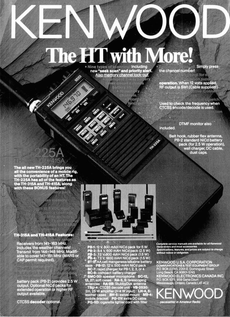
Related Documents