MT-FBC -18-E HALFEN FLEXIBLE BOLT CONNECTIONS Technical Product Information • CE-marking EN 1090-1, EN 1090-2 for all hot-rolled framing channels • Supplementary load capacities according to Eurocode 3 • Addition of framing channels HM 55/42, HZM 64/44, HZM 41/27

Welcome message from author
This document is posted to help you gain knowledge. Please leave a comment to let me know what you think about it! Share it to your friends and learn new things together.
Transcript

MT-FBC -18-E
HALFEN FLEXIBLE BOLT CONNECTIONS Technical Product Information
• CE-marking EN 1090-1, EN 1090-2 for all hot-rolled framing channels
• Supplementary load capacities according to Eurocode 3
• Addition of framing channels HM 55/42, HZM 64/44, HZM 41/27

Under the Leviat brand, we are uniting the expertise, skills and resources of HALFEN and its sister companies to create a world leader in fixing, connecting and anchoring technology.
The products you know and trust, including the flexible bolt connections, will remain an integral part of Leviat’s comprehensive brand and product portfolio. As Leviat, we can offer you an extended range of specialist products and services, greater technical expertise, a larger and more agile supply chain and better, faster innovation.
By bringing together CRH’s construction accessories family as one global organisation, we are better equipped to meet the needs of our customers, and the demands of construction projects, of any scale, anywhere in the world.
This is an exciting change. Join us on our journey. Read more about Leviat at Leviat.com
Leviat is the new name of CRH’s construction accessories companies worldwide.
We are one team. We are Leviat.

people worldwidecountries
sales in
Our product brands include:
locations300030+60
Imagine. Model. Make. Leviat.com

© F
otol
ia
2
HM 72/48
HZM41/41
© 2020 · MT-FBC 18-E · www.halfen.com
Industrial Technology
- European standards EN 1090 / EN 1993 4 - General overview 5
Framing channels - Introduction – Framing channels and bolts 6–7 - Bolt length selection, locking plates, order examples 8 - Framing channels – The advantages at a glance 9 - Materials, finishes, coatings 10–11 - Product range – overview framing channels and bolts 12–13
Framing channels - heavy duty framing system
- Profile HM 72/48 14 - HALFEN Bolt HS 72/48 15 - Profiles HM 55/42, HM 52/34 16–17 - Profiles HM 50/30, HM 49/30, HM 50/40, HM 486 18–20 - HALFEN Bolts HS 50/30, HSR 50/30 21 - Locking plates GWP 50/30, GWP 50/40 22 - Profiles HM 40/22, HM 40/25, HM 422 23–24 - HALFEN Bolts and locking plates HS 40/22, HSR 40/22, GWP 40/22 25 - Serrated profile HZM 64/44 26 - Serrated HALFEN Bolt HZS 64/44 27 - Serrated profile HZM 53/34 28 - Serrated HALFEN Bolt HZS 53/34 29 - Serrated profiles HZM 41/27, HZM 38/23 30–31 - HALFEN Bolts HZS 38/23, HS 38/17 32 - Serrated profile HZM 29/20 33 - HALFEN Bolts HZS 29/20, HS 28/15 34
Framing channels - medium duty framing system (Continued on the following page)
- Profiles HM 41/41, HL 41/41 35 - Serrated profiles HZM 41/41, HZL 41/41 36 - Profiles HM 41/62, HL 41/62, HM 41/83, HL 41/83 37–38 - Powerclick standard profile HZL 63/63 39 - Profiles HM 41/22, HL 41/22 40 - Serrated profiles HZM 41/22, HZL 41/22 41
INDUSTRIAL TECHNOLOGYContents

3
y z
e2e1
yx z
FR
FL FQ
FSz
HM38/17
© 2020 · MT-FBC 18-E · www.halfen.com
Framing channels - medium duty framing system (Continued from previous page) - Profiles HLL 41/41, HLL 41/22 42 - HALFEN Bolts HZS 41/41, HZS 41/22, HS 41/41 43 - Locking plates GWP 41/... and locking plates with spring 44
Framing channels - light duty framing systems
- Profiles HM 36/36, HL 36/36, HM 38/17 45 - HALFEN Bolts and locking plates HS 38/17, GWP 38/17 46 - Profiles 28/28, 28/15, HM 315 47–50 - HALFEN Bolts and locking plates 28/15 50 - Profiles and HALFEN Bolts 20/12 51–52
Accessories
- Bolts – overview 54–55 - Threaded rods, nuts, washers, hexagon head bolts 56–57 - Channel end caps, channel covers 58 - Cantilevers – Flexible comprehensive support systems 59
Statics
- Cross section properties/bending load capacities: hot-rolled channels 60–61 - Cross section properties/bending load capacities: cold-rolled channels 62–63 - Cross section properties/bending load capacities: slotted channels 64–65 - Point-load capacities of welded or bolted channels 66–68 - Bending moment of our Bolts 69 - Flexural buckling – Framing channels as compression elements 70–71
Application in mechanical engineering
- Design references 72 - Selecting the correct bolt length 73 - Channel bolt connection: pre-tension force 75 - Channel bolt connection: load capacities/design examples 76–78 - Transfer of dynamic loads 79
Appendix
- Tender, examples 80 - Powerclick System 81 - Index/contact/technical support 82–85
INDUSTRIAL TECHNOLOGYContents

4 © 2020 · MT-FBC 18-E · www.halfen.com
European standards EN 1090 / EN 1993
The new EN 1090 series of standards replace the previous DIN 18800-7 standard, regulating execution of steel structures and manufacturing qualifica-tions. European standard EN 1090-1 specifies requirements for conformity assessment (CE marking) of structural components which will be placed on the European market as construction products.The conformity assessment covers the manufacturing characteristics and where appropriate the structural design characteristics.The EN 1090-2 standard regulates the requirements applicable to the execu-tion of steel structures. This standard applies to structures that are verified according to the appropriate section of EN 1993 (EC3).
The phase-out period for DIN 18800-7 ended on the 30th of June 2014. Basis for the evaluation of conformity of steel construction products is the system of assessment of conformity 2+ according to Construction Products Regulation (CPR) EU No. 305/2011.The CE marking confirms conformity The European standard EN 1993 was
created with the intention to establish uniform, Europe-wide calculation methods for steel structures. However, because these calculation methods have not yet been adopted in all industries we have decided to include two sets of values for load capacities of framing channels and bolts in the following tables.
The traditional, deterministic safety concept however is based on the method of using a global safety factor for material resistance and is known as the “allowable load method” resp. “allowable tension method”. These methods are used in mechanical and plant engineering. For these cases the allowable values for load capacity are calculated. Verification is as follows:
The term “design value” is taken from the current applicable standards, for example EN 1993 (EC3), with new safety concept, and must be strictly differentiated from the term “allowable load”. The European standard which is based on the so called “partial safety factors” is applied to material resis-tance as well as to the action (load). The following verification is required:
F = load on the structure allow. F = allowable load
with the declared performance of
our products and with all relevant
European harmonized standards in the
European Union.
Our framing channels are also subject to
these regulations. To meet CE evalua-tion obligations the marked products are statically verified in accordance with EN 1993 and the principal perfor-mance characteristics are detailed in the respective Declaration of Perfor-mance, CONF-DOP_HM resp. CONF-DOP_HZM. CE marking is mandatory from the 1st of July 2014 when distributing load bearing metallic construction products in the European market.We are certified by the notified Body ZDH-ZERT GmbH. Apart from produc-tion, the certification includes the method of calculation required by the our engineers and their respective qualifications.
FEd ≤ FRd
F ≤ allow. F
FEd = calculation value for actionFRd = design value for resistance
• working loads will continue to be defined as "allow. F" and
• design values of the resistance will be defined as "FRd".
Design method
INDUSTRIAL TECHNOLOGYGeneral Information
EN 1090-1, EN 1090-22499 – CPR-0113070-00-01

5© 2020 · MT-FBC 18-E · www.halfen.com
Our adjustable channel fixing systems offer a whole range of benefits:
▪ The adjustable channel-bolt system is a supporting as well as a fixing system
▪ Full flexibility in positioning and dimensioning the bolt connections
▪ Choice of corrosion protection:- Strip galvanized framing channels for low demands
- Hot-dip galvanized framing channels for high demands
- Framing channels in stainless steel for maximum requirements
▪ Quick assembly and adjustment of equipment and structural components
With our framing channels you avoid:
▪ Time consuming planning of inflexible bolted fixings ▪ Costly manufacturing of bolt fixings
INDUSTRIAL TECHNOLOGYGeneral Information
Quality is an outstanding feature of our products. Our materials and prod-ucts are subject to stringent quality controls.
Quality
Our channels
Certificate no. 202384-2016-AQ-GER-DAkkS
A quality audit by the DNV GL confirmed that our quality manage-ment system meets the demands of the ISO 9001:2015 standard.
All hot-rolled profiles and some of the light framing channels are also available as HALFEN HTA/HZA Cast-in channels. Both versions use the same bolts and locking plates.
You can find more information on our channels in our Technical Product Information " HALFEN Cast-in channels".
▪ Costly corrosion protection work when upgrading already completed structural components i.e. when adjusting components to site
▪ Change or up-date entire projects with standard tools
▪ No specialist required to carry out modifications on site
▪ Dust free and low noise levels when modification work is done on site
▪ Corrosion protection is not compromised by bolting▪ A large selection of standard chan-
nels with good load bearing charac-teristics
www.halfen.com/Products/Fixing systems/HTA-Cast-in channels

6 © 2020 · MT-FBC 18-E · www.halfen.com
Ligh
t D
uty
Fra
min
g Sy
stem
sA
cces
sories
Fram
ing
Cha
nnel
sM
ediu
m D
uty
Fra
min
g Sy
stem
sH
eavy
Dut
y F
ram
ing
Syst
ems
Sta
tics
Mec
hani
cal e
ngin
eering
F raming channels HM, HL, HZM and HZL
INDUSTRIAL TECHNOLOGYFraming Channels
The hot-rolling process makes these framing channels ideally suitable for: ▪ heavy loads▪ dynamic loads ▪ welding
Cold-rolled framing channelsCold-rolled channels are economic for lower loads. Channels are available with holes or without holes.
Hot-rolled framing channels
Smooth channels HM▪ very high tensile load capacity▪ by using nibbed bolts longitudinal loads are possible (applies only to standard steel)
Cold-rolled framing channels HL, HM▪ economic due to large selection of channels
Serrated channels HZM▪ serration allows high longitudinal
loads ▪ 5 channel sizes for maximum
efficiency
Serrated channels HZL, HZM▪ for loads in longitudinal channel
direction ▪ positive-locking connection for
high channel loads
Cantilever fixing on a vertical conveyor system
Welding-jig, locomotive construction
Roller-bearing fixing of a cableway
Framing channels HM, HL, HZM and HZL

7
H 4.6HALFEN8.8
H 4.6HALFEN4.6
H 4.6HALFENA4-50
H 4.6HALFENA4-70
H 4.64.6
H 4.68.8
HSR All TypesHZS 38/23HZS 29/20
HS All TypesHZS 41/22HZS 41/41
H 4.6H 4.6HALFEN4.6
Manufacturer
Strength class resp. property class
(for individual dimensions)
© 2020 · MT-FBC 18-E · www.halfen.com
Ligh
t D
uty
Fra
min
g Sy
stem
sA
cces
sories
Fram
ing
Cha
nnel
sM
ediu
m D
uty
Fra
min
g Sy
stem
sH
eavy
Dut
y F
ram
ing
Syst
ems
Sta
tics
Mec
hani
cal e
ngin
eering
HALFEN Bol ts HS, HZS and HSR
INDUSTRIAL TECHNOLOGYBolts
Type HS Type HSR Type HZS
HALFEN Bolts▪ suitable for all channels ▪ load bearing capacity in two directions▪ marked at shank end
with one notch
HALFEN Bolts with nibs▪ suitable for use in hot-rolled, standard steel channels from the heavy duty system▪ nibbed; therefore positive-locking, load bearing in all directions▪ the T-bolts prevent turning under vibration▪ marked at shank end with two notches
Serrated HALFEN Bolts▪ for serrated framing channels HZM and HZL▪ serration also provides positive load bearing transmission in longitudinal channel direction; risk of slippage is eliminated▪ marked at shank end with two notches
Ident i fy ing HALFEN Bol ts
Marking at the shank end of our bolts: After assembly check the correct orientation of the notches on the shank end of the bolts. The slots must be at right angles to the channel length.
Location of nib on bolt
Strength class 4.6galvanized or hot-dip galvanized
Strength class 8.8galvanized or hot-dip galvanized
Property class A4 - 50stainless steel
Property class A4 - 70stainless steel
Notches on the shank tip:
Bolt identification on the bolt head
HALFEN Bolts HS, HZS and HSR

8
Dimensions Vmin
Bolt diameter vmin = m + u [mm]
M6 11.0
M8 12.5
M10 14.5
M12 17.0
M16 20.5
M20 26.0
M24 29.0
M27 31.5
M30 33.5
Thickness channel lip i
Profile 28/15 29/20 38/17 36/36 38/23 40/22 40/25 41/22 41/27 422 486 49/30 50/30 50/40 52/34 53/34 55/42 64/44 72/48
i [mm] 2.25 5.0 3.0 2.5 5.5 6.0 5.6 7.0 7.0 6.0 6.0 7.39 7.85 7.0 10.5 7.5 12.9 10.0 15.5
fixt
l
vmin
s
i
erf
HALFEN Bolt
© 2020 · MT-FBC 18-E · www.halfen.com
Ligh
t D
uty
Fra
min
g Sy
stem
sA
cces
sories
Fram
ing
Cha
nnel
sM
ediu
m D
uty
Fra
min
g Sy
stem
sH
eavy
Dut
y F
ram
ing
Syst
ems
Sta
tics
Mec
hani
cal e
ngin
eering
INDUSTRIAL TECHNOLOGYBolts and Locking Plates
Locking plates GWP
Ordering examples
Locking plates with “grip” (see me-dium duty framing system, page 44). The “serration” grips the channel lips.
Locking plates with spring are used in particular for securing plates or panels (see medium duty framing system, page 44).
Locking plates (channel nuts) allow any metric bolt or threaded rod to be used.
or use the 12-digit order no. e.g. 0280.200-00003 or use the 12-digit order no. e.g. 0350.090-00081Order numbers for our bolts can be found in the our pricelist.
Order example – framing channels Order example – bolts
TypeThread diam.Length (mm)MaterialProperty class
HS 50/30 M20× 100 GVs 8.8
TypeMaterialLength (mm)
HM 50/30 - FV-6070
lreq = required bolt lengthtfix = thickness: attached componenti = channel lip thicknesss = washer thickness → see page 56
vmin = m + um = nut height EN ISO 4032u = bolt protrusion approx. 5 mm
according to DIN 78 (bolts larger M20 require min. 7 mm)
lreq = tfix + i + s + vmin
Calculating the bolt length lreq for our bolts (steel construction)
9© 2020 · MT-FBC 18-E · www.halfen.com
Ligh
t D
uty
Fra
min
g Sy
stem
sA
cces
sories
Fram
ing
Cha
nnel
sM
ediu
m D
uty
Fra
min
g Sy
stem
sH
eavy
Dut
y F
ram
ing
Syst
ems
Sta
tics
Mec
hani
cal e
ngin
eering
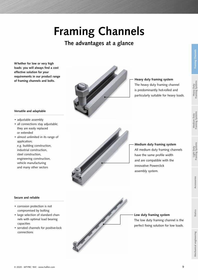
Whether for low or very high loads: you will always find a cost effective solution for your requirements in our product range of framing channels and bolts.
Versatile and adaptable
• adjustable assembly• all connections stay adjustable;
they are easily replaced or extended• almost unlimited in its range of
application; e.g. building construction, industrial construction, steel construction, engineering construction, vehicle manufacturing and many other sectors
Heavy duty framing system
The heavy duty framing channel
is predominantly hot-rolled and
particularly suitable for heavy loads.
Medium duty framing system
All medium duty framing channels
have the same profi le width
and are compatible with the
innovative Powerclick
assembly system.
Low duty framing system
The low duty framing channel is the
perfect fi xing solution for low loads.
Framing ChannelsThe advantages at a glance
Secure and reliable
• corrosion protection is not compromised by bolting
• large selection of standard chan-nels with optimal load bearing capacities
• serrated channels for positive-lock connections

10
Channels Heavy duty framing systems Medium duty framing systems Light duty framing systems
Material: Order code Pages 14 – 34 Pages 35 – 44 Pages 45 – 53
WB Hot-rolledmaterial S235JR, acc. to EN 10025, material no. 1.0038
Type HZM: S275JR, material no. 1.0044,acc. to EN 10025
Cold-rolled:material S235JR, acc. to EN 10025 mill-finished
Material S235JR, acc. to EN 10025, material no. 1.0038
Material S235JR, acc to EN 10025, material no. 1.0038
Mill-finished
FV Hot-rolledmaterial S235JR, acc. to EN 10025, material no. 1.0038
type HZM: S275JR acc. to EN 10025
Cold-rolled:material S235JR, acc. to EN 10025Hot-dip galvanized, acc. to EN ISO 1461, zinc coating min. 50 μm
Material S235JR, acc to EN 10025, material no. 1.0038
Hot-dip galvanized, acc. to EN ISO 1461zinc coating min. 50 μm
Material S235JR, acc. to EN 10025, material no. 1.0038
Hot-dip galvanized, acc. to EN ISO 1461,zinc coating min. 50 μm
Hot-dip galvanized acc. to EN ISO 1461suitable for outdoor
application
SV DX51D + Z275NA, material no. 1.0226, acc.to EN 10346
Sendzimir galvanized,hot-dip galvanized min. 20 μm
DX51D + Z275NA, material no. 1.0226, acc. to EN 10346
Sendzimir galvanized,hot-dip galvanized min. 20 μm
Strip-galvanizedacc. to EN 10142suitable for indoor
application
Stainless steelacc. to EN 10088 and EN 1993-1-4
A2 Material no. 1.4301,acc. to EN 10088
A4Material no. 1.4571 / 1.4404,acc. to EN 10088
Material no. 1.4571 / 1.4404,acc. to EN 10088
Material no. 1.4571 / 1.4404,acc. to EN 10088
HCR
HCR = high corroison resistant stainless steel, material no. 1.4529 or 1.4547, acc. to EN 10088, for channels 49/30
HCR = high corroison resistant stainless steel, material no. 1.4529 or 1.4547, acc. to EN 10088, for channels 28/15 and 38/17
hot-rolled
cold-rolled
© 2020 · MT-FBC 18-E · www.halfen.com
Ligh
t D
uty
Fra
min
g Sy
stem
sA
cces
sories
Fram
ing
Cha
nnel
sM
ediu
m D
uty
Fra
min
g Sy
stem
sH
eavy
Dut
y F
ram
ing
Syst
ems
Sta
tics
Mec
hani
cal e
ngin
eering
INDUSTRIAL TECHNOLOGYMaterials, Types

11
Bolts/Accessories Bolts Locking plates Hexagon bolts Hexagon nuts
Our bolts with s-shape head for safer assembly. The head shape guarantees better hold, preventing the bolt turning in the channel, even coping with manufacturing tolerances in the channel widths. We supply both types;subject to change.
TypesHS,HSR,HZS
incl.nut
Pages54 – 55
Type GWP
Type HSK
EN ISO 4017DIN 933
Type MU
DIN EN ISO 4032DIN 934
Material: Order code Page 57 Page 56
Hot-dip galvanizedacc. to EN ISO 10684,
for threaded partsacc. to DIN 267 part 10
FV 4.6 Hot-dip galvanized acc. to EN ISO 10684property class 4.6acc. to EN ISO 898-1
Hot-dip galvanized acc. to EN ISO 10684strength 8FV 8.8 Hot-dip galvanized acc. to
EN ISO 10684property class 8.8acc. to EN ISO 898-1
Zinc-electroplatedacc. to DIN 50961,
DIN EN 1403,DIN EN ISO 4042
zinc flake coating
GV 4.6 Zinc-electroplated withspecial coating Cr(VI)-free,GVszinc coating min. 12 μm,property class 4.6acc. to EN ISO 898-1
Zinc-electroplatedCr(VI)-free,zinc covermin. 5 μm
Zinc-electroplatedCr(VI)-free,zinc covermin. 5 μm,property class 8
GV 8.8 Zinc-electroplated withspecial coating Cr(VI)-free,GVszinc coating min. 12 μm,property class 8.8acc. to EN ISO 898-1
Zinc-electroplatedCr(VI)-free,zinc cover ca. 5 μm,property class 8.8
zl Zinc flake coating (only Type HZS 41/41)
Stainless steel acc. to EN 10088
orEN 1993-1-4
A2 Stainless steel A2Property class 50 acc. to EN ISO 3506-1
Property class 70 acc. to EN ISO 3506-1
A4
Stainless steel A4
Stainless steel A4-70
Stainless steel A4-70 or A4-80
Property class 50acc. to EN ISO 3506-1
Property class 70 acc. to EN ISO 3506-1
HCRMaterial HCR-50, material no. 1.4529, acc. toEN ISO 3506-1 on request
FA Property class 70 material no. 1.4462
© 2020 · MT-FBC 18-E · www.halfen.com
Ligh
t D
uty
Fra
min
g Sy
stem
sA
cces
sories
Fram
ing
Cha
nnel
sM
ediu
m D
uty
Fra
min
g Sy
stem
sH
eavy
Dut
y F
ram
ing
Syst
ems
Sta
tics
Mec
hani
cal e
ngin
eering
FRAMING SYSTEMS Materials, Types
Standard s-shaped head
alternative shape of bolt head

12
Medium duty framing system
Cold-rolled Cold-rolled, serrated Cold-rolled Cold-rolled, serrated
HM 41/41, HL 41/41 HZM 41/41, HZL 41/41 HM 41/62, HL 41/62 HM 41/83, HL 41/83 HZL 63/63 HZM 41/22, HZL 41,22
HZS/HS 41/41, HZS 41/22GWP 41/41, GWP 41/22
Light duty framing system
Cold-rolled Cold-rolled
HM 36/36, HL 36/36 HM 38/17 HM 28/28, HL 28/28 HM 28/15, HL 28/15 HM 315 HM 20/12, HL 20/12
17,5
HS 38/17,GWP 38/17
HS 28/15,GWP 28/15 GWP 28/15 HS 20/12,
GWP 20/12
Heavy duty framing system
Hot-rolled Cold-rolled
HM 72/48 HM 55/42 HM 52/34 HM 50/30 HM 49/30 HM 50/40, HL 50/40 HM 486
72
33
48,5
26
4254,5
52,5
22,5
33,5
49
22,5
50
22
30
49
39 27
HS 72/48, HSR 72/48,GWP 72/48 HS 50/30 HS 50/30, HSR 50/30,
GWP 50/30HS 50/30,
GWP 50/30 and GWP 50/40
© 2020 · MT-FBC 18-E · www.halfen.com
Ligh
t D
uty
Fra
min
g Sy
stem
sA
cces
sories
Fram
ing
Cha
nnel
sM
ediu
m D
uty
Fra
min
g Sy
stem
sH
eavy
Dut
y F
ram
ing
Syst
ems
Sta
tics
Mec
hani
cal e
ngin
eering
INDUSTRIAL TECHNOLOGYProduct Range Overview: Framing Channels and Bolts

13
Cold-rolled
HM 41/22, HL 41/22 HLL 41/41 HLL 41/22
Material grades: abbreviations and explanations
A2: Steel of corrosion resistance class (CRC) II according to EN 1993-1-4 : 2015-10, table A.3
A4: Steel of corrosion resistance class (CRC) III according to EN 1993-1-4 : 2015-10, table A.3
HCR: Steel of corrosion resistance class (CRC) V according to EN 1993-1-4 : 2015-10, table A.3
Hot-dip galvanized FV or mill finish WB
Sendzimir galvanized SV
Stainless steel A4 1.4571/1.4404
Stainless steel A2 1.4301/1.4307
Stainless steel HCR 1.4547/1.4529
HZM/HZL serrated profiles
Material and finishes:
Further information on materials
and finishes → see page 10
Hot-rolled Cold-rolled Hot-rolled, serrated
HM 40/22 HM 40/25 HM 422 HZM 64/44 HZM 53/34 HZM 41/27 HZM 38/23 HZM 29/20
39,5 39,521
,5
64
26
44
34
22,5
52,540
27
18,5
HS 40/22, HSR 40/22, GWP 40/22 HZS 64/44 HZS 53/34 HZS 38/23 HZS 38/23,
HS 38/17HZS 29/20, HS 28/15
40
2518
© 2020 · MT-FBC 18-E · www.halfen.com
Ligh
t D
uty
Fra
min
g Sy
stem
sA
cces
sories
Fram
ing
Cha
nnel
sM
ediu
m D
uty
Fra
min
g Sy
stem
sH
eavy
Dut
y F
ram
ing
Syst
ems
Sta
tics
Mec
hani
cal e
ngin
eering
INDUSTRIAL TECHNOLOGYProduct Range Overview: Framing Channels and Bolts

14
Dimensions and cross-section properties Load capacities
Length Weight Cross section area
Moment ofinertia
Elastic section modulus
Max. point-load bearing capacity
Bending load capacity at span L
F [kN]
Material Order no. G A ly lz Wy Wz Fz ew
HM 72/48 0280. [mm] [kg/m] [cm2] [cm4] [cm4] [cm3] [cm3] [kN] [cm] 0.5 m 1.0 m 1.5 m
WB 180-00002
6070 8.85 11.27 34.97 83.35 14.28 23.15
Fz,Rd
30.0
FRd
65.8 31.2 15.6 10.4FV 180-00003
allow. Fz allow. F
A4 180-00001 47.0 22.3 11.2 7.4
Fz = max. load bearing capacity of the channel lips - see also page 66
y z
yx z
L [m]
Fz
Fz
ew
© 2020 · MT-FBC 18-E · www.halfen.com
Stat
ics
Ligh
t D
uty
Fra
min
g Sy
stem
sA
cces
sories
Fram
ing
Cha
nnel
sM
ediu
m D
uty
Fra
min
g Sy
stem
sH
eavy
Dut
y F
ram
ing
Syst
ems
Mec
hani
cal e
ngin
eering
INDUSTRIAL TECHNOLOGYFraming Channels – Heavy Duty Framing System
Double channel on request - profile data, see page 60
M1:1[mm]
Framing channel HM 72/48
VUS 72/49 Washer→ see page 56
Suitable HALFEN Bolt HS 72/48 and HSR 72/48 → see page 15
HM 72/48 hot-rolled
Accessories
y z
yx z
Cross section data→ page 60
Fz
xFy
Point-load capacity→ pages 66–67
N
Flexural buckling→ page 70
Further design properties
HM 72/48
72
33
5
4.5
48.5
15.5
72/48

15
Load capacities GWP 72/48
Fz
x
z
y
Thread Load capacity [kN]
M12FRd 13.0
allow. F 9.3
M16FRd 24.2
allow. F 17.3
M20FRd 30.8
allow. F 22.0
HSR 72/48 available bolts
Length l [mm] M20
75 FV 8.8
GWP 72/48 available plates
GV thread
A4thread
a[mm]
b[mm]
d[mm]
M12 M12
62 31 22M16 M16
M20 M20
Load bearing capacities for our bolts
Load capacities for our bolts Recommended load capacity per bolt in channel longitudinal direction
Recommended torque
Fz
xFy xy
z
Fx
Thread Ø F [kN] Fx [kN] Tinst [Nm]
72/48HS HSR HS HSR = 3 HS HSR
4.6 8.8 A4-50 8.8 4.6 8.8 A4-50 8.8 4.6 8.8 A4-50 8.8
M20FRd 35.2 78.4 - 78.4 1.96 6.58 - 10.5
130 360 - 400allow. F 25.1 56.0 - 56.0 1.4 4.7 - 7.5
M24FRd 50.7 113.0 44.5 - 2.8 9.52 2.8 -
200 680 200 -allow. F 36.2 80.7 31.8 - 2.0 6.8 2.0 -
M27FRd 66.0 146.9 - - 3.64 12.46 - -
300 1000 - -allow. F 47.1 104.9 - - 2.6 8.9 - -
M30FRd 80.6 - - - 4.48 15.26 - -
400 1400 - -allow. F 57.6 - - - 3.2 10.9 - -
Note: do not exceed the max. channel load bearing capacityLoad capability due to frictionAcc. to expert report
Length l [mm] M20 M24 M27 M30
50FV 4.6 FV 4.6
A4-50
60 FV 8.8
75FV 4.6 FV 4.6 FV 4.6 FV 4.6
GVs 8.8 FV 8.8
100FV 4.6 FV 4.6 FV 4.6 FV 4.6
GVs 8.8 GVs 8.8 FV 8.8
A4-50
Length l [mm] M20 M24 M27 M30
150FV 4.6 FV 4.6 FV 4.6
GVs 8.8
200 FV 4.6 FV 4.6 FV 4.6
HS 72/48 available bolts
© 2020 · MT-FBC 18-E · www.halfen.com
Stat
ics
Ligh
t D
uty
Fra
min
g Sy
stem
sA
cces
sories
Fram
ing
Cha
nnel
sM
ediu
m D
uty
Fra
min
g Sy
stem
sH
eavy
Dut
y F
ram
ing
Syst
ems
Mec
hani
cal e
ngin
eering
INDUSTRIAL TECHNOLOGYBolts and Accessories – Heavy Duty Framing System
HS 72/48HALFEN Bolt incl. nut
HSR 72/48HALFEN Bolt with nib incl. nut, for hot-rolled channels in mild steel WB/FV
HALFEN Bolts HS 72/48 and HSR 72/48
Locking plates
Locking plate GWP 72/48
ab
d

16
Dimensions and cross-section properties Load capacities
Length Weight Cross section area
Moment of inertia Elastic section modulus
Max. point-load bearing capacity
Bending load capacity at span L
F [kN]
Material Order no. G A ly lz Wy Wz Fz ew
HM 55/42 0280. [mm] [kg/m] [cm2] [cm4] [cm4] [cm3] [cm3] [kN] [cm] 0.5 m 1.0 m 1.5 m
WB 290-00001
6070 6.76 8.6 18.75 36.29 8.49 13.32
Fz,Rd
25.0
FRd
54.0 23.5 11.7 7.8
FV 290-00002
allow. Fz allow. F
38.6 16.8 8.4 5.6
Fz = max. load bearing capacity of the channel lips → see also page 66
y z
yx z
L [m]
Fz
Fz
ew
© 2020 · MT-FBC 18-E · www.halfen.com
Stat
ics
Ligh
t D
uty
Fra
min
g Sy
stem
sA
cces
sories
Fram
ing
Cha
nnel
sM
ediu
m D
uty
Fra
min
g Sy
stem
sH
eavy
Dut
y F
ram
ing
Syst
ems
Mec
hani
cal e
ngin
eering
Suitable HALFEN Bolt HS 50/30, see page 21
Double channel on request - profile data, see page 60
VUS 72/49 Washer→ see page 56
Framing channel HM 55/42
HM 55/42 hot-rolled
Accessories
y z
yx z
Cross section data→ page 60
Fz
xFy
Point-load capacity→ pages 66–67
N
Flexural buckling→ page 70
Further design properties
INDUSTRIAL TECHNOLOGYFraming Channels – Heavy Duty Framing System
HM 55/42
HM 55/42 D
26
42
5
54.5
12.9
55/42
M1:1[mm]

17
Dimensions and cross-section properties Load capacities
Length Weight Cross section area
Moment of inertia Elastic section modulus
Max. Point-load bearing capacity
Bending load capacity at span L
F [kN]
Material Order no. G A ly lz Wy Wz Fz ew
HM 52/34 0280. [mm] [kg/m] [cm2] [cm4] [cm4] [cm3] [cm3] [kN] [cm] 0.5 m 1.0 m 1.5 m
WB 190-00002
6070 4.98 6.35 9.33 23.74 5.36 9.04
Fz,Rd
20.0
FRd
36.3 12.3 6.1 3.9FV 190-00003
allow. Fz allow. F
A4 190-00001 25.9 8.8 4.4 2.8
Fz = max. load bearing capacity of the channel lips → see also page 66
y z
yx z L [m]Fz
Fz
ew
© 2020 · MT-FBC 18-E · www.halfen.com
Stat
ics
Ligh
t D
uty
Fra
min
g Sy
stem
sA
cces
sories
Fram
ing
Cha
nnel
sM
ediu
m D
uty
Fra
min
g Sy
stem
sH
eavy
Dut
y F
ram
ing
Syst
ems
Mec
hani
cal e
ngin
eering
HPE 52/34 Channel end cap→ see page 58
PA - 22 Channel cover→ see page 58
VUS 52/34 Washer→ see page 56
Accessories
Suitable HALFEN Bolts and locking plates HS 50/30, HSR 50/30, GWP 50/40 and GWP 50/30 → see pages 21–22
y z
yx z
Cross section data → page 60
Fz
xFy
Point-load capacity → pages 66–67
N
Flexural buckling→ page 70
Further design properties
Double channel on request profile data → see page 60
Framing channel HM 52/34
HM 52/34 hot-rolled
INDUSTRIAL TECHNOLOGYFraming Channels – Heavy Duty Framing System
52.5
22.5
4 33.5
10.5
4.1
52/34
M1:1[mm]
18
Dimensions and cross-section properties Load capacities
Length Weight Cross section area
Moment of inertia Elastic section modulus
Max. point-load bearing capacity
Bending load capacity at span L
F [kN]
Material Order no. G A ly lz Wy Wz Fz ew
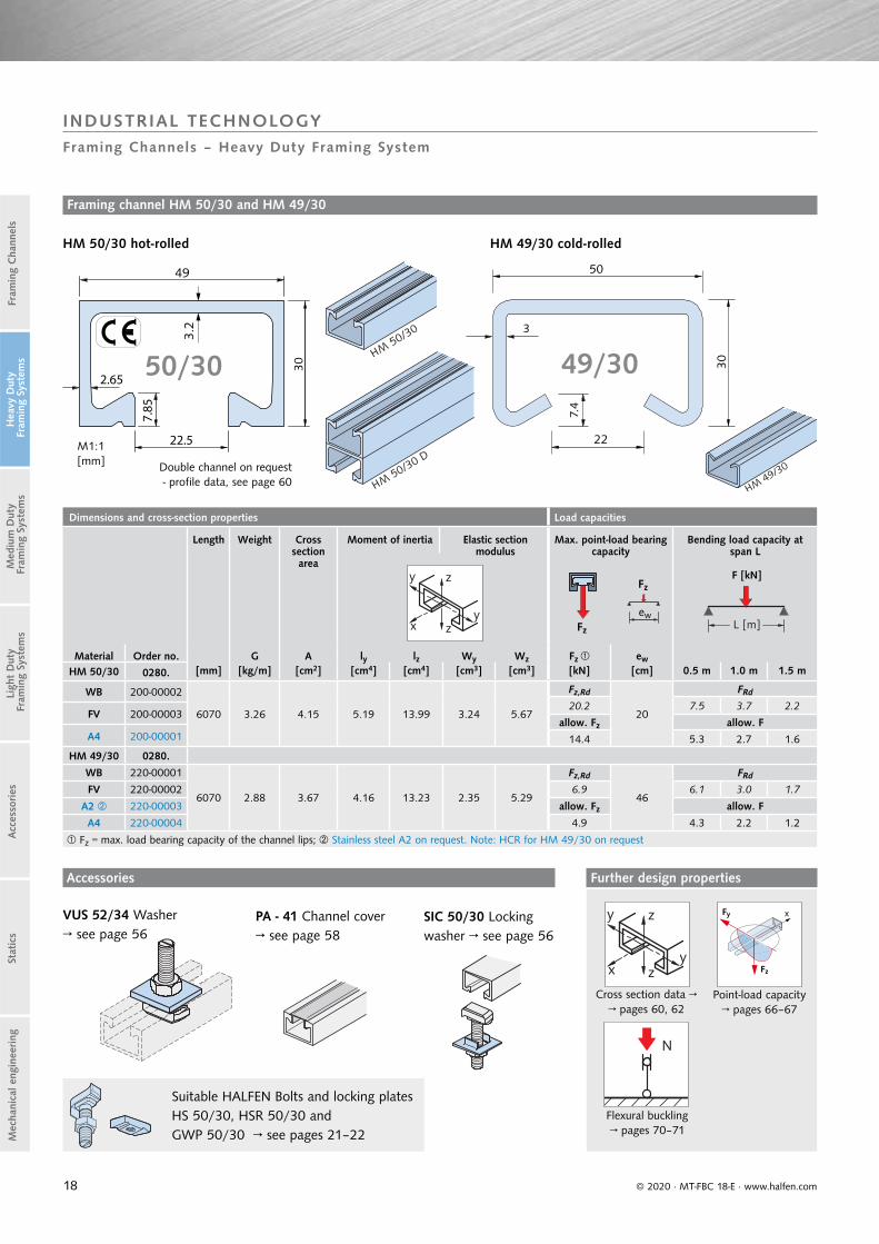
HM 50/30 0280. [mm] [kg/m] [cm2] [cm4] [cm4] [cm3] [cm3] [kN] [cm] 0.5 m 1.0 m 1.5 m
WB 200-00002
6070 3.26 4.15 5.19 13.99 3.24 5.67
Fz,Rd
20
FRd
20.2 7.5 3.7 2.2FV 200-00003
allow. Fz allow. FA4 200-00001 14.4 5.3 2.7 1.6
HM 49/30 0280.
WB 220-00001
6070 2.88 3.67 4.16 13.23 2.35 5.29
Fz,Rd
46
FRd
FV 220-00002 6.9 6.1 3.0 1.7
A2 220-00003 allow. Fz allow. F
A4 220-00004 4.9 4.3 2.2 1.2
Fz = max. load bearing capacity of the channel lips; Stainless steel A2 on request. Note: HCR for HM 49/30 on request
y z
yx z L [m]
Fz
Fz
ew
© 2020 · MT-FBC 18-E · www.halfen.com
Stat
ics
Ligh
t D
uty
Fra
min
g Sy
stem
sA
cces
sories
Fram
ing
Cha
nnel
sM
ediu
m D
uty
Fra
min
g Sy
stem
sH
eavy
Dut
y F
ram
ing
Syst
ems
Mec
hani
cal e
ngin
eering
Accessories
Framing channel HM 50/30 and HM 49/30
HM 50/30 hot-rolled HM 49/30 cold-rolled
Double channel on request - profile data, see page 60
Suitable HALFEN Bolts and locking plates HS 50/30, HSR 50/30 and GWP 50/30 → see pages 21–22
y z
yx z
Cross section data → → pages 60, 62
Fz
xFy
Point-load capacity → pages 66–67
N
Flexural buckling→ pages 70–71
Further design properties
PA - 41 Channel cover→ see page 58
VUS 52/34 Washer→ see page 56
SIC 50/30 Locking washer → see page 56
INDUSTRIAL TECHNOLOGYFraming Channels – Heavy Duty Framing System
49
2.65
22.5
7.85
3.2 3
7.4
50/30 49/30
M1:1[mm]

19
Dimensions and cross-section properties Load capacities
Length Weight Cross section area
Moment of inertia Elastic section modulus
Max. point-load bearing capacity
Bending load capacity at span L
Material Order no. G A ly lz Wy Wz Fz ≤ ew
HM 50/40 0280. [mm] [kg/m] [cm2] [cm4] [cm4] [cm3] [cm3] [kN] [cm] 0.5 m 1.0 m 1.5 m
WB 090-00002
6000 3.35 4.26 8.64 15.49 3.96 6.32
Fz,Rd
63.0
FRd
7.6 9.5 4.7 3.2FV 090-00003
allow. Fz allow. FA4 090-00001 5.4 6.8 3.4 2.3
HL 50/40 0281.
WB 100-00001
6000 3.15 3.73 7.14 15.36 3.65 6
Fz,Rd
53.0
FRd
7.6 8.0 4.1 2.7FV 100-00002
allow. Fz allow. FA4 100-00003 5.4 5.7 2.9 1.9
Fz = max. load bearing capacity of the channel lips
L [m]Fz
Fz
ew
y z
yx z
F [kN]
© 2020 · MT-FBC 18-E · www.halfen.com
Stat
ics
Ligh
t D
uty
Fra
min
g Sy
stem
sA
cces
sories
Fram
ing
Cha
nnel
sM
ediu
m D
uty
Fra
min
g Sy
stem
sH
eavy
Dut
y F
ram
ing
Syst
ems
Mec
hani
cal e
ngin
eering
Suitable HALFEN Bolts and locking plates HS 50/30, GWP 50/40 → see pages 21–22
Framing channel HM and HL 50/40
HM 50/40 and HL 50/40 cold-rolled
HPE 50/40 Channel end cap→ see page 58
PA - 41 Channel cover→ see page 58
Accessories
y z
yx z
Cross section data→ pages 62, 64
Fz
xFy
Point-load capacities → page 68
N
Flexural buckling→ page 71
Further design properties
INDUSTRIAL TECHNOLOGYFraming Channels – Heavy Duty Framing System
M1:1[mm]
18
40
60
HL 50/40HM
50/40
49
39
3
22
7
50/40
20
Dimensions and cross-section properties Load capacities
Length Weight Cross section area
Moment of inertia Elastic section modulus
Max. point-load bearing capacity
Bending load capacity at span L
F [kN]
Material Order no. G A ly lz Wy Wz Fz ≤ ew
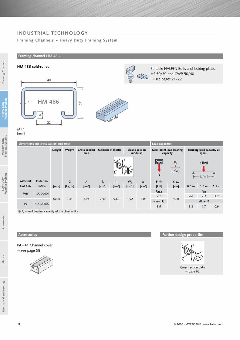
HM 486 0280. [mm] [kg/m] [cm2] [cm4] [cm4] [cm3] [cm3] [kN] [cm] 0.5 m 1.0 m 1.5 m
WB 100-00001
6000 2.31 2.95 2.97 9.62 1.92 4.01
FRd,z
47.0
FRd
4.7 4.6 2.3 1.2
FV 100-00002allow. Fz allow. F
3.5 3.3 1.7 0.9
Fz = load bearing capacity of the channel lips
y z
yx z
L [m]
Fz
Fz
ew
© 2020 · MT-FBC 18-E · www.halfen.com
Stat
ics
Ligh
t D
uty
Fra
min
g Sy
stem
sA
cces
sories
Fram
ing
Cha
nnel
sM
ediu
m D
uty
Fra
min
g Sy
stem
sH
eavy
Dut
y F
ram
ing
Syst
ems
Mec
hani
cal e
ngin
eering
Framing channel HM 486
HM 486 cold-rolled
PA - 41 Channel cover→ see page 58
Accessories
Suitable HALFEN Bolts and locking plates HS 50/30 and GWP 50/40 → see pages 21–22
y z
yx z
Cross section data → page 62
Further design properties
M1:1[mm]
INDUSTRIAL TECHNOLOGYFraming Channels – Heavy Duty Framing System
4827
22
6
2.5
HM486
HM 486
21
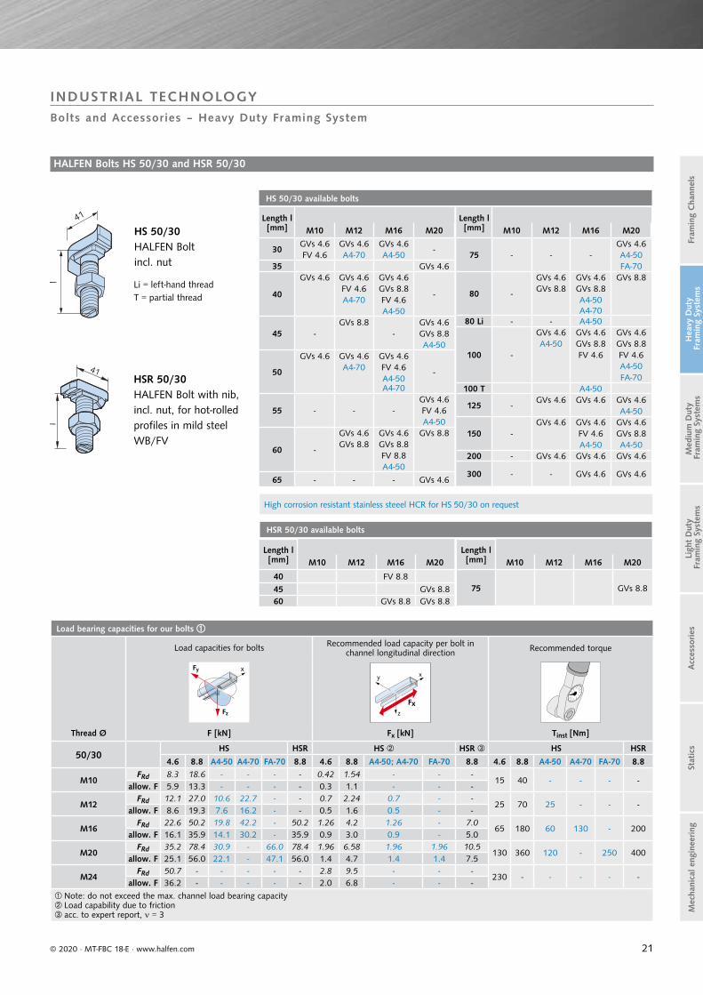
High corrosion resistant stainless steeel HCR for HS 50/30 on request
Length l [mm] M10 M12 M16 M20
30GVs 4.6 GVs 4.6 GVs 4.6
-FV 4.6 A4-70 A4-50
35 GVs 4.6
40
GVs 4.6 GVs 4.6 GVs 4.6
-FV 4.6 GVs 8.8A4-70 FV 4.6
A4-50
45 -GVs 8.8
-GVs 4.6GVs 8.8A4-50
50
GVs 4.6 GVs 4.6 GVs 4.6
-A4-70 FV 4.6A4-50A4-70
55 - - -GVs 4.6FV 4.6A4-50
60 -
GVs 4.6 GVs 4.6 GVs 8.8GVs 8.8 GVs 8.8
FV 8.8A4-50
65 - - - GVs 4.6
Length l [mm] M10 M12 M16 M20
75 - - -GVs 4.6A4-50FA-70
80 -
GVs 4.6 GVs 4.6 GVs 8.8GVs 8.8 GVs 8.8
A4-50A4-70
80 Li - - A4-50
100 -
GVs 4.6 GVs 4.6 GVs 4.6A4-50 GVs 8.8 GVs 8.8
FV 4.6 FV 4.6A4-50FA-70
100 T A4-50
125 -GVs 4.6 GVs 4.6 GVs 4.6
A4-50
150 -GVs 4.6 GVs 4.6 GVs 4.6
FV 4.6 GVs 8.8A4-50 A4-50
200 - GVs 4.6 GVs 4.6 GVs 4.6
300 - - GVs 4.6 GVs 4.6
HS 50/30 available bolts
Length l [mm] M10 M12 M16 M20
40 FV 8.845 GVs 8.860 GVs 8.8 GVs 8.8
Length l [mm] M10 M12 M16 M20
75 GVs 8.8
HSR 50/30 available bolts
Load bearing capacities for our bolts
Load capacities for bolts Recommended load capacity per bolt in channel longitudinal direction Recommended torque
Fz
xFyxy
z
Fx
Thread Ø F [kN] Fx [kN] Tinst [Nm]
50/30HS HSR HS HSR HS HSR
4.6 8.8 A4-50 A4-70 FA-70 8.8 4.6 8.8 A4-50; A4-70 FA-70 8.8 4.6 8.8 A4-50 A4-70 FA-70 8.8
M10FRd 8.3 18.6 - - - - 0.42 1.54 - - -
15 40 - - - -allow. F 5.9 13.3 - - - - 0.3 1.1 - - -
M12FRd 12.1 27.0 10.6 22.7 - - 0.7 2.24 0.7 - -
25 70 25 - - -allow. F 8.6 19.3 7.6 16.2 - - 0.5 1.6 0.5 - -
M16FRd 22.6 50.2 19.8 42.2 - 50.2 1.26 4.2 1.26 - 7.0
65 180 60 130 - 200allow. F 16.1 35.9 14.1 30.2 - 35.9 0.9 3.0 0.9 - 5.0
M20FRd 35.2 78.4 30.9 - 66.0 78.4 1.96 6.58 1.96 1.96 10.5
130 360 120 - 250 400allow. F 25.1 56.0 22.1 - 47.1 56.0 1.4 4.7 1.4 1.4 7.5
M24FRd 50.7 - - - - - 2.8 9.5 - - -
230 - - - - -allow. F 36.2 - - - - - 2.0 6.8 - - -
Note: do not exceed the max. channel load bearing capacityLoad capability due to frictionacc. to expert report, = 3
© 2020 · MT-FBC 18-E · www.halfen.com
Stat
ics
Ligh
t D
uty
Fra
min
g Sy
stem
sA
cces
sories
Fram
ing
Cha
nnel
sM
ediu
m D
uty
Fra
min
g Sy
stem
sH
eavy
Dut
y F
ram
ing
Syst
ems
Mec
hani
cal e
ngin
eering
HALFEN Bolts HS 50/30 and HSR 50/30
T = partial thread
HS 50/30HALFEN Bolt incl. nut
HSR 50/30HALFEN Bolt with nib, incl. nut, for hot-rolled profiles in mild steel WB/FV
Li = left-hand thread
INDUSTRIAL TECHNOLOGYBolts and Accessories – Heavy Duty Framing System

22
GWP 50/30 available bolts
FV GV A4
- M8 M8
M10 M10 M10
M12 M12 M12
M16 M16 M16
GWP 50/40 available bolts
GV A4
M6 M6
M8 M8
M10 M10
M12 M12
M16 M16
Load capacities for locking plates 50/30
Fz
x
z
y
50/30
Thread Load capacity [kN]
M8FRd 5.6
allow. F 4.0
M10FRd 9.0
allow. F 6.4
M12FRd 13.0
allow. F 9.3
M16FRd 13.0
allow. F 9.3
Load capacities for locking plates 50/40
Fz
x
z
y
50/40
Thread Load capacity [kN]
M6FRd 3.1
allow. F 2.2
M8FRd 5.6
allow. F 4.0
M10FRd 9.0
allow. F 6.4
M12FRd 9.0
allow. F 6.4
M16FRd 9.0
allow. F 6.4
© 2020 · MT-FBC 18-E · www.halfen.com
Stat
ics
Ligh
t D
uty
Fra
min
g Sy
stem
sA
cces
sories
Fram
ing
Cha
nnel
sM
ediu
m D
uty
Fra
min
g Sy
stem
sH
eavy
Dut
y F
ram
ing
Syst
ems
Mec
hani
cal e
ngin
eering
INDUSTRIAL TECHNOLOGYBolts and Accessories – Heavy Duty Framing System
Locking plates GWP 50/40
Locking plates GWP 50/30
Locking plate GWP 50/40
Locking plate GWP 50/30
21 43.5 12
20 42
8

23
F
Dimensions and cross-section properties Load capacities
Length Weight Cross section area
Moment of inertia Elastic section modulus
Max. point-load bearing capacity
Bending load capacity at span L
F [kN]
Material Order no. G A ly lz Wy Wz Fz ew
HM 40/22 0280. [mm] [kg/m] [cm2] [cm4] [cm4] [cm3] [cm3] [kN] [cm] 0.5 m 1.0 m 1.5 m
WB 210-00002
6070 2.12 2.70 1.98 5.77 1.59 2.92
Fz,Rd
15.0
FRd
11.4 3.7 1.9 0.8FV 210-00003
allow. Fz allow. FA4 210-00001 8.2 2.6 1.3 0.6
HM 40/25 0280.
WB 230-00001
6070 2.09 2.66 2.05 6.09 1.39 3.05
Fz,Rd
33.0
FRd
FV 230-00002 5.3 3.6 1.8 0.9
A2 230-00003 allow. Fz allow. F
A4 230-00004 3.8 2.6 1.3 0.6
Fz = max. load bearing capacity for the channel lips → see also page 66
y z
yx z L [m]
Fz ew
Fz
© 2020 · MT-FBC 18-E · www.halfen.com
Stat
ics
Ligh
t D
uty
Fra
min
g Sy
stem
sA
cces
sories
Fram
ing
Cha
nnel
sM
ediu
m D
uty
Fra
min
g Sy
stem
sH
eavy
Dut
y F
ram
ing
Syst
ems
Mec
hani
cal e
ngin
eering
Suitable HALFEN Bolts and locking plates HS 40/22, HSR 40/22 and GWP 40/22 → see page 25
M1:1[mm]
Values in brackets for stainless steel A2 and A4
Framing channel HM 40/22, HM 40/25
Accessories
HM 40/22 hot-rolled HM 40/25 cold-rolled
VUS 40/25Washer → see page 56
SIC 40/22Locking washer→ see page 56
Double channel on request - profile data, see page 60
SDM - 36/6 Rubber vibration absorber → see catalogue MT-FFC
y z
yx z
Cross section data→ pages 60, 62
Fz
xFy
Point-load capacities → pages 66–67
N
Flexural buckling→ pages 70–71
Further design properties
INDUSTRIAL TECHNOLOGYFraming Channels – Heavy Duty Framing System
.
2.3
2.6
40
2.75
5.6
(39.5)
(2.5)
HM 40/2240/22 40/25
24
Dimensions and cross-section properties Load capacities
Length Weight Cross section area
Moment of inertia elastic section modulus
Max. point-load bearing capacity
Bending load capacity at span L
F [kN]
Material Order no. G A ly lz Wy Wz Fz ≤ ew
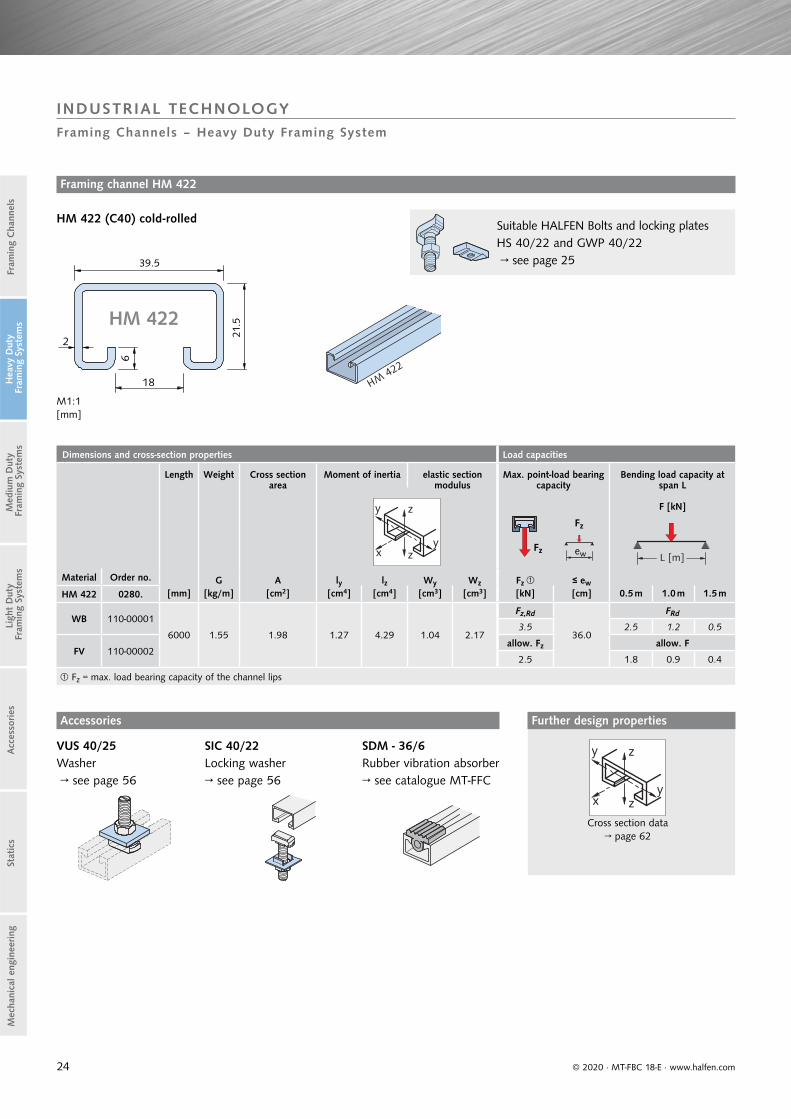
HM 422 0280. [mm] [kg/m] [cm2] [cm4] [cm4] [cm3] [cm3] [kN] [cm] 0.5 m 1.0 m 1.5 m
WB 110-00001
6000 1.55 1.98 1.27 4.29 1.04 2.17
Fz,Rd
36.0
FRd
3.5 2.5 1.2 0.5
FV 110-00002allow. Fz allow. F
2.5 1.8 0.9 0.4
Fz = max. load bearing capacity of the channel lips
y z
yx z L [m]
Fz ew
Fz
© 2020 · MT-FBC 18-E · www.halfen.com
Stat
ics
Ligh
t D
uty
Fra
min
g Sy
stem
sA
cces
sories
Fram
ing
Cha
nnel
sM
ediu
m D
uty
Fra
min
g Sy
stem
sH
eavy
Dut
y F
ram
ing
Syst
ems
Mec
hani
cal e
ngin
eering
Framing channel HM 422
HM 422 (C40) cold-rolled
M1:1[mm]
Suitable HALFEN Bolts and locking plates HS 40/22 and GWP 40/22 → see page 25
Accessories
VUS 40/25Washer → see page 56
SIC 40/22Locking washer→ see page 56
SDM - 36/6Rubber vibration absorber→ see catalogue MT-FFC
y z
yx z
Cross section data→ page 62
Further design properties
INDUSTRIAL TECHNOLOGYFraming Channels – Heavy Duty Framing System
HM 422
39.5
21.5

25
Length l [mm] M10 M12 M16
20 GVs 4.6 GVs 4.6
30
GVs 4.6 GVs 4.6 GVs 4.6
A4-70 GVs 8.8 A4-50
FV 4.6
A4-50
40
GVs 4.6 GVs 4.6 GVs 4.6
A4-70 GVs 8.8 A4-50
A4-50 A4-70
A4-70
45 GVs 8.8
50
GVs 4.6 GVs 4.6 GVs 4.6
A4-70 FV 4.6 FV 4.6
A4-50 A4-50
A4-70
Length l [mm] M10 M12 M16
60
GVs 4.6 GVs 4.6 GVs 4.6GVs 8.8 GVs 8.8
FV 4.6A4-50
80GVs 4.6 GVs 4.6 GVs 4.6
GVs 8.8 GVs 8.8A4-50 A4-50
80 Li - A4-50 A4-50
100GVs 4.6 GVs 4.6 GVs 4.6
GVs 8.8 FV 4.6A4-50 A4-50
125 - GVs 4.6 GVs 4.6
150 -GVs 4.6 GVs 4.6A4-50 A4-50
200 - GVs 4.6 GVs 4.6250 - - GVs 4.6300 - - GVs 4.6
HSR 40/22 available bolts
Length l [mm] M10 M12 M16
40 - - GVs 8.860 - - GVs 8.8
Load bearing capacities for our bolts
Load capacities for bolts Recommended load capacity per bolt in chan-nel longitudinal direction Recommended torque
Fz
xFy xy
z
Fx
Thread Ø F [kN] Fx [kN] Tinst [Nm]
40/22HS HSR HS HSR HS HSR
4.6 8.8 A4-50 A4-70 8.8 4.6 8.8 A4-50 A4-70 8.8 4.6 8.8 A4-50 A4-70 8.8
M10FRd 8.3 - - 15.6 - - - 0.42
- 15 - - 30 -allow. F 5.9 - - 11.2 - 0.3 - - 0.3
M12FRd 12.1 27.0 10.6 - - 0.7 -
- 25 70 25 - 70allow. F 8.6 19.3 7.6 - - 0.5 1.6 0.5 -
M16FRd 22.6 50.2 19.8 42.2 50.2 1.26 1.26 7.0
65 180 60 130 200allow. F 16.1 35.9 14.1 30.2 39.9 0.9 3.0 0.9 0.9 5.0
Note: do not exceed the channel load bearing capacityLoad capability due to frictionacc. to expert report, = 3
Load capacities for GWP 40/22
Fz
x
z
y
40/22
Thread Load capacity [kN]
M5FRd 3.1
allow. F 2.2
M6FRd 3.1
allow. F 2.2
M8FRd 5.6
allow. F 4.0
M10FRd 9.0
allow. F 6.4
M12FRd 13.0
allow. F 9.3
GWP 40/22 available plates
GV A4a
[mm]b
[mm]d
[mm]
M5 -
35 1710
M6 -
M8 M8
M10 M10
M12 M12 11.5
© 2020 · MT-FBC 18-E · www.halfen.com
Stat
ics
Ligh
t D
uty
Fra
min
g Sy
stem
sA
cces
sories
Fram
ing
Cha
nnel
sM
ediu
m D
uty
Fra
min
g Sy
stem
sH
eavy
Dut
y F
ram
ing
Syst
ems
Mec
hani
cal e
ngin
eering
HALFEN Bolts HS 40/22 and HSR 40/22
HSR 40/22HALFEN Bolt with nib, incl. nut, for hot-rolled profiles in mild steel WB/FV
Locking plates GWP 40/22
Li = left-hand thread
HS 40/22HALFEN Bolt incl. nut
Locking plate GWP 40/22
HS 40/22 available bolts
INDUSTRIAL TECHNOLOGYBolts and Accessories – Heavy Duty Framing System
32,5
32,5

26
Dimensions and cross-section properties Load capacities
Length Weight Cross section area
Moment of inertia
Elastic section modulus
Max. point-load bearing capacity
Bending load capacity at span L
F [kN]
Material Order no. G A ly lz Wy Wz Fz ≤ ewHZM 64/44 0284. [mm] [kg/m] [cm2] [cm4] [cm4] [cm3] [cm3] [kN] [cm] 0.5 m 1.0 m 1.5 m
WB 080-00002
6070 7.15 9.1 23.83 53.94 10.36 16.85
Fz,Rd
25.0
FRd
53.3 34.8 17.4 10.0FV 080-00003
allow. Fz allow. FA4 080-00001 38.1 24.8 12.4 7.1
Fz = max. load bearing capacity of the channel lips - see also page 66
L [m]
F
Fz ew
y z
yx z
© 2020 · MT-FBC 18-E · www.halfen.com
Stat
ics
Ligh
t D
uty
Fra
min
g Sy
stem
sA
cces
sories
Fram
ing
Cha
nnel
sM
ediu
m D
uty
Fra
min
g Sy
stem
sH
eavy
Dut
y F
ram
ing
Syst
ems
Mec
hani
cal e
ngin
eering
Double channel on request - profile data, see page 60
Suitable HALFEN Bolts HZS 64/44 → see page 27
HZM 64/44 hot-rolled, serrated
Framing channel HZM 64/44
VUS 72/48 Washer→ see page 56
Accessories
y z
yx z
Cross section data→ page 60
Fz
FxFy
Point-load capacities→ pages 66–67
N
Flexural buckling→ page 70
Further design properties
INDUSTRIAL TECHNOLOGYFraming Channels – Heavy Duty Framing System
HZM 64/44
64
26
44
5
10
4.5
HZM 64/44
HZM 64/44 D
M1:1 [mm]

27
HZS 64/44 available bolts
Length l [mm] M20 M24
80GVs 8.8 GVs 8.8
A4-70 A4-70
125GVs 8.8
–A4-70
150 –GVs 8.8
A4-70
Load bearing capacities for our bolts
Load capacities for bolts Max. load capacity per bolt in chan-nel longitudinal direction
Recommended torque
Thread Ø F [kN] Fx [kN] Tinst [Nm]
64/44HZS HZS HZS
8.8 A4-70 8.8 A4-70 8.8 A4-70
M20FRd 79.0 51.5 37.8 37.8
350 350allow. F 56.4 36.8 27.0 27.0
M24FRd 113.7 54.3 37.8 37.8
450 450allow. F 81.2 38.8 27.0 27.0
Note: do not exceed the max. channel load bearing capacity
Fz
xFyxy
z
Fx
© 2020 · MT-FBC 18-E · www.halfen.com
Stat
ics
Ligh
t D
uty
Fra
min
g Sy
stem
sA
cces
sories
Fram
ing
Cha
nnel
sM
ediu
m D
uty
Fra
min
g Sy
stem
sH
eavy
Dut
y F
ram
ing
Syst
ems
Mec
hani
cal e
ngin
eering
HZS 64/44HALFEN Bolt,serrated incl. nut
In case of simultaneously loading in all directions (longitudinal -x, transverse -y, centrical tension -z) the resultant load must not exceed the load bearing capacity given in the table.
Fx2 + Fy
2 + Fz2 ≤ allow. F
resp.
Fx,Ed2 + Fy,Ed
2 + Fz,Ed2 ≤ FRd
Fx, Fy, Fz = existing loads
allow. F = allowable load bearing capacity of the bolt
resp.
Fx,Ed, Fy,Ed, Fz,Ed = design values of actionFRd = design value of resistance
HALFEN Bolts HZS 64/44
INDUSTRIAL TECHNOLOGYBolts – Heavy Duty Framing System
l
51

28
Dimensions and cross-section properties Load capacities
Length Weight Cross section area
Moment of inertia Elalstic section modulus
Max. point-load bearing capacity
Bending load capacityat span L
F [kN]
Material Order no. G A ly lz Wy Wz Fz ≤ ew
HZM 53/34 0284. [mm] [kg/m] [cm2] [cm4] [cm4] [cm3] [cm3] [kN] [cm] 0.5 m 1.0 m 1.5 m
WB 070-00002
6070 4.63 5.88 9.19 23.18 4.95 8.83
F z,Rd
20.0
FRd
43.3 17.3 8.6 3.8FV 070-00003
allow. Fz allow. F
A4 070-00001 30.9 12.4 6.2 2.7
Fz = max. load bearing capacity of the channel lips - see also page 66
y z
yx z L [m]
Fz
F
ew
© 2020 · MT-FBC 18-E · www.halfen.com
Stat
ics
Ligh
t D
uty
Fra
min
g Sy
stem
sA
cces
sories
Fram
ing
Cha
nnel
sM
ediu
m D
uty
Fra
min
g Sy
stem
sH
eavy
Dut
y F
ram
ing
Syst
ems
Mec
hani
cal e
ngin
eering
Framing channel HZM 53/34
Double channel on request - profile data, see page 60
HZM 53/34 hot-rolled, serrated
PA - 22Channel cover→ see page 58
VUS 52/34Washer→ see page 56
y z
yx z
Cross section data→ page 60
Fz
FxFy
Point-load capacities → pages 66–67
N
Flexural buckling→ page 70
Further design properties
Suitable HALFEN Bolts HZS 53/34 → see page 29
Accessories
INDUSTRIAL TECHNOLOGYFraming Channels – Heavy Duty Framing System
M1:1 [mm]
4
4
34
52.5
22.5
7.5
HZM 53/34
HZM 53/34 D
29
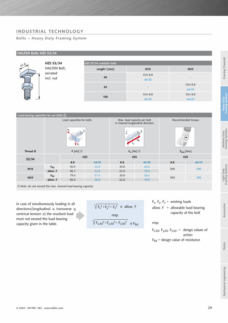
Load bearing capacities for our bolts Load capacities for bolts Max. load capacity per bolt
in channel longitudinal directionRecommended torque
Thread Ø F [kN] Fx [kN] Tinst [Nm]
53/34HZS HZS HZS
8.8 A4-70 8.8 A4-70 8.8 A4-70
M16FRd 50.5 33.0 30.8 26.6
200 200allow. F 36.1 23.6 22.0 19.0
M20FRd 79.0 51.5 30.8 26.6
350 350allow. F 56.4 36.8 22.0 19.0
Note: do not exceed the max. channel load bearing capacity
Fz
xFy xy
z
Fx
HZS 53/34 available bolts
Length l [mm] M16 M20
60GVs 8.8
-A4-70
65 -GVs 8.8
A4-70
100GVs 8.8 GVs 8.8
A4-70 A4-70
© 2020 · MT-FBC 18-E · www.halfen.com
Stat
ics
Ligh
t D
uty
Fra
min
g Sy
stem
sA
cces
sories
Fram
ing
Cha
nnel
sM
ediu
m D
uty
Fra
min
g Sy
stem
sH
eavy
Dut
y F
ram
ing
Syst
ems
Mec
hani
cal e
ngin
eering
HALFEN Bolts HZS 53/34
HZS 53/34HALFEN Bolt,serratedincl. nut
Fx2 + Fy
2 + Fz2 ≤ allow. F
resp.
Fx,Ed2 + Fy,Ed
2 + Fz,Ed2 ≤ FRd
INDUSTRIAL TECHNOLOGYBolts – Heavy Duty Framing System
In case of simultaneously loading in all directions (longitudinal -x, transverse -y, centrical tension -z) the resultant load must not exceed the load bearing capacity given in the table.
Fx, Fy, Fz = existing loads
allow. F = allowable load bearing capacity of the bolt
resp.
Fx,Ed, Fy,Ed, Fz,Ed = design values of action
FRd = design value of resistance
41,6
30
Dimensions and cross-section properties Load capacities
Length Weight Cross section area
Moment of inertia Elastic section modulus
Max. point-load bearing capacity
Bending load capacity at span L
F [kN]
Material Order no. G A ly lz Wy Wz Fz ≤ ew
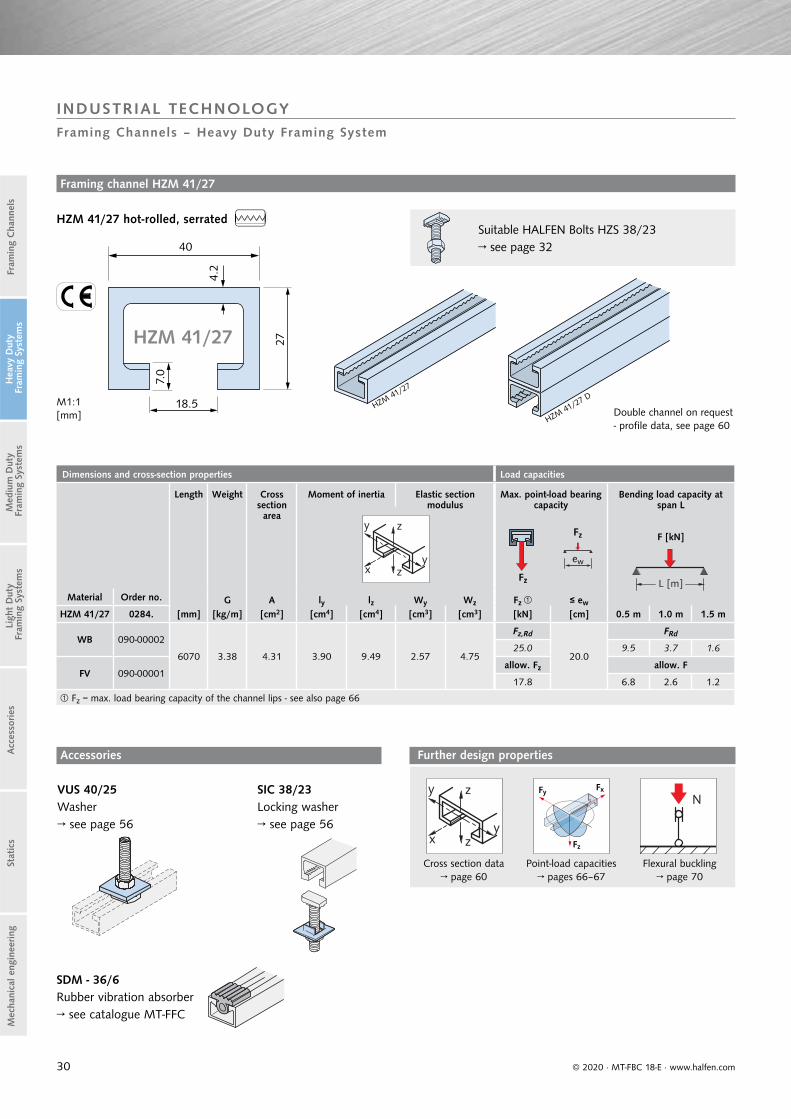
HZM 41/27 0284. [mm] [kg/m] [cm2] [cm4] [cm4] [cm3] [cm3] [kN] [cm] 0.5 m 1.0 m 1.5 m
WB 090-00002
6070 3.38 4.31 3.90 9.49 2.57 4.75
Fz,Rd
20.0
FRd
25.0 9.5 3.7 1.6
FV 090-00001allow. Fz allow. F
17.8 6.8 2.6 1.2
Fz = max. load bearing capacity of the channel lips - see also page 66
y z
yx z
L [m]Fz
Fz
ew
© 2020 · MT-FBC 18-E · www.halfen.com
Stat
ics
Ligh
t D
uty
Fra
min
g Sy
stem
sA
cces
sories
Fram
ing
Cha
nnel
sM
ediu
m D
uty
Fra
min
g Sy
stem
sH
eavy
Dut
y F
ram
ing
Syst
ems
Mec
hani
cal e
ngin
eering
M1:1[mm]
HZM 41/27 hot-rolled, serrated
Double channel on request - profile data, see page 60
Accessories
VUS 40/25Washer→ see page 56
SIC 38/23Locking washer→ see page 56
Framing channel HZM 41/27
Suitable HALFEN Bolts HZS 38/23 → see page 32
SDM - 36/6 Rubber vibration absorber→ see catalogue MT-FFC
y z
yx z
Cross section data→ page 60
Fz
FxFy
Point-load capacities→ pages 66–67
N
Flexural buckling→ page 70
Further design properties
INDUSTRIAL TECHNOLOGYFraming Channels – Heavy Duty Framing System
HZM 41/27
HZM 41/27
HZM 41/27
D
40
27
18.5
4.2
7.0
31
Dimensions and cross-section properties Load capacities
Length Weight Cross section area
Moment of inertia Elastic section modulus
Max. point-load bearing capacity
Bending load capacity at span L
F [kN]
Material Order no. G A ly lz Wy Wz Fz ≤ ew
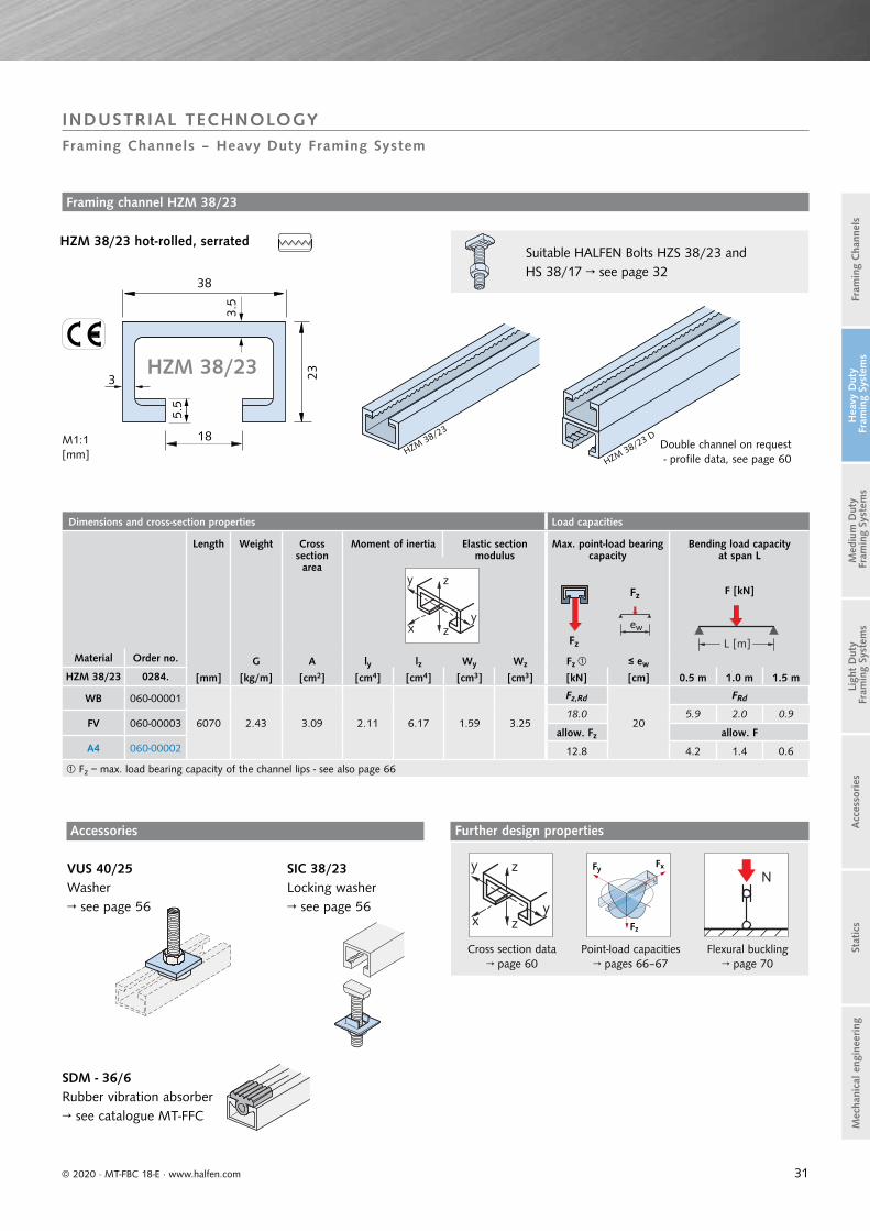
HZM 38/23 0284. [mm] [kg/m] [cm2] [cm4] [cm4] [cm3] [cm3] [kN] [cm] 0.5 m 1.0 m 1.5 m
WB 060-00001
6070 2.43 3.09 2.11 6.17 1.59 3.25
Fz,Rd
20
FRd
18.0 5.9 2.0 0.9FV 060-00003
allow. Fz allow. FA4 060-00002 12.8 4.2 1.4 0.6
Fz = max. load bearing capacity of the channel lips - see also page 66
y z
yx z
L [m]Fz
Fz
ew
© 2020 · MT-FBC 18-E · www.halfen.com
Stat
ics
Ligh
t D
uty
Fra
min
g Sy
stem
sA
cces
sories
Fram
ing
Cha
nnel
sM
ediu
m D
uty
Fra
min
g Sy
stem
sH
eavy
Dut
y F
ram
ing
Syst
ems
Mec
hani
cal e
ngin
eering
M1:1[mm]
Framing channel HZM 38/23
HZM 38/23 hot-rolled, serrated
Double channel on request - profile data, see page 60
Accessories
VUS 40/25Washer→ see page 56
SIC 38/23Locking washer→ see page 56
Suitable HALFEN Bolts HZS 38/23 and HS 38/17 → see page 32
SDM - 36/6 Rubber vibration absorber→ see catalogue MT-FFC
y z
yx z
Cross section data→ page 60
Fz
FxFy
Point-load capacities→ pages 66–67
N
Flexural buckling→ page 70
Further design properties
INDUSTRIAL TECHNOLOGYFraming Channels – Heavy Duty Framing System
HZM 38/23
HZM 38/23
HZM 38/23 D
23
38
18
3
3.5
5.5
32
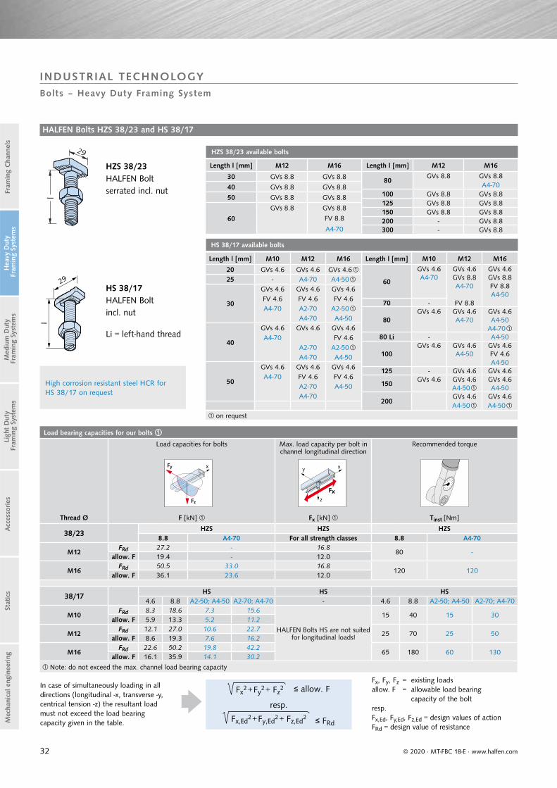
Length l [mm] M12 M16
30 GVs 8.8 GVs 8.8
40 GVs 8.8 GVs 8.8
50 GVs 8.8 GVs 8.8
60
GVs 8.8 GVs 8.8
FV 8.8
A4-70
Length l [mm] M12 M16
80GVs 8.8 GVs 8.8
A4-70100 GVs 8.8 GVs 8.8125 GVs 8.8 GVs 8.8150 GVs 8.8 GVs 8.8200 - GVs 8.8300 - GVs 8.8
Load bearing capacities for our bolts Load capacities for bolts Max. load capacity per bolt in
channel longitudinal direction Recommended torque
Thread Ø F [kN] Fx [kN] Tinst [Nm]
38/23HZS HZS HZS
8.8 A4-70 For all strength classes 8.8 A4-70
M12FRd 27.2 - 16.8
80 -allow. F 19.4 - 12.0
M16FRd 50.5 33.0 16.8
120 120allow. F 36.1 23.6 12.0
38/17HS HS HS
4.6 8.8 A2-50; A4-50 A2-70; A4-70 - 4.6 8.8 A2-50; A4-50 A2-70; A4-70
M10FRd 8.3 18.6 7.3 15.6
HALFEN Bolts HS are not suited for longitudinal loads!
15 40 15 30allow. F 5.9 13.3 5.2 11.2
M12FRd 12.1 27.0 10.6 22.7
25 70 25 50allow. F 8.6 19.3 7.6 16.2
M16FRd 22.6 50.2 19.8 42.2
65 180 60 130allow. F 16.1 35.9 14.1 30.2
Note: do not exceed the max. channel load bearing capacity
Fz
xFy xy
z
Fx
HZS 38/23 available bolts
Length l [mm] M10 M12 M16
20 GVs 4.6 GVs 4.6 GVs 4.6 25 - A4-70 A4-50
30
GVs 4.6 GVs 4.6 GVs 4.6FV 4.6 FV 4.6 FV 4.6A4-70 A2-70 A2-50
A4-70 A4-50
40
GVs 4.6 GVs 4.6 GVs 4.6A4-70 FV 4.6
A2-70 A2-50A4-70 A4-50
50
GVs 4.6 GVs 4.6 GVs 4.6A4-70 FV 4.6 FV 4.6
A2-70 A4-50A4-70
Length l [mm] M10 M12 M16
60
GVs 4.6 GVs 4.6 GVs 4.6A4-70 GVs 8.8 GVs 8.8
A4-70 FV 8.8A4-50
70 - FV 8.8
80GVs 4.6 GVs 4.6 GVs 4.6
A4-70 A4-50A4-70
80 Li - A4-50
100GVs 4.6 GVs 4.6 GVs 4.6
A4-50 FV 4.6A4-50
125 - GVs 4.6 GVs 4.6
150GVs 4.6 GVs 4.6 GVs 4.6
A4-50 A4-50
200GVs 4.6 GVs 4.6A4-50 A4-50
HS 38/17 available bolts
on request
© 2020 · MT-FBC 18-E · www.halfen.com
Stat
ics
Ligh
t D
uty
Fra
min
g Sy
stem
sA
cces
sories
Fram
ing
Cha
nnel
sM
ediu
m D
uty
Fra
min
g Sy
stem
sH
eavy
Dut
y F
ram
ing
Syst
ems
Mec
hani
cal e
ngin
eering
In case of simultaneously loading in all directions (longitudinal -x, transverse -y, centrical tension -z) the resultant load must not exceed the load bearing capacity given in the table.
Fx2 + Fy
2 + Fz2 ≤ allow. F
resp.
Fx,Ed2 + Fy,Ed
2 + Fz,Ed2 ≤ FRd
Fx, Fy, Fz = existing loadsallow. F = allowable load bearing capacity of the boltresp.Fx,Ed, Fy,Ed, Fz,Ed = design values of actionFRd = design value of resistance
HALFEN Bolts HZS 38/23 and HS 38/17
HZS 38/23HALFEN Bolt serrated incl. nut
HS 38/17HALFEN Bolt incl. nut
Li = left-hand thread
High corrosion resistant steel HCR for HS 38/17 on request
INDUSTRIAL TECHNOLOGYBolts – Heavy Duty Framing System
29

33
Dimensions and cross-section properties Load capacities
Length Weight Cross section area
Moment of inertia Elastic section modulus
Max. point-load bearing capacity
Bending load capacity at span L
F [kN]
Material Order no. G A ly lz Wy Wz Fz ≤ ew
HZM 29/20 0284. [mm] [kg/m] [cm2] [cm4] [cm4] [cm3] [cm3] [kN] [cm] 0.5 m 1.0 m 1.5 m
WB 050-00001
6070 1.55 1.98 1.02 2.42 0.91 1.67
Fz,Rd
15.0
FRd
11.2 3.3 1.0 0.4
FV 050-00003allow. Fz allow. F
8.0 2.4 0.7 0.3
Fz = max. load bearing capacity of the channel lips - see also page 66
y z
yx z
L [m]
Fz
Fz ew
© 2020 · MT-FBC 18-E · www.halfen.com
Stat
ics
Ligh
t D
uty
Fra
min
g Sy
stem
sA
cces
sories
Fram
ing
Cha
nnel
sM
ediu
m D
uty
Fra
min
g Sy
stem
sH
eavy
Dut
y F
ram
ing
Syst
ems
Mec
hani
cal e
ngin
eering
Double channel on request- profile data, see page 60
M1:1[mm]
Framing channel HZM 29/20
HZM 29/20 hot-rolled, serrated
Accessories
SIC 29/20Locking washer→ see page 56
US DIN 9021Washer → see page 56
Suitable HALFEN Bolt HZS 29/20 and HS 28/15 → see page 34
y z
yx z
Cross section data page 60
Fz
FxFy
Point-load capacities pages 66–67
N
Flexural buckling page 70
Further design properties
INDUSTRIAL TECHNOLOGYFraming Channels – Heavy Duty Framing System
HZM 29/20
2920
14
5
2.5
2.5
HZM29/20
HZM 29/20 D

34
Load bearing capacities for our bolts Load capacities for bolts Max. load capacity per bolt in
channel longitudinal directionRecommended torque
Thread Ø F [kN] Fx [kN] Tinst [Nm]
29/20HZS HZS HZS8.8 8.8 8.8
M12FRd 27.2 11.2
80allow. F 19.4 8.0
28/15HS HS HS
4.6 8.8 A2/A4-50 A2/A4-70 - 4.6 8.8 A2/A4-50 A2/A4-70
M6FRd 2.9 - - -
HALFEN Bolts HS are not suited for longitudinal loads!
3 - 3 -allow. F 2.1 - - -
M8FRd 5.3 11.7 -
8 20 8 15allow. F 3,8 8.3 - 5.5
M10FRd 8.3 18.6 7.3 15.6
15 40 15 30allow. F 5,9 13.3 5.2 11.2
M12FRd 12.1 - - -
25 70 25 50allow. F 8,6 - - -
Note: do not exceed the max. channel load bearing capacity
Fz
xFy xy
z
Fx
HS 28/15 available bolts
Length l [mm] M6 M8 M10 M12
15 GVs 4.6 GVs 4.6 GVs 4.6
20GVs 4.6 GVs 4.6 GVs 4.6
GVs 8.8 A2-70A2-70 A4-70
25GVs 4.6 GVs 4.6 GVs 4.6
A2-70 A2-70A4-70
30
GVs 4.6 GVs 4.6 GVs 4.6 GVs 4.6A2-70 FV 4.6A4-70 A2-70
A4-7035 GVs 4.6
40
GVs 4.6 GVs 4.6 GVs 4.6FV 8.8A2-70A4-70
Length l [mm] M6 M8 M10 M12
50
GVs 4.6 GVs 4.6 GVs 4.6FV 4.6A2-70A4-70
60GVs 4.6 GVs 4.6
GVs 8.8A4-70
80GVs 4.6 GVs 4.6 GVs 4.6
A4-70
100GVs 4.6 GVs 4.6
A4-50
125GVs 4.6A4-50
150GVs 4.6 GVs 4.6
A4-50
200GVs 4.6A4-50
on request
Length l [mm] M12
30 GVs 8.840 GVs 8.850 GVs 8.860 GVs 8.880 GVs 8.8100 GVs 8.8
Length l [mm] M12
125 GVs 8.8150 GVs 8.8200 GVs 8.8250 GVs 8.8
300 GVs 8.8
HZS 29/20 available bolts
© 2020 · MT-FBC 18-E · www.halfen.com
Stat
ics
Ligh
t D
uty
Fra
min
g Sy
stem
sA
cces
sories
Fram
ing
Cha
nnel
sM
ediu
m D
uty
Fra
min
g Sy
stem
sH
eavy
Dut
y F
ram
ing
Syst
ems
Mec
hani
cal e
ngin
eering
High corrosion resistant stainless steel HCR for HS 28/15 on request
HALFEN Bolts HZS 29/20 and HS 28/15
HZS 29/20HALFEN Bolt serrated incl. nut
In case of simultaneously loading in all directions (longitudinal -x, transverse -y, centrical tension -z) the resultant load must not exceed the load bearing capacity given in the table.
Fx2 + Fy
2 + Fz2 ≤ allow. F
resp.
Fx,Ed2 + Fy,Ed
2 + Fz,Ed2 ≤ FRd
HS 28/15HALFEN Bolt incl. nut
INDUSTRIAL TECHNOLOGYBolts – Heavy Duty Framing System
Fx, Fy, Fz = existing loadsallow. F = allowable load bearing capacity
of the boltresp.Fx,Ed, Fy,Ed, Fz,Ed = design values of actionFRd = design value of resistance
35
Dimensions and cross-section properties Load capacities
Length Weight Cross section area
Moment of inertia Elastic section modulus
Max. point-load bearing capacity
Bending load capacity at span L
F [kN]
Material Order no. G A ly lz Wy Wz Fz ≤ ew
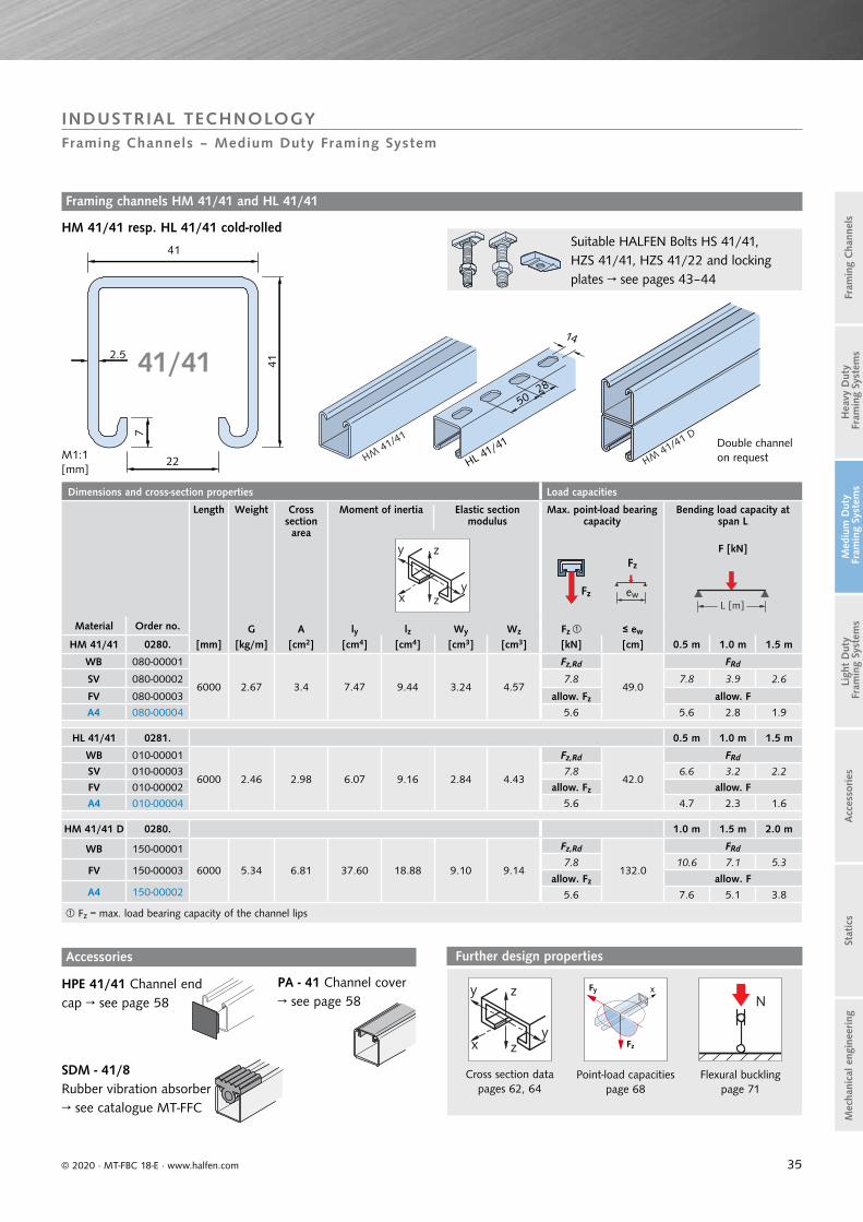
HM 41/41 0280. [mm] [kg/m] [cm2] [cm4] [cm4] [cm3] [cm3] [kN] [cm] 0.5 m 1.0 m 1.5 m
WB 080-00001
6000 2.67 3.4 7.47 9.44 3.24 4.57
Fz,Rd
49.0
FRd
SV 080-00002 7.8 7.8 3.9 2.6
FV 080-00003 allow. Fz allow. F
A4 080-00004 5.6 5.6 2.8 1.9
HL 41/41 0281. 0.5 m 1.0 m 1.5 m
WB 010-00001
6000 2.46 2.98 6.07 9.16 2.84 4.43
Fz,Rd
42.0
FRd
SV 010-00003 7.8 6.6 3.2 2.2
FV 010-00002 allow. Fz allow. F
A4 010-00004 5.6 4.7 2.3 1.6
HM 41/41 D 0280. 1.0 m 1.5 m 2.0 m
WB 150-00001
6000 5.34 6.81 37.60 18.88 9.10 9.14
Fz,Rd
132.0
FRd
7.8 10.6 7.1 5.3FV 150-00003
allow. Fz allow. FA4 150-00002 5.6 7.6 5.1 3.8
Fz = max. load bearing capacity of the channel lips
y z
yx z L [m]
Fz
Fz
ew
41
41
22
7
2.5
HM41/41
HM41/41 D
M1:1[mm]
41/41
Suitable HALFEN Bolts HS 41/41, HZS 41/41, HZS 41/22 and locking plates → see pages 43–44
HL 41/41
5028
14
© 2020 · MT-FBC 18-E · www.halfen.com
Stat
ics
Ligh
t D
uty
Fra
min
g Sy
stem
sA
cces
sories
Fram
ing
Cha
nnel
sM
ediu
m D
uty
Fra
min
g Sy
stem
sH
eavy
Dut
y F
ram
ing
Syst
ems
Mec
hani
cal e
ngin
eering
INDUSTRIAL TECHNOLOGYFraming Channels – Medium Duty Framing System
Accessories
HPE 41/41 Channel end cap → see page 58
PA - 41 Channel cover→ see page 58
SDM - 41/8 Rubber vibration absorber→ see catalogue MT-FFC
Framing channels HM 41/41 and HL 41/41
HM 41/41 resp. HL 41/41 cold-rolled
Double channel on request
y z
yx z
Cross section datapages 62, 64
Fz
xFy
Point-load capacitiespage 68
N
Flexural bucklingpage 71
Further design properties

36
y z
yx z
Cross section datapages 62, 64
Fz
FxFy
Point-load capacitiespage 68
N
Flexural bucklingpage 71
Further design properties
Dimensions and cross-section properties Load capacities
Length Weight Cross section area
Moment of inertia Elastic section modulus
Max. point-load bearing capacity
Bending load capacity at span L
F [kN]
Material Order no. G A ly lz Wy Wz Fz ≤ ew
HZM 41/41 0284. [mm] [kg/m] [cm2] [cm4] [cm4] [cm3] [cm3] [kN] [cm] 0.5 m 1.0 m 1.5 m
WB 010-00001
6000 2.63 3.35 7.34 9.37 3.15 4.54
Fz,Rd
47.0
FRd
FV 010-00002 7.8 7.7 3.8 2.6
A4 010-00003 allow. Fz allow. F
5.6 5.5 2.7 1.8
HZL 41/41 0283. 0.5 m 1.0 m 1.5 m
WB 010-00001
6000 2.46 2.90 5.87 9.04 2.69 4.38
Fz,Rd
41.0
FRd
FV 010-00002 7.8 6.3 3.2 2.1A4 010-00003 allow. Fz allow. F
5.6 4.5 2.3 1.5
HZM 41/41 D 0284. 1.0 m 1.5 m 2.0 m
WB 030-00001
6000 5.27 6.7 36.45 18.73 8.83 9.07
Fz,Rd
126.0
FRd
FV 030-00002 7.8 10.3 6.9 5.2A4 030-00003 allow. Fz allow. F
5.6 7.4 4.9 3.7
Fz = max. load bearing capacity of the channel lips
L [m]Fz
Fz
ew
y z
yx z
HZL 41/41
14
28
50
41
41
22
7
2.5
HZM41/41
HZM41/41 D
M1:1[mm]
41/41
© 2020 · MT-FBC 18-E · www.halfen.com
Stat
ics
Ligh
t D
uty
Fra
min
g Sy
stem
sA
cces
sories
Fram
ing
Cha
nnel
sM
ediu
m D
uty
Fra
min
g Sy
stem
sH
eavy
Dut
y F
ram
ing
Syst
ems
Mec
hani
cal e
ngin
eering
INDUSTRIAL TECHNOLOGYFraming Channels – Medium Duty Framing System
Framing channel HZM 41/41 and HZL 41/41
Accessories
HZM resp. HZL 41/41 cold-rolled, serrated
HPE 41/41Channel end cap
PA - 41 Channel cover→ see page 58
SDM - 41/8Rubber vibration absorber→ see catalogue MT-FFC
→ see page 58
Double channel on request
Suitable HALFEN Bolts HS 41/41, HZS 41/41, HZS 41/22 and locking plates → see pages 43–44
37
Dimensions and cross-section properties Load capacities
Length Weight Cross section area
Moment of inertia Elastic section modulus
Max. point-load bearing capacity
Bending load capacity at span L
F [kN]
Material Order no. G A ly lz Wy W Fz ≤ ew
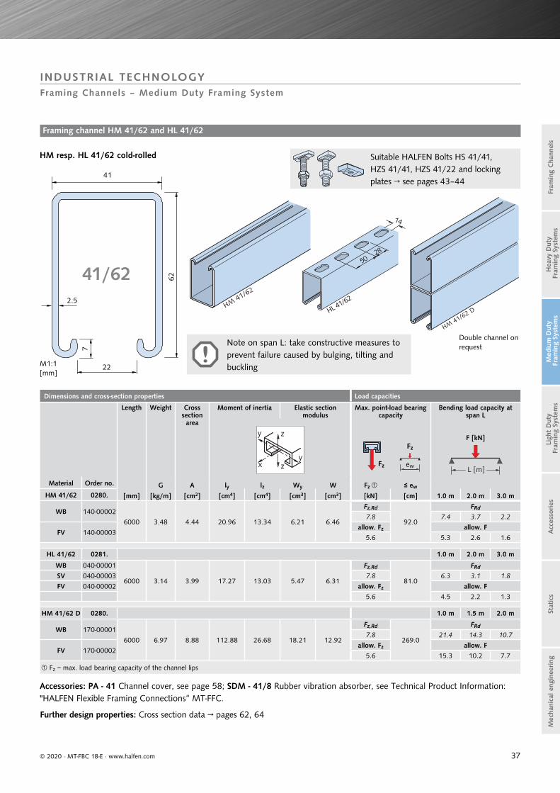
HM 41/62 0280. [mm] [kg/m] [cm2] [cm4] [cm4] [cm3] [cm3] [kN] [cm] 1.0 m 2.0 m 3.0 m
WB 140-00002
6000 3.48 4.44 20.96 13.34 6.21 6.46
Fz,Rd
92.0
FRd
7.8 7.4 3.7 2.2
FV 140-00003allow. Fz allow. F
5.6 5.3 2.6 1.6
HL 41/62 0281. 1.0 m 2.0 m 3.0 m
WB 040-00001
6000 3.14 3.99 17.27 13.03 5.47 6.31
Fz,Rd
81.0
FRd
SV 040-00003 7.8 6.3 3.1 1.8
FV 040-00002 allow. Fz allow. F
5.6 4.5 2.2 1.3
HM 41/62 D 0280. 1.0 m 1.5 m 2.0 m
WB 170-00001
6000 6.97 8.88 112.88 26.68 18.21 12.92
Fz,Rd
269.0
FRd
7.8 21.4 14.3 10.7
FV 170-00002 allow. Fz allow. F
5.6 15.3 10.2 7.7
Fz = max. load bearing capacity of the channel lips
L [m]Fz
Fz
ew
y z
yx z
41/62
HM41/62
HL 41/62
14
2850
HM41/62 D
4162
22
7
2.5
M1:1[mm]
© 2020 · MT-FBC 18-E · www.halfen.com
Stat
ics
Ligh
t D
uty
Fra
min
g Sy
stem
sA
cces
sories
Fram
ing
Cha
nnel
sM
ediu
m D
uty
Fra
min
g Sy
stem
sH
eavy
Dut
y F
ram
ing
Syst
ems
Mec
hani
cal e
ngin
eering
INDUSTRIAL TECHNOLOGYFraming Channels – Medium Duty Framing System
Suitable HALFEN Bolts HS 41/41, HZS 41/41, HZS 41/22 and locking plates → see pages 43–44
Framing channel HM 41/62 and HL 41/62
HM resp. HL 41/62 cold-rolled
Accessories: PA - 41 Channel cover, see page 58; SDM - 41/8 Rubber vibration absorber, see Technical Product Information: "HALFEN Flexible Framing Connections“ MT-FFC.
Note on span L: take constructive measures to prevent failure caused by bulging, tilting and buckling
Double channel on request
Further design properties: Cross section data → pages 62, 64

38
Dimensions and cross-section properties Load capacities
Length Weight Cross section area
Moment of inertia Elastic section modulus
Max. point-load bearing capacity
Bending load capacity at span L
F [kN]
Material Order no. G A ly lz Wy Wz Fz ≤ ew
HM 41/83 0280. [mm] [kg/m] [cm2] [cm4] [cm4] [cm3] [cm3] [kN] [cm] 1.0 m 2.0 m 3.0 m
WB 130-00002
6000 4.29 5.47 43.82 17.22 9.91 8.34
Fz,Rd
148.0
FRd
SV 130-00001 7.8 11.7 5.9 3.9FV 130-00003 allow. Fz allow. F
5.6 8.4 4.2 2.8
HL 41/83 0281. 1.0 m 2.0 m 3.0 m
WB 030-00004
6000 3.93 5.02 37.07 16.93 8.85 8.20
Fz,Rd
133.0
FRd
SV 030-00006 7.8 10.2 5.2 3.4FV 030-00005 allow. Fz allow. F
5.6 7.3 3.7 2.4
Fz = max. load bearing capacity of the channel lips
Fz
Fz
ew
L [m]
y z
yx z
41/83
41
83
22
72.5
HM41/83
14
28
50
HL 41/83
© 2020 · MT-FBC 18-E · www.halfen.com
Stat
ics
Ligh
t D
uty
Fra
min
g Sy
stem
sA
cces
sories
Fram
ing
Cha
nnel
sM
ediu
m D
uty
Fra
min
g Sy
stem
sH
eavy
Dut
y F
ram
ing
Syst
ems
Mec
hani
cal e
ngin
eering
INDUSTRIAL TECHNOLOGYFraming Channels – Medium Duty Framing System
Framing channel HM 41/83 and HL 41/83
HM 41/83 resp. HL 41/83 cold-rolled
SDM - 41/8 Rubber vibration absorber→ see catalogue MT-FFC
Accessories
PA - 41 Channel cover→ see page 58
y z
yx z
Further design properties
Cross section datapages 62, 64
Note on span L: take constructive measures to prevent failure caused by bulging, tilting and buckling
Suitable HALFEN Bolts HS 41/41, HZS 41/41, HZS 41/22 and locking plates → see pages 43–44

39
Dimensions and cross-section properties Load capacities
Length Weight Cross section area
Moment of inertia Elastic section modulus
Max. point-load bearing capacity
Bending load capacity at span L
F [kN]
Material Order no. G A ly lz Wy Wz Fz ≤ ew
HZL 63/63 0283. [mm] [kg/m] [cm2] [cm4] [cm4] [cm3] [cm3] [kN] [cm] 0.5 m 1.0 m 1.5 m
FV 030-00001 3000
6.35 7.09 33.07 42.95 10.06 13.63
Fz,Rd
134.0
FRd
7.8 23.1 11.5 7.7
FV 030-00003 6000allow. Fz allow. F
5.6 16.5 8.2 5.5
Fz = max. load bearing capacity of the channel lips
L [m]
Fz
F
ew
y z
yx z
HALFEN
63
63
22
7
3
9.5 9.5
2.5
M1:1[mm]
HZL 63/63
28
14
250
HZL 63/
63
© 2020 · MT-FBC 18-E · www.halfen.com
Stat
ics
Ligh
t D
uty
Fra
min
g Sy
stem
sA
cces
sories
Fram
ing
Cha
nnel
sM
ediu
m D
uty
Fra
min
g Sy
stem
sH
eavy
Dut
y F
ram
ing
Syst
ems
Mec
hani
cal e
ngin
eering
INDUSTRIAL TECHNOLOGYFraming Channels – Medium Duty Framing System
Accessories
HPE 63/63Channel end cap→ see page 58
PA - 41Channel cover→ see page 58
Serration
Framing channel HZL 63/63
HZL 63/63 cold-rolled, serratedStandard profile for our Powerclick System 63. More information on the Framing System "Powerclick" can be found in Technical Product Information "HALFEN Powerclick PC63".
Suitable HALFEN Bolts HS 41/41, HZS 41/41, HZS 41/22 and locking plates → see pages 43–44
SDM - 41/8Rubber vibration absorber→ see catalogue MT-FFC
y z
yx z
Cross section datapage 64
N
Flexural bucklingpage 71
Further design properties
▪ mit Tragfähigkeiten nach EC3
▪ with load capacities acc. to EC3
▪ aktualisiert nach Druckgeräte- richtlinie 2014/68/EU
▪ updated acc. to Pressure Equipment Directive (PED) 2014/68/EU
PC63 17
HALFEN POWERCLICK SYSTEM 63 Produktinformation Technik/Technical Product Information

40
Dimensions and cross-section properties Load capacities
Length Weight Cross section area
Moment of inertia Elastic section modulus
Max. point-load bearing capacity
Bending load capacity at span L
F [kN]
Material Order no. G A ly lz Wy Wz Fz ≤ ew
HM 41/22 0280. [mm] [kg/m] [cm2] [cm4] [cm4] [cm3] [cm3] [kN] [cm] 0.5 m 1.0 m 1.5 m
WB 120-00001
6000 1.86 2.37 1.28 5.56 1.05 2.69
Fz,Rd
15.0
FRd
SV 120-00002 7.8 2.7 1.2 0.5
FV 120-00003 allow. Fz allow. F
A4 120-00004 5.6 1.9 0.9 0.4
HL 41/22 0281. 0.5 m 1.0 m 1.5 m
WB 020-00001
6000 1.57 1.95 0.99 5.27 0.89 2.55
Fz,Rd
12.0
FRd
SV 020-00003 7.8 2.2 1.0 0.4
FV 020-00002 allow. Fz allow. F
A4 020-00004 5.6 1.6 0.7 0.3
HM 41/22 D 0280. 1.0 m 1.5 m 2.0 m
WB 160-00001
6000 3.73 4.75 6.02 11.11 2.91 5.38
Fz,Rd
42.0
FRd
FV 160-00002 7.8 3.5 2.3 1.4
A4 160-00003 allow. Fz allow. F5.6 2.5 1.7 1.0
Fz = max. load bearing capacity of the channel lips
L [m]
Fz
Fz
ew
y z
yx z
41/22
41
21
22
7
2.5
HM 41/22
HL 41/22
14
28
50
HM41/22 D
M1:1[mm]
© 2020 · MT-FBC 18-E · www.halfen.com
Stat
ics
Ligh
t D
uty
Fra
min
g Sy
stem
sA
cces
sories
Fram
ing
Cha
nnel
sM
ediu
m D
uty
Fra
min
g Sy
stem
sH
eavy
Dut
y F
ram
ing
Syst
ems
Mec
hani
cal e
ngin
eering
INDUSTRIAL TECHNOLOGYFraming Channels – Medium Duty Framing System
Framing channel HM 41/22 and HL 41/22
HM 41/22 resp. HL 41/22 cold-rolled
SDM - 41/8Rubber vibration absorber→ see catalogue MT-FFC
Accessories
HPE 41/22Channel end cap→ see page 58
PA - 41Channel cover→ see page 58
Double channel on request
Suitable HALFEN Bolts HS 41/41, HZS 41/41, HZS 41/22 and locking plates → see pages 43–44
Fz
xFy
Point load capacitiespage 68
y z
yx z
Cross section data→ pages 62, 64
Fz
xFy
Point-load capacities → page 68
Further design properties

41
Dimensions and cross-section properties Load capacities
Length Weight Cross section area
Moment of inertia Elastic section mo-dulus
Max. point-load bearing capacity
Bending load capacity at span L
F [kN]
Material Order no. G A ly lz Wy Wz Fz ≤ ew
HZM 41/22 0284. [mm] [kg/m] [cm2] [cm4] [cm4] [cm3] [cm3] [kN] [cm] 0.5 m 1.0 m 1.5 m
WB 020-00001
6070 1.83 2.33 1.26 5.48 1.03 2.66
Fz,Rd
14.0
FRd
FV 020-00002 7.8 2.7 1.2 0.5
A4 020-00003 allow. Fz allow. F
5.6 1.9 0.8 0.4
HZL 41/22 0.5 m 1.0 m 1.5 m
WB 020-00001
6000 1.57 1.87 0.97 5.15 0.86 2.49
Fz,Rd
12.0
FRd
FV 020-00002 7.8 2.1 0.8 0.4
A4 020-00003 allow. Fz allow. F5.6 1.5 0.6 0.3
HZM 41/22 D 1.0 m 1.5 m 2.0 m
WB 040-00001
6070 3.58 4.65 5.83 10.97 2.82 5.31
Fz,Rd
42.0
FRd
FV 040-00002 7.8 3.4 2.2 1.4
A4 040-00003 allow. Fz allow. F5.6 2.4 1.6 1.0
Fz = max. load bearing capacity of the channel lips
L [m]Fz
Fz
ew
y z
yx z
HZM
41/22
HZM
41/22D
41/22
4121
22
7
2.5
M1:1[mm] HZL 4
1/22
5028
14
© 2020 · MT-FBC 18-E · www.halfen.com
Stat
ics
Ligh
t D
uty
Fra
min
g Sy
stem
sA
cces
sories
Fram
ing
Cha
nnel
sM
ediu
m D
uty
Fra
min
g Sy
stem
sH
eavy
Dut
y F
ram
ing
Syst
ems
Mec
hani
cal e
ngin
eering
INDUSTRIAL TECHNOLOGYFraming Channels – Medium Duty Framing System
Framing channel HZM 41/22 and HZL 41/22
HZM resp. HZL 41/22 cold-rolled, serrated
SDM - 41/8Rubber vibration absorber→ see catalogue MT-FFC
Accessories
HPE 41/22Channel end cap→ see page 58
PA - 41 Channel cover→ see page 58
Double channel on request
Suitable HALFEN Bolts HS 41/41, HZS 41/41, HZS 41/22 and locking plates → see pages 43–44
y z
yx z
Cross section datapages 62, 64
Fz
xFy
Point-load capacities page 68
Further design properties

42
41/4141/22
14
28
50
HLL 41/22HLL 41/41
14
28
50M1:1[mm]
Dimensions and cross-section properties Load capacities
Length Weight Cross section area
Moment of inertia Elastic section modulus
Max. point-load bearing capacity
Bending load capacity at span L
F [kN]
Material Order no. G A ly lz Wy Wz Fz ≤ ew HLL 41/41 0282. [mm] [kg/m] [cm2] [cm4] [cm4] [cm3] [cm3] [kN] [cm] 0.5 m 1.0 m 1.5 m
SV 010-00002 6000 1.61 1.92 4.24 6.10 2.04 2.95
Fz,Rd
91.0
FRd
2.5 4.5 2.2 1.4
allow. Fz allow. F
1.8 3.2 1.6 1.0
HLL 41/22 0282.
SV 020-00003 6000 1.14 1.33 0.75 3.67 0.71 1.78
Fz,Rd
31.0
FRd
2.5 1.54 0.56 0.28allow. Fz allow. F
1.8 1.1 0.4 0.2
Fz = max. load bearing capacity of the channel lips
L [m]
Fz
Fz
ew
y z
yx z
41/4141/22
14
28
50
HLL 41/22HLL 41/41
14
28
50M1:1[mm]
4141
22
7.5
1.5
41
21
227
1.5
© 2020 · MT-FBC 18-E · www.halfen.com
Stat
ics
Ligh
t D
uty
Fra
min
g Sy
stem
sA
cces
sories
Fram
ing
Cha
nnel
sM
ediu
m D
uty
Fra
min
g Sy
stem
sH
eavy
Dut
y F
ram
ing
Syst
ems
Mec
hani
cal e
ngin
eering
INDUSTRIAL TECHNOLOGYFraming Channels – Medium Duty Framing System
SDM - 41/8 Rubber vibration absorber→ see catalogue MT-FFC
Framing channel HLL 41/41 and HLL 41/22
Accessories
HLL 41/41 cold-rolled HLL 41/22 cold-rolled
HPE 41/41 resp. HPE 41/22 Channel end cap→ see page 58
PA - 41 Channel cover→ see page 58
Suitable HALFEN Bolts HS 41/41, HZS 41/41, HZS 41/22 and locking plates → see pages 43–44

43
l
34,5
l
34,5
l
35,2
HZS 41/41 available bolts
Length l [mm] M6 M8 M10 M12 M16
30 ZL ZL ZL ZL -
50 - ZL ZL ZL -
63 - - - - ZL
75 - - ZL ZL -
100 - - -ZL
-FV 4.6
102 - - - - ZL
Diameter M16 is not compatible with profile 41/22
Diameter M16 can only be inserted into the slot from channel end
ZL = zinc flake coating
HZS 41/22 available bolts
Length l [mm] M12 M16
35FV 8.8 A4-50A4-50 -
50FV 8.8 FV 8.8A4-50 A4-50
80 A4-50 -100 - FV 8.8
HS 41/41 available bolts
Length l [mm] M10 M12
35FV 4.6 FV 4.6A4-70 A4-70
50 - FV 4.6
Load capacities for 41/... HALFEN Bolts
Thread Ø
Load bearing capacities per bolt for centric tension
for all 41/... and 63/... profiles
Fz [kN]
– Do not exceed the channel load bearing capacity –
Recommended load capacity per bolt in channel longitudinal direction
Fx [kN]
For profilesHZM/HZL
41/22, 41/41, 63/63
For profiles HM/HL 41/22,
41/41, 41/62, 41/83
For profiles HLL 41/22,
41/41
41/...HZS 41/41 HZS 41/22 HZS 41/22 HS 41/41 HS 41/41 HZS 41/41 HZS 41/22 HZS 41/22 HZS 41/41 HZS 41/22 HZS 41/41
steel 8.8 A4-50 4.6 A4-70 steel 8.8 A4-50 steel A4-50 steel
M6FRd 7.0 - - - - 3.1 - - 1.4 - 1.4
allow. F 5.0 - - - - 2.2 - - 1.0 - 1.0
M8FRd 8.4 - - - - 5.6 - - 3.4 - 3.4
allow. F 6.0 - - - - 4.0 - - 2.4 - 2.4
M10FRd 9.8 - - 9.0 9.0 7.0 - - 4.9 - 4.9
allow. F 7.0 - - 6.4 6.4 5.0 - - 3.5 - 3.5
M12FRd 9.8 9.8 9.8 11.2 13.0 7.0 7.0 7.0 5.6 2.4 5.0
allow. F 7.0 7.0 7.0 8.0 9.3 5.0 5.0 5.0 4.0 1.7 3.6
M16FRd 16.8 16.8 16.8 - - 5.6 7.0 7.0 5.6 5.6 5.6
allow. F 12.0 12.0 12.0 - - 4.0 5.0 5.0 4.0 4.0 4.0
Diameter M16 is not compatible with profile 41/22Diameter M16 can only be inserted into the slot from channel endHZS 41/41 M16 × 102 without serration
Fz
x
z
y
xy
z
Fx
Torques for HALFEN Bolts
41/...
Recommended torques Tinst [Nm]
Thread Ø HZS 41/41steel
HZS 41/228.8
HZS 41/22A4-50
HS 41/414.6
HS 41/41A4-70
M6 12 - - - -
M8 28 - - - -
M10 55 - - 15 15
M12 60 (55) 50 50 25 25
M16 125 (95) 80 80 - -
( ) values for HLL profiles in brackets
l
34,5
l
34,5
l
35,2
© 2020 · MT-FBC 18-E · www.halfen.com
Stat
ics
Ligh
t D
uty
Fra
min
g Sy
stem
sA
cces
sories
Fram
ing
Cha
nnel
sM
ediu
m D
uty
Fra
min
g Sy
stem
sH
eavy
Dut
y F
ram
ing
Syst
ems
Mec
hani
cal e
ngin
eering
INDUSTRIAL TECHNOLOGYFraming Channels – Medium Duty Framing System
HALFEN Bolts HZS 41/41, HZS 41/22 and HS 41/41
HZS 41/41HALFEN Boltserrated,order nut separately
HZS 41/22HALFEN Bolt serrated, incl. nutfor serrated channels41/41, 41/22 and 63/63
HS 41/41HALFEN Bolt incl. nut
HALFEN Bolts for all 41/... channels:

44
GWP 41/41 SN available plates
GV d[mm]
b[mm]
a[mm]
M6 6
20 34,5M8 8
M109
F M12
F = flat shape, fits to all 41/.. and 63/.. profiles
GWP 41/41 SH available plates
GV d[mm]
b[mm]
a[mm]
M6 6
20 34,5
M8 8
M10 9
M12 12
Load capacities for 41/... locking plates
Thread Ø
Load bearing capacities for centric tension
for all 41/... and 63/... profiles
Fz [kN]
– Do not exceed the channel load bearing capacity –
Recommended load capacity for locking plates in channel longitudinal direction
Fx [kN]
For profilesHZM/HZL 41/22, 41/41,
HZL 63/63
For profilesHM/HL
41/22, 41/41, 41/62, 41/83
For profiles HLL
41/22, 41/41
41/... GWP 41/41steel
GWP 41/41A4
GWP 41/22steel
GWP 41/22A4
GWP 41/41steel
GWP 41/41 A4
GWP 41/22steel
GWP 41/22A4
GWP 41/41steel
GWP 41/41steel
M6FRd 7.0 7.0 7.0 7.0 3.1 3.1 3.1 - 1.4 1.4
allow. F 5.0 5.0 5.0 5.0 2.2 2.2 2.2 - 1.0 1.0
M8FRd 8.4 8.4 8.4 8.4 5.6 5.6 5.6 5.6 3.4 3.4
allow. F 6.0 6.0 6.0 6.0 4.0 4.0 4.0 4.0 2.4 2.4
M10FRd 9.8 9.8 9.8 9.8 7.0 7.0 7.0 7.0 4.9 4.9
allow. F 7.0 7.0 7.0 7.0 5.0 5.0 5.0 5.0 3.5 3.5
M12FRd 12.6 - 9.8 9.8 7.0 - 7.0 7.0 7.0 5.0
allow. F 9.0 - 7.0 7.0 5.0 - 5.0 5.0 5.0 3.6
F M12FRd 9.8 9.8 - - 7.0 7.0 - - 5.6 5.0
allow. F 7.0 7.0 - - 5.0 5.0 - - 4.0 3.6
M16 FRd 16.8 9.8 9.8 9.8 10.5 7.0 10.5 7.0 10.5 6.3
allow. F 12.0 7.0 7.0 7.0 7.5 5.0 7.5 5.0 7.5 4.5
F = flat shape, fits to all standard 41/.. and 63/.. profilesNot compatible with profiles 41/22 and 63/63Diameter M16 can only be inserted into the slot from channel end
GWP 41/22 available plates
GV A4 d[mm]
b[mm]
a[mm]
M6 -
7.5 20 34.5
M8 M8
M10 M10
M12 M12
M16 M16
Torques for 41/... locking plates
41/...
Recommended torquesTinst [Nm]
Thread Ø
GWP 41/41 GWP 41/41 GWP 41/22 GWP 41/22
steel A4 steel A4
M6 12 6.5 12 6.5
M8 28 16.0 28 16.0
M10 55 31.5 55 31.5
M12 75 (55) - 50 50
F M12 60 (55) 55 - -
M16 125 (95) 125 80 80
( ) values for HLL profiles in brackets
Fz
x
z
y xy
z
Fx
GWP 41/41 available plates
FV GV A4 d[mm]
b[mm]
a[mm]
- M6 M6 6
2034.5
M8 M8 M8 8/6M10 M10 M10
9F M12 F M12 F M12M12 M12 -
12M16 - M16 30
F = flat shape, fits to all flat 41/.. and 63/.. profiles
b
d
a
b a
d
ba
dd
ba
© 2020 · MT-FBC 18-E · www.halfen.com
Stat
ics
Ligh
t D
uty
Fra
min
g Sy
stem
sA
cces
sories
Fram
ing
Cha
nnel
sM
ediu
m D
uty
Fra
min
g Sy
stem
sH
eavy
Dut
y F
ram
ing
Syst
ems
Mec
hani
cal e
ngin
eering
INDUSTRIAL TECHNOLOGYFraming Channels – Medium Duty Framing System
GWP 41/41Locking plate for all 41/... channelsand profile 63/63
GWP 41/41 SNLocking plate with short spring for channels 41/22 and 63/63
GWP 41/41 SHLocking plate with long spring forchannel 41/41
Locking plates GWP 41/41 - SN, - SH, GWP 41/22
GWP 41/22Locking plate forserrated channel 41/22 and 41/41
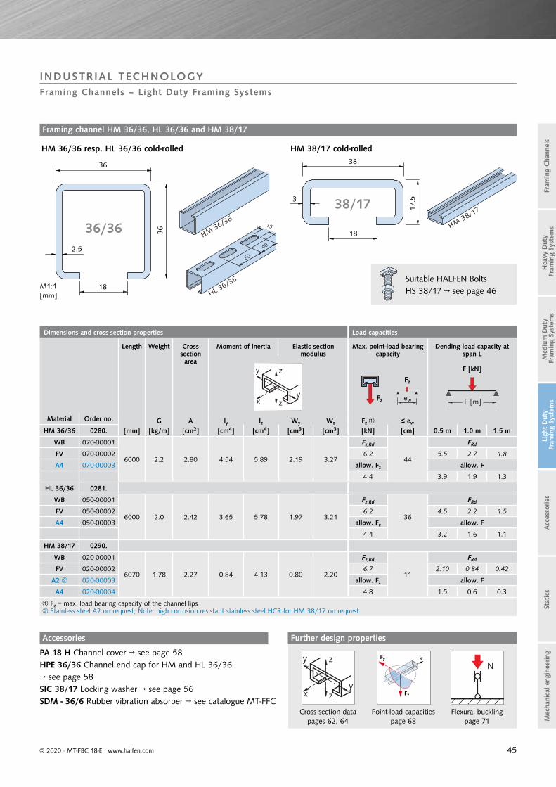
45
Dimensions and cross-section properties Load capacities
Length Weight Cross section area
Moment of inertia Elastic section modulus
Max. point-load bearing capacity
Dending load capacity at span L
F [kN]
Material Order no. G A ly lz Wy Wz Fz ≤ ew
HM 36/36 0280. [mm] [kg/m] [cm2] [cm4] [cm4] [cm3] [cm3] [kN] [cm] 0.5 m 1.0 m 1.5 m
WB 070-00001
6000 2.2 2.80 4.54 5.89 2.19 3.27
Fz,Rd
44
FRd
FV 070-00002 6.2 5.5 2.7 1.8
A4 070-00003 allow. Fz allow. F
4.4 3.9 1.9 1.3
HL 36/36 0281.
WB 050-00001
6000 2.0 2.42 3.65 5.78 1.97 3.21
Fz,Rd
36
FRd
FV 050-00002 6.2 4.5 2.2 1.5
A4 050-00003 allow. Fz allow. F
4.4 3.2 1.6 1.1
HM 38/17 0290.
WB 020-00001
6070 1.78 2.27 0.84 4.13 0.80 2.20
Fz,Rd
11
FRd
FV 020-00002 6.7 2.10 0.84 0.42
A2 020-00003 allow. Fz allow. F
A4 020-00004 4.8 1.5 0.6 0.3
Fz = max. load bearing capacity of the channel lips Stainless steel A2 on request; Note: high corrosion resistant stainless steel HCR for HM 38/17 on request
L [m]Fz
Fz
ew
y z
yx z
3636
18
2.5
HM36/36
40
60
15
HL 36/36
HM38/17
M1:1[mm]
36/36
38
3
18
17.538/17
© 2020 · MT-FBC 18-E · www.halfen.com
Stat
ics
Ligh
t D
uty
Fra
min
g Sy
stem
sA
cces
sories
Fram
ing
Cha
nnel
sM
ediu
m D
uty
Fra
min
g Sy
stem
sH
eavy
Dut
y F
ram
ing
Syst
ems
Mec
hani
cal e
ngin
eering
INDUSTRIAL TECHNOLOGYFraming Channels – Light Duty Framing Systems
Framing channel HM 36/36, HL 36/36 and HM 38/17
Accessories
HM 36/36 resp. HL 36/36 cold-rolled HM 38/17 cold-rolled
Suitable HALFEN Bolts HS 38/17 → see page 46
PA 18 H Channel cover → see page 58HPE 36/36 Channel end cap for HM and HL 36/36 → see page 58SIC 38/17 Locking washer → see page 56SDM - 36/6 Rubber vibration absorber → see catalogue MT-FFC
y z
yx z
Cross section datapages 62, 64
Fz
xFy
Point-load capacitiespage 68
N
Flexural bucklingpage 71
Further design properties

46
Length l [mm] M10 M12 M16
20 GVs 4.6 GVs 4.6 GVs 4.6
25 A4-70 A4-50
30
GVs 4.6 GVs 4.6 GVs 4.6
FV 4.6 FV 4.6 FV 4.6
A4-70 A2-70 A2-50
A4-70 A4-50
40
GVs 4.6 GVs 4.6 GVs 4.6
FV 4.6
A4-70 A2-70 A2-50
A4-70 A4-50
50
GVs 4.6 GVs 4.6 GVs 4.6
A4-70 FV 4.6 FV 4.6
A2-70 A4-50
A4-70 A4-70
Length l [mm] M10 M12 M16
60
GVs 4.6 GVs 4.6 GVs 4.6A4-70 GVs 8.8 GVs 8.8
A4-70 FV 8.8A4-50
70 FV 8.8
80GVs 4.6 GVs 4.6 GVs 4.6
A4-70 A4-50A4-70
80 Li A4-50
100GVs 4.6 GVs 4.6 GVs 4.6
A4-50 FV 4.6A4-50
125 GVs 4.6 GVs 4.6
150GVs 4.6 GVs 4.6 GVs 4.6
A4-50 A4-50
200GVs 4.6 GVs 4.6A4-50 A4-50
HS 38/17 available bolts
on request
Load bearing capacities for bolts
Thread Ø
Load capacities for bolts Recommended load bearing capacities per bolt
in channel longitudinal direction
Recommended torques
Fz
xFy xy
z
Fx
F [kN] Fx [kN] Tinst [Nm]
38/17HS HS HS
4.6 8.8 A2-50 A4-50
A2-70 A4-70 4.6 8.8 A2-50; A4-50
A2-70; A4-70 4.6 8.8 A2-50 A4-50
A2-70 A4-70
M10FRd 8.3 18.6 7.3 15.6 0.42 1.54 0.42
15 40 15 30allow. F 5.9 13.3 5.2 11.2 0.3 1.1 0.3
M12FRd 12.1 27.0 10.6 22.7 0.7 2.2 0.7
25 70 25 50allow. F 8.6 19.3 7.6 16.2 0.5 1.6 0.5
M16FRd 22.6 50.2 19.8 42.2 1.3 4.2 1.26
65 180 60 130allow. F 16.1 35.9 14.1 30.2 0.9 3.0 0.9
Note: do not exceed the max. channel load bearing capacity!Load capability due to friction
Load capacities GWP 38/17
Fz
x
z
y
38/17
Thread Load capacity [kN]
M6FRd 3.1
allow. F 2.2
M8FRd 5.6
allow. F 4.0
M10FRd 8.0
allow. F 5.7
M12FRd 8.0
allow. F 5.7
GWP 38/17 available bolts
GV A4 a
[mm]b
[mm]d
[mm]
M6 M6
33.5 17.5 6
M8 M8
M10 M10
M12 M12
29
b
d
a
© 2020 · MT-FBC 18-E · www.halfen.com
Stat
ics
Ligh
t D
uty
Fra
min
g Sy
stem
sA
cces
sories
Fram
ing
Cha
nnel
sM
ediu
m D
uty
Fra
min
g Sy
stem
sH
eavy
Dut
y F
ram
ing
Syst
ems
Mec
hani
cal e
ngin
eering
INDUSTRIAL TECHNOLOGYBolts – Light Duty Framing Systems
HALFEN Bolts HS 38/17
Locking plates
HS 38/17
HALFEN Bolt incl. nut
Li = left-hand thread
GWP 38/17
High corrosion resistant stainless steel HCR on request

47
Dimensions and cross-section properties Load capacities
Length Weight Cross section area
Moment of inertia Elastic section modulus
Max. point-load bearing capacity
Bending load capacity at span L
F [kN]
Material Order no. G A ly lz Wy Wz Fz ≤ ew
HM 28/28 0280. [mm] [kg/m] [cm2] [cm4] [cm4] [cm3] [cm3] [kN] [cm] 0.5 m 1.0 m 1.5 m
WB 050-00001
6000 1.36 1.73 1.70 2.01 1.08 1.49
Fz,Rd
31.0
FRd
SV 050-00003 4.2 2.7 1.3 0.7
FV 050-00002 allow. Fz allow. F
A4 050-00004 3.0 1.9 0.9 0.5
HL 28/28 0281.
WB 060-00001
6000 1.22 1.48 1.33 1.98 0.95 1.47
Fz,Rd
25.5
FRd
SV 060-00003 4.2 2.10 1.12 0.56
FV 060-00002 allow. Fz allow. F
A4 060-00004 3.0 1.5 0.8 0.4
Fz = max. load bearing capacity of the channel lips
L [m]Fz
Fz
ew
y z
yx z
28
12
27
2
HM28/28
12,5
25
40
HL 28/28
M1:1[mm]
28/28
© 2020 · MT-FBC 18-E · www.halfen.com
Stat
ics
Ligh
t D
uty
Fra
min
g Sy
stem
sA
cces
sories
Fram
ing
Cha
nnel
sM
ediu
m D
uty
Fra
min
g Sy
stem
sH
eavy
Dut
y F
ram
ing
Syst
ems
Mec
hani
cal e
ngin
eering
INDUSTRIAL TECHNOLOGYFraming Channels – Light Duty Framing Systems
Framing channels HM 28/28 and HL 28/28
Accessories
HM 28/28 resp. HL 28/28 cold-rolled
HPE 28/28 Channel end cap→ see page 58
Suitable HALFEN Bolts HS 28/15 → see page 50
SDM - 28/6 Rubber vibration absorber→ see catalogue MT-FFC
y z
yx z
Cross section data pages 62, 64
N
Flexural buckling page 71
Further design properties

48
Dimensions and cross-section properties Load capacities
Length Weight Cross section area
Moment of inertia Elastic section modulus
Max. point-load bearing capacity
Bending load capacity at span L
F [kN]
Material Order no. G A ly lz Wy Wz Fz ≤ ew
HM 28/15 0280. [mm] [kg/m] [cm2] [cm4] [cm4] [cm3] [cm3] [kN] [cm] 0.5 m 1.0 m 1.5 m
WB 010-00001
6070 1.09 1.39 0.41 1.45 0.46 1.03
Fz,Rd
8.2
FRd
FV 010-00002 5.5 1.15 0.38 0.17
A2 010-00004 allow. Fz allow. F
A4 070-00003 3.9 0.82 0.27 0.12
HL 28/15 0281.
WB 080-00001
6070 0.86 1.16 0.32 1.35 0.40 0.98
Fz,Rd
7.0
FRd
FV 080-00004 5.5 0.98 0.31 0.14
A2 080-00002 allow. Fz allow. F
A4 080-00003 3.9 0.7 0.22 0.10
Fz = max. load bearing capacity of the channel lips Stainless steel A2 on request; Note: high corrosion resistant stainless steel HCR for HM 28/15 on request
L [m]Fz
Fz
ew
y z
yx z
SDM 28/6 Rubber vibration absorber→ see catalogue MT-FFC
HPE 28/15 Channel end cap→ see page 58
HM28/15
25
40HL 28/15
9
12
28
15.2
5
2.25 28/15
M1:1[mm]
© 2020 · MT-FBC 18-E · www.halfen.com
Stat
ics
Ligh
t D
uty
Fra
min
g Sy
stem
sA
cces
sories
Fram
ing
Cha
nnel
sM
ediu
m D
uty
Fra
min
g Sy
stem
sH
eavy
Dut
y F
ram
ing
Syst
ems
Mec
hani
cal e
ngin
eering
INDUSTRIAL TECHNOLOGYFraming Channels – Light Duty Framing Systems
Framing channel HM 28/15 and HL 28/15
Accessories
HM 28/15 and HL 28/15 cold-rolled
SIC 28/15 Locking washer→ see page 56
Suitable HALFEN Bolts HS 28/15 → see page 50
y z
yx z
Cross section datapages 62, 64
Fz
xFy
Point-load capacities page 68
Further design properties
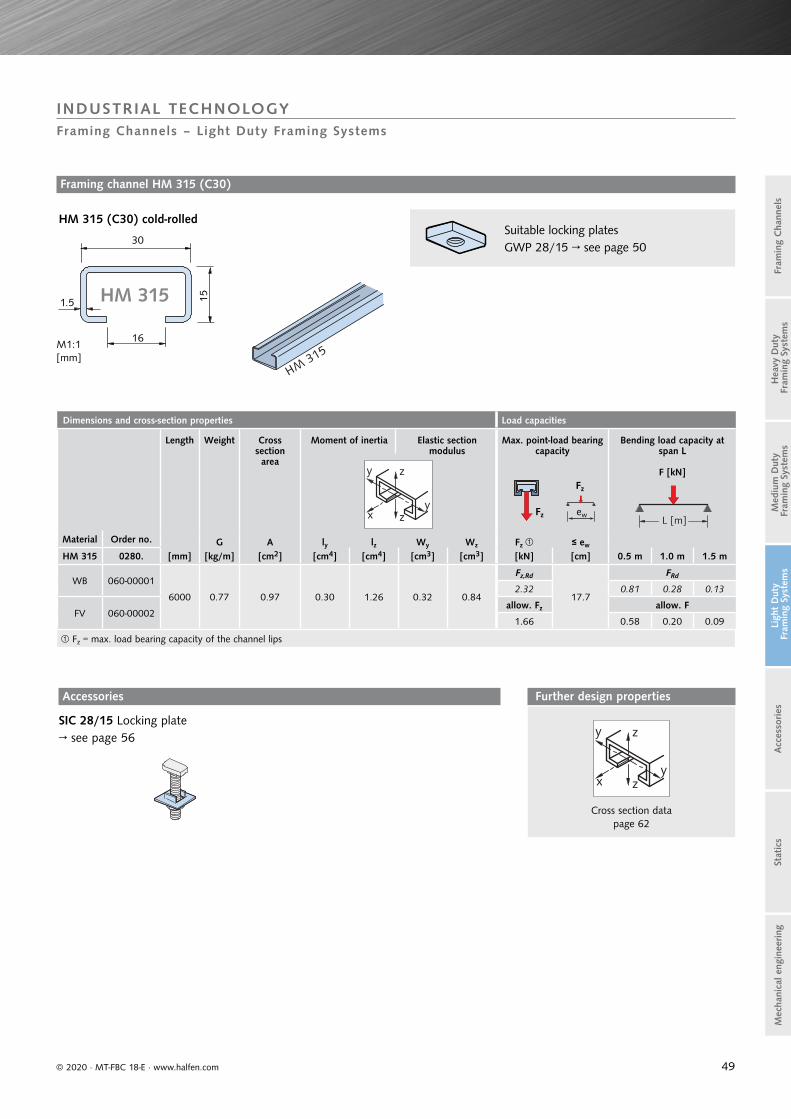
49
Dimensions and cross-section properties Load capacities
Length Weight Cross section area
Moment of inertia Elastic section modulus
Max. point-load bearing capacity
Bending load capacity at span L
F [kN]
Material Order no. G A ly lz Wy Wz Fz ≤ ew
HM 315 0280. [mm] [kg/m] [cm2] [cm4] [cm4] [cm3] [cm3] [kN] [cm] 0.5 m 1.0 m 1.5 m
WB 060-00001
6000 0.77 0.97 0.30 1.26 0.32 0.84
Fz,Rd
17.7
FRd
2.32 0.81 0.28 0.13
FV 060-00002allow. Fz allow. F
1.66 0.58 0.20 0.09
Fz = max. load bearing capacity of the channel lips
L [m]Fz
Fz
ew
y z
yx z
15
16
30
1.5
HM315
M1:1[mm]
HM 315
© 2020 · MT-FBC 18-E · www.halfen.com
Stat
ics
Ligh
t D
uty
Fra
min
g Sy
stem
sA
cces
sories
Fram
ing
Cha
nnel
sM
ediu
m D
uty
Fra
min
g Sy
stem
sH
eavy
Dut
y F
ram
ing
Syst
ems
Mec
hani
cal e
ngin
eering
INDUSTRIAL TECHNOLOGYFraming Channels – Light Duty Framing Systems
HM 315 (C30) cold-rolled
Framing channel HM 315 (C30)
Suitable locking plates GWP 28/15 → see page 50
Accessories
SIC 28/15 Locking plate→ see page 56 y z
yx z
Cross section data page 62
Further design properties

50
Length l [mm] M6 M8 M10 M12
15 GVs 4.6 GVs 4.6 GVs 4.6
20GVs 4.6 GVs 4.6 GVs 4.6
GVs 8.8 A2-70A2-70 A4-70
25GVs 4.6 GVs 4.6 GVs 4.6
A2-70 A2-70A4-70
30
GVs 4.6 GVs 4.6 GVs 4.6 GVs 4.6A2-70 FV 4.6A4-70 A2-70
A4-7035 GVs 4.6
40
GVs 4.6 GVs 4.6 GVs 4.6FV 8.8A2-70A4-70
Length l [mm] M6 M8 M10 M12
50GVs 4.6 GVs 4.6 GVs 4.6
FV 4.6
60GVs 4.6 GVs 4.6
GVs 8.8A4-70
80GVs 4.6 GVs 4.6 GVs 4.6
GVs 8.8A4-70
100GVs 4.6 GVs 4.6
A4-50
125GVs 4.6A4-50
150GVs 4.6 GVs 4.6
A4-50
200GVs 4.6A4-50
Load bearing capacities for bolts Load capacities for bolts Recommended load bearing capacity
per bolt in channel longitudinal direction
Recommended torque
Thread Ø F [kN] Fx [kN] Tinst [Nm]
28/15HS HS HS
4.6 8.8 A2-50 A4-50
A2-70 A4-70 4.6; 8.8 A2-50; A4-50;
A2-70; A4-70 4.6 8.8 A2-50 A4-50
A2-70 A4-70
M6FRd 2.9 6.4 2.5 5.4 0.14 0.14
3 - 3 -allow. F 2.1 4.6 1.8 3.8 0.1 0.1
M8FRd 5.3 11.7 4.6 9.9 0.28 0.28
8 20 8 15allow. F 3.8 8.3 3.3 7.1 0.2 0.2
M10FRd 8.3 18.6 7.3 15.6 0.42 0.42
15 40 15 30allow. F 5.9 13.3 5.2 11.2 0.3 0.3
M12FRd 12.1 27.0 10.6 22.7 0.7 0.7
25 70 25 50allow. F 8.6 19.3 7.6 16.2 0.5 0.5
Note: do not exceed the max. channel load bearing capacityLoad capability due to friction
GWP 28/15 Load capacities
Fz
x
z
y
28/15
Thread Fz [kN]
M5FRd 2.1
allow. F 1.5
M6FRd 2.7
allow. F 1.9
M8FRd 3.9
allow. F 2.8
M10FRd 4.2
allow. F 3.0
GWP 28/15 available plates
GV A4 a
[mm]b
[mm]d
[mm]
M5 -
24.5 13.0 4M6 M6
M8 M8
M10 M10 33.5 17.5 5
HS 28/15 available bolts
on request
Fz
xFy xy
z
Fx
b
d
a
© 2020 · MT-FBC 18-E · www.halfen.com
Stat
ics
Ligh
t D
uty
Fra
min
g Sy
stem
sA
cces
sories
Fram
ing
Cha
nnel
sM
ediu
m D
uty
Fra
min
g Sy
stem
sH
eavy
Dut
y F
ram
ing
Syst
ems
Mec
hani
cal e
ngin
eering
INDUSTRIAL TECHNOLOGYFraming Channels – Light Duty Framing Systems
HALFEN Bolts HS 28/15
Locking plates
HS 28/15HALFEN Bolts incl. nut
Not for HM 315
Li = left-hand thread
GWP 28/15for profiles 28/15 and HM 315 (C30)
Assembly notes:M6 and M8: insert the locking plate at an angle through the channel slot!M10: insert the locking plate first, then fit and turn the threaded rod!
High corrosion resistant stainless steel HCR on request
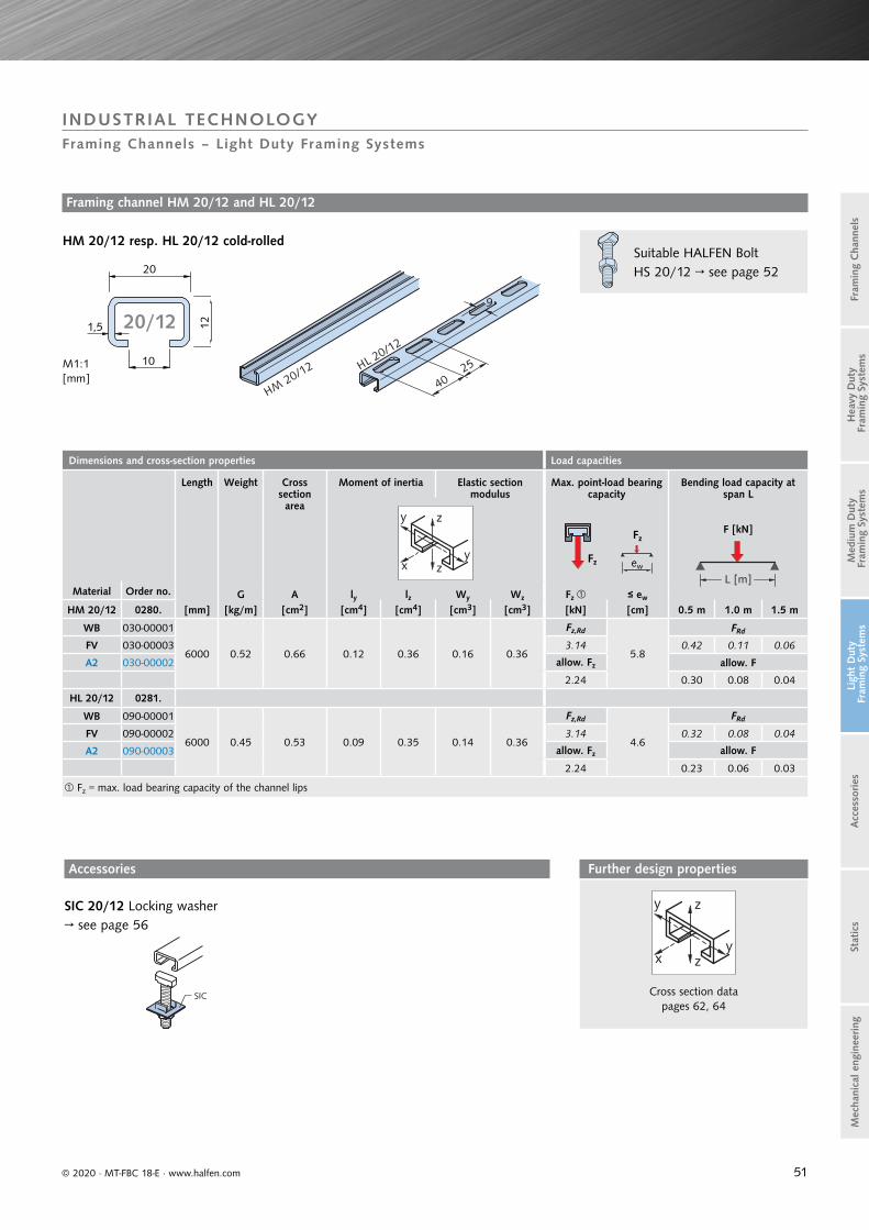
51
Dimensions and cross-section properties Load capacities
Length Weight Cross section area
Moment of inertia Elastic section modulus
Max. point-load bearing capacity
Bending load capacity at span L
F [kN]
Material Order no. G A ly lz Wy Wz Fz ≤ ew
HM 20/12 0280. [mm] [kg/m] [cm2] [cm4] [cm4] [cm3] [cm3] [kN] [cm] 0.5 m 1.0 m 1.5 m
WB 030-00001
6000 0.52 0.66 0.12 0.36 0.16 0.36
Fz,Rd
5.8
FRd
FV 030-00003 3.14 0.42 0.11 0.06
A2 030-00002 allow. Fz allow. F
2.24 0.30 0.08 0.04
HL 20/12 0281.
WB 090-00001
6000 0.45 0.53 0.09 0.35 0.14 0.36
Fz,Rd
4.6
FRd
FV 090-00002 3.14 0.32 0.08 0.04
A2 090-00003 allow. Fz allow. F
2.24 0.23 0.06 0.03
Fz = max. load bearing capacity of the channel lips
L [m]
Fz
Fz
ew
y z
yx z
12
10
20
1,5
HM20/12 HL 20/12
9
25
40
M1:1[mm]
20/12
SIC
© 2020 · MT-FBC 18-E · www.halfen.com
Stat
ics
Ligh
t D
uty
Fra
min
g Sy
stem
sA
cces
sories
Fram
ing
Cha
nnel
sM
ediu
m D
uty
Fra
min
g Sy
stem
sH
eavy
Dut
y F
ram
ing
Syst
ems
Mec
hani
cal e
ngin
eering
INDUSTRIAL TECHNOLOGYFraming Channels – Light Duty Framing Systems
Framing channel HM 20/12 and HL 20/12
HM 20/12 resp. HL 20/12 cold-rolled
SIC 20/12 Locking washer→ see page 56
Suitable HALFEN BoltHS 20/12 → see page 52
Accessories
y z
yx z
Cross section data pages 62, 64
Further design properties

52
GWP 20/12 available plates
GV Thread
A4Thread
a[mm]
b[mm]
d[mm]
M5 M5
16 9 4
M6 M6
Length l [mm] M6 M8
15 - GVs 4.6
20GVs 4.6 GVs 4.6
- A2-70
25 - GVs 4.6
30GVs 4.6 GVs 4.6
- A2-70
Length l [mm] M6 M8
40GVs 4.6 GVs 4.6
- A2-70
50 -GVs 4.6
A2-70
60 - GVs 4.6
80 - GVs 4.6
100 - GVs 4.6
Load bearing capacities for bolts
Load capacities for bolts Recommended load capacity per bolt
in channel longitudinal direction
Recommended torque
Thread Ø F [kN] Fx [kN] Tinst [Nm]
20/12HS HS HS
4.6 A2-70 4.6 A2-70 4.6 A2-70
M6
FRd 2.9 5.4 0.14 0.143 -
allow. F2.1 3.8 0.1 0.1
M8
FRd 5.3 9.9 0.28 0.288 8
allow. F3.8 7.1 0.2 0.2
Note: do not exceed the max. channel load bearing capacity Load capability due to friction
Load capacities for GWP 20/12
Fz
x
z
y
20/12
Thread Fz [kN]
M5FRd 2.1
allow. F 1.5
M6FRd 2.7
allow. F 1.9
Fz
xFy xy
z
Fx
HS 20/12 available bolts
on request
l
15.515.5
© 2020 · MT-FBC 18-E · www.halfen.com
Stat
ics
Ligh
t D
uty
Fra
min
g Sy
stem
sA
cces
sories
Fram
ing
Cha
nnel
sM
ediu
m D
uty
Fra
min
g Sy
stem
sH
eavy
Dut
y F
ram
ing
Syst
ems
Mec
hani
cal e
ngin
eering
INDUSTRIAL TECHNOLOGYFraming Channels – Light Duty Framing Systems
HALFEN Bolts HS 20/12
Locking plates
HS 20/12HALFEN Bolts incl. nut
Locking plate GWP 20/12
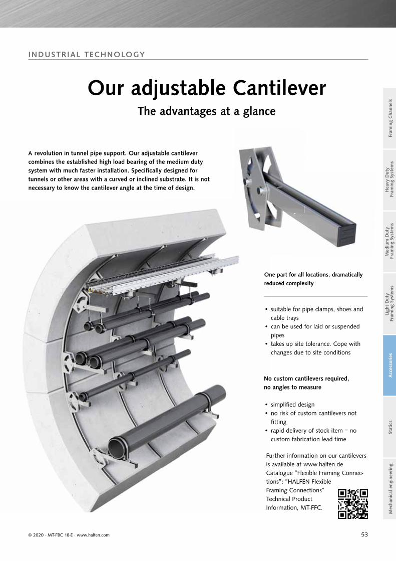
53© 2020 · MT-FBC 18-E · www.halfen.com
Stat
ics
Ligh
t D
uty
Fra
min
g Sy
stem
sA
cces
sories
Fram
ing
Cha
nnel
sM
ediu
m D
uty
Fra
min
g Sy
stem
sH
eavy
Dut
y F
ram
ing
Syst
ems
Mec
hani
cal e
ngin
eering
INDUSTRIAL TECHNOLOGY
A revolution in tunnel pipe support. Our adjustable cantilever combines the established high load bearing of the medium dutysystem with much faster installation. Specifically designed for tunnels or other areas with a curved or inclined substrate. It is not necessary to know the cantilever angle at the time of design.
No custom cantilevers required, no angles to measure
One part for all locations, dramatically reduced complexity
Our adjustable CantileverThe advantages at a glance
• simplified design• no risk of custom cantilevers not
fitting• rapid delivery of stock item = no
custom fabrication lead time
• suitable for pipe clamps, shoes and cable trays
• can be used for laid or suspended pipes
• takes up site tolerance. Cope with changes due to site conditions
Further information on our cantilevers is available at www.halfen.de Catalogue ”Flexible Framing Connec-tions”: ”HALFEN Flexible Framing Connections” Technical Product Information, MT-FFC.
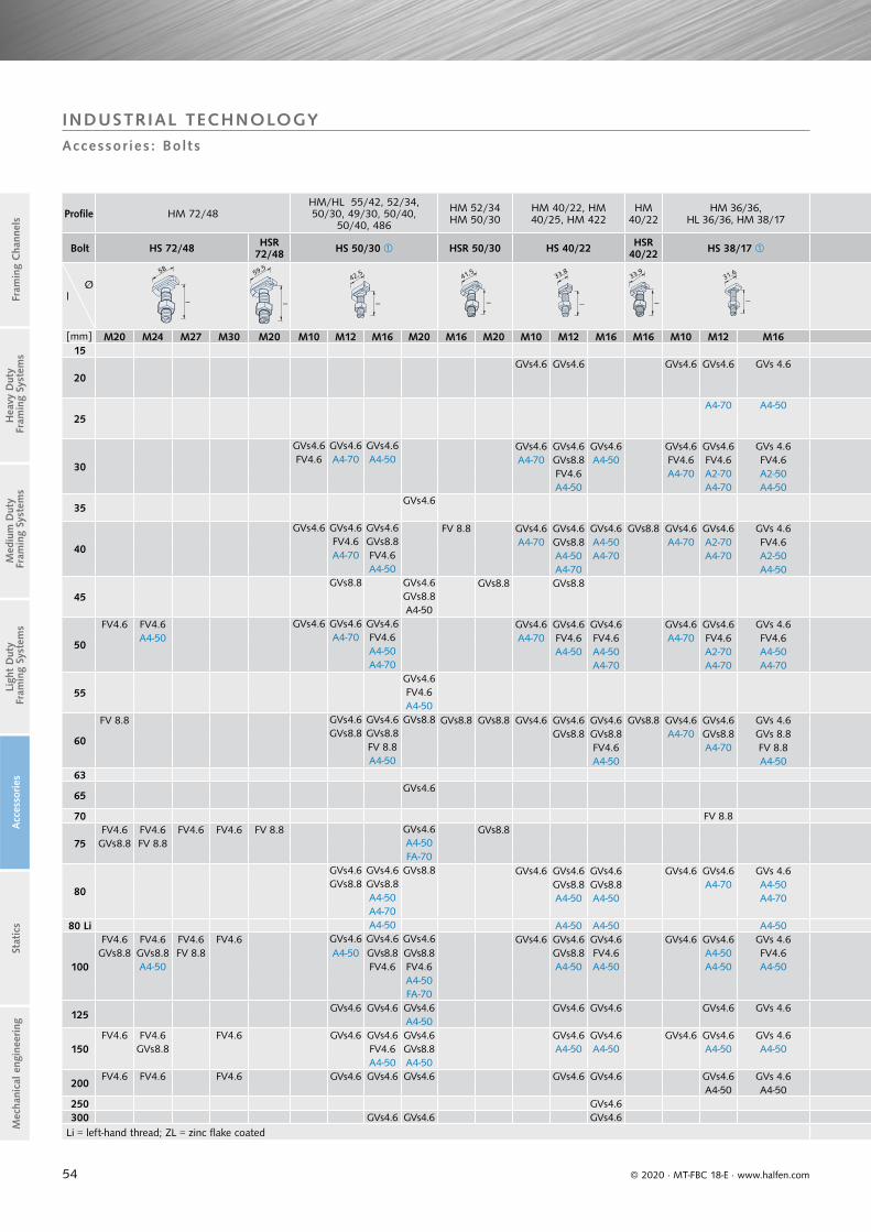
54
Profile HM 72/48HM/HL 55/42, 52/34, 50/30, 49/30, 50/40,
50/40, 486
HM 52/34HM 50/30
HM 40/22, HM 40/25, HM 422
HM 40/22
HM 36/36, HL 36/36, HM 38/17
Bolt HS 72/48 HSR 72/48 HS 50/30 HSR 50/30 HS 40/22 HSR
40/22 HS 38/17
Øl
58
l l
59,5
l
42,5
l
41,5
l
33,8
l
33,9
l
31,6
[mm] M20 M24 M27 M30 M20 M10 M12 M16 M20 M16 M20 M10 M12 M16 M16 M10 M12 M1615
20GVs 4.6 GVs 4.6 GVs 4.6 GVs 4.6 GVs 4.6
25A4-70 A4-50
30
GVs 4.6 GVs 4.6 GVs 4.6 GVs 4.6 GVs 4.6 GVs 4.6 GVs 4.6 GVs 4.6 GVs 4.6FV4.6 A4-70 A4-50 A4-70 GVs 8.8 A4-50 FV4.6 FV4.6 FV4.6
FV4.6 A4-70 A2-70 A2-50A4-50 A4-70 A4-50
35GVs 4.6
40
GVs 4.6 GVs 4.6 GVs 4.6 FV 8.8 GVs 4.6 GVs 4.6 GVs 4.6 GVs 8.8 GVs 4.6 GVs 4.6 GVs 4.6FV4.6 GVs 8.8 A4-70 GVs 8.8 A4-50 A4-70 A2-70 FV4.6A4-70 FV4.6 A4-50 A4-70 A4-70 A2-50
A4-50 A4-70 A4-50
45GVs 8.8 GVs 4.6 GVs 8.8 GVs 8.8
GVs 8.8A4-50
50
FV4.6 FV4.6 GVs 4.6 GVs 4.6 GVs 4.6 GVs 4.6 GVs 4.6 GVs 4.6 GVs 4.6 GVs 4.6 GVs 4.6A4-50 A4-70 FV4.6 A4-70 FV4.6 FV4.6 A4-70 FV4.6 FV4.6
A4-50 A4-50 A4-50 A2-70 A4-50A4-70 A4-70 A4-70 A4-70
55GVs 4.6FV4.6A4-50
60
FV 8.8 GVs 4.6 GVs 4.6 GVs 8.8 GVs 8.8 GVs 8.8 GVs 4.6 GVs 4.6 GVs 4.6 GVs 8.8 GVs 4.6 GVs 4.6 GVs 4.6GVs 8.8 GVs 8.8 GVs 8.8 GVs 8.8 A4-70 GVs 8.8 GVs 8.8
FV 8.8 FV4.6 A4-70 FV 8.8A4-50 A4-50 A4-50
63
65GVs 4.6
70 FV 8.8
75FV4.6 FV4.6 FV4.6 FV4.6 FV 8.8 GVs 4.6 GVs 8.8
GVs 8.8 FV 8.8 A4-50FA-70
80
GVs 4.6 GVs 4.6 GVs 8.8 GVs 4.6 GVs 4.6 GVs 4.6 GVs 4.6 GVs 4.6 GVs 4.6GVs 8.8 GVs 8.8 GVs 8.8 GVs 8.8 A4-70 A4-50
A4-50 A4-50 A4-50 A4-70A4-70
80 Li A4-50 A4-50 A4-50 A4-50
100
FV4.6 FV4.6 FV4.6 FV4.6 GVs 4.6 GVs 4.6 GVs 4.6 GVs 4.6 GVs 4.6 GVs 4.6 GVs 4.6 GVs 4.6 GVs 4.6GVs 8.8 GVs 8.8 FV 8.8 A4-50 GVs 8.8 GVs 8.8 GVs 8.8 FV4.6 A4-50 FV4.6
A4-50 FV4.6 FV4.6 A4-50 A4-50 A4-50 A4-50A4-50FA-70
125GVs 4.6 GVs 4.6 GVs 4.6 GVs 4.6 GVs 4.6 GVs 4.6 GVs 4.6
A4-50
150FV4.6 FV4.6 FV4.6 GVs 4.6 GVs 4.6 GVs 4.6 GVs 4.6 GVs 4.6 GVs 4.6 GVs 4.6 GVs 4.6
GVs 8.8 FV4.6 GVs 8.8 A4-50 A4-50 A4-50 A4-50A4-50 A4-50
200FV4.6 FV4.6 FV4.6 GVs 4.6 GVs 4.6 GVs 4.6 GVs 4.6 GVs 4.6 GVs 4.6 GVs 4.6
A4-50 A4-50250 GVs 4.6300 GVs 4.6 GVs 4.6 GVs 4.6
Li = left-hand thread; ZL = zinc flake coated
© 2020 · MT-FBC 18-E · www.halfen.com
Stat
ics
Ligh
t D
uty
Fra
min
g Sy
stem
sA
cces
sories
Fram
ing
Cha
nnel
sM
ediu
m D
uty
Fra
min
g Sy
stem
sH
eavy
Dut
y F
ram
ing
Syst
ems
Mec
hani
cal e
ngin
eering
INDUSTRIAL TECHNOLOGYAccessor ies : Bol ts
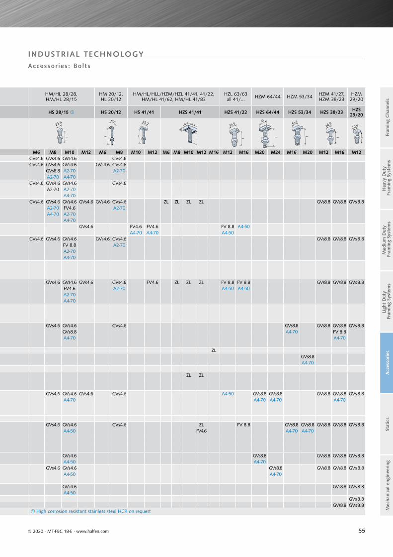
55
HM/HL 28/28,HM/HL 28/15
HM 20/12, HL 20/12
HM/HL/HLL/HZM/HZL 41/41, 41/22, HM/HL 41/62, HM/HL 41/83
HZL 63/63all 41/... HZM 64/44 HZM 53/34 HZM 41/27,
HZM 38/23HZM 29/20
HS 28/15 HS 20/12 HS 41/41 HZS 41/41 HZS 41/22 HZS 64/44 HZS 53/34 HZS 38/23 HZS 29/20
l
23,6
l
15,5
l
35,2
d
b
l
34,5
l
34,5
l
5141,6
l l
28,820,5
M6 M8 M10 M12 M6 M8 M10 M12 M6 M8 M10 M12 M16 M12 M16 M20 M24 M16 M20 M12 M16 M12GVs 4.6 GVs 4.6 GVs 4.6 GVs 4.6GVs 4.6 GVs 4.6 GVs 4.6 GVs 4.6 GVs 4.6
GVs 8.8 A2-70 A2-70A2-70 A4-70
GVs 4.6 GVs 4.6 GVs 4.6 GVs 4.6A2-70 A2-70
A4-70GVs 4.6 GVs 4.6 GVs 4.6 GVs 4.6 GVs 4.6 GVs 4.6 ZL ZL ZL ZL GVs 8.8 GVs 8.8 GVs 8.8
A2-70 FV4.6 A2-70A4-70 A2-70
A4-70GVs 4.6 FV4.6 FV4.6 FV 8.8 A4-50
A4-70 A4-70 A4-50GVs 4.6 GVs 4.6 GVs 4.6 GVs 4.6 GVs 4.6 GVs 8.8 GVs 8.8 GVs 8.8
FV 8.8 A2-70A2-70A4-70
GVs 4.6 GVs 4.6 GVs 4.6 GVs 4.6 FV4.6 ZL ZL ZL FV 8.8 FV 8.8 GVs 8.8 GVs 8.8 GVs 8.8FV4.6 A2-70 A4-50 A4-50A2-70A4-70
GVs 4.6 GVs 4.6 GVs 4.6 GVs 8.8 GVs 8.8 GVs 8.8 GVs 8.8GVs 8.8 A4-70 FV 8.8A4-70 A4-70
ZLGVs 8.8A4-70
ZL ZL
GVs 4.6 GVs 4.6 GVs 4.6 GVs 4.6 A4-50 GVs 8.8 GVs 8.8 GVs 8.8 GVs 8.8 GVs 8.8A4-70 A4-70 A4-70 A4-70
GVs 4.6 GVs 4.6 GVs 4.6 ZL FV 8.8 GVs 8.8 GVs 8.8 GVs 8.8 GVs 8.8 GVs 8.8A4-50 FV4.6 A4-70 A4-70
GVs 4.6 GVs 8.8 GVs 8.8 GVs 8.8 GVs 8.8A4-50 A4-70
GVs 4.6 GVs 4.6 GVs 8.8 GVs 8.8 GVs 8.8 GVs 8.8A4-50 A4-70
GVs 4.6 GVs 8.8 GVs 8.8A4-50
GVs 8.8GVs 8.8 GVs 8.8
High corrosion resistant stainless steel HCR on request
© 2020 · MT-FBC 18-E · www.halfen.com
Stat
ics
Ligh
t D
uty
Fra
min
g Sy
stem
sA
cces
sories
Fram
ing
Cha
nnel
sM
ediu
m D
uty
Fra
min
g Sy
stem
sH
eavy
Dut
y F
ram
ing
Syst
ems
Mec
hani
cal e
ngin
eering
INDUSTRIAL TECHNOLOGYAccessor ies : Bol ts

56
GV Galvanized
A4 Stainless steel
Suitable for HALFEN Bolts
Type Dimensions
SIC - 50/30 - GV SIC - 50/30 - A4 50/30 M16, M20
SIC - 40/22 - GV SIC - 40/22 - A4 38/1740/22 M16
SIC - 38/23 - GV - 38/23 M16
SIC - 29/20 - GV - 29/20 M12
SIC - 38/17 - GV SIC - 38/17 - A4 38/1740/22 M12, M10
SIC - 28/15 - GV SIC - 28/15 - A4 28/15 M8, M10
SIC - 20/12 - GV SIC - 20/12 - A4 20/12 M8
Ordering example: SIC - 38/17 - GV
GV A4 S/m S/m eGalvanized
F.k. 8Thread
Stainless steel A4Thread
DIN ISO
[mm] [mm] [mm]
M6 M6 10/5 10/6 11.5
M8 M8 13/6.5 13/7.5 15.0
M10 M10 17/8 16/ 9.5 19.6
M12 M12 19/10 18/12 21.9
M16 M16 24/13 24/15.5 27.7
M20 M20 30/16 30/19 34.6
M24 - 36/19 36/22 41.5
FV Hot-dip
galvanizedThread
A2 S/m S/m eStainless steel A4Thread
DIN EN
[mm] [mm] [mm]
M6, M8 M8 13/6.5 13/7.5 15.0
M10 M10 17/08 16/9.5 19.6
M12 M12 19/10 18/12 21.9
M16 M16 24/13 24/15.5 27.7
DIN
GV A4 D d s
Galvanized
For bolt
Stainless steel
For bolt[mm] [mm] [mm]
440 M6 - 22 6.6 2
9021 M8 M8 24 8.4 2
9021 M10 M10 30 10.5 2.5
440 M12 - 45 13.5 4
9021 M12 M12 37 13 3
9021 M16 M16 50 17 3
440 M20 - 72 22 6
Ordering example: US - M12 - GV - DIN 9021
GV A4 D d sGalvanized
For bolt
Stainless steel A4For bolt
[mm] [mm] [mm]
M6 M6 12 6.4 1.6
M8 M8 16 8.4 1.6
M10 M10 21 10.5 2
M12 M12 24 13 2.5
M16 M16 30 17 3
M20 M20 37 21 3
M24 - 44 25 4
FVHot-dip galva-
nizedFor bolt
A2Stainless steel A2 For bolt
D d s
[mm] [mm] [mm]
- M8 17 8.4 1.6
M10 M10 21 10.5 2
M12 M12 24 13 2.5
M16 M16 30 17 3
Ordering example: US - M12 - GV - DIN 125
FV A4 a x b x d
Hot-dip galvanized
For bolt size:
Stainless steel A4
For bolt size:[mm]
VUS 40/25 for profile40/25;HZA 41/22
M10 M10 40 x 40 x 5
M12 M12 40 x 40 x 5
M16 M16 40 x 40 x 5
VUS 49/30 for profile 54/33,49/30
M10 M10 37 x 37 x 5
M12 M12 37 x 37 x 5
M16 M16 37 x 37 x 5
VUS 52/34 for profile52/34, 50/30
M20 M20 37 x 37 x 5
M16 M16 50 x 50 x 6
M20 M20 50 x 50 x 6
VUS 72/49 for profile72/48,72/49
M20 M20 54 x 54 x 6
M24 M24 54 x 54 x 6
M27 M27 54 x 54 x 6
M30 M30 54 x 54 x 6
VUS 41/41for all41/.. profiles
M6 M6 40 x 40 x 6
M10 M10 40 x 40 x 6
M12 M12 40 x 40 x 6
Ordering example: VUS 52/34 - FV - M20
© 2020 · MT-FBC 18-E · www.halfen.com
Stat
ics
Ligh
t D
uty
Fra
min
g Sy
stem
sA
cces
sories
Fram
ing
Cha
nnel
sM
ediu
m D
uty
Fra
min
g Sy
stem
sH
eavy
Dut
y F
ram
ing
Syst
ems
Mec
hani
cal e
ngin
eering
INDUSTRIAL TECHNOLOGYAccessor ies
VUSSquare washers
VUS
SICLocking washer
Application SIC:for securing HALFEN Bolts; prevents bolts turning when tightening nuts
MUHexagonal nutsEN ISO 4032/DIN 934
USWashersDIN 9021/ EN ISO 7094/DIN 440
USWashersEN ISO 7089/DIN 125
Application VUS:for shimming non-flush installation of HALFEN Anchor channels or for stand-off installations → see page 69
Shimming
HALFEN Framing channel
Assembly scheme:
HALFEN Bolt
Locking washer SIC

57
GV A4 D L FRd allow. F
Galvanized
Thread
Stainless steel
Thread [mm]
[mm]
[kN] [kN]
M6 M6 10/10 15 3.1 2.2
M8 M8 12/14 20 5.6 4.0
M10 M10 13/16 25 9.0 6.4
M12 M12 16/20 30 13.0 9.3
M16 M16 21/25 40 24.2 17.3
M20 M20 26/32 50 37.8 27.0
Ordering example: VBM - A4 - M16
FV A4 S L FRd allow. F
Hot-dip galvanized
Thread
Stainless steel
Thread [mm]
[mm]
[kN] [kN]
M10 M10 13 40 9.0 6.4
M12 M12 17 40 13.0 9.3
M16 M16 22 50 24.2 17.3
Ordering example: SKM - FV - M12
GV d FRd allow. F
C 15E, galvanizedThread
[mm]
[kN] [kN]
M8 20 2.0 1.4
M10 25 3.2 2.3
M12 30 4.8 3.4
M16 35 9.8 7.0
M20 40 16.8 12.0
Ordering example: RM - GV - M12
GV A4 Length FRd allow. F
Galvanized F.k. 4.6Thread
Stainless steel A4
Thread [mm]
[kN] [kN]
M6 M6 1000 3.1 2.2
M8 M8 1000 5.6 4.0
M10 M10 1000 9.0 6.4
M12 M12 1000 13.0 9.3
M16 M16 1000 24.2 17.3
M20 M20 1000 37.8 27.0
M24 - 1000 54.3 38.8
Ordering example: GWS - M12 × 1000 - GV
GV 8.8 A4 S SGalvanized
FK 8.8Dimensions
Stainless steel
Dimensions
DIN EN ISO
[mm] [mm]
M 6 x 12 10
10 M 6 x 25
M 8 x 25 M8 x 2513 13
M 8 x 40
M 10 x 20
17 16
M 10 x 30 M10 x 30
M 10 x 45 M10 x 45
M 10 x 60
M 10 x 70
M 12 x 22
19
18
M 12 x 25 M12 x 25
M 12 x 30 M12 x 30
M 12 x 40 M12 x 40
M 12 x 50
M 12 x 60 M12 x 60
M 12 x 80 M12 x 80
M 12 x 90
M 16 x 40 M16 x 40
24 24M 16 x 60 M16 x 60
M 16 x 90 M16 x 90
FV A4 t b d max. FEd
allow. F
Hot-dip galvanized
Type
Stainless steelType
[mm] [mm] [mm] [kN] [kN]
1 1 6 40 13 2.1 1.5
2 2 8 50 17 4.6 3.3
3 3 10 50 17 7.0 5
A4 A4 D D
Stainless steel Thread M12
× Length L [mm]
Stainless steelThread M16
× Length L [mm]
ForM12[mm]
ForM16[mm]
M 12 × 60 M 16 × 60 16 22
M 12 × 75 M 16 × 75 16 22
M 12 × 95 M 16 × 95 16 22
M 12 × 115 M 16 × 115 16 22
M 12 × 135 M 16 × 135 16 22
allow. F = 5 kN FRd = 7 kN
allow. F = 10 kN FRd = 14 kN
Ordering example: SPH - A4 - M12 x 75
© 2020 · MT-FBC 18-E · www.halfen.com
Stat
ics
Ligh
t D
uty
Fra
min
g Sy
stem
sA
cces
sories
Fram
ing
Cha
nnel
sM
ediu
m D
uty
Fra
min
g Sy
stem
sH
eavy
Dut
y F
ram
ing
Syst
ems
Mec
hani
cal e
ngin
eering
INDUSTRIAL TECHNOLOGYAccessor ies
VBMCoupler sleeves, round
SKMHexagonal coup-ler sleeves with view holes
RMRing nutDIN 582 from 2010-09
GWSThreaded rodsDIN 976-1
HSKHexagonal head boltsEN ISO 4017/DIN 933(without nut)
Hex bolts are used in combination with HALFEN Locking plates
HJVAdjustment coupler
SPHTurnbuckles with right- and left-hand thread
f = min. screw depthM12=10mmM16=13 mm
Recommended design value of the load capacity with a centric tensile stress
Recommended design value of the load
Cross section

58
Product range
DescriptionOrder no. Suitable for
channel0318.000-
HPE 63/63 00010 63/63
HPE 52/34 00001 52/34
HPE 50/40 00002 50/40
HPE 41/41 00003 41/41
HPE 41/22 00004 41/22
HPE 36/36 00005 36/36
HPE 28/28 00006 28/28
HPE 28/15 00011 28/15
Available types
TypeLength Order no.[mm] 0321.000-
PA - 41 - KS - 3000 00002
PA - 41 - SV - 3000 00001
PA - 22 - KS - 3000 00003
PA - 18H - KS - 3000 00004
Type overview
Type PA 41 PA 22 PA 18 H
Suitable for profiles:50/40, 50/30, 486,
all 41/... Profiles
Suitable for profile52/34
Suitable for profiles36/36, 38/17
Quality:hard PVC
(KS)
41
21
9
22
15
27,5
5
,527
16,5
white medium grey medium grey
Quality:steel
sendzimir zinc plated (SV)
41
21
9
HALFENHALFEN
PA 22
15
© 2020 · MT-FBC 18-E · www.halfen.com
Stat
ics
Ligh
t D
uty
Fra
min
g Sy
stem
sA
cces
sories
Fram
ing
Cha
nnel
sM
ediu
m D
uty
Fra
min
g Sy
stem
sH
eavy
Dut
y F
ram
ing
Syst
ems
Mec
hani
cal e
ngin
eering
INDUSTRIAL TECHNOLOGYAccessor ies
Assembly diagram:Channel end caps in plastic
Type HPE 63/63Colour: blue
Type HPEColour: black
Type HPE 41/41Type HPE 41/22Colour: black
Type HPE 63/63
Type HPE
Type HPE 41/41Type HPE 41/22
The channel cover PA is used to protect the channel slot against dirt etc.
Assembly diagram:
Profilendstopfen HPE
PA Channel cover
HPE Channel end caps
HALFEN Channeli.e. HM 52/34
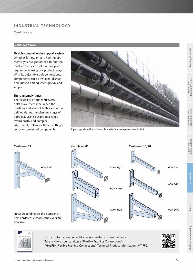
59© 2020 · MT-FBC 18-E · www.halfen.com
Stat
ics
Ligh
t D
uty
Fra
min
g Sy
stem
sA
cces
sories
Fram
ing
Cha
nnel
sM
ediu
m D
uty
Fra
min
g Sy
stem
sH
eavy
Dut
y F
ram
ing
Syst
ems
Mec
hani
cal e
ngin
eering
INDUSTRIAL TECHNOLOGY
Cant i levers
Flexible comprehensive support system
Short assembly timesThe flexibility of our cantilevers/bolts make them ideal when the positions and sizes of bolts can not be defined during the planning stage of a project. Using our product range avoids costly and complex adjustment, drilling or thread cutting in corrosion protected components.
Whether for low or very high require-ments: you are guaranteed to find the most cost-efficient solution for your requirements using our product range. With its adjustable bolt connections, components can be installed, disman-tled, moved and adjusted quickly and simply.
Cantilever 52: Cantilever 41: Cantilever 36/28:
Pipe supports with cantilevers brackets in a sewage treatment plant
Note: Depending on the number of items ordered, custom cantilevers are available
Cantilevers KON
KON 28/1
KON 36/1
KON 36/2
KON 41/1
KON 41/D
KON 41/2
KON 52/2
Adjustable Cantilever• Time saving• Economical• Space efficient
MT-FFC 17-E
FLEXIBLE FRAMING CONNECTIONS Technical Product Information
MT-FFC 17
Further information on cantilevers is available at www.halfen.de Take a look at our catalogue ”Flexible Framing Connections”: ”HALFEN Flexible Framing Connections” Technical Product Information, MT-FFC.

60
y z
e2
e1
yx z
Materials/coatings
Channel weight
Cross section area
Centroid Moment of inertia
Elastic/plastic section modulus
Max. point-load bearing capacity
y z
yx z
y z
yx z
G
[kg/m]
A
[cm²]
e2
[cm]
Iy[cm4]
Iz[cm4]
Wy,el
[cm³]
Wz,el
[cm³]
Wy,pl
[cm³]
Wz,pl
[cm³]
allow. Fz
[kN]
Fz,Rd
[kN]
ew
[cm]
HM 72/48
Hot
-rolle
d
WB - FV - A4 8.85 11.27 2.45 34.97 83.35 14.28 23.15 18.28 28.94 47.0 65.8 30.0
HM 55/42 WB - FV - - 6.76 8.61 1.99 18.75 36.29 8.49 13.32 11.73 16.69 38.6 54.0 25.0
HM 52/34
WB - FV - A4
4.98 6.35 1.61 9.33 23.74 5.36 9.04 7.19 11.50 25.9 36.3 20.0
HM 50/30 3.26 4.15 1.37 5.26 13.78 3.23 5.62 4.38 7.05 14.4 20.2 20.0
HM 40/22 2.12 2.70 1.05 1.99 5.77 1.59 2.92 2.17 3.68 8.2 11.4 15.0
HM 72/48 D
- -
17.70 22.54 4.85 205.15 166.70 42.30 46.30 55.20 57.89 47.0 65.8 30.0
HM 55/42 D 13.52 17.22 4.20 105.70 72.58 25.17 26.64 34.27 33.37 38.6 54.0 25.0
HM 52/34 D 9.96 12.70 3.35 51.49 47.48 15.37 18.09 20.42 23.00 25.9 36.3 20.0
HM 50/30 D 6.52 8.27 3.00 26.56 28.14 8.85 11.49 11.52 14.27 14.4 20.2 20.0
HM 40/22 D 4.24 5.33 2.30 10.06 11.61 4.38 5.88 5.73 7.36 8.2 11.4 15.0
HZM 64/44 WB - FV - A4 7.15 9.10 2.10 23.83 53.94 10.36 16.85 13.66 20.86 38.1 53.3 25.0
HZM 53/34 WB - FV - A4 4.63 5.88 1.54 9.19 23.18 4.95 8.83 6.80 10.94 30.9 43.3 20.0
HZM 41/27 WB - FV - - 3.38 4.31 1.19 3.90 9.49 2.57 4.75 3.74 5.98 17.8 25.0 20.0
HZM 38/23 WB - FV - A4 2.43 3.10 0.97 2.11 6.17 1.59 3.25 2.31 4.06 12.8 18.0 20.0
HZM 29/20 WB - FV - - 1.55 1.99 0.88 1.02 2.42 0.91 1.67 1.31 2.06 8.0 11.2 15.0
HZM 64/44 D
- -
14.3 18.21 4.40 127.94 107.87 29.08 33.71 38.23 41.72 38.1 53.3 25.0
HZM 53/34 D 9.26 11.75 3.40 46.38 46.36 13.64 17.66 18.14 21.89 30.9 43.3 20.0
HZM 41/27 D 6.76 8.62 2.70 19.91 18.98 7.37 9.49 10.22 11.96 17.8 25.0 20.0
HZM 38/23 D 4.86 6.19 2.30 10.04 12.35 4.36 6.50 6.00 8.13 12.8 18.0 20.0
HZM 29/20 D 3.10 3.97 2.00 5.12 4.84 2.56 3.34 3.49 4.11 8.0 11.2 15.0
Fz
Fz
ew
© 2020 · MT-FBC 18-E · www.halfen.com
Stat
ics
Ligh
t D
uty
Fra
min
g Sy
stem
sA
cces
sories
Fram
ing
Cha
nnel
sM
ediu
m D
uty
Fra
min
g Sy
stem
sH
eavy
Dut
y F
ram
ing
Syst
ems
Mec
hani
cal e
ngin
eering
INDUSTRIAL TECHNOLOGYFraming Channels, Hot-Rolled, Non-Slotted – Bending Load Capacities
Observe the minimum distance ae between the channel end
and the load point (bolt, locking plate):
heavy and medium duty framing systems: ae ≥ 30 mm,
light duty framing systems: ae ≥ 20 mm.
Do not exceed the bolt load capacity or the max. channel
load bearing capacity.
For maximum point-load capacity:
Fz = max. load bearing capacity of the channel lips.
Take constructive measures to prevent failure caused by
bulging, tilting and buckling.
On request.
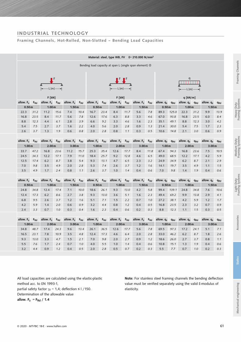
61
ew
Material: steel, type WB, FV E= 210.000 N/mm2
Bending load capacity at span L (single span element)
F
L [m]
F F
L [m]
q
L [m]
F [kN] F [kN] q [kN/m]
allow. Fz FRd allow. Fz FRd allow. Fz FRd allow. Fz FRd allow. Fz FRd allow. Fz FRd allow. qz qRd allow. qz qRd allow. qz qRd
0.50 m 1.00 m 1.50 m 0.50 m 1.00 m 1.50 m 0.50 m 1.00 m 1.50 m
22.3 31.2 11.2 15.6 7.4 10.4 16.7 23.4 8.4 11.7 5.6 7.8 89.3 125.0 22.3 31.2 9.9 13.9
16.8 23.5 8.4 11.7 5.6 7.8 12.6 17.6 6.3 8.8 3.3 4.6 67.0 93.8 16.8 23.5 6.0 8.4
8.8 12.3 4.4 6.1 2.8 3.9 6.6 9.2 3.3 4.6 1.6 2.3 35.1 49.1 8.8 12.3 3.0 4.2
5.4 7.5 2.7 3.7 1.6 2.2 4.0 5.6 2.0 2.8 0.9 1.3 21.4 30.0 5.4 7.5 1.7 2.3
2.6 3.7 1.3 1.9 0.6 0.8 2.0 2.8 0.8 1.1 0.3 0.5 10.6 14.8 2.1 3.0 0.6 0.9
allow. Fz FRd allow. Fz FRd allow. Fz FRd allow. Fz FRd allow. Fz FRd allow. Fz FRd allow. qz qRd allow. qz qRd allow. qz qRd
1.00 m 2.00 m 3.00 m 1.00 m 2.00 m 3.00 m 1.00 m 2.00 m 3.00 m
33.7 47.2 16.8 23.6 11.2 15.7 25.3 35.4 12.6 17.7 8.4 11.8 67.4 94.3 16.8 23.6 7.5 10.5
24.5 34.3 12.2 17.1 7.9 11.0 18.4 25.7 9.2 12.8 4.6 6.5 49.0 68.5 12.2 17.1 4.2 5.9
12.5 17.4 6.2 8.7 3.8 5.4 9.3 13.1 4.7 6.5 2.3 3.2 24.9 34.9 6.2 8.7 2.1 2.9
7.0 9.8 3.5 4.9 2.0 2.8 5.3 7.4 2.6 3.7 1.2 1.6 14.1 19.7 3.5 4.9 1.1 1.5
3.5 4.9 1.7 2.4 0.8 1.1 2.6 3.7 1.0 1.4 0.4 0.6 7.0 9.8 1.4 1.9 0.4 0.6
allow. Fz FRd allow. Fz FRd allow. Fz FRd allow. Fz FRd allow. Fz FRd allow. Fz FRd allow. qz qRd allow. qz qRd allow. qz qRd
0.50 m 1.00 m 1.50 m 0.50 m 1.00 m 1.50 m 0.50 m 1.00 m 1.50 m
24.8 34.8 12.4 17.4 7.1 10.0 18.6 26.1 9.3 13.0 4.2 5.8 99.4 139.1 24.8 34.8 7.6 10.6
12.4 17.3 6.2 8.6 2.7 3.8 9.3 13.0 3.6 5.1 1.6 2.3 49.4 69.2 9.9 13.8 2.9 4.1
6.8 9.5 2.6 3.7 1.2 1.6 5.1 7.1 1.5 2.2 0.7 1.0 27.2 38.1 4.2 5.9 1.2 1.7
4.2 5.9 1.4 2.0 0.6 0.9 3.2 4.4 0.8 1.2 0.4 0.5 16.8 23.5 2.3 3.2 0.7 0.9
2.4 3.3 0.7 1.0 0.3 0.4 1.6 2.3 0.4 0.6 0.2 0.3 8.8 12.3 1.1 1.5 0.3 0.5
allow. Fz FRd allow. Fz FRd allow. Fz FRd allow. Fz FRd allow. Fz FRd allow. Fz FRd allow. qz qRd allow. qz qRd allow. qz qRd
1.00 m 2.00 m 3.00 m 1.00 m 2.00 m 3.00 m 1.00 m 2.00 m 3.00 m
34.8 48.7 17.4 24.3 9.6 13.4 26.1 36.5 12.6 17.7 5.6 7.8 69.5 97.3 17.2 24.1 5.1 7.1
16.5 23.1 7.8 10.9 3.5 4.8 12.4 17.3 4.6 6.4 2.0 2.8 33.0 46.2 6.2 8.7 1.8 2.6
9.3 13.0 3.3 4.7 1.5 2.1 7.0 9.8 2.0 2.7 0.9 1.2 18.6 26.0 2.7 3.7 0.8 1.1
5.5 7.6 1.7 2.4 0.7 1.0 4.0 5.5 1.0 1.4 0.4 0.6 10.8 15.1 1.3 1.9 0.4 0.6
3.2 4.4 0.9 1.2 0.4 0.5 2.0 2.8 0.5 0.7 0.2 0.3 5.5 7.7 0.7 1.0 0.2 0.3
© 2020 · MT-FBC 18-E · www.halfen.com
Stat
ics
Ligh
t D
uty
Fra
min
g Sy
stem
sA
cces
sories
Fram
ing
Cha
nnel
sM
ediu
m D
uty
Fra
min
g Sy
stem
sH
eavy
Dut
y F
ram
ing
Syst
ems
Mec
hani
cal e
ngin
eering
All load capacities are calculated using the elastic-plastic
method acc. to EN 1993-1,
partial safety factor F = 1,4; deflection ≤ l /150.
Determination of the allowable value
allow. Fz = FRd / 1.4
Note: For stainless steel framing channels the bending deflection
value must be verified separately using the valid E-modulus of
elasticity.
INDUSTRIAL TECHNOLOGYFraming Channels, Hot-Rolled, Non-Slotted – Bending Load Capacities

62
y z
e2
e1
yx z
Materials/coatings
Channel weight
Cross section area
Centroid Moment of inertia
Elastic/plastic section modulus
Max. point-load bearing capacity
y z
yx z
y z
yx z
G
[kg/m]
A
[cm²]
e2
[cm]
Iy[cm4]
Iz[cm4]
Wy,el
[cm³]
Wz,el
[cm³]
Wy,pl
[cm³]
Wz,pl
[cm³]
allow. Fz
[kN]
Fz,Rd
[kN]
ew
[cm]
HM 49/30
Col
d-ro
lled
WB - FV - A4 2.88 3.67 1.23 4.16 13.23 2.35 5.29 3.56 6.49 4.9 6.9 46.0
HM 40/25 WB - FV - A4 2.09 2.66 1.02 2.05 6.09 1.39 3.05 2.11 3.75 3.8 5.3 33.0
HM 50/40 WB - FV - A4 3.35 4.26 1.72 8.64 15.49 3.96 6.32 5.53 7.62 5.4 7.6 63.0
HM 486 WB - FV - - 2.31 2.95 1.15 2.97 9.62 1.92 4.01 2.71 4.95 3.5 4.7 47.0
HM 422 (C40) WB - FV - - 1.55 1.98 0.93 1.27 4.29 1.04 2.17 1.46 2.71 2.5 3.5 36.0
HM 41/41 WB SV FV - A4 2.67 3.40 1.82 7.47 9.44 3.24 4.57 4.57 5.37 5.6 7.8 49.0
HZM 41/41 WB - FV - A4 2.63 3.36 1.80 7.34 9.37 3.15 4.54 4.48 5.31 5.6 7.8 47.0
HM 41/22 WB SV FV - A4 1.86 2.38 0.85 1.28 5.56 1.05 2.69 1.59 3.37 5.6 7.8 15.0
HZM 41/22 WB - FV - A4 1.83 2.33 0.84 1.26 5.48 1.03 2.66 1.56 3.32 5.6 7.8 14.0
HM 41/83 WB SV FV - - 4.29 5.47 3.84 43.82 17.22 9.91 8.34 13.73 9.38 5.6 7.8 148.0
HM 41/62 WB SV FV - - 3.48 4.44 2.83 20.96 13.34 6.21 6.46 8.63 7.38 5.6 7.8 92.0
HM 41/41 D WB - FV - A4 5.34 6.81 4.13 37.60 18.88 9.10 9.14 12.42 10.75 5.6 7.8 49.0
HZM 41/41 D WB - FV - A4 5.27 6.71 4.13 36.45 18.73 8.83 9.07 12.09 10.63 5.6 7.8 47.0
HM 41/22 D WB - FV - A4 3.73 4.75 2.07 6.02 11.11 2.91 5.38 4.06 6.75 5.6 7.8 15.0
HZM 41/22 D - FV - A4 3.58 4.65 2.07 5.83 10.97 2.82 5.31 3.92 6.63 5.6 7.8 14.0
HM 41/62 D WB - - A4 6.97 8.88 6.20 112.88 26.68 18.21 12.92 25.10 14.76 5.6 7.8 92.0
HM 36/36 WB - FV - A4 2.20 2.80 1.53 4.54 5.89 2.19 3.27 3.19 3.85 4.4 6.2 44.0
HM 38/17 WB - FV A2 A4 1.78 2.27 0.70 0.84 4.13 0.80 2.20 1.21 2.82 4.8 6.7 11.0
HM 315 (C30) WB - FV - - 0.77 0.98 0.58 0.30 1.26 0.32 0.84 0.47 1.03 1.66 2.32 17.7
HM 28/28 WB SV FV - A4 1.36 1.73 1.22 1.70 2.01 1.08 1.49 1.54 1.77 3.0 4.20 31.0
HM 28/15 WB - FV A2 A4 1.09 1.39 0.64 0.41 1.45 0.46 1.03 0.67 1.31 3.90 5.50 8.2
HM 20/12 WB - FV A2 - 0.52 0.66 0.48 0.12 0.36 0.16 0.36 0.25 0.45 2.24 3.14 5.8
Fz
Fz
ew
© 2020 · MT-FBC 18-E · www.halfen.com
Stat
ics
Ligh
t D
uty
Fra
min
g Sy
stem
sA
cces
sories
Fram
ing
Cha
nnel
sM
ediu
m D
uty
Fra
min
g Sy
stem
sH
eavy
Dut
y F
ram
ing
Syst
ems
Mec
hani
cal e
ngin
eering
INDUSTRIAL TECHNOLOGYFraming Channels, Cold-Rolled, Non-Slotted – Bending Load Capacities
Observe the minimum distance ae between the channel end and the load point (bolt, locking plate): heavy and medium duty framing systems: ae ≥ 30 mm, light duty framing systems: ae ≥ 20 mm.
Do not exceed the bolt load capacity or the max. channel load bearing capacity.
For maximum point-load capacity: Fz = max. load bearing capacity of the channel lips.
Take constructive measures to prevent failure caused by bulging, tilting and buckling.
On request.

63
ew
Material: steel, type WB, FV, SV E= 210.000 N/mm2
Bending load capacity at span L (single span element)
F
L [m]
F F
L [m]
q
L [m]
F [kN] F [kN] q [kN/m]
allow. Fz FRd allow. Fz FRd allow. Fz FRd allow. Fz FRd allow. Fz FRd allow. Fz FRd allow. qz qRd allow. qz qRd allow. qz qRd
0.50 m 1.00 m 1.50 m 0.50 m 1.00 m 1.50 m 0.50 m 1.00 m 1.50 m
4.3 6.1 2.2 3.0 1.2 1.7 3.3 4.6 1.6 2.3 0.7 1.0 17.4 24.3 4.3 6.1 1.3 1.9
2.6 3.6 1.3 1.8 0.6 0.9 1.9 2.7 0.8 1.1 0.4 0.5 10.3 14.5 2.2 3.1 0.7 0.9
6.8 9.5 3.4 4.7 2.3 3.2 5.1 7.1 2.5 3.5 1.5 2.1 27.0 37.8 6.8 9.5 2.8 3.9
3.3 4.6 1.7 2.3 0.9 1.2 2.5 3.5 1.2 1.6 0.5 0.7 13.2 18.5 3.2 4.5 0.9 1.3
1.8 2.5 0.9 1.2 0.4 0.5 1.3 1.9 0.5 0.7 0.2 0.3 7.1 10.0 1.4 1.9 0.4 0.6
allow. Fz FRd allow. Fz FRd allow. Fz FRd allow. Fz FRd allow. Fz FRd allow. Fz FRd allow. qz qRd allow. qz qRd allow. qz qRd
0.50 m 1.00 m 1.50 m 0.50 m 1.00 m 1.50 m 0.50 m 1.00 m 1.50 m
5.6 7.8 2.8 3.9 1.9 2.6 4.2 5.9 2.1 2.9 1.3 1.8 22.3 31.2 5.6 7.8 2.4 3.3
5.5 7.7 2.7 3.8 1.8 2.6 4.1 5.7 2.1 2.9 1.3 1.8 21.9 30.6 5.5 7.7 2.3 3.3
1.9 2.7 0.9 1.2 0.4 0.5 1.5 2.0 0.5 0.7 0.2 0.3 7.8 10.9 1.4 1.9 0.4 0.6
1.9 2.7 0.8 1.2 0.4 0.5 1.4 2.0 0.5 0.7 0.2 0.3 7.6 10.6 1.4 1.9 0.4 0.6
allow. Fz FRd allow. Fz FRd allow. Fz FRd allow. Fz FRd allow. Fz FRd allow. Fz FRd allow. qz qRd allow. qz qRd allow. qz qRd
1.00 m 2.00 m 3.00 m 1.00 m 2.00 m 3.00 m 1.00 m 2.00 m 3.00 m
8.4 11.7 4.2 5.9 2.8 3.9 6.3 8.8 3.1 4.4 1.9 2.7 16.8 23.5 4.2 5.9 1.7 2.4
5.3 7.4 2.6 3.7 1.6 2.2 3.9 5.5 2.0 2.8 0.9 1.3 10.5 14.7 2.6 3.7 0.8 1.2
allow. Fz FRd allow. Fz FRd allow. Fz FRd allow. Fz FRd allow. Fz FRd allow. Fz FRd allow. qz qRd allow. qz qRd allow. qz qRd
1.00 m 1.50 m 2.00m 1.00 m 1.50 m 2.00 m 1.00 m 1.50 m 2.00m
7.6 10.6 5.1 7.1 3.8 5.3 5.7 8.0 3.8 5.3 2.8 4.0 15.2 21.2 6.7 9.4 3.8 5.3
7.4 10.3 4.9 6.9 3.7 5.2 5.5 7.7 3.7 5.2 2.8 3.9 14.8 20.7 6.6 9.2 3.7 5.2
2.5 3.5 1.7 2.3 1.0 1.4 1.9 2.6 1.1 1.5 0.6 0.8 5.0 6.9 1.9 2.7 0.8 1.1
2.4 3.4 1.6 2.2 1.0 1.4 1.8 2.5 1.0 1.4 0.6 0.8 4.8 6.7 1.9 2.6 0.8 1.1
15.3 21.4 10.2 14.3 7.7 10.7 11.5 16.1 7.7 10.7 5.7 8.0 30.6 42.9 13.6 19.1 7.7 10.7
allow. Fz FRd allow. Fz FRd allow. Fz FRd allow. Fz FRd allow. Fz FRd allow. Fz FRd allow. qz qRd allow. qz qRd allow. qz qRd
0.50 m 1.00 m 1.50 m 0.50 m 1.00 m 1.50 m 0.50 m 1.00 m 1.50 m
3.9 5.5 1.9 2.7 1.3 1.8 2.9 4.1 1.5 2.0 0.8 1.1 15.6 21.8 3.9 5.5 1.4 2.0
1.5 2.1 0.6 0.8 0.3 0.4 1.1 1.6 0.3 0.5 0.15 0.2 5.9 8.3 0.9 1.3 0.3 0.4
0.6 0.8 0.2 0.3 0.1 0.1 0.4 0.6 0.12 0.16 0.05 0.07 2.3 3.2 0.3 0.4 0.1 0.1
1.9 2.6 0.9 1.3 0.5 0.7 1.4 2.0 0.7 0.9 0.3 0.4 7.5 10.5 1.8 2.6 0.5 0.8
0.8 1.2 0.3 0.4 0.12 0.17 0.6 0.9 0.16 0.2 0.07 0.1 3.3 4.6 0.4 0.6 0.13 0.2
0.3 0.42 0.08 0.11 0.03 0.05 0.18 0.26 0.05 0.06 0.02 0.03 1.0 1.40 0.12 0.17 0.04 0.05
© 2020 · MT-FBC 18-E · www.halfen.com
Stat
ics
Ligh
t D
uty
Fra
min
g Sy
stem
sA
cces
sories
Fram
ing
Cha
nnel
sM
ediu
m D
uty
Fra
min
g Sy
stem
sH
eavy
Dut
y F
ram
ing
Syst
ems
Mec
hani
cal e
ngin
eering
INDUSTRIAL TECHNOLOGYFraming Channels, Cold-Rolled, Non-Slotted – Bending Load Capacities
All load capacities were calculated using the elastic-plastic method acc. to EN 1993-1, partial safety factor F = 1,4; deflection ≤ l / 150.
Determination of the allowable value
allow. Fz = FRd / 1.4
Note: For stainless steel framing channels the bending deflection value must be verified separately using the valid E-modulus of elasticity.
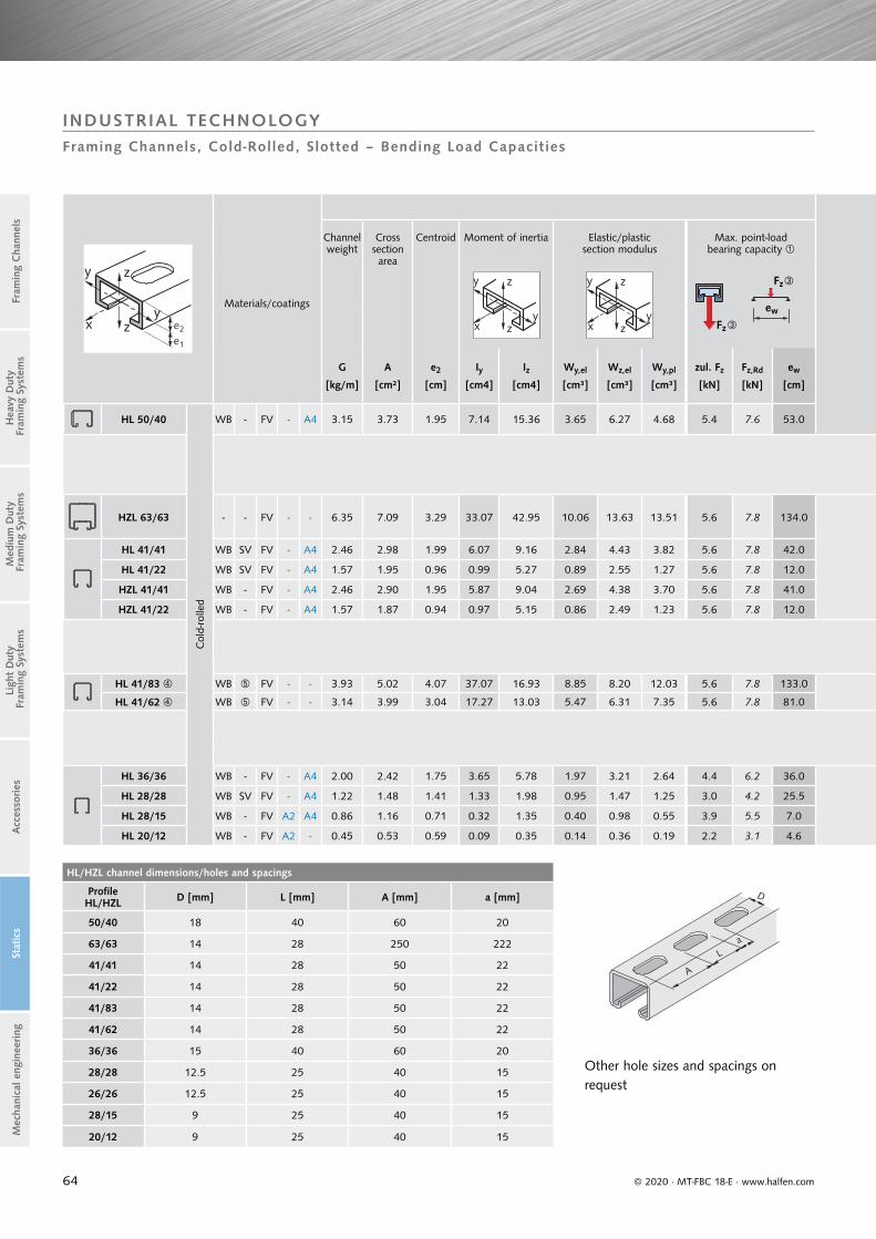
64
y z
e2
e1
yx z
Materials/coatings
Channel weight
Cross section area
Centroid Moment of inertia Elastic/plastic section modulus
Max. point-load bearing capacity
y z
yx z
y z
yx z
G
[kg/m]
A
[cm²]
e2
[cm]
Iy[cm4]
Iz[cm4]
Wy,el
[cm³]
Wz,el
[cm³]
Wy,pl
[cm³]
zul. Fz
[kN]
Fz,Rd
[kN]
ew
[cm]
HL 50/40
Col
d-ro
lled
WB - FV - A4 3.15 3.73 1.95 7.14 15.36 3.65 6.27 4.68 5.4 7.6 53.0
HZL 63/63 - - FV - - 6.35 7.09 3.29 33.07 42.95 10.06 13.63 13.51 5.6 7.8 134.0
HL 41/41 WB SV FV - A4 2.46 2.98 1.99 6.07 9.16 2.84 4.43 3.82 5.6 7.8 42.0
HL 41/22 WB SV FV - A4 1.57 1.95 0.96 0.99 5.27 0.89 2.55 1.27 5.6 7.8 12.0
HZL 41/41 WB - FV - A4 2.46 2.90 1.95 5.87 9.04 2.69 4.38 3.70 5.6 7.8 41.0
HZL 41/22 WB - FV - A4 1.57 1.87 0.94 0.97 5.15 0.86 2.49 1.23 5.6 7.8 12.0
HL 41/83 WB FV - - 3.93 5.02 4.07 37.07 16.93 8.85 8.20 12.03 5.6 7.8 133.0
HL 41/62 WB FV - - 3.14 3.99 3.04 17.27 13.03 5.47 6.31 7.35 5.6 7.8 81.0
HL 36/36 WB - FV - A4 2.00 2.42 1.75 3.65 5.78 1.97 3.21 2.64 4.4 6.2 36.0
HL 28/28 WB SV FV - A4 1.22 1.48 1.41 1.33 1.98 0.95 1.47 1.25 3.0 4.2 25.5
HL 28/15 WB - FV A2 A4 0.86 1.16 0.71 0.32 1.35 0.40 0.98 0.55 3.9 5.5 7.0
HL 20/12 WB - FV A2 - 0.45 0.53 0.59 0.09 0.35 0.14 0.36 0.19 2.2 3.1 4.6
Fz
Fz
ew
HL/HZL channel dimensions/holes and spacings
Profile HL/HZL D [mm] L [mm] A [mm] a [mm]
50/40 18 40 60 20
63/63 14 28 250 222
41/41 14 28 50 22
41/22 14 28 50 22
41/83 14 28 50 22
41/62 14 28 50 22
36/36 15 40 60 20
28/28 12.5 25 40 15
26/26 12.5 25 40 15
28/15 9 25 40 15
20/12 9 25 40 15
L
A
a
D
© 2020 · MT-FBC 18-E · www.halfen.com
Stat
ics
Ligh
t D
uty
Fra
min
g Sy
stem
sA
cces
sories
Fram
ing
Cha
nnel
sM
ediu
m D
uty
Fra
min
g Sy
stem
sH
eavy
Dut
y F
ram
ing
Syst
ems
Mec
hani
cal e
ngin
eering
Other hole sizes and spacings on request
INDUSTRIAL TECHNOLOGYFraming Channels, Cold-Rolled, Slotted – Bending Load Capacities

65
Material: steel, type WB, FV, SV E= 210.000 N/mm2
Bending load capacity at span L (single span element)
F
L [m]
F F
L [m]
q
L [m]
F [kN] F [kN] q[kN/m]
allow. Fz FRd allow. Fz FRd allow. Fz FRd allow. Fz FRd allow. Fz FRd allow. Fz FRd allow. qz qRd allow. qz qRd allow. qz qRd
0.50 m 1.00 m 1.50 m 0.50 m 1.00 m 1.50 m 0.50 m 1.00 m 1.50 m
5.7 7.98 2.9 4.06 1.9 2.66 4.3 6.02 2.1 2.94 1.3 1.82 22.9 32.06 5.7 7.98 2.3 3.22
allow. Fz FRd allow. Fz FRd allow. Fz FRd allow. Fz FRd allow. Fz FRd allow. Fz FRd allow. qz qRd allow. qz qRd allow. qz qRd
0.50 m 1.00 m 1.50 m 0.50 m 1.00 m 1.50 m 0.50 m 1.00 m 1.50 m
16.5 23.1 8.2 11.5 5.5 7.7 12.4 17.4 6.2 8.7 4.1 5.7 66 92.4 16.5 23.1 7.3 10.2
4.7 6.6 2.3 3.2 1.6 2.2 3.5 4.9 1.7 2.4 1.1 1.5 18.7 26.2 4.7 6.6 1.9 2.7
1.6 2.2 0.7 1.0 0.3 0.4 1.2 1.7 0.4 0.6 0.17 0.2 6.2 8.7 1.1 1.5 0.3 0.4
4.5 6.3 2.3 3.2 1.5 2.1 3.4 4.8 1.7 2.4 1 1.4 18.1 25.3 4.5 6.3 1.9 2.7
1.5 2.1 0.6 0.8 0.3 0.4 1.1 1.5 0.4 0.6 0.16 0.2 6 8.4 1 1.4 0.3 0.4
allow. Fz FRd allow. Fz FRd allow. Fz FRd allow. Fz FRd allow. Fz FRd allow. Fz FRd allow. qz qRd allow. qz qRd allow. qz qRd
1.00 m 2.00 m 3.00 m 1.00m 2.00 m 3.00 m 1.00 m 2.00 m 3.00 m
7.3 10.2 3.7 5.2 2.4 3.4 5.5 7.7 2.8 3.9 1.6 2.2 14.7 20.6 3.7 5.2 1.5 2.1
4.5 6.3 2.2 3.1 1.3 1.8 3.4 4.8 1.7 2.4 0.8 1.1 9 12.6 2.2 3.1 0.7 1.0
allow. Fz FRd allow. Fz FRd allow. Fz FRd allow. Fz FRd allow. Fz FRd allow. Fz FRd allow. qz qRd allow. qz qRd allow. qz qRd
0.50 m 1.00 m 1.50 m 0.50 m 1.00 m 1.50 m 0.50 m 1.00 m 1.50 m
3.20 4.48 1.60 2.24 1.10 1.54 2.40 3.36 1.20 1.68 0.60 0.84 12.90 18.06 3.20 4.48 1.20 1.68
1.50 2.10 0.80 1.12 0.40 0.56 1.10 1.54 0.50 0.70 0.23 0.32 6.10 8.54 1.40 1.96 0.40 0.56
0.70 0.98 0.22 0.31 0.10 0.14 0.50 0.70 0.13 0.18 0.06 0.08 2.70 3.78 0.30 0.42 0.10 0.14
0.23 0.32 0.06 0.08 0.03 0.04 0.14 0.20 0.04 0.06 0.02 0.03 0.80 1.12 0.10 0.14 0.03 0.04
© 2020 · MT-FBC 18-E · www.halfen.com
Stat
ics
Ligh
t D
uty
Fra
min
g Sy
stem
sA
cces
sories
Fram
ing
Cha
nnel
sM
ediu
m D
uty
Fra
min
g Sy
stem
sH
eavy
Dut
y F
ram
ing
Syst
ems
Mec
hani
cal e
ngin
eering
INDUSTRIAL TECHNOLOGYFraming Channels, Cold-Rolled, Slotted – Bending Load Capacities
All load capacities were calculated using the elastic-plastic method acc. to EN 1993-1, partial safety factor F = 1,4; deflection ≤ l / 150.Determination of the allowable value allow. Fz = FRd / 1.4.
Note: For stainless steel framing channels the bending deflection
value must be verified separately using the valid E-modulus of
elasticity.
Observe minimum distance ae between channel end and load point (bolt, locking plate): heavy and medium duty framing systems: ae ≥ 30 mm, light duty framing systems: ae ≥ 20 mm.
Do not exceed the bolt load capacity or the max. channel load bearing capacity.
For maximum point-load capacity: Fz = max, load bearing capacity of the channel lips.
Take constructive measures to prevent failure caused by bulging, tilting and buckling.
On request.
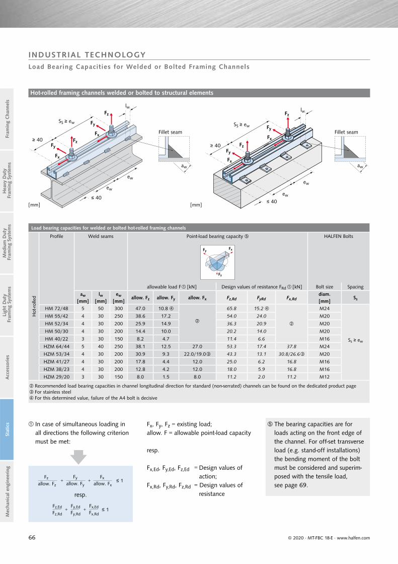
66
Load bearing capacities for welded or bolted hot-rolled framing channels
Hot
-rolle
d
Profile Weld seams Point-load bearing capacity HALFEN Bolts
Fz
FxFy
allowable load F [kN] Design values of resistance FRd [kN] Bolt size Spacing
aw lw ew allow. Fz allow. Fy allow. Fx Fz,Rd FyRd Fx,Rddiam.
Ss[mm] [mm] [mm] [mm]HM 72/48 5 50 300 47.0 10.8
65.8 15.2
M24
Ss ≥ ew
HM 55/42 4 30 250 38.6 17.2 54.0 24.0 M20
HM 52/34 4 30 200 25.9 14.9 36.3 20.9 M20
HM 50/30 4 30 200 14.4 10.0 20.2 14.0 M20
HM 40/22 3 30 150 8.2 4.7 11.4 6.6 M16
HZM 64/44 5 40 250 38.1 12.5 27.0 53.3 17.4 37.8 M24
HZM 53/34 4 30 200 30.9 9.3 22.0/19.0 43.3 13.1 30.8/26.6 M20
HZM 41/27 4 30 200 17.8 4.4 12.0 25.0 6.2 16.8 M16
HZM 38/23 4 30 200 12.8 4.2 12.0 18.0 5.9 16.8 M16
HZM 29/20 3 30 150 8.0 1.5 8.0 11.2 2.0 11.2 M12
Recommended load bearing capacities in channel longitudinal direction for standard (non-serrated) channels can be found on the dedicated product pageFor stainless steelFor this determined value, failure of the A4 bolt is decisive
Fx
ew
ew
≤ 40
SS ≥ ew
≥ 40
lw
Fx
Fy
Fy
Fz
Fz
aw aw
ew
ew
≤ 40
SS ≥ ew
Fx
lw
Fx
Fy
Fy
Fz
Fz≥ 40
[mm] [mm]
© 2020 · MT-FBC 18-E · www.halfen.com
Stat
ics
Ligh
t D
uty
Fra
min
g Sy
stem
sA
cces
sories
Fram
ing
Cha
nnel
sM
ediu
m D
uty
Fra
min
g Sy
stem
sH
eavy
Dut
y F
ram
ing
Syst
ems
Mec
hani
cal e
ngin
eering
Hot-rolled framing channels welded or bolted to structural elements
In case of simultaneous loading in all directions the following criterion must be met:
Fz
allow. Fz +
Fy
allow. Fy +
Fx
allow. Fx ≤ 1
resp.
Fz,Ed
Fz,Rd +
Fy,Ed
Fy,Rd +
Fx,Ed
Fx,Rd ≤ 1
Fx, Fy, Fz = existing load;allow. F = allowable point-load capacity
resp.
Fx,Ed, Fy,Ed, Fz,Ed = Design values of action;Fx,Rd, Fy,Rd, Fz,Rd = Design values of resistance
The bearing capacities are for loads acting on the front edge of the channel. For off-set transverse load (e.g. stand-off installations) the bending moment of the bolt must be considered and superim-posed with the tensile load,see page 69.
Fillet seam Fillet seam
INDUSTRIAL TECHNOLOGYLoad Bearing Capacities for Welded or Bolted Framing Channels

67
50
45
40
30
25
20
20
15
15
10
10
5
50
0
35 50
40
30
20
10
00 5 10 15 20 25
60
70
40
30
25
20
15
10
5
0
35
20151050 0 5 10 15 20 25
50
40
30
20
10
0
60
© 2020 · MT-FBC 18-E · www.halfen.com
Stat
ics
Ligh
t D
uty
Fra
min
g Sy
stem
sA
cces
sories
Fram
ing
Cha
nnel
sM
ediu
m D
uty
Fra
min
g Sy
stem
sH
eavy
Dut
y F
ram
ing
Syst
ems
Mec
hani
cal e
ngin
eering
INDUSTRIAL TECHNOLOGYLoad Bearing Capacities for Welded or Bolted Framing Channels
Framing channels welded or bolted to structural elements
Allowable point-load capacities for HM Channels Design point-load for HM Channels
Design point-load for HZM ChannelsAllowable point-load capacities for HZM Channels
HM 72/48; ew = 300 mmHM 55/42; ew = 250 mmHM 52/34; ew = 200 mmHM 50/30; ew = 200 mmHM 40/22; ew = 200 mm
allow. Fz [kN]
allow. Fy [kN]
Allowable DesignFz,Rd [kN]
Fy,Rd [kN]
allow. Fz [kN] Allowable
HZM 64/44; ew = 250 mmHZM 53/34; ew = 200 mmHZM 41/27; ew = 200 mmHZM 38/23; ew = 200 mmHZM 29/20; ew = 150 mm
Fz,Rd [kN] Design
HM 72/48; ew = 300 mmHM 55/42; ew = 250 mmHM 52/34; ew = 200 mmHM 50/30; ew = 200 mmHM 40/22; ew = 200 mm
HZM 64/44; ew = 250 mmHZM 53/34; ew = 200 mmHZM 41/27; ew = 200 mmHZM 38/23; ew = 200 mmHZM 29/20; ew = 150 mm
zul. Fy [kN] Fy,Rd [kN]

68
Load bearing capacities for welded or bolted cold-rolled framing channels
Col
d-ro
lled
Profil Weld seams
Point-load bearing capacities
Fz
Fy
Fx
Tension α ≤ 60° Fz [kN]
Transverse tension < 60°Fy [kN]
Longitudinal tension Fx [kN]
aw[mm]
lw [mm]
ew [mm] allow. Fz Fz,Rd allow. Fy Fy,Rd allow. Fx Fx,Rd
HM 50/40 3 30 400 5.4 7.6 1.9 2.7
HZM 41/41 3 30 300 5.6 7.8 1.2 1.7 5.0 7.0
HZM 41/22 3 30 120 5.6 7.8 1.5 2.1 5.0 7.0
HM 41/41 3 30 300 5.6 7.8 1.2 1.7
HM 41/22 3 30 120 5.6 7.8 1.5 2.1
HM 36/36 3 30 300 4.4 6.2 1.2 1.7
HM 38/17 3 30 100 4.8 6.7 2.5 3.5
HM 28/15 3 30 100 2.5 3.5 1.2 1.7
Recommended load bearing capacities in channel longitudinal direction for standard (non-serrated) channels can be found on the dedicated product page
Fz
Fy
Fy
Tension areaα ≤ 60°
Transverse tension area < 60°
Fx
ew
≤ 40
ew
SS ≥ ew
≥ 40
lw
Fx
Fy
Fy
Fz
Fz
SS ≥ ew
≥ 40
Fx
ew
ew
≤ 40
lw
Fx
Fy
Fy
Fz
Fz
aw aw
[mm][mm]
© 2020 · MT-FBC 18-E · www.halfen.com
Stat
ics
Ligh
t D
uty
Fra
min
g Sy
stem
sA
cces
sories
Fram
ing
Cha
nnel
sM
ediu
m D
uty
Fra
min
g Sy
stem
sH
eavy
Dut
y F
ram
ing
Syst
ems
Mec
hani
cal e
ngin
eering
Cold-rolled framing channels welded or bolted to structural elements
The bearing capacities are for loads acting on the front edge of the channel. For off-set transverse load (e.g. stand-off installations) the bending moment of the bolt must be considered and superim-posed with the tensile stress, see page 69.
Fillet seam Fillet seam
INDUSTRIAL TECHNOLOGYLoad Capacities for Welded or Bolted Framing Channels

69
Bending moments of bolts
Recommendedbolt bending moments
from the front edge of the channel
Strength class
Thread Ø4.6 8.8 A2-50; A4-50 A2-70; A4-70
allow. M MRd allow. M MRd allow. M MRd allow. M MRd
M6 2.0 2.8 - - 1.8 2.5 3.8 5.3
M8 5.0 7.0 - - 4.4 6.2 9.4 13.2
M10 10.0 14.0 24.9 34.9 8.7 12.2 18.7 26.2
M12 17.5 24.5 43.7 61.2 15.3 21.4 32.8 45.9
M16 44.4 62.2 111.0 155.4 38.8 54.3 83.3 116.6
M20 86.5 121.1 216.4 303.0 75.7 106.0 162.3 227.2
M24 149.7 209.4 374.2 524.0 131.1 183.3 156.2 218.7
M27 221.9 310.7 554.8 776.7 - - - -
M30 299.9 419.9 - - - - - -
Recommended design value of bending moment capability for boltsFor profile HM/HL 28/15 bending moment must be reduced to MRd = 42 Nm resp. allow. M = 30 NmFor profile HM/HL 38/17 bending moment must be reduced to MRd = 91 Nm resp. allow. M = 65 Nm
FQ
Fz
L
FQ
M = FQ x L
© 2020 · MT-FBC 18-E · www.halfen.com
Stat
ics
Ligh
t D
uty
Fra
min
g Sy
stem
sA
cces
sories
Fram
ing
Cha
nnel
sM
ediu
m D
uty
Fra
min
g Sy
stem
sH
eavy
Dut
y F
ram
ing
Syst
ems
Mec
hani
cal e
ngin
eering
INDUSTRIAL TECHNOLOGYBolts – Bending moments
Bending moments of bolts
In cases of bending with additional centric tension the action loads must be superimposed with the tensile load.
Fz ≤ allow. F ⋅ 1 − M
allow. M
resp.
Fz,Ed ≤ FRd ⋅ 1 − MEd
MRd A square washer must always be
used with stand-off installations.
Square washer Fz = existing tension loadallow. Fz = allowable load bearing capacity of the boltM = existing bending moment of the boltallow. M = allowable bending moment of the bolt
resp.
Fz,Ed = Design value for the existing tension load of the boltFz,Rd = Design value for the resistance of the boltMEd = Design value for the existing bending moment of the boltMRd = Design value for bending moment resistance of the bolt

70
Load bearing capacities — flexural buckling
Hot
-rolle
d fr
amin
g ch
anne
ls
Type
Cross-section properties N [kN] , for element length L [mm]
A e1 ly Wy Wpl 500 1000 1500 2000 2500 3000 3500 4000 4500 5000
[cm2] [cm] [cm4] [cm3] [cm3] [kN]
HM 72/48 11.27 2.40 34.97 14.28 18.28NRd 104.6 81.6 62.0 50.0 40.0 32.2 26.4 21.8 18.4 15.6
allow. N 74.7 58.3 44.3 35.7 28.6 23.0 18.9 15.6 13.1 11.1
HM 55/42 8.61 2.21 18.75 8.49 11.73NRd 79.0 57.5 43.0 32.8 25.1 19.8 15.8 12.9 10.7 9.0
allow. N 56.4 41.1 30.7 23.4 17.9 14.1 11.3 9.2 7.6 6.4
HM 52/34 6.34 1.74 9.33 5.35 7.19NRd 50.4 34.6 25.3 18.5 13.9 10.7 8.5 6.8 5.6 4.7
allow. N 36.0 24.7 18.1 13.2 9.9 7.6 6.1 4.9 4.0 3.4
HM 50/30 4.15 1.63 5.26 3.23 4.38NRd 31.8 21.4 15.3 11.0 8.2 6.3 4.9 4.0 3.2 2.7
allow. N 22.7 15.3 10.9 7.9 5.8 4.5 3.5 2.8 2.3 1.9
HM 40/22 2.70 1.25 1.99 1.59 2.17NRd 18.2 11.2 7.3 5.0 3.5 2.6 - - - -
allow. N 13.0 8.0 5.2 3.5 2.5 1.9 - - - -
HM 72/48 D 22.54 4.85 205.15 42.30 55.20NRd 195.2 169.2 148.0 128.0 110.0 98.0 87.0 77.0 68.5 61.0
allow. N 139.4 120.9 105.7 91.4 78.6 70.0 62.1 55.0 48.9 43.6
HM 55/42 D 17.22 4.20 105.70 25.17 34.27NRd 155.0 130.0 109.0 90.0 78.0 67.0 57.5 46.3 43.0 37.5
allow. N 110.7 92.9 77.9 64.3 55.7 47.9 41.1 33.1 30.7 26.8
HM 52/34 D 12.70 3.35 51.49 15.37 20.42NRd 97.0 80.0 64.5 53.5 45.0 37.5 31.8 26.9 23.1 20.0
allow. N 69.3 57.1 46.1 38.2 32.1 26.8 22.7 19.2 16.5 14.3
HM 50/30 D 8.27 3.00 26.56 8.85 11.52NRd 61.5 49.0 38.5 31.7 26.0 21.5 17.9 15.0 12.8 11.0
allow. N 43.9 35.0 27.5 22.6 18.6 15.4 12.8 10.7 9.1 7.9
HM 40/22 D 5.33 2.30 10.06 4.38 5.73NRd 37.0 27.5 20.9 16.1 12.6 10.0 8.1 6.7 5.6 4.7
allow. N 26.4 19.6 14.9 11.5 9.0 7.1 5.8 4.8 4.0 3.4
HZM 64/44 9.10 2.30 23.83 10.36 13.66NRd 91.0 68.0 51.0 39.5 30.5 24.3 19.5 16.0 13.3 11.2
allow. N 65.0 48.6 36.4 28.2 21.8 17.4 13.9 11.4 9.5 8.0
HZM 53/34 5.88 1.86 9.19 4.95 6.80NRd 51.8 35.0 25.5 18.5 13.9 10.6 8.4 6.8 5.6 4.7
allow. N 37.0 25.0 18.2 13.2 9.9 7.6 6.0 4.8 4.0 3.3
HZM 41/27 4.31 1.51 3.90 2.57 3.74NRd 31.5 20.0 13.2 9.2 6.7 5.0 3.9 3.1 2.5 -
allow. N 22.5 14.3 9.4 6.6 4.8 3.6 2.8 2.2 1.8 -
HZM 38/23 3.10 1.33 2.11 1.59 2.31NRd 20.7 12.5 7.9 5.3 3.8 2.8 2.2 - - -
allow. N 14.8 8.9 5.6 3.8 2.7 2.0 1.6 - - -
HZM 29/20 1.99 1.12 1.02 0.91 1.31NRd 12.5 7.1 4.3 2.8 - - - - - -
allow. N 8.9 5.1 3.1 2.0 - - - - - -
HZM 64/44 D 18.21 4.40 127.94 29.08 38.23NRd 171.0 144.5 122.0 102.0 88.5 76.5 66.0 57.5 50.0 43.9
allow. N 122.1 103.2 87.1 72.9 63.2 54.6 47.1 41.1 35.7 31.4
HZM 53/34 D 11.75 3.40 46.38 13.64 18.14NRd 100.0 81.0 63.5 53.0 43.5 36.3 30.3 25.5 21.7 18.8
allow. N 71.4 57.9 45.4 37.9 31.1 25.9 21.6 18.2 15.5 13.4
HZM 41/27 D 8.62 2.70 19.91 7.37 10.22NRd 65.5 49.5 38.0 29.8 23.5 18.9 15.3 12.7 10.6 9.0
allow. N 46.8 35.4 27.1 21.3 16.8 13.5 10.9 9.1 7.6 6.4
HZM 38/23 D 6.19 2.30 10.04 4.36 6.00NRd 43.6 30.9 23.4 17.5 13.5 10.6 8.5 6.9 5.8 4.9
allow. N 31.1 22.1 16.7 12.5 9.6 7.6 6.1 4.9 4.1 3.5
HZM 29/20 D 3.97 2.00 5.12 2.56 3.49NRd 27.9 19.1 13.8 10.0 7.6 5.9 4.6 3.8 3.1 2.6
allow. N 19.9 13.6 9.9 7.1 5.4 4.2 3.3 2.7 2.2 1.8
zz
N
L
z
y y
e1P
S
N
L
© 2020 · MT-FBC 18-E · www.halfen.com
Stat
ics
Ligh
t D
uty
Fra
min
g Sy
stem
sA
cces
sories
Fram
ing
Cha
nnel
sM
ediu
m D
uty
Fra
min
g Sy
stem
sH
eavy
Dut
y F
ram
ing
Syst
ems
Mec
hani
cal e
ngin
eering
INDUSTRIAL TECHNOLOGY
Framing channels as compression element — hot-rolled
Flexural buckling acc. to EN 1993-1-1(Point-load applied at P)
Framing Channels as Compression Elements
Table footnotes → see page 71

71
Load bearing capacities — Flexural buckling
Col
d-ro
lled
fram
ing
chan
nels
Type
Cross-section properties N [kN] , for element length L [mm]
A e1 ly Wy Wpl 500 1000 1500 2000 2500 3000 3500 4000 4500 5000
[cm2] [cm] [cm4] [cm3] [cm3] [kN]
HM 50/40 4.26 2.18 8.64 3.96 5.53NRd 33.2 24.6 18.5 14.2 11.1 8.8 7.0 5.8 4.8 4.1
allow. N 23.7 17.6 13.2 10.1 7.9 6.3 5.0 4.1 3.5 2.9
HM 41/41 3.40 2.31 7.47 3.24 4.57NRd 26.3 19.7 15.0 11.7 9.2 7.3 6.0 4.9 4.1 3.5
allow. N 18.8 14.1 10.7 8.4 6.6 5.2 4.3 3.5 2.9 2.5
HM 36/36 2.80 2.07 4.54 2.19 3.19NRd 19.7 14.1 10.6 8.0 6.1 4.8 3.9 3.2 2.6 2.2
allow. N 14.1 10.1 7.5 5.7 4.4 3.4 2.8 2.3 1.9 1.6
HM 28/28 1.73 1.58 1.70 1.08 1.54NRd 11.4 7.5 5.2 3.7 2.7 - - - - -
allow. N 8.1 5.4 3.7 2.6 2.0 - - - - -
HZM 41/41 3.36 2.33 7.34 3.15 4.48NRd 25.5 19.3 14.6 11.4 9.0 7.2 5.8 4.8 4.0 3.4
allow. N 18.2 13.8 10.4 8.1 6.4 5.1 4.1 3.4 2.9 2.4
HZM 41/41 D 6.71 4.13 36.45 8.83 12.09NRd 49.0 41.5 35.0 29.1 25.3 21.8 18.8 16.3 14.2 12.5
allow. N 35.0 29.6 25.0 20.8 18.1 15.6 13.4 11.6 10.1 8.9
HL 50/40 3.73 1.95 7.14 3.65 4.68NRd 31.5 22.8 16.9 12.8 9.8 7.7 6.1 5.0 4.1 3.5
allow. N 22.5 16.3 12.1 9.1 7.0 5.5 4.4 3.6 2.9 2.5
HL 41/41 2.98 2.14 6.07 2.84 3.82NRd 23.8 17.5 13.2 10.1 7.9 6.2 5.0 4.1 3.4 2.9
allow. N 17.0 12.5 9.4 7.2 5.6 4.4 3.6 2.9 2.4 2.0
HL 36/36 2.42 1.85 3.65 1.97 2.64NRd 18.3 12.7 9.4 7.0 5.3 4.1 3.2 2.6 - -
allow. N 13.1 9.1 6.7 5.0 3.8 2.9 2.3 1.9 - -
HL 28/28 1.48 1.39 1.33 0.95 1.25NRd 10.4 6.7 4.5 3.1 2.3 - - - - -
allow. N 7.4 4.8 3.2 2.2 1.6 - - - - -
HZL 63/63 7.09 3.01 33.07 10.06 13.51NRd 65.0 53.2 43.3 35.4 29.7 24.8 20.9 17.7 15.2 13.1
allow. N 46.4 38.0 30.9 25.3 21.2 17.7 14.9 12.6 10.9 9.4
HZL 41/41 2.90 2.18 5.87 2.69 3.70NRd 22.5 16.7 12.6 9.7 7.5 6.0 4.8 4.0 3.3 2.8
allow. N 16.1 11.9 9.0 6.9 5.4 4.3 3.4 2.8 2.3 2.0
N
L
N
L
z
z
y y
e1P
S
© 2020 · MT-FBC 18-E · www.halfen.com
Stat
ics
Ligh
t D
uty
Fra
min
g Sy
stem
sA
cces
sories
Fram
ing
Cha
nnel
sM
ediu
m D
uty
Fra
min
g Sy
stem
sH
eavy
Dut
y F
ram
ing
Syst
ems
Mec
hani
cal e
ngin
eering
Note:For higher excentricity ”e > e1” a flexural buckling analysis acc. to Eurocode 3 is necessary.
Framing channels as compression elements — cold-rolled
NRd = Design value of resistance allow. N = allowable load
allow. N = NRd / 1.4; E = 170 000 N/mm2
allow. N = NRd / 1.4; E = 210 000 N/mm2
INDUSTRIAL TECHNOLOGY Framing Channels as Compression Elements
Flexural buckling acc to. EN 1993-1-1(Point-load applied at P)
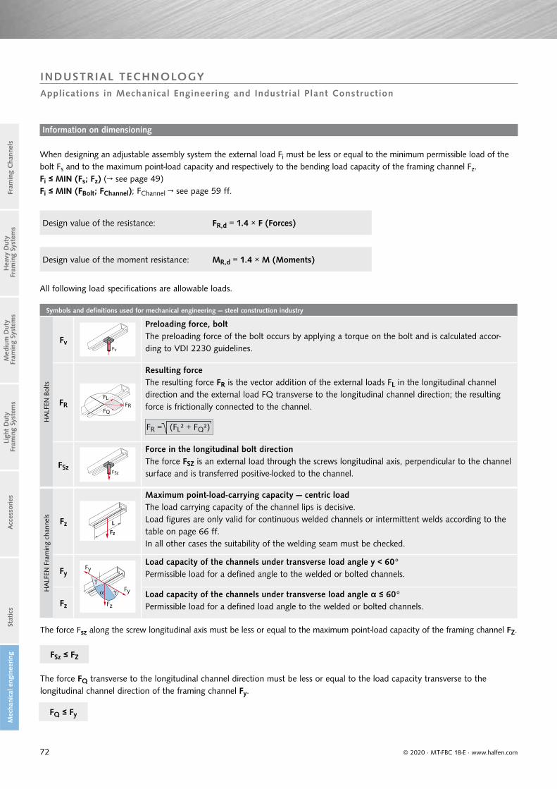
72
Symbols and definitions used for mechanical engineering — steel construction industry
HA
LFEN
Bol
ts
FvFv
Preloading force, boltThe preloading force of the bolt occurs by applying a torque on the bolt and is calculated accor-ding to VDI 2230 guidelines.
FRFL
FQFR
Resulting force The resulting force FR is the vector addition of the external loads FL in the longitudinal channel direction and the external load FQ transverse to the longitudinal channel direction; the resulting force is frictionally connected to the channel.
FSzFSz
Force in the longitudinal bolt direction The force FSZ is an external load through the screws longitudinal axis, perpendicular to the channel surface and is transferred positive-locked to the channel.
HA
LFEN
Fra
min
g ch
anne
ls
FzFz
L
Maximum point-load-carrying capacity — centric loadThe load carrying capacity of the channel lips is decisive.Load figures are only valid for continuous welded channels or intermittent welds according to the table on page 66 ff.In all other cases the suitability of the welding seam must be checked.
Fy
Fz
Fy
Fy
Load capacity of the channels under transverse load angle y < 60°Permissible load for a defined angle to the welded or bolted channels.
Fz
Load capacity of the channels under transverse load angle α ≤ 60°Permissible load for a defined load angle to the welded or bolted channels.
FR = (FL² + FQ²)
© 2020 · MT-FBC 18-E · www.halfen.com
Stat
ics
Ligh
t D
uty
Fra
min
g Sy
stem
sA
cces
sories
Fram
ing
Cha
nnel
sM
ediu
m D
uty
Fra
min
g Sy
stem
sH
eavy
Dut
y F
ram
ing
Syst
ems
Mec
hani
cal e
ngin
eering
INDUSTRIAL TECHNOLOGYApplications in Mechanical Engineering and Industrial Plant Construction
When designing an adjustable assembly system the external load Fi must be less or equal to the minimum permissible load of the bolt Fs and to the maximum point-load capacity and respectively to the bending load capacity of the framing channel Fz. Fi ≤ MIN (Fs; Fz) (→ see page 49)Fi ≤ MIN (FBolt; FChannel); FChannel → see page 59 ff.
All following load specifications are allowable loads.
Design value of the resistance: FR,d = 1.4 × F (Forces)
Design value of the moment resistance: MR,d = 1.4 × M (Moments)
The force Fsz along the screw longitudinal axis must be less or equal to the maximum point-load capacity of the framing channel FZ.
The force FQ transverse to the longitudinal channel direction must be less or equal to the load capacity transverse to the longitudinal channel direction of the framing channel Fy.
FQ ≤ Fy
FSz ≤ FZ
Information on dimensioning

73
Minimum required supplement for bolts (heavy duty framing systems) [mm]
Thread HM 72/48
HM 55/42
HM 52/34
HM 50/30
HM 49/30
HM 40/22
HM 40/25
HM 422
HZM 64/44
HZM 53/34
HZM 41/27
HZM 38/23
HZM 29/20
HM 50/40
HM 486
M6 - - - - - - - - - - - - - - -
M8 - - - - - - - - - - - - 12 - -
M10 - 25 24 20 20 18 18 18 - - 18 17 15 - -
M12 - 29 27 24 23 22 22 22 - - 21 21 16 19 18
M16 - 35 33 30 29 28 28 28 - 28 27 27 20 23 22
M20 42 39 38 34 34 - - - 34 32 - - - 29 28
M24 47 - - - - - - - 40 - - - - 33 32
M27 50 - - - - - - - - - - - - - -
M30 53 - - - - - - - - - - - - - -
Minimum required supplement for bolts (medium duty framing systems) [mm]
Thread HZL63/63
HM 41/41
HM 41/22
HM 41/62
HM 41/83
HLL 41/41
HLL 41/22
M6 - - - - - - -
M8 - 18 18 18 18 18 18
M10 - 19 19 19 19 19 19
M12 19 23 23 23 23 23 23
M16 23 29 29 29 29 29 29
M20 29 - - - - - -
M24 33 - - - - - -
Minimum required supplement for bolts (light duty framing systems) [mm]
Thread HM 36/36 HM 38/17 HM 28/28 HM 26/26 HM 28/15 HM 315 HM 20/12
M6 - - - - - - -
M8 - - 10 9 10 9 9
M10 15 15 13 12 13 12 12
M12 18 19 14 13 14 14 -
M16 24 25 18 17 18 17 -
KD
v
m
h
max
Lbolt
© 2020 · MT-FBC 18-E · www.halfen.com
Stat
ics
Ligh
t D
uty
Fra
min
g Sy
stem
sA
cces
sories
Fram
ing
Cha
nnel
sM
ediu
m D
uty
Fra
min
g Sy
stem
sH
eavy
Dut
y F
ram
ing
Syst
ems
Mec
hani
cal e
ngin
eering
INDUSTRIAL TECHNOLOGYApplications in Mechanical Engineering and Industrial Plant Construction
The required bolt length Lbolt is the sum of the clamp thickness KD and the minimum required supplement Lsup.
The thread protrusion v has to extend pass the nut at least 0.5 x the nut height m (DIN EN 24032 regulation for nuts).
Minimum required supplement Lsup according to the table below
Lbolt = KD + Lsup
Lsup = h + m + v
Required bolt length Lbolt

74
60
HS 40/22-HM 40/22
40
20
00 100 200 300 400
HS40/22-HM40/22_01
HS40/22-HM40/22_02
HS40/22-HM40/22_03
35
30
25
20
15
10
5
000
a120fx1 a120fx2 a120fx3
1 2 3 4 5 6
© 2020 · MT-FBC 18-E · www.halfen.com
Stat
ics
Ligh
t D
uty
Fra
min
g Sy
stem
sA
cces
sories
Fram
ing
Cha
nnel
sM
ediu
m D
uty
Fra
min
g Sy
stem
sH
eavy
Dut
y F
ram
ing
Syst
ems
Mec
hani
cal e
ngin
eering
INDUSTRIAL TECHNOLOGYApplications in Mechanical Engineering and Industrial Plant Construction
Static and dynamic tension tests
The transferability of static and dynamic loads for adjustable assem-bly systems was intensely studied in cooperation with the State Material Testing Institute at the TU Darmstadt (Technical University Darmstadt).
Tightening test
Graph; tightening test results Graph, tension test results
Tension test Fatigue test
Following VDI guideline 2230, the data acquired from bolt tightening tests, static and dynamic traction tests form the basis of algorithms used for calculating adjustable assembly systems.
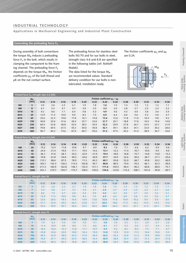
75
Preload force FV, strength class 4.6 [kN]
MA[Nm]
Friction coefficient μG = μK
0.12 0.14 0.16 0.18 0.20 0.22 0.24 0.26 0.28 0.30 0.32 0.34 0.36M6 3 3.0 2.6 2.3 2.1 1.9 1.8 1.6 1.5 1.4 1.3 1.2 1.2 1.1M8 8 6.1 5.3 4.7 4.3 3.9 3.5 3.3 3.0 2.8 2.7 2.5 2.4 2.2M10 15 9.2 8.0 7.1 6.4 5.8 5.3 4.9 4.6 4.3 4.0 3.8 3.6 3.4M12 25 12.9 11.3 10.0 9.0 8.2 7.5 6.9 6.4 6.0 5.6 5.3 5.0 4.7M16 65 25.6 22.3 19.8 17.8 16.1 14.8 13.6 12.6 11.8 11.0 10.4 9.8 9.2M20 130 40.8 35.6 31.6 28.4 25.7 23.6 21.7 20.1 18.8 17.6 16.5 15.6 14.8M24 230 60.5 52.8 46.8 42.0 38.2 34.9 32.2 29.9 27.8 26.1 24.5 23.1 21.9M27 340 79.8 69.5 61.5 55.2 50.0 45.8 42.1 39.1 36.4 34.1 32.0 30.2 28.6M30 460 96.7 84.2 74.6 67.0 60.7 55.6 51.2 47.5 44.2 41.4 38.9 36.7 34.8
Preload force FV, strength class 8.8 [kN]
MA[Nm]
Friction coefficient μG = μK
0.12 0.14 0.16 0.18 0.20 0.22 0.24 0.26 0.28 0.30 0.32 0.34 0.36M8 20 15.2 13.3 11.8 10.6 9.7 8.9 8.2 7.6 7.1 6.6 6.2 5.9 5.6M10 40 24.4 21.4 19.0 17.1 15.5 14.2 13.1 12.2 11.4 10.7 10.0 9.5 9.0M12 70 36.1 31.6 28.1 25.2 22.9 21.0 19.4 18.0 16.8 15.7 14.8 14.0 13.2M16 180 70.8 61.8 54.8 49.2 44.6 40.9 37.7 34.9 32.6 30.5 28.7 27.1 25.6M20 360 113.1 98.6 87.5 78.5 71.3 65.2 60.1 55.8 52.0 48.7 45.8 43.2 40.9M24 620 163.1 142.3 126.2 113.3 102.8 94.1 86.8 80.5 75.0 70.3 66.1 62.3 59.0M27 900 211.2 183.9 162.8 146.1 132.5 121.1 111.6 103.5 96.4 90.2 84.8 80.0 75.7M30 1200 252.1 219.7 194.7 174.7 158.5 145.0 133.6 123.8 115.4 108.1 101.6 95.8 90.7
Preload force FV, strength class 50
MA[Nm]
Friction coefficient μG = μK
0.12 0.14 0.16 0.18 0.20 0.22 0.24 0.26 0.28 0.30 0.32 0.34 0.36M6 3 3.0 2.6 2.3 2.1 1.9 1.8 1.6 1.5 1.4 1.3 1.2 1.2 1.1M8 7 5.3 4.6 4.1 3.7 3.4 3.1 2.9 2.7 2.5 2.3 2.2 2.1 2.0M10 14 8.6 7.5 6.7 6.0 5.4 5.0 4.6 4.3 4.0 3.7 3.5 3.3 3.1M12 25 12.9 11.3 10.0 9.0 8.2 7.5 6.9 6.4 6.0 5.6 5.3 5.0 4.7M16 60 23.6 20.6 18.3 16.4 14.9 13.6 12.6 11.6 10.9 10.2 9.6 9.0 8.5M20 120 37.7 32.9 29.2 26.2 23.8 21.7 20.0 18.6 17.3 16.2 15.3 14.4 13.6M24 200 52.6 45.9 40.7 36.6 33.2 30.4 28.0 26.0 24.2 22.7 21.3 20.1 19.0
Preload force FV, strength class 70
MA[Nm]
Friction coefficient μG = μK
0.12 0.14 0.16 0.18 0.20 0.22 0.24 0.26 0.28 0.30 0.32 0.34 0.36M6 7 7.0 6.2 5.5 4.9 4.5 4.1 3.8 3.5 3.3 3.1 2.9 2.7 2.6M8 15 11.4 10.0 8.9 8.0 7.2 6.6 6.1 5.7 5.3 5.0 4.7 4.4 4.2M10 30 18.3 16.0 14.3 12.8 11.7 10.7 9.9 9.2 8.5 8.0 7.5 7.1 6.7M12 50 25.8 22.6 20.0 18.0 16.4 15.0 13.8 12.9 12.0 11.2 10.6 10.0 9.4M16 125 49.2 42.9 38.0 34.2 31.0 28.4 26.2 24.3 22.6 21.2 19.9 18.8 17.8M20 245 76.9 67.1 59.5 53.5 48.5 44.4 40.9 38.0 35.4 33.1 31.2 29.4 27.8M24 420 110.5 96.4 85.5 76.8 69.7 63.8 58.8 54.5 50.8 47.6 44.8 42.2 40.0
Fv
MA
© 2020 · MT-FBC 18-E · www.halfen.com
Stat
ics
Ligh
t D
uty
Fra
min
g Sy
stem
sA
cces
sories
Fram
ing
Cha
nnel
sM
ediu
m D
uty
Fra
min
g Sy
stem
sH
eavy
Dut
y F
ram
ing
Syst
ems
Mec
hani
cal e
ngin
eering
INDUSTRIAL TECHNOLOGYApplications in Mechanical Engineering and Industrial Plant Construction
Generating the preloading force FV
During assembly of bolt connections the torque MA induces a preloading force Fv in the bolt, which results in clamping the component to the fram-ing channel. The preloading force Fv depends on the torque MA, the friction coefficients μG of the bolt thread and μK on the nut contact surface.
The preloading forces for stainless steel bolts 50/70 and for our bolts in steel, strength class 4.6 and 8.8 are specified in the following tables (ref. Rohloff-Matek).The data listed for the torque MA are recommended values. Standard delivery condition for our bolts is non-lubricated, installation ready.
The friction coefficients μG and μK
are 0.24.
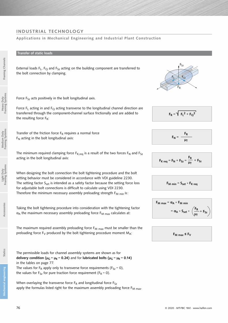
76
FR
FL FQ
FSz
© 2020 · MT-FBC 18-E · www.halfen.com
Stat
ics
Ligh
t D
uty
Fra
min
g Sy
stem
sA
cces
sories
Fram
ing
Cha
nnel
sM
ediu
m D
uty
Fra
min
g Sy
stem
sH
eavy
Dut
y F
ram
ing
Syst
ems
Mec
hani
cal e
ngin
eering
INDUSTRIAL TECHNOLOGYApplications in Mechanical Engineering and Industrial Plant Construction
Transfer of static loads
External loads FL, FQ and FSz acting on the building component are transferred to the bolt connection by clamping.
Force FSz acts positively in the bolt longitudinal axis.
Force FL acting in and FQ acting transverse to the longitudinal channel direction are transferred through the component-channel surface frictionally and are added to the resulting force FR:
Transfer of the friction force FR requires a normal force FN acting in the bolt longitudinal axis:
The minimum required clamping force FK,req is a result of the two forces FN and FSz
acting in the bolt longitudinal axis:
The permissible loads for channel assembly systems are shown as fordelivery condition (μG = μK = 0.24) and for lubricated bolts (μG = μK = 0.14)in the tables on page 77. The values for FR apply only to transverse force requirements (FSz = 0), the values for FSz for pure traction force requirement (FR = 0).
When overlaying the transverse force FR and longitudinal force FSz
apply the formulas listed right for the maximum assembly preloading force FM max.
FR = FL2 + FQ
2
FN =FR
μT
FM max ≤ FV
FM min = Sset × FK req
When designing the bolt connection the bolt tightening procedure and the bolt setting behavior must be considered in accordance with VDI guideline 2230.The setting factor Sset is intended as a safety factor because the setting force loss for adjustable bolt connections is difficult to calculate using VDI 2230. Therefore the minimum necessary assembly preloading strength FM min is :
Taking the bolt tightening procedure into consideration with the tightening factor αA the maximum necessary assembly preloading force FM max calculates at:
The maximum required assembly preloading force FM max must be smaller than the preloading force FV produced by the bolt tightening procedure moment MA:
FRFK req = FN + FSz = μT
+ FSz
FM max = αA × FM min
= αA × Sset ×FR
μT+ FSz

77
Allowable loads FR and FSz– channel bolt connection
Strength class 4.6
Delivery condition Lubricated
μG = μK = 0.24 μG = μK = 0.14
Thread MA [Nm]
Fv [kN]
FR [kN]
FZ [kN]
Fv [kN]
FR [kN]
FZ [kN]
M6 3 1.6 0.2 0.7 2.6 0.3 1.1
M8 8 3.3 0.3 1.4 5.3 0.6 2.2
M10 15 4.9 0.5 2.1 8.0 0.8 3.3
M12 25 6.9 0.7 2.9 11.3 1.2 4.7
M16 65 13.6 1.4 5.7 22.3 2.3 9.3
M20 130 21.7 2.3 9.0 35.6 3.7 14.8
M24 230 32.2 3.4 13.4 52.8 5.5 22.0
M27 340 42.1 4.4 17.6 69.5 7.2 28.9
M30 460 51.2 5.3 21.3 84.2 8.8 35.1
Allowable loads FR and FSz – channel bolt connection
Strength class 8.8
Delivery condition Lubricated
μG = μK = 0.24 μG = μK = 0.14
Thread MA [Nm]
Fv [kN]
FR [kN]
FZ [kN]
Fv [kN]
FR [kN]
FZ [kN]
M10 40 13.1 1.4 5.5 21.4 2.2 8.9
M12 70 19.4 2.0 8.1 31.6 3.3 13.2
M16 180 37.7 3.9 15.7 61.8 6.4 25.7
M20 360 60.1 6.3 25.1 98.6 10.3 41.1
M24 620 86.8 9.0 36.2 142.3 14.8 59.3
M27 900 111.6 11.6 46.5 183.9 19.2 76.6
Allowable loads FR and FSz – channel bolt connection
Strength class 50
Delivery condition Lubricated
μG = μK = 0.24 μG = μK = 0.14
Thread MA [Nm]
Fv [kN]
FR [kN]
FZ [kN]
Fv [kN]
FR [kN]
FZ [kN]
M8 7 2.9 0.3 1.4 4.6 0.6 2.2
M10 14 4.6 0.5 2.1 7.5 0.8 3.4
M12 25 6.9 0.7 2.9 11.3 1.2 4.7
M16 60 12.6 1.3 5.3 20.6 2.2 8.6
M20 120 20.0 2.1 8.4 32.9 3.4 13.8
M24 200 28.0 2.9 11.7 45.9 4.8 19.2
Allowable loads FR and FSz – channel bolt connection
Strength class 70
Delivery condition Lubricated
μG = μK = 0.24 μG = μK = 0.14
Thread MA [Nm]
Fv [kN]
FR [kN]
FZ [kN]
Fv [kN]
FR [kN]
FZ [kN]
M8 15 6.1 0.6 2.6 10.0 1.0 4.2
M10 30 9.9 1.0 4.1 16.0 1.7 6.7
M12 50 13.8 0.9 5.8 22.6 1.4 9.4
M16 125 26.2 2.7 10.9 42.9 4.5 17.9
M20 245 40.9 4.3 17.1 67.1 7.0 28.0
M24 420 58.8 6.1 24.5 96.4 10.0 40.2
© 2020 · MT-FBC 18-E · www.halfen.com
Stat
ics
Ligh
t D
uty
Fra
min
g Sy
stem
sA
cces
sories
Fram
ing
Cha
nnel
sM
ediu
m D
uty
Fra
min
g Sy
stem
sH
eavy
Dut
y F
ram
ing
Syst
ems
Mec
hani
cal e
ngin
eering
INDUSTRIAL TECHNOLOGYApplications in Mechanical Engineering and Industrial Plant Construction
The given data is based on the following failure modes and values:
Failure mode for transverse force load FR : component slippageFailure mode for longitudinal force load FSz : component separationFriction coefficient in connection: μT = 0.25Tightening factor (electrical-audible torque wrench): αA = 2.0Safety factor setting of bolt connection: Sset = 1.2
The force FQ transverse to the longitudinal channel direction must be smaller or equal to the load capacity transverse to the longitudinal channel direction of the framing channel Fy (→ see table on page 78).
The force in the longitudinal bolt direction FSz must be smaller or equal to the maximum point-load capacity of the framing channel Fz (→ see table on page 78).
FQ ≤ Fy
Fsz ≤ Fz
FQ ≤ Fy
FSz ≤ FZ
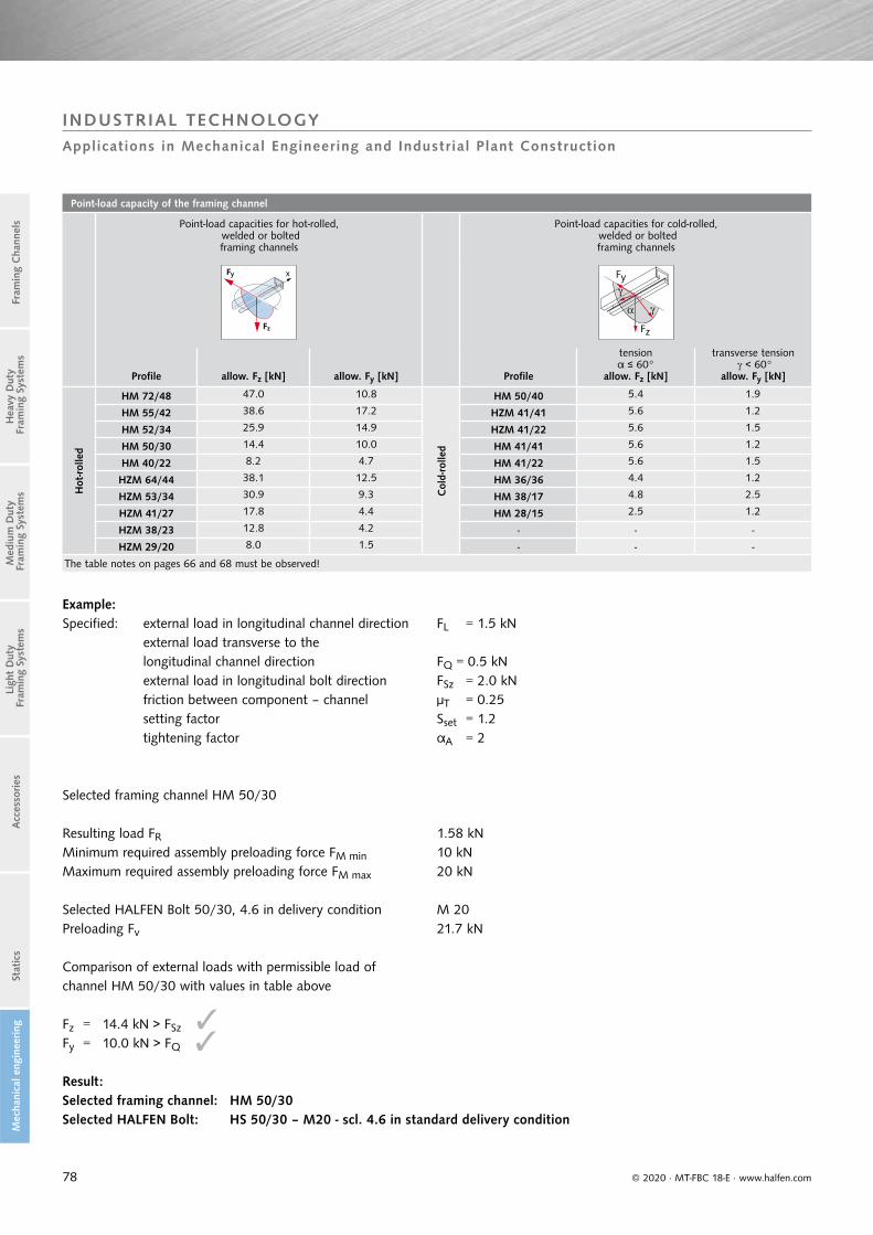
78
Point-load capacity of the framing channel
Point-load capacities for hot-rolled, welded or bolted framing channels
Point-load capacities for cold-rolled, welded or bolted framing channels
Fz
xFy
Fz
Fy
Profile allow. Fz [kN] allow. Fy [kN] Profile
tensionα ≤ 60°
allow. Fz [kN]
transverse tension < 60°
allow. Fy [kN]
Hot
-rolle
d
HM 72/48 47.0 10.8
Col
d-ro
lled
HM 50/40 5.4 1.9
HM 55/42 38.6 17.2 HZM 41/41 5.6 1.2
HM 52/34 25.9 14.9 HZM 41/22 5.6 1.5
HM 50/30 14.4 10.0 HM 41/41 5.6 1.2
HM 40/22 8.2 4.7 HM 41/22 5.6 1.5
HZM 64/44 38.1 12.5 HM 36/36 4.4 1.2
HZM 53/34 30.9 9.3 HM 38/17 4.8 2.5
HZM 41/27 17.8 4.4 HM 28/15 2.5 1.2
HZM 38/23 12.8 4.2 - - -
HZM 29/20 8.0 1.5 - - -
The table notes on pages 66 and 68 must be observed!
© 2020 · MT-FBC 18-E · www.halfen.com
Stat
ics
Ligh
t D
uty
Fra
min
g Sy
stem
sA
cces
sories
Fram
ing
Cha
nnel
sM
ediu
m D
uty
Fra
min
g Sy
stem
sH
eavy
Dut
y F
ram
ing
Syst
ems
Mec
hani
cal e
ngin
eering
INDUSTRIAL TECHNOLOGYApplications in Mechanical Engineering and Industrial Plant Construction
Example:
Result:Selected framing channel: HM 50/30Selected HALFEN Bolt: HS 50/30 – M20 - scl. 4.6 in standard delivery condition
Specified: external load in longitudinal channel direction FL = 1.5 kN external load transverse to the longitudinal channel direction FQ = 0.5 kN external load in longitudinal bolt direction FSz = 2.0 kN friction between component – channel μT = 0.25 setting factor Sset = 1.2 tightening factor αA = 2
Selected framing channel HM 50/30
Resulting load FR 1.58 kNMinimum required assembly preloading force FM min 10 kNMaximum required assembly preloading force FM max 20 kN
Selected HALFEN Bolt 50/30, 4.6 in delivery condition M 20Preloading Fv 21.7 kN
Comparison of external loads with permissible load of channel HM 50/30 with values in table above
Fz = 14.4 kN > FSz
Fy = 10.0 kN > FQ

79
Allowable dynamic loads FL dyn – channel-bolt connection
HALFEN Bolts HSR and HZS, strength class 8.8
Delivery condition Lubricated
μG = μK = 0.24 μG = μK = 0.14
Thread MA [Nm] FV [kN] FL dyn [kN] Typ FV [kN] FL dyn [kN] Type
M12 80 22.3 2.3 HZS 36.2 3.8 HZS
M16 120 25.2 2.6 HZS 41.3 4.3 HZS
M16 200 42.1 4.4 HSR 68.8 7.2 HSR
M20 400 67.2 7.0 HSR 109.9 11.4 HSR
FL dyn FN
© 2020 · MT-FBC 18-E · www.halfen.com
Stat
ics
Ligh
t D
uty
Fra
min
g Sy
stem
sA
cces
sories
Fram
ing
Cha
nnel
sM
ediu
m D
uty
Fra
min
g Sy
stem
sH
eavy
Dut
y F
ram
ing
Syst
ems
Mec
hani
cal e
ngin
eering
INDUSTRIAL TECHNOLOGYApplications in Mechanical Engineering, Machine Construction and Industrial Plant Construction
This data is based on the following failure modes and values:Failure mode for transverse force load FL dyn: component slippage Friction coefficient in connection: μT = 0.25Tightening factor (electrical-audible torque wrench): αA = 2.0Safety factor setting of bolt joint: Sset = 1.2Individual calculation of bolted connections is achieved using the formulas and tables listed above.
Transfer of dynamic loads
Hot-rolled assembly channels are suitable for the transfer of dynamic loads when used in conjunction with nibbed HALFEN Bolts (type HSR) or serrated HALFEN Bolts (type HZS). The dynamic load FL dyn acting on the building component in the longitudinal channel direction, is transferred frictionally via the channel/bolt contact surface to the channel.
A clamping force FK req acting in the bolt longitudinal axis is necessary for friction transfer FL dyn:
The calculated maximum assembly preloading force FM max must be smaller or equal to the preloading force Fv of the bolt (see table):
The permissible dynamic loads for channel assembly systems are shown as for delivery condition (μG = μK = 0.24) and for a lubricated condition (μG = μK = 0.14) in the following table. The values are valid for pure alternating stress with a transverse force in the longitudinal channel direction.The stress ratio is R = −1 and the maximum load changes value is N = 10
6.
FK req =FL dyn
μT
FL dyn
μTFM max = αA × SSet ×
FM max ≤ FV
FM min = SSet × FK req
According to VDI guideline 2230 when designing the bolt connection, the bolt tightening procedure and the bolt setting behavior must be considered.The setting factor Sset is intended as a safety factor because the setting force loss for adjustable bolt connections is difficult to calculate using VDI 2230.
Therefore the minimum necessary assembly preloading strength FM min is:
Taking the bolt tightening procedure into consideration with the tightening factor αA the maximum necessary assembly preloading force FM max is calculated at:

80 © 2020 · MT-FBC 18-E · www.halfen.com
INDUSTRIAL TECHNOLOGYInvitation to tender
Invitation to tender – examples for framing channels and cantilevers
Further tender specifi cations at : www.halfen.de/Service/Tender texts
HM 52/34 - black steel - 6070HALFEN - Framing channel HM 52/34 profile, hot-rolled, black steel, with CE-marking in accordance with DIN EN 1090, for the flexible linking of framing constructions using system-compliant HALFEN Bolt connections. Required framing channel length pursuant to structural requirements.Nominal profile dimensions (width x height): 52 mm x 34 mmLength (mm): ......- 6.070- Fixed length (fixed length surcharge)Deliver, cut to the required extent (if not fixed length) and assemble.Please note information provided by the manufacturer regarding assembly and use.
HM 50/30 - HDG - 6070HALFEN - Framing channel HM 50/30 profile, hot-rolled, hot-dip galvanised (hdg), with CE-marking in accordance with DIN EN 1090, for the flexible linking of framing constructions using system-compliant HALFEN Bolt connections. Required framing channel length pursuant to structural requirements.Nominal profile dimensions (width x height): 50 mm x 30 mm Length (mm): ......- 6.070- Fixed length (fixed length surcharge)Deliver, cut to the required extent (if not fixed length) and assemble.Please note information provided by the manufacturer regarding assembly and use.
HZM 53/34 - A4 - 6070HALFEN - Framing channel HZM 53/34 profile, hot-rolled and toothed, A4, with CE-marking in accordance with DIN EN 1090, for the flexible linking of framing constructions using system-compliant HALFEN Bolt connections. Required framing channel length pursuant to structural requirements.Nominal profile dimensions (width x height): 53 mm x 34 mmLength (mm): ......- 6.070- Fixed length (fixed length surcharge)Deliver, cut to the required extent (if not fixed length) and assemble.Please note information provided by the manufacturer regarding assembly and use.
HALFEN Cantilever KON 36/2, hot-dip galvanisedHALFEN - cantilever, KON 36/2, hot-dip galvanized (hdg), with CE-marking in accordance with DIN EN 1090, for the flexible linking of framing constructions using system-compliant HALFEN Bolt connections. Required cantilever length pursuant to structural requirements.Length (mm): .....Deliver and assemble.Please note information provided by the manufacturer regarding assembly and use.

81
HALFEN POWERCLICK SYSTEM 41+22 Produktinformation Technik/Technical Product Information
PC41 17
HALFEN POWERCLICK SYSTEM 41+22 Produktinformation Technik/Technical Product Information
PC41 17
▪ mit Tragfähigkeiten nach EC3
▪ with load capacities acc. to EC3
▪ aktualisiert nach Druckgeräte- richtlinie 2014/68/EU
▪ updated acc. to Pressure Equipment Directive (PED) 2014/68/EU
PC63 17
HALFEN POWERCLICK SYSTEM 63 Produktinformation Technik/Technical Product Information
PC Z 17
HALFEN POWERCLICK ZUBEHÖR/ACCESSORIES Produktinformation Technik/Technical Product Information
TESTEDACC. TO EN 13480(TYPE TESTING)BY TÜVPOWERCLICK SYSTEM 63
© 2020 · MT-FBC 18-E · www.halfen.com
POWERCLICK SYSTEMThe Innovation in Pipeline Construction
The multi-functional system for any project
POWERCLICK SYSTEM 63
POWERCLICK SYSTEM 41
POWERCLICK SYSTEM 22
POWERCLICK ACCESSORIES
Suitable for pipes with nominal diameters up to DN 150 mm or with separate verification up to 400 mm→ Catalogue PC 63
Suitable for pipes with nominal diameters up to 80 mm or with short spans up to 150 mm with separate verifications→ Catalogue PC 41
Suitable for pipes with nominal diameters up to 25 mm→ Catalogue PC 41
Cantilever brackets, pipe clamps, sliding supports→ Catalogue PC Z
Product information on the internet. Catalogues and tender texts available at: halfen.de/Products/Powerclick. Or simply scan the code, select the required document and download the PDF.
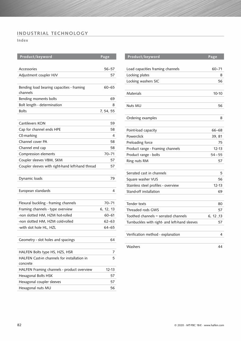
82 © 2020 · MT-FBC 18-E · www.halfen.com
INDUSTRIAL TECHNOLOGYIndex
Product/keyword Page
Accessories 56–57
Adjustment coupler HJV 57
Bending load bearing capacities - framing channels
60–65
Bending moments bolts 69
Bolt length - determination 8
Bolts 7, 54, 55
Cantilevers KON 59
Cap for channel ends HPE 58
CE-marking 4
Channel cover PA 58
Channel end cap 58
Compression elements 70–71
Coupler sleeves VBM, SKM 57
Coupler sleeves with right-hand left-hand thread 57
Dynamic loads 79
European standards 4
Flexural buckling - framing channels 70–71
Framing channels - type overview 6, 12, 13
-non slotted HM, HZM hot-rolled 60–61
-non slotted HM, HZM cold-rolled 62–63
-with slot hole HL, HZL 64–65
Geometry - slot holes and spacings 64
HALFEN Bolts type HS, HZS, HSR 7
HALFEN Cast-in channels for installation in concrete
5
HALFEN Framing channels - product overview 12-13
Hexagonal Bolts HSK 57
Hexagonal coupler sleeves 57
Hexagonal nuts MU 56
Product/keyword Page
Load capacities framing channels 60–71
Locking plates 8
Locking washers SIC 56
Materials 10-10
Nuts MU 56
Ordering examples 8
Point-load capacity 66–68
Powerclick 39, 81
Preloading force 75
Product range - Framing channels 12-13
Product range - bolts 54 – 55
Ring nuts RM 57
Serrated cast in channels 5
Square washer VUS 56
Stainless steel profiles - overview 12-13
Stand-off installation 69
Tender texts 80
Threaded rods GWS 57
Toothed channels = serrated channels 6, 12 ,13
Turnbuckles with right- and left-hand sleeves 57
Verification method - explanation 4
Washers 44
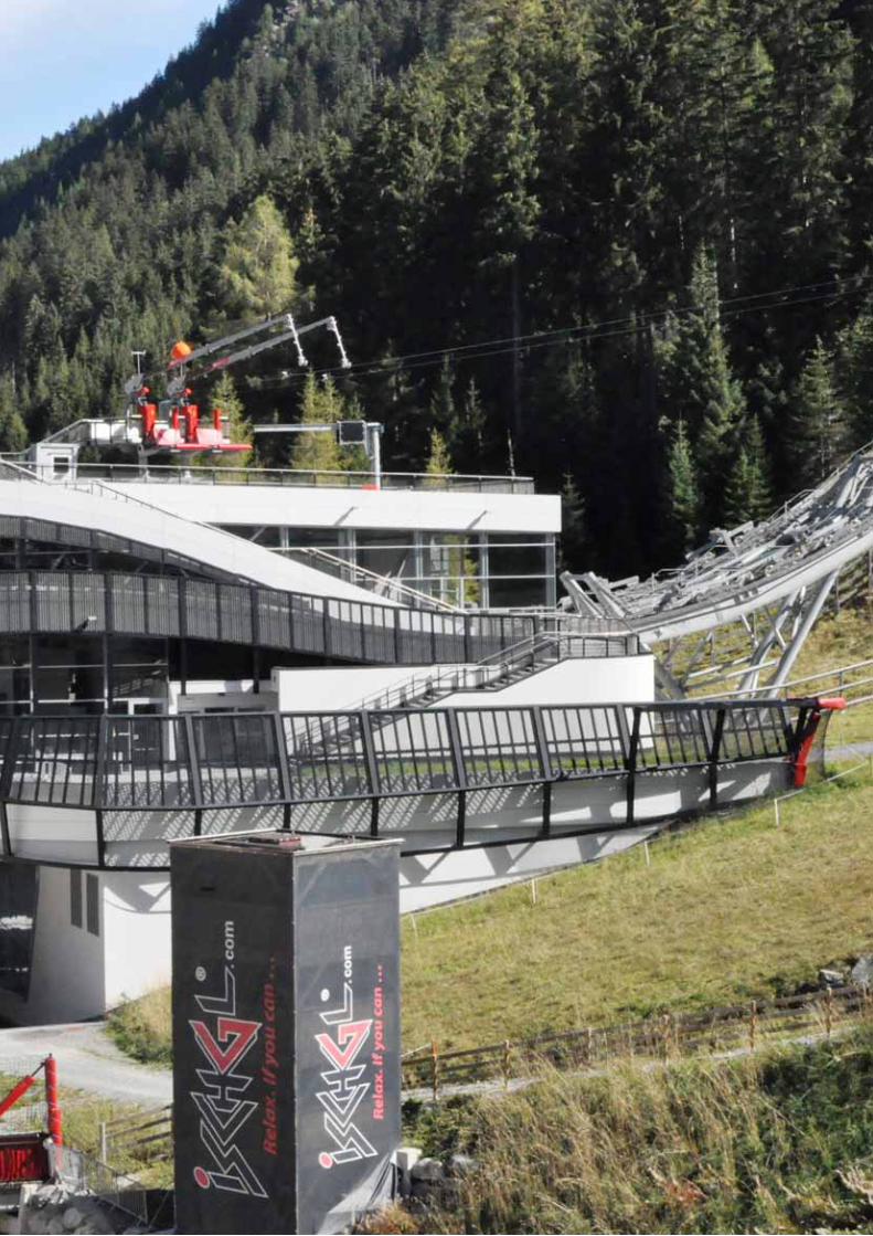

Innovative engineered products and
construction solutions that allow
the industry to build safer,
stronger and faster.

Worldwide contacts for Leviat:
Notes regarding this catalogue
© Protected by copyright. The construction applications and details provided in this publication are indicative only. In every case, project
working details should be entrusted to appropriately qualified and experienced persons. Whilst every care has been exercised in the preparation
of this publication to ensure that any advice, recommendations or information is accurate, no liability or responsibility of any kind is accepted
by Leviat for inaccuracies or printing errors. Technical and design changes are reserved. With a policy of continuous product development,
Leviat reserves the right to modify product design and specification at any time.
AustraliaLeviat
98 Kurrajong Avenue,
Mount Druitt Sydney, NSW 2770
Tel: +61 - 2 8808 3100
Email: [email protected]
AustriaLeviat
Leonard-Bernstein-Str. 10
Saturn Tower, 1220 Wien
Tel: +43 - 1 - 259 6770
Email: [email protected]
BelgiumLeviat
Borkelstraat 131
2900 Schoten
Tel: +32 - 3 - 658 07 20
Email: [email protected]
China Leviat
Room 601 Tower D, Vantone Centre
No. A6 Chao Yang Men Wai Street
Chaoyang District
Beijing · P.R. China 100020
Tel: +86 - 10 5907 3200
Email: [email protected]
Czech Republic Leviat
Business Center Šafránkova
Šafránkova 1238/1
155 00 Praha 5
Tel: +420 - 311 - 690 060
Email: [email protected]
FinlandLeviat
Vädursgatan 5
412 50 Göteborg / Sweden
Tel: +358 (0)10 6338781
Email: [email protected]
France Leviat
18, rue Goubet
75019 Paris
Tel: +33 - 1 - 44 52 31 00
Email: [email protected]
Germany Leviat
Liebigstrasse 14
40764 Langenfeld
Tel: +49 - 2173 - 970 - 0
Email: [email protected]
IndiaLeviat
309, 3rd Floor, Orion Business Park
Ghodbunder Road, Kapurbawdi,
Thane West, Thane,
Maharashtra 400607
Tel: +91 - 22 2589 2032
Email: [email protected]
Italy
Leviat
Via F.lli Bronzetti 28
24124 Bergamo
Tel: +39 - 035 - 0760711
Email: [email protected]
MalaysiaLeviat
28 Jalan Anggerik Mokara 31/59
Kota Kemuning, 40460 Shah Alam
Selangor
Tel: +603 - 5122 4182
Email: [email protected]
Netherlands Leviat
Oostermaat 3
7623 CS Borne
Tel: +31 - 74 - 267 14 49
Email: [email protected]
New ZealandLeviat
2/19 Nuttall Drive, Hillsborough,
Christchurch 8022
Tel: +64 - 3 376 5205
Email: [email protected]
Norway Leviat
Vestre Svanholmen 5
4313 Sandnes
Tel: +47 - 51 82 34 00
Email: [email protected]
Philippines Leviat
2933 Regus, Joy Nostalg,
ADB Avenue
Ortigas Center
Pasig City
Tel: +63 - 2 7957 6381
Email: [email protected]
Poland Leviat
Ul. Obornicka 287
60-691 Poznań
Tel: +48 - 61 - 622 14 14
Email: [email protected]
SingaporeLeviat
14 Benoi Crescent
Singapore 629977
Tel: +65 - 6266 6802
Email: [email protected]
Spain Leviat
Polígono Industrial Santa Ana
c/ Ignacio Zuloaga, 20
28522 Rivas-Vaciamadrid
Tel: +34 - 91 632 18 40
Email: [email protected]
Sweden Leviat
Vädursgatan 5
412 50 Göteborg
Tel: +46 - 31 - 98 58 00
Email: [email protected]
Switzerland Leviat
Hertistrasse 25
8304 Wallisellen
Tel: +41 - 44 - 849 78 78
Email: [email protected]
United Kingdom Leviat
A1/A2 Portland Close
Houghton Regis LU5 5AW
Tel: +44 - 1582 - 470 300
Email: [email protected]
United States of America Leviat
6467 S Falkenburg Rd.
Riverview, FL 33578
Tel: (800) 423-9140
Email: [email protected]
For countries not listedEmail: [email protected]
Leviat.com
For information on certified management systems and standards see www.ancon.co.uk | www.aschwanden.com | www.halfen.com

Imagine. Model. Make. Leviat.com
© 2
02
0
M-0
12-E
– 1
0/1
8
PD
F 10
/20
Related Documents