© 2011 Pearson Education, In All Rights Reserv Automotive Technology, Fourth Edition James Halderman COOLING SYSTEM OPERATION AND DIAGNOSIS 21

Welcome message from author
This document is posted to help you gain knowledge. Please leave a comment to let me know what you think about it! Share it to your friends and learn new things together.
Transcript
© 2011 Pearson Education, Inc.All Rights Reserved
Automotive Technology, Fourth EditionJames Halderman
COOLING SYSTEM OPERATION AND
DIAGNOSIS
21

21 COOLING SYSTEM OPERATION AND DIAGNOSIS
Automotive Technology, Fourth EditionJames Halderman
© 2011 Pearson Education, Inc.All Rights Reserved
ObjectivesObjectives• The student should be able to:
– Prepare for ASE Engine Repair (A1) certification test content area “D” (Lubrication and Cooling Systems Diagnosis and Repair).
– Describe how coolant flows through an engine.
– Discuss the operation of the thermostat.
21 COOLING SYSTEM OPERATION AND DIAGNOSIS
Automotive Technology, Fourth EditionJames Halderman
© 2011 Pearson Education, Inc.All Rights Reserved
ObjectivesObjectives• The student should be able to:
– Explain the purpose and function of the radiator pressure cap.
– Describe the operation and service of water pumps.
– Discuss how to diagnose cooling system problems.

21 COOLING SYSTEM OPERATION AND DIAGNOSIS
Automotive Technology, Fourth EditionJames Halderman
© 2011 Pearson Education, Inc.All Rights Reserved
COOLING SYSTEMCOOLING SYSTEM

21 COOLING SYSTEM OPERATION AND DIAGNOSIS
Automotive Technology, Fourth EditionJames Halderman
© 2011 Pearson Education, Inc.All Rights Reserved
Cooling SystemCooling System• Purpose and Function
– Cooling system operation depends on design and operating conditions
– Basis of cooling system design

21 COOLING SYSTEM OPERATION AND DIAGNOSIS
Automotive Technology, Fourth EditionJames Halderman
© 2011 Pearson Education, Inc.All Rights Reserved
Cooling SystemCooling System• Purpose and Function
– Basis of cooling system design• Heat output of engine• Radiator size

21 COOLING SYSTEM OPERATION AND DIAGNOSIS
Automotive Technology, Fourth EditionJames Halderman
© 2011 Pearson Education, Inc.All Rights Reserved
Cooling SystemCooling System• Purpose and Function
– Basis of cooling system design• Type of coolant • Size of water pump (coolant pump)
21 COOLING SYSTEM OPERATION AND DIAGNOSIS
Automotive Technology, Fourth EditionJames Halderman
© 2011 Pearson Education, Inc.All Rights Reserved
Cooling SystemCooling System• Purpose and Function
– Basis of cooling system design• Type of fan, thermostat, system pressure

21 COOLING SYSTEM OPERATION AND DIAGNOSIS
Automotive Technology, Fourth EditionJames Halderman
© 2011 Pearson Education, Inc.All Rights Reserved
Cooling SystemCooling System• Purpose and Function
– Cooling system must allow engine to warm up to operating temperature rapidly and then maintain temperature

21 COOLING SYSTEM OPERATION AND DIAGNOSIS
Automotive Technology, Fourth EditionJames Halderman
© 2011 Pearson Education, Inc.All Rights Reserved
Cooling SystemCooling System• Purpose and Function
– Peak combustion temperature from 4,000°F to 6,000°F (2,200°C to 3,300°C)
21 COOLING SYSTEM OPERATION AND DIAGNOSIS
Automotive Technology, Fourth EditionJames Halderman
© 2011 Pearson Education, Inc.All Rights Reserved
Cooling SystemCooling System• Purpose and Function
– Average combustion temperatures from 1,200°F to 1,700°F (650°C to 925°C)

21 COOLING SYSTEM OPERATION AND DIAGNOSIS
Automotive Technology, Fourth EditionJames Halderman
© 2011 Pearson Education, Inc.All Rights Reserved
Cooling SystemCooling System• Purpose and Function
– Continued operation at these temperatures will weaken engine parts
– Cooling system keeps head and cylinder walls at temperature for maximum efficiency
21 COOLING SYSTEM OPERATION AND DIAGNOSIS
Automotive Technology, Fourth EditionJames Halderman
© 2011 Pearson Education, Inc.All Rights Reserved
Cooling SystemCooling System• Purpose and Function
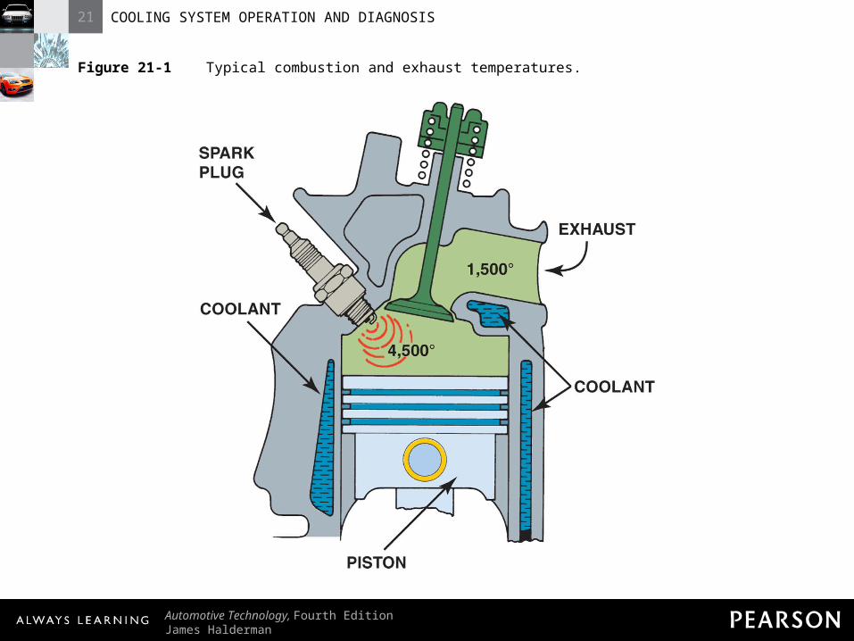
– Cooling system removes about one-third of heat
– One-third of heat escapes through exhaust system
21 COOLING SYSTEM OPERATION AND DIAGNOSIS
Automotive Technology, Fourth EditionJames Halderman
© 2011 Pearson Education, Inc.All Rights Reserved
Figure 21-1 Typical combustion and exhaust temperatures.

21 COOLING SYSTEM OPERATION AND DIAGNOSIS
Automotive Technology, Fourth EditionJames Halderman
© 2011 Pearson Education, Inc.All Rights Reserved
Cooling SystemCooling System• Low-Temperature Engine Problems
– Operating temperatures must be above minimum temperature
– Failure to reach specified temperature may cause engine-related faults
21 COOLING SYSTEM OPERATION AND DIAGNOSIS
Automotive Technology, Fourth EditionJames Halderman
© 2011 Pearson Education, Inc.All Rights Reserved
Cooling SystemCooling System• Low-Temperature Engine Problems
– PO128 diagnostic trouble code (DTC)• Code indicates “coolant temperature below
thermostat regulating temperature”

21 COOLING SYSTEM OPERATION AND DIAGNOSIS
Automotive Technology, Fourth EditionJames Halderman
© 2011 Pearson Education, Inc.All Rights Reserved
Cooling SystemCooling System• Low-Temperature Engine Problems
• Usually a defective thermostat staying open or partly open

21 COOLING SYSTEM OPERATION AND DIAGNOSIS
Automotive Technology, Fourth EditionJames Halderman
© 2011 Pearson Education, Inc.All Rights Reserved
Cooling SystemCooling System• Low-Temperature Engine Problems
– Moisture created by combustion process• Can condense and flow into oil

21 COOLING SYSTEM OPERATION AND DIAGNOSIS
Automotive Technology, Fourth EditionJames Halderman
© 2011 Pearson Education, Inc.All Rights Reserved
Cooling SystemCooling System• Low-Temperature Engine Problems
– Moisture created by combustion process• Each gallon of fuel produces moisture equal
to one gallon of water

21 COOLING SYSTEM OPERATION AND DIAGNOSIS
Automotive Technology, Fourth EditionJames Halderman
© 2011 Pearson Education, Inc.All Rights Reserved
Cooling SystemCooling System• Low-Temperature Engine Problems
– Moisture created by combustion process• Condensed moisture combines with
unburned hydrocarbons and additives
21 COOLING SYSTEM OPERATION AND DIAGNOSIS
Automotive Technology, Fourth EditionJames Halderman
© 2011 Pearson Education, Inc.All Rights Reserved
Cooling SystemCooling System• Low-Temperature Engine Problems
– Moisture created by combustion process• Forms carbonic acid, sulfuric acid, nitric
acid, hydrobromic acid, hydrochloric acid
21 COOLING SYSTEM OPERATION AND DIAGNOSIS
Automotive Technology, Fourth EditionJames Halderman
© 2011 Pearson Education, Inc.All Rights Reserved
Cooling SystemCooling System• Most manufacturers offer block heaters
– Plug into household current (110 volts AC)– Heating element warms coolant
21 COOLING SYSTEM OPERATION AND DIAGNOSIS
Automotive Technology, Fourth EditionJames Halderman
© 2011 Pearson Education, Inc.All Rights Reserved
Cooling SystemCooling System• High-Temperature Engine Problems
– Maximum engine temperature limits required to protect engine
– Higher than normal temperatures can cause engine-related issues
21 COOLING SYSTEM OPERATION AND DIAGNOSIS
Automotive Technology, Fourth EditionJames Halderman
© 2011 Pearson Education, Inc.All Rights Reserved
Cooling SystemCooling System• High-Temperature Engine Problems
– Oxidation of engine oil producing hard carbon and varnish
• Varnish causes hydraulic valve lifter plungers to stick
21 COOLING SYSTEM OPERATION AND DIAGNOSIS
Automotive Technology, Fourth EditionJames Halderman
© 2011 Pearson Education, Inc.All Rights Reserved
Cooling SystemCooling System• High-Temperature Engine Problems
– Higher than normal temperatures causes oil to become thinner
• Thinned oil will cause excessive oil consumption

21 COOLING SYSTEM OPERATION AND DIAGNOSIS
Automotive Technology, Fourth EditionJames Halderman
© 2011 Pearson Education, Inc.All Rights Reserved
Cooling SystemCooling System• High-Temperature Engine Problems
– High coolant temperatures raise combustion temperature and cause detonation (spark knock or ping)

21 COOLING SYSTEM OPERATION AND DIAGNOSIS
Automotive Technology, Fourth EditionJames Halderman
© 2011 Pearson Education, Inc.All Rights Reserved
COOLING SYSTEM COOLING SYSTEM OPERATIONOPERATION
21 COOLING SYSTEM OPERATION AND DIAGNOSIS
Automotive Technology, Fourth EditionJames Halderman
© 2011 Pearson Education, Inc.All Rights Reserved
Cooling System OperationCooling System Operation• Purpose and Function
– Coolant flows through engine, picks up heat
– Coolant flows to radiator, heat is passed to outside air

21 COOLING SYSTEM OPERATION AND DIAGNOSIS
Automotive Technology, Fourth EditionJames Halderman
© 2011 Pearson Education, Inc.All Rights Reserved
Figure 21-2 Coolant circulates through the water jackets in the engine block and cylinder head.

21 COOLING SYSTEM OPERATION AND DIAGNOSIS
Automotive Technology, Fourth EditionJames Halderman
© 2011 Pearson Education, Inc.All Rights Reserved
Figure 21-3 Coolant flow through a typical engine cooling system.

21 COOLING SYSTEM OPERATION AND DIAGNOSIS
Automotive Technology, Fourth EditionJames Halderman
© 2011 Pearson Education, Inc.All Rights Reserved
Cooling System OperationCooling System Operation• Cooling System Operation
– Coolant temperature rises up to 15°F (8°C) as goes through engine and cools as it goes through radiator

21 COOLING SYSTEM OPERATION AND DIAGNOSIS
Automotive Technology, Fourth EditionJames Halderman
© 2011 Pearson Education, Inc.All Rights Reserved
Cooling System OperationCooling System Operation• Cooling System Operation
– Coolant flow rate may be 1 gallon (4 liters) per minute for each engine horsepower

21 COOLING SYSTEM OPERATION AND DIAGNOSIS
Automotive Technology, Fourth EditionJames Halderman
© 2011 Pearson Education, Inc.All Rights Reserved
Cooling System OperationCooling System Operation• Cooling System Operation
– Hot coolant comes out of thermostat housing on top of engine in most engines
21 COOLING SYSTEM OPERATION AND DIAGNOSIS
Automotive Technology, Fourth EditionJames Halderman
© 2011 Pearson Education, Inc.All Rights Reserved
Cooling System OperationCooling System Operation• Cooling System Operation
– Engine coolant outlet connects to radiator by upper radiator hose and clamps
21 COOLING SYSTEM OPERATION AND DIAGNOSIS
Automotive Technology, Fourth EditionJames Halderman
© 2011 Pearson Education, Inc.All Rights Reserved
Cooling System OperationCooling System Operation• Cooling System Operation
– Coolant is cooled by air flowing through radiator
– Coolant leaves radiator through outlet and lower radiator hose

21 COOLING SYSTEM OPERATION AND DIAGNOSIS
Automotive Technology, Fourth EditionJames Halderman
© 2011 Pearson Education, Inc.All Rights Reserved
Cooling System OperationCooling System Operation• Cooling System Operation
– Coolant flows to the inlet on water pump, which recirculates it through engine
21 COOLING SYSTEM OPERATION AND DIAGNOSIS
Automotive Technology, Fourth EditionJames Halderman
© 2011 Pearson Education, Inc.All Rights Reserved
Cooling System OperationCooling System Operation• Cooling System Operation
– NOTE: Some newer engine designs place thermostat on inlet side of water pump. Thermostat closes until coolant temperature causes it to open. Placement on inlet side reduces rapid temperature changes.

21 COOLING SYSTEM OPERATION AND DIAGNOSIS
Automotive Technology, Fourth EditionJames Halderman
© 2011 Pearson Education, Inc.All Rights Reserved
THERMOSTATSTHERMOSTATS
21 COOLING SYSTEM OPERATION AND DIAGNOSIS
Automotive Technology, Fourth EditionJames Halderman
© 2011 Pearson Education, Inc.All Rights Reserved
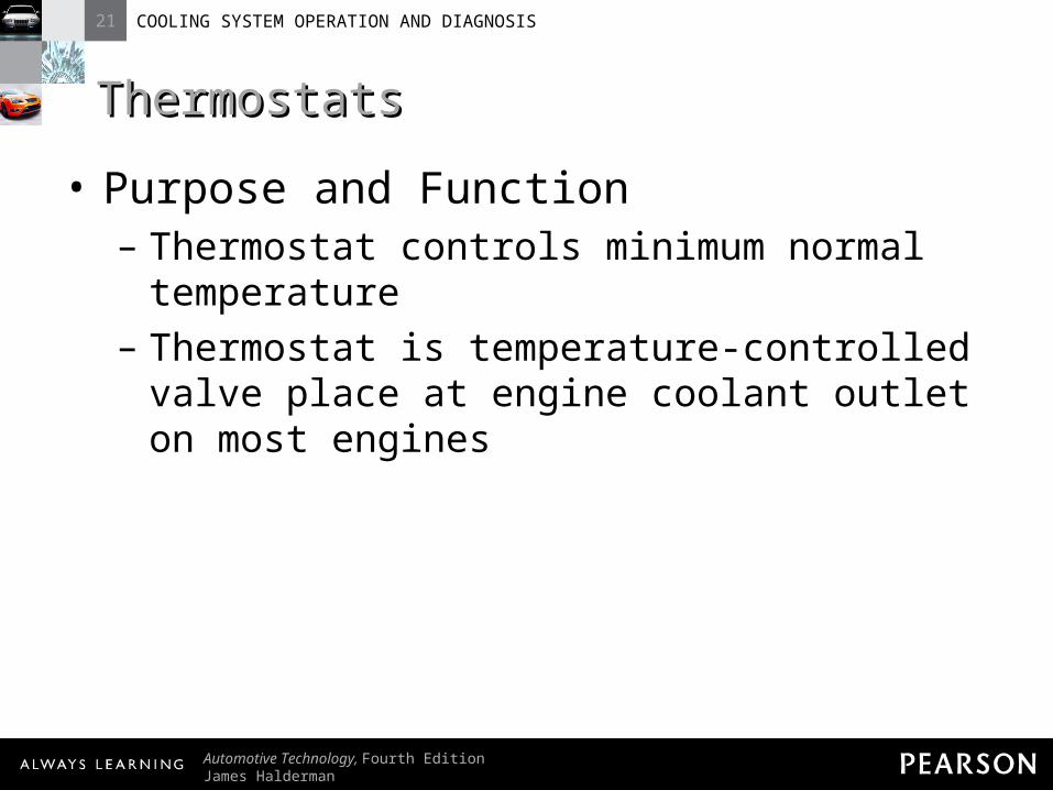
ThermostatsThermostats• Purpose and Function
– Thermostat controls minimum normal temperature
– Thermostat is temperature-controlled valve place at engine coolant outlet on most engines
21 COOLING SYSTEM OPERATION AND DIAGNOSIS
Automotive Technology, Fourth EditionJames Halderman
© 2011 Pearson Education, Inc.All Rights Reserved
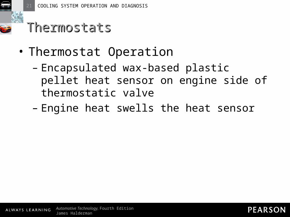
ThermostatsThermostats• Thermostat Operation
– Encapsulated wax-based plastic pellet heat sensor on engine side of thermostatic valve
– Engine heat swells the heat sensor

21 COOLING SYSTEM OPERATION AND DIAGNOSIS
Automotive Technology, Fourth EditionJames Halderman
© 2011 Pearson Education, Inc.All Rights Reserved
Figure 21-4 A cross section of a typical wax-actuated thermostat showing the position of the wax pellet and spring.
21 COOLING SYSTEM OPERATION AND DIAGNOSIS
Automotive Technology, Fourth EditionJames Halderman
© 2011 Pearson Education, Inc.All Rights Reserved
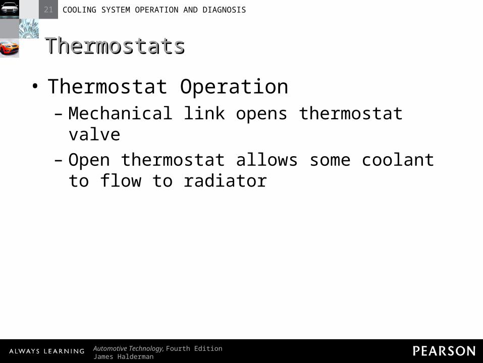
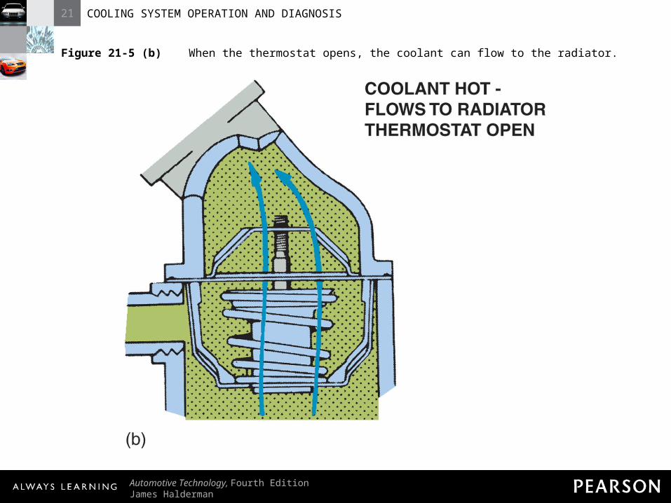
ThermostatsThermostats• Thermostat Operation
– Mechanical link opens thermostat valve– Open thermostat allows some coolant to
flow to radiator
21 COOLING SYSTEM OPERATION AND DIAGNOSIS
Automotive Technology, Fourth EditionJames Halderman
© 2011 Pearson Education, Inc.All Rights Reserved
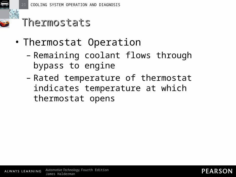
ThermostatsThermostats• Thermostat Operation
– Remaining coolant flows through bypass to engine
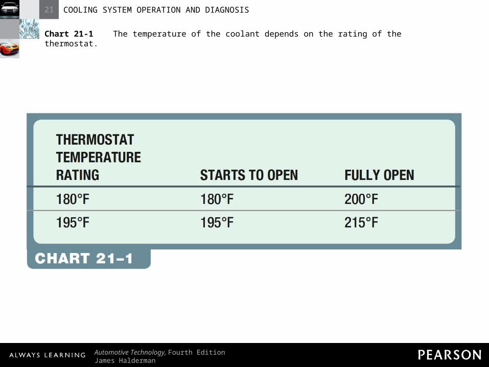
– Rated temperature of thermostat indicates temperature at which thermostat opens

21 COOLING SYSTEM OPERATION AND DIAGNOSIS
Automotive Technology, Fourth EditionJames Halderman
© 2011 Pearson Education, Inc.All Rights Reserved
Figure 21-5 (a) When the engine is cold, the coolant flows through the bypass.
21 COOLING SYSTEM OPERATION AND DIAGNOSIS
Automotive Technology, Fourth EditionJames Halderman
© 2011 Pearson Education, Inc.All Rights Reserved
Figure 21-5 (b) When the thermostat opens, the coolant can flow to the radiator.

21 COOLING SYSTEM OPERATION AND DIAGNOSIS
Automotive Technology, Fourth EditionJames Halderman
© 2011 Pearson Education, Inc.All Rights Reserved
ThermostatsThermostats• Thermostat Operation
– Thermostat fully open at about 20°F higher than opening temperature
21 COOLING SYSTEM OPERATION AND DIAGNOSIS
Automotive Technology, Fourth EditionJames Halderman
© 2011 Pearson Education, Inc.All Rights Reserved
Chart 21-1 The temperature of the coolant depends on the rating of the thermostat.
21 COOLING SYSTEM OPERATION AND DIAGNOSIS
Automotive Technology, Fourth EditionJames Halderman
© 2011 Pearson Education, Inc.All Rights Reserved
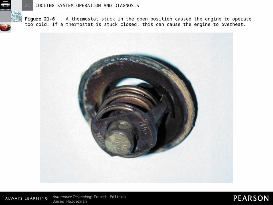
Figure 21-6 A thermostat stuck in the open position caused the engine to operate too cold. If a thermostat is stuck closed, this can cause the engine to overheat.

21 COOLING SYSTEM OPERATION AND DIAGNOSIS
Automotive Technology, Fourth EditionJames Halderman
© 2011 Pearson Education, Inc.All Rights Reserved
ThermostatsThermostats• Thermostat Operation
– NOTE: Bypass around closed thermostat allows coolant to circulate during engine warm-up. Bypass may be cast or drilled into engine and pump parts.

21 COOLING SYSTEM OPERATION AND DIAGNOSIS
Automotive Technology, Fourth EditionJames Halderman
© 2011 Pearson Education, Inc.All Rights Reserved
Figure 21-7 This internal bypass passage in the thermostat housing directs cold coolant to the water pump.

21 COOLING SYSTEM OPERATION AND DIAGNOSIS
Automotive Technology, Fourth EditionJames Halderman
© 2011 Pearson Education, Inc.All Rights Reserved
Figure 21-8 A cutaway of a small block Chevrolet V-8 showing the passage from the cylinder head through the front of the intake manifold to the thermostat.
21 COOLING SYSTEM OPERATION AND DIAGNOSIS
Automotive Technology, Fourth EditionJames Halderman
© 2011 Pearson Education, Inc.All Rights Reserved
ThermostatsThermostats• Thermostat Testing
– Hot Water Method• Thermostat is removed and suspended in
water using 0.015 in. (0.4mm) feeler gauge with a thermometer
21 COOLING SYSTEM OPERATION AND DIAGNOSIS
Automotive Technology, Fourth EditionJames Halderman
© 2011 Pearson Education, Inc.All Rights Reserved
ThermostatsThermostats• Thermostat Testing
– Hot Water Method• Container is heated until thermostat opens
21 COOLING SYSTEM OPERATION AND DIAGNOSIS
Automotive Technology, Fourth EditionJames Halderman
© 2011 Pearson Education, Inc.All Rights Reserved
ThermostatsThermostats• Thermostat Testing
– Hot Water Method• Opening temperature should be within 5°F
(4°C) of temperature on thermostat
21 COOLING SYSTEM OPERATION AND DIAGNOSIS
Automotive Technology, Fourth EditionJames Halderman
© 2011 Pearson Education, Inc.All Rights Reserved
ThermostatsThermostats• Thermostat Testing
– Infrared Thermometer Method• Infrared thermometer (pyrometer) measures
temperature near thermostat

21 COOLING SYSTEM OPERATION AND DIAGNOSIS
Automotive Technology, Fourth EditionJames Halderman
© 2011 Pearson Education, Inc.All Rights Reserved
ThermostatsThermostats• Thermostat Testing
– Infrared Thermometer Method• As engine warms, temperature reaches
thermostat opening temperature

21 COOLING SYSTEM OPERATION AND DIAGNOSIS
Automotive Technology, Fourth EditionJames Halderman
© 2011 Pearson Education, Inc.All Rights Reserved
ThermostatsThermostats• Thermostat Testing
– Infrared Thermometer Method• As thermostat opens, coolant temperature
drops
21 COOLING SYSTEM OPERATION AND DIAGNOSIS
Automotive Technology, Fourth EditionJames Halderman
© 2011 Pearson Education, Inc.All Rights Reserved
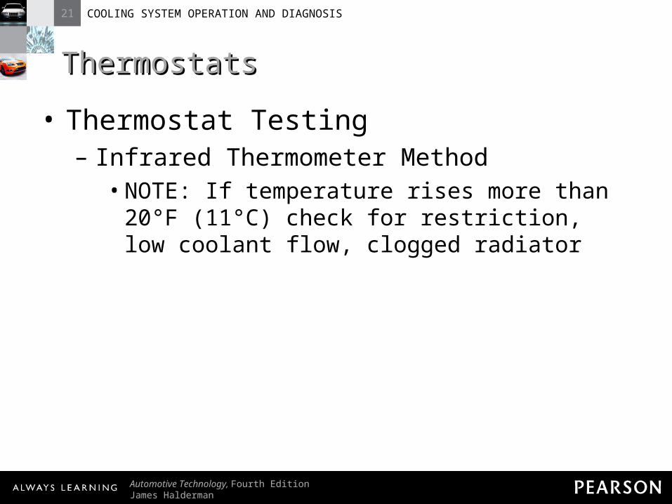
ThermostatsThermostats• Thermostat Testing
– Infrared Thermometer Method• As thermostat cycles, temperature ranges
from opening temperature to 20°F (11°C) above opening temperature
21 COOLING SYSTEM OPERATION AND DIAGNOSIS
Automotive Technology, Fourth EditionJames Halderman
© 2011 Pearson Education, Inc.All Rights Reserved
ThermostatsThermostats• Thermostat Testing
– Infrared Thermometer Method• NOTE: If temperature rises more than 20°F
(11°C) check for restriction, low coolant flow, clogged radiator

21 COOLING SYSTEM OPERATION AND DIAGNOSIS
Automotive Technology, Fourth EditionJames Halderman
© 2011 Pearson Education, Inc.All Rights Reserved
ThermostatsThermostats• Scan Tool Method
– Scan tool reads actual temperature detected by ECT sensor
21 COOLING SYSTEM OPERATION AND DIAGNOSIS
Automotive Technology, Fourth EditionJames Halderman
© 2011 Pearson Education, Inc.All Rights Reserved
ThermostatsThermostats• Thermostat Replacement
– Overheating engine may result from faulty thermostat
– Engine that does not get warm always indicates faulty thermostat
21 COOLING SYSTEM OPERATION AND DIAGNOSIS
Automotive Technology, Fourth EditionJames Halderman
© 2011 Pearson Education, Inc.All Rights Reserved
ThermostatsThermostats• Thermostat Replacement
– To replace thermostat, drain coolant from radiator to below level of thermostat

21 COOLING SYSTEM OPERATION AND DIAGNOSIS
Automotive Technology, Fourth EditionJames Halderman
© 2011 Pearson Education, Inc.All Rights Reserved
ThermostatsThermostats• Thermostat Replacement
– Remove hose from thermostat housing neck
– Remove housing to expose thermostat

21 COOLING SYSTEM OPERATION AND DIAGNOSIS
Automotive Technology, Fourth EditionJames Halderman
© 2011 Pearson Education, Inc.All Rights Reserved
ThermostatsThermostats• Thermostat Replacement
– Clean gasket flanges and thermostat housing
– Place thermostat in engine with sensing pellet toward engine

21 COOLING SYSTEM OPERATION AND DIAGNOSIS
Automotive Technology, Fourth EditionJames Halderman
© 2011 Pearson Education, Inc.All Rights Reserved
Figure 21-10 Some thermostats are an integral part of the housing. This thermostat and radiator hose housing is serviced as an assembly. Some thermostats snap into the engine radiator fill tube underneath the pressure cap.
21 COOLING SYSTEM OPERATION AND DIAGNOSIS
Automotive Technology, Fourth EditionJames Halderman
© 2011 Pearson Education, Inc.All Rights Reserved
ThermostatsThermostats• Thermostat Replacement
– Install thermostat housing with new gasket or O-ring
– CAUTION: Failure to set thermostat into recessed groove will cause housing to tilt.

21 COOLING SYSTEM OPERATION AND DIAGNOSIS
Automotive Technology, Fourth EditionJames Halderman
© 2011 Pearson Education, Inc.All Rights Reserved
ThermostatsThermostats• Thermostat Replacement
– Tightening bolts will usually crack housing, creating leak

21 COOLING SYSTEM OPERATION AND DIAGNOSIS
Automotive Technology, Fourth EditionJames Halderman
© 2011 Pearson Education, Inc.All Rights Reserved
RADIATORSRADIATORS
21 COOLING SYSTEM OPERATION AND DIAGNOSIS
Automotive Technology, Fourth EditionJames Halderman
© 2011 Pearson Education, Inc.All Rights Reserved
RadiatorsRadiators• Types
– Serpentine fin core– Plate fin core

21 COOLING SYSTEM OPERATION AND DIAGNOSIS
Automotive Technology, Fourth EditionJames Halderman
© 2011 Pearson Education, Inc.All Rights Reserved
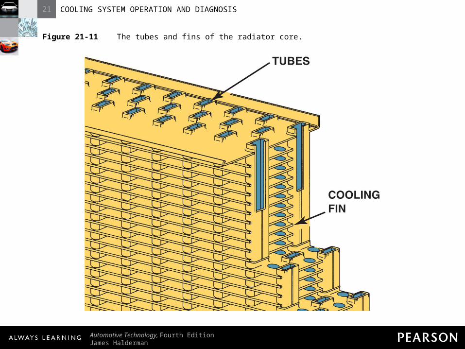
RadiatorsRadiators• Types
– In each type, coolant flows through oval-shaped core tubes
– Heat is transferred to cooling fins

21 COOLING SYSTEM OPERATION AND DIAGNOSIS
Automotive Technology, Fourth EditionJames Halderman
© 2011 Pearson Education, Inc.All Rights Reserved
RadiatorsRadiators• Types
– Air flows through radiator and removes heat
– Older radiators made from yellow brass
21 COOLING SYSTEM OPERATION AND DIAGNOSIS
Automotive Technology, Fourth EditionJames Halderman
© 2011 Pearson Education, Inc.All Rights Reserved
Figure 21-11 The tubes and fins of the radiator core.
21 COOLING SYSTEM OPERATION AND DIAGNOSIS
Automotive Technology, Fourth EditionJames Halderman
© 2011 Pearson Education, Inc.All Rights Reserved
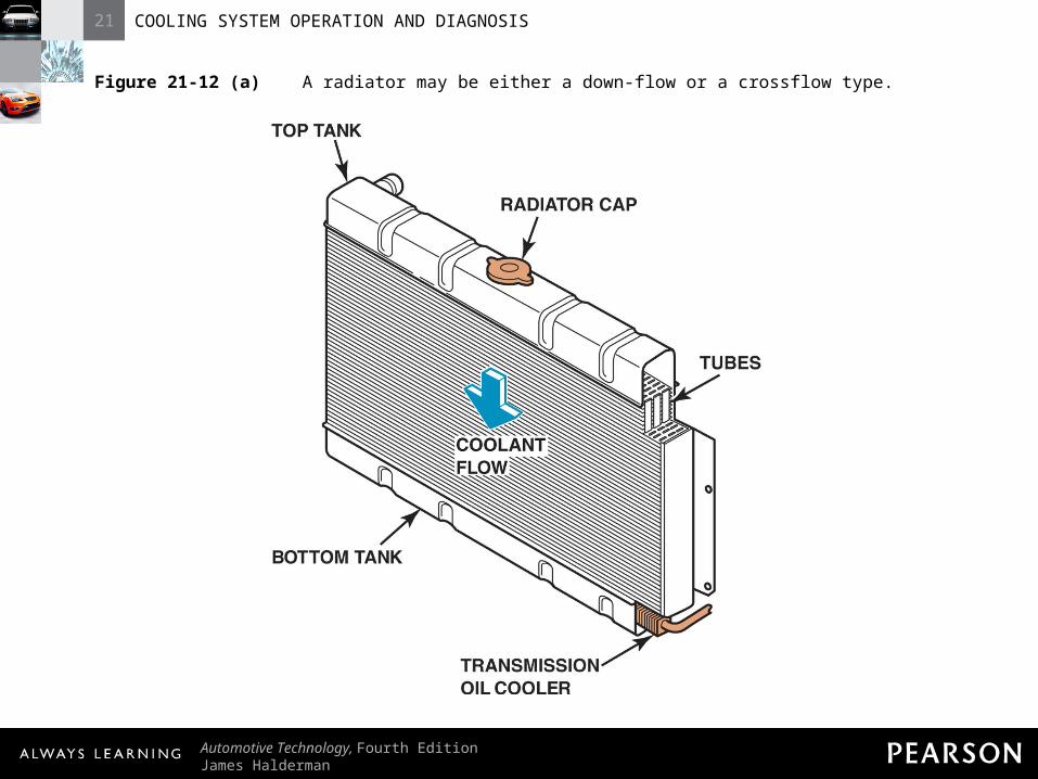
Figure 21-12 (a) A radiator may be either a down-flow or a crossflow type.

21 COOLING SYSTEM OPERATION AND DIAGNOSIS
Automotive Technology, Fourth EditionJames Halderman
© 2011 Pearson Education, Inc.All Rights Reserved
Figure 21-12 (b) A radiator may be either a down-flow or a crossflow type.

21 COOLING SYSTEM OPERATION AND DIAGNOSIS
Automotive Technology, Fourth EditionJames Halderman
© 2011 Pearson Education, Inc.All Rights Reserved
RadiatorsRadiators• Types
– Since 1980s, radiators made from aluminum with nylon-reinforced plastic side tanks

21 COOLING SYSTEM OPERATION AND DIAGNOSIS
Automotive Technology, Fourth EditionJames Halderman
© 2011 Pearson Education, Inc.All Rights Reserved
RadiatorsRadiators• Types
– Core tubes are 0.0045 to 0.012 in. (0.1 to 0.3 mm) sheet brass or aluminum
21 COOLING SYSTEM OPERATION AND DIAGNOSIS
Automotive Technology, Fourth EditionJames Halderman
© 2011 Pearson Education, Inc.All Rights Reserved
RadiatorsRadiators• Types
– Two Basic Designs:• Down-flow radiators• Cross-flow radiators
21 COOLING SYSTEM OPERATION AND DIAGNOSIS
Automotive Technology, Fourth EditionJames Halderman
© 2011 Pearson Education, Inc.All Rights Reserved
RadiatorsRadiators• How Radiators Work
– Main limitation of heat transfer is from radiator to the air
– Heat transfers from water to fins up to seven times faster than from fins to air

21 COOLING SYSTEM OPERATION AND DIAGNOSIS
Automotive Technology, Fourth EditionJames Halderman
© 2011 Pearson Education, Inc.All Rights Reserved
RadiatorsRadiators• How Radiators Work
– Radiator must remove heat equal to heat energy produced by engine
• Each horsepower equals 42 BTUs (10,800 calories) per minute

21 COOLING SYSTEM OPERATION AND DIAGNOSIS
Automotive Technology, Fourth EditionJames Halderman
© 2011 Pearson Education, Inc.All Rights Reserved
RadiatorsRadiators• How Radiators Work
– Radiator capacity by be increased by increasing core thickness or packing more material in same volume, or both
21 COOLING SYSTEM OPERATION AND DIAGNOSIS
Automotive Technology, Fourth EditionJames Halderman
© 2011 Pearson Education, Inc.All Rights Reserved
RadiatorsRadiators• How Radiators Work
– NOTE: Lower air dam in front of vehicle directs air through radiator. Damaged or missing air dam can cause engine to overheat.

21 COOLING SYSTEM OPERATION AND DIAGNOSIS
Automotive Technology, Fourth EditionJames Halderman
© 2011 Pearson Education, Inc.All Rights Reserved
RadiatorsRadiators• How Radiators Work
– When transmission oil cooler is used, it is placed in outlet tank

21 COOLING SYSTEM OPERATION AND DIAGNOSIS
Automotive Technology, Fourth EditionJames Halderman
© 2011 Pearson Education, Inc.All Rights Reserved
Figure 21-13 Many vehicles equipped with an automatic transmission use a transmission fluid cooler installed in one of the radiator tanks.

21 COOLING SYSTEM OPERATION AND DIAGNOSIS
Automotive Technology, Fourth EditionJames Halderman
© 2011 Pearson Education, Inc.All Rights Reserved
PRESSURE CAPSPRESSURE CAPS

21 COOLING SYSTEM OPERATION AND DIAGNOSIS
Automotive Technology, Fourth EditionJames Halderman
© 2011 Pearson Education, Inc.All Rights Reserved
Pressure CapsPressure Caps• Operation
– Cap has spring-loaded valve that closes cooling system vent
– Cooling pressure builds up to pressure setting of cap
21 COOLING SYSTEM OPERATION AND DIAGNOSIS
Automotive Technology, Fourth EditionJames Halderman
© 2011 Pearson Education, Inc.All Rights Reserved
Pressure CapsPressure Caps• Operation
– Cap releases excess pressure– Pressure raises boiling temperature of
coolant• Boiling temperature increases about 3°F
(1.6°C) per pound of pressure
21 COOLING SYSTEM OPERATION AND DIAGNOSIS
Automotive Technology, Fourth EditionJames Halderman
© 2011 Pearson Education, Inc.All Rights Reserved
Pressure CapsPressure Caps• Operation
– Pressure raises boiling temperature of coolant
• At sea level, water boils at 212°F (100°C)

21 COOLING SYSTEM OPERATION AND DIAGNOSIS
Automotive Technology, Fourth EditionJames Halderman
© 2011 Pearson Education, Inc.All Rights Reserved
Pressure CapsPressure Caps• Operation
– Pressure raises boiling temperature of coolant
• 15 PSI (100kPa) pressure cap increases boiling temp to 257°F (125°C)

21 COOLING SYSTEM OPERATION AND DIAGNOSIS
Automotive Technology, Fourth EditionJames Halderman
© 2011 Pearson Education, Inc.All Rights Reserved
Pressure CapsPressure Caps• Functions
– Specified coolant system temperature serves two purposes:
• Allows engine to run at efficient temperature, close to 200°F (93°C)

21 COOLING SYSTEM OPERATION AND DIAGNOSIS
Automotive Technology, Fourth EditionJames Halderman
© 2011 Pearson Education, Inc.All Rights Reserved
Pressure CapsPressure Caps• Functions
– Specified coolant system temperature serves two purposes:
• The higher the coolant temperature, the more heat it can transfer
21 COOLING SYSTEM OPERATION AND DIAGNOSIS
Automotive Technology, Fourth EditionJames Halderman
© 2011 Pearson Education, Inc.All Rights Reserved
Pressure CapsPressure Caps• Functions
– Specified coolant system temperature serves two purposes:
• For proper cooling, system must have right pressure cap

21 COOLING SYSTEM OPERATION AND DIAGNOSIS
Automotive Technology, Fourth EditionJames Halderman
© 2011 Pearson Education, Inc.All Rights Reserved
Pressure CapsPressure Caps• Functions
– Vacuum valve allows coolant to flow back to radiator when it cools down
– NOTE: Proper pressure cap especially important at high altitudes.

21 COOLING SYSTEM OPERATION AND DIAGNOSIS
Automotive Technology, Fourth EditionJames Halderman
© 2011 Pearson Education, Inc.All Rights Reserved
Figure 21-14 The pressure valve maintains the system pressure and allows excess pressure to vent. The vacuum valve allows coolant to return to the system from the recovery tank.
21 COOLING SYSTEM OPERATION AND DIAGNOSIS
Automotive Technology, Fourth EditionJames Halderman
© 2011 Pearson Education, Inc.All Rights Reserved
Pressure CapsPressure Caps• Functions
– NOTE: Proper pressure cap especially important at high altitudes.
• Boiling point of water lowered by about 1°F for every 550 ft increase in altitude

21 COOLING SYSTEM OPERATION AND DIAGNOSIS
Automotive Technology, Fourth EditionJames Halderman
© 2011 Pearson Education, Inc.All Rights Reserved
Pressure CapsPressure Caps• Functions
– NOTE: Proper pressure cap especially important at high altitudes.
• In Denver, Colorado (altitude 5,280 ft), water boils at 202°F

21 COOLING SYSTEM OPERATION AND DIAGNOSIS
Automotive Technology, Fourth EditionJames Halderman
© 2011 Pearson Education, Inc.All Rights Reserved
Pressure CapsPressure Caps• Metric Radiator Caps
– All radiator caps indicate their normal pressure rating
– Most original equipment radiator caps rated at 14 to 16 PSI (97 to 110kPa)

21 COOLING SYSTEM OPERATION AND DIAGNOSIS
Automotive Technology, Fourth EditionJames Halderman
© 2011 Pearson Education, Inc.All Rights Reserved
Pressure CapsPressure Caps• Metric Radiator Caps
– Many vehicles from Japan and Europe measure pressure in unit called bar
– One bar is about 14.7 PSI

21 COOLING SYSTEM OPERATION AND DIAGNOSIS
Automotive Technology, Fourth EditionJames Halderman
© 2011 Pearson Education, Inc.All Rights Reserved
Chart 21-2 Comparison showing the metric pressure as shown on the top of the cap to pounds per square inch (PSI).

21 COOLING SYSTEM OPERATION AND DIAGNOSIS
Automotive Technology, Fourth EditionJames Halderman
© 2011 Pearson Education, Inc.All Rights Reserved
Pressure CapsPressure Caps• Metric Radiator Caps
– NOTE: Many radiator repair shops use 7PSI (0.5bar) radiator caps.
• A 7 PSI cap provides boil protection of 21°F (3°F × 7 PSI = 21°F) above boiling point

21 COOLING SYSTEM OPERATION AND DIAGNOSIS
Automotive Technology, Fourth EditionJames Halderman
© 2011 Pearson Education, Inc.All Rights Reserved
Pressure CapsPressure Caps• Metric Radiator Caps
– NOTE: Many radiator repair shops use 7PSI (0.5bar) radiator caps.
• The coolant can still boil before the “hot” dash warning light comes on

21 COOLING SYSTEM OPERATION AND DIAGNOSIS
Automotive Technology, Fourth EditionJames Halderman
© 2011 Pearson Education, Inc.All Rights Reserved
Pressure CapsPressure Caps• Metric Radiator Caps
– NOTE: Many radiator repair shops use 7PSI (0.5bar) radiator caps.
• Lower boil point can cause cavitation and damage water pump
21 COOLING SYSTEM OPERATION AND DIAGNOSIS
Automotive Technology, Fourth EditionJames Halderman
© 2011 Pearson Education, Inc.All Rights Reserved
Pressure CapsPressure Caps• Metric Radiator Caps
– NOTE: Many radiator repair shops use 7PSI (0.5bar) radiator caps.
• Always follow vehicle manufacturer’s recommended radiator cap
21 COOLING SYSTEM OPERATION AND DIAGNOSIS
Automotive Technology, Fourth EditionJames Halderman
© 2011 Pearson Education, Inc.All Rights Reserved
COOLANT RECOVERYCOOLANT RECOVERYSYSTEMSSYSTEMS

21 COOLING SYSTEM OPERATION AND DIAGNOSIS
Automotive Technology, Fourth EditionJames Halderman
© 2011 Pearson Education, Inc.All Rights Reserved
Coolant Recovery SystemsCoolant Recovery Systems• Purpose and Function
– Excess pressure causes coolant to overflow– Most cooling systems connect to plastic
reservoir to hold excess coolant

21 COOLING SYSTEM OPERATION AND DIAGNOSIS
Automotive Technology, Fourth EditionJames Halderman
© 2011 Pearson Education, Inc.All Rights Reserved
Figure 21-15 The level in the coolant recovery system raises and lowers with engine temperature.
21 COOLING SYSTEM OPERATION AND DIAGNOSIS
Automotive Technology, Fourth EditionJames Halderman
© 2011 Pearson Education, Inc.All Rights Reserved
Coolant Recovery SystemsCoolant Recovery Systems• Purpose and Function
– When system cools, pressure is reduced creating partial vacuum
– Vacuum pulls coolant from reservoir back into cooling system
21 COOLING SYSTEM OPERATION AND DIAGNOSIS
Automotive Technology, Fourth EditionJames Halderman
© 2011 Pearson Education, Inc.All Rights Reserved
Coolant Recovery SystemsCoolant Recovery Systems• Purpose and Function
– System called coolant recovery system
21 COOLING SYSTEM OPERATION AND DIAGNOSIS
Automotive Technology, Fourth EditionJames Halderman
© 2011 Pearson Education, Inc.All Rights Reserved
Coolant Recovery SystemsCoolant Recovery Systems• Surge Tank
– Some vehicles use surge tank– Surge tank located at highest level of
cooling system
21 COOLING SYSTEM OPERATION AND DIAGNOSIS
Automotive Technology, Fourth EditionJames Halderman
© 2011 Pearson Education, Inc.All Rights Reserved
Coolant Recovery SystemsCoolant Recovery Systems• Surge Tank
– Surge tank holds about 1 quart (1 liter) of coolant
– Hose attaches bottom of surge tank to inlet side of water pump

21 COOLING SYSTEM OPERATION AND DIAGNOSIS
Automotive Technology, Fourth EditionJames Halderman
© 2011 Pearson Education, Inc.All Rights Reserved
Coolant Recovery SystemsCoolant Recovery Systems• Surge Tank
– Smaller bleed hose attaches side of surge tank to highest point of radiator
– Bleed line allows some coolant circulation through surge tank
21 COOLING SYSTEM OPERATION AND DIAGNOSIS
Automotive Technology, Fourth EditionJames Halderman
© 2011 Pearson Education, Inc.All Rights Reserved
Coolant Recovery SystemsCoolant Recovery Systems• Surge Tank
– Air is forced from system if pressure exceeds rating of radiator cap
21 COOLING SYSTEM OPERATION AND DIAGNOSIS
Automotive Technology, Fourth EditionJames Halderman
© 2011 Pearson Education, Inc.All Rights Reserved
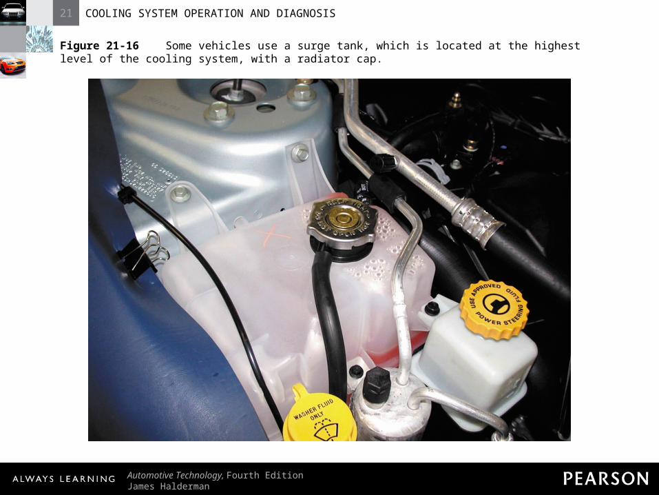
Figure 21-16 Some vehicles use a surge tank, which is located at the highest level of the cooling system, with a radiator cap.
21 COOLING SYSTEM OPERATION AND DIAGNOSIS
Automotive Technology, Fourth EditionJames Halderman
© 2011 Pearson Education, Inc.All Rights Reserved
WATER PUMPSWATER PUMPS

21 COOLING SYSTEM OPERATION AND DIAGNOSIS
Automotive Technology, Fourth EditionJames Halderman
© 2011 Pearson Education, Inc.All Rights Reserved
Water PumpsWater Pumps• Operation
– Water pump is driven by one of two methods:
• Crankshaft belt• Camshaft
21 COOLING SYSTEM OPERATION AND DIAGNOSIS
Automotive Technology, Fourth EditionJames Halderman
© 2011 Pearson Education, Inc.All Rights Reserved
Water PumpsWater Pumps• Operation
– Coolant recirculates from radiator to engine and back to radiator
– Low-temperature coolant leaves radiator by bottom outlet
21 COOLING SYSTEM OPERATION AND DIAGNOSIS
Automotive Technology, Fourth EditionJames Halderman
© 2011 Pearson Education, Inc.All Rights Reserved
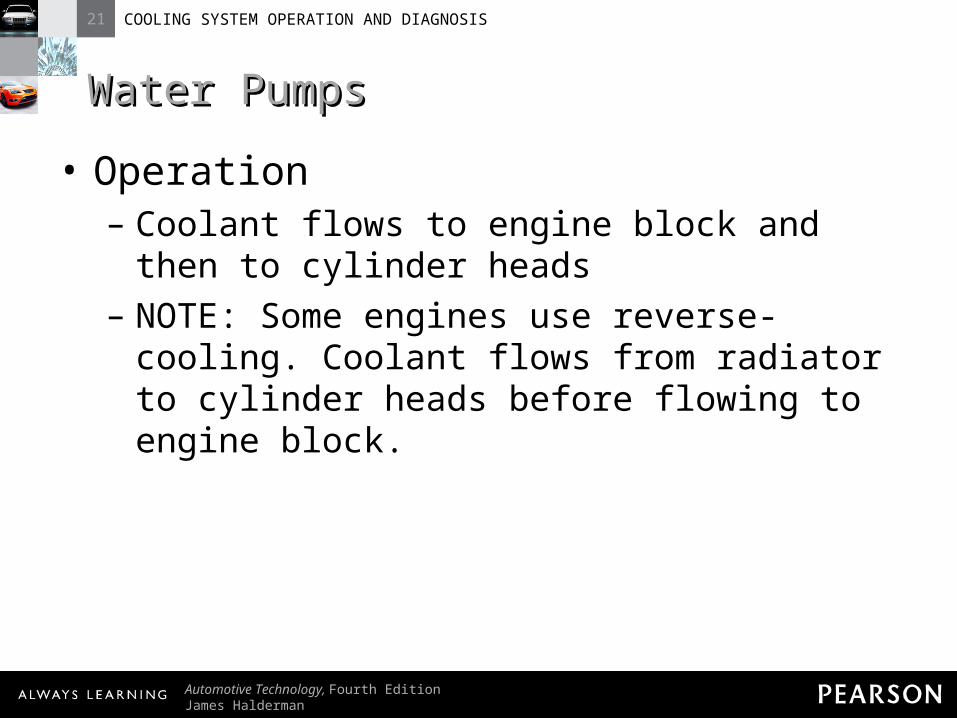
Water PumpsWater Pumps• Operation
– Coolant flows to engine block and then to cylinder heads
– NOTE: Some engines use reverse-cooling. Coolant flows from radiator to cylinder heads before flowing to engine block.

21 COOLING SYSTEM OPERATION AND DIAGNOSIS
Automotive Technology, Fourth EditionJames Halderman
© 2011 Pearson Education, Inc.All Rights Reserved
Water PumpsWater Pumps• Operation
– Water pump is not positive displacement pump
– Water pump is centrifugal pump
21 COOLING SYSTEM OPERATION AND DIAGNOSIS
Automotive Technology, Fourth EditionJames Halderman
© 2011 Pearson Education, Inc.All Rights Reserved
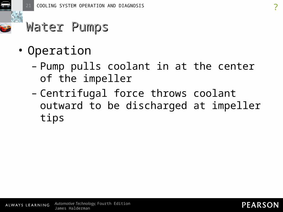
Water PumpsWater Pumps• Operation
– Pump pulls coolant in at the center of the impeller
– Centrifugal force throws coolant outward to be discharged at impeller tips
?

21 COOLING SYSTEM OPERATION AND DIAGNOSIS
Automotive Technology, Fourth EditionJames Halderman
© 2011 Pearson Education, Inc.All Rights Reserved
Figure 21-17 Coolant flow through the impeller and scroll of a coolant pump for a V-type engine.
21 COOLING SYSTEM OPERATION AND DIAGNOSIS
Automotive Technology, Fourth EditionJames Halderman
© 2011 Pearson Education, Inc.All Rights Reserved
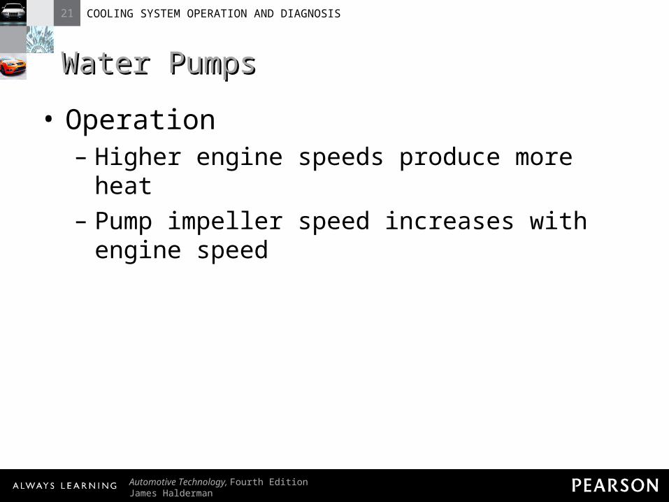
Water PumpsWater Pumps• Operation
– Higher engine speeds produce more heat– Pump impeller speed increases with engine
speed
21 COOLING SYSTEM OPERATION AND DIAGNOSIS
Automotive Technology, Fourth EditionJames Halderman
© 2011 Pearson Education, Inc.All Rights Reserved
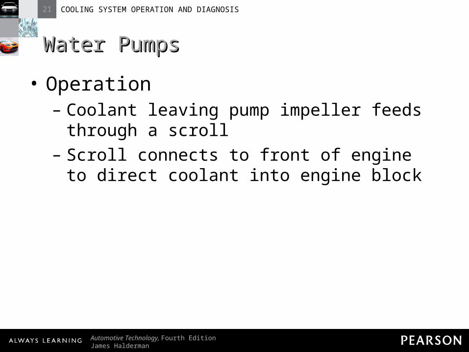
Water PumpsWater Pumps• Operation
– Coolant leaving pump impeller feeds through a scroll
– Scroll connects to front of engine to direct coolant into engine block
21 COOLING SYSTEM OPERATION AND DIAGNOSIS
Automotive Technology, Fourth EditionJames Halderman
© 2011 Pearson Education, Inc.All Rights Reserved
Water PumpsWater Pumps• Operation
– On V-type engines, two outlets are often used
– Occasionally, diverts are needed to equalize coolant flow between engine banks

21 COOLING SYSTEM OPERATION AND DIAGNOSIS
Automotive Technology, Fourth EditionJames Halderman
© 2011 Pearson Education, Inc.All Rights Reserved
Water PumpsWater Pumps• Water Pump Service
– Worn impeller can reduce amount of coolant flow
– If water pump seal fails, coolant will leak from weep hole
21 COOLING SYSTEM OPERATION AND DIAGNOSIS
Automotive Technology, Fourth EditionJames Halderman
© 2011 Pearson Education, Inc.All Rights Reserved
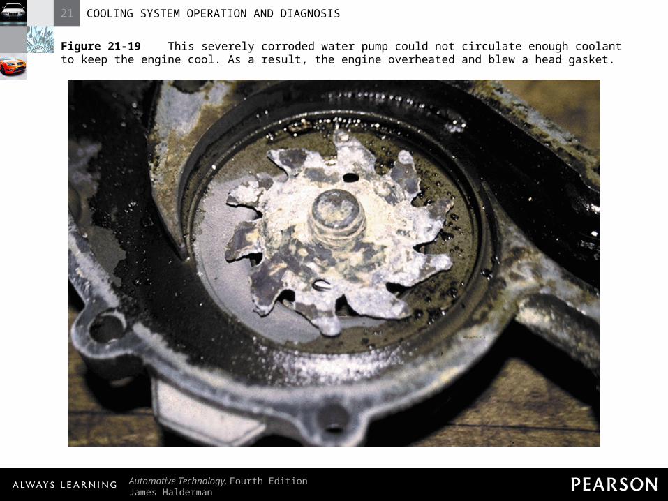
Figure 21-19 This severely corroded water pump could not circulate enough coolant to keep the engine cool. As a result, the engine overheated and blew a head gasket.

21 COOLING SYSTEM OPERATION AND DIAGNOSIS
Automotive Technology, Fourth EditionJames Halderman
© 2011 Pearson Education, Inc.All Rights Reserved
Water PumpsWater Pumps• Water Pump Service
– Weep hole allows coolant to escape– Defective bearing is noisy and must be
replaced
21 COOLING SYSTEM OPERATION AND DIAGNOSIS
Automotive Technology, Fourth EditionJames Halderman
© 2011 Pearson Education, Inc.All Rights Reserved
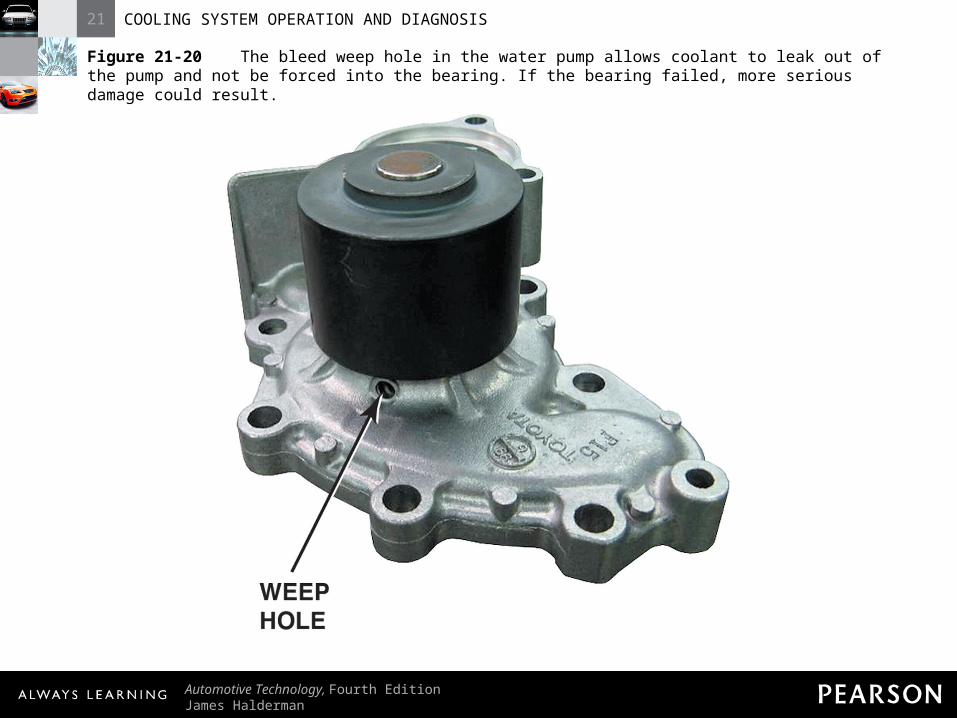
Figure 21-20 The bleed weep hole in the water pump allows coolant to leak out of the pump and not be forced into the bearing. If the bearing failed, more serious damage could result.
21 COOLING SYSTEM OPERATION AND DIAGNOSIS
Automotive Technology, Fourth EditionJames Halderman
© 2011 Pearson Education, Inc.All Rights Reserved
Water PumpsWater Pumps• Water Pump Service
– Before replacing water pump because of noisy bearing, check
• Drive belt tension• Bent fan
21 COOLING SYSTEM OPERATION AND DIAGNOSIS
Automotive Technology, Fourth EditionJames Halderman
© 2011 Pearson Education, Inc.All Rights Reserved
Water PumpsWater Pumps• Water Pump Service
– Before replacing water pump because of noisy bearing, check
• Fan for balance
21 COOLING SYSTEM OPERATION AND DIAGNOSIS
Automotive Technology, Fourth EditionJames Halderman
© 2011 Pearson Education, Inc.All Rights Reserved
Water PumpsWater Pumps• Water Pump Service
– If pump drive belt is too tight, excessive force may be exerted on pump bearing
21 COOLING SYSTEM OPERATION AND DIAGNOSIS
Automotive Technology, Fourth EditionJames Halderman
© 2011 Pearson Education, Inc.All Rights Reserved
Water PumpsWater Pumps• Water Pump Service
– If cooling fan is bent or out of balance, vibration can damage pump bearing
21 COOLING SYSTEM OPERATION AND DIAGNOSIS
Automotive Technology, Fourth EditionJames Halderman
© 2011 Pearson Education, Inc.All Rights Reserved
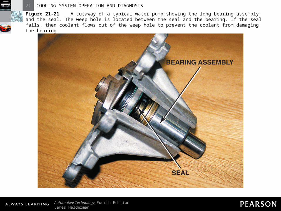
Figure 21-21 A cutaway of a typical water pump showing the long bearing assembly and the seal. The weep hole is located between the seal and the bearing. If the seal fails, then coolant flows out of the weep hole to prevent the coolant from damaging the bearing.

21 COOLING SYSTEM OPERATION AND DIAGNOSIS
Automotive Technology, Fourth EditionJames Halderman
© 2011 Pearson Education, Inc.All Rights Reserved
COOLANT FLOWCOOLANT FLOWIN THE ENGINEIN THE ENGINE
21 COOLING SYSTEM OPERATION AND DIAGNOSIS
Automotive Technology, Fourth EditionJames Halderman
© 2011 Pearson Education, Inc.All Rights Reserved
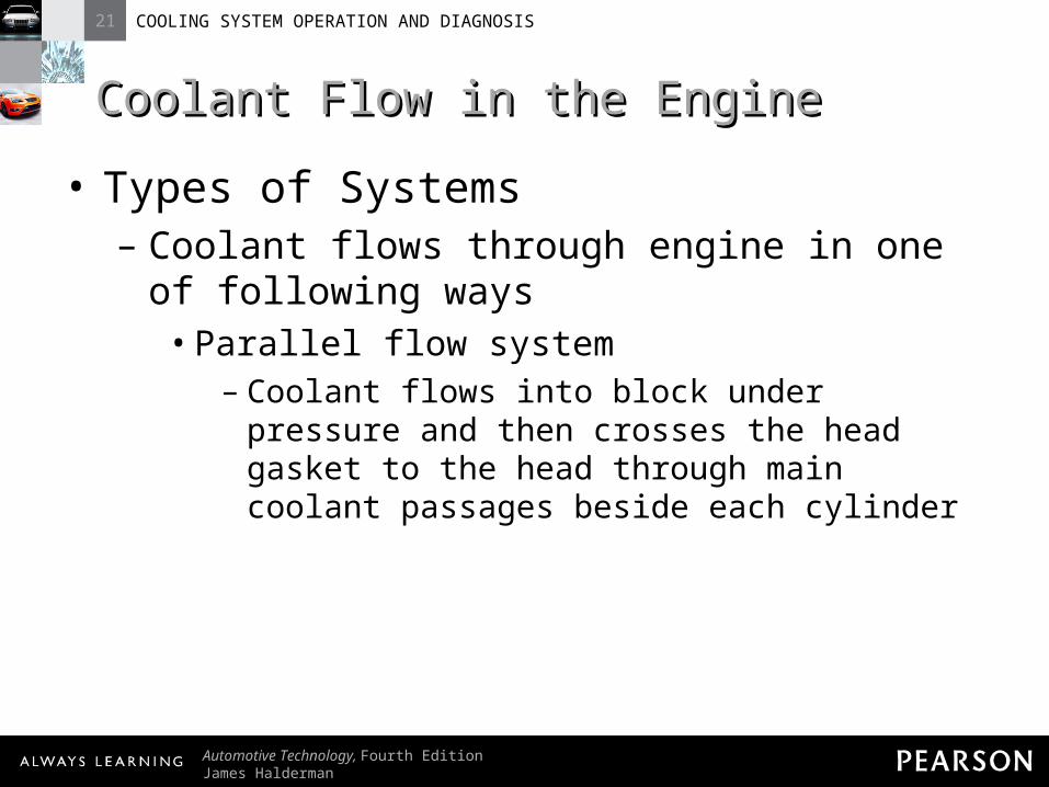
Coolant Flow in the EngineCoolant Flow in the Engine• Types of Systems
– Coolant flows through engine in one of following ways
• Parallel flow system– Coolant flows into block under pressure and
then crosses the head gasket to the head through main coolant passages beside each cylinder

21 COOLING SYSTEM OPERATION AND DIAGNOSIS
Automotive Technology, Fourth EditionJames Halderman
© 2011 Pearson Education, Inc.All Rights Reserved
Coolant Flow in the EngineCoolant Flow in the Engine• Types of Systems
– Coolant flows through engine in one of following ways
• Series flow system– Coolant flows around cylinders on each bank
21 COOLING SYSTEM OPERATION AND DIAGNOSIS
Automotive Technology, Fourth EditionJames Halderman
© 2011 Pearson Education, Inc.All Rights Reserved
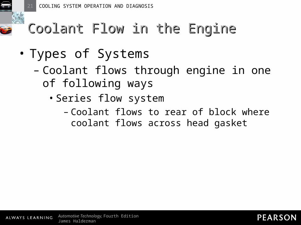
Coolant Flow in the EngineCoolant Flow in the Engine• Types of Systems
– Coolant flows through engine in one of following ways
• Series flow system– Coolant flows to rear of block where coolant
flows across head gasket
21 COOLING SYSTEM OPERATION AND DIAGNOSIS
Automotive Technology, Fourth EditionJames Halderman
© 2011 Pearson Education, Inc.All Rights Reserved
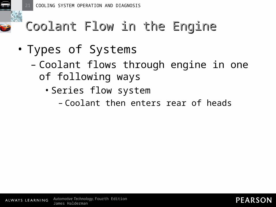
Coolant Flow in the EngineCoolant Flow in the Engine• Types of Systems
– Coolant flows through engine in one of following ways
• Series flow system– Coolant then enters rear of heads
21 COOLING SYSTEM OPERATION AND DIAGNOSIS
Automotive Technology, Fourth EditionJames Halderman
© 2011 Pearson Education, Inc.All Rights Reserved
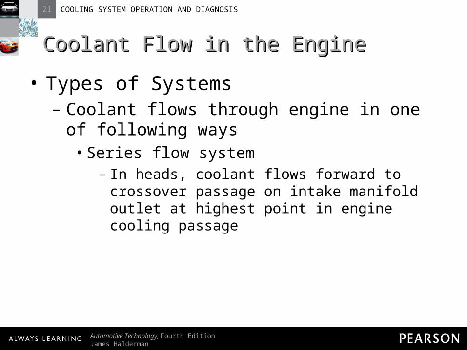
Coolant Flow in the EngineCoolant Flow in the Engine• Types of Systems
– Coolant flows through engine in one of following ways
• Series flow system– In heads, coolant flows forward to crossover
passage on intake manifold outlet at highest point in engine cooling passage
21 COOLING SYSTEM OPERATION AND DIAGNOSIS
Automotive Technology, Fourth EditionJames Halderman
© 2011 Pearson Education, Inc.All Rights Reserved
Coolant Flow in the EngineCoolant Flow in the Engine• Types of Systems
– Coolant flows through engine in one of following ways
• Series-parallel flow system– Combination of series-flow and parallel-flow
systems
21 COOLING SYSTEM OPERATION AND DIAGNOSIS
Automotive Technology, Fourth EditionJames Halderman
© 2011 Pearson Education, Inc.All Rights Reserved
Coolant Flow in the EngineCoolant Flow in the Engine• Types of Systems
– Coolant flows through engine in one of following ways
• Series-parallel flow system– Any stem goes directly to top of radiator
21 COOLING SYSTEM OPERATION AND DIAGNOSIS
Automotive Technology, Fourth EditionJames Halderman
© 2011 Pearson Education, Inc.All Rights Reserved
Coolant Flow in the EngineCoolant Flow in the Engine• Types of Systems
– Coolant flows through engine in one of following ways
• Series-parallel flow system– Bleed holes or steam slits let out the steam

21 COOLING SYSTEM OPERATION AND DIAGNOSIS
Automotive Technology, Fourth EditionJames Halderman
© 2011 Pearson Education, Inc.All Rights Reserved
Coolant Flow in the EngineCoolant Flow in the Engine• Coolant Flow and Head Gasket Design
– Most but not all V-type engines use cylinder heads that are interchangeable side to side

21 COOLING SYSTEM OPERATION AND DIAGNOSIS
Automotive Technology, Fourth EditionJames Halderman
© 2011 Pearson Education, Inc.All Rights Reserved
Coolant Flow in the EngineCoolant Flow in the Engine• Coolant Flow and Head Gasket Design
– Double check that cylinder head is matched to block and that head gasket is installed correctly
21 COOLING SYSTEM OPERATION AND DIAGNOSIS
Automotive Technology, Fourth EditionJames Halderman
© 2011 Pearson Education, Inc.All Rights Reserved
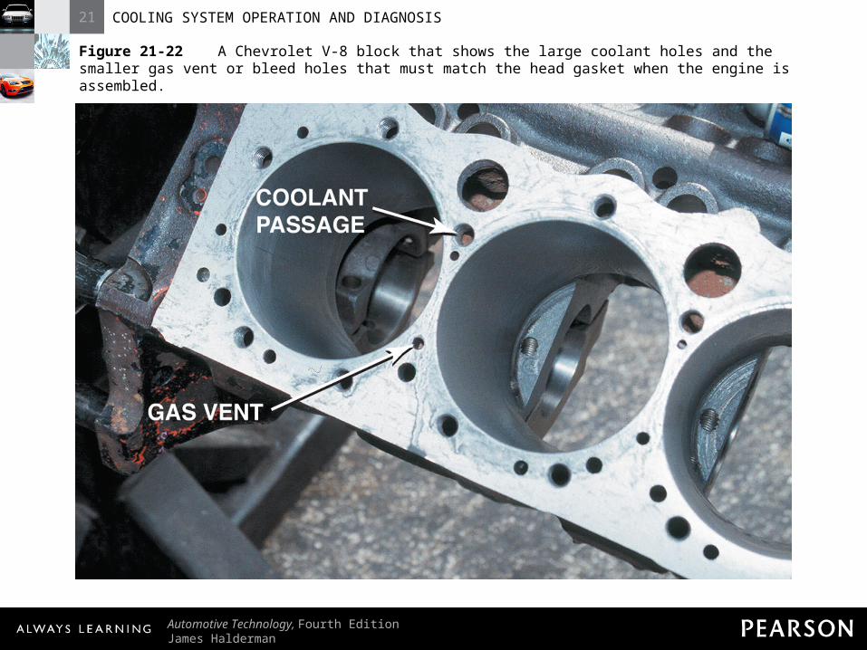
Figure 21-22 A Chevrolet V-8 block that shows the large coolant holes and the smaller gas vent or bleed holes that must match the head gasket when the engine is assembled.
21 COOLING SYSTEM OPERATION AND DIAGNOSIS
Automotive Technology, Fourth EditionJames Halderman
© 2011 Pearson Education, Inc.All Rights Reserved
COOLING FANSCOOLING FANS

21 COOLING SYSTEM OPERATION AND DIAGNOSIS
Automotive Technology, Fourth EditionJames Halderman
© 2011 Pearson Education, Inc.All Rights Reserved
Cooling FansCooling Fans• Electronically Controlled Cooling Fan
– Two Types• One two-speed cooling fan
21 COOLING SYSTEM OPERATION AND DIAGNOSIS
Automotive Technology, Fourth EditionJames Halderman
© 2011 Pearson Education, Inc.All Rights Reserved
Cooling FansCooling Fans• Electronically Controlled Cooling Fan
– Two Types• Two cooling fans (one for normal cooling;
one for high heat conditions)
21 COOLING SYSTEM OPERATION AND DIAGNOSIS
Automotive Technology, Fourth EditionJames Halderman
© 2011 Pearson Education, Inc.All Rights Reserved
Cooling FansCooling Fans• Electronically Controlled Cooling Fan
– PCM commands low-speed fans under these conditions
• ECT exceeds approximately 223°F (106°C)

21 COOLING SYSTEM OPERATION AND DIAGNOSIS
Automotive Technology, Fourth EditionJames Halderman
© 2011 Pearson Education, Inc.All Rights Reserved
Cooling FansCooling Fans• Electronically Controlled Cooling Fan
– PCM commands low-speed fans under these conditions
• A/C refrigerant pressure exceeds 190 PSI (1,310 kPa)
21 COOLING SYSTEM OPERATION AND DIAGNOSIS
Automotive Technology, Fourth EditionJames Halderman
© 2011 Pearson Education, Inc.All Rights Reserved
Cooling FansCooling Fans• Electronically Controlled Cooling Fan
– PCM commands low-speed fans under these conditions
• After engine is shut off, coolant temperature is greater than 284°F (140°C) and system voltage is more than 12 volts.
21 COOLING SYSTEM OPERATION AND DIAGNOSIS
Automotive Technology, Fourth EditionJames Halderman
© 2011 Pearson Education, Inc.All Rights Reserved
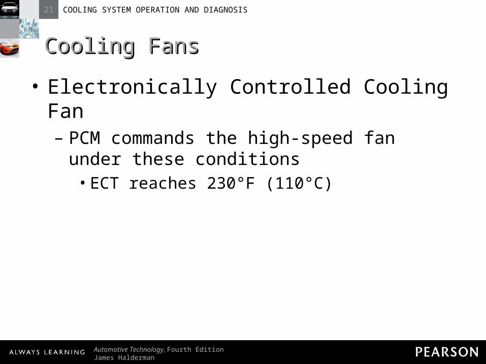
Cooling FansCooling Fans• Electronically Controlled Cooling Fan
– PCM commands the high-speed fan under these conditions
• ECT reaches 230°F (110°C)

21 COOLING SYSTEM OPERATION AND DIAGNOSIS
Automotive Technology, Fourth EditionJames Halderman
© 2011 Pearson Education, Inc.All Rights Reserved
Cooling FansCooling Fans• Electronically Controlled Cooling Fan
– PCM commands the high-speed fan under these conditions
• A/C refrigerant pressure exceeds 240 PSI (1,655 kPa)
21 COOLING SYSTEM OPERATION AND DIAGNOSIS
Automotive Technology, Fourth EditionJames Halderman
© 2011 Pearson Education, Inc.All Rights Reserved
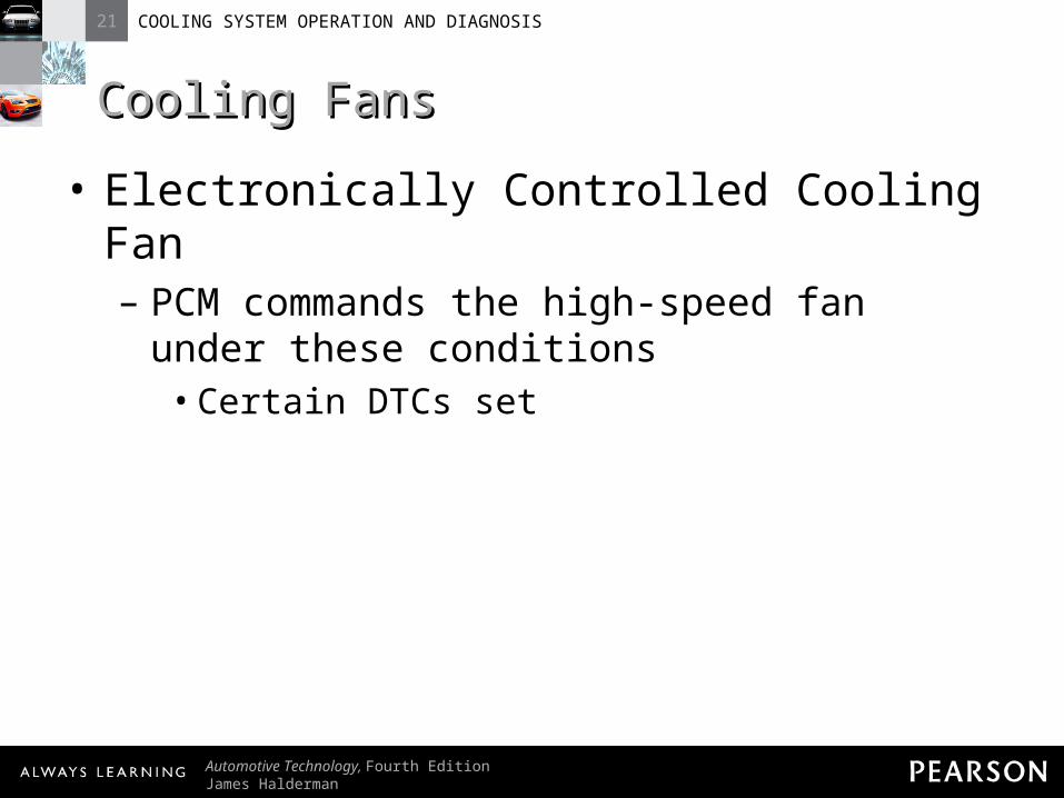
Cooling FansCooling Fans• Electronically Controlled Cooling Fan
– PCM commands the high-speed fan under these conditions
• Certain DTCs set
21 COOLING SYSTEM OPERATION AND DIAGNOSIS
Automotive Technology, Fourth EditionJames Halderman
© 2011 Pearson Education, Inc.All Rights Reserved
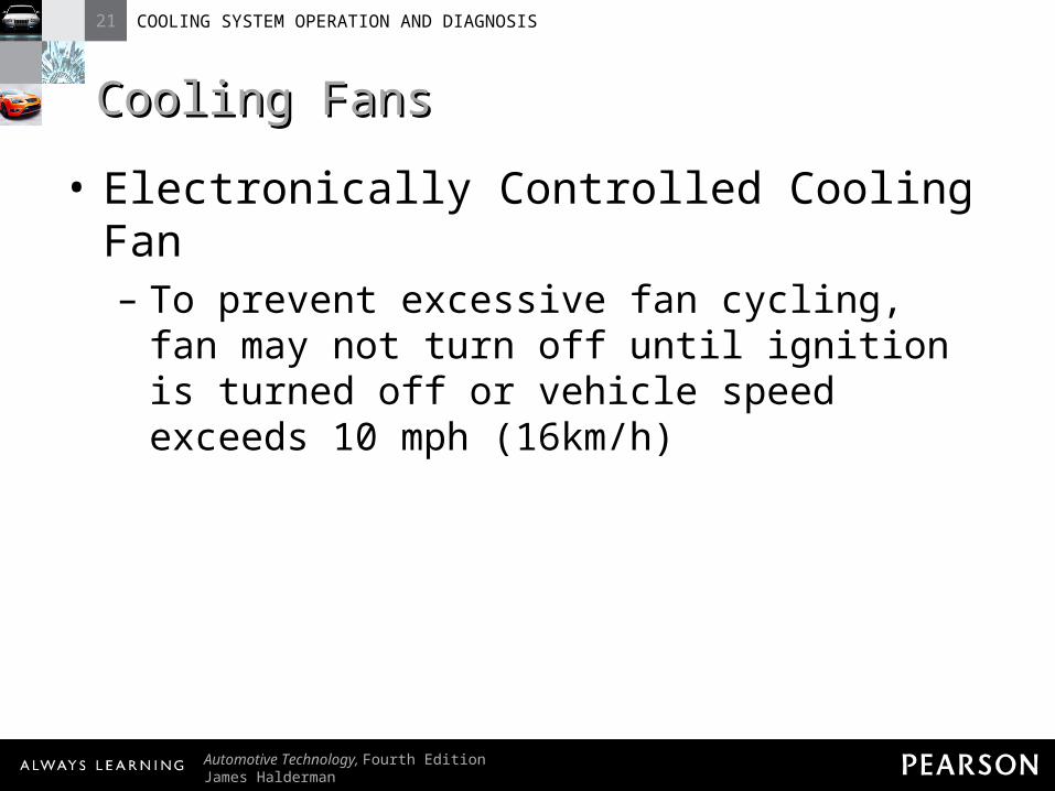
Cooling FansCooling Fans• Electronically Controlled Cooling Fan
– To prevent excessive fan cycling, fan may not turn off until ignition is turned off or vehicle speed exceeds 10 mph (16km/h)

21 COOLING SYSTEM OPERATION AND DIAGNOSIS
Automotive Technology, Fourth EditionJames Halderman
© 2011 Pearson Education, Inc.All Rights Reserved
Cooling FansCooling Fans• Electronically Controlled Cooling Fan
– Many rear-wheel-drive vehicles and all transverse engines drive the fan with an electric motor
21 COOLING SYSTEM OPERATION AND DIAGNOSIS
Automotive Technology, Fourth EditionJames Halderman
© 2011 Pearson Education, Inc.All Rights Reserved
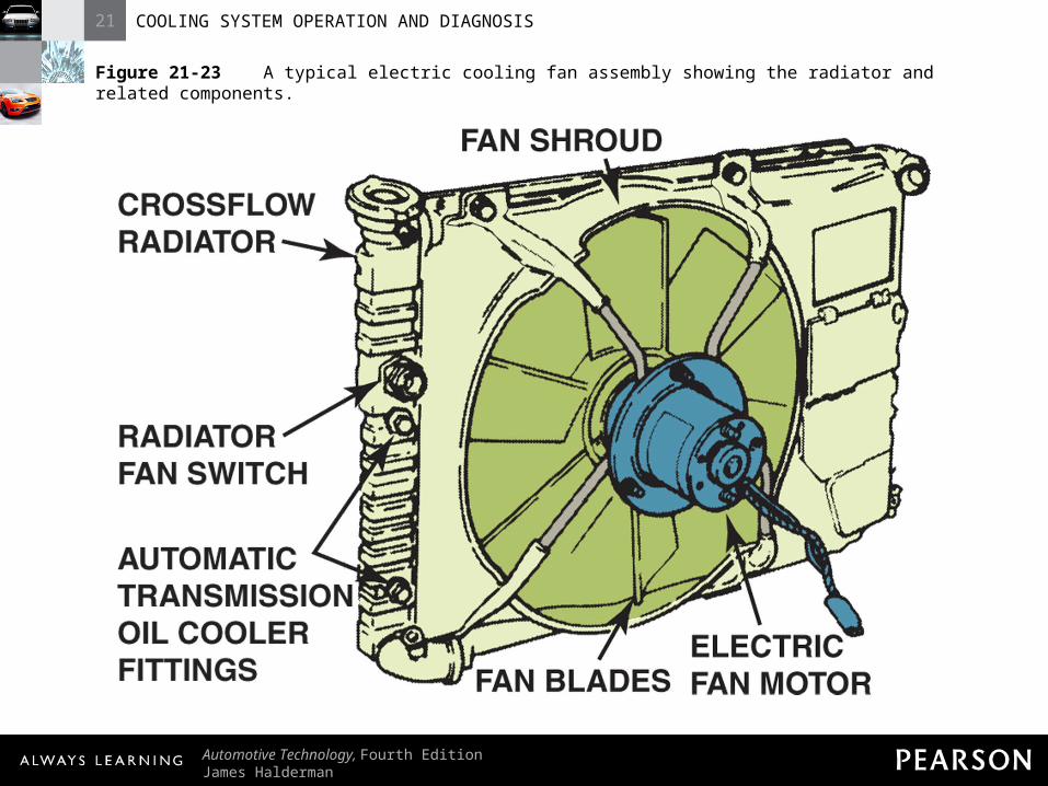
Figure 21-23 A typical electric cooling fan assembly showing the radiator and related components.

21 COOLING SYSTEM OPERATION AND DIAGNOSIS
Automotive Technology, Fourth EditionJames Halderman
© 2011 Pearson Education, Inc.All Rights Reserved
Cooling FansCooling Fans• Electronically Controlled Cooling Fan
– NOTE: Most electric cooling fans are computer controlled. Most are turned off when vehicle exceeds 35 mph (55 km/h). Ram air keeps radiator cool. If computer senses temperature is too high, computer turns on cooling fan.
21 COOLING SYSTEM OPERATION AND DIAGNOSIS
Automotive Technology, Fourth EditionJames Halderman
© 2011 Pearson Education, Inc.All Rights Reserved
Cooling FansCooling Fans• Thermostatic Fans
– On some rear-wheel-drive vehicles, a thermostatic cooling fan is driven by a belt from the crankshaft
21 COOLING SYSTEM OPERATION AND DIAGNOSIS
Automotive Technology, Fourth EditionJames Halderman
© 2011 Pearson Education, Inc.All Rights Reserved
Cooling FansCooling Fans• Thermostatic Fans
– The cooling systems transfers more heat at higher speeds

21 COOLING SYSTEM OPERATION AND DIAGNOSIS
Automotive Technology, Fourth EditionJames Halderman
© 2011 Pearson Education, Inc.All Rights Reserved
Cooling FansCooling Fans• Thermostatic Fans
– Two Types of Thermostatic Fans:• Silicone coupling: fan drive is mounted
between drive pulley and fan– HINT: When diagnosing overheating, examine
cooling fan. If silicone is leaking, fan may not function correctly.

21 COOLING SYSTEM OPERATION AND DIAGNOSIS
Automotive Technology, Fourth EditionJames Halderman
© 2011 Pearson Education, Inc.All Rights Reserved
Cooling FansCooling Fans• Thermostatic Fans
– Two Types of Thermostatic Fans:• Thermostatic spring: thermostatic spring
added to silicone coupling fan drive– Thermostatic spring operates valve that
allows fan to freewheel when radiator is cold
21 COOLING SYSTEM OPERATION AND DIAGNOSIS
Automotive Technology, Fourth EditionJames Halderman
© 2011 Pearson Education, Inc.All Rights Reserved
Cooling FansCooling Fans• Thermostatic Fans
– Two Types of Thermostatic Fans:• Thermostatic spring: thermostatic spring
added to silicone coupling fan drive– When radiator warms to 150°F (65°C), spring
opens valve that allows drive to operate like silicone coupling drive

21 COOLING SYSTEM OPERATION AND DIAGNOSIS
Automotive Technology, Fourth EditionJames Halderman
© 2011 Pearson Education, Inc.All Rights Reserved
Figure 21-24 A typical engine-driven thermostatic spring cooling fan.

21 COOLING SYSTEM OPERATION AND DIAGNOSIS
Automotive Technology, Fourth EditionJames Halderman
© 2011 Pearson Education, Inc.All Rights Reserved
HEATER CORESHEATER CORES
21 COOLING SYSTEM OPERATION AND DIAGNOSIS
Automotive Technology, Fourth EditionJames Halderman
© 2011 Pearson Education, Inc.All Rights Reserved
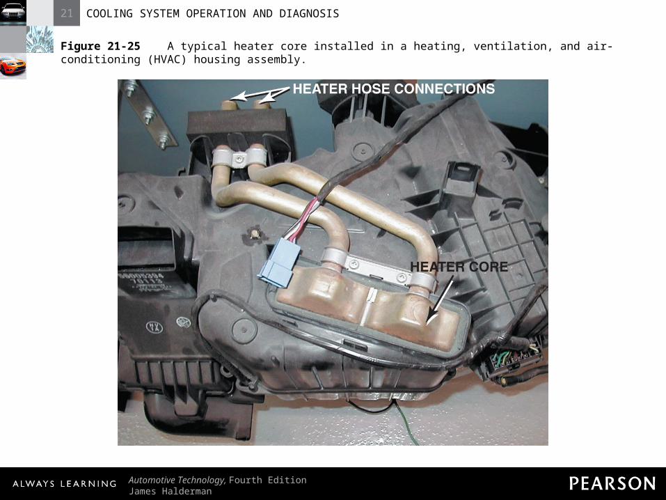
Heater CoresHeater Cores• Purpose and Function
– Some heat absorbed by cooling system passes through tubes to small core of the heater

21 COOLING SYSTEM OPERATION AND DIAGNOSIS
Automotive Technology, Fourth EditionJames Halderman
© 2011 Pearson Education, Inc.All Rights Reserved
Heater CoresHeater Cores• Purpose and Function
– Air passes across heater fends and sent to passenger compartment
21 COOLING SYSTEM OPERATION AND DIAGNOSIS
Automotive Technology, Fourth EditionJames Halderman
© 2011 Pearson Education, Inc.All Rights Reserved
Figure 21-25 A typical heater core installed in a heating, ventilation, and air-conditioning (HVAC) housing assembly.
21 COOLING SYSTEM OPERATION AND DIAGNOSIS
Automotive Technology, Fourth EditionJames Halderman
© 2011 Pearson Education, Inc.All Rights Reserved
Heater CoresHeater Cores• Heater Problem Diagnosis
– To find cause of lack of heat to heater follow these steps
21 COOLING SYSTEM OPERATION AND DIAGNOSIS
Automotive Technology, Fourth EditionJames Halderman
© 2011 Pearson Education, Inc.All Rights Reserved
Heater CoresHeater Cores• Heater Problem Diagnosis
– Step 1: Feel upper radiator hose; it should be too hot to hold; it should have pressure.
• If hose is not hot, replace thermostat.

21 COOLING SYSTEM OPERATION AND DIAGNOSIS
Automotive Technology, Fourth EditionJames Halderman
© 2011 Pearson Education, Inc.All Rights Reserved
Heater CoresHeater Cores• Heater Problem Diagnosis
– Step 1: Feel upper radiator hose; it should be too hot to hold; it should have pressure.
• If hose is not pressurized, test or replace radiator pressure cap.
21 COOLING SYSTEM OPERATION AND DIAGNOSIS
Automotive Technology, Fourth EditionJames Halderman
© 2011 Pearson Education, Inc.All Rights Reserved
Heater CoresHeater Cores• Heater Problem Diagnosis
– Step 1: Feel upper radiator hose; it should be too hot to hold; it should have pressure.
• If okay, see step 2.
21 COOLING SYSTEM OPERATION AND DIAGNOSIS
Automotive Technology, Fourth EditionJames Halderman
© 2011 Pearson Education, Inc.All Rights Reserved
Heater CoresHeater Cores• Heater Problem Diagnosis
– Step 2: With engine running, feel both heater hoses. Both should be too hot to hold.
• If hoses are warm or cool, check heater control valve.

21 COOLING SYSTEM OPERATION AND DIAGNOSIS
Automotive Technology, Fourth EditionJames Halderman
© 2011 Pearson Education, Inc.All Rights Reserved
Heater CoresHeater Cores• Heater Problem Diagnosis
– Step 2: With engine running, feel both heater hoses. Both should be too hot to hold.
• If one hose is hot and other warm or cool, remove hoses and flush heater core.

21 COOLING SYSTEM OPERATION AND DIAGNOSIS
Automotive Technology, Fourth EditionJames Halderman
© 2011 Pearson Education, Inc.All Rights Reserved
Heater CoresHeater Cores• Heater Problem Diagnosis
– Step 3: If both hoses are hot but heat is insufficient, check for airflow blend door malfunction.

21 COOLING SYSTEM OPERATION AND DIAGNOSIS
Automotive Technology, Fourth EditionJames Halderman
© 2011 Pearson Education, Inc.All Rights Reserved
Heater CoresHeater Cores• HINT: Heat from heater that comes and
goes is likely the result of low coolant level. It may work at lower engine speeds but not at higher speeds.
21 COOLING SYSTEM OPERATION AND DIAGNOSIS
Automotive Technology, Fourth EditionJames Halderman
© 2011 Pearson Education, Inc.All Rights Reserved
COOLING SYSTEM COOLING SYSTEM TESTINGTESTING

21 COOLING SYSTEM OPERATION AND DIAGNOSIS
Automotive Technology, Fourth EditionJames Halderman
© 2011 Pearson Education, Inc.All Rights Reserved
Cooling System TestingCooling System Testing• Visual Inspection
– Many faults can be identified with visual inspection
• Water pump drive belt for tension or faults
21 COOLING SYSTEM OPERATION AND DIAGNOSIS
Automotive Technology, Fourth EditionJames Halderman
© 2011 Pearson Education, Inc.All Rights Reserved
Cooling System TestingCooling System Testing• Visual Inspection
– Many faults can be identified with visual inspection
• Cooling fan for faults
21 COOLING SYSTEM OPERATION AND DIAGNOSIS
Automotive Technology, Fourth EditionJames Halderman
© 2011 Pearson Education, Inc.All Rights Reserved
Cooling System TestingCooling System Testing• Visual Inspection
– Many faults can be identified with visual inspection
• Heater and radiator hoses for condition and leaks
21 COOLING SYSTEM OPERATION AND DIAGNOSIS
Automotive Technology, Fourth EditionJames Halderman
© 2011 Pearson Education, Inc.All Rights Reserved
Cooling System TestingCooling System Testing• Visual Inspection
– Many faults can be identified with visual inspection
• Coolant overflow or surge tank coolant level
21 COOLING SYSTEM OPERATION AND DIAGNOSIS
Automotive Technology, Fourth EditionJames Halderman
© 2011 Pearson Education, Inc.All Rights Reserved
Cooling System TestingCooling System Testing• Visual Inspection
– Many faults can be identified with visual inspection
• Evidence of coolant loss

21 COOLING SYSTEM OPERATION AND DIAGNOSIS
Automotive Technology, Fourth EditionJames Halderman
© 2011 Pearson Education, Inc.All Rights Reserved
Cooling System TestingCooling System Testing• Visual Inspection
– Many faults can be identified with visual inspection
• Radiator condition
21 COOLING SYSTEM OPERATION AND DIAGNOSIS
Automotive Technology, Fourth EditionJames Halderman
© 2011 Pearson Education, Inc.All Rights Reserved
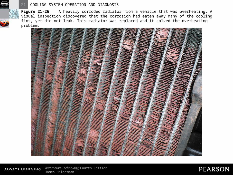
Figure 21-26 A heavily corroded radiator from a vehicle that was overheating. A visual inspection discovered that the corrosion had eaten away many of the cooling fins, yet did not leak. This radiator was replaced and it solved the overheating problem.

21 COOLING SYSTEM OPERATION AND DIAGNOSIS
Automotive Technology, Fourth EditionJames Halderman
© 2011 Pearson Education, Inc.All Rights Reserved
Cooling System TestingCooling System Testing• Pressure Testing
– Using hand-operated pressure tester, remove radiator cap
– Operating plunger on pump pressurizes cooling system

21 COOLING SYSTEM OPERATION AND DIAGNOSIS
Automotive Technology, Fourth EditionJames Halderman
© 2011 Pearson Education, Inc.All Rights Reserved
Figure 21-27 Pressure testing the cooling system. A typical handoperated pressure tester applies pressure equal to the radiator cap pressure. The pressure should hold; if it drops, this indicates a leak somewhere in the cooling system. An adapter is used to attach the pump to the cap to determine if the radiator can hold pressure, and release it when pressure rises above its maximum rated pressure setting.

21 COOLING SYSTEM OPERATION AND DIAGNOSIS
Automotive Technology, Fourth EditionJames Halderman
© 2011 Pearson Education, Inc.All Rights Reserved
Cooling System TestingCooling System Testing• Pressure Testing
– CAUTION: Do not pump up pressure beyond that specified by vehicle manufacturer, usually 14 PSI (100 kPa).
21 COOLING SYSTEM OPERATION AND DIAGNOSIS
Automotive Technology, Fourth EditionJames Halderman
© 2011 Pearson Education, Inc.All Rights Reserved
Cooling System TestingCooling System Testing• Pressure Testing
– If system is free from leaks, pressure will stay and not drop

21 COOLING SYSTEM OPERATION AND DIAGNOSIS
Automotive Technology, Fourth EditionJames Halderman
© 2011 Pearson Education, Inc.All Rights Reserved
Cooling System TestingCooling System Testing• Pressure Testing
– If pressure drops check for leaks• Heater hoses• Radiator hoses

21 COOLING SYSTEM OPERATION AND DIAGNOSIS
Automotive Technology, Fourth EditionJames Halderman
© 2011 Pearson Education, Inc.All Rights Reserved
Cooling System TestingCooling System Testing• Pressure Testing
– If pressure drops check for leaks• Radiator• Heater core

21 COOLING SYSTEM OPERATION AND DIAGNOSIS
Automotive Technology, Fourth EditionJames Halderman
© 2011 Pearson Education, Inc.All Rights Reserved
Cooling System TestingCooling System Testing• Pressure Testing
– If pressure drops check for leaks• Cylinder head• Core plugs in block or cylinder head
21 COOLING SYSTEM OPERATION AND DIAGNOSIS
Automotive Technology, Fourth EditionJames Halderman
© 2011 Pearson Education, Inc.All Rights Reserved
Cooling System TestingCooling System Testing• Pressure Testing
– Perform pressure testing whenever there is leak or suspected leak
– Pressure tester can also be used to test radiator cap
21 COOLING SYSTEM OPERATION AND DIAGNOSIS
Automotive Technology, Fourth EditionJames Halderman
© 2011 Pearson Education, Inc.All Rights Reserved
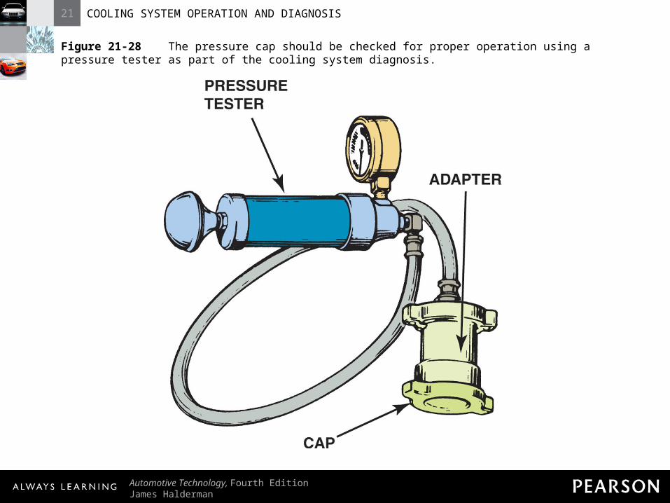
Figure 21-28 The pressure cap should be checked for proper operation using a pressure tester as part of the cooling system diagnosis.
21 COOLING SYSTEM OPERATION AND DIAGNOSIS
Automotive Technology, Fourth EditionJames Halderman
© 2011 Pearson Education, Inc.All Rights Reserved
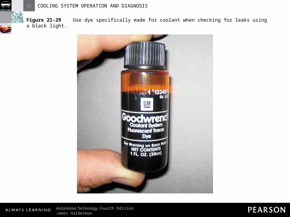
Cooling System TestingCooling System Testing• Coolant Dye Leak Testing
– Use fluorescent dye in coolant– Operate vehicle to reach normal operating
temperature
21 COOLING SYSTEM OPERATION AND DIAGNOSIS
Automotive Technology, Fourth EditionJames Halderman
© 2011 Pearson Education, Inc.All Rights Reserved
Cooling System TestingCooling System Testing• Coolant Dye Leak Testing
– Use black light to inspect cooling system
21 COOLING SYSTEM OPERATION AND DIAGNOSIS
Automotive Technology, Fourth EditionJames Halderman
© 2011 Pearson Education, Inc.All Rights Reserved
Figure 21-29 Use dye specifically made for coolant when checking for leaks using a black light.
21 COOLING SYSTEM OPERATION AND DIAGNOSIS
Automotive Technology, Fourth EditionJames Halderman
© 2011 Pearson Education, Inc.All Rights Reserved
COOLANT COOLANT TEMPERATURETEMPERATURE
WARNING LIGHTWARNING LIGHT
21 COOLING SYSTEM OPERATION AND DIAGNOSIS
Automotive Technology, Fourth EditionJames Halderman
© 2011 Pearson Education, Inc.All Rights Reserved
Coolant Temperature Warning LightCoolant Temperature Warning Light• Purpose and Function
– Most vehicles have heat sensor to engine operating temperature indicator light

21 COOLING SYSTEM OPERATION AND DIAGNOSIS
Automotive Technology, Fourth EditionJames Halderman
© 2011 Pearson Education, Inc.All Rights Reserved
Coolant Temperature Warning LightCoolant Temperature Warning Light• Purpose and Function
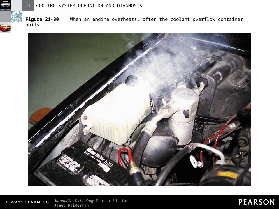
– If light comes on (or temperature gauge goes into red danger zone) coolant is 250°F to 258°F (120°C to 126°C)
21 COOLING SYSTEM OPERATION AND DIAGNOSIS
Automotive Technology, Fourth EditionJames Halderman
© 2011 Pearson Education, Inc.All Rights Reserved
Figure 21-30 When an engine overheats, often the coolant overflow container boils.
21 COOLING SYSTEM OPERATION AND DIAGNOSIS
Automotive Technology, Fourth EditionJames Halderman
© 2011 Pearson Education, Inc.All Rights Reserved
Coolant Temperature Warning LightCoolant Temperature Warning Light• Precautions
– If coolant temperature warning light comes on, follow these steps
• Step 1: Shut off air conditioning and turn on heater. Set blower speed to high.
21 COOLING SYSTEM OPERATION AND DIAGNOSIS
Automotive Technology, Fourth EditionJames Halderman
© 2011 Pearson Education, Inc.All Rights Reserved
Coolant Temperature Warning LightCoolant Temperature Warning Light• Precautions
– If coolant temperature warning light comes on, follow these steps
• Step 2: Shut engine off and let it cool.• Step 3: Do not remove radiator cap while
engine is hot.
21 COOLING SYSTEM OPERATION AND DIAGNOSIS
Automotive Technology, Fourth EditionJames Halderman
© 2011 Pearson Education, Inc.All Rights Reserved
Coolant Temperature Warning LightCoolant Temperature Warning Light• Precautions
– If coolant temperature warning light comes on, follow these steps
• Step 4: Do not continue to drive.• Step 5: If engine does not feel or smell hot,
problem may be faulty hot light sensor or gauge.

21 COOLING SYSTEM OPERATION AND DIAGNOSIS
Automotive Technology, Fourth EditionJames Halderman
© 2011 Pearson Education, Inc.All Rights Reserved
Coolant Temperature Warning LightCoolant Temperature Warning Light• Common Causes of Overheating
– Low coolant level– Plugged, dirty, or blocked radiator

21 COOLING SYSTEM OPERATION AND DIAGNOSIS
Automotive Technology, Fourth EditionJames Halderman
© 2011 Pearson Education, Inc.All Rights Reserved
Coolant Temperature Warning LightCoolant Temperature Warning Light• Common Causes of Overheating
– Defective fan clutch or electric fan– Incorrect ignition timing (if adjustable)

21 COOLING SYSTEM OPERATION AND DIAGNOSIS
Automotive Technology, Fourth EditionJames Halderman
© 2011 Pearson Education, Inc.All Rights Reserved
Coolant Temperature Warning LightCoolant Temperature Warning Light• Common Causes of Overheating
– Low engine oil level– Broken fan drive belt

21 COOLING SYSTEM OPERATION AND DIAGNOSIS
Automotive Technology, Fourth EditionJames Halderman
© 2011 Pearson Education, Inc.All Rights Reserved
Coolant Temperature Warning LightCoolant Temperature Warning Light• Common Causes of Overheating
– Defective radiator cap– Dragging brakes

21 COOLING SYSTEM OPERATION AND DIAGNOSIS
Automotive Technology, Fourth EditionJames Halderman
© 2011 Pearson Education, Inc.All Rights Reserved
Coolant Temperature Warning LightCoolant Temperature Warning Light• Common Causes of Overheating
– Frozen coolant (in freezing weather)– Defective thermostat

21 COOLING SYSTEM OPERATION AND DIAGNOSIS
Automotive Technology, Fourth EditionJames Halderman
© 2011 Pearson Education, Inc.All Rights Reserved
Coolant Temperature Warning LightCoolant Temperature Warning Light• Common Causes of Overheating
– Defective water pump (impeller slipping on internal shaft)
– Blocked cooling passages in block or cylinder head(s)

21 COOLING SYSTEM OPERATION AND DIAGNOSIS
Automotive Technology, Fourth EditionJames Halderman
© 2011 Pearson Education, Inc.All Rights Reserved
COOLING SYSTEMCOOLING SYSTEMINSPECTIONINSPECTION

21 COOLING SYSTEM OPERATION AND DIAGNOSIS
Automotive Technology, Fourth EditionJames Halderman
© 2011 Pearson Education, Inc.All Rights Reserved
Cooling System InspectionCooling System Inspection• Coolant Level
– Normal maintenance involves checking coolant level and visual inspection for leaks and condition of hoses and belts

21 COOLING SYSTEM OPERATION AND DIAGNOSIS
Automotive Technology, Fourth EditionJames Halderman
© 2011 Pearson Education, Inc.All Rights Reserved
Cooling System InspectionCooling System Inspection• Coolant Level
– CAUTION: Check coolant only when engine is cool. Removing pressure cap from hot engine will cause coolant to boil immediately. Vapors will blow coolant from system. Coolant will be lost; someone may be injured.
21 COOLING SYSTEM OPERATION AND DIAGNOSIS
Automotive Technology, Fourth EditionJames Halderman
© 2011 Pearson Education, Inc.All Rights Reserved
Cooling System InspectionCooling System Inspection• Accessory Drive Belt Tension
– Four ways manufacturers specific belt tension is within specifications1. Belt tension gauge
– Install belt and operate engine for five minutes

21 COOLING SYSTEM OPERATION AND DIAGNOSIS
Automotive Technology, Fourth EditionJames Halderman
© 2011 Pearson Education, Inc.All Rights Reserved
Cooling System InspectionCooling System Inspection• Accessory Drive Belt Tension
– Four ways manufacturers specific belt tension is within specifications1. Belt tension gauge
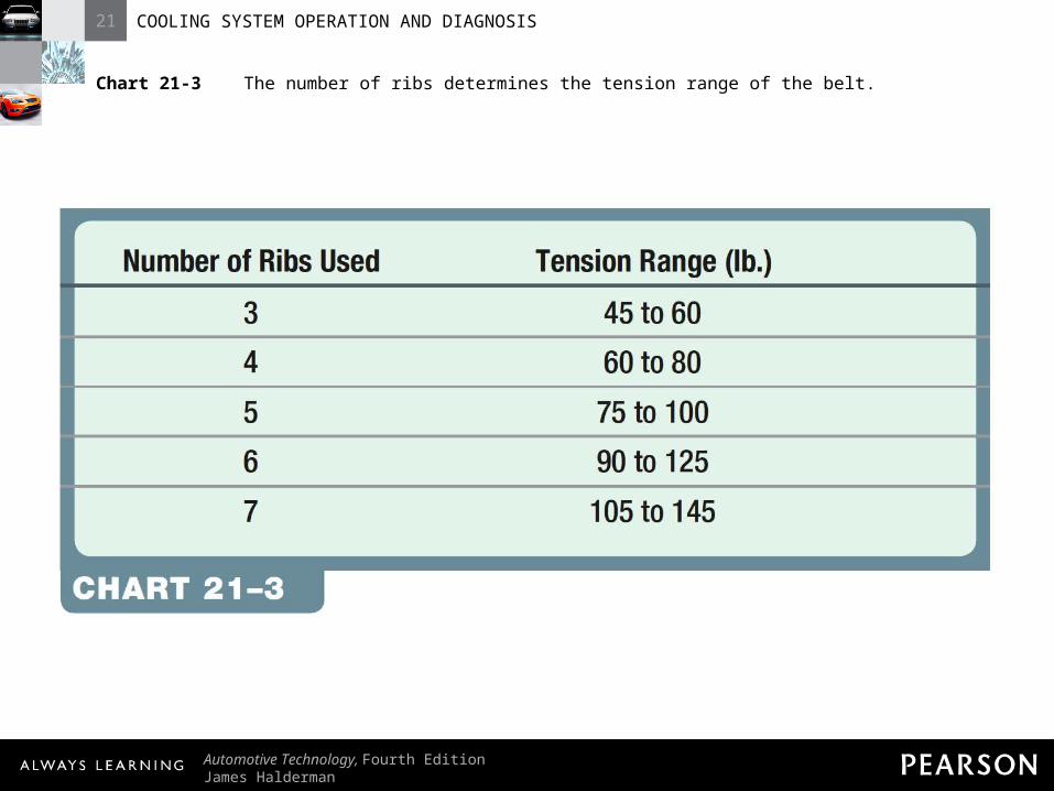
– Adjust tension to factory specifications or use Chart 21-3
21 COOLING SYSTEM OPERATION AND DIAGNOSIS
Automotive Technology, Fourth EditionJames Halderman
© 2011 Pearson Education, Inc.All Rights Reserved
Chart 21-3 The number of ribs determines the tension range of the belt.

21 COOLING SYSTEM OPERATION AND DIAGNOSIS
Automotive Technology, Fourth EditionJames Halderman
© 2011 Pearson Education, Inc.All Rights Reserved
Cooling System InspectionCooling System Inspection• Accessory Drive Belt Tension
– Four ways manufacturers specific belt tension is within specifications1. Belt tension gauge
– Replace serpentine belt with more than three cracks in 3 in. span
21 COOLING SYSTEM OPERATION AND DIAGNOSIS
Automotive Technology, Fourth EditionJames Halderman
© 2011 Pearson Education, Inc.All Rights Reserved
Cooling System InspectionCooling System Inspection• Accessory Drive Belt Tension
– Four ways manufacturers specific belt tension is within specifications2. Marks on tensioner
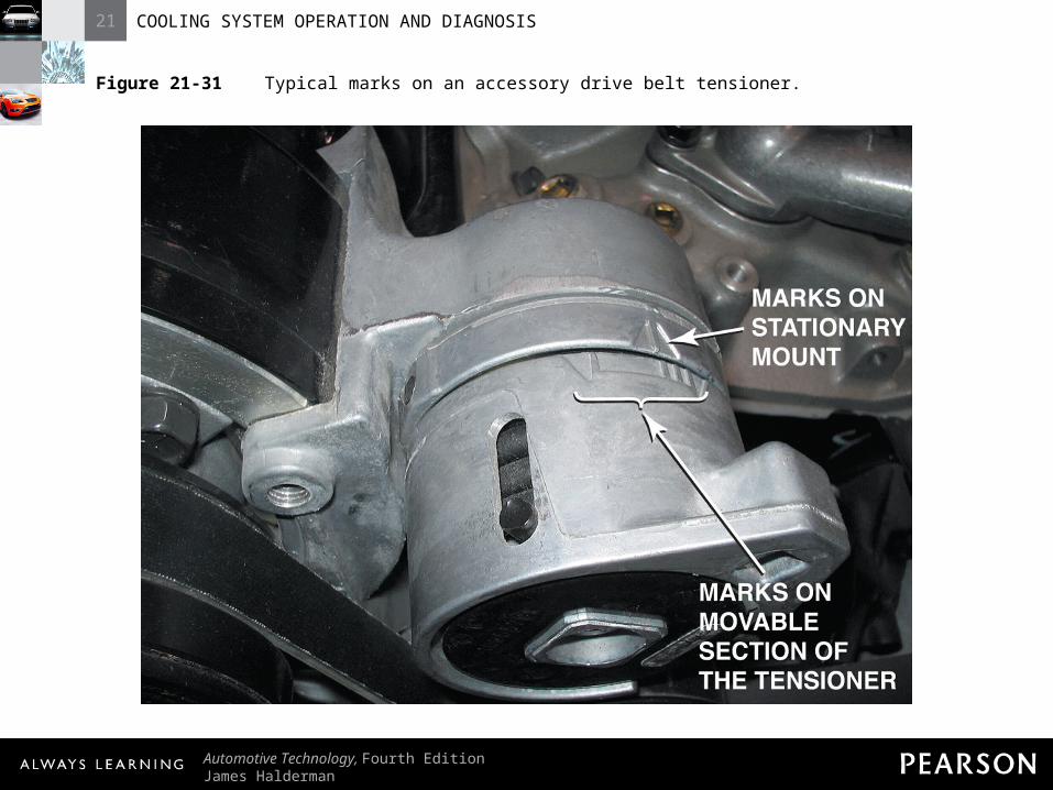
– Many tensioners have marks indicating normal operating tension range

21 COOLING SYSTEM OPERATION AND DIAGNOSIS
Automotive Technology, Fourth EditionJames Halderman
© 2011 Pearson Education, Inc.All Rights Reserved
Cooling System InspectionCooling System Inspection• Accessory Drive Belt Tension
– Four ways manufacturers specific belt tension is within specifications2. Marks on tensioner
– Check service information for location of tensioner mark
21 COOLING SYSTEM OPERATION AND DIAGNOSIS
Automotive Technology, Fourth EditionJames Halderman
© 2011 Pearson Education, Inc.All Rights Reserved
Figure 21-31 Typical marks on an accessory drive belt tensioner.

21 COOLING SYSTEM OPERATION AND DIAGNOSIS
Automotive Technology, Fourth EditionJames Halderman
© 2011 Pearson Education, Inc.All Rights Reserved
Cooling System InspectionCooling System Inspection• Accessory Drive Belt Tension
– Four ways manufacturers specific belt tension is within specifications3. Torque wrench reading
– Some manufacturers specify use of beam-type torque wrench
21 COOLING SYSTEM OPERATION AND DIAGNOSIS
Automotive Technology, Fourth EditionJames Halderman
© 2011 Pearson Education, Inc.All Rights Reserved
Cooling System InspectionCooling System Inspection• Accessory Drive Belt Tension
– Four ways manufacturers specific belt tension is within specifications4. Deflection
– Depress belt between the two pulleys that are farthest apart
21 COOLING SYSTEM OPERATION AND DIAGNOSIS
Automotive Technology, Fourth EditionJames Halderman
© 2011 Pearson Education, Inc.All Rights Reserved
Cooling System InspectionCooling System Inspection• Accessory Drive Belt Tension
– Four ways manufacturers specific belt tension is within specifications4. Deflection
– Deflection should be 1/2 in.
21 COOLING SYSTEM OPERATION AND DIAGNOSIS
Automotive Technology, Fourth EditionJames Halderman
© 2011 Pearson Education, Inc.All Rights Reserved
COOLING SYSTEMCOOLING SYSTEMSERVICESERVICE

21 COOLING SYSTEM OPERATION AND DIAGNOSIS
Automotive Technology, Fourth EditionJames Halderman
© 2011 Pearson Education, Inc.All Rights Reserved
Cooling System ServiceCooling System Service• Flushing Coolant
– Step 1: Drain system.– Step 2: Fill system with clean water and
flushing/cleaning chemical.

21 COOLING SYSTEM OPERATION AND DIAGNOSIS
Automotive Technology, Fourth EditionJames Halderman
© 2011 Pearson Education, Inc.All Rights Reserved
Cooling System ServiceCooling System Service• Flushing Coolant
– Step 3: Start engine; run until it reaches operating temperature with heater on.
– Step 4: Drain system and fill with water.
21 COOLING SYSTEM OPERATION AND DIAGNOSIS
Automotive Technology, Fourth EditionJames Halderman
© 2011 Pearson Education, Inc.All Rights Reserved
Cooling System ServiceCooling System Service• Flushing Coolant
– Step 5: Repeat until drain water runs clear.– Step 6: Fill system with 50/50
antifreeze/water mix or premixed coolant.
21 COOLING SYSTEM OPERATION AND DIAGNOSIS
Automotive Technology, Fourth EditionJames Halderman
© 2011 Pearson Education, Inc.All Rights Reserved
Cooling System ServiceCooling System Service• Flushing Coolant
– Step 7: Run engine until it reaches operating temperature with heater on.
– Step 8: Adjust coolant level as needed.
21 COOLING SYSTEM OPERATION AND DIAGNOSIS
Automotive Technology, Fourth EditionJames Halderman
© 2011 Pearson Education, Inc.All Rights Reserved
Cooling System ServiceCooling System Service• Flushing Coolant
– Bleed air from cooling system• Attach clear hose to bleeder valve; put other
end in container

21 COOLING SYSTEM OPERATION AND DIAGNOSIS
Automotive Technology, Fourth EditionJames Halderman
© 2011 Pearson Education, Inc.All Rights Reserved
Cooling System ServiceCooling System Service• Flushing Coolant
– Bleed air from cooling system• Check service information for specific
bleeding procedures and location of bleeder fittings

21 COOLING SYSTEM OPERATION AND DIAGNOSIS
Automotive Technology, Fourth EditionJames Halderman
© 2011 Pearson Education, Inc.All Rights Reserved
Figure 21-32 (a) Many vehicle manufacturers recommend that the bleeder valve be opened whenever refilling the cooling system.

21 COOLING SYSTEM OPERATION AND DIAGNOSIS
Automotive Technology, Fourth EditionJames Halderman
© 2011 Pearson Education, Inc.All Rights Reserved
Figure 21-32 (b) Chrysler recommends that a clear plastic hose (1/4 in. ID) be attached to the bleeder valve and directed into a suitable container to keep from spilling coolant onto the ground and on the engine and to allow the technician to observe the flow of coolant for any remaining oil bubbles.
21 COOLING SYSTEM OPERATION AND DIAGNOSIS
Automotive Technology, Fourth EditionJames Halderman
© 2011 Pearson Education, Inc.All Rights Reserved
Cooling System ServiceCooling System Service• Coolant Exchange Machine
– Many coolant exchange machines can perform one of more of these operations
• Exchange old coolant with new coolant
21 COOLING SYSTEM OPERATION AND DIAGNOSIS
Automotive Technology, Fourth EditionJames Halderman
© 2011 Pearson Education, Inc.All Rights Reserved
Cooling System ServiceCooling System Service• Coolant Exchange Machine
– Many coolant exchange machines can perform one of more of these operations
• Flush cooling system
21 COOLING SYSTEM OPERATION AND DIAGNOSIS
Automotive Technology, Fourth EditionJames Halderman
© 2011 Pearson Education, Inc.All Rights Reserved
Cooling System ServiceCooling System Service• Coolant Exchange Machine
– Many coolant exchange machines can perform one of more of these operations
• Pressure or vacuum check system for leaks
21 COOLING SYSTEM OPERATION AND DIAGNOSIS
Automotive Technology, Fourth EditionJames Halderman
© 2011 Pearson Education, Inc.All Rights Reserved
Cooling System ServiceCooling System Service• Coolant Exchange Machine
– Exchange machine helps eliminate air pockets

21 COOLING SYSTEM OPERATION AND DIAGNOSIS
Automotive Technology, Fourth EditionJames Halderman
© 2011 Pearson Education, Inc.All Rights Reserved
Cooling System ServiceCooling System Service• Coolant Exchange Machine
– Air pockets show these symptoms• Lack of heat from heater
21 COOLING SYSTEM OPERATION AND DIAGNOSIS
Automotive Technology, Fourth EditionJames Halderman
© 2011 Pearson Education, Inc.All Rights Reserved
Cooling System ServiceCooling System Service• Coolant Exchange Machine
– Air pockets show these symptoms• Overheating
21 COOLING SYSTEM OPERATION AND DIAGNOSIS
Automotive Technology, Fourth EditionJames Halderman
© 2011 Pearson Education, Inc.All Rights Reserved
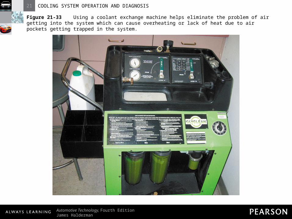
Figure 21-33 Using a coolant exchange machine helps eliminate the problem of air getting into the system which can cause overheating or lack of heat due to air pockets getting trapped in the system.
21 COOLING SYSTEM OPERATION AND DIAGNOSIS
Automotive Technology, Fourth EditionJames Halderman
© 2011 Pearson Education, Inc.All Rights Reserved
Cooling System ServiceCooling System Service• Hose Inspection
– A hose should be replaced any time it appears abnormal

21 COOLING SYSTEM OPERATION AND DIAGNOSIS
Automotive Technology, Fourth EditionJames Halderman
© 2011 Pearson Education, Inc.All Rights Reserved
Figure 21-34 All cooling system hoses should be checked for wear or damage.

21 COOLING SYSTEM OPERATION AND DIAGNOSIS
Automotive Technology, Fourth EditionJames Halderman
© 2011 Pearson Education, Inc.All Rights Reserved
Cooling System ServiceCooling System Service• Hose Inspection
– HINT: To make hose removal easier and to avoid damage to radiator, slit hose lengthwise with utility knife. Peel hose off.

21 COOLING SYSTEM OPERATION AND DIAGNOSIS
Automotive Technology, Fourth EditionJames Halderman
© 2011 Pearson Education, Inc.All Rights Reserved
Cooling System ServiceCooling System Service• Hose Inspection
– Position hose and hose clam so clamp is close to the bead on the neck
21 COOLING SYSTEM OPERATION AND DIAGNOSIS
Automotive Technology, Fourth EditionJames Halderman
© 2011 Pearson Education, Inc.All Rights Reserved
Cooling System ServiceCooling System Service• Disposing of Used Coolant
– Dispose of coolant according to state or local laws
– Some communities allow draining into sewer
21 COOLING SYSTEM OPERATION AND DIAGNOSIS
Automotive Technology, Fourth EditionJames Halderman
© 2011 Pearson Education, Inc.All Rights Reserved
Cooling System ServiceCooling System Service• Disposing of Used Coolant
– Groundwater contamination can occur if coolant is spilled on ground
– Check with recycling companies for recommended disposal methods
21 COOLING SYSTEM OPERATION AND DIAGNOSIS
Automotive Technology, Fourth EditionJames Halderman
© 2011 Pearson Education, Inc.All Rights Reserved
Cooling System ServiceCooling System Service• Cleaning the Radiator Exterior
– Overheating can result from exterior and interior radiator plugging

21 COOLING SYSTEM OPERATION AND DIAGNOSIS
Automotive Technology, Fourth EditionJames Halderman
© 2011 Pearson Education, Inc.All Rights Reserved
Cooling System ServiceCooling System Service• Cleaning the Radiator Exterior
– Exterior plugging can be seen if you look through the radiator
– Exterior can be cleaned with water pressure from hose
Related Documents


