ASTERICS - H2020 - 653477 Demonstration of VLBI synchronization via existing SURFnet/LOFAR network ASTERICS GA DELIVERABLE: D5.14 Document Identifier: ASTERICS-D5.14 Date: June 28, 2019 Work Package: WP5 - CLEOPATRA Lead Partner: JIVE Document Status: Final Dissemination Level: Public Document Link: https://www.asterics2020.eu/ documents/ASTERICS-D5.14.pdf Ref. Ares(2019)4433670 - 10/07/2019

Welcome message from author
This document is posted to help you gain knowledge. Please leave a comment to let me know what you think about it! Share it to your friends and learn new things together.
Transcript

ASTERICS - H2020 - 653477
Demonstration of VLBI synchronization viaexisting SURFnet/LOFAR network
ASTERICS GA DELIVERABLE: D5.14
Document Identifier: ASTERICS-D5.14
Date: June 28, 2019
Work Package: WP5 - CLEOPATRA
Lead Partner: JIVE
Document Status: Final
Dissemination Level: Public
Document Link: https://www.asterics2020.eu/
documents/ASTERICS-D5.14.pdf
Ref. Ares(2019)4433670 - 10/07/2019

Abstract
A common challenge in the design of research facilities is the distribution of an
accurate timing and frequency reference. In this part of the Cleopatra project,
we research the suitability of the open ‘White Rabbit’ protocol to deliver a
clock signal with sufficient stability for radio astronomical applications. In par-
ticular, we demonstrate its suitability by performing VLBI using a remote hy-
drogen maser reference over optical links of up to 169 km in length, without
interrupting the other traffic on the link.
COPYRIGHT NOTICE 1
I COPYRIGHT NOTICECopyright © Members of the ASTERICS Collaboration, 2015. See www.asterics2020.eu for details ofthe ASTERICS project and the collaboration. ASTERICS (Astronomy ESFRI & Research InfrastructureCluster) is a project funded by the European Commission as a Research and Innovation Actions (RIA)within the H2020 Framework Programme. ASTERICS began in May 2015 and will run for 4 years.This work is licensed under the Creative Commons Attribution- Noncommercial 3.0 License. To view acopy of this license, visit http://creativecommons.org/licenses/by-nc/3.0/ or send a letter to CreativeCommons, 171 Second Street, Suite 300, San Francisco, California, 94105, and USA. The work must beattributed by attaching the following reference to the copied elements: “Copyright © Members of theASTERICS Collaboration, 2015. See www.asterics2020.eu for details of the ASTERICS project and thecollaboration”. Using this document in a way and/or for purposes not foreseen in the license, requiresthe prior written permission of the copyright holders. The information contained in this document rep-resents the views of the copyright holders as of the date such views are published.
II DELIVERY SLIP
Name Partner/WP Date
From
Author(s) Paul Boven JIVE June 28, 2019
Chantal van Tour OPNT June 28, 2019
Rob Smets SURFnet June 28, 2019
Reviewed by Giuseppe Cimó
Approved by AMST
ASTERICS - 653477 © Members of the ASTERICS collaboration PUBLIC

DOCUMENT LOG 2
III DOCUMENT LOG
Issue Date Comment Author/Partner
1 2019-04-08 First draft Paul Boven
2 2019-04-16 Chapter on Timing Calibration Chantal v. Tour
3 2019-04-25 Contributions to Link Setup Rob Smets
4 2018-06-12 Update of the VLBI chapter Paul Boven
5 2019-06-20 Fixed a Formula Chantal v. Tour
6 2019-06-24 LOFAR chapter, VLBI update Paul Boven
7 2019-06-28 Intro, References, layout Paul Boven
IV APPLICATION AREAThis document is a formal deliverable for the GA of the project, applicable to all members of the AS-TERICS project, beneficiaries and third parties, as well as its collaborating projects.
V TERMINOLOGY
A complete project glossary is provided at the following page:http://www.asterics2020.eu/about/glossary/
CERN Conseil Européen pour la Recherce Nucléaire
ERIC European Research Infrastructure Consortium
LHC Large Hadron Collider
JIVE Joint Institute for VLBI ERIC
LOFAR Low Frequency Array
VLBI Very Long Baseline Interferometry
WR White Rabbit
WSRT Westerbork Synthesis Radio Telescope
ASTERICS - 653477 © Members of the ASTERICS collaboration PUBLIC

PROJECT SUMMARY 3
VI PROJECT SUMMARY
ASTERICS (Astronomy ESFRI & Research Infrastructure Cluster) aims to address the cross-cutting syn-ergies and common challenges shared by the various Astronomy ESFRI facilities (SKA, CTA, KM3Net &E-ELT). It brings together for the first time, the astronomy, astrophysics and particle astrophysics com-munities, in addition to other related research infrastructures. The major objectives of ASTERICS areto support and accelerate the implementation of the ESFRI telescopes, to enhance their performancebeyond the current state-of-the-art, and to see them interoperate as an integrated, multi-wavelengthand multi-messenger facility. An important focal point is the management, processing and scientific ex-ploitation of the huge datasets the ESFRI facilities will generate. ASTERICS will seek solutions to theseproblems outside of the traditional channels by directly engaging and collaborating with industry andspecialised SMEs. The various ESFRI pathfinders and precursors will present the perfect proving groundfor new methodologies and prototype systems. In addition, ASTERICS will enable astronomers fromacross the member states to have broad access to the reduced data products of the ESFRI telescopesvia a seamless interface to the Virtual Observatory framework. This will massively increase the scientificimpact of the telescopes, and greatly encourage use (and re-use) of the data in new and novel ways,typically not foreseen in the original proposals. By demonstrating cross-facility synchronicity, and byharmonising various policy aspects, ASTERICS will realise a distributed and interoperable approach thatushers in a new multi-messenger era for astronomy. Through an active dissemination programme, in-cluding direct engagement with all relevant stakeholders, and via the development of citizen scientistmass participation experiments, ASTERICS has the ambition to be a flagship for the scientific, industrialand societal impact ESFRI projects can deliver.
VII EXECUTIVE SUMMARY
In this deliverable we study the distribution of stable and accurate frequency and time reference signalsover optical communications fibre, using modifications of the White Rabbit standard. Link calibrationand phase performance are determined, and we demonstrate the usability of the WR links by perform-ing VLBI observations, using the optically distributed reference clock from another radio telescope.
ASTERICS - 653477 © Members of the ASTERICS collaboration PUBLIC

TABLE OF CONTENTS 4
Table of Contents
I COPYRIGHT NOTICE . . . . . . . . . . . . . . . . . . . . . . . . . . . . . . . . . . . . . . . . . . . 1
II DELIVERY SLIP . . . . . . . . . . . . . . . . . . . . . . . . . . . . . . . . . . . . . . . . . . . . . . . 1
III DOCUMENT LOG . . . . . . . . . . . . . . . . . . . . . . . . . . . . . . . . . . . . . . . . . . . . . 2
IV APPLICATION AREA . . . . . . . . . . . . . . . . . . . . . . . . . . . . . . . . . . . . . . . . . . . . 2
V TERMINOLOGY . . . . . . . . . . . . . . . . . . . . . . . . . . . . . . . . . . . . . . . . . . . . . . . 2
VII EXECUTIVE SUMMARY . . . . . . . . . . . . . . . . . . . . . . . . . . . . . . . . . . . . . . . . . . 3
Table of Contents . . . . . . . . . . . . . . . . . . . . . . . . . . . . . . . . . . . . . . . . . . . . . . . 4
1 Introduction . . . . . . . . . . . . . . . . . . . . . . . . . . . . . . . . . . . . . . . . . . . . . . . . 5
2 White Rabbit Link Setup . . . . . . . . . . . . . . . . . . . . . . . . . . . . . . . . . . . . . . . . 62.1 Co-existing TFT service in a carrier network . . . . . . . . . . . . . . . . . . . . . . . . . . . 62.2 Network setup for both the VLBI and LOFAR TFT service . . . . . . . . . . . . . . . . . . . 62.3 Network setup for the LOFAR TFT service . . . . . . . . . . . . . . . . . . . . . . . . . . . . 72.4 Network setup for the VLBI CAMRAS TFT service . . . . . . . . . . . . . . . . . . . . . . . 72.5 Link design and operation . . . . . . . . . . . . . . . . . . . . . . . . . . . . . . . . . . . . . 7
3 Timing Calibration . . . . . . . . . . . . . . . . . . . . . . . . . . . . . . . . . . . . . . . . . . . . 103.1 Device delay asymmetries . . . . . . . . . . . . . . . . . . . . . . . . . . . . . . . . . . . . 103.2 Link delay asymmetries . . . . . . . . . . . . . . . . . . . . . . . . . . . . . . . . . . . . . . 113.3 Overall timing performance . . . . . . . . . . . . . . . . . . . . . . . . . . . . . . . . . . . . 14
4 VLBI with the WR link . . . . . . . . . . . . . . . . . . . . . . . . . . . . . . . . . . . . . . . . . . 154.1 VLBI Requirements . . . . . . . . . . . . . . . . . . . . . . . . . . . . . . . . . . . . . . . . . 154.2 Frequency Reference Stability . . . . . . . . . . . . . . . . . . . . . . . . . . . . . . . . . . 154.3 A COTS VLBI receiver and backend . . . . . . . . . . . . . . . . . . . . . . . . . . . . . . . 16
4.3.1 Detailed flowgraph description . . . . . . . . . . . . . . . . . . . . . . . . . . . . . 174.4 Dwingeloo Fringes, Again . . . . . . . . . . . . . . . . . . . . . . . . . . . . . . . . . . . . . 184.5 The Last Mile . . . . . . . . . . . . . . . . . . . . . . . . . . . . . . . . . . . . . . . . . . . . 184.6 Parallel Link test . . . . . . . . . . . . . . . . . . . . . . . . . . . . . . . . . . . . . . . . . . 194.7 VLBI Observations . . . . . . . . . . . . . . . . . . . . . . . . . . . . . . . . . . . . . . . . . 19
5 LOFAR WR Connection . . . . . . . . . . . . . . . . . . . . . . . . . . . . . . . . . . . . . . . . . 22
6 Conclusions . . . . . . . . . . . . . . . . . . . . . . . . . . . . . . . . . . . . . . . . . . . . . . . . 23
Bibliography . . . . . . . . . . . . . . . . . . . . . . . . . . . . . . . . . . . . . . . . . . . . . . . . . . 24
ASTERICS - 653477 © Members of the ASTERICS collaboration PUBLIC
Introduction 5
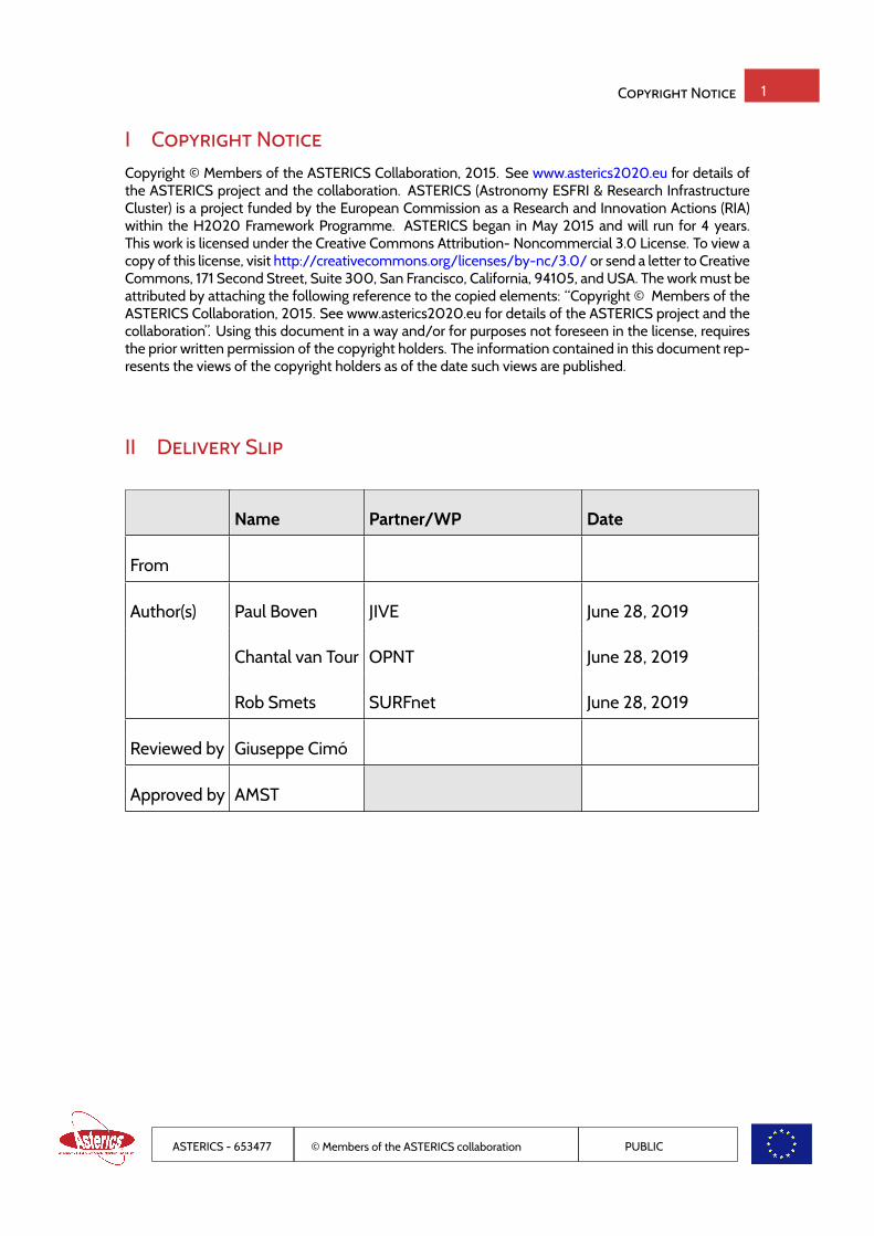
1 IntroductionIn this deliverable, we aim to demonstrate the suitability of the White Rabbit protocol to deliver a verystable and accurate reference clock. In particular, we attempt to bring the signal from the hydrogenmaser reference at the Westerbork Synthesis Radio Telescope (WSRT) to the Dwingeloo Telescope,and to LOFAR, co-existing on an already existing optical network with other traffic. Very Long BaselineInterferometry (VLBI) observations using this transported reference clock are then used to demonstratethe achieved stability.The original design of White Rabbit (WR) was aimed at synchronizing the beam control electronics ofthe LHC at CERN, with the goal of achieving sub-ns performance on links of up to 10km distance. CERNpublished their design as open hardware, and it has since become a very successful project. Accuratedistribution of time and frequency are important challenges for any observatory, and make this an im-portant question for multi-messenger astronomy. The frequency stability requirements for VLBI areparticularly challenging, as it requires coherence at microwave frequencies, at timescales of up to tensof minutes. Only a hydrogen maser can comfortably meet these requirements, but at a significant cap-ital expense. The ability to share such a stable reference signal over existing fibre links makes this a veryinteresting solution for any kind of observatory.The performance of White Rabbit as standardized by CERN doesn’t quite meet the requirements forVLBI. The frequency noise performance of the WR switches has been improved by the design of a LowJitter Daughter-boards (Rizzi et al. 2018), which we installed in our equipment. Additionally, a clean-up oscillator was included in the White Rabbit switch at the telescope, as described in our ASTERICSdeliverable D5.4 (Koelemeij and van Tour 2017). The supported link distance was improved by the useof long haul DWDM SFPs and bi-directional optical amplifiers (BDOAs). The use of DWDM SFPs re-quires the use of external optical multiplexers. Choosing wavelengths that are close together reducesthe asymmetry of the fiber link due to its dispersion, and reduces the sensitivity to fiber temperaturechanges.The WR links that were built for this research have already been described in our ASTERICS deliver-able D5.7 (van Tour et al. 2018). Two links between the Westerbork Synthesis Telescope (WSRT) andDwingeloo Telescope (DT) were provisioned: one that utilizes the SURFnet DWDM production fibreinfrastructure (link length of 169 km, via Groningen), and a direct dark fibre link (35 km). As part of thework in this deliverable, the long link was later changed to connect the LOFAR radio telescope to theWSRT, too. For reference, we include in figure 1 the link diagram from D5.7.
Figure 1: White Rabbit Links between the WSRT, DT and LOFAR
ASTERICS - 653477 © Members of the ASTERICS collaboration PUBLIC

White Rabbit Link Setup 6
2 White Rabbit Link Setup2.1 Co-existing TFT service in a carrier networkWhen a TFT service, such as the White-Rabbit based DWDM high precision TFT service, is to be de-ployed, either a dedicated fiber must be provided or the TFT service must "piggy-back" on existingservices. The latter becomes an absolute requirement when fiber cost plays an important role.In conventional DWDM transport systems, a dual fiber infrastructure is used. This means a span fromlocation A to B contains two fibers. One fiber is used to transmit light from A to B and the other fiberfrom B to A. In rare occasions a single fiber is used containing counter-propagating light from A to B andB to A in this one fiber to implement bi-directional data transport. In the case of the White-Rabbit TFTservice bi-directional data transport using counter-propagating light is essential to reduce uncertaintywhen correcting time at the slave with half the round-trip delay.Relevant parts of the current network for the connections between ASTRON in Dwingeloo, Westerbork(a.k.a. Zwiggelte), and Groningen, are depicted in Figure 2.
Figure 2: Topology of the SURFnet core network in the Northern branch.
The green symbols indicate components such as EDFAs, ROADMs and Add/drop structures, transpon-ders, and light sources from old production equipment, that belong to the DWDM production network.The final component that is used to gain access to the line fibers is called the CT-filter and is used tocombine and split the DWDM production uni-directional signals from other signals such as the uni-directional optical supervisory channel (OSC) and the bi-directional TFT signals.
2.2 Network setup for both the VLBI and LOFAR TFT serviceIn this project two Proof of Concepts (PoCs) were selected. In one case the TFT service is to synchronizethe radio telescoipe in Dwingeloo and in the other case the LOFAR antenna field in Exloo. In both casesthe reference clock is the hydrogen maser atomic clock located at the Westerbork Synthesis Radio Tele-scope (WSRT). This section describes the common infrastructure for these two applications while thenext two sections describe the infrastructure of the LOFAR application and VLBI application, respec-tively. Figure 3 displays how the master White Rabbit switch is connected to the production networkof SURFnet. Under normal conditions the production network uses the 1511nm window to implementan Optical Supervisory Channel (OSC) service for out-of-band management. In this scenario, the OSChas been implemented on 1591nm in order to make the 1511nm band available for the two white rabbitsignals: 1511.8nm from master to slave and 1511.0nm from slave to master (return channel). In order tomultiplex the White Rabbit signal with the OSC signal a 1511nm mux/demux is used. This multiplexedsignal is then inserted in the line filter with the DWDM production traffic and launched into the line fiber
ASTERICS - 653477 © Members of the ASTERICS collaboration PUBLIC

White Rabbit Link Setup 7
Figure 3: Master White-Rabbit switch in Zwiggelte (zwt001a) transmits light towards Groningen (gn012a) and receives light fromslave switches in either Exloo for the LOFAR TFT service or Dwingeloo (dgl001a) for the VLBI CAMRAS TFT service.
going to Groningen. In Groningen the reverse operation takes place (See Figure 4) and the fiber contain-ing both counter propagating TFT signals is connected to the BDOA amplifier. Note that the conventionused here is that we the signal as if it were uni-directional in the direction from Master to Slave. In thisdirection the labeling on the filters, amplifiers and bidi-filters agrees with the direction of propagation.At the output of the bi-directional optical amplifier, an ODF allows the signal to be patched to either a
dark fiber going to LOFAR (Exloo) or back towards Zwiggelte and then further to Dwingeloo (using thesecond fiber of the fiber pair).
2.3 Network setup for the LOFAR TFT serviceIn the case the signal in Groningen is patched towards LOFAR in Exloo, the signal terminates at a slaveWhite Rabbit switch in Exloo. The recovered time and frequency can then be used to synchronize thedifferent antenna fields to the frequency and time source in Zwiggelte. From a transport perspectivethis is a simple termination. The schematic can be found in Figure 5
2.4 Network setup for the VLBI CAMRAS TFT serviceIn the case the signal is to be delivered for the VLBI CAMRAS application, the amplified master-slavesignal is patched back to Zwiggelte using the second fiber of the pair between zwt001a and gn001a. Thesignal arriving in Zwiggelte needs to be amplified before it can be launched towards its final destinationDwingeloo. This is done as depicted in Figure 6.Finally in Dwingeloo the slave White Rabbit switch can detect the signal from the master and transmitthe return channel to the master switch.
2.5 Link design and operationFor these two PoCs three different Optical Transmission Sections (OTS), or spans, have been used. Inorder to facilitate link engineering using the BDOA amplifiers with equal gains, fixed-attenuators (pads)have been added to make the total loss of each OTS equal. The only exception is the span that connectsto a receiving photo-diode as receiving more optical power improves performance and makes the sys-tem less vulnerable to the polarization dependent loss of the semi-conductor optical amplifier basedBDOAs. With gain settings of around 20dB-24dB and input powers around -20dBm the launch powerinto the optical fiber varies under normal conditions between -2dBm and +2dBm, making the systeminsensitive to Amplified Spontaneous Emission (ASE), without invoking fiber non-linear distortion.
ASTERICS - 653477 © Members of the ASTERICS collaboration PUBLIC

White Rabbit Link Setup 8
Figure 4: TFT amplifier station in Groningen (gn012a). In Groningen it is possible to patch the service to Exloo for the LOFARapplication or back to Dwingeloo (gdl001a) via Zwiggelte for the VLBI CAMRAS application
Figure 5: Slave White-Rabbit switch in Exloo receives light from the master switch in Zwiggelte and transmits light towards themaster switch.
Figure 6: Amplification in Zwiggelte (Westerbork)
ASTERICS - 653477 © Members of the ASTERICS collaboration PUBLIC

White Rabbit Link Setup 9
Figure 7: Slave White-Rabbit switch in Dwingeloo (dgl001a) receives light from the master switch in Zwiggelte looped back viaGroningen and transmits light towards the master switch.
ASTERICS - 653477 © Members of the ASTERICS collaboration PUBLIC
Timing Calibration 10
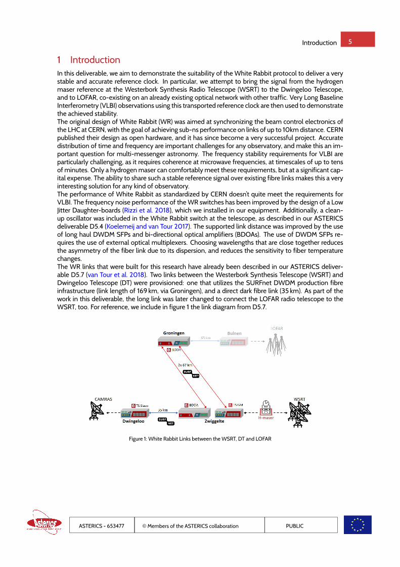
3 Timing CalibrationAs described in ASTERICS deliverable 5.7 (van Tour et al. 2018), a WR link contains delay asymmetries,causing a phase offset between a grandmaster (GM) and slave WR switch. This phase offset, skew, isgiven by
skew =δms − δsm
2, (1)
where δms is the upstream master-to-slave (ms) delay and δsm is the downstream slave-to-master (sm)delay. The delay asymmetries are measured and corrected for in such a way that the phase offset be-tween the GM and slave WR switch is minimized. Figure 8 shows the lay-out of the WR links betweenZwiggelte and Dwingeloo, including all devices and fiber-optic links that contribute to the phase offsetbetween the WR switches. The next sections describe 1) the device delay asymmetries and 2) the linkdelay asymmetries.
Figure 8: Link lay-out containing all relevant devices for the timing calibration.
3.1 Device delay asymmetriesThe device delay asymmetries are caused by
• electrical-electrical delay asymmetries in the WR switches
• optical-electrical delay asymmetries in the SFPs
• optical-optical delay asymmetries in the optical multiplexers and BDOAs
CERN developed calibration techniques to measure and correct for these device delay asymmetries(Daniluk 2015). These techniques are used to calibrate the WR switches and optical devices, as was pre-viously described in deliverable 5.7 (van Tour et al. 2018). The WR switches were calibrated by measur-ing and correcting for the phase offset between the WR GM and the WR slaves, while the WR switcheswere directly connected to each other using short patch-cords. The phase offset was measured with aStanford Research SR620 time interval counter. The uncertainty in the final phase offsets between theWR GM and each WR slave is based on the 25 ps (coverage factor k = 1) resolution of the SR620 timeinterval counter (SRS) and the WR restart jitter of 12 ps (k = 1). The total uncertainty of 30 ps (k = 1) iscalculated with the square root of the quadratic sum of the uncertainties,
σWR GM - WR Slave =√σ2
SR620 + σ2WR restart. (2)
The optical devices that are part of the 169 km link (Zwiggelte-Groningen-Zwiggelte, Fig. 8) were delay-calibrated within OPNT premises. Table 1 lists all the measured optical device delay asymmetries. This
ASTERICS - 653477 © Members of the ASTERICS collaboration PUBLIC

Timing Calibration 11
table also lists a total uncertainty in the phase offset between the WR GM and WR slave 1 ofσoptical devices =31 ps (k = 1). JIVE reported that the optical multiplexers in the 34 km link (Zwiggelte-Dwingeloo) do notadd significant delay asymmetries.
Table 1: overview of the optical device delay asymmetries for the 169 km link.
Device Serial number Location Skew (ps)
Optical Multiplexer (Mux) TF2018000020 Zwiggelte −38± 12
Optical de-Multiplexer (deMux) TF2018000023 Dwingeloo 37± 12
Bi-Directional Optical Amplifier (BDOA) TA2017000014 Zwiggelte −1016± 15
Bi-Directional Optical Amplifier (BDOA) TA2017000013 Groningen 887± 21
Total −130± 31
3.2 Link delay asymmetriesApart from the delay asymmetries caused by the optical devices, long-haul fiber-optic links (> 1 km) alsoadd significant delay asymmetries. This is caused by the chromatic dispersion (CD) of the fiber-opticlink. This CD causes a temporal delay difference between traveling signals with different wavelengths.This delay difference between any two wavelengths, λ1 and λ2, is given by
δ2 − δ1 = L∫ λ2
λ1
D(λ)dλ, (3)
where D(λ) is the dispersion of the fiber-optic link, and L is the length of the fiber-optic link. Since theWR links use two different wavelengths for the upstream (λms) and downstream (λms) signals, the CDcauses a phase offset between the GM and slave WR switch. This phase offset can be written in termsof the CD by combining Eqs. 1 and 3,
skew|CD =L2
∫ λms
λsm
D(λ)dλ. (4)
As becomes clear from this equation, the CD induced phase offset between the GM and slave WRswitch is directly proportional to L, while the CD itself is not proportional to L. In order to treat the CD-induced delay asymmetry purely as a property of the fiber’s material, the WR switches use the followingdimensionless α parameter,
α ≡ δms, fiber − δsm, fiber
δsm, fiber. (5)
This α parameter, in combination with a round-trip delay measurement, is then used to calculate andcorrect for the CD-induced phase offset between the WR GM and WR Slave. Since the round-trip delayis frequently updated, any possible change in the fiber-optic link length does not require a new calibra-tion.
To determine the α parameter of the link between Zwiggelte and Groningen (G652.D fiber), WR Slave 1was temporarily placed in Zwiggelte. This allowed us to directly measure the phase offset between theWR GM and WR Slave 1, skew|CD, while inserting the fiber-optic link. The exact procedure and results ofthis calibration are described in deliverable 5.7 (van Tour et al. 2018).
ASTERICS - 653477 © Members of the ASTERICS collaboration PUBLIC

Timing Calibration 12
Figure 9: Schematic of the link lay-out that is used for calibration of the 1511.81/1511.05 nm Zwiggelte-Dwingeloo link. An extra 2m of coax cable is added to the PPS output of WR Slave 2 to make sure that the time interval counter readings are always positive.The SURFnet equipment is not depicted.
The determination of the α parameters of the Zwiggelte-Dwingeloo (G655.D fiber) links required a dif-ferent method, described in (Boven 2017). Figure 9 shows a schematic of the setup that was used forthe calibration of the 1511.81/1511.05 nm Zwiggelte-Dwingeloo link. During the calibration, WR Slave 2was used as a stable reference, while the upstream and downstream wavelengths of the 1511.81/1511.05nm link were interchanged. While doing so, the round-trip delay (δ) of the 1511.81/1511.05 nm link andthe phase offset between the two WR slave switches were measured with the SR620. The difference inphase offsets between measurement 1 (skew1) and measurement 2 (skew2), together with the measuredδ, give sufficient information to calculate α. This is possible, because α (Eq. 5) can be re-written (usingsome basic algebra) into (Daniluk 2015):
α = 2skew|CD
12δ − skew|CD
, (6)
with
skew|CD =skew2 − skew1
2. (7)
This equation is used to calculate the α parameter of the optical link for wavelengths 1511.81 nm and1511.05 nm. Similarly, the calibration of the 1560.61/1558.59 nm link was performed by using WR Slave1 as a reference, while swapping the upstream and downstream wavelengths of the 1560.61/1558.59nm link.
The uncertainty in the calculated α parameter is given by
σα =
√∣∣∣∣ ∂α
∂skew|CD
∣∣∣∣2 σ2skew|CD
+∣∣∣∣∂α∂δ
∣∣∣∣2 σ2δ
=4
(δ − 2skew|CD)2√δ2σ2
skew|CD+ skew|2CDσ
2δ
(8)
Since skew|2CDσ2δ � δ2σ2
skew|CDand skew|CD � δ, the uncertainty in α can be simplified to
σα ≈ 4σskew|CD
δ. (9)
So, it turns out that the uncertainty in α is determined by the uncertainty in skew|CD. This uncertainty iscalculated with (using Eq. 7):
σskew|CD =12
√σ2
skew1+ σ2
skew2. (10)
ASTERICS - 653477 © Members of the ASTERICS collaboration PUBLIC

Timing Calibration 13
The uncertainties in these phase offset measurements (skew1 and skew2) are (just as in section 3.1) basedon the resolution of the SR620 time interval counter and the restart jitter of the WR switches. Therefore,Eq. 10 can be rewritten into:
σskew|CD =12
√2σ2
SR620 + 2σ2WR restart. (11)
Inserting the values mentioned in section 3.1 into equation 11 results in an uncertainty of 20 ps. How-ever, the actual calibration measurements resulted in somewhat larger uncertainties (see Table 2). Thoselisted uncertainties are used in further calculations.
Table 2 lists a complete overview of all the results from the link delay asymmetry measurements. Thistable also provides a value of the estimated CD values, D. These values are estimated by assuming aconstant CD over the measured wavelength range (∆λ = λms − λsm). This allows us to rewrite Eq. 4 interms of D into
D ≈ 2skew|CD
L∆λfor λ = λms...λsm. (12)
The uncertainties in these estimated CD values are calculated with
σD =
√∣∣∣∣ ∂D∂skew|CD
∣∣∣∣2 σ2skew|CD
+∣∣∣∣∂D∂L
∣∣∣∣2 σ2L +∣∣∣∣ ∂D∂∆λ
∣∣∣∣2 σ2∆λ
=|D|
√∣∣∣∣ σskew|CD
skew|CD
∣∣∣∣2 +∣∣∣σL
L
∣∣∣2 +∣∣∣σ∆λ
∆λ
∣∣∣2.
(13)
To calculate these uncertainties, σL (50 m, k = 1) and σ∆λ(50 pm, k = 1) are estimated using the speci-
fications of the fiber-optic links and SFPs, respectively.
The estimated CD values are all in accordance with the ITU recommendations (ITU-T G.652; ITU-TG.655). To illustrate this, Fig. 10 shows the estimated CD value for the G652.D (Zwiggelte-Groningen-Zwiggelte) fiber-optic link and the estimated CD values for the G655 (Zwiggelte-Dwingeloo) fiber-opticlink, together with ITU recommendations (colored areas). In case of the G652.D fiber, SURFnet alsoprovided more accurate CD measurements (dashed line).
Table 2: overview of the properties of the fiber-optic links, and the measured link delay asymmetries. All listed uncertainties arereported with k = 1.
Link Zwiggelte-Groningen-Zwiggelte Zwiggelte-Dwingeloo Zwiggelte-Dwingeloo
(Zwt-Gn-Zwt) (Zwt-Dwg) (Zwt-Dwg)
Fiber Type G652.D G655 G655
λmaster (nm) 1511.81 1511.81 1560.61
λ slave (nm) 1511.05 1511.05 1558.59
Length (km) 133.64± 0.05 34.37± 0.05 34.37± 0.05
skew|CD (ps) 544± 47 45± 38 116± 12
δ (ps) 1311048015± 100 34309488± 17 343197646± 56
D (ps/(nm km)) 11± 2 4± 3 4± 1
α (17± 2)× 10−7 (5± 4)× 10−7 (14± 2)× 10−7
ASTERICS - 653477 © Members of the ASTERICS collaboration PUBLIC

Timing Calibration 14
Figure 10: Estimated CD values in comparison with the ITU recommendations and SURFnet data.
3.3 Overall timing performanceTo check the timing performance of the WR links, the PPS outputs of the WR slaves (see Fig. 8) arecompared with each other, using the SR620. The remaining phase offset between the two PPS outputsof the WR slaves is (370 ± 30) ps with k = 1, where tslave1 < tslave2. The total uncertainty on this phaseoffset, due to mentioned calibration uncertainties, can be calculated with:
σ =√σ2
WR GM - WR Slave 1 + σ2WR GM - WR Slave 2 + σ2
optical devices + σ2Zwt-Gn-Zwt, 1511 + σ2
Zwt-Dwg, 1511 + σ2Zwt-Dwg, 1560
σ =√
302 + 302 + 312 + 472 + 382 + 222 = 90 ps.(14)
This uncertainty analysis does not account for the (−370 ± 30) ps measured offset between the twoWR Slaves. However, there are a still multiple origins of uncertainty not taken into account. Theseare not included in the calculations, because more research is needed to quantify those uncertainties.One of those extra origins of uncertainty comes from the wavelength drift of the SFPs. The calibra-tion of the Zwiggelte-Groningen-Zwiggelte link was performed in August 2018, while the calibrationof the Zwiggelte-Dwingeloo was performed in March 2019. The transmitted wavelengths of the SFPsthat are used in the link could have drifted in the meantime. Furthermore, the calibration performedat Zwiggelte-Dwingeloo required two pairs of SFPs, of which only one pair of SFPs is used in the finalsetup. Any difference in wavelength of the SFPs will contribute to the uncertainty in the link calibration.The extra uncertainty between the two WR slaves due to uncertainty in the transmitted wavelength ofthe SFPs is estimated at∼40 ps (k = 1), using Eq. 4 together with the estimated CD values from Table 2and σ∆λ
of 50 pm (k = 1). Another uncertainty that is not exactly known comes from the SR620 timeinterval counter. Temporal variations in the asymmetry between the two channels of the TIC wouldincrease the uncertainty in the results. The 25 ps uncertainty that was used as an uncertainty for theSR620 does not include such type of variation. Further research should be performed to analyze theexact contribution of the SR620 to the total uncertainty budget.
In conclusion, the WR links are calibrated with better than 1 ns uncertainty with respect to each other. Areal verification of the timing performance would require an extra Dwingeloo-Zwigggelte link such thata loop can be created and the WR slaves can be directly compared with the WR GM.
ASTERICS - 653477 © Members of the ASTERICS collaboration PUBLIC
VLBI with the WR link 15
4 VLBI with the WR linkThe main goal of this deliverable is to demonstrate the suitability of our WR system to distribute thereference clock with sufficient stability to perform VLBI observations, specifically between the Wester-bork Synthesis Ratio Telescope (WSRT) and the Dwingeloo Telescope (DT). The WSRT is an operationalradio telescope which participates regularly in VLBI observations as part of the European VLBI Network(EVN). The DT, in contrast, has been decommissioned and is now a listed national monument. It is runby the volunteers of the CAMRAS (C.A. Muller Radio Astronomy Station) foundation. Although it is usedregularly to observe e.g. pulsars and the hydrogen line, it lacks the essential equipment to perform VLBIobservations.
4.1 VLBI RequirementsVLBI is one of the more challenging observational methods within radio astronomy. Part of the chal-lenge is that the cross correlation fringe will vanish if frequency, stability, time, pointing or location arewrong, without providing a clue as to the cause of the failure. The list below summarizes what is re-quired to participate in VLBI observations, with the major items worked out in subsequent sections ofthis chapter.
• Radio Telescope, with sufficient sensitivity
• Frequency Reference, with sufficient phase stability
• Time Reference, accurate to a few µs
• Receiver, tunable, with tens to hundreds of MHz of bandwidth
• Backend, to digitize and timestamp the received signal
• Location and geometry of the telescope, accurate to a fraction of the observing wavelength
• RF Noise source, for calibrating the telescope sensitivity
• Field system, to steer the telescope to a source, and control the observation
The precise location of the DT has been established a few years before in a professional GPS survey.For its geometry (distance between the azimuth and elevation axes), we use the values from the radiotelescope in Defford (UK), which is an exact copy of the DT. We decided to do without the noise source,because amplitude calibration is required for imaging VLBI observations, but we are only interestedin the frequency stability performance at this stage. Likewise, as only simple observations targeting asingle source are foreseen in this deliverable, we skip installing a ‘field system’, and instead control thetelescope and VLBI equipment manually.
4.2 Frequency Reference StabilityIn this project, the DT will use the WSRT’s hydrogen maser as its frequency and time reference, trans-ported by WR. To demonstrate the long term phase noise performance of the link, we conducted severalVLBI astronomical observations. As a criterion for success, we use the same requirements as adoptedfor the design of the VLBI capability of the future SKA, i.e. a coherence loss (due to the clock distribution)of less than 2%, for integration times of 1 s and 60 s. The SKA1-Mid requirements are based on a highestobserving frequency of 13.8 GHz. The Dwingeloo telescope, due to its mesh dish surface, stops beinguseful above 8 GHz, but meeting the SKA design requirements would show the general applicability ofthe WR frequency transfer.The first long distance link we had working for this project was the round-trip from the WSRT to Gronin-gen, and back. As described in deliverable D5.7, we performed a loop-back test on this link, whichshowed an ADEV of approximately 10−12 at 1 s integration time. For reference, the figure from deliver-able D5.7 is repeated below.The coherence loss requirement can be converted into an Allan deviation (ADEV) value. This conversioncan be done analytically only in the case of white phase noise (ADEV slope of −1) or white frequencynoise (ADEV slope of − 1
2 ). As already determined during D5.7 (see figure 11), we measured a slope of
ASTERICS - 653477 © Members of the ASTERICS collaboration PUBLIC

VLBI with the WR link 16
Figure 11: ADEV (left) and MDEV (right) of the 2x 67 km loopback test. Red: measured with 50 Hz bandwidth. Blue: same, 0.5 Hzbw. Black: H-maser performance specifications from sales literature. Green: PPS measurements. Brown: clean-up oscillatorstand-alone performance. Gray: 3120A noise floor.
−1, which means that the WR link is in the white phase noise regime. For an observing frequency of upto 13.4 GHz, this requires an ADEV of 2.8 · 10−12 at one second on the link (Alachkar et al. 2018), whichwe do indeed (just) meet.
4.3 A COTS VLBI receiver and backendA VLBI backend digitizes (samples) the signals within the observed radio bandwidth and adds accuratetimestamps, so the data can later be aligned with that of the other radio telescopes, and correlated. PastVLBI digitizers would use analog filters to divide the observed bandwidth into smaller sub-bands beforedigitizing, whereas modern backends will sample the full bandwidth, and use digital signal processing togenerate the sub-bands. The bottleneck in VLBI observations is usually in storage capacity or networkingbandwidth. Using fewer bits to represent the samples allows for a higher observed bandwidth, but alsoresults in higher quantization noise. Most VLBI recordings use only 2 bits per sample to get the bestsensitivity.
(a) The Ettus X310 SDR (b) The TwinRX Receiver Module
Figure 12: COTS hardware for the VLBI Receiver/Backend (source: Ettus website)
As no VLBI backend was readily available for the DT, we chose to implement our own using a com-mercial off the shelf (COTS) software defined radio (SDR). Due to its high bandwidth, modularity, andinputs for PPS and 10 MHz reference signals, the Ettus Research X310 was selected. Another advan-tage of the X310 is the relatively large capacity of its FPGA, which enables offloading some of the VLBI
ASTERICS - 653477 © Members of the ASTERICS collaboration PUBLIC

VLBI with the WR link 17
processing to it. The X310 is a modular SDR, and for its receiver, we selected a pair of ‘TwinRX’ mod-ules, for their bandwidth and built-in filtering. These modules can be tuned to any frequency between10 MHz and 6 GHz, and together provide up to 320 MHz of bandwidth, or 160 MHz on two polariza-tions. For Nyquist sampled 2 bits data, this RF bandwidth would correspond to a VLBI backend outputof 1.28 Gb/s.GNU Radio is an open source software ecosystem for software defined radio (SDR). It contains opti-mized implementations of many important SDR blocks for signal processing such as filtering and Fouriertransforms. The GNU Radio Companion (GRC) is its graphical user interface, which makes it possibleto construct complicated signal processing processes as a flow-graph of interconnected blocks. Wedeveloped a flow-graph to process the recorded samples from the backend and generate VLBI DataInterchange Format (VDIF) compliant data.
Figure 13: GNU Radio VLBI Flowchart
4.3.1 Detailed flowgraph description
Recordings from the X310 SDR are at 100 MS/s, complex (interleaved I and Q) shorts (16 bits), with anactual bandwidth of 80 MHz. In the flow-graph (figure 13), such a recording is read by the ‘File Source’block at the top left. The interleaved shorts are subsequently converted to complex floating point num-bers, and then re-sampled in the ‘Rational Resampler Base’ block to 80 MHz bandwidth. The ‘MultiplyConjugate’ and ‘Signal Source’ block together shift the spectrum up by 8 MHz. The ‘Polyphase Chan-nelizer’ subdivides the recorded spectrum in five bands of 16 MHz each. Due to the earlier frequencyshift of 8 MHz, the band edges end up together in a single sub-band, and are discarded in the ‘Null Sink’block. The remaining four sub-bands are each 16 MHz wide, for a total observed bandwidth of 64 MHzin a single polarization.Each sub-band is then passed through a set of three blocks, where the sampling rate is doubled (‘In-terpolating FIR filter’), shifted up by 8 MHz by the ‘Multiply Conjugate’ block, and then the imaginarypart of the signal is dropped. This sequence converts each sub-band from complex, via analytic, to real(upper side band) at twice the sampling rate, to be compatible with the JIVE SFXC correlator. The ‘Inter-leave’ block sequences groups of 32000 samples together, to get packets with 8000 bytes of payload.Re-quantizing the data to 2 bits per sample is done in two stages: first the floating point numbers areconverted to 8 bit numbers (‘chars’), and then the ‘Map’ block forms a look-up table with 256 entries.This two stage approach turned out to be necessary to sidestep a small bug in the quantization of small
ASTERICS - 653477 © Members of the ASTERICS collaboration PUBLIC

VLBI with the WR link 18
numbers that was present at that time in GNU Radio.GNU Radio offers the ability to create custom blocks in C++ or Python, that can be integrated intoflowcharts. The block ‘vdif_packetize’ is a custom block created to add VDIF headers to the VLBI data.These headers contain details such as the station code (‘DW’ for Dwingeloo), a timestamp, and fieldsdescribing which channel is contained in each packet. Adding the VDIF header makes the VLBI datacompatible with most VLBI correlators, including the SFXC correlator at JIVE.Given the high data throughput of VLBI observations, and all the filtering steps in the flowchart, it is notsurprising that even a modern PC cannot perform this work in real-time. On a high-end workstationequipped with an Intel i9900K CPU, NVME SSD and 64 GB of RAM, it achieves a speed of about 20%of real time.The custom module, and VLBI flowchart, have been released by us as open source software under theGPL, and are available on the ASTERICS repository, and Github.
4.4 Dwingeloo Fringes, AgainThe Dwingeloo telescope participated in the first European VLBI tests in 1978 (Schilizzi et al. 1979), butthe WSRT soon took over as the Dutch VLBI telescope. On August 29th 2018, 40 years after its initialVLBI observations, we obtained fringes again with the Dwingeloo telescope, to both the WSRT, and theMark2 telescope at Jodrell Bank Observatory (JBO) in the UK. All three telescopes observed the source4C39.25 at 1332.49 MHz. Dwingeloo only observed in left-hand circular polarization (LCP), generatingfour sub-bands of each 16 MHz. Due to the high output rate of the backend, the data could only berecorded to RAM, limiting recording times to 10 s. As the WR link was not in place yet, a Rubidiumatomic clock (FS725) was used as a time base for the DT, while the other participating stations usedtheir hydrogen masers. Our GNU Radio flowchart was used to convert the recorded samples for the DTinto VDIF data. Correlation was performed on the SFXC correlator at JIVE. Fringes were obtained rightaway, in all four sub-bands.
Figure 14: The Astron/JIVE daily image, showing the fringes and participating telescopes
This milestone in the project was published as a ’ASTRON/JIVE daily image’, and a poster and paper forthe EVN Symposium in Granada.
4.5 The Last MileThe Dwingeloo telescope is only 60 m away from the ASTRON building, and already connected to it bymulti-mode optical fibre. White Rabbit however requires single mode fibre, and an upgrade of the fibre
ASTERICS - 653477 © Members of the ASTERICS collaboration PUBLIC

VLBI with the WR link 19
connection was also required to support the higher networking bandwidths generated by VLBI. Theeasiest route between the telescope and the SURFnet connections in the basement of the ASTRONbuilding turned out to be 275 m long, of which about 100 m is inside the building. ASTRON was kindenough to donate 510 m of G.652.D glass-fibre to the project, left over from the recent upgrade to theWSRT. Only about 100 m of actual digging was required.
(a) Digging the trench (b) Conduit (c) Installing the fibre cable
Figure 15: CAMRAS volunteers running new fiber
In December 2018, we rented a small digger, and a large group of CAMRAS volunteers joined to helpwith the groundwork. We installed specialized conduit for the glass fibre (as this wasn’t rated for outdooruse without protection), placed warning tape above it, and closed the ground again. Two months later,the fibre itself was run through the conduit. Further work included a new fibre path inside the telescope,including a flexible ‘cable wrap’ around the azimuth axis of the telescope, so there would be no stresseson the fibre while turning the telescope. Finally, to complete the connection, the fibres had to be splicedtogether just outside the telescope, and connectorized at both ends of the run, all of which took severaldays to complete. In March, we had the link complete, and finally were able to connect the WR linkfrom the WSRT maser, to the Dwingeloo telescope.
4.6 Parallel Link testAt this stage in the project, we had three operational WR links between WSRT and the DT. We had twolinks of 35 km dark fiber running directly between the two observatories, and the 169 km link through theSURFnet DWDM network. The shorter links had been used to calibrate the dispersion on the WSRT-DTlink (see previous chapter), and will remain in place after the project. Furthermore, we had a WR switchwith, and without cleanup-oscillator available in the DT. This allowed the opportunity to measure thedifferential performance between two links, albeit without the cleanup oscillator on one of them.As the ADEV measurement in this case is the relative performance between two links, the requiredADEV for less than 2% coherence loss becomes
√2×2.8 · 10−12 = 4.0 · 10−12, which the system meets
with a small margin.These measurements were carried out using a MicroSemi 3120a phase noise analyzer, and two WRswitches, one of which was equipped with a clean-up oscillator. As can be viewed in figure 16, there isno discernible difference in performance between the 35 km (blue line) and 169 km link (purple), whencompared against the other 35 km link. Not having a cleanup oscillator (green line) seems to make onlya small difference, but this is because there was only one WR switch with cleanup oscillator, so all mea-surements (with or without cleanup oscillator) are relative to a switch without cleanup, and thereforedominated by the phase noise contributions of the WR switch without cleanup oscillator.
4.7 VLBI ObservationsOn March 8th 2019, the Dwingeloo telescope joined in a regular EVN network measurement exper-iment (NME), named N19L1. Twenty telescopes participated in this observation. With the new fibreconnection, the DT VLBI backend could be connected at 10 Gb/s to a JIVE server for recording the data,removing the earlier limit of ten seconds of observation time. EVN L-band observations are mostly at
ASTERICS - 653477 © Members of the ASTERICS collaboration PUBLIC

VLBI with the WR link 20
Figure 16: Relative ADEV between two parallel WR links
18 cm, whereas the Dwingeloo telescope L-band receiver is for 21 cm. Participating in this observationrequired that the CAMRAS volunteers installed new low-noise amplifiers for the 18 cm band, which wascarried out despite the rather poor weather, with rain and high winds. Fringes between the DT and manyof the participating stations were detected, in our first observation using the remote hydrogen maser.The gain of the new LNAs was a bit lower than expected, causing significant sensitivity loss, which didimpact the signal to noise of the Dwingeloo fringes.
(a) Channel 1, LSB (b) Channel 1, USB (c) Channel 2, LSB (d) Channel 2, USB
Figure 17: Dwingeloo - Effelsberg fringes, N19L1
To better study the VLBI performance of the new WR link, a number of small VLBI observations werescheduled, with the VLBI stations WSRT, Jodrell Bank and Torun participating in these tests. These werecarried out at around 1330 MHz, where the DT has better sensitivity, but still away from the Galactichydrogen line. Each observation targeted 3C84, a bright, compact source at L-band.In order to measure the frequency stability, we use the JIVE SFXC correlator to calculate the phase oneach of the baselines between the telescopes, at integration times of 1 s. These phase values are thenconverted into timing differences at the observing frequency, and from this, the Allan deviation is cal-culated. We expect the phase noise measured in such a fashion to be higher than the directly measuredphase noise performance of the link itself. Otherwise, the clock distribution system itself would be thelimiting factor for the phase sensitivity, and hence limit the VLBI observations. Random fluctuationsin the troposphere and ionosphere will cause uncorrelated phase errors on timescales beyond a fewminutes. This destroys the phase coherence between distant VLBI stations, and will cause the ADEV toincrease at averaging times beyond a few minutes.Figure 18a shows the measured ADEV of the fringe between the WSRT and the DT. This observationconsisted of two scans of 90 minutes each. The included line graphing the link performance (measureddirectly) demonstrates that the VLBI is not limited by the clock stability. At longer timescales, the resultsare determined by ionospheric effects and source structure, as expected.
ASTERICS - 653477 © Members of the ASTERICS collaboration PUBLIC

VLBI with the WR link 21
(a) FT032 (Dwingeloo - WSRT) VLBI ADEV (b) FT033 (Dwingeloo, JBO, WSRT) VLBI ADEV
Figure 18: VLBI measurements, expressed as ADEV
During FT033, the final VLBI observation of this project, we had access to a second USRP and WRswitch, allowing a direct comparison between different WR links. The radio telescopes in Jodrell Bankand Torun were kind enough to also participate in this observation, although the Torun data turned outto have phase jumps, and no valid ADEV measurements could be extracted from it.Figure 18b shows several measurements extracted from this observation. From lowest to highest ADEV,these are: Zero baseline (Dwingeloo receiver 1 against Dwingeloo receiver 2) carried out with a 35 kmlink against 35 km (purple line) and 169 km (green), showing no significant difference in performance.Fringes between the WSRT telescope and the two Dwingeloo receivers on each of the links show evenless difference (blue, orange). The final three lines show the results on the baselines with Jodrell Bank,versus the long link (station Dw, yellow), the short link (station D2, green again) and the WSRT (Red).Comparing these results shows that the fringes between the WSRT and Jodrell Bank have a slightlybetter performance, but this is likely due to their better sensitivity compared to Dwingeloo, as at longertimescales, the results are nearly the same.
ASTERICS - 653477 © Members of the ASTERICS collaboration PUBLIC

LOFAR WR Connection 22
5 LOFAR WR ConnectionOnce the WR connection to the Dwingeloo telescope had been fully tested and characterized, it wastime to connect LOFAR to the hydrogen maser at the WSRT as well. The SURFnet link was reconfiguredto run from the WSRT, via Groningen (where the signal is amplified optically), to the LOFAR concentratornode in Exloo. We installed a White Rabbit switch (with low jitter daughter board) in the racks and thelink was brought up.
(a) First WR light at LOFAR (b) BDOA in Groningen
Figure 19: Connecting the WR link to LOFAR
For initial verification, the phase of the reference clock output was compared to that of a free runningRubidium clock. In the near future, the WR signal will become the timing reference of the LOFAR tele-scope. However, as this is an operational telescope that is constantly recording science data, such aswitch-over has to be carried out with a lot of care and planning.
ASTERICS - 653477 © Members of the ASTERICS collaboration PUBLIC

Conclusions 23
6 ConclusionsOur results show that, with our adaptations, White Rabbit can co-exist with other services on a produc-tion DWDM network. The timing accuracy of well below 1 ns, and a frequency stability within one orderof magnitude of a hydrogen maser, make this solution a very interesting tool for radio astronomy andother sciences. Our measurements show no performance degretation between the 35 km and 169 kmlink. The VLBI observations have demonstrated that the remote reference clock offers sufficient phasestability to perform VLBI observations. Through these results we have shown that the existing fiber-optic network infrastructure is not only capable of transmitting high-capacity VLBI observational data,but also of distributing a common reference clock to VLBI stations at long distances. The implemen-tation in the form of White Rabbit is especially important in view of the upcoming inclusion of WhiteRabbit in the next IEEE 1588 standard for time transfer.The WR links that have been established to LOFAR and to the Dwingeloo telescope as part of thisproject, will remain in use after the conclusion of the ASTERICS project. This will offer improved timingto both observatories, and allow us to further study the performance of the WR links.Noteworthy in this project was the cooperation of a volunteer organisation (CAMRAS), and their activesupport during the construction of the WR links to the historic Dwingeloo telescope, and during theVLBI observations. This mutually beneficial arangement made it possible to not just measure the phasenoise performance of the links, but to demonstrate that it is indeed sufficient for VLBI observations.
ASTERICS - 653477 © Members of the ASTERICS collaboration PUBLIC

BIBLIOGRAPHY 24
BibliographyB. Alachkar, A. Wilkinson, and K. Grainge. Frequency reference stability and coherence loss in radio
astronomy interferometers, application to ska. Journal of Astronomical Instrumentation, 2018. URLhttps://arxiv.org/abs/1801.05419v1.
P Boven. White Rabbit in Radio Astronomy. ICALEPCS, 2017. URL http://accelconf.web.cern.
ch/AccelConf/icalepcs2017/talks/tucpl03_talk.pdf.G. Daniluk. White Rabbit calibration procedure. November 2015. URL https://www.ohwr.org/
project/white-rabbit/wikis/Documents/White-Rabbit-calibration-procedure.ITU-T G.652. Characteristics of a single-mode optical fibre and cable. November 2016.ITU-T G.655. Characteristics of a non-zero dispersion-shifted single-mode optical fibre and cable.
November 2009.J. C. J. Koelemeij and C. van Tour. Hardware for maser-level time & frequency distribution in public
networks. ASTERICS Deliverable D5.4, 2017.M. Rizzi et al. White rabbit clock synchronization: Ultimate limits on close-in phase noise and short-term
stability due to fpga implementation. IEEE Transactions on Ultrasonics, Ferroelectrics and FrequencyControl, 65:1726–1737, 2018.
R. T. Schilizzi, G. K. Miley, A. van Ardenne, B. Baud, L. Bååth, B. O. Rönnäng, and I. I. K. Pauliny-Toth. Highresolution observation of the compact central component of the giant radio source 3c236. Astronomyand Astrophysics, 77, 1979.
SRS. Measurements with the SR620. URL https://www.thinksrs.com/downloads/pdfs/
applicationnotes/SR620_details.pdf.C. van Tour, R. Smets, P. Boven, R. Maat, P. Smets, J. C. J. Koelemeij, and A. Szomoru. Time Transfer in
SURFnet/LOFAR network & general design rules for network implementation. ASTERICS DeliverableD5.7, 2018.
ASTERICS - 653477 © Members of the ASTERICS collaboration PUBLIC
Related Documents