TECHNICAL MANUAL NATIONAL PRECAST CONCRETE ASSOCIATION AUSTRALIA

Welcome message from author
This document is posted to help you gain knowledge. Please leave a comment to let me know what you think about it! Share it to your friends and learn new things together.
Transcript
T E C H N I C A L M A N U A L
N A T I O N A L P R E C A S T C O N C R E T E A S S O C I A T I O N A U S T R A L I A
H O L L O W C O R E P A N E L S
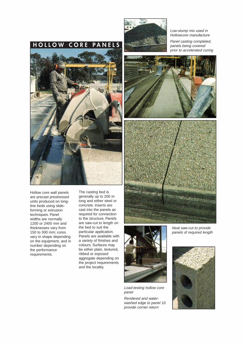
Hollow core wall panelsare precast prestressedunits produced on long-line beds using slide-forming or extrusiontechniques. Panelwidths are normally1200 or 2400 mm andthicknesses vary from150 to 300 mm; coresvary in shape dependingon the equipment, and innumber depending onthe performancerequirements.
The casting bed isgenerally up to 200 mlong and either steel orconcrete. Inserts arecast into the panels asrequired for connectionto the structure. Panelsare saw-cut to length onthe bed to suit theparticular application.Panels are available witha variety of finishes andcolours. Surfaces maybe either plain, textured,ribbed or exposedaggregate depending onthe project requirementsand the locality.
Load-testing hollow corepanel
Rendered and water-washed edge to panel 10provide corner return
Neat saw-cut to providepanels of required length
Low-slump mix used inHollowcore manufacture
Panel casting completed,panels being coveredprior to accelerated curing

Hollow core wall panelsare precast in the factoryaway from the buildingsite. Panels are storedready for delivery to siteas required forinstallation. Manufactureis unaffected by weatherconditions.
Hollow core panels aremanufactured to suit thejob. This gives simple,fast erection - often withonly a three-man crew.Shorter time schedulesreduce risk, cut financecosts and provide anincome-producingbuilding sooner.
F A C T O R Y - C A S T B Y M A C H I N E
R A P I D C O N S T R U C T I O N

S I M P L E C O N N E C T I O N SA N D F I X I N G S
R E D U C E D O N - S I T EL A B O U R
E F F I C I E N T
D U R A B I L I T Y
S E C U R I T Y
L I G H T - W E I G H T S E C T I O N
D E S I G N F L E X I B I L I T Y
The connections and fix-ings use simple cast-inferrules and clips ordowels which connect tothe supporting structure.Expansion anchor boltsand toggle bolts are alsoused.
Only a small erectioncrew is required to installas much as 300 squaremetres per day. Thistypical erection rate canbe improved by theallocation of increasederection resources. Thetime of tradesmen on siteis kept to a minimum.Expensive formwork,scaffolding or temporaryprops are eliminated.
The hollow cores andprestressing result inpanels that are light inweight but strong. Thethickness and the strandpattern can be varied atminimum cost to suit thewall height and loadrequirements.
Panels canaccommodate mostbuilding requirementsincluding openings,roof slopes andcantilever parapets. Concrete quality meets
the durabilityrequirements of AS 3600Concrete Structures.Strand cover may bevaried to suit particularexposure classifications.
Precast prestressedconcrete is inherentlyrobust, secure andvandal resistant.
R E D U C E D S U P P O R T R E Q U I R E M E N T
H I G H L O A D C A P A C I T Y
F I R E R E S I S T A N C E
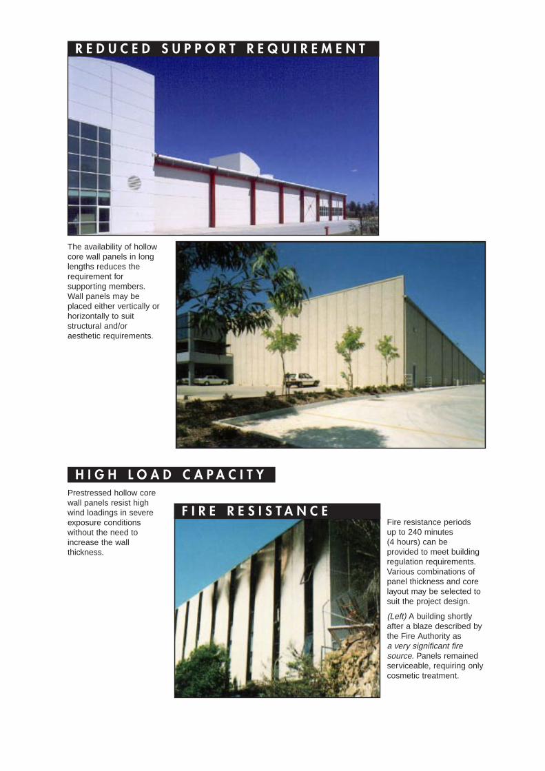
The availability of hollowcore wall panels in longlengths reduces therequirement forsupporting members.Wall panels may beplaced either vertically orhorizontally to suitstructural and/oraesthetic requirements.
Prestressed hollow corewall panels resist highwind loadings in severeexposure conditionswithout the need toincrease the wallthickness.
Fire resistance periodsup to 240 minutes(4 hours) can beprovided to meet buildingregulation requirements.Various combinations ofpanel thickness and corelayout may be selected tosuit the project design.
(Left) A building shortlyafter a blaze described bythe Fire Authority asa very significant firesource. Panels remainedserviceable, requiring onlycosmetic treatment.
S O U N D I N S U L A T I O NThe low soundtransmission property ofhollow core panelsreduces the amount ofnoise transmitted throughwalls. SoundTransmission Classratings as specified in theBuilding Code of Australiacan be met for a variety ofoccupancies.
T H E R M A L I N S U L A T I O NHollow core wall panelshave a good resistance toheat transmission andthe capacity to absorband store large quantitiesof heat. This thermalmass reduces peakheating and coolingloads.
S E R V I C E D U C T SLongitudinal ducts inpanels can be used asservice ducts to concealservices such asplumbing, electrical andtelephone cables.Breakouts can be drilledas required.
E A R T H R E T A I N I N GThe structural capacity ofthe panels can be utilisedto retain fill material.
C O M P L E T E P A C K A G EHollow core wall panelsare in many casesmanufactured, delivered,placed in position andjoints between panelssealed by themanufacturer as acomplete package.
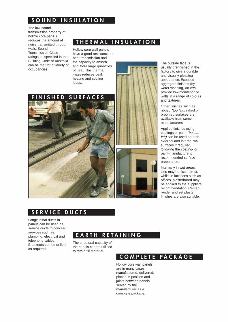
F I N I S H E D S U R F A C E S
The outside face isusually prefinished in thefactory to give a durableand visually pleasingappearance. Exposedaggregate finishes (bywater-washing, far left)provide low-maintenancewalls in a range of coloursand textures.
Other finishes such asribbed (top left), raked orbroomed surfaces areavailable from somemanufacturers.
Applied finishes usingcoatings or paint (bottomleft) can be used on bothexternal and internal wallsurfaces if required,following the coating- orpaint-manufacturer'srecommended surfacepreparation.
Internally in wet areas,tiles may be fixed direct,whilst in locations such asoffices, plasterboard maybe applied to the suppliersrecommendation. Cementrender and set plasterfinishes are also suitable.
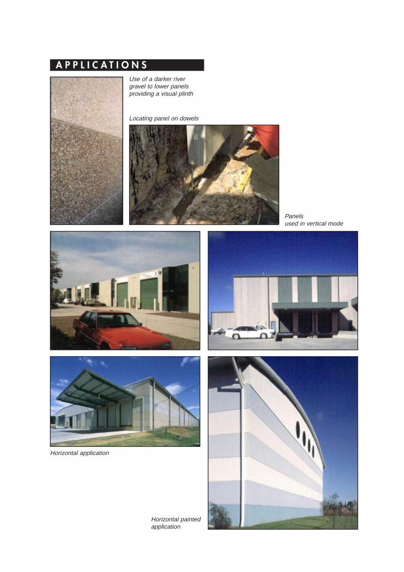
A P P L I C A T I O N SUse of a darker rivergravel to lower panelsproviding a visual plinth
Locating panel on dowels
Panelsused in vertical mode
Horizontal application
Horizontal paintedapplication
GeneralHollow core wall panels are produced in standardwidths of 1200 and 2400 mm depending on theManufacturer's machine module. They are cast onlong-line beds and cut to length to suit the wallheight – or span in the case of horizontal panels.In planning a structural arrangement considerablebenefits are achieved by establishing a framingconcept for a hollow core module and spancapability rather than substituting hollow core wallpanels for traditional masonry in a layout preparedfor the latter.
Manufacturers provide a technical advisory serviceand assistance wfth feasibility studies. Theiradvice should be sought at the preilminary stageof a project so that a cost-effective and practicaldesign is achieved.
In developing a framing plan using hollow core wallpanels the principal considerations are the spanand the modular width. The panel thicknessdepends on the structural requirements of theloading and the span. The fire resistance periodalso determines the required effective thickness ofthe panel.
Panel WidthIt is desirable that the planning grid should suit themodular width of the panels – either 1200 or2400 mm. Non-modular dimensions areaccommodated using special-width panels madeby either longitudinal sawing or casting narrowerwidths. These special panels can be kept to aminimum by locating openings such as doors andwindows to suit the modular width.
Panel Thlckness and LengthFor a preliminary design the panel thickness maybe selected to satisfy siructural requirements byusing the typical panel properties (page 12). Tolimit deflections in service the ratio of span (ie thelength between the fixings) to overall thickness isusually restricted to 50. For handling and erectionpurposes the ratio of overall length to thicknessshould not exceed 60.
The effective thickness of the panel is selected tosuit the required fire resistance level; this maycontrol the overall thickness of the panel.
In some cases the exposure conditions andrequired durability may control the cover to thestrands and thus the overall thickness of the panel.
CantileversHollow core wall panels may be used forcantilevers projecting above the structure and roofline to form parapets and the like. As wall panelsare usually provided with uniform prestress, theextent of any cantilever is limited by the stressesinduced in the cantilever under lateral load. Inpractice, cantilevers are limited also by the need torestrict deformation arising from differentialtemperature on the faces of the panel.
Connections and JointsThe type and details of the connections betweenthe panels and the supporting structure should bechosen to suit industry standards. Examples ofsuitable connections and joints that have beendeveloped to suit practical construction and designconditions are shown on pages 14–16.
TolerancesConstruction tolerances must be allowed for indeveloping a layout. Tolerance in panel length isaccommodated by allowing a variable gap at thebottom grouted support of a vertical panel and/orfixing a cover flashing or capping at the top of thepanel. Tolerance in panel width is accommodatedby a variation in nominal joint width to maintain themodule along the wall.
Horizontal panels are generally supported at theirends, hence the visual effects of temperaturechange should be considered where long panelsare used.
P L A N N I N G A N D D E S I G N
H O L L O W C O R E
WALLING
Design RequimmentsHollow core wall panels are designed to complywith AS 3600 Concrete Structures and the relevantbuilding regulations. The design of a hollow corewall is undertaken usually in two stages:
■ Preliminary design when the general layout,overall dimensions of the panel and the typicaldetails are selected to suit the buildingrequirements
■ Final design when the details of the panel –strand pattern, connections, special cut-outs andthe shop drawings are produced.
The preliminary design is carried out by thedesigner responsible for the project and isincorporated in the contract documents. Thedetailed final design is usually undertaken by themanufacturer and based on a performancespecification. The structural engineer provides fulldetails of the design criteria, including lateral loadsand any vertical loads to be resisted, and theinterface requirements with other constructionmaterials and building elements. This is especiallyimportant in the case of walls that are required toact partly as retaining walls and thus resist lateralearth pressure. The Fire Resistance Levels andany other statutory requirements should also bespecified.
The Manufacturer usually provides full details ofthe connection type and details of any itemsembedded in the panels. The Manufacturer alsoliaises with the builder to ensure that anyembedments in the structure are provided.
The builder must approve the shop drawings fordimensional accuracy and details and for suitabilityfor inclusion in the project, including adequacy forfollowing trades.
Load Distribution
Wall panels are usually designed to resist lateralloads as simple one-way-spanning slabs. Theinterlocking keys between adjacent panels providesome capacity for load distribution and somerestraint against the independent movement ofadjacent panels. These keys may be relied uponto distribute loads arising from minor openingssuch as access doors and windows. The transferof significant forces or concentrations caused bylarge openings should be investigated.
1 Determine a feasible arrangement for the basic-structure, columns, beams and wall panels. Noteoptions for vertical and horizontal application ofpanels.
2 Establish the basic design data:
Occupancy of the buildingFire resistance (building regulations)Sound transmission (building regulations)Exposure classification and durabilityrequirements (AS 3600).
3 Select a suitable overall thickness of panel tosatisfy handling and serviceability requirements.Typical slenderness limits are (where 't' is theactual panel thickness):
Overall length – 60 tLength between fixings – 50 tCantilever length – 8 t.
4 Check against the required minimum effectivethickness for fire resistance, sound transmission,and the minimum concrete strength and cover fordurability established in item 2 of this check list.
5 Determine the dead, live, wind and any otherloads acting on the wall. Any concentrated loadsor large openings should be assessed separately.
6 Check the strength capacity of the panel andthe connections. Note: for simple panels subject tonominal vertical and wind loads a comparison withstandard capacities is usually sufficient.
D E S I G N C H E C K L I S T
The fire resistance period of a wall is defined inthe Building Code of Australia (BCA) as the periodin minutes for which the wall must retain itsstructural adequacy, integrity and insulation whensubjected to the standard fire test.
AS 3600 specifies the design for fire resistance tobe met either by testing or calculation or byproportioning members to comply with certainrules. Some manufacturers can provide fire testcertificates.
In practice the deemed-to-comply rules areadopted usually as a convenient method ofcompliance (note that where a fire rating has beenestablished by test, manufacturers are notgoverned by the effective-thickness principle).Two criteria must be satisfied:
■ Insulation requires a minimum effectivethickness of concrete and a minimum thickness ofconcrete between adjacent cores and between acore and the surface exposed to the fire.
■ Structural Adequacy requires a minimumconcrete cover to the prestressing strand. For awall, integrity is deemed to be satisfied if thecriteria of insulation and structural adequacyare met.
A wall usually provides a fire-separating function,ie it restricts the spread of fire from onecompartment to adjoining compartments. In thisinstance the wall is exposed to fire on one sideonly. Where a wall does not provide afire-separating function and can be exposed to fireon both sides simultaneously, then it must betreated as a column in accordance with Clause 5.6of AS 3600.
Traditionally walls have been classified asloadbearing or non-loadbearing with differentcriteria for assessing their structural adequacyunder fire loading. This has created someanomalies which have been eliminated orsimplified in AS 3600. A loadbearing wall isdefined in AS 3600 as a member intended tosupport or transmit axial load additional to its ownweight and where the design axial force atmid-height is greater than 0.03 f’c Ag (where f’c isthe characteristic compressive strength and Ag isthe gross cross sectional area).
Note that the design axial force is the loadcombination for fire resistance given in Clause 3.5of AS 3600. Other walls are deemed to benon-loadbearing.
The practical effect of this definition is to permit awall panel to support loads such as roof loads andlocal concentrations at door openings and betreated as a non-loadbearing wall. Provided thatthe slenderness ratio does not exceed 50, such awall is deemed to be structurally adequate. Inpractice most walls in industrial buildings satisfythose deemed-to-comply provisions fornon-loadbearing walls.
For loadbearing fire walls the slenderness ratio isnot to exceed 20 and a minimum cover to thestrand is required for each fire resistance level.
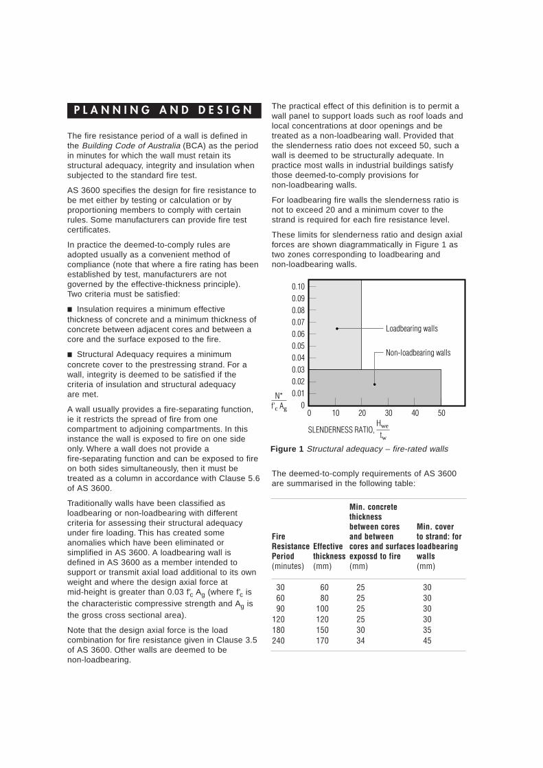
These limits for slenderness ratio and design axialforces are shown diagrammatically in Figure 1 astwo zones corresponding to loadbearing andnon-loadbearing walls.
P L A N N I N G A N D D E S I G N
SLENDERNESS RATIO,
N*f'c Ag
Hwe
tw
00.010.020.030.040.050.060.070.080.090.10
0 10 20 30 40 50
Loadbearing walls
Non-loadbearing walls
Figure 1 Structural adequacy – fire-rated walls
The deemed-to-comply requirements of AS 3600are summarised in the following table:
Min. concretethicknessbetween cores Min. cover
Fire and between to strand: forResistance Effective cores and surfaces IoadbearingPeriod thickness expossd to fire walls(minutes) (mm) (mm) (mm)
30 60 25 3060 80 25 3090 100 25 30
120 120 25 30180 150 30 35240 170 34 45
For a hollow core panel the effective concretethickness is taken as the net cross sectional areadivided by the width of the cross section. Theequivalent thickness of a hollow core paneldepends on the size and spacing of the cores.
Manufacturers can vary the layout of cores in awall panel to provide a range of Fire ResistanceLevels in the same overall panel thickness. Forexample a 200-mm-thick panel may be producedto provide fire resistance periods of 120,180 or240 minutes. The required covers to the strand inthe above table apply for load bearing walls.AS 3600 does not specify the cover fornon-load bearing walls. In practice, however, aminimum cover of 30 mm is usually provided.
The Fire Resistance Level of wall panels ispreserved at the standard key joint since the gapat this joint is sufficiently narrow to maintain theintegrity of the wall. In practice some plain buttjoints occur with vertical panels at the corners ofbuildings and where panels are saw-cut to fitclosing dimensions. Butt joints occur also at theends of horizontal panels, usually adjacent to asupporting column.
Fire tests have shown that a fire rating can beachieved with a simple butt joint depending on thewidth and depth of the joint. For example, a200-mm-thick panel with a joint width of 10 mm,where the cores are not sealed at the ends gives afire resistance level of 90 minutes. Sealing thecores increases the fire resistance level to 180minutes. Alternatively, the joint may be filled with asuitable depth of fire-resisting material. Wheregaps are wider than 10 mm the fire-resistancelevel is reduced; in this case filling withfire-resisting material is a practical solution.Reference should be made to the paper Fire Testsof Joints Between Precast Wall Panels byGustaferro and Abrams, PCI Journal, September1975 for further details.
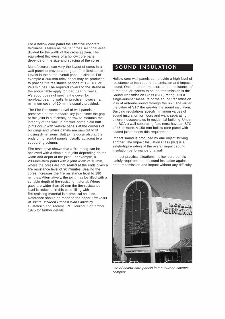
Hollow core wall panels can provide a high level ofresistance to both sound transmission and impactsound. One important measure of the resistance ofa material or system to sound transmission is theSound Transmission Class (STC) rating. It is asingle-number measure of the sound transmissionloss of airborne sound through the unit. The largerthe value of STC the greater the sound insulation.Building regulations specify minimum values ofsound insulation for floors and walls separatingdifferent occupancies in residential building. Underthe BCA a wall separating flats must have an STCof 45 or more. A 150-mm hollow core panel withsealed joints meets this requirement.
Impact sound is produced by one object strikinganother. The Impact Insulation Class (IIC) is asingle-figure rating of the overall impact soundinsulation performance of a wall.
In most practical situations, hollow core panelssatisfy requirements of sound insulation againstboth transmission and impact without any difficulty.
S O U N D I N S U L A T I O N
use of hollow core panels in a suburban cinemacomplex
Hollow core wall panels are cast using concretewith a low water-cement ratio and a typicalconcrete strength of 40 MPa. This concrete isinherently durable and protects the strandsprovided that the thickness of cover chosen isappropriate for the degree of exposure.
Durability of hollow core panels is further improvedby their crack-free characteristic resulting fromprestressing.
AS 3600 provides a classification of typicalexposure conditions to cover the range from aninternal enclosed environment to exteriorenvironment with exposure conditions of differentdegrees of severity:
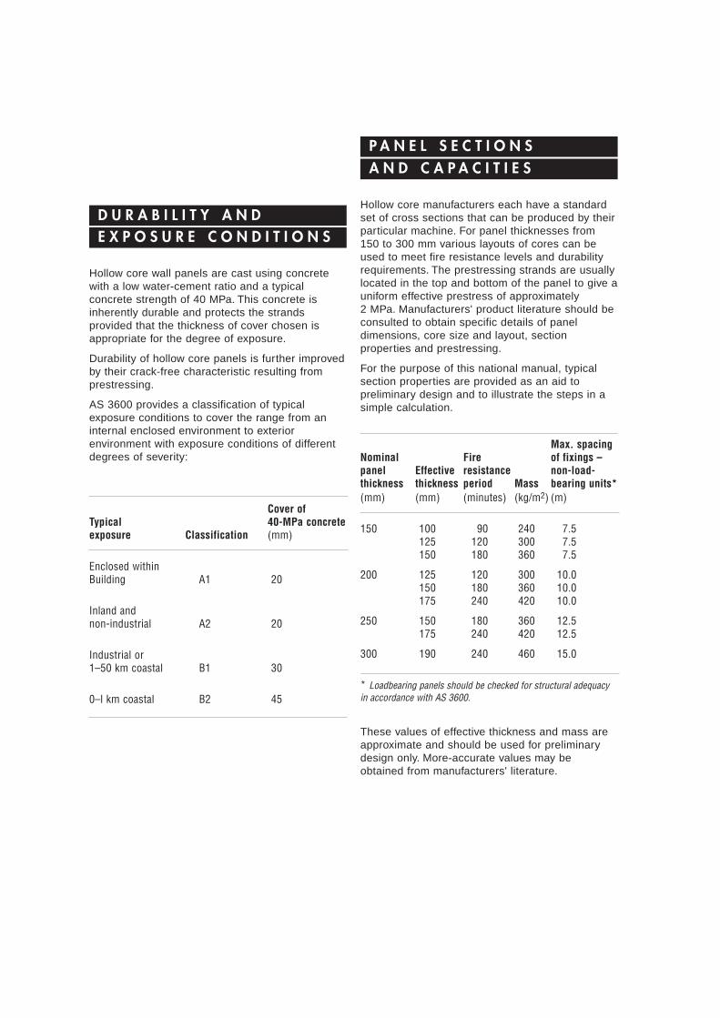
Hollow core manufacturers each have a standardset of cross sections that can be produced by theirparticular machine. For panel thicknesses from150 to 300 mm various layouts of cores can beused to meet fire resistance levels and durabilityrequirements. The prestressing strands are usuallylocated in the top and bottom of the panel to give auniform effective prestress of approximately2 MPa. Manufacturers' product literature should beconsulted to obtain specific details of paneldimensions, core size and layout, sectionproperties and prestressing.
For the purpose of this national manual, typicalsection properties are provided as an aid topreliminary design and to illustrate the steps in asimple calculation.
These values of effective thickness and mass areapproximate and should be used for preliminarydesign only. More-accurate values may beobtained from manufacturers' literature.
D U R A B I L I T Y A N DE X P O S U R E C O N D I T I O N S
P A N E L S E C T I O N SA N D C A P A C I T I E S
Cover ofTypical 40-MPa concreteexposure Classification (mm)
Enclosed withinBuilding A1 20
Inland andnon-industrial A2 20
Industrial or1–50 km coastal B1 30
0–l km coastal B2 45
Max. spacingNominal Fire of fixings –panel Effective resistance non-load-thickness thickness period Mass bearing units*(mm) (mm) (minutes) (kg/m2) (m)
150 100 90 240 7.5125 120 300 7.5150 180 360 7.5
200 125 120 300 10.0150 180 360 10.0175 240 420 10.0
250 150 180 360 12.5175 240 420 12.5
300 190 240 460 15.0
* Loadbearing panels should be checked for structural adequacyin accordance with AS 3600.

Further, the values are based on:
■ Concrete strength – f’c = 40 MPa
■ Prestressing strand – ultimate tensile strength 9.3-mm strand – 102 kN
12.7-mm strand – 184 kN
These values are for the widely-used, superlow-relaxation strand.
For many applications the calculation of thestrength of wall panels may be simplified by usingthe design procedures given in Clause 11.2 ofAS 3600. For the common case of a wall subjectprincipally to horizontal forces perpendicular to thewall, Clause 11.2.4 of the Standard may be used.In this instance, if the design vertical force N* doesnot exceed 0.03 f’c Ag and the ratio of the effectiveheight to thickness does not exceed 50, then thewall may be designed as a slab in accordance withSection 9 of the Standard.
For a panel width of 1200 mm and concretestrength of 40 MPa this limit on design verticalforce is directly proportional to the effectivethickness of the panel. Typical values are set out inthe following table.
Limiting Axial Capacity
N* = 0.03 f’c Ag
(AS 3600 Clauses 11.2.4 and 5.7.4)
The bending strength of a wall panel may becalculated in accordance with Clause 8.1 ofAS 3600. For the usual case of a nominal level ofprestress of approximately 2 MPa and a concretestrength of 40 MPa, the bending strength of thepanel is approximately proportional to the effectivestrength of the strands and the effective depth ofthe cross section. Typical values are set out in thefollowing table.
Approximate Moment Capacity
M* = f Mu
(AS 3600 Clause 8.1)
EffectiveWidth thickness te N*(mm) (mm) (kN)
1200 100 140
125 175
150 210
175 245
190 265
Effective depth No. ofto each face 9.3-mm M*(mm) strands (kNm)
100 4+4 29
150 4+4 45
200 6+6 92
250 6+6 114
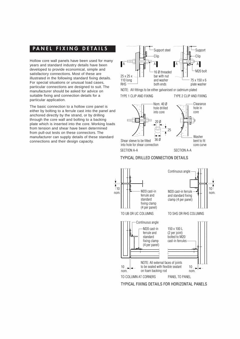
Hollow core wall panels have been used for manyyears and standard industry details have beendeveloped to provide economical, simple andsatisfactory connections. Most of these areillustrated in the following standard fixing details.For special situations or unusual load cases,particular connections are designed to suit. Themanufacturer should be asked for advice onsuitable fixing and connection details for aparticular application.
The basic connection to a hollow core panel iseither by bolting to a ferrule cast into the panel andanchored directly by the strand, or by drillingthrough the core wall and bolting to a backingplate which is inserted into the core. Working loadsfrom tension and shear have been determinedfrom pull-out tests on these connectors. Themanufacturer can supply details of these standardconnections and their design capacity.
P A N E L F I X I N G D E T A I L S
�����
������
���
���������
���
TYPE 1 CLIP AND FIXING
A
TYPICAL DRILLED CONNECTION DETAILS
A A A
TYPE 2 CLIP AND FIXING
SECTION A-A SECTION A-A
Support steel
Clip
16 Ø threadedbar with nutand washerboth ends
25 x 25 x110 longRHS
Shear sleeve to be fittedinto hole for shear connection
M20 bolt
75 x 150 x 6plate washer
Clearancehole incore
Washerbent to fitcore curve
Nom. 40 Øhole drilledinto core
20 Ø
36 Ø
25
Support
Clip
NOTE: All fittings to be either galvanised or cadmium plated
����
����
����������
����������
TO UB OR UC COLUMNS
10nom.
10 nom.
10nom.
10nom.
M20 cast-inferrule andstandardfixing clamp(4 per panel)
M20 cast-in ferruleand standard fixingclamp (4 per panel)
Continuous angle
TO SHS OR RHS COLUMNS
M20 cast-inferrule andstandardfixing clamp(4 per panel)
150 x 100 L(2 per joint)bolted to M20cast-in ferrules
TO COLUMN AT CORNERS PANEL TO PANEL
NOTE: All external faces of jointsto be sealed with flexible sealanton foam backing rod
TYPICAL FIXING DETAILS FOR HORIZONTAL PANELS
Continuous angle
����@@@@����ÀÀÀÀ����@@@@����ÀÀÀÀ����@@@@����ÀÀÀÀ����@@@@����ÀÀÀÀ����@@@@����ÀÀÀÀ����@@@@����ÀÀÀÀ����yyyy���@@@���ÀÀÀ���@@@���ÀÀÀ���@@@���ÀÀÀ���@@@���ÀÀÀ���@@@���ÀÀÀ���@@@���ÀÀÀ���yyy
����@@@@����ÀÀÀÀ����@@@@����ÀÀÀÀ����@@@@����ÀÀÀÀ����@@@@����ÀÀÀÀ����@@@@����ÀÀÀÀ����@@@@����ÀÀÀÀ����yyyy����@@@@����ÀÀÀÀ����@@@@����ÀÀÀÀ����@@@@����ÀÀÀÀ����@@@@����ÀÀÀÀ����@@@@����ÀÀÀÀ����@@@@����ÀÀÀÀ����yyyy
����@@@@����ÀÀÀÀ����@@@@����ÀÀÀÀ����@@@@����ÀÀÀÀ����@@@@����ÀÀÀÀ����@@@@����ÀÀÀÀ����@@@@����ÀÀÀÀ����yyyy�@�À�@�À�@�À�@�À�@�À�@�À�y��
��@@@@����ÀÀÀÀ����@@@@����ÀÀÀÀ����@@@@����ÀÀÀÀ����@@@@����ÀÀÀÀ����@@@@����ÀÀÀÀ����@@@@����ÀÀÀÀ����yyyy��@@��ÀÀ��@@��ÀÀ��@@��ÀÀ��@@��ÀÀ��@@��ÀÀ��@@��ÀÀ��yy
����@@@@����ÀÀÀÀ����@@@@����ÀÀÀÀ����@@@@����ÀÀÀÀ����@@@@����ÀÀÀÀ����@@@@����ÀÀÀÀ����@@@@����ÀÀÀÀ����yyyy��@@��ÀÀ��@@��ÀÀ��@@��ÀÀ��@@��ÀÀ��@@��ÀÀ��@@��ÀÀ��yy
����@@@@����ÀÀÀÀ����@@@@����ÀÀÀÀ����@@@@����ÀÀÀÀ����@@@@����ÀÀÀÀ����@@@@����ÀÀÀÀ����@@@@����ÀÀÀÀ����yyyy����@@@@����ÀÀÀÀ����@@@@����ÀÀÀÀ����@@@@����ÀÀÀÀ����@@@@����ÀÀÀÀ����@@@@����ÀÀÀÀ����@@@@����ÀÀÀÀ����yyyy
��@@��ÀÀ��@@��ÀÀ��@@��ÀÀ��@@��ÀÀ��@@��ÀÀ��@@��ÀÀ��yy��@@��ÀÀ��@@��ÀÀ��@@��ÀÀ��@@��ÀÀ��@@��ÀÀ��@@��ÀÀ��yy
��
������
���
������
������
��������
��������
������
������
����
��������
������
��������
�����
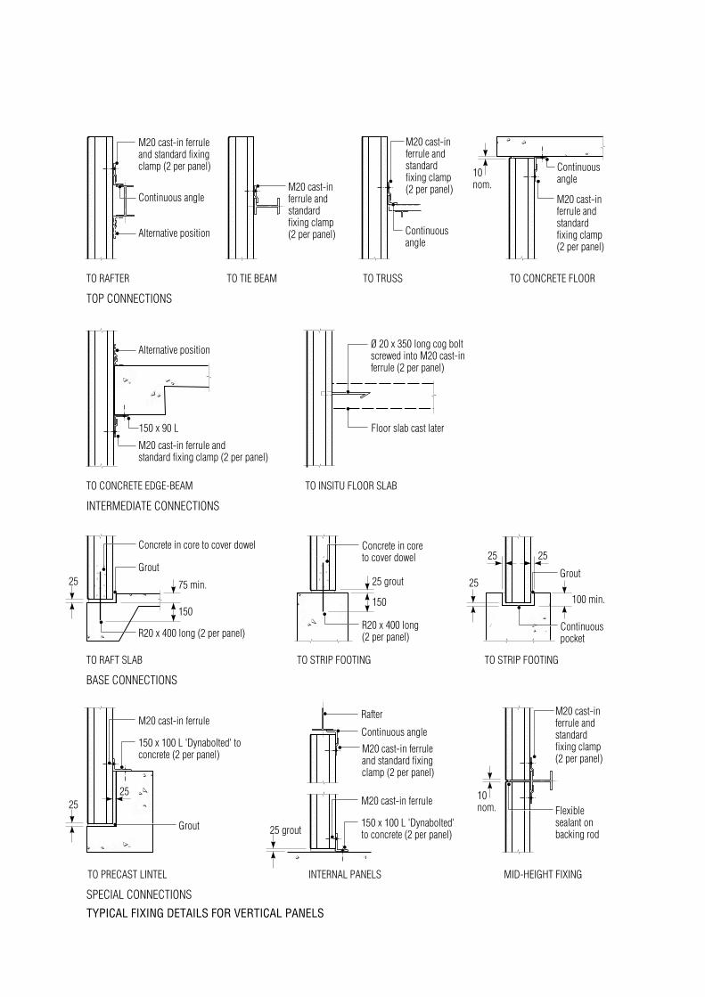
TYPICAL FIXING DETAILS FOR VERTICAL PANELS
SPECIAL CONNECTIONS
INTERNAL PANELSTO PRECAST LINTEL MID-HEIGHT FIXING
BASE CONNECTIONS
TO RAFT SLAB TO STRIP FOOTING TO STRIP FOOTING
INTERMEDIATE CONNECTIONS
TO CONCRETE EDGE-BEAM TO INSITU FLOOR SLAB
TOP CONNECTIONS
TO RAFTER TO TIE BEAM TO CONCRETE FLOORTO TRUSS
��
��
10nom.M20 cast-in
ferrule andstandardfixing clamp(2 per panel)
M20 cast-in ferruleand standard fixingclamp (2 per panel)
Continuous angle
150 x 90 L
Alternative position
M20 cast-inferrule andstandardfixing clamp(2 per panel)
Continuousangle
M20 cast-inferrule andstandardfixing clamp(2 per panel)
Continuousangle
Alternative position
M20 cast-in ferrule andstandard fixing clamp (2 per panel)
Floor slab cast later
Ø 20 x 350 long cog boltscrewed into M20 cast-inferrule (2 per panel)
25 25 grout
150
Concrete in core to cover dowel
Grout
R20 x 400 long (2 per panel)
75 min.
150
Concrete in coreto cover dowel
R20 x 400 long(2 per panel)
25100 min.
25 25
Grout
Continuouspocket
2525
M20 cast-in ferrule
150 x 100 L 'Dynabolted' toconcrete (2 per panel)
Grout
M20 cast-in ferrule
150 x 100 L 'Dynabolted'to concrete (2 per panel)
Rafter
Continuous angle
M20 cast-in ferruleand standard fixingclamp (2 per panel)
25 grout
10nom.
M20 cast-inferrule andstandardfixing clamp(2 per panel)
Flexiblesealant onbacking rod
��
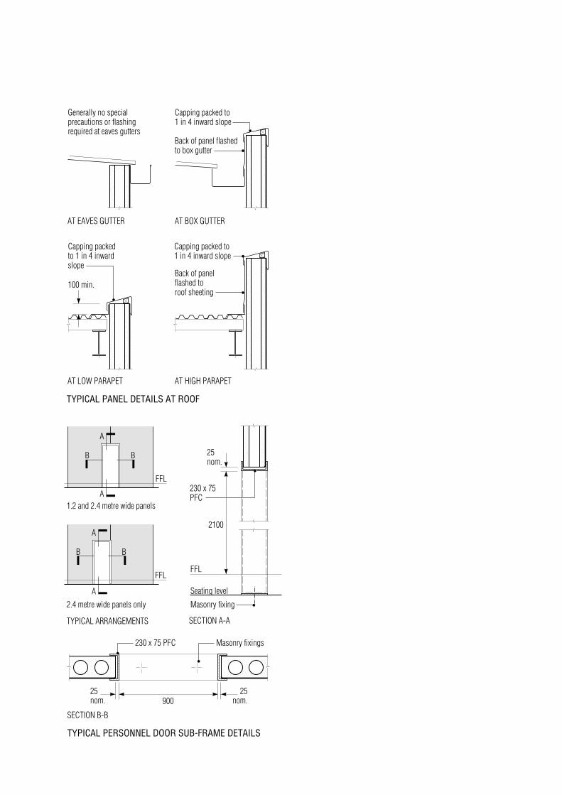
TYPICAL PANEL DETAILS AT ROOF
AT LOW PARAPET
���
���
����
AT HIGH PARAPET
AT EAVES GUTTER AT BOX GUTTER
Capping packed to1 in 4 inward slope
Back of panel flashedto box gutter
Back of panelflashed to roof sheeting
Capping packedto 1 in 4 inwardslope
100 min.
Capping packed to1 in 4 inward slope
Generally no specialprecautions or flashingrequired at eaves gutters
��
����
����
�
�
��
��
SECTION A-A
TYPICAL PERSONNEL DOOR SUB-FRAME DETAILS
A
A
B B
2100
25nom.
FFL
Seating level
Masonry fixing
230 x 75PFC
TYPICAL ARRANGEMENTS
FFL
FFL
SECTION B-B
25nom.
25nom.900
Masonry fixings230 x 75 PFC
1.2 and 2.4 metre wide panels
2.4 metre wide panels only
A
A
B B

Hollow core wall panels can be supplied in avariety of surface finishes. Widely used is anexposed aggregate surface which reveals thecolour and texture of the aggregate. The selectedaggregate should be available locally and may bequartz, granite or other crushed rock or multi-coloured river gravel.
Exposed aggregate is an economical, durable andattractive finish suitable for most applications.Smooth finishes are available as trowelled by themachine or as the off-form face.
Striated, broomed or raked finishes are availablefrom some manufacturers. Prototypes may be castto determine the depth of texturing best suited to aproject.
Shallow rib finishes available from somemanufacturers give an aesthetically pleasingappearance with shadow lines formed by the ribs.The rib surface may be left plain, broomed orwater-washed to expose the aggregate.
Large, flat wall areas with penetrations for windowsand doors should be detailed to allow the sheddingof rainwater clear of the panel surfaces to avoidunsightly stains. Similarly, parapet capping andmetal frames should be detailed to avoidconcentrated water run-oft with consequentstaining.
S U R F A C E F I N I S H E S
Exposed aggregate – note that the availability ofmany colours of river gravel and crushed stonesuch as granite provides for a wide choice ofappearance
Ribbed finish

Scope
This guide specification is intended to be used inthe preparation of the specification for a particularproject. It should be checked for compatibility withthe particular job requirements by deleting anyprovisions that do not apply and adding specialprovisions if needed.
It covers the design, manufacture and erection ofhollow core wall panels produced by an approvedmanufacturer.
Design The general arrangement drawings shallbe submitted for approval of layout, adequacy anddimensions prior to manufacture. The drawingsshall show the locations of all panels wfth allopenings detailed. Sections and details shall showthe connections and edge details of the panels.Design details on drawings shall include fireresistance levels and exposure classification.
Materials Materials used in the manufacture ofhollow core panels shall comply wfth the following:
Cement AS 3972Aggregates AS 2758 1Chemical Admixtures AS 1478 (The use of calciumchloride shall not be permitted.)Prestressing Steel AS 1311 Stress Reileved,Low-Relaxation Strand. Strand shall be clean andfree of deleterious material at the time ofconcreting.Concrete Grade 40 and complying with therequirements of AS 3600. Concrete strength at therelease of prestress shall be a minimum 20 MPa.Steel plates, bolts and ferrules shall comply wfththe relevant Australian Standards.
Manutacture Hollow core panels shall bemachine cast on a long-line bed and mechanicallycompacted. The top surface shall be finished asspecified and in accordance with the sampleapproved prior to casting. The underside finishshall be as cast against the bed and surface voidsand colour variations shall be as agreed prior tocasting.
Tolerances Panels shall be suppiled inaccordance wfth the following tolerances:
Length ±1O mm
Width ±3 mm
Thickness ±3 mm
Squareness of end ±6 mm
Location of ferrules ±20 mm
Location of strand ±3 mm
Differential bowing betweenadjacent panels of the same length 15 mm
Delivery and Handling Hollow core panels shallbe lited and supported during manufacture,storage, transport and erection operations only atthe manufacturer's nominated fifting positions.Panels shall be stored off the ground and besupported by full-width battens directly above eachother in the stack or as per manufacturer'sinstructions. Only methods approved by therelevant authorities shall be used for lifting wallpanels.
Erection The General Contractor shall beresponsible for providing suitable access at thesite to enable trucks and cranes to operate undertheir own power The General Contractor shall beresponsible for providing true level bearingsurfaces to support the hollow core panels. Thestructure shall be plumb and all bracing necessaryfor stabifity shall be in place prior to erection. Thehollow core panels shall be installed only by theManufacturer or an experienced erectioncontractor.All bearing surfaces and dowel cores shall begrouted as detailed. All retaining clips, plates andbolts shall be fixed as detailed.
Attachments and Penetrations Attachments andfixings to the hollow core panels shall be inaccordance wfth the approved details only andshall not impair the strength of the panels.Penetrations and chases to the hollow core panelsshall be in accordance wfth the approved detailsonly and shall be approved by the Manufacturerand the Structural Engineer.
Joints Joints between panels shall be sealed withan approved sealant placed against a closed-cellfoam backing rod.
Inspection and Acceptance The Manufacturershall provide, access and any necessary facilitiesfor inspection of work in progress. Panels withstructural defects shall be rectified to the approvalof the Structural Engineer.
G U I D E S P E C I F I C A T I O N
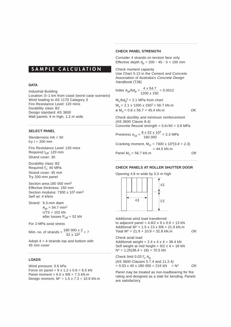
DATA
Industrial BuildingLocation: 0–1 km from coast (worst case scenario)Wind loading to AS 1170 Category 3Fire Resistance Level: 120 minsDurability class: B2Design standard: AS 3600Wall panels: 9 m high, 1.2 m wide
SELECT PANEL
Slenderness HA < 50try t = 200 mm
Fire Resistance Level: 120 minsRequired teff: 120 mmStrand cover: 30
Durability class: B2Required f'c: 40 MPaStrand cover: 45 mmTry 200-mm panel
Section area:180 000 mm2
Effective thickness: 150 mmSection modulus: 7300 x 103 mm3
Self wt: 4 kN/m
Strand: 9.3-mm diamApt = 54.7 mm2
UTS = 102 kNafter losses Peff = 52 kN
For 2-MPa axial stress
Mim. no. of strands = 180 000 x 2 = 752 x 103
Adopt 4 + 4 strands top and bottom with45 mm cover
LOADS
Wind pressure: 0.6 kPaForce on panel = 9 x 1.2 x 0.6 = 6.5 kNPanel moment = 6.5 x 9/8 = 7.3 kN.mDesign moment, M* = 1.5 x 7.3 = 10.9 kN.m
CHECK PANEL STRENGTH
Consider 4 strands on tension face onlyEffective depth dp = 200 - 45 - 5 = 150 mm
Check moment capacityUse Chart 5.13 in the Cement and ConcreteAssociation of Australia's Concrete DesignHandbook (T38)
lndex Apt/bdp = 4 x 54.7 = 0.00121200 x 150
Mu/bdp2 = 2.1 MPa from chart
Mu = 2.1 x 1200 x 1502 = 56.7 kN.mø Mu = 0.8 x 56.7 = 45.4 kN.m OK
Check ductility and minimum reinforcement(AS 3600 Clause 8.4)Concrete flexural strength = 0.6√40 = 3.8 MPa
Prestress σcp = 8 x 52 x 103= 2.3 MPa
180 000
Cracking moment, Mcr = 7300 x 103(3.8 + 2.3) = 44.5 kN.m
Panel Mu = 56.7 kN.m OK
CHECK PANELS AT ROLLER SHUTTER DOOR
Opening 4.8 m wide by 5.0 m high
Additional wind load transferredto adjacent panel = 4.8/2 x 9 x 0.6 = 13 kNAdditional M* = 1.5 x 13 x 9/8 = 21.9 kN.mTotal M* = 21.9 + 10.9 = 32.8 kN.m OK
Check axial loadAdditional weight = 2.4 x 4 x 4 = 38.4 kNSelf weight at mid height = 9/2 x 4 = 18 kNN* = 1.25(38.4 + 18) = 70.5 kN
Check limit 0.03 f’c Ag
(AS 3600 Clauses 5.7.4 and 11.2.4)= 0.03 x 40 x 180 000 = 216 kN > N* OK
Panel may be treated as non-loadbearing for firerating and designed as a slab for bending. Panelsare satisfactory.
S A M P L E C A L C U L A T I O N
4.8
4.0
5.0

Published by the National Precast ConcreteAssociation Australia on behalf of the followingHollowcore manufacturers.
AUSCORE CONCRETE PTY LTD83 MORNINGTON - TYABB ROAD TYABB VICTORIA 3913TELEPHONE 059 5977 4667 FACSIMILE 03 9770 1976
DELTA CORPORATION LTDLOT P3 CAMPERSIE ROAD HERNE HILL WA 6056TELEPHONE 08 9296 4111 FACSIMILE 08 9296 1184
HOLLOWCORE CONCRETE PTY LTD12-14 MARIA STREET LAVERTON NORTH VICTORIA 3026TELEPHONE 03 9369 4944 FACSIMILE 03 9369 2025
RESCRETE INDUSTRIES PTY LTD214 RIVERSTONE PARADE RIVERSTONE NSW 2765TELEPHONE 02 9627 2666 FACSIMILE 02 9627 5161
WESTKON PRECAST CONCRETE PTY LTD528A BALLARAT ROAD SUNSHINE VICTORIA 3020TELEPHONE 03 9312 3688 FACSIMILE 03 9312 1735
NATIONAL PRECAST CONCRETEASSOCIATION AUSTRALIA ACN 051 987 181
LEVEL 2, 8-10 PALMER STREETNORTH PARRAMATTA NSW 2151TELEPHONE 02 9890 8853 FACSIMILE 02 9890 8854
PRODUCED FOR THE WWW BY:TECHMEDIA PUBLISHING PTY LTD TELEPHONE 02 9477 7766
Related Documents