GX Works3 Operating Manual -SW1DND-GXW3-E

Welcome message from author
This document is posted to help you gain knowledge. Please leave a comment to let me know what you think about it! Share it to your friends and learn new things together.
Transcript

GX Works3 Operating Manual
-SW1DND-GXW3-E


1
SAFETY PRECAUTIONS(Read these precautions before using this product.)
Before using this product, please read this manual carefully and pay full attention to safety to handle the product correctly.
The precautions given in this manual are concerned with this product only. For the safety precautions for the programmable
controller system, refer to the user's manual for the module used and MELSEC iQ-R Module Configuration Manual.
In this manual, the safety precautions are classified into two levels: " WARNING" and " CAUTION".
Under some circumstances, failure to observe the precautions given under " CAUTION" may lead to serious
consequences.
Observe the precautions of both levels because they are important for personal and system safety.
Make sure that the end users read this manual and then keep the manual in a safe place for future reference.
[Design Precautions]
[Startup and Maintenance Precautions]
WARNING● When data change, program change, or status control are performed from a personal computer to a
running CPU module, create an interlock circuit outside the programmable controller to ensure that
the whole system always operates safely.
Furthermore, for the online operations performed from a personal computer to a programmable
controller CPU, the corrective actions against a communication error due to such as a cable
connection fault should be predetermined as a system.
● To maintain the safety of the programmable controller system against unauthorized access from
external devices via the network, take appropriate measures.
To maintain the safety against unauthorized access via the Internet, take measures such as installing
a firewall.
CAUTION● The online operations performed from a personal computer to a running CPU module (program
change while a CPU module is in RUN, operating status changes such as RUN-STOP switching, and
remote control operation) must be executed after the manual has been carefully read and the safety
has been ensured.
● When changing a program while a CPU module is in RUN (online program change), it may cause a
program corruption in some operating conditions. Fully understand the precautions before use.
● The positioning test functions such as OPR, JOG, inching, or testing positioning data for positioning
module must be executed with the CPU module set to STOP after the manual has been carefully read
and the safety has been ensured.
Specially when executing the function on the network system, ensure the safety thoroughly since the
machinery whose operation cannot be checked by an operator may be activated. The operation
failure may cause the injury or machine damage.
WARNING Indicates that incorrect handling may cause hazardous conditions, resulting in death or severe injury.
CAUTION Indicates that incorrect handling may cause hazardous conditions, resulting in minor or moderate injury or property damage.

2
CONDITIONS OF USE FOR THE PRODUCT(1) Mitsubishi programmable controller ("the PRODUCT") shall be used in conditions;
i) where any problem, fault or failure occurring in the PRODUCT, if any, shall not lead to any major or serious accident; and ii) where the backup and fail-safe function are systematically or automatically provided outside of the PRODUCT for the case of any problem, fault or failure occurring in the PRODUCT.
(2) The PRODUCT has been designed and manufactured for the purpose of being used in general industries.MITSUBISHI SHALL HAVE NO RESPONSIBILITY OR LIABILITY (INCLUDING, BUT NOT LIMITED TO ANY AND ALL RESPONSIBILITY OR LIABILITY BASED ON CONTRACT, WARRANTY, TORT, PRODUCT LIABILITY) FOR ANY INJURY OR DEATH TO PERSONS OR LOSS OR DAMAGE TO PROPERTY CAUSED BY the PRODUCT THAT ARE OPERATED OR USED IN APPLICATION NOT INTENDED OR EXCLUDED BY INSTRUCTIONS, PRECAUTIONS, OR WARNING CONTAINED IN MITSUBISHI'S USER, INSTRUCTION AND/OR SAFETY MANUALS, TECHNICAL BULLETINS AND GUIDELINES FOR the PRODUCT. ("Prohibited Application")Prohibited Applications include, but not limited to, the use of the PRODUCT in;• Nuclear Power Plants and any other power plants operated by Power companies, and/or any other cases in which the
public could be affected if any problem or fault occurs in the PRODUCT.• Railway companies or Public service purposes, and/or any other cases in which establishment of a special quality
assurance system is required by the Purchaser or End User.• Aircraft or Aerospace, Medical applications, Train equipment, transport equipment such as Elevator and Escalator,
Incineration and Fuel devices, Vehicles, Manned transportation, Equipment for Recreation and Amusement, and Safety devices, handling of Nuclear or Hazardous Materials or Chemicals, Mining and Drilling, and/or other applications where there is a significant risk of injury to the public or property.
Notwithstanding the above, restrictions Mitsubishi may in its sole discretion, authorize use of the PRODUCT in one or more of the Prohibited Applications, provided that the usage of the PRODUCT is limited only for the specific applications agreed to by Mitsubishi and provided further that no special quality assurance or fail-safe, redundant or other safety features which exceed the general specifications of the PRODUCTs are required. For details, please contact the Mitsubishi representative in your region.

3
INTRODUCTIONThank you for purchasing the engineering software, MELSOFT series.
This manual describes the programming and functions required when using GX Works3.
Before using this product, please read this manual carefully, and develop familiarity with the functions and performance of GX
Works3 to handle the product correctly.

4
CONTENTSSAFETY PRECAUTIONS . . . . . . . . . . . . . . . . . . . . . . . . . . . . . . . . . . . . . . . . . . . . . . . . . . . . . . . . . . . . . . . . . . . .1
CONDITIONS OF USE FOR THE PRODUCT . . . . . . . . . . . . . . . . . . . . . . . . . . . . . . . . . . . . . . . . . . . . . . . . . . . .2
INTRODUCTION. . . . . . . . . . . . . . . . . . . . . . . . . . . . . . . . . . . . . . . . . . . . . . . . . . . . . . . . . . . . . . . . . . . . . . . . . . .3
RELEVANT MANUALS . . . . . . . . . . . . . . . . . . . . . . . . . . . . . . . . . . . . . . . . . . . . . . . . . . . . . . . . . . . . . . . . . . . . .13
TERMS . . . . . . . . . . . . . . . . . . . . . . . . . . . . . . . . . . . . . . . . . . . . . . . . . . . . . . . . . . . . . . . . . . . . . . . . . . . . . . . . .13
PART 1 FUNDAMENTALS OF GX Works3
CHAPTER 1 BEFORE USING THIS PRODUCT 16
1.1 Main Functions of GX Works3 . . . . . . . . . . . . . . . . . . . . . . . . . . . . . . . . . . . . . . . . . . . . . . . . . . . . . . . . . . . . . 16
1.2 RnPCPU . . . . . . . . . . . . . . . . . . . . . . . . . . . . . . . . . . . . . . . . . . . . . . . . . . . . . . . . . . . . . . . . . . . . . . . . . . . . . . . 18
Process Control System . . . . . . . . . . . . . . . . . . . . . . . . . . . . . . . . . . . . . . . . . . . . . . . . . . . . . . . . . . . . . . . . . . . 19
Redundant system. . . . . . . . . . . . . . . . . . . . . . . . . . . . . . . . . . . . . . . . . . . . . . . . . . . . . . . . . . . . . . . . . . . . . . . . 24
1.3 RnSFCPU . . . . . . . . . . . . . . . . . . . . . . . . . . . . . . . . . . . . . . . . . . . . . . . . . . . . . . . . . . . . . . . . . . . . . . . . . . . . . . 25
Safety system . . . . . . . . . . . . . . . . . . . . . . . . . . . . . . . . . . . . . . . . . . . . . . . . . . . . . . . . . . . . . . . . . . . . . . . . . . . 25
1.4 RnPSFCPU . . . . . . . . . . . . . . . . . . . . . . . . . . . . . . . . . . . . . . . . . . . . . . . . . . . . . . . . . . . . . . . . . . . . . . . . . . . . . 27
Process control system . . . . . . . . . . . . . . . . . . . . . . . . . . . . . . . . . . . . . . . . . . . . . . . . . . . . . . . . . . . . . . . . . . . . 27
Safety system . . . . . . . . . . . . . . . . . . . . . . . . . . . . . . . . . . . . . . . . . . . . . . . . . . . . . . . . . . . . . . . . . . . . . . . . . . . 27
Redundant system. . . . . . . . . . . . . . . . . . . . . . . . . . . . . . . . . . . . . . . . . . . . . . . . . . . . . . . . . . . . . . . . . . . . . . . . 27
1.5 Remote Head Module . . . . . . . . . . . . . . . . . . . . . . . . . . . . . . . . . . . . . . . . . . . . . . . . . . . . . . . . . . . . . . . . . . . . 28
1.6 NCCPU . . . . . . . . . . . . . . . . . . . . . . . . . . . . . . . . . . . . . . . . . . . . . . . . . . . . . . . . . . . . . . . . . . . . . . . . . . . . . . . . 28
1.7 Procedure from Project Creation to CPU Module Operation . . . . . . . . . . . . . . . . . . . . . . . . . . . . . . . . . . . . 29
1.8 Learning Operation Methods of GX Works3 . . . . . . . . . . . . . . . . . . . . . . . . . . . . . . . . . . . . . . . . . . . . . . . . . . 36
Displaying Help . . . . . . . . . . . . . . . . . . . . . . . . . . . . . . . . . . . . . . . . . . . . . . . . . . . . . . . . . . . . . . . . . . . . . . . . . . 36
Connecting to MITSUBISHI ELECTRIC FA Global Website . . . . . . . . . . . . . . . . . . . . . . . . . . . . . . . . . . . . . . . . 36
Checking the version of GX Works3 . . . . . . . . . . . . . . . . . . . . . . . . . . . . . . . . . . . . . . . . . . . . . . . . . . . . . . . . . . 36
1.9 Connection Configurations between a Personal Computer and a CPU Module . . . . . . . . . . . . . . . . . . . . . 37
CHAPTER 2 SCREEN CONFIGURATION AND BASIC OPERATIONS 39
2.1 Start and End . . . . . . . . . . . . . . . . . . . . . . . . . . . . . . . . . . . . . . . . . . . . . . . . . . . . . . . . . . . . . . . . . . . . . . . . . . . 39
2.2 Display Language Switching . . . . . . . . . . . . . . . . . . . . . . . . . . . . . . . . . . . . . . . . . . . . . . . . . . . . . . . . . . . . . . 39
2.3 Screen Configuration . . . . . . . . . . . . . . . . . . . . . . . . . . . . . . . . . . . . . . . . . . . . . . . . . . . . . . . . . . . . . . . . . . . . 40
Main frame. . . . . . . . . . . . . . . . . . . . . . . . . . . . . . . . . . . . . . . . . . . . . . . . . . . . . . . . . . . . . . . . . . . . . . . . . . . . . . 40
Navigation window. . . . . . . . . . . . . . . . . . . . . . . . . . . . . . . . . . . . . . . . . . . . . . . . . . . . . . . . . . . . . . . . . . . . . . . . 43
Connection destination window. . . . . . . . . . . . . . . . . . . . . . . . . . . . . . . . . . . . . . . . . . . . . . . . . . . . . . . . . . . . . . 45
Element selection window . . . . . . . . . . . . . . . . . . . . . . . . . . . . . . . . . . . . . . . . . . . . . . . . . . . . . . . . . . . . . . . . . . 45
2.4 Menu List . . . . . . . . . . . . . . . . . . . . . . . . . . . . . . . . . . . . . . . . . . . . . . . . . . . . . . . . . . . . . . . . . . . . . . . . . . . . . . 48
2.5 Checking and Changing Shortcut Keys . . . . . . . . . . . . . . . . . . . . . . . . . . . . . . . . . . . . . . . . . . . . . . . . . . . . . 64
2.6 Checking and Changing Colors and Fonts. . . . . . . . . . . . . . . . . . . . . . . . . . . . . . . . . . . . . . . . . . . . . . . . . . . 65
2.7 Comment Display Setting . . . . . . . . . . . . . . . . . . . . . . . . . . . . . . . . . . . . . . . . . . . . . . . . . . . . . . . . . . . . . . . . . 66
2.8 Option Setting for Each Function . . . . . . . . . . . . . . . . . . . . . . . . . . . . . . . . . . . . . . . . . . . . . . . . . . . . . . . . . . 67
2.9 Printing Data . . . . . . . . . . . . . . . . . . . . . . . . . . . . . . . . . . . . . . . . . . . . . . . . . . . . . . . . . . . . . . . . . . . . . . . . . . . 74

5
CO
NT
EN
TS
PART 2 SYSTEM DESIGN AND SETTINGS
CHAPTER 3 PROJECT MANAGEMENT 80
3.1 Project File and Data Configuration . . . . . . . . . . . . . . . . . . . . . . . . . . . . . . . . . . . . . . . . . . . . . . . . . . . . . . . . 80
File format . . . . . . . . . . . . . . . . . . . . . . . . . . . . . . . . . . . . . . . . . . . . . . . . . . . . . . . . . . . . . . . . . . . . . . . . . . . . . . 80
Safety project backup . . . . . . . . . . . . . . . . . . . . . . . . . . . . . . . . . . . . . . . . . . . . . . . . . . . . . . . . . . . . . . . . . . . . . 81
Data configuration . . . . . . . . . . . . . . . . . . . . . . . . . . . . . . . . . . . . . . . . . . . . . . . . . . . . . . . . . . . . . . . . . . . . . . . . 82
3.2 Creating Project Files . . . . . . . . . . . . . . . . . . . . . . . . . . . . . . . . . . . . . . . . . . . . . . . . . . . . . . . . . . . . . . . . . . . . 85
Creating a project . . . . . . . . . . . . . . . . . . . . . . . . . . . . . . . . . . . . . . . . . . . . . . . . . . . . . . . . . . . . . . . . . . . . . . . . 85
Opening a project . . . . . . . . . . . . . . . . . . . . . . . . . . . . . . . . . . . . . . . . . . . . . . . . . . . . . . . . . . . . . . . . . . . . . . . . 87
Opening a GX Works2 format project . . . . . . . . . . . . . . . . . . . . . . . . . . . . . . . . . . . . . . . . . . . . . . . . . . . . . . . . . 89
Opening a PX Developer format project . . . . . . . . . . . . . . . . . . . . . . . . . . . . . . . . . . . . . . . . . . . . . . . . . . . . . . . 92
Opening a GX IEC Developer format project . . . . . . . . . . . . . . . . . . . . . . . . . . . . . . . . . . . . . . . . . . . . . . . . . . . 97
Saving a project. . . . . . . . . . . . . . . . . . . . . . . . . . . . . . . . . . . . . . . . . . . . . . . . . . . . . . . . . . . . . . . . . . . . . . . . . 105
Deleting a project. . . . . . . . . . . . . . . . . . . . . . . . . . . . . . . . . . . . . . . . . . . . . . . . . . . . . . . . . . . . . . . . . . . . . . . . 106
3.3 Creating Data . . . . . . . . . . . . . . . . . . . . . . . . . . . . . . . . . . . . . . . . . . . . . . . . . . . . . . . . . . . . . . . . . . . . . . . . . . 107
Creating data . . . . . . . . . . . . . . . . . . . . . . . . . . . . . . . . . . . . . . . . . . . . . . . . . . . . . . . . . . . . . . . . . . . . . . . . . . . 108
Editing data . . . . . . . . . . . . . . . . . . . . . . . . . . . . . . . . . . . . . . . . . . . . . . . . . . . . . . . . . . . . . . . . . . . . . . . . . . . . 109
Associating data with help files . . . . . . . . . . . . . . . . . . . . . . . . . . . . . . . . . . . . . . . . . . . . . . . . . . . . . . . . . . . . . 111
Properties . . . . . . . . . . . . . . . . . . . . . . . . . . . . . . . . . . . . . . . . . . . . . . . . . . . . . . . . . . . . . . . . . . . . . . . . . . . . . 112
3.4 Changing the Module Type and Operation Mode of Projects . . . . . . . . . . . . . . . . . . . . . . . . . . . . . . . . . . . 114
3.5 Verifying Projects . . . . . . . . . . . . . . . . . . . . . . . . . . . . . . . . . . . . . . . . . . . . . . . . . . . . . . . . . . . . . . . . . . . . . . 116
Verification . . . . . . . . . . . . . . . . . . . . . . . . . . . . . . . . . . . . . . . . . . . . . . . . . . . . . . . . . . . . . . . . . . . . . . . . . . . . . 116
Checking a verification result. . . . . . . . . . . . . . . . . . . . . . . . . . . . . . . . . . . . . . . . . . . . . . . . . . . . . . . . . . . . . . . 118
Exporting data to file . . . . . . . . . . . . . . . . . . . . . . . . . . . . . . . . . . . . . . . . . . . . . . . . . . . . . . . . . . . . . . . . . . . . . 121
3.6 Project Revision History . . . . . . . . . . . . . . . . . . . . . . . . . . . . . . . . . . . . . . . . . . . . . . . . . . . . . . . . . . . . . . . . . 122
Registering histories . . . . . . . . . . . . . . . . . . . . . . . . . . . . . . . . . . . . . . . . . . . . . . . . . . . . . . . . . . . . . . . . . . . . . 122
Displaying a history list . . . . . . . . . . . . . . . . . . . . . . . . . . . . . . . . . . . . . . . . . . . . . . . . . . . . . . . . . . . . . . . . . . . 123
3.7 Managing Profiles . . . . . . . . . . . . . . . . . . . . . . . . . . . . . . . . . . . . . . . . . . . . . . . . . . . . . . . . . . . . . . . . . . . . . . 125
CHAPTER 4 CREATING MODULE CONFIGURATION DIAGRAM AND SETTING PARAMETERS 126
4.1 Creating a Module Configuration Diagram . . . . . . . . . . . . . . . . . . . . . . . . . . . . . . . . . . . . . . . . . . . . . . . . . . 127
Editor configuration when creating a module configuration diagram. . . . . . . . . . . . . . . . . . . . . . . . . . . . . . . . . 127
Placing objects . . . . . . . . . . . . . . . . . . . . . . . . . . . . . . . . . . . . . . . . . . . . . . . . . . . . . . . . . . . . . . . . . . . . . . . . . 128
Checking the module information . . . . . . . . . . . . . . . . . . . . . . . . . . . . . . . . . . . . . . . . . . . . . . . . . . . . . . . . . . . 130
Setting parameters on a module configuration diagram . . . . . . . . . . . . . . . . . . . . . . . . . . . . . . . . . . . . . . . . . . 131
Multiple CPU configuration . . . . . . . . . . . . . . . . . . . . . . . . . . . . . . . . . . . . . . . . . . . . . . . . . . . . . . . . . . . . . . . . 133
Redundant system configurations . . . . . . . . . . . . . . . . . . . . . . . . . . . . . . . . . . . . . . . . . . . . . . . . . . . . . . . . . . . 135
Inputting the start XY in a batch . . . . . . . . . . . . . . . . . . . . . . . . . . . . . . . . . . . . . . . . . . . . . . . . . . . . . . . . . . . . 136
Inputting default points in a batch . . . . . . . . . . . . . . . . . . . . . . . . . . . . . . . . . . . . . . . . . . . . . . . . . . . . . . . . . . . 136
XY assignment display . . . . . . . . . . . . . . . . . . . . . . . . . . . . . . . . . . . . . . . . . . . . . . . . . . . . . . . . . . . . . . . . . . . 136
Checking a power supply capacity and I/O points. . . . . . . . . . . . . . . . . . . . . . . . . . . . . . . . . . . . . . . . . . . . . . . 136
Checking system configurations . . . . . . . . . . . . . . . . . . . . . . . . . . . . . . . . . . . . . . . . . . . . . . . . . . . . . . . . . . . . 136
Operation for Write to PLC/Read from PLC . . . . . . . . . . . . . . . . . . . . . . . . . . . . . . . . . . . . . . . . . . . . . . . . . . . 136
4.2 Setting Parameters . . . . . . . . . . . . . . . . . . . . . . . . . . . . . . . . . . . . . . . . . . . . . . . . . . . . . . . . . . . . . . . . . . . . . 137
Common operations for parameter settings . . . . . . . . . . . . . . . . . . . . . . . . . . . . . . . . . . . . . . . . . . . . . . . . . . . 138
Setting system parameters . . . . . . . . . . . . . . . . . . . . . . . . . . . . . . . . . . . . . . . . . . . . . . . . . . . . . . . . . . . . . . . . 139
Setting parameters of control CPU . . . . . . . . . . . . . . . . . . . . . . . . . . . . . . . . . . . . . . . . . . . . . . . . . . . . . . . . . . 140
Setting parameters for an I/O module and intelligent function module . . . . . . . . . . . . . . . . . . . . . . . . . . . . . . . 141
6
Parameter interaction with MELSOFT Navigator . . . . . . . . . . . . . . . . . . . . . . . . . . . . . . . . . . . . . . . . . . . . . . . 147
4.3 Other Settings of Intelligent Function Modules . . . . . . . . . . . . . . . . . . . . . . . . . . . . . . . . . . . . . . . . . . . . . . 148
Setting with a module tool/drive tool . . . . . . . . . . . . . . . . . . . . . . . . . . . . . . . . . . . . . . . . . . . . . . . . . . . . . . . . . 148
Simple Motion Module Setting function . . . . . . . . . . . . . . . . . . . . . . . . . . . . . . . . . . . . . . . . . . . . . . . . . . . . . . . 149
4.4 Predefined Protocol Support Function . . . . . . . . . . . . . . . . . . . . . . . . . . . . . . . . . . . . . . . . . . . . . . . . . . . . . 150
Start and End. . . . . . . . . . . . . . . . . . . . . . . . . . . . . . . . . . . . . . . . . . . . . . . . . . . . . . . . . . . . . . . . . . . . . . . . . . . 150
4.5 Circuit Trace Function. . . . . . . . . . . . . . . . . . . . . . . . . . . . . . . . . . . . . . . . . . . . . . . . . . . . . . . . . . . . . . . . . . . 151
4.6 Change Module . . . . . . . . . . . . . . . . . . . . . . . . . . . . . . . . . . . . . . . . . . . . . . . . . . . . . . . . . . . . . . . . . . . . . . . . 152
CHAPTER 5 REGISTERING LABELS 155
5.1 About Labels . . . . . . . . . . . . . . . . . . . . . . . . . . . . . . . . . . . . . . . . . . . . . . . . . . . . . . . . . . . . . . . . . . . . . . . . . . 155
5.2 Registering Labels . . . . . . . . . . . . . . . . . . . . . . . . . . . . . . . . . . . . . . . . . . . . . . . . . . . . . . . . . . . . . . . . . . . . . 157
Configuration of label editor. . . . . . . . . . . . . . . . . . . . . . . . . . . . . . . . . . . . . . . . . . . . . . . . . . . . . . . . . . . . . . . . 157
Entering information . . . . . . . . . . . . . . . . . . . . . . . . . . . . . . . . . . . . . . . . . . . . . . . . . . . . . . . . . . . . . . . . . . . . . 159
Creating a defined structure . . . . . . . . . . . . . . . . . . . . . . . . . . . . . . . . . . . . . . . . . . . . . . . . . . . . . . . . . . . . . . . 167
Importing/exporting files . . . . . . . . . . . . . . . . . . . . . . . . . . . . . . . . . . . . . . . . . . . . . . . . . . . . . . . . . . . . . . . . . . 167
5.3 Registering Module Labels. . . . . . . . . . . . . . . . . . . . . . . . . . . . . . . . . . . . . . . . . . . . . . . . . . . . . . . . . . . . . . . 168
5.4 Registration of tag FBs . . . . . . . . . . . . . . . . . . . . . . . . . . . . . . . . . . . . . . . . . . . . . . . . . . . . . . . . . . . . . . . . . . 169
Configuration of the tag FB setting editor . . . . . . . . . . . . . . . . . . . . . . . . . . . . . . . . . . . . . . . . . . . . . . . . . . . . . 169
Entering information . . . . . . . . . . . . . . . . . . . . . . . . . . . . . . . . . . . . . . . . . . . . . . . . . . . . . . . . . . . . . . . . . . . . . 170
Data to be added with tag FB registration . . . . . . . . . . . . . . . . . . . . . . . . . . . . . . . . . . . . . . . . . . . . . . . . . . . . . 171
5.5 Registering System Label. . . . . . . . . . . . . . . . . . . . . . . . . . . . . . . . . . . . . . . . . . . . . . . . . . . . . . . . . . . . . . . . 173
System label . . . . . . . . . . . . . . . . . . . . . . . . . . . . . . . . . . . . . . . . . . . . . . . . . . . . . . . . . . . . . . . . . . . . . . . . . . . 173
Registering labels in system label database . . . . . . . . . . . . . . . . . . . . . . . . . . . . . . . . . . . . . . . . . . . . . . . . . . . 174
Importing system labels in system label database to GX Works3. . . . . . . . . . . . . . . . . . . . . . . . . . . . . . . . . . . 174
Releasing system labels . . . . . . . . . . . . . . . . . . . . . . . . . . . . . . . . . . . . . . . . . . . . . . . . . . . . . . . . . . . . . . . . . . 174
Verifying system label information . . . . . . . . . . . . . . . . . . . . . . . . . . . . . . . . . . . . . . . . . . . . . . . . . . . . . . . . . . . 175
Importing the changes of system label database . . . . . . . . . . . . . . . . . . . . . . . . . . . . . . . . . . . . . . . . . . . . . . . 175
PART 3 PROGRAMMING
CHAPTER 6 CREATING PROGRAMS 178
6.1 Programming Function . . . . . . . . . . . . . . . . . . . . . . . . . . . . . . . . . . . . . . . . . . . . . . . . . . . . . . . . . . . . . . . . . . 178
Creation procedure . . . . . . . . . . . . . . . . . . . . . . . . . . . . . . . . . . . . . . . . . . . . . . . . . . . . . . . . . . . . . . . . . . . . . . 179
6.2 Program Execution Order and Execution Type Settings. . . . . . . . . . . . . . . . . . . . . . . . . . . . . . . . . . . . . . . 180
Program execution order setting . . . . . . . . . . . . . . . . . . . . . . . . . . . . . . . . . . . . . . . . . . . . . . . . . . . . . . . . . . . . 180
Program execution type change . . . . . . . . . . . . . . . . . . . . . . . . . . . . . . . . . . . . . . . . . . . . . . . . . . . . . . . . . . . . 181
Execution control of a process control program . . . . . . . . . . . . . . . . . . . . . . . . . . . . . . . . . . . . . . . . . . . . . . . . 181
6.3 Creating a Ladder Program . . . . . . . . . . . . . . . . . . . . . . . . . . . . . . . . . . . . . . . . . . . . . . . . . . . . . . . . . . . . . . 182
Configuration of the ladder editor . . . . . . . . . . . . . . . . . . . . . . . . . . . . . . . . . . . . . . . . . . . . . . . . . . . . . . . . . . . 182
Entering ladders . . . . . . . . . . . . . . . . . . . . . . . . . . . . . . . . . . . . . . . . . . . . . . . . . . . . . . . . . . . . . . . . . . . . . . . . 185
Entering comments/statements/notes . . . . . . . . . . . . . . . . . . . . . . . . . . . . . . . . . . . . . . . . . . . . . . . . . . . . . . . . 194
Inserting/deleting NOP instruction . . . . . . . . . . . . . . . . . . . . . . . . . . . . . . . . . . . . . . . . . . . . . . . . . . . . . . . . . . . 199
Changing TC setting values . . . . . . . . . . . . . . . . . . . . . . . . . . . . . . . . . . . . . . . . . . . . . . . . . . . . . . . . . . . . . . . 199
Copying/pasting a ladder. . . . . . . . . . . . . . . . . . . . . . . . . . . . . . . . . . . . . . . . . . . . . . . . . . . . . . . . . . . . . . . . . . 200
Returning ladder diagrams to the condition before editing . . . . . . . . . . . . . . . . . . . . . . . . . . . . . . . . . . . . . . . . 201
Changing ladder blocks temporarily . . . . . . . . . . . . . . . . . . . . . . . . . . . . . . . . . . . . . . . . . . . . . . . . . . . . . . . . . 202
Searching/replacing data in a program . . . . . . . . . . . . . . . . . . . . . . . . . . . . . . . . . . . . . . . . . . . . . . . . . . . . . . . 204
Displaying instruction help. . . . . . . . . . . . . . . . . . . . . . . . . . . . . . . . . . . . . . . . . . . . . . . . . . . . . . . . . . . . . . . . . 205
Importing/exporting ladder programs. . . . . . . . . . . . . . . . . . . . . . . . . . . . . . . . . . . . . . . . . . . . . . . . . . . . . . . . . 206

7
CO
NT
EN
TS
6.4 Creating an ST Program . . . . . . . . . . . . . . . . . . . . . . . . . . . . . . . . . . . . . . . . . . . . . . . . . . . . . . . . . . . . . . . . . 217
Configuration of ST editor . . . . . . . . . . . . . . . . . . . . . . . . . . . . . . . . . . . . . . . . . . . . . . . . . . . . . . . . . . . . . . . . . 217
Entering programs. . . . . . . . . . . . . . . . . . . . . . . . . . . . . . . . . . . . . . . . . . . . . . . . . . . . . . . . . . . . . . . . . . . . . . . 219
Searching/replacing data in a program . . . . . . . . . . . . . . . . . . . . . . . . . . . . . . . . . . . . . . . . . . . . . . . . . . . . . . . 222
Displaying instruction help. . . . . . . . . . . . . . . . . . . . . . . . . . . . . . . . . . . . . . . . . . . . . . . . . . . . . . . . . . . . . . . . . 222
6.5 Creating an FBD/LD Program. . . . . . . . . . . . . . . . . . . . . . . . . . . . . . . . . . . . . . . . . . . . . . . . . . . . . . . . . . . . . 223
Configuration of FBD/LD editor . . . . . . . . . . . . . . . . . . . . . . . . . . . . . . . . . . . . . . . . . . . . . . . . . . . . . . . . . . . . . 223
Entering programs. . . . . . . . . . . . . . . . . . . . . . . . . . . . . . . . . . . . . . . . . . . . . . . . . . . . . . . . . . . . . . . . . . . . . . . 228
Display/setting an FB property . . . . . . . . . . . . . . . . . . . . . . . . . . . . . . . . . . . . . . . . . . . . . . . . . . . . . . . . . . . . . 233
Linking a comment . . . . . . . . . . . . . . . . . . . . . . . . . . . . . . . . . . . . . . . . . . . . . . . . . . . . . . . . . . . . . . . . . . . . . . 236
Displaying FBD network blocks in a list. . . . . . . . . . . . . . . . . . . . . . . . . . . . . . . . . . . . . . . . . . . . . . . . . . . . . . . 238
Searching/replacing data in a program . . . . . . . . . . . . . . . . . . . . . . . . . . . . . . . . . . . . . . . . . . . . . . . . . . . . . . . 239
Displaying Help . . . . . . . . . . . . . . . . . . . . . . . . . . . . . . . . . . . . . . . . . . . . . . . . . . . . . . . . . . . . . . . . . . . . . . . . . 239
6.6 Creating an SFC Program. . . . . . . . . . . . . . . . . . . . . . . . . . . . . . . . . . . . . . . . . . . . . . . . . . . . . . . . . . . . . . . . 240
Configuration of SFC diagram editor . . . . . . . . . . . . . . . . . . . . . . . . . . . . . . . . . . . . . . . . . . . . . . . . . . . . . . . . . 241
Creating SFC diagrams. . . . . . . . . . . . . . . . . . . . . . . . . . . . . . . . . . . . . . . . . . . . . . . . . . . . . . . . . . . . . . . . . . . 245
Creating/displaying Zooms (action/transition) . . . . . . . . . . . . . . . . . . . . . . . . . . . . . . . . . . . . . . . . . . . . . . . . . . 263
Displaying an SFC block list . . . . . . . . . . . . . . . . . . . . . . . . . . . . . . . . . . . . . . . . . . . . . . . . . . . . . . . . . . . . . . . 265
Searching/replacing data in a program . . . . . . . . . . . . . . . . . . . . . . . . . . . . . . . . . . . . . . . . . . . . . . . . . . . . . . . 267
Displaying Help . . . . . . . . . . . . . . . . . . . . . . . . . . . . . . . . . . . . . . . . . . . . . . . . . . . . . . . . . . . . . . . . . . . . . . . . . 267
6.7 Registering Device Comments. . . . . . . . . . . . . . . . . . . . . . . . . . . . . . . . . . . . . . . . . . . . . . . . . . . . . . . . . . . . 268
Device comments . . . . . . . . . . . . . . . . . . . . . . . . . . . . . . . . . . . . . . . . . . . . . . . . . . . . . . . . . . . . . . . . . . . . . . . 268
Configuration of device comment editor . . . . . . . . . . . . . . . . . . . . . . . . . . . . . . . . . . . . . . . . . . . . . . . . . . . . . . 270
Creating device comments . . . . . . . . . . . . . . . . . . . . . . . . . . . . . . . . . . . . . . . . . . . . . . . . . . . . . . . . . . . . . . . . 271
Deleting unused device comments . . . . . . . . . . . . . . . . . . . . . . . . . . . . . . . . . . . . . . . . . . . . . . . . . . . . . . . . . . 272
Clearing all device comments . . . . . . . . . . . . . . . . . . . . . . . . . . . . . . . . . . . . . . . . . . . . . . . . . . . . . . . . . . . . . . 272
Importing to/exporting from device comments. . . . . . . . . . . . . . . . . . . . . . . . . . . . . . . . . . . . . . . . . . . . . . . . . . 273
Searching device comments . . . . . . . . . . . . . . . . . . . . . . . . . . . . . . . . . . . . . . . . . . . . . . . . . . . . . . . . . . . . . . . 274
Reading sample comments . . . . . . . . . . . . . . . . . . . . . . . . . . . . . . . . . . . . . . . . . . . . . . . . . . . . . . . . . . . . . . . . 275
6.8 Checking a program . . . . . . . . . . . . . . . . . . . . . . . . . . . . . . . . . . . . . . . . . . . . . . . . . . . . . . . . . . . . . . . . . . . . 276
Syntax check . . . . . . . . . . . . . . . . . . . . . . . . . . . . . . . . . . . . . . . . . . . . . . . . . . . . . . . . . . . . . . . . . . . . . . . . . . . 276
Program check . . . . . . . . . . . . . . . . . . . . . . . . . . . . . . . . . . . . . . . . . . . . . . . . . . . . . . . . . . . . . . . . . . . . . . . . . 277
6.9 Converting Programs . . . . . . . . . . . . . . . . . . . . . . . . . . . . . . . . . . . . . . . . . . . . . . . . . . . . . . . . . . . . . . . . . . . 279
Converting any or all programs . . . . . . . . . . . . . . . . . . . . . . . . . . . . . . . . . . . . . . . . . . . . . . . . . . . . . . . . . . . . . 279
Performing the Online Program Change function simultaneously at conversion . . . . . . . . . . . . . . . . . . . . . . . 287
Checking for errors and warnings . . . . . . . . . . . . . . . . . . . . . . . . . . . . . . . . . . . . . . . . . . . . . . . . . . . . . . . . . . . 287
6.10 Calculating Memory Size . . . . . . . . . . . . . . . . . . . . . . . . . . . . . . . . . . . . . . . . . . . . . . . . . . . . . . . . . . . . . . . . 288
CHAPTER 7 SETTING DEVICE MEMORY 289
7.1 Device Memory . . . . . . . . . . . . . . . . . . . . . . . . . . . . . . . . . . . . . . . . . . . . . . . . . . . . . . . . . . . . . . . . . . . . . . . . 289
7.2 Configuration of Device Memory Editor . . . . . . . . . . . . . . . . . . . . . . . . . . . . . . . . . . . . . . . . . . . . . . . . . . . . 290
Setting display format . . . . . . . . . . . . . . . . . . . . . . . . . . . . . . . . . . . . . . . . . . . . . . . . . . . . . . . . . . . . . . . . . . . . 290
7.3 Setting Device Memory . . . . . . . . . . . . . . . . . . . . . . . . . . . . . . . . . . . . . . . . . . . . . . . . . . . . . . . . . . . . . . . . . . 291
Setting device values in units of points . . . . . . . . . . . . . . . . . . . . . . . . . . . . . . . . . . . . . . . . . . . . . . . . . . . . . . . 291
Setting values in batch . . . . . . . . . . . . . . . . . . . . . . . . . . . . . . . . . . . . . . . . . . . . . . . . . . . . . . . . . . . . . . . . . . . 292
Setting character strings . . . . . . . . . . . . . . . . . . . . . . . . . . . . . . . . . . . . . . . . . . . . . . . . . . . . . . . . . . . . . . . . . . 293
Clearing whole memory of device memory . . . . . . . . . . . . . . . . . . . . . . . . . . . . . . . . . . . . . . . . . . . . . . . . . . . . 293
Interaction with device initial value . . . . . . . . . . . . . . . . . . . . . . . . . . . . . . . . . . . . . . . . . . . . . . . . . . . . . . . . . . 294
7.4 Writing/Reading Data to/from CPU Module. . . . . . . . . . . . . . . . . . . . . . . . . . . . . . . . . . . . . . . . . . . . . . . . . . 294
8
CHAPTER 8 SETTING DEVICE INITIAL VALUES 295
8.1 About Device Initial Values. . . . . . . . . . . . . . . . . . . . . . . . . . . . . . . . . . . . . . . . . . . . . . . . . . . . . . . . . . . . . . . 295
8.2 Configuration of Device Initial Value Editor . . . . . . . . . . . . . . . . . . . . . . . . . . . . . . . . . . . . . . . . . . . . . . . . . 296
8.3 Setting Device Initial Values . . . . . . . . . . . . . . . . . . . . . . . . . . . . . . . . . . . . . . . . . . . . . . . . . . . . . . . . . . . . . . 297
CHAPTER 9 SEARCHING DATA 299
9.1 Searching/Replacing Devices/Labels . . . . . . . . . . . . . . . . . . . . . . . . . . . . . . . . . . . . . . . . . . . . . . . . . . . . . . 301
9.2 Searching/Replacing Instructions . . . . . . . . . . . . . . . . . . . . . . . . . . . . . . . . . . . . . . . . . . . . . . . . . . . . . . . . . 303
9.3 Searching/Replacing Character Strings . . . . . . . . . . . . . . . . . . . . . . . . . . . . . . . . . . . . . . . . . . . . . . . . . . . . 304
9.4 Changing Contacts between Open Contact and Close Contact . . . . . . . . . . . . . . . . . . . . . . . . . . . . . . . . . 306
9.5 Batch Replacing of Devices and Labels . . . . . . . . . . . . . . . . . . . . . . . . . . . . . . . . . . . . . . . . . . . . . . . . . . . . 307
9.6 Displaying Device and Label Reference Information in a List . . . . . . . . . . . . . . . . . . . . . . . . . . . . . . . . . . 308
Displaying cross reference information . . . . . . . . . . . . . . . . . . . . . . . . . . . . . . . . . . . . . . . . . . . . . . . . . . . . . . . 309
Displaying a list of unused labels . . . . . . . . . . . . . . . . . . . . . . . . . . . . . . . . . . . . . . . . . . . . . . . . . . . . . . . . . . . 312
9.7 Displaying Device Usage List. . . . . . . . . . . . . . . . . . . . . . . . . . . . . . . . . . . . . . . . . . . . . . . . . . . . . . . . . . . . . 313
CHAPTER 10 SEGMENTING PROGRAMS 315
10.1 Creating a Function Block . . . . . . . . . . . . . . . . . . . . . . . . . . . . . . . . . . . . . . . . . . . . . . . . . . . . . . . . . . . . . . . 317
Function block . . . . . . . . . . . . . . . . . . . . . . . . . . . . . . . . . . . . . . . . . . . . . . . . . . . . . . . . . . . . . . . . . . . . . . . . . . 317
Creating a function block . . . . . . . . . . . . . . . . . . . . . . . . . . . . . . . . . . . . . . . . . . . . . . . . . . . . . . . . . . . . . . . . . . 317
Creating a user-defined tag FB . . . . . . . . . . . . . . . . . . . . . . . . . . . . . . . . . . . . . . . . . . . . . . . . . . . . . . . . . . . . . 321
Enhanced use of module FBs . . . . . . . . . . . . . . . . . . . . . . . . . . . . . . . . . . . . . . . . . . . . . . . . . . . . . . . . . . . . . . 326
10.2 Creating a Function. . . . . . . . . . . . . . . . . . . . . . . . . . . . . . . . . . . . . . . . . . . . . . . . . . . . . . . . . . . . . . . . . . . . . 328
Functions . . . . . . . . . . . . . . . . . . . . . . . . . . . . . . . . . . . . . . . . . . . . . . . . . . . . . . . . . . . . . . . . . . . . . . . . . . . . . . 328
Creating a function . . . . . . . . . . . . . . . . . . . . . . . . . . . . . . . . . . . . . . . . . . . . . . . . . . . . . . . . . . . . . . . . . . . . . . 328
10.3 Enhancing Use of User Library . . . . . . . . . . . . . . . . . . . . . . . . . . . . . . . . . . . . . . . . . . . . . . . . . . . . . . . . . . . 330
User library . . . . . . . . . . . . . . . . . . . . . . . . . . . . . . . . . . . . . . . . . . . . . . . . . . . . . . . . . . . . . . . . . . . . . . . . . . . . 330
Creating a library . . . . . . . . . . . . . . . . . . . . . . . . . . . . . . . . . . . . . . . . . . . . . . . . . . . . . . . . . . . . . . . . . . . . . . . . 331
Enhanced use of libraries . . . . . . . . . . . . . . . . . . . . . . . . . . . . . . . . . . . . . . . . . . . . . . . . . . . . . . . . . . . . . . . . . 334
10.4 Enhanced Use of Application Library/MELSOFT Library . . . . . . . . . . . . . . . . . . . . . . . . . . . . . . . . . . . . . . 338
PART 4 DEBUGGING AND OPERATION
CHAPTER 11 PROGRAM SIMULATION 342
11.1 Simulation Function . . . . . . . . . . . . . . . . . . . . . . . . . . . . . . . . . . . . . . . . . . . . . . . . . . . . . . . . . . . . . . . . . . . . 342
Safety and handling consideration . . . . . . . . . . . . . . . . . . . . . . . . . . . . . . . . . . . . . . . . . . . . . . . . . . . . . . . . . . 344
11.2 Simulation . . . . . . . . . . . . . . . . . . . . . . . . . . . . . . . . . . . . . . . . . . . . . . . . . . . . . . . . . . . . . . . . . . . . . . . . . . . . 345
Simulation of a CPU module . . . . . . . . . . . . . . . . . . . . . . . . . . . . . . . . . . . . . . . . . . . . . . . . . . . . . . . . . . . . . . . 345
11.3 System Simulation . . . . . . . . . . . . . . . . . . . . . . . . . . . . . . . . . . . . . . . . . . . . . . . . . . . . . . . . . . . . . . . . . . . . . 346
Simulation of a multiple CPU system . . . . . . . . . . . . . . . . . . . . . . . . . . . . . . . . . . . . . . . . . . . . . . . . . . . . . . . . 348
Simulation of a programmable controller CPU and a motion CPU . . . . . . . . . . . . . . . . . . . . . . . . . . . . . . . . . . 351
Simulation of a CPU module and a simple motion module . . . . . . . . . . . . . . . . . . . . . . . . . . . . . . . . . . . . . . . . 354
Simulation for cyclic transmission . . . . . . . . . . . . . . . . . . . . . . . . . . . . . . . . . . . . . . . . . . . . . . . . . . . . . . . . . . . 356
Saving a simulation environment file . . . . . . . . . . . . . . . . . . . . . . . . . . . . . . . . . . . . . . . . . . . . . . . . . . . . . . . . . 359
Opening a simulation environment file . . . . . . . . . . . . . . . . . . . . . . . . . . . . . . . . . . . . . . . . . . . . . . . . . . . . . . . 360
Ending a system simulation. . . . . . . . . . . . . . . . . . . . . . . . . . . . . . . . . . . . . . . . . . . . . . . . . . . . . . . . . . . . . . . . 360
11.4 Simulation of External Device Operations . . . . . . . . . . . . . . . . . . . . . . . . . . . . . . . . . . . . . . . . . . . . . . . . . . 361
I/O System Setting function . . . . . . . . . . . . . . . . . . . . . . . . . . . . . . . . . . . . . . . . . . . . . . . . . . . . . . . . . . . . . . . . 361
Execution procedure of I/O System Setting function . . . . . . . . . . . . . . . . . . . . . . . . . . . . . . . . . . . . . . . . . . . . . 361
9
CO
NT
EN
TS
Executing I/O System Setting function . . . . . . . . . . . . . . . . . . . . . . . . . . . . . . . . . . . . . . . . . . . . . . . . . . . . . . . 362
Available devices/labels . . . . . . . . . . . . . . . . . . . . . . . . . . . . . . . . . . . . . . . . . . . . . . . . . . . . . . . . . . . . . . . . . . 369
CHAPTER 12 SETTING ROUTE TO CPU MODULE 371
12.1 Specification of Connection Destination . . . . . . . . . . . . . . . . . . . . . . . . . . . . . . . . . . . . . . . . . . . . . . . . . . . 371
12.2 Direct Connection . . . . . . . . . . . . . . . . . . . . . . . . . . . . . . . . . . . . . . . . . . . . . . . . . . . . . . . . . . . . . . . . . . . . . . 374
USB connection. . . . . . . . . . . . . . . . . . . . . . . . . . . . . . . . . . . . . . . . . . . . . . . . . . . . . . . . . . . . . . . . . . . . . . . . . 374
Ethernet connection. . . . . . . . . . . . . . . . . . . . . . . . . . . . . . . . . . . . . . . . . . . . . . . . . . . . . . . . . . . . . . . . . . . . . . 374
Serial connection . . . . . . . . . . . . . . . . . . . . . . . . . . . . . . . . . . . . . . . . . . . . . . . . . . . . . . . . . . . . . . . . . . . . . . . . 378
12.3 Accessing via Network (Single Network) . . . . . . . . . . . . . . . . . . . . . . . . . . . . . . . . . . . . . . . . . . . . . . . . . . . 379
12.4 Accessing via Network (Co-existence Network) . . . . . . . . . . . . . . . . . . . . . . . . . . . . . . . . . . . . . . . . . . . . . 380
12.5 Accessing via Serial Communication Module . . . . . . . . . . . . . . . . . . . . . . . . . . . . . . . . . . . . . . . . . . . . . . . 381
Connection on a 1:1 basis . . . . . . . . . . . . . . . . . . . . . . . . . . . . . . . . . . . . . . . . . . . . . . . . . . . . . . . . . . . . . . . . . 381
Connection on a 1:n basis . . . . . . . . . . . . . . . . . . . . . . . . . . . . . . . . . . . . . . . . . . . . . . . . . . . . . . . . . . . . . . . . . 382
12.6 Accessing via GOT (GOT Transparent Function). . . . . . . . . . . . . . . . . . . . . . . . . . . . . . . . . . . . . . . . . . . . . 383
Access via a GOT . . . . . . . . . . . . . . . . . . . . . . . . . . . . . . . . . . . . . . . . . . . . . . . . . . . . . . . . . . . . . . . . . . . . . . . 383
Accessing via a module. . . . . . . . . . . . . . . . . . . . . . . . . . . . . . . . . . . . . . . . . . . . . . . . . . . . . . . . . . . . . . . . . . . 383
12.7 Accessing via QCPU (Q mode) . . . . . . . . . . . . . . . . . . . . . . . . . . . . . . . . . . . . . . . . . . . . . . . . . . . . . . . . . . . 384
12.8 Connection to the Multiple CPU System. . . . . . . . . . . . . . . . . . . . . . . . . . . . . . . . . . . . . . . . . . . . . . . . . . . . 385
12.9 Connection to the Redundant System . . . . . . . . . . . . . . . . . . . . . . . . . . . . . . . . . . . . . . . . . . . . . . . . . . . . . 387
12.10 Considerations of Communication with a CPU module . . . . . . . . . . . . . . . . . . . . . . . . . . . . . . . . . . . . . . . 389
CHAPTER 13 WRITING/READING DATA TO CPU MODULE 390
13.1 Writing/Reading Programmable Controller Data . . . . . . . . . . . . . . . . . . . . . . . . . . . . . . . . . . . . . . . . . . . . . 390
Configuration of Online Data Operation screen. . . . . . . . . . . . . . . . . . . . . . . . . . . . . . . . . . . . . . . . . . . . . . . . . 390
Writing data to a programmable controller . . . . . . . . . . . . . . . . . . . . . . . . . . . . . . . . . . . . . . . . . . . . . . . . . . . . 392
Reading data from a programmable controller . . . . . . . . . . . . . . . . . . . . . . . . . . . . . . . . . . . . . . . . . . . . . . . . . 398
Deleting data in CPU module . . . . . . . . . . . . . . . . . . . . . . . . . . . . . . . . . . . . . . . . . . . . . . . . . . . . . . . . . . . . . . 401
Considerations for Online data operation . . . . . . . . . . . . . . . . . . . . . . . . . . . . . . . . . . . . . . . . . . . . . . . . . . . . . 401
13.2 Verifying Programmable Controller Data . . . . . . . . . . . . . . . . . . . . . . . . . . . . . . . . . . . . . . . . . . . . . . . . . . . 403
13.3 Writing Programs While a CPU Module is in the RUN State . . . . . . . . . . . . . . . . . . . . . . . . . . . . . . . . . . . . 405
Considerations. . . . . . . . . . . . . . . . . . . . . . . . . . . . . . . . . . . . . . . . . . . . . . . . . . . . . . . . . . . . . . . . . . . . . . . . . . 405
Writing data after changing programs partially while a CPU module is running (Online program change). . . . 406
Writing data for each file while a CPU module is running (file batch online change) . . . . . . . . . . . . . . . . . . . . 411
13.4 Reading/Writing/Deleting User Data . . . . . . . . . . . . . . . . . . . . . . . . . . . . . . . . . . . . . . . . . . . . . . . . . . . . . . . 413
13.5 Deleting All Files (Initialization) . . . . . . . . . . . . . . . . . . . . . . . . . . . . . . . . . . . . . . . . . . . . . . . . . . . . . . . . . . . 414
13.6 Writing/Reading Data to/from Memory Card. . . . . . . . . . . . . . . . . . . . . . . . . . . . . . . . . . . . . . . . . . . . . . . . . 415
Configuration of Memory Card Operation screen . . . . . . . . . . . . . . . . . . . . . . . . . . . . . . . . . . . . . . . . . . . . . . . 415
Writing to/Reading from a memory card . . . . . . . . . . . . . . . . . . . . . . . . . . . . . . . . . . . . . . . . . . . . . . . . . . . . . . 415
CHAPTER 14 CHECKING OPERATION OF PROGRAMS 416
14.1 Monitor Status . . . . . . . . . . . . . . . . . . . . . . . . . . . . . . . . . . . . . . . . . . . . . . . . . . . . . . . . . . . . . . . . . . . . . . . . . 418
14.2 Checking Execution Programs on Program Editor . . . . . . . . . . . . . . . . . . . . . . . . . . . . . . . . . . . . . . . . . . . 421
Ladder . . . . . . . . . . . . . . . . . . . . . . . . . . . . . . . . . . . . . . . . . . . . . . . . . . . . . . . . . . . . . . . . . . . . . . . . . . . . . . . . 423
ST . . . . . . . . . . . . . . . . . . . . . . . . . . . . . . . . . . . . . . . . . . . . . . . . . . . . . . . . . . . . . . . . . . . . . . . . . . . . . . . . . . . 424
FBD/LD . . . . . . . . . . . . . . . . . . . . . . . . . . . . . . . . . . . . . . . . . . . . . . . . . . . . . . . . . . . . . . . . . . . . . . . . . . . . . . . 425
SFC . . . . . . . . . . . . . . . . . . . . . . . . . . . . . . . . . . . . . . . . . . . . . . . . . . . . . . . . . . . . . . . . . . . . . . . . . . . . . . . . . . 426
14.3 Checking Device/Buffer Memory in Batch . . . . . . . . . . . . . . . . . . . . . . . . . . . . . . . . . . . . . . . . . . . . . . . . . . 431
14.4 Checking Current Values by Registering Devices/Labels . . . . . . . . . . . . . . . . . . . . . . . . . . . . . . . . . . . . . . 434
14.5 Turning Input/Output Device ON/OFF Forcibly. . . . . . . . . . . . . . . . . . . . . . . . . . . . . . . . . . . . . . . . . . . . . . . 438

10
14.6 Pausing/Restarting the Operation of Function Blocks . . . . . . . . . . . . . . . . . . . . . . . . . . . . . . . . . . . . . . . . 440
Pause . . . . . . . . . . . . . . . . . . . . . . . . . . . . . . . . . . . . . . . . . . . . . . . . . . . . . . . . . . . . . . . . . . . . . . . . . . . . . . . . 441
Restart . . . . . . . . . . . . . . . . . . . . . . . . . . . . . . . . . . . . . . . . . . . . . . . . . . . . . . . . . . . . . . . . . . . . . . . . . . . . . . . . 442
List display. . . . . . . . . . . . . . . . . . . . . . . . . . . . . . . . . . . . . . . . . . . . . . . . . . . . . . . . . . . . . . . . . . . . . . . . . . . . . 442
14.7 Checking Processing Time of Program . . . . . . . . . . . . . . . . . . . . . . . . . . . . . . . . . . . . . . . . . . . . . . . . . . . . 443
14.8 Checking Execution Counts of Interrupt Programs. . . . . . . . . . . . . . . . . . . . . . . . . . . . . . . . . . . . . . . . . . . 444
14.9 Checking Current Values in Intelligent Function Module . . . . . . . . . . . . . . . . . . . . . . . . . . . . . . . . . . . . . . 445
14.10 Checking Current Logging Data . . . . . . . . . . . . . . . . . . . . . . . . . . . . . . . . . . . . . . . . . . . . . . . . . . . . . . . . . . 447
Procedure for using the realtime monitor . . . . . . . . . . . . . . . . . . . . . . . . . . . . . . . . . . . . . . . . . . . . . . . . . . . . . 447
14.11 Checking tag data . . . . . . . . . . . . . . . . . . . . . . . . . . . . . . . . . . . . . . . . . . . . . . . . . . . . . . . . . . . . . . . . . . . . . . 448
Checking tag data on the gauge window (faceplate). . . . . . . . . . . . . . . . . . . . . . . . . . . . . . . . . . . . . . . . . . . . . 448
Interaction with PX Developer Monitor Tool. . . . . . . . . . . . . . . . . . . . . . . . . . . . . . . . . . . . . . . . . . . . . . . . . . . . 451
Initial FB property value update/FB property management . . . . . . . . . . . . . . . . . . . . . . . . . . . . . . . . . . . . . . . . 452
PART 5 MAINTENANCE AND INSPECTION
CHAPTER 15 PROTECTING DATA 456
15.1 Preventing Illegal Access to programs (Protected by a Password) . . . . . . . . . . . . . . . . . . . . . . . . . . . . . . 457
Block password function . . . . . . . . . . . . . . . . . . . . . . . . . . . . . . . . . . . . . . . . . . . . . . . . . . . . . . . . . . . . . . . . . . 457
Procedure for using the block password function . . . . . . . . . . . . . . . . . . . . . . . . . . . . . . . . . . . . . . . . . . . . . . . 457
Setting block password . . . . . . . . . . . . . . . . . . . . . . . . . . . . . . . . . . . . . . . . . . . . . . . . . . . . . . . . . . . . . . . . . . . 457
15.2 Preventing Illegal Access to Programs (Protected by a Key) . . . . . . . . . . . . . . . . . . . . . . . . . . . . . . . . . . . 459
Security key authentication function . . . . . . . . . . . . . . . . . . . . . . . . . . . . . . . . . . . . . . . . . . . . . . . . . . . . . . . . . 459
Procedure for using the security key authentication function (access prevention) . . . . . . . . . . . . . . . . . . . . . . 460
Creating/deleting security key . . . . . . . . . . . . . . . . . . . . . . . . . . . . . . . . . . . . . . . . . . . . . . . . . . . . . . . . . . . . . . 461
Copying security key . . . . . . . . . . . . . . . . . . . . . . . . . . . . . . . . . . . . . . . . . . . . . . . . . . . . . . . . . . . . . . . . . . . . . 462
Registering a security key in a program file. . . . . . . . . . . . . . . . . . . . . . . . . . . . . . . . . . . . . . . . . . . . . . . . . . . . 463
15.3 Preventing Illegal Program Execution. . . . . . . . . . . . . . . . . . . . . . . . . . . . . . . . . . . . . . . . . . . . . . . . . . . . . . 464
Procedure for using the security key authentication function (execution prevention) . . . . . . . . . . . . . . . . . . . . 464
Writing/deleting security key to/from CPU module . . . . . . . . . . . . . . . . . . . . . . . . . . . . . . . . . . . . . . . . . . . . . . 465
15.4 Preventing Illegal Access to Project . . . . . . . . . . . . . . . . . . . . . . . . . . . . . . . . . . . . . . . . . . . . . . . . . . . . . . . 467
User Authentication function . . . . . . . . . . . . . . . . . . . . . . . . . . . . . . . . . . . . . . . . . . . . . . . . . . . . . . . . . . . . . . . 467
Procedure for using the user authentication function (access prevention) . . . . . . . . . . . . . . . . . . . . . . . . . . . . 468
Logging on to project . . . . . . . . . . . . . . . . . . . . . . . . . . . . . . . . . . . . . . . . . . . . . . . . . . . . . . . . . . . . . . . . . . . . . 468
Changing password of logon user . . . . . . . . . . . . . . . . . . . . . . . . . . . . . . . . . . . . . . . . . . . . . . . . . . . . . . . . . . . 468
User management . . . . . . . . . . . . . . . . . . . . . . . . . . . . . . . . . . . . . . . . . . . . . . . . . . . . . . . . . . . . . . . . . . . . . . . 469
15.5 Preventing Illegal Access to CPU Module. . . . . . . . . . . . . . . . . . . . . . . . . . . . . . . . . . . . . . . . . . . . . . . . . . . 470
Procedure for using the user authentication function (access prevention) . . . . . . . . . . . . . . . . . . . . . . . . . . . . 471
Writing/reading user information to/from CPU module . . . . . . . . . . . . . . . . . . . . . . . . . . . . . . . . . . . . . . . . . . . 471
Logging on to CPU module . . . . . . . . . . . . . . . . . . . . . . . . . . . . . . . . . . . . . . . . . . . . . . . . . . . . . . . . . . . . . . . . 472
Changing password. . . . . . . . . . . . . . . . . . . . . . . . . . . . . . . . . . . . . . . . . . . . . . . . . . . . . . . . . . . . . . . . . . . . . . 472
Authentication destination setting in the online function . . . . . . . . . . . . . . . . . . . . . . . . . . . . . . . . . . . . . . . . . . 472
Logging off from a CPU module . . . . . . . . . . . . . . . . . . . . . . . . . . . . . . . . . . . . . . . . . . . . . . . . . . . . . . . . . . . . 473
Copying user information to the other system. . . . . . . . . . . . . . . . . . . . . . . . . . . . . . . . . . . . . . . . . . . . . . . . . . 473
15.6 Preventing Illegal Data Reading/Writing . . . . . . . . . . . . . . . . . . . . . . . . . . . . . . . . . . . . . . . . . . . . . . . . . . . . 474
File password function. . . . . . . . . . . . . . . . . . . . . . . . . . . . . . . . . . . . . . . . . . . . . . . . . . . . . . . . . . . . . . . . . . . . 474
Procedure for using the file password function . . . . . . . . . . . . . . . . . . . . . . . . . . . . . . . . . . . . . . . . . . . . . . . . . 475
Setting file password . . . . . . . . . . . . . . . . . . . . . . . . . . . . . . . . . . . . . . . . . . . . . . . . . . . . . . . . . . . . . . . . . . . . . 476
15.7 Restricting Access from Other Than Specific Communication Route . . . . . . . . . . . . . . . . . . . . . . . . . . . . 477
Remote password function . . . . . . . . . . . . . . . . . . . . . . . . . . . . . . . . . . . . . . . . . . . . . . . . . . . . . . . . . . . . . . . . 477
11
CO
NT
EN
TS
Procedure for using the remote password function . . . . . . . . . . . . . . . . . . . . . . . . . . . . . . . . . . . . . . . . . . . . . . 477
Setting remote password. . . . . . . . . . . . . . . . . . . . . . . . . . . . . . . . . . . . . . . . . . . . . . . . . . . . . . . . . . . . . . . . . . 478
CHAPTER 16 MODULE DIAGNOSTIC 479
16.1 Module Status Check of a System. . . . . . . . . . . . . . . . . . . . . . . . . . . . . . . . . . . . . . . . . . . . . . . . . . . . . . . . . 480
16.2 Sensor/Device Status Check . . . . . . . . . . . . . . . . . . . . . . . . . . . . . . . . . . . . . . . . . . . . . . . . . . . . . . . . . . . . . 482
16.3 Module Diagnostic. . . . . . . . . . . . . . . . . . . . . . . . . . . . . . . . . . . . . . . . . . . . . . . . . . . . . . . . . . . . . . . . . . . . . . 483
16.4 Network Diagnostic . . . . . . . . . . . . . . . . . . . . . . . . . . . . . . . . . . . . . . . . . . . . . . . . . . . . . . . . . . . . . . . . . . . . . 485
Ethernet diagnostic . . . . . . . . . . . . . . . . . . . . . . . . . . . . . . . . . . . . . . . . . . . . . . . . . . . . . . . . . . . . . . . . . . . . . . 485
CC-Link IE Controller Network diagnostic . . . . . . . . . . . . . . . . . . . . . . . . . . . . . . . . . . . . . . . . . . . . . . . . . . . . . 486
CC-Link IE Field Network diagnostic . . . . . . . . . . . . . . . . . . . . . . . . . . . . . . . . . . . . . . . . . . . . . . . . . . . . . . . . . 488
CC-Link IE Field Network Basic diagnostic . . . . . . . . . . . . . . . . . . . . . . . . . . . . . . . . . . . . . . . . . . . . . . . . . . . . 489
MELSECNET diagnostic . . . . . . . . . . . . . . . . . . . . . . . . . . . . . . . . . . . . . . . . . . . . . . . . . . . . . . . . . . . . . . . . . . 490
CC-Link diagnostic . . . . . . . . . . . . . . . . . . . . . . . . . . . . . . . . . . . . . . . . . . . . . . . . . . . . . . . . . . . . . . . . . . . . . . 491
Simple CPU communication diagnostic. . . . . . . . . . . . . . . . . . . . . . . . . . . . . . . . . . . . . . . . . . . . . . . . . . . . . . . 492
16.5 Error History/Operation History Check . . . . . . . . . . . . . . . . . . . . . . . . . . . . . . . . . . . . . . . . . . . . . . . . . . . . . 493
CHAPTER 17 SAMPLING DEVICE DATA 495
17.1 Memory Dump Function . . . . . . . . . . . . . . . . . . . . . . . . . . . . . . . . . . . . . . . . . . . . . . . . . . . . . . . . . . . . . . . . . 495
Procedure for using the memory dump function . . . . . . . . . . . . . . . . . . . . . . . . . . . . . . . . . . . . . . . . . . . . . . . . 495
Setting the internal buffer capacity for the memory dump function . . . . . . . . . . . . . . . . . . . . . . . . . . . . . . . . . . 496
Writing memory dump settings . . . . . . . . . . . . . . . . . . . . . . . . . . . . . . . . . . . . . . . . . . . . . . . . . . . . . . . . . . . . . 497
Reading memory dump results . . . . . . . . . . . . . . . . . . . . . . . . . . . . . . . . . . . . . . . . . . . . . . . . . . . . . . . . . . . . . 499
Displaying memory dump results . . . . . . . . . . . . . . . . . . . . . . . . . . . . . . . . . . . . . . . . . . . . . . . . . . . . . . . . . . . 500
17.2 Data Logging Function . . . . . . . . . . . . . . . . . . . . . . . . . . . . . . . . . . . . . . . . . . . . . . . . . . . . . . . . . . . . . . . . . . 501
Procedure for using the data logging function . . . . . . . . . . . . . . . . . . . . . . . . . . . . . . . . . . . . . . . . . . . . . . . . . . 501
Setting internal buffer capacity for the data logging function. . . . . . . . . . . . . . . . . . . . . . . . . . . . . . . . . . . . . . . 502
17.3 Checking Sampled Data on Program Editor . . . . . . . . . . . . . . . . . . . . . . . . . . . . . . . . . . . . . . . . . . . . . . . . . 503
Checking memory dump results . . . . . . . . . . . . . . . . . . . . . . . . . . . . . . . . . . . . . . . . . . . . . . . . . . . . . . . . . . . . 503
Checking logging data . . . . . . . . . . . . . . . . . . . . . . . . . . . . . . . . . . . . . . . . . . . . . . . . . . . . . . . . . . . . . . . . . . . . 505
CHAPTER 18 CHECKING/CHANGING MODULE OPERATION 507
18.1 Clock Setting in a CPU Module . . . . . . . . . . . . . . . . . . . . . . . . . . . . . . . . . . . . . . . . . . . . . . . . . . . . . . . . . . . 508
18.2 Remote Operation . . . . . . . . . . . . . . . . . . . . . . . . . . . . . . . . . . . . . . . . . . . . . . . . . . . . . . . . . . . . . . . . . . . . . . 509
18.3 Redundant Programmable Controller Operations . . . . . . . . . . . . . . . . . . . . . . . . . . . . . . . . . . . . . . . . . . . . 511
System switching. . . . . . . . . . . . . . . . . . . . . . . . . . . . . . . . . . . . . . . . . . . . . . . . . . . . . . . . . . . . . . . . . . . . . . . . 511
Operation mode change . . . . . . . . . . . . . . . . . . . . . . . . . . . . . . . . . . . . . . . . . . . . . . . . . . . . . . . . . . . . . . . . . . 511
Memory copy from the control system to the standby system. . . . . . . . . . . . . . . . . . . . . . . . . . . . . . . . . . . . . . 512
Control system forced start while waiting for the other system started . . . . . . . . . . . . . . . . . . . . . . . . . . . . . . . 512
Redundant function module communication test. . . . . . . . . . . . . . . . . . . . . . . . . . . . . . . . . . . . . . . . . . . . . . . . 512
System A/B setting . . . . . . . . . . . . . . . . . . . . . . . . . . . . . . . . . . . . . . . . . . . . . . . . . . . . . . . . . . . . . . . . . . . . . . 512
18.4 Safety Programmable Controller Operations . . . . . . . . . . . . . . . . . . . . . . . . . . . . . . . . . . . . . . . . . . . . . . . . 513
Safety operation mode switching. . . . . . . . . . . . . . . . . . . . . . . . . . . . . . . . . . . . . . . . . . . . . . . . . . . . . . . . . . . . 513
Identification check for safety data . . . . . . . . . . . . . . . . . . . . . . . . . . . . . . . . . . . . . . . . . . . . . . . . . . . . . . . . . . 515
Safety backup/restoration function . . . . . . . . . . . . . . . . . . . . . . . . . . . . . . . . . . . . . . . . . . . . . . . . . . . . . . . . . . 515
Safety module operation . . . . . . . . . . . . . . . . . . . . . . . . . . . . . . . . . . . . . . . . . . . . . . . . . . . . . . . . . . . . . . . . . . 516
18.5 Checking Memory Usage . . . . . . . . . . . . . . . . . . . . . . . . . . . . . . . . . . . . . . . . . . . . . . . . . . . . . . . . . . . . . . . . 517
18.6 Initializing/Clearing Memory. . . . . . . . . . . . . . . . . . . . . . . . . . . . . . . . . . . . . . . . . . . . . . . . . . . . . . . . . . . . . . 518
12
APPENDIX 519
Appendix 1 Additions and Changes from Previous Version . . . . . . . . . . . . . . . . . . . . . . . . . . . . . . . . . . . . . . . . . 519
Functions, operability, and performance . . . . . . . . . . . . . . . . . . . . . . . . . . . . . . . . . . . . . . . . . . . . . . . . . . . . . . 519
Modules . . . . . . . . . . . . . . . . . . . . . . . . . . . . . . . . . . . . . . . . . . . . . . . . . . . . . . . . . . . . . . . . . . . . . . . . . . . . . . . 536
Appendix 2 Unusable Character String (Reserved Word) . . . . . . . . . . . . . . . . . . . . . . . . . . . . . . . . . . . . . . . . . . . 538
Appendix 3 Applicable Devices in GX Works3 . . . . . . . . . . . . . . . . . . . . . . . . . . . . . . . . . . . . . . . . . . . . . . . . . . . . 541
RCPUs. . . . . . . . . . . . . . . . . . . . . . . . . . . . . . . . . . . . . . . . . . . . . . . . . . . . . . . . . . . . . . . . . . . . . . . . . . . . . . . . 541
FX5CPUs. . . . . . . . . . . . . . . . . . . . . . . . . . . . . . . . . . . . . . . . . . . . . . . . . . . . . . . . . . . . . . . . . . . . . . . . . . . . . . 543
Remote head modules . . . . . . . . . . . . . . . . . . . . . . . . . . . . . . . . . . . . . . . . . . . . . . . . . . . . . . . . . . . . . . . . . . . 544
Appendix 4 Using a Project in a Different Version . . . . . . . . . . . . . . . . . . . . . . . . . . . . . . . . . . . . . . . . . . . . . . . . . 546
Appendix 5 Using Simulation Function . . . . . . . . . . . . . . . . . . . . . . . . . . . . . . . . . . . . . . . . . . . . . . . . . . . . . . . . . . 553
Supported CPU module functions . . . . . . . . . . . . . . . . . . . . . . . . . . . . . . . . . . . . . . . . . . . . . . . . . . . . . . . . . . . 557
Supported devices. . . . . . . . . . . . . . . . . . . . . . . . . . . . . . . . . . . . . . . . . . . . . . . . . . . . . . . . . . . . . . . . . . . . . . . 565
Supported instructions. . . . . . . . . . . . . . . . . . . . . . . . . . . . . . . . . . . . . . . . . . . . . . . . . . . . . . . . . . . . . . . . . . . . 574
Enabled/disabled parameter items . . . . . . . . . . . . . . . . . . . . . . . . . . . . . . . . . . . . . . . . . . . . . . . . . . . . . . . . . . 578
Process response operation . . . . . . . . . . . . . . . . . . . . . . . . . . . . . . . . . . . . . . . . . . . . . . . . . . . . . . . . . . . . . . . 581
Module buffer memory. . . . . . . . . . . . . . . . . . . . . . . . . . . . . . . . . . . . . . . . . . . . . . . . . . . . . . . . . . . . . . . . . . . . 583
Link devices of network module . . . . . . . . . . . . . . . . . . . . . . . . . . . . . . . . . . . . . . . . . . . . . . . . . . . . . . . . . . . . 584
Network . . . . . . . . . . . . . . . . . . . . . . . . . . . . . . . . . . . . . . . . . . . . . . . . . . . . . . . . . . . . . . . . . . . . . . . . . . . . . . . 585
Considerations. . . . . . . . . . . . . . . . . . . . . . . . . . . . . . . . . . . . . . . . . . . . . . . . . . . . . . . . . . . . . . . . . . . . . . . . . . 587
Appendix 6 USB Driver Installation Procedure . . . . . . . . . . . . . . . . . . . . . . . . . . . . . . . . . . . . . . . . . . . . . . . . . . . . 591
Appendix 7 Replacement of other format projects . . . . . . . . . . . . . . . . . . . . . . . . . . . . . . . . . . . . . . . . . . . . . . . . . 592
Replacement of GX Works2 format projects . . . . . . . . . . . . . . . . . . . . . . . . . . . . . . . . . . . . . . . . . . . . . . . . . . . 592
Replacement from a PX Developer format project . . . . . . . . . . . . . . . . . . . . . . . . . . . . . . . . . . . . . . . . . . . . . . 604
Appendix 8 Considerations for Changing from FX5CPUs to RCPUs . . . . . . . . . . . . . . . . . . . . . . . . . . . . . . . . . . 610
Appendix 9 Using Sample Programs . . . . . . . . . . . . . . . . . . . . . . . . . . . . . . . . . . . . . . . . . . . . . . . . . . . . . . . . . . . . 614
Appendix 10Troubleshooting. . . . . . . . . . . . . . . . . . . . . . . . . . . . . . . . . . . . . . . . . . . . . . . . . . . . . . . . . . . . . . . . . . . 615
Appendix 11Differences with Conventional Applications. . . . . . . . . . . . . . . . . . . . . . . . . . . . . . . . . . . . . . . . . . . . 616
Differences of functions . . . . . . . . . . . . . . . . . . . . . . . . . . . . . . . . . . . . . . . . . . . . . . . . . . . . . . . . . . . . . . . . . . . 616
Differences of option settings . . . . . . . . . . . . . . . . . . . . . . . . . . . . . . . . . . . . . . . . . . . . . . . . . . . . . . . . . . . . . . 645
INDEX 658
REVISIONS. . . . . . . . . . . . . . . . . . . . . . . . . . . . . . . . . . . . . . . . . . . . . . . . . . . . . . . . . . . . . . . . . . . . . . . . . . . . .660
TRADEMARKS . . . . . . . . . . . . . . . . . . . . . . . . . . . . . . . . . . . . . . . . . . . . . . . . . . . . . . . . . . . . . . . . . . . . . . . . . .662
13
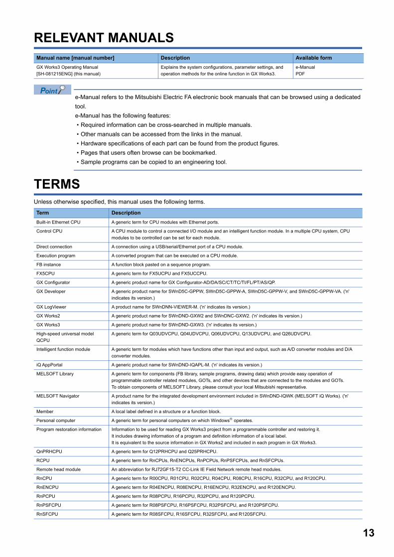
RELEVANT MANUALS
e-Manual refers to the Mitsubishi Electric FA electronic book manuals that can be browsed using a dedicated
tool.
e-Manual has the following features:
• Required information can be cross-searched in multiple manuals.
• Other manuals can be accessed from the links in the manual.
• Hardware specifications of each part can be found from the product figures.
• Pages that users often browse can be bookmarked.
• Sample programs can be copied to an engineering tool.
TERMSUnless otherwise specified, this manual uses the following terms.
Manual name [manual number] Description Available form
GX Works3 Operating Manual
[SH-081215ENG] (this manual)
Explains the system configurations, parameter settings, and
operation methods for the online function in GX Works3.
e-Manual
Term Description
Built-in Ethernet CPU A generic term for CPU modules with Ethernet ports.
Control CPU A CPU module to control a connected I/O module and an intelligent function module. In a multiple CPU system, CPU
modules to be controlled can be set for each module.
Direct connection A connection using a USB/serial/Ethernet port of a CPU module.
Execution program A converted program that can be executed on a CPU module.
FB instance A function block pasted on a sequence program.
FX5CPU A generic term for FX5UCPU and FX5UCCPU.
GX Configurator A generic product name for GX Configurator-AD/DA/SC/CT/TC/TI/FL/PT/AS/QP.
GX Developer A generic product name for SWnD5C-GPPW, SWnD5C-GPPW-A, SWnD5C-GPPW-V, and SWnD5C-GPPW-VA. ('n'
indicates its version.)
GX LogViewer A product name for SWnDNN-VIEWER-M. ('n' indicates its version.)
GX Works2 A generic product name for SWnDND-GXW2 and SWnDNC-GXW2. ('n' indicates its version.)
GX Works3 A generic product name for SWnDND-GXW3. ('n' indicates its version.)
High-speed universal model
QCPU
A generic term for Q03UDVCPU, Q04UDVCPU, Q06UDVCPU, Q13UDVCPU, and Q26UDVCPU.
Intelligent function module A generic term for modules which have functions other than input and output, such as A/D converter modules and D/A
converter modules.
iQ AppPortal A generic product name for SWnDND-IQAPL-M. ('n' indicates its version.)
MELSOFT Library A generic term for components (FB library, sample programs, drawing data) which provide easy operation of
programmable controller related modules, GOTs, and other devices that are connected to the modules and GOTs.
To obtain components of MELSOFT Library, please consult your local Mitsubishi representative.
MELSOFT Navigator A product name for the integrated development environment included in SWnDND-IQWK (MELSOFT iQ Works). ('n'
indicates its version.)
Member A local label defined in a structure or a function block.
Personal computer A generic term for personal computers on which Windows operates.
Program restoration information Information to be used for reading GX Works3 project from a programmable controller and restoring it.
It includes drawing information of a program and definition information of a local label.
It is equivalent to the source information in GX Works2 and included in each program in GX Works3.
QnPRHCPU A generic term for Q12PRHCPU and Q25PRHCPU.
RCPU A generic term for RnCPUs, RnENCPUs, RnPCPUs, RnPSFCPUs, and RnSFCPUs.
Remote head module An abbreviation for RJ72GF15-T2 CC-Link IE Field Network remote head modules.
RnCPU A generic term for R00CPU, R01CPU, R02CPU, R04CPU, R08CPU, R16CPU, R32CPU, and R120CPU.
RnENCPU A generic term for R04ENCPU, R08ENCPU, R16ENCPU, R32ENCPU, and R120ENCPU.
RnPCPU A generic term for R08PCPU, R16PCPU, R32PCPU, and R120PCPU.
RnPSFCPU A generic term for R08PSFCPU, R16PSFCPU, R32PSFCPU, and R120PSFCPU.
RnSFCPU A generic term for R08SFCPU, R16SFCPU, R32SFCPU, and R120SFCPU.
14
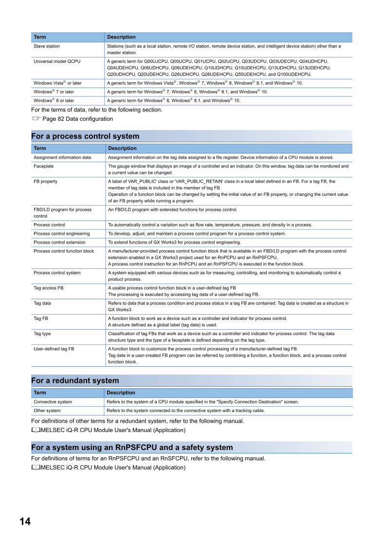
For the terms of data, refer to the following section.
Page 82 Data configuration
For a process control system
For a redundant system
For definitions of other terms for a redundant system, refer to the following manual.
MELSEC iQ-R CPU Module User's Manual (Application)
For a system using an RnPSFCPU and a safety systemFor definitions of terms for an RnPSFCPU and an RnSFCPU, refer to the following manual.
MELSEC iQ-R CPU Module User's Manual (Application)
Slave station Stations (such as a local station, remote I/O station, remote device station, and intelligent device station) other than a
master station.
Universal model QCPU A generic term for Q00UJCPU, Q00UCPU, Q01UCPU, Q02UCPU, Q03UDCPU, Q03UDECPU, Q04UDHCPU,
Q04UDEHCPU, Q06UDHCPU, Q06UDEHCPU, Q10UDHCPU, Q10UDEHCPU, Q13UDHCPU, Q13UDEHCPU,
Q20UDHCPU, Q20UDEHCPU, Q26UDHCPU, Q26UDEHCPU, Q50UDEHCPU, and Q100UDEHCPU.
Windows Vista or later A generic term for Windows Vista, Windows 7, Windows 8, Windows 8.1, and Windows 10.
Windows 7 or later A generic term for Windows 7, Windows 8, Windows 8.1, and Windows 10.
Windows 8 or later A generic term for Windows 8, Windows 8.1, and Windows 10.
Term Description
Assignment information data Assignment information on the tag data assigned to a file register. Device information of a CPU module is stored.
Faceplate The gauge window that displays an image of a controller and an indicator. On this window, tag data can be monitored and
a current value can be changed.
FB property A label of VAR_PUBLIC' class or 'VAR_PUBLIC_RETAIN' class in a local label defined in an FB. For a tag FB, the
member of tag data is included in the member of tag FB.
Operation of a function block can be changed by setting the initial value of an FB property, or changing the current value
of an FB property while running a program.
FBD/LD program for process
control
An FBD/LD program with extended functions for process control.
Process control To automatically control a variation such as flow rate, temperature, pressure, and density in a process.
Process control engineering To develop, adjust, and maintain a process control program for a process control system.
Process control extension To extend functions of GX Works3 for process control engineering.
Process control function block A manufacturer-provided process control function block that is available in an FBD/LD program with the process control
extension enabled in a GX Works3 project used for an RnPCPU and an RnPSFCPU.
A process control instruction for an RnPCPU and an RnPSFCPU is executed in the function block.
Process control system A system equipped with various devices such as for measuring, controlling, and monitoring to automatically control a
product process.
Tag access FB A usable process control function block in a user-defined tag FB
The processing is executed by accessing tag data of a user-defined tag FB.
Tag data Refers to data that a process condition and process status in a tag FB are contained. Tag data is created as a structure in
GX Works3.
Tag FB A function block to work as a device such as a controller and indicator for process control.
A structure defined as a global label (tag data) is used.
Tag type Classification of tag FBs that work as a device such as a controller and indicator for process control. The tag data
structure type and the type of a faceplate is defined depending on the tag type.
User-defined tag FB A function block to customize the process control processing of a manufacturer-defined tag FB.
Tag data in a user-created FB program can be referred by combining a function, a function block, and a process control
function block.
Term Description
Connective system Refers to the system of a CPU module specified in the "Specify Connection Destination" screen.
Other system Refers to the system connected to the connective system with a tracking cable.
Term Description
15
PA
RT
1
PART 1 FUNDAMENTALS OF GX Works3
This part explains the screen configuration and basic operations of GX Works3.
1 BEFORE USING THIS PRODUCT
2 SCREEN CONFIGURATION AND BASIC OPERATIONS

161 BEFORE USING THIS PRODUCT1.1 Main Functions of GX Works3
1 BEFORE USING THIS PRODUCT
GX Works3 is an engineering tool for configuring settings, programming, debugging, and performing the maintenance for
programmable controllers such as MELSEC iQ-R series/MELSEC iQ-F series.
By comparing with conventional GX Works2, the functions are enhanced and their operability have been improved.
1.1 Main Functions of GX Works3 GX Works3 manages programs and parameters in each project for each CPU module.
GX Works3 functions are shown below.
Program creation functionPrograms can be created in a programming language appropriate for the processing contents.
<Ladder program> <ST program>
<FBD/LD program> 〈SFC program〉
1 BEFORE USING THIS PRODUCT1.1 Main Functions of GX Works3 17
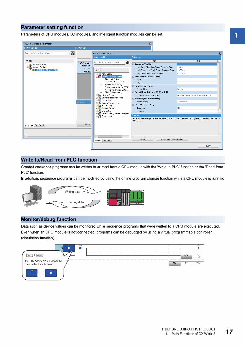
1Parameter setting functionParameters of CPU modules, I/O modules, and intelligent function modules can be set.
Write to/Read from PLC functionCreated sequence programs can be written to or read from a CPU module with the 'Write to PLC' function or the 'Read from
PLC' function.
In addition, sequence programs can be modified by using the online program change function while a CPU module is running.
Monitor/debug functionData such as device values can be monitored while sequence programs that were written to a CPU module are executed.
Even when an CPU module is not connected, programs can be debugged by using a virtual programmable controller
(simulation function).
Writing data
Reading data
Turning ON/OFF by pressing the contact each time.

181 BEFORE USING THIS PRODUCT1.2 RnPCPU
Diagnostic functionThe current error status and error history of a CPU module or network can be diagnosed. The recovery time will be shortened
by this function.
Detailed information on a module, such as an intelligent function module, can be acquired by using the system monitor
function. The recovery time will be much shortened by this function when an error occurs.
1.2 RnPCPUGX Works3 supports both MELSEC iQ-R series RnPCPUs constructing a process control system and a redundant system
and process control programs.
In RnPCPUs, two operation modes are available: process mode and redundant mode. The type of project which can be
created differs depending on the selected mode.
■CPU module diagnostic ("Module Diagnostics" screen)
Mode Description Reference
Process To create a project for process control programs. This section
Redundant To create a project for process control programs and the functions for a redundant system. This section
Page 24 Redundant system
1 BEFORE USING THIS PRODUCT1.2 RnPCPU 19
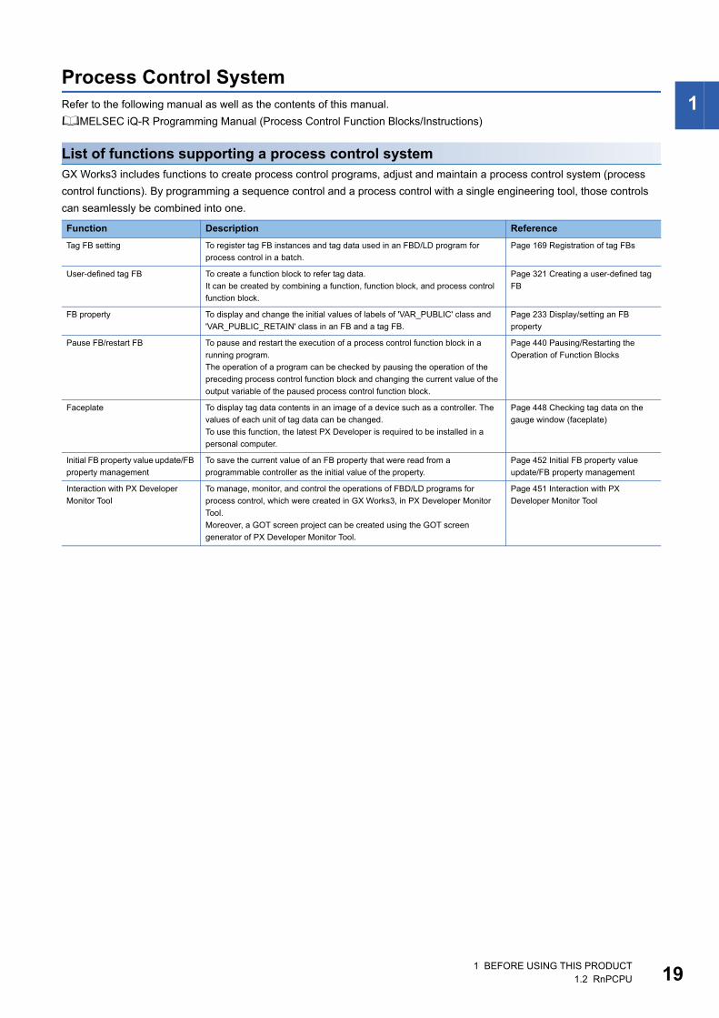
1Process Control SystemRefer to the following manual as well as the contents of this manual.
MELSEC iQ-R Programming Manual (Process Control Function Blocks/Instructions)
List of functions supporting a process control systemGX Works3 includes functions to create process control programs, adjust and maintain a process control system (process
control functions). By programming a sequence control and a process control with a single engineering tool, those controls
can seamlessly be combined into one.
Function Description Reference
Tag FB setting To register tag FB instances and tag data used in an FBD/LD program for
process control in a batch.
Page 169 Registration of tag FBs
User-defined tag FB To create a function block to refer tag data.
It can be created by combining a function, function block, and process control
function block.
Page 321 Creating a user-defined tag
FB
FB property To display and change the initial values of labels of 'VAR_PUBLIC' class and
'VAR_PUBLIC_RETAIN' class in an FB and a tag FB.
Page 233 Display/setting an FB
property
Pause FB/restart FB To pause and restart the execution of a process control function block in a
running program.
The operation of a program can be checked by pausing the operation of the
preceding process control function block and changing the current value of the
output variable of the paused process control function block.
Page 440 Pausing/Restarting the
Operation of Function Blocks
Faceplate To display tag data contents in an image of a device such as a controller. The
values of each unit of tag data can be changed.
To use this function, the latest PX Developer is required to be installed in a
personal computer.
Page 448 Checking tag data on the
gauge window (faceplate)
Initial FB property value update/FB
property management
To save the current value of an FB property that were read from a
programmable controller as the initial value of the property.
Page 452 Initial FB property value
update/FB property management
Interaction with PX Developer
Monitor Tool
To manage, monitor, and control the operations of FBD/LD programs for
process control, which were created in GX Works3, in PX Developer Monitor
Tool.
Moreover, a GOT screen project can be created using the GOT screen
generator of PX Developer Monitor Tool.
Page 451 Interaction with PX
Developer Monitor Tool
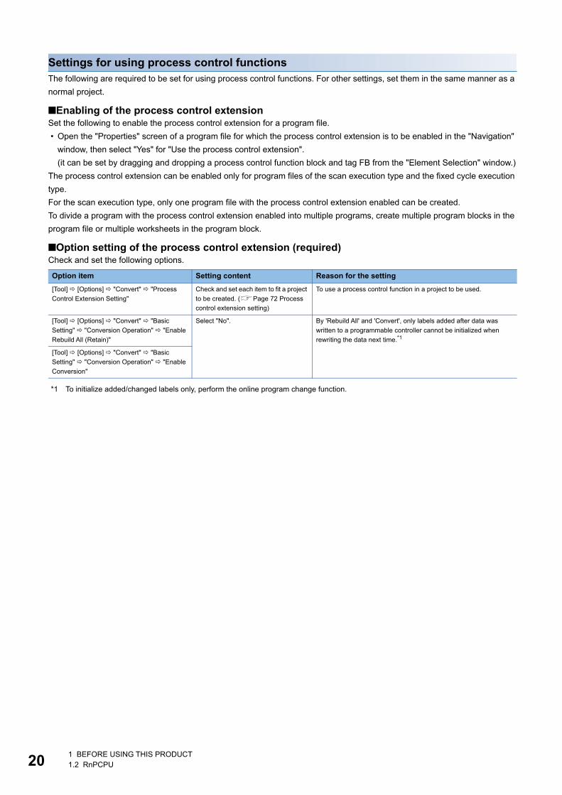
201 BEFORE USING THIS PRODUCT1.2 RnPCPU
Settings for using process control functionsThe following are required to be set for using process control functions. For other settings, set them in the same manner as a
normal project.
■Enabling of the process control extensionSet the following to enable the process control extension for a program file.
• Open the "Properties" screen of a program file for which the process control extension is to be enabled in the "Navigation"
window, then select "Yes" for "Use the process control extension".
(it can be set by dragging and dropping a process control function block and tag FB from the "Element Selection" window.)
The process control extension can be enabled only for program files of the scan execution type and the fixed cycle execution
type.
For the scan execution type, only one program file with the process control extension enabled can be created.
To divide a program with the process control extension enabled into multiple programs, create multiple program blocks in the
program file or multiple worksheets in the program block.
■Option setting of the process control extension (required)Check and set the following options.
*1 To initialize added/changed labels only, perform the online program change function.
Option item Setting content Reason for the setting
[Tool] [Options] "Convert" "Process
Control Extension Setting"
Check and set each item to fit a project
to be created. (Page 72 Process
control extension setting)
To use a process control function in a project to be used.
[Tool] [Options] "Convert" "Basic
Setting" "Conversion Operation" "Enable
Rebuild All (Retain)"
Select "No". By 'Rebuild All' and 'Convert', only labels added after data was
written to a programmable controller cannot be initialized when
rewriting the data next time.*1
[Tool] [Options] "Convert" "Basic
Setting" "Conversion Operation" "Enable
Conversion"

1 BEFORE USING THIS PRODUCT1.2 RnPCPU 21
1
■CPU parameter settingSet the following items of "CPU Parameter".
*1 The "Latch Range Setting" screen appears by selecting in "Device Setting" [...] button of "Detailed Setting" [...] button on the "Latch (2)" column
*2 It can also be set by clicking the [Yes] button in the screen that appears when setting the following parameter item."File Setting" "File Register Setting" "Use Common File Register in All Programs" for "Use Or Not Setting"
■Execution cycle settingSet the execution cycle of a program with the process control extension enabled to fit the processing.
■Process control extension toolbarThe following toolbar appears in a project for which the process control functions are usable.
■Multiple comment display settingDescriptions of the labels in a tag FB and in the structure members of tag data are displayed by setting "English" for "Target"
in the "Multiple Comments Display Setting" screen.*1
*1 The "Multiple Comments Display Setting" screen will appear by selecting the following menu.[View] [Multiple Comments Display Setting]
The following table shows the display examples.
Parameter item Setting content Reason for the setting
"File Setting" "File Register Setting" "Use
Or Not Setting"
Select "Use Common File Register in
All Programs".
Tag FBs use file registers.
"Memory/Device Setting" "Device/Label
Memory Area Setting" "Device/Label
Memory Area Detailed Setting" "Device
Setting"
Set 'ZR(R)' in the [Latch (2)] tab in the
"Latch Range Setting" screen.*1,*2File registers used in tag FBs need to be latched.
"File Setting" "Label Initial Value Reflection
Setting" "Label Initial Value Reflection
Setting at STOP to RUN"
Select "Disable". To apply initial label values only once to the current values at the
timing when the status of a CPU module switches from STOP to
RUN after writing the data.
"Memory/Device Setting" "Index Register
Setting" "Points Setting" "Total Points"
"Index Register (Z)"
Set seven points or higher. 'Z0' to 'Z6' are used for system data (system header and system
footer) to extend a process control.
Execution type Setting content
Scan Set the execution cycle in the "Properties" screen of a program block.
Fixed scan Set the fixed cycle interval in the program setting of CPU parameters.
Function Display location Display example
FBD/LD editor Option in the edit box
Label comment
Tool hint
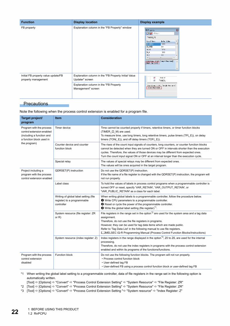
221 BEFORE USING THIS PRODUCT1.2 RnPCPU
Precautions
Note the following when the process control extension is enabled for a program file.
*1 When writing the global label setting to a programmable controller, data of file registers in the range set in the following option is automatically written.[Tool] [Options] "Convert" "Process Control Extension Setting" "System Resource" "File Register: ZR"
*2 [Tool] [Options] "Convert" "Process Control Extension Setting" "System Resource" "File Register: ZR"*3 [Tool] [Options] "Convert" "Process Control Extension Setting " "System resource" "Index Register: Z"
FB property Explanation column in the "FB Property" window
Initial FB property value update/FB
property management
Explanation column in the "FB Property Initial Value
Updater" screen
Explanation column in the "FB Property
Management" screen
Target project/program
Item Consideration
Program with the process
control extension enabled
(including a function and
a function block used in
the program)
Timer device Time cannot be counted properly if timers, retentive timers, or timer function blocks
(TIMER__M) are used.
To measure time, use long timers, long retentive timers, pulse timers (TP(_E)), on delay
timers (TON(_E)), and off delay timers (TOF(_E)).
Counter device and counter
function block
The rises of the count input signals of counters, long counters, or counter function blocks
cannot be detected when they are turned ON or OFF in intervals shorter than the execution
cycles. Therefore, the values of those devices may be different from expected ones.
Turn the count input signal ON or OFF at an interval longer than the execution cycle.
Special relay The values of special relays may be different from expected ones.
The values will be ones acquired in the target program.
Project including a
program with the process
control extension enabled
QDRSET(P) instruction Do not use the QDRSET(P) instruction.
If the file name of a file register is changed with the QDRSET(P) instruction, the program will
not run properly.
Label class To hold the values of labels in process control programs when a programmable controller is
turned OFF or reset, specify 'VAR_RETAIN', 'VAR_OUTPUT_RETAIN', or
'VAR_PUBLIC_RETAIN' as a class for each label.
Writing of global label setting (file
register) to a programmable
controller
When writing global labels to a programmable controller, follow the procedure below.
Write CPU parameters to a programmable controller.
Reset or cycle the power of the programmable controller.
Write the global label setting (file register)*1.
System resource (file register: ZR
or R)
File registers in the range set in the option*2 are used for the system area and a tag data
assignment.
Therefore, do not use the file registers in programs.
However, they can be used for tag data items which are made public.
Refer to 'Tag Data List' in the following manual to use file registers.
MELSEC iQ-R Programming Manual (Process Control Function Blocks/Instructions)
System resource (index register: Z) Index registers in the range displayed in the option*3, Z0 to Z6, are used for the internal
processing.
Therefore, do not use the index registers in programs with the process control extension
enabled and within its programs of the functions/functions.
Program with the process
control extension
disabled
Function block Do not use the following function blocks. The program will not run properly.
• Process control function block
• User-defined tag FB
• User-defined FB using a process control function block or user-defined tag FB
Function Display location Display example

1 BEFORE USING THIS PRODUCT1.2 RnPCPU 23
1Differences in terms between GX Works3 and PX DeveloperThere are differences in terms related to the process control functions between PX Developer and GX Works3 that are
engineering tools used to create process control programs. The following table shows the terms in PX Developer and GX
Works3 to compare each other.
Terms for PX Developer Terms for GX Works3
Cold-start compile Rebuild all (reassignment)
Compile (online change) Online program change
Constant VAR_CONSTANT
Device variable Device
Entry variable monitor Watch
General function, general FB Standard function, function block
Global variable Global label
Hot-start compile Rebuilt all (retain), convert
I/O simulation setting [Tool] [I/O System Setting] or [Start I/O System Setting] in GX Simulator3
screen
Input variable VAR_INPUT
Internal variable VAR, VAR_RETAIN
Local variable Local Label
Module FB Module label and module FB
Output variable VAR_OUTPUT, VAR_OUTPUT_RETAIN
Process function, process FB Process control function block
Program execution setting Execution type of a program file
Project parameter [Tool] [Options] "Convert" "Process Control Extension Setting"
Public variable VAR_PUBLIC, VAR_PUBLIC_RETAIN
Reading the current value of an FB property Initial FB property value update
Tag FB variable Tag FB instance and tag data
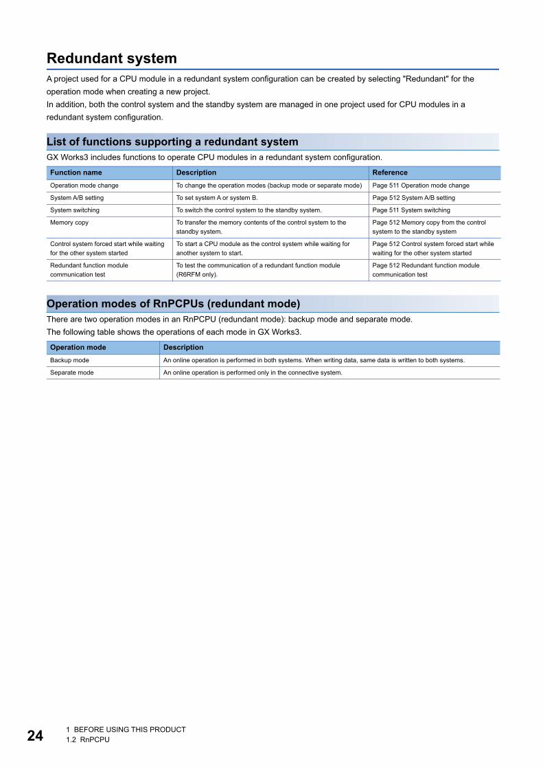
241 BEFORE USING THIS PRODUCT1.2 RnPCPU
Redundant systemA project used for a CPU module in a redundant system configuration can be created by selecting "Redundant" for the
operation mode when creating a new project.
In addition, both the control system and the standby system are managed in one project used for CPU modules in a
redundant system configuration.
List of functions supporting a redundant systemGX Works3 includes functions to operate CPU modules in a redundant system configuration.
Operation modes of RnPCPUs (redundant mode)There are two operation modes in an RnPCPU (redundant mode): backup mode and separate mode.
The following table shows the operations of each mode in GX Works3.
Function name Description Reference
Operation mode change To change the operation modes (backup mode or separate mode) Page 511 Operation mode change
System A/B setting To set system A or system B. Page 512 System A/B setting
System switching To switch the control system to the standby system. Page 511 System switching
Memory copy To transfer the memory contents of the control system to the
standby system.
Page 512 Memory copy from the control
system to the standby system
Control system forced start while waiting
for the other system started
To start a CPU module as the control system while waiting for
another system to start.
Page 512 Control system forced start while
waiting for the other system started
Redundant function module
communication test
To test the communication of a redundant function module
(R6RFM only).
Page 512 Redundant function module
communication test
Operation mode Description
Backup mode An online operation is performed in both systems. When writing data, same data is written to both systems.
Separate mode An online operation is performed only in the connective system.
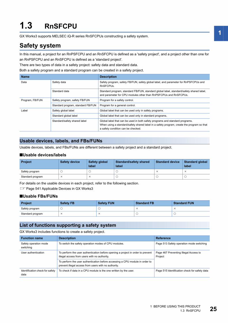
1 BEFORE USING THIS PRODUCT1.3 RnSFCPU 25
11.3 RnSFCPUGX Works3 supports MELSEC iQ-R series RnSFCPUs constructing a safety system.
Safety systemIn this manual, a project for an RnPSFCPU and an RnSFCPU is defined as a 'safety project', and a project other than one for
an RnPSFCPU and an RnSFCPU is defined as a 'standard project'.
There are two types of data in a safety project: safety data and standard data.
Both a safety program and a standard program can be created in a safety project.
Usable devices, labels, and FBs/FUNsUsable devices, labels, and FBs/FUNs are different between a safety project and a standard project.
■Usable devices/labels
For details on the usable devices in each project, refer to the following section.
Page 541 Applicable Devices in GX Works3
■Usable FBs/FUNs
List of functions supporting a safety systemGX Works3 includes functions to create a safety project.
Name Description
Data Safety data Safety program, safety FB/FUN, safety global label, and parameter for RnPSFCPUs and
RnSFCPUs.
Standard data Standard program, standard FB/FUN, standard global label, standard/safety shared label,
and parameter for CPU modules other than RnPSFCPUs and RnSFCPUs.
Program, FB/FUN Safety program, safety FB/FUN Program for a safety control.
Standard program, standard FB/FUN Program for a general control.
Label Safety global label Global label that can be used only in safety programs.
Standard global label Global label that can be used only in standard programs.
Standard/safety shared label Global label that can be used in both safety programs and standard programs.
When using a standard/safety shared label in a safety program, create the program so that
a safety condition can be checked.
Project Safety device Safety global label
Standard/safety shared label
Standard device Standard global label
Safety program
Standard program
Project Safety FB Safety FUN Standard FB Standard FUN
Safety program
Standard program
Function name Description Reference
Safety operation mode
switching
To switch the safety operation modes of CPU modules. Page 513 Safety operation mode switching
User authentication To perform the user authentication before opening a project in order to prevent
illegal access from users with no authority.
Page 467 Preventing Illegal Access to
Project
To perform the user authentication before accessing a CPU module in order to
prevent illegal access from users with no authority.
Identification check for safety
data
To check if data in a CPU module is the one written by the user. Page 515 Identification check for safety data
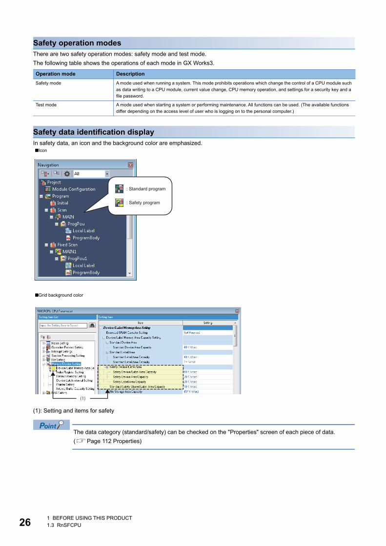
261 BEFORE USING THIS PRODUCT1.3 RnSFCPU
Safety operation modesThere are two safety operation modes: safety mode and test mode.
The following table shows the operations of each mode in GX Works3.
Safety data identification displayIn safety data, an icon and the background color are emphasized.
(1): Setting and items for safety
The data category (standard/safety) can be checked on the "Properties" screen of each piece of data.
(Page 112 Properties)
Operation mode Description
Safety mode A mode used when running a system. This mode prohibits operations which change the control of a CPU module such
as data writing to a CPU module, current value change, CPU memory operation, and settings for a security key and a
file password.
Test mode A mode used when starting a system or performing maintenance. All functions can be used. (The available functions
differ depending on the access level of user who is logging on to the personal computer.)
■Icon
■Grid background color
: Safety program
: Standard program
(1)
1 BEFORE USING THIS PRODUCT1.4 RnPSFCPU 27
11.4 RnPSFCPUGX Works3 supports MELSEC iQ-R series RnPSFCPUs constructing a process control system, a safety system, and a
redundant system.
For details on an RnPSFCPU system, refer to the following manual.
MELSEC iQ-R CPU Module User's Manual (Application)
Process control systemTwo types of programs, safety program and standard program, can be created in a project used for RnPSFCPUs.
Process control programs can only be created in a standard program.
For a process control system, refer to the following section.
Page 19 Process Control System
Safety systemFor a safety system, refer to the following section.
Page 25 Safety system
List of functions supporting a safety system using an RnPSFCPUFor the functions common to a safety system using an RnSFCPU, refer to the following section.
Page 25 List of functions supporting a safety system
The following functions can be used only in a system using an RnPSFCPU.
Redundant systemOnly the redundant mode can be selected for the operation mode of an RnPSFCPU.
For a redundant system, refer to the following section.
Page 24 Redundant system
Operation modes of RnPSFCPUsOnly the backup mode can be selected for the operation mode of an RnPSFCPU.
An online operation is performed in both systems in the backup mode.
Function name Description Reference
User authentication To log off from a CPU module that the user authentication is performed. Page 473 Logging off from a CPU module
To copy user information to the other system to match it between both systems. Page 473 Copying user information to the
other system
Safety module operation To set whether or not to enable the safety communication function for modules
used in a system using an RnPSFCPU.
Page 516 Safety module operation

281 BEFORE USING THIS PRODUCT1.5 Remote Head Module
1.5 Remote Head ModuleGX Works3 supports MELSEC iQ-R series remote head modules.
And, a remote head module supports a redundant system configuration.
When creating a new project, a module type needs to be selected according to the system configuration to be created.
For details on a redundant system configuration, refer to the following manual.
MELSEC iQ-R CC-Link IE Field Network Remote Head Module User's Manual (Application)
Any programs cannot be created for a project of a remote head module.
Therefore, a program needs to be created for a project of a CPU module on the master station.
List of functions supporting remote head modules in a redundant system configurationGX Works3 includes functions to operate remote head modules in a redundant system configuration.
1.6 NCCPUGX Works3 supports MELSEC iQ-R series NCCPUs.
In an NCCPU project, ladder programs including devices can be applied. Data of labels and parameters can be edited but
they are not written.
For details on NCCPUs, refer to the manual of NCCPUs.
Project System configuration
RJ72GF15-T2 Configuration other than that for a redundant system
RJ72GF15-T2(SR) Redundant system configuration (single line)
RJ72GF15-T2(LR) Redundant system configuration (redundant line)
Function name
Description Reference
System
switching
To switch the control system of a remote head module to the standby system. Page 511 System switching

1 BEFORE USING THIS PRODUCT1.7 Procedure from Project Creation to CPU Module Operation 29
11.7 Procedure from Project Creation to CPU Module
OperationThe operating procedure from program creation to a CPU module operation in GX Works3 is shown below.
For the operation methods of a CPU module, refer to the following manuals.
MELSEC iQ-R CPU Module User's Manual (Application)
MELSEC iQ-F FX5 User's Manual (Application)
MELSEC iQ-R CC-Link IE Field Network Remote Head Module User's Manual (Application)
Standard projectTarget module type: RnCPUs, RnENCPUs, RnPCPUs (with the process control extension disabled)
Page 39 Start
Page 85 Creating a project
Page 137 Setting Parameters
Page 108 Creating data
Page 180 Program Execution Order and Execution Type Settings
Page 157 Registering Labels
Page 182 Creating a Ladder Program, Page 217 Creating an ST Program,
Page 223 Creating an FBD/LD Program, Page 240 Creating an SFC Program,
Page 317 Creating a Function Block, Page 328 Creating a Function
Page 279 Converting Programs
Page 342 PROGRAM SIMULATION
Page 371 SETTING ROUTE TO CPU MODULE
Start
1. Create a project.
Start GX Works3.
Create a new project.
2. Set the parameters.
3. Create a program.
Create a Program Organization Unit (POU).
Set the global labels/local labels.
Edit the program of each POU.
Perform conversion.
Set an execution order and an execution type.
4. Perform debugging with the simulator.
5. Connect a personal computer to a CPU module, and set the connection destination.
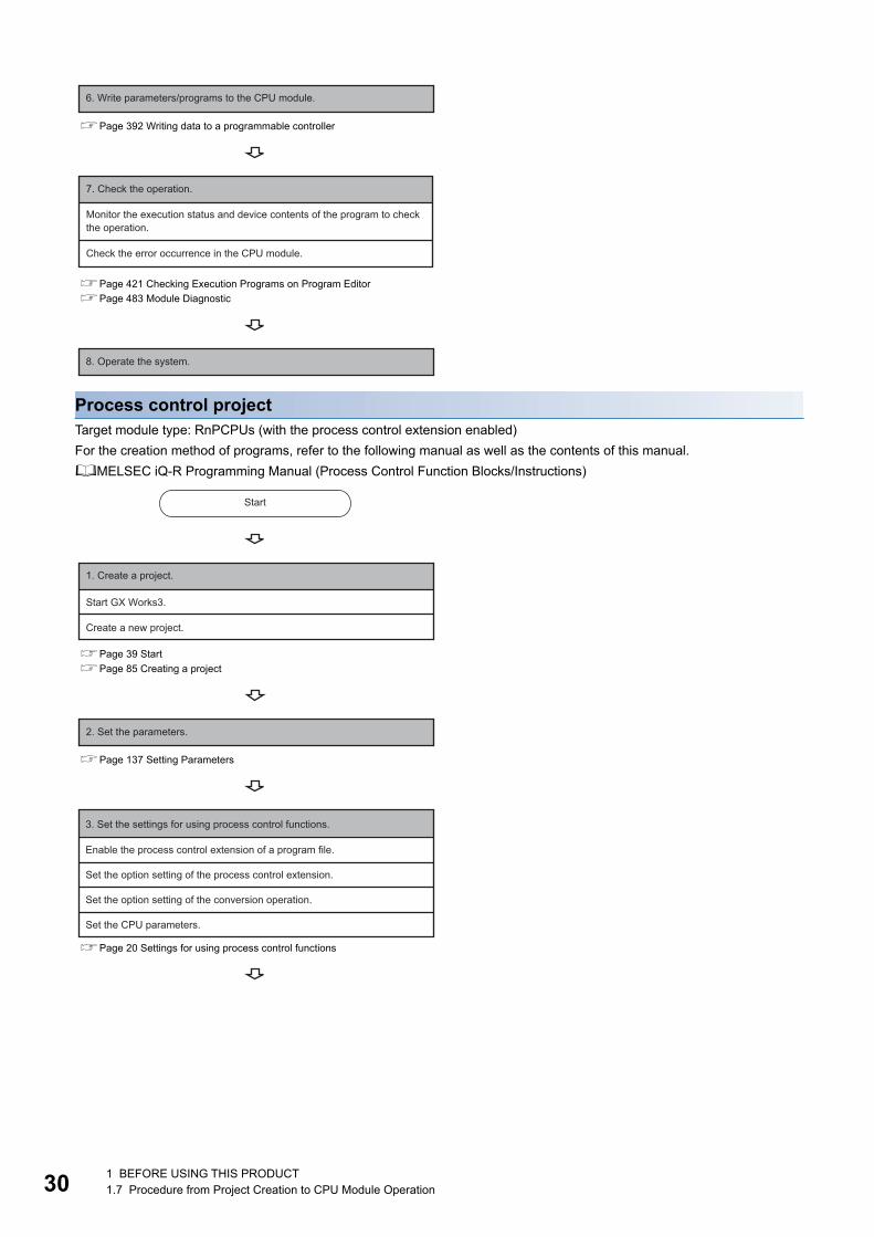
301 BEFORE USING THIS PRODUCT1.7 Procedure from Project Creation to CPU Module Operation
Process control projectTarget module type: RnPCPUs (with the process control extension enabled)
For the creation method of programs, refer to the following manual as well as the contents of this manual.
MELSEC iQ-R Programming Manual (Process Control Function Blocks/Instructions)
Page 392 Writing data to a programmable controller
Page 421 Checking Execution Programs on Program Editor
Page 483 Module Diagnostic
Page 39 Start
Page 85 Creating a project
Page 137 Setting Parameters
Page 20 Settings for using process control functions
6. Write parameters/programs to the CPU module.
7. Check the operation.
Monitor the execution status and device contents of the program to check the operation.
Check the error occurrence in the CPU module.
8. Operate the system.
Start
1. Create a project.
Start GX Works3.
Create a new project.
2. Set the parameters.
3. Set the settings for using process control functions.
Set the option setting of the process control extension.
Set the CPU parameters.
Enable the process control extension of a program file.
Set the option setting of the conversion operation.

1 BEFORE USING THIS PRODUCT1.7 Procedure from Project Creation to CPU Module Operation 31
1
Page 169 Registration of tag FBs
Page 108 Creating data
Page 233 Display/setting an FB property
Page 223 Creating an FBD/LD Program, Page 317 Creating a Function
Block, Page 233 Utilizing a tag FB, Page 321 Creating a user-defined tag FB,
Page 328 Creating a Function
Page 279 Converting Programs
Page 371 SETTING ROUTE TO CPU MODULE
Page 392 Writing data to a programmable controller
Page 421 Checking Execution Programs on Program Editor, Page 440
Pausing/Restarting the Operation of Function Blocks
Page 483 Module Diagnostic
Page 434 Checking Current Values by Registering Devices/Labels
Page 448 Checking tag data
Page 452 Initial FB property value update/FB property management
4. Create a program.
Perform conversion.
Create a program for sequence control.
Set the initial value of an FB property.
Create an FBD/LD program for process control.
Register a tag FB.
5. Connect a personal computer to a CPU module, and set the connection destination.
6. Write parameters/programs to the CPU module.
7. Check the operation.
Monitor the execution status and device contents of the program to check the operation.
Check the error occurrence in the CPU module.
Check the control status of a tag FB on a faceplate.
Change the current value of an FB property on the watch window.
Set the current value of an FB property as the initial value of the FB property.
8. Operate the system.

321 BEFORE USING THIS PRODUCT1.7 Procedure from Project Creation to CPU Module Operation
Safety projectTarget module type: RnSFCPUs, RnPSFCPUs (with the process control extension disabled)
Page 39 Start
Page 85 Creating a project
Page 469 User management
Page 105 Saving a project
Page 137 Setting Parameters
Page 108 Creating data
Page 180 Program Execution Order and Execution Type Settings
Page 157 Registering Labels
Page 182 Creating a Ladder Program, Page 317 Creating a Function
Block, Page 328 Creating a Function
Page 279 Converting Programs
Page 371 SETTING ROUTE TO CPU MODULE
Page 392 Writing data to a programmable controller
Start
1. Create a project.
Start GX Works3.
Create a new project.
Register user information.
Save the project.
Setting the safety device/label area is required.
2. Set the parameters.
3. Create a program.
Create a Program Organization Unit (POU).
Set the global labels/local labels.
Edit the program of each POU.
Perform conversion.
Set an execution order and an execution type.
4. Connect a personal computer to a CPU module, and set the connection destination.
5. Write parameters/programs to the CPU module.
Monitor the execution status and device contents of the program to check the operation.
Check the error occurrence in the CPU module.
6. Check the operation. (Test mode)

1 BEFORE USING THIS PRODUCT1.7 Procedure from Project Creation to CPU Module Operation 33
1
Safety project for which the process control extension is set to be usedTarget module type: RnPSFCPUs (with the process control extension enabled)
For the creation method of programs, refer to the following manual as well as the contents of this manual.
MELSEC iQ-R Programming Manual (Process Control Function Blocks/Instructions)
Page 421 Checking Execution Programs on Program Editor
Page 483 Module Diagnostic
Page 515 Identification check for safety data
Page 513 Safety operation mode switching
Page 39 Start
Page 85 Creating a project
Page 469 User management
Page 105 Saving a project
Page 137 Setting Parameters
Page 20 Settings for using process control functions
Check whether the written project is correct.
Switch it the safety mode.
7. Switch the safety operation modes.
8. Operate the system.
Start
1. Create a project.
Start GX Works3.
Create a new project.
Register user information.
Save the project.
Setting the safety device/label area is required.
2. Set the parameters.
3. Set the settings for using process control functions.
Set the option setting of the process control extension.
Set the CPU parameters.
Enable the process control extension of a program file.
Set the option setting of the conversion operation.
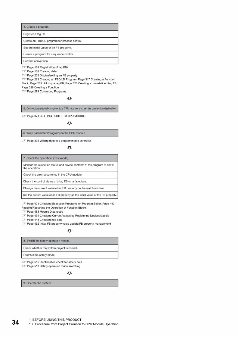
341 BEFORE USING THIS PRODUCT1.7 Procedure from Project Creation to CPU Module Operation
Page 169 Registration of tag FBs
Page 108 Creating data
Page 233 Display/setting an FB property
Page 223 Creating an FBD/LD Program, Page 317 Creating a Function
Block, Page 233 Utilizing a tag FB, Page 321 Creating a user-defined tag FB,
Page 328 Creating a Function
Page 279 Converting Programs
Page 371 SETTING ROUTE TO CPU MODULE
Page 392 Writing data to a programmable controller
Page 421 Checking Execution Programs on Program Editor, Page 440
Pausing/Restarting the Operation of Function Blocks
Page 483 Module Diagnostic
Page 434 Checking Current Values by Registering Devices/Labels
Page 448 Checking tag data
Page 452 Initial FB property value update/FB property management
Page 515 Identification check for safety data
Page 513 Safety operation mode switching
4. Create a program.
Perform conversion.
Create a program for sequence control.
Set the initial value of an FB property.
Create an FBD/LD program for process control.
Register a tag FB.
5. Connect a personal computer to a CPU module, and set the connection destination.
6. Write parameters/programs to the CPU module.
7. Check the operation. (Test mode)
Monitor the execution status and device contents of the program to check the operation.
Check the error occurrence in the CPU module.
Check the control status of a tag FB on a faceplate.
Change the current value of an FB property on the watch window.
Set the current value of an FB property as the initial value of the FB property.
Check whether the written project is correct.
Switch it the safety mode.
8. Switch the safety operation modes.
9. Operate the system.
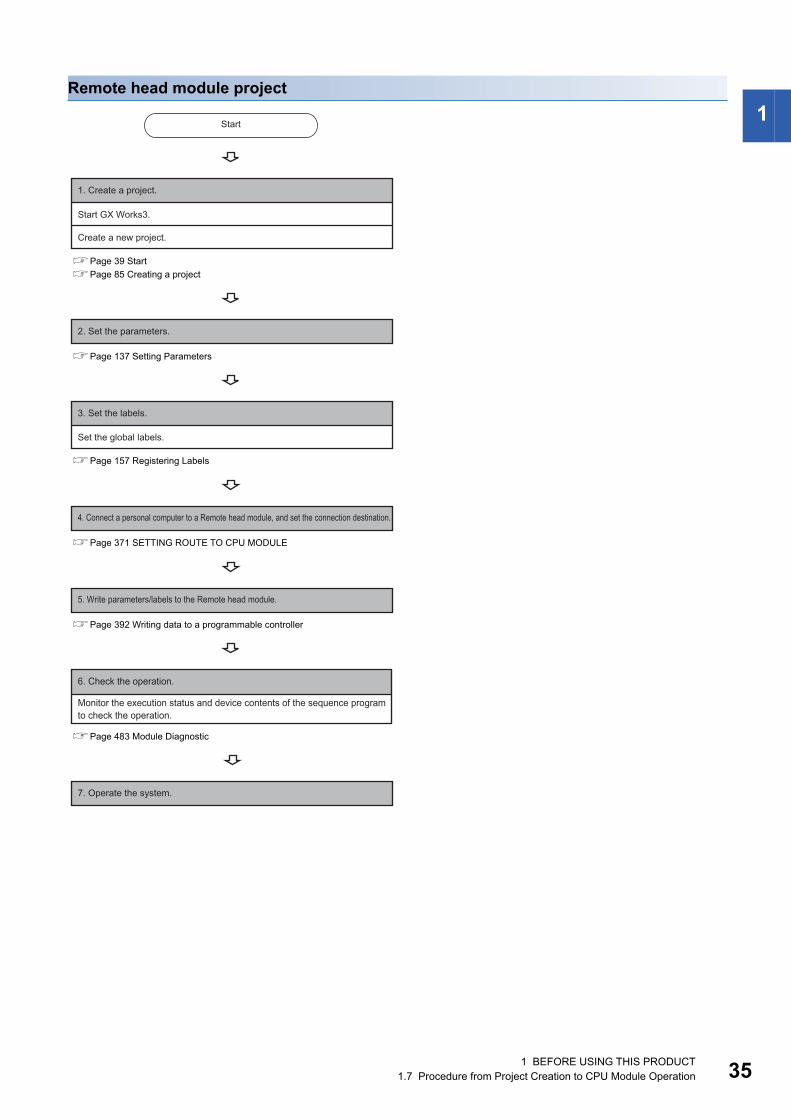
1 BEFORE USING THIS PRODUCT1.7 Procedure from Project Creation to CPU Module Operation 35
1Remote head module project
Page 39 Start
Page 85 Creating a project
Page 137 Setting Parameters
Page 157 Registering Labels
Page 371 SETTING ROUTE TO CPU MODULE
Page 392 Writing data to a programmable controller
Page 483 Module Diagnostic
Start
1. Create a project.
Start GX Works3.
Create a new project.
2. Set the parameters.
Set the global labels.
3. Set the labels.
4. Connect a personal computer to a Remote head module, and set the connection destination.
5. Write parameters/labels to the Remote head module.
6. Check the operation.
Monitor the execution status and device contents of the sequence program to check the operation.
7. Operate the system.
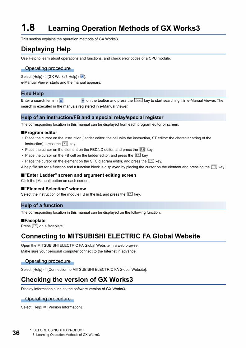
361 BEFORE USING THIS PRODUCT1.8 Learning Operation Methods of GX Works3
1.8 Learning Operation Methods of GX Works3This section explains the operation methods of GX Works3.
Displaying HelpUse Help to learn about operations and functions, and check error codes of a CPU module.
Operating procedure
Select [Help] [GX Works3 Help] ( ).
e-Manual Viewer starts and the manual appears.
Find HelpEnter a search term in on the toolbar and press the key to start searching it in e-Manual Viewer. The
search is executed in the manuals registered in e-Manual Viewer.
Help of an instruction/FB and a special relay/special registerThe corresponding location in this manual can be displayed from each program editor or screen.
■Program editor • Place the cursor on the instruction (ladder editor: the cell with the instruction, ST editor: the character string of the
instruction), press the key.
• Place the cursor on the element on the FBD/LD editor, and press the key.
• Place the cursor on the FB cell on the ladder editor, and press the key
• Place the cursor on the element on the SFC diagram editor, and press the key.
A help file set for a function and a function block is displayed by placing the cursor on the element and pressing the key.
■"Enter Ladder" screen and argument editing screenClick the [Manual] button on each screen.
■"Element Selection" windowSelect the instruction or the module FB in the list, and press the key.
Help of a functionThe corresponding location in this manual can be displayed on the following function.
■FaceplatePress on a faceplate.
Connecting to MITSUBISHI ELECTRIC FA Global WebsiteOpen the MITSUBISHI ELECTRIC FA Global Website in a web browser.
Make sure your personal computer connect to the Internet in advance.
Operating procedure
Select [Help] [Connection to MITSUBISHI ELECTRIC FA Global Website].
Checking the version of GX Works3Display information such as the software version of GX Works3.
Operating procedure
Select [Help] [Version Information].
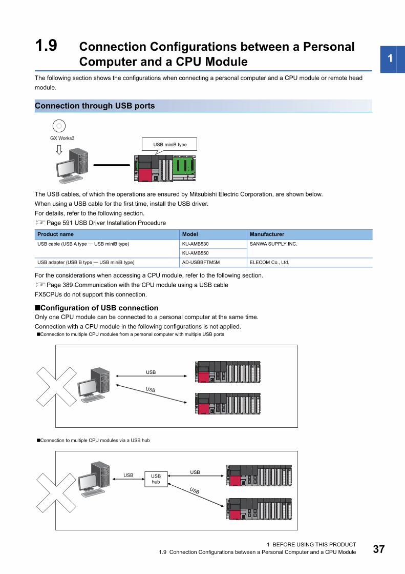
1 BEFORE USING THIS PRODUCT1.9 Connection Configurations between a Personal Computer and a CPU Module 37
11.9 Connection Configurations between a Personal
Computer and a CPU ModuleThe following section shows the configurations when connecting a personal computer and a CPU module or remote head
module.
Connection through USB ports
The USB cables, of which the operations are ensured by Mitsubishi Electric Corporation, are shown below.
When using a USB cable for the first time, install the USB driver.
For details, refer to the following section.
Page 591 USB Driver Installation Procedure
For the considerations when accessing a CPU module, refer to the following section.
Page 389 Communication with the CPU module using a USB cable
FX5CPUs do not support this connection.
■Configuration of USB connectionOnly one CPU module can be connected to a personal computer at the same time.
Connection with a CPU module in the following configurations is not applied.
Product name Model Manufacturer
USB cable (USB A type USB miniB type) KU-AMB530 SANWA SUPPLY INC.
KU-AMB550
USB adapter (USB B type USB miniB type) AD-USBBFTM5M ELECOM Co., Ltd.
■Connection to multiple CPU modules from a personal computer with multiple USB ports
■Connection to multiple CPU modules via a USB hub
GX Works3 USB miniB type
USB
USB
USB USB
USB
USB hub
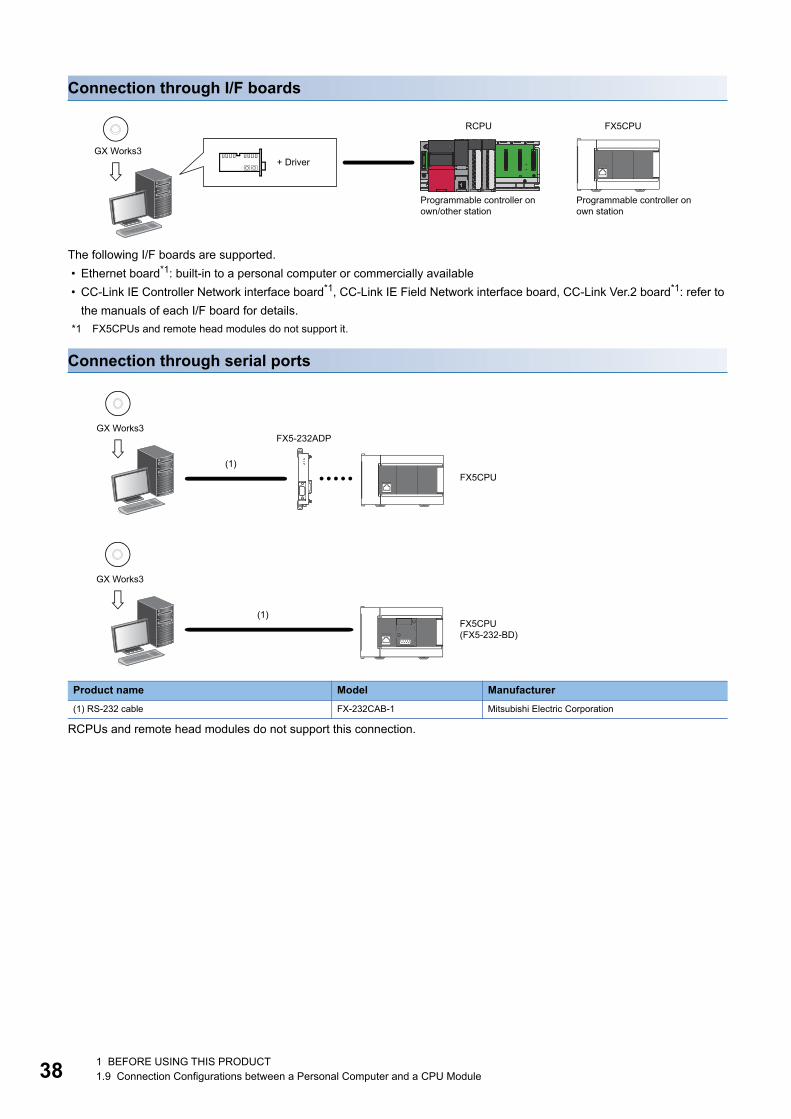
381 BEFORE USING THIS PRODUCT1.9 Connection Configurations between a Personal Computer and a CPU Module
Connection through I/F boards
The following I/F boards are supported.
• Ethernet board*1: built-in to a personal computer or commercially available
• CC-Link IE Controller Network interface board*1, CC-Link IE Field Network interface board, CC-Link Ver.2 board*1: refer to
the manuals of each I/F board for details.
*1 FX5CPUs and remote head modules do not support it.
Connection through serial ports
RCPUs and remote head modules do not support this connection.
Product name Model Manufacturer
(1) RS-232 cable FX-232CAB-1 Mitsubishi Electric Corporation
RCPU FX5CPU
GX Works3+ Driver
Programmable controller on own/other station
Programmable controller on own station
FX5CPU
FX5-232ADP
FX5CPU(FX5-232-BD)
GX Works3
(1)
GX Works3
(1)
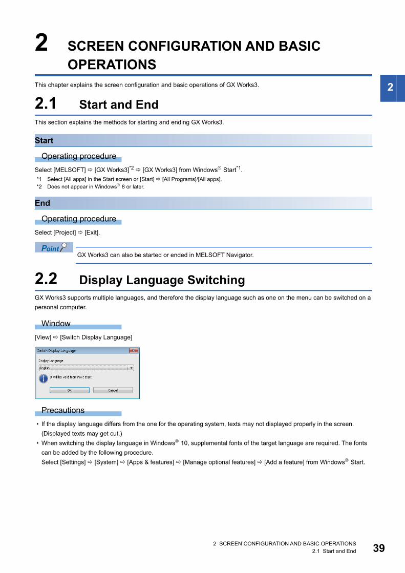
2 SCREEN CONFIGURATION AND BASIC OPERATIONS2.1 Start and End 39
2
2 SCREEN CONFIGURATION AND BASIC OPERATIONS
This chapter explains the screen configuration and basic operations of GX Works3.
2.1 Start and EndThis section explains the methods for starting and ending GX Works3.
Start
Operating procedure
Select [MELSOFT] [GX Works3]*2 [GX Works3] from Windows Start*1.
*1 Select [All apps] in the Start screen or [Start] [All Programs]/[All apps].*2 Does not appear in Windows 8 or later.
End
Operating procedure
Select [Project] [Exit].
GX Works3 can also be started or ended in MELSOFT Navigator.
2.2 Display Language SwitchingGX Works3 supports multiple languages, and therefore the display language such as one on the menu can be switched on a
personal computer.
Window
[View] [Switch Display Language]
Precautions
• If the display language differs from the one for the operating system, texts may not displayed properly in the screen.
(Displayed texts may get cut.)
• When switching the display language in Windows 10, supplemental fonts of the target language are required. The fonts
can be added by the following procedure.
Select [Settings] [System] [Apps & features] [Manage optional features] [Add a feature] from Windows Start.
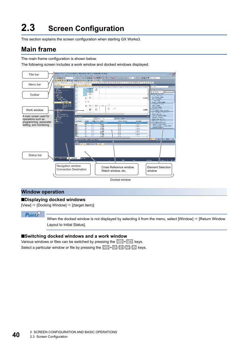
402 SCREEN CONFIGURATION AND BASIC OPERATIONS2.3 Screen Configuration
2.3 Screen ConfigurationThis section explains the screen configuration when starting GX Works3.
Main frameThe main frame configuration is shown below.
The following screen includes a work window and docked windows displayed.
Window operation
■Displaying docked windows[View] [Docking Window] [(target item)]
When the docked window is not displayed by selecting it from the menu, select [Window] [Return Window
Layout to Initial Status].
■Switching docked windows and a work windowVarious windows or files can be switched by pressing the + keys.
Select a particular window or file by pressing the +/// keys.
Title bar
Menu bar
Toolbar
A main screen used for operations such as programming, parameter setting, and monitoring
Navigation windowConnection Destination
Cross Reference window, Watch window, etc.
Element Selection window
Docked window
Work window
Status bar
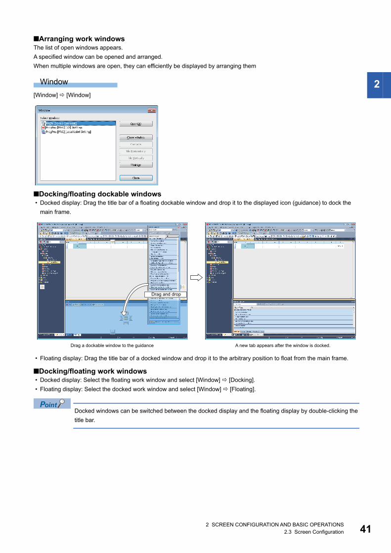
2 SCREEN CONFIGURATION AND BASIC OPERATIONS2.3 Screen Configuration 41
2
■Arranging work windowsThe list of open windows appears.
A specified window can be opened and arranged.
When multiple windows are open, they can efficiently be displayed by arranging them
Window
[Window] [Window]
■Docking/floating dockable windows • Docked display: Drag the title bar of a floating dockable window and drop it to the displayed icon (guidance) to dock the
main frame.
• Floating display: Drag the title bar of a docked window and drop it to the arbitrary position to float from the main frame.
■Docking/floating work windows • Docked display: Select the floating work window and select [Window] [Docking].
• Floating display: Select the docked work window and select [Window] [Floating].
Docked windows can be switched between the docked display and the floating display by double-clicking the
title bar.
Drag and drop
Drag a dockable window to the guidance A new tab appears after the window is docked.

422 SCREEN CONFIGURATION AND BASIC OPERATIONS2.3 Screen Configuration
Customizing/resetting toolbarsSet the types of tool buttons to be displayed on each toolbar.
The selected tool buttons on the list are displayed on the toolbar.
Operating procedure
■Customizing toolbar
1. Click on the toolbar, and select [Show/Hide Buttons] [(toolbar name)].
2. Select the tool button to be displayed from the list.
■Resetting toolbarClick on the toolbar, and select [Show/Hide Buttons] [Reset].

2 SCREEN CONFIGURATION AND BASIC OPERATIONS2.3 Screen Configuration 43
2
Navigation windowThe "Navigation" window displays contents of a project in a tree format.
Operations such as creating new data and displaying editing screens can be performed on the tree.
For details, refer to the following section.
Page 80 PROJECT MANAGEMENT
Window
[View] [Docking Window] [Navigation] ( )
POUs, global labels, and structures are displayed in the following color.
*1 Data that failed in conversion is displayed as unused data before conversion.
Displayed items
The font color and the background color can be changed.
Page 65 Checking and Changing Colors and Fonts
Color Data
White Converted data
Red Unconverted data
Unused data before conversion
Light blue Unconverted data*1
Name Description Reference
(1) Filter Data displayed in a tree format can be filtered.
• ALL: All the items in the "Navigation" window are displayed.
• Parameter: Module Configuration and Parameter are displayed.
• Program: Program, FB/FUN, Label, and Device are displayed.
(2) Status icons To display icons indicating the status of a project. Page 44 Status icons
(2)
(1)Toolbar
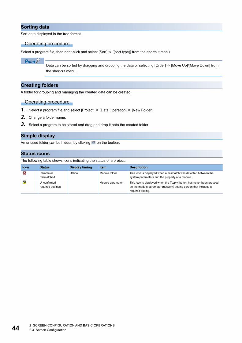
442 SCREEN CONFIGURATION AND BASIC OPERATIONS2.3 Screen Configuration
Sorting dataSort data displayed in the tree format.
Operating procedure
Select a program file, then right-click and select [Sort] [(sort type)] from the shortcut menu.
Data can be sorted by dragging and dropping the data or selecting [Order] [Move Up]/[Move Down] from
the shortcut menu.
Creating foldersA folder for grouping and managing the created data can be created.
Operating procedure
1. Select a program file and select [Project] [Data Operation] [New Folder].
2. Change a folder name.
3. Select a program to be stored and drag and drop it onto the created folder.
Simple displayAn unused folder can be hidden by clicking on the toolbar.
Status iconsThe following table shows icons indicating the status of a project.
Icon Status Display timing Item Description
Parameter
mismatched
Offline Module folder This icon is displayed when a mismatch was detected between the
system parameters and the property of a module.
Unconfirmed
required settings
Module parameter This icon is displayed when the [Apply] button has never been pressed
on the module parameter (network) setting screen that includes a
required setting.
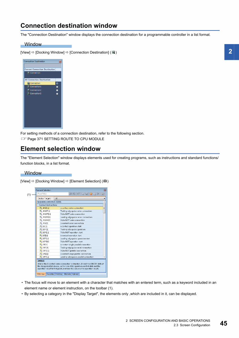
2 SCREEN CONFIGURATION AND BASIC OPERATIONS2.3 Screen Configuration 45
2
Connection destination windowThe "Connection Destination" window displays the connection destination for a programmable controller in a list format.
Window
[View] [Docking Window] [Connection Destination] ( )
For setting methods of a connection destination, refer to the following section.
Page 371 SETTING ROUTE TO CPU MODULE
Element selection windowThe "Element Selection" window displays elements used for creating programs, such as instructions and standard functions/
function blocks, in a list format.
Window
[View] [Docking Window] [Element Selection] ( )
• The focus will move to an element with a character that matches with an entered term, such as a keyword included in an
element name or element instruction, on the toolbar (1).
• By selecting a category in the "Display Target", the elements only ,which are included in it, can be displayed.
(1)
462 SCREEN CONFIGURATION AND BASIC OPERATIONS2.3 Screen Configuration
Pasting elements
■Pasting elements in a programWhen a program editor is active, elements which can be pasted are displayed in the "Element Selection" window.
Elements can be pasted by dragging and dropping them from the list onto a program.
For ST editor, the selected element is pasted at the cursor position by pressing the key.
■Pasting objects in a module configuration diagramWhen a module configuration diagram is active, elements which can be pasted are displayed in the "Element Selection"
window.
Elements can be pasted by dragging and dropping them from the list onto the module configuration diagram.
FavoritesFrequently used modules and elements/SFC elements (devices, labels, instructions, FB instances, functions) can be
registered in the [Favorites] tab for each category.
A new folder, which is for classification of elements, can be created by clicking on the toolbar. The created folder can be
moved by dragging and dropping and the folder name can also be changed.
When a module configuration diagram is active, only modules are displayed.
When a program editor is active, elements which can be used in the editor are displayed.
Operating procedure
■Adding elements from the element listModules, instructions, functions, and function blocks can be added to the [Favorites] tab.
1. Select an element to add from the list in the "Element Selection" window, and click on the toolbar.
2. Select a registration destination in the "Register to Favorites" screen, and click the [OK] button.
■Adding from the "Navigation" windowFunctions and function blocks can be added to the [Favorites] tab.
1. Select an element to add in the "Navigation" window, and drag and drop it onto the "Element Selection" window.
2. Select a registration destination in the "Register to Favorites" screen, and click the [OK] button.
■Adding from the ladder editorDevices, labels, instructions, and FB instances can be added to the [Favorites] tab.
1. Select the cell of an element to add, and drag the border of the cell and drop it onto the "Element Selection" window.
2. Select a registration destination in the "Register to Favorites" screen, and click the [OK] button.
■Adding from the ST editorDevices, labels, and FB instances can be added to the [Favorites] tab.
1. Select the token of a part to add, and drag and drop it onto the "Element Selection" window.
2. Select a registration destination in the "Register to Favorites" screen, and click the [OK] button.
■Adding from the FBD/LD editorDevices, labels, and FB instances can be added to the [Favorites] tab.
1. Select an element to add, and drag and drop it onto the "Element Selection" window with the key held down.
2. Select a registration destination in the "Register to Favorites" screen, and click the [OK] button.
■Adding from the SFC diagram editorDevices and labels can be added to the [Favorites] tab.
1. Select an SFC element to add, and drag and drop it onto the "Element Selection" window.
2. Select a registration destination in the "Register to Favorites" screen, and click the [OK] button.
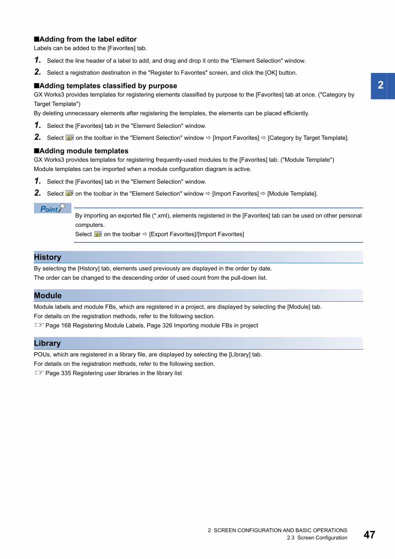
2 SCREEN CONFIGURATION AND BASIC OPERATIONS2.3 Screen Configuration 47
2
■Adding from the label editorLabels can be added to the [Favorites] tab.
1. Select the line header of a label to add, and drag and drop it onto the "Element Selection" window.
2. Select a registration destination in the "Register to Favorites" screen, and click the [OK] button.
■Adding templates classified by purposeGX Works3 provides templates for registering elements classified by purpose to the [Favorites] tab at once. ("Category by
Target Template")
By deleting unnecessary elements after registering the templates, the elements can be placed efficiently.
1. Select the [Favorites] tab in the "Element Selection" window.
2. Select on the toolbar in the "Element Selection" window [Import Favorites] [Category by Target Template].
■Adding module templatesGX Works3 provides templates for registering frequently-used modules to the [Favorites] tab. ("Module Template")
Module templates can be imported when a module configuration diagram is active.
1. Select the [Favorites] tab in the "Element Selection" window.
2. Select on the toolbar in the "Element Selection" window [Import Favorites] [Module Template].
By importing an exported file (*.xml), elements registered in the [Favorites] tab can be used on other personal
computers.
Select on the toolbar [Export Favorites]/[Import Favorites]
HistoryBy selecting the [History] tab, elements used previously are displayed in the order by date.
The order can be changed to the descending order of used count from the pull-down list.
ModuleModule labels and module FBs, which are registered in a project, are displayed by selecting the [Module] tab.
For details on the registration methods, refer to the following section.
Page 168 Registering Module Labels, Page 326 Importing module FBs in project
LibraryPOUs, which are registered in a library file, are displayed by selecting the [Library] tab.
For details on the registration methods, refer to the following section.
Page 335 Registering user libraries in the library list
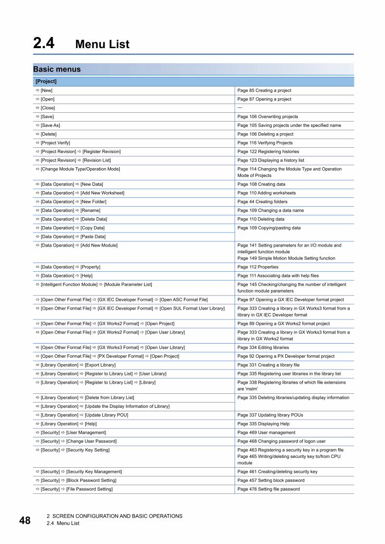
482 SCREEN CONFIGURATION AND BASIC OPERATIONS2.4 Menu List
2.4 Menu List
Basic menus
[Project]
[New] Page 85 Creating a project
[Open] Page 87 Opening a project
[Close]
[Save] Page 106 Overwriting projects
[Save As] Page 105 Saving projects under the specified name
[Delete] Page 106 Deleting a project
[Project Verify] Page 116 Verifying Projects
[Project Revision] [Register Revision] Page 122 Registering histories
[Project Revision] [Revision List] Page 123 Displaying a history list
[Change Module Type/Operation Mode] Page 114 Changing the Module Type and Operation
Mode of Projects
[Data Operation] [New Data] Page 108 Creating data
[Data Operation] [Add New Worksheet] Page 110 Adding worksheets
[Data Operation] [New Folder] Page 44 Creating folders
[Data Operation] [Rename] Page 109 Changing a data name
[Data Operation] [Delete Data] Page 110 Deleting data
[Data Operation] [Copy Data] Page 109 Copying/pasting data
[Data Operation] [Paste Data]
[Data Operation] [Add New Module] Page 141 Setting parameters for an I/O module and
intelligent function module
Page 149 Simple Motion Module Setting function
[Data Operation] [Property] Page 112 Properties
[Data Operation] [Help] Page 111 Associating data with help files
[Intelligent Function Module] [Module Parameter List] Page 145 Checking/changing the number of intelligent
function module parameters
[Open Other Format File] [GX IEC Developer Format] [Open ASC Format File] Page 97 Opening a GX IEC Developer format project
[Open Other Format File] [GX IEC Developer Format] [Open SUL Format User Library] Page 333 Creating a library in GX Works3 format from a
library in GX IEC Developer format
[Open Other Format File] [GX Works2 Format] [Open Project] Page 89 Opening a GX Works2 format project
[Open Other Format File] [GX Works2 Format] [Open User Library] Page 333 Creating a library in GX Works3 format from a
library in GX Works2 format
[Open Other Format File] [GX Works3 Format] [Open User Library] Page 334 Editing libraries
[Open Other Format File] [PX Developer Format] [Open Project] Page 92 Opening a PX Developer format project
[Library Operation] [Export Library] Page 331 Creating a library file
[Library Operation] [Register to Library List] [User Library] Page 335 Registering user libraries in the library list
[Library Operation] [Register to Library List] [Library] Page 338 Registering libraries of which file extensions
are 'mslm'
[Library Operation] [Delete from Library List] Page 335 Deleting libraries/updating display information
[Library Operation] [Update the Display Information of Library]
[Library Operation] [Update Library POU] Page 337 Updating library POUs
[Library Operation] [Help] Page 335 Displaying Help
[Security] [User Management] Page 469 User management
[Security] [Change User Password] Page 468 Changing password of logon user
[Security] [Security Key Setting] Page 463 Registering a security key in a program file
Page 465 Writing/deleting security key to/from CPU
module
[Security] [Security Key Management] Page 461 Creating/deleting security key
[Security] [Block Password Setting] Page 457 Setting block password
[Security] [File Password Setting] Page 476 Setting file password
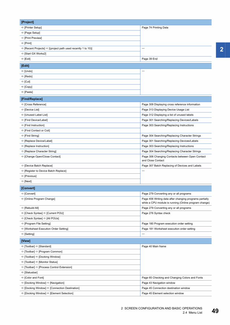
2 SCREEN CONFIGURATION AND BASIC OPERATIONS2.4 Menu List 49
2
[Printer Setup] Page 74 Printing Data
[Page Setup]
[Print Preview]
[Print]
[Recent Projects] [(project path used recently 1 to 10)]
[Start GX Works2]
[Exit] Page 39 End
[Edit]
[Undo]
[Redo]
[Cut]
[Copy]
[Paste]
[Find/Replace]
[Cross Reference] Page 309 Displaying cross reference information
[Device List] Page 313 Displaying Device Usage List
[Unused Label List] Page 312 Displaying a list of unused labels
[Find Device/Label] Page 301 Searching/Replacing Devices/Labels
[Find Instruction] Page 303 Searching/Replacing Instructions
[Find Contact or Coil]
[Find String] Page 304 Searching/Replacing Character Strings
[Replace Device/Label] Page 301 Searching/Replacing Devices/Labels
[Replace Instruction] Page 303 Searching/Replacing Instructions
[Replace Character String] Page 304 Searching/Replacing Character Strings
[Change Open/Close Contact] Page 306 Changing Contacts between Open Contact
and Close Contact
[Device Batch Replace] Page 307 Batch Replacing of Devices and Labels
[Register to Device Batch Replace]
[Previous]
[Next]
[Convert]
[Convert] Page 279 Converting any or all programs
[Online Program Change] Page 406 Writing data after changing programs partially
while a CPU module is running (Online program change)
[Rebuild All] Page 279 Converting any or all programs
[Check Syntax] [Current POU] Page 276 Syntax check
[Check Syntax] [All POUs]
[Program File Setting] Page 180 Program execution order setting
[Worksheet Execution Order Setting] Page 181 Worksheet execution order setting
[Setting]
[View]
[Toolbar] [Standard] Page 40 Main frame
[Toolbar] [Program Common]
[Toolbar] [Docking Window]
[Toolbar] [Monitor Status]
[Toolbar] [Process Control Extension]
[Statusbar]
[Color and Font] Page 65 Checking and Changing Colors and Fonts
[Docking Window] [Navigation] Page 43 Navigation window
[Docking Window] [Connection Destination] Page 45 Connection destination window
[Docking Window] [Element Selection] Page 45 Element selection window
[Project]

502 SCREEN CONFIGURATION AND BASIC OPERATIONS2.4 Menu List
[Docking Window] [Output] Page 40 Main frame
[Docking Window] [Progress]
[Docking Window] [Find/Replace]
[Docking Window] [Find Results]
[Docking Window] [(Cross Reference 1 to 2)] Page 309 Displaying cross reference information
[Docking Window] [Device List] Page 313 Displaying Device Usage List
[Docking Window] [Device Assignment Confirmation] Page 144 Checking refresh devices assigned to modules
[Docking Window] [FB Property] Page 233 Display/setting an FB property
[Docking Window] [Input the Configuration Detailed Information]
[Docking Window] [Result of Power Supply Capacity and I/O Points Check]
[Docking Window] [Module Start I/O No. Related Area]
[Docking Window] [(Watch 1 to 4)] Page 434 Checking Current Values by Registering
Devices/Labels
[Docking Window] [Intelligent Function Module Monitor] [(Intelligent Function Module
Monitor 1 to 10)]
Page 445 Checking Current Values in Intelligent Function
Module
[Zoom] [Set Zoom Factor]
[Zoom] [Zoom In]
[Zoom] [Zoom Out]
[Zoom] [Fit the editor width to the window width]
[Switch Display Language] Page 39 Display Language Switching
[Multiple Comments Display Setting] Page 66 Comment Display Setting
[Online]
[Current Connection Destination] Page 371 Specification of Connection Destination
[Read from PLC] Page 390 Writing/Reading Programmable Controller
Data [Write to PLC]
[Verify with PLC] Page 403 Verifying Programmable Controller Data
[Remote Operation] Page 509 Remote Operation
[Safety PLC Operation] [Check Safety Data Identity] Page 515 Identification check for safety data
[Safety PLC Operation] [Switch Safety Operation Mode] Page 513 Safety operation mode switching
[Safety PLC Operation] [Safety Module Operation] Page 516 Safety module operation
[Safety PLC Operation] [Automatic Restore Setting] [Enable] Page 515 Automatic restoration setting
[Safety PLC Operation] [Automatic Restore Setting] [Disable]
[Redundant PLC Operation] [Redundant Operation] Page 511 Redundant Programmable Controller
Operations
[Redundant PLC Operation] [System A/B Setting] Page 512 System A/B setting
[CPU Memory Operation] Page 517 Checking Memory Usage
[Delete PLC Data] Page 390 Configuration of Online Data Operation screen
[User Data] [Read] Page 413 Reading/Writing/Deleting User Data
[User Data] [Write]
[User Data] [Delete]
[Set Clock] Page 508 Clock Setting in a CPU Module
[Monitor] [Monitor Mode] Page 184 Read mode/Write mode/Monitor read mode/
Monitor write mode [Monitor] [Monitor (Write Mode)]
[Monitor] [Start Monitoring (All Windows)] Page 418 Starting/stopping monitoring
[Monitor] [Stop Monitoring (All Windows)]
[Monitor] [Start Monitoring]
[Monitor] [Stop Monitoring]
[Monitor] [Change Value Format (Decimal)] Page 418 Changing display format of word devices
[Monitor] [Change Value Format (Hexadecimal)]
[Monitor] [Device/Buffer Memory Batch Monitor] Page 431 Checking Device/Buffer Memory in Batch
[Monitor] [Program List Monitor] Page 443 Checking Processing Time of Program
[Monitor] [Interrupt Program List Monitor] Page 444 Checking Execution Counts of Interrupt
Programs
[View]
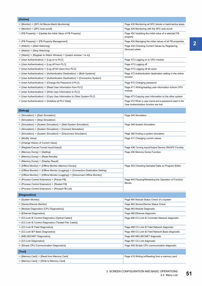
2 SCREEN CONFIGURATION AND BASIC OPERATIONS2.4 Menu List 51
2
[Monitor] [SFC All Blocks Batch Monitoring] Page 430 Monitoring all SFC blocks in batch/active steps
[Monitor] [SFC Auto-scroll] Page 428 Monitoring with the SFC auto-scroll
[FB Property] [Update the Initial Value of FB Property] Page 452 Updating the initial value of a selected FB
property
[FB Property] [FB Property Management] Page 454 Managing the initial values of all FB properties
[Watch] [Start Watching] Page 434 Checking Current Values by Registering
Devices/Labels [Watch] [Stop Watching]
[Watch] [Register to Watch Window] [(watch window 1 to 4)]
[User Authentication] [Log on to PLC] Page 472 Logging on to CPU module
[User Authentication] [Log off from PLC] Page 473 Logging off
[User Authentication] [Log off All Users from PLC] Page 473 Logging off all users
[User Authentication] [Authentication Destination] [Both Systems] Page 472 Authentication destination setting in the online
function [User Authentication] [Authentication Destination] [Connective System]
[User Authentication] [Change the Password of PLC] Page 472 Changing password
[User Authentication] [Read User Information from PLC] Page 471 Writing/reading user information to/from CPU
module [User Authentication] [Write User Information to PLC]
[User Authentication] [Copy User Information to Other System PLC] Page 473 Copying user information to the other system
[User Authentication] [Initialize all PLC Data] Page 472 When a user name and a password used in the
User Authentication function are lost
[Debug]
[Simulation] [Start Simulation] Page 345 Simulation
[Simulation] [Stop Simulation]
[Simulation] [System Simulation] [Start System Simulation] Page 346 System Simulation
[Simulation] [System Simulation] [Connect Simulation]
[Simulation] [System Simulation] [Disconnect Simulation] Page 360 Ending a system simulation
[Modify Value] Page 417 Changing current values
[Change History of Current Value]
[Register/Cancel Forced Input/Output] Page 438 Turning Input/Output Device ON/OFF Forcibly
[Memory Dump] [Setting] Page 495 Memory Dump Function
[Memory Dump] [Read Results]
[Memory Dump] [Display Result]
[Offline Monitor] [Offline Monitor (Memory Dump)] Page 503 Checking Sampled Data on Program Editor
[Offline Monitor] [Offline Monitor (Logging)] [Connection Destination Setting]
[Offline Monitor] [Offline Monitor (Logging)] [Disconnect Offline Monitor]
[Process Control Extension] [Pause FB] Page 440 Pausing/Restarting the Operation of Function
Blocks [Process Control Extension] [Restart FB]
[Process Control Extension] [Paused FB List]
[Diagnostics]
[System Monitor] Page 480 Module Status Check of a System
[Sensor/Device Monitor] Page 482 Sensor/Device Status Check
[Module Diagnostics (CPU Diagnostics)] Page 483 Module Diagnostic
[Ethernet Diagnostics] Page 485 Ethernet diagnostic
[CC-Link IE Control Diagnostics (Optical Cable)] Page 486 CC-Link IE Controller Network diagnostic
[CC-Link IE Control Diagnostics (Twisted Pair Cable)]
[CC-Link IE Field Diagnostics] Page 488 CC-Link IE Field Network diagnostic
[CC-Link IEF Basic Diagnostics] Page 489 CC-Link IE Field Network Basic diagnostic
[MELSECNET Diagnostics] Page 490 MELSECNET diagnostic
[CC-Link Diagnostics] Page 491 CC-Link diagnostic
[Simple CPU Communication Diagnostics] Page 492 Simple CPU communication diagnostic
[Tool]
[Memory Card] [Read from Memory Card] Page 415 Writing to/Reading from a memory card
[Memory Card] [Write to Memory Card]
[Online]

522 SCREEN CONFIGURATION AND BASIC OPERATIONS2.4 Menu List
Available menus when editing a module configuration diagram
[Check Program] Page 277 Program check
[Check Parameter] Page 138 Checking parameters
[Confirm Memory Size (Offline)] Page 288 Calculating Memory Size
[Logging Configuration Tool] Page 501 Data Logging Function
[Realtime Monitor Function] Page 447 Checking Current Logging Data
[Module Tool List] Page 148 Displaying the module tool list
[Drive Tool List] Page 148 Displaying the drive tool list
[Profile Management] [Register] Page 125 Registration
[Profile Management] [Delete] Page 125 Deletion
[Register Sample Library] Page 338 Registering libraries of which file extensions
are 'gx3s'
[Shortcut Key] Page 64 Checking and Changing Shortcut Keys
[Predefined Protocol Support Function] Page 150 Predefined Protocol Support Function
[Circuit Trace] Page 151 Circuit Trace Function
[Options] Page 67 Option Setting for Each Function
[Window]
[Cascade]
[Tile Vertically]
[Tile Horizontally]
[Arrange Icons]
[Close All Windows]
[Return Window Layout to Initial Status] Page 40 Displaying docked windows
[Split]
[Restore Split]
[Floating] Page 41 Docking/floating work windows
[Docking]
[(Window information being displayed)]
[Window] Page 41 Arranging work windows
[Help]
[GX Works3 Help] Page 36 Displaying Help
[Connection to MITSUBISHI ELECTRIC FA Global Website] Page 36 Connecting to MITSUBISHI ELECTRIC FA
Global Website
[Version Information] Page 36 Checking the version of GX Works3
[Edit]
[Delete]
[Select All]
[Bring to Front]
[Send to Back]
[Module Status Setting (Empty)] Page 129 Module status setting (empty)
[Display Module Information] Page 130 Check model names on module objects
[XY Assignment Display] Page 136 XY assignment display
[Check] [Power Supply Capacity and I/O Points] Page 136 Checking a power supply capacity and I/O
points
[Check] [System Configuration] Page 136 Checking system configurations
[Parameter] [Fix] Page 131 Setting parameters on a module configuration
diagram
[Parameter] [Input Detailed Configuration Information Window] Page 131 Setting parameters on a module configuration
diagram
[Start XY Batch Input] Page 136 Inputting the start XY in a batch
[Default Points Batch Input] Page 136 Inputting default points in a batch
[Tool]

2 SCREEN CONFIGURATION AND BASIC OPERATIONS2.4 Menu List 53
2
[View]
[Toolbar] [Module Configuration Diagram]
[Online]
[Read Module Configuration from PLC] Page 129 Reading the module configuration from an
actual system
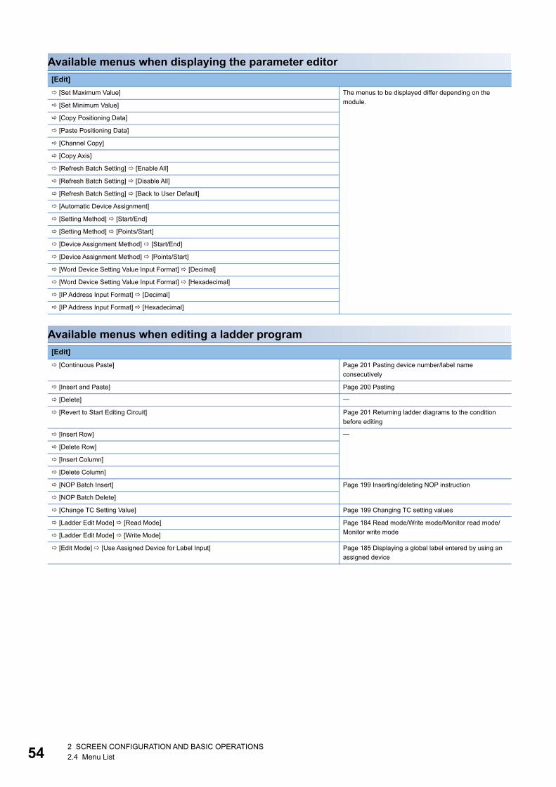
542 SCREEN CONFIGURATION AND BASIC OPERATIONS2.4 Menu List
Available menus when displaying the parameter editor
Available menus when editing a ladder program
[Edit]
[Set Maximum Value] The menus to be displayed differ depending on the
module. [Set Minimum Value]
[Copy Positioning Data]
[Paste Positioning Data]
[Channel Copy]
[Copy Axis]
[Refresh Batch Setting] [Enable All]
[Refresh Batch Setting] [Disable All]
[Refresh Batch Setting] [Back to User Default]
[Automatic Device Assignment]
[Setting Method] [Start/End]
[Setting Method] [Points/Start]
[Device Assignment Method] [Start/End]
[Device Assignment Method] [Points/Start]
[Word Device Setting Value Input Format] [Decimal]
[Word Device Setting Value Input Format] [Hexadecimal]
[IP Address Input Format] [Decimal]
[IP Address Input Format] [Hexadecimal]
[Edit]
[Continuous Paste] Page 201 Pasting device number/label name
consecutively
[Insert and Paste] Page 200 Pasting
[Delete]
[Revert to Start Editing Circuit] Page 201 Returning ladder diagrams to the condition
before editing
[Insert Row]
[Delete Row]
[Insert Column]
[Delete Column]
[NOP Batch Insert] Page 199 Inserting/deleting NOP instruction
[NOP Batch Delete]
[Change TC Setting Value] Page 199 Changing TC setting values
[Ladder Edit Mode] [Read Mode] Page 184 Read mode/Write mode/Monitor read mode/
Monitor write mode [Ladder Edit Mode] [Write Mode]
[Edit Mode] [Use Assigned Device for Label Input] Page 185 Displaying a global label entered by using an
assigned device
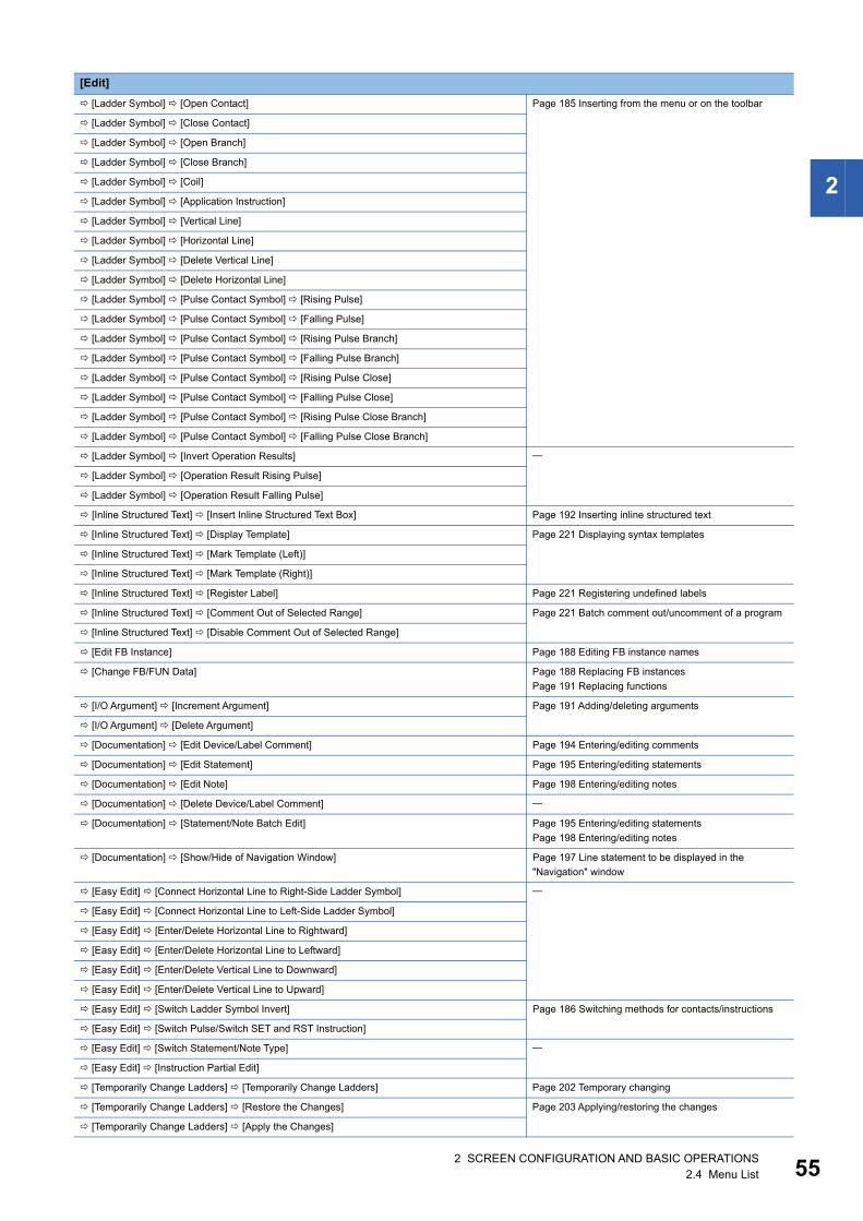
2 SCREEN CONFIGURATION AND BASIC OPERATIONS2.4 Menu List 55
2
[Ladder Symbol] [Open Contact] Page 185 Inserting from the menu or on the toolbar
[Ladder Symbol] [Close Contact]
[Ladder Symbol] [Open Branch]
[Ladder Symbol] [Close Branch]
[Ladder Symbol] [Coil]
[Ladder Symbol] [Application Instruction]
[Ladder Symbol] [Vertical Line]
[Ladder Symbol] [Horizontal Line]
[Ladder Symbol] [Delete Vertical Line]
[Ladder Symbol] [Delete Horizontal Line]
[Ladder Symbol] [Pulse Contact Symbol] [Rising Pulse]
[Ladder Symbol] [Pulse Contact Symbol] [Falling Pulse]
[Ladder Symbol] [Pulse Contact Symbol] [Rising Pulse Branch]
[Ladder Symbol] [Pulse Contact Symbol] [Falling Pulse Branch]
[Ladder Symbol] [Pulse Contact Symbol] [Rising Pulse Close]
[Ladder Symbol] [Pulse Contact Symbol] [Falling Pulse Close]
[Ladder Symbol] [Pulse Contact Symbol] [Rising Pulse Close Branch]
[Ladder Symbol] [Pulse Contact Symbol] [Falling Pulse Close Branch]
[Ladder Symbol] [Invert Operation Results]
[Ladder Symbol] [Operation Result Rising Pulse]
[Ladder Symbol] [Operation Result Falling Pulse]
[Inline Structured Text] [Insert Inline Structured Text Box] Page 192 Inserting inline structured text
[Inline Structured Text] [Display Template] Page 221 Displaying syntax templates
[Inline Structured Text] [Mark Template (Left)]
[Inline Structured Text] [Mark Template (Right)]
[Inline Structured Text] [Register Label] Page 221 Registering undefined labels
[Inline Structured Text] [Comment Out of Selected Range] Page 221 Batch comment out/uncomment of a program
[Inline Structured Text] [Disable Comment Out of Selected Range]
[Edit FB Instance] Page 188 Editing FB instance names
[Change FB/FUN Data] Page 188 Replacing FB instances
Page 191 Replacing functions
[I/O Argument] [Increment Argument] Page 191 Adding/deleting arguments
[I/O Argument] [Delete Argument]
[Documentation] [Edit Device/Label Comment] Page 194 Entering/editing comments
[Documentation] [Edit Statement] Page 195 Entering/editing statements
[Documentation] [Edit Note] Page 198 Entering/editing notes
[Documentation] [Delete Device/Label Comment]
[Documentation] [Statement/Note Batch Edit] Page 195 Entering/editing statements
Page 198 Entering/editing notes
[Documentation] [Show/Hide of Navigation Window] Page 197 Line statement to be displayed in the
"Navigation" window
[Easy Edit] [Connect Horizontal Line to Right-Side Ladder Symbol]
[Easy Edit] [Connect Horizontal Line to Left-Side Ladder Symbol]
[Easy Edit] [Enter/Delete Horizontal Line to Rightward]
[Easy Edit] [Enter/Delete Horizontal Line to Leftward]
[Easy Edit] [Enter/Delete Vertical Line to Downward]
[Easy Edit] [Enter/Delete Vertical Line to Upward]
[Easy Edit] [Switch Ladder Symbol Invert] Page 186 Switching methods for contacts/instructions
[Easy Edit] [Switch Pulse/Switch SET and RST Instruction]
[Easy Edit] [Switch Statement/Note Type]
[Easy Edit] [Instruction Partial Edit]
[Temporarily Change Ladders] [Temporarily Change Ladders] Page 202 Temporary changing
[Temporarily Change Ladders] [Restore the Changes] Page 203 Applying/restoring the changes
[Temporarily Change Ladders] [Apply the Changes]
[Edit]

562 SCREEN CONFIGURATION AND BASIC OPERATIONS2.4 Menu List
[Temporarily Change Ladders] [Temporarily Changed Ladder List] Page 203 Displaying ladder blocks changed temporarily
in a list
[Import File] Page 206 Importing/exporting ladder programs
[Export to File] Page 206 Importing/exporting ladder programs
[Find/Replace]
[Line Statement List] Page 196 Displaying a list
[Jump] Page 205 Jump
[Jump to Next Ladder Block Start]
[Jump to Previous Ladder Block Start]
[View]
[Toolbar] [Ladder]
[Comment Display] Page 194 Entering/editing comments
[Statement Display] Page 195 Entering/editing statements
[Note Display] Page 198 Entering/editing notes
[Display Lines of Monitored Current Value]
[Grid Display]
[Display Format for Device Comment]
[Change Display Format of Device/Label Name] [1 Cell Display] Page 182 Configuration of the ladder editor
[Change Display Format of Device/Label Name] [Wrapping Ladder Display]
[Outline] [Expand/Collapse of Outlines]
[Outline] [Expand/Collapse of All Outlines]
[Outline] [Show/Hide of Outlines] Page 182 Configuration of the ladder editor
[Display Device]
[Text Size] [Bigger]
[Text Size] [Smaller]
[Open Label Setting of Selected Element] [Open in Front]
[Open Label Setting of Selected Element] [Tile Horizontally]
[Open Program Body of Selected Element] [Open in Front]
[Open Program Body of Selected Element] [Tile Horizontally]
[Open Label Setting] [Open in Front]
[Open Label Setting] [Tile Horizontally]
[Open Device Comment Setting] [Open in Front] Page 270 Displaying the device comment editor in a
program editor [Open Device Comment Setting] [Tile Horizontally]
[Open Zoom Source Block] Page 263 Creating/displaying Zooms (action/transition)
[Instruction Help] Page 205 Displaying instruction help
[Edit]
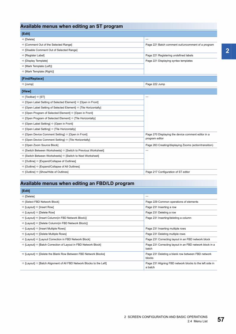
2 SCREEN CONFIGURATION AND BASIC OPERATIONS2.4 Menu List 57
2
Available menus when editing an ST program
Available menus when editing an FBD/LD program
[Edit]
[Delete]
[Comment Out of the Selected Range] Page 221 Batch comment out/uncomment of a program
[Disable Comment Out of Selected Range]
[Register Label] Page 221 Registering undefined labels
[Display Template] Page 221 Displaying syntax templates
[Mark Template (Left)]
[Mark Template (Right)]
[Find/Replace]
[Jump] Page 222 Jump
[View]
[Toolbar] [ST]
[Open Label Setting of Selected Element] [Open in Front]
[Open Label Setting of Selected Element] [Tile Horizontally]
[Open Program of Selected Element] [Open in Front]
[Open Program of Selected Element] [Tile Horizontally]
[Open Label Setting] [Open in Front]
[Open Label Setting] [Tile Horizontally]
[Open Device Comment Setting] [Open in Front] Page 270 Displaying the device comment editor in a
program editor [Open Device Comment Setting] [Tile Horizontally]
[Open Zoom Source Block] Page 263 Creating/displaying Zooms (action/transition)
[Switch Between Worksheets] [Switch to Previous Worksheet]
[Switch Between Worksheets] [Switch to Next Worksheet]
[Outline] [Expand/Collapse of Outlines]
[Outline] [Expand/Collapse of All Outlines]
[Outline] [Show/Hide of Outlines] Page 217 Configuration of ST editor
[Edit]
[Delete]
[Select FBD Network Block] Page 229 Common operations of elements
[Layout] [Insert Row] Page 231 Inserting a row
[Layout] [Delete Row] Page 231 Deleting a row
[Layout] [Insert Column(in FBD Network Block)] Page 231 Inserting/deleting a column
[Layout] [Delete Column(in FBD Network Block)]
[Layout] [Insert Multiple Rows] Page 231 Inserting multiple rows
[Layout] [Delete Multiple Rows] Page 231 Deleting multiple rows
[Layout] [Layout Correction in FBD Network Block] Page 231 Correcting layout in an FBD network block
[Layout] [Batch Correction of Layout in FBD Network Block] Page 231 Correcting layout in an FBD network block in a
batch
[Layout] [Delete the Blank Row Between FBD Network Blocks] Page 231 Deleting a blank row between FBD network
blocks
[Layout] [Batch Alignment of All FBD Network Blocks to the Left] Page 231 Aligning FBD network blocks to the left side in
a batch
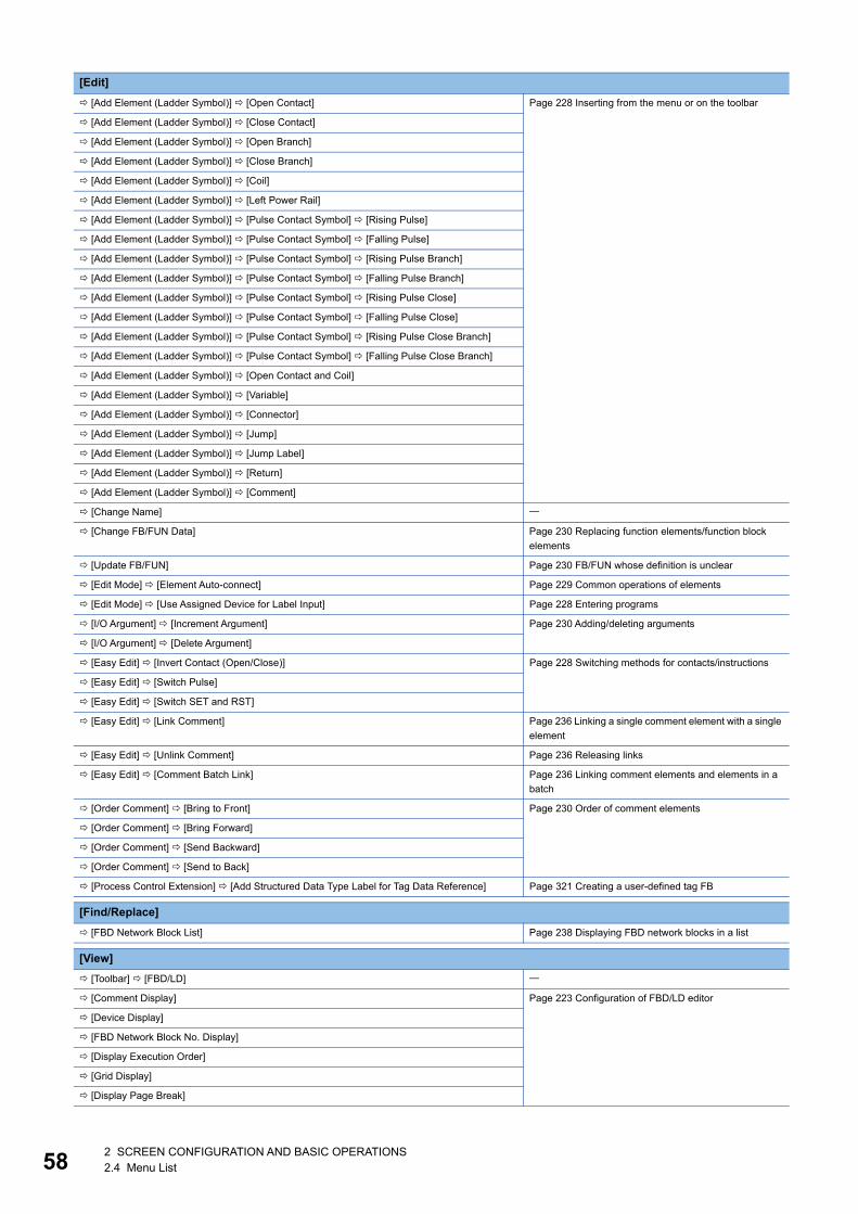
582 SCREEN CONFIGURATION AND BASIC OPERATIONS2.4 Menu List
[Add Element (Ladder Symbol)] [Open Contact] Page 228 Inserting from the menu or on the toolbar
[Add Element (Ladder Symbol)] [Close Contact]
[Add Element (Ladder Symbol)] [Open Branch]
[Add Element (Ladder Symbol)] [Close Branch]
[Add Element (Ladder Symbol)] [Coil]
[Add Element (Ladder Symbol)] [Left Power Rail]
[Add Element (Ladder Symbol)] [Pulse Contact Symbol] [Rising Pulse]
[Add Element (Ladder Symbol)] [Pulse Contact Symbol] [Falling Pulse]
[Add Element (Ladder Symbol)] [Pulse Contact Symbol] [Rising Pulse Branch]
[Add Element (Ladder Symbol)] [Pulse Contact Symbol] [Falling Pulse Branch]
[Add Element (Ladder Symbol)] [Pulse Contact Symbol] [Rising Pulse Close]
[Add Element (Ladder Symbol)] [Pulse Contact Symbol] [Falling Pulse Close]
[Add Element (Ladder Symbol)] [Pulse Contact Symbol] [Rising Pulse Close Branch]
[Add Element (Ladder Symbol)] [Pulse Contact Symbol] [Falling Pulse Close Branch]
[Add Element (Ladder Symbol)] [Open Contact and Coil]
[Add Element (Ladder Symbol)] [Variable]
[Add Element (Ladder Symbol)] [Connector]
[Add Element (Ladder Symbol)] [Jump]
[Add Element (Ladder Symbol)] [Jump Label]
[Add Element (Ladder Symbol)] [Return]
[Add Element (Ladder Symbol)] [Comment]
[Change Name]
[Change FB/FUN Data] Page 230 Replacing function elements/function block
elements
[Update FB/FUN] Page 230 FB/FUN whose definition is unclear
[Edit Mode] [Element Auto-connect] Page 229 Common operations of elements
[Edit Mode] [Use Assigned Device for Label Input] Page 228 Entering programs
[I/O Argument] [Increment Argument] Page 230 Adding/deleting arguments
[I/O Argument] [Delete Argument]
[Easy Edit] [Invert Contact (Open/Close)] Page 228 Switching methods for contacts/instructions
[Easy Edit] [Switch Pulse]
[Easy Edit] [Switch SET and RST]
[Easy Edit] [Link Comment] Page 236 Linking a single comment element with a single
element
[Easy Edit] [Unlink Comment] Page 236 Releasing links
[Easy Edit] [Comment Batch Link] Page 236 Linking comment elements and elements in a
batch
[Order Comment] [Bring to Front] Page 230 Order of comment elements
[Order Comment] [Bring Forward]
[Order Comment] [Send Backward]
[Order Comment] [Send to Back]
[Process Control Extension] [Add Structured Data Type Label for Tag Data Reference] Page 321 Creating a user-defined tag FB
[Find/Replace]
[FBD Network Block List] Page 238 Displaying FBD network blocks in a list
[View]
[Toolbar] [FBD/LD]
[Comment Display] Page 223 Configuration of FBD/LD editor
[Device Display]
[FBD Network Block No. Display]
[Display Execution Order]
[Grid Display]
[Display Page Break]
[Edit]
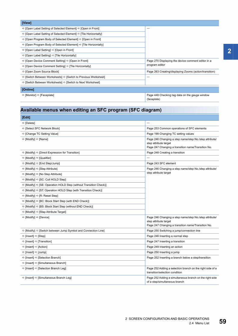
2 SCREEN CONFIGURATION AND BASIC OPERATIONS2.4 Menu List 59
2
Available menus when editing an SFC program (SFC diagram)
[Open Label Setting of Selected Element] [Open in Front]
[Open Label Setting of Selected Element] [Tile Horizontally]
[Open Program Body of Selected Element] [Open in Front]
[Open Program Body of Selected Element] [Tile Horizontally]
[Open Label Setting] [Open in Front]
[Open Label Setting] [Tile Horizontally]
[Open Device Comment Setting] [Open in Front] Page 270 Displaying the device comment editor in a
program editor [Open Device Comment Setting] [Tile Horizontally]
[Open Zoom Source Block] Page 263 Creating/displaying Zooms (action/transition)
[Switch Between Worksheets] [Switch to Previous Worksheet]
[Switch Between Worksheets] [Switch to Next Worksheet]
[Online]
[Monitor] [Faceplate] Page 448 Checking tag data on the gauge window
(faceplate)
[Edit]
[Delete]
[Select SFC Network Block] Page 253 Common operations of SFC elements
[Change TC Setting Value] Page 199 Changing TC setting values
[Modify] [Name] Page 246 Changing a step name/step No./step attribute/
step attribute target
Page 247 Changing a transition name/Transition No.
[Modify] [Direct Expression for Transition] Page 248 Creating a transition
[Modify] [Qualifier]
[Modify] [End Step/Jump] Page 243 SFC element
[Modify] [Step Attribute] Page 246 Changing a step name/step No./step attribute/
step attribute target [Modify] [No Step Attribute]
[Modify] [SC: Coil HOLD Step]
[Modify] [SE: Operation HOLD Step (without Transition Check)]
[Modify] [ST: Operation HOLD Step (with Transition Check)]
[Modify] [R: Reset Step]
[Modify] [BC: Block Start Step (with END Check)]
[Modify] [BS: Block Start Step (without END Check)]
[Modify] [Step Attribute Target]
[Modify] [Device] Page 246 Changing a step name/step No./step attribute/
step attribute target
Page 247 Changing a transition name/Transition No.
[Modify] [Switch between Jump Symbol and Connection Line] Page 250 Switching a jump/connection line
[Insert] [Step] Page 246 Inserting a normal step
[Insert] [Transition] Page 247 Inserting a transition
[Insert] [Action] Page 249 Inserting an action
[Insert] [Jump] Page 250 Inserting a jump
[Insert] [Selection Branch] Page 252 Inserting a branch below a step/transition
[Insert] [Simultaneous Branch]
[Insert] [Selection Branch Leg] Page 252 Adding a selection branch on the right side of a
transition/selection condition
[Insert] [Simultaneous Branch Leg] Page 252 Adding a simultaneous branch on the right side
of a step/simultaneous branch
[View]
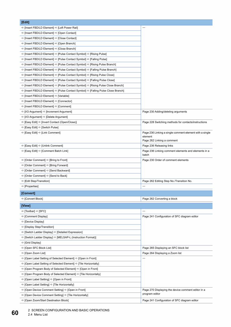
602 SCREEN CONFIGURATION AND BASIC OPERATIONS2.4 Menu List
[Insert FBD/LD Element] [Left Power Rail]
[Insert FBD/LD Element] [Open Contact]
[Insert FBD/LD Element] [Close Contact]
[Insert FBD/LD Element] [Open Branch]
[Insert FBD/LD Element] [Close Branch]
[Insert FBD/LD Element] [Pulse Contact Symbol] [Rising Pulse]
[Insert FBD/LD Element] [Pulse Contact Symbol] [Falling Pulse]
[Insert FBD/LD Element] [Pulse Contact Symbol] [Rising Pulse Branch]
[Insert FBD/LD Element] [Pulse Contact Symbol] [Falling Pulse Branch]
[Insert FBD/LD Element] [Pulse Contact Symbol] [Rising Pulse Close]
[Insert FBD/LD Element] [Pulse Contact Symbol] [Falling Pulse Close]
[Insert FBD/LD Element] [Pulse Contact Symbol] [Rising Pulse Close Branch]
[Insert FBD/LD Element] [Pulse Contact Symbol] [Falling Pulse Close Branch]
[Insert FBD/LD Element] [Variable]
[Insert FBD/LD Element] [Connector]
[Insert FBD/LD Element] [Comment]
[I/O Argument] [Increment Argument] Page 230 Adding/deleting arguments
[I/O Argument] [Delete Argument]
[Easy Edit] [Invert Contact (Open/Close)] Page 228 Switching methods for contacts/instructions
[Easy Edit] [Switch Pulse]
[Easy Edit] [Link Comment] Page 236 Linking a single comment element with a single
element
Page 262 Linking a comment
[Easy Edit] [Unlink Comment] Page 236 Releasing links
[Easy Edit] [Comment Batch Link] Page 236 Linking comment elements and elements in a
batch
[Order Comment] [Bring to Front] Page 230 Order of comment elements
[Order Comment] [Bring Forward]
[Order Comment] [Send Backward]
[Order Comment] [Send to Back]
[Edit Step/Transition] Page 262 Editing Step No./Transition No.
[Properties]
[Convert]
[Convert Block] Page 262 Converting a block
[View]
[Toolbar] [SFC]
[Comment Display] Page 241 Configuration of SFC diagram editor
[Device Display]
[Display Step/Transition]
[Switch Ladder Display] [Detailed Expression]
[Switch Ladder Display] [MELSAP-L (Instruction Format)]
[Grid Display]
[Open SFC Block List] Page 265 Displaying an SFC block list
[Open Zoom List] Page 264 Displaying a Zoom list
[Open Label Setting of Selected Element] [Open in Front]
[Open Label Setting of Selected Element] [Tile Horizontally]
[Open Program Body of Selected Element] [Open in Front]
[Open Program Body of Selected Element] [Tile Horizontally]
[Open Label Setting] [Open in Front]
[Open Label Setting] [Tile Horizontally]
[Open Device Comment Setting] [Open in Front] Page 270 Displaying the device comment editor in a
program editor [Open Device Comment Setting] [Tile Horizontally]
[Open Zoom/Start Destination Block] Page 241 Configuration of SFC diagram editor
[Edit]
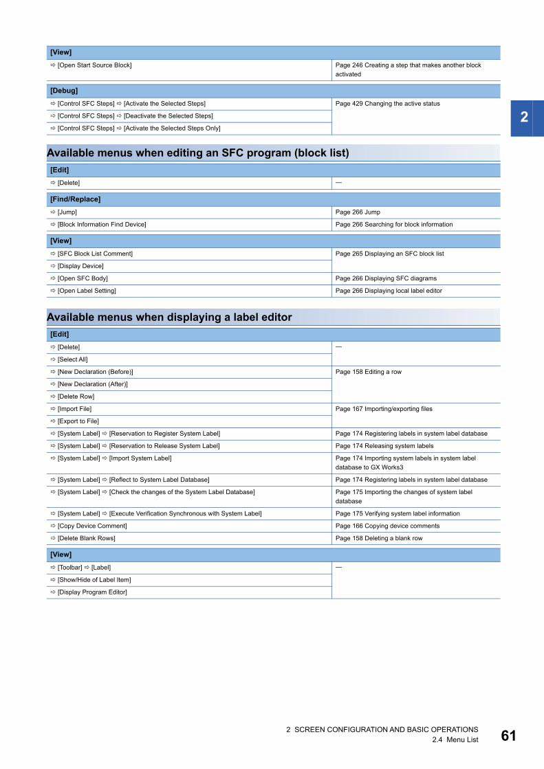
2 SCREEN CONFIGURATION AND BASIC OPERATIONS2.4 Menu List 61
2
Available menus when editing an SFC program (block list)
Available menus when displaying a label editor
[Open Start Source Block] Page 246 Creating a step that makes another block
activated
[Debug]
[Control SFC Steps] [Activate the Selected Steps] Page 429 Changing the active status
[Control SFC Steps] [Deactivate the Selected Steps]
[Control SFC Steps] [Activate the Selected Steps Only]
[Edit]
[Delete]
[Find/Replace]
[Jump] Page 266 Jump
[Block Information Find Device] Page 266 Searching for block information
[View]
[SFC Block List Comment] Page 265 Displaying an SFC block list
[Display Device]
[Open SFC Body] Page 266 Displaying SFC diagrams
[Open Label Setting] Page 266 Displaying local label editor
[Edit]
[Delete]
[Select All]
[New Declaration (Before)] Page 158 Editing a row
[New Declaration (After)]
[Delete Row]
[Import File] Page 167 Importing/exporting files
[Export to File]
[System Label] [Reservation to Register System Label] Page 174 Registering labels in system label database
[System Label] [Reservation to Release System Label] Page 174 Releasing system labels
[System Label] [Import System Label] Page 174 Importing system labels in system label
database to GX Works3
[System Label] [Reflect to System Label Database] Page 174 Registering labels in system label database
[System Label] [Check the changes of the System Label Database] Page 175 Importing the changes of system label
database
[System Label] [Execute Verification Synchronous with System Label] Page 175 Verifying system label information
[Copy Device Comment] Page 166 Copying device comments
[Delete Blank Rows] Page 158 Deleting a blank row
[View]
[Toolbar] [Label]
[Show/Hide of Label Item]
[Display Program Editor]
[View]
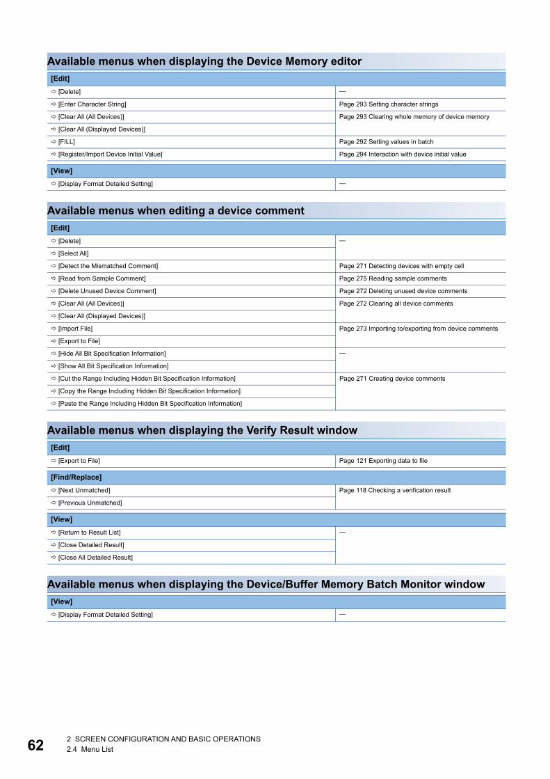
622 SCREEN CONFIGURATION AND BASIC OPERATIONS2.4 Menu List
Available menus when displaying the Device Memory editor
Available menus when editing a device comment
Available menus when displaying the Verify Result window
Available menus when displaying the Device/Buffer Memory Batch Monitor window
[Edit]
[Delete]
[Enter Character String] Page 293 Setting character strings
[Clear All (All Devices)] Page 293 Clearing whole memory of device memory
[Clear All (Displayed Devices)]
[FILL] Page 292 Setting values in batch
[Register/Import Device Initial Value] Page 294 Interaction with device initial value
[View]
[Display Format Detailed Setting]
[Edit]
[Delete]
[Select All]
[Detect the Mismatched Comment] Page 271 Detecting devices with empty cell
[Read from Sample Comment] Page 275 Reading sample comments
[Delete Unused Device Comment] Page 272 Deleting unused device comments
[Clear All (All Devices)] Page 272 Clearing all device comments
[Clear All (Displayed Devices)]
[Import File] Page 273 Importing to/exporting from device comments
[Export to File]
[Hide All Bit Specification Information]
[Show All Bit Specification Information]
[Cut the Range Including Hidden Bit Specification Information] Page 271 Creating device comments
[Copy the Range Including Hidden Bit Specification Information]
[Paste the Range Including Hidden Bit Specification Information]
[Edit]
[Export to File] Page 121 Exporting data to file
[Find/Replace]
[Next Unmatched] Page 118 Checking a verification result
[Previous Unmatched]
[View]
[Return to Result List]
[Close Detailed Result]
[Close All Detailed Result]
[View]
[Display Format Detailed Setting]

2 SCREEN CONFIGURATION AND BASIC OPERATIONS2.4 Menu List 63
2
Available menus when displaying the tag FB setting editor
[Edit]
[Delete]
[Select All]
[New Declaration (Before)]
[Delete Row]
[Export Assignment Information Database File]

642 SCREEN CONFIGURATION AND BASIC OPERATIONS2.5 Checking and Changing Shortcut Keys
2.5 Checking and Changing Shortcut KeysShortcut keys of each function can be checked and changed in the "Shortcut Key" screen.
Up to three shortcut keys can be assigned to one command.
Window
[Tool] [Shortcut Key]
Operating procedure
1. Double-click a command cell to change the shortcut key.
2. Press a key to assign on the keyboard.
■Changing the default settingThe shortcut key assignment set to the default can be changed by selecting a format from the pull-down list for "Current Key
Format"
The available formats are as follows:
• GX Works3 format: Select this to reset the shortcut key assignment to the original one. Keys same as GX Works2 are
included.
• GPPA format: Select this to change the shortcut key assignment for all commands to one same as GPPA in a batch.
• GPPW format: Select this to change the shortcut key assignment for all commands to one same as GX Developer in a
batch.
• MEDOC format: Select this to change the shortcut key assignment for all commands to one same as MELSEC MEDOC in
a batch.
By importing an exported file (*.gks), the setting can be utilized on other personal computers.
Setting files exported in GX Works2 can also be imported.
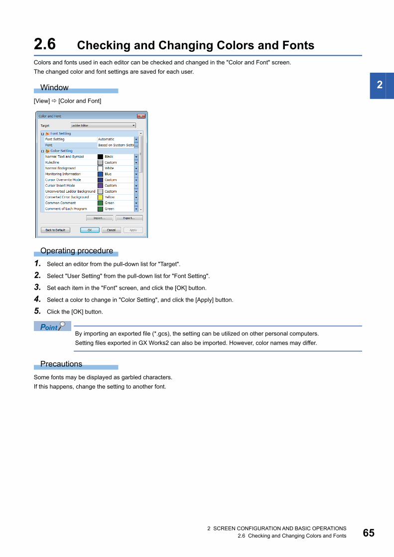
2 SCREEN CONFIGURATION AND BASIC OPERATIONS2.6 Checking and Changing Colors and Fonts 65
2
2.6 Checking and Changing Colors and FontsColors and fonts used in each editor can be checked and changed in the "Color and Font" screen.
The changed color and font settings are saved for each user.
Window
[View] [Color and Font]
Operating procedure
1. Select an editor from the pull-down list for "Target".
2. Select "User Setting" from the pull-down list for "Font Setting".
3. Set each item in the "Font" screen, and click the [OK] button.
4. Select a color to change in "Color Setting", and click the [Apply] button.
5. Click the [OK] button.
By importing an exported file (*.gcs), the setting can be utilized on other personal computers.
Setting files exported in GX Works2 can also be imported. However, color names may differ.
Precautions
Some fonts may be displayed as garbled characters.
If this happens, change the setting to another font.
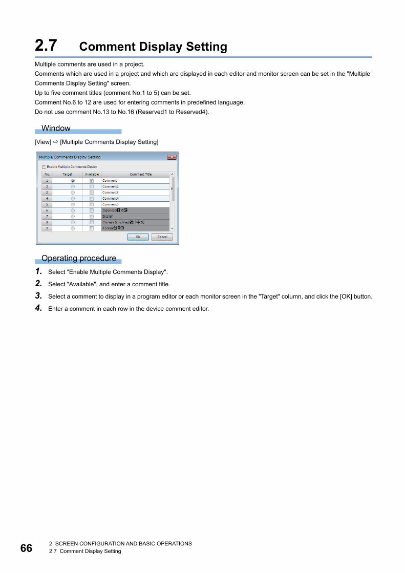
662 SCREEN CONFIGURATION AND BASIC OPERATIONS2.7 Comment Display Setting
2.7 Comment Display SettingMultiple comments are used in a project.
Comments which are used in a project and which are displayed in each editor and monitor screen can be set in the "Multiple
Comments Display Setting" screen.
Up to five comment titles (comment No.1 to 5) can be set.
Comment No.6 to 12 are used for entering comments in predefined language.
Do not use comment No.13 to No.16 (Reserved1 to Reserved4).
Window
[View] [Multiple Comments Display Setting]
Operating procedure
1. Select "Enable Multiple Comments Display".
2. Select "Available", and enter a comment title.
3. Select a comment to display in a program editor or each monitor screen in the "Target" column, and click the [OK] button.
4. Enter a comment in each row in the device comment editor.
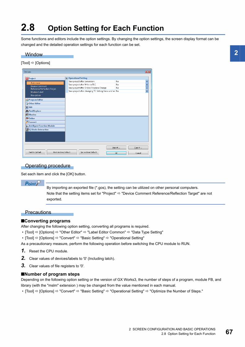
2 SCREEN CONFIGURATION AND BASIC OPERATIONS2.8 Option Setting for Each Function 67
2
2.8 Option Setting for Each FunctionSome functions and editors include the option settings. By changing the option settings, the screen display format can be
changed and the detailed operation settings for each function can be set.
Window
[Tool] [Options]
Operating procedure
Set each item and click the [OK] button.
By importing an exported file (*.gos), the setting can be utilized on other personal computers.
Note that the setting items set for "Project" "Device Comment Reference/Reflection Target" are not
exported.
Precautions
■Converting programsAfter changing the following option setting, converting all programs is required.
• [Tool] [Options] "Other Editor" "Label Editor Common" "Data Type Setting"
• [Tool] [Options] "Convert" "Basic Setting" "Operational Setting"
As a precautionary measure, perform the following operation before switching the CPU module to RUN.
1. Reset the CPU module.
2. Clear values of devices/labels to '0' (Including latch).
3. Clear values of file registers to '0'.
■Number of program stepsDepending on the following option setting or the version of GX Works3, the number of steps of a program, module FB, and
library (with the "mslm" extension ) may be changed from the value mentioned in each manual.
• [Tool] [Options] "Convert" "Basic Setting" "Operational Setting" "Optimize the Number of Steps."

682 SCREEN CONFIGURATION AND BASIC OPERATIONS2.8 Option Setting for Each Function
■Project for which "Yes" is selected for "Optimize the Number of Steps."A conversion error may occur in a project that satisfies the following two conditions. In that case, a subroutine program or
interrupt program must be changed to a program using an FB or inline structured text box.
• "Yes" is selected for "Optimize the Number of Steps."*1 in [Tool] [Options] "Convert" "Basic Setting" "Operational
Setting".
• Any of the data in the following table is used in a subroutine program or an interrupt program.
*1 "Collectively Allocate Temporary Area to Optimize the Number of Steps" is also displayed for a project used for an FX5CPU.
Modify a subroutine program or an interrupt program by any of the following methods.
(1) Change a program to a function block.
No. Data
1 A label for which two or more devices or labels are used as an array index
(Example) A label whose data type is structure array
(Example) A label whose data type is two-dimensional array
2 A subroutine type function block in which EN/ENO is used
3 Standard function
DINT_TO_BCD(_E), BCD_TO_DINT(_E), MUL(_E), DIV(_E), MOD(_E), XOR(_E), MAX(_E), MIN(_E), MUX(_E), LT(_E), LE(_E), EQ(_E),
GE(_E), GT(_E), MID(_E), CONCAT(_E), INSERT(_E), MUL_TIME(_E), DIV_TIME(_E)
Subroutine program
• Change the subroutine program (1) to the function block (2), and change the program to call the created function block (2).
(Example) Program before modification
(Example) Program after modification
(1)
(2)
(1)
Instruction
…P1192
RET

2 SCREEN CONFIGURATION AND BASIC OPERATIONS2.8 Option Setting for Each Function 69
2
Interrupt program
• Change the interrupt program (1) to the function block (2).
(Example) Program before modification
(Example) Program after modification
(1)
(2)
(1)
Instruction
…I129
IRET
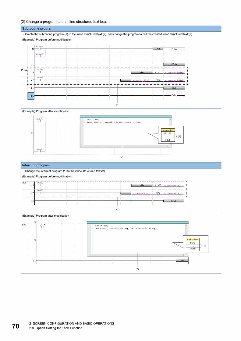
702 SCREEN CONFIGURATION AND BASIC OPERATIONS2.8 Option Setting for Each Function
(2) Change a program to an inline structured text box.
Subroutine program
• Create the subroutine program (1) to the inline structured text (2), and change the program to call the created inline structured text (2).
(Example) Program before modification
(Example) Program after modification
Interrupt program
• Change the interrupt program (1) to the inline structured text (2).
(Example) Program before modification
(Example) Program after modification
(1)
(2)
…
Instruction
(1)P1192
RET
(1)
(2)
Instruction
(1)…I129
IRET

2 SCREEN CONFIGURATION AND BASIC OPERATIONS2.8 Option Setting for Each Function 71
2
■An error 'Temporary area exceeded' occurs in an FX5CPUA temporary area is used for passing and receiving the arguments of function blocks and functions, and calculating
operations.
The memory capacity for a temporary area that can be allocated for each program block in a program file is limited. If a
program file including a program block exceeding the capacity is written to a CPU module, an error 'Temporary area
exceeded' will occur.
In that case, reduce the usage of the temporary area for one program block by any of the following actions.
• Set "No" for "Collectively Allocate Temporary Area to Optimize the Number of Steps" in [Tool] [Options] "Convert"
"Basic Setting" "Operational Setting"
• Divide one program block into some program blocks
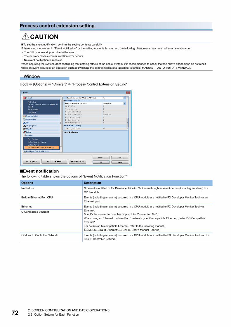
722 SCREEN CONFIGURATION AND BASIC OPERATIONS2.8 Option Setting for Each Function
Process control extension setting
Window
[Tool] [Options] "Convert" "Process Control Extension Setting"
■Event notificationThe following table shows the options of "Event Notification Function".
CAUTION■To set the event notification, confirm the setting contents carefully.
If there is no module set in "Event Notification" or the setting contents is incorrect, the following phenomena may result when an event occurs.
• The CPU module stopped due to the error.
• The network module communication error occurs.
• No event notification is received.
When adjusting the system, after confirming that nothing affects of the actual system, it is recommended to check that the above phenomena do not result
when an event occurs by an operation such as switching the control modes of a faceplate (example: MANUAL → AUTO, AUTO → MANUAL).
Options Description
Not to Use No event is notified to PX Developer Monitor Tool even though an event occurs (including an alarm) in a
CPU module.
Built-in Ethernet Port CPU Events (including an alarm) occurred in a CPU module are notified to PX Developer Monitor Tool via an
Ethernet port.
Ethernet Events (including an alarm) occurred in a CPU module are notified to PX Developer Monitor Tool via
Ethernet.
Specify the connection number of port 1 for "Connection No.".
When using an Ethernet module (Port 1 network type: Q-compatible Ethernet) , select "Q Compatible
Ethernet".
For details on Q-compatible Ethernet, refer to the following manual.
MELSEC iQ-R Ethernet/CC-Link IE User's Manual (Startup)
Q Compatible Ethernet
CC-Link IE Controller Network Events (including an alarm) occurred in a CPU module are notified to PX Developer Monitor Tool via CC-
Link IE Controller Network.
2 SCREEN CONFIGURATION AND BASIC OPERATIONS2.8 Option Setting for Each Function 73
2
Precautions
■For CC-Link IE Controller NetworkDo not use the following channel numbers for the link dedicated instructions in a ladder program.
• Channel number used by the own station: Channel number set in "Event Notification"
• Channel number of a target station used for storing data: 1 (number for PX Developer Monitor Tool)
For details on channel numbers, refer to the manual of a network module used.
■For an Ethernet module/built-in Ethernet CPUBroadcast in UDP/IP is used for sending data.
The UDP connection device number (broadcast) that was added in the following parameter is required to be set for
"Connection No." in "Event Notification".
• Ethernet module: "Module Information" "(module name)" "(module parameter)" "Basic Settings" "External Device
Configuration"
• Built-in Ethernet CPU: "(CPU model name of the project)" "Module Parameter" "Basic Settings" "External Device
Configuration"
The same number needs to be set for "Port No." of "Sensor/Device" and "Event Notification UDP Port No.(HEX)" in PX
Developer Monitor Tool.
For details, refer to the following manual.
PX Developer Version 1 Operating Manual (Monitor Tool)
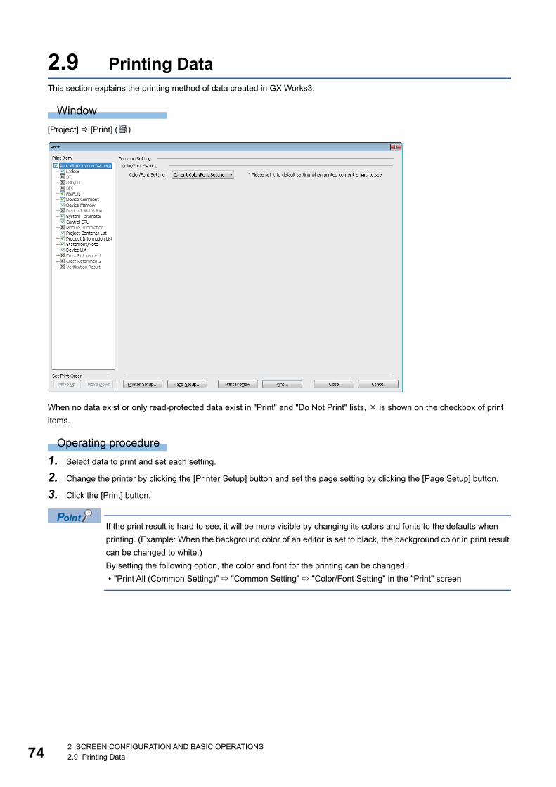
742 SCREEN CONFIGURATION AND BASIC OPERATIONS2.9 Printing Data
2.9 Printing DataThis section explains the printing method of data created in GX Works3.
Window
[Project] [Print] ( )
When no data exist or only read-protected data exist in "Print" and "Do Not Print" lists, is shown on the checkbox of print
items.
Operating procedure
1. Select data to print and set each setting.
2. Change the printer by clicking the [Printer Setup] button and set the page setting by clicking the [Page Setup] button.
3. Click the [Print] button.
If the print result is hard to see, it will be more visible by changing its colors and fonts to the defaults when
printing. (Example: When the background color of an editor is set to black, the background color in print result
can be changed to white.)
By setting the following option, the color and font for the printing can be changed.
• "Print All (Common Setting)" "Common Setting" "Color/Font Setting" in the "Print" screen
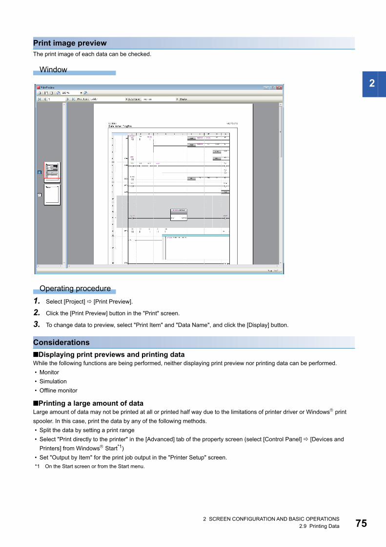
2 SCREEN CONFIGURATION AND BASIC OPERATIONS2.9 Printing Data 75
2
Print image previewThe print image of each data can be checked.
Window
Operating procedure
1. Select [Project] [Print Preview].
2. Click the [Print Preview] button in the "Print" screen.
3. To change data to preview, select "Print Item" and "Data Name", and click the [Display] button.
Considerations
■Displaying print previews and printing dataWhile the following functions are being performed, neither displaying print preview nor printing data can be performed.
• Monitor
• Simulation
• Offline monitor
■Printing a large amount of dataLarge amount of data may not be printed at all or printed half way due to the limitations of printer driver or Windows print
spooler. In this case, print the data by any of the following methods.
• Split the data by setting a print range
• Select "Print directly to the printer" in the [Advanced] tab of the property screen (select [Control Panel] [Devices and
Printers] from Windows Start*1)
• Set "Output by Item" for the print job output in the "Printer Setup" screen.
*1 On the Start screen or from the Start menu.
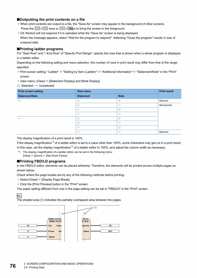
762 SCREEN CONFIGURATION AND BASIC OPERATIONS2.9 Printing Data
■Outputting the print contents on a file • When print contents are output to a file, the "Save As" screen may appear in the background of other screens.
Press the + keys or + keys to bring the screen in the foreground.
• GX Works3 will not respond if it is operated while the "Save As" screen is being displayed.
When the message appears, select "Wait for the program to respond". Selecting "Close the program" results in loss of
unsaved data.
■Printing ladder programsFor "Start Row" and "--End Row" of "Specify Print Range", specify the rows that is shown when a whole program is displayed
in a ladder editor.
Depending on the following setting and menu selection, the number of rows in print result may differ from that of the range
specified.
• Print screen setting: "Ladder" "Setting by Item (Ladder)" "Additional Information" "Statement/Note" in the "Print"
screen
• View menu: [View] [Statement Display] and [Note Display]
: Selected, : Unselected
The display magnification of a print result is 100%.
If the display magnification*1 of a ladder editor is set to a value other than 100%, some characters may get cut in a print result.
In this case, set the display magnification*1 of a ladder editor to 100%, and adjust the column width as necessary.
*1 The display magnification of a ladder editor can be set in the following menu.[View] [Zoom] [Set Zoom Factor]
■Printing FBD/LD programsIn the FBD/LD editor, elements can be placed arbitrarily. Therefore, the elements will be printed across multiple pages as
shown below.
Check where the page breaks are by any of the following methods before printing.
• Select [View] [Display Page Break].
• Click the [Print Preview] button in the "Print" screen.
The paper setting different from one in the page setting can be set in "FBD/LD" in the "Print" screen.
Ex.
The shaded area (1) indicates the partially overlapped area between the pages.
Print screen setting View menu Print result
Statement/Note Statement Note
Matched
Mismatched
Matched
(1)

2 SCREEN CONFIGURATION AND BASIC OPERATIONS2.9 Printing Data 77
2
■Printing SFC programs • When printing statements and notes, ones in a Zoom will not be printed.
• In the SFC diagram editor, SFC elements will be printed across multiple pages as shown below. Check the layout in the
print preview before printing.
Ex.
The shaded area (1) indicates the partially overlapped area between the pages.
■Printing the product information listThe information in a specified CSV file is printed out within the range of 500 rows × 20 columns.
(1)

782 SCREEN CONFIGURATION AND BASIC OPERATIONS2.9 Printing Data
MEMO
79
PA
RT
2
PART 2 SYSTEM DESIGN AND SETTINGS
This part explains the system design such as project management and parameter/label settings.
3 PROJECT MANAGEMENT
4 CREATING MODULE CONFIGURATION DIAGRAM AND SETTING PARAMETERS
5 REGISTERING LABELS
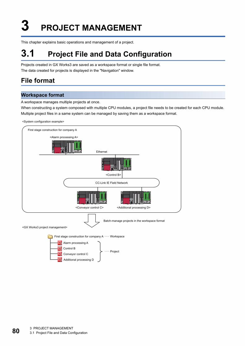
803 PROJECT MANAGEMENT3.1 Project File and Data Configuration
3 PROJECT MANAGEMENT
This chapter explains basic operations and management of a project.
3.1 Project File and Data ConfigurationProjects created in GX Works3 are saved as a workspace format or single file format.
The data created for projects is displayed in the "Navigation" window.
File format
Workspace formatA workspace manages multiple projects at once.
When constructing a system composed with multiple CPU modules, a project file needs to be created for each CPU module.
Multiple project files in a same system can be managed by saving them as a workspace format.
<System configuration example>
First stage construction for company A
<Alarm processing A>
Ethernet
<Control B>
CC-Link IE Field Network
<Conveyor control C> <Additional processing D>
Batch-manage projects in the workspace format
<GX Works3 project management>
····· WorkspaceFirst stage construction for company A
Alarm processing A
Control B····· Project
Conveyor control C
Additional processing D
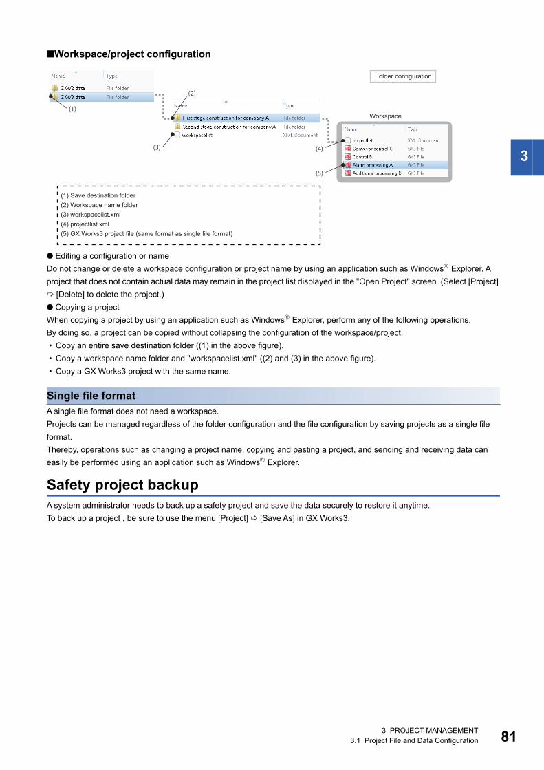
3 PROJECT MANAGEMENT3.1 Project File and Data Configuration 81
3
■Workspace/project configuration
● Editing a configuration or name
Do not change or delete a workspace configuration or project name by using an application such as Windows Explorer. A
project that does not contain actual data may remain in the project list displayed in the "Open Project" screen. (Select [Project]
[Delete] to delete the project.)
● Copying a project
When copying a project by using an application such as Windows Explorer, perform any of the following operations.
By doing so, a project can be copied without collapsing the configuration of the workspace/project.
• Copy an entire save destination folder ((1) in the above figure).
• Copy a workspace name folder and "workspacelist.xml" ((2) and (3) in the above figure).
• Copy a GX Works3 project with the same name.
Single file formatA single file format does not need a workspace.
Projects can be managed regardless of the folder configuration and the file configuration by saving projects as a single file
format.
Thereby, operations such as changing a project name, copying and pasting a project, and sending and receiving data can
easily be performed using an application such as Windows Explorer.
Safety project backupA system administrator needs to back up a safety project and save the data securely to restore it anytime.
To back up a project , be sure to use the menu [Project] [Save As] in GX Works3.
Folder configuration
Workspace
(1) Save destination folder(2) Workspace name folder(3) workspacelist.xml(4) projectlist.xml(5) GX Works3 project file (same format as single file format)
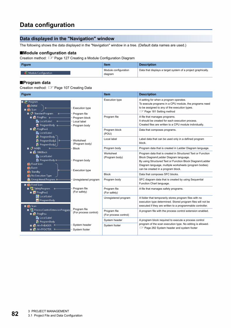
823 PROJECT MANAGEMENT3.1 Project File and Data Configuration
Data configuration
Data displayed in the "Navigation" windowThe following shows the data displayed in the "Navigation" window in a tree. (Default data names are used.)
■Module configuration dataCreation method: Page 127 Creating a Module Configuration Diagram
■Program dataCreation method: Page 107 Creating Data
Figure Item Description
Module configuration
diagram
Data that displays a target system of a project graphically.
Figure Item Description
Execution type A setting for when a program operates.
To execute programs in a CPU module, the programs need
to be assigned to any of the execution types.
Page 181 Setting method
Program file A file that manages programs.
It should be created for each execution process.
Created files are written to a CPU module individually.
Program block
(POU)
Data that composes programs.
Local label Label data that can be used only in a defined program
block.
Program body Program data that is created in Ladder Diagram language.
Worksheet
(Program body)
Program data that is created in Structured Text or Function
Block Diagram/Ladder Diagram language.
By using Structured Text or Function Block Diagram/Ladder
Diagram language, multiple worksheets (program bodies)
can be created in a program block.
Block Data that composes SFC blocks.
Program body SFC diagram data that is created by using Sequential
Function Chart language.
Program file
(For safety)
A file that manages safety programs.
Unregistered program A folder that temporarily stores program files with no
execution type determined. Stored program files will not be
executed if they are written to a programmable controller.
Program file
(For process control)
A program file with the process control extension enabled.
System header A program block required to execute a process control
program of the scan execution type. No editing is allowed.
Page 282 System header and system footerSystem footer
Execution type
Program fileProgram blockLocal labelProgram body
Execution type
Unregistered program
System footer
System header
Program file(For safety)
Worksheet(Program body)
Block
Program body
Program file(For process control)
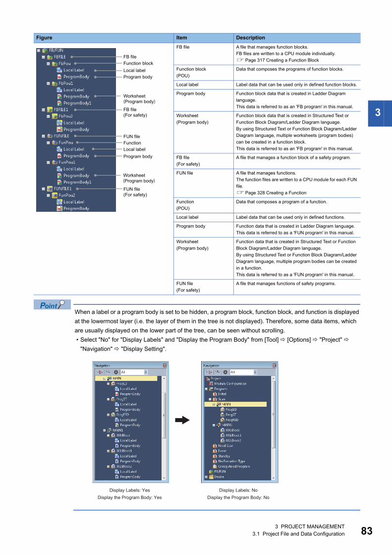
3 PROJECT MANAGEMENT3.1 Project File and Data Configuration 83
3
When a label or a program body is set to be hidden, a program block, function block, and function is displayed
at the lowermost layer (i.e. the layer of them in the tree is not displayed). Therefore, some data items, which
are usually displayed on the lower part of the tree, can be seen without scrolling.
• Select "No" for "Display Labels" and "Display the Program Body" from [Tool] [Options] "Project"
"Navigation" "Display Setting".
FB file A file that manages function blocks.
FB files are written to a CPU module individually.
Page 317 Creating a Function Block
Function block
(POU)
Data that composes the programs of function blocks.
Local label Label data that can be used only in defined function blocks.
Program body Function block data that is created in Ladder Diagram
language.
This data is referred to as an 'FB program' in this manual.
Worksheet
(Program body)
Function block data that is created in Structured Text or
Function Block Diagram/Ladder Diagram language.
By using Structured Text or Function Block Diagram/Ladder
Diagram language, multiple worksheets (program bodies)
can be created in a function block.
This data is referred to as an 'FB program' in this manual.
FB file
(For safety)
A file that manages a function block of a safety program.
FUN file A file that manages functions.
The function files are written to a CPU module for each FUN
file.
Page 328 Creating a Function
Function
(POU)
Data that composes a program of a function.
Local label Label data that can be used only in defined functions.
Program body Function data that is created in Ladder Diagram language.
This data is referred to as a 'FUN program' in this manual.
Worksheet
(Program body)
Function data that is created in Structured Text or Function
Block Diagram/Ladder Diagram language.
By using Structured Text or Function Block Diagram/Ladder
Diagram language, multiple program bodies can be created
in a function.
This data is referred to as a 'FUN program' in this manual.
FUN file
(For safety)
A file that manages functions of safety programs.
Figure Item Description
FB fileFunction blockLocal labelProgram body
FUN fileFunctionLocal labelProgram body
FB file(For safety)
FUN file(For safety)
Worksheet(Program body)
Worksheet(Program body)
Display Labels: Yes Display Labels: NoDisplay the Program Body: Yes Display the Program Body: No
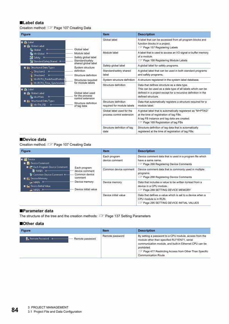
843 PROJECT MANAGEMENT3.1 Project File and Data Configuration
■Label dataCreation method: Page 107 Creating Data
■Device dataCreation method: Page 107 Creating Data
■Parameter dataThe structure of the tree and the creation methods: Page 137 Setting Parameters
■Other data
Figure Item Description
Global label A label that can be accessed from all program blocks and
function blocks in a project.
Page 157 Registering Labels
Module label A label that is used to access an I/O signal or buffer memory
of a module.
Page 168 Registering Module Labels
Safety global label A global label for safety programs.
Standard/safety shared
label
A global label that can be used in both standard programs
and safety programs.
System structure definition A structure registered in the system label database.
Structure definition Data that defines structure as a data type.
This can be used as a data type of all labels which can be
defined in a project except for a recursive definition in the
defined structure.
Structure definition
required for module labels
Data that automatically registers a structure required for a
module label.
Global label used for the
process control extension
A global label that is automatically registered as "M+PTAG"
at the time of registration of tag FBs.
A tag FB instance and tag data are created.
Page 169 Registration of tag FBs
Structure definition of tag
data
Structure definition of tag data that is automatically
registered at the time of registration of tag FBs.
Figure Item Description
Each program
device comment
Device comment data that is used in a program file which
have a same name.
Page 268 Registering Device Comments
Common device comment Device comment data that is commonly used in multiple
programs.
Page 268 Registering Device Comments
Device memory Data that includes a value to be written to/read from a
device in a CPU module.
Page 289 SETTING DEVICE MEMORY
Device initial value Data that defines a value which is set to a device when a
CPU module is in RUN.
Page 295 SETTING DEVICE INITIAL VALUES
Figure Item Description
Remote password By setting a password to a CPU module, access from the
module other than specified RJ71EN71, serial
communication module, and built-in Ethernet CPU can be
prohibited.
Page 477 Restricting Access from Other Than Specific
Communication Route
Global labelModule label
Structure definition
Structures required for module labels
Global label used for the process control extension
Structure definition of tag data
System structure definition
Safety global labelStandard/safety shared global label
Each program device commentCommon device commentDevice memory
Device initial value
Remote password

3 PROJECT MANAGEMENT3.2 Creating Project Files 85
3
3.2 Creating Project FilesThis section explains basic operations of GX Works3 such as creating, opening, and saving projects.
Creating a projectFor a safety project, registering a user is required when creating a new project since a user information for the User
Authentication function is needed. (Page 469 User management)
Window
[Project] [New] ( )
Operating procedure
Set each item and click the [OK] button.
Precautions
When creating a safety project, set a screen saver in Windows to lock the personal computer automatically if the non-
operated state has been continued for a certain time.
For details, refer to Windows Help and Support.
■Selecting QCPUs (Q mode), LCPUs, or FXCPUsWhen a QCPU (Q mode), an LCPU, or an FXCPU is selected, GX Works3 is started in the Q/L/FX series compatibility mode.
When GX Works2 is installed on the personal computer, it will be started up automatically.
If it is not installed, execute the "setup.exe" in the installation DVD-ROM (Disk2) of GX Works3.
■Creating projects used for RnENCPUsAn RnENCPU consists of the two slots; CPU part and network part.
The CPU part only is placed after creating a new project.
Place the network part any of the following methods.
• Place a CPU extension module (_RJ71EN71) in the "Module Configuration" window.
• Set a CPU extension module (_RJ71EN71) in "I/O Assignment Setting" in "System Parameter".
■Specifying model names of FX5CPUsA model name of an FX5CPU can be specified by any of the following methods.
• Right-click on a CPU module on the module configuration diagram, and click [Change CPU Model Name] from the shortcut
menu.
• Select the specific model name of a CPU module in "I/O Assignment Setting" on the [I/O Assignment] tab on the "System
Parameter" screen.

863 PROJECT MANAGEMENT3.2 Creating Project Files
Creating new projects by reading data from programmable controllersWhen data is read from a programmable controller without creating a new project, a new project is created based on the data
from a CPU module and intelligent function module.
When a QCPU (Q mode), an LCPU, or an FXCPU is selected, GX Works3 is started in the Q/L/FX series compatibility mode
and a new project can be created.
When user information is registered to a project, user authentication is required. (Page 472 Logging on to CPU module)
Operating procedure
1. Start GX Works3 and select [Online] [Read from PLC] ( ).
2. Select the series to be read on the "Series Selection" screen, and click the [OK] button.
3. Set the communication route to access the CPU module on the "Specify Connection Destination" screen, and click the
[OK] button.
4. Perform the Read from PLC function on the "Online Data Operation" screen.
For the method for performing the Read from PLC function on the "Online Data Operation" screen, refer to the following
section.
Page 398 Reading data from a programmable controller
Precautions
When parameters are not read from the programmable controller with data to create a new project, default parameters will be
set. Check the parameter setting.
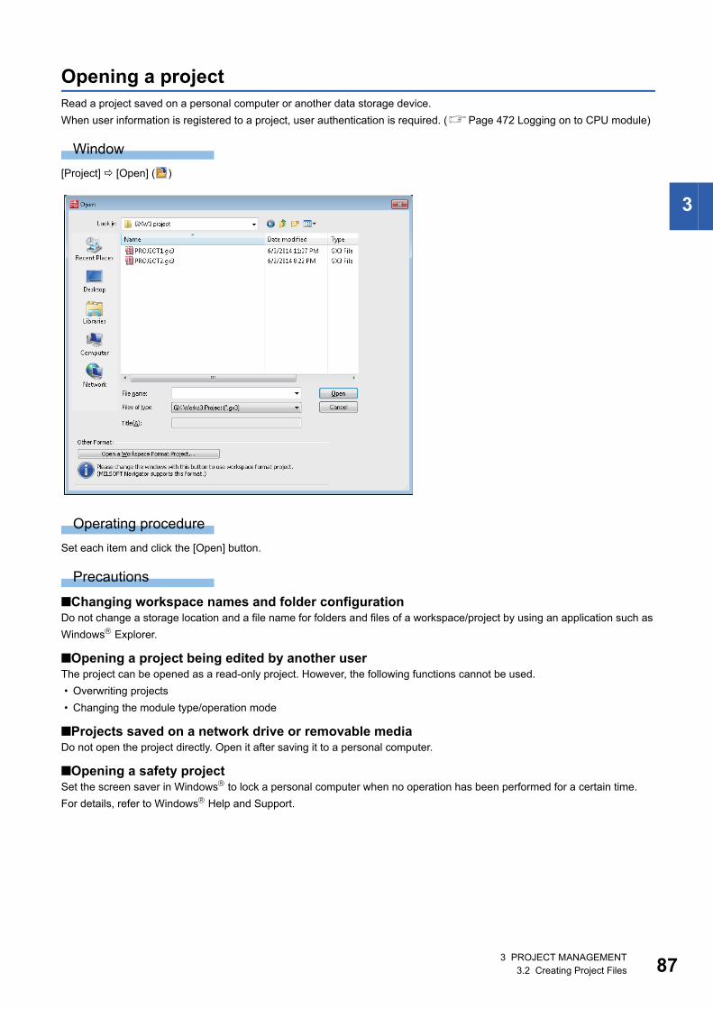
3 PROJECT MANAGEMENT3.2 Creating Project Files 87
3
Opening a projectRead a project saved on a personal computer or another data storage device.
When user information is registered to a project, user authentication is required. (Page 472 Logging on to CPU module)
Window
[Project] [Open] ( )
Operating procedure
Set each item and click the [Open] button.
Precautions
■Changing workspace names and folder configurationDo not change a storage location and a file name for folders and files of a workspace/project by using an application such as
Windows Explorer.
■Opening a project being edited by another userThe project can be opened as a read-only project. However, the following functions cannot be used.
• Overwriting projects
• Changing the module type/operation mode
■Projects saved on a network drive or removable mediaDo not open the project directly. Open it after saving it to a personal computer.
■Opening a safety projectSet the screen saver in Windows to lock a personal computer when no operation has been performed for a certain time.
For details, refer to Windows Help and Support.

883 PROJECT MANAGEMENT3.2 Creating Project Files
■Opening projects used for QCPUs (Q mode), LCPUs, or FXCPUsWhen one of the following project is selected, the project is opened with the Q/L/FX series compatibility mode in GX Works3.
• GX Works2 project saved as a single file format
• GX Works2 project saved in a workspace format
• GX Works3 project created in the Q/L/FX series compatibility mode which was saved as a single file format
When opening a project which was compressed in GX Works2, decompress the project in GX Works2 in advance.
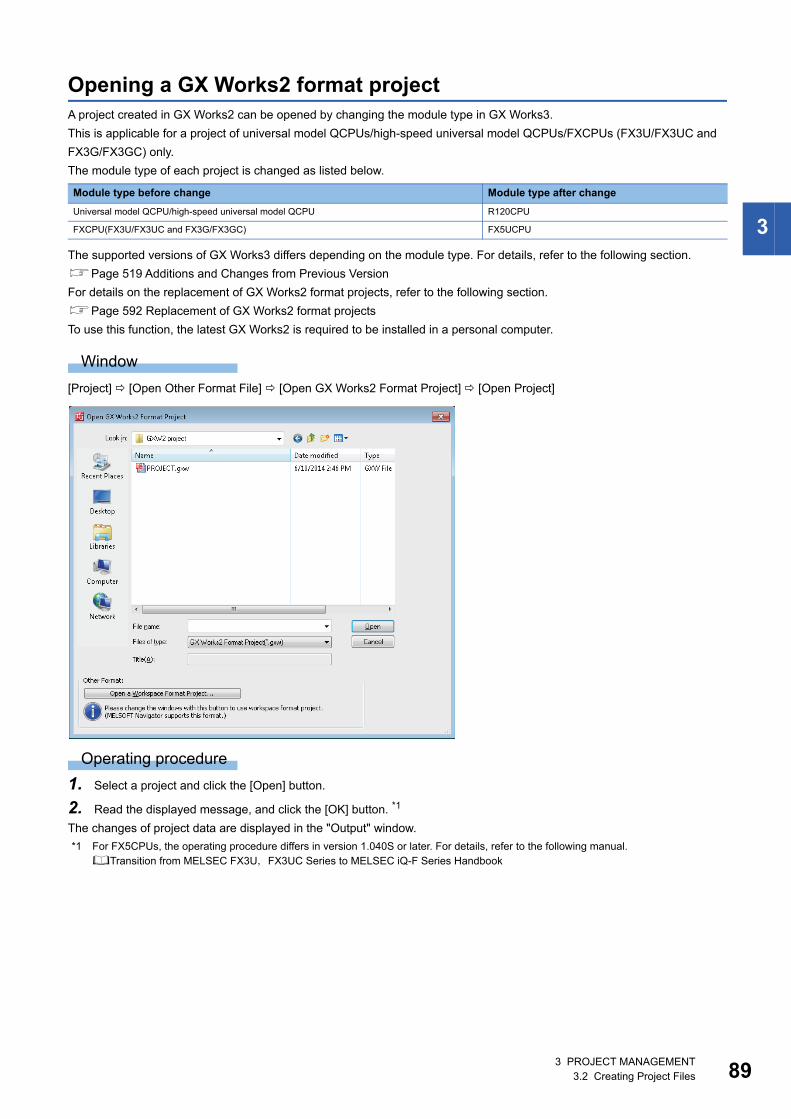
3 PROJECT MANAGEMENT3.2 Creating Project Files 89
3
Opening a GX Works2 format projectA project created in GX Works2 can be opened by changing the module type in GX Works3.
This is applicable for a project of universal model QCPUs/high-speed universal model QCPUs/FXCPUs (FX3U/FX3UC and
FX3G/FX3GC) only.
The module type of each project is changed as listed below.
The supported versions of GX Works3 differs depending on the module type. For details, refer to the following section.
Page 519 Additions and Changes from Previous Version
For details on the replacement of GX Works2 format projects, refer to the following section.
Page 592 Replacement of GX Works2 format projects
To use this function, the latest GX Works2 is required to be installed in a personal computer.
Window
[Project] [Open Other Format File] [Open GX Works2 Format Project] [Open Project]
Operating procedure
1. Select a project and click the [Open] button.
2. Read the displayed message, and click the [OK] button. *1
The changes of project data are displayed in the "Output" window.
*1 For FX5CPUs, the operating procedure differs in version 1.040S or later. For details, refer to the following manual.Transition from MELSEC FX3U,FX3UC Series to MELSEC iQ-F Series Handbook
Module type before change Module type after change
Universal model QCPU/high-speed universal model QCPU R120CPU
FXCPU(FX3U/FX3UC and FX3G/FX3GC) FX5UCPU

903 PROJECT MANAGEMENT3.2 Creating Project Files
Precautions
• If a program that contains a compilation error exists in GX Works2, the project cannot be opened. Check if the program can
be compiled in GX Works2.
• A project in which user management setting or access authority setting is configured cannot be opened. Clear the setting in
GX Works2.
• If a project file of GX Works2 is compressed (*.gwz), open the file in GX Works3 after decompressing it.
• The check processing at a conversion of GX Works3 is enhanced by comparing with GX Works2. Therefore a conversion
error may occur in a program in GX Works3 even if it does not occur in GX Works2. In that case, check the error content
and correct the program.
■Data to be changed when changing the module typeThe following table shows data to be retained, returned to the default, or deleted when changing the module type.
Data in a module will be deleted if there is no module to replace with a module in MELSEC iQ-R series or MELSEC iQ-F FX5
series.
Operation in module type change
Setting content in GX Works2 Remarks
Changing in accordance with the
target module type
• PLC parameter*1 PLC name Check the settings after the change.
PLC system*2,*3
PLC file*2
PLC RAS*2,*3
Boot file
Program*3
SFC*4
Device*2
I/O assignment*2,*3
Multiple CPU*2
Built-in Ethernet port*2,*3
• Network parameter CC-Link IE Field*1
CC-Link IE Control*1,*3
Ethernet*1,*2,*3
CC-Link*2,*5
• Intelligent function module
parameter*1Input
Output
I/O
Interrupt input
Analog input
Analog output
Temperature input
Temperature control
Simple motion
Positioning
High-speed counter
Serial communication
• FB/FUN
• Structured ladder/FBD program*6
• SFC program*1,*3,*4
• Device comment for devices other than SM/SD*7
• ST programs
• Device/label automatic-assign
Returning to the default/
deleting the data
• Options (other than "Device Comment Reference/Reflection Target")
• System label
• Device comments of SM/SD
• Connection destination
• Remote password
Set them in GX Works3.

3 PROJECT MANAGEMENT3.2 Creating Project Files 91
3
*1 The data returns to the default or is deleted when the module type is changed to an FX5UCPU.*2 The items which are not supported by GX Works3 are deleted.*3 Some items return to the default or their data are deleted. Check/set them in GX Works3 after the change.*4 To read SFC programs, GX Works2 of which version is 1.535H or later is required to be installed in a personal computer.*5 When a local station is set in the "CC-Link Configuration", it will be changed to an intelligent device station. Check the station type.*6 To read Structured Ladder/FBD programs, GX Works2 of which version is 1.519R or later is required to be installed in a personal
computer.*7 When changing the module type to an FX5UCPU, the data of M8000 or higher/D8000 or higher will change to SM8000 or higher/
SD8000 or higher. For details, refer to the following handbook.Transition from MELSEC FX3U,FX3UC Series to MELSEC iQ-F Series Handbook
■Opening projects used for QnPRHCPUs in GX Works3A project used for a QnPRHCPU can be opened in GX Works3 according to the following procedure.
1. Change the PLC type of a project from a QnPRHCPU to a QnUDPVCPU in GX Works2.
2. Open the project used for QnUDPVCPU by selecting [Project] [Open Other Format File] [GX Works2 Format]
[Open Project] in GX Works3.
3. Select [Project] [Change Module Type/Operation Mode], then change the module type to an RnPCPU and the
operation mode to the redundant mode.
4. Set parameters. After changing the module type and operation mode, redundant parameters are not retained.
Deleting • PLC parameter Communication head Not supported by GX Works3.
Built-in I/O function
Serial communication
Built-in serial
Adapter serial
Memory capacity
Special function block
Positioning
Operation
• Redundant parameter Operation mode
Tracking
• Programs of user library that are not registered to the program setting
• Task
• Project revision
• Device memory (only when the module type is changed to an FX5UCPU)
Operation in module type change
Setting content in GX Works2 Remarks
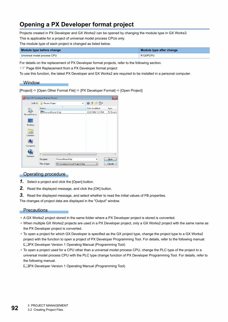
923 PROJECT MANAGEMENT3.2 Creating Project Files
Opening a PX Developer format projectProjects created in PX Developer and GX Works2 can be opened by changing the module type in GX Works3.
This is applicable for a project of universal model process CPUs only.
The module type of each project is changed as listed below.
For details on the replacement of PX Developer format projects, refer to the following section.
Page 604 Replacement from a PX Developer format project
To use this function, the latest PX Developer and GX Works2 are required to be installed in a personal computer.
Window
[Project] [Open Other Format File] [PX Developer Format] [Open Project]
Operating procedure
1. Select a project and click the [Open] button.
2. Read the displayed message, and click the [OK] button.
3. Read the displayed message, and select whether to read the initial values of FB properties.
The changes of project data are displayed in the "Output" window.
Precautions
• A GX Works2 project stored in the same folder where a PX Developer project is stored is converted.
• When multiple GX Works2 projects are used in a PX Developer project, only a GX Works2 project with the same name as
the PX Developer project is converted.
• To open a project for which GX Developer is specified as the GX project type, change the project type to a GX Works2
project with the function to open a project of PX Developer Programming Tool. For details, refer to the following manual.
PX Developer Version 1 Operating Manual (Programming Tool)
• To open a project used for a CPU other than a universal model process CPU, change the PLC type of the project to a
universal model process CPU with the PLC type change function of PX Developer Programming Tool. For details, refer to
the following manual.
PX Developer Version 1 Operating Manual (Programming Tool)
Module type before change Module type after change
Universal model process CPU R120PCPU
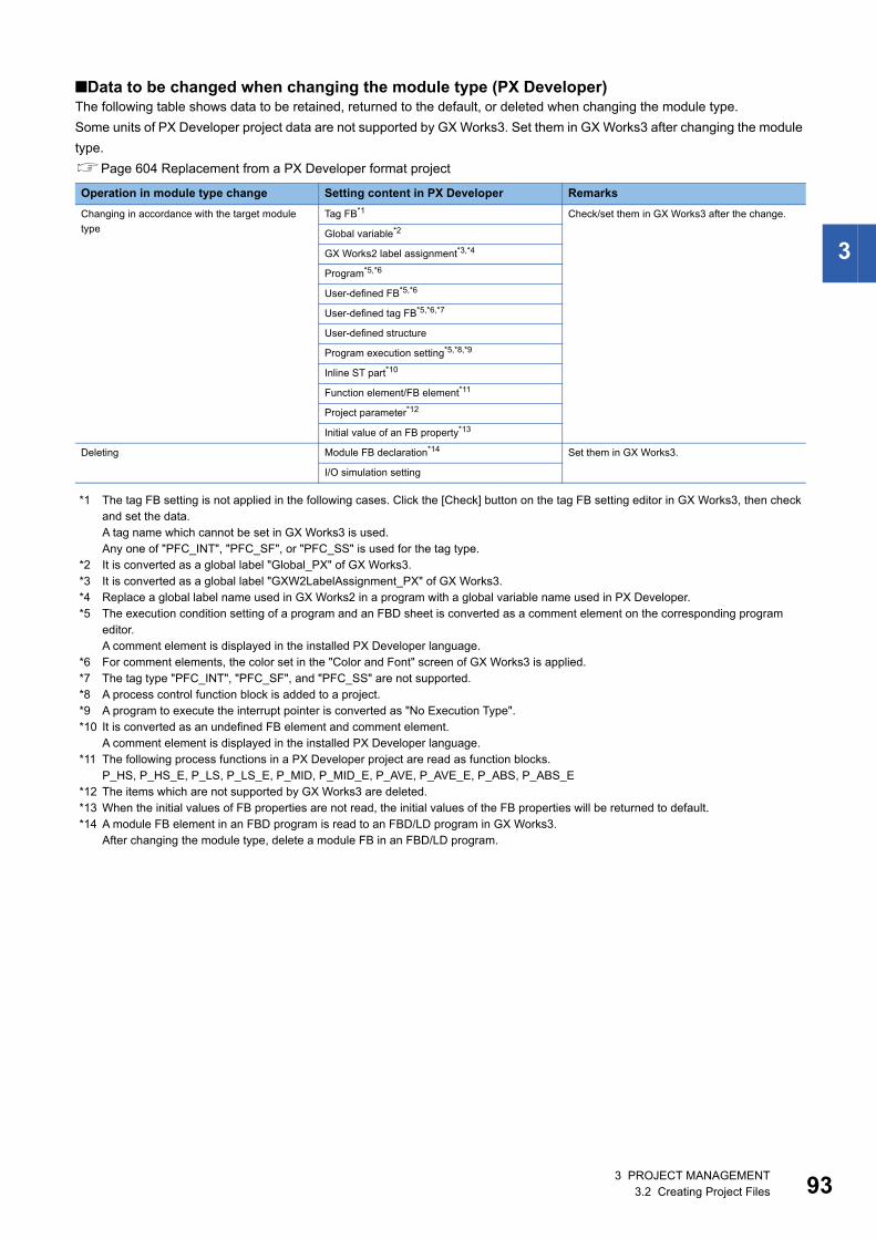
3 PROJECT MANAGEMENT3.2 Creating Project Files 93
3
■Data to be changed when changing the module type (PX Developer)The following table shows data to be retained, returned to the default, or deleted when changing the module type.
Some units of PX Developer project data are not supported by GX Works3. Set them in GX Works3 after changing the module
type.
Page 604 Replacement from a PX Developer format project
*1 The tag FB setting is not applied in the following cases. Click the [Check] button on the tag FB setting editor in GX Works3, then check and set the data.A tag name which cannot be set in GX Works3 is used.Any one of "PFC_INT", "PFC_SF", or "PFC_SS" is used for the tag type.
*2 It is converted as a global label "Global_PX" of GX Works3.*3 It is converted as a global label "GXW2LabelAssignment_PX" of GX Works3.*4 Replace a global label name used in GX Works2 in a program with a global variable name used in PX Developer.*5 The execution condition setting of a program and an FBD sheet is converted as a comment element on the corresponding program
editor.A comment element is displayed in the installed PX Developer language.
*6 For comment elements, the color set in the "Color and Font" screen of GX Works3 is applied.*7 The tag type "PFC_INT", "PFC_SF", and "PFC_SS" are not supported.*8 A process control function block is added to a project.*9 A program to execute the interrupt pointer is converted as "No Execution Type".*10 It is converted as an undefined FB element and comment element.
A comment element is displayed in the installed PX Developer language.*11 The following process functions in a PX Developer project are read as function blocks.
P_HS, P_HS_E, P_LS, P_LS_E, P_MID, P_MID_E, P_AVE, P_AVE_E, P_ABS, P_ABS_E*12 The items which are not supported by GX Works3 are deleted.*13 When the initial values of FB properties are not read, the initial values of the FB properties will be returned to default.*14 A module FB element in an FBD program is read to an FBD/LD program in GX Works3.
After changing the module type, delete a module FB in an FBD/LD program.
Operation in module type change Setting content in PX Developer Remarks
Changing in accordance with the target module
type
Tag FB*1 Check/set them in GX Works3 after the change.
Global variable*2
GX Works2 label assignment*3,*4
Program*5,*6
User-defined FB*5,*6
User-defined tag FB*5,*6,*7
User-defined structure
Program execution setting*5,*8,*9
Inline ST part*10
Function element/FB element*11
Project parameter*12
Initial value of an FB property*13
Deleting Module FB declaration*14 Set them in GX Works3.
I/O simulation setting
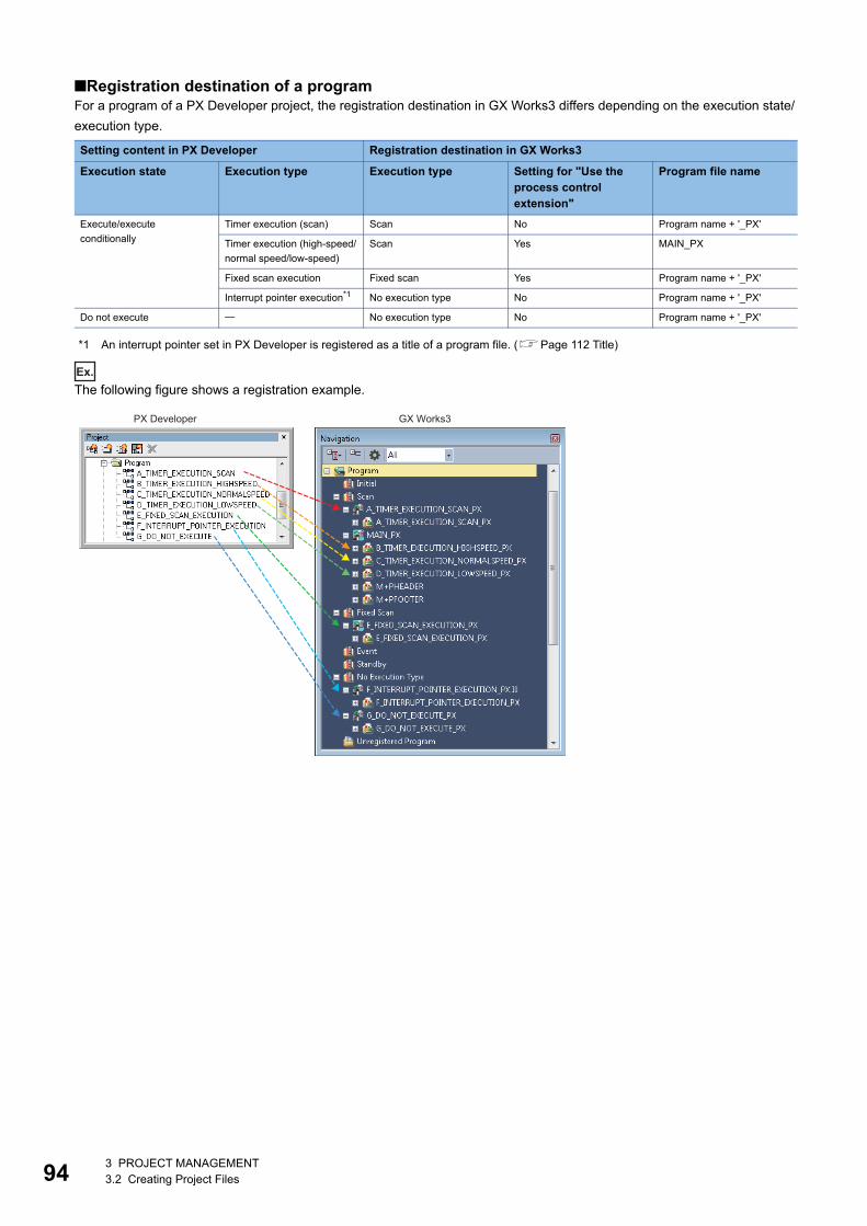
943 PROJECT MANAGEMENT3.2 Creating Project Files
■Registration destination of a programFor a program of a PX Developer project, the registration destination in GX Works3 differs depending on the execution state/
execution type.
*1 An interrupt pointer set in PX Developer is registered as a title of a program file. (Page 112 Title)
Ex.
The following figure shows a registration example.
Setting content in PX Developer Registration destination in GX Works3
Execution state Execution type Execution type Setting for "Use the process control extension"
Program file name
Execute/execute
conditionally
Timer execution (scan) Scan No Program name + '_PX'
Timer execution (high-speed/
normal speed/low-speed)
Scan Yes MAIN_PX
Fixed scan execution Fixed scan Yes Program name + '_PX'
Interrupt pointer execution*1 No execution type No Program name + '_PX'
Do not execute No execution type No Program name + '_PX'
PX Developer GX Works3
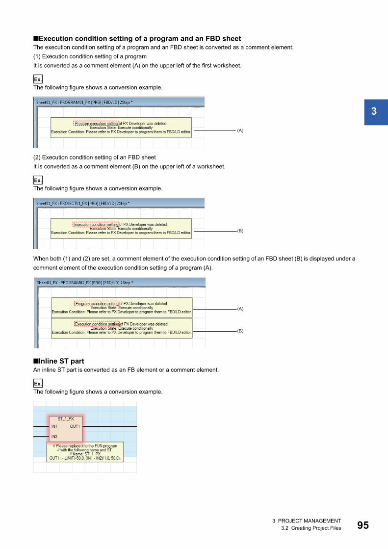
3 PROJECT MANAGEMENT3.2 Creating Project Files 95
3
■Execution condition setting of a program and an FBD sheetThe execution condition setting of a program and an FBD sheet is converted as a comment element.
(1) Execution condition setting of a program
It is converted as a comment element (A) on the upper left of the first worksheet.
Ex.
The following figure shows a conversion example.
(2) Execution condition setting of an FBD sheet
It is converted as a comment element (B) on the upper left of a worksheet.
Ex.
The following figure shows a conversion example.
When both (1) and (2) are set, a comment element of the execution condition setting of an FBD sheet (B) is displayed under a
comment element of the execution condition setting of a program (A).
■Inline ST partAn inline ST part is converted as an FB element or a comment element.
Ex.
The following figure shows a conversion example.
(A)
(B)
(A)
(B)
963 PROJECT MANAGEMENT3.2 Creating Project Files
■Label area capacityThe following data is applied to "Label Area Capacity" or "Latch Label Area Capacity" in the CPU parameter of a GX Works3
project
*1 Capacity that is calculated based on the number of points for file registers and timers set in the system resource of the project parameter in a PX Developer project.
*2 Capacity that is calculated based on the total number of points for each device (for VAR) set in the device/label automatic-assign in a GX Works2 project
*3 Capacity that is calculated based on the total number of points for each device (for VAR_RETAIN) set in the device/label automatic-assign in a GX Works2 project
Precautions
When a PX Developer format project is opened in GX Works3, "0 K Word" may be set for "Label Area Capacity" and "Latch
Label Area Capacity".
For details, refer to the following section.
Page 609 Label area capacity
■Data to be changed when changing the module type (GX Works2)To retain data in a GX Works2 project used in a PX Developer project, refer to the following section.
Page 90 Data to be changed when changing the module type
The following data are deleted.
Precautions
■Tag names that cannot be set for GX Works3Some tag names set in a PX Developer project are not applied to a tag FB setting in GX Works3; therefore, the FB property
initial value is returned to the default.
In that case, change the tag name in PX Developer to the one available in GX Works3.
After changing the tag name, open the PX Developer format project in GX Works3 again.
For details, refer to the following section.
Page 608 Tag names that cannot be set in GX Works3
■Data name overlappingWhen changing the module type, the data name of a PX Developer project is changed.
Therefore, the data name may be duplicated and the module type change may be canceled.
Correct the data name of PX Developer format project, and change the module type again.
For details, refer to the following section.
Page 609 Data name overlapping
Parameter in GX Works3 Capacity
Label area capacity Capacity that is calculated based on the capacity in a PX Developer project*1 + Capacity that is calculated based on the
capacity in a GX Works2 project*2
Latch label area capacity Capacity that is calculated based on the capacity in a PX Developer project*1 + Capacity that is calculated based on the
capacity in a GX Works2 project*3
Setting content in GX Works2 Remarks
Program file Deleted when the data name starts with "#FBDQ".
Program block
Program setting
Global label Deleted when the data name matches "#FBDQ".
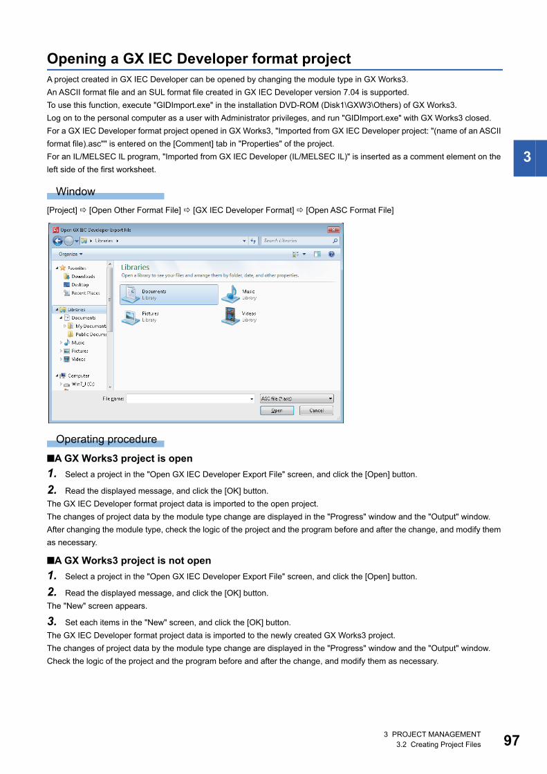
3 PROJECT MANAGEMENT3.2 Creating Project Files 97
3
Opening a GX IEC Developer format projectA project created in GX IEC Developer can be opened by changing the module type in GX Works3.
An ASCII format file and an SUL format file created in GX IEC Developer version 7.04 is supported.
To use this function, execute "GIDImport.exe" in the installation DVD-ROM (Disk1\GXW3\Others) of GX Works3.
Log on to the personal computer as a user with Administrator privileges, and run "GIDImport.exe" with GX Works3 closed.
For a GX IEC Developer format project opened in GX Works3, "Imported from GX IEC Developer project: "(name of an ASCII
format file).asc"" is entered on the [Comment] tab in "Properties" of the project.
For an IL/MELSEC IL program, "Imported from GX IEC Developer (IL/MELSEC IL)" is inserted as a comment element on the
left side of the first worksheet.
Window
[Project] [Open Other Format File] [GX IEC Developer Format] [Open ASC Format File]
Operating procedure
■A GX Works3 project is open
1. Select a project in the "Open GX IEC Developer Export File" screen, and click the [Open] button.
2. Read the displayed message, and click the [OK] button.
The GX IEC Developer format project data is imported to the open project.
The changes of project data by the module type change are displayed in the "Progress" window and the "Output" window.
After changing the module type, check the logic of the project and the program before and after the change, and modify them
as necessary.
■A GX Works3 project is not open
1. Select a project in the "Open GX IEC Developer Export File" screen, and click the [Open] button.
2. Read the displayed message, and click the [OK] button.
The "New" screen appears.
3. Set each items in the "New" screen, and click the [OK] button.
The GX IEC Developer format project data is imported to the newly created GX Works3 project.
The changes of project data by the module type change are displayed in the "Progress" window and the "Output" window.
Check the logic of the project and the program before and after the change, and modify them as necessary.
983 PROJECT MANAGEMENT3.2 Creating Project Files
Precautions
• POUs in Sequential Function Chart language for FX series are not imported.
• Devices and instructions used for POUs need to be modified.
• Devices in address representation (such as %MX0.1) will be converted into device representation. Inconvertible devices
into address representation will be read as they are.
• Functions/Function blocks used in a GX IEC Developer format project will be changed to undefined ones when the module
after changing the module type does not support them.
• When an IL/MELSEC IL program is converted into an FBD/LD program in GX Works3, the numbers of parameters of
functions may not match between the GX IEC Developer project and the GX Works3 project.
In this case, the function keeps the number of parameters of the GX IEC Developer project and is converted as one whose
definition is unclear.
• Module type change will be cancelled if the [Cancel] button in the progress dialog is clicked during processing.
Data which has already been replaced in GX Works3 project before the cancellation will not be deleted.
■Data to be changed when changing the module type
*1 When the same data name as that included in a GX IEC Developer format project exists in a GX Works3 project, the name of the data in the GX IEC Developer format project is incremented. (Example: Item_1→Item_2)
*2 For FX series, data is deleted.*3 The global variables of GX IEC Developer are defined as global labels in "Global" only when no global label exists in "Global (Global
Label Setting)" in a GX Works3 project.When any global label exists in "Global", a new global label setting is created.
Operation in module type change Setting content in GX IEC Developer Remarks
Changing in accordance with the target
module type
Program POU*1 Check the settings after the change.
Function POU*1
Function Block POU*1
POU (FBD)
POU (LD)
POU (ST)
POU (SFC)*2
POU (IL/MELSEC IL)
SFC action (FBD)*2
SFC action (LD)*2
SFC action (ST)*2
SFC action (IL/MELSEC IL)*2
SFC transition (FBD)*2
SFC transition (LD)*2
SFC transition (ST)*2
SFC transition (IL/MELSEC IL)*2
Data Unit Type/Structured Data Type*1
Global variables*3
Task*1/Program File
User Library When creating a library in GX Works3 format from
a library in GX IEC Developer format, refer to the
following section.
Page 333 Creating a library in GX Works3
format from a library in GX IEC Developer format
Returning to the default/
deleting the data
CPU Parameter Set them in GX Works3.
System Parameter
Network Parameter
Module Parameter
Connection Settings
Entry Data Monitor/Watch
Options
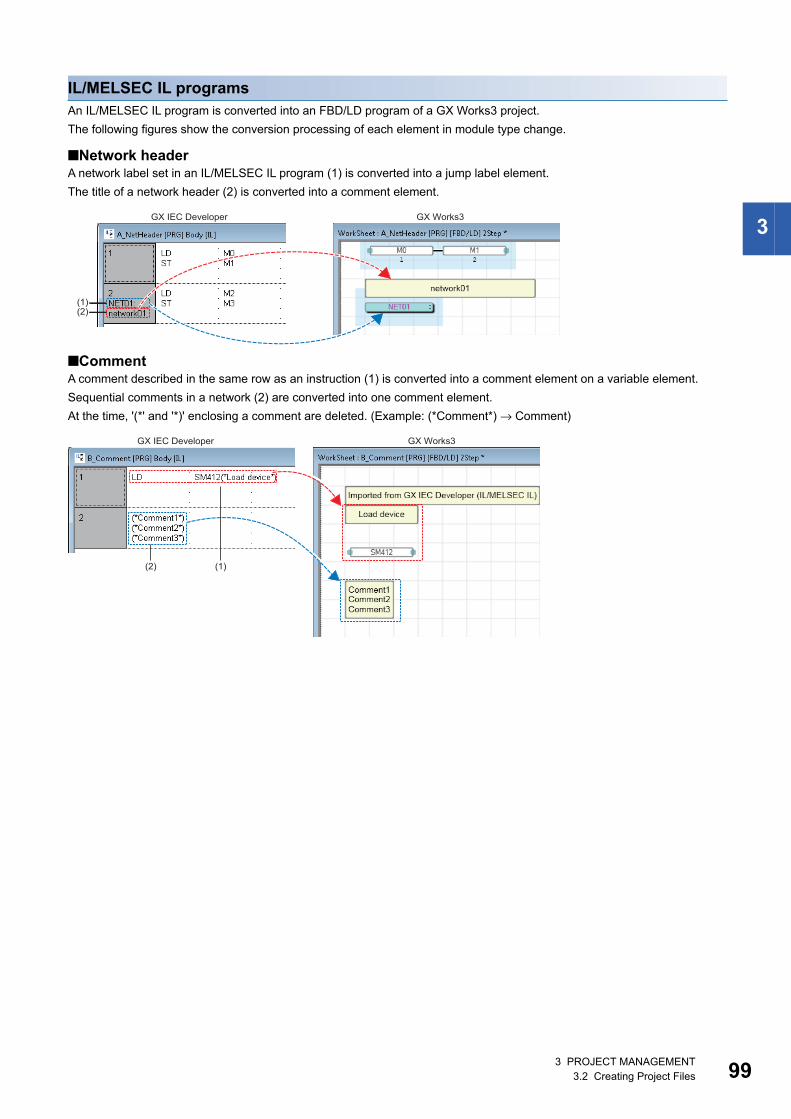
3 PROJECT MANAGEMENT3.2 Creating Project Files 99
3
IL/MELSEC IL programsAn IL/MELSEC IL program is converted into an FBD/LD program of a GX Works3 project.
The following figures show the conversion processing of each element in module type change.
■Network headerA network label set in an IL/MELSEC IL program (1) is converted into a jump label element.
The title of a network header (2) is converted into a comment element.
■CommentA comment described in the same row as an instruction (1) is converted into a comment element on a variable element.
Sequential comments in a network (2) are converted into one comment element.
At the time, '(*' and '*)' enclosing a comment are deleted. (Example: (*Comment*) → Comment)
GX IEC Developer GX Works3
(1)(2)
GX IEC Developer
(2)
GX Works3
(1)

1003 PROJECT MANAGEMENT3.2 Creating Project Files
■Programming instructionsThe following figures show a conversion example of programming instructions.
• IEC programming instructions
For an LDN instruction (1), the function 'NOT' is added only when an output variable is connected.
• MELSEC programming instructions
GX IEC Developer GX Works3
(1)
(1)
GX IEC Developer GX Works3
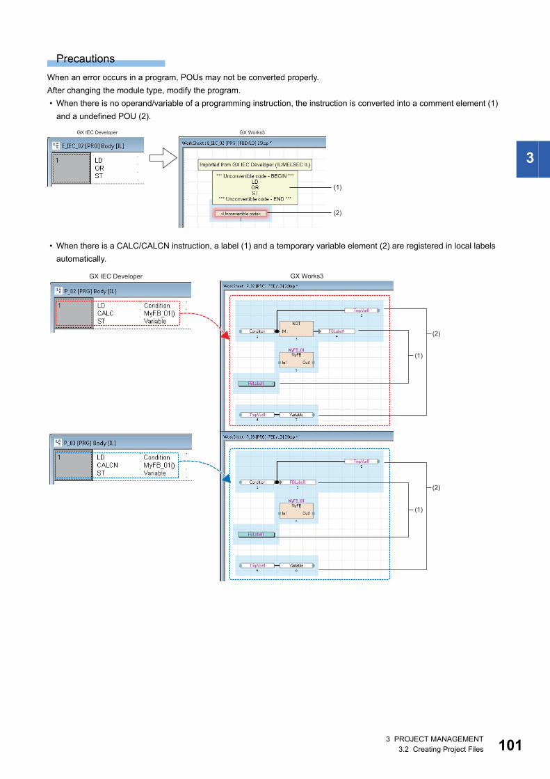
3 PROJECT MANAGEMENT3.2 Creating Project Files 101
3
Precautions
When an error occurs in a program, POUs may not be converted properly.
After changing the module type, modify the program.
• When there is no operand/variable of a programming instruction, the instruction is converted into a comment element (1)
and a undefined POU (2).
• When there is a CALC/CALCN instruction, a label (1) and a temporary variable element (2) are registered in local labels
automatically.
GX IEC Developer GX Works3
(1)
(2)
GX IEC Developer GX Works3
(1)
(2)
(2)
(1)

1023 PROJECT MANAGEMENT3.2 Creating Project Files
Actions/transitions (IL/MELSEC IL)Actions/transitions of an SFC program created in IL/MELSEC IL language are converted into ones of an SFC program created
in Function Block Diagram/Ladder Diagram language.
To convert actions/transitions, the following instructions are required at the end of the program.
• IL program: ST instruction that a transition name or the SFC dedicated instruction "TRAN" is used for the variable
• MELSEC IL program: OUT instruction that the SFC dedicated instruction "TRAN" is used for the variable
The programs of the actions/transitions are converted into ones to call the function "TRAN".
Global variablesAdd global variables set in a GX IEC Developer format project to the global label setting of GX Works3.
Operating procedure
1. In GX IEC Developer, export "Global_Vars" to an ASCII format file.
2. Open the ASCII format file exported in step 1 in a GX Works3 project by changing the module type.
Up to 20480 global variables are added to the global label setting in GX Works3.
To add 20480 or more global variables to the global label setting of GX Works3, follow the procedure below.
3. Change the name of the global label setting added in step 2. (Example: Global→Global_1)
4. Open the ASCII format file exported in step 1, and delete 20480 global variables which ware added to the global label
setting of GX Works3.
5. Open the ASCII format file exported in step 4 in a GX Works3 project by changing the module type.
GX IEC Developer GX Works3
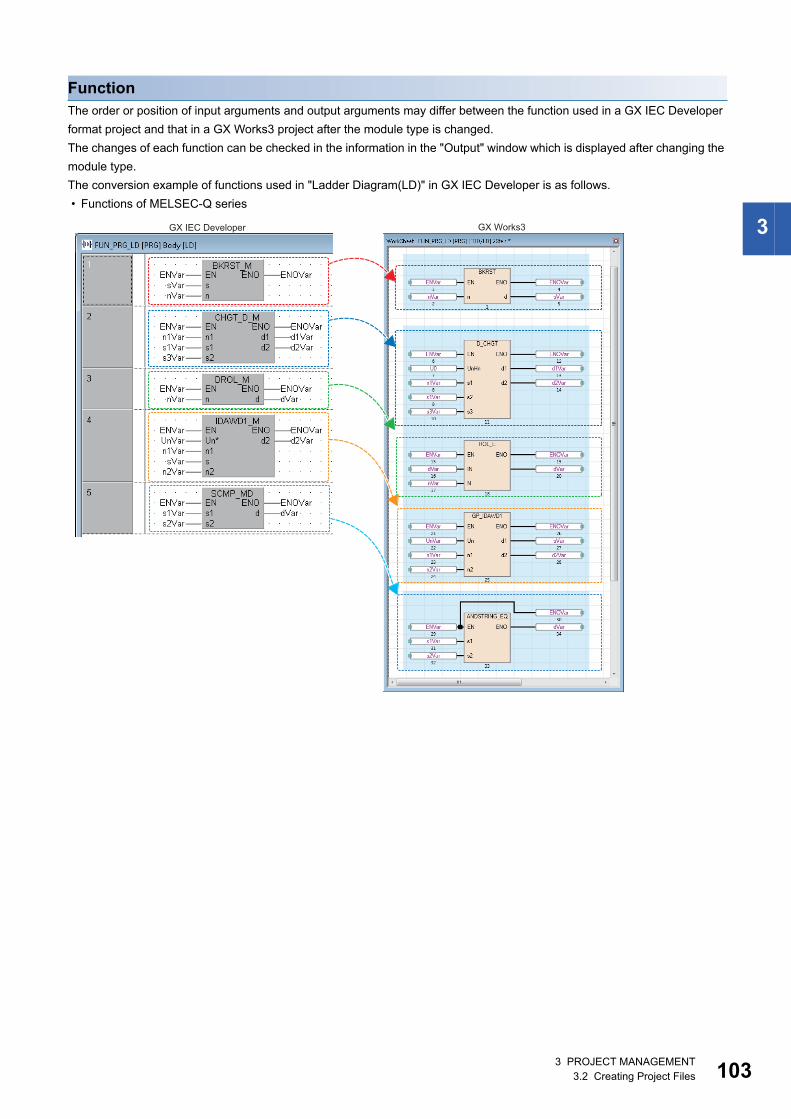
3 PROJECT MANAGEMENT3.2 Creating Project Files 103
3
FunctionThe order or position of input arguments and output arguments may differ between the function used in a GX IEC Developer
format project and that in a GX Works3 project after the module type is changed.
The changes of each function can be checked in the information in the "Output" window which is displayed after changing the
module type.
The conversion example of functions used in "Ladder Diagram(LD)" in GX IEC Developer is as follows.
• Functions of MELSEC-Q series
GX IEC Developer GX Works3
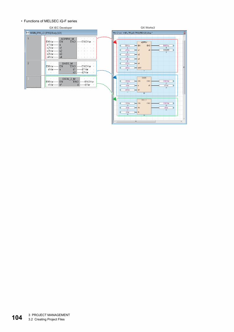
1043 PROJECT MANAGEMENT3.2 Creating Project Files
• Functions of MELSEC iQ-F series
GX IEC Developer GX Works3
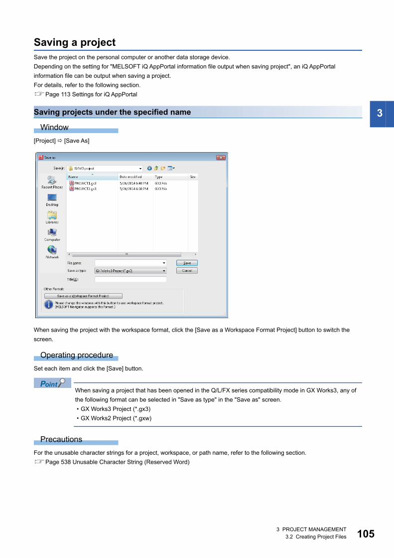
3 PROJECT MANAGEMENT3.2 Creating Project Files 105
3
Saving a projectSave the project on the personal computer or another data storage device.
Depending on the setting for "MELSOFT iQ AppPortal information file output when saving project", an iQ AppPortal
information file can be output when saving a project.
For details, refer to the following section.
Page 113 Settings for iQ AppPortal
Saving projects under the specified name
Window
[Project] [Save As]
When saving the project with the workspace format, click the [Save as a Workspace Format Project] button to switch the
screen.
Operating procedure
Set each item and click the [Save] button.
When saving a project that has been opened in the Q/L/FX series compatibility mode in GX Works3, any of
the following format can be selected in "Save as type" in the "Save as" screen.
• GX Works3 Project (*.gx3)
• GX Works2 Project (*.gxw)
Precautions
For the unusable character strings for a project, workspace, or path name, refer to the following section.
Page 538 Unusable Character String (Reserved Word)
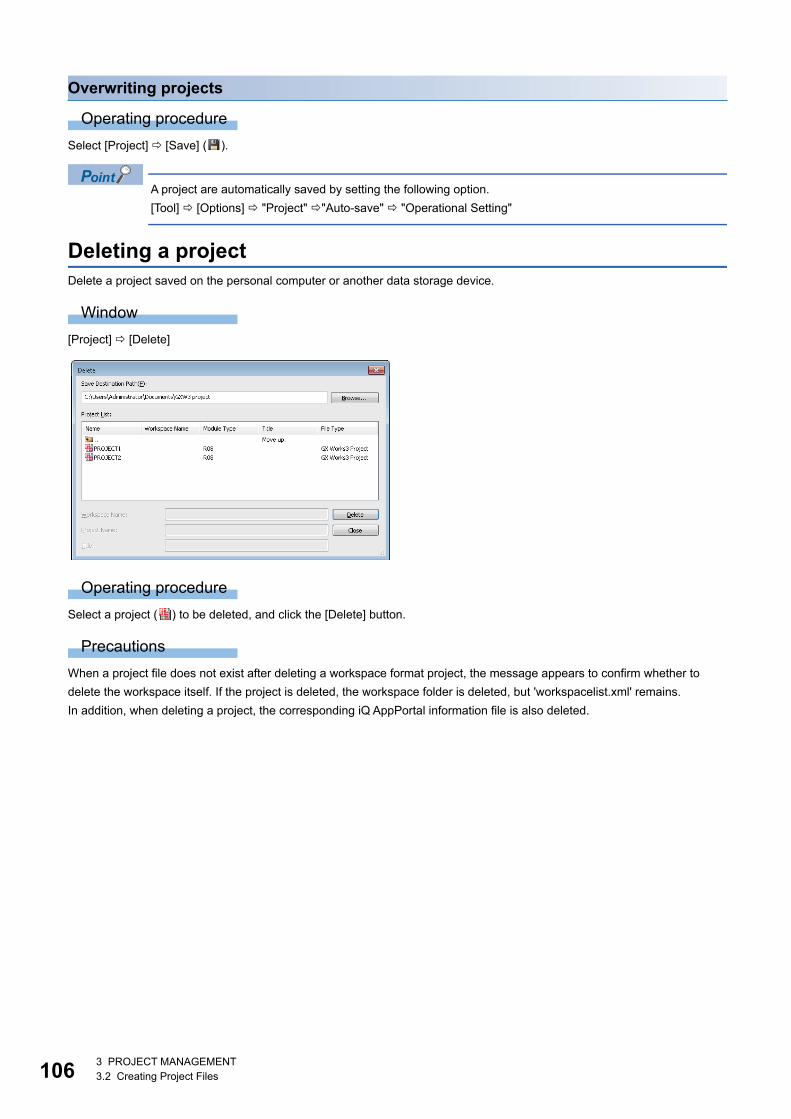
1063 PROJECT MANAGEMENT3.2 Creating Project Files
Overwriting projects
Operating procedure
Select [Project] [Save] ( ).
A project are automatically saved by setting the following option.
[Tool] [Options] "Project" "Auto-save" "Operational Setting"
Deleting a projectDelete a project saved on the personal computer or another data storage device.
Window
[Project] [Delete]
Operating procedure
Select a project ( ) to be deleted, and click the [Delete] button.
Precautions
When a project file does not exist after deleting a workspace format project, the message appears to confirm whether to
delete the workspace itself. If the project is deleted, the workspace folder is deleted, but 'workspacelist.xml' remains.
In addition, when deleting a project, the corresponding iQ AppPortal information file is also deleted.
3 PROJECT MANAGEMENT3.3 Creating Data 107
3
3.3 Creating DataThis section explains the creation method of each unit of data.
Data
■Unusable character stringsRefer to the following section.
Page 538 Unusable Character String (Reserved Word)
■Maximum number of data that can be created in one projectThe following table shows the number of pieces of data that can be created in each data type:
Precautions
For data names, use the characters in the Unicode Basic Multilingual Plane.
If the characters outside the Unicode Basic Multilingual Plane are specified, the program may not operate properly.
Data type name RCPU FX5CPU
Program block 2048 2048
Function block and function 8192 960
FB file 256 15
Other data 800 800

1083 PROJECT MANAGEMENT3.3 Creating Data
Creating dataCreate new data in a project.
Window
Select data in the "Navigation" window, then select [Project] [Data Operation] [New Data] ( ), or right-click in the
"Navigation" window and select [New Data] ( ) from the shortcut menu.
In a safety project, the "Category" column to select "Standard", "Safety", or "Standard/Safety Shared" is displayed. For details
on the data to select, refer to the following section.
Page 25 Safety system
Operating procedure
Set each item and click the [OK] button.
For the setting items when "Function Block" or "FB File" is selected for "Data Type", refer to the following section.
Page 317 Creating a function block
For the setting items when "Function" is selected for "Data Type", refer to the following section.
Page 328 Creating a function
Precautions
• When function block and function data are added by the above method, the FB file and FUN file will be in the unconverted
state.
• SFC data and program blocks written in programming languages except for SFC (Ladder, ST, FBD/LD) cannot exist in a
same program file.
3 PROJECT MANAGEMENT3.3 Creating Data 109
3
Editing data
Changing a data name
Operating procedure
1. Select the data to change its name in the "Navigation" window.
2. Select [Project] [Data Operation] [Rename], or right-click in the Navigation window and select [Rename] from the
shortcut menu.
3. Change the data name and press the key.
Copying/pasting dataUtilize the data of project being edited or other projects.
Elements can be pasted only to the place where is able to create the same type of data.
Data cannot be copied/pasted between projects with different module type.
Operating procedure
1. Select the data of the copy source in the "Navigation" window.
2. Select [Project] [Data Operation] [Copy Data] ( ), or right-click in the Navigation window and select [Copy Data]
( ) from the shortcut menu.
3. Select a folder to paste the data (one-level upper hierarchy of the copy source data) in the "Navigation" window or other
projects.
4. Select [Project] [Data Operation] [Paste Data] ( ), or right-click in the Navigation window and select [Paste Data]
( ) from the shortcut menu.
If the same data name exists in the folder where the data is to be pasted, the pasted data is named automatically.
If the module type is different between the copy source and the copy destination, it can be utilized by opening
each editor and copy the corresponding data.
Precautions
• The pasted program will be in the unconverted state.
• The structures/function blocks used in the global label cannot be copied.
If the same structure/function block name does not exist in the folder where the data is to be pasted, the pasted data will be
an undefined data type.
• Pasting of global label data is canceled when the maximum number of labels (20480) is exceeded. Adjust the number of
global labels in the copy destination and the copy source, and retry pasting data.
■Program filesA program block under the selected program file is copied when copying a program file.
A common device comment can also be copied by setting the following option when pasting the data to other projects.
Set it in the project of a copy source.
• [Tool] [Options] "Edit" "Copy" "Operational Setting"
■Copying a program bodyFor an ST program and FBD/LD program, a program body can be copied and pasted onto the data created in the same
programming language.
Even if the data type of a copy destination and source differ, the program can be pasted.

1103 PROJECT MANAGEMENT3.3 Creating Data
Adding worksheetsA worksheet (program body) of a POU (program block, function block, and function) can be added.
This operation is applied to a POU used in an ST program and FBD/LD program.
Operating procedure
1. Select a POU to which the worksheet is to be added in the "Navigation" window.
2. Select [Project] [Data Operation] [Add New Worksheet], or right-click in the Navigation window and select [Add New
Worksheet] from the shortcut menu.
Deleting dataData can be deleted from the open project.
Operating procedure
1. Select data to delete in the "Navigation" window.
2. Select [Project] [Data Operation] [Delete Data], or right-click in the Navigation window and select [Delete Data] from
the shortcut menu.
3 PROJECT MANAGEMENT3.3 Creating Data 111
3
Associating data with help filesData can be associated with help files (such as PDF files).
The associable data is listed below.
• Project
• POUs (Program block, Function block, Function)
• Global labels, structures
Associated help files are displayed in the "Navigation" window or on a program editor.
Setting for a help fileThe path information of a help file can be set for data by the following procedure.
Operating procedure
1. Select the project or data in the "Navigation" window, then select [Project] [Data Operation] [Property] ( ) or right-
click and select [Property] ( ) from the shortcut menu.
2. Set the path of the help file in the "Help Path Information", and click the [OK] button.
To use Help in multiple languages, prepare a help file that has been added the following text corresponding to
each language to the end of the file name. (Example: help_ja-JP.pdf, help_en-US.pdf)
• Japanese: _ja-JP
• English: _en-US
• Simplified Chinese: _zh-CN
• Korean: _ko-KR
• Traditional Chinese: _zh-TW
For the "Help Path Information" in the property, specify the file name with no text described above. (Example:
c:\library\help.pdf)
Displaying a help fileA help file associated with data can be displayed by the following procedure.
Operating procedure
■Opening a help file in the "Navigation" window
1. Select a project or data in the "Navigation" window.
2. Press the key.
■Opening a help file on a program editor
1. Select a function or function block on a program editor.
2. Press the key.
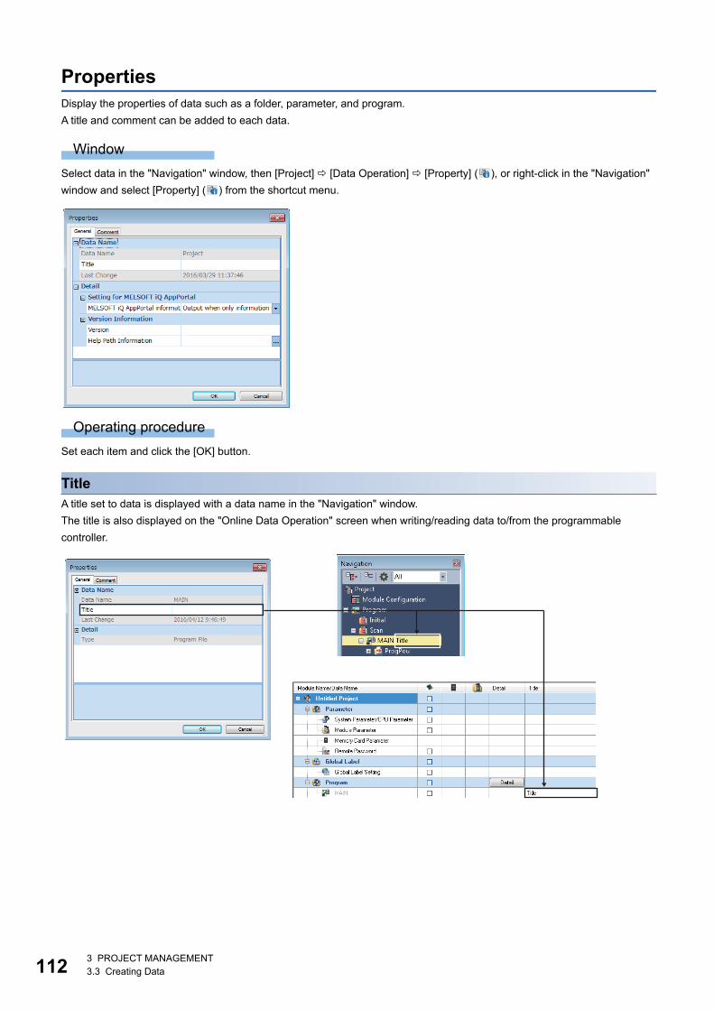
1123 PROJECT MANAGEMENT3.3 Creating Data
PropertiesDisplay the properties of data such as a folder, parameter, and program.
A title and comment can be added to each data.
Window
Select data in the "Navigation" window, then [Project] [Data Operation] [Property] ( ), or right-click in the "Navigation"
window and select [Property] ( ) from the shortcut menu.
Operating procedure
Set each item and click the [OK] button.
TitleA title set to data is displayed with a data name in the "Navigation" window.
The title is also displayed on the "Online Data Operation" screen when writing/reading data to/from the programmable
controller.
3 PROJECT MANAGEMENT3.3 Creating Data 113
3
Settings for iQ AppPortalAn iQ AppPortal information file can be output by setting the following item.
It is output when saving a project or exporting a library.
For iQ AppPortal, refer to the following manual.
iQ AppPortal Operating Manual
Operating procedure
1. Select the project in the "Navigation" window, then select [Project] [Data Operation] [Property] ( ) or right-click in
the "Navigation" window and select [Property] ( ) from the shortcut menu.
2. Select "Always output" for "MELSOFT iQ AppPortal information file output when saving project", and click the [OK]
button.
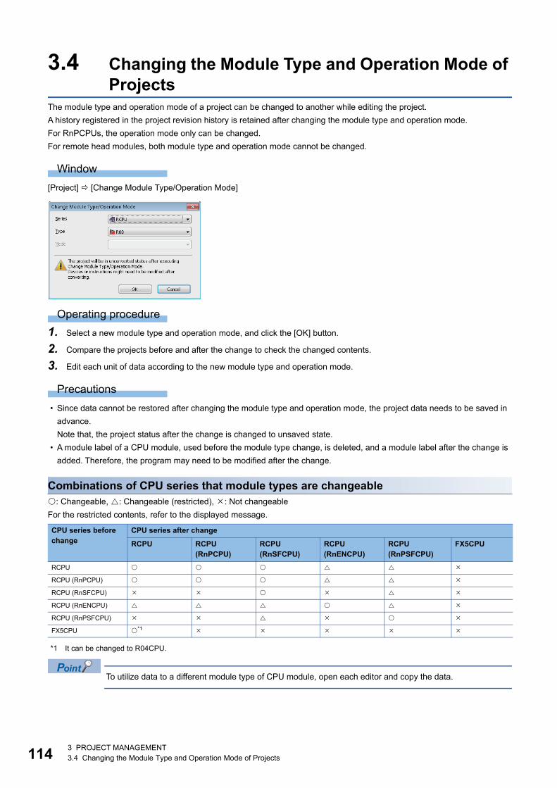
1143 PROJECT MANAGEMENT3.4 Changing the Module Type and Operation Mode of Projects
3.4 Changing the Module Type and Operation Mode of Projects
The module type and operation mode of a project can be changed to another while editing the project.
A history registered in the project revision history is retained after changing the module type and operation mode.
For RnPCPUs, the operation mode only can be changed.
For remote head modules, both module type and operation mode cannot be changed.
Window
[Project] [Change Module Type/Operation Mode]
Operating procedure
1. Select a new module type and operation mode, and click the [OK] button.
2. Compare the projects before and after the change to check the changed contents.
3. Edit each unit of data according to the new module type and operation mode.
Precautions
• Since data cannot be restored after changing the module type and operation mode, the project data needs to be saved in
advance.
Note that, the project status after the change is changed to unsaved state.
• A module label of a CPU module, used before the module type change, is deleted, and a module label after the change is
added. Therefore, the program may need to be modified after the change.
Combinations of CPU series that module types are changeable: Changeable, : Changeable (restricted), : Not changeable
For the restricted contents, refer to the displayed message.
*1 It can be changed to R04CPU.
To utilize data to a different module type of CPU module, open each editor and copy the data.
CPU series before change
CPU series after change
RCPU RCPU (RnPCPU)
RCPU (RnSFCPU)
RCPU (RnENCPU)
RCPU (RnPSFCPU)
FX5CPU
RCPU
RCPU (RnPCPU)
RCPU (RnSFCPU)
RCPU (RnENCPU)
RCPU (RnPSFCPU)
FX5CPU *1
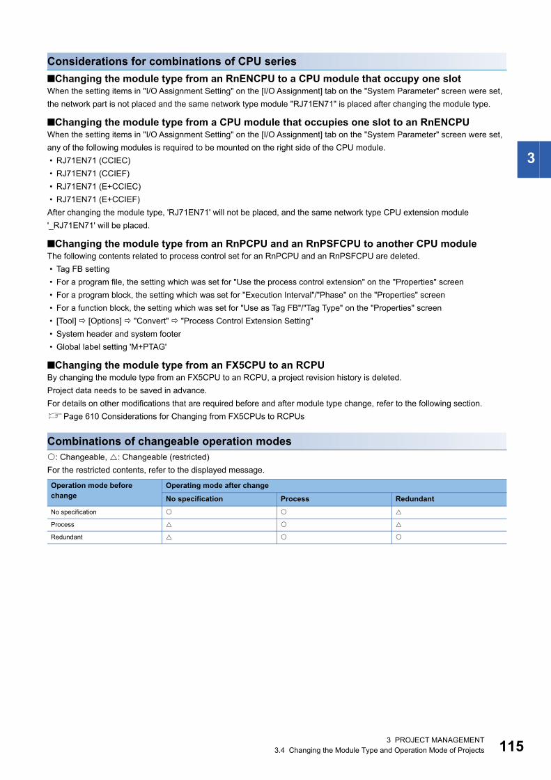
3 PROJECT MANAGEMENT3.4 Changing the Module Type and Operation Mode of Projects 115
3
Considerations for combinations of CPU series
■Changing the module type from an RnENCPU to a CPU module that occupy one slotWhen the setting items in "I/O Assignment Setting" on the [I/O Assignment] tab on the "System Parameter" screen were set,
the network part is not placed and the same network type module "RJ71EN71" is placed after changing the module type.
■Changing the module type from a CPU module that occupies one slot to an RnENCPUWhen the setting items in "I/O Assignment Setting" on the [I/O Assignment] tab on the "System Parameter" screen were set,
any of the following modules is required to be mounted on the right side of the CPU module.
• RJ71EN71 (CCIEC)
• RJ71EN71 (CCIEF)
• RJ71EN71 (E+CCIEC)
• RJ71EN71 (E+CCIEF)
After changing the module type, 'RJ71EN71' will not be placed, and the same network type CPU extension module
'_RJ71EN71' will be placed.
■Changing the module type from an RnPCPU and an RnPSFCPU to another CPU moduleThe following contents related to process control set for an RnPCPU and an RnPSFCPU are deleted.
• Tag FB setting
• For a program file, the setting which was set for "Use the process control extension" on the "Properties" screen
• For a program block, the setting which was set for "Execution Interval"/"Phase" on the "Properties" screen
• For a function block, the setting which was set for "Use as Tag FB"/"Tag Type" on the "Properties" screen
• [Tool] [Options] "Convert" "Process Control Extension Setting"
• System header and system footer
• Global label setting 'M+PTAG'
■Changing the module type from an FX5CPU to an RCPUBy changing the module type from an FX5CPU to an RCPU, a project revision history is deleted.
Project data needs to be saved in advance.
For details on other modifications that are required before and after module type change, refer to the following section.
Page 610 Considerations for Changing from FX5CPUs to RCPUs
Combinations of changeable operation modes: Changeable, : Changeable (restricted)
For the restricted contents, refer to the displayed message.
Operation mode before change
Operating mode after change
No specification Process Redundant
No specification
Process
Redundant

1163 PROJECT MANAGEMENT3.5 Verifying Projects
3.5 Verifying ProjectsVerify a open project with the data of another project.
Use this function to check whether the program contents are consistent, or the modifications are reflected etc.
When user information is registered to a project, user authentication is required. (Page 468 Logging on to project)
Verification
Window
[Project] [Project Verify]
Operating procedure
1. Specify a project for "Verify Destination" on the [Verification Data Selection] tab.
2. Select the data to be verified, and click the [Verify] button.
The target project file can be specified by dragging and dropping.
Precautions
• A GX Works2 or GX Developer project cannot be verified.
• A project for which a security is set can be verified when both data of the verification source and verification destination are
not read-protected.
• Verification is stopped by clicking the [Stop] button on the "Verification Progress" screen.
After stopping, the verification result before stopping is displayed in the verification result on the [Module Parameter] tab.
• The link of a comment in an FBD/LD program and SFC program is not verified.
• Module extended parameters can be verified when the start I/O No. and the module names match between the verification
source and the verification destination.
For a simple motion module, module extended parameters for which the module names mismatch can be selected as the
verification targets.
3 PROJECT MANAGEMENT3.5 Verifying Projects 117
3
Parameters
■Verification targetModule extended parameters are excluded from a verification.
However, the module extended parameters of a simple motion module can be verified.
For a project used for an FX5CPU, parameters except for ones of the following modules cannot be verified.
• FX5-232ADP, FX5-485ADP, FX5-4AD-ADP, FX5-4AD-PT-ADP, FX5-4AD-TC-ADP, FX5-4DA-ADP
• FX5-16ET/ES-H, FX5-16ET/ESS-H, FX5-40SSC-S, FX5-80SSC-S, FX5-CCLIEF, FX5-CCL-MS
• FX5-4LC, FX5-4LC(FX3), FX5-8AD, FX5-8AD(FX2N), FX5-20PG-P, FX5-ASL-M, FX5-4AD, FX5-4DA
■Verification levelsA parameter verification level can be selected from the [Options] tab of the "Project Verify" screen.
■Verifying only specific intelligent function modules on RCPUsProcedure is as follows:
1. Select "Module Parameter" in the [Result List] tab in the "Verify Result" window after verifying projects, and double-click
it or press the key.
2. Click the [Stop] button on the "Verification Progress" screen immediately after verification starts.
3. Select a module to verify in the [Module Parameter] tab in the "Verify Result" screen, and double-click it or press the
key.
1183 PROJECT MANAGEMENT3.5 Verifying Projects
Checking a verification resultCheck the details of mismatched data in the "Verify Result" window.*1
*1 Only mismatched device types are displayed for verification of device comments and device memories.
Operating procedure
1. Select and double-click a row of data to display its detail in the "Verify Result" window.
2. Select [Find/Replace] [Next Unmatched] ( )/[Previous Unmatched] ( ).
• A font color, background color, and font can be changed. (Page 65 Checking and Changing Colors and
Fonts)
• The latest data is always applied to a verification source. Therefore, the verification result can be checked
with the latest data in the verification source without verifying again after mismatched data is modified.
Precautions
■When the versions of GX Works3 that converted program files/FB files/FUN files are differentFor verification of program files/FB Files/FUN files, when the versions of GX Works3 that converted the program files of a
verification source and verification destination are different, there may be a difference in the conversion result, and
the verification result also may be mismatched. In this case, convert all programs in both verification source and verification
destination with the same version of GX Works3, then verify them again.
■When a function block with EN/ENO is used in a ladder programWhen a project that satisfies the following two conditions is verified with a programmable controller, another project, or a
history, program files, FB files, or FUN files in a ladder or SFC may be mismatched. In this case, convert all programs in both
verification source and verification destination with the same version of GX Works3, and verify them again.
• The function block, to which "Yes" has been selected for "Use EN/ENO" on the "Properties" screen, is used in a ladder
program or Zoom created in a ladder.
• The project that contains a program described above is written to a CPU module, and all programs are converted with the
setting that retains the label assignment after reading the program from the CPU module
■When a function is usedEven if the project configurations of a verification source and verification destination are same, the program files/FUN files
may be mismatched due to the difference of the order in which a function was added.
■When block passwords are set to POUs • When specifying a program file/FB file/FUN file including a POU, for which a block password is set, as a verification
destination, the locked POU is not displayed in the verification result.
If the block password is set only for the POU of the verification destination, the locked POU is displayed in the verification
result by unlocking the password. (Page 458 Authenticating a block password)
• When specifying a program file/FB file/FUN file including a POU, for which a block password is set, as a verification
destination, the detailed verification result screen of each file does not appear.
If the block password is set only for the POU of the verification destination, the screen appears by unlocking the password.
(Page 458 Authenticating a block password)
■When a security is set for a program fileWhen specifying a program file/ FB file/FUN file including a program file, for which a security is set, as a verification
destination, the detailed verification result screen of each file does not appear.
The detailed verification result screen of each file appears by changing the setting of the locked program file to
accessible.(Page 460 Procedure for making locked program files accessible)
■When verifying projects of which the system locales are differentWhen the system locale (or display language) for a project differs between the verification source and verification destination,
the verification result of program files/FB files/FUN files may be mismatched.
The system locales for projects of the verification destination and verification source need to be matched to verify their data.
3 PROJECT MANAGEMENT3.5 Verifying Projects 119
3
■Considerations for verification of program files • When the program files mismatched but the programs in the program files matched, it may be caused by the difference of
the execution orders of programs in the program files. Check the program file setting.
• In a program including a subroutine type function block, arguments of the FBCALL instruction (LFBCALL, LSAFBCALL)
may be mismatched.
The FBCALL instruction is automatically created to call a subroutine type function block by a system.
Arguments of the FBCALL instruction indicate an FB file of a function block to be called, POU, and the addresses of
memory reserved area (label area, latch label area, signal flow area).
Therefore, even if a project configurations are same, the arguments of FBCALL instruction may differ due to the order to
create programs. However, operations of the verification source and verification destination have no difference.
■When verifying device comments or device memoriesDevice comments or device memories with a different data name can be verified.
Projects can be verified between different module types of a same series.
The following results are displayed on the detailed verification result screen.
• Source only
• Dest. only
Projects cannot be verified between a remote head module and a CPU module other than it.
■When the number of mismatched parameters exceeds 1000Up to 1000th mismatched parameters are displayed on the detailed verification result screen, and verification for 1001st or
later is interrupted.
To verify parameters after interruption, correct the mismatched data before verifying again.
The following restrictions apply when a parameter item was added to the verification destination with upgrade
of an intelligent function module.
• The added parameter item is excluded from a verification because the verification source that has not been
upgraded cannot identify the item. Therefore, other parameters will be verified, and when those parameters
matched, it is applied to the verification result in each module.
Program file/FB file/FUN fileThe details of the execution program of a verification target are displayed in a list format by double-clicking the file name
displayed in the verification result.
■Detailed display (list format) • The cursor jumps to a corresponding row in a program editor by double-clicking an instruction in the list.
• When "Hide System Generated Items" is selected in the pull-down list of a Verify Result screen (detailed display), the
following instruction codes are omitted in display.
_TMALLOC, _TMFREE, JMPO, NOP H0, EXEFBDUMMY, FBRET, NOP, LD TMP, OUT TMP

1203 PROJECT MANAGEMENT3.5 Verifying Projects
Ladder programsThe details of verification target ladder program are displayed by double-clicking the program displayed in the verification
result.
A display format, "Ladder Diagram" or "List", can be selected from the pull-down list in a Verify Result screen (detailed
display).
A matched ladder block is not displayed.
Precautions
When there is no program in a macro type function block, the cursor is moved to the top of the ladder block.
■Detailed display (ladder diagram format)The cursor is jumped to the corresponding instruction on the ladder editor by double-clicking a instruction in a ladder diagram.
Precautions
• When an instruction which cannot be displayed in a ladder diagram format (such as NOP) is mismatched, it is displayed as
it had been matched. (Only "Mismatch" is displayed in the status bar). Check it by displaying in a list format.
• A background color is highlighted for each instruction. However, the background of a cell, in which a horizontal line only is
written on a ladder block, may also be changed ( such as the next cell of an input argument (BOOL value) for function
block).
• The background of a ladder block, that contains a function block including an input/output label (VAR_IN_OUT), may
highlighted even without a change.
■Detailed display (list format) • The cursor is jumped to a corresponding instruction on the ladder editor by double-clicking an instruction on the list.
• When the program that contains the inline structured text is verified, "STB" is displayed on the row of the inline structured
text.
The cursor is jumped to the corresponding row of the inline structured text by double-clicking the "STB".
• When programs containing a functions and/or function blocks are verified, the result is displayed as follows:
Function: row from "*;FUN BLK START" to "*;FUN BLK END"
Function block: row from "*;FB BLK START" to "*;FB BLK END"
ST programs
■Detailed displayThe cursor jumps to a corresponding row in the ST editor by double-clicking a row in the verification result.
FBD/LD programsThe details of verification target FBD/LD program are displayed in a list format by double-clicking the program displayed in the
verification result.
Precautions
When the versions of GX Works3 used for editing programs of a verification destination and source are different, the
verification result may be mismatched due to the difference of position information of elements. In this case, edit, convert, and
save the programs in both the verification source and the verification destination with a same version of GX Works3, and
perform the verification again*1.
*1 When verifying with a programmable controller, perform the "Write to PLC" or "Online Program Change" in advance.
■Detailed display (list format) • The cursor is jumped to a corresponding instruction on the FBD/LD editor by double-clicking an instruction on the list.
• When programs containing a functions and/or function blocks are verified, the result is displayed as follows:
Function: row from "*;FUN BLK START" to "*;FUN BLK END"
Function block: row from "*;FB BLK START" to "*;FB BLK END"
It can be hidden by setting the following option.
[Tool] [Options] "Program Editor" FBD/LD Editor" "Verify" "Verify Setting"
3 PROJECT MANAGEMENT3.5 Verifying Projects 121
3
Precautions
• When a step of the verification source is displayed with "-", it cannot jump to the FBD/LD editor.
• When any of the following operations are applied to a verification source program or a verification destination program,
"Mismatch" is displayed in the "Verification Result" column, and "Element arrangements do not match" is displayed in the
"Caution" column. In that case, the mismatched element is not highlighted and a cursor is not jumped to the mismatched
element.
⋅The position of an element is changed (position change in which the processing order is not changed).
⋅ A comment element is edited.
SFC programsThe verification result of the block (verification result of the block information, program, and Zoom) are displayed in a list
format by double-clicking the program displayed in the verification result.
The details of the verification result is displayed in a list format by double-clicking the program or Zoom from the verification
result of a displayed block.
It is not possible to verify in a Zoom and display the details in a list format when verifying with a programmable controller or the
SFC program which has been read from a CPU module without converting all programs.
■Detailed display of programs (list format)The cursor is jumped to a corresponding instruction on the SFC editor by double-clicking an instruction on the verification
result.
■Detailed display of ZoomFor the detailed display of programs, refer to the detailed display for each programming language.
Precautions
• Even if the SFC diagram, displayed for the verification destination, looks totally same as the one for the verification source,
the verification result may be mismatched because of the difference of the internal data which occurs depending on the
creation procedure.
• When a step of the verification source is displayed with "-", it cannot jump to a program editor.
• When any of the following operations are applied to a verification source program or a verification destination program,
"Mismatch" is displayed in the "Verification Result" column, and "Element arrangements do not match" is displayed in the
"Caution" column. In that case, the mismatched element is not highlighted and a cursor is not jumped to the mismatched
element.
⋅The data name of a step is changed.
⋅ A comment element is edited.
⋅ The positions of a contact, left power rail, variable, and connector, which are used for the direct expression of a transition,
is changed.
ParametersWhen the same profiles are not registered to the verification destination and source, the verification result may be
mismatched.
The details of verification target parameter are displayed in a table format by double-clicking the parameter displayed in the
verification result.
■Detailed display (table format)The cursor is jumped to a corresponding setting items on the parameter editor by double-clicking a parameter in a table.
Exporting data to fileExport data, which is displayed in the "Verify Result" window, to a file.
Operating procedure
Select [Edit] [Export to File] ( ).
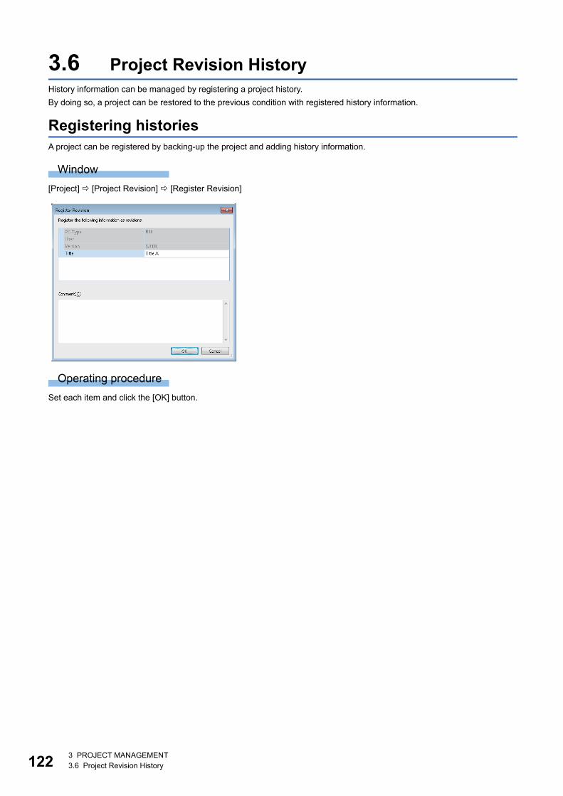
1223 PROJECT MANAGEMENT3.6 Project Revision History
3.6 Project Revision HistoryHistory information can be managed by registering a project history.
By doing so, a project can be restored to the previous condition with registered history information.
Registering historiesA project can be registered by backing-up the project and adding history information.
Window
[Project] [Project Revision] [Register Revision]
Operating procedure
Set each item and click the [OK] button.

3 PROJECT MANAGEMENT3.6 Project Revision History 123
3
Displaying a history list
Window
[Project] [Project Revision] [Revision List]
Select and right-click on history information, then select [Details] in the shortcut menu. The "Detailed Revision Information"
screen appears, so check the information such as comments entered at the time of registration.
Registering historiesA project history can be registered by clicking the [Register] button.
This time, information for iQ AppPortal is not registered.
Precautions
It may take time to register a history for a large project that the size of project file exceeds 10 MB.
Restoring historiesOnly registered history information can be restored.
Operating procedure
1. Select a history to be restored, and click the [Restore] button.
2. Click the [OK] button on the "Restore Revision" screen.
After restoring the project, is displayed at the head of restored history information on the "Revision List" screen.
Precautions
• Before restoring a project, register a history of the project being edited. Otherwise, the project before the restoration is
overwritten if another history is restored and overwritten first.
• The added/changed/deleted user information is not restored if the history is restored.
Deleting historiesRegistered history information can be deleted.
Operating procedure
Select a history to be deleted, and click the [Delete] button.

1243 PROJECT MANAGEMENT3.6 Project Revision History
Verifying historiesHistory information can be verified with other history information or a project being edited.
Operating procedure
Select a history to be verified, and click the [Verify] button.
If only one history is selected for verification, the history is verified with a project being edited. To verify histories, two histories
need to be selected.
The operation method for displaying the verification result is the same as that of project verification. For more details, refer to
the following section.
Page 118 Checking a verification result

3 PROJECT MANAGEMENT3.7 Managing Profiles 125
3
3.7 Managing ProfilesThe registration status of a profile (such as CSP+*1) can be managed.
A profile is data that stores information of a connected device (such as a model name.)
A profile is managed by each personal computer, and shared within GX Works3 and other MELSOFT products. Therefore, a
profile registered in GX Works3 is applied to other MELSOFT products.
Before registering/deleting a profile, log on a personal computer as the user with the administrator authority, and close the
project in advance.
*1 For CSP+, refer to the CC-Link Partner Association website (www.cc-link.org).
RegistrationA profile can be registered in GX Works3.
Operating procedure
1. Select [Tool] [Profile Management] [Register].
2. Select a file on the "Register Profile" screen, and click the [Register] button.
Precautions
A profile is a compressed file (such as *.zip, *.ipar, and *.cspp). Register a profile without decompressing.
DeletionA profile registered in GX Works3 can be deleted.
Operating procedure
1. Select [Tool] [Profile Management] [Delete].
2. Select a model name to be deleted on the "Profile Delete" screen, then click the [Delete] button.
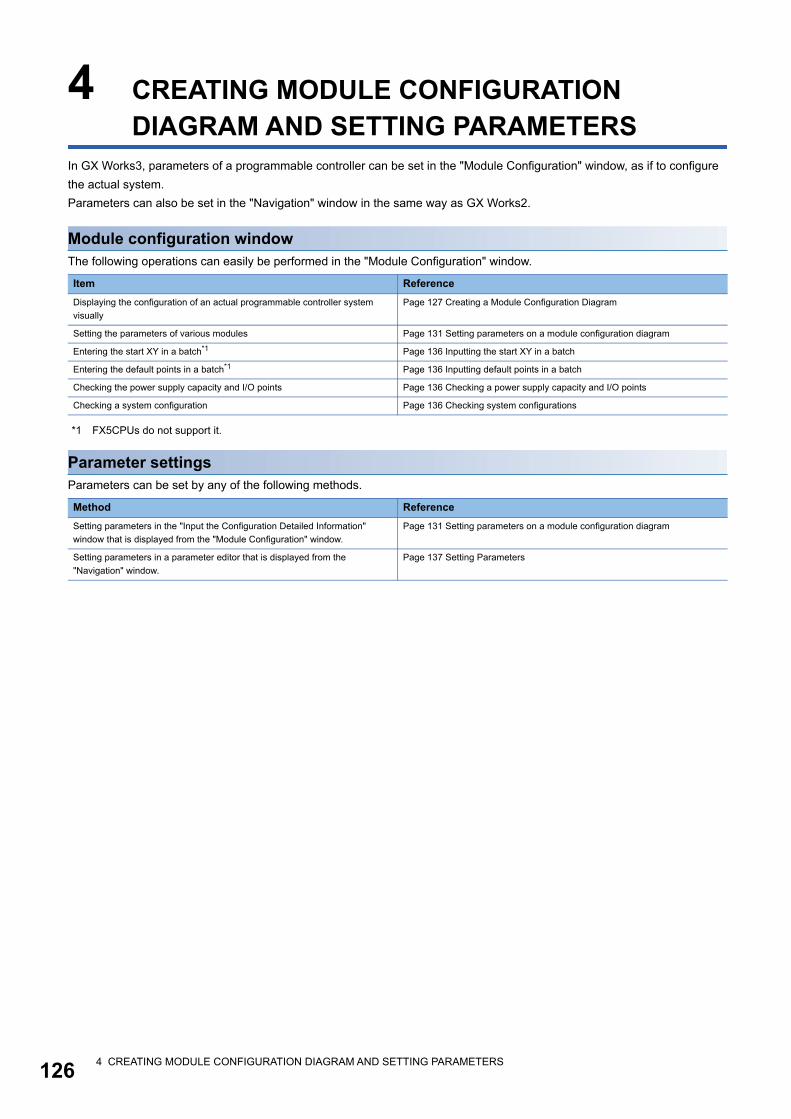
1264 CREATING MODULE CONFIGURATION DIAGRAM AND SETTING PARAMETERS
4 CREATING MODULE CONFIGURATION DIAGRAM AND SETTING PARAMETERS
In GX Works3, parameters of a programmable controller can be set in the "Module Configuration" window, as if to configure
the actual system.
Parameters can also be set in the "Navigation" window in the same way as GX Works2.
Module configuration windowThe following operations can easily be performed in the "Module Configuration" window.
*1 FX5CPUs do not support it.
Parameter settingsParameters can be set by any of the following methods.
Item Reference
Displaying the configuration of an actual programmable controller system
visually
Page 127 Creating a Module Configuration Diagram
Setting the parameters of various modules Page 131 Setting parameters on a module configuration diagram
Entering the start XY in a batch*1 Page 136 Inputting the start XY in a batch
Entering the default points in a batch*1 Page 136 Inputting default points in a batch
Checking the power supply capacity and I/O points Page 136 Checking a power supply capacity and I/O points
Checking a system configuration Page 136 Checking system configurations
Method Reference
Setting parameters in the "Input the Configuration Detailed Information"
window that is displayed from the "Module Configuration" window.
Page 131 Setting parameters on a module configuration diagram
Setting parameters in a parameter editor that is displayed from the
"Navigation" window.
Page 137 Setting Parameters
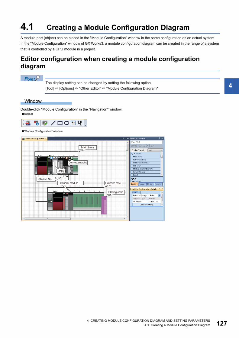
4 CREATING MODULE CONFIGURATION DIAGRAM AND SETTING PARAMETERS4.1 Creating a Module Configuration Diagram 127
4
4.1 Creating a Module Configuration DiagramA module part (object) can be placed in the "Module Configuration" window in the same configuration as an actual system.
In the "Module Configuration" window of GX Works3, a module configuration diagram can be created in the range of a system
that is controlled by a CPU module in a project.
Editor configuration when creating a module configuration diagram
The display setting can be changed by setting the following option.
[Tool] [Options] "Other Editor" "Module Configuration Diagram"
Window
Double-click "Module Configuration" in the "Navigation" window.■Toolbar
■"Module Configuration" window
General module
Main base
Connection point
Empty
Station No.Extension base
Placing error
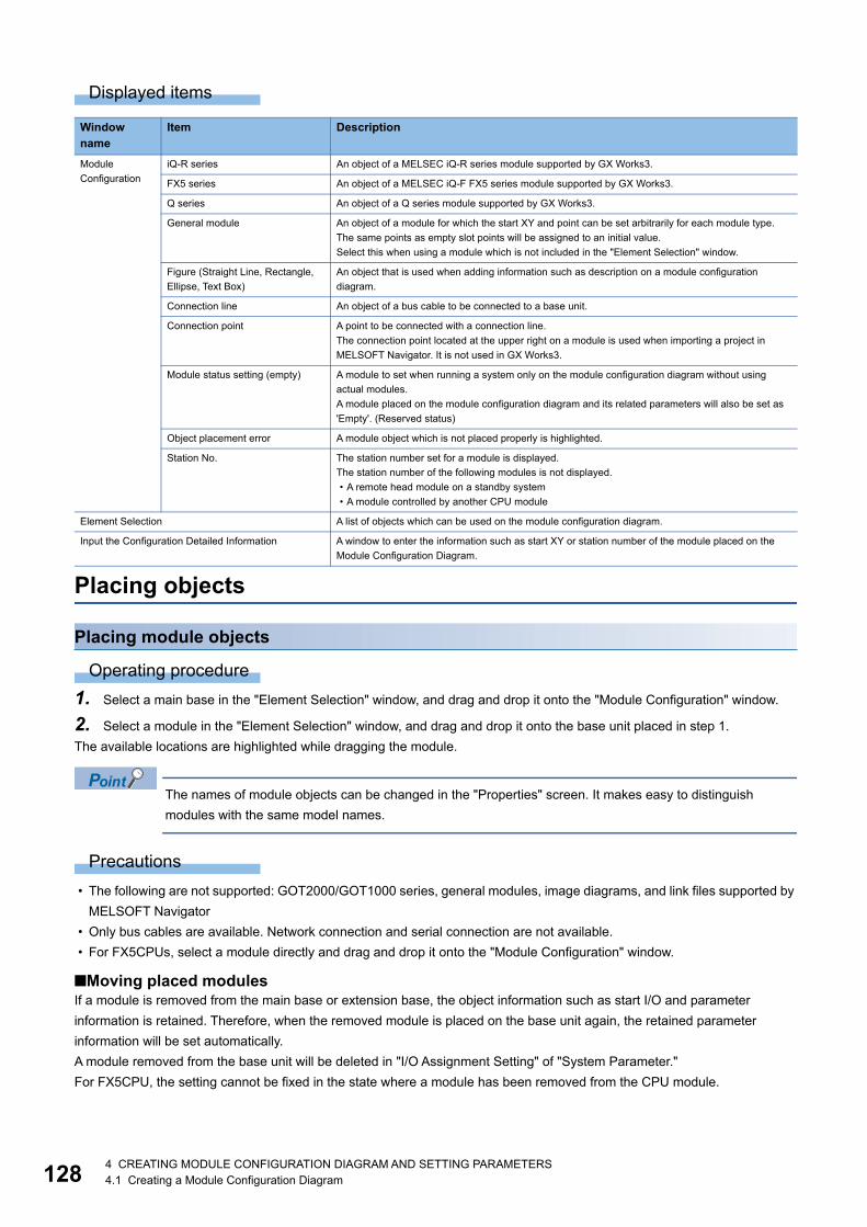
1284 CREATING MODULE CONFIGURATION DIAGRAM AND SETTING PARAMETERS4.1 Creating a Module Configuration Diagram
Displayed items
Placing objects
Placing module objects
Operating procedure
1. Select a main base in the "Element Selection" window, and drag and drop it onto the "Module Configuration" window.
2. Select a module in the "Element Selection" window, and drag and drop it onto the base unit placed in step 1.
The available locations are highlighted while dragging the module.
The names of module objects can be changed in the "Properties" screen. It makes easy to distinguish
modules with the same model names.
Precautions
• The following are not supported: GOT2000/GOT1000 series, general modules, image diagrams, and link files supported by
MELSOFT Navigator
• Only bus cables are available. Network connection and serial connection are not available.
• For FX5CPUs, select a module directly and drag and drop it onto the "Module Configuration" window.
■Moving placed modulesIf a module is removed from the main base or extension base, the object information such as start I/O and parameter
information is retained. Therefore, when the removed module is placed on the base unit again, the retained parameter
information will be set automatically.
A module removed from the base unit will be deleted in "I/O Assignment Setting" of "System Parameter."
For FX5CPU, the setting cannot be fixed in the state where a module has been removed from the CPU module.
Window name
Item Description
Module
Configuration
iQ-R series An object of a MELSEC iQ-R series module supported by GX Works3.
FX5 series An object of a MELSEC iQ-F FX5 series module supported by GX Works3.
Q series An object of a Q series module supported by GX Works3.
General module An object of a module for which the start XY and point can be set arbitrarily for each module type.
The same points as empty slot points will be assigned to an initial value.
Select this when using a module which is not included in the "Element Selection" window.
Figure (Straight Line, Rectangle,
Ellipse, Text Box)
An object that is used when adding information such as description on a module configuration
diagram.
Connection line An object of a bus cable to be connected to a base unit.
Connection point A point to be connected with a connection line.
The connection point located at the upper right on a module is used when importing a project in
MELSOFT Navigator. It is not used in GX Works3.
Module status setting (empty) A module to set when running a system only on the module configuration diagram without using
actual modules.
A module placed on the module configuration diagram and its related parameters will also be set as
'Empty'. (Reserved status)
Object placement error A module object which is not placed properly is highlighted.
Station No. The station number set for a module is displayed.
The station number of the following modules is not displayed.
• A remote head module on a standby system
• A module controlled by another CPU module
Element Selection A list of objects which can be used on the module configuration diagram.
Input the Configuration Detailed Information A window to enter the information such as start XY or station number of the module placed on the
Module Configuration Diagram.
4 CREATING MODULE CONFIGURATION DIAGRAM AND SETTING PARAMETERS4.1 Creating a Module Configuration Diagram 129
4
■Deleting placed modulesWhen a module is deleted, the module information displayed in the "Navigation" window after fixing parameters will be deleted
as well.
For a single CPU configuration, a CPU module object cannot be deleted.
For a multiple CPU configuration, the host CPU cannot be deleted.
■Copying and pasting modulesCopy source parameter information is utilized.
If a CPU module placed on the base unit in a multiple CPU configuration is copied, the CPU number will be unknown.
The objects can be copied to the "Module Configuration" window of other projects.
Placing figure objectsA figure and text box can be placed in the "Module Configuration" window.
A figure placed in the "Module Configuration" window is not written to a CPU module. It is saved only in a project.
Operating procedure
Select a figure in "Figure" in the "Element Selection" window, and drag and drop it onto the "Module Configuration" window.
The font and color of a figure object can be changed on the "Properties" screen.
Changing the model name of CPU modulesThe model name of a CPU module placed on the module configuration diagram can be changed.
RCPUs do not support it.
Operating procedure
1. Select a placed CPU module. Right-click and select [Change CPU Model Name] from the shortcut menu.
2. Select the model name after the change on the "Change CPU" screen.
Module status setting (empty)Set this when operating a system without mounting actual modules.
The module is highlighted in a pale color.
FX5CPUs do not support it.
Operating procedure
Select a module to be set to empty, and [Edit] [Module Status Setting (Empty)].
Reading the module configuration from an actual systemThe Module Configuration Diagram can be configured by using the information read from a CPU module.
For an FX5CPU, a module, of which the model name cannot be identified, is placed as a general module on the Module
Configuration Diagram.
If a module except for CPU No.1 is set as the connection destination when reading information from a remote head module in
a redundant system configuration, the CPU No.1 is read as the host module.
Operating procedure
Select [Online] [Read Module Configuration from PLC].
Precautions
The module configuration cannot be read when the number of extension base unit was set incorrectly.
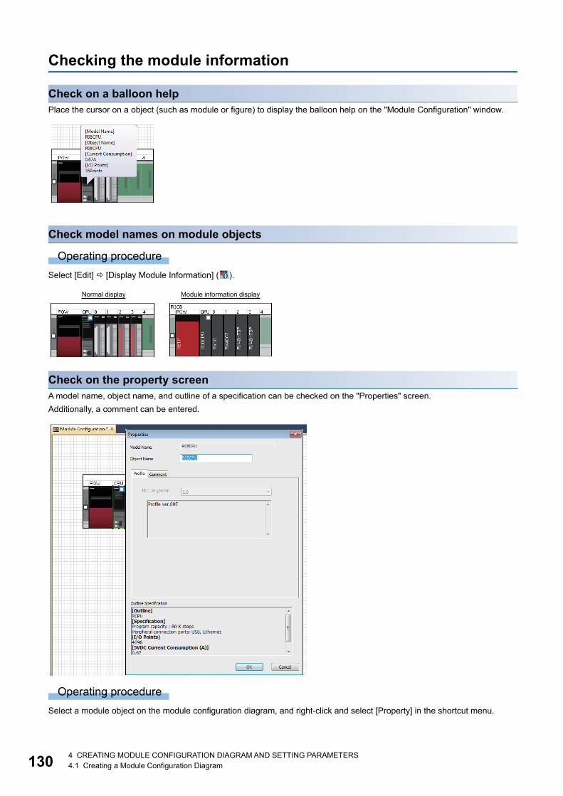
1304 CREATING MODULE CONFIGURATION DIAGRAM AND SETTING PARAMETERS4.1 Creating a Module Configuration Diagram
Checking the module information
Check on a balloon helpPlace the cursor on a object (such as module or figure) to display the balloon help on the "Module Configuration" window.
Check model names on module objects
Operating procedure
Select [Edit] [Display Module Information] ( ).
Check on the property screenA model name, object name, and outline of a specification can be checked on the "Properties" screen.
Additionally, a comment can be entered.
Operating procedure
Select a module object on the module configuration diagram, and right-click and select [Property] in the shortcut menu.
Normal display Module information display

4 CREATING MODULE CONFIGURATION DIAGRAM AND SETTING PARAMETERS4.1 Creating a Module Configuration Diagram 131
4
Setting parameters on a module configuration diagramParameters of a module placed onto a module configuration diagram can be set in the "Input the Configuration Detailed
Information" window.
Operating procedure
1. Select a module object to edit the parameters.
2. Click [Edit] [Parameter] [Input Detailed Configuration Information Window]( ).
The "Input the Configuration Detailed Information" window appears.
3. Set each item in the "Input the Configuration Detailed Information" window.
4. Select [Edit] [Parameter] [Fix] ( ).
To set details of the module, click the [Detailed Setting] button in the "Input the Configuration Detailed Information" window
and set details in the parameter editor.
Operations that make parameters unfixWhen an object is edited in the "Module Configuration" window, the status of parameters may be unfixed.
The following shows the list of operations that make parameters unfixed.
• Connecting modules
• Setting the Module status setting (empty)
• Performing undo/redo
• Performing the Start XY Batch Input function
• Performing the Default Points Batch Input function
• Operations in the "Input the Configuration Detailed Information" window
• Adding or deleting a module
• Cutting and pasting modules
• Changing the property of a module
• Removing a module, or placing the same module to the slot of a base unit again.
For FX5CPU, removing a module or connecting the same module to a CPU module.
Data updated after fixing parametersThe following data is updated after fixing parameters.
• "Navigation" window
(For new module information, the module information is added in the "Navigation" window.)
• Parameter editor
• "I/O Assignment Setting" of "System Parameter"
Application of parameter informationThe parameter information of a cut or copied module object can be utilized by pasting the module object onto the "Module
Configuration" window and fixing the parameters.
Precautions
Parameter information cannot be utilized by the following operations. The parameter information of the pasted module object
is returned to the default.
• Paste a cut or copied module object onto the "Module Configuration" window in another project.
• Before fixing parameters, change the station type of the module object in the "Input the Configuration Detailed Information"
window.

1324 CREATING MODULE CONFIGURATION DIAGRAM AND SETTING PARAMETERS4.1 Creating a Module Configuration Diagram
List of the changed location of start XY numberWhen the start XY number of a module is changed on the Module Configuration Diagram, the list of data which will be affected
by the change is displayed on the "Module Start I/O No. Related Area" window. Check the details and correct the data.
• Affected data: Program, FB program, system parameter, CPU parameter, module parameter, global label (including a
structure), and module label
• Affected device: Start XY devices specified for the arguments of FROM(P), DFROM(P), TO(P), or DTO(P) instructions
FX5CPUs do not support it.
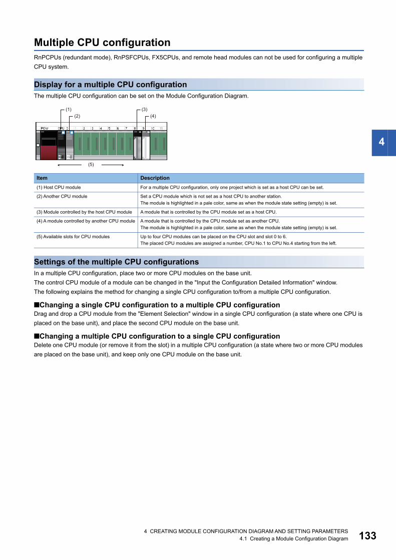
4 CREATING MODULE CONFIGURATION DIAGRAM AND SETTING PARAMETERS4.1 Creating a Module Configuration Diagram 133
4
Multiple CPU configurationRnPCPUs (redundant mode), RnPSFCPUs, FX5CPUs, and remote head modules can not be used for configuring a multiple
CPU system.
Display for a multiple CPU configurationThe multiple CPU configuration can be set on the Module Configuration Diagram.
Settings of the multiple CPU configurationsIn a multiple CPU configuration, place two or more CPU modules on the base unit.
The control CPU module of a module can be changed in the "Input the Configuration Detailed Information" window.
The following explains the method for changing a single CPU configuration to/from a multiple CPU configuration.
■Changing a single CPU configuration to a multiple CPU configurationDrag and drop a CPU module from the "Element Selection" window in a single CPU configuration (a state where one CPU is
placed on the base unit), and place the second CPU module on the base unit.
■Changing a multiple CPU configuration to a single CPU configurationDelete one CPU module (or remove it from the slot) in a multiple CPU configuration (a state where two or more CPU modules
are placed on the base unit), and keep only one CPU module on the base unit.
Item Description
(1) Host CPU module For a multiple CPU configuration, only one project which is set as a host CPU can be set.
(2) Another CPU module Set a CPU module which is not set as a host CPU to another station.
The module is highlighted in a pale color, same as when the module state setting (empty) is set.
(3) Module controlled by the host CPU module A module that is controlled by the CPU module set as a host CPU.
(4) A module controlled by another CPU module A module that is controlled by the CPU module set as another CPU.
The module is highlighted in a pale color, same as when the module state setting (empty) is set.
(5) Available slots for CPU modules Up to four CPU modules can be placed on the CPU slot and slot 0 to 6.
The placed CPU modules are assigned a number, CPU No.1 to CPU No.4 starting from the left.
(1) (3)(2) (4)
(5)
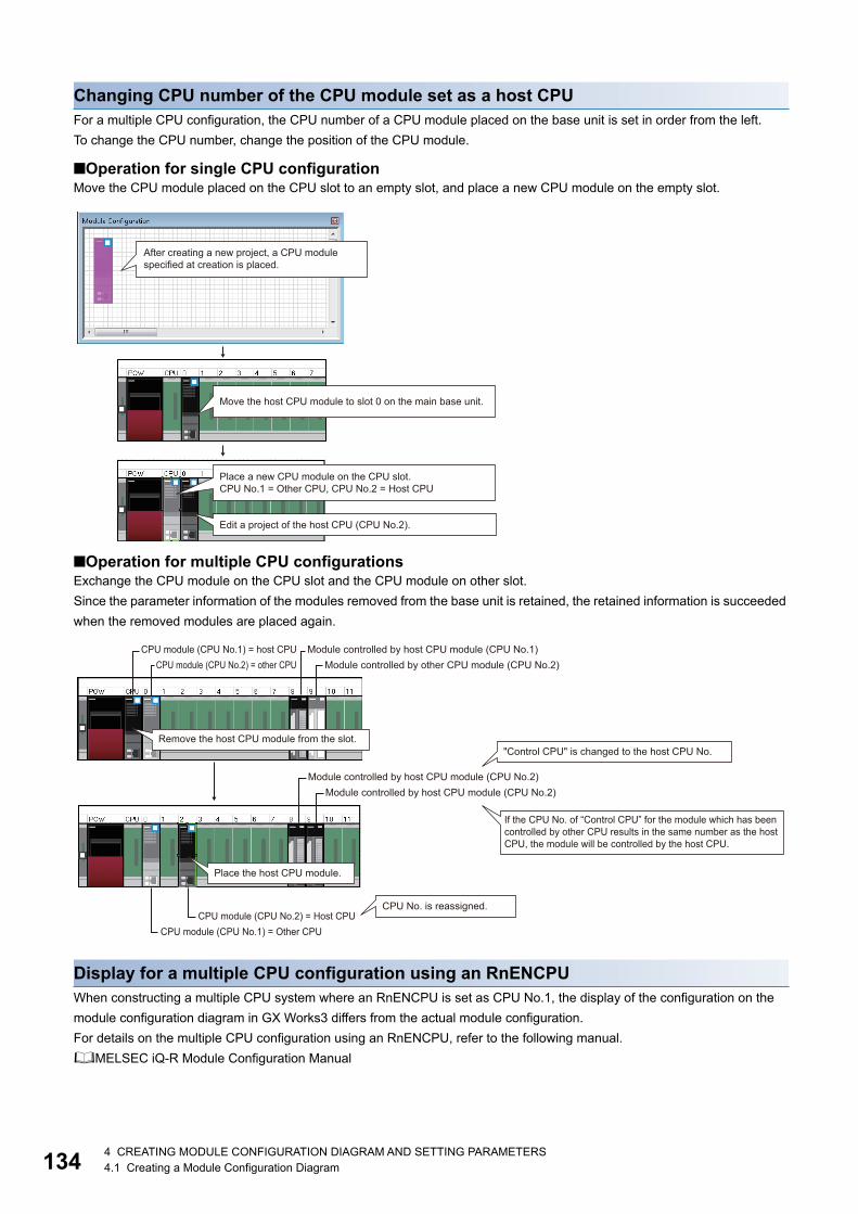
1344 CREATING MODULE CONFIGURATION DIAGRAM AND SETTING PARAMETERS4.1 Creating a Module Configuration Diagram
Changing CPU number of the CPU module set as a host CPUFor a multiple CPU configuration, the CPU number of a CPU module placed on the base unit is set in order from the left.
To change the CPU number, change the position of the CPU module.
■Operation for single CPU configurationMove the CPU module placed on the CPU slot to an empty slot, and place a new CPU module on the empty slot.
■Operation for multiple CPU configurationsExchange the CPU module on the CPU slot and the CPU module on other slot.
Since the parameter information of the modules removed from the base unit is retained, the retained information is succeeded
when the removed modules are placed again.
Display for a multiple CPU configuration using an RnENCPUWhen constructing a multiple CPU system where an RnENCPU is set as CPU No.1, the display of the configuration on the
module configuration diagram in GX Works3 differs from the actual module configuration.
For details on the multiple CPU configuration using an RnENCPU, refer to the following manual.
MELSEC iQ-R Module Configuration Manual
After creating a new project, a CPU module specified at creation is placed.
Move the host CPU module to slot 0 on the main base unit.
Place a new CPU module on the CPU slot.CPU No.1 = Other CPU, CPU No.2 = Host CPU
Edit a project of the host CPU (CPU No.2).
CPU module (CPU No.1) = host CPU Module controlled by host CPU module (CPU No.1)CPU module (CPU No.2) = other CPU Module controlled by other CPU module (CPU No.2)
Remove the host CPU module from the slot."Control CPU" is changed to the host CPU No.
Module controlled by host CPU module (CPU No.2)Module controlled by host CPU module (CPU No.2)
If the CPU No. of “Control CPU” for the module which has been controlled by other CPU results in the same number as the host CPU, the module will be controlled by the host CPU.
Place the host CPU module.
CPU No. is reassigned.CPU module (CPU No.2) = Host CPU
CPU module (CPU No.1) = Other CPU
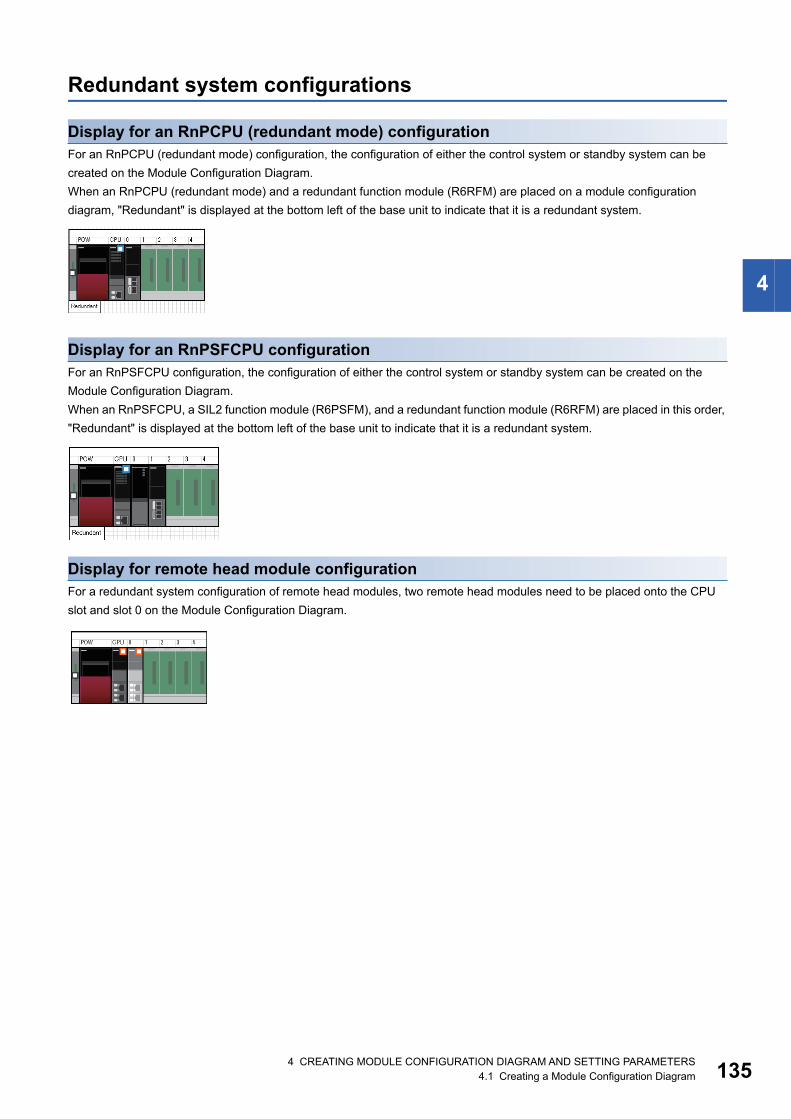
4 CREATING MODULE CONFIGURATION DIAGRAM AND SETTING PARAMETERS4.1 Creating a Module Configuration Diagram 135
4
Redundant system configurations
Display for an RnPCPU (redundant mode) configurationFor an RnPCPU (redundant mode) configuration, the configuration of either the control system or standby system can be
created on the Module Configuration Diagram.
When an RnPCPU (redundant mode) and a redundant function module (R6RFM) are placed on a module configuration
diagram, "Redundant" is displayed at the bottom left of the base unit to indicate that it is a redundant system.
Display for an RnPSFCPU configurationFor an RnPSFCPU configuration, the configuration of either the control system or standby system can be created on the
Module Configuration Diagram.
When an RnPSFCPU, a SIL2 function module (R6PSFM), and a redundant function module (R6RFM) are placed in this order,
"Redundant" is displayed at the bottom left of the base unit to indicate that it is a redundant system.
Display for remote head module configurationFor a redundant system configuration of remote head modules, two remote head modules need to be placed onto the CPU
slot and slot 0 on the Module Configuration Diagram.
1364 CREATING MODULE CONFIGURATION DIAGRAM AND SETTING PARAMETERS4.1 Creating a Module Configuration Diagram
Inputting the start XY in a batchThe start XY of each module can be set in order of the slot number in a batch.
FX5CPUs do not support it.
Operating procedure
Select [Edit] [Start XY Batch Input] ( ).
Inputting default points in a batchFor all modules and empty slots on the Module Configuration Diagram, points including empty slots and on the empty slot side
(for a module which occupies two or more slots) can be changed to the default in a batch.
FX5CPUs do not support it.
Operating procedure
Select [Edit] [Default Points Batch Input].
XY assignment displayInput and output number assignment for each module can be displayed.
RCPUs do not support it.
Operating procedure
Select [Edit] [XY Assignment Display].
Checking a power supply capacity and I/O pointsWhether the power supply capacity and I/O points in the configuration on the Module Configuration Diagram exceed the upper
limit can be checked.
Operating procedure
1. Select [Edit] [Check] [Power Supply Capacity and I/O Points] ( ).
2. Check the result displayed on the "Result of Power Supply Capacity and I/O Points Check" window.
Checking system configurationsWhether the place of each module on the module configuration diagram is correct can be checked. The result is displayed on
the "Output" window.
Operating procedure
1. Select [Edit] [Check] [System Configuration] ( ).
2. Check the result displayed on the "Output" window.
Operation for Write to PLC/Read from PLCOnly parameters of the modules in the information of Module Configuration Diagram can be read/written.
After reading data from a programmable controller, the coordinate position of the modules on the Module Configuration
Diagram are displayed by default status.
The figure information is deleted.
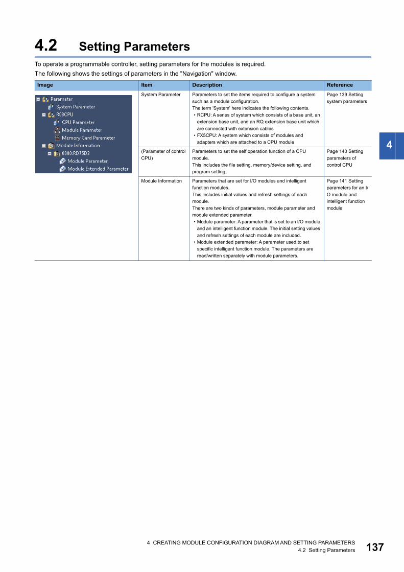
4 CREATING MODULE CONFIGURATION DIAGRAM AND SETTING PARAMETERS4.2 Setting Parameters 137
4
4.2 Setting ParametersTo operate a programmable controller, setting parameters for the modules is required.
The following shows the settings of parameters in the "Navigation" window.
Image Item Description Reference
System Parameter Parameters to set the items required to configure a system
such as a module configuration.
The term 'System' here indicates the following contents.
• RCPU: A series of system which consists of a base unit, an
extension base unit, and an RQ extension base unit which
are connected with extension cables
• FX5CPU: A system which consists of modules and
adapters which are attached to a CPU module
Page 139 Setting
system parameters
(Parameter of control
CPU)
Parameters to set the self operation function of a CPU
module.
This includes the file setting, memory/device setting, and
program setting.
Page 140 Setting
parameters of
control CPU
Module Information Parameters that are set for I/O modules and intelligent
function modules.
This includes initial values and refresh settings of each
module.
There are two kinds of parameters, module parameter and
module extended parameter.
• Module parameter: A parameter that is set to an I/O module
and an intelligent function module. The initial setting values
and refresh settings of each module are included.
• Module extended parameter: A parameter used to set
specific intelligent function module. The parameters are
read/written separately with module parameters.
Page 141 Setting
parameters for an I/
O module and
intelligent function
module
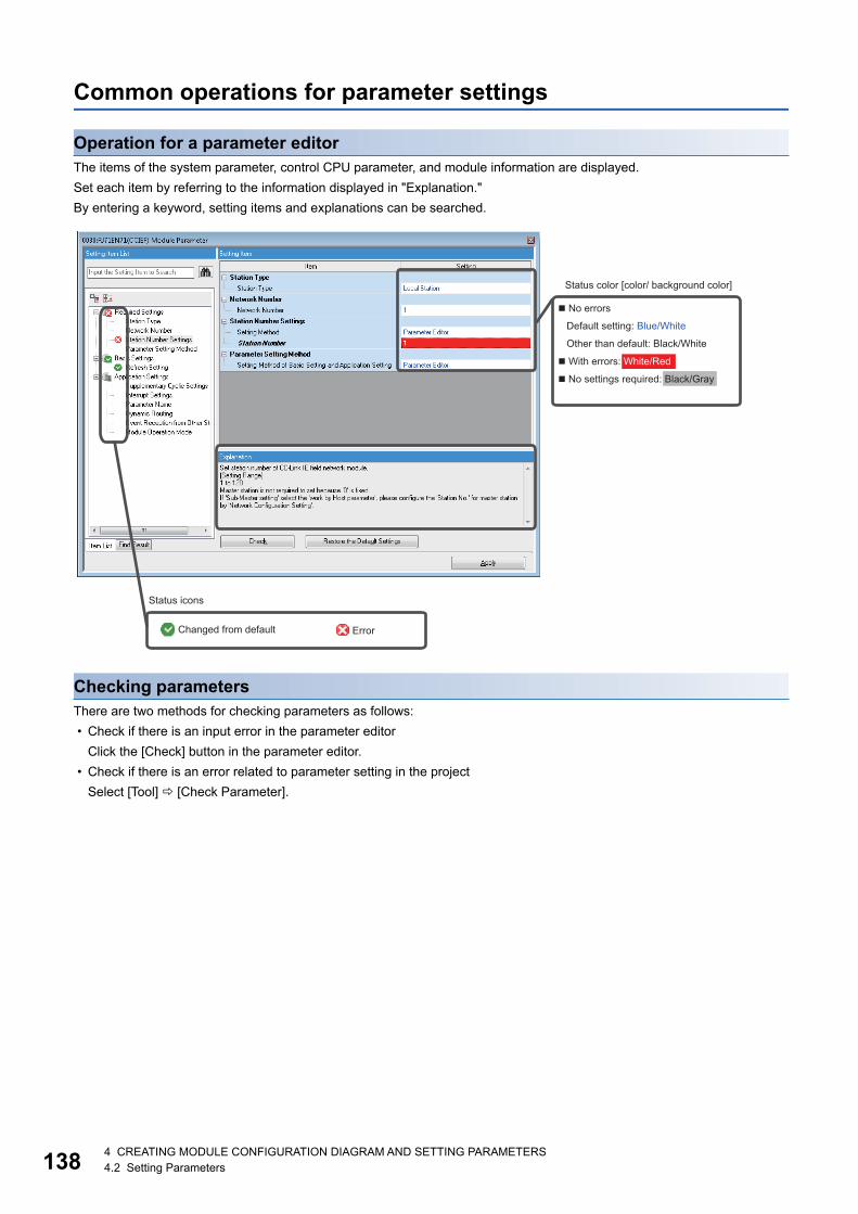
1384 CREATING MODULE CONFIGURATION DIAGRAM AND SETTING PARAMETERS4.2 Setting Parameters
Common operations for parameter settings
Operation for a parameter editorThe items of the system parameter, control CPU parameter, and module information are displayed.
Set each item by referring to the information displayed in "Explanation."
By entering a keyword, setting items and explanations can be searched.
Checking parametersThere are two methods for checking parameters as follows:
• Check if there is an input error in the parameter editor
Click the [Check] button in the parameter editor.
• Check if there is an error related to parameter setting in the project
Select [Tool] [Check Parameter].
Status color [color/ background color]
� No errors
Default setting: Blue/White
Other than default: Black/White
� With errors: White/Red
� No settings required: Black/Gray
Status icons
Changed from default Error
4 CREATING MODULE CONFIGURATION DIAGRAM AND SETTING PARAMETERS4.2 Setting Parameters 139
4
Setting system parametersSet the parameters relating to whole system such as the I/O assignment setting, the multiple CPU setting, and the inter-
module synchronization setting.
For details on the setting items of the parameters, refer to the following manuals.
• I/O assignment setting: MELSEC iQ-R Module Configuration Manual, MELSEC iQ-F FX5 User's Manual (Application)
• Multiple CPU setting: MELSEC iQ-R CPU Module User's Manual (Application)
• Inter-module synchronization setting: MELSEC iQ-R Inter-Module Synchronization Function Reference Manual
RnPCPUs (redundant mode), RnPSFCPUs, FX5CPUs, and remote head modules do not support the multiple CPU setting.
Remote head modules in the redundant system configuration, RnPCPUs (redundant mode), RnPSFCPUs, and FX5CPUs,
and do not support the inter-module synchronization setting.
Setting parameters
Operating procedure
1. Double-click "Parameter" "System Parameter" in the "Navigation" window.
2. Select the items to be set in the [I/O Assignment] tab, [Multiple CPU Setting] tab, or [Inter-module Synchronization
Setting] tab.
3. Set each item and click the [OK] button.
■When a module is deleted in the I/O assignment setting"Unset" is displayed for the parameter of the deleted module in the "Navigation" window. To restore the settings (to display
them in the I/O assignment setting), select the mount position in the "Properties" screen.
■When the I/O assignment setting is read from the read mounting statusFor an extension base unit in which the number of extension bases was set incorrectly, the mounting status (number of CPU
modules, the I/O assignment setting (module name/point), and the base/power/extension cable setting) cannot be read
properly.
The mounting status can be read to the I/O assignment setting by clicking the [Read Mounting Status] button.
Utilizing system parametersSystem parameters of another project can be utilized.
Operating procedure
1. Double-click "Parameter" "System Parameter" in the "Navigation" window.
2. Click the [System Parameter Diversion] button.
3. Read the displayed message, and click the [OK] button.
4. Select a project and click the [Open] button.
■Project in which system parameters cannot be utilizedNote that utilizing system parameters of another project is not allowed to RnPCPUs (redundant mode), RnPSFCPUs, and
FX5CPUs.
■Utilizing system parameters in a project used for an R00CPU, R01CPU, or R02CPUTo utilize system parameters of a project used for an RnCPU except for R00CPU, R01CPU, or R02CPU, change the module
type any of 'R00CPU', 'R01CPU', or 'R02CPU', then save the project.
By doing so, system parameters can be utilized from the saved project to a project used for an R00CPU, R01CPU, or
R02CPU.
1404 CREATING MODULE CONFIGURATION DIAGRAM AND SETTING PARAMETERS4.2 Setting Parameters
Setting parameters of control CPUSet the parameters related to a CPU module (the host CPU for a multiple CPU configuration).
For details on the setting items of the parameters, refer to the following manuals.
• CPU parameter: MELSEC iQ-R CPU Module User's Manual (Application), MELSEC iQ-F FX5 User's Manual
(Application), MELSEC iQ-R CC-Link IE Field Network Remote Head Module User's Manual (Application)
• Memory card parameter: MELSEC iQ-R CPU Module User's Manual (Application), MELSEC iQ-F FX5 User's Manual
(Application)
• Module parameter: MELSEC iQ-R Ethernet User's Manual (Application), MELSEC iQ-F FX5 User's Manual
(Application)
Setting parameters
Operating procedure
1. Double-click "Parameter" "(CPU model name of the project)" "CPU Parameter"/"Module Parameter"/"Memory Card
Parameter" in the "Navigation" window.
2. Set each item on the parameter editor.
3. Click the [Apply] button or [OK] button.
The setting screen can also be opened by double-clicking the object of a module on the Module Configuration
Diagram.
Precautions
For the setting values of the parameters, use the characters in the Unicode Basic Multilingual Plane.
If the characters outside the Unicode Basic Multilingual Plane are specified, the program may not operate properly.
• File register setting of the file setting: file name
• Initial value setting of the file setting: name of an initial value file of global labels
• Program setting of the program setting: program name
• FB/FUN file setting of the program setting: FB/FUN file name
4 CREATING MODULE CONFIGURATION DIAGRAM AND SETTING PARAMETERS4.2 Setting Parameters 141
4
Setting parameters for an I/O module and intelligent function moduleSet the parameters of an I/O module and intelligent function module of MELSEC iQ-R series, MELSEC iQ-F series/Q series
supported by GX Works3.
Set the switch settings and refresh settings of MELSEC-Q series module on the parameter editor.
For details on the parameter items, refer to the user's manual of each module.
For details on the MELSEC iQ-F series high speed pulse input/output modules, refer to the following manual.
MELSEC iQ-F FX5 User's Manual (Application)
MELSEC iQ-F FX5 User's Manual (Positioning Control - CPU module built-in, High-speed pulse input/output module)
Setting parameters
Operating procedure
1. Select "Parameter" "Module Information" in the "Navigation "window, and select [Project] [Data Operation] [Add
New Module] or right-click and select [Add New Module] from the shortcut menu.
2. Select each item on the "Add New Module" screen.
3. Double-click the created parameter.
Precautions
The following table shows the modules in which a parameter error occurs by default.
Series Module type Model name
Q series Temperature control module Q64TCRTBWN
Q64TCRTN
Q64TCTTBWN
Q64TCTTN

1424 CREATING MODULE CONFIGURATION DIAGRAM AND SETTING PARAMETERS4.2 Setting Parameters
Setting network configuration and target devicesSet a network configuration and a target device of Ethernet, AnyWireASLINK, CC-Link IE Field, CC-Link IE Field Network
Basic, and CC-Link on the configuration setting screen.
For details on the setting, refer to each user's manual.
Window
The configuration setting screen appears by selecting the following items in "Parameter" in the "Navigation" window.
• Ethernet (CPU module): "(CPU model name of the project)" "Module Parameter" "Basic Settings" "External Device
Configuration"*1
• Ethernet (Ethernet module): "Module Information" "(module name)" "(module parameter)" "Basic Settings"
"External Device Configuration"
• AnyWireASLINK: "Module Information" "(module name)" "AnyWireASLINK Configuration"
• CC-Link IE Field (master station)*2: "Module Information" "(module name)" "(module parameter)" "Basic Settings"
"Network Configuration Settings"
• CC-Link IE Field Network Basic*3: "(CPU model name of the project)" "Module Parameter" "Basic Settings" "CC-
Link IEF Basic Settings" "Network Configuration Settings"
• CC-Link (master station): "Module Information" "(module name)" "(module parameter)" "Basic Settings" "Network
Configuration Settings"
*1 For FX5CPU, set in the parameter setting ("Module Parameter") for a control CPU.*2 FX5CPUs do not support it.*3 RnCPUs, RnENCPUs, and FX5CPUs support it.
The following screen is an example for the CC-Link IE Field configuration setting.
Precautions
The AnyWireASLINK configuration setting is not written to a programmable controller.
Therefore, the AnyWireASLINK configuration setting returns to the default after reading a module parameter from a
programmable controller.
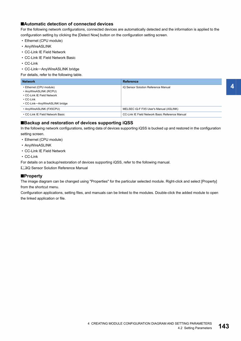
4 CREATING MODULE CONFIGURATION DIAGRAM AND SETTING PARAMETERS4.2 Setting Parameters 143
4
■Automatic detection of connected devicesFor the following network configurations, connected devices are automatically detected and the information is applied to the
configuration setting by clicking the [Detect Now] button on the configuration setting screen.
• Ethernet (CPU module)
• AnyWireASLINK
• CC-Link IE Field Network
• CC-Link IE Field Network Basic
• CC-Link
• CC-LinkAnyWireASLINK bridge
For details, refer to the following table.
■Backup and restoration of devices supporting iQSSIn the following network configurations, setting data of devices supporting iQSS is bucked up and restored in the configuration
setting screen.
• Ethernet (CPU module)
• AnyWireASLINK
• CC-Link IE Field Network
• CC-Link
For details on a backup/restoration of devices supporting iQSS, refer to the following manual.
iQ Sensor Solution Reference Manual
■PropertyThe image diagram can be changed using "Properties" for the particular selected module. Right-click and select [Property]
from the shortcut menu.
Configuration applications, setting files, and manuals can be linked to the modules. Double-click the added module to open
the linked application or file.
Network Reference
• Ethernet (CPU module)
• AnyWireASLINK (RCPU)
• CC-Link IE Field Network
• CC-Link
• CC-LinkAnyWireASLINK bridge
iQ Sensor Solution Reference Manual
• AnyWireASLINK (FX5CPU) MELSEC iQ-F FX5 User's Manual (ASLINK)
• CC-Link IE Field Network Basic CC-Link IE Field Network Basic Reference Manual
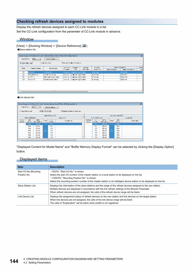
1444 CREATING MODULE CONFIGURATION DIAGRAM AND SETTING PARAMETERS4.2 Setting Parameters
Checking refresh devices assigned to modulesDisplay the refresh devices assigned to each CC-Link module in a list.
Set the CC-Link configuration from the parameter of CC-Link module in advance.
Window
[View] [Docking Window] [Device Reference] ( )
"Displayed Content for Model Name" and "Buffer Memory Display Format" can be selected by clicking the [Display Option]
button.
Displayed items
■Slave station list
■Link device list
Item Description
Start I/O No./Mounting
Position No.
• RCPU: "Start I/O No." is shown.
Select the start I/O number of the master station or a local station to be displayed on the list.
• FX5CPU: "Mounting Position No." is shown.
Select the mounting position number of the master station or an intelligent device station to be displayed on the list.
Slave Station List Displays the information of the slave stations and the range of the refresh devices assigned to the own station.
Multiple devices are displayed in accordance with the link refresh settings of the Module Parameter.
When refresh devices are not assigned, the cells of the refresh device range will be blank.
Link Device List Displays the assignment status of refresh devices on the own station and link devices on the target station.
When link devices are not assigned, the cells of the link device range will be blank.
The cells of "Explanation" will be blank when profile is not registered.
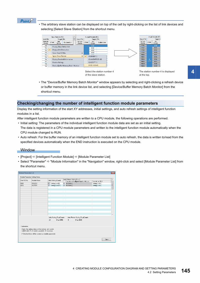
4 CREATING MODULE CONFIGURATION DIAGRAM AND SETTING PARAMETERS4.2 Setting Parameters 145
4
• The arbitrary slave station can be displayed on top of the cell by right-clicking on the list of link devices and
selecting [Select Slave Station] from the shortcut menu.
• The "Device/Buffer Memory Batch Monitor" window appears by selecting and right-clicking a refresh device
or buffer memory in the link device list, and selecting [Device/Buffer Memory Batch Monitor] from the
shortcut menu.
Checking/changing the number of intelligent function module parametersDisplay the setting information of the start XY addresses, initial settings, and auto refresh settings of intelligent function
modules in a list.
After intelligent function module parameters are written to a CPU module, the following operations are performed.
• Initial setting: The parameters of the individual intelligent function module data are set as an initial setting.
The data is registered in a CPU module parameters and written to the intelligent function module automatically when the
CPU module changed to RUN.
• Auto refresh: For the buffer memory of an intelligent function module set to auto refresh, the data is written to/read from the
specified devices automatically when the END instruction is executed on the CPU module.
Window
• [Project] [Intelligent Function Module] [Module Parameter List]
• Select "Parameter" "Module Information" in the "Navigation" window, right-click and select [Module Parameter List] from
the shortcut menu.
Select the station number 4of the slave station.
The station number 4 is displayed at the top.
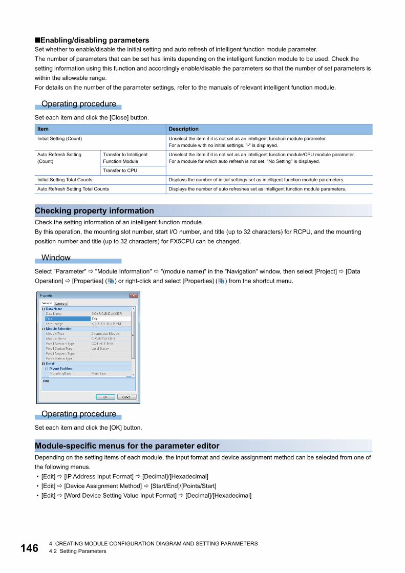
1464 CREATING MODULE CONFIGURATION DIAGRAM AND SETTING PARAMETERS4.2 Setting Parameters
■Enabling/disabling parametersSet whether to enable/disable the initial setting and auto refresh of intelligent function module parameter.
The number of parameters that can be set has limits depending on the intelligent function module to be used. Check the
setting information using this function and accordingly enable/disable the parameters so that the number of set parameters is
within the allowable range.
For details on the number of the parameter settings, refer to the manuals of relevant intelligent function module.
Operating procedure
Set each item and click the [Close] button.
Checking property informationCheck the setting information of an intelligent function module.
By this operation, the mounting slot number, start I/O number, and title (up to 32 characters) for RCPU, and the mounting
position number and title (up to 32 characters) for FX5CPU can be changed.
Window
Select "Parameter" "Module Information" "(module name)" in the "Navigation" window, then select [Project] [Data
Operation] [Properties] ( ) or right-click and select [Properties] ( ) from the shortcut menu.
Operating procedure
Set each item and click the [OK] button.
Module-specific menus for the parameter editorDepending on the setting items of each module, the input format and device assignment method can be selected from one of
the following menus.
• [Edit] [IP Address Input Format] [Decimal]/[Hexadecimal]
• [Edit] [Device Assignment Method] [Start/End]/[Points/Start]
• [Edit] [Word Device Setting Value Input Format] [Decimal]/[Hexadecimal]
Item Description
Initial Setting (Count) Unselect the item if it is not set as an intelligent function module parameter.
For a module with no initial settings, "-" is displayed.
Auto Refresh Setting
(Count)
Transfer to Intelligent
Function Module
Unselect the item if it is not set as an intelligent function module/CPU module parameter.
For a module for which auto refresh is not set, "No Setting" is displayed.
Transfer to CPU
Initial Setting Total Counts Displays the number of initial settings set as intelligent function module parameters.
Auto Refresh Setting Total Counts Displays the number of auto refreshes set as intelligent function module parameters.
4 CREATING MODULE CONFIGURATION DIAGRAM AND SETTING PARAMETERS4.2 Setting Parameters 147
4
Parameter interaction with MELSOFT NavigatorBy using the parameter interaction function of MELSOFT Navigator, the parameter consistency can be ensured between
MELSOFT Navigator and GX Works3.
This function is operated in MELSOFT Navigator. For details, refer to MELSOFT Navigator Help.
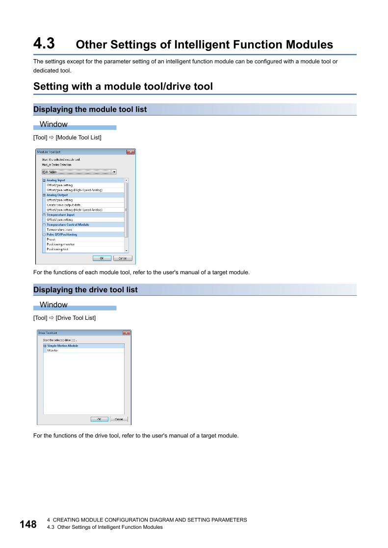
1484 CREATING MODULE CONFIGURATION DIAGRAM AND SETTING PARAMETERS4.3 Other Settings of Intelligent Function Modules
4.3 Other Settings of Intelligent Function ModulesThe settings except for the parameter setting of an intelligent function module can be configured with a module tool or
dedicated tool.
Setting with a module tool/drive tool
Displaying the module tool list
Window
[Tool] [Module Tool List]
For the functions of each module tool, refer to the user's manual of a target module.
Displaying the drive tool list
Window
[Tool] [Drive Tool List]
For the functions of the drive tool, refer to the user's manual of a target module.
4 CREATING MODULE CONFIGURATION DIAGRAM AND SETTING PARAMETERS4.3 Other Settings of Intelligent Function Modules 149
4
Simple Motion Module Setting functionThe parameter and positioning data of a simple motion module can be set by using the Simple Motion Module Setting
function.
For details on the operation methods and setting items, refer to the help of Simple Motion Module Setting function.
Operating procedure
1. Select "Parameter" "Module Information" in the "Navigation" window, and select [Project] [Data Operation] [Add
New Module].
2. Select each item on the "Add New Module" screen.
3. Double-click the "Simple Motion Module Setting" or "Module Extended Parameter".
Precautions
The settings of simple motion module are also saved when saving the GX Works3 project.
1504 CREATING MODULE CONFIGURATION DIAGRAM AND SETTING PARAMETERS4.4 Predefined Protocol Support Function
4.4 Predefined Protocol Support FunctionStart the Predefined Protocol Support Function from GX Works3, and set the protocol and read/write data from/to a module.
For details, refer to the following manuals.
MELSEC iQ-R Serial Communication Module User's Manual(Application)
MELSEC iQ-R Ethernet User's Manual (Application)
MELSEC iQ-F FX5 User's Manual (Serial Communication)
MELSEC iQ-F FX5 User's Manual (Ethernet Communication)
For RnPCPUs (redundant mode), this function can be used when the modules are in the separate mode and "Not Specified"
is selected for "Specify Redundant CPU."
For RnPSFCPUs, this function can be used only when "Not Specified" is selected for "Specify Redundant CPU."
The files saved in GX Works2 can be read using the Predefined Protocol Support Function of GX Works3.
Start and EndStart and end the predefined protocol support function.
Start
Operating procedure
1. Select GX Works3 menu [Tool] [Predefined Protocol Support Function].
2. Set each item on the "Predefined Protocol Support Function" screen and click the [OK] button.
End
Operating procedure
Select [File] [Exit] on the protocol setting screen.
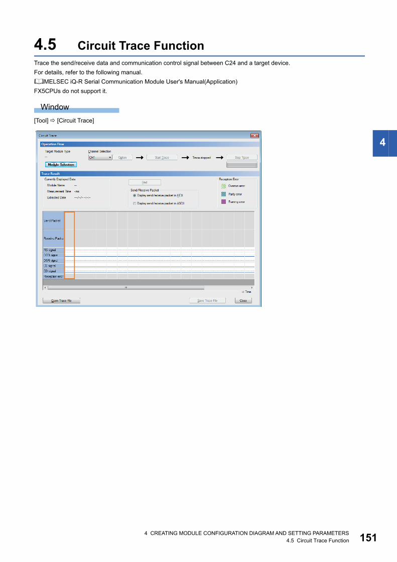
4 CREATING MODULE CONFIGURATION DIAGRAM AND SETTING PARAMETERS4.5 Circuit Trace Function 151
4
4.5 Circuit Trace FunctionTrace the send/receive data and communication control signal between C24 and a target device.
For details, refer to the following manual.
MELSEC iQ-R Serial Communication Module User's Manual(Application)
FX5CPUs do not support it.
Window
[Tool] [Circuit Trace]
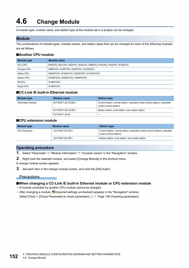
1524 CREATING MODULE CONFIGURATION DIAGRAM AND SETTING PARAMETERS4.6 Change Module
4.6 Change ModuleA module type, module name, and station type of the module set in a project can be changed.
ModuleThe combinations of module types, module names, and station types that can be changed for each of the following modules
are as follows.
■Another CPU module
■CC-Link IE built-in Ethernet module
■CPU extension module
Operating procedure1. Select "Parameter" "Module Information" "(module name)" in the "Navigation" window.
2. Right-click the selected module, and select [Change Module] in the shortcut menu.
A change module screen appears.
3. Set each item in the change module screen, and click the [OK] button.
Precautions
■When changing a CC-Link IE built-in Ethernet module or CPU extension module • A module controlled by another CPU module cannot be changed.
• After changing a module, (required settings unchecked) appears in the "Navigation" window.
Select [Tool] [Check Parameter] to check parameters. (Page 138 Checking parameters)
Module type Module name
PLC CPU R00CPU, R01CPU, R02CPU, R04CPU, R08CPU, R16CPU, R32CPU, R120CPU
Process CPU R08PCPU, R16PCPU, R32PCPU, R120PCPU
Safety CPU R08SFCPU, R16SFCPU, R32SFCPU, R120SFCPU
Motion CPU R16MTCPU, R32MTCPU, R64MTCPU
NCCPU R16NCCPU
Robot CPU R16RTCPU
Module type Module name Station type
Information Module RJ71EN71 (E+CCIEC) Control station, normal station, extended mode (control station), extended
mode (normal station)
RJ71EN71 (E+CCIEF) Master station, local station, sub-master station
RJ71EN71 (E+E)
Module type Module name Station type
CPU Extension _RJ71EN71(E+IEC) Control station, normal station, extended mode (control station), extended
mode (normal station)
_RJ71EN71(E+IEF) Master station, local station, sub-master station
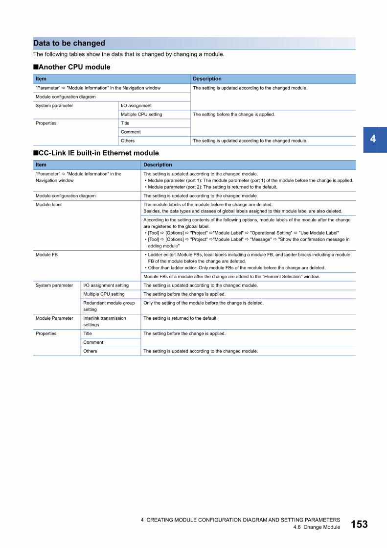
4 CREATING MODULE CONFIGURATION DIAGRAM AND SETTING PARAMETERS4.6 Change Module 153
4
Data to be changedThe following tables show the data that is changed by changing a module.
■Another CPU module
■CC-Link IE built-in Ethernet module
Item Description
"Parameter" "Module Information" in the Navigation window The setting is updated according to the changed module.
Module configuration diagram
System parameter I/O assignment
Multiple CPU setting The setting before the change is applied.
Properties Title
Comment
Others The setting is updated according to the changed module.
Item Description
"Parameter" "Module Information" in the
Navigation window
The setting is updated according to the changed module.
• Module parameter (port 1): The module parameter (port 1) of the module before the change is applied.
• Module parameter (port 2): The setting is returned to the default.
Module configuration diagram The setting is updated according to the changed module.
Module label The module labels of the module before the change are deleted.
Besides, the data types and classes of global labels assigned to this module label are also deleted.
According to the setting contents of the following options, module labels of the module after the change
are registered to the global label.
• [Tool] [Options] "Project" "Module Label" "Operational Setting" "Use Module Label"
• [Tool] [Options] "Project" "Module Label" "Message" "Show the confirmation message in
adding module"
Module FB • Ladder editor: Module FBs, local labels including a module FB, and ladder blocks including a module
FB of the module before the change are deleted.
• Other than ladder editor: Only module FBs of the module before the change are deleted.
Module FBs of a module after the change are added to the "Element Selection" window.
System parameter I/O assignment setting The setting is updated according to the changed module.
Multiple CPU setting The setting before the change is applied.
Redundant module group
setting
Only the setting of the module before the change is deleted.
Module Parameter Interlink transmission
settings
The setting is returned to the default.
Properties Title The setting before the change is applied.
Comment
Others The setting is updated according to the changed module.

1544 CREATING MODULE CONFIGURATION DIAGRAM AND SETTING PARAMETERS4.6 Change Module
■CPU extension module
Item Description
"Parameter" "Module Information" in the
Navigation window
The setting is updated according to the changed module.
• Module parameter (port 1): The module parameter (port 1) of the module before the change is applied.
• Module parameter (port 2): The setting is returned to the default.
Module configuration diagram The setting is updated according to the changed module.
Module label Module labels of a module before the change are deleted.
Besides, the data types and classes of global labels assigned to this module label are also deleted.
According to the setting contents of the following options, module labels of the module after the change
are registered to the global label.
• [Tool] [Options] "Project" "Module Label" "Operational Setting" "Use Module Label"
• [Tool] [Options] "Project" "Module Label" "Message" "Show the confirmation message in
adding module"
Module FB • Ladder editor: Module FBs, local labels including a module FB, and ladder blocks including a module
FB of the module before the change are deleted.
• Other than ladder editor: Only module FBs of the module before the change are deleted.
The module FBs of the module after the change are added to the "Element Selection" window.
System parameter I/O assignment The setting is updated according to the changed module.
Multiple CPU setting The setting before the change is applied.
Module parameter Interlink transmission
settings
The setting is returned to the default.
Properties Title The setting before the change is applied.
Comment
Others The setting is updated according to the changed module.
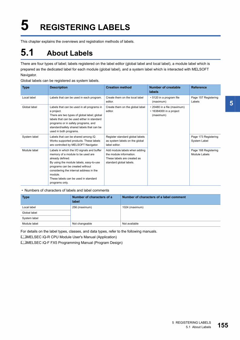
5 REGISTERING LABELS5.1 About Labels 155
5
5 REGISTERING LABELS
This chapter explains the overviews and registration methods of labels.
5.1 About LabelsThere are four types of label; labels registered on the label editor (global label and local label), a module label which is
prepared as the dedicated label for each module (global label), and a system label which is interacted with MELSOFT
Navigator.
Global labels can be registered as system labels.
• Numbers of characters of labels and label comments
For details on the label types, classes, and data types, refer to the following manuals.
MELSEC iQ-R CPU Module User's Manual (Application)
MELSEC iQ-F FX5 Programming Manual (Program Design)
Type Description Creation method Number of creatable labels
Reference
Local label Labels that can be used in each program. Create them on the local label
editor.
• 5120 in a program file
(maximum)
Page 157 Registering
Labels
Global label Labels that can be used in all programs in
a project.
There are two types of global label; global
labels that can be used either in standard
programs or in safety programs, and
standard/safety shared labels that can be
used in both programs.
Create them on the global label
editor.
• 20480 in a file (maximum)
• 16384000 in a project
(maximum)
System label Labels that can be shared among iQ
Works supported products. These labels
are controlled by MELSOFT Navigator.
Register standard global labels
as system labels on the global
label editor.
Page 173 Registering
System Label
Module label Labels in which the I/O signals and buffer
memory of a module to be used are
already defined.
By using the module labels, easy-to-use
programs can be created without
considering the internal address in the
module.
These labels can be used in standard
programs only.
Add module labels when adding
the module information.
These labels are created as
standard global labels.
Page 168 Registering
Module Labels
Type Number of characters of a label
Number of characters of a label comment
Local label 256 (maximum) 1024 (maximum)
Global label
System label
Module label Not changeable Not available
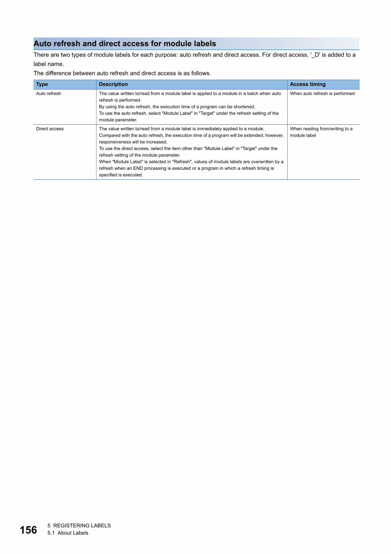
1565 REGISTERING LABELS5.1 About Labels
Auto refresh and direct access for module labelsThere are two types of module labels for each purpose: auto refresh and direct access. For direct access, '_D' is added to a
label name.
The difference between auto refresh and direct access is as follows.
Type Description Access timing
Auto refresh The value written to/read from a module label is applied to a module in a batch when auto
refresh is performed.
By using the auto refresh, the execution time of a program can be shortened.
To use the auto refresh, select "Module Label" in "Target" under the refresh setting of the
module parameter.
When auto refresh is performed
Direct access The value written to/read from a module label is immediately applied to a module.
Compared with the auto refresh, the execution time of a program will be extended; however,
responsiveness will be increased.
To use the direct access, select the item other than "Module Label" in "Target" under the
refresh setting of the module parameter.
When "Module Label" is selected in "Refresh", values of module labels are overwritten by a
refresh when an END processing is executed or a program in which a refresh timing is
specified is executed.
When reading from/writing to a
module label
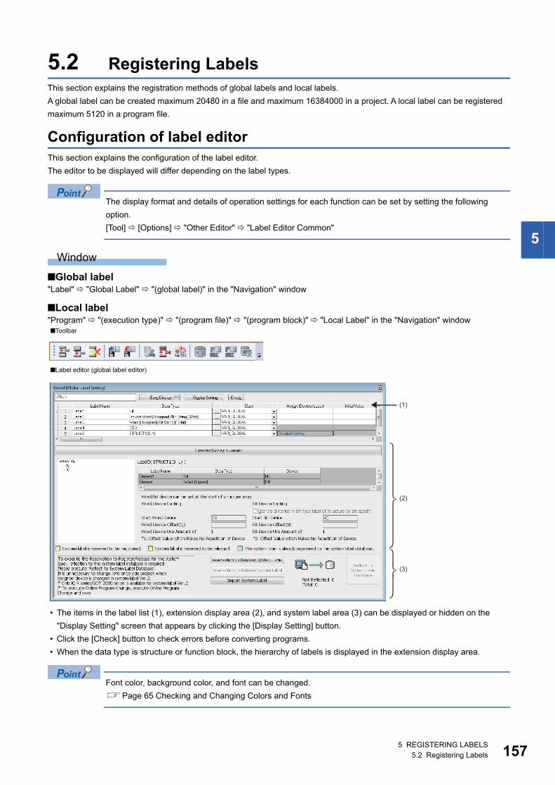
5 REGISTERING LABELS5.2 Registering Labels 157
5
5.2 Registering LabelsThis section explains the registration methods of global labels and local labels.
A global label can be created maximum 20480 in a file and maximum 16384000 in a project. A local label can be registered
maximum 5120 in a program file.
Configuration of label editorThis section explains the configuration of the label editor.
The editor to be displayed will differ depending on the label types.
The display format and details of operation settings for each function can be set by setting the following
option.
[Tool] [Options] "Other Editor" "Label Editor Common"
Window
■Global label"Label" "Global Label" "(global label)" in the "Navigation" window
■Local label"Program" "(execution type)" "(program file)" "(program block)" "Local Label" in the "Navigation" window
• The items in the label list (1), extension display area (2), and system label area (3) can be displayed or hidden on the
"Display Setting" screen that appears by clicking the [Display Setting] button.
• Click the [Check] button to check errors before converting programs.
• When the data type is structure or function block, the hierarchy of labels is displayed in the extension display area.
Font color, background color, and font can be changed.
Page 65 Checking and Changing Colors and Fonts
■Toolbar
■Label editor (global label editor)
(1)
(2)
(3)
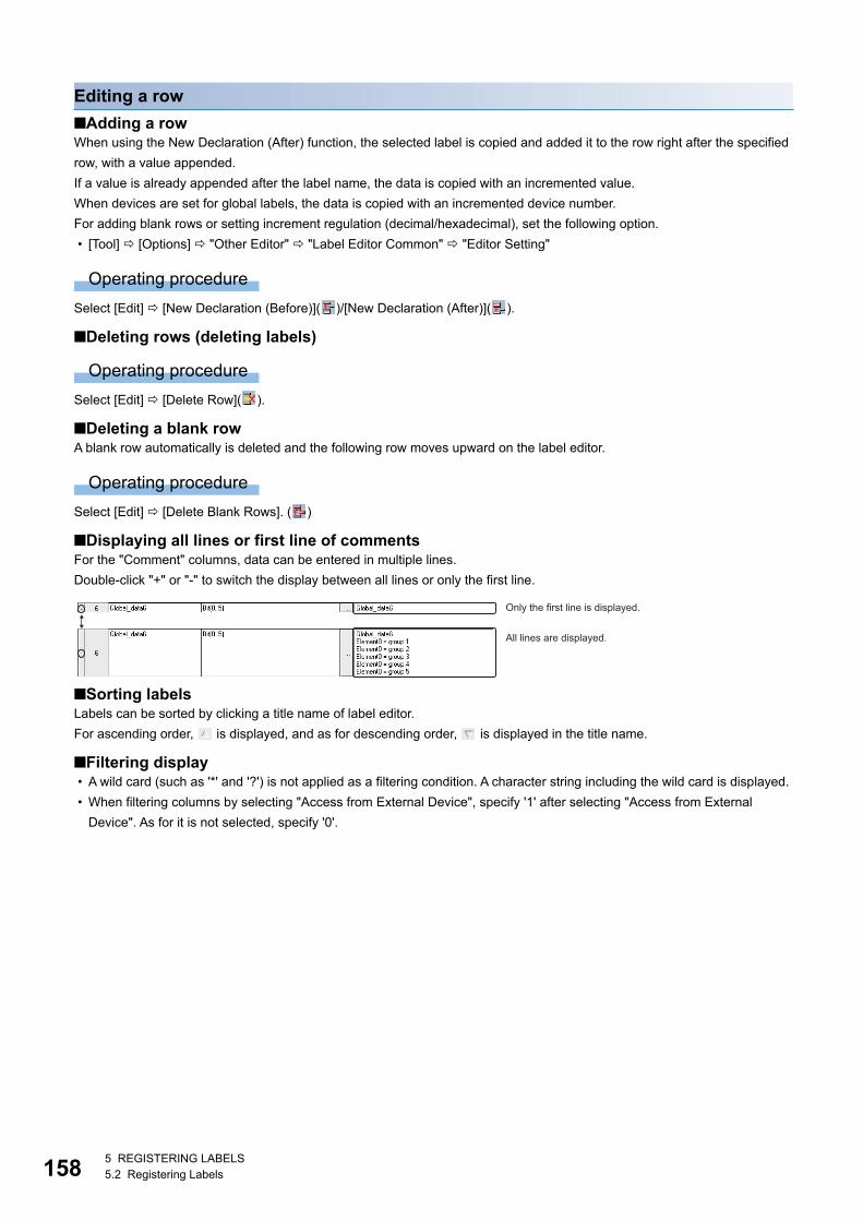
1585 REGISTERING LABELS5.2 Registering Labels
Editing a row
■Adding a rowWhen using the New Declaration (After) function, the selected label is copied and added it to the row right after the specified
row, with a value appended.
If a value is already appended after the label name, the data is copied with an incremented value.
When devices are set for global labels, the data is copied with an incremented device number.
For adding blank rows or setting increment regulation (decimal/hexadecimal), set the following option.
• [Tool] [Options] "Other Editor" "Label Editor Common" "Editor Setting"
Operating procedure
Select [Edit] [New Declaration (Before)]( )/[New Declaration (After)]( ).
■Deleting rows (deleting labels)
Operating procedure
Select [Edit] [Delete Row]( ).
■Deleting a blank rowA blank row automatically is deleted and the following row moves upward on the label editor.
Operating procedure
Select [Edit] [Delete Blank Rows]. ( )
■Displaying all lines or first line of commentsFor the "Comment" columns, data can be entered in multiple lines.
Double-click "+" or "-" to switch the display between all lines or only the first line.
■Sorting labelsLabels can be sorted by clicking a title name of label editor.
For ascending order, is displayed, and as for descending order, is displayed in the title name.
■Filtering display • A wild card (such as '*' and '?') is not applied as a filtering condition. A character string including the wild card is displayed.
• When filtering columns by selecting "Access from External Device", specify '1' after selecting "Access from External
Device". As for it is not selected, specify '0'.
Only the first line is displayed.
All lines are displayed.

5 REGISTERING LABELS5.2 Registering Labels 159
5
Entering information
Label nameSet a name with avoiding the following conditions:
• A label name that includes a space.
• A label name starting with a number
• A same label name as one for a device
For the unusable character strings to a label name, refer to the following section.
Page 539 Unusable character string for label name
Precautions
For label names, constants, and device initial values, use the characters in the Unicode Basic Multilingual Plane.
The label names and constants that specifies the characters other than the Unicode Basic Multilingual Plane cannot be used
in programs.
A program including an initial value using the characters outside the Unicode Basic Multilingual Plane may not operate
properly.
■AliasBy entering an existing label name for the "Assign (Device/Label)" column in a label editor, a label can be set as an alternative
label name of the existing one.
A label to which an existing label is assigned is referred to as 'alias'.
An existing label that is assigned to an alias is referred to as 'alias source'.
The following information of an arias source will be succeeded: data types, classes, initial values, and constants.
For an alias, a label with the same category (standard, safety, and standard/safety shared) as an alias source can only be set.
Ex.
(1): Alias
(2): Alias source
Precautions
• For an arias, do not assign an instance of a function block or module FB.
• In the "Assign (Device/Label)" column of a label editor, enter the same text as that in the "Label Name" column.
• For an alias, a structure member and a label in a function block can not be assigned.
• The following error occurs at conversion when a structure member or a label used in a function block is entered in the
"Assign (Device/Label)" column of an alias, and the alias is used in the program editor.
Content: An invalid device or an invalid constant is being used.
Error code: 0x12011067
(1)
(2)
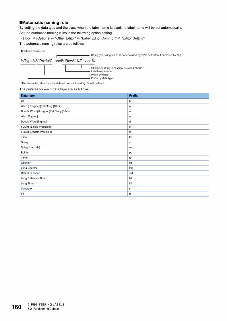
1605 REGISTERING LABELS5.2 Registering Labels
■Automatic naming ruleBy setting the data type and the class when the label name is blank , a label name will be set automatically.
Set the automatic naming rules in the following option setting.
• [Tool] [Options] "Other Editor" "Label Editor Common" "Editor Setting"
The automatic naming rules are as follows.
The prefixes for each data type are as follows.
Data type Prefix
Bit b
Word [Unsigned]/Bit String [16-bit] u
Double Word [Unsigned]/Bit String [32-bit] ud
Word [Signed] w
Double Word [Signed] d
FLOAT [Single Precision] e
FLOAT [Double Precision] le
Time tm
String s
String [Unicode] ws
Pointer pd
Timer td
Counter cd
Long Counter lcd
Retentive Timer std
Long Retentive Timer lstd
Long Timer ltd
Structure st
FB fb
%Type%%Prefix%Label%Row%%Device%
●Defined charactersString (the string which is not enclosed by '%' is set without enclosed by '%')
Character string in "Assign (Device/Label)"Label row numberPrefix by classPrefix by data type
*The character other than the defined one enclosed by '%' will be blank.

5 REGISTERING LABELS5.2 Registering Labels 161
5
The prefixes that are added depending on the selected class are as follows.
• When "Bit" is selected in the "Data Type" column: bLabel1
Prefix 'b' that indicates the bit type + character string 'Label' + label row number '1'
• When "VAR_GLOBAL" is selected in the "Class" column: G_Label2
Prefix 'G_' that indicates the class + character string 'Label' + label row number '2'
• When 'D0' is specified in the "Assign (Device/Label)" column: Label3
Character string 'Label' + label row number '3'
■Automatic synchronizationWhen label names/alias names are changed on the label editor, the label names/alias names used on the editor (program
editors such as ST editor, FBD/LD editor, and SFC editor) will also be replaced automatically.
• Select "Yes" for "Track label name automatically in program editor" from [Tool] [Options] "Other Editor" "Label Editor
Common" "Operational Setting"
The labels are distinguished between global labels and local labels in the automatic synchronization. (Page 179 Entering
global labels/local labels)
The programs in which the replaced labels are used will be in the unconverted state.
If labels names/alias are changed, check if the change affects control programs using the Cross Reference function.
■Label synchronizationThe contents edited on the global label editor are immediately applied on the ladder editor by setting the following option.
When labels undefined on the ladder editor are newly added on the label editor, they will be in the defined state.
• Set "Synchronize" for "Operation on Editing Label Editor" in [Tool] [Options] "Program Editor" "Ladder Editor"
"Label Synchronization" "Operational Setting".
Local labels always synchronize with the data on the label editor regardless of the option setting.
Class Prefix
VAR_GLOBAL G_
VAR_GLOBAL_RETAIN GR_
VAR_GLOBAL_CONSTANT GC_
VAR Not added.
VAR_RETAIN r_
VAR_CONSTANT c_
VAR_INPUT i_
VAR_OUTPUT o_
VAR_IN_OUT io_
VAR_OUTPUT_RETAIN or_
VAR_PUBLIC pb_
VAR_PUBLIC_RETAIN pbr_
■Setting example
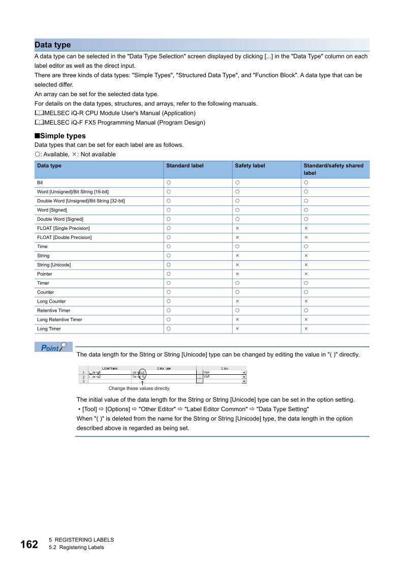
1625 REGISTERING LABELS5.2 Registering Labels
Data typeA data type can be selected in the "Data Type Selection" screen displayed by clicking [...] in the "Data Type" column on each
label editor as well as the direct input.
There are three kinds of data types: "Simple Types", "Structured Data Type", and "Function Block". A data type that can be
selected differ.
An array can be set for the selected data type.
For details on the data types, structures, and arrays, refer to the following manuals.
MELSEC iQ-R CPU Module User's Manual (Application)
MELSEC iQ-F FX5 Programming Manual (Program Design)
■Simple typesData types that can be set for each label are as follows.
: Available, : Not available
The data length for the String or String [Unicode] type can be changed by editing the value in "( )" directly.
The initial value of the data length for the String or String [Unicode] type can be set in the option setting.
• [Tool] [Options] "Other Editor" "Label Editor Common" "Data Type Setting"
When "( )" is deleted from the name for the String or String [Unicode] type, the data length in the option
described above is regarded as being set.
Data type Standard label Safety label Standard/safety shared label
Bit
Word [Unsigned]/Bit String [16-bit]
Double Word [Unsigned]/Bit String [32-bit]
Word [Signed]
Double Word [Signed]
FLOAT [Single Precision]
FLOAT [Double Precision]
Time
String
String [Unicode]
Pointer
Timer
Counter
Long Counter
Retentive Timer
Long Retentive Timer
Long Timer
Change these values directly.
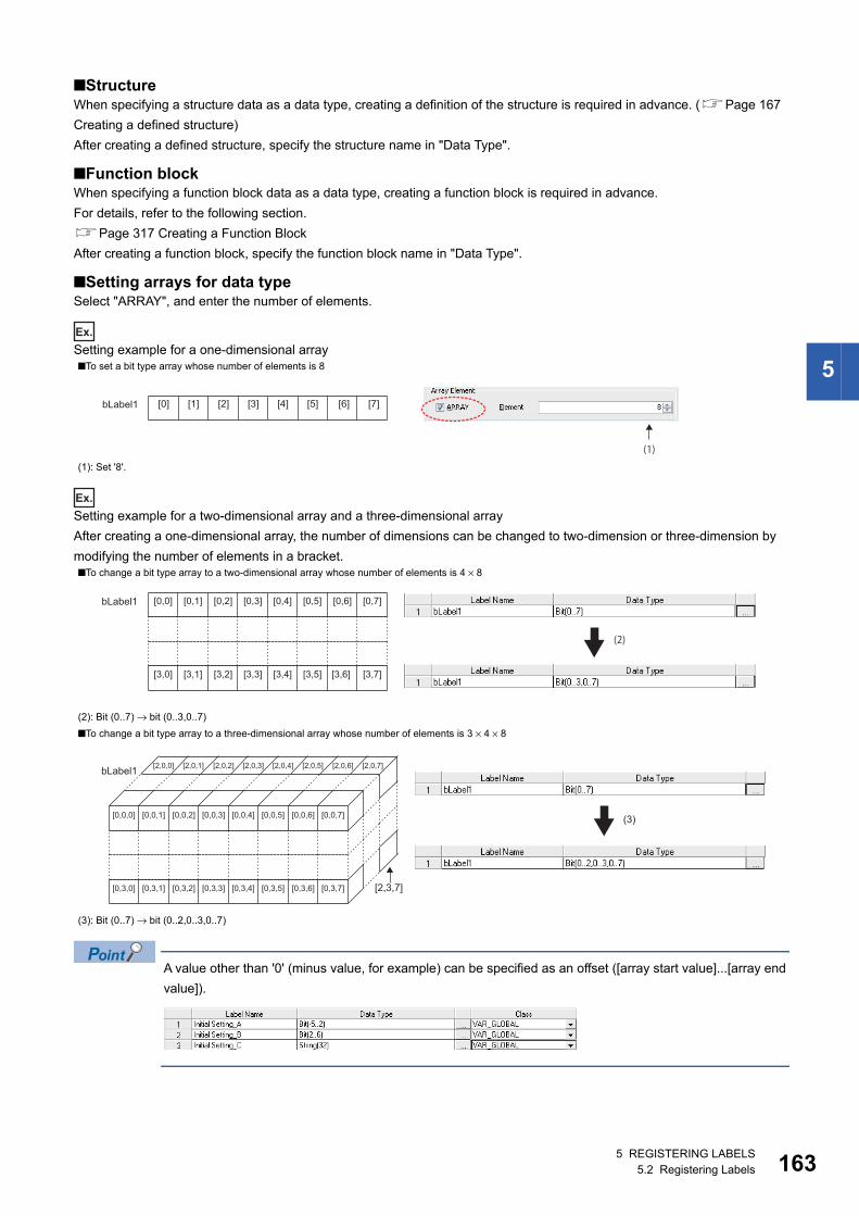
5 REGISTERING LABELS5.2 Registering Labels 163
5
■StructureWhen specifying a structure data as a data type, creating a definition of the structure is required in advance. (Page 167
Creating a defined structure)
After creating a defined structure, specify the structure name in "Data Type".
■Function blockWhen specifying a function block data as a data type, creating a function block is required in advance.
For details, refer to the following section.
Page 317 Creating a Function Block
After creating a function block, specify the function block name in "Data Type".
■Setting arrays for data typeSelect "ARRAY", and enter the number of elements.
Ex.
Setting example for a one-dimensional array
Ex.
Setting example for a two-dimensional array and a three-dimensional array
After creating a one-dimensional array, the number of dimensions can be changed to two-dimension or three-dimension by
modifying the number of elements in a bracket.
A value other than '0' (minus value, for example) can be specified as an offset ([array start value]...[array end
value]).
■To set a bit type array whose number of elements is 8
(1): Set '8'.
■To change a bit type array to a two-dimensional array whose number of elements is 4 × 8
(2): Bit (0..7) → bit (0..3,0..7)
■To change a bit type array to a three-dimensional array whose number of elements is 3 × 4 × 8
(3): Bit (0..7) → bit (0..2,0..3,0..7)
bLabel1 [0] [1] [3] [4] [5] [7][6][2]
(1)
bLabel1 [0,0] [0,1] [0,3] [0,4] [0,5] [0,7][0,6][0,2]
[3,0] [3,1] [3,3] [3,4] [3,5] [3,7][3,6][3,2]
(2)
bLabel1
[0,0,0] [0,0,1] [0,0,3] [0,0,4] [0,0,5] [0,0,7][0,0,6][0,0,2]
[0,3,0] [0,3,1] [0,3,3] [0,3,4] [0,3,5] [0,3,7][0,3,6][0,3,2]
[2,0,0] [2,0,1] [2,0,3] [2,0,4] [2,0,5] [2,0,7][2,0,6][2,0,2]
[2,3,7]
(3)
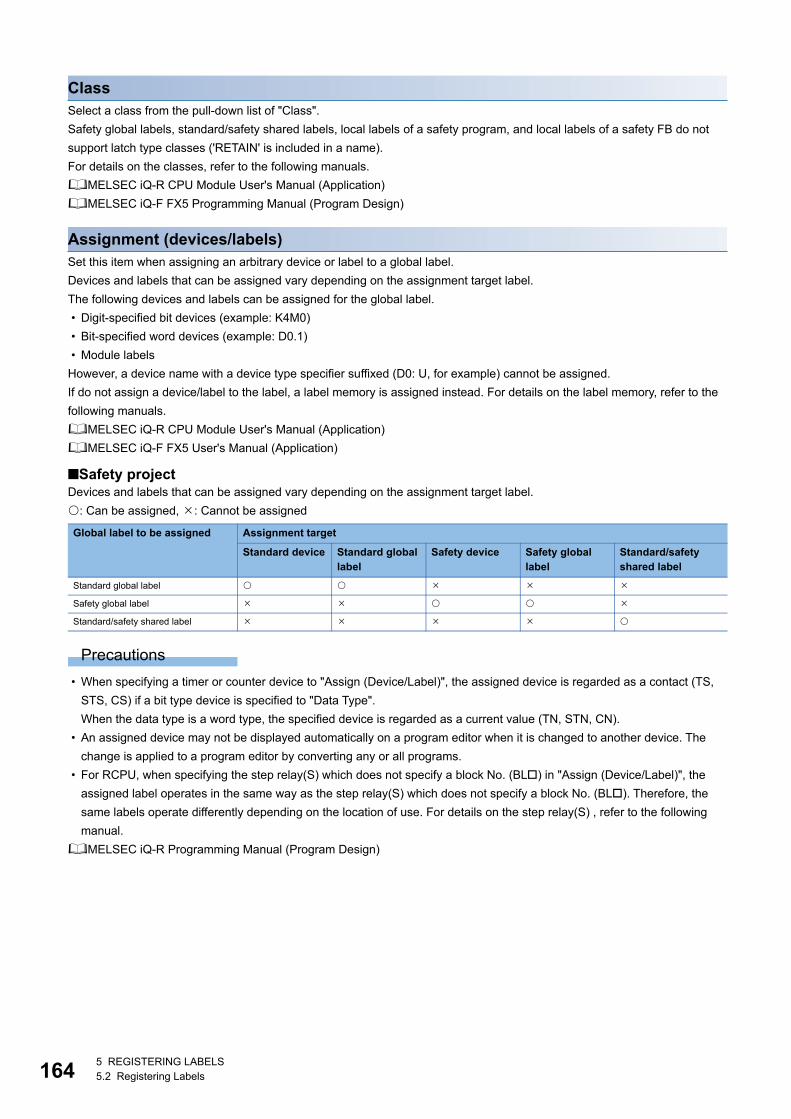
1645 REGISTERING LABELS5.2 Registering Labels
ClassSelect a class from the pull-down list of "Class".
Safety global labels, standard/safety shared labels, local labels of a safety program, and local labels of a safety FB do not
support latch type classes ('RETAIN' is included in a name).
For details on the classes, refer to the following manuals.
MELSEC iQ-R CPU Module User's Manual (Application)
MELSEC iQ-F FX5 Programming Manual (Program Design)
Assignment (devices/labels)Set this item when assigning an arbitrary device or label to a global label.
Devices and labels that can be assigned vary depending on the assignment target label.
The following devices and labels can be assigned for the global label.
• Digit-specified bit devices (example: K4M0)
• Bit-specified word devices (example: D0.1)
• Module labels
However, a device name with a device type specifier suffixed (D0: U, for example) cannot be assigned.
If do not assign a device/label to the label, a label memory is assigned instead. For details on the label memory, refer to the
following manuals.
MELSEC iQ-R CPU Module User's Manual (Application)
MELSEC iQ-F FX5 User's Manual (Application)
■Safety projectDevices and labels that can be assigned vary depending on the assignment target label.
: Can be assigned, : Cannot be assigned
Precautions
• When specifying a timer or counter device to "Assign (Device/Label)", the assigned device is regarded as a contact (TS,
STS, CS) if a bit type device is specified to "Data Type".
When the data type is a word type, the specified device is regarded as a current value (TN, STN, CN).
• An assigned device may not be displayed automatically on a program editor when it is changed to another device. The
change is applied to a program editor by converting any or all programs.
• For RCPU, when specifying the step relay(S) which does not specify a block No. (BL) in "Assign (Device/Label)", the
assigned label operates in the same way as the step relay(S) which does not specify a block No. (BL). Therefore, the
same labels operate differently depending on the location of use. For details on the step relay(S) , refer to the following
manual.
MELSEC iQ-R Programming Manual (Program Design)
Global label to be assigned Assignment target
Standard device Standard global label
Safety device Safety global label
Standard/safety shared label
Standard global label
Safety global label
Standard/safety shared label
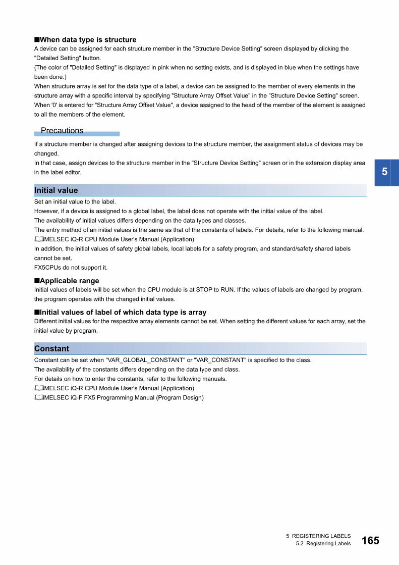
5 REGISTERING LABELS5.2 Registering Labels 165
5
■When data type is structureA device can be assigned for each structure member in the "Structure Device Setting" screen displayed by clicking the
"Detailed Setting" button.
(The color of "Detailed Setting" is displayed in pink when no setting exists, and is displayed in blue when the settings have
been done.)
When structure array is set for the data type of a label, a device can be assigned to the member of every elements in the
structure array with a specific interval by specifying "Structure Array Offset Value" in the "Structure Device Setting" screen.
When '0' is entered for "Structure Array Offset Value", a device assigned to the head of the member of the element is assigned
to all the members of the element.
Precautions
If a structure member is changed after assigning devices to the structure member, the assignment status of devices may be
changed.
In that case, assign devices to the structure member in the "Structure Device Setting" screen or in the extension display area
in the label editor.
Initial valueSet an initial value to the label.
However, if a device is assigned to a global label, the label does not operate with the initial value of the label.
The availability of initial values differs depending on the data types and classes.
The entry method of an initial values is the same as that of the constants of labels. For details, refer to the following manual.
MELSEC iQ-R CPU Module User's Manual (Application)
In addition, the initial values of safety global labels, local labels for a safety program, and standard/safety shared labels
cannot be set.
FX5CPUs do not support it.
■Applicable rangeInitial values of labels will be set when the CPU module is at STOP to RUN. If the values of labels are changed by program,
the program operates with the changed initial values.
■Initial values of label of which data type is arrayDifferent initial values for the respective array elements cannot be set. When setting the different values for each array, set the
initial value by program.
ConstantConstant can be set when "VAR_GLOBAL_CONSTANT" or "VAR_CONSTANT" is specified to the class.
The availability of the constants differs depending on the data type and class.
For details on how to enter the constants, refer to the following manuals.
MELSEC iQ-R CPU Module User's Manual (Application)
MELSEC iQ-F FX5 Programming Manual (Program Design)
1665 REGISTERING LABELS5.2 Registering Labels
CommentAppend a comment to the defined labels.
When entering comments on the label editor, press the + keys to insert a line feed (two characters are used) in a
cell.
Two or more comments can be set for one label. Set the display settings of the multiple comments on the "Multiple Comments
Display Setting" screen.
For details, refer to the following section.
Page 66 Comment Display Setting
■Copying device commentsThe comment of the device assigned to the selected label can be copied to the label editor.
Operating procedure
Select [Edit] [Copy Device Comment] ( ).
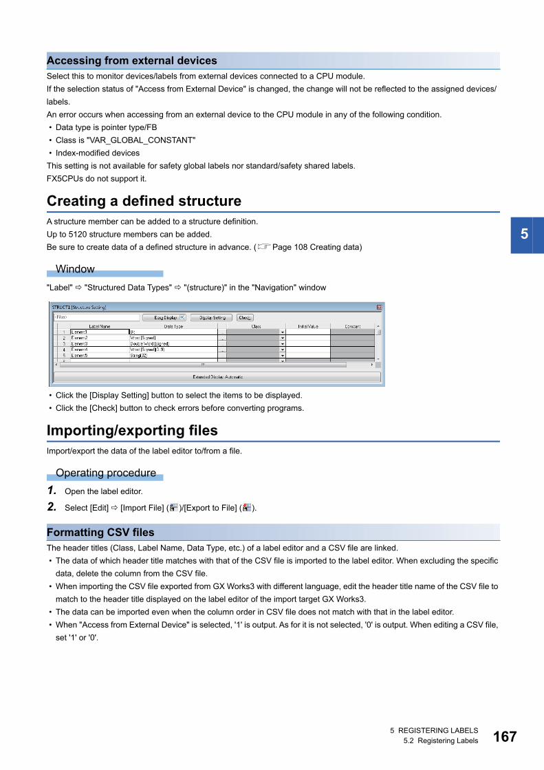
5 REGISTERING LABELS5.2 Registering Labels 167
5
Accessing from external devicesSelect this to monitor devices/labels from external devices connected to a CPU module.
If the selection status of "Access from External Device" is changed, the change will not be reflected to the assigned devices/
labels.
An error occurs when accessing from an external device to the CPU module in any of the following condition.
• Data type is pointer type/FB
• Class is "VAR_GLOBAL_CONSTANT"
• Index-modified devices
This setting is not available for safety global labels nor standard/safety shared labels.
FX5CPUs do not support it.
Creating a defined structureA structure member can be added to a structure definition.
Up to 5120 structure members can be added.
Be sure to create data of a defined structure in advance. (Page 108 Creating data)
Window
"Label" "Structured Data Types" "(structure)" in the "Navigation" window
• Click the [Display Setting] button to select the items to be displayed.
• Click the [Check] button to check errors before converting programs.
Importing/exporting filesImport/export the data of the label editor to/from a file.
Operating procedure
1. Open the label editor.
2. Select [Edit] [Import File] ( )/[Export to File] ( ).
Formatting CSV filesThe header titles (Class, Label Name, Data Type, etc.) of a label editor and a CSV file are linked.
• The data of which header title matches with that of the CSV file is imported to the label editor. When excluding the specific
data, delete the column from the CSV file.
• When importing the CSV file exported from GX Works3 with different language, edit the header title name of the CSV file to
match to the header title displayed on the label editor of the import target GX Works3.
• The data can be imported even when the column order in CSV file does not match with that in the label editor.
• When "Access from External Device" is selected, '1' is output. As for it is not selected, '0' is output. When editing a CSV file,
set '1' or '0'.

1685 REGISTERING LABELS5.3 Registering Module Labels
The files exported from GX Works2 can be imported to GX Works3.
Before importing the CSV file exported from GX Works2, edit the header title name of the CSV file to match
the header title on the label editor of GX Works3.
5.3 Registering Module LabelsThis section explains the registration methods of module labels.
Registering to global labelThe module label is registered when the module setting has been set as "Module Label: Use" on the confirmation screen
displayed after performing either of the following operations.
• Place a module on the Module Configuration Diagram and fix the parameters.
• Add a new module in the "Navigation" window.
The registered module labels are displayed in "Global Label" in the "Navigation" window and in the [Module] tab in the
"Element Selection" window.
When using a module label in a program, enter a module label name directly or drag and drop it from the "Element Selection"
window.
To use a module label under arbitrary name, set alias to the module label.
Precautions
■Considerations when registering module labelsSince all the registered module labels are written to a CPU module, the memory capacity of the CPU module may be
exceeded. In this case, perform any of the following operations.
• Change the write target of the global labels to SD memory card.
• For FX5CPU, the writable capacity is the same as that of the CPU module even when data is written to an SD memory
card.
■Module label with the name that starts with 'zReserve'Do not write data to the module label with the label name that starts with 'zReserve' among the module labels. Doing so may
cause malfunction of the programmable controller systems.
Ex.
'Instance name'_'Module number'.'Label name' GF11_1.zReserveAreaSB00007
Editing module labelsA module label (M+Global) which has been registered into the global label can only be deleted by selecting a row on the label
editor.
Do not edit and add a label on the label editor.
Re-registering deleted module labelsWhen registering the module labels which are once deleted from the global label editor, select a module name displayed in
the [Module] tab in the "Element Selection" window, then right-click it and select [Add Module Label] from the shortcut menu.
Editing structuresOnce module labels are registered, the definitions of the structures in the module labels are registered into "Structured Data
Types" in the "Navigation" window.
A defined structure can be copied in the "Navigation" window. The copied defined structure of the module label is changed
from "+" to "_".

5 REGISTERING LABELS5.4 Registration of tag FBs 169
5
5.4 Registration of tag FBsIn a project used for an RnPCPU and an RnPSFCPU, tag FBs can be used in an FBD/LD program with the process control
extension enabled.
To use tag FBs, they are required to be registered on the tag FB setting editor in advance.
Enter a tag name, tag FB type, and comment, then click the [Apply] button.
Up to 480 tag FBs can be registered in a project.
For details on tag FBs, refer to the following manual.
MELSEC iQ-R Programming Manual (Process Control Function Blocks/Instructions)
Precautions
To use tag FBs, it is recommended to register and apply them on the tag FB setting editor before adding data of a program
block, function block, function, global label, and structure definition.
When a lot of data mentioned above is registered in a project, it may take time to apply the tag FB setting.
Configuration of the tag FB setting editorThe following shows the screen configuration of the tag FB setting editor.
Window
Click "Tag FB Setting" ( ) on the toolbar.
Displayed items
: Editable, : Not editable
• The following option can be checked and set by clicking the [Maximum Number of Tags] button.
[Tool] [Options] "Convert" "Process Control Extension Setting" "Tag FB" "Maximum Number of Tags"
• Click the [Check] button to check an error before applying.
Item Editability Description
Tag Name Enter a tag FB name.
Tag FB Type Select the tag FB type of a tag FB instance.
Tag Type The tag type of a tag FB instance is displayed.
Structured Data Type A structure definition name of tag data is displayed.
FB Instance Name A tag FB instance name is displayed.
Label Name of Structured
Data Type
A tag data name is displayed.
Assigned Device The following device is assigned.
• The start device of a system resource + 3000 + ((row number -1)*130)
Set the system resource in [Tool] [Options] "Convert" "Process Control Extension Setting"
"System Resource" "File Register: ZR".
Comment Enter a comment that is applied to a comment of a tag FB instance and tag data.
1705 REGISTERING LABELS5.4 Registration of tag FBs
Editing a row
■Adding a rowA row can be added above a selected row. (Multiple selections allowed.)
Assigned devices in each tag FB setting is changed after the addition.
Operating procedure
Select [Edit] [New Declaration (Before)]( ).
■Deleting a rowA selected row can be deleted. (Multiple selections allowed.)
Assigned devices in each tag FB setting is changed after the deletion.
Operating procedure
Select [Edit] [Delete Row]( ).
■Copying a rowBy clicking the [Apply] button after copying or cutting a row and pasting, the initial value of the FB property in the copy source
is retained. However, it will not be retained if the tag FB type is changed after pasting.
■Setting an applicable/inapplicable rowThe number of rows set in [Tool] [Options] "Convert" "Process Control Extension Setting" "Tag FB" "Maximum
Number of Tags" will be applicable and other rows will be inapplicable as follows:
• Applicable row: Included in checking and applying the tag FB setting
• Inapplicable row: Excluded from checking and applying the tag FB setting. In addition, the information cannot be edited.
The option can be checked and set by clicking the [Maximum Number of Tags] button on the tag FB setting editor.
■Filtering displayA wild card (such as '*' and '?') is not applied as a filtering condition. A character string including the wild card is displayed.
Entering information
Tag nameSet a name with avoiding the following conditions:
• A label name starting with a number
• A same label name as one for a device
• A label name including a unusable character (reserved word) (Page 539 Unusable character string for label name)
Use only alphanumeric characters when monitoring data on a faceplate or exporting an assignment information database file.
Tag FB typeSelect a tag FB in the "Select Tag FB Type" screen displayed by clicking the [...] button in the "Tag FB Type" column.
For details on manufacturer-defined tag FB types, refer to the following manual.
MELSEC iQ-R Programming Manual (Process Control Function Blocks/Instructions)
For details on user-defined tag FBs, refer to the following section.
Page 321 Creating a user-defined tag FB
CommentUse only alphanumeric characters when monitoring data on a faceplate or exporting an assignment information database file.
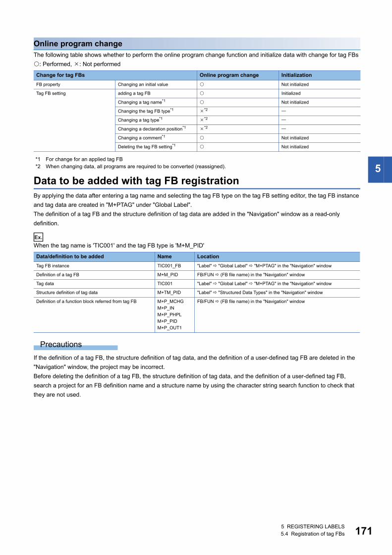
5 REGISTERING LABELS5.4 Registration of tag FBs 171
5
Online program changeThe following table shows whether to perform the online program change function and initialize data with change for tag FBs
: Performed, : Not performed
*1 For change for an applied tag FB*2 When changing data, all programs are required to be converted (reassigned).
Data to be added with tag FB registrationBy applying the data after entering a tag name and selecting the tag FB type on the tag FB setting editor, the tag FB instance
and tag data are created in "M+PTAG" under "Global Label".
The definition of a tag FB and the structure definition of tag data are added in the "Navigation" window as a read-only
definition.
Ex.
When the tag name is 'TIC001' and the tag FB type is 'M+M_PID'
Precautions
If the definition of a tag FB, the structure definition of tag data, and the definition of a user-defined tag FB are deleted in the
"Navigation" window, the project may be incorrect.
Before deleting the definition of a tag FB, the structure definition of tag data, and the definition of a user-defined tag FB,
search a project for an FB definition name and a structure name by using the character string search function to check that
they are not used.
Change for tag FBs Online program change Initialization
FB property Changing an initial value Not initialized
Tag FB setting adding a tag FB Initialized
Changing a tag name*1 Not initialized
Changing the tag FB type*1 *2
Changing a tag type*1 *2
Changing a declaration position*1 *2
Changing a comment*1 Not initialized
Deleting the tag FB setting*1 Not initialized
Data/definition to be added Name Location
Tag FB instance TIC001_FB "Label" "Global Label" "M+PTAG" in the "Navigation" window
Definition of a tag FB M+M_PID FB/FUN (FB file name) in the "Navigation" window
Tag data TIC001 "Label" "Global Label" "M+PTAG" in the "Navigation" window
Structure definition of tag data M+TM_PID "Label" "Structured Data Types" in the "Navigation" window
Definition of a function block referred from tag FB M+P_MCHG
M+P_IN
M+P_PHPL
M+P_PID
M+P_OUT1
FB/FUN (FB file name) in the "Navigation" window

1725 REGISTERING LABELS5.4 Registration of tag FBs
Tag FB instance and tag data registered in "M+PTAG"Only the initial value can be set for a tag FB instance registered in the global label setting "M+PTAG".
Window
"Label" "Global Label" "M+PTAG" in the "Navigation" window
Precautions
Do not delete "M+PTAG" from a project.
Display/setting an FB propertyThe initial value of a tag FB instance can also be set in the "FB Property" window.
The display contents in the "FB Property" window is linked with the contents in the selected row on the FB setting editor.
For details on the "FB Property" window, refer to the following section.
Page 233 Display/setting an FB property
In the "FB Property" window, the initial value of a tag FB instance which has already been applied on the tag FB editor is
displayed. A tag FB which is not applied, excluded from applying, or for which setting contents are changed after application is
not displayed.

5 REGISTERING LABELS5.5 Registering System Label 173
5
5.5 Registering System LabelThis section explains the method to register global labels as system labels.
Only standard global labels support system labels.
System labelUsing the system labels controlled by MELSOFT Navigator enables programming with the same label names among the iQ
Works supported products (GX Works3, MT Developer2, GT Designer3).
Once a workspace is saved with MELSOFT Navigator, a database to manage system labels is created in the workspace.
System labels cannot be used in a workspace without the system label database.
Precautions
Since module labels are read only, they cannot be registered as system label.
System label versionThere are two types of system labels for MELSOFT Navigator: system label ver.1 and system label ver.2.
FX5CPU only supports system label ver.1.
For more details on the differences between system label ver.1 and system label ver.2, and creation methods of each system
label database, refer to MELSOFT Navigator Help.
Configuration of label editor
Window
"Label" "Global Label" "(global label)" in the "Navigation" window
Displayed items
Item Description
System Label Relation Displays the relation between the global label and the system label.
• Disclose: The status in which the global labels are open as the system labels
• Reference: The status in which the system labels opened by other projects are imported in the global labels
• Blank: The status in which the global labels is not related to the system labels
System Label Name Displays the system label name related to the global labels.
Attribute Displays the attribute of the system label which is related to the global labels.
1745 REGISTERING LABELS5.5 Registering System Label
Registering labels in system label databaseDisclose standard global labels created with GX Works3 as system labels.
When registering in the system label database at the first time, create a workspace with MELSOFT Navigator and save
projects of GX Works3 in the workspace in advance.
Operating procedure
1. Display the global label editor.
2. Select the labels to be registered as system label, and click the [Reservation to Register System Label] button.
3. Click the [Reflect to System Label Database] button.
The "Check before registering in system label data base" screen is displayed.
4. Check the list of labels to be registered, and click the [Register] button.
Precautions
The structure array type global labels for which "Structure Array Offset Value" has been set cannot be registered as system
labels.
Importing system labels in system label database to GX Works3Import the system labels registered with MELSOFT Navigator or other projects to a project.
Operating procedure
1. Display the global label editor.
2. Click the [Import System Label] button.
The "Import System Labels to Project" screen is displayed.
3. Select the system labels to be imported, and click the [Import] button.
Releasing system labelsRelease the relation with the system label database, and restore system labels to normal global labels.
Operating procedure
1. Display the global label editor.
2. Select the labels of which relation is to be released from the labels registered as system labels.
3. Click the [Reservation to Release System Label] button.
4. Click the [Reflect to System Label Database] button.
The "Check before registering in system label data base" screen is displayed.
5. Check the list of labels to be released, and click the [Register] button.
5 REGISTERING LABELS5.5 Registering System Label 175
5
Verifying system label informationCompare the system label information of GX Works3 projects to the system label database, and check if there is any
difference.
If differences exist, correct the system label information of the GX Works3 projects, and synchronize the information with the
system label database.
Operating procedure
1. Select [Edit] [System Label] [Execute Verification Synchronous with System Label].
2. Check and correct information on the "Execute Verify and Synchronize with system label" screen.
3. Click the [Reflection] button.
Importing the changes of system label databaseImport the changed contents to the GX Works3 projects when the system labels used in a project have been changed in other
projects.
Importing the changes automatically
Operating procedure
Click the [Yes] button on the message to confirm whether or not import the changed contents, which appears when any of the
following operations is performed in a state where a system label change notification has been received.
• Opening a project
• Saving a project
• Reflecting labels to system label database
• Displaying the "Online Data Operation" screen
• Starting the Simulation function
Click the [No] button to import them after checking the changed contents. (Page 175 Importing after checking the
changes)
Importing after checking the changesWhen the system label information in the GX Works3 projects is different from the system label database, the icon to notify the
changes is displayed at the lower-left corner of the GX Works3 screen.
Check the contents that have been changed when the icon is displayed. In addition, import the changed contents to the GX
Works3 projects.
Operating procedure
1. Select [Edit] [System Label] [Check the changes of the System Label Database]( ).
2. Check the information on the "Import Change Contents of System Label Database" screen.
3. Click the [Import] button.

1765 REGISTERING LABELS5.5 Registering System Label
MEMO

177
PA
RT
3
PART 3 PROGRAMMING
This part explains the functions of the editor to edit a sequence program and the settings of device memory/
device initial values.
6 CREATING PROGRAMS
7 SETTING DEVICE MEMORY
8 SETTING DEVICE INITIAL VALUES
9 SEARCHING DATA
10 SEGMENTING PROGRAMS

1786 CREATING PROGRAMS6.1 Programming Function
6 CREATING PROGRAMS
This chapter explains the creation method of a program.
Remote head modules do not support creating a program.
6.1 Programming Function
Features and types of programming languageThe following table shows the programming languages supported by GX Works3.
*1 Safety programs are supported.*2 FX5CPUs do not support it.
Features and the type of POUsThe following table shows the usable POUs in a program.
Entering global devices/local devicesTo use global devices and local devices individually, enter the devices as follows:
• Standard global device: Enter a device name (Example: D10)
Safety global device: Prefix 'SA\' to the device name (Example: SA\D10)
• Standard local device: Prefix '#' to the device name (Example: #D10)
Safety local device: Prefix 'SA\#' to the device name (Example: SA\#D10)
For details of the global device/local device, refer to the following manual.
MELSEC iQ-R CPU Module User's Manual (Application)
Note that FX5CPUs do not support local devices.
Programming language
Name Description Creation method of a program
Language specification
Ladder*1 Ladder Diagram A graphic language using ladder programs composed of
contacts and coils.
The inline structured text functions to edit ST programs on
the ladder editor can be used.
Page 182 Creating a
Ladder Program
MELSEC iQ-R
Programming Manual
(Program Design)
MELSEC iQ-F FX5
Programming Manual
(Program Design)ST Structured Text Control syntax such as selection branch by conditional
syntax or repetitions by iterative syntax can be controlled,
as in the high-level language such as C language. By using
these syntax, concise programs can be written.
Page 217 Creating an ST
Program
FBD/LD Function Block
Diagram/Ladder
Diagram
A graphic language for creating a control program only by
placing and connecting an element.
Page 223 Creating an
FBD/LD Program
SFC*2 Sequential
Function Chart
A graphic language for clarifying the execution order and
the execution condition of a program.
Page 240 Creating an
SFC Program
POU Description Reference
Function block An element that has the internal memory and output an operation result according to values
in the memory and the input value.
Page 317 Creating a Function
Block
Function An element that has no internal memory and output always the same operation result for an
same input value.
Page 328 Creating a Function
6 CREATING PROGRAMS6.1 Programming Function 179
6
Entering global labels/local labelsWhen a label with the same name exists in both global labels and local labels, the label in a program is handled as follows:
• After a global label and a local label are registered, the label names are entered in the program: Treated as a local label.
• After a global label is registered, the label name is entered in the program, and then a local label with the same name is
registered: Treated as a global label.
• After a local label is registered, the label name is entered in the program, and then a global label with the same name is
registered: Treated as a local label.
The global labels and local labels can be distinguished by setting the different color on the "Color and Font" screen.
Creation procedure1. Create data of a program block. (Page 108 Creating data)
2. Set the execution order and the execution type. (Page 180 Program Execution Order and Execution Type Settings)
3. Create a program. (Page 182 Creating a Ladder Program, Page 217 Creating an ST Program, Page 223 Creating
an FBD/LD Program, Page 240 Creating an SFC Program)
4. Check the created program. (Page 276 Checking a program)
5. Convert the program. (Page 279 Converting Programs)
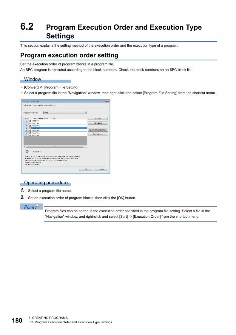
1806 CREATING PROGRAMS6.2 Program Execution Order and Execution Type Settings
6.2 Program Execution Order and Execution Type Settings
This section explains the setting method of the execution order and the execution type of a program.
Program execution order settingSet the execution order of program blocks in a program file.
An SFC program is executed according to the block numbers. Check the block numbers on an SFC block list.
Window
• [Convert] [Program File Setting]
• Select a program file in the "Navigation" window, then right-click and select [Program File Setting] from the shortcut menu.
Operating procedure
1. Select a program file name.
2. Set an execution order of program blocks, then click the [OK] button.
Program files can be sorted in the execution order specified in the program file setting. Select a file in the
"Navigation" window, and right-click and select [Sort] [Execution Order] from the shortcut menu.

6 CREATING PROGRAMS6.2 Program Execution Order and Execution Type Settings 181
6
Worksheet execution order settingWhen multiple program bodies are included in a POU, the execution order of the program bodies can be set.
This setting is allowed to POUs used in an ST program and FBD/LD program.
Window
• [Convert] [Worksheet Execution Order Setting]
• Select a POU in the "Navigation" window, then right-click and select [Worksheet Execution Order Setting] from the shortcut
menu.
Operating procedure
1. Select a program body.
2. Set the execution order of programs, then click the [OK] button.
Program bodies can be sorted in the execution order specified in the worksheet execution order setting.
Select a POU in the "Navigation" window, and right-click and select [Sort] [Execution Order] from the
shortcut menu.
Program execution type changeOne of the following execution types can be specified to a program: Initial, Scan, Fixed Scan, Event, Standby, or No Execution
Type.
For details, refer to the following manuals.
MELSEC iQ-R CPU Module User's Manual (Application)
MELSEC iQ-F FX5 User's Manual (Application)
Only 'Fixed Scan' can be specified in safety programs.
Setting methodTo set the execution type, right-click on a target program in the "Navigation" window and select [Register Program] from the
shortcut menu, or drag the program and drop it onto the target execution type.
The set execution type will be applied to "Program Setting" of "CPU Parameter".
Execution control of a process control programThere are two methods for executing the program: timer execution and interrupt execution.
For details, refer to the following manual.
MELSEC iQ-R Programming Manual (Process Control Function Blocks/Instructions)
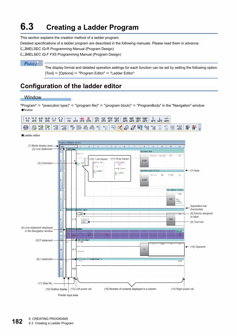
1826 CREATING PROGRAMS6.3 Creating a Ladder Program
6.3 Creating a Ladder ProgramThis section explains the creation method of a ladder program.
Detailed specifications of a ladder program are described in the following manuals. Please read them in advance.
MELSEC iQ-R Programming Manual (Program Design)
MELSEC iQ-F FX5 Programming Manual (Program Design)
The display format and detailed operation settings for each function can be set by setting the following option.
[Tool] [Options] "Program Editor" "Ladder Editor"
Configuration of the ladder editor
Window
"Program" "(execution type)" "(program file)" "(program block)" "ProgramBody" in the "Navigation" window■Toolbar
■Ladder editor
(1) Mode display area(2) Line statement
(7) Note
Separation bar (horizontal)(8) Device assigned to label
(4) Line statement displayed in the Navigation window
(5) P statement
(10) Operand
(9) Tool hint
(6) I statement
(11) Step No.
(14) Right power rail(12) Outline display (13) Left power rail
Pointer input area
(15) Number of contacts displayed in a column
(3) Comment<(16) 1 cell display> <(17) Wrap display>

6 CREATING PROGRAMS6.3 Creating a Ladder Program 183
6
Displayed items
Item Description Related operation
(1) Mode display area An area that displays mode such as Write/Read/Write
Mntr/Read Mntr.
■Switching mode
Page 184 Read mode/Write mode/Monitor read
mode/Monitor write mode
(2) Line statement A comment that is appended to a ladder block. ■Entering elements
Page 194 Entering comments/statements/notes
■Show/Hide
[View] [Comment Display]/[Statement Display]/[Note
Display]
(3) Comment A comment set to a device/label.
(4) Line statement displayed in the
Navigation window
A line statement that is displayed in the tree in the
"Navigation" window.
(5) P statement A comment that is appended to a pointer number.
(6) I statement A comment that is appended to an interrupt pointer
number.
(7) Note A comment that is appended to a coil/application
instruction in the program.
(8) Device assigned to label A device assigned to a label.
A label displayed on the ladder editor can be edited,
searched and replaced.
A device with any of the following conditions is not
displayed.
• A device that is assigned by converting the program
• A device that is assigned to a label used for an array
index
• A device that is assigned to a structure type label
■Settings
Page 157 Registering Labels
■Show/Hide
[View] [Display Device] ( )
(9) Tool hint The information on device/label where the mouse cursor
is placed over is displayed.
■Changing display contents
[Tool] [Options] "Program Editor" "Ladder Editor"
"Tool Hint"
(10) Operand A value or label name/device name to be operated.
(11) Step No. The start Step No. of a ladder block.
(19) FB instance
(18) Wrapping symbol (wrapping source)
(21) Inline structured text box(18) Wrapping
symbol (wrapping destination)
Separation bar (vertical)
(20) Function
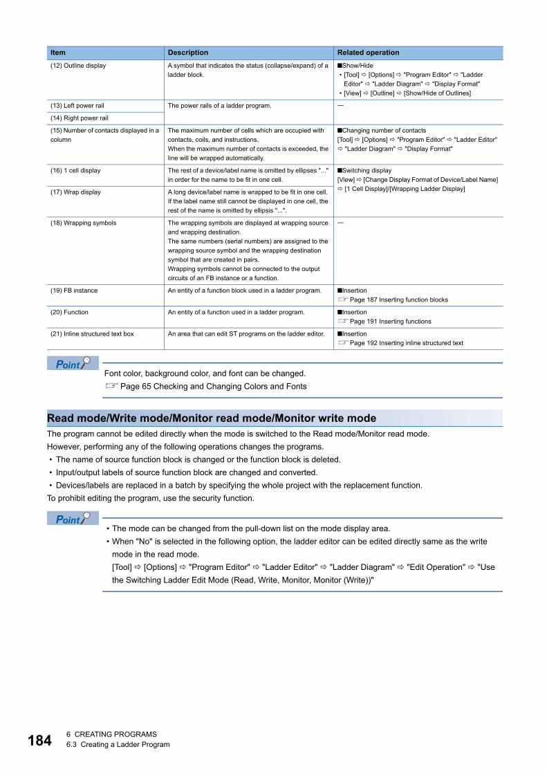
1846 CREATING PROGRAMS6.3 Creating a Ladder Program
Font color, background color, and font can be changed.
Page 65 Checking and Changing Colors and Fonts
Read mode/Write mode/Monitor read mode/Monitor write modeThe program cannot be edited directly when the mode is switched to the Read mode/Monitor read mode.
However, performing any of the following operations changes the programs.
• The name of source function block is changed or the function block is deleted.
• Input/output labels of source function block are changed and converted.
• Devices/labels are replaced in a batch by specifying the whole project with the replacement function.
To prohibit editing the program, use the security function.
• The mode can be changed from the pull-down list on the mode display area.
• When "No" is selected in the following option, the ladder editor can be edited directly same as the write
mode in the read mode.
[Tool] [Options] "Program Editor" "Ladder Editor" "Ladder Diagram" "Edit Operation" "Use
the Switching Ladder Edit Mode (Read, Write, Monitor, Monitor (Write))"
(12) Outline display A symbol that indicates the status (collapse/expand) of a
ladder block.
■Show/Hide
• [Tool] [Options] "Program Editor" "Ladder
Editor" "Ladder Diagram" "Display Format"
• [View] [Outline] [Show/Hide of Outlines]
(13) Left power rail The power rails of a ladder program.
(14) Right power rail
(15) Number of contacts displayed in a
column
The maximum number of cells which are occupied with
contacts, coils, and instructions.
When the maximum number of contacts is exceeded, the
line will be wrapped automatically.
■Changing number of contacts
[Tool] [Options] "Program Editor" "Ladder Editor"
"Ladder Diagram" "Display Format"
(16) 1 cell display The rest of a device/label name is omitted by ellipses "..."
in order for the name to be fit in one cell.
■Switching display
[View] [Change Display Format of Device/Label Name]
[1 Cell Display]/[Wrapping Ladder Display](17) Wrap display A long device/label name is wrapped to be fit in one cell.
If the label name still cannot be displayed in one cell, the
rest of the name is omitted by ellipsis "...".
(18) Wrapping symbols The wrapping symbols are displayed at wrapping source
and wrapping destination.
The same numbers (serial numbers) are assigned to the
wrapping source symbol and the wrapping destination
symbol that are created in pairs.
Wrapping symbols cannot be connected to the output
circuits of an FB instance or a function.
(19) FB instance An entity of a function block used in a ladder program. ■Insertion
Page 187 Inserting function blocks
(20) Function An entity of a function used in a ladder program. ■Insertion
Page 191 Inserting functions
(21) Inline structured text box An area that can edit ST programs on the ladder editor. ■Insertion
Page 192 Inserting inline structured text
Item Description Related operation

6 CREATING PROGRAMS6.3 Creating a Ladder Program 185
6
Entering laddersThis section explains the entering method of a ladder.
For details of ladder symbols, refer to the following manuals.
MELSEC iQ-R Programming Manual (Program Design)
MELSEC iQ-F FX5 Programming Manual (Program Design)
Inserting contacts, coils, instructions, arguments
Operating procedure
■Inserting on the element entry dialogSelect a cell to enter or edit*1, and double-click on it or press the key. Then, enter an instruction and argument on the
displayed element entry dialog*2.
*1 For the "Insert mode" (press the key to switch to the Overwrite mode), instructions are inserted on the cursor position. Therefore, if an instruction is already inserted in the selected cell, the existing instruction will be moved back.
*2 The cursor position on the ladder editor can be moved by pressing the + /// keys.To select an instruction/argument, press the +/ keys.Options of instructions/labels are displayed by pressing the + keys.
■Inserting from the "Enter Ladder" screen with descriptionSelect an instruction*1 and enter an argument on the "Enter Ladder" screen displayed by clicking the [Extd Dspl] button on the
element entry dialog.
*1 Frequently used instructions can be registered as "Favorites" by right-clicking on the instruction and selecting [Add to Favorites] from the shortcut menu. After the addition, "Favorites" can be selected in the lowest cell of the pull-down list in "List".
■Inserting from the menu or on the toolbarSelect a cell to add an element on the ladder editor, then select [Edit] [Ladder Symbol] [(element)]. It can also be added
by selecting the icon on the toolbar.
■Inserting from the "Element Selection" windowSelect a contact, coil, or instruction displayed in the "Element Selection" window, then drag and drop it onto the ladder editor.
After the insertion, edit the argument.
■Editing arguments directlySelect a cell where an argument is inserted, and press the key to edit the argument.
■Displaying a global label entered by using an assigned deviceBy entering a device which was assigned as a global label to a program, the global label of the device can be displayed in the
program.
Note that, only global labels whose data type is the simple type with no array can be displayed.
Enter an assigned device after changing the entering method by one of the following option, then the global label is displayed.
• [Edit] [Edit Mode] [Use Assigned Device for Label Input]( )
• [Tool] [Options] "Program Editor" "Ladder Editor" "Comment" "Operational Setting" "Use assigned device for
label input"
• A device number/label name can be incremented (+1)/decremented (-1) by pressing the +/ keys.
• When inserting an instruction without entering an argument, '?' is displayed automatically. ('?' can be
entered as an argument.
Arguments can also be entered later.
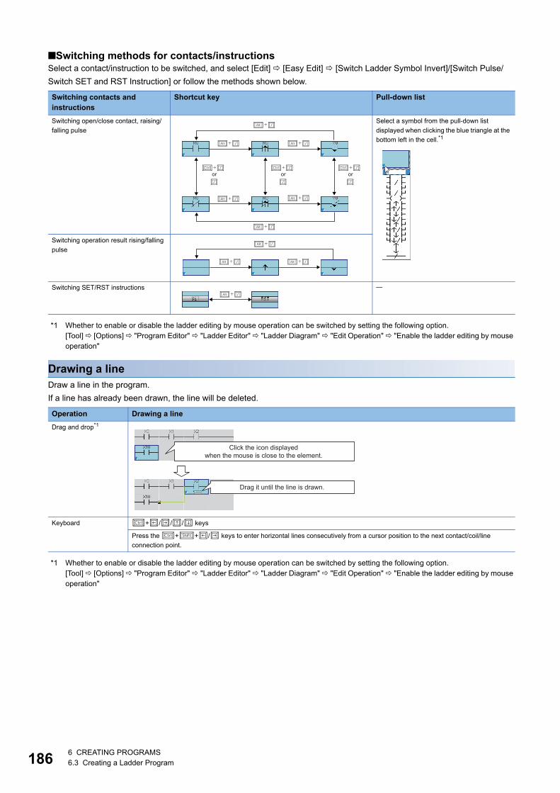
1866 CREATING PROGRAMS6.3 Creating a Ladder Program
■Switching methods for contacts/instructionsSelect a contact/instruction to be switched, and select [Edit] [Easy Edit] [Switch Ladder Symbol Invert]/[Switch Pulse/
Switch SET and RST Instruction] or follow the methods shown below.
*1 Whether to enable or disable the ladder editing by mouse operation can be switched by setting the following option.[Tool] [Options] "Program Editor" "Ladder Editor" "Ladder Diagram" "Edit Operation" "Enable the ladder editing by mouse operation"
Drawing a lineDraw a line in the program.
If a line has already been drawn, the line will be deleted.
*1 Whether to enable or disable the ladder editing by mouse operation can be switched by setting the following option.[Tool] [Options] "Program Editor" "Ladder Editor" "Ladder Diagram" "Edit Operation" "Enable the ladder editing by mouse operation"
Switching contacts and instructions
Shortcut key Pull-down list
Switching open/close contact, raising/
falling pulse
Select a symbol from the pull-down list
displayed when clicking the blue triangle at the
bottom left in the cell.*1
Switching operation result rising/falling
pulse
Switching SET/RST instructions
Operation Drawing a line
Drag and drop*1
Keyboard +/// keys
Press the ++/ keys to enter horizontal lines consecutively from a cursor position to the next contact/coil/line
connection point.
or or or
Click the icon displayed when the mouse is close to the element.
Drag it until the line is drawn.
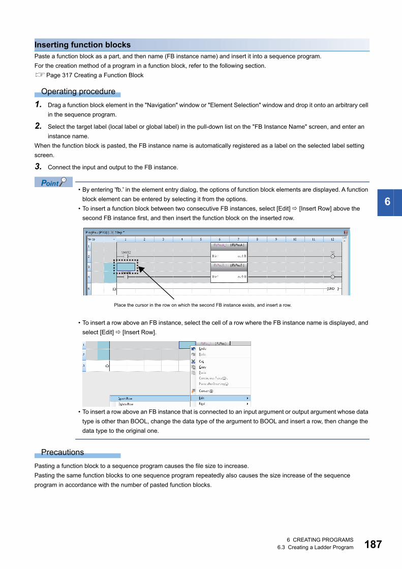
6 CREATING PROGRAMS6.3 Creating a Ladder Program 187
6
Inserting function blocksPaste a function block as a part, and then name (FB instance name) and insert it into a sequence program.
For the creation method of a program in a function block, refer to the following section.
Page 317 Creating a Function Block
Operating procedure
1. Drag a function block element in the "Navigation" window or "Element Selection" window and drop it onto an arbitrary cell
in the sequence program.
2. Select the target label (local label or global label) in the pull-down list on the "FB Instance Name" screen, and enter an
instance name.
When the function block is pasted, the FB instance name is automatically registered as a label on the selected label setting
screen.
3. Connect the input and output to the FB instance.
• By entering 'fb.' in the element entry dialog, the options of function block elements are displayed. A function
block element can be entered by selecting it from the options.
• To insert a function block between two consecutive FB instances, select [Edit] [Insert Row] above the
second FB instance first, and then insert the function block on the inserted row.
• To insert a row above an FB instance, select the cell of a row where the FB instance name is displayed, and
select [Edit] [Insert Row].
• To insert a row above an FB instance that is connected to an input argument or output argument whose data
type is other than BOOL, change the data type of the argument to BOOL and insert a row, then change the
data type to the original one.
Precautions
Pasting a function block to a sequence program causes the file size to increase.
Pasting the same function blocks to one sequence program repeatedly also causes the size increase of the sequence
program in accordance with the number of pasted function blocks.
Place the cursor in the row on which the second FB instance exists, and insert a row.
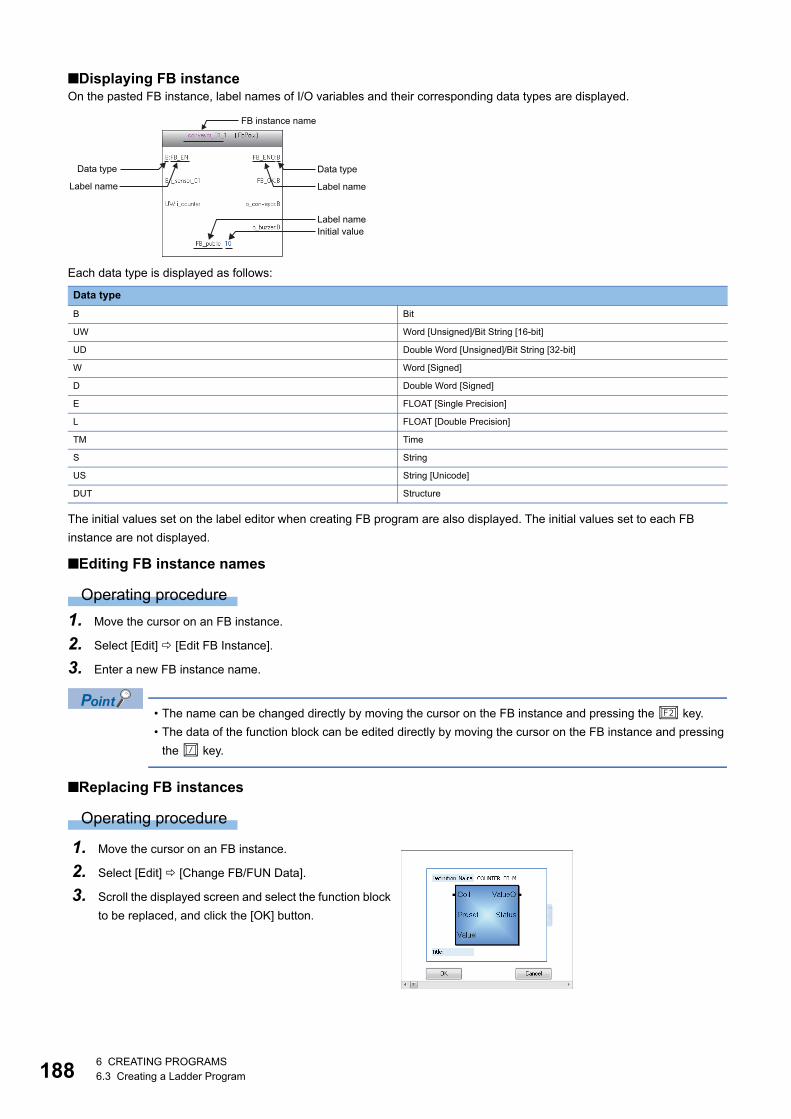
1886 CREATING PROGRAMS6.3 Creating a Ladder Program
■Displaying FB instanceOn the pasted FB instance, label names of I/O variables and their corresponding data types are displayed.
Each data type is displayed as follows:
The initial values set on the label editor when creating FB program are also displayed. The initial values set to each FB
instance are not displayed.
■Editing FB instance names
Operating procedure
1. Move the cursor on an FB instance.
2. Select [Edit] [Edit FB Instance].
3. Enter a new FB instance name.
• The name can be changed directly by moving the cursor on the FB instance and pressing the key.
• The data of the function block can be edited directly by moving the cursor on the FB instance and pressing
the key.
■Replacing FB instances
Operating procedure
Data type
B Bit
UW Word [Unsigned]/Bit String [16-bit]
UD Double Word [Unsigned]/Bit String [32-bit]
W Word [Signed]
D Double Word [Signed]
E FLOAT [Single Precision]
L FLOAT [Double Precision]
TM Time
S String
US String [Unicode]
DUT Structure
1. Move the cursor on an FB instance.
2. Select [Edit] [Change FB/FUN Data].
3. Scroll the displayed screen and select the function block
to be replaced, and click the [OK] button.
FB instance name
Data typeData type
Label nameLabel name
Label nameInitial value

6 CREATING PROGRAMS6.3 Creating a Ladder Program 189
6
■Creating input and output circuit parts of an FB instanceCreate input circuits (1) and output circuits (2) of an FB instance pasted to a sequence program.
The number of cells occupied by input circuits or output circuits of an FB instance differs depending on the setting of the
following option.
• [Tool] [Options] "Program Editor" "Ladder Editor" "Ladder Diagram" "Display Format" "Display Connection
of Ladder Diagram"
Instructions that exceed the number of cells occupied by input circuits or output circuits cannot be entered.
When instructions cannot be placed by changing the number of displayed contacts, the ladder block may not be displayed
properly.
Operating procedure
1. Select [Convert] [Convert] ( ).
The ladder block is converted, and lines are connected to the input and output labels of the FB instance.
2. Edit the input circuits.
Enter an element to the input circuit in the same manner as creating normal ladder programs. Create a program in
accordance with the data type of input variable.
3. Enter elements to the output circuit in the same manner as the input circuit.
Edit the program other than function blocks as well. After complete editing, convert the program.
A parallel circuit can be created in a input circuit on a FB instance.
To add an element between a parallel circuits, select a cell under the second row in the input circuit as shown
below, and select [Edit] [Insert Row] to enter an element in the added row.
Setting of the number of displayed contacts Number of cells in input circuit Number of cells in output circuit
9 contacts 4 cells 4 cells
11 contacts 5 cells 5 cells
13 contacts 6 cells 6 cells
17 contacts 8 cells 8 cells
21 contacts 10 cells 10 cells
33 contacts 16 cells 16 cells
45 contacts 22 cells 22 cells
(1) (2)

1906 CREATING PROGRAMS6.3 Creating a Ladder Program
■Considerations for using function block • A single function block can be pasted to a single ladder block.
The output of an FB instance cannot be directly connected to the input of another FB instance.
When connecting function blocks each other, use a coil to initially receive the output of a single function block, and then
connect the contact of the coil to the input of the other function block.
• When the label settings of a function block is changed, convert the program or all programs.
■Considerations for using function block that the class of label is "VAR_IN_OUT" • If the version of GX Works3 is 1.011M or earlier, use the same device/label to both the input and output which are
connected to the label of 'VAR_IN_OUT' ,otherwise, the program does not execute properly.
• The subroutine type function blocks that the devices/labels for the input and the output connecting to the label of
'VAR_IN_OUT' are not same, the verification result is mismatched. It is due to the difference of the version of GX Works3
which was used for converting all programs (version 1.011M or earlier, and version 1.015R or later). In that case, convert all
programs using the same version of GX Works3.
• For GX Works3 version 1.015R or later, a conversion error occurs when one or more instructions or coils are set to the left
side of "VAR_IN_OUT" of a function block.
■Consideration when an FB instance is connected directly to the left power railIn the input circuit of an FB instance, if an EN or input variable (bit type) is directly connected to the left power rail, the ON/OFF
state will not be changed.
To change the ON/OFF status of an EN and input variable (bit type), use a contact or an instruction equivalent to a contact.

6 CREATING PROGRAMS6.3 Creating a Ladder Program 191
6
Inserting functionsInsert a function in a ladder program.
For the creation method of a function, refer to the following section.
Page 328 Creating a Function
Operating procedure
1. Drag a function element in the "Navigation" window or "Element Selection" window and drop it onto an arbitrary cell in
the sequence program.
2. Connect an input and an output to the function.
• By entering 'fun.' in the element entry dialog, the options of function elements are displayed. A function
element can be entered by selecting it from the options.
• To insert a row above a function, select the cell of a row where the function name is displayed, and select
[Edit] [Insert Row].
• To insert a row above a function that is connected to an input argument or output argument whose data type
is other than BOOL, change the data type of the argument to BOOL and insert a row, then change the data
type to the original one.
■Adding/deleting argumentsOnly for a function of which the number of arguments can be changed, an argument can be added/deleted.
Operating procedure
1. Move the cursor on a function.
2. Select [Edit] [I/O Argument] [Increment Argument] ( )/[Delete Argument] ( ).
■Replacing functions
Operating procedure
1. Move the cursor on a function.
2. Select [Edit] [Change FB/FUN Data].
3. Scroll the screen and select the function block to be
replaced, and click the [OK] button.
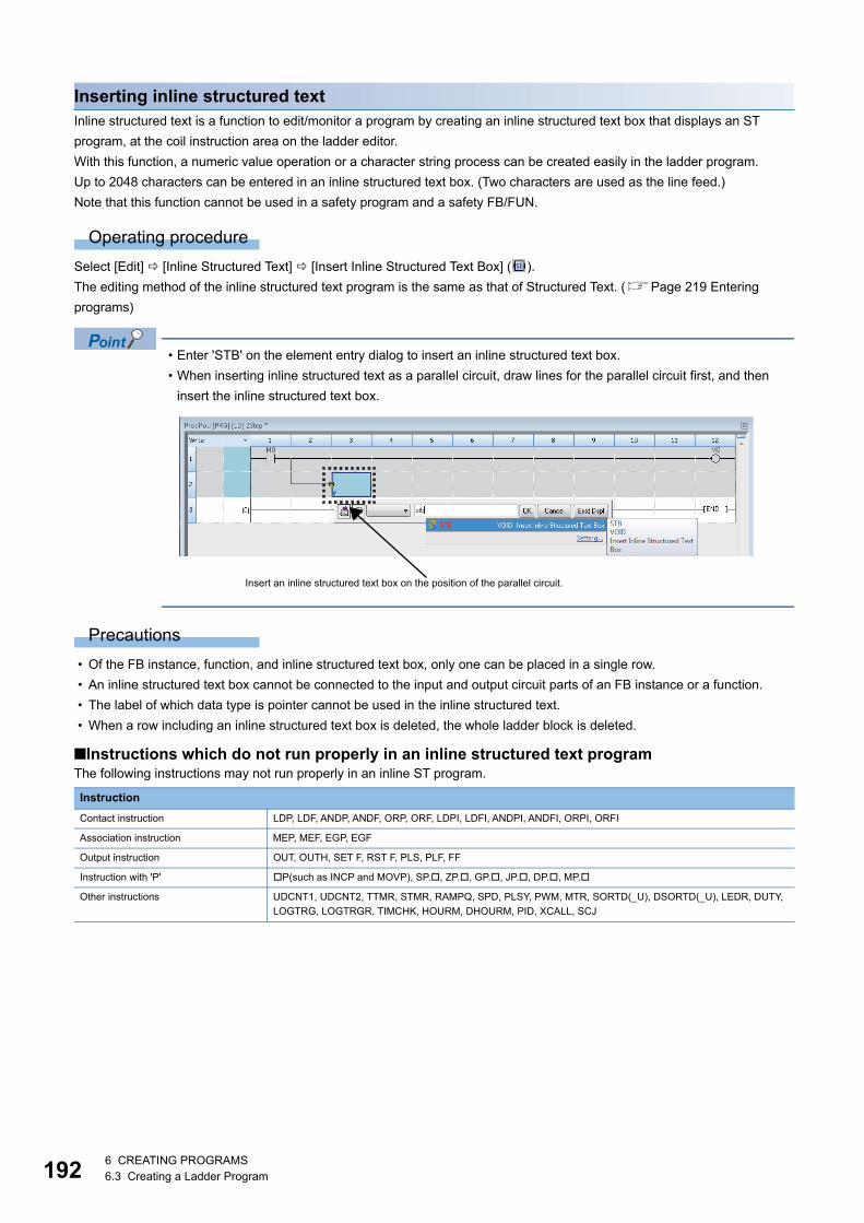
1926 CREATING PROGRAMS6.3 Creating a Ladder Program
Inserting inline structured textInline structured text is a function to edit/monitor a program by creating an inline structured text box that displays an ST
program, at the coil instruction area on the ladder editor.
With this function, a numeric value operation or a character string process can be created easily in the ladder program.
Up to 2048 characters can be entered in an inline structured text box. (Two characters are used as the line feed.)
Note that this function cannot be used in a safety program and a safety FB/FUN.
Operating procedure
Select [Edit] [Inline Structured Text] [Insert Inline Structured Text Box] ( ).
The editing method of the inline structured text program is the same as that of Structured Text. (Page 219 Entering
programs)
• Enter 'STB' on the element entry dialog to insert an inline structured text box.
• When inserting inline structured text as a parallel circuit, draw lines for the parallel circuit first, and then
insert the inline structured text box.
Precautions
• Of the FB instance, function, and inline structured text box, only one can be placed in a single row.
• An inline structured text box cannot be connected to the input and output circuit parts of an FB instance or a function.
• The label of which data type is pointer cannot be used in the inline structured text.
• When a row including an inline structured text box is deleted, the whole ladder block is deleted.
■Instructions which do not run properly in an inline structured text programThe following instructions may not run properly in an inline ST program.
Instruction
Contact instruction LDP, LDF, ANDP, ANDF, ORP, ORF, LDPI, LDFI, ANDPI, ANDFI, ORPI, ORFI
Association instruction MEP, MEF, EGP, EGF
Output instruction OUT, OUTH, SET F, RST F, PLS, PLF, FF
Instruction with 'P' P(such as INCP and MOVP), SP., ZP., GP., JP., DP., MP.
Other instructions UDCNT1, UDCNT2, TTMR, STMR, RAMPQ, SPD, PLSY, PWM, MTR, SORTD(_U), DSORTD(_U), LEDR, DUTY,
LOGTRG, LOGTRGR, TIMCHK, HOURM, DHOURM, PID, XCALL, SCJ
Insert an inline structured text box on the position of the parallel circuit.

6 CREATING PROGRAMS6.3 Creating a Ladder Program 193
6
Pasting from each screenPaste a label name/device name by dragging and dropping in an editor such as label editor and device comment editor.
By dragging and dropping a bit type label/device in a blank cell, a contact is inserted automatically and its label name/device
name is displayed.
Additionally, when dragging and dropping a bit type label/device to the right end of the cell, a coil is inserted automatically and
its label name/device is displayed.
A word type device/label can be pasted by dragging and dropping on the operand of an instruction.
Registering undefined labelsWhen an undefined label is entered, the "Undefined Label Registration" screen is displayed and it can be registered on the
label editor.
Checking the duplicated coilsCheck the duplicated coils in the same program when entering a coil in the program.
Whether to check the duplication can be set by setting the following option.
• [Tool] [Options] "Program Editor" "Ladder Editor" "Enter Ladder" "Operational Setting"
For the check target instructions/devices of duplicated coils, refer to the following section.
Page 277 Check targets for duplicated coil
Displaying MC/MCR instructionsWhen the MC instruction is inserted to a ladder program, the double-line symbol is displayed on the left vertical line. As for
MCR instruction, the left vertical line is delimited.
Automatically inserted after MC instruction is inserted. Read only.
Displayed after MCR instruction is entered.
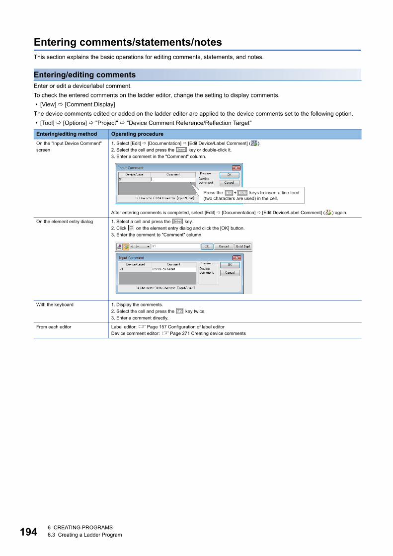
1946 CREATING PROGRAMS6.3 Creating a Ladder Program
Entering comments/statements/notesThis section explains the basic operations for editing comments, statements, and notes.
Entering/editing commentsEnter or edit a device/label comment.
To check the entered comments on the ladder editor, change the setting to display comments.
• [View] [Comment Display]
The device comments edited or added on the ladder editor are applied to the device comments set to the following option.
• [Tool] [Options] "Project" "Device Comment Reference/Reflection Target"
Entering/editing method Operating procedure
On the "Input Device Comment"
screen
1. Select [Edit] [Documentation] [Edit Device/Label Comment] ( ).
2. Select the cell and press the key or double-click it.
3. Enter a comment in the "Comment" column.
After entering comments is completed, select [Edit] [Documentation] [Edit Device/Label Comment] ( ) again.
On the element entry dialog 1. Select a cell and press the key.
2. Click on the element entry dialog and click the [OK] button.
3. Enter the comment to "Comment" column.
With the keyboard 1. Display the comments.
2. Select the cell and press the key twice.
3. Enter a comment directly.
From each editor Label editor: Page 157 Configuration of label editor
Device comment editor: Page 271 Creating device comments
Press the �+� keys to insert a line feed (two characters are used) in the cell.
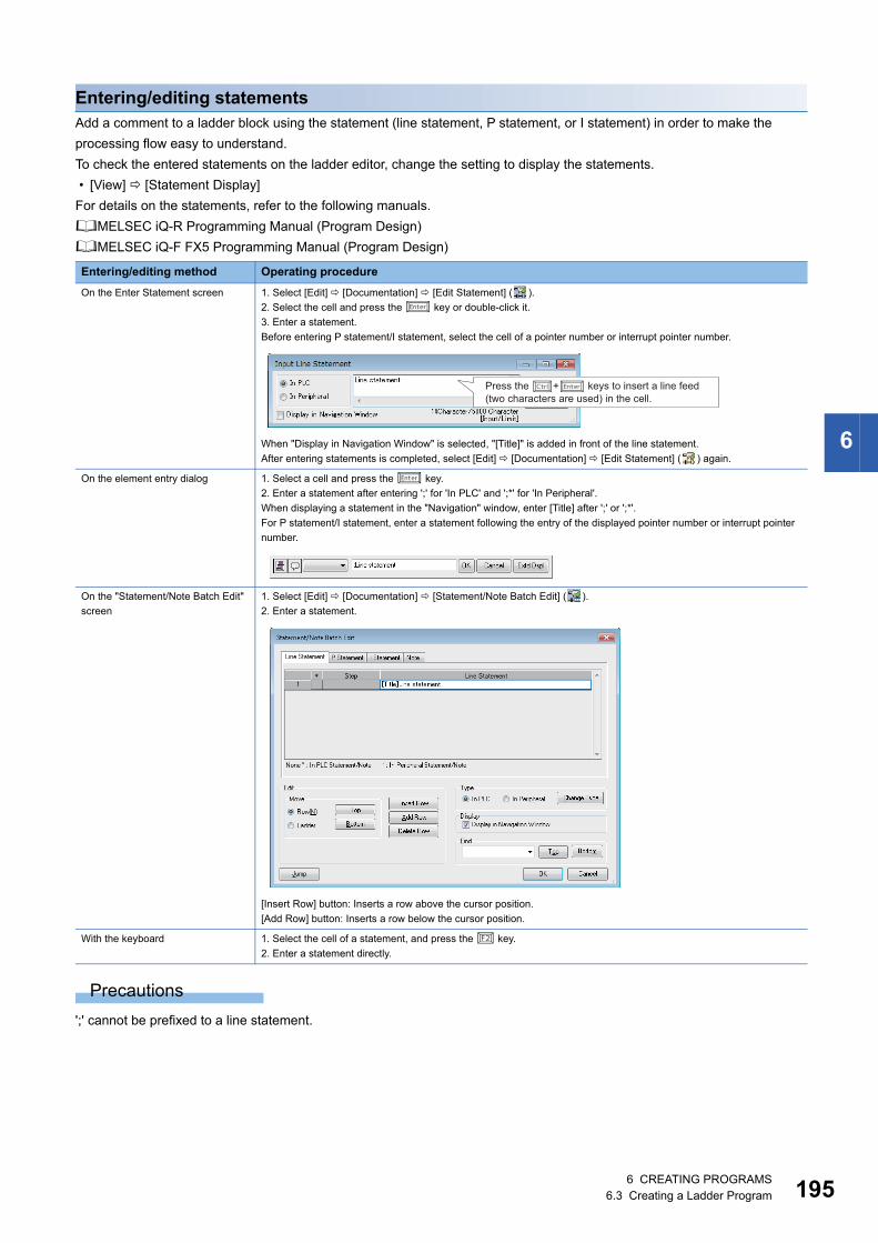
6 CREATING PROGRAMS6.3 Creating a Ladder Program 195
6
Entering/editing statementsAdd a comment to a ladder block using the statement (line statement, P statement, or I statement) in order to make the
processing flow easy to understand.
To check the entered statements on the ladder editor, change the setting to display the statements.
• [View] [Statement Display]
For details on the statements, refer to the following manuals.
MELSEC iQ-R Programming Manual (Program Design)
MELSEC iQ-F FX5 Programming Manual (Program Design)
Precautions
';' cannot be prefixed to a line statement.
Entering/editing method Operating procedure
On the Enter Statement screen 1. Select [Edit] [Documentation] [Edit Statement] ( ).
2. Select the cell and press the key or double-click it.
3. Enter a statement.
Before entering P statement/I statement, select the cell of a pointer number or interrupt pointer number.
When "Display in Navigation Window" is selected, "[Title]" is added in front of the line statement.
After entering statements is completed, select [Edit] [Documentation] [Edit Statement] ( ) again.
On the element entry dialog 1. Select a cell and press the key.
2. Enter a statement after entering ';' for 'In PLC' and ';*' for 'In Peripheral'.
When displaying a statement in the "Navigation" window, enter [Title] after ';' or ';*'.
For P statement/I statement, enter a statement following the entry of the displayed pointer number or interrupt pointer
number.
On the "Statement/Note Batch Edit"
screen
1. Select [Edit] [Documentation] [Statement/Note Batch Edit] ( ).
2. Enter a statement.
[Insert Row] button: Inserts a row above the cursor position.
[Add Row] button: Inserts a row below the cursor position.
With the keyboard 1. Select the cell of a statement, and press the key.
2. Enter a statement directly.
Press the �+� keys to insert a line feed (two characters are used) in the cell.
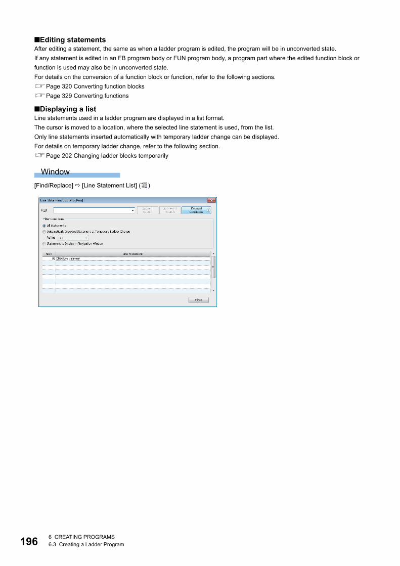
1966 CREATING PROGRAMS6.3 Creating a Ladder Program
■Editing statementsAfter editing a statement, the same as when a ladder program is edited, the program will be in unconverted state.
If any statement is edited in an FB program body or FUN program body, a program part where the edited function block or
function is used may also be in unconverted state.
For details on the conversion of a function block or function, refer to the following sections.
Page 320 Converting function blocks
Page 329 Converting functions
■Displaying a listLine statements used in a ladder program are displayed in a list format.
The cursor is moved to a location, where the selected line statement is used, from the list.
Only line statements inserted automatically with temporary ladder change can be displayed.
For details on temporary ladder change, refer to the following section.
Page 202 Changing ladder blocks temporarily
Window
[Find/Replace] [Line Statement List] ( )

6 CREATING PROGRAMS6.3 Creating a Ladder Program 197
6
■Line statement to be displayed in the "Navigation" windowSelect a line statement and select [Edit] [Documentation] [Show/Hide of Navigation Window] to switch showing or hiding
the line statement in the "Navigation" window.
When copying/deleting a line statement displayed in the "Navigation" window, the range of ladder blocks from the ladder block
including the selected line statement to the ladder block immediately before the next line statement displayed in the
"Navigation" window is copied/deleted.
The cursor is moved to the corresponding ladder block by double-clicking the line statement in the "Navigation" window.
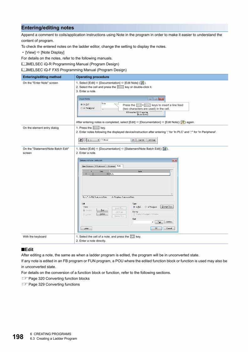
1986 CREATING PROGRAMS6.3 Creating a Ladder Program
Entering/editing notesAppend a comment to coils/application instructions using Note in the program in order to make it easier to understand the
content of program.
To check the entered notes on the ladder editor, change the setting to display the notes.
• [View] [Note Display]
For details on the notes, refer to the following manuals.
MELSEC iQ-R Programming Manual (Program Design)
MELSEC iQ-F FX5 Programming Manual (Program Design)
■EditAfter editing a note, the same as when a ladder program is edited, the program will be in unconverted state.
If any note is edited in an FB program or FUN program, a POU where the edited function block or function is used may also be
in unconverted state.
For details on the conversion of a function block or function, refer to the following sections.
Page 320 Converting function blocks
Page 329 Converting functions
Entering/editing method Operating procedure
On the "Enter Note" screen 1. Select [Edit] [Documentation] [Edit Note] ( ).
2. Select the cell and press the key or double-click it.
3. Enter a note.
After entering notes is completed, select [Edit] [Documentation] [Edit Note] ( ) again.
On the element entry dialog 1. Press the key.
2. Enter notes following the displayed device/instruction after entering ';' for 'In PLC' and ';*' for 'In Peripheral'.
On the "Statement/Note Batch Edit"
screen
1. Select [Edit] [Documentation] [Statement/Note Batch Edit] ( ).
2. Enter a note.
With the keyboard 1. Select the cell of a note, and press the key.
2. Enter a note directly.
Press the �+� keys to insert a line feed (two characters are used) in the cell.
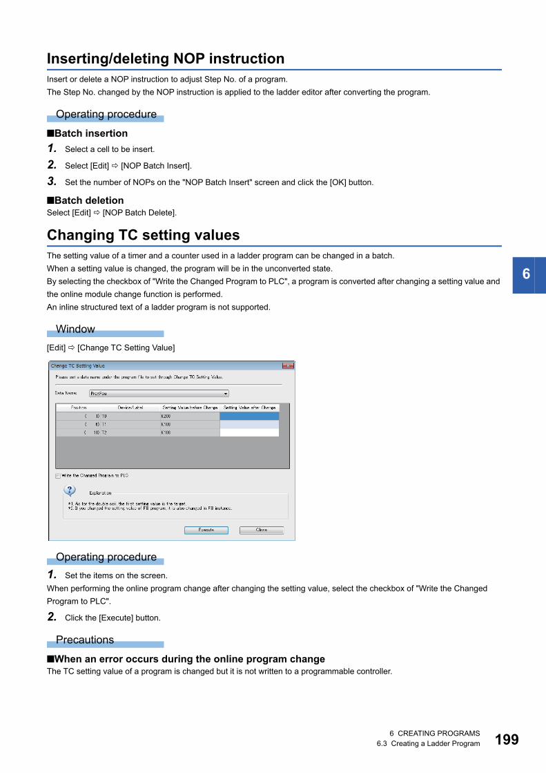
6 CREATING PROGRAMS6.3 Creating a Ladder Program 199
6
Inserting/deleting NOP instructionInsert or delete a NOP instruction to adjust Step No. of a program.
The Step No. changed by the NOP instruction is applied to the ladder editor after converting the program.
Operating procedure
■Batch insertion
1. Select a cell to be insert.
2. Select [Edit] [NOP Batch Insert].
3. Set the number of NOPs on the "NOP Batch Insert" screen and click the [OK] button.
■Batch deletionSelect [Edit] [NOP Batch Delete].
Changing TC setting valuesThe setting value of a timer and a counter used in a ladder program can be changed in a batch.
When a setting value is changed, the program will be in the unconverted state.
By selecting the checkbox of "Write the Changed Program to PLC", a program is converted after changing a setting value and
the online module change function is performed.
An inline structured text of a ladder program is not supported.
Window
[Edit] [Change TC Setting Value]
Operating procedure
1. Set the items on the screen.
When performing the online program change after changing the setting value, select the checkbox of "Write the Changed
Program to PLC".
2. Click the [Execute] button.
Precautions
■When an error occurs during the online program changeThe TC setting value of a program is changed but it is not written to a programmable controller.

2006 CREATING PROGRAMS6.3 Creating a Ladder Program
■When specifying "MELSAP-L (Instruction Format)" for the display format of an SFC programThe TC setting value of an SFC (Zoom) cannot be changed in the following settings:
• [Tool] [Options] "Program Editor" "SFC Diagram Editor" "Ladder Display Method"
• [View] [Switch Ladder Display]
Targets for changing TC setting values
■Target instructionThe following shows the instructions that can be set on the "Change TC Setting Value" screen.
• OUT: Timer/retentive timer output, long timer/long retentive timer output, counter/long counter output
• OUTH: High-speed timer/high-speed retentive timer
• OUTHS: High-speed timer/high-speed retentive timer*1
*1 RCPUs do not support it.
■Target deviceThe following table shows the devices that can be set on the "Change TC Setting Value" screen.
Copying/pasting a ladder
Cutting/copingSelect an instruction, range, or ladder block, and cut/copy it.
Select a row when copying a function/function block.
PastingPaste a cut/copied ladder.
For 'Insert mode' (press the key to switch to 'Overwrite mode'), one row will be inserted above the line where the cursor
placed over and the copied ladder will be pasted.
Even in 'Overwrite mode', a row/column will be inserted automatically and the copied ladder will be pasted by selecting [Edit]
[Insert and Paste].
Precautions
If the range to cut/copy is selected on a ladder as shown below, the vertical line on the right side cannot be pasted.
In this case, draw a vertical line after the pasting.
Instruction argument Device Global device Local device
Timer/counter/retentive timer T, ST, LT, LST, C, LC, SA\T, SA\ST, SA\C
Setting value D, SD, W, SW, Jn\W, Jn\SW, Un\G, U3En\G, U3En\HG, RD, R,
ZR, K, FD, SA\D, SA\SD, SA\W
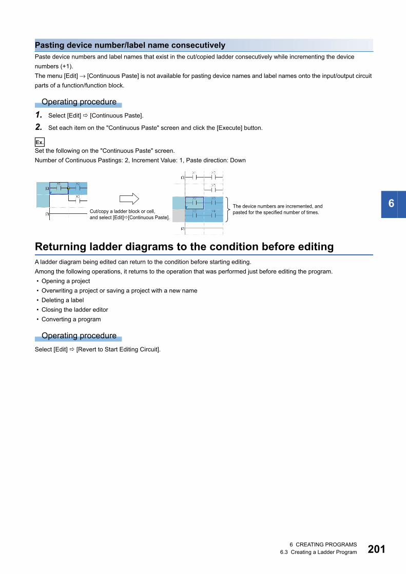
6 CREATING PROGRAMS6.3 Creating a Ladder Program 201
6
Pasting device number/label name consecutivelyPaste device numbers and label names that exist in the cut/copied ladder consecutively while incrementing the device
numbers (+1).
The menu [Edit] → [Continuous Paste] is not available for pasting device names and label names onto the input/output circuit
parts of a function/function block.
Operating procedure
1. Select [Edit] [Continuous Paste].
2. Set each item on the "Continuous Paste" screen and click the [Execute] button.
Ex.
Set the following on the "Continuous Paste" screen.
Number of Continuous Pastings: 2, Increment Value: 1, Paste direction: Down
Returning ladder diagrams to the condition before editingA ladder diagram being edited can return to the condition before starting editing.
Among the following operations, it returns to the operation that was performed just before editing the program.
• Opening a project
• Overwriting a project or saving a project with a new name
• Deleting a label
• Closing the ladder editor
• Converting a program
Operating procedure
Select [Edit] [Revert to Start Editing Circuit].
Cut/copy a ladder block or cell, and select [Edit]�[Continuous Paste].
The device numbers are incremented, and pasted for the specified number of times.
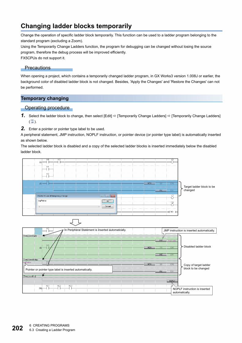
2026 CREATING PROGRAMS6.3 Creating a Ladder Program
Changing ladder blocks temporarilyChange the operation of specific ladder block temporarily. This function can be used to a ladder program belonging to the
standard program (excluding a Zoom).
Using the Temporarily Change Ladders function, the program for debugging can be changed without losing the source
program, therefore the debug process will be improved efficiently.
FX5CPUs do not support it.
Precautions
When opening a project, which contains a temporarily changed ladder program, in GX Works3 version 1.008J or earlier, the
background color of disabled ladder block is not changed. Besides, 'Apply the Changes' and 'Restore the Changes' can not
be performed.
Temporary changing
Operating procedure
1. Select the ladder block to change, then select [Edit] [Temporarily Change Ladders] [Temporarily Change Ladders]
( ).
2. Enter a pointer or pointer type label to be used.
A peripheral statement, JMP instruction, NOPLF instruction, or pointer device (or pointer type label) is automatically inserted
as shown below.
The selected ladder block is disabled and a copy of the selected ladder blocks is inserted immediately below the disabled
ladder block.
JMP instruction is inserted automatically.
Target ladder block to be changed
Disabled ladder block
Copy of target ladder block to be changed
In Peripheral Statement is inserted automatically.
Pointer or pointer type label is inserted automatically.
NOPLF instruction is inserted automatically.
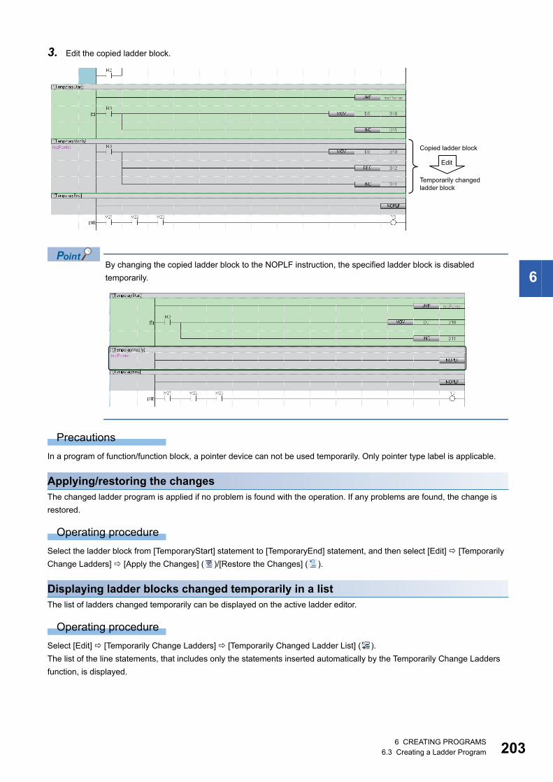
6 CREATING PROGRAMS6.3 Creating a Ladder Program 203
6
3. Edit the copied ladder block.
By changing the copied ladder block to the NOPLF instruction, the specified ladder block is disabled
temporarily.
Precautions
In a program of function/function block, a pointer device can not be used temporarily. Only pointer type label is applicable.
Applying/restoring the changesThe changed ladder program is applied if no problem is found with the operation. If any problems are found, the change is
restored.
Operating procedure
Select the ladder block from [TemporaryStart] statement to [TemporaryEnd] statement, and then select [Edit] [Temporarily
Change Ladders] [Apply the Changes] ( )/[Restore the Changes] ( ).
Displaying ladder blocks changed temporarily in a listThe list of ladders changed temporarily can be displayed on the active ladder editor.
Operating procedure
Select [Edit] [Temporarily Change Ladders] [Temporarily Changed Ladder List] ( ).
The list of the line statements, that includes only the statements inserted automatically by the Temporarily Change Ladders
function, is displayed.
Copied ladder block
Edit
Temporarily changed ladder block
2046 CREATING PROGRAMS6.3 Creating a Ladder Program
Considerations for editing ladder blocks changed temporarilyWhen the temporarily changed ladder block was edited with the contents listed in the following table, the program may not be
performed normally.
Searching/replacing data in a programThe search functions that can be used in a ladder editor are as follows.
Simple searchInstructions, devices, labels, statements, and notes can be searched by entering a text in the "Find" screen.
Operating procedure
1. Press the key on the ladder editor.
2. Enter a text, and click the [Find] button in the "Find" screen.
■Search optionsA search option can be set by adding the following commands at the end of a text for search.
For examples for searching devices using a search option, refer to the following section.
Page 302 Examples of device search
Description
Statement Delete/cut a statement.
Insert a ladder block between the [TemporaryModify] statement row and the ladder block changed temporarily (which is the row
setting a pointer).
Delete the [TemporaryEnd] statement row and NOPLF instruction.
Insert a ladder block/a statement/NOPLF instruction between the [TemporaryEnd] statement row and NOPLF instruction.
Insert a statement before and after the [TemporaryStart] statement row.
JMP instruction, Pointer Edit/delete a JMP instruction or a pointer.
Ladder block Edit a disabled ladder block.
Delete a ladder block disabled/changed temporarily.
Copy and paste a ladder block disabled/changed temporarily.
Function name Description Reference
Simple search Searches instructions, devices, labels, statements, and notes. Page 204 Simple search
Jump Moves the cursor on a specified step No. Page 205 Jump
Cross reference Checks a declaration location and a reference location of a device and a label in
a list.
Page 299 SEARCHING DATA
Device list Checks the usage of devices being used.
Find and replace • Searches for and replaces a device name, label name, instruction name, and
character strings.
• Changes open/close contact.
• Replaces devices in a batch.
Command Item name in the filed/replace window
Description
/K
(Example: M0/K)
Digit The entered device and digit-specified bit devices that include the entered device are searched.
/D
(Example: D0/D)
Multiple Word The entered device and the double-word format word devices that include the entered device are
searched.
;
(Example:
;statement)
Statements or notes are searched.
6 CREATING PROGRAMS6.3 Creating a Ladder Program 205
6
JumpSpecify a Step No., and move the cursor on the ladder editor.
Operating procedure
1. Select [Find/Replace] [Jump].
2. Specify a Step No. on the "Jump" screen, and click the [OK] button.
On the program editor, pressing a numeric key on the keyboard enables to display the "Jump" screen.
Displaying instruction helpCheck the instructions used in the ladder program on e-Manual Viewer.
To check the instructions, the files of the corresponding programming manual requires to be registered to e-Manual Viewer.
Operating procedure
1. Select the cell where the target instruction is entered.
2. Press the key.
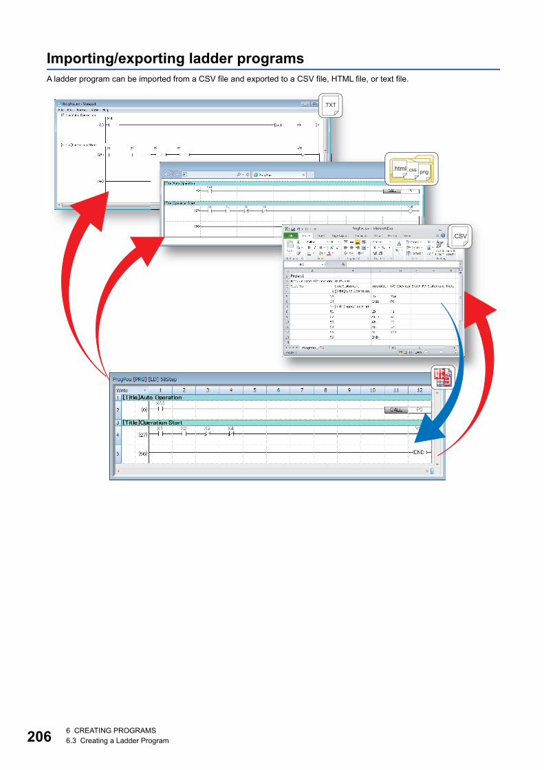
2066 CREATING PROGRAMS6.3 Creating a Ladder Program
Importing/exporting ladder programsA ladder program can be imported from a CSV file and exported to a CSV file, HTML file, or text file.
.CSV
.html .css .png
.TXT
6 CREATING PROGRAMS6.3 Creating a Ladder Program 207
6
Importing CSV filesA listed instruction in a CSV file can be imported into a ladder program.
When a CSV file is imported, the program will be in the unconverted state.
Operating procedure
1. Open the ladder editor, and select [Edit] [Import File]( ).
2. Select a file to import on the "Import File" screen.
3. Specify "CSV (tab delimited)(*.csv)" for the file type, and click the [Open] button.
4. Select "Convert to 'OUT SM4095'" or "Convert to line statement" for "Conversion Method for Incorrect Instruction" on the
screen to confirm import, and click the [Yes] button.
Precautions
When a program is being monitored or simulated, a file cannot be imported.
■Restrictions on data to be importedThe following restrictions apply to data to be imported.
• Data in the eighth column or later in a CSV file is not imported
• When a language of data to be imported is different from that of a project, some characters may be garbled
• When data is imported, the existing program in the import destination is deleted
■Import of a program in which a function clock or function is usedWhen importing a program including a function block or function, if the function block, function, or FB instance is undefined, an
error will occur.
Before importing a program, check that the following conditions are satisfied.
• Any FB/FUN exists in a project. (Except for standard FB/FUN.)
• The names, the data types, and the order of input/output labels (including the return value of an EN/ENO) of FB/FUN are
consistent with those of the definition in a project.
• An FB instance is defined.
■Import of a program in version 1.038Q or earlierIn version 1.038Q or earlier, an error occurs when importing a program including the following elements from a CSV file.
Import a program in version 1.040S or later.
• Label
• Inline structured text
• Function block function
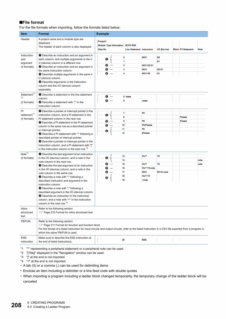
2086 CREATING PROGRAMS6.3 Creating a Ladder Program
■File formatFor the file formats when importing, follow the formats listed below:
*1 "*" representing a peripheral statement or a peripheral note can be used.*2 "[Title]" displayed in the "Navigation" window can be used.*3 "]" at the end is not imported.*4 ">" at the end is not imported.
• A tab (\t) or a comma (,) can be used for delimiting items
• Enclose an item including a delimiter or a line feed code with double quotes
• When importing a program including a ladder block changed temporarily, the temporary change of the ladder block will be
canceled
Item Format Example
Header A project name and a module type are
displayed.
The header of each column is also displayed.
Instruction
and
argument
(4 formats)
Describe an instruction and an argument in
each column, and multiple arguments in the I/
O (device) column in a different row.
Describe an instruction and an argument in
the same instruction column.
Describe multiple arguments in the same I/
O (device) column.
Describe arguments in the instruction
column and the I/O (device) column
separately.
Statement*1,
*2
(2 formats)
Describe a statement in the line statement
column.
Describe a statement with ";" in the
instruction column.
PI
statement*1
(4 formats)
Describe a pointer or interrupt pointer in the
instruction column, and a PI statement in the
PI statement column in the next row.
Describe a PI statement in the PI statement
column in the same row as a described pointer
or interrupt pointer.
Describe a PI statement with ";" following a
described pointer or interrupt pointer.
Describe a pointer or interrupt pointer in the
instruction column, and a PI statement with "["
in the instruction column in the next row.*3
Note*1
(5 formats)
Describe the last argument of an instruction
in the I/O (device) column, and a note in the
note column in the next row.
Describe the last argument of an instruction
in the I/O (device) column, and a note in the
note column in the same row.
Describe a note with ";" following a
described instruction and argument in the
instruction column.
Describe a note with ";" following a
described argument in the I/O (device) column.
Describe an instruction in the instruction
column, and a note with "<" in the instruction
column in the next row.*4
Inline
structured
text
Refer to the following section.
Page 210 Format for inline structured text
FB/FUN Refer to the following section.
Page 211 Format for function and function block
For the format of a listed instruction for input circuits and output circuits, refer to the listed instruction in a CSV file exported from a program in
which the same FB/FUN is used.
END
instruction
Make sure to describe the END instruction at
the end of listed instructions.
�
�
�
�
�
�
�
�
�
�
�
�
�
�
�
6 CREATING PROGRAMS6.3 Creating a Ladder Program 209
6
• The range of a character string in a line statement to be imported differs depending on a line feed format in a CSV file
• The following table shows the constants that the devices are changed when importing.
Exporting to a CSV fileA ladder program can be converted into a listed instruction format and exported to a CSV file.
Operating procedure
1. Open the ladder editor, and select [Edit] [Export to File]( ).
2. Enter a file name to export in the "Export to File" screen.
3. Specify "CSV (tab delimited)(*.csv)" for the file type, and click the [Save] button.
Precautions
Programs including an unconverted ladder cannot be exported.
If more than 5000 inline structured texts exist in a program, an error will occur.
Line feed format Import in GX Works2 Import in GX Works3
Line feed character "\r\n" is used A character string in a single row including the
line feed character "\r\n" is imported as a
statement.
A character string in which a line feed is inserted is
imported as a statement.
A CSV file is edited directly and a line feed is
inserted in a character string
A character string up to the first line feed is imported as a statement.
Type Example Description
CSV file Import in GX Works3
Boolean TRUE SM400 Replaced with SM400
FALSE SM401 Replaced with SM401
Binary 2#1111 H0F Imported as "H (hexadecimal)" (a value is same)
2#1111_1111 H0FF
Octal 8#10 H8
8#1_1 H9
Hexadecimal 16#1A H1A
16#1_A
Decimal 30 K30 Imported as "K (decimal)" (a value is same)
3_0
Real number 0.3 E0.3 Imported as "E (real number)" (a value is same)
3.14_15 E3.1415
1.00E+06 E1.0+6
String 'ABC' "ABC" Replaced with double quotes
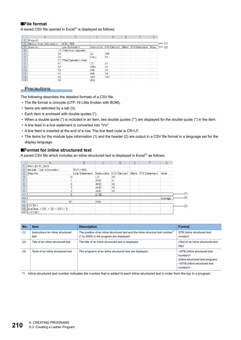
2106 CREATING PROGRAMS6.3 Creating a Ladder Program
■File formatA saved CSV file opened in Excel is displayed as follows:
Precautions
The following describes the detailed formats of a CSV file.
• The file format is Unicode (UTF-16 Little Endian with BOM).
• Items are delimited by a tab (\t).
• Each item is enclosed with double quotes (").
• When a double quote (") is included in an item, two double quotes ("") are displayed for the double quote (") in the item.
• A line feed in a line statement is converted into "\r\n".
• A line feed is inserted at the end of a row. The line feed code is CR+LF.
• The items for the module type information (1) and the header (2) are output in a CSV file format in a language set for the
display language.
■Format for inline structured textA saved CSV file which includes an inline structured text is displayed in Excel as follows:
*1 Inline structured text number indicates the number that is added to each inline structured text in order from the top in a program.
No. Item Description Format
(1) Instructions for inline structured
text
The position of an inline structured text and the inline structure text number*1
(1 to 5000) in the program are displayed.
STB (inline structured text
number)
(2) Title of an inline structured text The title of an inline structured text is displayed. (Text of an inline structured text
title)
(3) Texts of an inline structured text The programs of an inline structured text are displayed. <STB (inline structured text
number)>
(Inline structured text program)
</STB (inline structured text
number)>
(2)(1)
(1)(2)
(3)

6 CREATING PROGRAMS6.3 Creating a Ladder Program 211
6
■Format for function and function blockThe display example of CSV file in the format of function blocks is as follows.
A saved CSV file that includes a function block opened in Excel is displayed as follows:
No. Item Description Format
(1) Starting position The starting position of a ladder block in which a function block is used is
displayed.
*;FB BLK START
The starting position of a ladder block in which a function is used is
displayed.
*;FUN BLK START
(2) Input circuit part An input circuit of an FB instance or a function is displayed. Depends on an instruction (listed
instruction format)
Page 208 File format
(3) FB instance/
function
Program starting
position
The starting position of an FB program is displayed. FBCALL (FB data name)(FB
instance name)
The starting position of the program of a function is displayed. FUNCALL (FUN data name)
(4) Input label
definition
A label name, IN, and data type of an input label is displayed. (Label name) IN: (data type)
(5) Output label
definition
A label name, OUT, and data type of an output label is displayed. (Label name) OUT: (data type)
(6) Output circuit part The output circuit of an FB instance or a function is displayed. Depends on an instruction (listed
instruction format)
Page 208 File format
(7) End position The end position of a ladder block in which a function block is used is
displayed.
*;FB BLK END
The end position of a ladder block in which a function is used is displayed. *;FUN BLK END
(1)
(2)
(3)(4)(5)
(6)
(7)
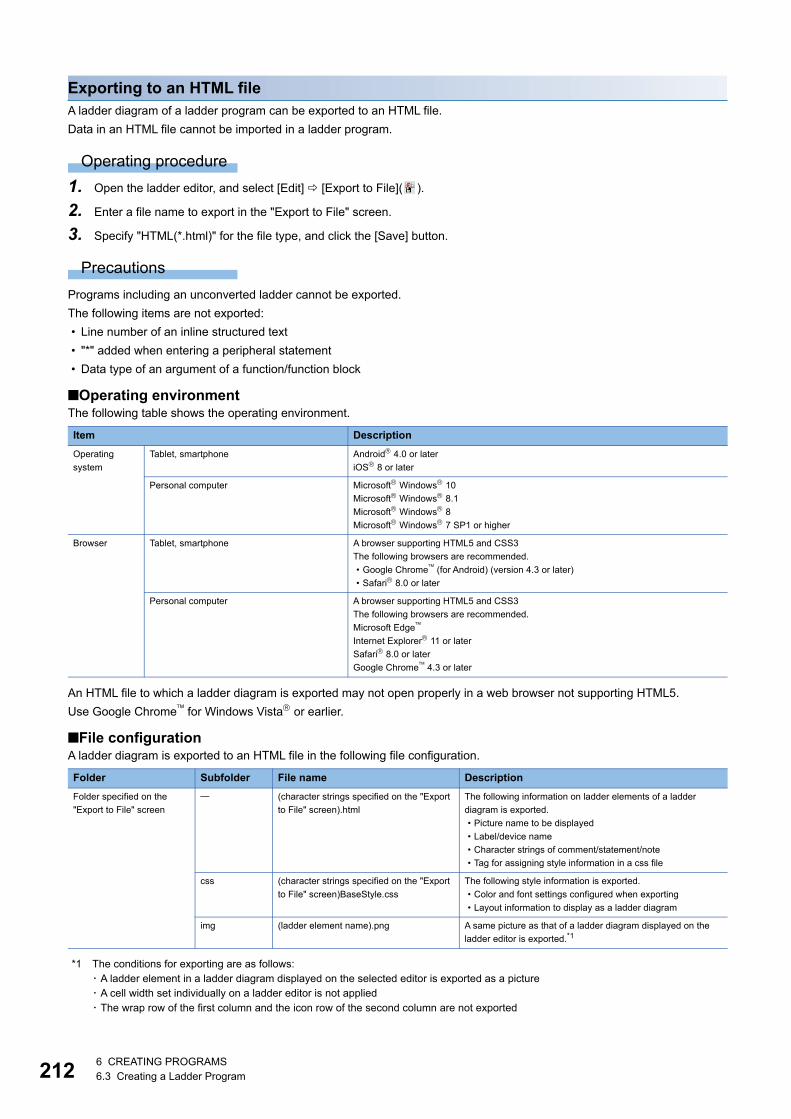
2126 CREATING PROGRAMS6.3 Creating a Ladder Program
Exporting to an HTML fileA ladder diagram of a ladder program can be exported to an HTML file.
Data in an HTML file cannot be imported in a ladder program.
Operating procedure
1. Open the ladder editor, and select [Edit] [Export to File]( ).
2. Enter a file name to export in the "Export to File" screen.
3. Specify "HTML(*.html)" for the file type, and click the [Save] button.
Precautions
Programs including an unconverted ladder cannot be exported.
The following items are not exported:
• Line number of an inline structured text
• "*" added when entering a peripheral statement
• Data type of an argument of a function/function block
■Operating environmentThe following table shows the operating environment.
An HTML file to which a ladder diagram is exported may not open properly in a web browser not supporting HTML5.
Use Google Chrome for Windows Vista or earlier.
■File configurationA ladder diagram is exported to an HTML file in the following file configuration.
*1 The conditions for exporting are as follows:・ A ladder element in a ladder diagram displayed on the selected editor is exported as a picture・ A cell width set individually on a ladder editor is not applied・ The wrap row of the first column and the icon row of the second column are not exported
Item Description
Operating
system
Tablet, smartphone Android 4.0 or later
iOS 8 or later
Personal computer Microsoft Windows 10
Microsoft Windows 8.1
Microsoft Windows 8
Microsoft Windows 7 SP1 or higher
Browser Tablet, smartphone A browser supporting HTML5 and CSS3
The following browsers are recommended.
• Google Chrome (for Android) (version 4.3 or later)
• Safari 8.0 or later
Personal computer A browser supporting HTML5 and CSS3
The following browsers are recommended.
Microsoft Edge
Internet Explorer 11 or later
Safari 8.0 or later
Google Chrome 4.3 or later
Folder Subfolder File name Description
Folder specified on the
"Export to File" screen
(character strings specified on the "Export
to File" screen).html
The following information on ladder elements of a ladder
diagram is exported.
• Picture name to be displayed
• Label/device name
• Character strings of comment/statement/note
• Tag for assigning style information in a css file
css (character strings specified on the "Export
to File" screen)BaseStyle.css
The following style information is exported.
• Color and font settings configured when exporting
• Layout information to display as a ladder diagram
img (ladder element name).png A same picture as that of a ladder diagram displayed on the
ladder editor is exported.*1

6 CREATING PROGRAMS6.3 Creating a Ladder Program 213
6
■File formatA saved HTML file opened in a web browser is displayed as follows:
• A line feed is not inserted for statements and comments.
• When closing ladder blocks in an outline display, they are exported in the closed state.
• Ladder blocks displayed in an editor can only be exported. (Example: When only a ladder block including a line statement
is displayed)
Precautions
• When the magnification of a character in a web browser is not same, a file is not displayed properly.
• Some characters may get cut depending on the fonts used in a web browser.
• The number of characters and rows to display the character string data, such as a device name and a comment, may not
match between the ladder editor and a web browser.
• When displaying a program with a large number of steps in an inline structured text, the line of the left ladder may be cut off.
• The position of a command name may differ between a ladder editor and a web browser.
• When character strings are not displayed all, "..." is added to the end for a device, data name of a function/function block,
FB instance name, statement, note, VAR_PUBLIC, and VAR_PUBLIC_RETAIN.

2146 CREATING PROGRAMS6.3 Creating a Ladder Program
Exporting to a text fileA ladder diagram of a ladder program can be exported to a text file.
Data in a text file cannot be imported in a ladder program.
This function supports programs within 260 KB.
Operating procedure
1. Open the ladder editor, and select [Edit] [Export to File]( ).
2. Enter a file name to export in the "Export to File" screen.
3. Specify "Text (*.txt)" for the file type, and click the [Save] button.
Precautions
Programs including an unconverted ladder cannot be exported.
In addition, the following items are not exported also.
• Line number of an inline structured text
■Operating environmentWhen characters are not displayed on the text editor or the display width of ladder diagrams is not uniform, check the
operating environment.
It is considered to occur in the following cases.
• A non-Japanese version of operating system is used.
• Japanese fonts are not installed.
• Fonts that are not supported by Shift JIS are used.
To display an exported text file normally, set the following settings.
• Install Japanese fonts and set the system locale as Japanese.
• Set the used fonts to monospaced fonts on the text editor.
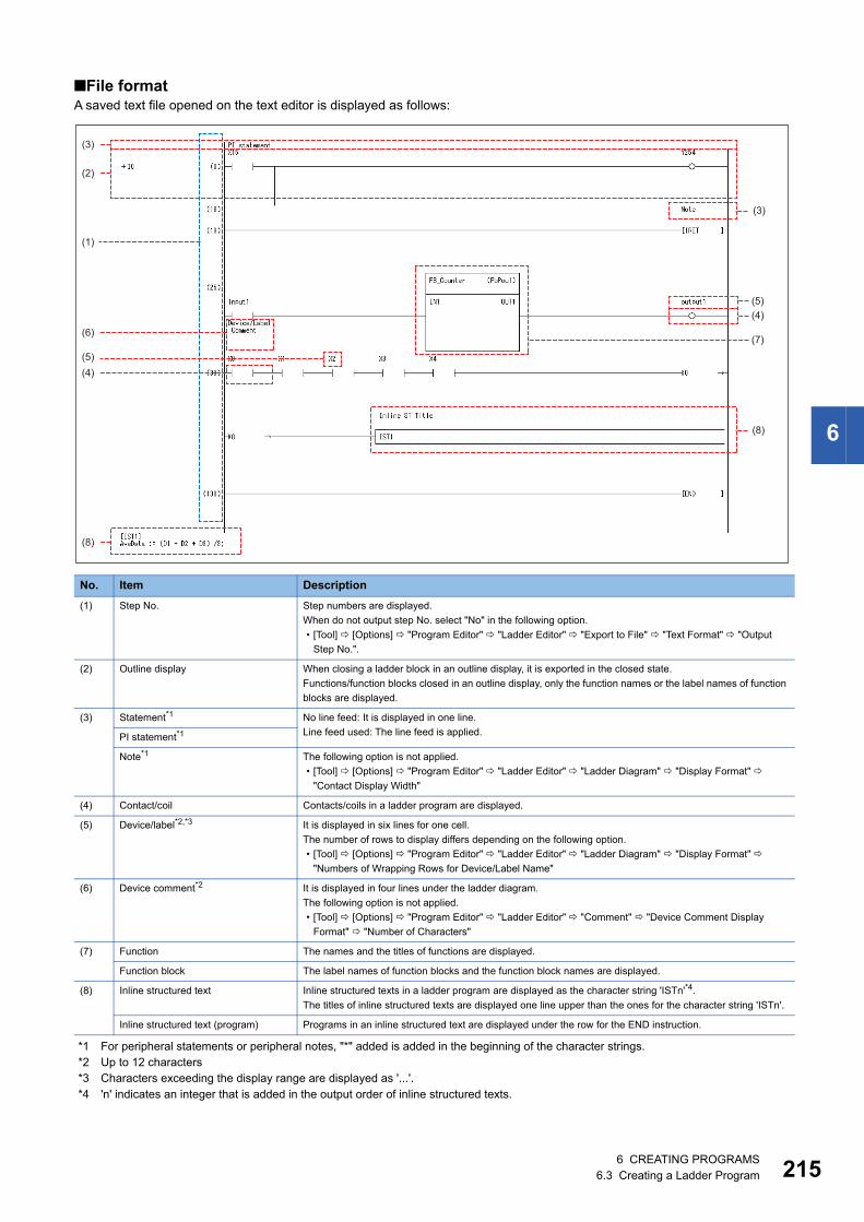
6 CREATING PROGRAMS6.3 Creating a Ladder Program 215
6
■File formatA saved text file opened on the text editor is displayed as follows:
*1 For peripheral statements or peripheral notes, "*" added is added in the beginning of the character strings.*2 Up to 12 characters*3 Characters exceeding the display range are displayed as '...'.*4 'n' indicates an integer that is added in the output order of inline structured texts.
No. Item Description
(1) Step No. Step numbers are displayed.
When do not output step No. select "No" in the following option.
• [Tool] [Options] "Program Editor" "Ladder Editor" "Export to File" "Text Format" "Output
Step No.".
(2) Outline display When closing a ladder block in an outline display, it is exported in the closed state.
Functions/function blocks closed in an outline display, only the function names or the label names of function
blocks are displayed.
(3) Statement*1 No line feed: It is displayed in one line.
Line feed used: The line feed is applied.PI statement*1
Note*1 The following option is not applied.
• [Tool] [Options] "Program Editor" "Ladder Editor" "Ladder Diagram" "Display Format"
"Contact Display Width"
(4) Contact/coil Contacts/coils in a ladder program are displayed.
(5) Device/label*2,*3 It is displayed in six lines for one cell.
The number of rows to display differs depending on the following option.
• [Tool] [Options] "Program Editor" "Ladder Editor" "Ladder Diagram" "Display Format"
"Numbers of Wrapping Rows for Device/Label Name"
(6) Device comment*2 It is displayed in four lines under the ladder diagram.
The following option is not applied.
• [Tool] [Options] "Program Editor" "Ladder Editor" "Comment" "Device Comment Display
Format" "Number of Characters"
(7) Function The names and the titles of functions are displayed.
Function block The label names of function blocks and the function block names are displayed.
(8) Inline structured text Inline structured texts in a ladder program are displayed as the character string 'ISTn'*4.
The titles of inline structured texts are displayed one line upper than the ones for the character string 'ISTn'.
Inline structured text (program) Programs in an inline structured text are displayed under the row for the END instruction.
(3)
(2)
(1)
(3)
(4)
(7)
(8)
(5)
(6)
(5)(4)
(8)
2166 CREATING PROGRAMS6.3 Creating a Ladder Program
Precautions
• Up to 12 characters for one cell, and up to 14 characters for one line
• The file format is Unicode (UTF-16 Little Endian with BOM).
• Grids are not displayed.
• Ladder blocks displayed in an editor can only be exported. (Example: When only a ladder block including a line statement
is displayed)
Exporting to all filesThe following explains the procedure to export ladder programs to a CSV file, HTML file, and text file simultaneously.
For the format of each file and a method to export ladder programs to each format file, refer to the following sections.
Page 209 Exporting to a CSV file
Page 212 Exporting to an HTML file
Page 214 Exporting to a text file
Operating procedure
1. Open the ladder editor, and select [Edit] [Export to File]( ).
2. Enter a file name to export in the "Export to File" screen.
3. Specify "All File Formats(*.csv;*.html;*.txt)" for the file type, and click the [Save] button.

6 CREATING PROGRAMS6.4 Creating an ST Program 217
6
6.4 Creating an ST ProgramThis section explains the creation method of an ST program.
The details on the specification of ST program are described in the following manual. Please read it in advance.
MELSEC iQ-R Programming Manual (Program Design)
MELSEC iQ-F FX5 Programming Manual (Program Design)
The display format and detailed operation settings for each function can be set by setting the following option.
[Tool] [Options] "Program Editor" "ST Editor"
Configuration of ST editorST editor is a language editor in text format for creating programs in Structured Text.
Spaces, tabs, and line feeds can be entered between keywords and variable names of a control syntax.
Terms and symbols that configure the program is referred to as a token.
Window
"Program" "(execution type)" "(program file)" "(program block)" "ProgramBody" in the "Navigation" window
Displayed items
■Toolbar
■ST editor
Item Description Related operation
(1) Icon display area The area to display icons. ■Icon type
Page 218 Icon type
(2) Line number The line numbers of a program. ■Changing display contents
[Tool] [Options] "Program Editor" "ST Editor" "Editor Display
Items"(3) Highlighted
display
The line on which the cursor is placed is highlighted.
(4) Error display A syntax error of the program is displayed.
(5) Outline display Symbols to display/hide the text blocks are displayed. ■Show/Hide
• [Tool] [Options] "Program Editor" "ST Editor" "Editor
Display Items"
• [View] [Outline] [Show/Hide of Outlines]
(6) Tool hint Information where the mouse cursor is placed over is
displayed.
■Changing display contents
[Tool] [Options] [Program Editor] "ST Editor" "Tool Hint"
(5)(2)
(1)
Separation bar
(6)
(4)
(3)

2186 CREATING PROGRAMS6.4 Creating an ST Program
■Colors of programs (default)
Font color, background color, and font can be changed.
Page 65 Checking and Changing Colors and Fonts
■Icon type
■Keywords for collapse and automatic indentA line can be outlined and displayed collapsed by using the keywords shown below. Additionally, pressing the key in a
control syntax inserts an indent automatically.
Figure Description Default color
(1) Control syntax Blue
(2) Device Black
(3) Operator Black
(4) Global label Magenta
(5) Error Red
(6) Local label Magenta
(7) Constant Black
(8) String constant Black
(9) Comment Green
Icon Description
This icon is displayed on the line jumped from the cross reference window.
This icon is displayed on the error line jumped from the "Output" window.
Category Start End Automatic indent
Comment texts (* *)
/* */
Selection statement IF END_IF
CASE END_CASE
While loop FOR END_FOR
WHILE END_WHILE
REPEAT END_REPEAT
6 CREATING PROGRAMS6.4 Creating an ST Program 219
6
Entering programsThis section explains the entering method of an ST program.
For the functions/instructions used in ST programs, refer to the following manuals.
MELSEC iQ-R Programming Manual (Program Design)
MELSEC iQ-F FX5 Programming Manual (Program Design)
Press the ++ keys to enter an assignment operator (:=).
Precautions
When an ST editor is set to read-only or monitoring, the program cannot be edited.
Inserting instructions, functions, and control syntaxThere are two methods for entering instructions, functions, and control syntax: entering texts using keyboard and dragging
and dropping them in the "Element Selection" window.
The input control syntax, operators, devices, and TRUE/FALSE are changed to the upper-case characters automatically.
Labels can be entered with aliases.
■Specification method for data type of deviceNormally, the data type of a word device is handled as INT (Word [Signed]) on the ST editor.
By adding a device type specifier, which indicates a device type, to a device name, a device storing 32-bit integer or real
number can be described directly in an operation formula.
For details, refer to the following manual.
MELSEC iQ-R Programming Manual (Program Design)
MELSEC iQ-F FX5 Programming Manual (Program Design)
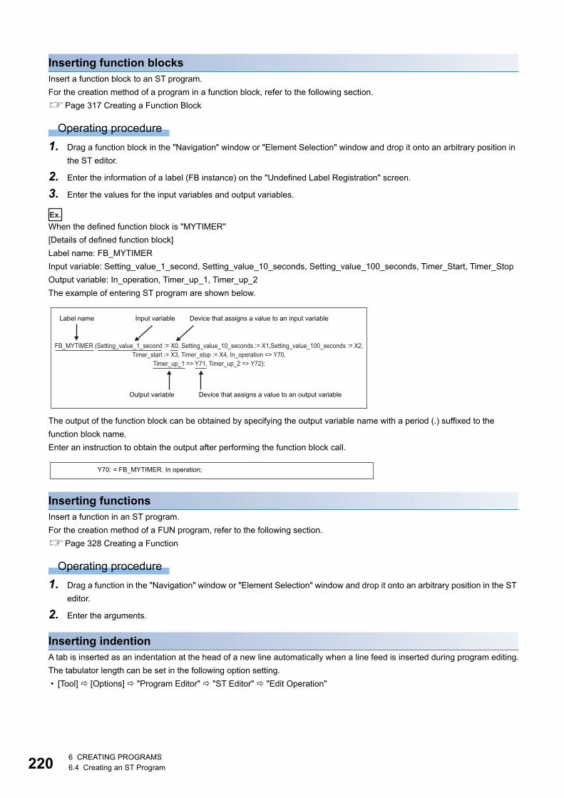
2206 CREATING PROGRAMS6.4 Creating an ST Program
Inserting function blocksInsert a function block to an ST program.
For the creation method of a program in a function block, refer to the following section.
Page 317 Creating a Function Block
Operating procedure
1. Drag a function block in the "Navigation" window or "Element Selection" window and drop it onto an arbitrary position in
the ST editor.
2. Enter the information of a label (FB instance) on the "Undefined Label Registration" screen.
3. Enter the values for the input variables and output variables.
Ex.
When the defined function block is "MYTIMER"
[Details of defined function block]
Label name: FB_MYTIMER
Input variable: Setting_value_1_second, Setting_value_10_seconds, Setting_value_100_seconds, Timer_Start, Timer_Stop
Output variable: In_operation, Timer_up_1, Timer_up_2
The example of entering ST program are shown below.
The output of the function block can be obtained by specifying the output variable name with a period (.) suffixed to the
function block name.
Enter an instruction to obtain the output after performing the function block call.
Inserting functionsInsert a function in an ST program.
For the creation method of a FUN program, refer to the following section.
Page 328 Creating a Function
Operating procedure
1. Drag a function in the "Navigation" window or "Element Selection" window and drop it onto an arbitrary position in the ST
editor.
2. Enter the arguments.
Inserting indentionA tab is inserted as an indentation at the head of a new line automatically when a line feed is inserted during program editing.
The tabulator length can be set in the following option setting.
• [Tool] [Options] "Program Editor" "ST Editor" "Edit Operation"
Label name Input variable Device that assigns a value to an input variable
FB_MYTIMER (Setting_value_1_second := X0, Setting_value_10_seconds := X1,Setting_value_100_seconds := X2, Timer_start := X3, Timer_stop := X4, In_operation => Y70,
Timer_up_1 => Y71, Timer_up_2 => Y72);
Output variable Device that assigns a value to an output variable
Y70: = FB_MYTIMER. In operation;
6 CREATING PROGRAMS6.4 Creating an ST Program 221
6
Inserting commentsEnter a comment which does not affect the program processing. Or, comment out/uncommented the already entered
programs in a batch.
Operating procedure
■Entering comments • When the line is one: Enter a comment after entering slashes '//'.
• When specifying the range: Enclose the comment in '/*' and '*/', or '(*' and '*)'.
■Batch comment out/uncomment of a program
1. Select a range to be commented out or uncommented. (Multiple lines can be selected.)
2. [Edit] [Comment Out of the Selected Range] ( )/[Disable Comment Out of Selected Range] ( )
Registering undefined labelsRegister an undefined label on the label editor.
Operating procedure
1. Enter the label name to be registered on the ST editor.
2. Select the token of a label name, and select [Edit] [Register Label] ( ).
3. Set each item on the "Undefined Label Registration" screen and click the [OK] button.
Displaying syntax templatesSyntax template is a format that defines data type of arguments and format of control syntax which are defined in each
instruction, function, and operator.
The syntax template of the inserted instruction can be displayed on the ST editor.
Operating procedure
1. Select the token of which syntax is to be displayed.
2. Select [Edit] [Display Template] ( ).
3. Enter the arguments in accordance with the displayed template.
Delete the data type name enclosed with '?', and enter a label name or device corresponding to its data type.
Select [Edit] [Mark Template (Left)] ( )/[Mark Template (Right)] ( ), or press the ++/ keys
to select an argument of the template one by one.
2226 CREATING PROGRAMS6.4 Creating an ST Program
Searching/replacing data in a programThe search functions that can be used in ST editor are as follows.
*1 It is searched with a device name excluding a device type specifier.
JumpSpecify a line number and move the cursor on the ST editor.
Operating procedure
1. Select [Find/Replace] [Jump].
2. Enter a line number of the program on the "Jump" screen, and click the [OK] button.
Displaying instruction helpCheck the instructions used in an ST program on e-Manual Viewer.
To check the instructions, the files of the corresponding programming manual requires to be registered to e-Manual Viewer.
The applicability of help display is shown below.
Operating procedure
1. Place the cursor on the token of the target instruction.
2. Press the key.
Function name Description Reference
Jump Specifies a line number on the ST editor, and move to the corresponding line. Page 222 Jump
Cross reference Checks a declaration location and a reference location of a device*1 and a label
in a list.
Page 299 SEARCHING DATA
Device list Checks the usage of devices being used*1.
Find and replace • Searches for and replaces a device name*1, label name, instruction name,
and character strings.
• Changes open/close contact.
• Replaces devices in a batch.
Token type Applicability
Operator
Control syntax
FB
Function
Constant, variable, comment
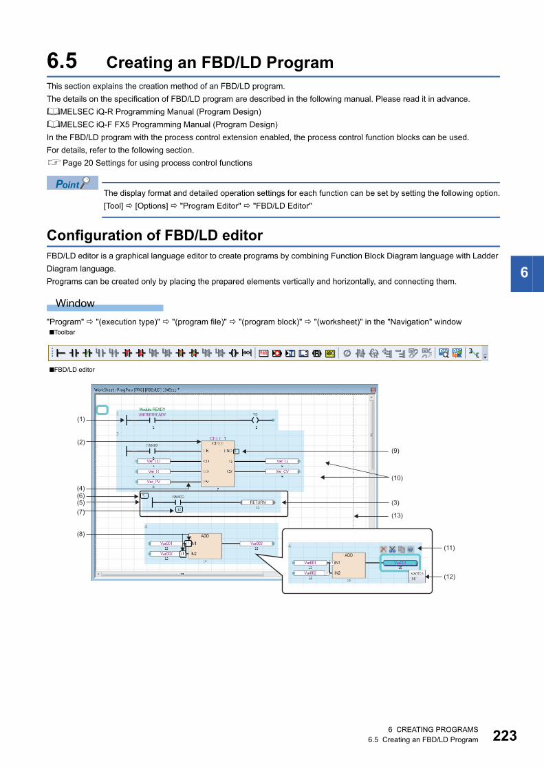
6 CREATING PROGRAMS6.5 Creating an FBD/LD Program 223
6
6.5 Creating an FBD/LD ProgramThis section explains the creation method of an FBD/LD program.
The details on the specification of FBD/LD program are described in the following manual. Please read it in advance.
MELSEC iQ-R Programming Manual (Program Design)
MELSEC iQ-F FX5 Programming Manual (Program Design)
In the FBD/LD program with the process control extension enabled, the process control function blocks can be used.
For details, refer to the following section.
Page 20 Settings for using process control functions
The display format and detailed operation settings for each function can be set by setting the following option.
[Tool] [Options] "Program Editor" "FBD/LD Editor"
Configuration of FBD/LD editorFBD/LD editor is a graphical language editor to create programs by combining Function Block Diagram language with Ladder
Diagram language.
Programs can be created only by placing the prepared elements vertically and horizontally, and connecting them.
Window
"Program" "(execution type)" "(program file)" "(program block)" "(worksheet)" in the "Navigation" window■Toolbar
■FBD/LD editor
(1)
(2)
(4)
(3)
(13)
(11)
(5)
(12)
(7)
(6)
(8)
(10)
(9)

2246 CREATING PROGRAMS6.5 Creating an FBD/LD Program
Displayed items
*1 It is shown or hidden by selecting in the [View] menu.*2 It is shown or hidden according to the setting in [Tool] [Options] "Program Editor" "FBD/LD Editor".
Font color, background color, and font can be changed.
However, for a comment element, only font color and background color can be changed.
Page 65 Checking and Changing Colors and Fonts
Item Description Editing operation
(1) LD element An element that constitutes a ladder program.
Page 225 LD element
■Editing method: Page 228 Entering programs
(2) FBD element An element that constitutes an FBD program.
Page 226 FBD element
(3) Common
element
A common element used regardless of program language.
Page 227 Common element
(4) Connector A line that connects the connection points between elements.
It is displayed by placing an element to be connected closer to the
connection point on the connection target.
(5) FBD network
block
A single FBD network block composed of all elements connected each
other or elements that perform any processing independently (such as
a function block and a jump label).
Maximum 4096 FBD network blocks can be created in a program.
■Release from an FBD network block: Select an element to
be released, and move it with the key held down.
■Layout adjustment: Page 231 Layout correction
(6) FBD network
block No.*1,*2A number assigned for each FBD network block in order from upper left
to lower right on the editor is displayed.
(7) Execution
order*1,*2The program execution order is displayed.
(8) Automatic
connector
When a connector cannot be displayed due to the conditions where an
element is placed, a number is displayed automatically.
The same number of automatic connector indicates that they are
connected.
(9) Connection point A terminal point to connect elements with a connector.
By adding an element while a connection point is being selected, the
element can be added with it connected already.
■Inverting: Page 228 Switching methods for contacts/
instructions
(10) Grid*1,*2 A grid line that serves as makers to place the elements.
(11) Smart tag*2 An operation button displayed around the selected element.
Relevant functions can be performed by clicking the button.
(12) Tool hint*2 The information on device/label and FB/FUN where the mouse cursor
is placed over is displayed.
(13) Page break*1 A line that indicates a page break for printing.
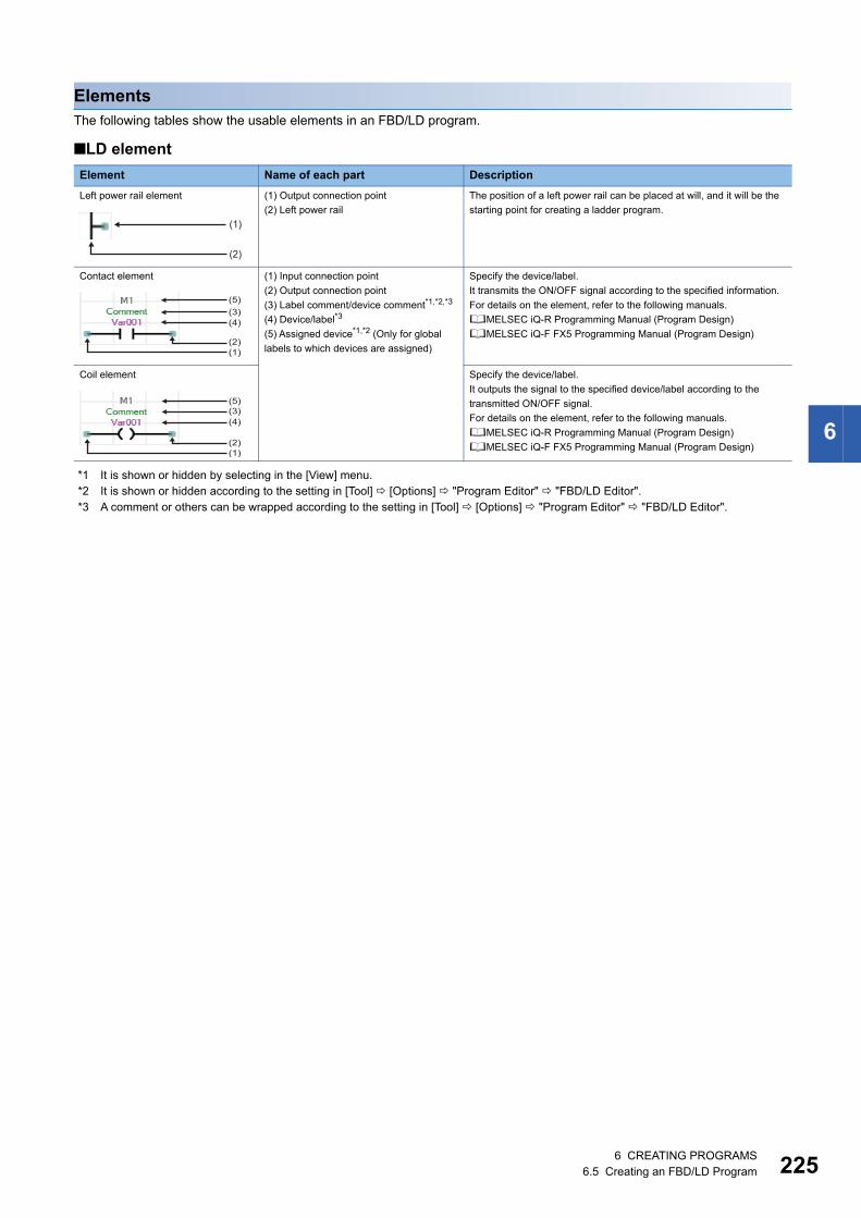
6 CREATING PROGRAMS6.5 Creating an FBD/LD Program 225
6
ElementsThe following tables show the usable elements in an FBD/LD program.
■LD element
*1 It is shown or hidden by selecting in the [View] menu.*2 It is shown or hidden according to the setting in [Tool] [Options] "Program Editor" "FBD/LD Editor".*3 A comment or others can be wrapped according to the setting in [Tool] [Options] "Program Editor" "FBD/LD Editor".
Element Name of each part Description
Left power rail element (1) Output connection point
(2) Left power rail
The position of a left power rail can be placed at will, and it will be the
starting point for creating a ladder program.
Contact element (1) Input connection point
(2) Output connection point
(3) Label comment/device comment*1,*2,*3
(4) Device/label*3
(5) Assigned device*1,*2 (Only for global
labels to which devices are assigned)
Specify the device/label.
It transmits the ON/OFF signal according to the specified information.
For details on the element, refer to the following manuals.
MELSEC iQ-R Programming Manual (Program Design)
MELSEC iQ-F FX5 Programming Manual (Program Design)
Coil element Specify the device/label.
It outputs the signal to the specified device/label according to the
transmitted ON/OFF signal.
For details on the element, refer to the following manuals.
MELSEC iQ-R Programming Manual (Program Design)
MELSEC iQ-F FX5 Programming Manual (Program Design)
(1)
(2)
(1)(2)
(5)(3)(4)
(1)(2)
(5)(3)(4)
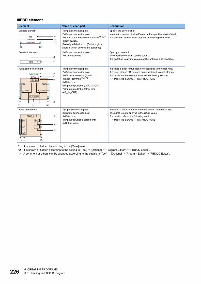
2266 CREATING PROGRAMS6.5 Creating an FBD/LD Program
■FBD element
*1 It is shown or hidden by selecting in the [View] menu.*2 It is shown or hidden according to the setting in [Tool] [Options] "Program Editor" "FBD/LD Editor".*3 A comment or others can be wrapped according to the setting in [Tool] [Options] "Program Editor" "FBD/LD Editor".
Element Name of each part Description
Variable element (1) Input connection point
(2) Output connection point
(3) Label comment/device comment*1,*2,*3
(4) Device/label
(5) Assigned device*1,*2 (Only for global
labels to which devices are assigned)
Specify the device/label.
Information can be obtained/stored in the specified device/label.
It is switched to a constant element by entering a constant.
Constant element (1) Output connection point
(2) Constant value
Specify a constant.
The specified constant can be output.
It is switched to a variable element by entering a device/label.
Function block element (1) Input connection point
(2) Output connection point
(3) FB instance name (label)
(4) Label comment*1,*2,*3
(5) Data type
(6) Input/output label (VAR_IN_OUT)
(7) Input/output label (other than
VAR_IN_OUT)
Indicates a block for function corresponding to the data type.
It is used with an FB instance name assigned to each element.
For details on the element, refer to the following section.
Page 315 SEGMENTING PROGRAMS
Function element (1) Input connection point
(2) Output connection point
(3) Data type
(4) Input/output label (argument)
(5) Return value
Indicates a block for function corresponding to the data type.
The name is not displayed in the return value.
For details, refer to the following section.
Page 315 SEGMENTING PROGRAMS
(1) (2)
(5)(3)(4)
(1)
(2)
(1)
(3)(4)
(5)
(6)(2)(7)
(1) (2)
(3)
(4)
(4)
(5)

6 CREATING PROGRAMS6.5 Creating an FBD/LD Program 227
6
■Common elementFor a jump element and a return element, inverting contact on its connection point is not available.
*1 Only local label that "Pointer" is selected for "Data Type" can be used. In addition, the members of a structure cannot be used.
The color setting of a comment element can individually be changed by using smart tags.
• To set font color, click the smart tag (1).
• To set a background color, click the smart tag (2).
• To clear color settings that individually changed, click the smart tag (3).
(1): Font color
(2): Background color
(3): Clear format
Precautions
When the following settings are changed by operating from the menu or setting an option, the display of a label name/device/
comment/assigned device of an element may overlap with those of another element. Adjust the position of the element.
• Whether or not to display a device/label comment
• Number of rows to display a device/label comment
• Whether or not to display an assigned device
• Number of rows to display a device/label name by wrapping it around
Element Name of each part Description
Jump element (1) Input connection point
(2) Label*1It is used to jump the execution processing from a jump element to a
jump label element.
Jump label element (1) Label*1 Enter a label to be specified as the jump destination.
Connector element (1) Input connection point
(2) Output connection point
(3) Connector label
It is used instead of a connector when placing an FBD network block in
the display range/print range on the editor. The same connector label
indicates that they are connected.
Return element (1) Input connection point
(2) Character string, "RETURN" (Not
editable)
It is used to suspend the processing in the middle of processing.
Comment element (1) Comment display area It is used to enter a comment.
Up to 2000 characters can be entered in a comment element.
The frame size of a comment can be adjusted for the comment length
by placing the mouse cursor on the frame and double-clicking it.
(1)
(2)
(1)
(1)(2)(3)
(1)(2)
(1)
(1)
(3)
(2)
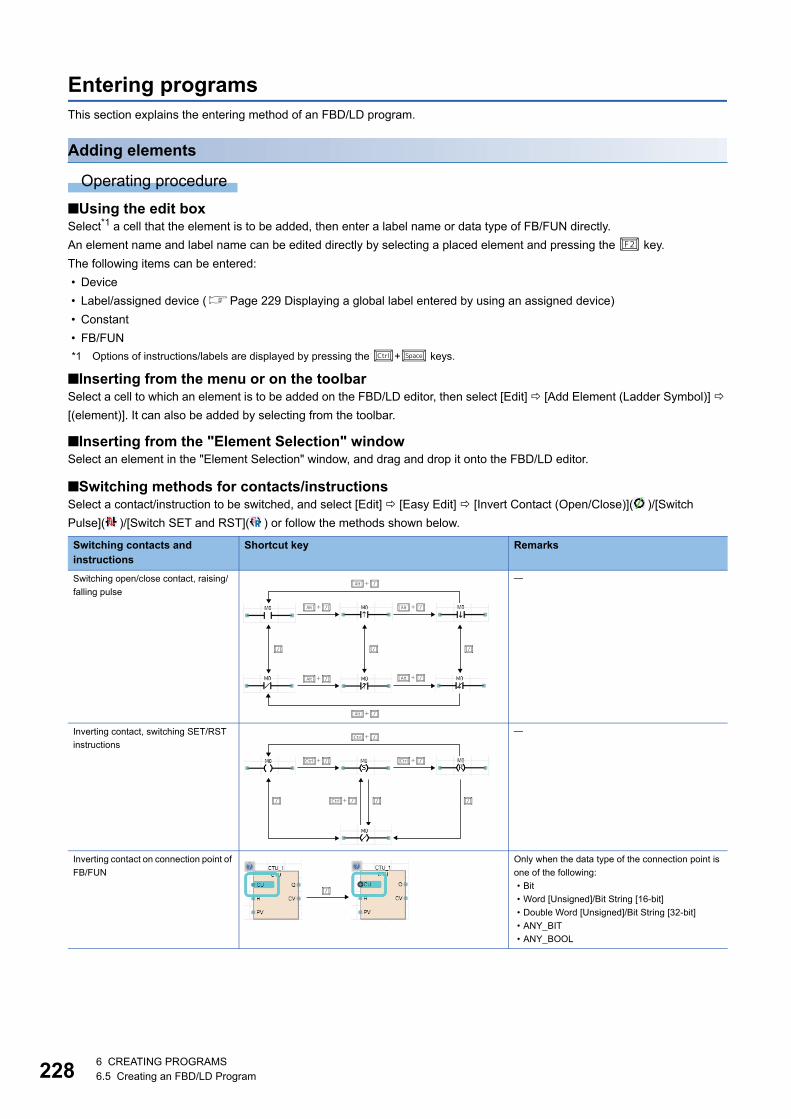
2286 CREATING PROGRAMS6.5 Creating an FBD/LD Program
Entering programsThis section explains the entering method of an FBD/LD program.
Adding elements
Operating procedure
■Using the edit boxSelect*1 a cell that the element is to be added, then enter a label name or data type of FB/FUN directly.
An element name and label name can be edited directly by selecting a placed element and pressing the key.
The following items can be entered:
• Device
• Label/assigned device (Page 229 Displaying a global label entered by using an assigned device)
• Constant
• FB/FUN
*1 Options of instructions/labels are displayed by pressing the + keys.
■Inserting from the menu or on the toolbarSelect a cell to which an element is to be added on the FBD/LD editor, then select [Edit] [Add Element (Ladder Symbol)]
[(element)]. It can also be added by selecting from the toolbar.
■Inserting from the "Element Selection" windowSelect an element in the "Element Selection" window, and drag and drop it onto the FBD/LD editor.
■Switching methods for contacts/instructionsSelect a contact/instruction to be switched, and select [Edit] [Easy Edit] [Invert Contact (Open/Close)]( )/[Switch
Pulse]( )/[Switch SET and RST]( ) or follow the methods shown below.
Switching contacts and instructions
Shortcut key Remarks
Switching open/close contact, raising/
falling pulse
Inverting contact, switching SET/RST
instructions
Inverting contact on connection point of
FB/FUN
Only when the data type of the connection point is
one of the following:
• Bit
• Word [Unsigned]/Bit String [16-bit]
• Double Word [Unsigned]/Bit String [32-bit]
• ANY_BIT
• ANY_BOOL
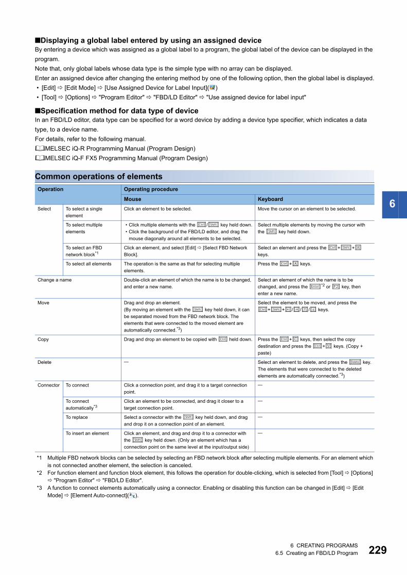
6 CREATING PROGRAMS6.5 Creating an FBD/LD Program 229
6
■Displaying a global label entered by using an assigned deviceBy entering a device which was assigned as a global label to a program, the global label of the device can be displayed in the
program.
Note that, only global labels whose data type is the simple type with no array can be displayed.
Enter an assigned device after changing the entering method by one of the following option, then the global label is displayed.
• [Edit] [Edit Mode] [Use Assigned Device for Label Input]( )
• [Tool] [Options] "Program Editor" "FBD/LD Editor" "Use assigned device for label input"
■Specification method for data type of deviceIn an FBD/LD editor, data type can be specified for a word device by adding a device type specifier, which indicates a data
type, to a device name.
For details, refer to the following manual.
MELSEC iQ-R Programming Manual (Program Design)
MELSEC iQ-F FX5 Programming Manual (Program Design)
Common operations of elements
*1 Multiple FBD network blocks can be selected by selecting an FBD network block after selecting multiple elements. For an element which is not connected another element, the selection is canceled.
*2 For function element and function block element, this follows the operation for double-clicking, which is selected from [Tool] [Options] "Program Editor" "FBD/LD Editor".
*3 A function to connect elements automatically using a connector. Enabling or disabling this function can be changed in [Edit] [Edit Mode] [Element Auto-connect]( ).
Operation Operating procedure
Mouse Keyboard
Select To select a single
element
Click an element to be selected. Move the cursor on an element to be selected.
To select multiple
elements
• Click multiple elements with the / key held down.
• Click the background of the FBD/LD editor, and drag the
mouse diagonally around all elements to be selected.
Select multiple elements by moving the cursor with
the key held down.
To select an FBD
network block*1Click an element, and select [Edit] [Select FBD Network
Block].
Select an element and press the ++
keys.
To select all elements The operation is the same as that for selecting multiple
elements.
Press the + keys.
Change a name Double-click an element of which the name is to be changed,
and enter a new name.
Select an element of which the name is to be
changed, and press the *2 or key, then
enter a new name.
Move Drag and drop an element.
(By moving an element with the key held down, it can
be separated moved from the FBD network block. The
elements that were connected to the moved element are
automatically connected.*3)
Select the element to be moved, and press the
++/// keys.
Copy Drag and drop an element to be copied with held down. Press the + keys, then select the copy
destination and press the + keys. (Copy +
paste)
Delete Select an element to delete, and press the key.
The elements that were connected to the deleted
elements are automatically connected.*3)
Connector To connect Click a connection point, and drag it to a target connection
point.
To connect
automatically*3Click an element to be connected, and drag it closer to a
target connection point.
To replace Select a connector with the key held down, and drag
and drop it on a connection point of an element.
To insert an element Click an element, and drag and drop it to a connector with
the key held down. (Only an element which has a
connection point on the same level at the input/output side)

2306 CREATING PROGRAMS6.5 Creating an FBD/LD Program
Replacing function elements/function block elements
Operating procedure
1. Select a function element/function block element.
2. Select [Edit] [Change FB/FUN Data], and enter the data type to be changed.
An element can also be replaced by dragging it from the "Element Selection" window and dropping it onto the
element to be replaced.
For function elements, similarly, the data type can be changed by selecting a function element and entering a
new data type directly.
Adding/deleting argumentsOnly for a function of which the number of arguments can be changed, an argument can be added/deleted.
Operating procedure
1. Move the cursor on a function element.
2. Select [Edit] [I/O Argument] [Increment Argument] ( )/[Delete Argument] ( ).
FB/FUN whose definition is unclearWhen the definition is unclear due to the deletion or change of pasted element, an error occurs and the element is displayed
as shown below.
When the definition is changed, select the element, and select [Edit] [Update FB/FUN] to update the definition information.
When there is no definition, select the element, and select [Edit] [Change FB/FUN Data] to change the data.
Adjusting position automaticallyWhen an element is added or moved, the position is adjusted automatically to avoid the overlap with others.
When a rectangular area of an FBD network block (area comprises elements connected with connectors and additional one
cell to each direction) overlaps with another area, the position is automatically adjusted so that the entire block does not
overlap.
However, comment elements can be superimposed since it is not subject for the automatic adjustment.
Order of comment elementsWhen comment elements are overlapped, the comment element added later is displayed at the front.
The order of comment elements can be changed in [Edit] [Order Comment] [Bring to Front]/[Bring Forward]/[Send
Backward]/[Send to Back].
After changing the order of comment elements, the elements will be in the unconverted state.
6 CREATING PROGRAMS6.5 Creating an FBD/LD Program 231
6
Layout correction
Operating procedure
■Inserting a rowSelect a cell in a row to be inserted, then select [Edit] [Layout] [Insert Row].
A new row is inserted on the selected cell.
■Deleting a rowSelect a cell in a row to be deleted, then select [Edit] [Layout] [Delete Row].
The row including the selected cell is deleted. When the row includes any elements, the row cannot be deleted.
■Inserting/deleting a columnMove the cursor onto an FBD network block in which a column will be inserted/deleted, then select [Edit] [Layout] [Insert
Column(in FBD network block)]/[Delete Column(in FBD network block)].
A column is inserted/deleted in the range of the FBD network block.
■Inserting multiple rowsSelect a cell in a row to be inserted, then select [Edit] [Layout] [Insert Multiple Rows].
Enter the number of rows to be inserted on the "Insert Multiple Rows" screen.
A new row is inserted on the selected cell.
■Deleting multiple rowsSelect a cell in a row to be deleted, then select [Edit] [Layout] [Delete Multiple Rows].
Enter the number of rows to be deleted on the "Delete Multiple Rows" screen.
The number of rows that has been set above is deleted from the row under the selected cell.
When the rows to be deleted include any element, a row upper than the row in which the element exists is deleted.
■Correcting layout in an FBD network blockSelect an FBD network block including elements to be corrected, and select [Edit] [Layout] [Layout Correction in FBD
Network Block].
The layout in the selected FBD network block is corrected.
■Correcting layout in an FBD network block in a batchSelect [Edit] [Layout] [Batch Correction of Layout in FBD Network Block].
The layout of all the FBD network blocks in the worksheet is corrected.
■Deleting a blank row between FBD network blocksSelect [Edit] [Layout] [Delete the Blank Row Between FBD Network Blocks].
The row between an FBD network block or elements will be deleted.
■Aligning FBD network blocks to the left side in a batchSelect [Edit] [Layout] [Batch Alignment of All FBD Network Blocks to the Left].
All FBD network blocks can be aligned to the left side of the FBD/LD editor.
When multiple FBD network blocks are included on the same line, the blank column between the blocks are retained.
The details of 'Layout Correction in FBD Network Block' and 'Batch Correction of Layout in FBD Network
Block' can be set in the following option.
• [Tool] [Options] "Program Editor" "FBD/LD Editor" "FBD Network Block" "Layout Correction in
FBD Network Block"
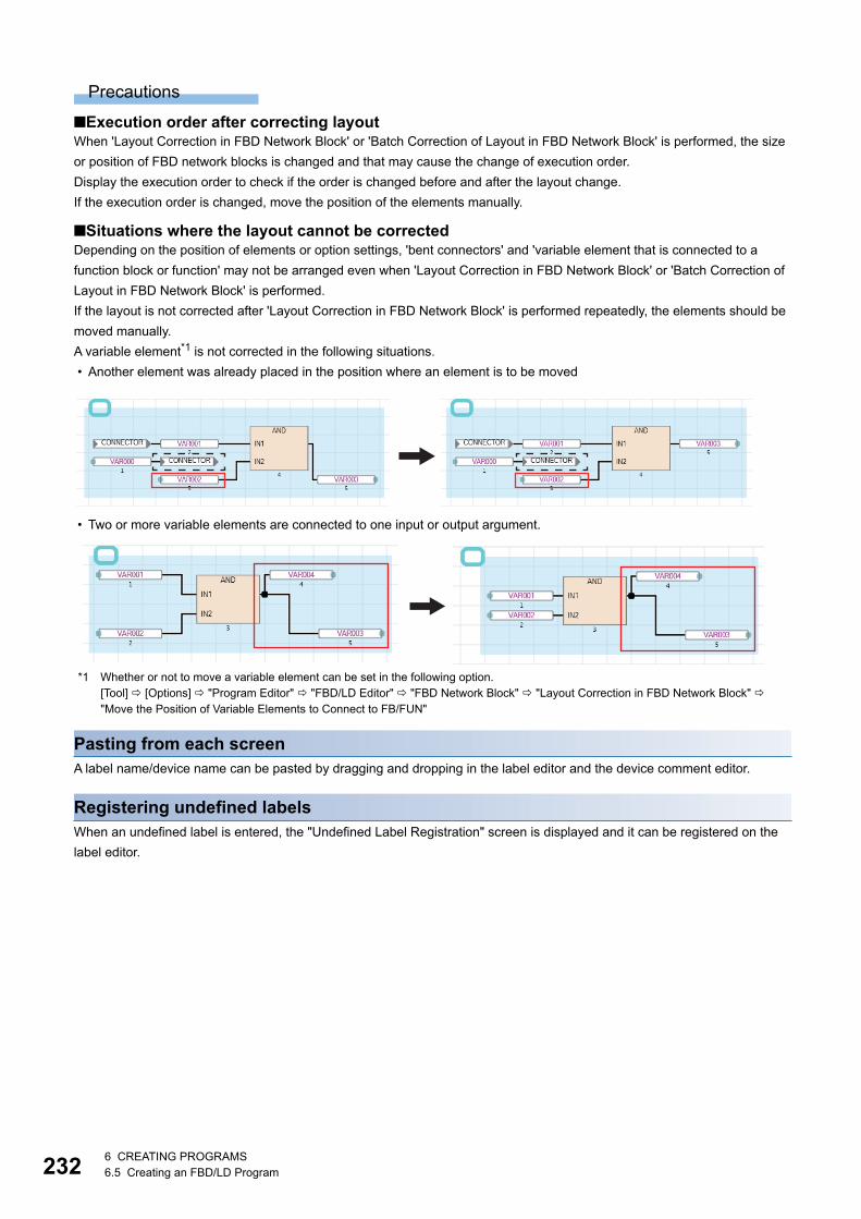
2326 CREATING PROGRAMS6.5 Creating an FBD/LD Program
Precautions
■Execution order after correcting layoutWhen 'Layout Correction in FBD Network Block' or 'Batch Correction of Layout in FBD Network Block' is performed, the size
or position of FBD network blocks is changed and that may cause the change of execution order.
Display the execution order to check if the order is changed before and after the layout change.
If the execution order is changed, move the position of the elements manually.
■Situations where the layout cannot be correctedDepending on the position of elements or option settings, 'bent connectors' and 'variable element that is connected to a
function block or function' may not be arranged even when 'Layout Correction in FBD Network Block' or 'Batch Correction of
Layout in FBD Network Block' is performed.
If the layout is not corrected after 'Layout Correction in FBD Network Block' is performed repeatedly, the elements should be
moved manually.
A variable element*1 is not corrected in the following situations.
• Another element was already placed in the position where an element is to be moved
• Two or more variable elements are connected to one input or output argument.
*1 Whether or not to move a variable element can be set in the following option.[Tool] [Options] "Program Editor" "FBD/LD Editor" "FBD Network Block" "Layout Correction in FBD Network Block" "Move the Position of Variable Elements to Connect to FB/FUN"
Pasting from each screenA label name/device name can be pasted by dragging and dropping in the label editor and the device comment editor.
Registering undefined labelsWhen an undefined label is entered, the "Undefined Label Registration" screen is displayed and it can be registered on the
label editor.
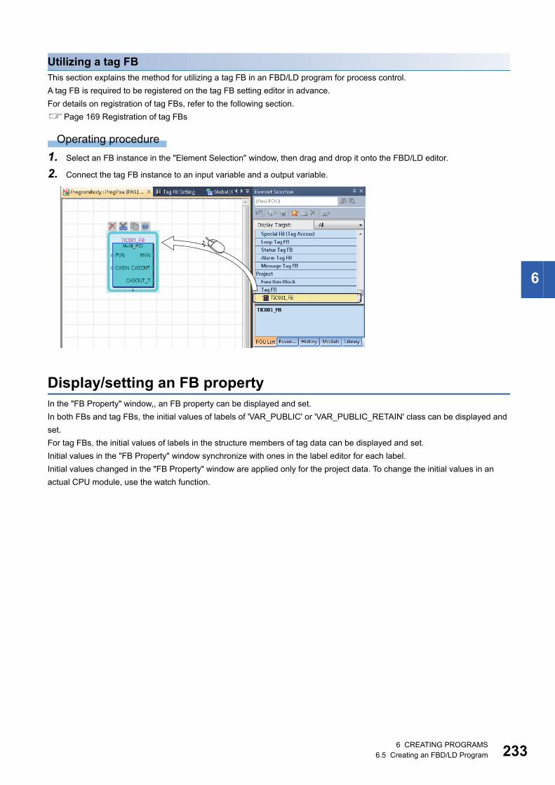
6 CREATING PROGRAMS6.5 Creating an FBD/LD Program 233
6
Utilizing a tag FBThis section explains the method for utilizing a tag FB in an FBD/LD program for process control.
A tag FB is required to be registered on the tag FB setting editor in advance.
For details on registration of tag FBs, refer to the following section.
Page 169 Registration of tag FBs
Operating procedure
1. Select an FB instance in the "Element Selection" window, then drag and drop it onto the FBD/LD editor.
2. Connect the tag FB instance to an input variable and a output variable.
Display/setting an FB propertyIn the "FB Property" window,, an FB property can be displayed and set.
In both FBs and tag FBs, the initial values of labels of 'VAR_PUBLIC' or 'VAR_PUBLIC_RETAIN' class can be displayed and
set.
For tag FBs, the initial values of labels in the structure members of tag data can be displayed and set.
Initial values in the "FB Property" window synchronize with ones in the label editor for each label.
Initial values changed in the "FB Property" window are applied only for the project data. To change the initial values in an
actual CPU module, use the watch function.
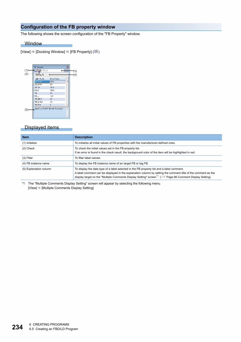
2346 CREATING PROGRAMS6.5 Creating an FBD/LD Program
Configuration of the FB property windowThe following shows the screen configuration of the "FB Property" window.
Window
[View] [Docking Window] [FB Property] ( )
Displayed items
*1 The "Multiple Comments Display Setting" screen will appear by selecting the following menu.[View] [Multiple Comments Display Setting]
Item Description
(1) Initialize To initialize all initial values of FB properties with the manufacturer-defined ones.
(2) Check To check the initial values set in the FB property list.
If an error is found in the check result, the background color of the item will be highlighted in red.
(3) Filter To filter label names.
(4) FB instance name To display the FB instance name of an target FB or tag FB.
(5) Explanation column To display the data type of a label selected in the FB property list and a label comment.
A label comment can be displayed in the explanation column by setting the comment title of the comment as the
display target on the "Multiple Comments Display Setting" screen*1. (Page 66 Comment Display Setting)
(3)(4)
(5)
(1)(2)
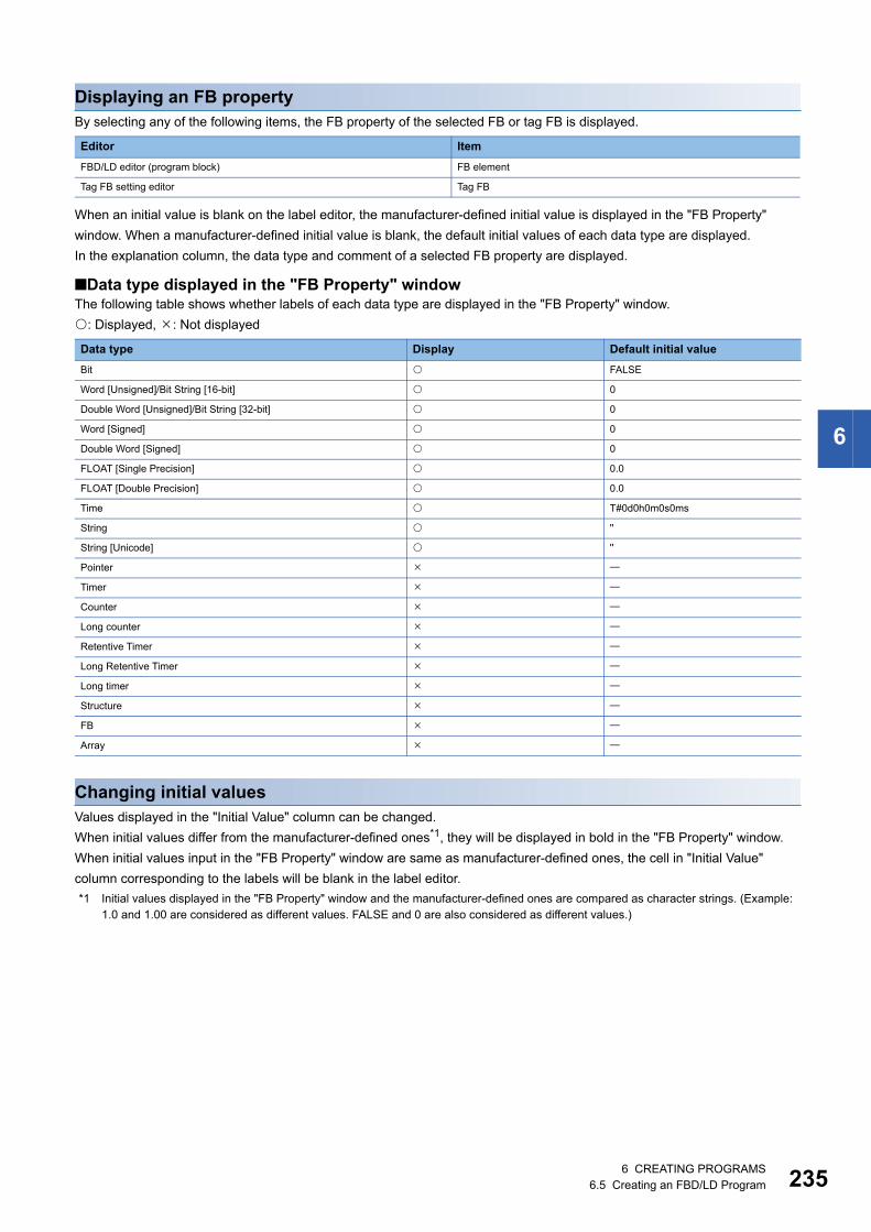
6 CREATING PROGRAMS6.5 Creating an FBD/LD Program 235
6
Displaying an FB propertyBy selecting any of the following items, the FB property of the selected FB or tag FB is displayed.
When an initial value is blank on the label editor, the manufacturer-defined initial value is displayed in the "FB Property"
window. When a manufacturer-defined initial value is blank, the default initial values of each data type are displayed.
In the explanation column, the data type and comment of a selected FB property are displayed.
■Data type displayed in the "FB Property" windowThe following table shows whether labels of each data type are displayed in the "FB Property" window.
: Displayed, : Not displayed
Changing initial valuesValues displayed in the "Initial Value" column can be changed.
When initial values differ from the manufacturer-defined ones*1, they will be displayed in bold in the "FB Property" window.
When initial values input in the "FB Property" window are same as manufacturer-defined ones, the cell in "Initial Value"
column corresponding to the labels will be blank in the label editor.
*1 Initial values displayed in the "FB Property" window and the manufacturer-defined ones are compared as character strings. (Example: 1.0 and 1.00 are considered as different values. FALSE and 0 are also considered as different values.)
Editor Item
FBD/LD editor (program block) FB element
Tag FB setting editor Tag FB
Data type Display Default initial value
Bit FALSE
Word [Unsigned]/Bit String [16-bit] 0
Double Word [Unsigned]/Bit String [32-bit] 0
Word [Signed] 0
Double Word [Signed] 0
FLOAT [Single Precision] 0.0
FLOAT [Double Precision] 0.0
Time T#0d0h0m0s0ms
String ''
String [Unicode] ''
Pointer
Timer
Counter
Long counter
Retentive Timer
Long Retentive Timer
Long timer
Structure
FB
Array
2366 CREATING PROGRAMS6.5 Creating an FBD/LD Program
Linking a commentA comment element is simultaneously moved with an element by linking them.
The link of a comment can be set for an element except for a connector, an input/output argument of an FB/FUN, and a
comment element.
Multiple comment elements can be linked with a single element.
The link of a comment element can be set only for a single element.
To change the link of a comment element to another, release the link first.
Linking a single comment element with a single elementSet a link between a comment element and an element.
Operating procedure
1. Select a comment element and an element.
2. Select [Edit] [Easy Edit] [Link Comment].
After this setting, the background of the linked comment element is changed.
Releasing linksReleasing the links between a comment element and an element.
All links can be released by selecting an element linking with multiple comment elements and releasing them.
Operating procedure
1. Select a comment element linking with an element.
2. Select [Edit] [Easy Edit] [Unlink Comment].
After the setting, the link between a comment element and an element is released and the background color of the comment
element is restored.
Linking comment elements and elements in a batchSet the links of unlinked comment elements in a batch in the active FBD/LD editor.
Operating procedure
Select [Edit] [Easy Edit] [Comment Batch Link].
After this setting, the background of the linked comment element is changed.

6 CREATING PROGRAMS6.5 Creating an FBD/LD Program 237
6
■Conditions for determining the link target of a comment in a batch linkingIn a batch linking, a comment element is automatically linked with an element that satisfies the following conditions in the
order mentioned below.
1. The link is set to the closest element that is found by searching in the red frame (range with a width of one comment
element and five cells to the right and the depth of the comment element and five cells downward). It is searched from
the upper left of the range to lower right.
2. When no element is found in the procedure above, the link is set to the closest element that is found by searching in the
blue frame (range with five cells to the left from one comment element and a depth of the comment element and five cells
downward). It is searched from the upper right of the range to lower left.
Any link is not set if no element that is to be the link target is found in the conditions above.
Operation when linking comments
■Selecting a single element in ones with linksBy selecting an element with a link, all elements linking with it are selected.
To select one element without releasing the link, click the target element twice or select it with held down.
■Editing an element with a linkWhen copying a comment element and element that link each other, the link is remained after the copy.
When deleting a comment element or element that link each other, the link is released.
■Correcting the element layoutWhen arranging the element layout by the following menu, the comment element linking with the element does not
synchronize with it.
• [Edit] [Layout] [Insert Row]
• [Edit] [Layout] [Delete Row]
• [Edit] [Layout] [Insert Column(in FBD Network Block)]
• [Edit] [Layout] [Delete Column(in FBD Network Block)]
• [Edit] [Layout] [Insert Multiple Rows]
• [Edit] [Layout] [Delete Multiple Rows]
+5+5
+5
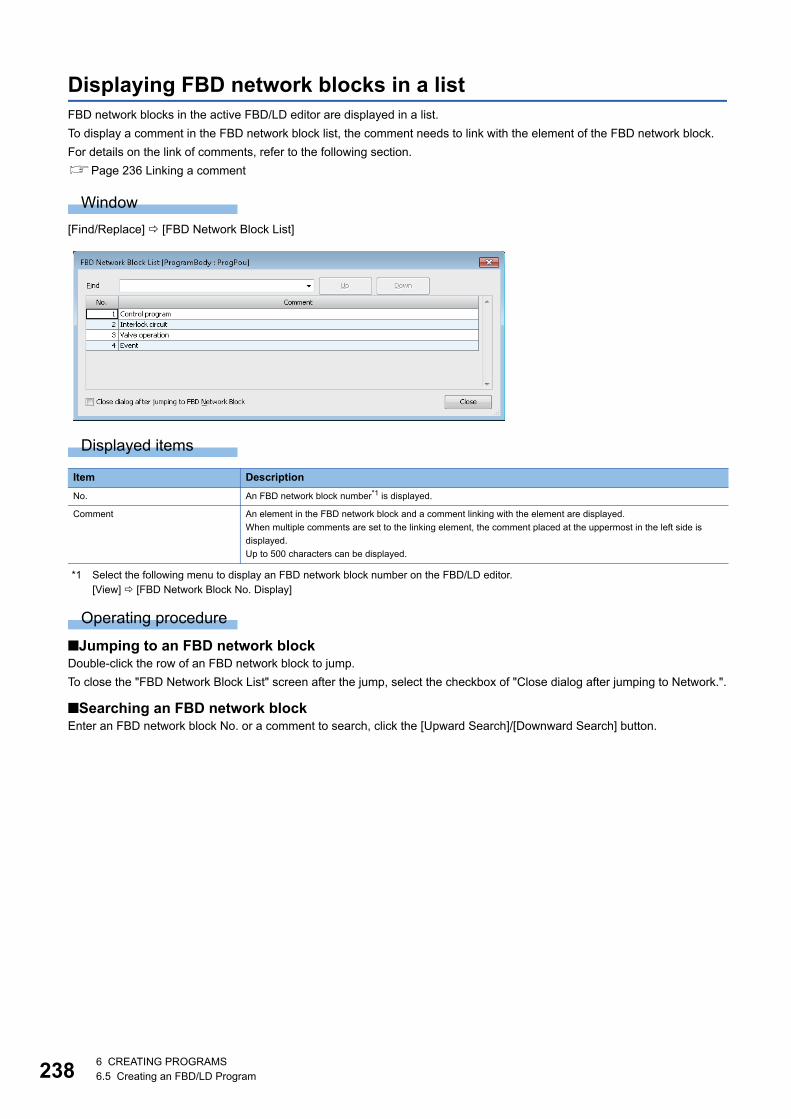
2386 CREATING PROGRAMS6.5 Creating an FBD/LD Program
Displaying FBD network blocks in a listFBD network blocks in the active FBD/LD editor are displayed in a list.
To display a comment in the FBD network block list, the comment needs to link with the element of the FBD network block.
For details on the link of comments, refer to the following section.
Page 236 Linking a comment
Window
[Find/Replace] [FBD Network Block List]
Displayed items
*1 Select the following menu to display an FBD network block number on the FBD/LD editor.[View] [FBD Network Block No. Display]
Operating procedure
■Jumping to an FBD network blockDouble-click the row of an FBD network block to jump.
To close the "FBD Network Block List" screen after the jump, select the checkbox of "Close dialog after jumping to Network.".
■Searching an FBD network blockEnter an FBD network block No. or a comment to search, click the [Upward Search]/[Downward Search] button.
Item Description
No. An FBD network block number*1 is displayed.
Comment An element in the FBD network block and a comment linking with the element are displayed.
When multiple comments are set to the linking element, the comment placed at the uppermost in the left side is
displayed.
Up to 500 characters can be displayed.

6 CREATING PROGRAMS6.5 Creating an FBD/LD Program 239
6
Searching/replacing data in a programThe search functions that can be used in FBD/LD editor are as follows.
Displaying HelpCheck the elements used in the FBD/LD program on e-Manual Viewer.
To check, the files of the corresponding programming manuals requires to be registered in e-Manual Viewer.
Operating procedure
1. Select the element to be checked.
2. Press the key.
Function name Description Reference
Cross reference Checks a declaration location and a reference location of a device and a label
in a list.
Page 299 SEARCHING DATA
Device list Checks the usage of devices being used.
Find and replace • Searches for and replaces a device name, label name, instruction name,
and character strings.
• Changes open/close contact.
• Replaces devices in a batch.
2406 CREATING PROGRAMS6.6 Creating an SFC Program
6.6 Creating an SFC ProgramThis section explains the creation method of SFC program.
The details on the specification of SFC program are described in the following manual. Please read it in advance.
MELSEC iQ-R Programming Manual (Program Design)
FX5CPUs do not support it.
The display format and detailed operation settings for each function can be set by setting the following option.
[Tool] [Options] "Program Editor" "SFC Diagram Editor"
Creation procedure1. Set the point of step relay (S) in "Device Setting" of "CPU Parameter". (The default is set as 0 points.)
2. Create new SFC data. (Page 108 Creating data)
3. Configure the following settings if needed.
• "SFC Setting" in "CPU Parameter"
• 'Act at Block Multi-Activated' which is set for a program file
• 'SFC information device' which is set for a block (block information)
For details, refer to the following manual.
MELSEC iQ-R Programming Manual (Program Design)
4. Open the SFC diagram editor, then create an SFC diagram. (Page 245 Creating SFC diagrams)
5. Edit a program of action/transition. (Page 263 Creating/displaying Zooms (action/transition))
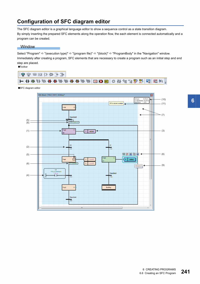
6 CREATING PROGRAMS6.6 Creating an SFC Program 241
6
Configuration of SFC diagram editorThe SFC diagram editor is a graphical language editor to show a sequence control as a state transition diagram.
By simply inserting the prepared SFC elements along the operation flow, the each element is connected automatically and a
program can be created.
Window
Select "Program" "(execution type)" "(program file)" "(block)" "ProgramBody" in the "Navigation" window.
Immediately after creating a program, SFC elements that are necessary to create a program such as an initial step and end
step are placed.■Toolbar
■SFC diagram editor
(4)
(1)
(2)
(3)
(10)
(8)
(9)
(6)(5)
(5)
(7)
(11)
(6)
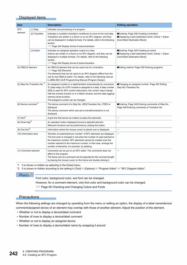
2426 CREATING PROGRAMS6.6 Creating an SFC Program
Displayed items
*1 It is shown or hidden by selecting in the [View] menu.*2 It is shown or hidden according to the setting in [Tool] [Options] "Program Editor" "SFC Diagram Editor".
Font color, background color, and font can be changed.
However, for a comment element, only font color and background color can be changed.
Page 65 Checking and Changing Colors and Fonts
Precautions
When the following settings are changed by operating from the menu or setting an option, the display of a label name/device/
comment/assigned device of an element may overlap with those of another element. Adjust the position of the element.
• Whether or not to display a device/label comment
• Number of rows to display a device/label comment
• Whether or not to display an assigned device
• Number of rows to display a device/label name by wrapping it around
Item Description Editing operation
SFC
element
(1) Step Indicates one processing of a program.
(2) Transition Indicates a condition (transition conditions) to move to the next step.
Transitions are written in a Zoom or on an SFC diagram, and they
can be displayed in multiple formats. For details, refer to the following
section.
Page 244 Display format of action/transition
■Entering: Page 248 Creating a transition
■Displaying a start destination block: [View] [Open
Zoom/Start Destination Block]
(3) Action Indicates an assigned operation output to a step.
Actions are written in a Zoom or an SFC diagram, and they can be
displayed in multiple formats. For details, refer to the following
section.
Page 244 Display format of action/transition
■Entering: Page 249 Creating an action
■Displaying a start destination block: [View] [Open
Zoom/Start Destination Block]
(4) FBD/LD element An FBD/LD element that can be used only for a transition.
Page 225 Elements
The elements that can be used on an SFC diagram differs from the
one for the FBD/LD editor. For details, refer to the following manual.
MELSEC iQ-R Programming Manual (Program Design)
■Editing method: Page 228 Entering programs
(5) Step No./Transition No.*1 An assigned number to a step/transition automatically by conversion.
'S' (step relay) of a CPU module is assigned to a step. A step number
(S) is used for SFC control instructions, the current value change
with the monitor function or in a Watch window, and the data logging/
memory dump function.
The assigned number can be changed.
■Changing an assigned number: Page 262 Editing
Step No./Transition No.
(6) Device comment*1 The device comment of a Step No. (S)/Transition No. (TR) is
displayed.
The device comment which was set to transitions/actions is not
displayed.
■Entering: Page 246 Entering comments of Step No.,
Page 248 Entering comments of Transition No.
(7) Grid*1 A grid line that serves as makers to place the elements.
(8) Smart tag*2 An operation button displayed around a selected element.
Relevant functions can be performed by clicking the button.
(9) Tool hint*2 Information where the mouse cursor is placed over is displayed.
(10) Information area "Number of used/maximum number" of SFC elements are displayed.
The font color is changed in red when the number of used reached to
the maximum number. SFC elements cannot be created once the
number reached to the maximum number. In that case, arrange the
number of elements, for example, by deleting.
(11) Comment element Comments can be put on an SFC editor. The comments does not
affect to the program.
The frame size of a comment can be adjusted for the comment length
by placing the mouse cursor on the frame and double-clicking it.
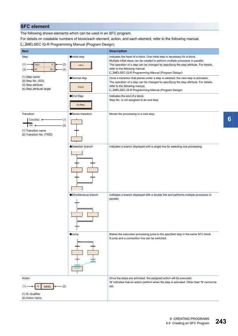
6 CREATING PROGRAMS6.6 Creating an SFC Program 243
6
SFC elementThe following shows elements which can be used in an SFC program.
For details on creatable numbers of block/each element, action, and each element, refer to the following manual.
MELSEC iQ-R Programming Manual (Program Design)
Item Description
Step
(1) Step name
(2) Step No. (S)
(3) Step attribute
(4) Step attribute target
■Initial step Indicates the head of a block. One initial step is necessary for a block.
Multiple initial steps can be created to perform multiple processes in parallel.
The operation of a step can be changed by specifying the step attribute. For details,
refer to the following manual.
MELSEC iQ-R Programming Manual (Program Design)
■Normal step Once a transition that places under a step is satisfied, the next step is activated.
The operation of a step can be changed by specifying the step attribute. For details,
refer to the following manual.
MELSEC iQ-R Programming Manual (Program Design)
■End Step Indicates the end of a block.
Step No. is not assigned to an end step.
Transition
(1) Transition name
(2) Transition No. (TR)
■Series transition Moves the processing to a next step.
■Selection branch Indicates a branch displayed with a single line for selecting one processing.
■Simultaneous branch Indicates a branch displayed with a double line and performs multiple processes in
parallel.
■Jump Makes the execution processing jump to the specified step in the same SFC block.
A jump and a connection line can be switched.
Action
(1) N: Qualifier
(2) Action name
Once the steps are activated, the assigned action will be executed.
'N' indicates that an action perform when the step is activated. Other than 'N' cannot be
set.
(1) (2)
(3) (4)
(1)
(2)
(1) (2)
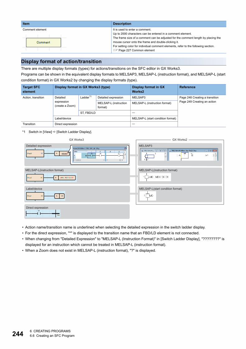
2446 CREATING PROGRAMS6.6 Creating an SFC Program
Display format of action/transitionThere are multiple display formats (types) for actions/transitions on the SFC editor in GX Works3.
Programs can be shown in the equivalent display formats to MELSAP3, MELSAP-L (instruction format), and MELSAP-L (start
condition format) in GX Works2 by changing the display formats (type).
*1 Switch in [View] [Switch Ladder Display].
• Action name/transition name is underlined when selecting the detailed expression in the switch ladder display.
• For the direct expression, "*" is displayed to the transition name that an FBD/LD element is not connected.
• When changing from "Detailed Expression" to "MELSAP-L (Instruction Format)" in [Switch Ladder Display], "????????" is
displayed for an instruction which cannot be treated in MELSAP-L (instruction format).
• When a Zoom does not exist in MELSAP-L (instruction format), "?" is displayed.
Comment element It is used to enter a comment.
Up to 2000 characters can be entered in a comment element.
The frame size of a comment can be adjusted for the comment length by placing the
mouse cursor onto the frame and double-clicking it.
For setting color for individual comment elements, refer to the following section.
Page 227 Common element
Target SFC element
Display format in GX Works3 (type) Display format in GX Works2
Reference
Action, transition Detailed
expression
(create a Zoom)
Ladder*1 Detailed expression MELSAP3 Page 248 Creating a transition
Page 249 Creating an actionMELSAP-L (instruction
format)
MELSAP-L (instruction format)
ST, FBD/LD
Label/device MELSAP-L (start condition format)
Transition Direct expression
Item Description
GX Works3 GX Works2
Detailed expression
Label/device
Direct expression
MELSAP-L(start condition format)
MELSAP-L(instruction format)MELSAP-L(instruction format)
MELSAP3
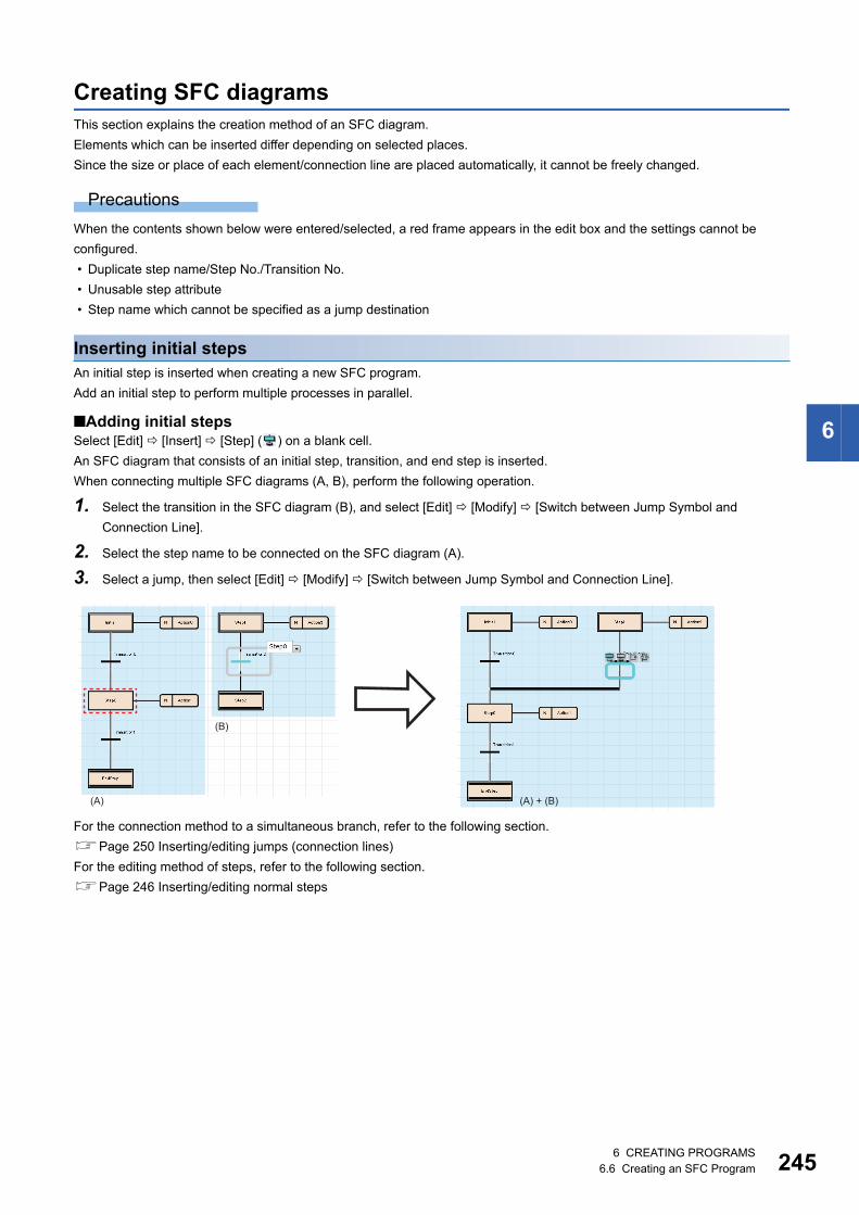
6 CREATING PROGRAMS6.6 Creating an SFC Program 245
6
Creating SFC diagramsThis section explains the creation method of an SFC diagram.
Elements which can be inserted differ depending on selected places.
Since the size or place of each element/connection line are placed automatically, it cannot be freely changed.
Precautions
When the contents shown below were entered/selected, a red frame appears in the edit box and the settings cannot be
configured.
• Duplicate step name/Step No./Transition No.
• Unusable step attribute
• Step name which cannot be specified as a jump destination
Inserting initial stepsAn initial step is inserted when creating a new SFC program.
Add an initial step to perform multiple processes in parallel.
■Adding initial stepsSelect [Edit] [Insert] [Step] ( ) on a blank cell.
An SFC diagram that consists of an initial step, transition, and end step is inserted.
When connecting multiple SFC diagrams (A, B), perform the following operation.
1. Select the transition in the SFC diagram (B), and select [Edit] [Modify] [Switch between Jump Symbol and
Connection Line].
2. Select the step name to be connected on the SFC diagram (A).
3. Select a jump, then select [Edit] [Modify] [Switch between Jump Symbol and Connection Line].
For the connection method to a simultaneous branch, refer to the following section.
Page 250 Inserting/editing jumps (connection lines)
For the editing method of steps, refer to the following section.
Page 246 Inserting/editing normal steps
(B)
(A) (A) + (B)
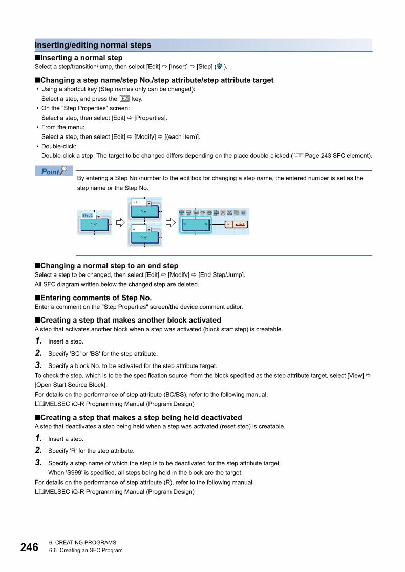
2466 CREATING PROGRAMS6.6 Creating an SFC Program
Inserting/editing normal steps
■Inserting a normal stepSelect a step/transition/jump, then select [Edit] [Insert] [Step] ( ).
■Changing a step name/step No./step attribute/step attribute target • Using a shortcut key (Step names only can be changed):
Select a step, and press the key.
• On the "Step Properties" screen:
Select a step, then select [Edit] [Properties].
• From the menu:
Select a step, then select [Edit] [Modify] [(each item)].
• Double-click:
Double-click a step. The target to be changed differs depending on the place double-clicked (Page 243 SFC element).
By entering a Step No./number to the edit box for changing a step name, the entered number is set as the
step name or the Step No.
■Changing a normal step to an end stepSelect a step to be changed, then select [Edit] [Modify] [End Step/Jump].
All SFC diagram written below the changed step are deleted.
■Entering comments of Step No.Enter a comment on the "Step Properties" screen/the device comment editor.
■Creating a step that makes another block activatedA step that activates another block when a step was activated (block start step) is creatable.
1. Insert a step.
2. Specify 'BC' or 'BS' for the step attribute.
3. Specify a block No. to be activated for the step attribute target.
To check the step, which is to be the specification source, from the block specified as the step attribute target, select [View]
[Open Start Source Block].
For details on the performance of step attribute (BC/BS), refer to the following manual.
MELSEC iQ-R Programming Manual (Program Design)
■Creating a step that makes a step being held deactivatedA step that deactivates a step being held when a step was activated (reset step) is creatable.
1. Insert a step.
2. Specify 'R' for the step attribute.
3. Specify a step name of which the step is to be deactivated for the step attribute target.
When 'S999' is specified, all steps being held in the block are the target.
For details on the performance of step attribute (R), refer to the following manual.
MELSEC iQ-R Programming Manual (Program Design)

6 CREATING PROGRAMS6.6 Creating an SFC Program 247
6
Inserting/editing transitions
■Inserting a transitionSelect a step/transition/jump, then select [Edit] [Insert] [Transition] ( ).
■Changing a transition name/Transition No. • Using a shortcut key (Transition names only can be changed):
Select a transition, and press the key.
• On the "Transition Properties" screen:
Select a transition, then select [Edit] [Properties].
• From the menu:
Select a transition, then select [Edit] [Modify] [Name]/[Device].
• Double-click:
By double-clicking a Transition No. (Page 243 SFC element), it can be changed. By double-clicking a transition name,
the Zoom is created/displayed.
For a transition that a Zoom has been created, the data name of Zoom will not be changed if the transition name was
changed.
Modify the data name to match with the transition name on the "Zoom List" screen. (Page 264 Displaying a Zoom list)
By entering a Transition No./number to the edit box of which the transition name is to be changed, the entered
values are set as the transition name and the transition No.
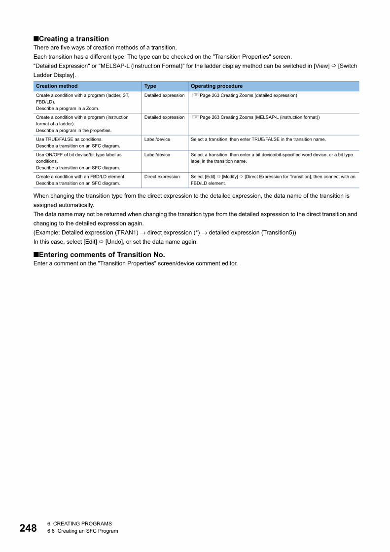
2486 CREATING PROGRAMS6.6 Creating an SFC Program
■Creating a transitionThere are five ways of creation methods of a transition.
Each transition has a different type. The type can be checked on the "Transition Properties" screen.
"Detailed Expression" or "MELSAP-L (Instruction Format)" for the ladder display method can be switched in [View] [Switch
Ladder Display].
When changing the transition type from the direct expression to the detailed expression, the data name of the transition is
assigned automatically.
The data name may not be returned when changing the transition type from the detailed expression to the direct transition and
changing to the detailed expression again.
(Example: Detailed expression (TRAN1) → direct expression (*) → detailed expression (Transition5))
In this case, select [Edit] [Undo], or set the data name again.
■Entering comments of Transition No.Enter a comment on the "Transition Properties" screen/device comment editor.
Creation method Type Operating procedure
Create a condition with a program (ladder, ST,
FBD/LD).
Describe a program in a Zoom.
Detailed expression Page 263 Creating Zooms (detailed expression)
Create a condition with a program (instruction
format of a ladder).
Describe a program in the properties.
Detailed expression Page 263 Creating Zooms (MELSAP-L (instruction format))
Use TRUE/FALSE as conditions.
Describe a transition on an SFC diagram.
Label/device Select a transition, then enter TRUE/FALSE in the transition name.
Use ON/OFF of bit device/bit type label as
conditions.
Describe a transition on an SFC diagram.
Label/device Select a transition, then enter a bit device/bit-specified word device, or a bit type
label in the transition name.
Create a condition with an FBD/LD element.
Describe a transition on an SFC diagram.
Direct expression Select [Edit] [Modify] [Direct Expression for Transition], then connect with an
FBD/LD element.

6 CREATING PROGRAMS6.6 Creating an SFC Program 249
6
Inserting/editing actions
■Inserting an actionSelect a step/an action, then select [Edit] [Insert] [Action] ( ).
Multiple actions can be inserted in a step.
If all actions in a step are deleted, a transition is only checked all the time while a step is activated. Once the
transition was satisfied, the next step is activated.
Steps without actions can be used when synchronizing the steps that are performing simultaneously etc.
■Changing an action nameClick the action, then select [Edit] [Modify] [Name]/press the key.
For an action that a Zoom has been created, the data name of Zoom will not be changed if the action name was changed.
Modify the data name to match with the action name on the "Zoom List" screen. (Page 264 Displaying a Zoom list)
■Creating an actionThere are three ways of creation method of an action.
Each action has a different type. The type can be checked on the "Action Properties" screen.
"Detailed Expression" or "MELSAP-L (Instruction Format)" for the ladder display method can be switched in [View] [Switch
Ladder Display].
Creation method Type Operating procedure
Create an action with a program (ladder, ST, FBD/
LD).
Describe a program in a Zoom.
Detailed expression Page 263 Creating Zooms (detailed expression)
Create an action with a program (instruction format
of a ladder).
Describe a program in the properties.
Detailed expression Page 263 Creating Zooms (MELSAP-L (instruction format))
Use ON/OFF of bit device/bit type label as an
action.
Describe an action on an SFC diagram.
Label/device Select an action, then enter a bit device/bit-specified word device, or a bit type
label in the action name.

2506 CREATING PROGRAMS6.6 Creating an SFC Program
Inserting/editing jumps (connection lines)
■Inserting a jump
■Changing a jump destination
1. Select the transition which is immediately before the jump, then select [Edit] [Modify] [Switch between Jump Symbol
and Connection Line].
Alternatively, select the jump, and press the key.
2. Select the step name of jump destination which is to be changed.
■Switching a jump/connection lineSelect a jump, then select [Edit] [Modify] [Switch between Jump Symbol and Connection Line].
To restore a connection line to a jump, select the connection line, then select [Edit] [Modify] [Switch between Jump
Symbol and Connection Line].
Insertion position Operating procedure
1. Select a transition, then select [Edit] [Insert] [Jump] ( ).
2. Select a step name of jump destination.
1. Select a transition, then select [Edit] [Modify] [Switch between Jump Symbol and
Connection Line].
2. Select a step name of jump destination.
All SFC diagram written below the inserted jump are deleted.
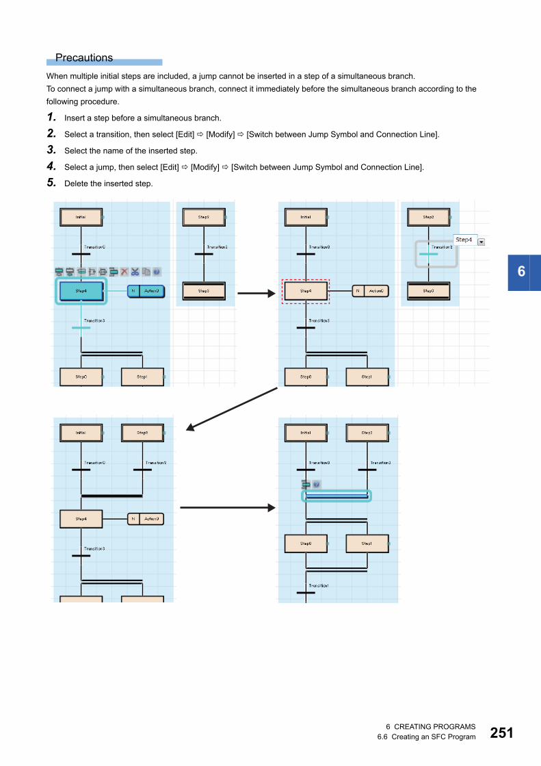
6 CREATING PROGRAMS6.6 Creating an SFC Program 251
6
Precautions
When multiple initial steps are included, a jump cannot be inserted in a step of a simultaneous branch.
To connect a jump with a simultaneous branch, connect it immediately before the simultaneous branch according to the
following procedure.
1. Insert a step before a simultaneous branch.
2. Select a transition, then select [Edit] [Modify] [Switch between Jump Symbol and Connection Line].
3. Select the name of the inserted step.
4. Select a jump, then select [Edit] [Modify] [Switch between Jump Symbol and Connection Line].
5. Delete the inserted step.
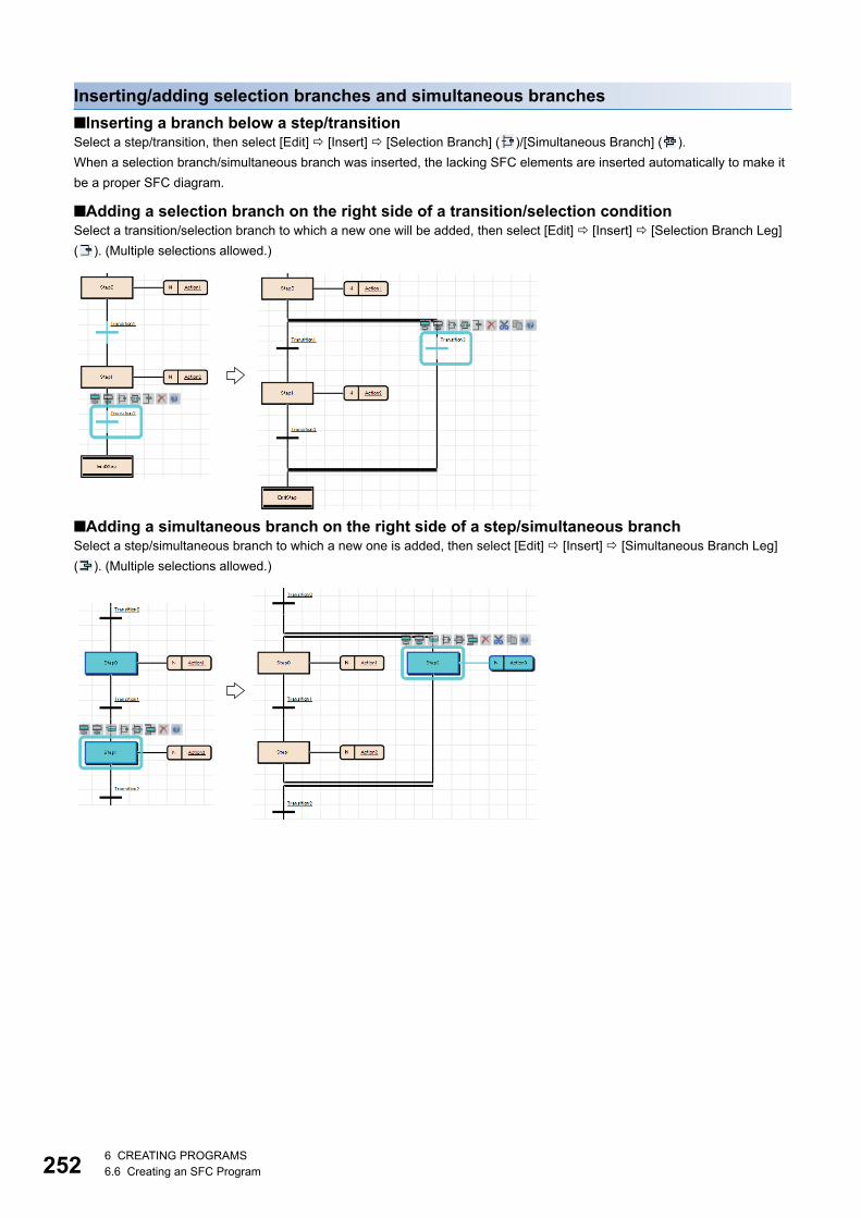
2526 CREATING PROGRAMS6.6 Creating an SFC Program
Inserting/adding selection branches and simultaneous branches
■Inserting a branch below a step/transitionSelect a step/transition, then select [Edit] [Insert] [Selection Branch] ( )/[Simultaneous Branch] ( ).
When a selection branch/simultaneous branch was inserted, the lacking SFC elements are inserted automatically to make it
be a proper SFC diagram.
■Adding a selection branch on the right side of a transition/selection conditionSelect a transition/selection branch to which a new one will be added, then select [Edit] [Insert] [Selection Branch Leg]
( ). (Multiple selections allowed.)
■Adding a simultaneous branch on the right side of a step/simultaneous branchSelect a step/simultaneous branch to which a new one is added, then select [Edit] [Insert] [Simultaneous Branch Leg]
( ). (Multiple selections allowed.)

6 CREATING PROGRAMS6.6 Creating an SFC Program 253
6
Common operations of SFC elements
*1 Copying a Zoom is followed as the option setting.
Operation Operating procedure
Mouse Keyboard
Select To select a single
element
Click an element to be selected. Move the cursor on an element to be selected.
To select multiple
elements
• Click multiple elements with the key held down.
• Click the background of the SFC diagram editor, and drag
the mouse diagonally around all elements to be selected.
Select multiple elements by moving the cursor with
the key held down.
To select an SFC
network block
Click an element, then select [Edit] [Select SFC Network
Block].
Select an element, then press the ++
keys.
To select whole
elements
The operation is the same as that for selecting multiple
elements.
Press the + keys.
Move Drag and drop an element. *1
Copy Drag and drop an element to be copied with held down. *1
Press the + keys, then select the copy
destination and press the + keys. (Copy +
paste)
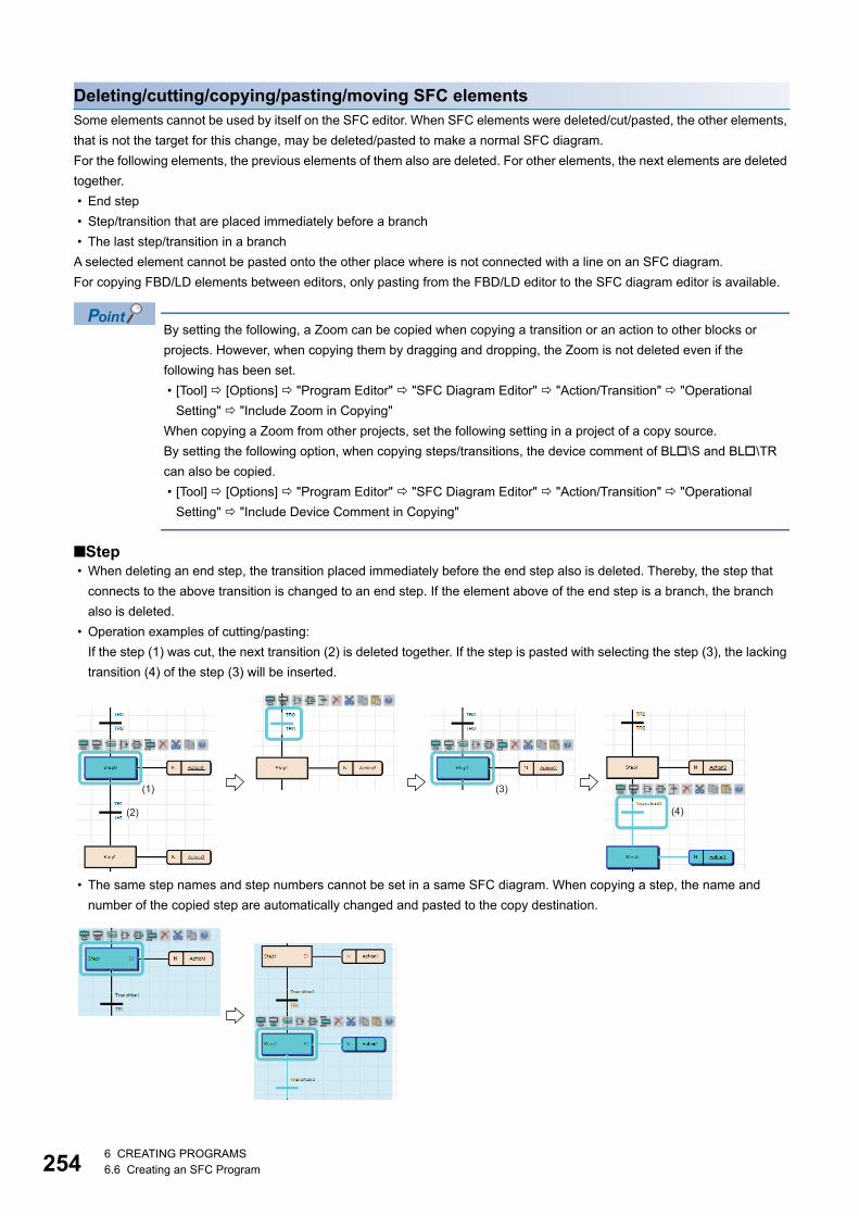
2546 CREATING PROGRAMS6.6 Creating an SFC Program
Deleting/cutting/copying/pasting/moving SFC elementsSome elements cannot be used by itself on the SFC editor. When SFC elements were deleted/cut/pasted, the other elements,
that is not the target for this change, may be deleted/pasted to make a normal SFC diagram.
For the following elements, the previous elements of them also are deleted. For other elements, the next elements are deleted
together.
• End step
• Step/transition that are placed immediately before a branch
• The last step/transition in a branch
A selected element cannot be pasted onto the other place where is not connected with a line on an SFC diagram.
For copying FBD/LD elements between editors, only pasting from the FBD/LD editor to the SFC diagram editor is available.
By setting the following, a Zoom can be copied when copying a transition or an action to other blocks or
projects. However, when copying them by dragging and dropping, the Zoom is not deleted even if the
following has been set.
• [Tool] [Options] "Program Editor" "SFC Diagram Editor" "Action/Transition" "Operational
Setting" "Include Zoom in Copying"
When copying a Zoom from other projects, set the following setting in a project of a copy source.
By setting the following option, when copying steps/transitions, the device comment of BL\S and BL\TR
can also be copied.
• [Tool] [Options] "Program Editor" "SFC Diagram Editor" "Action/Transition" "Operational
Setting" "Include Device Comment in Copying"
■Step • When deleting an end step, the transition placed immediately before the end step also is deleted. Thereby, the step that
connects to the above transition is changed to an end step. If the element above of the end step is a branch, the branch
also is deleted.
• Operation examples of cutting/pasting:
If the step (1) was cut, the next transition (2) is deleted together. If the step is pasted with selecting the step (3), the lacking
transition (4) of the step (3) will be inserted.
• The same step names and step numbers cannot be set in a same SFC diagram. When copying a step, the name and
number of the copied step are automatically changed and pasted to the copy destination.
(1)
(2)
(3)
(4)

6 CREATING PROGRAMS6.6 Creating an SFC Program 255
6
A step can be moved by dragging and dropping (Also, It can be copied with held down). Note that the operations differ
depending on the place where it is dropped.
An initial step cannot be dragged and dropped. Copy it at a keyboard.
■TransitionSame Transition No. cannot be set in a same SFC diagram.
When copying a transition, the number of the copied transition is automatically changed and pasted to an SFC diagram in the
same block.
When a Zoom has already been created, the Zoom is not deleted even if the transition is deleted on an SFC diagram. Delete
it on the "Zoom List" screen. (Page 264 Displaying a Zoom list)
A transition can be moved by dragging and dropping (Also, It can be copied with held down). Note that the operations
differ depending on the place where it is dropped.
Operation Example
Drag and drop a step (Step2) onto the connection line. The step (Step2) is
moved there.
When an action is connected with a step, the action is moved together.
Drag and drop a step (Step2) onto another step (Step1). The step (Step1) is
replaced.
When an action is connected to the dragged step, The step is inserted under
the dropped destination.
Operation Example
Drag and drop a transition (Transition1) onto the connection line. The
transition (Transition1) is moved there.
When a transition of the direct expression connects with an FBD/LD element
such as a contact, the FBD/LD element can be moved together.
Drag and drop a transition (Transition1) onto another transition (Transition0).
The transition (Transition0) is replaced.
When the dropped destination is the direct expression that connects with an
FBD/LD element, the connected FBD/LD element is disconnected when
replacing it.
When the dragged transition is the direct expression that connects with an
FBD/LD element, it cannot be moved.

2566 CREATING PROGRAMS6.6 Creating an SFC Program
When copying a transition, the transition name of a copy source is copied.
When copying and pasting a transition in a same block, a same Zoom is shared between a copy source and a
copy destination.
For copying a transition with a different transition name from that of a copy source, set the following option.
• [Tool] [Options] "Program Editor" "SFC Diagram Editor" "Action/Transition" "Operational
Setting" "Paste Data with Different Data Name"
■ActionCut/copy an action, and paste it selecting a step/action of the destination.
An action can be moved by dragging and dropping (Also, It can be copied with held down). Note that the operations differ
depending on the place where it is dropped.
When a Zoom has already been created, the Zoom will not be deleted if an action is deleted on an SFC diagram. Delete it on
the "Zoom List" screen. (Page 264 Displaying a Zoom list)
When copying an action, the action name of a copy source is copied.
When copying and pasting an action in a same block, a same Zoom is shared between a copy source and a
copy destination.
For copying an action with a different action name from that of a copy source, set the following option.
• [Tool] [Options] "Program Editor" "SFC Diagram Editor" "Action/Transition" "Operational
Setting" "Paste Data with Different Data Name"
Operation Example
Drag and drop an action (Action3) onto a target action (Action1). The
orders of those actions will be switched.
Drag and drop an action (Action3) onto the same height of a target action
(Action1). The action (Action1) is replaced.
Drag and drop an action (Action2) onto a target step (Step1). The action
(Action2) will be moved.
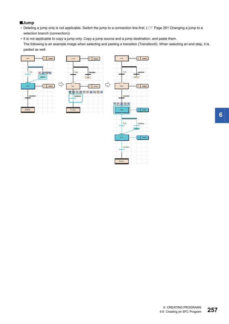
6 CREATING PROGRAMS6.6 Creating an SFC Program 257
6
■Jump • Deleting a jump only is not applicable. Switch the jump to a connection line first. (Page 261 Changing a jump to a
selection branch (connection))
• It is not applicable to copy a jump only. Copy a jump source and a jump destination, and paste them.
The following is an example image when selecting and pasting a transition (Transition0). When selecting an end step, it is
pasted as well.
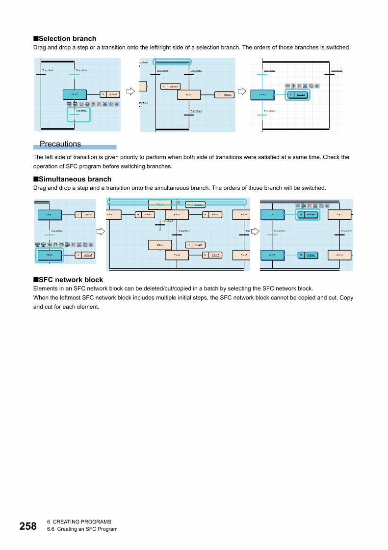
2586 CREATING PROGRAMS6.6 Creating an SFC Program
■Selection branchDrag and drop a step or a transition onto the left/right side of a selection branch. The orders of those branches is switched.
Precautions
The left side of transition is given priority to perform when both side of transitions were satisfied at a same time. Check the
operation of SFC program before switching branches.
■Simultaneous branchDrag and drop a step and a transition onto the simultaneous branch. The orders of those branch will be switched.
■SFC network blockElements in an SFC network block can be deleted/cut/copied in a batch by selecting the SFC network block.
When the leftmost SFC network block includes multiple initial steps, the SFC network block cannot be copied and cut. Copy
and cut for each element.
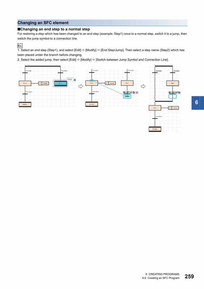
6 CREATING PROGRAMS6.6 Creating an SFC Program 259
6
Changing an SFC element
■Changing an end step to a normal stepFor restoring a step which has been changed to an end step (example: Step1) once to a normal step, switch it to a jump, then
switch the jump symbol to a connection line.
Ex.
1. Select an end step (Step1), and select [Edit] [Modify] [End Step/Jump]. Then select a step name (Step2) which has
been placed under the branch before changing.
2. Select the added jump, then select [Edit] [Modify] [Switch between Jump Symbol and Connection Line].
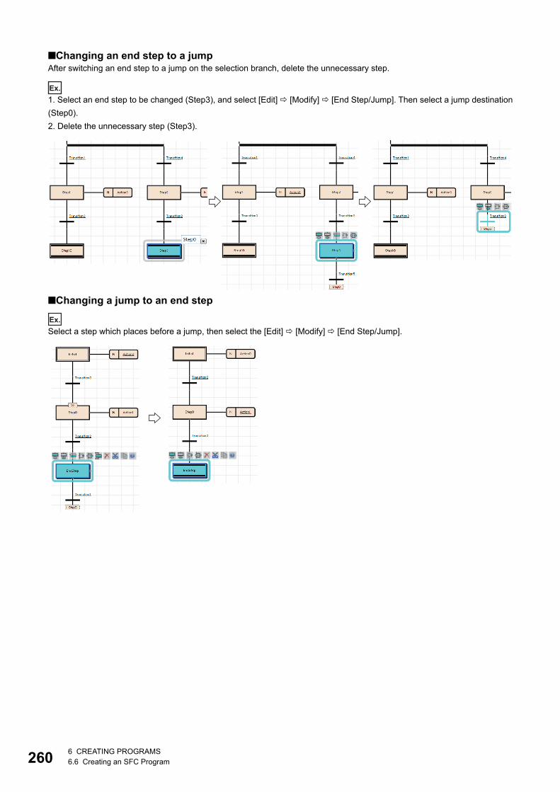
2606 CREATING PROGRAMS6.6 Creating an SFC Program
■Changing an end step to a jumpAfter switching an end step to a jump on the selection branch, delete the unnecessary step.
Ex.
1. Select an end step to be changed (Step3), and select [Edit] [Modify] [End Step/Jump]. Then select a jump destination
(Step0).
2. Delete the unnecessary step (Step3).
■Changing a jump to an end step
Ex.
Select a step which places before a jump, then select the [Edit] [Modify] [End Step/Jump].

6 CREATING PROGRAMS6.6 Creating an SFC Program 261
6
For a jump on a selection branch, insert a step before a jump to be changed, and change the step to an end step.
Ex.
1. Insert a step (Step3) before a jump to be changed.
2. Select the inserted step, then select [Edit] [Modify] [End Step/Jump].
■Changing a jump to a selection branch (connection)Change a jump destination to the step which is immediately after the branch to be connected, then switch it to a connection
line.
Ex.
1. Select the transition (Transition5) that places immediately before a jump to be changed, and select [Edit] [Modify]
[Switch between Jump Symbol and Connection Line]. Then, select the step (Step4) which will be connected with the
connection line.
2. Select a jump, then select [Edit] [Modify] [Switch between Jump Symbol and Connection Line].
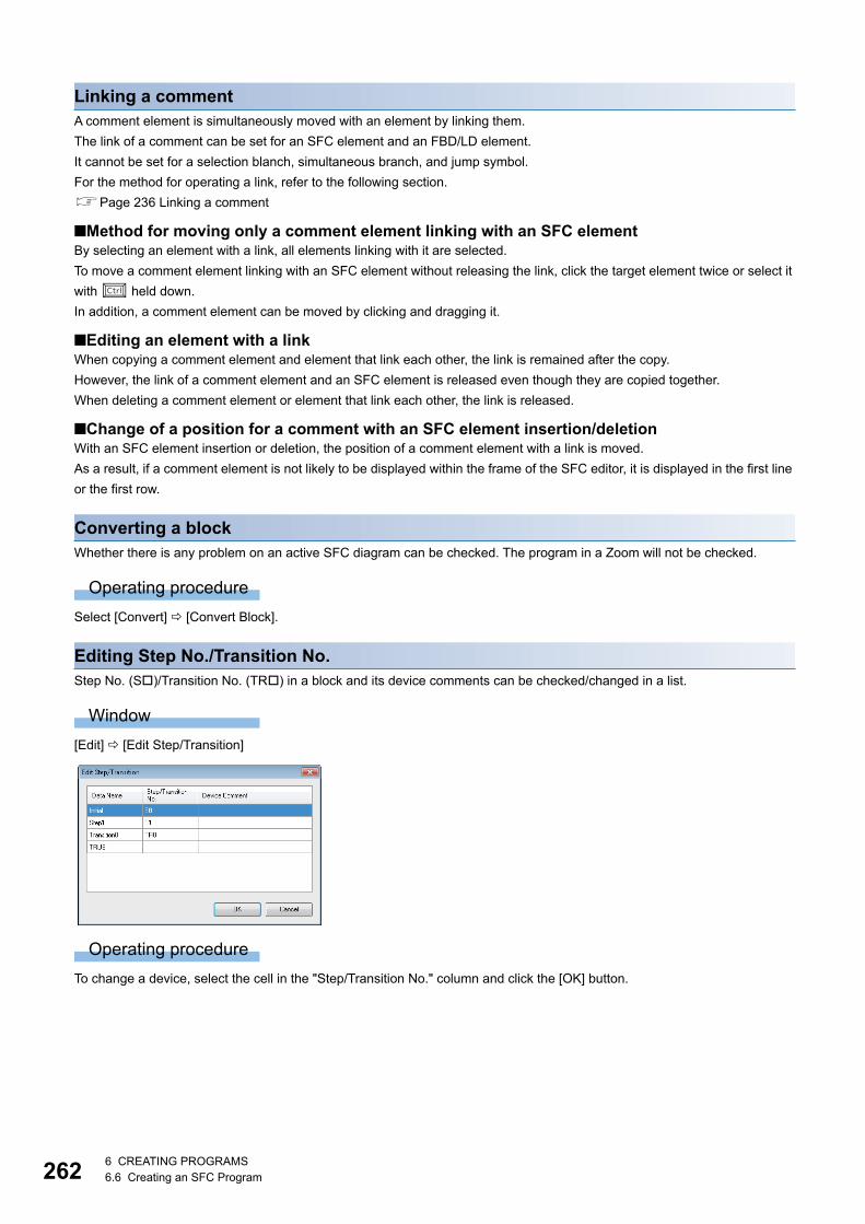
2626 CREATING PROGRAMS6.6 Creating an SFC Program
Linking a commentA comment element is simultaneously moved with an element by linking them.
The link of a comment can be set for an SFC element and an FBD/LD element.
It cannot be set for a selection blanch, simultaneous branch, and jump symbol.
For the method for operating a link, refer to the following section.
Page 236 Linking a comment
■Method for moving only a comment element linking with an SFC elementBy selecting an element with a link, all elements linking with it are selected.
To move a comment element linking with an SFC element without releasing the link, click the target element twice or select it
with held down.
In addition, a comment element can be moved by clicking and dragging it.
■Editing an element with a linkWhen copying a comment element and element that link each other, the link is remained after the copy.
However, the link of a comment element and an SFC element is released even though they are copied together.
When deleting a comment element or element that link each other, the link is released.
■Change of a position for a comment with an SFC element insertion/deletionWith an SFC element insertion or deletion, the position of a comment element with a link is moved.
As a result, if a comment element is not likely to be displayed within the frame of the SFC editor, it is displayed in the first line
or the first row.
Converting a blockWhether there is any problem on an active SFC diagram can be checked. The program in a Zoom will not be checked.
Operating procedure
Select [Convert] [Convert Block].
Editing Step No./Transition No.Step No. (S)/Transition No. (TR) in a block and its device comments can be checked/changed in a list.
Window
[Edit] [Edit Step/Transition]
Operating procedure
To change a device, select the cell in the "Step/Transition No." column and click the [OK] button.

6 CREATING PROGRAMS6.6 Creating an SFC Program 263
6
Creating/displaying Zooms (action/transition)
Creating Zooms (detailed expression)Programs of actions/transitions can be created in languages corresponding to contents.
The entering method of a program is same as the one for creating a program body. Some instructions cannot be used for an
action/transition. For details, refer to the following manual.
MELSEC iQ-R Programming Manual (Program Design)
To display the SFC diagram which is to be the start source, select [View] [Open Zoom Source Block].
Operating procedure
1. Double-click an action name/transition name on an SFC diagram.
2. Set each item on the "New Data" screen, then click the [OK] button.
3. Enter a program in a Zoom by using Ladder Diagram, Structured Text, or Function Block Diagram/Ladder Diagram
language.
Creating Zooms (MELSAP-L (instruction format))A program of an action/transition can be created in MELSAP-L (instruction format) of a ladder.
Enter a program in the property screen.
For details on MELSAP-L (instruction format), refer to the following manual.
MELSEC iQ-R Programming Manual (Program Design)
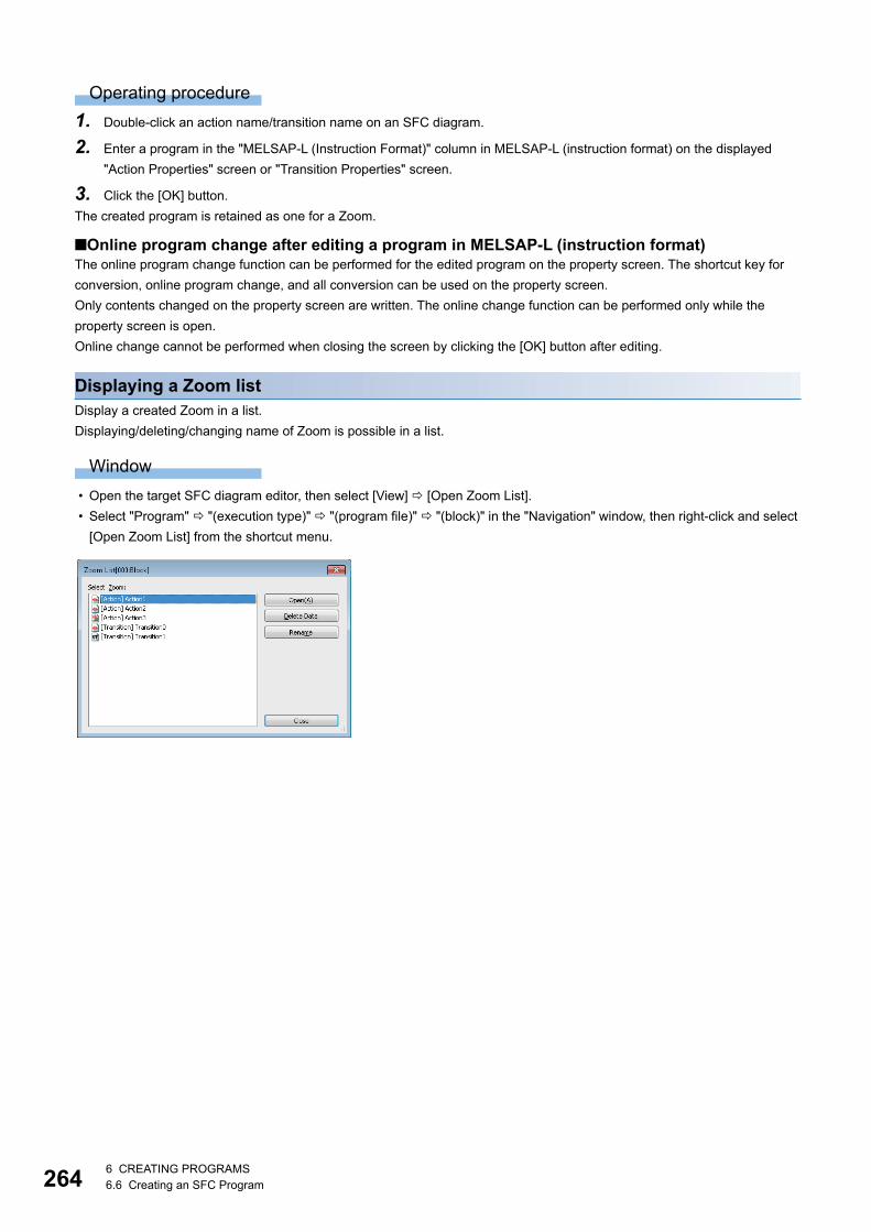
2646 CREATING PROGRAMS6.6 Creating an SFC Program
Operating procedure
1. Double-click an action name/transition name on an SFC diagram.
2. Enter a program in the "MELSAP-L (Instruction Format)" column in MELSAP-L (instruction format) on the displayed
"Action Properties" screen or "Transition Properties" screen.
3. Click the [OK] button.
The created program is retained as one for a Zoom.
■Online program change after editing a program in MELSAP-L (instruction format)The online program change function can be performed for the edited program on the property screen. The shortcut key for
conversion, online program change, and all conversion can be used on the property screen.
Only contents changed on the property screen are written. The online change function can be performed only while the
property screen is open.
Online change cannot be performed when closing the screen by clicking the [OK] button after editing.
Displaying a Zoom listDisplay a created Zoom in a list.
Displaying/deleting/changing name of Zoom is possible in a list.
Window
• Open the target SFC diagram editor, then select [View] [Open Zoom List].
• Select "Program" "(execution type)" "(program file)" "(block)" in the "Navigation" window, then right-click and select
[Open Zoom List] from the shortcut menu.

6 CREATING PROGRAMS6.6 Creating an SFC Program 265
6
Displaying an SFC block listDisplay a data name of a block, title, conversion status, and block information in a program file in a list.
For details on the block information, refer to the following manual.
MELSEC iQ-R Programming Manual (Program Design)
Window
• Open the target SFC diagram editor, then select [View] [Open SFC Block List].
• Select "Program" "(execution type)" "(program file)" in the "Navigation" window, then right-click and select [Open SFC
Block List] from the shortcut menu.
Displayed items
Editing/creating blocks on SFC block listTo edit existing blocks, and to create new blocks are applicable on an SFC block list.
Operating procedure
Double-click an editing target block. When creating a new block, select a blank row.
Copying blocks
Operating procedure
1. Select a block to be copied, then select [Edit] [Copy] ( ).
2. Select a block to be pasted, then select [Edit] [Paste] ( ).
3. Select whether to change or overwrite its block No. on the confirmation screen, then click the [OK] button.
4. Select an item to be pasted on the "Contents to Paste" screen, then click the [OK] button.
Blocks copied in the "Navigation" window can be pasted on a block list.
In that method, multiple blocks can be selected and copied in the "Navigation" window.
Precautions
If "Step/Transition Comment" is selected on the "Contents to Paste" screen, steps/transition comments in the device comment
will be pasted after pasting all copied data. Therefore, the steps/transition comments may not be pasted when the [Cancel]
button is clicked during the processing even if data pasting has been already completed.
Item Description Related operation
(1) Comment Comments set on the "Properties" screen of block. ■Show/Hide
[View] [SFC Block List Comment]
(2) Device/label comment Comments for devices/labels which were set to the block information on
the "Properties" screen of block.
■Show/Hide
[View] [Display Device]
(1)
(2)
2666 CREATING PROGRAMS6.6 Creating an SFC Program
Search
■Searching for block informationSearch for block information (device/label) on an SFC block list.
Operating procedure
1. Select [Find/Replace] [Block Information Find Device].
2. Enter a device/label to be searched, then click the [Find Next] button.
■JumpSpecify a block No. or a block name, and move the cursor on an SFC block list.
Operating procedure
1. Select [Find/Replace] [Jump].
2. Select a block No./block name on the "Jump" screen, then click the [OK] button.
The "Jump" screen can be displayed by pressing a numeric key of the keyboard on an SFC block list.
Displaying SFC diagramsDisplay an SFC diagram of block, which is pointed with the cursor, from an SFC block list.
Operating procedure
1. Move the cursor on a block to be displayed.
2. Select [View] [Open SFC Body], or double-click a block to be displayed.
Displaying local label editorDisplay a local label editor of block, which is pointed with the cursor, from an SFC block list.
Operating procedure
1. Move the cursor on a block to be displayed.
2. Select [View] [Open Label Setting].

6 CREATING PROGRAMS6.6 Creating an SFC Program 267
6
Searching/replacing data in a programThe search functions that can be used in the SFC diagram editor as follows:
Precautions
• When a Zoom has been created, the data name of Zoom will not be changed if the character strings of transition name/
action name are replaced on an SFC diagram. Change them on the "Zoom List" screen. (Page 264 Displaying a Zoom
list)
Displaying HelpCheck the elements used in the SFC program on the e-Manual Viewer.
To check, the files of the corresponding programming manuals requires to be registered in e-Manual Viewer.
Operating procedure
1. Select a check target element.
2. Press the key.
Function name Description Reference
Cross reference Checks a declaration location and a reference location of a device and a label
in a list.
Page 299 SEARCHING DATA
Device list Checks the usage of devices being used.
Find and replace • Searches for and replaces a device name, label name, instruction name,
and character strings.
• Changes open/close contact.
• Replaces devices in a batch.

2686 CREATING PROGRAMS6.7 Registering Device Comments
6.7 Registering Device CommentsThis section explains the features and setting methods for device comments.
Device commentsTwo types of device comments can be created: one that can be set in common and one that can be set for each program.
GX Works3 supports global device comments/local device comments of GX Works2, and common comments/comments by
program of GX Developer.
Up to 16 comments can be set for one device. (Page 66 Comment Display Setting)
Up to 1024 characters can be set for one comment.
Comments can be set in Japanese, English, Chinese or other languages, and the display language can be switched among
these languages.
Difference between a device comment and a label comment
'Device comment' refers to a comment that is added to devices, and read from/written to a CPU module.
'Label comment' refers to a comment that is added to a defined label.
Common device comment'Common device comment' refers to a device comment that is automatically created when creating a new project.
Set device comment data as a common device comment when using it in multiple programs.
This can be set even if only one program exists.
Device comment for each program'Device comment for each program' refers to a device comment that can be created arbitrarily.
This device comment can be used by creating it with the same name as a program and being associated with the program.
Create a new each program device comment if necessary. (Page 108 Creating data)
'Each program device comment' can be created under the different data name from the sequence program. However, the
comment will not be linked with the sequence program.
To make the comments relate to the sequence program, the comments should have the same data names as the program
name.
Remote head modules do not support device comments for each program.
Precautions
For FX5CPUs, device comments set for each program cannot be written to a CPU module.
Sequence program MAIN
Common device comment Sequence program SUB1
Sequence program SUB2
MAIN Device comments for each program Sequence program MAIN
SUB1 Device comments for each program Sequence program SUB1
SUB2 Device comments for each program Sequence program SUB2
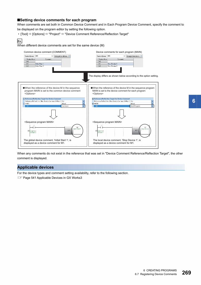
6 CREATING PROGRAMS6.7 Registering Device Comments 269
6
■Setting device comments for each programWhen comments are set both in Common Device Comment and in Each Program Device Comment, specify the comment to
be displayed on the program editor by setting the following option.
• [Tool] [Options] "Project" "Device Comment Reference/Reflection Target"
Ex.
When different device comments are set for the same device (M)
When any comments do not exist in the reference that was set in "Device Comment Reference/Reflection Target", the other
comment is displayed.
Applicable devicesFor the device types and comment setting availability, refer to the following section.
Page 541 Applicable Devices in GX Works3
Common device comment (COMMENT) Device comments for each program (MAIN)
The display differs as shown below according to the option setting.
●When the reference of the device M in the sequence program MAIN is set to the common device comment<Options>
●When the reference of the device M in the sequence program MAIN is set to the device comment for each program<Options>
<Sequence program MAIN> <Sequence program MAIN>
The local device comment, 'Stop Device 1', is displayed as a device comment for M1.
The global device comment, 'Initial Start 1', is displayed as a device comment for M1.
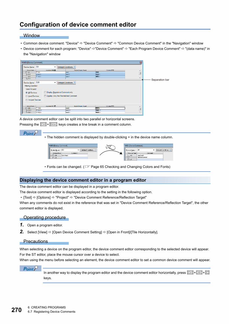
2706 CREATING PROGRAMS6.7 Registering Device Comments
Configuration of device comment editor
Window
• Common device comment: "Device" "Device Comment" "Common Device Comment" in the "Navigation" window
• Device comment for each program: "Device" "Device Comment" "Each Program Device Comment" "(data name)" in
the "Navigation" window
A device comment editor can be split into two parallel or horizontal screens.
Pressing the + keys creates a line break in a comment column.
• The hidden comment is displayed by double-clicking + in the device name column.
• Fonts can be changed. (Page 65 Checking and Changing Colors and Fonts)
Displaying the device comment editor in a program editorThe device comment editor can be displayed in a program editor.
The device comment editor is displayed according to the setting in the following option.
• [Tool] [Options] "Project" "Device Comment Reference/Reflection Target"
When any comments do not exist in the reference that was set in "Device Comment Reference/Reflection Target", the other
comment editor is displayed.
Operating procedure
1. Open a program editor.
2. Select [View] [Open Device Comment Setting] [Open in Front]/[Tile Horizontally].
Precautions
When selecting a device on the program editor, the device comment editor corresponding to the selected device will appear.
For the ST editor, place the mouse cursor over a device to select.
When using the menu before selecting an element, the device comment editor to set a common device comment will appear.
In another way to display the program editor and the device comment editor horizontally, press ++
keys.
Separation bar

6 CREATING PROGRAMS6.7 Registering Device Comments 271
6
Creating device commentsComments can be created for each device in the device comment editor.
Adding device comments make it easy to understand the content of program processing.
When less number of characters are entered, the data size to be written to CPU module can be reduced.
Set the applicable number of characters in the following option.
• [Tool] [Options] "Other Editor" "Device Comment Editor" "Number of Device Comment Editing/Displaying
Characters"
When creating device comments for each program, create a device comment data in advance. (Page 108 Creating data)
The comments can be entered on the ladder editor. For details, refer to the following section.
Page 194 Entering/editing comments
Operating procedure
1. Enter the device of which comment is to be set in "Device Name".
2. Enter a comment for "Comment".
• By selecting two or more consecutive cells in which the comment with number is inserted, and dragging the
'+' symbol displayed at the lower right corner of the cell, the data of which number is incremented can be
entered.
• When cutting/copying the hidden bit-specified word device comments, select the range and [Edit] [Cut
the Range Including Hidden Bit Specification Information]/[Copy the Range Including Hidden Bit
Specification Information].
The bit-specified comments can also be pasted regardless of the setting of display/hidden by selecting [Edit]
[Paste the Range Including Hidden Bit Specification Information].
Creating multiple comments and setting display targetFor details, refer to the following section.
Page 66 Comment Display Setting
Detecting devices with empty cellWhen comments are set in the multiple rows, detect the devices with empty cells.
Operating procedure
■Detect comments from device data being displayed on the device comment editorSelect "Display Only the Mismatched Comment" in the filter condition on the device comment editor.
■Detect comments from all device data in the device comment dataSelect [Edit] [Detect the Mismatched Comment].
Double-click "NG" on the displayed "Detect the Matched Comment of All Devices" screen to edit the device comment editor.
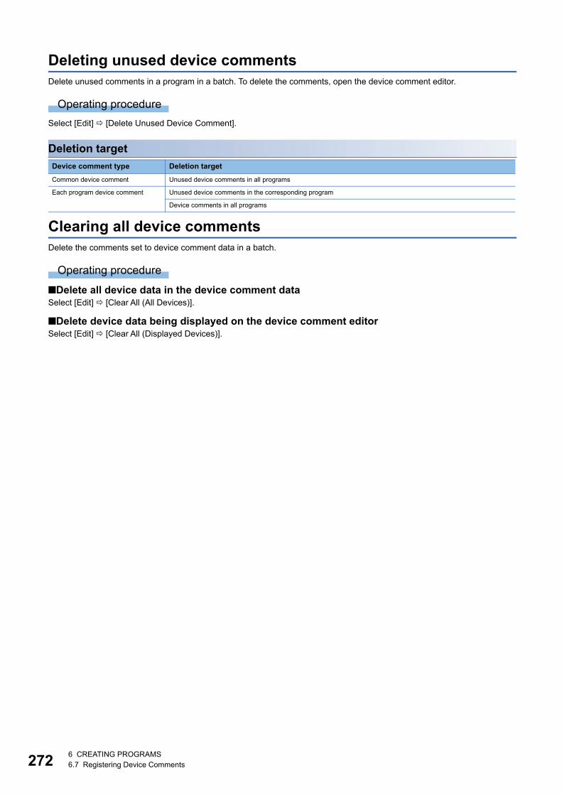
2726 CREATING PROGRAMS6.7 Registering Device Comments
Deleting unused device commentsDelete unused comments in a program in a batch. To delete the comments, open the device comment editor.
Operating procedure
Select [Edit] [Delete Unused Device Comment].
Deletion target
Clearing all device commentsDelete the comments set to device comment data in a batch.
Operating procedure
■Delete all device data in the device comment dataSelect [Edit] [Clear All (All Devices)].
■Delete device data being displayed on the device comment editorSelect [Edit] [Clear All (Displayed Devices)].
Device comment type Deletion target
Common device comment Unused device comments in all programs
Each program device comment Unused device comments in the corresponding program
Device comments in all programs
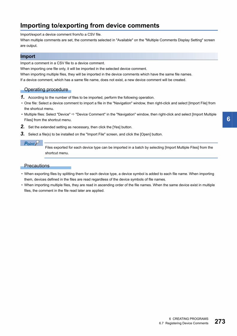
6 CREATING PROGRAMS6.7 Registering Device Comments 273
6
Importing to/exporting from device commentsImport/export a device comment from/to a CSV file.
When multiple comments are set, the comments selected in "Available" on the "Multiple Comments Display Setting" screen
are output.
ImportImport a comment in a CSV file to a device comment.
When importing one file only, it will be imported in the selected device comment.
When importing multiple files, they will be imported in the device comments which have the same file names.
If a device comment, which has a same file name, does not exist, a new device comment will be created.
Operating procedure
1. According to the number of files to be imported, perform the following operation.
• One file: Select a device comment to import a file in the "Navigation" window, then right-click and select [Import File] from
the shortcut menu.
• Multiple files: Select "Device" "Device Comment" in the "Navigation" window, then right-click and select [Import Multiple
Files] from the shortcut menu.
2. Set the extended setting as necessary, then click the [Yes] button.
3. Select a file(s) to be installed on the "Import File" screen, and click the [Open] button.
Files exported for each device type can be imported in a batch by selecting [Import Multiple Files] from the
shortcut menu.
Precautions
• When exporting files by splitting them for each device type, a device symbol is added to each file name. When importing
them, devices defined in the files are read regardless of the device symbols of file names.
• When importing multiple files, they are read in ascending order of the file names. When the same device exist in multiple
files, the comment in the file read later are applied.
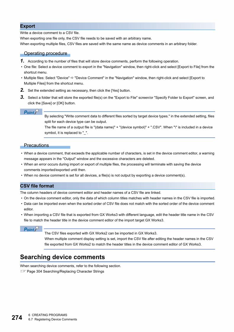
2746 CREATING PROGRAMS6.7 Registering Device Comments
ExportWrite a device comment to a CSV file.
When exporting one file only, the CSV file needs to be saved with an arbitrary name.
When exporting multiple files, CSV files are saved with the same name as device comments in an arbitrary folder.
Operating procedure
1. According to the number of files that will store device comments, perform the following operation.
• One file: Select a device comment to export in the "Navigation" window, then right-click and select [Export to File] from the
shortcut menu.
• Multiple files: Select "Device" "Device Comment" in the "Navigation" window, then right-click and select [Export to
Multiple Files] from the shortcut menu.
2. Set the extended setting as necessary, then click the [Yes] button.
3. Select a folder that will store the exported file(s) on the "Export to File" screen/or "Specify Folder to Export" screen, and
click the [Save] or [OK] button.
By selecting "Write comment data to different files sorted by target device types." in the extended setting, files
split for each device type can be output.
The file name of a output file is "(data name)" + "(device symbol)" + ".CSV". When "\" is included in a device
symbol, it is replaced to "_".
Precautions
• When a device comment, that exceeds the applicable number of characters, is set in the device comment editor, a warning
message appears in the "Output" window and the excessive characters are deleted.
• When an error occurs during import or export of multiple files, the processing will terminate with saving the device
comments imported/exported until then.
• When no device comment is set for all devices, a file(s) is not output by exporting a device comment(s).
CSV file formatThe column headers of device comment editor and header names of a CSV file are linked.
• On the device comment editor, only the data of which column titles matches with header names in the CSV file is imported.
• Data can be imported even when the sorted order of CSV file does not match with the sorted order of the device comment
editor.
• When importing a CSV file that is exported from GX Works3 with different language, edit the header title name in the CSV
file to match the header title in the device comment editor of the import target GX Works3.
The CSV files exported with GX Works2 can be imported in GX Works3.
When multiple comment display setting is set, import the CSV file after editing the header names in the CSV
file exported from GX Works2 to match the header titles in the device comment editor of GX Works3.
Searching device commentsWhen searching device comments, refer to the following section.
Page 304 Searching/Replacing Character Strings

6 CREATING PROGRAMS6.7 Registering Device Comments 275
6
Reading sample commentsSet the sample comments of special relays/special registers/CPU buffer memory and intelligent function modules
automatically.
Open the device comment editor in advance.
FX5CPUs do not support sample comments of CPU buffer memory.
Window
[Edit] [Read from Sample Comment]
Precautions
When reading sample comments of an intelligent function module, the data size may exceed the memory capacity of the CPU
module and data may not be written to a CPU module. In this case, prepare an SD memory card.
For FX5CPU, the writable capacity is the same as that of the CPU module even when data is written to an SD memory card.
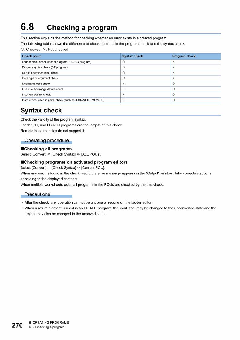
2766 CREATING PROGRAMS6.8 Checking a program
6.8 Checking a programThis section explains the method for checking whether an error exists in a created program.
The following table shows the difference of check contents in the program check and the syntax check.
: Checked, : Not checked
Syntax checkCheck the validity of the program syntax.
Ladder, ST, and FBD/LD programs are the targets of this check.
Remote head modules do not support it.
Operating procedure
■Checking all programsSelect [Convert] [Check Syntax] [ALL POUs].
■Checking programs on activated program editorsSelect [Convert] [Check Syntax] [Current POU].
When any error is found in the check result, the error message appears in the "Output" window. Take corrective actions
according to the displayed contents.
When multiple worksheets exist, all programs in the POUs are checked by the this check.
Precautions
• After the check, any operation cannot be undone or redone on the ladder editor.
• When a return element is used in an FBD/LD program, the local label may be changed to the unconverted state and the
project may also be changed to the unsaved state.
Check point Syntax check Program check
Ladder block check (ladder program, FBD/LD program)
Program syntax check (ST program)
Use of undefined label check
Data type of argument check
Duplicated coils check
Use of out-of-range device check
Incorrect pointer check
Instructions, used in pairs, check (such as (FOR/NEXT, MC/MCR)
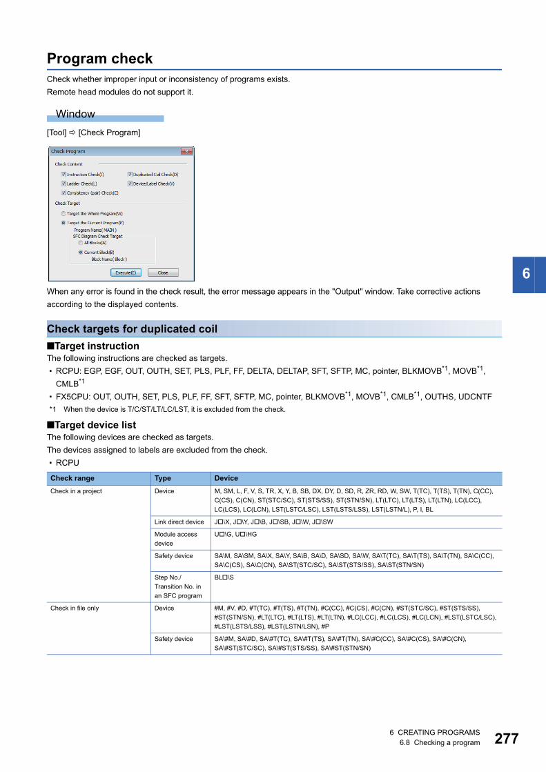
6 CREATING PROGRAMS6.8 Checking a program 277
6
Program checkCheck whether improper input or inconsistency of programs exists.
Remote head modules do not support it.
Window
[Tool] [Check Program]
When any error is found in the check result, the error message appears in the "Output" window. Take corrective actions
according to the displayed contents.
Check targets for duplicated coil
■Target instructionThe following instructions are checked as targets.
• RCPU: EGP, EGF, OUT, OUTH, SET, PLS, PLF, FF, DELTA, DELTAP, SFT, SFTP, MC, pointer, BLKMOVB*1, MOVB*1,
CMLB*1
• FX5CPU: OUT, OUTH, SET, PLS, PLF, FF, SFT, SFTP, MC, pointer, BLKMOVB*1, MOVB*1, CMLB*1, OUTHS, UDCNTF
*1 When the device is T/C/ST/LT/LC/LST, it is excluded from the check.
■Target device listThe following devices are checked as targets.
The devices assigned to labels are excluded from the check.
• RCPU
Check range Type Device
Check in a project Device M, SM, L, F, V, S, TR, X, Y, B, SB, DX, DY, D, SD, R, ZR, RD, W, SW, T(TC), T(TS), T(TN), C(CC),
C(CS), C(CN), ST(STC/SC), ST(STS/SS), ST(STN/SN), LT(LTC), LT(LTS), LT(LTN), LC(LCC),
LC(LCS), LC(LCN), LST(LSTC/LSC), LST(LSTS/LSS), LST(LSTN/L), P, I, BL
Link direct device J\X, J\Y, J\B, J\SB, J\W, J\SW
Module access
device
U\G, U\HG
Safety device SA\M, SA\SM, SA\X, SA\Y, SA\B, SA\D, SA\SD, SA\W, SA\T(TC), SA\T(TS), SA\T(TN), SA\C(CC),
SA\C(CS), SA\C(CN), SA\ST(STC/SC), SA\ST(STS/SS), SA\ST(STN/SN)
Step No./
Transition No. in
an SFC program
BL\S
Check in file only Device #M, #V, #D, #T(TC), #T(TS), #T(TN), #C(CC), #C(CS), #C(CN), #ST(STC/SC), #ST(STS/SS),
#ST(STN/SN), #LT(LTC), #LT(LTS), #LT(LTN), #LC(LCC), #LC(LCS), #LC(LCN), #LST(LSTC/LSC),
#LST(LSTS/LSS), #LST(LSTN/LSN), #P
Safety device SA\#M, SA\#D, SA\#T(TC), SA\#T(TS), SA\#T(TN), SA\#C(CC), SA\#C(CS), SA\#C(CN),
SA\#ST(STC/SC), SA\#ST(STS/SS), SA\#ST(STN/SN)

2786 CREATING PROGRAMS6.8 Checking a program
• FX5CPU
Check range Type Device
Check in a project Device M, SM, L, F, S, X, Y, B, SB, DX, DY, D, SD, R, W, SW, T(TC), T(TS), T(TN), C(CC), C(CS), C(CN),
ST(STC/SC), ST(STS/SS), ST(STN/SN), LC(LCC), LC(LCS), LC(LCN), P, I
Module access
device
U\G

6 CREATING PROGRAMS6.9 Converting Programs 279
6
6.9 Converting ProgramsThis section explains the method for converting a created program into a code that can be executed.
A data name displayed in red in the "Navigation" window indicates that the data is unconverted. The data is required to be
converted.
A data name displayed in light blue in the "Navigation" window indicates that the data is unused. The data is not converted.
The name of unused data that is not converted is displayed in red. After the data is converted successfully, it will be displayed
in light blue. If an conversion error occurs, all the unused data will be displayed in red.
Converting any or all programsThe program in a project can be converted and a label can be assigned. The program is also checked at verification.
The differences in operation between "Convert" and "Rebuild All" are shown below:
*1 Remote head modules do not support it.*2 A label of which the label name, data type, class, and initial value etc. have not been changed after reassigning the memory in previous
conversion of any or all programs.*3 The instruction check cannot be performed.
Operating procedure
1. Select [Convert] [Convert] *1( )/[Rebuild All] ( ).
2. To convert all programs, specify each item for "Label Assignment" and "Check Program""*2 on the "Rebuild All" screen,
and click the [OK] button.
*1 When "Yes" is selected in the following option setting, the online program change function is performed instead.[Tool] [Options] "Convert" "Online Program Change" "Operational Setting" "Execute Online Program Change in Converting"
*2 If there is no program, the check is not performed even if the check box for "Check Program" is selected.
The unconverted data can be checked. Select a global label, POU, or program file in the "Navigation" window,
and right-click and select [Expanded/Collapse Tree] [Open Unconverted Data] from the shortcut menu.
Item Conversion target Assignment of labels Program check
Convert*1 Newly added or changed program and
label
The memory is assigned to the newly added and
changed label.
Whether to perform the Check Program
function can be specified in "Basic Setting"
by selecting [Tool] [Options]
"Convert".
Rebuild All All programs and labels in a project
(regardless if changed or not)
Retain:
Converts a program without changing the
memory assigned to a defined label*2. A newly
added label and a label, of which the label name,
data type, class, and initial value etc. have been
changed, are reassigned again.
Reassignment:
Converts a program with assigning the memory to
all labels. The memory usage can be optimized.
Whether to perform the Check Program
function can be specified on the "Rebuild
All" screen*3.

2806 CREATING PROGRAMS6.9 Converting Programs
■Operations that requires a conversion for all programsWhen one of the following operation is performed, converting all programs is required.
• Change of system parameter (Fixed Scan Communication Area Setting)
• Changing CPU parameters (File Register Setting, Device/Label Memory Area Setting, Index Register Setting, Refresh
Memory Setting, Pointer Setting, Program Setting, FB/FUN File Setting, Refresh Setting (At I45 Exe))
• Changing the option setting ("Other Editor" "Label Editor Common" "Data Type Setting", "Convert" "Basic Setting"
"Operational Setting")
• Changing the type of a function block in the "Properties" screen of an FB file (Page 319 Changing the type of a function
block)
• Adding a label, of which the data type is the function block, to a local label of converted function block
• Changing reserved area capacities in the "Properties" screen of a function block. (Page 319 Setting reserved area
capacities)
• Adding a label which exceeds the reserved area capacity to a local label of converted function block
For the details on the reserved area capacity, refer to the following manuals (MELSEC iQ-R Programming Manual
(Program Design), MELSEC iQ-F FX5 Programming Manual (Program Design)).
• Changing the module type/operation mode
• Changing the tag FB setting (tag FB type, tag type, declaration position) of a project used for an RnPCPU and an
RnPSFCPU
Considerations for conversionFor details on the conversion of a function block and function, refer to the following sections.
Page 320 Converting function blocks
Page 329 Converting functions
Considerations for conversion or conversion for all programs
■Canceling conversionThe conversion is canceled in a program file unit. Therefore, even when the [Cancel] button is clicked during the conversion,
the conversion will not be canceled until the conversion for one program file is completed.
Note that a large-scale program file with multiple FBs/FUNs requires a longer time to cancel the conversion.
■Creating a sequence program with multiple instructions'LD SM400' may be added in the beginning of the program in order to execute the program.
■No program in a projectProgram check is not performed.
Considerations after converting any or all programs (Retain)A newly added label and a label of which the data type etc. have been changed are reassigned again.
The current (initial) value of a label can be reassigned by any of the following methods.
• Register the label to the Watch window, and set the current value.
• Set the initial value on the label editor.*1
*1 FX5CPU does not support the setting for initial values of labels.
When the current value of a local label needs to be retained, perform the Online Program Change function.
For details, refer to the following manual.
MELSEC iQ-R CPU Module User's Manual (Application)
6 CREATING PROGRAMS6.9 Converting Programs 281
6
Considerations after converting all programs (Reassignment)When all programs are converted (reassigned), the label memory area is reassigned to all POUs. If all the converted
programs are written to the CPU module and RUN as they are, the programs may be processed with the device values set
before the program change.
After converting all programs, initialize the labels by the following procedure.
Operating procedure
1. Switch the CPU module to STOP.
2. Select "Device/Label Memory" in the "CPU Memory Operation" screen displayed by selecting [Online] [CPU Memory
Operation] to clear the values.
3. Select [Online] [Write to PLC] ( ) to write the changed program files. When the initial values are set to the labels
used in the program, write the label initial value file as well.
4. Reset the CPU module.
It can also be reset by selecting [Online] [Remote Operation].
The labels are reset to '0' or initialized with the values set to the label initial value file.

2826 CREATING PROGRAMS6.9 Converting Programs
Converting a program file with the process control extension enabled
Operations of a program with the process control extension enabled can be set in the following option setting.
[Tool] [Options] "Convert" "Process Control Extension Setting"
■Adding/changing the program processing while the system is operatingFor process control, when changing/adding the program processing while the system is operating, the current value of a
registered label needs to be retained and the current value of a newly added/changed label needs to be initialized to keep the
system operating.
However, labels newly added/changed after writing a programmable controller only cannot be initialized by converting any or
all programs when writing them to the programmable controller next time.
To initialize only the current value of a newly added/changed label, perform the online program change function.
In addition, set the following option so as not to convert (retain)any or all program after creating a project.
• [Tool] [Options] "Convert" "Basic Setting" "Conversion Operation" "Enable Conversion"
■System header and system footerWhen creating a program file with the process control extension enabled, the system data for the process control extension is
generated at conversion.
A program file of the scan execution type with the process control extension enabled, the system header POU
(M+PHEADER) and system footer POU (M+PFOOTER) are created in the program file after conversion.
At conversion, the execution order of the system header is set to the start of the program file. As for the system footer, it is set
to the end of the program file. (The order can be checked in the program file setting.)
When the process control extension is disabled or the execution type other than scan is set, the system header and system
footer will be deleted from the program file at conversion.
■Increase of the number of steps usedThe number of steps used increases in a program with the process control extension enabled.
The following table shows the number of extra steps used.
■Device memoryWhen a program with the process control extension enabled exists and "Use Common File Register in All Programs" is set for
"File Register Setting" of "CPU Parameter", the device memory is created at conversion.
In addition, the data in the range set in the following option is overwritten to the device memory.
• [Tool] [Options] "Convert" "Process Control Extension Setting" "System Resource"
Program execution type Program block name Number of extra steps used
Scan M+PHEADER Approx. 1400 steps
M+PFOOTER Approx. 30 steps
Others Approx. 10 steps
Fixed scan All Approx. 60 steps

6 CREATING PROGRAMS6.9 Converting Programs 283
6
Project with the process control extension enabledNote the following for projects used for CPU modules in a redundant system configuration with the process control extension
enabled.
■Trucking settingThe following parameters are automatically set when converting a program.
*1 This indicates a trucking block number that was set in the following option.[Tool] [Options] "Convert" "Process Control Extension Setting" "Redundant Setting" "Tracking Block No."
The following device data must be set manually since it is not automatically set in "Device/Label Detailed Setting" of "CPU
Parameter".
• Device data other than file registers used for FBD/LD programs for process control
• Device data used for programs other than FBD/LD programs for process control
When setting the device data described above, set them to a trucking block number other than No.64 in "Device/Label
Detailed Setting" of "CPU Parameter"
Precautions
The contents of the tracking block No.64 in "Device/Label Detailed Setting" of "CPU Parameter" cannot be changed manually
since they are automatically set when converting a program.
When reading parameters from a CPU module after converting a program, if the parameter is overwritten with a different
content from the one that was automatically set as above, convert the program again.
Parameter Setting content
• "CPU Parameter" "Redundant System Settings" "Tracking Setting"
"Tracking Device/Label Setting"
The settings in "Detail Setting" are configured.
• "CPU Parameter" "Redundant System Settings" "Tracking Setting"
"Tracking Device/Label Setting" "Device/Label Detailed Setting"
The range of a file register that was set in the following option is set for the
trucking block No.64*1.
• [Tool] [Options] "Convert" "Process Control Extension Setting"
"System Resource" "File Register: ZR"

2846 CREATING PROGRAMS6.9 Converting Programs
Memory assignment of labelsWhen converting/converting all programs, the labels declared in the label editor are assigned to the memory in a packing
block (which is classified as type and data type, and set them in consecutive order of line numbers) unit. Since it is assigned
in POU units, the start position of POU will be 64-bit address boundary.
Ex.
The types of packing blocks and assignment order is shown below.
They are arranged in ascending order due to minimize the useless space.
Assignment order
Packing block Data type Remarks
1 Bit Bit Page 285 Assignment of bit type
2 Word Word [Unsigned]/Bit String [16-bit]
Word [Signed]
3 String String Padding is not inserted because a packing block is assigned per
one word unit, though the assignment amount differs depending
on the number of character strings.4 String [Unicode] String [Unicode]
5 Double Word Double Word [Unsigned]/Bit String [32-bit]
Double Word [Signed]
6 Time Time
7 FLOAT [Single
Precision]
FLOAT [Single Precision]
8 Timer Timer Page 286 Assignment of timer/retentive timer/counter
9 Retentive Timer Retentive Timer
10 Counter Counter
11 FLOAT [Double
Precision]
FLOAT [Double Precision]
12 Long Timer Long Timer Page 286 Assignment of timer/retentive timer/counter
13 Long Retentive Timer Long Retentive Timer
14 Long Counter Long Counter
15 Array All Page 285 Assignment of array
16 Structure/FB instance All Page 285 Assignment of structure
1. Labels are assigned per packing block.
2. In the packing block, the labels are assigned in order of the label row number without the label editor sorted.
3. When the data overlaps 64-bit address boundary in one data, a free space (padding) is inserted.
4. The data which requires 2-word assignment is assigned from the start position of 32-bit address boundary.
Assignment
Padding
PaddingPadding

6 CREATING PROGRAMS6.9 Converting Programs 285
6
■Assignment of bit typeIf the number of bit type labels exceeds 16, the labels will be assigned to the next memory area consecutively.
For FB instances, the area of EN/ENO is assigned to each head of the FB instances.
Ex.
■Assignment of arrayFor a bit type array, the memory is assigned from the start address (0 bit) of the array, and continuous bits for one-dimensional
element are assigned in word unit. As for the two-dimensional element or later, the same area as the one-dimensional
element is assigned for the number of the dimensional elements continuously.
For an array other than bit type, the area which is required for the element is assigned for the memory of the data type
continuously. A padding is not inserted between the array elements.
Ex.
■Assignment of structureA member of structure is assigned according to the assignment order of packing blocks. When a structure is declared in the
member of structure, it will be assigned in a packing block according to the order noted previously. It will be assigned from the
start position of 64-bit address boundary.
Ex.
Assignment
Two-dimension Two-dimension
<Assignment example of bit type two-dimension array_Bit (0..n, 0..m)> <Assignment example of word type two-dimension array_Word (0..n, 0..m)>
Assignment
Padding
Padding
It is assigned from the beginning of the 64-bit address boundary.

2866 CREATING PROGRAMS6.9 Converting Programs
■Assignment of timer/retentive timer/counter● Timer, retentive timer, counter
Timer type, retentive timer type, and counter type are the maker-defined structures that have the same data type as MELSEC
16-bit timer device (T), bit retentive timer device (ST), and bit counter device(C). The member configurations of each data
type are as follows:
Each of timer, retentive timer, and counter requires 2 words.
● Long timer, long retentive timer, long counter
Long timer type, long retentive timer type, and long counter type are the maker-defined structures that have the same data
type as MELSEC 32-bit timer device (LT), bit retentive timer device (LST), and bit counter device(LC). The member
configurations of each data type are as follows:
Each of long timer, long retentive timer, and long counter requires 4 words.
■Assignment of FB instancesFor details of the FB instances, refer to the following manuals.
MELSEC iQ-R Programming Manual (Program Design)
MELSEC iQ-F FX5 Programming Manual (Program Design)
Type Member Data type Description
Timer S Bit type The same operation as the contact (TS) of the timer device.
C Bit type The same operation as the coil (TC) of the timer device.
N Word [Unsigned]/Bit String [16-bit] The same operation as the current value (TN) of the timer device.
Retentive timer S Bit type The same operation as the contact (STS) of the retentive timer device.
C Bit type The same operation as the coil (STC) of the retentive timer device.
N Word [Unsigned]/Bit String [16-bit] The same operation as the current value (STN) of the retentive timer
device.
Counter S Bit type The same operation as the contact (CS) of the counter device.
C Bit type The same operation as the coil (CC) of the counter device.
N Word [Unsigned]/Bit String [16-bit] The same operation as the current value (CN) of the counter device.
Type Member Data type Description
Long timer S Bit type The same operation as the contact (LTS) of the timer device.
C Bit type The same operation as the coil (LTC) of the timer device.
N Double Word [Unsigned]/Bit String [32-bit] The same operation as the current value (LTN) of the timer device.
Long retentive timer S Bit type The same operation as the contact (LSTS) of the retentive timer
device.
C Bit type The same operation as the coil (LSTC) of the retentive timer device.
N Double Word [Unsigned]/Bit String [32-bit] The same operation as the current value (LSTN) of the retentive timer
device.
Long counter S Bit type The same operation as the contact (LCS) of the counter device.
C Bit type The same operation as the coil (LCC) of the counter device.
N Double Word [Unsigned]/Bit String [32-bit] The same operation as the current value (LCN) of the counter device.
Lower addressUpper address
Lower addressN (lower 16 bit)
Upper address
N (upper 16 bit)
6 CREATING PROGRAMS6.9 Converting Programs 287
6
Converting character codes
■Considerations for using an instruction not supporting UnicodeFor a string constant set to an argument of an instruction not supporting Unicode, check that the language set in the following
option corresponds to that of the string constant and replace it.
• [Tool] [Options] "Convert" "Basic Setting" "Operational Setting" "Language Used by Instruction Conversion of
String Operation"
For a string constant set to an argument of an instruction, create a program by selecting a same language used in a project.
The data type of an instruction not supporting Unicode is "string", "ANYSTRING_SINGLE", or
"ANYSTRING_SINGLE_ARRAY" mentioned in the following manual.
MELSEC iQ-R Programming Manual (CPU Module Instructions, Standard Functions/Function Blocks)
MELSEC iQ-R Programming Manual (Process Control Function Blocks/Instructions)
MELSEC iQ-R Programming Manual (Module Dedicated Instructions)
Performing the Online Program Change function simultaneously at conversionFor the operation methods for performing the online program change function simultaneously with conversion, refer to the
following section.
Page 405 Writing Programs While a CPU Module is in the RUN State
Checking for errors and warningsWhen the program is converted, the target programs and label settings are checked and the result is displayed in the "Output"
window.
The corresponding error location can be referred in the "Output" window.
Operating procedure
1. Double-click the error/warning message displayed in the "Output" window.
2. Check the corresponding error location and modify the error as instructed by the error/warning message.

2886 CREATING PROGRAMS6.10 Calculating Memory Size
6.10 Calculating Memory SizeThis section shows how to calculate offline a memory size required when writing data in a project to a CPU module.
Remote head modules do not support it.
Window
[Tool] [Confirm Memory Size (Offline)]
Operating procedure
1. Select a version from the pull-down list of "CPU Firmware Version".*1
2. Select "Byte" or "Step" from the pull-down list of "Display Unit".
3. When the data to be written to an SD memory card is included, select the corresponding SD memory card from the pull-
down list of "Memory Card Type".
4. Select the file to be written, then click the [Calculate] button.
*1 A version can be displayed in a project for RnCPU (except for R00CPU, R01CPU, and R02CPU), RnENCPU, RnPCPU, or RnSFCPU.
The setting methods for the details of a target file and each data are the same as those on the "Online Data Operation"
screen. Refer to the following section.
Page 390 WRITING/READING DATA TO CPU MODULE
Depending on the CPU parameter setting, the used capacity may be displayed after calculation even if any file is not selected.
(Example: File Register Setting)
The firmware version of a CPU module can be checked in the "Product Information List" screen which can be
displayed from the system monitor.
For details, refer to the following section.
Page 480 Module Status Check of a System
7 SETTING DEVICE MEMORY7.1 Device Memory 289
7
7 SETTING DEVICE MEMORY
This chapter explains the settings for the device memory.
7.1 Device MemoryThe device memory managed by GX Works3 is a data that reads/writes values from/to the device memory on a CPU module.
By reading device memory, the state of device memory in a CPU module can be checked. It can be used for offline
debugging.
In addition, the current values of device memory in a CPU module can be changed in a batch by writing the device memory to
a CPU module.
Read/write device memory on the "Online Data Operation" screen.
For details, refer to the following section.
Page 390 Writing/Reading Programmable Controller Data
Applicable devicesFor the devices that can be set on the Device Memory editor and its input method, refer to the following section.
Page 541 Applicable Devices in GX Works3
Writing device memory to global devices/local devicesA device memory has no distinction between a global device and local device.
Write a device memory to each device in a CPU module by the following methods.
• Global device: Create device memory data with a different name from the one for the program file, and write it to a CPU
module
• Local device: Create device memory with a same name as the one for the program file, and write it to a CPU module
FX5CPUs do not support local devices.
Considerations when the process control extension is enabledDo not change the value of a device memory in the range set for the system resource in the following option.
• [Tool] [Options] "Convert" "Process Control Extension Setting" "System Resource"
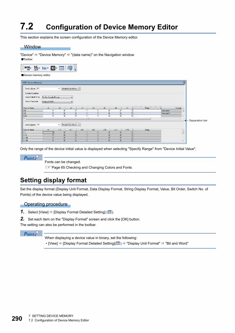
2907 SETTING DEVICE MEMORY7.2 Configuration of Device Memory Editor
7.2 Configuration of Device Memory EditorThis section explains the screen configuration of the Device Memory editor.
Window
"Device" "Device Memory" "(data name)" on the Navigation window
Only the range of the device initial value is displayed when selecting "Specify Range" from "Device Initial Value".
Fonts can be changed.
Page 65 Checking and Changing Colors and Fonts
Setting display formatSet the display format (Display Unit Format, Data Display Format, String Display Format, Value, Bit Order, Switch No. of
Points) of the device value being displayed.
Operating procedure
1. Select [View] [Display Format Detailed Setting] ( ).
2. Set each item on the "Display Format" screen and click the [OK] button.
The setting can also be performed in the toolbar.
When displaying a device value in binary, set the following:
• [View] [Display Format Detailed Setting]( ) "Display Unit Format" "Bit and Word"
■Toolbar
■Device memory editor
Separation bar
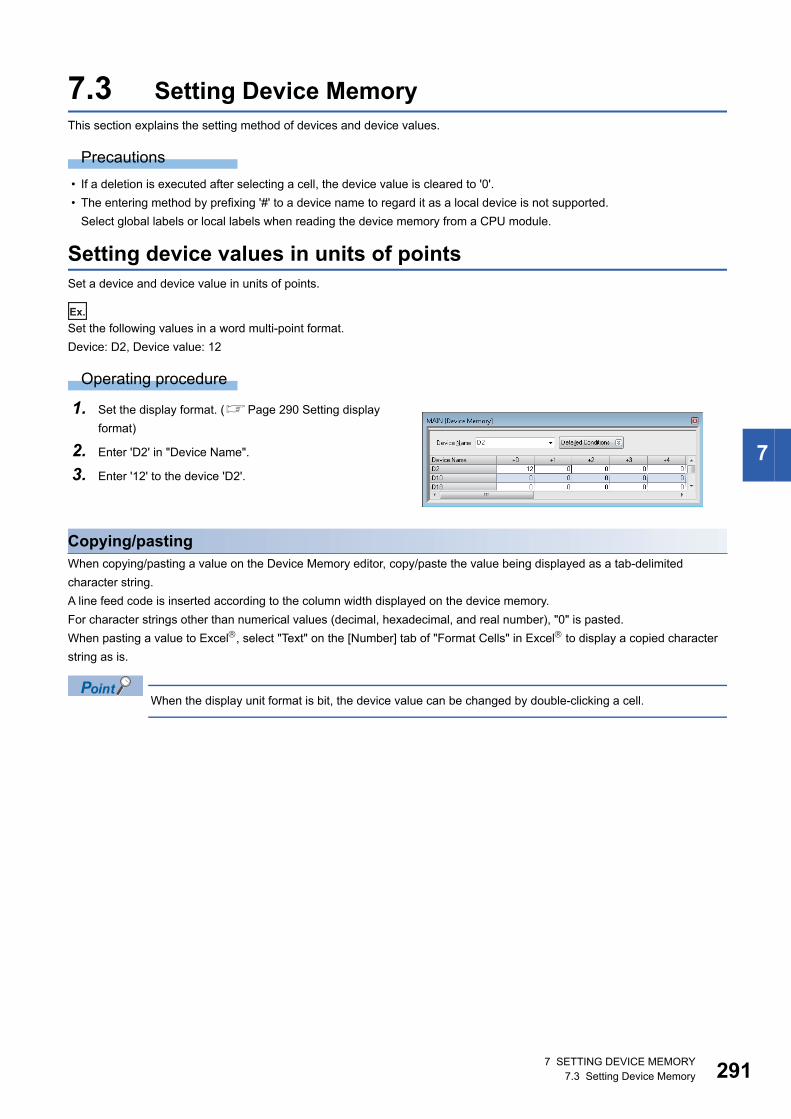
7 SETTING DEVICE MEMORY7.3 Setting Device Memory 291
7
7.3 Setting Device MemoryThis section explains the setting method of devices and device values.
Precautions
• If a deletion is executed after selecting a cell, the device value is cleared to '0'.
• The entering method by prefixing '#' to a device name to regard it as a local device is not supported.
Select global labels or local labels when reading the device memory from a CPU module.
Setting device values in units of pointsSet a device and device value in units of points.
Ex.
Set the following values in a word multi-point format.
Device: D2, Device value: 12
Operating procedure
Copying/pastingWhen copying/pasting a value on the Device Memory editor, copy/paste the value being displayed as a tab-delimited
character string.
A line feed code is inserted according to the column width displayed on the device memory.
For character strings other than numerical values (decimal, hexadecimal, and real number), "0" is pasted.
When pasting a value to Excel, select "Text" on the [Number] tab of "Format Cells" in Excel to display a copied character
string as is.
When the display unit format is bit, the device value can be changed by double-clicking a cell.
1. Set the display format. (Page 290 Setting display
format)
2. Enter 'D2' in "Device Name".
3. Enter '12' to the device 'D2'.
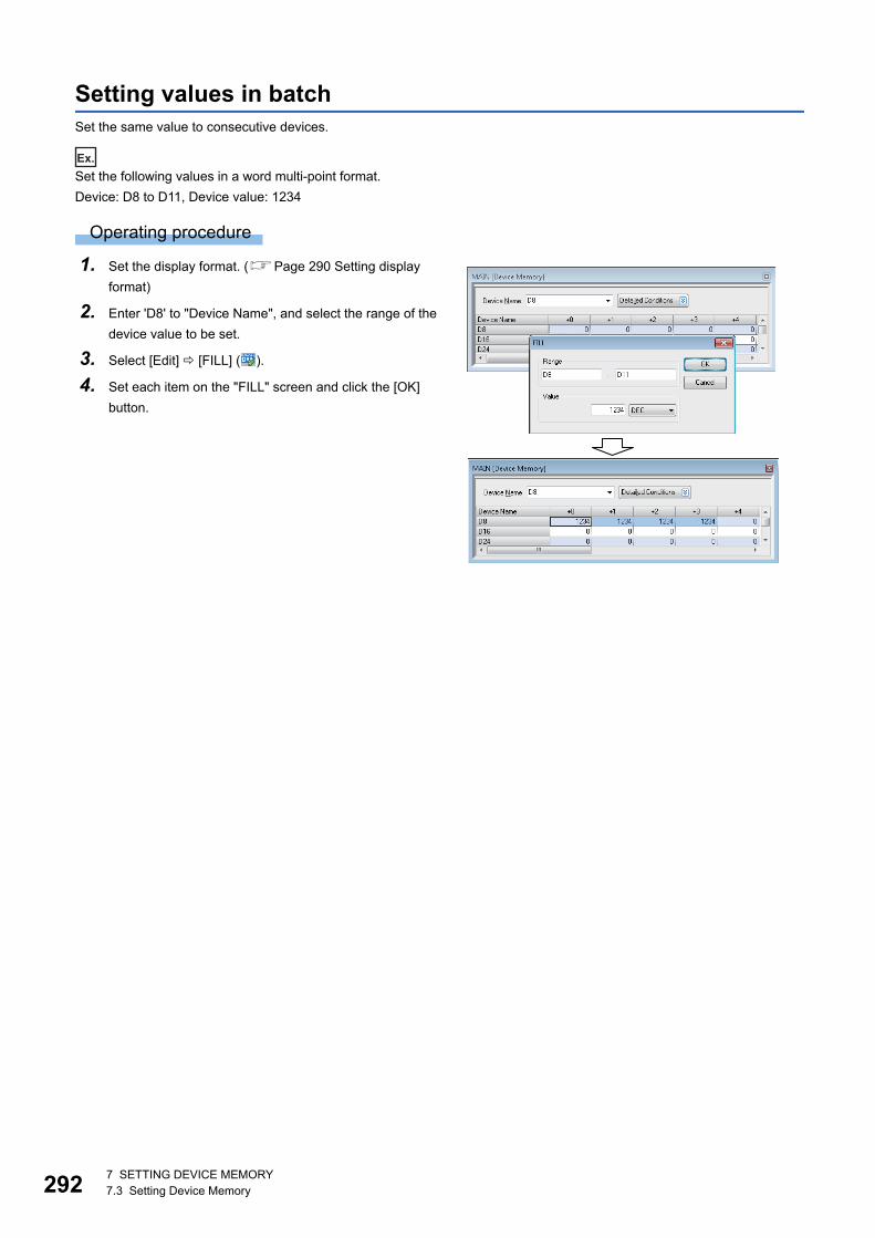
2927 SETTING DEVICE MEMORY7.3 Setting Device Memory
Setting values in batchSet the same value to consecutive devices.
Ex.
Set the following values in a word multi-point format.
Device: D8 to D11, Device value: 1234
Operating procedure
1. Set the display format. (Page 290 Setting display
format)
2. Enter 'D8' to "Device Name", and select the range of the
device value to be set.
3. Select [Edit] [FILL] ( ).
4. Set each item on the "FILL" screen and click the [OK]
button.

7 SETTING DEVICE MEMORY7.3 Setting Device Memory 293
7
Setting character stringsSet a character string to a device.
Ex.
Set the following values in a word multi-point format.
Device: D20, Character string: Device memory
Operating procedure
• Character string can be entered to "String" column directly.
• Click the [Read] button on the "Enter Character String" screen to read the set device values (string) one by
one.
Precautions
For device memory, use the characters in the Unicode Basic Multilingual Plane.
If a character outside the Unicode Basic Multilingual Plane is specified, it may not be displayed properly in the program.
Clearing whole memory of device memoryClear the data set to device memory data to '0' in batch in the project.
Operating procedure
■Delete all data in the device memory dataSelect [Edit] [Clear All (All Devices)].
■Delete the devices displayed on the Device Memory editorSelect [Edit] [Clear All (Displayed Devices)].
1. Set the display format. (Page 290 Setting display
format)
2. Enter 'D20' to "Device Name", and select [Edit] [Enter
Character String].
3. Enter a character string on the "Enter Character String"
screen, and click the [OK] button.
2947 SETTING DEVICE MEMORY7.4 Writing/Reading Data to/from CPU Module
Interaction with device initial valueDevice memory function registers/utilizes values to/from the device initial value.
Create a device initial value data to be registered in advance.
Remote head modules do not support it.
Operating procedure
1. Click the [Detailed Conditions] button.
2. Select "Specify Range" in the detailed conditions of "Device Initial Value".
3. Select [Edit] [Register/Import Device Initial Value].
The Device Initial Value editor is displayed. For details on the Device Initial Value editor, refer to the following sections.
• Registering the value of the device memory to device initial value: Page 298 Setting device initial values
• Utilizing values from device initial values to device memory: Page 298 Registering to device memory
7.4 Writing/Reading Data to/from CPU ModuleWhen writing/reading the value of device memory to/from the CPU module, perform them on the "Online Data operation"
screen in file units.

8 SETTING DEVICE INITIAL VALUES8.1 About Device Initial Values 295
8
8 SETTING DEVICE INITIAL VALUES
This chapter explains how to set the device initial values.
8.1 About Device Initial ValuesThe device initial value managed by GX Works3 is a data that can be read from/write to the device in a CPU module.
For details of device initial values, refer to the following manuals.
MELSEC iQ-R CPU Module User's Manual (Application)
MELSEC iQ-F FX5 User's Manual (Application)
Remote head modules do not support it.
Applicable devicesFor devices that can be set on the Device Initial Value editor, refer to the following section.
Page 541 Applicable Devices in GX Works3
Writing device initial values to global devices/local devicesA device initial value has no distinction between a global device and local device.
Write a device initial value to each device in a CPU module by the following methods.
• Global device: Create device initial value data with a different name from the one for the program file, and write it to a CPU
module
• Local device: Create device initial value data with a same name as the one for the program file, and write it to a CPU
module
The devices which cannot be used as local devices are not written even when they are set to device initial values.
FX5CPUs do not support local devices.
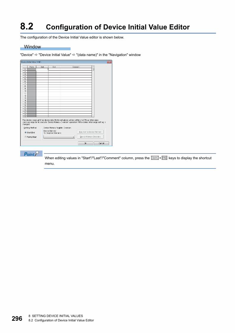
2968 SETTING DEVICE INITIAL VALUES8.2 Configuration of Device Initial Value Editor
8.2 Configuration of Device Initial Value EditorThe configuration of the Device Initial Value editor is shown below.
Window
"Device" "Device Initial Value" "(data name)" in the "Navigation" window
When editing values in "Start"/"Last"/"Comment" column, press the + keys to display the shortcut
menu.
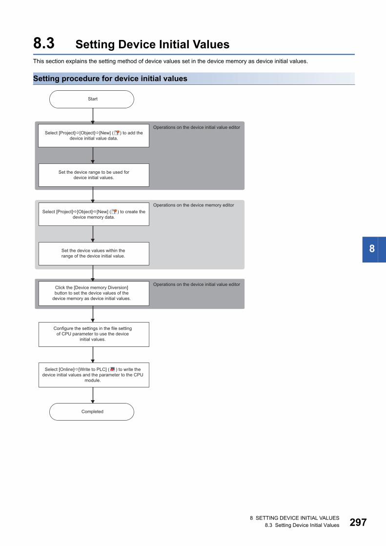
8 SETTING DEVICE INITIAL VALUES8.3 Setting Device Initial Values 297
8
8.3 Setting Device Initial ValuesThis section explains the setting method of device values set in the device memory as device initial values.
Setting procedure for device initial values
Start
Operations on the device initial value editorSelect [Project]�[Object]�[New] ( ) to add the
device initial value data.
Set the device range to be used for device initial values.
Operations on the device memory editorSelect [Project]�[Object]�[New] ( ) to create the
device memory data.
Set the device values within the range of the device initial value.
Operations on the device initial value editorClick the [Device memory Diversion] button to set the device values of the
device memory as device initial values.
Configure the settings in the file setting of CPU parameter to use the device
initial values.
Select [Online]�[Write to PLC] ( ) to write the device initial values and the parameter to the CPU
module.
Completed
2988 SETTING DEVICE INITIAL VALUES8.3 Setting Device Initial Values
Setting device initial valuesSet the device values set in the device memory as device initial values.
Create a device initial value data in advance. (Page 108 Creating data)
Operating procedure
1. Set each item on the Device Initial Value editor.
2. Select the data to be utilized from the pull-down list of "Device Memory for Register Diversion", and click the [Register to
Device Memory] button.
3. Click the [OK] button.
■Using device initial valuesTo use the values of each device in the set range as the initial values when starting a CPU module, specify a file name in "File
Setting" of "CPU Parameter".
■Device rangeInitial values can be set only for the devices in the range set in "File Setting" of "CPU Parameter".
Registering to device memoryThe data range set on the Device Initial Value editor is registered to device memory.
Operating procedure
1. Select data from the pull-down list of "Device Memory for Register Diversion".
2. Click the [Register to Device Memory] button.
If the registered data is modified on the device memory, it will not be applied to device initial values. Click the [Device Memory
Diversion] button on the Device Initial Value editor again.
To check the values of the device initial values, create a new device memory data and perform "Register to
Device Memory" to it.
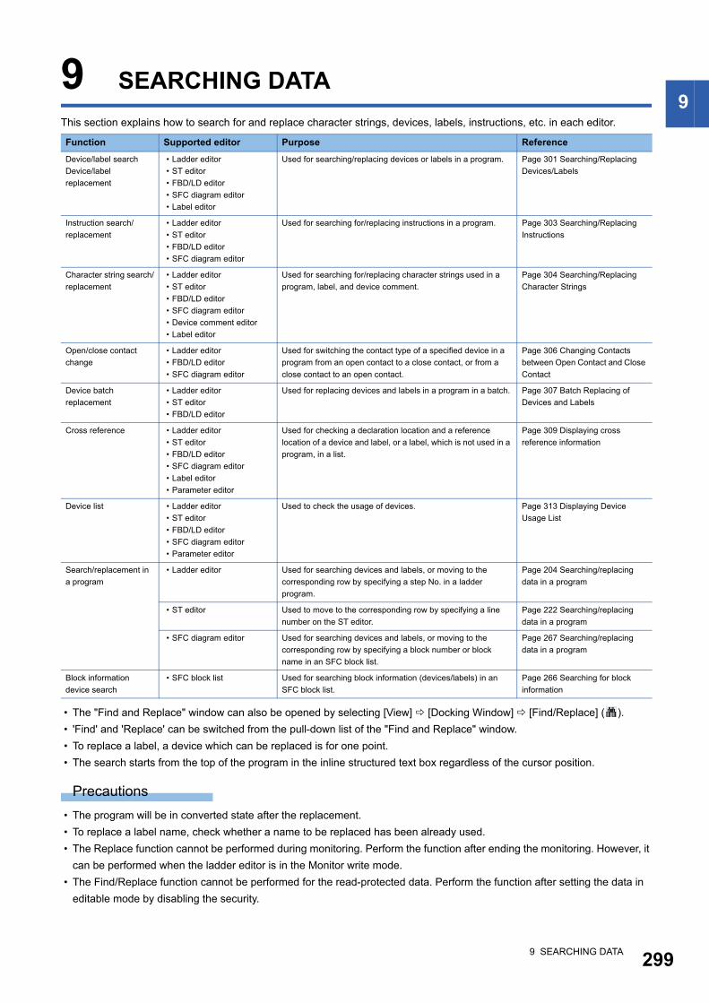
9 SEARCHING DATA 299
99 SEARCHING DATA
This section explains how to search for and replace character strings, devices, labels, instructions, etc. in each editor.
• The "Find and Replace" window can also be opened by selecting [View] [Docking Window] [Find/Replace] ( ).
• 'Find' and 'Replace' can be switched from the pull-down list of the "Find and Replace" window.
• To replace a label, a device which can be replaced is for one point.
• The search starts from the top of the program in the inline structured text box regardless of the cursor position.
Precautions
• The program will be in converted state after the replacement.
• To replace a label name, check whether a name to be replaced has been already used.
• The Replace function cannot be performed during monitoring. Perform the function after ending the monitoring. However, it
can be performed when the ladder editor is in the Monitor write mode.
• The Find/Replace function cannot be performed for the read-protected data. Perform the function after setting the data in
editable mode by disabling the security.
Function Supported editor Purpose Reference
Device/label search
Device/label
replacement
• Ladder editor
• ST editor
• FBD/LD editor
• SFC diagram editor
• Label editor
Used for searching/replacing devices or labels in a program. Page 301 Searching/Replacing
Devices/Labels
Instruction search/
replacement
• Ladder editor
• ST editor
• FBD/LD editor
• SFC diagram editor
Used for searching for/replacing instructions in a program. Page 303 Searching/Replacing
Instructions
Character string search/
replacement
• Ladder editor
• ST editor
• FBD/LD editor
• SFC diagram editor
• Device comment editor
• Label editor
Used for searching for/replacing character strings used in a
program, label, and device comment.
Page 304 Searching/Replacing
Character Strings
Open/close contact
change
• Ladder editor
• FBD/LD editor
• SFC diagram editor
Used for switching the contact type of a specified device in a
program from an open contact to a close contact, or from a
close contact to an open contact.
Page 306 Changing Contacts
between Open Contact and Close
Contact
Device batch
replacement
• Ladder editor
• ST editor
• FBD/LD editor
Used for replacing devices and labels in a program in a batch. Page 307 Batch Replacing of
Devices and Labels
Cross reference • Ladder editor
• ST editor
• FBD/LD editor
• SFC diagram editor
• Label editor
• Parameter editor
Used for checking a declaration location and a reference
location of a device and label, or a label, which is not used in a
program, in a list.
Page 309 Displaying cross
reference information
Device list • Ladder editor
• ST editor
• FBD/LD editor
• SFC diagram editor
• Parameter editor
Used to check the usage of devices. Page 313 Displaying Device
Usage List
Search/replacement in
a program
• Ladder editor Used for searching devices and labels, or moving to the
corresponding row by specifying a step No. in a ladder
program.
Page 204 Searching/replacing
data in a program
• ST editor Used to move to the corresponding row by specifying a line
number on the ST editor.
Page 222 Searching/replacing
data in a program
• SFC diagram editor Used for searching devices and labels, or moving to the
corresponding row by specifying a block number or block
name in an SFC block list.
Page 267 Searching/replacing
data in a program
Block information
device search
• SFC block list Used for searching block information (devices/labels) in an
SFC block list.
Page 266 Searching for block
information
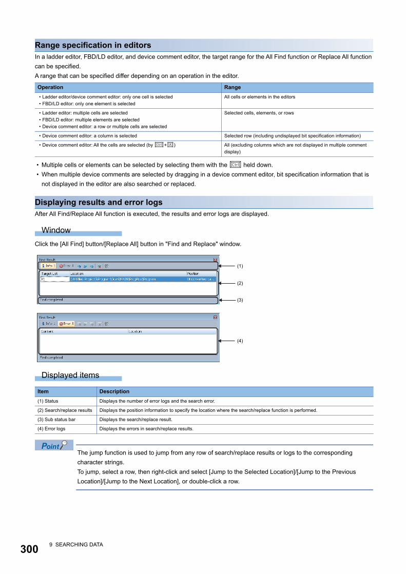
3009 SEARCHING DATA
Range specification in editorsIn a ladder editor, FBD/LD editor, and device comment editor, the target range for the All Find function or Replace All function
can be specified.
A range that can be specified differ depending on an operation in the editor.
• Multiple cells or elements can be selected by selecting them with the held down.
• When multiple device comments are selected by dragging in a device comment editor, bit specification information that is
not displayed in the editor are also searched or replaced.
Displaying results and error logsAfter All Find/Replace All function is executed, the results and error logs are displayed.
Window
Click the [All Find] button/[Replace All] button in "Find and Replace" window.
Displayed items
The jump function is used to jump from any row of search/replace results or logs to the corresponding
character strings.
To jump, select a row, then right-click and select [Jump to the Selected Location]/[Jump to the Previous
Location]/[Jump to the Next Location], or double-click a row.
Operation Range
• Ladder editor/device comment editor: only one cell is selected
• FBD/LD editor: only one element is selected
All cells or elements in the editors
• Ladder editor: multiple cells are selected
• FBD/LD editor: multiple elements are selected
• Device comment editor: a row or multiple cells are selected
Selected cells, elements, or rows
• Device comment editor: a column is selected Selected row (including undisplayed bit specification information)
• Device comment editor: All the cells are selected (by +) All (excluding columns which are not displayed in multiple comment
display)
Item Description
(1) Status Displays the number of error logs and the search error.
(2) Search/replace results Displays the position information to specify the location where the search/replace function is performed.
(3) Sub status bar Displays the search/replace result.
(4) Error logs Displays the errors in search/replace results.
(1)
(2)
(3)
(4)
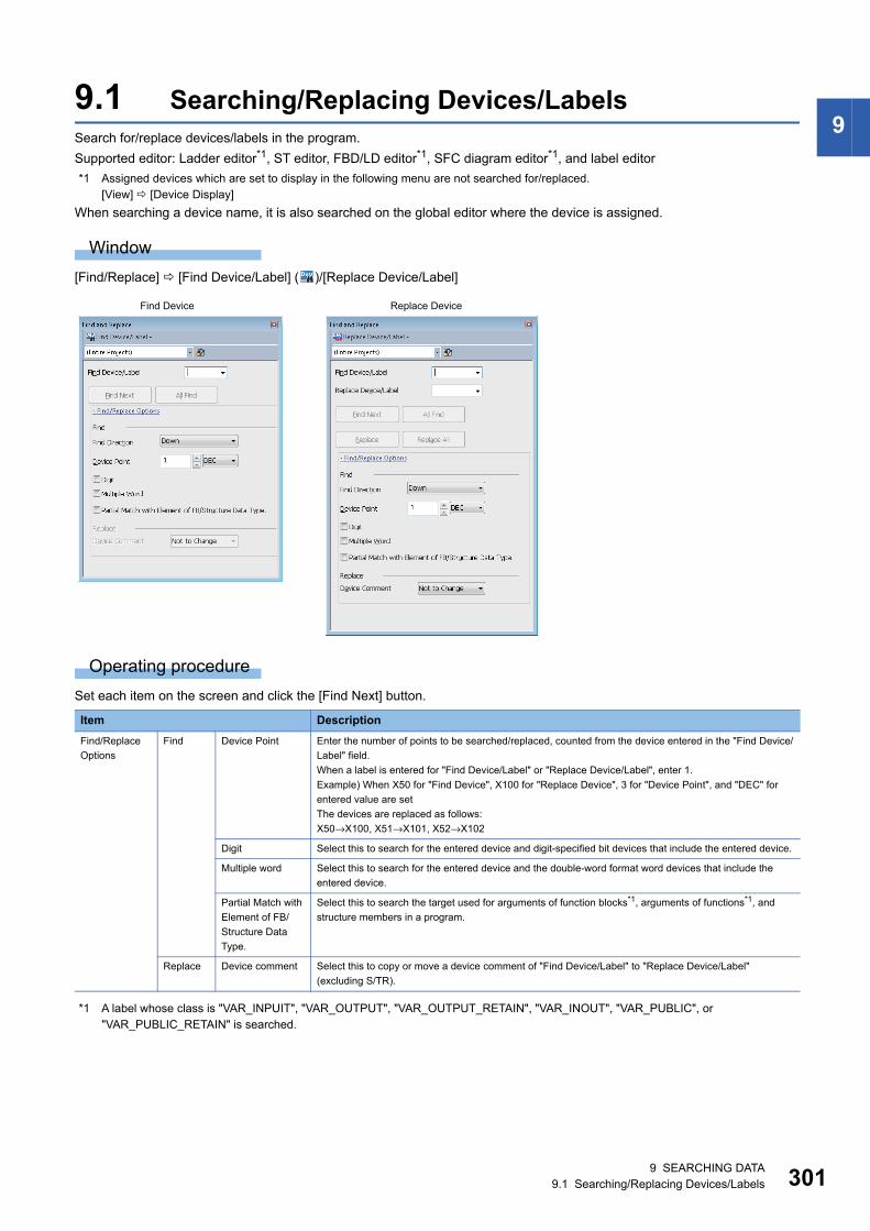
9 SEARCHING DATA9.1 Searching/Replacing Devices/Labels 301
99.1 Searching/Replacing Devices/LabelsSearch for/replace devices/labels in the program.
Supported editor: Ladder editor*1, ST editor, FBD/LD editor*1, SFC diagram editor*1, and label editor
*1 Assigned devices which are set to display in the following menu are not searched for/replaced.[View] [Device Display]
When searching a device name, it is also searched on the global editor where the device is assigned.
Window
[Find/Replace] [Find Device/Label] ( )/[Replace Device/Label]
Operating procedure
Set each item on the screen and click the [Find Next] button.
*1 A label whose class is "VAR_INPUIT", "VAR_OUTPUT", "VAR_OUTPUT_RETAIN", "VAR_INOUT", "VAR_PUBLIC", or "VAR_PUBLIC_RETAIN" is searched.
Item Description
Find/Replace
Options
Find Device Point Enter the number of points to be searched/replaced, counted from the device entered in the "Find Device/
Label" field.
When a label is entered for "Find Device/Label" or "Replace Device/Label", enter 1.
Example) When X50 for "Find Device", X100 for "Replace Device", 3 for "Device Point", and "DEC" for
entered value are set
The devices are replaced as follows:
X50→X100, X51→X101, X52→X102
Digit Select this to search for the entered device and digit-specified bit devices that include the entered device.
Multiple word Select this to search for the entered device and the double-word format word devices that include the
entered device.
Partial Match with
Element of FB/
Structure Data
Type.
Select this to search the target used for arguments of function blocks*1, arguments of functions*1, and
structure members in a program.
Replace Device comment Select this to copy or move a device comment of "Find Device/Label" to "Replace Device/Label"
(excluding S/TR).
Find Device Replace Device

3029 SEARCHING DATA9.1 Searching/Replacing Devices/Labels
When entering a label name, options for labels are displayed.
They can also be displayed by the following operations.
• Press the key + key.
• Enter '.' after entering a label name of a structure type or an instance name.
Examples of device search
■Options • Option: None
• Option: Digit
• Option: Multiple words
■Device with device type specifier (for ST editor, FBD/LD editor, and SFC diagram editor only)
Device specification Search result
M0 M0, K4M0, M0Z0, K4M0Z0
K4M0 K4M0, K4M0Z0
D0 D0, D0Z0, D0.1
D0.1 D0.1
J1\B0 J1\B0, J1\B0Z0, J1Z0\B0, J1Z0\B0Z0, J1\K4B0, J1\K4B0Z0, J1Z0\K4B0, J1Z0\K4B0Z0
Device specification Search result
X0 to X3 K1X0
X0 to X0F K4X0
X0 to X1F K8X0
X0Z0 X0Z0, K1X0Z0, K4X0Z0, K8X0Z0
Device specification Search result
D0 to D1 DMOV K1 D0, EMOV E1 D0, DMOV K1 @D0
D0 to D9 BMOV D0 D100 K10
J1\W0 to J1\W1 DMOV K1 J1\W0
@D0 to @D1 DMOV K1 @D0
T0 to T1 DMOV K1 T0
D0 to D1 D0:D, D0:DU, D0:E
D0 to D3 D0:ED
Device specification Search result Remarks
D100 D100: = 1;
D100: D: = 1;
D100: E:= 0.1;
Devices are searched regardless of device type specifier.
D100: D D100: = 1;
D100: D: = 1;
D100:E := 0.1;
Only devices with a specified device type specifier are searched.
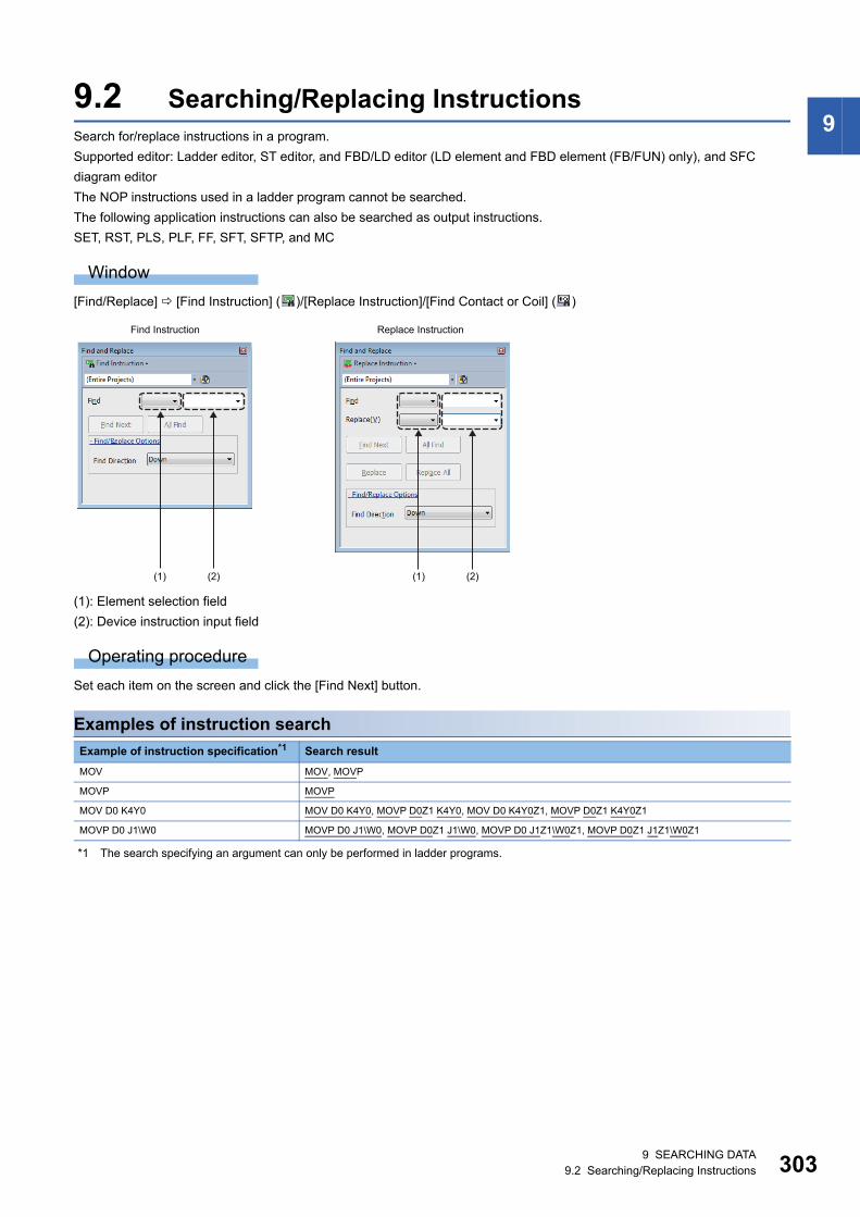
9 SEARCHING DATA9.2 Searching/Replacing Instructions 303
99.2 Searching/Replacing InstructionsSearch for/replace instructions in a program.
Supported editor: Ladder editor, ST editor, and FBD/LD editor (LD element and FBD element (FB/FUN) only), and SFC
diagram editor
The NOP instructions used in a ladder program cannot be searched.
The following application instructions can also be searched as output instructions.
SET, RST, PLS, PLF, FF, SFT, SFTP, and MC
Window
[Find/Replace] [Find Instruction] ( )/[Replace Instruction]/[Find Contact or Coil] ( )
(1): Element selection field
(2): Device instruction input field
Operating procedure
Set each item on the screen and click the [Find Next] button.
Examples of instruction search
*1 The search specifying an argument can only be performed in ladder programs.
Example of instruction specification*1 Search result
MOV MOV, MOVP
MOVP MOVP
MOV D0 K4Y0 MOV D0 K4Y0, MOVP D0Z1 K4Y0, MOV D0 K4Y0Z1, MOVP D0Z1 K4Y0Z1
MOVP D0 J1\W0 MOVP D0 J1\W0, MOVP D0Z1 J1\W0, MOVP D0 J1Z1\W0Z1, MOVP D0Z1 J1Z1\W0Z1
(1) (2) (1) (2)
Find Instruction Replace Instruction
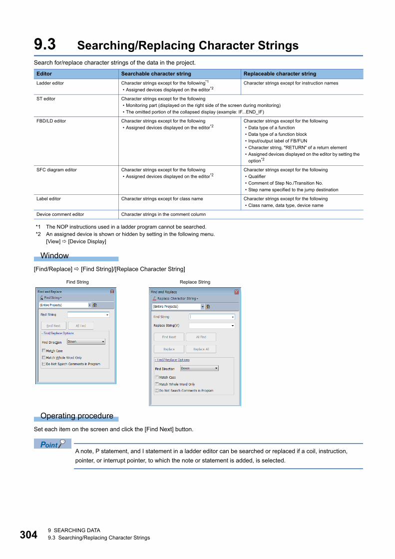
3049 SEARCHING DATA9.3 Searching/Replacing Character Strings
9.3 Searching/Replacing Character StringsSearch for/replace character strings of the data in the project.
*1 The NOP instructions used in a ladder program cannot be searched.*2 An assigned device is shown or hidden by setting in the following menu.
[View] [Device Display]
Window
[Find/Replace] [Find String]/[Replace Character String]
Operating procedure
Set each item on the screen and click the [Find Next] button.
A note, P statement, and I statement in a ladder editor can be searched or replaced if a coil, instruction,
pointer, or interrupt pointer, to which the note or statement is added, is selected.
Editor Searchable character string Replaceable character string
Ladder editor Character strings except for the following*1
• Assigned devices displayed on the editor*2Character strings except for instruction names
ST editor Character strings except for the following
• Monitoring part (displayed on the right side of the screen during monitoring)
• The omitted portion of the collapsed display (example: IF...END_IF)
FBD/LD editor Character strings except for the following
• Assigned devices displayed on the editor*2Character strings except for the following
• Data type of a function
• Data type of a function block
• Input/output label of FB/FUN
• Character string, "RETURN" of a return element
• Assigned devices displayed on the editor by setting the
option*2
SFC diagram editor Character strings except for the following
• Assigned devices displayed on the editor*2Character strings except for the following
• Qualifier
• Comment of Step No./Transition No.
• Step name specified to the jump destination
Label editor Character strings except for class name Character strings except for the following
• Class name, data type, device name
Device comment editor Character strings in the comment column
Find String Replace String

9 SEARCHING DATA9.3 Searching/Replacing Character Strings 305
9Search/replace data by matching whole word onlyThe whole word means a string delimited by the break characters.
The character string which is completely match with the character string entered in "Find String" is searched.
Break characters are shown as below.
• Space
• Tab
• Line feed
• Operator on ST editor
Ex.
Search for a device comment 'abc ; def' by the following character strings.
String to be searched for Search result
Unselected Selected
a abc; def Nothing is found.
abc abc; def abc; def
bc abc; def Nothing is found.
abc ; def abc; def abc; def
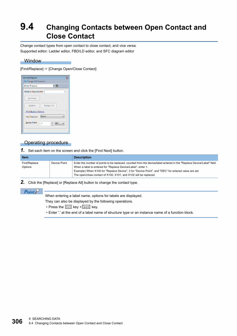
3069 SEARCHING DATA9.4 Changing Contacts between Open Contact and Close Contact
9.4 Changing Contacts between Open Contact and Close Contact
Change contact types from open contact to close contact, and vice versa.
Supported editor: Ladder editor, FBD/LD editor, and SFC diagram editor
Window
[Find/Replace] [Change Open/Close Contact]
Operating procedure
1. Set each item on the screen and click the [Find Next] button.
2. Click the [Replace] or [Replace All] button to change the contact type.
When entering a label name, options for labels are displayed.
They can also be displayed by the following operations.
• Press the key + key.
• Enter '.' at the end of a label name of structure type or an instance name of a function block.
Item Description
Find/Replace
Options
Device Point Enter the number of points to be replaced, counted from the device/label entered in the "Replace Device/Label" field.
When a label is entered for "Replace Device/Label", enter 1.
Example) When X100 for "Replace Device", 3 for "Device Point", and "DEC" for entered value are set
The open/close contact of X100, X101, and X102 will be replaced.
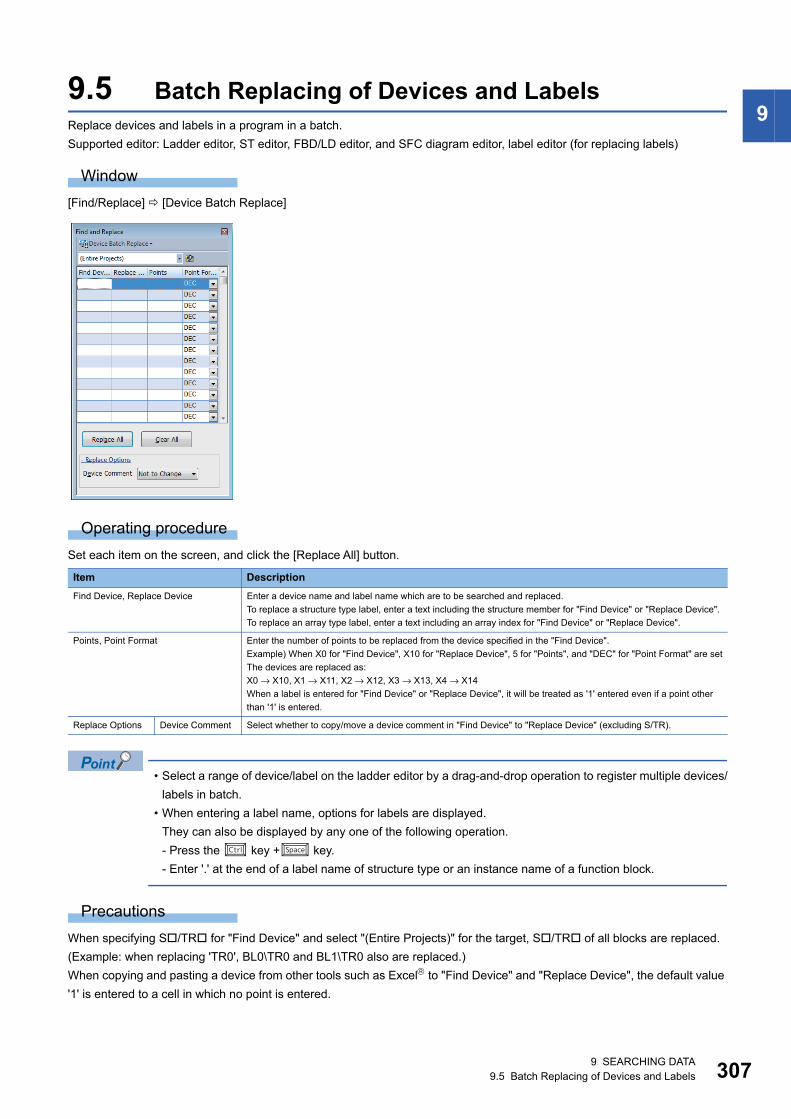
9 SEARCHING DATA9.5 Batch Replacing of Devices and Labels 307
99.5 Batch Replacing of Devices and LabelsReplace devices and labels in a program in a batch.
Supported editor: Ladder editor, ST editor, FBD/LD editor, and SFC diagram editor, label editor (for replacing labels)
Window
[Find/Replace] [Device Batch Replace]
Operating procedure
Set each item on the screen, and click the [Replace All] button.
• Select a range of device/label on the ladder editor by a drag-and-drop operation to register multiple devices/
labels in batch.
• When entering a label name, options for labels are displayed.
They can also be displayed by any one of the following operation.
- Press the key + key.
- Enter '.' at the end of a label name of structure type or an instance name of a function block.
Precautions
When specifying S/TR for "Find Device" and select "(Entire Projects)" for the target, S/TR of all blocks are replaced.
(Example: when replacing 'TR0', BL0\TR0 and BL1\TR0 also are replaced.)
When copying and pasting a device from other tools such as Excel to "Find Device" and "Replace Device", the default value
'1' is entered to a cell in which no point is entered.
Item Description
Find Device, Replace Device Enter a device name and label name which are to be searched and replaced.
To replace a structure type label, enter a text including the structure member for "Find Device" or "Replace Device".
To replace an array type label, enter a text including an array index for "Find Device" or "Replace Device".
Points, Point Format Enter the number of points to be replaced from the device specified in the "Find Device".
Example) When X0 for "Find Device", X10 for "Replace Device", 5 for "Points", and "DEC" for "Point Format" are set
The devices are replaced as:
X0 → X10, X1 → X11, X2 → X12, X3 → X13, X4 → X14
When a label is entered for "Find Device" or "Replace Device", it will be treated as '1' entered even if a point other
than '1' is entered.
Replace Options Device Comment Select whether to copy/move a device comment in "Find Device" to "Replace Device" (excluding S/TR).
3089 SEARCHING DATA9.6 Displaying Device and Label Reference Information in a List
9.6 Displaying Device and Label Reference Information in a List
A project can be searched to identify where a selected device/label is used, and the information is displayed in a list.
A Cross Reference window is displayed horizontally when it is docked on the top or bottom of the main frame, and displayed
vertically when it is docked on the left or right of the main frame.
The display format and detailed operation settings for each function can be set by setting the following option.
[Tool] [Options] "Find/Replace" "Cross Reference"
Target data for creating cross reference informationCross reference information is created based on devices used in the following data.
• Ladder programs
• ST programs
• FBD/LD programs
• SFC programs
• Global label
• Local label
• Structure
• Multiple CPU refresh setting of the CPU parameter
• Refresh setting of module parameters
• Simple CPU Communication Setting in the Module Parameter
For a project used for an FX5CPU, the cross reference information of devices that are used for the CPU built-in functions and
that are set in the parameter settings of extension modules and communication adapters are created.
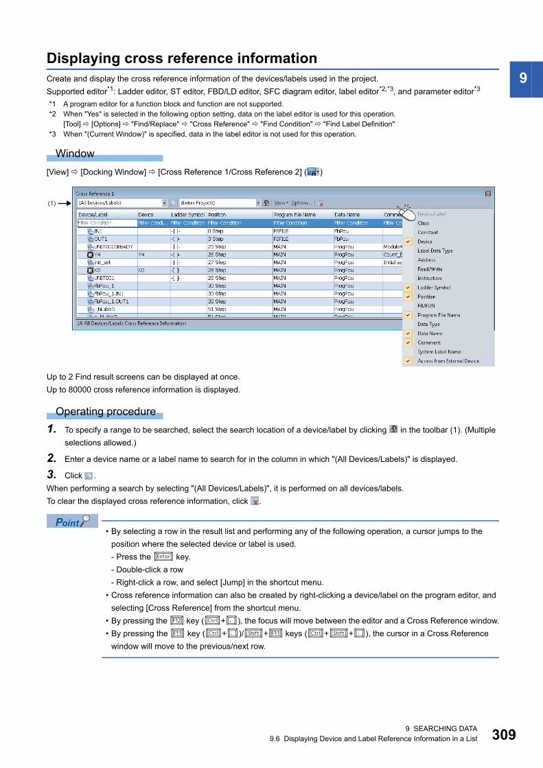
9 SEARCHING DATA9.6 Displaying Device and Label Reference Information in a List 309
9Displaying cross reference informationCreate and display the cross reference information of the devices/labels used in the project.
Supported editor*1: Ladder editor, ST editor, FBD/LD editor, SFC diagram editor, label editor*2,*3, and parameter editor*3
*1 A program editor for a function block and function are not supported.*2 When "Yes" is selected in the following option setting, data on the label editor is used for this operation.
[Tool] [Options] "Find/Replace" "Cross Reference" "Find Condition" "Find Label Definition"*3 When "(Current Window)" is specified, data in the label editor is not used for this operation.
Window
[View] [Docking Window] [Cross Reference 1/Cross Reference 2] ( )
Up to 2 Find result screens can be displayed at once.
Up to 80000 cross reference information is displayed.
Operating procedure
1. To specify a range to be searched, select the search location of a device/label by clicking in the toolbar (1). (Multiple
selections allowed.)
2. Enter a device name or a label name to search for in the column in which "(All Devices/Labels)" is displayed.
3. Click .
When performing a search by selecting "(All Devices/Labels)", it is performed on all devices/labels.
To clear the displayed cross reference information, click .
• By selecting a row in the result list and performing any of the following operation, a cursor jumps to the
position where the selected device or label is used.
- Press the key.
- Double-click a row
- Right-click a row, and select [Jump] in the shortcut menu.
• Cross reference information can also be created by right-clicking a device/label on the program editor, and
selecting [Cross Reference] from the shortcut menu.
• By pressing the key (+), the focus will move between the editor and a Cross Reference window.
• By pressing the key (+)/+ keys (++), the cursor in a Cross Reference
window will move to the previous/next row.
(1)

3109 SEARCHING DATA9.6 Displaying Device and Label Reference Information in a List
■Automatic synchronizationA function to create the cross reference information of devices/labels selected on the editor automatically.
The Cross Reference window used for displaying the result of automatic synchronization can be specified by selecting
"Options" in the window and setting the items in "Option" of "Operational Setting".
When performing automatic synchronization, the timing for updating the cross reference information can also be specified.
■A device assigned to a labelGlobal labels and devices assigned to the global labels can be searched at the same time.
In the following option, whether or not to search assigned devices can be selected.
• [Option] in the toolbar "Find Condition" "Include Assigned Device in Finding Label Name"
Displayed information
■ArrayWhen searching a label using a character other than number (such as a constant or a device) for an array index, a device that
was assigned to the first element within the array element set for the data type of this label is displayed in the "Device"
column.
■Displaying data types of arguments of an FB/FUNFor FBD/LD programs or SFC programs (FBD/LD elements), the data type of an FB/FUN using devices/labels as arguments
can be displayed in the "FB/FUN" column.
Contacts, coils, and variable elements are displayed.
Up to 10 data types of an FB/FUN can be displayed for one element.
Whether to display can be selected by setting the following option.
• [Tool] [Options] "Cross Reference" "Find Condition" "Find FB/FUN which uses device/label as an argument"
■Displaying and editing comments • For a ladder, the comments specified in [Tool] [Options] "Project" "Device Comment Reference/Reflection Target"
are displayed as device comments.
• To edit a comment, open the editor where the comment is defined by selecting a row arbitrarily in the search result in a
Cross Reference window, and right-clicking and selecting [Comment Edit] from the shortcut menu.
Page 268 Device comments
■Data protected by securityIt is not displayed in the Cross Reference window.
Incorrect cross reference information is displayed • When deleting data after converting, and displaying cross reference information, the deleted data may be displayed in the
search result. To display the latest information, convert again and display the cross reference information.
• If a program or the option setting is changed, cross reference information does not correspond with the program.
In order to update the cross reference information, display it again.
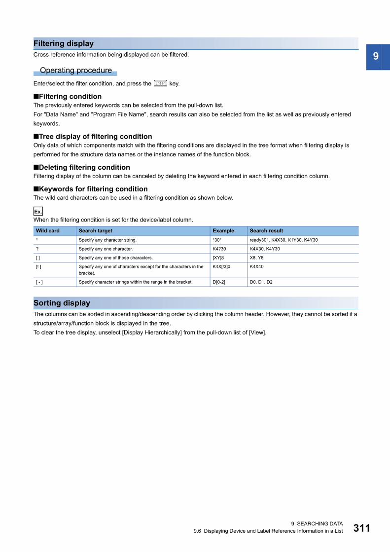
9 SEARCHING DATA9.6 Displaying Device and Label Reference Information in a List 311
9Filtering displayCross reference information being displayed can be filtered.
Operating procedure
Enter/select the filter condition, and press the key.
■Filtering conditionThe previously entered keywords can be selected from the pull-down list.
For "Data Name" and "Program File Name", search results can also be selected from the list as well as previously entered
keywords.
■Tree display of filtering conditionOnly data of which components match with the filtering conditions are displayed in the tree format when filtering display is
performed for the structure data names or the instance names of the function block.
■Deleting filtering conditionFiltering display of the column can be canceled by deleting the keyword entered in each filtering condition column.
■Keywords for filtering conditionThe wild card characters can be used in a filtering condition as shown below.
Ex.
When the filtering condition is set for the device/label column.
Sorting displayThe columns can be sorted in ascending/descending order by clicking the column header. However, they cannot be sorted if a
structure/array/function block is displayed in the tree.
To clear the tree display, unselect [Display Hierarchically] from the pull-down list of [View].
Wild card Search target Example Search result
* Specify any character string. *30* ready301, K4X30, K1Y30, K4Y30
? Specify any one character. K4?30 K4X30, K4Y30
[ ] Specify any one of those characters. [XY]8 X8, Y8
[! ] Specify any one of characters except for the characters in the
bracket.
K4X[!3]0 K4X40
[ - ] Specify character strings within the range in the bracket. D[0-2] D0, D1, D2

3129 SEARCHING DATA9.6 Displaying Device and Label Reference Information in a List
Displaying a list of unused labelsA list of labels unused in a project can be displayed.
Labels also can be deleted from the displayed list of labels.
Supported editor: Label editor
Window
[Find/Replace] [Unused Label List]
Operating procedure
1. To specify a range to be searched, select the search location of a label by clicking in the toolbar (1). (Multiple
selections allowed.)
2. Click .
Global labels which are not used in all POUs in a project and local labels which are not used in POUs within the range to be
searched are displayed in a list.
Precautions
• A function block, function, and structure which are not utilized in a program are not searched for.
• A label used in "Block Information" in the "Properties" screen of an SFC block as an array index is regarded as an unused
label if it is not used in a program.
• Labels specified as aliases are not detected as unused labels even when these are not used in a program.
Deleting unused labelsLabels can be deleted by specifying it in the list when "(Unused Label)" is selected in the search box in a Cross Reference
window.
Operating procedure
1. Select a label in the result list. (Multiple selections allowed.)
2. Right-click and select [Delete Label] from the shortcut menu.
Precautions
• When a label is deleted, the program related to the deleted label will be in the unconverted state.
• When utilizing a function block/function in a program, an input argument and an output argument which are not used in the
function block/function are treated as unused ones. Note that the definition of a function block/function is changed when
deleting an input argument and an output argument.
• When VAR_PUBLIC and VAR_PUBLIC_RETAIN are not used in the function block of the definition source, these are
detected as unused labels even when used in a program other than the function block of the definition source.
• When a label name of an input/output argument of a function block utilized in an ST program corresponds to a local label
name in the ST program, it is not detected as an unused label.
(1)
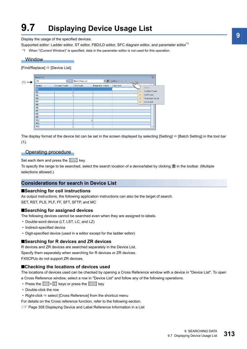
9 SEARCHING DATA9.7 Displaying Device Usage List 313
99.7 Displaying Device Usage ListDisplay the usage of the specified devices.
Supported editor: Ladder editor, ST editor, FBD/LD editor, SFC diagram editor, and parameter editor*1
*1 When "(Current Window)" is specified, data in the parameter editor is not used for this operation.
Window
[Find/Replace] [Device List].
The display format of the device list can be set in the screen displayed by selecting [Setting] [Batch Setting] in the tool bar
(1).
Operating procedure
Set each item and press the key.
To specify the range to be searched, select the search location of a device/label by clicking in the toolbar. (Multiple
selections allowed.)
Considerations for search in Device List
■Searching for coil instructionsAs output instructions, the following application instructions can also be the target of search.
SET, RST, PLS, PLF, FF, SFT, SFTP, and MC
■Searching for assigned devicesThe following devices cannot be searched even when they are assigned to labels.
• Double-word device (LT, LST, LC, and LZ)
• Indirect-specified device
• Digit-specified device (used in a editor except for the ladder editor)
■Searching for R devices and ZR devicesR devices and ZR devices are searched separately in the Device List.
Specify them separately when searching for R devices or ZR devices.
FX5CPUs do not support ZR devices.
■Checking the locations of devices usedThe locations of devices used can be checked by opening a Cross Reference window with a device in "Device List". To open
a Cross Reference window, select a row in "Device List" and follow any of the following operations.
• Press the + keys or press the key
• Double-click the row
• Right-click select [Cross Reference] from the shortcut menu
For details on the Cross reference function, refer to the following section.
Page 308 Displaying Device and Label Reference Information in a List
(1)

3149 SEARCHING DATA9.7 Displaying Device Usage List
■Displaying and editing comments • To search data by selecting one program, the comments specified by selecting [Tool] [Options] "Project" "Device
Comment Reference/Reflection Target" are displayed. (Page 268 Device comments)
• To search data by selecting multiple programs, common device comments are displayed.
• To edit a comment, open the editor where the comment is defined by selecting a row in the Device List, then right-clicking
and selecting [Comment Edit] from the shortcut menu.
■Searching for a step relay (S)when searching for a step relay (S), specify a step relay with a block specification (BL\S).

10 SEGMENTING PROGRAMS 315
10
10 SEGMENTING PROGRAMS
By segmenting a process program which is used repeatedly in a program into an element, it can be used in a sequence
program.
Efficient program development reduces a program error, thus program quality will be improved.
A segmented program file is referred to as 'POU' (Page 82 Data configuration).
Besides, multiple POUs can be collected into a different file from a project. The file is referred to as 'library'.
POUThere are two types of POUs which can repeatedly be used; function blocks and functions.
Remote head modules do not support it.
■Function block'Function block' is a program component (POU) created by segmenting a program, which outputs an operation result in
accordance with a value of the internal memory and an input value, into components.
It is classified into the following three types.
■Function'Function' is a program component (POU) created by segmenting a program, which has no internal memory and outputs the
same operation result to the same input value always.
It is classified into the following two types.
POU Description Reference
Function block
(User-created)
A function block which is created from a program including a label defined as an input label, internal
label, or an output label.
In a project used for an RnPCPU (process mode/redundant mode) and an RnPSFCPU, a function
block in which the process control processing of a manufacturer-defined tag FB is customized (user-
defined tag FB) can be created.
Page 317 Creating a
Function Block
Page 321 Creating a user-
defined tag FB
Standard function block A function block which can be used in general. It is prepared in GX Works3 in advance. Page 45 Element
selection window
Process control function
block
A function block for process control. It can be used in the following programs. It is prepared in GX
Works3 in advance.
In addition, process control function blocks can be used in the following program.
• FBD/LD program for process control
• FB program of a user-defined FB placed in an FBD/LD program (FBD/LD program)
• FB program of a user-defined tag FB placed in an FBD/LD program (FBD/LD program)
Page 45 Element
selection window
Module FB A function block which is created by segmenting a dedicated processing for a module. It is prepared in
GX Works3 in advance.
Page 326 Enhanced use
of module FBs
POU Description Reference
Function
(User-created)
A function block which is created from a program including a label defined as an input label or an
output label.
Page 328 Creating a
Function
Standard function A function which can be used in general. It is prepared in GX Works3 in advance. Page 45 Element
selection window

31610 SEGMENTING PROGRAMS
Library'Library' is an element collection of multiple POUs and structures. Elements in a library can be used in multiple projects.
■User library'User library' is an element collection which is composed of created POUs and structures.
For details, refer to the following section.
Page 330 Enhancing Use of User Library
■Application library/MELSOFT Library (sample library)'MELSOFT Library' (Sample Library) is an element collection provided by a manufacturer.
To obtain the application library/sample library (MELSOFT Library), please consult your local Mitsubishi representative.
For details, refer to the following section.
Page 338 Enhanced Use of Application Library/MELSOFT Library
Remote head modules do not support it.

10 SEGMENTING PROGRAMS10.1 Creating a Function Block 317
10
10.1 Creating a Function BlockThis section explains the method to create a sequence program using function blocks.
Function blockFor details on function blocks, refer to the following manuals.
MELSEC iQ-R Programming Manual (Program Design)
MELSEC iQ-F FX5 Programming Manual (Program Design)
Procedure to use1. Create new function block data. (Page 318 Creating new data)
2. Register a local label to use in a program body of a function block. Up to 5120 local labels can be registered in a function
block. (Page 318 Setting labels)
3. Create a program body by using a label. (Page 319 Creating a program)
4. Paste a function block onto a sequence program. (Page 187 Inserting function blocks, Page 220 Inserting function
blocks)
Creating a function blockThe following explains the method to create a function block.
Number of creatable function blocks
RCPU (other than R04CPU): Up to 8192 in conjunction with function data
R04CPU: Up to 4096 in conjunction with function data
FX5CPU: Up to 960 in conjunction with function data
However, the maximum number of data that can be created may not be reached depending on the configuration of FB files
and FUN files.
31810 SEGMENTING PROGRAMS10.1 Creating a Function Block
Creating new dataA function block data can be created in a project on the "New Data" screen.
*1 For the conditions to select "Yes", refer to the following section.Page 318 Conditions to select "Yes" for "Use MC/MCR to Control EN"
■Conditions to select "Yes" for "Use MC/MCR to Control EN"When all of the following conditions are applied, "Yes" can be selected for "Use MC/MCR to Control EN.
Precautions
• If the function block in which the MC/MCR instruction is used is not executed, the outputs and the current values of timers
in the function block will be reset. (If the instruction is not used, the current values are retained).
• When "Yes" is selected for "Use MC/MCR to Control EN", the system uses 'N0' (nesting) for MC/MCR instructions in an FB.
Therefore, do not use 'N0' for the MC/MCR instructions in the same FB.
Setting labelsSet a label to use in a program body on the label editor.
The operations on the screen is the same as that of other label editor. For details, refer to the following section.
Page 157 Registering Labels
Operating procedure
Select "FB/FUN" "(file name)" "(FB)" "Local Label" in the "Navigation" window.
Precautions
Do not assign the instance of a function block to an alias. (Page 159 Alias)
Item Description
Detail
Setting
Inherent
Property
Use MC/MCR to Control EN*1 For "Yes", the MC/MCR instructions are used to control 'EN'.
For "No", the CJ instruction is used to control 'EN'.
Select "Yes" when the raising/falling instructions are used in an FB.
The operations of a timer/counter and the OUT instruction used in an FB differ depending the
selected item.
For details, refer to the following manual.
MELSEC iQ-R Programming Manual (Program Design)
MELSEC iQ-F FX5 Programming Manual (Program Design)
Use EN/ENO For "Yes", a function block with EN/ENO is created, and EN/ENO labels can be used in a
program without registering as local labels.
For "No", a function block without EN/ENO is created.
For details on EN/ENO, refer to the following manuals.
MELSEC iQ-R Programming Manual (Program Design)
MELSEC iQ-F FX5 Programming Manual (Program Design)
FB File FB File of Add Destination Select a storage destination file of a function block to be created.
A new storage destination file can be created by entering a file name directly.
FB Type For "Macro Type", the program body of a function block is stored in an FB file that will be the
storage destination of the call source program block or program body of the function block.
For "Subroutine Type", the program body of a function block is stored in an FB file.
Condition
1 "Yes" is selected for "Use EN/ENO".
2 Any of the following settings are set.
• "Macro Type" is selected for "FB Type".
• "Yes" is selected for the following option and "Subroutine Type" is selected for "FB Type".
[Tool] [Options] "Convert" "Basic Setting" "Operational Setting" "Function Block" "Enable to Use MC/MCR to Control EN"
3 A CPU module and GX Works3 supporting this setting are used.
For the versions supporting this setting, refer to the following manual.
MELSEC iQ-R CPU Module User's Manual (Application)
10 SEGMENTING PROGRAMS10.1 Creating a Function Block 319
10
Creating a programCreate a program body of a function block by using a label.
Both local labels of the function block and global labels can be used.
The method for entering programs is the same as that of each program.
Operating procedure
1. Select "FB/FUN" "(file name)" "(FB)" "ProgramBody" in the "Navigation" window.
2. Configure the programs.
Changing the type of a function blockChange the type of a function block (macro type/subroutine type).
Operating procedure
1. Select "FB/FUN" "(file name)" in the "Navigation" window.
2. Select [Project] [Data Operation] [Properties].
3. Set the type of the function block for "FB Type" in the "Properties" screen, and click the [OK] button.
Setting reserved area capacitiesSet the reserved area capacities of FB instances for each function block.
To apply the set reserved area capacities for programs, all the programs are required to be converted (reassigned).
For details on reserved area capacities, refer to the following manual.
MELSEC iQ-R Programming Manual (Program Design)
Operating procedure
1. Select "Yes" for the following option.
[Tool] [Options] "Convert" "Basic Setting" "Operational Setting" "Function Block" "Enable to Set Reserved
Area"
2. Select "FB/FUN" "(file name)" "(FB)" in the "Navigation" window.
3. Select [Project] [Data Operation] [Properties].
4. Set a reserved area capacity for "Label Reserved Area" ,"Latch Label Reserved Area", or "Signal Flow Reserved Area",
then click the [OK] button in the "Properties" screen.
5. Convert (reassign) all the programs.
Precautions
• For projects used for FX5CPUs, the reserved area capacities of function blocks cannot be changed.
• Only for subroutine type function blocks, the reserved area capacity for "Signal Flow Reserved Area" can be set.

32010 SEGMENTING PROGRAMS10.1 Creating a Function Block
Converting function blocks • Function blocks (POUs) will not be converted even if a conversion was attempted as long as FB instances have not been
created, or FB instances have been created only in unregistered programs.
• When a function block is edited, all the programs in which the FB file and the function block are used will be in unconverted
state.
■When editing only the program body of a subroutine type function blockBy setting the following option, only the edited FB program or FB file will be in the unconverted state.
• [Tool] [Options] "Convert" "Basic Setting" "Operational Setting" "Convert, Online Program Change Target
Setting"
When an unconverted function block is converted after changing the option from "High-Speed" to "Low-Speed", a POU
including the function block is also converted.
Precautions
If the option is set to "High-speed" and any one of the following instruction is used in a subroutine type function block, a
conversion error may occur. A conversion is successfully completed by performing the conversion function or online program
change function.
• Rising instruction
• Falling instruction
• SCJ instruction
• STMR instruction
Considerations when creating FB programs
■Use of devicesUsing labels is recommended for creating FB programs.
If an FB program which uses devices (X10, Y10, etc.) is used at multiple locations, the program may not operate normally.
In addition, if an FB program which uses devices for the OUT instruction is used at multiple locations, duplicated coil is
resulted. Duplicated coil can be avoided with the SET/RST instruction.
■When using master control instructionsWhen using a master control instruction in an FB program, use the MC instruction and the MCR instruction together.
■When using function blocks for a sequence program to be executed multiple times in a single scan
If a function block, which contains a rising instruction/falling instruction, or an instruction that requires multiple scans before
the execution completion, is used in a sequence program to be executed multiple times in a single scan, the program may not
operate normally.
Item Description
Program type to be executed multiple times in a single scan • Fixed scan execution type program
• Interrupt program
• Subroutine program
• FOR-NEXT instruction program
Unusable instructions for FBs which are used for above
programs
Instructions which require multiple scans before the execution completion
(JP.READ/JP.WRITE instruction, SORT instruction, SP.FREAD/SP.FWRITE instruction, etc.)
Rising instruction
(P instruction (such as MOVP instruction), PLS, etc.)
Falling instruction
(PLF, LDF, ANDF, ORF, MEF, FCALLP, EFCALLP, etc.)
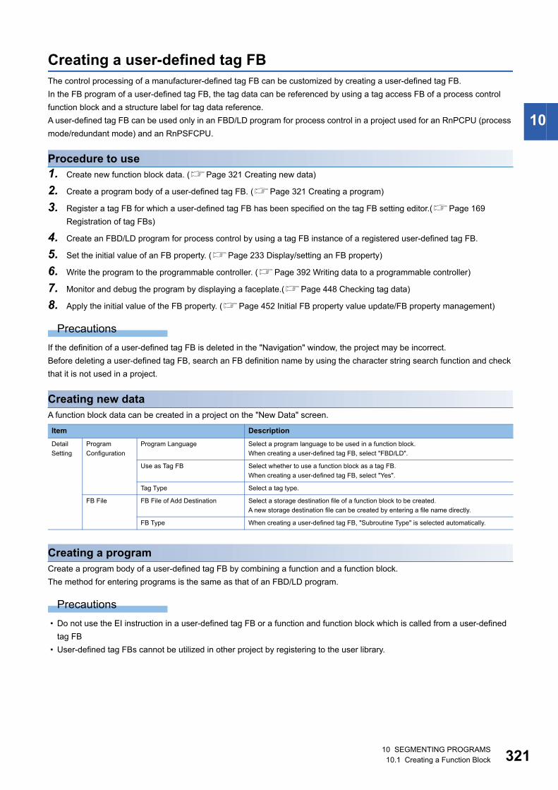
10 SEGMENTING PROGRAMS10.1 Creating a Function Block 321
10
Creating a user-defined tag FBThe control processing of a manufacturer-defined tag FB can be customized by creating a user-defined tag FB.
In the FB program of a user-defined tag FB, the tag data can be referenced by using a tag access FB of a process control
function block and a structure label for tag data reference.
A user-defined tag FB can be used only in an FBD/LD program for process control in a project used for an RnPCPU (process
mode/redundant mode) and an RnPSFCPU.
Procedure to use1. Create new function block data. (Page 321 Creating new data)
2. Create a program body of a user-defined tag FB. (Page 321 Creating a program)
3. Register a tag FB for which a user-defined tag FB has been specified on the tag FB setting editor.(Page 169
Registration of tag FBs)
4. Create an FBD/LD program for process control by using a tag FB instance of a registered user-defined tag FB.
5. Set the initial value of an FB property. (Page 233 Display/setting an FB property)
6. Write the program to the programmable controller. (Page 392 Writing data to a programmable controller)
7. Monitor and debug the program by displaying a faceplate.(Page 448 Checking tag data)
8. Apply the initial value of the FB property. (Page 452 Initial FB property value update/FB property management)
Precautions
If the definition of a user-defined tag FB is deleted in the "Navigation" window, the project may be incorrect.
Before deleting a user-defined tag FB, search an FB definition name by using the character string search function and check
that it is not used in a project.
Creating new dataA function block data can be created in a project on the "New Data" screen.
Creating a programCreate a program body of a user-defined tag FB by combining a function and a function block.
The method for entering programs is the same as that of an FBD/LD program.
Precautions
• Do not use the EI instruction in a user-defined tag FB or a function and function block which is called from a user-defined
tag FB
• User-defined tag FBs cannot be utilized in other project by registering to the user library.
Item Description
Detail
Setting
Program
Configuration
Program Language Select a program language to be used in a function block.
When creating a user-defined tag FB, select "FBD/LD".
Use as Tag FB Select whether to use a function block as a tag FB.
When creating a user-defined tag FB, select "Yes".
Tag Type Select a tag type.
FB File FB File of Add Destination Select a storage destination file of a function block to be created.
A new storage destination file can be created by entering a file name directly.
FB Type When creating a user-defined tag FB, "Subroutine Type" is selected automatically.
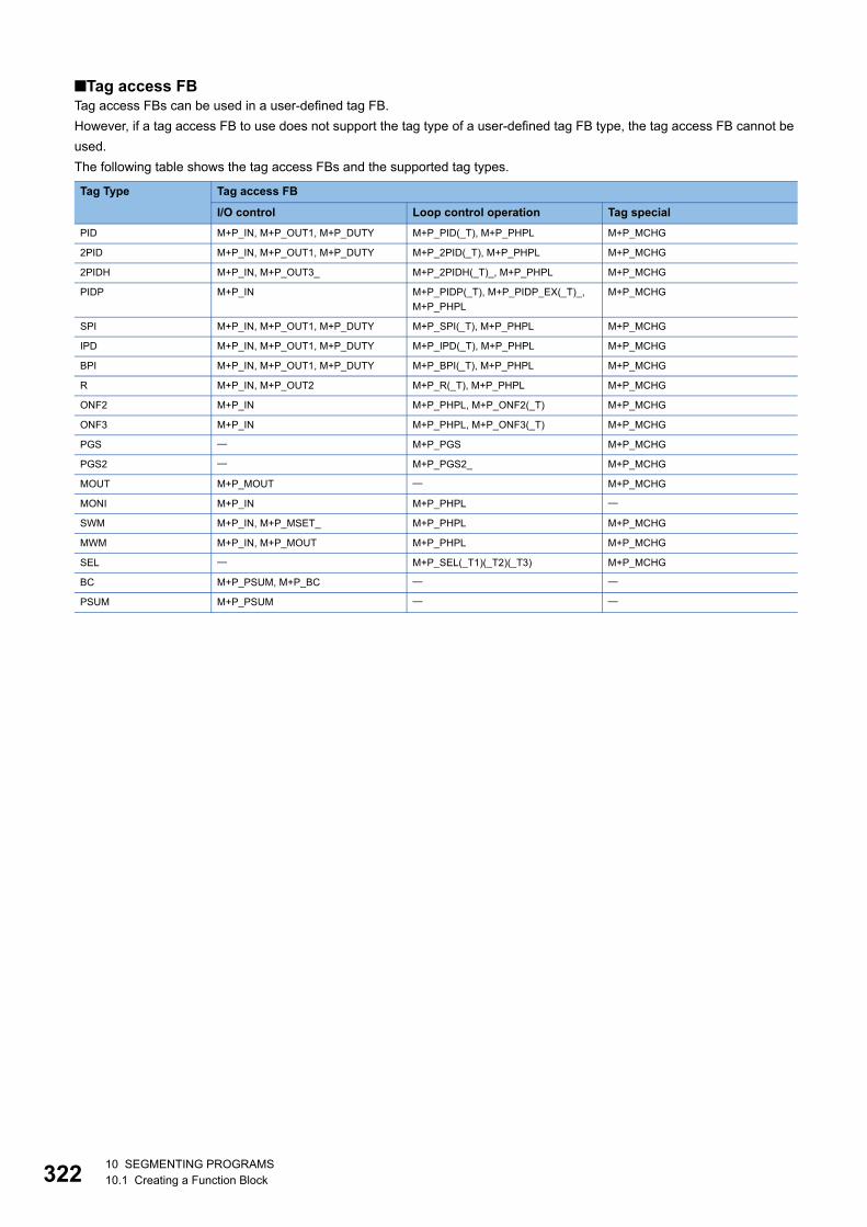
32210 SEGMENTING PROGRAMS10.1 Creating a Function Block
■Tag access FBTag access FBs can be used in a user-defined tag FB.
However, if a tag access FB to use does not support the tag type of a user-defined tag FB type, the tag access FB cannot be
used.
The following table shows the tag access FBs and the supported tag types.
Tag Type Tag access FB
I/O control Loop control operation Tag special
PID M+P_IN, M+P_OUT1, M+P_DUTY M+P_PID(_T), M+P_PHPL M+P_MCHG
2PID M+P_IN, M+P_OUT1, M+P_DUTY M+P_2PID(_T), M+P_PHPL M+P_MCHG
2PIDH M+P_IN, M+P_OUT3_ M+P_2PIDH(_T)_, M+P_PHPL M+P_MCHG
PIDP M+P_IN M+P_PIDP(_T), M+P_PIDP_EX(_T)_,
M+P_PHPL
M+P_MCHG
SPI M+P_IN, M+P_OUT1, M+P_DUTY M+P_SPI(_T), M+P_PHPL M+P_MCHG
IPD M+P_IN, M+P_OUT1, M+P_DUTY M+P_IPD(_T), M+P_PHPL M+P_MCHG
BPI M+P_IN, M+P_OUT1, M+P_DUTY M+P_BPI(_T), M+P_PHPL M+P_MCHG
R M+P_IN, M+P_OUT2 M+P_R(_T), M+P_PHPL M+P_MCHG
ONF2 M+P_IN M+P_PHPL, M+P_ONF2(_T) M+P_MCHG
ONF3 M+P_IN M+P_PHPL, M+P_ONF3(_T) M+P_MCHG
PGS M+P_PGS M+P_MCHG
PGS2 M+P_PGS2_ M+P_MCHG
MOUT M+P_MOUT M+P_MCHG
MONI M+P_IN M+P_PHPL
SWM M+P_IN, M+P_MSET_ M+P_PHPL M+P_MCHG
MWM M+P_IN, M+P_MOUT M+P_PHPL M+P_MCHG
SEL M+P_SEL(_T1)(_T2)(_T3) M+P_MCHG
BC M+P_PSUM, M+P_BC
PSUM M+P_PSUM
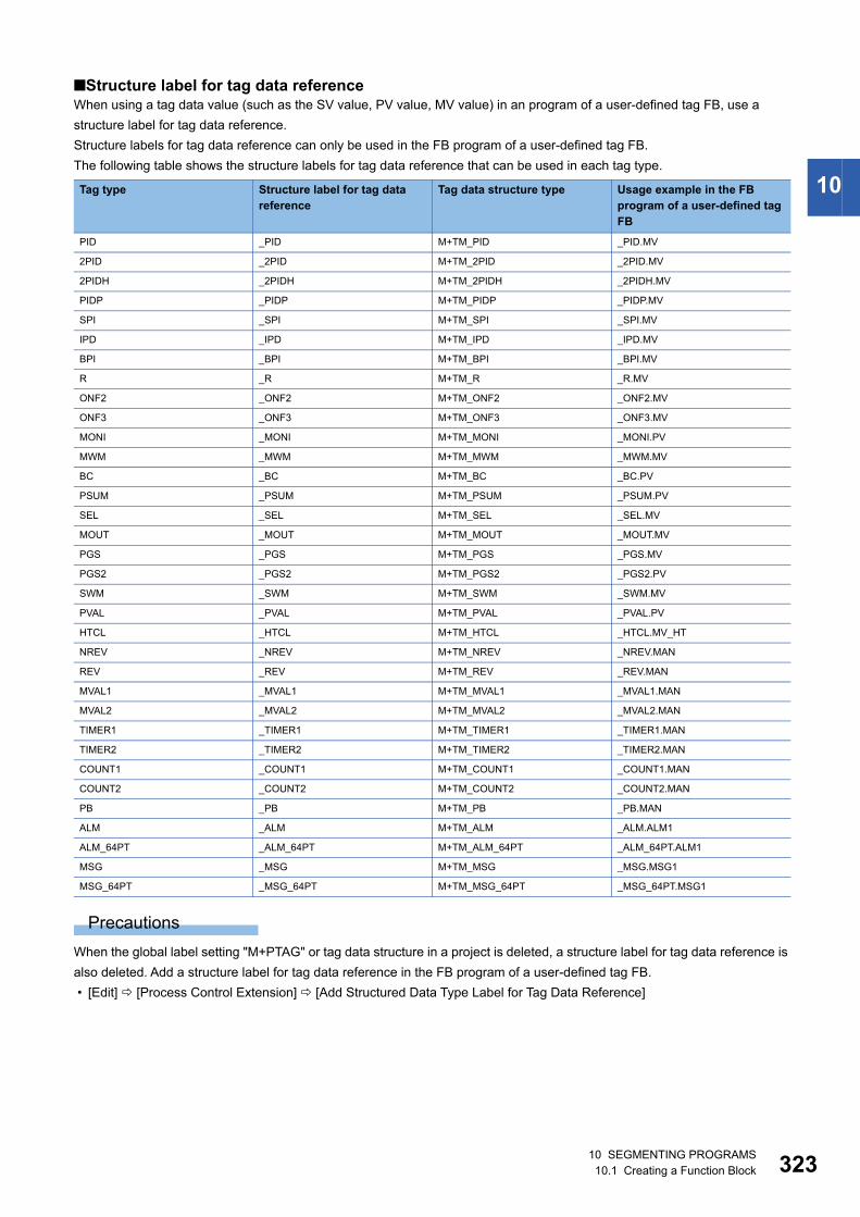
10 SEGMENTING PROGRAMS10.1 Creating a Function Block 323
10
■Structure label for tag data referenceWhen using a tag data value (such as the SV value, PV value, MV value) in an program of a user-defined tag FB, use a
structure label for tag data reference.
Structure labels for tag data reference can only be used in the FB program of a user-defined tag FB.
The following table shows the structure labels for tag data reference that can be used in each tag type.
Precautions
When the global label setting "M+PTAG" or tag data structure in a project is deleted, a structure label for tag data reference is
also deleted. Add a structure label for tag data reference in the FB program of a user-defined tag FB.
• [Edit] [Process Control Extension] [Add Structured Data Type Label for Tag Data Reference]
Tag type Structure label for tag data reference
Tag data structure type Usage example in the FB program of a user-defined tag FB
PID _PID M+TM_PID _PID.MV
2PID _2PID M+TM_2PID _2PID.MV
2PIDH _2PIDH M+TM_2PIDH _2PIDH.MV
PIDP _PIDP M+TM_PIDP _PIDP.MV
SPI _SPI M+TM_SPI _SPI.MV
IPD _IPD M+TM_IPD _IPD.MV
BPI _BPI M+TM_BPI _BPI.MV
R _R M+TM_R _R.MV
ONF2 _ONF2 M+TM_ONF2 _ONF2.MV
ONF3 _ONF3 M+TM_ONF3 _ONF3.MV
MONI _MONI M+TM_MONI _MONI.PV
MWM _MWM M+TM_MWM _MWM.MV
BC _BC M+TM_BC _BC.PV
PSUM _PSUM M+TM_PSUM _PSUM.PV
SEL _SEL M+TM_SEL _SEL.MV
MOUT _MOUT M+TM_MOUT _MOUT.MV
PGS _PGS M+TM_PGS _PGS.MV
PGS2 _PGS2 M+TM_PGS2 _PGS2.PV
SWM _SWM M+TM_SWM _SWM.MV
PVAL _PVAL M+TM_PVAL _PVAL.PV
HTCL _HTCL M+TM_HTCL _HTCL.MV_HT
NREV _NREV M+TM_NREV _NREV.MAN
REV _REV M+TM_REV _REV.MAN
MVAL1 _MVAL1 M+TM_MVAL1 _MVAL1.MAN
MVAL2 _MVAL2 M+TM_MVAL2 _MVAL2.MAN
TIMER1 _TIMER1 M+TM_TIMER1 _TIMER1.MAN
TIMER2 _TIMER2 M+TM_TIMER2 _TIMER2.MAN
COUNT1 _COUNT1 M+TM_COUNT1 _COUNT1.MAN
COUNT2 _COUNT2 M+TM_COUNT2 _COUNT2.MAN
PB _PB M+TM_PB _PB.MAN
ALM _ALM M+TM_ALM _ALM.ALM1
ALM_64PT _ALM_64PT M+TM_ALM_64PT _ALM_64PT.ALM1
MSG _MSG M+TM_MSG _MSG.MSG1
MSG_64PT _MSG_64PT M+TM_MSG_64PT _MSG_64PT.MSG1
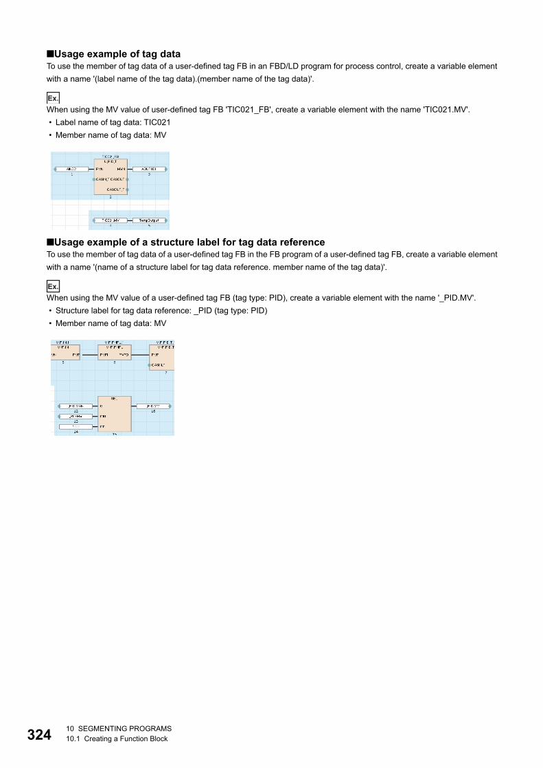
32410 SEGMENTING PROGRAMS10.1 Creating a Function Block
■Usage example of tag dataTo use the member of tag data of a user-defined tag FB in an FBD/LD program for process control, create a variable element
with a name '(label name of the tag data).(member name of the tag data)'.
Ex.
When using the MV value of user-defined tag FB 'TIC021_FB', create a variable element with the name 'TIC021.MV'.
• Label name of tag data: TIC021
• Member name of tag data: MV
■Usage example of a structure label for tag data referenceTo use the member of tag data of a user-defined tag FB in the FB program of a user-defined tag FB, create a variable element
with a name '(name of a structure label for tag data reference. member name of the tag data)'.
Ex.
When using the MV value of a user-defined tag FB (tag type: PID), create a variable element with the name '_PID.MV'.
• Structure label for tag data reference: _PID (tag type: PID)
• Member name of tag data: MV
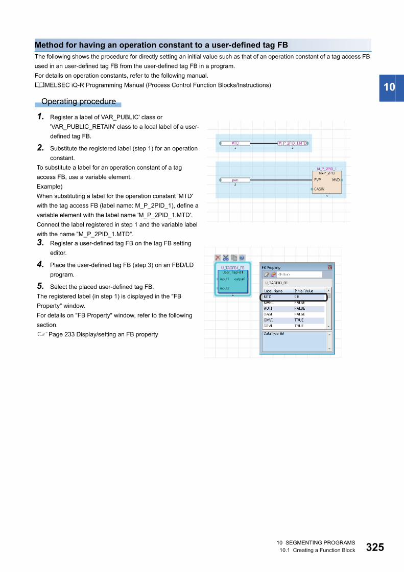
10 SEGMENTING PROGRAMS10.1 Creating a Function Block 325
10
Method for having an operation constant to a user-defined tag FBThe following shows the procedure for directly setting an initial value such as that of an operation constant of a tag access FB
used in an user-defined tag FB from the user-defined tag FB in a program.
For details on operation constants, refer to the following manual.
MELSEC iQ-R Programming Manual (Process Control Function Blocks/Instructions)
Operating procedure
1. Register a label of VAR_PUBLIC' class or
'VAR_PUBLIC_RETAIN' class to a local label of a user-
defined tag FB.
2. Substitute the registered label (step 1) for an operation
constant.
To substitute a label for an operation constant of a tag
access FB, use a variable element.
Example)
When substituting a label for the operation constant 'MTD'
with the tag access FB (label name: M_P_2PID_1), define a
variable element with the label name 'M_P_2PID_1.MTD'.
Connect the label registered in step 1 and the variable label
with the name "M_P_2PID_1.MTD".
3. Register a user-defined tag FB on the tag FB setting
editor.
4. Place the user-defined tag FB (step 3) on an FBD/LD
program.
5. Select the placed user-defined tag FB.
The registered label (in step 1) is displayed in the "FB
Property" window.
For details on "FB Property" window, refer to the following
section.
Page 233 Display/setting an FB property
32610 SEGMENTING PROGRAMS10.1 Creating a Function Block
Enhanced use of module FBsIn GX Works3, 'Module FB', which is composed of the segmented processing for each module (function block), is provided.
By using the module FBs, the operation settings can easily be performed without programming the processing of each
module.
Note that the module FBs cannot be used in safety programs.
Importing module FBs in projectModule FBs are displayed in the [Module] tab in the "Element Selection" window when one of the following operations is
performed.
• Place a module on a module configuration diagram and fix parameters.
• Add a new module in the "Navigation" window.
The manual of a module FB can be displayed from the "Element Selection" window.
Select and right-click a module FB, then select [Help] from the shortcut menu.
Using module FBs in programs
Operating procedure
1. Drag a module FB in the [Module] tab in the "Element Selection" window and drop it onto a program.
2. Select a target label (local label or global label) in the pull-down list in the "FB Instance Name" screen, and enter an FB
instance name.
Once an FB instance is created, the created function block (local Label, program body) is registered into "M_FBLIB" in the
"Navigation" window.
Precautions
• When using a module FB, registering a module label in advance (at creation of new project) is recommended.
Otherwise, it may take time when using the module FB.
• Do not assign the instance of a module FB to an alias. (Page 159 Alias)
■Using a library associated with a moduleDepending on a module (simple motion module), a library that is associated with a module can be used.
The following shows the procedure to use the library.
Operating procedure
1. In the [Module] tab in the "Element Selection" window, double-click "(module name)" under the tree of "Module FB".
2. Read the message, and click the [Yes] button.*1
A message with "Environment Setup Procedure" described in is displayed.
3. Obtain a library by following the message.
4. Register the library to the library list. (Page 335 Registering user libraries in the library list)
A shortcut to the library is added as a child item of "(module name)" in the tree expanded (double-clicked) in step 1.
5. Double-click the shortcut to the library.
6. Utilize an element from the library to a project. (Page 335 Utilizing an element)
*1 The message may not appear depending on the module.
10 SEGMENTING PROGRAMS10.1 Creating a Function Block 327
10
Precautions
■Data to be displayedWhen a library associated with a module is registered to the library list, the data displayed as child items of the module FB in
the tree may differ.
• Only a shortcut to the library is displayed.
• A shortcut to the library and a module FB are displayed.
• Only a module FB is displayed.
■Redisplay of a shortcut to a libraryA shortcut to the library disappears once the project is closed.
When opening the project next time, select a module in which a library associated with the module is used.
By clicking the [Yes] button after reading the message*1, a shortcut to the library is displayed again.
*1 The message may not appear depending on the module.
■Redisplay of a module FBTo redisplay module FBs that are not displayed in the tree, perform any one of the following operations.
Setting operation parameter of module FB
Operating procedure
1. Open the label editor where the FB instance of the module FB is registered (local label or global label of the program
where module FB is used).
2. Select the FB instance and enter the initial value of the label in the extension display area.
However, the initial value of a label whose operation parameter is array cannot be set in a label editor. Set an initial value in a
program.
When the operation parameter of module FB set in the label initial value is changed by program, the module FB operates with
the changed value. Before changing the label values of a module FB, check the influence of the change using the Cross
Reference function.
Editing module FBsA local label and a program body of a module FB cannot be edited.
However, module FBs can be copied in the "Navigation" window and the copied ones can be edited.
'+' of the copied module FB names will be replaced with '_'.
No. Operation
1 Delete the library that is associated with a module from the library list. (Page 335 Deleting libraries/updating display information)
2 Open the project again.
In the [Module] tab of the "Element Selection" window, double-click "(module name)" under "Module FB" in the tree.
Click the [No] button in the confirmation message appeared.
32810 SEGMENTING PROGRAMS10.2 Creating a Function
10.2 Creating a FunctionThis section explains the method to create a sequence program using functions.
FunctionsFor details of the functions, refer to the following manuals.
MELSEC iQ-R Programming Manual (Program Design)
MELSEC iQ-F FX5 Programming Manual (Program Design)
Procedure to use1. Create new function data. (Page 328 Creating new data)
2. Register a local label to be used in a FUN program. Maximum 5120 local labels can be registered in a function.
(Page 328 Setting labels)
3. Create a FUN program using labels. (Page 329 Creating a program)
4. Paste the function onto a sequence program. (Page 191 Inserting functions, Page 220 Inserting functions)
Creating a functionThe following explains the method to create a function.
Number of creatable functions
RCPU (other than R04CPU): Up to 8192 in conjunction with function block data
R04CPU: Up to 4096 in conjunction with function block data
FX5CPU: Up to 960 in conjunction with function block data
However, the maximum number of data that can be created may not be reached depending on the configuration of FB files
and FUN files.
Creating new dataA function block data can be created in a project on the "New Data" screen.
Setting labelsSet a label to use in a program body on the label editor.
The operations on the screen is the same as that of other label editor. For details, refer to the following section.
Page 157 Registering Labels
Operating procedure
Select "FB/FUN" "(file name)" "(Function)" "Local Label" in the "Navigation" window.
Item Description
Detail Setting Use EN/ENO Yes Become a function with EN/ENO.
EN/ENO labels can be used in a program without registering as local labels.
For details on EN/ENO, refer to the following manuals.
MELSEC iQ-R Programming Manual (Program Design)
MELSEC iQ-F FX5 Programming Manual (Program Design)
No Become a function without EN/ENO.
FUN File of Add Destination Select the storage destination file of a function to be created.
A new storage destination file can be created by entering a file name directly.
10 SEGMENTING PROGRAMS10.2 Creating a Function 329
10
Creating a programCreate a program body of a function by using a label.
The labels set to the local label of the function can be used.
The method for entering programs is the same as that of each program.
Operating procedure
1. Select "FB/FUN" "(file name)" "(function)" "ProgramBody" in the "Navigation" window.
2. Configure the programs.
Converting functions • Functions (POUs) will not be in the converted state even if the conversion was attempted as long as functions are not used
in the program, or functions are used only in unregistered programs.
• When a function is edited, all the programs in which the FUN file and the function are used will be in unconverted state.
■When editing only the program body of a functionBy setting the following option, only an edited FUN program or FUN file will be in unconverted state.
• [Tool] [Options] "Convert" "Basic Setting" "Operational Setting" "Convert, Online Program Change Target
Setting"
When an unconverted function is converted after changing the option from "High-speed" to "Low-speed", a POU including the
function is also converted.
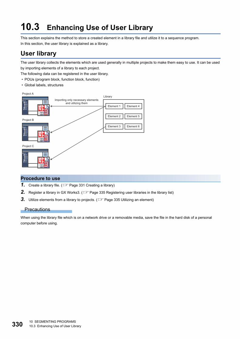
33010 SEGMENTING PROGRAMS10.3 Enhancing Use of User Library
10.3 Enhancing Use of User LibraryThis section explains the method to store a created element in a library file and utilize it to a sequence program.
In this section, the user library is explained as a library.
User libraryThe user library collects the elements which are used generally in multiple projects to make them easy to use. It can be used
by importing elements of a library to each project.
The following data can be registered in the user library.
• POUs (program block, function block, function)
• Global labels, structures
Procedure to use1. Create a library file. (Page 331 Creating a library)
2. Register a library in GX Works3. (Page 335 Registering user libraries in the library list)
3. Utilize elements from a library to projects. (Page 335 Utilizing an element)
Precautions
When using the library file which is on a network drive or a removable media, save the file in the hard disk of a personal
computer before using.
Library
Element 1
Element 2
Element 3
Element 4
Element 5
Element 6
Project A
Project B
Project C
Importing only necessary elements and utilizing them
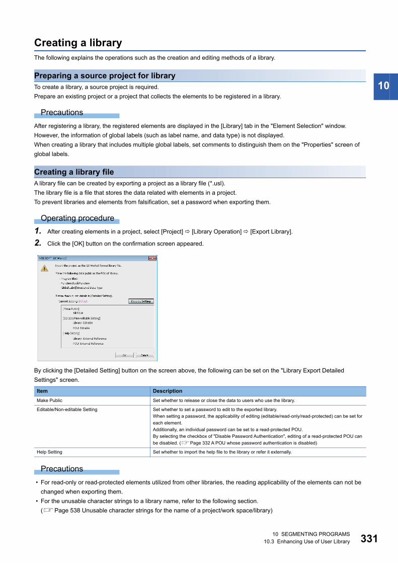
10 SEGMENTING PROGRAMS10.3 Enhancing Use of User Library 331
10
Creating a libraryThe following explains the operations such as the creation and editing methods of a library.
Preparing a source project for libraryTo create a library, a source project is required.
Prepare an existing project or a project that collects the elements to be registered in a library.
Precautions
After registering a library, the registered elements are displayed in the [Library] tab in the "Element Selection" window.
However, the information of global labels (such as label name, and data type) is not displayed.
When creating a library that includes multiple global labels, set comments to distinguish them on the "Properties" screen of
global labels.
Creating a library fileA library file can be created by exporting a project as a library file (*.usl).
The library file is a file that stores the data related with elements in a project.
To prevent libraries and elements from falsification, set a password when exporting them.
Operating procedure
1. After creating elements in a project, select [Project] [Library Operation] [Export Library].
2. Click the [OK] button on the confirmation screen appeared.
By clicking the [Detailed Setting] button on the screen above, the following can be set on the "Library Export Detailed
Settings" screen.
Precautions
• For read-only or read-protected elements utilized from other libraries, the reading applicability of the elements can not be
changed when exporting them.
• For the unusable character strings to a library name, refer to the following section.
(Page 538 Unusable character strings for the name of a project/work space/library)
Item Description
Make Public Set whether to release or close the data to users who use the library.
Editable/Non-editable Setting Set whether to set a password to edit to the exported library.
When setting a password, the applicability of editing (editable/read-only/read-protected) can be set for
each element.
Additionally, an individual password can be set to a read-protected POU.
By selecting the checkbox of "Disable Password Authentication", editing of a read-protected POU can
be disabled. (Page 332 A POU whose password authentication is disabled)
Help Setting Set whether to import the help file to the library or refer it externally.
33210 SEGMENTING PROGRAMS10.3 Enhancing Use of User Library
■A POU whose password authentication is disabledWhen disabling password authentication for a read-protected POU, note the following on a library file in which a read-
protected POU has been registered, and on a project in which the library file was created.
• Do not delete them; otherwise, the POU cannot be opened.
• It may not be determined if they are the latest ones.
To prevent this, before creating a library file, setting version information to the library file or a project in which the library file
is to be created is recommended.
The operating procedure for setting version information is shown below.
Item Procedure
Project Select "Project" in the "Navigation" window.
Right-click it and select [Properties] in the shortcut menu.
Enter a text for "Version" in the "Properties" screen.
Click the [OK] button.
Save the project.
Library file Enter a text for "Version" in the "Export Library" screen, which is displayed when creating a library file. (Page 331 Creating a library
file)
Click the [Save] button.

10 SEGMENTING PROGRAMS10.3 Enhancing Use of User Library 333
10
Creating a library in GX Works3 format from a library in GX Works2 formatRemote head modules do not support it.
Operating procedure
1. Select [Project] [Open Other Format File] [GX Works2 Format] [Open User Library], and specify the library to be
converted into a GX Works3 project.
2. Select the series on the confirmation screen displayed, then click the [OK] button.
3. Check the project after changing the module type, then edit it if necessary.
4. Export the project as a library file.
Creating a library in GX Works3 format from a library in GX IEC Developer formatThis function is supported for the SUL format files which are created with GX IEC Developer version 7.04.
Operating procedure
■A GX Works3 project is open
1. Select [Project] [Open Other Format File] [GX IEC Developer Format] [Open SUL Format User Library], and
specify a library to convert to GX Works3 project.
2. Read the displayed message, and click the [OK] button.
3. Check the project after changing the module type, then edit it if necessary.
4. Export the project as a library file.
■A GX Works3 project is not open
1. Select [Project] [Open Other Format File] [GX IEC Developer Format] [Open SUL Format User Library], and
specify a library to convert to GX Works3 project.
2. Read the displayed message, and click the [OK] button.
The "New" screen appears.
3. Set each items in the "New" screen, and click the [OK] button.
4. Check the contents of the project after changing the module type, and edit the project as necessary.
5. Export the project as a library file.
■Import of some library POUs
1. Create a library in GX Works3 format from a library in GX IEC Developer format. (Page 333 Creating a library in GX
Works3 format from a library in GX IEC Developer format)
2. Open a GX IEC Developer format project in a GX Works3 project by changing the module type. (Page 97 Opening a
GX IEC Developer format project)
3. Register the user library exported in step 1 in the library list. (Page 335 Registering user libraries in the library list)
4. Copy the library POUs to the GX Works3 project.
5. Repeat step 1 to step 4 for each GX IEC Developer format library.
Precautions
When a password is set for the user library, entering password is required when importing library elements.
However, when the following option is set in GX IEC Developer, entering a password is not necessary.
• [Edit] [User Library] [Change Password] "Change Password (user library name)" "Allow read access for closed
library"
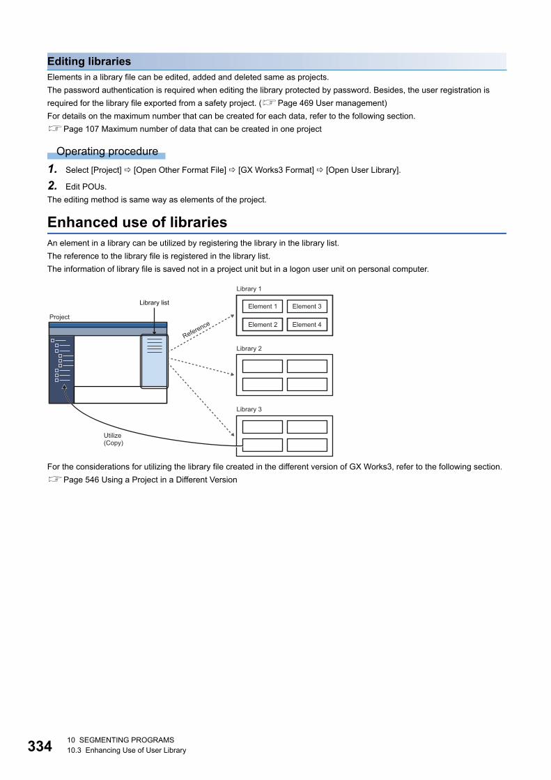
33410 SEGMENTING PROGRAMS10.3 Enhancing Use of User Library
Editing librariesElements in a library file can be edited, added and deleted same as projects.
The password authentication is required when editing the library protected by password. Besides, the user registration is
required for the library file exported from a safety project. (Page 469 User management)
For details on the maximum number that can be created for each data, refer to the following section.
Page 107 Maximum number of data that can be created in one project
Operating procedure
1. Select [Project] [Open Other Format File] [GX Works3 Format] [Open User Library].
2. Edit POUs.
The editing method is same way as elements of the project.
Enhanced use of librariesAn element in a library can be utilized by registering the library in the library list.
The reference to the library file is registered in the library list.
The information of library file is saved not in a project unit but in a logon user unit on personal computer.
For the considerations for utilizing the library file created in the different version of GX Works3, refer to the following section.
Page 546 Using a Project in a Different Version
Library list
Library 1
Element 1
Element 2
Element 3
Element 4
Library 2
Library 3
Project
Reference
Utilize(Copy)

10 SEGMENTING PROGRAMS10.3 Enhancing Use of User Library 335
10
Registering user libraries in the library listRegister a library containing elements to be utilized in the list.
Up to 64 libraries can be registered.
When the registered library file was edited while GX Works3 is running , updating the display information of library is
necessary.
Operating procedure
■Registering libraries to be referenced
1. Select [Project] [Library Operation] [Register to Library List] [User Library].
2. Select a file on the "Register Library to Library List" screen, then click the [Open] button.
For the library/element which is protected by password, the icon will be displayed in a pale color on the [Library] tab.
■Deleting libraries/updating display information
1. Select the [Library] tab in the "Element Selection" window.
2. Select the library to be deleted/updated, then select [Project] [Library Operation] [Delete from Library List] ( )/
[Update the Display Information of Library].
■Displaying Help
1. Select the [Library] tab in the "Element Selection" window.
2. Select a library or element, and select [Project] [Library Operation] [Help] or right-click [Help] from the shortcut
menu.
Utilizing an elementA library POU registered in the "Element Selection" window can be utilized to other projects.
To utilize POUs which were set the read-protection when exporting the library, the password is required before editing.
Operating procedure
■Pasting elements onto the" Navigation" windowDrag an element from the [Library] tab in the "Element Selection" window and drop it onto the "Navigation" window.
Elements can be dropped onto the place which is able to create the same kind of data only.
Read-protected POUs are displayed in the "Navigation" window as follow.
AuthenticatedRead-protected
33610 SEGMENTING PROGRAMS10.3 Enhancing Use of User Library
■Pasting elements onto a program editor (function block/function only)
1. Drag an element from the [Library] tab in the "Element Selection" window and drop it onto a sequence program.
2. For a function block, select a target label (local label or global label) in the pull-down list in the "FB Instance Name"
screen, and enter an FB instance name.
■Making the read-protected POUs editable
1. Select the POU which was utilized and read-protected, then right-click and select [Enter the Password to Edit] from the
shortcut menu.
2. Enter the password on the "Password Authentication" screen, and click the [OK] button.
The element will be editable until the project is closed.
■Copy of utilized elements • When the data name of a utilized element has "+", it will be replaced with "_" after a copy.
• A read-protected element cannot be copied. However, it can be copied by entering password to edit.
• For an edit-protected element, the copy of the element can only be editable.
Precautions
■Module label/structureA module label and structure cannot be utilized. Therefore, if utilizing an element in which a module label and/or structure is
used, the module label and/or structure will be changed to undefined.
To use the undefined label in the utilization destination program as a module label and/or structure, add the module label and/
or structure to the utilization destination program.
In the following cases, set an alias in the project of utilization destination and set the label name same as the one of the
utilized element. (Page 159 Alias)
• An arias is used in a module label and/or structure of an utilized element
• An instance name differ between a module label and/or structure in a utilized element and an added module label and/or
structure in a utilization destination
■A POU whose password authentication is disabledA read protected POU whose password authentication is disabled cannot be edited in the utilization destination project.
When editing the POU, edit a library file in which this POU is included or data in a project in which the library file was created.
(Page 334 Editing libraries)
Additionally, the edited POU can be utilized to a project again by the following procedure.
Operating procedure
1. Export a library or project in which a POU is edited as a library file. (Page 331 Creating a library file)
2. Register the library file created in step 1 to the library list of the project to be utilized. (Page 335 Registering user
libraries in the library list)
3. Utilize the POU to a project from the registered library. (Page 335 Utilizing an element)
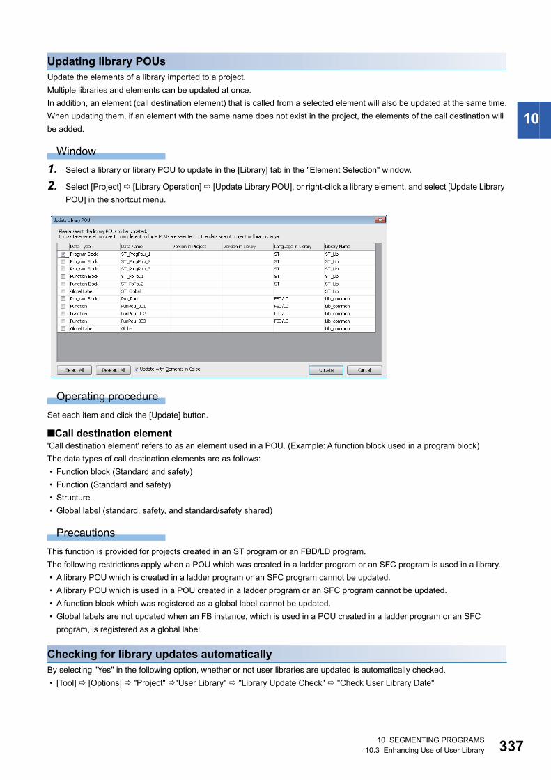
10 SEGMENTING PROGRAMS10.3 Enhancing Use of User Library 337
10
Updating library POUsUpdate the elements of a library imported to a project.
Multiple libraries and elements can be updated at once.
In addition, an element (call destination element) that is called from a selected element will also be updated at the same time.
When updating them, if an element with the same name does not exist in the project, the elements of the call destination will
be added.
Window
1. Select a library or library POU to update in the [Library] tab in the "Element Selection" window.
2. Select [Project] [Library Operation] [Update Library POU], or right-click a library element, and select [Update Library
POU] in the shortcut menu.
Operating procedure
Set each item and click the [Update] button.
■Call destination element'Call destination element' refers to as an element used in a POU. (Example: A function block used in a program block)
The data types of call destination elements are as follows:
• Function block (Standard and safety)
• Function (Standard and safety)
• Structure
• Global label (standard, safety, and standard/safety shared)
Precautions
This function is provided for projects created in an ST program or an FBD/LD program.
The following restrictions apply when a POU which was created in a ladder program or an SFC program is used in a library.
• A library POU which is created in a ladder program or an SFC program cannot be updated.
• A library POU which is used in a POU created in a ladder program or an SFC program cannot be updated.
• A function block which was registered as a global label cannot be updated.
• Global labels are not updated when an FB instance, which is used in a POU created in a ladder program or an SFC
program, is registered as a global label.
Checking for library updates automaticallyBy selecting "Yes" in the following option, whether or not user libraries are updated is automatically checked.
• [Tool] [Options] "Project" "User Library" "Library Update Check" "Check User Library Date"

33810 SEGMENTING PROGRAMS10.4 Enhanced Use of Application Library/MELSOFT Library
10.4 Enhanced Use of Application Library/MELSOFT Library
The application library/MELSOFT Library (sample library) are the element collection of program/function block/function/
structure that composed of specific processing.
In this section, the application library/MELSOFT Library (sample library) are explained as a library.
An element in a library can be utilized by registering the library in the library list.
The elements are imported into a project with by registering a library.
The registration method of a library differs depending on the file extension (*.gx3s, *.mslm).
To obtain the library, please consult your local Mitsubishi representative.
Remote head modules do not support it.
Precautions
Before registering a library, confirm that the module type of the current project (CPU module) supports the library.
Registering libraries of which file extensions are 'gx3s'
Operating procedure
1. Select [Tool] [Register Sample Library].
2. Select a file on the "Open Sample Library" screen, and click the [Open] button.
The function block of the library is displayed in the "Navigation" window ('M_FBLIB' is for the Mitsubishi Electric FA products,
and 'P_FBLIB' is for the partner's products).
Registering libraries of which file extensions are 'mslm'
Operating procedure
■Registering libraries to be referenced
1. Select [Project] [Library Operation] [Register to Library List] [Library].
2. Select a file on the "Register Library to Library List" screen, then click the [Open] button.
The registered library is displayed on the library list.
■Deleting libraries
1. Select the [Library] tab in the "Element Selection" window.
2. Select the library to be deleted, then select [Project] [Library Operation] [Delete from Library List] ( ).
■Updating librariesTo update a library, refer to the following section.
Page 337 Updating library POUs
10 SEGMENTING PROGRAMS10.4 Enhanced Use of Application Library/MELSOFT Library 339
10
Library classification displayLibraries (*.mslm) can be classified by registering them into the library classification definition file.
To obtain the library classification definition file, please consult your local Mitsubishi representative.
Operating procedure
■Classifying libraries
1. Select the [Library] tab in the "Element Selection" window.
2. Click on the toolbar and select [Register the Library Classification Definition].
3. Select a file on the "Register the Library Classification Definition" screen and click the [Open] button.
■Canceling library classifications
1. Select the [Library] tab in the "Element Selection" window.
2. Click on the toolbar and select [Delete the Library Classification Definition].

34010 SEGMENTING PROGRAMS10.4 Enhanced Use of Application Library/MELSOFT Library
MEMO
341
PA
RT
4
PART 4 DEBUGGING AND OPERATION
This part explains the communication route setting to access a CPU module, reading/writing data, and
monitoring the execution status.
11 PROGRAM SIMULATION
12 SETTING ROUTE TO CPU MODULE
13 WRITING/READING DATA TO CPU MODULE
14 CHECKING OPERATION OF PROGRAMS
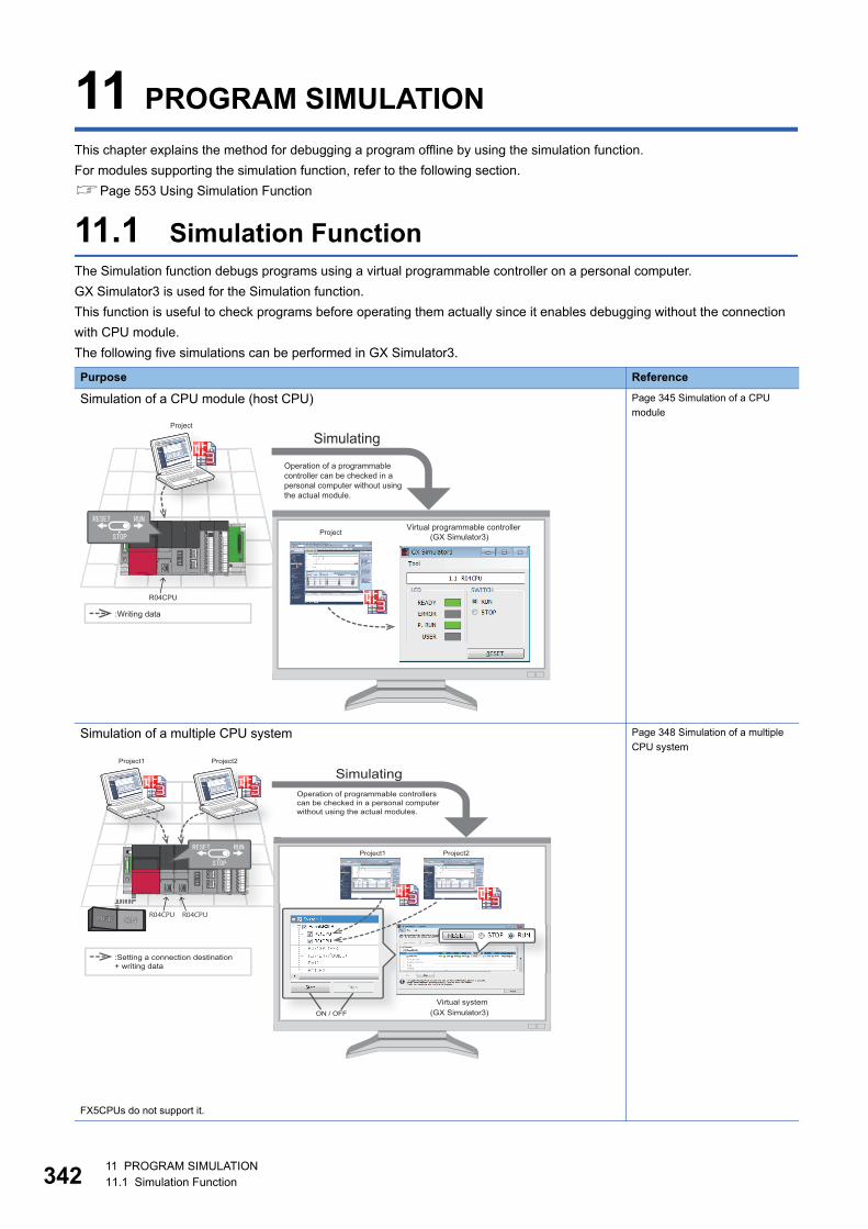
34211 PROGRAM SIMULATION11.1 Simulation Function
11 PROGRAM SIMULATION
This chapter explains the method for debugging a program offline by using the simulation function.
For modules supporting the simulation function, refer to the following section.
Page 553 Using Simulation Function
11.1 Simulation FunctionThe Simulation function debugs programs using a virtual programmable controller on a personal computer.
GX Simulator3 is used for the Simulation function.
This function is useful to check programs before operating them actually since it enables debugging without the connection
with CPU module.
The following five simulations can be performed in GX Simulator3.
Purpose Reference
Simulation of a CPU module (host CPU) Page 345 Simulation of a CPU
module
Simulation of a multiple CPU system
FX5CPUs do not support it.
Page 348 Simulation of a multiple
CPU system
Project
(GX Simulator3)Project
R04CPU
Simulating
Operation of a programmable controller can be checked in a personal computer without using the actual module.
Virtual programmable controller
:Writing data
Project1 Project2
(GX Simulator3)ON / OFF
Project1 Project2
R04CPU R04CPU
Virtual system
Simulating
:Setting a connection destination + writing data
Operation of programmable controllers can be checked in a personal computer without using the actual modules.
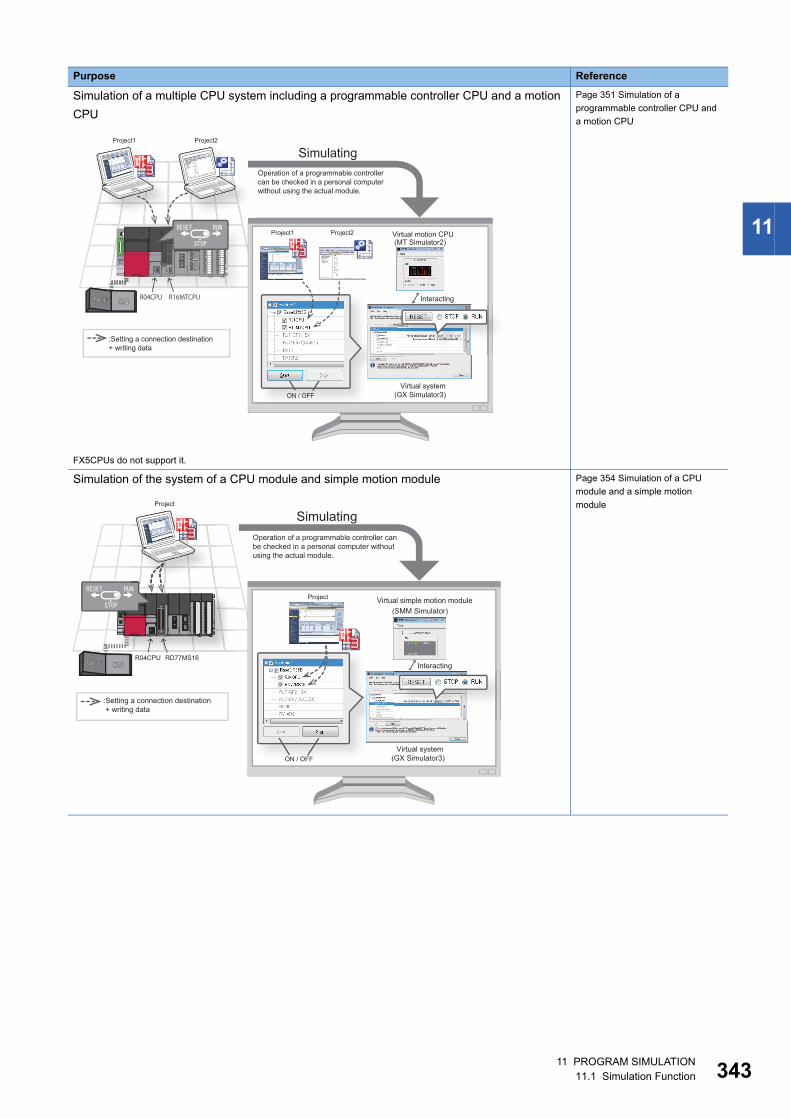
11 PROGRAM SIMULATION11.1 Simulation Function 343
11
Simulation of a multiple CPU system including a programmable controller CPU and a motion
CPU
FX5CPUs do not support it.
Page 351 Simulation of a
programmable controller CPU and
a motion CPU
Simulation of the system of a CPU module and simple motion module Page 354 Simulation of a CPU
module and a simple motion
module
Purpose Reference
Project1 Project2
(GX Simulator3)ON / OFF
Project1 Project2
R04CPU R16MTCPU
(MT Simulator2)
:Setting a connection destination + writing data
Interacting
Virtual motion CPU
SimulatingOperation of a programmable controller can be checked in a personal computer without using the actual module.
Virtual system
Project
(GX Simulator3)
(SMM Simulator)
ON / OFF
Project
R04CPU RD77MS16
j
SimulatingOperation of a programmable controller can be checked in a personal computer without using the actual module.
Virtual simple motion module
Interacting
Virtual system
:Setting a connection destination + writing data
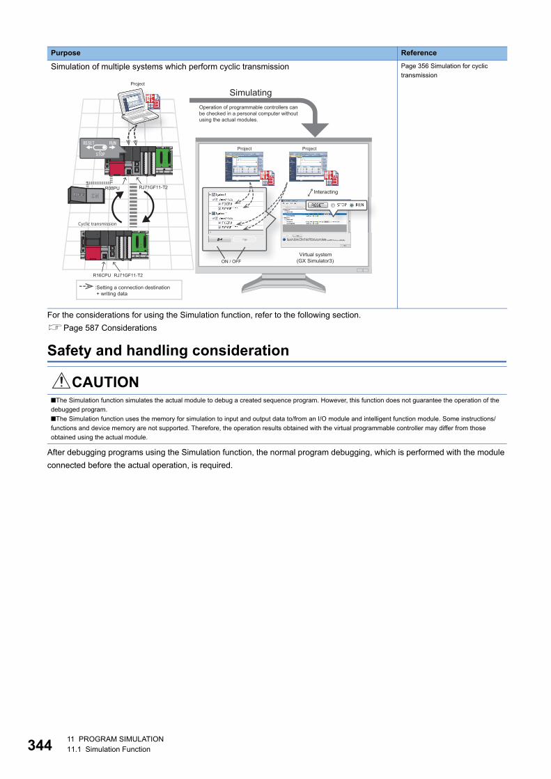
34411 PROGRAM SIMULATION11.1 Simulation Function
For the considerations for using the Simulation function, refer to the following section.
Page 587 Considerations
Safety and handling consideration
After debugging programs using the Simulation function, the normal program debugging, which is performed with the module
connected before the actual operation, is required.
Simulation of multiple systems which perform cyclic transmission Page 356 Simulation for cyclic
transmission
CAUTION■The Simulation function simulates the actual module to debug a created sequence program. However, this function does not guarantee the operation of the
debugged program.
■The Simulation function uses the memory for simulation to input and output data to/from an I/O module and intelligent function module. Some instructions/
functions and device memory are not supported. Therefore, the operation results obtained with the virtual programmable controller may differ from those
obtained using the actual module.
Purpose Reference
Project
(GX Simulator3)ON / OFF
ProjectProject
R08PU
j
R16CPU RJ71GF11-T2
RJ71GF11-T2
SimulatingOperation of programmable controllers can be checked in a personal computer without using the actual modules.
Interacting
Virtual system
:Setting a connection destination + writing data
Cyclic transmission
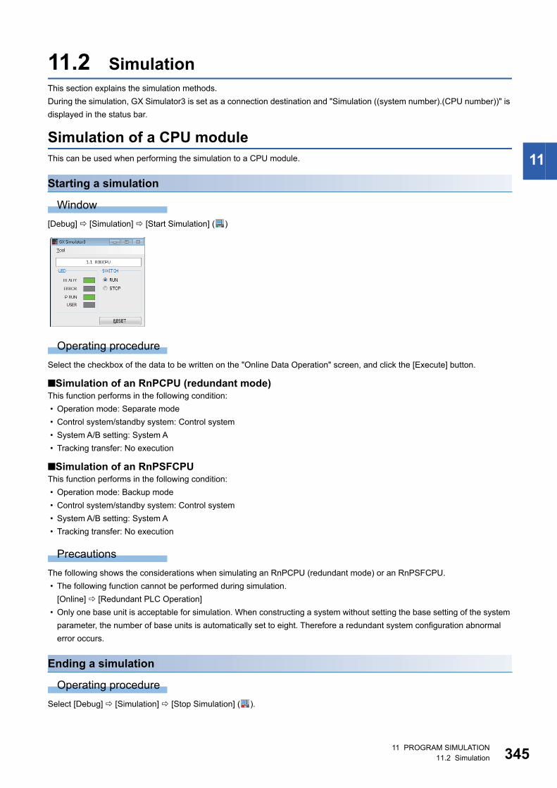
11 PROGRAM SIMULATION11.2 Simulation 345
11
11.2 SimulationThis section explains the simulation methods.
During the simulation, GX Simulator3 is set as a connection destination and "Simulation ((system number).(CPU number))" is
displayed in the status bar.
Simulation of a CPU moduleThis can be used when performing the simulation to a CPU module.
Starting a simulation
Window
[Debug] [Simulation] [Start Simulation] ( )
Operating procedure
Select the checkbox of the data to be written on the "Online Data Operation" screen, and click the [Execute] button.
■Simulation of an RnPCPU (redundant mode)This function performs in the following condition:
• Operation mode: Separate mode
• Control system/standby system: Control system
• System A/B setting: System A
• Tracking transfer: No execution
■Simulation of an RnPSFCPUThis function performs in the following condition:
• Operation mode: Backup mode
• Control system/standby system: Control system
• System A/B setting: System A
• Tracking transfer: No execution
Precautions
The following shows the considerations when simulating an RnPCPU (redundant mode) or an RnPSFCPU.
• The following function cannot be performed during simulation.
[Online] [Redundant PLC Operation]
• Only one base unit is acceptable for simulation. When constructing a system without setting the base setting of the system
parameter, the number of base units is automatically set to eight. Therefore a redundant system configuration abnormal
error occurs.
Ending a simulation
Operating procedure
Select [Debug] [Simulation] [Stop Simulation] ( ).
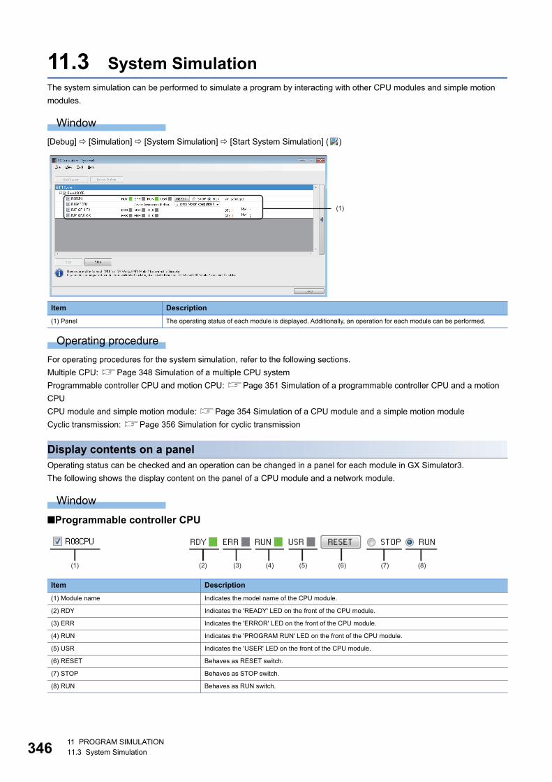
34611 PROGRAM SIMULATION11.3 System Simulation
11.3 System SimulationThe system simulation can be performed to simulate a program by interacting with other CPU modules and simple motion
modules.
Window
[Debug] [Simulation] [System Simulation] [Start System Simulation] ( )
Operating procedure
For operating procedures for the system simulation, refer to the following sections.
Multiple CPU: Page 348 Simulation of a multiple CPU system
Programmable controller CPU and motion CPU: Page 351 Simulation of a programmable controller CPU and a motion
CPU
CPU module and simple motion module: Page 354 Simulation of a CPU module and a simple motion module
Cyclic transmission: Page 356 Simulation for cyclic transmission
Display contents on a panelOperating status can be checked and an operation can be changed in a panel for each module in GX Simulator3.
The following shows the display content on the panel of a CPU module and a network module.
Window
■Programmable controller CPU
Item Description
(1) Panel The operating status of each module is displayed. Additionally, an operation for each module can be performed.
Item Description
(1) Module name Indicates the model name of the CPU module.
(2) RDY Indicates the 'READY' LED on the front of the CPU module.
(3) ERR Indicates the 'ERROR' LED on the front of the CPU module.
(4) RUN Indicates the 'PROGRAM RUN' LED on the front of the CPU module.
(5) USR Indicates the 'USER' LED on the front of the CPU module.
(6) RESET Behaves as RESET switch.
(7) STOP Behaves as STOP switch.
(8) RUN Behaves as RUN switch.
(1)
(1) (2) (3) (4) (5) (6) (7) (8)

11 PROGRAM SIMULATION11.3 System Simulation 347
11
■Motion CPU
■Field network
■Controller network
Item Description
(1) Module name Indicates the model name of the CPU module.
(2) Device Assignment Method Select a device assignment method for a motion CPU.
• Q series Motion compatible Device assignment
• MELSEC iQ-R Motion Device assignment
Item Description
(1) Module name Indicates the model name of the network module.
(2) ERR Indicates the 'ERROR ' LED on the front of the module.
(3) MST Indicates the 'MST' LED on the front of the module.
(4) DLK Indicates the 'D LINK' LED on the front of the module.
(5) ST Indicates the dot matrix LED of the module.
Only a station number is displayed on the panel of GX Simulator3.
(6) NW Indicates a network number set in the network parameter.
Item Description
(1) Module name Indicates the model name of the network module.
(2) ERR Indicates the 'ERROR ' LED on the front of the module.
(3) PRM Indicates the 'PRM' LED on the front of the module.
(4) DLK Indicates the 'D LINK' LED on the front of the module.
(5) ST Indicates the dot matrix LED of the module.
Only a station number is displayed on the panel of GX Simulator3.
(6) NW Indicates the network number set in a network parameter.
(1) (2)
(1) (2) (3) (4) (5) (6)
(1) (2) (3) (4) (5) (6)

34811 PROGRAM SIMULATION11.3 System Simulation
Simulation of a multiple CPU systemThis section shows the operation to simulate a multiple CPU system by using the example of the following system
configuration.
Operating procedure
• Starting GX Simulator31. Start GX Simulator3. (Page 346 System Simulation)
2. In the GX Simulator3 screen, click the [Add System]
button.
3. In the "GX Simulator3 Add System" screen, set a project
name and a system number.
4. In the GX Simulator3 screen, select the checkboxes of
the CPU modules to simulate, and click the [Start]
button.
R16CPUR16CPU

11 PROGRAM SIMULATION11.3 System Simulation 349
11
• Connecting to the CPU No.1 and writing data
• Connecting to the CPU No.2 and writing data
5. Select [Debug] [Simulation] [System Simulation]
[Connect Simulation].
6. In the "Specify Simulation Connection Destination"
screen, select the CPU module of the system which was
set in step 3, and click the [Connect] button.
"Simulation ((system number).(CPU number)) will be
displayed in the status bar.
7. Select [Online] [Write to PLC]. Write the parameters
and programs to GX Simulator3.
8. Start another GX Works3 and open the project of CPU
No.2.
9. Select [Debug] [Simulation] [System Simulation]
[Connect Simulation].
10. In the "Specify Simulation Connection Destination"
screen, select the CPU module of the system which was
set in step 3, and click the [Connect] button.
"Simulation ((system number).(CPU number))" will be
displayed in the status bar of GX Works3.
11. Select [Online] [Write to PLC]. Write the parameters
and programs to GX Simulator3.

35011 PROGRAM SIMULATION11.3 System Simulation
• Simulating12. In the GX Simulator3 screen, click the [RESET] button
in the row of the CPU No.1.
13.Select "RUN" in the row of each CPU.
14.Select [Online] [Monitor] [Start Monitoring].
The system simulation starts.
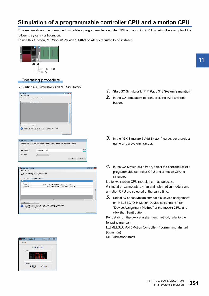
11 PROGRAM SIMULATION11.3 System Simulation 351
11
Simulation of a programmable controller CPU and a motion CPUThis section shows the operation to simulate a programmable controller CPU and a motion CPU by using the example of the
following system configuration.
To use this function, MT Works2 Version 1.140W or later is required to be installed.
Operating procedure
• Starting GX Simulator3 and MT Simulator21. Start GX Simulator3. (Page 346 System Simulation)
2. In the GX Simulator3 screen, click the [Add System]
button.
3. In the "GX Simulator3 Add System" scree, set a project
name and a system number.
4. In the GX Simulator3 screen, select the checkboxes of a
programmable controller CPU and a motion CPU to
simulate.
Up to two motion CPU modules can be selected.
A simulation cannot start when a simple motion module and
a motion CPU are selected at the same time.
5. Select "Q series Motion compatible Device assignment"
or "MELSEC iQ-R Motion Device assignment " for
"Device Assignment Method" of the motion CPU, and
click the [Start] button.
For details on the device assignment method, refer to the
following manual.
MELSEC iQ-R Motion Controller Programming Manual
(Common)
MT Simulator2 starts.
R16CPUR16MTCPU
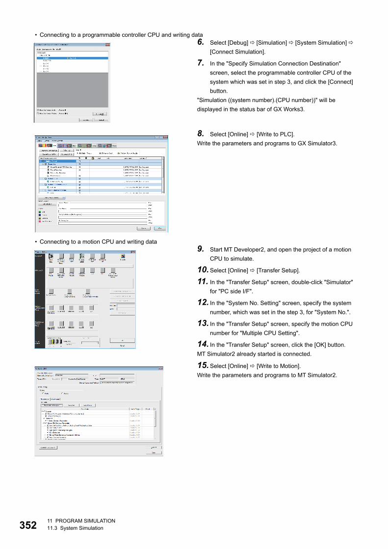
35211 PROGRAM SIMULATION11.3 System Simulation
• Connecting to a programmable controller CPU and writing data
• Connecting to a motion CPU and writing data
6. Select [Debug] [Simulation] [System Simulation]
[Connect Simulation].
7. In the "Specify Simulation Connection Destination"
screen, select the programmable controller CPU of the
system which was set in step 3, and click the [Connect]
button.
"Simulation ((system number).(CPU number))" will be
displayed in the status bar of GX Works3.
8. Select [Online] [Write to PLC].
Write the parameters and programs to GX Simulator3.
9. Start MT Developer2, and open the project of a motion
CPU to simulate.
10.Select [Online] [Transfer Setup].
11. In the "Transfer Setup" screen, double-click "Simulator"
for "PC side I/F".
12. In the "System No. Setting" screen, specify the system
number, which was set in the step 3, for "System No.".
13. In the "Transfer Setup" screen, specify the motion CPU
number for "Multiple CPU Setting".
14. In the "Transfer Setup" screen, click the [OK] button.
MT Simulator2 already started is connected.
15.Select [Online] [Write to Motion].
Write the parameters and programs to MT Simulator2.
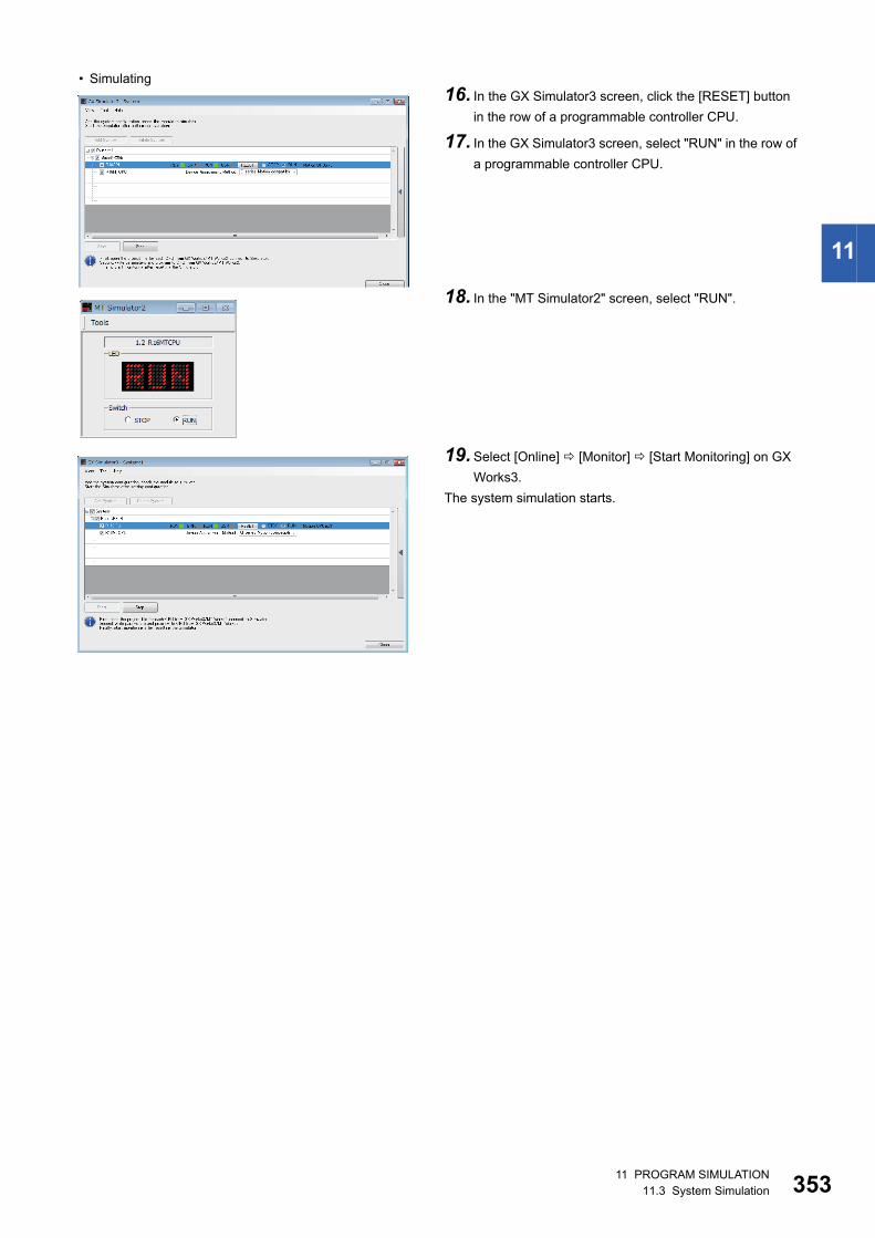
11 PROGRAM SIMULATION11.3 System Simulation 353
11
• Simulating16. In the GX Simulator3 screen, click the [RESET] button
in the row of a programmable controller CPU.
17. In the GX Simulator3 screen, select "RUN" in the row of
a programmable controller CPU.
18. In the "MT Simulator2" screen, select "RUN".
19.Select [Online] [Monitor] [Start Monitoring] on GX
Works3.
The system simulation starts.
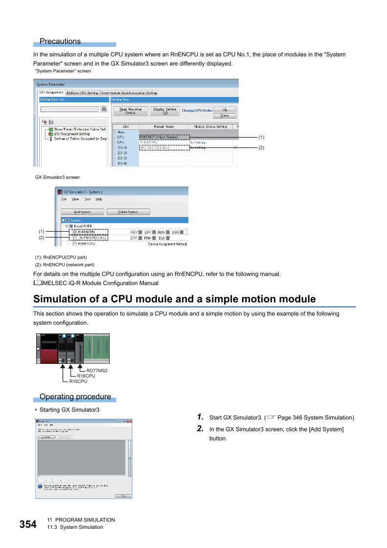
35411 PROGRAM SIMULATION11.3 System Simulation
Precautions
In the simulation of a multiple CPU system where an RnENCPU is set as CPU No.1, the place of modules in the "System
Parameter" screen and in the GX Simulator3 screen are differently displayed.
For details on the multiple CPU configuration using an RnENCPU, refer to the following manual.
MELSEC iQ-R Module Configuration Manual
Simulation of a CPU module and a simple motion moduleThis section shows the operation to simulate a CPU module and a simple motion by using the example of the following
system configuration.
Operating procedure
• Starting GX Simulator3
"System Parameter" screen
GX Simulator3 screen
(1): RnENCPU(CPU part)
(2): RnENCPU (network part)
1. Start GX Simulator3. (Page 346 System Simulation)
2. In the GX Simulator3 screen, click the [Add System]
button.
(1)
(2)
(1)(2)
R16CPU
RD77MS2R16CPU
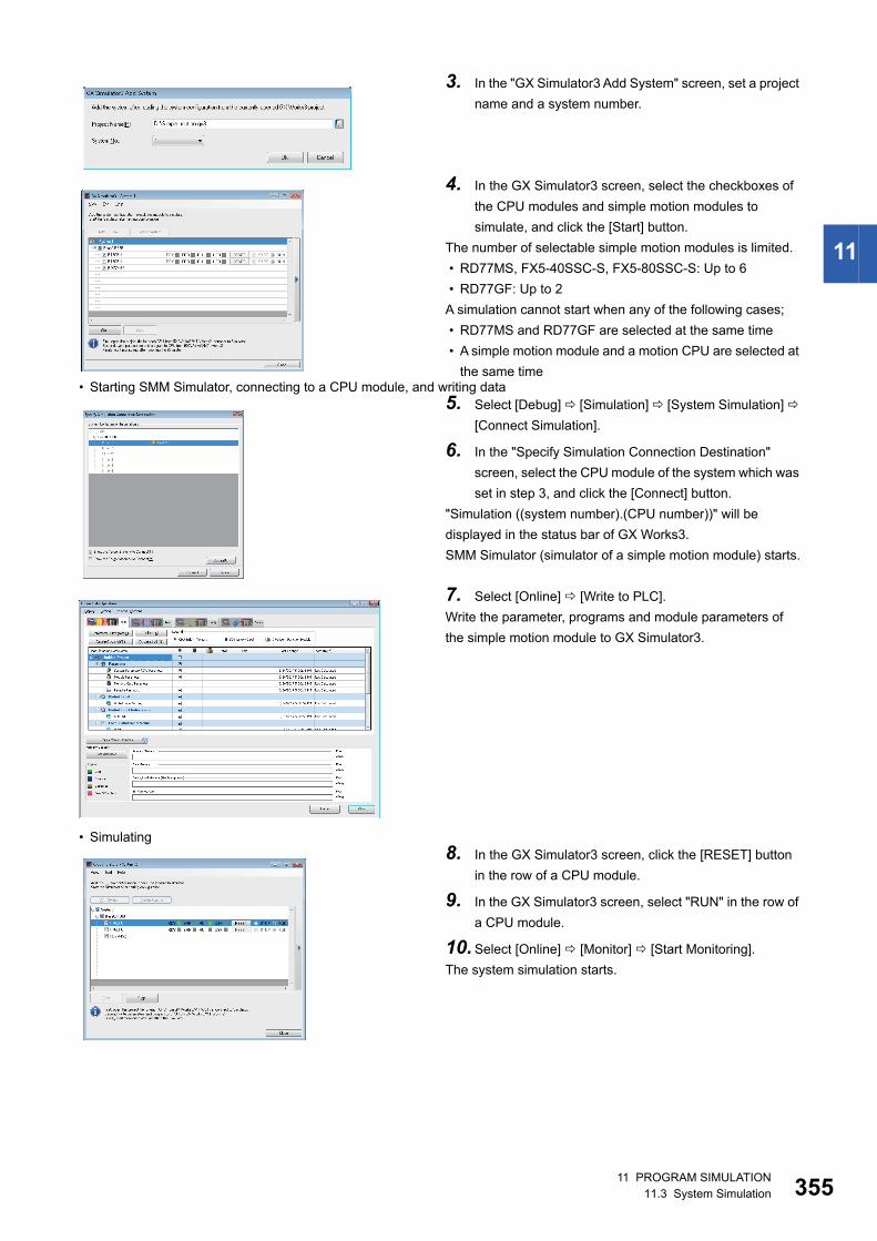
11 PROGRAM SIMULATION11.3 System Simulation 355
11
• Starting SMM Simulator, connecting to a CPU module, and writing data
• Simulating
3. In the "GX Simulator3 Add System" screen, set a project
name and a system number.
4. In the GX Simulator3 screen, select the checkboxes of
the CPU modules and simple motion modules to
simulate, and click the [Start] button.
The number of selectable simple motion modules is limited.
• RD77MS, FX5-40SSC-S, FX5-80SSC-S: Up to 6
• RD77GF: Up to 2
A simulation cannot start when any of the following cases;
• RD77MS and RD77GF are selected at the same time
• A simple motion module and a motion CPU are selected at
the same time
5. Select [Debug] [Simulation] [System Simulation]
[Connect Simulation].
6. In the "Specify Simulation Connection Destination"
screen, select the CPU module of the system which was
set in step 3, and click the [Connect] button.
"Simulation ((system number).(CPU number))" will be
displayed in the status bar of GX Works3.
SMM Simulator (simulator of a simple motion module) starts.
7. Select [Online] [Write to PLC].
Write the parameter, programs and module parameters of
the simple motion module to GX Simulator3.
8. In the GX Simulator3 screen, click the [RESET] button
in the row of a CPU module.
9. In the GX Simulator3 screen, select "RUN" in the row of
a CPU module.
10.Select [Online] [Monitor] [Start Monitoring].
The system simulation starts.
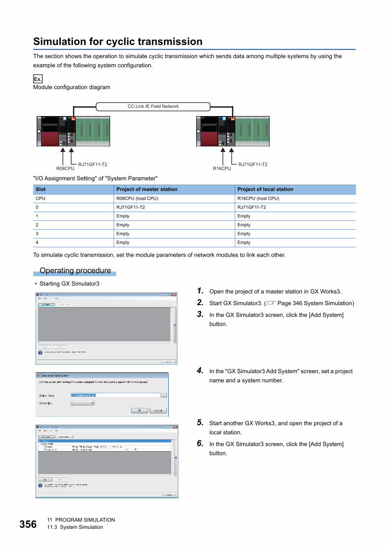
35611 PROGRAM SIMULATION11.3 System Simulation
Simulation for cyclic transmissionThe section shows the operation to simulate cyclic transmission which sends data among multiple systems by using the
example of the following system configuration.
Ex.
Module configuration diagram
"I/O Assignment Setting" of "System Parameter"
To simulate cyclic transmission, set the module parameters of network modules to link each other.
Operating procedure
• Starting GX Simulator3
Slot Project of master station Project of local station
CPU R08CPU (host CPU) R16CPU (host CPU)
0 RJ71GF11-T2 RJ71GF11-T2
1 Empty Empty
2 Empty Empty
3 Empty Empty
4 Empty Empty
1. Open the project of a master station in GX Works3.
2. Start GX Simulator3. (Page 346 System Simulation)
3. In the GX Simulator3 screen, click the [Add System]
button.
4. In the "GX Simulator3 Add System" screen, set a project
name and a system number.
5. Start another GX Works3, and open the project of a
local station.
6. In the GX Simulator3 screen, click the [Add System]
button.
RJ71GF11-T2R08CPU R16CPU
RJ71GF11-T2
CC-Link IE Field Network
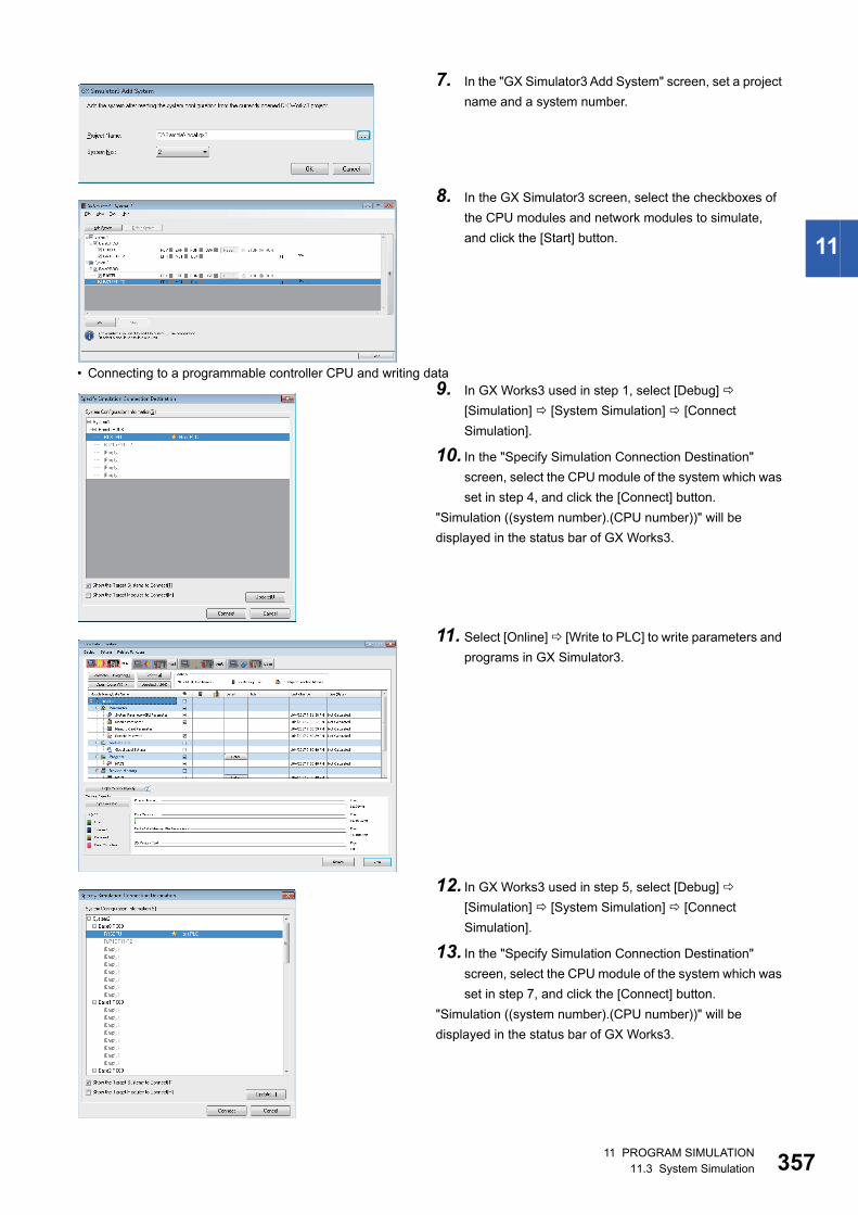
11 PROGRAM SIMULATION11.3 System Simulation 357
11
• Connecting to a programmable controller CPU and writing data
7. In the "GX Simulator3 Add System" screen, set a project
name and a system number.
8. In the GX Simulator3 screen, select the checkboxes of
the CPU modules and network modules to simulate,
and click the [Start] button.
9. In GX Works3 used in step 1, select [Debug]
[Simulation] [System Simulation] [Connect
Simulation].
10. In the "Specify Simulation Connection Destination"
screen, select the CPU module of the system which was
set in step 4, and click the [Connect] button.
"Simulation ((system number).(CPU number))" will be
displayed in the status bar of GX Works3.
11. Select [Online] [Write to PLC] to write parameters and
programs in GX Simulator3.
12. In GX Works3 used in step 5, select [Debug]
[Simulation] [System Simulation] [Connect
Simulation].
13. In the "Specify Simulation Connection Destination"
screen, select the CPU module of the system which was
set in step 7, and click the [Connect] button.
"Simulation ((system number).(CPU number))" will be
displayed in the status bar of GX Works3.
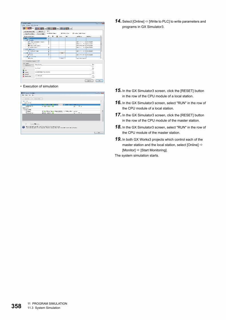
35811 PROGRAM SIMULATION11.3 System Simulation
• Execution of simulation
14.Select [Online] [Write to PLC] to write parameters and
programs in GX Simulator3.
15. In the GX Simulator3 screen, click the [RESET] button
in the row of the CPU module of a local station.
16. In the GX Simulator3 screen, select "RUN" in the row of
the CPU module of a local station.
17. In the GX Simulator3 screen, click the [RESET] button
in the row of the CPU module of the master station.
18. In the GX Simulator3 screen, select "RUN" in the row of
the CPU module of the master station.
19. In both GX Works3 projects which control each of the
master station and the local station, select [Online]
[Monitor] [Start Monitoring].
The system simulation starts.
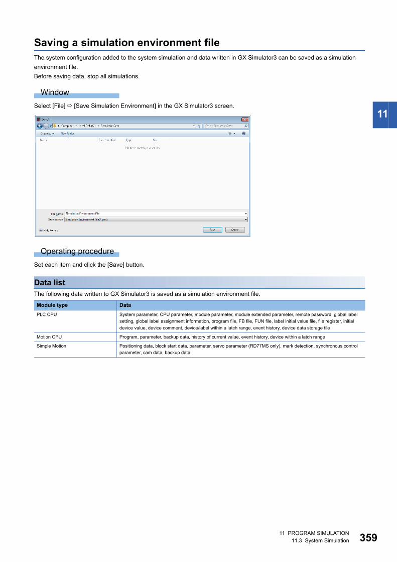
11 PROGRAM SIMULATION11.3 System Simulation 359
11
Saving a simulation environment fileThe system configuration added to the system simulation and data written in GX Simulator3 can be saved as a simulation
environment file.
Before saving data, stop all simulations.
Window
Select [File] [Save Simulation Environment] in the GX Simulator3 screen.
Operating procedure
Set each item and click the [Save] button.
Data listThe following data written to GX Simulator3 is saved as a simulation environment file.
Module type Data
PLC CPU System parameter, CPU parameter, module parameter, module extended parameter, remote password, global label
setting, global label assignment information, program file, FB file, FUN file, label initial value file, file register, initial
device value, device comment, device/label within a latch range, event history, device data storage file
Motion CPU Program, parameter, backup data, history of current value, event history, device within a latch range
Simple Motion Positioning data, block start data, parameter, servo parameter (RD77MS only), mark detection, synchronous control
parameter, cam data, backup data
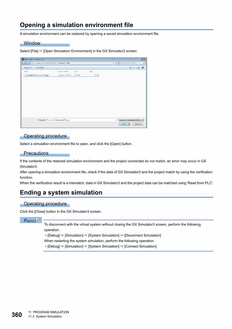
36011 PROGRAM SIMULATION11.3 System Simulation
Opening a simulation environment fileA simulation environment can be restored by opening a saved simulation environment file.
Window
Select [File] [Open Simulation Environment] in the GX Simulator3 screen.
Operating procedure
Select a simulation environment file to open, and click the [Open] button.
Precautions
If the contents of the restored simulation environment and the project connected do not match, an error may occur in GX
Simulator3.
After opening a simulation environment file, check if the data of GX Simulator3 and the project match by using the verification
function.
When the verification result is a mismatch, data in GX Simulator3 and the project data can be matched using 'Read from PLC'.
Ending a system simulation
Operating procedure
Click the [Close] button in the GX Simulator3 screen.
To disconnect with the virtual system without closing the GX Simulator3 screen, perform the following
operation.
• [Debug] [Simulation] [System Simulation] [Disconnect Simulation]
When restarting the system simulation, perform the following operation.
• [Debug] [Simulation] [System Simulation] [Connect Simulation]
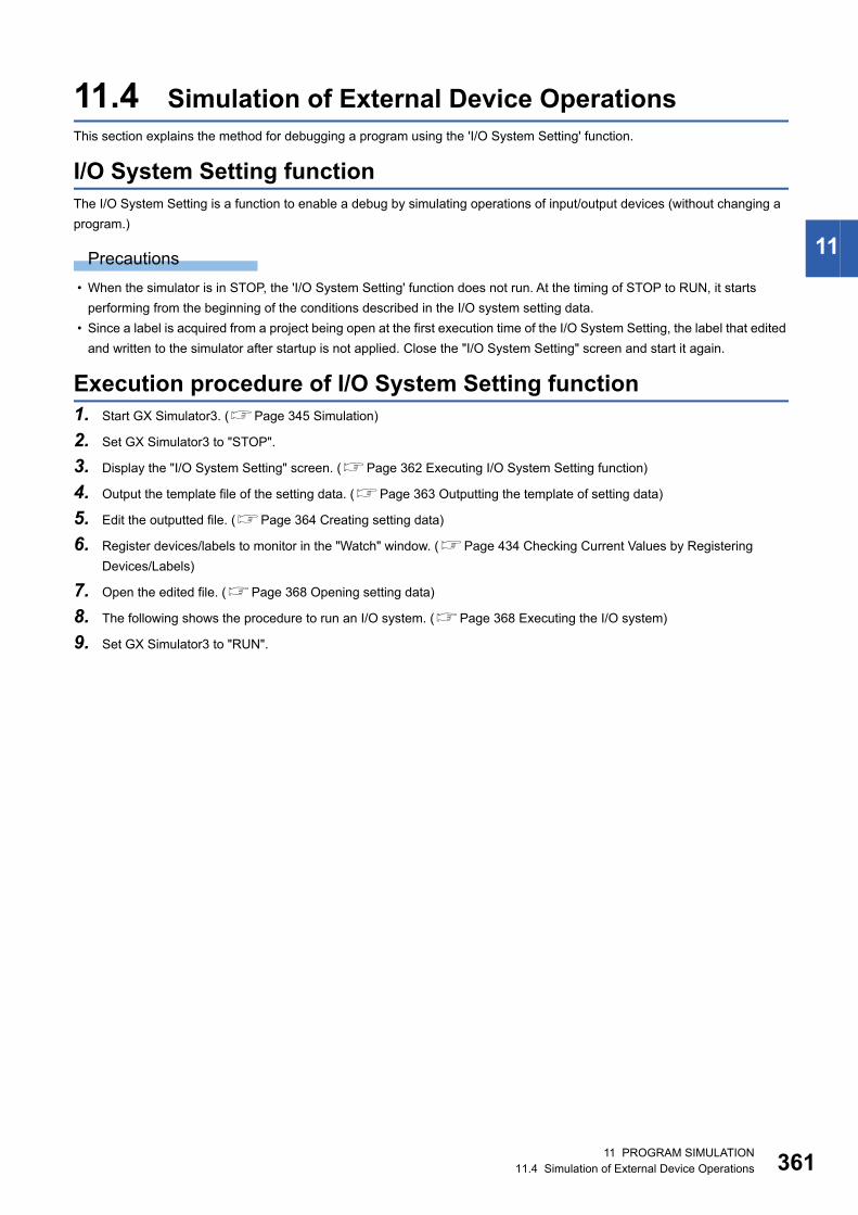
11 PROGRAM SIMULATION11.4 Simulation of External Device Operations 361
11
11.4 Simulation of External Device OperationsThis section explains the method for debugging a program using the 'I/O System Setting' function.
I/O System Setting functionThe I/O System Setting is a function to enable a debug by simulating operations of input/output devices (without changing a
program.)
Precautions
• When the simulator is in STOP, the 'I/O System Setting' function does not run. At the timing of STOP to RUN, it starts
performing from the beginning of the conditions described in the I/O system setting data.
• Since a label is acquired from a project being open at the first execution time of the I/O System Setting, the label that edited
and written to the simulator after startup is not applied. Close the "I/O System Setting" screen and start it again.
Execution procedure of I/O System Setting function1. Start GX Simulator3. (Page 345 Simulation)
2. Set GX Simulator3 to "STOP".
3. Display the "I/O System Setting" screen. (Page 362 Executing I/O System Setting function)
4. Output the template file of the setting data. (Page 363 Outputting the template of setting data)
5. Edit the outputted file. (Page 364 Creating setting data)
6. Register devices/labels to monitor in the "Watch" window. (Page 434 Checking Current Values by Registering
Devices/Labels)
7. Open the edited file. (Page 368 Opening setting data)
8. The following shows the procedure to run an I/O system. (Page 368 Executing the I/O system)
9. Set GX Simulator3 to "RUN".
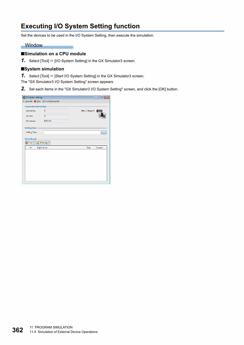
36211 PROGRAM SIMULATION11.4 Simulation of External Device Operations
Executing I/O System Setting functionSet the devices to be used in the I/O System Setting, then execute the simulation.
Window
■Simulation on a CPU module
1. Select [Tool] [I/O System Setting] in the GX Simulator3 screen.
■System simulation
1. Select [Tool] [Start I/O System Setting] in the GX Simulator3 screen.
The "GX Simulator3 I/O System Setting" screen appears.
2. Set each items in the "GX Simulator3 I/O System Setting" screen, and click the [OK] button.
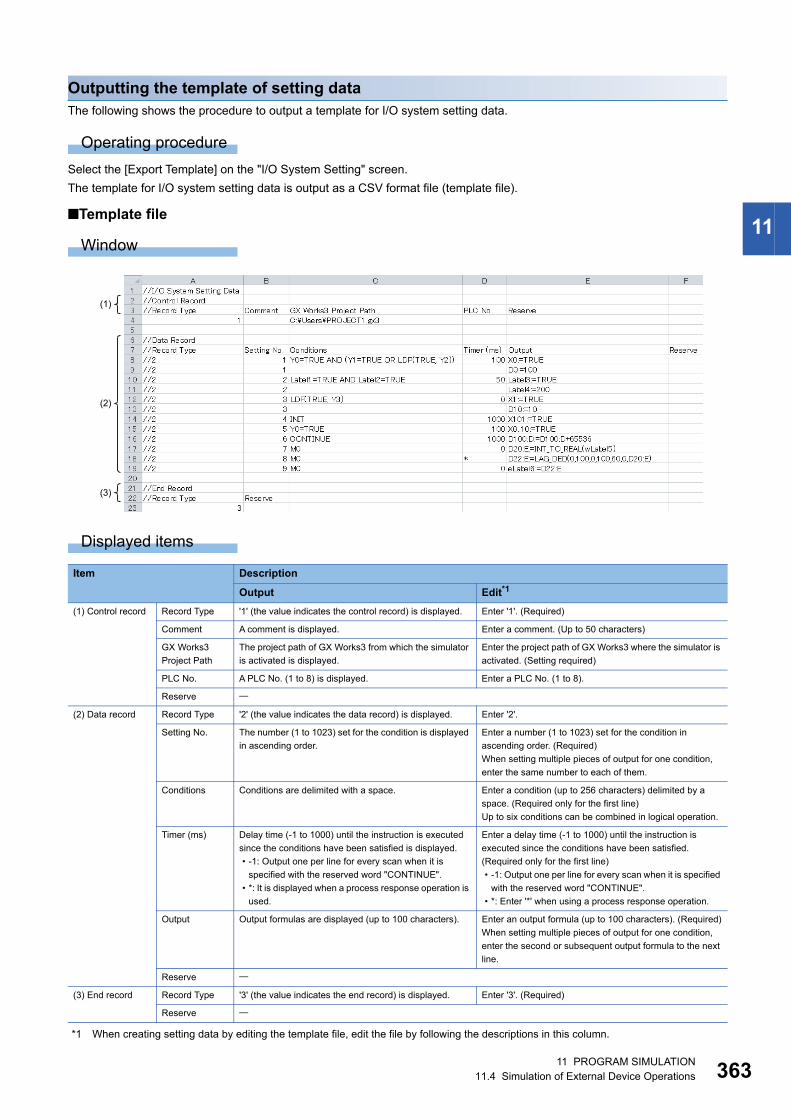
11 PROGRAM SIMULATION11.4 Simulation of External Device Operations 363
11
Outputting the template of setting dataThe following shows the procedure to output a template for I/O system setting data.
Operating procedure
Select the [Export Template] on the "I/O System Setting" screen.
The template for I/O system setting data is output as a CSV format file (template file).
■Template file
Window
Displayed items
*1 When creating setting data by editing the template file, edit the file by following the descriptions in this column.
Item Description
Output Edit*1
(1) Control record Record Type '1' (the value indicates the control record) is displayed. Enter '1'. (Required)
Comment A comment is displayed. Enter a comment. (Up to 50 characters)
GX Works3
Project Path
The project path of GX Works3 from which the simulator
is activated is displayed.
Enter the project path of GX Works3 where the simulator is
activated. (Setting required)
PLC No. A PLC No. (1 to 8) is displayed. Enter a PLC No. (1 to 8).
Reserve
(2) Data record Record Type '2' (the value indicates the data record) is displayed. Enter '2'.
Setting No. The number (1 to 1023) set for the condition is displayed
in ascending order.
Enter a number (1 to 1023) set for the condition in
ascending order. (Required)
When setting multiple pieces of output for one condition,
enter the same number to each of them.
Conditions Conditions are delimited with a space. Enter a condition (up to 256 characters) delimited by a
space. (Required only for the first line)
Up to six conditions can be combined in logical operation.
Timer (ms) Delay time (-1 to 1000) until the instruction is executed
since the conditions have been satisfied is displayed.
• -1: Output one per line for every scan when it is
specified with the reserved word "CONTINUE".
• *: It is displayed when a process response operation is
used.
Enter a delay time (-1 to 1000) until the instruction is
executed since the conditions have been satisfied.
(Required only for the first line)
• -1: Output one per line for every scan when it is specified
with the reserved word "CONTINUE".
• *: Enter '*' when using a process response operation.
Output Output formulas are displayed (up to 100 characters). Enter an output formula (up to 100 characters). (Required)
When setting multiple pieces of output for one condition,
enter the second or subsequent output formula to the next
line.
Reserve
(3) End record Record Type '3' (the value indicates the end record) is displayed. Enter '3'. (Required)
Reserve
(1)
(2)
(3)
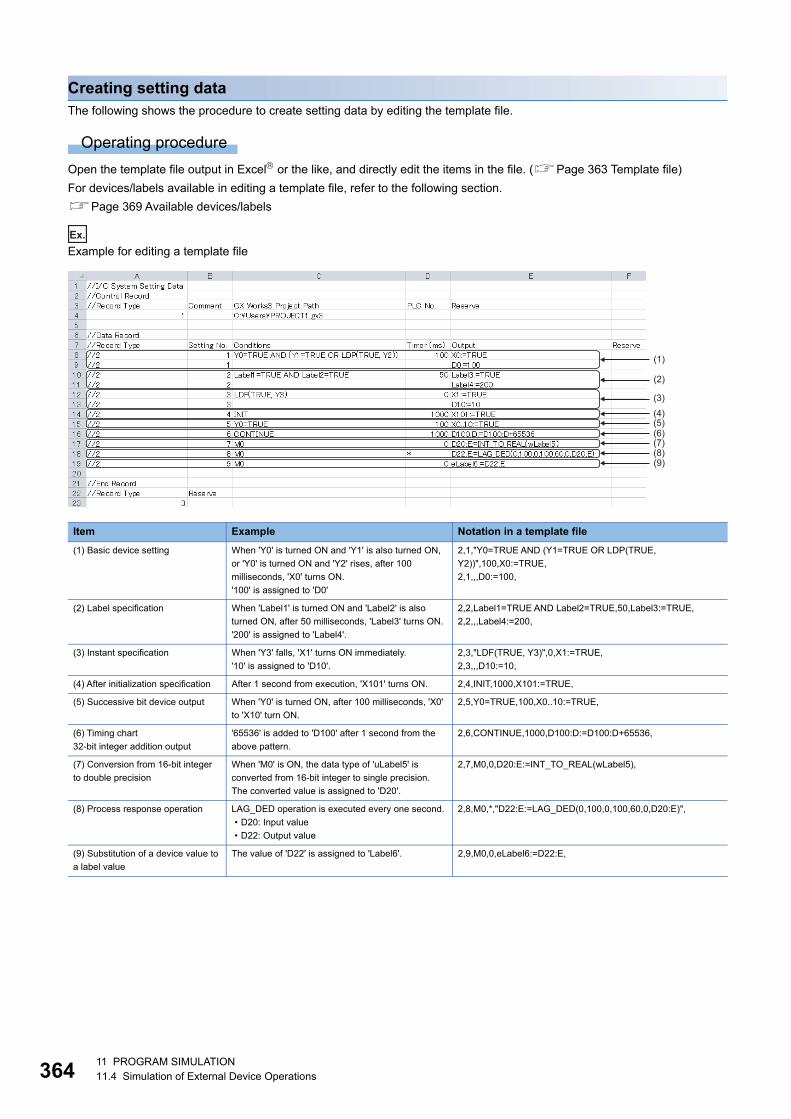
36411 PROGRAM SIMULATION11.4 Simulation of External Device Operations
Creating setting dataThe following shows the procedure to create setting data by editing the template file.
Operating procedure
Open the template file output in Excel or the like, and directly edit the items in the file. (Page 363 Template file)
For devices/labels available in editing a template file, refer to the following section.
Page 369 Available devices/labels
Ex.
Example for editing a template file
Item Example Notation in a template file
(1) Basic device setting When 'Y0' is turned ON and 'Y1' is also turned ON,
or 'Y0' is turned ON and 'Y2' rises, after 100
milliseconds, 'X0' turns ON.
'100' is assigned to 'D0'
2,1,"Y0=TRUE AND (Y1=TRUE OR LDP(TRUE,
Y2))",100,X0:=TRUE,
2,1,,,D0:=100,
(2) Label specification When 'Label1' is turned ON and 'Label2' is also
turned ON, after 50 milliseconds, 'Label3' turns ON.
'200' is assigned to 'Label4'.
2,2,Label1=TRUE AND Label2=TRUE,50,Label3:=TRUE,
2,2,,,Label4:=200,
(3) Instant specification When 'Y3' falls, 'X1' turns ON immediately.
'10' is assigned to 'D10'.
2,3,"LDF(TRUE, Y3)",0,X1:=TRUE,
2,3,,,D10:=10,
(4) After initialization specification After 1 second from execution, 'X101' turns ON. 2,4,INIT,1000,X101:=TRUE,
(5) Successive bit device output When 'Y0' is turned ON, after 100 milliseconds, 'X0'
to 'X10' turn ON.
2,5,Y0=TRUE,100,X0..10:=TRUE,
(6) Timing chart
32-bit integer addition output
'65536' is added to 'D100' after 1 second from the
above pattern.
2,6,CONTINUE,1000,D100:D:=D100:D+65536,
(7) Conversion from 16-bit integer
to double precision
When 'M0' is ON, the data type of 'uLabel5' is
converted from 16-bit integer to single precision.
The converted value is assigned to 'D20'.
2,7,M0,0,D20:E:=INT_TO_REAL(wLabel5),
(8) Process response operation LAG_DED operation is executed every one second.
• D20: Input value
• D22: Output value
2,8,M0,*,"D22:E:=LAG_DED(0,100,0,100,60,0,D20:E)",
(9) Substitution of a device value to
a label value
The value of 'D22' is assigned to 'Label6'. 2,9,M0,0,eLabel6:=D22:E,
(1)
(2)
(3)(4)(5)(6)(7)(8)(9)
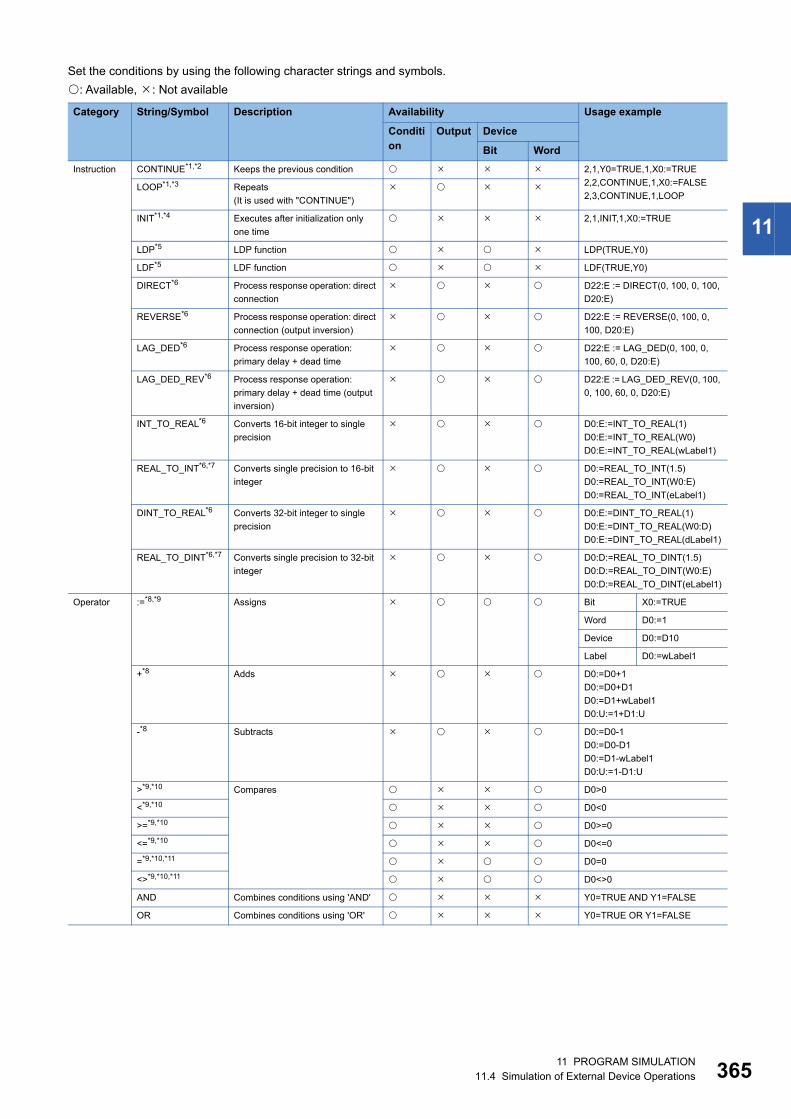
11 PROGRAM SIMULATION11.4 Simulation of External Device Operations 365
11
Set the conditions by using the following character strings and symbols.
: Available, : Not available
Category String/Symbol Description Availability Usage example
Condition
Output Device
Bit Word
Instruction CONTINUE*1,*2 Keeps the previous condition 2,1,Y0=TRUE,1,X0:=TRUE
2,2,CONTINUE,1,X0:=FALSE
2,3,CONTINUE,1,LOOPLOOP*1,*3 Repeats
(It is used with "CONTINUE")
INIT*1,*4 Executes after initialization only
one time
2,1,INIT,1,X0:=TRUE
LDP*5 LDP function LDP(TRUE,Y0)
LDF*5 LDF function LDF(TRUE,Y0)
DIRECT*6 Process response operation: direct
connection
D22:E := DIRECT(0, 100, 0, 100,
D20:E)
REVERSE*6 Process response operation: direct
connection (output inversion)
D22:E := REVERSE(0, 100, 0,
100, D20:E)
LAG_DED*6 Process response operation:
primary delay + dead time
D22:E := LAG_DED(0, 100, 0,
100, 60, 0, D20:E)
LAG_DED_REV*6 Process response operation:
primary delay + dead time (output
inversion)
D22:E := LAG_DED_REV(0, 100,
0, 100, 60, 0, D20:E)
INT_TO_REAL*6 Converts 16-bit integer to single
precision
D0:E:=INT_TO_REAL(1)
D0:E:=INT_TO_REAL(W0)
D0:E:=INT_TO_REAL(wLabel1)
REAL_TO_INT*6,*7 Converts single precision to 16-bit
integer
D0:=REAL_TO_INT(1.5)
D0:=REAL_TO_INT(W0:E)
D0:=REAL_TO_INT(eLabel1)
DINT_TO_REAL*6 Converts 32-bit integer to single
precision
D0:E:=DINT_TO_REAL(1)
D0:E:=DINT_TO_REAL(W0:D)
D0:E:=DINT_TO_REAL(dLabel1)
REAL_TO_DINT*6,*7 Converts single precision to 32-bit
integer
D0:D:=REAL_TO_DINT(1.5)
D0:D:=REAL_TO_DINT(W0:E)
D0:D:=REAL_TO_DINT(eLabel1)
Operator :=*8,*9 Assigns Bit X0:=TRUE
Word D0:=1
Device D0:=D10
Label D0:=wLabel1
+*8 Adds D0:=D0+1
D0:=D0+D1
D0:=D1+wLabel1
D0:U:=1+D1:U
-*8 Subtracts D0:=D0-1
D0:=D0-D1
D0:=D1-wLabel1
D0:U:=1-D1:U
>*9,*10 Compares D0>0
<*9,*10 D0<0
>=*9,*10 D0>=0
<=*9,*10 D0<=0
=*9,*10,*11 D0=0
<>*9,*10,*11 D0<>0
AND Combines conditions using 'AND' Y0=TRUE AND Y1=FALSE
OR Combines conditions using 'OR' Y0=TRUE OR Y1=FALSE
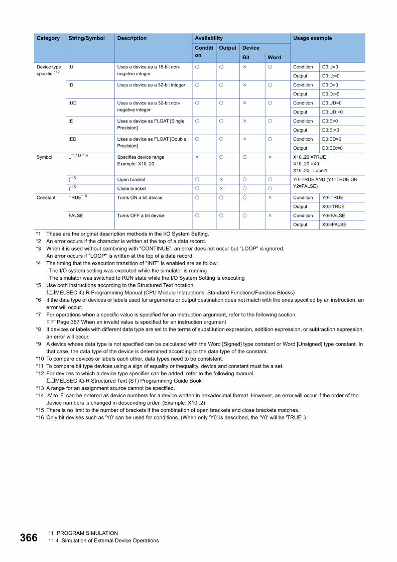
36611 PROGRAM SIMULATION11.4 Simulation of External Device Operations
*1 These are the original description methods in the I/O System Setting.*2 An error occurs if the character is written at the top of a data record.*3 When it is used without combining with "CONTINUE", an error does not occur but "LOOP" is ignored.
An error occurs if "LOOP" is written at the top of a data record.*4 The timing that the execution transition of "INIT" is enabled are as follow:
⋅ The I/O system setting was executed while the simulator is running⋅ The simulator was switched to RUN state while the I/O System Setting is executing
*5 Use both instructions according to the Structured Text notation.MELSEC iQ-R Programming Manual (CPU Module Instructions, Standard Functions/Function Blocks)
*6 If the data type of devices or labels used for arguments or output destination does not match with the ones specified by an instruction, an error will occur.
*7 For operations when a specific value is specified for an instruction argument, refer to the following section.Page 367 When an invalid value is specified for an instruction argument
*8 If devices or labels with different data type are set to the terms of substitution expression, addition expression, or subtraction expression, an error will occur.
*9 A device whose data type is not specified can be calculated with the Word [Signed] type constant or Word [Unsigned] type constant. In that case, the data type of the device is determined according to the data type of the constant.
*10 To compare devices or labels each other, data types need to be consistent.*11 To compare bit type devices using a sign of equality or inequality, device and constant must be a set.*12 For devices to which a device type specifier can be added, refer to the following manual.
MELSEC iQ-R Structured Text (ST) Programming Guide Book*13 A range for an assignment source cannot be specified.*14 'A' to 'F' can be entered as device numbers for a device written in hexadecimal format. However, an error will occur if the order of the
device numbers is changed in descending order. (Example: X10..2)*15 There is no limit to the number of brackets if the combination of open brackets and close brackets matches.*16 Only bit devises such as 'Y0' can be used for conditions. (When only 'Y0' is described, the 'Y0' will be 'TRUE'.)
Device type
specifier*12:U Uses a device as a 16-bit non-
negative integer
Condition D0:U=0
Output D0:U:=0
:D Uses a device as a 32-bit integer Condition D0:D=0
Output D0:D:=0
:UD Uses a device as a 32-bit non-
negative integer
Condition D0:UD=0
Output D0:UD:=0
:E Uses a device as FLOAT [Single
Precision]
Condition D0:E=0
Output D0:E:=0
:ED Uses a device as FLOAT [Double
Precision]
Condition D0:ED=0
Output D0:ED:=0
Symbol ..*1,*13,*14 Specifies device range
Example: X10..20
X10..20:=TRUE
X10..20:=X0
X10..20:=Label1
(*15 Open bracket Y0=TRUE AND (Y1=TRUE OR
Y2=FALSE))*15 Close bracket
Constant TRUE*16 Turns ON a bit device Condition Y0=TRUE
Output X0:=TRUE
FALSE Turns OFF a bit device Condition Y0=FALSE
Output X0:=FALSE
Category String/Symbol Description Availability Usage example
Condition
Output Device
Bit Word

11 PROGRAM SIMULATION11.4 Simulation of External Device Operations 367
11
■When an invalid value is specified for an instruction argumentIf an invalid value is specified for an instruction argument, the value of the argument will be changed as follows.
Precautions
A row starting with '//' is regarded as a comment, and therefore it is skipped.
Instruction Argument Incorrect value Changed value
REAL_TO_INT Device/label -0 0
Denormalized number
NaN
±∞
Constant E32768 or more 32767
Device/label 32768 or more
Constant E-32769 or less -32768
Device/label -32769 or less
REAL_TO_DINT Device/label -0 0
Denormalized number
NaN
±∞
Constant E2147483648 or more 2147483647
Device/label 2147483648 or more
Constant E-2147483649 or less -2147483648
Device/label -2147483649 or less

36811 PROGRAM SIMULATION11.4 Simulation of External Device Operations
Opening setting dataThe following shows the procedure to open created setting data.
Operating procedure
1. Click the [...] button in the setting data column on the "I/O System Setting" screen.
2. Select a file, then click the [Open] button.
Precautions
Language-specific characters are included in the setting data.
If the language font to display is not installed on the personal computer, some characters may be garbled.
Executing the I/O systemThe following shows the procedure to run an I/O system after checking the setting data.
Operating procedure
Select [Execute] on the "I/O System Setting" screen.
If an error is included in the check result, correct the setting data and run the system again.
Precautions
If a function, device, or label which is not supported by the 'I/O System Setting' function in GX Works3 is included in the
setting data, an error will occur.
Stopping the I/O systemThe following shows the procedure to stop an I/O system.
Operating procedure
Select [Stop] on the "I/O System Setting" screen.
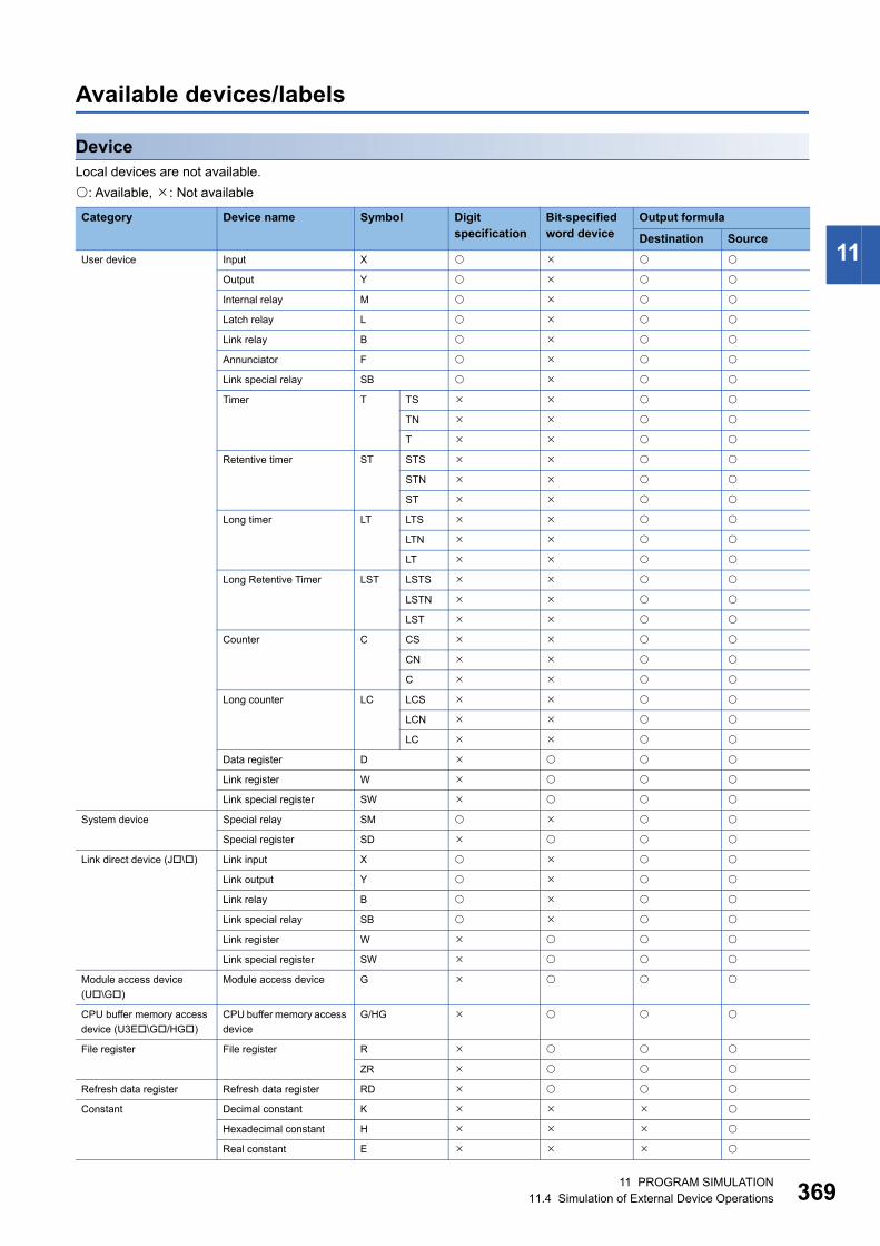
11 PROGRAM SIMULATION11.4 Simulation of External Device Operations 369
11
Available devices/labels
DeviceLocal devices are not available.
: Available, : Not available
Category Device name Symbol Digit specification
Bit-specified word device
Output formula
Destination Source
User device Input X
Output Y
Internal relay M
Latch relay L
Link relay B
Annunciator F
Link special relay SB
Timer T TS
TN
T
Retentive timer ST STS
STN
ST
Long timer LT LTS
LTN
LT
Long Retentive Timer LST LSTS
LSTN
LST
Counter C CS
CN
C
Long counter LC LCS
LCN
LC
Data register D
Link register W
Link special register SW
System device Special relay SM
Special register SD
Link direct device (J\) Link input X
Link output Y
Link relay B
Link special relay SB
Link register W
Link special register SW
Module access device
(U\G)
Module access device G
CPU buffer memory access
device (U3E\G/HG)
CPU buffer memory access
device
G/HG
File register File register R
ZR
Refresh data register Refresh data register RD
Constant Decimal constant K
Hexadecimal constant H
Real constant E

37011 PROGRAM SIMULATION11.4 Simulation of External Device Operations
LabelThe following labels are available.
• Global label
• Module label
• Labels of which class is "VAR_GLOBAL"/"VAR_GLOBAL_RETAIN"
• Labels except for string (32)/string [Unicode] (32)/pointer type
Precautions
• A label to which a device unavailable for outputs or conditions for data record is assigned cannot be used when creating
setting data. (Page 369 Device)
• For the labels of timer/retentive timer/counter type, a contact/coil/current value need to be specified as same as devices.
• A device and label cannot be used as an array index.
Safety device Safety input SA\X
Safety output SA\Y
Safety internal relay SA\M
Safety link relay SA\B
Safety special relay SA\SM
Safety data register SA\D
Safety link register SA\W
Safety special register SA\SD
Safety timer SA\T TS
TN
T
Safety retentive timer SA\ST STS
STN
ST
Safety counter SA\C CS
CN
C
Category Device name Symbol Digit specification
Bit-specified word device
Output formula
Destination Source
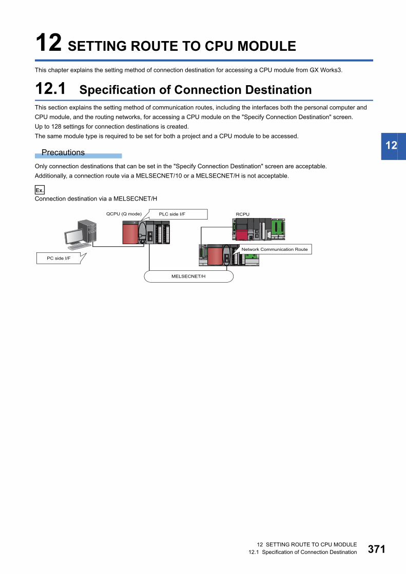
12 SETTING ROUTE TO CPU MODULE12.1 Specification of Connection Destination 371
12
12 SETTING ROUTE TO CPU MODULE
This chapter explains the setting method of connection destination for accessing a CPU module from GX Works3.
12.1 Specification of Connection DestinationThis section explains the setting method of communication routes, including the interfaces both the personal computer and
CPU module, and the routing networks, for accessing a CPU module on the "Specify Connection Destination" screen.
Up to 128 settings for connection destinations is created.
The same module type is required to be set for both a project and a CPU module to be accessed.
Precautions
Only connection destinations that can be set in the "Specify Connection Destination" screen are acceptable.
Additionally, a connection route via a MELSECNET/10 or a MELSECNET/H is not acceptable.
Ex.
Connection destination via a MELSECNET/H
RCPU
MELSECNET/H
QCPU (Q mode)
Network Communication Route
PLC side I/F
PC side I/F
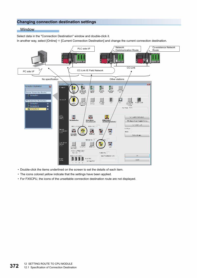
37212 SETTING ROUTE TO CPU MODULE12.1 Specification of Connection Destination
Changing connection destination settings
Window
Select data in the "Connection Destination" window and double-click it.
In another way, select [Online] [Current Connection Destination] and change the current connection destination.
• Double-click the items underlined on the screen to set the details of each item.
• The icons colored yellow indicate that the settings have been applied.
• For FX5CPU, the icons of the unsettable connection destination route are not displayed.
CC-Link
Co-existence Network RoutePLC side I/F Network
Communication Route
CC-Link IE Field NetworkPC side I/F
No specification Other stations

12 SETTING ROUTE TO CPU MODULE12.1 Specification of Connection Destination 373
12
Displayed items
*1 To specify the own station, select "No Specification".
Adding connection destination settingsAdd a new setting of a connection destination.
Operating procedure
1. Right-click in the "Connection Destination" window and select [Create New Connection Destination] from the shortcut
menu.
2. Set each item and click the [OK] button.
Switching connection destinationsSwitch a connection destination used as the default.
Operating procedure
1. Select a connection destination under "All Connection Destination" in the Connection Destination window.
2. Right-click and select [Set as Default Connection] from the shortcut menu.
Display the illustration of the connection routeClick the [System Image] button to display the set connection route in an illustration to check the route.
Precautions
For the considerations when using a MELSECNET/H network module on an RQ extension base unit, refer to the following
manual.
MELSEC iQ-R Module Configuration Manual
Item Description
Other
Station
Setting
No Specification Specify this to access a CPU module directly connected to a personal computer.
Other Station (Single
Network) *1Specify this to access a CPU module on another station via only one kind of network (including a multi-tier
system).
Ethernet, CC-Link IE Controller Network, and CC-Link IE Field Network are regarded as the same kind. When
accessing a system in which those are mixed, specify "Single Network".
Other Station (Co-existence
Network) *1Specify this to access the CPU module on another station via two kinds of network.
Network Communication Route Select the network type, network number, station number, and start I/O number of the network to be routed
through to access another station. The setting items differ depending on the selected network type.
Co-existence Network Route Select the network type, network number, station number, and start I/O number of the network to be accessed.
The setting items differ depending on the selected network type.
Target System • Multiple CPU Setting: Specify an access destination in a multiple CPU system.
• Specify Redundant CPU: Select a system of a CPU module to be connected.

37412 SETTING ROUTE TO CPU MODULE12.2 Direct Connection
12.2 Direct ConnectionThis section explains the setting method for accessing the CPU module directly connected to a personal computer.
Click the [CPU Module Direct Coupled Setting] button on the "Specify Connection Destination" screen to
change the settings to direct connection.
For FX5CPUs, the Ethernet adapter on a personal computer, which is used when connecting directly to an
Ethernet port, can be specified. For details, refer to the following section.
Page 375 Specifying the Ethernet adapter on a personal computer used for FX5CPUs
USB connectionThe following shows the setting example for accessing a CPU module on the own station with a USB from GX Works3.
FX5CPUs do not support this connection.
Ethernet connectionThe following shows the setting example for accessing a built-in Ethernet CPU with Ethernet from GX Works3.
Remote head modules do not support it.
*1 No setting items for FX5CPUs
No. Item Item to be selected Internal setting Input value
(1) PC side I/F Serial/USB USB
(2) PLC side I/F PLC Module PLC Mode RCPU
Other Station Setting No Specification Check at Communication Time 30 seconds
Retry Times 0 time
No. Item Item to be selected Internal setting Input value
(1) PC side I/F Ethernet Board Network No.*1
Station No.*1
Protocol*1 TCP
(2) PLC side I/F PLC Module Ethernet Port Direct Connection
Other Station Setting No Specification Check at Communication Time 30 seconds
Retry Times 0 time
Host CPU module
USB port
Built-in Ethernet CPU(192.168.3.39)
Ethernet port(192.168.3.1)
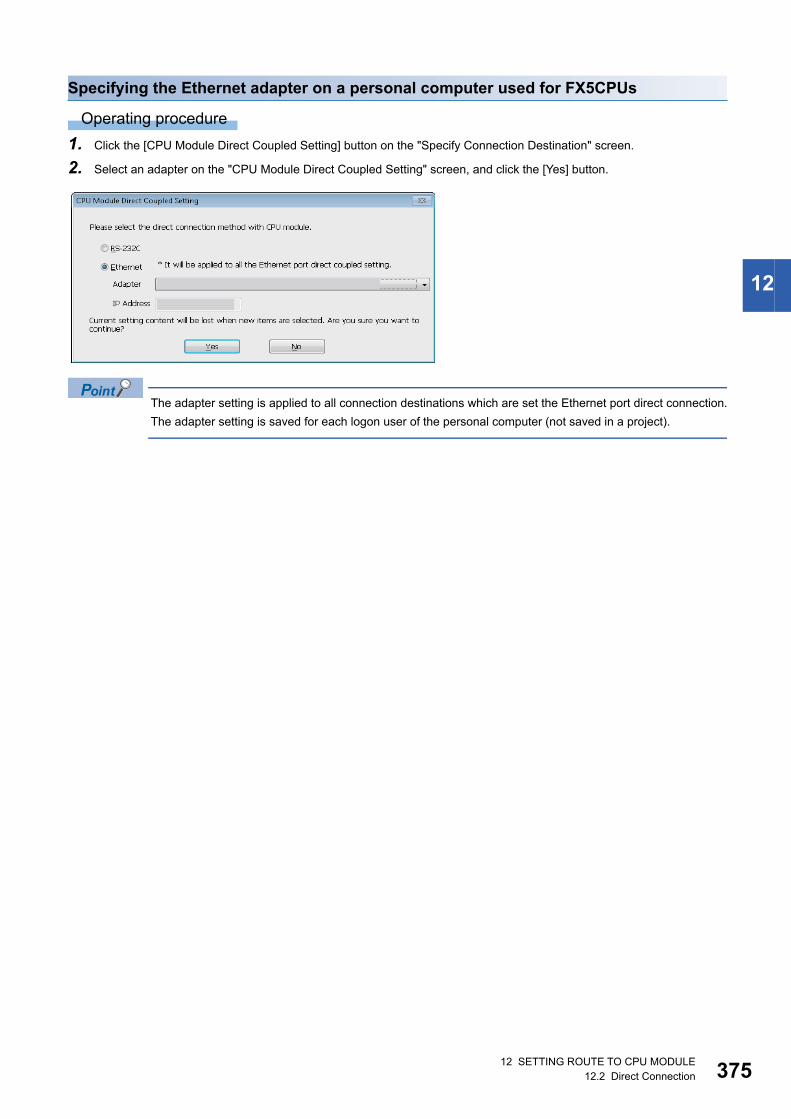
12 SETTING ROUTE TO CPU MODULE12.2 Direct Connection 375
12
Specifying the Ethernet adapter on a personal computer used for FX5CPUs
Operating procedure
1. Click the [CPU Module Direct Coupled Setting] button on the "Specify Connection Destination" screen.
2. Select an adapter on the "CPU Module Direct Coupled Setting" screen, and click the [Yes] button.
The adapter setting is applied to all connection destinations which are set the Ethernet port direct connection.
The adapter setting is saved for each logon user of the personal computer (not saved in a project).
37612 SETTING ROUTE TO CPU MODULE12.2 Direct Connection
Precautions
■Windows Vista or laterA warning message may appear.
Click the [Unblock] button for Windows Vista, and click the [Allow access] button for Windows 7 or later to unblock the
program (permit the access) and continue the operation.
■When the same IP addresses are displayedWhen the [Find] button is clicked on the "PLC side I/F Detailed Setting of PLC Module" screen, the same IP addresses may
be displayed in the list of the connection destination CPU.
Two or more IP addresses may have been set to the [IP Settings] tab in the "Advanced TCP/IP Settings" screen of Windows
network settings. Set only one IP address.
■When communication with GX Works3 is not allowed by Windows FirewallWhen Windows Firewall is enabled and communication with GX Works3 is not allowed, a timeout may occur.
To allow the communication, refer to the following procedures.
When using other software with a firewall function, refer to the manual of the software and allow the communication with GX
Works3.
Ex.
For Windows Vista
1. Select [Control Panel] [Security] [Windows Firewall] [Allow a program through Windows Firewall] from the Start
menu of Windows.
2. Click the [Add Program] button in the [Exception] tab.
3. Select "GX Works3" on the "Add a Program" screen, and click the [OK] button.
4. Select "GX Works3"*1 in the list, and click the [OK] button.
*1 'gxw3' may be displayed when RCPU/Ethernet module is searched on the network and access through the Windows firewall is set to allow before Ethernet port direct connection.
Ex.
For Windows 7 or later
1. Select [Control Panel] [System and Security] [Windows Firewall] [Allow a program*1 or feature through Windows
Firewall] from Windows Start.
2. Click the [Change settings] button, and click the [Allow another program*1] button.
3. Select "GX Works3" on the "Add a Program*1" screen, and click the [Add] button.
4. Select "Domain", "Home/Work (Private)", and "Public" of GX Works3*2 added in the list, and click the [OK] button.
*1 For Windows 8 or later, "Apps" is displayed.*2 'gxw3' may be displayed when RCPU/Ethernet module is searched on the network and access through the Windows firewall is set to
allow before Ethernet port direct connection.
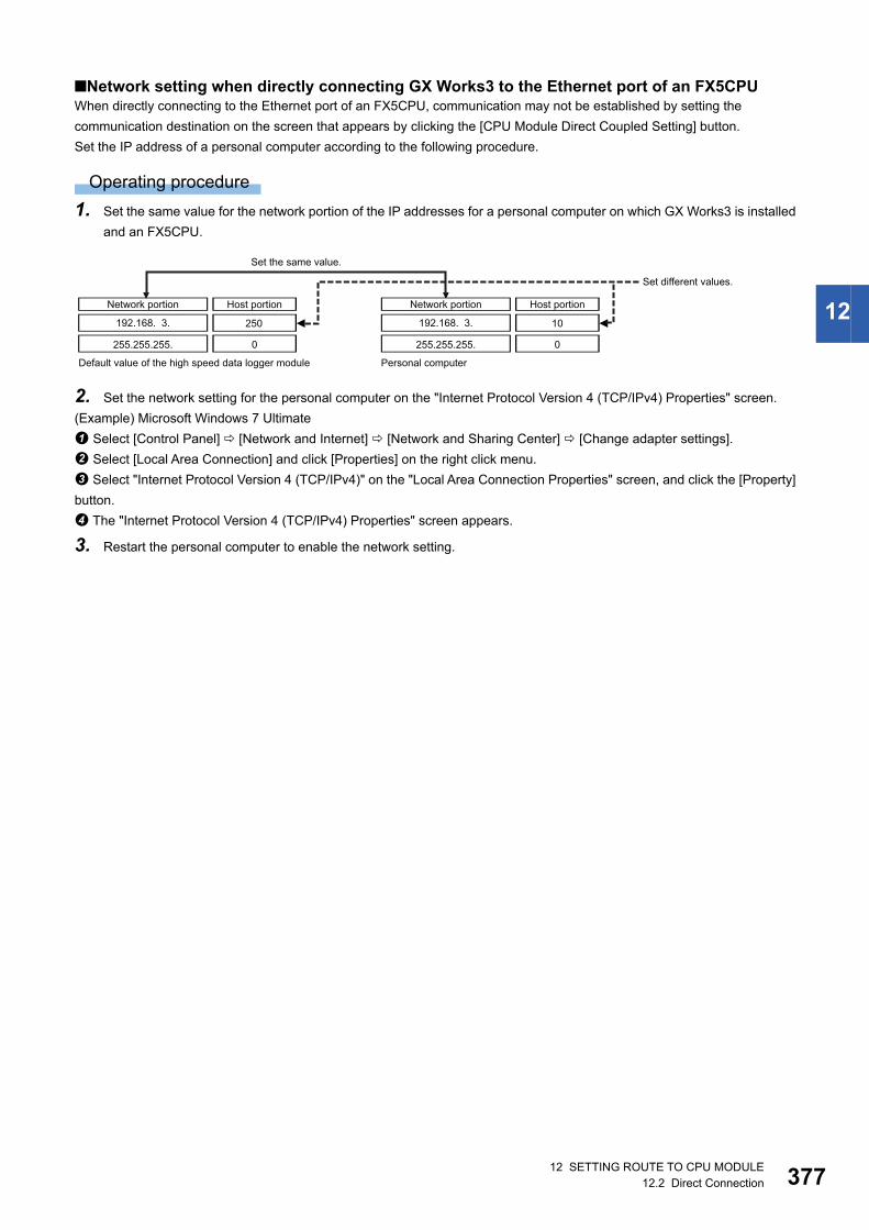
12 SETTING ROUTE TO CPU MODULE12.2 Direct Connection 377
12
■Network setting when directly connecting GX Works3 to the Ethernet port of an FX5CPUWhen directly connecting to the Ethernet port of an FX5CPU, communication may not be established by setting the
communication destination on the screen that appears by clicking the [CPU Module Direct Coupled Setting] button.
Set the IP address of a personal computer according to the following procedure.
Operating procedure
1. Set the same value for the network portion of the IP addresses for a personal computer on which GX Works3 is installed
and an FX5CPU.
2. Set the network setting for the personal computer on the "Internet Protocol Version 4 (TCP/IPv4) Properties" screen.
(Example) Microsoft Windows 7 Ultimate
Select [Control Panel] [Network and Internet] [Network and Sharing Center] [Change adapter settings].
Select [Local Area Connection] and click [Properties] on the right click menu.
Select "Internet Protocol Version 4 (TCP/IPv4)" on the "Local Area Connection Properties" screen, and click the [Property]
button.
The "Internet Protocol Version 4 (TCP/IPv4) Properties" screen appears.
3. Restart the personal computer to enable the network setting.
0
192.168. 3. 250
255.255.255. 0
192.168. 3. 10
255.255.255.
Set the same value.
Set different values.
Network portion Network portionHost portion Host portion
Default value of the high speed data logger module Personal computer
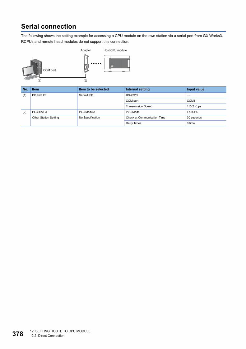
37812 SETTING ROUTE TO CPU MODULE12.2 Direct Connection
Serial connectionThe following shows the setting example for accessing a CPU module on the own station via a serial port from GX Works3.
RCPUs and remote head modules do not support this connection.
No. Item Item to be selected Internal setting Input value
(1) PC side I/F Serial/USB RS-232C
COM port COM1
Transmission Speed 115.2 Kbps
(2) PLC side I/F PLC Module PLC Mode FX5CPU
Other Station Setting No Specification Check at Communication Time 30 seconds
Retry Times 0 time
Host CPU module
COM port
Adapter

12 SETTING ROUTE TO CPU MODULE12.3 Accessing via Network (Single Network) 379
12
12.3 Accessing via Network (Single Network)This section shows the setting example for accessing a CPU module on another station via a single network after accessing
an Ethernet built-in CPU from GX Works3.
*1 No setting items for FX5CPUs
Access via Ethernet moduleThe following shows the setting example for accessing a CPU module via a CC-Link IE built-in Ethernet module from GX
Works3.
It is same settings when accessing a CPU module via the network part of RnENCPU.
FX5CPUs do not support it.
No. Item Item to be selected Internal setting Input value
(1) PC side I/F Ethernet Board Network No.*1
Station No.*1
Protocol*1 TCP
(2) PLC side I/F PLC Module Ethernet Port Direct Connection
Other Station Setting Other Station (Single Network) Check at Communication Time 30 seconds
Retry Times 0 time
(3) Network Communication Route CC IE Field Network No. 1
Station No. 0
No. Item Item to be selected Internal setting Input value
(1) PC side I/F Ethernet Board Network No. 1
Station No. 2
Protocol TCP
CC-Link IE Field Network
Ethernet port(192.168.3.1)
Network No.1(192.167.0.2)Station number: 2
RJ71EN71 (192.168.0.2)Station number: 2 Ethernet port
RJ71EN71 (192.167.0.1)Station number: 1
Network No.2RJ71EN71 (192.168.0.3)Station number: 3
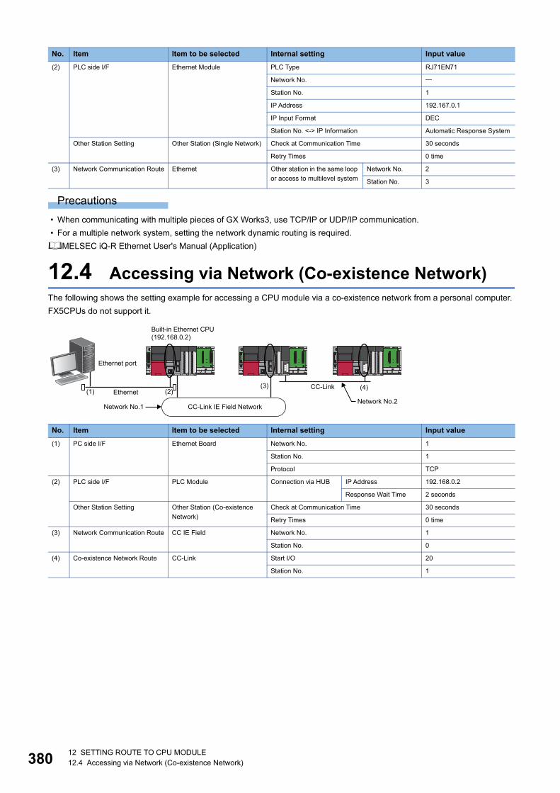
38012 SETTING ROUTE TO CPU MODULE12.4 Accessing via Network (Co-existence Network)
Precautions
• When communicating with multiple pieces of GX Works3, use TCP/IP or UDP/IP communication.
• For a multiple network system, setting the network dynamic routing is required.
MELSEC iQ-R Ethernet User's Manual (Application)
12.4 Accessing via Network (Co-existence Network)The following shows the setting example for accessing a CPU module via a co-existence network from a personal computer.
FX5CPUs do not support it.
(2) PLC side I/F Ethernet Module PLC Type RJ71EN71
Network No.
Station No. 1
IP Address 192.167.0.1
IP Input Format DEC
Station No. <-> IP Information Automatic Response System
Other Station Setting Other Station (Single Network) Check at Communication Time 30 seconds
Retry Times 0 time
(3) Network Communication Route Ethernet Other station in the same loop
or access to multilevel system
Network No. 2
Station No. 3
No. Item Item to be selected Internal setting Input value
(1) PC side I/F Ethernet Board Network No. 1
Station No. 1
Protocol TCP
(2) PLC side I/F PLC Module Connection via HUB IP Address 192.168.0.2
Response Wait Time 2 seconds
Other Station Setting Other Station (Co-existence
Network)
Check at Communication Time 30 seconds
Retry Times 0 time
(3) Network Communication Route CC IE Field Network No. 1
Station No. 0
(4) Co-existence Network Route CC-Link Start I/O 20
Station No. 1
No. Item Item to be selected Internal setting Input value
EthernetCC-Link
Built-in Ethernet CPU(192.168.0.2)
Ethernet port
Network No.2CC-Link IE Field NetworkNetwork No.1

12 SETTING ROUTE TO CPU MODULE12.5 Accessing via Serial Communication Module 381
12
12.5 Accessing via Serial Communication ModuleThis section explains the setting method for accessing a CPU module on the own station or on another station via a serial
communication module.
FX5CPUs do not support it.
Connection on a 1:1 basisThe following shows the setting example for accessing a CPU module by connecting a personal computer and a serial
communication module.
*1 Set the same station number as RJ71C24.Set the station number on the Module Parameter screen.
No. Item Item to be selected Internal setting Input value
(1) PC side I/F Serial/USB COM port COM1
Transmission Speed 115.2 Kbps
(2) PLC side I/F C24 PLC Type RJ71C24
Station No.*1
Parity
Sum Check
Other Station Setting No Specification Check at Communication Time
Retry Times
RJ71C24
COM port
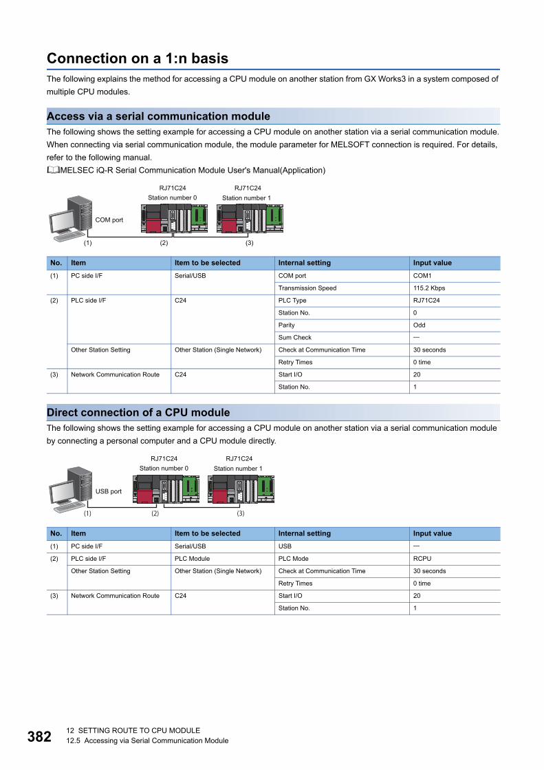
38212 SETTING ROUTE TO CPU MODULE12.5 Accessing via Serial Communication Module
Connection on a 1:n basisThe following explains the method for accessing a CPU module on another station from GX Works3 in a system composed of
multiple CPU modules.
Access via a serial communication moduleThe following shows the setting example for accessing a CPU module on another station via a serial communication module.
When connecting via serial communication module, the module parameter for MELSOFT connection is required. For details,
refer to the following manual.
MELSEC iQ-R Serial Communication Module User's Manual(Application)
Direct connection of a CPU moduleThe following shows the setting example for accessing a CPU module on another station via a serial communication module
by connecting a personal computer and a CPU module directly.
No. Item Item to be selected Internal setting Input value
(1) PC side I/F Serial/USB COM port COM1
Transmission Speed 115.2 Kbps
(2) PLC side I/F C24 PLC Type RJ71C24
Station No. 0
Parity Odd
Sum Check
Other Station Setting Other Station (Single Network) Check at Communication Time 30 seconds
Retry Times 0 time
(3) Network Communication Route C24 Start I/O 20
Station No. 1
No. Item Item to be selected Internal setting Input value
(1) PC side I/F Serial/USB USB
(2) PLC side I/F PLC Module PLC Mode RCPU
Other Station Setting Other Station (Single Network) Check at Communication Time 30 seconds
Retry Times 0 time
(3) Network Communication Route C24 Start I/O 20
Station No. 1
RJ71C24 RJ71C24Station number 0 Station number 1
COM port
RJ71C24 RJ71C24Station number 0 Station number 1
USB port
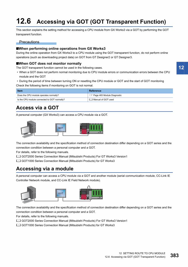
12 SETTING ROUTE TO CPU MODULE12.6 Accessing via GOT (GOT Transparent Function) 383
12
12.6 Accessing via GOT (GOT Transparent Function)This section explains the setting method for accessing a CPU module from GX Works3 via a GOT by performing the GOT
transparent function.
Precautions
■When performing online operations from GX Works3During the online operation from GX Works3 to a CPU module using the GOT transparent function, do not perform online
operations (such as downloading project data) on GOT from GT Designer2 or GT Designer3.
■When GOT does not monitor normallyThe GOT transparent function cannot be used in the following cases.
• When a GOT does not perform normal monitoring due to CPU module errors or communication errors between the CPU
module and the GOT
• During the period of time between turning ON or resetting the CPU module or GOT and the start of GOT monitoring
Check the following items if monitoring on GOT is not normal.
Access via a GOTA personal computer (GX Works3) can access a CPU module via a GOT.
The connection availability and the specification method of connection destination differ depending on a GOT series and the
connection condition between a personal computer and a GOT.
For details, refer to the following manuals.
GOT2000 Series Connection Manual (Mitsubishi Products) For GT Works3 Version1
GOT1000 Series Connection Manual (Mitsubishi Products) for GT Works3
Accessing via a moduleA personal computer can access a CPU module via a GOT and another module (serial communication module, CC-Link IE
Controller Network module, and CC-Link IE Field Network module).
The connection availability and the specification method of connection destination differ depending on a GOT series and the
connection condition between a personal computer and a GOT.
For details, refer to the following manuals.
GOT2000 Series Connection Manual (Mitsubishi Products) For GT Works3 Version1
GOT1000 Series Connection Manual (Mitsubishi Products) for GT Works3
Item Reference
Does the CPU module operates normally? Page 483 Module Diagnostic
Is the CPU module connected to GOT normally? Manual of GOT used
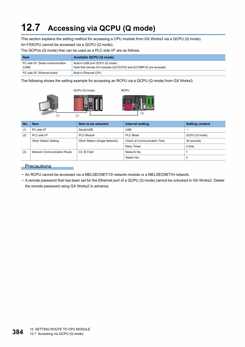
38412 SETTING ROUTE TO CPU MODULE12.7 Accessing via QCPU (Q mode)
12.7 Accessing via QCPU (Q mode)This section explains the setting method for accessing a CPU module from GX Works3 via a QCPU (Q mode).
An FX5CPU cannot be accessed via a QCPU (Q mode).
The QCPUs (Q mode) that can be used as a PLC side I/F are as follows.
The following shows the setting example for accessing an RCPU via a QCPU (Q mode) from GX Works3.
Precautions
• An RCPU cannot be accessed via a MELSECNET/10 network module or a MELSECNET/H network.
• A remote password that has been set for the Ethernet port of a QCPU (Q mode) cannot be unlocked in GX Works3. Delete
the remote password using GX Works2 in advance.
Item Available QCPU (Q mode)
PC side I/F: Serial communication
(USB)
Built-in USB port QCPU (Q mode)
Note that remote I/O modules (QJ72LP25 and QJ72BR15) are excluded.
PC side I/F: Ethernet board Built-in Ethernet CPU
No. Item Item to be selected Internal setting Setting content
(1) PC side I/F Serial/USB USB
(2) PLC side I/F PLC Module PLC Mode QCPU (Q mode)
Other Station Setting Other Station (Single Network) Check at Communication Time 30 seconds
Retry Times 0 time
(3) Network Communication Route CC IE Field Network No. 1
Station No. 0
(1) (2)(3)
RCPUQCPU (Q mode)
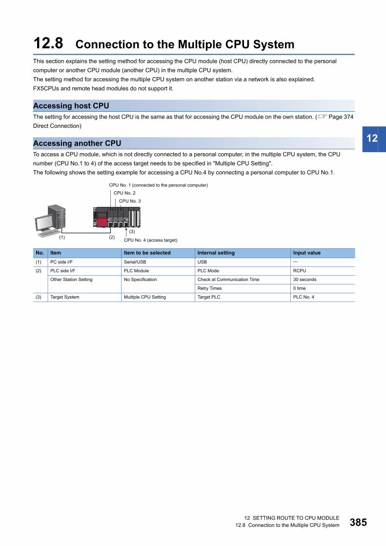
12 SETTING ROUTE TO CPU MODULE12.8 Connection to the Multiple CPU System 385
12
12.8 Connection to the Multiple CPU SystemThis section explains the setting method for accessing the CPU module (host CPU) directly connected to the personal
computer or another CPU module (another CPU) in the multiple CPU system.
The setting method for accessing the multiple CPU system on another station via a network is also explained.
FX5CPUs and remote head modules do not support it.
Accessing host CPUThe setting for accessing the host CPU is the same as that for accessing the CPU module on the own station. (Page 374
Direct Connection)
Accessing another CPUTo access a CPU module, which is not directly connected to a personal computer, in the multiple CPU system, the CPU
number (CPU No.1 to 4) of the access target needs to be specified in "Multiple CPU Setting".
The following shows the setting example for accessing a CPU No.4 by connecting a personal computer to CPU No.1.
No. Item Item to be selected Internal setting Input value
(1) PC side I/F Serial/USB USB
(2) PLC side I/F PLC Module PLC Mode RCPU
Other Station Setting No Specification Check at Communication Time 30 seconds
Retry Times 0 time
(3) Target System Multiple CPU Setting Target PLC PLC No. 4
CPU No. 1 (connected to the personal computer)
CPU No. 2
CPU No. 3
CPU No. 4 (access target)
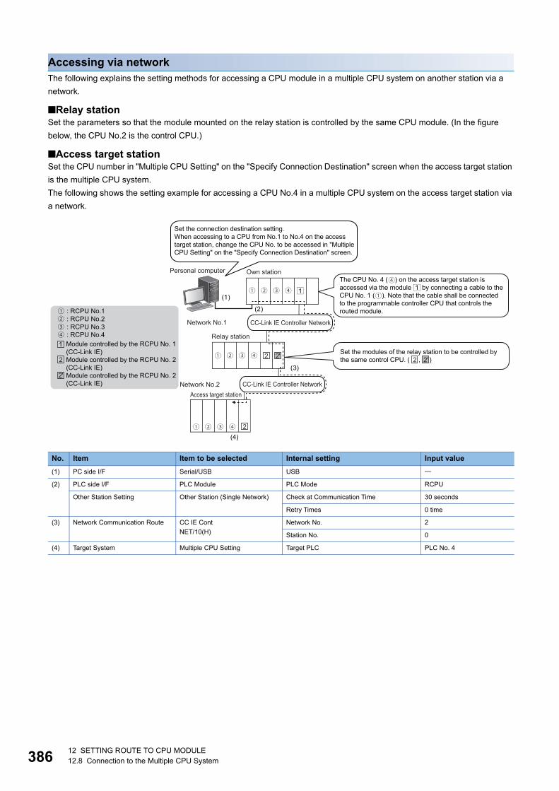
38612 SETTING ROUTE TO CPU MODULE12.8 Connection to the Multiple CPU System
Accessing via networkThe following explains the setting methods for accessing a CPU module in a multiple CPU system on another station via a
network.
■Relay stationSet the parameters so that the module mounted on the relay station is controlled by the same CPU module. (In the figure
below, the CPU No.2 is the control CPU.)
■Access target stationSet the CPU number in "Multiple CPU Setting" on the "Specify Connection Destination" screen when the access target station
is the multiple CPU system.
The following shows the setting example for accessing a CPU No.4 in a multiple CPU system on the access target station via
a network.
No. Item Item to be selected Internal setting Input value
(1) PC side I/F Serial/USB USB
(2) PLC side I/F PLC Module PLC Mode RCPU
Other Station Setting Other Station (Single Network) Check at Communication Time 30 seconds
Retry Times 0 time
(3) Network Communication Route CC IE Cont
NET/10(H)
Network No. 2
Station No. 0
(4) Target System Multiple CPU Setting Target PLC PLC No. 4
Set the connection destination setting.When accessing to a CPU from No.1 to No.4 on the access target station, change the CPU No. to be accessed in "Multiple CPU Setting" on the "Specify Connection Destination" screen.
Personal computer Own stationThe CPU No. 4 ( ) on the access target station is accessed via the module by connecting a cable to the CPU No. 1 ( ). Note that the cable shall be connected to the programmable controller CPU that controls the routed module.: RCPU No.1
: RCPU No.2: RCPU No.3: RCPU No.4
Network No.1 CC-Link IE Controller Network
Relay stationModule controlled by the RCPU No. 1(CC-Link IE)Module controlled by the RCPU No. 2(CC-Link IE)Module controlled by the RCPU No. 2(CC-Link IE)
Set the modules of the relay station to be controlled by the same control CPU. ( , )
CC-Link IE Controller NetworkNetwork No.2Access target station
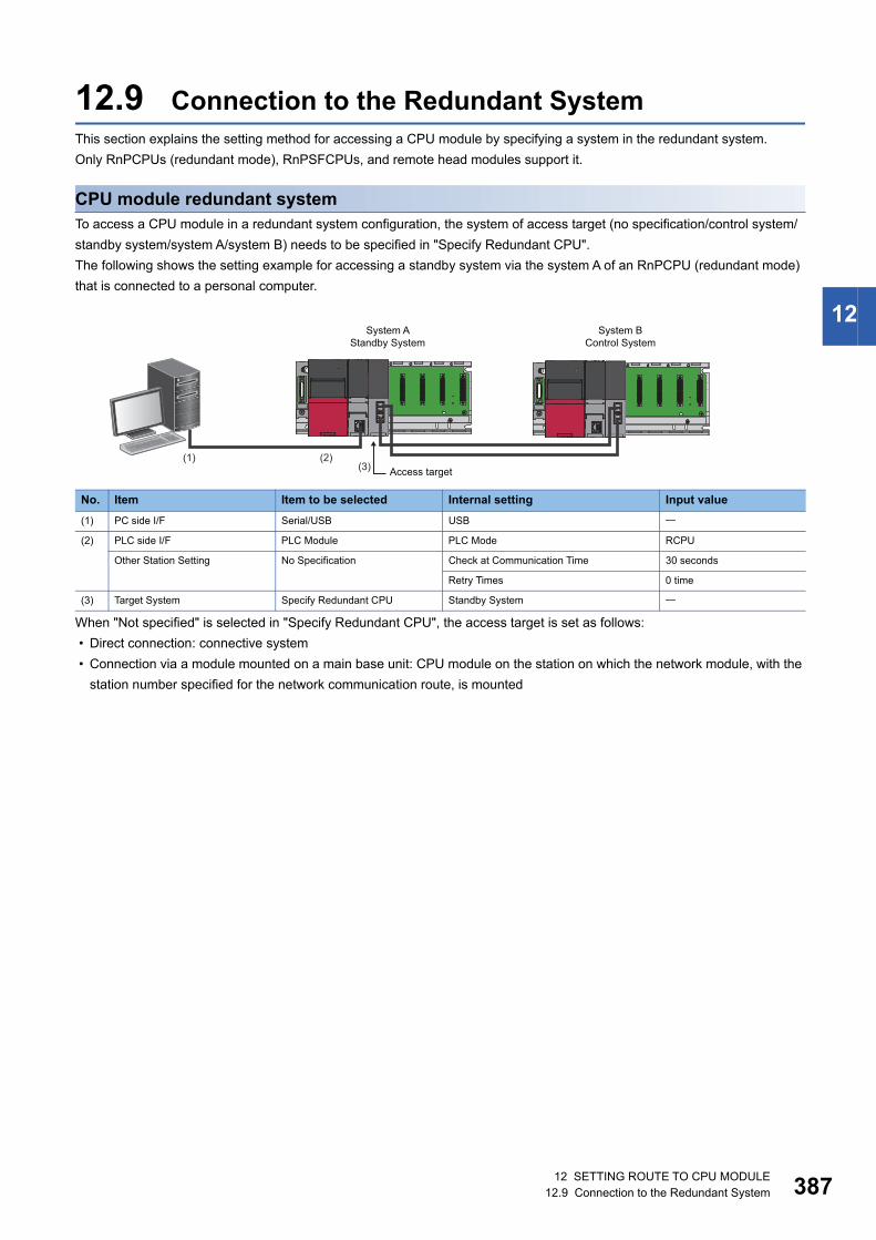
12 SETTING ROUTE TO CPU MODULE12.9 Connection to the Redundant System 387
12
12.9 Connection to the Redundant SystemThis section explains the setting method for accessing a CPU module by specifying a system in the redundant system.
Only RnPCPUs (redundant mode), RnPSFCPUs, and remote head modules support it.
CPU module redundant systemTo access a CPU module in a redundant system configuration, the system of access target (no specification/control system/
standby system/system A/system B) needs to be specified in "Specify Redundant CPU".
The following shows the setting example for accessing a standby system via the system A of an RnPCPU (redundant mode)
that is connected to a personal computer.
When "Not specified" is selected in "Specify Redundant CPU", the access target is set as follows:
• Direct connection: connective system
• Connection via a module mounted on a main base unit: CPU module on the station on which the network module, with the
station number specified for the network communication route, is mounted
No. Item Item to be selected Internal setting Input value
(1) PC side I/F Serial/USB USB
(2) PLC side I/F PLC Module PLC Mode RCPU
Other Station Setting No Specification Check at Communication Time 30 seconds
Retry Times 0 time
(3) Target System Specify Redundant CPU Standby System
(1) (2)(3)
System AStandby System
System BControl System
Access target

38812 SETTING ROUTE TO CPU MODULE12.9 Connection to the Redundant System
Remote head module redundant systemTo access a remote head module in a redundant system configuration, the access target (CPU No.1/CPU No.2/no
specification/control system/standby system) needs to be specified in "Multiple CPU Setting" or "Specify Redundant CPU".
The setting for either "Multiple CPU Setting" or "Specify Redundant CPU" can be set.
The following shows the setting example for accessing a remote head module (single line) from GX Works3 using a USB
connection.
When "Not specified" is selected in "Specify Redundant CPU", the access target is set as follows:
• Direct connection: remote head module that is directly connected to a personal computer
• Connection via a module mounted on a main base unit: remote head module No.1 (mounted on a CPU slot) on the station
on which the network module, with the station number specified for the network communication route, is mounted
• Connection via a module mounted on an extension base unit: remote head module No.1 (mounted on a CPU slot)
No. Item Item to be selected Internal setting Input value
(1) PC side I/F Serial/USB USB
(2) PLC side I/F Head module RJ72GF15-T2
Other Station Setting No Specification Check at Communication Time 30 seconds
Retry Times 0 time
(3) Target System Specify Redundant CPU Control System
Standby SystemControl System
Access target
12 SETTING ROUTE TO CPU MODULE12.10 Considerations of Communication with a CPU module 389
12
12.10 Considerations of Communication with a CPU module
This section explains the considerations of communication with a CPU module.
Refer to the considerations described in each section as well as the descriptions in this section.
Communication via network system (single/multiple)When accessing an RCPU via a network system, all the connected stations must be RCPUs or QCPUs (Q mode).
In that case, an RCPU must be used for a relay station.
Connected station: Station directly connected from GX Works3
Relay station: Stations to be routed on network system
Communication with the CPU module using a USB cable
■Connecting/disconnecting a USB cable, resetting a CPU module, and turning the power ON or OFF
A communication error may occur and it may not be recovered if connecting and disconnecting a USB cable, resetting the
CPU module, or turning the power ON or OFF is performed frequently during communication with a CPU module.
Therefore, set GX Works3 to offline as much as possible during these operations. 'Offline' indicates the state other than
below.
• Write to PLC/Read from PLC, Monitor, and PLC diagnostics
If the operation is not recovered from an error, remove the USB cable. Then, connect it again after five or more seconds.
(Even after this operation, an error may occur at initial communication. However, communication will be successful after that.)
Click the [OK] button on the warning message, and remove a USB cable from the personal computer.
■Combination of personal computer models and USB cablesA communication error may occur depending on the combination of personal computer models and USB cables.
If an error occurs, take appropriate actions in accordance with the message displayed on the screen.
Other considerations
■High-speed communication using an RS-232 cableCommunication may fail depending on the performance of the personal computer when high-speed communication is
attempted by changing the transmission speed at the serial port of the personal computer (personal computer side interface).
Communication speed may also slow down due to communication retries.
Decrease the transmission speed if high-speed communication cannot be performed normally.
■Resume function, suspend setting, power saving function, and standby mode of the personal computer
A communication error may occur during communication with the CPU module when any of the settings shown above are
enabled.
Disable these settings for communication with the CPU module.
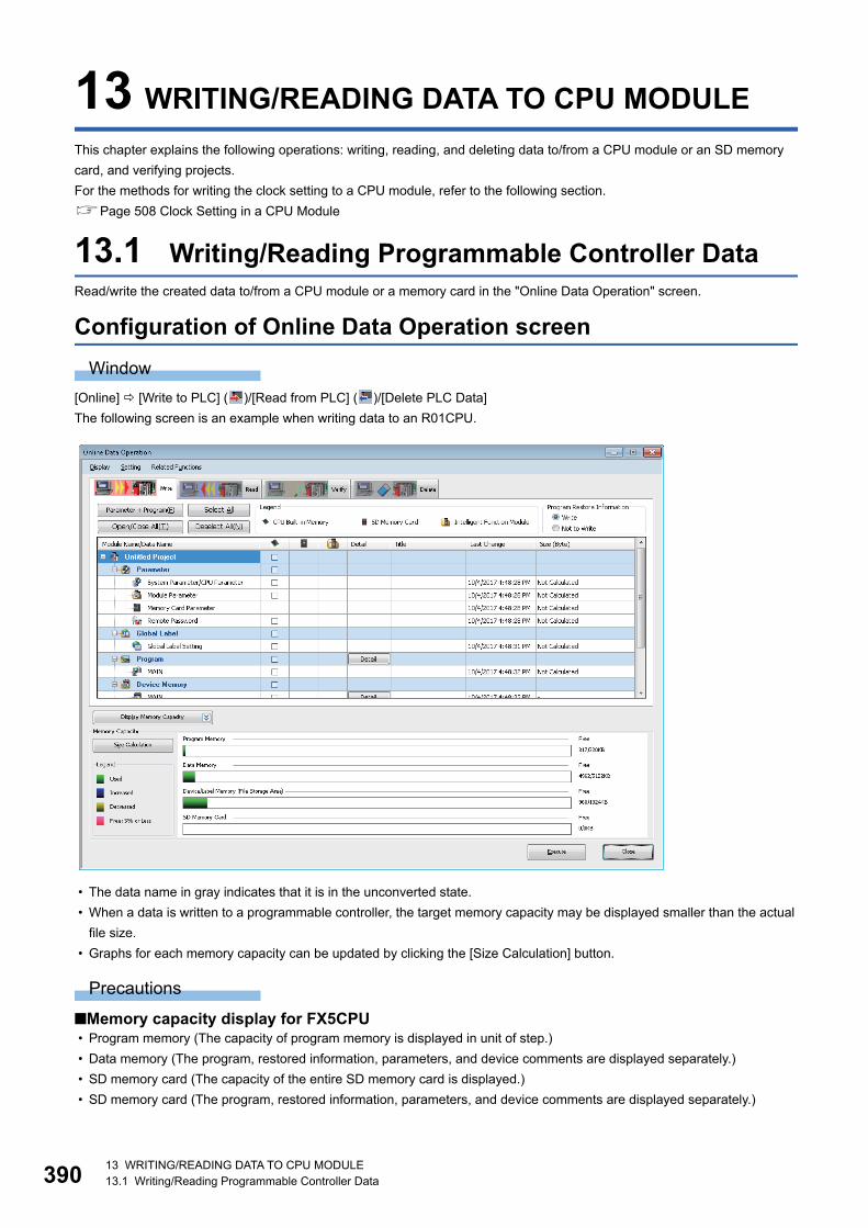
39013 WRITING/READING DATA TO CPU MODULE13.1 Writing/Reading Programmable Controller Data
13 WRITING/READING DATA TO CPU MODULE
This chapter explains the following operations: writing, reading, and deleting data to/from a CPU module or an SD memory
card, and verifying projects.
For the methods for writing the clock setting to a CPU module, refer to the following section.
Page 508 Clock Setting in a CPU Module
13.1 Writing/Reading Programmable Controller DataRead/write the created data to/from a CPU module or a memory card in the "Online Data Operation" screen.
Configuration of Online Data Operation screen
Window
[Online] [Write to PLC] ( )/[Read from PLC] ( )/[Delete PLC Data]
The following screen is an example when writing data to an R01CPU.
• The data name in gray indicates that it is in the unconverted state.
• When a data is written to a programmable controller, the target memory capacity may be displayed smaller than the actual
file size.
• Graphs for each memory capacity can be updated by clicking the [Size Calculation] button.
Precautions
■Memory capacity display for FX5CPU • Program memory (The capacity of program memory is displayed in unit of step.)
• Data memory (The program, restored information, parameters, and device comments are displayed separately.)
• SD memory card (The capacity of the entire SD memory card is displayed.)
• SD memory card (The program, restored information, parameters, and device comments are displayed separately.)
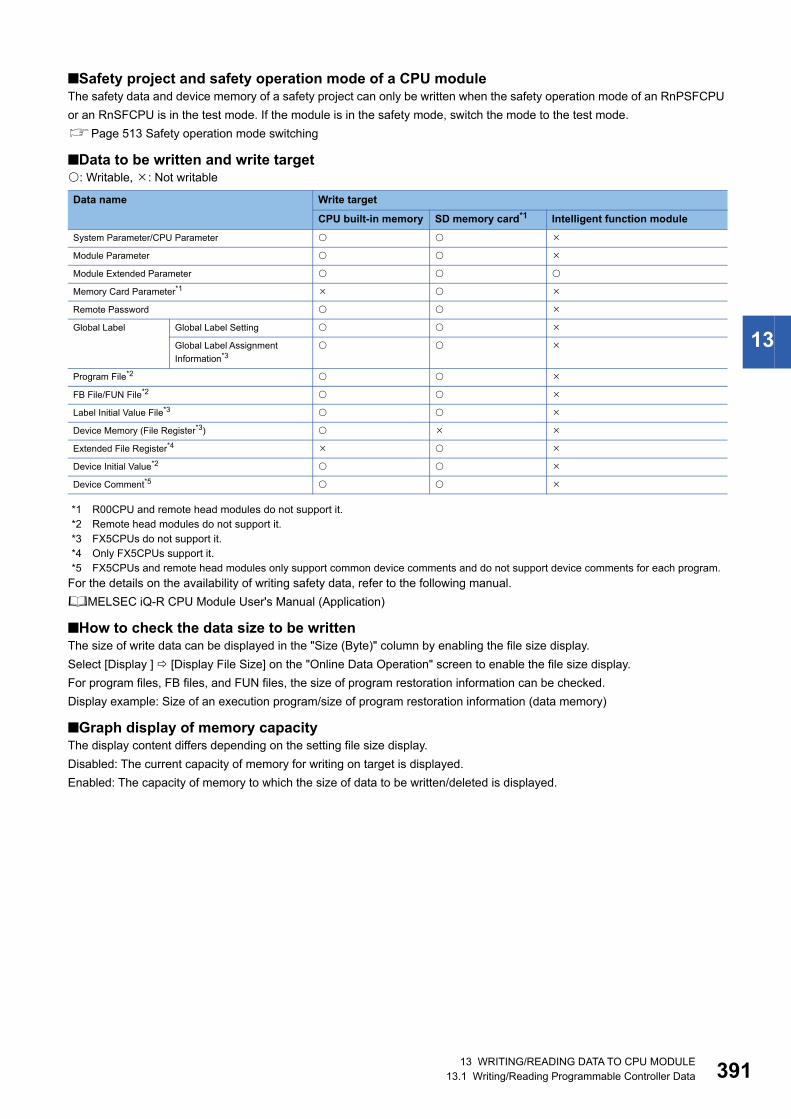
13 WRITING/READING DATA TO CPU MODULE13.1 Writing/Reading Programmable Controller Data 391
13
■Safety project and safety operation mode of a CPU moduleThe safety data and device memory of a safety project can only be written when the safety operation mode of an RnPSFCPU
or an RnSFCPU is in the test mode. If the module is in the safety mode, switch the mode to the test mode.
Page 513 Safety operation mode switching
■Data to be written and write target: Writable, : Not writable
*1 R00CPU and remote head modules do not support it.*2 Remote head modules do not support it.*3 FX5CPUs do not support it.*4 Only FX5CPUs support it.*5 FX5CPUs and remote head modules only support common device comments and do not support device comments for each program.
For the details on the availability of writing safety data, refer to the following manual.
MELSEC iQ-R CPU Module User's Manual (Application)
■How to check the data size to be writtenThe size of write data can be displayed in the "Size (Byte)" column by enabling the file size display.
Select [Display ] [Display File Size] on the "Online Data Operation" screen to enable the file size display.
For program files, FB files, and FUN files, the size of program restoration information can be checked.
Display example: Size of an execution program/size of program restoration information (data memory)
■Graph display of memory capacityThe display content differs depending on the setting file size display.
Disabled: The current capacity of memory for writing on target is displayed.
Enabled: The capacity of memory to which the size of data to be written/deleted is displayed.
Data name Write target
CPU built-in memory SD memory card*1 Intelligent function module
System Parameter/CPU Parameter
Module Parameter
Module Extended Parameter
Memory Card Parameter*1
Remote Password
Global Label Global Label Setting
Global Label Assignment
Information*3
Program File*2
FB File/FUN File*2
Label Initial Value File*3
Device Memory (File Register*3)
Extended File Register*4
Device Initial Value*2
Device Comment*5
39213 WRITING/READING DATA TO CPU MODULE13.1 Writing/Reading Programmable Controller Data
Writing data to a programmable controllerWrite data to a CPU module.
For the considerations for writing, refer to the following section.
Page 401 Considerations for Online data operation
Operating procedure
1. Select the [Write] tab on the "Online Data Operation" screen.
2. Select data to be written and a write destination.
3. Click the [Detail] button to set the details such as a range to be written.
4. Click the [Execute] button.
After writing a safety program or a parameter to an RnPSFCPU or an RnSFCPU, manuals are displayed to clarify the
information that needs to be confirmed by users for using a safety project safely.
When more than one program is written to the CPU module, the programs categorized as "No Execution
Type" will never be executed on the CPU module. For saving the memory capacity of the CPU module,
removing them from the target data at writing data is recommended.
■POU duplication checkWhen performing 'Write to PLC', the program is checked whether a POU name is duplicated in the program and in a program
in the CPU module.
When using a CPU module in a redundant system configuration and writing a program to both systems, the program is
checked whether a POU name is duplicated in the both systems.
Whether to check the duplication can be set by setting the following option.
• [Tool] [Options] "Online" "Write to PLC "Operational Setting" "Duplication Check for POU"
■Program restoration informationWhether to write the program restoration information with a program can be selected when performing 'Write to PLC'.
By setting the following option, whether or not to write the program restoration information can be selected in the "Online Data
Operation" screen.
• [Tool] [Options] "Online" "Program Restore Information" "Operational Setting" "Enable the setting to write/not
to write program restore information"
When a safety program, safety FB, and safety FUN is written while "Not to Write" is selected in "Program Restore
Information", the program restoration information is written to an RnSFCPU.
When a program is written without writing the program restoration information, the data cannot be read with 'Read from PLC',
and the detailed verification result screen cannot be displayed with 'Verify with PLC'.
For CPU modules that do not support this function, whether to write the program restoration information cannot be selected
even when the option is set.
13 WRITING/READING DATA TO CPU MODULE13.1 Writing/Reading Programmable Controller Data 393
13
■Skip overwriting dataWhen writing data to a CPU module, writing data that is not changed from the previous writing can be skipped, and that can
shorten the time required for writing.
In the confirmation message appeared after the [Execute] button is clicked in the "Online Data Operation" screen, select the
checkbox of "Skip writing for the files that has not been changed.".
The following files are overwritten even if the checkbox of "Skip writing for the files that has not been changed." is selected.
• Memory card parameter
• Global label assignment information
• Global label initial value
• Local label initial value
• Device memory
• File register
When writing program restoration information to a CPU module where no program restoration information is written, a
program file, FB file, and/or FUN file is written even if no changes are applied.
When an SD memory card or intelligent function module is selected as a write target, the data is written even if the data is not
modified.
■Operations when using CPU modules in a redundant system configurationFor an RnPCPU (redundant mode), the operations differ depending on the operation modes.
An RnPSFCPU operates only when selecting the backup mode for the operation mode.
Data allocations are changed by updating a firmware version from 30 or earlier to 31 or later for the R04CPU,
R08CPU, R16CPU, R32CPU, or R120CPU.
For details on the operation, refer to the following manual.
(MELSEC iQ-R CPU Module User's Manual (Application))
This may cause a lack of free space in the program memory when data backed up is written to the CPU
module. In this case, perform any of the following operations and write the data again.
• Reduce the setting value of "Allocate Memory for Online Program Change". (Default: 500 steps)
• Reduce the number of program steps.
Operation mode Operation
Separate mode Applied to the CPU module in the connective system.
Backup mode Applied to both systems (order: control system → standby system).
If an error occurs in the control system while writing data, it is not written to the standby system. If an error occurs in
the standby system while writing data, the data of control system cannot be restored to its former condition.
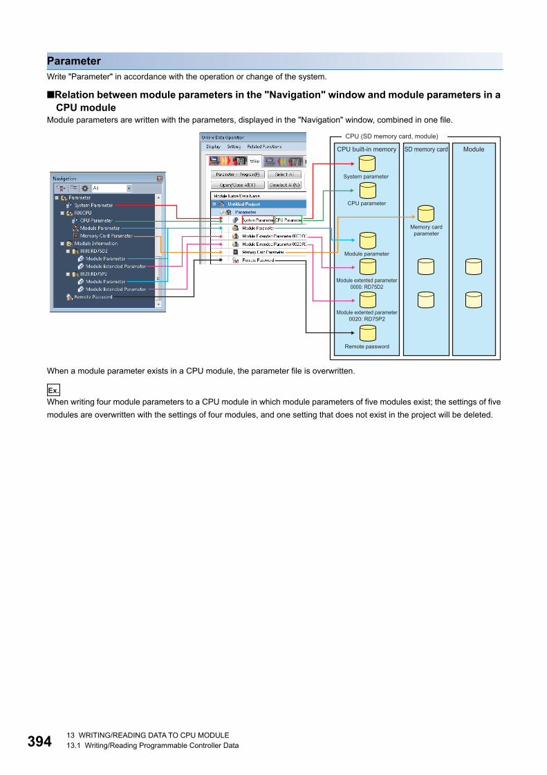
39413 WRITING/READING DATA TO CPU MODULE13.1 Writing/Reading Programmable Controller Data
ParameterWrite "Parameter" in accordance with the operation or change of the system.
■Relation between module parameters in the "Navigation" window and module parameters in a CPU module
Module parameters are written with the parameters, displayed in the "Navigation" window, combined in one file.
When a module parameter exists in a CPU module, the parameter file is overwritten.
Ex.
When writing four module parameters to a CPU module in which module parameters of five modules exist; the settings of five
modules are overwritten with the settings of four modules, and one setting that does not exist in the project will be deleted.
Remote password
Memory card parameter
Module extented parameter0020: RD75P2
Module extented parameter0000: RD75D2
Module parameter
CPU parameter
System parameter
CPU built-in memory
CPU (SD memory card, module)
SD memory card Module

13 WRITING/READING DATA TO CPU MODULE13.1 Writing/Reading Programmable Controller Data 395
13
■Consistency of parametersWhen writing a part of the parameters additionally or writing modified parameters, the consistency of the parameters are
required. Consistency means matching the information such as the I/O assignment setting (start I/O number, slot number,
etc.) between the system parameters and each parameter.
There are two methods to keep the consistency.
• Read a system parameter and each parameter and change them. After that, write them to a CPU module. The CPU module
needs to be reset to change the system parameter.
• Read each parameter to be changed, and change them to be consistent with the system parameters in the project. After
that, write the changed parameters only to the CPU module. Basically, the CPU module is does not need to be reset,
however, some modules are required to reset the CPU module after changing parameters. For details, refer to the manual
of the module used.
■Modules with start I/O number unsetThe unset module parameters cannot be written to a programmable controller.
■Writing parameters of remote I/O module (slave station) on CC-Link IE Field NetworkParameters can be written to a slave station in the "CC IE Field Configuration" window. For details, refer to the manual of each
remote I/O module.
ProgramWhen creating a program (local label, program body), write "Program".
When the column of "Initial Value" is set on the local label editor, write "Label Initial Value by Program".
When the column of "Initial Value" is not set, an initial value file of labels is not displayed. In addition, the initial value file of
labels with a same name in the programmable controller is deleted.
When a standard function or a standard function block is used in the program, write "SlibFbFile" of POU.
■Setting the secured steps for online program changeSet the range of program (program file) to be written and secured steps for online program change on the "Program Detail
Setting" screen displayed by clicking the [Detail] button of "Program".
FX5CPUs do not support this setting.
■Operations after writing SFC programsFor SFC programs, the operations performs differently between Ladder, ST, and FBD/LD when changing programs by writing
them to a programmable controller. For the details, refer to the following manual.
MELSEC iQ-R Programming Manual (Program Design)
Global labelAfter setting global labels, write "Global Label Setting".
When the column of "Initial Value" is set on the global label editor, write "Global Label Initial Value".
When the column of "Initial Value" is not set, an initial value file of labels is not displayed. In addition, the initial value file of
labels with a same name in the programmable controller is deleted.
When "Access from External Device" is selected on the global label editor, write "Global Label Assignment Information".
FX5CPUs do not support the setting for initial values of labels and access from external devices.
Precautions
The sample comments are included in the write target. If the data size to be written exceeds the memory capacity of the CPU
module at writing data, prepare an SD memory card.
For FX5CPU, the writable capacity is the same as that of the CPU module even when data is written to an SD memory card.
Item Description
Allocate Memory for Online
Program Change
Writing programs while the CPU module is running affects scan time due to the change of number of steps.
Enter the secured steps for online program change to handle the change of number of steps when performing the online
program change function.
When the number of program steps is changed, the capacity of program files is not changed if the changed number of steps
are within the range of the number of the secured steps for online program change.
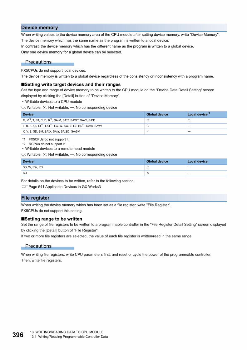
39613 WRITING/READING DATA TO CPU MODULE13.1 Writing/Reading Programmable Controller Data
Device memoryWhen writing values to the device memory area of the CPU module after setting device memory, write "Device Memory".
The device memory which has the same name as the program is written to a local device.
In contrast, the device memory which has the different name as the program is written to a global device.
Only one device memory for a global device can be selected.
Precautions
FX5CPUs do not support local devices.
The device memory is written to a global device regardless of the consistency or inconsistency with a program name.
■Setting write target devices and their rangesSet the type and range of device memory to be written to the CPU module on the "Device Data Detail Setting" screen
displayed by clicking the [Detail] button of "Device Memory".
• Writable devices to a CPU module
: Writable, : Not writable, : No corresponding device
*1 FX5CPUs do not support it.*2 RCPUs do not support it.
• Writable devices to a remote head module
: Writable, : Not writable, : No corresponding device
For details on the devices to be written, refer to the following section.
Page 541 Applicable Devices in GX Works3
File registerWhen writing the device memory which has been set as a file register, write "File Register".
FX5CPUs do not support this setting.
■Setting range to be writtenSet the range of file registers to be written to a programmable controller in the "File Register Detail Setting" screen displayed
by clicking the [Detail] button of "File Register".
If two or more file registers are selected, the value of each file register is written/read in the same range.
Precautions
When writing file registers, write CPU parameters first, and reset or cycle the power of the programmable controller.
Then, write file registers.
Device Global device Local device*1
M, V*1, T, ST, C, D, R*2, SA\M, SA\T, SA\ST, SA\C, SA\D
L, B, F, SB, LT*1, LST*1, LC, W, SW, Z, LZ, RD*1, SA\B, SA\W
X, Y, S, SD, SM, SA\X, SA\Y, SA\SD, SA\SM
Device Global device Local device
SB, W, SW, RD
SD
13 WRITING/READING DATA TO CPU MODULE13.1 Writing/Reading Programmable Controller Data 397
13
Extended file registerValues set in the device memory (extension file registers (ER)) of a project can be all written to extended file registers (ER) of
an SD memory card in a batch.
It is not available in a project used for an RCPU.
■Range to be writtenValues of the device memory (extension file registers (ER)) of a project are stored in extended file registers (ER) of an SD
memory card by selecting "Extend File Register" of the SD memory card and performing writing.
All the points (32768 points) of the device memory of a project are written to extended file registers (ER) of an SD memory
card regardless of the number of points of a user device set in file registers (R).
Device initial valuesAfter setting a device initial value, the device needs to be written.
A device initial value which has the same name as a program is written as a file for a local device. A device, which cannot be
used as a local device, is not written.
A device initial value which has a difference name from a program is written as a file for a global device.
FX5CPUs do not support local devices. The device memory is written to a global device regardless of the consistency or
inconsistency of a program name.
Device commentAfter setting device comments, write "Common Device Comment" or "Each Program Device Comment".
For FX5CPU, 'each program device comment' cannot be written to the CPU module.
■Setting range to be writtenSet the range of "Common Device Comment"/"Each Program Device Comment" to be written to a CPU module on the
"Device Comment Detail Setting" screen displayed by clicking the [Detail] button of "Common Device Comment" or "Each
Program Device Comment".
Set this setting to limit the writing range of device comments in cases such as when the CPU module has small free capacity.
When the range of device comments is not set, all device comments are written.
Precautions
When the sample comments are read to device comments, all the sample comments are written to the CPU module.
Therefore, the data size to be written may exceed the memory capacity of the CPU module. In this case, perform any of the
following operations.
• Delete the device comments of unused devices.
• Set the write target of device comments to SD memory card.
For FX5CPU, the writable capacity of SD memory card is the same as that of CPU module.
• Set the range to be written.
Tag FB settingFor a project used for an RnPCPU (process mode/redundant mode) and an RnPSFCPU, write CPU parameters (only when it
is set at the first time or changed) and the global label setting when using a program with the process control extension
enabled or for which the tag FB setting is set.
File register data in the range assigned to FB properties in a tag FB is written only one time after converting all programs (re-
assigning labels).
Item Description
Number of characters per 1
comment
Set the maximum number of comments to be written to a CPU module.
When the character length of an input value is less than the number of characters of device comment set for the project,
the device comment with less number of characters is written to a CPU module. Therefore, mismatched data may be
detected when verifying project data.

39813 WRITING/READING DATA TO CPU MODULE13.1 Writing/Reading Programmable Controller Data
Reading data from a programmable controllerRead data from a CPU module.
For the considerations for reading data, refer to the following section.
Page 401 Considerations for Online data operation
Operating procedure
1. Select the [Read] tab on the "Online Data Operation" screen.
2. Select the files to be read and read target.
3. Click the [Detail] button to set the details such as a range to be read.
4. Click the [Execute] button.
■Writing a program without writing the program restoration informationWhen a CPU module contains the following data, 'Read from PLC' cannot be performed.
• Execution program that the program restoration information is not written
• Execution program that the program restoration information is not written at the same time
■Operations when using CPU modules in a redundant system configurationData is read from the CPU module in the connective system.
Data can be read even when a project is not open.
Page 86 Creating new projects by reading data from programmable controllers
Precautions
During the frequent access of an SD memory card with a data logging function or database function, the response to the
reading operation from a programmable controller (until the "Online Data Operation" screen is displayed) could be slow.
Parameters
■Unsupported modulesThe module parameters that are not supported by GX Works3 cannot be read.
ProgramWhen reading a program (local label, program body), read "Program".
■Initial values of local labelsThe operation differs between writing to and reading from the programmable controller.
• Writing: Local labels are written as "Label Initial Value by Program".
• Reading: the "Initial Value" of local labels are also read with global labels by reading programs.
FX5CPUs do not support it.
■Execution type which is overwritten at reading program • When reading CPU parameters and program file at once: The program file is overwritten with the execution type in
accordance with the program setting of the read CPU parameter.
• When reading a program file only: The program file is overwritten in accordance with the parameter settings in GX Works3.
• When the CPU parameter setting does not exist in both CPU module and GX Works3: The program file is overwritten with
"No Execution Type".
■Setting read rangeSet the range of a program (program file) to be read from a CPU module on the "Program Detail Setting" screen displayed by
clicking the [Detail] button on the "Online Data Operation" screen.
In addition, the secured steps for online program change can be obtained from CPU module.
FX5CPUs do not support it.
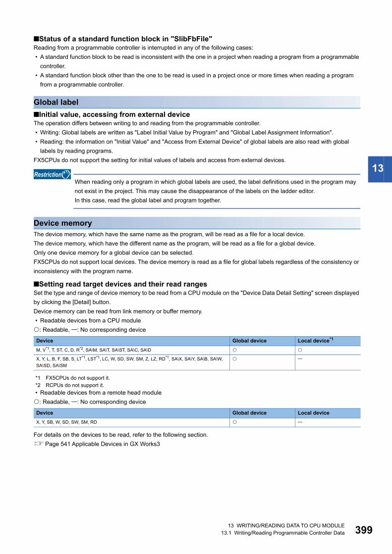
13 WRITING/READING DATA TO CPU MODULE13.1 Writing/Reading Programmable Controller Data 399
13
■Status of a standard function block in "SlibFbFile"Reading from a programmable controller is interrupted in any of the following cases:
• A standard function block to be read is inconsistent with the one in a project when reading a program from a programmable
controller.
• A standard function block other than the one to be read is used in a project once or more times when reading a program
from a programmable controller.
Global label
■Initial value, accessing from external deviceThe operation differs between writing to and reading from the programmable controller.
• Writing: Global labels are written as "Label Initial Value by Program" and "Global Label Assignment Information".
• Reading: the information on "Initial Value" and "Access from External Device" of global labels are also read with global
labels by reading programs.
FX5CPUs do not support the setting for initial values of labels and access from external devices.
When reading only a program in which global labels are used, the label definitions used in the program may
not exist in the project. This may cause the disappearance of the labels on the ladder editor.
In this case, read the global label and program together.
Device memoryThe device memory, which have the same name as the program, will be read as a file for a local device.
The device memory, which have the different name as the program, will be read as a file for a global device.
Only one device memory for a global device can be selected.
FX5CPUs do not support local devices. The device memory is read as a file for global labels regardless of the consistency or
inconsistency with the program name.
■Setting read target devices and their read rangesSet the type and range of device memory to be read from a CPU module on the "Device Data Detail Setting" screen displayed
by clicking the [Detail] button.
Device memory can be read from link memory or buffer memory.
• Readable devices from a CPU module
: Readable, : No corresponding device
*1 FX5CPUs do not support it.*2 RCPUs do not support it.
• Readable devices from a remote head module
: Readable, : No corresponding device
For details on the devices to be read, refer to the following section.
Page 541 Applicable Devices in GX Works3
Device Global device Local device*1
M, V*1, T, ST, C, D, R*2, SA\M, SA\T, SA\ST, SA\C, SA\D
X, Y, L, B, F, SB, S, LT*1, LST*1, LC, W, SD, SW, SM, Z, LZ, RD*1, SA\X, SA\Y, SA\B, SA\W,
SA\SD, SA\SM
Device Global device Local device
X, Y, SB, W, SD, SW, SM, RD

40013 WRITING/READING DATA TO CPU MODULE13.1 Writing/Reading Programmable Controller Data
Device comment
■Setting read rangeSet the range of Common device comments/Each program device comments to be read from a programmable controller on
the "Device Comment Detail Setting" screen displayed by clicking the [Detail] button.
Device initial valuesEven when the device initial value read from the CPU module is local device, it is not displayed as a local device (# is not
added) on GX Works3.
Tag FB settingFor a project used for an RnPCPU (process mode/redundant mode) and an RnPSFCPU, read the global label setting when
using a program with the process control extension enabled or for which the tag FB setting is set.
Note that FB properties are not read.
To read the current value of an FB property, update the initial value of the FB property.
Page 452 Initial FB property value update/FB property management

13 WRITING/READING DATA TO CPU MODULE13.1 Writing/Reading Programmable Controller Data 401
13
Deleting data in CPU moduleDelete the data such as programs and parameters in the CPU module.
For a safety project, safety data can be deleted when the safety operation mode of a CPU module is in the test mode.
Operating procedure
1. Select the [Delete] tab on the "Online Data Operation" screen.
2. Select a file to be deleted, and click the [Execute] button.
■Operations when using CPU modules in a redundant system configurationFor an RnPCPU (redundant mode), the operations differ depending on the operation modes.
An RnPSFCPU operates only when selecting the backup mode for the operation mode.
Considerations for Online data operation
Unlocking a remote passwordThe confirmation message for unlocking the remote password is displayed when the remote password is set to the CPU
module to be accessed. Unlock the password by following the message.
For details, refer to the following section.
Page 477 Restricting Access from Other Than Specific Communication Route
Unusable functions while transferring programsThe following functions cannot be used while transferring a program.
• Writing data to a programmable controller
• Reading data from a programmable controller
• Verifying data with a programmable controller
• Deleting data in a programmable controller
• Reading/writing/deleting user data
• Closing a project
• Changing the module type and operation mode
• Ethernet diagnostics
• CC-Link IE Control diagnostics (optical cable)
• CC-Link IE Control diagnostics (twisted pair cable)
• CC-Link Field diagnostics
• MELSECNET diagnostics
• Changing a connection destination setting
• Circuit trace
• Simulation
Cases where the option setting is changedThe following option setting may be changed when reading data from a programmable controller.
• [Tool] [Options] "Convert" "Basic Setting" "Operational Setting" "Convert, Online Program Change Target
Setting"
"Low-speed" is set in the option for the following cases:
• When reading data for which "High-speed" is selected to a project for which "Low-speed" is selected
• When reading data for which "Low-speed" is selected to a project for which "High-speed" is selected
Operation mode Operation
Separate mode Applied to the CPU module in the connective system.
Backup mode Applied to both systems (order: control system → standby system).
If an error occurs while deleting data from the control system, it is not deleted from the standby system. If an error
occurs while deleting data from the standby system, the data of control system cannot be restored to its former
condition.
40213 WRITING/READING DATA TO CPU MODULE13.1 Writing/Reading Programmable Controller Data
Structures restored by reading data from a programmable controllerWhen reading data in which structure is used from a CPU module, the definition of the structure is restored to the state where
it was written to the CPU module.
Note that if the definition of a structure is edited after writing it to a CPU module and data including the structure is read, it will
return to the state before the editing.
Structure can be used in the following data.
• Standard program
• Safety program
• Standard FB
• Safety FB
• Standard FUN
• Safety FUN
• Standard global label
• Standard/safety global label
• Safety global label
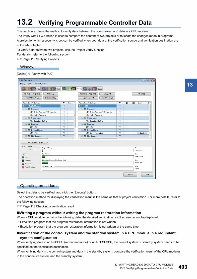
13 WRITING/READING DATA TO CPU MODULE13.2 Verifying Programmable Controller Data 403
13
13.2 Verifying Programmable Controller DataThis section explains the method to verify data between the open project and data in a CPU module.
The Verify with PLC function is used to compare the content of two projects or to locate the changes made in programs.
A project for which a security is set can be verified when both data of the verification source and verification destination are
not read-protected.
To verify data between two projects, use the Project Verify function.
For details, refer to the following section.
Page 116 Verifying Projects
Window
[Online] [Verify with PLC]
Operating procedure
Select the data to be verified, and click the [Execute] button.
The operation method for displaying the verification result is the same as that of project verification. For more details, refer to
the following section.
Page 118 Checking a verification result
■Writing a program without writing the program restoration informationWhen a CPU module contains the following data, the detailed verification result screen cannot be displayed.
• Execution program that the program restoration information is not written
• Execution program that the program restoration information is not written at the same time
■Verification of the control system and the standby system in a CPU module in a redundant system configuration
When verifying data in an RnPCPU (redundant mode) or an RnPSFCPU, the control system or standby system needs to be
specified as the verification destination.
When verifying data in the control system and data in the standby system, compare the verification result of the CPU modules
in the connective system and the standby system.
40413 WRITING/READING DATA TO CPU MODULE13.2 Verifying Programmable Controller Data
Parameter
■Verification of module parametersModule extended parameters are excluded from a verification.
However, the module extended parameters of a simple motion module can be verified.
Device memoryIn special relays and special registers of FX5CPUs, there are devices for which the values vary when a programmable
controller is stopped.
Therefore, the verification result between a programmable controller and device memory may be mismatched.
Tag FB settingIn a project used for an RnPCPU (process mode/redundant mode) and an RnPSFCPU, the tag FB setting is excluded from a
verification.
Function/function blockIn GX Works3 Version 1.036N to Version 1.044W, unconverted functions/function blocks in FB files/FUN files are excluded
from verification.
To verify unconverted functions/function blocks, install the latest GX Works3 or perform the 'Project Verify' function. (Page
116 Verifying Projects)
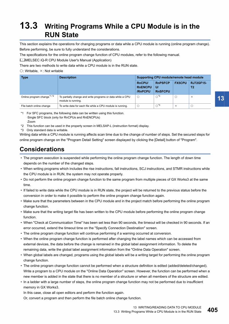
13 WRITING/READING DATA TO CPU MODULE13.3 Writing Programs While a CPU Module is in the RUN State 405
13
13.3 Writing Programs While a CPU Module is in the RUN State
This section explains the operations for changing programs or data while a CPU module is running (online program change).
Before performing, be sure to fully understand the considerations.
The specifications for the online program change function of CPU modules, refer to the following manual.
MELSEC iQ-R CPU Module User's Manual (Application)
There are two methods to write data while a CPU module is in the RUN state.
: Writable, : Not writable
*1 For SFC programs, the following data can be written using this function.⋅Single SFC block (only for RnCPUs and RnENCPUs)⋅Zoom
*2 This function can be used in the property screen in MELSAP-L (instruction format) display.*3 Only standard data is writable.
Writing data while a CPU module is running affects scan time due to the change of number of steps. Set the secured steps for
online program change on the "Program Detail Setting" screen displayed by clicking the [Detail] button of "Program".
Considerations • The program execution is suspended while performing the online program change function. The length of down time
depends on the number of the changed steps.
• When writing programs which includes the rise instructions, fall instructions, SCJ instructions, and STMR instructions while
the CPU module is in RUN, the system may not operate properly.
• Do not perform the online program change function to the same program from multiple pieces of GX Works3 at the same
time.
• If failed to write data while the CPU module is in RUN state, the project will be returned to the previous status before the
conversion in order to make it possible to perform the online program change function again.
• Make sure that the parameters between in the CPU module and in the project match before performing the online program
change function.
• Make sure that the writing target file has been written to the CPU module before performing the online program change
function.
• When "Check at Communication Time" has been set less than 90 seconds, the timeout will be checked in 90 seconds. If an
error occurred, extend the timeout time on the "Specify Connection Destination" screen.
• The online program change function will continue performing if a warning occurred at conversion.
• When the online program change function is performed after changing the label names which can be accessed from
external devices, the data before the change is remained in the global label assignment information. To delete the
remaining data, write the global label assignment information from the "Online Data Operation" screen.
• When global labels are changed, programs using the global labels will be a writing target for performing the online program
change function.
• The online program change function cannot be performed when a structure definition is edited (added/deleted/changed).
Write a program to a CPU module on the "Online Data Operation" screen. However, the function can be performed when a
new member is added in the state that there is no member of a structure or when all members of the structure are edited.
• In a ladder with a large number of steps, the online program change function may not be performed due to insufficient
memory in GX Works3.
In this case, close all open editors and perform the function again.
Or, convert a program and then perform the file batch online change function.
Type Description Supporting CPU module/remote head module
RnCPU/RnENCPU/RnPCPU
RnPSFCPU/RnSFCPU
FX5CPU RJ72GF15-T2
Online program change*1,*2 To partially change and write programs or data while a CPU
module is running.
*3
File batch online change To write data for each file while a CPU module is running. *3

40613 WRITING/READING DATA TO CPU MODULE13.3 Writing Programs While a CPU Module is in the RUN State
Design instructions
Startup/Maintenance Instructions
Writing data after changing programs partially while a CPU module is running (Online program change)This function partially overwrites data such as program files in the CPU module. Before changing the program, check if the
programs between in the CPU module and in the project match using the "Verify with PLC" function. If there is no target file in
the CPU module, the online program change function cannot be performed.
The list of operations for the data which can perform the online program change function and the target files are as shown
below.
: Applicable, : Not applicable
*1 FX5CPUs do not support it.*2 The operation for the assignment information can be performed only when the labels are set to be accessed from external devices.*3 The operation for a initial value file of labels can be performed only when initial values are set to labels. When the initial values are not
applied to labels, the initial value file of labels with a same name in a programmable controller will be deleted.
WARNING■When data change, program change, or status control is performed from a personal computer to a running programmable controller, create an interlock circuit
outside the programmable controller to ensure that the whole system always operates safely.
Furthermore, for the online operations performed from a personal computer to a CPU module, the corrective actions against a communication error due to such
as a cable connection fault should be predetermined as a system.
CAUTION■The online operations performed from a personal computer to a running CPU module (program change while a CPU module is in RUN state, operating status
change such as RUN-STOP switching, and remote control operation) have to be executed after the manual has been carefully read and the safety has been
ensured.
When changing a program while the CPU module is in RUN, it may cause a program corruption in some operating conditions. Fully understand the precautions
described in this section.
Operation Online program change target file
Program POU Local label initial value*1
Global label (settings, assignment information*1)
Global Label Initial Value*1
Global label Adding/changing global labels *2 *3
Program block Adding/changing local labels *3
Adding/changing/deleting
programs
Function block Adding/changing local labels
Adding/changing/deleting
programs
Function Adding/changing local labels
Adding/changing/deleting
programs
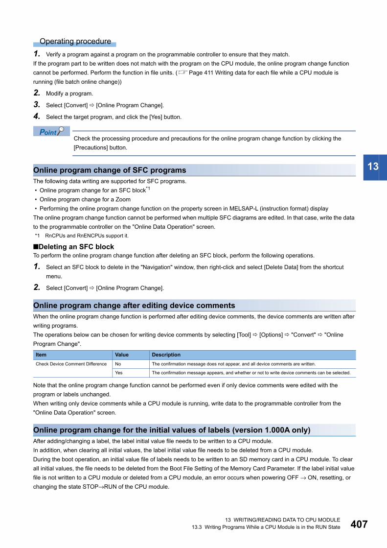
13 WRITING/READING DATA TO CPU MODULE13.3 Writing Programs While a CPU Module is in the RUN State 407
13
Operating procedure
1. Verify a program against a program on the programmable controller to ensure that they match.
If the program part to be written does not match with the program on the CPU module, the online program change function
cannot be performed. Perform the function in file units. (Page 411 Writing data for each file while a CPU module is
running (file batch online change))
2. Modify a program.
3. Select [Convert] [Online Program Change].
4. Select the target program, and click the [Yes] button.
Check the processing procedure and precautions for the online program change function by clicking the
[Precautions] button.
Online program change of SFC programsThe following data writing are supported for SFC programs.
• Online program change for an SFC block*1
• Online program change for a Zoom
• Performing the online program change function on the property screen in MELSAP-L (instruction format) display
The online program change function cannot be performed when multiple SFC diagrams are edited. In that case, write the data
to the programmable controller on the "Online Data Operation" screen.
*1 RnCPUs and RnENCPUs support it.
■Deleting an SFC blockTo perform the online program change function after deleting an SFC block, perform the following operations.
1. Select an SFC block to delete in the "Navigation" window, then right-click and select [Delete Data] from the shortcut
menu.
2. Select [Convert] [Online Program Change].
Online program change after editing device commentsWhen the online program change function is performed after editing device comments, the device comments are written after
writing programs.
The operations below can be chosen for writing device comments by selecting [Tool] [Options] "Convert" "Online
Program Change".
Note that the online program change function cannot be performed even if only device comments were edited with the
program or labels unchanged.
When writing only device comments while a CPU module is running, write data to the programmable controller from the
"Online Data Operation" screen.
Online program change for the initial values of labels (version 1.000A only)After adding/changing a label, the label initial value file needs to be written to a CPU module.
In addition, when clearing all initial values, the label initial value file needs to be deleted from a CPU module.
During the boot operation, an initial value file of labels needs to be written to an SD memory card in a CPU module. To clear
all initial values, the file needs to be deleted from the Boot File Setting of the Memory Card Parameter. If the label initial value
file is not written to a CPU module or deleted from a CPU module, an error occurs when powering OFF → ON, resetting, or
changing the state STOP→RUN of the CPU module.
Item Value Description
Check Device Comment Difference No The confirmation message does not appear, and all device comments are written.
Yes The confirmation message appears, and whether or not to write device comments can be selected.

40813 WRITING/READING DATA TO CPU MODULE13.3 Writing Programs While a CPU Module is in the RUN State
Online program change for the initial values of labels (version 1.032J or later)When the initial values of labels are not set, the initial value file of labels with a same name in a programmable controller will
be deleted.
During the boot operation, an initial value file of labels needs to be written to an SD memory card in a CPU module. By
selecting "Reflect Changes to Boot Source" when the online program change function is performed, an initial value file of
labels is written even if the initial values of labels are not set.
Writing range for online program changeThe range to be written differs depending on the editing methods of programs.
■Ladder programWhen a new ladder block is inserted, or a ladder block is deleted, the inserted program is written together with one instruction
after the inserted ladder block to the CPU module.
Therefore, the online program change function may not be completed at a time depending on the number of program steps
before and after addition or deletion. In this case, reduce the number of steps written at a time and perform the function in
several times.
Execution of rising/falling instructions after performing online program changeWhen the raising/falling instructions in the subroutine function block program are modified or added, the instructions do not
operate normally immediately after the online program change function is performed even if the execution condition is
satisfied.
This is the same as the case of the macro type function block in the subroutine function block in the following example of
program configuration.
For details, refer to the following manual.
MELSEC iQ-R CPU Module User's Manual (Application)
POU duplication checkWhen writing a program while the CPU module is in RUN state, the program can be checked whether a POU name is
duplicated in the program and in a program in the module.
Whether to check the duplication can be set by setting the following option.
• [Tool] [Options] "Convert" "Online Program Change" "Operational Setting" "Duplication Check for POU"
MAIN1 FbPou1
MAIN2 FbPou2 FbPou3
:Program file:Subroutine type function block
:Program file:Subroutine type function block:Macro type function block
13 WRITING/READING DATA TO CPU MODULE13.3 Writing Programs While a CPU Module is in the RUN State 409
13
Program transfer when a CPU module is in RUN stateA program can be transferred (i.e. the program restoration information are written and the program memory are transferred) in
the background while a CPU module is in RUN state.
By doing so, the waiting time until the program becomes editable can be shorten.
The following conditions need to be satisfied to transfer a program in the background.
• "Write in Background" is selected in the following option.
[Tool] [Options] "Convert" "Online Program Change" "Operational Setting" "Write a Program Restore
Information"
• The boot operation is not in process. Or, the boot operation is in process and "Reflect Changes to Boot Source" is not
selected when the online program change function is performed.
This function is available only for a project created in an RnCPU project, RnENCPU project, or RnSFCPU project.
Precautions
■Interruption of writing the program restoration informationWhen the power-OFF or reset of a CPU module, or cable disconnection is detected while writing the program restoration
information, the processing is canceled and a message appears.
For the interruption caused by the power-OFF or reset of a CPU module, write the program restoration information again.
For the interruption caused by the cable disconnection, connect the cable again, and click the [Retry] button on the message.
When the [Cancel] button is clicked, the following error occurs.
• The restoration information is not written. Therefore, an error occurs when reading the data from a programmable controller
and it is not read.
• The execution program and the restoration information may be mismatched. Therefore, an error occurs after resetting the
programmable controller and the program cannot be executed.
To clear the errors, set the CPU module in the STOP state and write the program again.
41013 WRITING/READING DATA TO CPU MODULE13.3 Writing Programs While a CPU Module is in the RUN State
Program restoration informationWhether or not to write program restoration information with a program can be selected when performing the online program
change function.
By setting the following option, whether or not to write the program restoration information can be selected in the "Online
Program Change" screen.
• [Tool] [Options] "Online" "Program Restore Information" "Operational Setting" "Enable the setting to write/not
to write program restore information"
When a program is written without writing the program restoration information, the data cannot be read with 'Read from PLC',
and the detailed verification result screen cannot be displayed with 'Verify with PLC'.
For CPU modules that do not support this function, whether to write the program restoration information cannot be selected
even when the option is set.
Operations when using CPU modules in a redundant system configurationFor an RnPCPU (redundant mode), the operations differ depending on the operation modes.
An RnPSFCPU operates only when selecting the backup mode for the operation mode.
Operation mode Operation
Separate mode Applied to the CPU module in the connective system.
Backup mode Applied to the CPU module in the connective system.
A program is transferred to the other system after performed in the connective system.

13 WRITING/READING DATA TO CPU MODULE13.3 Writing Programs While a CPU Module is in the RUN State 411
13
Writing data for each file while a CPU module is running (file batch online change)A program and/or data can be written for each file while a CPU module is running.
FX5CPUs do not support it.
Operating procedure
Select [Online] [Write to PLC] while a CPU module is running.
Precautions
If there is not enough free capacity in the program memory of a CPU module to write the programs, the file batch online
change cannot be performed.
If labels and module parameters are not changed when using a module label, writing the module parameter is omitted and the
file batch online change of the program can be performed.
Execution conditionThe following table shows the files to which the file batch online change can be performed and the conditions.
Before writing a file other than the one described in the following table, change the status of the CPU module to STOP/
PAUSE.
■Project for RnCPUs, RnENCPUs, and RnPCPUs
*1 Before performing the file batch online change function, setting SM and/or SD devices of a CPU module is required in advance.For details, refer to the following manual.MELSEC iQ-R CPU Module User's Manual (Application)
*2 When "No" is selected for the following option, the file batch online change function can be performed even when converting (retaining) any or all programs.[Tool] [Options] "Online" "Write to PLC" "Operational Setting" "Turn PLC to STOP in writing to PLC after executing Rebuild All and execute remote RUN"
Target Condition
• Global label initial value
• Local label initial value
• Device memory
• File register
• Device initial value
• Common device comment
• Each program device comment
No condition
• Program file
(A global label/FB/FUN is not used.)
• Registered in the program setting of the CPU parameter.
• A standard program.
• A program file described in Ladder Diagram, Structured Text, or Function Block Diagram.
• Program file*1
(A global label/FB/FUN is used.)
• Registered in the program setting of the CPU parameter.
• A standard program.
• A program file described in Ladder Diagram, Structured Text, or Function Block Diagram.
• A standard/safety shared label is not used.
• All programs have not been converted since the previous writing of the global label setting and FB/FUN
to a CPU module.*2
• FB/FUN file*1 • Registered in the FB/FUN file setting of CPU parameters.
• A standard FB/FUN.
• All programs have not been converted since the previous writing of the FB/FUN file to a CPU module.*2
• Global label setting*1 • A standard global label.
• A global label that can be accessed from an external device is not set.
• All programs have not been converted since the previous writing of the global label setting to a CPU
module.*2
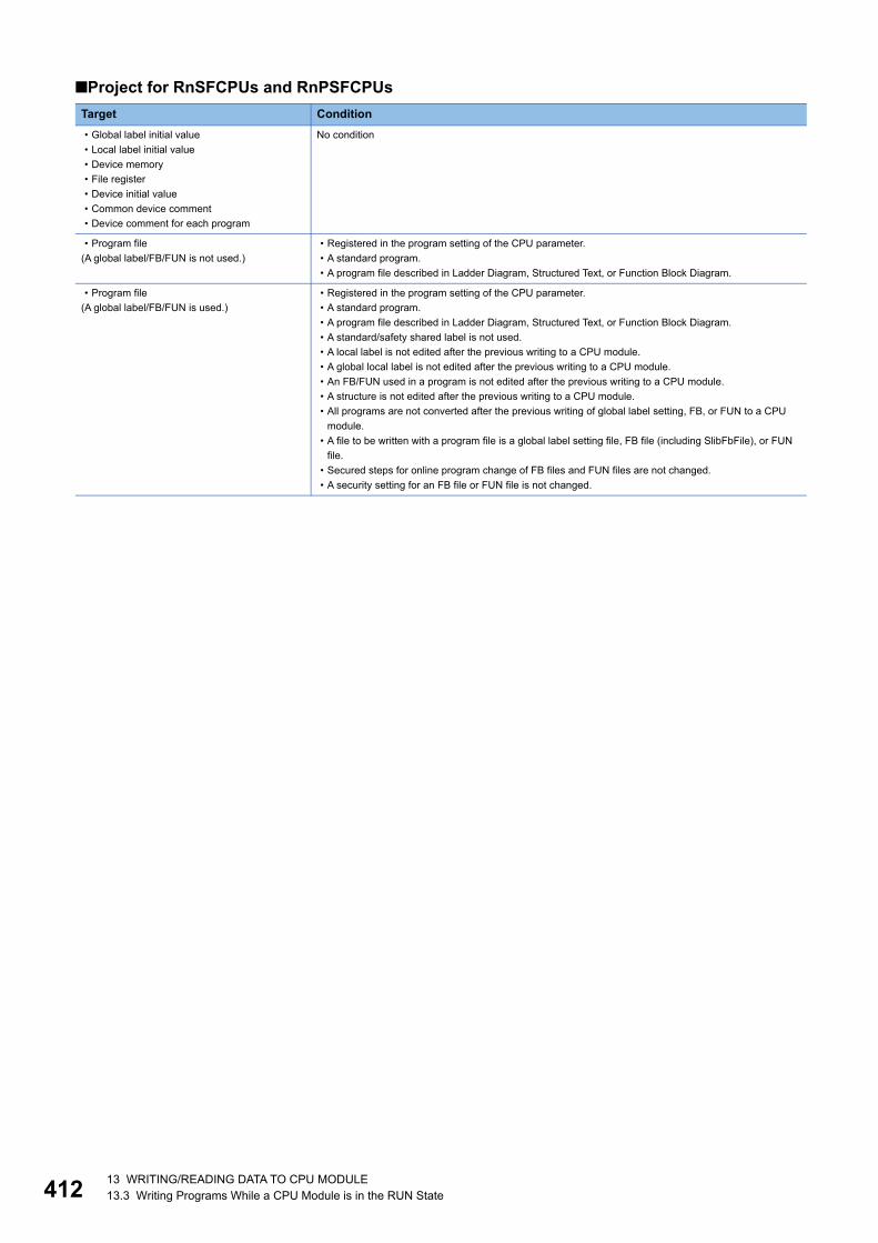
41213 WRITING/READING DATA TO CPU MODULE13.3 Writing Programs While a CPU Module is in the RUN State
■Project for RnSFCPUs and RnPSFCPUs
Target Condition
• Global label initial value
• Local label initial value
• Device memory
• File register
• Device initial value
• Common device comment
• Device comment for each program
No condition
• Program file
(A global label/FB/FUN is not used.)
• Registered in the program setting of the CPU parameter.
• A standard program.
• A program file described in Ladder Diagram, Structured Text, or Function Block Diagram.
• Program file
(A global label/FB/FUN is used.)
• Registered in the program setting of the CPU parameter.
• A standard program.
• A program file described in Ladder Diagram, Structured Text, or Function Block Diagram.
• A standard/safety shared label is not used.
• A local label is not edited after the previous writing to a CPU module.
• A global local label is not edited after the previous writing to a CPU module.
• An FB/FUN used in a program is not edited after the previous writing to a CPU module.
• A structure is not edited after the previous writing to a CPU module.
• All programs are not converted after the previous writing of global label setting, FB, or FUN to a CPU
module.
• A file to be written with a program file is a global label setting file, FB file (including SlibFbFile), or FUN
file.
• Secured steps for online program change of FB files and FUN files are not changed.
• A security setting for an FB file or FUN file is not changed.
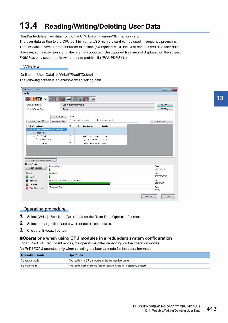
13 WRITING/READING DATA TO CPU MODULE13.4 Reading/Writing/Deleting User Data 413
13
13.4 Reading/Writing/Deleting User DataRead/write/delete user data from/to the CPU built-in memory/SD memory card.
The user data written to the CPU built-in memory/SD memory card can be used in sequence programs.
The files which have a three-character extension (example: csv, txt, bin, xml) can be used as a user data.
However, some extensions and files are not supported. Unsupported files are not displayed on the screen.
FX5CPUs only support a firmware update prohibit file (FWUPDP.SYU).
Window
[Online] [User Data] [Write]/[Read]/[Delete]
The following screen is an example when writing data.
Operating procedure
1. Select [Write], [Read], or [Delete] tab on the "User Data Operation" screen.
2. Select the target files, and a write target or read source.
3. Click the [Execute] button.
■Operations when using CPU modules in a redundant system configurationFor an RnPCPU (redundant mode), the operations differ depending on the operation modes.
An RnPSFCPU operates only when selecting the backup mode for the operation mode.
Operation mode Operation
Separate mode Applied to the CPU module in the connective system.
Backup mode Applied to both systems (order: control system → standby system).
41413 WRITING/READING DATA TO CPU MODULE13.5 Deleting All Files (Initialization)
Creating/deleting folders, changing folder nameA folder can be created in the CPU built-in memory or SD memory card.
A created folder can be deleted and the folder name can be changed.
Create/delete a folder, or change a folder name on the "Browse Folders" screen displayed by clicking the [Browse] button on
the "User Data Operation" screen.
■Creating foldersSelect the place in which the folder is to be created on the "Browse Folders" screen, right-click it and select [Create Folder]
from the shortcut menu.
■Deleting folders/changing folder nameSelect the target folder on the "Browse Folders" screen, right-click it and select [Delete Folder]/[Change Folder Name] from
the shortcut menu.
■Operations when using CPU modules in a redundant system configurationFor an RnPCPU (redundant mode), the operations differ depending on the operation modes.
An RnPSFCPU operates only when selecting the backup mode for the operation mode.
13.5 Deleting All Files (Initialization)Perform initialization to delete files in a CPU module or a memory card.
The process of "Initialization" is used when using a CPU module or memory card for the first time or clearing all data stored in
a CPU module or memory card.
Once initialized, the following processing on memory is performed.
• Data memory: All folders/files in the program memory and data memory are deleted.
• Device/label memory: All files in the file storage area in the device/label memory are deleted.
• SD memory card: All folders/files in the SD memory card are deleted.
Operating procedure
To delete all files in the "CPU Memory Operation" screen, refer to the following section.
Page 518 Initializing/Clearing Memory
Operation mode Operation
Separate mode Applied to the CPU module in the connective system.
Backup mode Applied to both systems (order: control system → standby system).

13 WRITING/READING DATA TO CPU MODULE13.6 Writing/Reading Data to/from Memory Card 415
13
13.6 Writing/Reading Data to/from Memory CardThis section explains how to writing/reading data to/from a memory card attached to a personal computer.
This operation is used, for example, when data can not be written/read by attaching a memory card to a CPU module.
However, this writing/ reading function cannot be used in a safety project.
For details on the writing/reading data to a CPU module attached a memory card, refer to the following section.
Page 390 Writing/Reading Programmable Controller Data
R00CPU and remote head modules do not support it.
Configuration of Memory Card Operation screen
Window
[Tool] [Memory Card] [Write to Memory Card]/[Read from Memory Card]
The following screen is an example when writing data.
The data name in gray indicates that it is in the unconverted state.
Writing to/Reading from a memory cardWrite/Read data to/from a memory card.
The file, which is in the '$MELPRJ$' folder of the specified drive path, is the target for reading/writing.
Operating procedure
1. Select the [Write] tab/[Read] tab on the "Memory Card Operation" screen.
2. Set the drive path of the write target/read source, then click the [Execute] button.
Considerations when reading program files from a memory cardPerform the following operations to read program files from a memory card.
■Parameters have been written with program files when writing to a memory cardRead the parameters with the program files.
■Parameters have not been written with program files when writing to a memory cardBefore reading the program files, open the project opened when writing to the memory card.
Read parameters used when writing to the memory card from the CPU module.

41614 CHECKING OPERATION OF PROGRAMS
14 CHECKING OPERATION OF PROGRAMS
This chapter explains the method for checking the execution status of an intelligent function module and a CPU module
connected to a personal computer.
The functions to check the execution status are as follows:
*1 This function can be used in a project for an RnPCPU (process mode/redundant mode) and RnPSFCPU with the process control extension enabled.
*2 FX5CPUs do not support it.
Purpose Function name Reference
To check the status of programs being executed on the
program editor.
Monitor Page 421 Checking Execution Programs on Program
Editor
To check the current values of devices or buffer memory in
a batch.
Device/buffer memory batch monitor Page 431 Checking Device/Buffer Memory in Batch
To check the current values of devices and labels by
registering them.
Watch Page 434 Checking Current Values by Registering
Devices/Labels
To check input and output devices, which are registered to a
CPU module, to ON/OFF forcibly.
Register/cancel forced input/output Page 438 Turning Input/Output Device ON/OFF
Forcibly
To pause and restart the operation of a process control
function block in a running program.
Pause FB/restart FB*1 Page 440 Pausing/Restarting the Operation of
Function Blocks
To check the processing time of a program being executed. Program list monitor*2 Page 443 Checking Processing Time of Program
To check the number of executions of an interrupt program
used in a program.
Interrupt program list monitor*2 Page 444 Checking Execution Counts of Interrupt
Programs
To check the I/O signals and the current value of buffer
memory by registering the module information of an
intelligent function module.
Intelligent function module monitor Page 445 Checking Current Values in Intelligent
Function Module
To check the current logging data sampled by a CPU
module.
Realtime monitor Page 447 Checking Current Logging Data
To check tag data. Faceplate*1, PX Developer Monitor
Tool interaction*1, initial FB property
value update/FB property
management*1
Page 448 Checking tag data
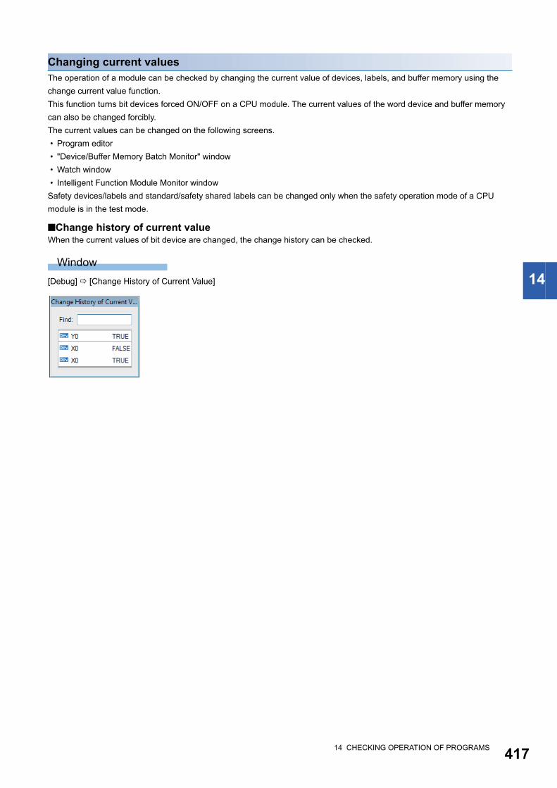
14 CHECKING OPERATION OF PROGRAMS 417
14
Changing current valuesThe operation of a module can be checked by changing the current value of devices, labels, and buffer memory using the
change current value function.
This function turns bit devices forced ON/OFF on a CPU module. The current values of the word device and buffer memory
can also be changed forcibly.
The current values can be changed on the following screens.
• Program editor
• "Device/Buffer Memory Batch Monitor" window
• Watch window
• Intelligent Function Module Monitor window
Safety devices/labels and standard/safety shared labels can be changed only when the safety operation mode of a CPU
module is in the test mode.
■Change history of current valueWhen the current values of bit device are changed, the change history can be checked.
Window
[Debug] [Change History of Current Value]

41814 CHECKING OPERATION OF PROGRAMS14.1 Monitor Status
14.1 Monitor StatusCheck the operating status of a CPU module or an intelligent function module using the monitoring function by connecting a
personal computer.
Starting/stopping monitoringStart/stop monitoring by selecting one of the following menus.
• [Online] [Monitor] [Start Monitoring]( )/[Stop Monitoring]( )
• [Online] [Monitor] [Start Monitoring (All Windows)]( )/[Stop Monitoring (All Windows)]( )
• [Online] [Watch] [Start Watching]/[Stop Watching]
• Select [Online] [Monitor] [Monitor Mode] on the active ladder editor
For a ladder editor, start monitoring by selecting a mode from the pull-down menu on the mode display area located at the
upper left of the ladder editor.
■When monitoring multiple projects using a single personal computer • If an communication error has occurred in one of the projects, the monitoring speed of the other projects may become slow.
The operation speed will be back to normal after closing the error message displayed in the project in which the
communication error occurred.
• The following functions may not be performed normally:
Program List Monitor and Interrupt Program List Monitor
■Monitoring buffer memory or link devicesMonitor the ON/OFF state of the buffer memory or link devices (example: U0\G0.1) by setting the following option.
• [Tool] [Options] "Monitor" "Common Item"/"(Program editor)" "Operational Setting"
■Changing display format of word devicesSelect [Online] [Monitor] [Change Value Format (Decimal)] / [Change Value Format (Hexadecimal)] to change the display
format of the monitored values.
■FB instanceTo monitor the devices/labels in an FB instance, open the FB program and select the FB instance to be monitored from the
monitor status bar.
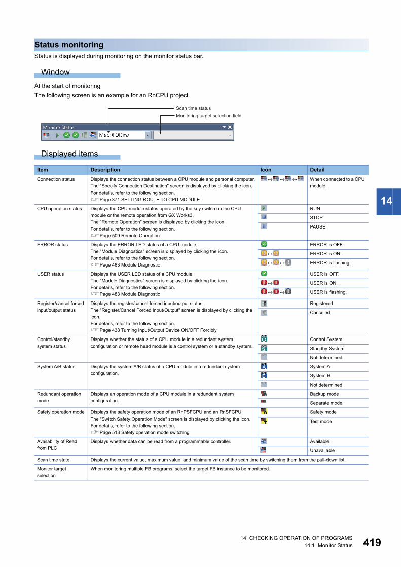
14 CHECKING OPERATION OF PROGRAMS14.1 Monitor Status 419
14
Status monitoringStatus is displayed during monitoring on the monitor status bar.
Window
At the start of monitoring
The following screen is an example for an RnCPU project.
Displayed items
Item Description Icon Detail
Connection status Displays the connection status between a CPU module and personal computer.
The "Specify Connection Destination" screen is displayed by clicking the icon.
For details, refer to the following section.
Page 371 SETTING ROUTE TO CPU MODULE
↔ ↔ ↔ When connected to a CPU
module
CPU operation status Displays the CPU module status operated by the key switch on the CPU
module or the remote operation from GX Works3.
The "Remote Operation" screen is displayed by clicking the icon.
For details, refer to the following section.
Page 509 Remote Operation
RUN
STOP
PAUSE
ERROR status Displays the ERROR LED status of a CPU module.
The "Module Diagnostics" screen is displayed by clicking the icon.
For details, refer to the following section.
Page 483 Module Diagnostic
ERROR is OFF.
↔ ERROR is ON.
↔ ↔ ERROR is flashing.
USER status Displays the USER LED status of a CPU module.
The "Module Diagnostics" screen is displayed by clicking the icon.
For details, refer to the following section.
Page 483 Module Diagnostic
USER is OFF.
↔ USER is ON.
↔ ↔ USER is flashing.
Register/cancel forced
input/output status
Displays the register/cancel forced input/output status.
The "Register/Cancel Forced Input/Output" screen is displayed by clicking the
icon.
For details, refer to the following section.
Page 438 Turning Input/Output Device ON/OFF Forcibly
Registered
Canceled
Control/standby
system status
Displays whether the status of a CPU module in a redundant system
configuration or remote head module is a control system or a standby system.
Control System
Standby System
Not determined
System A/B status Displays the system A/B status of a CPU module in a redundant system
configuration.
System A
System B
Not determined
Redundant operation
mode
Displays an operation mode of a CPU module in a redundant system
configuration.
Backup mode
Separate mode
Safety operation mode Displays the safety operation mode of an RnPSFCPU and an RnSFCPU.
The "Switch Safety Operation Mode" screen is displayed by clicking the icon.
For details, refer to the following section.
Page 513 Safety operation mode switching
Safety mode
Test mode
Availability of Read
from PLC
Displays whether data can be read from a programmable controller. Available
Unavailable
Scan time state Displays the current value, maximum value, and minimum value of the scan time by switching them from the pull-down list.
Monitor target
selection
When monitoring multiple FB programs, select the target FB instance to be monitored.
Scan time statusMonitoring target selection field

42014 CHECKING OPERATION OF PROGRAMS14.1 Monitor Status
Monitor modeLadder editors are switched to monitor mode during monitoring.
Page 182 Configuration of the ladder editor
Operations when the system is switched in the redundant configurationWhen a tracking communication error occurs while monitoring via CC IE Control, CC IE Field, CC-Link, or Ethernet in a
redundant configuration, monitoring is continued by switching a communication route (the system to be monitored).
This function performs when specifying any one of control system, standby system, system A, or system B as a connection
destination.
Supported monitor function: circuit monitor, watch, device/buffer memory batch monitor, local device monitor
14 CHECKING OPERATION OF PROGRAMS14.2 Checking Execution Programs on Program Editor 421
14
14.2 Checking Execution Programs on Program EditorUse the monitoring function to check the following execution programs on each program editor.
• Ladder program
• ST program
• FBD/LD program
• SFC program
Open a program editor to be monitored in advance.
The display format and detailed operation settings for each function can be set by setting the following option.
[Tool] [Options] "Monitor"
Applicable monitoring devices and labels
■Applicable devicesThe following table shows the devices that can be monitored on a program editor.
*1 'S' can be monitored in a Zoom or on an SFC diagram only. Monitor BL\S when using program editors not a Zoom.*2 The same value as 'N' (current value) is displayed.*3 'DX' and 'DY' cannot be monitored on an SFC diagram.
■Inapplicable labels • When a value other than a fixed value is used for an array index, the monitor value of the array is displayed as an indefinite
value, or the monitor value is not displayed.
• An indefinite value is displayed as the monitor value of a local label in a function, or the monitor value is not displayed.
■When the type of defined function block is the macro typeMonitoring input/output labels depend on the monitor condition of the connected element. Therefore, when the connected
element is not in the condition to be monitored, the input/output label cannot be monitored.
Considerations when monitoring file registersWhen monitoring file registers while "Use File Register of Each Program" is selected in "File Setting" of "CPU Parameter", the
monitor operation will differ depending on the device/label access service processing setting.
Therefore, add a program that transfers monitoring target file registers to devices, then monitor the transferred the program.
Note that the number of steps and scan time will increase for the added programs.
If the file register for which "Use File Register of Each Program" is selected is used as data with no latch (such that the data is
set to clear to '0' at the first time), replacing the file registers to local devices avoids increase of number of steps and scan time
due to the addition of programs.
• When "Execute END Processing between Programs" is selected:
When monitor is requested after the program which is set not to use the file register, FFFFH (-1) will be monitored since the
monitor is performed between programs or at the END process.
• When other than "Execute END Processing between Programs" is selected:
The value of the file register file that is enabled in the program executed at the right before the END processing is
monitored.
Example) When the execution order of the program is 'A→B→C→(END processing)→A→B', monitor the value of the file
register at execution of program C.
Program editor type Device
Ladder, ST, FBD/LD, SFC X, Y, M, L, B, F, SB, V, S*1, T*2, T(TS), T(TC), T(TN), ST*2, ST(STS), ST(STC), ST(STN), LT*2, LT(LTS), LT(LTC), LT(LTN),
LST*2, LST(LSTS), LST(LSTC), LST(LSTN), C*2, C(CS), C(CC), C(CN), LC*2, LC(LCS), LC(LCC), LC(LCN), D, W, SW,
FX, FY, SM, SD, J\X, J\Y, J\B, J\SB, J\W, J\SW, U\G, U3E\G, U3E\HG, DX*3, DY*3, Z, LZ, R, ZR, RD, BL,
BL\S

42214 CHECKING OPERATION OF PROGRAMS14.2 Checking Execution Programs on Program Editor
Considerations when monitoring labelsSince the data type of an instruction arguments (labels) is represented as the genetic data type, the argument such as ANY16
or ANY32 may have both attribute of "Signed" and "Unsigned".
The monitor value of the genetic data type is displayed as the specified label data type. Specify the data type according to the
instruction specifications (MELSEC iQ-R Programming Manual (CPU Module Instructions, Standard Functions/Function
Blocks)).
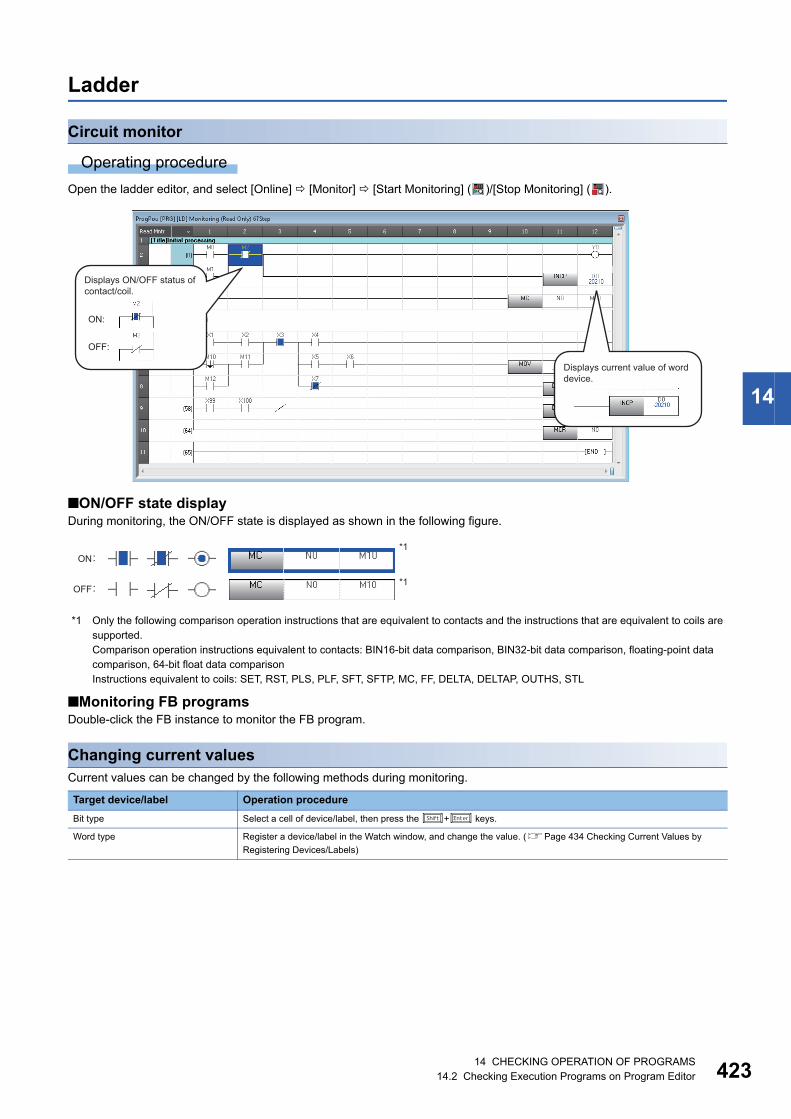
14 CHECKING OPERATION OF PROGRAMS14.2 Checking Execution Programs on Program Editor 423
14
Ladder
Circuit monitor
Operating procedure
Open the ladder editor, and select [Online] [Monitor] [Start Monitoring] ( )/[Stop Monitoring] ( ).
■ON/OFF state displayDuring monitoring, the ON/OFF state is displayed as shown in the following figure.
*1 Only the following comparison operation instructions that are equivalent to contacts and the instructions that are equivalent to coils are supported.Comparison operation instructions equivalent to contacts: BIN16-bit data comparison, BIN32-bit data comparison, floating-point data comparison, 64-bit float data comparisonInstructions equivalent to coils: SET, RST, PLS, PLF, SFT, SFTP, MC, FF, DELTA, DELTAP, OUTHS, STL
■Monitoring FB programsDouble-click the FB instance to monitor the FB program.
Changing current valuesCurrent values can be changed by the following methods during monitoring.
Target device/label Operation procedure
Bit type Select a cell of device/label, then press the + keys.
Word type Register a device/label in the Watch window, and change the value. (Page 434 Checking Current Values by
Registering Devices/Labels)
Displays ON/OFF status of contact/coil.
Displays current value of word device.

42414 CHECKING OPERATION OF PROGRAMS14.2 Checking Execution Programs on Program Editor
STThe monitor value of bit type is displayed on a program, and the monitor value of a label other than bit type and a word device
are displayed on the right side of the split window.
A monitor value is displayed on the tooltip by placing the cursor on a device/label name.
Monitor
Operating procedure
Open the ST editor, and select [Online] [Monitor] [Start Monitoring] ( )/[Stop Monitoring] ( ).
Changing current valuesCurrent values can be changed by the following methods during monitoring.
Target device/label Operation procedure
Bit type Select a token of device/label, then press the + keys.
Word type Register a device/label in the Watch window, and change the value. (Page 434 Checking Current Values by
Registering Devices/Labels)
Displays TRUE/FALSE of bit type label or bit device.
Monitored value of counter0
Monitored value of D0
Data in the collapsed line is not monitored.

14 CHECKING OPERATION OF PROGRAMS14.2 Checking Execution Programs on Program Editor 425
14
FBD/LD
Monitor
Operating procedure
Select [Online] [Monitor] [Start Monitoring] ( )/[Stop Monitoring] ( ).
When the current values cannot be monitored, "---" is displayed.
■Display format of a contactThe current continuity state can be checked by looking a contact.
By setting the following option, ON/OFF of a constant can be changed with the current value of a device/label.
• [Tool] [Options] "Monitor" "FBD/LD editor" "Display Setting" "Use Same Display Format for Contact as Device/
Label Current Value"
■Display format of word devicesA word device is displayed in Word [Signed].
For a word device with a device type specifier, the word device is displayed in the data type indicated by the device type
specifier.
For details on a device type specifier, refer to the following manual.
MELSEC iQ-R Programming Manual (Program Design)
Changing current valuesCurrent values can be changed by the following methods during monitoring.
Target device/label Operation procedure
Bit type Select an element of a device/label, then press the + keys.
Word type Register a device/label in the Watch window, and change the value. (Page 434 Checking Current Values by
Registering Devices/Labels)
Displays ON/OFF status of contact/coil.
Displays TRUE/FALSE of bit type label or bit device.
Displays the monitored value underneath the input/output label of the FB element.
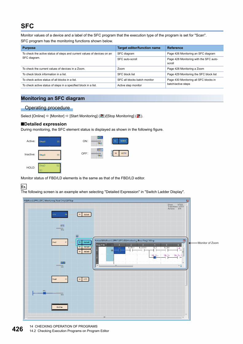
42614 CHECKING OPERATION OF PROGRAMS14.2 Checking Execution Programs on Program Editor
SFCMonitor values of a device and a label of the SFC program that the execution type of the program is set for "Scan".
SFC program has the monitoring functions shown below.
Monitoring an SFC diagram
Operating procedure
Select [Online] [Monitor] [Start Monitoring] ( )/[Stop Monitoring] ( ).
■Detailed expressionDuring monitoring, the SFC element status is displayed as shown in the following figure.
Monitor status of FBD/LD elements is the same as that of the FBD/LD editor.
Ex.
The following screen is an example when selecting "Detailed Expression" in "Switch Ladder Display".
Purpose Target editor/function name Reference
To check the active status of steps and current values of devices on an
SFC diagram.
SFC diagram Page 426 Monitoring an SFC diagram
SFC auto-scroll Page 428 Monitoring with the SFC auto-
scroll
To check the current values of devices in a Zoom. Zoom Page 428 Monitoring a Zoom
To check block information in a list. SFC block list Page 429 Monitoring the SFC block list
To check active status of all blocks in a list. SFC all blocks batch monitor Page 430 Monitoring all SFC blocks in
batch/active stepsTo check active status of steps in a specified block in a list. Active step monitor
Inactive:
Active:
HOLD:
Monitor of Zoom

14 CHECKING OPERATION OF PROGRAMS14.2 Checking Execution Programs on Program Editor 427
14
■MELSAP-L (instruction format)For a monitor value of the bit type expressed in MELSAP-L (instruction format), the continuity state is highlighted on an SFC
diagram as shown in the following table:
*1 A character string comparison instruction is not highlighted.*2 A digit-specified bit device is not highlighted.
A monitor value of a label other than the bit type and a word device is displayed on the right side of the split window.
The following table shows the monitoring availability depending on the data type of a device and a label.
: Monitored, : Not monitored, : Not applicable
*1 An instruction other than a comparison operation instruction that is equivalent to a contact is monitored with a device type specifier added according to the data type of an argument.Devices used for a comparison operation instruction are monitored with a device type specifier added according to each instruction.A label used for a comparison operation instruction is monitored in the data type defined in a label editor.
*2 When a value other than a fixed value is used for an array index, the monitor value is not displayed in the editor, or displayed as an indefinite value.
*3 The current value (N) is displayed. When using it as a contact for a transition, the contact (S) is monitored, not the current value (N).
Instruction Display example when monitoring
Coil output, set output ,
Reset output
At the time of output of a timer/high-speed timer
At the time of output of a counter
, ,
At the time when a timer/high-speed timer is up
At the time when the value of a counter is counted up to the specified value
, ,
Open contact/close contact ,
Rising contact/falling contact ,
Comparison operation instruction equivalent to a contact*1
Bit device in an application instruction*2
Data type*1 Variable Constant
Device Label*2 Device Label
Bit
Word [Unsigned]/Bit String [16-bit]
Double Word [Unsigned]/Bit String [32-bit]
Word [Signed]
Double Word [Signed]
FLOAT [Single Precision]
FLOAT [Double Precision]
Time
String
Pointer
Timer*3
Retentive timer*3
Counter*3
Long timer*3
Long retentive timer*3
Long counter*3
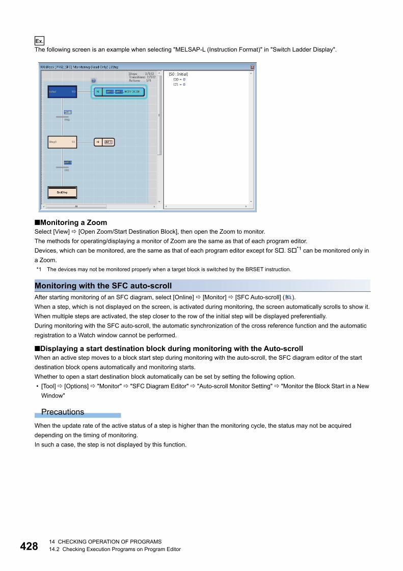
42814 CHECKING OPERATION OF PROGRAMS14.2 Checking Execution Programs on Program Editor
Ex.
The following screen is an example when selecting "MELSAP-L (Instruction Format)" in "Switch Ladder Display".
■Monitoring a ZoomSelect [View] [Open Zoom/Start Destination Block], then open the Zoom to monitor.
The methods for operating/displaying a monitor of Zoom are the same as that of each program editor.
Devices, which can be monitored, are the same as that of each program editor except for S. S*1 can be monitored only in
a Zoom.
*1 The devices may not be monitored properly when a target block is switched by the BRSET instruction.
Monitoring with the SFC auto-scrollAfter starting monitoring of an SFC diagram, select [Online] [Monitor] [SFC Auto-scroll] ( ).
When a step, which is not displayed on the screen, is activated during monitoring, the screen automatically scrolls to show it.
When multiple steps are activated, the step closer to the row of the initial step will be displayed preferentially.
During monitoring with the SFC auto-scroll, the automatic synchronization of the cross reference function and the automatic
registration to a Watch window cannot be performed.
■Displaying a start destination block during monitoring with the Auto-scrollWhen an active step moves to a block start step during monitoring with the auto-scroll, the SFC diagram editor of the start
destination block opens automatically and monitoring starts.
Whether to open a start destination block automatically can be set by setting the following option.
• [Tool] [Options] "Monitor" "SFC Diagram Editor" "Auto-scroll Monitor Setting" "Monitor the Block Start in a New
Window"
Precautions
When the update rate of the active status of a step is higher than the monitoring cycle, the status may not be acquired
depending on the timing of monitoring.
In such a case, the step is not displayed by this function.
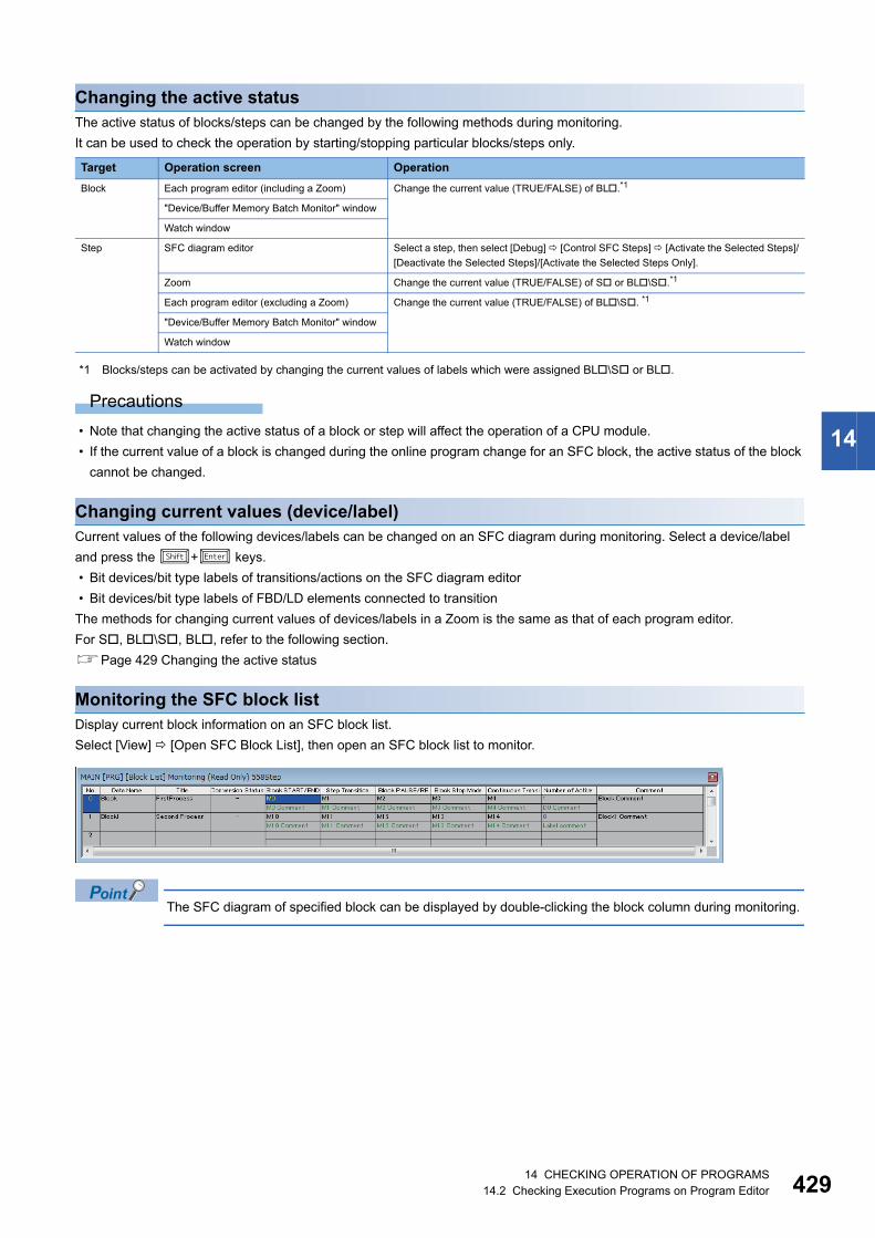
14 CHECKING OPERATION OF PROGRAMS14.2 Checking Execution Programs on Program Editor 429
14
Changing the active statusThe active status of blocks/steps can be changed by the following methods during monitoring.
It can be used to check the operation by starting/stopping particular blocks/steps only.
*1 Blocks/steps can be activated by changing the current values of labels which were assigned BL\S or BL.
Precautions
• Note that changing the active status of a block or step will affect the operation of a CPU module.
• If the current value of a block is changed during the online program change for an SFC block, the active status of the block
cannot be changed.
Changing current values (device/label)Current values of the following devices/labels can be changed on an SFC diagram during monitoring. Select a device/label
and press the + keys.
• Bit devices/bit type labels of transitions/actions on the SFC diagram editor
• Bit devices/bit type labels of FBD/LD elements connected to transition
The methods for changing current values of devices/labels in a Zoom is the same as that of each program editor.
For S, BL\S, BL, refer to the following section.
Page 429 Changing the active status
Monitoring the SFC block listDisplay current block information on an SFC block list.
Select [View] [Open SFC Block List], then open an SFC block list to monitor.
The SFC diagram of specified block can be displayed by double-clicking the block column during monitoring.
Target Operation screen Operation
Block Each program editor (including a Zoom) Change the current value (TRUE/FALSE) of BL.*1
"Device/Buffer Memory Batch Monitor" window
Watch window
Step SFC diagram editor Select a step, then select [Debug] [Control SFC Steps] [Activate the Selected Steps]/
[Deactivate the Selected Steps]/[Activate the Selected Steps Only].
Zoom Change the current value (TRUE/FALSE) of S or BL\S.*1
Each program editor (excluding a Zoom) Change the current value (TRUE/FALSE) of BL\S. *1
"Device/Buffer Memory Batch Monitor" window
Watch window

43014 CHECKING OPERATION OF PROGRAMS14.2 Checking Execution Programs on Program Editor
Monitoring all SFC blocks in batch/active stepsActive status of all blocks/steps can be displayed.
Active status of /blocks/steps are not changed if the status of a CPU module is switched from RUN to STOP. Thereby, the
active status when the CPU module was changed to STOP state is displayed on a monitor screen.
Precautions
This monitoring function may not work properly when there is a difference between the program written in a CPU module and
program in a project.
■Monitoring SFC blocks in batchDisplay current active/inactive status of all blocks in a list.
Window
Select [Online] [Monitor] [SFC All Blocks Batch Monitoring] ( ).
■Monitoring active stepsDisplay current active/inactive status of all steps that exist in a specified block in a list.
Up to five monitor screens can be displayed at once.
Operating procedure
Move the cursor on a block to be monitored on the "Block Batch Monitor" screen, then click the [Active Step Monitor] button.
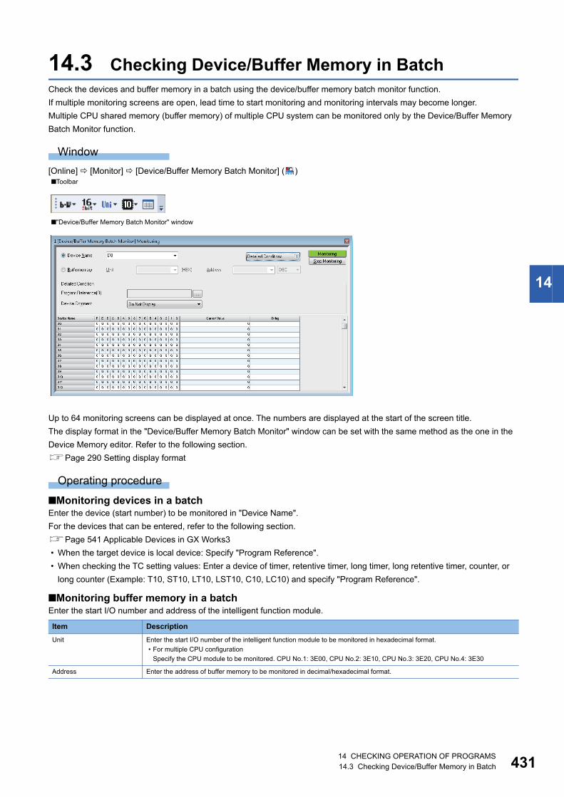
14 CHECKING OPERATION OF PROGRAMS14.3 Checking Device/Buffer Memory in Batch 431
14
14.3 Checking Device/Buffer Memory in BatchCheck the devices and buffer memory in a batch using the device/buffer memory batch monitor function.
If multiple monitoring screens are open, lead time to start monitoring and monitoring intervals may become longer.
Multiple CPU shared memory (buffer memory) of multiple CPU system can be monitored only by the Device/Buffer Memory
Batch Monitor function.
Window
[Online] [Monitor] [Device/Buffer Memory Batch Monitor] ( )
Up to 64 monitoring screens can be displayed at once. The numbers are displayed at the start of the screen title.
The display format in the "Device/Buffer Memory Batch Monitor" window can be set with the same method as the one in the
Device Memory editor. Refer to the following section.
Page 290 Setting display format
Operating procedure
■Monitoring devices in a batchEnter the device (start number) to be monitored in "Device Name".
For the devices that can be entered, refer to the following section.
Page 541 Applicable Devices in GX Works3
• When the target device is local device: Specify "Program Reference".
• When checking the TC setting values: Enter a device of timer, retentive timer, long timer, long retentive timer, counter, or
long counter (Example: T10, ST10, LT10, LST10, C10, LC10) and specify "Program Reference".
■Monitoring buffer memory in a batchEnter the start I/O number and address of the intelligent function module.
■Toolbar
■"Device/Buffer Memory Batch Monitor" window
Item Description
Unit Enter the start I/O number of the intelligent function module to be monitored in hexadecimal format.
• For multiple CPU configuration
Specify the CPU module to be monitored. CPU No.1: 3E00, CPU No.2: 3E10, CPU No.3: 3E20, CPU No.4: 3E30
Address Enter the address of buffer memory to be monitored in decimal/hexadecimal format.

43214 CHECKING OPERATION OF PROGRAMS14.3 Checking Device/Buffer Memory in Batch
■Monitoring blocks/steps in an SFC program in batchEnter BL in "Device Name" when monitoring blocks, and enter BL\S there when monitoring steps.
Fonts can be changed.
Page 65 Checking and Changing Colors and Fonts
Applicable monitoring devicesThe following table shows the devices that can be monitored in the "Device/Buffer Memory Batch Monitor" window.
Changing current valuesDuring monitoring, current values can be changed by one of the following operation.
• Double-click a cell of a device.
• Enter the key.
• Right-click a cell of a device or the "Current Value" column, and select [Modify Value] in the shortcut menu
■For bit devicesThe current value is changed.
■For word devicesA device is registered in a Watch window.
Change the current value in the Watch window. (Page 434 Checking Current Values by Registering Devices/Labels)
Multiple word devices can be registered in a Watch window at once by selecting multiple cells of the current values.
Precautions
• For T, and C device, a contact and the current value can be changed in RCPU, and a contact only can be changed in
FX5CPU.
• When "Bit and Word" is selected in "Display Unit Mode" of "Display Format Detailed Setting" ( ), the current value of the
following devices can be changed by changing the bit status in the 0 to F column.
DX, DY, FX, FY, J\X, J\Y, J\B, J\SB
• When "Bit and Word" is selected in "Display Unit Mode" of "Display Format Detailed Setting" ( ), the current value of a Z
device cannot be changed even if the bit status in the 0 to F column is changed.
• For S, BL\S, BL, blocks/steps are activated/deactivated by changing the current values. (Page 429 Changing
the active status)
Considerations when monitoring file registersThe operation of file registers differ depending on the settings of the CPU parameters. Refer to the considerations in the
following section.
Page 421 Considerations when monitoring file registers
Module type Device
RCPU X, Y, M, L, B, F, SB, V, T, T(TS), T(TC), T(TN), ST, ST(STS/SS), ST(STC/SC), ST(STN/SN), LT, LT(LTS), LT(LTC), LT(LTN), LST,
LST(LSTS), LST(LSTC), LST(LSTN), C, C(CS), C(CC), C(CN), LC, LC(LCS), LC(LCC), LC(LCN), D, W, SW, FX, FY, SM, SD,
FD, J\X, J\Y, J\B, J\SB, J\W, J\SW, U\G, U\HG, DX, DY, Z, LZ, K, R, ZR, RD, BL, BL\S
Remote head module X, Y, SB, W, SW, SM, SD, U\G, DX, DY, RD
14 CHECKING OPERATION OF PROGRAMS14.3 Checking Device/Buffer Memory in Batch 433
14
Specifying reference target of programSpecify the monitoring target program when monitoring the setting values of timer devices and counter devices, or local
devices.
Operating procedure
1. Click the [Detailed Conditions] button, then click the [...] button of "Program Reference" in the "Device/Buffer Memory
Batch Monitor" window.
2. Set each item on the "Program Reference" screen, and click the [OK] button.

43414 CHECKING OPERATION OF PROGRAMS14.4 Checking Current Values by Registering Devices/Labels
14.4 Checking Current Values by Registering Devices/Labels
To check the current values by registering devices or labels, use the watch function. Registering devices or labels to be
checked in a Watch window is required.
By specifying a range, multiple devices or labels can be registered at once.
Once devices/labels are registered and the project is saved, the registered devices/labels are displayed in the registered state
when the project is opened again.
Window
[View] [Docking Window] [Watch 1] to [Watch 4] ( )
The display format can be selected per row from the pull-down list displayed when selecting the display format.
Operating procedure
1. Register devices/labels to be monitored. (Page 435 Register to Watch window)
2. Select [Online] [Watch] [Start Watching].
During monitoring, "[Watching]" is added in the title of the Watch window.
■Updating a Watch windowIf data is changed by editing or converting*1 program, the change will not be applied to a Watch window.
After changing data, update the display of a Watch window. *2
*1 Example: A comment is edited in a label editor.*2 Label names, program names, and POU names are not updated. To update these items, register them in the Watch window again.
■Changing titlesTo edit a title, open the "Change Title" screen by selecting a row in the Watch window, then right-clicking and selecting
[Change Title] from the shortcut menu.
■ON/OFF of a bit deviceThe display format of the current value of a bit device can be changed from 'TRUE/FALSE' to 'ON/OFF' by right-clicking an
arbitrary row in a Watch window and selecting [ON/OFF Display] from the Shortcut menu.
■Editing commentsTo edit a comment, open the editor where the comment is defined by selecting a row in the Watch window, then right-clicking
and selecting [Comment Edit] from the shortcut menu.

14 CHECKING OPERATION OF PROGRAMS14.4 Checking Current Values by Registering Devices/Labels 435
14
Register to Watch windowRegister devices/labels to be monitored in the Watch window.
Operating procedure
■Enter to register
1. Open a Watch window.
2. Enter a device/label to be registered in the "Name" column, and press the key.
The input format of devices/labels are as follows:
• Global device: Device name
• Local device: Program name/#Device name ('#' is not necessary for index register (Z))
• Global device: Label name
• Local device: Program block name/label name
• Step relay: BL\S
For structures, function blocks, and arrays, enter the items by referring to the following table.
Options for labels are displayed when entering a label name.
They can also be displayed by any of the following operations.
• Press the key + key
• Enter '/' after entering a program block name
• Enter '.' at the end of a label name of structure type or an instance name of a function block.
Type Target Input format
Structure Label (Structure) Label name
Structure member Label name.member name
Function block Label (Function block) Label name
Label in the function block Label name.Label name in the function block
Array Label (Array) Label name excluding array notation
Array index and the specific dimension part of
array (more than two-dimensional array)
Label name[three-dimensional index] [two-dimensional index]
[one-dimensional index]
Structure array Label (Structure array) Label name
Specific member Label name[three-dimensional index] [two-dimensional index]
[one-dimensional index].member name
Nested function block Label (Nested function block) Label name
Labels in the nested function block Label name. label name in the function block. label name in the
nested function block
When nesting labels for one or more level deeper, the lower
part of the label name which are delimited by a dot '.' is
regarded as a label name. (Example: MAIN_PRG_LD/
FB0_1.FB1_1.FB2_1.INOUT)
When a function block includes array labels or
structured labels
Follow the specification method of the array or structure.

43614 CHECKING OPERATION OF PROGRAMS14.4 Checking Current Values by Registering Devices/Labels
■Registering devices/labels from program editor/label editor
1. In a program editor or the label editor, select a device or label to register in the Watch window.
2. Select [Online] [Watch] [Register to Watch Window] [Watch 1] to [Watch 4].
Devices/labels can be registered by dragging and dropping onto the Watch window.
• Ladder editor*1: Select a cell of device/label, and then drag the border of the selected cell and drop it onto a Watch window.
• ST editor*1: Select a token of a device/label, and then drag and drop it onto a Watch window.
• FBD/LD editor*1: Select an element of a device/label, and then drag and drop it onto a Watch window with pressing the
key.
• SFC diagram editor: Select a step, or a transition/action for which a device/label is set, and then drag and drop it onto a
Watch window.
• Label editor: Select the header of a label, and then drag and drop it onto the Watch window
*1 For RCPU, step relays (S) cannot be registered except in a Zoom.Step relays (S) are registered as step relays with a block specification (BL\S) automatically in a Zoom.
Rectangular selection can be made by dragging the devices/labels while pressing the key on the ST
editor. The devices/labels only in the selected range can be registered.
■Registering devices/labels from the Cross Reference windowTo register a device/label in a Watch window, select a row in the Cross Reference window, then right-click and select [Register
to Watch 1] to [Register to Watch 4].
Precautions
■Inapplicable labels • When a value other than fixed value is used for an array index, the monitor value is not displayed or displayed as an
indefinite value in a Watch window.
• The monitor values of a local label used in a function are not displayed, or displayed as indefinite values in a Watch
window.
Automatic registration to Watch windowsDevices and labels in a selected range in a program editor are automatically registered in a Watch window.
Devices and labels in a Watch window are updated every time when the specific range is changed.
The following table shows the range of automatic registration for each program language.
Operating procedure
1. Set the following option.
Select one of [Watch 1] to [Watch 4] in [Tool] [Options] "Monitor" "Ladder Editor"/"ST Editor"/"FBD/LD Editor"
"Setting for Automatic Registration to Watch Window" "Set Automatic Registration Destination".
2. During monitoring, select a range of devices/labels to be registered to a Watch window in a program editor.
Program language Range Remarks
Ladder Device/label on a ladder block containing the selected cell A device/label in an FB and inline structured text is
excluded.
Ladder (Inline
structured text)
Device/label in a selected row within the selected inline structured text It follows the option setting for the ladder editor.
ST Device/label on which the cursor is placed When multiple rows are selected, only a device/label in
the row on which the cursor is placed is registered.
FBD/LD Device/label in an FBD network block containing the element on which the
cursor is placed
When multiple FBD network blocks are selected, only
the device/label in the block containing the element on
which the cursor is placed is registered.
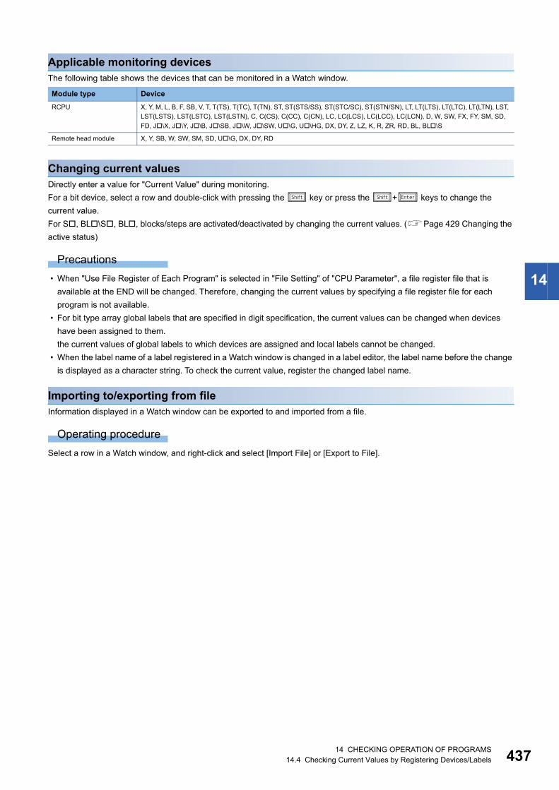
14 CHECKING OPERATION OF PROGRAMS14.4 Checking Current Values by Registering Devices/Labels 437
14
Applicable monitoring devicesThe following table shows the devices that can be monitored in a Watch window.
Changing current valuesDirectly enter a value for "Current Value" during monitoring.
For a bit device, select a row and double-click with pressing the key or press the + keys to change the
current value.
For S, BL\S, BL, blocks/steps are activated/deactivated by changing the current values. (Page 429 Changing the
active status)
Precautions
• When "Use File Register of Each Program" is selected in "File Setting" of "CPU Parameter", a file register file that is
available at the END will be changed. Therefore, changing the current values by specifying a file register file for each
program is not available.
• For bit type array global labels that are specified in digit specification, the current values can be changed when devices
have been assigned to them.
the current values of global labels to which devices are assigned and local labels cannot be changed.
• When the label name of a label registered in a Watch window is changed in a label editor, the label name before the change
is displayed as a character string. To check the current value, register the changed label name.
Importing to/exporting from fileInformation displayed in a Watch window can be exported to and imported from a file.
Operating procedure
Select a row in a Watch window, and right-click and select [Import File] or [Export to File].
Module type Device
RCPU X, Y, M, L, B, F, SB, V, T, T(TS), T(TC), T(TN), ST, ST(STS/SS), ST(STC/SC), ST(STN/SN), LT, LT(LTS), LT(LTC), LT(LTN), LST,
LST(LSTS), LST(LSTC), LST(LSTN), C, C(CS), C(CC), C(CN), LC, LC(LCS), LC(LCC), LC(LCN), D, W, SW, FX, FY, SM, SD,
FD, J\X, J\Y, J\B, J\SB, J\W, J\SW, U\G, U\HG, DX, DY, Z, LZ, K, R, ZR, RD, BL, BL\S
Remote head module X, Y, SB, W, SW, SM, SD, U\G, DX, DY, RD
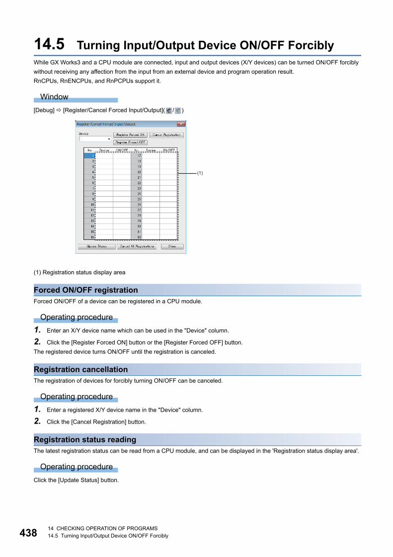
43814 CHECKING OPERATION OF PROGRAMS14.5 Turning Input/Output Device ON/OFF Forcibly
14.5 Turning Input/Output Device ON/OFF ForciblyWhile GX Works3 and a CPU module are connected, input and output devices (X/Y devices) can be turned ON/OFF forcibly
without receiving any affection from the input from an external device and program operation result.
RnCPUs, RnENCPUs, and RnPCPUs support it.
Window
[Debug] [Register/Cancel Forced Input/Output]( / )
(1) Registration status display area
Forced ON/OFF registrationForced ON/OFF of a device can be registered in a CPU module.
Operating procedure
1. Enter an X/Y device name which can be used in the "Device" column.
2. Click the [Register Forced ON] button or the [Register Forced OFF] button.
The registered device turns ON/OFF until the registration is canceled.
Registration cancellationThe registration of devices for forcibly turning ON/OFF can be canceled.
Operating procedure
1. Enter a registered X/Y device name in the "Device" column.
2. Click the [Cancel Registration] button.
Registration status readingThe latest registration status can be read from a CPU module, and can be displayed in the 'Registration status display area'.
Operating procedure
Click the [Update Status] button.
(1)

14 CHECKING OPERATION OF PROGRAMS14.5 Turning Input/Output Device ON/OFF Forcibly 439
14
Batch cancellation of registrationAll the registered devices for forcibly turning ON/OFF can be canceled.
Operating procedure
Click the [Cancel All Registrations] button.
Considerations • This function is not controlled exclusively on a CPU module side. The registered contents may be changed by a peripheral
device connected via another station.
• Even when forcibly turning devices ON/OFF by using the 'Modify Value' function, a current value of the device for which
forced ON/OFF is registered is not changed.
■RnPCPUs (redundant mode)When GX Works3 is connected to an RnPCPU (redundant mode), a type of the system (control system or standby system) of
the connected CPU module on the connected system is displayed in the title of the "Register/Cancel Forced Input/Output"
screen.
The following table shows the availability of the buttons in the "Register/Cancel Forced Input/Output" screen for each system
of the CPU module on a connected system.
: Available, : Not available
*1 Only the registration status of the CPU module on the connected system is read.
System Button
Register Forced ON Register Forced OFF
Cancel Registration
Update Status Cancel All Registrations
Control system
(Other system: standby
system)
*1
Control system
(Other system: other
than standby system)
Standby system *1
Not specified
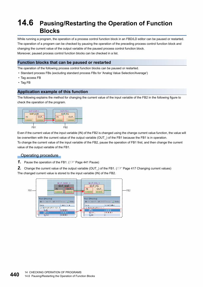
44014 CHECKING OPERATION OF PROGRAMS14.6 Pausing/Restarting the Operation of Function Blocks
14.6 Pausing/Restarting the Operation of Function Blocks
While running a program, the operation of a process control function block in an FBD/LD editor can be paused or restarted.
The operation of a program can be checked by pausing the operation of the preceding process control function block and
changing the current value of the output variable of the paused process control function block.
Moreover, paused process control function blocks can be checked in a list.
Function blocks that can be paused or restartedThe operation of the following process control function blocks can be paused or restarted.
• Standard process FBs (excluding standard process FBs for 'Analog Value Selection/Average')
• Tag access FB
• Tag FB
Application example of this functionThe following explains the method for changing the current value of the input variable of the FB2 in the following figure to
check the operation of the program.
Even if the current value of the input variable (IN) of the FB2 is changed using the change current value function, the value will
be overwritten with the current value of the output variable (OUT_) of the FB1 because the FB1 is in operation.
To change the current value of the input variable of the FB2, pause the operation of FB1 first, and then change the current
value of the output variable of the FB1.
Operating procedure
1. Pause the operation of the FB1. (Page 441 Pause)
2. Change the current value of the output variable (OUT_) of the FB1. (Page 417 Changing current values)
The changed current value is stored to the input variable (IN) of the FB2.
FB1 FB2
FB1 FB2
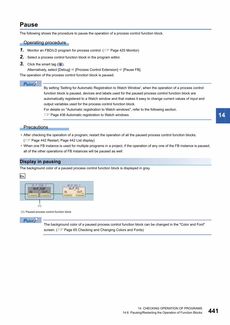
14 CHECKING OPERATION OF PROGRAMS14.6 Pausing/Restarting the Operation of Function Blocks 441
14
PauseThe following shows the procedure to pause the operation of a process control function block.
Operating procedure
1. Monitor an FBD/LD program for process control. (Page 425 Monitor)
2. Select a process control function block in the program editor.
3. Click the smart tag ( ).
Alternatively, select [Debug] [Process Control Extension] [Pause FB].
The operation of the process control function block is paused.
By setting 'Setting for Automatic Registration to Watch Window', when the operation of a process control
function block is paused, devices and labels used for the paused process control function block are
automatically registered to a Watch window and that makes it easy to change current values of input and
output variables used for the process control function block.
For details on "Automatic registration to Watch windows", refer to the following section.
Page 436 Automatic registration to Watch windows
Precautions
• After checking the operation of a program, restart the operation of all the paused process control function blocks.
(Page 442 Restart, Page 442 List display)
• When one FB instance is used for multiple programs in a project, if the operation of any one of the FB instance is paused,
all of the other operations of FB instances will be paused as well.
Display in pausingThe background color of a paused process control function block is displayed in gray.
Ex.
The background color of a paused process control function block can be changed in the "Color and Font"
screen. (Page 65 Checking and Changing Colors and Fonts)
(1): Paused process control function block
(1)

44214 CHECKING OPERATION OF PROGRAMS14.6 Pausing/Restarting the Operation of Function Blocks
RestartThe following shows the procedure to restart the operation of a paused process control function block.
Operating procedure
1. Select a paused process control function block in a program editor.
2. Click the smart tag ( ).
Alternatively, select [Debug] [Process Control Extension] [Restart FB].
The operation of the process control function block is restarted.
List displayThe following shows the procedure to display paused process control function blocks in a list.
Operating procedure
Select [Debug] [Process Control Extension] [Paused FB List].
Paused process control function blocks are displayed in the "Output" window.
By selecting a row in the "Output" window and performing any one of the following operation, a cursor jumps
to the position where an FB instance of the process control function block is used.
- Press the key.
- Double-click a row.
- Right-click a row, and select [Jump] in the shortcut menu.
Precautions
• After checking the operation of a program, check that all the process control function blocks are running.
• Function blocks in a program that is protected by a security key or block password are not displayed.
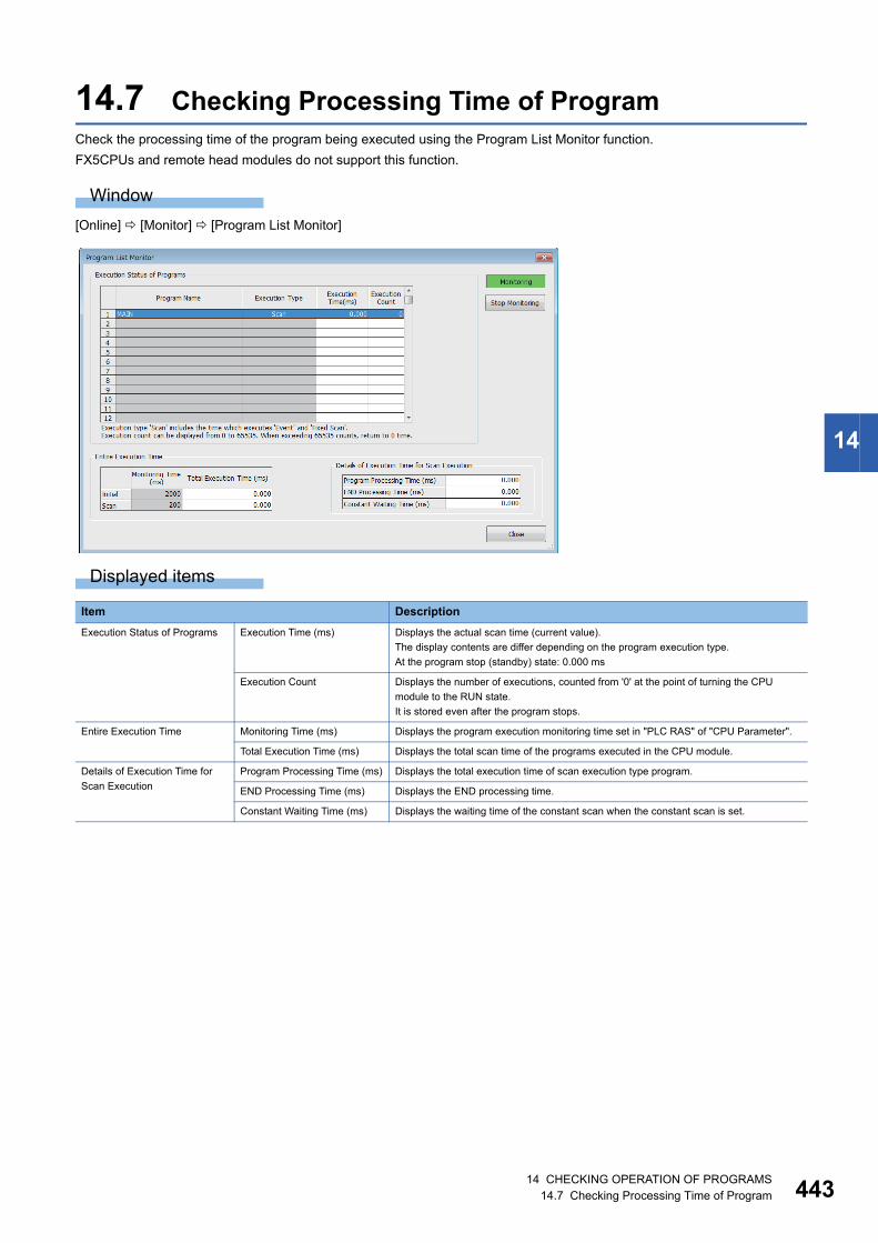
14 CHECKING OPERATION OF PROGRAMS14.7 Checking Processing Time of Program 443
14
14.7 Checking Processing Time of ProgramCheck the processing time of the program being executed using the Program List Monitor function.
FX5CPUs and remote head modules do not support this function.
Window
[Online] [Monitor] [Program List Monitor]
Displayed items
Item Description
Execution Status of Programs Execution Time (ms) Displays the actual scan time (current value).
The display contents are differ depending on the program execution type.
At the program stop (standby) state: 0.000 ms
Execution Count Displays the number of executions, counted from '0' at the point of turning the CPU
module to the RUN state.
It is stored even after the program stops.
Entire Execution Time Monitoring Time (ms) Displays the program execution monitoring time set in "PLC RAS" of "CPU Parameter".
Total Execution Time (ms) Displays the total scan time of the programs executed in the CPU module.
Details of Execution Time for
Scan Execution
Program Processing Time (ms) Displays the total execution time of scan execution type program.
END Processing Time (ms) Displays the END processing time.
Constant Waiting Time (ms) Displays the waiting time of the constant scan when the constant scan is set.
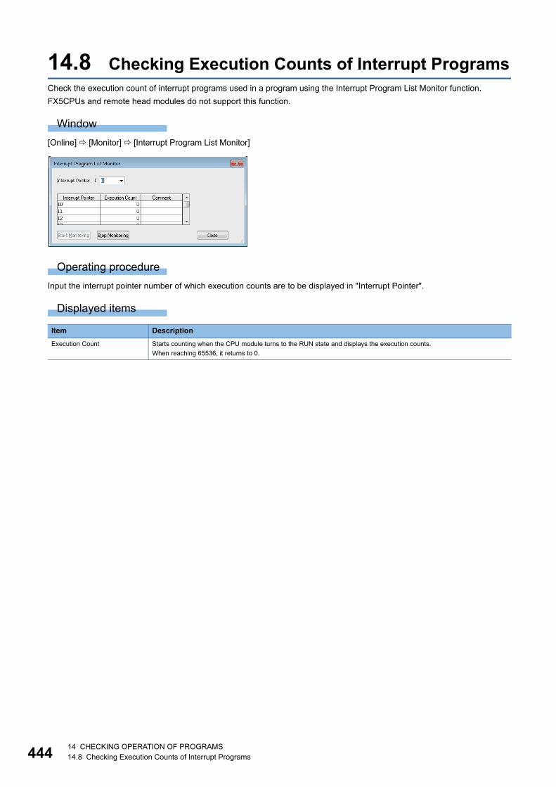
44414 CHECKING OPERATION OF PROGRAMS14.8 Checking Execution Counts of Interrupt Programs
14.8 Checking Execution Counts of Interrupt ProgramsCheck the execution count of interrupt programs used in a program using the Interrupt Program List Monitor function.
FX5CPUs and remote head modules do not support this function.
Window
[Online] [Monitor] [Interrupt Program List Monitor]
Operating procedure
Input the interrupt pointer number of which execution counts are to be displayed in "Interrupt Pointer".
Displayed items
Item Description
Execution Count Starts counting when the CPU module turns to the RUN state and displays the execution counts.
When reaching 65536, it returns to 0.

14 CHECKING OPERATION OF PROGRAMS14.9 Checking Current Values in Intelligent Function Module 445
14
14.9 Checking Current Values in Intelligent Function Module
Check the current value of I/O signals and buffer memory of an intelligent function module using the Intelligent Function
Module Monitor function.
Window
[View] [Docking Window] [Intelligent Function Module Monitor] [Intelligent Function Module Monitor 1] to [Intelligent
Function Module Monitor 10]
Operating procedure
1. Register an intelligent function module to be monitored. (Page 446 Registering intelligent function modules)
2. Select [Online] [Watch] [Start Watching].
During monitoring, "[Watching]" is added in the title of the Intelligent Function Module Monitor window.
Select and right-click the module information, and then select [Copy] from the shortcut menu to paste it to a
text file.
Detailed display of monitor items
■Detailed display of log informationThe details of log information can be displayed during monitoring.
Double-click a row in which "Detail Dialog" is displayed in "Data Type" column, or right-click and select [Detailed Dialog] from
the shortcut menu.
When the menu is not selectable, it is not supported by the module.
■Detailed display of error codes/alarm codesThe details of an error code/alarm code can be displayed in an Intelligent Function Module Monitor window or the detailed
dialog.
Double-click a row in which an error code/alarm code is displayed, or right-click and select [Detail Display] from the shortcut
menu.
Precautions
The Intelligent Function Module Monitor updates current values only within the range displayed on the window for monitoring
acceleration.
When performing operation such as copy and paste on Excel, "--" or the previously monitored current value is displayed for
the data outside the range displayed on the window.
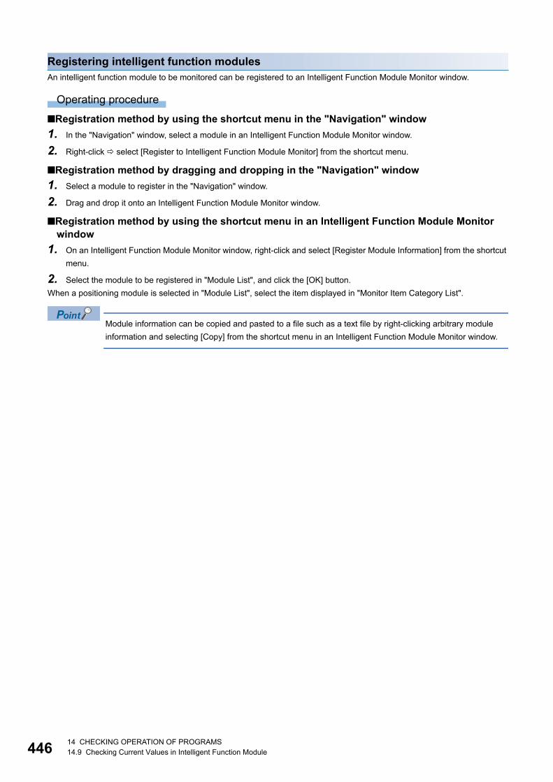
44614 CHECKING OPERATION OF PROGRAMS14.9 Checking Current Values in Intelligent Function Module
Registering intelligent function modulesAn intelligent function module to be monitored can be registered to an Intelligent Function Module Monitor window.
Operating procedure
■Registration method by using the shortcut menu in the "Navigation" window
1. In the "Navigation" window, select a module in an Intelligent Function Module Monitor window.
2. Right-click select [Register to Intelligent Function Module Monitor] from the shortcut menu.
■Registration method by dragging and dropping in the "Navigation" window
1. Select a module to register in the "Navigation" window.
2. Drag and drop it onto an Intelligent Function Module Monitor window.
■Registration method by using the shortcut menu in an Intelligent Function Module Monitor window
1. On an Intelligent Function Module Monitor window, right-click and select [Register Module Information] from the shortcut
menu.
2. Select the module to be registered in "Module List", and click the [OK] button.
When a positioning module is selected in "Module List", select the item displayed in "Monitor Item Category List".
Module information can be copied and pasted to a file such as a text file by right-clicking arbitrary module
information and selecting [Copy] from the shortcut menu in an Intelligent Function Module Monitor window.
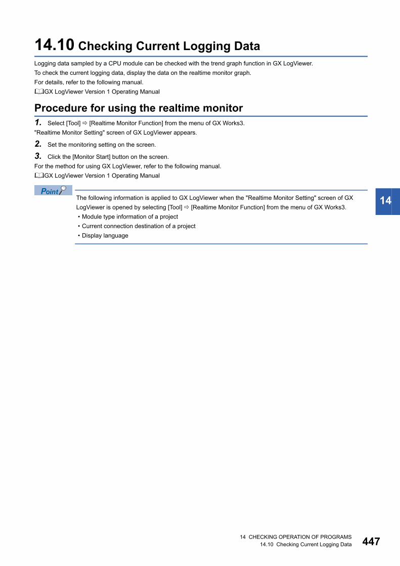
14 CHECKING OPERATION OF PROGRAMS14.10 Checking Current Logging Data 447
14
14.10 Checking Current Logging DataLogging data sampled by a CPU module can be checked with the trend graph function in GX LogViewer.
To check the current logging data, display the data on the realtime monitor graph.
For details, refer to the following manual.
GX LogViewer Version 1 Operating Manual
Procedure for using the realtime monitor1. Select [Tool] [Realtime Monitor Function] from the menu of GX Works3.
"Realtime Monitor Setting" screen of GX LogViewer appears.
2. Set the monitoring setting on the screen.
3. Click the [Monitor Start] button on the screen.
For the method for using GX LogViewer, refer to the following manual.
GX LogViewer Version 1 Operating Manual
The following information is applied to GX LogViewer when the "Realtime Monitor Setting" screen of GX
LogViewer is opened by selecting [Tool] [Realtime Monitor Function] from the menu of GX Works3.
• Module type information of a project
• Current connection destination of a project
• Display language
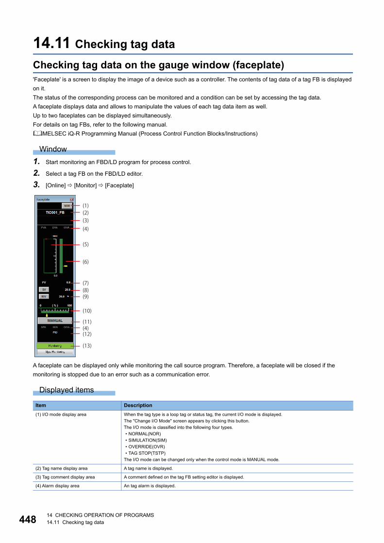
44814 CHECKING OPERATION OF PROGRAMS14.11 Checking tag data
14.11 Checking tag data
Checking tag data on the gauge window (faceplate)'Faceplate' is a screen to display the image of a device such as a controller. The contents of tag data of a tag FB is displayed
on it.
The status of the corresponding process can be monitored and a condition can be set by accessing the tag data.
A faceplate displays data and allows to manipulate the values of each tag data item as well.
Up to two faceplates can be displayed simultaneously.
For details on tag FBs, refer to the following manual.
MELSEC iQ-R Programming Manual (Process Control Function Blocks/Instructions)
Window
1. Start monitoring an FBD/LD program for process control.
2. Select a tag FB on the FBD/LD editor.
3. [Online] [Monitor] [Faceplate]
A faceplate can be displayed only while monitoring the call source program. Therefore, a faceplate will be closed if the
monitoring is stopped due to an error such as a communication error.
Displayed items
Item Description
(1) I/O mode display area When the tag type is a loop tag or status tag, the current I/O mode is displayed.
The "Change I/O Mode" screen appears by clicking this button.
The I/O mode is classified into the following four types.
• NORMAL(NOR)
• SIMULATION(SIM)
• OVERRIDE(OVR)
• TAG STOP(TSTP)
The I/O mode can be changed only when the control mode is MANUAL mode.
(2) Tag name display area A tag name is displayed.
(3) Tag comment display area A comment defined on the tag FB setting editor is displayed.
(4) Alarm display area An tag alarm is displayed.
(1)
(12)
(13)
(4)(11)
(8)(7)
(6)
(5)
(4)
(2)(3)
(10)
(9)
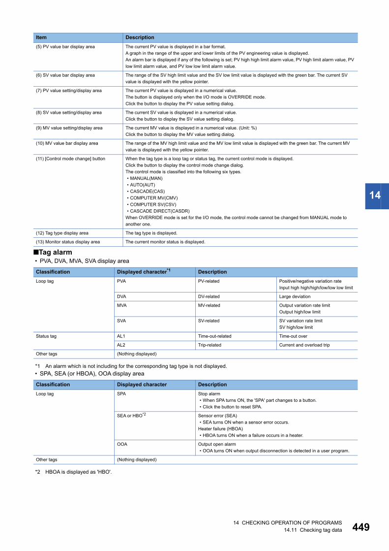
14 CHECKING OPERATION OF PROGRAMS14.11 Checking tag data 449
14
■Tag alarm • PVA, DVA, MVA, SVA display area
*1 An alarm which is not including for the corresponding tag type is not displayed.
• SPA, SEA (or HBOA), OOA display area
*2 HBOA is displayed as 'HBO'.
(5) PV value bar display area The current PV value is displayed in a bar format.
A graph in the range of the upper and lower limits of the PV engineering value is displayed.
An alarm bar is displayed if any of the following is set; PV high high limit alarm value, PV high limit alarm value, PV
low limit alarm value, and PV low low limit alarm value.
(6) SV value bar display area The range of the SV high limit value and the SV low limit value is displayed with the green bar. The current SV
value is displayed with the yellow pointer.
(7) PV value setting/display area The current PV value is displayed in a numerical value.
The button is displayed only when the I/O mode is OVERRIDE mode.
Click the button to display the PV value setting dialog.
(8) SV value setting/display area The current SV value is displayed in a numerical value.
Click the button to display the SV value setting dialog.
(9) MV value setting/display area The current MV value is displayed in a numerical value. (Unit: %)
Click the button to display the MV value setting dialog.
(10) MV value bar display area The range of the MV high limit value and the MV low limit value is displayed with the green bar. The current MV
value is displayed with the yellow pointer.
(11) [Control mode change] button When the tag type is a loop tag or status tag, the current control mode is displayed.
Click the button to display the control mode change dialog.
The control mode is classified into the following six types.
• MANUAL(MAN)
• AUTO(AUT)
• CASCADE(CAS)
• COMPUTER MV(CMV)
• COMPUTER SV(CSV)
• CASCADE DIRECT(CASDR)
When OVERRIDE mode is set for the I/O mode, the control mode cannot be changed from MANUAL mode to
another one.
(12) Tag type display area The tag type is displayed.
(13) Monitor status display area The current monitor status is displayed.
Classification Displayed character*1 Description
Loop tag PVA PV-related Positive/negative variation rate
Input high high/high/low/low low limit
DVA DV-related Large deviation
MVA MV-related Output variation rate limit
Output high/low limit
SVA SV-related SV variation rate limit
SV high/low limit
Status tag AL1 Time-out-related Time-out over
AL2 Trip-related Current and overload trip
Other tags (Nothing displayed)
Classification Displayed character Description
Loop tag SPA Stop alarm
• When SPA turns ON, the 'SPA' part changes to a button.
• Click the button to reset SPA.
SEA or HBO*2 Sensor error (SEA)
• SEA turns ON when a sensor error occurs.
Heater failure (HBOA)
• HBOA turns ON when a failure occurs in a heater.
OOA Output open alarm
• OOA turns ON when output disconnection is detected in a user program.
Other tags (Nothing displayed)
Item Description
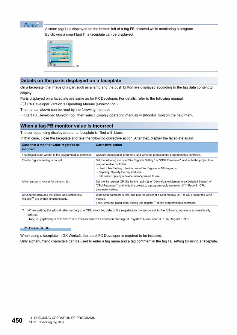
45014 CHECKING OPERATION OF PROGRAMS14.11 Checking tag data
A smart tag(1) is displayed on the bottom left of a tag FB selected while monitoring a program.
By clicking a smart tag(1), a faceplate can be displayed.
Details on the parts displayed on a faceplateOn a faceplate, the image of a part such as a lamp and the push button are displayed according to the tag data content to
display.
Parts displayed on a faceplate are same as for PX Developer. For details, refer to the following manual.
PX Developer Version 1 Operating Manual (Monitor Tool)
The manual above can be read by the following methods.
• Start PX Developer Monitor Tool, then select [Display operating manual] [Monitor Tool] on the help menu.
When a tag FB monitor value is incorrectThe corresponding display area on a faceplate is filled with black.
In that case, close the faceplate and tale the following corrective action. After that, display the faceplate again.
*1 When writing the global label setting to a CPU module, data of file registers in the range set in the following option is automatically written.[Tool] [Options] "Convert" "Process Control Extension Setting" "System Resource" "File Register: ZR"
Precautions
When using a faceplate in GX Works3, the latest PX Developer is required to be installed.
Only alphanumeric characters can be used to enter a tag name and a tag comment in the tag FB setting for using a faceplate.
Case that a monitor value regarded as incorrect
Corrective action
The project is not written to the programmable controller. Convert (reassign) all programs, and write the project to the programmable controller.
The file register setting is not set. Set the following items in "File Register Setting " of "CPU Parameter", and write the project to a
programmable controller.
• Use Or Not Setting: Use Common File Register in All Programs
• Capacity: Specify the required size.
• File name: Specify a device memory name to use.
A file register is not set for the latch (2). Set the file register 'ZR (R)' for the latch (2) in "Device/Label Memory Area Detailed Setting" of
"CPU Parameter", and write the project to a programmable controller. (Page 21 CPU
parameter setting)
CPU parameters and the global label setting (file
register)*1 are written simultaneously.
Write CPU parameters first, and turn the power of a CPU module OFF to ON or reset the CPU
module.
Then, write the global label setting (file register)*1 to the programmable controller.
(1)
14 CHECKING OPERATION OF PROGRAMS14.11 Checking tag data 451
14
Interaction with PX Developer Monitor ToolAn FBD/LD program for process control created in GX Works3 can be managed, monitored, and controlled in PX Developer
Monitor Tool.
Moreover, a GOT screen project can be created using the GOT screen generator of PX Developer Monitor Tool.
To use this function, follow the procedure in the table below.
Exporting an assignment information database fileThe following shows the procedure to export the assignment information database file of a GX Works3 project.
Operating procedure
1. Open a GX Works3 project where an FBD/LD program for process control is used.
2. Click "Export Assignment Information Database File" ( ) in the toolbar.
3. Click the [Save] button in the "Export Assignment Information Database File" screen.
The assignment information database file (*.FADB) is exported.
Precautions
• When exporting an assignment information database file, only alphanumeric characters are available for a tag name and
tag comment in the tag FB setting.
• When using the GOT screen generator of PX Developer Monitor Tool, export an assignment information database file in GX
Works3 Version 1.045X or later.
No. Procedure Reference
1 Export an assignment information database file in GX Works3. Page 451 Exporting an assignment information
database file
2 Set the assignment information database file in PX Developer. PX Developer Version 1 Operating Manual (Monitor
Tool)3 Monitor FBD/LD programs for process control in PX Developer Monitor Tool.
Create a GOT screen project in PX Developer Monitor Tool. PX Developer Version 1 Operating Manual (GOT
Screen Generator)
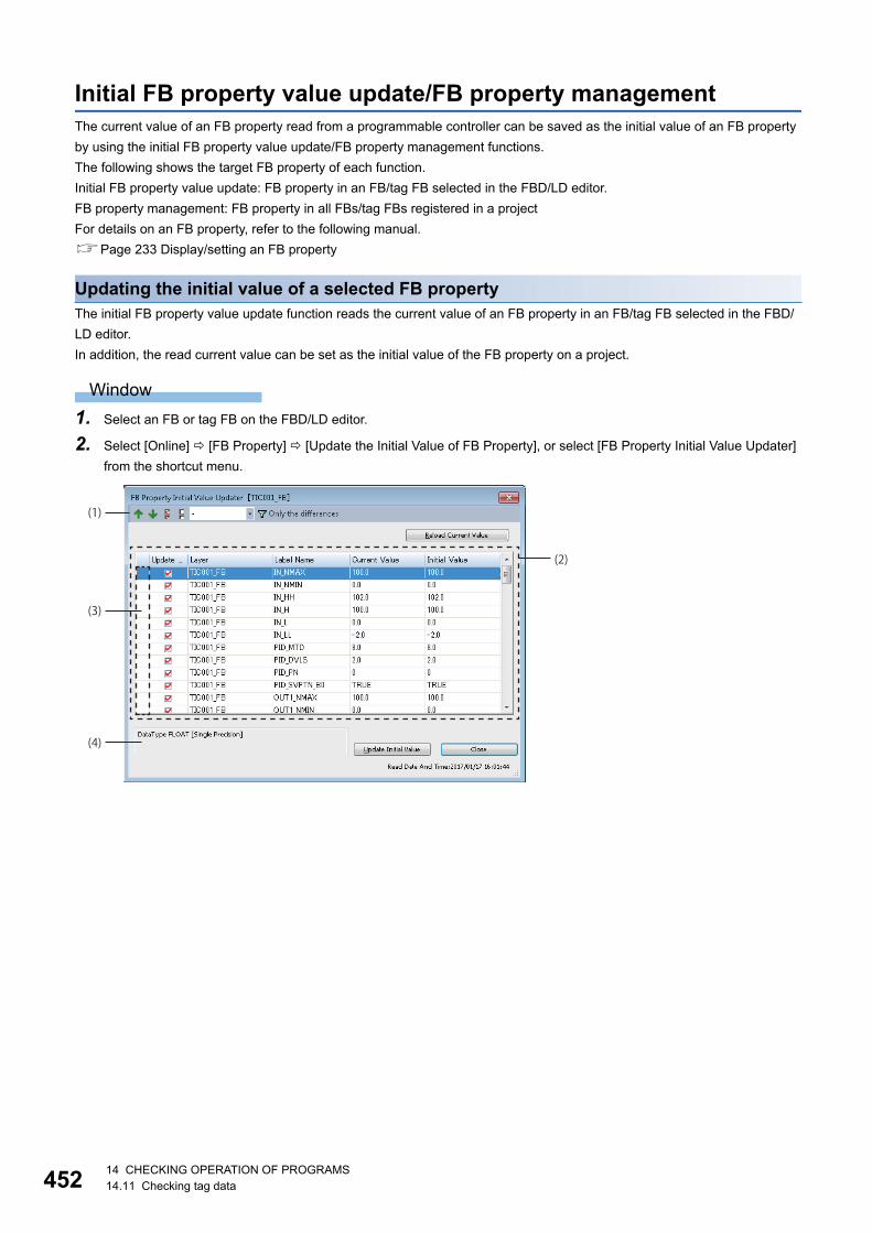
45214 CHECKING OPERATION OF PROGRAMS14.11 Checking tag data
Initial FB property value update/FB property managementThe current value of an FB property read from a programmable controller can be saved as the initial value of an FB property
by using the initial FB property value update/FB property management functions.
The following shows the target FB property of each function.
Initial FB property value update: FB property in an FB/tag FB selected in the FBD/LD editor.
FB property management: FB property in all FBs/tag FBs registered in a project
For details on an FB property, refer to the following manual.
Page 233 Display/setting an FB property
Updating the initial value of a selected FB propertyThe initial FB property value update function reads the current value of an FB property in an FB/tag FB selected in the FBD/
LD editor.
In addition, the read current value can be set as the initial value of the FB property on a project.
Window
1. Select an FB or tag FB on the FBD/LD editor.
2. Select [Online] [FB Property] [Update the Initial Value of FB Property], or select [FB Property Initial Value Updater]
from the shortcut menu.
(2)
(3)
(4)
(1)

14 CHECKING OPERATION OF PROGRAMS14.11 Checking tag data 453
14
Displayed items
*1 When the digits after the decimal point are more than seven digits, the value is applied only for the item of the double precision. For the item the single precision, six digits are applied.
*2 The current value and the initial value in the FB property list are compared in binary. (Example: 1.0 and 1.00 is considered as the same value.)
*3 The "Multiple Comments Display Setting" screen can be displayed from the following menu.[View] [Multiple Comments Display Setting]
Precautions
The "FB Property Initial Value Updater" screen can be displayed only when the whole FB is selected as shown below.
Item Description
(1) Toolbar Previous difference To jump the cursor to the row with a difference in values (the row where the current value and
initial value are different) before the current cursor position in the FB property list.
(Always available)
Next difference To jump the cursor to the row with a difference in values after the current cursor position in the
FB property list.
(Always available)
Select All To select all selectable FB property items in the FB property list.
(Always available)
Deselect All To unselect all selected FB property items in the FB property list.
(Always available)
Number of digits
after decimal point specification
To specify the number of digits after decimal point for the current value of which the data type is
single precision or double precision. *1
• Without specification:
• With specification: 1 to 14
The number of digits can be specified only when a row with a difference in values is not
specified.
If filtering a row with a difference in values when the number of digits after the decimal point are
specified, the row is filtered by keeping the setting.
(Available only for the current value)
Filtering/clearing of a row with a
difference
To display/ not display only a row with a difference by filtering.
Filtering will be cleared when the current value is reloaded while filtering.
(2) FB property list To display the FB property list of a specified FB when opening the "FB Property Initial Value Updater" screen.
Update Check To select whether to set or not the current value as the initial value when the [Update Initial
Value] button is clicked.
• Selected: The current value is set as the initial value.
• Not selected: The current value is not set as the initial value.
The selection state is saved in a project for each FB instance.
Layer To display the layer of the target function block and tag data.
The display contents of each FB are as follows.
Function block (local label definition): POU name/FB label name in a program
Function block (global label definition), tag FB: FB label name
Tag data: label name of tag data
Label Name To display the FB property item name in a target FB.
Current Value To display the current value of an FB property acquired from a programmable controller.
When the values between the current value and the initial value differ, the character string is
displayed in red.*2
Initial Value To display the initial value of an FB property acquired from a project.
When the values between the current value and the initial value differ, the character string is
displayed in red.*2
(3) Header To display an error icon ( ) when the current value cannot be set as the initial value.
(4) Explanation column To display the data type of a label selected in the FB property list and a label comment.
A label comment can be displayed in the explanation column by setting the comment title of the comment as the display target on
the "Multiple Comments Display Setting" screen*3. (Page 66 Comment Display Setting)

45414 CHECKING OPERATION OF PROGRAMS14.11 Checking tag data
Managing the initial values of all FB propertiesThe FB property management function reads the current value of an FB property in all FBs/tag FBs registered in a project in a
batch.
In addition, the read current value can be set as the initial value of the FB property on a project in a batch.
Window
[Online] [FB Property] [FB Property Management]
Displayed items
The display contents are same as on the "FB Property Initial Value Updater" screen. (Page 452 Updating the initial value
of a selected FB property)
The following FBs and tag FBs are displayed in the FB property list.
• FB instance set for a global label
• FB instance set for a local label in a program
Once the initial value is updated, a program related to a label of which the initial value was updated will be in
the unconverted state.

455
PA
RT
5
PART 5 MAINTENANCE AND INSPECTION
This part explains the maintenance and inspection methods such as a function to protect data (prevent from
falsification and data leakage) and display the system status of the CPU module.
15 PROTECTING DATA
16 MODULE DIAGNOSTIC
17 SAMPLING DEVICE DATA
18 CHECKING/CHANGING MODULE OPERATION
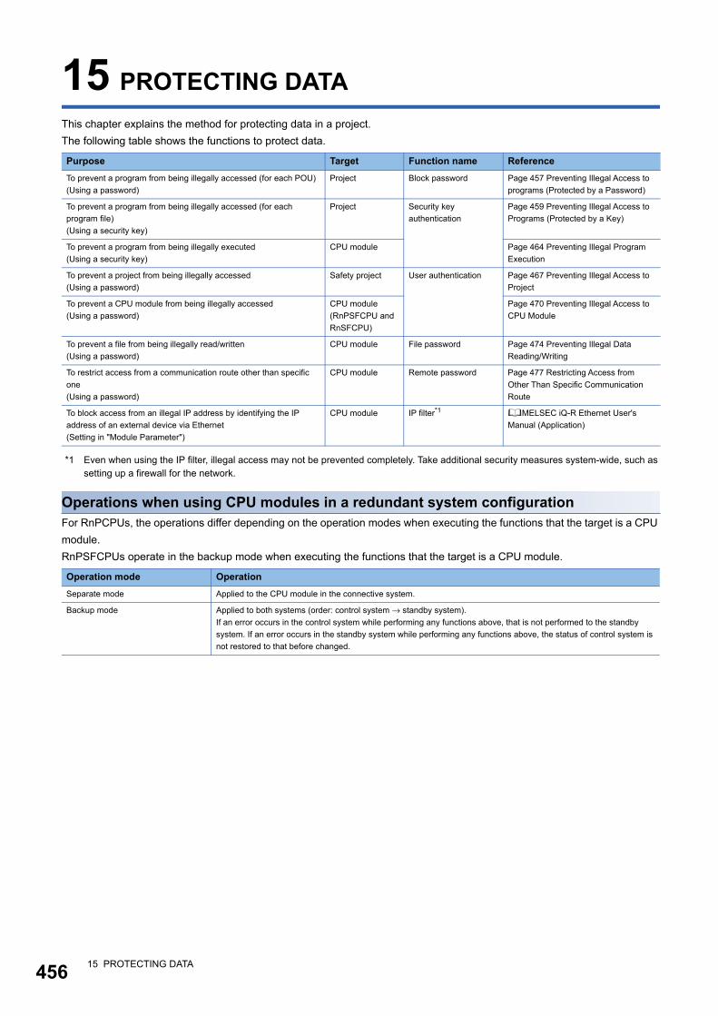
45615 PROTECTING DATA
15 PROTECTING DATA
This chapter explains the method for protecting data in a project.
The following table shows the functions to protect data.
*1 Even when using the IP filter, illegal access may not be prevented completely. Take additional security measures system-wide, such as setting up a firewall for the network.
Operations when using CPU modules in a redundant system configurationFor RnPCPUs, the operations differ depending on the operation modes when executing the functions that the target is a CPU
module.
RnPSFCPUs operate in the backup mode when executing the functions that the target is a CPU module.
Purpose Target Function name Reference
To prevent a program from being illegally accessed (for each POU)
(Using a password)
Project Block password Page 457 Preventing Illegal Access to
programs (Protected by a Password)
To prevent a program from being illegally accessed (for each
program file)
(Using a security key)
Project Security key
authentication
Page 459 Preventing Illegal Access to
Programs (Protected by a Key)
To prevent a program from being illegally executed
(Using a security key)
CPU module Page 464 Preventing Illegal Program
Execution
To prevent a project from being illegally accessed
(Using a password)
Safety project User authentication Page 467 Preventing Illegal Access to
Project
To prevent a CPU module from being illegally accessed
(Using a password)
CPU module
(RnPSFCPU and
RnSFCPU)
Page 470 Preventing Illegal Access to
CPU Module
To prevent a file from being illegally read/written
(Using a password)
CPU module File password Page 474 Preventing Illegal Data
Reading/Writing
To restrict access from a communication route other than specific
one
(Using a password)
CPU module Remote password Page 477 Restricting Access from
Other Than Specific Communication
Route
To block access from an illegal IP address by identifying the IP
address of an external device via Ethernet
(Setting in "Module Parameter")
CPU module IP filter*1 MELSEC iQ-R Ethernet User's
Manual (Application)
Operation mode Operation
Separate mode Applied to the CPU module in the connective system.
Backup mode Applied to both systems (order: control system → standby system).
If an error occurs in the control system while performing any functions above, that is not performed to the standby
system. If an error occurs in the standby system while performing any functions above, the status of control system is
not restored to that before changed.

15 PROTECTING DATA15.1 Preventing Illegal Access to programs (Protected by a Password) 457
15
15.1 Preventing Illegal Access to programs (Protected by a Password)
To prevent illegal access to a program (in a POU unit) by setting a password, use the Block password function.
Block password functionThe password registered to a POU restricts the operations.
• Restricted operation: Accessing to a POU (The operations will be allowed while the program is authenticated even if a
password has been registered.)
• Target data: Program blocks, function blocks, and functions (Page 82 Data configuration)
Procedure for using the block password function
Procedure for making a security enable1. Set a block password to a POU. (Page 457 Setting block password)
2. Save a project. (Page 105 Saving a project)
After closing a project in which the block password is set, the POU cannot be accessed when the file is opened next time.
Procedure for making locked POUs accessible • Authenticate the block password set to the POU. (Page 458 Authenticating a block password)
The POU can be accessed while the project is open.
Setting block passwordRegister a block password to POUs.
Window
• [Project] [Security] [Block Password Setting]
• Select a POU on the "Navigation" window, then right-click and select [Block Password Setting] from the shortcut menu.

45815 PROTECTING DATA15.1 Preventing Illegal Access to programs (Protected by a Password)
Registering/changing a block passwordRegister/change a block password to POUs.
Operating procedure
1. Select a POU to set a block password and click the [Register]/[Change] button.
2. Enter each item on the "Register Password" screen/"Change Password" screen, and click the [OK] button.
When a block password is registered, the icons in the "Navigation" window will be displayed as shown below.
By selecting multiple POUs in "Data Name", a block password can be registered to the selected POUs in
batch.
Authenticating a block passwordUnlock the POU temporarily by authenticating the password which has been set to it.
Once the password is authenticated, the data can be accessed until the project is closed.
Operating procedure
1. Select the POU to authenticate the block password, and click the [Authentication] button.
2. Enter the password on the "Password Authentication" screen, and click the [OK] button.
Deleting a block passwordDelete the block password registered to a POU.
Operating procedure
1. Select the POU to delete the block password, and click the [Delete] button.
2. Enter the password on the "Delete Password" screen, and click the [OK] button.
Registered Authenticated
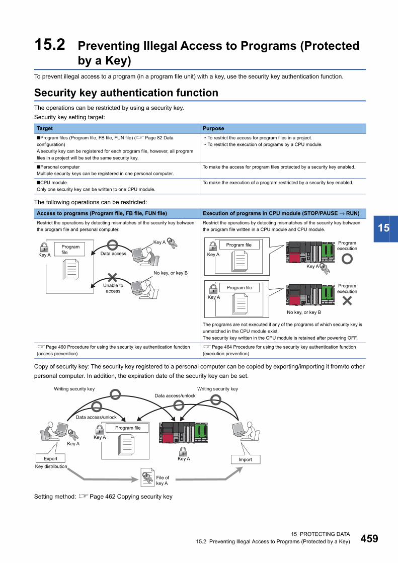
15 PROTECTING DATA15.2 Preventing Illegal Access to Programs (Protected by a Key) 459
15
15.2 Preventing Illegal Access to Programs (Protected by a Key)
To prevent illegal access to a program (in a program file unit) with a key, use the security key authentication function.
Security key authentication functionThe operations can be restricted by using a security key.
Security key setting target:
The following operations can be restricted:
Copy of security key: The security key registered to a personal computer can be copied by exporting/importing it from/to other
personal computer. In addition, the expiration date of the security key can be set.
Setting method: Page 462 Copying security key
Target Purpose
■Program files (Program file, FB file, FUN file) (Page 82 Data
configuration)
A security key can be registered for each program file, however, all program
files in a project will be set the same security key.
• To restrict the access for program files in a project.
• To restrict the execution of programs by a CPU module.
■Personal computer
Multiple security keys can be registered in one personal computer.
To make the access for program files protected by a security key enabled.
■CPU module
Only one security key can be written to one CPU module.
To make the execution of a program restricted by a security key enabled.
Access to programs (Program file, FB file, FUN file) Execution of programs in CPU module (STOP/PAUSE → RUN)
Restrict the operations by detecting mismatches of the security key between
the program file and personal computer.
Restrict the operations by detecting mismatches of the security key between
the program file written in a CPU module and CPU module.
The programs are not executed if any of the programs of which security key is
unmatched in the CPU module exist.
The security key written in the CPU module is retained after powering OFF.
Page 460 Procedure for using the security key authentication function
(access prevention)
Page 464 Procedure for using the security key authentication function
(execution prevention)
Key AProgram file Data accessKey A
No key, or key B
Unable to access
Program file
Key A
Program file
Key A
No key, or key B
Program execution
Key A
Program execution
Writing security key Writing security keyData access/unlock
Data access/unlock
Program file
Key AKey A
Export Key A ImportKey distribution
File of key A
46015 PROTECTING DATA15.2 Preventing Illegal Access to Programs (Protected by a Key)
Precautions
The security key registered to a personal computer is not deleted even if GX Works3 is uninstalled. Delete the security key on
the "Security Key Management" screen.
Procedure for using the security key authentication function (access prevention)
Procedure for making a security enable1. Create a security key. (Page 461 Creating/deleting security key)
2. Register the security key in a program file. (Page 463 Registering a security key in a program file)
3. Save a project. (Page 105 Saving a project)
A personal computer which does not have the same security key as the one registered in the project cannot be accessed.
Procedure for making locked program files accessible1. Copy the same security key as the saved program file. (Page 462 Exporting a security key)
2. Register the security key in a personal computer from which a program file is to be accessed. (Page 462 Import)
3. Open the program file. (Page 87 Opening a project)
A program file can be accessed when the security key between the program file and a personal computer is consistent.
The operations shown above are not required for the personal computer with which a security key is registered in a program
file. However, the above operations are required when the security key is deleted.

15 PROTECTING DATA15.2 Preventing Illegal Access to Programs (Protected by a Key) 461
15
Creating/deleting security keyCreate/delete security keys on the "Security Key Management" screen.
Window
[Project] [Security] [Security Key Management]
Displayed items
Creating a security keyCreate a security key and register it to the personal computer.
Number of security key registration: The security keys can be created for each logon user. Up to 128 security keys combined
with the created security keys and imported ones can be registered for each logon user.
Operating procedure
1. Click the [New] button.
2. Enter the security key name on the "New Security Key" screen and click the [OK] button.
Deleting a security keyDelete the security key registered to the personal computer.
If the security key used to lock the project is deleted, the locked data in the project cannot be accessed/edited.
After deleting the security key, even when the security key with the same name as the deleted one is recreated, it will not be
the same security key as the deleted one. Take extra caution when deleting a security key.
Operating procedure
1. Select the security key to be deleted on the "Security Key Management" screen.
2. Click the [Delete] button.
Item Description
Creation Date Displays the registered date of the security key.
Expiration Date Displays the expiration date set when the security key was exported.
Export Displays "Enable/Disable" that indicates whether re-exporting the security key is enabled/disabled set when the security key
was exported.
Protection Target Selection Displays "Enable/Disable" that indicates whether selecting data to be protected is enabled/disabled set when the security key
was exported.
Key Registration to CPU Displays "Enable/Disable" that indicates whether writing data to CPU module is enabled/disabled set when the security key
was exported.
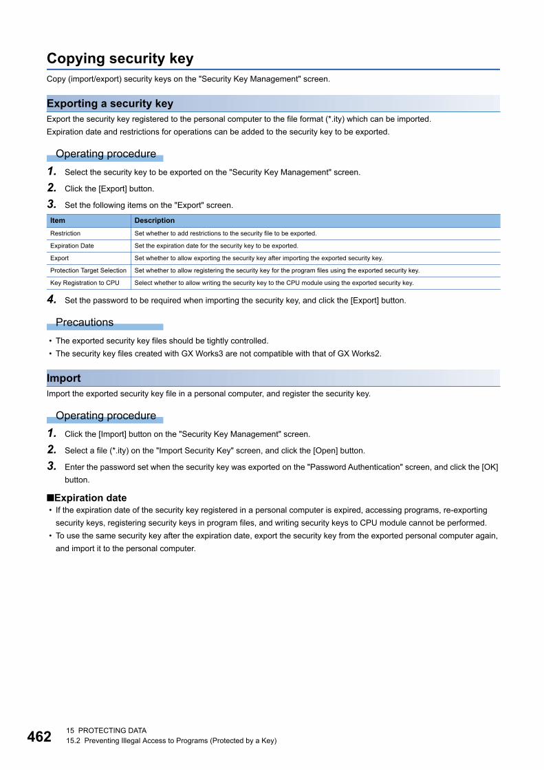
46215 PROTECTING DATA15.2 Preventing Illegal Access to Programs (Protected by a Key)
Copying security keyCopy (import/export) security keys on the "Security Key Management" screen.
Exporting a security keyExport the security key registered to the personal computer to the file format (*.ity) which can be imported.
Expiration date and restrictions for operations can be added to the security key to be exported.
Operating procedure
1. Select the security key to be exported on the "Security Key Management" screen.
2. Click the [Export] button.
3. Set the following items on the "Export" screen.
4. Set the password to be required when importing the security key, and click the [Export] button.
Precautions
• The exported security key files should be tightly controlled.
• The security key files created with GX Works3 are not compatible with that of GX Works2.
ImportImport the exported security key file in a personal computer, and register the security key.
Operating procedure
1. Click the [Import] button on the "Security Key Management" screen.
2. Select a file (*.ity) on the "Import Security Key" screen, and click the [Open] button.
3. Enter the password set when the security key was exported on the "Password Authentication" screen, and click the [OK]
button.
■Expiration date • If the expiration date of the security key registered in a personal computer is expired, accessing programs, re-exporting
security keys, registering security keys in program files, and writing security keys to CPU module cannot be performed.
• To use the same security key after the expiration date, export the security key from the exported personal computer again,
and import it to the personal computer.
Item Description
Restriction Set whether to add restrictions to the security file to be exported.
Expiration Date Set the expiration date for the security key to be exported.
Export Set whether to allow exporting the security key after importing the exported security key.
Protection Target Selection Set whether to allow registering the security key for the program files using the exported security key.
Key Registration to CPU Select whether to allow writing the security key to the CPU module using the exported security key.
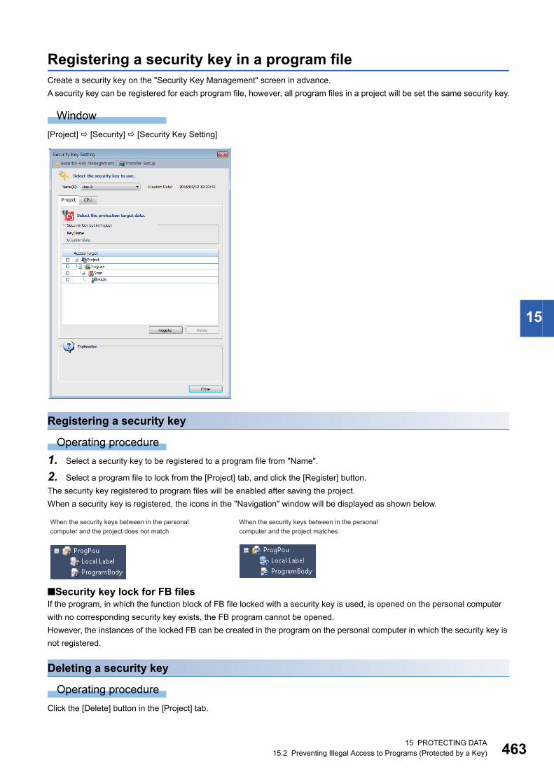
15 PROTECTING DATA15.2 Preventing Illegal Access to Programs (Protected by a Key) 463
15
Registering a security key in a program fileCreate a security key on the "Security Key Management" screen in advance.
A security key can be registered for each program file, however, all program files in a project will be set the same security key.
Window
[Project] [Security] [Security Key Setting]
Registering a security key
Operating procedure
1. Select a security key to be registered to a program file from "Name".
2. Select a program file to lock from the [Project] tab, and click the [Register] button.
The security key registered to program files will be enabled after saving the project.
When a security key is registered, the icons in the "Navigation" window will be displayed as shown below.
■Security key lock for FB files If the program, in which the function block of FB file locked with a security key is used, is opened on the personal computer
with no corresponding security key exists, the FB program cannot be opened.
However, the instances of the locked FB can be created in the program on the personal computer in which the security key is
not registered.
Deleting a security key
Operating procedure
Click the [Delete] button in the [Project] tab.
When the security keys between in the personal computer and the project does not match
When the security keys between in the personal computer and the project matches
46415 PROTECTING DATA15.3 Preventing Illegal Program Execution
15.3 Preventing Illegal Program ExecutionTo prevent an illegal execution for programs (STOP/PAUSE → RUN) written in a CPU module, use the security key
authentication function.
For details on the security key authentication function, refer to the following section.
Page 459 Security key authentication function
Procedure for using the security key authentication function (execution prevention)
Procedure for making a security enable1. Create a security key. (Page 461 Creating/deleting security key)
2. Register the security key in the program file to be written to the CPU module. (Page 463 Registering a security key
in a program file)
3. Write the program files to the CPU module. (Page 392 Writing data to a programmable controller)
A CPU module which does not have the same security key as the one registered in the program file cannot execute the
programs.
Procedure for making locked programs executable1. Set the Specify Connection Destination to access to the CPU module. (Page 371 Specification of Connection
Destination)
2. Write the same security key as the protected program file to the CPU module. (Page 465 Writing/deleting security
key to/from CPU module)
The programs can be executed unless otherwise the security key set to the program file or CPU module is changed.

15 PROTECTING DATA15.3 Preventing Illegal Program Execution 465
15
Writing/deleting security key to/from CPU moduleBy writing the same security key as a project to the CPU module, the execution of the programs can be permitted.
A security key can be written to any of the following.
• CPU module
• Cassette (extended SRAM cassette*1 or battery-less option cassette*2)
*1 An extended SRAM cassette cannot be attached to R00CPUs, R01CPUs, R02CPUs, FX5CPUs, and remote head modules.*2 A battery-less option cassette cannot be attached to R00CPUs, R01CPUs, R02CPUs, RnPCPUs, RnPSFCPUs, RnSFCPUs,
FX5CPUs, and remote head modules.
Additionally, one security key can be written to multiple CPU modules.
When writing a security key, create a key on the "Security Key Management" screen and connect a personal computer and a
CPU module in advance. (Only when a CPU module is in STOP state, a security key can be written and deleted.)
For a safety project, the security key can be written/deleted when the safety operation mode of a CPU module is in the test
mode.
Window
[Project] [Security] [Security Key Setting]
46615 PROTECTING DATA15.3 Preventing Illegal Program Execution
Writing security key
Operating procedure
1. Select the security key to be written from "Name".
2. Select the target to be written in the [CPU] tab, and click the [Write] button.
■When a security key is written to a cassetteA security key can be succeeded to the replaced CPU module only by replacing a cassette (extended SRAM cassette or
battery-less option cassette). Writing the security key from the personal computer in which the security key is registered is
unnecessary.
■Write target of a security key in a multiple CPU systemIn a multiple CPU system, write a security key to each CPU module. Additionally, the security key set in CPU No.1 can be
used in CPU No.2 to CPU No.4.
■Operations when using CPU modules in a redundant system configurationWhen "Write to CPUs of both systems" is selected for an RnPCPU (redundant mode), the operations differ depending on the
operation modes.
When "Write to CPUs of both systems" is selected for an RnPSFCPU, the module operates in the backup mode.
Deleting a security keyThe security key written in the CPU module can be deleted on the personal computer in which the security key is not
registered.
However, the program of which security key is registered in the CPU module exists, the security key cannot be deleted.
Operating procedure
Select the security key to be deleted from the [CPU] tab, then click the [Delete] button.
Operation mode Operation
Separate mode Applied to the CPU module in the connective system.
Backup mode Applied to both systems (order: control system → standby system).
If an error occurs in the control system during writing, that is not performed to the standby system. If an error occurs in
the standby system during writing, the status of control system is not restored to that before changed.

15 PROTECTING DATA15.4 Preventing Illegal Access to Project 467
15
15.4 Preventing Illegal Access to ProjectTo prevent an illegal access to a safety project from the users with no authority, use the User Authentication function.
Only RnPSFCPUs and RnSFCPUs support the function.
User Authentication functionThe operations can be restricted by registering a user/password in a project and a CPU module.
The following operations can be restricted:
The user information registered in a CPU module needs to match with the user information of a project.
Access levelAccess level is an operation privilege that is given to a user who logs on to a project and/or CPU module.
The operations allowed for each access level are as follows.
Access to project Access to CPU module
To access to a project, logging on with the registered user information (user
name/password) is required.
To access to a CPU module, logging on with the registered user information
(user name/password) is required.
Page 468 Procedure for using the user authentication function (access
prevention)
Page 471 Procedure for using the user authentication function (access
prevention)
Access level Operation authority
Higher
Lower
Administrators
(Administrator level)
All operations including user management of projects and CPU modules
Developers
(Developer level)
Operations except for user management and security setting
Writing of data on a standard program and safety program to a CPU module
Assistant
Developers
(Developer level)
Operations except for user management, security setting, writing of safety programs and parameters
Writing of data on a standard program to a CPU module
Users
(Operator level)
Referencing of a project and monitoring of CPU modules
Data access
Data access
User information
Project
Logged-on user
Unlogged-on user
Reading/writing
Reading/writing
User information
programmable controller
Logged-on user
Unlogged-on user
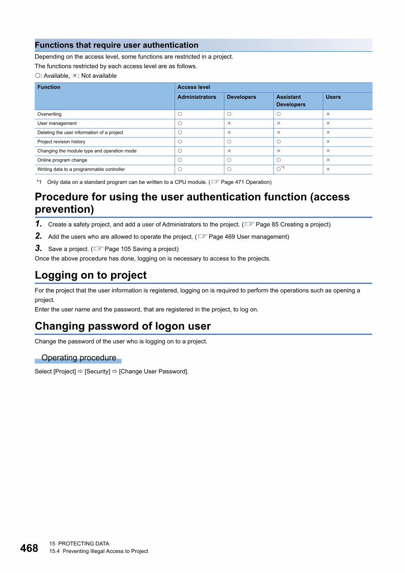
46815 PROTECTING DATA15.4 Preventing Illegal Access to Project
Functions that require user authenticationDepending on the access level, some functions are restricted in a project.
The functions restricted by each access level are as follows.
: Available, : Not available
*1 Only data on a standard program can be written to a CPU module. (Page 471 Operation)
Procedure for using the user authentication function (access prevention)1. Create a safety project, and add a user of Administrators to the project. (Page 85 Creating a project)
2. Add the users who are allowed to operate the project. (Page 469 User management)
3. Save a project. (Page 105 Saving a project)
Once the above procedure has done, logging on is necessary to access to the projects.
Logging on to projectFor the project that the user information is registered, logging on is required to perform the operations such as opening a
project.
Enter the user name and the password, that are registered in the project, to log on.
Changing password of logon userChange the password of the user who is logging on to a project.
Operating procedure
Select [Project] [Security] [Change User Password].
Function Access level
Administrators Developers Assistant Developers
Users
Overwriting
User management
Deleting the user information of a project
Project revision history
Changing the module type and operation mode
Online program change
Writing data to a programmable controller *1

15 PROTECTING DATA15.4 Preventing Illegal Access to Project 469
15
User managementManage the user registration status of a project to which the security is set.
A User of the Administrators can change all user's passwords.
Window
[Project] [Security] [User Management]
Adding/changing usersAdd/change a user information (user name/password) to/from a project.
Operating procedure
1. Click the [Add]/[Change] button.
2. Set each item on the "Add New User" screen/"Change User" screen, and click the [OK] button.
Deleting user informationDelete the user information registered in a project.
Operating procedure
Select the user name to be deleted, and click the [Delete] button.
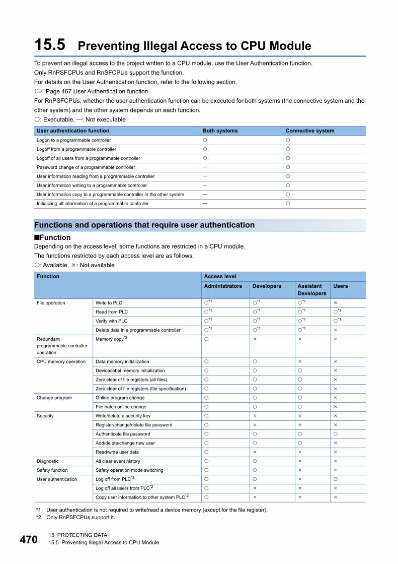
47015 PROTECTING DATA15.5 Preventing Illegal Access to CPU Module
15.5 Preventing Illegal Access to CPU ModuleTo prevent an illegal access to the project written to a CPU module, use the User Authentication function.
Only RnPSFCPUs and RnSFCPUs support the function.
For details on the User Authentication function, refer to the following section.
Page 467 User Authentication function
For RnPSFCPUs, whether the user authentication function can be executed for both systems (the connective system and the
other system) and the other system depends on each function.
: Executable, : Not executable
Functions and operations that require user authentication
■FunctionDepending on the access level, some functions are restricted in a CPU module.
The functions restricted by each access level are as follows.
: Available, : Not available
*1 User authentication is not required to write/read a device memory (except for the file register).*2 Only RnPSFCPUs support it.
User authentication function Both systems Connective system
Logon to a programmable controller
Logoff from a programmable controller
Logoff of all users from a programmable controller
Password change of a programmable controller
User information reading from a programmable controller
User information writing to a programmable controller
User information copy to a programmable controller in the other system
Initializing all information of a programmable controller
Function Access level
Administrators Developers Assistant Developers
Users
File operation Write to PLC *1 *1 *1
Read from PLC *1 *1 *1 *1
Verify with PLC *1 *1 *1 *1
Delete data in a programmable controller *1 *1 *1
Redundant
programmable controller
operation
Memory copy*2
CPU memory operation Data memory initialization
Device/label memory initialization
Zero clear of file registers (all files)
Zero clear of file registers (file specification)
Change program Online program change
File batch online change
Security Write/delete a security key
Register/change/delete file password
Authenticate file password
Add/delete/change new user
Read/write user data
Diagnostic All clear event history
Safety function Safety operation mode switching
User authentication Log off from PLC*2
Log off all users from PLC*2
Copy user information to other system PLC*2
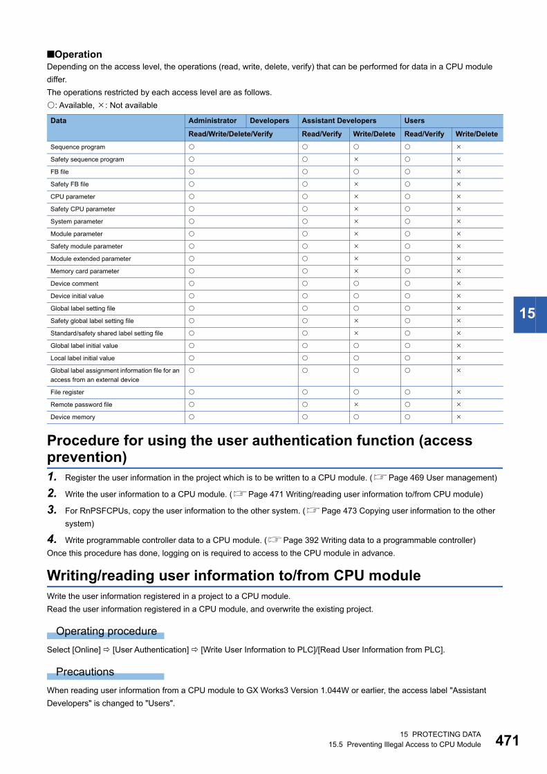
15 PROTECTING DATA15.5 Preventing Illegal Access to CPU Module 471
15
■OperationDepending on the access level, the operations (read, write, delete, verify) that can be performed for data in a CPU module
differ.
The operations restricted by each access level are as follows.
: Available, : Not available
Procedure for using the user authentication function (access prevention)1. Register the user information in the project which is to be written to a CPU module. (Page 469 User management)
2. Write the user information to a CPU module. (Page 471 Writing/reading user information to/from CPU module)
3. For RnPSFCPUs, copy the user information to the other system. (Page 473 Copying user information to the other
system)
4. Write programmable controller data to a CPU module. (Page 392 Writing data to a programmable controller)
Once this procedure has done, logging on is required to access to the CPU module in advance.
Writing/reading user information to/from CPU moduleWrite the user information registered in a project to a CPU module.
Read the user information registered in a CPU module, and overwrite the existing project.
Operating procedure
Select [Online] [User Authentication] [Write User Information to PLC]/[Read User Information from PLC].
Precautions
When reading user information from a CPU module to GX Works3 Version 1.044W or earlier, the access label "Assistant
Developers" is changed to "Users".
Data Administrator Developers Assistant Developers Users
Read/Write/Delete/Verify Read/Verify Write/Delete Read/Verify Write/Delete
Sequence program
Safety sequence program
FB file
Safety FB file
CPU parameter
Safety CPU parameter
System parameter
Module parameter
Safety module parameter
Module extended parameter
Memory card parameter
Device comment
Device initial value
Global label setting file
Safety global label setting file
Standard/safety shared label setting file
Global label initial value
Local label initial value
Global label assignment information file for an
access from an external device
File register
Remote password file
Device memory
47215 PROTECTING DATA15.5 Preventing Illegal Access to CPU Module
Logging on to CPU moduleLogging on is required to access to the CPU module in which the user information is registered.
Enter the user name and the password, that are registered in the CPU module, to log on.
For RnPSFCPUs, users can log on to both systems or the connective system.
After logging on, the user is automatically logged off if the CPU module has no access within the logoff judgment time or user
information are written.
The logoff judgment time differs depending on the firmware version of a CPU module.
For details, refer to the following manual.
MELSEC iQ-R CPU Module User's Manual (Application)
Operating procedure
1. Select [Online] [User Authentication] [Log on to PLC]
2. Set each item on the "User Authentication" screen and click the [OK] button.
■When a user name and a password used in the User Authentication function are lostInitialize the user information, the programmable controller data, and the security keys in the CPU module by performing the
following operation.
• Select [Online] [User Authentication] [Initialize all PLC Data]
Rewrite the user information, the programmable controller data, and security keys (optional) to the CPU module after
initialization.
If the power of the CPU is turned OFF → ON or the CPU module was reset, the allocation for the device/label memory is back
to the initial status. (Each area has the default capacity.)
Changing passwordChange the password for the CPU module to the same password set to a project.
Operating procedure
Select [Online] [User Authentication] [Change the Password of PLC]
Authentication destination setting in the online functionWhen executing the online function, select either both systems or the connective system as the target of the user
authentication.
Only RnPSFCPUs support it.
Operating procedure
Select [Online] [User Authentication] [Authentication Destination] [Both Systems]/[Connective System].
15 PROTECTING DATA15.5 Preventing Illegal Access to CPU Module 473
15
Logging off from a CPU moduleLog off from a logged on CPU module.
Only RnPSFCPUs support it.
Users can log off from both systems or the connective system.
Logging offLog off from a logged on CPU module.
Operating procedure
Select [Online] [User Authentication] [Log off from PLC].
Logging off all usersLog off all users from a logged on CPU module.
Operating procedure
Select [Online] [User Authentication] [Log off All Users from PLC].
Copying user information to the other systemCopy user information from the CPU module in the connective system to the CPU module in the other system.
Only RnPSFCPUs support it.
Operating procedure
Select [Online] [User Authentication] [Copy User Information to Other System PLC].

47415 PROTECTING DATA15.6 Preventing Illegal Data Reading/Writing
15.6 Preventing Illegal Data Reading/WritingTo prevent data from being illegally read from/written to CPU module, use the File password function.
File password functionBy registering a password to the files in the CPU module, the password authentication is required when reading/writing files.
By selecting "Permanent PLC Lock" on FX5CPU, the operations to read/write a file are prohibited and the protection cannot
be released. The password setting is not required when "Permanent PLC Lock" is selected.
There are two kinds of protections in password and "Permanent PLC Lock"; "Read Protection" and "Write Protection". Both of
them can be set to one file.
Operations that require password authentication by setting a file password
: Required, : Not required
Target file
: Available, : Not available
Online operation Applicability Password to be set
Read to a programmable controller Read-protected password
Write to a programmable controller Write-protected password
Online program change
(Online Program Change, File batch online change)
Write-protected password
Verification with a programmable controller Read-protected password
File password setting (register/change/authentication/deletion) Read-protected password, write-protected password
Delete data in a programmable controller Write-protected password
CPU memory operation (initialization)
File name Availability
System parameter, CPU parameter, module parameter, module extended parameter, memory card parameter
Remote password
Global label setting
Global label assignment information
Global label initial value
Local label initial value
Program file
POU (FB file/FUN file)
File register
Device initial value
Common device comment
Each program device comment
Firmware update prohibited file
Faulty database check file
System file for backing up CPU module data
Backup data file for backing up CPU module data
Device/label data file for backing up CPU module data
System file for the iQ Sensor Solution data backup/restoration function
Backup data file for the iQ Sensor Solution data backup/restoration function
ODBC server setting file
Database path file

15 PROTECTING DATA15.6 Preventing Illegal Data Reading/Writing 475
15
When accessing a file saved in an RCPU from an external device by using a function other than one in GX Works3
A file password is validate when accessing a file using the FTP server function. For details, refer to the following manual.
MELSEC iQ-R Ethernet User's Manual (Application)
A file password is validate when accessing a file using MC protocols. For details, refer to the following manual.
MELSEC iQ-R Serial Communication Module User's Manual(Application)
Precautions
• Keep passwords in a secure place.
If the registered password is lost, or "Permanent PLC Lock" set in FX5CPU is needed to be cancelled, initialize the CPU
module using the CPU Memory Operation function (Page 517 Checking Memory Usage) and write the project to the
CPU module.
• To set "Permanent PLC Lock" to both of "Read Protection" and "Write Protection", configure the both settings at the time of
the first registration. If only one of them was registered, the other cannot be registered later.
Procedure for using the file password function
Procedure for making a security enable1. Set the Specify Connection Destination to access to the CPU module. (Page 371 Specification of Connection
Destination)
2. Set a file password to the file in the CPU module. (Page 476 Setting file password)
If the project in which the file password is set is closed, the file cannot be read and write when GX Works3 is started up next
time.
Procedure for making locked files readable/writable1. Set the Specify Connection Destination to access to the CPU module. (Page 371 Specification of Connection
Destination)
2. Authenticate the file password which has been set to the file in the CPU module. (Page 476 Setting file password)
The file can be write and read while the project is open.
The files can also be read/written when entering a correct password in the "File Password Setting" screen displayed when
accessing a file.

47615 PROTECTING DATA15.6 Preventing Illegal Data Reading/Writing
Setting file passwordWhen registering a file password, connect a personal computer and CPU module in advance.
"Register", "Change", "Authentication", or "Delete" can be set in the "File Password Setting" screen.
For a safety project, a file password can be set when the safety operation mode of a CPU module is in the test mode. Only the
authentication can be performed in the safety mode.
For R00CPU, a file password for an SD memory card cannot be set.
Window
[Project] [Security] [File Password Setting]
Operating procedure
1. Select the target data and click the [Register]/[Change]/[Authentication]/[Delete] button.
2. Set each item on the displayed screen and click the [Completed] button.
3. Click the [Setting] button on the "File Password Setting" screen.
Setting Operation
Register Restrict online operations by setting password to data in the CPU module.
A password set to data in the transfer source memory of boot operation remains set in the transfer destination memory.
Change Change the password set to data in the CPU module.
Authentication Unlock the data in the CPU module temporarily by authenticating the password.
By authenticating a password, the corresponding data in the CPU module can be read/written until the project is closed.
Delete Delete a password set to data in CPU module.
15 PROTECTING DATA15.7 Restricting Access from Other Than Specific Communication Route 477
15
15.7 Restricting Access from Other Than Specific Communication Route
To restrict the access from other than specific communication route, use the Remote password function.
Remote password functionBy setting a password for the CPU module, accessing via the specified RJ71EN71, serial communication module, and built-in
Ethernet CPU is limited.
For the modules that support remote password setting and details on the remote password setting, refer to the user's manual
used.
Procedure for using the remote password function
Procedure for making a security enable1. Set the remote password. (Page 478 Setting remote password)
2. Specify "Remote Password" and write the data to the CPU module. (Page 392 Writing data to a programmable
controller)
The access to the CPU module will be restricted.
Procedure for accessing a locked CPU module Entering the password is required in order to access the CPU module. The access is permitted when the entered password is
correct.
1. Access to the CPU module (writing or reading operation). (Page 392 Writing data to a programmable controller,
Page 398 Reading data from a programmable controller)
2. Unlock the remote password by following the message. (Page 478 Setting remote password)
When the entered password is correct, the access to the CPU module will be permitted.
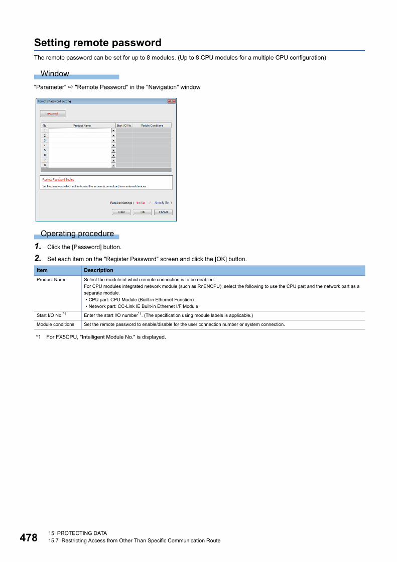
47815 PROTECTING DATA15.7 Restricting Access from Other Than Specific Communication Route
Setting remote passwordThe remote password can be set for up to 8 modules. (Up to 8 CPU modules for a multiple CPU configuration)
Window
"Parameter" "Remote Password" in the "Navigation" window
Operating procedure
1. Click the [Password] button.
2. Set each item on the "Register Password" screen and click the [OK] button.
*1 For FX5CPU, "Intelligent Module No." is displayed.
Item Description
Product Name Select the module of which remote connection is to be enabled.
For CPU modules integrated network module (such as RnENCPU), select the following to use the CPU part and the network part as a
separate module.
• CPU part: CPU Module (Built-in Ethernet Function)
• Network part: CC-Link IE Built-in Ethernet I/F Module
Start I/O No.*1 Enter the start I/O number*1. (The specification using module labels is applicable.)
Module conditions Set the remote password to enable/disable for the user connection number or system connection.
16 MODULE DIAGNOSTIC 479
16
16 MODULE DIAGNOSTIC
This function displays the status of modules, networks, and entire system. At the time of error, it displays the error contents
and the corrective action.
The diagnostic functions of GX Works3 are as follows:
*1 FX5CPUs do not support it.
Function Reference
System monitor*1 Page 480 Module Status Check of a System
Sensor/device monitor Page 482 Sensor/Device Status Check
Module diagnostic Page 483 Module Diagnostic
Network diagnostic Page 485 Ethernet diagnostic
Page 486 CC-Link IE Controller Network diagnostic
Page 488 CC-Link IE Field Network diagnostic
Page 489 CC-Link IE Field Network Basic diagnostic
Page 490 MELSECNET diagnostic
Page 491 CC-Link diagnostic
Page 492 Simple CPU communication diagnostic
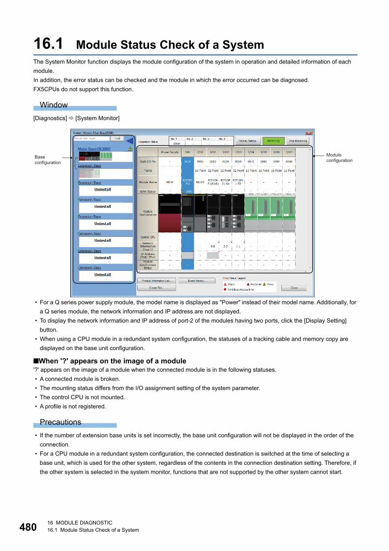
48016 MODULE DIAGNOSTIC16.1 Module Status Check of a System
16.1 Module Status Check of a SystemThe System Monitor function displays the module configuration of the system in operation and detailed information of each
module.
In addition, the error status can be checked and the module in which the error occurred can be diagnosed.
FX5CPUs do not support this function.
Window
[Diagnostics] [System Monitor]
• For a Q series power supply module, the model name is displayed as "Power" instead of their model name. Additionally, for
a Q series module, the network information and IP address are not displayed.
• To display the network information and IP address of port-2 of the modules having two ports, click the [Display Setting]
button.
• When using a CPU module in a redundant system configuration, the statuses of a tracking cable and memory copy are
displayed on the base unit configuration.
■When '?' appears on the image of a module'?' appears on the image of a module when the connected module is in the following statuses.
• A connected module is broken.
• The mounting status differs from the I/O assignment setting of the system parameter.
• The control CPU is not mounted.
• A profile is not registered.
Precautions
• If the number of extension base units is set incorrectly, the base unit configuration will not be displayed in the order of the
connection.
• For a CPU module in a redundant system configuration, the connected destination is switched at the time of selecting a
base unit, which is used for the other system, regardless of the contents in the connection destination setting. Therefore, if
the other system is selected in the system monitor, functions that are not supported by the other system cannot start.
Module configuration
Base configuration
16 MODULE DIAGNOSTIC16.1 Module Status Check of a System 481
16
Automatic diagnostic functionThis function starts up the System Monitor function automatically when connecting CPU module and a personal computer by
USB connection.
Set whether to start up automatically on the task tray.
Check of the module firmware version and product informationThe firmware version and product information can be checked in the "Product Information List" screen which is displayed after
[Product Information List] button is clicked.
File creation functionInformation displayed on the system monitor can be output to a CSV file.

48216 MODULE DIAGNOSTIC16.2 Sensor/Device Status Check
16.2 Sensor/Device Status CheckThe status and the current value of a sensor/device connected to a network can be displayed.
Supported network: Ethernet (CPU module), AnyWireASLINK*1, CC-Link IE Field Network, CC-Link
*1 Projects used for FX5CPUs are not supported.
Window
1. Select [Diagnostics] [Sensor/Device Monitor].
2. Select a master module or master station in the "Module Selection (Sensor/Device Monitor)" screen, and click the [OK]
button.
The following image is a screen example displayed when selecting a master station in CC-Link IE Field Network.
Operating procedure
Select a target device supporting iQSS to be monitored in the list of stations (1) or the device map area (2) on the sensor/
device monitor screen.
The status of a selected device supporting iQSS is displayed in the "Monitoring Information" window (3).
• Check the error status of a device supporting iQSS by using the network diagnostic function.
• The sensor/device monitor function reads a large volume of information from a CPU module at once.
Therefore, the processing speed of the sensor/device monitor function may decrease depending on the set
communication route.
(1)
(2)
(3)
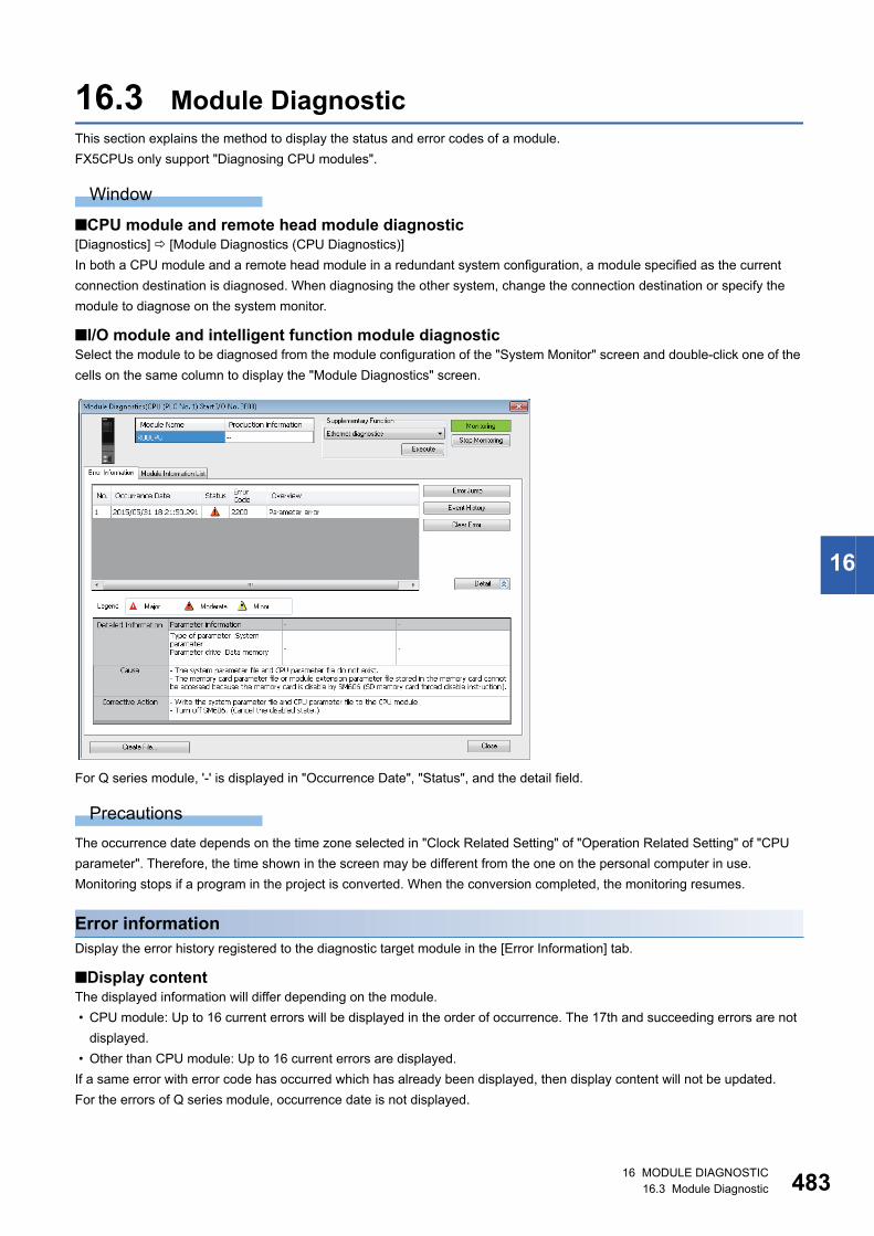
16 MODULE DIAGNOSTIC16.3 Module Diagnostic 483
16
16.3 Module DiagnosticThis section explains the method to display the status and error codes of a module.
FX5CPUs only support "Diagnosing CPU modules".
Window
■CPU module and remote head module diagnostic[Diagnostics] [Module Diagnostics (CPU Diagnostics)]
In both a CPU module and a remote head module in a redundant system configuration, a module specified as the current
connection destination is diagnosed. When diagnosing the other system, change the connection destination or specify the
module to diagnose on the system monitor.
■I/O module and intelligent function module diagnosticSelect the module to be diagnosed from the module configuration of the "System Monitor" screen and double-click one of the
cells on the same column to display the "Module Diagnostics" screen.
For Q series module, '-' is displayed in "Occurrence Date", "Status", and the detail field.
Precautions
The occurrence date depends on the time zone selected in "Clock Related Setting" of "Operation Related Setting" of "CPU
parameter". Therefore, the time shown in the screen may be different from the one on the personal computer in use.
Monitoring stops if a program in the project is converted. When the conversion completed, the monitoring resumes.
Error informationDisplay the error history registered to the diagnostic target module in the [Error Information] tab.
■Display contentThe displayed information will differ depending on the module.
• CPU module: Up to 16 current errors will be displayed in the order of occurrence. The 17th and succeeding errors are not
displayed.
• Other than CPU module: Up to 16 current errors are displayed.
If a same error with error code has occurred which has already been displayed, then display content will not be updated.
For the errors of Q series module, occurrence date is not displayed.

48416 MODULE DIAGNOSTIC16.3 Module Diagnostic
■Error jumpClick the [Error Jump] button to jump to the selected error item.
Target items are a program, function block, and each parameter.
A jump to parameters is available for the items supported by the Error jump function. The supported items differ depending on
the module.
For an inline structured text on ladder editor, the cursor will jump to the head line of the inline structured text regardless of the
line that error occurs.
Precautions
In the following conditions, an error may not be found at the error jump destination.
• When the open project does not match with the data on the CPU module.
• When diagnosing programmable controller other than the one set as a connection destination in the project.
Ex.
When selecting a module from the "CC-Link IE Control Diagnostics" screen and activating the System Monitor function, and
activating the "Module Diagnostics" screen from the activated "System Monitor" screen.
■Event historyPage 493 Error History/Operation History Check
■Clearing errorsAfter the errors displayed on the module diagnostic screen are cleared, click the [Clear Error] button to clear the error status of
the module. (The LED that indicates error status on the front of the module turns OFF.)
The error content are also deleted from the list of the error information.
Module information listThe current LED information and switch information of a target module are displayed in the [Module Information List] tab.

16 MODULE DIAGNOSTIC16.4 Network Diagnostic 485
16
16.4 Network DiagnosticThis section explains the method to diagnose various networks.
Ethernet diagnosticCheck the status of each connection, status of each protocol, and connection status.
For details, refer to the following manuals.
MELSEC iQ-R Ethernet User's Manual (Application)
MELSEC iQ-F FX5 User's Manual (Ethernet Communication)
Window
[Diagnostics] [Ethernet Diagnostics]
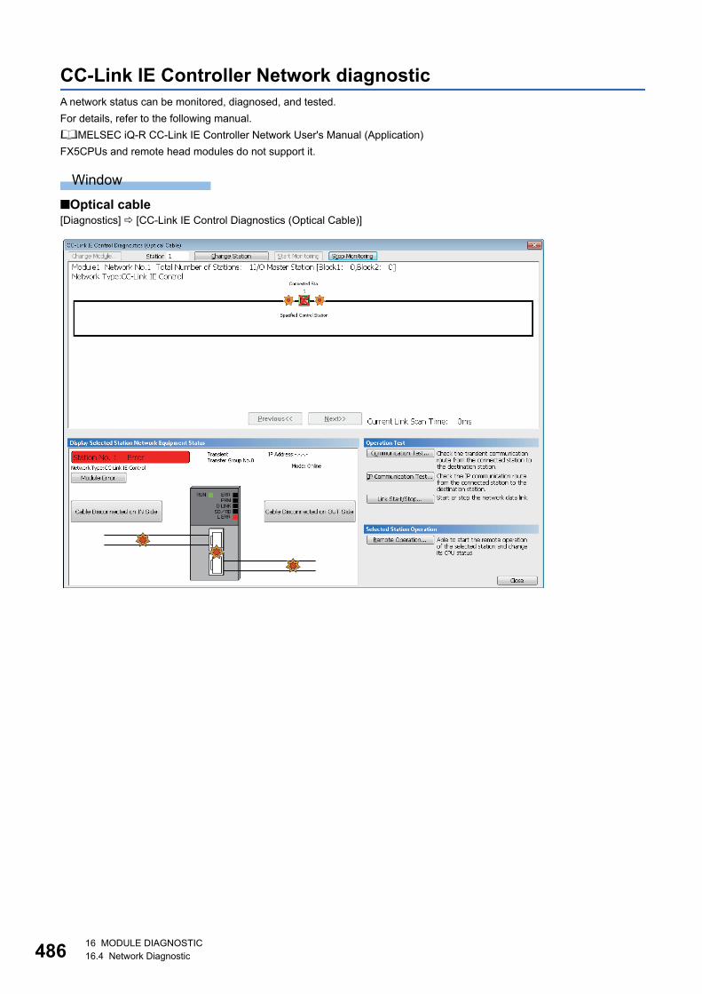
48616 MODULE DIAGNOSTIC16.4 Network Diagnostic
CC-Link IE Controller Network diagnosticA network status can be monitored, diagnosed, and tested.
For details, refer to the following manual.
MELSEC iQ-R CC-Link IE Controller Network User's Manual (Application)
FX5CPUs and remote head modules do not support it.
Window
■Optical cable[Diagnostics] [CC-Link IE Control Diagnostics (Optical Cable)]
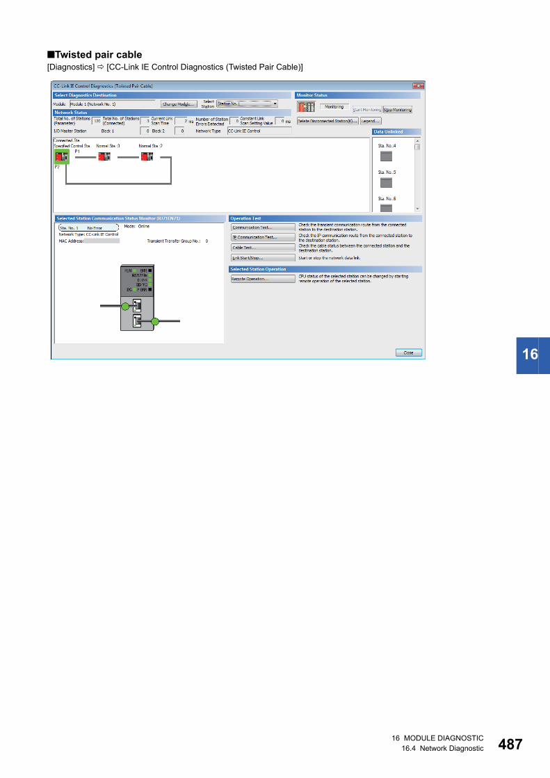
16 MODULE DIAGNOSTIC16.4 Network Diagnostic 487
16
■Twisted pair cable[Diagnostics] [CC-Link IE Control Diagnostics (Twisted Pair Cable)]

48816 MODULE DIAGNOSTIC16.4 Network Diagnostic
CC-Link IE Field Network diagnosticA network status can be monitored, diagnosed, and tested.
For details, refer to the following manual.
MELSEC iQ-R CC-Link IE Field Network User's Manual (Application)
MELSEC iQ-F FX5 User's Manual (Application)
Window
[Diagnostics] [CC-Link IE Field Diagnostics]
■Displaying product informationThe product information of a module can be checked by the following operation.
• Select and right-click a module, and select [Production Information] from the shortcut menu.
Note that this function cannot be used when a selected module does not support displaying the product information or an error
occurs on a connected station.
For details, refer to the manual of each module.
■Displaying error historyAn error history in a slave station can be checked by the following operation.
• Select and right-click a module, and select [Error History] from the shortcut menu.
This function is available only when a remote device station or intelligent device station which can read error history is
selected.
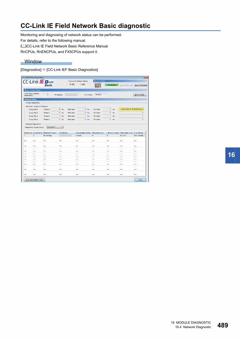
16 MODULE DIAGNOSTIC16.4 Network Diagnostic 489
16
CC-Link IE Field Network Basic diagnosticMonitoring and diagnosing of network status can be performed.
For details, refer to the following manual.
CC-Link IE Field Network Basic Reference Manual
RnCPUs, RnENCPUs, and FX5CPUs support it.
Window
[Diagnostics] [CC-Link IEF Basic Diagnostics]
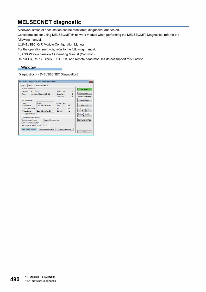
49016 MODULE DIAGNOSTIC16.4 Network Diagnostic
MELSECNET diagnosticA network status of each station can be monitored, diagnosed, and tested.
Considerations for using MELSECNET/H network module when performing the MELSECNET Diagnostic , refer to the
following manual.
MELSEC iQ-R Module Configuration Manual
For the operation methods, refer to the following manual.
GX Works2 Version 1 Operating Manual (Common)
RnPCPUs, RnPSFCPUs, FX5CPUs, and remote head modules do not support this function.
Window
[Diagnostics] [MELSECNET Diagnostics]

16 MODULE DIAGNOSTIC16.4 Network Diagnostic 491
16
CC-Link diagnosticA network status of each station can be monitored, diagnosed, and tested.
For details, refer to the following manual.
MELSEC iQ-R CC-Link System Master/Local Module User's Manual (Application)
MELSEC iQ-F FX5 User's Manual (CC-Link)
Window
[Diagnostics] [CC-Link Diagnostics]

49216 MODULE DIAGNOSTIC16.4 Network Diagnostic
Simple CPU communication diagnosticA network status can be diagnosed.
For details, refer to the following manual.
MELSEC iQ-R Ethernet User's Manual (Application)
RnCPUs and RnENCPUs support this function.
Window
[Diagnostics] [Simple CPU Communication Diagnostics]
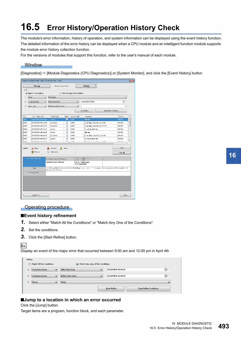
16 MODULE DIAGNOSTIC16.5 Error History/Operation History Check 493
16
16.5 Error History/Operation History CheckThe module's error information, history of operation, and system information can be displayed using the event history function.
The detailed information of the error history can be displayed when a CPU module and an intelligent function module supports
the module error history collection function.
For the versions of modules that support this function, refer to the user's manual of each module.
Window
[Diagnostics] [Module Diagnostics (CPU Diagnostics)] or [System Monitor], and click the [Event History] button
Operating procedure
■Event history refinement
1. Select either "Match All the Conditions" or "Match Any One of the Conditions".
2. Set the conditions.
3. Click the [Start Refine] button.
Ex.
Display an event of the major error that occurred between 9:00 am and 12:00 pm in April 4th
■Jump to a location in which an error occurredClick the [Jump] button.
Target items are a program, function block, and each parameter.

49416 MODULE DIAGNOSTIC16.5 Error History/Operation History Check
■Event history clearingClick the [Clear All] button.
All event histories are deleted.
Precautions
• The occurrence date on the event history depends the time zone selected in "Clock Related Setting" of "Operation Related
Setting" of "CPU parameter". Therefore, the time shown in the screen may be different from the one on the personal
computer in use.
• When writing/reading data to/from the CPU module for which a remote password has been set, the event, success to lock/
unlock the remote password, is registered more than once.
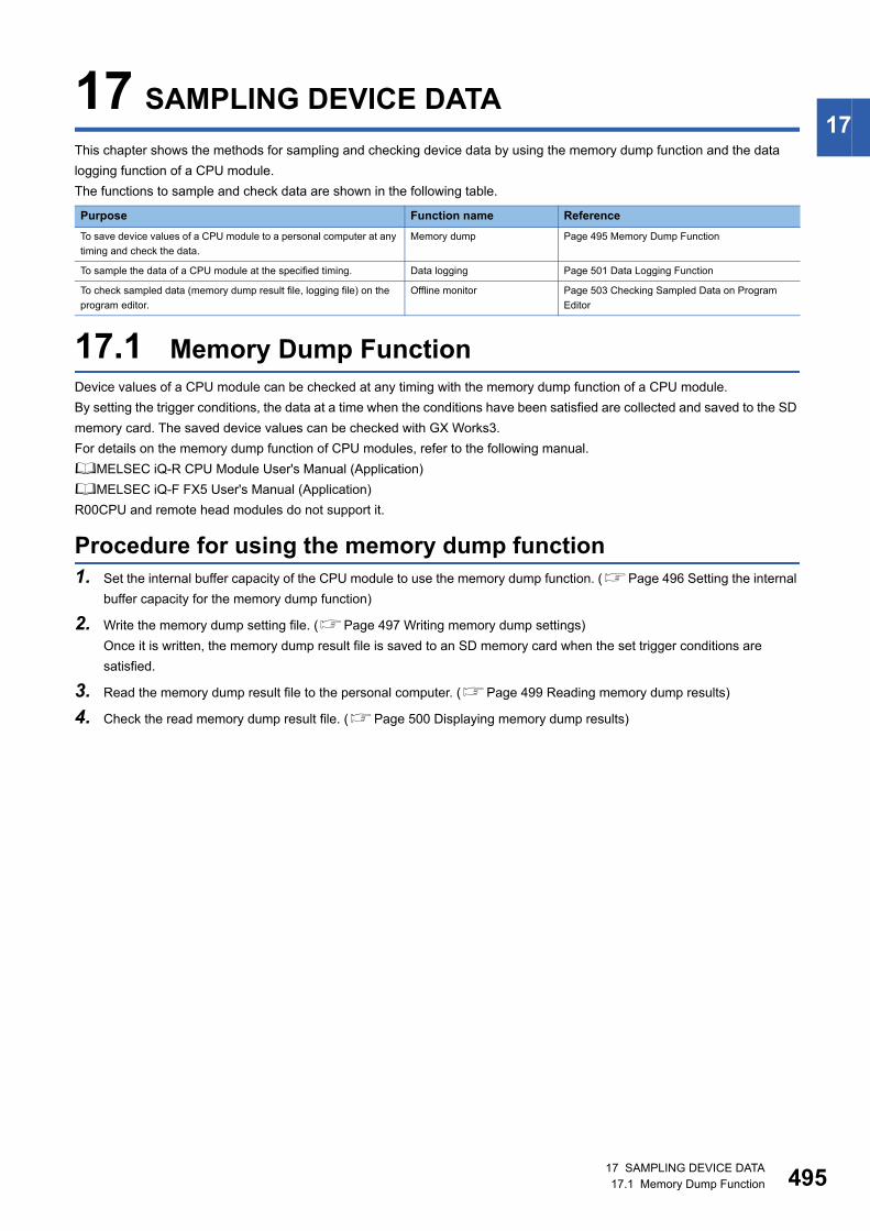
17 SAMPLING DEVICE DATA17.1 Memory Dump Function 495
1717 SAMPLING DEVICE DATA
This chapter shows the methods for sampling and checking device data by using the memory dump function and the data
logging function of a CPU module.
The functions to sample and check data are shown in the following table.
17.1 Memory Dump FunctionDevice values of a CPU module can be checked at any timing with the memory dump function of a CPU module.
By setting the trigger conditions, the data at a time when the conditions have been satisfied are collected and saved to the SD
memory card. The saved device values can be checked with GX Works3.
For details on the memory dump function of CPU modules, refer to the following manual.
MELSEC iQ-R CPU Module User's Manual (Application)
MELSEC iQ-F FX5 User's Manual (Application)
R00CPU and remote head modules do not support it.
Procedure for using the memory dump function1. Set the internal buffer capacity of the CPU module to use the memory dump function. (Page 496 Setting the internal
buffer capacity for the memory dump function)
2. Write the memory dump setting file. (Page 497 Writing memory dump settings)
Once it is written, the memory dump result file is saved to an SD memory card when the set trigger conditions are
satisfied.
3. Read the memory dump result file to the personal computer. (Page 499 Reading memory dump results)
4. Check the read memory dump result file. (Page 500 Displaying memory dump results)
Purpose Function name Reference
To save device values of a CPU module to a personal computer at any
timing and check the data.
Memory dump Page 495 Memory Dump Function
To sample the data of a CPU module at the specified timing. Data logging Page 501 Data Logging Function
To check sampled data (memory dump result file, logging file) on the
program editor.
Offline monitor Page 503 Checking Sampled Data on Program
Editor
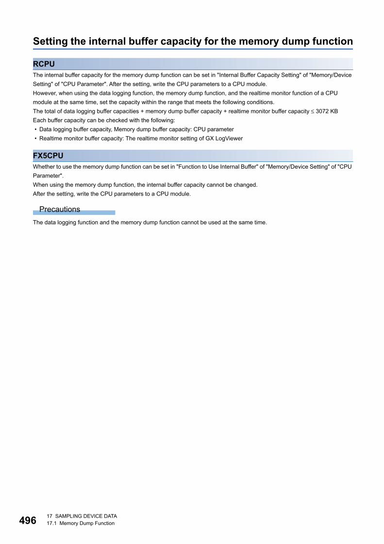
49617 SAMPLING DEVICE DATA17.1 Memory Dump Function
Setting the internal buffer capacity for the memory dump function
RCPUThe internal buffer capacity for the memory dump function can be set in "Internal Buffer Capacity Setting" of "Memory/Device
Setting" of "CPU Parameter". After the setting, write the CPU parameters to a CPU module.
However, when using the data logging function, the memory dump function, and the realtime monitor function of a CPU
module at the same time, set the capacity within the range that meets the following conditions.
The total of data logging buffer capacities + memory dump buffer capacity + realtime monitor buffer capacity ≤ 3072 KB
Each buffer capacity can be checked with the following:
• Data logging buffer capacity, Memory dump buffer capacity: CPU parameter
• Realtime monitor buffer capacity: The realtime monitor setting of GX LogViewer
FX5CPUWhether to use the memory dump function can be set in "Function to Use Internal Buffer" of "Memory/Device Setting" of "CPU
Parameter".
When using the memory dump function, the internal buffer capacity cannot be changed.
After the setting, write the CPU parameters to a CPU module.
Precautions
The data logging function and the memory dump function cannot be used at the same time.

17 SAMPLING DEVICE DATA17.1 Memory Dump Function 497
17Writing memory dump settingsOnce the memory dump setting file is written, the Memory Dump function is started and waits for a trigger.
If the memory dump setting file has already been stored, the Memory Dump function is started by powering ON the CPU
module.
Window
[Debug] [Memory Dump] [Setting]
The following screen is an example when opening a project used for an RCPU.
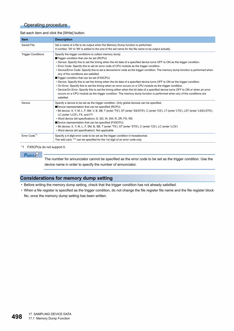
49817 SAMPLING DEVICE DATA17.1 Memory Dump Function
Operating procedure
Set each item and click the [Write] button.
*1 FX5CPUs do not support it.
The number for annunciator cannot be specified as the error code to be set as the trigger condition. Use the
device name in order to specify the number of annunciator.
Considerations for memory dump setting • Before writing the memory dump setting, check that the trigger condition has not already satisfied.
• When a file register is specified as the trigger condition, do not change the file register file name and the file register block
No. once the memory dump setting has been written.
Item Description
Saved File Set a name of a file to be output when the Memory Dump function is performed.
A number, '00' to '99' is added to the end of the set name for the file name to be output actually.
Trigger Conditions Specify the trigger conditions to collect memory dump.
■Trigger condition that can be set (RCPU)
• Device: Specify this to set the timing when the bit data of a specified device turns OFF to ON as the trigger condition.
• Error Code: Specify this to set an error code of CPU module as the trigger condition.
• Device/Error Code: Specify this to set a device/error code as the trigger condition. The memory dump function is performed when
any of the conditions are satisfied.
■Trigger condition that can be set (FX5CPU)
• Device: Specify this to set the timing when the bit data of a specified device turns OFF to ON as the trigger condition.
• On Error: Specify this to set the timing when an error occurs on a CPU module as the trigger condition.
• Device/On Error: Specify this to set the timing either when the bit data of a specified device turns OFF to ON or when an error
occurs on a CPU module as the trigger condition. The memory dump function is performed when any of the conditions are
satisfied.
Device Specify a device to be set as the trigger condition. Only global devices can be specified.
■Device representation that can be specified (RCPU)
• Bit device: X, Y, M, L, F, SM, V, B, SB, T (enter 'TS'), ST (enter 'SS/STS'), C (enter 'CS'), LT (enter 'LTS'), LST (enter 'LSS/LSTS'),
LC (enter 'LCS'), FX, and FY
• Word device (bit specification): D, SD, W, SW, R, ZR, FD, RD
■Device representation that can be specified (FX5CPU)
• Bit device: X, Y, M, L, F, SM, B, SB, T (enter 'TS'), ST (enter 'STS'), C (enter 'CS'), LC (enter 'LCS')
• Word device (bit specification): Not applicable
Error Code*1 Specify a 4-digit error code to be set as the trigger condition in hexadecimal.
The wild card, "*" can be specified for the 1st digit of an error code only.
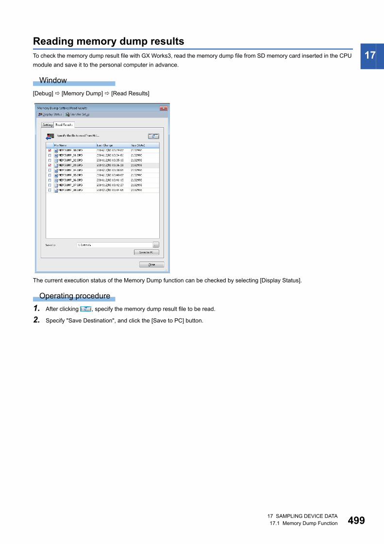
17 SAMPLING DEVICE DATA17.1 Memory Dump Function 499
17Reading memory dump resultsTo check the memory dump result file with GX Works3, read the memory dump file from SD memory card inserted in the CPU
module and save it to the personal computer in advance.
Window
[Debug] [Memory Dump] [Read Results]
The current execution status of the Memory Dump function can be checked by selecting [Display Status].
Operating procedure
1. After clicking , specify the memory dump result file to be read.
2. Specify "Save Destination", and click the [Save to PC] button.
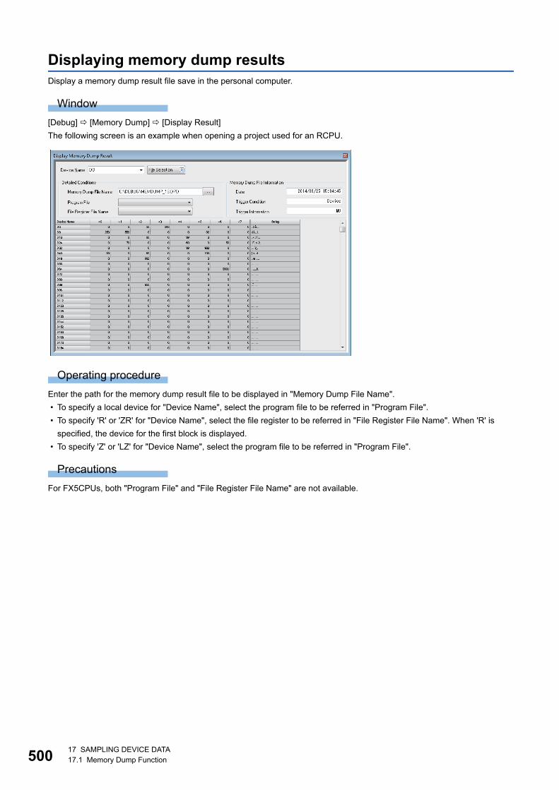
50017 SAMPLING DEVICE DATA17.1 Memory Dump Function
Displaying memory dump resultsDisplay a memory dump result file save in the personal computer.
Window
[Debug] [Memory Dump] [Display Result]
The following screen is an example when opening a project used for an RCPU.
Operating procedure
Enter the path for the memory dump result file to be displayed in "Memory Dump File Name".
• To specify a local device for "Device Name", select the program file to be referred in "Program File".
• To specify 'R' or 'ZR' for "Device Name", select the file register to be referred in "File Register File Name". When 'R' is
specified, the device for the first block is displayed.
• To specify 'Z' or 'LZ' for "Device Name", select the program file to be referred in "Program File".
Precautions
For FX5CPUs, both "Program File" and "File Register File Name" are not available.
17 SAMPLING DEVICE DATA17.2 Data Logging Function 501
1717.2 Data Logging FunctionData can be sampled at the specified timing with the data logging function of a MELSEC-iQ-R series or MELSEC iQ-F series
CPU module.
For details on the data logging, refer to the following manual.
MELSEC iQ-R CPU Module User's Manual (Application)
MELSEC iQ-F FX5 User's Manual (Application)
For R00CPU, the data logging function cannot be used.
Procedure for using the data logging function1. Set the internal buffer capacity of the CPU module, which is used for the data logging function. (Page 502 Setting
internal buffer capacity for the data logging function)
2. Configure the data logging settings with CPU Module Logging Configuration Tool, and write the setting to the CPU
module.
3. Start data logging with CPU Module Logging Configuration Tool.
4. Check the data logging results (logging data) in GX LogViewer.
For the method for using CPU Module Logging Configuration Tool, refer to the following manual.
MELSEC iQ-R CPU Module User's Manual (Application)
MELSEC iQ-F FX5 User's Manual (Application)
For the method for using GX LogViewer, refer to the following manual.
GX LogViewer Version 1 Operating Manual
Following menus start each tool.
• [Tool] [Logging Configuration Tool]
• [Tool] [Realtime Monitor Function]
(GX LogViewer starts and "Realtime Monitor Setting" screen appears.)
50217 SAMPLING DEVICE DATA17.2 Data Logging Function
Setting internal buffer capacity for the data logging function
RCPUThe internal buffer capacity for the data logging function can be set in "Internal Buffer Capacity Setting" of "Memory/Device
Setting" of "CPU parameter". After the setting, write the CPU parameters to a CPU module.
However, when using the data logging function, the memory dump function, and the realtime monitor function of a CPU
module at the same time, set the capacity within the range that meets the following conditions.
The total of data logging buffer capacities + memory dump buffer capacity + realtime monitor buffer capacity ≤ 3072 KB
Each buffer capacity can be checked with the following:
• Data logging buffer capacity, memory dump buffer capacity: CPU parameter
• Realtime monitor buffer capacity: the realtime monitor setting of GX LogViewer
FX5CPUWhether to use the data logging function can be set in "Function to Use Internal Buffer" of "Memory/Device Setting" of "CPU
Parameter".
The internal buffer capacity for the data logging function can be set in "Internal Buffer Capacity Setting" of "Memory/Device
Setting" in "CPU parameter".
After the setting, write the CPU parameters to a CPU module.
However, set the capacity in the range that satisfies the following condition.
The total of data logging buffer capacities ≤ 320 KB
Precautions
The data logging function and the memory dump function cannot be used at the same time.
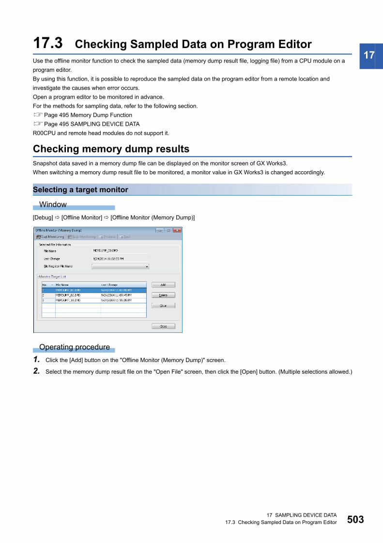
17 SAMPLING DEVICE DATA17.3 Checking Sampled Data on Program Editor 503
1717.3 Checking Sampled Data on Program EditorUse the offline monitor function to check the sampled data (memory dump result file, logging file) from a CPU module on a
program editor.
By using this function, it is possible to reproduce the sampled data on the program editor from a remote location and
investigate the causes when error occurs.
Open a program editor to be monitored in advance.
For the methods for sampling data, refer to the following section.
Page 495 Memory Dump Function
Page 495 SAMPLING DEVICE DATA
R00CPU and remote head modules do not support it.
Checking memory dump resultsSnapshot data saved in a memory dump file can be displayed on the monitor screen of GX Works3.
When switching a memory dump result file to be monitored, a monitor value in GX Works3 is changed accordingly.
Selecting a target monitor
Window
[Debug] [Offline Monitor] [Offline Monitor (Memory Dump)]
Operating procedure
1. Click the [Add] button on the "Offline Monitor (Memory Dump)" screen.
2. Select the memory dump result file on the "Open File" screen, then click the [Open] button. (Multiple selections allowed.)
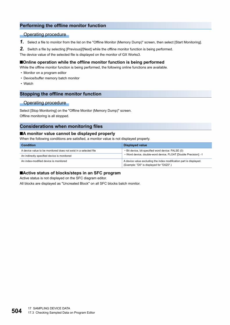
50417 SAMPLING DEVICE DATA17.3 Checking Sampled Data on Program Editor
Performing the offline monitor function
Operating procedure
1. Select a file to monitor from the list on the "Offline Monitor (Memory Dump)" screen, then select [Start Monitoring].
2. Switch a file by selecting [Previous]/[Next] while the offline monitor function is being performed.
The device value of the selected file is displayed on the monitor of GX Works3.
■Online operation while the offline monitor function is being performedWhile the offline monitor function is being performed, the following online functions are available.
• Monitor on a program editor
• Device/buffer memory batch monitor
• Watch
Stopping the offline monitor function
Operating procedure
Select [Stop Monitoring] on the "Offline Monitor (Memory Dump)" screen.
Offline monitoring is all stopped.
Considerations when monitoring files
■A monitor value cannot be displayed properlyWhen the following conditions are satisfied, a monitor value is not displayed properly.
■Active status of blocks/steps in an SFC programActive status is not displayed on the SFC diagram editor.
All blocks are displayed as "Uncreated Block" on all SFC blocks batch monitor.
Condition Displayed value
A device value to be monitored does not exist in a selected file • Bit device, bit-specified word device: FALSE (0)
• Word device, double-word device, FLOAT [Double Precision]: -1An indirectly specified device is monitored
An index-modified device is monitored A device value excluding the index modification part is displayed.
(Example: "D0" is displayed for "D0Z0".)
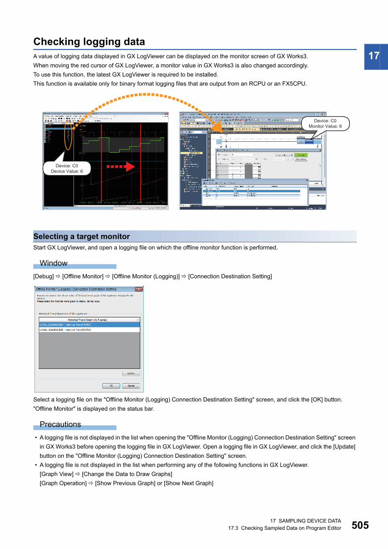
17 SAMPLING DEVICE DATA17.3 Checking Sampled Data on Program Editor 505
17Checking logging dataA value of logging data displayed in GX LogViewer can be displayed on the monitor screen of GX Works3.
When moving the red cursor of GX LogViewer, a monitor value in GX Works3 is also changed accordingly.
To use this function, the latest GX LogViewer is required to be installed.
This function is available only for binary format logging files that are output from an RCPU or an FX5CPU.
Selecting a target monitorStart GX LogViewer, and open a logging file on which the offline monitor function is performed.
Window
[Debug] [Offline Monitor] [Offline Monitor (Logging)] [Connection Destination Setting]
Select a logging file on the "Offline Monitor (Logging) Connection Destination Setting" screen, and click the [OK] button.
"Offline Monitor" is displayed on the status bar.
Precautions
• A logging file is not displayed in the list when opening the "Offline Monitor (Logging) Connection Destination Setting" screen
in GX Works3 before opening the logging file in GX LogViewer. Open a logging file in GX LogViewer, and click the [Update]
button on the "Offline Monitor (Logging) Connection Destination Setting" screen.
• A logging file is not displayed in the list when performing any of the following functions in GX LogViewer.
[Graph View] [Change the Data to Draw Graphs]
[Graph Operation] [Show Previous Graph] or [Show Next Graph]
Device: C0Monitor Value: 6
Device: C0Device Value: 6
50617 SAMPLING DEVICE DATA17.3 Checking Sampled Data on Program Editor
Performing the offline monitor function
Operating procedure
1. Start monitoring in GX Works3. (Page 418 Starting/stopping monitoring)
2. Move the red cursor in the "Historical Trend" window of GX LogViewer.
An updated device value in the graph legend area is displayed on the monitor of GX Works3.
■Online operation while the offline monitor function is being performedWhile the offline monitor function is being performed, the following online functions are available.
• Monitor on a program editor
• Device/buffer memory batch monitor
• Watch
Stopping the offline monitor function
Operating procedure
Select [Debug] [Offline Monitor] [Offline Monitor (Logging)] [Disconnect Offline Monitor].
Monitoring stops on all screens in GX Works3.
■Pausing and restarting the offline monitor functionWhen stopping monitoring in GX Works3, the offline monitor function pauses only for the stopped screen.
When restarting monitoring in GX Works3, the offline monitor function also restarts.
Considerations
■Active status of blocks/steps in an SFC programActive status is not displayed on the SFC diagram editor.
All blocks are displayed as "Uncreated Block" on all SFC blocks batch monitor.
■Conditions that monitored values are not displayed properlyWhen any of the following conditions is satisfied, a monitor value is not displayed properly.
■Conditions that labels can be monitoredLabels can be monitored only when all of the following conditions are satisfied.
• GX Works3 Version 1.045X or later is used.
• GX LogViewer Version 1.82L or later is used.
• Monitoring is performed in the project which was written to a CPU module when a logging file was output
• Label assignment status is consistent between in a logging file and in a project to be monitored.
Condition Value
A device value to be monitored does not exist in a file opened in the
"Historical Trend" window
The following values are displayed.
• Bit device, bit-specified word device: FALSE (0)
• Word device, double-word device, FLOAT [Double Precision]: -1A device that exists either in the lower bit or the upper bit is monitored by
specifying in double-word format
An indirectly specified device is monitored
An index-modified device is monitored A device value excluding the index modification part is displayed.
(Example: "D0" is displayed for "D0Z0".)
A project which was written to a CPU module when a logging file was
output and a project to monitor do not match.
If label assignment status is inconsistent between in a logging file and in a project
to be monitored, values that are different from the ones displayed in the
"Historical Trend" window of GX LogViewer may be displayed.
18 CHECKING/CHANGING MODULE OPERATION 507
18
18 CHECKING/CHANGING MODULE OPERATION
The operation status of a CPU module and remote head module can be checked, and their operations can be changed in GX
Works3.
CPU module
Remote head module
Purpose Function name Reference
To set the clock on a CPU module Clock setting Page 508 Clock Setting in a CPU Module
To switch the operation status of a CPU module
connected to GX Works3 to RUN/STOP/PAUSE/RESET
Remote operation Page 509 Remote Operation
To perform the functions of CPU modules in a
redundant system configuration
System switching
Operation mode change
Memory copy
Control system forced start while waiting for the other
system started
Redundant function module communication test
System A/B setting
Page 511 Redundant Programmable
Controller Operations
To perform the functions of RnPSFCPUs and
RnSFCPUs
Safety operation mode switching
Identification check for safety data
Page 513 Safety Programmable Controller
Operations
To perform the functions of RnPSFCPUs Safety module operation Page 516 Safety module operation
To check the usage of data memory CPU memory operation Page 517 Checking Memory Usage
To clear values in data memory Clear value Page 518 Initializing/Clearing Memory
Purpose Function name Reference
To switch the operation status of a remote head module
connected to GX Works3 to the RUN/STOP/PAUSE/
RESET status
Remote operation Page 509 Remote Operation
To perform the functions of remote head modules in a
redundant system configuration
System switching Page 511 Redundant Programmable
Controller Operations
To check the usage of data memory CPU memory operation Page 517 Checking Memory Usage
To clear values in data memory Clear value Page 518 Initializing/Clearing Memory
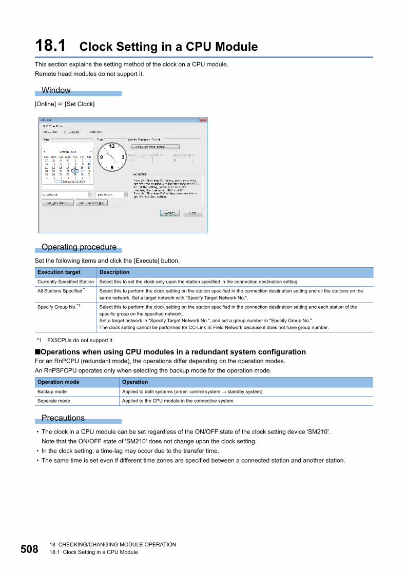
50818 CHECKING/CHANGING MODULE OPERATION18.1 Clock Setting in a CPU Module
18.1 Clock Setting in a CPU ModuleThis section explains the setting method of the clock on a CPU module.
Remote head modules do not support it.
Window
[Online] [Set Clock]
Operating procedure
Set the following items and click the [Execute] button.
*1 FX5CPUs do not support it.
■Operations when using CPU modules in a redundant system configurationFor an RnPCPU (redundant mode), the operations differ depending on the operation modes.
An RnPSFCPU operates only when selecting the backup mode for the operation mode.
Precautions
• The clock in a CPU module can be set regardless of the ON/OFF state of the clock setting device 'SM210'.
Note that the ON/OFF state of 'SM210' does not change upon the clock setting.
• In the clock setting, a time-lag may occur due to the transfer time.
• The same time is set even if different time zones are specified between a connected station and another station.
Execution target Description
Currently Specified Station Select this to set the clock only upon the station specified in the connection destination setting.
All Stations Specified*1 Select this to perform the clock setting on the station specified in the connection destination setting and all the stations on the
same network. Set a target network with "Specify Target Network No.".
Specify Group No.*1 Select this to perform the clock setting on the station specified in the connection destination setting and each station of the
specific group on the specified network.
Set a target network in "Specify Target Network No.", and set a group number in "Specify Group No.".
The clock setting cannot be performed for CC-Link IE Field Network because it does not have group number.
Operation mode Operation
Backup mode Applied to both systems (order: control system → standby system).
Separate mode Applied to the CPU module in the connective system.

18 CHECKING/CHANGING MODULE OPERATION18.2 Remote Operation 509
18
18.2 Remote OperationThis section explains the method for switching the execution status of a CPU module and remote head module (such as RUN/
STOP) in GX Works3.
Window
[Online] [Remote Operation]
The screen above is an example when connecting with an RnCPU.
Operating procedure
Set the following items and click the [Execute] button.
*1 When resetting a CPU module in a redundant system configuration and a remote head module, "Currently Specified Station/Specify Both Systems" is displayed.
*2 FX5CPUs and remote head modules do not support it.
Execution target Description
Currently Specified
Station*1■CPU module
Select this to perform the remote operation only on the station specified in the connection destination setting.
■Remote head module in a redundant system configuration
• When starting from [Online] [Remote Operation]: the remote operation is performed on the system of the remote head
module specified as the connection destination.
• When starting from the "CC IE Field Diagnostics" screen: the remote operation is performed on the system of the remote head
module specified as the diagnostics target.
All Stations Specified*2 Select this to perform the remote operation on the station specified in the connection destination setting and all the stations on the
same network. Set a target network in "Specify Target Network No.".
Specify Group No.*2 Select this to perform the remote operation on the station specified in the connection destination setting and each station of the
specific group on the specified network.
Set a target network in "Specify Target Network No.", and set a group number in "Specify Group No.".
The remote operation cannot be performed for CC-Link IE Field Network because it does not have group number.
Specify Both Systems*2 Select this to perform the remote operation on the both systems (control/standby) on the route specified on the "Specify
Connection Destination" screen. This setting is applied for a CPU module in a redundant system configuration.
51018 CHECKING/CHANGING MODULE OPERATION18.2 Remote Operation
Remote operation and RUN/STOP switchWhen the operation to the CPU module differs by the remote operation, RUN/STOP switch, or remote RUN/PAUSE contact,
the CPU module operates according to the priority shown below:
The operating status after RUN/STOP switching on the CPU module or remote RUN/STOP contact operation are as follows.
*1 Remote head modules do not support it.*2 Remote reset is required to be enabled in "Operation Related Setting" of "CPU Parameter".*3 Operable when the CPU module is switched to STOP by remote operation.
■Operations when using CPU modules in a redundant system configurationFor an RnPCPU (redundant mode), the operations differ depending on the operation modes.
An RnPSFCPU operates only when selecting the backup mode for the operation mode.
Operation to CPU module Priority
STOP 1
PAUSE 2
RUN 3
Remote operation CPU module switch Remote RUN/STOP contact is ON(The CPU module is in STOP.)RUN STOP
RUN RUN STOP STOP
STOP STOP STOP STOP
PAUSE*1 PAUSE STOP STOP
RESET*2 Inoperable *3 RESET RESET
Operation mode Operation
Backup mode ■STOP
Applied to both systems (order: control system → standby system).
■RUN, PAUSE
Applied to both systems (order: control system → standby system).
■RESET
Control system (specified): applied to both systems (order: control system → standby system).
Standby system (specified): applied to the standby system only.
Separate mode Applied to the CPU module in the connective system.
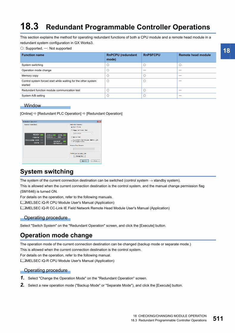
18 CHECKING/CHANGING MODULE OPERATION18.3 Redundant Programmable Controller Operations 511
18
18.3 Redundant Programmable Controller OperationsThis section explains the method for operating redundant functions of both a CPU module and a remote head module in a
redundant system configuration in GX Works3.
: Supported, : Not supported
Window
[Online] [Redundant PLC Operation] [Redundant Operation]
System switchingThe system of the current connection destination can be switched (control system → standby system).
This is allowed when the current connection destination is the control system, and the manual change permission flag
(SM1646) is turned ON.
For details on the operation, refer to the following manuals.
MELSEC iQ-R CPU Module User's Manual (Application)
MELSEC iQ-R CC-Link IE Field Network Remote Head Module User's Manual (Application)
Operating procedure
Select "Switch System" on the "Redundant Operation" screen, and click the [Execute] button.
Operation mode changeThe operation mode of the current connection destination can be changed (backup mode or separate mode.)
This is allowed when the current connection destination is the control system.
For details on the operation, refer to the following manual.
MELSEC iQ-R CPU Module User's Manual (Application)
Operating procedure
1. Select "Change the Operation Mode" on the "Redundant Operation" screen.
2. Select a new operation mode ("Backup Mode" or "Separate Mode"), and click the [Execute] button.
Function name RnPCPU (redundant mode)
RnPSFCPU Remote head module
System switching
Operation mode change
Memory copy
Control system forced start while waiting for the other system
started
Redundant function module communication test
System A/B setting
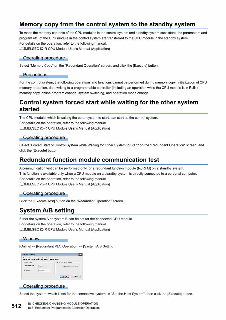
51218 CHECKING/CHANGING MODULE OPERATION18.3 Redundant Programmable Controller Operations
Memory copy from the control system to the standby systemTo make the memory contents of the CPU modules in the control system and standby system consistent, the parameters and
program etc. of the CPU module in the control system are transferred to the CPU module in the standby system.
For details on the operation, refer to the following manual.
MELSEC iQ-R CPU Module User's Manual (Application)
Operating procedure
Select "Memory Copy" on the "Redundant Operation" screen, and click the [Execute] button.
Precautions
For the control system, the following operations and functions cannot be performed during memory copy; initialization of CPU
memory operation, data writing to a programmable controller (including an operation while the CPU module is in RUN),
memory copy, online program change, system switching, and operation mode change.
Control system forced start while waiting for the other system startedThe CPU module, which is waiting the other system to start, can start as the control system.
For details on the operation, refer to the following manual.
MELSEC iQ-R CPU Module User's Manual (Application)
Operating procedure
Select "Forced Start of Control System while Waiting for Other System to Start" on the "Redundant Operation" screen, and
click the [Execute] button.
Redundant function module communication testA communication test can be performed only for a redundant function module (R6RFM) on a standby system.
This function is available only when a CPU module on a standby system is directly connected to a personal computer.
For details on the operation, refer to the following manual.
MELSEC iQ-R CPU Module User's Manual (Application)
Operating procedure
Click the [Execute Test] button on the "Redundant Operation" screen.
System A/B settingEither the system A or system B can be set for the connected CPU module.
For details on the operation, refer to the following manual.
MELSEC iQ-R CPU Module User's Manual (Application)
Window
[Online] [Redundant PLC Operation] [System A/B Setting]
Operating procedure
Select the system, which is set for the connective system, in "Set the Host System", then click the [Execute] button.
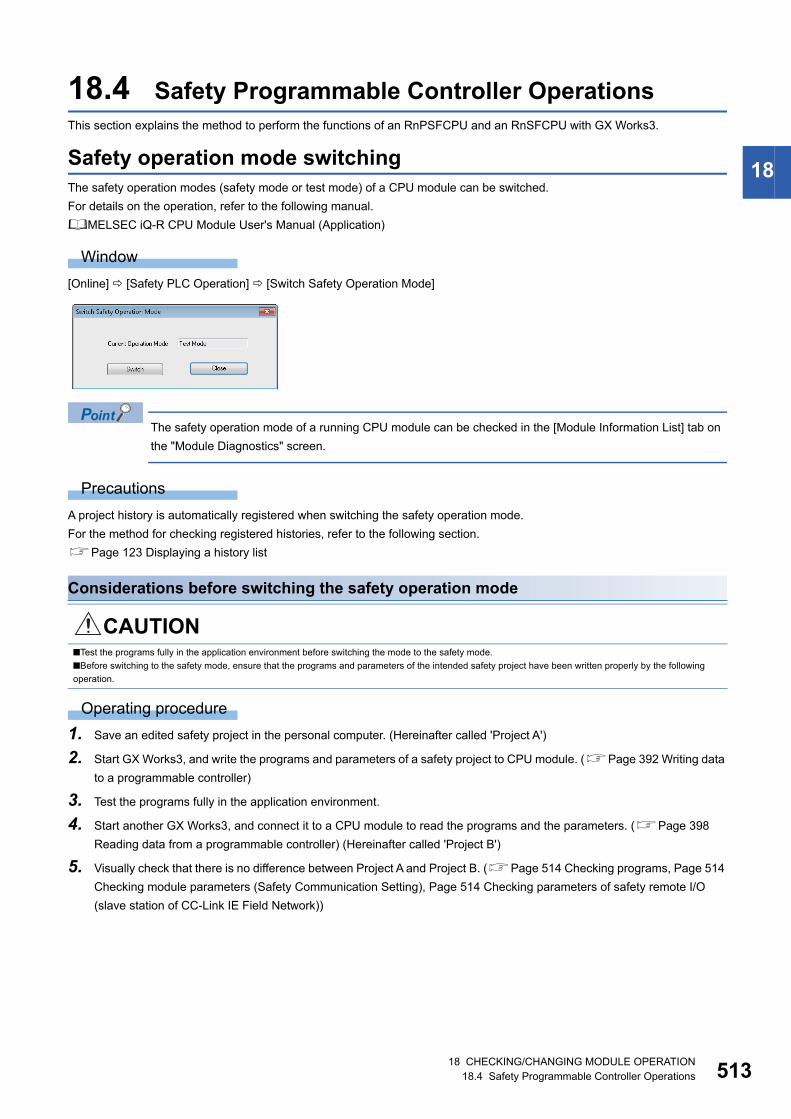
18 CHECKING/CHANGING MODULE OPERATION18.4 Safety Programmable Controller Operations 513
18
18.4 Safety Programmable Controller OperationsThis section explains the method to perform the functions of an RnPSFCPU and an RnSFCPU with GX Works3.
Safety operation mode switchingThe safety operation modes (safety mode or test mode) of a CPU module can be switched.
For details on the operation, refer to the following manual.
MELSEC iQ-R CPU Module User's Manual (Application)
Window
[Online] [Safety PLC Operation] [Switch Safety Operation Mode]
The safety operation mode of a running CPU module can be checked in the [Module Information List] tab on
the "Module Diagnostics" screen.
Precautions
A project history is automatically registered when switching the safety operation mode.
For the method for checking registered histories, refer to the following section.
Page 123 Displaying a history list
Considerations before switching the safety operation mode
Operating procedure
1. Save an edited safety project in the personal computer. (Hereinafter called 'Project A')
2. Start GX Works3, and write the programs and parameters of a safety project to CPU module. (Page 392 Writing data
to a programmable controller)
3. Test the programs fully in the application environment.
4. Start another GX Works3, and connect it to a CPU module to read the programs and the parameters. (Page 398
Reading data from a programmable controller) (Hereinafter called 'Project B')
5. Visually check that there is no difference between Project A and Project B. (Page 514 Checking programs, Page 514
Checking module parameters (Safety Communication Setting), Page 514 Checking parameters of safety remote I/O
(slave station of CC-Link IE Field Network))
CAUTION■Test the programs fully in the application environment before switching the mode to the safety mode.
■Before switching to the safety mode, ensure that the programs and parameters of the intended safety project have been written properly by the following
operation.
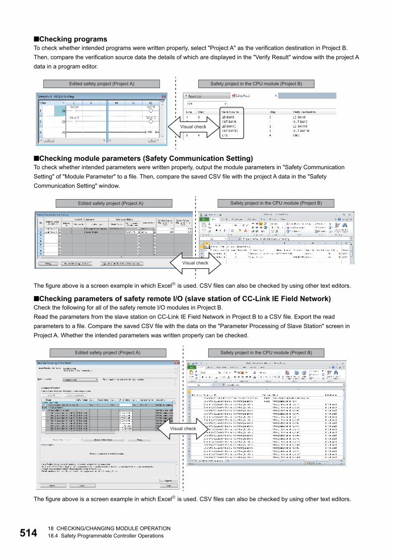
51418 CHECKING/CHANGING MODULE OPERATION18.4 Safety Programmable Controller Operations
■Checking programsTo check whether intended programs were written properly, select "Project A" as the verification destination in Project B.
Then, compare the verification source data the details of which are displayed in the "Verify Result" window with the project A
data in a program editor.
■Checking module parameters (Safety Communication Setting)To check whether intended parameters were written properly, output the module parameters in "Safety Communication
Setting" of "Module Parameter" to a file. Then, compare the saved CSV file with the project A data in the "Safety
Communication Setting" window.
The figure above is a screen example in which Excel is used. CSV files can also be checked by using other text editors.
■Checking parameters of safety remote I/O (slave station of CC-Link IE Field Network)Check the following for all of the safety remote I/O modules in Project B.
Read the parameters from the slave station on CC-Link IE Field Network in Project B to a CSV file. Export the read
parameters to a file. Compare the saved CSV file with the data on the "Parameter Processing of Slave Station" screen in
Project A. Whether the intended parameters was written properly can be checked.
The figure above is a screen example in which Excel is used. CSV files can also be checked by using other text editors.
Edited safety project (Project A) Safety project in the CPU module (Project B)
Visual check
Edited safety project (Project A) Safety project in the CPU module (Project B)
Visual check
Edited safety project (Project A) Safety project in the CPU module (Project B)
Visual check
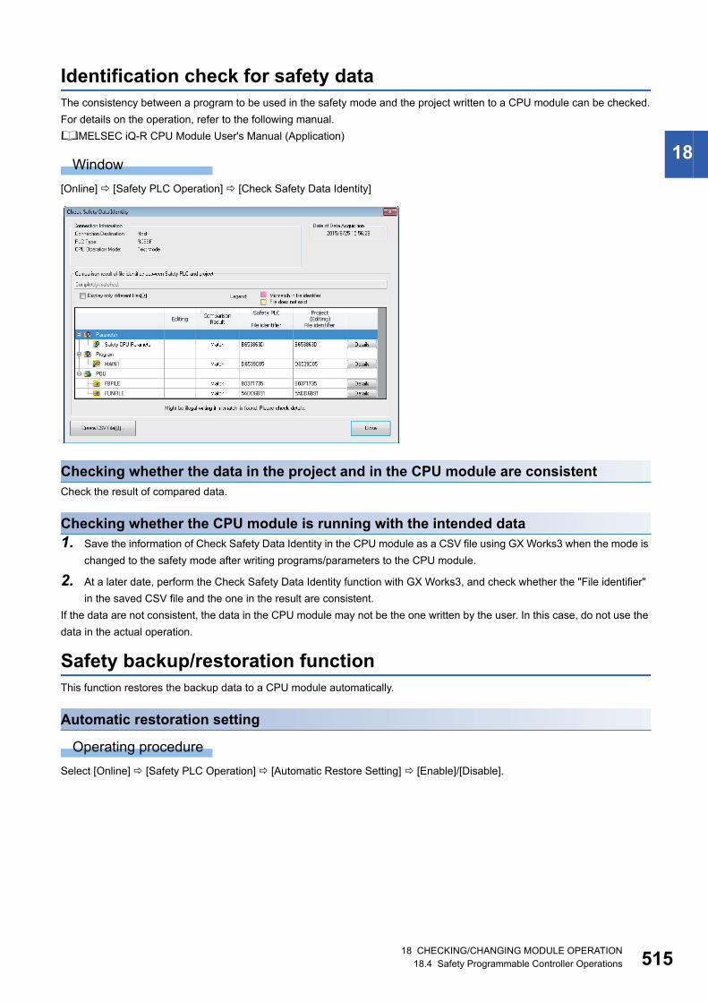
18 CHECKING/CHANGING MODULE OPERATION18.4 Safety Programmable Controller Operations 515
18
Identification check for safety dataThe consistency between a program to be used in the safety mode and the project written to a CPU module can be checked.
For details on the operation, refer to the following manual.
MELSEC iQ-R CPU Module User's Manual (Application)
Window
[Online] [Safety PLC Operation] [Check Safety Data Identity]
Checking whether the data in the project and in the CPU module are consistentCheck the result of compared data.
Checking whether the CPU module is running with the intended data1. Save the information of Check Safety Data Identity in the CPU module as a CSV file using GX Works3 when the mode is
changed to the safety mode after writing programs/parameters to the CPU module.
2. At a later date, perform the Check Safety Data Identity function with GX Works3, and check whether the "File identifier"
in the saved CSV file and the one in the result are consistent.
If the data are not consistent, the data in the CPU module may not be the one written by the user. In this case, do not use the
data in the actual operation.
Safety backup/restoration functionThis function restores the backup data to a CPU module automatically.
Automatic restoration setting
Operating procedure
Select [Online] [Safety PLC Operation] [Automatic Restore Setting] [Enable]/[Disable].
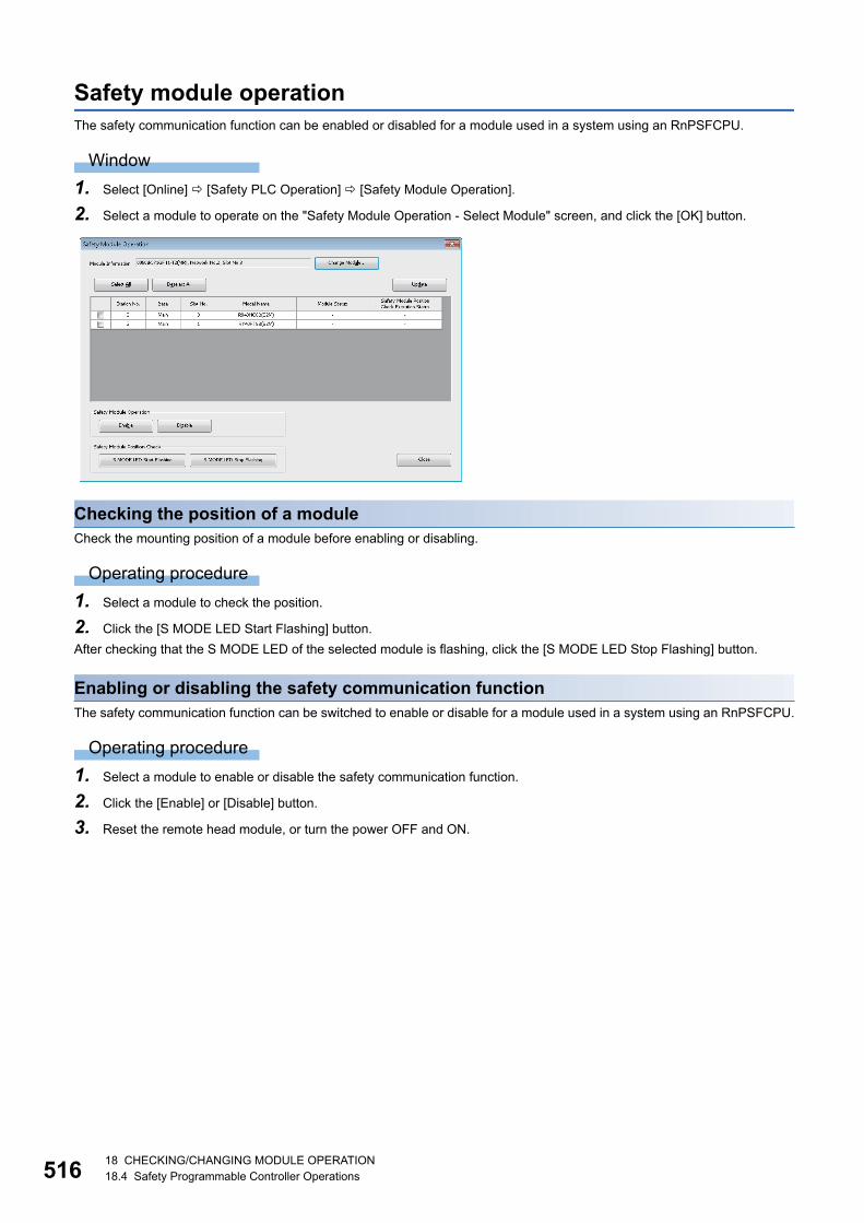
51618 CHECKING/CHANGING MODULE OPERATION18.4 Safety Programmable Controller Operations
Safety module operationThe safety communication function can be enabled or disabled for a module used in a system using an RnPSFCPU.
Window
1. Select [Online] [Safety PLC Operation] [Safety Module Operation].
2. Select a module to operate on the "Safety Module Operation - Select Module" screen, and click the [OK] button.
Checking the position of a moduleCheck the mounting position of a module before enabling or disabling.
Operating procedure
1. Select a module to check the position.
2. Click the [S MODE LED Start Flashing] button.
After checking that the S MODE LED of the selected module is flashing, click the [S MODE LED Stop Flashing] button.
Enabling or disabling the safety communication functionThe safety communication function can be switched to enable or disable for a module used in a system using an RnPSFCPU.
Operating procedure
1. Select a module to enable or disable the safety communication function.
2. Click the [Enable] or [Disable] button.
3. Reset the remote head module, or turn the power OFF and ON.
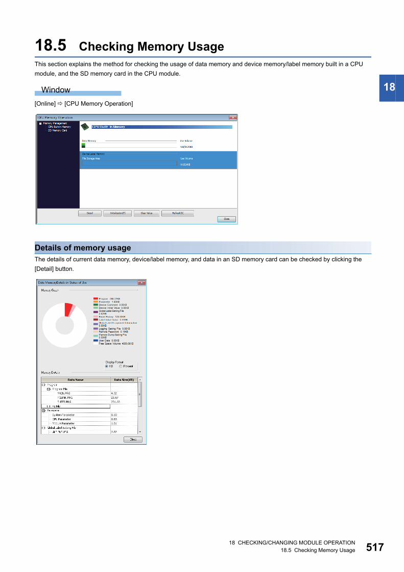
18 CHECKING/CHANGING MODULE OPERATION18.5 Checking Memory Usage 517
18
18.5 Checking Memory UsageThis section explains the method for checking the usage of data memory and device memory/label memory built in a CPU
module, and the SD memory card in the CPU module.
Window
[Online] [CPU Memory Operation]
Details of memory usageThe details of current data memory, device/label memory, and data in an SD memory card can be checked by clicking the
[Detail] button.
51818 CHECKING/CHANGING MODULE OPERATION18.6 Initializing/Clearing Memory
18.6 Initializing/Clearing MemoryThis section explains how to operate memory (such as initialization and zero clear.)
For details on the memory operation, refer to the following manuals.
MELSEC iQ-R CPU Module User's Manual (Application)
MELSEC iQ-F FX5 User's Manual (Application)
Initializing dataDelete files in the data memory/device memory/label memory of the CPU module, or folders/files stored in the SD memory
card.
Note that the information for the user authentication will not be deleted. To delete the information, initialize all information.
(Page 472 When a user name and a password used in the User Authentication function are lost)
After initializing, rewrite the programmable controller data to the CPU module.
If the power of the CPU is turned OFF → ON or the CPU module was reset, the allocation for the device/label memory is back
to the initial status. (Each area has the default capacity.)
Operating procedure
1. Select [Online] [CPU Memory Operation]. (Page 517 Checking Memory Usage)
2. Select "Data Memory" or "File Storage Area" on the "CPU Memory Operation" screen, and click the [Initialization] button.
When initializing an SD memory card, select "SD Memory Card" displayed on the left of the screen.
Precautions
Format a memory card to be used for CPU modules by using this function.
If a memory card is formatted using the function such as Windows format function, it may not be used on a CPU module.
■Operations when using CPU modules in a redundant system configurationFor an RnPCPU (redundant mode), the operations differ depending on the operation modes.
An RnPSFCPU operates only when selecting the backup mode for the operation mode.
Clearing valuesClear the values of devices, labels, and file registers to '0', and perform latch clear operation.
Operating procedure
1. Select [Online] [CPU Memory Operation]. (Page 517 Checking Memory Usage)
2. Select "Device/Label Memory" on the "CPU Memory Operation" screen, and click the [Clear Value] button.
3. Set each item on the "Clear Value" screen and click the [Execute] button.
When the device initial value file/label initial value file is written in the CPU module, it can be initialized by
resetting the CPU module.
■Operations when using CPU modules in a redundant system configurationFor an RnPCPU (redundant mode), the operations differ depending on the operation modes.
An RnPSFCPU operates only when selecting the backup mode for the operation mode.
Operation mode Operation
Separate mode Applied to the CPU module in the connective system.
Backup mode Applied to both systems (order: control system → standby system).
Operation mode Operation
Separate mode Applied to the CPU module in the connective system.
Backup mode Applied to both systems (order: control system → standby system).
APPXAppendix 1 Additions and Changes from Previous Version 519
A
APPENDIXAppendix 1 Additions and Changes from Previous
VersionThis section shows the additions and changes with upgrade.
Functions, operability, and performance
Version 1.001B
Version 1.005F
Version 1.007H
Item Description Reference
Online program change • Online program change on an instruction basis in ladder programs is supported.
• Online program change for ST programs is supported.
• Online program change after changing/deleting label initial values is supported.
Page 405 Writing Programs While
a CPU Module is in the RUN State
Monitoring • When using a constant label for an input argument of a function block, a constant
value is displayed in monitoring.
Page 421 Checking Execution
Programs on Program Editor
• When display language in GX Works3 is changed, the language in an Intelligent
Function Module Monitor window is also changed.
Item Description Reference
Display language switching • Display in Simplified Chinese is supported. Page 39 Display Language
Switching
Printing • Printing the product information list is supported. Page 74 Printing Data
Module tool list The following settings are available.
• "Offset/gain setting" under "Temperature Input" for "iQ-R Series"
• "Q61LD Two-Point Calibration Setting" under "Analog Module" for "Q Series"
• "Q61LD Default Setting" under "Analog Module" for "Q Series"
Page 148 Other Settings of
Intelligent Function Modules
Interaction with iQ Works*1 • System labels are supported.
• The parameter reflection function of MELSOFT Navigator and the parameter import
function are supported.
Page 155 REGISTERING
LABELS
Program check • The program check function is supported. Page 276 Checking a program
Diagnostic*4 • The CC-Link IE Controller Network diagnostic (Twisted pair cable) is supported. Page 486 CC-Link IE Controller
Network diagnostic
Memory dump*3 • The memory dump function is supported. Page 495 Memory Dump
Function
Item Description Reference
Creating a program • Function Block Diagram/Ladder Diagram language is supported. *3 Page 223 Creating an FBD/LD
Program
Module tool list • "Analog input - Offset/gain setting" under "Analog Adapter" for "FX5 Series" is
supported.
• "Analog output - Offset/gain setting" under "Analog Adapter" for "FX5 Series" is
supported.
Page 148 Other Settings of
Intelligent Function Modules
Simple motion module setting • The advanced synchronous control setting can be set on one screen, and the
monitor function is supported.
Page 149 Simple Motion Module
Setting function
Reading sample comments • Sample comments is supported for a project in which an RD77MS is configured. Page 275 Reading sample
comments
Simulation The following projects can be simulated.
• Project used for an RnCPU
• Project in which RD77MS is configured (It can interact with the simulation function of
a project used for an RnCPU.)
Page 342 PROGRAM
SIMULATION
Others • Connected devices on the CC-Link IE Field Network can automatically be detected.
520APPXAppendix 1 Additions and Changes from Previous Version
Version 1.008J
Version 1.010L
System label • A system label change notification can be received automatically. Page 175 Importing after
checking the changes
Item Description Reference
Event history • In the event history of an R12CCPU-V, script position information is added to the
detailed information of the error code (3044h: program fault).
Page 493 Error History/Operation
History Check
Item Description Reference
Verification • Labels can be verified. Page 116 Verifying Projects
Project revision history • The project revision history function is supported. Page 122 Project Revision History
Temporary ladder change • An operation of a ladder block can temporarily changed in a ladder program. Page 202 Changing ladder blocks
temporarily
Search • As one of the search functions, a function to search a global device and a local
device individually is added.
Page 301 Searching/Replacing
Devices/Labels
Library management • A user library is supported. Page 330 Enhancing Use of User
Library
Simulation • A project used for an RnPCPU can be simulated. Page 342 PROGRAM
SIMULATION
Diagnostic • The MELSECNET diagnostic is supported for a project in which a Q series
MELSECNET/H network module configured.
Page 490 MELSECNET
diagnostic
Options The following option is added.
• "Convert" "Online Program Change" "Operational Setting" "Write device
comment"
Page 67 Option Setting for Each
Function
Item Description Reference
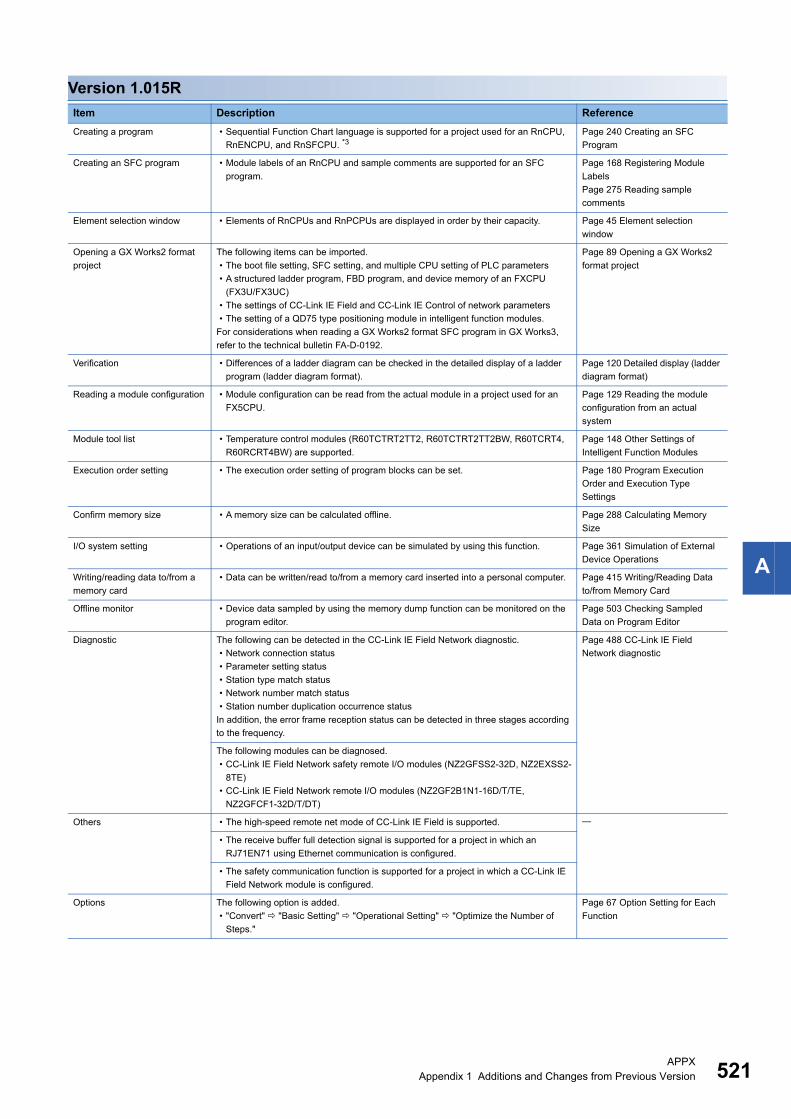
APPXAppendix 1 Additions and Changes from Previous Version 521
A
Version 1.015R
Item Description Reference
Creating a program • Sequential Function Chart language is supported for a project used for an RnCPU,
RnENCPU, and RnSFCPU. *3Page 240 Creating an SFC
Program
Creating an SFC program • Module labels of an RnCPU and sample comments are supported for an SFC
program.
Page 168 Registering Module
Labels
Page 275 Reading sample
comments
Element selection window • Elements of RnCPUs and RnPCPUs are displayed in order by their capacity. Page 45 Element selection
window
Opening a GX Works2 format
project
The following items can be imported.
• The boot file setting, SFC setting, and multiple CPU setting of PLC parameters
• A structured ladder program, FBD program, and device memory of an FXCPU
(FX3U/FX3UC)
• The settings of CC-Link IE Field and CC-Link IE Control of network parameters
• The setting of a QD75 type positioning module in intelligent function modules.
For considerations when reading a GX Works2 format SFC program in GX Works3,
refer to the technical bulletin FA-D-0192.
Page 89 Opening a GX Works2
format project
Verification • Differences of a ladder diagram can be checked in the detailed display of a ladder
program (ladder diagram format).
Page 120 Detailed display (ladder
diagram format)
Reading a module configuration • Module configuration can be read from the actual module in a project used for an
FX5CPU.
Page 129 Reading the module
configuration from an actual
system
Module tool list • Temperature control modules (R60TCTRT2TT2, R60TCTRT2TT2BW, R60TCRT4,
R60RCRT4BW) are supported.
Page 148 Other Settings of
Intelligent Function Modules
Execution order setting • The execution order setting of program blocks can be set. Page 180 Program Execution
Order and Execution Type
Settings
Confirm memory size • A memory size can be calculated offline. Page 288 Calculating Memory
Size
I/O system setting • Operations of an input/output device can be simulated by using this function. Page 361 Simulation of External
Device Operations
Writing/reading data to/from a
memory card
• Data can be written/read to/from a memory card inserted into a personal computer. Page 415 Writing/Reading Data
to/from Memory Card
Offline monitor • Device data sampled by using the memory dump function can be monitored on the
program editor.
Page 503 Checking Sampled
Data on Program Editor
Diagnostic The following can be detected in the CC-Link IE Field Network diagnostic.
• Network connection status
• Parameter setting status
• Station type match status
• Network number match status
• Station number duplication occurrence status
In addition, the error frame reception status can be detected in three stages according
to the frequency.
Page 488 CC-Link IE Field
Network diagnostic
The following modules can be diagnosed.
• CC-Link IE Field Network safety remote I/O modules (NZ2GFSS2-32D, NZ2EXSS2-
8TE)
• CC-Link IE Field Network remote I/O modules (NZ2GF2B1N1-16D/T/TE,
NZ2GFCF1-32D/T/DT)
Others • The high-speed remote net mode of CC-Link IE Field is supported.
• The receive buffer full detection signal is supported for a project in which an
RJ71EN71 using Ethernet communication is configured.
• The safety communication function is supported for a project in which a CC-Link IE
Field Network module is configured.
Options The following option is added.
• "Convert" "Basic Setting" "Operational Setting" "Optimize the Number of
Steps."
Page 67 Option Setting for Each
Function

522APPXAppendix 1 Additions and Changes from Previous Version
Version 1.020W
Item Description Reference
Creating a program • Sequential Function Chart language is supported for an RnPCPU. Page 240 Creating an SFC
Program
Creating an SFC program The following are improved in an SFC program.
• Multiple initial steps can be edited on the SFC editor.
• A jump can be edited on the SFC editor.
• A Zoom can be copied on the SFC editor.
• SFC Auto-scroll monitor can be used.
• Block information can be searched and replaced.
Page 245 Inserting initial steps
Page 250 Inserting/editing jumps
(connection lines)
Page 428 Monitoring with the
SFC auto-scroll
Ladder editor • When a contact is moved with a drag and drop operation while pressing the
key, lines are automatically drawn and the program of the original ladder block is
completed.
• After selecting a range by pressing the + keys, when the mouse
cursor is moved back to the original position, the selected range is deselected.
Page 185 Entering ladders
FBD/LD editor • When registering a label by entering a label name in an editor, a suitable data type
for the label in the location where the element is to be added is displayed in the
"Undefined Label Registration" screen.
• A blank row between FBD network blocks and a blank column in the FBD network
blocks can be deleted.
• Multiple undefined FBs/FUNs can be updated in a batch.
• Multiple rows can be inserted/deleted at the same time.
• An element can be edited by pressing the key or key on the editor.
• During monitoring, the background color of values of BOOL type labels and a
continuity state of connectors can be set.
Page 228 Adding elements
Navigation window • Scan programs can be sorted by execution order.
• "Program Setting" in "CPU Parameter" in the parameter editor can be displayed by
selecting a program execution type in the "Navigation" window and right-clicking
[Program Setting] in the shortcut menu.
Page 43 Navigation window
Opening a project • When opening a project, the process to open the work windows that were opened in
the previous project can be cancelled by pressing the + [Pause Break] key.
Page 87 Opening a project
Opening a GX Works2 format
project
The following items can be imported.
• Structured ladder program used for an FXCPU (FX3U/FX3UC)
• Setting for the CC-Link and Ethernet of network parameters
• Setting of an analog module and a high-speed counter module of intelligent function
modules
• The boot file setting, SFC setting, and multiple CPU setting of PLC parameters
Page 89 Opening a GX Works2
format project
Verification • An FBD/LD program and an SFC program can be verified with ones in a CPU
module.
• The verification result of an SFC program and a Zoom can be checked in the
detailed display.
Page 403 Verifying
Programmable Controller Data
Page 121 SFC programs
Temporary ladder change • Only a ladder program changed temporarily can be displayed in the list of the line
statements.
• When changing the operation of a specific ladder block temporarily, an unused
pointer device can be entered.
• When a character string is entered, it can be registered as a pointer type label.
Page 203 Displaying ladder
blocks changed temporarily in a
list
Program check • The program check function is supported for a project used for an FX5CPU. Page 277 Program check
Library management • A user library is supported for a project used for an FX5CPU. Page 331 Creating a library file
Library • A library POU to be exported can be selected individually.
• Multiple library POUs can be selected in the library list.
• A help file can be set and displayed from the library list.
Page 331 Creating a library
Page 334 Enhanced use of
libraries
Simulation The following are supported by the simulation function.
• Project used for multiple CPUs
• Project used for an RnSFCPU
• Project used for an RnENCPU
In addition, the following are supported by the simulation function.
• SFC program execution in a project used for an RnCPU
• Simulation of a project in which multiple RD77MSs are configured (SMM Simulator2)
• I/O system setting (process response operation)
Page 346 System Simulation
Diagnostic The following modules can be diagnosed.
• CC-Link IE Field Network remote I/O modules (NZ2GFCF1-32D, NZ2GFCF1-32T,
Z2GFCF1-32DT)
Page 488 CC-Link IE Field
Network diagnostic
Import/export of device
comments
• Multiple device comments can be imported/exported in a batch. Page 273 Importing to/exporting
from device comments
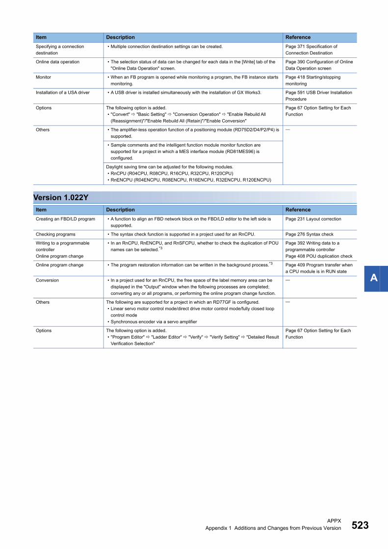
APPXAppendix 1 Additions and Changes from Previous Version 523
A
Version 1.022Y
Specifying a connection
destination
• Multiple connection destination settings can be created. Page 371 Specification of
Connection Destination
Online data operation • The selection status of data can be changed for each data in the [Write] tab of the
"Online Data Operation" screen.
Page 390 Configuration of Online
Data Operation screen
Monitor • When an FB program is opened while monitoring a program, the FB instance starts
monitoring.
Page 418 Starting/stopping
monitoring
Installation of a USA driver • A USB driver is installed simultaneously with the installation of GX Works3. Page 591 USB Driver Installation
Procedure
Options The following option is added.
• "Convert" "Basic Setting" "Conversion Operation" "Enable Rebuild All
(Reassignment)"/"Enable Rebuild All (Retain)"/"Enable Conversion"
Page 67 Option Setting for Each
Function
Others • The amplifier-less operation function of a positioning module (RD75D2/D4/P2/P4) is
supported.
• Sample comments and the intelligent function module monitor function are
supported for a project in which a MES interface module (RD81MES96) is
configured.
Daylight saving time can be adjusted for the following modules.
• RnCPU (R04CPU, R08CPU, R16CPU, R32CPU, R120CPU)
• RnENCPU (R04ENCPU, R08ENCPU, R16ENCPU, R32ENCPU, R120ENCPU)
Item Description Reference
Creating an FBD/LD program • A function to align an FBD network block on the FBD/LD editor to the left side is
supported.
Page 231 Layout correction
Checking programs • The syntax check function is supported in a project used for an RnCPU. Page 276 Syntax check
Writing to a programmable
controller
Online program change
• In an RnCPU, RnENCPU, and RnSFCPU, whether to check the duplication of POU
names can be selected.*3Page 392 Writing data to a
programmable controller
Page 408 POU duplication check
Online program change • The program restoration information can be written in the background process.*3 Page 409 Program transfer when
a CPU module is in RUN state
Conversion • In a project used for an RnCPU, the free space of the label memory area can be
displayed in the "Output" window when the following processes are completed;
converting any or all programs, or performing the online program change function.
Others The following are supported for a project in which an RD77GF is configured.
• Linear servo motor control mode/direct drive motor control mode/fully closed loop
control mode
• Synchronous encoder via a servo amplifier
Options The following option is added.
• "Program Editor" "Ladder Editor" "Verify" "Verify Setting" "Detailed Result
Verification Selection"
Page 67 Option Setting for Each
Function
Item Description Reference
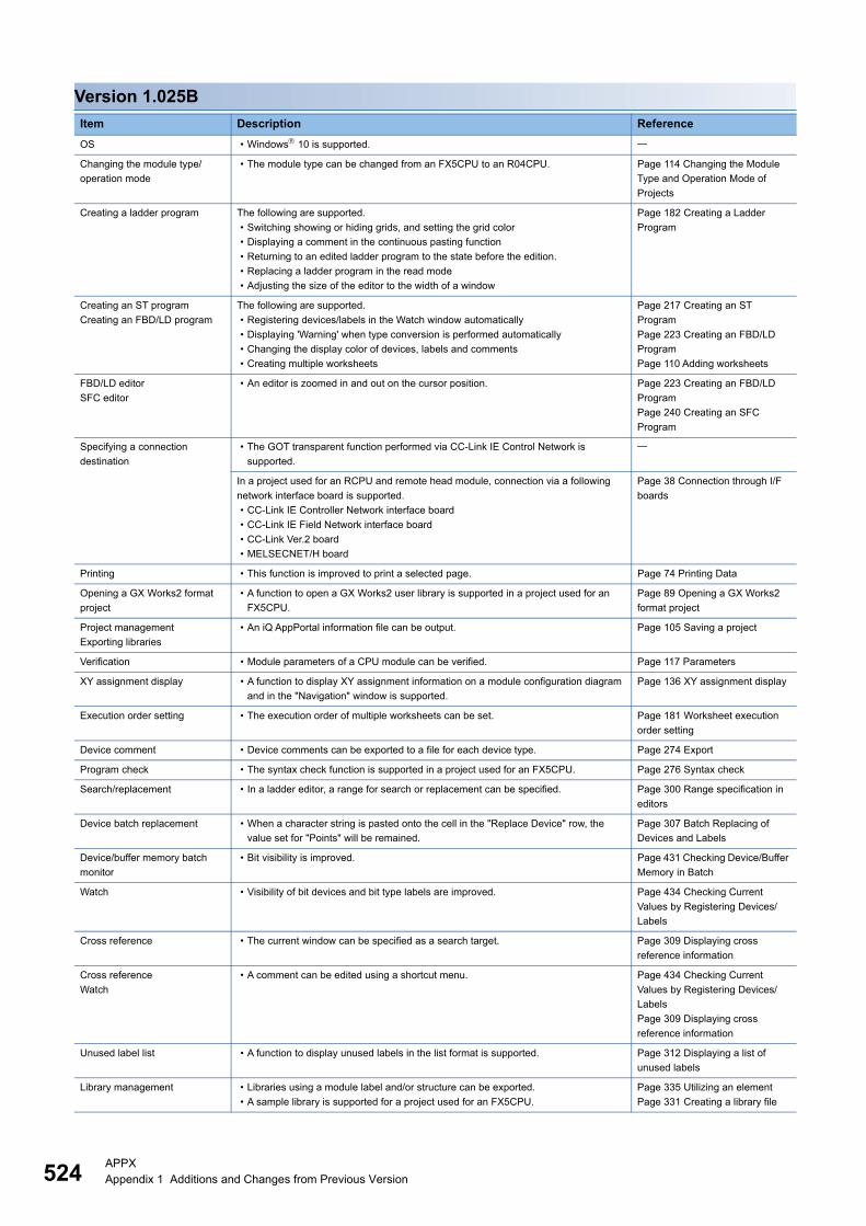
524APPXAppendix 1 Additions and Changes from Previous Version
Version 1.025B
Item Description Reference
OS • Windows 10 is supported.
Changing the module type/
operation mode
• The module type can be changed from an FX5CPU to an R04CPU. Page 114 Changing the Module
Type and Operation Mode of
Projects
Creating a ladder program The following are supported.
• Switching showing or hiding grids, and setting the grid color
• Displaying a comment in the continuous pasting function
• Returning to an edited ladder program to the state before the edition.
• Replacing a ladder program in the read mode
• Adjusting the size of the editor to the width of a window
Page 182 Creating a Ladder
Program
Creating an ST program
Creating an FBD/LD program
The following are supported.
• Registering devices/labels in the Watch window automatically
• Displaying 'Warning' when type conversion is performed automatically
• Changing the display color of devices, labels and comments
• Creating multiple worksheets
Page 217 Creating an ST
Program
Page 223 Creating an FBD/LD
Program
Page 110 Adding worksheets
FBD/LD editor
SFC editor
• An editor is zoomed in and out on the cursor position. Page 223 Creating an FBD/LD
Program
Page 240 Creating an SFC
Program
Specifying a connection
destination
• The GOT transparent function performed via CC-Link IE Control Network is
supported.
In a project used for an RCPU and remote head module, connection via a following
network interface board is supported.
• CC-Link IE Controller Network interface board
• CC-Link IE Field Network interface board
• CC-Link Ver.2 board
• MELSECNET/H board
Page 38 Connection through I/F
boards
Printing • This function is improved to print a selected page. Page 74 Printing Data
Opening a GX Works2 format
project
• A function to open a GX Works2 user library is supported in a project used for an
FX5CPU.
Page 89 Opening a GX Works2
format project
Project management
Exporting libraries
• An iQ AppPortal information file can be output. Page 105 Saving a project
Verification • Module parameters of a CPU module can be verified. Page 117 Parameters
XY assignment display • A function to display XY assignment information on a module configuration diagram
and in the "Navigation" window is supported.
Page 136 XY assignment display
Execution order setting • The execution order of multiple worksheets can be set. Page 181 Worksheet execution
order setting
Device comment • Device comments can be exported to a file for each device type. Page 274 Export
Program check • The syntax check function is supported in a project used for an FX5CPU. Page 276 Syntax check
Search/replacement • In a ladder editor, a range for search or replacement can be specified. Page 300 Range specification in
editors
Device batch replacement • When a character string is pasted onto the cell in the "Replace Device" row, the
value set for "Points" will be remained.
Page 307 Batch Replacing of
Devices and Labels
Device/buffer memory batch
monitor
• Bit visibility is improved. Page 431 Checking Device/Buffer
Memory in Batch
Watch • Visibility of bit devices and bit type labels are improved. Page 434 Checking Current
Values by Registering Devices/
Labels
Cross reference • The current window can be specified as a search target. Page 309 Displaying cross
reference information
Cross reference
Watch
• A comment can be edited using a shortcut menu. Page 434 Checking Current
Values by Registering Devices/
Labels
Page 309 Displaying cross
reference information
Unused label list • A function to display unused labels in the list format is supported. Page 312 Displaying a list of
unused labels
Library management • Libraries using a module label and/or structure can be exported.
• A sample library is supported for a project used for an FX5CPU.
Page 335 Utilizing an element
Page 331 Creating a library file
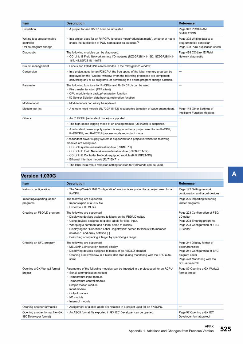
APPXAppendix 1 Additions and Changes from Previous Version 525
AVersion 1.030G
Simulation • A project for an FX5CPU can be simulated. Page 342 PROGRAM
SIMULATION
Writing to a programmable
controller
Online program change
• In a project used for an RnPCPU (process mode/redundant mode), whether or not to
check the duplication of POU names can be selected.*3Page 392 Writing data to a
programmable controller
Page 408 POU duplication check
Diagnostic The following modules can be diagnosed.
• CC-Link IE Field Network remote I/O modules (NZ2GF2B1N1-16D, NZ2GF2B1N1-
16T, NZ2GF2B1N1-16TE)
Page 488 CC-Link IE Field
Network diagnostic
Project management • Labels and FBs/FUNs can be hidden in the "Navigation" window.
Conversion • In a project used for an FX5CPU, the free space of the label memory area can be
displayed on the "Output" window when the following processes are completed;
converting any or all programs, or performing the online program change function.
Parameter The following functions for RnCPUs and RnENCPUs can be used.
• File transfer function (FTP client)
• CPU module data backup/restoration function
• iQ Sensor Solution data backup/restoration function
Module label • Module labels can easily be updated.
Module tool list • A remote head module (RJ72GF15-T2) is supported (creation of wave output data). Page 148 Other Settings of
Intelligent Function Modules
Others • An RnPCPU (redundant mode) is supported.
• The high-speed logging mode of an analog module (Q64ADH) is supported.
• A redundant power supply system is supported for a project used for an RnCPU,
RnENCPU, and RnPCPU (process mode/redundant mode.
A redundant power supply system is supported for a project in which the following
modules are configured.
• CC-Link system master/local module (RJ61BT11)
• CC-Link IE Field Network master/local module (RJ71GF11-T2)
• CC-Link IE Controller Network-equipped module (RJ71GP21-SX)
• Ethernet interface module (RJ71EN71)
• The label initial value reflection setting function for RnPCPUs can be used.
Item Description Reference
Network configuration • The "AnyWireASLINK Configuration" window is supported for a project used for an
RnCPU.
Page 142 Setting network
configuration and target devices
Importing/exporting ladder
programs
The following are supported.
• Import/export of a CSV file
• Export to a HTML file
Page 206 Importing/exporting
ladder programs
Creating an FBD/LD program The following are supported.
• Displaying devices assigned to labels on the FBD/LD editor.
• Using devices assigned to global labels for label input.
• Wrapping a comment and a label name to display.
• Displaying the "Undefined Label Registration" screen for labels with member
notation '.' and array notation '[ ]'.
• Searching or replacing a target by specifying a range
Page 223 Configuration of FBD/
LD editor
Page 228 Entering programs
Page 223 Configuration of FBD/
LD editor
Creating an SFC program The following are supported.
• MELSAP-L (instruction format) display
• Displaying devices assigned to labels of an FBD/LD element
• Opening a new window in a block start step during monitoring with the SFC auto-
scroll
Page 244 Display format of
action/transition
Page 241 Configuration of SFC
diagram editor
Page 428 Monitoring with the
SFC auto-scroll
Opening a GX Works2 format
project
Parameters of the following modules can be imported in a project used for an RCPU.
• Serial communication module
• Temperature input module
• Temperature control module
• Simple motion module
• Input module
• Output module
• I/O module
• Interrupt module
Page 89 Opening a GX Works2
format project
Opening another format file • Assignment of global labels are retained in a project used for an FX5CPU.
Opening another format file (GX
IEC Developer format)
• An ASCII format file exported in GX IEC Developer can be opened. Page 97 Opening a GX IEC
Developer format project
Item Description Reference
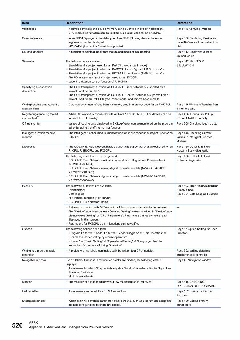
526APPXAppendix 1 Additions and Changes from Previous Version
Verification • A device comment and device memory can be verified in project verification.
• CPU module parameters can be verified in a project used for an FX5CPU.
Page 116 Verifying Projects
Cross reference • In an FBD/LD program, the data type of an FB/FUN using devices/labels as
arguments can be displayed.
• MELSAP-L (instruction format) is supported.
Page 308 Displaying Device and
Label Reference Information in a
List
Unused label list • A function to delete a label from the unused label list is supported. Page 312 Displaying a list of
unused labels
Simulation The following are supported.
• Simulation of a project used for an RnPCPU (redundant mode)
• Simulation of a project in which an RnMTCPU is configured (MT Simulator2)
• Simulation of a project in which an RD77GF is configured (SMM Simulator2)
• The I/O system setting of a project used for an FX5CPU
• Label initialization control function of RnPCPUs
Page 342 PROGRAM
SIMULATION
Specifying a connection
destination
• The GOT transparent function via CC-Link IE Field Network is supported for a
project used for an RCPU.
• The GOT transparent function via CC-Link IE Control Network is supported for a
project used for an RnPCPU (redundant mode) and remote head module.
Writing/reading data to/from a
memory card
• Data can be written to/read from a memory card in a project used for an FX5CPU. Page 415 Writing to/Reading from
a memory card
Registering/canceling forced
input/output*3• When GX Works3 is connected with an RnCPU or RnENCPU, X/Y devices can be
turned ON/OFF forcibly.
Page 438 Turning Input/Output
Device ON/OFF Forcibly
Offline monitor • Values of logging data displayed in GX LogViewer can be monitored on the program
editor by using the offline monitor function.
Page 505 Checking logging data
Intelligent function module
monitor
• The intelligent function module monitor function is supported in a project used for an
FX5CPU.
Page 445 Checking Current
Values in Intelligent Function
Module
Diagnostic • The CC-Link IE Field Network Basic diagnostic is supported for a project used for an
RnCPU, RnENCPU, and FX5CPU.
Page 489 CC-Link IE Field
Network Basic diagnostic
The following modules can be diagnosed.
• CC-Link IE Field Network multiple input module (voltage/current/temperature)
(NZ2GF2S-60MD4)
• CC-Link IE Field Network analog-digital converter module (NZ2GFCE-60ADI8,
NZ2GFCE-60ADV8)
• CC-Link IE Field Network digital-analog converter module (NZ2GFCE-60DAI8,
NZ2GFCE-60DAV8)
Page 488 CC-Link IE Field
Network diagnostic
FX5CPU The following functions are available.
• Event history
• Data logging
• File transfer function (FTP server)
• CC-Link IE Field Network Basic
Page 493 Error History/Operation
History Check
Page 501 Data Logging Function
• A device connected with GX Works3 on Ethernet can automatically be detected.
• The "Device/Label Memory Area Detailed Setting" screen is added in "Device/Label
Memory Area Setting" of "CPU Parameters". Parameters can easily be set and
displayed in this screen.
• Parameters for FX5CPU built-in functions can be verified.
Options The following options are added.
• "Program Editor" "Ladder Editor" "Ladder Diagram" "Edit Operation"
"Enable the ladder editing by mouse operation"
• "Convert" "Basic Setting" "Operational Setting" "Language Used by
Instruction Conversion of String Operation"
Page 67 Option Setting for Each
Function
Writing to a programmable
controller
• A project with no labels can individually be written to a CPU module. Page 392 Writing data to a
programmable controller
Navigation window Even if labels, functions, and function blocks are hidden, the following data is
displayed.
• A statement for which "Display in Navigation Window" is selected in the "Input Line
Statement" window.
• Multiple worksheets
Page 43 Navigation window
Monitor • The visibility of a ladder editor with a low magnification is improved. Page 416 CHECKING
OPERATION OF PROGRAMS
Ladder editor • A statement can be set for an END instruction. Page 182 Creating a Ladder
Program
System parameter • When opening a system parameter, other screens, such as a parameter editor and
module configuration diagram, are closed.
Page 139 Setting system
parameters
Item Description Reference
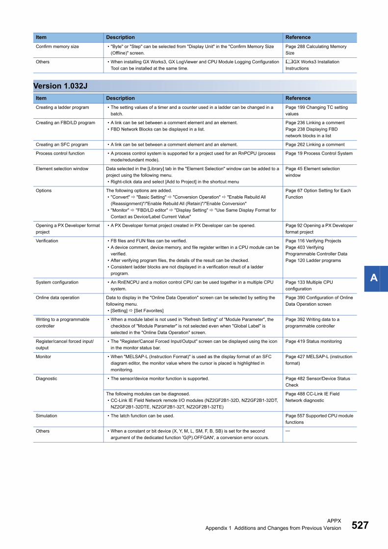
APPXAppendix 1 Additions and Changes from Previous Version 527
A
Version 1.032J
Confirm memory size • "Byte" or "Step" can be selected from "Display Unit" in the "Confirm Memory Size
(Offline)" screen.
Page 288 Calculating Memory
Size
Others • When installing GX Works3, GX LogViewer and CPU Module Logging Configuration
Tool can be installed at the same time.
GX Works3 Installation
Instructions
Item Description Reference
Creating a ladder program • The setting values of a timer and a counter used in a ladder can be changed in a
batch.
Page 199 Changing TC setting
values
Creating an FBD/LD program • A link can be set between a comment element and an element.
• FBD Network Blocks can be displayed in a list.
Page 236 Linking a comment
Page 238 Displaying FBD
network blocks in a list
Creating an SFC program • A link can be set between a comment element and an element. Page 262 Linking a comment
Process control function • A process control system is supported for a project used for an RnPCPU (process
mode/redundant mode).
Page 19 Process Control System
Element selection window Data selected in the [Library] tab in the "Element Selection" window can be added to a
project using the following menu.
• Right-click data and select [Add to Project] in the shortcut menu
Page 45 Element selection
window
Options The following options are added.
• "Convert" "Basic Setting" "Conversion Operation" "Enable Rebuild All
(Reassignment)"/"Enable Rebuild All (Retain)"/"Enable Conversion"
• "Monitor" "FBD/LD editor" "Display Setting" "Use Same Display Format for
Contact as Device/Label Current Value"
Page 67 Option Setting for Each
Function
Opening a PX Developer format
project
• A PX Developer format project created in PX Developer can be opened. Page 92 Opening a PX Developer
format project
Verification • FB files and FUN files can be verified.
• A device comment, device memory, and file register written in a CPU module can be
verified.
• After verifying program files, the details of the result can be checked.
• Consistent ladder blocks are not displayed in a verification result of a ladder
program.
Page 116 Verifying Projects
Page 403 Verifying
Programmable Controller Data
Page 120 Ladder programs
System configuration • An RnENCPU and a motion control CPU can be used together in a multiple CPU
system.
Page 133 Multiple CPU
configuration
Online data operation Data to display in the "Online Data Operation" screen can be selected by setting the
following menu.
• [Setting] [Set Favorites]
Page 390 Configuration of Online
Data Operation screen
Writing to a programmable
controller
• When a module label is not used in "Refresh Setting" of "Module Parameter", the
checkbox of "Module Parameter" is not selected even when "Global Label" is
selected in the "Online Data Operation" screen.
Page 392 Writing data to a
programmable controller
Register/cancel forced input/
output
• The "Register/Cancel Forced Input/Output" screen can be displayed using the icon
in the monitor status bar.
Page 419 Status monitoring
Monitor • When "MELSAP-L (Instruction Format)" is used as the display format of an SFC
diagram editor, the monitor value where the cursor is placed is highlighted in
monitoring.
Page 427 MELSAP-L (instruction
format)
Diagnostic • The sensor/device monitor function is supported. Page 482 Sensor/Device Status
Check
The following modules can be diagnosed.
• CC-Link IE Field Network remote I/O modules (NZ2GF2B1-32D, NZ2GF2B1-32DT,
NZ2GF2B1-32DTE, NZ2GF2B1-32T, NZ2GF2B1-32TE)
Page 488 CC-Link IE Field
Network diagnostic
Simulation • The latch function can be used. Page 557 Supported CPU module
functions
Others • When a constant or bit device (X, Y, M, L, SM, F, B, SB) is set for the second
argument of the dedicated function 'G(P).OFFGAN', a conversion error occurs.
Item Description Reference

528APPXAppendix 1 Additions and Changes from Previous Version
Version 1.035M
Item Description Reference
Creating a ladder program • Pasting to the input/output circuit parts of a function block and function is supported.
• The device comment editor can be opened in a program editor with the menu or
shortcut key.
• The width of all the selected columns can be changed.
• Lines remain after deleting an instruction in "Insert mode".
• When an element is pasted to the position where a line cannot be pasted, only the
element is pasted.
• After pressing the key to edit a device name, the edit can be cancelled by
pressing the key.
Page 270 Displaying the device
comment editor in a program
editor
The display magnification of all ladder editors can be set in a batch by setting the
following menu.
• [View] [Zoom] [Set Zoom Factor]
Importing/exporting ladder
programs
• Ladder programs can be exported to a text file. Page 214 Exporting to a text file
Creating an ST Program • Usable instructions in an ST program are added.
• The device comment editor can be opened in a program editor with the menu or
shortcut key.
Page 270 Displaying the device
comment editor in a program
editor
Creating an FBD/LD program • Connecting elements automatically can be disabled.
• The device comment editor can be opened in a program editor with the menu or
shortcut key.
• The display order of comment elements can be changed.
Page 229 Common operations of
elements
Page 270 Displaying the device
comment editor in a program
editor
Creating an SFC program • The device comment editor can be opened in a program editor with the menu or
shortcut key.
• The display order of comment elements can be changed.
Page 270 Displaying the device
comment editor in a program
editor
Print An FBD/LD program can be printed according to the setting in the following option.
• "Program Editor" "FBD/LD Editor" "Element (Ladder Symbol)" "Display
Format" "Numbers of Wrapping Rows for Device/Label Name"
Page 74 Printing Data
Creating a function block and
function
• "Use MC/MCR to Control EN" can be set for a subroutine type function block in a
project used for an RnCPU and an RnENCPU.*3Page 318 Creating new data
Options The following options are added.
• "Project" "Auto-save" "Operational Setting" "Save project after conversion"/
"Save project after Write to PLC"/"Save project after Online Program Change"/"Save
project after changing TC Setting Value and writing to PLC"
• "Find/Replace" "Common Item" "Operational Setting" "Distinguish DX/DY
device from X/Y device when X/Y device is specified"
Page 67 Option Setting for Each
Function
The following option can be used in a project for FX5CPU.
• "Convert" "Basic Setting" "Operational Setting" "Optimize the Number of
Steps."
Opening a GX Works2 format
project
• The parameters of a triac output module (QY22) are imported. Page 89 Opening a GX Works2
format project
Opening another format file (GX
IEC Developer format)
• An IL/MELSEC IL program created in GX IEC Developer can be opened. Page 97 Opening a GX IEC
Developer format project
Help file • A help file can be linked to a function or function block. Page 111 Associating data with
help files
Verification • Module extended parameters of a simple motion module can be verified.
• The module information of an intelligent function module can be verified.
Page 116 Verifying Projects
Page 403 Verifying
Programmable Controller Data
Module tool list • Multiple input modules (FX5-8AD) are supported.
• Temperature control modules (FX5-4LC) are supported.
• Positioning modules (FX5-20PG-P) are supported.
Page 148 Other Settings of
Intelligent Function Modules
Online program change The following data can be written to a CPU module using this function.
• A single SFC block*3
• SFC inactive block
Page 407 Online program change
of SFC programs
• After writing a project to a running RnPCPU (process mode), program restoration
information can be written in the background process.*3
• When only one program file that is set as "No Execution Type" exists in a project, the
data can be written to a CPU module by using the "Online Program Change"
function.
Page 405 Writing Programs While
a CPU Module is in the RUN State
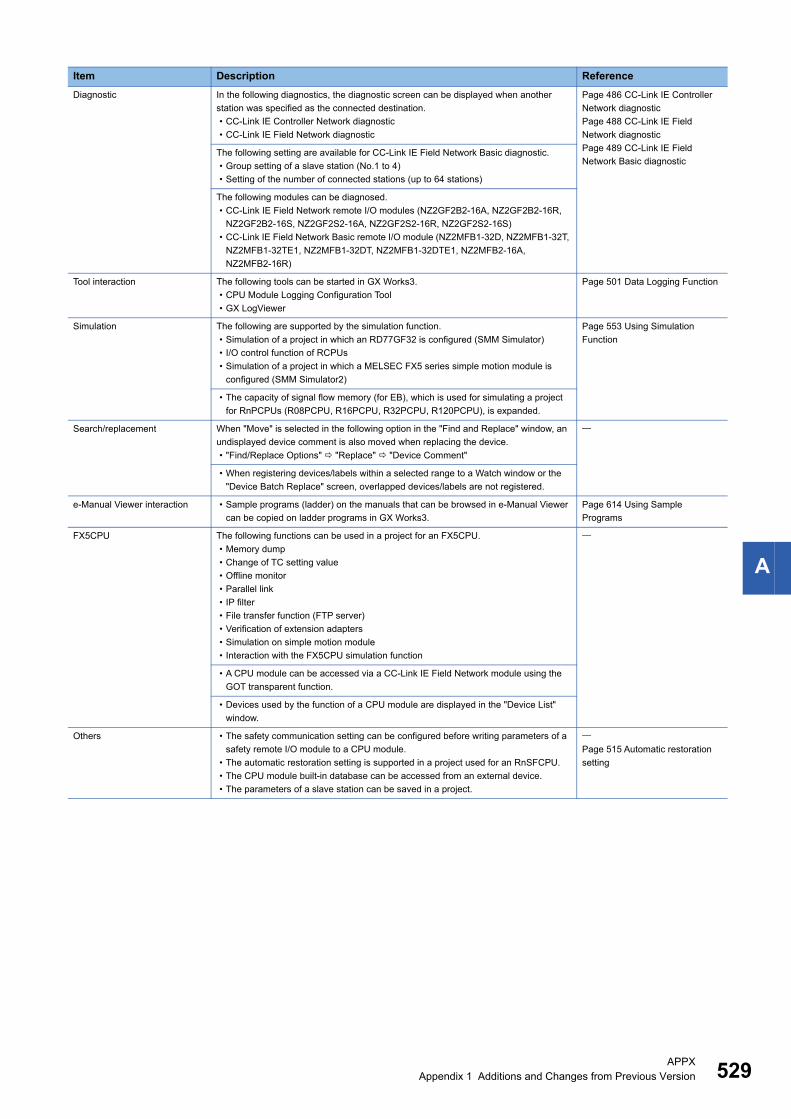
APPXAppendix 1 Additions and Changes from Previous Version 529
A
Diagnostic In the following diagnostics, the diagnostic screen can be displayed when another
station was specified as the connected destination.
• CC-Link IE Controller Network diagnostic
• CC-Link IE Field Network diagnostic
Page 486 CC-Link IE Controller
Network diagnostic
Page 488 CC-Link IE Field
Network diagnostic
Page 489 CC-Link IE Field
Network Basic diagnosticThe following setting are available for CC-Link IE Field Network Basic diagnostic.
• Group setting of a slave station (No.1 to 4)
• Setting of the number of connected stations (up to 64 stations)
The following modules can be diagnosed.
• CC-Link IE Field Network remote I/O modules (NZ2GF2B2-16A, NZ2GF2B2-16R,
NZ2GF2B2-16S, NZ2GF2S2-16A, NZ2GF2S2-16R, NZ2GF2S2-16S)
• CC-Link IE Field Network Basic remote I/O module (NZ2MFB1-32D, NZ2MFB1-32T,
NZ2MFB1-32TE1, NZ2MFB1-32DT, NZ2MFB1-32DTE1, NZ2MFB2-16A,
NZ2MFB2-16R)
Tool interaction The following tools can be started in GX Works3.
• CPU Module Logging Configuration Tool
• GX LogViewer
Page 501 Data Logging Function
Simulation The following are supported by the simulation function.
• Simulation of a project in which an RD77GF32 is configured (SMM Simulator)
• I/O control function of RCPUs
• Simulation of a project in which a MELSEC FX5 series simple motion module is
configured (SMM Simulator2)
Page 553 Using Simulation
Function
• The capacity of signal flow memory (for EB), which is used for simulating a project
for RnPCPUs (R08PCPU, R16PCPU, R32PCPU, R120PCPU), is expanded.
Search/replacement When "Move" is selected in the following option in the "Find and Replace" window, an
undisplayed device comment is also moved when replacing the device.
• "Find/Replace Options" "Replace" "Device Comment"
• When registering devices/labels within a selected range to a Watch window or the
"Device Batch Replace" screen, overlapped devices/labels are not registered.
e-Manual Viewer interaction • Sample programs (ladder) on the manuals that can be browsed in e-Manual Viewer
can be copied on ladder programs in GX Works3.
Page 614 Using Sample
Programs
FX5CPU The following functions can be used in a project for an FX5CPU.
• Memory dump
• Change of TC setting value
• Offline monitor
• Parallel link
• IP filter
• File transfer function (FTP server)
• Verification of extension adapters
• Simulation on simple motion module
• Interaction with the FX5CPU simulation function
• A CPU module can be accessed via a CC-Link IE Field Network module using the
GOT transparent function.
• Devices used by the function of a CPU module are displayed in the "Device List"
window.
Others • The safety communication setting can be configured before writing parameters of a
safety remote I/O module to a CPU module.
• The automatic restoration setting is supported in a project used for an RnSFCPU.
• The CPU module built-in database can be accessed from an external device.
• The parameters of a slave station can be saved in a project.
Page 515 Automatic restoration
setting
Item Description Reference
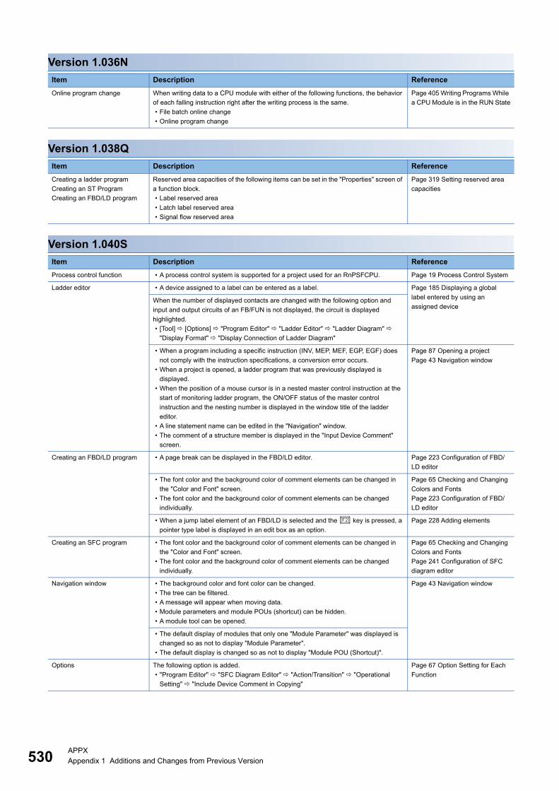
530APPXAppendix 1 Additions and Changes from Previous Version
Version 1.036N
Version 1.038Q
Version 1.040S
Item Description Reference
Online program change When writing data to a CPU module with either of the following functions, the behavior
of each falling instruction right after the writing process is the same.
• File batch online change
• Online program change
Page 405 Writing Programs While
a CPU Module is in the RUN State
Item Description Reference
Creating a ladder program
Creating an ST Program
Creating an FBD/LD program
Reserved area capacities of the following items can be set in the "Properties" screen of
a function block.
• Label reserved area
• Latch label reserved area
• Signal flow reserved area
Page 319 Setting reserved area
capacities
Item Description Reference
Process control function • A process control system is supported for a project used for an RnPSFCPU. Page 19 Process Control System
Ladder editor • A device assigned to a label can be entered as a label. Page 185 Displaying a global
label entered by using an
assigned deviceWhen the number of displayed contacts are changed with the following option and
input and output circuits of an FB/FUN is not displayed, the circuit is displayed
highlighted.
• [Tool] [Options] "Program Editor" "Ladder Editor" "Ladder Diagram"
"Display Format" "Display Connection of Ladder Diagram"
• When a program including a specific instruction (INV, MEP, MEF, EGP, EGF) does
not comply with the instruction specifications, a conversion error occurs.
• When a project is opened, a ladder program that was previously displayed is
displayed.
• When the position of a mouse cursor is in a nested master control instruction at the
start of monitoring ladder program, the ON/OFF status of the master control
instruction and the nesting number is displayed in the window title of the ladder
editor.
• A line statement name can be edited in the "Navigation" window.
• The comment of a structure member is displayed in the "Input Device Comment"
screen.
Page 87 Opening a project
Page 43 Navigation window
Creating an FBD/LD program • A page break can be displayed in the FBD/LD editor. Page 223 Configuration of FBD/
LD editor
• The font color and the background color of comment elements can be changed in
the "Color and Font" screen.
• The font color and the background color of comment elements can be changed
individually.
Page 65 Checking and Changing
Colors and Fonts
Page 223 Configuration of FBD/
LD editor
• When a jump label element of an FBD/LD is selected and the key is pressed, a
pointer type label is displayed in an edit box as an option.
Page 228 Adding elements
Creating an SFC program • The font color and the background color of comment elements can be changed in
the "Color and Font" screen.
• The font color and the background color of comment elements can be changed
individually.
Page 65 Checking and Changing
Colors and Fonts
Page 241 Configuration of SFC
diagram editor
Navigation window • The background color and font color can be changed.
• The tree can be filtered.
• A message will appear when moving data.
• Module parameters and module POUs (shortcut) can be hidden.
• A module tool can be opened.
Page 43 Navigation window
• The default display of modules that only one "Module Parameter" was displayed is
changed so as not to display "Module Parameter".
• The default display is changed so as not to display "Module POU (Shortcut)".
Options The following option is added.
• "Program Editor" "SFC Diagram Editor" "Action/Transition" "Operational
Setting" "Include Device Comment in Copying"
Page 67 Option Setting for Each
Function
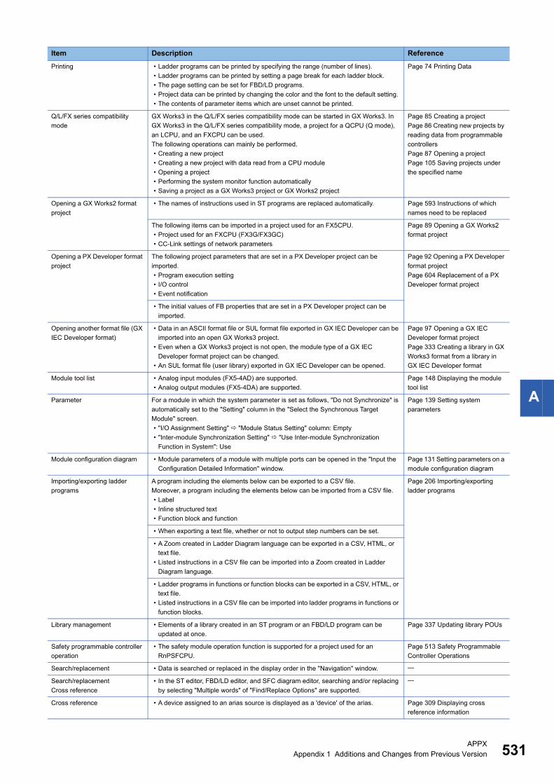
APPXAppendix 1 Additions and Changes from Previous Version 531
A
Printing • Ladder programs can be printed by specifying the range (number of lines).
• Ladder programs can be printed by setting a page break for each ladder block.
• The page setting can be set for FBD/LD programs.
• Project data can be printed by changing the color and the font to the default setting.
• The contents of parameter items which are unset cannot be printed.
Page 74 Printing Data
Q/L/FX series compatibility
mode
GX Works3 in the Q/L/FX series compatibility mode can be started in GX Works3. In
GX Works3 in the Q/L/FX series compatibility mode, a project for a QCPU (Q mode),
an LCPU, and an FXCPU can be used.
The following operations can mainly be performed.
• Creating a new project
• Creating a new project with data read from a CPU module
• Opening a project
• Performing the system monitor function automatically
• Saving a project as a GX Works3 project or GX Works2 project
Page 85 Creating a project
Page 86 Creating new projects by
reading data from programmable
controllers
Page 87 Opening a project
Page 105 Saving projects under
the specified name
Opening a GX Works2 format
project
• The names of instructions used in ST programs are replaced automatically. Page 593 Instructions of which
names need to be replaced
The following items can be imported in a project used for an FX5CPU.
• Project used for an FXCPU (FX3G/FX3GC)
• CC-Link settings of network parameters
Page 89 Opening a GX Works2
format project
Opening a PX Developer format
project
The following project parameters that are set in a PX Developer project can be
imported.
• Program execution setting
• I/O control
• Event notification
Page 92 Opening a PX Developer
format project
Page 604 Replacement of a PX
Developer format project
• The initial values of FB properties that are set in a PX Developer project can be
imported.
Opening another format file (GX
IEC Developer format)
• Data in an ASCII format file or SUL format file exported in GX IEC Developer can be
imported into an open GX Works3 project.
• Even when a GX Works3 project is not open, the module type of a GX IEC
Developer format project can be changed.
• An SUL format file (user library) exported in GX IEC Developer can be opened.
Page 97 Opening a GX IEC
Developer format project
Page 333 Creating a library in GX
Works3 format from a library in
GX IEC Developer format
Module tool list • Analog input modules (FX5-4AD) are supported.
• Analog output modules (FX5-4DA) are supported.
Page 148 Displaying the module
tool list
Parameter For a module in which the system parameter is set as follows, "Do not Synchronize" is
automatically set to the "Setting" column in the "Select the Synchronous Target
Module" screen.
• "I/O Assignment Setting" "Module Status Setting" column: Empty
• "Inter-module Synchronization Setting" "Use Inter-module Synchronization
Function in System": Use
Page 139 Setting system
parameters
Module configuration diagram • Module parameters of a module with multiple ports can be opened in the "Input the
Configuration Detailed Information" window.
Page 131 Setting parameters on a
module configuration diagram
Importing/exporting ladder
programs
A program including the elements below can be exported to a CSV file.
Moreover, a program including the elements below can be imported from a CSV file.
• Label
• Inline structured text
• Function block and function
Page 206 Importing/exporting
ladder programs
• When exporting a text file, whether or not to output step numbers can be set.
• A Zoom created in Ladder Diagram language can be exported in a CSV, HTML, or
text file.
• Listed instructions in a CSV file can be imported into a Zoom created in Ladder
Diagram language.
• Ladder programs in functions or function blocks can be exported in a CSV, HTML, or
text file.
• Listed instructions in a CSV file can be imported into ladder programs in functions or
function blocks.
Library management • Elements of a library created in an ST program or an FBD/LD program can be
updated at once.
Page 337 Updating library POUs
Safety programmable controller
operation
• The safety module operation function is supported for a project used for an
RnPSFCPU.
Page 513 Safety Programmable
Controller Operations
Search/replacement • Data is searched or replaced in the display order in the "Navigation" window.
Search/replacement
Cross reference
• In the ST editor, FBD/LD editor, and SFC diagram editor, searching and/or replacing
by selecting "Multiple words" of "Find/Replace Options" are supported.
Cross reference • A device assigned to an arias source is displayed as a 'device' of the arias. Page 309 Displaying cross
reference information
Item Description Reference
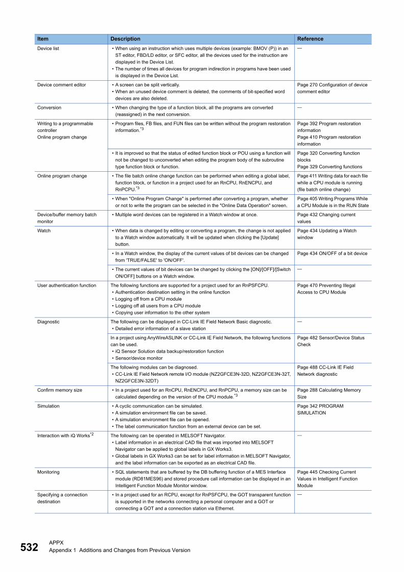
532APPXAppendix 1 Additions and Changes from Previous Version
Device list • When using an instruction which uses multiple devices (example: BMOV (P)) in an
ST editor, FBD/LD editor, or SFC editor, all the devices used for the instruction are
displayed in the Device List.
• The number of times all devices for program indirection in programs have been used
is displayed in the Device List.
Device comment editor • A screen can be split vertically.
• When an unused device comment is deleted, the comments of bit-specified word
devices are also deleted.
Page 270 Configuration of device
comment editor
Conversion • When changing the type of a function block, all the programs are converted
(reassigned) in the next conversion.
Writing to a programmable
controller
Online program change
• Program files, FB files, and FUN files can be written without the program restoration
information.*3Page 392 Program restoration
information
Page 410 Program restoration
information
• It is improved so that the status of edited function block or POU using a function will
not be changed to unconverted when editing the program body of the subroutine
type function block or function.
Page 320 Converting function
blocks
Page 329 Converting functions
Online program change • The file batch online change function can be performed when editing a global label,
function block, or function in a project used for an RnCPU, RnENCPU, and
RnPCPU.*3
Page 411 Writing data for each file
while a CPU module is running
(file batch online change)
• When "Online Program Change" is performed after converting a program, whether
or not to write the program can be selected in the "Online Data Operation" screen.
Page 405 Writing Programs While
a CPU Module is in the RUN State
Device/buffer memory batch
monitor
• Multiple word devices can be registered in a Watch window at once. Page 432 Changing current
values
Watch • When data is changed by editing or converting a program, the change is not applied
to a Watch window automatically. It will be updated when clicking the [Update]
button.
Page 434 Updating a Watch
window
• In a Watch window, the display of the current values of bit devices can be changed
from 'TRUE/FALSE' to 'ON/OFF'.
Page 434 ON/OFF of a bit device
• The current values of bit devices can be changed by clicking the [ON]/[OFF]/[Switch
ON/OFF] buttons on a Watch window.
User authentication function The following functions are supported for a project used for an RnPSFCPU.
• Authentication destination setting in the online function
• Logging off from a CPU module
• Logging off all users from a CPU module
• Copying user information to the other system
Page 470 Preventing Illegal
Access to CPU Module
Diagnostic The following can be displayed in CC-Link IE Field Network Basic diagnostic.
• Detailed error information of a slave station
In a project using AnyWireASLINK or CC-Link IE Field Network, the following functions
can be used.
• iQ Sensor Solution data backup/restoration function
• Sensor/device monitor
Page 482 Sensor/Device Status
Check
The following modules can be diagnosed.
• CC-Link IE Field Network remote I/O module (NZ2GFCE3N-32D, NZ2GFCE3N-32T,
NZ2GFCE3N-32DT)
Page 488 CC-Link IE Field
Network diagnostic
Confirm memory size • In a project used for an RnCPU, RnENCPU, and RnPCPU, a memory size can be
calculated depending on the version of the CPU module.*3Page 288 Calculating Memory
Size
Simulation • A cyclic communication can be simulated.
• A simulation environment file can be saved.
• A simulation environment file can be opened.
• The label communication function from an external device can be set.
Page 342 PROGRAM
SIMULATION
Interaction with iQ Works*2 The following can be operated in MELSOFT Navigator.
• Label information in an electrical CAD file that was imported into MELSOFT
Navigator can be applied to global labels in GX Works3.
• Global labels in GX Works3 can be set for label information in MELSOFT Navigator,
and the label information can be exported as an electrical CAD file.
Monitoring • SQL statements that are buffered by the DB buffering function of a MES Interface
module (RD81MES96) and stored procedure call information can be displayed in an
Intelligent Function Module Monitor window.
Page 445 Checking Current
Values in Intelligent Function
Module
Specifying a connection
destination
• In a project used for an RCPU, except for RnPSFCPU, the GOT transparent function
is supported in the networks connecting a personal computer and a GOT or
connecting a GOT and a connection station via Ethernet.
Item Description Reference
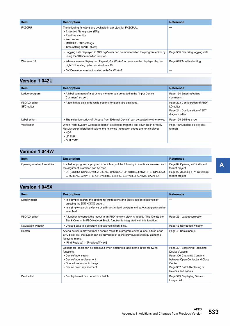
APPXAppendix 1 Additions and Changes from Previous Version 533
A
Version 1.042U
Version 1.044W
Version 1.045X
FX5CPU The following functions are available in a project for FX5CPUs.
• Extended file registers (ER)
• Realtime monitor
• Web server
• MODBUS/TCP settings
• Time setting (SNTP client)
• Logging data displayed in GX LogViewer can be monitored on the program editor by
using the 'Offline monitor' function.
Page 505 Checking logging data
Windows 10 • When a screen display is collapsed, GX Works3 screens can be displayed by the
high DPI scaling option on Windows 10.
Page 615 Troubleshooting
• GX Developer can be installed with GX Works3.
Item Description Reference
Ladder program • A label comment of a structure member can be edited in the "Input Device
Comment" screen.
Page 194 Entering/editing
comments
FBD/LD editor
SFC editor
• A tool hint is displayed while options for labels are displayed. Page 223 Configuration of FBD/
LD editor
Page 241 Configuration of SFC
diagram editor
Label editor • The selection status of "Access from External Device" can be pasted to other rows. Page 158 Editing a row
Verification When "Hide System Generated Items" is selected from the pull-down list in a Verify
Result screen (detailed display), the following instruction codes are not displayed.
• NOP
• LD TMP
• OUT TMP
Page 119 Detailed display (list
format)
Item Description Reference
Opening another format file In a ladder program, a program in which any of the following instructions are used and
the argument is omitted can be read.
• D(P).DDRD, D(P).DDWR, JP.READ, JP.SREAD, JP.WRITE, JP.SWRITE, GP.READ,
GP.SREAD, GP.WRITE, GP.SWRITE, J.ZNRD, J.ZNWR, JP.ZNWR, JP.ZNRD
Page 89 Opening a GX Works2
format project
Page 92 Opening a PX Developer
format project
Item Description Reference
Ladder editor • In a simple search, the options for instructions and labels can be displayed by
pressing the + button.
• In a simple search, a device used in a standard program and safety program can be
searched.
FBD/LD editor • A function to correct the layout in an FBD network block is added. (The 'Delete the
Blank Column In FBD Network Block' function is integrated with this function.)
Page 231 Layout correction
Navigation window • Unused data in a program is displayed in light blue. Page 43 Navigation window
Search After a cursor is moved from a search result to a program editor, a label editor, or an
SFC block list, the cursor can be moved back to the previous position by using the
following menu.
• [Find/Replace] [Previous]/[Next]
Page 48 Basic menus
Options for labels can be displayed when entering a label name in the following
functions.
• Device/label search
• Device/label replacement
• Open/close contact change
• Device batch replacement
Page 301 Searching/Replacing
Devices/Labels
Page 306 Changing Contacts
between Open Contact and Close
Contact
Page 307 Batch Replacing of
Devices and Labels
Device list • Display format can be set in a batch. Page 313 Displaying Device
Usage List
Item Description Reference
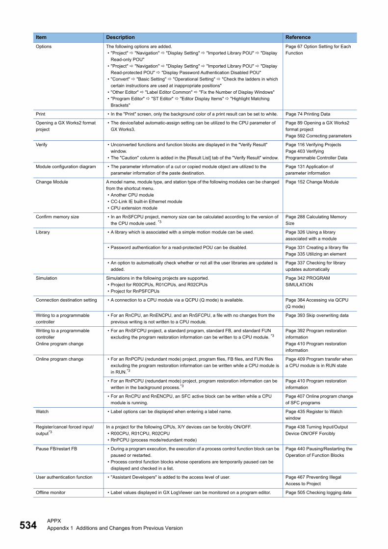
534APPXAppendix 1 Additions and Changes from Previous Version
Options The following options are added.
• "Project" "Navigation" "Display Setting" "Imported Library POU" "Display
Read-only POU"
• "Project" "Navigation" "Display Setting" "Imported Library POU" "Display
Read-protected POU" "Display Password Authentication Disabled POU"
• "Convert" "Basic Setting" "Operational Setting" "Check the ladders in which
certain instructions are used at inappropriate positions"
• "Other Editor" "Label Editor Common" "Fix the Number of Display Windows"
• "Program Editor" "ST Editor" "Editor Display Items" "Highlight Matching
Brackets"
Page 67 Option Setting for Each
Function
Print • In the "Print" screen, only the background color of a print result can be set to white. Page 74 Printing Data
Opening a GX Works2 format
project
• The device/label automatic-assign setting can be utilized to the CPU parameter of
GX Works3.
Page 89 Opening a GX Works2
format project
Page 592 Correcting parameters
Verify • Unconverted functions and function blocks are displayed in the "Verify Result"
window.
• The "Caution" column is added in the [Result List] tab of the "Verify Result" window.
Page 116 Verifying Projects
Page 403 Verifying
Programmable Controller Data
Module configuration diagram • The parameter information of a cut or copied module object are utilized to the
parameter information of the paste destination.
Page 131 Application of
parameter information
Change Module A model name, module type, and station type of the following modules can be changed
from the shortcut menu.
• Another CPU module
• CC-Link IE built-in Ethernet module
• CPU extension module
Page 152 Change Module
Confirm memory size • In an RnSFCPU project, memory size can be calculated according to the version of
the CPU module used. *3Page 288 Calculating Memory
Size
Library • A library which is associated with a simple motion module can be used. Page 326 Using a library
associated with a module
• Password authentication for a read-protected POU can be disabled. Page 331 Creating a library file
Page 335 Utilizing an element
• An option to automatically check whether or not all the user libraries are updated is
added.
Page 337 Checking for library
updates automatically
Simulation Simulations in the following projects are supported.
• Project for R00CPUs, R01CPUs, and R02CPUs
• Project for RnPSFCPUs
Page 342 PROGRAM
SIMULATION
Connection destination setting • A connection to a CPU module via a QCPU (Q mode) is available. Page 384 Accessing via QCPU
(Q mode)
Writing to a programmable
controller
• For an RnCPU, an RnENCPU, and an RnSFCPU, a file with no changes from the
previous writing is not written to a CPU module.
Page 393 Skip overwriting data
Writing to a programmable
controller
Online program change
• For an RnSFCPU project, a standard program, standard FB, and standard FUN
excluding the program restoration information can be written to a CPU module. *3Page 392 Program restoration
information
Page 410 Program restoration
information
Online program change • For an RnPCPU (redundant mode) project, program files, FB files, and FUN files
excluding the program restoration information can be written while a CPU module is
in RUN.*3
Page 409 Program transfer when
a CPU module is in RUN state
• For an RnPCPU (redundant mode) project, program restoration information can be
written in the background process.*3Page 410 Program restoration
information
• For an RnCPU and RnENCPU, an SFC active block can be written while a CPU
module is running.
Page 407 Online program change
of SFC programs
Watch • Label options can be displayed when entering a label name. Page 435 Register to Watch
window
Register/cancel forced input/
output*3In a project for the following CPUs, X/Y devices can be forcibly ON/OFF.
• R00CPU, R01CPU, R02CPU
• RnPCPU (process mode/redundant mode)
Page 438 Turning Input/Output
Device ON/OFF Forcibly
Pause FB/restart FB • During a program execution, the execution of a process control function block can be
paused or restarted.
• Process control function blocks whose operations are temporarily paused can be
displayed and checked in a list.
Page 440 Pausing/Restarting the
Operation of Function Blocks
User authentication function • "Assistant Developers" is added to the access level of user. Page 467 Preventing Illegal
Access to Project
Offline monitor • Label values displayed in GX LogViewer can be monitored on a program editor. Page 505 Checking logging data
Item Description Reference

APPXAppendix 1 Additions and Changes from Previous Version 535
A
*1 To use this function, it is required that MELSOFT Navigator supports the function. For information on the versions of supporting MELSOFT Navigator, refer to MELSOFT Navigator Help.
*2 To use this function, it is required that MELSOFT Navigator supports the function. For information on the versions of supporting MELSOFT Navigator, refer to following manual.Let's start iQ Works Version 2
*3 To use this function, it is required that CPU module supports the function. For information on the firmware version of the supported CPU modules, refer to the following manual.MELSEC iQ-R CPU Module User's Manual (Application)MELSEC iQ-F FX5 User's Manual (Application)
*4 To use this function, it is required that the module supports the function. For information on the firmware version of the supported module, refer to the manual for respective modules.
Diagnostics • The 'Simple CPU Communication Diagnostics' function can be used. Page 492 Simple CPU
communication diagnostic
The following functions can be used in a project using Ethernet (CPU module) and CC-
Link.
• iQ Sensor Solution data backup/restoration
• Sensor/device monitor
Page 482 Sensor/Device Status
Check
The following information can be displayed in CC-Link IE Field Network diagnostic.
• Error history in a slave station
Page 488 CC-Link IE Field
Network diagnostic
The following modules can be diagnosed.
• CC-Link IE Field Network Basic remote I/O module (NZ2MF2S1-32D, NZ2MF2S1-
32T, NZ2MF2S1-32TE1, NZ2MF2S1-32DT, NZ2MF2S1-32DTE1)
• CC-Link IE Field Network remote I/O module (NZ2GF12A-60IOLH8, NZ2GFSS2-
16DTE, NZ2GFSS2-8D, NZ2GFSS2-8TE, FCU8-EX564, FR-A8NCE)
• MELIPC (MI5122-VW)
Page 489 CC-Link IE Field
Network Basic diagnostic
Page 488 CC-Link IE Field
Network diagnostic
FX5CPU • The GOT transparent function, which connects a personal computer and a GOT, and
the GOT and a CPU on Ethernet, can be used.
Page 383 Accessing via GOT
(GOT Transparent Function)
• A simulation environment file can be saved.
• A simulation environment file can be opened.
Page 359 Saving a simulation
environment file
Page 360 Opening a simulation
environment file
• A power supply capacity and I/O points can be checked. Page 136 Checking a power
supply capacity and I/O points
Parameter The following items are added to the parameters for RnCPU and RnENCPU.
• Web Server Settings
• Battery-less Option Cassette Setting
• Simple CPU Communication Setting
Others • The devices on a CC-Link network can be detected.
Item Description Reference
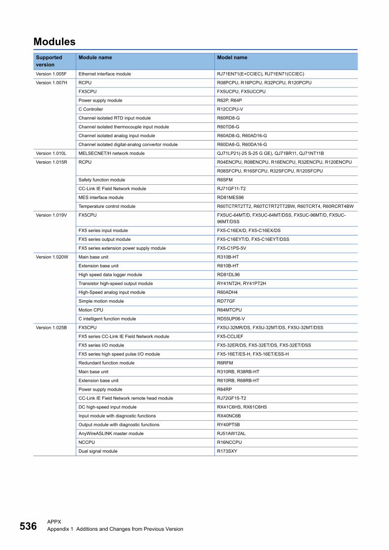
536APPXAppendix 1 Additions and Changes from Previous Version
ModulesSupported version
Module name Model name
Version 1.005F Ethernet interface module RJ71EN71(E+CCIEC), RJ71EN71(CCIEC)
Version 1.007H RCPU R08PCPU, R16PCPU, R32PCPU, R120PCPU
FX5CPU FX5UCPU, FX5UCCPU
Power supply module R62P, R64P
C Controller R12CCPU-V
Channel isolated RTD input module R60RD8-G
Channel isolated thermocouple input module R60TD8-G
Channel isolated analog input module R60AD8-G, R60AD16-G
Channel isolated digital-analog convertor module R60DA8-G, R60DA16-G
Version 1.010L MELSECNET/H network module QJ71LP21(-25 S-25 G GE), QJ71BR11, QJ71NT11B
Version 1.015R RCPU R04ENCPU, R08ENCPU, R16ENCPU, R32ENCPU, R120ENCPU
R08SFCPU, R16SFCPU, R32SFCPU, R120SFCPU
Safety function module R6SFM
CC-Link IE Field Network module RJ71GF11-T2
MES interface module RD81MES96
Temperature control module R60TCTRT2TT2, R60TCTRT2TT2BW, R60TCRT4, R60RCRT4BW
Version 1.019V FX5CPU FX5UC-64MT/D, FX5UC-64MT/DSS, FX5UC-96MT/D, FX5UC-
96MT/DSS
FX5 series input module FX5-C16EX/D, FX5-C16EX/DS
FX5 series output module FX5-C16EYT/D, FX5-C16EYT/DSS
FX5 series extension power supply module FX5-C1PS-5V
Version 1.020W Main base unit R310B-HT
Extension base unit R610B-HT
High speed data logger module RD81DL96
Transistor high-speed output module RY41NT2H, RY41PT2H
High-Speed analog input module R60ADH4
Simple motion module RD77GF
Motion CPU R64MTCPU
C intelligent function module RD55UP06-V
Version 1.025B FX5CPU FX5U-32MR/DS, FX5U-32MT/DS, FX5U-32MT/DSS
FX5 series CC-Link IE Field Network module FX5-CCLIEF
FX5 series I/O module FX5-32ER/DS, FX5-32ET/DS, FX5-32ET/DSS
FX5 series high speed pulse I/O module FX5-16ET/ES-H, FX5-16ET/ESS-H
Redundant function module R6RFM
Main base unit R310RB, R38RB-HT
Extension base unit R610RB, R68RB-HT
Power supply module R64RP
CC-Link IE Field Network remote head module RJ72GF15-T2
DC high-speed input module RX41C6HS, RX61C6HS
Input module with diagnostic functions RX40NC6B
Output module with diagnostic functions RY40PT5B
AnyWireASLINK master module RJ51AW12AL
NCCPU R16NCCPU
Dual signal module R173SXY

APPXAppendix 1 Additions and Changes from Previous Version 537
A
Version 1.030G Power supply module R63RP
Triac output module RY20S6
Flexible high-speed I/O control module RD40PD01
Simple motion module RD77GF32
FX5CPU FX5U-64MR/DS, FX5U-64MT/DS, FX5U-64MT/DSS, FX5U-80MR/
DS, FX5U-80MT/DS, FX5U-80MT/DSS
FX5 series I/O module FX5-16ER/ES, FX5-16ET/ES, FX5-16ET/ESS
FX5 series RTD input adapter FX5-4AD-PT-ADP
FX5 series thermocouple input adapter FX5-4AD-TC-ADP
FX5 series simple motion module FX5-80SSC-S
Version 1.032J AC input module RX28
Contact output module RY18R2A
High-speed analog output module (voltage/current) R60DAH4
Extension cable RC100B
Version 1.035M Robot CPU R16RTCPU
OPC UA server module RD81OPC96
BACnet module RJ71BAC96
FX5CPU FX5UC-32MT/DS-TS, FX5UC-32MT/DSS-TS
FX5 series input module FX5-C32EX/DS-TS
FX5 series output module FX5-C32EYT/D-TS, FX5-C32EYT/DSS-TS
FX5 series I/O module FX5-C32ET/DS-TS, FX5-C32ET/DSS-TS
FX5 series multiple input module FX5-8AD
FX5 series temperature control module FX5-4LC
FX5 series positioning module FX5-20PG-P
FX5 series CC-Link system master/intelligent device module FX5-CCL-MS
FX5 series AnyWireASLINK master module FX5-ASL-M
Version 1.038Q CANopen module RJ71CN91
Version 1.040S RCPU R00CPU, R01CPU, R02CPU, R08PSFCPU, R16PSFCPU,
R32PSFCPU, R120PSFCPU
SIL2 function module R6PSFM
Input module with diagnostic functions RX40NC6B(S2M), RX40NC6B(S2S)
Output module with diagnostic functions RY40PT5B(S2M), RY40PT5B(S2S)
MES interface module QJ71MES96N
FX5 series analog input module FX5-4AD
FX5 series analog output module FX5-4DA
Version 1.045X PROFIBUS interface module RJ71PB91V(S)
Input module RX70C4, RX71C4, RX72C4, RX10-TS, RX40C7-TS, RX41C4-TS
Output module RY40PT5B-AS, RY10R2-TS, RY40NT5P-TS, RY40PT5P-TS,
RY41NT2P-TS, RY41PT1P-TS
CC-Link IE Controller Network module RJ71GP21S-SX
DeviceNet master/slave module QJ71DN91, RJ71DN91
Channel isolated analog input module R60AD8-G(S2M), R60AD8-G(S2S)
Channel isolated digital-analog convertor module R60DA8-G(S2M)
Supported version
Module name Model name
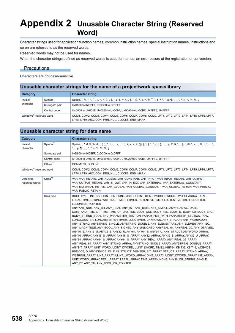
538APPXAppendix 2 Unusable Character String (Reserved Word)
Appendix 2 Unusable Character String (Reserved Word)
Character strings used for application function names, common instruction names, special instruction names, instructions and
so on are referred to as the reserved words.
Reserved words may not be used for names.
When the character strings defined as reserved words is used for names, an error occurs at the registration or conversion.
Precautions
Characters are not case-sensitive.
Unusable character strings for the name of a project/work space/library
Unusable character string for data name
Category Character string
Invalid
character
Symbol Space, ", %, ', *, /, ., :, <, >, ?, \, |, ¡, ¢, £, ¤, \, ¦, §, ¨, ©, ª, «, ¬, ®, ¯, °, ±, ², ³, ´, µ, ¶, ·, ¸, ¹, º, », ¼, ½, ¾, ¿
Surrogate pair 0xD800 to 0xDBFF, 0xDC00 to 0xDFFF
Control code U+0000 to U+001F, U+0080 to U+009F, U+00A0 to U+00BF, U+FFFE, U+FFFF
Windows reserved word COM1, COM2, COM3, COM4, COM5, COM6, COM7, COM8, COM9, LPT1, LPT2, LPT3, LPT4, LPT5, LPT6, LPT7,
LPT8, LPT9, AUX, CON, PRN, NUL, CLOCK$, END_MARK
Category Character string
Invalid
character
Symbol*1 Space, !, ", #, $, %, &, ', (, ), *, +, /, ,, -, ., :, ;, <, =, >, ?, @, [, \, ], ^, `, {, |, }, ~, ¡, ¢, £, ¤, \, ¦, §, ¨, ©, ª, «, ¬, ®, ¯, °, ±, ²,
³, ´, µ, ¶, ·, ¸, ¹, º, », ¼, ½, ¾, ¿
Surrogate pair 0xD800 to 0xDBFF, 0xDC00 to 0xDFFF
Control code U+0000 to U+001F, U+0080 to U+009F, U+00A0 to U+00BF, U+FFFE, U+FFFF
Others*1 COMMENT, GLBLINF
Windows reserved word COM1, COM2, COM3, COM4, COM5, COM6, COM7, COM8, COM9, LPT1, LPT2, LPT3, LPT4, LPT5, LPT6, LPT7,
LPT8, LPT9, AUX, CON, PRN, NUL, CLOCK$, END_MARK
Data type
reserved words
Class*1 VAR, VAR_RETAIN, VAR_ACCESS, VAR_CONSTANT, VAR_INPUT, VAR_INPUT_RETAIN, VAR_OUTPUT,
VAR_OUTPUT_RETAIN, VAR_IN_OUT, VAR_IN_EXT, VAR_EXTERNAL, VAR_EXTERNAL_CONSTANT,
VAR_EXTERNAL_RETAIN, VAR_GLOBAL, VAR_GLOBAL_CONSTANT, VAR_GLOBAL_RETAIN, VAR_PUBLIC,
VAR_PUBLIC_RETAIN
Data type BOOL, BYTE, INT, SINT, DINT, LINT, UINT, USINT, UDINT, ULINT, WORD, DWORD, LWORD, ARRAY, REAL,
LREAL, TIME, STRING, WSTRING, TIMER, LTIMER, RETENTIVETIMER, LRETENTIVETIMER, COUNTER,
LCOUNTER, POINTER
ANY, ANY_NUM, ANY_BIT, ANY_REAL, ANY_INT, ANY_DATE, ANY_SIMPLE, ANY16, ANY32, DATE,
DATE_AND_TIME, DT, TIME, TIME_OF_DAY, TOD, BODY_CCE, BODY_FBD, BODY_IL, BODY_LD, BODY_SFC,
BODY_ST, END_BODY, END_PARAMETER_SECTION, PARAM_FILE_PATH, PARAMETER_SECTION, POW,
LONGCOUNTER, LONGRETENTIVETIMER, LONGTIMER, UNKNOWN, ANY_BITADDR, ANY_WORDADDR,
ANY_STRING, ANYSTRING_SINGLE, ANYSTRING_DOUBLE, ANY_ELEMENTARY, ANY_ELEMENTARY_IEC,
ANY_MAGNITUDE, ANY_BOOL, ANY_SIGNED, ANY_UNSIGNED, ANYREAL_64, ANYREAL_32, ANY_DERIVED,
ANY16_S, ANY16_U, ANY32_S, ANY32_U, ANY64, ANY64_S, ANY64_U, ANY_STRUCT, ANYWORD_ARRAY,
ANY16_ARRAY, ANY16_S_ARRAY, ANY16_U_ARRAY, ANY32_ARRAY, ANY32_S_ARRAY, ANY32_U_ARRAY,
ANY64_ARRAY, ANY64_S_ARRAY, ANY64_U_ARRAY, ANY_REAL_ARRAY, ANY_REAL_32_ARRAY,
ANY_REAL_64_ARRAY, ANY_STRING_ARRAY, ANYSTRING_SINGLE_ARRAY, ANYSTRING_DOUBLE_ARRAY,
ANYBIT_ARRAY, UINT_WORD, UDINT_DWORD, ULINT_LWORD, TIME2, KBIT64, KBIT32, KBIT16, WDEVICE,
BDEVICE, DUMMYDEVICE, FB, FUN, STRUCT_MEMBER, BIT_ARRAY, STRUCT_ARRAY, STRING_ARRAY,
WSTRING_ARRAY, LINT_ARRAY, ULINT_LWORD_ARRAY, DINT_ARRAY, UDINT_DWORD_ARRAY, INT_ARRAY,
UINT_WORD_ARRAY, REAL_ARRAY, LREAL_ARRAY, TIME_ARRAY, NONE, ANY16_OR_STRING_SINGLE,
ANY_DT, ANY_TM, ANY_BOOL_OR_POINTER
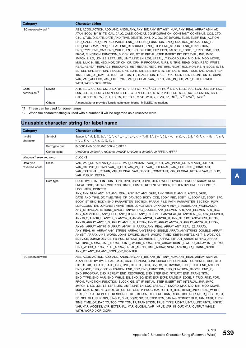
APPXAppendix 2 Unusable Character String (Reserved Word) 539
A
*1 These can be used for some names.*2 When the character string is used with a number, it will be regarded as a reserved word.
Unusable character string for label name
IEC reserved word*1 ABS, ACOS, ACTION, ADD, AND, ANDN, ANY, ANY_BIT, ANY_INT, ANY_NUM, ANY_REAL, ARRAY, ASIN, AT,
ATAN, BOOL, BY, BYTE, CAL, CALC, CASE, CONCAT, CONFIGURATION, CONSTANT, CONTINUE, COS, CTD,
CTU, CTUD, D, DATE, DATE_AND_TIME, DELETE, DINT, DIV, DO, DT, DWORD, ELSE, ELSIF, END_ACTION,
END_CASE, END_CONFIGURATION, END_FOR, END_FUNCTION, END_FUNCTION_BLOCK , END_IF,
END_PROGRAM, END_REPEAT, END_RESOURCE, END_STEP, END_STRUCT, END_TRANSITION,
END_TYPE, END_VAR, END_WHILE, EN, ENO, EQ, EXIT, EXP, EXPT, FALSE, F_EDGE, F_TRIG, FIND, FOR,
FROM, FUNCTION, FUNCTION_BLOCK, GE, GT, IF, INITIAL_STEP, INSERT, INT, INTERVAL, JMP, JMPC,
JMPCN, L, LD, LDN, LE, LEFT, LEN, LIMIT, LINT, LN, LOG, LREAL, LT, LWORD, MAX, MID, MIN, MOD, MOVE,
MUL, MUX, N, NE, NEG, NOT, OF, ON, OR, ORN, P, PROGRAM, R, R1, R_TRIG, READ_ONLY, READ_WRITE,
REAL, REPEAT, REPLACE, RESOURCE, RET, RETAIN, RETC, RETURN, RIGHT, ROL, ROR, RS, R_EDGE, S, S1,
SD, SEL, SHL, SHR, SIN, SINGLE, SINT, SQRT, SR, ST, STEP, STN, STRING, STRUCT, SUB, TAN, TASK, THEN,
TIME, TIME_OF_DAY, TO, TOD, TOF, TON, TP, TRANSITION, TRUE, TYPE, UDINT, UINT, ULINT, UNTIL, USINT,
VAR, VAR_ACCESS, VAR_EXTERNAL, VAR_GLOBAL, VAR_INPUT, VAR_IN_OUT, VAR_OUTPUT, WHILE,
WITH, WORD, XOR, XORN
Code
conversion*1Device A, B, BL, C, CC, CN, CS, D, DX, DY, E, F, FD, FX, FY, G*2, GLP, H, HG*2, I, J, K, L, LC, LCC, LCN, LCS, LLP, LSC,
LSN, LSS, LST, LSTC, LSTN, LSTS, LT, LTC, LTN, LTS, LZ, M, N, P, PH, R, RD, S, SB, SC, SD, SM, SN, SS, ST,
STC, STN, STS, SW, SZ, T, TC, TN, TR, TS, U, V, VD, W, X, Y, Z, ZR, ZZ, RX*2, RY*2, RWr*2, RWw*2
Others A manufacturer-provided functions/function blocks, MELSEC instructions
Category Character string
Invalid
character
Symbol Space, !, ", #, $, %, &, ', (, ), *, +, /, ,, -, ., :, ;, <, =, >, ?, @, [, \, ], ^, `, {, |, }, ~, ¡, ¢, £, ¤, \, ¦, §, ¨, ©, ª, «, ¬, ®, ¯, °, ±, ²,
³, ´, µ, ¶, ·, ¸, ¹, º, », ¼, ½, ¾, ¿
Surrogate pair 0xD800 to 0xDBFF, 0xDC00 to 0xDFFF
Control code U+0000 to U+001F, U+0080 to U+009F, U+00A0 to U+00BF, U+FFFE, U+FFFF
Windows reserved word CLOCK$
Data type
reserved words
Class VAR, VAR_RETAIN, VAR_ACCESS, VAR_CONSTANT, VAR_INPUT, VAR_INPUT_RETAIN, VAR_OUTPUT,
VAR_OUTPUT_RETAIN, VAR_IN_OUT, VAR_IN_EXT, VAR_EXTERNAL, VAR_EXTERNAL_CONSTANT,
VAR_EXTERNAL_RETAIN, VAR_GLOBAL, VAR_GLOBAL_CONSTANT, VAR_GLOBAL_RETAIN, VAR_PUBLIC,
VAR_PUBLIC_RETAIN
Data type BOOL, BYTE, INT, SINT, DINT, LINT, UINT, USINT, UDINT, ULINT, WORD, DWORD, LWORD, ARRAY, REAL,
LREAL, TIME, STRING, WSTRING, TIMER, LTIMER, RETENTIVETIMER, LRETENTIVETIMER, COUNTER,
LCOUNTER, POINTER
ANY, ANY_NUM, ANY_BIT, ANY_REAL, ANY_INT, ANY_DATE, ANY_SIMPLE, ANY16, ANY32, DATE,
DATE_AND_TIME, DT, TIME, TIME_OF_DAY, TOD, BODY_CCE, BODY_FBD, BODY_IL, BODY_LD, BODY_SFC,
BODY_ST, END_BODY, END_PARAMETER_SECTION, PARAM_FILE_PATH, PARAMETER_SECTION, POW,
LONGCOUNTER, LONGRETENTIVETIMER, LONGTIMER, UNKNOWN, ANY_BITADDR, ANY_WORDADDR,
ANY_STRING, ANYSTRING_SINGLE, ANYSTRING_DOUBLE, ANY_ELEMENTARY, ANY_ELEMENTARY_IEC,
ANY_MAGNITUDE, ANY_BOOL, ANY_SIGNED, ANY_UNSIGNED, ANYREAL_64, ANYREAL_32, ANY_DERIVED,
ANY16_S, ANY16_U, ANY32_S, ANY32_U, ANY64, ANY64_S, ANY64_U, ANY_STRUCT, ANYWORD_ARRAY,
ANY16_ARRAY, ANY16_S_ARRAY, ANY16_U_ARRAY, ANY32_ARRAY, ANY32_S_ARRAY, ANY32_U_ARRAY,
ANY64_ARRAY, ANY64_S_ARRAY, ANY64_U_ARRAY, ANY_REAL_ARRAY, ANY_REAL_32_ARRAY,
ANY_REAL_64_ARRAY, ANY_STRING_ARRAY, ANYSTRING_SINGLE_ARRAY, ANYSTRING_DOUBLE_ARRAY,
ANYBIT_ARRAY, UINT_WORD, UDINT_DWORD, ULINT_LWORD, TIME2, KBIT64, KBIT32, KBIT16, WDEVICE,
BDEVICE, DUMMYDEVICE, FB, FUN, STRUCT_MEMBER, BIT_ARRAY, STRUCT_ARRAY, STRING_ARRAY,
WSTRING_ARRAY, LINT_ARRAY, ULINT_LWORD_ARRAY, DINT_ARRAY, UDINT_DWORD_ARRAY, INT_ARRAY,
UINT_WORD_ARRAY, REAL_ARRAY, LREAL_ARRAY, TIME_ARRAY, NONE, ANY16_OR_STRING_SINGLE,
ANY_DT, ANY_TM, ANY_BOOL_OR_POINTER
IEC reserved word ABS, ACOS, ACTION, ADD, AND, ANDN, ANY, ANY_BIT, ANY_INT, ANY_NUM, ANY_REAL, ARRAY, ASIN, AT,
ATAN, BOOL, BY, BYTE, CAL, CALC, CASE, CONCAT, CONFIGURATION, CONSTANT, CONTINUE, COS, CTD,
CTU, CTUD, D, DATE, DATE_AND_TIME, DELETE, DINT, DIV, DO, DT, DWORD, ELSE, ELSIF, END_ACTION,
END_CASE, END_CONFIGURATION, END_FOR, END_FUNCTION, END_FUNCTION_BLOCK , END_IF,
END_PROGRAM, END_REPEAT, END_RESOURCE, END_STEP, END_STRUCT, END_TRANSITION,
END_TYPE, END_VAR, END_WHILE, EN, ENO, EQ, EXIT, EXP, EXPT, FALSE, F_EDGE, F_TRIG, FIND, FOR,
FROM, FUNCTION, FUNCTION_BLOCK, GE, GT, IF, INITIAL_STEP, INSERT, INT, INTERVAL, JMP, JMPC,
JMPCN, L, LD, LDN, LE, LEFT, LEN, LIMIT, LINT, LN, LOG, LREAL, LT, LWORD, MAX, MID, MIN, MOD, MOVE,
MUL, MUX, N, NE, NEG, NOT, OF, ON, OR, ORN, P, PROGRAM, R, R1, R_TRIG, READ_ONLY, READ_WRITE,
REAL, REPEAT, REPLACE, RESOURCE, RET, RETAIN, RETC, RETURN, RIGHT, ROL, ROR, RS, R_EDGE, S, S1,
SD, SEL, SHL, SHR, SIN, SINGLE, SINT, SQRT, SR, ST, STEP, STN, STRING, STRUCT, SUB, TAN, TASK, THEN,
TIME, TIME_OF_DAY, TO, TOD, TOF, TON, TP, TRANSITION, TRUE, TYPE, UDINT, UINT, ULINT, UNTIL, USINT,
VAR, VAR_ACCESS, VAR_EXTERNAL, VAR_GLOBAL, VAR_INPUT, VAR_IN_OUT, VAR_OUTPUT, WHILE,
WITH, WORD, XOR, XORN
Category Character string
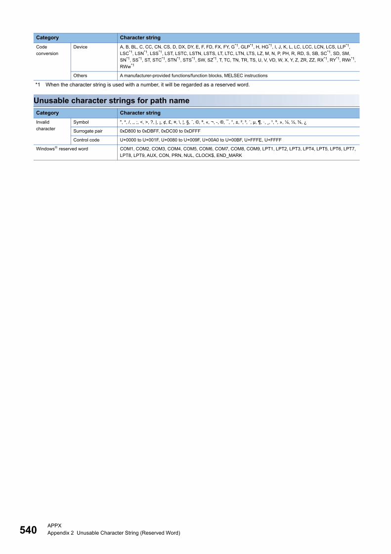
540APPXAppendix 2 Unusable Character String (Reserved Word)
*1 When the character string is used with a number, it will be regarded as a reserved word.
Unusable character strings for path name
Code
conversion
Device A, B, BL, C, CC, CN, CS, D, DX, DY, E, F, FD, FX, FY, G*1, GLP*1, H, HG*1, I, J, K, L, LC, LCC, LCN, LCS, LLP*1,
LSC*1, LSN*1, LSS*1, LST, LSTC, LSTN, LSTS, LT, LTC, LTN, LTS, LZ, M, N, P, PH, R, RD, S, SB, SC*1, SD, SM,
SN*1, SS*1, ST, STC*1, STN*1, STS*1, SW, SZ*1, T, TC, TN, TR, TS, U, V, VD, W, X, Y, Z, ZR, ZZ, RX*1, RY*1, RWr*1,
RWw*1
Others A manufacturer-provided functions/function blocks, MELSEC instructions
Category Character string
Invalid
character
Symbol ", *, /, ,, ;, <, >, ?, |, ¡, ¢, £, ¤, \, ¦, §, ¨, ©, ª, «, ¬, -, ®, ¯, °, ±, ², ³, ´, µ, ¶, ·, ¸, ¹, º, », ¼, ½, ¾, ¿
Surrogate pair 0xD800 to 0xDBFF, 0xDC00 to 0xDFFF
Control code U+0000 to U+001F, U+0080 to U+009F, U+00A0 to U+00BF, U+FFFE, U+FFFF
Windows reserved word COM1, COM2, COM3, COM4, COM5, COM6, COM7, COM8, COM9, LPT1, LPT2, LPT3, LPT4, LPT5, LPT6, LPT7,
LPT8, LPT9, AUX, CON, PRN, NUL, CLOCK$, END_MARK
Category Character string

APPXAppendix 3 Applicable Devices in GX Works3 541
A
Appendix 3 Applicable Devices in GX Works3
RCPUs: Applicable, : Display only, : Not applicable : Not available
Category Device name Symbol Digit specification
Bit-specified word device
Device comment
Device memory
Device initial value
User device Input X
Output Y
Internal relay M *1
Latch relay L
Link relay B
Annunciator F
Link special relay SB
Edge relay V*1
Step relay S*2
Timer T *1
Retentive timer ST *1
Long timer LT*1
Long retentive timer LST*1
Counter C *1
Long counter LC *1
Data register D *1
Link register W
Link special register SW
Direct access input X (DX)
Direct access output Y (DY)
System device Function input FX
Function output FY
Function register FD
Special relay SM
Special register SD
Link direct device Link input J\X
Link output J\Y
Link relay J\B
Link special relay J\SB
Link register J\W
Link special register J\SW
Module access device Module access device U\G
CPU buffer memory access
device
CPU buffer memory access
device
U3E\G
U3E\H
G
Index register Index register Z *1
Long index register LZ *1
File register File register R
ZR
Refresh data register Refresh data register RD
Nesting Nesting N
Pointer Pointer P *1
Interrupt pointer I

542APPXAppendix 3 Applicable Devices in GX Works3
*1 Writing to local devices is available.*2 When editing it in other places except in a Zoom, specify a step relay with a block specification (BL\S).
How to input local devicesPrefix '#' to the device name (Example: #D10)
Creating comments for module access devicesDevice comments within the following range can be created in the buffer memory (3E00H to 3E30H) of CPU module in a
multiple CPU system.
Applicable devices in safety project: Applicable, : Display only, : Not applicable : Not available
*1 Writing to local devices is available.
■How to input deviceGlobal device: Prefix 'SA\' to the device name. (Example: SA\D10)
Local device: Prefix 'SA\#' to the device name. (Example: SA\#D10)
Other devices SFC block device BL
SFC transition device TR
Step relay (with a block
specification)
BL\S
SFC transition device (with a
block specification)
BL\TR
Network number specified
device
J
I/O number specified device U
Constant Decimal constant K
Hexadecimal constant H
Real constant E
String constant
Supported range Unsupported range
U0 (\G0) to U1FF (\G268435455) U200 (\G0) to U3DF (\G268435455)
U3E0 (\G0) to U3E3 (\G268435455)
Category Device name Symbol Digit specification
Bit-specified word device
Device comment
Device memory
Device initial value
User device Safety input SA\X
Safety output SA\Y
Safety internal relay SA\M*1
Safety link relay SA\B
Safety timer SA\T*1
Safety retentive timer SA\ST*1
Safety counter SA\C*1
Safety data register SA\D*1
Safety link register SA\W
System device Safety special relay SA\SM
Safety special register SA\SD
Category Device name Symbol Digit specification
Bit-specified word device
Device comment
Device memory
Device initial value
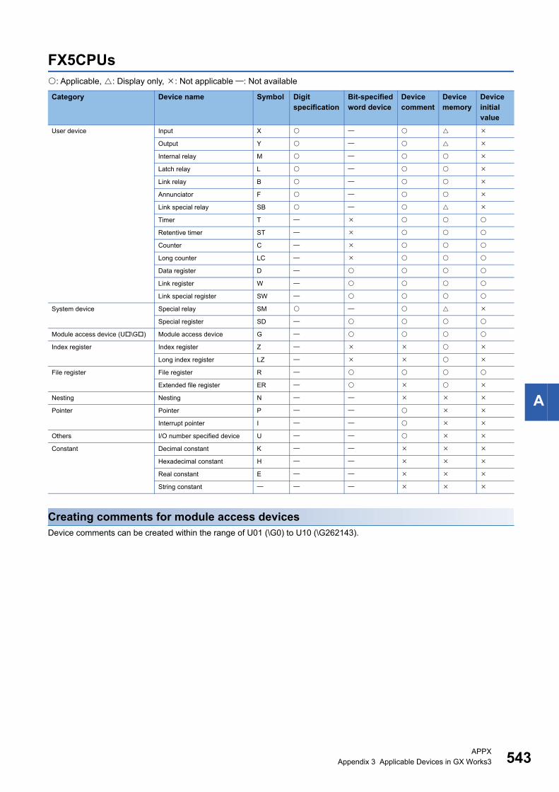
APPXAppendix 3 Applicable Devices in GX Works3 543
A
FX5CPUs: Applicable, : Display only, : Not applicable : Not available
Creating comments for module access devicesDevice comments can be created within the range of U01 (\G0) to U10 (\G262143).
Category Device name Symbol Digit specification
Bit-specified word device
Device comment
Device memory
Device initial value
User device Input X
Output Y
Internal relay M
Latch relay L
Link relay B
Annunciator F
Link special relay SB
Timer T
Retentive timer ST
Counter C
Long counter LC
Data register D
Link register W
Link special register SW
System device Special relay SM
Special register SD
Module access device (U\G) Module access device G
Index register Index register Z
Long index register LZ
File register File register R
Extended file register ER
Nesting Nesting N
Pointer Pointer P
Interrupt pointer I
Others I/O number specified device U
Constant Decimal constant K
Hexadecimal constant H
Real constant E
String constant
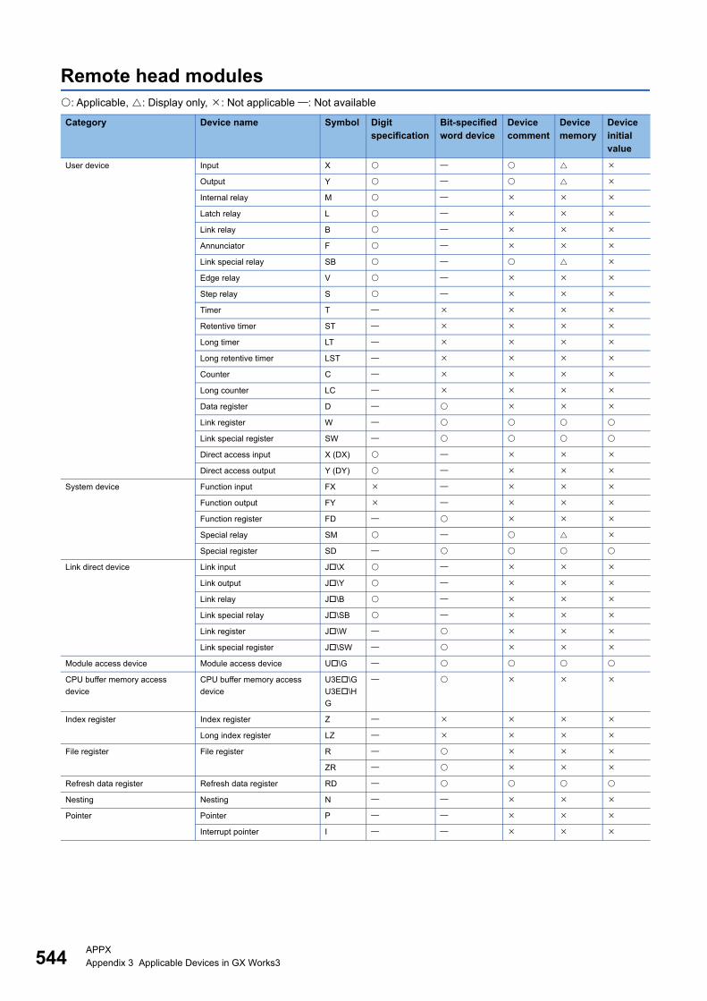
544APPXAppendix 3 Applicable Devices in GX Works3
Remote head modules: Applicable, : Display only, : Not applicable : Not available
Category Device name Symbol Digit specification
Bit-specified word device
Device comment
Device memory
Device initial value
User device Input X
Output Y
Internal relay M
Latch relay L
Link relay B
Annunciator F
Link special relay SB
Edge relay V
Step relay S
Timer T
Retentive timer ST
Long timer LT
Long retentive timer LST
Counter C
Long counter LC
Data register D
Link register W
Link special register SW
Direct access input X (DX)
Direct access output Y (DY)
System device Function input FX
Function output FY
Function register FD
Special relay SM
Special register SD
Link direct device Link input J\X
Link output J\Y
Link relay J\B
Link special relay J\SB
Link register J\W
Link special register J\SW
Module access device Module access device U\G
CPU buffer memory access
device
CPU buffer memory access
device
U3E\G
U3E\H
G
Index register Index register Z
Long index register LZ
File register File register R
ZR
Refresh data register Refresh data register RD
Nesting Nesting N
Pointer Pointer P
Interrupt pointer I
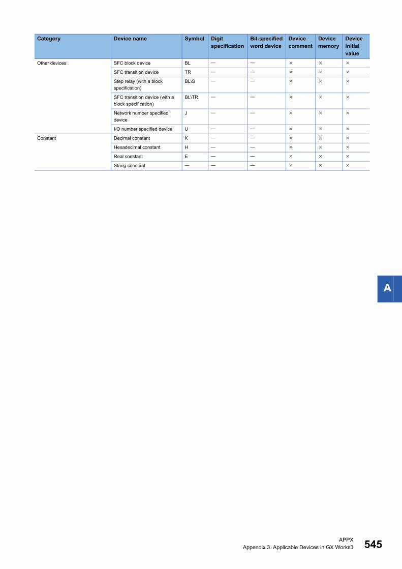
APPXAppendix 3 Applicable Devices in GX Works3 545
A
Other devices SFC block device BL
SFC transition device TR
Step relay (with a block
specification)
BL\S
SFC transition device (with a
block specification)
BL\TR
Network number specified
device
J
I/O number specified device U
Constant Decimal constant K
Hexadecimal constant H
Real constant E
String constant
Category Device name Symbol Digit specification
Bit-specified word device
Device comment
Device memory
Device initial value
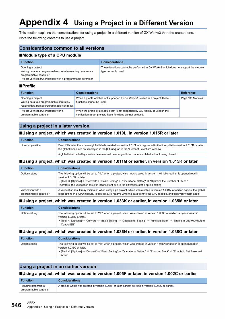
546APPXAppendix 4 Using a Project in a Different Version
Appendix 4 Using a Project in a Different VersionThis section explains the considerations for using a project in a different version of GX Works3 than the created one.
Note the following contents to use a project.
Considerations common to all versions
■Module type of a CPU module
■Profile
Using a project in a later version
■Using a project, which was created in version 1.010L, in version 1.015R or later
■Using a project, which was created in version 1.011M or earlier, in version 1.015R or later
■Using a project, which was created in version 1.033K or earlier, in version 1.035M or later
■Using a project, which was created in version 1.036N or earlier, in version 1.038Q or later
Using a project in an earlier version
■Using a project, which was created in version 1.005F or later, in version 1.002C or earlier
Function Considerations
Opening a project
Writing data to a programmable controller/reading data from a
programmable controller
Project verification/verification with a programmable controller
These functions cannot be performed in GX Works3 which does not support the module
type currently used.
Function Considerations Reference
Opening a project
Writing data to a programmable controller/
reading data from a programmable controller
When a profile which is not supported by GX Works3 is used in a project, these
functions cannot be used.
Page 536 Modules
Project verification/verification with a
programmable controller
When the profile of a module that is not supported by GX Works3 is used in the
verification target project, these functions cannot be used.
Function Considerations
Library operation Even if libraries that contain global labels created in version 1.010L are registered in the library list in version 1.015R or later,
the global labels are not displayed in the [Library] tab in the "Element Selection" window.
A global label called by a utilized element will be changed to an undefined label without being utilized.
Function Considerations
Option setting The following option will be set to "No" when a project, which was created in version 1.011M or earlier, is opened/read in
version 1.015R or later.
• [Tool] [Options] "Convert" "Basic Setting" "Operational Setting" "Optimize the Number of Steps."
Therefore, the verification result is inconsistent due to the difference of the option setting.
Verification with a
programmable controller
A verification result may mismatch when verifying a project, which was created in version 1.011M or earlier, against the global
label setting in a CPU module. In this case, re-read/re-write the data from/to the CPU module, and then verify them again.
Function Considerations
Option setting The following option will be set to "No" when a project, which was created in version 1.033K or earlier, is opened/read in
version 1.035M or later.
• [Tool] [Options] "Convert" "Basic Setting" "Operational Setting" "Function Block" "Enable to Use MC/MCR to
Control EN"
Function Considerations
Option setting The following option will be set to "No" when a project, which was created in version 1.036N or earlier, is opened/read in
version 1.038Q or later.
• [Tool] [Options] "Convert" "Basic Setting" "Operational Setting" "Function Block" "Enable to Set Reserved
Area"
Function Considerations
Reading data from a
programmable controller
A project, which was created in version 1.005F or later, cannot be read in version 1.002C or earlier.
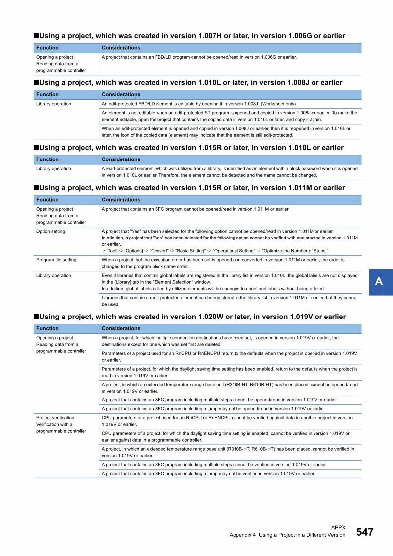
APPXAppendix 4 Using a Project in a Different Version 547
A
■Using a project, which was created in version 1.007H or later, in version 1.006G or earlier
■Using a project, which was created in version 1.010L or later, in version 1.008J or earlier
■Using a project, which was created in version 1.015R or later, in version 1.010L or earlier
■Using a project, which was created in version 1.015R or later, in version 1.011M or earlier
■Using a project, which was created in version 1.020W or later, in version 1.019V or earlier
Function Considerations
Opening a project
Reading data from a
programmable controller
A project that contains an FBD/LD program cannot be opened/read in version 1.006G or earlier.
Function Considerations
Library operation An edit-protected FBD/LD element is editable by opening it in version 1.008J. (Worksheet only)
An element is not editable when an edit-protected ST program is opened and copied in version 1.008J or earlier. To make the
element editable, open the project that contains the copied data in version 1.010L or later, and copy it again.
When an edit-protected element is opened and copied in version 1.008J or earlier, then it is reopened in version 1.010L or
later, the icon of the copied data (element) may indicate that the element is still edit-protected.
Function Considerations
Library operation A read-protected element, which was utilized from a library, is identified as an element with a block password when it is opened
in version 1.010L or earlier. Therefore, the element cannot be detected and the name cannot be changed.
Function Considerations
Opening a project
Reading data from a
programmable controller
A project that contains an SFC program cannot be opened/read in version 1.011M or earlier.
Option setting A project that "Yes" has been selected for the following option cannot be opened/read in version 1.011M or earlier.
In addition, a project that "Yes" has been selected for the following option cannot be verified with one created in version 1.011M
or earlier.
• [Tool] [Options] "Convert" "Basic Setting" "Operational Setting" "Optimize the Number of Steps."
Program file setting When a project that the execution order has been set is opened and converted in version 1.011M or earlier, the order is
changed to the program block name order.
Library operation Even if libraries that contain global labels are registered in the library list in version 1.010L, the global labels are not displayed
in the [Library] tab in the "Element Selection" window.
In addition, global labels called by utilized elements will be changed to undefined labels without being utilized.
Libraries that contain a read-protected element can be registered in the library list in version 1.011M or earlier, but they cannot
be used.
Function Considerations
Opening a project
Reading data from a
programmable controller
When a project, for which multiple connection destinations have been set, is opened in version 1.019V or earlier, the
destinations except for one which was set first are deleted.
Parameters of a project used for an RnCPU or RnENCPU return to the defaults when the project is opened in version 1.019V
or earlier.
Parameters of a project, for which the daylight saving time setting has been enabled, return to the defaults when the project is
read in version 1.019V or earlier.
A project, in which an extended temperature range base unit (R310B-HT, R610B-HT) has been placed, cannot be opened/read
in version 1.019V or earlier.
A project that contains an SFC program including multiple steps cannot be opened/read in version 1.019V or earlier.
A project that contains an SFC program including a jump may not be opened/read in version 1.019V or earlier.
Project verification
Verification with a
programmable controller
CPU parameters of a project used for an RnCPU or RnENCPU cannot be verified against data in another project in version
1.019V or earlier.
CPU parameters of a project, for which the daylight saving time setting is enabled, cannot be verified in version 1.019V or
earlier against data in a programmable controller.
A project, in which an extended temperature range base unit (R310B-HT, R610B-HT) has been placed, cannot be verified in
version 1.019V or earlier.
A project that contains an SFC program including multiple steps cannot be verified in version 1.019V or earlier.
A project that contains an SFC program including a jump may not be verified in version 1.019V or earlier.

548APPXAppendix 4 Using a Project in a Different Version
■Using a project, which was created in version 1.025B or later, in version 1.022Y or earlier
Library operation A project that contains an SFC program including multiple steps cannot be read in version 1.019V or earlier.
A project that contains an SFC program including a jump may not be read in version 1.019V or earlier.
Libraries that contain an element, for which the edit password has individually been set, can be registered in the library list in
version 1.019V or earlier, but they cannot be used.
A help file, for which "Import" has been selected at exporting, retains as the unused data in a project or a library when it is
opened by version 1.019V or earlier. When it is reopened in version 1.020W or later after being saved in version 1.019V or
earlier, the help file of the unused data is deleted.
Reading from a memory card A project that contains an SFC program including multiple steps cannot be read in version 1.019V or earlier.
A project that contains an SFC program including a jump may not be read in version 1.019V or earlier.
Editing an SFC program An SFC program, which was created in GX Works3 version 1.020W or later, may run unstably if it is used in version 1.019V or
earlier.
When editing an SFC program, use version 1.020W or later.
Function Considerations
Opening a project
Reading data from a
programmable controller
Parameters of a project used for an RnCPU, RnENCPU, and RnPCPU (process mode/redundant mode) return to the defaults
when the project is opened in version 1.022Y or earlier.
A project used for an RnPCPU (redundant mode) is changed to one used for an RnPCPU (process mode).
Parameters of a project used for an RnCPU and RnENCPU, for which the FTP client is set, return to the defaults when the
project is opened in version 1.022Y or earlier.
A project used for a remote head module cannot be opened/read in version 1.022Y or earlier.
Parameters of a project, in which a redundant power supply base unit (R310RB, R38RB-HT, R610RB, R68RB-HT) has been
placed and for which a power supply 2 has been set, return to the defaults when the project is opened/read in version 1.022Y
or earlier.
A project, in which some worksheets are created in a POU, cannot be opened in version 1.025B or earlier.
A project, in which an AnyWireASLINK master module (RJ51AW12AL) has been placed, cannot be opened/read in version
1.022Y or earlier.
Project verification
Verification with a
programmable controller
A project used for an RnPCPU (redundant mode) cannot be verified in version 1.022Y or earlier.
A project used for a remote head module cannot be verified in version 1.022Y or earlier.
Parameters of a project, in which a redundant power supply base unit (R310RB, R38RB-HT, R610RB, R68RB-HT) has been
placed and for which a power supply 2 has been set, cannot be verified in version 1.022Y or earlier.
A project, in which an AnyWireASLINK master module (RJ51AW12AL) has been placed, cannot be verified in version 1.022Y
or earlier.
Connection destination
specification
If any of the following options are set, the setting for connection destination on the "Specify Connection Destination" screen
returns to the default when the screen is opened.
• "GOT" is selected for "PLC side I/F" and "CC IE Cont" is set in the "PLC side I/F Detailed Setting of GOT" screen.
• "CC IE Control NET/10(H) Board" is set for "PC side I/F".
• "CC-Link Board" is set for "PC side I/F".
• "CC IE Field board" is set for "PC side I/F".
Library operation Libraries that contain a module label/ structure cannot be used in version 1.022Y or earlier.
Function Considerations
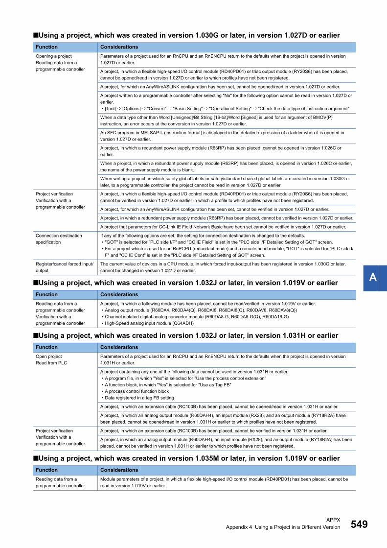
APPXAppendix 4 Using a Project in a Different Version 549
A
■Using a project, which was created in version 1.030G or later, in version 1.027D or earlier
■Using a project, which was created in version 1.032J or later, in version 1.019V or earlier
■Using a project, which was created in version 1.032J or later, in version 1.031H or earlier
■Using a project, which was created in version 1.035M or later, in version 1.019V or earlier
Function Considerations
Opening a project
Reading data from a
programmable controller
Parameters of a project used for an RnCPU and an RnENCPU return to the defaults when the project is opened in version
1.027D or earlier.
A project, in which a flexible high-speed I/O control module (RD40PD01) or triac output module (RY20S6) has been placed,
cannot be opened/read in version 1.027D or earlier to which profiles have not been registered.
A project, for which an AnyWireASLINK configuration has been set, cannot be opened/read in version 1.027D or earlier.
A project written to a programmable controller after selecting "No" for the following option cannot be read in version 1.027D or
earlier.
• [Tool] [Options] "Convert" "Basic Setting" "Operational Setting" "Check the data type of instruction argument"
When a data type other than Word [Unsigned]/Bit String [16-bit]/Word [Signed] is used for an argument of BMOV(P)
instruction, an error occurs at the conversion in version 1.027D or earlier.
An SFC program in MELSAP-L (instruction format) is displayed in the detailed expression of a ladder when it is opened in
version 1.027D or earlier.
A project, in which a redundant power supply module (R63RP) has been placed, cannot be opened in version 1.026C or
earlier.
When a project, in which a redundant power supply module (R63RP) has been placed, is opened in version 1.026C or earlier,
the name of the power supply module is blank.
When writing a project, in which safety global labels or safety/standard shared global labels are created in version 1.030G or
later, to a programmable controller, the project cannot be read in version 1.027D or earlier.
Project verification
Verification with a
programmable controller
A project, in which a flexible high-speed I/O control module (RD40PD01) or triac output module (RY20S6) has been placed,
cannot be verified in version 1.027D or earlier in which a profile to which profiles have not been registered.
A project, for which an AnyWireASLINK configuration has been set, cannot be verified in version 1.027D or earlier.
A project, in which a redundant power supply module (R63RP) has been placed, cannot be verified in version 1.027D or earlier.
A project that parameters for CC-Link IE Field Network Basic have been set cannot be verified in version 1.027D or earlier.
Connection destination
specification
If any of the following options are set, the setting for connection destination is changed to the defaults.
• "GOT" is selected for "PLC side I/F" and "CC IE Field" is set in the "PLC side I/F Detailed Setting of GOT" screen.
• For a project which is used for an RnPCPU (redundant mode) and a remote head module, "GOT" is selected for "PLC side I/
F" and "CC IE Cont" is set in the "PLC side I/F Detailed Setting of GOT" screen.
Register/cancel forced input/
output
The current value of devices in a CPU module, in which forced input/output has been registered in version 1.030G or later,
cannot be changed in version 1.027D or earlier.
Function Considerations
Reading data from a
programmable controller
Verification with a
programmable controller
A project, in which a following module has been placed, cannot be read/verified in version 1.019V or earlier.
• Analog output module (R60DA4, R60DA4(Q), R60DAI8, R60DAI8(Q), R60DAV8, R60DAV8(Q))
• Channel isolated digital-analog convertor module (R60DA8-G, R60DA8-G(Q), R60DA16-G)
• High-Speed analog input module (Q64ADH)
Function Considerations
Open project
Read from PLC
Parameters of a project used for an RnCPU and an RnENCPU return to the defaults when the project is opened in version
1.031H or earlier.
A project containing any one of the following data cannot be used in version 1.031H or earlier.
• A program file, in which "Yes" is selected for "Use the process control extension"
• A function block, in which "Yes" is selected for "Use as Tag FB"
• A process control function block
• Data registered in a tag FB setting
A project, in which an extension cable (RC100B) has been placed, cannot be opened/read in version 1.031H or earlier.
A project, in which an analog output module (R60DAH4), an input module (RX28), and an output module (RY18R2A) have
been placed, cannot be opened/read in version 1.031H or earlier to which profiles have not been registered.
Project verification
Verification with a
programmable controller
A project, in which an extension cable (RC100B) has been placed, cannot be verified in version 1.031H or earlier.
A project, in which an analog output module (R60DAH4), an input module (RX28), and an output module (RY18R2A) has been
placed, cannot be verified in version 1.031H or earlier to which profiles have not been registered.
Function Considerations
Reading data from a
programmable controller
Module parameters of a project, in which a flexible high-speed I/O control module (RD40PD01) has been placed, cannot be
read in version 1.019V or earlier.
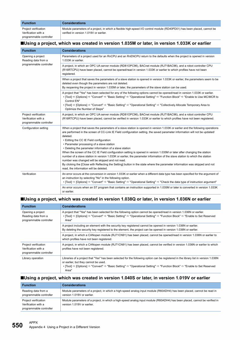
550APPXAppendix 4 Using a Project in a Different Version
■Using a project, which was created in version 1.035M or later, in version 1.033K or earlier
■Using a project, which was created in version 1.038Q or later, in version 1.036N or earlier
■Using a project, which was created in version 1.040S or later, in version 1.019V or earlier
Project verification
Verification with a
programmable controller
Module parameters of a project, in which a flexible high-speed I/O control module (RD40PD01) has been placed, cannot be
verified in version 1.019V or earlier.
Function Considerations
Opening a project
Reading data from a
programmable controller
Parameters of a project used for an RnCPU and an RnENCPU return to the defaults when the project is opened in version
1.033K or earlier.
A project, in which an OPC UA server module (RD81OPC96), BACnet module (RJ71BAC96), and a robot controller CPU
(R16RTCPU) have been placed, cannot be opened/read in version 1.033K or earlier to which profiles have not been
registered.
When a project that saves the parameters of a slave station is opened in version 1.033K or earlier, the parameters seem to be
deleted even though the parameters are not deleted.
By reopening the project in version 1.035M or later, the parameters of the slave station can be used.
A project that "Yes" has been selected for any of the following options cannot be opened/read in version 1.033K or earlier.
• [Tool] [Options] "Convert" "Basic Setting" "Operational Setting" "Function Block" "Enable to Use MC/MCR to
Control EN"
• [Tool] [Options] "Convert" "Basic Setting" "Operational Setting" "Collectively Allocate Temporary Area to
Optimize the Number of Steps"
Project verification
Verification with a
programmable controller
A project, in which an OPC UA server module (RD81OPC96), BACnet module (RJ71BAC96), and a robot controller CPU
(R16RTCPU) have been placed, cannot be verified in version 1.033K or earlier to which profiles have not been registered.
Configuration setting When a project that saves the parameters of a slave station is opened in version 1.033K or earlier and the following operations
are performed in the screen of CC-Link IE Field configuration setting, the saved parameter information will not be updated/
deleted.
• Editing the CC IE Field configuration
• Parameter processing of a slave station
• Deleting the parameter information of a slave station
When the screen of the CC IE Field configuration setting is opened in version 1.035M or later after changing the station
number of a slave station in version 1.033K or earlier, the parameter information of the slave station to which the station
number was changed will be skipped and not read.
By clicking the [Close with Reflecting the Setting] button in the state where the parameter information was skipped and not
read, the information will be deleted.
Verification An error occurs at the conversion in version 1.033K or earlier when a different data type has been specified for the argument of
an instruction by selecting "No" in the following option.
• [Tool] [Options] "Convert" "Basic Setting" "Operational Setting" "Check the data type of instruction argument"
An error occurs when an ST program that contains an instruction supported in 1.035M or later is converted in version 1.033K
or earlier.
Function Considerations
Opening a project
Reading data from a
programmable controller
A project that "Yes" has been selected for the following option cannot be opened/read in version 1.036N or earlier.
• [Tool] [Options] "Convert" "Basic Setting" "Operational Setting" "Function Block" "Enable to Set Reserved
Area"
A project including an element with the security key registered cannot be opened in version 1.036N or earlier.
By deleting the security key registered to the element, the project can be opened in version 1.036N or earlier.
A project, in which a CANopen module (RJ71CN91) has been placed, cannot be opened/read in version 1.036N or earlier to
which profiles have not been registered.
Project verification
Verification with a
programmable controller
A project, in which a CANopen module (RJ71CN91) has been placed, cannot be verified in version 1.036N or earlier to which
profiles have not been registered.
Library operation Libraries of a project that "Yes" has been selected for the following option can be registered in the library list in version 1.036N
or earlier, but they cannot be used.
• [Tool] [Options] "Convert" "Basic Setting" "Operational Setting" "Function Block" "Enable to Set Reserved
Area"
Function Considerations
Reading data from a
programmable controller
Module parameters of a project, in which a high-speed analog input module (R60ADH4) has been placed, cannot be read in
version 1.019V or earlier.
Project verification
Verification with a
programmable controller
Module parameters of a project, in which a high-speed analog input module (R60ADH4) has been placed, cannot be verified in
version 1.019V or earlier.
Function Considerations
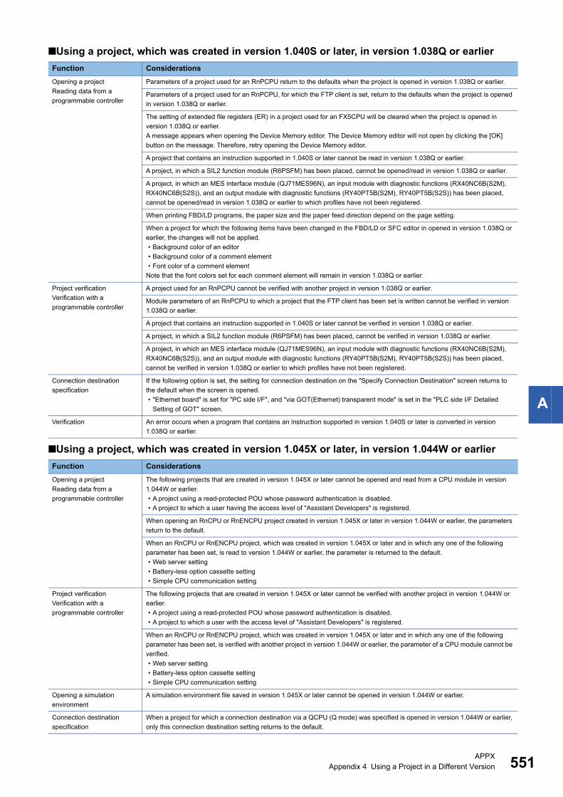
APPXAppendix 4 Using a Project in a Different Version 551
A
■Using a project, which was created in version 1.040S or later, in version 1.038Q or earlier
■Using a project, which was created in version 1.045X or later, in version 1.044W or earlier
Function Considerations
Opening a project
Reading data from a
programmable controller
Parameters of a project used for an RnPCPU return to the defaults when the project is opened in version 1.038Q or earlier.
Parameters of a project used for an RnPCPU, for which the FTP client is set, return to the defaults when the project is opened
in version 1.038Q or earlier.
The setting of extended file registers (ER) in a project used for an FX5CPU will be cleared when the project is opened in
version 1.038Q or earlier.
A message appears when opening the Device Memory editor. The Device Memory editor will not open by clicking the [OK]
button on the message. Therefore, retry opening the Device Memory editor.
A project that contains an instruction supported in 1.040S or later cannot be read in version 1.038Q or earlier.
A project, in which a SIL2 function module (R6PSFM) has been placed, cannot be opened/read in version 1.038Q or earlier.
A project, in which an MES interface module (QJ71MES96N), an input module with diagnostic functions (RX40NC6B(S2M),
RX40NC6B(S2S)), and an output module with diagnostic functions (RY40PT5B(S2M), RY40PT5B(S2S)) has been placed,
cannot be opened/read in version 1.038Q or earlier to which profiles have not been registered.
When printing FBD/LD programs, the paper size and the paper feed direction depend on the page setting.
When a project for which the following items have been changed in the FBD/LD or SFC editor in opened in version 1.038Q or
earlier, the changes will not be applied.
• Background color of an editor
• Background color of a comment element
• Font color of a comment element
Note that the font colors set for each comment element will remain in version 1.038Q or earlier.
Project verification
Verification with a
programmable controller
A project used for an RnPCPU cannot be verified with another project in version 1.038Q or earlier.
Module parameters of an RnPCPU to which a project that the FTP client has been set is written cannot be verified in version
1.038Q or earlier.
A project that contains an instruction supported in 1.040S or later cannot be verified in version 1.038Q or earlier.
A project, in which a SIL2 function module (R6PSFM) has been placed, cannot be verified in version 1.038Q or earlier.
A project, in which an MES interface module (QJ71MES96N), an input module with diagnostic functions (RX40NC6B(S2M),
RX40NC6B(S2S)), and an output module with diagnostic functions (RY40PT5B(S2M), RY40PT5B(S2S)) has been placed,
cannot be verified in version 1.038Q or earlier to which profiles have not been registered.
Connection destination
specification
If the following option is set, the setting for connection destination on the "Specify Connection Destination" screen returns to
the default when the screen is opened.
• "Ethernet board" is set for "PC side I/F", and "via GOT(Ethernet) transparent mode" is set in the "PLC side I/F Detailed
Setting of GOT" screen.
Verification An error occurs when a program that contains an instruction supported in version 1.040S or later is converted in version
1.038Q or earlier.
Function Considerations
Opening a project
Reading data from a
programmable controller
The following projects that are created in version 1.045X or later cannot be opened and read from a CPU module in version
1.044W or earlier.
• A project using a read-protected POU whose password authentication is disabled.
• A project to which a user having the access level of "Assistant Developers" is registered.
When opening an RnCPU or RnENCPU project created in version 1.045X or later in version 1.044W or earlier, the parameters
return to the default.
When an RnCPU or RnENCPU project, which was created in version 1.045X or later and in which any one of the following
parameter has been set, is read to version 1.044W or earlier, the parameter is returned to the default.
• Web server setting
• Battery-less option cassette setting
• Simple CPU communication setting
Project verification
Verification with a
programmable controller
The following projects that are created in version 1.045X or later cannot be verified with another project in version 1.044W or
earlier.
• A project using a read-protected POU whose password authentication is disabled.
• A project to which a user with the access level of "Assistant Developers" is registered.
When an RnCPU or RnENCPU project, which was created in version 1.045X or later and in which any one of the following
parameter has been set, is verified with another project in version 1.044W or earlier, the parameter of a CPU module cannot be
verified.
• Web server setting
• Battery-less option cassette setting
• Simple CPU communication setting
Opening a simulation
environment
A simulation environment file saved in version 1.045X or later cannot be opened in version 1.044W or earlier.
Connection destination
specification
When a project for which a connection destination via a QCPU (Q mode) was specified is opened in version 1.044W or earlier,
only this connection destination setting returns to the default.

552APPXAppendix 4 Using a Project in a Different Version
Library operation When a password authentication for a read-protected POU is disabled in version 1.045X or later, a library including the POU
cannot be used in version 1.044W or earlier.
User authentication When reading user information whose access level is set as "Assistant Developers" in version 1.045X or later from a CPU
module using version 1.044W or earlier, the access level is changed to "Users" . (Page 471 Writing/reading user
information to/from CPU module)
Function Considerations
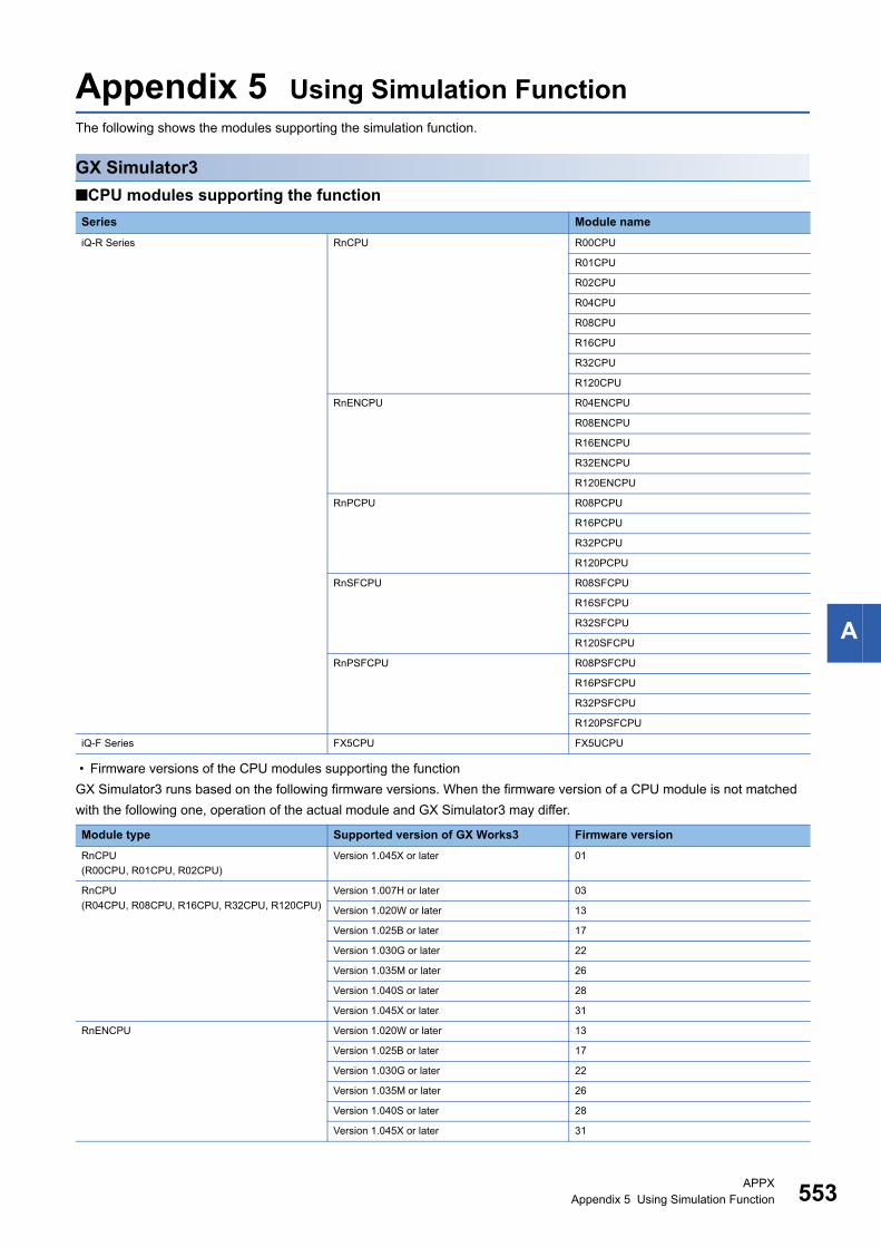
APPXAppendix 5 Using Simulation Function 553
A
Appendix 5 Using Simulation FunctionThe following shows the modules supporting the simulation function.
GX Simulator3
■CPU modules supporting the function
• Firmware versions of the CPU modules supporting the function
GX Simulator3 runs based on the following firmware versions. When the firmware version of a CPU module is not matched
with the following one, operation of the actual module and GX Simulator3 may differ.
Series Module name
iQ-R Series RnCPU R00CPU
R01CPU
R02CPU
R04CPU
R08CPU
R16CPU
R32CPU
R120CPU
RnENCPU R04ENCPU
R08ENCPU
R16ENCPU
R32ENCPU
R120ENCPU
RnPCPU R08PCPU
R16PCPU
R32PCPU
R120PCPU
RnSFCPU R08SFCPU
R16SFCPU
R32SFCPU
R120SFCPU
RnPSFCPU R08PSFCPU
R16PSFCPU
R32PSFCPU
R120PSFCPU
iQ-F Series FX5CPU FX5UCPU
Module type Supported version of GX Works3 Firmware version
RnCPU
(R00CPU, R01CPU, R02CPU)
Version 1.045X or later 01
RnCPU
(R04CPU, R08CPU, R16CPU, R32CPU, R120CPU)
Version 1.007H or later 03
Version 1.020W or later 13
Version 1.025B or later 17
Version 1.030G or later 22
Version 1.035M or later 26
Version 1.040S or later 28
Version 1.045X or later 31
RnENCPU Version 1.020W or later 13
Version 1.025B or later 17
Version 1.030G or later 22
Version 1.035M or later 26
Version 1.040S or later 28
Version 1.045X or later 31
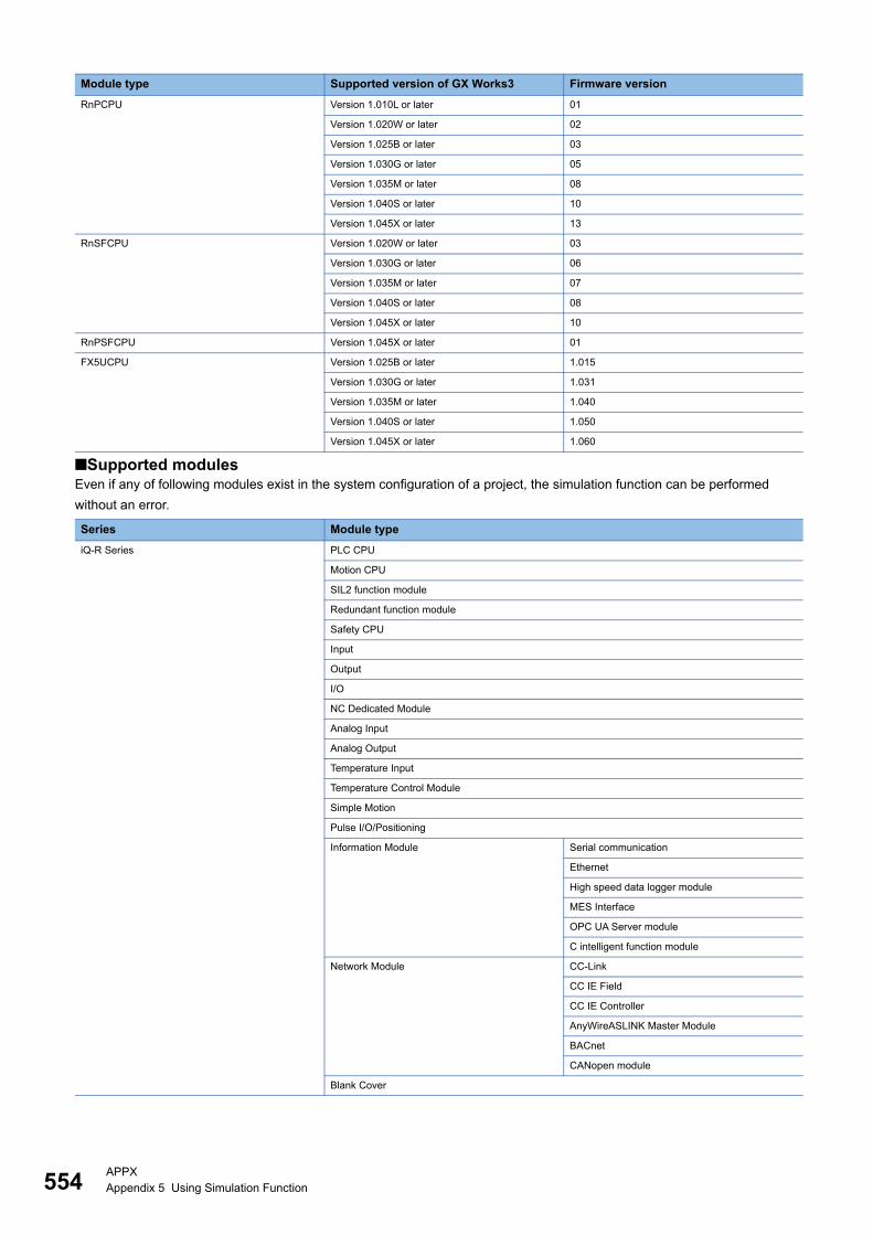
554APPXAppendix 5 Using Simulation Function
■Supported modulesEven if any of following modules exist in the system configuration of a project, the simulation function can be performed
without an error.
RnPCPU Version 1.010L or later 01
Version 1.020W or later 02
Version 1.025B or later 03
Version 1.030G or later 05
Version 1.035M or later 08
Version 1.040S or later 10
Version 1.045X or later 13
RnSFCPU Version 1.020W or later 03
Version 1.030G or later 06
Version 1.035M or later 07
Version 1.040S or later 08
Version 1.045X or later 10
RnPSFCPU Version 1.045X or later 01
FX5UCPU Version 1.025B or later 1.015
Version 1.030G or later 1.031
Version 1.035M or later 1.040
Version 1.040S or later 1.050
Version 1.045X or later 1.060
Series Module type
iQ-R Series PLC CPU
Motion CPU
SIL2 function module
Redundant function module
Safety CPU
Input
Output
I/O
NC Dedicated Module
Analog Input
Analog Output
Temperature Input
Temperature Control Module
Simple Motion
Pulse I/O/Positioning
Information Module Serial communication
Ethernet
High speed data logger module
MES Interface
OPC UA Server module
C intelligent function module
Network Module CC-Link
CC IE Field
CC IE Controller
AnyWireASLINK Master Module
BACnet
CANopen module
Blank Cover
Module type Supported version of GX Works3 Firmware version
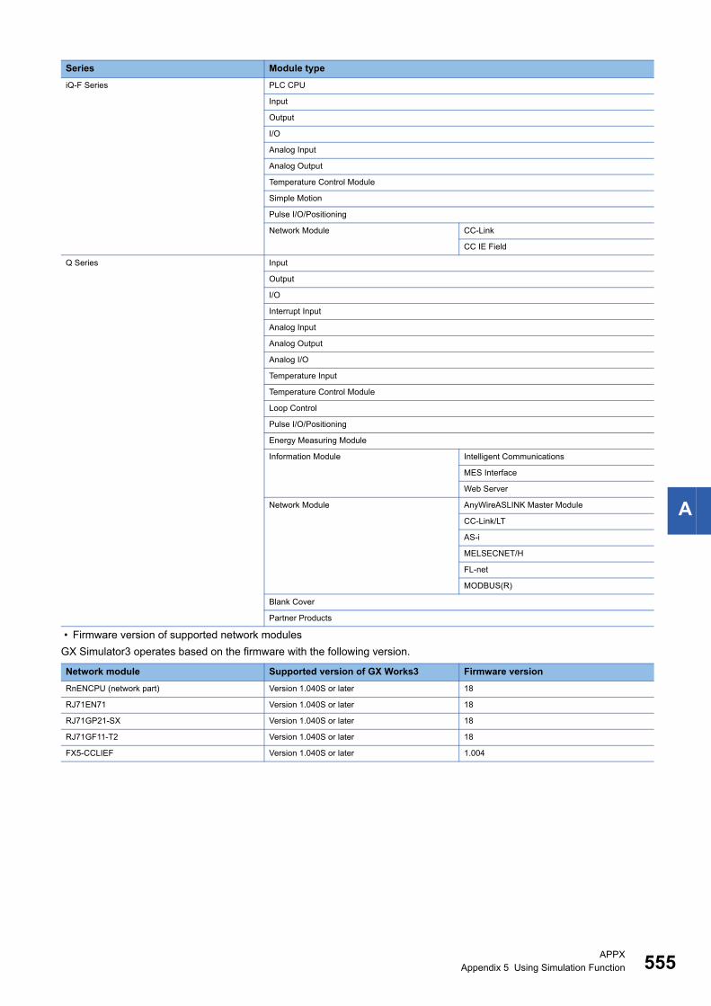
APPXAppendix 5 Using Simulation Function 555
A
• Firmware version of supported network modules
GX Simulator3 operates based on the firmware with the following version.
iQ-F Series PLC CPU
Input
Output
I/O
Analog Input
Analog Output
Temperature Control Module
Simple Motion
Pulse I/O/Positioning
Network Module CC-Link
CC IE Field
Q Series Input
Output
I/O
Interrupt Input
Analog Input
Analog Output
Analog I/O
Temperature Input
Temperature Control Module
Loop Control
Pulse I/O/Positioning
Energy Measuring Module
Information Module Intelligent Communications
MES Interface
Web Server
Network Module AnyWireASLINK Master Module
CC-Link/LT
AS-i
MELSECNET/H
FL-net
MODBUS(R)
Blank Cover
Partner Products
Network module Supported version of GX Works3 Firmware version
RnENCPU (network part) Version 1.040S or later 18
RJ71EN71 Version 1.040S or later 18
RJ71GP21-SX Version 1.040S or later 18
RJ71GF11-T2 Version 1.040S or later 18
FX5-CCLIEF Version 1.040S or later 1.004
Series Module type

556APPXAppendix 5 Using Simulation Function
SMM Simulator
MT Simulator2
Series Module type Module name
iQ-R Series Simple Motion RD77MS2
RD77MS4
RD77MS8
RD77MS16
RD77GF4
RD77GF8
RD77GF16
RD77GF32
iQ-F Series Simple Motion FX5-40SSC-S
FX5-80SSC-S
Series Module type Module name
iQ-R Series Motion CPU R16MTCPU
R32MTCPU
R64MTCPU
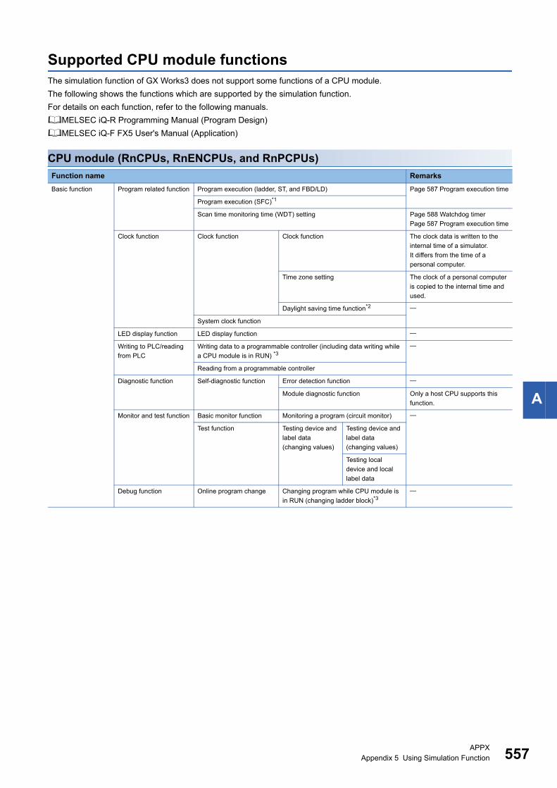
APPXAppendix 5 Using Simulation Function 557
A
Supported CPU module functionsThe simulation function of GX Works3 does not support some functions of a CPU module.
The following shows the functions which are supported by the simulation function.
For details on each function, refer to the following manuals.
MELSEC iQ-R Programming Manual (Program Design)
MELSEC iQ-F FX5 User's Manual (Application)
CPU module (RnCPUs, RnENCPUs, and RnPCPUs)
Function name Remarks
Basic function Program related function Program execution (ladder, ST, and FBD/LD) Page 587 Program execution time
Program execution (SFC)*1
Scan time monitoring time (WDT) setting Page 588 Watchdog timer
Page 587 Program execution time
Clock function Clock function Clock function The clock data is written to the
internal time of a simulator.
It differs from the time of a
personal computer.
Time zone setting The clock of a personal computer
is copied to the internal time and
used.
Daylight saving time function*2
System clock function
LED display function LED display function
Writing to PLC/reading
from PLC
Writing data to a programmable controller (including data writing while
a CPU module is in RUN) *3
Reading from a programmable controller
Diagnostic function Self-diagnostic function Error detection function
Module diagnostic function Only a host CPU supports this
function.
Monitor and test function Basic monitor function Monitoring a program (circuit monitor)
Test function Testing device and
label data
(changing values)
Testing device and
label data
(changing values)
Testing local
device and local
label data
Debug function Online program change Changing program while CPU module is
in RUN (changing ladder block)*3
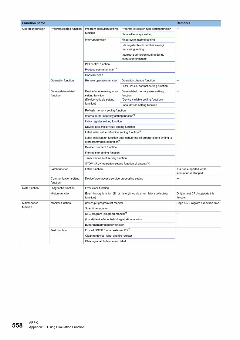
558APPXAppendix 5 Using Simulation Function
Operation function Program related function Program execution setting
function
Program execution type setting function
Device/file usage setting
Interrupt function Fixed cycle interval setting
File register block number saving/
recovering setting
Interrupt permission setting during
instruction execution
PID control function
Process control function*4
Constant scan
Operation function Remote operation function Operation change function
RUN-PAUSE contact setting function
Device/data related
function
Device/label memory area
setting function
(Device variable setting
function)
Device/label memory area setting
function
(Device variable setting function)
Local device setting function
Refresh memory setting function
Internal buffer capacity setting function*5
Index register setting function
Device/label initial value setting function
Label initial value reflection setting function*4
Label initialization function after converting all programs and writing to
a programmable controller*4
Device comment function
File register setting function
Timer device limit setting function
STOP→RUN operation setting function of output (Y)
Latch function Latch function It is not supported while
simulation is stopped.
Communication setting
function
Device/label access service processing setting
RAS function Diagnostic function Error clear function
History function Event history function (Error history/module error history collecting
function)
Only a host CPU supports this
function.
Maintenance
function
Monitor function (Interrupt) program list monitor Page 587 Program execution time
Scan time monitor
SFC program (diagram) monitor*1
(Local) device/label batch/registration monitor
Buffer memory monitor function
Test function Forced ON/OFF of an external I/O*2
Clearing device, label and file register
Clearing a latch device and label
Function name Remarks

APPXAppendix 5 Using Simulation Function 559
A
*1 RnPCPUs (redundant mode) do not support them.*2 RnCPUs and RnENCPUs support it.*3 In the simulation for an RnPCPU (redundant mode), program restoration information cannot be written to GX Simulator3.*4 Only RnPCPUs support them.*5 R00CPUs do not support it.*6 Only RnPCPUs (redundant mode) support it.
Multiple CPU
system function
Operation setting Other PLC control module
setting function
Control CPU setting function
Importing I/O from outside group function Only a CPU, which operates
interactively with another module
in the system simulation, supports
these functions.
Operation mode setting
function
Clock data synchronization function
Operation setting function at stop error
Multiple CPU synchronous startup setting
function
CPU data
communication function
Communication function The cycle of the fixed cycle
communication function
Only a CPU, which operates
interactively with another module
in the system simulation, supports
these functions.Fixed scan communication sending data
function
CPU number-based data assurance
function
Communication function by refresh
Communication function by direct access
Interrupt function Multiple CPU synchronization interrupt function (I45) Only a CPU, which operates
interactively with another module
in the system simulation, supports
these functions.
Redundant
function*6Page 345 Simulation of an RnPCPU (redundant mode)
Function name Remarks
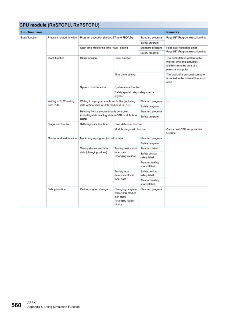
560APPXAppendix 5 Using Simulation Function
CPU module (RnSFCPU, RnPSFCPU)
Function name Remarks
Basic function Program related function Program execution (ladder, ST, and FBD/LD) Standard program Page 587 Program execution time
Safety program
Scan time monitoring time (WDT) setting Standard program Page 588 Watchdog timer
Page 587 Program execution timeSafety program
Clock function Clock function Clock function The clock data is written to the
internal time of a simulator.
It differs from the time of a
personal computer.
Time zone setting The clock of a personal computer
is copied to the internal time and
used.
System clock function System clock function
Safety special relay/safety special
register
Writing to PLC/reading
from PLC
Writing to a programmable controller (including
data writing while a CPU module is in RUN)
Standard program
Safety program
Reading from a programmable controller
(including data reading while a CPU module is in
RUN)
Standard program
Safety program
Diagnostic function Self-diagnostic function Error detection function
Module diagnostic function Only a host CPU supports this
function.
Monitor and test function Monitoring a program (circuit monitor) Standard program
Safety program
Testing device and label
data (changing values)
Testing device and
label data
(changing values)
Standard label
Safety device/
safety label
Standard/safety
shared label
Testing local
device and local
label data
Safety device/
safety label
Standard/safety
shared label
Debug function Online program change Changing program
while CPU module
is in RUN
(changing ladder
block)
Standard program
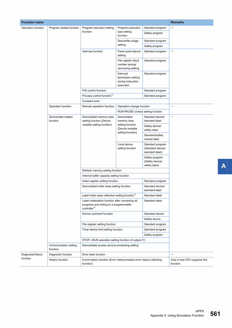
APPXAppendix 5 Using Simulation Function 561
A
Operation function Program related function Program execution setting
function
Program execution
type setting
function
Standard program
Safety program
Device/file usage
setting
Standard program
Safety program
Interrupt function Fixed cycle interval
setting
Standard program
File register block
number saving/
recovering setting
Standard program
Interrupt
permission setting
during instruction
execution
Standard program
PID control function Standard program
Process control function*1 Standard program
Constant scan
Operation function Remote operation function Operation change function
RUN-PAUSE contact setting function
Device/data related
function
Device/label memory area
setting function (Device
variable setting function)
Device/label
memory area
setting function
(Device variable
setting function)
Standard device/
standard label
Safety device/
safety label
Standard/safety
shared label
Local device
setting function
Standard program
(Standard device/
standard label)
Safety program
(Safety device/
safety label)
Refresh memory setting function
Internal buffer capacity setting function
Index register setting function Standard program
Device/label initial value setting function Standard device/
standard label
Label initial value reflection setting function*1 Standard label
Label initialization function after converting all
programs and writing to a programmable
controller*1
Standard label
Device comment function Standard device
Safety device
File register setting function Standard program
Timer device limit setting function Standard program
Safety program
STOP→RUN operation setting function of output (Y)
Communication setting
function
Device/label access service processing setting
Diagnosis/History
function
Diagnostic function Error clear function
History function Event history function (Error history/module error history collecting
function)
Only a host CPU supports this
function.
Function name Remarks
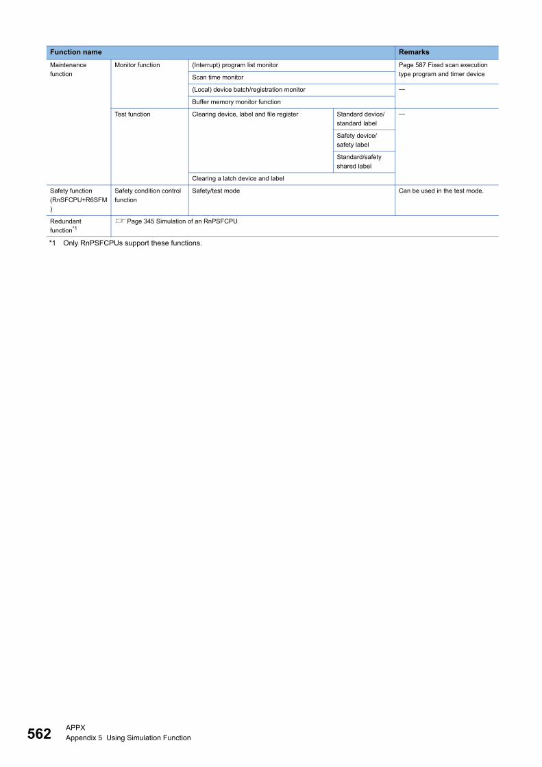
562APPXAppendix 5 Using Simulation Function
*1 Only RnPSFCPUs support these functions.
Maintenance
function
Monitor function (Interrupt) program list monitor Page 587 Fixed scan execution
type program and timer deviceScan time monitor
(Local) device batch/registration monitor
Buffer memory monitor function
Test function Clearing device, label and file register Standard device/
standard label
Safety device/
safety label
Standard/safety
shared label
Clearing a latch device and label
Safety function
(RnSFCPU+R6SFM
)
Safety condition control
function
Safety/test mode Can be used in the test mode.
Redundant
function*1Page 345 Simulation of an RnPSFCPU
Function name Remarks
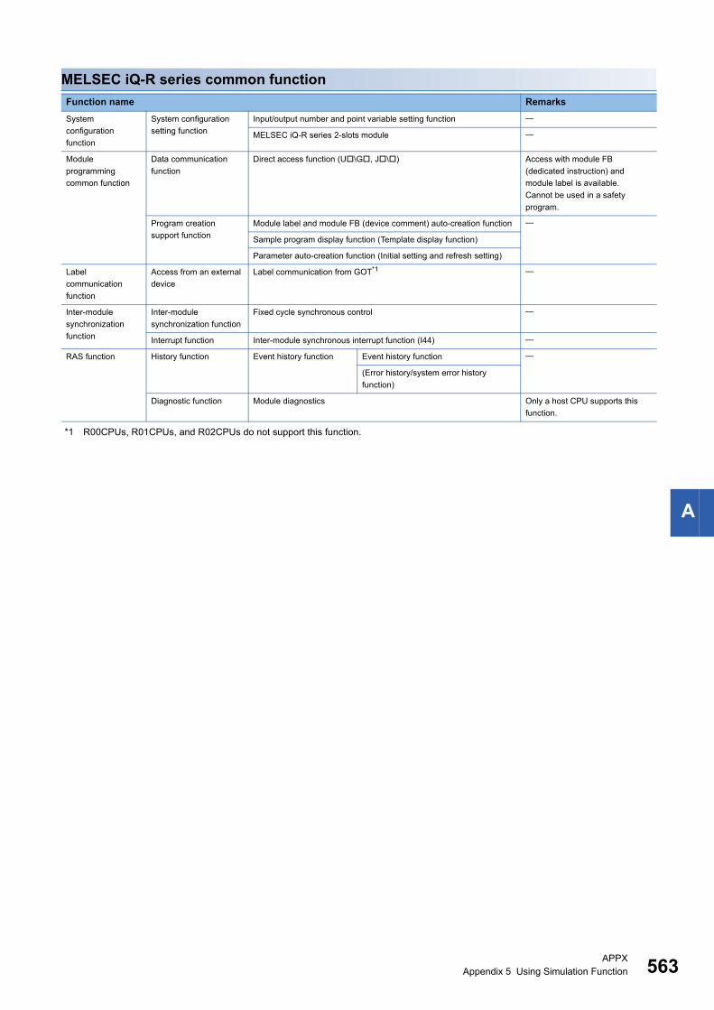
APPXAppendix 5 Using Simulation Function 563
A
MELSEC iQ-R series common function
*1 R00CPUs, R01CPUs, and R02CPUs do not support this function.
Function name Remarks
System
configuration
function
System configuration
setting function
Input/output number and point variable setting function
MELSEC iQ-R series 2-slots module
Module
programming
common function
Data communication
function
Direct access function (U\G, J\) Access with module FB
(dedicated instruction) and
module label is available.
Cannot be used in a safety
program.
Program creation
support function
Module label and module FB (device comment) auto-creation function
Sample program display function (Template display function)
Parameter auto-creation function (Initial setting and refresh setting)
Label
communication
function
Access from an external
device
Label communication from GOT*1
Inter-module
synchronization
function
Inter-module
synchronization function
Fixed cycle synchronous control
Interrupt function Inter-module synchronous interrupt function (I44)
RAS function History function Event history function Event history function
(Error history/system error history
function)
Diagnostic function Module diagnostics Only a host CPU supports this
function.
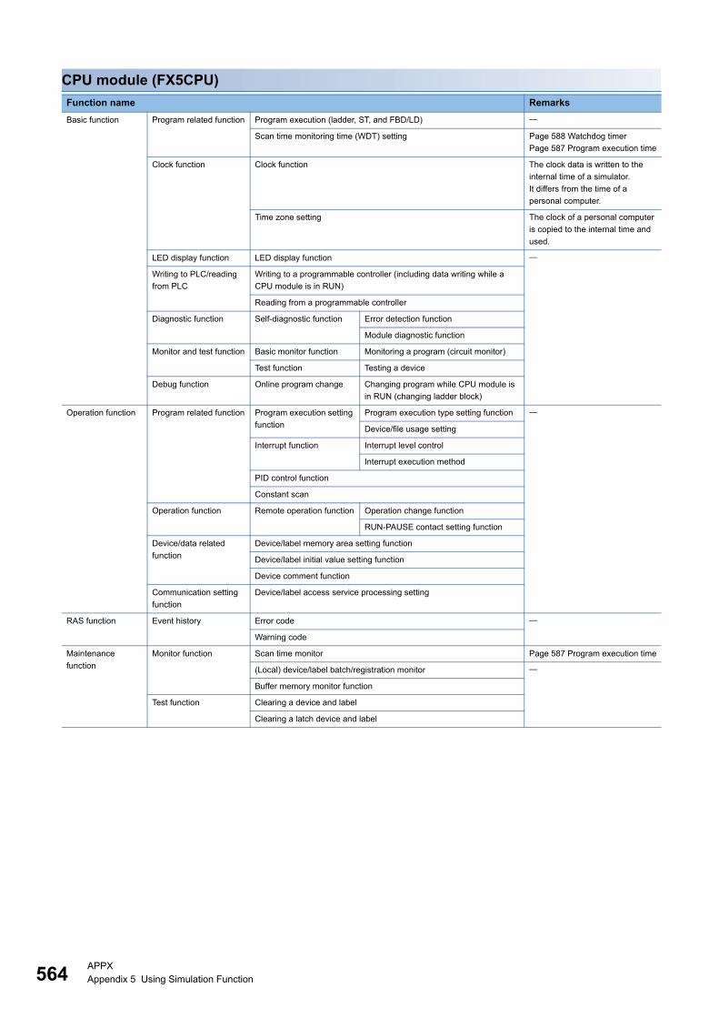
564APPXAppendix 5 Using Simulation Function
CPU module (FX5CPU)
Function name Remarks
Basic function Program related function Program execution (ladder, ST, and FBD/LD)
Scan time monitoring time (WDT) setting Page 588 Watchdog timer
Page 587 Program execution time
Clock function Clock function The clock data is written to the
internal time of a simulator.
It differs from the time of a
personal computer.
Time zone setting The clock of a personal computer
is copied to the internal time and
used.
LED display function LED display function
Writing to PLC/reading
from PLC
Writing to a programmable controller (including data writing while a
CPU module is in RUN)
Reading from a programmable controller
Diagnostic function Self-diagnostic function Error detection function
Module diagnostic function
Monitor and test function Basic monitor function Monitoring a program (circuit monitor)
Test function Testing a device
Debug function Online program change Changing program while CPU module is
in RUN (changing ladder block)
Operation function Program related function Program execution setting
function
Program execution type setting function
Device/file usage setting
Interrupt function Interrupt level control
Interrupt execution method
PID control function
Constant scan
Operation function Remote operation function Operation change function
RUN-PAUSE contact setting function
Device/data related
function
Device/label memory area setting function
Device/label initial value setting function
Device comment function
Communication setting
function
Device/label access service processing setting
RAS function Event history Error code
Warning code
Maintenance
function
Monitor function Scan time monitor Page 587 Program execution time
(Local) device/label batch/registration monitor
Buffer memory monitor function
Test function Clearing a device and label
Clearing a latch device and label
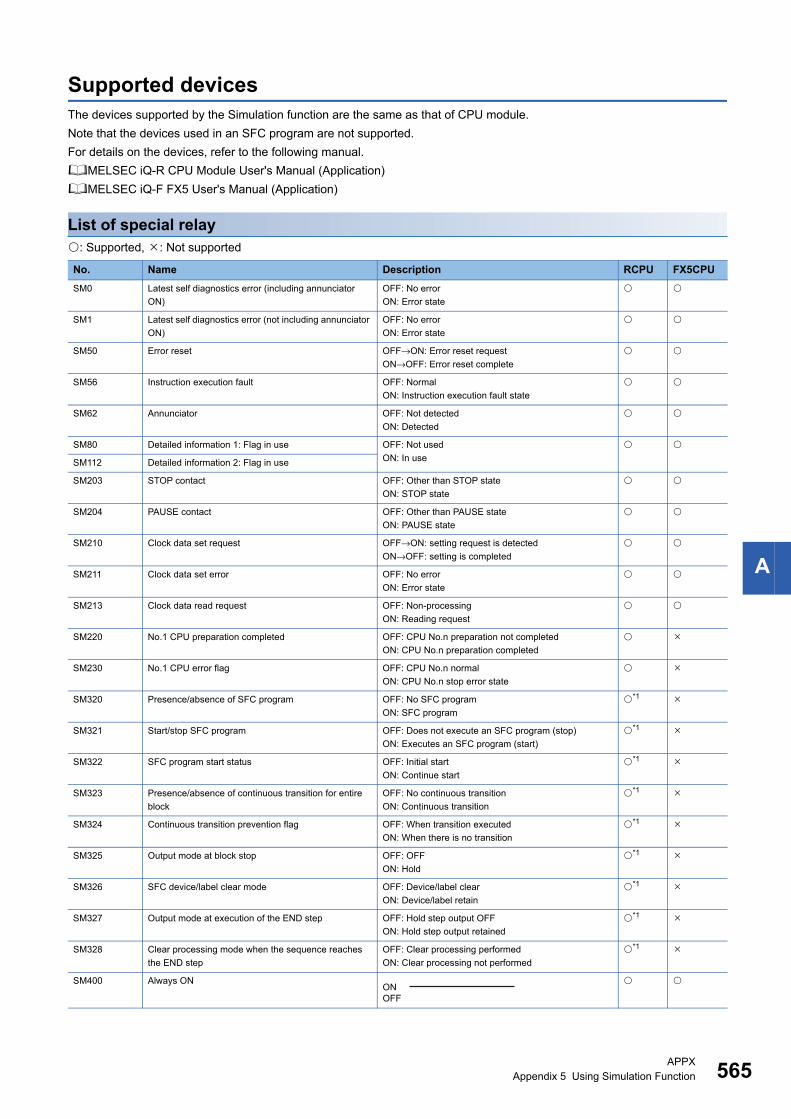
APPXAppendix 5 Using Simulation Function 565
A
Supported devicesThe devices supported by the Simulation function are the same as that of CPU module.
Note that the devices used in an SFC program are not supported.
For details on the devices, refer to the following manual.
MELSEC iQ-R CPU Module User's Manual (Application)
MELSEC iQ-F FX5 User's Manual (Application)
List of special relay: Supported, : Not supported
No. Name Description RCPU FX5CPU
SM0 Latest self diagnostics error (including annunciator
ON)
OFF: No error
ON: Error state
SM1 Latest self diagnostics error (not including annunciator
ON)
OFF: No error
ON: Error state
SM50 Error reset OFF→ON: Error reset request
ON→OFF: Error reset complete
SM56 Instruction execution fault OFF: Normal
ON: Instruction execution fault state
SM62 Annunciator OFF: Not detected
ON: Detected
SM80 Detailed information 1: Flag in use OFF: Not used
ON: In use
SM112 Detailed information 2: Flag in use
SM203 STOP contact OFF: Other than STOP state
ON: STOP state
SM204 PAUSE contact OFF: Other than PAUSE state
ON: PAUSE state
SM210 Clock data set request OFF→ON: setting request is detected
ON→OFF: setting is completed
SM211 Clock data set error OFF: No error
ON: Error state
SM213 Clock data read request OFF: Non-processing
ON: Reading request
SM220 No.1 CPU preparation completed OFF: CPU No.n preparation not completed
ON: CPU No.n preparation completed
SM230 No.1 CPU error flag OFF: CPU No.n normal
ON: CPU No.n stop error state
SM320 Presence/absence of SFC program OFF: No SFC program
ON: SFC program
*1
SM321 Start/stop SFC program OFF: Does not execute an SFC program (stop)
ON: Executes an SFC program (start)
*1
SM322 SFC program start status OFF: Initial start
ON: Continue start
*1
SM323 Presence/absence of continuous transition for entire
block
OFF: No continuous transition
ON: Continuous transition
*1
SM324 Continuous transition prevention flag OFF: When transition executed
ON: When there is no transition
*1
SM325 Output mode at block stop OFF: OFF
ON: Hold
*1
SM326 SFC device/label clear mode OFF: Device/label clear
ON: Device/label retain
*1
SM327 Output mode at execution of the END step OFF: Hold step output OFF
ON: Hold step output retained
*1
SM328 Clear processing mode when the sequence reaches
the END step
OFF: Clear processing performed
ON: Clear processing not performed
*1
SM400 Always ON ONOFF
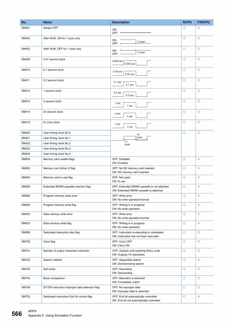
566APPXAppendix 5 Using Simulation Function
SM401 Always OFF
SM402 After RUN, ON for 1 scan only
SM403 After RUN, OFF for 1 scan only
SM409 0.01 second clock
SM410 0.1 second clock
SM411 0.2 second clock
SM412 1 second clock
SM413 2 second clock
SM414 2n second clock
SM415 2n (ms) clock
SM420 User timing clock No.0
SM421 User timing clock No.1
SM422 User timing clock No.2
SM423 User timing clock No.3
SM424 User timing clock No.4
SM600 Memory card usable flags OFF: Disabled
ON: Enabled
SM603 Memory card (drive 2) flag OFF: No SD memory card inserted
ON: SD memory card inserted
SM604 Memory card in-use flag OFF: Not used
ON: In use
SM626 Extended SRAM cassette insertion flag OFF: Extended SRAM cassette is not attached
ON: Extended SRAM cassette is attached
SM628 Program memory write error OFF: Write error
ON: No write operation/normal
SM629 Program memory write flag OFF: Writing is in progress
ON: No write operation
SM632 Data memory write error OFF: Write error
ON: No write operation/normal
SM633 Data memory write flag OFF: Writing is in progress
ON: No write operation
SM699 Dedicated instruction skip flag OFF: Instruction is executing or completed
ON: Instruction has not been executed
SM700 Carry flag OFF: Carry OFF
ON: Carry ON
SM701 Number of output characters selection OFF: Outputs until reaching NULL code
ON: Outputs 16 characters
SM702 Search method OFF: Sequential search
ON: Dichotomizing search
SM703 Sort order OFF: Ascending
ON: Descending
SM704 Block comparison OFF: Mismatch is detected
ON: Completely match
SM709 DT/TM instruction improper data detection flag OFF: No improper data
ON: Improper data is detected
SM752 Dedicated instruction End bit control flag OFF: End bit automatically controlled
ON: End bit not automatically controlled
No. Name Description RCPU FX5CPU
ONOFF
ONOFF 1 scan
ONOFF 1 scan
0.005 sec0.005 sec
0.05 sec0.05 sec
0.1 sec0.1 sec
0.5 sec0.5 sec
1 sec1 sec
n secn sec
n msn ms
n1
n2
scan
scan

APPXAppendix 5 Using Simulation Function 567
A
*1 RnCPUs and RnENCPUs support it.*2 Only RnPCPUs support it.*3 Only RnSFCPUs support it.
SM753 File being accessed OFF: File access is not in progress
ON: File access is in progress
SM754 BIN/DBIN instruction error control flag OFF: Executes error detection
ON: No execute error detection
SM755 Scaling data check settings OFF: Performs data check
ON: Not perform data check
SM756 Module access completion wait control flag OFF: Not wait the completion
ON: Waits the completion
SM776 Local device setting at CALL OFF: Disables local devices
ON: Enables local devices
SM777 Local device setting in interrupt programs OFF: Disables local devices
ON: Enables local devices
SM816 Hold mode OFF: Value not held
ON: Value held
*2
SM817 Hold mode OFF: Value not held
ON: Value held
*2
SM1524 Initial processing successful completion state OFF: The initial processing was completed successfully.
ON: The initial processing was not completed
successfully.
SM1525 Initial processing error completion state OFF: The initial processing was completed with an error.
ON: The initial processing was not completed with an
error.
SM1888 Safety cycle processing time execution cycle error flag OFF: No safety cycle processing time execution cycle
error occurred (normal)
ON: A safety cycle processing time execution cycle error
occurred
*3
No. Name Description RCPU FX5CPU
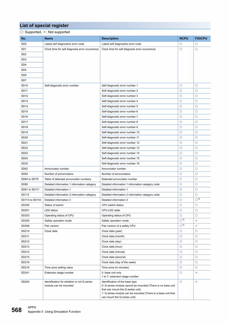
568APPXAppendix 5 Using Simulation Function
List of special register: Supported, : Not supported
No. Name Description RCPU FX5CPU
SD0 Latest self diagnostics error code Latest self diagnostics error code
SD1 Clock time for self diagnosis error occurrence Clock time for self diagnosis error occurrence
SD2
SD3
SD4
SD5
SD6
SD7
SD10 Self-diagnostic error number Self-diagnostic error number 1
SD11 Self-diagnostic error number 2
SD12 Self-diagnostic error number 3
SD13 Self-diagnostic error number 4
SD14 Self-diagnostic error number 5
SD15 Self-diagnostic error number 6
SD16 Self-diagnostic error number 7
SD17 Self-diagnostic error number 8
SD18 Self-diagnostic error number 9
SD19 Self-diagnostic error number 10
SD20 Self-diagnostic error number 11
SD21 Self-diagnostic error number 12
SD22 Self-diagnostic error number 13
SD23 Self-diagnostic error number 14
SD24 Self-diagnostic error number 15
SD25 Self-diagnostic error number 16
SD62 Annunciator number Annunciator number
SD63 Number of annunciators Number of annunciators
SD64 to SD79 Table of detected annunciator numbers Detected annunciator number
SD80 Detailed information 1 information category Detailed information 1 information category code
SD81 to SD111 Detailed information 1 Detailed information 1
SD112 Detailed information 2 information category Detailed information 2 information category code
SD113 to SD143 Detailed information 2 Detailed information 2 *4
SD200 Status of switch CPU switch status
SD201 LED status CPU-LED state
SD203 Operating status of CPU Operating status of CPU
SD205 Safety operation mode Safety operation mode *3
SD206 Pair version Pair version of a safety CPU *3
SD210 Clock data Clock data (year)
SD211 Clock data (month)
SD212 Clock data (day)
SD213 Clock data (hour)
SD214 Clock data (minute)
SD215 Clock data (second)
SD216 Clock data (day of the week)
SD218 Time zone setting value Time zone (in minutes)
SD241 Extension stage number 0: base unit only
1 to 7: extension stage number
SD242 Identification for whether or not Q series
module can be mounted
Identification of the base type
0: Q series module cannot be mounted (There is no base unit
that can mount the Q series unit)
1: Q series module can be mounted (There is a base unit that
can mount the Q series unit)
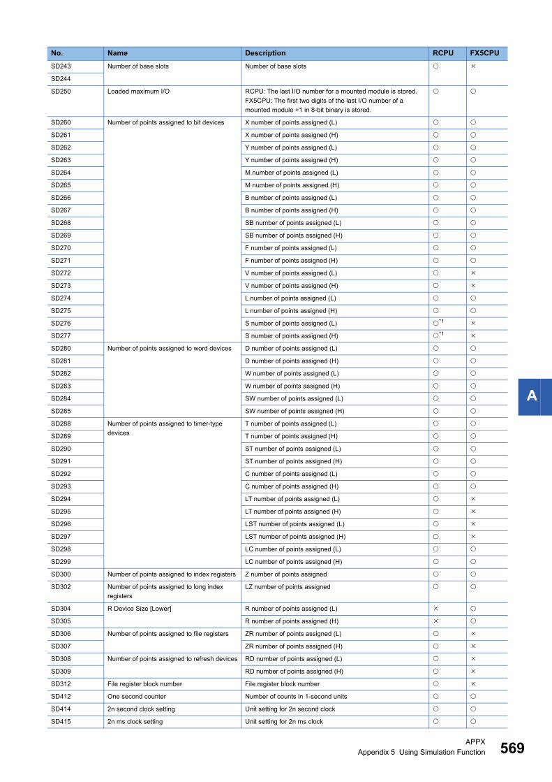
APPXAppendix 5 Using Simulation Function 569
A
SD243 Number of base slots Number of base slots
SD244
SD250 Loaded maximum I/O RCPU: The last I/O number for a mounted module is stored.
FX5CPU: The first two digits of the last I/O number of a
mounted module +1 in 8-bit binary is stored.
SD260 Number of points assigned to bit devices X number of points assigned (L)
SD261 X number of points assigned (H)
SD262 Y number of points assigned (L)
SD263 Y number of points assigned (H)
SD264 M number of points assigned (L)
SD265 M number of points assigned (H)
SD266 B number of points assigned (L)
SD267 B number of points assigned (H)
SD268 SB number of points assigned (L)
SD269 SB number of points assigned (H)
SD270 F number of points assigned (L)
SD271 F number of points assigned (H)
SD272 V number of points assigned (L)
SD273 V number of points assigned (H)
SD274 L number of points assigned (L)
SD275 L number of points assigned (H)
SD276 S number of points assigned (L) *1
SD277 S number of points assigned (H) *1
SD280 Number of points assigned to word devices D number of points assigned (L)
SD281 D number of points assigned (H)
SD282 W number of points assigned (L)
SD283 W number of points assigned (H)
SD284 SW number of points assigned (L)
SD285 SW number of points assigned (H)
SD288 Number of points assigned to timer-type
devices
T number of points assigned (L)
SD289 T number of points assigned (H)
SD290 ST number of points assigned (L)
SD291 ST number of points assigned (H)
SD292 C number of points assigned (L)
SD293 C number of points assigned (H)
SD294 LT number of points assigned (L)
SD295 LT number of points assigned (H)
SD296 LST number of points assigned (L)
SD297 LST number of points assigned (H)
SD298 LC number of points assigned (L)
SD299 LC number of points assigned (H)
SD300 Number of points assigned to index registers Z number of points assigned
SD302 Number of points assigned to long index
registers
LZ number of points assigned
SD304 R Device Size [Lower] R number of points assigned (L)
SD305 R number of points assigned (H)
SD306 Number of points assigned to file registers ZR number of points assigned (L)
SD307 ZR number of points assigned (H)
SD308 Number of points assigned to refresh devices RD number of points assigned (L)
SD309 RD number of points assigned (H)
SD312 File register block number File register block number
SD412 One second counter Number of counts in 1-second units
SD414 2n second clock setting Unit setting for 2n second clock
SD415 2n ms clock setting Unit setting for 2n ms clock
No. Name Description RCPU FX5CPU

570APPXAppendix 5 Using Simulation Function
SD420 Scan counter Number of counts in each scan
SD500 Execution program number Execution type of the program being executed
SD518 Initial scan time Initial scan time (unit: ms)
SD519 Initial scan time (unit: μs)
SD520 Current scan time Current scan time (unit: ms)
SD521 Current scan time (unit: μs)
SD522 Minimum scan time Minimum scan time (unit: ms)
SD523 Minimum scan time (unit: μs)
SD524 Maximum scan time Maximum scan time (unit: ms)
SD525 Maximum scan time (unit: μs)
SD526 END processing time END processing time (unit: ms)
SD527 END processing time (unit: μs)
SD528 Constant scan wait time Constant scan wait time (unit: ms)
SD529 Constant scan wait time (unit: μs)
SD530 Scan program execution time Scan program execution time (unit: ms)
SD531 Scan program execution time (unit: μs)
SD600 Memory card mounting status SD memory card type
SD604 SD memory card (drive 2) usage status SD memory card (drive 2) usage status
SD606 SD memory card (drive 2) capacity SD memory card (drive 2) capacity: the lower digit (unit: KB)
SD607 SD memory card (drive 2) capacity: the higher digits (unit: KB)
SD610 SD memory card (drive 2) free space SD memory card (drive 2) free space: the lower digit (unit: KB)
SD611 SD memory card (drive 2) free space: the higher digits (unit:
KB)
SD614 Device/label memory (drive 3) usage status Device/label memory (drive 3) usage status
SD616 Device/label memory (drive 3) capacity Device/label memory (drive 3) capacity: the lower digits (unit:
KB)
SD617 Device/label memory (drive 3) capacity: the higher digits (unit:
KB)
SD618 Device/label memory (file storage area)
capacity
Device/label memory (file storage area) (drive 3) capacity: the
lower digits (unit: KB)
SD619 Device/label memory (file storage area) (drive 3) capacity: the
higher digits (unit: KB)
SD620 Data memory (drive 4) usage status Data memory (drive 4) usage status
SD622 Data memory (drive 4) capacity Data memory (drive 4) capacity: the lower digits (unit: KB)
SD623 Data memory (drive 4) capacity: the higher digits (unit: KB)
SD626 Extended SRAM cassette capacity
identification information
Capacity identification information of the Extended SRAM
cassette
SD629 Program memory write (transfer) status Write (transfer) status display (percent)
SD633 Data memory write (transfer) status Write (transfer) status display (percent)
SD642 Internal buffer capacity Internal buffer capacity: the lower digits (unit: KB) *1
SD643 Internal buffer capacity: the higher digits (unit: KB) *1
SD644 Internal buffer free area capacity Internal buffer free area capacity: the lower digits (unit: KB) *1
SD645 Internal buffer free area capacity: the higher digits (unit: KB) *1
SD757 Current interrupt priority Current interrupt priority
SD758 Interrupt disabling for each priority setting
value
Interrupt disabling for each priority setting value
SD771 Specification of the number of write
instruction executions to data memory
Specification of the number of write instruction executions to
data memory
SD816 Basic period Basic period *2
SD817
SD818 Bumpless function availability setting for the
S.PIDP instruction
0: Enable
1: Disable
*2
SD819 Dummy device Dummy device *2
SD820
No. Name Description RCPU FX5CPU

APPXAppendix 5 Using Simulation Function 571
A
*1 RnCPUs and RnENCPUs support it.*2 Only RnPCPUs support it.*3 Only RnSFCPUs support it.*4 SD116 to SD129 cannot be used.*5 Only SD1400 and SD1401 can be used.
Safety special relays list
SD1400 to
SD1463
Interrupt pointer mask pattern Mask pattern *5
SD1504 Open completion signal Open completion
SD1505 Open request signal Open request
SD1844 Number of points assigned to safety bit
devices
SA\X number of points assigned (L) *3
SD1845 SA\X number of points assigned (H) *3
SD1846 SA\Y number of points assigned (L) *3
SD1847 SA\Y number of points assigned (H) *3
SD1848 SA\M number of points assigned (L) *3
SD1849 SA\M number of points assigned (H) *3
SD1850 SA\B number of points assigned (L) *3
SD1851 SA\B number of points assigned (H) *3
SD1864 Number of points assigned to safety word
devices
SA\D number of points assigned (L) *3
SD1865 SA\D number of points assigned (H) *3
SD1866 SA\W number of points assigned (L) *3
SD1867 SA\W number of points assigned (H) *3
SD1872 Number of points assigned to safety timer/
counter devices
SA\T number of points assigned (L) *3
SD1873 SA\T number of points assigned (H) *3
SD1874 SA\ST number of points assigned (L) *3
SD1875 SA\ST number of points assigned (H) *3
SD1876 SA\C number of points assigned (L) *3
SD1877 SA\C number of points assigned (H) *3
SD1888 Safety cycle processing time execution cycle
error count
0: No safety cycle processing time execution cycle error
occurred (normal)
1 to 65535: Cumulative number of execution cycle errors
during safety cycle processing time
*3
SD1890 Current safety cycle processing time Current safety cycle processing time (unit: ms) *3
SD1891 Current safety cycle processing time (unit: μs) *3
SD1892 Minimum safety cycle processing time Minimum safety cycle processing time (unit: ms) *3
SD1893 Minimum safety cycle processing time (unit: μs) *3
SD1894 Maximum safety cycle processing time Maximum safety cycle processing time (unit: ms) *3
SD1895 Maximum safety cycle processing time (unit: μs) *3
SD1903 Total standard/safety shared label usage
capacity
Total standard/safety shared label usage capacity (unit: words) *3
No. Name Description
SA\SM400 Always ON
SA\SM401 Always OFF
SA\SM444 On at the first safety program execution
No. Name Description RCPU FX5CPU
ONOFF
ONOFF
ONOFF
First time only
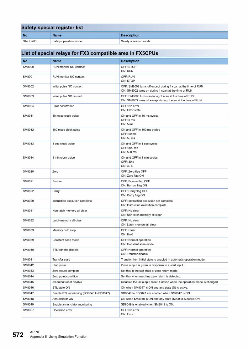
572APPXAppendix 5 Using Simulation Function
Safety special register list
List of special relays for FX3 compatible area in FX5CPUs
No. Name Description
SA\SD205 Safety operation mode Safety operation mode
No. Name Description
SM8000 RUN monitor NO contact OFF: STOP
ON: RUN
SM8001 RUN monitor NC contact OFF: RUN
ON: STOP
SM8002 Initial pulse NO contact OFF: SM8002 turns off except during 1 scan at the time of RUN
ON: SM8002 turns on during 1 scan at the time of RUN
SM8003 Initial pulse NC contact OFF: SM8003 turns on during 1 scan at the time of RUN
ON: SM8003 turns off except during 1 scan at the time of RUN
SM8004 Error occurrence OFF: No error
ON: Error state
SM8011 10 msec clock pulse ON and OFF in 10 ms cycles
OFF: 5 ms
ON: 5 ms
SM8012 100 msec clock pulse ON and OFF in 100 ms cycles
OFF: 50 ms
ON: 50 ms
SM8013 1 sec clock pulse ON and OFF in 1 sec cycles
OFF: 500 ms
ON: 500 ms
SM8014 1 min clock pulse ON and OFF in 1 min cycles
OFF: 30 s
ON: 30 s
SM8020 Zero OFF: Zero flag OFF
ON: Zero flag ON
SM8021 Borrow OFF: Borrow flag OFF
ON: Borrow flag ON
SM8022 Carry OFF: Carry flag OFF
ON: Carry flag ON
SM8029 Instruction execution complete OFF: Instruction execution not complete
ON: Instruction execution complete
SM8031 Non-latch memory all clear OFF: No clear
ON: Non-latch memory all clear
SM8032 Latch memory all clear OFF: No clear
ON: Latch memory all clear
SM8033 Memory hold stop OFF: Clear
ON: Hold
SM8039 Constant scan mode OFF: Normal operation
ON: Constant scan mode
SM8040 STL transfer disable OFF: Normal operation
ON: Transfer disable
SM8041 Transfer start Transfer from initial state is enabled in automatic operation mode.
SM8042 Start pulse Pulse output is given in response to a start input.
SM8043 Zero return complete Set this in the last state of zero return mode.
SM8044 Zero point condition Set this when machine zero return is detected.
SM8045 All output reset disable Disables the 'all output reset' function when the operation mode is changed.
SM8046 STL state ON ON when SM8047 is ON and any state (S) is active.
SM8047 Enable STL monitoring (SD8040 to SD8047) SD8040 to SD8047 are enabled when SM8047 is ON.
SM8048 Annunciator ON ON when SM8049 is ON and any state (S900 to S999) is ON.
SM8049 Enable annunciator monitoring SD8049 is enabled when SM8049 is ON.
SM8067 Operation error OFF: No error
ON: Error

APPXAppendix 5 Using Simulation Function 573
A
List of special registers for FX3 compatible area in FX5CPUs
SM8068 Operation error latch OFF: No error
ON: Error (latch)
SM8090 Block comparison signal Block comparison signal ON when all comparison results are ON.
SM8161 8 bit operation mode OFF: 16 bit operation mode
ON: 8 bit operation mode
SM8168 SMOV data mode BIN → BCD conversion will not be performed, if a SMOV instruction is executed
after turning ON SM8168.
SM8304 Zero OFF: Zero flag OFF
ON: Zero flag ON
SM8306 Carry OFF: Carry flag OFF
ON: Carry flag ON
SM8330 Timing clock output 1 DUTY instruction: Timing clock output 1
SM8331 Timing clock output 2 DUTY instruction: Timing clock output 2
SM8332 Timing clock output 3 DUTY instruction: Timing clock output 3
SM8333 Timing clock output 4 DUTY instruction: Timing clock output 4
SM8334 Timing clock output 5 DUTY instruction: Timing clock output 5
No. Name Description
SD8000 Watchdog timer The watchdog timer is stored.
SD8001 PLC type and system version The PLC type and system version are stored.
SD8010 Current scan time The current scan time is stored.
SD8011 Minimum scan time The minimum scan time is stored.
SD8012 Maximum scan time The maximum scan time is stored.
SD8013 RTC: Second The second data is stored.
SD8014 RTC: Minute The minute data is stored.
SD8015 RTC: Hour The hour data is stored.
SD8016 RTC: Day The day data is stored.
SD8017 RTC: Month The month data is stored.
SD8018 RTC: Year The year data is stored.
SD8019 RTC: Day of week The day of week data is stored.
SD8039 Constant scan time The constant scan time is stored.
SD8040 to SD8047 STL: ON state number The ON state number is stored.
SD8049 Lowest active annunciator The lowest active annunciator is stored.
SD8067 Operation error The error code number of an operation error is stored.
SD8310 to SD8311 RND Random number generation The RND random number generation data is stored.
SD8330 to SD8334 Timing clock output
Counted number of scans
The scan count for timing clock output is stored.
No. Name Description
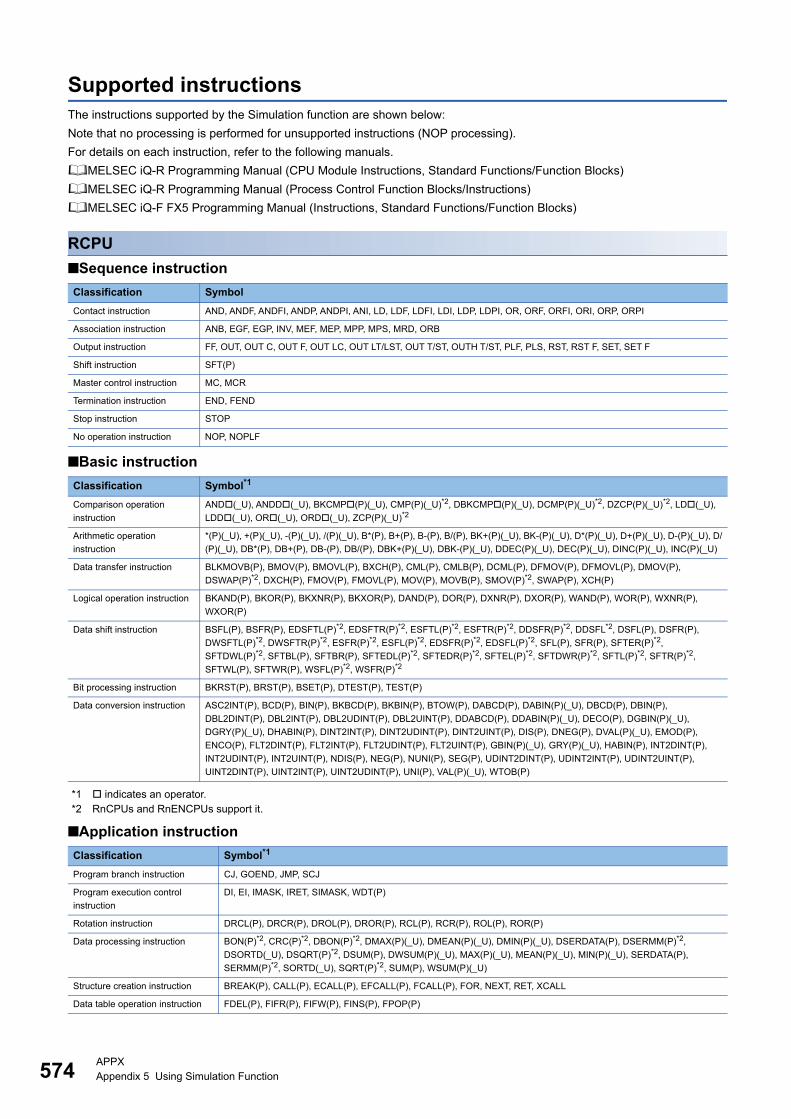
574APPXAppendix 5 Using Simulation Function
Supported instructionsThe instructions supported by the Simulation function are shown below:
Note that no processing is performed for unsupported instructions (NOP processing).
For details on each instruction, refer to the following manuals.
MELSEC iQ-R Programming Manual (CPU Module Instructions, Standard Functions/Function Blocks)
MELSEC iQ-R Programming Manual (Process Control Function Blocks/Instructions)
MELSEC iQ-F FX5 Programming Manual (Instructions, Standard Functions/Function Blocks)
RCPU
■Sequence instruction
■Basic instruction
*1 indicates an operator.*2 RnCPUs and RnENCPUs support it.
■Application instruction
Classification Symbol
Contact instruction AND, ANDF, ANDFI, ANDP, ANDPI, ANI, LD, LDF, LDFI, LDI, LDP, LDPI, OR, ORF, ORFI, ORI, ORP, ORPI
Association instruction ANB, EGF, EGP, INV, MEF, MEP, MPP, MPS, MRD, ORB
Output instruction FF, OUT, OUT C, OUT F, OUT LC, OUT LT/LST, OUT T/ST, OUTH T/ST, PLF, PLS, RST, RST F, SET, SET F
Shift instruction SFT(P)
Master control instruction MC, MCR
Termination instruction END, FEND
Stop instruction STOP
No operation instruction NOP, NOPLF
Classification Symbol*1
Comparison operation
instruction
AND(_U), ANDD(_U), BKCMP(P)(_U), CMP(P)(_U)*2, DBKCMP(P)(_U), DCMP(P)(_U)*2, DZCP(P)(_U)*2, LD(_U),
LDD(_U), OR(_U), ORD(_U), ZCP(P)(_U)*2
Arithmetic operation
instruction
*(P)(_U), +(P)(_U), -(P)(_U), /(P)(_U), B*(P), B+(P), B-(P), B/(P), BK+(P)(_U), BK-(P)(_U), D*(P)(_U), D+(P)(_U), D-(P)(_U), D/
(P)(_U), DB*(P), DB+(P), DB-(P), DB/(P), DBK+(P)(_U), DBK-(P)(_U), DDEC(P)(_U), DEC(P)(_U), DINC(P)(_U), INC(P)(_U)
Data transfer instruction BLKMOVB(P), BMOV(P), BMOVL(P), BXCH(P), CML(P), CMLB(P), DCML(P), DFMOV(P), DFMOVL(P), DMOV(P),
DSWAP(P)*2, DXCH(P), FMOV(P), FMOVL(P), MOV(P), MOVB(P), SMOV(P)*2, SWAP(P), XCH(P)
Logical operation instruction BKAND(P), BKOR(P), BKXNR(P), BKXOR(P), DAND(P), DOR(P), DXNR(P), DXOR(P), WAND(P), WOR(P), WXNR(P),
WXOR(P)
Data shift instruction BSFL(P), BSFR(P), EDSFTL(P)*2, EDSFTR(P)*2, ESFTL(P)*2, ESFTR(P)*2, DDSFR(P)*2, DDSFL*2, DSFL(P), DSFR(P),
DWSFTL(P)*2, DWSFTR(P)*2, ESFR(P)*2, ESFL(P)*2, EDSFR(P)*2, EDSFL(P)*2, SFL(P), SFR(P), SFTER(P)*2,
SFTDWL(P)*2, SFTBL(P), SFTBR(P), SFTEDL(P)*2, SFTEDR(P)*2, SFTEL(P)*2, SFTDWR(P)*2, SFTL(P)*2, SFTR(P)*2,
SFTWL(P), SFTWR(P), WSFL(P)*2, WSFR(P)*2
Bit processing instruction BKRST(P), BRST(P), BSET(P), DTEST(P), TEST(P)
Data conversion instruction ASC2INT(P), BCD(P), BIN(P), BKBCD(P), BKBIN(P), BTOW(P), DABCD(P), DABIN(P)(_U), DBCD(P), DBIN(P),
DBL2DINT(P), DBL2INT(P), DBL2UDINT(P), DBL2UINT(P), DDABCD(P), DDABIN(P)(_U), DECO(P), DGBIN(P)(_U),
DGRY(P)(_U), DHABIN(P), DINT2INT(P), DINT2UDINT(P), DINT2UINT(P), DIS(P), DNEG(P), DVAL(P)(_U), EMOD(P),
ENCO(P), FLT2DINT(P), FLT2INT(P), FLT2UDINT(P), FLT2UINT(P), GBIN(P)(_U), GRY(P)(_U), HABIN(P), INT2DINT(P),
INT2UDINT(P), INT2UINT(P), NDIS(P), NEG(P), NUNI(P), SEG(P), UDINT2DINT(P), UDINT2INT(P), UDINT2UINT(P),
UINT2DINT(P), UINT2INT(P), UINT2UDINT(P), UNI(P), VAL(P)(_U), WTOB(P)
Classification Symbol*1
Program branch instruction CJ, GOEND, JMP, SCJ
Program execution control
instruction
DI, EI, IMASK, IRET, SIMASK, WDT(P)
Rotation instruction DRCL(P), DRCR(P), DROL(P), DROR(P), RCL(P), RCR(P), ROL(P), ROR(P)
Data processing instruction BON(P)*2, CRC(P)*2, DBON(P)*2, DMAX(P)(_U), DMEAN(P)(_U), DMIN(P)(_U), DSERDATA(P), DSERMM(P)*2,
DSORTD(_U), DSQRT(P)*2, DSUM(P), DWSUM(P)(_U), MAX(P)(_U), MEAN(P)(_U), MIN(P)(_U), SERDATA(P),
SERMM(P)*2, SORTD(_U), SQRT(P)*2, SUM(P), WSUM(P)(_U)
Structure creation instruction BREAK(P), CALL(P), ECALL(P), EFCALL(P), FCALL(P), FOR, NEXT, RET, XCALL
Data table operation instruction FDEL(P), FIFR(P), FIFW(P), FINS(P), FPOP(P)
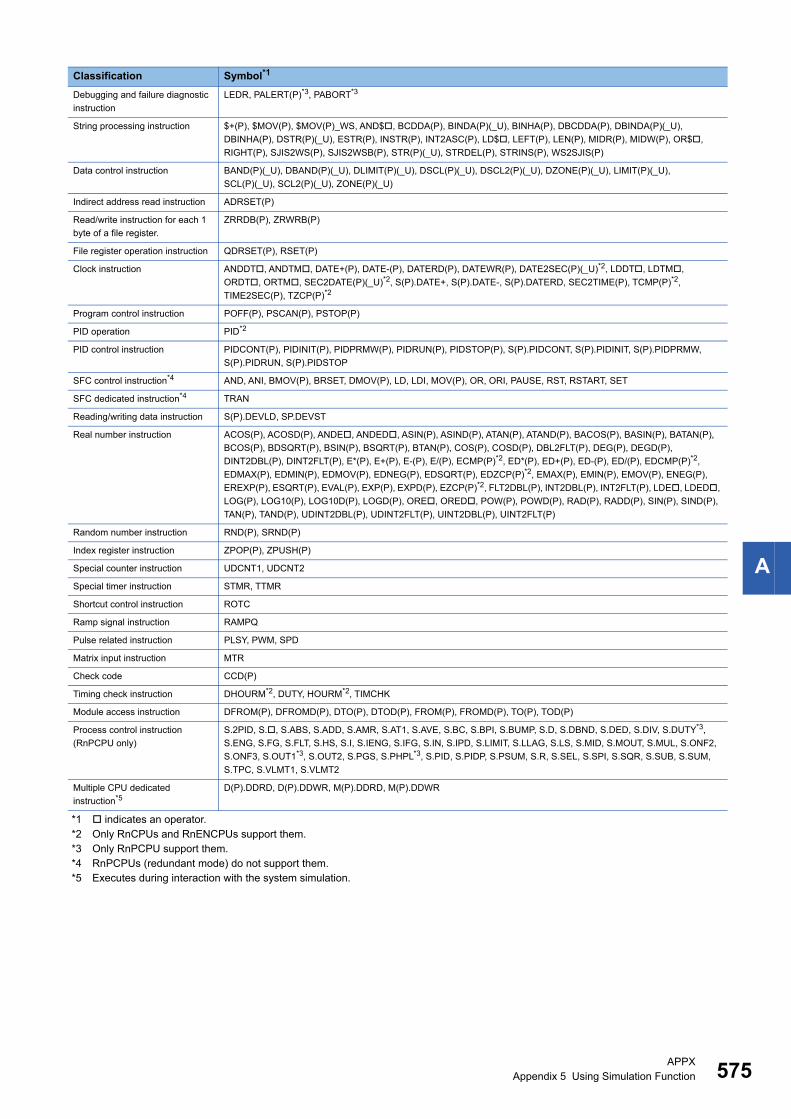
APPXAppendix 5 Using Simulation Function 575
A
*1 indicates an operator.*2 Only RnCPUs and RnENCPUs support them.*3 Only RnPCPU support them.*4 RnPCPUs (redundant mode) do not support them.*5 Executes during interaction with the system simulation.
Debugging and failure diagnostic
instruction
LEDR, PALERT(P)*3, PABORT*3
String processing instruction $+(P), $MOV(P), $MOV(P)_WS, AND$, BCDDA(P), BINDA(P)(_U), BINHA(P), DBCDDA(P), DBINDA(P)(_U),
DBINHA(P), DSTR(P)(_U), ESTR(P), INSTR(P), INT2ASC(P), LD$, LEFT(P), LEN(P), MIDR(P), MIDW(P), OR$,
RIGHT(P), SJIS2WS(P), SJIS2WSB(P), STR(P)(_U), STRDEL(P), STRINS(P), WS2SJIS(P)
Data control instruction BAND(P)(_U), DBAND(P)(_U), DLIMIT(P)(_U), DSCL(P)(_U), DSCL2(P)(_U), DZONE(P)(_U), LIMIT(P)(_U),
SCL(P)(_U), SCL2(P)(_U), ZONE(P)(_U)
Indirect address read instruction ADRSET(P)
Read/write instruction for each 1
byte of a file register.
ZRRDB(P), ZRWRB(P)
File register operation instruction QDRSET(P), RSET(P)
Clock instruction ANDDT, ANDTM, DATE+(P), DATE-(P), DATERD(P), DATEWR(P), DATE2SEC(P)(_U)*2, LDDT, LDTM,
ORDT, ORTM, SEC2DATE(P)(_U)*2, S(P).DATE+, S(P).DATE-, S(P).DATERD, SEC2TIME(P), TCMP(P)*2,
TIME2SEC(P), TZCP(P)*2
Program control instruction POFF(P), PSCAN(P), PSTOP(P)
PID operation PID*2
PID control instruction PIDCONT(P), PIDINIT(P), PIDPRMW(P), PIDRUN(P), PIDSTOP(P), S(P).PIDCONT, S(P).PIDINIT, S(P).PIDPRMW,
S(P).PIDRUN, S(P).PIDSTOP
SFC control instruction*4 AND, ANI, BMOV(P), BRSET, DMOV(P), LD, LDI, MOV(P), OR, ORI, PAUSE, RST, RSTART, SET
SFC dedicated instruction*4 TRAN
Reading/writing data instruction S(P).DEVLD, SP.DEVST
Real number instruction ACOS(P), ACOSD(P), ANDE, ANDED, ASIN(P), ASIND(P), ATAN(P), ATAND(P), BACOS(P), BASIN(P), BATAN(P),
BCOS(P), BDSQRT(P), BSIN(P), BSQRT(P), BTAN(P), COS(P), COSD(P), DBL2FLT(P), DEG(P), DEGD(P),
DINT2DBL(P), DINT2FLT(P), E*(P), E+(P), E-(P), E/(P), ECMP(P)*2, ED*(P), ED+(P), ED-(P), ED/(P), EDCMP(P)*2,
EDMAX(P), EDMIN(P), EDMOV(P), EDNEG(P), EDSQRT(P), EDZCP(P)*2, EMAX(P), EMIN(P), EMOV(P), ENEG(P),
EREXP(P), ESQRT(P), EVAL(P), EXP(P), EXPD(P), EZCP(P)*2, FLT2DBL(P), INT2DBL(P), INT2FLT(P), LDE, LDED,
LOG(P), LOG10(P), LOG10D(P), LOGD(P), ORE, ORED, POW(P), POWD(P), RAD(P), RADD(P), SIN(P), SIND(P),
TAN(P), TAND(P), UDINT2DBL(P), UDINT2FLT(P), UINT2DBL(P), UINT2FLT(P)
Random number instruction RND(P), SRND(P)
Index register instruction ZPOP(P), ZPUSH(P)
Special counter instruction UDCNT1, UDCNT2
Special timer instruction STMR, TTMR
Shortcut control instruction ROTC
Ramp signal instruction RAMPQ
Pulse related instruction PLSY, PWM, SPD
Matrix input instruction MTR
Check code CCD(P)
Timing check instruction DHOURM*2, DUTY, HOURM*2, TIMCHK
Module access instruction DFROM(P), DFROMD(P), DTO(P), DTOD(P), FROM(P), FROMD(P), TO(P), TOD(P)
Process control instruction
(RnPCPU only)
S.2PID, S., S.ABS, S.ADD, S.AMR, S.AT1, S.AVE, S.BC, S.BPI, S.BUMP, S.D, S.DBND, S.DED, S.DIV, S.DUTY*3,
S.ENG, S.FG, S.FLT, S.HS, S.I, S.IENG, S.IFG, S.IN, S.IPD, S.LIMIT, S.LLAG, S.LS, S.MID, S.MOUT, S.MUL, S.ONF2,
S.ONF3, S.OUT1*3, S.OUT2, S.PGS, S.PHPL*3, S.PID, S.PIDP, S.PSUM, S.R, S.SEL, S.SPI, S.SQR, S.SUB, S.SUM,
S.TPC, S.VLMT1, S.VLMT2
Multiple CPU dedicated
instruction*5D(P).DDRD, D(P).DDWR, M(P).DDRD, M(P).DDWR
Classification Symbol*1
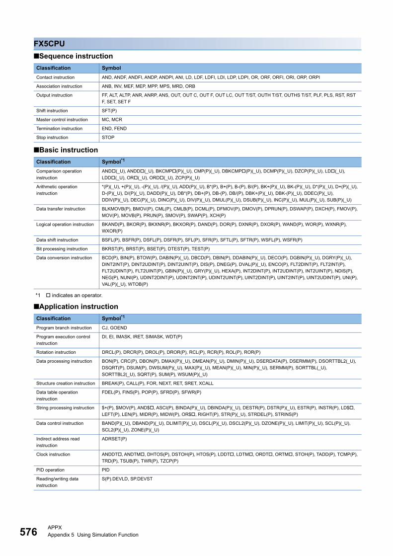
576APPXAppendix 5 Using Simulation Function
FX5CPU
■Sequence instruction
■Basic instruction
*1 indicates an operator.
■Application instruction
Classification Symbol
Contact instruction AND, ANDF, ANDFI, ANDP, ANDPI, ANI, LD, LDF, LDFI, LDI, LDP, LDPI, OR, ORF, ORFI, ORI, ORP, ORPI
Association instruction ANB, INV, MEF, MEP, MPP, MPS, MRD, ORB
Output instruction FF, ALT, ALTP, ANR, ANRP, ANS, OUT, OUT C, OUT F, OUT LC, OUT T/ST, OUTH T/ST, OUTHS T/ST, PLF, PLS, RST, RST
F, SET, SET F
Shift instruction SFT(P)
Master control instruction MC, MCR
Termination instruction END, FEND
Stop instruction STOP
Classification Symbol*1
Comparison operation
instruction
AND(_U), ANDD(_U), BKCMP(P)(_U), CMP(P)(_U), DBKCMP(P)(_U), DCMP(P)(_U), DZCP(P)(_U), LD(_U),
LDD(_U), OR(_U), ORD(_U), ZCP(P)(_U)
Arithmetic operation
instruction
*(P)(_U), +(P)(_U), -(P)(_U), /(P)(_U), ADD(P)(_U), B*(P), B+(P), B-(P), B/(P), BK+(P)(_U), BK-(P)(_U), D*(P)(_U), D+(P)(_U),
D-(P)(_U), D/(P)(_U), DADD(P)(_U), DB*(P), DB+(P), DB-(P), DB/(P), DBK+(P)(_U), DBK-(P)(_U), DDEC(P)(_U),
DDIV(P)(_U), DEC(P)(_U), DINC(P)(_U), DIV(P)(_U), DMUL(P)(_U), DSUB(P)(_U), INC(P)(_U), MUL(P)(_U), SUB(P)(_U)
Data transfer instruction BLKMOVB(P), BMOV(P), CML(P), CMLB(P), DCML(P), DFMOV(P), DMOV(P), DPRUN(P), DSWAP(P), DXCH(P), FMOV(P),
MOV(P), MOVB(P), PRUN(P), SMOV(P), SWAP(P), XCH(P)
Logical operation instruction BKAND(P), BKOR(P), BKXNR(P), BKXOR(P), DAND(P), DOR(P), DXNR(P), DXOR(P), WAND(P), WOR(P), WXNR(P),
WXOR(P)
Data shift instruction BSFL(P), BSFR(P), DSFL(P), DSFR(P), SFL(P), SFR(P), SFTL(P), SFTR(P), WSFL(P), WSFR(P)
Bit processing instruction BKRST(P), BRST(P), BSET(P), DTEST(P), TEST(P)
Data conversion instruction BCD(P), BIN(P), BTOW(P), DABIN(P)(_U), DBCD(P), DBIN(P), DDABIN(P)(_U), DECO(P), DGBIN(P)(_U), DGRY(P)(_U),
DINT2INT(P), DINT2UDINT(P), DINT2UINT(P), DIS(P), DNEG(P), DVAL(P)(_U), ENCO(P), FLT2DINT(P), FLT2INT(P),
FLT2UDINT(P), FLT2UINT(P), GBIN(P)(_U), GRY(P)(_U), HEXA(P), INT2DINT(P), INT2UDINT(P), INT2UINT(P), NDIS(P),
NEG(P), NUNI(P), UDINT2DINT(P), UDINT2INT(P), UDINT2UINT(P), UINT2DINT(P), UINT2INT(P), UINT2UDINT(P), UNI(P),
VAL(P)(_U), WTOB(P)
Classification Symbol*1
Program branch instruction CJ, GOEND
Program execution control
instruction
DI, EI, IMASK, IRET, SIMASK, WDT(P)
Rotation instruction DRCL(P), DRCR(P), DROL(P), DROR(P), RCL(P), RCR(P), ROL(P), ROR(P)
Data processing instruction BON(P), CRC(P), DBON(P), DMAX(P)(_U), DMEAN(P)(_U), DMIN(P)(_U), DSERDATA(P), DSERMM(P), DSORTTBL2(_U),
DSQRT(P), DSUM(P), DWSUM(P)(_U), MAX(P)(_U), MEAN(P)(_U), MIN(P)(_U), SERMM(P), SORTTBL(_U),
SORTTBL2(_U), SQRT(P), SUM(P), WSUM(P)(_U)
Structure creation instruction BREAK(P), CALL(P), FOR, NEXT, RET, SRET, XCALL
Data table operation
instruction
FDEL(P), FINS(P), POP(P), SFRD(P), SFWR(P)
String processing instruction $+(P), $MOV(P), AND$, ASCI(P), BINDA(P)(_U), DBINDA(P)(_U), DESTR(P), DSTR(P)(_U), ESTR(P), INSTR(P), LD$,
LEFT(P), LEN(P), MIDR(P), MIDW(P), OR$, RIGHT(P), STR(P)(_U), STRDEL(P), STRINS(P)
Data control instruction BAND(P)(_U), DBAND(P)(_U), DLIMIT(P)(_U), DSCL(P)(_U), DSCL2(P)(_U), DZONE(P)(_U), LIMIT(P)(_U), SCL(P)(_U),
SCL2(P)(_U), ZONE(P)(_U)
Indirect address read
instruction
ADRSET(P)
Clock instruction ANDDT, ANDTM, DHTOS(P), DSTOH(P), HTOS(P), LDDT, LDTM, ORDT, ORTM, STOH(P), TADD(P), TCMP(P),
TRD(P), TSUB(P), TWR(P), TZCP(P)
PID operation PID
Reading/writing data
instruction
S(P).DEVLD, SP.DEVST
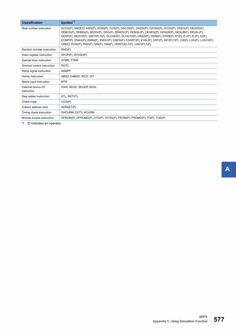
APPXAppendix 5 Using Simulation Function 577
A
*1 indicates an operator.
Real number instruction ACOS(P), ANDE, ASIN(P), ATAN(P), COS(P), DACOS(P), DASIN(P), DATAN(P), DCOS(P), DDEG(P), DEADD(P),
DEBCD(P), DEBIN(P), DEDIV(P), DEG(P), DEMOV(P), DEMUL(P), DENEG(P), DESQR(P), DESUB(P), DEVAL(P),
DEXP(P), DEZCP(P), DINT2FLT(P), DLOGE(P), DLOG10(P), DRAD(P), DSIN(P), DTAN(P), E*(P), E+(P), E-(P), E/(P),
ECMP(P), EMAX(P), EMIN(P), EMOV(P), ENEG(P), ESQRT(P), EVAL(P), EXP(P), INT2FLT(P), LDE, LOG(P), LOG10(P),
ORE, POW(P), RAD(P), SIN(P), TAN(P), UDINT2FLT(P), UINT2FLT(P)
Random number instruction RND(P)
Index register instruction ZPOP(P), ZPUSH(P)
Special timer instruction STMR, TTMR
Shortcut control instruction ROTC
Ramp signal instruction RAMPF
Handy instruction ABSD, DABSD, INCD, IST
Matrix input instruction MTR
External device I/O
instruction
DSW, SEGD, SEGDP, SEGL
Step ladder instruction STL, RETSTL
Check code CCD(P)
Indirect address read ADRSET(P)
Timing check instruction DHOURM, DUTY, HOURM
Module access instruction DFROM(P), DFROMD(P), DTO(P), DTOD(P), FROM(P), FROMD(P), TO(P), TOD(P)
Classification Symbol*1
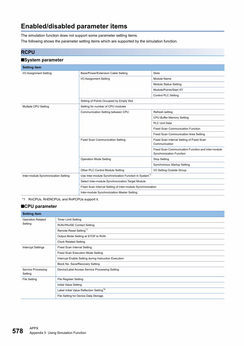
578APPXAppendix 5 Using Simulation Function
Enabled/disabled parameter itemsThe simulation function does not support some parameter setting items.
The following shows the parameter setting items which are supported by the simulation function.
RCPU
■System parameter
*1 RnCPUs, RnENCPUs, and RnPCPUs support it.
■CPU parameter
Setting item
I/O Assignment Setting Base/Power/Extension Cable Setting Slots
I/O Assignment Setting Module Name
Module Status Setting
Module/Points/Start XY
Control PLC Setting
Setting of Points Occupied by Empty Slot
Multiple CPU Setting Setting for number of CPU modules
Communication Setting between CPU Refresh setting
CPU Buffer Memory Setting
PLC Unit Data
Fixed Scan Communication Function
Fixed Scan Communication Area Setting
Fixed Scan Communication Setting Fixed Scan Interval Setting of Fixed Scan
Communication
Fixed Scan Communication Function and Inter-module
Synchronization Function
Operation Mode Setting Stop Setting
Synchronous Startup Setting
Other PLC Control Module Setting I/O Setting Outside Group
Inter-module Synchronization Setting Use Inter-module Synchronization Function in System*1
Select Inter-module Synchronization Target Module
Fixed Scan Interval Setting of Inter-module Synchronization
Inter-module Synchronization Master Setting
Setting item
Operation Related
Setting
Timer Limit Setting
RUN-PAUSE Contact Setting
Remote Reset Setting*1
Output Mode Setting at STOP to RUN
Clock Related Setting
Interrupt Settings Fixed Scan Interval Setting
Fixed Scan Execution Mode Setting
Interrupt Enable Setting during Instruction Execution
Block No. Save/Recovery Setting
Service Processing
Setting
Device/Label Access Service Processing Setting
File Setting File Register Setting
Initial Value Setting
Label Initial Value Reflection Setting*4
File Setting for Device Data Storage
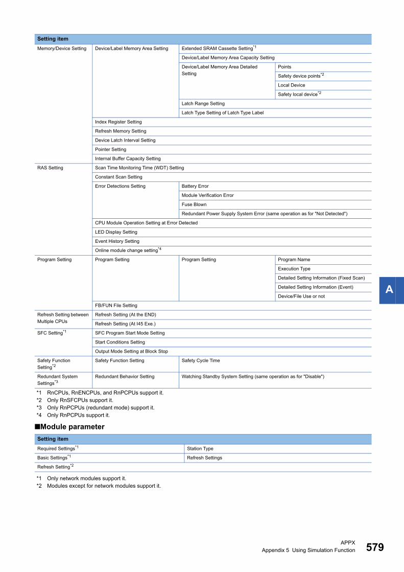
APPXAppendix 5 Using Simulation Function 579
A
*1 RnCPUs, RnENCPUs, and RnPCPUs support it.*2 Only RnSFCPUs support it.*3 Only RnPCPUs (redundant mode) support it.*4 Only RnPCPUs support it.
■Module parameter
*1 Only network modules support it.*2 Modules except for network modules support it.
Memory/Device Setting Device/Label Memory Area Setting Extended SRAM Cassette Setting*1
Device/Label Memory Area Capacity Setting
Device/Label Memory Area Detailed
Setting
Points
Safety device points*2
Local Device
Safety local device*2
Latch Range Setting
Latch Type Setting of Latch Type Label
Index Register Setting
Refresh Memory Setting
Device Latch Interval Setting
Pointer Setting
Internal Buffer Capacity Setting
RAS Setting Scan Time Monitoring Time (WDT) Setting
Constant Scan Setting
Error Detections Setting Battery Error
Module Verification Error
Fuse Blown
Redundant Power Supply System Error (same operation as for "Not Detected")
CPU Module Operation Setting at Error Detected
LED Display Setting
Event History Setting
Online module change setting*4
Program Setting Program Setting Program Setting Program Name
Execution Type
Detailed Setting Information (Fixed Scan)
Detailed Setting Information (Event)
Device/File Use or not
FB/FUN File Setting
Refresh Setting between
Multiple CPUs
Refresh Setting (At the END)
Refresh Setting (At I45 Exe.)
SFC Setting*1 SFC Program Start Mode Setting
Start Conditions Setting
Output Mode Setting at Block Stop
Safety Function
Setting*2Safety Function Setting Safety Cycle Time
Redundant System
Settings*3Redundant Behavior Setting Watching Standby System Setting (same operation as for "Disable")
Setting item
Required Settings*1 Station Type
Basic Settings*1 Refresh Settings
Refresh Setting*2
Setting item
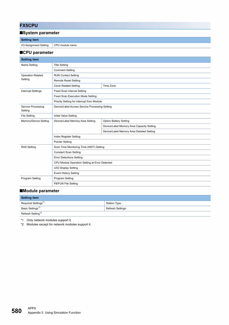
580APPXAppendix 5 Using Simulation Function
FX5CPU
■System parameter
■CPU parameter
■Module parameter
*1 Only network modules support it.*2 Modules except for network modules support it.
Setting item
I/O Assignment Setting CPU module name
Setting item
Name Setting Title Setting
Comment Setting
Operation Related
Setting
RUN Contact Setting
Remote Reset Setting
Clock Related Setting Time Zone
Interrupt Settings Fixed Scan Interval Setting
Fixed Scan Execution Mode Setting
Priority Setting for Interrupt from Module
Service Processing
Setting
Device/Label Access Service Processing Setting
File Setting Initial Value Setting
Memory/Device Setting Device/Label Memory Area Setting Option Battery Setting
Device/Label Memory Area Capacity Setting
Device/Label Memory Area Detailed Setting
Index Register Setting
Pointer Setting
RAS Setting Scan Time Monitoring Time (WDT) Setting
Constant Scan Setting
Error Detections Setting
CPU Module Operation Setting at Error Detected
LED Display Setting
Event History Setting
Program Setting Program Setting
FB/FUN File Setting
Setting item
Required Settings*1 Station Type
Basic Settings*1 Refresh Settings
Refresh Setting*2
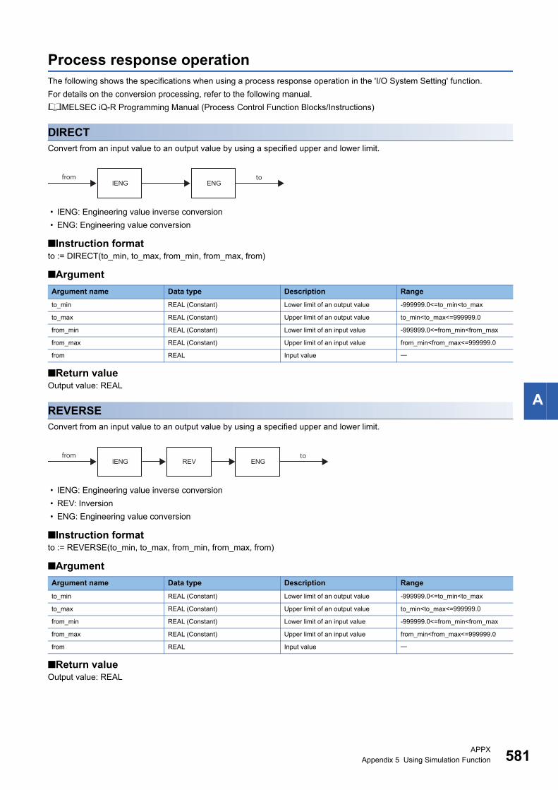
APPXAppendix 5 Using Simulation Function 581
A
Process response operationThe following shows the specifications when using a process response operation in the 'I/O System Setting' function.
For details on the conversion processing, refer to the following manual.
MELSEC iQ-R Programming Manual (Process Control Function Blocks/Instructions)
DIRECTConvert from an input value to an output value by using a specified upper and lower limit.
• IENG: Engineering value inverse conversion
• ENG: Engineering value conversion
■Instruction formatto := DIRECT(to_min, to_max, from_min, from_max, from)
■Argument
■Return valueOutput value: REAL
REVERSEConvert from an input value to an output value by using a specified upper and lower limit.
• IENG: Engineering value inverse conversion
• REV: Inversion
• ENG: Engineering value conversion
■Instruction formatto := REVERSE(to_min, to_max, from_min, from_max, from)
■Argument
■Return valueOutput value: REAL
Argument name Data type Description Range
to_min REAL (Constant) Lower limit of an output value -999999.0<=to_min<to_max
to_max REAL (Constant) Upper limit of an output value to_min<to_max<=999999.0
from_min REAL (Constant) Lower limit of an input value -999999.0<=from_min<from_max
from_max REAL (Constant) Upper limit of an input value from_min<from_max<=999999.0
from REAL Input value
IENGfrom to
ENG
IENGfrom to
REV ENG
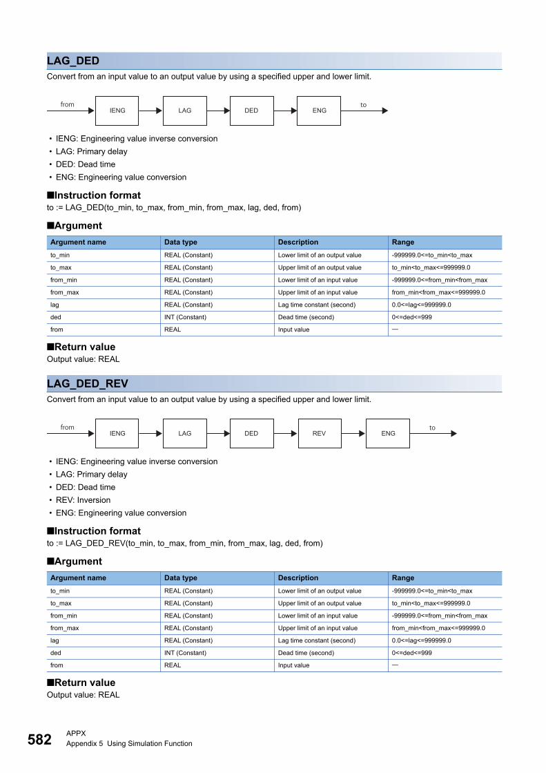
582APPXAppendix 5 Using Simulation Function
LAG_DEDConvert from an input value to an output value by using a specified upper and lower limit.
• IENG: Engineering value inverse conversion
• LAG: Primary delay
• DED: Dead time
• ENG: Engineering value conversion
■Instruction formatto := LAG_DED(to_min, to_max, from_min, from_max, lag, ded, from)
■Argument
■Return valueOutput value: REAL
LAG_DED_REVConvert from an input value to an output value by using a specified upper and lower limit.
• IENG: Engineering value inverse conversion
• LAG: Primary delay
• DED: Dead time
• REV: Inversion
• ENG: Engineering value conversion
■Instruction formatto := LAG_DED_REV(to_min, to_max, from_min, from_max, lag, ded, from)
■Argument
■Return valueOutput value: REAL
Argument name Data type Description Range
to_min REAL (Constant) Lower limit of an output value -999999.0<=to_min<to_max
to_max REAL (Constant) Upper limit of an output value to_min<to_max<=999999.0
from_min REAL (Constant) Lower limit of an input value -999999.0<=from_min<from_max
from_max REAL (Constant) Upper limit of an input value from_min<from_max<=999999.0
lag REAL (Constant) Lag time constant (second) 0.0<=lag<=999999.0
ded INT (Constant) Dead time (second) 0<=ded<=999
from REAL Input value
IENGfrom to
LAG DED ENG
IENGfrom to
LAG DED REV ENG
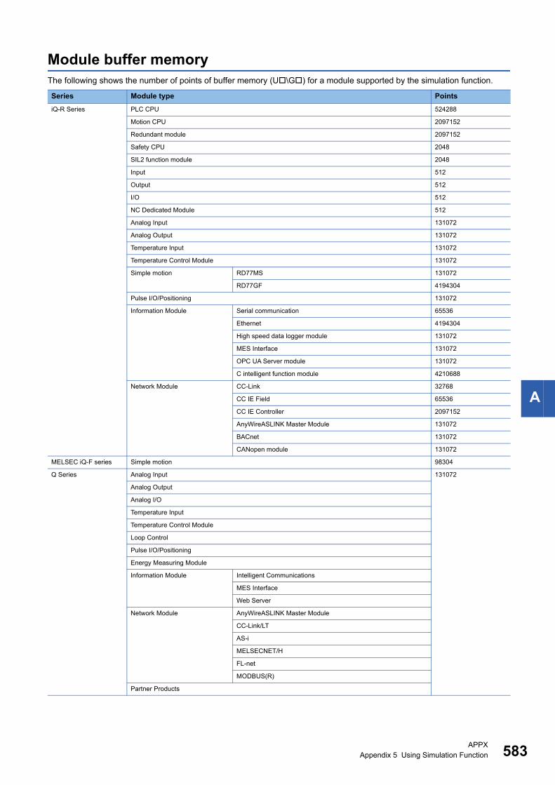
APPXAppendix 5 Using Simulation Function 583
A
Module buffer memoryThe following shows the number of points of buffer memory (U\G) for a module supported by the simulation function.
Series Module type Points
iQ-R Series PLC CPU 524288
Motion CPU 2097152
Redundant module 2097152
Safety CPU 2048
SIL2 function module 2048
Input 512
Output 512
I/O 512
NC Dedicated Module 512
Analog Input 131072
Analog Output 131072
Temperature Input 131072
Temperature Control Module 131072
Simple motion RD77MS 131072
RD77GF 4194304
Pulse I/O/Positioning 131072
Information Module Serial communication 65536
Ethernet 4194304
High speed data logger module 131072
MES Interface 131072
OPC UA Server module 131072
C intelligent function module 4210688
Network Module CC-Link 32768
CC IE Field 65536
CC IE Controller 2097152
AnyWireASLINK Master Module 131072
BACnet 131072
CANopen module 131072
MELSEC iQ-F series Simple motion 98304
Q Series Analog Input 131072
Analog Output
Analog I/O
Temperature Input
Temperature Control Module
Loop Control
Pulse I/O/Positioning
Energy Measuring Module
Information Module Intelligent Communications
MES Interface
Web Server
Network Module AnyWireASLINK Master Module
CC-Link/LT
AS-i
MELSECNET/H
FL-net
MODBUS(R)
Partner Products
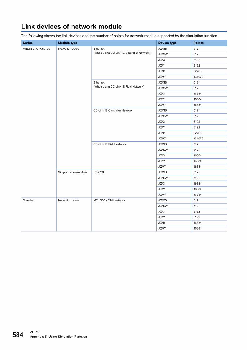
584APPXAppendix 5 Using Simulation Function
Link devices of network moduleThe following shows the link devices and the number of points for network module supported by the simulation function.
Series Module type Device type Points
MELSEC iQ-R series Network module Ethernet
(When using CC-Link IE Controller Network)
J\SB 512
J\SW 512
J\X 8192
J\Y 8192
J\B 32768
J\W 131072
Ethernet
(When using CC-Link IE Field Network)
J\SB 512
J\SW 512
J\X 16384
J\Y 16384
J\W 16384
CC-Link IE Controller Network J\SB 512
J\SW 512
J\X 8192
J\Y 8192
J\B 32768
J\W 131072
CC-Link IE Field Network J\SB 512
J\SW 512
J\X 16384
J\Y 16384
J\W 16384
Simple motion module RD77GF J\SB 512
J\SW 512
J\X 16384
J\Y 16384
J\W 16384
Q series Network module MELSECNET/H network J\SB 512
J\SW 512
J\X 8192
J\Y 8192
J\B 16384
J\W 16384
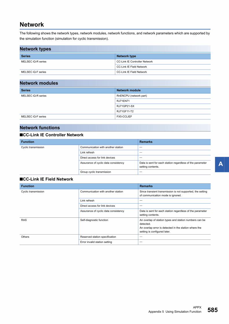
APPXAppendix 5 Using Simulation Function 585
A
NetworkThe following shows the network types, network modules, network functions, and network parameters which are supported by
the simulation function (simulation for cyclic transmission).
Network types
Network modules
Network functions
■CC-Link IE Controller Network
■CC-Link IE Field Network
Series Network type
MELSEC iQ-R series CC-Link IE Controller Network
CC-Link IE Field Network
MELSEC iQ-F series CC-Link IE Field Network
Series Network module
MELSEC iQ-R series RnENCPU (network part)
RJ71EN71
RJ71GP21-SX
RJ71GF11-T2
MELSEC iQ-F series FX5-CCLIEF
Function Remarks
Cyclic transmission Communication with another station
Link refresh
Direct access for link devices
Assurance of cyclic data consistency Data is sent for each station regardless of the parameter
setting contents.
Group cyclic transmission
Function Remarks
Cyclic transmission Communication with another station Since transient transmission is not supported, the setting
of communication mode is ignored.
Link refresh
Direct access for link devices
Assurance of cyclic data consistency Data is sent for each station regardless of the parameter
setting contents.
RAS Self-diagnostic function An overlap of station types and station numbers can be
detected.
An overlap error is detected in the station where the
setting is configured later.
Others Reserved station specification
Error invalid station setting
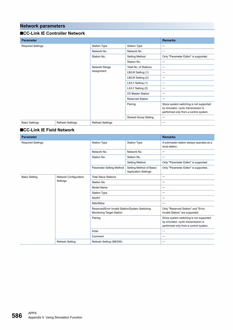
586APPXAppendix 5 Using Simulation Function
Network parameters
■CC-Link IE Controller Network
■CC-Link IE Field Network
Parameter Remarks
Required Settings Station Type Station Type
Network No. Network No.
Station No. Setting Method Only "Parameter Editor" is supported.
Station No.
Network Range
Assignment
Total No. of Stations
LB/LW Setting (1)
LB/LW Setting (2)
LX/LY Setting (1)
LX/LY Setting (2)
I/O Master Station
Reserved Station
Pairing Since system switching is not supported
by simulator, cyclic transmission is
performed only from a control system.
Shared Group Setting
Basic Settings Refresh Settings Refresh Settings
Parameter Remarks
Required Settings Station Type Station Type A submaster station always operates as a
local station.
Network No. Network No.
Station No. Station No.
Setting Method Only "Parameter Editor" is supported.
Parameter Setting Method Setting Method of Basic/
Application Settings
Only "Parameter Editor" is supported.
Basic Setting Network Configuration
Settings
Total Slave Stations
Station No.
Model Name
Station Type
RX/RY
RWr/RWw
Reserved/Error Invalid Station/System Switching
Monitoring Target Station
Only "Reserved Station" and "Error
Invalid Station" are supported.
Pairing Since system switching is not supported
by simulator, cyclic transmission is
performed only from a control system.
Arias
Comment
Refresh Setting Refresh Setting (SB/SW)
APPXAppendix 5 Using Simulation Function 587
A
ConsiderationsThe following describes the considerations on debugging programs using the simulation function.
Program execution timeSince the instruction processing speed differs between the simulation function and CPU module, the simulator operates as
follows.
• A simulation time is calculated by adding a value of instruction processing time every execution of an instruction in a CPU
module.
The simulator operates behind the actual time when the simulation time takes longer than the actual time due to the
performance of a personal computer.
The simulation time gains in accordance with the actual time when the actual time takes longer than the simulation time.
For instruction processing time, refer to the following manual.
MELSEC iQ-R Programming Manual (CPU Module Instructions, Standard Functions/Function Blocks)
Fixed scan execution type program and timer deviceA program is executed in accordance with the simulation time.
Handling of floating pointA rounding error may occur in the operation result of an instruction using floating point. The result will not the same as that of
a CPU module.
RnSFCPU
■Safety operation modeThe simulation function can be used in the test mode only.
■Safety support functionsThe following menus cannot be perform during a simulation.
• [Online] [Safety PLC Operation] [Check Safety Data Identity]
• [Online] [Safety PLC Operation] [Switch Safety Operation Mode]
• [Online] [User Authentication]
■Identification check for safety dataWhen the target for writing is a simulator, the writing is not treated as one to a programmable controller.
Therefore, the file ID and the writing date and time are not updated.
Multiple CPU system functionThe multiple CPU system function can be used only for a CPU module that operates interactively with another CPU module in
a system simulation.
Simulation to a single CPU module or a CPU module, which does not operates interactively with other CPU modules, are not
supported.
An error is not detected in a CPU module that does not operate interactively and a module controlled by the CPU.
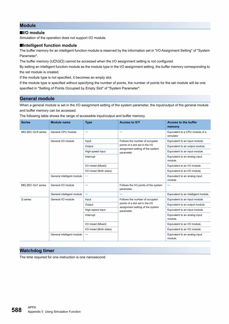
588APPXAppendix 5 Using Simulation Function
Module
■I/O moduleSimulation of the operation does not support I/O module.
■Intelligent function moduleThe buffer memory for an intelligent function module is reserved by the information set in "I/O Assignment Setting" of "System
Parameter".
The buffer memory (U\G) cannot be accessed when the I/O assignment setting is not configured.
By setting an intelligent function module as the module type in the I/O assignment setting, the buffer memory corresponding to
the set module is created.
If the module type is not specified, it becomes an empty slot.
If the module type is specified without specifying the number of points, the number of points for the set module will be one
specified in "Setting of Points Occupied by Empty Slot" of "System Parameter".
General moduleWhen a general module is set in the I/O assignment setting of the system parameter, the input/output of the general module
and buffer memory can be accessed.
The following table shows the range of accessible input/output and buffer memory.
Watchdog timerThe time required for one instruction is one nanosecond.
Series Module name Type Access to X/Y Access to the buffer memory
MELSEC iQ-R series General CPU module Equivalent to a CPU module of a
simulator
General I/O module Input Follows the number of occupied
points of a slot set in the I/O
assignment setting of the system
parameter.
Equivalent to an input module.
Output Equivalent to an output module.
High-speed input Equivalent to an input module.
Interrupt Equivalent to an analog input
module.
I/O mixed (Mixed) Equivalent to an I/O module.
I/O mixed (Both sides) Equivalent to an I/O module.
General intelligent module Equivalent to an analog input
module.
MELSEC iQ-F series General I/O module Follows the I/O points of the system
parameter.
General intelligent module Equivalent to an intelligent module.
Q series General I/O module Input Follows the number of occupied
points of a slot set in the I/O
assignment setting of the system
parameter.
Equivalent to an input module.
Output Equivalent to an output module.
High-speed input Equivalent to an input module.
Interrupt Equivalent to an analog input
module.
I/O mixed (Mixed) Equivalent to an I/O module.
I/O mixed (Both sides) Equivalent to an I/O module.
General intelligent module Equivalent to an analog input
module.

APPXAppendix 5 Using Simulation Function 589
A
Attachment of extended SRAM cassetteThe simulator operates as if an extended SRAM cassette (8 MB or 16 MB*1) was attached.
An parameter error will occur when specifying the capacity more than 8 MB or 16 MB in "Extended SRAM Cassette Setting" of
"CPU Parameter".
*1 The capacity of a extended SRAM cassette differs depending on the types.RnCPU, RnENCPU: 16 MBRnPCPU, RnSFCPU: 8 MB
SD memory cardA function to read and write data from and to an SD memory card is not available.
Ex.
"Memory Card" is selected in "Save Destination" under "Event History Setting" of "CPU Parameter".
Drive usageThe data in the ROM drive of a CPU module (program memory/data memory) is stored in a temporary folder in the hard disk
of a personal computer.
The ROM drive usage per data depends on the hard disk of a personal computer.
Enabling the remote RESETIn the simulation function, the simulator operates on the assumption that "Enable" is selected in "Remote Reset Setting" of
"Operation Related Setting" of "CPU Parameter".
In the multiple CPU system, the CPU, in which the RESET button in the system simulation is enabled, operates as if "Enable"
is being set. The CPU, in which the RESET button is disabled, operates as if "Disable" is being set.
Writing parameters to an intelligent function moduleWhen writing parameters on the "Online Data Operation" screen, the availability differs according to the interaction with an
intelligent function module.
: Writable, : Not writable, : Not supported
Clock functionA program is executed in accordance with the simulation time.
The clock on a personal computer is applied to the time of the clock function every time simulation is started or reset.
Operation when the base setting is not setWhen the number of slots is not set, the system on the simulation operates as if the eight base units in MELSEC iQ-R series,
which have eight slots for each, were being set.
When the model name of a base unit is not set, the base unit on the simulation operates as if a base unit in the MELSEC iQ-
R series was being used.
When the model name of a power supply module is not set, the power supply module operates as if R61P was being used on
a base unit in the MELSEC iQ-R series, or Q61P was being used on a base unit of the Q series.
Self-diagnostic function errorFor RCPUs, the self-diagnostic function error '1900H' (constant scan time exceeded) is not detected.
Error information on module diagnosticsWithin errors detected by the simulator, error information which is different from the one that will occur in an actual CPU
module may displayed in the module diagnostics screen.
Parameter With interaction Without interaction
Simple motion module setting ×
Others ×
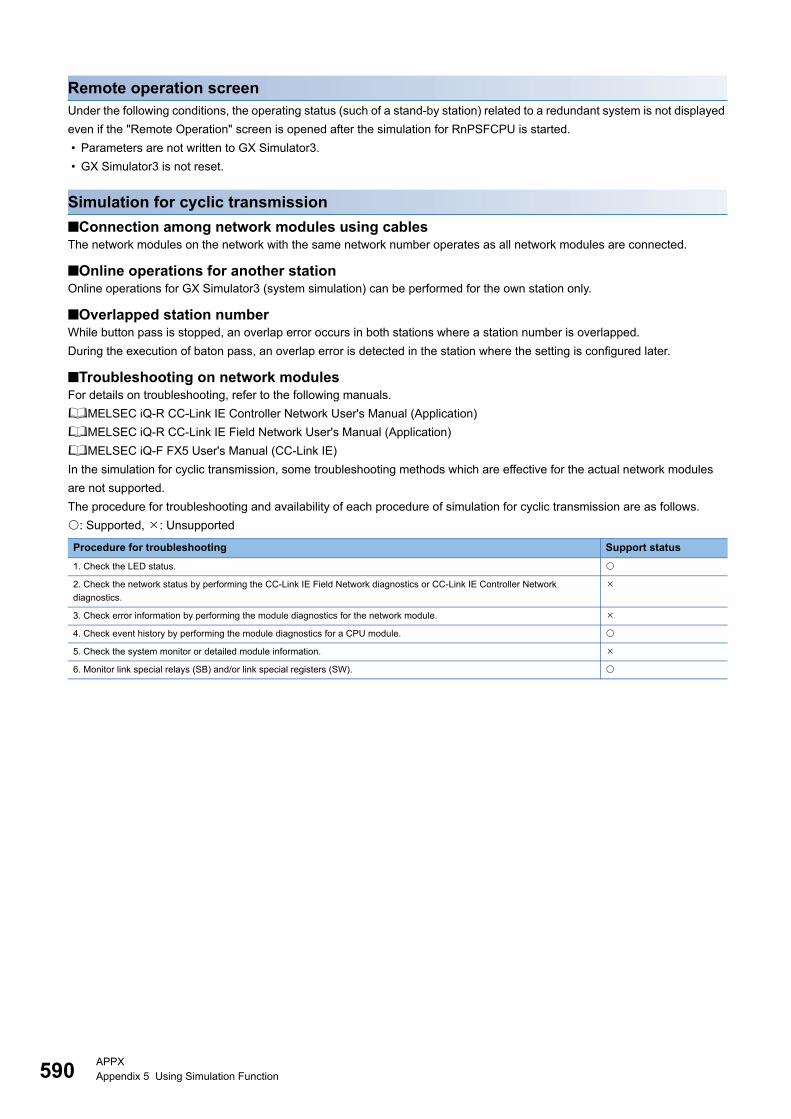
590APPXAppendix 5 Using Simulation Function
Remote operation screenUnder the following conditions, the operating status (such of a stand-by station) related to a redundant system is not displayed
even if the "Remote Operation" screen is opened after the simulation for RnPSFCPU is started.
• Parameters are not written to GX Simulator3.
• GX Simulator3 is not reset.
Simulation for cyclic transmission
■Connection among network modules using cablesThe network modules on the network with the same network number operates as all network modules are connected.
■Online operations for another stationOnline operations for GX Simulator3 (system simulation) can be performed for the own station only.
■Overlapped station numberWhile button pass is stopped, an overlap error occurs in both stations where a station number is overlapped.
During the execution of baton pass, an overlap error is detected in the station where the setting is configured later.
■Troubleshooting on network modulesFor details on troubleshooting, refer to the following manuals.
MELSEC iQ-R CC-Link IE Controller Network User's Manual (Application)
MELSEC iQ-R CC-Link IE Field Network User's Manual (Application)
MELSEC iQ-F FX5 User's Manual (CC-Link IE)
In the simulation for cyclic transmission, some troubleshooting methods which are effective for the actual network modules
are not supported.
The procedure for troubleshooting and availability of each procedure of simulation for cyclic transmission are as follows.
: Supported, : Unsupported
Procedure for troubleshooting Support status
1. Check the LED status.
2. Check the network status by performing the CC-Link IE Field Network diagnostics or CC-Link IE Controller Network
diagnostics.
3. Check error information by performing the module diagnostics for the network module.
4. Check event history by performing the module diagnostics for a CPU module.
5. Check the system monitor or detailed module information.
6. Monitor link special relays (SB) and/or link special registers (SW).
APPXAppendix 6 USB Driver Installation Procedure 591
A
Appendix 6 USB Driver Installation ProcedureTo communicate with a CPU module via USB, installing a USB driver is required.
If multiple MELSOFT products are already installed, refer to the installation location of the first product.
Windows XP
Operating procedure
1. Connect a personal computer and a CPU module with a USB cable, and turn the power of the programmable controller
ON.
2. Select "Install from a list or specific location (Advanced)" on the "Found New Hardware Wizard" screen.
3. Select "Search for the best driver in these locations" in the next screen. Select "Include this location in the search" and
specify 'Easysocket\USBDrivers' in the folder where GX Works3 has been installed.
Precautions
If the driver cannot be installed, check the following settings on Windows.
The USB driver may not be installed when "BlockNever install unsigned driver software" is selected in [Control Panel]
[System] [Hardware] [Driver Signing].
Select "Ignore Install the software anyway and don't ask for my approval", or "Warn Prompt me each time to choose an
action" in [Driver Signing], and execute the USB driver installation.
Windows Vista
Operating procedure
1. Connect a personal computer and a CPU module with a USB cable, and turn the power of the programmable controller
ON.
2. Select "Locate and install driver software (recommended)" on the "Found New Hardware Wizard" screen.
3. Select "Browse my computer for driver software (advanced)" on the "Found New Hardware" screen.
4. Select "Search for the best driver in these locations" in the next screen. Select "Include subfolders" and specify
'Easysocket\USBDrivers' in the folder where GX Works3 has been installed.
Precautions
When "Windows can't verify the publisher of this driver software" screen appears during the installation, select "Install this
driver software anyway".
Windows 7 or later
Operating procedure
1. Connect a personal computer and a CPU module with a USB cable, and turn the power of the programmable controller
ON.
2. Select [Control Panel] [System and Security] [Administrative Tools] [Computer Management] [Device
Manager] from Windows Start*1. Right-click "Unknown device" and click "Update Driver Software".
3. Select "Browse my computer for driver software" on the "Update Driver Software" screen, and specify
'Easysocket\USBDrivers' in the folder where GX Works3 is installed on the next screen.
*1 On the Start screen or from the Start menu.
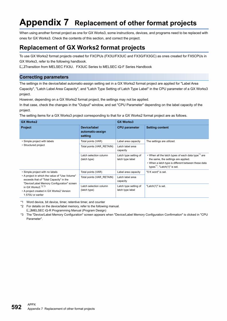
592APPXAppendix 7 Replacement of other format projects
Appendix 7 Replacement of other format projectsWhen using another format project as one for GX Works3, some instructions, devices, and programs need to be replaced with
ones for GX Works3. Check the contents of this section, and correct the project.
Replacement of GX Works2 format projectsTo use GX Works2 format projects created for FXCPUs (FX3U/FX3UC and FX3G/FX3GC) as ones created for FX5CPUs in
GX Works3, refer to the following handbook.
Transition from MELSEC FX3U,FX3UC Series to MELSEC iQ-F Series Handbook
Correcting parametersThe settings in the device/label automatic-assign setting set in a GX Works2 format project are applied for "Label Area
Capacity", "Latch Label Area Capacity", and "Latch Type Setting of Latch Type Label" in the CPU parameter of a GX Works3
project.
However, depending on a GX Works2 format project, the settings may not be applied.
In that case, check the changes in the "Output" window, and set "CPU Parameter" depending on the label capacity of the
project.
The setting items for a GX Works3 project corresponding to that for a GX Works2 format project are as follows.
*1 Word device, bit device, timer, retentive timer, and counter*2 For details on the device/label memory, refer to the following manual.
MELSEC iQ-R Programming Manual (Program Design)*3 The "Device/Label Memory Configuration" screen appears when "Device/Label Memory Configuration Confirmation" is clicked in "CPU
Parameter".
GX Works2 GX Works3
Project Device/label automatic-assign setting
CPU parameter Setting content
• Simple project with labels
• Structured project
Total points (VAR) Label area capacity The settings are utilized.
Total points (VAR_RETAIN) Latch label area
capacity
Latch selection column
(latch type)
Latch type setting of
latch type label
• When all the latch types of each data type*1 are
the same, the settings are applied.
• When a latch type is different between these data
types*1, "Latch(1)" is set.
• Simple project with no labels
• A project in which the value of "Use Volume"
exceeds that of "Total Capacity" in the
"Device/Label Memory Configuration" screen
in GX Works3.*2,*3
• A project created in GX Works2 Version
1.570U or earlier
Total points (VAR) Label area capacity "0 K word" is set.
Total points (VAR_RETAIN) Latch label area
capacity
Latch selection column
(latch type)
Latch type setting of
latch type label
"Latch(1)" is set.
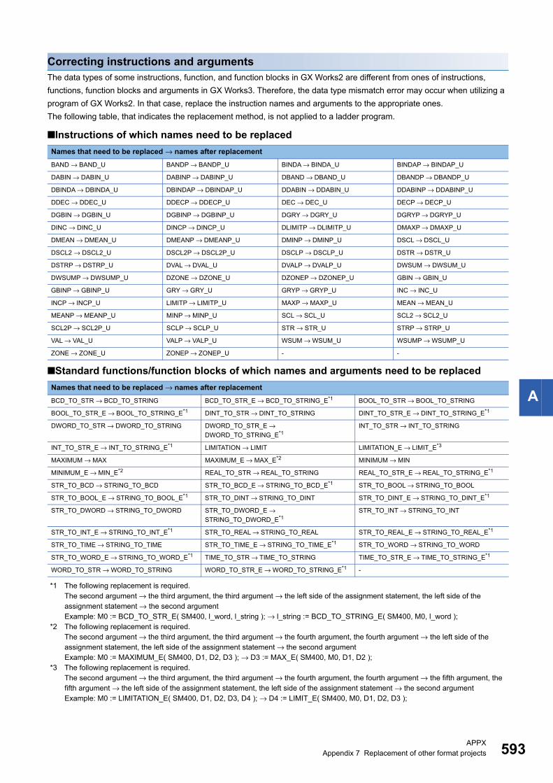
APPXAppendix 7 Replacement of other format projects 593
A
Correcting instructions and argumentsThe data types of some instructions, function, and function blocks in GX Works2 are different from ones of instructions,
functions, function blocks and arguments in GX Works3. Therefore, the data type mismatch error may occur when utilizing a
program of GX Works2. In that case, replace the instruction names and arguments to the appropriate ones.
The following table, that indicates the replacement method, is not applied to a ladder program.
■Instructions of which names need to be replaced
■Standard functions/function blocks of which names and arguments need to be replaced
*1 The following replacement is required.The second argument → the third argument, the third argument → the left side of the assignment statement, the left side of the assignment statement → the second argumentExample: M0 := BCD_TO_STR_E( SM400, l_word, l_string ); → l_string := BCD_TO_STRING_E( SM400, M0, l_word );
*2 The following replacement is required.The second argument → the third argument, the third argument → the fourth argument, the fourth argument → the left side of the assignment statement, the left side of the assignment statement → the second argumentExample: M0 := MAXIMUM_E( SM400, D1, D2, D3 ); → D3 := MAX_E( SM400, M0, D1, D2 );
*3 The following replacement is required.The second argument → the third argument, the third argument → the fourth argument, the fourth argument → the fifth argument, the fifth argument → the left side of the assignment statement, the left side of the assignment statement → the second argumentExample: M0 := LIMITATION_E( SM400, D1, D2, D3, D4 ); → D4 := LIMIT_E( SM400, M0, D1, D2, D3 );
Names that need to be replaced → names after replacement
BAND → BAND_U BANDP → BANDP_U BINDA → BINDA_U BINDAP → BINDAP_U
DABIN → DABIN_U DABINP → DABINP_U DBAND → DBAND_U DBANDP → DBANDP_U
DBINDA → DBINDA_U DBINDAP → DBINDAP_U DDABIN → DDABIN_U DDABINP → DDABINP_U
DDEC → DDEC_U DDECP → DDECP_U DEC → DEC_U DECP → DECP_U
DGBIN → DGBIN_U DGBINP → DGBINP_U DGRY → DGRY_U DGRYP → DGRYP_U
DINC → DINC_U DINCP → DINCP_U DLIMITP → DLIMITP_U DMAXP → DMAXP_U
DMEAN → DMEAN_U DMEANP → DMEANP_U DMINP → DMINP_U DSCL → DSCL_U
DSCL2 → DSCL2_U DSCL2P → DSCL2P_U DSCLP → DSCLP_U DSTR → DSTR_U
DSTRP → DSTRP_U DVAL → DVAL_U DVALP → DVALP_U DWSUM → DWSUM_U
DWSUMP → DWSUMP_U DZONE → DZONE_U DZONEP → DZONEP_U GBIN → GBIN_U
GBINP → GBINP_U GRY → GRY_U GRYP → GRYP_U INC → INC_U
INCP → INCP_U LIMITP → LIMITP_U MAXP → MAXP_U MEAN → MEAN_U
MEANP → MEANP_U MINP → MINP_U SCL → SCL_U SCL2 → SCL2_U
SCL2P → SCL2P_U SCLP → SCLP_U STR → STR_U STRP → STRP_U
VAL → VAL_U VALP → VALP_U WSUM → WSUM_U WSUMP → WSUMP_U
ZONE → ZONE_U ZONEP → ZONEP_U - -
Names that need to be replaced → names after replacement
BCD_TO_STR → BCD_TO_STRING BCD_TO_STR_E → BCD_TO_STRING_E*1 BOOL_TO_STR → BOOL_TO_STRING
BOOL_TO_STR_E → BOOL_TO_STRING_E*1 DINT_TO_STR → DINT_TO_STRING DINT_TO_STR_E → DINT_TO_STRING_E*1
DWORD_TO_STR → DWORD_TO_STRING DWORD_TO_STR_E →
DWORD_TO_STRING_E*1INT_TO_STR → INT_TO_STRING
INT_TO_STR_E → INT_TO_STRING_E*1 LIMITATION → LIMIT LIMITATION_E → LIMIT_E*3
MAXIMUM → MAX MAXIMUM_E → MAX_E*2 MINIMUM → MIN
MINIMUM_E → MIN_E*2 REAL_TO_STR → REAL_TO_STRING REAL_TO_STR_E → REAL_TO_STRING_E*1
STR_TO_BCD → STRING_TO_BCD STR_TO_BCD_E → STRING_TO_BCD_E*1 STR_TO_BOOL → STRING_TO_BOOL
STR_TO_BOOL_E → STRING_TO_BOOL_E*1 STR_TO_DINT → STRING_TO_DINT STR_TO_DINT_E → STRING_TO_DINT_E*1
STR_TO_DWORD → STRING_TO_DWORD STR_TO_DWORD_E →
STRING_TO_DWORD_E*1STR_TO_INT → STRING_TO_INT
STR_TO_INT_E → STRING_TO_INT_E*1 STR_TO_REAL → STRING_TO_REAL STR_TO_REAL_E → STRING_TO_REAL_E*1
STR_TO_TIME → STRING_TO_TIME STR_TO_TIME_E → STRING_TO_TIME_E*1 STR_TO_WORD → STRING_TO_WORD
STR_TO_WORD_E → STRING_TO_WORD_E*1 TIME_TO_STR → TIME_TO_STRING TIME_TO_STR_E → TIME_TO_STRING_E*1
WORD_TO_STR → WORD_TO_STRING WORD_TO_STR_E → WORD_TO_STRING_E*1 -
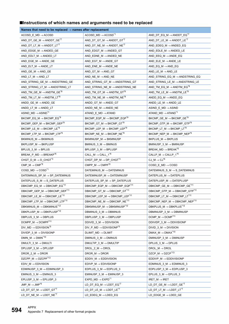
594APPXAppendix 7 Replacement of other format projects
■Instructions of which names and arguments need to be replaced
Names that need to be replaced → names after replacement
ACOSD_E_MD → ACOSD ACOSD_MD → ACOSD*1 AND_DT_EQ_M → ANDDT_EQ*7
AND_DT_GE_M → ANDDT_GE*7 AND_DT_GT_M → ANDDT_GT*7 AND_DT_LE_M → ANDDT_LE*7
AND_DT_LT_M → ANDDT_LT*7 AND_DT_NE_M → ANDDT_NE*7 AND_EDEQ_M → ANDED_EQ
AND_EDGE_M → ANDED_GE AND_EDGT_M → ANDED_GT AND_EDLE_M → ANDED_LE
AND_EDLT_M → ANDED_LT AND_EDNE_M → ANDED_NE AND_EEQ_M → ANDE_EQ
AND_EGE_M → ANDE_GE AND_EGT_M → ANDE_GT AND_ELE_M → ANDE_LE
AND_ELT_M → ANDE_LT AND_ENE_M → ANDE_NE AND_EQ_M → AND_EQ
AND_GE_M → AND_GE AND_GT_M → AND_GT AND_LE_M → AND_LE
AND_LT_M → AND_LT AND_NE_M → AND_NE AND_STRING_EQ_M → ANDSTRING_EQ
AND_STRING_GE_M → ANDSTRING_GE AND_STRING_GT_M → ANDSTRING_GT AND_STRING_LE_M → ANDSTRING_LE
AND_STRING_LT_M → ANDSTRING_LT AND_STRING_NE_M → ANDSTRING_NE AND_TM_EQ_M → ANDTM_EQ*8
AND_TM_GE_M → ANDTM_GE*8 AND_TM_GT_M → ANDTM_GT*8 AND_TM_LE_M → ANDTM_LE*8
AND_TM_LT_M → ANDTM_LT*8 AND_TM_NE_M → ANDTM_NE*8 ANDD_EQ_M → ANDD_EQ
ANDD_GE_M → ANDD_GE ANDD_GT_M → ANDD_GT ANDD_LE_M → ANDD_LE
ANDD_LT_M → ANDD_LT ANDD_NE_M → ANDD_NE ASIND_E_MD → ASIND
ASIND_MD → ASIND*1 ATAND_E_MD → ATAND ATAND_MD → ATAND*1
BKCMP_EQ_M → BKCMP_EQ*9 BKCMP_EQP_M → BKCMP_EQP*9 BKCMP_GE_M → BKCMP_GE*9
BKCMP_GEP_M → BKCMP_GEP*9 BKCMP_GT_M → BKCMP_GT*9 BKCMP_GTP_M → BKCMP_GTP*9
BKCMP_LE_M → BKCMP_LE*9 BKCMP_LEP_M → BKCMP_LEP*9 BKCMP_LT_M → BKCMP_LT*9
BKCMP_LTP_M → BKCMP_LTP*9 BKCMP_NE_M → BKCMP_NE*9 BKCMP_NEP_M → BKCMP_NEP*9
BKMINUS_M → BKMINUS BKMINUSP_M → BKMINUSP BKPLUS_M → BKPLUS
BKPLUSP_M → BKPLUSP BMINUS_3_M → BMINUS BMINUSP_3_M → BMINUSP
BPLUS_3_M → BPLUS BPLUSP_3_M → BPLUSP BREAK_MD → BREAK*6
BREAK_P_MD → BREAKP*6 CALL_M → CALL_1*6 CALLP_M → CALLP_1*6
CHGT_D_M → D_CHGT*3 CHGT_DP_M → DP_CHGT*3 CJ_M → CJ*6
CMP_M → CMP*9 CMPP_M → CMPP*9 COSD_E_MD → COSD
COSD_MD → COSD*1 DATEMINUS_M → DATEMINUS DATEMINUS_S_M → S_DATEMINUS
DATEMINUS_SP_M → SP_DATEMINUS DATEMINUSP_M → DATEMINUSP DATEPLUS_M → DATEPLUS
DATEPLUS_S_M → S_DATEPLUS DATEPLUS_SP_M → SP_DATEPLUS DATEPLUSP_M → DATEPLUSP
DBKCMP_EQ_M → DBKCMP_EQ*11 DBKCMP_EQP_M → DBKCMP_EQP*11 DBKCMP_GE_M → DBKCMP_GE*11
DBKCMP_GEP_M → DBKCMP_GEP*11 DBKCMP_GT_M → DBKCMP_GT*11 DBKCMP_GTP_M → DBKCMP_GTP*11
DBKCMP_LE_M → DBKCMP_LE*11 DBKCMP_LEP_M → DBKCMP_LEP*11 DBKCMP_LT_M → DBKCMP_LT*11
DBKCMP_LTP_M → DBKCMP_LTP*11 DBKCMP_NE_M → DBKCMP_NE*11 DBKCMP_NEP_M → DBKCMP_NEP*11
DBKMINUS_M → DBKMINUS*12 DBKMINUSP_M → DBKMINUSP*12 DBKPLUS_M → DBKPLUS*12
DBKPLUSP_M → DBKPLUSP*12 DBMINUS_3_M → DBMINUS DBMINUSP_3_M → DBMINUSP
DBPLUS_3_M → DBPLUS DBPLUSP_3_M → DBPLUSP DCMP_M → DCMP*11
DCMPP_M → DCMPP*11 DDIVID_3_M → DDIVISION DDIVIDP_3_M → DDIVISIONP
DIV_MD → EDIVISION*5 DIV_P_MD → EDIVISIONP*5 DIVID_3_M → DIVISION
DIVIDP_3_M → DIVISIONP DLIMIT_MD → DLIMIT DMAX_M → DMAX*10
DMIN_M → DMIN*10 DMINUS_3_M → DMINUS DMINUSP_3_M → DMINUSP
DMULTI_3_M → DMULTI DMULTIP_3_M → DMULTIP DPLUS_3_M → DPLUS
DPLUSP_3_M → DPLUSP DROL_2_M → DROL DROL_M → DROL
DROR_2_M → DROR DROR_M → DROR DZCP_M → DZCP*13
DZCPP_M → DZCPP*13 EDDIV_M → EDDIVISION EDDIVP_M → EDDIVISIONP
EDIV_M → EDIVISION EDIVP_M → EDIVISIONP EDMINUS_3_M → EDMINUS_3
EDMINUSP_3_M → EDMINUSP_3 EDPLUS_3_M → EDPLUS_3 EDPLUSP_3_M → EDPLUSP_3
EMINUS_3_M → EMINUS_3 EMINUSP_3_M → EMINUSP_3 EPLUS_3_M → EPLUS_3
EPLUSP_3_M → EPLUSP_3 EXPD_MD → EXPD*1 IRET_M → IRET
JMP_M → JMP*6 LD_DT_EQ_M → LDDT_EQ*7 LD_DT_GE_M → LDDT_GE*7
LD_DT_GT_M → LDDT_GT*7 LD_DT_LE_M → LDDT_LE*7 LD_DT_LT_M → LDDT_LT*7
LD_DT_NE_M → LDDT_NE*7 LD_EDEQ_M → LDED_EQ LD_EDGE_M → LDED_GE
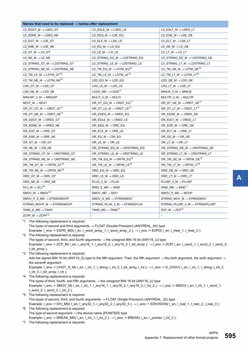
APPXAppendix 7 Replacement of other format projects 595
A
*1 The following replacement is required.The types of second and third arguments → FLOAT (Double Precision) (ANYREAL_64) typeExample: l_eno := EXPD_MD( l_en, l_word_array_1, l_word_array_2 ); → l_eno := EXPD( l_en, l_lreal_1, l_lreal_2 );
*2 The following replacement is required.The types of second, third, and fourth arguments → the unsigned BIN 16 bit (ANY16_U) typeExample: l_eno := ZCP_M( l_en, l_any16_1, l_any16_2, l_any16_3, l_bit_array ); → l_eno := ZCP( l_en, l_word_1, l_word_2, l_word_3, l_bit_array );
*3 The following replacement is required.Add the signed BIN 16 bit (ANY16_S) type to the fifth argument. Then, the fifth argument → the sixth argument, the sixth argument → the seventh argumentExample: l_eno := CHGT_D_M( l_en, l_int_1, l_string, l_int_2, l_bit_array, l_int ); → l_eno := D_CHGT( l_en, l_int_1, l_string, l_int_2, l_int_3, l_bit_array, l_int );
*4 The following replacement is required.The types of third, fourth, and fifth arguments → the unsigned BIN 16 bit (ANY16_U) typeExample: l_eno := SMOV_M( l_en, l_int_1, l_any16_1, l_any16_2, l_any16_3, l_int_2 ); → l_eno := SMOV( l_en, l_int_1, l_word_1, l_word_2, l_word_3, l_int_2 );
*5 The following replacement is required.The types of second, third, and fourth arguments → FLOAT (Single Precision) (ANYREAL_32) typeExample: l_eno := DIV_MD( l_en, l_any32_1, l_any32_2, l_any32_3 ); → l_eno := EDIVISION( l_en, l_real_1, l_real_2, l_real_3 );
*6 The following replacement is required.The type of second argument → the device name (POINTER) typeExample: l_eno := BREAK_MD( l_en, l_int_1, l_int_2 ); → l_eno := BREAK( l_en, l_pointer, l_int_2 );
*7 The following replacement is required.
LD_EDGT_M → LDED_GT LD_EDLE_M → LDED_LE LD_EDLT_M → LDED_LT
LD_EDNE_M → LDED_NE LD_EEQ_M → LDE_EQ LD_EGE_M → LDE_GE
LD_EGT_M → LDE_GT LD_ELE_M → LDE_LE LD_ELT_M → LDE_LT
LD_ENE_M → LDE_NE LD_EQ_M → LD_EQ LD_GE_M → LD_GE
LD_GT_M → LD_GT LD_LE_M → LD_LE LD_LT_M → LD_LT
LD_NE_M → LD_NE LD_STRING_EQ_M → LDSTRING_EQ LD_STRING_GE_M → LDSTRING_GE
LD_STRING_GT_M → LDSTRING_GT LD_STRING_LE_M → LDSTRING_LE LD_STRING_LT_M → LDSTRING_LT
LD_STRING_NE_M → LDSTRING_NE LD_TM_EQ_M → LDTM_EQ*8 LD_TM_GE_M → LDTM_GE*8
LD_TM_LE_M → LDTM_GT*8 LD_TM_LE_M → LDTM_LE*8 LD_TM_LT_M → LDTM_LT*8
LD_TM_NE_M → LDTM_NE*8 LDD_EQ_M → LDD_EQ LDD_GE_M → LDD_GE
LDD_GT_M → LDD_GT LDD_LE_M → LDD_LE LDD_LT_M → LDD_LT
LDD_NE_M → LDD_NE LOGD_MD → LOGD*1 MINUS_3_M → MINUS
MINUSP_3_M → MINUSP MULTI_3_M → MULTI MULTIP_3_M → MULTIP
NEXT_M → NEXT OR_DT_EQ_M → ORDT_EQ*7 OR_DT_GE_M → ORDT_GE*7
OR_DT_GT_M → ORDT_GT*7 OR_DT_LE_M → ORDT_LE*7 OR_DT_LT_M → ORDT_LT*7
OR_DT_NE_M → ORDT_NE*7 OR_EDEQ_M → ORED_EQ OR_EDGE_M → ORED_GE
OR_EDGT_M → ORED_GT OR_EDLE_M → ORED_LE OR_EDLT_M → ORED_LT
OR_EDNE_M → ORED_NE OR_EEQ_M → ORE_EQ OR_EGE_M → ORE_GE
OR_EGT_M → ORE_GT OR_ELE_M → ORE_LE OR_ELT_M → ORE_LT
OR_ENE_M → ORE_NE OR_EQ_M → OR_EQ OR_GE_M → OR_GE
OR_GT_M → OR_GT OR_LE_M → OR_LE OR_LT_M → OR_LT
OR_NE_M → OR_NE OR_STRING_EQ_M → ORSTRING_EQ OR_STRING_GE_M → ORSTRING_GE
OR_STRING_GT_M → ORSTRING_GT OR_STRING_LE_M → ORSTRING_LE OR_STRING_LT_M → ORSTRING_LT
OR_STRING_NE_M → ORSTRING_NE OR_TM_EQ_M → ORTM_EQ*8 OR_TM_GE_M → ORTM_GE*8
OR_TM_GT_M → ORTM_GT*8 OR_TM_LE_M → ORTM_LE*8 OR_TM_LT_M → ORTM_LT*8
OR_TM_NE_M → ORTM_NE*8 ORD_EQ_M → ORD_EQ ORD_GE_M → ORD_GE
ORD_GT_M → ORD_GT ORD_LE_M → ORD_LE ORD_LT_M → ORD_LT
ORD_NE_M → ORD_NE PLUS_3_M → PLUS PLUSP_3_M → PLUSP
SCJ_M → SCJ*6 SIND_E_MD → SIND SIND_MD → SIND*1
SMOV_M → SMOV*4 SMOV_MD → MOV SMOV_P_MD → MOVP
SMOV_P_S_MD → STRINGMOVP SMOV_S_MD → STRINGMOV STRING_MOV_M → STRINGMOV
STRING_MOVP_M → STRINGMOVP STRING_PLUS_3_M → STRINGPLUS STRING_PLUSP_3_M → STRINGPLUSP
TAND_E_MD → TAND TAND_MD → TAND*1 ZCP_M → ZCP*2
ZCPP_M → ZCPP*2 - -
Names that need to be replaced → names after replacement

596APPXAppendix 7 Replacement of other format projects
The types of second and third arguments → the signed BIN 16 bit (ANY_DT) typeExample: l_eno := LD_DT_EQ_M( l_en, l_any16_array_1, l_any16_array_2, l_int_3 ); → l_eno := LDDT_EQ( l_en, l_int_1, l_int_2, l_int_3 );
*8 The following replacement is required.The types of second and third arguments → the signed BIN 16 bit (ANY_TM) typeExample: l_eno := LD_TM_EQ_M( l_en, l_any16_array_1, l_any16_array_2, l_int_3 ); → l_eno := LDTM_EQ( l_en, l_int_1, l_int_2, l_int_3 );
*9 The following replacement is required.The types of second and third arguments → the signed BIN 16 bit (ANY16_S) typeExample: l_eno := CMP_M( l_en, l_word_1, l_word_2, l_bit_array ); → l_eno := CMP( l_en, l_int_1, l_int_2, l_bit_array );
*10 The following replacement is required.The type of second argument → the signed BIN 32 bit (ANY32_S) type, the type of fourth argument → the signed BIN 32 bit (ANY32_S_ARRAY, number of elements: 4) typeExample: l_eno := DMAX_M( l_en, l_any32_1, l_word, l_any32_2 ); → l_eno := DMAX( l_en, l_dint, l_word, l_dint_array );
*11 The following replacement is required.The types of second and third arguments → the signed BIN 32 bit (ANY32_S) typeExample: l_eno := DBKCMP_EQ_M( l_en, l_any32_1, l_any32_2, l_word, l_bool ); → l_eno := DBKCMP_EQ( l_en, l_dint_1, l_dint_2, l_word, l_bool );
*12 The following replacement is required.The types of second, third, and fifth arguments → the signed BIN 32 bit (ANY32_S) type, the type of fourth argument → the unsigned BIN 16 bit (ANY16) typeExample: l_eno := DBKMINUS_M( l_en, l_any32_1, l_any32_2, l_any32_3, l_any32_4 ); → l_eno := DBKMINUS( l_en, l_dint_1, l_dint_2, l_word, l_dint_3 );
*13 The following replacement is required.The types of second, third, and fourth arguments → the signed BIN 32 bit (ANY32_S) typeExample: l_eno := DZCP_M( l_en, l_any32_1, l_any32_2, l_any32_3, l_bit_array ); → l_eno := DZCP( l_en, l_dint_1, l_dint_2, l_dint_3, l_bit_array );
■Standard functions of which arguments need to be replaced
*1 The following replacement is required.The second argument → the third argument, the third argument → the left side of the assignment statement, the left side of the assignment statement → the second argumentExample: M0 := ABS_E( SM400, l_num_in, l_num_d ); → l_num_d := ABS_E( SM400, M0, l_num_in );
*2 The following replacement is required.The second argument → the third argument, the third argument → the fourth argument, the fourth argument → the left side of the assignment statement, the left side of the assignment statement → the second argumentExample: M0 := ADD_E( SM400, l_num1, l_num2, l_num_d ); → l_num_d := ADD_E( SM400, M0, l_num1, l_num2 );
*3 The following replacement is required.
Name
ABS_E*1 ACOS*3 ACOS_E*1 ADD_E*2 ADD_TIME_E*2 AND_E*2
ASIN*3 ASIN_E*1 ATAN*3 ATAN_E*1 BCD_TO_DINT_E*1 BCD_TO_INT_E*1
BITARR_TO_DINT_E*2 BITARR_TO_INT_E*1 BOOL_TO_DINT_E*1 BOOL_TO_DWORD_E*1
BOOL_TO_INT_E*1 BOOL_TO_TIME_E*1
BOOL_TO_WORD_E*1 CONCAT_E*2 COS*3 COS_E*1 CPY_BIT_OF_INT_E*2 CPY_BITARR_E*2
DELETE_E*2 DINT_TO_BCD_E*1 DINT_TO_BITARR_E*
2DINT_TO_BOOL_E*1 DINT_TO_DWORD_E*1 DINT_TO_INT_E*1
DINT_TO_LREAL*1 DINT_TO_LREAL_E*1 DINT_TO_REAL_E*1 DINT_TO_TIME_E*1 DINT_TO_WORD_E*1 DIV_E*2
DIV_TIME_E*2 DWORD_TO_BOOL_E*1
DWORD_TO_DINT_E*
1DWORD_TO_INT_E*1 DWORD_TO_TIME_E*
1DWORD_TO_WORD_E*
1
EQ_E*2 EXP*3 EXP_E*1 EXPT_E*2 FIND_E*2 GE_E*2
GET_BIT_OF_INT_E*2 GT_E*2 INSERT_E*4 INT_TO_BCD_E*1 INT_TO_BITARR_E*2 INT_TO_BOOL_E*1
INT_TO_DINT_E*1 INT_TO_DWORD_E*1 INT_TO_LREAL_E*1 INT_TO_REAL_E*1 INT_TO_TIME_E*1 INT_TO_WORD_E*1
LE_E*2 LEFT*6 LEFT_E*2 LEN*3 LEN_E*1 LN_E*1
LREAL_TO_DINT_E*1 LREAL_TO_INT_E*1 LREAL_TO_REAL_E*1 LT_E*2 MID_E*4 MOD_E*2
MOVE_E*1 MUL_E*1 MUL_TIME_E*1 MUX_E*1 NE_E*1 NOT_E*1
OR_E*1 REAL_TO_DINT_E*1 REAL_TO_INT_E*1 REAL_TO_LREAL_E*1 REPLACE_E*7 RIGHT*6
RIGHT_E*2 ROL*5 ROL_E*2 ROR*5 ROR_E*2 SEL_E*1
SET_BIT_OF_INT_E*2 SHL_E*1 SHR_E*1 SIN*3 SIN_E*1 SQRT_E*1
SUB_E*1 SUB_TIME_E*2 TAN*3 TAN_E*1 TIME_TO_BOOL_E*1 TIME_TO_DINT_E*1
TIME_TO_DWORD_E*
1TIME_TO_INT_E*1 TIME_TO_WORD_E*1 WORD_TO_BOOL_E*1 WORD_TO_DINT_E*1 WORD_TO_DWORD_E*
1
WORD_TO_INT_E*1 WORD_TO_TIME_E*1 XOR_E*2 - - -
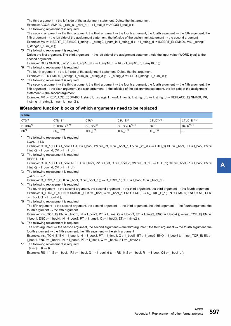
APPXAppendix 7 Replacement of other format projects 597
A
The third argument → the left side of the assignment statement. Delete the first argument.Example: ACOS( SM400, l_real_s, l_real_d ); → l_real_d := ACOS( l_real_s );
*4 The following replacement is required.The second argument → the third argument, the third argument → the fourth argument, the fourth argument → the fifth argument, the fifth argument → the left side of the assignment statement, the left side of the assignment statement → the second argumentExample: M0 := INSERT_E( SM400, l_string1, l_string2, l_num_in, l_string_d ); → l_string_d := INSERT_E( SM400, M0, l_string1, l_string2, l_num_in );
*5 The following replacement is required.Delete the first argument. The third argument → the left side of the assignment statement. Add the input value (WORD type) to the second argument.Example: ROL( SM400, l_any16_in, l_any16_d ); → l_any16_d := ROL( l_any16_in, l_any16_n );
*6 The following replacement is required.The fourth argument → the left side of the assignment statement. Delete the first argument.Example: LEFT( SM400, l_string1, l_num_in, l_string_d ); → l_string_d := LEFT( l_string1, l_num_in );
*7 The following replacement is required.The second argument → the third argument, the third argument → the fourth argument, the fourth argument → the fifth argument, the fifth argument → the sixth argument, the sixth argument → the left side of the assignment statement, the left side of the assignment statement → the second argumentExample: M0 := REPLACE_E( SM400, l_string1, l_string2, l_num1, l_num2, l_string_d ); → l_string_d := REPLACE_E( SM400, M0, l_string1, l_string2, l_num1, l_num2 );
■Standard function blocks of which arguments need to be replaced
*1 The following replacement is required.LOAD → LDExample: CTD_1( CD := l_bool, LOAD := l_bool, PV := l_int, Q := l_bool_d, CV := l_int_d ); → CTD_1( CD := l_bool, LD := l_bool, PV := l_int, Q := l_bool_d, CV := l_int_d );
*2 The following replacement is required.RESET → RExample: CTU_1( CU := l_bool, RESET := l_bool, PV := l_int, Q := l_bool_d, CV := l_int_d ); → CTU_1( CU := l_bool, R := l_bool, PV := l_int, Q := l_bool_d, CV := l_int_d );
*3 The following replacement is required._CLK → CLKExample: R_TRIG_1( _CLK := l_bool, Q := l_bool_d ); → R_TRIG_1( CLK := l_bool, Q := l_bool_d );
*4 The following replacement is required.The fourth argument → the second argument, the second argument → the third argument, the third argument → the fourth argumentExample: R_TRIG_E_1( EN := SM400, _CLK := l_bool, Q := l_bool_d, ENO := M0 ); → R_TRIG_E_1( EN := SM400, ENO := M0, CLK := l_bool, Q := l_bool_d );
*5 The following replacement is required.The fifth argument → the second argument, the second argument → the third argument, the third argument → the fourth argument, the fourth argument → the fifth argumentExample: inst_TOF_E( EN := l_bool1, IN := l_bool2, PT := l_time, Q := l_bool3, ET := l_time2, ENO := l_bool4 ); → inst_TOF_E( EN := l_bool1, ENO := l_bool4, IN :=l_bool2, PT := l_time1, Q := l_bool3, ET := l_time2 );
*6 The following replacement is required.The sixth argument → the second argument, the second argument → the third argument, the third argument → the fourth argument, the fourth argument → the fifth argument, the fifth argument → the sixth argumentExample: inst_TON_E( EN := l_bool1, IN := l_bool2, PT := l_time1, Q := l_bool3, ET := l_time2, ENO := l_bool4 ); → inst_TOF_E( EN := l_bool1, ENO := l_bool4, IN := l_bool2, PT := l_time1, Q := l_bool3, ET := l_time2 );
*7 The following replacement is required._S → S, _R → RExample: RS_1( _S := l_bool, _R1 := l_bool, Q1 := l_bool_d ); → RS_1( S := l_bool, R1 := l_bool, Q1 := l_bool_d );
Name
CTD*1 CTD_E*1 CTU*2 CTU_E*2 CTUD*1,*2 CTUD_E*1,*2
F_TRIG*3 F_TRIG_E*3,*4 R_TRIG*3 R_TRIG_E*3,*4 RS*7 RS_E*7,*4
SR*2 SR_E*7,*5 TOF_E*5 TON_E*6 TP_E*6 -
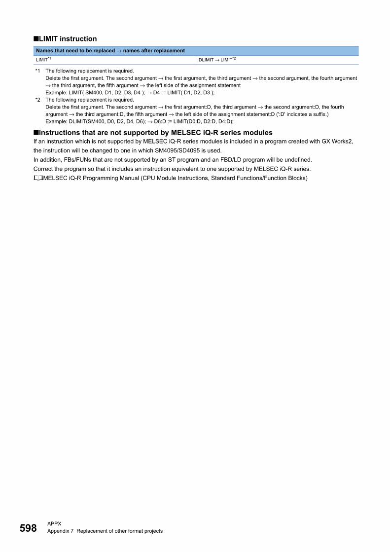
598APPXAppendix 7 Replacement of other format projects
■LIMIT instruction
*1 The following replacement is required.Delete the first argument. The second argument → the first argument, the third argument → the second argument, the fourth argument → the third argument, the fifth argument → the left side of the assignment statementExample: LIMIT( SM400, D1, D2, D3, D4 ); → D4 := LIMIT( D1, D2, D3 );
*2 The following replacement is required.Delete the first argument. The second argument → the first argument:D, the third argument → the second argument:D, the fourth argument → the third argument:D, the fifth argument → the left side of the assignment statement:D (':D' indicates a suffix.)Example: DLIMIT(SM400, D0, D2, D4, D6); → D6:D := LIMIT(D0:D, D2:D, D4:D);
■Instructions that are not supported by MELSEC iQ-R series modulesIf an instruction which is not supported by MELSEC iQ-R series modules is included in a program created with GX Works2,
the instruction will be changed to one in which SM4095/SD4095 is used.
In addition, FBs/FUNs that are not supported by an ST program and an FBD/LD program will be undefined.
Correct the program so that it includes an instruction equivalent to one supported by MELSEC iQ-R series.
MELSEC iQ-R Programming Manual (CPU Module Instructions, Standard Functions/Function Blocks)
Names that need to be replaced → names after replacement
LIMIT*1 DLIMIT → LIMIT*2
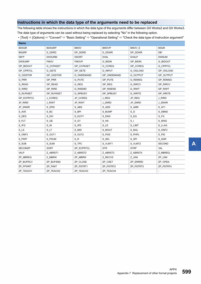
APPXAppendix 7 Replacement of other format projects 599
A
Instructions in which the data type of the arguments need to be replacedThe following table shows the instructions in which the data type of the arguments differ between GX Works2 and GX Works3.
The data type of arguments can be used without being replaced by selecting "No" in the following option.
• [Tool] [Options] "Convert" "Basic Setting" "Operational Setting" "Check the data type of instruction argument"
Name
BDSQR BDSQRP BMOV BMOVP BMOV_E BSQR
BSQRP D_DDRD DP_DDRD D_DDWR DP_DDWR DB*
DB*P DHOURM DSORT DVAL DVALP DWSUM
DWSUMP FMOV FMOVP G_BIDIN GP_BIDIN G_BIDOUT
GP_BIDOUT G_CCPASET GP_CCPASET G_CCREQ GP_CCREQ G_CPRTCL
GP_CPRTCL G_GETE GP_GETE G_INPUT G_OGLOAD GP_OGLOAD
G_OGSTOR GP_OGSTOR G_ONDEMAND GP_ONDEMAND G_OUTPUT GP_OUTPUT
G_PRR GP_PRR G_PUTE GP_PUTE G_RDMSG GP_RDMSG
G_READ GP_READ G_REQ GP_REQ G_RIRCV GP_RIRCV
G_RIRD GP_RIRD G_RISEND GP_RISEND G_RIWT GP_RIWT
G_RLPASET GP_RLPASET G_SPBUSY GP_SPBUSY G_WRITE GP_WRITE
GP_ECPRTCL J_CCREQ JP_CCREQ J_REQ JP_REQ J_RIRD
JP_RIRD J_RIWT JP_RIWT J_ZNRD JP_ZNRD J_ZNWR
JP_ZNWR S_2PID S_ABS S_ADD S_AMR S_AT1
S_AVE S_BC S_BPI S_BUMP S_D S_DBND
S_DED S_DIV S_DUTY S_ENG S_EQ S_FG
S_FLT S_GE S_GT S_HS S_I S_IENG
S_IFG S_IN S_IPD S_LE S_LIMT S_LLAG
S_LS S_LT S_MID S_MOUT S_MUL S_ONF2
S_ONF3 S_OUT1 S_OUT2 S_PGS S_PHPL S_PID
S_PIDP S_PSUM S_R S_SEL S_SPI S_SQR
S_SUB S_SUM S_TPC S_VLMT1 S_VLMT2 SECOND
SECONDP SORT SP_ECPRTCL STR STRP VAL
VALP Z_ABRST1 Z_ABRST2 Z_ABRST3 Z_ABRST4 Z_MBREQ
ZP_MBREQ Z_MBRW ZP_MBRW Z_RECVS Z_UINI ZP_UINI
ZP_BUFRCV ZP_BUFSND ZP_CLOSE ZP_CSET ZP_ERRRD ZP_OPEN
ZP_PFWRT ZP_PINIT ZP_PSTRT1 ZP_PSTRT2 ZP_PSTRT3 ZP_PSTRT4
ZP_TEACH1 ZP_TEACH2 ZP_TEACH3 ZP_TEACH4 - -
600APPXAppendix 7 Replacement of other format projects
Correcting devices
■Devices that are not supported by MELSEC iQ-R series module • When a device, which is not supported by MELSEC iQ-R series module, is used in a program created with GX Works2, it is
changed to SM4095/SD4095. In addition, when a GX Works2 project consists of a ladder program, the device, which is
changed to a character string by an instruction, is changed to "SM4095"/"SD4095". To search a character string, refer to the
search function. (Page 304 Searching/Replacing Character Strings)
• The following devices will be deleted when they are set to the device memory data or the device initial value data created
with GX Works2.
S device, R device
■Number of device points and start/end deviceThe setting range for the number of device points may differ between the CPU type of a project created with GX Works2 and
a MELSEC iQ-R series module. When the value, which has been set to the parameter, cannot be set for a MELSEC iQ-R
series module, it is corrected to the value configurable in the MELSEC iQ-R series module after changing the module type.
■Increase of the number of device points due to the differences in local device setting unitsAlthough the bit devices and word devices of local devices are set in one point units for Q series, the bit devices, word devices
(excluding T/ST/C), and T/ST/C for MELSEC iQ-R series are set in 64-point units, 4-point units, and 32-point units,
respectively. Since the setting units are different between Q series and MELSEC iQ-R series, the CPU parameters are
automatically changed after changing the module type, resulting in the increase of the number of device points.
■Device name and label name display • For a device that has been set as the local device with GX Works2, '#' is added in front of the device name.
• When a label used in GX Works2 has a name starting with "M+" or "P+", the "+" of the label name is replaced with "_".
■Step relay/SFC block deviceA step relay/SFC block device may not be used on the ST editor and the FBD/LD editor.
Correct the program to provide the equivalent operation to the ST program and Structured Ladder/FBD program of GX
Works2.
For details, refer to the following manual.
MELSEC iQ-R Programming Manual (Program Design)
■Correcting devices in address representationGX Works3 does not support address representation of devices (such as '%MW0.0').
When address representation is used in a project created in GX Works2, it is read as is.
Correct each device in address representation by replacing the character string.
APPXAppendix 7 Replacement of other format projects 601
A
Correcting a program
■Structured Ladder/FBD program • The execution order is handled differently between Structured Ladder/Function Block Diagram language in GX Works2 and
Function Block Diagram/Ladder Diagram language in GX Works3. Display the execution order and check it.
• A way of counting FBD network blocks differ between a program written in Structured Ladder/Function Block Diagram
language in GX Works2 and a program written in Function Block Diagram/Ladder Diagram language in GX Works3. For a
program written in Structured Ladder/Function Block Diagram language in GX Works2, a single function block is counted as
a single FBD network block. For a program written in Function Block Diagram/Ladder Diagram language in GX Works3, all
connected elements are counted as a single FBD network block. Therefore, a GX Works2 program may exceed the
maximum number of creatable FBD network blocks (4096) when it is opened in GX Works3. In this case, divide the
program and reduce the number of FBD network blocks.
• A performance of an return element differ between a program written in Structured Ladder/Function Block Diagram
language in GX Works2 and a program written in Function Block Diagram/Ladder Diagram language in GX Works3. For
details on return elements in GX Works3, refer to the following section.
(Page 227 Common element)
• There may be differences in the number and order of I/O arguments of a function element/function block element between
Structured Ladder/Function Block Diagram language in GX Works2 and Function Block Diagram/Ladder Diagram language
in GX Works3. In this case, the element is displayed as an undefined FB/FUN. Select [Edit] [Update FB/FUN] to update
the definition information, and correct the program.
• When a program in which members of standard FB are referenced is created in Structured Ladder/Function Block Diagram
of GX Works2, a conversion error may occur after opening the program with GX Works3. In this case, check the member
name and class of the standard FB, and correct the program.
• Inverting the contact is available for I/O arguments of function elements/function block elements in Function Block Diagram/
Ladder Diagram language of GX Works3. (Page 228 Switching methods for contacts/instructions)
Connectors of those elements are deleted when the elements other than above are inverted in a Structured Ladder/FBD
program of GX Works2. Correct the program to provide equivalent operations to the Structured Ladder/FBD program in GX
Works2.
• Function Block Diagram/Ladder Diagram language in GX Works3 does not support wired OR of FBD elements. Correct the
program to provide the equivalent operation to the Structured Ladder/FBD program of GX Works2 since a conversion error
is caused.
• When a pointer branch instruction (CJ, SCJ, JMP), a jump, or a subroutine program is used, a conversion error may occur.
For more details, refer to the following manual.
(MELSEC iQ-R Programming Manual (Program Design))
• The program layout may be changed due to the differences between a Structured Ladder/FBD editor of GX Works2 and an
FBD/LD editor of GX Works3. In that case, correct the layout properly.
Additionally, the layout can be corrected by the layout correction function. For details on the layout correction function, refer
to the following section.
(Page 231 Layout correction)
• Ladder block label used in the Structured Ladder/FBD of GX Works2 is defined as the pointer type in a local label.
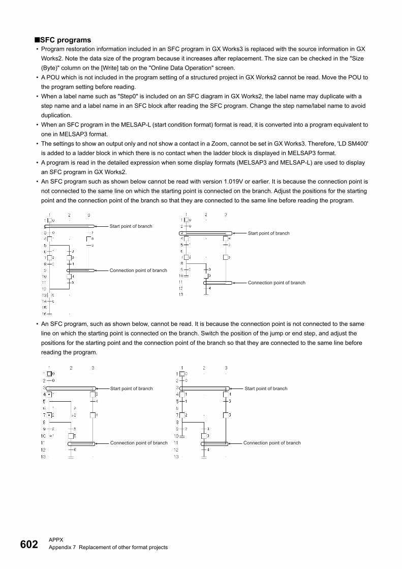
602APPXAppendix 7 Replacement of other format projects
■SFC programs • Program restoration information included in an SFC program in GX Works3 is replaced with the source information in GX
Works2. Note the data size of the program because it increases after replacement. The size can be checked in the "Size
(Byte)" column on the [Write] tab on the "Online Data Operation" screen.
• A POU which is not included in the program setting of a structured project in GX Works2 cannot be read. Move the POU to
the program setting before reading.
• When a label name such as "Step0" is included on an SFC diagram in GX Works2, the label name may duplicate with a
step name and a label name in an SFC block after reading the SFC program. Change the step name/label name to avoid
duplication.
• When an SFC program in the MELSAP-L (start condition format) format is read, it is converted into a program equivalent to
one in MELSAP3 format.
• The settings to show an output only and not show a contact in a Zoom, cannot be set in GX Works3. Therefore, 'LD SM400'
is added to a ladder block in which there is no contact when the ladder block is displayed in MELSAP3 format.
• A program is read in the detailed expression when some display formats (MELSAP3 and MELSAP-L) are used to display
an SFC program in GX Works2.
• An SFC program such as shown below cannot be read with version 1.019V or earlier. It is because the connection point is
not connected to the same line on which the starting point is connected on the branch. Adjust the positions for the starting
point and the connection point of the branch so that they are connected to the same line before reading the program.
• An SFC program, such as shown below, cannot be read. It is because the connection point is not connected to the same
line on which the starting point is connected on the branch. Switch the position of the jump or end step, and adjust the
positions for the starting point and the connection point of the branch so that they are connected to the same line before
reading the program.
Start point of branch
Connection point of branch
Start point of branch
Connection point of branch
Start point of branch Start point of branch
Connection point of branch Connection point of branch

APPXAppendix 7 Replacement of other format projects 603
A
• When an independent SFC diagram exists between the SFC diagrams in which multiple initial steps are connected each
other as shown below, the program is read by moving the independent program to the rightmost.
• FX5CPUs do not support SFC programs. A project is read excluding an SFC program.
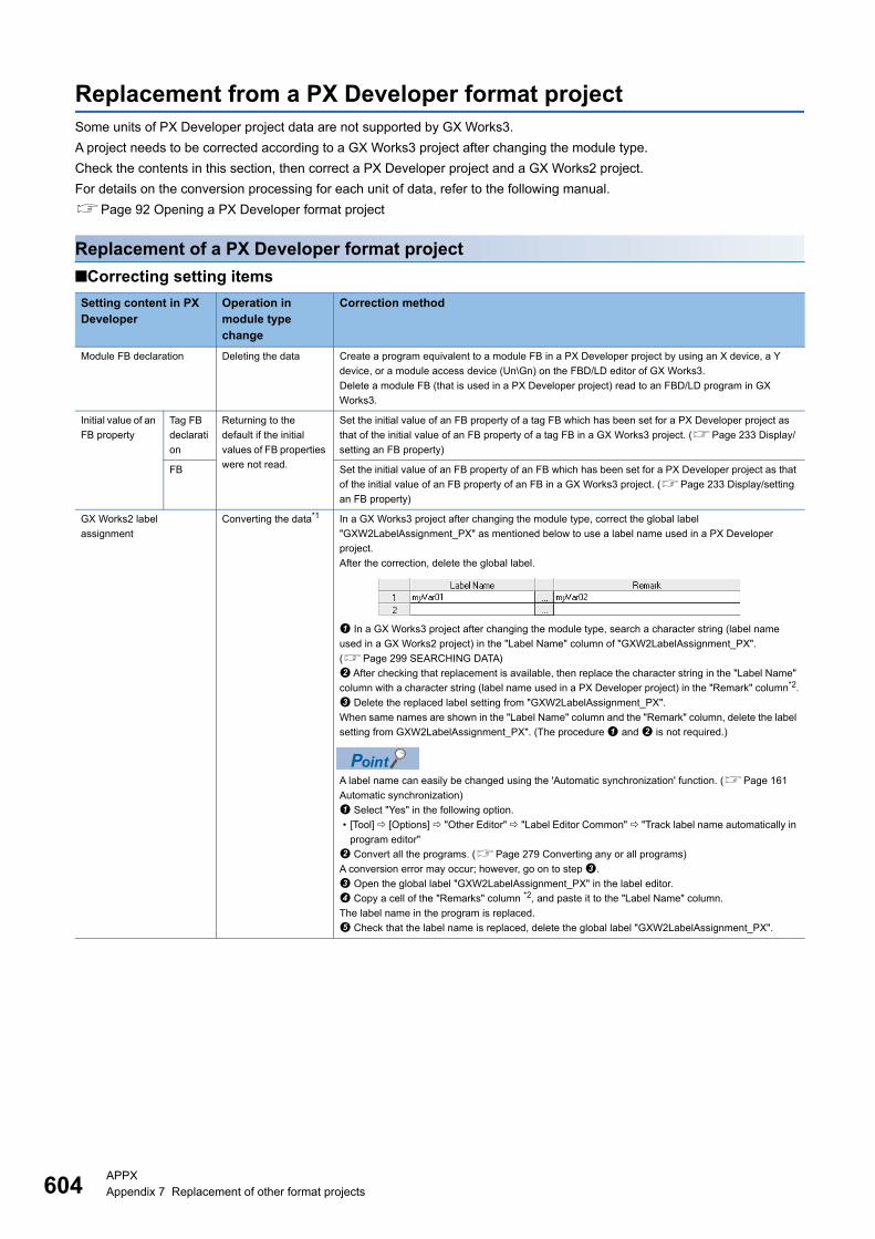
604APPXAppendix 7 Replacement of other format projects
Replacement from a PX Developer format projectSome units of PX Developer project data are not supported by GX Works3.
A project needs to be corrected according to a GX Works3 project after changing the module type.
Check the contents in this section, then correct a PX Developer project and a GX Works2 project.
For details on the conversion processing for each unit of data, refer to the following manual.
Page 92 Opening a PX Developer format project
Replacement of a PX Developer format project
■Correcting setting items
Setting content in PX Developer
Operation in module type change
Correction method
Module FB declaration Deleting the data Create a program equivalent to a module FB in a PX Developer project by using an X device, a Y
device, or a module access device (Un\Gn) on the FBD/LD editor of GX Works3.
Delete a module FB (that is used in a PX Developer project) read to an FBD/LD program in GX
Works3.
Initial value of an
FB property
Tag FB
declarati
on
Returning to the
default if the initial
values of FB properties
were not read.
Set the initial value of an FB property of a tag FB which has been set for a PX Developer project as
that of the initial value of an FB property of a tag FB in a GX Works3 project. (Page 233 Display/
setting an FB property)
FB Set the initial value of an FB property of an FB which has been set for a PX Developer project as that
of the initial value of an FB property of an FB in a GX Works3 project. (Page 233 Display/setting
an FB property)
GX Works2 label
assignment
Converting the data*1 In a GX Works3 project after changing the module type, correct the global label
"GXW2LabelAssignment_PX" as mentioned below to use a label name used in a PX Developer
project.
After the correction, delete the global label.
In a GX Works3 project after changing the module type, search a character string (label name
used in a GX Works2 project) in the "Label Name" column of "GXW2LabelAssignment_PX".
(Page 299 SEARCHING DATA)
After checking that replacement is available, then replace the character string in the "Label Name"
column with a character string (label name used in a PX Developer project) in the "Remark" column*2.
Delete the replaced label setting from "GXW2LabelAssignment_PX".
When same names are shown in the "Label Name" column and the "Remark" column, delete the label
setting from GXW2LabelAssignment_PX". (The procedure and is not required.)
A label name can easily be changed using the 'Automatic synchronization' function. (Page 161
Automatic synchronization)
Select "Yes" in the following option.
• [Tool] [Options] "Other Editor" "Label Editor Common" "Track label name automatically in
program editor"
Convert all the programs. (Page 279 Converting any or all programs)
A conversion error may occur; however, go on to step .
Open the global label "GXW2LabelAssignment_PX" in the label editor.
Copy a cell of the "Remarks" column *2, and paste it to the "Label Name" column.
The label name in the program is replaced.
Check that the label name is replaced, delete the global label "GXW2LabelAssignment_PX".

APPXAppendix 7 Replacement of other format projects 605
A
Interrupt pointer execution Changing to "No
Execution Type"
Set the following for the target program.
Select "CPU Parameter" "Program Setting", then set a program name of a program to execute
the interrupt pointer in the "Program Name" column.
Select "Event" in the "Type" column of "Execution Type".
Click the [...] button in the "Detailed Setting Information" column, and select "Interruption
Occurrence" for "Trigger Type" on the "Event Execution Type Detailed Setting" screen.
Set a interrupt pointer for "Interruption Occurrence".
Execution condition setting
of a program and an FBD
sheet
Converting as a
comment element
Create a program to control the execution by combining a contact with jump/return on the FBD/LD
editor in GX Works3 according to the execution condition settings of a program and an FBD sheet
which have been set for a PX Developer project.
The following shows the examples of processing to control the execution of a program.
Example 1) Execute a program when 'M0' or 'M1' is true. (It is not executed when 'M0' and 'M1' are
false.)
Example 2) Not execute a program of a worksheet always
Setting content in PX Developer
Operation in module type change
Correction method
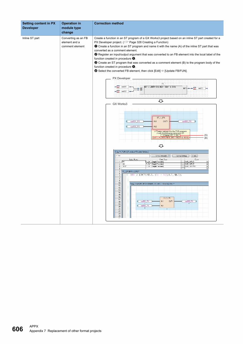
606APPXAppendix 7 Replacement of other format projects
Inline ST part Converting as an FB
element and a
comment element
Create a function in an ST program of a GX Works3 project based on an inline ST part created for a
PX Developer project. (Page 328 Creating a Function)
Create a function in an ST program and name it with the name (A) of the inline ST part that was
converted as a comment element.
Register an input/output argument that was converted to an FB element into the local label of the
function created in procedure .
Create an ST program that was converted as a comment element (B) to the program body of the
function created in procedure .
Select the converted FB element, then click [Edit] [Update FB/FUN].
Setting content in PX Developer
Operation in module type change
Correction method
GX Works3
PX Developer
(A) (B)
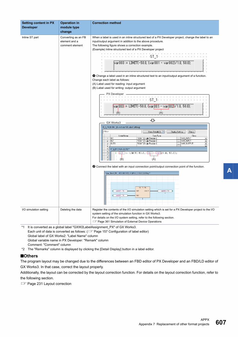
APPXAppendix 7 Replacement of other format projects 607
A
*1 It is converted as a global label "GXW2LabelAssignment_PX" of GX Works3.Each unit of data is converted as follows: (Page 157 Configuration of label editor)Global label of GX Works2: "Label Name" columnGlobal variable name in PX Developer: "Remark" columnComment: "Comment" column
*2 The "Remarks" column is displayed by clicking the [Detail Display] button in a label editor.
■OthersThe program layout may be changed due to the differences between an FBD editor of PX Developer and an FBD/LD editor of
GX Works3. In that case, correct the layout properly.
Additionally, the layout can be corrected by the layout correction function. For details on the layout correction function, refer to
the following section.
Page 231 Layout correction
Inline ST part Converting as an FB
element and a
comment element
When a label is used in an inline structured text of a PX Developer project, change the label to an
input/output argument in addition to the above procedure.
The following figure shows a correction example.
(Example) Inline structured text of a PX Developer project
Change a label used in an inline structured text to an input/output argument of a function.
Change each label as follows:
(A) Label used for reading: input argument
(B) Label used for writing: output argument
Connect the label with an input connection point/output connection point of the function.
I/O simulation setting Deleting the data Register the contents of the I/O simulation setting which is set for a PX Developer project to the I/O
system setting of the simulation function in GX Works3.
For details on the I/O system setting, refer to the following section.
Page 361 Simulation of External Device Operations
Setting content in PX Developer
Operation in module type change
Correction method
GX Works3
PX Developer
(A)
(B) (A)
(B)
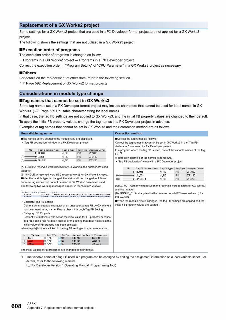
608APPXAppendix 7 Replacement of other format projects
Replacement of a GX Works2 projectSome settings for a GX Works2 project that are used in a PX Developer format project are not applied for a GX Works3
project.
The following shows the settings that are not utilized in a GX Works3 project.
■Execution order of programsThe execution order of programs is changed as follow.
• Programs in a GX Works2 project → Programs in a PX Developer project
Correct the execution order in "Program Setting" of "CPU Parameter" in a GX Works3 project as necessary.
■OthersFor details on the replacement of other data, refer to the following section.
Page 592 Replacement of GX Works2 format projects
Considerations in module type change
■Tag names that cannot be set in GX Works3Some tag names set in a PX Developer format project may include characters that cannot be used for label names in GX
Works3. (Page 539 Unusable character string for label name)
In that case, the tag FB settings are not applied to GX Works3, and the initial FB property values are changed to their default.
To apply the initial FB property values, change the tag names in a PX Developer project in advance.
Examples of tag names that cannot be set in GX Works3 and their correction method are as follows.
*1 The variable name of a tag FB used in a program can be changed by editing the assignment information on a local variable sheet. For details, refer to the following manual.PX Developer Version 1 Operating Manual (Programming Tool)
Unavailable tag name Correction method
■Tag names before changing the module type are displayed.
• "Tag FB declaration" window in a PX Developer project
(A) LC001: A reserved word (device) for GX Works3 and number are used
together.
(B) SINGLE: A reserved word (IEC reserved word) for GX Works3 is used.
■After the module type is changed, the status will be changed as follows
because tag names that cannot be used in GX Works3 have been used.
The following two warning messages appear in the "Output" window.
• Category: Tag FB Setting
Content: An unsettable character or an unsupported tag FB by GX Works3
has been used in tag name. Please check it through Tag FB Setting.
• Category: FB Property
Content: Default value was set as the initial value for FB property because
Tag FB Setting has not been applied or the setting that does not reflect the
initial value of FB property has been selected.
When [Apply] button is clicked in the tag FB setting editor, an error occurs.
The initial values of FB properties are changed to their default.
■Correct the tag names as follows.
Correct the tag names that cannot be set in GX Works3 in the "Tag FB
declaration" windows of a PX Developer project.
In a program where the tag FB is used, correct the variable names of the tag
FB. *1
A correction example of tag names is as follows.
• "Tag FB declaration" window in a PX Developer project
(A) LC_001: Add any text between the reserved word (device) for GX Works3
and the number.
(B) SINGLE_01: Add any text to the reserved word (IEC reserved word) for
GX Works3.
■When the module type is changed, the tag FB settings are applied and the
initial FB property values are utilized.
(A)(B)
(B)(A)
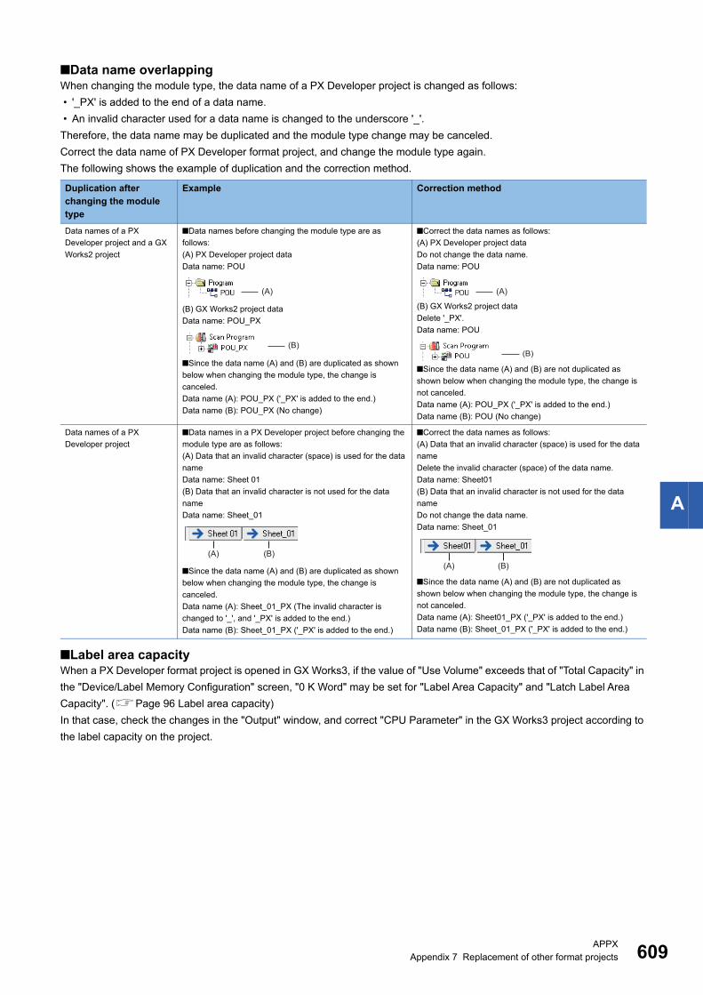
APPXAppendix 7 Replacement of other format projects 609
A
■Data name overlappingWhen changing the module type, the data name of a PX Developer project is changed as follows:
• '_PX' is added to the end of a data name.
• An invalid character used for a data name is changed to the underscore '_'.
Therefore, the data name may be duplicated and the module type change may be canceled.
Correct the data name of PX Developer format project, and change the module type again.
The following shows the example of duplication and the correction method.
■Label area capacityWhen a PX Developer format project is opened in GX Works3, if the value of "Use Volume" exceeds that of "Total Capacity" in
the "Device/Label Memory Configuration" screen, "0 K Word" may be set for "Label Area Capacity" and "Latch Label Area
Capacity". (Page 96 Label area capacity)
In that case, check the changes in the "Output" window, and correct "CPU Parameter" in the GX Works3 project according to
the label capacity on the project.
Duplication after changing the module type
Example Correction method
Data names of a PX
Developer project and a GX
Works2 project
■Data names before changing the module type are as
follows:
(A) PX Developer project data
Data name: POU
(B) GX Works2 project data
Data name: POU_PX
■Since the data name (A) and (B) are duplicated as shown
below when changing the module type, the change is
canceled.
Data name (A): POU_PX ('_PX' is added to the end.)
Data name (B): POU_PX (No change)
■Correct the data names as follows:
(A) PX Developer project data
Do not change the data name.
Data name: POU
(B) GX Works2 project data
Delete '_PX'.
Data name: POU
■Since the data name (A) and (B) are not duplicated as
shown below when changing the module type, the change is
not canceled.
Data name (A): POU_PX ('_PX' is added to the end.)
Data name (B): POU (No change)
Data names of a PX
Developer project
■Data names in a PX Developer project before changing the
module type are as follows:
(A) Data that an invalid character (space) is used for the data
name
Data name: Sheet 01
(B) Data that an invalid character is not used for the data
name
Data name: Sheet_01
■Since the data name (A) and (B) are duplicated as shown
below when changing the module type, the change is
canceled.
Data name (A): Sheet_01_PX (The invalid character is
changed to '_', and '_PX' is added to the end.)
Data name (B): Sheet_01_PX ('_PX' is added to the end.)
■Correct the data names as follows:
(A) Data that an invalid character (space) is used for the data
name
Delete the invalid character (space) of the data name.
Data name: Sheet01
(B) Data that an invalid character is not used for the data
name
Do not change the data name.
Data name: Sheet_01
■Since the data name (A) and (B) are not duplicated as
shown below when changing the module type, the change is
not canceled.
Data name (A): Sheet01_PX ('_PX' is added to the end.)
Data name (B): Sheet_01_PX ('_PX' is added to the end.)
(A)
(B)
(A)
(B)
(A) (B)(A) (B)

610APPXAppendix 8 Considerations for Changing from FX5CPUs to RCPUs
Appendix 8 Considerations for Changing from FX5CPUs to RCPUs
This section explains the considerations when changing the module type from an FX5CPU to an RCPU.
Considerations before changing the module type
■Checking the security set to a projectWhen an element to which a block password and security key are set is included, the module type cannot be changed to an
RCPU.
Delete the setting of a block password and a security key before changing the module type.
■Checking the representation recognized as X/Y devices after changing the module type.An element such as 'X08' or 'Y0F', which is not recognized as a device in an FX5CPU, is not converted when changing the
module type.
These elements are recognized as devices in an RCPU after the change. Correct them before changing the module type.
Procedure to change the module type1. Check the project data before changing the module type. (Page 610 Considerations before changing the module
type)
2. Change the project used for an FX5CPU to the one used for an RCPU by changing the module type and operation
mode.
3. Set the module configuration for the project after changing the module type and operation mode.
4. Set the parameter.
5. Correct the program. (Page 612 Correction after changing the module type)
Replace the X/Y devices, module specification number, and instruction.
Review the program according to the system configuration after changing the module type and operation mode.
6. Check the operation on the programmable controller.
Data to be changed when changing the module type
Project data used for FX5CPU Description
Program
Function
Function block
Ladder*1 X/Y devices are converted to hexadecimal from octal.
An R device is replaced with a ZR device.ST
FBD/LD
Program file management Program file Succeeded.
FBFILE
FUNFILE
Module Configuration Diagram Returns to the default.
System Parameter I/O Assignment Setting Returns to the default.
CPU Parameter Name Setting Succeeded.
When it cannot be succeeded, change the setting depending on the module
type after the change to succeed.Operation Related Setting
Interrupt Settings
Service Processing Setting
File Setting
Memory/Device Setting
RAS Setting
Program Setting

APPXAppendix 8 Considerations for Changing from FX5CPUs to RCPUs 611
A
*1 An instruction of which the argument specification is different exists in the module types before and after the change. When correcting a program, note that a device used for such an instruction is not converted at the module type change.
Module Parameter Ethernet Port Succeeded.
When it cannot be succeeded, change the setting depending on the module
type after the change to succeed.
Change the following settings to the defaults.
• CC-Link IEF Basic setting
485 Serial Port Deleted.
High Speed I/O
Input Response Time
Analog Input
Analog Output
Expansion Board
Memory Card Parameter Boot Setting Succeeded.
When it cannot be succeeded, change the setting depending on the module
type after the change to succeed.Setting of File/Data Use or Not in
Memory Card
Module Information Deleted.
Remote Password Returns to the default.
Structured Data Types The definition of the module label is deleted.
Label Global Label X/Y devices are converted to hexadecimal from octal.
An R device is replaced with a ZR device.
M+Global and all the data in M+Global are deleted.
Local Label Succeeded.
Device Memory An S device is deleted.
X/Y devices are converted to hexadecimal from octal.
An R device is replaced with a ZR device.
An ER device is deleted.
The data of SM4096 or later are deleted.
The data of SD4096 or later are deleted.
Device Comment
Device Initial Value A device which cannot be used for a module after changing the module type is
deleted.
An R device is replaced with a ZR device.
The data of SD4096 or later are deleted.
Connection Destination Setting Returns to the default.
Options The setting value of R is changed to that of ZR in [Tool] [Options]
"Project" "Device Comment Reference/Reflection Target".
Print Setting Returns to the default.
Project data used for FX5CPU Description
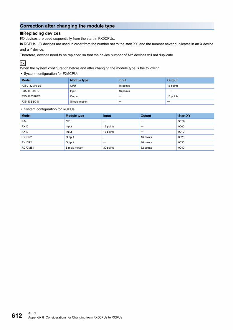
612APPXAppendix 8 Considerations for Changing from FX5CPUs to RCPUs
Correction after changing the module type
■Replacing devicesI/O devices are used sequentially from the start in FX5CPUs.
In RCPUs, I/O devices are used in order from the number set to the start XY, and the number never duplicates in an X device
and a Y device.
Therefore, devices need to be replaced so that the device number of X/Y devices will not duplicate.
Ex.
When the system configuration before and after changing the module type is the following:
• System configuration for FX5CPUs
• System configuration for RCPUs
Model Module type Input Output
FX5U-32MR/ES CPU 16 points 16 points
FX5-16EX/ES Input 16 points
FX5-16EYR/ES Output 16 points
FX5-40SSC-S Simple motion
Model Module type Input Output Start XY
R04 CPU 3E00
RX10 Input 16 points 0000
RX10 Input 16 points 0010
RY10R2 Output 16 points 0020
RY10R2 Output 16 points 0030
RD77MS4 Simple motion 32 points 32 points 0040
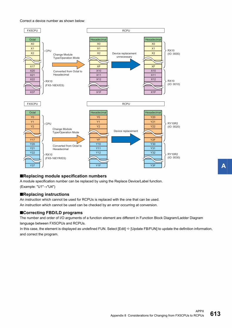
APPXAppendix 8 Considerations for Changing from FX5CPUs to RCPUs 613
A
Correct a device number as shown below:
■Replacing module specification numbersA module specification number can be replaced by using the Replace Device/Label function.
(Example: "U1"→"U4")
■Replacing instructionsAn instruction which cannot be used for RCPUs is replaced with the one that can be used.
An instruction which cannot be used can be checked by an error occurring at conversion.
■Correcting FBD/LD programsThe number and order of I/O arguments of a function element are different in Function Block Diagram/Ladder Diagram
language between FX5CPUs and RCPUs.
In this case, the element is displayed as undefined FUN. Select [Edit] [Update FB/FUN] to update the definition information,
and correct the program.
FX5CPU RCPU
RCPUFX5CPU
X17X20X21X22
X37
X2
X1
X0
CPU
CPU
XFX10X11X12
X1F
X2
X1
X0
XF
Y17Y20Y21Y22
Y37
Y2
Y1
Y0
X10X11X12
X1F
X2
X1
X0
YFY10Y11Y12
Y1F
Y2
Y1
Y0
Y2FY30Y31Y32
Y3F
Y22
Y21
Y20
RX10(IO: 0000)
RX10(IO: 0010)
RY10R2(IO: 0020)
RY10R2(IO: 0030)
(FX5-16EX/ES)
(FX5-16EYR/ES)
Hexadecimal
HexadecimalHexadecimalOctal
Octal Hexadecimal
Change Module Type/Operation Mode
Converted from Octal to Hexadecimal
Converted from Octal to Hexadecimal
Device replacement unnecessary
Device replacementChange Module Type/Operation Mode
RX10
RX10
614APPXAppendix 9 Using Sample Programs
Appendix 9 Using Sample ProgramsThis section shows the method for using sample programs, described in manuals that can be browsed on e-Manual Viewer, in
GX Works3.
To use this function, GX Works3 Version 1.035M or later and e-Manual Viewer Version 1.13P or later are required to be
installed.
For the operation method of e-Manual Viewer, refer to e-Manual Viewer Help.
Procedure to use
■Label
1. Create a module label in the project, following the manual on e-Manual Viewer, and set parameters.
2. Click "Copy a label (for GX Works3)" on the manual to copy the global labels/local labels.
3. Set the item order (label name, data type, class, assignment (device/label) of the labels copied in step 2 to be the same
order as ones on the label editor in GX Works3.
4. Paste the labels on the global label editor/local label editor in GX Works3.
■Ladder program
1. Click "Copy Ladder Program (for GX Works3)" on the manual to copy the ladder program.
2. Paste the program on the ladder editor in GX Works3.
Precautions
■When a label name is duplicatedAn error occurs at the program conversion when a label name in a sample program and one in a project where the program is
pasted are duplicated.
Copy and paste the sample program again according to the following procedure.
1. Delete the ladder program pasted from the sample program.
2. Change the label name to be duplicated on the label editor.
3. Paste the ladder program of the sample program on the ladder editor in GX Works3.
4. Change the label name used in the ladder program to the one set in the step 2.
■When an undefined label existsIn the following cases, the module labels in sample programs are pasted as undefined labels.
Check that the latest GX Works3 is installed.
• The versions of module labels differ between the sample program and GX Works3.
• GX Works3 does not support the module labels of the sample program.

APPXAppendix 10 Troubleshooting 615
A
Appendix 10TroubleshootingThis section shows the errors which may occur when using GX Works3 and their corrective actions.
*1 The Windows version can be checked by the following procedure. Press Windows key + , or select [Windows System] [Run] from the Start menu of Windows. Enter 'winver' in the "Run" screen. Check the version in the displayed screen.
*2 The display of GX Works3 will be blurred by enlarging.The following lists the setting values for "Change the size of text, apps, and other items" and the recommended display resolution for each setting value in Windows 10.Setting value: 100%, display resolution: 1024 × 768 dots or moreSetting value: 125%, display resolution: 1900 × 1200 dots or moreSetting value: 150%, display resolution: 1900 × 1200 dots or moreSetting value: 175%, display resolution: 2880 × 1620 dots or moreSetting value: 200%, display resolution: 2880 × 1620 dots or moreSetting value: 225%, display resolution: 3840 × 2160 dots or moreSetting value: 250%, display resolution: 3840 × 2160 dots or more
*3 'GXW3.exe' is stored in the folder where GX Works3 has been installed.The following is an example of a storage location.64-bit version operating system: C:\Program Files (x86)\MELSOFT\GPPW3\GXW3.exe32-bit version operating system: C:\Program Files\MELSOFT\GPPW3\GXW3.exe
Symptom Check point Corrective action
Contents in the screen may not be
displayed properly.
(For example, overlapping of icons,
text overflowing from the flame of a
button, etc.)
Is the size of the text and/or other
items in the screen changed to a
value other than the default value
(such as 96 DPI, 100%, and 9 pt) in
Windows settings?
• Return the settings to the defaults.
• For Windows 10 (version 1703 or later)*1, GX Works3 can be displayed in
high DPI scaling by using a Windows 10 function*2.
Select 'GXW3.exe'*3, and select [Properties] on the right-click menu.
Select "Override high DPI scaling behavior. Scaling performed by:" in the
[Compatibility] tab, and select "System" from the pull-down list.
Click the [OK] button.
Timeout occurs while GX Works3 is
accessing to a built-in Ethernet CPU
in Ethernet.
Is communication with GX Works3
allowed when Windows Firewall is
enabled?
For details, refer to the following section.
Page 376 When communication with GX Works3 is not allowed by
Windows Firewall
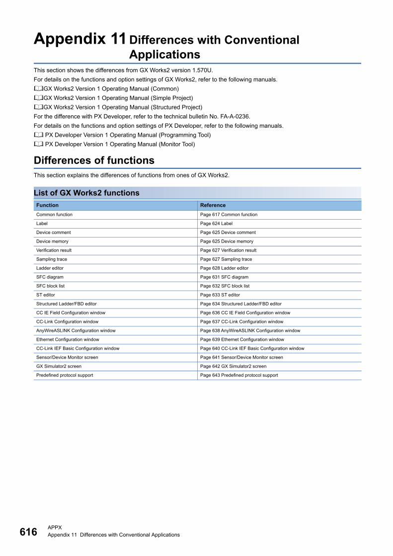
616APPXAppendix 11 Differences with Conventional Applications
Appendix 11 Differences with Conventional Applications
This section shows the differences from GX Works2 version 1.570U.
For details on the functions and option settings of GX Works2, refer to the following manuals.
GX Works2 Version 1 Operating Manual (Common)
GX Works2 Version 1 Operating Manual (Simple Project)
GX Works2 Version 1 Operating Manual (Structured Project)
For the difference with PX Developer, refer to the technical bulletin No. FA-A-0236.
For details on the functions and option settings of PX Developer, refer to the following manuals.
PX Developer Version 1 Operating Manual (Programming Tool)
PX Developer Version 1 Operating Manual (Monitor Tool)
Differences of functionsThis section explains the differences of functions from ones of GX Works2.
List of GX Works2 functions
Function Reference
Common function Page 617 Common function
Label Page 624 Label
Device comment Page 625 Device comment
Device memory Page 625 Device memory
Verification result Page 627 Verification result
Sampling trace Page 627 Sampling trace
Ladder editor Page 628 Ladder editor
SFC diagram Page 631 SFC diagram
SFC block list Page 632 SFC block list
ST editor Page 633 ST editor
Structured Ladder/FBD editor Page 634 Structured Ladder/FBD editor
CC IE Field Configuration window Page 636 CC IE Field Configuration window
CC-Link Configuration window Page 637 CC-Link Configuration window
AnyWireASLINK Configuration window Page 638 AnyWireASLINK Configuration window
Ethernet Configuration window Page 639 Ethernet Configuration window
CC-Link IEF Basic Configuration window Page 640 CC-Link IEF Basic Configuration window
Sensor/Device Monitor screen Page 641 Sensor/Device Monitor screen
GX Simulator2 screen Page 642 GX Simulator2 screen
Predefined protocol support Page 643 Predefined protocol support
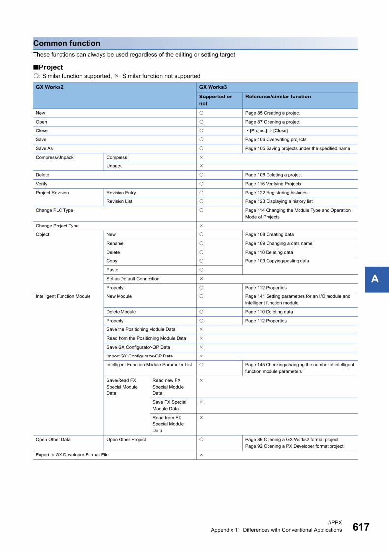
APPXAppendix 11 Differences with Conventional Applications 617
A
Common functionThese functions can always be used regardless of the editing or setting target.
■Project: Similar function supported, : Similar function not supported
GX Works2 GX Works3
Supported or not
Reference/similar function
New Page 85 Creating a project
Open Page 87 Opening a project
Close • [Project] [Close]
Save Page 106 Overwriting projects
Save As Page 105 Saving projects under the specified name
Compress/Unpack Compress
Unpack
Delete Page 106 Deleting a project
Verify Page 116 Verifying Projects
Project Revision Revision Entry Page 122 Registering histories
Revision List Page 123 Displaying a history list
Change PLC Type Page 114 Changing the Module Type and Operation
Mode of Projects
Change Project Type
Object New Page 108 Creating data
Rename Page 109 Changing a data name
Delete Page 110 Deleting data
Copy Page 109 Copying/pasting data
Paste
Set as Default Connection
Property Page 112 Properties
Intelligent Function Module New Module Page 141 Setting parameters for an I/O module and
intelligent function module
Delete Module Page 110 Deleting data
Property Page 112 Properties
Save the Positioning Module Data
Read from the Positioning Module Data
Save GX Configurator-QP Data
Import GX Configurator-QP Data
Intelligent Function Module Parameter List Page 145 Checking/changing the number of intelligent
function module parameters
Save/Read FX
Special Module
Data
Read new FX
Special Module
Data
Save FX Special
Module Data
Read from FX
Special Module
Data
Open Other Data Open Other Project Page 89 Opening a GX Works2 format project
Page 92 Opening a PX Developer format project
Export to GX Developer Format File
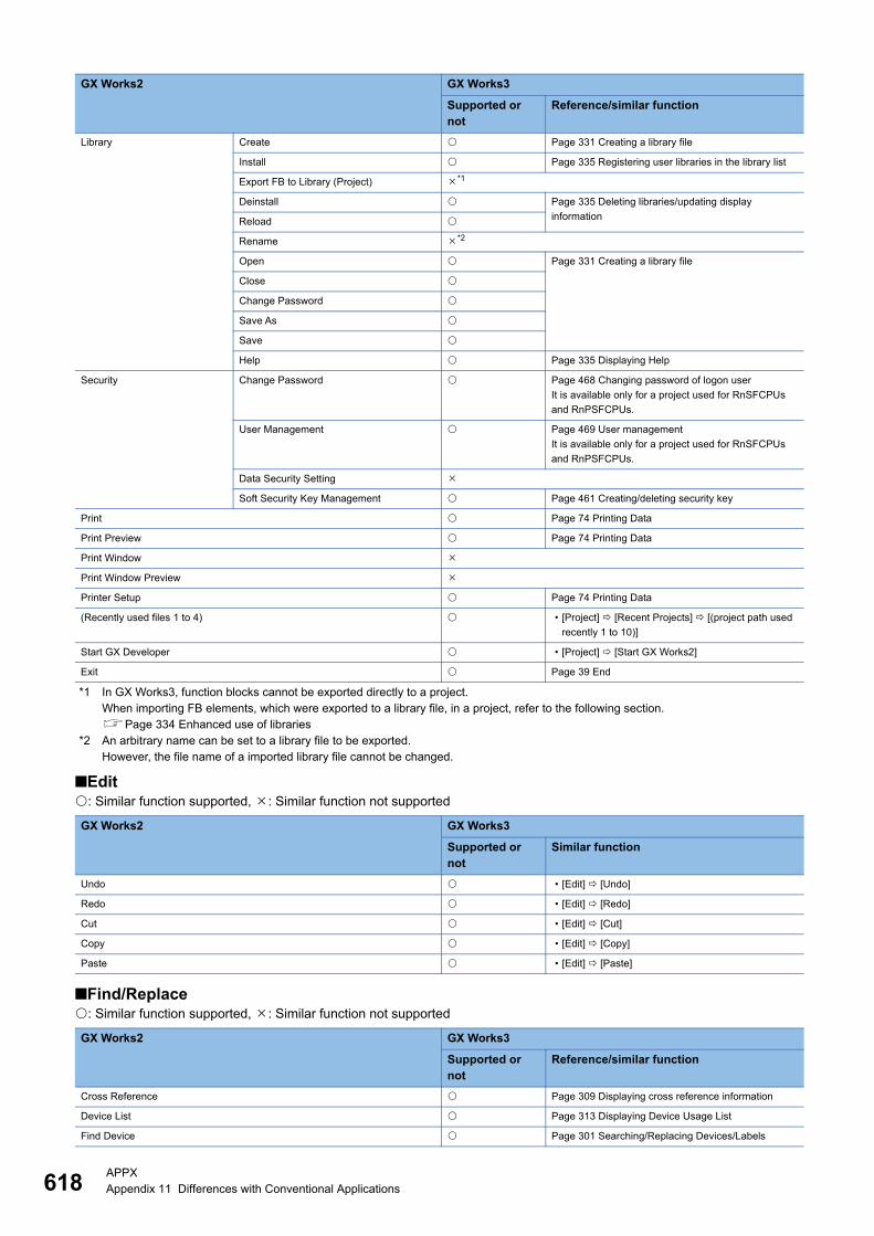
618APPXAppendix 11 Differences with Conventional Applications
*1 In GX Works3, function blocks cannot be exported directly to a project.When importing FB elements, which were exported to a library file, in a project, refer to the following section.Page 334 Enhanced use of libraries
*2 An arbitrary name can be set to a library file to be exported.However, the file name of a imported library file cannot be changed.
■Edit: Similar function supported, : Similar function not supported
■Find/Replace: Similar function supported, : Similar function not supported
Library Create Page 331 Creating a library file
Install Page 335 Registering user libraries in the library list
Export FB to Library (Project) *1
Deinstall Page 335 Deleting libraries/updating display
informationReload
Rename *2
Open Page 331 Creating a library file
Close
Change Password
Save As
Save
Help Page 335 Displaying Help
Security Change Password Page 468 Changing password of logon user
It is available only for a project used for RnSFCPUs
and RnPSFCPUs.
User Management Page 469 User management
It is available only for a project used for RnSFCPUs
and RnPSFCPUs.
Data Security Setting
Soft Security Key Management Page 461 Creating/deleting security key
Print Page 74 Printing Data
Print Preview Page 74 Printing Data
Print Window
Print Window Preview
Printer Setup Page 74 Printing Data
(Recently used files 1 to 4) • [Project] [Recent Projects] [(project path used
recently 1 to 10)]
Start GX Developer • [Project] [Start GX Works2]
Exit Page 39 End
GX Works2 GX Works3
Supported or not
Similar function
Undo • [Edit] [Undo]
Redo • [Edit] [Redo]
Cut • [Edit] [Cut]
Copy • [Edit] [Copy]
Paste • [Edit] [Paste]
GX Works2 GX Works3
Supported or not
Reference/similar function
Cross Reference Page 309 Displaying cross reference information
Device List Page 313 Displaying Device Usage List
Find Device Page 301 Searching/Replacing Devices/Labels
GX Works2 GX Works3
Supported or not
Reference/similar function

APPXAppendix 11 Differences with Conventional Applications 619
A
■Convert/Compile: Similar function supported, : Similar function not supported
■View: Similar function supported, : Similar function not supported
Find Instruction Page 303 Searching/Replacing Instructions
Find Contact or Coil
Find String Page 304 Searching/Replacing Character Strings
Replace Device Page 301 Searching/Replacing Devices/Labels
Replace Instruction Page 303 Searching/Replacing Instructions
Replace String Page 304 Searching/Replacing Character Strings
Change Open/Close Contact Page 306 Changing Contacts between Open Contact
and Close Contact
Device Batch Replace Page 307 Batch Replacing of Devices and Labels
Register to Device Batch Replace • [Find/Replace] [Register to Device Batch
Replace]
GX Works2 GX Works3
Supported or not
Reference/similar function
Build Page 279 Converting any or all programs
Online Program Change Page 406 Writing data after changing programs
partially while a CPU module is running (Online
program change)
Rebuild All Page 279 Converting any or all programs
GX Works2 GX Works3
Supported or not
Reference/similar function
Toolbar Toolbar name Page 40 Main frame
Display All
Statusbar Page 40 Main frame
Color and Font Page 65 Checking and Changing Colors and Fonts
Docking Window Navigation Page 43 Navigation window
Element Selection Page 45 Element selection window
Output • [View] [Docking Window] [Output]
Cross Reference Page 309 Displaying cross reference information
Device List Page 313 Displaying Device Usage List
Device Reference (CC-Link) Page 144 Checking refresh devices assigned to
modules
Device Reference (AnyWireASLINK)
Watch 1 to 4 Page 434 Checking Current Values by Registering
Devices/Labels
Intelligent Function
Module Monitor
Module 1 to 10 Page 445 Checking Current Values in Intelligent
Function Module
Intelligent Function Module Guidance
Find/Replace • [View] [Docking Window] [Find/Replace]
Debug Break Point
Break Device
Skip Range
Reset the Window Position to its Default Page 40 Displaying docked windows
GX Works2 GX Works3
Supported or not
Reference/similar function

620APPXAppendix 11 Differences with Conventional Applications
■Online: Similar function supported, : Similar function not supported
GX Works2 GX Works3
Supported or not
Reference/similar function
Read from PLC Page 390 Writing/Reading Programmable Controller
DataWrite to PLC
Verify with PLC Page 403 Verifying Programmable Controller Data
Remote Operation Page 509 Remote Operation
Redundant Operation Page 511 Redundant Programmable Controller
Operations
Password/Keyword New Page 476 Setting file password
Delete
Disable
Soft Security Key Management Page 463 Registering a security key in a program file
PLC Memory Operation Format PLC Memory Page 517 Checking Memory Usage
Clear PLC Memory
Arrange PLC Memory
Delete PLC Data Page 390 Writing/Reading Programmable Controller
Data
PLC User Data Read Page 413 Reading/Writing/Deleting User Data
Write
Delete
Export to ROM Format
Program Memory Batch Download
Latch Data Backup Backup *1
Delete Backup Data *1
PLC Module Change Create Backup Data *2
Restore *2
Set Clock Page 508 Clock Setting in a CPU Module
Register/Cancel Display Module Menu
Monitor Monitor Mode Page 184 Read mode/Write mode/Monitor read mode/
Monitor write modeMonitor (Write Mode)
Start Monitoring (All Windows) Page 418 Starting/stopping monitoring
Stop Monitoring (All Windows)
Start Monitoring
Stop Monitoring
Change Value Format (Decimal) Page 418 Changing display format of word devices
Change Value Format (Hexadecimal)
Device/Buffer Memory Batch Page 431 Checking Device/Buffer Memory in Batch
Program List Page 443 Checking Processing Time of Program
Interrupt Program List Page 444 Checking Execution Counts of Interrupt
Programs
Change Instance (Function Block)
SFC All Block Batch Monitoring Page 430 Monitoring all SFC blocks in batch/active
steps
SFC Auto Scroll Page 428 Monitoring with the SFC auto-scroll
Watch Start Watching Page 434 Checking Current Values by Registering
Devices/LabelsStop Watching
Insert Next Object
Display Format of
Bit Device
Number Display
ON/OFF Display
Symbol Display
Register to Watch Page 434 Checking Current Values by Registering
Devices/Labels

APPXAppendix 11 Differences with Conventional Applications 621
A
*1 It is a function of RnCPUs.For details, refer to the following manual.MELSEC iQ-R CPU Module User's Manual (Application)
*2 It is a function of RnPCPUs.For details, refer to the following manual.MELSEC iQ-R CPU Module User's Manual (Application)
Local Device Batch Read + Save CSV
GX Works2 GX Works3
Supported or not
Reference/similar function
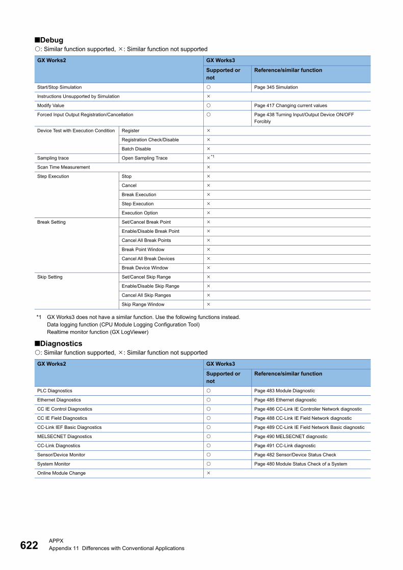
622APPXAppendix 11 Differences with Conventional Applications
■Debug: Similar function supported, : Similar function not supported
*1 GX Works3 does not have a similar function. Use the following functions instead.Data logging function (CPU Module Logging Configuration Tool)Realtime monitor function (GX LogViewer)
■Diagnostics: Similar function supported, : Similar function not supported
GX Works2 GX Works3
Supported or not
Reference/similar function
Start/Stop Simulation Page 345 Simulation
Instructions Unsupported by Simulation
Modify Value Page 417 Changing current values
Forced Input Output Registration/Cancellation Page 438 Turning Input/Output Device ON/OFF
Forcibly
Device Test with Execution Condition Register
Registration Check/Disable
Batch Disable
Sampling trace Open Sampling Trace *1
Scan Time Measurement
Step Execution Stop
Cancel
Break Execution
Step Execution
Execution Option
Break Setting Set/Cancel Break Point
Enable/Disable Break Point
Cancel All Break Points
Break Point Window
Cancel All Break Devices
Break Device Window
Skip Setting Set/Cancel Skip Range
Enable/Disable Skip Range
Cancel All Skip Ranges
Skip Range Window
GX Works2 GX Works3
Supported or not
Reference/similar function
PLC Diagnostics Page 483 Module Diagnostic
Ethernet Diagnostics Page 485 Ethernet diagnostic
CC IE Control Diagnostics Page 486 CC-Link IE Controller Network diagnostic
CC IE Field Diagnostics Page 488 CC-Link IE Field Network diagnostic
CC-Link IEF Basic Diagnostics Page 489 CC-Link IE Field Network Basic diagnostic
MELSECNET Diagnostics Page 490 MELSECNET diagnostic
CC-Link Diagnostics Page 491 CC-Link diagnostic
Sensor/Device Monitor Page 482 Sensor/Device Status Check
System Monitor Page 480 Module Status Check of a System
Online Module Change

APPXAppendix 11 Differences with Conventional Applications 623
A
■Tool: Similar function supported, : Similar function not supported
*1 GX Works3 supports multiple languages, and therefore the display language such as one on the menu can be switched on a personal computer.For details, refer to the section.Page 39 Display Language Switching
GX Works2 GX Works3
Supported or not
Reference/similar function
IC Memory Card Read IC Memory Card Page 415 Writing to/Reading from a memory card
Write IC Memory Card
Read from IC Memory Card
(Edit and Data Copy)
Write to IC Memory Card
(Edit and Data Copy)
Read from IC Memory Card
(Edit and Data Copy)
Write to IC Memory Card
(Edit and Data Copy)
Check Program Page 277 Program check
Check Parameter Page 138 Checking parameters
Clear All Parameters
Check Device Duplication of Global Label
Device/Label Automatic-Assign Setting
Block Password Page 457 Setting block password
Confirm Memory Size Page 288 Calculating Memory Size
Delete Unused Device Comment Page 272 Deleting unused device comments
Merge Data
Set TEL Data/Connect via Modem Line Connection
Line Disconnection
AT Command Registration
Phone Book
Options
Logging Configuration Tool Page 501 Data Logging Function
Real-time Monitor Function Page 447 Checking Current Logging Data
Ethernet Adapter Module Configuration Tool
Built-in I/O Module Tool Positioning Monitor
High-Speed Counter Monitor
I/O Monitor
Check Intelligent Function Module
Parameter
Check Auto Refresh Duplication Page 138 Checking parameters
Intelligent Function Module Tool Page 148 Displaying the module tool list
Predefined Protocol Support Function Page 150 Predefined Protocol Support Function
Language Selection *1
Profile Management Register Page 125 Managing Profiles
Delete
Key Customize Page 64 Checking and Changing Shortcut Keys
Options Page 67 Option Setting for Each Function

624APPXAppendix 11 Differences with Conventional Applications
■Window: Similar function supported, : Similar function not supported
■Help: Similar function supported, : Similar function not supported
LabelThe following table shows the functions available for setting and editing labels.
: Similar function supported, : Similar function not supported
GX Works2 GX Works3
Supported or not
Reference/similar function
Cascade • [Window] [Cascade]
Tile Vertically • [Window] [Tile Vertically]
Tile Horizontally • [Window] [Tile Horizontally]
Arrange Icons • [Window] [Arrange Icons]
Close All • [Window] [Close All Windows]
(Switch to other window) • [Window] [(Window information being displayed)]
Other Window Page 41 Arranging work windows
GX Works2 GX Works3
Supported or not
Reference/similar function
GX Works2 Help Page 36 Displaying Help
Connection to MITSUBISHI ELECTRIC FA Global Website Page 36 Connecting to MITSUBISHI ELECTRIC FA
Global Website
About Page 36 Checking the version of GX Works3
GX Works2 GX Works3
Supported or not
Reference/similar function
Delete
Select All
New Declaration (Before) Page 158 Editing a row
New Declaration (After)
Delete Row
Read from CSV File Page 167 Importing/exporting files
Write to CSV File
System Label Reservation to Register System Label Page 174 Registering labels in system label database
Reservation to Release System Label Page 174 Releasing system labels
Import System Label Page 174 Importing system labels in system label
database to GX Works3
Reflect to System Label Database Page 174 Registering labels in system label database
Confirm Update of System Label
Database
Page 175 Importing the changes of system label
database
Execute Verification Synchronous
with System Label
Page 175 Verifying system label information
Sort Page 158 Sorting labels
Unused label list Page 312 Displaying a list of unused labels
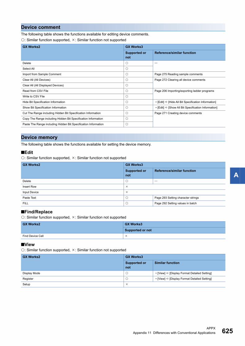
APPXAppendix 11 Differences with Conventional Applications 625
A
Device commentThe following table shows the functions available for editing device comments.
: Similar function supported, : Similar function not supported
Device memoryThe following table shows the functions available for setting the device memory.
■Edit: Similar function supported, : Similar function not supported
■Find/Replace: Similar function supported, : Similar function not supported
■View: Similar function supported, : Similar function not supported
GX Works2 GX Works3
Supported or not
Reference/similar function
Delete
Select All
Import from Sample Comment Page 275 Reading sample comments
Clear All (All Devices) Page 272 Clearing all device comments
Clear All (All Displayed Devices)
Read from CSV File Page 206 Importing/exporting ladder programs
Write to CSV File
Hide Bit Specification Information • [Edit] [Hide All Bit Specification Information]
Show Bit Specification Information • [Edit] [Show All Bit Specification Information]
Cut The Range including Hidden Bit Specification Information Page 271 Creating device comments
Copy The Range including Hidden Bit Specification Information
Paste The Range including Hidden Bit Specification Information
GX Works2 GX Works3
Supported or not
Reference/similar function
Delete
Insert Row
Input Device
Paste Text Page 293 Setting character strings
FILL Page 292 Setting values in batch
GX Works2 GX Works3
Supported or not
Find Device Cell
GX Works2 GX Works3
Supported or not
Similar function
Display Mode • [View] [Display Format Detailed Setting]
Register • [View] [Display Format Detailed Setting]
Setup

626APPXAppendix 11 Differences with Conventional Applications
■Tool: Similar function supported, : Similar function not supported
GX Works2 GX Works3
Supported or not
Read Device Memory from PLC
Write Device Memory to PLC
Read from Excel File
Write to Excel File
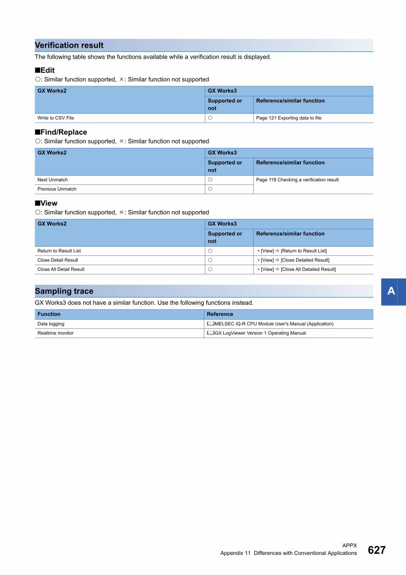
APPXAppendix 11 Differences with Conventional Applications 627
A
Verification resultThe following table shows the functions available while a verification result is displayed.
■Edit: Similar function supported, : Similar function not supported
■Find/Replace: Similar function supported, : Similar function not supported
■View: Similar function supported, : Similar function not supported
Sampling traceGX Works3 does not have a similar function. Use the following functions instead.
GX Works2 GX Works3
Supported or not
Reference/similar function
Write to CSV File Page 121 Exporting data to file
GX Works2 GX Works3
Supported or not
Reference/similar function
Next Unmatch Page 118 Checking a verification result
Previous Unmatch
GX Works2 GX Works3
Supported or not
Reference/similar function
Return to Result List • [View] [Return to Result List]
Close Detail Result • [View] [Close Detailed Result]
Close All Detail Result • [View] [Close All Detailed Result]
Function Reference
Data logging MELSEC iQ-R CPU Module User's Manual (Application)
Realtime monitor GX LogViewer Version 1 Operating Manual

628APPXAppendix 11 Differences with Conventional Applications
Ladder editorThe following table shows the functions available for editing data in the ladder editor.
■Edit: Similar function supported, : Similar function not supported
GX Works2 GX Works3
Supported or not
Reference/similar function
Continuous Paste Page 201 Pasting device number/label name
consecutively
Delete
Restore After Ladder Conversion Page 201 Returning ladder diagrams to the condition
before editing
Insert Row • [Edit] [Insert Row]/[Delete Row]/[Insert Column]/
[Delete Column]Delete Row
Insert Column
Delete Column
NOP Batch Insert Page 199 Inserting/deleting NOP instruction
NOP Batch Delete
Edit Line *1
Delete Line *1
Change TC Setting Page 199 Changing TC setting values
Ladder Edit Mode Read Mode Page 184 Read mode/Write mode/Monitor read mode/
Monitor write modeWrite Mode
Ladder Symbol Open Contact Page 185 Entering ladders
Close Contact
Open Branch
Close Branch
Coil
Application Instruction
Vertical Line
Horizontal Line
Delete Vertical Line
Delete Horizontal Line
Pulse Contact
Symbol
Rising Pulse
Falling Pulse
Rising Pulse Branch
Falling Pulse
Branch
Rising Pulse Close
Falling Pulse Close
Rising Pulse Close
Branch
Falling Pulse Close
Branch
Invert Operation Results • [Edit] [Ladder Symbol] [Invert Operation
Results]/[Operation Result Rising Pulse]/[Operation
Result Falling Pulse]Operation Result Rising Pulse
Operation Result Falling Pulse
Inline Structured Text Insert Inline Structured Text Box Page 192 Inserting inline structured text
Display Template Page 221 Displaying syntax templates
Mark Template (Left)
Mark Template (Right)
Edit FB Instance Page 188 Editing FB instance names
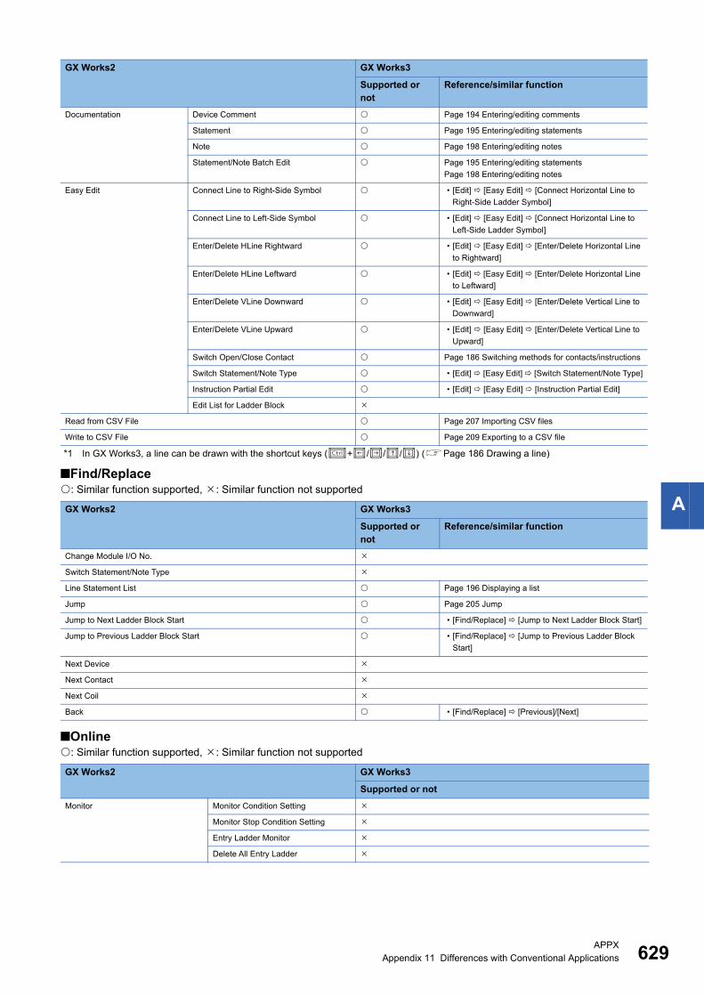
APPXAppendix 11 Differences with Conventional Applications 629
A
*1 In GX Works3, a line can be drawn with the shortcut keys (+///) (Page 186 Drawing a line)
■Find/Replace: Similar function supported, : Similar function not supported
■Online: Similar function supported, : Similar function not supported
Documentation Device Comment Page 194 Entering/editing comments
Statement Page 195 Entering/editing statements
Note Page 198 Entering/editing notes
Statement/Note Batch Edit Page 195 Entering/editing statements
Page 198 Entering/editing notes
Easy Edit Connect Line to Right-Side Symbol • [Edit] [Easy Edit] [Connect Horizontal Line to
Right-Side Ladder Symbol]
Connect Line to Left-Side Symbol • [Edit] [Easy Edit] [Connect Horizontal Line to
Left-Side Ladder Symbol]
Enter/Delete HLine Rightward • [Edit] [Easy Edit] [Enter/Delete Horizontal Line
to Rightward]
Enter/Delete HLine Leftward • [Edit] [Easy Edit] [Enter/Delete Horizontal Line
to Leftward]
Enter/Delete VLine Downward • [Edit] [Easy Edit] [Enter/Delete Vertical Line to
Downward]
Enter/Delete VLine Upward • [Edit] [Easy Edit] [Enter/Delete Vertical Line to
Upward]
Switch Open/Close Contact Page 186 Switching methods for contacts/instructions
Switch Statement/Note Type • [Edit] [Easy Edit] [Switch Statement/Note Type]
Instruction Partial Edit • [Edit] [Easy Edit] [Instruction Partial Edit]
Edit List for Ladder Block
Read from CSV File Page 207 Importing CSV files
Write to CSV File Page 209 Exporting to a CSV file
GX Works2 GX Works3
Supported or not
Reference/similar function
Change Module I/O No.
Switch Statement/Note Type
Line Statement List Page 196 Displaying a list
Jump Page 205 Jump
Jump to Next Ladder Block Start • [Find/Replace] [Jump to Next Ladder Block Start]
Jump to Previous Ladder Block Start • [Find/Replace] [Jump to Previous Ladder Block
Start]
Next Device
Next Contact
Next Coil
Back • [Find/Replace] [Previous]/[Next]
GX Works2 GX Works3
Supported or not
Monitor Monitor Condition Setting
Monitor Stop Condition Setting
Entry Ladder Monitor
Delete All Entry Ladder
GX Works2 GX Works3
Supported or not
Reference/similar function
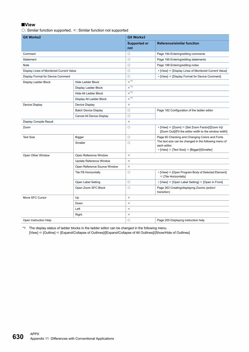
630APPXAppendix 11 Differences with Conventional Applications
■View: Similar function supported, : Similar function not supported
*1 The display status of ladder blocks in the ladder editor can be changed in the following menu.[View] [Outline] [Expand/Collapse of Outlines]/[Expand/Collapse of All Outlines]/[Show/Hide of Outlines]
GX Works2 GX Works3
Supported or not
Reference/similar function
Comment Page 194 Entering/editing comments
Statement Page 195 Entering/editing statements
Note Page 198 Entering/editing notes
Display Lines of Monitored Current Value • [View] [Display Lines of Monitored Current Value]
Display Format for Device Comment • [View] [Display Format for Device Comment]
Display Ladder Block Hide Ladder Block *1
Display Ladder Block *1
Hide All Ladder Block *1
Display All Ladder Block *1
Device Display Device Display
Batch Device Display Page 182 Configuration of the ladder editor
Cancel All Device Display
Display Compile Result
Zoom • [View] [Zoom] [Set Zoom Factor]/[Zoom In]/
[Zoom Out]/[Fit the editor width to the window width]
Text Size Bigger Page 65 Checking and Changing Colors and Fonts
The text size can be changed in the following menu of
each editor.
• [View] [Text Size] [Bigger]/[Smaller]
Smaller
Open Other Window Open Reference Window
Update Reference Window
Open Reference Source Window
Tile FB Horizontally • [View] [Open Program Body of Selected Element]
[Tile Horizontally]
Open Label Setting • [View] [Open Label Setting] [Open in Front]
Open Zoom SFC Block Page 263 Creating/displaying Zooms (action/
transition)
Move SFC Cursor Up
Down
Left
Right
Open Instruction Help Page 205 Displaying instruction help

APPXAppendix 11 Differences with Conventional Applications 631
A
SFC diagramThe following table shows the functions available for editing SFC diagrams.
By comparing with GX Works2, the functions are enhanced and their operability have been improved.
For the editing method, refer to the following section.
Page 240 Creating an SFC Program
■Edit: Similar function supported, : Similar function not supported
■Find/Replace: Similar function supported, : Similar function not supported
■Convert/Compile: Similar function supported, : Similar function not supported
GX Works2 GX Works3
Supported or not
Reference/similar function
Delete
Arrange SFC
Change TC Setting Page 199 Changing TC setting values
Ladder Edit Mode Read Mode
Write Mode
SFC Step Attribute No Attribute Page 246 Changing a step name/step No./step
attribute/step attribute targetStored Coil
Stored Operation (without Transition
Check)
Stored Operation (with Transition
Check)
Reset
Sort SFC Step No.
Documentation SFC Step/Transition Comment
GX Works2 GX Works3
Supported or not
Jump
Find Jump Step
Change SFC Step No.
GX Works2 GX Works3
Supported or not
Reference/similar function
Convert Block Page 262 Converting a block

632APPXAppendix 11 Differences with Conventional Applications
■View: Similar function supported, : Similar function not supported
■Online: Similar function supported, : Similar function not supported
SFC block listThe following table shows the functions available for editing the SFC block list.
■Find/Replace: Similar function supported, : Similar function not supported
■View: Similar function supported, : Similar function not supported
GX Works2 GX Works3
Supported or not
Reference/similar function
Program Display
SFC Step/Transition Comment Page 241 Configuration of SFC diagram editor
Zoom • [View] [Zoom] [Set Zoom Factor]/[Zoom In]/
[Zoom Out]
Text Size Bigger
Smaller
SFC Column Setting
Open SFC Blocklist Page 265 Displaying an SFC block list
MELSAP3 Display Page 244 Display format of action/transition
MELSAP-L (Instruction Format) Display
MELSAP-L (Start Conditions Format) Display
Open Zoom/Start Destination Block Page 241 Configuration of SFC diagram editor
Back to Start SFC Block Page 246 Creating a step that makes another block
activated
Open Header Page 266 Displaying local label editor
Reset the Window Position to its Default
GX Works2 GX Works3
Supported or not
Monitor Monitor Condition Setting
Monitor Stop Condition Setting
GX Works2 GX Works3
Supported or not
Reference/similar function
Jump Page 266 Jump
Find Block Number
Block Information Find Device Page 266 Searching for block information
GX Works2 GX Works3
Supported or not
Reference/similar function
SFC Block List Comment Page 265 Displaying an SFC block list
Device Display
Open SFC Body Page 266 Displaying SFC diagrams
Open Header Page 266 Displaying local label editor
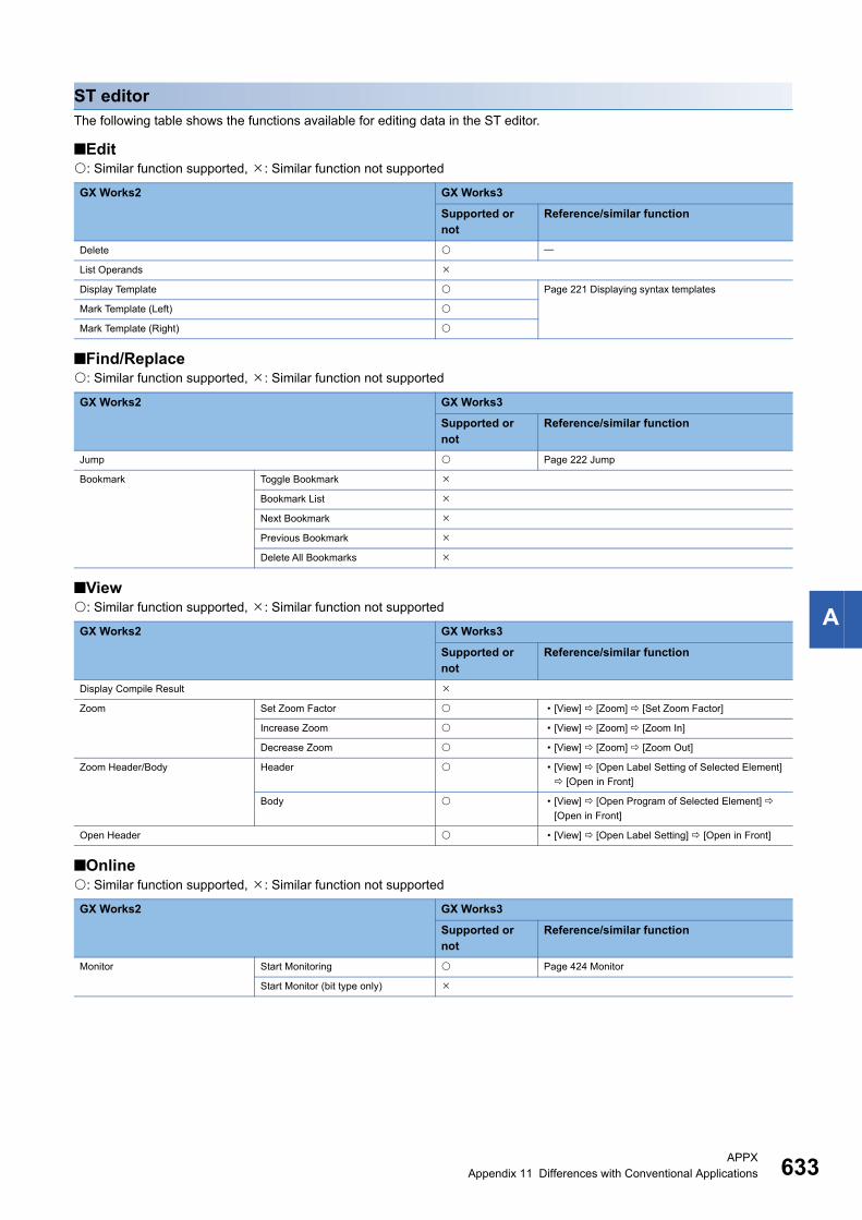
APPXAppendix 11 Differences with Conventional Applications 633
A
ST editorThe following table shows the functions available for editing data in the ST editor.
■Edit: Similar function supported, : Similar function not supported
■Find/Replace: Similar function supported, : Similar function not supported
■View: Similar function supported, : Similar function not supported
■Online: Similar function supported, : Similar function not supported
GX Works2 GX Works3
Supported or not
Reference/similar function
Delete
List Operands
Display Template Page 221 Displaying syntax templates
Mark Template (Left)
Mark Template (Right)
GX Works2 GX Works3
Supported or not
Reference/similar function
Jump Page 222 Jump
Bookmark Toggle Bookmark
Bookmark List
Next Bookmark
Previous Bookmark
Delete All Bookmarks
GX Works2 GX Works3
Supported or not
Reference/similar function
Display Compile Result
Zoom Set Zoom Factor • [View] [Zoom] [Set Zoom Factor]
Increase Zoom • [View] [Zoom] [Zoom In]
Decrease Zoom • [View] [Zoom] [Zoom Out]
Zoom Header/Body Header • [View] [Open Label Setting of Selected Element]
[Open in Front]
Body • [View] [Open Program of Selected Element]
[Open in Front]
Open Header • [View] [Open Label Setting] [Open in Front]
GX Works2 GX Works3
Supported or not
Reference/similar function
Monitor Start Monitoring Page 424 Monitor
Start Monitor (bit type only)
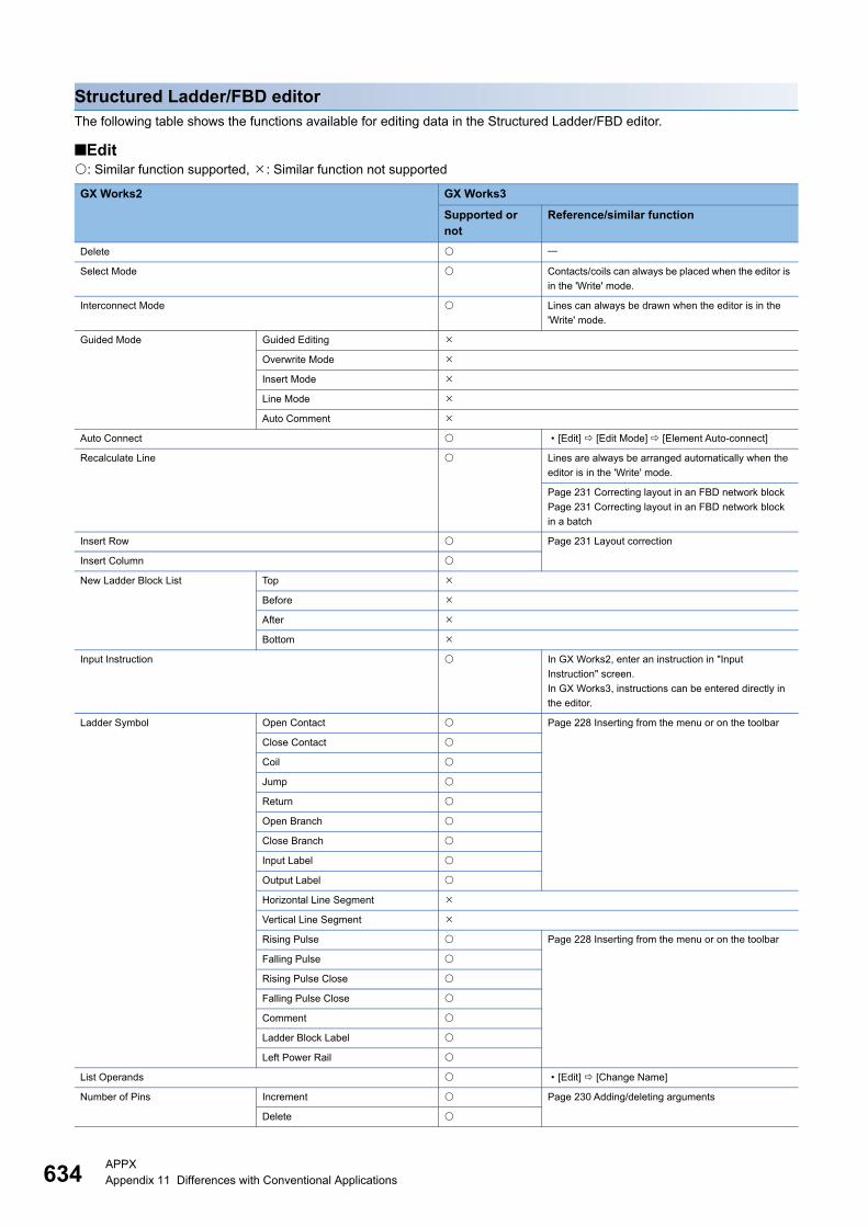
634APPXAppendix 11 Differences with Conventional Applications
Structured Ladder/FBD editorThe following table shows the functions available for editing data in the Structured Ladder/FBD editor.
■Edit: Similar function supported, : Similar function not supported
GX Works2 GX Works3
Supported or not
Reference/similar function
Delete
Select Mode Contacts/coils can always be placed when the editor is
in the 'Write' mode.
Interconnect Mode Lines can always be drawn when the editor is in the
'Write' mode.
Guided Mode Guided Editing
Overwrite Mode
Insert Mode
Line Mode
Auto Comment
Auto Connect • [Edit] [Edit Mode] [Element Auto-connect]
Recalculate Line Lines are always be arranged automatically when the
editor is in the 'Write' mode.
Page 231 Correcting layout in an FBD network block
Page 231 Correcting layout in an FBD network block
in a batch
Insert Row Page 231 Layout correction
Insert Column
New Ladder Block List Top
Before
After
Bottom
Input Instruction In GX Works2, enter an instruction in "Input
Instruction" screen.
In GX Works3, instructions can be entered directly in
the editor.
Ladder Symbol Open Contact Page 228 Inserting from the menu or on the toolbar
Close Contact
Coil
Jump
Return
Open Branch
Close Branch
Input Label
Output Label
Horizontal Line Segment
Vertical Line Segment
Rising Pulse Page 228 Inserting from the menu or on the toolbar
Falling Pulse
Rising Pulse Close
Falling Pulse Close
Comment
Ladder Block Label
Left Power Rail
List Operands • [Edit] [Change Name]
Number of Pins Increment Page 230 Adding/deleting arguments
Delete

APPXAppendix 11 Differences with Conventional Applications 635
A
■Find/Replace: Similar function supported, : Similar function not supported
■View: Similar function supported, : Similar function not supported
Ladder Block List Page 238 Displaying FBD network blocks in a list
Signal Configuration Configure Page 228 Switching methods for contacts/instructions
Toggle
GX Works2 GX Works3
Supported or not
Reference/similar function
Jump Page 238 Displaying FBD network blocks in a list
GX Works2 GX Works3
Supported or not
Reference/similar function
View Mode Label Labels used in programs are always displayed with
their label names.
Device
Address
Comment
Change Label-Device-Address Mode
Change Label-Comment Mode
Change I/O Label-Comment Mode
Add Label Display Items Device Page 223 Configuration of FBD/LD editor
Address
Label Comment Page 223 Configuration of FBD/LD editor
Device Comment
All Device Display
Cancel All Device Display
Grid Page 223 Configuration of FBD/LD editor
Print Wrap Position • [View] [Display Page Break]
Display Compile Result
Zoom Set Zoom Factor • [View] [Zoom] [Set Zoom Factor]
Increase Zoom • [View] [Zoom] [Zoom In]
Decrease Zoom • [View] [Zoom] [Zoom Out]
Zoom Header/Body Header • [View] [Open Label Setting of Selected Element]
Body • [View] [Open Program Body of Selected Element]
Open Header • [View] [Open Label Setting]
GX Works2 GX Works3
Supported or not
Reference/similar function
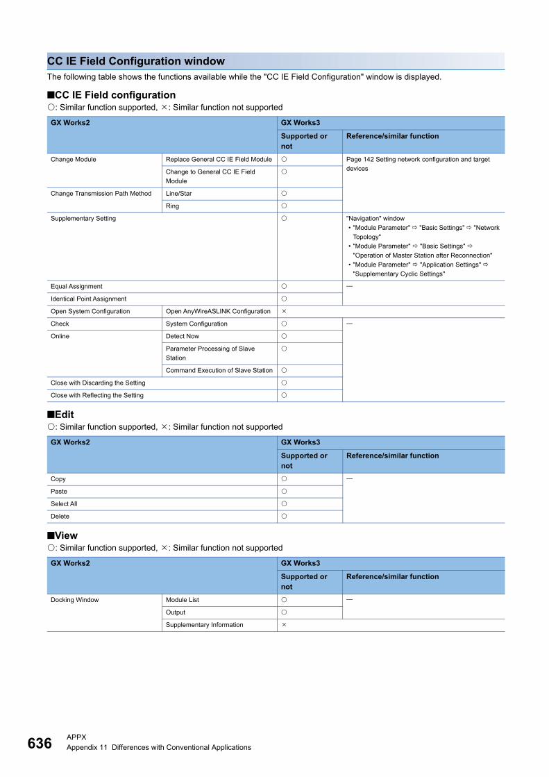
636APPXAppendix 11 Differences with Conventional Applications
CC IE Field Configuration windowThe following table shows the functions available while the "CC IE Field Configuration" window is displayed.
■CC IE Field configuration: Similar function supported, : Similar function not supported
■Edit: Similar function supported, : Similar function not supported
■View: Similar function supported, : Similar function not supported
GX Works2 GX Works3
Supported or not
Reference/similar function
Change Module Replace General CC IE Field Module Page 142 Setting network configuration and target
devicesChange to General CC IE Field
Module
Change Transmission Path Method Line/Star
Ring
Supplementary Setting "Navigation" window
• "Module Parameter" "Basic Settings" "Network
Topology"
• "Module Parameter" "Basic Settings"
"Operation of Master Station after Reconnection"
• "Module Parameter" "Application Settings"
"Supplementary Cyclic Settings"
Equal Assignment
Identical Point Assignment
Open System Configuration Open AnyWireASLINK Configuration
Check System Configuration
Online Detect Now
Parameter Processing of Slave
Station
Command Execution of Slave Station
Close with Discarding the Setting
Close with Reflecting the Setting
GX Works2 GX Works3
Supported or not
Reference/similar function
Copy
Paste
Select All
Delete
GX Works2 GX Works3
Supported or not
Reference/similar function
Docking Window Module List
Output
Supplementary Information
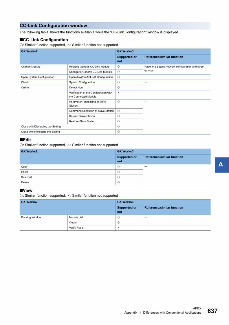
APPXAppendix 11 Differences with Conventional Applications 637
A
CC-Link Configuration windowThe following table shows the functions available while the "CC-Link Configuration" window is displayed.
■CC-Link Configuration: Similar function supported, : Similar function not supported
■Edit: Similar function supported, : Similar function not supported
■View: Similar function supported, : Similar function not supported
GX Works2 GX Works3
Supported or not
Reference/similar function
Change Module Replace General CC-Link Module Page 142 Setting network configuration and target
devicesChange to General CC-Link Module
Open System Configuration Open AnyWireASLINK Configuration
Check System Configuration
Online Detect Now
Verification of the Configuration with
the Connected Module
Parameter Processing of Slave
Station
Command Execution of Slave Station
Backup Slave Station
Restore Slave Station
Close with Discarding the Setting
Close with Reflecting the Setting
GX Works2 GX Works3
Supported or not
Reference/similar function
Copy
Paste
Select All
Delete
GX Works2 GX Works3
Supported or not
Reference/similar function
Docking Window Module List
Output
Verify Result
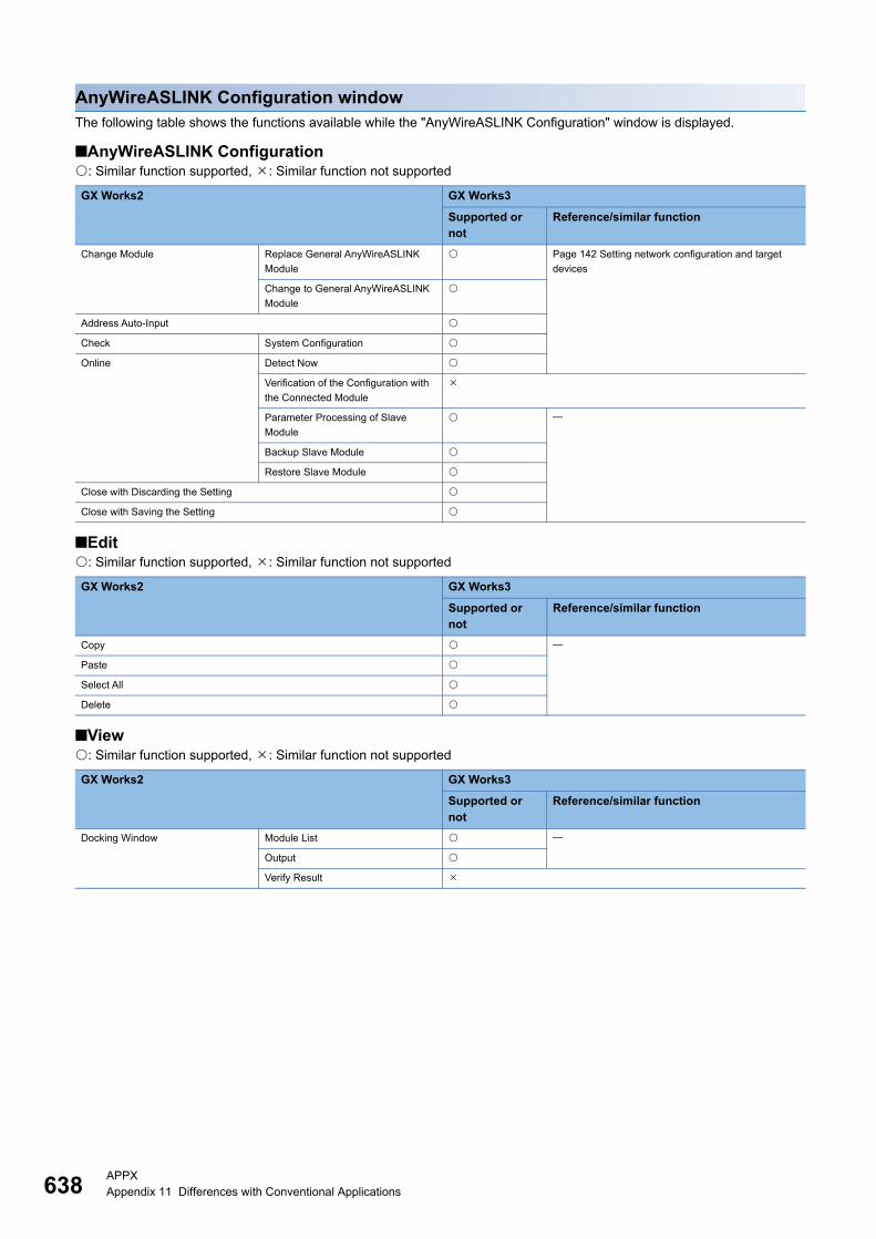
638APPXAppendix 11 Differences with Conventional Applications
AnyWireASLINK Configuration windowThe following table shows the functions available while the "AnyWireASLINK Configuration" window is displayed.
■AnyWireASLINK Configuration: Similar function supported, : Similar function not supported
■Edit: Similar function supported, : Similar function not supported
■View: Similar function supported, : Similar function not supported
GX Works2 GX Works3
Supported or not
Reference/similar function
Change Module Replace General AnyWireASLINK
Module
Page 142 Setting network configuration and target
devices
Change to General AnyWireASLINK
Module
Address Auto-Input
Check System Configuration
Online Detect Now
Verification of the Configuration with
the Connected Module
Parameter Processing of Slave
Module
Backup Slave Module
Restore Slave Module
Close with Discarding the Setting
Close with Saving the Setting
GX Works2 GX Works3
Supported or not
Reference/similar function
Copy
Paste
Select All
Delete
GX Works2 GX Works3
Supported or not
Reference/similar function
Docking Window Module List
Output
Verify Result
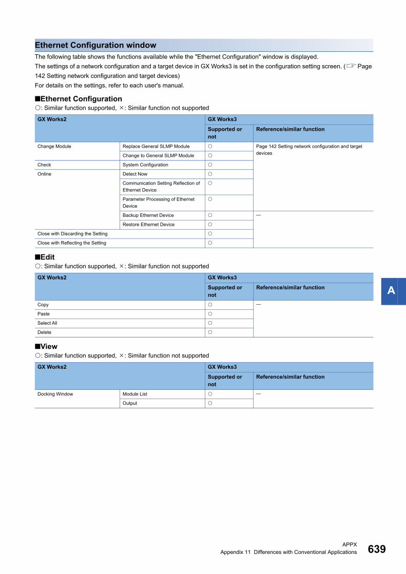
APPXAppendix 11 Differences with Conventional Applications 639
A
Ethernet Configuration windowThe following table shows the functions available while the "Ethernet Configuration" window is displayed.
The settings of a network configuration and a target device in GX Works3 is set in the configuration setting screen. (Page
142 Setting network configuration and target devices)
For details on the settings, refer to each user's manual.
■Ethernet Configuration: Similar function supported, : Similar function not supported
■Edit: Similar function supported, : Similar function not supported
■View: Similar function supported, : Similar function not supported
GX Works2 GX Works3
Supported or not
Reference/similar function
Change Module Replace General SLMP Module Page 142 Setting network configuration and target
devicesChange to General SLMP Module
Check System Configuration
Online Detect Now
Communication Setting Reflection of
Ethernet Device
Parameter Processing of Ethernet
Device
Backup Ethernet Device
Restore Ethernet Device
Close with Discarding the Setting
Close with Reflecting the Setting
GX Works2 GX Works3
Supported or not
Reference/similar function
Copy
Paste
Select All
Delete
GX Works2 GX Works3
Supported or not
Reference/similar function
Docking Window Module List
Output

640APPXAppendix 11 Differences with Conventional Applications
CC-Link IEF Basic Configuration windowThe following table shows the functions available while the "CC-Link IEF Basic Configuration" window is displayed.
■CC-Link IEF Basic Configuration: Similar function supported, : Similar function not supported
■Edit: Similar function supported, : Similar function not supported
■View: Similar function supported, : Similar function not supported
GX Works2 GX Works3
Supported or not
Reference/similar function
Change Module Replace CC-Link IEF Basic
Connected Module
Page 142 Setting network configuration and target
devices
Change to CC-Link IEF Basic
Connected Module
Link Scan Setting
Check System Configuration
Online Detect Now
Communication Setting Reflection of
Slave Station
Parameter Processing of Slave
Station
Close with Discarding the Setting
Close with Reflecting the Setting
GX Works2 GX Works3
Supported or not
Reference/similar function
Copy
Paste
Select All
Delete
GX Works2 GX Works3
Supported or not
Reference/similar function
Docking Window Module List
Output
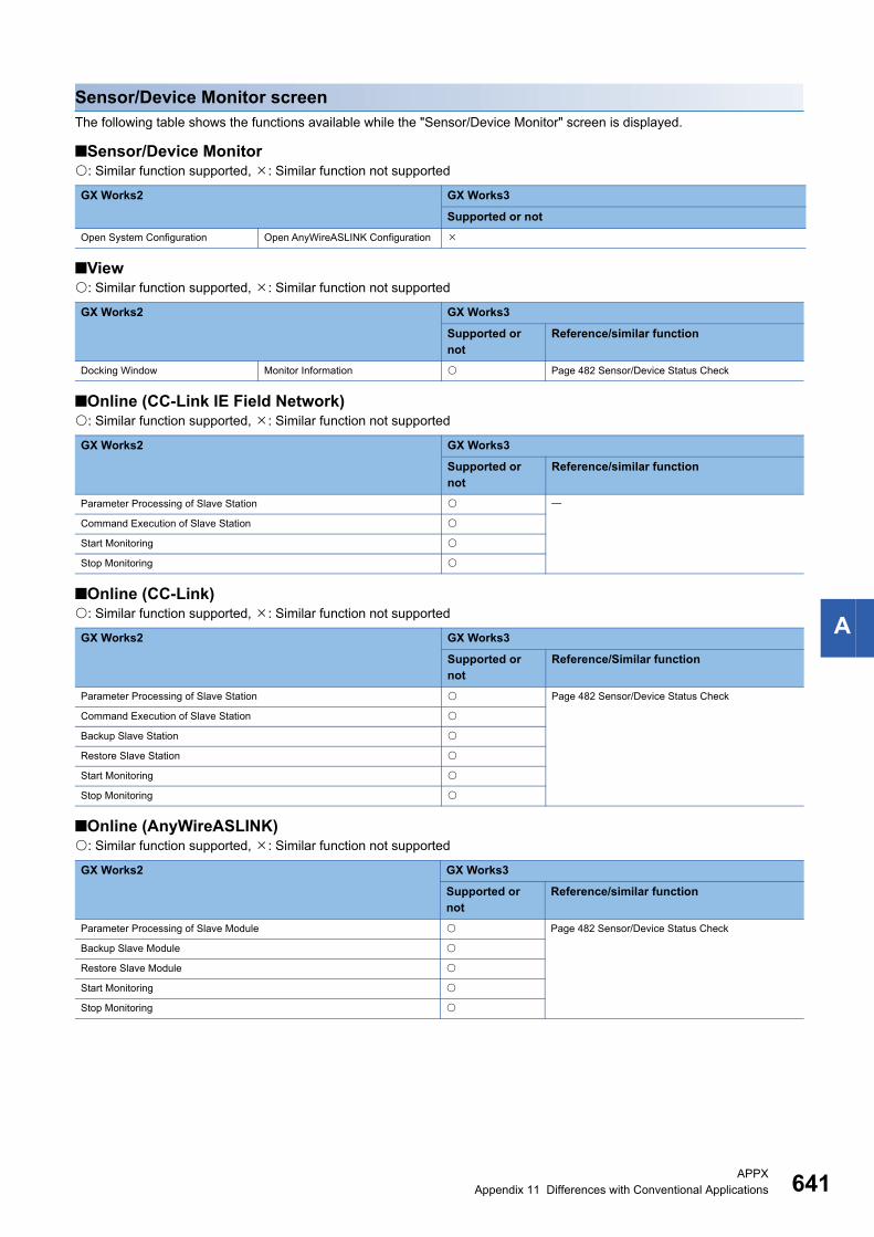
APPXAppendix 11 Differences with Conventional Applications 641
A
Sensor/Device Monitor screenThe following table shows the functions available while the "Sensor/Device Monitor" screen is displayed.
■Sensor/Device Monitor: Similar function supported, : Similar function not supported
■View: Similar function supported, : Similar function not supported
■Online (CC-Link IE Field Network): Similar function supported, : Similar function not supported
■Online (CC-Link): Similar function supported, : Similar function not supported
■Online (AnyWireASLINK): Similar function supported, : Similar function not supported
GX Works2 GX Works3
Supported or not
Open System Configuration Open AnyWireASLINK Configuration
GX Works2 GX Works3
Supported or not
Reference/similar function
Docking Window Monitor Information Page 482 Sensor/Device Status Check
GX Works2 GX Works3
Supported or not
Reference/similar function
Parameter Processing of Slave Station
Command Execution of Slave Station
Start Monitoring
Stop Monitoring
GX Works2 GX Works3
Supported or not
Reference/Similar function
Parameter Processing of Slave Station Page 482 Sensor/Device Status Check
Command Execution of Slave Station
Backup Slave Station
Restore Slave Station
Start Monitoring
Stop Monitoring
GX Works2 GX Works3
Supported or not
Reference/similar function
Parameter Processing of Slave Module Page 482 Sensor/Device Status Check
Backup Slave Module
Restore Slave Module
Start Monitoring
Stop Monitoring
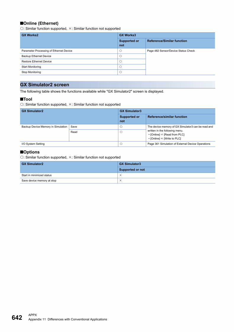
642APPXAppendix 11 Differences with Conventional Applications
■Online (Ethernet): Similar function supported, : Similar function not supported
GX Simulator2 screenThe following table shows the functions available while "GX Simulator2" screen is displayed.
■Tool: Similar function supported, : Similar function not supported
■Options: Similar function supported, : Similar function not supported
GX Works2 GX Works3
Supported or not
Reference/Similar function
Parameter Processing of Ethernet Device Page 482 Sensor/Device Status Check
Backup Ethernet Device
Restore Ethernet Device
Start Monitoring
Stop Monitoring
GX Simulator2 GX Simulator3
Supported or not
Reference/similar function
Backup Device Memory in Simulation Save The device memory of GX Simulator3 can be read and
written in the following menu.
• [Online] [Read from PLC]
• [Online] [Write to PLC]
Read
I/O System Setting Page 361 Simulation of External Device Operations
GX Simulator2 GX Simulator3
Supported or not
Start in minimized status
Save device memory at stop
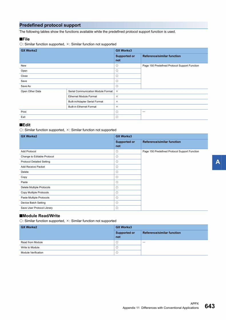
APPXAppendix 11 Differences with Conventional Applications 643
A
Predefined protocol support The following tables show the functions available while the predefined protocol support function is used.
■File: Similar function supported, : Similar function not supported
■Edit: Similar function supported, : Similar function not supported
■Module Read/Write: Similar function supported, : Similar function not supported
GX Works2 GX Works3
Supported or not
Reference/similar function
New Page 150 Predefined Protocol Support Function
Open
Close
Save
Save As
Open Other Data Serial Communication Module Format
Ethernet Module Format
Built-in/Adapter Serial Format
Built-in Ethernet Format
Exit
GX Works2 GX Works3
Supported or not
Reference/similar function
Add Protocol Page 150 Predefined Protocol Support Function
Change to Editable Protocol
Protocol Detailed Setting
Add Receive Packet
Delete
Copy
Paste
Delete Multiple Protocols
Copy Multiple Protocols
Paste Multiple Protocols
Device Batch Setting
Save User Protocol Library
GX Works2 GX Works3
Supported or not
Reference/similar function
Read from Module
Write to Module
Module Verification
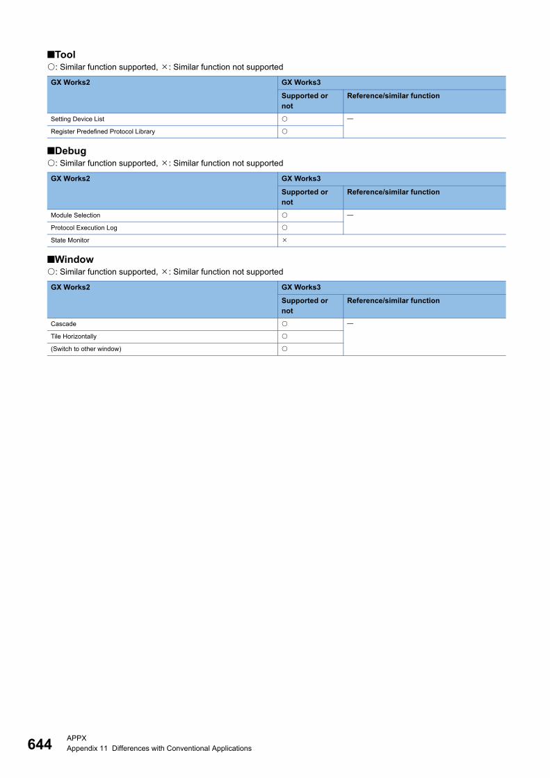
644APPXAppendix 11 Differences with Conventional Applications
■Tool: Similar function supported, : Similar function not supported
■Debug: Similar function supported, : Similar function not supported
■Window: Similar function supported, : Similar function not supported
GX Works2 GX Works3
Supported or not
Reference/similar function
Setting Device List
Register Predefined Protocol Library
GX Works2 GX Works3
Supported or not
Reference/similar function
Module Selection
Protocol Execution Log
State Monitor
GX Works2 GX Works3
Supported or not
Reference/similar function
Cascade
Tile Horizontally
(Switch to other window)
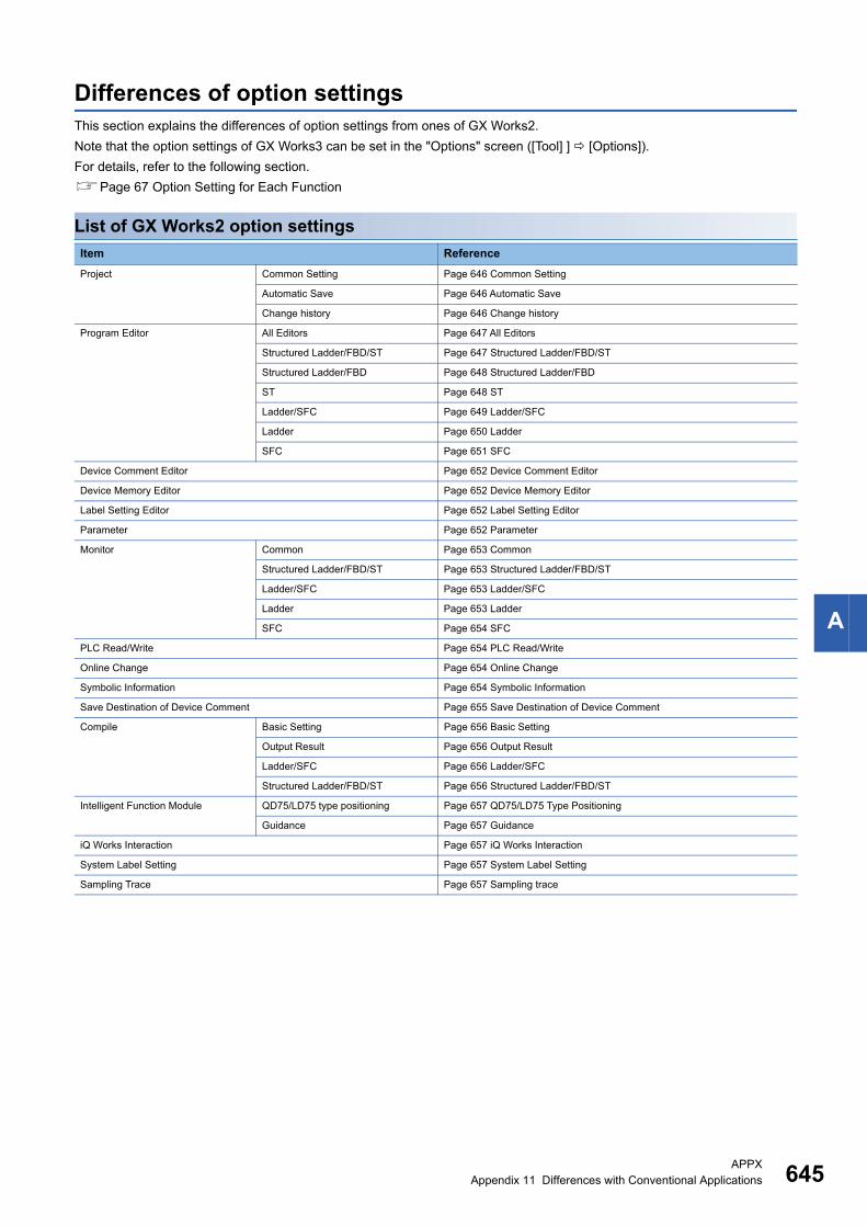
APPXAppendix 11 Differences with Conventional Applications 645
A
Differences of option settingsThis section explains the differences of option settings from ones of GX Works2.
Note that the option settings of GX Works3 can be set in the "Options" screen ([Tool] ] [Options]).
For details, refer to the following section.
Page 67 Option Setting for Each Function
List of GX Works2 option settings
Item Reference
Project Common Setting Page 646 Common Setting
Automatic Save Page 646 Automatic Save
Change history Page 646 Change history
Program Editor All Editors Page 647 All Editors
Structured Ladder/FBD/ST Page 647 Structured Ladder/FBD/ST
Structured Ladder/FBD Page 648 Structured Ladder/FBD
ST Page 648 ST
Ladder/SFC Page 649 Ladder/SFC
Ladder Page 650 Ladder
SFC Page 651 SFC
Device Comment Editor Page 652 Device Comment Editor
Device Memory Editor Page 652 Device Memory Editor
Label Setting Editor Page 652 Label Setting Editor
Parameter Page 652 Parameter
Monitor Common Page 653 Common
Structured Ladder/FBD/ST Page 653 Structured Ladder/FBD/ST
Ladder/SFC Page 653 Ladder/SFC
Ladder Page 653 Ladder
SFC Page 654 SFC
PLC Read/Write Page 654 PLC Read/Write
Online Change Page 654 Online Change
Symbolic Information Page 654 Symbolic Information
Save Destination of Device Comment Page 655 Save Destination of Device Comment
Compile Basic Setting Page 656 Basic Setting
Output Result Page 656 Output Result
Ladder/SFC Page 656 Ladder/SFC
Structured Ladder/FBD/ST Page 656 Structured Ladder/FBD/ST
Intelligent Function Module QD75/LD75 type positioning Page 657 QD75/LD75 Type Positioning
Guidance Page 657 Guidance
iQ Works Interaction Page 657 iQ Works Interaction
System Label Setting Page 657 System Label Setting
Sampling Trace Page 657 Sampling trace
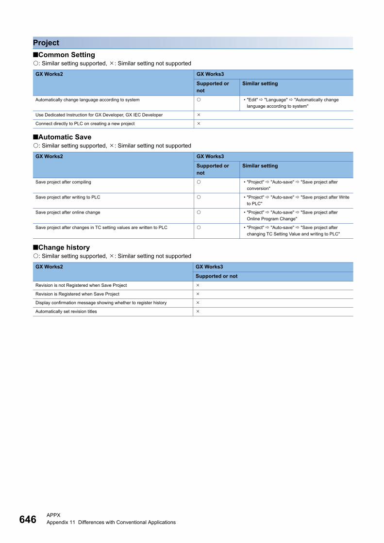
646APPXAppendix 11 Differences with Conventional Applications
Project
■Common Setting: Similar setting supported, : Similar setting not supported
■Automatic Save: Similar setting supported, : Similar setting not supported
■Change history: Similar setting supported, : Similar setting not supported
GX Works2 GX Works3
Supported or not
Similar setting
Automatically change language according to system • "Edit" "Language" "Automatically change
language according to system"
Use Dedicated Instruction for GX Developer, GX IEC Developer
Connect directly to PLC on creating a new project
GX Works2 GX Works3
Supported or not
Similar setting
Save project after compiling • "Project" "Auto-save" "Save project after
conversion"
Save project after writing to PLC • "Project" "Auto-save" "Save project after Write
to PLC"
Save project after online change • "Project" "Auto-save" "Save project after
Online Program Change"
Save project after changes in TC setting values are written to PLC • "Project" "Auto-save" "Save project after
changing TC Setting Value and writing to PLC"
GX Works2 GX Works3
Supported or not
Revision is not Registered when Save Project
Revision is Registered when Save Project
Display confirmation message showing whether to register history
Automatically set revision titles
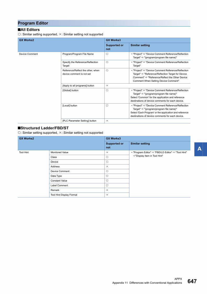
APPXAppendix 11 Differences with Conventional Applications 647
A
Program Editor
■All Editors: Similar setting supported, : Similar setting not supported
■Structured Ladder/FBD/ST: Similar setting supported, : Similar setting not supported
GX Works2 GX Works3
Supported or not
Similar setting
Device Comment Program/Program File Name • "Project" "Device Comment Reference/Reflection
Target" "(program/program file name)"
Specify the Reference/Reflection
Target
• "Project" "Device Comment Reference/Reflection
Target"
Reference/Reflect the other, when
device comment is not set
• "Project" "Device Comment Reference/Reflection
Target" "Reference/Reflection Target for Device
Comment" "Reference/Reflect the Other Device
Comment When Setting Device Comment"
[Apply to all programs] button
[Global] button • "Project" "Device Comment Reference/Reflection
Target" "(program/program file name)"
Select 'Common' for the application and reference
destinations of device comments for each device.
[Local] button • "Project" "Device Comment Reference/Reflection
Target" "(program/program file name)"
Select 'Each Program' or the application and reference
destinations of device comments for each device.
[PLC Parameter Setting] button
GX Works2 GX Works3
Supported or not
Similar setting
Tool Hint Monitored Value • "Program Editor" "FBD/LD Editor" "Tool Hint"
"Display Item in Tool Hint"Class
Device
Address
Device Comment
Data Type
Constant Value
Label Comment
Remark
Tool Hint Display Format
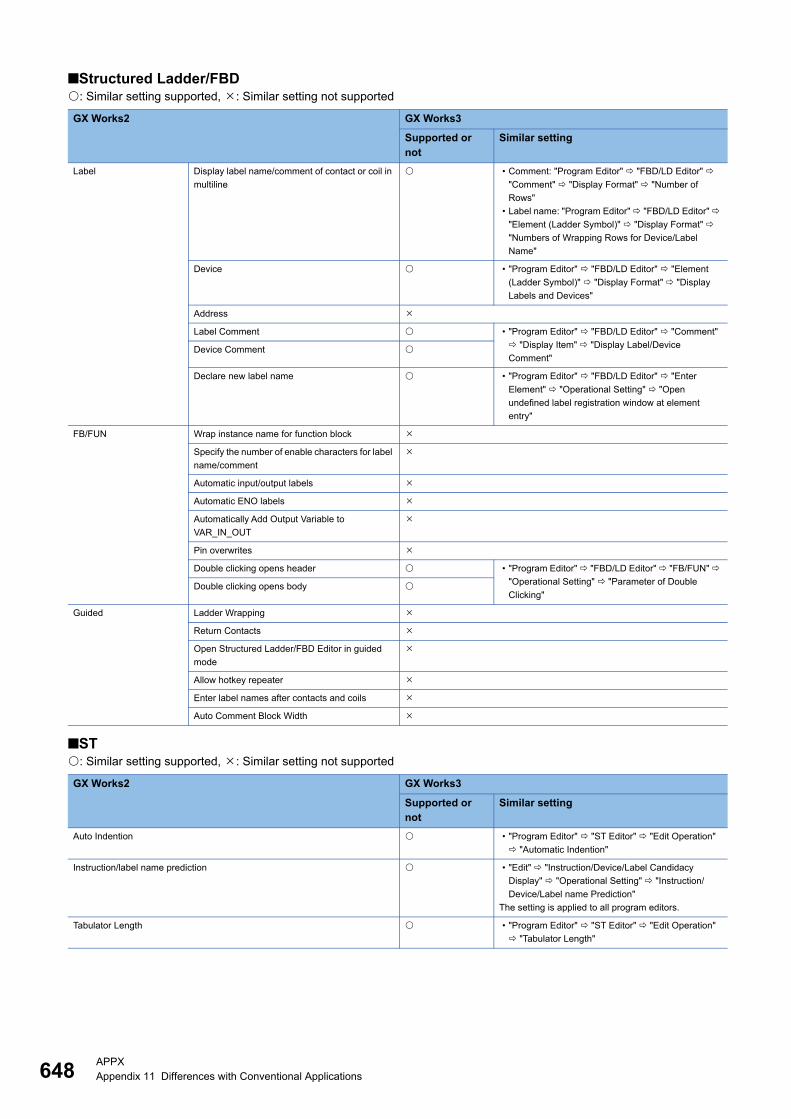
648APPXAppendix 11 Differences with Conventional Applications
■Structured Ladder/FBD: Similar setting supported, : Similar setting not supported
■ST: Similar setting supported, : Similar setting not supported
GX Works2 GX Works3
Supported or not
Similar setting
Label Display label name/comment of contact or coil in
multiline
• Comment: "Program Editor" "FBD/LD Editor"
"Comment" "Display Format" "Number of
Rows"
• Label name: "Program Editor" "FBD/LD Editor"
"Element (Ladder Symbol)" "Display Format"
"Numbers of Wrapping Rows for Device/Label
Name"
Device • "Program Editor" "FBD/LD Editor" "Element
(Ladder Symbol)" "Display Format" "Display
Labels and Devices"
Address
Label Comment • "Program Editor" "FBD/LD Editor" "Comment"
"Display Item" "Display Label/Device
Comment"Device Comment
Declare new label name • "Program Editor" "FBD/LD Editor" "Enter
Element" "Operational Setting" "Open
undefined label registration window at element
entry"
FB/FUN Wrap instance name for function block
Specify the number of enable characters for label
name/comment
Automatic input/output labels
Automatic ENO labels
Automatically Add Output Variable to
VAR_IN_OUT
Pin overwrites
Double clicking opens header • "Program Editor" "FBD/LD Editor" "FB/FUN"
"Operational Setting" "Parameter of Double
Clicking"Double clicking opens body
Guided Ladder Wrapping
Return Contacts
Open Structured Ladder/FBD Editor in guided
mode
Allow hotkey repeater
Enter label names after contacts and coils
Auto Comment Block Width
GX Works2 GX Works3
Supported or not
Similar setting
Auto Indention • "Program Editor" "ST Editor" "Edit Operation"
"Automatic Indention"
Instruction/label name prediction • "Edit" "Instruction/Device/Label Candidacy
Display" "Operational Setting" "Instruction/
Device/Label name Prediction"
The setting is applied to all program editors.
Tabulator Length • "Program Editor" "ST Editor" "Edit Operation"
"Tabulator Length"
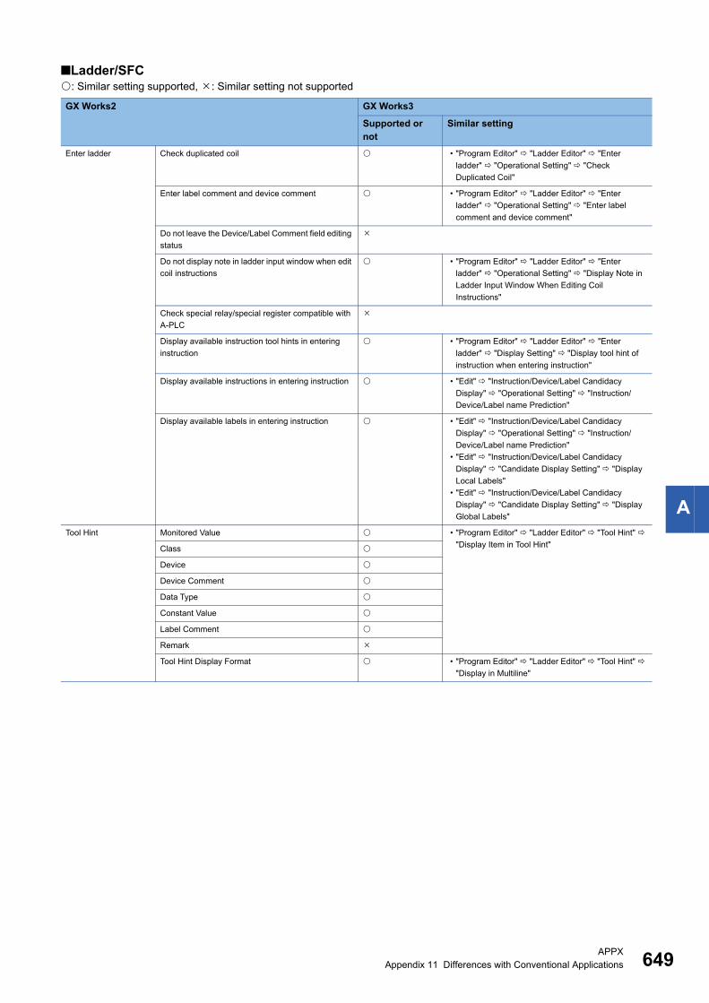
APPXAppendix 11 Differences with Conventional Applications 649
A
■Ladder/SFC: Similar setting supported, : Similar setting not supported
GX Works2 GX Works3
Supported or not
Similar setting
Enter ladder Check duplicated coil • "Program Editor" "Ladder Editor" "Enter
ladder" "Operational Setting" "Check
Duplicated Coil"
Enter label comment and device comment • "Program Editor" "Ladder Editor" "Enter
ladder" "Operational Setting" "Enter label
comment and device comment"
Do not leave the Device/Label Comment field editing
status
Do not display note in ladder input window when edit
coil instructions
• "Program Editor" "Ladder Editor" "Enter
ladder" "Operational Setting" "Display Note in
Ladder Input Window When Editing Coil
Instructions"
Check special relay/special register compatible with
A-PLC
Display available instruction tool hints in entering
instruction
• "Program Editor" "Ladder Editor" "Enter
ladder" "Display Setting" "Display tool hint of
instruction when entering instruction"
Display available instructions in entering instruction • "Edit" "Instruction/Device/Label Candidacy
Display" "Operational Setting" "Instruction/
Device/Label name Prediction"
Display available labels in entering instruction • "Edit" "Instruction/Device/Label Candidacy
Display" "Operational Setting" "Instruction/
Device/Label name Prediction"
• "Edit" "Instruction/Device/Label Candidacy
Display" "Candidate Display Setting" "Display
Local Labels"
• "Edit" "Instruction/Device/Label Candidacy
Display" "Candidate Display Setting" "Display
Global Labels"
Tool Hint Monitored Value • "Program Editor" "Ladder Editor" "Tool Hint"
"Display Item in Tool Hint"Class
Device
Device Comment
Data Type
Constant Value
Label Comment
Remark
Tool Hint Display Format • "Program Editor" "Ladder Editor" "Tool Hint"
"Display in Multiline"
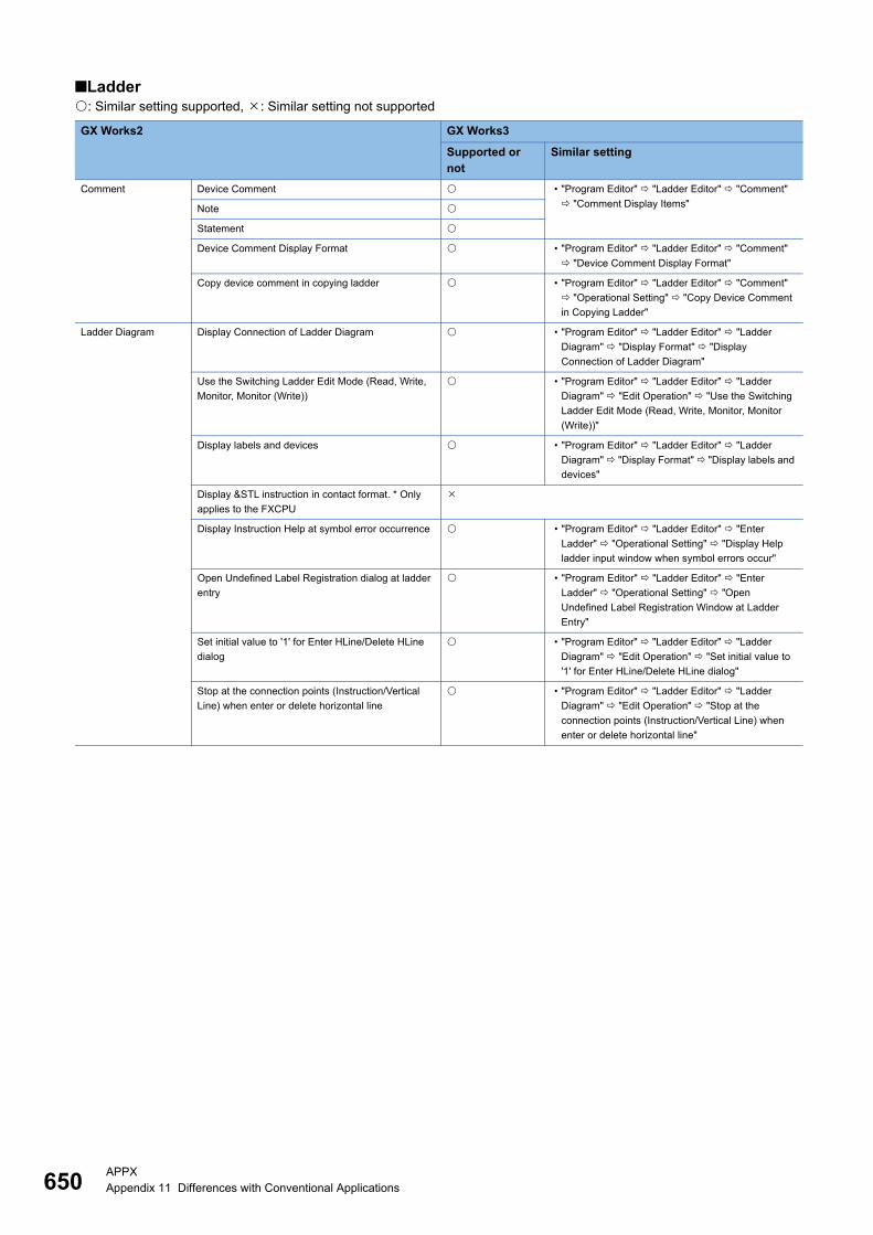
650APPXAppendix 11 Differences with Conventional Applications
■Ladder: Similar setting supported, : Similar setting not supported
GX Works2 GX Works3
Supported or not
Similar setting
Comment Device Comment • "Program Editor" "Ladder Editor" "Comment"
"Comment Display Items"Note
Statement
Device Comment Display Format • "Program Editor" "Ladder Editor" "Comment"
"Device Comment Display Format"
Copy device comment in copying ladder • "Program Editor" "Ladder Editor" "Comment"
"Operational Setting" "Copy Device Comment
in Copying Ladder"
Ladder Diagram Display Connection of Ladder Diagram • "Program Editor" "Ladder Editor" "Ladder
Diagram" "Display Format" "Display
Connection of Ladder Diagram"
Use the Switching Ladder Edit Mode (Read, Write,
Monitor, Monitor (Write))
• "Program Editor" "Ladder Editor" "Ladder
Diagram" "Edit Operation" "Use the Switching
Ladder Edit Mode (Read, Write, Monitor, Monitor
(Write))"
Display labels and devices • "Program Editor" "Ladder Editor" "Ladder
Diagram" "Display Format" "Display labels and
devices"
Display &STL instruction in contact format. * Only
applies to the FXCPU
Display Instruction Help at symbol error occurrence • "Program Editor" "Ladder Editor" "Enter
Ladder" "Operational Setting" "Display Help
ladder input window when symbol errors occur"
Open Undefined Label Registration dialog at ladder
entry
• "Program Editor" "Ladder Editor" "Enter
Ladder" "Operational Setting" "Open
Undefined Label Registration Window at Ladder
Entry"
Set initial value to '1' for Enter HLine/Delete HLine
dialog
• "Program Editor" "Ladder Editor" "Ladder
Diagram" "Edit Operation" "Set initial value to
'1' for Enter HLine/Delete HLine dialog"
Stop at the connection points (Instruction/Vertical
Line) when enter or delete horizontal line
• "Program Editor" "Ladder Editor" "Ladder
Diagram" "Edit Operation" "Stop at the
connection points (Instruction/Vertical Line) when
enter or delete horizontal line"
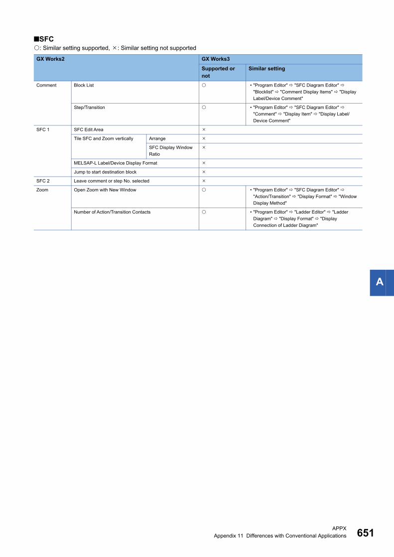
APPXAppendix 11 Differences with Conventional Applications 651
A
■SFC: Similar setting supported, : Similar setting not supported
GX Works2 GX Works3
Supported or not
Similar setting
Comment Block List • "Program Editor" "SFC Diagram Editor"
"Blocklist" "Comment Display Items" "Display
Label/Device Comment"
Step/Transition • "Program Editor" "SFC Diagram Editor"
"Comment" "Display Item" "Display Label/
Device Comment"
SFC 1 SFC Edit Area
Tile SFC and Zoom vertically Arrange
SFC Display Window
Ratio
MELSAP-L Label/Device Display Format
Jump to start destination block
SFC 2 Leave comment or step No. selected
Zoom Open Zoom with New Window • "Program Editor" "SFC Diagram Editor"
"Action/Transition" "Display Format" "Window
Display Method"
Number of Action/Transition Contacts • "Program Editor" "Ladder Editor" "Ladder
Diagram" "Display Format" "Display
Connection of Ladder Diagram"

652APPXAppendix 11 Differences with Conventional Applications
Device Comment Editor: Similar setting supported, : Similar setting not supported
Device Memory Editor: Similar setting supported, : Similar setting not supported
Label Setting Editor: Similar setting supported, : Similar setting not supported
Parameter: Similar setting supported, : Similar setting not supported
GX Works2 GX Works3
Supported or not
Similar setting
Number of Device Comment Edit/Display Characters • "Other Editor" "Device Comment Editor"
"Number of Editing/Displaying Characters"
"Number of Device Comment Editing/Displaying
Characters"
Extended setting
Execute the operation including the hidden bit specification information
GX Works2 GX Works3
Supported or not
Always Confirm
Auto
Specify the number of column
GX Works2 GX Works3
Supported or not
Similar setting
Automatic copy and increment when inserting a row • "Other Editor" "Label Editor Common" "Editor
Setting" "Automatic Copy and Increment in
Inserting a Row"
Copy data type/comment items • "Other Editor" "Label Editor Common" "Editor
Setting" "Copy Data Type/Comment Items"
Default Length of String Data Type • "Other Editor" "Label Editor Common" "Data
Type Setting" "Data Length of Character String
Data Types"
Display last blank row • "Other Editor" "Label Editor Common" "Display
Setting" "Display Last Blank Row"
GX Works2 GX Works3
Supported or not
Use user defined parameter
Display number of columns for CC-Link list setting
Display number of rows for CC-Link station information
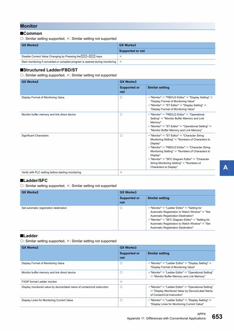
APPXAppendix 11 Differences with Conventional Applications 653
A
Monitor
■Common: Similar setting supported, : Similar setting not supported
■Structured Ladder/FBD/ST: Similar setting supported, : Similar setting not supported
■Ladder/SFC: Similar setting supported, : Similar setting not supported
■Ladder: Similar setting supported, : Similar setting not supported
GX Works2 GX Works3
Supported or not
Disable Current Value Changing by Pressing the+ keys
Start monitoring if converted or compiled program is opened during monitoring
GX Works2 GX Works3
Supported or not
Similar setting
Display Format of Monitoring Value • "Monitor" "FBD/LD Editor" "Display Setting"
"Display Format of Monitoring Value"
• "Monitor" "ST Editor" "Display Setting"
"Display Format of Monitoring Value"
Monitor buffer memory and link direct device • "Monitor" "FBD/LD Editor" "Operational
Setting" "Monitor Buffer Memory and Link
Memory"
• "Monitor" "ST Editor" "Operational Setting"
"Monitor Buffer Memory and Link Memory"
Significant Characters • "Monitor" "ST Editor" "Character String
Monitoring Setting" "Numbers of Characters to
Display"
• "Monitor" "FBD/LD Editor" "Character String
Monitoring Setting" "Numbers of Characters to
Display"
• "Monitor" "SFC Diagram Editor" "Character
String Monitoring Setting" "Numbers of
Characters to Display"
Verify with PLC setting before starting monitoring
GX Works2 GX Works3
Supported or not
Similar setting
Set automatic registration destination • "Monitor" "Ladder Editor" "Setting for
Automatic Registration to Watch Window" "Set
Automatic Registration Destination"
• "Monitor" "SFC Diagram Editor" "Setting for
Automatic Registration to Watch Window" "Set
Automatic Registration Destination"
GX Works2 GX Works3
Supported or not
Similar setting
Display Format of Monitoring Value • "Monitor" "Ladder Editor" "Display Setting"
"Display Format of Monitoring Value"
Monitor buffer memory and link direct device • "Monitor" "Ladder Editor" "Operational Setting"
"Monitor Buffer Memory and Link Memory"
FXGP format Ladder monitor
Display monitored value by device/label name of contact/coil instruction • "Monitor" "Ladder Editor" "Operational Setting"
"Display Monitored Value by Device/Label Name
of Contact/Coil Instruction"
Display Lines for Monitoring Current Value • "Monitor" "Ladder Editor" "Display Setting"
"Display Lines for Monitoring Current Value"
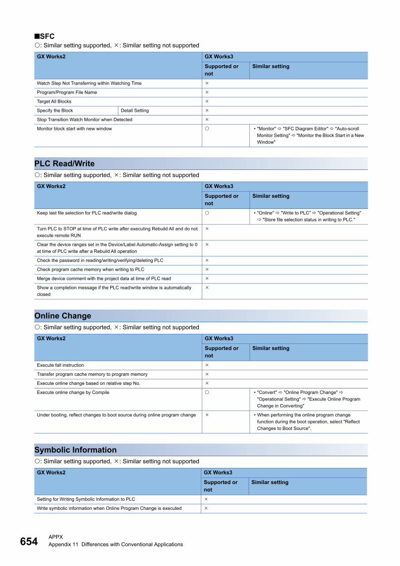
654APPXAppendix 11 Differences with Conventional Applications
■SFC: Similar setting supported, : Similar setting not supported
PLC Read/Write: Similar setting supported, : Similar setting not supported
Online Change: Similar setting supported, : Similar setting not supported
Symbolic Information: Similar setting supported, : Similar setting not supported
GX Works2 GX Works3
Supported or not
Similar setting
Watch Step Not Transferring within Watching Time
Program/Program File Name
Target All Blocks
Specify the Block Detail Setting
Stop Transition Watch Monitor when Detected
Monitor block start with new window • "Monitor" "SFC Diagram Editor" "Auto-scroll
Monitor Setting" "Monitor the Block Start in a New
Window"
GX Works2 GX Works3
Supported or not
Similar setting
Keep last file selection for PLC read/write dialog • "Online" "Write to PLC" "Operational Setting"
"Store file selection status in writing to PLC."
Turn PLC to STOP at time of PLC write after executing Rebuild All and do not
execute remote RUN
Clear the device ranges set in the Device/Label Automatic-Assign setting to 0
at time of PLC write after a Rebuild All operation
Check the password in reading/writing/verifying/deleting PLC
Check program cache memory when writing to PLC
Merge device comment with the project data at time of PLC read
Show a completion message if the PLC read/write window is automatically
closed
GX Works2 GX Works3
Supported or not
Similar setting
Execute fall instruction
Transfer program cache memory to program memory
Execute online change based on relative step No.
Execute online change by Compile • "Convert" "Online Program Change"
"Operational Setting" "Execute Online Program
Change in Converting"
Under booting, reflect changes to boot source during online program change • When performing the online program change
function during the boot operation, select "Reflect
Changes to Boot Source".
GX Works2 GX Works3
Supported or not
Similar setting
Setting for Writing Symbolic Information to PLC
Write symbolic information when Online Program Change is executed

APPXAppendix 11 Differences with Conventional Applications 655
A
Save Destination of Device Comment: Similar setting supported, : Similar setting not supported
In the Write to PLC window, keep the symbolic information selected status as
a write target
• "Online" "Program Restore Information"
"Operational Setting" "Enable the setting to write/
not to write program restore information"
Setting for Save Destination of Symbolic Information to PLC
GX Works2 GX Works3
Supported or not
Set save destination of device comment to the target memory of PLC data
Save Destination of Device Comment
GX Works2 GX Works3
Supported or not
Similar setting
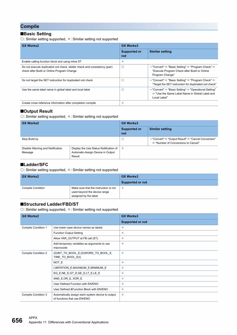
656APPXAppendix 11 Differences with Conventional Applications
Compile
■Basic Setting: Similar setting supported, : Similar setting not supported
■Output Result: Similar setting supported, : Similar setting not supported
■Ladder/SFC: Similar setting supported, : Similar setting not supported
■Structured Ladder/FBD/ST: Similar setting supported, : Similar setting not supported
GX Works2 GX Works3
Supported or not
Similar setting
Enable calling function block and using inline ST
Do not execute duplicated coil check, ladder check and consistency (pair)
check after Build or Online Program Change
• "Convert" "Basic Setting" "Program Check"
"Execute Program Check after Build or Online
Program Change"
Do not target the SET instruction for duplicated coil check • "Convert" "Basic Setting" "Program Check"
"Target the SET instruction for duplicated coil check"
Use the same label name in global label and local label • "Convert" "Basic Setting" "Operational Setting"
"Use the Same Label Name in Global Label and
Local Label"
Create cross reference information after completion compile.
GX Works2 GX Works3
Supported or not
Similar setting
Stop Build by • "Convert" "Output Result" "Cancel Conversion"
"Number of Conversions to Cancel"
Disable Warning and Notification
Message
Display the Use Status Notification of
Automatic-Assign Device in Output
Result
GX Works2 GX Works3
Supported or not
Compile Condition Make sure that the instruction is not
used beyond the device range
assigned by the label
GX Works2 GX Works3
Supported or not
Compile Condition 1 Use lower-case device names as labels
Function Output Setting
Allow VAR_OUTPUT at FB call (ST)
Add temporary variables as arguments to use
macrocode
Compile Condition 2 (D)INT_TO_BOOL_E,(D)WORD_TO_BOOL_E,
TIME_TO_BOOL_E(I)
NOT_E
LIMITATION_E,MAXIMUM_E,MINIMUM_E
EQ_E,NE_E,GT_E,GE_E,LT_E,LE_E
AND_E,OR_E, XOR_E
User Defined Function with EN/ENO
User Defined &Function Block with EN/ENO
Compile Condition 3 Automatically assign each system device to output
of functions that use EN/ENO
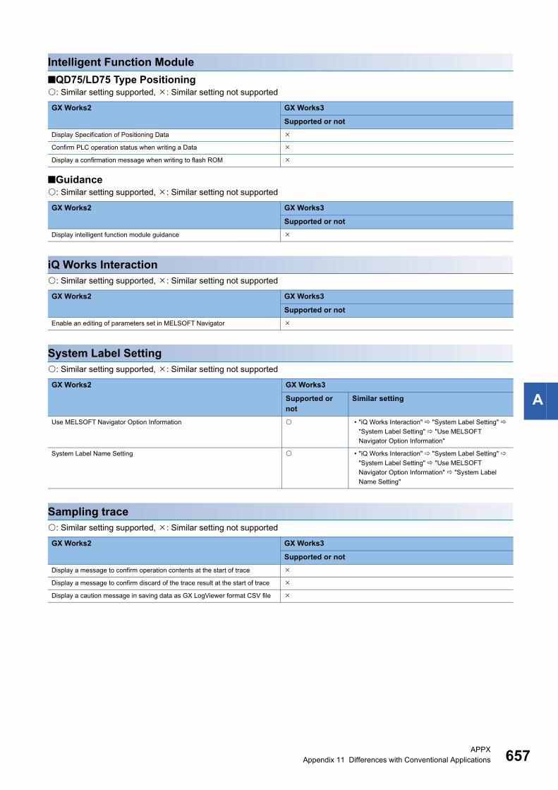
APPXAppendix 11 Differences with Conventional Applications 657
A
Intelligent Function Module
■QD75/LD75 Type Positioning: Similar setting supported, : Similar setting not supported
■Guidance: Similar setting supported, : Similar setting not supported
iQ Works Interaction: Similar setting supported, : Similar setting not supported
System Label Setting: Similar setting supported, : Similar setting not supported
Sampling trace: Similar setting supported, : Similar setting not supported
GX Works2 GX Works3
Supported or not
Display Specification of Positioning Data
Confirm PLC operation status when writing a Data
Display a confirmation message when writing to flash ROM
GX Works2 GX Works3
Supported or not
Display intelligent function module guidance
GX Works2 GX Works3
Supported or not
Enable an editing of parameters set in MELSOFT Navigator
GX Works2 GX Works3
Supported or not
Similar setting
Use MELSOFT Navigator Option Information • "iQ Works Interaction" "System Label Setting"
"System Label Setting" "Use MELSOFT
Navigator Option Information"
System Label Name Setting • "iQ Works Interaction" "System Label Setting"
"System Label Setting" "Use MELSOFT
Navigator Option Information" "System Label
Name Setting"
GX Works2 GX Works3
Supported or not
Display a message to confirm operation contents at the start of trace
Display a message to confirm discard of the trace result at the start of trace
Display a caution message in saving data as GX LogViewer format CSV file
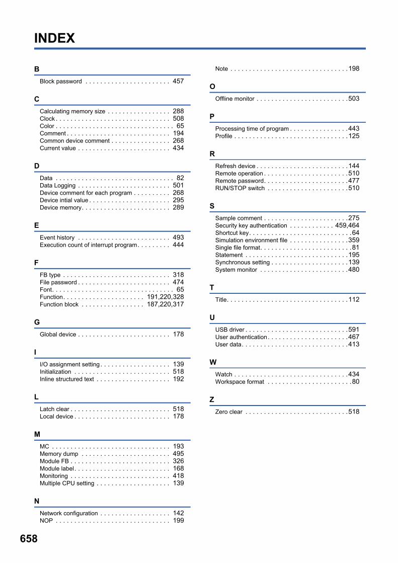
658
INDEX
B
Block password . . . . . . . . . . . . . . . . . . . . . . . 457
C
Calculating memory size . . . . . . . . . . . . . . . . . 288Clock . . . . . . . . . . . . . . . . . . . . . . . . . . . . . . . 508Color . . . . . . . . . . . . . . . . . . . . . . . . . . . . . . . . 65Comment . . . . . . . . . . . . . . . . . . . . . . . . . . . . 194Common device comment . . . . . . . . . . . . . . . . 268Current value . . . . . . . . . . . . . . . . . . . . . . . . . 434
D
Data . . . . . . . . . . . . . . . . . . . . . . . . . . . . . . . . 82Data Logging . . . . . . . . . . . . . . . . . . . . . . . . . 501Device comment for each program . . . . . . . . . . 268Device intial value . . . . . . . . . . . . . . . . . . . . . . 295Device memory. . . . . . . . . . . . . . . . . . . . . . . . 289
E
Event history . . . . . . . . . . . . . . . . . . . . . . . . . 493Execution count of interrupt program. . . . . . . . . 444
F
FB type . . . . . . . . . . . . . . . . . . . . . . . . . . . . . 318File password . . . . . . . . . . . . . . . . . . . . . . . . . 474Font. . . . . . . . . . . . . . . . . . . . . . . . . . . . . . . . . 65Function. . . . . . . . . . . . . . . . . . . . . . 191,220,328Function block . . . . . . . . . . . . . . . . . 187,220,317
G
Global device . . . . . . . . . . . . . . . . . . . . . . . . . 178
I
I/O assignment setting . . . . . . . . . . . . . . . . . . . 139Initialization . . . . . . . . . . . . . . . . . . . . . . . . . . 518Inline structured text . . . . . . . . . . . . . . . . . . . . 192
L
Latch clear . . . . . . . . . . . . . . . . . . . . . . . . . . . 518Local device . . . . . . . . . . . . . . . . . . . . . . . . . . 178
M
MC . . . . . . . . . . . . . . . . . . . . . . . . . . . . . . . . 193Memory dump . . . . . . . . . . . . . . . . . . . . . . . . 495Module FB . . . . . . . . . . . . . . . . . . . . . . . . . . . 326Module label. . . . . . . . . . . . . . . . . . . . . . . . . . 168Monitoring . . . . . . . . . . . . . . . . . . . . . . . . . . . 418Multiple CPU setting . . . . . . . . . . . . . . . . . . . . 139
N
Network configuration . . . . . . . . . . . . . . . . . . . 142NOP . . . . . . . . . . . . . . . . . . . . . . . . . . . . . . . 199
Note . . . . . . . . . . . . . . . . . . . . . . . . . . . . . . . .198
O
Offline monitor . . . . . . . . . . . . . . . . . . . . . . . . .503
P
Processing time of program . . . . . . . . . . . . . . . .443Profile . . . . . . . . . . . . . . . . . . . . . . . . . . . . . . .125
R
Refresh device . . . . . . . . . . . . . . . . . . . . . . . . .144Remote operation . . . . . . . . . . . . . . . . . . . . . . .510Remote password. . . . . . . . . . . . . . . . . . . . . . .477RUN/STOP switch . . . . . . . . . . . . . . . . . . . . . .510
S
Sample comment . . . . . . . . . . . . . . . . . . . . . . .275Security key authentication . . . . . . . . . . . . 459,464Shortcut key. . . . . . . . . . . . . . . . . . . . . . . . . . . .64Simulation environment file . . . . . . . . . . . . . . . .359Single file format. . . . . . . . . . . . . . . . . . . . . . . . .81Statement . . . . . . . . . . . . . . . . . . . . . . . . . . . .195Synchronous setting . . . . . . . . . . . . . . . . . . . . .139System monitor . . . . . . . . . . . . . . . . . . . . . . . .480
T
Title. . . . . . . . . . . . . . . . . . . . . . . . . . . . . . . . .112
U
USB driver . . . . . . . . . . . . . . . . . . . . . . . . . . . .591User authentication. . . . . . . . . . . . . . . . . . . . . .467User data. . . . . . . . . . . . . . . . . . . . . . . . . . . . .413
W
Watch . . . . . . . . . . . . . . . . . . . . . . . . . . . . . . .434Workspace format . . . . . . . . . . . . . . . . . . . . . . .80
Z
Zero clear . . . . . . . . . . . . . . . . . . . . . . . . . . . .518

I
659
MEMO
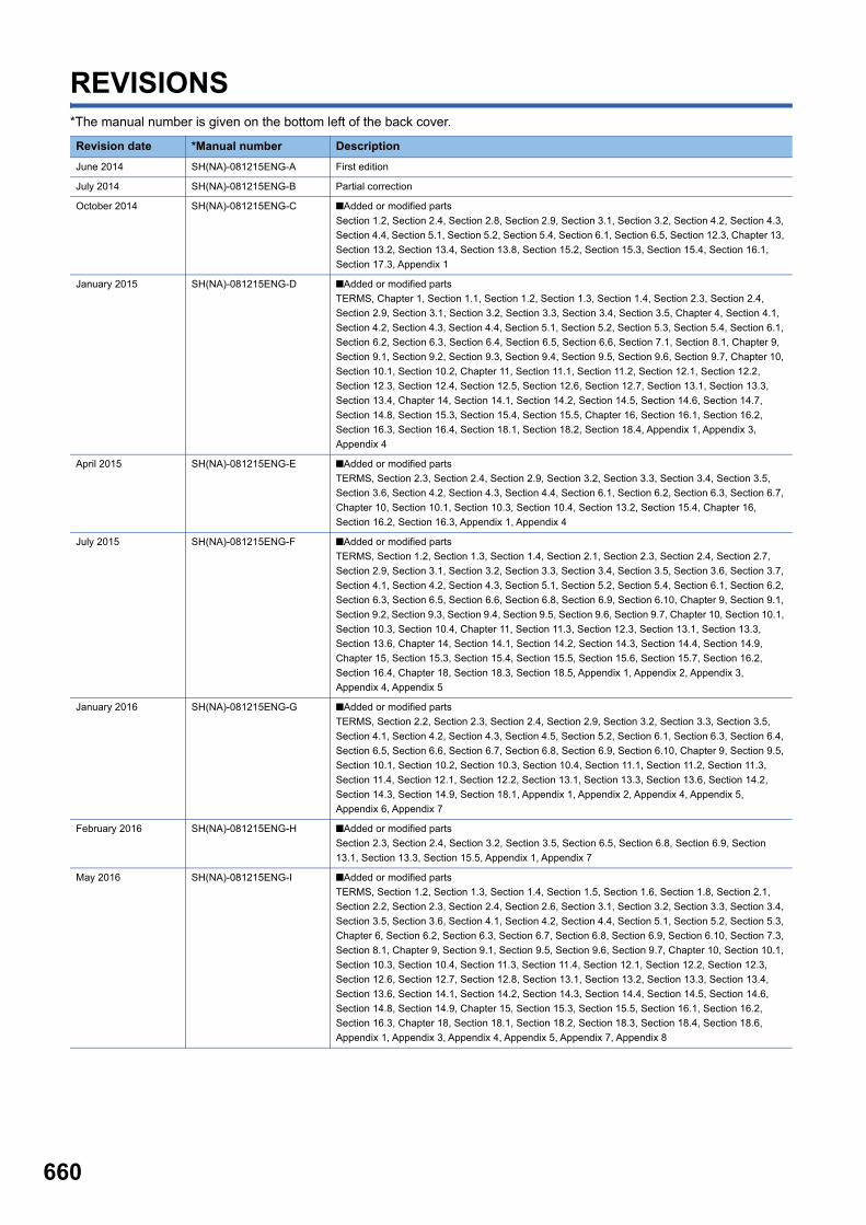
660
REVISIONS*The manual number is given on the bottom left of the back cover.
Revision date *Manual number Description
June 2014 SH(NA)-081215ENG-A First edition
July 2014 SH(NA)-081215ENG-B Partial correction
October 2014 SH(NA)-081215ENG-C ■Added or modified parts
Section 1.2, Section 2.4, Section 2.8, Section 2.9, Section 3.1, Section 3.2, Section 4.2, Section 4.3,
Section 4.4, Section 5.1, Section 5.2, Section 5.4, Section 6.1, Section 6.5, Section 12.3, Chapter 13,
Section 13.2, Section 13.4, Section 13.8, Section 15.2, Section 15.3, Section 15.4, Section 16.1,
Section 17.3, Appendix 1
January 2015 SH(NA)-081215ENG-D ■Added or modified parts
TERMS, Chapter 1, Section 1.1, Section 1.2, Section 1.3, Section 1.4, Section 2.3, Section 2.4,
Section 2.9, Section 3.1, Section 3.2, Section 3.3, Section 3.4, Section 3.5, Chapter 4, Section 4.1,
Section 4.2, Section 4.3, Section 4.4, Section 5.1, Section 5.2, Section 5.3, Section 5.4, Section 6.1,
Section 6.2, Section 6.3, Section 6.4, Section 6.5, Section 6.6, Section 7.1, Section 8.1, Chapter 9,
Section 9.1, Section 9.2, Section 9.3, Section 9.4, Section 9.5, Section 9.6, Section 9.7, Chapter 10,
Section 10.1, Section 10.2, Chapter 11, Section 11.1, Section 11.2, Section 12.1, Section 12.2,
Section 12.3, Section 12.4, Section 12.5, Section 12.6, Section 12.7, Section 13.1, Section 13.3,
Section 13.4, Chapter 14, Section 14.1, Section 14.2, Section 14.5, Section 14.6, Section 14.7,
Section 14.8, Section 15.3, Section 15.4, Section 15.5, Chapter 16, Section 16.1, Section 16.2,
Section 16.3, Section 16.4, Section 18.1, Section 18.2, Section 18.4, Appendix 1, Appendix 3,
Appendix 4
April 2015 SH(NA)-081215ENG-E ■Added or modified parts
TERMS, Section 2.3, Section 2.4, Section 2.9, Section 3.2, Section 3.3, Section 3.4, Section 3.5,
Section 3.6, Section 4.2, Section 4.3, Section 4.4, Section 6.1, Section 6.2, Section 6.3, Section 6.7,
Chapter 10, Section 10.1, Section 10.3, Section 10.4, Section 13.2, Section 15.4, Chapter 16,
Section 16.2, Section 16.3, Appendix 1, Appendix 4
July 2015 SH(NA)-081215ENG-F ■Added or modified parts
TERMS, Section 1.2, Section 1.3, Section 1.4, Section 2.1, Section 2.3, Section 2.4, Section 2.7,
Section 2.9, Section 3.1, Section 3.2, Section 3.3, Section 3.4, Section 3.5, Section 3.6, Section 3.7,
Section 4.1, Section 4.2, Section 4.3, Section 5.1, Section 5.2, Section 5.4, Section 6.1, Section 6.2,
Section 6.3, Section 6.5, Section 6.6, Section 6.8, Section 6.9, Section 6.10, Chapter 9, Section 9.1,
Section 9.2, Section 9.3, Section 9.4, Section 9.5, Section 9.6, Section 9.7, Chapter 10, Section 10.1,
Section 10.3, Section 10.4, Chapter 11, Section 11.3, Section 12.3, Section 13.1, Section 13.3,
Section 13.6, Chapter 14, Section 14.1, Section 14.2, Section 14.3, Section 14.4, Section 14.9,
Chapter 15, Section 15.3, Section 15.4, Section 15.5, Section 15.6, Section 15.7, Section 16.2,
Section 16.4, Chapter 18, Section 18.3, Section 18.5, Appendix 1, Appendix 2, Appendix 3,
Appendix 4, Appendix 5
January 2016 SH(NA)-081215ENG-G ■Added or modified parts
TERMS, Section 2.2, Section 2.3, Section 2.4, Section 2.9, Section 3.2, Section 3.3, Section 3.5,
Section 4.1, Section 4.2, Section 4.3, Section 4.5, Section 5.2, Section 6.1, Section 6.3, Section 6.4,
Section 6.5, Section 6.6, Section 6.7, Section 6.8, Section 6.9, Section 6.10, Chapter 9, Section 9.5,
Section 10.1, Section 10.2, Section 10.3, Section 10.4, Section 11.1, Section 11.2, Section 11.3,
Section 11.4, Section 12.1, Section 12.2, Section 13.1, Section 13.3, Section 13.6, Section 14.2,
Section 14.3, Section 14.9, Section 18.1, Appendix 1, Appendix 2, Appendix 4, Appendix 5,
Appendix 6, Appendix 7
February 2016 SH(NA)-081215ENG-H ■Added or modified parts
Section 2.3, Section 2.4, Section 3.2, Section 3.5, Section 6.5, Section 6.8, Section 6.9, Section
13.1, Section 13.3, Section 15.5, Appendix 1, Appendix 7
May 2016 SH(NA)-081215ENG-I ■Added or modified parts
TERMS, Section 1.2, Section 1.3, Section 1.4, Section 1.5, Section 1.6, Section 1.8, Section 2.1,
Section 2.2, Section 2.3, Section 2.4, Section 2.6, Section 3.1, Section 3.2, Section 3.3, Section 3.4,
Section 3.5, Section 3.6, Section 4.1, Section 4.2, Section 4.4, Section 5.1, Section 5.2, Section 5.3,
Chapter 6, Section 6.2, Section 6.3, Section 6.7, Section 6.8, Section 6.9, Section 6.10, Section 7.3,
Section 8.1, Chapter 9, Section 9.1, Section 9.5, Section 9.6, Section 9.7, Chapter 10, Section 10.1,
Section 10.3, Section 10.4, Section 11.3, Section 11.4, Section 12.1, Section 12.2, Section 12.3,
Section 12.6, Section 12.7, Section 12.8, Section 13.1, Section 13.2, Section 13.3, Section 13.4,
Section 13.6, Section 14.1, Section 14.2, Section 14.3, Section 14.4, Section 14.5, Section 14.6,
Section 14.8, Section 14.9, Chapter 15, Section 15.3, Section 15.5, Section 16.1, Section 16.2,
Section 16.3, Chapter 18, Section 18.1, Section 18.2, Section 18.3, Section 18.4, Section 18.6,
Appendix 1, Appendix 3, Appendix 4, Appendix 5, Appendix 7, Appendix 8
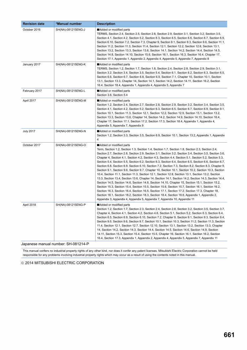
661
Japanese manual number: SH-081214-P
2014 MITSUBISHI ELECTRIC CORPORATION
October 2016 SH(NA)-081215ENG-J ■Added or modified parts
TERMS, Section 2.4, Section 2.5, Section 2.8, Section 2.9, Section 3.1, Section 3.2, Section 3.5,
Section 4.1, Section 4.2, Section 5.2, Section 6.3, Section 6.5, Section 6.6, Section 6.7, Section 6.9,
Section 6.10, Section 7.2, Section 7.3, Chapter 9, Section 9.1, Section 9.3, Section 9.6, Section 11.1,
Section 11.2, Section 11.3, Section 11.4, Section 12.1, Section 12.2, Section 12.6, Section 13.1,
Section 13.2, Section 13.3, Section 13.6, Section 14.1, Section 14.2, Section 14.4, Section 14.5,
Section 14.8, Section 14.10, Section 15.6, Section 16.1, Section 16.3, Section 16.4, Chapter 17,
Section 17.1, Appendix 1, Appendix 2, Appendix 4, Appendix 5, Appendix 7, Appendix 8
January 2017 SH(NA)-081215ENG-K ■Added or modified parts
TERMS, Section 1.2, Section 1.7, Section 1.8, Section 2.4, Section 2.8, Section 2.9, Section 3.1,
Section 3.2, Section 3.4, Section 3.5, Section 5.4, Section 6.1, Section 6.2, Section 6.3, Section 6.5,
Section 6.6, Section 6.7, Section 6.8, Section 6.9, Section 7.1, Chapter 10, Section 10.1, Section
13.1, Section 13.3, Chapter 14, Section 14.1, Section 14.2, Section 14.11, Section 16.2, Section
16.4, Section 18.4, Appendix 1, Appendix 4, Appendix 5, Appendix 7
February 2017 SH(NA)-081215ENG-L ■Added or modified parts
Section 3.6, Section 5.4
April 2017 SH(NA)-081215ENG-M ■Added or modified parts
Section 1.2, Section 2.4, Section 2.7, Section 2.8, Section 2.9, Section 3.2, Section 3.4, Section 3.5,
Section 4.1, Section 4.2, Section 5.2, Section 6.3, Section 6.5, Section 6.7, Section 6.9, Section 9.1,
Section 10.1, Section 11.3, Section 12.1, Section 12.2, Section 12.9, Section 13.1, Section 13.2,
Section 13.3, Section 13.6, Chapter 14, Section 14.2, Section 14.9, Section 14.10, Section 16.4,
Chapter 17, Section 17.1, Section 17.2, Section 17.3, Section 18.4, Appendix 1, Appendix 4,
Appendix 5, Appendix 7, Appendix 9
July 2017 SH(NA)-081215ENG-N ■Added or modified parts
Section 1.2, Section 3.3, Section 3.5, Section 6.9, Section 10.1, Section 13.2, Appendix 1, Appendix
4
October 2017 SH(NA)-081215ENG-O ■Added or modified parts
Term, Section 1.2, Section 1.3, Section 1.4, Section 1.7, Section 1.8, Section 2.3, Section 2.4,
Section 2.7, Section 2.8, Section 2.9, Section 3.1, Section 3.2, Section 3.4, Section 3.5, Section 3.6,
Chapter 4, Section 4.1, Section 4.2, Section 4.3, Section 4.4, Section 5.1, Section 5.2, Section 5.3,
Section 5.4, Section 5.5, Section 6.2, Section 6.3, Section 6.4, Section 6.5, Section 6.6, Section 6.7,
Section 6.8, Section 6.9, Section 6.10, Section 7.2, Section 7.3, Section 8.2, Section 8.3, Chapter 9,
Section 9.1, Section 9.6, Section 9.7, Chapter 10, Section 10.1, Section 10.2, Section 10.3, Section
10.4, Section 11.1, Section 11.3, Section 12.1, Section 12.8, Section 13.1, Section 13.2, Section
13.3, Section 13.4, Section 13.6, Chapter 14, Section 14.1, Section 14.2, Section 14.3, Section 14.4,
Section 14.5, Section 14.6, Section 14.8, Section 14.10, Chapter 15, Section 15.1, Section 15.2,
Section 15.3, Section 15.4, Section 15.5, Section 15.6, Section 15.7, Section 16.1, Section 16.2,
Section 16.3, Section 16.4, Section 16.5, Section 17.1, Section 17.2, Section 17.3, Chapter 18,
Section 18.1, Section 18.2, Section 18.3, Section 18.4, Section 18.6, Appendix 1, Appendix 2,
Appendix 3, Appendix 4, Appendix 5, Appendix 7, Appendix 10, Appendix 11
April 2018 SH(NA)-081215ENG-P ■Added or modified parts
Section 1.2, Section 1.7, Section 2.3, Section 2.4, Section 2.8, Section 3.2, Section 3.5, Section 3.7,
Chapter 4, Section 4.1, Section 4.2, Section 4.6, Section 5.1, Section 5.2, Section 6.3, Section 6.4,
Section 6.5, Section 6.9, Section 6.10, Section 7.2, Chapter 9, Section 9.1, Section 9.3, Section 9.4,
Section 9.5, Section 9.6, Section 9.7, Section 10.1, Section 10.3, Section 11.2, Section 11.3, Section
11.4, Section 12.1, Section 12.7, Section 12.10, Section 13.1, Section 13.2, Section 13.3, Chapter
14, Section 14.2, Section 14.3, Section 14.4, Section 14.5, Section 14.6, Section 14.9, Section
14.11, Section 15.3, Section 15.4, Section 15.5, Chapter 16, Section 16.1, Section 16.2, Section
16.4, Section 17.3, Appendix 1, Appendix 2, Appendix 4, Appendix 5, Appendix 7, Appendix 11
This manual confers no industrial property rights of any other kind, nor does it confer any patent licenses. Mitsubishi Electric Corporation cannot be held
responsible for any problems involving industrial property rights which may occur as a result of using the contents noted in this manual.
Revision date *Manual number Description
662
TRADEMARKSMicrosoft, Windows, Windows Vista, Microsoft Edge, and Internet Explorer are either registered trademarks or trademarks of
Microsoft Corporation in the United States and/or other countries.
Celeron, Intel, and Pentium are either registered trademarks or trademarks of Intel Corporation in the United States and/or
other countries.
Ethernet is a registered trademark of Fuji Xerox Co., Ltd. in Japan.
Android and Google Chrome are either registered trademarks or trademarks of Google Inc.
Safari is a trademark of Apple Inc., registered in the U.S. and other countries.
IOS (iOS) is either a registered trademark or trademark of Cisco Systems, Inc. and/or its affiliates in the United States and
certain other countries, and iOS is used under license by Apple Inc.
The SD and SDHC logos are trademarks of SD-3C, LLC.
The company names, system names and product names mentioned in this manual are either registered trademarks or
trademarks of their respective companies.
In some cases, trademark symbols such as '' or '' are not specified in this manual.


SH(NA)-081215ENG-P(1804)
MODEL:GXW3-O-E
Specifications subject to change without notice.
When exported from Japan, this manual does not require application to theMinistry of Economy, Trade and Industry for service transaction permission.
HEAD OFFICE : TOKYO BUILDING, 2-7-3 MARUNOUCHI, CHIYODA-KU, TOKYO 100-8310, JAPANNAGOYA WORKS : 1-14 , YADA-MINAMI 5-CHOME , HIGASHI-KU, NAGOYA , JAPAN
Related Documents


![MITSUBISHI ELECTRIC Global website...I-Efficient Programming_fod005go tha 23.1 POU POU MELSOFT GX Works3 POU POU 5udnnffi51.Jtnm Comment [Vers on] ver. B [Last Change] 2017/02/17](https://static.cupdf.com/doc/110x72/5f6133031420e27f9d6d2c7d/mitsubishi-electric-global-website-i-efficient-programmingfod005go-tha-231.jpg)

![スライド 1 - mitsubishielectric.com · Ki6m tra phiên bán MELSOFT GX Works3 Sau khi båt MELSOFT GX Works3, chon [Help] - [Version Information] tù menu. ME SEC iQ-R series](https://static.cupdf.com/doc/110x72/5e0865960532ac36145861d9/ff-1-ki6m-tra-phin-bn-melsoft-gx-works3-sau-khi-bt-melsoft-gx.jpg)