G.W.Jiang source:IEEE

G.W.Jiang
Feb 22, 2016
source:IEEE. G.W.Jiang. Outline. Introduction Experiments Results and Discussion Conclusion. Introduction. - PowerPoint PPT Presentation
Welcome message from author
This document is posted to help you gain knowledge. Please leave a comment to let me know what you think about it! Share it to your friends and learn new things together.
Transcript
G.W.Jiang
source:IEEE

1
Outline
Introduction
Experiments
Results and Discussion
Conclusion

2
Introduction The typical AlGaN EBL is insufficiently effective in
blocking the electron leakage and hole injection will be inhibited into the active region are generally recognized as the primary cause of efficiency droop.
Recently, graded AlGaN EBL has been suggested to benefit hole injection and electron confinement but is still under debate which kind of Al content variation trend best favors the reduction of efficiency droop.

In this letter, we use step-graded AlGaN EBLs with different Al content variation trend to compare with the original AlGaN EBL.
3

4
Experiments
chip size: 300 um × 300um Fig. 1. Schematic diagrams of the LEDs with the original.
170nm
x63nm/10nm
3um5x1018cm-3
25nm
2um
3x1019cm-3
5x1019cm-3
IEBL
DEBL
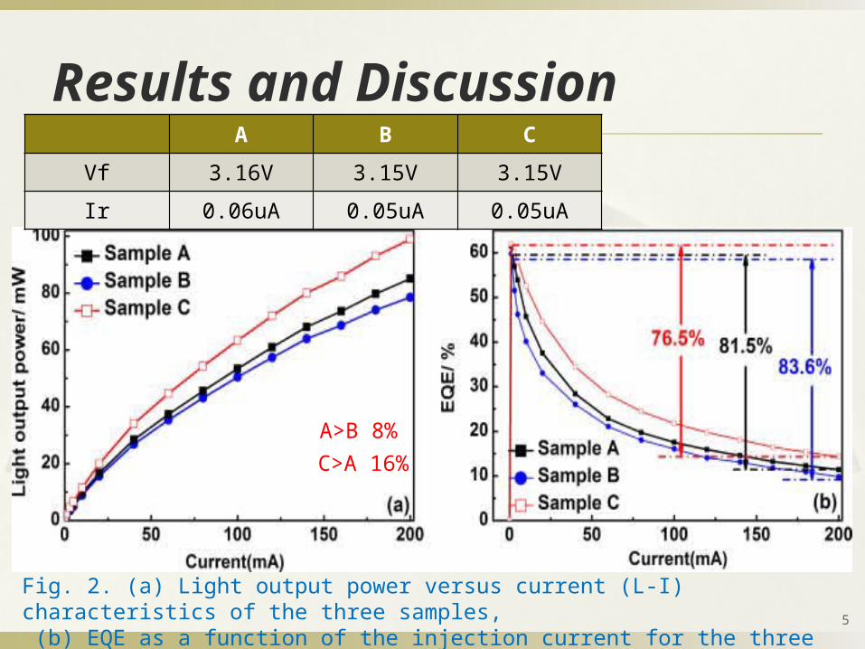
Fig. 2. (a) Light output power versus current (L-I) characteristics of the three samples, (b) EQE as a function of the injection current for the three samples. 5
Results and DiscussionA B C
Vf 3.16V 3.15V 3.15V
Ir 0.06uA 0.05uA 0.05uA
A>B 8%C>A 16%

Fig. 3. (a) Enlarged conduction band diagram, (b) Electron concentration distribution near the EBLs of the three samples at 200 mA forward current.
6
7
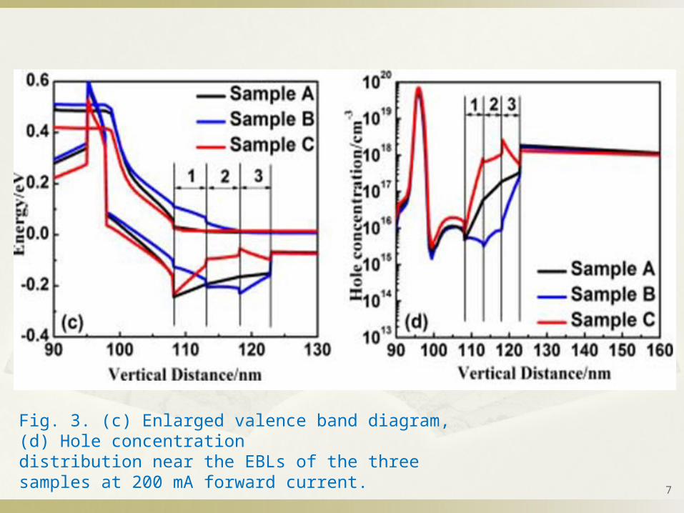
Fig. 3. (c) Enlarged valence band diagram, (d) Hole concentrationdistribution near the EBLs of the three samples at 200 mA forward current.
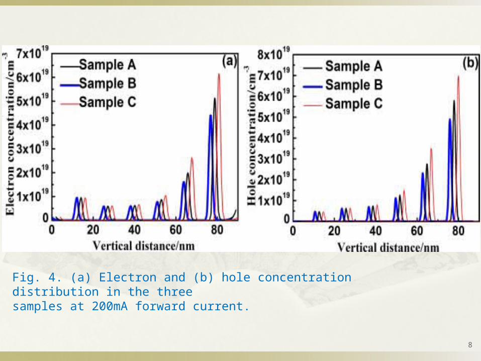
Fig. 4. (a) Electron and (b) hole concentration distribution in the threesamples at 200mA forward current.
8
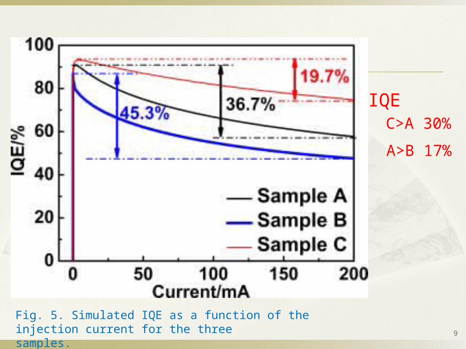
Fig. 5. Simulated IQE as a function of the injection current for the threesamples. 9
IQEC>A 30%
A>B 17%
10
Conclusion The experimental results indicate that the adoption of step-
graded AlGaN EBLs has little influence on the electrical properties of the fabricated LEDs.
And experiments show that the IEBL gives rise to inferior optical performance, compared to the DEBL and original EBL.
Simulation results, the DEBL can improve performance is attributed to enhanced hole injection without losing the capability of electron confinement.

G.W.Jiang
11
source:IEEE

12
Outline
Introduction
Experiments
Results and Discussion
Conclusion
References

13
Introduction The optical performances of LEDs can be largely weakened
by several mechanisms; including carrier leakage due to the polarization effect、 Auger recombination、 current injection efficiency、 lack of hole injection、 the self-heating effect etc.
However, electron current leakage and poor hole injection efficiency are usually identified to be the major reasons for the efficiency droop issue.

Unfortunately, the conventional p-type AlGaN EBL cannot usually block the electron in the active region effectively due to the large band-bending caused by the polarization field.
In this paper, we propose a novel sawtooth-shaped EBL to improve the efficiency of electron confinement and hole injection .
14
15
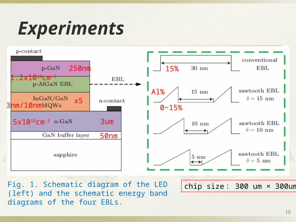
Experiments
chip size: 300 um × 300um Fig. 1. Schematic diagram of the LED (left) and the schematic energy band diagrams of the four EBLs.
50nm
3um5x1018cm-3
1.2x1018cm-3
250nm
Al%
0~15%x53nm/10nm
15%

Fig. 2. Conduction energy band diagrams for LEDs with (a) conventional EBL, (b) sawtooth EBL (d =15 nm) at an injection current of 180 mA..
16
Results and Discussion
0%
15%
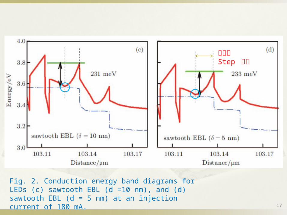
Fig. 2. Conduction energy band diagrams for LEDs (c) sawtooth EBL (d =10 nm), and (d) sawtooth EBL (d = 5 nm) at an injection current of 180 mA.
17
距離長Step 較多
18
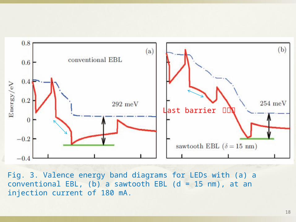
Fig. 3. Valence energy band diagrams for LEDs with (a) a conventional EBL, (b) a sawtooth EBL (d = 15 nm), at an injection current of 180 mA.
Last barrier 較趨緩
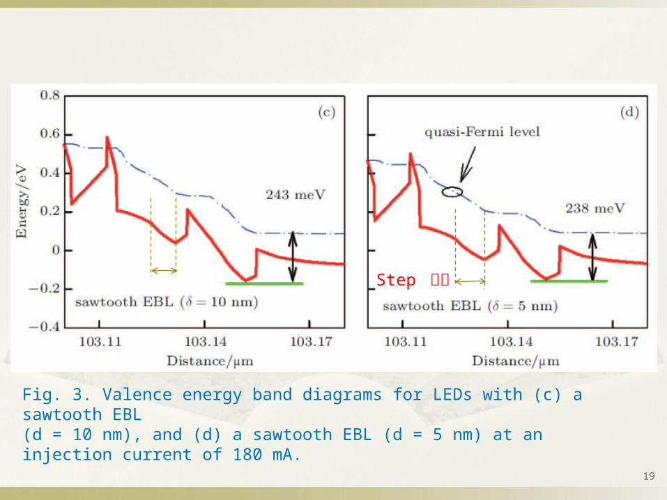
Fig. 3. Valence energy band diagrams for LEDs with (c) a sawtooth EBL(d = 10 nm), and (d) a sawtooth EBL (d = 5 nm) at an injection current of 180 mA.
19
Step 較多
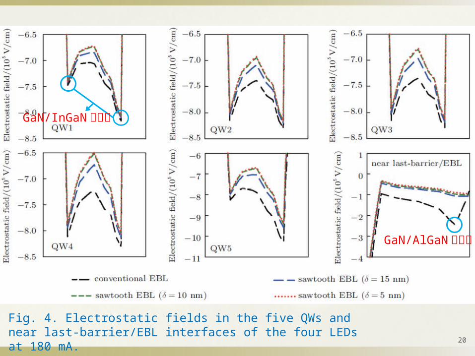
Fig. 4. Electrostatic fields in the five QWs and near last-barrier/EBL interfaces of the four LEDs at 180 mA.
20
GaN/InGaN接面處
0GaN/AlGaN接面處

21
Fig. 5. Electron current leakage profiles near the active region for the four LEDs at 180 mA.
判斷電子 confinement的好壞

22
Fig. 6. Electron concentrations within the active regions for the four LEDs at 180 mA.
23
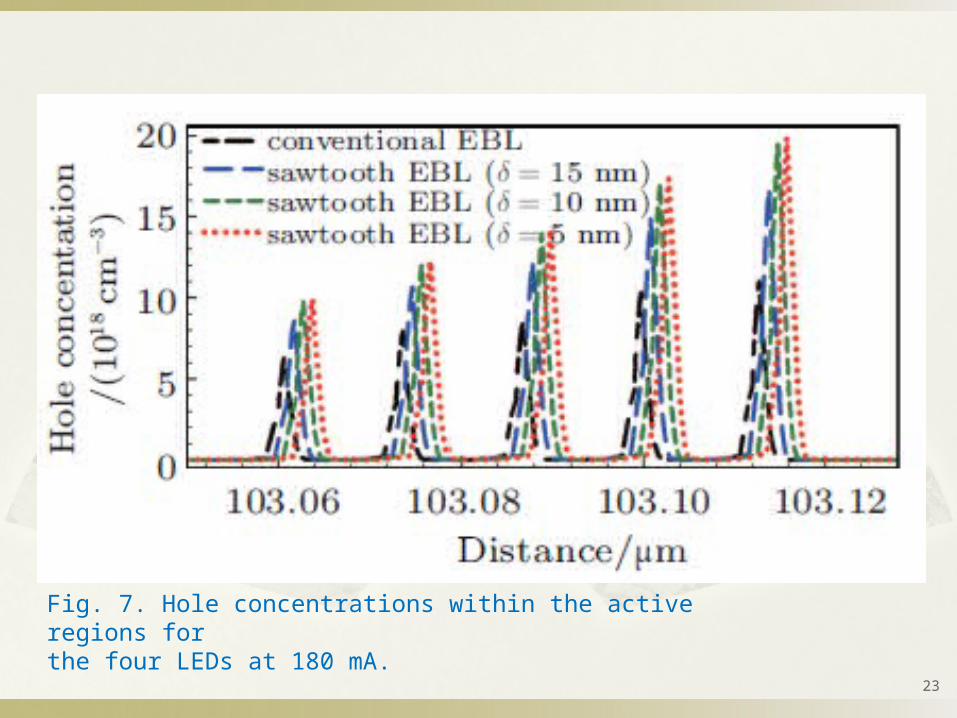
Fig. 7. Hole concentrations within the active regions forthe four LEDs at 180 mA.
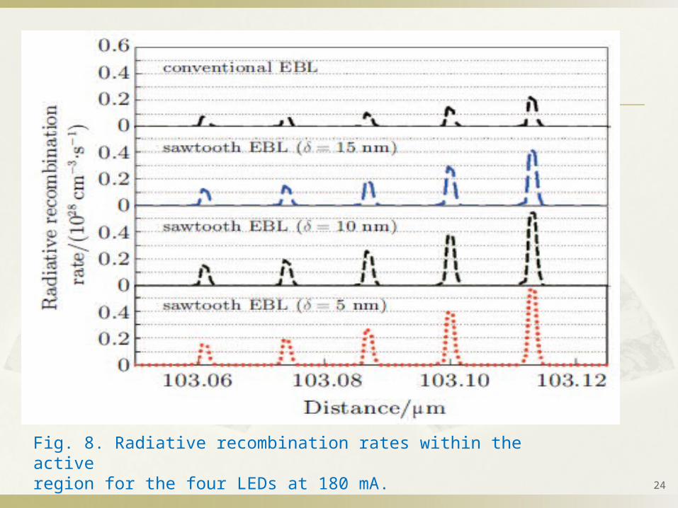
Fig. 8. Radiative recombination rates within the activeregion for the four LEDs at 180 mA.
24

Fig. 9. (color online) Curves of (a) internal quantum efficiency and (b)light output power versus injection current for the four LEDs.
Droop%
Con EBL=55.2%
D:5nm EBL = 35.4%
Output power
D:5nm / con =2.69
25
26
Conclusion When used a sawtooth-shaped EBL, the effective barrier
height of the conduction band is increased and the barrier obstacle in the valence band for holes is mitigated due to the correctly modified energy band of the EBL.
The electron confinement is enhanced and more holes can be transported from the p-type region into the MQW.
This effect prevents electron leakage and improves the radiative recombination rate in the QW, leading to a significant improvement in IQE and light output power.

27
References [21] Fiorentini V, Bernardini F and Ambacher O 2002
Appl. Phys. Lett. 80 1204
[22] Vurgaftman I and Meyer J R 2003 J. Appl. Phys. 94 3675 088504-

28
Thanks for your attention.