GUNN’S HILL WIND FARM EXECUTIVE SUMMARY FINAL June 2013 Gunn’s Hill Windfarm Inc. 226 ½ James Street North, Unit A Hamilton, Ontario L8R 2L3 Tel: 905-528-1747 Fax: 866-203-6516 Email: [email protected]

Welcome message from author
This document is posted to help you gain knowledge. Please leave a comment to let me know what you think about it! Share it to your friends and learn new things together.
Transcript
GUNN’S HILL WIND FARM
EXECUTIVE SUMMARY
FINAL
June 2013
Gunn’s Hill Windfarm Inc. 226 ½ James Street North, Unit A Hamilton, Ontario L8R 2L3 Tel: 905-528-1747 Fax: 866-203-6516 Email: [email protected]

January 8, 2014
Reference: Notice of Project Design Change – Gunn’s Hill Wind Farm
PLEASE NOTE: The Renewable Energy Approval (REA) Application for the Gunn’s Hill wind Farm was submitted to the Ontario Ministry of the Environment (MOE) in June, 2013.
The tap line connecting the project substation to Woodstock Transformer Station will no longer be required, as connection will be at or near the substation itself.
The tapline has been removed from Project mapping, but there are no changes to the Draft REA Reports provided to the MOE for review.
Please note there are no new environmental effects due to removal of the tap line from the Project description.

Gunn’s Hill Wind Farm Executive Summary
June 2013
i
TABLE OF CONTENTS
1. PROJECT DESCRIPTION SUMMARY .. . . . . . . . . . . . . . . . . . . . . . . . . . . . . . . . . . . . . . . . . . . . . . . . . . . . . . . . . . . . . . . . . . . . 1
1.1. Project Components ................................................................................................................ 1
1.2. Project Timing .......................................................................................................................... 2
1.3. Project Activities....................................................................................................................... 3
1.4. Construction Activities ............................................................................................................. 3
1.4.1. Surveying and Geotechnical Studies .......................................................................... 3
1.4.2. LAND CLEARING ........................................................................................................... 4
1.4.3. ACCESS ROAD AND CRANE PAD CONSTRUCTION...................................................... 4
1.4.4. TRANSPORT OF EQUIPMENT........................................................................................ 4
1.4.5. CONSTRUCTION OF TURBINE FOUNDATIONS............................................................. 4
1.4.6. WIND TURBINE ASSEMBLY AND INSTALLATION ........................................................ 4
1.4.7. ELECTRICAL NETWORK INSTALLATION....................................................................... 4
1.4.8. CONSTRUCTION OF SUBSTATION................................................................................ 4
1.4.9. CONSTRUCTION OF OPERATION AND MAINTENANCE BUILDING.............................. 5
1.4.10. CLEAN UP AND SITE RECLAMATION............................................................................ 5
1.5. OPERATION AND MAINTENANCE ............................................................................................ 5
1.5.1. WIND TURBINE OPERATION......................................................................................... 5
1.5.2. MAINTENANCE .............................................................................................................. 5
1.5.3. WASTE MANAGEMENT ................................................................................................. 6
1.6. DECOMMISSIONING ................................................................................................................ 6
1.7. POTENTIAL ENVIRONMENTAL EFFECTS ................................................................................. 6
1.7.1. CULTURAL HERITAGE And Archaeological Resources................................................ 6
1.7.2. NATURAL HERITAGE RESOURCES (SUCH AS WETLANDS AND WOODLANDS) ............ 7
1.7.3. SURFACE WATER AND GROUNDWATER...................................................................... 7
1.7.4. EMISSIONS TO AIR........................................................................................................ 8
1.7.5. NOISE ................................................................................................................ 8
1.7.6. LOCAL INTERESTS, LAND USE AND INFRASTRUCTURE ............................................. 8
1.7.7. PUBLIC HEALTH AND SAFETY ...................................................................................... 8
2. DESIGN AND OPERATIONS REPORT .. . . . . . . . . . . . . . . . . . . . . . . . . . . . . . . . . . . . . . . . . . . . . . . . . . . . . . . . . . . . . . . . . 10
2.1. FACILITY DESIGN PLAN..........................................................................................................10
2.1.1. WIND TURBINES .........................................................................................................10
2.1.2. ACCESS ROADS...........................................................................................................10
2.1.3. ELECTRICAL SYSTEM..................................................................................................11
2.1.4. SUBSTATION 11

Gunn’s Hill Wind Farm Executive Summary
June 2013
ii
2.1.5. TURBINE LAYDOWN AREAS AND CRANE PADS ........................................................12
2.1.6. OPERATIONS AND MAINTENANCE BUILDING ...........................................................12
2.2. FACILITY OPERATION PLAN ...................................................................................................12
2.2.1. WIND TURBINE OPERATION AND MAINTENANCE ....................................................12
2.2.2. MAINTENANCE ............................................................................................................12
2.2.3. WASTE MANAGEMENT ...............................................................................................13
2.3. EMERGENCY RESPONSE AND COMMUNICATION PLAN......................................................13
2.4. ENVIRONMENTAL EFFECTS MONITORING PLAN - SECTION 6 ............................................13
2.4.1. CULTURAL HERITAGE .................................................................................................13
2.4.2. ARCHAEOLOGICAL ASSESSMENT..............................................................................14
2.4.3. Natural Heritage Resources (such as wetlands and forests) ..................................14
2.4.4. WATER BODIES AND AQUTIC RESOURCES ...............................................................17
2.4.5. Emissions to Air ..........................................................................................................18
2.4.6. Noise ..............................................................................................................18
2.4.7. Local Interests, Land Use and Infrastructure ...........................................................18
2.4.8. Surveying and Geotechnical Studies ........................................................................18
3. CONSTRUCTION PLAN .. . . . . . . . . . . . . . . . . . . . . . . . . . . . . . . . . . . . . . . . . . . . . . . . . . . . . . . . . . . . . . . . . . . . . . . . . . . . . . . . . . . . 19
3.1. Construction Activities ...........................................................................................................19
3.1.1. Surveying and Geotechnical Studies ........................................................................19
3.1.2. Land Clearing And Construction Of Access Roads ...................................................19
3.1.3. Construction Of Crane Pad and Laydown Areas.......................................................20
3.1.4. Transport Of Turbine Components ............................................................................21
3.1.5. Construction Of Turbine Foundations .......................................................................21
3.1.6. Wind Turbine Assembly And Installation...................................................................21
3.1.7. Construction Of Electrical Network ...........................................................................21
3.1.8. Construction Of Substation........................................................................................22
3.1.9. Construction Of Operation And Maintenance Building ............................................23
3.1.10. Clean Up And Site Reclamation.................................................................................23
3.2. Construction and Installation Schedule ...............................................................................23
3.2.1. Schedule ..............................................................................................................23
3.2.2. Timeline ..............................................................................................................24
4. DECOMMISSIONING .. . . . . . . . . . . . . . . . . . . . . . . . . . . . . . . . . . . . . . . . . . . . . . . . . . . . . . . . . . . . . . . . . . . . . . . . . . . . . . . . . . . . . . . 25
4.1. Restoration of Land and Water.............................................................................................25
LIST OF APPENDICES
Appendix A – Project Layout Map

Gunn’s Hill Wind Farm Executive Summary
June 2013
1
1. PROJECT DESCRIPTION SUMMARY
Prowind Inc. (Prowind) is a Canadian wind energy developer based in Hamilton, Ontario. Prowind is affiliated with its parent company, Prowind GmbH, based in Osnabrück, Germany. Prowind’s mandate is to create small-‐scale, renewable and zero-‐emission power generation. Prowind believes in distributed generation that has a minimum impact on the surrounding environment and landscape.
Prowind is proposing the Gunn’s Hill Wind Farm (The Project) that is categorized as a Class 4 facility, which will consist of up to ten (10) turbines from the Siemens SWT 3.0-‐113 family. The turbines will have a maximum nameplate rating of 2.5 MW each and the project will have a maximum total installed nameplate capacity of 25 MW. These wind turbines have a hub height of 99.5 m and a rotor diameter of 113 m for a total height of 156 m.
Other basic components include step-‐up transformers located adjacent to the base of each turbine (step up voltage from approximately 0.69 kV to 27.6 kV), a 27.6 kV underground collector system, fibre optic data lines, a non-‐Transformer substation, operation and maintenance building and/or storage shed (if required), and turbine access roads. Temporary components during construction include laydown areas at the turbine locations, crane pads, temporary parking, concrete wash ponds and construction trailers
The 27.6 kV underground collector lines will transport the electricity generated from each turbine to the substation located along Firehall Road, just east of the buried cable to Turbine 1. As this is a distribution connected project, a 27.6 kV feeder line will be required to connect into the local distribution system. The overhead lines will be owned and maintained by the proponent and installed on rented space on poles owned by Hydro One and Woodstock Hydro.
The purpose of Executive Summary is to summarize the content of the REA reports; it is a key document for consultation. The Executive Summary was prepared in accordance with the requirements outlined in Ontario Regulation 359/09, the regulation governing renewable energy projects in Ontario.
1.1. PROJECT COMPONENTS
The proposed project layout includes the major components of the Project listed below:
• Up to 10 Siemens SWT 3.0-‐113 wind turbines (2.5 MW maximum power);
• Step up transformers located at or within the base of each turbine (step up voltage approximately 0.69 kV to 27.6 kV);
• Turbine laydown and storage areas (including temporary staging areas, crane pads and turnaround areas surrounding each wind turbine);
• Temporary construction infrastructure (including laydown areas for construction materials, construction trailers, storage sheds, parking areas, concrete wash ponds);
• Underground fibre optic cables and electrical collection lines (27.6 kV) and ancillary equipment (e.g., above ground electrical junction boxes) to connect the turbines to the proposed substation;

Gunn’s Hill Wind Farm Executive Summary
June 2013
2
• Substation which switches the underground electrical collection lines to overhead lines and contains the necessary protection and control, switchgear, and communication equipment to safely operate the project;
• An approximately 6.5 km underground and overhead dedicated feeder line (27.6 kV) on Hydro One and Woodstock Hydro poles to connect to the provincially controlled electrical grid (through the Woodstock Transformer Station);
• Turbine access roads; and
• Optional Operations and Maintenance building, with permanent parking and/or storage shed.
1.2. PROJECT TIMING
Construction for the Gunn’s Hill Wind Farm is expected to begin in January 2014 (dependent on receiving the required approvals), and last for approximately 6 months. The operations phase is anticipated to start in July 2014, and the Project will operate for approximately 20 years, after which point the Project may be decommissioned or repowered.

Gunn’s Hill Wind Farm Executive Summary
June 2013
3
1.3. PROJECT ACTIVITIES
The lifecycle of a wind farm progresses through three stages:
1. Construction and Installation -‐ This stage is expected to take 6 months. It will be comprised of surveying, road construction, foundation construction, electrical cable installation, turbine installation, testing and commissioning.
2. Operation and Maintenance – This stage is expected to last twenty years at the Gunn’s Hill Wind Farm. Maintenance includes regularly scheduled service as well as emergency response.
3. Decommissioning -‐ This stage is similar to construction, but includes the dismantling of the wind turbines and other infrastructure and restoration of the land to its original state.
Construction will occur as soon as permits have been secured and the site conditions are suitable for planned activities. Certain construction activities will not occur during restricted seasonal periods. Local roads and highways are not available for heavy loads transport during March and April, nor is the ground suitable at this time for construction of the crane pad areas. Any activity within 30 m of surface water crossings (hydro pole replacement) will not be done during the fish spawning and rearing period of March 15 to June 30.
Once started, construction is expected to take 6 months, not including the exception periods stated above.
The Operational phase of the project will begin as soon as commissioning has occurred and is expected to last for 20 years. Routine maintenance will be ongoing during this time. Roadways will be maintained and snow will be cleared throughout the operation of the project. It is expected that a major component will need to be replaced in an approximately 7-‐year cycle, which may require heavy load transportation and rehabilitation of the crane pad areas and turning radii.
The Decommissioning phase will begin after the end of operation of the wind farm and in any event, no later than 12 months beyond the official decommissioning date. This phase is expected to take less than 6 months to complete and will occur outside any period where road limits apply, or the ground is not suitable for crane pad reconstruction (i.e. March – April), or sensitive time periods for local habitat.
1.4. CONSTRUCTION ACTIVITIES
1.4.1. Surveying and Geotechnical Studies
Surveys are required to identify locations of major Project components; this involves surveyors walking around the sites and marking locations using stakes.
Geotechnical sampling is required to locate turbine foundations; this involves drilling boreholes and sampling within the turbine foundation area. Turbine manufacturers require knowledge of the subsurface soil conditions in order to design the appropriate foundation. A wide variety of soil properties are determined and groundwater levels are measured to enable an engineer to design a safe foundation.
Gunn’s Hill Wind Farm Executive Summary
June 2013
4
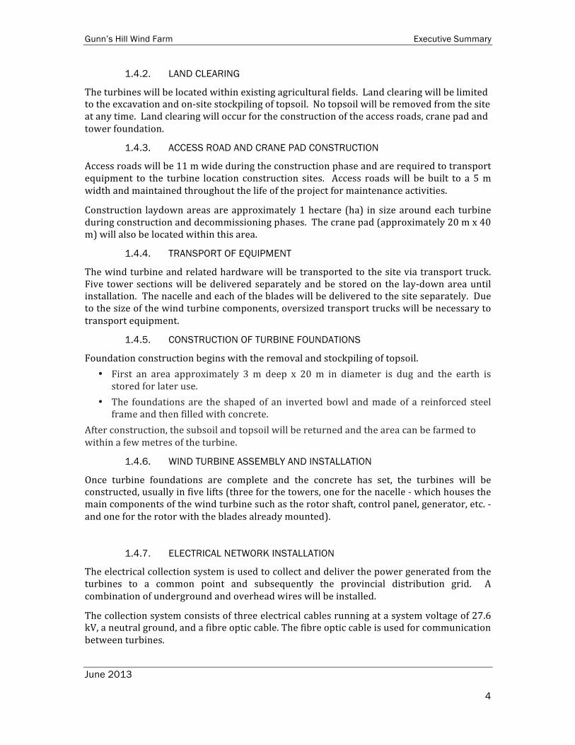
1.4.2. LAND CLEARING
The turbines will be located within existing agricultural fields. Land clearing will be limited to the excavation and on-‐site stockpiling of topsoil. No topsoil will be removed from the site at any time. Land clearing will occur for the construction of the access roads, crane pad and tower foundation.
1.4.3. ACCESS ROAD AND CRANE PAD CONSTRUCTION
Access roads will be 11 m wide during the construction phase and are required to transport equipment to the turbine location construction sites. Access roads will be built to a 5 m width and maintained throughout the life of the project for maintenance activities.
Construction laydown areas are approximately 1 hectare (ha) in size around each turbine during construction and decommissioning phases. The crane pad (approximately 20 m x 40 m) will also be located within this area.
1.4.4. TRANSPORT OF EQUIPMENT
The wind turbine and related hardware will be transported to the site via transport truck. Five tower sections will be delivered separately and be stored on the lay-‐down area until installation. The nacelle and each of the blades will be delivered to the site separately. Due to the size of the wind turbine components, oversized transport trucks will be necessary to transport equipment.
1.4.5. CONSTRUCTION OF TURBINE FOUNDATIONS
Foundation construction begins with the removal and stockpiling of topsoil. • First an area approximately 3 m deep x 20 m in diameter is dug and the earth is stored for later use.
• The foundations are the shaped of an inverted bowl and made of a reinforced steel frame and then filled with concrete.
After construction, the subsoil and topsoil will be returned and the area can be farmed to within a few metres of the turbine.
1.4.6. WIND TURBINE ASSEMBLY AND INSTALLATION
Once turbine foundations are complete and the concrete has set, the turbines will be constructed, usually in five lifts (three for the towers, one for the nacelle -‐ which houses the main components of the wind turbine such as the rotor shaft, control panel, generator, etc. -‐ and one for the rotor with the blades already mounted).
1.4.7. ELECTRICAL NETWORK INSTALLATION
The electrical collection system is used to collect and deliver the power generated from the turbines to a common point and subsequently the provincial distribution grid. A combination of underground and overhead wires will be installed.
The collection system consists of three electrical cables running at a system voltage of 27.6 kV, a neutral ground, and a fibre optic cable. The fibre optic cable is used for communication between turbines.

Gunn’s Hill Wind Farm Executive Summary
June 2013
5
The collection system cables connect to the transformer at the base of each turbine and subsequently connect to the other turbines along the collection system route. A T-‐Junction box will be used to join radial arms of the collection system and to splice cables together where required.
1.4.8. CONSTRUCTION OF SUBSTATION
The substation will be located on the south side of Firehall Road just east of the buried cable to Turbine 1. Construction will involve the removal and storage of topsoil from a 40 m x 80 m area. A concrete foundation will be poured on top of engineered gravel.
Substation electrical components typically consist of switchgear, SCADA, fuses, communication hardware and antenna, and other protection and control systems. This equipment is housed in grey electrical cabinets bolted to a concrete foundation. The substation area will be fenced to ensure safety and security.
1.4.9. CONSTRUCTION OF OPERATION AND MAINTENANCE BUILDING
An Operations and Maintenance building may be constructed to support the operational phase of the project. The building will have maximum dimensions of 16 m x 32 m and would host office space, parking for approximately 4 vehicles, tools, spare parts, and equipment for the wind farm. Both new and waste fluids would also be temporarily stored at the facility before and after use respectively. Waste fluids would be stored until a qualified service provider can remove them. A physical spill containment area would be constructed within the building for the fluids.
1.4.10. CLEAN UP AND SITE RECLAMATION
Site clean-‐up will occur throughout the construction phase and site reclamation will occur after construction has been completed. Materials will be recycled as much as possible and waste will be removed from the site and disposed of at an appropriate facility. All disturbed areas will be restored with the stockpiled soil and reseeded, as appropriate.
1.5. OPERATION AND MAINTENANCE
1.5.1. WIND TURBINE OPERATION
Turbine operation and maintenance (O&M) will be either contracted to a specialized third party service provider or handled by a project owner possessing infrastructure and capabilities for this activity. The O&M service provider will have a staff of trained Wind Turbine Technicians, Site Supervisors, and a data monitoring centre located in the O&M building (if constructed) and/or off-‐site to monitor the status of each turbine 24 hours per day, 365 days per year.
The scope of the activities will include day-‐to-‐day monitoring and operation of the turbines via SCADA hardware and fibre optic communication linkage as well as on-‐going
1.5.2. MAINTENANCE
Approximately every 6 months, routine maintenance will be carried out by 2-‐3 workers over a full day at each turbine.
The substation will receive periodic protective relay maintenance and the collection lines will receive periodic assessments of their condition.

Gunn’s Hill Wind Farm Executive Summary
June 2013
6
Unplanned maintenance can include failure of small components and may be addressed by a technician over several hours.
Events involving the replacement of major components such as gearboxes are not typical; however, this could require the use of large equipment.
1.5.3. WASTE MANAGEMENT
Waste generated during operations will be removed from the operations and maintenance building by a licensed operator and disposed of at an approved facility. Recycling services will be used to the extent available.
1.6. DECOMMISSIONING
At the end of the Project life, the wind turbines may be ‘re-‐powered’, meaning turbine components could be replaced to extend the life of the Project and delay any decommissioning activities. Alternatively, the wind turbines may be decommissioned. Project decommissioning will follow the Ontario Occupational Health and Safety Act along with any applicable municipal, provincial and federal regulations and standards.
The following components will be removed during dismantling:
1. Turbines; 2. Overhead lines and poles; and, 3. Transformer substation.
1.7. POTENTIAL ENVIRONMENTAL EFFECTS
An assessment for the construction, operation and decommissioning phases of the Project was completed to identify potential effects. This is done so that mitigation or corrective actions can be proposed to eliminate or minimize potential effects.
This section provides examples of some potential effects and mitigation measures of each phase for specific environmental components. For further details on mitigation measures and monitoring plans, please refer to the Construction Plan Report and the Design and Operations Report. Note that effects from construction are anticipated to be similar to those from decommissioning, as such, they are shown together below.
1.7.1. CULTURAL HERITAGE and ARCHAEOLOGICAL RESOURCES
There is a potential to disrupt existing unknown European and First Nations archaeological sites during construction. For this reason Stage 1 and Stage 2 archaeological surveys have been conducted on any lands likely to be disrupted during construction. These surveys included both desktop and field surveys (pedestrian surveys and test pitting) throughout the project area, targeted on any area that would be directly affected by project activities, including turbine or lay-‐down areas, roadways, underground and overhead cabling positions. Results are presented in their entirety in the Archaeological Assessment and Cultural Heritage Resources Reports.
Stage 2 Archaeological Assessment encountered a single First Nations findspot. The findspot is an isolated individual artefact that does not represent a significant planning

Gunn’s Hill Wind Farm Executive Summary
June 2013
7
concern. No further work is recommended at the location. No other archaeological resources were encountered during the Stage 2 work.
It is unlikely that unknown archaeological sites exist within the project location due to the ongoing and extensive soil disruption from present and historic agricultural activities in the project area.
A Heritage Impact Assessment was conducted for Gunn’s Hill Wind Farm to identify any Built Heritage features or Cultural Heritage Landscapes in the project area. This assessment involved desktop historical land-‐use studies and windshield surveys of the area for identification of culturally significant heritage features. The assessment concluded that there will be no impacts from the wind farm on heritage features or landscapes in the project area. An additional Heritage Impact Assessment was conducted and completed in Nov 2012 to address the additional overhead lines to the Woodstock Transformer Station. The assessment determined that the properties, roads, railway and other heritage resources in the area would not be negatively impacted by the project. Ministry of Tourism, Culture and Sport has reviewed and provided comment on both Heritage Impact Assessment Reports and has released the Gunn’s Hill Wind Farm from any further concerns.
1.7.2. NATURAL HERITAGE RESOURCES (SUCH AS WETLANDS AND WOODLANDS)
Construction and decommissioning: Vegetation removal could disturb wildlife and affect wildlife movement in the area. No direct impacts to wetlands present in the project area.
Mitigation measures: Designed in a way that avoids vegetation removal so that minimal habitat is lost during construction of the wind farm.
Operation: Disturbance or mortality to wildlife (e.g. birds and bats) may occur due to collisions with turbines.
Mitigation measures: Operational mitigation techniques may be implemented, such as a periodic shut-‐down of turbines during times when there is a greater change for bird and bat collisions. Monitoring will consist of post-‐construction mortality surveys for birds and bats which will be submitted to the Ministry of Natural Resources.
1.7.3. SURFACE WATER AND GROUNDWATER
Construction and decommissioning: Construction activities close to streams could increased surface water sedimentation, increased surface water contamination and fish and fish habitat disturbance.
Mitigation measures: to address increased surface water sedimentation and contamination include placing sedimentation control measures between construction activities and the Water Body. Where Water Bodies contained fish habitat, timing of near water works will be conducted outside of the fish spawning and rearing period of March 15 to June 30 as much as possible.
Operation: Water contamination is possible, although unlikely, due to accidental spills associated with maintenance activities.
Mitigation measures: A spill response plan will be developed and an emergency spill kit will

Gunn’s Hill Wind Farm Executive Summary
June 2013
8
be kept on site. In addition, the Ministry of the Environment and the local municipalities will be notified of any spills.
1.7.4. EMISSIONS TO AIR
Construction and decommissioning: The increase of heavy truck traffic on local roads during construction could create dust and increase emissions to air.
Mitigation measures: Road surfaces will be sprayed with water or an environmentally friendly dust suppressant to reduce the amount of dust created.
Operation: Maintenance vehicles may create dust and increase emissions to air. Mitigation measures: To reduce the amount of dust generated, the speed of maintenance vehicles will be limited. All construction vehicles will meet provincial emissions regulations.
1.7.5. NOISE
Construction and decommissioning: Construction activities will increase noise levels in the Project area.
Mitigation measures: All construction equipment will be maintained in good working condition and construction activities will abide by local by-‐laws regarding hours of operation.
Operation: The operating turbines and substation may increase noise levels experienced by some residents.
Mitigation measures: Turbines will be set back at least 550 m from all residents who are not leasing their land for the Project to avoid or lessen the effects. Noise modelling was also conducted to predict and ensure that noise levels from the operating turbines and substation will not be greater than limits set by the Ministry of Environment. Any noise-‐related complaints will be tracked and follow-‐up monitoring will occur as required.
1.7.6. LOCAL INTERESTS, LAND USE AND INFRASTRUCTURE
Construction and decommissioning: The increase in construction traffic could cause damage to local roads.
Mitigation measures: A Traffic Management Plan will be prepared prior to beginning construction activities. Finally, any damage to local infrastructure caused by construction activities will be repaired to original (or better) condition.
Operation: Turbines, access roads, and the substation will result in a minor reduction in usable agricultural land.
Mitigation measures: The length of access roads will be minimized where possible.
1.7.7. PUBLIC HEALTH AND SAFETY
Construction and decommissioning: Similar effects to those identified under Emissions to Air, Noise and Local Interest, Land Use and Infrastructure.
Gunn’s Hill Wind Farm Executive Summary
June 2013
9
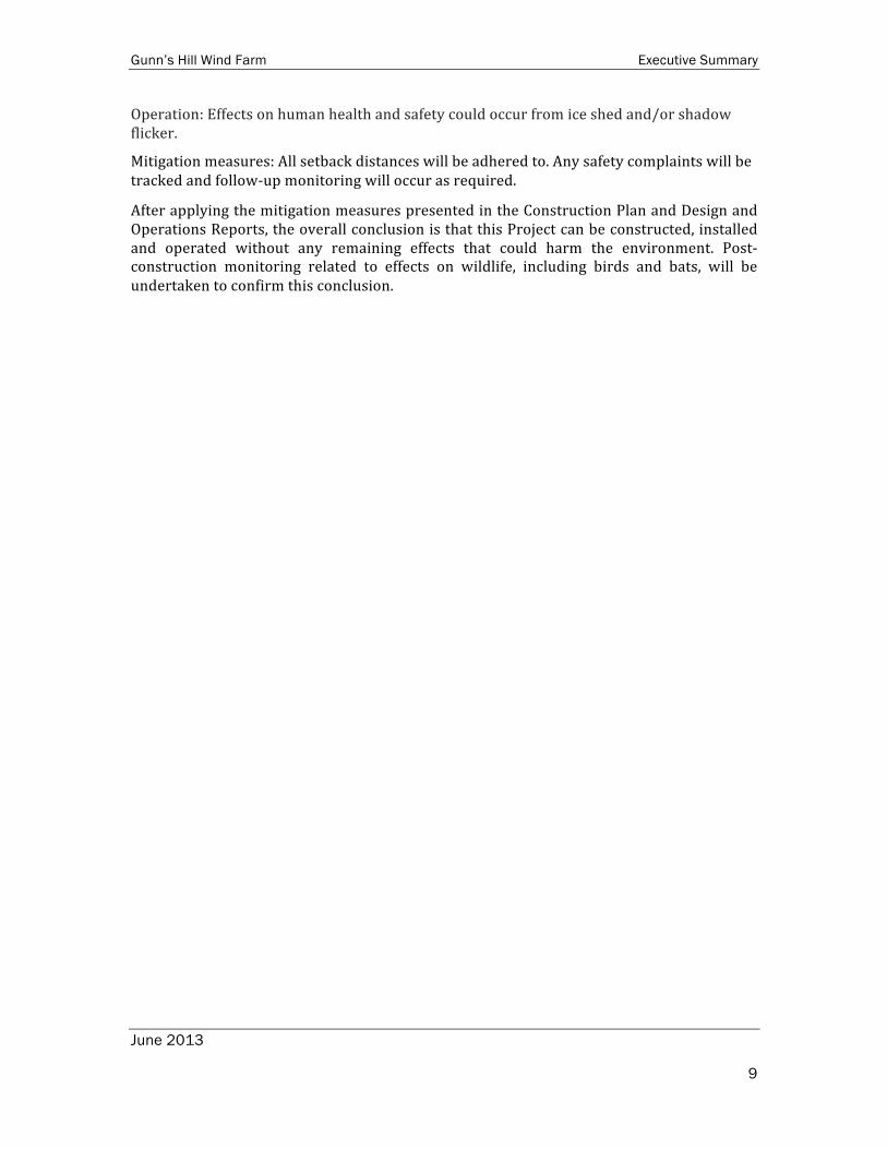
Operation: Effects on human health and safety could occur from ice shed and/or shadow flicker.
Mitigation measures: All setback distances will be adhered to. Any safety complaints will be tracked and follow-‐up monitoring will occur as required.
After applying the mitigation measures presented in the Construction Plan and Design and Operations Reports, the overall conclusion is that this Project can be constructed, installed and operated without any remaining effects that could harm the environment. Post-‐construction monitoring related to effects on wildlife, including birds and bats, will be undertaken to confirm this conclusion.

Gunn’s Hill Wind Farm Executive Summary
June 2013
10
2. DESIGN AND OPERATIONS REPORT
The purpose of the Design and Operations Report is to provide specific details on how the Project is designed, the equipment used, operated and how emergencies and ongoing communication will be managed. The report also presents mitigation measures, monitoring commitments and residual effects, if any. Residual effects are “left over” effects once mitigation measures have been applied.
The Design and Operation Reports was prepared in accordance with the requirements outlined in Ontario Regulation 359/09, the regulation governing renewable energy projects in Ontario.
The Site Plan was designed to meet Provincial “setback distances” outlined in the following table.
Setback Distance (metres (m))
Details
Noise Receptors 550* To be measured from the centre of a turbine’s base to a noise receptor. Property Line Hub height
(80) Setback can be reduced to blade length plus 10 m (60 m total) measured from the centre of the turbine’s base to the nearest property boundary if a Property Line Setback Assessment Report demonstrates that siting turbines closer will not cause adverse effects.
Roads and Railway
Blade length plus 10 m
Blade length plus 10 m (60 m total) measured from the centre of the turbine’s base to the boundary of the right-‐of-‐way.
Significant Natural Heritage Features
120 Measured from the project location boundary to the nearest point of the natural features. Project components may be sited closer than the prescribed setback if an Environmental Impact Study is prepared.
Water Bodies 120 Measured from the average annual high water mark of a lake, or permanent / intermittent stream (Project components may be sited closer than 120 m if a Water Body Report is prepared -‐ note that turbines and transformers may not be sited closer than 30 m to these features).
Petroleum Resources
75 Setback may be reduced with the submission of a Petroleum Engineer’s Report to the MNR.
Note: * Setback does not apply to noise receptors on land owned by a proponent of a wind energy facility or by a person who has entered into an agreement to permit all or part of the facility on their lands.
2.1. FACILITY DESIGN PLAN
2.1.1. WIND TURBINES
Up to ten (10) turbines from the Siemens SWT 3.0-‐113 family will be used for this Project. The turbines will have a maximum nameplate rating of 2.5 MW. These wind turbines have a hub heights of 99.5 m and a rotor diameter of 113 m for a total height of 156.5 m.
2.1.2. ACCESS ROADS
Access roads to project turbines will be 5 m wide during the operational phase and will have a foundation of ‘grade B’ gravel and a finished surface of ‘grade A’ gravel. The access
Gunn’s Hill Wind Farm Executive Summary
June 2013
11
roads provide access to properties for equipment during construction and for maintenance during operations.
2.1.3. ELECTRICAL SYSTEM
Turbines will be electrically connected to one another and to the substation by buried cables referred to as the collection system. The collection system brings electricity and operational data from each turbine to the control and switchgear hardware in the substation. The electricity is then fed to the point of common coupling (PCC) with the Hydro One controlled grid via the tap line.
The collection system will consist of three electrical cables running at a system voltage of 27.6 kV, a neutral ground, and a fibre optic cable for communication and control purposes. The grounding wire will be the same diameter as the Hydro One system grounding wire to minimize any risk of “stray voltage”.
A tap line will be used to connect the project substation to the existing provincially controlled grid. The routing of the tap line was selected to follow the most direct path that has existing hydro poles back to the point of common coupling with the provincial electrical grid. The selected route follows Hydro One’s M4 feeder to the low voltage bus of the Woodstock TS. Where the M4 feeder traverses the Cedar Creek Golf Club, alternate routes were considered along Juliana Dr, Norwich Ave, and Parkinson Rd, as well as through other nearby residential streets. However, the route through the golf course was deemed preferable.
The tap line will be buried for a length of approximately 350 m from the substation west to the existing overhead Hydro One poles. The line will share the Hydro One and Woodstock Hydro poles up to the point of common coupling at or adjacent to the Woodstock TS. The overhead wires will have a rated voltage of 27.6 kV, which is common on Hydro One’s distribution network in the area. Hydro One and Woodstock Hydro will determine whether upgrades are needed to the existing poles to support the additional cables and perform the upgrades at the cost of the proponent.
The portion of the tap line that will traverse the Cedar Creek Golf Club lands may be overhead or underground depending on the needs of the golf course owners and Hydro One.
2.1.4. SUBSTATION
The substation will consist of an entrance from Firehall Rd, an internal access road, and fenced-‐in metal enclosures housing switchgear and communication hardware for the project. Substation electrical components typically consist of switchgear, SCADA, fuses, and other protection and control systems. This equipment will be housed in electrical cabinets bolted to the concrete slab and/or a small e-‐house approximately 2.5 m x 6 m that can be accessed by a human. There is also potential for a grounding transformer to be installed at the substation.
Gunn’s Hill Wind Farm Executive Summary
June 2013
12
2.1.5. TURBINE LAYDOWN AREAS AND CRANE PADS
A turbine component “lay-‐down” area covering approximately 1 hectare (100 m x 100 m) will be required around each turbine during the construction phase. This area is required to store tower sections, blades, the nacelle and the rotor hub during the construction process and decommissioning processes. The crane pad will also be located within this area.
2.1.6. OPERATIONS AND MAINTENANCE BUILDING
An Operations and Maintenance building may be constructed to support the operational phase of the project. The building would have dimensions up to 16 m x 32 m and would host office space, parking for 4 vehicles, tools, equipment, and spare parts for the wind farm. New and waste lubricants and fluids would be stored within the facility. An area within the building would be built to a standard suitable for hazardous waste storage so that any leaks or spills of waste lubricants from the site are contained and prevented from contacting the ground or surface water.
2.2. FACILITY OPERATION PLAN
2.2.1. WIND TURBINE OPERATION AND MAINTENANCE
Turbine operation and maintenance (O&M) will be either contracted to a specialized third party service provider or handled by a project owner possessing infrastructure and capabilities for this activity. The O&M service provider will have a staff of trained Wind Turbine Technicians, Site Supervisors, and a data monitoring centre located in the O&M building (if constructed) and/or off-‐site to monitor the status of each turbine 24 hours per day, 365 days per year.
The scope of the activities will include day-‐to-‐day monitoring and operation of the turbines via SCADA hardware and fibre optic communication linkage as well as on-‐going. maintenance required on-‐site.
2.2.2. MAINTENANCE
The wind turbines will be subject to periodic inspection and maintenance, including routine motor maintenance, and lubricant and fluid replacement. To ensure proper operational output and safety, the wind turbines will be maintained by certified technicians according to the schedules recommended by equipment manufacturers.
Regular maintenance activities will be performed by a small crew (2-‐4 people) accessing the site using a pick-‐up truck. Periodically, major components of the wind turbines such as blades or generators may require replacement. Major component replacement will be performed with similar equipment and methods to those used in the construction phase, including cranes and oversized vehicles for transportation. Crane pads will be reconstructed as necessary for this activity.
Scheduled maintenance will include the following:
• Visual inspection;
• Inspection of mechanical components;
• Inspection of electrical components; and,

Gunn’s Hill Wind Farm Executive Summary
June 2013
13
• Greasing and general maintenance.
Initial visits for planned maintenance are more frequent, slowing to once every six months or more as the Project matures. Maintenance of each wind turbine usually takes one day to complete.
The proponent will also provide unscheduled maintenance for the turbine units when required. Maintenance and inspection related to the electrical collector system will be sub-‐contracted.
2.2.3. WASTE MANAGEMENT
Waste generated during operations will be removed by a licensed operator and disposed of at an approved facility. Recycling services will be used to the extent available.
2.3. EMERGENCY RESPONSE AND COMMUNICATION PLAN
The Emergency Response and Communication Plan, which will be filed with the Ministry of the Environment and the municipalities, will include details on:
• Emergency Action Plans for outlining steps to be taken in the event of an on-‐site emergency;
• Ongoing Communication to update the community throughout the construction and operations phase; and
• Complaints Resolution Process for dealing with any questions or concerns.
2.4. ENVIRONMENTAL EFFECTS MONITORING PLAN - SECTION 6
This section provides a summary of some of the potential effects, mitigation measures and monitoring commitments from the effects assessment. For the full effects assessment, refer to the Design and Operations Report.
2.4.1. CULTURAL HERITAGE
In accordance with O. Reg. 359/09, a Heritage Impact Assessment (HIA) was undertaken for the Project, and is included within the Archaeological Assessment and Cultural Heritage Resources Report.
Two HIAs were completed for this project – 1-‐ wind farm area excluding the overhead cable route, 2 -‐ overhead cable route. The results of both reports have been merged for the following summary. The Heritage Impact Assessments determined that:
• There are no protected properties within the Project Study Area;
• 32 properties with potential built heritage resources are within the Study Area ( 32 of which are of cultural heritage value or interest); these will not be negatively impacted by the Project; and,

Gunn’s Hill Wind Farm Executive Summary
June 2013
14
• 3 potential cultural heritage landscapes are within the Study Area; these will not be negatively impacted by the Project.
Potential Effects
As operational and maintenance activities will not occur on the properties containing the built heritage resources and cultural heritage landscapes, no adverse effects on heritage resources are anticipated during operations.
The Heritage Impact Assessment Reports determined that the proposed Project infrastructure will not result in the direct or indirect obstruction of any significant views or vistas within, from, or of built or natural features associated with the built heritage resources or cultural heritage landscapes. Significant views and vistas are not heritage attributes of any of the properties with identified heritage resources. .
Mitigation Measures
As no potential effects are likely to occur as a result of the Project on heritage resources, no mitigation measures are necessary. The Heritage Impact Assessment Reports recommended that “the Gunn’s Hill Wind Farm be released from further heritage concerns”.
Net Effects
No net effects are anticipated.
2.4.2. ARCHAEOLOGICAL ASSESSMENT
In accordance with O. Reg. 359/09, a Stage 1 Archaeological Assessment and Stage 2 Archaeological Assessments were completed for the Project.
A Stage 2 Archaeological Assessment was recommended for all areas of archaeological potential within the Project Location including the areas proposed for access roads, parking lot, optional O&M Building, collector lines, turbines and the distribution substation.
The Stage 2 assessment indicated that “…a single First Nations findspot was encountered. The First Nations findspot, an isolated individual artifact, does not represent a significant planning concern. No further work is recommended at this location.”
Potential Effects
There are no areas that will be excavated during the operation phase that will not have been assessed by a Stage 2 Archaeology Assessment; therefore no potential effects are anticipated to archaeological resources.
Mitigation Measures
No potential effects are anticipated during operation and therefore no mitigation measures are necessary.
Net Effects
No net effects are anticipated.
2.4.3. Natural Heritage Resources (such as wetlands and forests)
Wetlands

Gunn’s Hill Wind Farm Executive Summary
June 2013
15
There were five (5) wetlands identified within the Zone of Investigation. None of the wetlands will be directly impacted by the Project and therefore assumed to all be significant features. There will be no impacts to wetlands from Operation of the wind farm, so there were no mitigation measures suggested for this period of the wind farm life cycle
Woodlands
Four (4) significant woodlands are located within the Zone of Investigation. None of the woodlands will be directly impacted by the Project. There will be no impacts to woodlands from Operation of the wind farm, so there were no mitigation measures suggested for this period of the wind farm life cycle.
Potential Effects
No direct effects are anticipated to significant woodlands as a result of operation or maintenance activities.
Indirect impacts may occur to significant woodlands due to erosion.
During operation and maintenance of the facility, some materials such as lubricating oils and other fluids associated with turbine maintenance have the potential for discharge to the on-‐site environment through accidental spills.
Mitigation Measures
Mitigation measures related to erosion and accidental spills are outlined in the Construction Plan Report.
Net Effects
Indirect impacts are expected to be short-‐term in duration, and highly localized. Accidental spills would be spatially limited and of short duration and protocols to minimize their impact would be provided in the Emergency Preparedness/Response Plan.
Significant Wildlife Habitat
The following significant wildlife habitats were identified within the Zone of Investigation. These wildlife habitat are all potentially significant and required further pre-‐construction surveying to accurately determine their significance.
• Bat Maternity Colonies (2 locations)
• Amphibian Wetland Breeding (1 location)
Potential Effects
The potential effects to amphibian species from the Project are primarily from the Construction period when increased traffic will be on site. Traffic from maintenance may pose a risk if this habitat is determined to be significance. These species are at risk of harm from vehicular traffic as the habitat area is adjacent to an access road. If these species cross or rest on the road, they are at risk from maintenance crews travelling to the turbines.
The candidate Bat Maternity Colony is at risk from the turbine operation as the habitats are adjacent to the location of a proposed turbine. The bats are at risk of collision with the turbine or avoidance of their habitat if the turbine is a disturbance.

Gunn’s Hill Wind Farm Executive Summary
June 2013
16
Mitigation Measures
Pre-‐construction surveys for all of the above potential significant wildlife habitat will be conducted in the upcoming seasons. If any of the habitats are found to be significant, mitigation measures will be put in place.
Mitigation measures for amphibian species will include silt fencing located between habitat feature and wind farm infrastructure and education of construction and maintenance crews about the risks at each particular site.
Mitigation measures for bat maternity roosts will include additional post-‐construction mortality monitoring to evaluate impacts to local populations as outlined below:
• Bat mortality monitoring at all turbines will be conducted twice-‐weekly (3-‐4 day intervals) at all turbines from May 1st -‐ October 31st for three years following start of operations.
• Searcher efficiency and carcass removal trials will be conducted seasonally (spring, summer, and fall) between May 1 and October 31, and repeated for each searcher. Searcher efficiency and carcass removal rates are known to be more variable for bats than for birds throughout the year and depending on habitat (in part due to the relative size of the species).
• Regular reporting that includes analysis and submission of results to the MOE and MNR.
If significant mortality events do occur, mitigation measures such as feathering the blades or increasing the cut-‐in speed of the turbines may be enacted.
Net Effects
Given the agricultural land use in the area and the low potential for significant wildlife habitat in this area, effects are likely to be low. With the application of proposed mitigation, minimal net effects are predicted for amphibian and bat habitats.
Consultation with the MNR will be ensured should significant impacts to any species in the area be identified.
Generalized Significant Wildlife Habitat
In addition to the significant wildlife habitats, the following Generalized Significant Wildlife Habitats were identified within the Zone of Investigation:
• Species of Conservation Concern – River Bluet (Damselfly) (2 locations)
• Terrestrial Crayfish (4 locations)
• Seeps and Springs (1 locations)
Potential Effects
Potential effects to Species of Conservation Concern – River Bluet, Terrestrial Crayfish or Seeps and Springs from the Construction, Operation and Maintenance and Decommissioning periods of the wind farm life cycle include general habitat disturbance such as soil erosion, vegetation removal, surface water contamination.

Gunn’s Hill Wind Farm Executive Summary
June 2013
17
Mitigation Measures
The primary mitigation measure is to locate project activities away from these habits as best as possible. IF construction activities are located within 30 m of the of habitat areas, siltation fencing or straw bales will be used to protect the features from overland flow causing erosion, and contamination.
In the unlikely case that vegetation is required to be removed, the area will be rehabilitated with similar vegetation species.
Net Effects
Given the agricultural land use in the area, effects are likely to be low. With the application of proposed mitigation, minimal net effects are predicted for generalized wildlife habitat.
2.4.4. WATER BODIES AND AQUTIC RESOURCES
It is not anticipated that operation of the Project will adversely affect groundwater quality, quantity or movement. Some materials, such as fuel, lubricating oils and other fluids associated with turbine maintenance have the potential for discharge to the on-‐site environment through accidental spills
Water contamination is possible, although unlikely, due to accidental spills associated with maintenance activities. A spill response plan will be developed and an emergency spill kit will be kept on site. In addition, the Ministry of the Environment and the local municipalities will be notified of any spills.
Eight REA water bodies were identified within the Zone of Investigation. Two will be crossed by underground collector lines and five will be crossed by overhead feeder line. One Water Body is more than 30 m from the overhead feeder line and does not require environmental effect and mitigation measures analysis. No access roads are located within 120 m of a water body.
Potential Effects
The potential for effects on watercourses during operation exists from soil erosion resulting from maintenance activities (removal of stabilizing vegetative cover). Erosion can cause downstream sediment transport and a short-‐term increase in surface water turbidity, including associated impacts to fish and fish habitat. The magnitude and duration of potential effects to watercourses depend on the specific characteristics of each watercourse (e.g. flow regime, water velocity, bed substrates, bank conditions, local soils and the extent and duration of exposure). In addition, some materials, such as fuel, lubricating oils and other fluids associated with turbine maintenance have the potential for release to the environment in the event of accidental spills.
Mitigation Measures
Mitigation measures related to sedimentation and erosion would be the same as discussed in Section 5.10 and 5.9 respectively of the Construction Plan Report.
The Emergency Preparedness/Response Plan (Section 4.2.1) will contain procedures for spill contingency and response plans, spill response training, notification procedures, and necessary cleanup materials and equipment. As per S.13 of the Environmental Protection Act, all spills that could potentially have an adverse environmental effect, are outside the

Gunn’s Hill Wind Farm Executive Summary
June 2013
18
normal course of events, or are in excess of prescribed regulatory levels will be reported to the MOE’s Spills Action Centre.
Construction activities located within 120 m of fish habitat will consider the sensitive fish spawning and rearing period of March 15 to June 30, if possible,
Net Effects
Provided that maintenance activities are performed properly, no adverse net effects on surface water features and fish/fish habitat are anticipated during operation of the Project.
2.4.5. Emissions to Air
Maintenance vehicles may create dust and increase emissions to air. To reduce the amount of dust generated, the speed of maintenance vehicles will be limited. All construction vehicles will meet provincial emissions regulations.
2.4.6. Noise
The operation of turbines and the substation may increase noise levels experienced by some residents. Turbines will be set back at least 550 m from all residents who are not leasing their land for the Project to avoid or lessen the effects. Noise modeling was also conducted to predict and ensure that noise levels from the operating turbines and substation will not be greater than limits set by the Ministry of Environment. Any noise-‐related complaints will be tracked and follow-‐up monitoring will occur as required.
2.4.7. Local Interests, Land Use and Infrastructure
Turbines, access roads, and the substation will result in a minor reduction in usable agricultural land. To avoid or lessen these effects, the length of access roads will be minimized where possible.
2.4.8. Surveying and Geotechnical Studies
Potential effects on human health and safety could occur from ice shed (ice falling from turbine blades). To avoid or mitigate these effects, all setback distances will be adhered to. Shadow flicker (a “flicker” caused when rotating turbine blades are directly between a viewer and the sun) represents a potential annoyance to some residents under certain conditions and the effect is reduced by adhering to the required setback distances. Any safety or other complaints will be tracked and follow-‐up monitoring will occur as required.
2.4.9 Conclusions
The overall conclusion of the Design and Operations Report is that this Project can be operated without any remaining effects that could harm the environment. Post-‐construction monitoring related to effects on wildlife, including birds and bats, will be undertaken to confirm this conclusion.

Gunn’s Hill Wind Farm Executive Summary
June 2013
19
3. CONSTRUCTION PLAN
The purpose of the Construction Plan Report is to describe all activities that are part of the Project’s construction phase so that possible negative environmental effects can be identified. The report also presents mitigation measures, monitoring commitments and residual effects, if any. Residual effects are “left over” effects once mitigation measures have been applied.
The Construction Plan Report was prepared in accordance with the requirements outlined in Ontario Regulation 359/09, the regulation governing renewable energy projects in Ontario.
The land proposed to host the wind turbines, buried cable, access roads and substation is bounded by Firehall Road to the north, Oxford Road 14 to the east, Gunn’s Hill Road to the south and Oxford Road 59 to the west. This land is privately owned, agricultural land neighbouring the Hamlets of Oxford Centre and Curries, Ontario; located southeast of the City of Woodstock, Ontario. The overhead cable is proposed within municipal road Right-‐of-‐Ways within The Township of Norwich and the City of Woodstock.
3.1. CONSTRUCTION ACTIVITIES
In general terms, the construction phase of a wind project consists of site preparation, construction and installation of project infrastructure, and site rehabilitation. All of which can be ongoing concurrently as work progresses across the project area.
All project activities will be undertaken according to current guidelines provided by governmental agencies, Township of Norwich, City of Woodstock, Electrical Safety Authority, Hydro One, Woodstock Hydro and the turbine manufacturer.
3.1.1. Surveying and Geotechnical Studies
Surveys are required to identify locations of major Project components; this involves surveyors walking around the sites and marking locations using stakes. Surveying work will be carried out by a crew in one or two four-‐wheel drive pickup trucks.
Geotechnical sampling is required to locate turbine foundations; this involves drilling boreholes to collect information on the type of soil below ground. Boreholes will likely be drilled using a truck mounted drill rig (~30 ton). Should field conditions be prohibitive for the use of a truck mounted drill rig, a drill rig mounted to a tracked vehicle will be used. The tracked vehicle will be transported the site on a 16 m flatbed trailer.
3.1.2. Land Clearing And Construction Of Access Roads
Land clearing is necessary to prepare the land surface to facilitate further construction activities. As the project is located in intensively cultivated agricultural fields, there is little vegetation clearing required and land clearing will mostly entail the removal of topsoil from work areas and the preparation of the subsoil. First, the land is cleared and the topsoil is removed, stored for later use and replaced with a layer of gravel.

Gunn’s Hill Wind Farm Executive Summary
June 2013
20
Land clearing will occur for the construction of access roads, tower foundations, crane pads, lay-‐down areas, and some of the underground electrical network. The turbines will be located within existing agricultural fields, with the crane pads and lay-‐down areas located next to each foundation. Access roads are placed along field edges and existing farm roads where possible to minimize disruption to agricultural practices, in discussion with the landowners. The electrical cabling will be placed adjacent to access roads where possible and within the municipal road allowance along Middletown Line and Firehall Rd which will minimize land clearing requirements. The equipment used for land clearing will be the same equipment used to construct access roads.
Access roads and crane paths will be 11 m wide during the construction phase and are required to transport equipment to the turbine location construction sites.
The access road layout has been designed to minimize impacts to the natural environment and farming practices while utilizing existing entrances to the greatest extent possible. Access roads will be built on private land and will be privately maintained. Maintenance of the roads, including snow removal, is the responsibility of the wind farm operator and will be contracted to a local service provider. There is potential for entrances from public roadways to be gated, pending detailed consultation with local emergency services and the landowners.
Access roads will have a foundation of ‘grade B’ gravel and a finished surface of ‘grade A’ gravel, sourced from a local aggregate quarry and delivered to the site in dump trucks. The access roads will be built to a width of 6 m and be slightly graded to self-‐drain toward each edge. Access roads will be built such that the edge of the road is roughly flush with the field surface to maintain existing drainage patterns and farming operations.
Any culverts at entrances along Curries Rd, Middletown Line, and Firehall Rd may require upgrading to accommodate the increased turning radius and load capacity needed for delivery of turbine components and construction equipment. The design of upgraded culvert installation will comply with local municipal and/or conservation authority regulations and will prevent impacts to upstream and downstream landowners. Upgraded culverts will only be required for entrances to span the roadside ditch; no natural watercourses will be crossed by access roads.
3.1.3. Construction Of Crane Pad and Laydown Areas
A turbine component “lay-‐down” area covering approximately 1 hectare (100 m x 100 m) will be required around each turbine during the construction phase. This area is required to store tower sections, blades, nacelle and rotor hub during the construction process. It may also host a portable field office trailer and/or a portable storage container.
The lay-‐down area will be cleared and the topsoil may be stockpiled and seeded with native quick-‐sprouting grass and/or covered with a geo-‐textile to prevent wind erosion. Stockpiles will be located outside of the floodplain, if applicable. The lay-‐down area will then be covered with gravel sourced from a local supplier and transported to the site via dump truck.
The crane pad will be located within the lay-‐down area. The surface area of the crane pad will be approximately 20 m x 40 m (800 m2) at each location. The crane pad will be constructed of the same gravel material as the access roads.

Gunn’s Hill Wind Farm Executive Summary
June 2013
21
At the end of the construction period, the gravel will be removed from the lay-‐down area with the exception of the crane pad and the topsoil will be returned. The topsoil will be returned to the area to enable farming activity to resume.
3.1.4. Transport Of Turbine Components
The wind turbine and related hardware will be transported to the site via transport truck and trailer. Oversized trucks will be necessary to transport turbine components and some construction equipment.
Not including the foundation construction, each turbine will require 12 heavy-‐haul trucks listed below for transportation of the plant components listed below:
• 5 for tower sections • 1 for the hub • 1 for the nacelle • 1 for the parts container • 1 for miscellaneous components • 3 for the rotor blades
These components will be stored within the designated lay-‐down area until assembly. The only chemicals required for this phase are oils, gasoline, and grease used to operate construction equipment. Fuel-‐handling will be conducted in compliance with the mitigation measures outlined below.
The load restrictions on the municipal roads during March and April will be respected for all traffic related to the wind farm construction
3.1.5. Construction Of Turbine Foundations
Turbine foundation construction begins with the removal and stockpiling of topsoil. Excavated topsoil will be stockpiled in low-‐lying windrows and used for back-‐filling and grading operations once the foundation construction is complete and the site is rehabilitated.
Typically, shallow spread foundations are 18 m in diameter and 2 m deep. A reinforced steel frame is constructed first and then concrete will be poured for each foundation.
3.1.6. Wind Turbine Assembly And Installation
Once turbine foundations are complete and the concrete has set, the turbines will be constructed, usually in five lifts by a crane (three for the towers, one for the nacelle -‐ which houses the main components of the wind turbine such as the rotor shaft, control panel, generator, etc. -‐ and one for the rotor with the blades already mounted).
The cranes will be moved from turbine to turbine via wind farm access roads where possible and will be disassembled, loaded onto flatbed trailers and re-‐assembled when driving the crane from turbine to turbine is not possible.
3.1.7. Construction Of Electrical Network
The electrical collection system is used to collect and deliver the power generated from the turbines to a common point and subsequently the provincial distribution grid. A combination of underground and overhead wires will be installed.

Gunn’s Hill Wind Farm Executive Summary
June 2013
22
The collection system consists of three electrical cables running at a system voltage of 27.6 kV, a neutral ground, and a fibre optic cable. The fibre optic cable is used for communication between turbines.
The collection system cables connect to the transformer at the base of each turbine and subsequently connect to the other turbines along the collection system route. A T-‐Junction box will be used to join radial arms of the collection system and to splice cables together where required.
The cables running along Middletown Line and Firehall Road will be buried within the municipal road allowance. Road easement permits will be obtained from the municipality, where necessary. The underground collection system will terminate at the project-‐owned substation on Firehall Rd.
A feeder line will be used to connect the project to the existing provincially controlled grid. The routing of the feeder line was selected to follow the most direct path that has existing hydro poles back to the point of common coupling with the provincial electrical grid. The selected route follows Hydro One’s M4 feeder to the low voltage bus of the Woodstock TS. Where the M4 feeder traverses the Cedar Creek Golf Club, alternate routes were considered along Juliana Dr, Norwich Ave, and Parkinson Rd, as well as through other nearby residential streets. However, the route through the golf course was deemed preferable.
The feeder line will be buried for a length of approximately 350 m from the substation west to the existing overhead Hydro One poles. The line will share the Hydro One and Woodstock Hydro poles up to the point of common coupling at or adjacent to the Woodstock TS. The overhead wires will have a rated voltage of 27.6 kV. Hydro One and Woodstock Hydro will determine whether upgrades are needed to the existing poles to support the additional cables and perform the upgrades at the cost of the proponent Appropriate permits and agreements will be obtained prior to the construction phase.
The portion of the feeder line that will traverse the Cedar Creek Golf Club lands may be overhead or underground depending on the needs of the golf course owners and Hydro One.
3.1.8. Construction Of Substation
The substation will be located on the south side of Firehall Road approximately 60 m east of the buried cable line coming from Turbine 1. Construction will involve the removal and storage of topsoil from a 40 m x 80 m area. This will be performed using an excavator and/or bulldozer. The displaced top soil will be applied to adjacent land of the same owner. The substation area will then be leveled and covered with a layer of engineered gravel delivered by approximately 6 dump trucks. Concrete slab foundations will then be poured on top of the engineered gravel to form platforms for electrical cabinets and the transformer. Concrete for the platforms will arrive onsite via approximately 3 concrete trucks.
Substation electrical components typically consist of switchgear, SCADA, fuses and other protection and control systems, a metal lattice tower or wooden utility pole with an antenna, (there is no transformer present at the substation). This equipment is housed in grey electrical cabinets bolted to a concrete foundation. This equipment will be brought to the site on flatbed trucks that may be equipped with a boom to unload the equipment.

Gunn’s Hill Wind Farm Executive Summary
June 2013
23
A chain link fence will be installed around the substation for safety and security purposes. The fencing material will be sourced from a local building supplies provider and will be delivered in approximately 3 loads from a flatbed truck with a boom.
3.1.9. Construction Of Operation And Maintenance Building
An Operations and Maintenance building may be constructed to support the operational phase of the project. The building will have maximum dimensions of 16 m x 32 m and would host office space, parking for approximately 4 vehicles, tools, spare parts, and equipment for the wind farm. Both new and waste fluids would also be temporarily stored at the facility before and after use respectively. Waste fluids would be stored until a qualified service provider can remove them. A physical spill containment area would be constructed within the building for the fluids.
3.1.10. Clean Up And Site Reclamation
Site clean-‐up will occur throughout the construction phase and site reclamation will occur after construction has been completed.
Materials will be recycled as much as possible and waste will be removed from the site and disposed of at an appropriate facility.
All disturbed areas will be restored with the stockpiled soil and reseeded, as appropriate.
3.2. CONSTRUCTION AND INSTALLATION SCHEDULE
The proposed construction and installation schedule is listed below. Due to factors such as weather and equipment availability, wind farm construction schedules are subject to minor variation. Construction activity is proposed to occur between the hours of 7:00 – 21:00 up to 7 days per week as a maximum scenario. More typically, construction will occur between 7:00 – 17:00, 6 days per week. Based on community feedback, activities producing high levels of noise will be limited to 08:00 – 20:00. The likely start time for construction is January 2014.
3.2.1. Schedule
Activity Days Surveying 4 Land Clearing 14 Access Road Construction 14 Crane Pad Construction 12 Electrical Network Installation 60 Substation Construction 14 Foundation Construction 90 Turbine Installation 30 Turbine Commissioning 20 Site Rehabilitation 12

Gunn’s Hill Wind Farm Executive Summary
June 2013
24
3.2.2. Timeline
A general timeline of the construction and installation activities is depicted below. This timeline represents a conservative estimate for construction duration.

Gunn’s Hill Wind Farm Executive Summary
June 2013
25
4. DECOMMISSIONING
The purpose of the Decommissioning Plan Report is to describe all activities involved in dismantling or decommissioning of the Project at the end of the operations phase. The report also explains how the Project owner will restore the land and manage excess water or waste.
The Decommissioning Plan Report was prepared in accordance with the requirements outlined in Ontario Regulation 359/09, the regulation governing renewable energy projects in Ontario. Corresponding section references are provided below to assist with reviewing the associated reports.
The anticipated life of the Project is approximately 20 years. Decommissioning typically occurs following the operations phase.
At the end of the Project life, the wind turbines may be ‘re-‐powered’, meaning turbine components could be replaced to extend the life of the Project and delay any decommissioning activities. Alternatively, the wind turbines may be decommissioned. Project decommissioning will follow the Ontario Occupational Health and Safety Act along with any applicable municipal, provincial and federal regulations and standards.
The following components will be removed during dismantling:
1. Turbines; 2. Overhead lines and poles (including point of connection); 3. Substation; 4. Partial removal of wind turbine foundations; and 5. Removal of turbine access roads, if required by landowners.
4.1. RESTORATION OF LAND AND WATER
All areas, including the access roads, transformer pads and crane pads will be restored as much as practical to their original condition with native soils and seeding.

Gunn’s Hill Wind Farm Executive Summary
APPENDIX A
PROJECT LAYOUT MAP

>
>
>
>
>
>>
>
>
>
CURRIES ROAD
OLD STAGE ROAD
PATTULLO AVENUE
HIGHWAY 59
GUNNS HILL ROAD
FIREHALL ROAD
HIGHWAY 401
OXFORD 14
HIGHWAY 403
CEDAR LINE
OXFORD CENTRE ROAD
ORIEL LINE
PARKINSON ROAD
JULIANA DRIVE
MIDDLETOWN LINE
SWEA
BURG
ROA
D
OLD 14 LINE
COMMERCE WAY
FINKLE STREET
SUBSTATION ROADRIVERS ROAD
HORN ROAD
ATHL
ONE A
VENU
E
DODGE LINE
BEARDS LANE
RIDGEWAY ROAD
DOVER STREET KEYES DRIVEPAVEY STREET
GREENLY LINE
MIDDLETOWN LINE
HIGHWAY 403
MIDDLETOWN LINE
MIDDLETOWN LINE
4
3
8
2 7
1
6
9
5
10
Gunn's Hill Wind Farm Proposed Project Layout
May 29, 2013Prowind Canada Inc.NAD 83 Zone 171:40,000
!(^̂
0 250 500 750 1,000Meters
^ Gunn's HillOttawa
!( TorontoOntario
Key Map to Project Area´
LegendZone of Investigation (50 m)
Zone of Investigation (120 m)
> Turbine
Blade Swept Area
Access Roads (5 m)
Overhead Cable
Buried Cables
Substation/O&M Building/Parking
Laydown Area
OHN Waterbody (LIO)
OHN Watercourse (LIO)
Wooded Area (LIO)
Existing Roads
Existing Transmission Line
Municipal Boundaries
Participating PropertiesNoise Receptors
! Participating
" Non-Participating (Occupied)
X Non-Participating (Vacant)
Related Documents