Shell Exploration & Production 2/12/2007 File Title Copyright: Shell Exploration & Production Ltd. Guidelines for the Selection of a Waterflood Deoxygenation Strategy C. Deuel Shell EPT-Projects Houston, TX 17 th Annual Produced Water Seminar Hilton Houston NASA Clear Lake, TX Thursday January 18, 2007 J. Walsh, PhD SEPCo New Orleans, LA

Welcome message from author
This document is posted to help you gain knowledge. Please leave a comment to let me know what you think about it! Share it to your friends and learn new things together.
Transcript
Shell Exploration & Production
2/12
/200
7Fi
le T
itle
Cop
yrig
ht: S
hell
Expl
orat
ion
& P
rodu
ctio
n Ltd
.
Guidelines for the Selectionof a Waterflood
Deoxygenation Strategy
C. DeuelShell EPT-ProjectsHouston, TX
17th Annual Produced Water SeminarHilton Houston NASAClear Lake, TX
ThursdayJanuary 18, 2007
J. Walsh, PhDSEPCoNew Orleans, LA
Shell Exploration & Production
Deuel, Walsh: Deoxygenation Guidance Slide No. 2
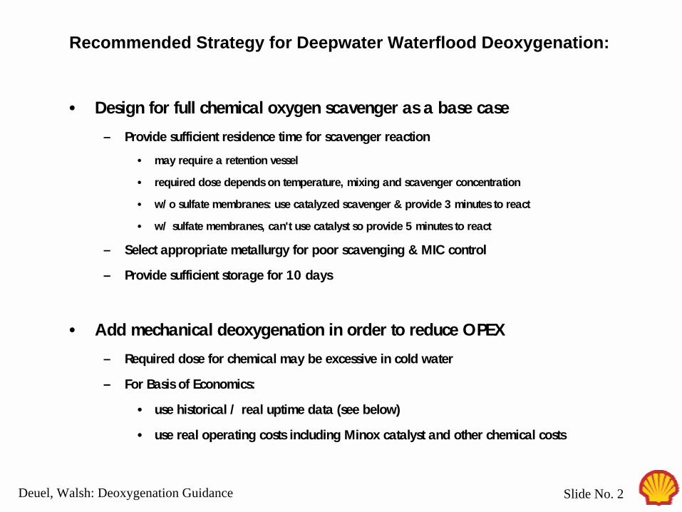
Types of Minox de-oxygenation systemsRecommended Strategy for Deepwater Waterflood Deoxygenation:
• Design for full chemical oxygen scavenger as a base case
– Provide sufficient residence time for scavenger reaction
• may require a retention vessel
• required dose depends on temperature, mixing and scavenger concentration
• w/o sulfate membranes: use catalyzed scavenger & provide 3 minutes to react
• w/ sulfate membranes, can't use catalyst so provide 5 minutes to react
– Select appropriate metallurgy for poor scavenging & MIC control
– Provide sufficient storage for 10 days
• Add mechanical deoxygenation in order to reduce OPEX
– Required dose for chemical may be excessive in cold water
– For Basis of Economics:
• use historical / real uptime data (see below)
• use real operating costs including Minox catalyst and other chemical costs

Shell Exploration & Production
Deuel, Walsh: Deoxygenation Guidance Slide No. 3
SeaJect - Extensive field trials
– Developed initially by Norsk Process Inc. in 1980's
• Initial funding / interest by Conoco
– 1990 Shell testing on shore
– 1990 One week pilot field test on Cognac
– 1992/1993 One year Bullwinkle field trial in parallel train
• review report - many problems, excessive downtime
– 1994 - 2001 Shell Ram-Powell waterflood - SeaJect on-line
• many problems, excessive downtime
• relying on chemical oxygen scavenger
• extensive well tubing corrosion
– 1998 Axsia Serck Baker acquires SeaJect
– 2001 Shell selects SeaJect for Bonga
– 2001 Shell decommissions SeaJect on Ram-Powell
Historical Involvement in Compact Deoxygenation:
Shell Exploration & Production
Deuel, Walsh: Deoxygenation Guidance Slide No. 4
2001 / 2002 Pivotal Years:
– SeaJect selected for Bonga & GA approved for construction
• But operations raise strong objections
– Mars WF approved assuming compact deoxygenation
• GA, weight & space constrained
– Shell acquires Enterprise, inc Bijupira-Salema
• Minox selected by Modec / Alliance Engineering, designed by Minox
– Shell & BP (Mars partner) share their experience:
• BP initial good experience with Minox
• Minox selected for several more BP waterfloods
• Not much industry experience available regarding Minox
Shell selects Minox for both Mars and Bonga
Historical Involvement in Compact Deoxygenation:

Shell Exploration & Production
Deuel, Walsh: Deoxygenation Guidance Slide No. 5
MeOHGas Blower
WF DeOx System – Common to all 3 DW WF:
Oxygen scavenger
Instrument Air
Gas/Gas HEx
Electric HeaterCatalystBed
1st StageSeparator
2nd StageSeparator
!Overall nitrogen / seawater flow is counter-current
!Local nitrogen / seawater flow is co-current• nitrogen / seawater mixing in static mixers
!High efficiency from:• small bubble size (high surface area, short gas diffusion length)• 2-stage counter-current process
Shell Exploration & Production
Deuel, Walsh: Deoxygenation Guidance Slide No. 6
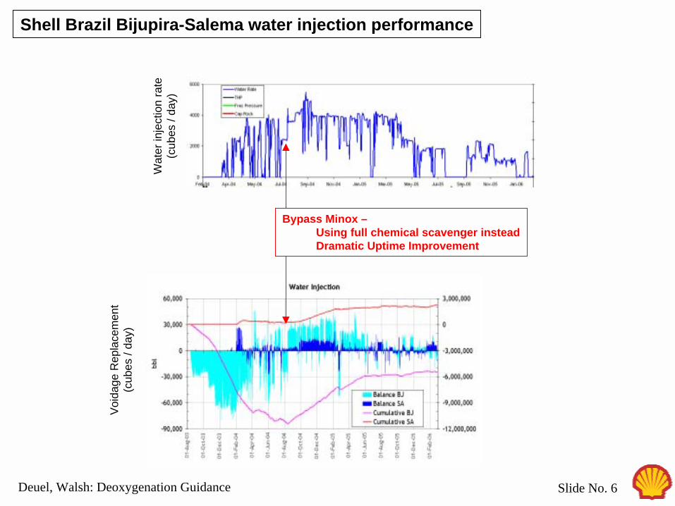
Shell Brazil Bijupira-Salema water injection performance
Wat
er in
ject
ion
rate
(cub
es /
day)
Bypass Minox –Using full chemical scavenger insteadDramatic Uptime Improvement
Void
age
Rep
lace
men
t(c
ubes
/ da
y)
Shell Exploration & Production
Deuel, Walsh: Deoxygenation Guidance Slide No. 7
WF2 Operating Experience
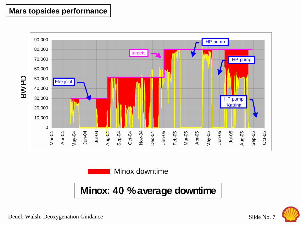
Minox: 40 % average downtime
BWPD
0
10,000
20,000
30,000
40,000
50,000
60,000
70,000
80,000
90,000
Mar
-04
Apr
-04
May
-04
Jun-
04
Jul-0
4
Aug
-04
Sep
-04
Oct
-04
Nov
-04
Dec
-04
Jan-
05
Feb-
05
Mar
-05
Apr
-05
May
-05
Jun-
05
Jul-0
5
Aug
-05
Sep
-05
Oct
-05
Flexjoint
targets
HP pump
HP pump
HP pumpKatrina
BWPD
0
10,000
20,000
30,000
40,000
50,000
60,000
70,000
80,000
90,000
Mar
-04
Apr
-04
May
-04
Jun-
04
Jul-0
4
Aug
-04
Sep
-04
Oct
-04
Nov
-04
Dec
-04
Jan-
05
Feb-
05
Mar
-05
Apr
-05
May
-05
Jun-
05
Jul-0
5
Aug
-05
Sep
-05
Oct
-05
Flexjoint
targets
HP pump
HP pump
HP pumpKatrina
Minox downtime
Mars topsides performance

Shell Exploration & Production
Deuel, Walsh: Deoxygenation Guidance Slide No. 8
Project Company Mark DateInstalled
CapacitykBWPD
WorkingEffectively Comments
Snorre Saga 1991 375
Foinaven BP Mark 1 1995 165 YMinox unit very successful here - single stage, using the catalyst reactor. Static mixer & stripping tower contactor / separator.
Schiehallion BP Mark 1 1996 280 N76% injection against target - single stage, using the catalyst reactor. Static mixer & stripping tower contactor / separator.
Vigdis (Snorre) Saga 1996 136Masa Petronas 1998 25Siri Statoil 1998 81.5Statfjord Statoil 1998 790 Conversion of fuel gas stripping towerGabon Marathon 1999 45 - Not installedPogo 1 (Thailand) Chevron 1999 20 N Not operatingPogo 3 (Thailand) Chevron 1999 40 N Not operatingGlitne (FPSO) Statoil PGS 2000 65Pogo 2 (Thailand) Chevron 2000 20 N Not operatingValHall BP Two stage 2000 220 NHalfdan Maersk 2001 220 Y Fixed by NATCoHeidrun Statoil 2001 200
Bijupira Salema Shell Mark 3 2002 100 N Minox currently by-passed. Relying on oxygen scavenger.
Mars Shell Mark 2 2003 94 Y Shell designBalam GOM Pemex 2005 30
Clair BP Two stage 2005 100 Y Requires 80 kbwpd. T. Marsh note of 29/6 says best achievable through Minox is 35 kbwpd
Holstein BP Mark 3 2005 100 NP 18 (Brazil) Petrobras 2005 150Thunderhorse GOM BP Two stage 2005 200
Bonga Shell Mark 3 2005 400 N Minox in permanent bypass due to blower bearing problems. Relying on Oxy Scavenger injection.
Agbami (W. Africa) Chevron 2006 450 - Under installation 10/06Atlantis GOM BP Two stage 2006 75
Ursa (future) Shell Mark 2 2008 - Shell design with large vessels, internals and scrubbers (SRM: cannot inject de-foamer)
Shell Exploration & Production
Deuel, Walsh: Deoxygenation Guidance Slide No. 9
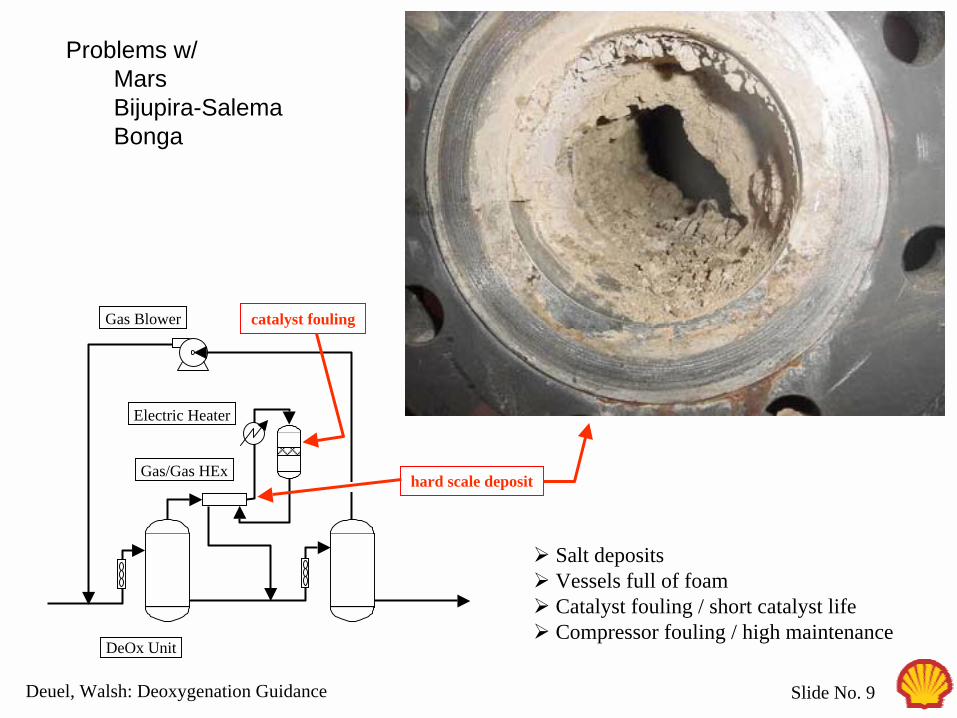
Gas Blower
DeOx Unit
Gas/Gas HEx hard scale deposit
Problems w/MarsBijupira-SalemaBonga
Electric Heater
! Salt deposits! Vessels full of foam! Catalyst fouling / short catalyst life! Compressor fouling / high maintenance
catalyst fouling
Shell Exploration & Production
Deuel, Walsh: Deoxygenation Guidance Slide No. 10
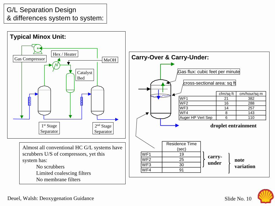
G/L Separation Design& differences system to system:
Almost all conventional HC G/L systems havescrubbers U/S of compressors, yet thissystem has:
No scrubbersLimited coalescing filtersNo membrane filters
MeOHGas CompressorHex / Heater
CatalystBed
1st StageSeparator
2nd StageSeparator
Typical Minox Unit:
Residence Time(sec)
WF1 19WF2 25WF3 30WF4 91
cross-sectional area: sq ft
Gas flux: cubic feet per minute
notevariation
droplet entrainment
carry-under
cfm/sq ft cm/hour/sq mWF1 21 382WF2 16 288WF3 14 257WF4 8 143Auger HP Vert Sep 6 110
Carry-Over & Carry-Under:
Shell Exploration & Production
Deuel, Walsh: Deoxygenation Guidance Slide No. 11
0.0
1.0
2.0
3.0
4.0
5.0
6.0
0.0 1.0 2.0 3.0 4.0 5.0foam height (inch)
foam
life
time
(min
utes
)
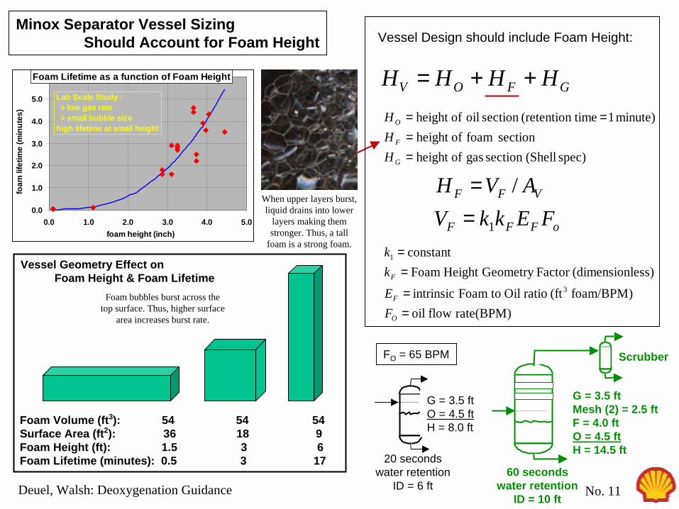
Foam Lifetime as a function of Foam Height
Lab Scale Study : > low gas rate > small bubble sizehigh lifetime at small height
Minox Separator Vessel SizingShould Account for Foam Height Vessel Design should include Foam Height:
GFOV HHHH ++=
rate(BPM)flowoilfoam/BPM)(ftratioOiltoFoamintrinsic
less)(dimensionFactorGeometryHeightFoamconstant
3
1
==
==
O
F
F
FEkk
spec) (Shellsection gas ofheight section foam ofheight
minute) 1 time(retentionsection oil ofheight
==
==
G
F
O
HHH
oFFF
VFF
FEkkVAVH
1
/==
20 secondswater retention
ID = 6 ft60 seconds
water retentionID = 10 ft
G = 3.5 ftO = 4.5 ftH = 8.0 ft
G = 3.5 ftMesh (2) = 2.5 ftF = 4.0 ftO = 4.5 ftH = 14.5 ft
FO = 65 BPM Scrubber
When upper layers burst, liquid drains into lower
layers making them stronger. Thus, a tall
foam is a strong foam.
Foam Volume (ft3): 54 54 54Surface Area (ft2): 36 18 9Foam Height (ft): 1.5 3 6Foam Lifetime (minutes): 0.5 3 17
Vessel Geometry Effect onFoam Height & Foam Lifetime
Foam bubbles burst across the top surface. Thus, higher surface
area increases burst rate.

Shell Exploration & Production
Deuel, Walsh: Deoxygenation Guidance Slide No. 12
Foam Height versus DeOx Vessel Inside Diameter:
02468
101214161820
8 9 10 11 12 13 14vessel ID (ft)
foam
hei
ght (
ft)
foaminess index: 0.1 0.15 0.2
Foam height as a function of vessel ID and foaminess index for the UPWF Minox separators:
Bonga Foaminess Index 0.134 cu ft / BPM Vessel ID 8.43 ft Liquid flux rate 1.9 BPM / sq ft Foam height 3.30 ft
Seawater / Nitrogen Foam Height Design Curves:
Calibration usingBonga Data:
UPWF design

Shell Exploration & Production
Deuel, Walsh: Deoxygenation Guidance Slide No. 13
Inst Air
To Injection Pumps
From Fine
Filters
Drain Drain
Minox System. Possible Upgrades shown in red
Atm. Vent
Check valve or SDV?
Atm. Vent
Outlet LCV here or at PCV3200 as
Mars?
Scrubber on catalyst inlet?
Scrubber oncompressor suction?
Nitrogen Backup MEOH
Injection
Backup Antifoam Injection
Replace LCV‘s for control /
isolation
Spre compressor?
Gas oxygen analyzer?
High Capacity O2 scav linked
to bypass
Gas oxygen analyzer?
FCV, FIC?

Shell Exploration & Production
Deuel, Walsh: Deoxygenation Guidance Slide No. 14
WaterfloodFeed Pumps
StrainersCartridge
Filters
0
1
2
3
4
5
6
7
8
9
DP
(PS
I)
0
2 0 0
4 0 0
6 0 0
8 0 0
1 0 0 0
1 2 0 0
1 4 0 0
1 6 0 0
(SC
FM)
Overlay of Air Makeup & Strainer BackwashWF2 Complex Oxygen Control Response
Air Makeup
0123456789
Delta
P (P
SI)
02004006008001000120014001600
SCFM
Separator Level control converted to direct control
Added a FIC / FCV upstream of the 1st stage separator
Changed the instrument gas pressure regulator to a FIC / FCV
Shell Exploration & Production
Deuel, Walsh: Deoxygenation Guidance Slide No. 15
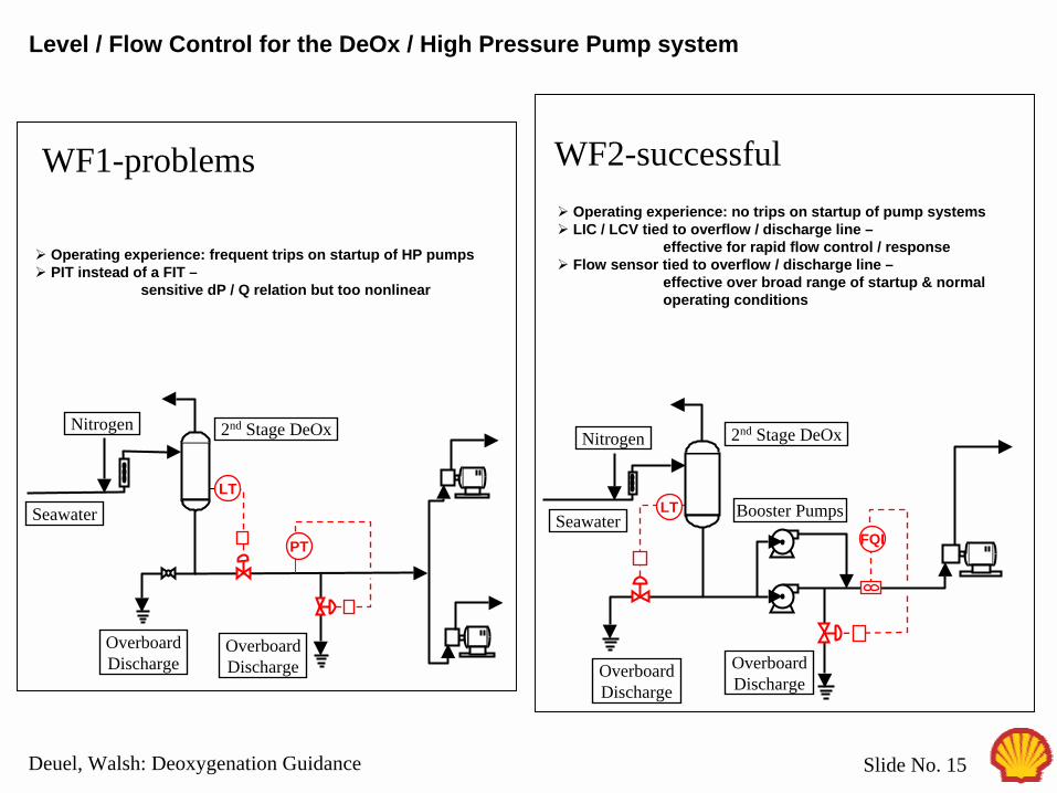
Level / Flow Control for the DeOx / High Pressure Pump system
Seawater
OverboardDischarge
2nd Stage DeOxNitrogen
OverboardDischarge
LT
PT
! Operating experience: frequent trips on startup of HP pumps! PIT instead of a FIT –
sensitive dP / Q relation but too nonlinear
Booster PumpsLT
FQI
OverboardDischarge
OverboardDischarge
2nd Stage DeOx
Seawater
Nitrogen
WF1-problems WF2-successful! Operating experience: no trips on startup of pump systems! LIC / LCV tied to overflow / discharge line –
effective for rapid flow control / response ! Flow sensor tied to overflow / discharge line –
effective over broad range of startup & normal operating conditions
Shell Exploration & Production
Deuel, Walsh: Deoxygenation Guidance Slide No. 16
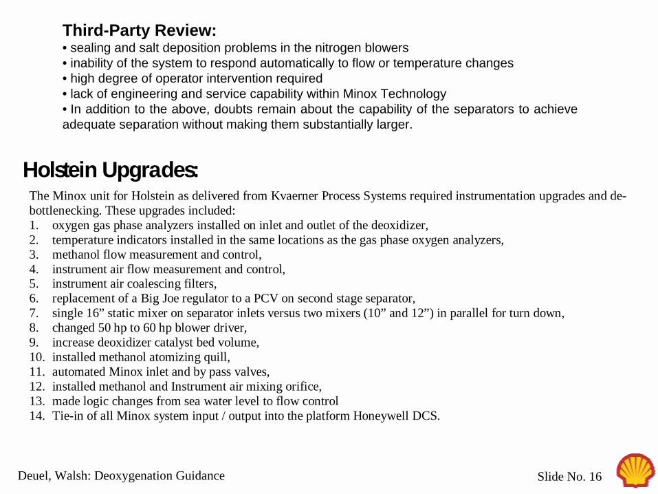
Third-Party Review:• sealing and salt deposition problems in the nitrogen blowers• inability of the system to respond automatically to flow or temperature changes• high degree of operator intervention required• lack of engineering and service capability within Minox Technology• In addition to the above, doubts remain about the capability of the separators to achieve adequate separation without making them substantially larger.
The Minox unit for Holstein as delivered from Kvaerner Process Systems required instrumentation upgrades and de-bottlenecking. These upgrades included: 1. oxygen gas phase analyzers installed on inlet and outlet of the deoxidizer, 2. temperature indicators installed in the same locations as the gas phase oxygen analyzers, 3. methanol flow measurement and control, 4. instrument air flow measurement and control, 5. instrument air coalescing filters, 6. replacement of a Big Joe regulator to a PCV on second stage separator, 7. single 16” static mixer on separator inlets versus two mixers (10” and 12”) in parallel for turn down, 8. changed 50 hp to 60 hp blower driver, 9. increase deoxidizer catalyst bed volume, 10. installed methanol atomizing quill, 11. automated Minox inlet and by pass valves, 12. installed methanol and Instrument air mixing orifice, 13. made logic changes from sea water level to flow control 14. Tie-in of all Minox system input / output into the platform Honeywell DCS.
Holstein Upgrades:

Shell Exploration & Production
Deuel, Walsh: Deoxygenation Guidance Slide No. 17
0
1000
2000
3000
4000
5000
0 50 100 150 200 250Water Rate (MBWPD)
Dai
ly C
ost (
$/da
y)
0
500,000
1,000,000
1,500,000
Ann
ual C
ost
Opex Cost Considerations:
Scavenger: ppm rate depends on water T and source depthHolstein: 50 ppm (-650 feet from NSL)Bonga: 55 ppm (warm water)Brazil: 45 ppm (warm water)Mars: 80 ppm
Minox:MeOHpolishing scavengerdefoamercatalyst replacement cost
100 ppm
Minox
50 ppm

Shell Exploration & Production
Deuel, Walsh: Deoxygenation Guidance Slide No. 18
Hypo / Oxygen Scavenger / Biocide Injection:
TypicalWell
CourseFilters
FineFilters
SeawaterLift
Pumps
PT
Hypo
Oxy scav is incompatible w/ hypo, which exposes D/S piping to biofilm.
Org biocide is incompatible w/ oxy scav which causes an oxygen excursion when batch biocide is performed.
Thus, oxy scav must be nearly fully reacted before batch biocide addition. Also, a flush biocide treatment can be performed during S/D.
Guidelines for Biomonitoring & Control should be followed.
There are other small but important design details that must be incorporated for long term integrity using chemical.
Global Category Management is working on this Guideline.
Biocide
Oxygen scavenger
Biocide

Shell Exploration & Production
Deuel, Walsh: Deoxygenation Guidance Slide No. 19
Other options:Stripping towerVacuum tower
Even with these, break dependence on production uptime for power, gas, etc need to switch to chemical to achieve waterflood uptime
However with chemical only systems, need to have high quality injection equipment plant uptime, sparing, automated flow control, alarm measurement, etc.,Need residence time, and tanks
Weight space cost comparisons logistics storage uptimevs Brazil & Bonga uptime 95% +

Related Documents